SEA Gate 2 DG R1 El manual del propietario
- Categoría
- Abridor de puerta
- Tipo
- El manual del propietario

GATE 2 DG R1
(Cod. 23023025)
Sistemi Elettronici
di Apertura Porte e Cancelli
International registered trademark n. 804888
®
SEA S.p.A.
Zona industriale 64020 S.ATTO Teramo - (ITALY)
Tel. +39 0861 588341 r.a. Fax +39 0861 588344
www.seateam.com
67411385
Italiano
English
Français
Español
CENTRALE ELETTRONICA PER 1 O 2 MOTORI A 230V/115V
ELECTRONIC CONTROL UNIT FOR 1 OR 2 230V/115V MOTORS
ARMOIRE DE COMMANDE POUR 1 OU 2 MOTEURS EN 230V/115V
CENTRAL ELECTRÓNICA PARA 1 O 2 MOTORES A 230V/115V
Rev.07 - 12/2014

67411385
CN1 = Input/output connectors
CN2 = Limit switch, 24V~, Electrolock connector
CN3 = M1 Motors and capacitors connector
CN4 = M2 motors and capacitors connector
CN5 = Courtesy light output connector
CN6 = Power supply connector
CN7 = Encoder connector
CNA = RX Receiver connector
CNP = Porgramming connector
EXP = Expansion module connector / LE Card
JOLLY = Jolly and Jolly 2 connector
DS = Programming display
OK = Programming button
DOWN = Programming button
UP = Programming button
T1 = Motors piloting Triac
T2 = Motors piloting Triac
R1 = Motors comand relay
R2 = Courtesy light comand relay
R3 = Photocell autotest relay
R4 = Electrolock relay
F1 = Accessories 1A fuse
F2 = 6.3AT fuse on 230V/10AT on 115V
F3 = 6.3A Electrolock fuse
TR1 = Power transformer
24
English
GATE 2 DG R1
Sistemi Elettronici
di Apertura Porte e Cancelli
International registered trademark n. 804888
®
COMPONENTS
TECHNICAL SPECIFICATIONS
Control unit power supply: 230 Vac 50/60 Hz - 115Vac 50/60 Hz
Absorption in stand by: 30 mA
Environment temperature : -20°C +50°C
Specifications of external enclosure: 325,7 X 246 X 140
RECEIVER RX
168 mm
174 mm
CNP
CN7
EXP
JOLLY
CNA
CN6
CN5
CN4
CN3
CN1 CN2
F1
UP DOWN OK
F2
F3
R2
R1
T1 T2
TR1
R4
R3
DS
JOLLY-JOLLY2
1 2
ON
CN1
CNP
DS1
POTENC
M2
M1
1 2 4
P01 D1 P11 P02 D2 P12 I1
5 6 7
I2
GND
I3 I4
3 8 9 10 11
+ -
LE CARD
Rev.07 - 12/2014

67411385
English
GATE 2 DG R1
Sistemi Elettronici
di Apertura Porte e Cancelli
International registered trademark n. 804888
®
1
2
3 4
5 6
7 8
9
10
11
12
13
CN1
Start
Stop
Common
Antenna
START Pedestrian
Common
Photocell 1
Common
ANT COM STRT
STPD
STOP COM PH1 PH2
EDG1
COM 24VA FLS
Safety edge 1
Photocell 2
Lamp
(500mA max)
+
-
Safety edge 2
AUX
(24V 800mA
max)
24V~
(800 mA max)
24VPh
(800 mA max)
14
15
16 17
18 19
20 21
22
23
CN2
Electrolock
24
25
26 27
28
CN3
29
30
31 32
33
CN4
M1
M2
JUMPERS
1
2
3 4
5 6
7 8
9
10
11
12
13
CN1
+
-
EDG2
LSO1 LSC1 LSO2 LSC2 COM 24V~ 24VPH LOCK CLM1 NM1 OPM1 CAPM1 CLM2 NM2 OPM2 CAPM2
ANT COM STRT
STPD
STOP COM PH1 PH2
EDG1
COM 24VA FLS
EDG2
67411385
25
CONNECTIONS
WARNING: The control unit is designed with the automatic detection of not used N.C. inputs (Photocells, Stop and Limit
switch) except the SAFETY EDGE input. The exclude inputs in self-programming can be restored in the “Check inputs”
menu without need to repeat the programming (page 38).
Limit Switch opening M1
Limit Switch closing M1
Limit Switch opening M2
Limit Switch closing M2
Common
Motor 1
opening
Motor 1
closing
Motor 1
Neutral
Capacitor
Motor 1
Motor 2
opening
Motor 2
closing
Motor 2
Neutral
Capacitor
Motor 2
Start
Stop
Common
Antenna
START Pedestrian
Common
Photocell 1
Safety edge 1
Photocell 2
Safety edge 2
The herein reported
functions are
available starting
from revision 33, on
R1B versions only.
Optional
Obligatory jumper
without accessory
connection.
Common
Lamp
(500mA max)
AUX
(24V 800mA
max)
Rev.07 - 12/2014

67411385
UPDOWN
ALL OTHER PARAMETERS HAVE DEFAULT SETTINGS WHICH ARE USEFUL FOR THE 90% OF THE APPLICATIONS
BUT CAN BE HOWEVER SET THROUGH THE SPECIAL MENU. FOR ENTERING INTO THE SPECIAL MENU MOVE
ON ONE OF THE MENU AND PRESS THE UP AND DOWN BUTTONS AT THE SAME TIME FOR 5 S.
26
MENU
SEA
SET
MENU
SEA
SET
MENU
SEA
SET
MENU
SEA
SET
MENU
SEA
SET
MENU
SEA
SET
MENU
SEA
SET
MENU
SEA
SET
MENU
SEA
SET
MENU
SEA
SET
MENU
SEA
SET
OK
1
2
3
4
5
6
7
8
OK
OK
OK
OK
OK OK
OK OK
OK OK
OK OK
OK OK
UP
UP
UP
UP
UP
UP
UP
OK
PRESS
BUTTON
STORED
TRANSMITTERS
START
MOTOR
ONE SINGLE
LEAF
LOGIC
PAUSE TIME
START IN
PAUSE
PROGRAM-
MING
TEST START
MENU
SEA
SET
MENU
SEA
SET
OK
UP
LANGUAGE
ITALIANO
UP
PROGRAMMING
BUTTONS
OK
DOWNUP
9
Skip this step if you do not want to program a transmitter
Press the
button of the
TX to be
stored
OK to exit
Menu or press
the button of
the next TX to
be stored
Choose the type of
motor with
UP or DOWN
To confirm and return
to main menu
With UP or DOWN
choose
the desired logic
To confirm and return
to main menu
With UP or DOWN
choose a delay for
automatic closing
To confirm and return
to main menu
Skip this step
if you want to work
in half-automatic
logic
With UP or DOWN
Choose ON
To confirm and return
to main menu
With UP or DOWN choose ON
to start times learning
At the end of the selflearning
the control unit returns automatically
to the main menu
With
UP or DOWN Choose
ON to start test
To confirm and return to
main menu
Skip this step if a TX has already been stored
With UP or DOWN choose
ON only if in single
leaf mode (Motor 1)
To confirm and return
to the main menu
Skip this step if you are working in double leaf mode
English
GATE 2 DG R1
Sistemi Elettronici
di Apertura Porte e Cancelli
International registered trademark n. 804888
®
MENU
SEA
SET
RECEIVER
MISSING
If on the display
appears the item:
Check if a receiver has
been connceted
(see page 24)
(See
page 27)
The gate will execute a CLOSING-OPENING-CLOSING CYCLE
(See
page 27)
PROGRAMMING
QUICK START
Rev.07 - 12/2014

67411385
27
MENU
Default
1 - langvage
4 - one s ngle
leaf *
SET
espanol
engl sk
fran(a s
tal ano
stop
start
off
on
off
1 240
Start
Stop
start
off
off
tal ano
kydravli(
E(kan (
U
Sliding
Reversible sliding gate
Hydraulic
Mechanic
off
7 - start n pavse
on
Off on
off
off
vnlo(k
Storing of a command
for unlocking an
electric brake
MENU FUNCTIONS TABLE GATE 2 DG R1
Description
Set value
Italian
English
French
Spanish
U
2 - trans tters
External odvle
U
Pedestr an Start
(Lear e ory
UU
Delete a trans itter
U
Ped Start.
External module
Pedestrian Start
Delete single transmitter
Delete transmitter memory
3 - otor
U
Sl d ng
Reuers ble Sl d ng gate
E(kan (
U
Disabled
In ON activates single leaf
mode (Motor 1)
5 - log (
Avto at (
U
open-stop-(lose-stop-open
2 bvttons
safety
Dead an
U
open-stop-(lose-open
Automatic
Step by step type 1
Step by step type 2
Two buttons
Safety
Dead man
Avto at (
U
6 - paVse t e
U
Setting from 1s to 4min.
OFF
(semi-automatic logics)
8 - progra ng
U U
Times learning start
In pause start is not acceped
In pause start is accepted
Note 1: The * indicates that the default value or the menu may change depending on the selected motor
type.
dut(k
Olandese
English
GATE 2 DG R1
Sistemi Elettronici
di Apertura Porte e Cancelli
International registered trademark n. 804888
®
(See page 29)
Off on
off
9 - test start
end
Start command
Select END and press OK to exit the menu.The menu
deactivates automatically after 2 minutes
(See page 28)
Rev.07 - 12/2014

The control unit is pre-set with the default settings, to start the control unit with the
DEFAULT settings just keep pressed the UP and DOWN buttons at the same time power
supplying the control unit the display shows the message init.
The DEFAULT settings are shown in the Menues table.
SELFLEARNING OPERATION TIME WITH AMPEROMETRIC SENSOR
(For electromechanical motors only)
The times learning can be done only on electromechanical gates, taking advantage of the automatic detection of
the stops.
Once the programming has been started just make sure that the gate executes the following cycle: CLOSING M2
- CLOSING M1 - OPENING M1 - OPENING M2 - CLOSING M2 - CLOSING M1.
Note: For stop detection sensitivity setting refer to the special menu.
LEARNING WITH LIMIT SWITCH
When limit switches are mounted, the gate executes automatically the follwing cycle: CLOSING M2 - CLOSING M1 -
OPENING M1 - OPENING M2 - CLOSING M2 - CLOSING M1.
Before starting the learning, make sure( through the test menu), that the relative limit switches of every leaf and every
opening are employed.
Exe: For the M2 motor closing the limit switch M2 in closing must be employed.
67411385
WORKING TIMES SELFLEARNING THROUGH IMPULSES
ATTENTION: This procedure is potentially dangerous and should only be performed by qualified people in
safety conditions.
NOTE: The card is preset with the standard working times, therefore the automation can be started even
without the times programming, simply by adjusting the timing on the display (see default times).
1) Turn off electricity, release the motors and manually position the leaves on halfway.
Reset the mechanical lock.
2) Connect the control board to the power supply
3) Select on the on-board display or JOLLY programmer, the type of motor that you are using as indicated in the
dispaly management ( E(kani( - Ele(trokydravli(, etc).
4) If necessary also set the operation logic and the other parameters. If you want to program with a transmitter, store
a transmitter before programming.
5) Select PROGra ing on the display, press OK and than one of the UP or DOWN buttons.
(If the motor starts in opening, remove and re-put power supply, select on the display reuerse otor. And through
the UP and DOWN button put it on ON, or if you have the Jolly programmer, activate the motor exchange function. )
6) At this point the gate will start the following cycle: CLOSING M2 - CLOSING M1 - OPENING M1 - OPENING M2 -
CLOSING M2 - CLOSING M1. During cycle, to store the respective stops, press UP or DOWN or START at every
point of stop of the leaf.
7) The self-learning is done.
U
UU
U
English
GATE 2 DG R1
Sistemi Elettronici
di Apertura Porte e Cancelli
International registered trademark n. 804888
®
WORKING TIMES SELF LEARNING
28
SELFLERNING OPERATION TIME WITH ENCODER / POTENTIOMETER
When an encoder is installed, it is necessary to select On in the EN(oder menu, when the potentiometer is installed, it
is necessary to select POTENtio eter in the EN(oder menu. Start programming and make sure that leaf 2 starts as
first in closing. The gate will automatically execute the following cycle: CLOSING M2 - CLOSING M1 - OPENING M1
- OPENING M2 - CLOSING M2 - CLOSING M1.
Note: For stop detection sensitivity setting refer to the special menu.
U
Rev.07 - 12/2014

FUNCTION LOGIC
AUTOMATIC LOGIC
A start impulse opens the gate. A second impluse during the opening will not be accepted.
A start impulse during closing reverses the movement.
SECURITY LOGIC
A start impulse opens the gate. A second impulse during opening reverses the movement.
A start impulse during closing reverses the movement.
STEP BY STEP TYPE 1 LOGIC
The start impulse follows the OPEN-STOP-CLOSE-STOP-OPEN logic.
STEP BY STEP TYPE 2 LOGIC
The start impulse follows the OPEN-STOP-CLOSE -OPEN logic.
DEAD MAN LOGIC
The gate opens as long as the START button of opening is pressed; releasing it the gate stops. The gate closes as
long as the button connected to the PEDESTRIAN START is pressed; releasing it the gate stops. To execute
complete opening and/or closing cycles the related pushbuttons must be constantly pressed.
2 PUSHBUTTONS LOGIC
One start opens, one pedestrian start closes. In opening the closing will not be accepted. In closing a start command
reopens, a pedestrian start command (closes) will be ignored.
NOTE 1: To have the automatic closing it is necessary to set a pause time, otherwise all the logic will be semi-
automatic.
NOTE2: It is possible to choose, whether to accept or not, the start in pause, selecting in the MENU the item
Startin pavse and choosing ON or OFF. By default, the parameter is OFF.
English
GATE 2 DG R1
Sistemi Elettronici
di Apertura Porte e Cancelli
International registered trademark n. 804888
®
67411385
29
Rev.07 - 12/2014

67411385
30
PRESS AT THE SAME TIME FOR 5 SECONDS TO ENTER OR TO EXIT THE SPECIAL MENU
MENU SP
Default
SET
10 100
10 100
0.0 5.0
Pre-flashing only
active before closing
75
Off
75
10 100
10 100
75
75
Off 6
2,5
1,5
Off 20
6 - leaf delay n (los ng *
7 - Pvshouer *
Off
Only (los ng
Off
8 - pvsk ng stroke
Off 3
Off 50
20
Off 50
20
Off 50
20
Off 50
20
bvzzer
Buzzer
15 - reuerse otor *
U
Off
On
Off
Off
UPDOWN
SPECIAL MENU FUNCTIONS TABLE GATE 2 DG R1
UP and DOWN
press END or
UP and DOWN
For entering into the special menu move on one of the menu and press the
buttons at the same time for 5 s. For exiting the special menu move on one of the
menu and press the buttons at the same time for 5 s.
Description
Set value
1 - open ng torq 1 *
2 - (los ng torq 1 *
3 - open ng torq 2 *
4 - (los ng torq 2 *
M1 opening torque
Note: with hydraulic motors
the torque will be on 100%
M2 opening torque
Note: with hydraulic motors
the torque will be on 100%
M2 closing torque
Note: with hydraulic motors
the torque will be on 100%
M1 closing torque
Note: with hydraulic motors
the torque will be on 100%
5 - leaf delay n open ng *
Setting from OFF to
6 seconds
Setting from OFF to
20 seconds
Open ng and (los ng
Only open ng
Disabled
Opening an closing
Opening only
Closing only
From OFF to 3 seconds
10 - (los ng sloudoun 1
9 - open ng sloudoun 1
12 - (los ng sloudoun 2 *
11 - open ng sloudoun 2 *
From OFF to 50% of
the stroke
From OFF to 50% of
the stroke
From OFF to 50% of
the stroke
From OFF to 50% of
the stroke
13 - preflasx ng
14 - flasx ng l gxt
Only (los ng
Nor al
U
L gxt
aluays
Normal
Control lamp
Always ON
Pre-flashing time
Synchronized right motor
Synchronized left motor
Nor al
U
English
GATE 2 DG R1
Sistemi Elettronici
di Apertura Porte e Cancelli
International registered trademark n. 804888
®
SPECIAL MENU
Rev.07 - 12/2014

MENU SP
Default
SET
Description
Set value
English
GATE 2 DG R1
Sistemi Elettronici
di Apertura Porte e Cancelli
International registered trademark n. 804888
®
OFF
ON
Off
Off
16 - EN(ODER *
xxx.s
Xxx.
xxx.s
Xxx.
16 - EN(ODER *
17 - opening ti e
otor 1
u
u
18 - (losing ti e
otor 1
u
u
xxx.s
xxx.s
Xxx.
Xxx.
In ON enables the
Encoder.
19 - opening ti e
otor 2
u
u
20 - (losing ti e
otor 2
u
u
17 - en(oder tot.
Otor 1
u
18 - en(oder par.
Otor 1
u
19 - en(oder tot.
Otor 2
u
20 - en(oder par.
Otor 2
u
In OFF disabled the
Encoder
Indicates the working times selflearning
in opening and closing on motor 1.
With UP or DOWN it is possible to increase
or reduce the working times.
Indicates the working times selflearning
in opening and closing on motor 2.
With UP or DOWN it is possible to increase
or reduce the working times.
Encoder impulses stored in programming
on motor 1.
Encoder impulses during operation
on motor 1.
Encoder impulses stored in programming
on motor 2.
Encoder impulses during operation
on motor 2.
67411385
31
Off
16 - EN(ODER *
Enables the reading of
the potentiometer with
LE card.
Potentio eter
u
Reports the current posi-
tion of the potentiometer
on the leaf of motor 1.
This parameter is useful
for seeing if the potentio-
meter is read correctly.
--------
Reports the impulses
stored by the control unit
when the leaf of motor 1
is fully open.
--------
--------
--------
--------
--------
Reports the impulses
stored by the control unit
when the leaf of motor 1
is fully close.
Reports the current posi-
tion of the potentiometer
on the leaf of motor 2.
This parameter is useful
for seeing if the potentio-
meter is read correctly.
Reports the impulses
stored by the control unit
when the leaf of motor 2
is fully open.
Reports the impulses
stored by the control unit
when the leaf of motor 2
is fully close.
21 - i.par. 1 *
u
22 - i.ap. 1 *
u
23 - i.(h. 1 *
u
24 - i.par. 2 *
u
25 - i.ap. 2 *
u
26 - i.(h. 2 *
u
Rev.07 - 12/2014

MENU SP
Default
SET
Description
Set value
English
GATE 2 DG R1
Sistemi Elettronici
di Apertura Porte e Cancelli
International registered trademark n. 804888
®
1 240
20
Off on
Off
5 100
100
0 10e9 0
1 240
100 10e4
0 100
100%
10e4
= start
Off
= start
27 - (ourtesy l gxt
N (y(le
Courtesy light setting
from 1s to 4min.
Courtesy light in cycle
28 - traff ( l gxt
reseruat on
When setting this function
the pedestrian input will be
activated to work on the
auxiliary board SEM
(traffic light management).
29 - pedestr an open ng
Setting from 5 to 100
30 - pedestr an PAvSE
31 - a((elerat on
32 - a ntenan(e (y(les
U
33 - perfor ed (y(les
U
Pause in pedestrian
opening same as in
total opening
Disabled
Acceleration ramp
Setting from 1s to 4 min.
Setting from 100 to
100000
Reports the executed
cycles. Keep pressed OK
to reset the cycles
34 - t er
U
off
off
ON PXOTO2
Disabled
Timer function active
on photocell 2
ON PEDESTR AN ENTRY
Timer function active on
pedestrian input
Active in opening
and closing
35 - EDGE1
ONLY (LOS NG
OPEN NG AND (LOS NG
ONLY OPEN NG
Active only in opening
Active only in closing
OPEN NG
AND
(LOS NG
36 - EDGE2
37 - EDGE1
8x2
38 - EDGE2
8x2
ONLY (LOS NG
OPEN NG AND (LOS NG
ONLY OPEN NG
Active in opening
and closing
Active only in opening
Active only in closing
OPEN NG
AND
(LOS NG
Nor al
U
Nor al
U
Edge is active and
protected by a 8k2 resistor
Normal N.C. contact
Edge is active and
protected by a 8k2 resistor
Normal N.C. contact
Nor al
U
Nor al
U
Rev.07 - 12/2014 67411385
32

stop
39 - PKOTO1
40 - PKOTO2
MENU SP
Default
SET
Description
Set value
OPEN NG AND (LOS NG
(LOS NG
Stop AND (LOSE
(LOSE
PAUSE RELOAD
Active in opening
and closing
Photocell active in closing
Photocell active before
opening
The photocell gives a
command to close during
opening, pause and
closing
The photocell charging the
pausing time
The photocell stops in closing
and closes when released
stop
OPEN NG AND (LOS NG
(LOS NG
Stop AND (LOSE
(LOSE
PAUSE RELOAD
Active in opening
and closing
Photocell active in closing
Photocell active before
opening
The photocell gives a
command to close during
opening, pause and
closing
The photocell charging the
pausing time
The photocell stops in closing
and closes when released
(LOS NG
OPEN NG
If the photocell is occupied
during opening, pause or
closing, the gate reopens
completely and closes
without observing the
pause time.
Delay pause ti e
u
English
GATE 2 DG R1
Sistemi Elettronici
di Apertura Porte e Cancelli
International registered trademark n. 804888
®
Delay pause ti e
u
If the photocell is occupied
during opening, pause or
closing, the gate reopens
completely and closes
without observing the
pause time.
67411385
41 - 24u avx
ALUAYS
N (Y(LE
N pavsE
OPEN NG
(LOS NG
AUX output always
power supplied
AUX output power
supplied only during opening
AUX output power
supplied only during closing
AUX output power
supplied only during pause
AUX output active only
during cycle
POS T UE BRAKE
ANAGE ENT
UU
NEGAT UE BRAKE
ANAGE ENT
U
U
Positive Electrobrake
Negative Electrobrake
ALUAYS
1 flash per sec. in opening
2 flashes per sec. in closing
Steady lit in Stop or Open.
Gate open uorning
light
Rev.07 - 12/2014
33

0 20
1
42 - opening POSiTiON
RE(OUERY *
Recovers the motor inertia
in opening after stop or
inversion.
0.1
44 - OTOR RELEASE *
U
Off
0.1 3.0
45 - BRAKE *
----
Disabled
Setting from 1 to 3
Adjusts the braking on the
limit switches
0
MENU SP
Default
SET
Description
Set value
off 8
46 - PER OD (AL pvshouer *
off
Off
Off
3
Off 5
49 - lock
off
Off
On
51 - ant ouerlap *
Off
On
Desactivate the leaves
anti-overlapping control,
allowing separate control
of the two leaves.
Activate the leaves
anti-overlapping control
off
Allows the repetition of the
Pushover functionat a
distance of time adjustable
from 0 to 8 hours at hourly
intervals
47 - ant ntrvs on
ONLY (LOS NG
ONLY OPEN NG
OPEN NG AND (LOS NG
Only on limit switch in opening
Only on limit switch in closing
On limit switches in closing
and in opening
If the limit switch is freed
manually it forces the
reclosing of the gate
48 - LOCK T E
U
Sets the lock release
time from 0 to 5 s
ONLY (LOS NG
ONLY OPEN NG
OPEN NG AND (LOS NG
Active only before opening
Active before opening
and closing
Active only before cloning
OPEN NG
The flashing light remains
ON with active timer and
open gate
The flashing light remains
OFF with the active timer
and open gate
50 - FLASX NG L GXT AND
t er
U
English
GATE 2 DG R1
Sistemi Elettronici
di Apertura Porte e Cancelli
International registered trademark n. 804888
®
67411385
0 20
1
43 - (losing POSiTiON
RE(OUERY *
Recovers the motor inertia
in closing after stop or
inversion.
1 10
Shows last event
(See alarms table)
52 - diagnosti(S
53 - sloudoun ra p torq
U
100
Adjusts the transition
between max. torque
and slowdown
0 %
100%
Rev.07 - 12/2014
34

55 - edge AVTOTEST
edge1
edge2
edge1-2
Off
edge1-2
Test enabled on edge
1 and 2
Test enabled on edge 1
Test enabled on edge 2
Disabled
MENU SP
Default
SET
Description
Set value
0
0 100
0
0 100
Adjust the tolerance
between stop and
obstacle Motor 1 opening.
0
0 100
0
0 100
off
off
off
off
off
64 - slou doun
sens t u ty *
56 - OPEN NG TOLERAN(E
otor1
U
57 - (los ng TOLERAN(E
otor1
U
58 - OPEN NG TOLERAN(E
otor2 *
U
59 - (los ng TOLERAN(E
otor2 *
U
60 - open ng sens t u ty
otor1
U
61 - (los ng sens t u ty
otor1
U
62 - open ng sens t u ty
otor2 *
U
63 - (los ng sens t u ty
otor2 *
U
Disabled
Adjusts the intervention time
of the Encoder / Potentiometer
on Motor 1 in opening
Disabled
Disabled
Adjusts the amperometric
sensitivity in slowdown.
Active only if the motors
are electromechanical.
Disabled
Adjust the tolerance
between stop and
obstacle Motor 2 opening.
Adjust the tolerance
between stop and
obstacle Motor 1 closing.
Adjust the tolerance
between stop and
obstacle Motor 2 closing.
English
GATE 2 DG R1
Sistemi Elettronici
di Apertura Porte e Cancelli
International registered trademark n. 804888
®
54 - fototest
photo1
photo2
photo1-2
Off
Off
Auto-test active only on
Photo1
Auto-test active only on
Photo2
Auto-test active on
Photo1 and Photo2
Disabled
67411385
10% (max) 99% (min)
Off (Intervention excluded)
10% (Fast intervention)
99% (Slow intervention)
10% (Fast intervention)
99% (Slow intervention)
10% (Fast intervention)
99% (Slow intervention)
Off (Intervention excluded)
Off (Intervention excluded)
off
Disabled
Off (Intervention excluded)
10% (Fast intervention)
99% (Slow intervention)
Adjusts the intervention time
of the Encoder / Potentiometer
on Motor 1 in closing
Adjusts the intervention time
of the Encoder / Potentiometer
on Motor 2 in opening
Adjusts the intervention time
of the Encoder / Potentiometer
on Motor 2 in closing
Rev.07 - 12/2014
35

MENU SP
Default
SET
Description
Set value
English
GATE 2 DG R1
Sistemi Elettronici
di Apertura Porte e Cancelli
International registered trademark n. 804888
®
Avto at (
U
Limit switch in automatic
recognition
Only limit switch in
opening present
ONLY (LOS NG
Avto at (
U
73 - sELE(T L T SU T(K
U
ONLY OPEN NG
Only limit switch in
closing present
To be activated if there is
a limit switch that stops
the motor phase.
75 - passuord
---- ----
Allows the entering of a
password blocking the
control unit parameters
modification.
END
Select END and press OK to exit the special menu.
The special menu switches off automatically after 20 minutes.
Otor internal
U
If limit switches are present
it adds an extra time to the
movement of the motors
after the reading of the limit
switches.
74 - ektra ti e
U
0.0 s 10 s
0.0 s
67411385
69 - pot. Slovdoun
threshold opening1 *
Adjust the threshold of the
potentiometer in slowdown.
By default this value is set
on 1 and can be increased
manually up to the
maximum value read on
the DEBUG VPI, VP2
menu.
65 - pot. threshold
opening 1 *
Adjusts the threshold of the
potentiometer intervention.
The parameter self-
determines in learning but
can also be adjusted later.
The lower the value, the
slower will be the response
of the potentiometer.
The parameter can be set
as maximum threshold at
the value read on the
DEBUG VPI, VP2 menu.
66 - pot. threshold
(losing 1 *
1 100
1 10
67 - pot. threshold
opening 2 *
68 - pot. threshold
(losing 2 *
70 - pot. Slovdoun
threshold (losing1 *
71 - pot. Slovdoun
threshold opening 2 *
72 - pot. Slovdoun
threshold (losing 2 *
Note 1: The * indicates that the default value or the menu may change depending on the selected motor type.
Note 2: After initialization the parameters "motor type" and "limit switch type" remain son the value chosen in the
setup program.
Rev.07 - 12/2014
36

English
GATE 2 DG R1
Sistemi Elettronici
di Apertura Porte e Cancelli
International registered trademark n. 804888
®
PASSWORD ENTERING MANAGEMENT
With a new control unit all menus can be displayed and set and the password will be disabled.
Selecting one of the Menus and keeping UP and DOWN pressed at the same time for 5 seconds, you will access the SP Menu
containing the Passuord Submenu.
Pressing OK in the Passuord Menu, you will proceed with the entering of the numeric code of the 4-digit PASSWORD.
Use UP and DOWN to increase or decrease the number, press OK to confirm it and you will pass automatically to the entering of
the next number. Pressing OK after the last entered number the word SvRE? appears, confirm the activation of the PASSWORD
and the message Ok appears, pressing UP or DOWN instead you can cancel the operation and NO OPERATION will appear on the
display.
Once entered the PASSWORD, it will be definitively activated, once the display switch off timeout has expired, or by turning off
and on again the control unit. Once the PASSWORD has been activated, the menus of the display can be only displayed but not
set. To unlock them you must enter the correct PASSWORD in the Passuord menu, if the password is wrong the message ERRor
will appear.
At this point, if the password has been entered correctly, the menus will be unlocked and it will be possible to change the
parameters of the control unit again.
If the control unit has been unlocked through Passuord Menu, it is possible to enter a new and different password, using the
same entering process as for the first one; at this point, the old password will no longer be valid.
If the password has been forgotten, the only way to unlock the control unit is to contact the SEA technical assistance, which will
assess whether to provide the procedure to unlock the control unit or not.
Note: The password cannot be set through the Jolly or Jolly 2 terminal.
POTENTIOMETER MANAGEMENT (Position Gate)
(Available only on GATE 2 DG R1B)
1 2
ON
CN1
CNP
DS1
POTENC
M2
M1
1 2 4
P01 D1 P11 P02 D2 P12 I1
5 6 7
I2
GND
I3 I4
3 8 9 10 11
+ -
LE CARD
Potentiometer 1 (Position Gate)
Potentiometer 2 (Position Gate)
D2 (White)
P02 (Green)
P12 (Brown)
D1 (White)
P01 (Green)
P11 (Brown)
To connect the potentiometer you must use the LE card (Cod.23001256) and set with Dip Switches 1 and 2 both in OFF.
With the potentiometer it is possible to access the hidden DEBUG menu to check the maximum settable value as threshold in
normal and slowdown speed.
To access this menu you have to press, in the menu that displays the firmware version, UP and OK at the same time until the
menus VP1 speed of potentiometer 1 and VP2 speed of potentiometer 2 will appear.
To view the speed of the potentiometer on the related menu, press OK.
To exit the DEBUG menu go to END and press OK.
If the reading of the potentiometer is reversed relative to the movement of the motor, on the display will appear the alarm
"Potentiometer direction" and you will have to reverse the brown wire with the green one and repeat programming.
Rev.07 - 12/2014 67411385
37

67411385
MENU
SEA
SET
---
----
----
DISPLAY INPUT STATUS
When the segment is
ON during self-
learning, the input
status is closed or
OFF.
Start
Start
pedestrian
Stop
Limit
Switch
opening
motor 1
Photocell 1
Photocell 2
Edge 1 Edge 2
Limit
Switch
closing
motor 1
Limit Switch
opening motor 2
Limit Switch
closing motor 2
Initial system
Software Version
Programming example
u.022
UP
OK
UP
UP
UP
DOWN
DOWN
DOWN
OK
OK
OK
DOWN
ELE(T
otOR
U
E(ka
U
Sl d
The settings of the control unit are made through the UP, DOWN and OK buttons. The UP and DOWN buttons to scroll through the MENUS and
SUBMENUS. By pressing OK you enter from MENU into SUBMENU and confirm the choice.
Moving in the language menu pressing the UP and DOWN buttons at the same time you access the SP MENU for special settings.
Moving in the language menu pressing the OK button for 5 seconds, you enter the CHECK MENU, where you can check the operating status of
all inputs.
L T SU T(H
(LOS NG 1
U
L T SU T(H
OPEN NG 1
U
MENU
start
Description
Description
EDGE1
PHOTO1
PHOTO2
PedESTR AN Start
END
Start test
Stop test
Pedestrian
start test
Safety edge1
test
Photocell 1
test
Photocell 2
test
M1 Opening
limit switch
test
M1 Closing
limit switch
test
The contact must be a N.O. Contact . When activating the related command
on the display SET lights up, the input works.
If SET is always on, check the wirings.
The contact must be a N.C. Contact. When activating the related command
on the display SET lights up, the input works.
If SET is always on, make sure that the contact is a N.C. Contact
The contact must be a N.C. Contact. When activating the related command
on the display SET lights up, the input works. If SET is always on, make
sure that the contact is a N.C. contact or that the related limit switch is not occupied.
The contact must be a N.O. Contact. When activating the related command
on the display SET lights up, the input works.
If SET is always on, check the wirings.
The contact must be a N.C. Contact. When activating the related command
on the display SET lights up, the input works.
If SET is always on, make sure that the contact is a N.C. Contact
IThe contact must be a N.C. Contact. When activating the related command
on the display SET lights up, the input works.
If SET is always on, make sure that the contact is a N.C. Contact
The contact must be a N.C. Contact. When activating the related command
on the display SET lights up, the input works.
If SET is always on, make sure that the contact is a N.C. Contact
The contact must be a N.C. Contact. When activating the related command
on the display SET lights up, the input works. If SET is always on, make
sure that the contact is a N.C. Contact or that the related limit switch is not occupied.
Exit menu
stop
OK
OK
OK
MENU FUNCTION TABLE CHECK GATE 2 DG R1 INPUTS
To access the Menu for input check keep pressed OK for about 5 seconds.
enabled
blo(ked
enabled
blo(ked
enabled
blo(ked
OK
enabled
blo(ked
EDGE2
Safety edge2
test
The contact must be a N.C. Contact. When activating the related command
on the display SET lights up, the input works.
If SET is always on, make sure that the contact is a N.C. Contact
OK
enabled
blo(ked
L T SU T(H
(LOS NG 2
U
L T SU T(H
OPEN NG 2
U
M2 Opening
limit switch
test
M2 Closing
limit switch
test
The contact must be a N.C. Contact. When activating the related command
on the display SET lights up, the input works. If SET is always on, make
sure that the contact is a N.C. contact or that the related limit switch is not occupied.
The contact must be a N.C. Contact. When activating the related command
on the display SET lights up, the input works. If SET is always on, make
sure that the contact is a N.C. Contact or that the related limit switch is not occupied.
Note: If the Stop, Photocell 1 and Photocell 2, Edge 1 and Enge 2 contacts are not bridged in self-learning, they will be deactivated and
can be reactivated through this menu, without repeating times self-learning.
English
GATE 2 DG R1
Sistemi Elettronici
di Apertura Porte e Cancelli
International registered trademark n. 804888
®
MENU FOR INPUT CHECK
38
Rev.07 - 12/2014

67411385
39
English
GATE 2 DG R1
Sistemi Elettronici
di Apertura Porte e Cancelli
International registered trademark n. 804888
®
RADIO TRANSMITTER SELF LEARNING
WITH RECEIVER ON BOARD OF CONTROL UNIT
!!
ROLLING CODE:
press twice
1 2 3 4
0
1
2
3
4
5
TABLE EXAMPLE
Transmitter
button
Memory
location
Serial number Customer
WARNING: Make the radio transmitters programming before you connect the antenna and insert the receiver into the
special CMR connector (if available) with turned off control unit.
With RF UNI module it will be possible to use both Coccinella Roll Plus transmitters, max. 800 codes (buttons), and radio
transmitters with fixed code, max. 100 codes (buttons). The first memorized radio transmitter will determine the type of the
remaining radio transmitters.
If the receiver is a Rolling Code, press twice the button of the radio transmitter that you want to program to memorize the first TX.
Notes:
- Enter radio transmitters learning only when the working cycle stops and the gate is closed.
- You can store max. 2 of the available 4 functions. If the control unit receives a code which was already associated to another function it will be
updated with the new function.
In the case of transmitters with fixed code it is necessary to press 1 time the button of the transmitter you want to program to store the first
remote control
FIXED CODE:
press once
MENU
SEA
SET
MENU
SEA
SET
MENU
SEA
SET
UP
MENU
SEA
SET
MENU
SEA
SET
MENU
SEA
SET
MENU
SEA
SET
UP
MENU
SEA
SET
MENU
SEA
SET
UP
MENU
SEA
SET
MENU
SEA
SET
MENU
SEA
SET
UP
MENU
SEA
SET
MENU
SEA
SET
UP
MENU
SEA
MENU
SEA
SET
MENU
SEA
SET
MENU
SEA
SET
SET
START
PEDESTRIAN
START
EXTERNAL
MODULE
STOP
DELETE A
TRANSMITTER
0
OK? OK
CLEAR
MEMORY
OK
PRESS
BUTTON
STORED
STORED
STORED
STORED
PRESS
BUTTON
PRESS
BUTTON
PRESS
BUTTON
If you want to program
the pedestrian
start as second
channel.
If you want to
delete a single
transmitter.
If you want to delete
the whole memory
If you want to program
the activation
of the LIGHT
output
as second channel.
Press the
button of the
transmitter
to be stored
Press the
button of the
transmitter
to be stored
Press the
button of the
transmitter
to be stored
Select with
UP or DOWN
the memory
location
to be deleted
and press OK
Press the
button of the
transmitter
to be stored
If you do not want to execute the cancellation,
press UP or DOWN to return to the
TRANSMITTER menu.
Confirm the cancellation.
If you want to
program the
UNLOCH as
second channel.
MENU
SEA
SET
MENU
SEA
SET
UP
MENU
SEA
SET
UNLOCH
STORED
PRESS
BUTTON
Press the
button of the
transmitter
to be stored
If you want to
program the
STOP as
second channel.
OK
OK
OK
OK
OK
OK
OK
for 10 s.
MENU
SEA
SET
OK
TRANSMITTERS
OK
Rev.07 - 12/2014

Photocell 1 and Photocell 2 Connections
Note: If the photocells are not connected, it is not necessary put a jumper between the clamps
(6 and 7 and/ou 6 and 8 of the CN1 terminal)
24VA = AUX 24V (Accessories) 800 mA max COM = 0V PH1 = Photocell contact 1
PH2 = Photocell contact 2
Note: For the autotest in the fototest menu select the photocell or the photocells on which you want
to perform it. Auto-test is possible only when the transmitter of the photocell is powered on 24V~.
The default setting of the photocell 1 is FOTO CLOSE and the one of the photocell 2 is FOTO OPEN.
The photocell 2 can also be set as TIMER (see TIMER function).
TIMER
Options AUX 24V 800 mA max can be set with on-board
Display or with Jolly device.
It is possible to chose when having tension on the AUX output.
The options are: always, only during opening, only during
cycle, only before opening or only during pause or for the
management of the positive or negative electrobrake.
N.B: For the autotest connect
the transmitters to the
contacts 20 and 21, if you do
not want the autotest connect
the transmitters to the
contacts 19 and 20.
67411385
START - STOP - PEDESTRIAN START - ANTENNA -
PHOTOCELL
PEDESTRIAN START (N.O.) The pedestrian start can be connected
between the conectors 2 and 4 of the CN1 terminal .
This input allows a partial opening, the opening space can be set through
the on-board display or through the JOLLY device.
Note1: The contact for partial opening is a N.O. Contact (Normally open).
Holding START starts the TIMER function, releasing the pedestrian start,
the operator repeats the pause and then performs the closing. In the case
of triggering a safety device the timer will automatically reset after 6
seconds.
Note2:In 2 BUTTONS logic it is necessary to keep pressed the Start Ped.
to re-close the automation.
Note3: In deadman logic this button executes the re-closing if you keep it
pressed.
Note4: When closed during pause, the gate will reclose only after this
input has been reopened.
TIMER activation: This input can be transformed into TIMER (See
TIMER).
START (N.O.) The
An impulse given to this contact opens and closes the automation depending on the selected logic, it can be given by a keyswitch, a keypad, etc.
To connect the other devices refer to the related instructions leaflets. (ie. loop detectors and proximity switches).
Note1: In DEADMAN logic keep pressed the Start for the opening of the automation.
Note2:
START is connected between connector 2 and 3 of the CN 1 terminal.
In the case of triggering a safety device
the timer will automatically reset after 6 seconds.
Holding START starts the TIMER function, releasing the start, the operator repeats the pause and then performs the closing.
In 2 BUTTONS logic this button performs the opening.
STOP (N.C.) The STOP is connected between the clamps 2 and 5 of the CN1 terminal .
When pressing this button the motor immediately stops in any condition/position. To re-start the movement give a start command.
After a stop the motor always re-starts in closing.
Can be activated through the on-board display or through the Jolly programmer. In both cases it’s a N.O. contact which provoques the
opening of the automation keeping it open as long as it is activated. When it’s released, after having paused for the set pausing time the
gate recloses. The TIMER can be activated on the inputs FOTO2, PEDESTRIAN START or keeping busy the START input.
Note1: When activated on the pedestrian entry, the pedestrian will be OFF also on the radio transmitter.
Note2: In the event of an intervention of a security device during the timer (Stop, amperometric, Edge), a start impulse restors the
movement.
Note3: In case of no power supply with open gate and active Timer the control unit will restore its function, otherwise if during restoring of
the power supply the TIMER is not activated it will be necessary to give a start impulse for the reclosing.
10 11 12 13
1 2 3 4 5 6 7 8 9
-
3
6
5
6
4
START
PEDESTRIAN
START
STOP
C
CN2
RX1
RX2
TX1
TX2
6
7
6
8
14 15 16 17 18 19 20 21 22 23
14 15 16 17 18 19 20 21 22 23
20
21
19
20
19
20
20
21
CN2
CN1
OPTIONS ON FOTO1 and FOTO2 adjustable on on- board display or with JOLLY
terminal.
FOTO CLOSE activation ((losing): if occupied, reverses the movement in closing,
during pause it prevent the closing.
Activation repeat pause (pavse RELOAD): If occupied, during pause it recharges the
timer of pause. In closing it reverses the movement.
FOTO OPEN activation (oPEning): If activated the photocell blocks the movement as
long as it’s busy, when released the opening continues.
FOTO PARK activation (stop and (lose): in opening it is not active; in pause are
activated it commands the closing when released, otherwise it’s not active; in closing it
stops the movement as long as it is busy, when released the closing continues.
FOTO STOP activation (STOP): When activated before the opening the photocell
blocks the automation as long as it is busy, during the opening it will be ignored. In
closing the intervention of the photocell causes the reopening.
Activation PHOTO CLOSE IMMEDIATELY ((lose): The photocell stops the gate as
long as it is occupied in both opening and closing, when released it gives a closing
command (Closing one second after release of the photocell ).
Activation delay pause TI E: If the photocell is occupied during opening, pause or
closing, the gate reopens completely and closes without observing the pause time.
U
English
GATE 2 DG R1
Sistemi Elettronici
di Apertura Porte e Cancelli
International registered trademark n. 804888
®
40
Rev.07 - 12/2014

67411385
SAFETY EDGE AND FLASHING LAMP
SAFETY EDGE
Two safety edges (EDG1 e EDG2) can be connected, respectively between the contacts 9, 11 and 10 and 11 of CN1.
Pressing EDG1 and EDG2, the contact opens, causing a partial reversing of the gate in closing and opening.
Note1: Put a jumper between the not used N.C. Contacts. The EDG1 and EDG2
inputs can be set: only in closing, only in opening or in both directions.
Note2: It is possible to activate a balanced edge 8K2 through the on board
display or through the Jolly programmer, in such case the edge contact will be
controled by a specific resistance value, detecting the possible involontary short
circuit of the device. In case of an imbalanced device a special alarm will show on
the on board display or on the JOLLY programmer.
If you connect a wireless edge it is possible to make a self-test on the power
supply of the receiver by connecting it to 24Vac and selecting in the Edge
avtotest menu the edge or the edges on which to perform the test.
SAFETY GATE
The Safety Gate, unlike the amperometric sensor, can be used both on
electromechanical and hydraulic operators.
The Safety Gate is an ENCODER allowing the detection of the gate position
and its reversing in case of obstacles. To use the ENCODER it is necessary
to enable it inside the special EN(oder Menu. The sensitivity on the obstacle is
adjustable from 0 - 99%. The higher the percentage is the more it will be
difficult to detect the obstacle.
AMPEROMETRIC DEVICE FOR ELECTROMECHANICAL OPERATORS
This control unit comes with an obstacle detection system working only on electromechanical operators allowing to
have the reversing on obstacles and the automatic detection of the stops.
Sensitivity adjustable from off to 99% inside the special menu. The more the percentage is high the more the
obstacle detection will be difficult. On hydraulic unit this parameter will be always OFF.
SAFETY GATE OR AMPEROMETRIC MANAGEMENT
ATTENTION: The first
operation after power failure, will
be executed with the set speed
to search the mechanical stops
limit.
SAFETY GATE 1
1
3
4
1
3
4
SAFETY GATE 2
1
2
3 4
ENC1+24V ENC2 GND
CN7
2
24V Flashing light 3W Max
The flashing light can be connected between the FLS and COM
connectors from Cn1 (It is recomended to use a 24V Flash Led
flashing light).
It blinks once per second during opening and twice per second during
closing, while it remains lit during pause.
Throught the warning light it is also possible to identify alarm signals comming from the STOP, PHOTOCELL 1,
PHOTOCELL2 and EDGE devices. Through the on board display or the Jolly programmer it is possible to activate the pre -
flashing function and/or to modify the flashing light function choosing between fixed flashing, control lamp or Buzzer.
The pre-flashing can be set from 0 to 5 s. or it is possible to have it only before closing.
COURTESY LIGHT
Timing
from 0 to 4 min
(230V~ 50W Max - 115V~ 50W Max)
CN5
34 35
English
GATE 2 DG R1
Sistemi Elettronici
di Apertura Porte e Cancelli
International registered trademark n. 804888
®
10 11 12 13
1 2 3 4 5 6 7 8 9
CN1
9
11
10
11
13
11
FLS
Common
41
EDG2 Safety edge
in opening
EDG1 Safety edge
in closing
Rev.07 - 12/2014

Example
Motor 2
Motor 1 connection
M = Opening/Closing
Com = COMMON
Motor 1
Motor 2 connection
M = Opening /Closing
Com = COMMON
Motor to be connected in case
of single-leaf.
M1
M2
Cap M2
Cap M1
Example
POWER SUPPLY INPUT
NOTE: For power supply connection follow the rules in
force
MOTORS CONNECTION, CAPACITY AND POWER SUPPLY
CN4
Phase 1
Neutral
Phase 2
Phase 1
Neutral
Phase 2
CN3
CN4
Line
Neutral
67411385
CN3
CN6
24 25 26 27 28 29 30 31 32 33
L N
27
28
32
33
24
25
26
29
30
31
English
GATE 2 DG R1
Sistemi Elettronici
di Apertura Porte e Cancelli
International registered trademark n. 804888
®
42
Rev.07 - 12/2014

Limit switch
Does not need a jumper when not connected.
For the limit switch function, limit switches must be installed, both in
opening and closing. In the case of single-leaf connect motor 1 (it is not
necessary to bridge the limit switches of motor 2).
Anti-intrusion function can be activated. This function needs at least
one limit switch, which pushes the motor in closing direction once it’s
released.
The right operation of the limit switch is guaranteed when
the motors turning direction correspond with the respective
employed limit switche.
Com = Common
C= Contact
LIMIT SWITCH, ELECTROLOCK CONNECTION
67411385
!!
Limit switch
M1 opening
Limit switch
M1 closing
Limit switch
M2 opening
Limit switch
M2 closing
ELECTROLOCK
Electrolock output
A 12V 15W max electrolock can be connected
Electrolock can be deactivated when not used for energy saving on
the control unit. Electrolock release can be timed from 0 to 5 s.
The electrobrake can be set: only before opening, only before
closing or in both directions.
EXP
DS1
DS2
RL4 RL3 RL2 RL1
L4
L3
L2
IC2
- M2+
1 CNP
CN1
L1
M1
24V~ / (ac/dc)
o
230V~
1 2 3 4 5 6 7 8
1
2
3
4
TRAFFIC LIGHT CARD CONNECTION
Connect on
EXP terminal
14 15 16 17 18 19 20 21 22 23
CN2
N.C.
N.C.
N.C.
N.C.
14
18
15
18
16
18
22 23
17
18
English
GATE 2 DG R1
Sistemi Elettronici
di Apertura Porte e Cancelli
International registered trademark n. 804888
®
43
Rev.07 - 12/2014

ALARM DESCRIPTION
Note 1: If in the diagnostics shows "Max. cycles reached ", do the maintenance and / or reset the number of cycles
performed.
Note2: To exit from the error messages, press OK. If the error persists, make all required checks for the specific
error and / or disconnect the device that generates the error to see if the error disappears.
At each opening and closing of the automation the flashing light will blink. It blinks once per second during
opening and twice per second during closing, while it remains lit during pause.
It is possible to view the alarms also on the flashing light or on the control lamp, simply by observing the number of
flashes emitted and verifying the reference in the table below:
Signals Kind of alarm
Solutions
FA LVRE OTOR
u
FA LVRE24UAVK
FA LVRE SELF TEST
FA LVRE L T SU TCK
U
FA LVRE FLASK NG L GKT
Motors current
failure
AUX output voltage
Sure there are no short circuits on the motor or on the control
unit.
Make sure there are no short circuits on wiring or control unit
and no overload.
Power supply failure
Check the network or the F2 fuse
Self-test photocells
failure
Limit switch
activation failure
Flashing lamp failure
Check the photocells operation and / or connections on the
control unit.
Check the operation of both limit switches and / or
correspondence between movement direction of the motor
and engaged limit switches.
Check connections and / or conditions of the lamp.
Blinks
9
2
3
6
4
Blinks
5
7
6
4 fast
Cause of alarm
Motors failure
Photocell in closing
Photocell in opening
Collision in opening
Safety edge
Cause of alarm
Stop
Max. Cycles reached
Collision in closing
Limit switch fault
67411385
FA LVRE net
English
GATE 2 DG R1
Sistemi Elettronici
di Apertura Porte e Cancelli
International registered trademark n. 804888
®
44
Potentiometer failure
FA LVRE POTENTIO ETER
U
The message appears only if the potentiometer is ON and the
potentiometer (LE) card is broken or not connected.
Rev.07 - 12/2014

67411385
Advises
Make sure all Safeties are turned ON
All N.C. contacts must have jumpers
Problem Found Possibile Cause Solutions
Motor doesn’t respond to any
START impulse
Gate doesn’t move while the
motor is running
Gate doesn’t reach the complete
Open / Closed position
The gate opens but doesn’t
close
The gate doesn’t close
automatically
a.) Check the connected N.C. contacts
b.) Burnt fuse
a.) The motor is in the released position
b.) There is an obstacle
a.) Pause time set to high
b.) Control unit in semi-autom. logic
a.) Wrong setting of the limit switches
b.) Error on programming
c.) Gate is stopped by an obstacle
d.) Torque too low
a.)
.) Ammeter alarm
e.) Encoder alarm
The contacts of the photocells are
connected and open
b.) The stop contact is connected and open
c.) The edge contact is open
d
a.) Check the connections or the jumpers on the
connections of the safety edges or of the stop
and of the photocell if connected
b.) Replace the burned fuse on the control unit
a.) Re-lock the motor
b.) Remove obstacle
a.) Adjust pause time
a.) Set limit switches
b.) Repeat programming
c.) Remove obstacle
d.) Increase torque parameter
a.) b.) c.) Check the jumpers or the
signals indicated on the warning lamp
d.) Check if the ammeter alarm has
intervened and eventually increase the
torque parameter.
b.) Set the pause parameter on a different
value from the off
TROUBLE SHOOTING
Page for both instaler and user
WAREHOUSING TEMPERATURES
T
min
T
Max
Dampness
min
Dampness
Max
5% Not condensing 90% Not condensing
MAINTENANCE
Considering the number of working cycles and the kind of gate, if the gate has changed the clutches and doesn’t work it’s necessary to
periodically proceed, with the learning times reprogramming on the electronic control unit.
Periodically clean the optical systems of the photocells.
REPLACEMENTS
Any request for spare parts must be sent to:
SEA S.p.A. - Zona Ind.le, 64020 S.ATTO - Teramo - Italia
SAFETY AND ENVIRONMENTAL COMPATIBILITY
Disposal of the packaging materials of products and/or circuits should take place in an approved disposal facility.
REGULAR PRODUCT DISPOSAL (electric and electronic waste)
(It’s applicable in EU countries and in those ones provided with a differential waste collection)
The brand that you find on the product or on documentation signals that the product must not be disposed off together with other domestic
waste at the end of life cycle. In order to avoid any possible environmental or health damage caused by irregular waste disposal, we
recommand to separate this product from other forms of waste and to recycle it in a responsible way in order to provide the sustainable re-use of
material resources. Domestic users are invited to contact the retailer where the product has been purchased or the local office in charge of all
the information related to differential watse collection and recycling of this kind of product.
STORING
Materials handling must be made with appropriate vehicles..
WARRANTY LIMITS
SEA reserves the right to make any required modification or change to the products and/or to this manual without any advanced notice
obligation.
For the guarantee see the sales conditions on the official SEA price list.
- 20°C + 65°C
e.) Check the reading of the Encoder
and/or the sensibility
English
GATE 2 DG R1
Sistemi Elettronici
di Apertura Porte e Cancelli
International registered trademark n. 804888
®
45
Rev.07 - 12/2014

TERMS OF SALES
EFFICACY OF THE FOLLOWING TERMS OF SALE: the following general terms of sale shall be applied to all orders sent to SEA S.p.A.
All sales made by SEA to all costumers are made under the prescription of this terms of sales which are integral part of sale contract and
cancel and substitute all apposed clauses or specific negotiations present in order document received from the buyer.
GENERAL NOTICE The systems must be assembled exclusively with SEA components, unless specific agreements apply. Non-
compliance with the applicable safety standards (European Standards EM12453 – EM 12445) and with good installation practice
releases SEA from any responsibilities. SEA shall not be held responsible for any failure to execute a correct and safe installation under
the above mentioned standards.
1) PROPOSED ORDER The proposed order shall be accepted only prior SEA approval of it. By signing the proposed order, the Buyer
shall be bound to enter a purchase agreement, according to the specifications stated in the proposed order.
On the other hand, failure to notify the Buyer of said approval must not be construed as automatic acceptance on the part of SEA.
2) PERIOD OF THE OFFER The offer proposed by SEA or by its branch sales department shall be valid for 30 solar days, unless
otherwise notified.
3) PRICING The prices in the proposed order are quoted from the Price List which is valid on the date the order was issued. The discounts
granted by the branch sales department of SEA shall apply only prior to acceptance on the part of SEA. The prices are for merchandise
delivered ex-works from the SEA establishment in Teramo, not including VAT and special packaging. SEA reserves the right to change at
any time this price list, providing timely notice to the sales network. The special sales conditions with extra discount on quantity basis (Qx,
Qx1, Qx2, Qx3 formula) is reserved to official distributors under SEA management written agreement.
4) PAYMENTS The accepted forms of payment are each time notified or approved by SEA. The interest rate on delay in payment shall be
1.5% every month but anyway shall not be higher than the max. interest rate legally permitted.
5) DELIVERY Delivery shall take place, approximately and not peremptorily, within 30 working days from the date of receipt of the order,
unless otherwise notified. Transport of the goods sold shall be at Buyer’s cost and risk. SEA shall not bear the costs of delivery giving the
goods to the carrier, as chosen either by SEA or by the Buyer. Any loss and/or damage of the goods during transport, are at Buyer’s cost.
6) COMPLAINTS Any complaints and/or claims shall be sent to SEA within 8 solar days from receipt of the goods, proved by adequate
supporting documents as to their truthfulness.
7) SUPPLY The concerning order will be accepted by SEA without any engagement and subordinately to the possibility to get it’s supplies
of raw material which is necessary for the production; Eventual completely or partially unsuccessful executions cannot be reason for
complains or reservations for damage. SEA supply is strictly limited to the goods of its manufacturing, not including assembly, installation
and testing. SEA, therefore, disclaims any responsibility for damage deriving, also to third parties, from non-compliance of safety
standards and good practice during installation and use of the purchased products.
8) WARRANTY The standard warranty period is 12 months. This warranty time can be extended by means of expedition of the warranty
coupon as follows:
SILVER: The mechanical components of the operators belonging to this line are guaranteed for 24 months from the date of
manufacturing written on the operator.
GOLD: The mechanical components of the operators belonging to this line are guaranteed for 36 months from the date of manufacturing
written on the operator.
PLATINUM: The mechanical components of the operators belonging to this line are guaranteed for 36 months from the date of
manufacturing written on the operator. The base warranty (36 months) will be extended for further 24 months (up to a total of 60 months)
when it is acquired the certificate of warranty which will be filled in and sent to SEA S.p.A. The electronic devices and the systems of
command are guaranteed for 24 months from the date of manufacturing. In case of defective product, SEA undertakes to replace free of
charge or to repair the goods provided that they are returned to SEA repair centre. The definition of warranty status is by unquestionable
assessment of SEA. The replaced parts shall remain propriety of SEA. Binding upon the parties, the material held in warranty by the
Buyer, must be sent back to SEA repair centre with fees prepaid, and shall be dispatched by SEA with carriage forward. The warranty
shall not cover any required labour activities.
The recognized defects, whatever their nature, shall not produce any responsibility and/or damage claim on the part of the Buyer against
SEA. The guarantee is in no case recognized if changes are made to the goods, or in the case of improper use, or in the case of tampering
or improper assembly, or if the label affixed by the manufacturer has been removed including the SEA registered trademark No. 804888.
Furthermore, the warranty shall not apply if SEA products are partly or completely coupled with non-original mechanical and/or electronic
components, and in particular, without a specific relevant authorization, and if the Buyer is not making regular payments. The warranty
shall not cover damage caused by transport, expendable material, faults due to non-conformity with performance specifications of the
products shown in the price list. No indemnification is granted during repairing and/or replacing of the goods in warranty. SEA disclaims
any responsibility for damage to objects and persons deriving from non-compliance with safety standards, installation instructions or use
of sold goods. The repair of products under warranty and out of warranty is subject to compliance with the procedures notified by SEA.
9) RESERVED DOMAIN A clause of reserved domain applies to the sold goods; SEA shall decide autonomously whether to make use of
it or not, whereby the Buyer purchases propriety of the goods only after full payment of the latter.
10) COMPETENT COURT OF LAW In case of disputes arising from the application of the agreement, the competent court of law is the
tribunal of Teramo. SEA reserves the faculty to make technical changes to improve its own products, which are not in this price list at any
moment and without notice. SEA declines any responsibility due to possible mistakes contained inside the present price list caused by
printing and/or copying. The present price list cancels and substitutes the previous ones. The Buyer, according to the law No. 196/2003
(privacy code) consents to put his personal data, deriving from the present contract, in SEA archives and electronic files, and he also
gives his consent to their treatment for commercial and administrative purposes.
Industrial ownership rights: once the Buyer has recognized that SEA has the exclusive legal ownership of the registered SEA brand
num.804888 affixed on product labels and / or on manuals and / or on any other documentation, he will commit himself to use it in a way
which does not reduce the value of these rights, he won’t also remove, replace or modify brands or any other particularity from the
products. Any kind of replication or use of SEA brand is forbidden as well as of any particularity on the products, unless preventive and
expressed authorization by SEA.
In accomplishment with art. 1341 of the Italian Civil Law it will be approved expressively clauses under numbers:
4) PAYMENTS - 8) GUARANTEE - 10) COMPETENT COURT OF LOW
GATE 2 DG R1
Sistemi Elettronici
di Apertura Porte e Cancelli
International registered trademark n. 804888
®
67411385
91
Rev.07 - 12/2014

Sistemi Elettronici
di Apertura Porte e Cancelli
International registered trademark n. 804888
®
67411385
Italiano
English
Français
AVVERTENZE GENERALI PER INSTALLATORE E UTENTE
1. Leggere attentamente le Istruzioni di Montaggio e le Avvertenze Generali prima di iniziare l’installazione del prodotto. Conservare la documentazione per
consultazioni future
2. Non disperdere nell’ ambiente i materiali di imballaggio del prodotto e/o circuiti
3. Questo prodotto è stato progettato e costruito esclusivamente per l’utilizzo indicato in questa documentazione. Qualsiasi altro utilizzo non espressamente indicato
potrebbe pregiudicare l’integrità del prodotto e/o rappresentare fonte di pericolo. L’uso improprio è anche causa di cessazione della garanzia. La SEA S.p.A. declina
qualsiasi responsabilità derivata dall’uso improprio o diverso da quello per cui l’automatismo è destinato.
4. I prodotti SEA sono conformi alle Direttive: Macchine (2006/42/CE e successive modifiche), Bassa Tensione (2006/95/CE e successive modifiche), Compatibilità
Elettromagnetica (2004/108/CE e successive modifiche). L’installazione deve essere effettuata nell’osservanza delle norme EN 12453 e EN 12445.
5. Non installare l’apparecchio in atmosfera esplosiva.
6. SEA S.p.A. non è responsabile dell’inosservanza della Buona Tecnica nella costruzione delle chiusure da motorizzare, nonché delle deformazioni che dovessero
verificarsi durante l’ uso.
7. Prima di effettuare qualsiasi intervento sull’impianto, togliere l’alimentazione elettrica e scollegare le batterie. Verificare che l’impianto di terra sia realizzato a
regola d’arte e collegarvi le parti metalliche della chiusura.
8. Per ogni impianto SEA S.p.A. consiglia l’utilizzo di almeno una segnalazione luminosa nonché di un cartello di segnalazione fissato adeguatamente sulla struttura
dell’infisso.
9. SEA S.p.A. declina ogni responsabilità ai fini della sicurezza e del buon funzionamento della automazione, in caso vengano utilizzati componenti di altri produttori.
10. Per la manutenzione utilizzare esclusivamente parti originali SEA.
11. Non eseguire alcuna modifica sui componenti dell’automazione.
12. L’installatore deve fornire tutte le informazioni relative al funzionamento manuale del sistema in caso di emergenza e consegnare all’Utente utilizzatore
dell’impianto il libretto d’avvertenze allegato al prodotto.
13. Non permettere ai bambini o persone di sostare nelle vicinanze del prodotto durante il funzionamento. L’applicazione non può essere utilizzata da bambini, da
persone con ridotte capacità fisiche, mentali, sensoriali o da persone prive di esperienza o del necessario addestramento. Tenere inoltre fuori dalla portata dei
bambini radiocomandi o qualsiasi altro datore di impulso, per evitare che l’automazione possa essere azionata involontariamente.
14. Il transito tra le ante deve avvenire solo a cancello completamente aperto.
15. Tutti gli interventi di manutenzione, riparazione o verifiche periodiche devono essere eseguiti da personale professionalmente qualificato. L’utente deve
astenersi da qualsiasi tentativo di riparazione o d’intervento e deve rivolgersi esclusivamente a personale qualificato SEA. L’utente può eseguire solo la manovra
manuale.
2
16. La lunghezza massima dei cavi di alimentazione fra centrale e motori non deve essere superiore a 10 m. Utilizzare cavi con sezione 2.5 mm . Utilizzare cablaggi
con cavi in doppio isolamento (cavi con guaina) nelle immediate vicinanze dei morsetti specie per il cavo di alimentazione (230V). Inoltre è necessario mantenere
adeguatamente lontani (almeno 2.5 mm in aria) i conduttori in bassa tensione (230V) dai conduttori in bassissima tensione di sicurezza (SELV) oppure utilizzare
un’adeguata guaina che fornisca un isolamento supplementare avente uno spessore di almeno 1 mm.
GENERAL NOTICE FOR THE INSTALLER AND THE USER
1. Read carefully these Instructions before beginning to install the product. Store these instructions for future reference
2. Don’t waste product packaging materials and /or circuits.
3. This product was designed and built strictly for the use indicated in this documentation. Any other use, not expressly indicated here, could compromise the good
condition/operation of the product and/or be a source of danger. SEA S.p.A. declines all liability caused by improper use or different use in respect to the intended
one.
4. The mechanical parts must be comply with Directives: Machine Regulation 2006/42/CE and following adjustments), Low Tension (2006/95/CE), electromgnetic
Consistency (2004/108/CE) Installation must be done respecting Directives: EN12453 and En12445.
5. Do not install the equipment in an explosive atmosphere.
6. SEA S.p.A. is not responsible for failure to observe Good Techniques in the construction of the locking elements to motorize, or for any deformation that may occur
during use.
7. Before attempting any job on the system, cut out electrical power and disconnect the batteries. Be sure that the earthing system is perfectly constructed, and
connect it metal parts of the lock.
8. Use of the indicator-light is recommended for every system, as well as a warning sign well-fixed to the frame structure.
9. SEA S.p.A. declines all liability as concerns the automated system’s security and efficiency, if components used, are not produced by SEA S.p.A..
10. For maintenance, strictly use original parts by SEA.
11. Do not modify in any way the components of the automated system.
12. The installer shall supply all information concerning system’s manual functioning in case of emergency, and shall hand over to the user the warnings handbook
supplied with the product.
13. Do not allow children or adults to stay near the product while it is operating. The application cannot be used by children, by people with reduced physical, mental
or sensorial capacity, or by people without experience or necessary training. Keep remote controls or other pulse generators away from children, to prevent
involuntary activation of the system.
14. Transit through the leaves is allowed only when the gate is fully open.
15. The User must not attempt to repair or to take direct action on the system and must solely contact qualified SEA personnel or SEA service centers. User can apply
only the manual function of emergency.
2
16. The power cables maximum length between the central engine and motors should not be greater than 10 m. Use cables with 2,5 mm section. Use double
insulation cable (cable sheath) to the immediate vicinity of the terminals, in particular for the 230V cable. Keep an adequate distance (at least 2.5 mm in air), between
the conductors in low voltage (230V) and the conductors in low voltage safety (SELV) or use an appropriate sheath that provides extra insulation having a thickness
of 1 mm.
CONSIGNES POUR L’INSTALLATEUR ET L’UTILISATEUR
1. Lire attentivement les instructions avant d’installer le produit.Conserver les instructions en cas de besoin.
2. Ne pas dispenser dans l’ environnement le materiel d’ emballage du produit et/ou des circuits
4. Ce produit a été conçu et construit exclusivement pour l’usage indiqué dans cette fiche. Toute autre utilisation non expressément indiquée pourraient
compromettre l’intégrité du produit et/ou représenter une source de danger. SEA S.p.A. décline toute responsabilités qui dériverait d’usage impropre ou différent de
celui auquel l’automatisme est destiné.Une mauvaise utilisation cause la cessation de la garantie.
5. Les composants doivent répondre aux prescriptions des Normes: Machines (2006/42/CE et successifs changements); Basse Tension (2006/95/CE et successifs
changements); EMC (2004/108/CE et successifs changements). L’installation doit être effectuée conformément aux Normes EN 12453 et EN 12445.
6. Ne pas installer l’appareil dans une atmosphère explosive.
7. SEA S.p.A. n’est pas responsable du non-respect de la Bonne Technique de construction des fermetures à motoriser, ni des déformations qui pourraient intervenir
lors de l’utilisation.
8. Couper l’alimentation électrique et déconnecter la batterie avant toute intervention sur l’installation.Vérifier que la mise à terre est réalisée selon les règles de l’art
et y connecter les pièces métalliques de la fermeture.
9. On recommande que toute installation soit doté au moins d’une signalisation lumineuse, d’un panneau de signalisation fixé, de manière appropriée, sur la
structure de la fermeture.
10. SEA S.p.A. décline toute responsabilité quant à la sécurité et au bon fonctionnement de l’automatisme si les composants utilisés dans l’installation
n’appartiennent pas à la production SEA.
92
Rev.07 - 12/2014

Sistemi Elettronici
di Apertura Porte e Cancelli
International registered trademark n. 804888
®
67411385
11. Utiliser exclusivement, pour l’entretien, des pièces SEA originales.
12. Ne jamais modifier les composants d’automatisme.
13. L’installateur doit fournir toutes les informations relatives au fonctionnement manuel du système en cas d’urgence et remettre à l’Usager qui utilise l’installation
les “Instructions pour l’Usager” fournies avec le produit.
14. Interdire aux enfants ou aux tiers de stationner près du produit durant le fonctionnement. Ne pas permettre aux enfants, aux personnes ayant des capacités
physiques, mentales et sensorielles limitées ou dépourvues de l’expérience ou de la formation nécessaires d’utiliser l’application en question. Eloigner de la portée
des enfants les radiocommandes ou tout autre générateur d’impulsions, pour éviter tout actionnement involontaire de l’automatisme.
15. Le transit entre les vantaux ne doit avoir lieu que lorsque le portail est complètement ouvert.
16. L’utilisateur doit s’abstenir de toute tentative de réparation ou d’intervention et doigt s’adresser uniquement et exclusivement au personnel qualifié SEA ou aux
centres d’assistance SEA. L’utilisateur doigt garder la documentation de la réparation. L’utilisateur peut exécuter seulement la manoeuvre manuel.
17. La longueur maximum des câbles d’alimentation entre la carte et les moteurs ne devrait pas être supérieure à 10 m. Utilisez des câbles avec une section de 2,5
2
mm . Utilisez des câblage avec cable à double isolation (avec gaine) jusqu’à proximité immédiate des terminaux, en particulier pour le câble d’alimentation (230V). Il
est également nécessaire de maintenir une distance suffisante (au moins 2,5 mm dans l’air), entre les conducteurs en basse tension (230V) et les conducteurs de
très basse tension de sécurité (SELV) ou utiliser une gaine ayant une épaisseur d’au moin 1 mm, qui fournisse une isolation supplémentaire.
ADVERTENCIAS GENERALES PARA INSTALADORES Y USUARIOS
1 Leer las instrucciones de instalación antes de comenzar la instalación. Mantenga las instrucciones para consultas futura
2. No disperdiciar en el ambiente los materiales de embalaje del producto o del circuito
3. Este producto fue diseñado y construido exclusivamente para el uso especificado en esta documentación. Cualquier otro uso no expresamente indicado puede
afectar la integridad del producto y ser una fuente de peligro. El uso inadecuado es también causa de anulación de la garantía. SEA S.p.A. se exime de toda
responsabilidad causadas por uso inapropiado o diferente de aquel para el que el sistema automatizado fue producido.
4. Los productos cumplen con la Directiva: Maquinas (2006/42/CE y siguientes modificaciones), Baja Tension (2006/95/CE, y siguientes modificaciones),
Compatibilidad Electromagnética (2004/108/CE modificada). La instalación debe ser llevada a cabo de conformidad a las normas EN 12453 y EN 12445.
5. No instalar el dispositivo en una atmósfera explosiva.
6. SEA S.p.A. no es responsable del incumplimiento de la mano de obra en la construcción de la cacela a automatizar y tampoco de las deformaciones que puedan
producirse durante el uso.
7. Antes de realizar cualquier operación apagar la fuente de alimentación y desconectar las baterías. Comprobar que el sistema de puesta a tierra sea diseñado de
una manera profesional y conectar las partes metálicas del cierre.
8. Para cada instalación se recomienda utilizar como mínimo una luz parpadeante y una señal de alarma conectada a la estructura del marco.
9. SEA S.p.A. no acepta responsabilidad por la seguridad y el buen funcionamiento de la automatización en caso de utilización de componentes no producidos por
SEA.
10. Para el mantenimiento utilizar únicamente piezas originales SEA S.p.A..
11. No modificar los componentes del sistema automatizado.
12. El instalador debe proporcionar toda la información relativa al funcionamiento manual del sistema en caso de emergencia y darle al usuario el folleto de adjunto
al producto.
13. No permita que niños o adultos permanecen cerca del producto durante la la operación. La aplicación no puede ser utilizada por niños, personas con movilidad
reducida de tipo fìsico, mental, sensorial o igual por personas sin experiencia o formación necesaria. Tener los radiomandos fuera del alcance de niños asì como
cualquier otro generador de impulsos radio para evitar que el automación pueda ser accionada accidentalmente.
14. El tránsito a través de las hojas sólo se permite cuando la puerta está completamente abierta.
15. Todo el mantenimiento, reparación o controles deberán ser realizados por personal cualificado. Evitar cualquier intente a reparar o ajustar. En caso de necesitad
comunicarse con un personal SEA calificado. Sólo se puede realizar la operación manual.
2
16. La longitud máxima de los cables de alimentación entre motor y central no debe ser superior a 10 metros. Utilizar cables con 2,5 mm . Utilizar cables con doble
aislamiento (cables con váina) hasta muy cerca de los bornes, especialmente por el cable de alimentación (230V). Además es necesario mantener adecuadamente
distanciados (por lo menos 2,5 mm en aire) los conductores de baja tensión (230V) y los conductores de baja tensión de seguridad (SELV) o utilizar una váina
adecuada que proporcione aislamiento adicional con un espesor mínimo de 1 mm.
Einem Abstand von mindestens 2,5 mm gehalten werden, oder eine geeignete Hülse von 1mm Dicke , für eine zusätzliche Isolierung verwenden..
Español
93
Rev.07 - 12/2014

Dichiarazione di conformità
Declaration of Conformity
La SEA S.p.A. dichiara sotto la propria responsabilità e, se applicabile, del suo rappresentante
autorizzato che il prodotto:
SEA S.p.A. declares under its proper responsability and, if applicable, under the responsability of its
authorised representative that the product:
Descrizione / Description Modello / Model Marca / Trademark
Gate 2 DG (e tutti i suoi derivati) 23023025 SEA
Gate 2 DG (and all its by-products) 23023025 SEA
è costruito per essere incorporato in una macchina o per essere assemblato con altri macchinari per
costruire una macchina ai sensi della Direttiva 2006/42/CE:
is built to be integrated into a machine or to be assembled with other machinery to create a machine
under the provisions of Directive 2006/42/CE:
è conforme ai requisiti essenziali di sicurezza relativi al prodotto entro il campo di applicabilità delle
Direttive Comunitarie 2006/95/CE e 2004/108/CE.
it is conforming to the essential safety requirements related to the product within the field of applicability
of the Community Directives 2006/95/CE and 2004/108/CE.
COSTRUTTORE o RAPPRESENTANTE AUTORIZZATO:
MANUFACTURER or AUTHORISED REPRESENTATIVE:
SEA S.p.A.
DIREZIONE E STABILIMENTO:
Zona industriale 64020 S.ATTO Teramo - (ITALY)
Tel. +39 0861 588341 r.a. Fax +39 0861 588344
Http://www.seateam.com
I test sul prodotto sono stati effettuati in configurazione standard e in riferimento alle norme specifiche
per la sua classe d'utilizzo.
The products have been tested in standard configuration and with reference to the special norms
concerning the classe of use.
(Luogo, data di emissione)
(Place, date of issue)
Teramo, 22/01/2013
Sistemi Elettronici
di Apertura Porte e Cancelli
International registered trademark n. 804888
®
67411385
94
Rev.07 - 12/2014

Sistemi Elettronici
di Apertura Porte e Cancelli
International registered trademark n. 804888
®
SEA S.p.A.
Zona industriale 64020 S.ATTO Teramo - (ITALY)
Tel. +39 0861 588341 r.a. Fax +39 0861 588344
www.seateam.com
-
 1
1
-
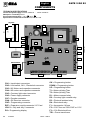 2
2
-
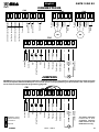 3
3
-
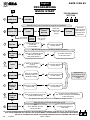 4
4
-
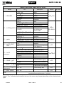 5
5
-
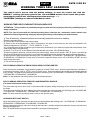 6
6
-
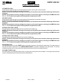 7
7
-
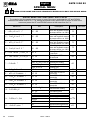 8
8
-
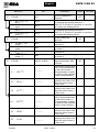 9
9
-
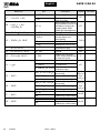 10
10
-
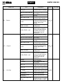 11
11
-
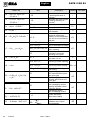 12
12
-
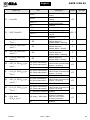 13
13
-
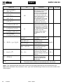 14
14
-
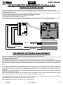 15
15
-
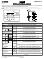 16
16
-
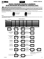 17
17
-
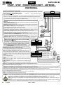 18
18
-
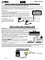 19
19
-
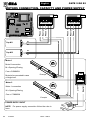 20
20
-
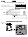 21
21
-
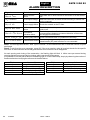 22
22
-
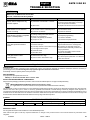 23
23
-
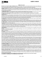 24
24
-
 25
25
-
 26
26
-
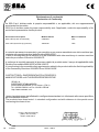 27
27
-
 28
28


SEA Gate 2 DG R1 El manual del propietario
- Categoría
- Abridor de puerta
- Tipo
- El manual del propietario
en otros idiomas
- italiano: SEA Gate 2 DG R1 Manuale del proprietario
- English: SEA Gate 2 DG R1 Owner's manual
Artículos relacionados
-
SEA Gate 2 DG R1B El manual del propietario
-
-
-
-
-
-
-
Otros documentos
-
Nice Automation WIL El manual del propietario
-
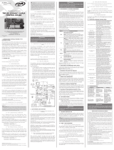 PPA Triflex Connect Fullrange Dupla Manual de usuario
-
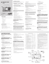 PPA Facility TOP Manual de usuario
-
BFT THALIA Guía de instalación
-
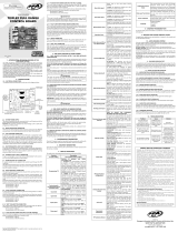 PPA Triflex Fullrange Manual de usuario
-
V2 Elettronica V2 Alfariss El manual del propietario
-
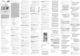 PPA FACILITY CONNECT Manual de usuario
-
BFT Virgo Smart BT A Manual de usuario
-
V2 V2 Zariss El manual del propietario
-
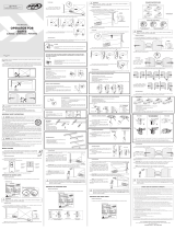 PPA Dz Hub R 350 Legero Manual de usuario


