La página se está cargando...

1. MAIN FEATURES
• It can be used with either digital end-of-stroke (encoder hall) or magnetic-
end-of-stroke (analog).
• RF 433.92 Mhz Receiver Module
• Code learning – up to 160 different and button-independent remote controls.
• Inputs:
- Photocell.
- Loose RF Receiver Module.
- RS-485 Serial Module.
• Outputs:
- Traffic Light Module.
- Electronic lock module.
- Courtesy light module.
• Control of the motor:
- Soft start.
- Electronic clutch.
- Electronic brake.
- Torque control.
• Opening delay timing (used in conjunction with a traffic light).
2. SN LED FUNCTIONS
This procedure will reset the memory (erases old information / prepares the memory
to receive new remote controls).
• Flashes once (60-Hz power source).
• Flashes twice (50-Hz power source).
• Flashes normally* 3 times (Opening cycle).
• Flashes normally* 4 times (Closing cycle).
• Flashes inversely** 3 times (Opening cycle with encoder failure).
• Flashes inversely** 4 times (Closing cycle with encoder failure).
• Flashes normally* 5 times (Gate path reset).
• Flashes in ‘clock mode’ every one second (counting the time for automatic
closing).
• Continuously lit (photocell input activated).
3. ELECTRONIC LOCK INPUT
The ECU will enable or disable the electromagnetic lock automatically when a relay
module is connected or disconnected to the TRV connector.
An electromagnetic lock installation results in a 1-second delay on the opening
command. The electromagnetic lock activation time is 3 seconds.
4. FUNCTIONS OF “+” AND “-” BUTTONS
• In access operations, i.e., when the levers of the DIP Switch are off, they are
used as opening / closing commands.
• When programming the ECU (any lever(s) of the DIP Switch on) or adding a
remote control, they are used as an input to the memory update.
5. FACTORY DEFAULT SETTINGS
• Em operações de funcionamento para acesso, ou seja, quando as chaves 1 a 8 da
dip estiverem em posição OFF, atua como comando para abertura ou fechamento.
1. The gate must be still.
2. Turn lever 1 on.
3. SN LED remains off.
4. Press and release the (+) button.
5. SN LED rapidly flashes once.
6. In order to finish, turn the lever 1 off.
7. Analog end-of-stroke.
WARNING: After resetting it to the default factory setting, if the operator
uses a digital end-of-stroke system (encoder sensor hall), a new path acquiring is
necessary for a proper operation.
DEFAULT FACTORY SETTINGS:
• Strength = maximum.
• Soft start = disabled.
• Semiautomatic mode (Push-to-close).
• Opening / Closing time = 4 minutes
• Brake strength = level 1.
• Brake activation time= 400 milliseconds.
• Courtesy light time = 60 seconds.
• Traffic light = continuous.
• End-of-stroke = digital.
• Accept a command when opening = enabled.
• Direction movement reversion through a command = enabled.
• Strength of torque control when opening = level 5.
• Strength of torque control when closing = level 5.
• Strength of torque control when opening (path acquiring) = level 9.
• Strength of torque control when closing (path acquiring) = level 9.
• Limit of opening end of stroke = path – 16 pulses.
• Limit of opening end of stroke = path – 16 pulses.
• FCF (Closing end-of-stroke) adjustment = 0-pulse setback.
• FCA (Opening end-of-stroke) adjustment = 0-pulse setback.
6. SELECTING THE END-OF-STROKE TYPE
(ANALOG OR DIGITAL)
1. The gate must be still.
2. Turn the lever 3 on.
3. SN LED remains off.
4. Choose the type of end-of-stroke:
- Digital end-of-stroke = (+) button.
- Analog end-of-stroke = (–) button.
WARNING: The SN LED rapidly flashes for the selected option.
5. In order to change the type of end-of-stroke, go back to step 4.
6. In order to finish, turn the lever 3 off.
7. The SN LED will keep flashing 5 times, indicating that the path is reset (digital
end-of-stroke).
WARNING: Whenever a new type of end-of-stroke is chosen, the opening /
closing time is reset to the 4-minute default factory setting (analog end-of-stroke)
or the path is reset (digital end-of-stroke). For applications with a digital end-of-
stroke, in order to have a proper operation, a new path acquiring is mandatory.
7. SELECTING HYBRID END-OF-STROKE
WARNING: The encoder cable (Reed digital) must be connected to the ENC
and the analog end-of-stroke must be connected to the HBD.
The ECU will automatically enable or disable the electromagnetic lock functions
whenever a relay module is connected or disconnected to the TRV connector.
1. The gate must be still.
2. Turn the levers 3 and 8 on.
3. SN LED remains off.
4. Press the (+) button.
WARNING: SN LED flashes once.
5. In order to finish, turn the levers 3 and 8 off.
WARNING: When using a hybrid system, there is no need to acquire the path. On
the first command, the ECU automatically does it, in normal speed.
8. SELECTING THE APPLICATION TYPE
1. The gate must be still.
2. Turn the lever 4 on.
3. SN LED remains off.
4. Choose the type of application:
- Sliding = Press the (+) button once.
- Vertical Swing = Press the (+) button twice.
5. Wait three seconds.
6. If the SN LED flashes rapidly, the application is valid. If it flashes slowly, the
application is invalid.
7. In order to choose a new application, go back to step 4.
8. In order to finish, turn lever 4 off.
9. The SN LED will keep flashing 5 times, indicating that the path is reset (digital
end-of-stroke).
WARNING: Whenever a new application is chosen, the opening / closing time
is reset to the 2-minute default factory setting (analog end-of-stroke) or the path
is reset (digital end-of-stroke). For applications with a digital end-of-stroke, in
order to have a proper operation, a new path acquiring is mandatory.
9. AUTOMATIC / SEMIAUTOMATIC MODE
1. The ECU must not be counting the time for an automatic closing (pause time).
2. Turn the lever 5 on.
3. SN LED remains off.
4. Set the closing mode, as follows:
SETTING AUTOMATIC MODE (PAUSE TIME):
5. Press and hold the (+) button.
6. SN LED starts operating in ‘clock mode’.
7. Count the desired time interval through the SN LED.
WARNING: The maximum time interval is 255 seconds (4.25 minutes). During
the time counting, when it reaches the 255-second limit time, the counting is
reset to 1 second.
8. Release the (+) button.
9. SN LED ceases operating in ‘clock mode’.
10. In order to add a new pause time, go back to step 5.
11. In order to set it in semiautomatic mode, go to step 13.
12. In order to finish, turn the lever 5 off.
SEMIAUTOMATIC MODE (PUSH-TO-CLOSE):
13. Press the (–) button.
14. SN LED flashes for 2 seconds.
15. In order to set it in automatic mode, go back to step 5.
16. In order to finish, turn the lever 5 off.
10. COURTESY LIGHT TIMING
1. Turn the levers 5 and 1 on.
2. SN LED remains off.
3. Use the (+) and (–) buttons to increase or decrease the time interval.
4. Check the SN LED:
0 = does not count the time, it turns itself off immediately after the gate
reaches the closing end-of-stroke.
1 = 10 seconds.
24 = 240 seconds (4 minutes).
5. In order to finish, turn the levers 5 and 1 off.
11. TRAFFIC LIGHT TIMING
1. Turn the levers 5 and 2 on.
2. SN LED remains off.
3. Use the (+) and (–) buttons to increase or decrease the time interval.
4. Check the SN LED:
0 = continuous mode.
1 = oscillating mode (50 milliseconds).
20 = oscillating mode (1000 milliseconds).
5. In order to finish, turn the levers 5 and 2 off.
12. SOFT START TIMING
1. Turn the levers 5 and 3 on.
2. SN LED remains off.
3. Use the (+) and (–) buttons to increase or decrease the time interval.
4. Check the SN LED:
60 Hz:
0 = Soft start disabled (motor starts with network rated voltage).
1 = Soft start enabled (120 milliseconds).
30 = Soft start enabled (3.6 seconds).
50 Hz:
0 = Soft start disabled (motor starts with network rated voltage).
1 = Soft start enabled (160 milliseconds).
30 = Soft start enabled (4.8 seconds).
5. In order to finish, turn the levers 5 and 3 off.
13. BRAKE TIME
1. Turn the levers 5 and 4 on.
2. SN LED remains off.
3. Use the (+) and (–) buttons to increase or decrease the time interval.
4. Check the SN LED:
0 = brake disabled.
1 = 200 milliseconds.
12 = 2.4 seconds.
5. In order to finish, turn the levers 5 and 4 off.
14. MANDATORY AUTOMATIC ACQUIRING OF
THE OPENING / CLOSING TIMING (ANALOG
END-OF-STROKE) OR PATH (DIGITAL END-OF-
STROKE)
1. The gate must be still.
2. Turn the lever 6 on.
3. SN LED remains off.
4. Press and release the (+) button. The motor will be activated for the closing cycle
up to the Closing End-of-stroke. After one second, the motor will be activated
for the opening cycle, acquiring the path through the opening / closing time
(analog end-of-stroke) or through the pulses of the digital encoder (digital end-
of-stroke). Three seconds are added to the opening and closing time (analog
end-of-stroke).
5. In order to finish, turn the lever 6 off.
6. In order to perform a new path acquiring, go back to step 2.
WARNING: The remote control can be used to cancel and restart the path
acquiring process. During the acquiring path, one can cancel the process turning
the lever 6 off or through a remote control command.
15. OPENING RAMP (LIMIT OF THE OPENING
END-OF-STROKE AREA TO DECELERATE THE
GATE)
It is the distance between the opening mechanical stop plate and the point on the path
where the ECU enters the torque control mode to decrease the speed of the gate and
turn it off on the acquired path.
1. Turn the levers 6 and 1 on.
2. SN LED remains off.
3. Use the (+) and (–) buttons to increase or decrease the end-of-stroke limit.
4. Check the SN LED.
5. In order to finish, turn the levers 6 and 1 off.
16. CLOSING RAMP (LIMIT OF THE CLOSING
END-OF-STROKE AREA TO DECELERATE THE
GATE)
It is the distance between the closing mechanical stop plate and the point on the path
where the ECU enters the torque control mode to decrease the speed of the gate and
turn it off on the 0 (zero) position.
1. Turn the levers 6 and 2 on.
2. SN LED remains off.
3. Use the (+) and (–) buttons to increase or decrease the end-of-stroke limit.
4. In order to finish, turn the levers 6 and 2 off.
* Flashes normally: LED normally o, goes on for 100 milliseconds. This cycle repeats itself every 2
seconds.
** Flashes inversely: LED normally on, goes o for 100 milliseconds. This cycle repeats itself every 2
seconds.
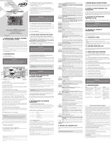
FACILITY TOP
ECU
TECHNICAL MANUAL
WARNING
Do not use the equipment
without referring to this
manual fir.
P05629 - 11/2021
Rev. 6
17. GAP BETWEEN THE GATE AND THE
OPENING STOPPER (END-OF-STROKE
SETBACK ADJUSTMENT) FOR REED DIGITAL
It is the adjustment of the setback (1 pulse) or of the stepping ahead (1 pulse) of the
opening end-of-stroke.
1. Turn the levers 6 and 3 on.
2. SN LED remains off.
3. Use the (+) and (–) buttons to increase or decrease the end-of-stroke position.
4. Check the SN LED.
5. In order to finish, turn the levers 6 and 3 off.
18. GAP BETWEEN THE GATE AND THE
CLOSING STOPPER (END-OF-STROKE SETBACK
ADJUSTMENT) FOR REED DIGITAL
It is the adjustment of the setback (1 pulse) or of the stepping ahead (1 pulse) of the
closing end-of-stroke.
1. Turn the levers 6 and 4 on.
2. SN LED remains off.
3. Use the (+) and (–) buttons to increase or decrease the end-of-stroke position.
4. Check the SN LED.
5. In order to finish, turn the levers 6 and 4 off.
19. STRENGTH (ELECTRONIC CLUTCH)
In order to have a proper utilization of this security sensor device, proceed as follows:
- After properly installing the gate opener on the gate, adjust the electronic
clutch so that the minimum strength is needed to move the gate leaf on its
entire path, for both opening and closing.
1. This adjustment can be performed with the gate either moving or still
2. Turn the lever 7 on.
3. SN LED turns itself off.
4. Use the (+) and (–) buttons to increase or decrease the strength.
5. Check the SN LED.
The adjustment levels variations are:
60 Hz = 0 up to 13 pulses.
50 Hz = 0 up to 17 pulses.
6. In order to finish, turn the lever 7 off.
20. TORQUE CONTROL STRENGTH DURING
OPENING RAMP
1. Turn the levers 7 and 1 on.
2. SN LED remains off.
3. Use the (+) and (–) buttons to increase or decrease the torque control strength.
4. Check the SN LED.
5. In order to finish, turn the levers 7 and 1 off.
21. TORQUE CONTROL STRENGTH DURING
CLOSING RAMP
1. Turn levers the 7 and 2 on.
2. SN LED remains off.
3. Use the (+) and (–) buttons to increase or decrease the torque control strength.
4. Check the SN LED.
5. In order to finish, turn the levers 7 and 2 off.
22. TORQUE CONTROL STRENGTH WHEN
ACQUIRING THE PATH (CLOSING)
1. Turn the levers 7 and 3 on.
2. SN LED remains off.
3. Use the (+) and (–) buttons to increase or decrease the torque control strength.
4. Check the SN LED.
5. In order to finish, turn the levers 7 and 3 off.
23. TORQUE CONTROL STRENGTH WHEN
ACQUIRING THE PATH (OPENING)
1. Turn the levers 7 and 4 on.
2. SN LED remains off.
3. Use the (+) and (–) buttons to increase or decrease the torque control strength.
4. Check the SN LED.
5. In order to finish, turn the levers 7 and 4 off.
24. ADDING REMOTE CONTROLS
Code learning up to 160 remote controls, independently from the fact that either
one button or two buttons per remote control have been added.
1. The gate must be still and must not be counting the pause time for automatically
closing.
2. Turn the lever 8 on.
3. Press the button of the remote control ne wants to add.
4. SN LED must flash rapidly.
5. Press and release the (+) button.
6. Check the SN LED: If it flashes once, the button has been successfully added; if
it flashes twice, the button is already added to the memory; if it flashes three
times, the memory is full.
7. Release the button of the remote control.
8. In order to add other remote control, go back to step 3.
9. In order to finish, turn the lever 8 off.
25. ERASING ALL REMOTE CONTROLS
10. The gate must be still and must not be counting the pause time for automatically
closing.
11. Turn the lever 8 on.
12. Press and release the (–) button.
13. The SN LED lights up.
14. Press and release the the (+) button to confirm the exclusion of all remote
controls (the SN LED flashes four times) or press and release the (–) button to
cancel the exclusion process.
15. In order to finish, turn the lever 8 off.
26. ENABLING OR DISABLING A COMMAND
ON OPENING CYCLE / DELAY WHEN OPENING
It is a permission for a pushbutton / remote control command to be accepted during
the opening cycle.
It also has the function of programming the pushbutton / remote control operation
mode when the ECU is counting the time for delaying an opening with the traffic light
switched on.
The gate opening delay time interval can be cancelled through a pushbutton or a
remote control.
Partial opening – When the gate is totally closed and it receives an opening command,
the traffic light will be switched on through the programmed time and then the
opening cycle of the gate will start. If during the delay time interval it receives a new
command, the traffic light will be switched off and the time will be reset. Only during
the opening cycle a command is ignored.
Total opening – When the gate is totally closed and it receives an opening command,
the traffic light will be switched on through the programmed time and then the
opening cycle of the gate will start. During the delay time interval and the opening
cycle, a command will be ignored.
SETTINGS:
0 = command when opening enabled.
1 = command in partial opening, opening delay time interval with traffic light on = 5 seconds.
2 = command in partial opening, opening delay time interval with traffic light on = 10 seconds.
3 = command in partial opening, opening delay time interval with traffic light on = 15 seconds.
4 = command in total opening, opening delay time interval with traffic light on = 5 seconds.
5 = command in total opening, opening delay time interval with traffic light on = 10 seconds.
6 = command in total opening, opening delay time interval with traffic light on = 15 seconds.
Instructions:
1. The gate must be still;
2. Turn the levers 8 and 2 on;
3. SN LED remains off;
4. Press the (+) button to increase the value; SN LED rapidly flashes once;
5. Press the (-) button to decrease the value; SN LED rapidly flashes once;
6. In order to finish, turn the levers 8 and 2 off.
PROGRAMMING INDEX CHART
Lever(s) Function (+) Button (–) Button
8Adds remote controls Adds
8Erases remote controls 2nd Confirms 1st Erases
8+1
Enables or disables direction movement
reversion through a command (Pushbutton
and remote control)
Enables Disables
8+2 Enables or disables a command in opening /
Delay in opening Increases Decreases
7Strength (Electronic clutch) + Strength – Strength
7+4 Torque control strength on the closing
end-of-stroke area (Acquiring) + Torque – Torque
7+3 Torque control strength on the opening
end-of-stroke area (Acquiring) + Torque – Torque
7+2 Torque control strength on the closing
end-of-stroke area + Torque – Torque
7+1 Torque control strength on the opening
end-of-stroke area + Torque – Torque
6Path acquiring (Digital end-of-stroke) or ope-
ning / closing time (Analog end-of-stroke)
Starts reading
the path
6+4
Closing end-of-stroke setback adjustment
(difference between the gate and the
stopper)
Larger setbackLesser setback
6+3
Opening end-of-stroke setback adjustment
(difference between the gate and the
stopper)
Larger setbackLesser setback
6+2 Limit of the closing end-of-stroke area Larger space Lesser space
6+1 Limit of the closing end-of-stroke area Larger space Lesser space
5Automatic or semiautomatic mode (hold the
button pressed for the desired time)
Pause time
(automatic) Semiautomatic
5+4 Electronic brake activation time + Brake – Brake
5+3 Soft start time (120 milliseconds per pulse) Higher Lesser
5+2 Traffic light time (50 milliseconds per pulse) Higher Lesser
5+1 Courtesy light time (10 seconds per pulse) Higher Lesser
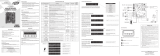
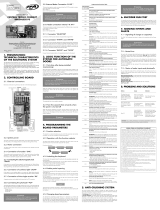
127 VAC
220 VAC
(50 Hz/60 Hz)
VOLTAGE
SELECTION
JUMPER
FUNCTION-ADJUSTING
BUTTONS
DIP SWITCH
FOR CHOOSING
THE FUNCTIONS
RF 433.92
MHZ RECEIVER
HRF
CLOSED = ENABLES RF
OPEN = DISABLES RF
ENGINE
STARTING
CAPACITOR
RELAY
MODULE FOR
ELECTROMAGNETIC
LOCK
LOOSE
RECEIVER
RELAY
MODULE FOR
COURTESY LIGHT
RELAY
MODULE FOR
TRAFFIC LIGHT
TX
PHOTOCELL
RX
OPERATOR WITH
END-OF-STROKE
FCA
FCF
ACF
DIGITAL
END-OF-STROKE YELLOW
RED / BLACK
BLACK / RED
SINGLE-PHASE
INDUCTION
MOTOR
GENERAL TERMS AND CONDITIONS OF WARRANTY
MOTOPPAR, Indury and Commerce of Automatic Gate Operators Ltd., regiered with
the CNPJ (National Regiry of Legal Entities) under Number 52.605.821/0001-55, located
at 3526 Dr. Labieno da Coa Machado Avenue, Indurial Dirict, Garça – SP – Brazil, Zip
Code 17400-000, manufacturer of PPA Products, hereby guarantees this product again
design, manufacturing or assembly defects and/or supportively as a result of material
quality aws that could make its intended use improper or inadequate, within a legal
period of ninety days from time of acquisition, provided that the inallation inructions
described in the inruction manual are observed.
Due to the credibility and tru placed on PPA products, we will add 275 more days to
the period mentioned above, reaching a warranty period of one year, likewise counted
from the time of acquisition proven by consumer through proof of purchase (Cuomer
Receipt).
In case of defect, within the warranty period, PPA responsibilities are rericted to the
repair or subitution of the product manufactured by the company, under the following
conditions:
1. Repair and readjument of equipment may only be carried out by PPA Technical
Assiance, which is qualied to open, remove, and subitute parts or components, as
well as repair defects covered by this warranty; thus, failure on observing this guideline
and the veried use of any non-original parts will cause the resignation of this warranty
on the part of the user;
2. The warranty will not extend to accessories such as cables, screw kit, xing brackets,
power supplies etc.;
3. Expenses for packaging, transportation and product reinallation will be sole
responsibility of the consumer;
4. The equipment mu be sent directly to the Company responsible for the sale
(manufacturer's representative), through the address contained in the purchase invoice,
properly packed, thus avoiding loss of the warranty;
5. Within the additional period of 275 days, visits and transportation in places where
authorized technical assiance is not available will be charged. The co of transportation
of the product and/or technician will be sole responsibility of the consumer and
6. The subitution or repair of the product does not prolong the warranty time.
This warranty will be terminated if the product:
1. Is damaged by natural agents, such as atmospheric discharges, oods, wildres,
landslides etc.;
2. Is inalled in an improper electric power supply or if it is not according to any of the
inallation inructions displayed on the manual;
3. Shows defects caused by droppings, collisions or any other physical accident;
4. Shows signs of product violation or attempted repair by unauthorized personnel;
5. Is not used for its intended purpose;
6. Is not used under normal conditions;
7. Is damaged by accessories or equipment connected to it.
Recommendation:
We recommend that both the inallation and the maintenance of the operator to be
performed by an authorized PPA technical service. If the product fails or has an improper
operation, seek an Authorized Technical Service to x it.

1. PRINCIPALES CARACTERÍSTICAS
• Puede ser utilizado con final de carrera digital (encoder hall) o final de carrera
magnético (analógico).
• Módulo receptor RF 433.92 MHz.
• Code learning para hasta 160 controles remotos distintos, independientemente
del número de botones grabados.
• Entradas para:
- Fotocélula.
- Módulo receptor RF suelto.
- Módulo serial RS-485.
• Salidas para:
- Módulo de semáforo.
- Módulo de traba.
- Módulo para luz de garaje.
• Control del motor:
- Arranque Suave.
- Embrague electrónico.
- Freno electrónico.
- Control de Torque.
• Tiempo de retardo para apertura con semáforo.
2. FUNCIONES DEL LED SN
Este procedimiento irá borrar y preparar la memoria para recibir los nuevos
controles remotos.
• Parpadea 1 vez (red eléctrica 60 Hz).
• Parpadea 2 veces (red eléctrica 50 Hz).
• Parpadea normalmente* 3 veces (ciclo de apertura).
• Parpadea normalmente* 4 veces (ciclo de cierre).
• Parpadea reversamente** 3 veces (ciclo de apertura con fallo de encoder).
• Parpadea reversamente** 4 veces (ciclo de cierre con fallo de encoder).
• Parpadea normalmente* 5 veces (recorrido del portón puesto a cero).
• Parpadea en modo de reloj cada 1 segundo (contando el tiempo pausa para
cierre automático).
• Encendido continuamente (entrada de fotocélula activada).
3. ENTRADA DE ELECTROCERRADURA
La central irá habilitar o deshabilitar las funciones de electrocerradura automáticamente
cuando un módulo de relé sea conectado o desconectado del conector TRV.
La instalación de la electrocerradura acarrea un retraso de 1 segundo en el comando de
apertura. El tiempo de accionamiento de la electrocerradura es 3 segundos.
4. FUNCIONES DE LOS BOTONES + Y -
• En operaciones de funcionamiento para acceso, es decir, cuando las palancas
1 hasta 8 del DIP Switch estén en posición OFF, sirve como comando para
apertura o cierre.
• En operaciones de programación de la central (cualquiera una de las palancas
del DIP Switch en la posición ON) o grabación del control remoto, sirve como
entrada para actualización de memoria.
5. CONFIGURACIONES ESTÁNDARES DE
FÁBRICA
• En operaciones de funcionamiento para acceso, es decir, cuando las palancas 1
hasta 8 del DIP Switch estén en posición OFF, sirve como comando para apertura
o cierre.
1. El portón debe estar parado.
2. Mueva la palanca 1 del DIP Switch para ON.
3. El LED SN queda apagado.
4. Apriete y suelte el botón (+).
5. El LED SN parpadea 1 vez rápidamente.
6. Para finalizar, mueva la palanca 1 del DIP Switch para OFF.
7. Fin de carrera analógico.
NO TA : Después de la reconfiguración estándar de fábrica, si el automatizador utiliza
sistema de fin de carrera digital (encoder sensor hall), una nueva memorización de recorrido
es necesaria para el buen funcionamiento.
VALORES ESTÁNDARES DE FÁBRICA:
• Fuerza = máxima.
• Arranque suave = deshabilitado.
• Modo semiautomático.
• Tiempo de apertura y cierre = 4 minutos
• Fuerza del freno = nivel 1.
• Tiempo de accionamiento del freno = 400 millisegundos
• Tiempo de la luz de garaje = 60 segundos
• Semáforo = continuo.
• Tipo de fin de carrera = digital.
• Comando en la apertura = habilitado.
• Reversión por el comando = habilitado.
• Fuerza del control de torque en la apertura = nivel 5.
• Fuerza del control de torque en el cierre = nivel 5.
• Fuerza del control de torque en la apertura (memorización) = nivel 9.
• Fuerza del control de torque en el cierre (memorización) = nivel 9.
• Límite del fin de carrera de apertura = recorrido – 16 pulsos.
• Límite del fim curso de cierre = recorrido – 16 pulsos.
• Ajuste de la posición FCF (Fin de carrera de cierre) = retroceso de 0 pulso.
• Ajuste de la posición FCA (Fin de carrera de apertura) = retroceso de 0 pulso.
6. SELECCIONANDO EL TIPO DE FIN DE
CARRERA (ANALÓGICO O DIGITAL)
1. El portón debe estar parado.
2. Mueva la palanca 3 del DIP Switch para ON.
3. El LED SN queda apagado.
4. Eligir el tipo de fin de carrera:
- Fin de carrera digital = b otón (+).
- Fin de carrera analógico = botón (–).
NOTA : El LED SN parpadea rápidamente para la elección seleccionada.
5. Para cambiar el tipo de fin de carrera, vaya al paso 4.
6. Para finalizar, mueva la palanca 3 del DIP Switch para OFF.
7. El LED SN parpadeará 5 veces, señalando que el recorrido está puesto a cero (fin
de carrera digital).
NOTA : Toda vez que que un nuevo tipo de fin de carrera es elegido, el tiempo
de apertura y cierre es restaurado para el estándar de fábrica de 4 minutos
(sistema de fin de carrera analógico) o el recorrido es puesto a cero (sistema
de fin de carrera digital). Para aplicaciones con fin de carrera digital, una nueva
memorización de recorrido es obligatoria para el buen funcionamiento.
7. ELEGIENDO EL TIPO DE FIN DE CARRERA
HÍBRIDO
NOTA : El cable del encoder (Reed digital) debe estar conectado al ENC y el fin
de carrera analógico debe estar conectado al HBD.
La central irá habilitar o deshabilitar las funciones de electrocerradura automáticamente
cuando un módulo de relé sea conectado o desconectado al conector TRV.
1. El portón debe estar parado.
2. Mueva las palancas 3 y 8 del DIP Switch para ON.
3. El LED SN queda apagado.
4. Apriete el botón (+).
NOTA : El LED SN parpadea 1 vez.
5. Para finalizar, mueva las palancas 3 y 8 del DIP Switch para OFF.
NOTA : En el sistema Híbrido, no es necessário memorizar el recorrido. En el
primer comando, la central lo hará automáticamente y en velocidad normal.
8. ELEGIENDO EL TIPO DE APLICACIÓN
1. El portón debe estar parado.
2. Mueva la palanca 4 del DIP Switch para ON.
3. El LED SN queda apagado.
4. Elija el tipo de aplicación:
- Corredizo = Apriete el botón (+) 1 vez.
- Basculante Vertical = Apriete el botón (+) 2 veces.
5. Espere 3 segundos.
6. Si el LED SN parpadear rápidamente, la aplicación es válida. En caso en que el LED
SN parpadee lentamente, la aplicación es no válida.
7. Para eligir una nueva aplicación, vaya al paso 4.
8. Para finalizar, mueva la palanca 4 del DIP Switch para OFF.
9. El LED SN parpadeará 5 veces, señalando que el recorrido está puesto a cero (fin
de carrera digital).
NOTA : Toda vez que una nueva aplicación es eligida, el tiempo de apertura
y cierre es restaurado para el estándar de fábrica de 2 minutos (fin de carrera
analógico) o el recorrido es puesto a cero (fin de carrera digital). Para aplicaciones
con sistema de fin de carrera digital, una nueva memorización de recorrido es
obligatoria para el buen funcionamiento.
9. MODO AUTOMÁTICO/SEMIAUTOMÁTICO
1. La central no debe estar contando el tiempo para cierre automático (tiempo de
pausa).
2. Mueva la palanca 5 del DIP Switch para ON.
3. El LED SN queda apagado.
4. Configurar el modo de cierre, como se muestra a continuación:
PARA CONFIGURAR EL MODO AUTOMÁTICO (TIEMPO DE PAUSA):
5. Mantenga presionado el botón (+).
6. El LED SN empieza a parpadear en modo de reloj.
7. Cuente el tiempo deseado usando el LED SN.
NOTA : El tiempo máximo es 255 segundos (4.25 minutos). Durante el conteo
del tiempo, cuando él alcanzar el límite de 255 segundos, el conteo será
reiniciado para 1 segundo.
8. Suelte el botón (+).
9. El LED SN en modo de reloj es desligado.
10. Para grabar un nuevo tiempo de pausa, vuelva para el paso 5.
11. Para configurar en modo semiautomático, vaya al paso 13.
12. Para finalizar, mueva la palanca 5 del DIP Switch para OFF.
MODO SEMIAUTOMÁTICO:
13. Apriete el botón (–).
14. El LED SN parpadea por 2 segundos.
15. Para configurar el modo automático, vaya al paso 5.
16. Para finalizar, mueva la palanca 5 del DIP Switch para OFF.
10. TIEMPO DE LUZ DE GARAJE
1. Mueva las palancas 5 y 1 del DIP Switch para ON.
2. El LED SN queda apagado.
3. Use los botones (+) o (–) para aumentar o disminuir el tiempo.
4. Verifique el LED SN:
0 = no cuenta el tiempo, apaga inmediatamente después del Fin de Carrera
Cerrado.
1 = 10 segundos.
24 = 240 segundos. (4 minutos).
5. Para finalizar, mueva las palancas 5 y 1 del DIP Switch para OFF.
11. TIEMPO DE SEMÁFORO
1. Mueva las palancas 5 y 2 del DIP Switch para ON.
2. El LED SN queda apagado.
3. Use los botones (+) o (–) para aumentar o disminuir el tiempo.
4. Verifique el LED SN:
0 = modo continuo.
1 = modo oscilante en 50 milissegundos.
20 = modo oscilante en 1000 milissegundos.
5. Para finalizar, mueva las palancas 5 y 2 del DIP Switch para OFF.
12. TIEMPO DE ARRANQUE SUAVE
1. Mueva las palancas 5 y 3 del DIP Switch para ON.
2. El LED SN queda apagado.
3. Use los botones (+) o (–) para aumentar o disminuir el tiempo.
4. Verifique el LED SN:
En 60 Hz:
0 = arranque suave deshabilitado (arranque con tensión nominal de red).
1 = arranque suave habilitado (120 milissegundos).
30 = arranque suave habilitado (3.6 segundos).
En 50 Hz:
0 = arranque suave deshabilitado (arranque con tensión nominal de red).
1 = arranque suave habilitado (160 milissegundos).
30 = arranque suave habilitado (4.8 segundos).
5. Para finalizar, mueva las palancas 5 y 3 del DIP Switch para OFF.
13. TIEMPO DE ACCIONAMIENTO DEL FRENO
1. Mueva las palancas 5 y 4 del DIP Switch para ON.
2. El LED SN queda apagado.
3. Use los botones (+) o (–) para aumentar o disminuir el tiempo.
4. Verifique el LED SN:
0 = freno apagado.
1 = 200 milissegundos.
12 = 2.4 segundos.
5. Para finalizar, mueva las palancas 5 y 4 del DIP Switch para OFF.
14. MEMORIZACIÓN AUTOMÁTICA
OBLIGATORIA DEL TIEMPO DE APERTURA Y
CIERRE (FIN DE CARRERA ANALÓGICO) O DE
RECORRIDO (FIN DE CARRERA DIGITAL)
1. El portón debe estar parado.
2. Mueva la palanca 6 del DIP Switch para ON.
3. El LED SN queda apagado.
4. Apriete y suelte el botón (+). El motor es accionado para el ciclo de cierre hasta
el fim de recorrido FCF (Fin de Carrera Cerrado). Después de 1 segundo, el motor
es accionado para el ciclo de apertura, memorizando el recorrido por el tiempo
de apertura y cierre (Fin de carrera analógico) o por los pulsos del encoder digital
hasta el fim de recorrido FCA (Fin de carrera digital). Al tiempo de recorrido de
apertura y cierre más 3 segundos son adicionados (Fin de carrera analógico).
5. Para finalizar, mueva la palanca 6 del DIP Switch para OFF.
6. Para una nueva memorización de recorrido, vuelva para el paso 2.
NOTA : El control remoto puede ser utilizado para cancelar y reiniciar
el procedimiento de memorización de recorrido. Durante el recorrido de
memorización, podemos cancelar el procedimiento movendo la palanca 6 para
OFF o con un comando por el control remoto.
15. RAMPA DE APERTURA (LÍMITE DE ÁREA
DEL FIN DE CARRERA DE APERTURA PARA
DECELERACIÓN DEL PORTÓN)
Es la distância entre el stop (tope, batiente) mecánico de apertura y el local del recorrido
donde la central entra en modo de control de torque para reducir la velocidad del
portón y para que se apague en el recorrido memorizado.
1. Mueva las palancas 6 y 1 del DIP Switch para ON.
2. El LED SN queda apagado.
3. Use los botones (+) o (–) para aumentar o disminuir el límite del Fin de carrera.
4. Verifique el LED SN.
5. Para finalizar, mueva las palancas 6 y 1 del DIP Switch para OFF.
*Parpadea normalmente: LED normalmente apagado, enciende por 100 milissegundos. El ciclo se
repite cada 2 segundos.
**Parpadea reversamente: LED normalmente encendido, apaga por 100 milissegundos. El ciclo se
repite cada 2 segundos.
CENTRAL FACILITY
TOP
MANUAL TÉCNICO
ADVERTENCIA
No utilice el equipo sin
antes leer ee manual de
inrucciones.
P05629 - 11/2021
Rev. 6
16. RAMPA DE CIERRE (LÍMITE DE ÁREA
DEL FIN DE CARRERA DE CIERRE PARA
DECELERACIÓN DEL PORTÓN)
Es la distância entre el stop (tope, batiente) mecánico de cierre y el local del recorrido
donde la central entra en modo de control de torque para reducir la velocidad del
portón y para que se apague en la posición 0 (cero).
1. Mueva las palancas 6 y 2 del DIP Switch para ON.
2. El LED SN queda apagado.
3. Use los botones (+) o (–) para aumentar o disminuir el límite del fin de carrera.
4. Para finalizar, mueva las palancas 6 y 2 del DIP Switch para OFF.
17. ESPACIO ENTRE EL PORTÓN Y EL BATENTE
DE APERTURA (AJUSTE DEL RETROCESO DE FIN
DE CARRERA) PARA REED DIGITAL
Es el ajuste de retroceso (1 pulso) o avance (1 pulso) del fin de carrera de apertura.
1. Mueva las palancas 6 y 3 del DIP Switch para ON.
2. El LED SN queda apagado.
3. Use los botones (+) o (–) para aumentar o disminuir la posición del fin de carrera.
4. Verifique el LED SN.
5. Para finalizar, mueva las palancas 6 y 3 del DIP Switch para OFF.
18. ESPACIO ENTRE EL PORTÓN Y EL BATENTE
DE CIERRE (AJUSTE DEL RETROCESO DEL FIN
DE CARRERA) PARA REED DIGITAL
Es el ajuste de retroceso (1 pulso) o avance (1 pulso) del fin de carrera de cierre.
1. Mueva las palancas 6 y 4 del DIP Switch para ON.
2. El LED SN queda apagado.
3. Use los botones (+) o (–) para aumentar o disminuir la posición del fin de carrera.
4. Verifique el LED SN.
5. Para finalizar, mueva las palancas 6 y 4 del DIP Switch para OFF.
19. FUERZA (EMBRAGUE ELECTRÓNICO)
Para que la utilización deste dispositivo sensor de seguridad sea eficaz, haga lo
siguiente:
- Después de la debida instalación del automatizador en el portón, regule
el embrague electrónico de forma tal que que la fuerza seja la mínima
necessária para mover la hoja del portón en todo su recorrido, en la
apertura y cierre.
1. Este tipo de ajuste puede lograrse con el portón en movimiento o detenido.
2. Mueva la palanca 7 del DIP Switch para ON.
3. El LED SN se apaga.
4. Use los botones (+) o (–) para aumentar o disminuir la fuerza.
5. Verifique el LED SN.
Los niveles de ajuste son:
60 Hz = 0 hasta 13 pulsos.
50 Hz = 0 hasta 17 pulsos.
6. Para finalizar, mueva la palanca 7 del DIP Switch para OFF.
20. FUERZA EN CONTROL DE TORQUE
DURANTE LA RAMPA DE APERTURA
1. Mueva las palancas 7 y 1 del DIP Switch para ON.
2. El LED SN queda apagado.
3. Use (+) o (–) para aumentar o disminuir la fuerza del control de torque.
4. Verifique el LED SN.
5. Para finalizar, mueva las palancas 7 y 1 del DIP Switch para OFF.
21. FUERZA EN CONTROL DE TORQUE
DURANTE LA RAMPA DE CIERRE
1. Mueva las palancas 7 y 2 del DIP Switch para ON.
2. El LED SN queda apagado.
3. Use (+) o (–) para aumentar o disminuir la fuerza del control de torque.
4. Verifique el LED SN.
5. Para finalizar, mueva las palancas 7 y 2 del DIP Switch para OFF.
22. FUERZA EN CONTROL DE TORQUE
EN EL SENTIDO DE CIERRE DURANTE LA
MEMORIZACIÓN DEL RECORRIDO
1. Mueva las palancas 7 y 3 del DIP Switch para ON.
2. El LED SN queda apagado.
3. Use (+) o (–) para aumentar o disminuir la fuerza del control de torque.
4. Verifique el LED SN.
5. Para finalizar, mueva las palancas 7 y 3 del DIP Switch para OFF.
23. FUERZA DEL CONTROL DE TORQUE EN
EL SENTIDO DE APERTURA DURANTE LA
MEMORIZACIÓN DEL RECORRIDO
1. Mueva las palancas 7 y 4 para ON.
2. El LED SN queda apagado.
3. Use los botones (+) o (–) para aumentar o disminuir la fuerza del control de
torque.
4. Verifique el LED SN.
5. Para finalizar, mueva las palancas 7 y 4 del DIP Switch para OFF.
24. GRABAR CONTROLES REMOTOS
Code learning hasta 160 controles remotos, independientemente de la grabación de
uno o dos botones por control remoto.
1. El portón debe estar parado y no debe estar contando tiempo de pausa.
2. Mueva la palanca 8 del DIP Switch para ON.
3. Apriete el botón del control remoto que se quiere grabar.
4. El LED SN debe parpadear rápidamente.
5. Apriete y suelte el botón (+).
6. Verifique el LED SN: Si él parpadea 1 vez, el botón ha sido grabado con éxito; si
parpadea 2 veces, el botón ya está grabado en la memoria; si parpadea 3 veces, la
memoria está llena.
7. Suelte el botón del control remoto.
8. Para grabar otros controles remotos, vuelva para el paso 3.
9. Para finalizar, mueva la palanca 8 del DIP Switch para OFF.
25. BORRAR TODOS LOS CONTROLES
REMOTOS
1. El portón debe estar parado y no debe estar contando tiempo de pausa.
2. Mueva la palanca 8 del DIP Switch para ON.
3. Apriete y suelte el botón (–).
4. El LED SN se enciende.
5. Apriete y suelte el botón (+) para confirmar la exclusión de todos los controles
remotos (el LED SN parpadea 4 veces) o apriete y suelte el botón (–) para cancelar
el procedimiento de exclusión.
6. 6. Para finalizar, mueva la palanca 8 del DIP Switch para OFF.
26. HABILITANDO O DESHABILITANDO EL
COMANDO EN EL CICLO DE APERTURA /
RETARDO EN LA APERTURA
Permiso de comando de la botonera o control remoto, para que funcionen durante el
recorrido de apertura del portón.
Además cumple la función de programar el modo de operación de la botonera o
control remoto durante el conteo de tiempo de retardo en la apertura con semáforo
encendido.
El tiempo de retardo de la apertura del portón puede ser cancelado por la botonera
o control remoto.
Apertura parcial – Cuando el portón esté totalmente cerrado y recibir comando para
apertura, el semáforo será encendido por el tiempo programado y después el ciclo de
apertura del portón es accionado. Si durante el tiempo de retardo él recibe un nuevo
comando, el semáforo se apaga y el tiempo es cancelado. Somente durante el ciclo de
apertura el comando es ignorado.
Apertura total – Cuando el portón esté totalmente cerrado y recibir un comando para
apertura, el semáforo será apagado por el tiempo programado y después el portón
será accionado para ciclo de apertura. Durante el tiempo de retardo del semáforo y
ciclo de apertura, el comando es ignorado.
VALORES:
0 = comando en la apertura habilitado.
1 = comando en la apertura parcial, tiempo del retardo en la apertura con
semáforo de 5 segundos
2 = comando en la apertura parcial, tiempo del retardo en la apertura con
semáforo de 10 segundos
3 = comando en la apertura parcial, tiempo del retardo en la apertura con
semáforo de 15 segundos
4 = comando en la apertura total, tiempo del retardo en la apertura con semáforo
de 5 segundos
5 = comando en la apertura total, tiempo del retardo en la apertura con semáforo
de 10 segundos
6 = comando en la apertura total, tiempo del retardo en la apertura con semáforo
de 15 segundos
Operaciones:
1. El portón debe estar parado;
2. Mueva las palancas 8 y 2 del DIP Switch para ON;
3. El LED SN queda apagado;
4. Botón (+) para incrementar valor, el LED SN parpadea 1 vez rápidamente;
5. Botón (-) para decrementar valor, el LED SN parpadea 1 vez rápidamente;
6. Para finalizar, mueva las palancas 8 y 2 del DIP Switch para OFF.
TABELA DE ÍNDICE DE LAS PROGRAMACIONES
Palanca Función Botón (+) Botón (–)
8Agrega controles remotos Agrega
8Borra controles remotos 2.° Confirmar 1.° Borrar
8+1 Habilita o deshabilita la reversión por el comando
(botonera y control remoto) Habilita Deshabilita
8+2 Habilita o deshabilita comando en la Apertura /
Retardo en la apertura Aumenta Disminuye
7Fuerza (embrague electrónico) + Fuerza – Fuerza
7+4 Fuerza del control de torque en el área del fin de
carrera de cierre (memorización) + Torque – Torque
7+3 Fuerza del control de torque en el área del fin de
carrera de apertura (memorización) + Torque – Torque
7+2 Fuerza del control de torque en el área del fin de
carrera de cierre + Torque – Torque
7+1 Fuerza del control de torque en el área del fin de
carrera de apertura + Torque – Torque
6Memorización del recorrido (FC digital) o el tiempo
de A/C (FC analógico)
Empieza la
lectura
6+4 Ajuste de retroceso del fin de carrera de cierre
(diferencia entre el portón y el batente) Retroceso mayor Retroceso menor
6+3 Ajuste de retroceso del fin de carrera de apertura
(diferencia entre el portón y el batente) Retroceso mayor Retroceso menor
6+2 Límite de área del fin de carrera de cierre Mayor espacio Menor espacio
6+1 Límite de área del fin de carrera de apertura Mayor espacio Menor espacio
5Modo automático o semiautomático (mantener el
botón apretado por el tiempo deseado)
Tiempo de pausa
(automático) Semiautomático
5+4 Tiempo de accionamiento del freno electrónico + Freno – Freno
5+3 Tiempo de arranque suave (120 milisegundos por
impulso) Mayor Menor
5+2 Tiempo del semáforo (50 milisegundos por impulso) Mayor Menor
5+1 Tiempo de la luz de garaje (10 segundos por pulso) Mayor Menor
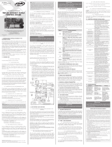
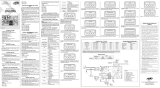
127 VAC
220 VAC
(50 Hz/60 Hz)
JUMPER
SELECTOR
DE VOLTAJE
BOTONES
PARA AJUSTES
DE FUNCIONES
DIP SWITCH PARA
SELECCIONAR LAS
FUNCIONES
RECEPTOR RF
433,92 MHz
HRF
CERRADO = HABILITARF
ABIERTO = DESABILITARF
CAPACITOR
DE ARRANQUE
DEL MOTOR
MÓDULO
RELÉ
PARA TRABA
RECEPTOR
AVULSO
MÓDULO
RELÉ PARA LUZ
DE GARAJE
MÓDULO RELÉ
PARA SEÑALIZACIÓN
EXTERNA
TX
FOTOCÉLULA
RX
AUTOMATIZADOR
CON FIN DE CARRERA
FCA
FCF
ACF
FIN DE CARRERA
DIGITAL AMARILLO
NEGRO / ROJO
ROJO / NEGRO
MOTOR
DE INDUCCIÓN
MONOFÁSICO
PLAZO DE GARANTÍA
MOTOPPAR, Induria y Comercio de Automatizadores Ltda., regirada con CNPJ (CIF)
52.605.821/0001-55, localizada en la Avenida Dr. Labieno da Coa Machado número 3526,
Dirito Indurial, Garça – SP – Brasil, Código Poal 17.400-000, fabricante de los productos
PPA, garantiza eo aparato contra defectos de proyectos, fabricación, montaje y/o
solidariamente en consecuencia de vicios de calidad de material que se lo hagan impropio
o inadecuado al consumo a cual se deina por el plazo legal de noventa días desde la
fecha de adquisición, siempre que se cumplan las orientaciones de inalación descritas en
el manual de inrucciones.
Como consecuencia de la credibilidad y de la conanza depositada en los productos PPA,
añadimos al plazo anteriormente descrito más 275 días, alcanzando el total de un año,
igualmente contados desde que la fecha de adquisición pueda ser comprobada por el
consumidor a través do comprobante de compra (Recibo).
En caso de defecto, en el período cubierto por la garantía, la responsabilidad de PPA se
queda reringida a la reparación o reemplazo del aparato por ella fabricada, bajo las
siguientes condiciones:
1. La reparación y reajue de aparatos solo pueden realizarse por la Asiencia Técnica
de PPA, que eá habilitada a abrir, remover, suituir piezas o componentes, así como
arreglar los defectos cubiertos por la garantía, siendo que el incumplimiento de ee
y cualquier utilización de piezas no originales observadas en el uso, implicará en la
exclusión de la garantía por parte del consumidor;
2. La garantía no se extenderá a accesorios como cables, kit de tornillos, soportes de
jación, fuentes de alimentación etc.;
3. Los coos de embalaje, transporte y reinalación del producto son responsabilidad
exclusiva de los consumidores nales;
4. Se debe enviar el aparato directamente a la empresa responsable de la venta
(representante del fabricante), a través de la dirección que gura en el recibo de compra,
debidamente embalado, evitando así la pérdida de la garantía;
5. En el período adicional de 275 días, las visitas y los transportes donde no haya servicios
autorizados serán cargadas. Los gaos de transporte del aparato y/o técnico son
responsabilidad del propietario y
6. La reparación o reemplazo del aparato no prorroga el plazo de garantía.
Ea garantía perderá su validez si el producto:
1. Sufrir daños provocados por agentes de la naturaleza, como descargas atmosféricas,
inundaciones, incendios, desmoronamientos etc.;
2. Sea inalado en red eléctrica inadecuada o en desacuerdo con cualquiera de las
inrucciones de inalación descritas en el manual;
3. Presenta defectos causados por caídas, golpes o cualquier otro accidente físico;
4. Presenta violación o intento de reparación o mantenimiento por parte de personal no
autorizado;
5. No sea usado para lo que ha sido proyectado;
6. No sea usado en condiciones normales;
7. Sufrir daños causados por accesorios o aparatos conectados al producto.
Recomendación:
Recomendamos que la inalación y mantenimientos del aparato sean efectuados por
servicio técnico autorizado PPA.
Caso el producto presente defecto o funcionamiento anormal, busque un Servicio Técnico
especializado para los debidos arreglos.
/