La página se está cargando...

IMPORTANT SAFETY INFORMATION
Please, closely read and follow all the instructions herein
in order to use the product properly as well as to ensure an
appropriate installation. All data contained herein are merely
informative. We reserve the right to change our products,
as well as specifications and features, at our sole discretion
without prior notice.
QUICK REFERENCE GUIDE FOR THE PROGRAMMING
INDEX THROUGH A REMOTE CONTROL
Simultaneously press the two buttons of the remote control
(the number of times specified below). It is necessary that at
least one of the buttons have been added:
Once: ECU automatic programming (complete cycle).
Twice: ECU automatic programming starting by the pause
adjustment.
3 times: Erasing all remote controls from the memory.
4 times: Default factory settings (Reset).
5 times: Torque control adjustment (opening/closing).
6 times: End-of-stroke position adjustment (opening/closing).
7 times: End-of-stroke limit adjustment (opening/closing).
8 times: Torque control adjustment when acquiring (opening/
closing).
9 times: Brake activation time adjustment.
10 times: Selecting type of remote control code (fixed/rolling).
11 times: Selecting type of relay module (electromagnetic
lock, courtesy light or traffic light).
1. MAIN FEATURES
• Digital / Analog end-of-stroke system.
• RF 433.92 Mhz Receiver Module.
• Rolling Code / Fixed code up to 160 different and button-
independent remote controls.
• Automatic path acquiring.
• Selection of automatic / semiautomatic mode through remote
control, external program switch and bluetooth.
• Programming of the pause time interval for automatic closing
through remote control, external program switch and bluetooth
(maximum time = 4.0 minutes).
• Electronic clutch (strength) adjustment through remote control,
external program switch and bluetooth.
• A command to erase all remote controls through remote control,
external program switch and bluetooth.
• A command to set the ECU (Default factory settings) through
remote control, external program switch and bluetooth.
• Output for Courtesy light, Traffic light and Electromagnetic lock
relay module.
• Input for an external program switch as a programming device
or bluetooth for accessing and programming.
• Input for photocell.
• Input for loose RF receiver.
• Input for pushbutton.
• Delay time interval for opening with a traffic light on.
2. DEFAULT FACTORY SETTINGS
• Strength = maximum.
• Closing = Semiautomatic mode (Push-to-close).
• Strength of torque control when opening = Level 8.
• Strength of torque control when closing = Level 5.
• Strength of torque control when opening (path acquiring) = Level 11.
• Strength of torque control when closing (path acquiring) = Level 7.
• End-of-stroke system = It depends on the FC jumper setting:
- If the FC jumper is open = Analog end-of-stroke, then:
*Brake time (opening / closing) = 200 milliseconds.
*Opening / Closing time = 60 seconds
- If the FC jumper is closed = Digital end-of-stroke, then:
*Brake time (opening / closing) = Off.
*Path = 0.
End-of-stroke limit = Path/16
• Opening End-of-stroke setback = 0 pulse.
• Closing End-of-stroke setback = 0 pulse.
• Relay module output = Electromagnetic lock
WARNING: When the electromagnetic lock is enabled, the
courtesy light and traffic light are disabled.
In order to reset the settings for the default factory ones:
1. The gate must be still and must not be counting the pause time
for automatically closing.
2. With the FC jumper, chose the type of end-of-stroke: Analog
(open FC jumper) or Digital (closed FC jumper).
3. Close the PROG jumper. The green SN LED will be dimly lit.
4. Simultaneously press and release the two buttons of the (added)
remote control 4 times. The SN LED will flash whenever the
buttons are released. Wait 5 seconds.
5. The SN LED will flash 4 times confirming that the ECU has been
reset.
6. Open the PROG jumper.
WARNING: If the type of end-of-stroke used is the digital
one, after programming the “Default Factory Settings”, the
path acquiring is necessary. Otherwise, the ECU will operate
with a minimum path distance of 100 pulses.
IMPORTANTE
• After installing the ECU on the operator, a path acquiring is
necessary for a proper operation.
• If the type of end-of-stroke is the digital one, whenever
the ECU is activated (first command after a power cut), the
motor will be activated (Torque control mode) for opening
until it reaches the mechanical opening stop plate. Once it
has been done, the operation will be normal.
• If the type of end-of-stroke is the digital one, whenever
it is necessary to reverse the rotation of the motor, (black
and red wires), the ECU must be turned off. After the
first command, following the reactivation, the operation
procedure will be identical to the previous one. It is not
necessary to reverse the encoder position, since the ECU
corrects its position automatically.
• It is necessary to reverse the direction of the motor rotation
in order to adequate the ECU operation to the gate position.
Failure to observe this item can result in inappropriate
operation, since the operation logic for commands and
photocell may be reversed.
• When using the digital end-of-stroke, while acquiring the
path close to the end-of-stroke, the motor is operating in
torque control mode, i.e., the motor keeps continuously
switching on and off.
• Maximum pause time interval is 4 minutes.
• When using the digital end-of-stroke, if an equipment has
low strength when acquiring the path, one should interrupt
the process and enter the programming mode to increase
the acquiring torque control strength (simultaneously press
the two buttons of the remote control 8 times).
• In order to perform any step when programming the ECU,
there is no need to add the two buttons of the remote
control. By adding only one button of the remote control,
we are able to access all functions regarding the electronics.
• When the PROG jumper is open, the GRV button functions
as a command for opening / closing the gate.
3. ADDING REMOTE CONTROLS
The ECU allows one to add up to 160 remote controls,
independently from the fact that either one button or two buttons
per remote control have been added.
In order to add remote controls:
1. The gate must be still and must not be counting the pause time
for automatically closing.
2. Close the PROG jumper. The green SN LED will be dimly lit.
3. Press and hold the button of the remote control. The green SN
LED must keep flashing.
4. Press and release the GRV button; check the SN LED:
- If the SN LED flashes once: The button of the remote
control has been added.
- If the SN LED flashes twice: The button of the remote
control is already added.
- If the SN LED flashes 3 times: The memory is full.
5. Release the button of the remote control.
6. In order to add other buttons of other remote controls, go back
to step 3.
7. In order to finish the process, open the PROG jumper.
WARNING: In user mode (PROG jumper open), the
commands of the remote control are only for opening / closing
the gate. In this mode, the ECU will not accept any command
when the two buttons of the remote control are simultaneously
pressed.
4. CHOOSING THE DIGITAL OR ANALOG END-OF-
STROKE
1. The gate must be still and must not be counting the pause time
for automatically closing.
2. Keep the PROG jumper open.
3. Choose the end-of-stroke option through the FC jumper:
FC open: Analog end-of-stroke.
FC closed: Digital end-of-stroke.
4. After choosing the end-of-stroke system, an automatic path
acquiring is necessary. Otherwise, if the digital end-of-stroke
system is chosen, the ECU will operate with a minimum path of
100 pulses or, if the analog end-of-stroke is chosen, the opening
/ closing time will be 120 seconds.
5. AUTOMATIC PROGRAMMING OF THE ECU
(COMPLETE CYCLE)
1. The gate must be open.
2. Close the PROG jumper. The green SN LED will be dimly lit.
3. Simultaneously press and release the two buttons of the
(added) remote control only once. The SN LED will flash
whenever the buttons are released. After 5 seconds, the ECU
will enter automatic programming mode.
4. The gate will close after reaching the FCF (Closing end-of-
stroke) mechanical stop plate or if the two buttons of the
remote control are simultaneously pressed. After one second,
the gate will open, acquiring the path until it reaches the FCA
(Opening end-of-stroke) mechanical stop plate or if the two
buttons of the remote control are simultaneously pressed.
WARNING: When using the digital end-of-stroke, while
acquiring the path, the motor is operating in torque control
mode.
5. The SN LED starts flashing in ‘clock mode’ (it flashes every
second); it will wait for the programming either to automatic or
to semiautomatic mode.
WARNING: If the two buttons of the remote control are
simultaneously pressed, the pause adjustment will be cancelled
and it will go forward to the next step; the last adjustment is
kept.
Automatic mode: In this mode, after opening, the gate
will automatically close after a programmed pause time.
In order to set the pause time interval, one must press and
hold the right button of the remote control, and count the
seconds either by using a watch or by using the SN LED
in ‘clock mode’. After counting the pause time, one must
release the button of the remote control.
Semiautomatic mode: In this mode, after opening the
gate, a new command for closing is necessary.
In order to set it, one must press and release the left
button of the remote control.
6. The gate will enter a continuous closing and opening cycle;
then, it will wait for Motor Strength (Electronic clutch)
programming. Such strength must be checked by trying to
manually hold the gate. In order to increase or decrease the
strength exerted by the motor, proceed as follows:
Decreasing the strength: Hold and release the left
button of the remote control and check the strength again.
If necessary, one can pausingly press and release the left
button a few times until the desired adjustment.
Increasing the strength: Hold and release the right
button of the remote control and check the strength again.
If necessary, one can pausingly press and release the right
button a few times until the desired adjustment.
WARNING: At this stage, the gate will not reach the
mechanical (opening / closing) stop plate; instead, it will reach
the point on the path where the speed changes from high to
low. This transition point can be set (See ‘Adjustment of the
end-of-stroke limit’).
7. When the desired strength level is chosen, one must
simultaneously press and release the two buttons of the
remote control; then, the motor will be switched off and the
chosen strength level will be saved in the memory.
WARNING: At this stage, if the PROG jumper is open, the
motor will be switched off and it will not save the strength
adjustment, keeping the previous setting.
8. In order to finish the Automatic Programming (Complete
Cycle), one must open the jumper PROG.
WARNING: the Automatic Programming (Complete Cycle)
can be finished at any moment during the setting cycle of the
ECU, by only opening the PROG jumper.
During the programming process, only a remote control
added to the memory and which has started the programming
is able to interfere or change the setting parameters. In order
to change the ECU programming with another added remote
control, one must restart the entire programming process.
6. AUTOMATIC PROGRAMMING OF THE ECU (FROM
PAUSE ADJUSTMENT ON)
1. Close the PROG jumper. The green SN LED will be dimly lit.
2. Simultaneously press and release the two buttons of the
(added) remote control twice. The SN LED will flash whenever
the buttons are released. After 5 seconds, the ECU will enter
automatic programming mode (see item 5 from the previous
topic – Automatic programming of the ECU (Complete Cycle)).
7. ERASING ALL REMOTE CONTROLS FROM THE
MEMORY
1. The gate must be still and must not be counting the pause time
for automatically closing.
2. Close the PROG jumper. The green SN LED will be dimly lit.
3. Simultaneously press and release the two buttons of the
(added) remote control 3 times. The SN LED will flash whenever
the buttons are released. Wait 5 seconds.
4. Afterwards, the SN LED will stay lit waiting for either a
confirmation of the erasing of the remote controls or the
cancellation of the process.
In order to cancel the operation: Press and release the
left button of the remote control. The SN LED will again
be dimly lit.
Erasing all remote controls: Press and release the right
button of the remote control. The SN LED will flash three
times, indicating that all remote controls have been erased.
5. Open the PROG jumper.
8. ADJUSTMENT OF THE INDEPENDENT TORQUE
CONTROL STRENGTH FOR OPENING AND CLOSING
The ECU will keep ‘pulsating’ the motor, i.e., it will rapidly keep
switching it on and off, so that it has strength even with a low
rotation.
The torque control must be adjusted according to the gate weight,
in order to properly open and close it.
1. The gate must be still and must not be counting the pause time
for automatically closing.
2. Digital end-of-stroke chosen (FC jumper closed).
3. The gate path must have been previously acquired. Otherwise,
the function will be cancelled.
4. Close the PROG jumper. The green SN LED will be dimly lit.
5. Simultaneously press and release the two buttons of the
(added) remote control 5 times. The SN LED will flash whenever
the buttons are released. Wait 5 seconds.
6. Afterwards, the SN LED will go off and the ECU will wait the
programming of the adjustment of the torque control strength.
7. In order to adjust the torque control in the closing cycle, one
must press and release the GRV button. The SN LED will blink
once.
WARNING: If the GRV button is not pressed, the adjustment
of the torque control strength will be specifically for the
opening cycle.
8. Adjust the strength and check the SN LED. This function has up
to 36 adjustment levels:
Decrease the torque control strength: Press the left
button of the remote control until one reaches the desired
adjustment.
Increase the torque control strength: Press the right
button of the remote control until one reaches the desired
adjustment.
When the SN LED:
• Blinks slowly once (for two seconds): Minimum
strength level.
• Rapidly blinks: Intermediate strength level.
• Blinks slowly once (for two seconds): Maximum
strength level.
In order to go back and choose a new adjustment (step 6):
Simultaneously press and release the two buttons of the remote
control.
In order to finish the programming: Simultaneously press and
release the two buttons of the remote control or open the PROG
jumper.
9. ADJUSTMENT OF THE OPENING / CLOSING END-
OF-STROKE POSITION
This type of adjustment allows one to move gradually the end-of-
stroke back and forth, independently for the opening and closing
stoppers.
1. The gate must be still and must not be counting the pause time
for automatically closing.
2. Digital end-of-stroke chosen (FC jumper closed).
3. The gate path must have been previously acquired. Otherwise,
the function will be cancelled.
4. Close the PROG jumper. The green SN LED will be dimly lit.
5. Simultaneously press and release the two buttons of the
(added) remote control 6 times. The SN LED will flash whenever
the buttons are released. Wait 5 seconds.
6. Afterwards, the SN LED will go off and the ECU will wait the
programming of the end-of-stroke position.
7. In order to set the closing end-of-stroke position, one must
press and release the GRV button. The SN LED will flash once.
WARNING: If the GRV button is not pressed, the adjustment
of the torque control strength will be specifically for the
opening cycle.
8. Adjusting the end-of-stroke position (adjustment up to 10 pulses):
Make the end-of-stroke position go back one pulse:
Press the left button of the remote control until one
reaches the desired adjustment.
Make the end-of-stroke position go forth one pulse:
Press the right button of the remote control until one
reaches the desired adjustment.
In order to go back and choose a new adjustment (step 6):
Simultaneously press and release the two buttons of the remote
control.
In order to finish the programming: Simultaneously press and
release the two buttons of the remote control or open the PROG
jumper.
10. ADJUSTMENT OF THE INDEPENDENT OPENING /
CLOSING END-OF-STROKE LIMIT
The end-of-stroke limit is the distance remaining to reach the
mechanical stop plate. The ECU keeps continuously monitoring the
gate position and when it reaches the aforementioned limit, the
torque control mode is activated in order to decrease the speed and
softly reach the stopper.
1. The gate must be still and must not be counting the pause time
for automatically closing.
2. Digital end-of-stroke chosen (FC jumper closed).
3. The gate path must have been previously acquired. Otherwise,
the function will be cancelled.
4. Close the PROG jumper. The green SN LED will be dimly lit.
5. Simultaneously press and release the two buttons of the
(added) remote control 7 times. The SN LED will flash whenever
the buttons are released. Wait 5 seconds.
6. Afterwards, the SN LED will go off and the ECU will wait the
programming of the end-of-stroke limit.
7. Adjust the limit and check the SN LED. The function has up to
7 adjustment levels.
8. In order to set the closing end-of-stroke position, one must
press and release the GRV button. The SN LED will flash once .
WARNING: If the GRV button is not pressed, the adjustment
of the torque control strength will be specifically for the
opening cycle.
Decrease the end-of-stroke distance: Press the left button of
the remote control until one reaches the desired adjustment.
Increase the end-of-stroke distance: Press the right button of
the remote control until one reaches the desired adjustment.
In order to finish the programming: Simultaneously press
and release the two buttons of the remote control or open PROG
jumper.
When the SN LED:
• Blinks slowly once (for two seconds): Minimum limit.
• Rapidly blinks: Intermediate strength limit.
• Blinks slowly once (for two seconds): Maximum limit.
Divider Adjustment Index (7 levels):
04, 08, 16, 32, 64, 128 e 256
Example:
• Path acquired by the ECU = 1000 pulses.
• Chosen end-of-stroke limit = Divider 04.
• Calculation: 1000 pulses/04 = 250 remaining pulses.
• So, when there are 250 remaining pulses for the gate to reach
the mechanical stop plate, the ECU will decrease the speed
in torque control mode, so that the gate softly reaches the
stopper.
WARNING: The larger the divider, the lesser the distance for
decreasing the speed, i.e., the gate will be closer to the end-of-
stroke mechanical stop plate.
11. ADJUSTMENT OF THE INDEPENDENT TORQUE
CONTROL STRENGTH FOR OPENING AND CLOSING
WHEN ACQUIRING THE PATH
This type of adjustment is identical to the “Adjustment of the
independent Torque Control Strength for Opening and Closing”
but is valid only for path acquiring.
In order to adjust it, one must simultaneously press and release the
two buttons of the (added) remote control 8 times.
WARNING: This adjustment is only available for the digital
end-of-stroke system.
12. INDEPENDENT BRAKE ACTIVATION TIME FOR
OPENING AND CLOSING
This type of adjustment allows one to either turn the brake off or
count the time to activate it.
1. The gate must be still and must not be counting the pause time
for automatically closing.
2. Close the PROG jumper. The green SN LED will be dimly lit.
3. Simultaneously press and release the two buttons of the
(added) remote control 9 times. The SN LED will flash whenever
the buttons are released. Wait 5 seconds.
4. Afterwards, the SN LED will go off and the ECU will wait the
programming of the end-of-stroke position.
5. In order to choose the closing brake adjustment, one must
press and release the GRV button. The SN LED will flash once .
WARNING: If the GRV button is not pressed, the adjustment
of the brake will be specifically for the opening cycle.
6. Adjusting the brake time. The function has up to 16 adjustment
levels:
Decrease the brake time (SN LED flashes rapidly)
or turn it off (SN LED flashes slowly): Press the
left button of the remote control until one reaches the
desired adjustment.
Increase the brake time (SN LED flashes rapidly):
Press the right button of the remote control until one
reaches the desired adjustment.
In order to go back and choose a new adjustment (step 4):
Simultaneously press and release the two buttons of the remote
control.
In order to finish the programming: Open PROG jumper.
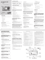
FACILITY CONNECT
TECHNICAL MANUAL
ATTENTION
Do not use this equipment without
first reading the User’s Guide.
P05628 - 12/2022
Rev. 5
Made by:
Motoppar da Amazônia Indústria e Comércio de Eletrônicos Ltda.
Avenida Açaí, 875 - Distrito Industrial I
Manaus - AM - CEP 69075-904 - Brasil
CNPJ: 09.084.119/0001-64
www.ppa.com.br | +55 14 3407 1000
GO FORWARD
GO BACK
INCREASE THE VALUE OF THE FUNCTION
DECREASE THE VALUE OF THE FUNCTION
COMMAND FOR OPENING OR CLOSING THE GATE
Simultaneously and pausingly press and release the two buttons
of the remote control in order to activate the motor and check the
gate status.
WARNING: The command for opening or closing the gate
can be triggered from any screen, either the home screen or
a specific function screen. The adjustment is automatically
saved, it is not necessary to exit the functions menu to activate it.
INFORMATION SCREEN
It shows the gate status information, sensors and position of the
remote control that has allowed the access through the gate.
Reed (Gate
position) Status,
open or closed.
Remaining seconds counter for
automatic closing when the ECU
is set for automatic mode.
REMOTE CONTROL
Fixed
code
Rolling
code
WARNING: When attempting to program the type of
remote control with the gate moving, the function will be
cancelled and an audible alarm will go off.
ADDING REMOTE CONTROLS
1. It is not necessary to close the ECU’s PROG jumper.
2. Press and hold the button of the remote control.
13. CHOOSING THE TYPE OF REMOTE CONTROL (FIXED
CODE / ROLLING CODE)
1. The gate must be still and must not be counting the pause time
for automatically closing.
2. Close the PROG jumper. The green SN LED will be dimly lit.
3. Simultaneously press and release the two buttons of the
(added) remote control 10 times. The SN LED will flash
whenever the buttons are released. Wait 5 seconds.
4. Afterwards, the SN LED will go off and the ECU will wait the
adjustment of the type of remote control.
For fixed code remote control: Press and release the
left button of the remote control.
For rolling code remote control: Press and release the
right button of the remote control.
5. Open the PROG jumper.
In order to finish the programming: Simultaneously press and
release the two buttons of the remote control or open the PROG
jumper. After choosing the type of remote control, the memory is
erased.
14. CHOOSING THE FUNCTION OF THE RELAY
MODULE
1. The gate must be still and must not be counting the pause time
for automatically closing.
2. Close the PROG jumper. The green SN LED will be dimly lit.
3. Simultaneously press and release the two buttons of the
(added) remote control 11 times. The SN LED will flash whenever
the buttons are released. Wait 5 seconds.
4. Afterwards, the SN LED starts flashing in ‘clock mode’ (one
flashing per second) and the ECU will wait for the adjustment
of the relay module function.
For electromagnetic lock: Simultaneously press and release
the two buttons of the remote control.
Operation: When the gate is totally closed and the relay
module is connected to the electronic board, when receiving
a command, the electromagnetic lock will be activated; after
two seconds, the motor will be activated for the opening
cycle; three seconds later, the electromagnetic lock will be
deactivated.
For traffic light: Press and release the left button of the
remote control.
Operation: The traffic light is switched on whenever the
gate either is opening / closing or is open, waiting for a new
command; then it is switched off when the gate is totally closed.
For courtesy light: Press and hold the right button of the
remote control and count the number of times the LED flashes.
Each time the LED flashes amounts to 10 seconds for the
courtesy light. The adjustment goes from 0 up to 240 seconds.
Operation: The courtesy light stays on whenever the gate either
is opening / closing or is open, waiting for a new command,
and it will be switched off when the gate totally closes or after
reaching the programmed LG time limit.
For an opening delay with traffic light on: Press and hold
the left button of the remote control and count the number of
times the LED flashes. Each time the LED flashes amounts to 2
seconds for the opening delay with the traffic light on.
WARNING: When the LED flashes more than 8 times, the
delay time will be 15 seconds.
Operation: Whenever the gate is totally closing and whenever
it receives a command for the opening cycle, the traffic light
will be activated and will remain so for the programmed time
interval; then the motor will be activated. The traffic light
will be switched off after the gate finishes its closing cycle or
whenever it receives a new command through the remote
control when the ECU is counting the time for the delay.
WARNING: Whenever one changes the relay module
programming, the operator will automatically enter torque
control mode and it will search the opening stopper
(poweronreset).
5. Open the PROG jumper
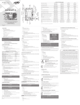
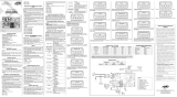
127 or 220 V
(50 / 60 Hz)
FCA
FCF
Motor start
capacitor
Loose
receiver
Pushbutton
Courtesy light,
Traffic light,
electromagnetic
lock optional
module
Input for
external
program switch
or bluetooth
module
Analog
end-of-
-stroke
Digital end-of-stroke
433.92 MHz RF
Receiver
Button used for adding
remote controls, perform
adjustments and some
functions through a remote
control; it is also used for
opening and closing the
gate.
Photocell
End-of-stroke
selection
jumper
Programming
jumper
Motor
Yellow
Red / Black
Black / Red
15. EXTERNAL PROGRAM SWITCH
It is used for programming the internal functions in a quicker and
independent way.
Function of the buttons:
= Go forward;
= Go back;
= Increase the value of the function.
= Decrease the value of the function.
= The two buttons simultaneously pressed to activate
the motor.
When switching the ECU on, the external program switch will
show the messages from pictures 1, 2 and 3 in a row.
3. The ‘s’ indicator on the screen will show the presence of a
remote control.
4. Pausingly press and release the (+) button; the ‘g’ indicator on
the screen will show that the remote control has been added.
5. The ‘n:’ addded remote controls counter on the screen is
updated.
6. Release the button of the remote control; the ‘s’ indicator will
disappear from the screen.
7. In order to add other buttons, go back to item 2.
ACQUIRING PATH
The ECU enters the closing cycle until it reaches the end-of-
stroke; one second later, it starts the opening cycle, acquiring
the time or pulses of the encoder until the gate reaches the
opening end-of-stroke.
(+) but ton
used for
starting the
automatic path
acquiring.
WARNING: This function applies for both analog end-of-
stroke and digital end-of-stroke.
CLOSING RAMP
Decrease
distance
Increase
distance
WARNING: When attempting to program the closing
ramp with the gate moving, the function will be cancelled
and an audible alarm will go off.
OPENING RAMP
Decrease
distance
Increase
distance
WARNING: When attempting to program the opening ramp
with the gate moving, the function will be cancelled and an
audible alarm will go off.
RAMP TORQUE WHEN CLOSING
Decrease
torque 1 level
at a time
Increase
torque 1 level
at a time
RAMP TORQUE WHEN OPENING
Decrease
torque 1 level
at a time
Increase
torque 1 level
at a time
ACQUIRING TORQUE WHEN CLOSING
Decrease
torque 1 level
at a time
Increase
torque 1 level
at a time
ACQUIRING TORQUE WHEN OPENING
Decrease
torque 1 level
at a time
Increase
torque 1 level
at a time
STRENGTH
Adjustment of the electronic clutch with the gate either moving or
still; up to 14 levels.
Decrease level Increase level
PAUSE
Adjustment of the automatic closing time when the gate reaches the
FCA opening end-of-stroke sensor.
Decrease time
every 10 seconds
Increase time every
10 seconds
ELECTROMAGNETIC LOCK
In a command for opening cycle, if the electromagnetic lock
[S] is enabled and the module connected to the ECU, it will be
activated after one second. The ECU will activate the motor and
two seconds later, the electromagnetic lock will be deactivated.
Deactivate
electromagnetic
lock
Activate
electromagnetic
lock
COURTESY LIGHT / TRAFFIC LIGHT / DELAY TIME
• For courtesy light, set the time in xxx seconds; when the ECU
reaches the FCF closing end-of-stroke sensor, it will count the
time for switching it off.
• For traffic light, set the time for 000 seconds, when the ECU
reaches the FCF closing end-of-stroke sensor, it will switch it off.
• For delay time, set the time between 001 and 015 seconds, and
when this time is reset, the gate will start the opening cycle.
WARNING: In order to activate the courrtesy light or
traffic light functions, deactivate the electromagnetic lock
module [N].
Decrease
time every 10
seconds
Increase time
every 10 seconds
BRAKE TIME WHEN OPENING
Decrease time
every 100
milliseconds
Increase time
every 100
milliseconds
BRAKE TIME WHEN CLOSING
Decrease
time every 20
milliseconds
Decrease
time every 20
milliseconds
RESTORING THE DEFAULT FACTORY SETTINGS
(+) button used
for restoring the
default factory
settings
WARNING: When attempting to program the default
factory settings with the gate moving, the function will be
cancelled and an audible alarm (long beep) will go off.
WARNING: Whenever the (+) button is pressed, the
audible alarm (two short beeps) will be activated indicating
that the action has been performed.
ERASE A REMOTE CONTROL
(+) but ton
used for
erasing and
starting the
memory
WARNING: When attempting to erase the remote controls
memory with the gate moving, the function will be
cancelled and an audible alarm will go off.
WARNING: Whenever the (+) button is pressed, the audible
alarm (two short beeps) will be activated indicating that the
action has been performed.
(+) button used
for adding
new remote
controls
Counter for
remote controls
added to the
memory
The
indicator on the screen will show the presence of a
remote control.
Pausingly press and release the (+) button; the
indicator on
the screen will show that the remote control has been added.
‘n:’
addded remote controls counter on the screen is
updated.
Release the button of the remote control; the
indicator will
remote control.
Pausingly press and release the (+) button; the
the screen will show that the remote control has been added.
addded remote controls counter on the screen is
Release the button of the remote control; the
Release the button of the remote control; the
disappear from the screen.
In order to add other buttons, go back to item 2.
In order to add other buttons, go back to item 2.
In order to add other buttons, go back to item 2.
Release the button of the remote control; the
Release the button of the remote control; the
disappear from the screen.
In order to add other buttons, go back to item 2.
Release the button of the remote control; the
the screen will show that the remote control has been added.
addded remote controls counter on the screen is
Release the button of the remote control; the
In order to add other buttons, go back to item 2.
In order to add other buttons, go back to item 2.
In order to add other buttons, go back to item 2.

IMPORTANTE
Por favor, lea este manual con atención para un uso
correcto y para garantizar la instalación adecuada del
automatizador Todos los datos de este manual son
meramente informativos. Se reservan todos y cualquier
cambio técnico al producto, sin previo aviso.
GUÍA DE CONSULTA RÁPIDA DE LOS
ÍNDICES DE PROGRAMACIÓN
Presione simultáneamente los 2 botones del transmisor (el
número de veces indicado a continuación). Es necesario que
al menos uno de los botones esté grabado:
1 vez: Programación automática de la central (ciclo completo).
2 veces: Programación automática de la central iniciando el
ajuste de Pausa.
3 veces: Apagando todos los transmisores de la
memoria.
4 veces: Ajustes predeterminados de fábrica (Reset).
5 veces: Ajuste del torque pulsante (apertura / cierre).
6 veces: Ajuste de la posición del final de carrera (apertura
/ cierre).
7 veces: Ajuste del límite de fin de carrera (apertura / cierre).
8 veces: Ajuste del torque pulsante en la memorización
(apertura / cierre).
9 veces: Ajuste del tiempo de funcionamiento del freno.
10 veces: Seleccionar el tipo del transmisor (fijo / rotativo).
11 veces: Seleccionar el tipo de módulo de relé (traba, luz de
garaje o señalera).
1. PRINCIPALES CARACTERÍSTICAS
• Sistema de fin de carrera digital / analógico.
• Módulo receptor RF 433,92 MHz.
• Rolling Code hasta 160 transmisores de código fijo o rotativo
diferentes e independientes de los botones.
• Memorización automática de recorrido.
• Selección del modo automático o semiautomático a través del
transmisor, programador externo y bluetooth.
• Programación del tiempo de pausa para cierre automático a través
del transmisor (máximo = 4,0 min).
• Ajuste del embrague electrónico (fuerza) a través del transmisor,
programador externo y bluetooth.
• Comando para borrar todos los transmisores a través del
transmisor, programador externo y bluetooth.
• Comando para configurar la central (estándar de fábrica) a
través del transmisor, programador externo y bluetooth.
• Salida para módulo de relé Luz de Garaje, Señalera o Traba.
• Entrada para dispositivo externo selector como programador o
bluetooth para acceso y también programador.
• Entrada para fotocélula.
• Entrada para receptor separado RF.
• Entrada para la botonera.
• Tiempo de retardo para apertura con señalera.
2. CONFIGURACIONES DEFAULT (ESTÁNDAR
DE FÁBRICA)
• Fuerza = Máximo.
• Cierre = Semiautomático.
• Fuerza del torque pulsante (apertura) = Nivel 8.
• Fuerza del torque pulsante (cierre) = Nivel 5.
• Fuerza del torque pulsante en la memorización (apertura) =
Nivel 11.
• Fuerza del torque pulsante en la memorización (cierre) = Nivel 7.
• Sistema de fin de carrera = Depende de la configuración del
jumper FC:
- Si el jumper FC abierto = Fin de curso analógico, entonces:
*Tiempo de freno (apertura / cierre) = 200 mseg.
*Tiempo A / F = 60seg.
- Si el jumper FC cerrado Fin de carrera digital, entonces:
*Tiempo de freno (apertura / cierre) = Desactivado.
*Recorrido = 0.
• Límite de fin de carrera = Recorrido / 16
• Retroceso FCA = 0 pulsos.
• Retroceso FCF = 0 pulsos.
• Salida del módulo relé = Traba
NOTA: Cuando la traba esté prendida, la luz de garaje y
señalera estarán deshabilitadas.
Para reanudar la configuración predeterminada de fábrica:
1. El portón debe estar parado y no estar temporizado para el
cierre automático.
2. En el jumper FC, seleccione el final de carrera: Analógico (FC
abierto) o Digital (FC cerrado).
3. Cerrar el jumper PROG. El LED verde SN deberá quedar
débilmente encendido.
4. Presione y suelte simultáneamente los 2 botones del transmisor
(grabado) 4 veces. El LED SN parpadeará cada vez que se
liberan los botones. Esperar 5 segundos.
5. El LED SN parpadeará 4 veces confirmando el Reset de la
central.
6. Abra el jumper PROG.
NOTA: si el sistema fin de carrera digital, después de la
programación del tema “Configuración predeterminada”, es
necesaria la memorización del recoorido. En caso contrario,
la central funcionará con un recorrido mínimo de 100 pulsos.
IMPORTANTE
• Después de la instalación de la central en el automatismo,
es necesaria la memorización de recorrido para el
correcto funcionamiento.
• En el caso de Fin de Carrera Digital, cuando la central es
conectada (primer mando después de corte de energía),
el motor será accionado (modo torque pulsante) para
cerramiento hasta encontrar el stop mecánico de cierre.
Hecho esto, el funcionamiento será normal.
• En el caso de Fin de Carrera Digital, siempre que sea
necesario invertir la rotación del motor (cables negro y
rojo), la central deberá apagarse. Después del primer
comando después de reconectarla, el procedimiento
de funcionamiento será idéntico al tema anterior. No es
necesario invertir la posición del encoder, pues la central
corrige la posición automáticamente. La inversión del
sentido de rotación del motor se hace necesaria para
adecuar el funcionamiento de la central a la posición del
portón. La no observación de este ítem puede acarrear
el funcionamiento inadecuado del automatizador,
invirtiendo la lógica de funcionamiento para los mandos
y la fotocélula.
• En el caso de Fin de Carrera Digital, cuando se conmueve
el recorrido o cerca del final de carrera, el motor
funcionará en modo de torque pulsante, es decir, el
motor se encender y apagar continuamente.
• El tiempo de pausa máximo es de 4 minutos.
• En el caso de Fin de Carrera Digital, en equipamientos
que estén presentando poca fuerza para aprender
el recorrido, debemos abortar el proceso y entrar
en la programación para aumentar la fuerza de
torque pulsante en la memorización (presumiendo
simultáneamente los tiempos 2 botones del transmisor por
8 veces).
• Para realizar cualquiera de los pasos de programación
en la central de mando, no es necesario grabar las 2
teclas del transmisor. Sólo con una de las teclas grabadas,
podemos acceder a todas las funciones de la electrónica.
• Cuando el jumper PROG está abierto, el botón GRV
funciona como un mando para abrir / cerrar el portón.
3. GRABAR TRANSMISORES
La central permite grabar hasta 160 transmisores diferentes e
independientes de los botones.
Para grabar transmisores:
1. El portón debe estar parado y no estar temporizado para el
cierre automático.
2. Cierre el jumper PROG. El LED verde SN deberá quedar
débilmente encendido.
3. Presione y mantenga presionado el botón del transmisor. El
LED verde SN debe parpadear.
4. Presione y suelte el botón GRV y verifique el LED SN:
- Si el LED SN parpadea 1 vez: Grabó el botón del
transmisor.
- Si el LED SN parpadea 2 veces: El botón del
transmisor ya está grabado.
- Si el LED SN parpadea 3 veces: La memoria está llena.
5. Liberar el botón del transmisor.
6. Para grabar otros botones de transmisores, continúe desde el
paso 3.
7. Para finalizar la operación, abra el jumper PROG.
NOTA: En el modo de usuario ( jumper PROG abierto), los
mandos del transmisor son sólo para el accionamiento de
apertura / cierre del portón. En este modo, la central no
aceptará el mando cuando se presionen simultáneamente los
2 botones del transmisor.
4. SELECCIONANDO SISTEMA DE FIN DE
CARRERA DIGITAL O ANALÓGICO
1. El portón debe estar parado y no temporizarse para el cierre
automático.
2. Mantener el jumper PROG abierto.
3. Seleccione la opción de fin de carrera a través del papel FC:
FC Abierto: Fin de Carrera Analógico.
FC Cerrado: Fin de Carrera Digital.
4. Después de la selección del sistema de fin de carrera, será
necesario la memorización automática de recorrido. En caso
contrario, si se selecciona Fin de Carrera Digital, la central
funcionará con un recorrido mínimo de 100 pulsos o, si se
selecciona Fin de Carrera Analógico, el tiempo de apertura /
cierre será de 120 segundos.
5. PROGRAMACIÓN AUTOMÁTICA DE LA
CENTRAL (CICLO COMPLETO)
1. El portón debe estar abierto.
2. Cierre el jumper PROG. El LED verde SN deberá quedar
débilmente encendido.
3. Presione y suelte simultáneamente los 2 botones del transmisor
(grabado) una sola vez. El LED SN parpadeará cuando se
suelten los botones. Después de 5 segundos, la central entrará
en el modo de programación automática.
4. El portón se cerrará hasta encontrar el stop mecánico FCF
(Fin de carrera de cierre) o si se presionan simultáneamente
los 2 botones del transmisor. Después de 1 segundo, el portón
se abrirá memorizando el recorrido hasta encontrar el stop
mecánico FCA (Fin de Carrera de Apertura) o si se presionan
simultáneamente los 2 botones del transmisor.
NOTA: En el caso de Fin de Carrera Digital, en la Memoria
del Recorrido el motor actuará en modo de Torque Pulsante.
5. El LED SN comenzará a parpadear como un reloj, cada 1
segundo y esperará la programación del Modo Automático o
Semiautomático.
NOTA: Si se presionan simultáneamente los 2 botones del
transmisor, el ajuste de Pausa se cancela y se irá al siguiente
paso, dejando grabando el último ajuste.
Modo Automático: En este modo, una vez abierto,
el portón se cerrará automáticamente después de un
tiempo de pausa programado.
Para programar el tiempo de pausa, se debe presionar
y mantener presionado el botón derecho del transmisor
y contar los segundos por el reloj o el LED SN. Después
de contar el tiempo de pausa, se debe liberar el botón
del transmisor.
Modo Semiautomático: En este modo, después de
abrir el portón, será necesario un nuevo comando para
el cierre.
Para programar, se debe presionar y soltar el botón
izquierdo del transmisor.
6. El portón comenzará a entrar en ciclo continuo de cierre y
apertura y aguardará la programación de la Fuerza del Motor
(Embrague Electrónico). Esta fuerza debe ser comprobada
intentando sostener el portón. Para disminuir o aumentar
la fuerza ejercida por el motor, se procederá de la siguiente
manera:
Reducir la fuerza: Presionar y soltar el botón izquierdo
del transmisor y volver a comprobar la fuerza. Si es
necesario, se puede presionar y liberar pausadamente el
botón izquierdo por algunas veces hasta que encuentre
el ajuste deseado.
Aumentar fuerza: Presione y suelte el botón derecho
del transmisor y vuelva a comprobar la fuerza. Si es
necesario, se puede presionar y liberar pausadamente el
botón derecho varias veces hasta que encuentre el ajuste
deseado.
NOTA: En esta etapa, el portón no llegará hasta el stop mecánico
(apertura / cierre), sino hasta el punto del recorrido donde existirá
el cambio de velocidad alta a baja. Este punto de transición es
progresivo (véase “Ajuste del límite de fin de carrera”).
7. Cuando se elige la fuerza deseada, se debe presionar y
liberar simultáneamente los 2 botones del transmisor y, a
continuación, el motor se apagará y la fuerza seleccionada se
guardará en la memoria.
NOTA: En esta etapa, si el jumper PROG se abre, el motor
se apagará y no guardará el ajuste de fuerza manteniendo el
registro anterior.
8. Para finalizar la Programación Automática (Ciclo Completo), se
debe abrir el jumper PROG.
NOTA: La Programación Automática (ciclo completo) puede
finalizarse en cualquier momento del centro de configuración
de la central, sólo abriendo el jumper PROG.
Durante el proceso de programación, sólo el transmisor
grabado en la memoria y que inició la programación puede
interferir o alterar los parámetros de configuración. Para
cambiar la programación de la central con otro transmisor
grabado, se debe reiniciar todo el proceso de programación.
6. PROGRAMACIÓN AUTOMÁTICA DE LA
CENTRAL (A PARTIR DEL AJUSTE DE PAUSA)
1. Cierre el jumper PROG. El LED verde SN deberá quedar
débilmente encendido.
2. Presione y suelte simultáneamente los 2 botones del
transmisor (grabado) 2 veces. El LED SN parpadeará cada vez
que se suelten los botones. Después de 5 segundos, la central
entrará en modo de programación automática (véase desde
el paso 5 del tema anterior - Programación automática de la
central [ciclo completo]).
7. BORRANDO TODOS LOS TRANSMISORES
DE LA MEMORIA
1. El portón debe estar parada y no temporizarse para el cierre
automático.
2. Cierre el jumper PROG. El LED verde SN deberá quedar
débilmente encendido.
3. Presione y suelte simultáneamente las dos boquilla del
transmisor (grabado) 3 veces. El LED SN se enciende cada vez
que se sueltan los botones. Aguardar 5 segundos.
4. A continuación, el LED SN quedará encendido aguardando
la confirmación para la exclusión de los transmisores o la
cancelación de la operación.
Para cancelar operación: Presione y suelte el botón
izquierdo del transmisor. El LED SN volverá a ser débil.
Exclusión de todos los transmisores: Presione y suelte
el botón derecho del transmisor. El LED SN parpadeará 3
veces indicando que ha borrado todos los transmisores.
5. Abra el jumper PROG.
8. AJUSTE DE LA FUERZA DEL TORQUE
PULSANTE INDEPENDIENTE PARA APERTURA Y
CIERRE
La central quedará pulsando el motor, es decir, quedará encendido y
apagado rápidamente de modo que tenga fuerza en baja rotación.
Dependiendo del peso del portón, el torque deberá ajustarse para
moverlo.
1. El portón debe estar parado y no temporizarse para el cierre
automático.
2. Fin de Carrera Digital seleccionado ( jumper FC cerrado).
3. El recorrido de el portón deberá estar memorizado. En caso
contrario, se cancelará la función.
4. Cierre el jumper PROG. El LED verde SN deberá quedar
débilmente encendido.
5. Presione y suelte simultáneamente los 2 botones del
transmisor (grabado) 5 veces. El LED SN parpadeará cada vez
que se liberan los botones. Esperar 5 segundos.
6. A continuación, el LED SN se apagará y la central aguarda- la
programación del ajuste de la fuerza del torque pulsante.
7. Para ajustar la fuerza del torque pulsante en el ciclo de cierre, se
debe presionar y soltar el botón GRV. El LED SN parpadeará 1 vez.
NOTA: Si el botón GRV no se presiona, el ajuste de fuerza del
torque pulsante será para el ciclo de apertura.
8. Ajustar la fuerza y verificar el LED SN. La función tiene hasta
36 niveles de ajuste:
Disminuir la fuerza del torque pulsante: Pulsar el
botón izquierdo del transmisor hasta encontrar el ajuste
deseado.
Aumentar la fuerza del torque pulsante: Pulsar el
botón derecho del transmisor hasta encontrar el ajuste
deseado.
Cuando el LED SN:
• Parpadear lento 1 vez (2 seg.): Fuerza como mínimo.
• Parpadear rápido: Ajuste de la fuerza entre el mínimo
y el máximo.
• Parada lenta 1 vez (2 seg.): Fuerza máxima.
Para volver y seleccionar nuevo ajuste (paso 6): Presione y
suelte simultáneamente los 2 botones del transmisor.
Para finalizar la programación: Presione y suelte
simultáneamente los 2 botones del transmisor o abra el jumper
PROG.
9. AJUSTE DE LA POSICIÓN DEL FIN DE
CARRERA DE APERTURA / CIERRE
Este tipo de ajuste permite avanzar o retroceder gradualmente el
final de carrera, independiente para el stop de apertura y cierre.
1. El portón debe estar parado y no temporizarse para el cierre
automático.
2. Fin de Carrera Digital seleccionado ( jumper FC cerrado).
3. El recorrido del portón deberá estar memorizado. En caso
contrario, se cancelará la función.
4. Cierre el jumper PROG. El LED verde SN deberá quedar
débilmente encendido.
5. Presione y suelte simultáneamente los 2 botones del
transmisor (grabado) 6 veces. El LED SN parpadeará cada vez
que se liberan los botones. Esperar 5 segundos.
6. A continuación, el LED SN se apagará y la central aguarda la
programación de la posición del final de carrera.
7. Para ajustar la posición del final de carrera de cierre, se debe
presionar y soltar el botón GRV. El LED SN parpadeará 1 vez.
NOTA: Si el botón GRV no se presiona, el ajuste de la posición
del final de carrera será el de apertura.
8. Ajustando la posición del final de carrera (ajuste de hasta 10
pulsos):
Retroceder 1 pulso a la posición del final de carrera:
Pulsa el botón izquierdo del transmisor hasta que
encuentre el ajuste deseado.
Avanzar 1 pulso la posición del final de carrera:
Pulsar el botón derecho del transmisor hasta que
encuentre el ajuste deseado.
Para volver y seleccionar nuevo ajuste (paso 6): Presione y
suelte simultáneamente los 2 botones del transmisor.
Para finalizar la programación: Presione y suelte
simultáneamente los 2 botones del transmisor o abra el jumper
PROG.
10. AJUSTE DEL LÍMITE DE FIN DE CARRERA
INDEPENDIENTE DE APERTURA / CIERRE
El límite de fin de carrera es la distancia que falta para
alcanzar el stop mecánico. La central quedará monitoreando
continuamente la posición del portón y cuando alcanza este
límite, el modo de torque pulsante se conecta para reducir la
velocidad y se toca al stop suavemente.
1. El portón debe estar parado y no temporizarse para el
cierre automático.
2. Fin de Carrera Digital seleccionado (jumper FC cerrado).
3. El recorrido del portón deberá estar memorizado. En caso
contrario, se cancelará la función.
4. Cierre el jumper PROG. El LED verde SN deberá quedar
débilmente encendido.
5. Presione y suelte simultáneamente los 2 botones del
transmisor (grabado) 7 veces. El LED SN parpadeará cada
vez que se liberan los botones. Esperar 5 segundos.
6. A continuación, el LED SN se apagará y la central aguardará
la programación del límite de fin de carrera.
7. Ajustar el límite y comprobar el LED SN. La función tiene
hasta 5 niveles de ajuste:
8. Para ajustar la posición del final de carrera de cierre, se debe
presionar y soltar el botón GRV. El LED SN parpadeará 1 vez.
NOTA : Si el botón GRV no se presiona, el ajuste del límite
final de carrera se ajustará a la apertura.
Disminuir la distancia de fin de carrera: Pulsar el botón
izquierdo del transmisor hasta que encuentre el
ajuste deseado.
Aumentar la distancia de fin de carrera: Pulsar el botón
derecho del transmisor hasta que encuentre el ajuste deseado.
Finalizar la programación: Presionar y soltar
simultáneamente los 2 botones del transmisor o abrir el
jumper PROG.
Cuando el LED SN:
Led SN parpadea lento 1 vez (2 seg.): Límite mínimo.
Led SN parpadea rápido: ajuste el límite entre el
mínimo y el máximo.
Led SN parpadea lento 1 vez (2 seg.): Límite máximo.
Índice de ajuste del divisor (7 niveles): 04, 08, 16, 32,
64, 128 e 256
Ejemplo:
• Recorrido memorizado por la central = 1000 pulsos.
• Límite final de carrera seleccionado = Divisor 04.
• Cálculo: 1000 pulsos / 04 = 250 pulsos restantes.
• Entonces, cuando falte 250 pulsos para alcanzar el stop
mecánico, la central reducirá la velocidad en torsión
pulsante para que el portón encaje suavemente en el stop.
NOTA: Cuanto mayor sea el divisor, menor será la distancia
para la reducción de la velocidad, es decir, el portón estará
más cerca del stop mecánico de fin de carrera.
11. AJUSTE DE LA FUERZA DEL TORQUE
PULSANTE INDEPENDIENTE PARA APERTURA Y
CIERRE EN LA MEMORIZACIÓN DE RECORRIDO
Este tipo de ajuste es idéntico al “Ajuste de la fuerza del Torque
Pulsante independiente para apertura y cierre”, pero es válido
solamente en caso de memorización de recorrido.
Para este ajuste, se debe presionar y liberar simultáneamente los 2
botones del transmisor (grabado) 8 veces.
12. TIEMPO DE ACCIONAMIENTO DEL FRENO
INDEPENDIENTE PARA LA APERTURA Y CIERRE
Este tipo de ajuste permite apagar o temporizar el freno
electrónico.
1. El portón debe estar parado y no temporizarse para el cierre
automático.
2. Cierre el jumper PROG. El LED verde SN deberá quedar
débilmente encendido.
3. Presione y suelte simultáneamente los 2 botones del transmisor
(grabado) 9 veces. El LED SN parpadeará cada vez que se
liberan los botones. Esperar 5 segundos.
4. A continuación, el LED SN se apagará y esperará la
programación de la posición del final de carrera.
5. Para seleccionar el ajuste del freno en el cierre, se debe
presionar y liberar el botón GRV. El LED SN parpadeará 1 vez.
NOTA: Si el botón GRV no se presiona, el ajuste del freno será
el de apertura.
6. Ajustando el freno. La función tiene hasta 16 niveles de ajuste:
Disminuir el tiempo del freno (LED SN parpadea
rápido) o apagado (LED SN parpadea lento): Pulsar
el botón izquierdo del transmisor hasta encontrar el
ajuste deseado.
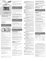
MANUAL TECNICO
ATENCIÓN
No utilice el equipo sin anter leer el
manual de instrucciones.
FACILITY CONNECT
P05628 - 12/2022
Rev. 5
Fabricado por:
Motoppar da Amazônia Indústria e Comércio de Eletrônicos Ltda.
Avenida Açaí, 875 - Distrito Industrial I
Manaus - AM - CEP 69075-904 - Brasil
CNPJ: 09.084.119/0001-64
www.ppa.com.br | +55 14 3407 1000 AVANZAR EN LA FUNCIÓN
REGRESAR EN LA FUNCIÓN
INCREMENTAR CONTENIDO DE LA FUNCIÓN
DECREMENTAR CONTENIDO DE LA FUNCIÓN
COMANDO PARA ABRIR O CERRAR EL PORTÓN
Presione y suelte los dos botones simultáneamente y pausa-
damente para accionar el motor y observar el estado del portón.
PANTALLA DE INFORMACIÓN
Muestra la información de estado dl portón, los sensores y la
posición del transmisor que ha liberado el acceso por la portón.
Estado del Reed
(posición del
portón), abierto
o fechado.
Contador de segundos restantes para
cierre automático cuando la central esté
configurada en el modo automático.
TRANSMISOR
Código
Fijo
Código
Rotativo
NOTA: En el intento de programar el tipo de transmisor con el
portón en movimiento, la función se cancelará y se activará una
alarma sonora.
Aumentar el tiempo del freno (LED SN parpadea
rápido): Pulsar el botón derecho del transmisor hasta
encontrar el ajuste deseado.
Para volver y seleccionar nuevo ajuste (paso 4): Presione y
suelte simultáneamente los 2 botones del transmisor.
Para finalizar la programación: Abrir el jumper PROG.
13. SELECCIONANDO EL TIPO DE
TRANSMISOR CÓDIGO FIJO O ROLANTE
1. El portón debe estar parado y no temporizarse para el cierre
automático.
2. Cierre el jumper PROG. El LED verde SN deberá quedar
débilmente encendido.
3. Presione y suelte simultáneamente los dos botones del
transmisor (grabado) 10 veces. El LED SN parpadeará cada vez
que se liberan los botones. Esperar 5 segundos.
4. A continuación, el LED SN se encenderá aguardando la
configuración del tipo de transmisor.
Para transmisor de código fijo: Presione y suelte el
botón izquierdo del transmisor.
Para transmissor código rolante: Pressionar e liberar o
botão direito do transmissor.
5. Abra el jumper PROG.
Finalizar la programación: Presione y suelte simultáneamente
los 2 botones del transmisor o abra el jumper PROG. Después de
seleccionar el tipo de transmisor, la memoria se apagará.
14. SELECCIONANDO LA FUNCIÓN DEL
MÓDULO DE RELÉ
1. El portón debe estar parado y no temporizarse para el cierre
automático.
2. Cierre el jumper PROG. El LED verde SN deberá quedar
débilmente encendido.
3. Presione y suelte simultáneamente las dos boticas del
transmisor (grabado) 11 veces. El LED SN parpadeará cada vez
que se liberan los botones. Esperar 5 segundos.
4. A continuación, el LED SN parpadeará en el modo de reloj
y aguardando la configuración de la función del módulo
de relé.
Para traba: Presione y suelte los botones derecho e
izquierdo del transmisor simultáneamente.
Funcionamiento: Cuando el portón está totalmente cerrado
y con el módulo de relé conectado a la placa, al recibir un
comando, la traba será accionada y después de 2 segundos
se conectará el motor al ciclo de apertura y después de 3
segundos la traba se apagará.
Para señalera: Presione y suelte el botón izquierdo del
transmisor.
Funcionamiento: La señalera se encenderá siempre
cuando el portón esté en movimiento o permanecer
abierto esperando un nuevo comando, y se apagará
cuando el portón se cierre completamente.
Para luz de garaje: Pulsar y mantener presionado el botón
derecho del transmisor y contar el número de parpadeos
por el LED. Cada parpadeo representa 10 segundos para la
luz de garaje. El ajuste es de 0 a 240 segundos.
Funcionamiento: La luz de garaje quedará encendida
siempre que el portón esté en movimiento o esté abiertao
esperando un nuevo comando, y se apagará cuando el
portón se cierre completamente y después de finalizar el
tiempo de LG programado.
Para retardo na apertura com señalera encendida:
Presionar y mantener presionado el botón izquierdo del
transmisor y contar el número de parpadeos por el LED.
Cada parpadeo representa 2 segundos de retardo en la
apertura con la señalera encendida.
NOTA: Más de 8 parpadeos, el tiempo será de 15
segundos.
Funcionamiento: Cuando el portón está cerrado
totalmente y al recibir un comando para el ciclo de
apertura, la señalera será accionada y quedará encendida
por el tiempo programado y después el motor será
accionado. La señalera se apagará al final del ciclo de
cierre del portón, o cuando reciba un nuevo comando por
el transmisor durante la temporización del retardo.
NOTA: Cada vez que se cambia la programación
del módulo relé, automáticamente en el siguiente
comando la máquina entrará en torque pulsante y va a
buscar el stop de apertura (poweronreset).
5. Abra el jumper PROG.
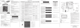
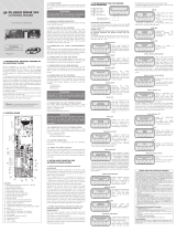
127 ou 220V
(50 / 60 Hz)
FCA
FCF
Condensador de
arranque del
motor
Receptor
Separado
Botonera
Módulo
opcional
Luz, Señalera,
Traba
Entrada para
programador
externo o
módulo
bluetooth.
Fin de
Carrera
Analógico
Fin de carrera digital
Receptor RF
433, 92 MHz
Botón para grabación de
TX, y ajustes de algunas
funciones por el transmisor
y también para comando de
apertura/cierre del portón.
Fotocélula
Jumper de
selección de
fin de carrera
Jumper de
programación
Motor
Amarillo
Rojo/Negro
Negro/Rojo
15. PROGRAMADOR
Tiene la finalidad de ejecutar la programación de las funciones
internas independientemente y más rápido.
Función de los botones:
= Avanzar en la función;
= Retroceder en la función;
= Incrementar el valor de la función.
= Decrementar el valor de la función.
= Los dos botones presionados simultáneamente para
accionar motor.
La central cuando se enciende, el programador mostrará los
mensajes de las figuras 1, 2 y 3 en secuencia.
GRABAR TRANSMISORES
1. No es necesario cerrar el jumper PROG de la central.
2. Presione y mantenga el botón del transmisor.
3. El indicador s en la pantalla señalará la presencia del
transmisor.
4. Presione y suelte pausadamente el botón +, y el indicador
g en la pantalla indicará que ha grabado.
5. El contador de transmisores grabados n: en la pantalla se
actualizará.
6. Soltar el botón del transmisor y el indicador s en la pantalla
se apagará.
7. Para grabar otros botones, repetir desde el punto 2.
Botón (+) para
grabar nuevo
transmisor
Contador de transmisores
grabados en la memoria
El indicador
en la pantalla señalará la presencia del
Presione y suelte pausadamente el botón +, y el indicador
en la pantalla indicará que ha grabado.
El contador de transmisores grabados
: en la pantalla se
Soltar el botón del transmisor y el indicador
en la pantalla
Presione y suelte pausadamente el botón +, y el indicador
en la pantalla indicará que ha grabado.
El contador de transmisores grabados
Soltar el botón del transmisor y el indicador
Para grabar otros botones, repetir desde el punto 2.
Para grabar otros botones, repetir desde el punto 2.
Contador de transmisores
grabados en la memoria
grabados en la memoria
Soltar el botón del transmisor y el indicador
Para grabar otros botones, repetir desde el punto 2.
Contador de transmisores
grabados en la memoria
grabados en la memoria
El contador de transmisores grabados
actualizará.
Soltar el botón del transmisor y el indicador
Para grabar otros botones, repetir desde el punto 2.
MEMORIZAR RECORRIDO
La central entrará en ciclo de cierre hasta encontrar el final de
carrera, y después de 1 seg., Inicializará el ciclo de apertura,
memorizando el tiempo o pulsos del encoder hasta encontrar el
final de carrera de apertura.
Botón (+)
para iniciar la
memorización
del recorrido
RAMPA DE CIERRE
Disminuir
distancia
Aumentar
distancia
NOTA: En el intento de programar la rampa de conexión
con el portón en movimiento, la función se cancelará y se
activará una alarma acústica.
RAMPA DE APERTURA
Disminuir
distancia
Aumentar
distancia
NOTA: Al intentar programar la rampa de apertura con el
portón en movimiento, se cancelará la función y se activará
una alarma acústica.
TORQUE DE RAMPA EN EL CIERRE
Reducir
torque por 1
Aumentar
torque por 1
TORQUE DE RAMPA EN LA APERTURA
Reducir
torque por 1
Aumentar
torque por 1
TORQUE DE MEMORIZACIÓN EN EL CIERRE
Reducir
torque por 1
Aumentar
torque por 1
TORQUE DE MEMORIZACIÓN EN LA APERTURA
Reducir
torque por 1
Aumentar
torque por 1
FUERZA
Ajuste del embrague electrónico con el portón en movimiento o
parado, hasta 14 niveles.
Disminuir nivel Aumentar nivel
PAUSA
Ajuste del tiempo de cierre automático cuando el portón encuentra
el sensor final de carrera de apertura FCA.
Disminuir tiempo a
cada 10 segundos
Aumentar tiempo a
cada 10 segundos
TRABA
En el mando de ciclo de apertura, si la traba está habilitado [S] y
el módulo conectado, se activará y después de 1 seg. la central
conectará el motor y después de 2 seg. la traba se apagará.
Apagar trava Encender trava
LUZ DE GARAJE / SEÑALERA / TIEMPO DE RETARDO
• Para luz de garaje, programar tiempo en xxx segundos, y
cuando la central encuentre el sensor de final de carrera de
cierre FCF, temporizará para el apagado.
• Para señalera intermitente, programar tiempo para 000
segundos, y cuando la central encuentra el sensor fin de
carrera de cierre FCF, se apagará.
• Para tiempo de retardo, programar tiempo entre 001 y
015 segundos, y cuando se haya vuelto a cero, la puerta
empezará movimiento de apertura.
NOTA: Para activar las funciones de luz de garaje o
señalera, desactivar el módulo de traba [N].
Disminuir tiempo
a cada 10seg
Aumentar tiempo
a cada 10seg
TIEMPO DE FRENO EN LA APERTURA
Disminuir tiempo
a cada 100mseg
Aumentar tiempo
a cada 100mseg
TIEMPO DE FRENO EN EL CIERRE
Disminuir tiempo
a cada 20mseg
Aumentar tiempo
a cada 20mseg
RESTAURAR ESTÁNDAR DE FÁBRICA
Botón (+) para
reconfigurar la
central para el
estándar de fábrica
NOTA: En el intento de programar el patrón de fábrica
con el portón en movimiento, la función se cancelará y
se activará la alarma sonora (beep largo).
NOTA: Cuando se presiona el botón (+), la alarma
sonoro (dos beeps cortos) se activará indicando que la
se ha efectuado la acción.
BORRAR TRANSMISSOR
Botón (+)
para borrar
e inicializar la
memoria
NOTA: Al intentar borrar la memoria de los transmisores
con el portón en movimiento, la función será cancelada y
una alarma sonora se activará.
NOTA: Cuando se presiona el botón (+), la alarma
sonoro (dos beeps cortos) se activará indicando que la
se ha efectuado la acción.
/