PPA Agility Pop Connect Manual de usuario
- Categoría
- Abridor de puerta de garage
- Tipo
- Manual de usuario

TECHNICAL CHARACTERISTICS
• 433.92MHz Receiver Module;
• 82 PPA standard rolling code controls;
• Output for garage lock and light modules;
• Analog limit switch;
• Photocell input;
• Electronic clutch adjustment;
• Entry to pushbutton;
• Automatic A/F route memorization;
• Brake adjustment;
• Adjustment of the ramp;
• Ramp torque adjustment;
• Delay time for opening with a signal;
• Allows conguration via PROG;
• Enables activation of the board via Wi-Fi Connect;
• Pre-setup conguration via jumpers according to gate
type, weight and speed;
• Source: 12v, 450mA
DELETE THE RECORDED COURSE
With the gate stopped, press the GRV button for
approximately three seconds until LED1 is lit, conrming
the action. When you release it, the route will be delete.
FACTORY STANDARD
Restore settings to factory default, with ramp disabled.
With the gate stopped, press the GRV button for
approximately ve seconds until LED1 ashes quickly,
conrming the action.
MODEL SELECTION
Set a pattern according to the model of the gate and
operator.
With the gate stopped, close the PROG jumper, make
the model selection according to the gate type jumpers
(sliding or overhead), gate weight (light or heavy) and
operator speed (fast or slow).
To conrm, press the GRV(+) and CMD(-) button until
led1 ashes quickly.
RECORD TRANSMITTERS
PPA standard transmitters.
1. With the gate stopped, close jumper TX, LED1 starts
ashing 2x until any button is pressed.
2. Press transmitter button, LED2 will start ashing
whenever it receives a valid code;
3. Press and release GRV button;
4. Release TX button;
5. Transmitter successfully saved LED1 ash 1x;
6. Button already registered ashes LED1 2x;
7. Memory full LED1 ashes 3x;
8. To record new transmitter button go back to step of
pressing transmitter button;
9. Remove jumper to nish;
DELETE TRANSMITTERS
Clears memory to record new transmitters.
1. With the gate stopped, close jumper TX, LED1 starts
ashing 2x until any button is pressed.
2. Press CMD button for three seconds until LED2 ashes
quickly, conrming the action.
3. Remove jumper to nish
AUTOMATIC / SEMI – AUTOMATIC TIME
After the end of the opening cycle, the gate waits for the
pause time set by the user to close the gate automatically.
To disable and set the time to zero, the board will wait for
a new command to close.
1. With the gate stopped, close the JPROG jumper where
LED1 starts to ash 2x until any button is pressed.
2. Press CMD button 1x, LED1 will stop ashing and stay
lit.
3. Press the GRV button to enter the function, where LED
will start to signal the setting level.
4. Press GRV button to increase auto timeout and CMD to
decrease time.
5. Resetting the automatic time leaves the board in mode
semi-automatic, LED1 ashes quickly.
6. To congure another parameter, press the CMD(-)
and GRV(+) buttons together, returning to the initial
programming state;
7. Remove jumper.
Levels:
• N1 ashing = Semi-automatic.
• N1 lit = 5 sec.
• N2 lit = 10 sec.
• N3 lit = 30 sec.
• N4 lit = 60 sec.
• N5 lit = 90 sec.
• N6 lit = 120 sec.
• N7 lit = 180 sec.
• N8 lit = 240 sec.
ADJUSTMENT OF THE OPENING AND CLOSING
RAMP
The ramp is the distance to reach the mechanical stop.
The board will be continuously monitoring the gate
position and when it reaches this limit the operating
torque reduces, reaching the mechanical stop smoothly.
1. With gate stopped, close JPROG jumper, LED1 starts
ashing 2x until any button is pressed.
2. For close ramp: press CMD button 2x LED1 will stop
ashing and LED2 should remain lit. Press the GRV
button to enter the function, where LED will start to
signal the setting level.
3. For opening ramp: pressing the CMD button 4x LED1
will stop ashing and LED4 should remain lit. Press the
GRV button to enter the function, where LED will start
to signal the setting level.
4. Press GRV to move the limit to the mechanical stop,
increasing the distance;
5. Press CMD to decrease the distance to the limit switch;
6. At the minimum value the ramp is disabled, it does not
reduce the torque, with the possibility of adjusting 8
levels;
Levels:
• N1 ashing = ramp disabled;
• N1 lit = 5% of route
• N2 lit = 10% of route.
• N3 lit = 15% of route.
• N4 lit = 20% of route.
• N5 lit = 25% of route.
• N6 lit = 30% of route.
• N7 lit = 35% of route.
• N8 lit = 40% of route.
TORQUE ON RAMP
The board will decrease the operating torque as soon as
it reaches the programmed ramp. Torque is set separately
for opening and closing.
1. With gate stopped, close JPROG jumper, LED1 starts
ashing 2x until any button is pressed.
2. For closing torque: press CMD button 3x LED1 will stop
ashing and LED3 should remain lit. Press the GRV
button to enter the function, where LED will start to
signal the setting level.
3. For opening torque: press CMD button 5x LED1 will
stop ashing and LED5 should remain lit. Press the GRV
button to enter the function, where LED will start to
signal the setting level.
4. Press GRV to increase the ramp torque;
5. Press CMD to decrease the ramp torque;
6. At the minimum value the ramp is disabled, it does not
reduce the torque, with the possibility of adjusting 8
levels;
7. To congure another parameter, press the CMD(-)
and GRV(+) buttons together, returning to the initial
programming state;
8. Remove Jumper.
Levels:
• N1 ashing = disabled;
• N1 lit = Minimum;
...
• N8 lit = Maximum;
BRAKE
When there is a command to turn o the engine, the
brake will be activated with the possibility of sensitivity
adjustment.
1. With gate stopped, close JPROG jumper, LED1 starts
ashing 2x until any button is pressed.
2. Pressing the CMD button 6x LED1 will stop ashing and
LED 6 should remain lit.
3. Press the GRV button to enter the function, where LED
will start to signal the setting level.
4. Press GRV to increase the time the brake will be applied;
5. Press CMD to decrease the brake;
6. At the minimum value the brake is disabled;
7. To congure another parameter, press the CMD(-)
and GRV(+) buttons together, returning to the initial
programming state;
8. Remove Jumper.
Levels:
• N1 ashing = disabled;
• N1 lit = Minimum;
...
• N8 lit = Maximum;
POWER (ELECTRONIC CLUTCH)
Adjust the engine operating force. For the use of this
safety sensor device to be eective, proceed as follows:
• After proper installation of the gate operator, adjust
the electronic clutch so that the force is the minimum
necessary to move the gate leaf along its entire path, in
opening and closing;
• At the end of the adjustment, test the function by
blocking the movement of the gate by placing a rigid
object in the limit switch of the gate.
1. With gate stopped, close JPROG jumper, LED1 starts
ashing 2x until any button is pressed.
2. Pressing the CMD button 7x LED1 will stop ashing and
the LED7 should remain lit.
3. Press GRV button to enter setup, LED will start to signal
setup level.
4. Press GRV button to increase strength and CMD to
decrease;
5. To congure another parameter, press the CMD(-)
and GRV(+) buttons together, returning to the initial
programming state;
6. Remove jumper.
GARAGE LIGHT TIME
Setting the time to turn o the garage light relay
module when the gate reaches the closing limit switch.
1. With gate stopped, close JPROG jumper, LED1 starts
ashing 2x until any button is pressed.
2. Pressing the CMD button 8x LED1 will stop ashing and
LED 8 should remain lit.
3. Press GRV button to enter setup, LED will start to signal
setup level.
4. Press GRV button to increase the standby time to turn
o the light and CMD to decrease it;
5. To congure another parameter, press the CMD(-)
and GRV(+) buttons together, returning to the initial
programming state;
6. Remove jumper.
Levels:
• N1 ashing = trac light, turns o as soon as it closes.
• N1 lit = 30 sec.
• N2 lit = 60 sec.
• N3 lit = 90 sec.
• N4 lit = 120 sec.
• N5 lit = 150 sec.
• N6 lit = 180 sec.
• N7 lit = 210 sec.
• N8 lit = 240 sec.
EXTRA SETTINGS MADE ONLY USING THE
PROG
Using the PROG programmer module it is also possible
to congure:
• Rollback: enabled or disabled;
• TX Type: the board accepts TX reception in xed mode
and in rolling mode, changing these parameters delete
all previously registered TX’s.
• Delay in opening: Time between reception of
the opening command and the board sending
the command to the gate, activating a trac light
connected to the garage light for signaling. It can be
congured as disabled or with time congured every
3s, ten of the maximum value of 24s.
SETTINGS BY THE PROGRAMMER “PROG”
PROG: Allows you to make the settings with more
precision.
While the PROG is in the board, the commands through
the pushbutton, the CMD button and the separate
receiver will be disabled for engine activation commands
in the limit switch.
Only PROG can send commands for opening and
closing the gate, with the button (+) and the registered
transmitter, if it is on the main sensor status screen.
Keeping any key pressed in the PROG, after 3 seconds, it
will enter the auto-repeat mode of the key pressed, which
will speed up the progress of the screens or adjustments.
HOME SCREEN
Monitoring of sensors and board
peripherals: (Gate status, FCF, FCA,
Photocell and Transmitter).
TYPE FACTORY
DEFAULT SETUP
Restores settings to factory
default.
RECORD
TRANSMITTERS
Records new transmitters
(controls) in the electronics board.
DELETE
TRANSMITTERS
Deletes (erases) all transmitters
(control) recorded on the
electronics board.
BREAK TIME
Time for automatic closing
• Semi-automatic (disabled)
• 1 (5 sec.)
• 2 (10 sec.)
• 8 (240 sec.)
CLOSING RAMP
9 levels
• 0 (Disabled)
• 1 minimum
• 8 Maximum
CLOSING TORQUE
9 levels
• 0 (Disabled)
• 1 minimum
• 8 Maximum
OPENING RAMP
9 levels
• 0 (Disabled)
• 1 minimum
• 8 Maximum
OPENING TORQUE
9 Niveis
• 0 (Desabilitado)
• 1(Minimo)
• 8(Maximo)
BRAKE
9 levels
• 0 (Disabled)
• 1 minimum
• 8 Maximum
STRENGTH
9 levels
• 0 (Disabled)
• 1 minimum
• 8 Maximum
GARAGE LIGHT
TIME
Garage light time
• 0 (Disabled)
• 1 (30 sec.)
• 2 (60 sec.)
• 8 (240 sec.)
REVERSAL
Pushbutton or transmitter command
permission to work during the
closing limit switch of the gate to
reversal.
CODE TYPE Rolling Code (PPA).
OPENING DELAY
9 levels
• 0 (Disabled)
• 1 minimum
• 8 Maximum
CLOSING LOCK
Collect the lock pin when the gate
is closing and release the lock
when closing is complete
ROUTE Delete recorded route
LANGUAGE Select the PROGRAM language
ST: FCF: FCA:
FOT: RF:
ST – STATUS: Signals the opening or closing state.
FCF: Identies the position between reed and drive nut
magnet
FCA: Identies the position between reed and drive nut
magnet
FOT: Identies the photocell pulse
RF: Identies radio frequency signal
FACTORY PATTERN
FACTORY PATTERN: In this screen press (-) until you
reach factory pattern done, press the keys (-) and (+) for 5
seconds until it appears written done on the screen.
Also on this screen dene the type and weight of the gate
using the (+) and (-) keys to navigate through the options:
• Light and slow BV
• Light and fast BV
• Heavy and slow BV
• Heavy and fast BV
• Light and slow DZ
• Heavy and slow DZ
RECORD TRANSMITTERS – [000]
In this function the display shows no signal, when sending
a signal the display will show (+) transmitter, to conrm
press and release the (+) key and the transmitter will be
saved.
DELETE TRANSMITTERS
To delete all recorded transmitters, just press and release
the (+) key, doing so will display a 10-sec counter. descend
to 0 sec, to conrm the action press and release the (+)
key.
BREAK TIME
To increase the automatic time press the (+) key and to
decrease it press the (-) key.
CLOSING RAMP
To increase the closing ramp, just press the (+) key and to
decrease it, just press the (-) key.
CLOSING TORQUE
To increase the closing torque, just press the (+) key to the
desired torque level and to decrease it, just press the (-)
key.
OPENING RAMP
To increase the opening ramp just press the (+) key and to
decrease it just press (-) key.
OPENING TORQUE
To increase the opening torque, just press the (+) key to
the desired torque level and to decrease it, just press the
(-) key.
CENTRAL AGILITY
POP CONNECT
TECHNICAL MANUAL
ATTENTION
Do not use the equipment
without rst reading the
instruction manual.
P09852 - 02/2023
Rev. 2
BRAKE
To increase the brake level, just press the (+) key and to
decrease it, just press the (-) key.
STRENGTH
The force leaves the factory at the maximum level, to
decrease it just press the (-) key to the desired level, to
increase it just press the (+) key.
GARAGE LIGHT TIME
To increase the garage light time, just press the (+) key
and to decrease it, just press the (-) key.
REVERSAL
To disable the rollback just press the (-) key to enable press
the (+) key.
CODE TYPE TX
Rolling code PPA standard only.
OPENING DELAY
To increase the opening delay time press and release the
(+) key and to decrease it press the (-) key.
CLOSING LOCK
To enable and increase the latch retraction time during
the closing limit switch press the (+) key and to decrease
press the (-) key.
PANEL ADJUSTMENTS
The factory setting goes out as allowed, to lock press
and release the (+) key, to unlock press and release the
(-) key. This function provides grater security, reducing the
chance of improper programming.
ROUTE
To delete the recorded route, just press the (+) key.
LANGUAGE
Select the desired language, Portuguese, English or
Spanish.
SETTINGS COMMAND TABLE
Parameters Select function Enter the function Increment Decrement
Automatic Time Press 1 x CMD (-) 1 x GRV (+) GRV (+) CMD (-)
Closing Ramp Press 2 x CMD (-) 1 x GRV (+) GRV (+) CMD (-)
Closing Torque Press 3 x CMD (-) 1 x GRV (+) GRV (+) CMD (-)
Opening Ramp Press 4 x CMD (-) 1 x GRV (+) GRV (+) CMD (-)
Opening Torque Press 5 x CMD (-) 1 x GRV (+) GRV (+) CMD (-)
Brake Press 6 x CMD (-) 1 x GRV (+) GRV (+) CMD (-)
Strength Press 7 x CMD (-) 1 x GRV (+) GRV (+) CMD (-)
Garage Light Time Press 8 x CMD (-) 1 x GRV (+) GRV (+) CMD (-)
NOTE: To change the parameter without having to open JUMPER PROG, it is necessary to press both CMD (-) and GRV (+)
buttons at the same time. LED1 starts ashing 2x until the CMD (-) button is pressed again for the next parameter.
JUMPERS SETTINGS
PARAMETERS STATE
OPEN CLOSE
JUMPERS
RAP / SLOW FAST SLOW
LIGHT/WEIGHT LIGHT GATE HEAVY GATE
DZ/BV SLIDING OVERHEAD
PROG WORKING PROGRAMING
TX WITHOUT RECORDING RECORDING
FACTORY DEFAULT SETTINGS TABLE
Parameters
Automatic Time Semi automatic
Closing Ramp Level 0
Closing Torque Level 1
Opening Ramp Level 0
Opening Torque Level 1
Brake Level 1
Strenth Level 8
Garage Light Time 0 sec.
Reversal Able
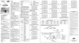
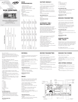
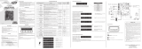
SUBTITLE
1 - RECORD button (+);
2 - COMMAND button (-);
3 - JUMPER Programming;
4 - JUMPER Application model;
5 - JUMPER Select gate weight;
6 - JUMPER Select technology;
7 - JUMPER Records transmitter (TX);
8 - LOCK connector;
9 - GARAGE LIGHT connector;
10 - PROG PPA connector;
11 - LED Signaling;
12 - Photocell Connector;
13 - RX / BOT Connector
GENERAL TERMS AND CONDITIONS OF WARRANTY
MOTOPPAR, Indury and Commerce of Automatic Gate Operators Ltd., regiered with the CNPJ (National Regiry of Legal Entities) under Number 52.605.821/0001-55, located at 3526 Dr.
Labieno da Coa Machado Avenue, Indurial Dirict, Garça – SP – Brazil, Zip Code 17400-000, manufacturer of PPA Products, hereby guarantees this product again design, manufacturing or
assembly defects and/or supportively as a result of material quality aws that could make its intended use improper or inadequate, within a legal period of ninety days from time of acquisition,
provided that the inallation inructions described in the inruction manual are observed.
Due to the credibility and tru placed on PPA products, we will add 275 more days to the period mentioned above, reaching a warranty period of one year, likewise counted from the time of
acquisition proven by consumer through proof of purchase (Cuomer Receipt).
In case of defect, within the warranty period, PPA responsibilities are rericted to the repair or subitution of the product manufactured by the company, under the following conditions:
1. Repair and readjument of equipment may only be carried out by PPA Technical Assiance, which is qualied to open, remove, and subitute parts or components, as well as repair defects
covered by this warranty; thus, failure on observing this guideline and the veried use of any non-original parts will cause the resignation of this warranty on the part of the user;
2. The warranty will not extend to accessories such as cables, screw kit, xing brackets, power supplies etc.;
3. Expenses for packaging, transportation and product reinallation will be sole responsibility of the consumer;
4. The equipment mu be sent directly to the Company responsible for the sale (manufacturer's representative), through the address contained in the purchase invoice, properly packed, thus
avoiding loss of the warranty;
5. Within the additional period of 275 days, visits and transportation in places where authorized technical assiance is not available will be charged. The co of transportation of the product and/
or technician will be sole responsibility of the consumer and
6. The subitution or repair of the product does not prolong the warranty time.
This warranty will be terminated if the product:
1. Is damaged by natural agents, such as atmospheric discharges, oods, wildres, landslides etc.;
2. Is inalled in an improper electric power supply or if it is not according to any of the inallation inructions displayed on the manual;
3. Shows defects caused by droppings, collisions or any other physical accident;
4. Shows signs of product violation or attempted repair by unauthorized personnel;
5. Is not used for its intended purpose;
6. Is not used under normal conditions;
7. Is damaged by accessories or equipment connected to it.
Recommendation:
We recommend that both the inallation and the maintenance of the operator to be performed by an authorized PPA technical service. If the product fails or has an improper operation, seek
an Authorized Technical Service to x it.
ELECTRICAL POWER
100 - 240 VAC
50 - 60 Hz
ELECTRICAL POWER
127 -220 V
ENGINE
START
CAPACITOR
LIMIT SWITCH
REEDS
M
TACT
LED
6
8
9
12
13
4
1
2
5
3
10
11
7
C A C F

CARACTERÍSTICAS TÉCNICAS
• Módulo receptor de 433,92 MHz;
• 82 controles de código variable estándar de PPA;
• Salida para cerradura de garaje y módulos de luz;
• Final de carrera analógico;
• Entrada de fotocélula;
• Ajuste electrónico del embrague;
• Entrada a pulsador;
• Memorización automática de ruta A / F;
• Ajuste de freno;
• Ajuste de la rampa;
• Ajuste de torque de rampa;
• Tiempo de retardo para apertura con señal;
• Permite la conguración a través de PROG;
• Permite la activación de la central a través de Wi-Fi
Connect;
• Conguración previa a la instalación mediante puentes
según tipo de puerta, peso y velocidad;
• Fuente: 12 V, 450 mA
BORRAR EL CURSO GRABADO
Con el puerta parado, presione el botón GRV durante
aproximadamente tres segundos hasta que el LED1 se
encienda, conrmando la acción. Cuando lo suelte, la ruta
se eliminará.
ESTÁNDAR DE FÁBRICA
Restaura la conguración a los valores predeterminados
de fábrica, con la rampa desactivada.
Con la puerta parado, presione el botón GRV durante
aproximadamente cinco segundos hasta que el LED1
parpadee rápidamente, conrmando la acción.
SELECCIÓN DE MODELO
Establezca un patrón de acuerdo con el modelo de la
puerta y el automator.
Con la puerta parado, cierre el jumper PROG, haga la
selección del modelo de acuerdo al tipo de puentes de la
puerta (corredera o basculante, peso de la puerta (ligero o
pesado) y velocidad del automator (rápido o lento).
Para conrmar presione el botón GRV (+) y CMD (-)
hasta que el led1 parpadee rápidamente.
TRANSMISORES DE REGISTRO
Transmisores estándar PPA.
1. Con la puerta parada, cierre el puente TX, el LED1
comienza a parpadear 2 veces hasta que se presione
cualquier botón.
2. Presione el botón del transmisor, el LED2 comenzará a
parpadear cada vez que reciba un código válido;
3. Presione y suelte el botón GRV;
4. Suelte el botón TX;
5. El transmisor guardó con éxito el ash LED1 1x;
6. Botón ya registrado parpadea LED1 2x;
7. Memoria llena LED1 parpadea 3 veces;
8. Para grabar un nuevo botón del transmisor, vuelva al
paso de presionar el botón del transmisor;
9. Quite el jumper para terminar;
BORRAR TRANSMISORES
Borra la memoria para grabar nuevos transmisores.
1. Con la puerta parada, cierre el jumper TX, el LED 1
comienza a parpadear 2 veces hasta que se presione
cualquier botón.
2. Presione el botón CMD durante tres segundos hasta
que el LED 2 parpadee rápidamente, conrmando la
acción.
3. Quite el jumper para terminar.
AUTOMÁTICO / SEMI - AUTOMÁTICO TIEMPO
Una vez nalizado el ciclo de apertura, de la puerta
espera el tiempo de pausa establecido por el usuario
para cerrar la puerta automáticamente. Para deshabilitar
y establecer el tiempo en cero, la central esperará a que se
cierre un nuevo comando.
1. Con la puerta detenida, cierre el jumper JPROG donde
el LED 1 comienza a parpadear 2 veces hasta que se
presione cualquier botón.
2. Presione el botón CMD 1x, el LED1 dejará de parpadear
y permanecerá encendido.
3. Presione el botón GRV para ingresar a la función, donde
el LED comenzará a señalar el nivel de conguración.
4. Presione el botón GRV para aumentar el tiempo de
espera automático y CMD para disminuir el tiempo.
5. Restablecer el tiempo automático deja la placa en
modo semiautomático, LED1 parpadea rápidamente.
6. Para congurar otro parámetro, presione los botones
CMD (-) y GRV (+) juntos, volviendo al estado de
programación inicial;
7. Quite el jumper.
Niveles:
• N1 intermitente = semiautomático.
• N1 encendido = 5 seg.
• N2 encendido = 10 seg.
• N3 encendido = 30 seg.
• N4 encendido = 60 seg.
• N5 encendido = 90 seg.
• N6 encendido = 120 seg.
• N7 encendido = 180 seg.
• N8 encendido = 240 seg.
AJUSTE DE LA RAMPA DE APERTURA Y CIERRE
La rampa es la distancia para llegar al tope mecánico. La
central estará monitoreando continuamente la posición
de la puerta y cuando alcance este límite, el torque de
operación se reducirá, alcanzando el tope mecánico sin
problemas.
1. Con la puerta detenida, cierre el jumper JPROG, el LED1
comienza a parpadear 2 veces hasta que se presione
cualquier botón.
2. Para cerrar la rampa: presione el botón CMD. 2x LED1
dejará de parpadear y el LED2 debe permanecer
encendido. Presione el botón GRV para ingresar a la
función, donde el LED comenzará a señalar el nivel de
conguración.
3. Para rampa de apertura: presionando el botón CMD 4x
LED1 dejará de parpadear y el LED4 debe permanecer
encendido. Presione el botón GRV para ingresar a la
función, donde el LED comenzará a señalar el nivel de
conguración.
4. Presione GRV para mover el límite al tope mecánico,
aumentando la distancia;
5. Presione CMD para disminuir la distancia al interruptor
de límite;
6. Al valor mínimo se desactiva la rampa, no reduce el
torque, con posibilidad de ajustar 8 niveles;
Niveles:
• N1 intermitente = rampa deshabilitada;
• N1 encendido = 5% de la ruta
• N2 encendido = 10% de la ruta.
• N3 encendido = 15% de la ruta.
• N4 encendido = 20% de la ruta.
• N5 encendido = 25% de la ruta.
• N6 encendido = 30% de la ruta.
• N7 encendido = 35% de la ruta.
• N8 encendido = 40% de la ruta.
TORQUE EN RAMPA
La central disminuirá el torque de operación tan pronto
como alcance la rampa programada. El torque se ajusta
por separado para la apertura y el cierre.
1. 1. Con la puerta detenida, cierre el jumper JPROG,
el LED1 comienza a parpadear 2 veces hasta que se
presione cualquier botón.
2. Para el torque de cierre: presione el botón CMD 3
veces. El LED1 dejará de parpadear y el LED3 debe
permanecer encendido. Presione el botón GRV para
ingresar a la función, donde el LED comenzará a señalar
el nivel de conguración.
3. Para torque de apertura: presione el botón CMD 5x El
LED1 dejará de parpadear y el LED5 debe permanecer
encendido. Presione el botón GRV para ingresar a la
función, donde el LED comenzará a señalar el nivel de
conguración.
4. Presione GRV para aumentar el torque de rampa;
5. Presione CMD para disminuir el torque de rampa;
6. Al valor mínimo se desactiva la rampa, no reduce el
torque, con posibilidad de ajustar 8 niveles;
7. Para congurar otro parámetro, presione los botones
CMD (-) y GRV (+) juntos, volviendo al estado de
programación inicial;
8. Retire el jumper.
Niveles:
• N1 intermitente = desactivado;
• N1 encendido = Mínimo ;
...
• N8 encendido = Máximo;
FRENO
Cuando hay un comando para apagar el motor, el freno
se activará con la posibilidad de ajustar la sensibilidad.
1. Con la puerta detenida, cierre el jumper JPROG, el LED1
comienza a parpadear 2 veces hasta que se presione
cualquier botón.
2. Al presionar el botón CMD 6x, el LED1 dejará de
parpadear y el LED 6 debe permanecer encendido.
3. Presione el botón GRV para ingresar a la función, donde
el LED comenzará a señalar el nivel de conguración.
4. Presione GRV para aumentar el tiempo que se aplicará
el freno;
5. Presione CMD para disminuir el freno;
6. En el valor mínimo, el freno está desactivado;
7. Para congurar otro parámetro, presione los botones
CMD (-) y GRV (+) juntos, volviendo al estado de
programación inicial;
8. Retire el jumper.
Niveles:
• N1 intermitente = desactivado;
• N1 encendido = Mínimo;
...
• N8 encendido = Máximo;;
POTENCIA (EMBRAGUE ELECTRONICO)
Ajuste la fuerza operativa del motor. Para que el uso
de este sensor de seguridad sea efectivo, proceder de la
siguiente:
• • Después de la instalación adecuada del automator
de puerta, ajuste el embrague electrónico para que la
fuerza sea la mínima necesaria para mover la hoja de
puerta a lo largo de todo su recorrido, en apertura y
cierre;
• Al nal del ajuste, pruebe la función bloqueando el
movimiento de la puerta colocando un objeto rígido
en el nal de carrera de la puerta.
1. Con la puerta detenida, cierre el jumper JPROG, el LED1
comienza a parpadear 2 veces hasta que se presione
cualquier botón.
2. Al presionar el botón CMD 7x, el LED1 dejará de
parpadear y el LED7 debe permanecer encendido.
3. Presione el botón GRV para ingresar a la conguración,
el LED comenzará a indicar el nivel de conguración.
4. Presione el botón GRV para aumentar la fuerza y CMD
para disminuir;
5. Para congurar otro parámetro, presione los botones
CMD (-) y GRV (+) juntos, volviendo al estado de
programación inicial;
6. Quite el jumper.
TIEMPO DE LUZ DE GARAJE
Conguración del tiempo para apagar el módulo de
relé de luz de garaje cuando la puerta llega al nal de
carrera de cierre.
1. Con la puerta detenida, cierre el jumper JPROG, el LED1
comienza a parpadear 2 veces hasta que se presione
cualquier botón.
2. Al presionar el botón CMD 8x, el LED1 dejará de
parpadear y el LED 8 debe permanecer encendido.
3. Presione el botón GRV para ingresar a la conguración,
el LED comenzará a indicar el nivel de conguración.
4. Presione el botón GRV para aumentar el tiempo de
espera para apagar la luz y CMD para disminuirlo;
5. Para congurar otro parámetro, presione los botones
CMD (-) y GRV (+) juntos, volviendo al estado de
programación inicial;
6. Quite el jumper.
Niveles:
• N1 intermitente = semáforo, se apaga en cuanto se
cierra.
• N1 encendido = 30 seg.
• N2 encendido = 60 seg.
• N3 encendido = 90 seg.
• N4 encendido = 120 seg.
• N5 encendido = 150 seg.
• N6 encendido = 180 seg.
• N7 encendido = 210 seg.
• N8 encendido = 240 seg.
AJUSTES ADICIONALES REALIZADOS
ÚNICAMENTE CON EL PROG
Utilizando el módulo programador PROG también es
posible congurar:
• Revertir: habilitado o deshabilitado;
• Tipo TX: la placa acepta recepción TX en modo jo y
en modo rolling, al cambiar estos parámetros se borran
todos los TX’s registrados previamente.
• Retraso en apertura: Tiempo entre la recepción
del mando de apertura y el envío del mando de la
puerta por parte de la central, activando un semáforo
conectado a la luz del garaje para señalización. Se
puede congurar como deshabilitado o con tiempo
congurado cada 3s, diez del valor máximo de 24s.
AJUSTES DEL PROGRAMADOR “PROG”
PROG: le permite realizar la conguración con más
precisión.
Mientras el PROG está en el tablero, los comandos a través
del botón pulsador, el botón CMD y el receptor separado
se desactivarán para los comandos de activación del
motor en el interruptor de límite.
Solo PROG puede enviar comandos para abrir y cerrar la
puerta, con el botón (+) y el transmisor registrado, si está
en la pantalla de estado del sensor principal.
Manteniendo cualquier tecla presionada en el PROG,
luego de 3 segundos, ingresará al modo de auto-
repetición de la tecla presionada, lo que acelerará el
progreso de las pantallas o ajustes.
PANTALLA DE
INICIO
Monitorización de sensores y
periféricos de central: (Estado
de puerta, FCF, FCA, Fotocélula y
Transmisor).
TIPO
CONFIGURACIÓN
PREDETERMINADA
DE FÁBRICA
Restaura la conguración a los
valores predeterminados de
fábrica.
TRANSMISORES DE
REGISTRO
Registra nuevos transmisores
(controles) en la central
electrónica.
BORRAR
TRANSMISORES
Elimina (borra) todos los
transmisores (control) registrados
en la central electrónica.
DESCANSO
Tiempo de cierre automático.
• Semiautomático (desactivado)
• 1 (5 segundos)
• 2 (10 segundos)
• 8 (240 seg.)
RAMPA DE CIERRE
9 niveles
• 0 (deshabilitado)
• 1 mínimo
• 8 máximo
TORQUE DE CIERRE
9 niveles
• 0 (deshabilitado)
• 1 (mínimo)
• 8 (máximo)
RAMPA DE
APERTURA
9 niveles
• 0 (deshabilitado)
• 1 (mínimo)
• 8 (máximo)
TORQUE DE
APERTURA
9 niveles
• 0 (deshabilitado)
• 1 (mínimo)
• 8 (máximo)
FRENO
9 niveles
• 0 (deshabilitado)
• 1 (mínimo)
• 8 (máximo)
FUERZA
9 niveles
• 0 (deshabilitado)
• 1 (mínimo)
• 8 (máximo)
TIEMPO DE LUZ DE
GARAJE
Tiempo de luz de garaje
• 0 (Disabled)
• 1 (30 sec.)
• 2 (60 sec.)
• 8 (240 sec.)
INVERSIÓN
Permiso de mando de ojal o
transmisor para trabajar durante
el n de carrera de cierre de la
puerta a marcha atrás.
TIPO DE CÓDIGO Código variable (PPA).
RETRASO EN
APERTURA
9 niveles
• 0 (deshabilitado)
• 1 (mínimo)
• 8 (máximo)
BLOQUEO DE
CIERRE
Recoja el pasador de bloqueo
cuando la puerta se esté cerrando
y suelte el bloqueo cuando se
complete el cierre
RUTA Eliminar ruta grabada
IDIOMA Seleccione el idioma del PROGRAMA
ST: FCF: FCA:
FOT: RF:
ST - ESTADO: Señala el estado de apertura o cierre.
FCF: identica la posición entre la lengüeta y el imán de
la tuerca impulsora.
FCA: identica la posición entre la lengüeta y el imán de
la tuerca impulsora.
FOT: identica el pulso de la fotocélula.
RF: identica la señal de radiofrecuencia.
PATRÓN DE FPABRICA
PATRÓN DE FÁBRICA: En esta pantalla presione (-) hasta
llegar al patrón de fábrica hecho, presione las teclas (-) y
(+) durante 5 segundos hasta que aparezca escrito hecho
en la pantalla.
También en esta pantalla dena el tipo y peso de la puerta
usando las teclas (+) y (-) para navegar por las opciones:
• BV ligero y lento
• BV ligero y rápido
• BV pesado y lento
• BV pesado y rápido
• DZ ligero y lento
• DZ pesado y lento
TRANSMISORES DE REGISTRO – [000]
En esta función la pantalla no muestra señal, al enviar una
señal la pantalla mostrará (+) transmisor, para conrmar
presione y suelte la tecla (+) y el transmisor se guardará.
BORRAR TRANSMISORES
Para borrar todos los transmisores grabados, simplemente
presione y suelte la tecla (+), al hacerlo, se mostrará
un contador de 10 segundos. descender a 0 seg, para
conrmar la acción pulsar y soltar la tecla (+).
DESCANSO
Para aumentar el tiempo automático presione la tecla (+)
y para disminuirlo presione la tecla (-).
RAMPA DE CIERRE
Para aumentar la rampa de cierre, presione la tecla (+) y
para disminuirla presione la tecla (-).
TORQUE DE CIERRE
Para aumentar el torque de cierre, simplemente presione
la tecla (+) hasta el nivel de par deseado y para disminuirlo,
simplemente presione la tecla (-).
CENTRAL AGILITY
POP CONNECT
MANUAL TÉCNICO
ATENCIÓN
No utilice el equipo sin
antes leer el manual de
instrucciones.
P09852 - 02/2023
Rev. 2
RAMPA DE APERTURA
Para aumentar la rampa de apertura solo presione la tecla
(+) y para disminuirla presione la tecla (-).
TORQUE DE APERTURA
Para aumentar el torque de apertura, simplemente
presione la tecla (+) hasta el nivel de torque deseado y
para disminuirlo, simplemente presione la tecla (-).
FRENO
Para aumentar el nivel de freno, simplemente presione la
tecla (+) y para disminuirlo, presione la tecla (-).
FUERZA
La fuerza sale de fábrica al nivel máximo, para disminuirla
basta con pulsar la tecla (-) hasta el nivel deseado, para
aumentarla basta con pulsar la tecla (+).
TIEMPO DE LUZ DE GARAJE
Para aumentar el tiempo de luz del garaje, simplemente
presione la tecla (+) y para disminuirlo, presione la tecla
(-).
INVERSIÓN
Para deshabilitar la reversión simplemente presione la
tecla (-) para habilitar presione la tecla (+).
TIPO DE CÓDIGO TX
Solo código variable estándar PPA.
RETRASO EN APERTURA
Para aumentar el tiempo de retardo de apertura presione
y suelte la tecla (+) y para disminuirlo presione la tecla (-).
BLOQUEO DE CIERRE
Para habilitar y aumentar el tiempo de retracción del
pestillo durante el nal de carrera de cierre presionar la
tecla (+) y para disminuir presionar la tecla (-).
AJUSTES EN LA CENTRAL
La conguración de fábrica sale como permitido, para
bloquear presione y suelte la tecla (+) para desbloquear
presione y suelte la tecla (-). Esta función proporciona
mayor seguridad, reduciendo la posibilidad de una
programación incorrecta.
RUTA
Para borrar la ruta grabada, simplemente presione la tecla
(+).
IDIOMA
Seleccione el idioma deseado, portugués, inglês o
español.
TABLA DE COMANDOS DE AJUSTES
Parámetros Seleccionar función Entrar en la función Incremento Decremento
Tiempo automático Prensa 1 x CMD (-) 1 x GRV (+) GRV (+) CMD (-)
Ramoa de cierre Prensa 2 x CMD (-) 1 x GRV (+) GRV (+) CMD (-)
Torque de cierre Prensa 3 x CMD (-) 1 x GRV (+) GRV (+) CMD (-)
Rampa de apertura Prensa 4 x CMD (-) 1 x GRV (+) GRV (+) CMD (-)
Torque de apertura Prensa 5 x CMD (-) 1 x GRV (+) GRV (+) CMD (-)
Freno Prensa 6 x CMD (-) 1 x GRV (+) GRV (+) CMD (-)
Fuerza Prensa 7 x CMD (-) 1 x GRV (+) GRV (+) CMD (-)
Tiempo de luz de garaje Prensa 8 x CMD (-) 1 x GRV (+) GRV (+) CMD (-)
NOTA: Para cambiar el parámetro sin tener que abrir JUMPER PROG, es necesario presionar los botones CMD (-) y GRV
(+) al mismo tiempo. El LED1 comienza a parpadear 2 veces hasta que se presiona nuevamente el botón CMD (-) para el
siguiente parámetro.
AJUSTES DE LOS JUMPERS
PARAMETROS ESTADO
ABIERTO CERRADO
JUMPERS
RAP / LENTO RÁPIDO LENTO
LIGERO PUERTA DE LUZ PUERTA PESADA
DZ / BV DESLIZANTE SOBRE LA CABEZA
PROG OPERANDO PROGRAMACIÓN
TX SIN GRABAR GRABACIÓN
TABLA DE AJUSTES PREDETERMINADOS DE FÁBRICA
Parámetros
Tiempo automático Semi automático
Rampa de cierre Nivel 0
Torque de cierre Nivel 1
Rampa de apertura Nivel 0
Torque de apertura Nível 1
Freno Nivel 1
Fuerza Nivel 8
Tiempo de luz del garaje 0 seg.
Reversión Capaz
PLAZO DE GARANTÍA
MOTOPPAR, Induria y Comercio de Automatizadores Ltda., regirada con CNPJ (CIF) 52.605.821/0001-55, localizada en la Avenida Dr. Labieno da Coa Machado número 3526,
Dirito Indurial, Garça – SP – Brasil, Código Poal 17.400-000, fabricante de los productos PPA, garantiza eo aparato contra defectos de proyectos, fabricación, montaje y/o
solidariamente en consecuencia de vicios de calidad de material que se lo hagan impropio o inadecuado al consumo a cual se deina por el plazo legal de noventa días desde la
fecha de adquisición, siempre que se cumplan las orientaciones de inalación descritas en el manual de inrucciones.
Como consecuencia de la credibilidad y de la conanza depositada en los productos PPA, añadimos al plazo anteriormente descrito más 275 días, alcanzando el total de un año,
igualmente contados desde que la fecha de adquisición pueda ser comprobada por el consumidor a través do comprobante de compra (Recibo).
En caso de defecto, en el período cubierto por la garantía, la responsabilidad de PPA se queda reringida a la reparación o reemplazo del aparato por ella fabricada, bajo las
siguientes condiciones:
1. La reparación y reajue de aparatos solo pueden realizarse por la Asiencia Técnica de PPA, que eá habilitada a abrir, remover, suituir piezas o componentes, así como
arreglar los defectos cubiertos por la garantía, siendo que el incumplimiento de ee y cualquier utilización de piezas no originales observadas en el uso, implicará en la exclusión
de la garantía por parte del consumidor;
2. La garantía no se extenderá a accesorios como cables, kit de tornillos, soportes de jación, fuentes de alimentación etc.;
3. Los coos de embalaje, transporte y reinalación del producto son responsabilidad exclusiva de los consumidores nales;
4. Se debe enviar el aparato directamente a la empresa responsable de la venta (representante del fabricante), a través de la dirección que gura en el recibo de compra,
debidamente embalado, evitando así la pérdida de la garantía;
5. En el período adicional de 275 días, las visitas y los transportes donde no haya servicios autorizados serán cargadas. Los gaos de transporte del aparato y/o técnico son
responsabilidad del propietario y
6. La reparación o reemplazo del aparato no prorroga el plazo de garantía.
Ea garantía perderá su validez si el producto:
1. Sufrir daños provocados por agentes de la naturaleza, como descargas atmosféricas, inundaciones, incendios, desmoronamientos etc.;
2. Sea inalado en red eléctrica inadecuada o en desacuerdo con cualquiera de las inrucciones de inalación descritas en el manual;
3. Presenta defectos causados por caídas, golpes o cualquier otro accidente físico;
4. Presenta violación o intento de reparación o mantenimiento por parte de personal no autorizado;
5. No sea usado para lo que ha sido proyectado;
6. No sea usado en condiciones normales;
7. Sufrir daños causados por accesorios o aparatos conectados al producto.
Recomendación:
Recomendamos que la inalación y mantenimientos del aparato sean efectuados por servicio técnico autorizado PPA.
Caso el producto presente defecto o funcionamiento anormal, busque un Servicio Técnico especializado para los debidos arreglos.
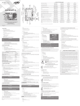
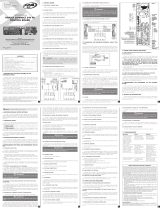
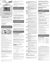
SUBTITULAR
1 - Botón GRABAR (+);
2 - Botón de COMANDO (-);
3 - Programación JUMPER;
4 - Modelo de aplicación JUMPER;
5 - PUENTE Seleccione el peso de la puerta;
6 - Tecnología JUMPER Select;
7 - Transmisor de registros JUMPER (TX);
8 - Conector LOCK;
9 - Conector LUZ GARAJE;
10 - Conector PROG PPA;
11 - Señalización LED;
12 - Conector de fotocélula;
13 - Conector RX / BOT
POTENCIA ELÉCTRICA
100 - 240 VAC
50 - 60 Hz
POTENCIA ELÉCTRICA
127-220 V
CONDENSADOR
DE ARRANQUE
DEL MOTOR
FIN DE CARRERA
REEDS
M
TACT
LED
6
8
9
12
13
4
1
2
5
3
10
11
7
C A C F
-
 1
1
-
 2
2


PPA Agility Pop Connect Manual de usuario
- Categoría
- Abridor de puerta de garage
- Tipo
- Manual de usuario
en otros idiomas
- English: PPA Agility Pop Connect User manual
Artículos relacionados
-
 PPA Agility Legero Manual de usuario
-
 PPA Facility 4T Manual de usuario
-
 PPA POP Manual de usuario
-
 PPA Triflex Facility Manual de usuario
-
 PPA Triflex Connect Fullrange Dupla Manual de usuario
-
 PPA Triflex Connect Brushless 24V PS Manual de usuario
-
 PPA Agility Levare Manual de usuario
-
 PPA Triflex Connect Brushless PS Manual de usuario
-
 PPA FACILITY CONNECT Manual de usuario
-
 PPA Triflex Connect Ind Manual de usuario


