La página se está cargando...

1. INTRODUCTION: TECHNICAL FEATURES OF THE
ELECTRONIC SYSTEM
Brushless 24V Control Board operates with a 32-bit processor with
features aimed for motor control. The processor used is able to manage
all the automator set as, for example, the motor, the encoder¹ and even
receive the code of a radio frequency (RF) transmitter.
It is endowed with an EEProm² memory that ores the codes of
the ored Remote controls as well as the operation parameters in an
encrypted form. The Control Board is also compatible with Rolling Code
Remote Controls with PPA's protocol.
The door position control is achieved through an encoder syem
patented by PPA called “Reed Digital”.
This Control Board controls Brushless synchronous motors with a
permanent magnet rotor (Brushless DC electric motors) produced by PPA.
Its syem also operates with a 24V battery when the primary source of
power is unavailable (for example, a power cut).
¹ Encoder, in indurial automation, is an eletromechanical device which counts or
reproduces electrical pulses from the rotational movement of the axis. It can also be
dened an an angular position transductor.
² EEPROM (from Electrically-Erasable Programmable Read-Only Memory) is a non-
volatile oring chip used in computers and other electronic devices.
2. CONTROL BOARD
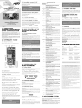
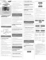
2.1 ELECTRICAL CONNECTIONS
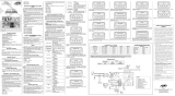
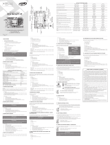
Refer to the general electrical connections on the diagram (image 1).
2.2 POWER SUPPLY
The operator mu be connected to the power grid through the inputs
on the power terminal block, “AC” connector; the operating voltage value
is from 100V to 220V, 50Hz or 60Hz. Refer to image 1.
2.3 CONNECTING THE BRUSHLESS MOTOR
The three wires from the 24V Brushless DC motor mu be connected
to the “A”, “B” e “C” inputs on the Control board; such wires can be
connected in either position (there's no correct order) to the connectors;
refer to the item “Fir operation after inalling the product”.
2.4 CONNECTING THE ENCODER (“ENC”)
It is used to connect, by using a proper cable, the motor and the
Control Board. Inside the operator gearbox, there are sensors that provide
the Control board wich information about the direction of the movement
and the position of the gate during the operation. Such information is
essential for the automator's proper operation.
There are two sensors inside the encoder and each one is represented
by the 'ECA' and 'ECB' LEDs. Each one lights according to the position
of the disc.
2.5 CONNECTING THE ELECTROMAGNETIC LOCK (“TRAVA”)
If one decides to use an (optional) Electromagnetic Lock, one mu
connect the “Optional Relay Module” to this connector. The Control
board will recognize the module automatically and a interval time (used
to art the opening movement of the operator after activating the
electromagnetic lock) will be added.
2.6 CONNECTING THE COURTESY LIGHT (“LUZ”)
If one decides to use a courtesy light (or any other proper use for this
output), one mu connect the “Optional Relay Module” to this connector.
The operation of the courtesy light is always enabled.
All one have to do is to set the desired time through the Programming
tool by PPA.
2.7 CONEXÃO DO RECEPTOR AVULSO “RX”
Um receptor avulso pode ser adicionado à central através do conector
“RX”.
WARNING: Before connecting optional accessories
(Electromagnetic lock and / or Courtesy Light / Trac Light /
Pushbuttons and so on), we recommend testing the operator overall
operation. In order to do so, just press the “GRV” button to activate the
path acquiring (Learning) of the operator.
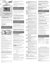
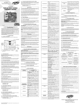
2.8 CONNECTING THE PHOTOCELL (“FOT”)
The photocells mu be inalled placed about 50cm (~1.65f) from the
ground (or according to the manufacturer recommendations), so that
both the receiver and the transmitter get properly aligned. The electric
connection mu be:
Male pin header (“+”): 13.8V(positive “+”);
Male pin header (“-“:) GND (negative “-“);
Male pin header (“FOTO”): Command (contact) of the photocell.
RED (+)
RED (+)
BLACK (-)
BLACK (-)
BLACK (-)
ORANGE (NO/NC)
ORANGE (NO/NC)
BLUE (C)
BLUE (C)
F30 PLUS
(EMITTER)
F30 (EMITTER) F30 (RECEIVER)
F30 PLUS
(RECEIVER)
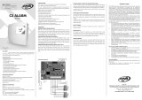
2.9 CONNECTING THE INTERNAL RADAR (“RD_INT”)
The 'RD_INT' is a Normally Open Input (N.O.) which receives the signal
from the radar considered internal.
WARNING
The logic controller provides 13.8V (500 mA maximum DC
Current) to power the photocells and receivers. If the de-
vices need increased voltage or current, using an auxiliary
power supply will be necessary.
2.10 CONNECTING THE EXTERNAL RADAR (“RD_EXT”)
The 'RD_INT' is a Normally Open Input (N.O.) which receives the signal
from the radar considered external.
RED (+)
INTERNAL
RADAR
EXTERNAL
RADAR
RED (+)
BROWN (-) BROWN (-)
YELLOW (RADARS) YELLOW (RADARS)
ORANGE (NO/NC) ORANGE (NO/NC)
2.11 CONNECTING THE INTEGRATED PHOTOCELL “RXFOT” AND
“TXFOT”
The control board has connections recessed photocells by PPA, in order to
provide the user with increased security, by avoiding that the door closes
whenever there is someone or something on its path. All one has to do is
to connect both the transmitter and the receiver of the photocell directly
to the control board. One can observe the alignment through the 'TX' and
'RX' LEDs on the control board.
RED (+)
RED (+)
BROWN (C)
RECESSED
PHOTOCELL
ORANGE - FOT (NO)
BLACK (-)
2.12 “PROG” CONNECTOR
This connector is used for communication between the Control board
and the programmer (PROG by PPA); refer to more information on item
“Programming with 'PROG' and Programming Tool by PPA”.
2.13 CONNECTING THE BATTERY
Brushless 24V Control Board operates with either a 12V or a 14V battery
when the primary source of power is unavailable (for example, a power
cut). All one has to do to is to connect the battery to the Control Board
through the '+' and '-' connectors on the 'BAT' input port.
When the battery is powered only by the battery, it is necessary to
press the 'ST' button to art it. This is due to the protective circuit again
total discharge of the battery, which is responsible for totally disconnecting
it in case its voltage reaches a very low value during the operation when
the primary source of power is unavailable.
WARNING
Whenever two (24V) batteries are used, the system has the
same speed when there is no available power supply. The
batteries must be at least 1.3Ah.
2.14. FUSES
The Brushless 24V Control Board is endowed with two fuses, 'F1' and
'F2'. The 'F2' (10A) fuse is in series with the battery and the 'F1' (5A) fuse is
in series with the power supply provided by the transformer.
+
M
BRUSHLESS
MOTOR
A
BATTERY 1
12V
BATTERY 2
12V
B C
ELECTRICAL
VOLTAGE
(110 - 220V)
PHOOCELL (Contact)
EXTERNAL RADAR (Contact)
INTERNAL RADAR (Contact)
LOCK CONNECTOR (Optional)
LIGHT CONNECTOR (Optional)
RXFOT (Receiver recessed photocell)
TXFOT (Transmitter recessed photocell)
GND (Negative)
GND (Negative)
13.8 V (Positive)
PROG / SELECTOR
CONNECTOR
RX Optional
(Loose
receiver)
EEPROM
MEMORY
ENCODER
CONNECTOR
CR / CF
(Rolling
Code and
Fixed Code
Protocols)
HRF
GRV
(INCREASES/
ADDS OR
COMMAND);
ST (STARTS
THE CONTROL
BOARD WHEN
A BATTERY IS
USED)
24 V BATTERY
VOLTAGE
3. SYSTEM LOGIC FUNCTION FOR DOORS
3.1 FIRST OPERATION AFTER INSTALLING THE PRODUCT
(MEMORIZATION)
When the Control Board is powered for the r time, after being
inalled to the operator, the door mu art an opening moviment after
an external command or if the button “GRV” has been pressed.
If the operator arts closing, disconnect the Control Board
from its Power Supply and change the position of the wires which
are connected to the 'A', 'B' or 'C' connectors in order to change
the operation direction of the motor. Then, turn it on again and
repeat the previous operation.
Once done, press the 'GRV' button or activate an external command
to the Control Board.
Afterwards, let the door open until it leans on the opening opper.
Then, it will reverse the direction to close; let it lean on the closing opper.
The automatic door is now ready to operate.
3.2. FROM THE SECOND OPERATION ON, WHEN THE CONTROL
BOARD IS DISCONNECTED FROM ITS POWER SUPPLY
After the previous operation, the door will not need to acquire
(memorize) the path again. It will simply and slowly open after a command,
until it leans on the opening opper; the motor will turn itself o and the
automatic door will be ready to operate.
4. PROGRAMMING THE PARAMETERS OF THE CONTROL
BOARD
This Control Board is provided with adjument parameters which
meet the needs mo operator models. Even though, if it is necessary to
change any parameter, all one has to do is to connect either the PROG
or a Programming tool (both by PPA) and change the desired parameter.
Refer to the item 'Programming with 'PROG' and Programming Tool by
PPA' for more information.
5. ERASING THE ACQUIRED PATH
In order to erase the path, all one has to do is to press the 'GRV' button
and keep it pressed until the 'OSC' LED lights. When releasing it, the path
will have been erased.
1 2 3 4
IMAGE 1
CONTENTS
1. INTRODUCTION: TECHNICAL FEATURES OF THE ELECTRONIC
SYSTEM ...................................................................................................................1
2. CONTROL BOARD .......................................................................................... 2
3. SYSTEM LOGIC FUNCTION FOR DOORS ................................................. 4
4. PROGRAMMING THE PARAMETERS OF THE CONTROL BOARD ......4
5. ERASING THE ACQUIRED PATH .................................................................. 4
6. RESTORING DEFAULT FACTORY SETTINGS .............................................. 5
7. ANTICRUSH SYSTEM ...................................................................................... 5
8. ENCODER FUNCTIONALITY TESTING ....................................................... 5
9. PROGRAMMING WITH 'PROG' AND PROGRAMMING TOOL ............ 5
10. EVENTS AND FAILS INDICATORS .............................................................. 7
Made by:
Motoppar Indústria e Comércio de Automatizadores Ltda
Av. Dr. Labieno da Costa Machado, 3526 - Distrito Industrial
Garça - SP - CEP 17406-200 - Brasil
CNPJ: 52.605.821/0001-55
www.ppa.com.br | +55 14 3407 1000
P07415 - 09/2022
Rev. 1
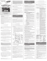
Technical Manual
TRIFLEX CONNECT 24V PS
CONTROL BOARD
WARNING
Do not use the equipment
without referring to this
manual first.
NOTE: The 'PROG' jumper must be open.
6. RESTORING DEFAULT FACTORY SETTINGS
In order to reore the default factory settings, ju press the 'GRV'
button and keep it pressed until the 'OSC' LED lights; do not release it;
keep it pressed until the 'OSC' LED arts ashing. When releasing it, the
path will have been erased and the default factory settings will have been
reored.
7. ANTICRUSH SYSTEM
The anticrush feature allows detecting the presence of obacles on the
door path. During a normal operation cycle, if an obacle is detected, the
syem will do as follows:
a) When closing: The door is activated on the opening direction. (It
reverses the moviment).
b) When opening: The motor is turned o and it will attempt to open
again, after 2 seconds, three times. After 3 unsuccessful attempts, a new
memorization (path acquiring) is arted again.
On the acquiring (memorization) cycle, the anticrush feature has only
the function of recognizing the opening and closing limit switches, i.e., the
point in the path where an obacle has been detected will be considered
a limit switch.
8. ENCODER FUNCTIONALITY TESTING
It is possible to te the operator's encoder. In order to do so, ju
connect it to the Control board and check if the 'ECA' and 'ACB' LEDs ash
when the automator is operating. Each LED corresponds to a sensor; for
example, the 'ECA' LED corresponds to the sensor A inside the gearmotor.
9. PROGRAMMING WITH 'PROG' AND PROGRAMMING TOOL BY
PPA
9.1 OPERATION SELECTION
In order to select an operaction function, all one has to do is to press
the button corresponding to the function on the Programming tool by
PPA. The functions are as follows:
OPEN DOOR: The Control Board permanently opens the door;
CLOSED DOOR: The Board turns the internal and external radars o;
EXIT ONLY: The Board turns the external radar o so that only exit is
allowed;
PARTIAL OPENING: The Board opens a percentage of the total path;
this value is set on the function menu.
The partial opening can be combined with other functions, such
as OPEN DOOR WITH PARTIAL OPENING, EXIT ONLY WITH PARTIAL
OPENING.
9.2 SETTING THE PARAMETERS OF THE BOARD
In order to change the parameters of the Control Board, all one has
to is to connect the PROG or Programming Tool (Both by PPA) and hold
the 'RIGHT' (->) button for 2 seconds to enter the Programming Menu.
Before the parameters, there are three Diagnoic Screens where one
can check the Accessory inputs, path and number of cycles. To navigate
between them, use the (<-) (->) buttons.
IMPORTANT
While using any of the aforementioned three screens, the
door can operate normally.
9.3 ERASING THE PATH AND APPLYING THE FACTORY SETTINGS
USING PROG
Whenever the user is in one of the diagnoic screens, all one has to do
is to simultaneously press the (+) and (-) buttons on the PROG; observe
that the message “Erase path” appears. Wait for the time to reach zero; the
path has been erased.
In order to apply the Factory settings, repeat the previous procedure;
after the path has been erased, the text "Factory Settings" appears; wait
the timing until "OK" appears.
9.4 ADDING AN RF REMOTE CONTROL (TRANSMITTER)
After the three diagnoic screens, the programming menu arts.
IMPORTANT
When entering these functions, the operator stops opera-
ting.
The r screen shown is used to add an RF remote control (Transmitter);
in order to do so, hold the button of the remote control one wants to add
for at lea two seconds; after the time has elapsed, press the '+' button on
the PROG. Observe that before the remote control is added, the display
shows the message "Receiving signal"; then, after it is added, the display
shows the message "TX added" during the transmission. One can add
at mo 240 Fixed Code Remote Controls or 120 Rolling Code Remote
Controls. The model of Remote Control used mu be the 4-button Zap
for Automatic Doors (by PPA); each button will correspond to a selection
function and the procedure to add a remote control mu be done for the
buttons one wants to use.
9.5 ERASING ALL ADDED RF REMOTE CONTROLS
In order to erase the RF Transmitters added to the memory, press
both '+' and '-' buttons of the Control Board for ten seconds; wait for the
Message "Empty Memory!" to appear on the screen. At this moment all
added Remote controls have been erased.
9.6 PAUSE TIME
Pause time for automatic closing; the control board only arts counting
this time after all command signals are o, i.e, all radars and photocells
indicate there is no obacle on the path.
9.7 CLOSING RAMP (DECELERATION ZONE)
Diance used to art decelerating during closing. We rongly
recommend at lea a 15-cm space (0.5 ft) in low velocity to increased
security.
WARNING
If the value is too low, the door can get in high speed to the
stopper and damage the mechanical parts.
9.8 OPENING RAMP (DECELERATION ZONE)
Diância para iniciar a desaceleração durante a abertura. Recomenda-
se um espaço de 15cm pelo menos em velocidade baixa para maior
segurança.
WARNING
If the value is too low, the door can get in high speed to the
stopper and damage the mechanical parts.
9.9 OPENING SPEED
Opening speed in percentage [%].
9.10 CLOSING SPEED
Closing speed in percentage [%]. We rongly recommend the closing
slower than the opening in order to avoid accidents.
9.11 OPENING RAMP SPEED
Speed on the area close to the opening opper.
9.12 CLOSING RAMP SPEED
Speed on the area close to the closing opper.
9.13 READING SPEED
Speed during the memorization or search of a reference for the r
time.
9.14 STRENGTH
Maximum rength allowed for the motor. We recommend using 80%
of the maximum value, if it necessary to increase it, it can mean there is
overload, which can be from a door with excessive friction or above the
allowed weight.
9.15 – COURTESY LIGHT TIME
Time used for turning the courtesy light o after the door has nished
its closing cycle. It increases tenfold (increases ten seconds at a time) up
to 240 seconds
9.16 'FOLLOW' PHOTOCELL MODE
Time for automatic closing when a photocell with 'Follow' mode is
used, i.e., after releasing the photocell signal, it arts counting the time
to automatically close it. This time prevails over the automatic time; for
example, if this time is two seconds and the automatic one is 15 seconds,
after a photocell command is released, it will count two seconds for closing.
9.17 LOCK PULSE WHEN CLOSING
This function activates or deactivates the lock pulse when closing, in
order to comply with the type of lock used.
9.18 SENSITIVITY OF THE ANTI-CRUSH SYSTEM
This function adjus the sensitivity of the anti-crush syem. The value
'0' means it takes the product more time to identify the object hit by the
door. A higher value, around 100, means a faer identication. Be careful
not to increasing too much the sensitivity, in order to avoid fake triggerings.
9.19 GAP OF THE OPENING STOPPER
This function adjus a gap between the door and the opening opper.
9.20 GAP OF THE CLOSING STOPPER
This function adjus a gap between the door and the closing opper.
9.21 MOVING THE MOTOR
This function allows one to manually activate the motor in order to
check the door path: hold the '+' button and observe the movement of the
leaf; if one performs this checking by using the '-' button, one can observe
the movement on the opposite direction.
9.22 OPERATOR MODEL
This function is used to change the operator model in which the control
board is inalled. So, the parameters applied will be close to the ideal
ones.
9.23 LANGUAGE
This function is used to change the language of the Menu on the
Programming tool.
9.24 PARTIAL OPENING
The value of the percentage of the partial opening when this operaction
function is used.
9.25 MOTOR STARTING STRENGTH
It is the force applied (in percentage) to perform the motor arting.
Remember that this STRENGTH is applied for the operation during the
normal operation path, not on the opper area. Example of conguration:
Light leaves - lower values (%) and Heavy leaves - Higher values.
9.26 – OPERATING WITH BATTERY
When the primary source of power is unavailable, one can choose
three kinds of operation, such as:
1- Normal operation (Opening and closing);
2- Opens (Opening only);
3- Opens after a command and remains open. (Pulse).
9.27 RECEPTOR DE RF
It functions either as a pushbutton or as a Operation selector (Door
open, door closed, exit only and partial opening).
9.28 AUTOMATIC ACTIVATION
Activation of the leaves os the opening direction when they are being
manually moved, i.e., when someone is manually opening the leaves, the
door activates the motor on the same direction.
9.29 EXITING THE FUNCTION MENU
On this screen, when one presses the either the '-' or the '+' button, it
goes back to the 'Function Selector' (Programmer) mode.
10. EVENTS AND FAILS INDICATORS
10.1 INDICATION OF MICROCONTROLLER OPERATION
The main function of the 'OSC' LED is to indicate that the board
microcontroller is properly working; it ashes with a frequent rate of ~1Hz,
since it is connected to a power supply.
10.2 INDICATION OF OVERCURRENT OR SHORT-CIRCUIT IN THE
MOTOR
The OSC LED rapidly ashes every 0.1 second in order to warn that
the power amplier has disarmed due to overcurrent or short-circuit in
the motor. The Control board can operate normally 10 seconds after the
Overcurrent.
10.3 INDICATION OF OPENING STOPPER AREA
The 'FC' LED ashes whenever the door is on the opening opper area.
10.4 INDICATION OF CLOSING STOPPER AREA
The 'FC' LED remains lit whenever the door is on the closing opper
area.
10.5 INDICATION OF LOAD ON THE CAPACITORS
The 'BUS' LED indicates there is a load on the capacitors of the power
amplier.
WARNING
One must not touch the power area (capacitors area) of the
board whenever the LED is lit, even after the inverter has
been disconnected from the power supply!
10.6 INDICATION OF COMMANDS
There is one LED for each input which remains lit whenever it is
receiving a command from the digital inputs, such as RD_EXT, RD_INT,FOT
etc.
10.8 INDICATION OF LACK OF EEPROM
The 'OSC' LED ashes twice whenever the memory is absent.
11. TROUBLESHOOTING
Symptom Cause Solution
The door does not
correspond to the
path of the place
where it has been
inalled (It breaks
before the closing
opper or hits it
when closing).
There is a ored
path dierent from
the path of the place
where it is inalled.
Press the 'GRV'
button and keep
it pressed until the
'OSC' LED lights.
Door remains
opened, and when it
receives a command
to open, it closes.
The acquiring
(memorization) has
not been properly
performed.
Refer to item: “Fir
Operation after
inalling the Product
(Memorization)”.
'OSC' LED rapidly
ashing and the
motor turns itself o.
Current sensor
actuating. This can
happen whenever the
motor is faulty.
Check the ator
resiance. Check the
motor current (it mu
be lesser than 2A
RMS medium and 4A
RMS peak [2 seconds
maximum]).
The door only opens,
it does not close.
A command has
been permanently
activtead.
Check, by using the
PROG, which input
ports are activated.
5 6 7 8
GENERAL TERMS AND CONDITIONS OF WARRANTY
MOTOPPAR, Indury and Commerce of Automatic Gate Operators Ltd., regiered with
the CNPJ (National Regiry of Legal Entities) under Number 52.605.821/0001-55, located at
3526 Dr. Labieno da Coa Machado Avenue, Indurial Dirict, Garça – SP – Brazil, Zip Code
17400-000, manufacturer of PPA Products, hereby guarantees this product again design,
manufacturing or assembly defects and/or supportively as a result of material quality aws
that could make its intended use improper or inadequate, within a legal period of ninety days
from time of acquisition, provided that the inallation inructions described in the inruction
manual are observed.
Due to the credibility and tru placed on PPA products, we will add 275 more days to the
period mentioned above, reaching a warranty period of one year, likewise counted from
the time of acquisition proven by consumer through proof of purchase (Cuomer Receipt).
In case of defect, within the warranty period, PPA responsibilities are rericted to the repair
or subitution of the product manufactured by the company, under the following conditions:
1. Repair and readjument of equipment may only be carried out by PPA Technical
Assiance, which is qualied to open, remove, and subitute parts or components, as
well as repair defects covered by this warranty; thus, failure on observing this guideline
and the veried use of any non-original parts will cause the resignation of this warranty
on the part of the user;
2. The warranty will not extend to accessories such as cables, screw kit, xing brackets, power
supplies etc.;
3. Expenses for packaging, transportation and product reinallation will be sole
responsibility of the consumer;
4. The equipment mu be sent directly to the Company responsible for the sale
(manufacturer's representative), through the address contained in the purchase invoice,
properly packed, thus avoiding loss of the warranty;
5. Within the additional period of 275 days, visits and transportation in places where
authorized technical assiance is not available will be charged. The co of transportation
of the product and/or technician will be sole responsibility of the consumer and
6. The subitution or repair of the product does not prolong the warranty time.
This warranty will be terminated if the product:
1. Is damaged by natural agents, such as atmospheric discharges, oods, wildres, landslides
etc.;
2. Is inalled in an improper electric power supply or if it is not according to any of the
inallation inructions displayed on the manual;
3. Shows defects caused by droppings, collisions or any other physical accident;
4. Shows signs of product violation or attempted repair by unauthorized personnel;
5. Is not used for its intended purpose;
6. Is not used under normal conditions;
7. Is damaged by accessories or equipment connected to it.
Recommendation:
We recommend that both the inallation and the maintenance of the operator to be
performed by an authorized PPA technical service. If the product fails or has an improper
operation, seek an Authorized Technical Service to x it.

1. PRESENTACIÓN: CARACTERÍSTICAS TÉCNICAS DEL SISTEMA
ELECTRÓNICO
La Central de mando Brushless 24V funciona con un procesador de 32
bits con caracteríicas especícas para el control del motor. El procesador
usado es capaz de geionar todo el conjunto del automatizador como,
por ejemplo, el motor, el encoder1 y aún recibir el código de un transmisor
de radiofrecuencia (RF).
Ella posee una memoria EEProm² que almacena los códigos de los
Controles remotos y parámetros de la Central de forma encriptada.
La Central es también compatible con Controles Remotos de Código
Rodante (variable) con protocolo propio de PPA.
El control de posición del portón es hecho a través de un siema de
encoder patentado por PPA llamado “Reed Digital”.
Ea central controla motores de PPA del tipo síncrono sin escobillas de
imán permanente en el rotor (Brushless DC). El siema opera también con
batería de 24V cuando no hay energía de la red eléctrica.
¹ Encoder, en automatización indurial, es un dispositivo electromecánico que
cuenta o reproduce pulsos eléctricos a partir del movimiento rotacional de su eje.
Puede también ser denido como un transductor de posición angular.
² EEPROM (Electrically-Erasable Programmable Read-Only Memory) es un
microprocesador no volátil usado en ordenadores y otros aparatos electrónicos.
2. CENTRAL DE MANDO
2.1 CONEXIONES ELÉCTRICAS
Vea las conexiones eléctricas en general en el diagrama (Imagen 1).
2.2 ALIMENTACIÓN DEL SISTEMA
Se debe hacer la conexión de la red eléctrica en las entradas del borne
de alimentación, conector 'AC'; el valor de la tensión de operación es
desde 100V haa 220V, 50 o 60Hz; vea imagen 1.
2.3 CONEXIÓN DEL MOTOR BRUSHLESS
Se debe conectar los tres cables (alambres) del motor BRUSHLESS
DC 24V a las entradas 'A', 'B' y 'C' de la central; se puede conectar los
cables en cualquier posición (orden) en los conectores. Vea ítem "Primera
operación tras la inalación".
2.4 CONEXIÓN DEL ENCODER 'ENC'
Es utilizado para la conexión, a través de un cable adecuado, entre
el motor y la Central de mando. Dentro de la caja de velocidades
del automatizador hay sensores que suminiran informaciones
de sentido de desplazamiento y posición del portón durante la
operación (funcionamiento). Eas informaciones son esenciales para el
funcionamiento adecuado del automatizador.
Hay dos sensores dentro del encoder y cada uno es representado por
los LEDs 'ECA' y 'ECB'. Cada uno se enciende de acuerdo con la posición
del disco.
2.5 CONEXIÓN DE LA ELECTROCERRADURA 'TRAVA'
Si se quiere usar una electrocerradura (opcional), se debe conectar el
"Módulo Opcional Relé" a ee conector. La central reconocerá el módulo
automáticamente y añadirá un intervalo de tiempo para empezar el
movimiento de apertura del automatizador tras el accionamiento de la
traba (electrocerradura).
2.6 CONEXIÓN DE LA LUZ DE CORTESÍA 'LUZ'
Si se quiere usar luz de cortesía o cualquier otra nalidad para ea
salida, se debe conectar el "Módulo Opcional Relé" a ee conector. El
funcionamiento de la luz de cortesía eará siempre habilitada.
Baa programar el intervalo de tiempo deseado con el programador
PPA.
2.7 CONEXÃO DO RECEPTOR AVULSO “RX”
Um receptor avulso pode ser adicionado à central através do conector
“RX”.
NOTA: Antes de conectar los accesorios opcionales
(Electrocerradura y/o Luz de Cortesía / Semáforo, botoneras etc.),
se recomienda probar totalmente el funcionamiento del aparato.
Para esto, basta pulsar el botón “GRV” para accionar el ciclo de
memorización del recorrido del automatizador.
2.8 CONEXIÓN DE LA FOTOCÉLULA 'FOT'
Se debe inalar las fotocélulas colocadas a una altura de
aproximadamente 50 cm del suelo (o según recomendaciones del
fabricante), de forma que el transmisor y el receptor se queden alineados
uno en relación con el otro. La conexión eléctrica debe ser:
Conector de pines (Macho) '+': 13.8V(positivo “+”);
Conector de pines (Macho) '-': GND (negativo “-“);
Conector de pines (Macho) 'FOTO': Comando (contacto) de la
fotocélula.
ROJO (+)
ROJO (+)
NEGRO (-)
NEGRO (-)
NEGRO (-)
NARANJA (NA/NC)
NARANJA (NA/NC)
AZUL (C)
AZUL (C)
F30 PLUS
(EMISOR)
F30 (EMISOR) F30 (RECEPTOR)
F30 PLUS
(RECEPTOR)
2.9 CONEXIÓN DE RADAR INTERNO “RD_INT”
La entrada RD_INT es una entrada normalmente abierta (N.A.) que
recibe la señal del radar considerado interno.
IMPORTANTE
El Controlador Lógico suministra 13.8 V (corriente continua
máxima de 500 mA) para alimentación de fotocélulas y
receptores. Caso los aparatos necesiten de más tensión o
corriente mayor, se debe usar una fuente de energía auxiliar.
2.10 CONEXIÓN DE RADAR EXTERNO “RD_EXT”
La entrada RD_EXT es una entrada normalmente abierta (N.A.) que
recibe la señal del radar considerado externo.
ROJO (+)
RADAR
INTERNO RADAR
EXTERNO
ROJO (+)
MARRÓN (-) MARRÓN (-)
AMARILLO (RADARES) AMARILLO (RADARES)
NARANJA (NA/NC) NARANJA (NA/NC)
2.11 CONEXIÓN DE LA FOTOCÉLULA INTEGRADA “RXFOT” Y “TXFOT”
La central posee conexiones para uso de fotocélula PPA empotrable para
mayor protección a n de evitar que la puerta cierre con alguien o algo
en su recorrido. Baa conectar el transmisor y el receptor de la fotocélula
directamente a la central. Se puede observar el alineamiento a través de
los LEDs 'TX' y 'RX' de la central.
ROJO (+)
ROJO (+)
MARRÓN (C)
FOTOCÉLULA
EMPOTRABLE
NARANJA - FOT (NA)
NEGRO (-)
2.12 CONECTOR “PROG”
Ee conector es usado para comunicación entre la central y el
programador PROG de PPA. Vea más detalles en el ítem “Programacióncom
Programador y PROG de PPA”.
2.13 CONEXIÓN DE LA BATERÍA
LA Central Brushless 24V opera con batería de 12V o 24V cuando no
hay energía de la red eléctrica. Baa conectar una batería a la central a
través de los conectores '+' y '-' de la entrada “BAT”.
Cuando alimente la central solamente por batería, es necesario
pulsar el botón 'ST' para iniciar. Eso se debe al circuito de protección
contra descarga total de la batería, que es responsable por desconectar
totalmente si su tensión llegar a un valor muy bajo durante la operación
sin energia eléctrica.
IMPORTANTE
Con dos baterías (24V), el sistema tendrá la misma velocidad
de cuando no hay energia eléctrica. Las Baterías deben ser
al mínimo de 1.3Ah.
2.14. FUSIBLES
La Central Brushless 24V posee dos fusibles, F1 y F2; el fusible F2 de
10A se conecta en serie con la batería y el fusible F1 de 5A se conecta en
serie con la alimentación procedente del transformador.
+
M
MOTOR
BRUSHLESS
A
BATERÍA 1
12V
BATERÍA 2
12V
B C
TENSIÓN
ELÉCTRICA
(110 - 220V)
FOTOCÉLULA (Contacto)
RADAR EXTERNO (Contacto)
RADAR INTERNO (Contacto)
CONECTOR TRAVA (Opcional)
CONECTOR LUZ (Opcional)
RXFOT (Receptor fotocélula empotrable)
TXFOT (Transmisor fotocélula empotrable)
GND (Negativo)
GND (Negativo)
13.8 V (Positivo)
CONECTOR
PROG /
PROGRAMADOR
RX (Receptor
suelto)
Opcional
MEMORIA
EEPROM
CONECTOR
ENCODER
CR / CF
(Protocolo
Código
Rolante
y Código Fijo)
HRF
GRV
(INCREMENTO/
GRABA (AÑADE)
O COMANDO);
ST (INICIALIZA
LA CENTRAL
CUANDO SE USA
BATERÍA)
TENSIÓN DE LA
BATERÍA 24 V
3. FUNCIÓN LÓGICA DEL SISTEMA PARA PUERTAS
3.1 PRIMERA OPERACIÓN TRAS LA INSTALACIÓN
(MEMORIZACIÓN)
Cuando la Central de Mando sea energizado por la primera vez, tras
ser inalada en el automatizador, la puerta debe empezar un movimiento
de apertura tras un comando externo o si el botón 'GRV' sea pulsado.
Si la puerta empieza a cerrar, desconecte la central de la fuente
de energía y cambie la posición de les conectores 'A', 'B' o 'C' para
cambiar el sentido de operación del motor. Después, encienda
nuevamente y repita el procedimiento anterior.
Una vez hecho eo, pulse 'GRV' o accione un comando externo para
la central.
Eo hecho, deje la puerta abrir haa que él se recuee en el tope de
apertura. Después, él va a revertir el sentido para cerrar; deje que él se
recuee en el tope de cierre. Ahora la puerta automática eá lia para
funcionar.
3.2. A PARTIR DEL SEGUNDO ACCIONAMIENTO ADELANTE
CUANDO SE DESENCHUFA LA CENTRAL DE LA FUENTE DE ENERGÍA
Tras la operación anterior, la puerta no necesitará memorizar el
recurrido nuevamente. Ella simplemente abrirá lentamente tras un
comando, haa que se recuee en el tope de apertura; el motor apagará
tras algunos segundos y la puerta eará lia para funcionar.
4. PROGRAMACIÓN DE LOS PARÁMETROS DE LA CENTRAL
La Central Brushless 24V es suminirada con parámetros de reglaje
que satisfacen la mayoría de modelos de automatizadores. Aun así, caso
sea necesario cambiar algún, baa conectar un PROG o Programador
PPA y cambiar el parámetro deseado. Vea más detalles en el ítem
“Programación con PROG y Programador PPA”.
5. BORRAR EL RECORRIDO MEMORIZADO
Para borrar el recurrido, baa pulsar el botón 'GRV' y mantenerlo
pulsado haa que el LED 'OSC' encienda. Al soltarlo, el recurrido eará
borrado.
NOTA: El jumper (puente, saltador) 'PROG' debe estar abierto.
1 2 3 4
IMAGEN 1
ÍNDICE
1. PRESENTACIÓN: CARACTERÍSTICAS TÉCNICAS DEL SISTEMA
ELECTRÓNICO.......................................................................................................1
2. CENTRAL DE MANDO ................................................................................... 2
3. FUNCIÓN LÓGICA DEL SISTEMA PARA PUERTAS ..................................4
4. PROGRAMACIÓN DE LOS PARÁMETROS DE LA CENTRAL ................ 4
5. BORRAR EL RECORRIDO MEMORIZADO .................................................4
6. RESTABLECER LOS VALORES DE FÁBRICA ................................................ 5
7. SISTEMA DE ANTIAPLASTAMIENTO .......................................................... 5
8. PRUEBA DE FUNCIONAMIENTO DEL ENCODER ................................... 5
9. PROGRAMACIÓN CON PROG Y PROGRAMADOR PPA....................... 5
10. INDICACIÓN DE EVENTOS Y FALLOS ...................................................... 7
Fabricado por:
Motoppar Indústria e Comércio de Automatizadores Ltda
Av. Dr. Labieno da Costa Machado, 3526 - Distrito Industrial
Garça - SP - CEP 17406-200 - Brasil
CNPJ: 52.605.821/0001-55
www.ppa.com.br | +55 14 3407 1000
P07415 - 09/2022
Rev. 1
Manual Técnico
CENTRAL DE MANDO
TRIFLEX CONNECT 24V PS
ATENCIÓN
Antes de utilizar el aparato,
lea este manual con atención.
6. RESTABLECER LOS VALORES DE FÁBRICA
Para volver el eándar de fábrica de las funciones, baa pulsar el
botón 'GRV' y mantenerlo pulsado haa que el LED 'OSC' encienda; no lo
suelte; lo mantenga pulsado haa que el LED 'OSC' empiece a parpadear.
Al soltarlo, el recorrido eará borrado y los valores (eándar) de fábrica
earán cargados nuevamente.
7. SISTEMA DE ANTIAPLASTAMIENTO
El recurso de antiaplaamiento permite detectar la presencia de
obáculos en el recorrido de la puerta. En el ciclo de funcionamiento
normal, se hay detectado un obáculo, el siema va a tomar las siguientes
medidas:
a) En el cierre: se acciona la puerta en el sentido de apertura
(Revierte).
b) En la apertura: se apaga el motor y la puerta intenta abrir
nuevamente tras 2 segundos, 3 veces. Tras tres intentos fallidos, la puerta
empieza otra memorización.
En el ciclo de memorización, el recurso de antiaplaamiento tiene
solamente la función de reconocer los nes de carrera de apertura y cierre,
eo es, el punto del recorrido donde hay sido detectado un obáculo será
interpretado como n de carrera.
8. PRUEBA DE FUNCIONAMIENTO DEL ENCODER
Es posible probar el encoder del automatizador; con ee n baa que
se lo conecte a la central y que se verique si los LEDs 'ECA' y 'ECB' eán
parpadeando cuando el automatizador funciona. Cada LED corresponde
a un sensor, por ejemplo, el LED 'ECA' corresponde al sensor A dentro
del motorreductor.
9. PROGRAMACIÓN CON PROG Y PROGRAMADOR PPA
9.1 FUNCIONES DE SELECCIÓN DE OPERACIÓN
Para seleccionar una función de operación, baa pulsar el botón
correspondiente en el Programador PPA. Las funciones son:
PUERTA ABIERTA: La central abrirá la puerta permanentemente;
PUERTA CERRADA: La central apaga los radares interno y externo;
SALIDA SOLAMENTE: La central apaga el radar externo para que se
permita salida solamente;
APERTURA PARCIAL: La central abre un porcentaje del recorrido total,
ee valor es congurado en el menú de funciones.
Se puede combinar la apertura parcial con otras funciones como, por
ejemplo, PUERTA ABIERTA CON APERTURA PARCIAL, SALIDA SOLAMENTE
CON APERTURA PARCIAL.
9.2 CONFIGURACIÓN DE PARÁMETROS DE LA CENTRAL
Para cambiar los parámetros de la central, baa conectar el PROG o
Prograamdor PPA y pulsar el botão a la derecha (->) por 2 segundos para
entrar en el Menú de Programación.
Antes de los parâmetros hay 3 pantallas de diagnóico donde se
puede vericar las entradas de accesorios, recorrido y número de ciclos.
Para navegar por las pantallas, utilice los botones '<-' y '->'.
IMPORTANTE
Cuando esté en una de estas 3 pantallas, la puerta puede
operar normalmente.
9.3 BORRAR RECORRIDO Y APLICAR VALORES DE FÁBRICA POR EL
'PROG'
Cuando eé en alguna de las pantallas de diagnóico, baa pulsar
simultáneamente los botones '+' y '-' del PROG. Observe que el mensaje
“Borrar Recorrido” aparecerá. Aguarde reducir el tiempo a cero y el
recorrido será borrado.
Para aplicar valores de Fábrica, repita el procedimiento anterior;
tras borrar el recorrido, aparecerá el texto “Valor de Fábrica”; aguarde
elcontador de tiempo haa aparecer “Ok”.
9.4 AÑADIR UN TRANSMISOR DE RADIOFRECUENCIA (RF)
Tras las 3 pantallas de diagnóico, se inicia el menú de programación.
IMPORTANTE
Cuando entre en estas funciones, el automatizador para sus
operaciones.
La primera pantalla presentada sirve para añadir un transmisor de
RF; pulse el botón del Transmisor que desea añadir como mínimo dos
segundos e lo mantenga pulsado; una vez pasado el tiempo, pulse el
botón '+' del PROG. Observe que antes del transmisor ear grabado, el
display muera el mensaje “Recebiendo Señal”; tras la grabación, el display
muera “TX Añadido” durante la transmisión. Se puede añadir como
máximo 240 transmisores en modo Código Fijo (CF) o 120 transmisores
en modo Código Rolante (CR - Rodante, Evolutivo, Variable). El transmisor
utilizado debe ser el ZAP de 4 botones para puerta automática, cada
botón corresponde a una función de selección y el se debe realizar el
procedimiento de grabación para los botones que desea utilizar.
9.5 BORRAR TODOS LOS TRANSMISORES DE RF GRABADOS
Para borrar los transmisores de RF grabados en la memoria, pulse lo
botones '+' y '-' de la central simultáneamente por 10 segundos; aguarde
el mensaje “¡Memoria Vacía!” en la pantalla. En ese momento, todos los
transmisores añadidos han sido borrados.
9.6 TIEMPO DE PAUSA
Tiempo de pausa para cierre automático; ee tiempo empieza el
conteo solamente tras todas las señales de comando para apertura han
sido apagadas, es decir, radares y fotocélulas indican que no hay obáculo
adelante.
9.7 RAMPA (DE DESACELERACIÓN) DE CIERRE
Diancia para empezar la desaceleração durante el cierre. Se
recomienda un espacio de 15cm, al menos, en baja velocidad para mayor
seguridad.
IMPORTANTE
Tenga cuidado cuando disminuir mucho el valor; la puerta
podrá llegar con velocidad alta en el tope y dañar las partes
mecánicas.
9.8 RAMPA (DE DESACELERACIÓN) DE APERTURA
Diância para iniciar a desaceleração durante a abertura. Recomenda-
se um espaço de 15cm pelo menos em velocidade baixa para maior
segurança.
IMPORTANTE
Tenga cuidado cuando disminuir mucho el valor; la puerta
podrá llegar con velocidad alta en el tope y dañar las partes
mecánicas.
9.9 VELOCIDAD DE APERTURA
Velocidad de apertura en porcentaje [%].
9.10 VELOCIDAD DE CIERRE
Velocidad de cierre en porcentaje [%]. Se recomienda un cierre siempre
más lento que la apertura para evitar accidentes.
9.11 VELOCIDAD DE RAMPA DE APERTURA
Velocidad en el area próxima al n de carrera de apertura.
9.12 VELOCIDAD DE RAMPA DE CIERRE
Velocidad en el area próxima al n de carrera de cierre.
9.13 VELOCIDAD DE LECTURA
Velocidad durante la memorización o búsqueda de referencia por
la primera vez.
9.14 FUERZA
Fuerza máxima permitida para el motor. Se recomienda el uso de 80%
del valor máximo; caso sea necesario aumentar, eso puede ser sobrecarga,
que puede ser procedente de puerta con mucha fricción o con un peso
superior al considerado ideal.
9.15 – TIEMPO DE LUZ DE CORTESÍA
Tiempo para apagar la salida de luz de cortesía cuando la puerta ha
encerrado el ciclo de cierre. Aumenta de diez en diez segundos, haa
240 segundos.
9.16 FOTOCÉLULA 'SEGUIDORA'
Tiempo para cierre automático cuando se utiliza una fotocélula com
función “seguidora”, es decir, tras liberar la señal de la fotocélula, se
inicia un contador de tiempo para cerrar automáticamente. Ese tiempo
predomina sobre el tiempo automático; por ejemplo, si ese tempo es 2
segundos y el tiempo automático es 15 segundos, tras un comando de
fotocélula liberado, serán contados 2 segundos para el cierre.
9.17 PULSO DE TRABA EN EL CIERRE
Ea función enciende o apaga el pulso de traba en el cierre para
adecuar al tipo de traba utilizada.
9.18 SENSIBILIDAD DEL SISTEMA DE ANTIAPLASTAMIENTO
Ea función regula la sensibilidad del siema de antiaplaamiento.
El valor 0 signica más demorado para identicar el obáculo aplaado.
Un valor más alto, alrededor de 100, signica mayor rapidez para
identicar. Tenga cuidado al dejar ee recurso muy sensible, a n de evitar
activaciones falsas.
9.19 ESPACIO DE TOPE DE APERTURA
Ea función regula un espacio entre la puerta y el tope de apertura.
9.20 ESPACIO DE TOPE DE CIERRE
Ea función regula un espacio entre la puerta y el tope de cierre.
9.21 MOVER EL MOTOR
Ea función permite accionar o motor manualmente para inspeccionar
el recorrido de la puerta: mantenga el botón '+' pulsado y observe el
movimiento de la hoja, caso haga lo mismo con el botón '-', podrá
observar el movimiento en sentido inverso.
9.22 MODELO DE AUTOMATIZADOR
Ea función sirve para cambiar el modelo de automatizador en que
la central eá inalada. Así, los valores de los parámetros serán aplicados
próximos al ideal.
9.23 IDIOMA
Ea función sirve para cambiar el idioma del Menu y del Programador
9.24 APERTURA PARCIAL
El valor del porcentaje de la apertura parcial cuando ea función de
operación sea seleccionada.
9.25 FUERZA DE ARRANQUE
Fuerza aplicada en porcentaje para realizar ela arranque do motor.
Recuerde que dicha FUERZA es aplicada para funcionamiento durante el
recorrido normal de operación, no eando en el límite de n de carrera.
Como ejemplo de conguración conforme el tipo de hoja, siendo hojas
leves, valores menores (%) y hojas pesadas, valores mayores (%).
9.26 – OPERACIÓN CON BATERÍA
Cuando falta energía eléctrica, se puede elegir tres tipos de
operaciones como:
1- Operación normal (Apertura y cierre);
2- Abre (Abertura solamente);
3- Abre tras algún comando y se queda abierta. (Pulso).
9.27 RECEPTOR DE RF
Funcionamiento como botonera solamente o funcionamiento como
programador (puerta abierta, puerta cerrada, salida solamente y apertura
parcial).
9.28 ACCIONAMENTO AUTOMÁTICO
Accionamiento de las hojas en sentido de apertura cuando
son manualmente movimentadas , es decir, cuando las hojas son
movimentadas en sentido de apertura por alguien, la puerta enciende el
motor en el mismo sentido.
9.29 SALIR DO MENÚ DE FUNCIONES
En ea pantalla, al pulsar el botón '-' o '+', se vuelve para el modo
“Selector de Funciones”.
10. INDICACIÓN DE EVENTOS Y FALLOS
10.1 INDICACIÓN DE FUNCIONAMIENTO DEL
MICROCONTROLADOR
La función principal del LED 'OSC' es indicar que el microcontrolador
de la placa eá operativo; él parpadea, con frecuencia ja de ~1Hz, a
condición de que eé enchufado a una fuente de energía.
10.2 INDICACIÓN DE SOBREINTENSIDAD O CORTOCIRCUITO EN
EL MOTOR
El LED 'OSC' parpadea rápidamente de 0,1 segundo en 0,1 segundo
para alertar que la etapa de potencia se ha desenchufado por motivo de
sobreintensidad o cortocircuito en el motor. La central podrá funcionar
normalmente 10 segundos después de la sobrecarga.
10.3 INDICACIÓN DE FIN DE CARRERA ABIERTO
El LED 'FC' parpadea cuando el portón eá en el área de n de carrera
abierto.
10.4 INDICACIÓN DE FIN DE CARRERA CERRADO
El LED 'FC' queda encendido cuando el portón eá en el área de n
de carrera cerrado.
10.5 INDICACIÓN DE CARGA EN LOS CAPACITORES
El LED 'BUS' indica que exie carga en los capacitores de la etapa de
potencia.
IMPORTANTE
¡No se debe tocar en el área de potencia (área de los capaci-
tores) de la placa mientras este LED esté encendido mismo
tras el inversor haya sido desenchufado de la red eléctrica!
10.6 INDICACIÓN DE COMANDOS
Hay un LED para cada entrada que se queda encendido cuando eá
recibiendo algún comando de las entradas digitales, como, por ejemplo,
RD_EXT, RD_INT, FOT etc.
10.8 INDICACIÓN DE EEPROM NO ENCONTRADA
El LED 'OSC' parpadea dos veces cuando la Memoria no eá presente.
11. RESOLUCIÓN DE PROBLEMAS
Falla Causa Solución
La puerta no
corresponde al
recorrido del local
inalado (frena antes
del tope de cierre o
colide en el cierre).
Hay un recorrido
memorizado
diferente del
recorrido del local
inalado.
Pulsar el botón 'GRV'
y mantenerlo pulsado
haa que el LED
'OSC' encienda.
Portón queda abierto
y cuando recibe
comandos para abrir,
él cierra.
La memorización
no ha sido realizada
correctamente.
Vea ítem: Primera
operación tras
la inalación
(Memorización).
LED 'OSC'
parpadeando
rápidamente y el
motor apaga.
Sensor de corriente
actuando. Eo puede
ocurrir cuando el
motor eá con
problemas.
Vericar resiencia
del eátor. Vericar la
corriente en el motor
(debe ser menor que
2A RMS medio y 4A
RMS de pico (Máx. 2
segundos)).
Puerta abre, pero no
cierra.
Algún comando
accionado
permanentemente.
Vericar, a través del
PROG, las entradas
que eán accionadas.
5 6 7 8
PLAZO DE GARANTÍA
MOTOPPAR, Induria y Comercio de Automatizadores Ltda., regirada con CNPJ (CIF)
52.605.821/0001-55, localizada en la Avenida Dr. Labieno da Coa Machado número 3526,
Dirito Indurial, Garça – SP – Brasil, Código Poal 17.400-000, fabricante de los productos
PPA, garantiza eo aparato contra defectos de proyectos, fabricación, montaje y/o
solidariamente en consecuencia de vicios de calidad de material que se lo hagan impropio o
inadecuado al consumo a cual se deina por el plazo legal de noventa días desde la fecha de
adquisición, siempre que se cumplan las orientaciones de inalación descritas en el manual
de inrucciones.
Como consecuencia de la credibilidad y de la conanza depositada en los productos PPA,
añadimos al plazo anteriormente descrito más 275 días, alcanzando el total de un año,
igualmente contados desde que la fecha de adquisición pueda ser comprobada por el
consumidor a través do comprobante de compra (Recibo).
En caso de defecto, en el período cubierto por la garantía, la responsabilidad de PPA se queda
reringida a la reparación o reemplazo del aparato por ella fabricada, bajo las siguientes
condiciones:
1. La reparación y reajue de aparatos solo pueden realizarse por la Asiencia Técnica de
PPA, que eá habilitada a abrir, remover, suituir piezas o componentes, así como arreglar
los defectos cubiertos por la garantía, siendo que el incumplimiento de ee y cualquier
utilización de piezas no originales observadas en el uso, implicará en la exclusión de la
garantía por parte del consumidor;
2. La garantía no se extenderá a accesorios como cables, kit de tornillos, soportes de jación,
fuentes de alimentación etc.;
3. Los coos de embalaje, transporte y reinalación del producto son responsabilidad
exclusiva de los consumidores nales;
4. Se debe enviar el aparato directamente a la empresa responsable de la venta (representante
del fabricante), a través de la dirección que gura en el recibo de compra, debidamente
embalado, evitando así la pérdida de la garantía;
5. En el período adicional de 275 días, las visitas y los transportes donde no haya servicios
autorizados serán cargadas. Los gaos de transporte del aparato y/o técnico son
responsabilidad del propietario y
6. La reparación o reemplazo del aparato no prorroga el plazo de garantía.
Ea garantía perderá su validez si el producto:
1. Sufrir daños provocados por agentes de la naturaleza, como descargas atmosféricas,
inundaciones, incendios, desmoronamientos etc.;
2. Sea inalado en red eléctrica inadecuada o en desacuerdo con cualquiera de las
inrucciones de inalación descritas en el manual;
3. Presenta defectos causados por caídas, golpes o cualquier otro accidente físico;
4. Presenta violación o intento de reparación o mantenimiento por parte de personal no
autorizado;
5. No sea usado para lo que ha sido proyectado;
6. No sea usado en condiciones normales;
7. Sufrir daños causados por accesorios o aparatos conectados al producto.
Recomendación:
Recomendamos que la inalación y mantenimientos del aparato sean efectuados por servicio
técnico autorizado PPA.
Caso el producto presente defecto o funcionamiento anormal, busque un Servicio Técnico
especializado para los debidos arreglos.
/