PPA Triflex Connect 24V Manual de usuario
- Categoría
- Abridor de puerta
- Tipo
- Manual de usuario

1 – INTRODUCTION: TECHNICAL FEATURES
OF THE ELECTRONIC SYSTEM
Triex Brushless 24V Control Unit operates with a 32-
bit processor with features aimed for motor control. The
processor used is able to manage all the automator set as, for
example, the motor, the encoder¹ and even receive the code
of a radio frequency (RF) transmitter.
It is endowed with an EEProm² memory that ores
the programming parameters and the codes of the ored
Remote controls in an encrypted form. The Control Unit is
also compatible with Rolling Code Remote Controls with PPA
own protocol.
The syem can be activated with a remote control
through a built-in radio frequency receiver, a loose receiver
or any other device with an NO (Normally Open) contact as a
pushbutton, for example.
The gate position control is achieved through an encoder
syem patented by PPA called “Reed Digital”.
This Control Unit directs the activities of synchronous
brushless motors with a permanent magnet in the rotor by
PPA (Brushless DC motors). The syem can also operate fed
by a battery when an electric energy source is not available.
2 – CONTROL UNIT
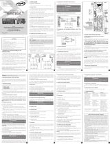
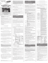
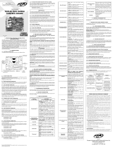
2.1 – WIRING DIAGRAM
The Wiring Diagram can be seen below:
2.2 – SYSTEM POWER SUPPLY
The Control Unit mu be connected to the energy
source through the inputs of the power terminal blocks ("AC"
Connector). The level of the supply voltage is from 85V up to
265V, 50Hz or 60Hz. Refer to picture 1.
2.3 – BRUSHLESS MOTOR CONNECTION
The three cables on the Brushless DC 24V motor mu
be connected to the “A”, “B” and “C” inputs on the Control
Unit. The cables do not need to follow any specic sequence
(order). Refer to Item 3.1 - Fir Activation of the Inverter After
Inallation (Acquiring / Memorization).
2.4 – CONNECTING THE “ENC” ENCODER
It is used to connect the encoder, by using a proper
cable, between the motor and the Control Unit. Inside the
operator gearbox, there are sensors that provide the ECU
wich information about the direction of the displacement
and the position of the gate during the operation. Such
information is essential for the automator's proper operation.
There are two sensors inside the encoder and each one
is represented by the "ECA" and "ECB" LEDs. Each one lights
according to the position of the disc.
2.5 – CONNECTING THE “TRAVA” ELECTROMAGNETIC LOCK
If one decides to use an (optional) electromagnetic
lock, one mu connect the “Optional Relay Module”
to this connector. The Control Unit will recognize the
module automatically and a interval time (used to art the
opening movement of the operator after activating the
electromagnetic lock) will be added.
2.6 – CONNECTING THE “LUZ” COURTESY LIGHT
If one decides to use courtesy light, one mu connect
the “Optional Relay Module” to this connector. The operation
of the courtesy light is always enabled.
For doing so, one only needs to set the desired time by
using the PROG (Programming tool by PPA).
2.7 – CONNECTING THE “RX” LOOSE RECEIVER
A loose receiver can be added to the Control Unit
through the “RX” connector.
When a command is accepted, the CMD LED (command)
lights. The "HRF" jumper mu be quit when a loose receiver is
added to the syem, in order to turn the built-in receiver o.
WARNING: Before connecting optional accessories
(Electromagnetic lock and / or Courtesy Light / Traffic
Light, Pushbutton and so on), we recommend testing
the operator overall operation. In order to do so, just
press the “GRV” button to activate the path acquiring
(memorization) of the operator.
2.8 – CONNECTING THE “FOT” PHOTOCELL
The photocells mu be inalled placed about
50cm (about 1.65f) from the ground (or according to the
manufacturer recommendations), so that both the receiver
and the transmitter get properly aligned. The electric
connection mu be:
"+": 15V (positive “+”);
“-“: GND (negative “-“);
“FOT”: Photocell Command (contact).
2.9 – CONNECTING A PUSHBUTTON (SAME CONNECTOR
OF THE "RX")
The Control Unit recognizes a pushbutton command
when the two pines to the right of the “RX” conector are
connected.
WARNING
The logic controller provides 13.8V (500 mA maximum
DC Current) to power the photocells and receivers. If
the devices need increased voltage or current, using
an auxiliary power supply will be necessary.
2.10 – CONNECTING THE “REED” LIMIT SWITCH SENSOR
REEDS
The Control Unit recognizes a “reed” switch activated
when the proper pin (which refers to the reed switch) on the
"REED" male pin header is connected to the "GND", it is, a
pulse to the "GND".
The only condition to be followed here is that the reed
switch which represents the gate open mu be connected
in such a way that it causes the "RDA" LED to light itself up
(pin of the "REED" connector marked "A"). And the “RDF” LED
mu light itself up when the gate is closed (pin of the "REED"
connector marked "F").
2.11 – “PROG” CONNECTOR
EThis connector is used to perform the communication
between the Prog (Programming Tool) by PPA. For further
information, refer to the Item “Programming using the
"PROG" Tool by PPA".
2.12 – CONNECTING THE BATTERY
The Triex Brushless 24V Control Unit operates fed by a
24V-battery when an electric energy source is not available.
For doing so, one only needs to connect a battery to the
Control Unit by using the (+) and (-) connectors from the
“BAT” input.
When powering the Control Unit only by using a battery,
it is necessary to press the “ST” button to art it. This is due
to the protective circuit again the battery total discharge,
which is responsible for totally disconnecting it in case its
voltage reaches a very low level when operating without an
electric energy source.
2.13 – FUSES
The Triex Brushless 24V Control Unit is endowed with
two fuses, "F1" and "F2". The 10A "F2" fuse is joined in series
to the battery whereas the 5A "F1" fuse is joined in series to
the power supply delivered by a transformer.
2.14 – OPERATION IN “MASTER AND SLAVE” MODES
Triex Brushless 24V Control Unit is endowed with a
function called "Maer" and "Slave" modes. Such syem is
used whenever there are two gearmotors and two Control
Units inalled on a double swing gate (Two leaves), and
one wants the boards to communicate to each other so that
there is a delay in one of the leaves. The Control Unit of the
"Maer" leave mu have a cable from the "SLV" connector
connected to the "RX" input (Two pines to the right of this
connector) of the Control Unit of the "Slave" leaf.
One can use the PROG tool to set a Control Unit as either
"Maer" or "Slave".
WARNING: The delay time between the leaves can also be
set through the “PROG” tool. By doing so, the “Master” leaf will start
moving first on an opening displacement and will be the last to close
when the gate is closing. In case the delay setting is reversed, one
only needs to reverse the connections in the “SLV” and “RX” inputs
on the Control Units and the setting on the “PROG”, so that the “Mas-
ter” and “Slave” settings are properly reversed (adjusted).
3 – LOGIC FUNCTION OF THE SYSTEM FOR
GATE OPENERS
3.1 – FIRST ACTIVATION OF THE INVERTER AFTER
INSTALLATION (ACQUIRING / MEMORIZATION)
When the inverter is powered for the r time, after
being inalled to the operator, the gate mu art an opening
displacement after an external command or if the button
“GRV” has been pressed.
If the movement is for closing, disconnect the Control
Unit from its power supply and change the position of the
wires of the motor which are connected to the “A”, “B” or “C”
connectors in order to reverse the direction of the rotation.
1 Encoder, in indurial automation, is an eletromechanical device which
counts or reproduces electrical pulses from the rotational movement of the
axis. It can also be dened an an angular position transductor.
2 EEPROM (Electrically-Erasable Programmable Read-Only Memory) is a
non-volatile oring chip used in computers and other electronic devices.
Made by:
Motoppar Indústria e Comércio de Automatizadores Ltda
Av. Dr. Labieno da Costa Machado, 3526 - Distrito Industrial
Garça - SP - CEP 17406-200 - Brasil
CNPJ: 52.605.821/0001-55
www.ppa.com.br | +55 14 3407 1000
P06660 - 03/2022
Rev. 1
Made by:
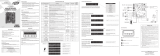
Technical Manual
TRIFLEX CONNECT 24V
CONTROL UNIT
WARNING
Do not use the equipment
without referring to this
manual.
10A
10A
POWER SUPPLY
(85V - 265V)
BATTERY 1
(12V)
BATTERY 2
(12V)
COMMAND TO START
THE CONTROL UNIT
WHEN IT IS POWERED
BY A BATTERY
(OPTIONAL)
LOOSE
RECEIVER
BRUSHLESS
MOTOR
(OPTIONAL) ELECTROMAGNETIC LOCK
(OPTIONAL) LIGHT
OUTPUT FOR "MASTER
AND SLAVE" MODES
PROG
OLS
CLS
M
Then, power the the Control Unit again and repeat the
previous procedure.
Once this has been done, press the “GRV” button or
activate an external command to the Control Unit.
Afterwards, let the gate open until it either leans to the
opening opper or activates the "RDA"(Opening Reed). The
gate will then reverse the direction to close; let it lean to
closing opper or activates the "RDF" (Closing Reed).
WARNING
The gate operator can operate only with ENCODER or
ENCODER plus REED, but cannot operate with a REED
only. When closing or acquiring the path (memoriza-
tion), only a photocell command can reverse the gate
movement.
The automatic gate opener is now ready to operate.
3.2 – FROM THE SECOND ACTIVATION ON, WHEN THE
CONTROL UNIT IS DISCONNECTED FROM THE POWER
SUPPLY
After the previous operation, the gate will not need to
acquire the path again. It will simply and slowly close after a
command, until it leans on the closing opper; the motor will
turn itself o for a couple seconds. The automatic gate is now
ready to operate.
In case the photocell beam is obructed or the Control
Unit congurada como Mere ou Escravo, during this r
closing displacement, the reference point to be sought will
be the opening one, in order to accelerate the acquiring of a
known point of the path.
WARNING
In Hybrid mode, i.e., REED plus ENCODER, if the gate
is located in one of the REEDs, the gate will start with
full speed, without needing to acquire the path.
WARNING
It is important to install opening and closing stoppers
on the gate that will be automated.
4 – PROGRAMMING THE INVERTER
PARAMETERS
Triex Brushless 24V leaves the factory with the set-up
parameters meeting the requirements of mo automatic
gate openers (Dierent models). Even so, if it is necessary to
change any of them, one only needs to connect a "PROG"
tool by PPA and change the desired parameter. For further
information, refer to the Item “Programming using the
"PROG" Tool by PPA".
5 – ERASING THE ACQUIRED PATH
In order to erase the path, ju press the "GRV" button
and keep it pressed until the "OSC" LED lights. After releasing
the button, the path will have been erased.
WARNING: The “PROG” jumper must be open.
6 – RESTORING DEFAULT FACTORY SETTINGS
In order to reore the default factory settings, ju
press the "GRV" button and keep it pressed until the "OSC"
LED lights; do not release it; keep it pressed until the "OSC"
LED arts ashing. After releasing it, the path will have
been erased and the default factory settings will have been
reored.
7 – ADDING A RADIO FREQUENCY (RF)
TRANSMITTER
In order to add a RF transmitter, close the "PROG"
Jumper, and keep the button of the transmitter one wants to
add pressed for at lea two seconds. Then, press the "GRV"
button from the Control Unit. Observe that before adding
the transmitter, the "OSC" LED was rapidly ashing; after
adding it, the "OSC" LED remains lit during the transmission.
A maximum 240 Fixed Code Transmitters can be added,
whereas 120 Rolling Code transmitters can be added.
8 – ERASING ALL RF TRANSMITTERS STORED
In order to erase all RF transmitters ored on the
memory, close the "PROG" Jumper, and keep the "GRV"
button of the Control Unit pressed for ten seconds. Observe
that the "OSC" LED will ash every second and once the
10-second interval is over, the "OSC" LED lights. At this point,
all the ored transmitters have been erased.
9 – SELECTING THE RF RECEPTION PROTOCOL
(FC/RC)
In order to select the reception protocol in Fixed Code,
ju open the CR/CF two-way male pin header, whereas in
order to select the Rolling Code, ju close the CR/CF two-way
male pin header.
WARNING
Whenever the state of this male pin header is chan-
ged from FC to RC or vice-versa, the EEProm memory
must be erased. Refer to item “Erasing all RF trans-
mitters stored”
10 – ANTICRUSH SYSTEM
The anticrush feature allows detecting the presence of
obacles on the gate path. During a normal operation cycle,
if an obacle is detected, the syem will do as follows:
a) When closing: the gate is activated on the opening
direction.
b) When opening: The motor is turned o and it waits to
receive a command to art closing.
On the acquiring cycle, the anticrush feature has only
the function of recognizing the opening and closing limit
switches, i.e., the point in the path where an obacle has
been detected will be considered a limit switch.
WARNING
This anticrush system is not enough to avoid acci-
dents with people and pets; therefore, we strongly
recommend using photocells on the automators.
WARNING
It is important to install opening and closing stoppers
on the gate that will be automated.
11 – ENCODER OPERATION TEST
It is possible to te the automator's encoder. In order
to do so, ju connect it to the Control Unit and check if
the "ECA" and "ECB" LEDs are both ashing whenever the
automator is operating. Each LED corresponds to a sensor;
for example, the "ECA" LED corresponds to the sensor "A"
inside the gearmotor.
12 – EVENTS AND FAULTS INDICATORS
12.1 – MICROCONTROLLER OPERATION INDICATORS
The main function of the "OSC" LED is to indicate that
the board microcontroller is properly working; it ashes with a
frequent rate of ~1Hz, since it is connected to a power supply.
12.2 – MOTOR OVERCURRENT OR SHORT-CIRCUIT
INDICATOR
The "OSC" LED rapidly ashes every 0.1 second in
order to warn that the power amplier has disarmed due to
overcurrent or short-circuit on the motor. The Control Unit
can operate normally 10 seconds after the Overcurrent.
12.3 – OPEN LIMIT SWITCH INDICATOR
The "FC" LED ashes whenever the gate is in an open
limit switch area.
12.4 – CLOSED LIMIT SWITCH INDICATOR
The "FC" LED keeps lit whenever the gate is in a closed
limit switch area.
12.5 – LOAD ON THE CAPACITORS INDICATOR
The "BUS" LED indicates there is a load on the capacitors
of the power amplier.
WARNING
One must not touch the power area (capacitors area)
of the board whenever the LED is lit, even after the in-
verter has been disconnected from the power supply!
12.6 – COMMANDS INDICATOR
The "CMD" LED, when lit, indicates that the Control Unit
is receiving a command from any of the digital inputs, such
as "RX" or "FOT".
12.7 – LACK OF EEPROM INDICATOR
The "OSC" LED ashes twice whenever the
memory is absent.
12.8 – EEPROM WITH INVALID DATA INDICATOR
The "OSC" LED ashes three times whenever the memory is
present but has a content which the microcontroller does not
identify as a Valid Transmitter Code.
13 – TROUBLESHOOTING
Fault Cause Solution
The gate does
not correspond
to the path
of the place
where it has
been inalled (It
breaks before the
closing opper
or hits it when
closing).
There is a
ored path
dierent from
the path of the
place where it is
inalled.
Press the "GRV"
button and keep it
pressed until the
"OSC" LED lights.
Gate remains
opened, and
when it receives
a command to
open, it closes.
The acquiring
has not been
properly
performed.
Refer to item
"Fir Activation
of the Inverter
After Inallation
(Acquiring /
Memorization)".
"OSC" LED
rapidly ashing
and the motor
turns itself o.
Current sensor
actuating. This
can happen
whenever the
motor is faulty.
Check the ator
resiance.
Check the motor
current (it mu
be lesser than
3A RMS medium
and 5A RMS
peak [2 seconds
maximum]).
GENERAL TERMS AND CONDITIONS OF WARRANTY
MOTOPPAR, Indury and Commerce of Automatic Gate Operators Ltd.,
regiered with the CNPJ (National Regiry of Legal Entities) under Number
52.605.821/0001-55, located at 3526 Dr. Labieno da Coa Machado Avenue,
Indurial Dirict, Garça – SP – Brazil, Zip Code 17400-000, manufacturer of
PPA Products, hereby guarantees this product again design, manufacturing
or assembly defects and/or supportively as a result of material quality aws
that could make its intended use improper or inadequate, within a legal
period of ninety days from time of acquisition, provided that the inallation
inructions described in the inruction manual are observed.
Due to the credibility and tru placed on PPA products, we will add 275
more days to the period mentioned above, reaching a warranty period of
one year, likewise counted from the time of acquisition proven by consumer
through proof of purchase (Cuomer Receipt).
In case of defect, within the warranty period, PPA responsibilities are
rericted to the repair or subitution of the product manufactured by the
company, under the following conditions:
1. Repair and readjument of equipment may only be carried out by PPA
Technical Assiance, which is qualied to open, remove, and subitute
parts or components, as well as repair defects covered by this warranty;
thus, failure on observing this guideline and the veried use of any non-
original parts will cause the resignation of this warranty on the part of
the user;
2. The warranty will not extend to accessories such as cables, screw kit, xing
brackets, power supplies etc.;
3. Expenses for packaging, transportation and product reinallation will be
sole responsibility of the consumer;
4. The equipment mu be sent directly to the Company responsible for the
sale (manufacturer's representative), through the address contained in
the purchase invoice, properly packed, thus avoiding loss of the warranty;
5. Within the additional period of 275 days, visits and transportation in
places where authorized technical assiance is not available will be
charged. The co of transportation of the product and/or technician will
be sole responsibility of the consumer and
6. The subitution or repair of the product does not prolong the warranty
time.
This warranty will be terminated if the product:
1. Is damaged by natural agents, such as atmospheric discharges, oods,
wildres, landslides etc.;
2. Is inalled in an improper electric power supply or if it is not according to
any of the inallation inructions displayed on the manual;
3. Shows defects caused by droppings, collisions or any other physical
accident;
4. Shows signs of product violation or attempted repair by unauthorized
personnel;
5. Is not used for its intended purpose;
6. Is not used under normal conditions;
7. Is damaged by accessories or equipment connected to it.
Recommendation:
We recommend that both the inallation and the maintenance of the
operator to be performed by an authorized PPA technical service. If the
product fails or has an improper operation, seek an Authorized Technical
Service to x it.

1 – PRESENTACIÓN: CARACTERÍSTICAS
TÉCNICAS DEL SISTEMA ELECTRÓNICO
La Central electrónica BRUSHLESS funciona con un
procesador de 32 bits con caracteríicas especícas para el
control del motor. El procesador usado es capaz de geionar
todo el conjunto del automatizador como, por ejemplo, el
motor, el encoder1 y aún recibir el código de un transmisor
de radiofrecuencia (RF).
Ella posee una memoria EEProm2 que almacena
los parámetros de programación y los códigos de los
Transmisores grabados de forma encriptada. La Central es
también compatible con Transmisores de Código Rodante
(variable) con protocolo propio de PPA.
Se puede accionar el siema por control remoto, a través
del receptor de radiofrecuencia incorporado, un receptor
suelto o por cualquier otro dispositivo que tenga un contacto
NA (normalmente abierto) como, por ejemplo, una botonera.
El control de posición del portón es hecho a través de
un siema de encoder patentado por PPA llamado “Reed
Digital”.
Ea central controla los motores PPA del tipo sincrónico
sin escobillas con imán permanente en el rotor (BRUSHLESS
– Brushless DC). El siema también funciona con batería de
12V cuando no hay energía de la red eléctrica.
2 – CENTRAL CONTROLADORA
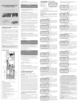
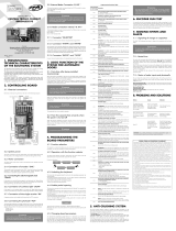
2.1 – DIAGRAMA DE CONEXIONES
Vea las conexiones eléctricas en general en el diagrama
a continuación:
2.2 – ALIMENTACIÓN DEL SISTEMA
La conexión de la red eléctrica debe ser hecha a través
de las entradas de la clema (bornera) de alimentación,
conector “AC”. El valor de la tensión de operación es 85V
haa 265V, 50Hz o 60Hz; vea gura 1.
2.3 – CONEXIÓN DEL MOTOR BRUSHLESS
Los tres cables del motor BRUSHLESS deben ser
conectados a las entradas “A”, “B” y “C” de la central; los
cables pueden ser conectados en cualquier posición del
borne, vea ítem “Primer Accionamiento del Convertidor
(Memorización)”.
2.4 – CONEXIÓN DEL ENCODER “ENC”
Es utilizado para la conexión, a través de un cable
adecuado, entre el motor y la Central Controladora. Dentro
de la caja de velocidades del automatizador hay sensores que
suminiran informaciones de sentido de desplazamiento y
posición del portón durante la operación (funcionamiento).
Eas informaciones son esenciales para el funcionamiento
adecuado del automatizador.
Hay dos sensores dentro del encoder y cada uno es
representado por los LEDs ECA y ECB. Cada uno se enciende
de acuerdo con la posición del disco.
2.5 – CONEXIÓN DE LA ELECTROCERRADURA “TRAVA”
Si se quiere usar una electrocerradura (opcional), se
debe conectar el "Módulo Opcional Relé" en ee conector.
La central reconocerá el módulo automáticamente y añadirá
un intervalo de tiempo para empezar la apertura del
automatizador tras el accionamiento de la traba.
2.6 – CONEXIÓN DE LA LUZ DE CORTESÍA “LUZ”
Si se quiere usar luz de cortesía, se debe conectar el
"Módulo Opcional Relé" en ee conector. El funcionamiento
de la luz de cortesía eará siempre habilitada.
Baa programar el intervalo de tiempo que se quiere a
través del accesorio PROG.
2.7 – CONEXIÓN DEL RECEPTOR SUELTO “RX”
Se puede añadir un receptor suelto pode a la central a
través del conector “RX”.
Cuando un comando es aceptado, el LED CMD
(comando) enciende. Se debe sacar el Jumper (puente,
saltador) HRF cuando el receptor suelto es añadido al siema
para apagar el receptor incorporado.
NOTA: Antes de conectar los accesorios opciona-
les (Electrocerradura y/o Luz de Cortesía / Semáforo,
botoneras etc.), se recomienda probar totalmente el
funcionamiento del equipo. Para esto, basta pulsar el
botón “GRV” para accionar el ciclo de memorización
del recurrido del automatizador.
2.8 – CONEXIÓN DE LA FOTOCÉLULA “FOT”
Se debe inalar las fotocélulas colocadas a una altura de
aproximadamente 50 cm del suelo (o según recomendaciones
del fabricante), de forma que el transmisor y el receptor se
queden alineados uno en relación con el otro. La conexión
eléctrica debe ser así:
"+": 15V(positivo +);
"-": GND (negativo -);
"FOT": Comando (contacto) de la fotocélula.
2.9 – CONEXIÓN DE UNA BOTONERA, MISMO CONECTOR
DEL CONTROL REMOTO ("RX")
La central reconoce un comando de botonera cuando
los dos pines a la derecha del conector “RX” han sido
conectados.
IMPORTANTE
El Controlador Lógico suministra 13,8 V (corriente
continua máxima de 500 mA) para alimentación de
fotocélulas y receptores. Caso los equipos necesiten
de más tensión o corriente mayor, se debe usar una
fuente de energía auxiliar.
2.10 – CONEXIÓN DE LOS SENSORES REEDS DE FIN DE
CARRERA “REED”
La central reconoce un “reed” accionado cuando el pine
referente a él en el conector de pines "REED" sea conectado
al GND, eo es, un pulso para GND.
La única condición que debe ser observada es que el reed
que representa el portón abierto debe ser conectado de forma
que el LED “RDA” encienda, pine del conector “REED” marcado
con la letra “A”. Y el LED “RDF” debe encender cuando el
portón eé cerrado, pine del conector “REED” marcado con
la letra “F”.
2.11 – CONECTOR “PROG”
Ee conector es el medio de comunicación entre la
central y el programador electrónico PROG de PPA. Vea más
detalles en el tópico “Programación con el Programador
electrónico PROG de PPA”.
2.12 – CONEXIÓN DE LA BATERÍA
La Central Triex Brushless 24V funciona con batería
de 24 V cuando no hay energía de la red eléctrica. Baa
conectar una batería a la central a través de los conectores
(+) y (-) de la entrada "BAT".
Cuando alimentar la central solamente por la batería, es
necesario apretar el botón “ST” para empezar. Eso se debe al
hecho de que el circuito de protección contra descarga total
de la batería, que es responsable por desconectar totalmente
la batería si su tensión llegar a un valor muy bajo durante el
funcionamiento sin energía eléctrica.
2.13 – FUSIBLES
La Central Triex Brushless 24V posee dos fusibles, F1
y F2. El fusible F2 de 10A eá en serie con la batería y el F1
de 5A eá en serie con la alimentación suminirada por el
transformador.
2.14 – OPERACIÓN EN MODO “MAESTRO Y ESCLAVO”
La Central Triex Brushless 24V posee una función
llamada “Modo Maero y Esclavo”. Ee siema es usado
cuando se tiene dos motorreductores y dos centrales
inalados en un portón pivotante doble y se quiere hacer
comunicación entre las placas para que haya un retardo en
una de las hojas del portón. La central de la hoja "maera"
debe tener el cable que sale del conector “SLV” conectado a
la entrada “RX” (los dos pines a la derecha de ee conector)
de la central de la hoja esclava.
Se puede congurar la central como "maera" o
"esclava" a través del PROG.
NOTA: Se puede ajustar el tiempo de retardo en-
tre las hojas a través del PROG; la hoja “maestra” se
movimienta primero en la apertura y llega el último
en el cierre. Si el retardo esté invertido, basta inverter
las conexiones en las entradas “SLV” y “RX” de las cen-
trales y la configuración en el PROG para inverter la
“maestra” con la “esclava”.
3 – FUNCIÓN LÓGICA DEL SISTEMA PARA
PORTONES
3.1 – PRIMER ACCIONAMIENTO DEL CONVERTIDOR
(MEMORIZACIÓN)
Cuando el inversor sea energizado por la primera
vez, tras ser inalado en el automatizador, el portón debe
empezar un movimiento de apertura tras un comando
externo o si el botón “GRV” sea pulsado.
Si el movimiento sea de cierre, desconecte la central de
la red eléctrica y cambie la posición de los dos cables del
motor que eán conectados a los conectores “A”, “B” o “C”
para cambiar el sentido de operación del motor; después,
encienda la central nuevamente y repita el último paso.
Una vez hecho eo, pulse “GRV” o accione un comando
1 Encoder, en automatización indurial, es un dispositivo electromecánico
que cuenta o reproduce pulsos eléctricos a partir del movimiento
rotacional de su eje. Puede también ser denido como un transductor de
posición angular.
2 EEPROM (de Electrically-Erasable Programmable Read-Only Memory)
es un microprocesador no volátil usado en ordenadores y otros aparatos
electrónicos.
Fabricado por:
Motoppar Indústria e Comércio de Automatizadores Ltda
Av. Dr. Labieno da Costa Machado, 3526 - Distrito Industrial
Garça - SP - CEP 17406-200 - Brasil
CNPJ: 52.605.821/0001-55
www.ppa.com.br | +55 14 3407 1000
P06660 - 03/2022
Rev. 1
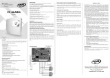
Fabricado por:
Manual Técnico
CENTRAL
TRIFLEX CONNECT 24V
ADVERTENCIA
No utilice el equipo sin
antes leer este manual de
instrucciones.
10A
10A
RED ELÉCTRICA
(85V - 265V)
BATERÍA 1
12V
BATERÍA 2
12V
COMANDO PARA
INICIALIZAR LA
CENTRAL CUANDO ESTÉ
FUNCIONANDO CON
BATERÍA
RECEPTOR
SUELTO
(OPCIONAL)
MOTOR
BRUSHLESS
ELECTROCERRADURA (OPCIONAL)
LUZ (OPCIONAL)
SALIDA PARA MODOS
"MAESTRO Y ESCLAVO"
PROG
FCA
FCF
M
externo para la central.
Eo hecho, deje el portón abrir haa que él se recuee
en el tope de apertura o accionar el "RDA". Después, él va a
revertir el sentido para cerrar, deje que él se recuee en el
tope de cierre o que accione el "RDF".
IMPORTANTE
El automatizador de portón puede funcionar sola-
mente con ENCODER o ENCODER y REED, pero no
puede funcionar solamente con REED. Durante el
cierre en el período de memorización, solamente un
comando de fotocelda puede revertir el portón.
Ahora el portón automático ya eá lio para funcionar.
3.2 – A PARTIR DEL SEGUNDO ACCIONAMENTO ADELANTE
CUANDO LA CENTRAL ELECTRÓNICA SEA DESENCHUFADA
DE LA FUENTE DE ENERGÍA
Tras la operación anterior, el portón no necesitará
memorizar el recorrido nuevamente. Él simplemente cerrará
lentamente tras un comando, haa que se recuee en el
tope de cierre; el motor apagará tras algunos segundos. El
portón ya eá lio para funcionar.
Si la fotocelda sea obruida o la central eé congurada
como "Maera" o "Esclava" durante ee primer cierre,
el punto de referencia a ser buscado será el de apertura,
para acelerar el reconocimiento de un punto conocido del
recorrido.
IMPORTANTE
En modo Híbrido, esto es, REED y ENCODER, si el portón esté
ubicado en uno de los REEDs (totalmente abierto o cerrado),
el portón empezará su movimiento con velocidad total, sin la
necesidad de reconocer el recurrido de nuevo.
IMPORTANTE
Es importante instalar topes de apertura y cierre en el
portón que será automatizado.
4 – PROGRAMACIÓN DE LOS PARÁMETROS
DEL CONVERTIDOR
La central Triex Brushless 24V tiene como eándar de
fábrica los parámetros de ajues que atienden la mayoría
de los modelos de automatizadores. Aun así, caso sea
necesario cambiar alguno, baa conectar un PROG PPA e
cambiar el parámetro deseado. Vea más detalles en el tópico
“Programación con accesorio PROG de PPA”.
5 – BORRAR EL RECORRIDO MEMORIZADO
Para borrar el recurrido, baa mantener pulsado el
botón GRV haa que el LED “OSC” encienda. Al soltarlo, el
recorrido eará borrado.
NOTA: El jumper “PROG” debe estar abierto.
6 – APLICAR ESTÁNDAR DE FÁBRICA
Para volver el eándar de fábrica de las funciones, baa
mantener pulsado el botón GRV haa que el LED “OSC”
encienda; no lo suelte; lo mantenga pulsado haa que el LED
“OSC” empiece a parpadear. Al soltarlo, el recurrido eará
borrado y el eándar de fábrica eará cargado nuevamente.
7 – AÑADIR UM TRANSMISOR DE
RADIOFRECUENCIA (RF)
Para grabar un transmisor de RF, cierre el jumper "PROG",
lo pulse y mantenga pulsado el botón del Transmisor que
desea grabar por un mínimo de dos segundos; tras ese
intervalo de tiempo, pulse el botón "GRV" de la Central.
Observe que antes del transmisor ear grabado, el LED
“OSC” parpadeaba rápidamente; tras la grabación, el LED
“OSC” queda encendido durante la transmisión. Se pueden
añadir un máximo de 240 transmisores en modo Código Fijo
(CF) o 120 transmisores en modo Código Rodante (CR).
8 – BORRAR TODOS LOS TRANSMISORES RF
GRABADOS
Para borrar los transmisores RF grabados en la memoria,
cierre el jumper "PROG", pulse el botón "GRV" de la Central
por 10 segundos. Observe que el LED OSC parpadeará de
1 en 1 segundo. Transcurridos los 10 segundos, el LED OSC
enciende; en ese momento todos los transmisores grabados
han sido borrados.
9 – SELECCIÓN DEL PROTOCOLO DE
RECEPCIÓN DE RF (CF/CR)
Para seleccionar el protocolo de recepción en modo de
Código Fijo (CF), baa abrir el conector de dos pines con
el nombre “CR/CF”, y para seleccionar el modo de Código
Rodante (CR) baa cerrar conector de dos pines “CR/CF”.
IMPORTANTE
Toda vez que el estado de este conector de dos pi-
nes sea alterado, de CF para CR o viceversa, se debe
repetir el procedimiento anterior (Borrar todos los
transmisores RF Grabados).
10 – SISTEMA DE ANTIAPLASTAMIENTO
El mecanismo de antiaplaamiento permite detectar la
presencia de obáculos en el recurrido de portón. En el ciclo
de funcionamiento normal, se hay detectado un obáculo, el
siema va a tomar las siguientes medidas:
a) En el cierre: el portón será accionado en el sentido de
apertura.
b) En la apertura: el motor será apagado y va a esperar recibir
algún comando para empezar el cierre.
En el ciclo de memorización, el mecanismo de
antiaplaamiento tiene solamente la función de reconocer
los nes de carrera de apertura y cierre, eo es, el punto del
recurrido donde hay sido detectado un obáculo que será
interpretado como n de carrera.
IMPORTANTE
Ese sistema de antiaplastamiento no es suficiente
para evitar accidentes con personas e mascotas, por
lo tanto es obligatorio usar Fotocélulas en los auto-
matizadores.
IMPORTANTE
Es importante instalar topes de apertura y cierre en el
portón que será automatizado.
11 – TESTE DE FUNCIONAMIENTO DEL
ENCODER
Es posible probar el encoder del automatizador; con
ee n baa que se lo conecte a la central y que se verique
si los LEDs “ECA” y “ECB” eán parpadeando cuando el
automatizador funciona. Cada LED corresponde a un sensor,
por ejemplo, el LED “ECA” corresponde al sensor A dentro del
motorreductor.
12 – SEÑALIZACIÓN DE EVENTOS Y FALLAS
12.1 – SEÑALIZACIÓN DE FUNCIONAMIENTO DEL
MICROCONTROLADOR
La función principal del LED “OSC” es indicar que el
microcontrolador de la placa eá operativo (él parpadea, con
frecuencia ja de ~1Hz, a condición de que eé enchufado a
una fuente de energía).
12.2 – SEÑALIZACIÓN DE SOBREINTENSIDAD O
CORTOCIRCUITO EN EL MOTOR
El LED “OSC” parpadea rápidamente de 0.1 segundo
en 0.1 segundo para alertar que la etapa de potencia se ha
desenchufado por motivo de sobreintensidad o cortocircuito
en el motor. La central podrá funcionar normalmente 10
segundos después de la sobrecarga.
12.3 – SEÑALIZACIÓN DE FIN DE CARRERA ABIERTO
El LED “FC” parpadea cuando el portón eá en el área de
n de carrera abierto.
12.4 – SEÑALIZACIÓN DE FIN DE CARRERA CERRADO
El LED “FC” queda encendido cuando el portón eá en
el área de n de carrera cerrado.
12.5 – SEÑALIZACIÓN DE CARGA EN LOS CAPACITORES
El LED “BUS” indica que exie carga en los capacitores
de la etapa de potencia.
IMPORTANTE
¡No se debe tocar en el área de potencia (área de
los capacitores) de la tarjeta mientras este LED esté
encendido mismo que el convertidor haya sido de-
senchufado de la red eléctrica!
12.6 – SEÑALIZACIÓN DE COMANDOS
El LED “CMD” encendido indica que la central eá
recibiendo algún comando de las entradas digitales, como,
por ejemplo, RX o FOT.
12.7 – SEÑALIZACIÓN DE EEPROM NO ENCONTRADA
El LED “OSC” parpadea dos veces cuando la Memoria no eá presente.
12.8 – SEÑALIZACIÓN DE EEPROM COM DATOS INVÁLIDOS
El LED “OSC” parpadea tres veces cuando la Memoria eá
presente pero posee un contenido que el microcontrolador
no identica como Código de Transmisor Válido.
13 – RESOLUCIÓN DE PROBLEMAS
Falla Causa Solución
El portón no
corresponde al
recurrido del
local inalado
(frena antes del
tope de cierre
o colide en el
cierre).
Hay un
recurrido
grabado
diferente del
recurrido del
local inalado.
Pulsar el
botón “GRV”
y mantenerlo
pulsado haa que
el LED “OSC”
encienda.
Portón queda
abierto y cuando
recibe comandos
para abrir, él
cierra.
La
memorización
no ha sido
realizada
correctamente.
Vea ítem "Primer
accionamiento
del Convertidor
(Memorización)".
LED “OSC”
parpadeando
rápidamente y el
motor apaga.
Sensor de
corriente
actuando. Eo
puede ocurrir
cuando el
motor eá con
problemas.
Vericar
resiencia del
eátor. Vericar
la corriente en
el motor (debe
ser menor que
3A RMS medio y
5A RMS de pico
(2 segundos en
máximo)).
PLAZO DE GARANTÍA
MOTOPPAR, Induria y Comercio de Automatizadores Ltda., regirada
con CNPJ (CIF) 52.605.821/0001-55, localizada en la Avenida Dr. Labieno da
Coa Machado número 3526, Dirito Indurial, Garça – SP – Brasil, Código
Poal 17.400-000, fabricante de los productos PPA, garantiza eo aparato
contra defectos de proyectos, fabricación, montaje y/o solidariamente en
consecuencia de vicios de calidad de material que se lo hagan impropio o
inadecuado al consumo a cual se deina por el plazo legal de noventa días
desde la fecha de adquisición, siempre que se cumplan las orientaciones de
inalación descritas en el manual de inrucciones.
Como consecuencia de la credibilidad y de la conanza depositada en los
productos PPA, añadimos al plazo anteriormente descrito más 275 días,
alcanzando el total de un año, igualmente contados desde que la fecha
de adquisición pueda ser comprobada por el consumidor a través do
comprobante de compra (Recibo).
En caso de defecto, en el período cubierto por la garantía, la responsabilidad
de PPA se queda reringida a la reparación o reemplazo del aparato por ella
fabricada, bajo las siguientes condiciones:
1. La reparación y reajue de aparatos solo pueden realizarse por la
Asiencia Técnica de PPA, que eá habilitada a abrir, remover, suituir
piezas o componentes, así como arreglar los defectos cubiertos por la
garantía, siendo que el incumplimiento de ee y cualquier utilización de
piezas no originales observadas en el uso, implicará en la exclusión de la
garantía por parte del consumidor;
2. La garantía no se extenderá a accesorios como cables, kit de tornillos,
soportes de jación, fuentes de alimentación etc.;
3. Los coos de embalaje, transporte y reinalación del producto son
responsabilidad exclusiva de los consumidores nales;
4. Se debe enviar el aparato directamente a la empresa responsable de la
venta (representante del fabricante), a través de la dirección que gura
en el recibo de compra, debidamente embalado, evitando así la pérdida
de la garantía;
5. En el período adicional de 275 días, las visitas y los transportes donde no
haya servicios autorizados serán cargadas. Los gaos de transporte del
aparato y/o técnico son responsabilidad del propietario y
6. La reparación o reemplazo del aparato no prorroga el plazo de garantía.
Ea garantía perderá su validez si el producto:
1. Sufrir daños provocados por agentes de la naturaleza, como descargas
atmosféricas, inundaciones, incendios, desmoronamientos etc.;
2. Sea inalado en red eléctrica inadecuada o en desacuerdo con cualquiera
de las inrucciones de inalación descritas en el manual;
3. Presenta defectos causados por caídas, golpes o cualquier otro accidente
físico;
4. Presenta violación o intento de reparación o mantenimiento por parte de
personal no autorizado;
5. No sea usado para lo que ha sido proyectado;
6. No sea usado en condiciones normales;
7. Sufrir daños causados por accesorios o aparatos conectados al producto.
Recomendación:
Recomendamos que la inalación y mantenimientos del aparato sean
efectuados por servicio técnico autorizado PPA.
Caso el producto presente defecto o funcionamiento anormal, busque un
Servicio Técnico especializado para los debidos arreglos.
-
 1
1
-
 2
2


PPA Triflex Connect 24V Manual de usuario
- Categoría
- Abridor de puerta
- Tipo
- Manual de usuario
en otros idiomas
- English: PPA Triflex Connect 24V User manual
Artículos relacionados
-
 PPA Triflex Connect Brushless 24V PS Manual de usuario
-
 PPA Triflex Facility Manual de usuario
-
 PPA Triflex Connect Ind Manual de usuario
-
 PPA Triflex Connect Fullrange Dupla Manual de usuario
-
 PPA Facility 4T Manual de usuario
-
 PPA Wind 24V Manual de usuario
-
 PPA Agility Levare Manual de usuario
-
 PPA Triflex Fullrange Manual de usuario
-
 PPA C2 Manual de usuario
-
 PPA Triflex Connect Brushless PS Manual de usuario


