La página se está cargando...

1. PRESENTATION:
TECHNICAL CHARACTERISTICS
OF THE ELECTRONIC SYSTEM
The Brushless board operates with a 32-bit processor capable of running
40 million instructions per second with motor control features.
The drive system can be performed by any device that provides a NO contact
(normally open), for example, buttonhole, radars for automatic doors etc.
Automatic door positioning control is done through a PPA patented “Reed
Digital” encoder system.
This board controls PPA motors of brushless synchronous type with
permanent magnet in the rotor (Brushless - Brushless DC) of 220V and
motors of induction 220V. The power supply is bivolt, ie the system can be
configured to operate on 127V or 220V.
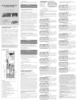
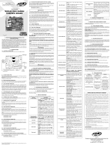
2. CONTROLLING BOARD
2.1. Electrical connections
Electrical connections in general can be seen in the following diagram:
FEEDING
ENCODER
FUNCTION
SELECTOR
PHOTOCELL
CONNECTION
AND RADARS RECEIVER
LOCK
AUXILIARY LIGHT
AIR CURTAIN
ANTIPANIC
SYSTEM
NF
NA
NA
MOTOR
SELECTOR TENSION
KEY
(CH1)
2.2. System power
The mains connection must be made directly to the bivolt board that comes
with the product. The voltage selection must be done through the CH1 key.
2.3. Motor connection
The three wires of the motor must be connected to the “MOTOR” terminal
of the board.
2.4. Connection of encoder “ENC”
The encoder must be connected to the “ENC”, it has the function of providing
direction of travel information and port position during operation. Such
information is essential for proper operation of the operator.
2.5. Connecting the electromagnetic lock
“TRAVA”
If the option is to use the Electromagnetic Lock (optional), the “Relay Option
Module” must be connected to this connector. The locking time must be set
via programming, see table at the end of the manual.
2.6. Connection of auxiliary light “LIGHT”
If the option is to use auxiliary light or air curtain, the “Relay Option Module”
must be connected to this connector. Auxiliary light operation is always enabled.
2.7. Connection of the single receiver “RX”
A separate receiver can be added to the board via the “RX” connector.
2.8. Connecting the photocell “FOT”
The photocells positioned at a height of about 50 cm (or as recommended by
the manufacturer) should be installed so that the transmitter and receiver are
aligned with each other. The electrical connection should be made as follows:
Borne 15V (+);
Borne GND (-);
Borne FOT.
WARNING
Note that the photocell operates with normally closed commands,
ie when the connection between GND and FOT is interrupted the
board will recognize that the photocell is obstructed.
2.9. External Radar Connection “R. EXT “
The board recognizes a radar command when the R. EXT terminal is connec-
ted to the GND, ie a pulse for GND.
Borne GND (-);
Borne R. EXT (Contact NA).
WARNING
The Logic Controller provides 15 V (maximum continuous current
of 400 mA) for powering photocells, radars and receivers. If the
equipment needs more voltage or current, it will be necessary to
use an auxiliary power supply.
2.10. Radar connection internal “R. INT “
The board recognizes a radar command when the R.TB terminal is connected
to the GND, ie a pulse for GND.
Borne GND (-);
Borne R. INT (Contact NA).
2.11. Connector “SELECTOR”
Connection of the function selector and parameter programmer.
2.12. Connector “ANTPA” and “ANTPB”
This connection can be used for operator door systems with Anti-Panic mechanisms.
The sensors are the same as those used in the operator encoder system. The anti-
-panic system keeps the sensors on when the leaves are in operation. If the system is
retracted, the sensors are turned off and the board door initiates the procedure set
function F12 in accordance with this manual function table.
2.13. Connector “RXFOT” and “TXFOT”
Unused: Future Implementation of integrated photocell to the board.
3. LOGIC FUNCTION OF THE
SYSTEM FOR AUTOMATIC
DOORS
3.1. First drive after being installed
(memorizing)
When the board is energized for the first time and after being installed to the
operator system, the door must initiate an opening movement after an external
control or the OK button of the Function Selector.
If the movement is closing, remove the F / R jumper to change the direction
of operation of the motor. If the F / R jumper is inserted again, the direction of
operation returns to the previous one.
WARNING
This anti-crushing system is not enough to prevent accidents
with people and animals, so it is mandatory to use Photocells to
protect and delimit protection areas in the opening region of the
automated door’s moving leaves.
6. ENCODER RUN TEST
It is possible to test the automation encoder by simply connecting it to the
control panel and checking through the PPA Selector when the automation
is moved. To do this, press the (-) button on the selector and a screen with
Speed and Stroke will be displayed. Note that the opening and closing stop
points will always remain the same during operation.
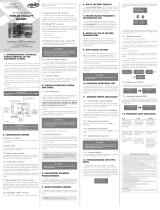
7. SIGNING EVENTS AND
FAULTS
7.1 – Signaling of charge on capacitors
The “BUS” LED indicates that there is charge in the capacitors of the Power
stage.
ATTENTION
The power region (capacitor region) of the board must not be
touched while this LED is lit even after the inverter is disconnected
from the mains!
7.2 – Route Error
Se a porta não conseguir abrir totalmente por algum motivo, será sinalizado
If the door cannot open fully for any reason, Error 03 will be signaled in
the function selector and a new memorization will be triggered at the next
command.
Error 03 will remain for about 1 minute on the display, then the default screen
will be shown again. To see if there are any errors, simply press the (-) button
on the selector until you reach the error screen. If there are no errors, this
screen is not displayed.
The error indication can be removed if the control panel is disconnected
from the mains.
7.3 – Status of radar inputs and photocells
You can check the states of the command inputs. To do this, press the (-)
button of the selector twice and a screen will show whether the inputs are
triggered or not:
External Photocell (FE): It is the photocell connected to the FOT terminal;
Integrated Photocell (FI): Is the photocell connected to RXFOT and TXFOT
(not yet available);
External Radar (RE);
Internal Radar (RI);
Receiver Command (RF): Command from the “RX” connector;
Anti Panic (AP).
8. PROBLEMS AND SOLUTIONS
Failure Cause Solution
The door does not
match the installed
location path (brakes
before closing stop or
hits closing).
There is a recorded
track that is different
from that of the
installed location.
Clear the path using
function F04.
Door remains open
and when it receives
commands to open it
closes.
The memorization
has not been
performed correctly.
See item: First drive
after being installed
(memorizing).
Error 03
Loose toothed
belt, problem in
positioning sensor
or obstruction in
the path of moving
sheets.
Stretch the belt again,
check the path through
the selector function
and check if the
mobile leaves are free
throughout the path.
NOTE: For a better performance in receiving transmitters signal, it is
recommended to keep the contral board antenna stretched.
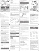
Programming Functions Table:
Code printed
on the displayFunction
F01
SEMI-AUTOMATIC MODE OR PAUSE TIME IN AUTOMATIC MODE
0 = semi automatic
99 seconds = maximum time
F02 ENABLES OR DISABLES LOCK OPERATION TIME
(0.1s to 9.9s) time in milliseconds.
F03
GARAGE LIGHT TIME REMAINING ON AFTER DOOR CLOSES
0 = minimum
99 seconds = maximum time
F04 DELETE OR MAINTAIN ROUTE
F05
OPENING SPEED
10% lower speed;
100% higher speed
F06
CLOSING SPEED
10% lower speed;
100% higher speed
F07
LIMIT SWITCH OPENING
Level: 1 (lowest) to 150 (highest) end of limit switch opening
space.
WARNING: For safety, this parameter must be set so that
the door starts to decelerate by 10 cm before reaching the
opening stop.
F08
LIMIT SWITCH CLOSING
Level: 1 (lowest) to 150 (highest) end of limit switch closing
space.
WARNIGN: For safety, this parameter must be adjusted so
that the door starts to decelerate by 10 cm before reaching
the closing stop.
F09 DOOR MODEL
Flash/Bona, Giro, Brushless
F10
SENSITIVITY OF ANTI CRUSH ON CLOSING
(From 1 to 100%) force determined in percentage.
Lower value: lower strength
Higher value: higher strength
F11 SAVE OR READ ROUTE WHEN THE DOOR IS ENERGIZED
F12
ENABLE OR DISABLE ANTI PANIC
Sets the door to stop or open fully after receiving an anti-
panic signal.
F13 FILTER TIME FOR PHOTOCELL COMMAND INPUT AND “RADAR 1”
(0.1 to 5.0 s) time in milliseconds.
F14
LIMIT SWITCH CLOSING
Level: 1 (lowest) to 150 (highest) end of limit switch closing
space.
NOTE: For safety, this parameter must be adjusted so that
the door starts to decelerate by 10 cm before reaching the
closing stop.
F15 APPLY THE FACTORY SETTINGS
F16
DECELERATION AT CLOSING
(From 1 to 99% / s) value determined in percent per second.
The lower the value the softer the motion is, and the higher
the limit switch should be.
F17
ENABLES OR DISABLES BUILT-IN PHOTOCELL
This function must be enabled if the photocell is connected
to the `` TX FOT and RX FOT’’
F18
ANTI PANIC OPENING SPEED
When there is an antipanic signal. The port must be configu-
red to open in function 12.
F19
OPENING FORCE
(From 1 to 100%) force determined in percentage.
WARNING:If the percentage value becomes too low, the
operator system may run out of power and may lose speed
at the door.
Strength at limit switch course closing
(From 1 to 50%) value determined in percentage.
F20
STRENGTH AT LIMIT SWITCH COURSE CLOSING
(From 1 to 50%) value determined in percentage.
Strength to ensure door closure.
F21
ENABLES OR DISABLES “ANTI-WIND”
This function is commonly used on pivoting doors (Giro). In
order to adjust the closing again, if the door opens due to an
external factor and not by an electric command.
F22
OPENING ACCELERATION / DECELERATION
(From 1 to 99% / s) value determined in percent per second.
By decreasing the value of this function, the opening movement
of the door will be smoother and the ‘open limit’ will have to be
increased, since the door will need more space to brake.
F23 ON / OFF LOCKING PULSE ON LOCK
F24
ENABLE INVERTED PAUSE
Non-inverted pause starts counting when the door is fully
open;
Inverted pause starts counting when there is no more radar,
photocell or buttonhole signal. If any command is restarted
during the pause, the count is restarted.
F25
WAITING TIME TO START THE ENGINE AFTER THE LOCK HAS BEEN
ACTUATED
(From 0.0 to 9.9 s) time in milliseconds.
WARNING: The value of the triggering time of the lock in
function 2 must be longer than the time to start the motor.
F26
AUTOMATIC OR MANUAL ACTIVATION.
When the door leaves are moved in the opening direction,
the board automatically starts the motor to make it easier
to open the door. Function to enable or disable this feature.
F27 ADJUSTING THE DISPLAY BACKLIGHT
(From 1 to 100%) value determined in percentage.
F28 Unused
F29
FUNCTION TO ENABLE THE PPA SELECTOR KEYPAD LOCK AND
CHOOSE THE LOCK LEVEL
- Lock function menu only;
- Block total.
- Unlock.
F30
FUNCTION TO CHOOSE THE MODE OF OPERATION IN BATTERY
OPERATED MODE (NOBREAK PPA)
- Operate normally with the battery;
- After receiving a battery command the door should open
and remain open until the power returns.
- The door keeps open after command by the battery.
F31
ADJUSTING CLEARANCE BETWEEN STOP AND LEAF IN OPENING
CLEARANCE DETERMINED BY PULSES:
1 = less clearance
20 = increased clearance
F32
PARTIAL OPENING
(From 10 to 95%) adjustment determined in percentage.
Note: The PPA function selector is required to operate the
function.
Example: if set 50%, when enabling partial opening by the
selector the door will open half the door route.
F33
ADJUSTING THE ENGINE BRAKE
(From 0 to 10%) adjustment determined in percentage.
Note: Function used only in the Brushless model.
This parameter should be around 5% for doors above 100Kg.
Out EXITS THE PROGRAMMING MENU.
5. ANTI-CRUSHING SYSTEM
The anti-crushing feature makes it possible to detect obstacles in the
automatic doorway. In the normal operating cycle, if an obstacle is detected,
the system will take the following actions:
A) At closing: the door will be activated in the opening direction.
B) At the opening: the engine will be turned off, the board will make three
attempts to open again, if it cannot, the route will be cleared and, upon
receiving a next command, the door will start a new route reading.
In the memorization cycle, the anti-crushing feature is only intended to
recognize the opening and closing limit switch, ie the point of the path where
an obstacle has been detected will be interpreted as an limit switch.
Made by:
Motoppar Indústria e Comércio de Automatizadores Ltda
Av. Dr. Labieno da Costa Machado, 3526 - Distrito Industrial
Garça - SP - CEP 17406-200 - Brasil
CNPJ: 52.605.821/0001-55
www.ppa.com.br | +55 14 3407 1000
P05632 - 07/2023
Rev. 2
Technical Manual
CENTRAL TRIFLEX CONNECT
BRUSHLESS PS
WARNING
Do not use the equipment
without first reading the
instruction manual.
WARNING
In Brushless door model in the case of larger and heavy leaves,
you need to increase the role 14 as to be heavier leaves may occur
that in reading the value that leaves the factory can not leave or
make a full reading of the route.
After this condition, leave the door open until it comes to rest against the
opening stop. Then it will start the engine to close, let it lean against the
closing stop.
WARNING
During closing in the storage period, only a photocell command
can revert the door.
The automatic door is now ready to operate.
3.2. From the second drive onwards when
the power is turned off
After the previous operation, the door will not need to record the route
again. It will simply open slowly after a command, until it clicks against the
opening stop, the engine will shut down after a few seconds. The door is
ready to operate.
WARNING
It is important to place opening stops for the door to be automated.
4. PROGRAMMING THE
BOARD PARAMETERS
4.1. Function selection
The selector is a device that allows you to control the automatic door leaf (s)
remotely. You can also configure the board parameters.
4.2. Operation with the function selector
To select preset selector functions, simply press the “SEL” button until the
desired function is found and then press the “OK” button.
Functions selections:
4.3. Unlocking the keyboard
The board has the keypad locked for entry into the operating parameters by
factory default.
To unlock the keypad, simply press the “(-)” and “(SEL)” buttons simultaneously
until the following message is displayed: “Unlock?”
Press “(OK)” to unlock or “(+)” to cancel this action.
To block, just repeat the above process.
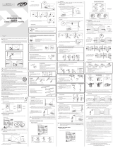
4.4. Enable partial opening
The board can operate with the opening reduced if desired. For example, for
night shifts, etc.
To enable partial opening, the keypad must be set to lock only the board’s
parameter settings so that the operating modes can be changed through
the PPA Selector.
The partial aperture percentage value can be set in function F32 according
to the “Programming function table”.
To turn on partial sheet operation, simply press the (-) button until the
following screen is displayed:
Then press the (+) button to switch to “Partial Opening Enabled”.
Whenever the door is disconnected from the power, the partial opening will
be disabled.
4.5. Changing board parameters
To change the parameters of the Board, it is necessary to connect the
function selector to the SELECTOR connector on the board. Press and hold
the SHIFT key (+) until the display shows F01, you can now release the key.
Okay, the user has already entered programming mode. The programming
menu has the functions described in the table below:
LINKED
RADARS
INTERNAL RADAR
OFF
EXTERNAL RADAR
OFF
CLOSED DOOR OPEN DOOR
PARTIAL OPENING
DISABLED
GENERAL TERMS AND CONDITIONS OF WARRANTY
MOTOPPAR, Indury and Commerce of Automatic Gate Operators Ltd., regiered with the
CNPJ (National Regiry of Legal Entities) under Number 52.605.821/0001-55, located at 3526 Dr.
Labieno da Coa Machado Avenue, Indurial Dirict, Garça – SP – Brazil, Zip Code 17406-200,
manufacturer of PPA Products, hereby guarantees this product again design, manufacturing
or assembly defects and/or supportively as a result of material quality aws that could make its
intended use improper or inadequate, within a legal period of ninety days from time of acquisition,
provided that the inallation inructions described in the inruction manual are observed.
Due to the credibility and tru placed on PPA products, we will add 275 more days to the period
mentioned above, reaching a warranty period of one year, likewise counted from the time of
acquisition proven by consumer through proof of purchase (Cuomer Receipt).
In case of defect, within the warranty period, PPA responsibilities are rericted to the repair or
subitution of the product manufactured by the company, under the following conditions:
1. Repair and readjument of equipment may only be carried out by PPA Technical Assiance,
which is qualied to open, remove, and subitute parts or components, as well as repair
defects covered by this warranty; thus, failure on observing this guideline and the veried use
of any non-original parts will cause the resignation of this warranty on the part of the user;
2. The warranty will not extend to accessories such as cables, screw kit, xing brackets, power
supplies etc.;
3. Expenses for packaging, transportation and product reinallation will be sole responsibility of
the consumer;
4. The equipment mu be sent directly to the Company responsible for the sale (manufacturer's
representative), through the address contained in the purchase invoice, properly packed, thus
avoiding loss of the warranty;
5. Within the additional period of 275 days, visits and transportation in places where authorized
technical assiance is not available will be charged. The co of transportation of the product
and/or technician will be sole responsibility of the consumer and
6. The subitution or repair of the product does not prolong the warranty time.
This warranty will be terminated if the product:
1. Is damaged by natural agents, such as atmospheric discharges, oods, wildres, landslides etc.;
2. Is inalled in an improper electric power supply or if it is not according to any of the inallation
inructions displayed on the manual;
3. Shows defects caused by droppings, collisions or any other physical accident;
4. Shows signs of product violation or attempted repair by unauthorized personnel;
5. Is not used for its intended purpose;
6. Is not used under normal conditions;
7. Is damaged by accessories or equipment connected to it.
Recommendation:
We recommend that both the inallation and the maintenance of the operator to be performed
by an authorized PPA technical service. If the product fails or has an improper operation, seek an
Authorized Technical Service to x it.

1. PRESENTACIÓN:
CARACTERÍSTICAS TÉCNICAS
DEL SISTEMA ELECTRÓNICO
La central BRUSHLESS opera con un procesador de 32 bits capaz de ejecutar
40 millones de instrucciones por segundo con características orientadas
para el control de motor.
El accionamiento delsistema puede ser realizado por cualquier disposi-
tivo que proporciona un contacto NA (normalmente abierto), por ejemplo,
botones pulsadores, radares para puertas automáticas y etc.
El control de posicionamiento de la puerta automáticase hace a través
de un sistema de PPA codificador patentado llamado “Reed Digital”.
La central controla los motores PPA síncronos sin escobillas con imán
permanente en el rotor (BRUSHLESS - Brushless DC) 220V y los motores
de inducción de 220V. La fuente de alimentación de la central esbivolt, es
decir, el sistema puede ser configurado para funcionar en 127V o 220V.
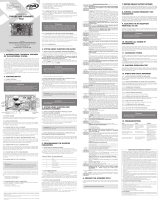
2. CENTRAL DE MANDO
2.1. Conexiones eléctricas
Las conexiones eléctricas en general pueden verse en el siguiente diagrama:
ALIMENTACIÓN
ENCODER
SELECTOR DE
FUNCIONES
CONEXIÓN
FOTOCÉLULA
Y RADARES RECEPTOR
TRABA
LUZ AUXILIAR
CORTINA DE AIRE
SISTEMA
ANTIPÁNICO
NF
NA
NA
MOTOR
CLAVE
SELECTORADE
TENSIÓN VOLTAJE
(CH1)
2.2. Sistema de alimentación
La conexión de la red eléctrica se debe hacer directamente en la central de
doble voltaje que acompaña al producto. La selección de voltaje debe hacerse
a través de la tecla CH1.
2.3. Conexión del motor
Los tres cables del motor deben estar conectados al terminal “MOTOR” de
la central.
2.4. Conexión del encoder “ENC”
El codificador debe estar conectado al “ENC” que tiene la función de
proporcionar informaciones acerca del sentido de desplazamiento y posición
de la puerta durante el funcionamiento. Esta información es esencial para el
buen funcionamiento del Automatizador.
2.5. Conexión de la traba
electromagnética”TRABA”
Si la elección se hace mediante el uso de la TrabaElectromagnética (opcional),
se debe conectar el “Módulo OpcionalRelé” en este conector. El tiempo de
activación de la traba se debe establecer mediante programación, consulte
la tabla al final de este manual.
2.6. La luz de posición de conexión “LUZ”
Si la opción es hecha por el uso de la luz auxiliar o una cortina de aire, se debe
conectar la “Módulo Opcional de relé” en este conector. El funcionamiento
de la luz de fondo siempre estará habilitado.
2.7. Conexión del receptor separado “RX”
Un receptor separado puede ser añadido a la central a través del conector “RX”.
2.8. Conexión de la fotocélula “FOT”
Se debe instalar fotocélulas colocadas a una altura de unos 50 cm desde el
suelo (o de acuerdo con las recomendaciones del fabricante), de manera
que el transmisor y el receptor estén alineados con respecto a la otra. La
conexión eléctrica debe realizarse de la siguiente manera:
Terminal 15V (+);
Terminal GND (-);
Terminal FOT.
ATENCIÓN
Tenga en cuenta que la fotocélula funciona con comandos nor-
malmente cerrados, es decir, cuando la conexión entre GND y
FOT se interrumpe, la central reconocerá que la fotocélula está
obstruida.
2.9. Conexión del radar externo “R. EXT “
El panel reconoce un comando de radar cuando el terminal EXT R. está co-
nectado a GND, es decir, un pulso a GND.
Terminal GND (-);
Borne R. EXT (Contacto).
ATENCIÓN
El controlador lógico proporciona 15 V (corriente máxima de 400
mA continuo) hacia la alimentación de la fotocélula, el radar y
receptores. Si el equipo que requiere mayor tensión o corriente,
se requiere el uso de una fuente de alimentación auxiliar.
2.10. Conexión del radar interno “R. INT “
La central reconoce un comando de radar cuando el terminal R. INT está
conectado al GND, es decir, un pulso a GND.
Borne GND (-);
Borne R. INT (Contato NA).
2.11. Conector “SELECTOR”
Conexión del interruptor de función y programador de parámetros.
2.12. Conector “ANTPA” y “ANTPB”
Esta conexión se puede utilizar para sistemas de puertas automáticas con
mecanismos antipánico. Los sensores son los mismos utilizados en el sistema
de encoder del automatizador. El sistema antipánico mantiene los sensores
se activan cuando las hojas están en funcionamiento. Si el sistema se retrae,
los sensores se apagan y la puerta central inicia el procedimiento establecido
en la función F12 de acuerdo con la tabla de funciones de este manual.
2.13. Conector “RXFOT” y “TXFOT”
No utilizados: Implementación futura de la fotocélula integrada a la central.
3. FUNCIÓN LÓGICA DEL
SISTEMA PARA PUERTAS
AUTOMÁTICAS
3.1. Primeroaccionamiento después de
haber sido instalado (memorización)
Cuando la central se activa por la primera vez y después de haber sido ins-
taladaa el automatizador, la puerta debe iniciar un movimiento de apertura
después de un comando externo o el botón OK delSelector deFunciones.
Si el movimiento es de cierre, retire el jumper F/R para cambiar la dirección
de funcionamiento del motor. Si se introduce nuevamente el jumper F/R, el sen-
tido de operación vuelve a la anterior.
ATENCIÓN
En el modelo de puerta BRUSHLESS, en el caso de las hojas más
grandes y pesadas, es necesario aumentar la función 14,en vista
que las hojas son más pesadas, puede ocurrir en la lectura del
valor que sale de la fábrica no puede salir o hacer una lectura
completa de la ruta.
Después de esta condición, deje la puerta abrir hasta apoyarse en el batiente
de parada. A continuación, se disparará el motor en el sentido para cerrar, la
deje apoyarse contra el batiente de cierre.
ATENCIÓN
Durante el cierre en el período de memorización sólo un comando
fotocélula puede revertir la puerta.
Ahora la puerta automática está lista para funcionar.
3.2. Después del segundo accionamiento
cuando se desconecta la central de la
energía
Después de la operación anterior de la puerta no tiene que grabar la ruta
de nuevo. Ella abrirá lentamente después de un comando, para apoyarse en
el batiente de abertura, el motor se apagará después de unos segundos. La
puerta está ahora lista para funcionar.
ATENCIÓN
Es importante instalar batientes de abertura en la puerta que va
ser automatizada.
4. PROGRAMACIÓN DE LOS
PARÁMETROS DE LA CENTRAL
4.1. Selección defunciones
El selector es un dispositivo que permite controlar la(s) hoja(s) de las puertas
automática remotamente. También puede establecer los parámetros de la
central controladora.
4.2. Funcionamiento con el selector de
funciones
Para seleccionar funcionespreestablecidasde selector, sólo tiene que pulsar
el botón “SEL” hasta que la función deseada y después pulsar el botón “OK”.
Secuencia de funciones:
4.3. Desbloqueo del teclado
La central tiene el teclado bloqueado para entrada en los parámetros de
operación por valores de fábrica.
Para desbloquear el teclado programador, sólo tiene que pulsar los botones
“(-)” y “(SEL)” simultáneamente hasta que aparezca el siguiente mensaje en el
display: “Desbloquear?”
Pulse “(OK)” para desbloquear o “(+)” para cancelar esta acción.
Para bloquear, sólo hay que repetir el proceso anterior.
4.4. Habilitar apertura parcial
La unidad de control puede funcionar con apertura reducida si se desea. Por
ejemplo, para los turnos de noche, etc.
Para permitir la apertura parcial, el teclado debe estar configurado para
bloquear sólo los ajustes de los parámetros de la central, los modos de
funcionamiento de este modo se pueden cambiar a través del Selector PPA.
El valor del porcentaje de apertura parcial se puede ajustar en lafunción
F32 de acuerdo con la “Tabla de funciones de programación”.
Para activar el funcionamiento parcial de las hojas, sólo tiene que pulsar
el botón - hasta que la tela a continuación se muestre:
A continuación, pulse el botón (+) para cambiar a “Apertura Parcial Ac-
tivada”.
Cada vez que la puerta está desconectada de la energía, la apertura par-
cial está desactivada.
4.5. Cambio de parámetros de la central
controladora
Para cambiar los parámetros de la Central Controladora es necesario co-
nectar el selector de funcionesen el conector SELECTOR en la central. Pulse
SHIFT (+), mantenga pulsada la tecla hasta que el display muestre F01, ahora
puede tener la clave. Allí, el usuario ha entrado en el modo de programación.
El menú de programación contiene las funciones descritas en la siguiente tabla:
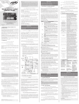
Tabla de Funciones Programables:
Código en
el display Función
F01
MODO SEMIAUTOMÁTICO O TIEMPO DE PAUSA EN EL MODO
AUTOMÁTICO
0 = semiautomática
99 segundos = tiempo máximo
F02 ACTIVA O DESACTIVA EL TIEMPO DE OPERACIÓN DE BLOQUEO
(0.1sa 9.9s) tiempo en milisegundos.
F03
TIEMPO LUZ DEL GARAJE PERMANECE ACTIVADO DESPUÉS DEL
CIERRE DE LA PUERTA
0 = mínimo
99 segundos = tiempo máximo
F04 APAGAR O MANTENER LA RUTA
F05
VELOCIDAD DE APERTURA
Velocidad 10% más lenta;
100% más velocidad
F06
VELOCIDAD DE CIERRE
Velocidad 10% más lenta;
100% más velocidad
F07
APERTURA LÍMITE
Nivel 1 (menor) a 150 (mayor) espacio límite de abertura.
Nota: Para mayor seguridad, este parámetro debe ajustarse
de modo que la puerta comience a desacelerar 10 cm antes
de llegar al batiente de la apertura.
F08
LÍMITE DE CIERRE
Nivel 1 (menor) a 150 (mayor)límite de cierre.
Nota: Para mayor seguridad, este parámetro debe ajustarse
de modo que la puerta comience a desacelerar 10 cm antes
de llegar al batientedel cierre.
F09 MODELO DE PUERTA
Flash/Bona, Giro, BRUSHLESS
F10
SENSIBILIDAD ANTIAPLASTAMIENTO EN EL CIERRE
(1 a 100%) fuerza determinada en porcentaje.
Menor valor: menos fuerza
Mayor valor: más fuerza
F11 GUARDAR O LEER RUTA CADA VEZ QUE SE ACTIVA LA PUERTA
F12
HABILITAR O DESHABILITAR EL ANTI-PÁNICO
Configura de manera para que la puerta pare o abra com-
pletamente después de recibir la señal antipánico.
F13
FILTRO DE TIEMPO PARA LA ENTRADA DE CONTROL DE
FOTOCÉLULA Y DE ENTRADA “RADAR 1”.
(de 0,1 a 5,0 s) tiempo en milisegundos.
F14
VELOCIDAD DE FIN DE CURSO
(de 1 a 50%) velocidad dada en porcentaje
Nota: El modelo de puerta BRUSHLESS, en el caso de hojas
más pesadas es necesario aumentar el porcentaje, por ser
hojas más pesadas será necesario aumentar el porcentaje,
que puede ocurrir cuando se lee el valor que viene de fábrica
no pueden salir o hacer una lectura completa de la ruta.
F15 APLICAR LOS AJUSTES DE FÁBRICA
F16
DESACELERACIÓN EN EL CIERRE
(De 1 a 99% / s) valor determinado en por ciento por se-
gundo.
En el valor menor, elmovimiento es más suave y el fin de
curso debe ser mayor.
F17
ACTIVA O DESACTIVA LA FOTOCÉLULA INCORPORADA
Esta función debe ser activada si la fotocélula está conectada
a los conectores “TX FOT y RX FOT”
F18
VELOCIDAD DE ABERTURA DEL ANTIPÁNICO
Cuando hay señal de antipánico. El puerto debe ser configu-
rado para abrir el la función 12.
F19
FUERZA DE ABERTURA
(1 a 100%) fuerza determinada en porcentaje.
Advertencia: Si el valor de porcentaje es demasiado bajo,
el automatizador puede quedarse sin energía y perder
velocidad a la puerta.
F20
FUERZA AL FIN DE CURSO DE CIERRE
(de 1 a 50%) valor determinado en porcentaje.
Fuerza para asegurar el cierre de la puerta.
F21
ACTIVA O DESACTIVA LA FUNCIÓN “ANTI-VIENTO”
Esta función se utiliza comúnmente en puertas pivotantes
(Giro). Con el fin de establecer el bloqueo de nuevo si la
puerta es abierta debido a un factor externo y no por una
carga eléctrica.
F22
ACELERACIÓN/DESACELERACIÓN EN LA ABERTURA
(De 1 a 99% / s) valor determinado en por ciento por
segundo.
Al disminuir el valor de esta función, el movimiento de
apertura de la puerta se había vuelto más suave y el “fin de
cursode Abertura” deberá ser incrementado debido a que
la puerta se necesita más espacio para frenar.
F23 LIGA/DESLIGA PULSO DE TRABA EN EL CIERRE
F24
PERMITE PAUSA INVERTIDA
Pausa no invertida empieza a contar cuando la puerta está
completamente abierta;
Pausa invertida empieza a contar cuando no hay más señales
de radar, fotocélula o botonera. Si cualquier comando vuelve
a activarse durante la pausa, el conteo se reinicia.
F25
TIEMPO DE ESPERA PARA ACCIONAR EL MOTOR DESPUÉS DE
ACCIONAR LA TRABA
(de 0,0 a 9,9 s) tiempo en milisegundos.
Nota: El valor de tiempo de activación de la traba en la fun-
ción 2 debe ser mayor que el tiempo necesario para accionar
el motor.
F26
ACCIONAMIENTO AUTOMÁTICO O MANUAL
Cuando las hojas de puerta se mueven en la dirección de
apertura, el centro desencadena automáticamente el motor
para facilitar la apertura de la puerta. Función para activar o
desactivar esterecurso.
F27 AJUSTE DE LUZ DE FONDO DEL DISPLAY
(1 a 100%) Valor, determinada como un porcentaje.
F28 Sin uso
F29
FUNCIÓN PARA ACTIVAR EL BLOQUEO DEL TECLADO DEL
SELECTOR PPA Y ELIJA EL NIVEL DE BLOQUE
- Bloque solamente de menú de funciones;
- Bloque total.
- Desbloquear.
F30
FUNCIONAR PARA ELEGIR EL MODO DE FUNCIONAMIENTO EN EL
MODO DE FUNCIONAMIENTO CON BATERÍA (UPS PPA)
- Funcionamiento normal con la batería;
- Después de recibir comandos tapa de la batería debería
abrirá y permanecerá abierta hasta que vuelve a alimentar.
- La puerta se mantiene abierta después de comando de
la batería.
F31
AJUSTE DE HOLGA ENTRE EL BATIENTE Y LA HOJA DETERMINADA
POR PULSOS:
1 = menos holgura
20 = mayor holgura
F32
LA APERTURA PARCIAL
(De 10 a 95%) en porcentaje determinado ajuste.
Nota: Para utilizar la función es necesario utilizar el selector
de función PPA.
Ejemplo: Si se establece en 50%, al permitir una apertura
parcial por el interruptor de la puerta se abrirá la mitad de la
carrera de la puerta.
F33
AJUSTE DEL FRENO DEL MOTOR
(0 a 10%) en el porcentaje de ajuste determinada.
Nota: Sólo se utiliza en el modelo de función BRUSHLESS.
Este parámetro debe estar alrededor de 5% para los puertos
anteriores 100 kg.
Out SALE DEL MENÚ DE PROGRAMACIÓN.
5. SISTEMA
ANTIAPLASTAMIENTO
La función antiaplastamiento permite detectar la presencia de obstáculos
en la ruta de la puerta automática. En el curso de la operación normal, si se
detecta un obstáculo, el sistema tomará las siguientes acciones:
a) En el cierre: la puerta se activará en la dirección de apertura.
b) En la apertura: el motor se apaga, el centro hará tres intentos para
abrir de nuevo, si no, se borrará la ruta, y al recibir la orden siguiente, la
puerta se iniciará una nueva lectura de la ruta.
En el ciclo de memoria, antiaplastamiento función sólo sirve para reco-
nocer la apertura y cierre de los interruptores de límite, a saber, el punto de
ruta, donde se detecta un obstáculo será interpretado como límite.
ATENCIÓN
Este sistema antiaplastamiento no es suficiente para evitar le-
siones a personas y animales, por lo que se requiere el uso de
fotocélulas para la protección y delimitación de las áreas pro-
tegidas en la región de apertura de las hojas móviles de puerta
automatizada.
6. TEST DEL
FUNCIONAMIENTO DEL
ENCODER
Puede probar el codificador del automatizador, sólo tiene que enchufar en
la central y comprobar a través del Selector PPA cuando el automatizador
se mueve. Para hacerlo, pulse el botón (-) de línea y una pantalla con la
velocidad y el curso se mostrará. Tenga en cuenta que los puntos de parada
de apertura y cierre son siempre los mismos durante el funcionamiento.
7. SEÑALIZACIÓN DE
EVENTOS Y FALLOS
7.1 - Señalización de carga en los
condensadores
El LED “BUS” indica que hay carga en los condensadores de la etapa de potencia.
ATENCIÓN
No toque la zona de alimentación (región de los condensadores)
del tablero mientras este LED está encendido, incluso después de
que el inversor se desconecta de la red!
7.2 - Error de ruta
Si la puerta no se abre completamente, por alguna razón, se señaliza un
Error 03 en el selector de funciones y un nuevo ciclo será conducido a la
siguiente orden.
El error 03 se mantendrá durante aproximadamente 1 minuto en la
pantalla, a continuación, de nuevo se mostrará la pantalla por defecto.
Para ver si hay algún error, simplemente pulse el botón (-) de línea botón
hasta que llegue a la pantalla de error. Si no hay errores, no se muestra esta
pantalla.
La indicación de error puede ser eliminado si el interruptor está desligado
de la red eléctrica.
7.3 - Estado de las entradas de radar y
fotocélulas
Puede comprobar los estados de las entradas de control. Para hacerlo, pulse
el botón (-) selector de dos veces el botón y una pantalla mostrará si las
entradas se activan o no:
Fotocélula Externa (FE): la célula fotoeléctrica está conectada a el terminal FOT;
Fotocélula Integrada (FI): La fotocélula se conecta a RXFOT y TXFOT (no
disponible);
Radar Externo (RE);
Radar Interno (RI);
Comando de receptor separado (RF): Comando del conector “RX”;
Antipânico (AP).
8. PROBLEMAS Y SOLUCIONES
Fallo Causa Solución
La puerta no coincide
con la trayectoria de la
ubicación de instalación
(frenaantes del batiente
de cierre o bate en el
cierre).
Hay una ruta
diferente de la ruta
registrada desde el
lugar de instalación.
Eliminación de la ruta
a través de la función
F04.
Puerta permanece
abierta y cuando recibe
comandos para abrir
cierra.
La memorización
no se realizó
correctamente.
Véase el tema: Primero
accionamiento después
de haber sido instalado
(memorización).
Erro 03
Correa dentada
suelta u
obstrucción en el
posicionamiento
del sensor en la
trayectoria de las
hojas móviles.
Estiré nuevamente
la correa, comprobé
la ruta a través de la
función de selección
y si las hojas móviles
son libres a lo largo del
camino.
NOTA: Para un mejor desempeño en la recepción de señal de los
transmisores, recomendamos mantener la antena de la central de mando
estirada.
Fabricado por:
Motoppar Indústria e Comércio de Automatizadores Ltda
Av. Dr. Labieno da Costa Machado, 3526 - Distrito Industrial
Garça - SP - CEP 17406-200 - Brasil
CNPJ: 52.605.821/0001-55
www.ppa.com.br | +55 14 3407 1000
Manual Técnico
CENTRAL TRIFLEX CONNECT
BRUSHLESS PS
ATENCIÓN
No utilice el equipo sin
antes leer el manual de
instrucciones.
P05632 - 07/2023
Rev. 2
TÉRMINOS Y CONDICIONES DE GARANTÍA
MOTOPPAR Indúria e Comércio de Automatizadores Ltda, inscrita en el CNPJ n°
52.605.821/0001-55, situada en la Av. Dr. Labieno da Coa Machado, n° 3526, Dirito
Indurial, Garça/SP, CEP 17406-200, fabricante de los productos PPA, garantiza ee
dispositivo contra defectos de diseño, fabricación, montaje o como consecuencia de
vicios de calidad del material que lo hagan impropio o inadecuado para su uso previo
durante el plazo legal de 90 (noventa) días a partir de la fecha de adquisición, siempre
que se respeten las directrices de inalación descritas en el manual de inrucciones.
Como resultado de la credibilidad y la conanza depositada en los productos PPA,
añadimos otros 275 (doscientos setenta y cinco) días al periodo anterior, alcanzando un
total de 01 (un) año de garantía, también contado a partir de la fecha de adquisición y
que el consumidor debe comprobar mediante la factura de compra.
En caso de defecto, dentro del período de garantía, la responsabilidad de PPA se
limita a la reparación o suitución del dispositivo de su fabricación bajo las siguientes
condiciones:
1. La reparación y regulación de los equipos solo podrán ser realizadas por la Asiencia
Técnica de PPA, la cual eá habilitada para abrir, retirar, reponer piezas o componentes,
así como reparar los defectos cubiertos por la garantía. El incumplimiento de ea
condición y cualquier utilización de piezas no originales en su uso dará lugar a la
renuncia de ee término por parte del consumidor.
2. La garantía no se extenderá a accesorios como cables, juego de tornillos, soportes de
jación, fuentes, etc.
3. Gaos de embalaje, transporte y reinalación del producto corren exclusivamente a
cargo del consumidor.
4. El equipo deberá ser enviado directamente a la Empresa responsable de la venta
representante del fabricante, a la dirección conante en la factura de compra,
debidamente acondicionado, para así evitar la pérdida de la garantía.
5. En el plazo adicional de 275 días se cobrarán las visitas técnicas en localidades donde
no exian servicios autorizados. Los gaos de transporte del dispositivo o del técnico
correrán a cargo del propietario consumidor.
6. La suitución o reparación del equipo no prorroga el plazo de garantía.
Ea garantía perderá sus efectos si el producto:
1. sufre daños causados por agentes de la naturaleza, como descargas atmosféricas,
inundaciones, incendios, derrumbes, etc.;
2. es inalado en una red eléctrica inadecuada o incluso en desacuerdo con alguna de las
inrucciones para inalación expueas en el manual;
3. presenta defectos causados por caídas, golpes o por cualquier otro accidente físico;
4. es modicado o por intento de reparación por parte de personal no autorizado;
5. no se usa para el n al cual eá deinado;
6. no se utiliza en condiciones normales;
7. sufre daños causados por accesorios o equipos acoplados al producto.
Recomendación:
Recomendamos que la inalación y el mantenimiento del producto sean realizados
por el servicio técnico especializado PPA.
Si el producto presenta algún defecto o el funcionamiento es anormal, contacte con
un Servicio Técnico especializado para que se hagan las correcciones necesarias.
/