La página se está cargando...

SETTING COMMANDS CHART
Default Factory Settings Select function
CMD- Once
Enter function
GRV+ Once
Confirm
GRV+ Once
Cancel
CMD- Once
Command when opening Select function
CMD- Twice
Enter function
GRV+ Once
Increase
GRV+ Once
Decrease
CMD- Once
Erasing Remote Controls Select function
CMD- Three times
Enter function
GRV+ Once
Confirm
GRV+ Once
Cancel
CMD- Once
Courtesy Light (LG) Interval time Select function
CMD- Four times
Enter function
GRV+ Once
Increase
GRV+
Decrease
CMD-
Brake Select function
CMD- Five times
Enter function
GRV+ Once
Increase
GRV+
Decrease
CMD-
Traffic Light (SIN) Interval Time Select function
CMD- Six times
Enter function
GRV+ Once
Increase
GRV+
Decrease
CMD-
Reversion through a command Select function
CMD- Seven times
Enter function
GRV+ Once
Enable
GRV+ Once
Disable
CMD- Once
Selecting type of End-of-Stroke Select function
CMD- Eight times
Enter function
GRV+ Once
Reed Digital
GRV+ Once
Analog
CMD- Once
Torque (Strength) when learning the opening
limits
Select function
CMD- Nine times
Enter function
GRV+ Once
Increase
GRV+
Decrease
CMD-
Torque (Strength) when learning the closing
limits
Select function
CMD- Ten times
Enter function
GRV+ Once
Increase
GRV+
Decrease
CMD-
Path covered when activating the electronic
lock (closing)
Select function
CMD- Eleven times
Enter function
GRV+ Once
Increase
GRV+
Decrease
CMD-
Setting the size of the opening ramp Select function
CMD- Twelve times
Enter function
GRV+ Once
Increase
GRV+
Decrease
CMD-
Opening delay when using a traffic light Select function
CMD- Thirteen times
Enter function
GRV+ Once
Increase
GRV+ Once
Decrease
CMD- Once
Adjustment of the anti-crushing sensor in the
path
To select the function,
press ‘CMD-’ 14 times
To enter the function,
press ‘GRV+’ once
Increment =
press ‘GRV+’ once
Decrement =
press ‘CMD-’ once
Adjustment of the anti-crushing sensor on the
ramp
To select the function,
press ‘CMD-’ 15 times
To enter the function,
press ‘GRV+’ once
Increment =
press ‘GRV+’ once
Decrement =
press ‘CMD-’ once
To exit, finish or cancel the function, open jumper PROG.
1. MAIN FEATURES
• Analog or Digital End-of-Stroke.
• RF 433,92 MHz Receiver module.
• Encrypted Code learning with external memory:
◦ 320 Remote controls with Fixed Code (HT6P20B standard).
◦ 160 Remote Controls with Rolling Code (PPA standard).
• Inputs:
◦ 01 x Photocell.
◦ 01 x Pushbutton (opening and closing).
◦ External RF Receiver Module.
• Outputs:
◦ Courtesy Light Module.
◦ Electronic lock module.
◦ Traffic Light Module.
• Deceleration ramp.
• Automatic Learning of the Opening / Closing Limits.
• Delay Timing when opening using a traffic light.
WARNING
First programming (setting) after installing or defining a new type of remote
control:
This procedure will reset the memory (erase old information / prepare the me-
mory to receive new remote controls).
1. Selecting type of remote control:
• With a resistor = PPA Rolling Code.
• Without a resistor = Fixed Code.
2. Erase a remote control (Refer to item “ERASING REMOTE CONTROLS”)
3. Add new remote controls (Refer to item “ADDING REMOTE CONTROLS”)
2. DEFAULT FACTORY SETTINGS
Restore the settings to the default factory settings.
Instructions:
1. The gate must be still;
2. Close jumper PROG;
3. Press and release the CMD button (Once);
4. Press and release the GRV button to enter the function;
5. Press button GRV+ to set as Default Factory Settings; or button CMD- / Open
jumper PROG (Cancel function).
WARNING
Before starting this functions, check the remote control configuration, CR/CF
resistor.
Instructions:
1. The gate must be still;
2. Close jumper PROG;
3. Press and release the CMD button (Three times);
4. Press and release the GRV button to enter the function;
5. Press button GRV+ to erase the memory of the remote controls or button CMD-
/ Open jumper PROG (Cancel function)
5. ADDING REMOTE CONTROLS
Remote Controls with PPA Standard (Fixed and Rolling Codes) are supported.
WARNING
In order to properly add remote controls, ensure that the memory has been ini-
tialized correctly with the corresponding remote control (Fixed / Rolling Code).
WARNING
I fone has pressed the button CMD- by mistake and then the button GRV+, the
ECU will enter Default Factory Settings mode and the LED will remain lit for ten
seconds. In order to cancel this function, open the jumper PROG.
Instructions:
1. The gate must be still;
2. Close jumper PROG;
3. Press the button on the remote control one wants to add;
4. The SN LED will flash rapidly;
5. Press and release the button GRV+;
6. The SN LED will flash once (button has been added), twice (button already
added) or three times (memory full);
7. Release the button on the remote control;
8. To back to step 3 to add a new button of the remote control;
9. In order to finish, open jumper PROG.
6. TEMPO LUZ DE GARAGEM (LG)
When the gate is either opening, closing or even still, the relay module keeps switched
on.
When the ECU finishes the closing cycle, the relay module will be switched off after
the set time.
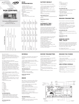
DEFAULT FACTORY SETTINGS CHART
COMMAND WHEN OPENING Enabled
DELAY TIME WHEN OPENING USING A TRAFFIC
LIGHT 0 (DISABLED)
COURTESY LIGHT 60 seconds
BRAKE ACTIVATION TIME 150,0 msec
TRAFFIC LIGHT On
REVERSION THROUGH A COMMAND Allowed
END-OF-STROKE Analog
TORQUE (STRENGTH) WHEN LEARNING THE
OPENING LIMITS Level 20
TORQUE (STRENGTH) WHEN LEARNING THE
CLOSING LIMITS Level 20
ELECTRONIC LOCK RAMP 0%
OPENING RAMP SETTING 0%
ANTI-CRUSHING SENSOR IN THE PATH 24
ANTI-CRUSHING SENSOR ON THE RAMP 66
3. COMMAND WHEN OPENING
It allows a command from a pushbutton or remote control to work while the gate is
opening.
It also has the function of programming the pushbutton / remote control operation
mode when counting time for opening delay while the traffic light is on.
One can cancel the opening delay time through a pushbutton or remote control.
SETTINGS:
0 = command when opening enabled.
1 = Partial command when opening, enabled only on the opening delay using a
traffic light and disabled when the gate is opening.
2 = total command when opening, disabled on the opening delay using a traffic
light and also when the gate is opening.
Instructions:
1. The gate must be still;
2. Close jumper PROG;
3. Press and release the CMD button (Twice);
4. Press and release the GRV button to enter the function;
5. Press the button GRV+ to increase or the button CMD- to decrease;
6. To finish, open jumper PROG
4. ERASING REMOTE CONTROLS
It erases and boots the memory to add new remote controls.
Settings:
0 = Minimum time 1.0 second
1 = Intermediate time 15.0 seconds
2 = Intermediate time 30.0 seconds
...
17 = Maximum time 255.0 seconds
Instructions:
1. The gate must be still;
2. Close jumper PROG;
3. Press and release the CMD button (Four times);
4. Press and release the GRV button to enter the function;
5. Press button CMD- to decrease, button GRV+ to increase or Open jumper
PROG (Cancel function).
SN LED Signs:
Flashes once = When releasing button CMD- and/or GRV+ (command has been
accepted).
Flashes three times = When releasing button CMD- or GRV+ (command has been
denied to maximum and minimum values reached)
7. BRAKE
It is activated when the motor is switched off through a command, or when reaching
the analog sensors (end-of-stroke).
Settings:
0 = Brake switched off.
1 = Time 0.150 seconds
2 = Time 0.300 seconds
...
17 = Oscillation time 2.55 seconds.
Instructions:
1. The gate must be still;
2. Close jumper PROG;
3. Press and release the CMD button (Five times);
4. Press and release the GRV button to enter the function;
5. Press button CMD- to decrease, button GRV+ to increase or Open jumper
PROG (Cancel function).
SN LED Signs:
Flashes once = When releasing button CMD- and/or GRV+ (command has been
accepted).
Flashes three times = When releasing button CMD- or GRV+ (command has been
denied to maximum and minimum values reached)
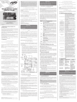
ECU FACILITY 4T
TECHNICAL MANUAL
P05626 - 01/2022
Rev. 6
WARNING:
Do not use the equipment
without referring to this
manual rst.
Made by: Motoppar Indústria e Comércio de Automatizadores Ltda
Av. Dr. Labieno da Costa Machado, 3526 - Distrito Industrial
Garça - SP - CEP 17406-200 - Brasil
CNPJ: 52.605.821/0001-55
www.ppa.com.br | +55 14 3407 1000
SETTING COMMANDS CHART
Default Factory Settings Select function
CMD- Once
Enter function
GRV+ Once
Confirm
GRV+ Once
Cancel
CMD- Once
Command when opening Select function
CMD- Twice
Enter function
GRV+ Once
Increase
GRV+ Once
Decrease
CMD- Once
Erasing Remote Controls Select function
CMD- Three times
Enter function
GRV+ Once
Confirm
GRV+ Once
Cancel
CMD- Once
Courtesy Light (LG) Interval time Select function
CMD- Four times
Enter function
GRV+ Once
Increase
GRV+
Decrease
CMD-
Brake Select function
CMD- Five times
Enter function
GRV+ Once
Increase
GRV+
Decrease
CMD-
Traffic Light (SIN) Interval Time Select function
CMD- Six times
Enter function
GRV+ Once
Increase
GRV+
Decrease
CMD-
Reversion through a command Select function
CMD- Seven times
Enter function
GRV+ Once
Enable
GRV+ Once
Disable
CMD- Once
Selecting type of End-of-Stroke Select function
CMD- Eight times
Enter function
GRV+ Once
Reed Digital
GRV+ Once
Analog
CMD- Once
Torque (Strength) when learning the opening
limits
Select function
CMD- Nine times
Enter function
GRV+ Once
Increase
GRV+
Decrease
CMD-
Torque (Strength) when learning the closing
limits
Select function
CMD- Ten times
Enter function
GRV+ Once
Increase
GRV+
Decrease
CMD-
Path covered when activating the electronic
lock (closing)
Select function
CMD- Eleven times
Enter function
GRV+ Once
Increase
GRV+
Decrease
CMD-
Setting the size of the opening ramp Select function
CMD- Twelve times
Enter function
GRV+ Once
Increase
GRV+
Decrease
CMD-
Opening delay when using a traffic light Select function
CMD- Thirteen times
Enter function
GRV+ Once
Increase
GRV+ Once
Decrease
CMD- Once
Adjustment of the anti-crushing sensor in the
path
To select the function,
press ‘CMD-’ 14 times
To enter the function,
press ‘GRV+’ once
Increment =
press ‘GRV+’ once
Decrement =
press ‘CMD-’ once
Adjustment of the anti-crushing sensor on the
ramp
To select the function,
press ‘CMD-’ 15 times
To enter the function,
press ‘GRV+’ once
Increment =
press ‘GRV+’ once
Decrement =
press ‘CMD-’ once
To exit, finish or cancel the function, open jumper PROG.
1. MAIN FEATURES
• Analog or Digital End-of-Stroke.
• RF 433,92 MHz Receiver module.
• Encrypted Code learning with external memory:
◦ 320 Remote controls with Fixed Code (HT6P20B standard).
◦ 160 Remote Controls with Rolling Code (PPA standard).
• Inputs:
◦ 01 x Photocell.
◦ 01 x Pushbutton (opening and closing).
◦ External RF Receiver Module.
• Outputs:
◦ Courtesy Light Module.
◦ Electronic lock module.
◦ Traffic Light Module.
• Deceleration ramp.
• Automatic Learning of the Opening / Closing Limits.
• Delay Timing when opening using a traffic light.
WARNING
First programming (setting) after installing or defining a new type of remote
control:
This procedure will reset the memory (erase old information / prepare the me-
mory to receive new remote controls).
1. Selecting type of remote control:
• With a resistor = PPA Rolling Code.
• Without a resistor = Fixed Code.
2. Erase a remote control (Refer to item “ERASING REMOTE CONTROLS”)
3. Add new remote controls (Refer to item “ADDING REMOTE CONTROLS”)
2. DEFAULT FACTORY SETTINGS
Restore the settings to the default factory settings.
Instructions:
1. The gate must be still;
2. Close jumper PROG;
3. Press and release the CMD button (Once);
4. Press and release the GRV button to enter the function;
5. Press button GRV+ to set as Default Factory Settings; or button CMD- / Open
jumper PROG (Cancel function).
WARNING
Before starting this functions, check the remote control configuration, CR/CF
resistor.
Instructions:
1. The gate must be still;
2. Close jumper PROG;
3. Press and release the CMD button (Three times);
4. Press and release the GRV button to enter the function;
5. Press button GRV+ to erase the memory of the remote controls or button CMD-
/ Open jumper PROG (Cancel function)
5. ADDING REMOTE CONTROLS
Remote Controls with PPA Standard (Fixed and Rolling Codes) are supported.
WARNING
In order to properly add remote controls, ensure that the memory has been ini-
tialized correctly with the corresponding remote control (Fixed / Rolling Code).
WARNING
I fone has pressed the button CMD- by mistake and then the button GRV+, the
ECU will enter Default Factory Settings mode and the LED will remain lit for ten
seconds. In order to cancel this function, open the jumper PROG.
Instructions:
1. The gate must be still;
2. Close jumper PROG;
3. Press the button on the remote control one wants to add;
4. The SN LED will flash rapidly;
5. Press and release the button GRV+;
6. The SN LED will flash once (button has been added), twice (button already
added) or three times (memory full);
7. Release the button on the remote control;
8. To back to step 3 to add a new button of the remote control;
9. In order to finish, open jumper PROG.
6. TEMPO LUZ DE GARAGEM (LG)
When the gate is either opening, closing or even still, the relay module keeps switched
on.
When the ECU finishes the closing cycle, the relay module will be switched off after
the set time.
DEFAULT FACTORY SETTINGS CHART
COMMAND WHEN OPENING Enabled
DELAY TIME WHEN OPENING USING A TRAFFIC
LIGHT 0 (DISABLED)
COURTESY LIGHT 60 seconds
BRAKE ACTIVATION TIME 150,0 msec
TRAFFIC LIGHT On
REVERSION THROUGH A COMMAND Allowed
END-OF-STROKE Analog
TORQUE (STRENGTH) WHEN LEARNING THE
OPENING LIMITS Level 20
TORQUE (STRENGTH) WHEN LEARNING THE
CLOSING LIMITS Level 20
ELECTRONIC LOCK RAMP 0%
OPENING RAMP SETTING 0%
ANTI-CRUSHING SENSOR IN THE PATH 24
ANTI-CRUSHING SENSOR ON THE RAMP 66
3. COMMAND WHEN OPENING
It allows a command from a pushbutton or remote control to work while the gate is
opening.
It also has the function of programming the pushbutton / remote control operation
mode when counting time for opening delay while the traffic light is on.
One can cancel the opening delay time through a pushbutton or remote control.
SETTINGS:
0 = command when opening enabled.
1 = Partial command when opening, enabled only on the opening delay using a
traffic light and disabled when the gate is opening.
2 = total command when opening, disabled on the opening delay using a traffic
light and also when the gate is opening.
Instructions:
1. The gate must be still;
2. Close jumper PROG;
3. Press and release the CMD button (Twice);
4. Press and release the GRV button to enter the function;
5. Press the button GRV+ to increase or the button CMD- to decrease;
6. To finish, open jumper PROG
4. ERASING REMOTE CONTROLS
It erases and boots the memory to add new remote controls.
Settings:
0 = Minimum time 1.0 second
1 = Intermediate time 15.0 seconds
2 = Intermediate time 30.0 seconds
...
17 = Maximum time 255.0 seconds
Instructions:
1. The gate must be still;
2. Close jumper PROG;
3. Press and release the CMD button (Four times);
4. Press and release the GRV button to enter the function;
5. Press button CMD- to decrease, button GRV+ to increase or Open jumper
PROG (Cancel function).
SN LED Signs:
Flashes once = When releasing button CMD- and/or GRV+ (command has been
accepted).
Flashes three times = When releasing button CMD- or GRV+ (command has been
denied to maximum and minimum values reached)
7. BRAKE
It is activated when the motor is switched off through a command, or when reaching
the analog sensors (end-of-stroke).
Settings:
0 = Brake switched off.
1 = Time 0.150 seconds
2 = Time 0.300 seconds
...
17 = Oscillation time 2.55 seconds.
Instructions:
1. The gate must be still;
2. Close jumper PROG;
3. Press and release the CMD button (Five times);
4. Press and release the GRV button to enter the function;
5. Press button CMD- to decrease, button GRV+ to increase or Open jumper
PROG (Cancel function).
SN LED Signs:
Flashes once = When releasing button CMD- and/or GRV+ (command has been
accepted).
Flashes three times = When releasing button CMD- or GRV+ (command has been
denied to maximum and minimum values reached)
ECU FACILITY 4T
TECHNICAL MANUAL
P05626 - 01/2022
Rev. 6
WARNING:
Do not use the equipment
without referring to this
manual rst.
Made by: Motoppar Indústria e Comércio de Automatizadores Ltda
Av. Dr. Labieno da Costa Machado, 3526 - Distrito Industrial
Garça - SP - CEP 17406-200 - Brasil
CNPJ: 52.605.821/0001-55
www.ppa.com.br | +55 14 3407 1000
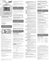
8. TRAFFIC LIGHT (SIN) INTERVAL TIME
When the gate is either opening, closing or even still (Open), the relay module keeps
switched on or oscillating. When the ECU finishes the closing cycle, the relay module
will be switched off.
Settings:
0 = Module on.
1 = Oscillation time 0.5 s
2 = Oscillation time 1.0 s
...
20 = Oscillation time 10.0 s
Instructions:
1. The gate must be still;
2. Close jumper PROG;
3. Press and release the CMD button (Six times);
4. Press and release the GRV button to enter the function;
5. Press button CMD- to decrease, button GRV+ to increase or Open jumper
PROG (Cancel function).
SN LED Signs:
Flashes once = When releasing button CMD- and/or GRV+ (command has been
accepted).
Flashes three times = When releasing button CMD- or GRV+ (command has been
denied to maximum and minimum values reached)
9. REVERSÃO PELO COMANDO
It allows the pushbutton or remote control to work when the gate is closing in order
to reverse its direction.
Instructions:
1. The gate must be still;
2. Close jumper PROG;
3. Press and release the CMD button (Seven times);
4. Press and release the GRV button to enter the function;
5. Press button GRV+ to enable the reversion through a command or the button
CMD- to disable the reversion through a command.
6. In order to finish, open jumper PROG
10. SELECTING TYPE OF END-OF-STROKE
Analog end-of-stroke system (reed-switch) or Reed Digital (Sensor Hall). After selecting
the type of end-of-stroke, the ECU will enter the path acquiring mode automatically
after the command.
Instructions:
1. The gate must be still;
2. Close jumper PROG;
3. Press and release the CMD button (Eight times);
4. Press and release the GRV button to enter the function;
5. Press button GRV+ in order to select Reed Digital or button CMD- to select
analog system.
6. In order to finish, open jumper PROG.
11. TORQUE (STRENGTH) WHEN LEARNING THE OPENING / CLOSING
LIMITS (DIGITAL ECU)
It is automatically activated whenever it is acquiring the path or after the ECU has been
connected to a power supply, in order to reach the first stop plate.
WARNING
This function is only available to the Digital End-of-Stroke system. It cannot be
used on the analog end-of-stroke system.
Settings:
34 adjustment levels.
0 = level 1.
...
33 = level 34
Instructions:
1. The gate must be still;
2. Close jumper PROG;
3. Press and release the CMD button (Nine times) to acquire torque control
when opening and (Ten times) when closing;
4. Press and release the GRV button;
5. Press button CMD- to decrease, button GRV+ to increase.
6. In order to finish, open jumper PROG.
12. PATH COVERED WHEN ACTIVATING THE ELECTRONIC LOCK
(CLOSING)
It adjusts the distance of the closing path to activate the electronic lock.
Settings:
10 adjustment levels.
0 = without lock pulse when closing.
1 = 2%.
...
9 = 20%.
Instructions:
1. The gate must be still;
2. Close jumper PROG;
3. Press and release the CMD button (Eleven times) to enter the function;
4. Press and release the GRV button;
5. Press button CMD- to decrease, button GRV+ to increase.
6. In order to finish, open jumper PROG
13. SETTING THE SIZE OF THE OPENING RAMP
It allows to individually setting the distance of the opening ramp to enter in torque
control mode to decrease the gate speed.
Settings:
17 adjustment levels.
0 = function disabled.
1 = 5% of the total path.
2 = 10% of the total path.
3 = 15% of the total path.
...
16 = 80% of the total path.
Instructions:
1. The gate must be still;
2. Close jumper PROG;
3. Press and release the CMD button (12 times) to enter the function;
4. Press and release the button GRV;
5. Press button CMD- to decrease, button GRV+ to increase.
6. In order to finish, open jumper PROG.
WARNING
In case the function is disabled (level 0), the setting of the RAMPA (ramp) trimpot
will be used to both sides (Opening and closing).
Otherwise (a level different from 0), the distance of the ramp for closing will be
defined by the RAMPA trimpot and the setting of function 12 (Adjustment on
opening ramp) will be used for the opening cycle.
14. OPENING DELAY WHEN USING A TRAFFIC LIGHT
When the gate is totally closed and still, whenever it receives a command for an
opening cycle, the traffic light will be activated and will remain switched on for the set
time interval; then the motor will be activated.
The traffic light will be switched off when the closing cycle is over, or whenever it
receives a new command through the remote control during the delay acquiring.
SETTINGS:
0 = delay disabled.
1 = 1-second delay.
2 = 2-second delay.
...
15 = 15-second delay.
Instructions:
1. The gate must be still;
2. Close jumper PROG;
3. Press and release the CMD button (Thirteen times);
4. Press and release the GRV button to enter the function;
5. Press button CMD- to decrease, button GRV+ to increase;
6. In order to finish, open jumper PROG.
15. AUTOMATIC CLOSING (PAUSE)
Semiautomatic Mode (Push-to-close – A/S Jumper
closed)
After a complete opening cycle, a new command for
closing will be necessary.
Automatic Mode (A/S Jumper open)
After a complete opening cycle, the set PAUSA (pause)
time is decreased every second; when it reaches zero,
the closing cycle will be initiated.
15.1. Pause time (Only for automatic mode)
Counterclockwise: decrease time interval. (Minimum = 1 second)
Clockwise: Increase time interval. (Maximum = 4 minutes)
16. ERASING THE PATH
Instructions:
1. The gate must be still;
2. Jumper PROG must be open;
3. Keep button GRV+ pressed for 3.0 seconds; the SN LED will flash, indicating it
has performed the operation.
17. STRENGTH (ELECTRONIC CLUTCH)
In order to this a proper utilization of this security sensor device, proceed as follows:
• After properly installing the gate opener on the gate, adjust the electronic
clutch so that the strength is the minimum needed to move the gate leaf
on its entire path, for both opening and closing.
• After finishing the adjustment, check the function, by trying its sensitivity.
Trimpot range = 20 levels.
Counterclockwise: decrease the strength
Clockwise: Increase the strength
18. RAMP TORQUE (STRENGTH)
This adjustment will decrease the gate speed when its path is into the Deceleration
ramp defined by the RAMPA (ramp) trimpot.
Set the “ramp torque” in such a way that the strength needed is the minimum for
moving the gate leaf for both opening and closing.
After finishing the adjustment, check the function, by trying its sensitivity.
In case the ramp is disabled through the RAMPA trimpot, the torque control will be
inoperative, working only according to the electronic clutch adjustment.
Trimpot range = 34 levels.
Counterclockwise: decrease torque control
Clockwise: Increase torque control
19. TRIMPOT FOR ADJUSTING OPENING / CLOSING RAMP
It will adjust the distance of the deceleration ramp at the end of the opening / closing
path, in order to decrease the gate speed.
Trimpot range = from 0% up to 80% from the acquired path.
Counterclockwise: decrease the ramp
Clockwise: Increase the ramp
WARNING
In case the parameter “OPENING RAMP SIZE ADJUSTMENT” is in a level other
than zero, the adjustment chosen on this trimpot will be used only for closing.
In case the function 12 is disabled, this trimpot will operate for both opening
and closing.
20. ADJUSTMENT OF THE ANTI-CRUSH SENSOR IN THE PATH
Upon encountering an obstacle during the closing cycle, the gate will stop and revert its
movement from opening to releasing.
ADJUSTMENT RANGE:
1 = Very sensitive
22 = Factory value
80 = Less sensitive
Instructions:
1. The gate must be still
2. Close the ‘PROG’ jumper
3. Press and release the ‘CMD’ button (14 times)
4. Press and release the ‘GRV’ button to enter the function
5. Use the ‘CMD-’ button to decrease the value (a more sensitive gate), or ‘GRV+’
to increase the value (a less sensitive gate), or remove the ‘PROG’ jumper to cancel
the function
6. To finish, remove the ‘PROG’ jumper.
21. ADJUSTMENT OF THE ANTI-CRUSHING SENSOR ON THE RAMP
Upon encountering an obstacle during the closing cycle, in the ramp area, the gate will
stop and revert its movement from opening to releasing.
ADJUSTMENT RANGE:
1 = Very sensitive
22 = Factory value
80 = Less sensitive
Instructions:
1. The gate must be still
2. Close the ‘PROG’ jumper
3. Press and release the ‘CMD’ button (15 times)
4. Press and release the ‘GRV’ button to enter the function
5. Use the ‘CMD-’ button to decrease the value (a more sensitive gate), or ‘GRV+’
to increase the value (a less sensitive gate), or remove the ‘PROG’ jumper to cancel
the function
6. To finish, remove the ‘PROG’ jumper.
WARNING
Open jumper = enable the ramp on
opening
Closed jumper = disable the ramp on
opening
GENERAL TERMS AND CONDITIONS OF WARRANTY
MOTOPPAR, Indury and Commerce of Automatic Gate Operators Ltd., regiered with
the CNPJ (National Regiry of Legal Entities) under Number 52.605.821/0001-55, located at
3526 Dr. Labieno da Coa Machado Avenue, Indurial Dirict, Garça – SP – Brazil, Zip Code
17400-000, manufacturer of PPA Products, hereby guarantees this product again design,
manufacturing or assembly defects and/or supportively as a result of material quality aws
that could make its intended use improper or inadequate, within a legal period of ninety days
from time of acquisition, provided that the inallation inructions described in the inruction
manual are observed.
Due to the credibility and tru placed on PPA products, we will add 275 more days to
the period mentioned above, reaching a warranty period of one year, likewise counted from
the time of acquisition proven by consumer through proof of purchase (Cuomer Receipt).
In case of defect, within the warranty period, PPA responsibilities are rericted to the repair
or subitution of the product manufactured by the company, under the following conditions:
1. Repair and readjument of equipment may only be carried out by PPA Technical Assiance,
which is qualied to open, remove, and subitute parts or components, as well as repair
defects covered by this warranty; thus, failure on observing this guideline and the veried
use of any non-original parts will cause the resignation of this warranty on the part of the
user;
2. The warranty will not extend to accessories such as cables, screw kit, xing brackets, power
supplies etc.;
3. Expenses for packaging, transportation and product reinallation will be sole responsibility
of the consumer;
4. The equipment mu be sent directly to the Company responsible for the sale
(manufacturer's representative), through the address contained in the purchase invoice,
properly packed, thus avoiding loss of the warranty;
5. Within the additional period of 275 days, visits and transportation in places where
authorized technical assiance is not available will be charged. The co of transportation
of the product and/or technician will be sole responsibility of the consumer and
6. The subitution or repair of the product does not prolong the warranty time.
This warranty will be terminated if the product:
1. Is damaged by natural agents, such as atmospheric discharges, oods, wildres, landslides
etc.;
2. Is inalled in an improper electric power supply or if it is not according to any of the
inallation inructions displayed on the manual;
3. Shows defects caused by droppings, collisions or any other physical accident;
4. Shows signs of product violation or attempted repair by unauthorized personnel;
5. Is not used for its intended purpose;
6. Is not used under normal conditions;
7. Is damaged by accessories or equipment connected to it.
Recommendation:
We recommend that both the inallation and the maintenance of the operator to be
performed by an authorized PPA technical service. If the product fails or has an improper
operation, seek an Authorized Technical Service to x it.

TABLA DE COMANDOS PARA CONFIGURACIONES
Estándar de fábrica Selecciona función
1 x CMD-
Entra na función
1 x GRV+
Confirmar
1 x GRV+
Cancelar
1 x CMD-
Comando en la Apertura Selecciona función
2 x CMD-
Entra en la función
1 x GRV+
Incrementar
1 x GRV+
Disminuir
1 x CMD-
Borrando transmisores Selecciona función
3 x CMD-
Entra en la función
1 x GRV+
Confirmar
1 x GRV+
Cancelar
1 x CMD-
Tiempo Luz de Garaje (LG) Selecciona función
4 x CMD-
Entra en la función
1 x GRV+
Incrementar
GRV+
Disminuir
CMD-
Freno Selecciona función
5 x CMD-
Entra en la función
1 x GRV+
Incrementar
GRV+
Disminuir
CMD-
Tiempo Señalera (SIN) Selecciona función
6 x CMD-
Entra en la función
1 x GRV+
Incrementar
GRV+
Disminuir
CMD-
Reversión por el comando Selecciona función
7 x CMD-
Entra en la función
1 x GRV+
Habilitar
1 x GRV+
Deshabilitar
1 x CMD-
Seleccionando tipo de final de carrera Selecciona función
8 x CMD-
Entra en la función
1 x GRV+
Reed Digital
1 x GRV+
Analógico
1 x CMD-
Torque (fuerza) de memorización en la apertura Selecciona función
9 x CMD-
Entra en la función
1 x GRV+
Incrementar
GRV+
Disminuir
CMD-
Torque (fuerza) de memorización en el cierre Selecciona función
10 x CMD
Entra en la función
1 x GRV+
Incrementar
GRV+
Disminuir
CMD-
Recorrido para accionamiento del bloqueo magnético en el cierre Selecciona función
11 x CMD-
Entra en la función
1 x GRV+
Incrementar
GRV+
Disminuir
CMD-
Ajuste del tamaño de la rampa de apertura Selecciona función
12 x CMD-
Entra en la función
1 x GRV+
Incrementar
GRV+
Disminuir
CMD-
Tiempo de retardo en la apertura con señalera Selecciona función
13 x CMD-
Entra en la función
1 x GRV+
Incrementar
GRV+
Disminuir
CMD-
Ajuste del sensor antiaplastamiento en el recorrido
Para seleccionar la
función, presione 'CMD-'
14 veces
Para ingresar a la función,
presione 'GRV +' una vez
Incremento =
presione 'GRV +'
una vez
Decremento =
presione 'CMD-'
una vez
Ajuste del sensor antiaplastamiento en la rampa
Para seleccionar la
función, presione 'CMD-'
15 veces
Para ingresar a la función,
presione 'GRV +' una vez
Incremento =
presione 'GRV +'
una vez
Decremento =
presione 'CMD-'
una vez
Para salir, finalizar o cancelar la función, retirar el jumper PROG.
1. PRINCIPALES CARACTERÍSTICAS
• Final de carrera analógico o digital.
• Módulo receptor RF 433,92 MHz.
• Code learning encriptado con memoria externa:
◦ 320 Transmisores código fijo (estándar HT6P20B).
◦ Transmisores código rotativo (estándar PPA).
• Entradas para:
◦ 01 x Fotocélula.
◦ 01 x Botonera (apertura y cierre).
◦ Módulo receptor RF externo.
• Salidas para:
◦ Módulo de Luz de Garaje.
◦ Módulo de Bloqueo.
◦ Módulo de Señalizador.
• Rampa de desaceleración.
• Memorización automática de recorrido A/F.
• Tiempo de retardo para apertura con señalización.
IMPORTANTE
Primera programación después de la instalación o definido nuevo tipo de trans-
misor:
Este procedimiento irá borrar y preparar la memoria para recibir los nuevos
transmisores.
1. Seleccionar tipo de transmisor:
• Con resistor = Código Rotativo PPA.
• Sin resistor = Código Fijo.
2. Borrar transmisor (ver tema “BORRANDO TRANSMISORES”)
3. Grabar nuevos transmisores (ver tema “GRABANDO TRANSMISORES”)
2. ESTÁNDAR DE FÁBRICA
Restaurar las configuraciones para el estándar de fábrica.
Operaciones:
1. Portón deberá estar parado;
2. Cerrar jumper PROG;
3. Presionar y liberar el botón CMD (1x);
4. Presionar y liberar el botón GRV para entrar en la función;
5. Botón GRV+ para configurar estándar de fábrica, o, Botón CMD- o Retirar
jumper PROG (Cancelar función).
IMPORTANTE
Antes de iniciar esta función, verificar la configuración del tipo de transmisor,
resistor CR/CF.
Operaciones:
1. Portón deberá estar parado;
2. Cerrar jumper PROG;
3. Presionar y liberar el botón CMD (3x);
4. Presionar y liberar el botón GRV para entrar en la función;
5. Botón GRV+ para borrar la memoria de los transmisores, o, Botón CMD- o Retirar
jumper PROG (Cancelar función).
5. GRABANDO TRANSMISORES
Transmisores estándar PPA (código fijo y rotativo) son suportados.
IMPORTANTE
Para la correcta grabación, tener certeza que la memoria fue iniciada correcta-
mente con el correspondiente tipo de transmisor código rotativo o fijo.
IMPORTANTE
Si por engaño es presionado el botón CMD- y en la secuencia el botón GRV+ la
central irá entrar en modo de configuración estándar de fábrica y el led quedará
encendido por 10seg. Para cancelar esta función retirar el jumper PROG.
Operaciones:
1. Portón deberá estar parado;
2. Cerrar jumper PROG;
3. Presionar botón del transmisor que desea grabar;
4. Led SN deberá estar parpadeando rápido;
5. Presionar y liberar el botón GRV+;
6. Led SN parpadea 01 vez (grabó botón) o parpadea 02 veces (botón del trans-
misor ya grabado) o 03 veces (memoria llena);
7. Liberar botón del transmisor;
8. Volver para paso 3 para grabar nuevo botón del transmisor;
9. Para finalizar, retirar jumper de PROG.
6. TIEMPO LUZ DE GARAJE (LG)
Durante ciclo de apertura o cierre del portón o parado abierto, el módulo de relé
quedará encendido.
Cuando la central finalizar el ciclo de cierre, el módulo de relé será apagado después
del tiempo programado.
CONFIGURACIONES ESTÁNDAR DE FÁBRICA
COMANDO EN LA APERTURA Habilitado
TIEMPO DE RETARDO EN LA APERTURA CON SEÑALERA 0 (Deshabilitado)
LUZ DE GARAJE 60 segs
TIEMPO ACCIONAMIENTO FRENO 150,0 mseg
SEÑALERA Activada
REVERSIÓN POR EL COMANDO Permitido
TIPO FINAL DE CARRERA Analógico
TORQUE DE APERTURA EN LA MEMORIZACIÓN Nivel 20
TORQUE DE CIERRE EN LA MEMORIZACIÓN Nivel 20
RAMPA DEL BLOQUEO MAGNÉTICO 0%
AJUSTE RAMPA APERTURA 0%
SENSOR ANTIAPLASTAMIENTO EN EL RECORRIDO 24
SENSOR ANTIAPLASTAMIENTO EN LA RAMPA 66
3. COMANDO EN LA APERTURA
Permiso de comando de la botonera o transmisor para que funcionen durante el
recorrido de apertura del portón.
También tiene la función de programar el modo de operación de la botonera
o transmisor durante el recuento de tiempo de retardo en la apertura con
señalera encendida.
El tiempo de retardo de la apertura del portón puede ser cancelado por la
botonera o transmisor.
VALORES:
0 = comando en la apertura habilitada.
1 = comando en la apertura parcial, habilitado solamente durante el retardo en
la apertura con señalera y deshabilitado durante el ciclo de apertura del portón.
2 = mando en la apertura total, deshabilitado durante el retardo en la apertura con
señalera y también durante el ciclo de apertura del portón.
Operaciones:
1. El portón debe estar parado;
2. Cierre el jumper PROG;
3. Presione y suelte el botón CMD (2x);
4. Presione y suelte el botón GRV para entrar en la función;
5. Botón GRV + para aumentar el valor, o, el botón CMD- para disminuir
el valor;
6. Para finalizar, retirar el puente de PROG
4. BORRANDO TRANSMISORES
Borra e inicializa la memoria para grabar nuevos transmisores.
Valores:
0 = Tiempo mínimo 1,0 segundo
1 = Tiempo intermediario 15,0 segundos
2 = Tiempo intermediario 30,0 segundos
...
17 = Tiempo máximo 255,0 segundos
Operaciones:
1. Portón deberá estar parado;
2. Cerrar jumper PROG;
3. Presionar y liberar el botón CMD (4x);
4. Presionar y liberar el botón GRV para entrar en la función;
5. Botón CMD- para disminuir valor, o, Botón GRV+ para aumentar valor, o,
retirar jumper PROG (Cancelar función).
Señalizaciones del led SN:
Parpadea 1x = Al liberar botón CMD- y/o GRV+ (comando acepto).
Parpadea 3x = Al liberar botón CMD- o GRV+ (comando negado para valores mí-
nimo y máximo alcanzado).
7. FRENO
Es accionado al desconectar el motor por comando, o, al encontrar los sensores ana-
lógicos (finales de carrera).
Valores:
0 = freno desconectado.
1 = Tiempo 0,150 segundos
2 = Tiempo 0,300 segundos
...
17 = Tiempo oscilación 2,55 segundos.
Operaciones:
1. Portón deberá estar parado;
2. Cerrar jumper PROG;
3. Presionar y liberar el botón CMD (5x);
4. Presionar y liberar el botón GRV para entrar en la función;
5. Botón CMD- para disminuir valor, o,
Botón GRV+ para aumentar valor, o,
Retirar jumper PROG (Cancelar función).
Señalizaciones del led SN:
Pisca 1x = Al liberar botón CMD- y/o GRV+ (comando acepto).
Pisca 3x = Al liberar botón CMD- o GRV+ (comando negado para valores mínimo
y máximo alcanzado).
CENTRAL FACILITY 4T
MANUAL TÉCNICO
P05626 - 01/2022
Rev. 6
ATENCIÓN:
No utilice el equipamiento
sin antes leer el manual de
instrucciones.
Fabricado por: Motoppar Indústria e Comércio de Automatizadores Ltda
Av. Dr. Labieno da Costa Machado, 3526 - Distrito Industrial
Garça - SP - CEP 17406-200 - Brasil
CNPJ: 52.605.821/0001-55
www.ppa.com.br | +55 14 3407 1000
8. TIEMPO SEÑALIZADOR (SIN)
Durante ciclo de apertura o cierre del portón o parado abierto, el módulo de relé
quedará encendido u oscilando.
Cuando la central finalizar el ciclo de cierre, el módulo de relé será apagado.
Valores:
0 = módulo encendido.
1 = Tiempo oscilación 0,5 segundo
2 = Tiempo oscilación 1,0 segundo
...
20 = Tiempo oscilación 10,0 segundos
Operaciones:
1. Portón deberá estar parado;
2. Cerrar jumper PROG;
3. Presionar y liberar el botón CMD (6x);
4. Presionar y liberar el botón GRV para entrar en la función;
5. Botón CMD- para disminuir valor, o, Botón GRV+ para aumentar valor, o,
Retirar jumper PROG (Cancelar función).
Señalizaciones del led SN:
Pisca 1x = Al liberar botón CMD- y/o GRV+ (comando acepto).
Pisca 3x = Al liberar botón CMD- o GRV+ (comando negado para valores mínimo
y máximo alcanzado).
9. REVERSIÓN POR EL COMANDO
Permiso de comando de la botonera o transmisor funcionen durante el recorrido de
cierre del portón para reversión.
Operaciones:
1. Portón deberá estar parado;
2. Cerrar jumper PROG;
3. Presionar y liberar el botón CMD (7x);
4. Presionar y liberar el botón GRV para entrar en la función;
5. Botón GRV+ para habilitar comando de reversión, o, Botón CMD- para de-
shabilitar el comando de reversión.
6. Para finalizar, retirar jumper de PROG.
10. SELECCIONANDO TIPO DE FINAL DE CARRERA
Sistema final de carrera Analógico (reed ampola) o Reed Digital (Sensor Hall). Tras
seleccionar el tipo de final de carrera, la central entrará en modo de memorización de
recorrido automáticamente después del comando.
Operaciones:
1. Portón deberá estar parado;
2. Cerrar jumper PROG;
3. Presionar y liberar el botón CMD (8x);
4. Presionar y liberar el botón GRV para entrar en la función;
5. Botón GRV+ para seleccionar Reed Digital, o, Botón CMD- para seleccionar
Analógico.
6. Para finalizar, retirar jumper de PROG.
11. TORQUE (FUERZA) DE MEMO-RIZACIÓN (CENTRAL DIGITAL) – APER-
TURA Y/O CIERRE
Es accionado automáticamente siempre que esté memorizando el recorrido o
después de la central ser energizada, esto para encontrar el primer stop mecánico.
IMPORTANTE
Esta función solo está disponible para el sistema de FC Digital. La misma no será
posible en el final de carrera analógico.
Valores:
34 niveles de ajuste.
0 = nivel 1.
...
33 = nivel 34
Operaciones:
1. Portón deberá estar parado;
2. Cerrar jumper PROG;
3. Presionar y liberar el botón CMD (9x) para memorización torque pulsante en
el ciclo de apertura y (10x) para ciclo de cierre;
4. Presionar y liberar el botón GRV;
5. Botón CMD- para disminuir valor, o, Botón GRV+ para aumentar valor.
6. Para finalizar, retirar jumper de PROG.
12. RECORRIDO PARA ACCIONAMIENTO DEL BLOQUEO MAGNÉTICO EN
EL CIERRE
Ajuste de la distancia de recorrido de cierre para accionamiento del bloqueo
magnético.
Valores:
10 niveles de ajuste.
0 = sin pulso de bloqueo en el cierre.
1 = 2%.
...
9 = 20%.
Operaciones:
1. Portón deberá estar parado;
2. Cerrar jumper PROG;
3. Presionar y liberar el botón CMD (11x) para entrar en la función;
4. Presionar y liberar el botón GRV;
5. Botón CMD- para disminuir valor, o, Botón GRV+ para aumentar valor.
6. Para finalizar, retirar jumper de PROG.
13. AJUSTE DEL TAMAÑO DE LA RAMPA DE APERTURA
Permite ajustar individualmente la distancia de la rampa de apertura para entrar en
torque pulsante para reducción de velocidad del portón.
Valores:
17 niveles de ajuste.
0 = función deshabilitada.
1 = 5% del recorrido total.
2 = 10% del recorrido total.
3 = 15% del recorrido total.
...
16 = 80% del recorrido total.
Operaciones:
1. Portón deberá estar parado;
2. Cerrar jumper PROG;
3. Presionar y liberar el botón CMD (12x) para entrar en la función;
4. Presionar y liberar el botón GRV;
5. Botón CMD- para disminuir valor, o, Botón GRV+ para aumentar valor.
6. Para finalizar, retirar jumper de PROG.
IMPORTANTE
Caso la función sea deshabilitada (nivel 0), el ajuste del trimpot RAMPA será
utilizado para ambos lados apertura y cierre.
Caso contrario, nivel diferente de 0, la distancia de la rampa para cierre será
definido por el trimpot RAMPA y el ajuste de la función 12 (Ajuste en la rampa de
apertura) será para el ciclo de apertura.
14. RETARDO EN LA APERTURA CON SEÑALERA
Cuando el portón esté totalmente cerrado y al recibir un mando para el ciclo de
apertura, la señalera será accionada y quedará encendida por el tiempo
programado y después el motor será accionado.
La señalera se apagará al término del ciclo de cierre del portón, o, cuando reciba un nuevo
mando por el transmisor durante la temporización del retardo.
VALORES:
0 = retardo deshabilitado.
1 = retardo de 1 seg.
2 = retardo de 2 seg.
...
15 = retardo de 15 seg.
Operaciones:
1. El portón debe estar parado;
2. Cierre el jumper PROG;
3. Presione y suelte el botón CMD (13x);
4. Presione y suelte el botón GRV para entrar en la función;
5. Botón CMD- para decrementar valor, o, botón GRV + para aumentar valor;
6. Para finalizar, retirar el puente de PROG
15. CIERRE AUTOMÁTICO (PAUSA)
Modo Semiautomático
(Jumper A/S = Cerrado)
Tras completar el ciclo de apertura del portón, será
necesario un nuevo comando para el ciclo de cierre.
Modo Automático (Jumper A/S = Abierto)
Tras completar el ciclo de apertura del portón, el tiempo
de PAUSA programado será disminuido a cada segundo,
y cuando reiniciar, el ciclo de cierre será inicializado.
15.1. Tiempo de pausa (solamente en modo automático)
Sentido anti-horario = disminuir tiempo. (Mínimo = 1seg)
Sentido horario = aumentar tiempo. (Máximo = 4min)
16. BORRANDO EL RECORRIDO
Operaciones:
1. Portón deberá estar parado;
2. El jumper PROG deberá estar abierto;
3. Mantener presionado el Botón GRV+ por 3,0 segundos; el Led SN irá encender
y apagar señalizando que ejecutó la operación.
17. FUERZA (EMBRAGUE ELECTRÓNICO)
Para que la utilización de este dispositivo sensor de seguridad sea eficaz, proceda de
la siguiente forma:
• Después de la debida instalación del automatizador en el portón, regule
el embrague electrónico de manera que la fuerza sea la mínima necesaria
para desplazar la hoja del portón en todo el recorrido, en la apertura y
cierre.
• Al final del ajuste, pruebe la función, verificando la sensibilidad.
Escala del trimpot = 20 niveles.
Sentido anti-horario = disminuir fuerza.
Sentido horario = aumentar fuerza.
18. TORQUE (FUERZA) EN LA RAMPA
Este ajuste irá disminuir la velocidad del portón cuando el recorrido esté dentro de la
región de rampa de desaceleración definido por el trimpot RAMPA
Regule el “torque en la rampa” de manera que la fuerza sea la mínima necesaria para
desplazar la hoja del portón en la apertura y cierre.
Al final del ajuste, pruebe la función, verificando la sensibilidad.
Caso la rampa es desactivada por el trimpot RAMPA, el torque pulsante quedará
inoperante, obedeciendo solamente el ajuste del embrague electrónico.
Escala del trimpot = 34 niveles.
Sentido anti-horario = disminuir torque pulsante.
Sentido horario = aumentar torque pulsante.
19. TRIMPOT DE AJUSTE DE LA RAMPA DE APERTURA Y CIERRE
Irá ajustar la distancia de las rampas de desaceleración del final de recorrido de apertura
y cierre, con el objetivo de disminuir la velocidad del portón.
Escala del trimpot = 0% hasta 80% del recorrido memorizado.
Sentido anti-horario = disminuir la rampa.
Sentido horario = aumentar la rampa.
IMPORTANTE
Caso el parámetro “AJUSTE DEL TAMAÑO DE LA RAMPA DE APERTURA” esté
en un nivel diferente de cero, el que sea programado en este trimpot será
obedecido apenas para el cierre. Caso la función (12) esté deshabilitada, este
trimpot irá operar para apertura y cierre.
20. AJUSTE DEL SENSOR ANTIAPLASTAMIENTO EN EL RECORRIDO
Al encontrar un obstáculo durante el ciclo de cierre, el portón se detendrá y revertirá su
movimiento de apertura para liberación.
RANGO DE AJUSTE:
1 = muy sensible
22 = valor de fábrica
80 = menos sensible
Instrucciones:
1. El portón debe estar parado;
2. Cierre el jumper ‘PROG’;
3. Presione y suelte el botón ‘CMD’ (14 veces);
4. Presione y suelte el botón ‘GRV’ para ingresar a la función;
5. Use el botón ‘CMD-’ para disminuir el valor (un portón más sensible), o ‘GRV +’
para aumentar el valor (un portón menos sensible), o quite el jumper ‘PROG’ para
cancelar la función;
6. Para terminar, quite el jumper ‘PROG’.
21. AJUSTE DEL SENSOR ANTIAPLASTAMIENTO EN LA RAMPA
Al encontrar un obstáculo durante el ciclo de cierre, en el área de la rampa, el portón se
detendrá y revertirá su movimiento de apertura para liberación.
RANGO DE AJUSTE:
1 = muy sensible
22 = valor de fábrica
80 = menos sensible
Instrucciones:
1. El portón debe estar parado;
2. Cierre el jumper ‘PROG’;
3. Presione y suelte el botón ‘CMD’ (15 veces);
4. Presione y suelte el botón ‘GRV’ para ingresar a la función;
5. Use el botón ‘CMD-’ para disminuir el valor (un portón más sensible), o ‘GRV +’
para aumentar el valor (un portón menos sensible), o quite el jumper ‘PROG’ para
cancelar la función;
6. Para terminar, quite el jumper ‘PROG’
ATENÇÃO
Jumper Abierto = Habilita la rampa en
la apertura.
Jumper Cerrado = Deshabilita la rampa
na apertura.
PLAZO DE GARANTÍA
MOTOPPAR, Induria y Comercio de Automatizadores Ltda., regirada con CNPJ (CIF)
52.605.821/0001-55, localizada en la Avenida Dr. Labieno da Coa Machado número 3526,
Dirito Indurial, Garça – SP – Brasil, Código Poal 17.400-000, fabricante de los productos
PPA, garantiza eo aparato contra defectos de proyectos, fabricación, montaje y/o
solidariamente en consecuencia de vicios de calidad de material que se lo hagan impropio o
inadecuado al consumo a cual se deina por el plazo legal de noventa días desde la fecha de
adquisición, siempre que se cumplan las orientaciones de inalación descritas en el manual
de inrucciones.
Como consecuencia de la credibilidad y de la conanza depositada en los productos
PPA, añadimos al plazo anteriormente descrito más 275 días, alcanzando el total de un
año, igualmente contados desde que la fecha de adquisición pueda ser comprobada por el
consumidor a través do comprobante de compra (Recibo).
En caso de defecto, en el período cubierto por la garantía, la responsabilidad de PPA
se queda reringida a la reparación o reemplazo del aparato por ella fabricada, bajo las
siguientes condiciones:
1. La reparación y reajue de aparatos solo pueden realizarse por la Asiencia Técnica de
PPA, que eá habilitada a abrir, remover, suituir piezas o componentes, así como arreglar
los defectos cubiertos por la garantía, siendo que el incumplimiento de ee y cualquier
utilización de piezas no originales observadas en el uso, implicará en la exclusión de la
garantía por parte del consumidor;
2. La garantía no se extenderá a accesorios como cables, kit de tornillos, soportes de jación,
fuentes de alimentación etc.;
3. Los coos de embalaje, transporte y reinalación del producto son responsabilidad
exclusiva de los consumidores nales;
4. Se debe enviar el aparato directamente a la empresa responsable de la venta (representante
del fabricante), a través de la dirección que gura en el recibo de compra, debidamente
embalado, evitando así la pérdida de la garantía;
5. En el período adicional de 275 días, las visitas y los transportes donde no haya servicios
autorizados serán cargadas. Los gaos de transporte del aparato y/o técnico son
responsabilidad del propietario y
6. La reparación o reemplazo del aparato no prorroga el plazo de garantía.
Ea garantía perderá su validez si el producto:
1. Sufrir daños provocados por agentes de la naturaleza, como descargas atmosféricas,
inundaciones, incendios, desmoronamientos etc.;
2. Sea inalado en red eléctrica inadecuada o en desacuerdo con cualquiera de las
inrucciones de inalación descritas en el manual;
3. Presenta defectos causados por caídas, golpes o cualquier otro accidente físico;
4. Presenta violación o intento de reparación o mantenimiento por parte de personal no
autorizado;
5. No sea usado para lo que ha sido proyectado;
6. No sea usado en condiciones normales;
7. Sufrir daños causados por accesorios o aparatos conectados al producto.
Recomendación:
Recomendamos que la inalación y mantenimientos del aparato sean efectuados por
servicio técnico autorizado PPA.
Caso el producto presente defecto o funcionamiento anormal, busque un Servicio Técnico
especializado para los debidos arreglos.
/