Craftsman 536.888110 Manual de usuario
- Categoría
- Lanzadores de nieve
- Tipo
- Manual de usuario
Este manual también es adecuado para

Operator's Manual
Snow Thrower
11 Horsepower
Electric Start
30-inch Dual Stage
Model 536.888110
CAUTION: Before using this product,
read this manual and follow all of its
Safety Rules and Operating Instructions,
Manual del usario
Quitanieves
de 30 pulgadas
11 caballos de fuerza (hp)
Bietapico
Arranque electrico
Modelo 536.888110
PRECAUCION: Antes de usar este producto,
lea este manual y siga todas las reglas de
seguridad e instrucciones de operaci6n,
Sears, Roebuck and Co., Hoffman Estates, IL 60179 U.S.A.
F-0410110L www.sears.com/craftsman

WARRANTY STATEMENT ...... 2
SAFETY RULES ............... 2
INTERNATIONAL SYMBOLS .... 4
ASSEMBLY ................... 6
OPERATION .................. 12
MAINTENANCE ............... 19
SERVICE AND ADJUSTMENT .. 23
STORAGE .................... 35
TROUBLESHOOTING TABLE . ,. 36
REPAIR PARTS ............... 40
ENGINE REPAIR PARTS ....... 60
SPANISH (ESPAI_IOL) .......... 69
PARTS ORDERING/SERVICE ..
BACK COVER
|Y/'-1 ;t ;r-'1_i tk'A[,,_
LIMITED TWO-YEAR WARRANTY ON CRAFTSMAN SNOW THROWER
For two years from the date of purchase, when this Craftsman Snow thrower is maintained,
lubricated, and tuned up according to the operating and maintenance instructions in the
owner's manual, Sears will repair, free of charge, any defect in material or workmanship.
If this Craftsman Snow thrower is used for commercial or rental purposes, this warranty ap-
plies for only 90 days from the date of purchase.
This warranty does not cover the following:
• Items which become worn during normal use, such as spark plugs, drive belts and shear
pins.
• Repair necessary because of operator abuse or negligence, including bent crankshafts
and the failure to maintain the equipment according to the instructions contained in the
owner's manual.
WARRANTY SERVICE IS AVAILABLE BY RETURNING THE CRAFTSMAN SNOW
THROWER TO THE NEAREST SEARS SERVICE CENTER IN THE UNITED STATES.
THIS WARRANTY APPLIES ONLY WHILE THIS PRODUCT IS IN USE IN THE UNITED
STATES.
This warranty gives you specific legal rights, and you may also have other rights which may
vary from state to state.
Sears, Roebuck and Co., D817WA, Hoffman Estates. IL 60179
_k OOK FOR THIS SYMBOL TO POINT OUT IMPORTANT SAFETY PRECAUTIONS.
IT MEANS--ATTENTION!!! BECOME ALERTt!! YOUR SAFETY IS INVOLVED.
Engine Exhaust, some of its constituents, and
certain vehicle components contain or emit
chemicals known to the State of California to
cause cancer and birth defects or other repro-
ductive harm.
Battery posts, terminals and related accessories
contain lead and lead compounds, chemicals
known to the State of California to cause cancer
and birth defects or other reproductive harm.
WASH HANDS AFTER HANDLING.
,_ WARNING: Always discon-
nect the spark plug wire
and place it where it cannot
make contact with spark plug to
prevent accidental starting during:
Preparation, Maintenance, or Stor-
age of your snow thrower.
IMPORTANT: Safety standards re-
quire operator presence controls to
minimize the risk of injury. Your snow
thrower is equipped with such controls.
Do not attempt to defeat the function of
the operator presence control under any
circumstances.
_0410110L 2

TRAINING
1. Read this operating and service instruction
manual carefully. Be thoroughly familiar
with the controls and the proper use of the
snow thrower. Know how to stop the snow
thrower and disengage the controls quick-
ly.
2. Never allow children to operate the snow
thrower. Never allow adults to operate the
snow thrower without proper instruction.
3. Keep the area of operation clear of all per-
sons, particularly small children and pets.
4. Exercise caution to avoid slipping or falling
especially when operating in reverse.
PREPARATION
1. Thoroughly inspect the area where the
snow thrower is to be used and remove all
doormats, sleds, boards, wires, and other
foreign objects.
2. Disengage all clutches before starting the
engine (motor).
3. Do not operate the snow thrower without
wearing adequate winter outer garments.
Wear footwear that will improve footing on
slippery surfaces.
4. Handle fuel with care; it is highly flam-
mable.
a. Use an approved fuel container.
b. Never remove fuel tank cap or add fuel
to a running engine (motor) or hot en-
gine (motor).
c. Fill fuel tank outdoors with extreme
care. Never fill fuel tank indoors.
d. Replace fuel cap securely and wipe up
spilled fuel.
e. Never store fuel or snow thrower with
fuel in the tank inside of a building
where fumes may reach an open flame
or spark.
f. Check fuel supply before each use, al-
lowing space for expansion as the heat
of the engine (motor) and/or sun can
cause fuel to expand.
5. For all snow throwers with electric starting
motors use electric starting extension
cords certified CSA/UL. Use only with a re-
ceptacle that has been installed in accord-
ance with local inspection authorities.
6. Let engine (motor) and snow thrower ad-
just to outdoor temperatures before starting
to clear snow.
7. Always wear safety glasses or eye shields
during operation or while performing an ad-
justment or repair to protect eyes from
foreign objects that may bethrown from the
snow thrower.
3
_0410110L
OPERATION
1. Do not operate this snow thrower if you are
taking drugs or other medication which can
cause drowsiness or affect your ability to
operate this snow thrower.
2. Do not use the snow thrower if you are
mentally or physically unable to operate the
snow thrower safely.
3. Do not put hands or feet near or under ro-
tating parts. Keep clear of the discharge
opening at all times.
4. Exercise extreme caution when operating
on or crossing gravel drives, walks or
roads. Stay alert for hidden hazards or
traffic.
5. After striking a foreign object, stop the en-
gine (motor), remove the wire from the
spark plug, thoroughly inspect snow
thrower for any damage, and repair the
damage before restarting and operating
the snow thrower.
6. If the snow thrower should start to vibrate
abnormally, stop the engine (motor) and
check immediately for the cause. Vibration
is generally a warning of trouble.
7. Stop the engine (motor) whenever you
leave the operating position, before un-
clogging the auger/impeller housing or dis-
charge chute and when making any
repairs, adjustments, or inspections.
8. When cleaning, repairing, or inspecting,
make certain the auger/impeller and all
moving parts have stopped and all controls
are disengaged. Disconnect the spark plug
wire and keep the wire away from the spark
plug to prevent accidental starting.
9. Take all possible precautions when leaving
the snow thrower unattended. Disengage
the auger/ impeller, stop engine (motor),
and remove key.
10. Do not start or run engine in enclosed area,
even if doors or windows are open. Ex-
haust fumes are dangerous (containing
CARBON MONOXIDE, an ODORLESS
and DEADLY GAS).
11. Do not clear snow across the face of
slopes. Exercise extreme caution when
changing direction on slopes. Do not at-
tempt to clear steep slopes.
12. Never operate the snow thrower without
proper guards, plates or other safety pro-
tective devices in place.
13. Never operate the snow thrower near en-
closures, automobiles, window wells, drop-
offs, and the like without proper adjustment
of the snow discharge angle. Keep children
and pets away.

14.Donotover!cadthesnowthrowercapacity
byattemptingtoclearsnowattoofasta
rate.
15.Neveroperatethesnowthrowerathigh
transportspeedsonslipperysurfaces.
Lookbehindandusecarewhenbacking
up.
16.Neverdirectdischargeatbystandersor
allowanyoneinfrontofthesnowthrower.
17.Disengagepowertothecollector/impeller
whensnowthroweristransportedornotin
use.
18.Useonlyattachmentsandaccessoriesap-
provedbythemanufacturerofthesnow
thrower(suchastirechains,electricstart
kits,ect.).
19,Neveroperatethesnowthrowerwithout
goodvisibilityorlight,Alwaysbesureof
yourfootingandkeepafirmholdonthe
handles.Walk;neverrun.
20,Donotover-reach.Keepproperfooting
andbalanceatalltimes,
21.Donotattempttousesnowthrowerona
roof.
MAINTENANCE AND STORAGE
1. Check shear bolts and other bolts at fre-
quent intervals for proper tightness to be
sure the snow thrower is in safe working
condition.
2. Store the snowthrower away from ignition
sources or appliances that have a pilot
light, such as hot water and space heaters,
clothes dryers, etc.... Allow the engine
(motor) to cool before storing in any enclos-
ure.
3. Always refer to operator's guide instruc-
tions for important details if the snow
thrower is to be stored for an extended
period.
4. Maintain or replace safety and instruction
labels, as necessary.
5. Run the snow thrower a few minutes after
throwing snow to prevent freeze-up of the
auger/impeller.
_lb WARNING: This snow thrower isfor use on sidewalks, driveways
and other ground level surfaces.
Caution should be exercised while using on
steep sloping surfaces. DO NOT USE
SNOW THROWER ON SURFACES ABOVE
GROUND LEVEL such as roofs of resi-
dences, garages, porches or other such
structures or buildings.
_"_"_'_o_l_..-_
IMPORTANT: Many of the following symbols are located on your snow thrower or on litera-
ture supplied with the product. Before you operate the snow thrower, learn and understand
the purpose for each symbol.
CONTROL AND OPERATING
SYMBOLS
Slow Fast Electric Start Engine Start Engine Run
I H N
Engine Off Engine Stop On Choke Off Choke On Neutral
I''J'" --'I"-
Throttle Primer Button Ignition Key
®®
Ignition Off Ignition On
_0410110L 4

Drive Clutch Forward Reverse Auger Clutch Auger Collector Engage
Push To Engage Fuel Oil Fuel Oil Mixture
Electric Starter
Discharge DOWN Discharge UP Discharge LEFT Discharge RIGHT
Weight Transfer Weight Transfer Transmission Ignition Key
Lift Handle To Depress Pedal Insert To Run,
Engage To Disengage Pull Out To Stop.
Safety Warning Symbols
DANGER DANGER WARNING
Thrown Objects. Thrown Objects.
Keep Bystanders Away. Keep Bystanders Away.
IMPORTANT
Read Owner's Manual
Before Operating
This Machine.
DANGER
Avoid Injury From
Rotating Auger. Keep
Hands, Feet And
Clothing Away.
DANGER
Stop The Engine Before
Unclogging Discharge Chute!
WARNING
HotSurface
STOP
_0410110L 5

CONTENTS OF PARTS BAG (ACTUAL SIZE)
1 - Owner's Manual (not shown)
1 - Packet of Fuel Stabilizer (not shown)
1 - Warranty Card (not shown)
*Non-Assembly Parts, foundintoolboxlocatedonbeltcover
*2 Spacer
1 Shift Lever Knob
(not actual size)
*2 Shear Pins
(_ 1 Washer
1 Nut
1 Remote Chute
Knob (not actual size)
1 Ignit__
F 0410110L 6

_hb ARNING: Always wear
safety glasses or eye shields
while assembling snow
thrower.
TOOLS REQUIRED FOR
ASSEMBLY
1 - Knife to cut carton
2 - 1/2 inch wrenches
(or adjustable wrenches)
2 - 9/16 inch wrenches
(or adjustable wrenches)
2 - 3/4 inch wrenches
(or adjustable wrenches)
1 - Pliers (to spread cotter pin)
1 - Screwdriver
1 - Measuring tape or ruler
Figure 1
Figure 1 shows the snow thrower in the
shipping position.
Figure 2 shows the snow thrower com-
pletely assembled.
References to the right or left hand side
of the snow thrower are from the view-
point of the operator's position behind
the unit.
TO REMOVE SNOW THROWER FROM CARTON
1. Locate all parts packed separately Auc er Drive Lever
and remove from the carton. Shifter Lever
NOTE: Place fuel stabilizer in a Traction
safe place until needed for storage. Drive Lever
2. Remove and discard the packing
material from around the snow
thrower.
3. Cut down all four corners of the car-
ton and lay the panels flat.
4. Cut the straps that secure the axle Chute
to the pallet. Deflector
5. For shipping purposes, the height
adjust skids are attached to the
pallet. Remove the screw that se-
cures each height adjust skid to
the pallet. See Figure 2.
6. Roll snow thrower off the pallet by
pulling on the lower handle.
CAUTION: DO NOT back over Height
control cables. Adjust
7. Remove all packing material from Skid
the unit.
8. Cut ties securing the clutch contro!
cable to the lower handle and lay Figure 2
cable back away from the motor
frame.
F 0410110L 7

TO ASSEMBLE THE HANDLE AND
CRANK ASSEMBLY
1. Cut tie holding shift rod to lower
handle and move shifter to the first
forward gear.
2. Cut and discard the plastic tie that
secures the crank assembly.
3. Loosen, but do not remove, the
screws, flatwashers, Iockwashers,
and hex nuts in the upper holes of
the lower handle. See Figure 3.
4. Remove the fasteners and the eye-
bolt from the lower holes of the low-
er handle See Figure 5.
RightHand Side
Of Upper Handle%
Loosen,
but do not
remove
11/32"
EF{
Flatwasher
5/16" Hex Nut'_;;t
5/16"
Screw
5/16" Split
Lockwasher
Figure 3
NOTE: Make sure the cables are not
caught between the upper and lower
handle.
5. Raise the upper handle into operat-
ing position.
NOTE: If the cables have become dis-
connected form the drive levers, rein-
stall the cables as shown in Figure 4.
Lever
"Z" Fitting X
6. Install the fasteners that were re-
moved in step 4. DO NOT tighten
until all bolts are in place.
Left Hand Side Of
Upper Handle
Eye Bolt
3/8" Nylon
_ Locknut
3/8"
Flatwasher
3/8" Flatwasher
Figure 5
7. Attach the crank rod to the universal
joint assembly with the hair pin. See
Figure 6.
8. Tighten nut on eye bolt, Make sure
eye bolt is properly aligned and the
crank can freely rotate.
9. Tighten all handle and panel bolts.
Universal Joint Asser
Crank Rod
Figure 6
Control Oable Figure 4
F 0410110L 8

NOTE"Ifthecableshavebecomedis-
connected,connectcablesasshownin
Figure7.
TractionDriveCable AugerDriveCable
Figure7
Remote Chute Knob
1. Assemble the remote chute knob
onto the lever until snug against the
nut (see Figure 8), On some mod-
els the remote chute knob is at-
tached,
2. Make sure lip on the remote chute
knob is pointed toward the engine.
3. Tighten the nut against the bottom
of the remote chute knob,
Lip _.
Remote
Chute
Knob
Figure 8
HOW TO INSTALL
THE SPEED SELECT KNOB
Install the speed select knob to the
speed select lever. See Figure 9. On
some models the speed select knob is
attached.
_ Speed Select
Knob
_ Speed Select
Lever
Figure 9
F 0410110L 9

How To Install The Speed Control Rod
1 Put the speed select lever into the
sixth gear position.
2. Put the speed select lever into the
first gear position.
3. Attach the ball joint, located on the
bottom end of the speed control
rod, to the shift yoke assembly.
See Figure 11. The fasteners
(washer and nut) to attach the ball
joint are in the parts bag.
4. The length ot the ball joint and
speed control rod have been pro-
adjusted at the factory. If an adjust-
ment is required, loosen the nut.
Remove the fasteners to discon-
nect the ball joint from the shift
yoke assembly. To lengthen or
shorten the speed control rod, turn
the adapter to obtain the correct
length.
5. Make sure the speed select lever
functions correctly. Move the speed
select lever through all speeds.
Speed
Select
Bracket
_SsPhi_-rdvSeelect
Cotter Pin
Speed
Control
Rod
Figure 10
k%_ Speed.Oontrol Rod
Nut_ _ y
Adapter 4_ ,
Bo?lnlt"1 _X
Fasteners
Figure 11
How To Assemble The Chute Deflector
1. Remove the carriage bolt. See
Figure 12.
2. Raise the chute deflector into op-
erating position.
3 Fasten chute deflector to flange
with carriage bolt. Make sure to
install with head of carriage bolt on
the inside of the flange.
Operating
Position
4. Fasten with washer and Iocknut.
5. Tighten Iocknut securely.
NOTE: Make sure all carriage bolts in
flange are tight. DO NOT
OVERTIGHTEN.
/
Carriage Bolt
Flange
F 0410110L
10
Chute
Deflector
Nut
/
\
Washer
Figure 12

How To Set The Skid Height
The snow thrower is equipped with
height adjustable skids mounted on
the outside of the auger housing. See
Figure 13. To adjust the height of the
skids, see To Adjust Skid Height para-
graph in the Service And Adjustment
section
AdjI Figure 13
How To Set
The Length Of The Cables
The cables were adjusted at the factory
and no adjustments should be neces-
sary. However, after the handles are put
in the operating position, the cables can
be too tight or too loose. If an adjust-
ment is necessary, see "How To Check
And Adjust The Cables" in the Service
And Adjustment section.
_-" CHECKLIST
Before you operate your new snow
thrower, to ensure that you receive the
best performance and satisfaction from
this quality product, please review the
following checklist:
_' All assembly instructions have been
completed.
v' The discharge chute rotates freely.
_' No remaining loose parts in carton.
_' Check the fasteners. Make sure all
fasteners are tight.
v' Check the air pressure of the tires.
Correct air pressure is from 14 to 17
PSI. See the side of the tire for maxi-
mum inflation. Do not exceed maxi-
mum inflation.
_' On electric start models, the unit was
shipped with the starter cord plugged
into the engine. Before operating, un-
plug the starter cord from the engine.
While learning how to use your snow
thrower, pay extra attention to the fol-
lowing important items:
_' Engine oil is at proper level. Use a
high quality detergent oil classified
"For Service SG, SH, SJ, SL, or
higher".
_' Make sure gas tank is filled properly
with clean, fresh, unleaded gasoline
with a minimum of 85 octane.
_" Become familiar with all controls-
their location and function. Operate
controls before starting engine.
F 0410110L 11

[o_o)_l
KNOW YOUR SNOW THROWER
READ THiS OWNER'S MANUAL AND SAFETY RULES BEFORE OPERATING
YOUR SNOW THROWER. Compare the illustrations with your SNOW THROWER
to familiarize yourself with the location of various controls and adjustments. Save
this manual for future reference.
Speed Shifter Lever _ Lever
Auger Drive Lever Traction Drive Lever
Chute
Deflector
Choke
Control Gas
Primer Cap
Bu_on
Discharge
Chute
Safety
Key
Recoil
Starter
Handle
Electric
Start
Stop Button
Switch
Height Adjust Skid Shear Pin
Scraper Bar Figure 14
Auger Drive Lever - Starts and stops
the auger and impeller (snow gathering
and throwing)
Traction Drive Lever - Propels the
snow thrower forward and in reverse.
Speed Shifter Lever - Selects the
speed of the snow thrower (6 speeds for-
ward and 2 speeds reverse).
Crank Assembly - Changes the direc-
tion of snow throwing through the dis-
charge chute.
Chute Deflector - Changes the distance
the snow is thrown.
Discharge Chute - Changes the height
and direction the snow is thrown.
Height Adjust Skid - Adjusts the ground
clearance of the auger housing.
Safety Key - Must be inserted to start
the engine.
F 0410110L
12
Recoil Starter Handle - Starts the en-
gine manually.
Choke Control - Used to start a cold
engine.
Primer Button - Injects fuel directly into
the carburetor manifold for fast starts in
cold weather.
Remote Chute Control Lever - Push
forward to discharge snow high and far.
Pull remote lever back to discharge snow
down.
Electric Start Button - (if so equipped)
Usedto startthe engineusingthe 120V elec-
tricstarter,
Shear Pin - Shear pins are designed to
break (to protect the machine) if an ob-
iect becomes lodged in the auger hous-
ing.
Toolbox - spare shear pins and
spacers are located in toolbox.

[o_o)_l
The operation of any snow thrower can
result in foreign objects being thrown
into the eyes, which can result in se-
vere eye damage. Always wear safety
glasses or eye shields while operating
the snow thrower.
We recommend standard safety
glasses or a wide vision safety mask for
over your glasses.
_ ARNING: Read Owner's
Manual before operating
machine. Never direct dis-
charge toward bystanders. Stop the
engine before unclogging discharge
chute or auger housing and before
leaving the machine.
TO STOP YOUR
SNOW THROWER
1. To stop throwing snow, release the
auger drive lever. See Figure 15.
2. To stop the wheels, release the
traction drive lever.
3. To stop the engine, pull out the
safety key.
CAUTION: To stop the engine, do not
move the choke control to CHOKE
position. Backfire or engine damage
can occur.
Auger Drive Lever Traction Drive Lever
Shift Lever
TOCONTROLSNOWDISCHARGE
1.
2.
Turn the crank assembly to set the
direction of the snow throwing.
Push the remote chute lever for-
ward to discharge the snow high
and far. Pull the remote chute le-
ver back to discharge the snow
down.
HOW TO MOVE FORWARD AND
BACKWARD
1. To shift, release the traction drive
lever (left hand) and move the
speed shift lever to the speed you
desire. See Figure 15. Ground
speed is determined by snow condi-
tions. Select the speed you desire
by moving the speed shifter lever
left into the appropriate notches on
the shift lever plate:
Speeds 1,2 - Wet, Heavy
Speed 3 - Light
Speed 4 -Very Light
Speed 5, 6 - Transport only
2. Engage the traction drive lever (left
hand). As the snow thrower starts
to move, maintain a firm hold on the
handles, and guide the snow throw-
er along the clearing path. Do not
attempt to push the snow thrower.
3. To move the snow thrower back-
ward, move the speed shifter lever
right into first or second reverse and
engage the traction drive lever (left
hand).
IMPORTANT: Do not move the 8peed
shifter lever while the traction lever
is down.
F 0410110L
Crank
&ssembly
Figure 15
13
TO THROW SNOW
1. Push down the auger driver lever
(right hand). See Figure 15.
2. Release to stop throwing snow.

[o_o)_l
HOW TO USE
THE WHEEL LOCKOUT
The right wheel is secured to the axle
with a lockout pin. See Figure 16. The
unit was shipped with the lockout pin in
the locked position. For ease of maneu-
verability in light snow conditions, dis-
connect the lockout pin as follows.
1. Pull the knob out to disengage the
lockout pin.
2. To lock in the disengaged position,
turn the knob 1/4 turn (90 degrees).
Knob
Wheel Lockout
Figure 16
BEFORE STARTING THE ENGINE
Before you service or start the en-
gine, familiarize yourself with the
snow thrower. Be sure you under-
stand the function and location of all
controls.
Check the tension of clutch cable
before starting the engine. See To
Adjust The Control Cable para-
graph in the Service & Adjust-
ments section of this manual.
3.
4.
Be sure that all fasteners are tight.
Make sure the height adjust skids
are properly adjusted. See To Ad-
just Skid Height paragraph in the
Service & Adjustments section of
this manual.
5. Check tire pressure (14-17
pounds). Do not exceed maximum
amount of pressure.
CHECK THE OIL:
NOTE: The engine was shipped from
the factory filled with oil. Check the lev-
el of the oil. Add oil as needed.
To Add Oil
1. Make sure the unit is level.
NOTE: Do not check the level of the
oil while the engine runs.
F 0410110L
2. Remove the oil fill cap/dipstick and
wipe with a clean cloth.
3. Insert the oil fill cap/dipstick and
turn clockwise to tighten.
4. Remove the oil fill cap/dipstick and
check the oil.
5. If necessary, add oil until the oil
reaches the FULL mark on the oil fill
cap/dipstick (see Figura 67). Do not
add too much oil.
)1t Fill Cap/Dipstick
14
%
NOTE: Oil level
must be at the
Full mark
Figure 17
6. Tighten the fill cap/dipstick securely
each time you check the oil level.
NOTE: Synthetic oil can assist with
starting in extreme cold temperatures.
Synthetic 5W30 is acceptable for all
temperatures. DO NOT mix oil with
gasoline.
FILL GAS:
This engine is certified to operate on
gasoline. Exhaust Emission Control
System: EM (Engine Modifications).

[o_o)_l
,_ WARNING: Alcohol blended
fuels (called gasohol or
those using ethanol or
methanol) can attract moisture
which leads to separation and
formation of acids during storage.
Acidic gas can damage the fuel sys-
tem of an engine while in storage.
NOTE: To avoid engine problems, the
fuel system must be emptied before
storage for 30 days or longer. Start the
engine and let it run until the fuel lines
and carburetor are empty. Use fresh
fuel next season. See the Storage
_b ARNING: Gasoline is flam-
mable. Always use caution
when handling or storing
gasoline.
• Turn engine off and let engine
cool at least two minutes before
removing the gas cap.
• Do not fill fuel tank while snow
thrower is running, when it is hot,
or when snow thrower is in an en-
closed area.
• Keep away from open flame or an
electrical spark and do not smoke
while filling the fuel tank.
section in this manual for additional in-
formation.
Never use engine or carburetor cleaner
products in the fuel tank or permanent
damage may occur.
Fill the fuel tank only with a fresh,
clean, unleaded regular, unleaded pre-
mium, or reformulated automotive gas-
oline with a minimum of 85 octane. DO
NOT use leaded gasoline. Make sure
that the container you pour the gasoline
from is clean and free from rust or other
foreign particles. Never use gasoline
that may be stale from long periods of
storage in the container.
• Never fill the tank completely. Fill
the tank to approximately 1-1/2"
below the top of the tank opening
to provide space for expansion of
fuel.
• Always fill fuel tank outdoors and
use a funnel or spout to prevent
spilling.
• Make sure to wipe up any spilled
fuel before stating the engine.
• Store gasoline in a clean, ap-
proved container and keep the
cap in place on the container.
TO STOP ENGINE
CAUTION: To stop the engine, do not
move the choke control to CHOKE
position. Backfire or engine damage
can occur.
1. Push the stop switch to the OFF
position.
Stop Switch
Pull out the safety key.
Safety Key
Figure 19
Figure 18
F 0410110L 15

[o_o)_l
TO START ENGINE
Be sure that the engine oil is at FULL
mark on dipstick. The snow thrower
engine is equipped with a 120 volt A.C.
electric starter and recoil starter. Be-
fore starting the engine, be certain that
you have read the following information.
If engine floods, set the choke to the
OPEN/RUN position and crank until the
engine starts.
A ARNING" Rapid retraction
of the starter cord (kick-
back) will pull your hand or
arm toward the engine faster than
you can let go of the starter cord.
Broken bones, fractures, bruises, or
sprains could result
• When starting the engine, slow-
ly pull the starter cord until re-
sistance is felt. Then, rapidly
pull the starter cord.
• Before starting the engine, re-
move all external equipment/en-
gine loads.
• Make sure components; such as
impellors, pulleys or sprockets,
are securely attached.
A ARNING: The starter i8
equipped with a three-wire
power cord and plug and is
designed to operate on 120 volt AC
household current. It must be prop-
erly grounded at all times to avoid
the possibility of electrical shock
which may be injurious to operator.
• Follow all instructions carefully
as set forth in the "To Start En-
gine" section.
• Determine that your house wiring
i8 a three-wire grounded system.
Ask a licensed electrician if you
are not sure. If your house wire
system is not a three-wire system,
do not use this electric starter un-
der any conditions.
• If your system is grounded and a
three-hole receptacle is not avail-
able at the point your starter will
normally be used, one should be
installed by a licensed electrician.
• When connecting 120 volt AC
"Power Cord", always connect the
cord to the Switch Box on the en-
gine first, then plug the other end
into the three-hole grounded re-
ceptacle. When disconnecting
"Power Cord", always unplug the
end in the three-hole grounded re-
ceptacle first.
Choke Knob
Starteri!
Button
Safety Key
F 0410110L
Stop Switch
16
Recoil Starter
Handle
Power Cord
Receptacle
Figure 20

[o_o)_l
How To Start A Cold Engine
1. Be sure auger drive and traction
drive levers are in the disengaged
(RELEASED) position.
2. Push the stop switch to the ON
position (see Figure 20).
3. Push in the safety key.
4. Rotate the choke knob to the
CHOKE position.
5. (Electric Start) Plug the power cord
into the starter motor on the en-
gine. Plug the other end of power
cord into a three-hole, grounded
120 VOLT, AC receptacle.
6. Push the primer button as speci-
fied below. Remove finger from
primer button between pushes.
• Push two times if temperature is
15° F (-9 ° C) or higher.
• Push four times if temperature is
below 15° F (-9 ° C).
7. (Electric Start) Push down on the
starter button until the engine starts.
To prolong the life d the starter, do not
crank for more than 5 seconds at a
time. Wait one minute between starts
to allow the starter motor to coo!.
8. (Recoil Start) Slowly pull the recoil
starter handle until resistance is
felt and then pull rapidly to start the
engine. Do not allow the recoil
starter handle to snap back. Slowly
return the recoil starter handle,
9. If the engine does not start in 5 or 6
tries, See Difficult Starting in the
"Troubleshooting Table".
10. Allow the engine to warm up for
several minutes. As the engine
warms up, adjust the choke knob
toward the RUN position. Wait until
the engine runs smoothly before
each choke adjustment.
11. (Electric Start) First disconnect
power cord from receptacle. Then,
disconnect the power cord from the
starter motor.
How To Start A Warm Engine
If restarting a warm engine after a short
shutdown, leave the choke lever in the
off position and do not push the primer
button. If the engine fails to start, follow
the Cold Start instructions.
Frozen Starter
If the starter is frozen and will not turn
the engine, follow the steps below.
1. Pull as much starter rope as pos-
sible out of the starter.
2. Release the starter handle and let it
snap back against the starter. Re-
peat until the engine starts.
Warm engines will cause condensation
in cold weather. To prevent possible
freeze-up of recoil starter and engine
controls, proceed as fol!ows after each
snow removal job.
1. With engine off, allow engine to cool
for several minutes.
2. Pull starter rope very slowly until re-
sistance is felt, then stop. Allow the
starter rope to recoil. Repeat three
times.
3. With the engine not running, wipe all
snow and moisture from the carbu-
retor cover in area of controls and
levers. Also, move the choke control
and starter handle several times.
F 0410110L 17

[o_o)_l
_b ARNING: Never run en-
gine indoors or in enclosed,
poorly ventilated areas. En-
gine exhaust contains CARBON
MONOXIDE, AN ODORLESS AND
DEADLY GAS. Keep hands, feet,
hair and loose clothing away from
any moving parts on engine and
snow thrower.
• Engine parts, especially the muf-
fler, become extremely hot. Se-
vere thermal burns can occur on
contact. Allow the engine to cool
before touching.
• Never allow children to operate
the snow thrower. Never allow
adults to operate the snow throw-
er without proper instruction.
• Keep the area of operation clear
of all persons, particularly small
children and pets.
• Never leave the snowthrower un-
attended while the engine is run-
ning. Anyone operating the en-
gine or equipment must carefully
read and understand the operat-
ing instructions.
TO REMOVE SNOW FROM AUGER
_ ARNING: Do not attempt
to remove snow or debris
that may become lodged in
auger with your hands. Use the
cleaning stick to remove snow or
debris.
A cleaning stick is attached to the top of
the auger housing. Use the cleaning
stick to remove snow from the auger
housing.
• Release auger drive lever.
• Remove (do not turn) safety key.
• Disconnect spark plug wire.
• Do not place your hands in the au-
ger or discharge chute. Use the
cleaning stick to remove snow.
SNOW THROWING TIPS
1. For maximum snow thrower efficien-
cy in removing snow, adjust ground
speed. Go slower in deep, freezing
or wet snow. If the wheels slips, re-
duce forward speed.
2. Most efficient snow throwing is ac-
complished when the snow is re-
moved immediately after if falls.
3. For complete snow removal, slightly
overlap each path previously taken.
4. The snow should be discharged
down wind whenever possible.
5. For normal usage, set the skids so
that the scraper bar is 1/8" above
the skids. For extremely hard-
packed snow surfaces, adjust the
skids upward so that the scraper
bar touches the ground.
6. On gravel or crushed rock surfaces,
set the skids at 1-1/4" below the
scraper bar. See To Adjust Skid
Height paragraph in the Service &
Adjustments section of this manu-
al. Rocks and gravel must not be
picked up and thrown by the ma-
chine.
7. After the snow throwing job has
been completed, allow the engine to
idle for a few minutes, which will
melt snow and accumulated ice off
the engine.
8. Clean the snow thrower thoroughly
after each use.
9. Remove ice and snow accumulation
and all debris from the entire snow
thrower, and flush with water (if pos-
sible) to remove all salt or other
chemicals. Wipe snow thrower dry.
F 0410110L 18

CUSTOMER RESPONSIBILITIES
SERVICERECORDS
Fillindatesasyou Before Every Every Every Every
completeregular Each 8 25 50 100 Each Before
service. Use Often Hours Hours Hours Hours Season Storage
Change Engine Oil
Tighten All Screw# and
Nuts
Check and Clean Spark
Plug
Clean and Inspect
Spark Arrestor
Check Fuel
Check Ad ustment of I i
Auger Control Cable
Auger Drive Belt *
n I I " ./ ' I I I
Check Tire Pressure '7
* Adjust after 2 to 4 hours of use.
GENERAL RECOMMENDATIONS
The warranty on this snow thrower does
not cover items that have been subjected
to operator abuse or negligence. To re-
ceive full value from the warranty, the op-
erator must maintain the snow thrower as
instructed in this manual.
Some adjustments will need to be made
periodically to properly maintain your
snow thrower.
Maintenance, replacement, or repair of the
emission control devices and systems can
be performed by any non-road engine re-
pair establishment or individual. Regular
maintenance will improve the performance
and extend the lifeof the engine.
_b WARNING: Do not strike the
flywheel with a hammer or a
hard opject. If done, the fly-
wheel can shatter during operation.
Do not tamper with the governor
spring, links or other parts to in-
crease engine speed.
F 0410110L
AFTER EACH USE
• Run the machine to clear the auger
of snow.
• To prevent freezing of the auger or
controls, remove all snow and slush
from the snow thrower.
• Check for any loose or damaged
parts.
• Tighten any loose fasteners.
• Check and maintain the auger.
• Check controls to make sure they
are functioning properly.
• If any parts are worn or damaged,
replace immediately.
19

ENGINE SPECIFICATIONS
HORSEPOWER 11 HP
DISPLACEMENT 305 cc
BORE 79mm (3.11 in.)
STROKE 62mm (2.44 in.)
GASOLINE 3 quarts
CAPACITY (unleaded)
OIL CAPACITY
5W30
(18 oz capacity)
SPARK PLUG: Champion RJ19LM
(Gap .030 in.) or
equivalent
VALVE Intake: 0.004 0.006 in.
CLEARANCE: Exhaust: 0.009 0.011 in.
ARMATURE
AIRGAP: 0.010 0.014 in.
POWER RATINGS
The power ratings for an individual
engine model are initially developed by
starting with SAE (Society of Automo-
tive Engineers) code J1940 (Small
Engine Power & Torque Rating Proce-
dure) (Revision 2002-05). Given both
the wide array of products on which our
engines are placed, and the variety of
environmental issues applicable to
operating the equipment, it may be that
the engine you have purchased will not
develop the rated horsepower when
used in a piece of power equipment
(actual "on-site" power). This difference
is due to a variety of factors including,
but not limited to, the following: differ-
ences in altitude, temperature, baro-
metric pressure, humidity, fuel, engine
lubrication, maximum governed engine
speed, individual engine to engine
variability, design of the particular piece
of power equipment, the manner in
which the engine is operated, engine
run-in to reduce friction and clean out of
combustion chambers, adjustments to
the valves and carburetor, and other
factors. The power ratings may also be
adjusted based on comparisons to
other similar engines utilized in similar
applications, and will therefore not
necessarily match the values derived
using the foregoing codes.
SNOW THROWER
AUGER DRIVE BELT
Adjust the auger drive belt after the first
2 to 4 hours of use, again about mid-
season and twice each season thereaf-
ter (See to "Belt Adjustment" in the
Service and Adjustment section).
LUBRICATION - EVERY 10 HOURS
1. Auger Shaft - Using a hand grease
gun, lubricate the auger shaft zerk
fittings (A) every ten (10) operating
hours. Each time a shear bolt is re-
placed, the auger shaft MUST be
greased. See Figure 21. See To
Replace Auger Shear Bolt in the
Service and Adjustment section.
Figure 21
F 0410110L 20

CHAIN LUBRICATION
EVERY 25 HOURS
1. Position speed selector lever in first
(1) forward gear.
2. Stand the snow blower up on the
auger housing end.
NOTE: When the crank case if
filled with oil, do not leave the
snow blower standing up on the
auger housing for an extended
period of time.
3. Remove the bottom panel.
4. Lubricate the chains with a chain
type lubricant.
5. For storage, wipe the hexshaft and
sprockets with 5W30 motor oil.
NOTE: Clean all excess grease or
oil found on the rubber friction
wheel or the disc drive plate.
CAUTION: Do not allow grease or
oil to contact the rubber friction
wheel or the disc drive plate.
6. Install the bottom panel.
Chain
Hexshaft
Figure 22
AUGER GEAR BOX
The auger gear box is lubricated at the
factory and should not require addition-
al lubrication. If for some reason the
lubricant should leak out, have auger
gear case checked by a competent re-
pairman.
ENGINE
LUBRICATION
Check the crankcase oil level before
starting the engine and after each eight
(8) hours of continuous use. See
Figure 23. Add S.A.E. 5W30 motor oil
as needed. Synthetic 5W30 is accept-
able for all temperatures. Tighten fill
cap/dipstick securely each time you
check the oil level.
Oi! Fill Cap/Dipstick
Oil Drain
Pluc
i
Change the oil every fifty (50) hours or
at least once a year if the snow thrower
is not used for fifty (50) hours.
TO CHANGE ENGINE OIL
1. Position the snow thrower so that
the oil drain plug is at the lowest
point on the engine.
2. When the engine is warm, remove
the oil drain plug and the oil fill
cap/dipstick (see Figure 23). Drain
the oil into a suitable container.
3. After draining all the oil, reinstall the
oil drain plug securely.
4. Fil! the engine crankcase with the
recommended motor oil, pouring
slowly. DO NOT OVERFILL. See
"To Add Oil" in the Operation Sec-
tion.
NOTE: FULL mark.
Figure 23
F 0410110L 21

SPARK PLUG
Check the spark plug every twenty-
five (25) hours. Replace the spark plug
if the electrodes are pitted or burned, if
the porcelain is cracked, or every 100
hours of use.
1. Make sure the spark plug is clean.
Clean the spark plug by carefully
scraping the electrodes (do not
sand blast or use a wire brush),
2. Check the spark plug gap with a
feeler gauge and reset gap to 0.30"
if necessary. See Figure 24.
3. Before installing the spark plug,
coat the threads lightly with oil for
easy removal. Tighten the spark
plug to a torque of 15 foot-pounds.
Feeler Gauge
0.030"
Spark Plug
Figure 24
F 0410110L 22

[.,,."_o,,_ V_IZIB]P'_"_
_b ARNING: Always discon-
nect the spark plug wire and
place it where it cannot
make contact with spark plug to pre-
vent accidental starting when mak-
ing any adjustments or repairs.
TO ADJUST SKID HEIGHT
This snow thrower is equipped with two
height adjustment skids, located on
the outside of the auger housing. See
Figure 25.
These skids elevate the front of the
snow thrower.
Mountinc Nuts
O
Aug ig Height Adjust Skid
Figure 25
For normal hard surfaces, such as a
paved driveway or walk, adjust the
skids as follows.
1. Position the snow thrower on a level
surface.
2. Make sure both tires are equally in-
flated. Proper tire pressure is 14 to
17 PSI. See side of tire for maxi-
mum inflation. Do not exceed maxi-
mum sidewall pressure on tire.
3. Place the extra shear bolts supplied
with the unit under each end of the
scraper bar next to the adjustable
skids.
4. Loosen the mounting nuts that hold
the adjustable skids. To bring the
front of the snow thrower down,
raise the adjustable skids. Tighten
the mounting nuts. See Figure 25.
NOTE: For rocky or uneven surfaces,
raise the front of the snow thrower by
moving the skids down.
,_ WARNING: Be certain to
maintain proper ground
clearance for your particular
area to be cleared. Objects such as
gravel, rocks or other debris, if
struck by the impeller, may be
thrown with sufficient force to cause
personal injury, property damage or
damage to the snow thrower.
TO ADJUST SCRAPER BAR
After considerable use, the metal scrap-
er bar will have a definite wear pattern.
The scraper bar in conjunction with the
skids should always be adjusted to al-
low 1/8" between the scraper bar and
the sidewalk or area to be cleaned.
1. Position the snow thrower on a level
surface,
2. Make sure both tires are equally in-
flated. Proper tire pressure is 14 to
17 PSI. See side of tire for maxi-
mum inflation. Do not exceed maxi-
mum sidewall pressure on tire.
3. Loosen the carriage bolts and nuts
securing the scraper bar to the au-
ger housing.
4. Adjust the scraper bar to the proper
position.
5. Tighten the carriage bolts and nuts,
making sure that the scraper bar is
parallel with the working surface.
6. For extended operation, the scraper
bar may be reversed. If the scraper
bar must be replaced due to wear,
remove the carriage bolts and nuts
and install a new scraper bar.
F 0410110L 23

[.,,."_o,,_ V_IZIB]P'_"_
HOW TO REMOVE
THE SNOW HOOD
To access the spark plug, the snow
hood must be removed as follows:
1. Remove the choke control knob
(see Figure 26).
2. Remove the safety key.
3. Remove the mounting screws
(see Figure 27).
4. Slowly remove the snow hood.
Make sure that the primer button
hose and the ignition wire are not
disconnected.
5. The spark plug can now be ac-
cessed.
6. To install the snow hood, first make
sure that the primer button hose
and the ignition wire are connected.
7. Mount the snow hood to the engine
and secure with the mounting
screws (see Figure 27).
8. Connect the choke control knob
with the choke shaft on the carbure-
tor (see Figure 28 and Figure 29).
Make sure the choke control knob is
properly installed. Ifthe choke con-
trol knob is not installed correctly,
the choke will not operate.
9. Install the safety key.
Choke
Contro
Snow Hood
Spark
Plug
Choke
Control Knob
Mounting Screws
Hose
gure 27
Figure 26
Choke Shaft
Figure 28
Safety Key
Carburetor
Figure 29
F 0410110L 24

[.,,."_o,,_ V_IZIB]P'_"_
BELT ADJUSTMENT
Traction Drive Belt
The traction drive belt has constant
spring pressure and does not require
an adjustment. Ifthe traction drive belt
is slipping, replace the belt. See "How
To Replace The Belts" in the Service
And Adjustment section.
Auger Drive Belt
If your snow blower will not discharge
snow, check the control cable adjust-
ment. If it is correct, then check the
condition of the auger drive belt. If it is
damaged or loose, replace it (see "How
To Replace The Belts" in this section of
the manual).
1. Disconnect spark plug wire.
2. Remove screw from belt cover.
Remove belt cover (see Figure 30).
6,
7.
Have someone engage auger drive
clutch. Check tension on belt (op-
posite idler pulley). Belt should de-
flect about 1/2 inch (12.5 mm) with
moderate pressure (Figure 31). You
may have to move idler pulley more
than once to obtain the correct ten-
sion.
Auger
Drive
_ ngine
Pulley
O 1/2 inch
(12.5mm)
Idle flection
Pulley
Engaged
Figure 31
Reinstall belt cover.
Whenever belts are adjusted or re-
placed, the cables will need to be
adjusted. (See Cable Adjustment in
this section of the manual).
8. Attach the spark plug wire.
Loosen nut on auger idler pulley
and move auger idler pulley towards
belt about 1/8 inch (3 mm) (see
Figure 34).
Tighten nut.
F 0410110L 25

[.,,."_o,,_ V_IZIB]P'_"_
HOW TO REPLACE THE BELTS
The drive belts are of special construc-
tion and must be replaced with original
equipment replacement belts available
from your nearest Sears service center.
Some steps require the assistance of a
second person.
How To Remove the Auger Drive Belt
If the auger drive belt is damaged, the
snow thrower will not discharge snow.
Replace the damaged belt as follows.
1. Disconnect the spark plug wire.
2. Loosen the bolte on each side of
the bottom panel (see Figure 32).
3. Remove the bottom panel.
Bolt Bottom
Panel
Auger
Housing
olt
Figure32
4. Remove screw from belt cover.
Remove the belt cover (see
Figure 30).
5. Loosen the belt guide. Pull the belt
guide away from the auger drive
pulley (see Figure 34).
6. Pull the idler pulley away from the
auger drive belt and slip the auger
drive belt off of the idler pulley.
7. Remove the auger drive belt from
the engine pulley. To remove the
auger drive belt, the engine pulley
may have to be partially rotated.
8. Remove the top four bolts that hold
together the auger housing and
the motor box. Loosen the bottom
F 0410110L
18.
19.
20.
26
two bolts. The auger housing and
the motor box can now be split
apart for removal of the belt (see
Figure 33).
9. Remove the old auger drive belt
from the auger drive pulley. Re-
place the auger drive belt with an
original factory replacement belt
available from an authorized service
center (see Figure 34).
10. Install the new auger drive belt
onto the auger drive pulley.
NOTE: To assemble the auger
housing to the motor box, have
someone hold the auger clutch
lever in the ENGAGED position.
This will move the idler arm and
pulley enough to allow the auger
drive pulley to move back into
position.
11. Assemble the auger housing to the
motor box with the four bolts that
were removed in step 8. Tighten the
bottom two bolts.
12. Install the auger drive belt onto the
engine pulley.
13. Slip the auger drive belt under the
idler pulley.
14. Adjust the auger drive belt. See
"How ToAdjust The Auger Drive
Belt" inthe Service And Adjustment
section.
15. Adjust the belt guide. See "How To
Adjust The Belt Guide" in the Ser-
vice And Adjustment section.
16. Install the belt cover. Tighten
ecrew (See Figure 30).
17. Check the adjustment of the cables.
See "How To Check And Adjust The
Cables" in the Service And Adjust-
ment section.
Install the bottom panel (see
Figure 32).
Tighten the bolts on each side of
the bottom panel.
Connect the spark plug wire.

[.,,."_o,,_ V_IZIB]P'_"_
Traction Drive Idler
Auger Idler Pulley
E Ring
Swing Plate
Axle Rod
Motor Box
Remove
Bolts
LoosenBoltsiiiiiiii
Auger
Housing
Belt Guide
Auger Drive Pulley
Auger Drive Belt
Figure 33
Traction Drive
Spring
Traction
Drive Belt
Traction
Drive Pulley
Engine
Pulley
Figure 34
F 0410110L 27

[.,,."_o,,_ V_IZIB]P'_"_
How To Remove
The Traction Drive Belt
If the snow thrower will not move for-
ward, check the traction drive belt for
wear or damage. If the traction drive
belt is worn or damaged, replace the
belt as follows.
plate is properly secured (see
Figure 35).
1.
2.
Disconnect the spark plug wire.
Remove the auger drive belt. See
"How To Remove The Auger Drive
Belt" in the Service And Adjustment
section.
Remove the e-ring from one end of
the swing plate axle rod. Remove
the swing plate axle rod to allow
the swing plate to pivot forward (see
Figure 34).
4. Remove the traction drive spring.
Remove the old traction drive belt
from the traction drive pulley and
from the engine pulley. Replace
the traction drive belt with an origi-
nal equipment replacement belt
available from a Sears service cen-
ter.
6. install the new traction drive belt
onto the traction drive pulley and
onto engine pulley.
7. Make sure the traction drive idler
pulley is properly aligned with the
traction drive belt.
8. Attach the traction drive spring.
9. Install the swing plate axle rod and
secure with the e-ring removed
earlier,
10. The bottom of the swing plate must
be positioned between the align-
ment tabs. Make sure the swing
F 0410110L
11.
12.
13.
14.
15.
16.
17.
28
Alignment Tabs Figure 35
NOTE: If the drive will not engage
after the traction drive belt has
been replaced, then check to
make sure that the swing plate is
positioned between the align-
ment tabs,
Install and adjust the auger drive
belt. See "How To Remove The Au-
ger Drive Belt" in the Service And
Adjustment section.
Adjust the belt guide. See "How To
Adjust The Belt Guide" in the Ser-
vice And Adjustment section.
Install the bottom panel (see
Figure 32).
Tighten the bolts on each side of
the bottom panel.
Install the belt cover. Tighten
screw (see Figure 30).
Check the adjustment of the cables,
See "How To Check And Adjust The
Cables" in the Service And Adjust-
ment section.
Connect the spark plug wire.

[.,,."_o,,_ V_IZIB]P'_"_
BELT GUIDE ADJUSTMENT
1. Remove spark plug wire.
2. Have someone engage auger drive.
3. Measure the distance between the
belt guide and belt. The distance
should be 1/8 inch (3.175 mm) for
guide. See Figure 36.
"Z" Fitting
l _ Belt Guide
..i"
\ u 1/8 Inch
- ......-\\""(3.175_)
? -\\
Engaged i o_
Figure 36
4. If adjustment is necessary, loosen
belt guide mounting bolt. Move belt
guide to the correct position. Tight-
en mounting bolt.
5. Reinstall belt cover.
6. Reconnect spark plug wire.
HOW TO CHECK AND
ADJUST THE CABLES
The cables are adjusted at the factory
and no adjustment should be neces-
sary. If the cables have become
stretched or are sagging adjustment will
be necessary.
Whenever belts are adjusted or re-
placed, the cables will need to be ad-
justed.
To check for correct adjustment, un-
hook "Z" fitting at clutch lever (see
Figure 37).
1. Move clutch lever to the full forward
position (just contacting plastic
bumper). Holding cable tight, note
position of fitting to hole in clutch le-
ver.
F 0410110L
Figure 37
The center of the "Z" fitting should
be between the center and top of
the hole in the clutch lever. Adjust
either the auger drive cable or the
traction drive cable as necessary
according to the following instruc-
tions.
Auger Drive Cable Adjustment
1. Run the engine until the fuel tank is
empty and the engine stops.
2. Stand the snow thrower up on the
front end of the auger housing.
3. Push cable through spring to ex-
pose the threaded portion of the
cable (see Figure 38).
Square
End _,
Cable Spring
Locknut
29
Figure 38
Hold square end of threaded portion
with pliers and adjust Iocknut in or
out until correct adjustment is
reached. Pull cable back through
spring and connect cable.

[.,,."_o,,_ V_IZIB]P'_"_
TRACTION DRIVE CABLE ADJUSTMENT
1. 6. Push the bottom of the traction
2,
3.
Run the engine until the fuel tank is
empty and the engine stops.
Stand the snow thrower up on the
front end of the auger housing.
Loosen the bolts on each side of
the bottom panel (see Figure 39).
Bolt Bottom Panel
N
Figure 39
9,
10.
drive cable through the cable ad-
justment bracket until the "Z"
hook can be removed.
Remove the "Z" hook from the
cable adjustment bracket. Move
the "Z" hook down to the next ad-
justment hole.
Pull the traction drive cable up
through the cable adjustment
bracket.
Put the cable boot over the cable
adjustment bracket.
To check the adjustment, depress
the drive lever and check the length
of one of the drive springs. In cor-
rect adjustment, the length of the
drive spring is:
minimum 3" (76 mm.)
maximum 3-3/8" (85 mm.)
(see Figure 41),
Remove the bottom panel,
Slide the cable boot off the cable
adjustment bracket (see
Figure 40),
¢_ so_
Traction f i'_f/ii
Drive Cable_i /
Cable Boot_X-(i J
_/ "Z" Hook
Cable Adjustment //
Bracket Figure 40
Drive S e 41
F 0410110L 30

[.,,."_o,,_ V_IZIB]P'_"_
HOW TO ADJUST OR REPLACE
THE FRICTION WHEEL
How To Check The Friction Wheel
If the snow thrower will not move for-
ward, check the traction drive belt, the
traction drive cable or the friction wheel.
If the friction wheel is worn or damaged,
it must be replaced. See "How To Re-
place the Friction Wheel" in this section.
If the friction wheel is not worn or dam-
aged, check as follows.
1. Run the engine until the fuel tank is
empty and the engine stops.
2. Stand the snow thrower up on the
front end of the auger housing
(see Figure 42).
3. Disconnect the spark plug wire.
4. Loosen the bolts on each side of
the bottom panel (see Figure 42).
5. Remove the bottom panel.
6. Position the shift speed lever in
the lowest forward speed.
7. Note the position of the friction
wheel (see Figure 43). The correct
distance "A" from the right side of
the friction wheel to the outside of
the motorbox is as follows:
Tire Size Distance "A"
12 and 13 inch 4-1/8"
16 inch 4-5/16"
If the friction wheel is not in the
correct position, adjust according to
the fo!lowing instructions.
How To Adjust The Friction Wheel
1. Position the shift speed lever in
the lowest forward speed.
2. Loosen hex jam nut on speed se-
lect rod. Remove ball joint from
shifter bracket (see Figure 44).
3. Move the friction wheel to the cor-
rect position (see Figure 43).
F 0410110L
31
4. Turn the adaptor until the ball joint
is aligned with the mounting hole in
the shifter rod (see Figure 44).
When aligned, attach the ball joint
to the shifter rod.
5. Tighten the jam nut.
6. Install the bottom panel (see
Figure 42).
7. Tighten the bolts on each side of
the bottom panel.
Bolt Bottom Panel
Auger
Housing
Figure 43
sSePleed_k% Shifter Rod
Jam Nut _ _--_/-_, ----'--
Ball Joint __
_Figure 44

[.,,."_o,,_ V_IZIB]P'_"_
How To Replace The Friction Wheel
If the friction wheel is worn or damaged,
the snow thrower will not move forward.
The friction wheel must be replaced as
follows.
1. Run the engine until the fuel tank is
empty and the engine stops.
2. Stand the snow thrower up on the
front end of the auger housing.
(see Figure 42).
3. Disconnect the spark plug wire.
4. Remove the fasteners that secure
the left wheel. Remove the left
wheel from the axle (see Figure 45)
5. Loosen the bolts on each side of
the bottom panel.
6. Remove the bottom panel.
7. Remove the fasteners that secure
the drive sprocket to the axle (see
Figure 46).
8. Remove the right wheel, axle, and
drive sprocket.
9. Remove the four bolts that hold the
bearings on each side of the hex
shaft (see Figure 47).
10. Remove the hex shaft and bear-
ings.
NOTE: Take special note of the posi-
tion of the washers on the hex shaft.
Wheel
Bottom Panel
Chain
Figure 45
Figure 46
Bolts
Figure 47
F 0410110L 32

[.,,."_o,,_ V_IZIB]P'_"_
11. Remove the three fasteners that
hold the friction wheel to the hub
(see Figure 48).
12. Remove the friction wheel from the
hub. Slip the friction wheel off the
hex shaft,
13. Assemble the new friction wheel
onto hub with the fasteners re-
moved earlier.
14. Install the hex shaft and bearings
with the four bolts removed earlier
(see Figure 49).
Make sure the washers are prop-
erly installed in the original posi-
tion. Also, make sure the two
washers are properly aligned
with the actuator arms.
15. Make sure the hex shaft turns free-
ly.
16. Install the right wheel, axle, and
drive sprocket with the fasteners
removed earlier. Install the chain
onto the drive sprocket (see
Figure 46).
17. Check the adjustment of the friction
wheel. See "How To Adjust The
Friction Wheel" in this section.
18. Make sure the friction wheel and the
disc drive plate are free from grease
or oil.
19. Install the bottom panel (see
Figure 45).
20. Tighten the bolts on each side of
the bottom panel.
21. Install the left wheel to the axle
with the fasteners removed earlier.
22. Connect the spark plug wire.
Friction
Fasteners
Hub Wheel
Hex Shaft
Fasteners
Figure 48
F 0410110L
Actuator Arms
Bearings
\
Washer
33
/_asher
Bearings
/
Washer
\
_ / Washer
Figure 49

[.,,."_o,,_ V_IZIB]P'_"_
HOW TO REPLACE
THE AUGER SHEAR BOLT
The augers are secured to the auger
shaft with special shear bolts. These
shear bolts are designed to break and
protect the machine if an object be-
comes lodged in the auger housing. Do
not use a harder bolt as the protection
provided by the shear bolt wil! be lost.
,_ WARNING: For safety and to
protect the machine, use
only original equipment
shear bolts,
To replace a broken shear bolt, proceed
as follows. Extra shear bolts were pro-
vided with the unit.
1. Stop the engine. Disengage all con-
trols.
2. Disconnect the spark plug wire.
Make sure all moving parts have
stopped.
3. Align the hole in the auger with the
hole in the auger shaft. Install the
new shear pin and spacer. See
Figure 50.
4. Connect the spark plug wire.
Shear Pin
/ i
Spacer
Figure 50
F 0410110L 34

_IL WARNING: Never store your
snow thrower with gasoline
in the fuel tank indoors or in
an enclosed, poorly ventilated area.
If gasoline remains in the tank,
fumes may reach an open flame,
spark or pilot light from a furnace,
water heater, clothes dryer, ciga-
rette, etc.
To prevent damage (if snow thrower is
not used for more than 30 days) follow
the steps below.
SNOW THROWER
1. Thoroughly clean the snow thrower.
2. Lubricate all lubrication points. See
the Maintenance section.
3. Be sure that all nuts, bolts and
screws are securely fastened. In-
spect all visible moving parts for
damage, breakage and wear. Re-
place if necessary.
4. Touch up all rusted or chipped paint
surfaces; sand lightly before paint-
ing.
5. Cover the bare metal parts of the
blower housing auger and the im-
peller with rust preventative, such
as a spray lubricant.
NOTE: A yearly checkup or tune-up by
a Sears service center is a good way of
ensuring that your snow thrower will
provide maximum performance for the
next season.
ENGINE
Gasoline must be removed or treated to
prevent gum deposits from forming in
the fuel tank, filter, hose, and carburetor
during storage. Also, during storage al-
cohol blended gasoline that uses etha-
nol or methanol (sometimes called
gasohol) attracts water. It acts on the
gasoline to form acids which damage
the engine.
1. Run the engine until the fuel tank is
empty and the engine stops.
2. If you do not remove the gasoline,
use fuel stabilizer supplied with unit
or purchase Craftsman Fuel Stabi-
lizer No. 3550. Add fuel stabilizer to
any gasoline left in the tank to mini-
mize gum deposits and acids. If the
fuel tank is almost empty, mix stabi-
lizer with fresh gasoline in a sepa-
rate container and add some to the
fuel tank.
3. Always follow the instructions on the
stabilizer container. After the stabi-
lizer is added to the fuel tank, run
the engine at least ten minutes to
allow the mixture to reach the car-
buretor.
4. Change the engine oil.
5. Remove the spark plug and pour
about 15 ml (1/2 oz) of engine oil
into the cylinder. Replace the spark
plug and crank slowly to distribute
the oil.
6. Store in a clean and dry area, but
NOT near a stove, furnace or water
heater which uses a pilot light or
any device that can create a spark.
OTHER
1. If possible, store your snow thrower
indoors and cover it to give protec-
tion from dust and dirt.
2. If the snow thrower must be stored
outdoors, put the snow thrower on
blocks to raise it off of the ground.
3. Cover the snow thrower with a suit-
able protective cover that does not
retain moisture. Do not use plastic.
IMPORTANT: Never cover snow
thrower while engine and exhaust areas
are stil! warm.
F 0410110L 35

h_o_U_oIo_
TROUBLE CORRECTION
Difficult starting Replacespark plug.
CAUSE
Defectivespark plug.
Wateror dirt in fuel system.
Remove fuel from fuel tank.
Add fresh fuel.
Engine runs erratically Blocked fuel line, empty gas Clean fuel line; check fuel
tank, or stale gasoline supply; add fresh gasoline
Engine stalls Unit running on CHOKE. Set choke lever to OFF
position.
Engine runs erratic; Water or dirt in fuel system. Remove fuel from fuel tank.
Loss of power Add fresh fuel.
Excessive vibration
Unit fails to propel itself
Loose parts: damaged
impeller
Traction drive belt loose or
damaged.
Immediately stop engine.
Remove ignition key. Tighten
all fasteners and make all
necessary repairs. If
vibration continues, take the
unit to a Sears service
center.
Replace traction drive belt.
Incorrect adjustment of Adjust traction drive cable.
traction drive cable
Worn or damaged friction Replace friction wheel.
wheel.
Unit fails to discharge
snow
Auger drive belt loose or
damaged.
Adjust auger drive belt;
replace if damaged.
Auger control cable not Adjust auger control cable.
adjusted correctly.
Shear bolt broken Replace shear bolt
Discharge chute clogged. Stop engine immediately and
disconnect spark plug wire.
Clean discharge chute and
inside of auger housing.
Foreign object lodged in
auger
Stop engine immediately and
disconnect spark plug wire.
Remove object from auger.
F 0410110L 36

(ThispageapplicableintheU.S.A.andCanadaonly.)
Sears, Roebuck and Co., U.S.A. (Sears), the California Air Resources Board
(CARB) and the United States Environmental Protection Agency (U.S. EPA)
Emission Control System Warranty Statement (Owner's Defect Warranty
Rights and Obligations)
EMISSION CONTROL WARRANTY COVERAGE IS APPLICABLE TO CERTIFIED
ENGINES PURCHASED IN CALIFORNIA IN 1995 AND THEREAFTER, WHICH ARE
USED iN CALIFORNIA, AND TO CERTIFIED MODEL YEAR 1997 AND LATER EN-
GINES WHICH ARE PURCHASED AND USED ELSEWHERE IN THE UNITED
STATES (AND AFTER JANUARY 1, 2001 IN CANADA).
California and United States Emission Control Defects Warranty Statement
The California Air Resources Board
(CARB), U.S. EPA and Sears are pleased
to explain the Emission Control System
Warranty on your model year 2000 and lat-
er small off-road engine (SORE). In Califor-
nia, new small off-road engines must be
designed, built and equipped to meet the
State's stringent anti-smog standards.
Elsewhere in the United States, new non-
road, spark-ignition engines certified for
model year 1997 and later must meet simi-
lar standards set forth by the U.S. EPA.
Sears must warrant the emission control
system on your engine for the periods of
time listed below, provided there has been
no abuse, neglect or improper mainte-
nance of your small off-road engine.
Your emission control system includes
parts such as the carburetor, air cleaner,
ignition system, muffler and catalytic con-
verter. Also included may be connectors
and other emission related assemblies.
Where a warrantable condition exists,
Sears will repair your small off-road en-
gine at no cost to you including diagnosis,
parts and labor.
Sears Emission Control
Small off-road engines are warranted rel-
ative to emission control parts defects for
a period of two years, subject to provi-
Defects Warranty Coverage
sions set forth below. If any covered part
on your engine is defective, the part wi!!
be repaired or replaced by Sears.
Owner's Warranty Responsibilities
As the small off-road engine owner, you
are responsible for the performance of
the required maintenance listed in your
Operating and Maintenance instructions.
Sears recommends that you retain all
your receipts covering maintenance on
your small off-road engine, but Sears
cannot deny warranty solely for the lack
of receipts or for your failure to ensure the
performance of all scheduled mainte-
nance.
As the small off-road engine owner, you
should however be aware that Sears may
deny you warranty coverage if your small
off-road engine or a part has failed due to
abuse, neglect, improper maintenance or
unapproved modifications.
You are responsible for presenting your
small off-road engine to an Authorized
Sears Service Dealer as soon as a prob-
lem exists. The undisputed warranty re-
pairs should be completed in a
reasonable amount of time, not to exceed
30 days.
If you have any questions regarding your
warranty rights and responsibilities, you
should contact a Sears Service Repre-
sentative at 1-800469-4663.
The emission warranty is a defects war-
ranty. Defects are judged on normal en-
gine performance. The warranty is not
related to an in-use emission test.
Sears Emission Control Defects Warranty Provisions
The following are specific provisions relative to your Emission Control Defects Warranty
Coverage. It is in addition to the Sears engine warranty for non-regulated engines found
in the Operating and Maintenance instructions.
F 0410110L 37

1. WarrantedParts
Coverageunderthiswarrantyex-
tendsonlytothepartslistedbelow
(theemissioncontrolsystems
parts)totheextenttheseparts
werepresentontheenginepur-
chased.
a. Fue!MeteringSystem
• Coldstartenrichmentsys-
tem
• Carburetorandinternal
parts
• FuelPump
b. AirInductionSystem
• Aircleaner
• Intakemanifold
c. IgnitionSystem
• Sparkplug(s)
• Magnetoignitionsystem
d. CatalystSystem
• Catalyticconverter
• Exhaustmanifold
• Airinjectionsystemor
pulsevalve
e. MiscellaneousItemsUsedin
AboveSystems
• Vacuum,temperature,
position,timesensitivevalves
andswitches
• Connectorsandassem-
blies
2. LengthofCoverage
Searswarrantstotheinitialowner
andeachsubsequentpurchaserthat
theWarrantedPartsshallbefree
fromdefectsinmaterialsandwork-
manshipwhichcausedthefailureof
theWarrantedPartsforaperiodof
twoyearsfromthedatetheengine
isdeliveredtoaretailpurchaser.
3. NoCharge
RepairorreplacementofanyWar-
rantedPartwillbeperformedatno
chargetotheowner,includingdiag-
nosticlaborwhichleadstothede-
terminationthataWarrantedPartis
defective,ifthediagnosticworkis
performedatanAuthorizedSears
ServiceDealer.Foremissionswar-
rantyservicecontactyournearest
AuthorizedSearsServiceDealeras
listedinthe"YellowPages"under
"Engines,Gasoline,""GasolineEn-
gines,""LawnMowers,"orsimilar
category.
4. ClaimsandCoverageExclusions
Warrantyclaimsshallbefiledinac-
cordancewiththeprovisionsofthe
SearsEngineWarrantyPolicy.War-
rantycoverageshallbeexcluded
forfailuresofWarrantedParts
whicharenotoriginalSearsparts
orbecauseofabuse,neglectorim-
propermaintenanceassetforthin
theSearsEngineWarrantyPolicy.
Searsisnotliabletocoverfailures
ofWarrantedPartscausedbythe
useofadd-on,non-original,ormo-
difiedparts.
5. Maintenance
AnyWarrantedPartwhichisnot
scheduledforreplacementasre-
quiredmaintenanceorwhichis
scheduledonlyforregularinspection
totheeffectof"repairorreplaceas
necessary"shallbewarrantedasto
defectsforthewarrantyperiod.Any
WarrantedPartwhichisscheduled
forreplacementasrequiredmainte-
nanceshallbewarrantedastode-
fectsonlyfortheperiodoftimeupto
thefirstscheduledreplacementfor
thatpart.Anyreplacementpartthat
isequivalentinperformanceanddu-
rabilitymaybeusedintheperfor-
manceofanymaintenanceor
repairs.Theownerisresponsiblefor
theperformanceofallrequired
maintenance,asdefinedinthe
SearsOperatingandMaintenance
Instructions.
6. ConsequentialCoverage
Coveragehereundershallextendto
thefailureofanyenginecompo-
nentscausedbythefailureofany
WarrantedPartstillunderwarranty.
IntheUSAandCanada,a24hourhotline,1-800-469-4663,hasamenuofpre-re-
cordedmessagesofferingyouenginemaintenanceinformation.
F 0410110L 38

Look For Relevant Emissions Durability Period and Air
Index Information On Your Engine Emissions Label
Engines that are certified to meet the California Air Resources Board (CARB) Tier 2
Emission Standards must display information regarding the Emissions Durability Pe-
riod and the Air Index. Sears, Roebuck and Co., U.S.A. makes this information avail-
able to the consumer on our emission labels.
The Emissions Durability Period describes the number of hours of actual running
time for which the engine is certified to be emissions compliant, assuming proper
maintenance in accordance with the Operating & Maintenance Instructions. The fol-
lowing categories are used:
Moderate: Engine is certified to be emission compliant for 125 hours of actual
engine running time.
Intermediate: Engine is certified to be emission compliant for 250 hours of actual
engine running time.
Extended: Engine is certified to be emission compliant for 500 hours of actual
engine running time.
For example, a typical walk-behind lawn mower is used 20 to 25 hours per year.
Therefore, the Emissions Durability Period of an engine with an intermediate
rating would equate to 10 to 12 years.
The Air Index is a calculated number describing the relative level of emissions for a
specific engine family. The lower the Air Index, the cleaner the engine. This informa-
tion is displayed in graphical form on the emissions label.
After July 1, 2000, Look For Emissions Compliance
Period OnEngine Emissions Compliance Label
After July 1, 2000 certain Sears, Roebuck and Co., U.S.A. engines will be certified to
meet the United States Environmental Protection Agency (USEPA) Phase 2 emission
standards. For Phase 2 certified engines, the Emissions Compliance Period referred to
on the Emissions Compliance label indicates the number of operating hours for which the
engine has been shown to meet Federal emission requirements. For engines less than
225 cc displacement, Category C = 125 hours, B = 250 hours and A = 500 hours. For
engines of 225 cc or more, Category C = 250 hours, B = 500 hours and A = 1000 hours.
The displacement engines of Model Series 90000 is 148 cc.
The displacement engines of Model Series 120000 is 206 cc.
The displacement engines of Model Series 200000 is 305 cc.
The displacement engines of Model Series 210000 is 342 cc.
This is a generic representationof the emission label
typically found on a certified engine.
FAMILY YBSXS.3192VA 274812
F 0410110L 39

CRAFTSMAN 30" 11 HP SNOW THROWER 536.888110
ENGINE
\ \
26
1
16
5
25 2
25 3
\
25 2
29
12
20_
22
\
15
6
7 11
8
/
17
18
/
9
Ref. Drive Page
Ref. Auger Housing Page
F 0410110L 40

CRAFTSMAN 30" 11 HP SNOW THROWER 536.888110
ENGINE
F 0410110L
Key
No. Part No. Description
1 6219 CORD, ELECTRIC
2 ENGINE
3 002x97 BOLT, CARRIAGE
4 028x76 RETAINER, PUSH
5 710026 NUT
6 1501109 PULLEY, ENGINE
7 710247 WASHER
8 71063 WASHER
9 71015 SCREW
10 579932 BELT, DRIVE V 3L
11 585416 BELT, AUGER V 4L
12 1501112 YZ BRACKET ASSEMBLY, IDLER
13 1501065
14 71060
15 710097
16 53704
17 50793
18 590
20 1501201
22 71060
24 710097
25
BUSHING, IDLER BRACKET
WASHER, SPLIT
SCREW 5/16 24 X 0.75
SPRING, IDLER TRACTION DRIVE
PULLEY, IDLER
NUT, JAM 3/8 16
GUIDE, ROD BELT
WASHER
SCREW
FRAME ASSEMBLY
25 1 1501062E201 PLATE, ENGINE
25 2 310169 SCREW
25 3 25x020 SCREW
25 4 1501049E201 MOTOR BOX
26 1501214 KEY, ENGINE
28 1501994 BRACKET, ENGINE SHIELD
29 06x117 SCREW
F 0410110L MANUAL
41

CRAFTSMAN 30" 11 HP SNOW THROWER 536.888110
DRIVE
Ref. Shift Yoke 229
Ref. Frame ._-- _.Page
Page
2OO
Ref. Whee
Page
206
\
201
\
225
223\ /
227
/
f
Y
/ 236
/ 204
2O3
\
\
Ref.
Wheel
Page
208
217 213
218
212
2O7
/I 215
\
210 238
218
230
\
22O
F 0410110L 42

CRAFTSMAN 30" 11 HP SNOW THROWER 536.888110
DRIVE
Key No. Part No.
200 1501092 YZ
201 579851
203 334163
204 579858
206 25x020
207 1501100
208 579868
210 337029
212 1501435
213 001x38
215 303008
217 579859
218 579858
220 334163
221 25x020
223 1501115
225 1501057 YZ
226 1501158
227 15x114
229 11x30
230 1501107 YZ
232 11x30
234 165x112
236 1501090
238 71074
Description
LF AXLE, SWING PLATE YZ
CHAIN, ROLLER #420 x 19.00 LG
BEARING AND RETAINER, ASSY
WASHER
SCREW, TAP 5/16 18x0.5
ASSY, HEX SHAFT
CHAIN, ROLLER #420 x 18.00 LG
BEARING, TRUNION CLUTCH R
WHEEL, FRICTION DISC
SCREW, 1/4 20 x 0.63
NUT, KEPS HEX 1/4 20
RING, RETEXT
WASHER
BEARING AND RETAINER, ASSY
SCREW, TAP 5/16 18 x .5
ASSY, FRICTION PULLEY
LF PLATE, SWINGING YZ
SPACER, FRICTION PULLEY
NUT, FLANGE LOCK 3/8 24
RETAINER, RING
LF ASSY, SPRING LINK YZ
RETAINER, RING
SPRING, EXTENSION
WLD, INTERMED SPROCKET 33T/7
WASHER, FLAT
F 0410110L 43

CRAFTSMAN 30" 11 HP SNOW THROWER 536.888110
AUGER HOUSING
484
/
480
482
499
_. 490
491
52
500
527
522
500
511
Ref. Gear Page
'_" 521
\
\ 520
524
\
525
\\
542 540
510
514
523
F 0410110L 44

CRAFTSMAN 30" 11 HP SNOW THROWER 536.888110
AUGER HOUSING
F 0410110L
Key No. Part No. Description
480 583146 PULLEY
482 2001022 KEY, SQUARE
484 15x112 NUT, 1/4 20
485 1501158 SPACER, FRICTION PULLEY
490 582957 YZ RETAINER, BALL BRNG
491 1501389 BEARING, BALL
493 001x92 BOLT, HEX 0.31 18X0.50
499 710026 NUT, 5/16 18 HEX
500 1501695E201 HOUSING, ASSY
510 760659E701 BLADE, SCRAPER
511 340720 BOLT, 1/4 20X.75
514 710026 NUT
520 760589E701 AUGER, ASSY, LH
521 760590E701 AUGER, ASSY, RH
522 9524 SCREW, 1/4 20Xl.75
523 3943 SPACER, SLEEVE
524 73826 NUT, 1/4 20
525 53757 BEARING,FLANGE
527 25x021 SCREW, 5/16 18X .75
540 762376E701 SKID, HEIGHT ADJUST
541 340720 BOLT, 5/16 18 X .75
542 710026 NUT, 5/16 18 REGHEX
550 1501576 BRUSH, CLEANOUT
551 1501672 CLIP, RETAINER
552 06x115 SCREW
553 15x146 NUT
554 578063 BLOCK
1501227 KIT, SHEAR BOLT
45

CRAFTSMAN 30" 11 HP SNOW THROWER 536.888110
GEAR CASE
34O
326
320
321
322
323
324
306
/ 310
305
\
330
316
312 _
313 _
315
312 "
301
\
304
314
/
310 \ 300
303
F 0410110L 46

CRAFTSMAN 30" 11 HP SNOW THROWER 536.888110
GEAR CASE
Key No. Part No. Description
300 896 CASE, GEAR, RH
301 895 CASE, GEAR, LH
303 910828 SCREW, 5/16 24 x 1.00
304 71100 NUT, 5/'16 24
305 330434 SCREW, 5/16 24 x 1.50
306 53749 PLUG, PIPE 0.25 18
310 780151 SEAL, OIL
311 53743 BEARING, SLEEVE
312 53748 WASHER, FLAT
313 760527 SHAFT, AUGER OUTPUT
314 897 GASKET, GEAR BOX
315 53730 WORM GEAR
316 73905 KEY, WOODRUFF #91
320 53737 RING, QUAD 0.924 ID
321 583126 BEARING, FLANGE
322 48275 WASHER, FLAT
323 50684 BEARING, ROLLER
324 48275 WASHER, FLAT
326 50795 KEY
327 53732 GEAR, WORM
330 53731 BEARING, SLEEVE
340 1501147E701 IMPELLER
* 333431 10oz TUBE LUBRIPLATE *
* (NOT ILLUSTRATED)
F 0410110L 47

CRAFTSMAN 30" 11 HP SNOW THROWER 536.888110
DISCHARGE CHUTE
585 584
582 _ 580
586
\
602
600
587 586 __
Pop Rivets
604
601
610
609
606
611
607_
607
Ref. Auger Housing Page
F 0410110L 48

CRAFTSMAN 30" 11 HP SNOW THROWER 536.888110
DISCHARGE CHUTE
Key No. Part No. Description
580 761168E701 CHUTE, UPPER W/REMOTE
582 578088 SCREW, 5/16 18 X.75
583 12021 WASHER, PLASTIC
584 71038 NUT
585 578088 SCREW, 5/16 18 X.75
586 6711 PLASTIC WASHER
587 71038 NUT
600 761169E701 CHUTE, LOWER W/R EMOTE
601 2xl 00 BOLT
602 71071 WASHER, FLAT
603 71038 NUT
604 762322 FLAP
606 1501932 YZ CHUTE COLLAR
607 02x101 BOLT
609 15x145 NUT
610 337227 RETAINER, RING INNER
611 1501282 RETAINER, RING OUTER
F 0410110L 49

CRAFTSMAN 30" 11 HP SNOW THROWER 536.888110
CHUTE ROD
856
855
854
Ref. -landle Assy 863
865
864
/
867
86O
862
861
/, 87O
Ref. Auger Housing Assy
/ 852-11
852-9
/
852-5
852-13
852-10
852-1
/
852-2
/
852-6
\\
x
869
\
/ /
852-7
852-3
F 0410110L 50

CRAFTSMAN 30" 11 HP SNOW THROWER 536.888110
CHUTE ROD
F 0410110L
Key No. Part No. Description
852 1 1501533 YZ ASSEMBLY, YOKE & ROD
852 2 164x37 SPRING
852_3 1501067 GEAR, CHUTE ROTATION 9T
852 5 579493 PIN, COTTER
852 6 1501306E701 BRACKET, CHUTE GEAR
852 7 1501293 PIN, HAIR
852 8 1501075 YZ ASSEMBLY, YOKE ADAPTER YZ
852 9 711682 PIN, HAIR
852 10 578060 PIN, UNIVERSAL JOINT
852 11 578309 PIN, CLEVIS
852 13 578063 HOUSING, UNIVERSAL
854 307399 KNOB, SLEEVE
855 309312 FLATWASHER
856 73664 NUT, PUSH ON 3/8"
860 1501456 EYE BOLT3/8 16X6.50
861 148 GROMMET, EYE BOLT
862 1501457 BOOT, EYE BOLT
863 71045 NUT, 3/8 16 HEXJAM
864 71072 FLATWASH ER .406X.81X.066
865 309344 ADAPTER, BOOT
867 71046 NUT, 3/8 16 HEXNYL
868 002x98 BOLT, CARRIAGE 1/4 20 X 1.00
869 15x145 NUT, 1/4 20
870 1501074 YZ CRANK, ASSY CHUTE
51

CRAFTSMAN 30" 11 HP SNOW THROWER 536.888110
HANDLE ASSEMBLY
729
\
795
8O0
\
791
799 741
787
798
739
\
790 I
801
805
808
811
729
739
724
72O
774
728
727
725 726
765
813
751
724
/
726
75O
753
740
765
751
-"_ 763 _
743
Ref. Engine
Page
759
745
762
F 0410110L 52

CRAFTSMAN 30" 11 HP SNOW THROWER 536.888110
HANDLE ASSEMBLY
Key
No. Part No. Description
720 1501378E701 ASSY,HANDLE
724 7288 SCREW
725 71072 WASHER, FLAT
726 71062 WASHER
727 71044 NUT
728 7289 STOP, PLASTIC
729 337399 GRIP, HANDLE
739 4049 BUMPER
740 1501452 CABLE, CLUTCH
741 1501451 CABLE, CLUTCH
743 313441 BRKT, CABLE ADJ
744 1673 SPRING, CLUTCH
745 15x145 NUT, HEX
750 1501449E701 HANDLE, LOWER
751 25x021 SCREW
758 15x144 BOLT, HEX
759 579860 SPOOL, CABLE
760 1501059 YZ BRKT, SPOOL
762 1501122 CABLE, DRIVE
763 001798 BOLT, HEX
765 308146 BOOT, CABLE
770 1501570 YZ BRACKET, SHIFT
771 4058 SCREW
772 50786 SPRING
Key
No. Part No. Description
773 71072 WASHER, FLAT
774 71046 NUT, HEX
785 71045 NUT, HEX
787 306689 KNOB, SHIFT
790 578926 ROD, ASSY LH
791 578924 ROD, ASSY RH
795 579002 BRACKET, CAM
796 002x53 SCREW
798 71038 NUT, NYLOCK
799 8417 CAM LOCK
800 584673 PIN, SPRING PIVOT
801 73664 NUT, PUSH ON
802 71081 PIN, COTTER
803 71071 FLATWASHER
804 1501728 ROD, SPEED CTRL
805 71042 NUT, 5/16 18
806 6352 ADAPTER, ROD
808 50782 BALL JOINT, STEEL
809 71060 WASHER
810 71042 NUT, 5/16 18
811 579944 BEARING, FL
812 1501110 YZ ROD, YOKE
813 11x30 RETAINER, RING
F 0410110L 53

CRAFTSMAN 30" 11 HP SNOW THROWER 536.888110
CONTROL PANEL
794
731
760
794
Ref.Key# 741
Ref.Key# 790
Ref. Key# 791
/
766
761
Ref. Upper Handle
F 0410110L
Key No. Part No.
730 1501357E701
731 1501358E701
337380
760 1501327
761 316042
765 578866E701
766 302900
767 71060
768 15x144
792 905531
794 908913
Description
CLUTCH HANDLE LH
CLUTCH HANDLE RH
GRIP, CLUTCH HANDLE
PANEL ASSY, CONTROL
SCREW, 10 X .62
BRACKET, PANEL
SCREW, 5/16 18 X 1.75
WASHER
NUT, 5/16 18
BOLT, 1/4 20 X .50
NUT, 1/4 2O
54

CRAFTSMAN 30" 11 HP SNOW THROWER 536.888110
HEADLIGHT
Ref. Control
Panel Page
632
Ref. Handle
Page
626
\ ,_ _ 628
\\ 627
\
630
\
632
625
\
622
Key
No. Part No. Description
621 762343 LIGHT, HALOGEN
622 1501455 HARNESS, WIRE
625 071372 TIE, CABLE
626 578921 BRACKET, LIGHT
627 901696 SCREW #8 X .50
F 0410110L
55
Key
No. Part No. Description
628 901736 WASHER, FLAT
629 1501401 COVER
630 1501402 COVER
631 1501330 FRAME
632 028x79 NUT, PUSH

CRAFTSMAN 30" 11 HP SNOW THROWER 536.888110
REMOTE CHUTE CONTROL
990
2
ine Mount Bolt
975 / 965
\
(_j995
J 994
Ref. Control
Panel
b
Ref. Upper Chute
981
974
971.
972
Ref. Lower Chute
968
969
970
Key
No. Part No,
965 318468
967 310088
968 73787
969 15x143
970 313676
971 306447 YZ
972 71391
F 0410110L
Key
Description No. Part No,
SPRING, RETURN 973 1001221
BOLT, 5/16-18 974 071372
WASHER, FLAT 975 1501393
NUT, 1/4 20 981 780220
SCREW, 5/16 18 X .75 990 760858
BRACKET, CABLE 994 71045
NUT, 5/16 18 995 306689
56
Description
TRIM
TIE, CABLE
CABLE, CONTROL
WIRE FORM
SCREW, 3/8 16 X 1.75
NUT, 3/8 16 HEX JAM
HANDLE

CRAFTSMAN 30" 11 HP SNOW THROWER 536.888110
FRAME
169
1o6 160
162
lO8\ !
/
111
Ref. Engine _ _
Page 167
162
91
/
9O
168
Ref. Auger
Housing
Page
Ref. Drive
Page
Key
No, Part No,
90 1501055E701
91 310169
103 1501226 YZ
105 711682
106 761761
107 165x159
108 761675 YZ
110 585781
111 711617
122 25x020
F 0410110L
/
1o3
Key
Description No. Part No.
COVER, BOTTOM 123 25x021
SCREW 148 50793
IDLER, AUGER 149 590
PIN, HAIR 160 1501052
PIN, CLEVIS 162 26x306
SPRING, TENSION 166 71067
SPRING ATTACH 168 1501200
BOLT, CARRIAGE 169 760539
WASHER, FLAT 170 761187
SCREW, TAP
57
149 107
Description
SCREW, TAP
PULLEY, IDLER
NUT, JAM
COVER, BELT
SCREW, TAP
WASHER, FLAT
SPACER
LID, TOOL BOX
PAD, FOAM

CRAFTSMAN 30" 11 HP SNOW THROWER 536.888110
WHEEL ASSEMBLY
678
673
\
\
675
671
655
653
Key No. Pa_ No,
650 1501563 YZ
652 1501089
653 01x193
654 15x145
655 1501114
671 712120
673 1501138
675 1501810
676 577015
677 15x145
678 239
680 1501811
681 1501032
682 2001066
683 1501857
684 164x34
685 1501856 YZ
686 1501855
688 73839
689 15x116
655
676
671
673
Ref, Drive Page
677
Description
SHAFT, AXLE
SPRKT & HUB
SCREW, 1/4 20X1.75
NUT, 1/4 20 HEX NYLOCK
BEARING, AXLE
FLATWASHER
BUSHING, WHEEL
TIRE & RIM, RIGHT
SCREW, 1/4 20X1.75
NUT, 1/4 20 HEX NYLOCK
RING, RET
TIRE & RIM, LEFT
DISC,WHEEL
SCREW
HUB, WHEEL LOCK
SPRING, COMPRESSION
PIN, LOCK
KNOB
SCREW
NUT
F 0410110L 58

CRAFTSMAN 30" 11 HP SNOW THROWER 536.888110
DECALS
Part No,
48x5286
48x5580
48x5556
48X5578
48x5627
48x5629
48x5628
48x5613
48x5610
48x5599
760983
Description
DECAL, DANGER & FOOT *
DECAL, DANGER CHUTE *
DECAL, 11/30 CRAFTSMAN *
DECAL, THROWN OBJECTS *
DECAL, TRAC / REMOTE CHUTE *
DECAL, SINGLE HAND CONTROL
DECAL, 11 /30
DECAL, HANDLE CRAFTSMAN *
DECAL, ENGINE 11liP
DECAL, CLEAN AND CLEAR BRUSH
DECAL, TOOL BOX BELT COVER *
* Not Illustrated
F 0410110L 59

BRIGGS & STRATTON ENGINE MODEL 20C114-0269-E1
_7
L....................................
Assemblies include all parts shown in frames.
F 0410110L 60

BRIGGS & STRATTON ENGINE
Key
No. PartNo.
1 695464
2 698340
7
12
15
15A
16
18
19
20
21
22
24
25
26
27
28
29
30
_391086
_A694872
_694953
695757
691686
696412
696914
698340
_391086
281658
695174
222698
695457
694004
690975
696581
694691
694692
MODEL 20Cll 4-0269-E1
Key
Description No. Part No. Description
Cylinder Assembly 32 690976 Screw
Kit-Bushing/Seal (Connecting Rod)
(Magneto Side) 46 790496 Camshaft
Seal-Oil 51.A.,694874 Gasket-intake
(Magneto Side) 51A.A°,694875 Gasket-intake
Gasket-Cylinder Head 122 _.,694876 Spacer-Carburetor
Gasket-Crankcase 146 690979 Key-Timing
P_ug-Oi_ Drain 219 693578 Gear-Governor
Plug-Oil Drain 220 691724 Washer
Crankshaft (Governor Gear)
Cover-Crankcase 287 691693 Screw
Kit-Bushing/Seal (Dipstick Tube)
(PTO Side) 306 697240 Shield-Cylinder
Seal-Oil 307 691660 Screw
(PTO Side) (Cylinder Shield)
Cap-Oil Fill 358 695438 Gasket Set-Engine
Screw 523 790477 Dipstick
(Crankcase 524 691676 SeaI-O Ring
Cover/Sump) (Dipstick Tube)
Key-Flywheel 525 790478 Tube-Dipstick
Piston Assembly 552 694674 Bushing-Governor
(Standard) Crank
Note-- 718 690959 Pin-Locating
695459 Piston 718A 695178 Pin-Locating
Assembly 741 691288 Gear-Timing
(.020" Oversize) 742 692564 Retainer-E Ring
Ring Set 746 694679 Gear-Idler
(Standard) 868 ,A690968 Seal-Valve
Note-- 883 _A695398 Gasket-Exhaust
694008 Ring Set 998 696683 Pipe-Oil
(.020" Oversize) 1019 790459 Kit-Label
Lock-Piston Pin 1022 _A690971 Gasket-Rocker Cover
Pin-Piston 1095 695440 Gasket Set-Valve
Rod-Connecting 1351 790017 Stud
Dipper-Connecting (Cylinder Shield)
Rod
F 0410110L 61

BRIGGS & STRATTON ENGINE MODEL 20C114-0269-E1
_3
45
632
Assemblies include all parts shown in frames.
F 0410110L 62

BRIGGS & STRATTON ENGINE
Key
No. PartNo. Description
5 697233 Head-Cylinder
7 _A694872 Gasket-Cylinder Head
11 696750 Tube-Breather
13 690360 Screw
(Cylinder Head)
33 499596 Valve-Exhaust
34 697464 Valve-Intake
35 694865 Spring-Valve
(Intake)
36 694865 Spring-Valve
(Exhaust)
42 499586 Keeper-Valve
45 690977 Tappet-Valve
51._,_,694874 Gasket-Intake
51A._,_,694875 Gasket-Intake
95 690718 Screw
(Throttle Valve)
97 696367 Shaft-Throttle
98 e695408 Kit-idle Speed
104 e694918 Pin-Float Hinge
105 e696136 Valve-Float Needle
108 696736 Valve-Choke
109 696735 Shaft-Choke
117 e696134 Jet-Main
(Standard)
118 696135 Jet-Main
(High Altitude)
121 696146 Kit-Carburetor
Overhaul
122 A,_,694876 Spacer-Carburetor
125 696737 Carburetor
127 e690727 Plug-Welch
130 696139 Valve-Throttle
MODEL 20C114-0269-E1
Key
No. PartNo. Description
133 694914 Float-Carburetor
135 696142 Tube-Fuel Transfer
137et695426 Gasket-Float Bowl
192 690083 Adjuster-Rocker Arm
337 491055 Plug-Spark
369 695422 Spring-Float Bowl
383 19374 Wrench-Spark Plug
632 695917 Spring/Link-
Mechanical Governor
633 oO690998 Seal-Choke/Throttle
Shaft
635 710901 Boot-Spark Pug
798 697890 Screw
(Rocker Arm)
868 -kA690968 Seal-Valve
883 _A695398 Gasket-Exhaust
914 693732 Screw
(Rocker Cover)
975 696138 Bowl-Float
977 696147 Gasket Set-Carbure-
tor
1022 _A690971 Gasket-Rocker Cover
1023 698042 Cover-Rocker
1026 695177 Rod-Push
1029 690972 Arm-Rocker
1100 690973 Pivot-Rocker Arm
1127 695407 Screw
(Float Bowl)
1171 696754 Stud
(Rocker Cover)
1275 696757 Nut
(Rocker Cover)
F 0410110L 63

BRIGGS & STRATTON ENGINE MODEL 20C114-0269-E1
................................................................................]
69/"
727 ;i
190
1005
332
i!//
Assemblies include all parts shown in frames.
F 0410110L 64

BRIGGS & STRATTON ENGINE MODEL 20Cl14-0269-E1
Key Key
No. PartNo. Description No. PartNo.
23 695485 Flywheel
55 696710 Housing-Rewind 601 95162
Starter 608 699335
58 693389 Rope-Starter 613 695312
(Cut to
Required Length) 613A 696705
60 695740 Grip-Starter Rope
65 697725 Screw 635 710901
(Rewind Starter) 689 691855
187 698080 Line-Fuel 697 698113
(Molded)
190 692127 Screw 727 697465
(Fue! Tank) 732 691097
300 699211 Muffler
304 697469 Housing-Blower 853 790455
305 690960 Screw 883 -kA695398
(Blower Housing) 930 696709
309 698112 Motor-Starter 957 695737
332 694665 Nut 972 695736
(Flywheel) 1005 694684
333 715231 Armature-Magneto 1036 698237
334 691061 Screw 1070 690372
(Magneto Armature)
356 692603 Wire-Stop 1119 691183
(Rocker Switch)
455 697226 Cup-Flywheel 1210 498144
456 692299 Plate-Pawl Friction
459 281505 PawI-Rachet
474 694457 Alternator 1211 498144
578 790481 Wire Assembly
592 690800 Nut
(Rewind Starter)
597 691696 Screw
Description
(Pawl Friction Plate)
Clamp-Hose
Starter-Rewind
Screw
(Muffler)
Screw
(Muffler)
Boot-Spark Plug
Spring-Friction
Screw
(Starter Motor)
Cover-Starter Drive
Screw
(Starter Drive Cover)
Wire-Adapter
Gasket-Exhaust
Guard-Rewind
Cap-Fuel
Tank-Fuel
Fan-Flywheel
Label-Emissions
Screw
(Flywheel Fan)
Screw
(Alternator)
Pulley/Spring
Assembly
(Pulley)
Pulley/Spring
Assembly
(Spring)
F 0410110L 65

f_ \aGs 8,s_B_o_ _\_l_
/ ;'_'_
L,
_,_ ,:_
...........
....._ ,,' '{{7__....

BRIGGS & STRATTON ENGINE
Key
No. PartNo.
11 696750
53 696753
188 690877
209 695491
222 694866
227 694864
281 697268
347 698338
472 790472
505 691251
562 691119
528 696751
564 790282
604 790473
604A 696758
615 694676
MODEL 20Cl14-0269-E1
Key
Description No. PartNo.
Tube-Breather
Stud 616 694675
(Carburetor) 663 790282
Screw
(Control Bracket) 725 696756
Spring-Governor 731 790470
(Position in 731A 790454
Number 6 Hole) 892 *2,696749
Bracket-Control 976 790221
Lever-Governor 990 695756
Control 1196 696692
Panel-Control
Switch-Rocker 1230 696747
Knob-Choke Shaft
Nut 1251 696762
(Governor Control 1251A 790472
Lever) 1252 696763
Bolt
(Governor 1288 696757
Control Lever)
Hose-Primer 1288A 698111
Screw
(Control Cover) 1298 698111
Cover-Control
Cover-Control
Retainer-Governor
Description
Shaft
Crank-Governor
Screw
(Control Panel)
Shield-Heat
Hood-Snow
Hood-Snow
Switch-Key
Primer-Carburetor
Key Set
Screw
(Snow Hood)
Stud
(Control Bracket)
Shield-Snow
Shield-Snow
Screw
(Snow Shield)
Nut
(Snow Hood)
Nut
(Snow Hood)
Nut
(Heat Shield)
F 0410110L 67

NOTES
F 0410110L 68

[_o_o]
PIEZASDEREPUESTO............ 40
PIEZASDEREPUESTO- MOTOR .... 60
GARANTiA ..................... 69
REGLASDESEGURIDAD .......... 69
SiMBOLOSINTERNACIONALES..... 72
ENSAMBLAJE................... 74
OPERACION.................... 80
MANTENtMIENTO................ 87
SERVICIOY AJUSTES............. 91
ALMACENAMIENTO.............. 103
TABLADELOCA,LIZACIONYo
REPARACIONDEAVERIAS ..... 104
PEDIDODEPIEZAS/SERVICIO....... 108
GARANTiA LIMITADA DE DOS AI_IOS PARA EL QUITANIEVES CRAFTSMAN
Durante dos ahos a partir de la fecha de compra, siempre que a este quitanieves Craftsman se le
de mantenimiento, lubricaci6n y afinamiento de acuerdo con las hlstrucciones de operaci6n y man-
tenimiento presentadas en el manual del usuario, Sears repararb., sin cargo alguno, cualquier defec-
to en material y mano de obra.
Si este quJtanieves Craftsman es usado con prop6sitos comerciales o de arrendamiento, esta ga-
rantia serb, vb.lida solamente por 90 dias a partir de la fecha de compra.
Esta garantia no cubre Io siguiente:
• Elementos de desgaste normal, tales como bujias, correas de transmisi6n y pasadores de segu-
ridad.
• Reparaciones necesarias debJdo at abuso o negligencia del operador, incluyendo variflas dobla-
dos y otras reparaciones necesarias por falta del mantenimiento a la unidad seg0n Io recomen-
dado en las instrucciones contenidas en el manual del propietario.
EL SERVlCIO DE GARANTJA SE PUEDE OBTENER LLEVANDO EL QUITANIEVES AL CEN-
TRO DE SERVIClO SEARS MAS CERCANO EN LOS ESTADOS UNIDOS. ESTA GARANTIA ES
VALIDA SOLO CUANDO ESTE PRODUCTO ES USADO EN LOS ESTADOS UNIDOS.
Esta garantia le otorga derechos legales especificos, y asimismo es posible que tenga otros dere-
chos los cuales varian de un estado a otto.
Sears, Roebuck and Co., D817WA, Hoffman Estates, IL 60179
Preste atenci6n a e,stesimbolo, Je indica precauciones de seguridad importantes. Sig-
nifica iiiATENOION!!! iiiESTE ALERTA!!! Se trata de su seguridad.
Las emanaciones de escape producidas pot este
motor y ciertos componentes de esta maquina con-
tienen quJmicos reconocidos pot el Estado de Cali-
fornia como carcinogenos, tambien pueden produ-
cir defectos en los recien nacidos o causar otros da-
5os al sistema reproductivo.
Los bornes, terminales y accesorios relacionados
con la baterJa contienen plomo y compuestos del
plomo, ademas de sustancias quimicas que el Esta-
do de California reconoce que estos compuestos
pueden causar cancer y defectos come carcinoge-
nas, ademas estas sustancias pueden producir da-
5os congenitos, a los bebes y ademas de otros da-
5os al sistema reproductivo humano. DEBE LAVAR-
SE MUY BIEN LAS MANOS DESPUI_S DE MANIPU-
LAR ESTOS COMPONENTES.
F 0410110L 69
_lb DVERTENCIA:
Siempre desconecte
el cable de la bujia y
col6qualo alejado de esta
para pravanir un arranque
accidental durante la prepa-
raci6n mantenimiento o al-
macenamiento del quitanie-
ves,
IMPORTANTE: Para prevenir
lesiones, las normas de seguri-
dad exigen controles en la unidad
que s61o puedan ser manejados
en presencia del operador. Su
quitanieves estb equipado con
dichos controles. Por ningt_n mo-
tivo intente pasar por alto la fun-
ci6n del control en presencia del
operador.

CAPACITACION
1. Lea con atenci6n las instrucciones en el
manual de operaci6n y servicio. Familiar?
cese completamente con los controles y
el uso apropiado del quitanieves. Apren-
da a detener el quitanieves y a desen-
ganchar rapidamente los controles.
2. Nunca permita a nifios operar el quita-
nieves. Nunca permita que adultos ope-
ren el quitanieves sin la instrucci6n
apropiada.
3. Mantenga el area libre de personas, es-
pecialmente nifios pequehos y mascotas.
4. Tenga mucho cuidado para evitar resba-
Iones o caidas, especialmente cuando
este retrocediendo.
PREPARACION
1. Inspeccione completamente el _rea don-
de se usar& el quitanieves y retire todas
las esteras, trineos, tableros, cables, y
otros objetos extraSos.
2. Desenganche todos los embragues antes
de hacer arrancar el motor.
3. No opere e! quitanieves sin vestir pren-
das de invierno adecuadas para trabajar
a la intemperie. Vista calzado que le de
buena tracci6n sobre superficies resbalo-
sas.
4. Maneje el combustible con cuidado; 6ste
es altamente inflamable.
(a) Use un contenedor aprobado para
combustible.
(b) Nunca quite la tapa del tanque de
combustible ni ahada combustible a
un motor en marcha o a un motor ca-
liente.
(c) Llene el tanque de combustible al ai-
re libre y con mucho cuidado. Nunca
Ilene el tanque en un recinto cerrado.
(d) Vuelva a colocar la tapa del tanque
de combustible de manera segura, y
limpie el combustible derramado.
(e)
Nunca almacene combustible o el
quitanieves con combustible en el
tanque dentro de un edificio donde
los vapores pudiesen alcanzar algu-
na llama abierta o chispas.
(f) Verifique que el quitanieves tenga
suficiente combustible antes de cada
uso, y deje un espacio adicional en el
tanque puesto que el calor del motor
F 0410110L
y/o del sol hace que el combustible
se expanda.
5. Para todos los quitanieves con motores
de arranque el6ctrico, use cables de ex-
tensi6n con certificaci6n CSA/UL. Use
solamente tomacorrientes que hayan si-
do instalados de acuerdo con los regla-
mentos de inspecci6n locales.
6. Permita que el motor y el quitanieves se
ajusten a las temperaturas exteriores an-
tes de comenzar a despejar la nieve.
7. Siempre use gafas de seguridad o pro-
tectores para los ojos durante la opera-
ci6n o mientras efect0a algt_n ajuste o
reparaci6n a la unidad, para proteger sus
ojos de objetos extra_os que pudiesen
ser lanzados por el quitanieves.
OPERACION
1. No opere este quitanieves si est_ toman-
do medicinas que puedan causar somno-
lencia o afectar su habilidad para operar
el quitanieves.
2. No use el quitanieves si pot motivos
emocionales o fisicos se le dificulta ma-
nejarlo de forma segura.
3. No coloque las manos o los pies cerca o
debajo de piezas en movimiento. Man-
t6ngase en todo momento a buena dis-
tancia de la abertura del tubo de
descarga.
4. Tenga mucho cuidado al operar el quita-
nieves en o a trav6s de entradas de au-
tos, senderos o caminos de grava.
Mant6ngase alerta de peligros ocultos o
trafico.
5.. Si golpea un objeto extrafio, pare e! mo-
tor, desconecte el cable de la bujia, ins-
peccione meticu!osamente el quitanieves
por si hubiera algQn da_o, y repArelo an-
tes de arrancar el motor y operar el quita-
nieves nuevamente.
6. Si el quitanieves comienza a vibrar de
manera excesiva, pare el motor y revise-
Io inmediatamente para encontrar la cau-
sa. Generalmente, la vibraci6n es una
advertencia de algQn problema.
7. Pare el motor cuando deje la posici6n de
operaci6n, antes de desobstruir el aloja-
miento de la barrena/propulsor o el tubo
de descarga, y cuando efectOe cualquier
reparaci6n, ajuste o inspecci6n.
8. Cuando limpie, repare o inspeccione el
quitanieves, asegOrese de que la barre-
na/propulsor y todas las partes m6viles
se encuentren detenidas, y que todos los
controles esten desenganchados. Desco-
70

necteelcabledelabujiaymant6ngalo
alejadodelabujiaparaevitarunarran-
queaccidental.
9. Tometodaslasprecaucionesposiblesal
dejarelquitanievesdesatendido.Desen-
ganchelabarrena/propulsor,pareelmo-
toryretirelaIlave.
10.Nohagaarrancarelmotorenrecintos
cerrados,aQnconlaspuertasyventanas
abiertas.Losvaporesdeescapesonpeli-
grosos(contienenMONOXIDODEOAR-
BONO,unGASINODOROyLETAL).
11.Nouseelquitanievesparalimpiar_treas
deterrenoinclinadas(cuestas,pendien-
tes).Tengamuchocuidadocuandocam-
biededirecci6n.Nointentelimpiar
pendientesmuypronunciadas.
12.Nuncaopereelquitanievessinquelos
resguardos,placasuotrosdispositivos
deseguridadseencuentrenensulugar.
13.Nuncaopereelquitanievescercadees-
caparatesdevidrio,autom6viles,vidrie-
ras,sitiosdecarga/descarga,ysimilares,
sinelajusteapropiadodelangulodedes-
cargadelanieve.Mantengaalosnifiosy
lasmascotasalejadosdel_reaqueest_
despejando.
14.Nosobrecarguelacapacidaddelquita-
nievesalintentarlimpiarlanieveauna
velocidaddemasiador&pida.
15.Nuncaopereelquitanievesaaltasveloci-
dadesdetransportesobresuperficies
resbalosas.Mirehaciaatr&sytengacui-
dadoalretroceder.
16.Nuncadescarguedirectamentehaciaes-
pectadoresnipermitaanadiefrenteal
quitanieves.
17.Desenganchelafuerzamotrizdelaba-
rrena/propulsorcuandoelquitanieves
seatrasportadoonoest6enuse.
18.UtiliceQnicamenteaditamentosyacceso-
riosaprobadosperelfabricantedelquita-
nieves(talescomecadenasparalas
ruedas,juegosdearranqueel6ctrico,
etc.).
19.Nuncaopereelquitanievessintenetbue-
navisibilidadoiluminaci6n.AsegQrese
siemprequetienebuenaestabilidad,y
sujeteconfirmezaelmango.Oamine;
nuncacorra.
20.Notratedealcanzarareasdiffciles.Man-
tengalaestabilidadyelbalanceentodo
memento.
21.Notratedeusarelquitanievesparalim-
piartechos.
MANTENIMIENTO Y
ALMACENAMIENTO
1. Revise los pernos con frecuencia para
asegurar que est6n bien apretados y que
el quitanieves est6 en condiciones segu-
ras de funcionamiento.
2. Guarde el quitanieves a una distancia de
fuentes de ignici6n o de aparatos domes-
ticos que tengan llamas de encendido,
tales come calentadores de agua y estu-
fas, secadoras de ropa, etc. Permita que
el motor se enfrie antes de guardar el
quitanieves en cualquier recinto.
3. Siva a almacenar el quitanieves por un
perfodo prolongado, siempre consulte las
instrucciones del manual del operador
donde encontrarA consejos importantes.
4. Mantenga o reemplace las etiquetas de
seguridad e instrucciones, segQn sea ne-
cesario.
5. Mantenga el quitanieves en marcha unos
cuantos minutes despu6s de despejar la
nieve, para evitar que se congele la ba-
rrena/propulsor.
,_ ADVERTENCIA: Este quitanieves
es para uso en aceras, entradas
de auto y otras superficies de te-
rreno planas. Se debe tener cuidado al
usar el quitanieves en superficies inclina-
alas. NO USE EL QUITANIEVES EN SU-
PERFICIES SOBRE EL NIVEL DEL SUELO
tales como techos de residencias, de ga-
rajes, porches u otras estructuras o cons-
trucciones similares.
F 0410110L 71

IMPORTANTE: Muchos de estos simbolos estan colocados en su quitanieves o estAn impresos en
los manuales que vienen con el producto, Antes de operar el quitanieves aprenda y comprenda el
objetivo de cada simbolo.
SiMBOLOS DE CONTROL Y OPERACION
Despacio Rapido
Arranque electrico
O
Arranque de motor
I
Motor en marcha Motor apagado Apagado Encendido
H N
Ahogador Ahogador
desactivado activado Neutro Acelerador
Boton cebador Llave de encendido
® @
Ignicion Ignici6n
desactivada activada
de propulsi6n Avance Marcha atras
Colector
de barrena
F 0410110L
Enganchar
[-,b©]
Optima para accionar
el arranque electrico.
72
Embrague
de barrena
O
Transmisi6n

SiMBOLOS DE CONTROL Y OPERAClON
Mezcla de combustible
Combustible Aceite y aceite
Descarga hacia Descarga hacia Descarga hacia la Descarga hacia la
ABAJO ARRIBA IZQUIERDA DERECHA
IB
|,m
Transferencia de peso Transferencia de peso Llave de encendido
Levante el mango Presione el pedal Insertar para marcha,
para enganchar, para desenganchar. Retirar para parar.
Simbolos de advertencia de seguridad
PELIGRO PELIGRO
Objetoe lanzados. Objetos lanzados.
Mantenga alejados a Mantenga alejados a
los transet_ntee, los transet_ntes. ADVERTENClA
IMPORTANTE
Lea el manual del
propietario antes de
opsrar esta maquina.
PELIGRO
Evite las leeionee que puede
cauear la barrena rotatoria.
Mantenga las manos, los pies y
la ropa fuera de su alcance.
PELIGRO
Pare el motor
antes de deeatascar
el tubo de deecarga.
ADVERTENCIA
Superficie caliente
F 0410110L
73
PARE

CONTENIDO DE LA BOLSA DE PARTES (TAMAI_IO REAL)
1 - Manual del Propietario (no se muestra)
1 - Paquete de estabilizador de combustible (no se muestra)
1 - Tarjeta de garantia (no se muestra)
*Las partesqueno necesitanensambladose encuentranen la cajade herramientasubicadaen la
cubiertade la correa.
1 Perilla de la palanca
de cambios (no en su
tamaho real)
*2 Pasadores
de seguridad
1 Arandela
1 Mango de la
palanca de
lanzamiento de nieve
(no en su tamaSo real)
©
1 Tuerca
1 Llaves_
F 0410110L 74

ADVERTENCIA: Siempre use
gafas de seguridad o protecto-
res para los ojos mientras en-
sambla el quitanieves.
HERRAMIENTAS NECESARIAS
1 - Cuchi!lo para cortar la caja
2 - Llave de tuercas de 1/2 pig
(o llave de tuercas ajustable)
2 - Llave de tuercas de 9/16 pig
(o llave de tuercas ajustable)
2 - Llave de tuercas de 3/4 pig
(o llave de tuercas ajustable)
1 - Alicate (para abrir las patas
del pasador de chaveta)
1 - Destornillador
1 - Cinta o regla para medir
Figura 51
La Figura 51 muestra el quitanieves en
posici6n de envio.
La Figura 52 muestra el quitanieves
completamente ensamblado.
La referencia a los lados izquierdo y
derecho del quitanieves se hace desde
la posici6n del operador cuando 6ste se
encuentra detr&s de la unidad.
COMO SACAR EL QUITANIEVES
DE LA CAJA
1. Ubique todas las piezas que vienen
empaquetadas por separado y
saquelas de la caja.
NOTA: Coloque el estabilizador de
combustible en un lugar seguro
hasta que Io necesite para guardar
la unidad.
2. Quite y deseche el material de
empaque que rodea la unidad.
3. Haga un corte de arriba hacia abajo
en cada esquina de la caja y deje
los paneles sobre el suelo.
4. Corte las tiras que sujetan el eje a
la plataforma de envio.
5. Para prop6sitos de envio, los pa-
tines de ajuste de altura, van suje-
tos a la plataforma de envio. Saque
el tornillo que sujeta cada patina
la plataforma. Vea la Figura 52.
6. Agarre el quitanieves por el mango
y jale para sacarlo de la plataforma.
PREOAUClON: NO retroceda so-
bre los cables de control.
7. Quite el material de empaque de!
conjunto de los mangos.
8. Corte los amarres que sujetan el
cable de control del embrague al
F 0410110L
mango inferior, y col6quelo alejado
del bastidor del motor.
Palanca de propulsi6n
de la barrena
Palanca de cambios
Palanca de
propulsi6n
por traccid
Deflector
dedescarga
Patines de
. ajuste de
altura
Figura 52
75

COMO ENSAMBLAR EL MANGO Y
EL CONJUNTO DE LA MANIVELA
1. Corte losamarres que sujetan la
palanca de cambios al mango
inferior y mueva la palanca a la
primera velocidad de avance.
2. Corte y deseche el amarre de plAs-
tico que sujeta e! conjunto de la ma-
nivela.
3. Afloje pero no quite los tornillos,
arandelas planas, arandelas de
seguridad y tuercas hexagonales
que se encuentran en los agujeros
superiores del mango inferior• Vea
la Figura 53.
4. Retire los sujetadores y el pemo de
anilla de los agujeros inferiores de!
mango inferior• Vea la Figura 55.
°erech° /"
• del _,,_
mango superior
Afloje pero
no quite
I_/ Arandela
Tuerca _ I[M =planade
hexagonalde I II /11/32pig
5/16 pig
Tornillo de
/ 5/16 pig
Arandela de
seguridad (abierta)
de 5/16 pig Figura 53
NOTA: Aseg_rese de que los cables no
queden atrapados entre los mangos
superior e inferior.
5. Levante el mango superior a la
posici6n de operaci6n.
NOTA: Si los cables se han desconec-
tado, conectelos como se muestra en la
Figura 54.
Palanca
Conexi6n en "Z"
Cable de control Figura 54
6. Instale los sujetadores que quit6 en
el paso 4. NO los apriete hasta
tener todos los pernos en su lugar.
Lado izquierdo del \
mango superiot_,_
Perno
de anilla
7.
Contratuerca
de nylon de
3/8 plg
_'_ Arandela
de 3/8 pig
Arandela
de 3/8 pig Figura 55
Conecte el eje de la manivela a la
junta universal con el pasador de
horquilla. Vea la Figura 56.
Apriete la tuerca del perno de
anilla. AsegOrese de que el perno
de anilla est6 bien alineado y que
la manivela pueda girar libremente.
Apriete todos los pernos del mango
y de! panel.
Junta
tl Figura 56
F 0410110L 76

NOTA" Si los cables se han desconec-
tado, conectelos come se muestra en la
Figura 57.
Cable de
propulsi6n
Cable de propul-
si6n de la barrena
Mango de la palanca remota de
lanzamiento de nieve
1. Monte el mango de la palanca de
lanzamiento de nieve en la palan-
ca hasta que quede apretado con-
tra la tuerca (vea la Figura 58. En
algunos modelos la mango de la
palanca de lanzamiento de nieve
viene ya instalado.
AsegLirese que el reborde del man-
go de la palanca de lanzamiento
de nieve quede orientado hacia el
motor.
3. Apriete la tuerca contra la parte in-
ferior del mango de la palanca de
lanzamiento de nieve.
Reborde
Figura 57
Mango de la
palanca de
lanzamiento de
nieve
Palanca
Figura 58
COMO INSTALAR LA PERILLA DE
VELOCIDAD
Instale la perilla de velocidad a la pa-
lanca de velocidad. Vea la Figura 59.
En algunos modelos la perilla de velo-
cidad viene ya instalado.
_ Perilla de la
palanca de
velocidad
_ Palanca de
velocidad
Figura 59
F 0410110L 77

C6MO INSTALAR LA VARILLA
DE CONTROL DE VELOCIDAD
1. Co]oque la palanca de velocidad en
la posici6n del engranaje nQmero seis.
2. Coloque la palanca de velocidad
en el primer cambio.
3. Conecte el junta articulada, ubica-
da en el extremo inferior de la vari-
Ila de control de velocidad al
conjunto de horquilla de cam-
bloc. Vea la Figura 61. Los eujeta-
dotes (arandela y tuerca) para
conectar la junta articulada vienen
en la bolsa de partes.
4. El largo de la junta articulada y de
la varilla de control de velocidad
han sido preajustados en la fabrica.
Si es necesario ajustarlo, afloje la
tuerca. Retire los sujetadores para
desconectar la junta articulada del
conjunto de horquilla de cam-
bios. Para alargar o acortar el largo
de la varilla de control de veloci-
dad, gire el adaptador para obten-
er el largo correcte.
5. AsegLirese de que la palanca de
velocidad funcione bien. Mueva la
palanca de velocidad a trav_s de
todas las velocidades.
Soporte
de la palanca
de velocidad
\
Palanca de
velocidad
Arandela
Pasador
de chaveta
Varilla de
control de
velocidad Figura 60
k_ Varilla de control de velocidad
I Enblrac_ajedre_ am-
Tuerca _'--_
Adaptad°r-- _%_'_ujetadores
arli%Ib k. Y Fi0°ro01
C6MO ENSAMBLAR EL DEFLECTOR DEL TUBO DE DESCARGA
1.
2.
Quite el perno cabeza de hongo.
Yea la Figura 62.
Levante el deflector del tubo de
descarga a la posicion de opera-
cion.
Monte el dsflsctor del tubo de
descarga en el reborde con los
pernos de cabeza de hongo. Ase-
gLirese de instalar los pernoe de
cabeza de hongo con la cabeza en
el parte interior de! reborde.
Sujete con las arandelas y las con-
tratuercas.
5. Apriete firmemente las contratuer-
ca8,
F 0410110L
NOTA: Compruebe que los pernos
de cabeza de hongo en el reborde
esten bien apretados. PERO NO LOS
APRIETE DEMASIADO.
Posicio'nde_
°perac_ _
Pernos de ca-
beza de bongo /
Reborde
_ eflector
del tubo de
descarga
T/uerca
Arandelas
Figura 62
78

FIJACION DE LA ALTURA DE
LOS PATINES
El quitanieves tiene patines de altura
ajustable montados en la parte de
atras del alojamiento de la barrena.
Para ajustar los patines de altura para dife-
rentes condiciones, consulte "Ajuste de los
patines de altura', en la secciAn de Servi-
eio y Ajustes.
Patines de
altura
ajustable Figura 63
COMO AJUSTAR EL LARGO DE
LOS CABLES
Puesto que los cables fueron ajustados
en la fAbrica, no es necesario que
usted los ajuste. Sin embargo, una vez
que se instalan los mangos en la posi-
ciAn de operaciAn, es posible que los
cables queden muy tirantes o muy flo-
jos. Si es necesario ajustarlos, consulte
la secciAn "CAme revisar y ajustar los
cables" que aparece en la secciAn de
Servicios y Ajustes.
_" LISTA DE REVISION
Antes de usar su nuevo quitanieves, y
para asegurar que obtenga el mejor
rendimiento y la mayor satisfacciAn de
este producto de calidad, per favor ha-
ga un repaso de la siguiente lista de re-
visiAn:
v' Se han completado todas las instruc-
ciones de ensamblado.
v' El tube de descarga gira libremente.
v' No quedan piezas sueltas en la caja
de cart6n.
v' Revise los sujetadores. Compruebe
que todos estAn bien apretados.
_' Revise la presiAn de aire de las rue-
das. La presi6n de aire correcta es de
14 a 17 PSI. En la parte lateral de las
Ilantas aparece la presiAn de aire mA-
xima para inflar las ruedas. No sobre-
pase este mAximo.
F 0410110L
79
_' En los modelos de arranque electri-
co, la unidad ha sido enviada con el
cable del sistema de arranque en-
chufado al motor. Antes de utilizar la
unidad, sirvase desenchufar e! cable
de arranque del motor.
AI mismo tiempo que aprende a usar su
quitanieves, preste mucha atenci6n a
los detalles siguientes:
_' El aceite del motor esta al nivel ade-
cuado. Use un aceite detergente de alta
calidad clasificado como "Para servicio
SG, SH, SJ, SL o superior".
_' AsegOrese que el tanque de gasolina
est6 Ileno con gasolina limpia, fresca
y sin plomo con un octanaje minimo de
85.
_' Familiaricese con todos los centre-
les, su ubicaciAn y funciAn. Opere los
controles antes de hacer arrancar e!
motor.

CONOZCA SU QUITANIEVES
Leaeste manual del propietario y lasreglas de seguridad antes de usar su quitanieves.Com-
pare las ilustracionescon su quitanievespara familiarizarse con las posiciones de losdiversos
controlesy ajustes.Guarde este manual para referenciaen elfuture,
Palanca de cambio de velocidades
Palanca de propulsi6n de la barrena
Estrangulador Tapa del
Bot6n tanque
cebador
Palanca de ajuste de lanza-
miento de nieve
Palanca de propulsi6n
Deflector del con-
Conducto de
descarga
Llave de Bot0n de arran
seguridad que electrico
Manija de Interrupter de
arranque parada
manual
Patines de altura ajustable
Pernos de
seguridad
Barra raspadora Figura 64
Palanca de propulsi6n de la barrena - A-
rranca y detiene la barrena y el propulsor (re-
coge y lanza la nieve)
Palanca de propulsi6n de traccion - Impul-
sa el quitanieves hacia delante o hacia atr_s
Palanca de cambio de velocidades - Se-
lecciona lavelocidad del quitanieves (6 veloci-
dades hacia adelante y 2 velocidades de
retroceso).
Ensamblado de la manivela de direcci6n
de descarga - Cambia la direcci6n de lanza-
miento de la nieve.
Deflector del conducto de descarga - Cam-
bia la distancia del lanzamiento de la nieve.
Conducto de descarga - Cambia la altura y
la direcci6n del lanzamiento de la nieve.
Patines de altura ajustable - Ajustan la dis-
tancia libre entre el terreno y el alojamiento de
la barrena,
F 0410110L
80
Llave de seguridad - Deber& ser insertada
para arrancar el motor.
Manija del arranque manual - Arranca el
motor manualmente.
Control de estrangulaci6n - Se usa para
arrancar un motor frio.
Boron de cebado - Inyecta el combustible
directamente dentro del carburador o distribui-
dot para un arranque rapido en temperaturas
bajas.
Boton de arranque electrico - (si la unidad
Io tiene) Se usa para arrancar el motor usan-
do el arrancador el_ctrico de 120V.
Pasadores de seguridad Pasadores dise-
fiados especialmente para romperse (para
proteger la m&quina) si un objeto se atora en
el alojamiento de la barrena.
Caja de herramientas Oontiene pasadores
de seguridad y espaciadores de repuesto.

Laoperaci6ndecualquierquitanievespuede 2.
ocasionarqueobjetosextrafiosseanlanza-
doshacialosojos,Iocualpodriaresultaren
lesionesgraves.Usesiempregafasdese-
guridadoprotectoresparalosojosmientras
opereelquitanieves.
Serecomiendanlasgafasdeseguridades-
tandarolamascaradeseguridaddevisi6n
ampliaparausarlasobrelosanteojos.
_ ADVERTENCIA: Lea el Manual 1.
del propietario antes de operar
la mi=quina. Nunca dirija la des-
carga hacia espectadores. Pare el motor
antes de desobstruir el conducto de des=
carga o el alojamienato de la barrena y
antes de dejar la mi=quina.
COMO DETENER EL
QUITANIEVES
1. Para detener el lanzamiento de nieve,
suelte la palanea de propulsion de la
barrena (vea la Figura 65).
2. Para parar las ruedas, suelte la palanea
de propulsi6n de traccibn.
3. Para parar el motor, saque la Ilave de
seguridad.
PRECAUCION: Para parar el motor, no
mueva el control de cebado a la posici6n
CHOKE. Puede producir petardeo o daho
al motor 2.
Palanca de propul- Palanca propulsi6n
si6n de la barrena de tracci6n
Palanca de cambio
de velocidades
para
establecer
Empuje la palanca de descarga distan-
te hacia adelante para lanzar la nieve a
buena altura y lejos. Jale la palanca de
descarga distante hacia atr_ts para
descargar la nieve hacia abajo.
COMO AVANZAR Y
RETROCEDER
Para cambiar de velocidad, suelte la pa-
lanca de propulsi6n de oruga y mueva la
palanca de cambios a la velocidad des-
eada (Figura 65). La velocidad en el te-
rreno estar& determinada por las
condiciones de la nieve. Seleccione la
velocidad que desea moviendo la palan-
ca de cambio de velocidades a la ranura
apropiada de la placa de la palanca de
cambios.
Velocidades 1,2 Nieve h_meda, pesa-
da, muy profunda
Velocidad 3 Nieve ligera
Velocidad 4 Muy ligera
Velocidades 5, 6 Para transportar la
unidad solamente
Enganche la palanca de propulsi6n de
tracci6n (en el lado izquierdo). A medida
que el quitanieves comienza a moverse,
sujete firmemente tos mangos, y gufe el
quitanieves a Io largo del camino a des-
pejar. No intente empujado.
Para mover el quitanieves en retroceso,
mueva la palanca de cambio de veloci-
dades a la primera o segunda velocidad
del retroceso y enganche la palanca de
propulsi6n de tracci6n (en el lade iz-
quierdo).
IMPORTANTE: Nunca mueva la palanca
de cambio de velocidades mientras la pa-
lanca de propulsion de tracci6n esta aba-
jo.
Figura 65
PARA CONTROLAR LA
DESCARGA DE NIEVE
1. Gire la manivela para establecer la di-
recci6n de lanzamiento de la nieve.
PARA LANZAR LA NIEVE
Empuje la palanca de propulsi6n de la
barrena hacia abajo (lado derecho) (vea
la Figura 65).
SQ61tela para detener el lanzamiento de
nieve.
F 0410110L 81

COMO USAR EL PASADOR DE
ENGANCHE DE LA RUEDA
La rueda del lado derecha va asegurada el
eje con un pasador de enganche. Vea la
Figura 66. La unidad fue enviada con el pa-
sador de enganche en posici6n. Para facili-
tar la maniobra de la unidad en condiciones
de poca nieve, desconecte el pasador de
enganche de la manera siguiente.
1. Jale la peri!la para desconectar el pasa-
dor de enganche.
2. Para fijar en la posici6n de desengan-
che, gire la perilla 1/4 de vuelta (90 gra-
dos).
Perilla
Pasador de enganche
de la rueda
Figura 66
ANTESDEENCENDERELMOTOR
1. Antes de dar servicio o encender el mo-
tor, familiaricese con su quitanieves.
AsegOrese de conocer la ubicaci6n de
todos los controles y entender su fun-
ci6n.
2. Revise la tensi6n del cable del embra-
gue antes de arrancar el motor. Consulte
el Ajuste del cable de control que apa-
rece en la secci6n de Servieio y Ajue-
tee de este manual.
3. Aseg5rese de que todos los sujetadores
esten apretados.
4. Compruebe que el ajuste de los patines
de altura est6 correcto. Consulte el p_.-
rrafo "Ajuete de los patinee de altura"
que aparece en la secci6n de Servicio y
Ajustee de este manual.
5. Revise la presi6n de los neum&ticos
(14-17 librae). No exceda el Iimite m&-
ximo de presi6n.
ANTES DE ARRANCAR EL MOTOR
NOTA: El motorfue enviado de laf_brica
con aceite. Reviseel nivelde aceite.Afiada
aceitesegOnsea necesario.
Paraafiadiraceite
1. Aseg_rese de que la unidad se encuen-
tre sobre una superficie nivelada.
NOTA: No revise el nivel de aceite estan-
do el motor en march&
2. Quite la tapa/vari!la indicadora del nivel
de aceite y limpiela con un patio limpio.
F 0410110L
3. Inserte la tapa/varilla indicadora del nivel
de aceite y gfrela hacia la derecha para
apretarla.
4. Saque la tapa/varilla indicadora del nivel
de aceite y revise el aceite.
5. Si es necesario, afiada aceite hasta la
linea FULL (lleno) en la tapa/varilla indi-
cadora del nivel de aceite ( Figura 67).
No exceda la medida.
Tapa/varilla indicadora
del nivel de acute J
82
NOT,a tivel del aceite deber_, estar
en la marca FULL (lleno)
Figura 67
6. Apriete firmemente la tapa/varilla cada
vez que revise el nivel de aceite.
NOTA: El aceite sintetico puede servide
para hacer arrancar el motor en condiciones
de temperaturas sumamente frfas. El aceite
sint6tico 5W30 es aceptable para todas las
temperaturas. NO mezcle el aceite con ga-
solina.
COMBUSTIBLE:
Este motor ha side certificadopara funcionar
con gasolina. Sistema de control de emi-
siones de escape: EM (Modificacionesal

motor).
_b DVERTENCIA: Los combusti-
bles mezclados con alcohol
(llamados gasohol o aquellos
que usan etanol o metanol) pueden
atraer humedad la cual conduce a la se-
paracion y formaci6n de acidos durante
el almacenamiento. Los gases acidicos
pueden daftar el sistema de combustible
de un motor mientras se encuentra en
almacenamiento.
NOTA: Para evitar problemas en e! motor, el
sistema de combustible debe vaciarse antes
del guardar la unidad por 30 dias o m_ts.
Arranque el motor y d6jelo en marcha hasta
que las lineas de combustible y el carbura-
dor est6n vacfos. Use gasolina fresca la si-
guiente temporada. Para mayor informaci6n
consulte la secci6n de Almacenamianto de
este manual.
Nunca use productos de limpieza de motor o
carburador en el tanque de combustible, de
Io contrario podria causar daho permanente
a la unidad.
Uene el tanque solamente con gasolina fres-
ca, limpia, regular sin plomo, super sin plo-
moo gasolina automotor reformulada con un
octanaje mfnimo de 85. NO use gasolina
con plomo. AsegOrese de que el recipiente
que contiene la gasolina a utilizar, este lim-
pio y sin 6xido u otras particulas extraBas.
Nunca use gasolina que pueda estar venci-
da debido a su prolongado almacenamiento.
ADVERTENCIA: La gasolina es
inflamable y debe tenet mucho
cuidado al manipularla o
alamcenarla.
• Apague el motor y deje qua se enfrie
por Io menos por dos minutos antes
de quitar la tapa del tanque de com-
bustible.
• No Ilene el tanque de combustible
mientras el quitanieves se encuentre
en marcha, cuando este caliente, o
cuando el quitanieves se encuentre
en un _:treacerrada.
• Mantenga la unidad alejada de llamas
abiertas o chispas electricas y no fume
mientras Ilena el tanque de combustible.
• Nunca Ilene el tanque completamente,
Llene el tanque hasta dejar entre 1-1/2
pulgada aproximadaments de la boqui-
Ila del tanque para proporcionar espa-
cio para la expansi6n del combustible.
• Siempre Ilene el tanque al aire libre y
use un embudo o boquilla para preve-
nir el derrame.
• Asegt_rese de limpiar cualquier com-
bustible derramado antes de arrancar
el motor.
• Almacene la gasolina en un conten-
dor, limpio y aprobado, y mantenga la
tapa pussta y segura en el
contenedor.
PARADADELMOTOR
PRECAUCI6N: Para parar el motor, no
mueva el control de cebado a la posicion
CHOKE. Puede producir petardeo o dafm
al motor
1. Empuje el interruptor de parada a la
posici6n APAGADO.
Interruptor
de parada
Jale hacia fuera la Ilave de seguridad.
Uave de
seguridad
Figura 69
Figura 68
F 0410110L 83

ARRANQUE DEL MOTOR
Aseg_rese de que el nivel de aceite indique
FULL (LLENO) en ta varilla. El motor del qui-
tanieves esta equipado con un arrancador
electrico de 120 voltios de corriente altema y
con un arrancador manual. Antes de arran-
car el motor, asegOrese de haber leido la
informaci6n siguiente:
Si el motor se ahoga, coloque el estrangula-
dot en la posici6n OPEN/RUN (abierto/en
marcha) y vire el motor hasta que arranque.
_IL DVERTENCIA: El rapido retro-
ceso del cordon de arranque
manual jalari= su mano o brazo
hacia el motor mucho mas rapido de Io
que usted pueda soltar el cord6n de
arranque manual. Esto puede causar ro-
tufa de huesos, fracturas, hematomas o
torceduras.
Cuando haga arrancar el motor, jale
lentamente el cordon de arranque
manual hasta que sienta resistencia.
Entonces, de el jal6n rapido al cor-
d6n de arranque manual.
Antes de hacer arrancar el motor,
quite toda carga externa de equipo/
motor.
Aseg_rese de que los componentes;
tales como el rotores, poleas o ruedas
dentadas, esten instalados firmemente.
_b DVERTENCIA: El motor de
arranque esti= equipado con un
cable de alimentaci6n y enchu-
fe trifilar, disehados para funcionar con
corriente domestica de 120 voltios CA. El
cable de alimentacion debera estar co-
nectado a tierra en todo momento para
evitar la posibilidad de un choque electri-
co que podria lesionar al operador.
• Siga cuidadosamente todas las ins-
trucciones de la seccibn "Arranque
del motor."
• Verifique que el alambrado electrico
de su casa tenga un sistema trifilar
conectado a tierra, Si no esta seguro
de esto, preguntele a un electricista
profesional. Si su casa no cuenta con
un sistema de alambrado electrico tri-
filar, no use el arrancador electrico
bajo ninguna circunstancia,
• Si su sistema esta conectado a tierra
pero no dispone de un tomacorrientes
trifilar, en un punto conveniente para
enchufar su arrancador electrico, pida
a un electricista profesional que le
instale uno.
• Para conectar el cable de alimenta-
cion de 120 voltios de CA, siempre
conecte primero el cable a la caja del
tomacorrientes del motor, luego en-
chufe el otto extremo en el tomaco-
rrientes trifilar conectado a tierra. AI
desconectar el cable de alimentacion
electrica, siempre desenchufe prime-
ro el extremo en el tomacorrientes co-
nectado a tierra.
Oebador
Llave de
seguridad
F 0410110L
Perilla de estrangulaci6n
InterrL
ii
_,_ anque
Enchufe del corddn
Manija_e arran- de alimentaci6n
que manual Figura 70
84

Cbmohacerarrancarelmotorenfrlo
1. Compruebe que las palancas de propul-
si6n de la barrena y de propulsi6n pot
tracci6n est6n en la posici6n desengan-
chado.
2. Empuje el boton de parada a la posi-
ci6n ENCENDIDO (Figura 70).
3. Empuje la Ilave de seguridad.
4. Gire la perilla de estrangulacion a la
posici6n ESTRANGULAOION.
5. (Arranque elecrrico) Conecte el cable
de alimentaci6n al motor de arranque
en el motor. Enchufe el otro extremo del
cable de alimentaci6n en un tomaco-
rrientes trifilar de 120 voltios CA, conec-
tado a tierra.
6. Empuje el bot6n cebador de la manera
indicada a continuaci6n. Quite el dedo
del bot6n cebador entre cebados.
• Oprima el bot6n dos veces si la tem-
peratura esta 15°F (9°0) o m_ts.
• Oprima el bot6n cuatro veces si la
temperatura se encuentra por debajo
de los 15°F _9°O).
7. (Arranque electrico) Presione el boton
de arranque hasta encender el motor.
Para prolongar la vida Otildel motor de
arranque, no Io presione por mrs de 5
segundos a la vez. Espere un minuto
entre arranques para permitir que el mo-
tor de arranque se enfrie.
8. (Arranque a manual) Jale lentamente
la manija de arranque manual
hasta que sienta resistencia y en-
tonces jalela r&pidamente para ar-
rancar el motor. No suelte la manija
inmediatamente despues de jalarla. Deje
que la manija del arranque manual se
enrolle lentamente.
9. Si el motor no arranca a los 5 6 6 inten-
tos, lea las instrucciones sobre: Dificul-
tad para arrancar en la "Tabla de
Iocalizaci6n y reparaci6n de averias".
10. Permita que el motor se caliente por va-
rios minutos. Mientras el motor se ca-
lienta, ajuste la perilla de
estrangulaci6n movi6ndola hacia la po-
sici6n EN MARCHA. Espere hasta que
el motor este en marcha suave antes de
cada ajuste del estrangulador.
11. (Arranque electrico) Desconecte el ca-
ble de alimentaci6n, primero del tomaco-
rrientes y luego del motor de arranque.
C6mohacerarrancarunmotorcaliente
Siesta arrancando un motor caliente des-
pu6s de haberlo apagado por un periodo
corto, deje la palanca del estrangulador en la
posici6n "DESAOTIVADO" y no oprima el
bot6n cebador. Si el motor no arranca, siga
las instrucciones sobre Arranque del motor
en fifo.
ARRANQUE CONGELADO
Si el motor de arranque est& congelado y no
enciende e! motor, siga los pasos siguientes.
1. Jale tanta cuerda del motor de arranque
como sea posible.
2. Suelte la manija de arranque manual y
d6jela enrollarse con fuerza contra el
motor de arranque. Repita hasta que Io-
gre encender el motor.
Cuando hace frio, un motor caliente produci-
r_tcondensaci6n. Para ayudar a evitar que
se congelen el arranque manual y los con-
troles del motor, proceda de la manera si-
guiente despu6s de cada trabajo de
remoci6n de nieve.
1. Deje que el motor (apagado) se enfrie
unos cuantos minutos.
F 0410110L
85
2. Jale lentamente el cord6n (cuerda) de
arranque hasta que sienta resistencia,
luego deje de jalar. Permita que el cor-
d6n vuelva a enrollarse. Repita tres ve-
ces.
3. Con el motor apagado, limpie toda la
nieve y humedad de la cubierta del car-
burador en la zona de los controles y las
palancas. Asimismo, mueva la palanca
del estrangulador/ahogador y la manija
de arranque varias veces.

Eo ]['03a
,_ ADVERTENCIA: Nunca arran-
que el motor dentro de un re-
cinto cerrado o en areas con
poca ventilaci6n. Los gases de escape
del motor contienen MONOXIDO DE
CARBONO, UN GAS INODORO Y MOR-
TAL. Mantenga las manos, los pies, el
pelo y la ropa suelta alejados de las par-
tes en movimiento tanto del motor como
del quitanieves.
• Las partes del motor, particularmente
el silenciador, se ponen muy calien-
tes. El contacto puede producir que-
maduras severas debido al calor. Deje
que el motor se enfrie antes de tocar-
Io.
• Los nihos nunca deben operar el qui-
tanieves. Los adultos no capacitados
nunca deben operar el quitanieves.
• Asegt_rese de que en el _:treaa despe-
jar no haya personas, sspecialmente
nihos pequeftos y mascotas.
• No deje nunca el quitanieves desaten-
dido mientras el motor esta encendi-
do. Las personas que operen el motor
o equipo deben haber leido detsnida-
mente y sntendido las instrucciones
de operacion.
COMOQUITARLANIEVEY ESCOM-
BROSATASCADOSDELABARRENA
_b ADVERTENCIA: No intente qui-
tar la nieve ni escombros atas-
cados en la barrena con sus
manos. Use el la barra de limpieza para
quitar la nieve o escombros.
En la parte de arriba del alojamiento de la ba-
rrena se encuentra un bast6n de limpieza. Uti-
lice el bast6n de limpieza para quitar la nieve
atascada en el alojamiento de la barrena.
• Suelte la palanca de propulsi6n de la ba-
rrena.
• Retire (sin girar) la Ilave de seguridad.
• Desconecte e! cable de la bujia.
• No coloque las manes en la barrena o
canal de descarga. Use el bast6n de lim-
pieza para quitar la nieve.
CONSEJOS SOBRE EL
LANZAMIENTO DE NIEVE
Para un rendimiento maximo de su qui-
tanieves, al despejar la nieve ajuste la
velocidad sobre el terreno. Avance lenta-
mente en nieve profunda, congelada, o
mojada. Si las ruedas patinan, reduzca
la velocidad de avance.
2. El lanzamiento de nieve es mAs eficiente
si el trabajo se realiza inmediatamente
despues de la nevada.
3. Para una remoci6n completa de la nieve,
traslape ligeramente cada camino adop-
tado previamente. En nieve profunda,
superponga los barridos entre si para
evitar sobrecargar la maquina.
4. La nieve deberia ser descargada en la
direcci6n del viento siempre que sea po-
sible.
Para uso normal, ajuste los patines de
altura de manera que la barra raspadora
quede a 1/8 de pulgada sobre los pati-
nes. Para superficies de nieve suma-
mente compacta, ajuste los patines de
altura hacia arriba de manera que la ba-
rra raspadora haga contacto con el sue-
Io.
6. En superficies de grava o piedra tritura-
da, ajuste los patines de altura a 1 1/4
pulgadas per debajo de la barra raspa-
dora. Consulte el pArrafo "Ajusts de los
patinss de altura" en la secci6n de Ssr-
vicio y Ajustss de este manual. Este
ajuste es importante para que la maqui-
na no recoja y lance piedras ni grava.
7. Despu6s de completar el trabajo de des-
pejar la nieve, deje el motor en marcha
por unos cuantos minutes, esto derretira
la nieve y hielo acumulados alrededor
del motor.
8.
9.
Limpie completamente el quitanieves
despues de cada uso.
Quite toda acumulaci6n de hielo y nieve
y todo material extra_o del quitanieves,
y enjuague con agua (si fuera posible)
para remover toda la sal u otros qufmi-
cos. Seque el quitanieves con un paho.
F 0410110L 86

_A: _ _ _A _ o]
RESPONSABILIDADES DEL PROPIETARIO
REGISTROSDE
SERVICIO
Anotelas fechas en Antes Cada Cada Cada Cada Cada
quesehacemanteni- deca- A me- 8 25 50 100 esta- Antesde
mientoregular dauso nudo horas horas horas horas cibn guardarlo
n n n n n n n n
Revisarel nivei de . I I I I
aceite del motor
Oambiarel aceite del
motor
Revisarla bujia
Limpiary examinarel
parachispas
hubricarel reborde del i
control de descarga
Revisarel combustible
Revisarel ajuste del I I
cable de controlde la / I
barrena . n n _ n n n
Oorreadepropulsi6n de
la barrena*
, , , , , , ,
Revise la presi6n delas I
ruedas ' ' ' ' _/ ' ' '
* Ajustar despues de 2 a 4 horas de uso.
RECOMENDACIONES GENERALES
La garantia de este quitanieves no cubre pie-
zas que hayan side sometidas a abuso o ne-
gligencia por parte del operador. Para recibir
el valor completo de la garantia, el operador
debe mantener el quitanieves de acuerdo a
las instrucciones contenidas en este manual.
Se deben hacer algunos ajustes peri6dica-
mente para mantener adecuadamente su
quitanieves.
El mantenimiento, reemplazo o reparaci6n de
los dispositivos y sistemas de control de emi-
siones, pueden ser realizados per personas
capacitadas o establecimientos de reparacio-
nes de unidades con motor m6vil no carrete-
ra. El mantenimiento periodico mejorar_ el
rendimiento y extender& la vida Qtildel motor.
_ DVERTENCIA: No golpee la
rueda volante con un martillo o
con algt_n objeto duro. Si Io
rueda volante puede quebrarse
durante el uso de la unidad. No trate de
modificar el resorte del regulador ni
otras piezas para incrementar la la velo-
cidad del motor.
F 0410110L
DESPUES DE CADA USO
• Hagafuncionar la unidad para que salga
toda la nieve acumulada en la barrena.
• Para evitar el congelamiento de la
barrena o de los controles, limpie toda la
nieve y el hielo del quitanieves.
• Vea si hay piezas sueltas o dahadas.
• Apriete los sujetadores que est6n sueltos.
• Revise y dele mantenimiento a la barrena.
• Revise los controles para asegurarse de
que funcionan adecuadamente.
• Para evitar el congelamiento de la
barrena o de los controles, limpie toda la
nieve y el hielo del quitanieves.
87

_A: _ _ _A _ o]
MOTOR ESPECIFICACIONES
CABALLOS DE 11 HP
FUERZA
CILINDRADA 305 cc
CALIBRE 79mm (3,11 pulg.)
CARRERA 62mm (2,44 pulg.)
CAPACIDAD DE 3 cuartos
GASOLINA (sin plomo)
CAPACIDAD DE
ACEITE 18 onzas, 5W30
BUJiA: Champion RJ19LM
(Entrehierro 0,030plg.)
JUEGODE Entrada: 0,004 0,006 pig.
VALVULA: Escape: 0,009 0,011 pig.
ENTREHIER-
RO DEL 0,010 0,014 pulg.
INDUCIDO:
CLASlFICAClON DE POTENClA
La clasificaci6n de potencia para un modelo
de motor en particular se desarrolla
inicialmente comenzando con el c6digo
J1940 de SAE (Sociedad de Ingenieros
Automotrices) (Procedimiento de Clasificaci6n
de Potencia & Torque del Motor Pequeflo)
(Revisi6n 2002-05). Dado ambos un amplio
conjunto de productos en los cuales son
puestos nuestros motores, y la variedad de
emisiones ambientales aplicables al operar el
equipo, puede que el motor que usted haya
comprado no desarrolle la potencia nominal
cuando sea usado en una parte del equipo
acoplado (potencia real "en e!-sitio"). Esta
diferencia se debe a una variedad de factores
incluyendo, pero no limit&ndose a, Io
siguiente: diferencias en altitud, temperatura,
presi6n barometrica, humedad, combustible,
lubricaci6n del motor, m&xima velocidad
regulada del motor, el motor particular a la
variabilidad del motor, diseflo de la parte en
particular del equipo acoplado, la manera en
la cual es operado el motor, el despegue del
motor para reducir la fricci6n y para limpiar
las c&maras de combusti6n, los ajustes alas
v&lvulas y al carburador, y otra variedad de
factores. Esta clasificaci6n de potencia puede
tambien ser ajustada bas&ndose en
comparaciones a otros motores semejantes
utilizados en aplicaciones similares, y per Io
tanto no se igualar&n necesariamente los
valores derivados usando los c6digos
anteriores.
QUITANIEVES
CORREA DE PROPULSION DE LA
BARRENA
Ajuste la correa de propulsi6n de la barrena
despues de las primeras 2 6 4 horas, y nue-
vamente a mitad de la temporada, y dos
veces cada temporada posteriormente,
(Consulte "Como ajustar las correas" en
la seccion de Servicio y Ajustee.
LUBRICACION - CADA 10 HORAS
1. Auger Shaft Using a hand grease gun,
lubricate the auger shaft zerk fittings (A)
every ten (10) operating hours. Each time
a shear bolt is replaced, the auger shaft
MUST be greased. See Figura 71. See
To Replace Auger Shear Bolt in the
Service and Adjustment section.
Figura 71
F 0410110L 88

u : _ _ u _ o]
LUBRICACION DE LA CADENA- CADA
25 HORAS
1. Ponga la palanca de selecci6n de veloci-
dad en primera (1).
2. Ponga el quitanieves de pie sobre el ex-
treme del alojamiento de la barrena.
NOTA: Cuando el c_trterdel motor este
Ileno de aceite, asegt_rese de no dejar el
quitanieves de pie sobre el alojamiento
de la barrena por mucho tiempo.
3. Quite el panel inferior.
4. Lubrique las cadenae con un lubricante
especial para cadenas.
5. Cuando vaya a almacenarlo, limpie el eje
hexagonal y los engranajes con aceite
de motor 5W30.
NOTA: Limpie todo exceeo de graea o
de aceite de la rueda de friccion o de
la placa del disco de propulsibn,
PRECAUClON: No permita que la
graea entre en contacto con la rueda
de friccion ni con la placa del disco de
propulsion.
6. Instale el panel inferior.
Cadena
ona[
gura 72
CAJA DE ENGRANAJES DE LA BARRENA
La caja de engranajes de la barrena se lubri-
ca en la f&brica y no requiere lubricaci6n. Si
por alguna raz6n el lubricante se escapa,
haga revisar esta caja de engranajes en un
centre de servicio autorizado.
MOTOR
LUBRICACION
Revise el nivel de aceite en el c&rter del mo-
tor antes de encenderlo y despues de cada
ocho (8) horas de uso continuo. Figura 73.
Agregue aceite de motor S.A,E. 5W30 a me-
dida que sea necesario. El aceite sint@ico
5W30 es aceptable para cualquier
temperatura, Apriete la tapa/varilla
indicadora en forma segura cada vez que
revise el nivel del aceite.
Tapa/varilla indicadora de! nivel de aceite
Tap6n de
drenaje del
aceite
NOTA: indicar
LLENO (FULL). Figura 73
F 0410110L
Oambie el aceite cada cincuenta (50) horas
de use, o per Io menos una vez al aSo si el
quitanieves no se usa per cincuenta (50)
horas.
89
CAMBIO DE ACEITE
1. Coloque el quitanieves de manera tal que
el tapon de drenaje del aeeite quede en
el punto m&s bajo del motor.
2. Una vez que el motor estercaliente, quite
el tap6n de drenaje del aceite y la
tapa/varilla indicadora del nivel de
aceite (Figura 75), Drene el aceite en
un recipiente apropiado.
3. Una vez que haya sacado todo el aceite,
coloque nuevamente el tapen de drenaje
en su lugar y aprietelo para que quede
seguro.
4. Llene lentamente el c&rter del motor con
aceite recomendado. NO LO LLENE DE-
MASlADO, Consulte "Para aria@
aceite" en la seccien de Operacien.

_A: _ _ _A _ o]
BUJJA
Revise la bujia cada veinticinco (25) horas.
Reempl&cela si los electrodos est&n picados
o quemados, si la porcelana est& rajada, o
cada 100 horas de uso.
1. AsegQrese de que la bujia est6 limpia.
Limpiela raspando con mucho cuidado
los electrodes (no use ehorro de arena
ni cepillo de alambres).
2. Revise el entrehierro de la bujJa usando
una lamina calibradora y restablezca el
entrehierro a 0,030 pig. si fuera
necesario. Figura 74.
3. Antes de instalar la bujia, cubra la rosca
con un poco de aceite para que sea m&s
f&cil sacarla, si fuera necesario. Apriete
la bujia a un par de apriete de 15
pie libra.
L&mina
calibradora
Bujfa Figura 74
F 0410110L 90

_ ADVERTENCIA: Para prevenir
el arranque accidental del mo-
tor, siempre desconecte el ca-
ble de la bujia y mantengalo alejado de
esta mientras realiza ajustes o repara-
ciones a la unidad.
C6MO AJUSTAR LOS PATINES DE
ALTURA
Este quitanieves esta equipado con dos pati-
nes de ajuste de altura, ubicados en el lade
exterior del alojamiento de la barrena. Vea la
Figura 75.
Estos patines de ajuste de altura elevan la
parte delantera del quitanieves.
Tuercas de montaje
O
Pafin de ajuste
Alojamiento
de la barrena de altura
Figura 75
Para superficies duras normales, tales como
entradas de auto o senderos pavimentados
ajuste los patines de ajuste de altura de la
de la siguiente manera:
1. Ponga el quitanieves en una superficie
nivelada.
2. Compruebe que ambos neumaticos ten-
gan la misma presi6n de aire. La presi6n
de aire correcta es 14 a 17 PSI. No exe-
da la presi6n maxima indicada en la cara
lateral del neum_tico.
3. Coloque los pernos de seguridad adicio-
nales que vienen con la unidad deba-
jo de cada extremo de la barra raspadora
junto a los patines de ajuste de altura.
4. Afloje las tuercas de montaje que sujetan
los patines de ajuste de altura. Para bajar
la parte delantera del quitanieves, suba
los patines. Apriete las tuercas de mon-
taje. Vea la Figura 75.
NOTA: Para las superficies pedregosas o
irregulares, suba la parte delantera del quita-
nieves bajando los patines de ajuste..
_ DVERTENCIA: Asegurese de
mantener la altura necesaria
sobre el suelo del area que se
va a limpiar. Si el impulsor golpea obje-
tos tales como grava, piedras u otros
desechos, los puede lanzar con sufi-
ciente fuerza como para causar lesio-
nes personales, dafios a la propiedad o
dafios al quitanieves.
AJUSTE DE LA BARRA
RASPADORA
Despu6s de mucho uso, la barra raspadora
metMica se gastara. La barra raspadora y
los patines, siempre deben ajustarse de ma-
nera que quede un espacio de 1/8 pig. entre
la barra raspadora y la acera o el area que
se va a despejar.
1. Ponga el quitanieves en una superficie
nivelada.
2. Compruebe que ambos neumaticos tie-
nen la misma presi6n de aire. La presi6n
correcta es de 14 a 17 PSI. No exceda
la presi6n m_txima indicada en la cara
lateral del neum_ttico.
3. Afloje las tuercas y pernos de coche que
sujetan la barra raspadora al alojamiento
de la barrena.
4. Ajuste la barra raspadora a la posici6n
correeta.
5. Apriete las tuercas y pernos de coche..
Asegure que la barra raspadora quede
paralela con la acera o el _trea que se va
a despejar.
6. Para que la barra raspadora dure mrs
tiempo, quftela y m6ntela al reves. Si de-
be reemplazarla debido al desgaste, qui-
te las tuercas y los pernos de coche e
instale una barra raspadora nueva.
F 0410110L 91

COMO DESMONTAR LA
CUBIERTA PROTECTORA
Para acceder a la bujia es necesario
quitar la cubierta protectora:
1. Quite el estrangulador (vea la
Figura 76).
2. Saque la Ilave de seguridad.
3. Quite los tornillos de montaje
(Figura 77).
4. Retire cuidadosamente la cubierta
protectora. AsegL_rese de que la
manguera del bot6n cebador y el
cable de ignici6n permanezcan con-
ectados.
5. Ahora se puede alcanzar la bujia.
6. Para instalar la cubierta protectora,
asegL_rese de que la manguera del
bot6n cebador y el cable de ignici6n
est6n conectados.
7. Monte la cubierta protectora en el
motor y fijela con los tornillos de
montaje (vea la Figura 77).
8. Conecte el estrangulador a la varilla
del estrangulador en el carburador
(Figura 78 y Figura 79). AsegL_rese
de que el estrangulador est6 insta-
lado correctamente. Si no Io esta, el
estrangulador no funcionara.
9. Instale la Ilave de 8eguridad.
Estrangulador
Figura 76
Cubierta
protectora
Bujia
Estragulador
Varilla del
estragulador
Tornillos de montaje
gura 77
Figura 78
Llave de
Oarburador
Figura 79
F 0410110L 92

AJUSTE DE LAS CORREAS
Correa de propulsion
La correa de propulsi6n tiene una
presi6n de resorte constante y no re-
quiere ningLin ajuste. Si nota que em-
peza a resbalar, reemplAcela. Consulte
"C6mo reemplazar la correa" en la sec-
ci6n de Servicio y Ajustes.
Correa de propulsion de la barrena
Si el quitanieves no expulsa la nieve,
compruebe el ajuste del cable. Si es
correcto, compruebe que la correa de
propulsi6n de la barrena est6 en buen
estado. Si estA estropeada o suelta,
reemplAcela (consulte "Como desmon-
tar la correa de propulsi6n de la barre-
na" en esta misma secci6n del manual).
1. Desconecte el cable de la bujia.
2. Quite el tornillo de la cubierta de
la correa. Quite la cubierta de la
correa (Figura 80).
Jra 80
3. Afloje la tuerca de la polea guia de
la barrena y mueva esta Oltima ha-
cia la correa un octavo de pulgada
aproximadamente (3 mm)
(Figura 84).
4. Apriete la tuerca.
5. Pida a alguien que ponga el embra-
gue de la barrena. Compruebe la
tensi6n de la correa (al lado contra-
rio de la polea guia). La correa de-
F 0410110L
93
beria ceder media pulgada (12,5
mm) con presi6n moderada
(Figura 81). Puede que tenga que
mover la polea guia mas de una
vez para conseguir la tensi6n co-
rrecta.
Polea de
propulsi6n
bdee' a
\\O Deflecci6n
\\ j 1/2 pig.
Poleaguia_"-__i 2'5mm)
puesta
Figura 81
6. Vuelva a poner la cubierta de la
correa.
7. Siempre que ajuste o reemplace las
correas, tambien har& falta ajustar
los cables. (Consulte "C6mo ajustar
los cables" en esta misma secci6n
del manual).
8. Conecte el cable de las bujias.
C6MO REEMPLAZAR LAS CO-
RREAS
Las correas de propulsi6n son especia-
les y se deben reemplazar con correas
originales del fabricante que podr& en-
contrar en su tienda Sears mAs cerca-
na.
Para completar algunos de estos pro-
cedimientos necesitarA la ayuda de otra
persona.
Corno deemontar la correa de propul-
sion de la barrena
Si la correa de propulsi6n estA estro-
peada, el quitanieves no expulsara la
nieve. Reemplace la correa de la si-
guiente manera.
1. Desconecte el cable de la bujia.

2. Afloje los pernos a cada lade del
panel inferior (Figura 82).
3. Quite el panel inferior.
Perno Panel
inferior
a-
de laba-
rrena
Figura82
4. Quite el tornillo de la ¢ubisrta ds
la ¢orrsa. Quite la ¢ubierta
(Figura 80).
5. Afloje la guia ds la corrsa. Separe
la guia de la polea de propulsion
ds la barrena (Figura 84).
6. Aleje la polsa tsnsora de la ¢orrea
dsl propulsor de la barrsna y des-
lice la corrsa dsl propulsor ds la
barrsna para sacarla de la polea
tensora
7 Saque la correa del propulsor de
la barrena de la polea del motor.
Para sacar la correa del propulsor
de la barrena, tal vez haya que gi-
rar parcialmente la polea del mo-
tor
8. Retire los cuatro pernos superi-
ores que unen el alojamisnto ds la
barrsna y la caja dsl motor. Afioje
los dos pernos inferiores. Ahora e!
alojamisnto ds la barrena y la
caja dsl motor pueden separarse
para retirar la correa (Figura 83).
9. Quite la antigua correa dsl propul-
sor ds la barrena de la polsa dsl
propulsor de la barrsna. Cambie
la correa del propulsor de la bar-
rena por una correa de repuesto
original de fAbrica disponible en un
centro de servicio autorizado
(Figura 84).
10. Instale la nueva corrsa del propul-
sor ds la barrsna en la polsa dsl
propulsor ds la barrsna.
NOTA: Para montar el alojamisn-
to ds la barrsna a la caja dsl mo-
tor, consiga qus otra persona
8ujste la palanca ds smbragus ds
la barrena sn la posici6n EN-
GANOHADO. Esto movsra el bra-
zo y la polsa tsnsora Io suficients
para permitir qus la polsa dsl
propulsor ds la barrsna vuslva a
su posicion.
11.Monte elalojamiento de barrena a la
eaja del motorcon los cuatro pernos
que seretiraron en el paso 8.Apriete los
dos pernos inferiores.
12. Instale la corrsa del propulsor ds
la barrena en la polsa del motor.
13. Deslice la corrsa dsl propulsor ds
la barrena per debajo de la polea
tsnsora.
14. Ajuste la corrsa ds propulsion ds
la barrena. Consulte "C6moajustar
la correa de propulsi6n de la barre-
na" en la secci6n de Servicio y
Ajustes.
15. Ajuste la guia ds la corrsa. Consul-
te "C6mo ajustar la guia de la co-
rrea" en la secci6n de Servicio y
Ajustes.
16. Instale la cubierta de la corrsa.
Apriete el tornillo (Figura 80).
17. Revise los cables. Consulte "C6mo
revisar y ajustar los cables" en la
secci6n de Servicio y Ajustes.
18. Instale el panel inferior (Figura 82).
19. Apriete los psrnos a cada lado del
panel inferior.
20. Conecte e! cable de la bujia.
F 0410110L 94

Retire
Oaja del
motor
AIojamiento
de la barrena
Figura 83
/Correa de propulsi6n
Polea del motor
Polea guia de la barrena
Guia de la correa
Polea de propulsi6n
de la barrena
Correa de propulsi6n
de la barrena
Eje de la
placa oscilante
Resorte de
propulsi6n
Oorrea de
propulsi6n
Polea de
propulsi6n
Polea del motor
Figura 84
F 0410110L 95

Como desmontar la correa de
propulsion
Si el quitanieves no se mueve hacia
adelante, asegOrese de que la correa
de propulsi6n no est6 excesivamente
desgastada o dafiada. Si Io est,_,
reemplAcela de la siguiente manera.
1. Desconecte el cable de la bujia.
Quite la correa de propulsi6n de la
barrena. Consulte "C6mo desmon-
tar la correa de propulsi6n de la ba-
rrena" en la secci6n de Servicio y
Ajustes.
Quite el anillo E de uno de los ex-
tremes del eje de la placa oecilan-
re. Quite este eje para que la placa
oscilante gire hacia adelante
(Figura 84).
4. Quite el reeorte de propulsion.
Quite la correa de propulsion vieja
de la polea de propulsion y de la
polea del motor. Instale una co-
rrea de propulsion original de fa-
brica disponible en un centro de
servicio Sears.
6. Instale la nueva correa de propul-
sion en la polea de propulsion y
en la polea del motor.
7. Aseg0rese de que la polea guia de
propulsion este alineada con la
correa de propulsion.
sujeta (Figura 85).
Marcas de alineamiento
11.
12.
13.
14.
Figura 85
NOTA. Si la tranemieion no fun-
ciona una vez que haya subetitui-
do la correa de propulsion,
asegurese de que la placa osci-
lante ee encuentre entre las dos
marcae de alineamiento.
Instale y ajuste la correa de pro-
pulsion de la barrena. Consulte
"C6mo desmontar la correa de pro-
pulsi6n de la barrena" en la secci6n
de Servicio y Ajustes.
Ajuste la guia de la correa. Consul-
te "C6mo ajustar la guia de la co-
rrea" en la secci6n de Servicio y
Ajustes.
Instale e! panel inferior (Figura 82).
Apriete los pernoe a ambos lades
del panel inferior.
8. Conecte e! reeorte de propulsion.
9. Instale el eje de la placa oecilante
y suj6telo con el anillo E.
10. La parte inferior de la plata oeci-
lante debe quedar entre las mar-
¢ae de alineamiento. Aseg0rese
de que la plata oecilante este bien
F 0410110L
15.
16.
17.
96
Instale la ¢ubierta de la correa.
Apriete el tornillo (Figura 80).
Revise el ajuste de los cables. Con-
suite "C6mo revisar y ajustar los
cables" en la secci6n de Servicio y
Ajustes.
Conecte e! cable de la bujia.

AJUSTES DE LA CORREA GUiA
1. Quite el cable de la bujia.
2. Pida a alguien que ponga el propul-
sor de la barrena.
3. Mida la distancia entre la guia de la
correa y la correa. La distancia de-
be ser de 1/8 de pulgada (3,175
mm) para la guia. (Figura 86).
de la ._J/€ \\
barrena--' l \\
en i O _,
funciena- _ _.
miente I _@__ '
Figura 86
4. Si necesita hacer algQn ajuste, aflo-
je el perno de montaje de la guia de
la correa. Ponga la guia en la posi-
ci6n correcta. Apriete el perno.
5. Vuelva a instalar la cubierta de la
correa.
6. Vuelve a conectar el cable de la bujia.
COMO REVlSAR Y AJUSTAR
LOS CABLES
Los cables se ajustan en la f&brica y no
deberia ser necesario ajustarlos. Si se
se dan de si o est&n flojos, ajQstelos.
Siempre que cambie o ajuste las
correas tendr& que ajustar los cables.
Para asegurarse de que esten bien
ajustados, suelte el accesorio "Z" en
la palanca de propulsion
(Figura 87).
1. Mueva la palanca de propulsi6n to-
do Io que pueda hacia adelante
(hasta que toque el tope de pl&sti-
co). Sujete bien el cable, observe
la posici6n del accesorio con res-
pecto al agujero en la palanca de
propulsi6n.
F 0410110L
Acceserie "Z"
Figura 87
2. El centro del accesorio "Z" debe es-
tar entre el centro y la parte super-
ior del agujero en la palanca de
propulsi6n. Ajuste el cable de pro-
pulsi6n de la barrena o el cable de
propulsi6n per tracci6n segOn sea
necesario, siguiendo las instruccio-
nes a continuaci6n.
Ajuste del cable de propulsion de la
barrena
1. Deje el motor en marcha hasta que
el tanque de combustible quede va-
cio y el motor se pare.
2. Levante el quitanieves con el extre-
me frontal del alojamiento de la ba-
rrena hacia abajo.
3. Meta el cable por el resorte hasta
exporter la porci6n roscada de! ca-
ble (Figura 88).
Extreme cuadrade
Reserte
del cable
Centratuerca
97
Figura 88
Sujete el extremo cuadrado de la
parte roscada con unos alicates y
ajuste la contratuerca hacia afuera
o hacia adentro hasta conseguir el
ajuste correcto. Vuelva a meter el
cable per el resorte y conectelo.

AJUSTES DEL CABLE DE PROPULSION
1. Deje el motor en marcha hasta que
el tanque de combustible quede va-
cioy el motor se pare.
2. Levante el quitanieves con el extre-
mo frontal del alojamiento de la ba-
rrena hacia abajo.
3. Afloje los perno8 a cada lado del
panel inferior (Figura 89).
Perno Panel inferior
miento
de la
barrena
Figura 89
Quite el panel inferior.
Saque el manguito del cable del
8oporte de ajuete del cable
(Figura 90).
6. Meta la parte inferior del cable de
propulsion por el soporte de ajus-
te del cable hasta que pueda sacar
el gancho "Z".
7. Saque el gancho "Z" del eoporte
de ajuete del cable. Mueva el gan-
cho "Z" hacia abajo hasta el si-
guiente agujero de ajuste.
8. Jale el cable de propulsion por el
8oporte de ajuste.
9. Ponga el manguito del cable sobre
el 8oporte de ajuste del cable.
10. Para revisar el ajuste, baje la palan-
ca de propulsi6n y compruebe la
Iongitud de uno de los resortee de
propulsion. Si el ajuste es el co-
rrecto, la Iongitud del reeorte de
propulsion es:
min. 3 pig. (76 mm.)
max. 3-3/8 pig (85 mm.)
(Figura 91).
Resorte de propulsi6n Figura 91
F 0410110L 98

B._e][o] l,'dI'Z_I[II]."_>"]
C6MO AJUSTAR O REEMPLAZAR LA RUEDA DE FRICCI6N
Como revisar la rueda de friccion
Si el quitanieves no avanza, revise la
correa de propulsi6n per tracci6n, el ca-
ble de propulsi6n o la rueda de fricci6n.
Si la rueda de fricci6n estA gastada o
dafiada, hay que cambiarla. Ver
"Reemplazo de la rueda de fricci6n" en
esta secci6n. Si la rueda de fricci6n no
estA gastada o dafiada, revisela de la
siguiente manera.
1. Deje el motor en marcha hasta que
el tanque de combustible quede va-
cioy el motor se pare.
2. Ponga el quitanieves en posici6n
vertical sobre la parte delantera de!
alojamiento de la barrena
(Figura 92).
3. Desconecte el cable de la bujia.
4. Afloje los pernoe a cada lado del pa-
nel inferior (Figura 92).
5. Quite el panel inferior.
6. Ponga la palanca de cambio de
velocidadee en la posici6n mAs
lenta de ve!ocidad de avance.
_-_ Perno Pan.inferior
7. Fijese en la posici6n de la rueda de
friccion (consulte la Figura 93). La
distancia correcta "A" desde el lado
derecho de la rueda de friccion
hasta la parte exterior de la caja
del motor es la siguiente:
Tamar_o Ilanta Dietancia "A"
12 y 13 pulgs. 4-1/8"
16 pulgs. 4-5/16"
F 0410110L
Si la rueda de fricciGn no esta_ en la
posici6n correcta, ajL_stela de acuer-
do alas instrucciones siguientes.
99
jura 93
Como ajuetar la rueda de friccion
1. Coloque la palanca de cambio de
velocidadee en la posici6n m&s
lenta de velocidad de avance.
2. Afloje la contratuerca hexagonal
en la vara de control de veloci-
dad. Quite la junta articulada de!
eje de cambioe (consulte la
Figura 94).
3. Mueva la rueda de friccion a la po-
sici6n correcta (Figura 93).
4. Gire el adaptador hasta que la jun-
ta articulada quede alineada con el
agujero de montaje en el eje de
cambioe (consulte la Figura 94).
Una vez alineada, instale la junta
articulada en el eje de cambioe.
5. Apriete la contratuerca.
6. Instale el panel inferior (Figura 92).
7. Apriete los pernoe que hay a cada
lado de! panel inferior.
Vara de
control de
velocidad
Tuerca J
Adaptador
Junta articulada df_
\
Figura 94

Como reemplazar la rueda de friccion
Si la rueda de fricci6n esta gastada o
dafiada, el quitanieves no avanza. La
rueda de fricci6n se debe cambiar de la
siguiente manera.
1. Deje el motor en marcha hasta que
el tanque de combustible quede va-
cioy el motor se pare.
2. Ponga el quitanieves en posici6n
vertical sobre la parte delantera de!
alojamiento de la barrena.
(Figura 92).
3. Desconecte el cable de la bujia.
4. Quite los sujetadores que fijan la
Ilanta izquierda. Quite la Ilanta iz-
quierda del eje (Figura 95)
5. Afloje los pernoe que haya a cada
lade de! panel inferior.
6. Quite el panel inferior.
7. Quite los sujetadores que fijan el
engranaje de propulei6n al eje
(Figura 96).
8. Quite la Ilanta derecha, el eje y el
engranaje de propulei6n.
9. Quite los cuatro pernoe que retie-
nen los cojinetee a cada lado del
eje hexagonal (Figura 97).
10. Quite el eje hexagonal y los coji-
netee.
NOTA:,Fijese especialmente en la
poeicion de lae arandelae en el eje
hexagonal.
Perno
Llanta
t
Panelinferior
Figura 95
Oadena
Figura 96
netes
.Pernos
Figura 97
F 0410110L 100

11. Quite los tres eujetadores que re-
tienen la rueda de friccion en e!
cubo (Figura 98).
12. Quite la rueda de friccion del cu-
bo. Deslice la rueda de friccion
fuera del eje hexagonal,
13. Instale la nueva rueda de friccion
en el cubo con los sujetadores que
quit6 antes.
14. Instale el eje hexagonal y los coji-
netee con los cuatro pernos que
quit6 antes (Figura 99).
Asegt_reee de que haya inetalado
correctamente las arandelae en
eu poeicion original. Aeimiemo,
compruebe que lae doe arande-
lae eeten correctamente alinea-
dae con los brazoe del impuleor.
15. AsegL_rese de que e! eje hexagonal
gira libremente.
16. Instale la Ilanta derecha, el eje y el
engranaje de propulsion con los
sujetadores que quit6 antes. Instale
la cadena en el engranaje de pro-
pulsion (Figura 96).
17. Revise el ajuste de la rueda de fric-
ci6n. Consulte "C6mo ajustar la rue-
da de fricci6n" en esta secci6n.
18. AsegOrese de que la rueda de fric-
ci6n y la placa del propulsor de dis-
co no tienen ni grasa ni aceite.
19. Instale el panel inferior (Figura 95).
20. Apriete los pernoe a cada lade del
panel inferior.
21. Instale la Ilanta izquierda en el eje
con los sujetadores que quit6 antes.
22. Conecte el cable de la bujia.
Rueda de
Sujetadores Cubo fricci6n
\
Eje hexagonal
Sujetadores
Figura 98
Brazes del impulsor
Cojinetes
\
Arandela
Arandela
/
Cojinetes
/
Arandela
/ Arandela
Figura 99
F 0410110L 101

COMO REEMPLAZAR LOS PERNOS DE SEGURIDAD DE LA
BARRENA
Las barrenas est_n sujetas al eje de la ba-
rrena con pernos de seguridad especiales.
Estos pernos estAn disefiados para romper-
se y proteger la m_quina en caso de que un
objeto se atasque en el alojamiento de la
barrena. No use pernos duros pues perdera
la protecci6n de los pernos de seguridad.
_IL DVERTENCIA: Pot razones de
seguridad y para proteger la
maquina, use solamente pernos
de seguridad originales.
Para cambiar un perno de seguridad roto,
proceda de la siguiente manera. En la bolsa
de partes encontrarA pernos de seguridad
adicionales.
1. Parar el motor. Desenganche todos los
controles.
2. Desconecte el cable de la bujia. AsegQ-
rese de que todas las piezas m6viles se
hayan detenido.
3. Alinee el agujero de la barrena con el
agujero del eje de la barrena. Instale el
nuevo pasador de seguridad y espacia-
dot. Figura 100.
4. Conecte el cable de la bujia.
Pasador de seguridad
/ |
Espaciador
Figura 100
F 0410110L 102

_b ADVERTENCIA: Nunca guar-
de su quitanieves con gaso-
lina en el tangue de combus-
tible en ambientes interiores o en
un area cerrada y mal ventilada. Si
queda gasolina en el tanque, los va-
pores podrian alcanzar alguna lla-
ma expuesta, chispa o llama piloto
de una caldera, calentador de
agua, 8ecadora de ropa, cigarrillo,
etc.
Para prevenir el dar_o (si el quitanieves
no se usa por mrs 30 dias) prepRrelo
come se indica a continuaci6n.
QU ITANI EVES
1. Limpie todo el quitanieves.
2. Lubrique todos los puntos de lubri-
caci6n. Consulte la secci6n de Man-
tenimiento.
3. AsegL_rese de que todas las tuercas,
pernos y tornillos esten bien apreta-
dos. Inspeccione todas las piezas
m6viles visibles para detectar da-
r_os, roturas y desgaste. Haga los
reemplazos necesarios.
4. Retoque todas las superficies oxida-
das o que tengan la pintura saltada;
lijelas suavemente antes de aplicar
la pintura.
5. Cubra las piezas de metal expuesto
del soplador del alojamiento de la
barrena y del impulsor, con un anti-
corrosivo, tal come un lubricante en
aerosol.
NOTA, Una revisi6n o afinamiento
anual hecho en un Centro de Servicio
Sears es una buena manera de asegu-
rar que su quitanieves le brinde e! ma-
ximo rendimiento la siguiente
temporada.
MOTOR
DeberR sacar la gasolina del tanque o
prepararla para prevenir la formaci6n
de dep6sitos de goma en el tanque, ill-
tro, manguera y carburador durante el
almacenamiento. Ademas, durante el
almacenamiento, la gasolina mezclada
con alcohol que contiene etanol o me-
tanol (llamada a veces gasohol) atrae
agua, y 6sta actOa sobre la gasolina
formando acidos que dar_an el motor.
1. Deje el motor en marcha hasta que
el tanque quede vacio y el motor se
pare.
2. Si no quiere sacar la gasolina, use el
estabilizador de combustible provis-
to con la unidad, o compre estabili-
zador de combustible Craftsman
N0m. 3550. Armada el estabilizador
de combustible a cualquier cantidad
de gasolina que permanezca en el
tanque para minimizar los dep6sitos
de goma y Rcido. Si el tanque esta
casi vacio, mezcle el estabilizador
con gasolina fresca en un recipiente
separado y a_ada un poco de esta
mezcla al tanque.
3. Siempre siga las instrucciones del
envase del estabilizador. Luego de
a_adir el estabilizador, encienda el
motor y dejelo correr per 10 minutes
per Io menos para permitir que la
mezcla alcance el carburador.
4. Cambie el aceite del motor
5. Saque la bujia y vierta aproximada-
mente 15 ml (1/2 onza) de aceite
para motor en e! cilindro. Vuelva a
colocar la bujia y vire el motor lenta-
mente para distribuir e! aceite.
6. Almacene en un Rrea limpia y seca,
pero NO cerca de una estufa, cal-
dera o calentador de agua que ten-
ga una llama piloto ni algOn otro
dispositivo que pueda generar chis-
pas.
OTRAS INDICACIONES
1. Si fuera posible, guarde su quita-
nieves dentro de un recinto, cubri6n-
dole para protegerlo del polvo y la
suciedad.
2. Si debe guardar el quitanieves afue-
ra, col6quelo sobre bloques para le-
vantarlo del suelo.
3. Cubra el quitanieves con una cubier-
ta protectora apropiada que no re-
tenga humedad. No use plastico.
IMPORTANTE: Nunca cubra el quita-
nieves mientras las Areas del motor y
de! escape est6n todavia calientes.
F 0410110L 103

PROBLEMA
Dificultad de
arranque
CAUSA CORRECClON
Bujia defectuosa. Reemplacela bujia defectuosa.
Agua o suciedad en el sistema Saque el combustible del tanque.
de combustible. Ahada combustible fresco.
El motor funeiona Linea de combustible bloqueada, Limpie la linea de combustible;
erraticamente falta de combustible o mezcla de revise la existencia de
combustible vieja, combustible en el tanque,
agregue gasolina fresca si es
necesario.
El motor ee para Unidad funcionando con Coloque la palanca de
estrangulador activado, estrangulador en la posici6n
DESACTIVADO.
El motor funciona Agua o suciedad en el sistema Saque el combustible del tanque.
erraticamente; de combustible. Ahada combustible fresco.
perdida de
potencia
Vibraci6n excesiva Piezas sueltas; propulsor
dahado.
La unidad no se
puede propulsar a
si misma
La unidad no
descarga la nieve
Correa de propulsi6n por
tracci6n floja o da5ada.
Pare el motor inmediatamente.
Saque la Ilave de encendido.
Apriete todos los sujetadores y
realice todas las reparaciones
necesarias. Si la vibraci6n
continua, Ileva la unidad a su
Centro de Servicio Sears.
Rueda de fricci6n gastada o
dahada.
Reemplace la correa de
propulsi6n por tracci6n.
Ajuste incorrecto del cable de Ajuste cable de propulsi6n por
propulsi6n por tracci6n, tracci6n.
Reemplace la rueda de fricci6n.
Correa de propulsi6n de la Reemplace la correa de
barrena suelta o dahada, propulsi6n de la barrena.
El cable de control de la barrena Ajuste e! cable de control de la
no est& ajustado correctamente, barrena.
Perno de seguridad roto. Reemplace el perno de
seguridad.
Canal de descarga obstruido Pare el motor inmediatamente y
desconecte el cable de la bujia.
Limpie el canal de descarga y la
parte de adentro del alojamiento
de la barrena.
Objeto extra_o atascado en la
barrena.
Pare el motor inmediatamente y
desconecte el cable de la bujia.
Retire el objeto atascado en la
barrena.
F 0410110L 104

(Estapaginaes apiicabie5nicamenteen EstadosUnidos deAmericay Canada.)
Sears, Roebuck and Co., U.S.A. (Sears), Junta de Recursos Ambientales de California
(CARB) y Agencia de Proteccion Ambiental de los Estados Unidos (U.S. EPA)
Declaracion de la Garantia del Sistema de Control de Emisiones (Derechos y
Obligaciones del Propietario de la Garantia de Defectos)
LA COBERTURA DE LA GARANTIA DEL CON-
TROL DE EMISIONES ES APLICABLE A LOS
MOTORES CERTIFICADOS QUE HAYAN SI-
DO COMPRADOS EN CALIFORNIA A PARTIR
DE 1995 Y DESPUES DE ESTA FECHA, LOS
CUALES SEAN USADOS EN CALIFORNIA, Y
PARA LOS MOTORES OERTIFICADOS MO-
DELOS 1997 EN ADELANTE QUE SEAN
COMPRADOS Y USADOS EN OTRA PARTE
DE LOS ESTADOS UNIDOS Of A PARTIR DE
ENERO 1 DE 2001 EN CANADA
Declaracion de la Garantia de Defectos del Sistema de Control de Emisiones de
California, Estados Unidos y Canada
La Junta de Recursos Ambientales (CARB), La
Agencia de Protecci6n Ambiental de los Estados
Unidos U.S. EPA y Sears se complacen en expli-
caries la Garantia del Sistema de Control de
Emisiones de su motor pequeho modelo 2000 en
adelante para use en terrenos sin pavimento
(SORE). En California, los nuevos motores
peque_os para use en terrenos sin pavimento
deben ser dise_ados, fabricados y equipados
para cumplir los rigurosos est_.ndares anti-smog
del Estado. En cualquier otra parte de los Esta-
dos Unidos, los nuevos motores de encendido
por chispa para no use en carreteras modelos
1997 y posteriores, deben cumplir est_.ndares si-
milares a los establecidos per la Agencia de Pro-
tecci6n Ambiental de los Estados Unidos (U.S.
EPA). Sears debe garantizar el sistema de con-
trol de emisiones en su motor pot los periodos de
tiempo listados abajo, teniendo en cuenta que no
haya habido abuse, negligencia o mantenimien-
to no apropiado en su motor pequeho para use
en terrenos sin pavimento.
Su sistema de control de emisiones incluye
partes tales come el carburador, el filtro de aire,
el sistema de encendido, el merle y el converti-
dot catalitico. Tambi6n puede incluir conecto-
res y otros con untos relacionados con el
sistema de emisiones.
Siempre que exista una condici6n de garantia,
Sears reparar_, su motor peque_io para use en
terrenos sin pavimento sin ningQn costo para
usted incluyendo el diagn6stico, las partes y la
mane de obra.
Cobertura de la Garantia de Defectos del Sistema de Control de Emisiones Sears
Los motores pequehos para use en terrenos
sin pavimento se garantizan relative a los de-
rectos de las partes del sistema de control de
emisiones durante un pedodo de dos aSos, su-
jeto alas provisiones establecidas abajo. Si al-
guna de las partes bajo cobertura en su motor
se encuentra defectuosa, la parte sera repara-
da o reemplazada per Sears.
Responsabilidades del Propietario de la Garantia
Como propietario de un motor pequeho para
uso en terrenos sin pavimento, usted es res-
ponsable de que se Ileve a cabo el manteni-
miento requerido el cual se indica en sus
Instrucciones de Mantenimiento y Operaci6n.
Sears le recomienda guardar todos sus recibos
que cubran el mantenimiento en su motor
peque_o para uso en terrenos sin pavimento,
pero Sears no solo puede negar la garantia pot
la falta de recibos sine per su omisi6n al asegu-
rar la realizaci6n de todo el mantenimiento pro-
gramado.
No obstante, come propietario de un motor pe-
queho para use en terrenos sin pavimento, us-
ted tiene que darse cuenta que Sears puede
negarle la cobertura de la garantia si su motor
peque_o para uso en terrenos sin pavimento o
una de sus partes ha fallado debido a abuse,
F 0410110L
negligencia, mantenimiento incorrecto o modi-
ficaciones no aprobadas
Usted es responsable de presentar su motor
pequeSo para use en terrenos sin pavimento a
un Distribuidor de Servicio Autorizado Sears
tan pronto se presente el problema. Las repara-
clones ba o garantia indisputables deben com-
pletarse en un periodo de tempo razonable
que no se exceda de 30 dias.
Si usted tiene algunas preguntas relacionadas
con los derechos y responsabilidades de la ga-
rantia, debe contactar a un Representante de
Servicio Sears marcando el telefono:
1-414-259-5262.
La garantia de emisiones es una garantia de
defectos. Los defectos son juzgados en el des-
empe_o normal de un motor. La garantia no es-
t,. relacionada con una prueba de emisiones en
use.
105

Provisiones de la GarantJa de Defectos del Sistema de Control de Emisiones Sears
Las siguientes son provisiones especificas re-
lativas a la Cobertura de Garantia de Defectos
del Sistema de Control de Emisiones. Es una
adici6n de la garantia del motor Sears para los
motores no-regulados encontrados en las
Instrucciones de Mantenimiento y Operaci6n.
1. Partes Garantizadas
La cobertura bajo esta garantia se extiende
0nicamente alas partes listadas abajo (par-
tes de los sistemas de control de emisiones)
hasta la extensi6n que estas partes fueron
presentadas en el motor comprado.
a. Sistema de Medici6n de Combustible
• Sistema de Enriquecimiento de
Arranque en Frio (estrangulaci6n suave)
• Carburador y Partes Internas
• Bomba de Combustible
b. Sistema de Inducci6n de Aire
• Filtro de Aire
• M01tiple de Admisi6n
c. Sistema de Encendido
• Bujia(s)
• Sistema de Encendido con Magneto
d. Sistema Catalizador
• Convertidor Catalitico
• MOltiple de Escape
• Sistema de Inyecci6n de Aire o V&lvu-
la de Pulsaci6n
e. Items Varies Usados en los Sistemas An-
teriores
• Vacio, Temperatura, Posici6n, V&lvu-
las Sensitivas de Tiempo y Suiches
• Conectores y Conjuntos
2. Duraci6n de la Cobertura
Sears garantiza al propietario inicial y a ca-
da comprador subsecuente que las Partes
Garantizadas estar&n libres de defectos en
materiales y mane de obra la cual haya oca-
sionado fallas de las Partes Garantizadas
per un periodo de dos aries a partir de la fe-
cha en que es entregado el motor a un
comprador detallista.
3. Sin Costo
La reparaci6n o cambio de cualquier Parte
Garantizada se Ilevar& a cabo sin costo al-
guno para el propietario, incluyendo la labor
de diagn6stico la cual conduce a la determi-
naci6n de que esa Parte Garantizada es de-
fectuosa, si el trabajo de diagn6stico es
realizado en un Centro de Servicio Autoriza-
do Sears. Para servicio de garantia de emi-
siones contacte su Centre de Servicio
Autorizado Sears m&s cercano listado en
las "P&ginas Amarillas" bajo "Motores,
Gasolina", "Motores a Gasolina", "M&quinas
Cortac6sped" o en una categoria similar.
4. Reclamos y Exclusiones de la Cobertura
Los reclamos de la garantia se completar&n
de acuerdo con las provisiones de la P61iza
de Garantia del Motor Sears. La cobertura
de la garantia estar& excluida para fallas de
las Partes Garantizadas las cuales no sean
partes originales Sears o per abuse, negli-
gencia o mantenimiento incorrecto segt_n
se establece en la P61iza de Garantia det
Motor Sears. Sears no se hace responsable
de cubrir fallas de Partes Garantizadas oca-
sionadas per e! uso de adici6n de partes,
partes no-originales o partes modificadas.
5. Mantenimiento
Cualquier parte garantizada la cual no este
programada para cambio al realizar e!
mantenimiento requerido o la cual est6 pro-
gramada Onicamente para una inspecci6n
regular per el efecto de "repare o cambie si
es necesario" se garantizar& por defectos
durante el periodo de la garantia. Cualquier
Parte Garantizada la cual est6 programada
para cambio per el mantenimiento requerido
se garantizar& Onicamente per defectos du-
rante el periodo de tiempo hasta el primer
cambio programado para esa parte. Cual-
quiet repuesto que sea equivalente en des-
empefio y durabilidad puede set usado al
Ilevar a cabo toda tarea de mantenimiento o
reparaci6n. El propietario es responsable
de la realizaci6n de todo el mantenimiento
requerido, segOnse define en las Instruccio-
nes de Mantenimiento y Operaci6n Sears.
6. Cobertura Consecuente
La cobertura aqui establecida se extender&
hasta la falla de cualquiera de los compo-
nentes del motor ocasionada per la falla de
cualquier Parte Garantizada que a0n se en-
cuentre bajo garanfia.
F 0410110L 106

Busque el Perlodo de Durabilidad de Emisiones y la Informaci6n del indice
deAire Pertinentes en su Etiquetade Emisiones del Motor
Los motores que son certificados para cumplir con las Normas de Emisiones Etapa 2 de la Junta
de Recursos Ambientales de California (CARB) deben mostrar la informaci6n referente al Pedo-
do de Durabilidad de Emisiones y al Indice de Aire. Sears, Roebuck and Co., U.S.A. n hace que
esta informaci6n est6 disponible para el consumidor en nuestras etiquetas de emisiones. La eti-
queta del motor indicar_t la informaci6n de certificaci6n.
El Periodo de Durabilidad de Emisiones describe e! n_mero de horas del tiempo real de oper-
aci6n para el cu_tlestA certificado el motor pot cumplir con las emisiones, asumiendo un manten-
imiento apropiado de acuerdo con las Instrucciones de Mantenimiento y Operaci6n. Se utilizan
las siguientes categorias:
Moderado: El motor es certificado para cumplir con las emisiones durante 125 horas
del tiempo real de operaci6n del motor.
Intermedio: El motor es certificado para cumplir con las emisiones durante 250 horas
del tiempo real de operaci6n del motor.
Prolongado: El motor es certificado para cumplir con las emisiones durante 500 horas
del tiempo real de operaci6n del motor.
Per ejemplo, una maquina cortac6sped de arrastrar tipica es usada de 20 a 25 horas per abe.
Per Io tanto, el Periodo de Durabilidad de Emisiones de un motor con una clasificaci6n inter-
media se igualaria de 10 a 12 aries.
El indice de Aire es un nOmero calculado que describe el nivel relative de emisiones para una
familia especifica de motores. Mientras m_s bajo sea el Indiee de Aire, m_s limpio ser_ el motor.
Esta informaci6n es mostrada en forma gr_fica en la etiqueta de emisiones.
Despu6s de Julio 1,2000, Busque el Periodo de Conformidad de Emisiones
en la Etiquetade Conformidad de Emisiones del Motor
Despu6s de Julio 1,2000 ciertos motores Sears, Roebuck and Co., U.S.A. estaran certificados
por cumplir con las normas de emisiones Fase 2 de la Agencia de Protecci6n Ambiental de los
Estados Unidos (USEPA). Para los motores certificados Fase 2, el Periodo de Conformidad de
Emisiones al cual se refiere la Etiqueta de Conformidad de Emisiones indica el nOmero de horas
de operaci6n para las cuales el motor ha demostrado que cumple con los requerimientos Feder-
ales de emisiones. Para motores con un desplazamiento inferior a 225 cc, Categoria O = 125
horas, B = 250 horas y A = 500 horas. Para motores con un desplazamiento de 225 cc o superior,
Oategoria O = 250 horas, B = 500 horas y A = 1000 horas.
El desplazamiento de los motores Modelos Serie 90000 es 148 cc.
El desplazamiento de los motores Modelos Serie 120000 es 206 cc.
El desplazamiento de los motores Modelos Serie 200000 es 305 cc.
El desplazamiento de los motores Modelos Serie 210000 es 342 cc.
Esta es una representaci6n gen_rica de una etiqueta de emisiones
tipicamente encontrada en un motor certificado.
FAMILY YBSXS,3192VA 274812
F 0410110L 107

iiiiiiiiiiiiiiiiii_'¸
Your Home
For repair - in your home - of all major brand appliances,
_'i!!i!!i!!i!!i!!i!!i!!i!!i!!i!!i!_ii_;!_ili_!;_ii
@ Regi_;lered T_ademark f _'_T_ademark / r;_ Service Mark of Sea_'s Roebuck and Co
@)Ma!'ea Regi:stl'ada l r_ M_e:_ade F_Jbriea i s_,_Ma_>a de Serv_cio de 8ea_s, Roebuck a_d Co
_c Marque de c4)mmerce / *¢x_Macque d_gpe¢@ede Sears, Roebuck and Co.
-
 1
1
-
 2
2
-
 3
3
-
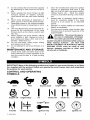 4
4
-
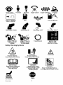 5
5
-
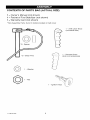 6
6
-
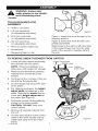 7
7
-
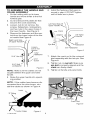 8
8
-
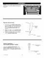 9
9
-
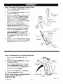 10
10
-
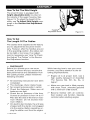 11
11
-
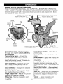 12
12
-
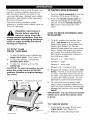 13
13
-
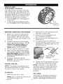 14
14
-
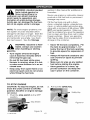 15
15
-
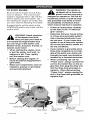 16
16
-
 17
17
-
 18
18
-
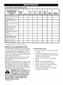 19
19
-
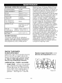 20
20
-
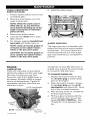 21
21
-
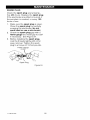 22
22
-
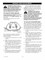 23
23
-
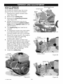 24
24
-
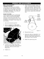 25
25
-
 26
26
-
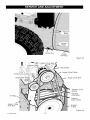 27
27
-
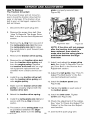 28
28
-
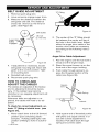 29
29
-
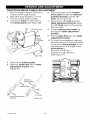 30
30
-
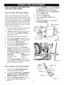 31
31
-
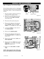 32
32
-
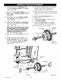 33
33
-
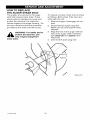 34
34
-
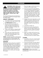 35
35
-
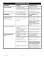 36
36
-
 37
37
-
 38
38
-
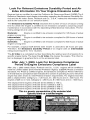 39
39
-
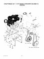 40
40
-
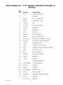 41
41
-
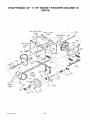 42
42
-
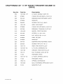 43
43
-
 44
44
-
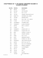 45
45
-
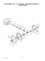 46
46
-
 47
47
-
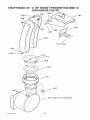 48
48
-
 49
49
-
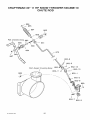 50
50
-
 51
51
-
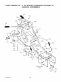 52
52
-
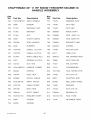 53
53
-
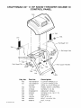 54
54
-
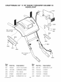 55
55
-
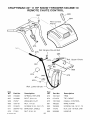 56
56
-
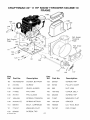 57
57
-
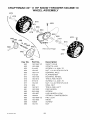 58
58
-
 59
59
-
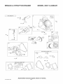 60
60
-
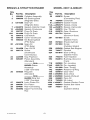 61
61
-
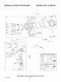 62
62
-
 63
63
-
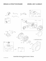 64
64
-
 65
65
-
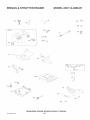 66
66
-
 67
67
-
 68
68
-
 69
69
-
 70
70
-
 71
71
-
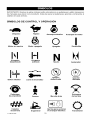 72
72
-
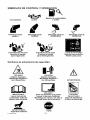 73
73
-
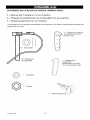 74
74
-
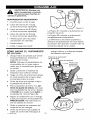 75
75
-
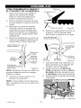 76
76
-
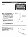 77
77
-
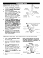 78
78
-
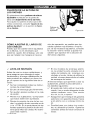 79
79
-
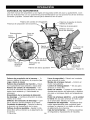 80
80
-
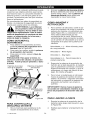 81
81
-
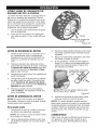 82
82
-
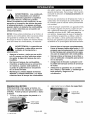 83
83
-
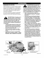 84
84
-
 85
85
-
 86
86
-
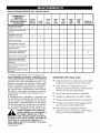 87
87
-
 88
88
-
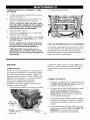 89
89
-
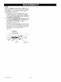 90
90
-
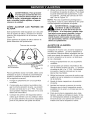 91
91
-
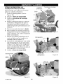 92
92
-
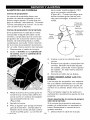 93
93
-
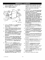 94
94
-
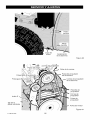 95
95
-
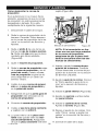 96
96
-
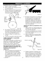 97
97
-
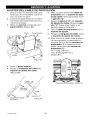 98
98
-
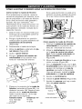 99
99
-
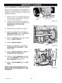 100
100
-
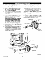 101
101
-
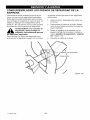 102
102
-
 103
103
-
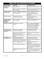 104
104
-
 105
105
-
 106
106
-
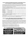 107
107
-
 108
108


Craftsman 536.888110 Manual de usuario
- Categoría
- Lanzadores de nieve
- Tipo
- Manual de usuario
- Este manual también es adecuado para
en otros idiomas
- English: Craftsman 536.888110 User manual
Artículos relacionados
-
Craftsman 536.881500 El manual del propietario
-
-
-
-
-
-
-
-
-
Otros documentos
-
Murray 629909X54B Instruction book
-
-
-
-
-
-
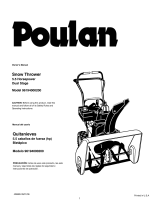 Poulan Pro 96194000200 Manual de usuario
-
-
Defiant 70304 Instrucciones de operación
