mundoclima AEROTHERM MAM-V9 Serie Guía de instalación
- Categoría
- Bombas de calor
- Tipo
- Guía de instalación

MONOBLOC AEROTHERM MAM-V9
Owner's & Installation manual
www.mundoclima.com
R32
SO30180 ~ SO30188
FR: "Manual d’utilisation et d’installation" voir www.mundoclima.com/fr
DE: "Benutzer- und Installationshandbuch" sehen www.mundoclima.com/de
PT: "Manual de instalaçao e do utilizador" ver www.mundoclima.com/pt
Manual de usuario e instalación
EN page 89

8
9
ÍNDICE
MEDIDAS DE SEGURIDAD
INFORMACIÓN GENERAL
ACCESORIOS
3.1
3.2
Accesorios provistos con la unidad
Accesorios provistos por el proveedor
ANTES DE LA INSTALACIÓN
INFORMACIÓN IMPORTANTE DEL REFRIGERANTE
LUGAR DE INSTALACIÓN
6.1
6.2
Selección de una ubicación en climas fríos
Selección de una ubicación en climas cálidos
PRECAUCIONES DE INSTALACIÓN
7.1
Dimensiones
7.2
7.3
7.4
Requisitos de instalación
Requisitos del espacio de mantenimiento
APLICACIONES TÍPICAS
8.1
8.2
8.3
8.4
8.5
8.6
8.7
8.8
Aplicación 1
Aplicación 2
Aplicación 3
Aplicación 4
Aplicación 5
Aplicación 6
Aplicación 7
Aplicación 8
VISTA DE LA UNIDAD
10
Componentes principales
Tubería de agua
Añadir agua
Aislamiento de la tubería de agua
9.7
Cableado
ARRANQUE Y CONFIGURACIÓN
Curvas climáticas
02
04
06
06
06
07
09
09
10
10
11
11
12
13
15
16
17
20
22
23
24
25
27
34
38
39
39
49
51
1
2
3
4
5
6
7
9.1
9.2
9.3
9.4
9.5
9.6
10.1
10.2
Manual de Instalación y Usuario
ES

11
10.3
10.4
10.5
10.6
10.7
PRUEBA DE FUNCIONAMIENTO Y COMPROBACIONES FINALES
12
13
11.1
11.2
MANTENIMIENTO Y CUIDADO
LOCALIZACIÓN DE AVERÍAS
14
13.1
13.2
13.3
13.4
Guías generales
Síntomas generales
ESPECIFICACIONES TÉCNICAS
14.1
14.2
General
15 SUSTITUCIÓN DE LAS VÁLVULAS DE SEGURIDAD
52
52
53
53
54
66
67
67
67
68
70
71
77
77
78
78
Comprobaciones previas
Encendido de la unidad
Prueba de funcionamiento (manual)
Parámetros de funcionamiento
Códigos de error
16 INFORMACIÓN DE MANTENIMIENTO

12/14/16 kW
5/7/9 kW
Sistema de refrigerante
Sistema de control eléctrico
Bloque de terminales
Sistema
hidráulico
después de la instalación.
Racor de instalación
NOT
A
Capacidad
de
Resistencia
5
7
3kW
9
Monofásico
12
14
3kW o 4.5kW
16 12
12/14/16 kW
Trifásico
14
4,5kW
5/7/9 kW
12/14/16 kW
16
-
Modelo
1

Este símbolo muestra que el manual de instalación y usuario se debe leer cuidadosa-
mente.
Este símbolo muestra que el personal de mantenimiento debe manipular este equipo
teniendo en cuenta el manual de instalación.
Este símbolo muestra que el personal de mantenimiento debe manipular este equipo
teniendo en cuenta el manual de instalación.
Este símbolo muestra que la información está disponible en el manual de instalación y
usuario.
1 MEDIDAS DE SEGURIDAD
Las precauciones enumeradas aquí se dividen en los siguientes tipos, que son muy importantes, así que asegúrese de
seguirlas cuidadosamente.
i
INFORMACIÓN
Lea estas instrucciones cuidadosamente antes de la instalación. Mantenga este manual a la mano para referencias
futuras.
Una mala instalación de la unidad o sus accesorios puede provocar descargas eléctricas, cortocircuitos, fuga, incen-
equipo de protección personal adecuado, como guantes y gafas de seguridad, cuando instale la unidad o cuando
realice actividades de mantenimiento.
Póngase en contacto con su distribuidor para obtener más ayuda.
Precaución: Riesgo de incendios/
ADVERTENCIA
-
¡PELIGRO!
ADVERTENCIA
PRECAUCIÓN
T
ambién se puede usar para alertar contra prácticas poco seguras.
NOT
A
Descripción de símbolos mostrados en la unidad interior o exterior:
2

¡PELIGRO!
Antes de tocar los componentes eléctricos, apague el equipo.
descargas eléctricas.
Antes de tocar los componentes eléctricos, desconecte el equipo.
ADVERTENCIA
•
•
que puedan causar lesiones.
•
incendios.
•
•
del equipo y posibles lesiones.
•
Una mala instalación puede provocar accidente debido a la caída del equipo.
•
-
to de alimentación o una mala instalación eléctrica pueden provocar descargas eléctricas o incendios.
•
Asegúrese de instalar un interruptor diferencial según la normativa vigente. Una mala instalación del interruptor
diferencial puede ocasionar descargas eléctricas e incendios.
•
-
lación incompleta o incorrecta puede provocar incendios.
•
Si el panel frontal no está bien instalado en su lugar se puede causar el sobrecalentamiento de los terminales des-
cargas eléctricas o incendios.
•
•
de refrigerante durante el funcionamiento ni inmediatamente después porque pueden estar calientes o frías, en
-
rese de usar guantes de protección apropiados.
•
-
internas y asegúrese de usar guantes apropiados.
PRECAUCIÓN
-
Tubería de gas:
-
para evitar el ruido).
regulaciones nacionales vigentes sobre el cableado. Si la entrada de alimentación está dañada, debe ser sustituida
3

pueden caer o provocar fugas de agua.
-
dadas puede causar fugas refrigerante.
- Cuando el equipo emite ondas electromagnéticas. Las ondas electromagnéticas pueden alterar el sistema de
control y causar un mal funcionamiento del equipo.
causar un incendio.
- Donde el aire contenga altos niveles de sal, cercano al mar
.
- Dentro de vehículos o depósitos.
- Donde haya vapores de sustancias ácidas o alcalinas.
-
los peligros que conlleva.
supervisión.
Si el cable de alimentación está dañado, se debe sustituir por el fabricante o su distribuidor o un especialista del
servicio técnico para evitar riesgos.
-
establecidos. Póngase en contacto con las autoridades locales para que le informen sobre los centros de recolec-
de sustancias nocivas pueden salir y llegar a las aguas subterráneas del subsuelo. Esto puede contaminar la cade-
na alimenticia y tener consecuencias nocivas para su salud y la de todos.
-
-
tricidad y gas.
Antes de la instalación, compruebe si la fuente de alimentación del usuario cumple con los requisitos de la instala-
etc.). Si no se cumplen los requisitos de instalación eléctrica del producto, se prohíbe la instalación del producto
hasta que se instale correctamente
de alimentación trifásica y se evitará que varias unidades se monten en la misma fase de la fuente de alimentación
trifásica.
NOTA
-
-
Si hay un sistema de detección de fugas instalado, se debe comprobar al menos cada 12 meses. Es muy reco-
incidencias.
2 INTRODUCCIÓN GENERAL
Estas unidades se usan tanto para las aplicaciones de calefacción como para refrigeración. Las unidades se pueden com-
suministrado) y kit solar (no suministrado).
para las diferentes unidades se relaciona a continuación.
4

Modelo
5~9kW 12~16kW
V
olumen depósito/ L
Mín. 100 200
Recomendado
200 300
-
biador de
calor (Ser-
pentín de
-
dable)
Calef.
área de
intercam-
bio/m
2
Mín. 1.4 1.75
Recomendado
2.5 4
V
olumen
/L
Mín. 12 14
Recomendado
20 32
-
biador
de calor
(Serpentín
esmaltado)
Calef.
área de
intercam-
bio/m
2
Mín. 1.7 2.5
Recomendado
3 5.6
V
olumen
/L
Mín. 14 20
Recomendado
24 45
Capacidad / Carga
ճ
ղ
ձ
ձCapacidad de la bomba de calor.
ղCapacidad de calefacción requerida (depende el lugar).
ճCapacidad de calor adicional ofrecida por la resistencia
Depósito de ACS (no suministrado)
Un depósito de ACS (con una resistencia eléctrica de
apoyo de 3 kW) se puede conectar a la unidad.
Los requisitos del depósito dependen del tipo de unidad
así como del material del intercambiador de calor.
Sensor de tem-
peratura (T5)
Serpentín
Salida
Resistencia del
depósito (TBH)
Entrada
Si el volumen del depósito es superior a 240L, el sensor de
temperatura (T5) debe instalarse en una posición superior
a la mitad de la altura del depósito.
Si el volumen del depósito es inferior a 240L, el sensor de
temperatura debe instalarse en una posición superior a 2/3
de la altura del depósito.
sensor de temperatura.
El intercambiador de calor (serpentín) debe instalarse por
-
sito debe ser inferior a 5 m.
43
30
-10
-25
5 12 25 35 50 60
46
*43
20
10
-5
5 10
25 50
35
30
-10
-25
5 12 25 35
55 60
Termostato ambiente (no suministrado)
El termostato de ambiente se puede conectar a la
unidad (el termostato de ambiente se debe mantener
lugar de instalación).
Kit solar para depósito de ACS (no suministrado)
Se puede conectar a la unidad un kit solar.
Kit de alarma a distancia (no suministrado)
Se puede conectar a la unidad un kit de alarma a
distancia.
intervalo de subida
5

-25~-16 -15~-11 -10~-6 -5~-1
“DHW Temp.
caudal agua
5~9kW 45 48 50 52
12~16kW 40 45 48 50
0~4 5~14 15~19 20~24
“DHW Temp.
caudal agua
5~9kW 55 55 55 52
12~16kW 53 55 55 50
25~29 30~34 35~39 40~43
“DHW Temp.
caudal agua
5~9kW 50 50 48 45
12~16kW 50 48 48 45
11 12 13
10 9 9 8
14 15 16 17
8776
18 19 20
6655
3 ACCESORIOS
3.1 Accesorios provistos con la unidad
Accesorios de instalación
Manual de usuario e
instalación
Ficha de producto
Filtro en forma de
Y
Panel de control
Bridas
Sensor de temperatura para el
depósito de agua caliente sanita-
ria o fuente de calor adicional*
Cable de prolongación
para T5
Cantidad
5~9kW
1
1
1
1
2
1
0
3
1
1
12~16kW
1
1
1
1
1
1
2
3
1
1
la temperatura del agua. Si está instalado solamente el
depósito de agua caliente sanitaria, el sensor de tempera-
tura puede funcionar como T5. Si está instalada solamente
la caldera, el sensor de temperatura puede funcionar como
T1B. Si ambas unidades están instaladas, se necesita un
sensor de temperatura adicional (póngase en contacto con
el proveedor). El sensor de temperatura debe conectarse
al puerto correspondiente en la placa de control principal
del sistema hidráulico (consulte la sección 9.3.1 Placa de
control principal del módulo hidráulico).
3.2
Accesorios opcionales
Sensor de temperatura de la tempe-
ratura de agua (T1B)
Cable de prolongación (para
T1B)
Preparación previa a la instalación
Manipulación
Debido a las grandes dimensiones y el peso elevado, la unidad solo se puede manipular mediante eslingas de elevación
colocados en el bastidor de base.
-
ción de hielo mediante la bomba de calor y la resistencia
Debido a que puede
ocurrir una falla de energía cuando la unidad está desaten-
en el sistema de agua. (Consulte con 9.4 Tubería de agua).
En el modo de refrigeración, a continuación se indica la tem-
peratura mínima de salida del agua (T1stoph) que la unidad
En el modo de calefacción, a continuación se indica la
-25 -24 -23 -22
35 35 35 37
-21 -20 -19 -18
39 40 42 44
-17 -16 -15 -14
46 48 50 52
-13 -12 -11 -10~30
54 56 58 60
31 32 33 34
59 58 57 56
35 36 37 38
55 55 55 55
39 40 41 42
54 53 52 51
43 44 45 46
50 50 50 50
4
ANTES DE LA INSTALACIÓN
Manual de usuario e
instalación del panel
de control
6

Para evitar lesiones, no toque la entrada de aire ni las lamas de aluminio de la unidad.
¡La unidad es muy pesada! Evite que se caiga la unidad al inclinarse durante la manipulación.
1000mm
540
PRECAUCIÓN
El gancho y el baricentro de
la unidad deben estar en una
línea en dirección vertical
para evitar una inclinación
inadecuada.
Pase la cuerda por los
soporte de madera
234 707
5/7/9 kW (unidad:mm)
540
605
222.5
641
12/14/16 kW (unidad:mm)
5 INFORMACIÓN IMPORT
ANTE DEL REFRIGERANTE
T
ipo de refrigerante R32; Volumen de GWP: 675.
GWP = Potencial de Calentamiento Global
Modelo
5kW
7kW
9kW
12kW
14kW
16kW
Volumen de refrigerante cargado de fábrica en la unidad
Refrigerante/kg
2.00
2.00
2.00
2.80
2.80
2.80
2 equivalentes
1.35
1.35
1.35
1.89
1.89
1.89
605
7

PRECAUCIÓN
Frecuencia de comprobaciones de fugas de refrigerante
2
o más, uni-
2
, comprobar al menos cada 12 meses, o
cuando se instale un sistema de detección
de fugas al menos cada 24 meses.
2
2
, comprobar al menos cada 12 meses, o cuando se instale un
sistema de detección de fugas al menos cada 12 meses.
2
o más, comprobar al menos cada 3 meses, o cuando se instale un s
istema de detección de fugas al menos
cada 6 meses.
invernadero.
6 LUGAR DE INSTALACIÓN
ADVERTENCIA
el interior
, se debe añadir un dispositivo adicional de detección de refrigerante y un equipo de ventilación de acuerdo
-
tos y pequeños animales.
Los animales pequeños cuando entran en contacto con los componentes eléctricos pueden provocar averías, humo
o incendios. Por favor, informe al cliente de mantener limpia el área alrededor de la unidad.
Seleccione un lugar de instalación donde se cumplan las condiciones siguientes y con el acuerdo del cliente: - Lugares bien
ventilados.
- Donde la unidad no moleste a los vecinos.
-
do).
- Donde se pueda evitar lluvia todo lo posible.
-
nos) donde se crea mucho polvo, se debe cubrir la unidad.
- Asegúrese de que se toman las precauciones necesarias en caso de fuga de refrigerante de acuerdo con las leyes y nor-
mativas locales pertinentes.
Viento fuerte de 5 m/s o más contra la salida de aire de la unidad causa cortocircuito (absorción de la descarga de aire) y
esto tiene las consecuencias siguientes:
- Deterioro de la capacidad de funcionamiento.
- Aceleración de la escarcha durante la calefacción.
- Problemas con el funcionamiento debido al aumento de la alta presión.
8

Modelo
5~9kW
12~16kW
A
(mm)
A
En caso de fuertes vientos y cuando se puede prever la
instalación de la unidad (cualquiera de ellas está bien):
pantalla.
Modelo
5~9kW
12~16kW
B
B(mm)
instalación.
la dirección del viento.
la base, para que salga el agua usada en torno a la
unidad.
la unidad sobre una base de bloques de hormigón, etc.
(la altura de la base debe ser de unos 100 mm (3,93").
Si instala la unidad sobre un bastidor, instale una placa
Al instalar la unidad reste especial atención si es un lu-
Si instala la unidad sobre una base debe
evitar que se acumule el agua del drena
-
NOT
A
¡La unidad es muy pesada!
-
tes de transporte.
6.1 Selección de una ubicación en
climas fríos
Consulte "Manipulación" en la sección “4.
Antes de la
instalación.
NOT
A
Cuando funciona la unidad en climas fríos, asegú-
rese de seguir las instrucciones que se describen a
continuación.
su lado de aspiración frente a la pared.
el lado de descarga de aire de la unidad.
Durante las tormentas de nieve es muy importante
seleccionar un sitio de instalación donde la nieve no
afecte la unidad. Si es posible que haya una caída
lateral de la nieve, asegúrese de que el serpentín del
intercambiador de calor no se afecte por la nieve (si es
necesario instale un techo).
ձ
ղ
ձ
ղ Monte una base.
tierra para evitar que se cubra de nieve.
6.2 Selección de una ubicación en
climas cálidos
del sol.
9

Modelo A B C D E F G H J
5/7/9kW 1210 374 402 502 404 215 277 945 165 59
12/14/16kW 1404 373 405 760 361 280 / 1414 176 144
7 PRECAUCIONES DE INST
ALACIÓN
7.1 Dimensiones
5/7/9 kW (unidad: mm) 12/14/16 kW (unidad: mm)
7.2 Requisitos de instalación
Compruebe la resistencia y la nivelación del suelo de instalación de manera que la unidad no provoque ninguna vibración o
ruido durante el funcionamiento.
10 Espárragos
Goma
Alfombrilla de
goma a prueba
de golpes
Solido
o techo
Base de
hormigón
(Unidad: mm)
H
J
I
H
J
I
E D
B
F
G
C
A
E D
B
F
C
A
10

por un tapón de
no puede cumplir
con los requisitos de
mismo tiempo.
-
5/7/9 kW
NOT
A
Es necesario instalar un aislamiento térmico si el agua no puede drenar en climas fríos, incluso si se ha abierto un
12/14/16
kW
7.4 Requisitos del espacio de mantenimiento
7.4.1 En caso de poco espacio de instalación
1) En caso de obstáculos frente del lado de salida. 2) En caso de que haya obstáculos frente a la entrada de aire.
A
Modelo
5~9kW
12~16kW
A(mm)
7.4.2 En caso de instalación de varias hileras de equipo (en el techo, etc.).
1) En caso de instalar una unidad por hilera.
11

Modelo A
(mm) B1(mm) B2(mm) C (mm)
5~9kW
12~16kW
Modelo
A
(mm) B1(mm) B2(mm) C (mm)
5~9kW
12~16kW
H
B1
C
A
H
B1
8 APLICACIONES
TÍPICAS
8.1 Aplicación
1
Espacio para calefacción con un termostato ambiente conectado a la unidad.
<1/2 H
B2
C
A
<1/2 H
B2
12

Código
1
1.1
1.2
1.3
1.4
1.5
1.6
1.7
1.8
2
3
1
1.6
1.7
1.5
1.8
1.3
1,4 1,2
1.1
2 3
Manómetro
Válvula de seguridad
Placa intercambiadora de calor
()
Purgador
P_i: Bomba recirculadora de la unidad
Filtro en forma de Y
Válvula de cierre (no suministrada)
6 7
8.1
8.2
Código
4
5
6
7
8
8.1
8.2
9
10
11
FHL 1…n
T
9
NOTA
4
5
10
11
----
FHL1
FHL2 FHLn
Panel de control
T
ermostato ambiente (no suministrado)
Válvula de llenado (no suministrada)
Depósito de equilibrio (no suministrado)
Purgador
Colector (no suministrado)
Suelo radiante (no suministrado)
----
El volumen del tanque de equilibrio (8) debe ser mayor que 40L (para una unidad de 5~9kW, mayor que 20L). La vál-
-
Funcionamiento de la unidad y calefacción:
Cuando un termostato ambiente se conecta a la unidad y cuando hay una solicitud de calefacción desde ese termostato, la uni-
se detendrán. Aquí se usa el termostato ambiente como interruptor.
NOT
A
Asegúrese de conectar los cables del termostato a los terminales correctos, debe seleccionarse el método B (véase
-
8.2 Aplicación
2
ACS que está conectado a la unidad.
8
13

Código
1
1.1
1.2
1.3
1.4
1.5
1.6
1.7
1.8
2
3
4 6
7
8
8.1
1
1.6
1.7
1.5
1.8
1.3
1,4 1,2
1.1
2 3
Manómetro
Válvula de seguridad
Placa intercambiadora de calor
()
Purgador
P_i: Bomba recirculadora de la unidad
Filtro en forma de Y
Válvula de cierre (no suministrada)
Panel de control
Válvula de llenado (no suministrada)
Depósito de equilibrio (no suministrado)
18
6 7
Purgador
8.1
8.2
8
9
Código
8.2
9
10
11
12
12.1
12.2
12.3
13
14
15
16
17
18
FHL 1…n
4
10
12.1
12
13
12.3
12.2
11
----
14
15
16
FHL1
FHL2 FHLn
Colector (no suministrado)
Depósito de ACS (no suministrado)
Purgador
Resistencia del depósito
T5: Sensor de temperatura del depósito de ACS
Grifo de agua caliente (no suministrado)
P_d: Bomba ACS (no suministrada)
Válvula de 1 vía (no suministrada)
Válvula de bypass (no suministrada)
SV1: Válvula de 3 vías (no suministrada)
Suelo radiante (no suministrado)
----
/ /
NOT
A
El volumen del tanque de equilibrio (8) debe ser mayor que 40L (para una unidad de 5~9kW, mayor que 20L). La válvula de
Funcionamiento de la bomba recirculadora
La bomba recirculadora (1.8) y (10) funcionarán mientras la unidad esté encendida para la calefacción.
La bomba recirculadora (1.8) bomba funcionará mientras la unidad este encendida para el
ACS (DHW).
Calefacción
1) La unidad (1) funcionará para lograr la temperatura de agua deseada según lo establecido en el panel de control.
2) Se debe seleccionar la válvula de manera que todo el tiempo se garantice el caudal de agua mínimo que se menciona
en 9.4
Tuberías de agua.
Agua caliente sanitaria (ACS)
Cuando el modo
ACS está activado (ya sea manual por el usuario o automáticamente mediante una programación) la
-
tencia eléctrica del depósito de ACS (cuando la resistencia del depósito de ACS esté en YES).
se activará para calentar el agua caliente sanitaria mediante la bomba de calor. Si hay una gran demanda de agua calien-
17
14

PRECAUCIÓN
-
ponentes/Válvula de 3 vías SV1.
NOT
A
mediante la resistencia del depósito de
ACS. Esto asegura que toda la capacidad de la bomba de calor está disponible
para la calefacción.
8.3 Aplicación 3
conecta a la unidad. La calefacción se suministra a través del circuito de suelo radiante y las unidades de fancoil. La refrige-
ración se provee solo mediante las unidades fancoil. El agua caliente sanitaria se produce mediante un depósito de
ACS que
está conectado a la unidad.
Código
1
1.1
1.2
1.3
1.4
1.5
1.6
1.7
1.8
2
3
4
5
6
7
8
8.1
1
1.6
1.7
1.5
1.8
1.3
1,4 1,2
1.1
2 3
Descripción
Manómetro
Válvula de seguridad
Placa intercambiadora de calor
()
Purgador
P_i: Bomba recirculadora de la unidad
Filtro en forma de Y
Válvula de cierre (no suministrada)
Panel de control
Termostato ambiente (no suministrado)
Válvula de llenado (no suministrada)
Depósito de equilibrio (no suministrado)
Purgador
18
12.1
12
13
T
12.3
12.2
8.1
4
5
9
10
14
15
16
19
11
----
FCU1 FCU2 FCUn ----
11
6 7 ----
8.2
8
Código
8.2
9
10
11
12
12.1
12.2
12.3
13
14
15
16
18
19
FHL 1…n
FCU 1...n
/
FHL1
FHL2
FHLn
Descripción
(no suministrada)
Colector (no suministrado)
Depósito de ACS (no suministrado)
Purgador
Resistencia del depósito
T5: Sensor de temperatura del depósito de ACS
Grifo de agua caliente (no suministrado)
P_d: Bomba ACS (no suministrada)
Válvula de 1 vía (no suministrada)
SV1: Válvula de 3 vías (no suministrada)
SV2: Válvula de 2 vías (no suministrada)
Suelo radiante (no suministrado)
----
Fancoil (no suministrado)
/
15

NOT
A
El volumen del tanque de equilibrio (8) debe ser mayor que 40L (para una unidad de 5~9kW, mayor que 20L). La válvu-
Funcionamiento en calefacción y refrigeración
calefacción y refrigeración. La unidad (1) funcionará hasta lograr la temperatura deseada, ya sea fría o caliente. En modo de
suelo radiante (FHL).
PRECAUCIÓN
esquema eléctrico.
Agua caliente sanitaria (ACS)
El agua caliente sanitaria es cómo se describe en 8.2
Aplicación 2.
8.4 Aplicación
4
controlar el encendido y apagado de la unidad. La calefacción se suministra a través del circuito de suelo radiante y las unida-
des de fancoil. La refrigeración se provee solo mediante las unidades Fancoil.
1
1.6
1.7
4
11
9
1.5 ----
1.8
1.3
1,4 1,2
1.1
2 3
8,1 19
10
FCU1
FCU2
FCUn ----
11
6 7 ----
8.2
8
FHL1 FHL2
FHLn ----
17
16

Código
1
1.1
1.2
1.3
1.4
1.5
1.6
1.7
1.8
2
3
4
Descripción
Manómetro
Válvula de seguridad
Placa intercambiadora de calor
()
Purgador
P_i: Bomba recirculadora de la unidad
Filtro en forma de Y
Válvula de cierre (no suministrada)
Pamel de control
Código
6
7
8
8.1
8.2
9
10
11
17
19
FHL 1…n
FCU 1...n
NOT
A
Descripción
Válvula de llenado (no suministrada)
Depósito de equilibrio (no suministrado)
Purgador
Colector (no suministrado)
Válvula de bypass (no suministrada)
SV2: Válvula de 2 vías (no suministrada)
Suelo radiante (no suministrado)
Fancoil (no suministrado)
El volumen del tanque de equilibrio (8) debe ser mayor que 40L (para una unidad de 5~9kW, mayor que 20L). La vál-
Funcionamiento de la bomba
La bomba recirculadora (1.8) y (10) funcionarán mientras la unidad esté encendida para la calefacción.
NOT
A
Como el sensor de temperatura se usa para detectar la temperatura ambiente, el panel de control (4) se debe colocar
las curvas climáticas, la unidad se apagará cuando la temp. ambiente llegue al valor deseado.
Calefacción y refrigeración
Según la temporada el cliente seleccionará calefacción o refrigeración a través del panel de control. La unidad (1) funciona-
rá en el modo calefacción o refrigeración para lograr la temperatura ambiente deseada. En el modo calefacción, la válvula
de 2 vías (19) (230 V
ac) se abrirá. El agua caliente se suministra tanto a las unidades Fancoil como a los circuitos de suelo
del circuito del suelo radiante (FHL).
PRECAUCIÓN
-
8.5 Aplicación
5
-
El funcionamiento combinado es posible para la calefacción y el ACS.
-
ción para la aplicación A.
en el cableado de campo según la ilustración para la aplicación b. En esta condición, la unidad puede enviar una señal de
encendido/apagado a la caldera en modo calefacción, pero el propio control de la caldera en modo ACS.
indica en la ilustración para la aplicación C.
17

PRECAUCIÓN
8.5.1 Aplicación
a
La caldera proporciona calor solo para la calefacción de espacios
1
1.6
1.7
1.5
1.8
1.3
1,4 1,2
8.5.2 Aplicación
b
para el calentamiento del
ACS.
1.1
2 3
12.1
18
12
13
12.3
12.2
6 7
14
15
16
8.1
8.2
8
4
9
10
16
22
23
23.1
11
----
FHL1 FHL2
FHLn
----
1
1.6
1.7
1.5
1.8
1.3
1,4 1,2
1.1
2 3
18
12.1
12
13
12.3
12.2
6 7
16
8.1
8.2
8
4
9
10
16
22
23
23.1
14
15
16
11
----
FHL1 FHL2
FHLn
----
18

8.5.3 Aplicación
C
caldera controlado por la unidad.
Código
1
1.1
1.2
1.3
1.4
1.5
1.6
1.7
1.8
2
3
4
6
7
8
8.1
8.2
1
1.6
1.7
1.5
1.8
1.3
1,4 1,2
1.1
2 3
Descripción
Manómetro
Válvula de seguridad
Placa intercambiadora de calor
()
Purgador
P_i: Bomba recirculadora de la unidad
Filtro en forma de Y
Válvula de cierre (no suministrada)
Panel de control
Válvula de llenado (no suministrada)
Depósito de equilibrio (no suministrado)
Purgador
18
6 7
22
12.1
8.1
8.2
8
Código
9
10
11
12
12.1
12.2
12.3
13
14
15
16
18
22
23
23.1
FHL 1…n
AHS
NOTA
9
4
12
13
10
12.3
12.2
14
15
16
11
----
FHL1 FHL2
FHLn
Descripción
Colector (no suministrado)
Depósito de ACS (no suministrado)
Purgador
Resistencia del depósito
T5: Sensor de temperatura
Grifo de agua caliente (no suministrado)
P_d: Bomba ACS (no suministrada)
Válvula de 1 vía (no suministrada)
SV1: Válvula de 3 vías (no suministrada)
T1B: Sensor de temperatura (no suministrado)
Suelo radiante (no suministrado)
Fuente de calor adicional (caldera) (alimentación de
campo)
----
El volumen del tanque de equilibrio (8) debe ser mayor que 40L (para una unidad de 5~9kW, mayor que 20L). La vál-
independiente e instalarla en la puerta. El sensor de temperatura T1B debe instalarse a la salida del AHS y conectarse
al puerto correspondiente de la placa de control principal del módulo hidráulico (véase 9.3.1 placa de control principal
Funcionamiento
19

Los cambios frecuentes pueden provocar corrosión a la caldera y acortar su vida útil. Póngase en contacto con el proveedor
de la caldera.
-
da como aparece en el panel de control.
NOTA
calor.
PRECAUCIÓN
-
Asegúrese de que las válvulas antiretorno (no suministradas) están bien instaladas en el sistema.
El fabricante/distribuidor no se hace responsable de los daños resultantes por el no cumplimiento de estas indicacio-
nes.
8.6 Aplicación
6
Calefacción con dos termostatos ambiente a través de los circuitos de suelo radiante y las unidades fancoil. Los circuitos de
El circuito de suelo radiante requiere una temperatura del agua inferior en modo calefacción comparada a las unidades fan-
del circuito de suelo radiante. Las unidades fancoil están directamente conectadas al circuito de agua de la unidad y al del
-
diendo de la temp. requerida del agua (se necesitan circuitos de suelo radiante y/o Fancoils) se puede activar el primer pun-
NOT
A
El cableado del termostato de ambiente 5A
(para Fancoils) y 5B (para suelo radiante) debe seguir el "método C" des-
20

Código
1
1.1
1.2
1.3
1.4
1.5
1.6
1.7
1.8
2
3
4
6
1
1.6
1.7
1.5
1.8
1.3
1,4 1,2
1.1
2 3
Manómetro
Válvula de seguridad
Placa intercambiadora de calor
()
Purgador
P_i: Bomba recirculadora de la unidad
Filtro en forma de Y
Válvula de cierre (no suministrada)
Panel de control
T
T
9
4
5
A
5B
8,1 10
19
M
23.1
6 7 23
8.2
8
Código
7
8
8.1
8.2
9
10
11
17
19
23
23.1
FHL 1…n
FCU 1...n
NOT
A
A
FCU1
B
FCU2
11
FCUn
FHL1
FHL2 FHLn
11
Válvula de llenado (no suministrada)
Depósito de equilibrio (no suministrado)
Purgador
Colector (no suministrado)
Válvula de bypass (no suministrada)
SV2:válvula de 2 vías (no suministrada)
Suelo radiante (no suministrado)
Fancoil (no suministrado)
17
El volumen del tanque de equilibrio (8) debe ser mayor que 40L (para una unidad de 5~9kW, mayor que 20L). La
-
-
-
Funcionamiento de las bombas
La bomba (1.8) y (10) funcionarán cuando haya una solicitud de calefacción de
A y / o B. La bomba (23.1) funcionará solo
-
da del agua. La temperatura de salida de agua depende de valor programado en el termostato ambiente que la solicitó.
de funcionar.
21

NOT
A
caliente en el circuito de calefacción, etc.).
de usar dos puntos de consigna.
8.7 Aplicación
7
Aplicación de la función de doble punto de consigna sin termostato de ambiente conectado a la unidad.
La calefacción se suministra a través del circuito de suelo radiante y las unidades de fancoil. Los circuitos de suelo radiante
El circuito de suelo radiante requiere una temperatura del agua inferior en modo calefacción comparada a las unidades
-
sitos del circuito de suelo radiante. Las unidades fancoil están directamente conectadas al circuito de agua de la unidad y al
-
pendiendo de la temperatura del agua requerida (se necesitan circuitos de suelo radiante y/o Fancoils) se puede activar el
1
1.6
1.7
1.5
1.8
1.3
1,4 1,2
1.1
2 3
6 7
9
8.1
8.2
8
4
A
11
----
FCU1 FCU2
FCUn
10 19
23
B
23.1
----
11
----
FHL1 FHL2
FHLn
----
17
22

Código
1
1.1
1.2
1.3
1.4
1.5
1.6
1.7
1.8
2
3
4
6
Descripción
Manómetro
Válvula de seguridad
Placa intercambiadora de calor
()
Purgador
P_i: Bomba recirculadora en la unidad
Filtro en forma de
Y
Válvula de cierre (no suministrada)
Panel de control
Código
7
8
8.1
8.2
9
10
11
17
19
23
23.1
FHL 1…n
FCU 1...n
NOT
A
Descripción
Válvula de llenado (no suministrada)
Depósito de equilibrio (no suministrado)
Purgador
Colector (no suministrado)
Válvula de bypass (no suministrada)
SV2:válvula de 2 vías (no suministrada)
Suelo radiante (no suministrado)
Fancoil (no suministrado)
El volumen del tanque de equilibrio (8) debe ser mayor que 40L (para una unidad de 5~9kW, mayor que 20L). La
El panel de control (4) debe colocarse en la habitación donde se instalan los circuitos de suelo radiante y las
cuando la temperatura ambiente alcance la temperatura deseada.
Funcionamiento de las bombas
La bomba (1.8) y (10) funcionará cuando se solicite calefacción de
A y/o B. La bomba (23.1) funcionará cuando la temp. am-
para lograr la temperatura del agua deseada.
8.8 Aplicación
8
calor, el ACS proviene de la bomba de calor y el kit de energía solar.
26
1
1.6
1.7
1.5
1.8
1.3
1,4 1,2
1.1
2 3
18
27
6 7
8.1
8.2
8
9
4
10
12.1
12.1
12
13
12.3
12.2
11
----
14
15
16
FHL1 FHL2
FHLn
----
17
23

Código
1
1.1
1.2
1.3
1.4
1.5
1.6
1.7
1.8
2
3
4
6
7
8
8.1
8.2
Descripción
Manómetro
Válvula de seguridad
Placa intercambiadora de calor
(
Purgador
P_i: Bomba recirculadora en la unidad
Filtro en forma de Y
Válvula de cierre (no suministrada)
Panel de control
Válvula de llenado (no suministrada)
Depósito de equilibrio (no suministrado)
Purgador
Código
9
10
11
12
12.1
12.2
12.3
13
14
15
16
17
18
FHL 1…n
26
27
/
NOT
A
Descripción
Colector (no suministrado)
Depósito de ACS (no suministrado) Purgador
Resistencia del depósito
T5: Sensor de temperatura
Grifo de agua caliente (no suministrado)
P_d: Bomba ACS (no suministrada)
Válvula de 1 vía (no suministrada)
Válvula de bypass (no suministrada)
SV1: Válvula de 3 vías (no suministrada)
Suelo radiante (no suministrado)
Kit de energía solar (no suministrado)
P_s: Bomba solar (no suministrada)
/
El volumen del tanque de equilibrio (8) debe ser mayor que 40L (para una unidad de 5~9kW, mayor que 20L). La vál-
independiente e instalarla en la puerta.
-
-
ACS durante el funcionamiento del kit de energía solar.
NOT
A
9 VIST
A DE LA UNIDAD
eléctricas y el compartimento hidráulico.
Puerta 1
Da acceso al del compresor
, a las
Puerta 1
Puerta 2
Para acceder al compartimento
12
1
5/7/9kW
12/14/16kW
24

ADVERTENCIA
antes de sacar las puertas 1 y 2.
Los componentes dentro de la unidad pueden estar calientes.
procedimiento al contrario. Evite lesiones en las manos.
9.2 Componentes principales
9.2.1 Módulo hidráulico
12/14/16kW
1
9
6.3
10
6.4
11
13
14
12
2
6.5
4
5
7
8
3
6.1
6.2
5/7/9kW
9
3
10
4
1
7
6.1
6.2
11
8
12
14
13
25

Código
1
2
3
4
5
6
7
8
9
10
11
12
13
14
Descripción
Purgador
Sensor de presión
Sensores de temperatura
Manómetro
Bomba recirculadora
Placa intercambiadora de calor
Válvula de seguridad
9.2.2 Diagrama del sistema hidráulico
Código
1
2
3
5
7
8
9
10
11
5
7
2
1
15,3
9
T2B
TW_out
T2
TW_in
T1
3
15.2
15.1 1
1
13 8
Descripción
Purgador
Descripción
El aire que queda en el circuito de agua se elimina automáticamente
del circuito de agua.
Proporciona capacidad de calentamiento adicional cuando la capaci-
-
sión: 2L en unidades de 5/7/9kW y 5L en unidades de 12/14/16kW.)
/
/
Cuatro sensores de temperatura determinan la temperatura de agua
y refrigerante en varios puntos del equipo.
6.1-T2B; 6.2-T2; 6.3-T1(opcional); 6.4-TW_out; 6.5-TW_in
/
Proporciona lectura de la presión del circuito de agua.
Detecta el caudal de agua para proteger el compresor y la bomba
Hace que circule agua en el circuito de agua.
/
y descargando el agua del circuito de agua.
10
Recipiente de agua con calentador de agua
(opcional)
Manómetro
Bomba recirculadora
Placa intercambiadora de calor
12
14
Código
12
13
14
15.1
15.2
15.3
16
17
2
1
/
16 17
T1
Descripción
Válvula de seguridad
Aislante térmico
Aislante térmico
Aislante térmico
Sensores de temperatura: TW_in;TW_out;T2B;T2;T1 (opcional)
26

NOT
A
PCB A
PCB A
PCB C (parte trasera
PCB B, solo para unidades
de 3 fases)
PCB B Placa de control principal del módulo hidráulico
5/7/9kW
Placa de control principal del módulo hidráulico
PCB B
12/14/16kW
27

9.3.1 Placa de control principal del módulo hidráulico
Código
1
2
3
4
5
6
7
8
9
10
11
12
13
14
15
16
17
18
19
20
21
22
23
24
25
26
27
Monofásico 5/7/9kW
Monofásico 12/14/16kW
Trifásico 12/14/16kW
Descripción
(P_o)/
5
27
26
25
24
23
22 21 20 19 18 17 16 15
1234 67
8
9
10
13
11
14
12
28

9.3.2 Unidades monofásicas de 5/7/9kW
1) PCB A,
Código
1
2
3
4
5
Descripción
2) PCB B, Placa de control principal
Código
6
7
8
9
/
Descripción
/
9
8
6
4
5
7
123
132
16
7
654
8
9
10
11
12
13
14
15
1718192021222326 25 24
27
28
29

Código
1
2
3
4
5
6
7
8
9
10
11
12
13
14
Sensor de temperatura del puerto de descarga
Sensor de temperatura del puerto de entrada
9.3.3 Unidades monofásicas de 12/14/16 kW
1)
PCB A,
Código
1
2
3
4
5
6
7
Puerto de entrada P para el módulo (P)
Código
15
16
17
18
19
20
21
22
23
24
25
26
27
28
Puerto de comunicación con el panel de control
Pantalla digital (DSP1)
(opcional)
Puerto para aislamiento térmico del compresor
Código
8
9
10
11
12
13
14
Puerto de salida P del Módulo PFC (P_1)
Puerto entrada para PFC inductancia L_1(L_1)
Puerto entrada para PFC inductancia L_2(L_2)
CN9
1
14
13
12
11
10
3
4
5
6789
2
30

Código Descripción Código Descripción
1
-
15
2
Puerto para el sensor de temperatura de entrada
16
3 17
Puerto para aislamiento térmico del compresor
4 18
Puerto para aislamiento térmico del chasis
5
19
6
Puerto de comunicación con el panel de control
20
7 21
8
22
9 23
10 24
11 25
12 26
13 27
14
2) PCB B, Placa de control principal
9.3.4 Unidades trifásicas de 12/14/16 kW
1) PCB A,
1
SW3
CN300
CN1
1
SW4
2
ON
ON
3 12
ON
ON
3
12 34 5 6 7 8 9 10
11
13
14151617
19
20
21
22
23
24
25
26
27
18
12
31

Código
1
2
3
4
5
6
7
8
9
Descripción
2) PCB B, Placa de control principal
PCB A
Código
1
2
3
4
5
6
7
8
9
10
11
12
13
Descripción
Puerto de control de comunicación con el
Código
14
15
16
17
18
19
20
21
22
23
24
25
/
Descripción
Puerto de salida para bobina de contactor P_line
(opcional)
/
9
76543
1
2
8
DIS1
134567
12
1415161718192025 212223
2
24
8
9
10
11
13
32

Código
1
2
3
4
5
6
PCB C
Descripción
Alimentación L3(L3)
Alimentación L2(L2)
Alimentación L1(L1)
Código
7
8
9
10
11
/
9.3.5 Piezas de control para la resistencia auxiliar(Reservado)
Código
1
2
3
4
5
6
Descripción
Filtrado L1 (L1')
Filtrado L2 (L2')
Filtrado L3 (L3')
/
Monofásico 12/14/16kW
T
rifásico 12/14/16kW
Descripción
Protector térmico automático
Protector térmico manual
-
Código
1
2
3
4
5
Descripción
Protector térmico automático
Protector térmico manual
-
CN32 CN38
CN37
CN36
CN39
CN31
CN30
CN18
CN19
11
1
2
3
4567
8
9
10
1234
5
1234
5
6
33

9.4 T
uberías de agua
T
odas las longitudes y distancias de las tuberías se han tomado en consideración.
Requisitos
(solo para instalaciones con acumulador de agua caliente sanitaria) . El cable
del sensor de temperatura suministrado con el acumulador de agua caliente
-
damos instalar la válvula de 3 vías y el acumulador de agua caliente lo más
cerca posible de la unidad.
NOT
A
Válvula
Longitud del cable del sensor de
temperatura menos 2 metros
Si la instalación está equipada con depósito de
ACS (no suministrado), consulte el manual del depósito de ACS.
Manual de usuario e instalación Si no hay glicol (anticongelante) en el sistema, y hay un fallo en la fuente de alimenta-
NOTA
partes del círculo de agua.
9.4.1 Comprobación del circuito de agua
1
1.6
1.5
1.7
9
1.8
1.3
1,4 1,2
1.1
2 3
6 7
8.1
8.2
8
4
10
11
----
FHL1 FHL2
FHLn ----
17
34

Volumen de agua ≤72 L(b)
Volumen de agua >72 L(b)
Acciones necesarias:
• Debe aumentar la pre-presión, calcule acorde
la sección "Cálculo de la pre-presión del vaso de
• Compruebe si el volumen de agua es menor
Acciones necesarias:
• Debe aumentar la pre-presión, calcule acorde
la sección "Cálculo de la pre-presión del vaso de
• Compruebe si el volumen de agua es menor
para la instalación.
Antes de proseguir con instalación de la unidad, compruebe los siguientes:
Siempre use material que sea compatible con el agua usada en el sistema y con los materiales usados en la unidad.
Cuide que componentes instalados en las tuberías puedan soportar la presión del agua y la temperatura.
durante el mantenimiento.
Los purgadores de aire se deben instalar en todos los puntos altos del sistema. Los purgadores se debe ubicar en puntos de
fácil acceso para el mantenimiento. Dentro de la unidad hay instalado un purgador de aire automático. Compruebe que este
purgador no esté muy apretado para que continúe saliendo el aire automáticamente del circuito de agua.
9.4.2 Comprobaciones del volumen de agua y la pre-presión del vaso de expansión
tiene una presión por defecto de 1,5 bar. Para asegurar el funcionamiento correcto de la unidad, es posible que sea necesario
volumen total de agua interna de la unidad.
NOTA
En la mayoría de las aplicaciones este volumen de agua mínimo tendrá un resultado satisfactorio.
En procesos de más intensidad o en habitaciones con una alta carga de calor puede necesitarse un volumen de
Cuando la circulación en cada circuito de calefacción es controlada por válvulas de control remoto, es importante
que este volumen mínimo de agua se mantenga incluso si todas las válvulas están cerradas.
Diferencia de
altura de la
instalación (a)
≤12 m
>12
m
menos que la unidad se encuentre en el punto más alto del sistema, en cuyo caso la diferencia de altura de instalación se
considera nula.
Para unidades monofásicas 12~16kW y trifásicas 12~16kW, este valor es 72L, para unidades 5~9kW, este valor es 30 L.
Cálculo de la pre-presión del vaso de expansión
Pg(bar)=(H(m)/10+0.3) bar
Comprobación del volumen máximo de agua permitido
35

Pg(bar)=(H(m)/10+0.3) bar
adicional:
V1=0.0693*V agua/ (2.5-Pg)-V0
Vwater es el volumen de agua en el sistema, V0 es el
(10~16kW
,V0=5L, 5~9kW,V0=2L).
9.4.3 Conexión del circuito de agua
-
to a la entrada y salida de agua.
PRECAUCIÓN
Cuide de no deformar las tuberías de la unidad usando
la tubería puede causar un mal funcionamiento de la
unidad.
Si el aire, la humedad o el polvo entra en el agua del circui-
to, pueden ocurrir problemas. Por tanto, siempre tenga en
cuenta lo siguiente cuando conecte el circuito de agua.
Use solo tuberías limpias.
quite las rebabas
-
vés de la pared para impedir que entre polvo y suciedad.
-
nes como las temperaturas del sistema.
Cuando use tuberías metálicas sin cobre, asegúrese de
aislar ambos materiales uno de otro para evitar corro-
sión galvánica.
El cobre es un material suave,
use las herramientas apropia-
das para conectar el circuito
de agua. Las herramientas
incorrectas pueden dañar las
tuberías.
NOT
A
La unidad solo se usa en un sistema cerrado de
agua. La aplicación en un circuito de agua abierto
tubería de agua:
-
en el circuito de agua interno de la unidad.
Al usar la válvula de 3 vías en el circuito de
-
tre el circuito de ACS y el circuito de agua para
suelo radiante.
Cuando se usa la válvula de 2 ó 3 vías en el
-
do de cambio de formato de la válvula debe ser
inferior a 60 segundos.
Determine para la pre-presión calculada (Pg) el
Compruebe que el volumen total de agua en todo el
circuito de agua es inferior a este valor. Si este no es el
muy pequeño para la instalación.
Presión (bar)
2.8
2.3
20 70 120 170
en el sistema
A1 Sistema sin glicol para unidades monofásicas de
12~16 kW y trifásicas de 12~16 kW
A2 Sistema sin glicol para unidad 5/7/ 9 kW
:
punto más alto en el circuito de agua. El volumen total
-
:
La unidad (16kW) está instalada en el punto más alto
en el circuito de agua. El volumen total de agua en el
circuito de agua es de 150 L.
Resultado:
Como 150 L
es superior a 72 L, la pre-presión debe
disminuir (ver la tabla arriba).
La pre-presión requerida es de: Pg(bar) =
(H(m)/10+0.3) bar = (0/10+0.3) bar = 0.3 bar
-
Como el volumen total de agua (150 L) está por de-
Cuando se requiera cambiar la presión de presión por
directrices:
-
sión llevará a un mal funcionamiento del sistema. la
-
adicional.
1.8
1.3
0.8
0.3
A2
A1
36

Calidad del
glicol%
Punto de
congelación/Υ
-
cidad refrigeración
la potencia
Resistencia
agua
caudal del agua
0
10
20
30
40
50
1.000
0.984
0.973
0.965
0.960
0.950
1.000
0.998
0.995
0.992
0.989
0.983
1.000
1.1
18
1.268
1.482
1.791
2.100
1.000
1.019
1.051
1.092
1.145
1.200
0.000
-4.000
-9.000
-16.000
-23.000
-37.000
9.4.4 Protección anti-hielo del circuito de agua
-
T
odas las partes hidrónicas internas están aisladas para reducir la pérdida de calor. También se debe agregar aislamiento a las
tuberías de la instalación.
Cuando la temp. del agua en el sistema desciende a un cierto valor, la unidad calentará el agua, ya sea usando la bomba de
-
En caso de un fallo de alimentación, las características anteriores no protegerían la unidad contra la congelación.
Dado que podría producirse un corte de corriente cuando la unidad está desatendida, el proveedor recomienda el uso de líqui-
do anticongelante en el sistema de agua. Consulte "Precauciones: Uso de glicol".
-
ción de glicol como se indica en la siguiente tabla.
Cuando se añade glicol al sistema, el rendimiento de la unidad se verá afectado. El factor de corrección de la capacidad de la
unidad, el caudal y la pérdida de carga del sistema se indica en la siguiente tabla.
Etilenglicol
Propilenglicol
Calidad del
glicol/%
0
10
20
30
40
50
-
cidad
refrigeración
1.000
0.976
0.961
0.948
0.938
0.925
potencia
1.000
0.996
0.992
0.988
0.984
0.975
Resistencia
agua
1.000
1.071
1.189
1.380
1.728
2.150
caudal de agua
1.000
1.000
1.016
1.034
1.078
1.125
Punto de
congelación/Υ
0.000
-3.000
-7.000
-13.000
-22.000
-35.000
ADVERTENCIA
Las concentraciones mencionadas en la tabla anterior no evitan el hielo, pero sí evitarán que se reviente el sistema
hidráulico.
37

NOTA
PRECAUCIÓN
Uso de glicol
Use glicol para las instalaciones con un
depósito
de ACS: Solo el propilenglicol
en la 5ta edición de la lista "Productos
Si hay demasiada presión al usar glicol,
conecte la válvula de seguridad a una
Corrosión del sistema debido a la glicol
El glicol libre se volverá ácido si entra en contacto con
-
de corrosión galvánica que causan un gran daño al
sistema. Es de gran importancia:
Si el tratamiento del agua es correcto y ha sido
controlado por un especialista.
El glicol con inhibidores de corrosión se selecciona
para contrarrestar los ácidos formados por los glico-
Que en caso de una instalación con un depósito de
ACS, solo el uso de propilenglicol está permitido. En
otras instalaciones el uso de etilenglicol es correcto.
de corrosión tienen un tiempo de vida limitado y contie-
ne silicatos que pueden corroer o enchufar el sistema.
de glicol ya que puede provocar la precipitación de
ciertos elementos en el inhibidor de corrosión del
glicol.
Asegurarse de que el glicol es compatible con los
Manténgase seco
NOT
A
T
enga en cuenta la propiedad higroscópica
del glicol. Absorbe la humedad del ambiente.
aumentará su concentración de agua. La
concentración de glicol es entonces más
glicol y evitar su evaporación.
También consulte "10.3 Comprobaciones antes del
funcionamiento/ Comprobaciones antes del arranque
inicial"
9.5 Añadir agua
Conectar el suministro de agua al puerto de llenado
y abrir la válvula.
Asegúrese de que la válvula de purga de aire está
abierta (al menos 2 vueltas).
Llene con agua hasta que el manómetro indique una
tanto como sea posible usando las válvulas de purga
de aire. El aire en el circuito de agua puede provocar
un mal funcionamiento de la resistencia eléctrica
plástico en el purgador en la
parte superior de la unidad
cuando el sistema está funcio-
nando.
Abra el purgador, mué-
completas para sacar
el aire del sistema.
38

NOT
A
Durante el llenado, puede que no sea posible sacar todo el aire del sistema. El aire que quede saldrá a través de las
válvulas de purga de aire automáticas durante las primeras horas de funcionamiento del sistema. Puede que sea nece-
sario un llenado adicional de agua.
La presión de agua indicada en el manómetro variará en dependencia de la temperatura del agua (presión más alta
a mayores temperaturas del agua). Sin embargo, en todo momento la presión de agua debe permanecer por encima
de 0.3 bar para evitar la entrada de aire en el circuito.
Puede que la unidad drene mucha agua a través de la válvula de descarga de temperatura y presión.
9.6
Aislamiento de la tubería de agua
T
odo el circuito de agua incluidas las tuberías debe estar aislado para evitar la condensación durante el modo refrigeración y
grosor de los materiales de sellado debe ser al menos de 13 mm con conductividad térmica 0.039 W/mK para evitar el hielo en
9.7 Cableado
ADVERTENCIA
-
-
nes que se relacionan a continuación.
equipo.
Asegúrese de instalar el interruptor diferencial (30mA) De lo contrario puede causar descargas eléctricas.
Asegúrese de instalar los fusibles o interruptores magnetotérmicos necesarios.
especialmente en el lado de alta presión.
eléctrica) para evitar tener que abrir el interruptor diferencial innecesariamente.
NOTA
El interruptor diferencial debe ser de alta velocidad 30mA
(<0.1 s).
del factor de potencia, sino que también puede causar un calentamiento anormal del condensador debido a las ondas de
9.7.2 Cableado - Resumen
La ilustración a continuación muestra el cableado necesario durante la instalación. Consulte también "8.
39

21
3
4
5
6
7
8
9
10
11
12
13
14
0
0
15
16
17
18
19
20
A
B
C
DE
F
G
H
I
J
K
l
M
N
N
N
N
N
2
1
3
4
5
6
7
8
9
10
11
21
22
12
13
14
0
0
15
16
17
18
19
20
A
B
C
D
E
F
G
H
I
J
K
l
M
N
N
N
N
N
N
12/14/16kW
5/7/9kW
40

Fig.
1
2
3
4
5
9
10
11
12
13
15
16
Descripción
Cable de comunicación del kit de energía solar
Cable del panel de control
Cable del termostato ambiente
Cable de control de la caldera
Cable del sensor de temperatura
T1B
Cable de control de la bomba de ACS
Cable de control de la válvula de 2 vías
Cable de control de la válvula de 3 vías
Cable del sensor T5
Cable de control de la resistencia del depósito ACS
Cable de alimentación para el calentador posterior
AC/DC
AC
AC
AC
/
DC
AC
AC
AC
DC
AC
AC
AC
Cantidad cables necesarios
2
5
2 ó 3
2
2
2
2
2 ó 3
2
2
200mA
200mA
200 mA (a)
200mA
(b)
200 mA (a)
200 mA (a)
200mAC
(b)
200 mA (a)
31A (Monofásico)
15A (Trifásico)
14A (Monofásico)
6A (Trifásico)
Código
A
B
C
D
E
F
G
H
Descripción
Kit de energía solar (no suministrado)
Panel de control
T
ermostato ambiente (no suministrado)
Caldera (no suministrada)
P_s: Bomba solar (no suministrada)
Código
J
K
L
M
P
Descripción
P_d: Bomba ACS (no suministrada)
SV2: Válvula de 2 vías (no suministrada)
SV1: Válvula de 3 vías para depósito de ACS
(no suministrada)
Depósito de agua caliente sanitaria
Resistencia del depósito
Contactor
Suministro eléctrico
(a) Sección mínima del cable
AWG18 (0,75 mm para el panel de control.
(b) El cable del sensor de temperatura se entrega con la unidad: Si la corriente de la carga es elevada, se necesita un
contactor de CA.
NOTA
cable del sensor de temperatura y el cable del panel de control.
debe controlar a través del contactor AC.
"AHS1" "AHS2", "A1" "A2", "R1" "R1" y "DTF1" "DTF2", los puertos de terminal cableado solo ofrecen la señal del interruptor.
Consulte la imagen de 9.7.6 para obtener la posición de los puertos en la unidad.
comparten el puerto de control.
Monofásico 12~16kW /
Trifásico 12~16kW
Código Descripción
9 Entrada de agua
10 Salida de agua
1
2
4
5
7
8
9
10
3
6
41

ADVERTENCIA
Código
1
2
3
4
5
Descripción
Salida de agua
Entrada de agua
Monofásico 5/7/9 kW
Guías para la instalación eléctrica
•
•
•
•
• Se ruega consulte el Manual de usuario e instalación del depósito de agua caliente sanitaria
Asegure el cableado como se
•
la tapa frontal.
•
Consulte el diagrama eléctrico para el tendido de los cables (el diagrama eléctrico está ubicado en la parte trasera de la
puerta 2.
•
9.7.3 Precauciones del cableado de alimentación
• Use un terminal para cable para conectar el cableado de alimentación al bornero. En caso que no se pueda usar debido a
-
-
sobrecalentamiento).
•
tornillo y evitar el apriete correcto.
•
•
•
2
1
3
4
5
42

NOT
A
LPS
1
LPS
L1 L2 L3
1
LPS
FUSE
AB C
5
L1 L2 L3
LPS
4
Unidad (kW)
Capacidad resist.
Monofásico T
rifásico
3 4.5
Amperios mín. circuito
(MCA)
Sección del cable
(mm
2
)
220-240VAC
14.3
20
4
380-415VAC
6.0
10
2.5
Unidad (kW)
Monofásico T
rifásico
5/7/9 12~16 12~16
20 30 15
Sección del cable
(mm
2
)
464
NOTA
ADVERTENCIA
Monofásico
•
El interruptor diferencial debe ser un interruptor mangnetotérmico de alta velocidad para 30 mA
(< 0,1 s).
9.7.5 Conexión de la fuente de alimentación de la resistencia auxiliar
.(Esta sección está desti-
nada sólo a los modelos que contienen resistencia auxiliar).
Requisitos del circuito de alimentación y del cable
-
de ACS.
Este circuito de alimentación debe estar protegido con los dispositivos de seguridad necesarios según la normativa local.
Seleccionar el cable de alimentación homologado según las regulaciones locales. Para más información sobre el rango de
(Trifásico)
Trifásico
El interruptor diferencial debe ser un interruptor mangnetotérmico de alta velocidad para 30 mA (< 0,1 s).
43

9.7.6 Conexión de otros componentes
Unidad 5~9kW
Unidad 12~16kW
Código
1
2
3
4
5
6
7
Entrada solar
Alarma remota
SV2
SV1
Cierre remoto
Bomba_C / Bomba_D
T
ermostato ambiente
Descripción Código
8
9
10
11
12
13
14
Descripción
Fuente de calor adicional
Entrada de señal del interruptor de retorno
Señal de desescarche
Control cableado
Los puertos proporcionan la señal de control a la carga. Dos tipos de puertos de señal de control:
Tipo 1: Contacto seco sin tensión.
Tipo 2: Proporciona 220V de tensión. Si la corriente de carga es <0.2A, la carga puede conectarse al puerto directamente.
Si la corriente de carga es >=0,2A, es necesario conectar el contactor de CA para la carga.
Carga
25
R1
26
R2
En funcio-
namiento
Tipo 1
Suministro eléctrico
7
8
5 3
6 4
1
2
4
TBH
A1
A2
15
Contactor
Tipo 2
a distancia, válvulas de 2 y 3 vías, bomba, resistencia del
1) Kit de energía solar
1
SL1
2
SL2
Sección del cable (mm
2
)
220-240V
AC
0.2
0.75
1
A
2
B
3
X
4
Y
5
E
6
P
7
Q
8
E
9
M1
10
M2
1
SL1
2
SL2
3
C
4
TBH
5
N
6
ON
7
OFF
8
PBo
9
N
10
HT
25
AHS1
33
DFT1
34
DFT2
35
HBK1
36
HBK2
37
P_d
38
N
39
N
40
L1
26
AHS2
27
R1
28
R2
31
H1
32
H2
29
11
N
12
A1
24
A2
23
N
22
PAs
21
N
20
IBH1
19
N
18
SV2
13
H
14
L1
15
N
16
PAc
17
N
CN5 CN7 CN8 CN9
CN9 CN11
CN19
CN10
CN10 CN15
CN16
CN17
14
5
13
1
7
8
6
6
4
3
10
2
XT6 XT7 XT8 XT9
CN18
CN20
CN13 CN14
L1
N
30
912
11
14
56
1
7
8
6
4
3
10
29
13
1
A
2
B
3
X
4
Y
5
E
6
P
7
Q
8
E
9
M1
10
M2
25
R1
29
PBd
30
N
31
DTF1
32
DTF2
26
R2
27
ASH1
28
ASH1
CN1
CN3
XT8
CN4
CN5 CN7 CN8 CN9 CN10
1
SL1
2
SL2
3
C
4
TBH
5
N
6
ON
7
OFF
8
PBo
9
N
10
HT
11
N
12
A1
24
A2
23
N
22
PAs
21
N
20
IBH1
19
N
18
SV2
13
H
14
L1
15
N
16
PAc
17
N
XT6 XT7
44

22
P_s
23
Salida de la señal de control
Amperios mín. circuito (MCA)
Sección del cable (mm
2
)
T
ipo de señal del puerto de control
2)
Alarma remota:
12
A1
24
A2
Sección del cable (mm
2
)
T
ipo de señal puerto de control
a) Procedimiento
Conectar el cable a los terminales correctos como se
muestra en el diagrama.
220-240VAC
0.2
0.75
Tipo 2
Señal pasiva
0.2
0.75
Tipo 1
3) Válvula de 2 vías SV2:
18
SV2
19
Sección del cable (mm
2
)
T
ipo de señal puerto de control
NOT
A
(normalmente cerrada).
220-240V
AC
0.2
0.75
Tipo 2
a) Procedimiento
Conecte el cable a los terminales correctos como se
4) Válvula de 3 vías SV1
6
7
21
SV1
Método 1
Sección del cable (mm
2
)
Tipo de señal puerto de control
6
7
21
SV1
Método 2
NOT
A
Antes del cableado, lea cuidadosamente el Manual
de uso
e instalación para la válvula de 3 vías e insta-
-
se de conectarla al número de terminales correctos.
220-240VAC
0.2
0.75
Tipo 2
a) Procedimiento
Conecte el cable a los terminales correctos como se
5) Parada remota:
9
10
M1 M2
6) Bomba del circuito del depósito P_d y mez-
cladora P_c:
16
P_c
17
PUMPC
29
P_d
30
PUMPC
37
P_d
38
PUMPC
45

NOT
A
Para las unidades 5/7/9 kW, el número del termi-
nal es 37 y 38. Para las unidades 12/14/16 kW
, el
número del terminal es 29 y 30.
Sección del cable (mm
2
)
Tipo de señal del puerto de control
a) Procedimiento
Conecte el cable a los terminales correctos como se
220-240VAC
0.2
0.75
Tipo 2
7) Termostato ambiente:
13
H
CALEFAC-
14
L1
RT1
3
C
-
GERA-
-
Método A:
13
H
RT1
14
L1
3
C
-
Método C:
13
H
14
L1
RT1
3
C
-
Método B:
RT1
RT
-
-
13
H
HEAT
3
RT2
15
C
Método A:
13
H
RT2
L
L
3
13
H
15
C
RT2
Método C:
Sección del cable (mm
2
)
NOT
A
dependiendo del tipo de termostato ambiente.
3
R
T2
15
C
Método B:
L
220-240VAC
0.2
0.75
L
la tensión al conector RT directamente. El puerto "14 L1"
proporciona la tensión de 220V al conector RT. El puerto
"14 L1" se conecta desde el puerto de alimentación princi-
pal de la unidad L de la fuente de alimentación monofási-
ca, el puerto L2 de la fuente de alimentación trifásica.
eléctrica al conector RT directamente. L se conecta desde
el puerto de alimentación principal de la unidad L de la
fuente de alimentación monofásica, el L2 de la fuente de
alimentación trifásica.
L1 L2 L3
Trifásico
46

R
T puede controlar la calefacción y la refrigeración individualmente. Cuando el módulo hidráulico está conectado con un termostato
refrigeración.
:
NOT
A
a válido, la unidad funciona solo de acuerdo con T1.
-
NOT
A
termostato ambiente.
La fuente de alimentación de la máquina y el termostato de ambiente deben conectarse a la misma línea neutra y a
la misma línea de fase (L2) (solo para la unidad trifásica).
a) Procedimiento
8) Resistencia del depósito de
ACS:
4
TBH
5
DE ACS
Sección del cable (mm
2
)
T
ipo de señal del puerto de control
220-240VAC
0.2
0.75
Tipo 2
ACS depende de la aplicación. Este cableado solo es
necesario cuando se instala el acumulador de ACS. La
unidad solo envía una señal de encendido/apagado a la
resistencia del depósito de ACS. Se necesita un interruptor
magnetotérmico adicional y un terminal para suministrar
energía a la resistencia del depósito de ACS.
-
a) Procedimiento
Conecte el cable a los terminales correctos como se
47

220-240VAC
0.2
Sección del cable (mm
2
) 0.75
T
ipo de señal del puerto de control
Tipo 2
220-240VAC
0.2
Sección del cable (mm
2
) 0.75
T
ipo de señal del puerto de control
Tipo 2
31
H1
39
32
H2
39
13) Para salida de la señal de desescarche
33
DFT1
34
DFT2
Sección del cable (mm
2
)
T
ipo de señal del puerto de control
14) Control cableado:
220-240VAC
0.2
0.75
Tipo 1
NOT
A
Este equipo soporta el protocolo de comunicación
Tipo de cable
Sección de cable (mm
2
)
Cable apantallado 5 hilos
0,75~1,25
50
9) Fuente de calor adicional:
27
AHS1
28
AHS2
Para unidades 5/7/9 kW, el número del terminal es 25 y 26.
Atco: Protector térmico de auto reinicio
Debe estar conectado al protector térmico!
12) Kit de resistencia auxiliar externa (opcio-
nal) (solo para la unidad de 5/7/9kW).
10) Bomba de circulación exterior P_o:
a) Procedimiento
1
1) Entrada de señal del interruptor de
retorno (solo para la unidad de 5/7/9 kW,
reservado):
8
P_o
9
Conecte el cable a los terminales correctos como se
-
rre de cable para asegurar que no estén tensados.
35
HBK1
36
HBK2
EABXY
12345
XT6
ABXYE
12345
MODBUS
E
A+
B-
48

T1s
Curva
-20 -15 -10 -5 0 5 10 15 20 25 35
1
2
3
4
5
6
7
8
38
35
33
35
33
31
29
29
37
34
33
34
32
30
29
28
36
34
32
33
32
30
28
28
36
33
32
32
31
29
28
27
35
32
31
31
30
28
27
26
34
32
31
31
30
28
27
26
33
31
31
30
29
27
27
25
33
31
30
29
29
27
26
25
32
30
30
28
28
26
26
24
32
30
30
28
28
26
26
24
32
30
30
28
28
26
26
24
1
2
3
4
5
6
7
8
55
55
55
50
50
45
45
40
54
54
53
49
49
44
44
39
54
52
51
49
47
44
42
39
53
51
49
48
46
43
41
38
52
50
47
47
45
42
40
37
52
49
45
47
44
42
39
37
51
47
44
46
42
41
37
36
51
46
42
46
41
41
36
36
50
45
40
45
40
40
35
35
50
45
40
45
40
40
35
35
50
45
40
45
40
40
35
35
puerto E.
a) Procedimiento
10 ARRANQUE
Y CONFIGURACIÓN
-
das, etc.) y conocimiento del usuario.
PRECAUCIÓN
Es importante que toda la información de este capítulo sea leída secuencialmente por el instalador y que el sistema
10.1 Curvas climáticas
deseada. En cada modo, el usuario puede seleccionar una curva de entre las curvas de el panel de control (la curva no puede
seleccionarse si la doble función de termostato de habitación está activada).
Es posible seleccionar curvas incluso si la doble función de termostato de habitación está activada. Esta función se debe
-
gen de la página siguiente. )
NOTA
-
Aplicación
temperatura
Alta
temperatura
49

Aplicación
T1s
Curva
-5~14 15~21 22~29 30~46
temperatura
1
2
3
4
5
6
7
8
18
17
18
19
20
21
22
23
11
12
13
14
15
16
17
18
8
9
10
11
12
13
14
15
5
6
7
8
9
10
11
12
Alta
temperatura
1
2
3
4
5
6
7
8
22
20
23
21
24
22
25
23
20
19
21
20
22
21
23
22
18
18
19
19
20
20
21
21
16
17
17
18
18
19
19
20
Curvas de temperatura para el modo Refrigeración
Curvas de alta temp. para el modo calefacción
23
25
27
29
31
33
35
37
39
-25 -15 -5 5 15 25 35
1
2
3
4
5
6
7
8
T4( )
T1s(°C)
1
2
3
4
5
6
7
8
-25 -15 -5 5 15 25 35
T4( )
T1s(°C)
33
38
43
48
53
58
50

Curvas de alta temperatura para el modo refrigeración
ADVERTENCIA
-
1 2 3 4 1 2 3 4
S1 S2
-5 5 15253545
T4( )
1
2
3
4
5
6
7
8
3
8
13
18
23
T1s(°C)
15
17
19
21
23
25
27
-5 5 15253545
T4( )
T1s(°C)
1
2
3
4
5
6
7
8
51

5/7/9kW
(Monofásico)
SW3
12/14/16kW
(Monofásico)
SW4
5/7/9kW
(Monofásico)
SW3
12/14/16kW
(Monofásico)
SW4
1 2 3
000
20 A 30 A
1 2 3
100 12A 22 A
1 2 3
001 18 A 28 A
1 2 3
101
12A 20 A
1 2 3
010
16 A 26 A
1 2 3
11
0 12A 18 A
1 2 3
011
14 A 24 A
1 2 3
111
12A 16 A
-
Descripción
-
rruptor
Descripción
S1
1
Selección de la longitud de
la tubería de refrigerante
/
Por
defecto
S2
1
-
peratura de salida de la fuente
de calor adicional
instalado
2
temperatura de salida de la
instalado
2
/ / /
3
ra
resis-
instalado
3
/ / /
4
da
resis-
instalado
4
/ / /
el tipo de código de acuerdo con la carga real.
ADVERTENCIA
-
-
tes niveles.
-
te. De lo contrario se puede fracturar hormigón a causa de los rápidos cambios de temperatura. Se ruega contacte con el
responsable de obra para más detalles.
-
10.4 Comprobaciones previas
Comprobaciones antes del arranque.
52

¡PELIGRO!
Después de la instalación de la unidad, compruebe lo siguiente antes de encender el interruptor magnetotérmico:
Cableado: Asegúrese de que se han seguido las orientaciones descritas en "Cableado" y las regulaciones locales
Fusibles, interruptores magnetotérmicos o dispositivos de protección. Compruebe que los fusibles o los dispositivos
-
cas. Asegúrese de que ni los fusibles ni los interruptores magnetotérmicos tengan bypass.
-
: Recuerde encender el interruptor magnetotérmi-
co de la resistencia del depósito de ACS (se aplica solo a las unidades con depósito de ACS opcional instalado).
Conecte a tierra: Asegúrese de que los cables de tierra estén bien conectados y de que los terminales de tierra
estén bien apretados.
Cableado interno:
de control.
:
Equipamiento dañado: Compruebe el interior de la unidad en busca de componentes dañados o tuberías aplasta-
das.
Fuga de refrigerante: Compruebe el interior de la unidad en busca de fugas de refrigerante. Si hay fugas de refrige-
rante llame a su instalador local.
:
Purgador: Cerciórese de está abierto el purgador (al menos 2 vueltas).
Válvulas de cierre: Asegúrese de que las válvula de cierre estén completamente abiertas.
Cuando se conecta la unidad a la alimentación, se mostrará "1%~99%" en el panel de control durante el encendido. Durante
este proceso el panel de control no puede funcionar
.
muesca indica la velocidad de la bomba.
P(KPa)
70
60
50
40
30
20
10
0
0.3 0.5 0.7 0.9 1.1 1.3 1.5 1.7 1.9 2.1 2.3
Caudal (m
3
/h)
III
II
I
53

¡PELIGRO!
¡Si hace funcionar el sistema con las válvulas cerradas se dañará la bomba recirculadora!
P(KPa)
90
80
70
60
50
40
30
20
10
0
0,3 0,8 1,3 1,8 2,3 2,8 3,3
Caudal (m
3
/h)
¡PELIGRO!
Si es necesario comprobar el estado de funcionamiento de la bomba cuando se enciende la unidad, no toque los com-
1) Diagnóstico LED de la bomba y soluciones
La bomba tiene una pantalla LED del estado de funcionamiento. Esto facilita al técnico buscar la causa de la falla en el sistema
de calefacción.
deseado.
reactivará automáticamente después que no tenga impedimentos. Lo que probablemente haya causado el problema es un
-
brecalentamiento del módulo, y se debe comprobar la temperatura ambiente y del agua.
bloqueada).
La bomba no puede volver a arrancar por sí misma debido a una falla permanente y se debe cambiar la bomba.
-
2) Diagnóstico del fallo en el momento de la primera instalación
En caso de que nada se visualice en el panel de control, compruebe uno de los siguientes errores antes de que pueda diag-
nosticar posibles códigos de error
.
El fusible de la PCB puede que esté fundido.
volumen de agua en el sistema sea inferior al volumen mínimo.
Si el código de error E2 se muestra en el panel de control, compruebe el cableado entre el panel de control y la unidad.
Puede encontrar más información sobre los códigos de error y averías en "13.4 Códigos de error"
III
II
I
54

Procedimiento
PRECAUCIÓN
T
eclas
BACK
Función
•
Acceda al menú estructura (en la página principal)
• Mueve el cursor en la pantalla
modo
• Encender o apagar las funciones en la estructura del menú
• Regresa al nivel superior
• Pulsación larga para bloquear/desbloquear el control
del ACS".
• Vaya al siguiente paso cuando programe un horario en la estruc-
de la estructura del menú.
Acerca de FOR SERVICEMAN
los parámetros iniciales del sistema.
Acceso a "FOR SERVICEMAN"
Escribir la contraseña:
2 3 4
Si es correcta aparecerá la siguiente página:
1. DHW MODE SETTING
2. COOL MODE SETTING
3. HEAT MODE SETTING
4. AUTO MODE SETTING
5. TEMP.TYPE SETTING
6. "ROOM THERMOSTAT"
7. OTHER HEATING SOURCE
8. HOLIDAY AWAY MODE SETTING
9. SERVICE CALL SETTING
10. RESTORE FACTORY SETTINGS
11. TEST RUN
12. SPECIAL FUNCTION
13. AUTO RESTART
Use -
modo
ACS)
Acerca del modo "DHW" (ACS)
DHW: Agua caliente sanitaria
Muestra de si está disponible la resistencia del depósi-
to de ACS o no.
:
:
de ACS para la bomba. Las funciones anteriores solo
son válidas para instalaciones con depósito de agua
caliente sanitaria.
Para determinar si el modo "DHW" es efectivo.
1,5. DHW PUMP
SÍ
SÍ
SÍ
SÍ
SÍ
-
55

Calentar para
TBH o AHS
Calentamiento por
bomba de calor
T4
T4_
t_TBH_DELAY
Use BACK para salir.
T5S que apaga el la resistencia del depósito. La resistencia
cuando la bomba de calor falle.
ambiente es inferior a su parámetro y la resistencia del de-
pósito está disponible. t_TBH_DELAY es el tiempo que el
compresor ha funcionado antes de arrancar la resistencia
del depósito (si T5<min (T5S,T5stop)).
El funcionamiento de la unidad durante el modo DHW se
T5S+dT5_
T5S
T5stop
min(T5S,T5
stop)-dT5_on
TBH
T5
t_TBH_delay
Hora
En la imagen, el T5stop es un parámetro relacionado con
apagará.
NOT
A
La resistencia del depósito de
ACS y la resistencia
resistencia del depósito de ACS ha estado encendi-
Si la resistencia del depósito de ACS no está habilita-
Para activar la función de desinfección, vaya a
-
T5
T5S
Compresor
Hora
T5S es la temperatura deseada del ACS. T5 es la tem-
peratura real del ACS. Cuando el valor de T5 disminuye
deseada de salida del agua (T1S=T5+dT1S5).
dT1S5
Use -
tros. Use BACK para salir.
puede funcionar la bomba de calor para calentar el ACS.
La unidad no funcionará si la temperatura ambiente es
superior a la del modo ACS.
bomba de calor puede funcionar para calentr el ACS. La
bomba de calor se apagará si la temperatura ambiente
entre el funcionamiento de la unidad y la temperatura
NOT
A
alta, la bomba de calor detendrá incluso la tempera-
Si la sonda de temperatura del agua se encuentra en
el fondo del tanque, es posible que se necesite mucho
tiempo para encender la bomba de calor, en esta con-
de temperatura en la parte superior del depósito.
65°C
30 MIN
120 MIN
SCROLL
1.3 DISINFECT
T5S_DI
t_DI_HIGHTMEP
.
t_DI_MAX
56

t
T5
T5S_D
T5S
Unidad
(kW)
V
olumen depósito
/L
min
12~16
300
250
200
90
75
60
5~7
200
150
100
90
70
50
T5
-
bio de la temperatura del agua doméstica se describe en la
imagen siguiente:
Tenga en cuenta que la temperatura del ACS en el grifo de
agua caliente será la misma que los valores seleccionados
-
ción.
Si la resistencia del depósito no está disponible
(consulte 10.7
-
temente alta, y la unidad permanecerá en modo
Desinfectar durante mucho tiempo, lo que afectará
a la calefacción.
-
nuación:
Min (T5S,T
stop)
Min (T5S,Tstop)-dT5_on
-
el ACS se calentará con una resistencia del depósito de
ACS (si está disponible).
Use ''BACK'' para salir.
funcionará como está programado y seguirá funcionando por
esto puede asegurar que la temperatura del agua en el
sistema sea uniforme.
NOT
A
ACS
Reinicio
Funciona
-
miento de
calefacción /
refrigeración
ACS
t_DHWHP_restrict
Hora
1.5 DHW PUMP
ADVERTENCIA
Si esta temperatura alta del ACS puede ser un
riesgo potencial para las personas, se debe instalar
la temperatura del agua que sale por el grifo nunca
a tem-
seleccionar según las legislaciones locales.
Para establecer la prioridad entre el calentamiento del ACS
-
para
Use BACK para salir.
-
(prioridad de ACS).
NOT
A
1.4 DHW PRIORITY
120MIN
30MIN
SCROLL
t_DHWHP_MAX
t_DHWHP_RESTRICT
57

temperatura ambiente es más alta.
-
La relación entre el funcionamiento de la unidad y la tem-
T4
dT1SC es la diferencia de temperatura entre T1 (tempera-
tura real del agua de salida) y T1S (temperatura deseada
del agua de salida) para arrancar la unidad en modo refri-
unidad se encenderá y se apagará si la T1 desciende a un
valor determinado. Vea el diagrama a continuación:
T1S+dT1SC
T1
dTSC es la diferencia de temperatura entre Ta (temperatura
ambiente real) y TS (temperatura ambiente deseada). Para
-
mente alta la unidad se encenderá, y la unidad se apagará
continuación:
TS+dTSC
10.7. 3 “HEAT MODE SETTING” (AJUSTE
MODO CALEFACCIÓN)
SOBRE EL MODO CALEFACCIÓN
:
-
temperatura de salida del agua.
encender la unidad
-
dido del compresor
Ta
Para determinar si el modo "HEAT" es efectivo, vaya a
-
cionará cuando la unidad esté en modo de desinfección y
10.7.2 “COOL
MODO SETTING” (AJUSTE
MODO REFRIGERACIÓN)
SOBRE EL MODO REFRIGERACIÓN
-
-
peratura de salida del agua.
encendido de la bomba de calor.
Aparecerá la siguiente página:
seleccionar
activar o desactivar el modo de enfriamiento. Cuando el
el rango deseado de la temperatura de salida del agua.
el panel de control) está activada, la curva seleccionada
relacionada con el clima (corresponde a la “temperatura
-
da, la curva seleccionada es la curva de alta temp.
,,dT1SC,
43°C
20°C
5°C
LOW HIGH
YES NON
1/2
SCROLL
2 COOL MODE SETTING
COOL MODE
T1S RANGE
T4CMAX
T4CMIN
dT1SC
2°C
5MIN
2/2
SCROLL
2 COOL
MODE SETTING
dTSC
t_INTERVAL_C
58

HEA
T
Calefac-
ción por
AHS
Calefacción
por bomba
de calor
T4
dT1SH
SÍ
-
-
var el modo calefacción. Cuando el cursor se encuentre en
agua de salida.-
relacionada con el clima (corresponde a la "temperatura
con el clima (corresponde a la "temperatura del tiempo
seleccionada es la curva de alta temperatura.
, , dT1SH,
modo calefacción. La unidad no puede funcionar si la
temperatura ambiente es más alta.
para el modo calefacción. La unidad se apagará si la tem-
peratura ambiente es inferior.
La relación entre el funcionamiento de la unidad y la tem-
HEAT
dT1SH es la diferencia de temperatura entre T1 y T1S
para encender la unidad en el modo calefacción.
Cuando la temp.deseada del agua de salida T1S<47,
la unidad se encenderá o apagará como se describe a
continuación:
T1S+dT1SH
HEAT
T1
Cuando la temperatura de salida deseada del agua es
:
HEAT
T1
dTSH es la diferencia de temperatura entre Ta (temp.
ambiente) y TS para encender la unidad cuando se activa
cierto valor se encenderá la unidad, y la unidad se apa-
esta función estará disponible).
TS+dTSH
del compresor en el modo calefacción. Cuando el compre-
minutos más tarde.
10.7.4 “AUT
O MODE SETTING” (AJUSTE
MODO AUTOMÁTICO)
SOBRE EL AJUSTE DEL MODO AUTO
:
:
funcionamiento para la refrigeración
de funcionamiento para la calefacción.
Se muestra la siguiente página.
funcionamiento para la refrigeración en modo automático.
La unidad se apagará si la temperatura ambiente es inferior
apagará si la temperatura ambiente es superior durante la
La relación entre el funcionamiento de la bomba de calor y
la temperatura ambiente se describe en la siguiente imagen.
10.7.5 “TEMP
. TYPE SETTING” (AJUSTE
TIPO TEMPERATURA)
SOBRE TEMP. TYPE SETTING
59

la página de inicio y la temp. ambiente funcionará como la
temp. deseada. La temperatura deseada del agua de salida
puede calcularse a partir de las curvas climáticas.
21: 55 08 - 08 - 2015 SAT.
SET 24
10.7.6 “ ROOM THERMOST
AT” (TERMOSTA-
TO AMBIENTE)
termostato ambiente está disponible.
muestra la siguiente página:
SÍ
SÍ
SÍ
Si el termostato ambiente está disponible, seleccione
YES
-
no está disponible; el modo de funcionamiento y la función
de encendido/apagado se seleccionan en el termosta-
to ambiente. La selección de la temperatura se puede
funcionamiento y la temperatura deseada, mientras on/
off de la unidad se determina por el termostato ambiente,
En DUAL
de funcionamiento y de la temperatura deseada se puede
solo cuando se usa la aplicación 6 (ver 8.6 Aplicación 6).
termostato ambiente 5A), la unidad se encenderá, El modo
de funcionamiento y la temperatura deseada del agua de
ambiente 5B), la unidad se encenderá. El modo de funcio-
namiento y la temperatura deseada del agua de salida se
decidirá de acuerdo con la temperatura ambiente (la temp.
deseada del agua de salida se calcula por las curvas
climáticas, si no se seleccionan curvas, se seleccionará la
unidad se apagará.
va a controlar la temperatura del agua o la temperatura
ambiente (detectada por el sensor de temperatura interno
del panel de control).
de salida del agua se calculará desde las curvas climáti-
cas. (Consulte 10.1 Curvas climáticas).
Se muestra la siguiente página:
la temp. del agua se mostrará en la página
principal, y será la que se prevalecerá como temp. desea-
da.
YES, la temperatura del agua se mostrará en la página de
En este estado, la primera temperatura deseada del
segunda se puede calcular a partir de las curvas climáti-
cas. En el modo calefacción, la temperatura de salida real
será la más alta, mientras que en el modo refrigeración se
Si
pulsa la página principal mostrará la temperatura
ambiente:
SET
18
SET 12
SÍ
SÍ
21: 55 08 - 08 - 2015 SA
T.
21: 55 08 - 08 - 2015 SAT.
21: 55 08 - 08 - 2015 SAT.
SET
24
60

NOTA
10.7.7 “ OTHER HEA
TING SOURCE” (OTRA
FUENTE DE CALOR)
SOBRE OTHER HEATING SOURCE
caldera o el kit de energía solar están disponibles.
calor)
7.1.BACKUP HEATER
7.2.AHS
SÍ
SÍ
SÍ
-
cione YES
en
aparecerá la página siguiente:
7.1 BACKUP HEATER
SÍ
SÍ
correspondiente, de lo contrario no estará disponible.
, ,
, y
-
ción.
Calefacción
solo por
Calefacción
por bomba de
Calefacción
por bomba
de calor
T4
si la diferencia de temperatura entre T1S y T1 es mayor
y la diferencia de temperatura se muestra en el diagrama a
continuación.
Si hay una fuente de calor adicional disponible, seleccione YES
página siguiente:
Si selecciona YES, la fuente de calor adicional estará dispo-
nible en el modo correspondiente, de lo contrario no estará
disponible.
-
proceder como se detalla en 8.5 Aplicación 5/
Aplicación A o en 8.5 Aplicación 5/ Aplicación B. Si
según 8.5 Aplicación 5/ Aplicación C.
t_AHS_DELAY
SÍ
SÍ
NOT
A
con termostato cableado. Si se selecciona YES
cableado debe seguir el método B. Si se selec-
del termostato ambiente debe seguir el "método
Termostato ambiente").
-
T1<T1S).
-
61

Calefacción
solo por
AHS
Calefacción
por bomba de
calor
y AHS
Calefacción
por bomba
de calor
T4
T1S_H.A_H
T5S_H.M_DHW
Cuando el cursor está en
T1S_H.A._H o T5S_H.M_DHW.
Use
T1S_H.A._H es la temperatura deseada del agua de salida
T5S_H.M_DHW es la temperatura de salida deseada para
10.7.9 “SER
VICE CALL SETTING” (CONFI-
GURACIÓN DE LLAMADA DE SERVICIO)
SOBRE SERVICE CALL
-
CE CALL". Si la unidad no funciona correctamente, tenga a
mano los teléfonos necesarios para recibir ayuda.
-
siguiente página:
si la longitud del número de teléfono es inferior a 12, ingre-
El número que se muestra en el panel de control es el
número de teléfono de su distribuidor local.
10.7.10 “RESTORE FACTORY SETTINGS”
(RESTAURAR LOS AJUSTES DE FÁBRICA)
AHS
Compresor
Hora
, ,
y
,
y
fuente de calor adicional. Cuando la temperatura ambiente
disponible. La relación entre el funcionamiento de la fuente
de calor adicional y la temperatura ambiente se muestra
y T1B para encender la fuente de calor adicional (solo
y T1B para apagar la fuente de calor adicional (cuando
adicional), t_AHS_DELAY es el tiempo que el compresor ha
funcionado antes de encender la fuente de calor adicional.
Debe ser más corto que el intervalo de tiempo de inicio de
la fuente de calor adicional. A continuación se muestra el
funcionamiento de la bomba de calor y de la fuente de calor
adicional:
T1s-T1B
T4<
dT1_AHS
dT1_AHS
t_AHS_delay
t_AHS_delay
Si el kit de energía solar está instalado, seleccione YES
en "7.3
funcionará cuando el kit de energía solar funcione para
el calentamiento de agua sanitaria, y la bomba de calor
10.7.8 “HOLIDAY AWAY SETTING” (AJUSTE
MODO VACACIONES)
SOBRE HOLIDAY AWAY SETTING
-
tura de salida del agua cuando el usuario está de vacacio-
nes para prevenir la formación del hielo.
62

3-WAY VALVE
BACKUP HEATER1
BACKUP
HEATER2
La prueba de funcionamiento está
activa.
El purgador de aire está activado.
La prueba de funcionamiento está
activa.
Bomba recirculadora activada.
Cómo REST
AURAR LOS AJUSTES DE FÁBRICA
YES
-
recerá la siguiente página:
Por favor espere...
5%
el panel de control restaurarán los valores de fábrica.
10.7.11 “TEST RUN” (PRUEBA DE FUNCIO-
NAMIENTO)
Acerca de TEST RUN
-
miento de las válvulas, la purga de aire, el funcionamiento
de la bomba de circulación, la refrigeración, la calefacción y
el calentamiento del agua sanitaria.
Acceso a TEST RUN
siguiente página:
YES
En caso de seleccionar
YES se muestra la página
siguiente:
-
da, el funcionamiento de la válvula de 3 vías es normal.
Si se encuentra en modo de purga de aire, se abrirá la
válvula de 3 vías y la válvula de 2 vías se cerrará, 60 s más
10 min. durante los cuales no funcionará el interruptor de
válvula de 3 vías y se abrirá la válvula de 2 vías, 60 s más
(funcionamiento de la bomba de circulación), la página se
mostrará de la siguiente manera:
página siguiente:
63

La prueba de funcionamiento está
activa.
El modo refrigeración está activo.
La temperatura de salida del agua
La prueba de funcionamiento está
activa.
El modo calefacción está activo.
La temperatura de salida del agua
La prueba de funcionamiento está
activa.
Modo ACS está activado.
Durante la prueba de funcionamiento todos los botones
unidad está en modo purga de aire, después de presionar
¿Desea desactivar la función
de prueba de funcionamiento
YES
La prueba de funcionamiento se apagará.
10.7.12 “SPECIAL FUNCTION” (Función
Especial)
Se usa en situaciones especiales.
inicial de la calefacción por suelo radiante.
NOT
A
Las funciones especiales solo pueden ser utili-
Cómo acceder a SPECIAL FUNCTION
(Función especial)
Durante la primera operación de la unidad, puede haber
aire en el sistema, esto puede provocar un mal funciona-
-
ción de purga de aire para liberar el aire (asegúrese de que
la válvula de purga de aire esté abierta).
El purgado de aire está funcionando
durante 25 min.
Cuando se pone la bomba de circulación en funcionamiento, to-
dos los componentes en funcionamiento se detienen. 60 minu-
tos más tarde, la válvula de 3 vías se abrirá, la válvula de 2 vías
bomba se detenga, la válvula de 3 vías se cerrará y la válvula de
siguiente comando.
mostrará lo siguiente:
mostrará lo siguiente:
Durante la prueba de funcionamiento en calefacción HEAT
-
pués de funcionar el compresor durante 10 min, 60 s des-
min., se apagarán. La bomba de calor funcionará hasta que
la temperatura del agua aumente a un cierto valor o reciba
mostrará lo siguiente:
Durante la prueba de funcionamiento del modo ACS (DHW),
-
tencia del depósito de ACS se encenderá después de que
el compresor funcione durante 10 min. La resistencia del
depósito de ACS se apagará 3 min. más tarde, la bomba de
calor funcionará hasta que la temperatura del agua aumente
a un cierto valor o hasta que se reciba el siguiente comando.
64

El precalentamiento del suelo está
funcionando durante 25 minutos.
¿Desea desactivar la función de
YES
Durante el purgado de aire, la válvula de 3 vías se abrirá y
la de 2 vías se cerrará. 60 segundos después, la bomba de
la bomba se detenga, la válvula de 3 vías se cerrará y la
válvula de 2 vías se abrirá. 60 segundos después, tanto la
comando de parada.
-
cionando la purga de aire. Durante la purga de aire, ningún
¿Desea desactivar la función de
YES
-
mostrará como sigue:
Cuando el cursor está en T1S, dT1SH o t_fristFH, Use
T1S es la temperatura del agua de salida deseada en el
Precalentamiento del suelo.
dT1SH de la diferencia de temperatura para detener la
calor se apagará) t_fristFH es el tiempo que queda para
Precalentamiento del suelo.
El funcionamiento de la unidad durante el precalentamiento
Bomba recir
culadora
Compresor
T1S
dT1SH
t_fristFH
-
PEAK TEMP. (T_DRYPEAK)
START DATE
8 días
5 días
5 días
15:00
01-05-2015
1/2
Durante el precalentamiento del suelo, ningún botón es
Aparecerá la siguiente página:
-
-
miento del suelo).
Antes del calentamiento del suelo, si queda mucha agua
en el suelo, éste se puede deformar o incluso romperse
durante el proceso de secado, para proteger el suelo es
necesario el secado durante el cual la temp. del suelo au-
menta gradualmente.
START DATE, use el
parámetro.
t_DRYUP es el día del calentamiento.
secado del suelo.
La temperatura deseada de salida de agua durante el se-
T1s+dT1s
T1s
t_interval_H
OFF
ON
OFF
ON
t_firstFH
t
65

¿Desea desactivar la función de
La unidad funcionará en Secado del
suelo a las 9:00 el 16-12-2015.
YES
para habilitar o inhabilitar la función de auto-rei-
nicio. Si está activada la función de auto-reinicio, cuando se
restablece el suministro eléctrico después de haberse corta-
del panel de control en el momento del fallo de corriente.
Si esta función está inhabilitada, cuando se restablece la
electricidad después de un corte de corriente, la unidad no
se reiniciará automáticamente.
Los detalles relacionados a esta máquina se relacionan a
continuación:
Parámetro
T1
T1B
T1S
T2
T2B
T3
T4
T5
Th
Tp
TW_in
TW_out
AHS
TBH
Pe
Descripción
Temperatura de salida del agua de
Temperatura de salida del agua de
la fuente de calor adicional
Tª deseada de salida del agua
Temperatura del refrigerante en la
salida/entrada del intercambiador
de calor de placas en modo Refrig./
Calefacción
Temperatura del refrigerante en la
salida/entrada del intercambiador
de calor de placas en modo Refrig./
Calefacción
Temperatura del tubo en la salida/
entrada del condensador en modo
Refrig./Calefacción
Temp. del tanque de ACS
Temperatura de aspiración
Temperatura de descarga
Temperatura de entrada del agua
en el intercambiador de calor
Temperatura de salida del agua en
el intercambiador de calor
Fuente de calor adicional
de ACS
Presión del sistema de refrigeran-
te en Refrig./Calefacción
11 PRUEBA DE FUNCIONAMIEN-
TO Y COMPROBACIÓN FINAL
-
miento de la unidad después de la instalación.
Antes de encender la unidad, lea las recomendaciones
siguientes:
SÍ
siguiente página:
Cuando hay una fallo en la bomba de calor, el modo de
secado del suelo se apagará cuando no esté disponible la
siguiente página:
Se apagará la función de secado del suelo.
10.7.13 AUTO RESTART (AUTO REINICIO)
Sobre el AUTO RESTART
el momento en que regresa el suministro eléctrico si ha
habido un corte de corriente.
t_DR
YUP
t_HIGHPEAK
T1S
t
t_DRYD
T_DRYPEAK
66

cierre todos los paneles frontales de la unidad y vuelva
a colocar la tapa de la unidad.
NOT
A
En el primer uso del equipo se requiere mayor
intensidad de corriente que la que se establece en
la etiqueta del fabricante. Este fenómeno se debe
a que el compresor necesita 50 horas de funciona-
miento hasta que alcance un consumo estable de
electricidad.
11.2 Prueba de funcionamiento (ma-
nual)
funcionamiento manual en cualquier momento para com-
probar que la purga de aire, la calefacción, la refrigeración
funcionamiento".
12 MANTENIMIENT
O Y CUIDADO
Para asegurar la disponibilidad óptima de la unidad, se
intervalos regulares.
Para asegurar la disponibilidad óptima de la unidad, se
intervalos regulares.
Técnico de Midea
¡PELIGRO!
-
nimiento o reparación, debe desconectar la ali-
mentación eléctrica del panel de alimentación.
10 minutos después de desconectar la alimen-
tación eléctrica.
El calentador de cárter del compresor puede
funcionar incluso en modo de espera.
eléctrica están calientes.
Prohibido lavar la unidad. Puede ocasionar
descargas eléctricas o incendios.
cuando se retire el panel de servicio.
•
Presión de agua
Compruebe la presión del agua, si es inferior a 1 bar
,
llene el sistema con agua.
•
Filtro de agua
•
Válvula de descarga de la presión de agua
Compruebe el funcionamiento correcto de la válvula
de alivio de presión girando el botón negro sobre la
póngase en contacto con su distribuidor local.
- En caso que el agua se mantenga saliendo de la
unidad, cierre tanto la entrada como la salida mediante
las válvulas de cierre y póngase en contacto con su
distribuidor local.
• Alivio de presión de la manguera de la válvula
Compruebe que la
manguera de la válvula de descarga
de presión esté bien colocada para drenar el agua.
•
Compruebe que la tapa aislante del depósito con resis-
•
La válvula de descarga de presión del depósito de
agua caliente sanitaria (no suministrado) se aplica solo
a la instalación con un depósito de
ACS. Compruebe el
funcionamiento correcto de la válvula de descarga de
presión en el depósito de ACS.
• Resistencia del depósito de
ACS
Se aplica solo a las instalaciones con un depósito de
ACS. Se recomienda sacar la acumulación de cal en la
resistencia del depósito de ACS para aumentar su vida
útil, especialmente en regiones con agua dura. Para
esto, drene toda el agua del depósito de ACS, saque
un producto que elimine la cal durante 24 horas.
•
cables dañados.
- Compruebe el correcto funcionamiento de los contac-
tores con un ohmímetro.
Todos los contactos de estas
-
rías de agua: Uso de glicol") Compruebe y anote la
concentración de glicol y el valor de PH en el sistema
gran cantidad del inhibidor se ha gastado y es necesa-
rio añadir más.
-
-
se bien antes de que ocurran daños graves.
Asegúrese de desechar la solución de glicol según las
regulaciones locales.
13 LOCALIZACIÓN DE
AVERÍAS
Esta sección ofrece información útil para el diagnóstico
y la corrección de algunos fallos que pueden ocurrir en
la unidad.
Esta sección ofrece una solución que solo la puede
13.1 Guías generales
67

correcto.
modo calefacción.
modo ACS.
• Compruebe que todas las válvulas de cierre del circuito del agua están
completamente abiertas.
• Asegúrese de que no hay aire en el sistema (purgar aire).
La presión de agua debe ser >1 bar (agua fría).
• Compruebe que la resistencia en el circuito de agua no es muy alta
para la bomba.
El volumen de agua en la instalación
Asegúrese de que el volumen de agua en la instalación está por encima del
-
ADVERTENCIA
unidad está desconectado.
Al activar un dispositivo de seguridad, detenga la unidad y busque porqué se activó el dispositivo de seguridad se activó antes
NOT
A
en el manual de uso e instalación de este kit.
13.2 Síntomas generales
Síntoma 1: La unidad está encendida pero ni la calefacción ni la refrigeración funcionan bien
• La unidad debe encenderse a
partir de su rango de funciona-
miento (la temperatura del agua es
activado.
68

Hay aire en el sistema. Purga de aire
La presión de agua en la entrada de la
La presión de agua debe ser > 1 bar (agua fría)
• Compruebe que el manómetro no está roto.
correcto (véase "9.3 Tuberías de agua/Comprobación del volumen de
La presión de llenado de agua en la
instalación es superior a 0.3 MPa.
Asegúrese de que la presión del agua de llenado en la instalación sea de
-
activada.
-
-
to de ACS no pueden funcionar simultáneamente.
Se usa mucha capacidad de la
bomba de calor para calentar el
ACS (solo se aplica a instalacio
-
nes con un depósito de ACS).
-
rados correctamente:
-
trol.
para activar la resistencia del depósito para calentar el ACS.
Síntoma 3: La bomba está haciendo ruidos (cavitación)
Síntoma 4: La válvula de descarga de presión se abre
Síntoma 5: La válvula de descarga de presión tiene fugas
La suciedad está bloqueando la
salida de la válvula de descarga
de agua.
Compruebe el funcionamiento correcto de la válvula de alivio de presión
con su distribuidor local.
• En caso que el agua se mantenga saliendo de la unidad, cierre tanto
la entrada como la salida mediante las válvulas de cierre y póngase en
contacto con su distribuidor local.
Síntoma 7: El modo calefacción no puede cambiar al modo
ACS inmediatamente.
El volumen del depósito es dema-
siado pequeño y la ubicación de la
sonda de temperatura del tanque
.
- Si se dispone de AHS (caldera), encienda primero la caldera; si se cumple
el requisito de encender la bomba de calor, la bomba de calor se encenderá.
- Si no se dispone de TBH ni de AHS, intente cambiar la posición de la son
-
da T5 (consulte la información general 2/Depósito de ACS).
69

El intercambiador de calor para la
grande
unidad, intente conectarla a la unidad.
• Agregue una válvula de 3 vías en la entrada del serpentín para asegurar un
pequeña
La función de desinfección está
activada pero sin TBH
• Función de desinfección deshabilitada
• Añadir TBH o AHS para modo ACS
grande
La misma solución que el síntoma 7
TBH o
AHS no está disponible
alcance el punto de consigna. Añadir TBH o AHS para el modo ACS, TBH y
AHS deben ser controlados por la unidad.
Síntoma 8: El modo
ACS no puede cambiar al modo calefacción inmediatamente.
-
sita calor, pero la unidad permanece en modo ACS.
13.3 Parámetros de funcionamiento
Este menú es para que el instalador o el ingeniero de mantenimiento puedan revisar los parámetros de funcionamiento.
Ta Room temp.
1/5
200kPa
4/5
i
2/5
--kPa
INFORMACIÓN
5/5
3/5
El parámetro de consumo de energía es preparatorio.
Algunos parámetros no están activados en el sistema, los pará-
metros mostrarán "--"
70

13.4 Códigos de error
En la tabla a continuación se puede comprobar la lista de códigos de error y cómo solucionarlos.
En caso de que este proceso de reinicio de seguridad no funcione, contacte a su técnico local.
A
VERÍA
(E8 mostrado 3 veces)
Fallo de secuencia de
fase (sólo para la unidad
trifásica)
Error de comunicación entre
de control principal del módulo
hidráulico
Error del sensor de tempe
-
ratura de salida del agua
del intercambiador de calor
(T1)
Error del sensor de temperatu
-
ra (T5) del
ACS
Error en el sensor de tem-
peratura de refrigerante de
salida del condensador (T3).
Error del sensor de tempe-
ratura ambiente (T4).
1. El cable del interruptor está en corto circuito o abierto.
V
uelva a conectar el cable correctamente.
-
1. Compruebe que los cables de alimentación estén bien co-
nectados para evitar que se pierda la fase.
2. Compruebe la secuencia de los cables de alimentación,
cambie cualquier secuencia de dos cables de los tres cables de
alimentación.
1 El cable no está conectado entre el control cableado y la
unidad. Conecte el cable.
2.Mala secuencia del cable de comunicación. Vuelva a conec
-
tar el cable en la secuencia correcta.
3. Si hay un alto campo magnético o una interferencia de alta
potencia como ascensores, transformadores de alta potencia,
etc.
Añadir una barrera, proteger la unidad o mover la unidad a otro
sitio.
Saque el agua, seque el conector. Ponga una cinta adhesiva
estanca.
3. Error del sensor T1, sustitúyalo por uno nuevo.
Saque el agua, seque el conector. Ponga una cinta adhesiva
estanca.
3. Error del sensor T5, sustitúyalo por uno nuevo.
agua, seque el conector. Ponga una cinta adhesiva estanca.
3. Error del sensor T3, sustitúyalo por uno nuevo.
el agua, seque el conector. Ponga una cinta adhesiva estanca.
3. Error del sensor T4, sustitúyalo por uno nuevo.
71

A
VERÍA
Error del sensor de temp. de
aspiración (Th)
Error del sensor de temp. de
descarga (Tp)
Error del sensor de tempe-
ratura del agua de entrada
(T
w_in)
placa de control principal del
módulo hidráulico
Error de comunicación entre
la placa de control principal
PCB B y la placa de control
principal del módulo hidráu
-
lico.
Compruebe que todas las válvulas de cierre del circuito del agua
están completamente abiertas.
2. V
er "9.4 Carga de agua"
3. Asegúrese de que no hay aire en el sistema (purgar aire).
agua. La presión de agua debe ser > 1 bar.
7. Comprobar que la resistencia del circuito de agua no es
bomba").
está bien conectada y de que los fusibles no están fundidos.
9. Compruebe que el fusible de la bomba y el fusible PCB no
están fundidos.
el agua, seque el conector. Ponga una cinta adhesiva estanca.
3. Error del sensor Th, sustitúyalo por uno nuevo.
el agua, seque el conector. Ponga una cinta adhesiva estanca.
3. Error del sensor Tp, sustitúyalo por uno nuevo.
dentro.
Saque el agua, séquelo. Ponga una cinta adhesiva estanca.
3. Error en el sensor Two_in, sustitúyalo.
1. El parámetro EEprom es error, reescriba los datos EEprom.
2. La parte del chip de la EEprom está rota, cambie una nueva
parte del chip de la EEprom.
3. El panel de control principal del módulo hidráulico está roto,
cambie una nueva placa de circuito impreso.
1. El cable no conecta entre la placa de control principal PCB B
y la placa de control principal del módulo hidráulico. Conecte el
cable.
2.Mala secuencia del cable de comunicación. Vuelva a conectar
el cable en la secuencia correcta.
3. Si hay un alto campo magnético o interferencia de alta po
-
tencia como ascensores, transformadores de alta potencia, etc.
Añadir una barrera, proteger la unidad o mover la unidad a otro
sitio.
72

A
VERÍAS
Error de comunicación entre el
-
Error del sensor de tempe-
ratura (T2) en la entrada
de refrigerante (tubería de
líquido) de la placa del inter
-
cambiador de calor.
Error en el sensor de
temperatura de salida del
refrigerante del intercambia
-
dor de calor de placas (tubo
de gas) (T2B).
Tres veces protección P6
Error del sensor de tempera-
tura (Ta) de la unidad interior.
Error del ventilador DC
principal
Error del sensor de presión
Error del sensor de tempera-
tura T1B del agua de salida
del sistema.
Error en el sensor de tempe-
ratura de salida de agua del
intercambiador de calor de
placas TW_out).
1. Si hay corriente en la placa de circuito impreso y el panel de
control. Compruebe si el indicador de la placa de circuito impreso
cable eléct.
-
tre la placa de circuito impreso principal y el panel de control, si el
por un cable nuevo.
3.
Reemplace una nueva placa de circuito impreso principal y una
Saque el agua, seque el conector. Ponga una cinta adhesiva
estanca.
3. Error del sensor T2, sustitúyalo por uno nuevo.
Saque el agua, seque el conector. Ponga una cinta adhesiva
estanca.
3. Error del sensor T2B, sustitúyalo por uno nuevo.
Lo mismo que P6
1. El sensor Ta está en el panel de control,
2. El sensor Ta falla, cámbielo por un sensor nuevo o un
panel de control nuevo.
1. En caso de fuertes vientos y cuando se puede prever la direc
-
ción del viento hacia el ventilador, puede hacer que el ventilador
funcione en la dirección opuesta. Cambie la dirección de la
movimiento.
2. El motor del ventilador está roto, cambie un nuevo motor del
ventilador.
1. Si la entrada de la fuente de alimentación está dentro del
rango disponible.
2. Apague y encienda el equipo varias veces rápidamente y en
-
tos antes de volverla a conectar.
-
pal está defectuosa. Sustituya la placa de circuito impreso por
una nueva.
2. Error en el sensor de presión, sustitúyalo.
el agua, seque el conector. Ponga una cinta adhesiva estanca.
3. Error del sensor T1B, sustitúyalo por uno nuevo.
Saque el agua, seque el conector. Ponga una cinta adhesiva
estanca.
3. Fallo del sensor TW_out, sustitúyalo.
73

La temperatura de salida del
refrigerante del condensador es
muy alta en la calefacción duran-
te más de 10 minutos.
unidad sigue funcionando en modo calefacción.
Apague el modo
1. El parámetro EEprom falta, reescriba los datos EEprom.
2. Chip de la EEprom roto, sustitúyalo.
3.Placa de circuito impreso principal rota, sustitúyala.
H6 se muestra 10 ve es en 2
horas.
Consultar H6
Fallo del módulo PFC
Póngase en contacto con su distribuidor local para los fallos del
módulo PFC
(Pe<0.6) ocurrió 3 veces en una
hora
Consultar P0
1. Al sistema le falta volumen de refrigerante. Cargue el volumen
correcto de refrigerante.
2. Cuando es en el modo de calefacción o en el modo de agua
caliente, el intercambiador de calor está sucio o algo está
elimine la obstrucción.
-
la válvula y enchufe o desenchufe el conector varias veces para
asegurarse de que la válvula está funcionando correctamente. E
Protección de alta presión
Modo calefacción,
Modo
ACS
2. La presión del agua es inferior a 0.1Mpa, cargue el agua para
3. Recargar el refrigerante al volumen correcto.
-
la válvula y enchufe o desenchufe el conector varias veces para
asegurarse de que la válvula está funcionando correctamente. E
instale el sensor de temp. TS en el modo de agua caliente en el
lugar adecuado: El depósito de agua del intercambiador de calor
es más pequeño que lo que se necesita.
1.7m
2
.(unidad de 10-16kW) ó 1.4m
2
( unidad de 5-9kW) Modo
refrigeración:
2. El intercambiador de calor está sucio o algo está bloqueado en
Limpie el intercambiador de calor de aire o elimine la obstrucción.
Protección de sobrecorriente
del compresor
tensión de alimentación al rango requerido.
74

A
VERÍA
Protección del compresor por
alta temperatura de salida
alta.
Protección del intercambiador
de calor de placas contra la
diferencia de temperatura entre
la entrada y salida de agua.
Protección del motor ventila
-
dor DC
2.
Al sistema le falta volumen de refrigerante. Cargue el volu-
men correcto de refrigerante.
-
tamente.
1. Compruebe que todas las válvulas de cierre del circuito del
agua están completamente abiertas.
3. Ver "9.4 Carga de agua"
4. Asegúrese de que no hay aire en el sistema (purgar el aire).
agua.
La presión de agua debe ser > 1 bar (agua fría)
8. Compruebe que la resistencia en el circuito de agua no es
la bomba).
2. El espacio entre las unidades es demasiado estrecho para el
intercambiador de calor. Aumente el espacio entre las unidades.
3. El intercambiador de calor está sucio o algo está bloqueado
obstrucción.
4. El ventilador no funciona. El motor del ventilador o el ventilador
están rotos. Sustitúyalos.
5. Recargar el refrigerante al volumen correcto.
bomba.
7. El sensor de temperatura de la salida de agua está suelto o
roto, reconéctelo o cambie por uno nuevo.
8. El depósito de agua del intercambiador de calor es más peque
-
ño que lo que se necesita.
1.7m
2
(unidad 10-16kW) ó 1,4m
2
(unidad 5-9kW).
9. Los cables del módulo o los tornillos están sueltos. Vuelva a
conectar los cables y los tornillos
El adhesivo termoconductor está seco o gotea. Añadir un poco de
adhesivo termoconductor.
los cables.
11. El panel de control está averiado, sustitúyalo por uno nuevo.
-
gún problema, entonces el compresor está defectuoso, reemplace
con un compresor nuevo.
Póngase en contacto con su técnico local.
75

A
VERÍA
Protección de alta temperatura
en la salida del refrigerante en
el condensador
.
Protección por alta temp.
en el radiador del módulo
Protección anti-hielo
La temperatura de entrada
de agua es superior a la de
salida de agua en el modo
de calefacción.
Protección por alta temp.
Protección inusual de la fre
-
cuencia de funcionamiento
2. El intercambiador de calor de aire está sucio o algo está
elimine la obstrucción.
intercambio de calor
.
4. El ventilador está roto, sustituya por uno nuevo.
Limpie las lamas del radiador. Si la lama está limpia, contac
-
te a su técnico local.
La unidad volverá al funcionamiento normal automáticamente.
1. El conector del cable del sensor de entrada/salida de agua
está suelto. Vuelva a conectarlo.
2.El sensor de entrada/salida de agua (TW_in /TW_out) está
roto. Sustitúyalo por uno nuevo.
3. La válvula 4-vías está bloqueada. Reinicie la unidad nueva-
mente para permitir que la válvula cambie la dirección.
4. La válvula de cuatro vías está rota, cambie a una válvula
nueva.
Póngase en contacto con su distribuidor local.
Póngase en contacto con su técnico local.
1. Compruebe la alimentación.
-
biela.
-
-
76

14 ESPECIFICACIONES TÉCNICAS
14.1 General
Capacidad nominal
Peso
Peso neto
Peso bruto
Entrada/salida del agua
Volumen
Bomba
Tipo
Velocidad
Volumen interno de agua
Presión de la válvula
de alivio de presión
Rango de funcionamiento - Lado líquido
Calefacción
Refrigeración
Rango-Lado de aire
Calefacción
Refrigeración
ACS por bomba de calor
Monofásico
12/14/16 kW
Consulte las especificaciones técnicas
1414×1404×405mm
158kg
178kg
5L
8 bar
agua fría
3
3.2L
3 bar
+
+
Unidad estándar (alimentación a través de la unidad)
Alimentación
Corriente nominal funcionamiento
Alimentación
Corriente nominal funcionamiento
T
rifásico
12/14/16 kW
1414×1404×405mm
172kg
193kg
Boquilla de manguera
5L
8 bar
agua fría
3
3.2L
3 bar
+
+
Monofásico 5/7/9/12/14/16
Monofásico
5/7/9 kW
945×1210×402mm
92kg
111kg
2L
8 bar
agua fría
3
2.0L
3 bar
+
+
Trifásico 12/14/16
77

Sustituya la válvula de seguridad como se indica a continuación:
1) Recuperar el refrigerante completamente del sistema. Para ello se necesita personal y equipo profesional;
a golpes o a las altas temperaturas;
al revestimiento del depósito;
4) Si se daña el revestimiento del depósito, pinte nuevamente el área dañada.
16 INFORMACIÓN DE MANTENIMIENT
O
4) Compruebe si hay refrigerante
El área se debe comprobar con un detector apropiado para refrigerante antes y durante el funcionamiento, para asegurar que
el técnico está al tanto del riesgo de incendios. Asegúrese de que el equipo de detección usado es compatible con refrigerantes
2
15 SUSTITUCIÓN DE LA
VÁLVULA DE SEGURIDAD (Solo para unidades
de 12~16kW)
Después de ese período es necesario que el personal de mantenimiento realice una inspección visual y compruebe el aspecto
del cuerpo de la válvula y el entorno de funcionamiento. Si el cuerpo de la válvula no presenta corrosión, grietas, suciedad o
-
Válvula de seguridad
78

7) Área ventilada
8) Comprobaciones al equipo
La cantidad de carga es según el tamaño del local dentro del cual se instalan el equipo con gas refrigerante.
El sistema de ventilación y las salidas están funcionando bien y no están obstruidas.
etiquetas del equipo tienen que seguir siendo visibles y legibles.
Las etiquetas ilegibles se deben corregir.
-
tancia que pueda dañar los componentes que contengan refrigerante, a menos que estén hechos con materiales resistentes
o tengan protección a tal efecto.
9) Comprobaciones de los dispositivos eléctricos
La reparación y el mantenimiento de los componentes eléctricos deben incluir comprobaciones de seguridad y de componentes.
repare el fallo. Si no se puede reparar el equipo inmediatamente y tiene que seguir funcionando, se puede usar una solución
temporal apropiada. Se debe informar de la avería al propietario.
Las comprobaciones previas de seguridad deben incluir:
•
•
purga del sistema.
•
10) Reparación a los componentes sellados
las tapas o cubiertas. Si es absolutamente necesario tener un suministro eléctrico durante el mantenimiento, se debe colocar
permanentemente un detector de fugas en el punto de más riesgo.
•
Asegúrese de que la unidad quede bien montada.
•
NOT
A
-
1
1) Reparación de componentes seguros
-
fera a partir de una fuga.
12) Cableado
-
to adverso. También se debe tener en cuenta los efectos del tiempo o de la vibración continuada de fuentes como compresores
o ventiladores.
79

14) Métodos de detección de fugas
-
(Los equipos de detección se deben calibrar en un área sin refrigerante). Asegúrese de que el detector no es una fuente potencial
detergentes con cloro, puede reaccionar con el refrigerante y corroer la tubería de cobre. Si se sospecha que hay fuga, se deben
eliminar o apagar todas las fuentes de ignición. Si se encuentra una fuga de refrigerante que necesita soldadura, se debe purgar
-
•
•
Purgar el circuito con gas inerte,
• Evacuar;
• Purgar nuevamente con gas inerte;
• Abrir el circuito al cortar o soldar
.
funcione.
Esta operación es vital cuando se va a soldar.
Asegúrese de que la salida de la bomba de vacío no está cerrada a fuentes de ignición y que hay ventilación.
16) Procedimientos de carga
Además de los procedimientos de carga convencional, se deben seguir los requisitos siguientes:
•
Asegúrese de que no haya contaminación de refrigerantes diferentes al cargarlo.
Tanto las mangueras como las tuberías
• Los cilindros deben mantenerse siempre de pie.
• Asegúrese de que el sistema de refrigeración está conectado a tierra antes de la carga de refrigerante.
•
• Se deben tomar todas las medidas de seguridad para no sobrecargar el sistema de refrigerante.
•
17) Desmantelamiento
-
mienda el uso de las buenas prácticas para una recuperación segura de todos los refrigerantes. Antes de llevar a cabo las tareas
se deben tomar muestras de aceite y refrigerante.
a) Familiarícese con el equipo y su funcionamiento.
b) Aísle el sistema eléctricamente.
•
• Todo el equipamiento para la protección física está disponible y debe usarse correctamente.
• El proceso de recuperación se supervisa en todo momento por una persona competente.
• El equipo de recuperación y los cilindros están homologados y cumplen la normativa.
d) Purgue con una bomba el sistema refrigerante si es posible.
sistema.
f) Asegúrese de que el cilindro está situado en las escalas antes de que se efectúe la recuperación.
g) Encienda la máquina de recuperación y hágala funcionar según las instrucciones del fabricante.
-
miento se sacan de su lugar oportunamente y que todas las válvulas de aislamiento están cerradas.
k) El refrigerante recuperado no se debe cargar en otro sistema de recuperación a menos que se haya limpiado y comprobado.
80

18) Etiquetado
El equipo debe estar etiquetado mencionando
que el equipo está reparado y sin refrigerante La etiqueta debe tener la fecha y la
19) Recuperación
Al transferir el refrigerante a los cilindros, asegúrese de que solo se emplean los cilindros de recuperación apropiados del refri-
gerante. Asegúrese de que está disponible la cantidad correcta de cilindros para contener la carga de todo el sistema. Todos los
-
ciales para la recuperación del refrigerante). Los cilindros se deben completar con válvula de alivio de presión y estar asociados
con válvulas de cierre en buen estado correcto. Los cilindros de recuperación vacíos se vacían y, si es posible, se enfría antes
de la recuperación.
-
básculas en buen estado.
Las mangueras deben estar completas con acopladores sin fugas y en buenas condiciones. Antes de usar el recuperador, com-
pruebe que está en buen estado, que se le ha dado un buen mantenimiento y que los componentes eléctricos asociados están
sellados para evitar incendios en caso de la salida del refrigerante. Consulte al fabricante en caso de dudas.
en los cilindros.
Si hay que sacar los compresores o sus aceites, asegúrese de que se han evacuado a un nivel aceptable para asegurarse de que
a los proveedores. Solo el calentador eléctrico al cuerpo del compresor se debe emplear para acelerar este proceso. Cuando se
drena el aceite del sistema se debe hacer de manera segura.
Pegue etiquetas en el equipo con símbolos acorde a las regulaciones locales.
Deseche el equipo con gases refrigerantes como lo indican las normativas nacionales.
fugas del refrigerante.
81

LP
HP
13
2
25
4
7
8
8
5
26
12
13
14
19
22
F
T
1
11
21
20
9
27
17
18
16
15
10
62 8
24
23
Ítem
Descripción
Ítem
Descripción
1 Compresor 15 Sensor de temperatura (tubería de líquido) de entra-
da de refrigerante
2
Válvula de 4 vías
16
Sensor de temperatura (tubería de gas) de salida de
refrigerante
3 Separador gas-líquido 17 Sensor de temperatura de salida del agua
4 18 Sensor de temperatura de entrada de agua
5 19 Purgador
6 Válvula electromagnética de una vía 20
7 Depósito de líquido 21 Bomba de circulación
8 Filtro 22 Manómetro
9
(Placa intercambiadora de calor)
23
Válvula de seguridad
10 24 Filtro en forma de Y
11
25
12 Sensor de temperatura de descarga 26
13 27 Válvula de presión
14
Sensor de evaporación en calefacción
(Sensor del condensador en refrigeración)
28
Capilar
ANEXO
A: Circuito de refrigerante/agua
Refrigeración
Calefacción
Salida
Entrada
82

CN32
U
V
CN501CN502
W
ACL
ACN
L-PRO
CN11
H-PRO
XS3
XP3
XS4
XP4
CN10
L-IN
N-IN
CN27
CN3
N-OUTN-OUT
CT1
CN19
CN20
CN13
CN28
CN17
C
N29
CN24
PE
PE
RL2
NO
COM
NOTE:
0.2A, 0.2A,
L-OUT
PCB A
CN12
ON/OFF
CN8
CN14CN36
C
N4
Po
CN27
/
P_s/ALARM
CN28
CN34
IBH2
IBH1
TRANS IN
TBH
CN13
CN6
CN3
S
W3
CN1
1
R1
R2
AHS1
AH
S2
DFT1
DFT2
CN10
CN20
_i
CN37
P_o/P_d/P_c/SV2
CN25
RUN/AHS
CN40CN41
X
E Y
CN22
CN2
CN21
CN1
CN15
CN19
P E
Q
CN14
H1
H2
P_d
N
CN15
N
L1
HBK1
HBK2
CN18
CN20
CN19
CN9 CN13
CN16
CN17
L1
N
CN7
CN5
CN8 CN9
CN10
A
BXYE
P
QEM1
M2
SL1
SL2 C
TBH
N
ON
OFF
N
HT N
A1
H
L1
NN
SV2
N IBH1 N N
A2
1
2
3
4
5
6
7
89
10
1
2
3
4
5
6
7
8
910
11
12
13
14 15 16 17 18
19
20 21 22 23 24
XT6
XT8 XT9
25 26 27 28
29 30 31 32
33 34 35 36
37 38 39 40
P_c
P_o
P_s
Transform 1
ON
34
DIP
2
1
ON
32
1
ON
34
DIP
2
1
T1B
T5
CN31
CN37
T3
T4
TpEEV.
CN9
XP1
XS2
XP2
CN8
XS1
CN33CN5
Th
CN1
H_SEN.
CN4
TF
CN14
4-W
AY
CN6
HEAT1
CN7
HEA
T2
CN8
Q
E
P
CN24
CN5
COMP
T2
T2B
TW-in
TW-out
T1
THANS OUT
TRANS
HEAT3
CN16
9
/1
XT1
U
V
W
MAIN BOARD2
S1 S2 S3
MAIN BOARD1
XT7
FS
_iSV1/SV3
SOLAR THERMOSTAT
3
U(R)
V(S)
W(C)
5
SV6
7
/36
/1
C
N32
U
V
CN501CN502
W
ACL
ACN
L-PRO
CN1
1
H-PRO
XS3
XP3
XS4
XP4
CN10
L-IN
N-IN
CN27
CN3
N-OUTN-OUT
CT1
CN19
CN20
CN13
CN28
CN17
C
N29
CN24
PE
PE
RL2
NO
COM
NOTE:
0.2A, 0.2A,
L-OUT
PCB A
CN12
ON/OFF
CN8
CN14CN36
C
N4
Po
CN27
/
P_s/ALARM
CN28
CN34
IBH2
IBH1
TRANS IN
TBH
CN13
CN6
CN3
S
W3
CN1
1
R1 R2
AHS1
AHS2
DFT1
DFT2
CN10
CN20
_i
CN37
P_o/P_d/P_c/SV2
CN25
RUN/AHS
CN40CN41
X
E Y
CN22
CN2
CN21
CN1
CN15
CN19
P E
Q
CN14
H1
H2
P_d
N
CN15
N
L1
HBK1
HBK2
CN18
CN20
CN19
CN9 CN13
CN16
CN17
L1
N
CN7
CN5
CN8 CN9
CN10
A
BXYE
P
QEM1
M2
SL1
SL2 C
TBH
N
ON
OFF
N
HT N
A1
H
L1
NN
SV2
N IBH1 N N
A2
1
2
3
4
5
6
7
89
10
1
2
3
4
5
6
7
8
910
11
12
13
14
15 16 17 18
19
20 21 22 23 24
XT6
XT8 XT9
25
26 27 28
29 30 31 32
33 34 35 36
37
38 39 40
P_c
P_o
P_s
Transform 1
ON
34
DIP
2
1
ON
32
1
ON
34
DIP
2
1
T1B
T5
CN31
CN37
T3
T4 TpEEV.
CN9
XP1
XS2
XP2
CN8
XS1
CN33CN5
Th
CN1
H_SEN.
CN4
TF
CN14
4-W
AY
CN6
HEA
T1
CN7
HEA
T2
CN8
Q
E
P
CN24
CN5
COMP
T2
T2B
TW-in
TW-out
T1
THANS OUT
TRANS
HEAT3
CN16
9
/1
XT1
U
V
W
MAIN BOARD2
S1 S2 S3
MAIN BOARD1
XT7
FS
_iSV1/SV3
SOLAR THERMOSTAT
3
U(R)
V(S)
W(C)
5
SV6
7
/36
/1
83

CN3
CN4
CN1
CN2
CN8
CN30
CN10
CN1
1
CN9
CN12
TRANS OUT
CN26
CN5
N
U
V
W
P_1
L_1
L_2
N_1
VIN_N
P
CN6
TRANS IN
CN51
CAP1
CAP2
L_2
L_1
XT3
1
23
5
Z
REC
CN22
L_OUT
N_OUT
L_IN
N_IN
CN1
CN3
SW4
ON
1
2 3
DIS1
CN17CN19
6:
21
CT1
STF1
CN24
CN28
CN16
Transform 2
EX_T
CN4
TRANS OUT
CN20
TRANS IN
CN12
ON/OFF
CN19
CN8
FS
CN14
CN36
PO
CN21
PO
CN27
CN24
CN34
PRO_HYD
S1
S2
CN3
CN28
_I
CN37
CN25
CN40
CN41
X
CN5
TBH_FBIBH2
CN22
IBH1
TBH
CN2
IBH1/ 2_FB
HEAT
P_S
ALARM
P_O
P_P
P_M
SV2
SV1
SV3
RUN
AHS
XT6 XT7
XT8
&1
&1 &1
&1 &1
$
%
;<(
3
4(0
0
6/
6/
&
7%+
1
21
2))
3BR 1
+7
1
$
+
/
1
3BF
1
6Y
1
,%+ 1 3BV 1
$
&1
5
5
$+6
$+6
3BG
1
'7)
'7)
&1
&1
XT9
XT10
FS_T
EV_T
E
Y
P
E
Q
_i
CN6
CN9
MG620877
H-PRO
COMP
U
V
W
A1
A2
A3
SV6
CN31
CN18
CN14
1
CN13
SV5
CN7
Transfo 1
TRANS
L-PRO
T3
T4
T5
CN1
H-PRES
T6
EEV
.
TRANS
CN6
T2
T2B
TW-in
TW-out
T1
CN13
CN15
T1B
T5
R1
NOT
ZR1
XT1
4
SW3
ON
1
2 3
IBH1
IBH2
7&2
/
$7&2
/
1
1
.0
I>
I>
CB
.0
.0
S3
(OP)
XT4
/36
/1
/36
/1
CT1
ANEXO B:
84

CAP1
CN65
CN64
CN67
CN66
CN68
CN17
IC201
CN205
CN19
DIS
1
CN10
CN201
R1 R2
CAP2
CN70
CN71
GND_2
CN30
CN31
CN32
L1’
L2’
L3’
CN19(CN18)
CN18(CN19)
CN61(CN41)
CN41(CN61)
GND_1
U
V
W
CN2
CN1
P
N(N_1)
CN4
ZR1
IC201
CN250
CN39
N
CN36
L1
CN37
L2
CN38
L3
Not
Note
I+
NOT
CN9
COMP
U
V
W
MG620877H-PRO
B1 B2 B3 P4
1
23
54
Z
STF1
SV6
T1
CN63
SV5
EX_T
CN4
TRANS OUT
CN20
TRANS IN
CN12
ON/OFF
CN19
CN8
FS
CN14
CN36
CN21
CN27
CN24
CN34
PRO_HYD
S1
S2
CN3
S3
CN28
_I
CN37
CN25
CN40
CN41
X
CN5
TBH_FBIBH2
CN22
IBH1 TBH
CN2
IBH1/ 2_FB
P_S
ALARM
P_O
P_P
P_M
SV2
SV1
SV3
RUN
AHS
XT6 XT7
XT8
&1
&1 &1
&1 &1
$
%
;<(
3
4(0
0
6/
6/
&
7%+
1
21
2))
3BR 1
+7
1
$
+
/
1
3BF
1
6Y
1 ,%+ 1 3BV 1
$
&1
5 5
$+6
$+6
3BG
1
'7)
'7)
&1
&1
XT9
XT10
FS_T
EV_T
E
Y
P
E
Q
_i
CN1
TRANS
CN6
T2
T2B
TW-in
TW-out
T1
CN13
CN15
T1B
T5
A1
A2
A3
REACTOR
REACTOR
REACTOR
REACTOR
CAP3
CAP4
CAP5
R4
R5
R3
XT1
PTC1
PTC2
77
2
4
6
22
1
3
5
21
2
4
6
22
1
3
5
21
XT4
XT3
A1
A1
A2A2
A2A2
CN8
CN9
CN4
CN36
T3
T4
XP8
XS7
XP7
XS8
T5
H-PRES
T6
CN6
L-PRO
XS6
XP6
XS5
XP5
CN22
EEV.
10
S
W8
ON
32
1
S
W7
ON
2
1
KM1
KM2
CT1
CT1
7&2
$7&2
/
/
1
1
.0
BACKUP HEATER(OPTIONAL)
XT5
IBH1 IBH2 IBH3
,!
,!
CB
,!
L1 L2 L3
.0
L1 L2 L
3
/36
$%&
LPS
L1
L2
L3
N
XT1
1
1///
v
v
v ! "
#
v $%&'(%%&'%%(%%%%)(%%)(%!%*+(%%*+%,
v -
v #.$*/:(;<
ANEXO B:
85

ANEXO C: Tabla de ajustes iniciales "FOR SERVICEMAN"
Nº Parámetro Descripción Valor Valor inicial Rango Escalón Unidad
1.1 DHW MODE Selección de si se va a usar o no el modo ACS YES YES/NON - -
1.1.1 dT5_ON
Diferencial de temp. entre T5 (temp. actual del tanque de
ACS) y T5S (temp. deseada en eltanque de ACS) para
arrancar la unidad en modo ACS (T5 = T5S - dT5_ON)
52 ~ 101ºC
1.1.2 dT1S5
en modo ACS
(
T1S = T5 + dT1S5
)
10 5 ~ 20 1 ºC
1.1.3 T4DHWMAX
Temp. ambiente exterior máx. que el equipo puede
calentar el a
g
ua del tan
q
ue de ACS mediante la bomba de calo
r
43 35 ~ 43 1 ºC
1.1.4 T4DHWMIN
Temp. ambiente exterior mín. que el equipo puede calentar
el a
g
ua del tan
q
ue de ACS mediante la bomba de calo
r
-10 -20 ~ 5 1 ºC
1.1.5 t_INTERVAL DHW
Intervalo de tiempo mín. entre arranques del compresor
en modo ACS
55 ~ 301min
1.2 TANK HEATER
Selección de si se va a usar o no el "TANK HEATER"
(
Resistencia tan
q
ue ACS
)
YES YES/NON - -
1.2.1 dT5_TBH_OFF
Diferencial de temp. para detener la Resistencia
del tan
q
ue de ACS
(
T5 > T5S + dT5
_
TBH
_
OFF
)
52 ~ 101ºC
1.2.2 T4_TBH_ON
Temp. ambiente exterior a la que se activa la
Resistencia del tan
q
ue de ACS
5 -5 ~ 20 1 ºC
1.2.3 t_TBH_DELAY
Intervalo de tiempo que tiene que funcionar el compresor
p
ara
q
ue se active la Resistencia del tan
q
ue de ACS
90 60 ~ 240 5 min
1.3 DISINFECT
Selección de si se va a usar o no la función
"DISINFECT"
(
desinfección
)
YES YES/NON - -
1.3.1 T5S_DI Temp. deseada en el tanque de ACS en modo desinfección 65 60 ~ 70 1 ºC
1.3.2 t_DI_HIGHTEMP.
Intervalo de tiempo que se debe manter la Temp. de
deseada en el tan
q
ue de ACS
p
ara la desinfección
(
T5S
_
DI
)
15 5 ~ 45 5 min
1.3.3 t_DI_MAX Intervalo de tiempo máx. que puede durar el modo desinfección 210 90 ~ 300 5 min
1.4 DHW PRIORITY
Selección de si se va a usar o no la función "DHW PRIORITY"
(
Prioridad ACS
)
YES YES/NON - -
1.4.1 t_DHWHP_MAX
Intervalo de tiempo máx. que el equipo puede estar de
forma continuada en modo ACS
180 60 ~ 600 5 min
1.4.2 t_DHWHP_RESTRICT
Intervalo de tiempo que el equipo puede estar en refrigeración/
calefacción sin atender el modo ACS
180 60 ~ 600 5 min
1.5 DHW PUMP
Selección de si se va a instalar o no la "DHW PUMP"
(
Bomba circuito ACS
)
NON YES/NON - -
1.5.1 TIMER RUNNING
Selección de si la "DHW PUMP" (Bomba circuito ACS)
funcionará según la programación de tiempo indicada
en "PUMP RUNNING TIME" o no
YES YES/NON - -
1.5.2 DISINFECT
Selección de si la "DHW PUMP" (Bomba circuito ACS)
funcionará durante el modo desinfección o no
YES YES/NON - -
1.5.3
PUMP RUNNING
TIME
Intervalo de tiempo para la detención de la "DHW PUMP"
(
Bomba circuito ACS
)
una vez a finalizado el modo ACS
5 5 ~ 120 1 min
2.1 COOL MODE Selección de si se va a usar o no el modo Refrigeración YES YES/NON - -
2.2 T1S RANGE
Selección del rango de temp. deseada en salida de agua
(
T1S
)
LOW LOW/HIGH - -
2.3 T4CMAX
Temp. ambiente exterior máx. que el equipo puede
funcionar en Refri
g
eración
43 35 ~ 46 1 ºC
2.4 T4CMIN
Temp. ambiente exterior mín. que el equipo puede
funcionar en Refri
g
eración
10 -5 ~ 25 1 ºC
2.5 dT1SC
Diferencial de temp. entre T1 (Temp. actual en la salida de
agua) y T1S (Temp. deseada en la salida de agua.) para
arrancar la unidad en modo Refri
g
eración
(
T1 > T1S + dT1SC
)
52 ~ 101ºC
2.6 dTSC
Diferencial de temp. entre Ta (Temp. ambiente actual) y
TS (Temp. ambiente deseada) para arrancar la unidad en
modo Refrigeración cuando se ha instalado un termostato
externo
(
T1 > T1S + dTSC
)
21 ~ 101ºC
2.7 t_INTERVAL_C
Intervalo de tiempo mín. entre arranques del compresor
en modo Refri
g
eración
55 ~ 301min
1. DHW MODE SETTING (Configuración del modo ACS)
2. COOL MODE SETTING (Configuración del modo Refrigeración)
Diferencial del valor corregido en la temp. de salida de agua T1S
86

Nº Parámetro Descripción Valor Valor inicial Rango Escalón Unidad
3.1 HEAT MODE Selección de si se va a usar el modo Calefacción o no YES YES/NON - -
3.2 T1S RANGE
Selección del rango de temp. deseada en salida
de a
g
ua
(
T1S
)
LOW LOW/HIGH - -
3.3 T4HMAX
Temp. ambiente exterior máx. que el equipo puede
funcionar en Calefacción
25 10 ~ 30 1 ºC
3.4 T4HMIN
Temp. ambiente exterior mín. que el equipo puede
funcionar en Calefacción
-15 -5 ~ 20 1 ºC
3.5 dT1SH
Diferencial de temp. entre T1 (Temp. actual en la salida
de agua) y T1S (Temp. deseada en la salida de agua.) para
arrancar la unidad en modo Calefacción
(
T1 = T1S - dT1SH
)
52 ~ 101ºC
3.6 dTSH
Diferencial de temp. entre Ta (Temp. ambiente actual) y
TS (Temp. ambiente deseada) para arrancar la unidad en
modo Calefacción cuando se ha instalado un termostato
externo
(
Ta = TS - dTSH
)
21 ~ 101ºC
3.7 t_INTERVAL_h
Intervalo de tiempo mín. entre arranques del compresor
en modo Calefacción
5 5 ~ 60 1 min
4.1 T4AUTOCMIN
Temp. ambiente exterior mín. que el equipo puede
funcionar en Refri
g
eración
25 20 ~ 29 1 ºC
4.2 T4AUTOHMAX
Temp. ambiente exterior máx. que el equipo puede
funcionar en Calefacción
17 10 ~ 17 1 ºC
5.1
WATER FLOW
TEMP.
Control por temp. de salida de agua (En la pantalla
p
rinci
p
al se muestra la tem
p
. de salida de a
g
ua
)
YES YES/NON - -
5.2 ROOM TEMP.
Control por temp. ambiente del sensor del panel de control
(
En la
p
antalla
p
rinci
p
al se muestra la tem
p
. ambiente
)
NON YES/NON - -
6.1
ROOM
THERMOSTAT
Selección de si se va a usar o no un Termostato ambiente
externo
NON YES/NON - -
6.2 MODE SETTING
Selección de si el Termostato ambiente externo es quien
eli
g
e el modo de funcionamiento
NON YES/NON - -
6.3
DUAL ROOM
THERMOSTAT
Selección de si se va a usar o no un Termostato ambiente
externo dual
NON YES/NON - -
7.1 BACKUP HEATER
Selección de si se va a usar o no la Resistencia eléctrica
auxiliar interna del e
q
ui
p
o
(
IBH
)
YES YES/NON - -
7.1.1 HEAT MODE
Selección de si se va a usar o no la Resistencia eléctrica
auxiliar interna del e
q
ui
p
o
(
IBH
)
en modo Calefacción
YES YES/NON - -
7.1.2 DHW MODE
Selección de si se va a usar o no la Resistencia eléctrica
auxiliar interna del e
q
ui
p
o
(
IBH
)
en modo ACS
NON YES/NON - -
7.1.3 T4_IBH_ON
Temp. ambiente exterior a la que la Resistencia eléctrica
auxiliar interna del e
q
ui
p
o
(
IBH
)
se activará
-5 -15 ~ 10 1 ºC
7.1.4 dT1_IBH_ON
Diferencial de temp. entre T1 (Temp. actual en la salida de agua)
y T1S (Temp. deseada en la salida de agua.) para activar la
Resistencia eléctrica auxiliar interna del equipo (IBH)
(T1
=
T1S
-
dT1 IBH ON)
52 ~ 101ºC
7.1.5 t_IBH_DELAY
Intervalo de tiempo que tiene que funcionar el compresor
para que se active la primera Resistencia eléctrica auxiliar
interna del e
q
ui
p
o
(
IBH1
)
30 15 ~ 120 5 min
7.1.6 t_IBH12_DELAY
Intervalo de tiempo que tiene que funcionar el compresor
para que se active la segunda Resistencia eléctrica auxiliar
interna del e
q
ui
p
o
(
IBH2
)
55 ~ 305min
7.2 AHS
Selección de si se va a usar o no la Fuente de calor auxiliar
(
AHS
)
NON YES/NON - -
7.2.1 HEAT MODE
Selección de si se va a usar o no la Fuente de calor auxiliar
(
AHS
)
en modo Calefacción
YES YES/NON - -
7.2.2 DHW MODE
Selección de si se va a usar o no la Fuente de calor auxiliar
(
AHS
)
en modo ACS
NON YES/NON - -
7.2.3 T4_AHS_ON
Temp. ambiente exterior a la que la Fuente de calor auxiliar
(
AHS
)
se activará
-5 -15 ~ 10 1 ºC
7.2.4 dT1_AHS_ON
Diferencial de temp. entre T1 (Temp. actual en la salida de agua)
y T1S (Temp. deseada en la salida de agua.) para activar la
Fuente de calor auxiliar
(
AHS
)
(
T1 = T1S - dT1 AHS ON
)
52 ~ 101ºC
7.2.5 dT1_AHS_OFF
Diferencial de temp. entre T1 (Temp. actual en la salida de agua)
y T1S (Temp. deseada en la salida de agua.) para detener la Fuente
de calor auxiliar
(
AHS
)
(
T1 > T1S + dT1 AHS OFF
)
0-5 ~ 01ºC
7.2.6 t_AHS_DELAY
Intervalo de tiempo que tiene que funcionar el compresor
p
ara
q
ue se active la Fuente de calor auxiliar
(
AHS
)
30 15 ~ 120 5 min
7.3 SOLAR ENERGY Selección de si se va a usar o no un Kit de energia solar NON YES/NON - -
8.1 T1S_H.A_H
Temp. deseada en la salida de agua (T1S) en Calefacción durante
el modo Vacaciones fuera
25 20 ~ 25 1 ºC
8.2 T5S_H.M_DHW
Temp. deseada en la salida de agua (T5S) para ACS durante
el modo Vacaciones fuera
25 15 ~ 25 1 ºC
7. OTHER HEATING SOURCE (Configuración de Otras fuentes de calor auxiliares)
8. HOLIDAY AWAY MODE SETTING (Configuración del modo Vacaciones fuera)
3. HEAT MODE SETTING (Configuración del modo Calefacción)
4. AUTO MODE SETTING (Configuración del modo Automático)
5. TEMP. TYPE SETTING Configuración del Tipo de control de temperatura
6. ROOM THERMOSTAT (Configuración del Termostato ambiente externo)
87

Nº Parámetro Descripción Valor Valor inicial Rango Escalón Unidad
9.1 PHONE NO. Numero telf. Fijo - - - -
9.2 MOBILE NO. Numero telf. Mobil - - - -
10.1
RESTORE FACTORE
SETTINGS
Selección de si desea o no Restaurar los ajustes de fábrica NON YES/NON - -
11.1 POINT CHECK Permite comprobar el estado de las señales salida - - - -
11.2 AIR PURGE Prueba de purgado de aire - - - -
11.3
CIRCULATED PUMP
RUNNING
Prueba de la bomba recirculadora - - - -
11.4
COOL MODE
RUNNING
Prueba del modo Refrigeración - - - -
11.5
HEAT MODE
RUNNING
Prueba del modo Calefacción - - - -
11.6
DHW MODE
RUNNING
Prueba del modo ACS - - - -
12.1 AIR PURGE Purgado de aire del circuito hidráulico - - - -
12.2
PREHEATING
FOR FLOOR
Precalentamiento del suelo - - - -
12.2.1
FLOW SET
TEMPERATURE
(
T1S
)
Temp. deseada en la salida de agua (T1S) durante el
Precalentamiento del suelo
30 25 ~ 35 1 ºC
12.2.2
RETURN
TEMPERATURE
(
dT1SH
)
Diferencial de temp. entre T1 (Temp. actual en la salida de agua)
y T1S (Temp. deseada en la salida de agua.) para detener el equipo
(
T1 > T1S + dT1SH
)
52 ~ 101ºC
12.2.3
PREHEATING
TIME
(
tfristFH
)
Tiempo de funcionamiento del Precalentamiento del suelo 72 48 ~ 96 1 h
12.2.4
OPERATE
PREHEATING
FOR FLOOR
Selección de si desea activar o no el Precalentamiento del suelo NON YES/NON - -
12.3
FLOOR
DRYING UP
Secado del suelo - - - -
12.3.1
(t DRYUP)
Ajuste de la durada total de la función de calentamiento del suelo 8 4 ~ 15 1 días
12. SPECIAL FUNCTION (Configuración de la Función especial)
11. TEST RUN (Prueba de funcionamiento)
10. RESTORE SETTINGS (Restaurar los ajustes de fábrica)
9. SERVICE CALL SETTING (Configuración del Numero de servicio)
(t_DRYUP)
j
12.3.2
(
t
_
HIGHPEAK
)
Ajuste del dia que se alcanzara la máxima temperatura 5 3 ~ 7 1 días
12.3.3
(
t
_
DRY D
)
Ajuste del dia que empezará a disminuir la temperatura 5 4 ~ 15 1 días
12.3.4
(
t
_
DRYPEAK
)
Temp. máx. deseada para el calentamiento del suelo 45 30 ~ 55 1 días
12.3.5 START TIME Ajuste de la hora de inicio del calentamiento del suelo - - - -
12.3.6 START DATE Ajuste de la fecha de inicio del calentamiento del suelo - - - -
12.3.7
OPERATE FLOOR
DRYING UP
Selección de si desea activar o no el Secado del suelo NON YES/NON - -
13.1
COOL/HEAT
MODE
Selección de si desea o no activar la función Auto Reinicio
durante los modos refri
g
eración/calefacción
YES YES/NON - -
13.2 DHW MODE
Selección de si desea o no activar la función Auto Reinicio
durante el modo ACS
YES YES/NON - -
13. AUTO RESTART (Configuración del Auto reinicio)
DRYING UP TIME
HIGE TEMP. TIME
DRYING DOWN TIME
PEAK TEMPERATURE
88

96
92
CONTENTS
96
94
1
3
2
96
4
97
5
99
99
6
103
102
8
106
107
110
112
113
105
115
114
9
124
128
129
117
141
139
10
100
100
101
101
Accessories supplied with the unit
Accessories avaliable from supplier
3.1
3.2
Climate related curves
DIP switch settings overview
10.1
10.2
Selecting a location in cold climates
Selecting a location in hot climates
6.1
6.2
Application 1
Application 2
Application 3
Application 4
Application 5
Application 6
Application 7
Application 8
8.1
8.2
8.3
8.4
8.5
8.6
8.7
8.8
Disassembling the unit
Main components
Electronic control box
Water piping
Adding water
Water piping insulation
Field wiring
9.1
9.2
9.3
9.4
9.5
9.6
9.7
Dimensions
Installation requirements
Drain hole position
Servicing space requirements
7.1
7.2
7.3
7.4
7
SAFETY CONSIDERATIONS
ACCESSORIES
GENERAL INFORMATION
BEFORE INSTALLATION
IMPORTANT INFORMATION FOR THE REFRIGERANT
INSTALLATION SITE
INSTALLATION PRECAUTIONS
TYPICAL APPLICATIONS
OVERVIEW OF THE UNIT
START-UP AND CONFIGURATION
129
EN
Owner's & Installation manual
89

157
12
142
142
143
143
144
157
156
11
Final checks
Test run operation (manually)
1
1.1
11.2
167
167
14
14.1
14.2
158
157
13
160
161
General guidelines
General symptoms
Operation parameter
Error codes
13.1
13.2
13.3
13.4
Initial start-up at low outdoor ambient temperature
Pre-operation checks
Powering up the unit
Setting the pump speed
Field settings
10.3
10.4
10.5
10.6
10.7
General
Electrical specifi
cations
TEST RUN AND FINAL CHECKS
MAINTENANCE AND SERVICE
TROUBLE SHOOTING
TECHNICAL SPECIFICATIONS
168
15
REPLACEMENT OF SAFETY VALVE
168
16
INFORMATION SERVICING
90

Capacity of
backup
heater
3kW
Backup heater(optional)
3kW or 4.5kW 4.5kW
Unit
1-phase 3-phase
5
7
9
1612 14
The standard unit is without backup heater. Backup heater kit is an optional part for 5,7,9kW models. Backup heater can be
integrated in the unit for customized models(12,14,16kW).
If the backup heater is installed, the port (CN6) for T1 in the main control board of hydraulic compartment should connect to
the corresponding port in the backup heater kit (more details please refer to 9.2.2 Hydraulic system diagram).
16
12
14
12/14/16 kW
5/7/9 kW
12/14/16 kW
5/7/9 kW
Please remove the hollow
plate after installation.
Wiring diagram:12~16kW(3-phase) for example
Electric Control System
Terminal Block
Hydraulic System
Refrigerant System
Installtion fitting
x2
The picture and function described in this manual contain the backup heater components.
NOTE
91

Servicing shall only be performed as recommended by the equipment manufacturer. Maintenance and repair requiring
the assistance of other skilled personnel shall be carried out under the supervision of the person competent in the use
of flammable refrigerants.
WARNING
Caution:Risk of fire/
flammable materials
Read these instructions carefully before installation. Keep this manual in a handy for future peference.
Improper installation of
equipment or accessories may result in electric shock, short-circuit, leakage, fire or other
damage to the equipment. Be sure to only use accessories made by the supplier, which are specifically designed for
the equipment and make sure to get installation done by a professional.
All the activitie described in this manual must be carried out by a licensed technician. Be sure to wear adequate
personal protection equipment such as gloves and safety glasses while installation the unit or carrying out
maintenance activities.
Contact your dealer for any furthur assistance.
INFORMATION
i
1 SAFETY PRECAUTIONS
The precautions listed here are divided into the following types.They are quite important, so be sure to follow them carefully.
Meanings of DANGER, WARNING, CAUTION and NOTE symbols.
Indicates an imminently hazardous situation which if not avoided, will result in death or serious injury
.
DANGER
Indicates a potentially hazardous situation which if not avoided, could result in death or serious injury
.
WARNING
CAUTION
Indicates a potentially
hazardous situation which if not avoided, may result in minor or moderate injury.
It is also used to alert against unsafe practices.
Indicates situations that could only result in accidental equipment or property damage.
NOTE
Explanation of symbols displayed on the indoor unit or outdoor unit
WARNING
CAUTION
CAUTION
CAUTION
CAUTION
This symbol shows that this appliance used a flammable refrigerant. If the refrigerant is
leaked and exposed to an external ignition source, there is a risk of fire.
This symbol shows that the operation manual should be read carefully.
This symbol shows that a service personnel should be handling this equipment with
reference to the installation manual.
This symbol shows that a service personnel should be handling this equipment with
reference to the installation manual.
This symbol shows that information is available such as the operating manual or
installation manual.
92

Before touching electric terminal parts, turn of
f power switch.
When service panels are removed, live parts can be easily touched by accident.
Never leave the unit unattended during installation or servicing when the service panel is removed.
Do not touch water pipes during and immediately after operation as the pipes may be hot and could burn your
hands. To avoid injury, give the piping time to return to normal temperature or be sure to wear protective gloves.
Do not touch any switch with wet fingers. Touching a switch with wet fingers can cause electrical shock.
Before touching electrical parts, turn off all applicable power to the unit.
DANGER
Tear apart and throw away plastic packaging bags so that children will not play with them.Children playing with
plastic bags face danger of death by suffocation.
Safely dispose of packing materials such as nails and other metal or wood parts that could cause injuries.
Ask your dealer or qualified personnel to perform installation work in accordance with this manual. Do not install the
unit yourself. Improper installation could result in water leakage, electric shocks or fire
Be sure to use only specified accessories and parts for installation work. Failure to use specified parts may result in
water leakage, electric shocks, fire, or the unit falling from its mount.
Install the unit on a foundation that can withstand its weight. Insufficient physical strength may cause the equipment
to fall and possible injury.
Perform specified installation work with full consideration of strong wind, hurricanes, or earthquakes. Improper
installation work may result in accidents due to equipment falling.
Make certain that all electrical work is carried out by qualified ersonnel according to the local laws and regulations
and this manual using a separate circuit. Insufficient capacity of the power supply circuit or improper electrical
construction may lead to electric shocks or fire.
Be sure to install a ground fault circuit interrupter according to local laws and regulations. Failure to install a ground
fault circuit interrupter may cause electric shocks and fire.
Make sure all wiring is secure. Use the specified wires and ensure that terminal connections or wires are protected
from water and other adverse external forces. Incomplete connection or affixing may cause a fire.
When wiring the power supply, form the wires so that the front panel can be securely fastened. If the front panel is
not in place there could be overheating of the terminals, electric shocks or fire.
After completing the installation work, check to make sure that there is no refrigerant leakage.
Never directly touch any leaking refrigerant as it could cause severe frostbite.Do not touch the refrigerant pipes
during and immediately after operation as the refrigerant pipes may be hot or cold, depending on the condition of
the refrigerant flowing through the refrigerant piping, compressor and other refrigerant cycle parts. Burns or frostbite
are possible if you touch the refrigerant pipes. To avoid injury, give the pipes time to return to normal temperature
or, if you must touchthembe sure to wear protective gloves.
Do not touch the internal parts (pump, backup heater, etc.) during and immediately after operation. Touching the
internal parts can cause burns. To avoid injury, give the internal parts time to return to normal temperature or, if you
must touch them, be sure to wear protective gloves.
WARNING
Ground the unit.
Grounding resistance should be according to local laws and regulations.
Do not connect the ground wire to gas or water pipes, lightning conductors or telephone ground wires.
Incomplete grounding may cause electric shocks.
- Gas pipes Fire or an explosion might occur if the gas leaks.
- W
ater pipes Hard vinyl tubes are not effective grounds.
- Lightning conductors or telephone ground wires Electrical threshold may rise abnormally if struck by a lightning
bolt.
Install the power wire at least 3 feet (1 meter) away from televisions or radios to prevent interference or noise.
(Depending on the radio waves, a distance of 3 feet (1 meter) may not be sufficient to eliminate the noise.)
Do not wash the unit. This may cause electric shocks or fire. The appliance must be installed in accordance with
national wiring regulations. If the supply cord is damaged, it must be replaced by the manufacturer, its service agent
or similarly qualified persons in order to avoid a hazard.
CAUTION
93

NOTE
About Fluorinated Gasses
-
This air-conditioning unit contains fluorinated gasses. For specific information on the type of gas and the amount,
please refer to the relevant label on the unit itself. Compliance with national gas regulations shall be observed.
- Installation, service, maintenance and repair of this unit must be performed by a certified technician.
- Product uninstallation and recycling must be performed by a certified technician.
- If the system has a leak-detection system installed, it must be checked for leaks at least every 12 months. When
the unit is checked for leaks, proper record-keeping of all checks is strongly recommended.
Do not install the unit in the following places:
-
Where there is mist of mineral oil, oil spray or vapors. Plastic parts may deteriorate, and cause them to come loose
or water to leak.
- Where corrosive gases (such as sulphurous acid gas) are produced. Where corrosion of copper pipes or soldered
parts may cause refrigerant to leak.
- Where there is machinery which emits electromagnetic waves. Electromagnetic waves can disturb the control
system and cause equipment malfunction.
- Where flammable gases may leak, where carbon fiber or ignitable dust is suspended in the air or where volatile
flammables such as paint thinner or gasoline are handled. These types of gases might cause a fire.
- Where the air contains high levels of salt such as near the ocean.
- Where voltage fluctuates a lot, such as in factories.
- In vehicles or vessels.
- Where acidic or alkaline vapors are present.
This appliance can be used by children 8 years old and above and persons with reduced physical, sensory or mental
capabilities or lack of experience and knowledge if they are supervised or given instruction on using the unit in a
safe manner and understand the hazards involved. Children should not play with the unit. Cleaning and user
maintenance should not be done by children without supervision.
Children should be supervised to ensure that they do not play with the appliance.
If the supply cord is damaged, it must be replaced by the manufaturer or its service agent or a similarly qualified
person.
DISPOSAL: Do not dispose this product as unsorted municipal waste. Collection of such waste seperatelly for
special treatment is necessary. Do not dispose of electrical appliances as municipal waste, use seperate collection
facilities. Contact your local goverment for information regarding the collection systems available. If electrical
appliances are disposed of in landfills or dumps, hazardous substance can leak into the groudwater and get into the
food chain, damaging your health and well-being.
The wiring must be performed by professional technicians in accordance with national wiring regulation and this
circuit diagram. An all-pole disconnection device which has at least 3mm seperation distance in all pole and a
residualcurrent device(RCD) with the rating not exceeding 30mA shall be incorporated in the fixed wiring according
to the national rule.
Confirm the safety of the installation area ( walls, floors, etc. ) without hidden dangers such as water, electricity, and
gas.Before wiring/pipes.
Before installation , check whether the user's power supply meets the electrical installation requirements of unit (
including reliable grounding , leakage , and wire diameter electrical load, etc. ). If the electrical installation
requirements of the product are not met, the installation of the product is prohibited until the product is rectified.
When installing multiple air conditioners in a centralized manner, please confirm the load balance of the three-phase
power supply, and multiple units are prevented from being assembled into the same phase of the three-phase power
supply.
Product installation should be fixed firmly, Take reinforcement measures, when necessary.
2 GENERAL INTRODUCTION
These units are used for both heating
and cooling applications.They can be combined with fan coil units, floor heating
applications, low temperature high efficiency radiators, domestic hot water tanks (field supply) and solar kits (field supply).
A wired controller is supplied with the unit .
If you choose the built-in backup heater unit, the backup heater can increase the heating capacity during cold outdoor
temperatures. The backup heater also serves as a backup in case of malfunctioning and for freeze protection of the outside
water piping during winter time. The capacity of backup heater for different units is listed below.
94

DOMESTIC W
ATER HEATING MODE
512 25 35 50 60
-25
30
43
-10
Outdoor temperature(°C)
Water flow temperature (°C)
No heat pump operation, backup heater or boiler
only
Water flow temperature drop or rise interval
*The maximum operating temperature of the
5/7/9kW model is 43°C
COOLING MODE
510 25 50
46
*43
20
-5
10
Outdoor temperature(°C)
Water flow temperature (°C)
Domestic hot water tank (field supply)
A domestic
hot water tank(with or without booster
heater) can be connected to the unit.
The requirement of the tank is different for different
unit and material of heat exchanger
ķ
Heat pump capacity.
ĸ
Required heating capacity (site dependent).
Ĺ
Additional heating capacity provided by backup heater.
If
the tank volume is greater than 240L, the temperature
probe (T5) should be installed at a position higher than
half of the tank’s height.
If the tank volume is less than 240L, the temperature
probe should be installed at a position higher than 2/3 of
the tank’s height.
The booster heater should be installed below the
temperature probe.
The heat exchanger (coil) should be installed below the
temperature probe.
The pipe length between the outdoor unit and tank
should be less than 5 meters.
5~9
kW
12~16
kW
V
olume of tank/L
Heat
exchanger
(Stainless
steel coil)
Heat
exchanger
(Enamel
coil)
Volume/L
Volume/L
Heat
exchange
area/m
2
Heat
exchange
area/m
2
Minimun
Recommended
Minimum
Recommended
Minimum
Recommended
Minimum
Recommended
Minimum
Recommended
Unit
100
200
1.4
2.5
12
20
1.7
3
14
24
200
300
1.75
4
14
32
2.5
5.6
20
45
Tbivalent Outdoor temperature
Capacity/Load
Ĺ
ĸ
ķ
Room thermostat(field supply)
Room thermostat
can be connected to the unit(room
thermostat should be kept away from heating source
when selecting the installation place).
Solar kit for domestic hot water tank(field supply)
An optional solar kit can be connected to the unit.
Remote alarm kit(field supply)
A remote alarm kit can be connected to the unit.
Operation range
HEA
TING MODE
512 25 35 5560
-25
-10
30
35
Outdoor temperature(°C)
Water flow temperature (°C)
Temperature
probe(T5)
Coil
Outlet
Booster heater
(TBH)
Inlet
95

The thermistor can be used to detect temperature of
water.If domestic hot water tank is installed
only, the
thermistor can work as T5. If boiler is installed only, the
thermistor can worke as T1B. If both unit are installed, an
addtional thermistor is needed(please contact the
supplier).The thermistor should connect to the
corresponding port in the main control board of
hydraulic(refer to 9.3.1Main control board of hydraulic
module).
3 ACCESSORIES
3.1 Accessories supplied with the unit
Installation and owner’s
manual(this book)
1
Quantity
Operation manual
Technical data manual
Y-shape filter
12~16kW
1
1
1
Shape
Name
5~9kW
1
1
1
1
Installation Fittings
Water outlet connection
pipe assembly
Wired controller
Tighten belt for
customer wiring use
Thermistor for domestic
hot water tank or
additional heating source*
0
2
33
1
1
1
2
1
1
11
Extension wire for T5
3.2 Accessories avaliable from
supplier
In heating mode, the maximum leaving
water flow
temperature (T1stoph) that heat pump can reach in
different outdoor temperature (T4) is listed below:
In DHW mode, the maximum domestic hot water
temperature(T5stop) that heat pump can reach in
different outdoor temperature(T4) is listed below:
Outdoor temp. (°C)
-25~-16
-15~-11
-10~-6
-5~-1
DHW Water
flow temp.
(°C)
Outdoor temp. (°C)
DHW Water
flow temp.
(°C)
Outdoor temp. (°C)
DHW Water
flow temp.
(°C)
5~9kW
45
48 50
52
12~16kW
12~16kW
40
45
48 50
0~4 5~14 15~19 20~24
5~9kW
12~16kW
5~9kW
55 55
55
55
55
52
53 50
25~29 30~34 35~39 40~43
50
50 48 45
50 48 48 45
The unit have
a freeze prevention function that uses the
heat pump and backup heater Customized model to
keep the water system safe from freezing in all
conditions. Since a power failure may happen when the
unit is unattended, It's suggested to use anti-freezing
flow switch in the water system. (Refer to 9.4 Water
piping).
In cooling mode, the minimum leaving water flow
temperature(T1stoph) that the unit can reach in different
outdoor temperature(T4) is listed below:
Outdoor temp. (°C)
Water flow temp. (°C)
Outdoor temp. (°C)
Water flow temp. (°C)
Outdoor temp. (°C)
Water flow temp. (°C)
10
14
8
18
6
11
9
15
7
19
6
12
9
16
7
20
5
13
8
17
6
5
-25
35
-21
39
-17
46
-13
54
31
59
35
55
39
54
43
50
-24
35
-20
40
-16
48
-12
56
32
58
36
55
40
53
44
50
-23
35
-19
42
-15
50
-11
58
33
57
37
55
41
52
45
50
-22
37
-18
44
-14
52
-10~30
60
34
56
38
55
42
51
46
50
Outdoor temp. (°C)
Water flow temp. (°C)
Outdoor temp. (°C)
Water flow temp. (°C)
Outdoor temp. (°C)
Water flow temp. (°C)
Outdoor temp. (°C)
Water flow temp. (°C)
Outdoor temp. (°C)
Water flow temp. (°C)
Outdoor temp. (°C)
Water flow temp. (°C)
Outdoor temp. (°C)
Water flow temp. (°C)
Outdoor temp. (°C)
Water flow temp. (°C)
Before installation
Be sure to confirm the model name and the serial number of the unit.
Handling
Due to
relatively large dimensions and heavy weight, the unit should only be handled using lifting tools with slings. The slings
can be fitted into foreseen sleeves at the base frame that are made specifically for this purpose.
4 BEFORE INSTALLATION
NAME SHAPE
Water temperature thermistor(T1B)
Extension wire(for T1B)
96

The position of barycenter for different unit can be seen in the picture below.
The hook and barycenter of
the unit should be on a line
in vertical direction to
prevent improper inclination
Make the rope go through
the lifting holes from both
the right and left sides in the
wooden collet
1000mm
T
o avoid injury, do not touch the air inlet or aluminum fins of the unit.
Do not use the grips in the fan grills to avoid damage.
The unit is top heavy! Prevent the unit from falling due to improper inclination during handling.
CAUTION
5 IMPORTANT INFORMATION FOR THE REFRIGERANT
This product has the fluorinated gas, it is forbidden to release to air.
Refrigerant type: R32; Volume of GWP: 675.
GWP=Global Warming Potential
Factory charged refrigerant volume in the unit
Refrigerant/kg
Tonnes CO
2 equivalent
5kW
2.00 1.35
7kW
2.00 1.35
9kW
2.00 1.35
12kW
2.80
1.89
14kW
2.80
1.89
16kW
2.80
1.89
Model
5/7/9 kW (unit:mm)
540
540
234 707
222.5
605
641
605
12/14/16 kW (unit:mm)
97

6 INSTALLATION SITE
There is flammable
refrigerant in the unit and it should be installed in a well-ventilated site. If the unit is installed
inside, an additional refrigerant detection device and ventilation equipment must be added in accordance with the
standard EN378. Be sure to adopt adequate measures to prevent the unit from being used as a shelter by small
animals.
Small animals making contact with electrical parts can cause malfunction, smoke or fire. Please instruct the
customer to keep the area around the unit clean.
WARNING
Frequency of Refrigerant Leakage Checks
- For unit that contains fluorinated greenhouse gases in quantities of 5 tonnes of CO
2
equivalent or more,but of
less than 50 tonnes of CO
2
equivalent,at least every 12 months, or where a leakage detection system is installed,
at least every 24 months.
- For unit that contains fluorinated greenhouse gases in quantities of 50 tonnes of CO
2
equivalent or more, but of
less than 500 tonnes of CO
2
equivalentat least every six months, or where a leakage detection system is installed,
at least every 12 months.
- For unit that contains fluorinated greenhouse gases in quantities of 500 tonnes of CO
2
equivalent or more,at
least every three months, or where a leakage detection system is installed,at least every six months.
- This air-conditioning unit is a hermetically sealed equipment that contains fluorinated greenhouse gases.
- Only certificated person is allowed to do installation, operation and maintenance.
CAUTION
Select an installation site where the following condition sare satisfied and one that meets with your customer's approval.
- Places that are well-ventilated.
- Places where the unit does not disturb next-door neighbors.
- Safe places which can bear the unit's weight and vibration and where the unit can be installed at an even level.
- Places where there is no possibility of flammable gas or product leak.
- The equipment is not intended for use in a potentially explosive atmosphere.
- Places where servicing space can be well ensured.
- Places where the units' piping and wiring lengths come within the allowable ranges.
- Places where water leaking from the unit cannot cause damage to the location (e.g. in case of a blocked drain pipe).
- Places where rain can be avoided as much as possible.
- Do not install the unit in places often used as a work space. In
case of construction work (e.g. grinding etc.) where a lot of
dust is created, the unit must be covered.
- Do not place any object or equipment on top of the unit (top plate)
- Do not climb, sit or stand on top of the unit.
- Be sure that sufficient precautions are taken in case of refrigerant leakage according to relevant local laws and
regulations.- Don’t install the unit near the sea or where there is corrosion gas.
When installing the unit in a place exposed to strong wind, pay special attention to the following.
Strong winds of 5 m/sec or more blowing against the unit's air outlet causes a short circuit (suction of discharge air), and this
may have the following consequences:
- Deterioration of the operational capacity.
- Frequent frost acceleration in heating operation.
- Disruption of operation due to rise of high pressure.
- When a strong wind blows continuously on the front of the unit, the fan can start rotating very fast until it breaks.
In normal condition,refer to the figures below for installation of the unit:
98

To prevent exposure to wind, install the unit with its
suction side facing the wall.
Never install the unit at a site where the suction side
may be exposed directly to wind.
To prevent exposure
to wind, install a baffle plate on
the air discharge side of the unit.
In heavy snowfall areas, it is very important to select
an installation site where the snow will not affect the
unit. If lateral snowfall is possible, make sure that the
heat exchanger coil is not affected by the snow (if
necessary construct a lateral canopy).
6.1 Selecting a location in cold
climates
Refer to "Handling" in section “4 Before installation”
When operating the unit in cold climates, be sure
to follow the instructions described below
.
NOTE
ķConstruct a large canopy.
ĸ Construct a pedestal.
Install the unit high enough off
the ground to prevent it
from being buried in snow.
6.2 Selecting a location in hot
climates
As
the outdoor temperature is measured via the outdoor
unit air thermistor, make sure to install the outdoor unit in
the shade or a canopy should be constructed to avoild
direct sunlight, so that it is not influenced by the sun’s
heat, otherwise protection may be possible to the unit.
ķ
ĸ
In case of strong wind and the wind direction can be
foreseen,refer to the figures below
for installation of the
unit(any one is OK):
Turn the air outlet side toward the building's wall, fence
or screen.
Make sure there is enough room to do the installation.
Set the outlet side at a right angle to the direction of the
wind.
B(mm)
Unit
5~9kW
12~16kW
Prepare a water drainage channel around the
foundation, to drain waste water from around the unit.
If
water does not easily drain from the unit, mount the
unit on a foundation of concrete blocks, etc. (the
height of the foundation should be about 100 mm
(3.93 in).
If you install the unit on a frame, please install a
waterproof plate (about 100 mm) on the underside of
the unit to prevent water from coming in from the low
side.
When installing the unit in a place frequently exposed
to snow, pay special attention to elevate the founda-
tion as high as possible.
Unit is top heavy!
T
ry not to install on the building frame.
NOTE
If
you install the unit on a building
frame, please install a waterproof plate
(field supply) (about 100mm, on the
underside of the unit) in order to avoid
drain water dripping. (See the picture in
the right).
A
B
A(mm)
Unit
5~9kW
12~16kW
99

7.1 Dimensions
7 INSTALLATION PRECAUTIONS
Model A B C D E F G H I J
5/7/9kW
12/14/16kW
1210
1404
374
373
402
405
502
760
404
361
215
280
277
/
945
1414
165
176
59
144
5/7/9 kW (unit: mm)
H
12/14/16 kW (unit: mm)
J
I
H
J
I
E D
B
F
G
C
A
E D
B
F
C
A
Check the strength and level of
the installation ground so that the unit may not cause any vibrations or noise during its
operation.
In accordance with the foundation drawing in the figure, fix the unit securely by means of foundation bolts. (Prepare four sets
each of 10 Expansion bolts, nuts and washers which are readily available in the market.)
Screw in the foundation bolts until their length is 20 mm from the foundation surface.
7.2 Installation requirements
(unit: mm)
Concrete
basement
h100mm
Rubber
shocking
proof mat
100
80
10 Expansion
bolt
Solid
ground
or roofing
100

1) In case of installing one unit per row.
7.4.2 In case of multiple-row installation (for roof top use, etc.)
7.3 Drain hole position
7.4 Servicing space requirements
7.4.1 In case of stacked installation
12/14/16 kW
5/7/9 kW
It's
necessary to install an electrical heating belt if water can't drain out in cold weather even the big drain hole has
opened.
NOTE
This drain hole is
covered
by rubber
plug. If the small
drain hole can not
meet the drainage
requirements, the big
drain hole can be
used at the same
time.
Drain hole
Drain hole
This drain
hole is covered by rubber
plug. If the small drain hole can not
meet the drainage requirements, the
big drain hole can be used at the same
time.
A
200mm
A(mm)
Unit
5~9kW
12~16kW
1) In case obstacles exist in front of the outlet side. 2) In case obstacles exist in front of the air inlet.
20mm
300mm
101

2) In case of installing multiple units in lateral connection per row.
Unit A(mm) B1(mm) B2(mm) C(mm)
5~9kW
12~16kW
1/2 H
B2
A
B1
C
H
500mm
500mm
1/2 H
B2
A
B1
C
H
Unit
A(mm) B1(mm) B2(mm) C(mm)
5~9kW
12~16kW
8.1 Application 1
Space heating with a room thermostat connected to the unit.
The application examples given below are for illustration only.
8 TYPICAL APPLICATIONS
102

Unit operation and space heating
When a room thermostat is connected to the unit and when there is a heating request from the room thermostat, the unit will
start operating
to achieve the target water flow temperature as set on the user interface. When the room temperature is above
the thermostat set point in the heating mode, the unit will stop operating. The circulation pump (1.8) and (10) will also stop
running. The room thermostat is used as a switch here.
The volume
of balance tank(8) should be greater than 40L(for 5~9kW unit, greater than 20L) The drain valve (6) should
be installed at the lowest positon of the system. An independent backup heater can be selected and installed in the door.
Pump_o(10) should be controlled by outdoor unit and connect to corresponding port in the outdoor unit(refer to 9.7.6
Connection for other components/For outside circulation pump P_o).
NOTE
Make sure to connect the thermostat wires to the correct terminals, method B should be selected (see "For room
thermostat" in 9.7.6 connection for other components). To correctly configure the ROOM THERMOSTAT in the FOR
SERVICEMAN mode see 10.7 Field settings/ROOM THERMOSTAT.
NOTE
1
1.1
1.2
1.3
1.4
1.5
1.6
1.7
1.8
2
3
Outdoor unit
Manometer
Pressure relief valve
Expansion vessel
Plate heat exchanger
Backup heater Customized model
Air purge valve
Flow switch
P_i: Circulation pump inside the unit
Assembly unit Assembly unit
Coding Coding
4
5
6
7
8
8.1
8.2
9
10
11
FHL 1…n
Wired controller
Air purge valve
Drain valve
1
1.6
1.5
1.4 1.2
1.3
1.8
1.7
1.1
8.1
8.2
2
3
67
8
FHL1 FHL2 FHLn----
----
9
T
10
11
4
5
8.2 Application 2
Space heating
without room thermostat connected to the unit. Domestic hot water is provided through the domestic hot water
tank that is connected to the unit.
103

1
1.1
1.2
1.3
1.4
1.5
1.6
1.7
1.8
2
3
Assembly unit Assembly unit
Coding Coding
4
6
7
8
8.1
Outdoor unit
Manometer
Pressure relief valve
Expansion vessel
Plate heat exchanger
Backup heater Customized model
Air purge valve
Flow switch
P_i: Circulation pump inside the unit
Wired controller
Air purge valve
8.2
9
10
11
FHL 1…n
/ /
12
12.1
12.2
12.3
13
14
15
16
17
18
Drain valve
Air purge valve
Heat exchanger coil
Booster heater
T5: temperature sensor
1
1.6
1.5
1.4 1.2
1.3
1.8
1.7
1.1
FHL1 FHL2 FHLn----
----
12.1
12.2
12.3
2
3
67
8.1
8.2
8
9
12
13
14
15
16
10
11
17
4
Circulation pump operation
The circulation pump (1.8) and (10) will operate as long as the unit is on for space heating.
The circulation pump (1.8) will operate as long as the unit is on for heating domestic hot water (DHW).
Space heating
1) The unit (1) will operate to achieve the target water flow temperature set on the wired controller.
2) The bypass valve should be selected so that at all times the minimum water flow as mentioned in 9.4Water piping is
guaranteed.
Domestic water heating
1) When the domestic water heating mode is enabled (either manually by the user, or automatically through scheduling)
the target domestic hot water temperature will be achieved by a combination of the heat exchanger coil and the electrical
booster heater (when the booster heater in the tank is set to YES).
2) When the domestic hot water temperature is below the user configured set point, the 3-way valve will be activated to
heat the domestic water by means of the heat pump. If there is a huge demand for hot water or a high hot water
temperature setting, the booster heater (12.1) can provide auxiliary heating.
The volume
of balance tank(8) should be greater than 40L(for 5~9kW unit, greater than 20L) The drain valve (6) should
be installed at the lowest positon in the system. An independent backup heater can be selected and installed in the door.
pump(10) should be controlled by outdoor unit and connect to corresponding port in the outdoor unit(refer to 9.7.6
Connection for other components/For outside circulation pump P_o).
NOTE
18
104

8.3 Application 3
Space cooling
and heating application with a room thermostat suitable for heating/cooling changeover when connected to the
unit. Heating is provided through floor heating loops and fan coil units. Cooling is provided through the fan coil units only.
Domestic hot water is provided through the domestic hot water tank which is connected to the unit.
The unit can
be configured so that at low outdoor temperatures, water is exclusively heated by the booster heater. This
assures that the full capacity of the heat pump is available for space heating.
Details on domestic hot water tank configuration for low outdoor temperatures (T4DHWMIN) can be found in 10.7 Field
settings/How to set the DHW MODE.
NOTE
Make sure to fit the 3-way valve correctly. For more details, refer to 9.7.6 Connection for other components/For 3-way
valve SV1.
CAUTION
1
1.1
1.2
1.3
1.4
1.5
1.6
1.7
1.8
2
3
Assembly unit Assembly unit
Coding Coding
6
7
8
8.1
8.2
9
10
11
FHL 1…n
12
12.1
12.2
12.3
13
14
15
16
18
4
5
Outdoor unit
Manometer
Pressure relief valve
Expansion vessel
Plate heat exchanger
Backup heater Customized model
Air purge valve
Flow switch
P_i: Circulation pump inside the unit
Wired controller
Air purge valve
19
FCU 1...n
/
Drain valve
Air purge valve
Heat exchanger coil
Booster heater
T5: temperature sensor
/
1
1.6
1.5
1.4 1.2
1.3
1.8
1.7
1.1
FHL1 FHL2 FHLn----
----
FCU1 FCU2 FCUn----
----
2
3
67
8.1
8.2
8
12.1
12.2
12.3
12
T
13
14
15
16
11
11
1910
9
4
5
18
105

The volume of balance tank(8) should be greater than 40L(for 5~9kW unit, greater than 20L) The drain valve (6) should
be installed at the lowest positon of the system. An independent backup heater can be selected and installed in the
door.pump(10) should be controlled by outdoor unit and connect to corresponding port in the outdoor unit(refer to 9.7.6
Connection for other components/For outside circulation pump P_o).
NOTE
Pump operation and space heating and cooling
The unit will switch to either heating
or cooling mode according to the setting of room thermostat. When space
heating/cooling is requested by the room thermostat (5), the pump will start operating and the unit (1) will switch to heating
mode/cooling mode. The unit (1) will operate to achieve the target cold/hot water leaving temperature. In the cooling mode.
the motorized 2-way valve (19) will close to prevent cold water running through the floor heating loops (FHL).
8.4 Application 4
Space cooling
and heating without a room thermostat connected to the unit. The temperature sensor Ta attached in the user
interface is used to control the ON/OFF of the unit. Heating is provided through floor heating loops and fan coil units. Cooling is
provided through fan coil units only.
The ON/OFF setting of the heating/cooling operation cannot be done on the user interface, the target outlet water temperature
should be set in the user interface.
Domestic water heating
Domestic water heating is as described in 8.2 Application 2.
Make sure to connect the thermostat wires to the correct terminals and to configure the ROOM THERMOSTAT in the
wired controller correctly (see 10.7 Field settings/ROOM THERMOSTAT). Wiring of the room thermostat should follow
method A as described in 9.7.6 connection for other components/For room thermostat.
Wiring of the 2-way valve (19) is different for a NC (normal closed) valve and a NO (normal open) valve! Make sure to
connect to the correct terminal numbers as detailed on the wiring diagram.
CAUTION
1
1.6
1.5
1.4 1.2
1.3
1.8
1.7
1.1
FHL1 FHL2 FHLn----
----
FCU1 FCU2 FCUn----
----
19
2
3
67
8.1
8.2
8
9
10
11
11
4
17
106

Pump operation
The circulation pump (1.8) and (10) will operate as long as the unit is on for space heating.
Space heating and cooling
According
to the season, the customer selects cooling or heating through the user interface. The unit (1) will operate in
cooling mode or heating mode to achieve the target room temperature. In heating mode, the 2-way valve (19) will open. Hot
water is provided to both the fan coil units and the floor heating loops. In cooling mode, the motorized 2-way valve (19) is
closed to prevent cold water running through the floor heating loops (FHL).
The volume
of balance tank(8) should be greater than 40L(for 5~9kW unit, greater than 20L) The drain valve (6) should
be installed at the lowest positon of the system. An independent backup heater can be selected and installed in the door.
pump(10) should be controlled by outdoor unit and connect to corresponding port in the outdoor unit(refer to 9.7.6
Connection for other components/For outside circulation pump P_o).
NOTE
As the temperature sensor is used to detect the room temperature, the user interface (4) should be placed in a room
where floor heating loops and fan coil units is installed
and away from the heating source. Correct configuration should
be applied in the user interface (refer to 10.7 field settings/TEMP. TYPE SETTING). The target room temperature can
be set on the main page of user interface, the target outlet water temperature will be calculated from climate related
curves, the unit will turn off when the room temperature reaches the target temperature.
NOTE
The ON/OFF setting of the heating/cooling operation is done by the user interface.
8.5 Application 5
Space heating with an auxiliary boiler (alternating operation).
Space heating application by either the unit or by an auxiliary boiler connected in the system.
The unit controlled
contact (also called "permission signal for the auxiliary boiler") is determined by the outdoor temperature
(thermistor located at the outdoor unit). See 10.7 Field settings/OTHER HEATING SOURCE.
Bivalent operation is possible for both space heating operation and domestic water heating operation.
If the auxiliary boiler only provides heat for space heating, the boiler must be integrated in the piping work and in the field
wiring according to the illustration for application a.
If the auxiliary boiler is also providing heat for domestic hot water, the boiler can be integrated in the piping work and in the
field wiring according to the illustration for application b. In this condition, the unit can sent ON/OFF signal to boiler in heating
mode, but the boiler control itself in DHW mode.
If the auxiliary boiler only provides heat for domestic water heating, the boiler must be integrated in the piping work and in
the field wiring according to the illustration for application c.
Wiring of the 2-way
valve (19) is different for a NC (normal closed) valve and a NO (normal open) valve. The NO valve
is unavailable to this unit. Make sure to connect to the correct terminal numbers as detailed on the wiring diagram.
CAUTION
17
19
1
1.1
1.2
1.3
1.4
1.5
1.6
1.7
1.8
2
3
Assembly unit Assembly unit
Coding Coding
FHL 1…n
4
Outdoor unit
Manometer
Pressure relief valve
Expansion vessel
Plate heat exchanger
Backup heater Customized model
Air purge valve
Flow switch
P_i: Circulation pump in the unit
Y-shape filter
Stop valve (field supply)
Wired controller
6
7
8
8.1
8.2
9
10
11
FCU 1...n
Drain valve (field supply)
Fill valve (field supply)
Balance tank (field supply)
Air purge valve
Drain valve
Expansion vessel (field supply)
Collector (field supply)
107

8.5.2 Application b
Boiler provide heat for
space heating and domestic water heating, the ON/OFF of boiler is controlled by itself for domestic water
heating.
8.5.1 Application a
Boiler provide heat for space heating only
Be
sure that the boiler and the integration of the boiler in the system is in accordance with relevant local laws and regula-
tions.
CAUTION
1
1.6
1.5
1.4 1.2
1.3
1.8
1.7
1.1
FHL1 FHL2 FHLn
----
----
2
3
12.1
12.2
12.3
12
13
14
15
16
16
22
23
11
67
8.1
23. 1
8.2
8
10
9
4
1
1.6
1.5
1.4 1.2
1.3
1.8
1.7
1.1
FHL1 FHL2 FHLn
----
----
2
3
12.1
12.2
12.3
12
13
14
15
16
16
16
22
23
11
67
8.1
23. 1
8.2
8
10
9
4
18
18
108

8.5.3 Application c
Boiler provide heat for space heating and domestic water heating. The ON/OFF of boiler controlled by unit.
The volume of balance tank(8) should be greater than 40L(for 5~9kW unit, greater than 20L) The drain valve (6) should
be installed at the lowest positon of the system. An independent backup heater can be selected and installed in the door.
Temperature sensor T1B must be installed at the outlet of AHS, and connect to the corresponding port in the main
control board of hydraulic module(refer to 9.3.1 Main control board of hydraulic module), pump(10) should be
controlled by outdoor unit and connect to corresponding port in the outdoor unit(refer to 9.7.6 Connection for other
components/For outside circulation pump P_o).
NOTE
1
1.1
1.2
1.3
1.4
1.5
1.6
1.7
1.8
2
3
Assembly unit Assembly unit
Coding Coding
FHL 1…n
8.2
9
10
11
12
12.1
12.2
12.3
13
14
15
16
18
4
6
7
8
8.1
Drain valve
Outdoor unit
Manometer
Pressure relief valve
Expansion vessel
Plate heat exchanger
Backup heater Customized model
Air purge valve
Flow switch
P_i: Circulation pump inside the unit
Wired controller
Air purge valve
22
23
23.1
AHS
Air purge valve
Heat exchanger coil
Booster heater
T5: Temperature sensor
P_c: Mixing pump
1
1.6
1.5
1.4 1.2
1.3
1.8
1.7
1.1
FHL1 FHL2 FHLn
----
----
12.1
12.2
12.3
12
13
14
15
16
4
2
3
11
67
8.1
8.2
8
10
9
22
Operation
When
heating is required, either the unit or the boiler starts operating, depending on the outdoor temperature (refer to 10.7 field
setting/OTHER HEATING SOURCE).
18
109

8.6 Application 6
Dual setpoint function application with two room thermostat connect to the outdoor unit.
Make sure to correctly configure FOR SER
VICEMAN in the user interface. Refer to 10.7 Field settings/Other heating
source.
NOTE
Ensure that return water to
the heat exchanger does not exceed 60°C. Never put the target water flow temperature set
point on the user interface above 60°C.
Make sure that the non-return valves (field supply) are correctly installed in the system.
The supplier will not be held liable for any damage resulting from failure to observe this rule.
CAUTION
As the outdoor
temperature is measured via the outdoor unit air thermistor, make sure to install the outdoor unit in the shade,
so that it is not influenced by the sun’s heat.
Frequent switching can cause corrosion of the boiler at an early stage. Contact the boiler manufacturer.
During heating operation of the unit, the unit will operate to achieve the target water flow temperature set on the user
interface. When weather dependent operation is active, the water temperature is determined automatically depending on the
outdoor temperature.
During heating operation of the boiler, the boiler will operate to achieve the target water flow temperature set on the user
interface.
Never set the target water flow temperature set point on the user interface above (60°C).
Space heating with two room thermostat application through floor heating loops and fan coil units. The floor heating loops
and fan coil units require different operating water temperatures.
The floor heating loops require a lower water temperature in heating mode compared to fan coil units. To achieve these two
set points, a mixing station is used to adapt the water temperature according to requirements of the floor heating loops. The
fan coil units are directly connected to the unit water circuit and the floor heating loops are after the mixing station. Control
of this mixing station is not done by the unit.
The operation and configuration of the field water circuit is the responsibility of the installer.
We only offer a dual set point control function. This function allows two set points to be generated. Depending on the required
water temperature (floor heating loops and/or fan coil units are required) the first set point(set on the user interface) or
second set point(calculate from climate related curves) can be activated. More details refer to 10.7 field setting /ROOM
THERMOSTAT.
The wiring
of room thermostat 5A(for fan coil units) and 5B(for floor eating loops) should follow 'method C' as described
in 9.7.6 Connection for other components/For room thermostat, and the thermostat which connect to port 'C' (in the
outdoor unit) should be placed on the zone where floor heating loops is installed(zone B), the other one connect to port
'H' should be placed on the zone where fan coil units are installed(zone A).
NOTE
110

NOTE
The volume
of balance tank(8) should be greater than 40L(for 5~9kW unit, greater than 20L) The drain valve (6)
should be installed at the lowest positon of the system. An independent backup heater can be selected and installed
in the door. pump(10) and pump(23.1) should be controlled by outdoor unit and connect to corresponding port in the
outdoor unit(refer to 9.7.6 Connection for other components/For outside circulation pump P_o and For tank loop
pump P_d and mix pump P_c).
The advantage of the dual set point control is that the heat pump will/can operate at the lowest required water flow
temperature when only floor heating is required. Higher water flow temperatures are only required in case fan coil
units are operating. This results in better heat pump performance.
Pump operation and space heating
The pump (1.8) and (10) will operate when there is request for heating from A and/or B. Pump (23.1) will operate only when
there
is request for heating from B. The outdoor unit will start operating to achieve the target water flow temperature. The target
water leaving temperature depends on which room thermostat is requesting heating.
When the room temperature of both zones is above the thermostat set point, the outdoor unit and pump will stop operating.
1
1.1
1.2
1.3
1.4
1.5
1.6
1.7
1.8
2
3
Assembly unit Assembly unit
Coding Coding
FHL 1…n 4
6
Outdoor unit
Manometer
Pressure relief valve
Expansion vessel
Plate heat exchanger
Backup heater Customized model
Air purge valve
Flow switch
P_i: Circulation pump in the unit
Wired controller
7
8
8.1
8.2
9
10
11
17
19
23
23.1
FCU 1...n
Air purge valve
Drain valve
P_c: mixing pump
1
1.6
1.5
1.4 1.2
1.3
1.8
1.7
2
3
67
8.1
8.2
8
10
9
11
11
FHL1 FHL2 FHLn
FCUnFCU2FCU1
M
1.1
19
17
T
T
4
5B
5A
23.1
23
A
B
111

NOTE
Make
sure to correctly configure the room thermostat installation on the user interface. Refer to "10.7 Field
settings/ROOM THERMOSTAT".
It is the installers’ responsibility to ensure that no unwanted situations can occur (e.g. extremely high temperature
water going towards floor heating loops, etc.)
The supplier does not offer any type of mixing station. Dual set point control only provides the possibility to use two
set points.
When only zone A requests heating, zone B will be fed with water at a temperature equal to the first set point. This
can lead to unwanted heating in zone B.
When only zone B requests heating, the mixing station will be fed with water at a temperature equal to the second
set point.Depending on the control of the mixing station, the floor heating loop can still receive water at a
temperature equal to the set point of the mixing station.
Be aware that the actual water temperature through the floor heating loops depends on the control and setting of
the mixing station.
8.7 Application 7
Dual setpoint function application without room thermostat connect to the outdoor unit.
Heating is provided through floor heating loops and fan coil units. The floor heating loops and fan coil units require different
operating water temperatures.
The floor heating loops require a lower water temperature in heating mode compared to fan coil units. To achieve these two
set points, a mixing station is used to adapt the water temperature according to requirements of the floor heating loops. The
fan coil units are directly connected to the unit water circuit and the floor heating loops are after the mixing
station. Control
of this mixing station is not done by the unit.
The operation and configuration of the field water circuit is the responsibility of the installer.
We only offer a dual set point control function. This function allows two set points to be generated. Depending on the
required water temperature (floor heating loops and/or fan coil units are required) the first set point or second set point can
be activated. See 10.7 field setting /TEMP. TYPE SETTING.
1
1.6
1.5
1.4 1.2
1.3
1.8
1.7
1.1
FHL1 FHL2 FHLn
----
FCU1 FCU2 FCUn
----
----
----
2
3
67
8.1
8.2
8
10 19
9
11
4
11
2 3
23. 1
A
B
17
112

NOTE
The volume of balance tank(8) should be greater than 40L(for 5~9kW unit, greater than 20L) The drain valve (6)
should be installed at the lowest positon of the system. An independent backup heater can be selected and installed
in the door.
As
the temperature sensor attached in the user interface is used to detect the room temperature, the user interface
(4) should be placed in the room where floor heating loops and fan coil units is installed and away from the heating
source. Correct configuration should be applied in the user interface (refer to 10.7 field settings/TEMP. TYPE
SETTING). The first setpoint is water temperature which can be set on the main page of user interface, the second
setpoint is calculated from climate related curves, the target outlet water temperature is the higher one of these two
setpoints. The unit will turn off when the room temperature reaches the target temperature.
8.8 Application 8
Space heating application
and domestic hot water heating with a solar energy kit connected to the system; space heating is
provided by heat pump, domestic hot water heating is provided by heat pump and solar energy kit.
Pump operation and space heating
The pump (1.8) and (10) will operate when there is request for heating from A and/or B. Pump (23.1) will operate when the room
temperature of zone B is lower than the set point which set in the user interface. The outdoor unit will start operating to achieve
the target water flow temperature.
1
1.1
1.2
1.3
1.4
1.5
1.6
1.7
1.8
2
3
Assembly unit Assembly unit
Coding Coding
FHL 1…n 4
6
Outdoor unit
Manometer
Pressure relief valve
Expansion vessel
Plate heat exchanger
Backup heater Customized model
Air purge valve
Flow switch
P_i: Circulate pump in the unit
Wired controller
7
8
8.1
8.2
9
10
11
17
19
23
23.1
FCU 1...n
Air purge valve
Drain valve
P_c: mixing pump
1
1.6
1.5
1.4 1.2
1.3
18
1.8
1.7
1.1
FHL1 FHL2 FHLn
----
----
12.3
12.2
12.1
12.1
2
3
67
8.1
8.2
8
9
12
13
14
15
16
10
11
27
26
4
17
113

1
1.1
1.2
1.3
1.4
1.5
1.6
1.7
1.8
2
3
Assembly unit Assembly unit
Coding Coding
FHL 1…n
8.2
9
10
11
12
12.1
12.2
12.3
13
14
15
16
18
4
6
7
8
8.1
Drain valve
Outdoor unit
Manometer
Pressure relief valve
Expansion vessel
Plate heat exchanger
Backup heater Customized model
Air purge valve
Flow switch
P_i: Circulate pump in the unit
Wired controller
Air purge valve
26
27
/
17
Air purge valve
Heat exchanger coil
Booster heater
T5: Temperature sensor
/
The pump (1.8) and (10) will operate when there is a request for heating floor heating loops. The outdoor unit will start
operating
to achieve the target water flow temperature. The target water can be set in the wired controller.
If solar energy is set avaliable in the wired controller(refer to 10.7 Field settings/OTHER HEATING SOURCE), the heating of
domestic hot water can be done by either the solar energy kit or heat pump. when the solar energy kit turns on, signal will be
sent to the outdoor unit, then the pump (27) will operate, the heat pump will stop heating for domestic hot water during solar
energy kit operation .
The volume
of balance tank(8) should be greater than 40L(for 5~9kW unit, greater than 20L) The drain valve (6) should
be installed at the lowest positon of the system. An independent backup heater can be selected and installed in the
door.
NOTE
Make sure to wiring
the solar energy kit(26) and solar pump(27) correctly, refer to “9.6.6 Connection for other
components/For solar energy kit”. User interface should be correctly configured, refer to “10.7 Field settings/OTHER
HEATING SOURCE”.
NOTE
9 OVERVIEW OF THE UNIT
9.1 Disassembling the unit
Door 1
To access to the compressor and
electrical parts.
Door 1
Door 2
12
To access to the hydraulic
compartment and electrical parts.
To access to the compressor and
electrical parts and hydraulic
compartment
1
5/7/9kW
12/14/16kW
114

9.2 Main components
9.2.1 Hydraulic module
Push the grill to the left until it stops, then pull its right edge, so you can removed the grill. You can also reverse the procedure.
Be careful to avoid hand injury.
12/14/16kW
1
9
6.3
10
6.4
11
13
14
12
2
6.5
4
5
7
8
3
6.1
6.2
WARNING
Switch off all power — i.e. unit power supply and backup heater and domestic hot water tank power supply (if
applicable) — before removing doors 1 and 2.
Parts inside the unit may be hot.
5/7/9kW
9
3
10
4
1
7
6.1
6.2
11
8
12
14
13
115

Assembly unit
Coding
1
2
3
4
5
6
7
8
9
10
11
12
13
14
Air purge valve
Backup heater(optional)
Expansion vessel
Pressure Sensor
Refrigerant gas connection
Temperature sensors
Refrigerant liquid connection
Manometer
Flow switch
Pump
Plate heat exchanger
Water outlet connection
Pressure relief valve
Water inlet connection
Explaination
Remaining air in the water circuit will be automatically removes
air from the water circuit.
Provides additional heating capacity when the heating
capacity of the heat pump is insufficient due to very low
outdoor temperature. Also protects the external water piping
from freezing.
Balances water system pressure. (Expansion vessel volume: 2L
in 5/7/9kW units and 5L in 12/14/16kW units.)
Four temperature sensors determine the water and refrigerant
temperature at various points in the water circuit.
6.1-T2B; 6.2-T2; 6.3-T1(optional); 6.4-TW_out; 6.5-TW_in
Provides water circuit pressure readout.
Detects water flow rate to protect compressor and water pump
in the event of insufficient water flow.
Circulates water in the water circuit.
Transfer heat from the refrigerant to the water.
Prevents excessive water pressure by opening at 43.5 psi (3 bar)
and discharging water from the water circuit.
/
/
/
/
/
9.2.2 Hydraulic system diagram
Air purge valve
Water vessel with backup heater(optional)
Expansion vessel
Refrigerant gas connection
Refrigerant liquid connection
Manometer
Flow switch
Circulation pump
Plate heat exchanger
Water outlet connection
Pressure relief valve
Water inlet connection
Electrical heating tape
Electrical heating tape
Electrical heating tape
Water inlet connection
Water outlet connection
Temperature sensors:TW_in;TW_out;T2B;T2;T1(optional)
Assembly unit Assembly unit
Coding Coding
1
2
3
5
7
8
9
10
11
12
13
14
15.1
15.2
15.3
16
17
1
2
15.3
9
T2B
TW_out
TW_in
T1
T1
16 17
10
3
15.2
15.1 11 13 8
14
12
T2
5
7
2
Backup Heater Kit (5/7/9kW)
1
116

9.3 Electronic control box
Note:The picture is for reference only, please refer to the actual product.
PCB A
Main control board of hydraulic module
PCB BPCB C (at back of the
PCB B,only for 3 phase unit)
12/14/16kW
PCB A
PCB B
5/7/9kW
Main control board of hydraulic module
NOTE
The standard
unit is without backup heater. Backup heater kit is an optional part for 5,7,9kw models. Backup heater
can be integrated in the unit for customized models(12,14,16kW).
If the backup heater is installed, the port (CN6) for T1 in the main control board of hydraulic compartment should
connect to the corresponding port in the backup heater kit.
117

9.3.1 Main control board of hydraulic module
1-phase 5/7/9kW
1-phase 12/14/16kW
3-phase 12/14/16kW
5
27
26
25
24
23
22 21 20 19 18 17 16 15
1234 67
8
9
10
13
11
14
12
Assembly unit
Coding
1
2
3
4
5
7
8
9
10
11
12
13
14
15
16
17
18
19
20
21
22
23
24
25
26
27
Input port for solar kits(CN5)
Output port for transformer(CN4)
Power supply port for the wired controller(CN36)
Port for remote switch(CN12)
Port for communication with PCB B(CN19)
Port for temp.sensors(TW_out, TW_in, T1, T2,T2B )(CN6)
Port for temp.sensor(T5, domestic hot water tank temp.sensor)(CN13)
Digital display(DIS1)
Rotary dip switch(S3)
Dip switch(S1,S2)
Output port for deforst(CN34)
Port for anti-freeze eletric heating tape (internal)(CN40)
Port for anti-freeze eletric heating tape (internal)(CN41)
Output port for external heating source /Output for operation(CN25)
Port for anti-freeze eletric heating tape(HEAT) /solar energy pump(P_S)/remote alarm(ALARM)(CN27)
Port for external circulted pumpP_opipe pump(P_d)/mix pump(P_c)/2-way valve(SV2)(CN37)
Port for SV1(3-way valve) and SV3(CN24)
Port for internal pump(CN28)
Input port for transformer(CN20)
Feedback port for temperature switch(CN1)
Port for power supply(CN21)
Feedback port for external temp. switch(shorted in default)(CN2)
Control port for backup heater/booster heater(CN22)
Control port for room thermostat(CN3)
6
Port for communication with the wired controller(CN14)
118

2) PCB B, Main control board
9
8
6
4
5
7
123
1
2
3
4
5
Assembly unit Assembly unitCoding
Coding
6
7
8
9
//
Port for fan(CN19)
Output port for +12V/5V(CN20)
Compressor connectio
n port U
Compressor connection port V
Compressor connection port W
Reserved(CN302)
Port for communication with PCB B(CN32)
Input port L for rectifier bridge(CN501)
Input port N for rectifier bridge(CN502)
9.3.2 1-phase for 5/7/9kW units
1) PCB A Inverter module
132
16
7
654
8
9
10
11
12
13
14
15
1718192021222326 25 24
27
28
119

Assembly unit Assembly unitCoding
15
16
17
18
19
20
21
22
23
Output port N to hydro-box control board(CN3)
Output port N to PCB A(CN27)
Port for communication with PCB A(CN17)
Port for ground wire(CN31)
Port for IC programming(CN32)
Port for ground wire(CN37)
Input port for live wire(CN11)
Input port for neutral wire(CN10)
DIP switch(SW3)
Input port for +12V/5V(CN24)
Port for outdoor ambient temp. sensor and
condenser temp.sensor(CN9)
Port for low pressure switch and high pressure
switch(CN13)
Port for discharge temp.sensor(CN8)
Port for TF temp.sensor(CN14)
Port for pressure sensor(CN4)
Port for communication with hydro-box control board
(CN29)
Reserved(CN2)
Reserved(CN30)
Port for electrical expansion value(CN33)
24
25
26
28
Digital display(DSP1)
Port for chassis electrical heating tape(CN16)(optional)
Port for compressor eletric heating tape 1(CN7)
Port for 4-way value(CN6)
Port for SV6 value(CN5)
Port for compressor eletric heating tape 2(CN8)
Output port L to hydro-box control board(RL2)
Port for sunction temp.sensor(CN1)
1
2
3
4
5
6
7
8
9
Coding
12
11
10
14
13 27 Ourput port L to PCB A(CN28)
CN9
1
14
13
12
11
10
3
4
5
6789
2
Assembly unit Assembly unit
Coding Coding
1
2
3
4
5
6
7
8
9
10
11
12
13
Compressor connection port V
Compressor connection port U
Output port N for PFC module(N_1)
Output port P for PFC module(P_1)
Input port for PFC inductance L_1(L_1)
Input port for PFC inductance L_2(L_2)
Input port N for PFC module(VIN_N)
14
Reserved(CN2)
Compressor connection port W
Port for communication with PCB B(CN1)
Output port for +15V(CN6)
Input port for high pressure switch(CN9)
Input port N for IPM module(N)
Input port P for IPM module(P)
9.3.3 1-phase for 12/14/16 kW units
1) PCB A Inverter module
120

Assembly unit Assembly unitCoding Coding
1
2
3
4
5
7
8
9
10
11
12
13
14
15
16
17
18
19
20
21
22
23
24
25
26
Port for low pressure switch and quick
check(CN12)
Port for suction temp.sensor(CN24)
Port for pressure sensor(CN28)
Port for discharge temp.sensor(CN8)
Port for outdoor ambient temp. sensor and
condenser temp. sensor(CN9)
Reserved(CN30)
Port for electrical expansion valve(CN22)
Input port for live wire(CN1)
Input port for neutral wire(CN2)
Output port for neutral wire(CN3)
Ourput port for live wire(CN4)
Ground wire(CN11)
Port for communication with hydro-box
control board (CN10)
6
Port for IC programming(CN300)
Port for 4-way valve(CN13)
Port for compressor eletrical heating tape(CN14)
Input port for transformer(CN26)
Power supply port for fan(CN18)
Port for down fan(CN19)
Port for up fan(CN17)
Output port for transformer(CN51)
DIP switch(SW3,SW4)
Digital display(DIS1)
Power supply port for hydro-box control
board(CN16)
Port for SV6 valve(CN7)
Port for communication with PCB A(CN6)
Port for chassis electrical heating tape(CN31)
(Optional)
27
9.3.4 3-phase for 12/14/16 kW units
1) PCB A Inverter module
2) PCB B, Main control board
1
SW3
CN300
CN1
1
SW4
2
ON
ON
3 12
ON
ON
3
12 34 5 6 7 8 9 10
11
13
14151617
19
20
21
22
23
24
25
26
27
18
12
121

9
76543
1
2
8
3-phase PCB A
1
2
3
4
5
6
7
8
9
Assembly unit
Coding
Output port for +15V(CN4)
Compressor connection
port W
Compressor connection port V
Compressor connection port U
Input port for high pressure switch (CN9)
Power for switching power supply(CN2)
Port for communication with PCB B (CN1)
Input port N for IPM module(N)
Input port P for IPM module(P)
DIS1
134567
12
1415161718192025 212223
2
24
8
9
10
11
13
2) PCB B, Main control board
1
2
3
4
5
6
7
Port for communication with hydro-box
control board (CN10)
Assembly unit Assembly unitCoding
Coding
9
14
15
16
17
18
19
20
21
22
23
24
25
Port for electrical expansion value(CN22)
Port for power supply(CN41)
Power supply port for hydro-box control board(CN61)
Out port for PFC contactor coil(CN63)
Out port for P_line contactor coil(CN64)
Port for discharge temp.sensor(CN8)
Port for sunction temp.sensor(CN4)
Port for pressure sensor(CN36)
Power supply port for PCB B(CN250)
Port for down fan(CN19)
Port for up fan(CN17)
Power supply port for module(CN70\71)
Port for communication with PCB A(CN201)
Port for voltage check(CN205)
//
PTC control(CN67)
Port for eletric heating tape(CN66)
Port for 4-way value(CN65)
Port for IC programming(CN301)
Port for outdoor ambient temp. sensor and
condenser temp.sensor(CN9)
Port for low pressure switch and quick
check(CN6)
8
Reserved(CN11)
10
11
DIP switch(SW7,SW8)
Digital display(DIS1)
12
13
Port for chassis electrical heating tape(CN68)(optional)
122

Assembly unit Assembly unit
Coding Coding
1
2
3
4
5
6
7
8
9
10
11
Power supply L3(L3)
Power supply L2(L2)
Power supply L1(L1)
Power supply N(N)
Ground wire(GND_1)
Power supply port for load(CN18)
Power supply port for main control board(CN19)
Ground wire(GND_2)
/
/
3) PCB C, filter board
9.3.5 Controls parts for backup heater Reserved
Auto thermal protector
Manu thermal protector
Backup heater contactor KM4
Backup heater circuit breaker CB
Backup heater contactor KM1
Backup heater contactor KM2
Coding
Assembly unit
1
2
3
4
5
6
Coding Assembly unit
1
2
3
4
5
Auto thermal protector
Manu thermal protector
Backup heater contactor KM4
Backup heater circuit breaker CB
Backup heater contactor KM1
1-phase 12/14/16kW 3-phase 12/14/16kW
1234
5
1234
5
6
PCB C 3-phase 12/14/16kW
CN32 CN38
CN37
CN36
CN39
CN31
CN30
CN18
CN19
11
1
2
3
4567
8
9
10
123

9.4.1 Check the water circuit
1
1.6
1.5
1.4 1.2
1.3
1.8
1.7
1.1
FHL1 FHL2 FHLn----
----
9.4 Water piping
All piping lengths and distances have been taken into consideration.
ValveRequirements
Thermistor cable length minus 2m
The maximum allowed
thermistor cable length is 20m. This is the maximum
allowable distance between the domestic hot water tank and the unit (only for
installations with a domestic hot water tank).The thermistor cable supplied with
the domestic hot water tank is 10m in length.In order to optimize efficiency we
recommend installing the 3-way valve and the domestic hot water tank as close
as possible to the unit.
8.1
8.2
2
3
67
8
9
10
11
17
4
The units are equipped with a water inlet and outlet for connection to a water circuit.
The units should only be connected to closed water circuits. Connection to an open water circuit would lead to excessive
corrosion of the water piping. Only materials complying with all applicable legislation should be used.
Example
If
the installation is equipped with a domestic hot water tank (field supply), please refer to the domestic hot water tank
Installation And Owner's Manual. If there is no glycol (anti-freeze) in the system there is a power supply or pump failure,
drain the system (as shown in the figure below).
NOTE
If water is not removed from the system in freezing weather when unit is not used. The frozen water may damage the
water circle parts.
NOTE
124

Always use materials that are compatible with the water used in the system and with the materials used in the unit.
Ensure that components installed in the field piping can withstand the water pressure and temperature.
Drain taps must be provided at all low points of the system to permit complete drainage of the circuit during maintenance.
Air vents must be provided
at all high points of the system. The vents should be located at points that are easily accessible
for service. An automatic air purge is provided inside the unit. Check that this air purge valve is not tightened so that
automatic release of air in the water circuit is possible.
Before continuing installation of the unit, check the following:
The units are equipped
with an expansion vessel (5/7/9kW models:2L; 12/14/16kW models:5L) that has a default pre-pressure
of 1.5 bar. To assure proper operation of the unit, the pre-pressure of the expansion vessel might need to be adjusted.
1) Check that the total water volume in the installation, excluding the internal water volume of the unit, is at least 25L(for 5/7/9
kW unit, the minimum volume is 15L) . Refer to 14 Technical specifications to find the total internal water volume of the unit.
2) Using the table below, determine if the expansion vessel pre- pressure requires adjustment.
3) Using the
table and instructions below, determine if the total water volume in the installation is below the maximum allowed
water volume.
9.4.2 Water volume and expansion vessel pre-pressure checks
İ12 m
>12 m
Installation
height
dif
ference(a)
Water volume İ72 L(b)
Water volume >72 L(b)
No pre-pressuread justment required.
Expansion vessel of the unit too small for the
installation.
Actions required:
according to
"Calculating the pre-pressure of the expansion
vessel" below.
allowed water volume (use graph below)
Actions required:
according to
"Calculating the pre-pressure of the expansion
vessel" below.
maximum allowed water volume (use graph below)
Heighe difference is between the highest point of the wateer circuit and the outdoor unit's expansion tank. Unless the unit is
located at the highest point of the system, in which case the installation height differnce is considered to be zero.
For 1-phase 12~16kW and 3-phase 12~16kW units, this value is 72L, for 5~9kW units, this value is 30 L.
Calculating the pre-pressure of the expansion vessel
The pre-pressure
(Pg) to be set depends on the maximum installation height difference (H) and is calculated as follows:
Pg(bar)=(H(m)/10+0.3) bar
Checking the maximum allowed water volume
To determine the maximum allowed water volume in the entire circuit, proceed as follows:
NOTE
In most applications this minimum water volume will be satisfactory
.
In critical processes or in rooms with a high heat load though, extra water might be required.
When circulation in each space heating loop is controlled by remotely controlled valves, it is important that this
minimum water volume is kept even if all the valves are closed.
125

Be careful not to deform the unit’s piping by
using excessive force when connecting the
piping. Deforming the piping can cause the unit
to malfunction.
CAUTION
Selecting the additional expansion vessel
If the expansion
vessel of the unit is too small for the
installation, an additional expansion vessel is needed.
calculate the pre-pressure of the expansion vessel:
Pg(bar)=(H(m)/10+0.3) bar
the expansion vessel equipped in the unit should
adjust the pre- pressure also.
calculate the volume needed of the additional expan-
sion vessel:
V1=0.0693*Vwater/(2.5-Pg)-V0
Vwater is volume of water in the system, V0 is volume
of expansion vessel which the unit is
equipped(10~16kW,V0=5L, 5~9kW,V0=2L).
9.4.3 Water circuit connection
Water connections
must be made correctly in
accordance with labels on the outdoor unit, with respect
to the water inlet and water outlet.
Use clean pipes only.
Hold the pipe end downwards when removing burrs.
Cover the pipe end when inserting it through a wall to
prevent dust and dirt entering.
Use a good thread sealant for sealing the
connections. The sealing must be able to withstand
the pressures and temperatures of the system.
When using non-copper metallic piping, be sure to
insulate two kind of materials from each other to
prevent galvanic corrosion.
If air, moisture
or dust gets in the water circuit, problems
may occur. Therefore, always take into account the
following when connecting the water circuit:
For copper is a soft material,
use appropriate tools for
connecting the water circuit.
Inappropriate tools will cause
damage to the pipes.
Pre-pressure = pre-pressure of the expansion vessel
Maximum water volume
= maximum water volume in the
system
A1 System without glycol for 1-phase 12~16 kW
and 3-phase 12~16 kW unit
A2 System without glycol for the 5/7/9 kW unit
Example 1
The
unit(16kW) is installed 10m below the highest point
in the water circuit. The total water volume in the water
circuit is 50 L. In this example, no action or adjustment is
required.
Example 2
The unit(16kW)
is installed at the highest point in the
water circuit. The total water volume in the water circuit is
150 L.
Result:
Since 150 L is more than 72 L, the pre-pressure must
be decreased (see table above).
The required pre-pressure is: Pg(bar) =
(H(m)/10+0.3) bar = (0/10+0.3) bar = 0.3 bar
The corresponding maximum water volume can be
read from the graph: approximately 160 L.
Since the total water volume (150 L) is below the
maximum water volume (160 L), the expansion
vessel suffices for the installation.
Setting the pre-pressure of the expansion vessel
When it
is required to change the default pre-pressure of
the expansion vessel (1.5 bar), following guidelines:
Use only dry nitrogen to set the expansion vessel
pre-pressure.
Inappropriate setting of the expansion vessel
pre-pressure will lead to malfunctioning of the
system. Pre-pressure should only be adjusted by a
licensed installer.
0.3
0.8
1.3
1.8
2.3
2.8
20 70 120 170
Pressure(bar)
Maximum water volume(L)
A1
A2
Determine the calculated
pre-pressure (Pg) for the
corresponding maximum water volume using the
graph below.
Check that the total water volume in the entire water
circuit is lower than this value. If this is not the case,
the expansion vessel inside the unit is too small for
the installation.
NOTE
Never use Zn-coated parts in the water
circuit. Excessive
corrosion of these parts
may occur as copper piping is used in the
unit's internal water circuit.
When using a 3-way valve in the water circuit.
Preferably choose a ball type 3-way valve to
guarantee full separation between the
domestic hot water and floor heating water
circuit.
When using a 3-way valve or a 2-way valve in
the water circuit. The recommended
maximum changeover time of the valve
should be less than 60 seconds.
The unit is only to be used in a closed water
system. Application in an open water circuit can
lead to excessive corrosion of the water piping:
126

9.4.4 Water circuit anti-freeze protection
Ice formation can cause damage to the hydraulic system. As the outdoor unit may be exposed to sub-zero temperatures, care
must be taken to prevent freezing of the system.
All internal hydronic parts are insulated to reduce heat loss. Insulation must also be added to the field piping.
The software contains special functions using the heat pump to protect the entire system against freezing. When the
temperature of the water flow in the system drops to a certain value, the unit will heat the water, either using the heat pump,
the electric heating tap, or the backup heater. The freeze protection function will turn off only when the temperature
increases to a certain value.
In event of a power failure, the above features would not protect the unit from freezing.
Since a power failure could happen when the
unit is unattended,the supplier recommends use anti-freeze fluid to the water
system. Refer to “Caution: Use of glycol” .
Depending on the expected lowest outdoor temperature, make sure the water system is filled with a concentration of glycol as
mentioned in the table below.
When glycol is added to the system, the performance of the unit will be affected. The correction factor of the unit capacity, flow
rate and pressure drop of the system is listed in the table below.
Ethylene Glycol and Propylene Glycol are
TOXIC
The concentrations mentioned in the table above will not prevent freezing, but will prevent the hydraulics from bursting.
WARNING
Ethylene Glycol
Propylene Glycol
If no glycol is added, the water must be drained out when there is a power failure.
Water may enter into the flow switch and
cannot be drained out and may freeze when the temperature is low enough. The flow
switch should be removed and dried, then can be reinstalled in the unit.
Quality of
glycol/%
0
10
20
30
40
50
1.000
0.984
0.973
0.965
0.960
0.950
1.000
0.998
0.995
0.992
0.989
0.983
1.000
1.1
18
1.268
1.482
1.791
2.100
1.000
1.019
1.051
1.092
1.145
1.200
0.000
-4.000
-9.000
-16.000
-23.000
-37.000
Freezing
point/
ć
Cooling capacity
modification
Power
modification
Water
resistance
Water flow
modification
Modification coefficient
Quality of
glycol/%
0
10
20
30
40
50
1.000
0.976
0.961
0.948
0.938
0.925
1.000
0.996
0.992
0.988
0.984
0.975
1.000
1.071
1.189
1.380
1.728
2.150
1.000
1.000
1.016
1.034
1.078
1.125
0.000
-3.000
-7.000
-13.000
-22.000
-35.000
Freezing
point/ć
Cooling capacity
modification
Power
modification
Water
resistance
Water flow
modification
Modification coefficient
127

That
the water treatment is correctly executed by a
qualified water specialist.
That a glycol with corrosion inhibitors is selected to
counteract acids formed by the oxidation of glycols.
That in case of an installation with a domestic hot
water tank, only the use of propylene glycol is
allowed. In other installations the use of ethylene
glycol is fine.
That no automotive glycol is used because their
corrosion inhibitors have a limited lifetime and contain
silicates that can foul or plug the system.
That galvanized piping is not used in glycol systems
since it may lead to the precipitation of certain
elements in the glycol’s corrosion inhibitor.
To ensure that the glycol is compatible with the
materials used in the system.
Also refer to
"10.3 Pre-operation checks/Checks before
initial start-up".
Be aware of the hygroscopic
property of
glycol. It absorbs moisture from the environ-
ment.
Leaving the cap off the glycol container
causes the concentration of water to
increase. The glycol concentration is then
lower and the water could freeze.
Preventive actions must be taken to ensure
minimal exposure of the glycol to air.
NOTE
Connect
the water supply to the fill valve and open
the valve.
Make sure the automatic air purge valve is open (at
least 2 turns).
Fill with water until the manometer indicates a
pressure of approximately 2.0 bar. Remove air in the
circuit as much as possible using the air purge
valves. Air in the water circuit could lead to
malfunction of the backup electric heater.
9.5 Adding water
Do not fasten the black plastic
cover on the vent valve at the
topside of the unit when the
system is running. Open air
purge valve, turn anticlockWise
at
least 2 full turns to release air
from the system.
Corrosion in the system due to glycol
Uninhibited
glycol will turn acidic under the influence of
oxygen. This process is accelerated by presence of
copper and at higher temperatures. The acidic
uninhibited glycol attacks metal surfaces and forms
galvanic corrosion cells that cause severe damage to the
system. It is of extreme importance:
CAUTION
Glycol use for installations with a domestic
hot water tank: Only propylene glycol
having
a toxicity rating or class of 1, as
listed in "Clinical Toxicology of Commercial
Products, 5th edition" may be used. The
maximum allowed water volume is then
reduced according to the figure on page
36.
If there is too much pressure when using
glycol, connect the safety valve to a drain
pan to recover the glycol.
CounterclockWise rotation, remove the
flow
switch.
Drying the flow switch completely.
NOTE
Keep dry
Use of glycol
128

A
main switch or other means of disconnection, having a contact separation in all poles, must be incorporated in the
fixed wiring in accordance with relevant local laws and regulations. Switch off the power supply before making any
connections. Use only copper wires. Never squeeze bundled cables and make sure they do not come in contact with
the piping and sharp edges. Make sure no external pressure is applied to the terminal connections. All field wiring and
components must be installed by a licensed electrician and must comply with relevant local laws and regulations.
The field wiring must be carried out in accordance with the wiring diagram supplied with the unit and the instructions
given below.
Be sure to use a dedicated power supply. Never use a power supply shared by another appliance.
Be sure to establish a ground. Do not ground the unit to a utility pipe, surge protector, or telephone ground. Incomplete
grounding may cause electrical shock.
Be sure to install a ground fault circuit interrupter (30 mA). Failure to do so may cause electrical shock.
Be sure to install the required fuses or circuit breakers.
WARNING
9.7.2 Wiring overview
The ground fault circuit interrupter must be a high- speed type breaker of 30 mA
(<0.1 s).
NOTE
This unit is equipped with an inverter. Installing a phase advancing capacitor not only will reduce the power factor improve-
ment effect,
but also may cause abnormal heating of the capacitor due to high-frequency waves. Never install a phase
advancing capacitor as it could lead to an accident.
The illustration below gives an overview of the required field wiring between several parts of the installation. Refer also to "8
Typical application examples".
Secure the electrical wiring with cable ties as shown in figure so that it does not come in contact with the piping, particularly
on the high-pressure side.
Make sure no external pressure is applied to the terminal connectors.
When installing the ground fault circuit interrupter make sure that it is compatible with the inverter (resistant to high frequency
electrical noise) to avoid unnecessary opening of the ground fault circuit interrupter.
Fix cables so that cables do not make contact with the pipes (especially on the high pressure side).
9.7.1 Precautions on electrical wiring work
9.6 Water piping insulation
9.7 Field wiring
The complete water circuit including
all piping, water piping must be insulated to prevent condensation during cooling operation
and reduction of the heating and cooling capacity as well as prevention of freezing of the outside water piping during winter. The
insulation material should at least of B1 fire resistance rating and complies with all applicable legislation. The thickness of the
sealing materials must be at least 13 mm with thermal conductivity 0.039 W/mK in order to prevent freezing on the outside water
piping.
If the outdoor ambient temperature is higher than 30°C and the humidity is higher than RH 80%, then the thickness of the
sealing materials should be at least 20 mm in order to avoid condensation on the surface of the seal.
NOTE
During filling, it
might not be possible to remove all air in the system. Remaining air will be removed through the
automatic air purge valves during the first operating hours of the system. Topping up the water afterwards might be
required.
The water pressure indicated on the manometer will vary depending on the water temperature (higher pressure at
higher water temperature). However, at all times water pressure should remain above 0.3 bar to avoid air entering
the circuit.
The unit might drain-off too much water through the pressure relief valve.
Water quality should be complied with EN 98/83 EC Directives.
Detailed water quality condition can be found in EN 98/83 EC Directives.
129

21
3
4
5
6
7
8
9
10
11
12
13
14
0
0
15
16
17
18
19
20
A
B
C
DE
F
G
H
I
J
K
l
M
N
N
N
N
N
2
1
3
4
5
6
7
8
9
10
11
21
22
12
13
14
0
0
15
16
17
18
19
20
A
B
C
D
E
F
G
H
I
J
K
l
M
N
N
N
N
N
N
12/14/16kW
5/7/9kW
130

(a) Minimum cable section AWG18 (0.75 mm
2
).
(b)The thermistor cable are delivered with the unit if the current of the load is large, an AC contactor is needed.
A
B
C
D
E
F
G
H
Assembly unitCoding
P_s: Solar pump (field supply)
P_c: Mixing pump (field supply)
P_o: Outside circulation pump (field supply)
Boiler (field supply)
Room thermostat (field supply)
User interface
Solar energy kit (field supply)
Outdoor unit
Assembly unitCoding
I
J
K
L
M
N
O
P
Contactor
Power supply
Backup heater
Booster heater
Domestic hot water tank
SV1: 3-way valve for domestic hot
water tank (field supply)
SV2: 2-way valve (field supply)
P_d: DHW pump (field supply)
1
2
3
4
5
9
10
11
12
13
15
Description AC/DC Required number of conductors Maximum running current
Item
16
DHW pump control cable
2-way valve control cable
3-way valve control cable
Thermistor cable
Booster heater control cable
Power supply cable for unit
Power supply cable for backup heater
Thenrmistor cable for T1B
Boiler control cable
Room thermostat cable
User interface cable
Solar energy kit signal cable AC 2 200mA
AC 5 200mA
AC 2 or 3 200mA(a)
/ 2 200mA
DC 2 (b)
AC 2
2
200mA(a)
AC 200mA(a)
AC 2 or 3 200mAC
DC 2 (b)
AC 2 200mA(a)
AC
2+GND(1-Phase)
3+GND(3-Phase)
31A (1-Phase)
15A (3-Phase)
2+GND(1-Phase)
3+GND(3-Phase)
14A (1-Phase)
6A (3-Phase)
AC
Equipment must be grounded.
All high-voltage external load, if it is metal or a grounded port, must be grounded.
All external load current is needed less than 0.2A,
if the single load current is greater than 0.2A, the load must be controlled
through AC contactor.
AHS1" "AHS2", "A1" "A2", "R1" "R1" and "DTF1" "DTF2" wiring terminal ports provide only the switch signal.
Please refer to image of 9.7.6 to get the ports position in the unit.
Expansion valve E-Heating tape,Plate heat exchanger E-Heating tape and Flow switch E-Heating tape share a control port.
1
2
4
5
7
8
1 High voltage wire hole
2 Low voltage wire hole
3 High voltage wire hole
4 Compressor connection port W
5 Drainage pipe hole
6 Low voltage wire hole
7 Low voltage wire hole(backup)
8 Low voltage wire hole(backup)
9 W
ater inlet
10 Water outlet
Assembly unitCoding
Please use H07RN-F for the power wire, all the cable are connect to high voltage except for
thermistor cable and cable
for user interface.
NOTE
9
10
3
6
1-phase 12~16kW
3-phase 12~16kW
131

2
1-phase 5/7/9 kW
1
3
4
5
1
2
3
4
5
High voltage wire hole
Low voltage wire hole
Draina
ge pipe hole
Water outlet
Water inlet
Assembly unitCoding
Switch of
f all power including the unit power supply and backup heater and domestic hot water tank power supply (if
applicable) before removing the switch box service panel.
WARNING
Field wiring guidelines
Most field wiring on the unit is to be made on the terminal block inside the switch box. To gain access to the terminal block,
remove the switch box service panel (door 2).
9.7.3 Precautions on wiring of power supply
Fix all cables using cable ties.
A dedicated power circuit is required for the backup heater.
Installations equipped
with a domestic hot water tank (field supply) require a dedicated power circuit for the booster heater.
Please refer to the domestic hot water tank Installation & Owner's Manual. Secure the wiring in the order shown below.
Lay out the electrical wiring so that the front cover does not rise up when doing wiring work and attach the front cover secure-
ly.
Follow the electric wiring diagram for electrical wiring works (the electric wiring diagrams are located on the rear side of door
2.
Install the wires and fix the cover firmly so that the cover may be fit in properly.
9.7.4 Specifications of standard wiring components
Door 1: compressor compartment and electrical parts: XT1
Use the
correct screwdriver to tighten the terminal screws. Small screwdrivers can damage the screw head and prevent
appropriate tightening.
Over-tightening the terminal screws can damage the screws.
Attach a ground fault circuit interrupter and fuse to the power supply line.
In wiring, make certain that prescribed wires are used, carry out complete connections, and fix the wires so that outside force
cannot affect the terminals.
Use a round
crimp-style terminal for connection to the power supply terminal board. In case it cannot be used due to unavoid-
able reasons, be sure to observe the following instructions.
Do not connect different gauge wires to the same power supply terminal. (Loose connections may cause overheating.)
When connecting wires of the same gauge, connect them according to the figure below.
-
-
132

This power circuit must be protected with the required safety devices according to local laws and regulations.
Select the power cable in accordance with relevant local laws and regulations. For the maximum running current of the backup
heater, refer to the table below.
Door 2: electrical parts of the hydraulic compartment, backup heater: XT5 3-phase /XT4(1-phase)
LP
S
F
USE
CBA
XT5
L1 L2 L3
LN
LP
S
XT4
LN
Wiring size(mm
2
)
Unit(kW)
Backup heater
nominal voltage
Minimum circuit
amps (MCA)
Maximum
overcurrent
protector(MOP)
4
3
220-240VAC
1-phase
2.5
4.5
380-415VAC
14.3 6.0
20 10
3-phase
Backup heater capacity
POWER SUPPLY FOR ELECTRIC HEATER
Be sure to use a dedicated power circuit for the backup heater
. Never use a power circuit shared by another appliance.
Use the same dedicated power supply for the unit, backup heater and booster heater (domestic hot water tank).
CAUTION
The ground fault circuit interrupter must be a high-speed type breaker of 30 mA
(<0.1 s).
NOTE
9.7.5 Connection of the backup heater power supply(This section is intended only for models
that contain backup heater.)
Power circuit and cable requirements
Stated values are maximum values (see electrical data for exact values).
OUTOOOR UNIT
POWER SUPPLY
OUTOOOR UNIT
POWER SUPPLY
1-phase 3-phase
LN
LN
LP
S
FUSE
XT1
LPS
F
USE
L1 NL2 L3
C NBA
XT1
12~165/7/9 12~16
Unit(kW)
Maximum
overcurrent
protector(MOP)
20 30 15
Wiring size(mm
2
)4
6
4
1-phase
3-phase
The ground fault circuit interrupter must be a high-speed type breaker of 30 mA (<0.1 s).
NOTE
133

1
2
3
Assembly unit Assembly unitCoding Coding
8
9
10
SV2
Solar input
Remote alarm
4
5
6
7
11
12
13
14
Pump_C / Pump_D
Room thermostat
Remote shut down
SV1
Defrosting prompt signal
Wired Controller
External backup heater kit
Feedback switch signal input
Pump_O
Additional heat source
DHW electric back heating
9.7.6 Connection for other components
Uint 5~9kW
Port provide the control signal to the load.Two kind of control signal port:
Type 1 Dry connector without voltage.
Type 2 Port provide the signal with 220V voltage. If the current of load is <0.2A, load can connect to the port directly.
If the current of load is >=0.2A, the AC contactor is required to connected for the load.
WIRING: transfer board/13 to 40 connection priority.
Unit 12~16kW
1
A
2
B
3
X
4
Y
5
E
6
P
7
Q
8
E
9
M1
10
M2
1
SL1
2
SL2
3
C
4
TBH
5
N
6
ON
7
OFF
8
PBo
9
N
10
HT
25
AHS1
33
DFT1
34
DFT2
35
HBK1
36
HBK2
37
P_d
38
N
39
N
40
L1
26
AHS2
27
R1
28
R2
31
H1
32
H2
29
11
N
12
A1
24
A2
23
N
22
PAs
21
N
20
IBH1
19
N
18
SV2
13
H
14
L1
15
N
16
PAc
17
N
CN5 CN7 CN8 CN9
CN9 CN11
CN19
CN10
CN10 CN15
CN16
CN17
14
5
13
1
7
8
6
6
4
3
10
2
XT6 XT7 XT8 XT9
CN18
CN20
CN13 CN14
L1
N
30
912
11
14
56
1
7
8
6
4
3
10
29
13
1
A
2
B
3
X
4
Y
5
E
6
P
7
Q
8
E
9
M1
10
M2
25
R1
29
PBd
30
N
31
DTF1
32
DTF2
26
R2
27
ASH1
28
ASH1
CN1
CN3
XT8
CN4
CN5 CN7 CN8 CN9 CN10
1
SL1
2
SL2
3
C
4
TBH
5
N
6
ON
7
OFF
8
PBo
9
N
10
HT
11
N
12
A1
24
A2
23
N
22
PAs
21
N
20
IBH1
19
N
18
SV2
13
H
14
L1
15
N
16
PAc
17
N
XT6 XT7
Control
signal port of hydraulic model : The XT6-XT9
contains terminals for solar energy, remote alarm, 2-way
valve, 3-way valve, pump, booster heater and external
heating source, etc.
The parts wiring is illustrated below:
Type 2
4
7531
A1
A2
2468
TBH
Power supply
Contactor
N
15
Type 1
Load
Running
L N
FUSE
25
26
R1
R2
1) For solar energy kit
SL1
SL2
1
2
CONNECT TO SOLAR
PUMP STATION
230VAC INPUT
V
oltage
Maximum running current(A)
Wiring size(mm
2
)
220-240VAC
0.2
0.75
134

Control port signal type
V
oltage
Maximum running current(A)
Wiring size(mm
2
)
Type 1
Passive signal port
0.2
0.75
Connect the cable to the appropriate
terminals as
shown on the diagram.
Fix the cable reliably.
a) Procedure
Wiring of the 3-way valve is dif
ferent for NC(nor-
mal close) and NO (normal open). Before wiring,
read the Installation & Owner's manual for the
3-way valve carefully and install the valve as
showed in the picture. Make sure to connect it to
the correct terminal numbers.
NOTE
a) Procedure
Connect
the cable to the appropriate terminals as
shown in the picture.
Fix the cable reliably.
5) For remote shut down:
CLOSE: SHUT DOWN
M1 M2
9
10
6) For tank loop pump P_d and mix pump P_c:
P_c N
16
17
PUMPC
CONTROL SIGNAL
OUTPUT
P_d N
PUMPC
CONTROL SIGNAL
OUTPUT
29 30
3) For 2-way valve SV2:
SV2
N
18 19
Only a normal closing
valve is available for this
unit
NOTE
Control port signal type
V
oltage
Maximum running current(A)
Wiring size(mm
2
)
Type 2
220-240VAC
0.2
0.75
a) Procedure
Connect the cable to the appropriate
terminals as
shown in the picture.
Fix the cable reliably.
4) For 3-way value SV1
Control port signal type
V
oltage
Maximum running current(A)
Wiring size(mm
2
)
Type 2
220-240VAC
0.2
0.75
SV1
ON
6
OFF
7
N
21
Method 1
SV1
ON
6
OFF
7
N
21
Method 2
Control port signal type
V
oltage
Minimum circuit amps (MCA)
Wiring size(mm
2
)
Type 2
220-240VAC
0.2
0.75
P_s N
22 23
SOLAR PUMP
Control signal output
2) For remote alarm:
FUSE
L N
A1
12
A2
24
REMOTE ALARM
P_d N
PUMPC
CONTROL SIGNAL
OUTPUT
37 38
135

a) Procedure
Connect
the cable to the appropriate terminals as
shown in the picture.
Fix the cable reliably.
Control port signal type
V
oltage
Maximum running current(A)
Wiring size(mm
2
)
Type 2
220-240VAC
0.2
0.75
For 5/7/9 kW units the terminal
number is 37
and 38. For 12/14/16 kW units the terminal
number is 29 and 30.
NOTE
V
oltage
Maximum running current(A)
Wiring size(mm
2
)
220-240VAC
0.2
0.75
C
3
13
N
15
H
N
L
N
L
Method C:
RT2 RT2
There are two optional
connect method depend
on the room thermostat type.
NOTE
Room thermostat type 1(RT1): “POWER IN” provide the
working voltage to the RT, doesn’t provide the voltage to
the RT connector directly. Port “14 L1” provide the 220V
voltage to the RT connector. Port “14 L1” connect from
the unit main power supply port L of 1- phase power
supply, L2 port of 3-phase power supply.
Room thermostat type2(RT2)(Recommend wire
connection method): L N provide the power supply to the
RT connector directly. L connect from the unit main
power supply port L of 1-phase power supply , L2 of
3-phase power supply.
There are three methods for connecting
the thermostat cable (as described in the picture above) and it depends on the
application.
L1 N
L2 L3
X
T1
HE
AT
RT
T
O CONTROL PCB
N
CO
OL
P
OWER SUPPLY
3-phase
7) For room thermostat:
Method B:
RT1
COOL
POWER
IN
HEAT
14
C
H
3
13
L1
14
C
H
3
13
L1
Method A:
RT1
POWER
IN
External ON/OFF thermostat
External thermostat
HEAT
C
3
13
N
L
N
15
RT2
H
C
3
13
N
15
H
N
L
Method A: Method B:
RT2
COOL
Method C:
14
C
H
3
13
L1
RT1
POWER IN
RT1
POWER IN
136

a) Procedure
Connect the cable to the appropriate terminals as shown in the picture.
Fix the cable with cable ties to the cable tie mountings to ensure stress relief.
Connection of
the booster heater cable depends on the
application. Only when the domestic hot water tank is
installed will this wiring be needed. The unit only sends a
turn on/off signal to the booster heater. An additional
circuit breaker is needed and a dedicated terminal is
needed to supply power to the booster heater.
See also "8 Typical application examples" and "10.7
Field settings/DHW control” for more information.
a) Procedure
Connect the cable to the appropriate terminals as
shown in the picture.
Fix the cable with cable ties to the cable tie mount-
ings to ensure stress relief.
8) For booster heater:
Control port signal type
V
oltage
Maximum running current(A)
Wiring size(mm
2
)
Type 2
220-240VAC
0.2
0.75
N
4
5
TBH
TANK BOOST HEATER
CONTROL SIGNAL OUTPUT
Method A
RT can control heating
and cooling individually, like the controller for 4-pipe FCU. When the hydraulic module is connected with
the external temperature controller, user interface FOR SERVICEMAN set THERMOSTAT and ROOM MODE SETTING to
YES
A.1 When unit detect voltage is 230VAC between C and N ,the unit operates in the cooling mode.
A.2 When unit detect voltage is 230VAC between H and N, the unit operates in the heating mode.
A.3 When unit detect voltage is 0VAC for both side(C-N, H-N) the unit stop working for space heating or cooling.
A.4 When unit detect voltage is 230VAC for both side(C-N, H-N) the unit working in cooling mode.
Method B
RT
provide the switch signal to unit. user interface FOR SERVICEMAN set ROOM THERMOSTAT and MODE SETTING to
YES
B.1 When unit detect voltage is 230VAC between H and N, unit turn on.
B.2 When unit detect voltage is 0VAC between H and N, unit turn off.
Method C
Hydraulic
module is connected with two external temperature controllers, while user interface FOR SERVICEMAN set DUAL
ROOM THERMOSTAT to YES:
C.1 When unit detect voltage is 230VAC between H and N ,the MAIN side turn on.When unit detect voltage is 0VAC between
H and N, the MAIN side turn off.
C.2 When unit detect voltage is 230VAC between C and N, the ROOM side turn on according to climate temp curve. When unit
detect voltage is 0V between C and N, the ROOM side turn off.
C.3 When H-N and C-N are detected as 0VAC, unit turn off.
C.4 when H-N and C-N are detected as 230VAC, both MAIN and ROOM side turn on.
When ROOM
THERMOSTAT is set to YES, the indoor temperature sensor Ta can’t be set to valid, unit running only
according to T1.
NOTE
The wiring
of the thermostat should correspond to the settings of the user interface. Refer to 10.7 Field setting/Room
Thermostat.
Power supply of machine and room thermostat must be connected to the same Neutral Line and (L2) Phase Line(for
3-phase unit only).
NOTE
137

9) For additional heat source control
For 5/7/9 kW unit the terminal number is 25 and 26.
AHS1 AHS2
27 28
ADDITIONAL HEAT SOURCE
CONTROL SIGNAL OUTPUT
12) For external backup heater kit (optional)
(5/7/9kW unit only)
Control port signal type
V
oltage
Maximum running current(A)
Wiring size(mm
2
)
Type 2
220-240VAC
0.2
0.75
10) For outside circulation pump P_o:
11) For feedback switch signal input(5/7/9
kW unit only, reserved):
Atco auto reset thermal protector
It must be connected to thermal protector!
a) Procedure
Connect the cable to the appropriate
terminals as
shown in the picture.
Fix the cable with cable ties to the cable tie mountings
to ensure stress relief.
Control port signal type
V
oltage
Maximum running current(A)
Wiring size(mm
2
)
Type 2
220-240VAC
0.2
0.75
P_o N
8
9
PUMPO
CONTROL
SIGNAL OUTPUT
IBH1/2 FEEDBACK INPUT
(SWITCH SIGNAL INPUT)
HBK1
35
36
HBK2
ATCO
RESERVED
H1 N
31
39
IBH1
CONTROL SIGNAL
OUTPUT
H2 N
32
39
IBH2
CONTROL SIGNAL
OUTPUT
E
13) For defrosting signal output:
DEFROSTING PROMPT SIGNAL
FUSE
33
DFT1 DFT2
34
L N
Control port signal type
Voltage
Maximum running current(A)
Wiring size(mm
2
)
Type 1
220-240VAC
0.2
0.75
14) For wired controller:
“PLEASE USE SHIELDED WIRE AND EARTH THE
WIRE.”
This equipment
supports MODBUS RTU
communication protocol.
NOTE
Wire type
Wire section(mm
2
)
Maximum wire length(m)
5 wire shielded cable
0.75~1.25
50
ABXY
12345
XT6
COMMUNICATION
ABXYE
12345
MODBUS
E
A+
B-
138

10 START-UP AND CONFIGURATION
The unit should be configured by the
installer to match the installation environment (outdoor climate, installed options, etc.) and
user expertise.
a) Procedure
Remove the rear part of the user interface.
Connect the cable to the appropriate terminals as shown in the picture.
Reattach the rear part of the user interface.
It is important that all information in this chapter is read sequentially by the installer and that the system is configured
as applicable.
CAUTION
10.1 Climate related curves
The Climate related curves can be selected in the user interface. Once the curve is selected, the target outlet temperature. In
each mode, user can select one curve from curves in the user interface(curve
can’t be selected if dual room thermostat function
is enabled.
It’s possible to select curves even dual room thermostat function is enabled. This function is for customized .
The relationship between outdoor temperature (T4/°C) and the target water temperature(T1S/°C) is described in the table and
picture in the next page. )
If
dual room thermostat function is enabled, only curve 4 can be used, for customazition product, curve selection is
possible even dual room thermalstat function is enabled.
NOTE
As
described above, during wiring, port A in the unit terminal XT6 corresponds to port A in the user interface. Port B corresponds
to port B. Port X corresponds to port X. Port Y corresponds to port Y, and port E corresponds to port E.
Temperature curves for heating mode and ECO heating mode
-20-15-10-5 0 5 1015202535
1
38 37 36 36 35 34 33 33 32 32 32
2
35 34 34 33 32 32 31 31 30 30 30
3
33 33 32 32 31 31 31 30 30 30 30
4
35 34 33 32 31 31 30 29 28 28 28
5
33 32 32 31 30 30 29 29 28 28 28
6
31 30 30 29 28 28 27 27 26 26 26
7
29 29 28 28 27 27 27 26 26 26 26
8
29 28 28 27 26 26 25 25 24 24 24
1
55 54 54 53 52 52 51 51 50 50 50
2
55 54 52 51 50 49 47 46 45 45 45
3
55 53 51 49 47 45 44 42 40 40 40
4
50 49 49 48 47 47 46 46 45 45 45
5
50 49 47 46 45 44 42 41 40 40 40
6
45 44 44 43 42 42 41 41 40 40 40
7
45 44 42 41 40 39 37 36 35 35 35
8
40 39 39 38 37 37 36 36 35 35 35
Outdoor Temperatures T4
Low
temperature
High
temperature
Application
Curve
number
T1s
139

Temperature curves for Cooling mode
-5~14 15~21 22~29 30~46
1
2
3
4
5
6
7
8
1
2
3
4
5
6
7
8
Outdoor Temperatures T4
Low
temperature
High
temperature
Application
Curve
number
T1s
18 11 8
7
17 12 9
8
18 13 10
9
19 14 11
10
20 15 12
11
21 16 13
12
22 17 14
23 18 15
22 20 18 16
20 19 18 17
23 21 19 17
21 20 19 18
20 18
22 21 20 19
25 23 21 19
23 22 21 20
24 22
6
5
Low temperature curves for heating mode
High temperature curves for heating mode
23
25
27
29
31
33
35
37
39
-25 -15 -5 5 15 25 35
1
2
3
4
5
6
7
8
T4( )
T1s(°C)
1
2
3
4
5
6
7
8
-25 -15 -5 5 15 25 35
T4( )
T1s(°C)
33
38
43
48
53
58
140

Low temperature curves for cooling mode
-5 5 15253545
T4( )
1
2
3
4
5
6
7
8
3
8
13
18
23
T1s(°C)
High temperature curves for cooling mode
15
17
19
21
23
25
27
-5 5 15253545
T4( )
T1s(°C)
1
2
3
4
5
6
7
8
DIP
switch 13 is located on the hydraulic module main control board (see "9.3.1 main control board of hydraulic module") and
allows configuration of additional heating source thermistor installation, the second inner backup heater installation, etc.
Switch of
f the power supply before opening the switch box service panel and making any changes to the DIP switch
settings.
WARNING
10.2.1 Function setting
10.2 DIP switch settings overview
1 2 3 4 1 2 3 4
S1 S2
ONOFF
141

Switch of
f the power supply before opening the switch box service panel and making any changes to the DIP switch
settings.
If you choose to reduce the maximum current operation, the machine effect will be affected by different levels.
WARNING
DIP switch is located on the main board (see "9.3 Electronic control box"), This function is only for single-phase
models (Three
phase model this function reservation), if the user configuration load is small, please select the dial code type according to the
actual load.
10.2.2 Maximum operating current setting
Description ON OFF
1
Selection of refrigerant
pipe length
/ Default
2
DIP
switch
2 Installed
Backup heater outlet
temperature thermistor
installation
Not
installed
Not
installed
3 Installed
The first inner backup
heater installation
Not
installed
4 Installed
The second inner backup
heater installation
Installed1
Not
installed
Additional heating source outlet
temperature thermistor
installation
3
4
Description ON OFF
DIP
switch
S1 S2
5/7/9kW (1-phase)
SW3
DIP
switch
5/7/9kW (1-phase)
SW3
12/14/16kW(1-phase)
SW4
12/14/16kW(1-phase)
SW4
DIP
switch
12
0N
3
20 A 30 A
18 A 28 A
000
001
16 A 26 A010
14 A 24 A
12A 22 A
12A 20 A
12A 18 A
12A 16 A0
11
100
101
11
0
111
12
0N
3
12
0N
3
12
0N
3
12
0N
3 12
0N
3
12
0N
3
12
0N
3
During
initial start-up and when water temperature is low, it is important that the water is heated gradually. Failure to do so may
result in concrete floors cracking due to rapid temperature change. Please contact the responsible cast concrete building
contractor for further details.
To do so, the lowest water flow set temperature can be decreased to a value between 25°C and 35°C by adjusting the FOR
SERVICEMAN. Refer to "FOR SERVICEMAN/special function/preheating for floor" .
Checks before initial start-up.
10.3 Initial start-up at low outdoor ambient temperature
10.4 Pre-operation checks
142

When power to the unit is turned on, "1%~99%"
is displayed on the user interface during initialization. During this process the
user interface cannot be operated.
10.5 Powering up the unit
DANGER
Switch of
f the power supply before making any connections.
After the installation of the unit, check the following before switching on the circuit breaker:
Field wiring Make sure that the field wiring between the local supply panel and unit and valves (when applicable),
unit and room thermostat (when applicable), unit and domestic hot water tank, and unit and backup heater kit have
been connected according to the instructions described in the chapter 9.6 Field wiring, according to the wiring
diagrams and to local laws and regulations.
Fuses, circuit breakers, or protection devices Check that the fuses or the locally installed protection devices are of
the size and type specified in the chapter 14 Technical specifications. Make sure that no fuses or protection devices
have been bypassed.
Backup heater circuit breaker Do not forget to turn on the backup heater circuit breaker in the switchbox (it
depends on the backup heater type). Refer to the wiring diagram.
Booster heater circuit breaker Do not forget to turn on the booster heater circuit breaker (applies only to units with
optional domestic hot water tank installed).
Ground wiring Make sure that the ground wires have been connected properly and that the ground terminals are
tightened.
Internal wiring Visually check the switch box for loose connections or damaged electrical components.
Mounting Check that the unit is properly mounted, to avoid abnormal noises and vibrations when starting up the
unit.
Damaged equipment Check the inside of the unit for damaged components or squeezed pipes.
Refrigerant leak Check the inside of the unit for refrigerant leakage. If there is a refrigerant leak, call your local
dealer.
Power supply voltage Check the power supply voltage on the local supply panel. The voltage must correspond to
the voltage on the identification label of the unit.
Air purge valve Make sure the air purge valve is open (at least 2 turns).
Shut-off valves Make sure that the shut-off valves are fully open.
The pump speed can be selected by adjusting
the red knob on the pump. The notch point indicates
pump speed.
The default setting is the highest speed (III). If the water flow in the system is too high the speed can
be set to low (I).
The available external static pressure function for water flow is shown in the graph below.
10.6 Setting the pump speed
Available external static pressure VS flowrate (5/7/9kW)
0
P(KPa)
0.3 0.5 0.7 0.9 1.1 1.3 1.5 1.7 1.9 2.1 2.3
10
20
30
40
50
60
70
Flowrate(m3/h)
143

2) Failure diagnosis at the moment of first installation
If
nothing is displayed on the user interface, it is necessary to check for any of the following abnormalities before diagnosing
possible error codes.
-Disconnection or wiring error (between power supply and unit and between unit and user interface).
-The fuse on the PCB may have blown.
If the user interface shows "E8"or"E0" as an error code, there is a possibility that there is air in the system, or the water level
in the system is less than the required minimum.
If the error code E2 is displayed on the user interface, check the wiring between the user interface and unit.
More error code and failure causes can be found in 13.4 Error codes.
The unit shall be configured
by the installer to match the installation environment (outdoor climate, installed options, etc.) and
user demand. A number of field settings are available. These settings are accessible and programmable through “FOR
SERVICEMAN” in user interface.
10.7 Field settings
DANGER
Operating the system with closed valves will damage the circulation pump!
DANGER
If it's necessary to check the running status of the pump when unit power on. please do not touch the internal electronic
control box components to avoid electric shock.
If the LED display lights up continuously green, it means the pump is running normally.
If the LED display is flashing green, it means the pump is running the venting function. The pump runs during the 10 minute
venting function. After its cycle, the installer needs to adjust the targeted performance.
If the LED is flashing green/red, it means that the pump has stopped operating due to an external reason. The pump will
restart by itself after the abnormal situation disappears. The probable reason causing the problem is pump undervoltage or
overvoltage (U<160V or U>280V), and you should check the voltage supply. Another reason is module overheating, and you
should check the water and ambient temperatures.
If the LED is flashing red, it means the pump has stopped operating, and a serious fault has happened (e.g. pump blocked).
The pump cannot restart itself due to a permanent failure and the pump should be changed.
If the LED does not light up, it means no power supply to the pump, possibly the pump is not connected to power supply.
Check the cable connection. If the pump is still running, it means the LED is damaged. Or the electronics are damaged and
the pump should be changed.
1) Pump LED diagnosis and solutions
The pump
has an LED operating status display. This makes it easy for the technician to search for the cause of a fault in the
heating system.
Available external static pressure VS flowrate (12~16kW)
0
10
20
30
40
50
60
70
80
90
0.3 0.8 1.3 1.8 2.3 2.8 3.3
P(KPa)
Flowrate(m
3
/h)
144

Procedure
To change one or more field settings, proceed as follows.
Use to navigate and use to adjust the
numerical value. Press OK. The password is 234, if it is
correct, the following page will appear:
Temperature values displayed on the wired controller (user interface) are in °C.
CAUTION
Keys Function
MENU
BACK
ON/OFF
mode
UNLOCK
adjusting ”
OK
menu structure; and confirm a selection to enter in the
submenu of the menu structure.
About FOR SERVICEMAN
“FOR SERVICEMAN” is designed
for the installer to set
the parameter.
How to go to FOR SERVICEMAN
Go to MENU> FOR SERVICEMAN. Press OK
Setting the composition of equipment.
Setting the parameter.
setting the parameters.
Please input the password:
ADJUST SCROLLOK ENTER
2 3 4
FOR SER
VICEMAN
SCROLLOK ENTER
FOR SER
VICEMAN
1. DHW MODE SETTING
2. COOL MODE SETTING
3. HEAT MODE SETTING
4. AUTO MODE SETTING
5. TEMP.TYPE SETTING
6. ROOM THERMOSTAT
7. OTHER HEATING SOURCE
8. HOLIDAY AWAY MODE SETTING
9. SERVICE CALL SETTING
10. RESTORE FACTORY SETTINGS
11. TEST RUN
12. SPECIAL FUNCTION
13. AUTO RESTART
SCROLLOK ENTER
FOR SER
VICEMAN
About DHW mode
DHW domestic hot water
DHW MODE SETTING typically
consists of the
following:
How to set the DHW mode
To determine whether the DHW mode is effective.
Go to MENU> FOR SERVICEMAN> DHW MODE
SETTING. Press OK. The following page is displayed:
10.7.1 DHW control
DHW MODE: enable or disable the DHW mode
TANK HEATER:
set whether the booster heater is
available or not
DISINFECT set the parameters for disinfection
DHW PRIORITY set the priority between domestic
hot water heating and space operation
DHW PUMP: set the parameters for DHW pump
operation. The functions above apply only to
installations with a domestic hot water tank.
Use to scroll and OK for enter. When the cursor is
on YES, Press OK to set the DHW MODE as effective.
When the cursor is on NON, press OK to set the DHW
MODE as ineffective.
1 DHW MODE SETTING
YES
YES
YES
YES
YES
NON
NON
NON
NON
NON
SCROLLOK ENTER
1.1. DHW MODE
1.2. T
ANK HEATER
1.3. DISINFECT
1.4. DHW PRIORITY
1.5. DHW PUMP
145

T_INTERVAL_DHW is the start
time interval of the
compressor in DHW mode. When the compressor stops
running, the next time the compressor turns on it should
be T_INTERVAL_DHW plus one minute later at least.
T5S is the target temperature for domestic hot water. T5
is the actual temperature of domestic hot water. When
T5 drops to a certain temperature (T5<T5S-dT5_ON) the
heat pump will be available. dT1S5 is the correct value
for the target outlet water temperature (T1S=T5+dT1S5).
T5S
T5
T5S-dT5_ON
Compressor
OFF ON OFF
Time
T4DHWMAX
is the maximum ambient temperature that
the heat pump can operate at for domestic water
heating. The unit will not operate if the ambient
temperature goes above it in DHW mode.
T4DHWMIN is the minimum ambient temperature that
the heat pump can operate for domestic water heating.
The heat pump will turn off if the ambient temperature
drops below it in water heating mode. The relationship
between operation of the unit and ambient temperature
can be illustrated in the picture below:
The default value of
dT1S5 is 10, if surface area
of coil in tank is not large enough, heat pump will
stop even water temperature in the tank is far
below the setpoint, it is suggested that set
dT1S5 to 20. If water temperature probe located
in the bottom of tank, it is possible that long time
is needed to turn on the heat pump, in this
condition please set dT1s5 to 20 and put the
temperature probe to the upper part of the tank.
NOTE
Heat by
TBH or AHS
Heat by
heat pump
T4
OFF
T4DHWMAXT4DHWMIN
Use and to scroll and adjust parameters. Use
BACK to exit.
dT5_ON
is the temperature difference for starting the
heat pump, the picture below illustrates the dT5_ON
function.
Go to MENU> FOR SERVICEMAN>DHW MODE
SETTING>1.1 DHW MODE
5°C
10°C
43°C
-10°C
5 MIN
1 DHW MODE SETTING
SCROLL
dT5_ON
dT1S5
T4DHWMAX
T4DHWMIN
t_INTER
VAL_DHW
If tank heater (booster heater) is avaliable, Go to FOR
SERVICEMAN >DHW MODE SETTING>1.2 TANK
HEATER and select “Yes”, when “OK” pressed, the
following page will appear:
5°C
20°C
30 MIN
SCROLL
1.2 T
ANK HEATER
dT5_TBH_OFF
T4_TBH_ON
t_TBH_DELAY
Use
and
to scroll and adjust parameters. Use
BACK to exit.
dT5_TBH_OFF is the temperature difference between T5
and T5S that turns the booster heater off. The booster
heater will turn off (T5T5S+dT_TBH_OFF) when the
heat pump malfunctions.
T4_TBH_ON is the temperature only when the ambient
temperature is lower than its parameter and the booster
heater will be available. t_TBH_DELAY is the time that
the compressor has run before starting the booster heater
(if T5 min (T5S,T5stop)).
The operation of the unit during DHW mode described in
the picture below:
In the picture, T5stop is a parameter related to ambient
temperature, which cannot be changed in the user
interface. When T5T5stop, the heat pump will turn off.
COMP.
min(T5S,T5
stop)-dT5_on
t_TBH_delay
TBH
T5stop
T5S
T5
Time
OFF
ON
OFF
ON
OFF
T5S+dT5_
TBH_OFF
The booster heater and backup heater can’t
operate simultaneously
, if the booster heater has
been on, the backup heater will be off.
If the booster heater is unavailable (1.2 TANK
HEATER NON is selected), the dT5_ON cannot
be adjusted and is fixed at 4.
NOTE
To enable
disinfect function,Go to MENU> FOR
SERVICEMAN> DHW MODE SETTING>1.3 DISIN-
FECT and select “YES”, when “OK” pressed, the
following page will appear.
65°C
30 MIN
120 MIN
SCROLL
1.3 DISINFECT
T5S_DI
t_DI_HIGHTMEP
.
t_DI_MAX
146

T5S_DI
is the target temperature of water in the domestic
hot water tank in the DISINFECT function.
t_DI_HIGHTEMP is the time that the hot water will last.
t_DI_MAX is the time that disinfection will last. The
change of domestic water temperature is described in the
picture below:
The function of the DHW PRIORITY is used to set the
operation priority between domestic water heating and
space (heating/cooling) operation. You can use
and
to scroll and adjust parameters.
Using BACK to exit.
t_DHWHP_MAX is the maximum continuous
working
period of the heat pump in DHW PRIORITY mode.
t_DHWHP_RESTRICT is the operation time for the space
heating/cooling operation.
Be aware that the domestic hot water temperature at the
hot water tap will be equal to the value selected in FOR
SERVICEMAN “T5S_DI” after a disinfection operation.
If this high
domestic hot water temperature can
be a potential risk for human injuries, a mixing
valve (field supply) should be installed at the hot
water outlet connection of the domestic hot
water tank. This mixing valve will ensure that the
hot water temperature at the hot water tap never
rises above a set maximum value. This
maximum allowable hot water temperature shall
be selected according to local laws and regula-
tions.
WARNING
t
T5
T5S_DI
T5S
t_DI_HIGHTEMP
t_DI_MAX
If booster heater is not available(refer
to 10.7
Field settings/Other heating source), please
disable DISINFECT, because the temperature of
water from heat pump is not high enough, and
the unit will stay in Disinfect mode for a long
time, which will effect space heating.
NOTE
To
set the priority between domestic water heating
and space operation Go to SERVICEMAN>DHW
MODE SETTING>1.4DHW PRIORITY:
1.4 DHW PRIORITY
120MIN
30MIN
SCROLL
t_DHWHP_MAX
t_DHWHP_RESTRICT
The suggested value of t_DHWHP_MAX is listed below:
If
DHW PRIORITY is enabled, the operation of the unit is
described in the picture below:
12~16
5~7
300
250
200
200
150
100
90
75
60
90
70
50
Unit
(kW)
volume of tank
/L
t_DHWHP_MAX
min
T5
Min (T5S,Tstop)-dT5_on
t_DHWHP_max
T
ime
Restart
t_DHWHP_restrict
Min (T5S,Tstop)
Space
heating/
cooling
operation
Heating
water
Heating
water
If
ROOM TEMP is enabled(refer to 10.7 Field
setting/TEMP. TYPE SETTING), it is suggested
that set t_DHWHP_RESTRICT to 10min.
NOTE
If
NON is selected in the DHW PRIORITY mode, when it
is available and the space heating/cooling is OFF, the
heat pump will heat the domestic water as required. If
space heating/cooling is ON, the domestic water will be
heated by booster heater(if booster heater is available).
5 If the DHW pump( P_d) is avaliable, Go to FOR
SERVICEMAN >DHW MODE SETTING>1.5DHW PUMP
and select “YES”, when “OK” pressed, the following page
will appear,You can use
and to scroll and
adjust parameters. Use BACK to exit.
When the TIMER RUNNING is ON, the DHW pump will
run as timed and keeps running for an certain time (as
defined in PUMP RUNNING TIME), this can ensure the
temperature of water in the system are uniform.
ON
ON
10MIN
ON/OFF SCROLL
ON/OFF
1.5 DHW PUMP
TIMER RUNNING
DISINFECT
PUMP
RUNNING TIME
147

How to set the Heat mode
To determine
whether the HEAT mode is effective, go to
MENU>FOR SERVICEMAN> HEAT MODE SETTING.
Press OK. The following page be displayed:
T4CMAX is the maximum ambient temperature in COOL
mode. The unit cannot work if the ambient temperature is
higher.
T4CMIN is the minimum ambient operating temperature
in COOL mode. The unit will turn off if the ambient
temperature drops below it.
The relationship between the operation of the unit and
ambient temperature is shown in the picture below:
dT1SC is the temperature difference between T1 (actual
outlet water temperature) and T1S (target outlet water
temperature) for starting the unit in cool mode. Only when
T1 is high enough will the unit turn on, and will turn off if
T1 drops to a certain value. See the diagram below:
OFF
COOL
T4
OFF
T4CMAX
T4CMIN
T1S+dT1SC
OFF
COOL
T1
dTSC
is the temperature difference between Ta (actual
room temperature) and TS (target room temperature) To
start the unit when ROOM TEMP is enabled in
TEMP.TYPE SETTING (refer to10.7 Field
setting/TEMP.TYPE SETTING). Only when the Ta is high
enough will the unit turn on, and the unit will turn off if the
Ta drops to a certain value. Only when the ROOM TEMP
is enabled will this function be available. See picture
below:
About HEAT MODE SETTING
HEAT MODE SETTING
typically consists of the
following
10.7.3 HEAT MODE SETTING
TS+dTSC
OFF
COOL
Ta
HEAT MODE: Enable or disable the HEAT mode
T1S RANGE: Selecting the range of target outlet
water temperature
T4HMAX: Setting the maximum ambient operating
temperature
T4HMIN: Setting the minimum operating ambient
operating temperature
dTISH: Setting the temperature difference for
starting the unit
t_INTERVAL_H: Setting the compressor start time
interval
About COOL MODE SETTING
DHW domestic hot water
COOL MODE SETTING typically
consists of the
following
How to set the COOL mode
To determine whether the COOL mode is effective, go to
MENU> FOR SERVICEMAN> COOL MODE SETTING.
Press OK.
The following page will be displayed:
10.7.2 COOL MODE SETTING
When DISINFECT is ON, the DHW pump
will operate
when the unit is in disinfect mode and T5T5S_DI-2.
Pump run time is PUMP RUNNING TIME+5min.
When the cursor is on COOL MODE, Use
to select
YES or NON. Then press OK to enable
or disable the
cool mode. When the cursor is on T1S RANGE. Use
to select the range
of outlet water temperature. When
LOW is selected, the minimum target temperature is
5°C. If climate-related curve function (corresponds to
“weather temperature set” in the user interface) is
enabled , the curve selected is low temperature curve.
When HIGH is selected, the minimum target temperature
is 18°C, if climate-related curve function (corresponds to
“weather temperature set” in the user interface) is
enabled, the curve selected is high temperature curve.
When the cursor is on T4CMAX T4CMIN dT1SC
dTSC or t_INTERVAL_C, Use
and to scroll
and adjust the parameter.
COOL MODE: Setting the COOL mode
effective or
non-effective
T1S RANGE: Selecting the range of target outlet
water temperature
T4CMAX: Setting the maximum ambient operation
temperature
T4CMIN: Setting the minimum ambient operating
temperature
dT1SC: Setting the temperature difference for
starting the heat pump
43°C
20°C
5°C
LOW HIGH
YES NON
1/2
SCROLL
2 COOL MODE SETTING
COOL MODE
T1S RANGE
T4CMAX
T4CMIN
dT1SC
2°C
5MIN
2/2
SCROLL
2 COOL
MODE SETTING
dTSC
t_INTERVAL_C
148

to YES or NON and press OK to enable or disable the
heat mode. When the cursor is on the T1S RANGE, use
range of outlet water temperature. When LOW is
selected, the maximum target temperature is 55°C. If
climate-related curve function (corresponds to “weather
temperature set” in the user interface) is enabled, the
curve selected is low temperature curve. When HIGH is
selected, the maximum target temperature is 60°C. If
climate-related curve function (corresponds to “weather
temperature set” in the user interface) is enabled, the
curve selected is high temperature curve.
When the cursor is on T4HMAX
T4HMIN dT1SH
and adjust the parameter.
T4HMAX is the maximum ambient operating
temperature for heat mode. The unit will not work if the
ambient temperature is higher.
T4HMIN is the minimum ambient operating temperature
for heat mode. The unit will turn off if the ambient
temperature is lower.
The relationship between the operation of the unit and
ambient temperature can be seen in the picture below:
dT1SH is the temperature difference between T1 and
T1S for starting the unit in heat mode.
When the target outlet water temperature T1S<47, the
unit will turn on or off as described below :
unit will on or off as described below
dTSH is the temperature difference between Ta (Ta is
the room temperature) and TS for starting the unit when
ROOM TEMP is enabled in TEMP.TYPE SETTING
(refer to 10.7 Field setting/TEMP.TYPE SETTING). Only
when Ta drops to a certain value will the unit turn on, and
the unit will turn off if the Ta high enough. See diagram
below. (only when ROOM TEMP is enabled will this
function be available).
HEAT
OFF
OFF
T4
T4HMIN
T4HMAX
T1S+dT1SH
OFF
HEAT
T1
MIN(T1S+dT1SH,65)
OFF
HEAT
T1
25°C
-15°C
5°C
LOW HIGH
YES NON
SCROLL
3 HEA
T MODE SETTING
HEAT MODE
T1S RANGE
T4HMAX
T4HMIN
dT1SH
t_INTERVAL_H is the compressor start time interval in
heat mode. When the compressor stops running, the next
time that the compressor turns on should be “
t_INTERVAL_H” and one minute later at least.
About AUTO SETTING
Controlling AUTO mode typically consists of the following
10.7.4 AUTO MODE SETTING
TS+dTSH
OFF
HEAT
Ta
T4AUTOCMIN setting the minimum operating
ambient temperature for cooling
T4AUTOHMAX:
setting the maximum operating
ambient temperature for heating
About TEMP. TYPE SETTING
10.7.5 TEMP. TYPE SETTING
How to set the AUTO mode
To determine whether the AUTO mode is effective, go to
MENU> FOR SERVICEMAN> AUTO MODE SETTING.
Press OK.
The following page is displayed.
In the picture, AHS is an additional heating source. IBH is
a backup heater in the unit.
Use
and to scroll and adjust the parameter.
T4AUTOCMIN is the minimum
operating ambient
temperature for cooling in auto mode. The unit will turn off
if the ambient temperature is lower when in space cooling
operation.
T4AUTOHMAX is the maximum operating ambient
temperature for heating in auto mode. The unit will turn off
if the ambient temperature is higher when in space
heating operation.
The relationship between heat pump operation and
ambient temperature is described in the picture below.
COOL OFF
T4
T4HMIN T4CMAXT4AUTOCMIN
OFF
T4AUTOHMAX
Heat mode
by IBH or
AHS
Heat mode
by heat
pump
25°C
17°C
SCROLL
4
AUTO MODE SETTING
T4AUTOCMIN
T4AUTOHMAX
149

The TEMP.
TYPE SETTING is used for selecting whether
the water flow temperature or room temperature(detected
by the temperature sensor attached in the user interface)
is used to control the ON/OFF of the heat pump.
When ROOM TEMP. is enabled, the target outlet water
temperature will be calculated from climate-related curves
(refer to “10.1 Climate related curves ”).
How to enter the TEMP. TYPE SETTING
To enter the TEMP.TYPE SETTING, go to MENU> FOR
SERVICEMAN> TEMP. TYPE SETTING. Press OK. The
following page is displayed:
If you set WATER FLOW TEMP. to YES, and set ROOM
TEMP. to NON, the water flow temperature will be
displayed on the home page, and the water flow
temperature will work as the target temperature.
If application 7 is applied(refer to 8.7 Application 7) please
set WATER FLOW TEMP. to YES, and set ROOM TEMP.
to YES, then the water temperature will be displayed on
the home page. and water temperature setpoint and room
temperature setpoint can be set in the main page.
In this state, the first target outlet water temperature can
be set in the main page, the second one can be calculated
from the climate-related curves. In heat mode, the higher
one will be the real target outlet temperature, while in cool
mode, the lower one will be selected.
If
is
pressed, the main page will display the room
temperature:
TANK 55 °c
DHW ONMAIN
OFF
21: 55 08 - 08 - 2015 SAT.
SET 18 °c
TANK 55 °c
DHW ONMAIN
OFF
21: 55 08 - 08 - 2015 SAT.
SET 12 °c
21: 55 08 - 08 - 2015 SAT.
ROOM
ON
SET 24 °c
YES
NON
YES NON
SCROLL
5 TEMP
. TYPE SETTING
WATER FLOW TEMP.
ROOM TEMP.
TANK 55 °c
DHW ONMAIN
ON
21: 55 08 - 08 - 2015 SAT.
SET 24 °c
About ROOM THERMOSTAT
The
ROOM THERMOSTAT is used to set whether the
room thermostat is available.
How to set the ROOM THERMOSTATt
To set the ROOM THERMOSTAT, go to MENU> FOR
SERVICEMAN> ROOM THERMOSTAT. Press OK. The
following page is displayed:
If room thermostat is available, select YES and press OK.
In MODE SETTING, if YES is selected, the mode setting
and the on/off function cannot be performed from the user
interface. The timer function is unavailable; the operation
mode, and the on/off function is decided by the room
thermostat. The temperature setting can be done by the
user interface. If NON is selected, the user interface can
be used to set operation mode and target temperature,
while the on/off function is determined by room
thermostat; the timer function is unavailable. In DUAL
ROOM THERMOSTAT, if YES is selected, the ROOM
THERMOSTAT MODE SETTING will turn to NON
automatically, and the WATER FLOW TEMP. and ROOM
TEMP. is forcibly set to YES. The timer function in the
user interface is unavailable. The setting of operation
mode and target temperature can be done on the user
interface.
The “DUAL ROOM THERMOSTAT” function can be used
only when application 6 (refer to 8.6 Application 6) is
applied. If zone A requires heating/cooling (ON signal
from room thermostat 5A), the unit will turn on. The
operation mode and target temperature of outlet water
should be set in the user interface. If zone B requires
heating/cooling (ON signal from room thermostat 5B), the
unit will turn on. The operation mode can be set in the
user interface, the target temperature of outlet water will
be decided by ambient temperature (target outlet water
temperature is calculated from climate-related curves, if
no curves are selected, the default curve will be curve 4).
If no heating/cooling is required for both zone A and zone
B (OFF signal from thermostat 5A and 5B), the unit will
turn off.
10.7.6 ROOM THERMOSTAT
If
application 4(refer to 8.4 Application 4) is applied,
please set WATER FLOW TEMP. to NON, and set
ROOM TEMP. to YES, then the room temperature will be
displayed on the home page, and the room temperature
will work as the target temperature. The target outlet
water temperature can be calculated from the climate
related curves.
YES NON
YES NON
YES NON
SCROLL
6
ROOM THERMOSTAT
ROOM THERMOSTAT
MODE SETTING
DUAL ROOM
THERMOSTAT
150

OFF
T4
T4HMIN
T4HMAX
Heat mode
by heat
pump
T4_IBH_ON
Heat mode
by IBH only
Heat mode by
heat pump and
IBH
How to set the OTHER HEATING SOURCEt
To set the OTHER HEATING SOURCE, go to MENU>
FOR SERVICEMAN> OTHER HEATING SOURCE,
Press OK. The following page will appear:
If backup heater is available, please select YES at
BACKUP HEATER. Press OK and the following page is
displayed:
When the cursor is on HEAT MODE or DHW MODE, Use
to select YES or NON. If YES is selected,
the
backup heater will be available in the corresponding
mode, otherwise it will be unavailable.
When the cursor is on T4_IBH_ON dT1_IBH_ON
t_IBH_DELAY or t_IBH12_DELAY, Use
and
to scroll and adjust the parameter.
T4_IBH_ON is
the ambient temperature for starting the
backup heater. If the ambient temperature rises above
T4_IBH_ON, the backup heater will be unavailable. The
relationship between operation of the backup heater and
the ambient is shown in the picture below.
About OTHER HEATING SOURCE
The OTHER HEATING SOURCE is used
to set whether
the backup heater, and additional heating sources like a
boiler or solar energy kit is available.
10.7.7 Other HEATING SOURCE
The setting in the user interface
should
correspond to the wiring of thermostat. If YES is
selected in ROOM THERMOSTAT and the
MODE SETTING is NON, the wiring of
thermostat should follow method A. If the MODE
SETTING is YES, then the wiring should follow
method B. If “DUAL ROOM THERMOSTAT” is
selected, the wiring of room thermostat should
follow “method C” . (refer to “9.7.6 Connection
for other components/For room thermostat”)
NOTE
YES NON
YES NON
YES NON
SCROLL
7 OTHER HEA
TING SOURCE
7.1.BACKUP HEATER
7.2.AHS
7.3.SOLAR ENERGY
-5°C
5°C
30MIN
5MIN
YES NON
YES NON
SCROLL
7.1 BACKUP
HEATER
HEAT MODE
DHW MODE
T4_IBH_ON
dT1_IBH_ON
t_IBH_DELAY
t_IBH12_DELAY
When the cursor is on HEAT MODE or DHW MODE, Use
to select YES or NON. If YES is selected, the
additional heating source will be available in the
corresponding mode, otherwise it will be unavailable.
If YES is selected in HEAT MODE the
installation of additional heating source should
follow “8.5 Application 5/Applica- -tion a” or “8.5
Application 5/Application b” . IfYES is selected in
DHW MODE, the installation of additional
heating source should follow “8.5 Application
5/Application c”.
NOTE
t_IBH_DELAY is the time that the compressor has run
before the first backup heater turns on (if T1<T1S).
t_IBH12_DELAY
is the time that the first backup heater
has run before the second backup heater turns on.
If an additional heating source is available, please select
YES at the corresponding position. Press OK and the
following page is displayed:
T1S-dT1_IBH_ON
IBH1 OFF
IBH1 ON
T1
T1S-dT1_IBH_ON-2
IBH2 OFF
IBH2 ON
T1
T1s-T1
T4 T4_IBH_ON
OFF
OFF
OFF
ON
OFF
OFF
ON
ON ON
ON
t_IBH_delay t_IBH12_delay t_IBH_delay t_IBH12_delay
dT1_IBH_ON+2
dT1_IBH_ON-2
dT1_IBH_ON
IBH 2
IBH 1
Compressor
dT1_IBH_ON is the temperature difference between
T1S
and T1 for starting the backup heater. Only when at the
T1<T1S-dT1_IBH_ON can the backup heater turn on.
When a second backup heater is installed, if the
temperature difference between T1S and T1 is larger than
dT1_IBH_ON+2, the second backup heater will turn on.
The relationship between operation of the backup heater
and the temperature difference is shown in the diagram
below.
7.2 ADDTIONAL HEATING SORUCE
-5°C
5°C
0°C
30MIN
YES NON
YES NON
SCROLL
HEA
T MODE
DHW MODE
T4_AHS_ON
dT1_AHS_ON
dT1_AHS_OFF
t_AHS_DELAY
151

How to enter the HOLIDAY AWAY SETTING
To enter the HOLIDAY AWAY SETTING, go to MENU>
FOR S ERVICEMAN> HOLIDAY AWAY SETTING. Press
OK. The following page is displayed:
About HOLIDAY AWAY SETTING
The HOLIDAY AWAY
SETTING is used to set the outlet
water temperature to prevent freezing when away for
holiday.
10.7.8 HOLIDAY AWAY SETTING
When the cursor is on T4_AHS_ON dT1_AHS_ON
dT1_AHS_OFF
or t_AHS_DELAY, Use
and to
scroll and adjust the parameter.
When the cursor is on T4_AHS_ON dT1_AHS_ON
dT1_AHS_OFF or t_AHS_DELAY, Use
and to
scroll and adjust the parameter.
T4_AHS_ON is the ambient temperature for starting the
additional heating source. When the ambient temperature
rises above T4_AHS_ON, the additional heating source
will be unavailable. The relationship between the
operation of additional heating source and ambient
temperature is shown in the picture below:
dT1_AHS_ON is the temperature difference between T1S
and T1B for turning the additional heating source on(only
when T1B<T1S-dT1_AHS _ON will the unit turn on),
dT1_AHS_OFF is the temperature difference between
T1S and T1B for turning the additional heating source off
(when T1BT1S+dT1_AHS_OFF the additional heating
source will turn off), t_AHS_DELAY is the time that the
compressor has run before starting the additional heating
source. It should be shorter than the additional heating
source start time interval.The operation of the heat pump
and the additional heating source is shown below:
If solar energy kit is installed, please select YES at “7.3
SOLAR ENERGY”, then the solar pump will operate when
the solar energy kit operating for domestic hot water
heating, and the heat pump will stop operating for
domestic hot water heating.
OFF
T4
T4HMIN
T4HMAX
Heat mode
by heat
pump
T4_AHS_ON
Heat mode
by AHS
only
Heat mode by
heat pump and
AHS
T1s-T1B T4 T4_AHS_ON
OFF OFF
OFF
Time
ONON
ON
t_AHS_delay t_AHS_delay
dT1_AHS
_ON
dT1_AHS
_OFF
AHS
Compressor
The number displayed on the user interface is the phone
number of your local dealer.
Use to scroll and set the phone number. The
maximum length of the phone number is 13 digits, if the
length of phone number is short than 12, please input ,
as shown below:
How to set the SERVICE CALL
To set the SERVICE CALL, go to MENU> FOR
SERVICEMAN>SERVICE CALL. Press OK. The
following page is displayed:
When the cursor is on T1S_H.A._H or T5S_H.M_DHW,
Use
and to scroll
and adjust the parameter,
T1S_H.A._H is the target outlet water temperature for
space heating when in holiday away mode.
T5S_H.M_DHW is the target outlet water temperature for
domestic hot water heating when in holiday away mode.
About SERVICE CALL
The installers can set the phone number of the local
dealer
in SERVICE CALL. If the unit doesn’t work
properly, call this number for help.
10.7.9 SERVICE CALL SETTING
About RESTORE FACTORY SETTINGS
The
RESTORE FACTORY SETTING is used to restore
all the parameters set in the user interface to the factory
setting.
10.7.10 RESTORE FACTORY SETTINGS
9 SERVICE CALL
PHONE NO. 0000000000000
MOBILE NO. 0000000000000
ADJUST SCROLLOK CONFIRM
9 SERVICE CALL
PHONE NO. ****************
MOBILE NO. ****************
ADJUST SCROLLOK CONFIRM
8 HOLIDA
Y AWAY SETTING
20°C
15°C
SCROLL
T1S_H.A_H
T5S_H.M_DHW
152

11 TEST RUN
Test run is on.
Circulation pump is on.
OK CONFIRM
About TEST RUN
TEST RUN is used to check correct operation
of the
valves, air purge, circulation pump operation, cooling,
heating and domestic water heating.
10.7.11 TEST RUN
How to set the RESTORE FACTORY SETTINGS
To restore factory settings, go to MENU> FOR
SERVICEMAN>RESTORE FACTORY
SETTINGS.
Press OK. The following page is displayed:
Use
to scroll the cursor to YES and press OK.
the
following page will be displayed:
After a few seconds, all the parameters set in the user
interface will be restored to factory settings.
How to enter TEST RUN
To enter test run, go to MENU> FOR SERVICEMAN>
TEST RUN. Press OK. The following page is displayed:
If YES is selected, the following page is displayed:
10 RESTORE FACTORY SETTINGS
All the settings will revert to
factory default. Do you want to
restore factory setting?
SCROLLOK CONFIRM
NO
YES
11 TEST RUN
Activate the settings and
activate “TEST RUN”?
SCROLLOK CONFIRM
NO
YES
Please wait…
5%
10 RESTORE FACTORY SETTINGS
SCROLLOK ENTER
1
1 TEST RUN
POINT CHECK
AIR PURGE
CIRCULATION PUMP RUNNING
COOL MODE RUNNING
HEAT MODE RUNNING
DHW MODE RUNNING
Use to scroll to the mode you want to run and press
OK. The unit will run as selected.
If POINT CHECK is selected, the following page will
appear:
Use to scroll to the components you want to check
and press ON/OFF. For example, when 3-WAY VALVE is
selected and ON/OFF is pressed, if the 3-way valve is
open/close, then the operation of 3-way valve is normal,
and so are other components.
If you select AIR PURGE and OK is pressed, the page will
displayed as follows:
When in air purge mode, the 3-way valve will open, the
2-way valve will close. 60s later the pump in the unit
(PUMPI) will operate for 10min during which the flow
switch will not work. After the pump stops, the 3-way valve
will close and the 2-way valve will open. 60s later both the
PUMPI and PUMPO will operate until the next command
is received.
When CIRCULATION PUMP RUNNING is selected, the
page will displayed as follows:
11 TEST RUN
Test run is on.
Air purge is on.
OK CONFIRM
11 TEST RUN( POINT CHECK)
OFF
OFF
OFF
OFF
OFF
OFF
SCROLL ON/OFF ON/OFF
3-W
AY VALVE
2-WAY VALVE
PUMP I
PUMP O
PUMP C
PUMPSOLAR
11 TEST RUN( POINT CHECK)
OFF
OFF
OFF
SCROLL ON/OFF ON/OFF
BACKUP HEATER1
BACKUP HEATER2
TANK HEATER
153

During DHW MODE
test running, the default target
temperature of the domestic water is 55°C. The booster
heater will turn on after the compressor runs for 10min.
The booster heater will turn off 3 min later, the heat pump
will operate until the water temperature increase to a
certain value or the next command is received.
During test run, all buttons except OK are invalid. If you
want to turn off the test run, please press OK. For
example ,when the unit is in air purge mode, after you
press OK, the page will displayed as follows:
When circulation pump running is turned on, all running
components will stop. 60 minutes later, the 3-way valve
will open, the 2-way valve will close, 60 seconds later
PUMPI will operate. 30s later, if the flow switch checked
normal flow, PUMPI will operate for 3min, after the pump
stops, the 3-way valve will close and the 2-way valve will
open. 60s later the both PUMPI and PUMPO will operate,
2 mins later, the flow switch will check the water flow. If
the flow switch closes for 15s, PUMPI and PUMPO will
operate until the next command is received.
When the COOL MODE RUNNING is selected, the page
will displayed as follows:
During COOL MODE test running, the default target outlet
water temperature is 7°C. The unit will operate until the
water temperature drops to a certain value or the next
command is received.
When the HEAT MODE RUNNING is selected, the page
will displayed as follows:
During HEAT MODE test running, the default target outlet
water temperature is 35°C. The first backup heater will
turn on after the compressor runs for 10 min, 60s later the
second backup heater will turn on. After the two backup
heater runs for 3 min, both backup heaters will turn off, the
heat pump will operate until the water temperature
increase to a certain value or the next command is
received.
When the DHW MODE RUNNING is selected, the page
will displayed as follows:
11 TEST RUN
Test run is on.
Cool mode is on.
Leaving water temperature is
15°C.
OK CONFIRM
1
1 TEST RUN
Test run is on.
Heat mode is on.
Leaving water temperature is
15°C.
OK CONFIRM
11 TEST RUN
Test run is on.
DHW mode is on.
Water flow temper. is 45°C
Water tank temper. is 30°C
OK CONFIRM
Use to scroll and use OK to enter.
During first
operation of the unit, air may remain in the
system which can case malfunctions during operation. It
is necessary to run the air purge function to release the air
(make sure the air purge valve is open).
Go to FOR SERVICEMAN > 12 SPECIAL
FUNCTION>12.1AIR PURGE
12.1 AIR PURGE
Air purge is running for 25
minutes.
OK CONFIRM
10.7.12 SPECIAL FUNCTION
About SPECIAL FUNCTION
The SPECIAL FUNCTION
contains AIR PURGE,
PREHEATING FOR FLOOR, and FLOOR DRYING UP.
It’s used in special situations.
For example: the initial start of the unit, initial running of
floor heating.
Use
to scroll the cursor to YES and press OK. The
test run will turn off.
How to enter SPECIAL FUNCTION
Go to MENU> FOR SERVICEMAN> SPECIAL
FUNCTION.
The special
functions can be used by service
man only, during special function operating other
functions ( SCHDULE , HOLIDAY AWAY,
HOLIDAY HOME) can’t be used.
NOTE
1
1 TEST RUN
Do you want to turn off the
test run(air purge) function?
SCROLLOK CONFIRM
NO
YES
SCROLLOK ENTER
12 SPECIAL
FUNCTION
12.1 AIR PURGE
12.2 PREHEATING FOR FLOOR
12.3 FLOOR DRYING UP
154

When the cursor is on
WARM UP TIME (t_DRYUP),
KEEP TIME (t_HIGHPEAK), TEMP. DOWN TIME
(t_DRYD), PEAK TEMP. (T_DRYPEAK), START TIME or
START DATE , Use
and to scroll and adjust
the parameter.
t_DRYUP is the day for warming up.
t_HIGHPEAK is the continue days in high temperature.
t_DRYD is the day of dropping temperature T_DRYPEAK
is the target peak temperature of water flow during floor
drying up.
The target outlet water temperature during floor drying up
described in the picture below:
T1s+dT1s
T1s
Compressor
Pump
t_interval_H
OFF
ON
OFF
ON
t_firstFH
t
When the cursor is on OPERATE
PREHEATING FOR
FLOOR, Use
to scroll to YES and press OK.
The
page will be displayed as follows:
Use
to scroll and use OK to confirm.
If PREHEATING FOR FLOOR is selected, after press OK
,the page will displayed as follows:
When the cursor is on T1S,
dT1SH or t_fristFH, Use
and to scroll and adjust the parameter.
T1S is the target outlet water temperature
in preheating
for floor mode.
The T1S set here should be equal to the target outlet
water temperature set in the main page.
dT1SH is the temperature difference for stopping the unit.
(When T1T1S+dT1S occurs the heat pump will turn off)
t_fristFH is the time last for preheating floor.
The operation of the unit during preheating for floor
described in the picture below:
During air purge, the 3-way valve will open, and the 2-way
valve will close. 60 seconds later the pump in the unit
(PUMPI) will operate for 10 min, during which the flow
switch will not work. After the pump stops, the 3-way valve
will close and the 2-way valve will open. 60s later the both
the PUMPI and PUMPO will operate until the stop
command is received.
The number displayed on the page is the time that the air
purge has run. During air purge, all the buttons except OK
are invalid. If you want to turn off the air purge, please
press OK, then the following page is displayed:
12.1 AIR PURGE
Do you want to turn off the
air purge function?
SCROLLOK CONFIRM
NO
YES
12.2 PREHEATING FOR FLOOR
30°C
5°C
72 HOURS
SCROLL
T1S
dT1SH
t_fristFH
OPERA
TE PREHEATING FOR FLOOR?
NO YES
Use
to
scroll the cursor to YES and press OK, the
preheating for floor will turn off.
Before floor heating, if large a amount of water remains on
the floor, the floor may be warped or even rupture during
floor heating operation, in order to protect the floor, floor
drying is necessary, during which the temperature of the
floor should be increased gradually.
If FLOOR DRYING UP is selected, after press OK ,the
page will displayed as follows:
During preheating for floor, all the buttons except OK are
invalid. If you want to turn off the preheating for floor,
please press OK.
The following page will be displayed:
12.2 PREHEATING FOR FLOOR
Do you want to turn off the
preheating for floor function?
SCROLLOK CONFIRM
NO
YES
12.2 PREHEATING FOR FLOOR
Preheat for floor is
running for 25 minutes.
Water flow temperature is 20°C.
OK CONFIRM
1/2
12.3 FLOOR DR
YING UP
8 days
5 days
5 days
45°C
15:00
01-05-2015
SCROLL
WARM UP TIME(t_DRYUP)
KEEP TIME(t_HIGHPEAK)
TEMP. DOWN TIME(t_DRYD)
PEAK TEMP. (T_DRYPEAK)
START TIME
START DATE
155

Parameter llustration
T1
Outlet water temperature of
backup heater
T1B
Outlet water temperature of
additional heating source
T1S Target outlet water temperature
T2
Temperature of refrigerant at
outlet /inlet of plate heat
exchanger when in heat
mode/cool mode
T2B
Temperature of refrigerant
at let outlet /inlet of plate
heat exchanger when in heat
mode/cool mode
T3
Temperature of tube at
outlet/inlet of condenser
when in cool/heat mode
T4 Ambient temperature
T5
Temperature of domestic
hot water
Th
Suction temperature
Tp
Discharge temperature
TW_in
Inlet water temperature of plate
heat exchanger
TW_out
Outlet water temperature of
plate heat exchanger
AHS
Additional heating source
IBH1
The first backup heater
IBH 2
The second backup heater
TBH
Backup heater in the domestic
hot water tank
Pe
Evaporate/condense pressure
in cool/heat mode
10.7.14 Description of terms
The terms related to
this unit are shown in the table
below.
Use , ,
,
to scroll and use OK to select YES or
NON to enable
or disable the auto restart function. If the
auto restart function is enabled, when power returns after
a power supply failure, the AUTO RESTART function
reapplies the user interface settings at the time of the
power supply failure. If this function is disabled, when
power returns after a power supply failure, the unit won’t
auto restart.
Before switching
on the unit, read following
recommendations:
The installer is obliged to verify correct operation of unit
after installation.
11 TEST RUN AND FINAL
CHECKS
11.1 Final checks
How to set the AUTO RESTART
Go to MENU> FOR SERVICEMAN>
AUTO RESTART
12.3 FLOOR DR
YING UP
The unit will operate floor
drying on 09:00 16-12-2015.
OK CONFIRM
About AUTO RESTART
The AUTO RESTART function is used to select whether
the unit reapplies
the user interface settings at the time
when power returns after a power supply failure.
10.7.13 AUTO RESTART
During floor drying, all the
buttons except OK are invalid.
When the heat pump malfunctions, the floor drying mode
will turn off when the backup heater and additional
heating source is unavailable. If you want to turn off floor
drying up, please press OK. The following page will be
displayed:
Use
to scroll the cursor to YES and press OK.
Floor
drying will turn off.
t_DR
YUP
t_HIGHPEAK
T1S
t
t_DRYD
T_DRYPEAK
When the cursor is on OPERATE
FLOOR DRYING? Use
to scroll to YES and press OK.
The page will be
displayed as follows:
12.3 FLOOR DRYING UP
Do you want to turn off the
floor drying up function?
SCROLLOK CONFIRM
NO
YES
YES
YES
NO
NO
13 AUTO RESTART
SCROLL
COOL/HEA
T MODE
DHW MODE
156

When the complete installation
and all necessary
settings have been carried out, close all front panels
of the unit and refit the unit cover.
The service panel of the switch box may only be
opened by a licensed electrician for
If
required, the installer can perform a manual test run
operation at any time to check correct operation of air
purge, heating, cooling and domestic water heating, refer
to 10.7 Field settings/test run.
11.2 Test run operation (manually)
That during
the first running period of the unit,
required power input may be higher than stated
on the nameplate of the unit. This phenomenon
originates from the compressor that needs
elapse of a 50 hours run in period before
reaching smooth operation and stable power
consumption.
NOTE
In
order to ensure optimal availability of the unit, a number
of checks and inspections on the unit and the field wiring
have to be carried out at regular intervals.
This maintenance needs to be carried out by your local
technician.
In order to ensure optimal availability of the unit, a number
of checks and inspections on the unit and the field wiring
have to be carried out at regular intervals.
This maintenance has to be carried out by your local
MUNDOCLIMA technician.
12 MAINTENANCE AND
SERVICE
DANGER
ELECTRIC SHOCK
Before carrying out any maintenance
or
repairing activity, must switch off the power
supply on the supply panel.
Do not touch any live part for 10 minutes after
the power supply is turned off.
The crank heater of compressor may operate
even in standby.
Please note that some sections of the electric
component box are hot.
Forbid touch any conductive parts.
Forbid rinse the unit. It may cause electric
shock or fire.
Forbid leave the unit unattended when
service panel is removed.
This section
provides useful information for diagnosing
and correcting certain troubles which may occur in the
unit.
This troubleshooting and related corrective actions may
only be carried out by your local technician.
13 TROUBLE SHOOTING
13.1 General guidelines
Make sure that
the disposal of the glycol solution is done
in accordance with relevant local laws and regulations.
Water pressure
Check the
water pressure, if it is below 1 bar,fill water
to the system.
Water filter
Clean the water filter.
Water pressure relief valve
Check for correct operation of the pressure relief
valve by turning the black knob on the valve
counter-clockWise:
-If you do not hear a clacking sound, contact your
local dealer.
-In case the water keeps running out of the unit, close
both the water inlet and outlet shut-off valves first and
then contact your local dealer.
Pressure relief valve hose
Check that the pressure relief valve hose is
positioned appropriately to drain the water.
Backup heater vessel insulation cover
Check that the backup heater insulation cover is
fastened tightly around the backup heater vessel.
Domestic hot water tank pressure relief valve (field
supply) Applies only to installations with a domestic
hot water tank. Check for correct operation of the
pressure relief valve on the domestic hot water tank.
Domestic hot water tank booster heater
Applies only to installations with a domestic hot water
tank. It is advisable to remove lime buildup on the
booster heater to extend its life span, especially in
regions with hard water. To do so, drain the domestic
hot water tank, remove the booster heater from the
domestic hot water tank and immerse in a bucket (or
similar) with lime-removing product for 24 hours.
Unit switch box
-Carry out a thorough visual inspection of the switch
box and look for obvious defects such as loose
connections or defective wiring.
-Check for correct operation of contactors with an
ohm meter. All contacts of these contactors must be
in open position.
Use of glycol (Refer to 9.3 Water pipework Caution:
"Use of glycol" ) Document the glycol concentration
and the pH-value in the system at least once a year.
-A PH-value below 8.0 indicates that a significant
portion of the inhibitor has been depleted and that
more inhibitor needs to be added.
-When the PH-value is below 7.0 then oxidation of the
glycol occurred, the system should be drained and
flushed thoroughly before severe damage occurs.
The following
checks must be performed at least once a
year by qualified person.
157

When a safety
device was activated, stop the unit and find out why the safety device was activated before resetting it. Under no
circumstances can safety devices be bridged or changed to a value other than the factory setting. If the cause of the problem
cannot be found, call your local dealer.
If the pressure relief valve is not working correctly and is to be replaced, always reconnect the flexible hose attached to the
pressure relief valve to avoid water dripping out of the unit!
Before starting the troubleshooting procedure, carry out a thorough visual inspection of the unit and look for obvious defects
such as loose connections or defective wiring.
For
problems related to the optional solar kit for domestic water heating, refer to the troubleshooting in the Installation
& Owner's manual for that kit.
NOTE
When carrying out an inspection
on the switch box of the unit, always make sure that the main switch of the unit is
switched off.
WARNING
Symptom 2: The unit is turned on but the compressor is not starting (space heating or domestic water heating)
POSSIBLE CAUSES CORRECTIVE ACTION
The unit must start up
out of its operation range
(the water temperature
is too low).
In case of low water temperature, the system utilizes the backup heater to
reach the minimum water temperature
first (12°C).
Symptom 1:
The unit is turned on but the unit is not heating or cooling as expected
13.2 General symptoms
POSSIBLE CAUSES CORRECTIVE ACTION
The temperature setting
is not correct.
Check the controller set point.T4HMAX,T4HMIN in heat mode.
T4CMAX,T4CMIN in cool mode.T4DHWMAX,T4DHWMIN
in DHW mode.
The water flow is too low.
completely open.
The water pressure must be>1 bar (water is cold).
for the pump.
The water volume in the
installation is too low.
Make sure that the water volume in the installation is above
the minimum required value (refer to "9.3 water piping/
Checking the water volume and expansion vessel pre-pressure").
158

Symptom 3: Pump is making noise (cavitation)
Symptom 4: The water pressure relief valve opens
POSSIBLE CAUSES CORRECTIVE ACTION
There is air in the system. Purge air.
Water pressure at pump
inlet is too low.
The water pressure must be > 1 bar (water is cold).
vessel is correct (refer to "9.3 water piping/Checking the
water volume and expansion vessel pre-pressure").
POSSIBLE CAUSES CORRECTIVE ACTION
The expansion vessel isbroken. Replace the expansion vessel.
The filling water pressure
in the installation is
higher than 0.3MPa.
Make sure that the filling water pressure in the installation is about
0.15~0.20MPa (refer to "9.3 water piping/Checking the water volume and
expansion vessel pre-pressure").
Symptom 6: Space heating capacity shortage at low outdoor temperatures
Symptom 5: The water pressure relief valve leaks
POSSIBLE CAUSES CORRECTIVE ACTION
Dirt is blocking the water
pressure relief valve
outlet.
Check for correct operation of the pressure relief valve by turning the red
knob on the valve counter clockwise:
water inlet and outlet shut-off valves first and then contact your
local dealer.
POSSIBLE CAUSES CORRECTIVE ACTION
Backup heater operation
is not activated.
Too much heat pump
capacity is used for
heating domestic hot
water (applies only to
installations with a
domestic hot water tank).
Check that the “t_DHWHP_MAX” and “t_DHWHP_RESTRICT” are
configured appropriately:
disabled.
to activate the booster heater for domestic water heating.
Check that the "OTHER HEATING SOURCE/ BACKUP HEATER"is
enabled, see "10.7 Field settings" Check whether or not the thermal
protector of the backup heater has been activated (refer to “Controls parts
for backup heater(IBH) ” ). Check if booster heater is running, the backup
heater and booster heater can’t operate simultaneously.
Symptom 7: Heat mode can’t change to DHW mode immediately
POSSIBLE CAUSES CORRECTIVE ACTION
Volume of tank is too
small and the location of
water temperature probe
not high enough
°C
, and set “t_DHWHP_RESTRICT” to minimum value.
°C
.
turn heat pump on is fullfilled, the heat pump will turn on.
of T5 probe(refer to 2 General information/Domestic hot water
tank).
159

Symptom 8: DHW mode can’t change to Heat mode immediately
POSSIBLE CAUSES CORRECTIVE ACTION
Heat exchanger for space
heating not big enough
Space heating load is small
Disinfect function is
enabled but without TBH
Normal , no need for heating
60min.
connect it to the unit.
flow.
Symptom 9: DHW mode heat pump stop work but setpoint not reached, space heating require heat but unit stay in DHW mode
POSSIBLE CAUSES
CORRECTIVE ACTION
Surface of coil in the tank
not large enough
The same solution for Symptom 7
TBH or AHS not available
Heat pump will stay in DHW mode untill “t_DHWHP_MAX” reached or
setpoint is reached. Add TBH or AHS for DHW mode,TBH and AHS should
be controlled by the unit.
13.3 Operation parameter
This menu is for installer or service engineer reviewing the operation parameter.
At home page, go to ''MENU''>''OPERATION PARAMETER''.
Press ''OK''. There are five pages for the operating parameter as following. Use '' '' '''' to scroll.
1/5
CHILD LOCK
SCROLL
OPERA
TE MODE COOL
COMPRESSOR CURRENT 12A
COMPRESSOR FREQUNCY 24Hz
COMP.RUN TIME1 54MIN
COMP.RUN TIME2 65MIN
COMP.RUN TIME3 10MIN
2/5
OPERA
TION PARAMETER
SCROLL
COMP
.RUN TIME4 1000HOUR
EXPANSION VALUE 240P
FAN SPEED 600 R/MIN
BACKUP HEATER1 CURRENT 0 A
BACKUP HEATER2 CURRENT 0 A
T1 LEAVING WATER TEMP.1 25°C
3/5
OPERA
TION PARAMETER
SCROLL
T1B LEA
VING WATER TEMP.2 25°C
T2 PLATE F-OUT TEMP. 30°C
T2B PLATE F-IN TEMP. 45°C
T3 OUTDOOR EXCHANGE TEMP. -7°C
T4 OUTDOOR AIR TEMP. -7°C
T5 WATER TANK TEMP. -7°C
The power consumption parameter is preparatory
. some parameter is not be activated in the system, the parameter will
show "--"
INFORMATION
i
4/5
OPERA
TION PARAMETER
SCROLL
T
a Room temp.
Th COMP. SUCTION TEMP.
Tp COMP. DISCHARGE TEMP.
Tw-0 PLATE W-OUTLET TEMP.
Tw-I PLATE W-INLET TEMP.
P1 COMP. PRESSURE1
25°C
25°C
25°C
25°C
25°C
200kPa
5/5
OPERA
TION PARAMETER
SCROLL
TP2 COMP
. PRESSURE2
POWER CONSUMPTION
--kPa
OKWH
160

When a safety device is activated, an error code will be displayed on the user interface.
A list of all errors and corrective actions can be found in the table below.
Reset the safety by turning the unit OFF and back ON.
In case this procedure for resetting the safety is not successful, contact your local dealer.
13.4 Error codes
ERROR
CODE
MALFUNCTION
OR PROTECTION
FAILURE CAUSE
AND CORRECTIVE ACTION
1.The wire circuit is short connected or open. Reconnect the
wire correctly.
2.Water flow rate is too low.
3. Water flow switch is failed, switch is open or close
continuously, change the water flow switch.
Flow switch error (E8
displayed 3 times)
1.Check the power supply cables should be connected stable,
to avoid phase loss.
2.Check the power supply cables sequence, change any two
cables sequence of the three power supply cables.
Phase sequence fault(only for
threephase unit)
1.wire doesn’t connect between wired controller and unit.
connect the wire.
2.Communication wire sequence is not right. Reconnect the
wire in the right sequence.
3. Whether there is a high magnetic field or high power
interfere, such as lifts, large power transformers, etc..
To add a barrier to protect the unit or to move the unit to the
other place.
Communication error between
user interface and main
control board of hydraulic
module
1. The T1 sensor connector is loosen. Reconnect it.
2.The T1 sensor connector is wet or there is water in. remove
the water, make the connector dry. Add waterproof adhesive.
3.The T1 sensor failure, change a new sensor.
The backup heater exchanger
outlet water temperature
sensor T1 error
1.The T5 sensor connector is loosen. Reconnect it.
2.The T5 sensor connector is wet or there is water in. remove
the water, make the connector dry. Add waterproof adhesive
3.The T5 sensor failure, change a new sensor.
The domestic hot water
temperature sensor (T5) error.
1. The T3 sensor connector is loosen. Reconnect it. 2.The T3
sensor connector is wet or there is water in. remove the water,
make the connector dry. Add waterproof adhesive
3. The T3 sensor failure, change a new sensor.
The condenser outlet
refrigerant temperature sensor
(T3)error.
1. The T4 sensor connector is loosen. Reconnect it. 2.The T4
sensor connector is wet or there is water in. remove the water,
make the connector dry. Add waterproof adhesive
3. The T4 sensor failure, change a new sensor.
The ambient temperature
sensor (T4) error.
161

ERROR
CODE
MALFUNCTION
OR PROTECTION
FAILURE CAUSE
AND CORRECTIVE ACTION
Check that all shut off valves of the water circuit are completely
open.
1. Check if the water filter needs cleaning.
2. Refer to "9.4 Charging water"
3. Make sure there is no air in the system(purge air).
4. Check on the manometer that there is sufficient water
pressure. The water pressure must be >1 bar.
5. Check that the pump speed setting is on the highest speed.
6. Make sure that the expansion vessel is not broken.
7. Check that the resistance in the water circuit is not too high
for the pump (refer to "Setting the pump speed" ).
8. If this error occurs at defrost operation (during space heating
or domestic water heating), make sure that the backup heater
power supply is wired correctly and that fuses are not blown.
9. Check that the pump fuse and PCB fuse are not blown.
Water flow failure
1. The Th sensor connector is loosen. Re connect it.
2.The Th sensor connector is wet or there is water in. remove
the water, make the connector dry. Add waterproof adhesive
3. The Th sensor failure, change a new sensor.
Suction temperature
sensor(Th) error
1. The EEprom parameter is error, rewrite the EEprom data.
2. EEprom chip part is broken, change a new EEprom chip
part.
3. main control board of hydraulic module is broken, change a
new PCB.
The main control board of
hydraulic module EEprom
failure
1.wire doesn’t connect between main control board PCB B and
main control board of hydraulic module. connect thewire.
2.Communication wire sequence is not right. Reconnect the
wire in the right sequence.
3. Whether there is a high magnetic field or high power
interfere, such as lifts, large power transformers, etc.. To add a
barrier to protect the unit or to move the unit to the other place.
Communication error between
main control board PCB B and
main control board of
hydraulic module
1. The Tw_in sensor connector is loosen. Re connect it.
2.The Tw_in sensor connector is wet or there is water in.
remove the water, make the connector dry. Add waterproof
adhesive
3. The Tw_in sensor failure, change a new sensor.
inlet water temperature
sensor(Tw_in) error
1. The Tp sensor connector is loosen. Re connect it.
2.The Tp sensor connector is wet or there is water in. remove
the water, make the connector dry. Add waterproof adhesive
3. The Tp sensor failure, change a new sensor.
Discharge temperature
sensor(Tp) error
162

1. The T1B sensor connector is loosen. Reconnect it. 2.The
T1B sensor connector is wet or there is water in. remove the
water, make the connector dry. add waterproof adhesive
3. The T1B sensor failure, change a new sensor.
The system outlet water
temperature sensor T1B
failure.
1. The TW_out sensor connector is loosen. Reconnect it. 2.The
TW_out sensor connector is wet or there is water in. remove
the water, make the connector dry. add waterproof adhesive
3. The TW_out sensor failure, change a new sensor.
The
plate heat exchanger
water outlet temperature
sensor (TW_out) error.
1. Whether there is power connected to the PCB and driven
board. Check the PCB indicator light is on or off. If Light is off,
reconnect the power supply wire.
2.if light is on, check the wire connection between the main
PCB and driven PCB, if the wire loosen or broken, reconnect
the wire or change a new wire.
3. Replace a new main PCB and driven board in turn.
Communication error between
inverter module PCB A and
main control board PCB B
ERROR
CODE
MALFUNCTION
OR PROTECTION
FAILURE CAUSE
AND CORRECTIVE ACTION
1. The Ta senor is in the interface;
2. The Ta sensor failure change a new sensor or change a
new interface.
The indoor temperature
sensor(Ta) error
1. Strong wind or typhoon below toward to the fan, to make the
fan running in the opposite direction. Change the unit direction
or make shelter to avoid typhoon below to the fan.
2.fan motor is broken, change a new fan motor.
The DC fan failure
1. Whether the power supply input is in the available range.
2. Power off and power on for several times rapidly in short time.
Remain the unit power off for more than
3 minutes than power on.
4. the circuit defect part of Main control board is defective.
Replace a new Main PCB.
Main circuit voltage failure
1. Pressure sensor connector is loosen, reconnect it.
2. Pressure sensor failure. change a new sensor.
Pressure sensor failure
1.The T2 sensor connector is loosen. Re connect it.
2.The T2 sensor connector is wet or there is water in. remove
the water, make the connector dry. Add waterproof adhesive
3. The T2 sensor failure, change a new sensor.
The plate heat exchanger
refrigerant inlet(liquid pipe)
temperature sensor(T2)
error.
1. The T2B sensor connector is loosen. Re connect it. 2.The
T2B sensor connector is wet or there is water in. remove the
water, make the connector dry. Add waterproof adhesive
3. The T2B sensor failure, change a new sensor.
The plate heat exchanger
refrigerant outlet(gas pipe)
temperature sensor (T2B )
error.
Same to P6
Three times P6 protect
163

ERROR
CODE
MALFUNCTION
OR PROTECTION
FAILURE CAUSE
AND CORRECTIVE ACTION
The outside ambient temperature is too high(higher than 30°C,
the unit still operate heat mode. close the heat mode when the
ambient temperature is higher than 30°C.
The condenser refrigerant
outlet temperature is too high
in heating mode for more than
10 minutes.
Contact your local dealer
PFC module fault
Refer to P0
Low pressure protection
Pe<0.6 occured 3 times
in an hour
Refer to H6
H6 displayed 10 times in 2
hours
1. The EEprom parameter is error, rewrite the EEprom data.
2. EEprom chip part is broken, change a new EEprom chip
part.
3. Main PCB is broken, change a new PCB.
The main control board PCB
B EEprom failure
1. System is lack of refrigerant volume. Charge the refrigerant
in right volume.
2.When at heating mode or heat water mode, Heat exchanger
is dirty or something is block on the surface. Clean the heat
exchanger or remove the obstruction.
3. The water flow is low in cooling mode.
4. Electrical expansion valve locked or winding connector is
loosen. Tap-tap the valve body and plug in/ plug off the
connector for several times to make sure the valve is working
correctly. And install the winding in the right location.
Low pressure protection
1.The same reason to P1.
2. Power supply voltage of the unit is low, increase the power
voltage to the required range.
Compressor overcurrent
protection.
Heating mode, DHW mode:
1. The water flow is low; water temp is high, whether there is
air in the water system. Release the air.
2. Water pressure is lower than 0.1Mpa, charge the water to let
the pressure in the range of 0.15~0.2Mpa.
3. Over charge the refrigerant volume. Recharge the refrigerant
in right volume.
4. Electrical expansion valve locked or winding connector is
loosen. Tap-tap the valve body and plug in/ plug off the
connector for several times to make sure the valve is working
correctly. And install the winding in the right location DHW
mode: Water tank heat exchanger is smaller than the required
1.7m2.(10-16kW unit)or 1.4m2(5-9kW unit) Cooling mode:
1.Heat exchanger cover is not removed. Remove it.
2. Heat exchanger is dirty or something is block on the surface.
Clean the heat exchanger or remove the obstruction.
High pressure protection
164

ERROR
CODE
MALFUNCTION
OR PROTECTION
FAILURE CAUSE
AND CORRECTIVE ACTION
1. Check that all shut off valves of the water circuit are
completely open.
2. Check if the water filter needs cleaning.
3. Refer to "9.4 Charging water"
4. Make sure there is no air in the system (purge air).
5. Check on the manometer that there is sufficient water
pressure. The water pressure must be >1 bar(water is cold).
6. Check that the pump speed setting is on the highest speed.
7. Make sure that the expansion vessel is not broken.
8. Check that the resistance in the water circuit is not too high
for the pump. (refer to "10.6 Setting the pump speed" ).
Contact your local dealer
1.The same reason to P1.
2. System is lack of refrigerant volume. Charge the refrigerant
in right volume.
3.TW_out temp sensor is loosen Reconnect it..
4. T1 temp sensor is loosen. Reconnect it.
5. T5 temp sensor is loosen. Reconnect it.
1. Power supply voltage of the unit is low, increase the power
voltage to the required range.
2. The space between the units is too narrow for heat
exchange. Increase the space between the units.
3. Heat exchanger is dirty or something is block on the surface.
Clean the heat exchanger or remove the obstruction.
4. Fan is not running. Fan motor or fan is broken, Change a
new fan or fan motor.
5. Over charge the refrigerant volume. Recharge the refrigerant
in right volume.
6. Water flow rate is low, there is air in system, or pump head
is not enough. Release the air and reselect the pump.
7. Water outlet temp sensor is loosen or broken, reconnect it or
change a new one.
8. Water tank heat exchanger is smaller than the required
1.7m2 (10-16kW unit) or 1.4m2 (5-9kW unit).
9.Module wires or screws are loosen. Reconnect wires and
screws. The Thermal Conductive Adhesive is dry or drop.Add
some thermal conductive adhesive.
10.The wire connection is loosen or drop. Reconnect the wire.
11. Drive board is defective, replace a new one.
12. If already confirm the control system has no problem, then
compressor is defective, replace a new compressor.
High Temperature difference
protection between water inlet
and water outlet of the plate
heat exchanger.
DC fan motor protect
High discharge temperature
protection.
Module protection
165

ERROR
CODE
MALFUNCTION
OR PROTECTION
FAILURE CAUSE
AND CORRECTIVE ACTION
Transducer module
temperature too high protect
Operate frequency unusual
protect
High temperature protection of
refrigerant outlet temp of
condenser.
Water inlet temperature is
higher than water outlet in
heating mode
Anti-freeze mode protection
Transducer module radiator
temperature too high protect
Contact your local dealer
Contact your local dealer
1. Heat exchanger cover is not removed. Remove it.
2. Heat exchanger is dirty or something is block on the surface.
Clean the heat exchanger or remove the obstruction.
3. There is no enough space around the unit for heat
exchanging.
4. fan motor is broken, replace a new one.
1.The water inlet/outlet sensor wire connector is loosen.
Reconnect it.
2.The water inlet/outlet TW_in /TW_out sensor is broken,
Change a new sensor.
3. Four-way valve is blocked. Restart the unit again to let the
valve change the direction.
4.Four-way valve is broken, change a new valve.
Unit will return to the normal operation automatically.
Clean the fines. If the fin is clean, contact your local dealer.
DC generatrix voltage is too
low
1. Check the power supply.
2. If the power supply is OK,and check if LED light is OK,
check the voltage PN, if it is 380V, the problem usually comes
from the main board. And if the light is OFF, disconnect the
power, check the IGBT, check those dioxides, if the voltage is
not correct, the inverter board is damaged, change it.
3. And if those IGBT are OK, which means the inverter board is
OK, power form rectifier bridge is not correct, check the bridge.
(Same method as IGBT, disconnect the power, check those
dioxides are damaged or not).
4. Usually if F1 exist when compressor start, the possible
reason is main board. If F1 exist when fan start, it may be
because of inverter board.
166

14 TECHNICAL SPECIFICATIONS
14.1 General
14.2 Electrical specifications
Refer to the Technical Data
Connections
Expansion vessel
Pump
Operation range - water side
Operation range - air side
Weight
Nominal capacity
Dimensions HxWxD
Net weight
Gross weight
water inlet/outlet
Water drain
volume
Maximum working
pressure (MWP)
Type
No. of speed
Internal water volume
Pressure relief valve
water circuit
heating
cooling
heating
cooling
domestic hot water by
heat pump
1-phase
12/14/16 kW
1414×1404×405mm
158kg
178kg
G5/4"BSP
5L
8 bar
water cooled
3
3.2L
3 bar
12~+60°C
5~+25°C
3-phase
12/14/16 kW
1414×1404×405mm
172kg
193kg
G5/4"BSP
hose nipple
5L
8 bar
water cooled
3
3.2L
3 bar
12~+60°C
5~+25°C
-25~35°C
-5~43°C
-5~46°C
-25~43°C
1-phase
5/7/9 kW
945×1210×402mm
92kg
111kg
G1"BSP
2L
8 bar
water cooled
3
2.0L
3 bar
12~+60°C
5~+25°C
1-phase 5/7/9/12/14/16 3-phase 12/14/16
Standard unit (power supply via unit)
Power Supply
Nominal Running Current
220-240V~ 50Hz 380-415V 3N~ 50Hz
Backup heater
Power Supply
Nominal Running Current
See "9.7.5 Connection of the backup heater power supply"
See "9.7.4 Specifications of standard wiring components"
167

16 INFORMATION SERVICING
15 REPLACEMENT OF SAFETY VALVE (Only for 12~16kW units)
1) Checks to the area
Prior to beginning
work on systems containing flammable refrigerants, safety checks are necessary to ensure that the risk of
ignition is minmised. For repair to the refrigerating system, the following precautions shall be complied with prior to conducting
work on the system.
2) Work procedure
Works shall be undertaken under a controlled procedure so as to minimise the risk of a flammable gas or vapour being present
while the work is being performed.
3) General work area
All mintenance staff and others working in the local area shall be instructed on the nature of work being carried out. work in
confined sapces shall be avoided. The area around the work space shall be sectioned off. Ensure that the conditions within the
area have been made safe by control of flammable material.
4) Checking for presence of refrigerant
The area shall be checked with an appropriate refrigerant detector prior to and during work, to ensure the technician is aware
of potentially flammable atmospheres. Ensure that the leak detection equipment being used is suitable for use with flammable
refrigerants, i.e. no sparking, adequately sealed or intrinsically safe.
5) Presence of fire extinguisher
If any hot work is to be conducted on the refrigeration equipment or any associated parts, appropriate fire extinguishing
equipment shall be available to hand. Have a dry power or CO
2
fire extinguisher adjacent to the charging area.
6) No ignition sources
No person
carrying out work in relation to a refrigeration system which involves exposing any pipe work that contains or has
contained flammable refrigerant shall use any sources of ignition in such a manner that it may lead to the risk of fire or explosion.
All possible ignition sources, including cigarette smoking, should be kept sufficiently far away from the site of installation,
repairing, removing and disposal, during which flammable refrigerant can possibly be released to the surrounding space. Prior
to work taking place, the area around the equipment is to be surveyed to make sure that there are no flammable hazards or
ignition risks. NO SMOKING signs shall be displayed.
Visual inspection is needed after that period, maintenance people should check the appearance of the valve body and the
operating environment. If the valve body is not obvious corrosion, cracks, dirt, damage, then the valve can be used continually.
Otherwise, please contact your supplier for spare part.
Replace the safety valve as follows (Suitable for type with safety valve):
1) Reclaim the refrigerant completely in the system. Doing so requires professional staff and equipment;
2) Note to protect the tank coating. Avoid damage to coating from external force or high temperature when removing and
installing the safety valve;
3) Heat the sealant to screw off the safety valve. Note to protect the area where the screwing tool meets the tank body and avoid
damages to the tank coating;
4) If tank coating is damaged, repaint the damaged area.
S
afety Valve
168

7) Ventilated area
Ensure that
the area is in the open or that it it adequately ventilated before breaking into the system or conducting any hot work.
A degree of ventilation shall continue during the period that the work is carried out. The ventilation should safely disperse any
released refrigerant and preferably expel it externally into the atmosphere.
8) Checks to the refrigeration equipment
Where electrical components are being changed, they shall be fit for the purpose and to the correct specification. At all times
the manufacturer s maintenance and service guidelines shall be followed. If in doubt consult the manufacturer s technical
department for assistance. The following checks shall be applied to installations using flammable refrigerants:
a) During repairs to sealed components, all electrical supplies shall be disconnected from the equipment being worked upon
prior to any removal of sealed covers, etc. If it is absolutely necessary to have an electrical supply to equipment during servicing,
then a permanently operating form of leak detection shall be located at the most critical point to warn of a potentially hazardous
situation.
b) Particular attention shall be paid to the following to ensure that by working on electrical components, the casing is not altered
in such a way that the level of protection is affected. This shall include damage to cables, excessive number of connections,
terminals not made to original specification, damage to seals, incorrect fitting of glands, etc.
9) Checks to electrical devices
Repair and maintenance to electrical components shall include initial safety checks and component inspection procedures. If a
fault exists that could compromise safety, then no electrical supply shall be connected to the circuit until it is satisfactorily dealt
with. If the fault cannot be corrected immediately but it is necessary to continue operation, and adequate temporary solution
shall be used. This shall be reported to the owner of the equipment so all parties are advised.
Initial safety checks shall include:
10) Repairs to sealed components
The charge size is in accordance with the room size within which the refrigerant containing parts are installed;
The ventilation machinery and outlets are operating adequately and are not obstructed;
If an indirect refrigerating circuit is being used, the secondary circuits shall be checked for the presence of refrigerant;
marking to the equipment continues to be visible and legible.
Marking and signs that are illegible shall be corrected;
Refrigeration pipe or components are installed in a position where they are unlikely to be exposed to any substance which
may corrode refrigerant containing components, unless the components are constructed of materials which are inherently
resistant to being corroded or are suitably protected against being so corroded.
That capacitors are discharged: this shall be done in a safe manner to avoid possibility of sparking;
That there no live electrical components and wiring are exposed while charging, recovering or purging the system;
That there is continuity of earth bonding.
Ensure that apparatus is mounted securely.
Ensure that seals or sealing
materials have not degraded such that they no longer serve the purpose of preventing the
ingress of flammable atmospheres. Replacement parts shall be in accordance with the manufacturer s specifications.
11) Repair to intrinsically safe components
Do not apply
any permanent inductive or capacitance loads to the circuit without ensuring that this will not exceed the
permissible voltage and current permitted for the equipment in use. Intrinscially safe components are the only types that can be
worked on while live in the presence of a flammable atmosphere. The test apparatus shall be at the correct rating. Replace
components only with parts specified by the manufacturer. Other parts may result in the ignition of refrigerant in the atmosphere
from a leak.
12) Cabling
Check that cabling will not be subject to wear, corrosion, excessive pressure, vibration, sharp edges or any other adverse
environmental effects. The check shall also take into account the effects of aging or continual vibration from sources such as
compressors or fans.
13) Detection of flammable refrigerants
Under no circumstances shall potential sources of ignition be used in the searching for or detection of refrigerant leaks. A halide
The use of silicon
sealant may inhibit the effectiveness of some types of leak detection equipment. Instrinsically safe
components do not have to be isolated prior to working on them.
NOTE
169

17) Decommissioning
Before carrying out this procedure, it is essential that
the technician is completely familiar with the equipment and all its detail.
It is recommended good practice that all refrigerants are recovered safely. Prior to the task being carried out, an oil and
refrigerant sample shall be taken.
In case analysis is required prior to re-use of reclaimed refrigerant. It is essential that electrical power is available before the
task is commenced.
a) Become familiar with the equipment and its operation.
b) Isolate system electrically
c) Before attempting the procedure ensure that:
Mechanical handling equipment is available, if required, for handling refrigerant cylinders;
All personal protetive equipment is available and being used correctly;
The recovery process is supervised at all times by a competent person;
Recovery equipment and cylinders conform to the appropriate standards.
The refrigerant
charge shall be recovered into the correct recovery cylinders. The system shall be flushed with OFN to render
the unit safe. This process may need to be repeated several times.
Compressed air or oxygen shall not be used for this task.
Flushing shall be achieved by breaking the vacuum in the system with OFN and continuing to fill until the working pressure is
achieved, then venting to atmosphere, and finally pulling down to a vacuum. This process shall be repeated until no refrigerant
is within the system.
When the final OFN charge is used, the system shall be vented down to atmospheric pressure to enable work to take place.
This operation is absolutely vital if brazing operations on the pipe-work are to take place.
Ensure that the outlet for the vacuum pump is not closed to any ignition sources and there is ventilation available.
16) Charging procedures
In addition to conventional charging procedures, the following requirements shall be followed:
14) Leak detection methods
The following leak detection methods are deemed acceptable for systems containing flammable refrigerants. Electronic leak
detectors shall be used to detect flammable refrigerants, but the sensitivity may not be adequate, or may need
re-calibration.(Detection equipment shall be calibrated in a refrigerant-free area.) Ensure that the detector is not a potential
source of ignition and is suitable for the refrigerant. Leak detection equipment shall be set at a percentage of the LFL of the
refrigerant and shall be calibrated to the refrigerant employed and the appropriate percentage of gas (25% maximum) is
confirmed. Leak detection fluids are suitable for use with most refrigerants but the use of detergents containing chlorine shall
be avoided as the chlorine may react with the refrigerant and corrode the copper pipe-work. If a leak is suspected ,all naked
flames shall be removed or extinguished. If a leakage of refrigernat is found which requires brazing, all of the refrigerant shall
be recovered from the system, or isolated(by means of shut off valves) in a part of the system remote from the leak . Oxygen
free
nitrogen(OFN) shall then be purged through the system both before and during the brazing process.
15) Removal and evacuation
When breaking into the refrigerant circuit to make repairs of for any other purpose conventional procedures shall be used,
However, it is important that best practice is followed since flammability is a consideration. The following procedure shall be
Ensure that contamination of different refrigerants does not occur when using charging equipment. Hoses or lines shall be
as short as possible to minimize the amount of refrigerant contained in them.
Cylinders shall be kept upright.
Ensure that the refrigeration system is earthed prior to charging the system with refrigerant.
Label the system when charging is complete(if not already).
Extreme care shall be taken not to overfill the refrigeration system.
Prior to recharging the system it shall be pressure tested with OFN. The system shall be leak tested on completion of
charging but prior to commissioning. A follow up leak test shall be carried out prior to leaving the site.
Remove refrigerant;
Purge the circuit with inert gas;
Evacuate;
Purge again with inert gas;
Open the circuit by cutting or brazing.
d) Pump down refrigerant system, if possible.
e) If a vacuum is not possible, make a manifold so that refrigerant can be removed from various parts of the system.
f) Make sure that cylinder is situated on the scales before recovery takes place.
g) Start the recovery machine and operate in accordance with manufacturer s instructions.
h) Do not overfill cylinders. (No more than 80% volume liquid charge).
i) Do not exceed the maximum working pressure of the cylinder, even temporarily.
j) When the cylinders
have been filled correctly and the process completed, make sure that the cylinders and the equipment are
removed from site promptly and all isolation valves on the equipment are closed off.
k) Recovered refrigerant shall not be charged into another refrigeration system unless it has been cleaned and checked.
170

18) Labelling
Equipment
shall be labelled stating that it has been de-commissioned and emptied of refrigerant. The label shall be dated and
signed. Ensure that there are labels on the equipment stating the equipment contains flammable refrigerant.
19) Recovery
When removing refrigerant from a system, either for service or decommissioning, it is recommended good practice that all
refrigerants are removed safely.
When tranferring refrigerant into cylinders, ensure that only appropriate refrigerant recovery cylinders are employed. Ensure
that the correct numbers of cylinders for holding the total system charge are available. All cylinders to be used are designated
for the recovered refrigerant and labelled for that refrigerant(i.e special cylinders for the recovery of refrigerant). Cylinders shall
be complete with pressure relief valve and associated shut-off valves in good working order.
Empty recovery cylinders are evacuated and, if possible, cooled before recovery occurs.
The recovery equipment shall be in good working order with a set of instructions concerning the equipment that is at hand and
shall be suitable for the recovery of flammable refrigerants. In addition, a set of calibrated weighing scales shall be available and
in good working order.
Hoses shall be complete with leak-free disconnect couplings and in good condition. Before using the recovery machine, check
that it is in satisfactory working order, has been properly maintained and that any associated electrical components are sealed
to prevent ignition in the event of a refrigerant release. Consult manufacturer if in doubt.
The recovered refrigerant shall be returned to the refrigerant supplier in the correct recovery cylinder, and the relevant Waste
Transfer Note arranged. Do not mix refrigerants in recovery units and especially not in cylinders.
If compressors or compressor oils are to be removed, ensure that they have been evacuated to an acceptable level to make
certain that flammable refrigerant does not remain within the lubricant. The evacuation process shall be carried out prior to
retruning the compressor to the suppliers. Only electric heating to the compressor body shall be employed to accelerate this
process. When oil is drained from a system, it shall be carried out safely.
20) Transportation, marking and storage for units
Transport of equipment containing flammable refrigerants Compliance with the transport regulations
Marking of equipment using signs Compliance with local regulations
Disposal of equipment using flammable refrigerants Compliance with national regulations
Storage of equipment/appliances
The storage of equipment should be in accordance with the manufacturer’s instructions.
Storage of packed (unsold) equipment
Storage package protection should be constructed such that mechanical damage to the equipment inside the package will not
cause a leak of the refrigerant charge.
The maximum number of pieces of equipment permitted to be stored together will be determined by local regulations.
171

1
2
3
4
5
6
7
8
9
10
11
12
13
14
Description Description
Item
15
16
17
18
19
20
21
22
23
24
25
26
27
28
Item
Compressor
4-Way Valve
Gas-liquid separator
Air side heat exchanger
Electronic expansion Valve
Single-way electromagnetic valve
Liquid Tank
Strainer
Water Side Heat Exchanger
(Plate Heat Exchange)
Backup heater (optional)
Flow switch
Discharge gas sensor
Outdoor temperature sensor
Evaporation sensor in heating
(Condenser sensor in cooling)
Refrigerant inlet (liquid pipe) temp. sensor
Refrigerant outlet (gas pipe)
temp. sensor
Water outlet temp. sensor
Water Inlet temp. sensor
Air purge valve
Expansion vessel
Circulating pump
Manometer
Safety valve
Y-shape filter
High Pressure Switch
Low Pressure Switch
Pressure valve
Capillary
ANNEX A: Refrigerant cycle
LP
HP
13
25
2
4
7
8
8
5
26
12
13
14
Cooling
Heating
19
22
Inlet
Outlet
F
T
1
11
21
20
27
9
17
18
16
15
10
628
24
23
172

ANNEX B: Electrically controlled wiring diagram
1-phase 5/7/9kW
CN32
U
V
CN501CN502
W
ACL
ACN
L-PRO
CN1
1
H-PRO
XS3
XP3
XS4
XP4
CN10
L-IN
N-IN
CN27 CN3
N-OUTN-OUT
CT1
CN19
CN20
FA
N
CN13
CN28
CN17
CN29
CN24
Leakage Protection Switch
must be installed to the Power
Supply of the unit.
PE
PE
RL2
Flow switch
E-Heating tape
NO
COM
NOTE:
3.All external load current is needed less than 0.2A, if the single load current is greater than 0.2A, the load must be
controlled through
AC contactor.
1.Equipment must be grounded.
2.All high-voltage external load, if it is metal or a grounded port, must be grounded.
4.AHS1" "AHS2", "A1" "A2", "R1" "R1" and "DTF1" "DTF2" wiring terminal ports provide only the switch signal.
5.Expansion valve E-Heating tape,Plate heat exchanger E-Heating tape and Flow switch E-Heating tape share a control port.
6.WIRING: transfer board/13 to 40 connection priority
L-OUT
PCB A,Inverter
board for 1phase
Main control board for 1phase
CN12
ON/OFF
CN8
POWER
CN14CN36
CN4
Power
CN27
HEA
T/P_s/ALARM
CN28
CN34
DEFROST
IBH2IBH1
TRANS IN
TBH
CN13
CN6
CN3
S
W3
CN1
1
R1 R2
AHS1
AH
S2
DFT1
DFT2
CN10
CN20
PUMP_i
CN37
P_o/P_d/P_c/SV2
CN25
RUN/AHS
CN40CN41
X
E Y
CN22
CN2
CN21
CN1
CN15
CN19
P E
Q
CN14
H1 H2
P_d
N
CN15
N
L1
HBK1 HBK2
CN18
CN20
CN19
CN9 CN13
CN16
CN17
L1
N
CN7
CN5
CN8
CN9
CN10
A
BXYE
P
QEM1
M2
SL1 SL2 C
TBH
N
ON
OFF
NHTN
A1
H
L1
NN
SV2
N IBH1 N N
A2
1
2
3
4
5
6
7
89
10
1
2
3
4
5
6
7
8
910
11
12
13
14 15 16 17 18
19
20 21 22 23 24
XT6
XT8 XT9
25 26 27 28
29 30 31 32
33 34 35 36
37 38 39 40
P_c
P_o
P_s
T
ransformer 1
Flow switch
S
3
ON
34
DIP
2
1
ON
32
1
ON
34
DIP
2
1
S1 S2
T1B
T5
Main control board of hydraulic module
CN31
CN37
T3
T4 TpEEV
.
CN9
XP1
XS2
XP2
CN8
XS1
CN33CN5
Th
CN1
H_SEN.
CN4
TF
CN14
4-WAY
CN6
HEA
T1
CN7
HEA
T2
CN8
Q
E
P
CN24
CN5
COMP
T2
T2B
TW-in
TW-out
T1
THANS OUT
TRANS
HEA
T3
CN16
9
/1
XT1
U
V
W
MAIN BOARD2
MAIN BOARD1
XT7
FS
SV1/SV3PUMP_i
SOLAR SIGNAL ROOM THERMOST
AT
3
U(R)
V(S)
W(C)
5
SV6
7
/36
/1
OUTDOOR UNIT
POWER SUPPL
Y
173

Annex B:
Electrically controlled wiring
diagram
1-phase 12/14/16kW
CN3
CN4
CN1
CN2
CN8
CN30
CN10
CN11
CN9
CN12
TRANS
OUT
CN26
CN5
N
U
V
W
P_1
L_1L_2
N_1
VIN_N
P
CN6
TRANS
IN
CN51
CAP1
CAP2
L_2
L_1
XT3
123
5
Z
REC
CN22
L_OUT
N_OUT
L_IN
N_IN
CN1
F
AN-DOWN FAN-UP
CN3
SW4
ON
1
2 3
DIS1
CN17CN19
6:
21
CT1
MAIN BOARD
POWER DRIVER
BOARD
STF1
CN24
CN28
CN16
Leakage
Protection Switch
must be installed to the Power
Supply of the electric heating.
Equipment must be grounded.
OUTDOOR UNIT
POWER SUPPL
Y
T
ransformer 2
EX_T
CN4
TRANS OUT
CN20
TRANS IN
CN12
ON/OFF
CN19
CN8
FS
CN14
CN36
POWER
CN21
POWER
CN27
CN24
CN34
DEFROST
PRO_HYD
S1
S2
CN3
SOLAR SIGNAL
CN28
PUMP_I
CN37
CN25
CN40
CN41
ROOM
THERMOST
AT
X
CN5
TBH_FBIBH2
CN22
IBH1 TBH
CN2
IBH1/ 2_FB
HEA
T
P_S
ALARM
P_O
P_P
P_M
SV2
SV1
SV3
RUN
AHS
XT6 XT7
XT8
&1
&1 &1
&1 &1
$
%;<(
3
4(0
0
6/
6/
&
7%+
1
21
2))
3BR 1
+7
1
$
+
/
1
3BF
1
6Y
1 ,%+ 1 3BV 1
$
&1
5 5
$+6
$+6
3BG
1
'7)
'7)
&1
&1
XT9
XT10
FS_T
EV_T
E
Y
P
E
Q
HY
DRO-BOX CONTROL BOARD
PUMP_i
CN6
CN9
MG620877
H-PRO
COMP
U
V
W
A1
A2 A3
SV6
CN31
CN18
CN14
HEAT1
CN13
SV5
CN7
T
ransformer 1
TRANS
L-PRO
T3
T4
T5
CN1
H-PRES
T6
EEV
.
TRANS
CN6
T2
T2B
TW-in
TW-out
T1
CN13 CN15
T1B
T5
R1
NOTE
External load current is needed less than 0.5A, if the load current is greater than
0.5A,the load must be controlled through
AC contactor. Each external load current
is needed less than 0.5A.
Equipment must be grounded.
All high-voltage external load, if it is metal or a grounded port, must be grounded.
"AHS1" "AHS2", "A1" "A2", "R1" "R1" and "DTF1" "DTF2" wiring terminal ports
provide only the switch signal.
ZR1
XT1
4
SW3
ON
1
2 3
IBH1 IB H2
7&2
/
$7&2
/
1
1
LEAKAGE P ROTECTIO N
TO THE POW ER S UPP LY O F
SW ITCH MU ST BE INS TALL ED
THEUN IT.
ELECTRIC HEATING
POWER SUPPLY
.0
I>
I>
CB
.0
.0
S3
BACKUP HEATER(OPTIONAL)
XT4
/36
/1
/36
/1
CT1
174

Annex B: Electrically controlled wiring diagram
3-phase 12/14/16kW
CAP1
CN65
CN64
CN67
CN66
CN68
CN17
IC201
CN205
CN19
DIS
1
CN10
CN201
R1 R2
CAP2
CN70
CN71
GND_2
CN30
CN31
CN32
L1’
L2’
L3’
CN19(CN18)
CN18(CN19)
CN61(CN41)
CN41(CN61)
GND_1
POWER & FIL
TER BOARD
MAIN CONTROL
BOARD
UV
W
CN2
CN1
P
N(N_1)
CN4
IPM MODULE
ZR1
IC201
CN250
CN39
N
CN36
L1
CN37
L2
CN38
L3
Note
Threading direction
Note
Threading direction
I+
NOTE
External load current is needed less than 0.5A, if the load current is greater than 0.5A,the load
must be controlled through
AC contactor. Each external load current is needed less than 0.5A
Equipment must be grounded.
All high-voltage external load, if it is metal or a grounded port, must be grounded.
"AHS1" "AHS2", "A1" "A2", "R1" "R1" and "DTF1" "DTF2" wiring terminal ports provide only
the switch signal.
CN9
COMP
U
V
W
MG6208
77H-PRO
B1 B2 B3 P4
1
23
54
Z
STF1
SV6
HEA
T1
CN63
SV5
EX_T
CN4
TRANS OUT
CN20
TRANS IN
CN12
ON/OFF
CN19
CN8
FS
CN14
CN36
POWER
CN21
POWER
CN27
CN24
CN34
DEFROST
PRO_HYD
S1
S2
CN3
SOLAR SIGNAL
S3
CN28
PUMP_I
CN37
CN25
CN40
CN41
ROOM
THERMOST
AT
X
CN5
TBH_FBIBH2
CN22
IBH1 TBH
CN2
IBH1/ 2_FB
HEA
T
P_S
ALARM
P_O
P_P
P_M
SV2
SV1
SV3
RUN
AHS
XT6 XT7
XT8
&1
&1 &1
&1 &1
$
%;<(
3
4(0
0
6/
6/
&
7%+
1
21
2))
3BR 1
+7
1
$
+
/
1
3BF
1
6Y
1 ,%+ 1 3BV 1
$
&1
5 5
$+6
$+6
3BG
1
'7)
'7)
&1
&1
XT9
XT10
FS_T
EV_T
E
Y
P
E
Q
HY
DRO-BOX CONTROL BOARD
PUMP_i
CN1
TRANS
CN6
T2
T2B
TW-in
TW-out
T1
CN13 CN15
T1B
T5
A1
A2 A3
REACT
OR
REACTOR
REACTOR
REACTOR
CAP3
CAP4
CAP5
R4
R5
R3
XT1
OUTDOOR UNIT
POWER SUPPL
Y
PTC1
PTC2
77
2
4
6
22
1
3
5
21
2
4
6
22
1
3
5
21
XT4
XT3
A1
A1
A2A2
A2A2
CN8
CN9
CN4
CN36
T3
T4
XP8
XS7
XP7
XS8
T5
H-PRES
T6
CN6
L-PRO
XS6
XP6
XS5
XP5
CN22
EEV
.
F
AN-DOWN FAN-UP
10
S
W8
ON
32
1
S
W7
ON
2
1
KM1
KM2
CT1
CT1
7&2
$7&2
ELECTRIC HEATING
POWER SUPPLY
/
/
1
1
.0
BACKUP HEATER(OPTIONAL)
XT5
Leakage Protection Switch
must be installed to the Power
Supply of the electric heating.
Equipment must be grounded.
IBH1 IBH2 IBH3
,!
,!
CB
,!
L1 L2 L3
.0
L1 L2 L3
LeakageProtection Switch
must be installed to the Power
Supply o f the elec tr ic heating .
/36
$%&
FUSE
LPS
L1
L2
L3
N
XT1
1
1///
175

Annex C: Table FOR SERVICEMAN
Nº Code Description Value Default value Range Step Unit
1.1 DHW MODE The selection of whether DHW mode is avalaible YES YES/NON - -
1.1.1 dT5_ON
Temperature difference between T5 (actual temp. of DHW) and
T5S
(
tar
g
et tem
p
. of DHW
)
for turn the unit ON
(
T5 = T5S - dT5
_
ON
)
52 ~ 101ºC
1.1.2 dT1S5 The correct value for T1S (target outlet water temp.)
1.1.3 T4DHWMAX The maximum operating ambient temp. 43 35 ~ 43 1 ºC
1.1.4 T4DHWMIN The minimum operating ambient temp. -10 -20 ~ 5 1 ºC
1.1.5 t_INTERVAL DHW The compressor start time interval 5 5 ~ 30 1 min
1.2 TANK HEATER The selection of whether TANK HEATER is avalaible YES YES/NON - -
1.2.1 dT5_TBH_OFF
Temp. difference between T5 and T5S that turn the tank heater OFF
(
T5 > T5S + dT5
_
TBH
_
OFF
)
52 ~ 101ºC
1.2.2 T4_TBH_ON
The temp. only when the ambient temperature lower than it the
tank heater will o
p
erate
5 -5 ~ 20 1 ºC
1.2.3 t_TBH_DELAY The time that the compressor has run before starting the tank heater 90 60 ~ 240 5 min
1.3 DISINFECT The selection of whether DISINFECT mode is avalaible YES YES/NON - -
1.3.1 T5S_DI The setting temp. of water in the domestic water tank 65 60 ~ 70 1 ºC
1.3.2 t_DI_HIGHTEMP. The time high temp. of water to be lasted 15 5 ~ 45 5 min
1.3.3 t_DI_MAX The time that desinfection to be lasted 210 90 ~ 300 5 min
1.4 DHW PRIORITY The selection of whether DHW priority is avalaible YES YES/NON - -
1.4.1 t_DHWHP_MAX The maximum operation time of heat pump 180 60 ~ 600 5 min
1.4.2 t_DHWHP_RESTRICT The operation time for space heating/cooling operation 180 60 ~ 600 5 min
1.5 DHW PUMP The selection for whether the DHW pump is installed or not NON YES/NON - -
1.5.1 TIMER RUNNING The selection for whether the DHW pump will run as timed YES YES/NON - -
1.5.2 DISINFECT The selection for whether the DHW pump will run as disinfect mode is on YES YES/NON - -
1.5.3
PUMP RUNNING
TIME
The pump running time 5 5 ~ 120 1 min
2.1 COOL MODE The selection of whether space cool mode is avalaible YES YES/NON - -
2.2 T1S RANGE The range of target outlet water temp. LOW LOW/HIGH - -
2.3 T4CMAX The maximum operating ambient temp. 43 35 ~ 46 1 ºC
2.4 T4CMIN The minimum operating ambient temp. 10 -5 ~ 25 1 ºC
2.5 dT1SC
The temp. difference between T1 (actual outlet water temp.) and
T1S
(
tar
g
et outlet water tem
p
.
)
for startin
g
the unit
(
T1 > T1S + dT1SC
)
52 ~ 101ºC
2.6 dTSC
The temp. difference between Ta (actual room temp.) and
TS (target room temp.) for starting the unit when room
thermostat is installed
(
T1 > T1S + dTSC
)
21 ~ 101ºC
2.7 t_INTERVAL_C The compressor start time interval 5 5 ~ 30 1 min
3.1 HEAT MODE The selection of whether space heat mode is avalaible YES YES/NON - -
3.2 T1S RANGE The range of target outlet water temp. LOW LOW/HIGH - -
3.3 T4HMAX The maximum operating ambient temp. 25 10 ~ 30 1 ºC
3.4 T4HMIN The minimum operating ambient temp. -15 -5 ~ 20 1 ºC
3.5 dT1SH
The temp. difference between T1 (actual outlet water temp.) and
T1S
(
tar
g
et outlet water tem
p
.
)
for startin
g
the unit
(
T1 = T1S - dT1SH
)
52 ~ 101ºC
3.6 dTSH
The temp. difference between Ta (actual room temp.) and
TS (target room temp.) for starting the unit when room
thermostat is installed
(
Ta = TS - dTSH
)
21 ~ 101ºC
3.7 t_INTERVAL_h The compressor start time interval 5 5 ~ 60 1 min
1. DHW MODE SETTING
2. COOL MODE SETTING
3. HEAT MODE SETTING
(
T1S = T5 + dT1S5
)
10 5 ~ 20 1 ºC
176

Nº Code Description Value Default value Range Step Unit
4.1 T4AUTOCMIN The minimum operation ambient temperature for cooling 25 20 ~ 29 1 ºC
4.2 T4AUTOHMAX The maximum operation ambient temperature for heating 17 10 ~ 17 1 ºC
5.1
WATER FLOW
TEMP.
The selection of whether the water temp. will be displayed
on the home
p
a
g
e
YES YES/NON - -
5.2 ROOM TEMP.
The selection of whether the room temp. will be displayed
on the home
p
a
g
e
NON YES/NON - -
6.1
ROOM
THERMOSTAT
The selection of whether the room thermostat is avalaible NON YES/NON - -
6.2 MODE SETTING
The selection for whether the mode setting is avalaible
b
y
thermostat
NON YES/NON - -
6.3
DUAL ROOM
THERMOSTAT
The selection for whether the dual room thermostat
is avalaible
NON YES/NON - -
7.1 BACKUP HEATER The selection for whether the inner hydrobox heater is avalaible YES YES/NON - -
7.1.1 HEAT MODE
The selection for whether the backup heater will be used
in s
p
ace heatin
g
mode
YES YES/NON - -
7.1.2 DHW MODE
The selection for whether the backup heater will be used
in DHW mode
NON YES/NON - -
7.1.3 T4_IBH_ON The ambient temp. for starting the backup heater -5 -15 ~ 10 1 ºC
7.1.4 dT1_IBH_ON
The temp. difference between T1S (target outlet water temp.)
and T1 (actual outlet water temp.) for starting the backup
heater
(
T1 = T1S - dT1 IBH ON
)
52 ~ 101ºC
7.1.5 t_IBH_DELAY
The time that the compressor has run before the first backup
heater turn ON
30 15 ~ 120 5 min
7.1.6 t_IBH12_DELAY
The time that the compressor has run before the second backup
heater turn ON
55 ~ 305min
7.2 AHS The selection for whether the additional heating sourse is avalaible NON YES/NON - -
7.2.1 HEAT MODE
The selección for whether the additional heating source will
be used in s
p
ace heatin
g
mode
YES YES/NON - -
7.2.2 DHW MODE
The selección for whether the additional heating source
will be used in DHW mode
NON YES/NON - -
7.2.3 T4_AHS_ON The ambient temp. for starting the AHS -5 -15 ~ 10 1 ºC
7.2.4 dT1_AHS_ON
The temp. difference between T1S (target outlet water temp.) and
T1 (actual outlet water temp.) for turning the AHS ON
(
T1 = T1S - dT1 AHS ON
)
52 ~ 101ºC
7.2.5 dT1_AHS_OFF
The temp. difference between T1S (target outlet water temp.)
and T1 (actual outlet water temp.) for turning the AHS OFF
(
T1 > T1S + dT1 AHS OFF
)
0-5 ~ 01ºC
7.2.6 t_AHS_DELAY The time that the compressor has runed before starting the AHS 30 15 ~ 120 5 min
7.3 SOLAR ENERGY The selection for whether the solar energy kit is avalaible NON YES/NON - -
8.1 T1S_H.A_H The target outlet water temp. for space heating 25 20 ~ 25 1 ºC
8.2 T5S_H.M_DHW The target outlet water temp. for DHW 25 15 ~ 25 1 ºC
4. AUTO MODE SETTING
5. TEMP. TYPE SETTING
8. HOLIDAY AWAY MODE SETTING
6. ROOM THERMOSTAT
7. OTHER HEATING SOURCE
177

Nº Code Description Value Default value Range Step Unit
9.1 PHONE NO. Phone number for service call - - - -
9.2 MOBILE NO. Mobile number for service call - - - -
10.1
RESTORE FACTORE
SETTINGS
Restore factory settings NON YES/NON - -
11.1 POINT CHECK Check function ----
11.2 AIR PURGE Test the air purge function ----
11.3
CIRCULATED PUMP
RUNNING
Test the circulated pump ----
11.4
COOL MODE
RUNNING
Test the cool mode ----
11.5
HEAT MODE
RUNNING
Test the heat mode ----
11.6
DHW MODE
RUNNING
Test the DHW mode ----
12.1 AIR PURGE Purge the air within the water circuit - - - -
12.2
PREHEATING
FOR FLOOR
Preheating the floor ----
12.2.1
FLOW SET
TEMPERATURE (T1S)
The target temp. of outlet water during preheating for floor 30 25 ~ 35 1 ºC
12.2.2
RETURN
TEMPERATURE
(dT1SH)
The temp. difference between T1 (actual outlet water temp.)
and T1S (target outlet water temp.) for turn the unit OFF
(T1 > T1S + dT1SH)
52 ~ 101ºC
12.2.3
PREHEATING
TIME (t_fristFH)
The time last for preheating for floor 72 48 ~ 96 1 h
12.2.4
OPERATE
PREHEATING
FOR FLOOR
The selection of start preheating for floor NON YES/NON - -
12.3
FLOOR
DRYING UP
Drying up the floor ----
12.3.1
(t_DRYUP)
The day for warming up 8 4 ~ 15 1 day
12.3.2
(t_HIGHPEAK)
The day for high temp. last 5 3 ~ 7 1 day
12.3.3
(t_DRY D)
The day for droping temp. 5 4 ~ 15 1 day
12.3.4
(t_DRYPEAK)
The target peak temp. of outlet water during floor drying up 45 30 ~ 55 1 day
12.3.5 START TIME The time of floor drying up start - - - -
12.3.6 START DATE The date of floor drying up start - - - -
12.3.7
OPERATE FLOOR
DRYING UP
The selection of start drying up floor NON YES/NON - -
13.1
COOL/HEAT
MODE
The selection of enable or disable auto restart function during
cool/heat mode
YES YES/NON - -
13.2 DHW MODE
The selection of enable or disable auto restart function during
DHW mode
YES YES/NON - -
13. AUTO RESTART
11. TEST RUN
9. SERVICE CALL SETTING
10. RESTORE SETTINGS
12. SPECIAL FUNCTION
DRYING UP TIME
HIGE TEMP. TIME
DRYING DOWN TIME
PEAK TEMPERATURE
178

NOTE
179

NOTE
180

www.mundoclima.com
SAT: (+34) 93 652 53 57
C/ PROVENZA 392 P2
08025 BARCELONA
SPAIN
(+34) 93 446 27 80
-
 1
1
-
 2
2
-
 3
3
-
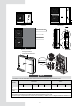 4
4
-
 5
5
-
 6
6
-
 7
7
-
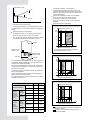 8
8
-
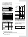 9
9
-
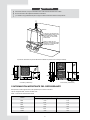 10
10
-
 11
11
-
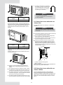 12
12
-
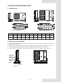 13
13
-
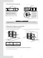 14
14
-
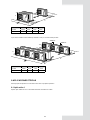 15
15
-
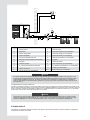 16
16
-
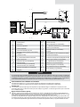 17
17
-
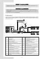 18
18
-
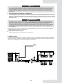 19
19
-
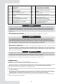 20
20
-
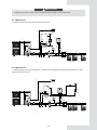 21
21
-
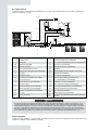 22
22
-
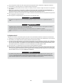 23
23
-
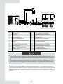 24
24
-
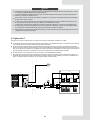 25
25
-
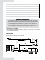 26
26
-
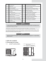 27
27
-
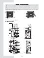 28
28
-
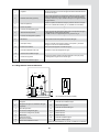 29
29
-
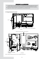 30
30
-
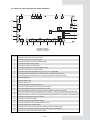 31
31
-
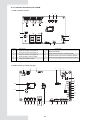 32
32
-
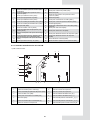 33
33
-
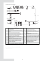 34
34
-
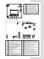 35
35
-
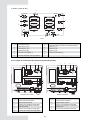 36
36
-
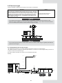 37
37
-
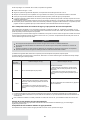 38
38
-
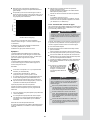 39
39
-
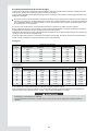 40
40
-
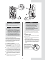 41
41
-
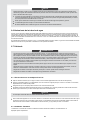 42
42
-
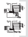 43
43
-
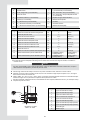 44
44
-
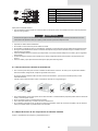 45
45
-
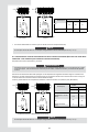 46
46
-
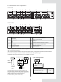 47
47
-
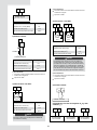 48
48
-
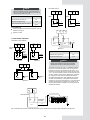 49
49
-
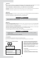 50
50
-
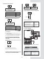 51
51
-
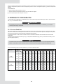 52
52
-
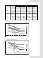 53
53
-
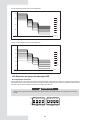 54
54
-
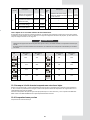 55
55
-
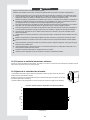 56
56
-
 57
57
-
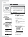 58
58
-
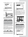 59
59
-
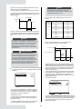 60
60
-
 61
61
-
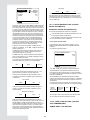 62
62
-
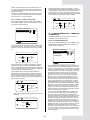 63
63
-
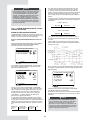 64
64
-
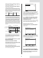 65
65
-
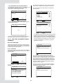 66
66
-
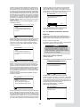 67
67
-
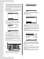 68
68
-
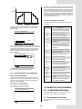 69
69
-
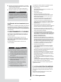 70
70
-
 71
71
-
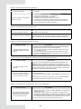 72
72
-
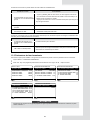 73
73
-
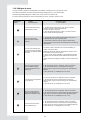 74
74
-
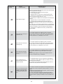 75
75
-
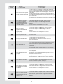 76
76
-
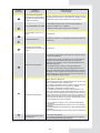 77
77
-
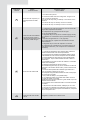 78
78
-
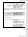 79
79
-
 80
80
-
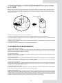 81
81
-
 82
82
-
 83
83
-
 84
84
-
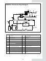 85
85
-
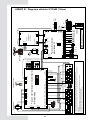 86
86
-
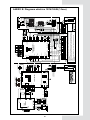 87
87
-
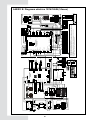 88
88
-
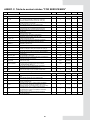 89
89
-
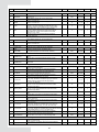 90
90
-
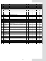 91
91
-
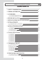 92
92
-
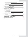 93
93
-
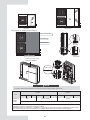 94
94
-
 95
95
-
 96
96
-
 97
97
-
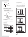 98
98
-
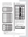 99
99
-
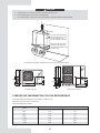 100
100
-
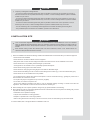 101
101
-
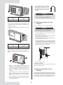 102
102
-
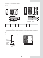 103
103
-
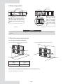 104
104
-
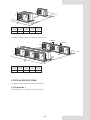 105
105
-
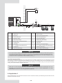 106
106
-
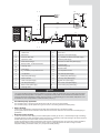 107
107
-
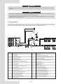 108
108
-
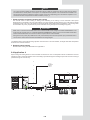 109
109
-
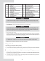 110
110
-
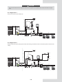 111
111
-
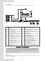 112
112
-
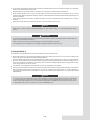 113
113
-
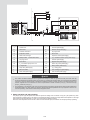 114
114
-
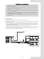 115
115
-
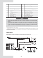 116
116
-
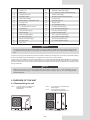 117
117
-
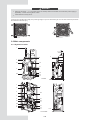 118
118
-
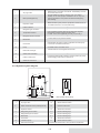 119
119
-
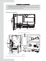 120
120
-
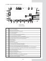 121
121
-
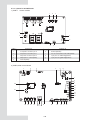 122
122
-
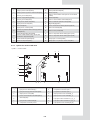 123
123
-
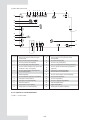 124
124
-
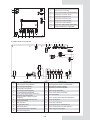 125
125
-
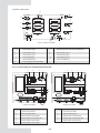 126
126
-
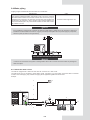 127
127
-
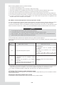 128
128
-
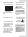 129
129
-
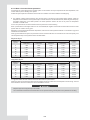 130
130
-
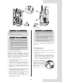 131
131
-
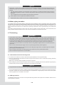 132
132
-
 133
133
-
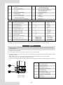 134
134
-
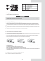 135
135
-
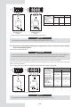 136
136
-
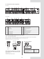 137
137
-
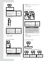 138
138
-
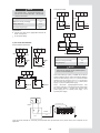 139
139
-
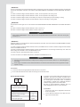 140
140
-
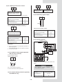 141
141
-
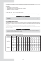 142
142
-
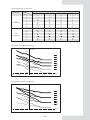 143
143
-
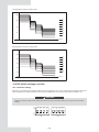 144
144
-
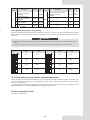 145
145
-
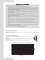 146
146
-
 147
147
-
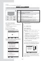 148
148
-
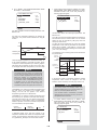 149
149
-
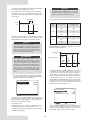 150
150
-
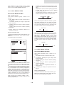 151
151
-
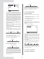 152
152
-
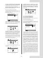 153
153
-
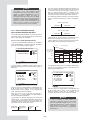 154
154
-
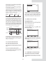 155
155
-
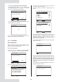 156
156
-
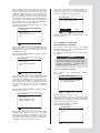 157
157
-
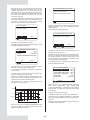 158
158
-
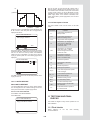 159
159
-
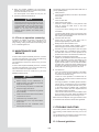 160
160
-
 161
161
-
 162
162
-
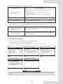 163
163
-
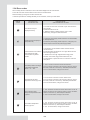 164
164
-
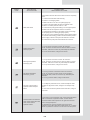 165
165
-
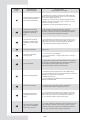 166
166
-
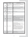 167
167
-
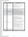 168
168
-
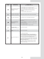 169
169
-
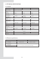 170
170
-
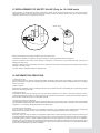 171
171
-
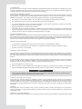 172
172
-
 173
173
-
 174
174
-
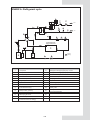 175
175
-
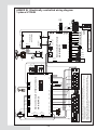 176
176
-
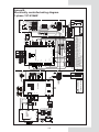 177
177
-
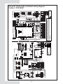 178
178
-
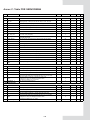 179
179
-
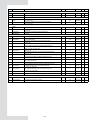 180
180
-
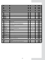 181
181
-
 182
182
-
 183
183
-
 184
184


mundoclima AEROTHERM MAM-V9 Serie Guía de instalación
- Categoría
- Bombas de calor
- Tipo
- Guía de instalación
en otros idiomas
Artículos relacionados
-
mundoclima Series Aerotherm V17 “Aerotherm Heat Pump” Manual de usuario
-
-
-
-
-
Otros documentos
-
Frigidaire FAD301NWD Información del Producto
-
Haier 1U09AP2VHA Manual de usuario
-
Daikin EBLQ036BA6VJU1 Guía de instalación
-
HTW ECO-THERMAL BIBLOCK INTEGRADO Manual de usuario
-
-
-
Gorenje TC120ZNT El manual del propietario
-
Dometic MCS6 Instrucciones de operación
-
Vaillant sensoCOMFORT VRC 720 Guía de instalación
-
LG LK-2580CH.AWG8SAF Guía de instalación