mundoclima AEROTHERM MAM-V9 Serie Manual de usuario
- Categoría
- Termostatos
- Tipo
- Manual de usuario
Este manual también es adecuado para

SV2
UI
SV2
UI
SV1
SV1
SV2
UI
AEROTHERM MAM-V9
Control Panel Owner's & Installation manual
Manual de usuario e instalación del panel de control
SO30180 ~ SO30188SO30180 ~ SO30188
www.mundoclima.com
FR: "Manual d’utilisation et d’installation" voir www.mundoclima.com/fr
DE: "Benutzer- und Installationshandbuch" sehen www.mundoclima.com/de
PT: "Manual de instalaçao e do utilizador" ver www.mundoclima.com/pt

.................................................................................................................................
..............................................................................................................................
ES
EN
2
26
Control Panel Owner's & Installation manual
Manual de usuario e instalación del panel de control

Este manual ofrece una descripción detallada de las
precauciones que se han de tener en cuenta durante el
funcionamiento del equipo.
Para asegurar el buen desempeño del control remoto cableado
lea cuidadosamente este manual antes de encender la unidad.
Por su conveniencia mantenga este manual accesible
después de leerlo para tenerlo de referencia futura.
ÍND
ICE
PÁG.
1
PRECAUCIONES GENERALES DE SEGURIDAD
..............
2
1
.1 Acerca de la documentaci
ó
n
................................
2
1.
2 Para el usuario.
.................................................
2
2 INFOR
MACI
Ó
N SOBRE EL PANEL DE CONTROL
............
3
2
.1 Control cableado
..............................................
3
2
.2 Iconos de estado
..............................................
3
3 USO DE P
Á
GINAS DE INICIO
.....................................
4
3
.1 Descripci
ó
n d
e las p
á
g
inas de inicio.
......................
4
4 MEN
Ú
.
.................................................................
5
4
.1 Estructura del men
ú
..........................................
5
4
.2 Acceder a las opciones del men
ú
...........................
6
4.3 Navegar en el men
ú
............................................
6
5 USO
B
Á
SIC
O
.........................................................
6
5
.1 Desbloqueo de la pantalla
.....................................
6
5
.2 Controles de ENCENDIDO/APAGADO
.......................
6
5
.3 Ajuste de la temperatura
.......................................
7
5
.4 Ajuste del espacio del modo de funcionamiento
.........
8
6 MEN
Ú
.
................................................................
9
6
.1 Modo de funcionamiento
......................................
9
6
.2 Pre-ajuste de la temperatura
..................................
9
6.3 Agua caliente sanitaria (ACS) (en el manual (DHW))
......
11
6
.4 Programaci
ó
n
....................................................
12
6.
5 Opciones
.........................................................
15
6
.6 Seguro para los ni
ñ
os
..........................................
16
6
.7 Informaci
ó
n
de mantenimiento
...............................
17
6.
8 Par
á
met
ro de funcionamiento.
................................
18
6
.9 Para los t
é
cn
icos de mantenimiento
.........................
18
7
ESTRUCTURA DEL MEN
Ú
R
esumen
...........................
19
8
MANUAL DE INSTALACI
Ó
N
......................................
24
8
.1 Medidas de seguridad
........................................
24
8
.2 Otras precauciones
............................................
24
8
.3 Procedimiento de instalaci
ó
n y aj
ustes
....................
24
8
.4 Instalaci
ó
n
del panel frontal
.................................
25
1
PRECAUCIONES GENERALES DE
SEGURIDAD
1.1
Acerca de la documentación
Las precauciones descritas en
este documento cubren temas
muy importantes, lea detenidamente.
1.1.1 Significado de las advertencias y símbolos
1.2
Para el usuario
Si no está
seguro de cómo hacer funcionar la unidad, póngase
en contacto con su instalador.
Este aparato no está diseñado para que lo usen niños
pequeños o personas enfermas sin supervisión. Se debe
supervisar que los niños no jueguen con la unidad.
Las u
nidades tienen este símbolo:
Esto significa que los productos electrónicos no se
pueden desechar junto con los residuos domésticos
no clasificados. NO intente desmontar el sistema sin
ayuda profesional: El desmontaje del sistema, el uso
del refrigerante, del aceite y de los componentes se
debe realizar por personal cualificado.
Los trabajos de instalación y mantenimiento deben
cumplir con la legislación vigente. Las unidades se
deben tratar en un centro de tratamiento
especializado para ser recicladas y recuperadas. Si
desecha este producto correctamente, estará
previniendo consecuencias nocivas tanto para el
medio ambiente como para la salud de todos. Para
cualquier pregunta contacte a su distribuidor local.
PREC
AUCIÓN
NO lavar la unidad. Esto causa descargas eléctricas o
INFORM
ACIÓN
Informa sobre consejos útiles o información adicional.
NOT
A
Indica una situación que puede provocar daños al
equipo o a bienes materiales.
PRECAUCIÓN
Indica una situaci
ó
n que puede provocar lesiones leves.
A
DVERTENCIA
Indica riesgo de lesiones graves o la muerte.
PELIG
RO
Indica la posibilidad de lesiones graves o la muerte.
PELIGRO: RIESGO DE QUEMADURA
Indica una situación que puede provocar quemaduras por
exceso de calor o frío.
PELIG
RO: RIESGO DE ELECTROCUCIÓN
Indica una situación que puede provocar electrocución.
incendios.
ES
Man
ual de usuario e instalación del panel de control
2

TANK
55
C
C
27
SET
SET
08 : 30
C
ON
ON
DHW MAIN
21: 55 08 - 08 - 2015 SA
T.
A
2
INFORMACIÓN SOBRE EL PANEL DE CONTROL
Ó
2.1 Control
cableado
Introduzca la selección del
menú desde la página de
inicio.
Navegador del cursor
en la pantalla/ navegador
para las opciones
del menú / configuración
de ajustes
Regresa al
nivel superior
Encender o apagar el modo calefacción
/refrigeración o el modo ACS (DHW) en
el menú.
Mantener pulsado el botón para
bloquear/desbloquear algunas
funciones del control como "ajuste de la
temperatura del depósito".
Va al próximo paso tras programar la selección
del menú confirma una selección/ introduce un
submenú dentro de sus opciones.
2.2 Iconos de estado
Función desinfección activada
Función Holiday away/home
(Vacaciones fuera / en casa)
Modo Silent activado
(Silencio)
Resistencia de apoyo
activada
Compresor funcionando
Detenido
Modo Calefacción
Modo Refrigeración
Modo Auto
Indica el modo
que se esta
ejecutando
Temperatura
deseada
Temperatura
deseada en
el tanque ACS
Modo ACS
(DHW)
Bloqueo
Indicador de avería
Temporizador
Fuente de calor adicional
(AHS) (Caldera)
Prevención de hielo
En la próxima p
rogramación, la temperatura deseada aumentará.
la temp. deseada
la temp. deseada
la
temp. deseada
no cambiar
á
. disminuir
á
. disminuir
á
.
Modo ECO
activado
Resistencia apoyo
del tanque activada
Desescarche
activado
Kit energia
activado
7
Modo Comfort
activado
solar
Programación
semanal
3

FHL1
FHL2...
FHLn
SV2
UI
SV1
T
ANK
55
C
27
SET
C
ON
ON
DHW ROOM
21: 55 08 - 08 - 2015 SAT.
TANK
55
C
35
SET
C
ON
ON
DHW MAIN
21: 55 08 - 08 - 2015 SAT.
FHL1
FHL2...
FHLn
SV2
UI
SV1
Todas las figuras pertenecen a
tipo Monobloc
Todas las figuras pertenecen a
tipo Monobloc
Distribución del sistema 1
.
.
Distribución del sistema 2
3
USO DE LAS PÁGINAS DE INICIO
3.1
Descripción de las páginas de inicio
Se pueden usar l
as páginas de inicio para leer y cambiar los ajustes diariamente. Lo que se puede ver y hacer en las páginas de inicio está
descrito donde se aplica. En función de la configuración, pueden visualizarse las páginas de inicio siguientes:
Temp. de la habitación (ROOM )
Temp. del agua (MAIN) DHW Temp. del depósito (TANK) DHW=agua caliente sanitaria (ACS)
ķPágina de inicio 1:
NOTA:
Todas las figuras de este manual se usan para
explicar las páginas visualizadas, puede que tengan
algunas diferencias con las que tiene el usuario.
ĸPágina de inicio 2:
Climatización (controlada por el panel de control) + ACS.
"WATER FLOW TEMP." en "NON".
"ROOM TEMP." en "YES".
El panel de control muestra la siguiente página principal:
NOTA:
En este caso el panel de control controlará la
temperatura de la habitación, por lo que se debe tener
en cuenta dónde
se instala.
En ajustes iniciales, ir a "FOR SERVICEMAN / TEMP. TYPE SETTING" (ver AJUSTE TIPO CONTROL TEMP. en el manual de la unidad
interior o monobloc) y ajustar "TEMP. TYPE SETTING" de la siguiente forma:
Climatización (controlada por temperatura de agua) + ACS.
"WATER FLOW TEMP." en "YES".
"ROOM TEMP." en "NON".
El panel de control muestra la siguiente página principal:
En ajustes iniciales, ir a "FOR SERVICEMAN / TEMP. TYPE SETTING" (ver AJUSTE TIPO CONTROL TEMP. en el manual de la unidad
interior o monobloc) y ajustar "TEMP. TYPE SETTING" de la siguiente forma:
4

Ĺ
ĺ
FHL1
FHL2...
FHLn
FCU1
FCU2...
FCUn
SV2
UI
21: 55 08 - 08 - 2015 SAT.
ON
ROOM
21: 55 08 - 08 - 2015 SA
T.
ON
MAIN
TANK
C
12
SET
C
ON
ON
DHW MAIN
21: 55 08 - 08 - 2015 SAT.
55
SET
C
24
21: 55 08 - 08 - 2015 SAT.
ON
ROOM
SV1
FHL1
FHL2...
FHLn
FCU1
FCU2...
FCUn
SV2
UI
SET
C
45
SET
C
24
Todas las figuras pertenecen a
tipo Monobloc
Todas las figuras pertenecen a
tipo Monobloc
Distribución del sistema 3
.
.
Distribución del sistema 4
Página de inicio 3:
Climatización (controlada por temperatura de agua / panel de control)
"WATER FLOW TEMP." en "YES".
"ROOM TEMP." en "YES".
El panel de control muestra la siguiente página principal y adicional:
PÁGINA PRINCI
PAL
PÁGINA ADICIONAL
Página de inicio 4:
PÁGINA PRINCI
PAL
PÁGINA ADICIONAL
Climatización (controlada por temperatura de agua / panel de control) + ACS.
"WATER FLOW TEMP." en "YES".
"ROOM TEMP." en "YES".
El panel de control muestra la siguiente página principal y adicional:
4 MENU
4.1
Estructura del menú
Puede usar la es
tructura del menú para saber los parámetros que no se deben usar en el uso diario. Lo que se puede visualizar y hacer
en la estructura del menú se describe donde se puede aplicar. Para un resumen de la estructura del menú, ver la sección "7. Estructura del
menú: Resumen" (ver Pág. 20).
En ajustes iniciales, ir a "FOR SERVICEMAN / TEMP. TYPE SETTING" (ver AJUSTE TIPO CONTROL TEMP. en el manual de la unidad
interior o monobloc) y ajustar "TEMP. TYPE SETTING" de la siguiente forma:
En ajustes iniciales, ir a "FOR SERVICEMAN / TEMP. TYPE SETTING" (ver AJUSTE TIPO CONTROL TEMP. en el manual de la unidad
interior o monobloc) y ajustar "TEMP. TYPE SETTING" de la siguiente forma:
5

ON
T
ANK
55
C
SET
C
OFF
DHW MAIN
21: 55 08 - 08 - 2015 SAT.
18
MENU
SERVICE INFORMA
TION
OPERATION PARAMETER
FOR SERVICEMAN
SCROLL
ENTER
OK
ON
T
ANK
55
C
SET
C
OFF
DHW MAIN
21: 55 08 - 08 - 2015 SAT.
18
ON
TANK
55
C
SET
C
OFF
DHW MAIN
21: 55 08 - 08 - 2015 SA
T.
18
ON
TANK
55
C
SET
C
OFF
DHW MAIN
21: 55 08 - 08 - 2015 SAT.
18
TA
NK
55
C
SET
C
ON
ON
DHW MAIN
21: 55 08 - 08 - 2015 SAT.
18
TANK
55
C
SET
C
ON
ON
DHW MAIN
21: 55 08 - 08 - 2015 SAT.
18
ON
TANK
55
C
SET
C
OFF
DHWMAIN
21: 55 08 - 08 - 2015 SAT.
18
SCROLL 1/2
2/2
ENTER
OK
MENU
OPERA
TE MODE
PRESET
TEMPERATURE
DOMESTIC HOT WATER(DHW)
SCHEDULE
OPTIONS
CHILD LOCK
UNLOCK UNLOCK
ON/OFF ON/OFF
4.2
Acceder a las opciones del menú
Desde una págin
a principal, pulsar "MENU".
Resultado: Se visualiza la estructura del menú:
4.3
Para navegar en la estructura del menú
Use ''''''
'' para moverse.
5
USO BÁSI
CO
5.1
Desbloqueo de la pantalla
Si se muestra el icono
, el panel de control está bloqueado.
Se visualiza la página:
Pulse cualquier tecla, el icono parpadeará. Mantener
pulsado el botón "UNLOCK". El icono desaparecerá, el
control se puede operar.
El control estará bloqueado si no
se pulsa ningún botón durante
un tiempo (unos 60 segundos: para ajustar ese tiempo, consulte la
sección 6.7 INFORMACIÓN DE MANTENIMIENTO).
Si el control está desbloqueado, mantenga pulsado el botón
"unlock", el control quedará bloqueado.
P
u
l
sac
i
ó
n
l
arga
DE
S
BL
OQU
E
O
P
u
l
sac
i
ó
n
l
arga
DE
S
BL
OQU
E
O
5.2 Encendido / Apagado (ON/OFF)
Use el panel de control para encender o apagar la unidad en
calefacción o refrigeración.
El ENCENDIDO/APAGADO de la unidad se puede controlar
mediante el panel de control si "ROOM THERMOSTAT" está
en "NON" (ver TERMOSTATO AMBIENTE en el manual de la
Use '''''''' en la página de inicio, aparecerá el cursor
negro:
unidad interior o monobloc).
1) Cuando el cursor esté seleccionando el modo de funcionamiento
(calefacción , refrigeración o automático ) pulsar el botón
"ON/OFF para encender o apagar.
A
6

SET
C
21: 55 08 - 08 - 2015 SAT.
ON
MAIN
18
SET
C
21: 55 08 - 08 - 2015 SAT.
OFF
MAIN
18
SET
C
21: 55 08 - 08 - 2015 SA
T.
ON
ROOM
18
SET
C
21: 55 08 - 08 - 2015 SAT.
OFF
ROOM
18
22:20 22-08-2018 SAT
Cool/heat mode is controlled by
the room thermostat.
The cool or heat mode is closed.
Please open the mode by the room
thermostat.
CONFIRM
OK
TANK
C
12
SET
C
ON
ON
DHW MAIN
21: 55 08 - 08 - 2015 SAT.
A
55
TA
NK
C
12
SET
C
OFF
ON
DHW MAIN
21: 55 08 - 08 - 2015 SAT.
A
55
TANK
55
C
SET
C
ON
ON
DHW MAIN
21: 55 08 - 08 - 2015 SAT.
A
SCROLL ADJUST ON/OFF
ON/OFF
18
TANK
C
12
SET
C
ON
ON
DHW MAIN
21: 55 08 - 08 - 2015 SAT.
A
55
TANK
55
C
SET
C
ONOFF DHW MAIN
21: 55 08 - 08 - 2015 SAT.
SCROLL
ADJUST
ON/OFF
ON/OFF
18
ON/OFF ON/OFF
ON/OFF ON/OFF
ON/OFF ON/OFF
Si se usa un termostato ambiente (externo) para encender o
apagar la unidad en calefacción / refrigeración.
ķSi "ROOM THERMOSTAT" está ajustado en "YES" (ver
TERMOSTATO AMBIENTE en el manual de la unidad interior o
monobloc) la unidad solo se podrá encender y apagar mediante
el termostato ambiente (externo), el panel de control indicará:
El modo
refrigeraci
ó
n
/calefacci
ó
n se
controla
mediante el termostato ambiente. El contacto
externo del modo refrigeraci
ó
n o
calefacci
ó
n
est
á
cerrad
o. Se ruega abrir el contacto del
a trav
é
s del termostato ambiente.
Traducción:
荜ġSi "DUAL ROOM THERMOSTAT" (termostato ambiente doble) está
en "YES" (ver TERMOSTATO AMBIENTE en el manual de la unidad
interior o monobloc).. Si el termostato de refrigeración está apagado, el
de calefacción está encendido y la un
idad está funcionando, pero la
pantalla está APAGADA. Se visualizará la página:
1) Use el control para encender o apagar la unidad en "DHW" (ACS).
Pulse '''' '' en la página de inicio aparecerá el cursor:''
2) Cuando el cursor está en el modo "DHW" (ACS). Use la tecla
"ON/OFF'' para encender/apagar el modo "DHW" (ACS).
5.3
Ajuste de la temperatura
Pulse ''
'''''' en la página de inicio, aparecerá el cursor negro:
7

TANK
55
c
SET
c
ON
ON
DHW MAIN
21: 55 08 - 08 - 2015 SAT.
A
SCROLL ADJUST ON/OFF
ON/OFF
TANK
c
SET
c
ON
ON
DHW MAIN
21: 55 08 - 08 - 2015 SAT.
A
SCROLL
ADJUST
ON/OFF
ON/OFF
55 12
Operation mode setting˖
OPERATION MODE
SCROLL CONFIRM
OK
COOL
AUTO
A
HEAT
Operation mode setting˖
OPERATION MODE
SCROLLCONFIRM
OK
HEA
T
heat
cool
auto
A
18
22:20 22-08-2018 SA
T
Cool/heat mode is controlled by
the room thermostat.
The cool or heat mode is closed.
Please open the mode by the room
thermostat.
CONFIRM
OK
TANK
c
18
SET
c
ON
ON
DHW MAIN
21: 55 08 - 08 - 2015 SAT.
A
SCROLL
ADJUST
ON/OFF
ON/OFF
55
TA
NK
55
C
SET
C
ON
ON
DHW MAIN
21: 55 08 - 08 - 2015 SAT.
A
SCROLL ADJUST ON/OFF
ON/OFF
18
SET
C
18
21: 55 08 - 08 - 2015 SAT.
ON
ROOM
A
Si el cursor está en la temperatura, use '''''''' para
seleccionar y use '''''''' para ajustar la temperatura.
5.4
A
juste del modo de funcionamiento para climatización
Ajuste del modo de funcionamiento mediante el panel de control.
Vaya a ''MENU'' > ''OPERATION MODE''. Pulse "OK",
se mostrará la página:
Hay tres modos disponibles: calefacción, refrigeración y modo
automático. Use ''''㸪'''' para moverse, pulse "OK" para
seleccionar.
Incluso si no pulsa "OK" y sale de la página, pulsando el botón "BACK",
el modo también es efectivo si el cursor se ha movido al modo de
funcionamiento.
Si solo se permite el modo calefacción, se visualizará:
El modo de funcionamiento no se puede cambiar (ver AJUSTE MODO
REFRIGERACIÓN en el manual de la unidad interior o monobloc).
Si
selecciona..
El modo de
funcionamiento es...
Siempre modo calefacción
Siempre modo refrigeración
Cambiado automáticamente por el software basado
en la temperatura exterior (y dependiendo del
ajuste inicial también la temp. interior), y teniendo
en cuenta los cambios mensuales.
Nota: Los cambios automáticos son posibles solo
bajo algunas condiciones. Consultar en AJUSTES
INICIALES > AJUSTES MODO AUTO en el manual
de la unidad interior o monobloc.
Si realiza el ajuste el modo de funcionamiento mediante el termostato
ambiente, (ver TERMOSTATO AMBIENTE en el manual de la unidad
interior o monobloc.)
Vaya a "MENU" > "OPERATION MODE", si pulsa cualquier tecla para
seleccionar o ajustar, se visualizará la página:
El modo refrigeración/calefacción
Traducción:
se controla mediante el termostato
ambiente. El contacto externo del
modo está cerrado. Se ruega abrir
el contacto a través del termostato
ambiente.
8

6 MENU
6.2.2 "WEATHER TEMP. SET" (Ajuste temp. segú n temp. exterior)
TANK
55
C
27
08:30
SET
C
ON
ON
DHW MAIN
8: 00 08 - 08 - 2015 SA
T.
NO. TIME TEMPER
1 8:30 35 ć
2 9:00 25 ć
3 10:00 35 ć
4 11:00 25 ć
5 12:
00 35 ć
6
13:
00
25
ć
TEMPE
R
35 ć
2 5 ć
8
:30 9 :00 10 :00 11 :00 12 :00 13 :00
6.1 "OPERATION MODE" (Modo de funcionamiento)
Ver "5.4 AJUST
E DEL MODO DE FUNCIONAMIENTO".
6.2 "PRESET TEMPERATURE"
"PRESET TEMPERATURE" tiene 4 ítems "PRESET TEMP."/
"WEATHER TEMP.SET" / "ECO MODE" / "COMFORT MODE".
6.2.1 "PRESET TEMP." (Pre-ajuste de temperatura)
La función "PRESET TEMP" se usa para ajustar temperaturas
diferentes en ho
rarios diferentes cuando está activo el modo
calefacción o refrigeración.
"PRESET TEMP." = "PRESET TEMPERATURE"
La función "PRESET TEMP." se apagará en estas condiciones.
1) El modo "AUTO" está activo.
2) "TIMER" o "WEEKLY SCHEDULE" están activados.
Vaya a ''MENU'' > ''PRESET TEMPERATURE'' > ''PRESET
TEMP''. Pulse ''OK''. Aparecerá la siguiente página:
Use '''''''''''''''' para moverse y use '''''''' para ajustar
el tiempo y la temperatura.
Cuando el cursor cambia a ''
'', como en las páginas siguientes:
Si pulsa ''OK'', y el punto '''' cambia a '' '' sin color. Se ha
seleccionado el temporizador 1. Si pulsa ''OK'' una vez más, y el
punto sin color '' '' cambia a ''''. No se ha seleccionado el
temporizador 1.
Use '''''''''''''''' para moverse y use '''''''' para ajustar
el tiempo y la temperatura.
Se pueden ajustar seis períodos y seis temperaturas.
Por ejemplo: Ahora son las 8:00 y hay una temp. de 30
°C.
Programamos "PRESET TEMP" como se muesta en la tabla siguiente:
Aparecer
á
la siguiente p
á
gina:
INFORM
ACIÓN
Cuando cambia el modo de funcionamiento el "PRESET TEMP."
se apaga automáticamente.
La función se puede usar en el modo calefacción y refrigeración.
Pero si se cambia el modo de funcionamiento, también hace falta
volver a ajustar la función.
La temperatura pre-ajustada no es válida si la unidad está
APAGADA. Cuando se vuelva a encender la unidad, la
temperatura pre-ajustada se activará nuevamente.
WEATHER TEMP.SET=WEATHER TEMPERATURE SET
Esta función se usa para pre-ajustar la temp. deseada del agua
automáticamente en dependencia de la temp. exterior del aire.
Durante el verano no se usa mucho la calefacción. Para evitar que
la bomba de calor produzca exceso de temp. del agua en el
circuito primario, esta función ("WEATHER TEMP. SET") se puede
usar para maximizar la eficiencia y reducir los costes de uso.
Vaya a ''MENU'' > ''PRESET TEMPERATURE''>''WEATHER
TEMP. SET''. Pulse ''OK''.
Aparecerá la siguiente página:
PR
ESET TEMPERATURE
S
CROLL
1/2
WEA
THER
TEMP.SET
ECO
MODE
PR
ESET
TEMP.
N
O. TIME TEMPER
00:00 25°C
00:00 25°C
00:00 25°C
2
3
1
PR
ESET TEMPERATURE
S
CROLL
2/2
WEA
THER
TEMP.SET
ECO
MODE
PR
ESET
TEMP.
N
O. TIME TEMPER
00:00 25°C
00:00 25°C
00:00 25°C
5
6
4
PR
ESET TEMPERATURE
SE
LECT
S
CROLL
1/2
WEA
THER
TEMP.SET
ECO
MODE
PR
ESET
TEMP.
N
O. TIME TEMPER
00:00 25°C
00:00 25°C
00:00 25°C
2
3
1
OK
PR
ESET TEMPERATURE
S
CROLL ADJUST
1/2
WE
ATHER
TEMP.SET
ECO
MODE
PR
ESET
TEMP.
NO
. TIME TEMPER
08:30 35°C
00:00 25°C
00:00 25°C
2
3
1
PR
ESET TEMPERATURE
S
CROLL
O
N/OFF
EC
O
MODE
PR
ESET
TEMP.
C
OOL MODE LOW TEMP
.
HE
AT MODE LOW TEMP.
OFF
OFF
WEATHER
TEMP.SET
ON
/OFF
PR
ESET TEMPERATURE
SCROLL ON/OFF
EC
O
MODE
PR
ESET
TEMP.
C
OOL MODE LOW TEMP
.
HE
AT MODE LOW TEMP.
ON
OFF
WEATHER
TEMP.SET
ON
/OFF
9

WEATHER
TEMP. SET TYPE:
WEATHER TEMP. SET
SCROLLCONFIRM
OK
1 2
3 5 6 7 8 4
6.2.3 "ECO MODE" (Modo Econó mico)
5:30 08-08-2016 SAT.
W
eather temp.set function is
on. Do you want to turn off it?
SCROLLENTER
OK
NO YES
INFORM
ACIÓN
"WEATHER TEMP. SET" tiene 4 tipos de curvas: 1. la curva de
ajuste a alta temperatura para calefacción, 2. la curva de ajuste a
baja temperatura para calefacción, 3. la curva de ajuste a alta
temperatura para refrigeración, 4. la curva de ajuste a baja
temperatura para refrigeración.
Solo tiene la curva del ajuste de alta temperatura para la
calefacción, si la alta temperatura se ajusta para la calefacción.
Solo tiene la curva del ajuste de baja temperatura para la
calefacción, si la baja temperatura se ajusta para la calefacción.
Solo tiene la curva del ajuste de alta temperatura para la
refrigeración, si la alta temperatura se ajusta para la refrigeración.
Solo tiene la curva del ajuste de baja temperatura para la
refrigeración, si la baja temperatura se ajusta para la refrigeración.
Véase AJUSTES INICIALES > AJUSTE MODO REFRIGERACIÓN
y AJUSTE MODO CALEFACCIÓN en el manual de la unidad interior
La temperatura deseada (TS1) no se puede ajustar, cuando la
curva de temperatura está ajustada en ON.
o monobloc.
Si desea usar el modo calefacción, seleccione: ''HEAT MODE
LOW TEMP''. Si desea usar el modo refrigeración, seleccione;
''COOL MODE LOW TEMP''. Puede seleccionar el ajuste de alta o
baja temperatura para calefacción o refrigeración, ver Tabla 1~8. Si
selecciona "ON" se visualizará la página siguiente:
Use "'''''' para moverse. Pulse ''OK'' para seleccionar.
Si está activado "WEATHER TEMP. SET", la temperatura
deseada no se puede programar en el panel de control. Pulse
Pulse las teclas '''''''' para ajustar la temperatura en la
página principal. Aparecerá la siguiente página:
Traducción:
La función de ajuste de temperatura según la temperatura
exterior esta activada. ¿Desesa desactivarla?
Mueva a "N
O", pulse "OK" para regresar a la página principal,
mueva a "YES", pulse "OK" para reiniciar "WHETHER TEMP. SET".
El "ECO MODE" se usa para ahorrar energía durante la noche.
Si el "ECO MODE" está activo, se muestra en la página de
inicio. Vaya a ''MENU'' > ''PRESET TEMPERATURE'' > ''ECO
MODE''. Pulse "OK". Aparecerá la siguiente página:
Pulse "ON/OFF". Aparecerá la siguiente página:
PR
ESET TEMPERATURE
S
CROLL
O
N/OFF
EC
O
MODE
PR
ESET
TEMP.
C
OOL MODE LOW TEMP.
HEAT MODE LOW TEMP.
ON
OFF
WEATHER
TEMP.SET
ON/
OFF
PR
ESET TEMPERATURE
PR
ESET
TEMP.
OFF
WEATHER
TEMP.SET
ECO
MODE
HEAT MODE LOW TEMP.
ON
/OFF
ON/
OFF
EC
O MODE SET TYPE:
ECO MODE SET
S
CROLL
CO
NFIRM
OK
1 2
3 5 6 7 8 4
Use '''''''' para moverse y pulse "OK" para seleccionar.
■
■
INFORM
ACIÓN
"ECO MODE SET" tiene dos tipos de curvas: 1. la curva de alta
temperatura para calefacción y 2. la curva de baja temperatura para
para calefacción.
Solo esta disponible la curva del ajuste de alta temperatura
para calefacción, si ha ajustado alta temperatura en calefacción,
es decir, si en el ajuste de "T1S RANGE" esta en "HIGH".
Solo esta disponible la curva del ajuste de baja temperatura
para calefacción, si ha ajustado baja temperatura en calefacción,
es decir, si en el ajuste de "T1S RANGE" esta en "LOW".
Véase "FOR SERVICEMAN" > "HEAT MODE SETTING" en el
manual de USO E INSTALACIÓN de la unidad.
Si el modo "HEAT" esta ON y el "ECO TIMER" es OFF, el equipo
funcionará en modo "ECO" todo el tiempo.
Si el modo "HEAT" esta ON y el "ECO TIMER" es ON, el equipo
funcionará en modo "ECO" de acuerdo con el tiempo programado de
encendico y de apagado.
ON
ECO
TIMER
START
END
08:00
:0019
10

DOMESTIC HOT
W
ATER˄DHW˅
DIS-
INFECT
ON
FAST
DHW
T
ANK
HEATER
OPERATE DAY
DHW
PUMP
START
FRI
23:00
CURRENT ST
ATE
SCROLL ON/OFF
ON/OFF
DOMESTIC HOT W
ATER˄DHW˅
DIS-
INFECT
OFF
FA
ST
DHW
T
ANK
HEATER
OPERATE DAY
DHW
PUMP
START
FRI
23:00
CURRENT
ST
ATE
SCROLL ON/OFF
ON/OFF
DOMESTIC HOT
W
ATER˄DHW˅
DIS-
INFECT
ON
T
ANK
HEA
TER
DHW
PUMP
CURRENT ST
ATE
SCROLL
ON/OFF
ON/OFF
F
AST
DHW
DOMESTIC HOT
WATER˄DHW˅
DIS-
INFECT
OFF
TANK
HEA
TER
DHW
PUMP
CURRENT ST
ATE
SCROLL ON/OFF
ON/OFF
FAST
DHW
ON/OFF
ON/OFF
ON/OFF ON/OFF
6.3 "DOMESTIC HOT WATER (DHW)" (Agua Caliente Sanitaria)
El menú "DHW" consta de:
1) "DISINFECT" 2) "FAST DHW"
3) "TANK HEATER" 4) "DHW PUMP"
6.3.1 "DISINFECT" (Desinfección)
La función "DESINFECT" se usa para eliminar la legionela. En esta
función el tanque alcanzará una temperatura de 65~70ć forzosamente
la temperatura de desinfección se ajusta en "FOR SERVICEMAN".
(Ver "DISINFECT" en el manual de usuario de la ud. interior o monobloc).
Vaya a ''MENU'' > ''DOMESTIC HOT WATER'' > ''DISINFECT''. Pulse
''OK''. Aparecerá la siguiente página:
6.3.2 "FAST DHW" (ACS Rápida)
La función "FAST DHW" se usa para forzar el sistema a funcionar en
modo "DHW" (ACS).
El equipo y las resistencias del deposito ACS o la resistencia de
apoyo auxiliar funcionarán juntas.
Vaya a "MENU"> "DOMESTIC HOT WATER" >"FAST DHW". Pulse "OK":
Use "ON/OFF" para seleccionar ON / OFF.
INFORMACIÓN
Si "CURRENT STATE" está en "OFF", "FAST DHW" no es válido,
y si "CURRENT STATE" está en "ON", la función "FAST DHW" es
efectiva.
La función "FAST DHW" es efectiva una vez.
6.3.3 "TANK HEATER" (Resistencia del depósito ACS)
La función "TANK HEATER" se usa para activar las resistencias del
depósito de ACS y calentar el agua del depósito. En la misma
situación, si se necesita refrigeración o calefacción y el sistema
funciona en refrigeración o calefacción, y sin embargo hay una
necesidad de agua caliente.
En este caso la función "TANK HEATER" se puede usar para calentar
el agua del depósito. También, incluso si el sistema de bomba de
calor falla. Ir a ''MENU'' > ''DOMESTIC HOT WATER'' > ''TANK
HEATER''. Pulse ''OK''.
23: 55 10 - 08 - 2015 FRI.
Use ''
'''''''''''''' para moverse y use '''''''' para ajustar los
parámetros al ajustar ''OPERATE DAY'' y ''START''. Si "OPERATE DAY"
se ajusta en "FRI" (Viernes) y el "START" (encendido) se ajusta a las
23:00, la función de desinfección se activará el viernes a las 23:00.
Si "CURRENT STATE" está en "OFF", "DISINFECT" no es válido.
Si la función de desinfección está activada, se visualizará la página
siguiente:
11

DOMESTIC HOT
WATER˄DHW˅
DIS-
INFECT
ON
FA
ST
DHW
T
ANK
HEATER
DHW
PUMP
CURRENT ST
ATE
SCROLL
ON/OFF
ON/OFF
DOMESTIC HOT W
ATER˄DHW˅
DIS-
INFECT
OFF
FA
ST
DHW
T
ANK
HEATER
DHW
PUMP
CURRENT ST
ATE
SCROLL
ON/OFF
ON/OFF
DOMESTIC HOT W
ATER˄DHW˅
SCROLL 1/2
NO. ST
ART
06:00
00:00
00:00
2
3
00:004
1
NO.
START
00:00
00:00
00:00
6
7
00:008
5
DIS-
INFECT
FAST
DHW
T
ANK
HEATER
DHW
PUMP
DOMESTIC HOT
WATER˄DHW˅
SCROLL 2/2
NO. ST
A
RT
06:00
00:00
00:00
10
11
00:00 12
9
NO. ST
ART
00:00
00:00
00:00
14
15
00:00 16
13
DIS-
INFECT
FA
ST
DHW
T
ANK
HEATER
DHW
PUMP
DOMESTIC HOT W
ATER˄DHW˅
1/2
NO. ST
A
RT
00:00
00:00
2
3
00:00 4
1
NO. ST
ART
00:00
00:00
00:00
6
7
00:00 8
5
DIS-
INFECT
FAST
DHW
T
ANK
HEATER
DHW
PUMP
06:00
SCROLL ADJUST
ON/OFF ON/OFF
TANK
55
C
SET
C
ON
ON
DHW MAIN
21: 55 08 - 08 - 2015 SA
T.
12
NO.
STAR
T
1
6:00
2
7:00
3
8:00
4
9:00
6 :
0 0 6 : 3 0 7 :00 7 : 3 0 8 :00 8 : 3 0 9:00 9:30
PU
MP
ON
OFF
Use ''ON/
OFF'' para seleccionar "ON" u "OFF". Use ''BACK''
para salir. Si "TANK HEATER" está activo, se mostrará la
página siguiente:
INFORMACIÓN
Si "CURRENT STATE" está en "OFF", "TANK HEATER" no es válido.
Si el sensor del depósito T5 está averiado, "TANK HEATER" no funciona.
6.3.4 "DHW PUMP" (Bomba de ACS)
La función "DHW PUMP" se usa para el retorno de agua al sistema.
Vaya a ''MENU'' > ''DOMESTIC HOT WATER'' > ''DHW PUMP''.
Pulse ''OK''. Aparecerá la siguiente página:
Moverse a “
”pulsar '' OK '' para seleccionar o eliminar.
( se ha seleccionado el temporizador,
se ha cancelado
el temporizador).
Use las teclas ''''''
'''''''''' para moverse y use ''''''''
para ajustar los parámetros.
Por ejemplo: ha ajustado el parámetro de "DHW PUMP" (Ver
el manual de la ud. interior o monobloc para más información
AJUSTES INICIALES > AJUSTES TIPO CONTROL TEMP.)
El tiempo de funcionamiento de la bomba es de 30 minutos.
Ajustar de la siguiente manera:
La bomba funciona de la siguiente manera:
6.4 "SCHEDULE" (Programación semanal)
El menú de "SCHEDULE" consta de:
1) "TIMER" para ajustar la programación diaria.
2) "WEEKLY SCHEDULE" para programar la semana.
3) "TIME" para ajustar la hora y fecha actual.
12

SCHEDULE
1/2
NO. STA
RT
00:00
00:00
2
3
00:00 4
1
END MODE TEMP
HEAT
HEAT
HEAT
HEAT
0ºC
0ºC
0ºC
0ºC
WEEKL
Y SCHEDULE
TIME
00:00
00:00
00:00
00:00
00:00
TIMER
SCROLL
SCHEDULE
2/2
NO. STA
RT
00:00
6
5
END MODE TEMP
HEAT
HEAT
0ºC
0ºC
WEEKLY
SCHEDULE
TIME
00:00
00:00
00:00
TIMER
SCROLL
SCHEDULE
MON TUES WED
THUR FRI SAT SUN
MON TUES WED THUR FRI SAT SUN
TIMETIMER
SCROLL
SET CANCEL
SELECT
WEEKLY
SCHEDULE
OK MON
SCHEDULE
TIMETIMER
CONFIRM
WEEKL
Y SCHEDULE
OK
NO. START END MODE TEMP
T1
1 :00 3 :00 DHW 50 ć
T2
7 :00 9 :00 HEAT 28 ć
T3
11 :30 13 :00 COOL 20 ć
T4 14 :00 16 :00 HEAT 28 ć
T5
1 5 :00 19 :00 COOL 20 ć
T6
18 :00 23 :00 DHW 50 ć
HE
AT MODE
D H W MO DE
HEAT MODE
COOL MODE
COOL MODE
D H W MO DE
1:00 3:00 7:00 9:00 11:30 13:00 14:00 15:00 18:00 19:00 23:00 24:00
Funcionamiento panel de control
1:00 DHW mode is turned O N
3:0
0 DHW mode is turned OFF
7
:
00 HEAT MODE is turned O N
9:
00 HEAT MODE is turned O FF
11:30 COOL MODE is turned O N
13
:00 COOL MODE is turned O FF
14:00 HEAT MODE is turned O N
15
:00 COOL MODE is turned O N and HEAT MODE is turned O FF
16:
00 HEAT MODE is turned O FF
1 8 :00
DHW MODE is turned O N
19:00 COOL MODE is turned O FF
23:
00 DHW mode is turned OFF
Timer 1 is useless.
The start time is same to the end time.
6.4.1 "TIMER" (Temporizador diario)
Use ''''''
'''''''''' para moverse y use '''''''' para ajustar
la hora, el modo y la temperatura.
Moverse a “”pulse ''OK '' para seleccionar o cancelar.
( se ha seleccionado el temporizador,
se ha cancelado
el temporizador). Se pueden ajustar 6 períodos horarios.
Si desea cancelar el "TIMER", mueva el cursor a pulse "OK",
el se convierte en , el temporizador no es válido.
Si la función "WEEKLY SCHEDULE" (prog. semanal) está
activada, el "TIMER" no será efectivo, siempre el último ajuste
será el efectivo. Si el "TIMER" esta activado, se muestra el
icono en la página principal.
Si ajusta la hora de inicio más tarde que la de apa
gado o la
temperatura está fuera del rango del modo. Aparecerá la siguiente
página:
El Temporizador 1 no puede configurarse.
Traducción:
La hora de encendido coincide con la hora
de apagado.
Ejemplo:
Ajuste de los seis temporizadores:
La unidad funcionará como sigue:
El funcionamiento del panel de control es con los siguientes horarios:
Hora
Si la hora de enc
endido es la misma que la de apagado en un
temporizador, el ajuste no será válido.
INFORMACIÓN
6.4.2 "WEEKLY SCHEDULE" (Programación semanal)
Si la función "TIMER" (temp. diario) está activada, el "WEEKLY
se mostrará el icono en la pantalla principal.
Vaya a ''MENU'' > ''SCHEDULE'' >''WEEKLY SCHEDULE''. Pulse
''OK''. Aparecerá la siguiente página:
7
SHEDULE" no sera efectivo. Si "WEEKLY SCHEDULE" esta activo,
Primero seleccio
ne los días de la semana que desea programar.
Use '''''''' para moverse, pulse ''OK'' para seleccionar o borrar el
día.
“
MON
” significa que se ha seleccionado el día, “MON
” que no se
ha seleccionado, cuando no tiene fondo negro.
INFORMACIÓN
Debemos ajustar al menos dos días cuando queremos activar la
función "WEEKLY SCHEDULE".
13

TIMETIMER WEEKLY
SCHEDULE
SCHEDULE
2/2
NO. STA
RT
00:00
6
5
END MODE
TEMP
HEAT
HEAT
0ºC
0ºC
00:00
00:00
00:00
SCROLL
SCHEDULE
TIMETIMER
SCROLL
SET
ENTER
WEEKLY
SCHEDULE
OK
MON TUES WED
THUR FRI SAT SUN
CANCEL
TIMER WEEKLY
SCHEDULE
SCHEDULE
12˖30
01-01-2015
SCROLL
TIME
CURRENT TIME
CURRENT DAY
You have to reset TIMER/WEEKLY SCHEDULE, if you change
the MAIN page to the ROOM page or you change the ROOM
page to the MAIN page.
The TIMER or WEEKLY SCHEDULE is invalid, if ROOM
THERMOSTAT is effect.
SCHEDULE
TIMETIMER
SCROLL
SET CANCEL
SELECT
WEEKLY
SCHEDULE
OK MON
MON TUES WED THUR FRI SAT SUN
TIMETIMER WEEKLY
SCHEDULE
SCHEDULE
1/2
NO. STA
RT
03:00
06:00
2
3
09:00 4
1
END MODE
TEMP
HEAT
COOL
HEAT
HEAT
30ºC
20ºC
35ºC
32ºC
00:00
04:00
08:00
10:00
02:00
SCROLL
Use ''''o
'''' mover a "SET", pulse "OK". De Lunes (MON) a
Viernes (FRI) se seleccionan para programarse y tienen la
misma programación.
Aparecerá la siguiente página:
Use '''''''''''''''' para moverse y para ajustar la hora,
el modo y la temperatura. En cada período se pueden
programar, la hora de encendido y de apagado, modo y
temperatura. El modo incluye calefacción, refrigeración y agua
caliente sanitaria "DHW".
El método de ajuste se refiere a la programación del temporizador.
La hora de apagado debe ser después que la de encendido, de lo
contrario se visualizará “Timer is of no effect” (Programación del
temporizador no válida).
Cancelar la programación semanal "WEEKLY SCHEDULE".
Cancelar la programación: Primero seleccionar los días de la
semana. Use '''''''' para moverse :
Use '' '''''' para mover a ”CANCEL”, pulse "OK"
para cancelar el horario. Si quiere salir de "WEEKLY
SCHEDULE", pulse “BACK”.
INFORMACIÓN
La función "TIME" se usa para ajustar la hora actual y la fecha.
Vaya a ''MENU''>''SCHEDULE''>''TIME''. Pulse ''OK''. Aparecerá
la siguiente página:
6.4.3 "TIME" (Hora actual)
Use ''''''
'''''''''' para moverse. Use '''' '''' para
ajustar.
INFORMACIÓN
Los modos "ECO" o "COMFORT" tienen la mayor prioridad, "TIMER"
o "WEEKLY SCHEDULE" tienen la segunda prioridad y "PRESET
TEMP." o "WEATHER TEMP SET" tienen la prioridad más baja.
"PRESET TEMP." o "WEATHER TEMP." Los valores ajustados
dejan de ser válidos, cuando validamos los valores de "ECO" o
"COMFORT". Debemos volver a ajustar "PRESET TEMP." o
"WEATHER TEMP". Los valores ajustados serán válidos si
ajustamos "ECO MODE" o "COMFORT MODE" no válidos.
No se afectan ni "TIMER" ni "WEEKLY SCHEDULE" cuando son
válidos los valores de "ECO" o "COMFORT". "TIMER" o "WEEKLY
SCHEDULE" están activados cuando está funcionando en "ECO"
o "COMFORT".
"TIMER" o "WEEKLY SCHEDULE" tienen la misma prioridad. La
función pos-ajuste es válida. "PRESET TEMP." se torna no válida
cuando los valores de "TIMER" o "WEEKLY SCHEDULE" son
válidos. "WEATHER TEMP. SET" no se afecta por el ajuste de
"TIMER" o "WEEKLY SCHEDULE".
Tienen la misma prioridad tanto "PRESET TEMP." como
"WEATHER TEMP. SET." La función pos-ajuste es válida.
INFORMACIÓN
Todos los ajuste de horarios ("PRESET TEMP.",
"ECO/COMFORT", "DISINFECT", "DHW PUMP", "TIMER",
"WEEKLY SCHEDULE", "SILENCE MODE","HOLIDAY HOME")
La activación de la función correspondiente solo se puede activar
durante el encendido o el apagado.
14

HOLIDAY
AWA
Y
HOLIDAY
HOME
BACKUP
HEATER
OPTIONS
OFF
OFF
OFF
ON
SILENT
MODE
SCROLL 1/2ON/OFF
ON/OFF
CURRENT
ST
ATE
DHW MODE
DISINFECT
HEAT MODE
HOLIDAY
AWA
Y
HOLIDAY
HOME
BACKUP
HEATER
OPTIONS
SILENT
MODE
2/2
FROM
UNTIL
SCROLLADJUST
07-08-2015
07-08-2015
HOLIDAY
AWA
Y
HOLIDAY
HOME
BACKUP
HEATER
OPTIONS
CURRENT
STATE
SILENT LEVEL
TIMER
ON
ENTER
SILENT
MODE
SCROLLADJUST
HOLIDAY
AWA
Y
HOLIDAY
HOME
BACKUP
HEATER
OPTIONS
OFF
ENTER
SILENT
MODE
SCROLLADJUST
CURRENT
STATE
SILENT LEVEL
TIMER
HOLIDA
Y
AWAY
HOLIDAY
HOME
BACKUP
HEATER
OPTIONS
CURRENT ST
ATE
SILENT LEVEL
TIMER
ON
ENTER
SILENT
MODE
SCROLLADJUST
HOLIDAY
AWA
Y
HOLIDAY
HOME
BACKUP
HEATER
OPTIONS
SILENT
MODE
NO. ST
ART
22:00
T1
T2
END
12:00
07:00
15:00
SCROLL
6.5 "OPTIONS"
(Opciones)
El menú de "OPTIONS" consta de:
1) "SILENT MODE" función silencio.
2) "HOLIDAY AWAY" función vacaciones fuera.
3) "HOLIDAY HOME" función vacaciones en casa
4) "BACKUP HEATER" para configurar la activación o no de las
resistencias de apoyo
6.5.1 "SILENT MODE" (Modo Silencio)
El "SILENT MODE" se usa para di
sminuir el sonido de la unidad. Sin
embargo, también disminuye la capacidad refrigeración/calefacción
del sistema. Hay dos niveles de silencio.
El nivel 2 es más silencioso que el nivel 1 y la capacidad de
calefacción o refrigeración también disminuye más.
Hay dos métodos para usar el "SILENT MODE":
1) modo silencio permanente;
2) modo silencio programado.
Vaya a la página de inicio para comprobar si el modo silencio está
activado. Si está activo, se mostrará en la página de inicio.
Vaya a ''MENU'' > ''OPTIONS'' > ''SILENT MODE''. Pulse "OK".
Aparecerá la siguiente página:
Use "ON/OFF" para seleccionar "ON" (activo) u "OFF" (inactivo).
Descripción:
Si el "CURRENT STATE" está en "OFF", "SILENT MODE" no es
Cuando selecciona "SILENT LEVEL" y pulsa ''OK'' o '' ".
Apa
recerá la
siguiente página:
válido.
NIVEL 1
NIVEL 2
Puede usar ''''''''
para seleccionar el nivel 1 ó 2. Pulse ''OK''.
Si se selecciona "TIMER", pulse "OK" para acceder, aparecerá la
siguiente página.
Hay dos temporizadores para ajustarMoverse a “”pulsar ''OK''
para seleccionar o borrar.
Si se borran los dos horarios, el "SILENT MODE" funcionará todo el
tiempo. De lo contrario, funcionará según el horario programado.
6.5.2 "HOLIDAY AWAY" (Vacaciones Fuera)
Si "HOLIDAY AWAY" está activo, el icono se mostrará en la
página principal.
Esta función se usa para prevenir que se congele la unidad
durante el invierno y activa la unidad antes del final de las
vacaciones.
Vaya a ''MENU'' > ''OPTIONS'' > ''HOLIDAY AWAY''. Pulse "OK".
Aparecerá la siguiente página:
Ejemplo de uso: Si está fuera du
rante el invierno, la fecha actual es
p.ej.: 2016-01-31, dos días después 2016-02-02, sería el comienzo
de las vacaciones.
Si se encuentra en la situación siguiente:
En dos días sale de casa durante dos semanas.
Desea ahorrar energía y que la casa no se enfríe. Puede hacer
lo siguiente:
1) Debe realizar la configuración antes de sus vacaciones.
15

CHILD LOCK
Please input the password:
ADJUST SCROLLENTER
OK
0 0 0
HOLIDAY
AWA
Y
HOLIDAY
HOME
BACKUP
HEATER
OPTIONS
ON
15-08-2015
17-08-2015
ENTER
SILENT
MODE
SCROLLENTER
OK
CURRENT ST
ATE
FROM
UNTIL
TIMER
HOLIDAY
AWA
Y
HOLIDAY
HOME
BACKUP
HEATER
OPTIONS
SILENT
MODE
SCROLL
HOLIDAY
AWA
Y
HOLIDAY
HOME
BACKUP
HEATER
OPTIONS
ON
ON
SILENT
MODE
SCROLLENTER
OK
BACKUP HEA
TER1
BACKUP HEATER2
"HOLIDAY AWAY"
ON
ON
2)
Activar el modo de vacaciones fuera.
Vaya a ''MENU'' > ''OPTIONS'' > ''HOLIDAY AWAY''. Pulse "OK".
Use ''ON/OFF'' para seleccionar ''OFF'' u ''ON'' y use
'''''''''''''''' para moverse y ajustar
Ajustes
Valor
desde
hasta
Modo funcion
amiento
Calefacción
Desinfección
2 de Feb. 2016
16 de Feb. 2016
INFORMACIÓN
INFORMACIÓN
Si el modo "DHW" está activado durante "HOLIDAY AWAY",
el ajuste de "DISINFECT" se desactivará.
Si "HOLIDAY AWAY" está "ON". Las funciones "TIMER"
y "WEEKLY SCHEDULE" no son válidas excepto en salida.
Si el "CURRENT STATE" está en "OFF", el "HOLIDAY
AWAY" está en inactivo.
El panel de control no acepta órdenes cuando
"HOLIDAY AWAY" está en "ON".
La desinfección de la unidad fue de 23:00 del último día si la
función "DISINFECT" está en "ON".
Si "HOLIDAY AWAY" entra en "ON", las curvas
ajustadas relacionadas con la temp. exterior no son válidas,
las curvas, tendrán efecto automáticamente después que termine
modo "HOLIDAY AWAY".
El "PRESET TEMP." no es valido si esta activado el modo
"HOLIDAY AWAY", pero el valor pre-ajustado aun se
muestra en la página principal.
INFORM
ACIÓN
Si el "CURRENT STATE" está en "ON", el "HOLIDAY
AWAY" está activo.
6.5.2.2 "HOLIDAY HOME" (Vacaciones en casa)
La función "HOLIDAY HOME" se usa para desviar desde la
programación normal sin tener que cambiarla durante las
vacaciones en casa.
Durante sus vacaciones, se puede usar el modo vacaciones para
salir de la programación normal sin tener que cambiarla.
Pe
r
í
odo
Después...
Antes y después de sus
Durante sus vacaciones
vacaciones
Se usarán sus programaciones
normales
Se usarán los ajustes de vacaciones
Para activar o desactivar el modo "HOLIDAY HOME":
Va
ya a ''MENU'' > ''OPTIONS'' > ''HOLIDAY HOME''. Pulse "OK".
Aparecerá la página siguiente:
Use ''ON/
OFF'' para seleccionar ''OFF'' o ''ON'' y use ''''''''
'''''''' para moverse y ajustar
Si el "CURRENT STATE" está en "OFF", el "HOLIDAY HOME "
está en "OFF". Si el "CURRENT STATE" está en "ON", en
"HOLIDAY HOME" está en "ON".
Use '''''''' para ajustar la fecha.
Antes y después de sus vacaciones, se usará su programación
Durante sus vacaciones, puede ahorrar energía y evitar que se
le enfríe la casa.
normal.
Una vez que regrese a casa debe borrar la programación de
las vacaciones, si desea cambiar la temperatura o no tiene a
su disposición los modos "DHW" o "HEAT".
6.5.3 "BACKUP HEATER" (Resistencia Auxiliar)
La función "BACKUP HEATER" se usa para forzar la resistencia
auxiliar. Vaya a ''MENU'' > ''OPTIONS'' > ''BACKUP HEATER''.
Pulse "OK".
Si "BACKUP HEATER" se ajusta a "NON" en ''OTHER HEATING
SOURCE". Aparecerá la siguiente página:
Si "BACKUP HEATER" se ajusta a "YES" en ''OTHER HEATING
SOURCE". Aparecerá la siguiente página:
Use ''ON/OFF'' para seleccionar ''OFF'' o ''ON'' y use ''''''''.
Si el modo de funcionamiento es automático en calefacción o
refrigeración, la resistencia auxiliar no se puede seleccionar.
La función "BACK HEATER" no es válida cuando solo se ha
activado "ROOM THERMOSTAT" (en AJUSTES TIPO CONTROL TEMP.)
6.6 "CHILD LOCK" (Bloqueo seguridad niños)
La función "CHILD LOCK" se usa para evitar que los niños mani-
-pulen el equipo. El modo y la temperatura deseada se pueden
bloquear o desbloquear con el uso de la función "CHILD LOCK"
Vaya a "MENU" > ''CHILD LOCK''. Se visualizará la página:
Por favor, escribir la contraseña:
Traducción:
16

CHILD LOCK
SCROLL
UNLOCK
UNLOCK
UNLOCK
COOL/HEAT
MODE ON/OFF
DHW TEMP. ADJUST
DHW MODE ON/OFF
UNLOCK
UNLOCK
UNLOCK
COOL/HEAT
TEMP. ADJUST
SERVICE INFORMA
TION
DISPLA
Y
PHONE NO. 0000000000000
MOBILE NO. 0000000000000
ERROR
CODE
SCROLL
P
ARAMETER
SER
VICE
CALL
SER
VICE INFORMA
TION
DISPLAYSERVICE
CALL
E2
E2
E2
E2
14:10 01-08-2015
14:00 01-08-2015
13:50 01-08-2015
13:20 01-08-2015
SCROLLENTER
OK
PARAMETERERROR
CODE
SERVICE INFORMA
TION
DISPLA
Y
SER
VICE
CALL
ROOM SET
TEMP.
MAIN SET TEMP.
TANK SET TEMP.
ROOM ACTUAL TEMP.
26ºC
55ºC
55ºC
24ºC
ERROR
CODE
SCROLL ENTER
OK
P
ARAMETER
SER
VICE INFORMATION
SERVICE
CALL
LANGUAGE
BACKLIGHT
BUZZER
SCREEN LOCK
TIME
EN
ON
ON
120SEC
ERROR
CODE
SCROLL ENTER
OK
PARAMETER DISPLAY
˖
12:30 08-08-2015 SAT.
E2 comunication fault between
controller and indoor unit
Please contact your dealer
.
CONFIRM
OK
SERVICE INFORMA
TION
DISPLAYSERVICE
CALL
E2
E2
E2
14:00 01-08-2015
13:50 01-08-2015
13:20 01-08-2015
SCROLL
ENTER
OK
PARAMETERERROR
CODE
E2 14:10 01-08-2015
aparecerá la página siguiente:
Use '''''''' para moverse y ''UNLOCK'' para seleccionar "LOCK"
o "UNLOCK". No se puede ajustar la temperatura cuando la
temperatura está bloqueada. El modo no se puede cambiar cuando
el modo está bloqueado. Si usted quiere cambiarlos, debe
desbloquearlos usando la función "CHILD LOCK".
6.7 "SERVICE INFORMATION" (Información de servicio)
6.7.1
Información de mantenimiento
El menú de "SERVICE INFORMATION" consta de:
1) "SERVICE CALL", información de contacto.
2) "ERROR CODE", para comprobar que significa un error.
3) "PARAMETER", para revisar los parámetros de funcionamiento.
4) "DISPLAY", para ajustar la pantalla del control.
6.7.2
Como acceder al menú información de mantenimiento
Ir a ''MENU'' > ''SERVICE INFORMATION''. Pulse "OK".
Aparecerá la siguiente página:
En la función "SERVICE CALL" se pueden ver los teléfonos
de contacto. El instalador puede introducir su número.
Véase "FOR SERVICEMAN":
"ERROR CODE" se usa para mostrar el error cuando ocurre y se
muestra el significado del código de error.
Pulse "OK" y la página aparecerá:
Pulse "OK" para mostrar el significado del código de error.
"PARAMETER" se
usa para visualizar los parámetros principales, hay
dos páginas para mostrar los parámetros:
"DISPLAY" se usa para ajustar el panel de control, los elementos
principales como idioma, luz de fondo, zumbador y tiempo de
apagado de la pantalla:
Use ''OK'' para acceder y use '''''''''''''''' para moverse.
Información㸸ġ
En estos momentos el panel de control solo está en Inglés.
▼▲
La contraseña es 123. Usar , para moverse y ,
◄►
para ajustar el valor numerico. Pulsar "OK".
17

FOR SERVICEMAN
Please input the password:
ADJUST SCROLL
ENTER
OK
FOR SERVICEMAN
Do you want to exit the for
serviceman?
SCROLL CONFIRM
OK
NO YES
6.8 "OPERATION PARAMETER" (Parámetros de funcionamiento)
Este menú es pa
ra que el instalador o el ingeniero de
mantenimiento puedan revisar los parámetros de funcionamiento.
Vaya a ''MENU'' > ''OPERATION PARAMETER''.
Pulse ''OK''. Hay cinco páginas para ver los parámetros de funcio-
-namiento. Use ''
'''''' para moverse.
INFORMACIÓN
El parámetro de consumo de corriente
es orientativo.
Si algunos parámetros no están activados en el sistema, el
parámetro que se mostrará es "--".
6.9 "FOR SERVICEMAN" (Ajustes iniciales)
6.9.1 Sobre "FOR SERVICEMAN"
Ajuste de la composición del sistema.
Ajuste de los parámetros.
6.9.2 Cómo acceder a los Ajustes Iniciales.
Vaya a ''MENU'' > ''FOR SERVICEMAN''. Pulse ''OK''.
Por favor, escribir la contraseña:
Traducción:
"FOR SERVICEMAN" se usar para realizar la configuración inicial
del sistema. Los usuarios finales NO deben cambiar los ajustes de
este menú.
"FOR SERVICEMAN" se usar para realizar la configuración inicial
del sistema. Los usuarios finales NO deben cambiar los ajustes de
este menú.
Por esta razón se necesita la protección de la contraseña para
evitar acceso no autorizado a los ajustes iniciales.
6.9.3 Cómo salir de los Ajustes Iniciales.
Si ha ajustado todos los parámetros.
Use "BACK", se visualizará la siguiente página:
Traducción:
¿Desea salir de los ajustes inciales?
Seleccionar ''YES'' y pulsar ''OK'' para salir de "FOR
SERVICEMAN". Después de salir de "FOR SERVICEMAN", el
equipo se apaga
rá.
2 3 4
La contraseña es 234.
OPERATION P
ARAMETER
P2 COMP. PRESSURE2 --kPa
POWER CONSUMPTION OKWH
SCROLL 5/5
OPERATION P
ARAMETER
30°C
T2 PLATE F-OUT TEMP.
45°C
T2B PLATE F-IN TEMP.
-7°C
T3 OUTDOOR EXCHANGE TEMP
.
-7°C
T4 OUTDOOR
AIR
TEMP.
-7°C
T5 OUTDOOR AIR TEMP.
SCROLL 3/5
OPERATION P
ARAMETER
COMP.RUN TIME4 1000HOUR
EXPANSION VALUE 240P
600 R/MIN FAN SPEED
0 A BACKUP HEATER1 CURRENT
0 A BACKUP HEATER2 CURRENT
T1 LEAVING WATER TEMP.1 25°C
SCROLL 2/5
OPERATION P
ARAMETER
Ta Room temp
25°C
P1 COMP. PRESSURE1 200kPa
SCROLL 4/5
25°C
T
w-0 PLA
TE W-OUTLET TEMP.
25°C
Tw-I PLATE W-INLET TEMP.
25°C
Th COMP.SUCTION TEMP.
25°C
OPERA
TION PARAMETER
OPERATE MODE COOL
COMPRESSOR CURRENT 12A
24Hz COMPRESSOR FREQUNCY
54MIN COMP.RUN TIME1
65MIN COMP.RUN TIME2
10MIN
COMP.RUN TIME3
SCROLL 1/5
Tp COMP
. DISCHARGE TEMP.
T1B
LEA
VING WATER TEMP.2
25°C
18

7 ESTRUCTURA DEL MENÚ : Sumario
MENU
SP
ACE OPERATION MODE
PRESET TEMPERATURE
DOMESTIC HOT WATER(DHW)
SCHEDULE
OPTIONS
CHILD LOCK
SERVICE INFORMATION
OPERATION PARAMETER
FOR SERVICEMAN
DISINFECT
CURRENT STATE
OPERATE DAY
STATE TIME
SILENT MODE
CURRENT STATE
SILENT LEVEL
TIMER
HOLIDAY AWAY
CURRENT STATE
DHW MODE
DISINFECT
HEAT MODE
FROM
UNTIL
HOLIDAY HOME
CURRENT STATE
FROM
UNTIL
SCHEDULE
DISPLAY
LANGUAGE
BACKLIGHT
BUZZER
SCREEN LOCK TIME
TIME
CURRENT TIME
CURRENT DAY
OPTIONS
SILENT MODE
HOLIDAY AWAY
HOLIDAY HOME
BACKUP HEATER
CHILD LOCK
COOL/HEAT TEMP.ADJUST
COOL/HEAT MODE
DHW TEMP.ADJUST
DHW MODE
SERVICE INFORMATION
SERVICE CALL
ERROR CODE
PARAMETER
DISPLAY
INSTALLATION MENU
DHW MODE SETTING
COOL MODE SETTING
HEAT MODE SETTING
AUTO MODE SETTING
TEMP. TYPE SETTING
ROOM THERMOSTAT
OTHER HEATING SOURECE
HOLIDAY AWAY SETTING
SERVICE CALL
RESTORE FACTORY SETTINGS
TEST RUN
SPECIAL FUNCTION
AUTO RESTART
OPERATION PARAMETER
SCHEDULE
TIMER
WEEKLY SCHEDULE
TIME
SPACE OPERATION MODE
HEA
T
COOL
AUT
O
PRESET
TEMPERATURE
PRESET
TEMP.
WEA
THER TEMP. SET
ECO MODE
DOMESTIC HOT
WATER(DHW)
DISINFECT
F
AST DHW
T
ANK HEATER
DHW PUMP
19

FOR SERVICEMAN
1 DHW MODE SETTING
2 COOL MODE SETTING
3 HEAT MODE SETTING
4 AUTO MODE SETTING
5 TEMP. TYPE SETTING
6 ROOM THERMOSTAT
7 OTHER HEATING SOURCE
8 HOLIDAY AWAY SETTING
9 SERVICE CALL
10 RESTORE FACTORY SET.
11 TEST RUN
12 SPECIAL FUNCTION
1 DHW MODE SETTING
1.1 DHW MODE
1.2 T
ANK HEATER
1.3 DISINFECT
1.4 DHW PRIORITY
1.5 DHW PUMP
1.1 DHW MODE
dT5_ON
dT1S5
T4DHWMAX
T4DHWMIN
t_INTER
V
Al DHW
1.2 TANK HEATER
dT5_TBH_ OFF
T4_TBH_ON
t_TBH_DELA
Y
1.3 DISINFECT
T5S_DI
t_DI_HIGHTEMP.
t_DI_MAX
1.4 DHW PRIORITY
t_DHWHP
MAX
t_DHWHP RESTRICT
1.5 DHW PUMP
TIMER RUNNING
DISINFECT
PUMP
RUNNING
TIME
7.1 BACKUP HEATER
HEA
T MODE
DHW MODE
T4_IBH_ON
Td1_IBH_ON
t_IBH_DELAY
t_IBH12_DELAY
7.2 ADDITIONAL HEATING SOURCE
HEA
T MODE
DHW MODE
T4_AHS_ON
dT1_AHS_ON
dT1_AHS_OFF
t_AHS_DELAY
12.2 PREHEATING FOR FLOOR
FLOW SET
TEMPERATURE
RETURN TEMPERATURE
PREHEATING TIME
OPERATE PREHEATING FOR FLOOR
12.3 FLOOR DRYING UP
DR
YING UP TIME
HIGE TEMP. TIME
DRYING DOWN TIME
PEAK TEMPERATURE
START TIME
START DATE
OPERATE FLOOR DRYING UP
2 COOL MODE SETTING
COOL
MODE
T1S RANGE
T4CMAX
T4CMIN
dT1SC
dTSC
t_INTERVAL_C
3 HE
A
T MODE SETTING
HEAT MODE
T1S RANGE
T4HMAX
T4HMIN
dT1SH
dTSH
t_INTERVAL_H
11 TEST RUN
AIR PURGE
CIRCULATED PUMP RUNNING
COOL
MODE RUNNING
HEAT MODE RUNNING
DHW MODE RUNNING
12 SPECIAL FUNCTION
13.1 AIR
PURGE
13.2 PREHEATING FOR FLOOR
13.3 FLOOR DRYING UP
13 AUTO REST
ART
COOL/HEAT MODE
DHW MODE
9 SER
VICE CALL
PHONE NO.
MOBILE NO.
4 AUT
O MODE SETTING
T4AUTOCMIN
T4AUTOHMAX
5 TEMP. TYPE SETTING
WATER FLOW TEMP.
ROOM TEMP.
8 HOLIDAY AWAY SETTING
T1S_H.A_H
T5S_H.M_DHW
7 OTHER HEATING SOURCE
7.1 BACKUP HEA
TER
7.2 AHS
7.3 SOLAR ENERGY
6 ROOM THERMOSTAT
ROOM THERMOST
AT
13 AUTO
RESTART
MODE SETTING
DUAL ROOM THERMOSTAT
POINT CHECK
10 RESTORE FACTORY SET.
20

NOTAS
21

Tabla 1 Curva de temperatura ambiente en el ajuste de baja temperatura para calefacción
Tabla 2 Curva de temperatura ambiente en el ajuste de alta temperatura para calefacción
30
38
37
36
35
35
34 34
33
32
33
32 32
35
34
33 33
32
31
33
32 32 32
31
30
31
30 30 30 29 28
29 28 28
27
29 28 28 28
27
26
2
4
5
6 7 8 9 10
11
12
13
14
15
16
17
18 19 20
35
34
33 33
32
32
31 31
30
31 31
30
31
30 30 28
30 29 29 28
28
27 27
26
27 27
26
38
35
33
35
33
31
29
29
1
35
32
31
31
30
28
27
26 26
25 25
24
38
35
33
35
33
31
29
29
3
35
32
31
31
28
27
26
35
32
31
31
30
28
27
26
38
35
33
33
31
29
29
34
32
31
31
30
28
27
26
33
29
37
34
32
30
28
34
34
32
31
30
28
27
26
33
29
30
37
34
32
30
28
34
34
32
31
30
28
27
26
33
29
30
37
34
32
30
28
34
34
31
27
29
31
27
25
30
37
34
32
30
28
34
34
31
27
28
32 32
29
31
27
25
30
37
34
32
30
28
31
27
28
25 25 25 25
24 24 24 24 24
32
30
30
28
28
26
26
32
30
30
28
28
26
26
32
30
30
28
28
26
26
32
30
30
29
28
26
26
30
30
29
28
26
26
33 33 33 33 33
26
27
29
29
30
31 31 31 31
27
27
27
27
26
27
29 29 29
29 29 29
31 31
30
36
34
32
33
28
36
32
33
28
33
31
29
27
36
32
33
28
33
31
29
36
32
33
28
27
33
31
29
36
32
28
27
32
33
31
29
36
32
28
27
32
33
31
29
32
28
27
35
32
33
31
29
32
28
27
35
32
33
31
29
32
28
27
31
35
-
19 -18
-17
-16
-15
-14
-13
-12
-11
-10 -9 -8 - 7 -6
-5
-4
-3
-2
-1
0 -20
T4
1-T1S
2- T1S
3- T1S
4- T1S
5- T1S
6- T1S
7 -T1S
8- T1S
T4
1-T1S
2- T1S
3- T1S
4- T1S
5- T1S
6- T1S
7 -T1S
8- T1S
T4
1-T1S
2- T1S
3- T1S
4- T1S
5- T1S
6- T1S
7 -T1S
8- T1S
T4
1-T1S
2- T1S
3- T1S
4- T1S
5- T1S
6- T1S
7 -T1S
8- T1S
-19 - 18
-17
-16
-15
-14
-13
-12
-11
-10 -9 -8 - 7 -6
-5
-4
-3
-2
-1
0 -20
55 55 55 55
54 54
53
52
55 55
54
53
52
51
50 50
55
54 54
53
52
51
50 49 48
47
50 50 50 49 48
47
50 50 49 48
47
46
45 45
45 45 45
44
43
42
45 45
44
43
42
41
40 40
40 40 40 39
38
37
1
2
3
4
5
6 7 8 9 10
11
12
13
14
15
16
17
18 19 20
52 52 52
51
50 50
50 49 49 48
47
46
45 45
47
46 46
45
44
43
42
41
40 40
47 47 47
46
45 45
45
44 44
43
42
41
40 40
42 42 42
41
40 40
40 39 39
38
37
36
35 35
37 37 37
36
35 35
54
50
49
45
44
40
52
49
46
47
44
42
39
37
53
54
49
44
52
49
47
44
42
39
37
54
49
44
39
45
53
54
49
44
52
47
42
37
48
43
38
49
44
39
45
52
47
42
37
54
53
52
48
43
48
43
38
49
44
39
51
44
46
41
36
54
53
52
48
43
48
43
38
49
44
39
51
44
46
41
36
54
53
48
43
49
44
39
51
47
42
37
51
46
41
36
54
49
44
39
52
47
42
43
47
42
37
51
46
41
36
54
49
44
39
50
52
47
42
43
47
42
3
7
51
46
41
36
53
48
43
38
50
52
47
42
51
46
41
36
46
42
41
36
53
48
43
38
51
46
41
36
51
49
46
41
46
41
36
53
48
43
38
50
41
45
40
35
51
49
46
41
46
41
36
53
48
43
38
50
41
45
40
35
51
46
41
53
48
43
38
48
45
40
35
50
45
40
35
53
48
43
38
50
45
40
40
48
45
40
35
50
45
40
35
53
48
43
38
22

Tabla 3 Curva de temperatura ambiente en el ajuste de baja temperatura para refrigeración
Tabla 4 Curva de temperatura ambiente en el ajuste de alta temperatura para refrigeración
T4
1 - T1S
T4
2 - T1S
T4
3- T1S
T4
4- T1S
T4
5 - T1S
T4
6 - T1S
T4
7 -T1S
T4
8 - T1S
18
11
8
5
17
12
96
18
13
10 7
19
14 11
8
20
15
12
9
21
16
13
10
22
17 14 11
23
18
15
12
-10 T4˘15
15 T4 ˘22
22 T4 ˘30 30 T4 ˘46
-10 T4˘15
15 T4 ˘22
22 T4 ˘30 30 T4 ˘46
-10 T4˘15
15 T4 ˘22
22 T4 ˘30 30 T4 ˘46
-10 T4˘15
15 T4 ˘22
22 T4 ˘30 30 T4 ˘46
-10 T4˘15
15 T4 ˘22
22 T4 ˘30 30 T4 ˘46
-10 T4˘15
15 T4 ˘22
22 T4 ˘30 30 T4 ˘46
-10 T4˘15
15 T4 ˘22
22 T4 ˘30 30 T4 ˘46
-10 T4˘15
15 T4 ˘22
22 T4 ˘30 30 T4 ˘46
22
20
18
16
20
19
18
17
23
21
19
17
21
20
19
18
24
22
20
18
22
21
20
19
25
23
21
19
23
22
21
20
T4
1 - T1S
T4
2 - T1S
T4
3- T1S
T4
4- T1S
T4
5 - T1S
T4
6 - T1S
T4
7 -T1S
T4
8 - T1S
-10 T4˘15
15 T4 ˘22
22 T4 ˘30 30 T4 ˘46
-10 T4˘15
15 T4 ˘22
22 T4 ˘30 30 T4 ˘46
-10 T4˘15
15 T4 ˘22
22 T4 ˘30 30 T4 ˘46
-10 T4˘15
15 T4 ˘22
22 T4 ˘30 30 T4 ˘46
-10 T4˘15
15 T4 ˘22
22 T4 ˘30 30 T4 ˘46
-10 T4˘15
15 T4 ˘22
22 T4 ˘30 30 T4 ˘46
-10 T4˘15
15 T4 ˘22
22 T4 ˘30 30 T4 ˘46
-10 T4˘15
15 T4 ˘
22
22 T4 ˘30 30 T4 ˘46
23

mm91
mm48
mm44
PP
PP
120mm
20mm
mm021
Caja Unidad Interior/Monobloc
AX
EY
B
Panel de control
AB
XY E
12
34 5
8 MANUAL
DE INSTALACIÓN
8.1 Medidas de seguridad
Lea cuidadosamente las precauciones de seguridad antes de instalar la unidad.
Las indicaciones de seguridad a continuación deben ser cumplidas.
Si no hay incidencias durante la prueba de funcionamiento, entregue el manual
al usuario.
Significado de las marcas:
El equipo debe ser instalado solamente por profesionales.
La instalación realizada por personas no expertas puede ser incorrecta y provocar
descargas eléctricas o incendios.
Cumpla estrictamente las orientaciones de este manual.
Una mala instalación puede provocar descargas eléctricas o incendios.
La reinstalación la deben realizar los profesionales.
Una mala instalación puede provocar descargas eléctricas o incendios.
No desmonte el aire acondicionado por su cuenta.
Si el desmontaje no es correcto puede provocar un mal funcionamiento o un
sobrecalentamiento que puede provocar incendios.
ADVERTENCIA
ADVERTENCIA
Una mala manipulación puede provocar la muerte o
lesiones graves.
PRECAUCIÓN
Una mala manipulación puede provocar lesiones o
daños materiales
PRECAUCI
Ó
N
No instal
e el equipo en un lugar peligroso con posibles fugas de gases inflamables.
Si hay fugas de gases inflamables y no se reparan, se puede incendiar el entorno del control.
Los cables deben ser compatibles a la corriente del control remoto cableado.
De lo contrario, pueden provocarse descargas eléctricas o calentamientos y ocasionarse
un incendio.
Se deben usar los cables especificados. No se debe ejercer fuerza
sobre el terminal.
De lo contrario, pueden provocarse descargas eléctricas o calentamientos y
ocasionarse un incendio.
No colocar el control remoto cableado cerca de lámparas, para evitar
que se obstruya la señal del control remoto. (consulte la figura a la
derecha)
8.2 Otra
s precauciones
8.2.1.
Ubicación
No instale la unidad en un lugar con mucho aceite, vapor o
gases de sulfuro. Si no, el producto se puede deformar o caer.
8. Preparación
previa a la instalación
1) Compruebe si los elementos a continuación están completos.
No
.
No
mbre
C
ant.
Observ
aciones
1
Contr
ol remoto cableado
1
2
T
ornillo de montaje de
madera con cabeza
redonda Philips
3
G
B950-86 M4X20
(Para el montaje en la pared)
3
T
ornillo de montaje de
cabeza redonda Philips
2
M4X
25 GB823-88
(Para el montaje en la
caja de conexiones)
4
Manual
de usuario e
instalaci
ó
n
1
5
Tornil
lo de plástico
2
E
ste accesorio se usa para
instalar el control dentro de una
caja eléctrica.
6
T
ubería plástica de
expansión
3
P
ara montar en la pared
8.3.2
Cableado
Voltaje
de entrada (A/B)
13.5V
AC
Sección del cable
0,75mm
2
8.2.3 Nota para
la instalación del control cableado:
1
) Este manual de instalación contiene información acerca del
procedimiento de instalación del panel de control
Consulte el manual de instalación de la unidad interior para la
conexión entre el control remoto cableado y la unidad interior.
2
) El circuito del control remoto cableado es de bajo voltaje. Nunca
lo conecte con un circuito estándar 220V/380V ni lo coloque en el
mismo tubo para cables con el circuito.
3
) El cable de protecci
ó
n
debe estar bien conectado a tierra,
sino la transmisi
ó
n puede
fallar.
4
) No trate de extender el cable apantallado al cortarlo, use
para la conexi
ó
n e
l bloque de conexi
ó
n d
e terminal.
5
) Después de terminar la conexión, no use el megger para comprobar
la instalación de la señal del cable.
8
.3 Procedimiento de ins
talación y ajustes del panel
de control
8
.3.1 Esq
uema con dimensiones
24

M4X25 GB823-88
PP
PP
B
C
A
8.3.3
Instal
aci
ó
n de l
a tapa trasera
Ranuras para abertura
Tapa trasera
Panel frontal
Destornillador plano
Agujero para instalarlo en la pared
tres
GB950-86 M4X20
Agujero para el tornillo a fijar en
la pared
Tapa tras
era
Cables
1) Use destornillador de cabeza plana para
insertar en las ranuras de la parte inferior
del control remoto cableado, haga palanca
con el destornillador hasta sacar la tapa.
(Realizar este movimiento del
destornillador con cuidado para evitar
dañar la tapa)
2) Use tres tornillos GB950-86 M4X20 para
instalar directamente la tapa trasera en
la pared.
3) Use dos tornillos M4X25 GB823-88 para
instalar la tapa trasera de la caja eléctrica
86, use un tornillo GB950-86 M4X20 para
la fijación en la pared.
8.3.4
Salida de
l cable
Ub
icaci
ó
n del cort
e
para la salida del
cable: izquierda abajo
4) Ajuste la longitud de dos tornillos en el
accesorio a la longitud estándar desde el
tornillo de la caja eléctrica a la pared.
Asegúrese de que cuando instale el tornillo
éste quede al ras con la pared.
5) Use tornillos de cabeza en estrella para
fijar la tapa inferior del control en la pared.
Asegúrese de que la tapa inferior del
control remoto cableado quede al mismo
nivel después de la instalación, luego
instale el control cableado de vuelta a la
tapa inferior.
6) El apriete excesivo del tornillo conducirá a
la deformación de la tapa trasera.
Cable
lateral
abajo
salida
Agujero en la pared y cable
Diámetro㸸8--10
Agujero
para
cable
Ca
ja el
é
ctrica
Masilla
Tra
mpa
Masilla
Trampa
Masilla
Trampa
Ev
ite que el agua entre en el
control remoto cableado, use
una trampa y masilla para
sellar los conectores de
cables durante la instalación
eléctrica.
8
.4 Instalación
del panel frontal
Después de ajustar y fijar la tapa frontal, evitar sujetar con abrazadera el
cable de comunicación durante la instalación.
El se
nsor no se afecta
con la humedad.
Inst
ale correctamente la parte de atrás de la tapa y fije firmemente la tapa
delantera, de lo contrario se caerá.
25

This manual gives detailed description of the precautions that
should be brought to your attention during operation.
In order to ensure correct service of the wiring controller please
read this manual carefully before using the unit.
For convenience of future reference, keep this manual after
reading it.
CONTENTS
P
AGE
1 GENERAL SAFETY PRECAUTIONS............................................26
1.1 About the documentation..................................................26
1.2 For the user.........................................................................26
2 A GLANCE OF THE USER INTERFACE......................................27
2.1 The appearance of the wire control device......................27
2.2 Status icons........................................................................27
3 USING HOME PAGES...................................................................28
3.1 About home pages.............................................................28
4 MENU..............................................................................................29
4.1 About the menu structure.................................................29
4.2 To go to the menu strcture................................................30
4.3 To navigate in the menu structure....................................30
5 BASIC USAGE................................................................................30
5.1 Screen unlock.......................................................................30
5.2 Turning ON/OFF controls.....................................................30
5.3 Adjusting the temerature.....................................................31
5.4 Adjusting space operation mode........................................32
6 MENU............................................................................................33
6.1 Operation mode....................................................................33
6.2 Preset temperature...............................................................33
6.3 Domestic hot water (DHW)..............................................35
6.4 Schedule..............................................................................36
6.5 Options................................................................................ 39
6.6 Child lock.............................................................................40
6.7 Service information............................................................41
6.8 Operation parameter..........................................................42
6.9 For serviceman...................................................................42
7 MENU STRUCTURE: Overview...................................................43
1 GENERAL SAFETY PRECAUTIONS
1.1 About the documentation
1.1.1 Meaning of warnings and symbols
The precautions described in this document cover very important
topics, follow them carefully
.
DANGER
Indicates a situation that results in death or serious injury.
DANGER: RISK OF BURNING
Indicates a situation that could result in burning because of
extreme hot or cold temperatures.
DANGER: RISK OF ELECTROCUTION
Indicates a situation that could result in electrocution.
CAUTION
Indicates a situation that could result in minor or moderate injury.
WARNING
Indicates a situation that could result in death or serious injury.
INFORMATION
Indicates useful tips or additional information.
NOTICE
Indicates a situation that could result in equipment or
property damage.
1.2 For the user
If you are not sure how to operate the unit, contact your installer.
The appliance is not intended for use by persons, including
children, with reduced physical, sensory or mental capabilities, or
lack of experience and knowledge, unless they have been given
supervision or instruction concerning use of the appliance by a
person responsible for their safety
. Children must be supervised
to ensure that they do not play with the product.
CAUTION
Do NOT rinse the unit.
This may cause electric shocks or fire.
Units are marked with the following symbol:
This means that electrical and electronic products may not
be mixed with unsorted household waste. Do NOT try to
dismantle the system yourself: the dismantling of the
system, treatment of the refrigerant, of oil and of other
parts must be done by
an authorized installer and must comply with applicable
legislation. Units must be treated at a specialized
treatment facility for reuse, recycling and recovery. By
ensuring this product is disposed of correctly, you will help
to prevent potential negative consequences for the
environment and human health. For more information,
contact your installer or local authority.
8 INSTALLATION MANUAL: ..........................................................48
8.1 Safety precaution ..............................................................48
8.2 Other precautions..............................................................48
8.3 Installation procedure and matching setting..............48
8.4 Front cover installation....................................................49
EN
Control Panel Owner's & Installation manual
26

2
A GLANCE OF THE USER INTERFACE
2.1 The appearance of the wire control device
2.2 Status icons
Turn on or off the
space operation
mode or DHW
mode turn on or
off the function in
the menu
structure
Enter the menu
structure from
the home page
Navigate the
cursor on the
displaynavigate
in the menu
structure adjust
the settings
Come back to
the up level
Long press for
unlocking /locking
the controller
unlock /lock some
function such as
''TANK'' temp.
adjusting''
Lock icon
Timer icon
Prevent freezing icon
The AHS
(additional heating source such as
gas boiler) is activated
A malfunction occured
Silent mode is activated
The disinfect function is activated
Holiday away/home is activated
Backup heater is activated
The compressor is activated
Desired temp
DHW mode
the desired temp.
will not change.
the desired temp.
will decrease.
the desired temp.
will increase.
TANK
55
C
C
27
SET
SET
08 : 30
C
ON
ON
DHW MAIN
21: 55 08 - 08 - 2015 SA
T.
Tank temp.
Heat mode
Cool mode
Auto mode
Mode
is operating
A
At the next scheduled action, the desired temp. will increase.
Shutoff
Go to the next step when
programming a schedule in the
menu structure confirm a
selection/enter a submenu in
the menu structure
ECO mode
is activated
Tank heater
is activated
Defrost mode
is activated
The solar
energy
is activated
Weekly
schedule
7
Comfort mode
is activated
27

3 USING HOME PAGES
3.1 About home pages
Y
ou can use the home pages to read out and change settings that are meant for daily usage. What you can see and do on the home pages is
described where applicable. Depending on the system layout, the following home pages may be possible:
Room temperature (ROOM ) Water flow temperature (MAIN) DHW tank temperature (TANK) DHW=domestic hot water
ĸ
If set the WA
TER FLOW TEMP. is set NON and ROOM
TEMP. is set YES (See FOR SERVICEMAN
TEMPERATURE TYPE SETTING on installation &
ower's manual). There will be only main page. The
system has the function including floor heating and
domestic hot water. The page will appear:
FHL1
FHL2...
FHLn
SV2
UI
SV1
T
ANK
55
C
27
SET
C
ON
ON
DHW ROOM
21: 55 08 - 08 - 2015 SAT.
ķ Home page 1:
If the W
ATER FLOW TEMP. is set YES and ROOM
TEMP. is set NON. (See FOR SERVICEMAN
TEMPERATURE TYPE SETTING on installation &
ower's manual). There will be only main page. The
system has the function including floor heating and
domestic water. The page will appear:
TANK
55
C
35
SET
C
ON
ON
DHW MAIN
21: 55 08 - 08 - 2015 SAT.
the system layout 1
the system layout 2
FHL1
FHL2...
FHLn
SV2
UI
SV1
NOTE:
The interface should be installed in the floor heating
room to check the room temperature.
NOTE
All the pictures in the manual are used to explain, the
actual pages in the screen maybe have some
difference.
Home page 2:
All pictures belongs to Monoblock
type only for your reference.
All pictures belongs to Monoblock
type only for your reference.
28

If the WA
TER FLOW TEMP. is set YES and ROOM TEMP.
is set YES (See FOR SERVICEMAN TEMPERATURE
TYPE SETTING on installation & ower's manual). There
will be main page and additional page. The system has
the function including floor heating and space cooling for
fan coil. The page will appear:
If the WATER FLOW TEMP. is set YES and ROOM TEMP. is set YES. There will be main page and addition page. The system has the function
including floor heating, space cooling for fan coil and domestic hot water. The page will appear:
Ĺ
ĺ
Main page
FHL1
FHL2...
FHLn
FCU1
FCU2...
FCUn
SV2
UI
ADDITION PAGE
21: 55 08 - 08 - 2015 SAT.
ON
ROOM
21: 55 08 - 08 - 2015 SA
T.
ON
MAIN
MAIN PAGE
ADDITION PAGE
TANK
C
12
SET
C
ON
ON
DHW MAIN
21: 55 08 - 08 - 2015 SAT.
55
SET
C
24
21: 55 08 - 08 - 2015 SAT.
ON
ROOM
SV1
FHL1
FHL2...
FHLn
FCU1
FCU2...
FCUn
SV2
UI
4 MENU
4.1 About the menu structure
You can use the menu structure to read out and configure settings that are NOT meant for daily usage. What you can see and do in the menu
structure is described where applicable. For an overview of the menu structure, see " 7 Menu structure: Overview".
the system layout 4
the system layout 3
SET
C
45
SET
C
24
Home page 3:
Home page 4:
All pictures belongs to Monoblock
type only for your reference.
All pictures belongs to Monoblock
type only for your reference.
29

ON
T
ANK
55
C
SET
C
OFF
DHW MAIN
21: 55 08 - 08 - 2015 SAT.
18
4.3 To navigate in the menu structure
Use''''ǃ''''to scroll.
MENU
SERVICE INFORMA
TION
OPERATION PARAMETER
FOR SERVICEMAN
SCROLL
ENTER
OK
5 BASIC USAGE
5.1 Screen Unlock
If the icon is on the screen, the controller is locked. The page is
displayed:
The interface will be locked if there is no handing for a long time (about
60 seconds: it can be set by the interface, see 6.7 SERVICE
INFORMA
TION.)
If the inerface is unlocked, long press "unlock", the interface will be
locked.
ON
TANK
55
C
SET
C
OFF
DHW MAIN
21: 55 08 - 08 - 2015 SA
T.
18
ON
TANK
55
C
SET
C
OFF
DHW MAIN
21: 55 08 - 08 - 2015 SA
T.
18
Press any key, the icon will flash.Long press the ''UNLOCK''
key
.The icon will disappear,the interface can be controlled.
5.2 Turning ON/OFF controls
The ON/OFF of the unit can be controlled by the interface if the
ROOM
THERMOSTAT is NON. (see ROOM THERMOSTAT
SETTING on INSTALLATION & OWNER'S MANUAL)
ON
TANK
55
C
SET
C
OFF
DHW MAIN
21: 55 08 - 08 - 2015 SAT.
18
long press
UNLOCK
1When the cursor is on space operation mode side (Including heat
mode , cool mode and auto mode ), press ''ON/OFF'' key
to turn on/off the operation mode .
TA
NK
55
C
SET
C
ON
ON
DHW MAIN
21: 55 08 - 08 - 2015 SAT.
A
18
TANK
55
C
SET
C
ON
ON
DHW MAIN
21: 55 08 - 08 - 2015 SAT.
18
ON
TANK
55
C
SET
C
OFF
DHWMAIN
21: 55 08 - 08 - 2015 SAT.
18
Press ''''ǃ'''' on home page, the black cursor will appear:
SCROLL 1/2
2/2
ENTER
OK
MENU
OPERA
TE MODE
PRESET
TEMPERATURE
DOMESTIC HOT WATER(DHW)
SCHEDULE
OPTIONS
CHILD LOCK
Use the interface to turn on or of
f the unit for space
heating or cooling.
long press
UNLOCK
UNLOCK UNLOCK
ON/OFF ON/OFF
4.2 To go to the menu structure
From a home page, press ''MENU''.
Result: The menu structure appear˖
30

SET
C
21: 55 08 - 08 - 2015 SAT.
ON
MAIN
18
SET
C
21: 55 08 - 08 - 2015 SAT.
OFF
MAIN
18
SET
C
21: 55 08 - 08 - 2015 SA
T.
ON
ROOM
18
SET
C
21: 55 08 - 08 - 2015 SAT.
OFF
ROOM
18
Use the room thermostat to turn on or of
f the unit for space heating or
cooling.
ķ The room thermostat is SET YES (see ROOM THERMOSAT on
installation & ower‘s manual) the unit is turned on or off by the room
thermostatˈpress on/off on the interface the page will display:
1) Use the interface to turn on or off the unit for DHW.Press
''''ǃ''
''
on home page,the black cursor will appear:
22:20 22-08-2018 SAT
Cool/heat mode is controlled by
the room thermostat.
The cool or heat mode is closed.
Please open the mode by the room
thermostat.
CONFIRM
OK
2) When the cursor is on DHW operation mode. Press ''ON/OFF''
key to turn on/off the DHW mode.
TANK
C
12
SET
C
ON
ON
DHW MAIN
21: 55 08 - 08 - 2015 SAT.
A
55
TA
NK
C
12
SET
C
OFF
ON
DHW MAIN
21: 55 08 - 08 - 2015 SAT.
A
55
5.3 Adjusting the temperature
Press ''''ǃ'''' on home page, the black cursor will appear:
TANK
55
C
SET
C
ON
ON
DHW MAIN
21: 55 08 - 08 - 2015 SAT.
A
SCROLLADJUSTON/OFF
ON/OFF
18
TANK
C
12
SET
C
ON
ON
DHW MAIN
21: 55 08 - 08 - 2015 SAT.
A
55
DUAL
ROOM THERMOSTAT is set YES (see ROOM
THERMOSTAT SETTING on INSTALLATION & OWNER'S
MANUAL). The room thermostat for fan coil is turned off, the room
thermostat for the floor heating is turned on, and the unit is running,
but the display is OFF. The page is displayed:
TANK
55
C
SET
C
ONOFF DHW MAIN
21: 55 08 - 08 - 2015 SAT.
SCROLL
ADJUST
ON/OFF
ON/OFF
18
ON/OFF ON/OFF
ON/OFF ON/OFF
ON/OFF ON/OFF
31

TANK
55
c
SET
c
ON
ON
DHW MAIN
21: 55 08 - 08 - 2015 SAT.
A
SCROLL ADJUST ON/OFF
ON/OFF
TANK
c
SET
c
ON
ON
DHW MAIN
21: 55 08 - 08 - 2015 SAT.
A
SCROLL
ADJUST
ON/OFF
ON/OFF
55 12
5.4 Adjusting space operation mode
Adjusting space operation mode by interface
Go to ''MENU'' > ''SP
ACE OPERATION MODE'' . Press"OK", the
page will appear:
There are three modes to be selected including heat, cool and auto.
mode. Use the ''''ˈ'''' to scroll, press ”OK” to select.
Even you don’t press OK button and exit the page by pressing BACK
button, the mode is also effective if the cursor have be moved to the
operation mode.
Operation mode setting˖
OPERATION MODE
SCROLL CONFIRM
OK
COOL
AUTO
A
HEAT
Operation mode setting˖
OPERATION MODE
SCROLLCONFIRM
OK
HEA
T
If there is only heat (cool) mode, the page will appear:
The operation mode can not be changed.
(see cool MODE SETTING on installation owner's manual).
If you
select…
Then the space operation
mode is…
Always heat mode
heat
Always cool mode
cool
auto
A
Automatically changed by the software based on the
outdoor temperature (and depending on installer
settings also the indoor temperature), and takes
monthly restrictions into account.
Note: Automatic changeover is only possible under
certain conditions.
See the FOR SERVICEMAN> AUT
O MODE
SETTING on installation & owner's manual.
Adjust space operation mode by the room thermostat (see ROOM
THERMOSTAT on installation & owner's manual).
Go to MENU>OPERATION MODE, if you press any key to select or
adjust, the page will appear:
18
22:20 22-08-2018 SA
T
Cool/heat mode is controlled by
the room thermostat.
The cool or heat mode is closed.
Please open the mode by the room
thermostat.
CONFIRM
OK
TANK
c
18
SET
c
ON
ON
DHW MAIN
21: 55 08 - 08 - 2015 SAT.
A
SCROLL
ADJUST
ON/OFF
ON/OFF
55
If the cursor is on the temperature, use the ''''ǃ'''' to select
and use ''''ǃ'''' to adjust the temperature.
TA
NK
55
C
SET
C
ON
ON
DHW MAIN
21: 55 08 - 08 - 2015 SAT.
A
SCROLL ADJUST ON/OFF
ON/OFF
18
SET
C
18
21: 55 08 - 08 - 2015 SAT.
ON
ROOM
A
32

6 MENU
6.1 Operation Mode
6.2 Preset Temperature
See "5.4 OPERARA
TION MODE" .
6.2.1 PRESET TEMP.
PRESET
TEMP. function is used to set different temperature on
different time when the heat mode or cool mode is on.
PRESET TEMP.=PRESET TEMPERATURE
The PRESET TEMP. function will be off in these conditions.
1AUTO mode is running.
2) TIMER or WEEKLY SCHEDULE is running.
Go to ''MENU'' > ''PRESET TEMPERATURE'' >
''PRESET TEMP''. Press ''OK''.
The following page will appear:
PRESET TEMPERATUER has PRESET TEMP\WEATHER
TEMP.SET\ECO MODE\COMFORT MODE 4 items.
use ''''ǃ''''ǃ''''ǃ'''' to scroll and use ''''ǃ'''' to adjust the
time and the temperature.
When the cursor is on '''', as the following page:
You press ''OK'', and the '''' becomes '' ''. The timer 1 is selected.
You press ''OK'' again, and the '' '' becomes ''''. The timer 1 is
unselected.
use ''''ǃ''''ǃ''''ǃ'''' to scroll and use ''''ǃ'''' to adjust the
time and the temperature.
Set six periods and six temperatures can be set.
When the space operation mode is changed the PRESET TEMP.
is off automatically.
The PRESET TEMP. function can be used in the heat mode or
cool mode. But if the operation mode is changed, the PRESET
TEMP. function need reset again.
The running preset temperature is invalid when the unit is OFF. It
will run according to the next preset temperature when the unit turn
on again.
6.2.2 WEATHER TEMPSET
WEATHER TEMP.SET=WEATHER TEMPERATURE SET
Weather temp.set function is used to preset the desired the water
flow temperature auto maticly depending on the outside air
temperature.During the warmer weather the demand for space
heating is reduced.To prevent the heat pump from producing
excessing water flow temperature for the primary circuit, the
weather temp.set can be used to maximise efficiency and reduce
running costs.
Go to ''MENU'' > ''PRESET TEMPERATURE''>''WEATHER TEMP.
SET''. Press''OK''.
The following page will appear:
INFORMATION
For example: Now time is 8:00 and temperature is 30
°C. We set the
PRESET TEMP as follows table.
The following page will appear:
TANK
55
C
27
08:30
SET
C
ON
ON
DHW MAIN
8: 00 08 - 08 - 2015 SA
T.
NO. TIME TEMPER
1 8:30 35 ć
2 9:00 25 ć
3 10:00 35 ć
4 11:00 25 ć
5 12:
00 35 ć
6
13:
00
25
ć
TEMPE
R
35 ć
2 5 ć
8
:30 9 :00 10 :00 11 :00 12 :00 13 :00
PR
ESET TEMPERATURE
S
CROLL
1/2
WEA
THER
TEMP.SET
ECO
MODE
PR
ESET
TEMP.
N
O. TIME TEMPER
00:00 25°C
00:00 25°C
00:00 25°C
2
3
1
PR
ESET TEMPERATURE
S
CROLL
2/2
WEA
THER
TEMP.SET
ECO
MODE
PR
ESET
TEMP.
N
O. TIME TEMPER
00:00 25°C
00:00 25°C
00:00 25°C
5
6
4
PRESET TEMPERATURE
SELECT SCROLL 1/2
WEA
THER
TEMP.SET
ECO
MODE
PR
ESET
TEMP.
NO. TIME TEMPER
00:00 25°C
00:00 25°C
00:00 25°C
2
3
1
OK
PR
ESET TEMPERATURE
S
CROLL ADJUST
1/2
WE
ATHER
TEMP.SET
ECO
MODE
PR
ESET
TEMP.
NO
. TIME TEMPER
08:30 35°C
00:00 25°C
00:00 25°C
2
3
1
PR
ESET TEMPERATURE
S
CROLL
O
N/OFF
EC
O
MODE
PR
ESET
TEMP.
C
OOL MODE LOW TEMP
.
HE
AT MODE LOW TEMP.
OFF
OFF
WEATHER
TEMP.SET
ON
/OFF
PR
ESET TEMPERATURE
SCROLL ON/OFF
EC
O
MODE
PR
ESET
TEMP.
C
OOL MODE LOW TEMP
.
HE
AT MODE LOW TEMP.
ON
OFF
WEATHER
TEMP.SET
ON
/OFF
33

Use '''ǃ''''to scroll .Press ''OK'' to select.
If the weather TEMP
.SET is actived,the desired temperature can not
be adjusted on the interface.Press the ''''ǃ'''' to adjust the
temperature on home page. The following page will appear:
If you want to use heat mode , you select ''HEAT MODE LOW
TEMP''. If you want to use cool mode, you select ''COOL MODE LOW
TEMP''. You can select the low or high temperature setting for
heating or cooling to see the “Table 1~8”. If you select ''ON'', the
following page will appear:
WEATHER TEMP. SET have four kinds of curves :1.the curve of
the high temperature setting for heating, 2.the curve of the low
temperature setting for heating, 3.the curve of the high temperature
setting for cooling, 4.the curve of the low temperature setting for
cooling.
It only have the curve of the high temperature setting for heating, if
the high temperature is set for heating.
It only have the curve of the low temperature setting for heating, if
the low temperature is set for heating.
It only have the curve of the high temperature setting for cooling, if
the high temperature is set for cooling.
It only have the curve of the low temperature setting for cooling, if the
low temperature is set for cooling.
See FOR SERVICEMAN> COOL MODE SETTING and >
HEAT MODE SETTING in installation & owner's manual.
The desired temperature (T1S) can’t be adjusted, when the
temperature curve is set ON.
WEATHER
TEMP. SET TYPE:
WEATHER TEMP. SET
SCROLLCONFIRM
OK
1 2
3 5 6 7 8 4
6.2.3 ECO MODE
Use ECO MODE is used to save energy during the night .
If ECO mode is activated, is displayed on the home page
Go to ''MENU'' > ''PRESET
TEMPERATURE'' > ''ECO MODE''.
Press ''OK'' . The following page will appear:
Press ''ON/OFF'' . The following page will appear:
5:30 08-08-2016 SAT.
W
eather temp.set function is
on. Do you want to turn off it?
SCROLLENTER
OK
NO YES
INFORMATION
Move to “NO”,press “OK” to come back to home page,move to
“YES”,press “OK” to reset the WEA
THER TEMP. SET.
PR
ESET TEMPERATURE
S
CROLL
O
N/OFF
EC
O
MODE
PR
ESET
TEMP.
C
OOL MODE LOW TEMP.
HEAT MODE LOW TEMP.
ON
OFF
WEATHER
TEMP.SET
ON/
OFF
PR
ESET TEMPERATURE
PR
ESET
TEMP.
OFF
WEATHER
TEMP.SET
ECO
MODE
HEAT MODE LOW TEMP.
ON
/OFF
ON/OFF
EC
O MODE SET TYPE:
ECO MODE SET
S
CROLL
CO
NFIRM
OK
1 2
3 5 6 7 8 4
Us
e '◄'' ''►''to scroll .Press ''OK'' to select.
■ ECO MODE SET have two kinds of curves :1.the curve of the high
temperature setting for heating,2.the curve of the low temperature
setting for heating,
It only have the curve of the high temperature setting for heating, if
the high temperature is set for heating.
It only have the curve of the low temperature setting for heating, if
the low temperature is set for heating.
■ See FOR SERVICEMAN>
HEAT MODE SETTING in installation& ower's manual.
■ The desired temperature (T1S) can’t be adjusted, when the ECO
mode is ON.
■ You can selet the low or hige temperature setting for heating to see
the “Table 5~6”.
■ If HEAT MODE is ON and ECO TIMER is OFF,the unit run ECO
mode all the time.
■ If HEAT MODE is ON and ECO TIMER is ON,the unit run ECO
mode according to the start time and end time.
IN
FORMATION
ON
ECO
TIMER
START
END
08:00
:0019
34

DOMESTIC HOT
W
ATER˄DHW˅
DIS-
INFECT
ON
FAST
DHW
T
ANK
HEATER
OPERATE DAY
DHW
PUMP
START
FRI
23:00
CURRENT ST
ATE
SCROLL ON/OFF
ON/OFF
6.3 Domestic Hot W
ATER (DHW)
6.3.1 Disinfect
DHW mode typically consists of the following :
1) DISINFECT 2) F
AST DHW
3) TANK HEATER 4) DHW PUMP
The DISINFECT function is used to kill the legionella.In disinfect
function the tank temperature will be reached 65~70ć forcely the
disinfect temperature is set in FOR SERVICEMAN. See DISINFECT
in Installation & Owner's manual.
Go to ''MENU'' > ''DOMESTIC HOT WATER'' > ''DISINFECT''. Press
''OK''. The following page will appear:
OPERATE DAY is set FRIDAY and the START is set 23:00,the
disinfect function will active on 23:00 Friday.
Use ''''ǃ''''ǃ''''ǃ'''' to scroll and use ''''ǃ'''' to adjust the
parameters when setting ''OPERATE DAY'' and ''START''. If the
The heat pump and the booster heater or backup heater will operate
for DHW mode together.
Go to MENU> DOMESTIC HOT WATER >FAST DHW.Press "OK":
The FAST DHW function is used forced the system to operation in
DHW mode.
6.3.2 Fast DHW
6.3.3 TANK HEATER
Go to ''MENU'' > ''DOMESTIC HOT WATER'' > ''TANK HEATER''.
Press ''OK''.
The tank heater function is used to force the tank heater to heat the
water in tank. In the same situation, the cooling or heating is required
and the heat pump system is operating for cooling or heating, however
there still is a demand from the hot water.
TANK HEATER function can be used to heat the water in
tank. Also, even if the heat pump system fails, TANK HEATER can be
used to heat water in tank.
Use "ON/OFF" key to select ON or "OFF".
DOMESTIC HOT W
ATER˄DHW˅
DIS-
INFECT
OFF
FA
ST
DHW
T
ANK
HEATER
OPERATE DAY
DHW
PUMP
START
FRI
23:00
CURRENT
ST
ATE
SCROLL ON/OFF
ON/OFF
DOMESTIC HOT
W
ATER˄DHW˅
DIS-
INFECT
ON
T
ANK
HEATER
DHW
PUMP
CURRENT STATE
SCROLL
ON/OFF
ON/OFF
FAST
DHW
DOMESTIC HOT
WATER˄DHW˅
DIS-
INFECT
OFF
TANK
HEA
TER
DHW
PUMP
CURRENT ST
ATE
SCROLL ON/OFF
ON/OFF
FAST
DHW
If CURRENT ST
ATE is OFF, the FAST DHW is invalid, and if
CURRENT STATE is ON, the FAST DHW function is effective.
The FAST DHW function is once effective.
If CURRENT STATE is OFF, DISINFECT is invalid.
INFORMA
TION
ON/OFF ON/OFF
ON/OFF ON/OFF
23: 55 10 - 08 - 2015 FRI.
If the disinfect function is running,the following page will appear:
35

Use ''ON/OFF'' to select ON or OFF. Use ''BACK'' to exit.
DOMESTIC HOT
WATER˄DHW˅
DIS-
INFECT
ON
FA
ST
DHW
T
ANK
HEATER
DHW
PUMP
CURRENT ST
ATE
SCROLL
ON/OFF
ON/OFF
DOMESTIC HOT W
ATER˄DHW˅
DIS-
INFECT
OFF
FA
ST
DHW
T
ANK
HEATER
DHW
PUMP
CURRENT ST
ATE
SCROLL
ON/OFF
ON/OFF
If CURRENT ST
ATE is OFF, TANK HEATER is invalid.
If the T5 (sensor of tank) is fault, tank heater can’t work.
INFORMATION
6.4 Schedule
Use ''''ǃ''''ǃ''''ǃ'''' to scroll and use ''''ǃ'''' to adjust the
parameters.
SCHEDULE menu contents as following:
1) TIMER to set the day schedule.
2) WEEKL
Y SCHEDULE to set the weekly schedule
3) TIME to set the current time and date
6.3.4 DHW Pump
The DHW PUMP function is used to return water of the water net.
Go to ''MENU'' > ''DOMESTIC HOT WATER'' > ''DHW PUMP''.
Press ''OK''. The following page will appear:
DOMESTIC HOT W
ATER˄DHW˅
SCROLL 1/2
NO.
START
06:00
00:00
00:00
2
3
00:004
1
NO.
START
00:00
00:00
00:00
6
7
00:008
5
DIS-
INFECT
FAST
DHW
T
ANK
HEATER
DHW
PUMP
DOMESTIC HOT
WATER˄DHW˅
SCROLL 2/2
NO. STA
RT
06:00
00:00
00:00
10
11
00:00 12
9
NO. ST
ART
00:00
00:00
00:00
14
15
00:00 16
13
DIS-
INFECT
FA
ST
DHW
T
ANK
HEATER
DHW
PUMP
DOMESTIC HOT W
ATER˄DHW˅
1/2
NO. ST
A
RT
00:00
00:00
2
3
00:00 4
1
NO. ST
ART
00:00
00:00
00:00
6
7
00:00 8
5
DIS-
INFECT
FAST
DHW
T
ANK
HEATER
DHW
PUMP
06:00
SCROLL ADJUST
ON/OFF ON/OFF
If T
ANK HEATER is effect, the following page will appear:
TANK
55
C
SET
C
ON
ON
DHW MAIN
21: 55 08 - 08 - 2015 SA
T.
12
Move to “”press '' OK '' to select or unselect.( the timer is selected.
the timer is unselected.)
For example:you have set the parameter about the DHW PUMP (See
FOR SERVICEMAN>
TEMP. TYPE SETTING on installation
& owner's manual). PUMP RUNNING TIME is 30 minutes.
Set as follows:
NO. START
1
6:00
2
7:00
3
8:00
4
9:00
The PUMP
will running as follows:
6
:
0 0 6 : 3 0 7 :00 7 : 3 0 8 :00 8 : 3 0 9:00 9:30
PU
MP
ON
OF
F
36

6.4.1 T
imer
Example:
SCHEDULE
1/2
NO. START
00:00
00:00
2
3
00:00 4
1
END MODE TEMP
HEAT
HEAT
HEAT
HEAT
0ºC
0ºC
0ºC
0ºC
WEEKLY SCHEDULE TIME
00:00
00:00
00:00
00:00
00:00
TIMER
SCROLL
SCHEDULE
2/2
NO. STA
RT
00:00
6
5
END MODE TEMP
HEAT
HEAT
0ºC
0ºC
WEEKLY
SCHEDULE
TIME
00:00
00:00
00:00
TIMER
SCROLL
6.4.2 Weekly schedule
Six timer is set as following:
The unit will run as following:
The operation of the controller at the following time:
SCHEDULE
MON TUES WED
THUR FRI SAT SUN
MON TUES WED THUR FRI SAT SUN
TIMETIMER
SCROLL
SET CANCEL
SELECT
WEEKLY
SCHEDULE
OK MON
SCHEDULE
TIMETIMER
CONFIRM
WEEKL
Y
SCHEDULE
OK
First select the days of the week you wish to schedul.
Use ''
''
ǃ''
''
to scroll, press ''OK'' to select on unselect the day.
“ ” means that the day is selected,“MON” means that the day
is unselected.
If the timer function is on the weekly schedule is off, the later setting is
ef
fective.If WEEKLY SCHEDULE is activated, is displayed on the
home page.
Go to ''MENU'' > ''SCHEDULE'' >''WEEKLY SCHEDULE''. Press
''OK''. The following page will appear:
If the start time is same to the end time in one timer, the timer is invalid.
INFORMA
TION
We must set two days at least when we want to enable WEEKL
Y
SCHEDULE function.
INFORMATION
If the weekly schedule function is on, the timer is of
f, the later setting
is effective. If the Timer is activated, is displayed on home page.
Move to “”press '' OK '' to select or unselect.( the timer is selected.
the timer is unselected.) six timers can be set.
If you want to cancel the TIMER, you move the cursor to “ ”, press
“OK”, the become , the timer is invaid.
If you set the start time later than the end time or the temperature out
of range of the mode. The following page will appear:
Use ''''ǃ''''ǃ''''ǃ'''' to scroll and use ''''ǃ'''' to adjust
the time, the mode and the temperature.
NO. START END MODE TEMP
T1
1 :00 3 :00 DHW 50 ć
T2
7 :00 9 :00 HEAT 28 ć
T3
11 :30 13 :00 COOL 20 ć
T4 14 :00 16 :00 HEAT 28 ć
T5
1 5 :00 19 :00 COOL 20 ć
T6
18 :00 23 :00 DHW 50 ć
HE
AT MODE
D H W MO DE
HEAT MODE
COOL MODE
COOL MODE
D H W MO DE
1:00 3:00 7:00 9:00 11:30 13:00 14:00 15:00 18:00 19:00 23:00 24:00
T ime
Th
e operaon of the controller
1:00 DHW mode is turned O N
3:0
0 DHW mode is turned OFF
7
:
00 HEAT MODE is turned O N
9:
00 HEAT MODE is turned O FF
11:30 COOL MODE is turned O N
13
:00 COOL MODE is turned O FF
14:00 HEAT MODE is turned O N
15
:00 COOL MODE is turned O N and HEAT MODE is turned O FF
16:
00 HEAT MODE is turned O FF
1 8 :00
DHW MODE is turned O N
19:00 COOL MODE is turned O FF
23:
00 DHW mode is turned OFF
7
MON
Timer 1 is useless.
The start time is same to the end time.
37

The following pages will appear:
TIMETIMER WEEKLY
SCHEDULE
SCHEDULE
2/2
NO. STA
RT
00:00
6
5
END MODE
TEMP
HEAT
HEAT
0ºC
0ºC
00:00
00:00
00:00
SCROLL
SCHEDULE
TIMETIMER
SCROLL
SET
ENTER
WEEKLY
SCHEDULE
OK
MON TUES WED
THUR FRI SAT SUN
CANCEL
Use ''''ǃ''''ǃ''''ǃ'''' to scroll and adjust the time ,the mode
and the temperature. T
imers can be set, including start time and end
time,mode and temperature. The mode includs heat mode, cool
mode and DHW mode.
The setting method reffer to timer setting. The end time must be later
than the start time.Otherwise this will show that Timer is of no effect.
Cancel the schedule: First select the days of the week.
Use ''''ǃ''''to scroll.
Use ''''ǃ''''to move to ”CANCEL”, press "OK" to cancel the
schedule.If you want to exit WEEKLY SCHEDULE,press “BACK”.
Use ''''or '''' move to SET, press"ok".The Monday to Friday
are selected to be scheduled and they have the same schedule
6.4.3 TIME
The TIME function is used to set the local actual time and date.
Go to ''MENU''>''SCHEDULE''>''TIME''. Press ''OK''.
The following
page will appear:
Use ''''ǃ''''ǃ''''ǃ'''' to scroll and Use '''' ǃ'''' adjust the
time and date.
TIMER WEEKLY
SCHEDULE
SCHEDULE
12˖30
01-01-2015
SCROLL
TIME
CURRENT TIME
CURRENT DAY
You have to reset TIMER/WEEKLY SCHEDULE, if you change
the MAIN page to the ROOM page or you change the ROOM
page to the MAIN page.
The TIMER or WEEKLY SCHEDULE is invalid, if ROOM
THERMOSTAT is effect.
INFORMATION
The ECO or COMFOR
T MODE has the highest priority, the TIMER
or WEEKLY SCHEDULE has the second priority and the PRESET
TEMP. or WEATHER TEMP. SET has the lowest priority.
The PRESET TEMP. or WEATHER TEMP. SET becomes invalid,
when we set the ECO or COMFORT valid. We must reset the
PRESET TEMP. or WEATHER TEMP. SET when we set the ECO or
COMFORT invalid.
TIMER or WEEKLY SCHEDULE is not affected when ECO or
COMFORT is valid. TIMER or WEEKLY SCHEDULE is activated
when the ECO or COMFORT is not running.
after setting function is valid. The PRESET TEMP. becomes invalid
when TIMER or WEEKLY SCHEDULE is valid. The WEATHER
TEMP. SET is not affected by the setting of TIMER or WEEKLY
SCHEDULE.
PRESET TEMP. and WATHER TEMP. SET are at the same priority.
The after setting function is valid.
INFORMA
TION
All about the time set items (PRESET TEMP
. ǃECO/COMFORTǃ
DISINFECTǃ DHW PUMPǃ TIMERǃ WEEKLY SCHEDULEǃ
SILENCE MODE ǃHOLIDAY HOME), the ON/OFF of the
corresponding function can be activated only when the start time or
the end time.
INFORMATION
How to cancel the WEEKL
Y SCHEDULE
SCHEDULE
TIMETIMER
SCROLL
SET CANCEL
SELECT
WEEKLY
SCHEDULE
OK MON
MON TUES WED THUR FRI SAT SUN
TIMETIMER WEEKLY
SCHEDULE
SCHEDULE
1/2
NO. STA
RT
03:00
06:00
2
3
09:00 4
1
END MODE
TEMP
HEAT
COOL
HEAT
HEAT
30ºC
20ºC
35ºC
32ºC
00:00
04:00
08:00
10:00
02:00
SCROLL
TIMER and WEEKLY SCHEDULE are at the same priority. The
38

6.5.2 Holiday A
way
You can use ''''ǃ'''' to select level 1 or level 2. Press ''OK''.
There are two timers for settingMove to “”press '' OK '' to select
or unselect.
LEVEL 1
LEVEL 2
If the holiday away mode is activated, will display on the home
page.
Go to ''MENU'' > ''OPTIONS'' > ''HOLIDA
Y
AWAY''. Press ''OK'' .
The following page will appear:
HOLIDAY
AWA
Y
HOLIDAY
HOME
BACKUP
HEATER
OPTIONS
OFF
OFF
OFF
ON
SILENT
MODE
SCROLL 1/2ON/OFF
ON/OFF
CURRENT ST
ATE
DHW MODE
DISINFECT
HEAT MODE
HOLIDAY
AWA
Y
HOLIDAY
HOME
BACKUP
HEATER
OPTIONS
SILENT
MODE
2/2
FROM
UNTIL
SCROLLADJUST
07-08-2015
07-08-2015
HOLIDAY
AWA
Y
HOLIDAY
HOME
BACKUP
HEATER
OPTIONS
CURRENT
STATE
SILENT LEVEL
TIMER
ON
ENTER
SILENT
MODE
SCROLLADJUST
6.5.1 Silent Mode
The SILENT
MODE is used to decrease the sound of the unit.
However
, it also decreases the heating/cooling capacity of the
system. There are two silent mode levels.
level 2 is more silent than level1and the heating or cooling capacity
is also more decreasing.
There are two method to use the silent mode:
1) silent mode in all time;
2) silent mode in timer.
Go to the home page to check if silent mode is activated. If
is displayed, If the silent mode is activated, will display on the home
page.
Go to ''MENU'' > ''OPTIONS'' > ''SILENT MODE''. Press ''OK'' .
The following page will appear:
Use ''ON/OFF'' to select ON or OFF.
Description:
If CURRENT STATE is OFF, SILENT MODE is invalid.
When you select SILENT LEVEL, and press ''OK'' or ''''. The
following page will appear:
HOLIDAY
AWA
Y
HOLIDAY
HOME
BACKUP
HEATER
OPTIONS
OFF
ENTER
SILENT
MODE
SCROLLADJUST
CURRENT ST
ATE
SILENT LEVEL
TIMER
6.5 Options
OPTIONS menu contents as following:
1) SILENT MODE
2) HOLIDAY AWAY
3) HOLIDAY HOME
4) BACKUP HEATER
HOLIDA
Y
AWAY
HOLIDAY
HOME
BACKUP
HEATER
OPTIONS
CURRENT ST
ATE
SILENT LEVEL
TIMER
ON
ENTER
SILENT
MODE
SCROLLADJUST
If the silent TIMER is selected, Press “OK” to enter
, the following page
will appear.
HOLIDAY
AWA
Y
HOLIDAY
HOME
BACKUP
HEATER
OPTIONS
SILENT
MODE
NO. ST
ART
22:00
T1
T2
END
12:00
07:00
15:00
SCROLL
If the two time are both unselected,the silent mode will operate in
all time.Otherwise, it will operate according as the time.
The holiday away function is used to prevent frozen in the winter
during the outside holiday
, and return the unit before the end of the
holiday
.
Usage example: You go away during the winter.The current date is
2016-01-31, two days later is 2016-02-02, it is the beginning date of
the holiday.
If you are in the following situation:
In 2 days, you go away for 2 weeks during the winter.
You want to save energy, but prevent your house from freezing.
Then you can do the following:
1) Configure the holiday. Configure the following settings:
39

CHILD LOCK
Please input the password:
ADJUST SCROLLENTER
OK
0 0 0
6.6 CHILD LOCK
The CHILD Lock function is used to prevent children error operation.
The mode setting and temperature adjusting can be locked or
unlocked by use CHILD LOCK function. Go to'' MENU'' > ''CHILD
LOCK''.
The page is displayed:
Period Then…
Before and after your holiday
Your normal schedules will be used.
During your holiday
The configured holiday settings
will be used.
6.5.2.2 Holiday Home
6.5.3 Backup Heater
To activate or deactivate the holiday home mode:
Go to ''MENU'' > ''OPTIONS'' > ''HOLIDA
Y HOME''. Press ''OK'' . The
following page will appear:
Before and after your holiday, your normal schedule will be used.
During your holiday, you save energy and prevent your house from
freezing.
The BACKUP HEATER function is used to force the backup heater.
Go to ''MENU'' > ''OPTIONS'' > ''BACKUP HEATER''. Press ''OK'' .
If the BACKUP HEATER is set NON in ''OTHER HEATING SOURCE'',
the following page will appear:
If the BACKUP HEATER is set YES in ''OTHER HEATING SOURCE'' ,
Use ''ON/OFF'' to select ''OFF'' or ''ON'' and use ''''ǃ'''' to scroll .
If the operation mode is auto mode in space heating or cooling
side, the backup heater function can not be selected.
The BACKUP HEATER function is invalid when only ROOM heat
mode enabled.
Use ''ON/OFF'' to select ''OFF'' or ''ON'' and use ''''ǃ''''ǃ''''ǃ''''
to scroll and adjust
If the CURRENT STATE is OFF, the HOLIDAY HOME is OFF.
If the CURRENT STATE is ON, the HOLIDAY HOME is ON.
Use ''''ǃ'''' to adjust the date.
HOLIDAY
AWA
Y
HOLIDAY
HOME
BACKUP
HEATER
OPTIONS
ON
15-08-2015
17-08-2015
ENTER
SILENT
MODE
SCROLLENTER
OK
CURRENT ST
ATE
FROM
UNTIL
TIMER
HOLIDAY
AWA
Y
HOLIDAY
HOME
BACKUP
HEATER
OPTIONS
SILENT
MODE
SCROLL
HOLIDAY
AWA
Y
HOLIDAY
HOME
BACKUP
HEATER
OPTIONS
ON
ON
SILENT
MODE
SCROLLENTER
OK
BACKUP HEA
TER1
BACKUP HEATER2
2) Activate the holiday mode.
Go to ''MENU'' > ''OPTIONS'' > ''HOLIDAY AWAY''. Press ''OK'' .
Use ''ON/OFF'' to select ''OFF'' or ''ON'' and use ''''ǃ''''ǃ''''ǃ''''
to scroll and adjust
Setting Value
Holiday away ON
From 2 February 2016
Until 16 February 2016
Operation mode Heating
disinfect ON
You have to reset Holiday away or Holiday home, if you change
the unit whether or not have the function of DHW or HEA
T.
INFORMATION
If DHW mode in holiday away mode is ON, The disinfect set
by user is invalid.
If holiday away mode is ON,
The timer and weekly schedule
are invalid except exit.
If the CURRENT STATE is OFF, the HOLIDAY AWAY is OFF.
If the CURRENT STATE is ON, the HOLIDAY AWAY is ON.
The remote control doesn’t accept any orders when holiday
away mode is ON.
Disinfecting the unit on 23:00 of the last day if disinfect is ON.
When in holiday away mode, the climate related curves
previously set is invalid, and the curves will automatically take
effect after the holiday away mode is end.
The preset temperature is invalid when in holiday away mode,
but the preset value still display on the main page.
INFORMATION
INFORMA
TION
During your holiday
, you can use the holiday mode to deviate from
your normal schedules without having to change them.
The holiday home function is used to deviate from the normal
schedules without having to change them during the holiday
at home.
the following page will appear:
T
he password is 123. Use ◄► to navigate and use ▼▲ to
adjust the numerical value. Press OK.
40

6.7 SER
VICE INFORMATION
6.7.1 About service information
6.7.2 How to go to service information menu
Use ''''ǃ'''' to scroll and'' UNLOCK'' to select LOCK or UNLOCK.
The temperature can't be adjusted when the temperature is
locked.The mode can't be changed when the mode is locked. If you
want to change them, you must unlock them use the CHILD LOCK
function.
Service information menu contents as following:
1) service call: to check service call for contacting;
2) error code: to check the error code mean;
3) parameter: to review the operation parameters;
4) display: to set the display
.
Go to ''MENU'' > ''SERVICE INFORMATION''. Press ''OK'' .
The following page will appear:
The service call can show the service phone or mobile nember.The
installer can input the phone number. See FOR SERVICEMAN
Input the current password, the following page will appear:
CHILD LOCK
SCROLL
UNLOCK
UNLOCK
UNLOCK
COOL/HEAT MODE ON/OFF
DHW TEMP. ADJUST
DHW MODE ON/OFF
UNLOCK
UNLOCK
UNLOCK
COOL/HEAT TEMP. ADJUST
SERVICE INFORMA
TION
DISPLA
Y
PHONE NO. 0000000000000
MOBILE NO. 0000000000000
ERROR
CODE
SCROLL
P
ARAMETER
SER
VICE
CALL
SER
VICE INFORMA
TION
DISPLAYSERVICE
CALL
E2
E2
E2
E2
14:10 01-08-2015
14:00 01-08-2015
13:50 01-08-2015
13:20 01-08-2015
SCROLLENTER
OK
PARAMETERERROR
CODE
SERVICE INFORMA
TION
DISPLA
Y
SER
VICE
CALL
ROOM SET
TEMP.
MAIN SET TEMP.
TANK SET TEMP.
ROOM ACTUAL TEMP.
26ºC
55ºC
55ºC
24ºC
ERROR
CODE
SCROLL ENTER
OK
P
ARAMETER
SER
VICE INFORMATION
SERVICE
CALL
LANGUAGE
BACKLIGHT
BUZZER
SCREEN LOCK
TIME
EN
ON
ON
120SEC
ERROR
CODE
SCROLL ENTER
OK
PARAMETER DISPLAY
Use ''OK'' to enter and use ''''ǃ''''ǃ''''ǃ'''' to scroll.
Press OK the page will appear:
press OK to show the mean of the error code˖
12:30 08-08-2015 SAT.
E2 comunication fault between
controller and indoor unit
Please contact your dealer
.
CONFIRM
OK
SERVICE INFORMA
TION
DISPLAYSERVICE
CALL
E2
E2
E2
14:00 01-08-2015
13:50 01-08-2015
13:20 01-08-2015
SCROLL
ENTER
OK
PARAMETERERROR
CODE
E2 14:10 01-08-2015
Error code is used to show when the fault or proction happen and
show the mean of the error code.
The display function is used to set the interface, the main items is
language, backlight, buzzer and screen lock time:
Information
Now there is only one language English in the interface.
The parameter function is used to display the main parameter
, there
are two pages to show the parameter:
41

6.9 For Serviceman
6.8 Operation Parameter
6.9.1
About For Serviceman
6.9.2 How T
o Go To FOR SERVICEMAN
This menu is for installer or service engineer reviewing the operation
parameter.
Press ''OK''. There are five pages for the operating parameter as
following. Use ''''ǃ'''' to scroll.
At home page, go to ''MENU'' > ''OPERATION PARAMETER''.
FOR SERVICEMAN is used for installater and service engineer.
Setting the composition of equipment.
Setting the parameters.
Go to ''MENU'' > ''FOR SERVICEMAN''. Press ''OK''.
The FOR SERVICEMAN is used for installer or service engineer.
It is NOT instended the home owener alters setting with this menu.
It is for this reason password protection is requierd to prevent
unanthorised access to the service settings.
If you have set all the parameter.
Press ''BACK'', the following page will be appear˖
Select ''YES'' and press ''OK'' to exit the FOR SERVICEMAN.
After exiting the FOR SERVICEMAN, the unit will be turned off.
6.9.3 How To Exit FOR SERVICEMAN
OPERATION P
ARAMETER
P2 COMP. PRESSURE2 --kPa
POWER CONSUMPTION OKWH
SCROLL 5/5
OPERATION P
ARAMETER
30°C
T2 PLATE F-OUT TEMP.
45°C
T2B PLATE F-IN TEMP.
-7°C
T3 OUTDOOR EXCHANGE TEMP
.
-7°C
T4 OUTDOOR
AIR TEMP.
-7°C
T5 OUTDOOR AIR TEMP.
SCROLL 3/5
OPERATION P
ARAMETER
COMP.RUN TIME4 1000HOUR
EXPANSION VALUE 240P
600 R/MIN FAN SPEED
0 A BACKUP HEATER1 CURRENT
0 A BACKUP HEATER2 CURRENT
T1 LEAVING WATER TEMP.1 25°C
SCROLL 2/5
OPERATION P
ARAMETER
Ta Room temp
25°C
P1 COMP. PRESSURE1 200kPa
SCROLL 4/5
25°C
T
w-0 PLA
TE W-OUTLET TEMP.
25°C
Tw-I PLATE W-INLET TEMP.
25°C
Th COMP.SUCTION TEMP.
25°C
OPERA
TION P
ARAMETER
OPERATE MODE COOL
COMPRESSOR CURRENT 12A
24Hz COMPRESSOR FREQUNCY
54MIN COMP.RUN TIME1
65MIN COMP.RUN TIME2
10MIN
COMP.RUN TIME3
SCROLL 1/5
FOR SERVICEMAN
Please input the password:
ADJUST SCROLL
ENTER
OK
FOR SERVICEMAN
Do you want to exit the for
serviceman?
SCROLL CONFIRM
OK
NO YES
The power consumption parameter is preparatory.
if some parameter is not be activated in the system, the parameter
will show "--"
INFORMATION
Tp COMP
. DISCHARGE TEMP.
2 3 4
The password is 234.
T1B
LEA
VING WATER TEMP.2
25°C
42

7 Menu structure: Overview
MENU
SP
ACE OPERATION MODE
PRESET TEMPERATURE
DOMESTIC HOT WATER(DHW)
SCHEDULE
OPTIONS
CHILD LOCK
SERVICE INFORMATION
OPERATION PARAMETER
FOR SERVICEMAN
DISINFECT
CURRENT STATE
OPERATE DAY
STATE TIME
SILENT MODE
CURRENT STATE
SILENT LEVEL
TIMER
HOLIDAY AWAY
CURRENT STATE
DHW MODE
DISINFECT
HEAT MODE
FROM
UNTIL
HOLIDAY HOME
CURRENT STATE
FROM
UNTIL
SCHEDULE
DISPLAY
LANGUAGE
BACKLIGHT
BUZZER
SCREEN LOCK TIME
TIME
CURRENT TIME
CURRENT DAY
OPTIONS
SILENT MODE
HOLIDAY AWAY
HOLIDAY HOME
BACKUP HEATER
CHILD LOCK
COOL/HEAT TEMP.ADJUST
COOL/HEAT MODE
DHW TEMP.ADJUST
DHW MODE
SERVICE INFORMATION
SERVICE CALL
ERROR CODE
PARAMETER
DISPLAY
INSTALLATION MENU
DHW MODE SETTING
COOL MODE SETTING
HEAT MODE SETTING
AUTO MODE SETTING
TEMP. TYPE SETTING
ROOM THERMOSTAT
OTHER HEATING SOURECE
HOLIDAY AWAY SETTING
SERVICE CALL
RESTORE FACTORY SETTINGS
TEST RUN
SPECIAL FUNCTION
AUTO RESTART
OPERATION PARAMETER
SCHEDULE
TIMER
WEEKLY SCHEDULE
TIME
SPACE OPERATION MODE
HEA
T
COOL
AUT
O
PRESET
TEMPERATURE
PRESET
TEMP.
WEA
THER TEMP. SET
ECO MODE
DOMESTIC HOT
WATER(DHW)
DISINFECT
F
AST DHW
T
ANK HEATER
DHW PUMP
43

FOR SERVICEMAN
1 DHW MODE SETTING
2 COOL MODE SETTING
3 HEAT MODE SETTING
4 AUTO MODE SETTING
5 TEMP. TYPE SETTING
6 ROOM THERMOSTAT
7 OTHER HEATING SOURCE
8 HOLIDAY AWAY SETTING
9 SERVICE CALL
10 RESTORE FACTORY SET.
11 TEST RUN
12 SPECIAL FUNCTION
1 DHW MODE SETTING
1.1 DHW MODE
1.2 T
ANK HEATER
1.3 DISINFECT
1.4 DHW PRIORITY
1.5 DHW PUMP
1.1 DHW MODE
dT5_ON
dT1S5
T4DHWMAX
T4DHWMIN
t_INTER
V
Al DHW
1.2 TANK HEATER
dT5_TBH_ OFF
T4_TBH_ON
t_TBH_DELA
Y
1.3 DISINFECT
T5S_DI
t_DI_HIGHTEMP.
t_DI_MAX
1.4 DHW PRIORITY
t_DHWHP
MAX
t_DHWHP RESTRICT
1.5 DHW PUMP
TIMER RUNNING
DISINFECT
PUMP
RUNNING
TIME
7.1 BACKUP HEATER
HEA
T MODE
DHW MODE
T4_IBH_ON
Td1_IBH_ON
t_IBH_DELAY
t_IBH12_DELAY
7.2 ADDITIONAL HEATING SOURCE
HEA
T MODE
DHW MODE
T4_AHS_ON
dT1_AHS_ON
dT1_AHS_OFF
t_AHS_DELAY
12.2 PREHEATING FOR FLOOR
FLOW SET
TEMPERATURE
RETURN TEMPERATURE
PREHEATING TIME
OPERATE PREHEATING FOR FLOOR
12.3 FLOOR DRYING UP
DR
YING UP TIME
HIGE TEMP. TIME
DRYING DOWN TIME
PEAK TEMPERATURE
START TIME
START DATE
OPERATE FLOOR DRYING UP
2 COOL MODE SETTING
COOL
MODE
T1S RANGE
T4CMAX
T4CMIN
dT1SC
dTSC
t_INTERVAL_C
3 HE
A
T MODE SETTING
HEAT MODE
T1S RANGE
T4HMAX
T4HMIN
dT1SH
dTSH
t_INTERVAL_H
11 TEST RUN
AIR PURGE
CIRCULATED PUMP RUNNING
COOL
MODE RUNNING
HEAT MODE RUNNING
DHW MODE RUNNING
12 SPECIAL FUNCTION
13.1 AIR
PURGE
13.2 PREHEATING FOR FLOOR
13.3 FLOOR DRYING UP
13 AUTO REST
ART
COOL/HEAT MODE
DHW MODE
9 SER
VICE CALL
PHONE NO.
MOBILE NO.
4 AUT
O MODE SETTING
T4AUTOCMIN
T4AUTOHMAX
5 TEMP. TYPE SETTING
WATER FLOW TEMP.
ROOM TEMP.
8 HOLIDAY AWAY SETTING
T1S_H.A_H
T5S_H.M_DHW
7 OTHER HEATING SOURCE
7.1 BACKUP HEA
TER
7.2 AHS
7.3 SOLAR ENERGY
6 ROOM THERMOSTAT
ROOM THERMOST
AT
13 AUTO
RESTART
MODE SETTING
DUAL ROOM THERMOSTAT
POINT CHECK
10 RESTORE FACTORY SET.
44

NOTE
45

T
able1 The environment temperature curve of the low temperature setting for heating
30
38
37
36
35
35
34 34
33
32
33
32 32
35
34
33 33
32
31
33
32 32 32
31
30
31
30 30 30 29 28
29 28 28
27
29 28 28 28
27
26
2
4
5
6 7 8 9 10
11
12
13
14
15
16
17
18 19 20
35
34
33 33
32
32
31 31
30
31 31
30
31
30 30 28
30 29 29 28
28
27 27
26
27 27
26
38
35
33
35
33
31
29
29
1
35
32
31
31
30
28
27
26 26
25 25
24
38
35
33
35
33
31
29
29
3
35
32
31
31
28
27
26
35
32
31
31
30
28
27
26
38
35
33
33
31
29
29
34
32
31
31
30
28
27
26
33
29
37
34
32
30
28
34
34
32
31
30
28
27
26
33
29
30
37
34
32
30
28
34
34
32
31
30
28
27
26
33
29
30
37
34
32
30
28
34
34
31
27
29
31
27
25
30
37
34
32
30
28
34
34
31
27
28
32 32
29
31
27
25
30
37
34
32
30
28
31
27
28
25 25 25 25
24 24 24 24 24
32
30
30
28
28
26
26
32
30
30
28
28
26
26
32
30
30
28
28
26
26
32
30
30
29
28
26
26
30
30
29
28
26
26
33 33 33 33 33
26
27
29
29
30
31 31 31 31
27
27
27
27
26
27
29 29 29
29 29 29
31 31
30
36
34
32
33
28
36
32
33
28
33
31
29
27
36
32
33
28
33
31
29
36
32
33
28
27
33
31
29
36
32
28
27
32
33
31
29
36
32
28
27
32
33
31
29
32
28
27
35
32
33
31
29
32
28
27
35
32
33
31
29
32
28
27
31
35
-
19 -18
-17
-16
-15
-14
-13
-12
-11
-10 -9 -8 - 7 -6
-5
-4
-3
-2
-1
0 -20
T4
1-T1S
2- T1S
3- T1S
4- T1S
5- T1S
6- T1S
7 -T1S
8- T1S
T4
1-T1S
2- T1S
3- T1S
4- T1S
5- T1S
6- T1S
7 -T1S
8- T1S
T4
1-T1S
2- T1S
3- T1S
4- T1S
5- T1S
6- T1S
7 -T1S
8- T1S
T4
1-T1S
2- T1S
3- T1S
4- T1S
5- T1S
6- T1S
7 -T1S
8- T1S
-19 - 18
-17
-16
-15
-14
-13
-12
-11
-10 -9 -8 - 7 -6
-5
-4
-3
-2
-1
0 -20
55 55 55 55
54 54
53
52
55 55
54
53
52
51
50 50
55
54 54
53
52
51
50 49 48
47
50 50 50 49 48
47
50 50 49 48
47
46
45 45
45 45 45
44
43
42
45 45
44
43
42
41
40 40
40 40 40 39
38
37
1
2
3
4
5
6 7 8 9 10
11
12
13
14
15
16
17
18 19 20
52 52 52
51
50 50
50 49 49 48
47
46
45 45
47
46 46
45
44
43
42
41
40 40
47 47 47
46
45 45
45
44 44
43
42
41
40 40
42 42 42
41
40 40
40 39 39
38
37
36
35 35
37 37 37
36
35 35
54
50
49
45
44
40
52
49
46
47
44
42
39
37
53
54
49
44
52
49
47
44
42
39
37
54
49
44
39
45
53
54
49
44
52
47
42
37
48
43
38
49
44
39
45
52
47
42
37
54
53
52
48
43
48
43
38
49
44
39
51
44
46
41
36
54
53
52
48
43
48
43
38
49
44
39
51
44
46
41
36
54
53
48
43
49
44
39
51
47
42
37
51
46
41
36
54
49
44
39
52
47
42
43
47
42
37
51
46
41
36
54
49
44
39
50
52
47
42
43
47
42
3
7
51
46
41
36
53
48
43
38
50
52
47
42
51
46
41
36
46
42
41
36
53
48
43
38
51
46
41
36
51
49
46
41
46
41
36
53
48
43
38
50
41
45
40
35
51
49
46
41
46
41
36
53
48
43
38
50
41
45
40
35
51
46
41
53
48
43
38
48
45
40
35
50
45
40
35
53
48
43
38
50
45
40
40
48
45
40
35
50
45
40
35
53
48
43
38
Table2 The environment temperature curve of the high temperature setting for heating
46

T
able3 The environment temperature curve of the low temperature setting for cooling
Table4 The environment temperature curve of the high temperature setting for cooling
T4
1 - T1S
T4
2 - T1S
T4
3- T1S
T4
4- T1S
T4
5 - T1S
T4
6 - T1S
T4
7 -T1S
T4
8 - T1S
18
11
8
5
17
12
96
18
13
10 7
19
14 11
8
20
15
12
9
21
16
13
10
22
17 14 11
23
18
15
12
-10 T4˘15
15 T4 ˘22
22 T4 ˘30 30 T4 ˘46
-10 T4˘15
15 T4 ˘22
22 T4 ˘30 30 T4 ˘46
-10 T4˘15
15 T4 ˘22
22 T4 ˘30 30 T4 ˘46
-10 T4˘15
15 T4 ˘22
22 T4 ˘30 30 T4 ˘46
-10 T4˘15
15 T4 ˘22
22 T4 ˘30 30 T4 ˘46
-10 T4˘15
15 T4 ˘22
22 T4 ˘30 30 T4 ˘46
-10 T4˘15
15 T4 ˘22
22 T4 ˘30 30 T4 ˘46
-10 T4˘15
15 T4 ˘22
22 T4 ˘30 30 T4 ˘46
22
20
18
16
20
19
18
17
23
21
19
17
21
20
19
18
24
22
20
18
22
21
20
19
25
23
21
19
23
22
21
20
T4
1 - T1S
T4
2 - T1S
T4
3- T1S
T4
4- T1S
T4
5 - T1S
T4
6 - T1S
T4
7 -T1S
T4
8 - T1S
-10 T4˘15
15 T4 ˘22
22 T4 ˘30 30 T4 ˘46
-10 T4˘15
15 T4 ˘22
22 T4 ˘30 30 T4 ˘46
-10 T4˘15
15 T4 ˘22
22 T4 ˘30 30 T4 ˘46
-10 T4˘15
15 T4 ˘22
22 T4 ˘30 30 T4 ˘46
-10 T4˘15
15 T4 ˘22
22 T4 ˘30 30 T4 ˘46
-10 T4˘15
15 T4 ˘22
22 T4 ˘30 30 T4 ˘46
-10 T4˘15
15 T4 ˘22
22 T4 ˘30 30 T4 ˘46
-10 T4˘15
15 T4 ˘
22
22 T4 ˘30 30 T4 ˘46
47

Conform there is no abnormal phenomena during test operation after complete, then
hand the manual to the user.
Meaning of marks:
WARNING
CAUTION
Means improper handling may lead to personal death or
y.
property loss.
W
ARNING
Please entrust the professionals to install the unit.
Strictly follow this manual.
Reinstallation must be performed by professionals.
improper installation may lead to electric shock or fire.
Do not disassemble your air conditioner at will.
CAUTION
Do not install the unit in a place vulnerable to leakage of flammable gases.
r
, fire may occure.
The wiring should adapt to the wire controller current.
The specified cables shall be applied in the wiring. No external force may
be applied to the terminal.
Do not place the wired remote controller near the lamps, to avoid the remote
signal of the controller to be disturbed. (refer to the right figure)
8.2.1. Installation location
.2.2 Preparation before installation
1
2
3
4
5
1
3
2
1
2
GB950-86 M4X20
M4X25 GB823-88
6
3
No. Name
Qty
.
Wire controller
Plastic bolt
W
all
mounting
Cross round head
mounting
Plastic expansion pipe
install the centralized control
inside the electric cabinet
8.2.3 Note to installation of wire controller:
1) This installation manual contains information about the procedure
3) The shield cable must be connected stable to the ground, or
transmission may fail.
4) Do not attempt to extend the shield cable by cutting, if it is
necessary, use Terminal Connection Block to connect.
mm91
mm48
mm44
PP
PP
120mm
20mm
mm021
.3.1 Structure size figure
8.3 Installation procedure and matching setting of wire
controller
.3.2 Wiring
Main Unit control box
AX
EY
B
Wire controller
AB
XY E
12
34 5
13.5VAC
0.75mm
2
Input Voltage(A/B)
W
iring size
8 INSTALLATION MANUAL
8.1 Safety precaution
8.2 Other precautions
8
8
8
8
8
8
48

.3.3 Back cover installation
Buckling
position
Back cover
three GB950-86 M4X20
M4X25 GB823-88
one GB950-86 M4X20
Back cover
4) the length of plastic bars in
the accessory to be standard length from
the electrical box bar to the
Make sure install the bar to the
5) cross head to fix the
controller bottom cover in the
through the bar. Make sure the
controller bottom cover is on the
same level after installation, and then
install the controller back to the bottom
cover.
6) Over fasten the lead to deforma
tion of back cover.
outlet
PP
PP
B
C
Wiring
hole
xob naicirtcel
Diameterφ
W
Putty
T
rap
Putty
Trap
Putty
Trap
void the enter into the
remote controller, use
trap and putty to seal the
connectors of during
8.4 Front cover installation
1
controller
r. (Pay attention to
the back cover!)
3) M4X25 to install
the back cover on the 86 electrician box,
and use one GB950-86 M4X20 for
8.3.4 W
ire outlet
Cutting place of left
A
Correct install the back cover and firmly buckle the front cover and back
cover
ff.
8
8
8
49

NOTE
50

www.mundoclima.com
SAT: (+34) 93 652 53 57
C/ PROVENZA 392 P2
08025 BARCELONA
SPAIN
(+34) 93 446 27 80
-
 1
1
-
 2
2
-
 3
3
-
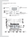 4
4
-
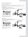 5
5
-
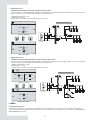 6
6
-
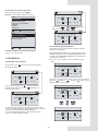 7
7
-
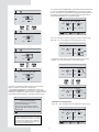 8
8
-
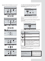 9
9
-
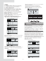 10
10
-
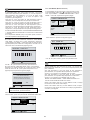 11
11
-
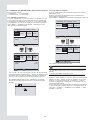 12
12
-
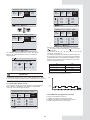 13
13
-
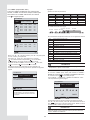 14
14
-
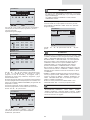 15
15
-
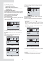 16
16
-
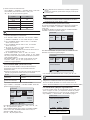 17
17
-
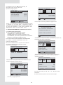 18
18
-
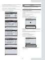 19
19
-
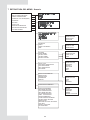 20
20
-
 21
21
-
 22
22
-
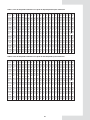 23
23
-
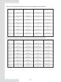 24
24
-
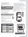 25
25
-
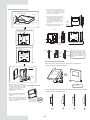 26
26
-
 27
27
-
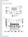 28
28
-
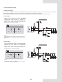 29
29
-
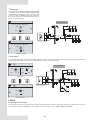 30
30
-
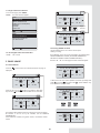 31
31
-
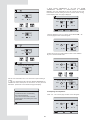 32
32
-
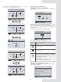 33
33
-
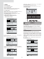 34
34
-
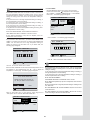 35
35
-
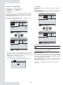 36
36
-
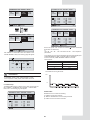 37
37
-
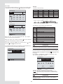 38
38
-
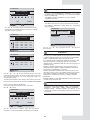 39
39
-
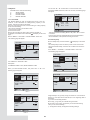 40
40
-
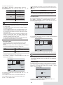 41
41
-
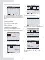 42
42
-
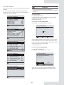 43
43
-
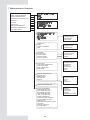 44
44
-
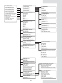 45
45
-
 46
46
-
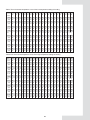 47
47
-
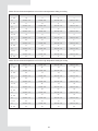 48
48
-
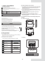 49
49
-
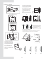 50
50
-
 51
51
-
 52
52


mundoclima AEROTHERM MAM-V9 Serie Manual de usuario
- Categoría
- Termostatos
- Tipo
- Manual de usuario
- Este manual también es adecuado para
en otros idiomas
Artículos relacionados
-
mundoclima Series Aerotherm V17 “Aerotherm Heat Pump” Manual de usuario
-
-
-
-
-
-
-
Otros documentos
-
Daikin EBLQ036BA6VJU1 Guía de instalación
-
-
Mitsubishi Heavy Industries eco touch RC-EX1A Guía de instalación
-
Sinclair GSH-80TRB2 Manual de usuario
-
Samsung RC120MHXEA Manual de usuario
-
OJ Electronics MCS4 Manual de usuario
-
Daikin EABH16DF6V Manual de usuario
-
Vaillant geoTHERM 22-46kw Manual de usuario
-
Samsung AEN160YDGHA Manual de usuario
-