Minebea Intec YDO07-X Datenausgang für Combics-Ex El manual del propietario
- Tipo
- El manual del propietario

Installation Instructions | Installationsanleitung | Notice d’installation
Istruzioni per l’installazione | Instrucciones de instalación
Minebea Intec Combics YDO07-X
Data Output Port for Combics-Ex
Datenausgang für Combics-Ex
Port de sortie pour interface Combics-Ex
Porta in uscita per interfaccia Combics-Ex
Puerto de salida para interfaz de Combics-Ex
98627-000-05
98627-000-05

2 YDO07-X YDO07-X 3
Contens
English – page 3
Deutsch – Seite 6
Français – page 9
Italiano – pagina 12
Español – página 15
Data transfer page 18
Notes on Using this Manual
This manual is part of the product. Keep it in a safe and easily
accessible location.
If the manual should be lost or misplaced, please contact
Minebea Intec for a replacement or download the latest manual
from our website: www.minebea-intec.com
The following symbols are used in this manual:
h This symbol indicates useful information and tips.
t Indicates a required action
y Describes the result of an action
Hotline/Technical support
Phone: +49 (0) 40/67960444
Fax: +49 (0) 40/67960474
E-mail:

YDO07-X 3
Contens
English
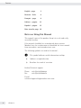
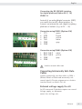
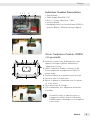
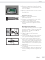
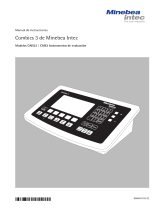
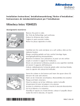
Combics indicator overview
1 Digital PCB
2 Power supply DC|DC PCB
3 Data I|O Adapter PCB
4 Interface PCB
5 Analog PCB, or optional YDO07-xRS-232 |
RS-485 Interface for digital platform.
Opening and Closing the Combics
CAIXS2 Indicator
t Pull power plug
t Opening the Combics indicator: Remove the ten
cap nuts from the rear panel.
t Rotate the indicator and lift off the front panel.
t Solve all plug connections
t Remove aluminum panel with the 4 countersunk
head screws.
t Replace interface board
t Insert the aluminum sheet with interface adapter
After completing repairs, visually inspect
the seal between the front panel and
housing for damage and replace if
necessary.
1 32 4 5
3
h

4 YDO07-X YDO07-X 5
English
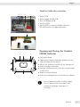
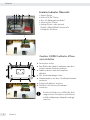
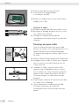
t Insert the seal in the front panel.
y The seal must be seated properly and should not
be cracked.
t Re-attach the front panel and secure it with the
ten cap nuts with 1 Nm.
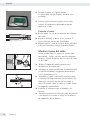
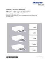
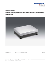
Preparing the Cable
t Strip approx. 14 cm from the end of the cable.
t Shorten the shielding to approx. 2 cm and pull
back over the insulation.
t Strip approximately 5 mm of the insulation from
the wires of the connecting cable and affix
ferrules to the wire ends.
Attaching the Cable Entry
Please use extreme caution when performing
any work on the equipment that affects this
cable gland.
You must use a torque wrench.
The torque for this cable gland is 5 Nm.
t Remove the protective caps from the bore hole
on the indicator.
t Insert the included cable gland through the bore
hole and secure from the inside using the locknut
(1).
t Insert the cable through the cable gland until the
shielding (2) comes into contact with the clamps
(3). Tighten the screw-down nut (4) until the
gasket (5) inserted between the screw-down nut
and cable forms a small beaded rim.
t Check the shielding and clamps.
t Securely connect the wires of the connecting
cable in accordance with the terminal assign-
ments.
4
15
2
3

YDO07-X 5
English English
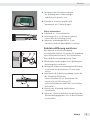
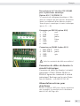
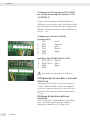
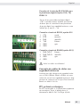
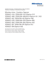
Connecting the RS 232/485 interface
for digital platform (Option A16 / 19)
YDO07-X
Instead of an analog/digital converter (ADC),
you could also install a data interface to
connect an intrinsically safe digital weighing
platform or balance (e.g. an IS......-X).
Connection using RS232 (Option A16)
1 CTS green
2 DTR brown
3 RxD yellow
4 TxD white
5 GND gray
6 GND
Connection using RS485 (Option A19)
1 RxD-TxD-P white
2 RxD-TxD-N yellow
3 GND gray
4 GND
3 Insulate unused cable ends
Connecting Intrinsically Safe Data
Cables
Connect intrinsically safe data cables to COM 1
(RS232, RS485 or RS422 and intrinsically safe
control signals). For pin assignments on the data
interface board, see 66015-741-50.
External voltage supply for AP1
At AP1 connected IS platform requires an external
Voltage supply, see document
66015-741-50 Page 2/9.
1 2 3
4 5 6
1
2 3
4 5 6
1 2 3 4
1 2 3
4 5 6
1
2 3
4 5 6
1 2 3 4

6 YDO07-X
YDO07-X 7
YDO07-X 7
Deutsch
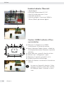
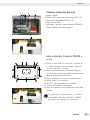
Combics Indicator Übersicht
1 Digital-Platine
2 Netzteil DC/DC Platine
3 Data I/O Adapterplatine/Kabel
4 Schnittstellen-Platine
5 Analog-Platine, oder optional
YDO07-x RS232/RS485 Schnittstelle
für digitale Plattform.
Combics CAIXS2 Indikator öffnen
und schließen
t Netzstecker ziehen
t Zum Öffnen der Combics Indikators zehn Hut-
muttern von der Rückseite entfernt.
t Indikator drehen und die Frontplatte
abheben.
t Alle Steckverbindungen lösen
t Aluminiumplatte mit den 4 Senkkopfschrauben
entfernen.
t Schnittstellenplatine tauschen
t Alu-Blech mit Schnittstellenadapter
montieren.
Vor dem Schließen von CAIXS2 die Dich-
tung zwischen Frontplatte und Gehäuse
auf Beschädigungen überprüft und ggf.
tauschen.
1 32 4 5
3
h

YDO07-X 7
YDO07-X 7
Deutsch Deutsch
t Dichtung in die Frontplatte einlegen.
Die Dichtung muss sauber anliegen
und darf nicht geknickt sein.
t Frontplatte aufsetzen und die zehn
Hutmuttern mit 1 Nm befestigen.
Kabel vorbereiten
t Kabelende ca. 14 cm abisolieren.
t Schirmung auf ca. 2 cm kürzen und nach
hinten über die Isolierung ziehen.
t Adern des Verbindungskabel ca. 5 mm
abisolieren und mit Aderendhülsen versehen.
Kabeldurchführung montieren
Alle Arbeiten an der Verschraubung
vorsichtig durchführen. Verwenden Sie unbedingt
einen Drehmomentschlüssel. Das Drehmoment
dieser Kabelverschraubung beträgt 5 Nm.
t Blindstopfen an der vorgesehenen Bohrung des
Auswertegerätes entfernen.
t Beiliegende Kabelverschraubung durch Bohrung
stecken und mit Kontermutter (1) von innen
sichern.
t Kabel durch die Kabelverschraubung stecken bis
die Schirmung (2) Kontakt
zu den Klemmen (3) hat. Druckmutter (4)
anziehen bis der Dichteinsatz (5)
zwischen Druckmutter und Kabel einen kleinen
Wulst bildet.
t Kontakt von Schirmung und Klemmen
kontrollieren.
t Adern des Schnittstellenkabels entsprechend den
Klemmenbelegungsplänen fest an den Klemmen
verschrauben
4
15
2
3

8 YDO07-X YDO07-X 9
YDO07-X 9
Deutsch
Anschluss der Schnittstelle RS 232/485
für digital Plattform (Option A16 /19)
YDO07-X
An Stelle des Analog/Digital-Umsetzers »ADU«
kann auch eine Datenschnittstelle zum Anschluss
einer eigensicheren digitalen Wägeplattform oder
Waage (z. B. eine IS......-X) eingebaut werden.
Anschluss über RS232 Option A16
1 CTS grün
2 DTR braun
3 RxD gelb
4 TxD weiß
5 GND grau
6 GND
Anschluss über RS485 (Option A19)
1 RxD-TxD-P weiß
2 RxD-TxD-N gelb
3 GND grau
4 GND
3 Nicht verwendete Kabelenden isolieren!
Anschluss eigensicherer Datenkabel
Anschluss eigensicherer Datenkabel an COM 1
(RS232, RS485 oder RS422 sowie
eigensichere Steuersignale). Ansschlussbelegungen
auf dem Data Interface Board: siehe
Dokument 66015-741-50.
Fremdspannungsversorgung WP1
An WP1 angeschlossenen IS Plattform benötigen
eine fremde Spannungsversorgung, siehe
Dokument 66015-741-50 Seite 2/9.
1 2 3
4 5 6
1
2 3
4 5 6
1 2 3 4
1 2 3
4 5 6
1
2 3
4 5 6
1 2 3 4

YDO07-X 9
YDO07-X 9
Deutsch
Français
Indicateur Combics Présentation
1 Digital Board
2 Power Supply Board DC / DC
3 Data I / O carte adaptateur / câble
4 Interface Board
5 Analogique-bord, ou éventuellement YDO07-x
interface RS232 / RS485 plateforme digitale.
Ouvrir l‘indicateur Combics CAIXS2
et à proximité
t Avant de connecter ou de déconnecter tout
appareil électrique auxiliaire, débranchez l
’appareil du secteur.
t Ouvrir l’indicateur Combics : Dévisser les dix
écrous borgnes de la plaque avant. Retirer la
plaque avant.
t Tournez indicateur et panneau avant ressortir.
t Desserrer tous les connecteurs
t Retirer la plaque en aluminium avec les quatre
vis à tête fraisée.
t Carte d’interface de change
t Tôle d’aluminium avec adaptateur d’interface
assembler.
L’étanchéité entre le panneau avant et
le logement vérifiée avant la clôture des
CAIXS2 pour les dommages et les remplacer
si nécessaire.
1 32 4 5
3
h

10 YDO07-X YDO07-X 11
YDO07-X 11
Français
t Placez le joint dans le panneau avant.
y Le joint doit être équipée propres
et ne doit pas être plié.
t Remettre la plaque avant et fixer les dix écrous
borgnes avec 1 Nm.
Préparer le câble
t Dénuder l’extrémité du câble sur environ 14 cm.
t Raccourcir le blindage d’environ 2 cm et le tirer
vers l’arrière sur l’isolation.
t Dénuder les conducteurs du câble de
raccordement sur environ 5 mm et y mettre des
embouts.
Montage du passe-câble
Tous les travaux effectués sur le passe-câble
doivent être réalisés avec le plus grand soin. Il est
impératif d’utiliser une clé dynamométrique.
Le moment du couple de ce passe-câble à vis est
de 5 Nm.
t Enlever le bouchon du trou prévu sur l’indicateur.
t Introduire le passe-câble à vis livré avec l’appareil
dans le trou et le visser de l’intérieur avec un
contre-écrou (1).
t Introduire le câble à travers le passe-câble
jusqu’à ce que le blindage (2) soit en contact
avec les bornes (3). Visser l’écrou de serrage (4)
jusqu’à ce que la pièce d’étanchéité (5) entre
l’écrou de serrage et le câble forme un léger
bourrelet.
t Contrôler que les bornes de connexion sont bien
en contact avec le blindage.
t Visser fermement les conducteurs du câble
d’interface aux bornes de connexion
conformément aux schémas d’affectation des
bornes.
4
15
2
3

YDO07-X 11
YDO07-X 11
Français Français
Raccordement de l’interface RS 232/485
pour la plateforme numérique
(Option A16 / 19) YDO07-X
Le convertisseur analogique/numérique « CAN »
peut être remplacé par une interface de données
pour le raccordement d’une balance ou plate-
forme de pesée numérique à sécurité intrinsèque
(par ex. IS......-X).
Connexion par RS232 (option A16)
1 CTS vert
2 DTR brun
3 RxD jaune
4 TxD blanc
5 GND gris
6 GND
Connexion par RS485 (option A19)
1 RxD-TxD-P blanc
2 RxD-TxD-N jaune
3 GND gris
4 GND
3 Isoler les extrémités de câble non utilisées !
Connexion de câbles de données à
sécurité intrinsèque
Connexion de câbles de données à sécurité
intrinsèque à COM 1 (RS232, RS485 ou
RS422 et signaux de commande à sécurité
intrinsèque). Brochages sur la carte d’inter-
face de données : voir 66015-741-50
Alimentation externe pour
plateforme
Au PP1 connecté EST plate-forme requièrent
une étrangère Le pouvoir,voir le document
66015-741-50 Page 2/9.
1 2 3
4 5 6
1
2 3
4 5 6
1 2 3 4
1 2 3
4 5 6
1
2 3
4 5 6
1 2 3 4

12 YDO07-X
YDO07-X 13
YDO07-X 13
Italiano
Combics Indicator Übersicht
1 Bordo Digitali
2 Scheda di alimentazione DC / DC
3 Dati I/O scheda adattatore / cavo
4 Scheda di interfaccia
5 Scheda analogica, o facoltativo YDO07-x
RS232 / RS485 piattaforma digitale.
Combics CAIXS2 Indikator öffnen
und schließen
t Effettuare il collegamento al CAIXS2
esclusivamente in assenza di tensione.
t Aprire l’indicatore Combics: Svitare i 10 dadi cie-
chi del pannello anteriore. Rimuovere il pannello
anteriore.
t Girare indicatore e pannello frontale risaltare.
t Allentare tutti i collegamenti a spina.
t Rimuovere il coperchio svitando le viti 4.
t Scheda di interfaccia di Exchange
t Foglio di alluminio con adattatore di interfaccia
montare.
La tenuta tra il pannello frontale e l’allog-
giamento controllato prima della chiusura
di CAIXS2 per danni e sostituire se neces-
sario.
1 32 4 5
3
h

YDO07-X 13
YDO07-X 13
Italiano Italiano
t Posizionare la guarnizione nel pannello frontale.
La guarnizione deve essere montata pulito e non
deve essere piegato..
t Rimettere il pannello frontale e fissare con 1Nm i
dieci dadi ciechi.
Preparazione del cavo
t Togliere ca. 14 cm di guaina isolante
dall’estremità del cavo.
t Accorciare la schermatura di ca. 2 cm e tirarla
all’indietro sopra la guaina isolante.
t Togliere ca. 5 mm di guaina isolante dai fili
del cavo di connessione e applicare le boccole
terminali.
Montaggio del passacavo
Tutti i lavori sul pressacavo devono essere eseguiti
con molta attenzione. Si deve usare una chiave
dinamometrica. La coppia di serraggio del
pressacavo è di 5 Nm.
t Togliere il tappo cieco dal foro presente
sull’indicatore.
t Inserire il fissaggio del cavo fornito attraverso il
foro e avvitare il controdado (1) dall’interno.
t Inserire il cavo attraverso il pressacavo fino al
punto in cui la schermatura (2) è a contatto con
i morsetti (3). Serrare il dado di compressione (4)
fino a quando l’anello di tenuta (5) posto tra il
dado di compressione e il cavo forma un piccolo
rigonfiamento.
t Controllare che i morsetti facciano contatto con
la schermatura.
t Avvitare saldamente i fili del cavo d’interfaccia ai
morsetti secondo gli schemi di assegnazione dei
morsetti.
4
15
2
3

14 YDO07-X YDO07-X 15
YDO07-X 15
Italiano
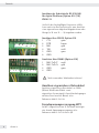
Collegamento dell’interfaccia RS 232/485
per la piattaforma digitale (Opzione A16 /
19) YDO07-X
Al posto del convertitore analogico/digitale (C.
A/D) può essere installata anche un’interfaccia dati
per il collegamento di una piattaforma di pesatura
digitale a sicurezza intrinseca o di una bilancia (es.
una IS......-X).
Collegamento attraverso RS232
(Opzione A16)
1 CTS verde
2 DTR marrone
3 RxD giallo
4 TxD bianco
5 GND grigio
6 GND
Anschluss über RS485 (Option A19)
1 RxD-TxD-P bianco
2 RxD-TxD-N giallo
3 GND grigio
4 GND
3 Non isolare le estremità cavo utilizzate.
Collegamento di cavi dati a sicurezza
intrinseca
Collegamento di cavi dati a sicurezza intrinseca
a COM 1 (RS232, RS485 o RS422 e a segnali di
controllo a sicurezza intrinseca). Schemi di colle-
gamento al Data Interface Board: vedere 66015-
741-50
Piaforma di pesatura potenza
straniera
A PP1 collegata è la piattaforma richiedono
una straniera Hanno il potere, vedere il
documento 66015-741-50 Page 2/9
1 2 3 4 5 6
1
2 3
4 5 6
1 2 3 4
1 2 3 4 5 6
1
2 3
4 5 6
1 2 3 4

YDO07-X 15
YDO07-X 15
Italiano
Español
Combics Indicador general
1 Tablero digital
2 Tablero de la fuente de alimentación DC / DC
3 Tarjeta del adaptador de datos I/O
4 Tarjeta de interfaz
5 Analógico a bordo, u opcionalmente YDO07-x
RS232 / RS485 plataforma digital.
Abrir indicador Combics CAIXS2 y
cerca
t Llevar a cabo todas las tareas de conexión en
el CAIXS2 exclusivamente cuando el aparato
no esté sometido a tensión.
t Abrir el instrumento de evaluación Combics:
Soltar las diez tuercas de sombrerete de la placa
frontal. Retirar la placa frontal.
t Gire el indicador y el panel frontal destacar.
t Afl oje todas las conexiones.
t Retire la tapa quitando los 4 tornillos.
t Tarjeta de interfaz de Exchange
t Hoja de aluminio con el adaptador de interfaz
montar.
La junta entre el panel frontal y la carcasa
controlados antes de su cierre de CAIXS2
por daños y reemplace si es necesario.
1 32 4 5
3
h

16 YDO07-X YDO07-X 17
YDO07-X 17
Español
t Coloque la junta en el panel frontal.
La junta debe encajar limpio y no debe estar
retorcido.
t Colocar la placa frontal y fijarla con las diez
tuercas de sombrerete aplicando un par de
apriete de 1 Nm.
Preparar el cable
t Retirar aprox. 14 cm de aislamiento del extremo
del cable.
t Acortar el blindaje a aprox. 2 cm y tirar de él
hacia atrás por encima del aislamiento.
t Eliminar aprox. 5 mm de aislante de los hilos del
cable de conexión y colocar casquillos finales.
Montar el paso del cable
Llevar a cabo todas las tareas en el racor con
precaución. Utilice sin falta una llave dinamo-
métrica. El par de apriete de este racor de cable
es de 5 Nm.
t Retirar el tapón del orificio previsto en el
instrumento de evaluación.
t Introducir el racor incluido con el suministro por
el orificio taladrado y asegurarlo desde dentro
con la contratuerca (1).
t Introducir el cable a través del racor hasta que
el blindaje (2) haga contacto con los bornes (3).
Apretar la tuerca de presión (4) hasta que la
junta (5) situada entre la tuerca y el cable forme
un pequeño abultamiento.
t Controlar el contacto entre el blindaje y los
bornes.
t Atornillar fijamente los hilos del cable de interfaz
a los bornes tal y como se refleja en los planos
de asignación de los bornes.
4
15
2
3

YDO07-X 17
YDO07-X 17
Español Español
Conexión de la interfaz RS 232/485 para
la plataforma digital (Opción A16 / 19)
YDO07-X
En vez de un convertidor analógico-digital
“CAD” es posible montar también una interfaz
de datos para la conexión de una plataforma
de pesaje digital con seguridad intrínseca o una
báscula (p. ej. una IS......-X).
Conexión a través de RS232, opción A16
1 CTS verde
2 DTR marrón
3 RxD amarillo
4 TxD blanco
5 GND gris
6 GND
Conexión a través de RS485 (opción A19)
1 RxD-TxD-P blanco
2 RxD-TxD-N amarillo
3 GND gris
4 GND
3 Aislar los cables no utilizados!
Conexión de cables de datos con
seguridad intrínseca
Conexión de cables de datos de seguridad intrín-
seca a COM 1 (RS232, RS485 o RS422 así como
señales de control con seguridad intrínseca). Asig-
naciones de contactos en la tarjeta Data Interface
Board: ver 66015-741-50
PP1 potencia extranjera
En PP1 conectado es la plataforma requieren
un extranjero Tener el poder,véase el
documento 66015-741-50 Page 2/9 de.
1 2 3
4 5 6
1
2 3
4 5 6
1 2 3 4
1 2 3
4 5 6
1
2 3
4 5 6
1 2 3 4

18 YDO07-X YDO07-X 19
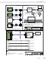
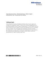
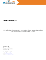
Data transfer
128 Betriebsanleitung Combics CAIXS2
Externe Datenschnittstelle
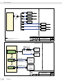
External Connections and
Data Transfer
CAIXS2 /
Rev. 00
Klausgrete2013-08-08
Sheet
of
1
9
66015-741-50
CAIXS2
YPS02-X.R
EX Power Supply
(100 -240 Vac)
YPS02-XV24
EX Power Supply
(24 Vdc)
YRB02-X
EX Rechargeable
Battery Pack
YPS02-Z.R
EX Power Supply
(100 -240 Vac)
YPS02-XV24
EX Power Supply
(24 Vdc)
Power Supply
3m*
0.2m
2m*
20m*
5m*
Notes:
*: Customer-made product: up to 20m
**: Options up to 40m
5m*
5m
5m
3m
3m
YPSC01-X
EX Power Supply
(100 -240 Vac)
3m**
3m
YPSC01-Z
EX Power Supply
(100 -240 Vac)
20m**
3m
Non-hazardous areaHazardous area
DC Input Cable
8-contact
male
connector
External Connections and
Data Transfer
CAIXS2 /
Rev. 00
Klausgrete2013-08-08
Sheet
of
2
9
66015-741-50
CAIXS2
Option A16:
CAPXS.-... /
IUXS4-... /
IFXS4-...
weighing platform
CAPXS.-... /
IUXS4-... /
IFXS4-...
weighing platform
ADU
DMS Frontend Board
(Option A15; default)
WP Board
Alternative
YCC02-XR14M6
connecting cable
Weighing Point (WP) Connection
6m
Option A19:
YCC02-XR14M6
connecting cable
6m
Or
Option M20:
Option M26:
Non-hazardous areaHazardous area
Option X2:
Separable connection
3m or 6m (depends on model)
Alternately
connectable
IS......-.X...
weighing module
or
FC/FCA......-.X...
with RS-232
data interface
IS......-.X...
weighing module
or
FC/FCA......-.X...
with RS-485
data interface
J102
WP Board
J101
RS232
RS485

YDO07-X 19
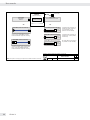
Data transfer Data transfer
Betriebsanleitung Combics CAIXS2 129
Externe Datenschnittstelle
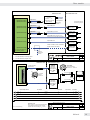
External Connections and
Data Transfer
CAIXS2 /
Rev. 00
Klausgrete2013-08-08
Sheet
of
3
9
66015-741-50
Option M21
0.2m
Option M14 **
Option M13 *
6m
0.2m
CAIXS2
Data Adapter Board
YDI05-Z; A24
Zener barrier
for data transfer see
the following sheets
IS......-.X... weighing
module or
FC/FCA......-.X...
with RS-232 or RS-485
data interface
YDI05-Z; A25
Zener barrier
RS232, RS485 and RS422 connections
Option A21: RS232
YDI05-Z; A24
Zener barrier
Option M52; 20m
Option A21: RS232
Option A23: RS485
Option A23: RS485
Option A22: RS422 YDI05-Z; A25
Zener barrier
Option M54; up to 999 m
Option A21: RS232
Option A23: RS485
Non-hazardous areaHazardous area
EX power supply
or
EX rechargeable
battery pack;
see sheet 1
Network
with up to 8
devices
Cable YCC485-X; max. total cable
length 1000m; see sheet 7
* : YCC02-XR14M6; connecting cable
**: YCC02-XR14F02; adapter cable
Option A22: RS422
for more information see
the following sheets
YDI05-Z; A24
Zener barrier
Option M53 (open cable end; up to
999m); than no option M21at CAIXS2
Option M51; 20m
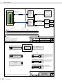
External Connections and
Data Transfer
CAIXS2 /
Rev. 00
Klausgrete2013-08-08
Sheet
of
4
9
66015-741-50
Non-hazardous areaHazardous area
YCC02-XR14F02
(Option M14)
YDI05-Z
(interface
converter)
with Options
M52, A24,
M55
YDI05-Z
(interface
converter)
with Options
M51, A24,
M55
YCC01-03ISM5
20m
20m0.2m
5m
PC
Important note:
Max. voltage V
m
of any electrical apparatus
connected to the Zener barrier must not
exceed 250V. Zener voltage V
z
is 12.6V.
RS-232 connection to a PC
Option M55:
12-contact female
connector on YDI05-Z
14-contact
female
connector
9-pin
D-SUB
*: Pin 1 = shield (housing)
TxD 3 Kyellow B 3 2 RxD
DTR 4 Ngreen D 5 8 CTS
RxD 2 Jwhite C 2 3 TxD
CTS 1 Abrown H20 4 DTR
Signal_GND 5 Mgray E7 5 Signal_GND
Data adapter board 14-contact 12-contact 25-contact * 9-contact
YCC01-09ISM5
5m
25-pin
D-SUB
CAIXS2
Data Adapter
Board
12 1
B
E
D
C
H
J
K
N
M
A

20 YDO07-X YDO07-X 21
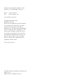
Data transfer
130 Betriebsanleitung Combics CAIXS2
Externe Datenschnittstelle
External Connections and
Data Transfer
CAIXS2 /
Rev. 00
Klausgrete2013-08-08
Sheet
of
6
9
66015-741-50
Connection to RS-485 output port on the
CAIXS2 (see page 7)
Optional Cables with YDI05-Z (RS232 to CAIXS2)
Option M51 (cable 65710-806-00)
20 m
Option M55
12-contact female connector
Option M56 (cable 65710-807-00)
3 m
Option M52 (cable 65710-808-00)
14-contact male connector 20 m
Option M58 (cable 65710-811-00)
3 m
25-contact
female
connector
YDI05-Z
interface converter
RS-232 <------------> RS-232
12-contact
Connection to RS-232 output port on the
CAIXS2 via adapter cable (option M14)
Connection to RS-232 output port on the
CAIXS2
9-contact RS-232 connection
to YDP03-0CE printer
(instead of YCC01-0019M3)
or a PC (instead of YCC01-
09ISM5)
25-contact RS-232
connection to PC (instead of
YCC01-03ISM5)
9-contact
female
connector
Option M57 (cable 65710-809-00)
3 m
9-contact RS-232 connection
to YDP04IS-0CE.. printer
(instead of 69Y03142)
9-contact
male
connector
Option M50 (without cable)
Cable gland
M16 x 1.5
Option A24
RS-232 to scale
or or
Note: The options on this page are options of the YDI05-Z interface converter.
External Connections and
Data Transfer
CAIXS2 /
Rev. 00
Klausgrete2013-08-08
Sheet
of
5
9
66015-741-50
Non-hazardous area
Hazardous area
20m
20m0.2m 1.5m
Important note:
Max. voltage V
m
of any electrical apparatus
connected to the Zener barrier must not
exceed 250V. Zener voltage V
z
is 12.6V.
RS-232 Connection to a Printer
YDP12IS-0CEUV
or
YDP12IS-0CEUVTH
or
YDP04IS-0CEUV
data printer with external
power supply included
YDP03-0CE
data printer
69Y03142
9-pin
D-SUB
YCC01-0016M3
YDP03-0CE
data printer
YCC01-0019M3
power
supply
*)
*:
Cable incl. in std. equipment
3m
3m
power
supply
YDI05-Z
(interface
converter)
with Options
M52,
A24
,
M55
YDI05-Z
(interface
converter)
with Options
M51,
A24
,
M55
YCC02-XR14F02
(Option M14)
TxD 3 Kyellow B
DTR 4 N green D
RxD 2 J white C
CTS 1 Abrown H
Signal_GND 5 Mgray E
Data adapter board 14-contact 12-contact
CAIXS2
Data Adapter
Board
12 1

YDO07-X 21
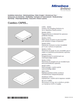
Data transfer Data transfer
Betriebsanleitung Combics CAIXS2 131
Externe Datenschnittstelle
External Connections and
Data Transfer
CAIXS2 /
Rev. 00
Klausgrete2013-08-08
Sheet
of
7
9
66015-741-50
RS-485 Wiring
Important note:
Max. voltage Vmof any electrical apparatus connected to the Zener
barrier must not exceed 250V. Zener voltage Vzis 12.6V.
Non-hazardous areaHazardous area
1: Total length up to 1000m (follow technical data on the EC type
examination certificate); cable is not included in the standard equipment
supplied; YCC485-X (light-blue cable); please indicate length)
2: Junction box 72583
3: 14-contact male connector 69Y03166
4: Optional: separable connection 6906924 (a) and 6906925 (b)
up to 8 devices in
the hazardous area
FC/FCA/IS......-.X...
FCT01-X..
SIWXS.../ ISX...
with RS-485 data
output port
1)
2)
3)
J
K
M
Option M50:
12-contact
female
connector
on YDI01-Z
14-contact female
connector of data output
port of FC/FCA/IS-.X.. /
FCT....-X... / SIWXS... /
ISX...
CIXS3
If necessary, connect final
terminal with 470 ohms /0.6W
(pin 2/3 or J/K)
PC or SPS with RS-
485 data output
port
12-contact male
connector
69QC0010
4b) 4a)
4b) 4a)
YDI05-Z
with Option
A24,
M50
RxD-TxD-P (A) 2 2 J 1 C (white)
RxD-TxD-N (B) 3 1 K 4 B (yellow)
Signal_GND 1 3,4 M 1 (LV1) E (grey)
CAIXS2 CIXS3 14- YDI05-Z 12-contact
Data UNICOM contact LV2
adapter LV2
board
UNICOM
14
LV2
CAIXS2
Data
Adapter
Board
4b) 4a)
CAIXS2
Data
Adapter
Board
B
E
C
External Connections and
Data Transfer
CAIXS2 /
Rev. 00
Klausgrete2013-08-08
Sheet
of
8
9
66015-741-50
Non-hazardous area
Hazardous area
YDI05-Z
Interface
converter
with Options
M53, A25, M55
see also page 9
Important note:
Max. voltage V
m
of any electrical apparatus
connected to the Zener barrier must not exceed
250V. Zener voltage V
z
is 12.6V.
RS-422 (EX) - RS-232 (Non-EX) Connection
RS-232 connection
see also pages 4 and 5
Signal_GND
LV3
up to 1000m
TxD+ RxD+
yellow
9
10
green
TxD- RxD-
CTS+ DTR+
red 3
4
blue
CTS- DTR-
1, 2
brown, white
LV3 DC power supply
12V DC (min) ...
30V DC (max)
**YAS04CIS**
**: not incl. in equipment
supplied withYDI05-ZV1
12-contact
16
LV1
B
H
E
12-contact
4
2
5
LV1
TxD
CTS
DTR+ CTS+
violet 5
6
black
DTR- CTS-
D
3DTR
RxD+ TxD+
pink 7
8
gray
RxD- TxD-
C
1RxD
10
1
or
Signal_GND
4
3
11
10
1,2
Data adapter board
5
7
12
6
CAIXS2
Data
Adapter
Board
12 1

22 YDO07-X YDO07-X 23
Data transfer
132 Betriebsanleitung Combics CAIXS2
Externe Datenschnittstelle
External Connections and
Data Transfer
CAIXS2 /
Rev. 00
Klausgrete2013-08-08
Sheet
of
9
9
66015-741-50
Optional Cables with YDI05-Z , option A25
Option M55
12-contact female connector
Option M50
Cable gland
M16x1.5
Option M53 (cable 65710-856-00)
Country-specific
power supply
Connection to RS-422 output port on the
CIXS2. Length: up to 999 m permitted.
Please indicate the length when ordering.
Option M56 (cable 65710-807-00)
3 m
Option M58 (cable 65710-811-00)
3 m
YDI05-Z
interface converter
RS-422 <------------> RS-232
12-contact
9-contact RS-232 connection to
YDP03-0CE printer (instead of
YCC01-0019M3) or a PC
(instead of YCC01-09ISM5)
25-contact RS-232 connection to
PC (instead of YCC01-03ISM5)
Option M57 (cable 65710-809-00)
3 m
9-contact RS-232 connection to
YDP04IS-0CE.. printer (instead
of 69Y03142)
Option M54 (cable 65710-858-00)
14-contact male connector
9-contact
female
connector
9-contact
male
connector
25-contact
female
connector
Connection to RS-422 output port on the
CAIXS2 via adapter cable (CAIXS2 option
M21). Length: up to 999 m permitted.
Please indicate the length when ordering.
Option A25
RS-422 to scale
or or
Note:
The options on this page are options of the YDI05-Z interface converter.

YDO07-X 23
Data transfer

Minebea Intec Bovenden GmbH & Co. KG
Leinetal 2, 37120 Bovenden, Germany
Phone: +49.551.309.83.0
Fax: +49.551.309.83.190
www.minebea-intec.com
Copyright by Minebea Intec,
Bovenden, Germany.
No part of this publication may be reprinted
or translated in any form or by any means
without the prior written permission of
Minebea Intec. All rights reserved by Minebea
Intec in accordance with copyright law. The
information and figures contained in these
instructions correspond to the version date
specified below. Minebea Intec reserves the
right to make changes to the technology,
features, specifications and design of the
equipment without notice.
Status: January 2017
Printed in Germany on bleached, chlorine-free
paper. RS · KT
Publication no.: WYD8001-p17012
-
 1
1
-
 2
2
-
 3
3
-
 4
4
-
 5
5
-
 6
6
-
 7
7
-
 8
8
-
 9
9
-
 10
10
-
 11
11
-
 12
12
-
 13
13
-
 14
14
-
 15
15
-
 16
16
-
 17
17
-
 18
18
-
 19
19
-
 20
20
-
 21
21
-
 22
22
-
 23
23
-
 24
24


Minebea Intec YDO07-X Datenausgang für Combics-Ex El manual del propietario
- Tipo
- El manual del propietario
en otros idiomas
Artículos relacionados
-
 Minebea Intec Combics CAIXS2 Para uso en áreas potencialmente explosivas El manual del propietario
-
 Minebea Intec CAPXS.. Models Stainless Steel Weighing Platforms for Use in Hazardous Areas/Locations El manual del propietario
-
 Minebea Intec Combics 3 CAISL3 | CAIS3 Instrumentos de evaluación El manual del propietario
-
Minebea Intec Puro EF-FES150-6d El manual del propietario
-
 Minebea Intec Signum: Opción Y2 para el uso en áreas potencialmente explosivas de las zonas 2 y 22 El manual del propietario
-
 Minebea Intec Combics, Signum Datenausgang für Combics | Signum-Schnittstelle UniCOM El manual del propietario
-
 Minebea Intec YFP02CWS Fastening Kit for Combics Weighing Platforms El manual del propietario
-
 Minebea Intec Combics Básculas completas CAW1P | CAW1S | CAS1 El manual del propietario
-
 Minebea Intec YDH02S display stand El manual del propietario
-
 Minebea Intec ISEDE-16-H(V1), ISEDE-16-HCE, ISEDE-34-H(V1), ISEDE-34-HCE, ISEDE-64-H(V1), ISEDE-64-S(V1), ISEDE-64-SCE El manual del propietario


Otros documentos
-
LiftMaster CAPXS Guía de instalación
-
Korenix JetPort 5801 Quick Installation Manual
-
Phoenix PSM-ME-RS232/RS485-P Installation Notes For Electricians
-
-
Mettler Toledo IND780 (11 MB) Guía de instalación
-
 ADEUNIS ARFx3 PRO Guía del usuario
-
Fagor CNC 8070 El manual del propietario
-
Fagor CNC 8065 El manual del propietario
-
Siemens SIMATIC PC Adapter TS Adapter Ficha de datos
-
Fagor CNC 8060 El manual del propietario
