
L8542678
12/2013 rev 3
CP.B24ESA
CP.B1024ESA
UNIONE NAZIONALE COSTRUTTORI
AUTOMATISMI PER CANCELLI, PORTE
SERRANDE ED AFFINI
CP.B24ESA CP.B1024ESA

2
LAMP
24Vdc
24Vdc
500mA max
- +
AUX1
AUX2
RADIO
BATTERY CHARGER
F1
+COM
P.P.
STOP
PHC
PHO
PED
BAR
BAR
AUX1
AUX1
BLINK
BLINK
+24V
-24V
N L
F2
MOT
L1
AUX
N1
L1
N1
0V
ANT
ANT
SHIELD
AUX2
AUX2
MOT
AUX
0V
COM
SWO
MOT
SWC
ENCODER
8k2
DAS
DAS
J1 DAS
Open
DAS N.C.
J1 DAS
Close
DAS 8K2
CP.B24 ESA CP.B1024 ESA CP.B24 ESA-A CP.B1024 ESA-A
F1 T2A
F2 T1A T2A T2A T4A
1

3
4
OPEN
OPEN
OPEN
OPEN
MINV:On
MINV:Off
2
3
SCA
AUX1:0
+COM
P.P.
STOP
PHOT
OPEN
CLOSE
BAR
BAR
AUX1
AUX1
BLINK
BLINK
+24V
-24V
SCA 24Vac
3W max
24Vac
500mA max
AUX1:1
II°CH RADIO
+COM
P.P.
STOP
PHOT
OPEN
CLOSE
BAR
BAR
AUX1
AUX1
BLINK
BLINK
+24V
-24V
AUX1:2
SERVICE/ZONE LIGHT
Service Light
AUX1:3
Zone Light
L N
Service/Zone
Light
230Vac
Relè 24Vac
P.P.
STOP
PHOT
OPEN
CLOSE
BAR
BAR
AUX1
AUX1
BLINK
BLINK
+24V
-24V
SCA
AUX2:0
SCA 24Vdc
3W max
24Vdc
1A max
AUX1
AUX1
BLINK
BLINK
+24V
-24V
AUX2
AUX2
AUX2:1
II°CH RADIO
AUX1
AUX1
BLINK
BLINK
+24V
-24V
AUX2
AUX2
SERVICE/ZONE LIGHT
L N
Service/Zone
Light
230Vac
Relè 24Vdc
AUX1
AUX1
BLINK
BLINK
+24V
-24V
AUX2
AUX2
AUX2:2
Service Light
AUX2:3
Zone Light

4
AVVERTENZE
Questo manuale è destinato esclusivamente a personale
qualificato per l’installazione e la manutenzione di aperture
automatiche.
Nessuna informazione qui presente è di interesse o di utilità
per l’utente finale.
Conservare questo manuale per futuri utilizzi.
L’installatore deve fornire tutte le informazioni relative
al funzionamento automatico, manuale e di emergenza
dell'automazione, e consegnare all’utilizzatore dell’impian-
to le istruzioni d’uso.
•
Prevedere sulla rete di alimentazione un inter-
ruttore/sezionatore onnipolare con distanza
d’apertura dei contatti uguale o superiore a 3 mm.
Verificare che a monte dell’impianto elettrico vi sia un interrut-
tore differenziale e una protezione di sovracorrente adeguati.
Alcune tipologie di installazione richiedono il collegamento
dell'anta ad un impianto di messa a terra rispondente alle
vigenti norme di sicurezza.
L’installazione elettrica e la logica di funzionamento devono
essere in accordo con le normative vigenti.
I conduttori alimentati con tensioni diverse, devono essere
fisicamente separati, oppure devono essere adeguata-
mente isolati con isolamento supplementare di almeno
1 mm.
I conduttori devono essere vincolati da un fissaggio sup-
plementare in prossimità dei morsetti.
Durante gli interventi di installazione, manutenzione e ri-
parazione, togliere l’alimentazione prima di accedere alle
parti elettriche.
Ricontrollare tutti i collegamenti fatti prima di dare ten-
sione.
Gli ingressi N.C. non utilizzati devono essere ponticellati.
Le descrizioni e le illustrazioni presenti in questo manuale
non sono impegnative. Lasciando inalterate le caratte-
ristiche essenziali del prodotto il fabbricante si riserva il
diritto di apportare qualsiasi modifica di carattere tecnico,
costruttivo o commerciale senza impegnarsi ad aggiornare
la presente pubblicazione.
Dichiarazione CE di Conformità
Dichiarazione in accordo alle Direttive 2004/108/CE(EMC); 2006/95/CE(LVD)
Fabbricante:
Automatismi Benincà SpA
Indirizzo:
Via Capitello, 45 - 36066 Sandrigo (VI) - Italia
Dichiara che il prodotto:
Centrale di comando per 1 motore 24Vdc, per cancelli scorrevoli:CP.B24ESA /CP.B1024ESA
è conforme alle condizioni delle seguenti Direttive CE:
• DIRETTIVA 2004/108/CE DEL PARLAMENTO EUROPEO E DEL CONSIGLIO del 15 dicembre 2004 concernente
il ravvicinamento delle legislazioni degli Stati membri relative alla compatibilità elettromagnetica e che abroga la direttiva
89/336/CEE, secondo le seguenti norme armonizzate:
EN 61000-6-2:2005, EN 61000-6-3:2007.
• DIRETTIVA 2006/95/CE DEL PARLAMENTO EUROPEO E DEL CONSIGLIO del 12 dicembre 2006 concernente il
ravvicinamento delle legislazioni degli Stati membri relative al materiale elettrico destinato ad essere adoperato entro taluni
limiti di tensione, secondo le seguenti norme armonizzate:
EN 60335-1:2002 + A1:2004 + A11:2004 + A12:2006 + A2:2006 + A13:2008; EN 60335-2-103:2003.
se applicabile:
• DIRETTIVA 1999/5/CE DEL PARLAMENTO EUROPEO E DEL CONSIGLIO del 9 marzo 1999 riguardante le ap-
parecchiature radio e le apparecchiature terminali di telecomunicazione e il reciproco riconoscimento della loro conformità,
secondo le seguenti norme armonizzate: ETSI EN 301 489-3 V1.4.1 (2002) + ETSI EN 301 489-1 V1.4.1 (2002) + ETSI EN
300 220-3 V1.1.1 (2000) + EN 60950-1 (2001)
Benincà Luigi, Responsabile legale.
Sandrigo, 05/07/2011.

5
CENTRALE DI COMANDO CP.B24 ESA / CP.B1024 ESA
COLLEGAMENTI ELETTRICI
Nella seguente tabella sono descritti i collegamenti elettrici rappresentati in Fig. 1:
Morsetti Funzione Descrizione
L/N Alimentazione
Ingresso 230Vac 50/60Hz (L-Fase/N-Neutro) CP:B24ESA/CP-B1024ESA
Ingresso 115Vac 50/60Hz (L-Fase/N-Neutro) CP:B24ESA-A/CP-B1024ESA-A
L1/N1
Primario
Trasformatore
Connettore per il collegamento del primario trasformatore
L1: Linea
N1: Neutro
0V/MOT/
AUX
Secondario
Trasformatore
Connettore collegamento del secondario trasformatore
CP.B24ESA: 0V:Ingresso 0V - MOT:23 Vac - AUX:18 Vac
CP.B1024ESA: 0V:Ingresso 0V - MOT:30 Vac - AUX:18 Vac
MOT Motore Connettore rapido per il collegamento motore
ENC Encoder Connettore rapido per il collegamento encoder
COM
SWO
SWC
Finecorsa
Connettore rapido per il collegamento dei finecorsa.
COM:Comune per finecorsa
SWO:Ingresso finecorsa APRE (contatto N.C.)
SWC:Ingresso finecorsa CHIUDE (contatto N.C.)
BAR/BAR
COSTA
SICUREZZA
Ingresso contatto costa sensibile
Costa resistiva 8K2: Jumper “DAS” chiuso
Costa meccanica: Jumper “DAS” aperto
L’intervento della costa arresta il movimento dell’anta e inverte per circa 3s.
PED PEDONALE
Ingresso pulsante pedonale (contatto N.O.), comanda l’apertura parziale dell’anta, secondo il
valore impostato dal parametro TPED.
Attivo solo con cancello in completa chiusura.
Diventa ingresso “CHIUDE” con logica OPCL:ON o HTR:ON.
PHO Fotocellula Apre Ingresso fotocellula attiva in fase di apertura e chiusura
PHC Fotocellula Ingresso fotocellula attiva in fase di chiusura.
STOP STOP Ingresso pulsante STOP (contatto N.C.)
P.P. Passo-Passo
Ingresso pulsante passo-passo (contatto N.O.).
Assume la funzione di ingresso APRE se la logica OPCL=ON o HTR=ON.
Nel caso la logica HTR sia ON è VIETATO utilizzare l’ingresso con temporizzatori o altri sistemi
analoghi.
+COM COMUNE Comune per tutti gli ingressi di comando.
SHIELD/ANT Antenna
Collegamento antenna scheda radioricevente incorporata
SHIELD: Schermo / ANT: Segnale
+ 24V - 24 Vdc Uscita alimentazione accessori 24Vdc/500mA max.
DATI TECNICI
Alimentazione centrale di comando
24 Vdc
Alimentazione di rete
230 Vac 50/60 Hz oppure 115Vac 50/60Hz a seconda della versione
Uscita Motore
1 motore 24Vdc
Corrente massima
CP.B24ESA: 2.8 A - CP.B1024ESA: 3.5 A
Uscita alimentazione accessori
24Vdc 500mA max.
Grado di protezione
CP.B24ESA:IP30 - CP.B1024ESA:IP20
Temp. funzionamento
-20°C / +50°C
Ricevitore radio
433,92 MHz incorporato e confgurabile (rolling-code o fisso+rolling-code + ARC
Advanced Rolling Code)
N° codici memorizzabili
64 rolling-code

6
BLINK Lampeggiante Collegamento lampeggiante 24Vdc 15W max.
AUX1 AUX1
Contatto pulito (N.O.) configurabile tramite il parametro AUX1 come SCA (spia cancello aperto),
secondo canale radio, luce di cortesia o di zona (vedi Parametro AUX1).
AUX2 AUX2
Contatto pulito (N.O.) configurabile tramite il parametro AUX2 come SCA (spia cancello aperto),
secondo canale radio, luce di cortesia o di zona (vedi Parametro AUX2).
AUTOAPPRENDIMENTO QUOTE E
TARATURA DISPOSITIVO ANTISCHIACCIAMENTO
Dopo aver eseguito il montaggio dell’automazione i collegamenti elettrici e aver programmato tutte le funzioni richieste è OBBLIGATO-
RIO eseguire l’autoapprendimento delle quote e la taratura delle soglie di intervento del dispositivo antischiacciamento (amperometri-
ca).
Portarsi nel menu AUTO e premere il pulsante <PG>
Il display visualizza la scritta PUSH.
Premere nuovamente il pulsante <PG>, ha inizio la procedura di autotaratura: il display visualizza la scritta PRG, mentre vengono co-
mandate almeno 2 manovre complete.
Terminata la procedura il display visualizza la scritta OK.
La procedura può essere eseguita da qualsiasi posizione dell’anta e può essere interrotta in qualsiasi momento con la pressione simul-
tanea dei tasti <+> e <->, o con l’intervento degli ingressi STOP/PHO/PHC/DAS/OPEN/CLOSE.
Al termine della procedura di autoset i parametri PMO e PMC, se precedentemente modificati, vengono riportati ai valori di default*. Se
la procedura non ha esito positivo, viene visualizzato il messaggio ERR, verificare eventuali ostacoli o punti di attrito sull’anta.
* ATTENZIONE!:
Il calcolo della coppia tiene conto delle variazioni di resistenza che oppone l’anta durante la manovra.
L’intera corsa viene suddivisa in 64 punti in apertura e 64 punti in chiusura la cui coppia ottimale di funzionamento viene letta e memo-
rizzata dalla centrale. I valori dei parametri PMO e PMC rappresentano un offset rispetto a quanto calcolato dalla centrale.
PMO/C %
OPEN
OPEN
CLOSE
40%
AUTOSET
Il valore default al 40% normalmente è sufficiente ad evitare falsi interventi, in ogni caso è necessario eseguire le prove di impatto previste
dalle normative vigenti e se necessario modificare i valori PMO e PMC.
PROGRAMMAZIONE
La programmazione delle varie funzionalità della centrale viene effettuata utilizzando il display LCD presente a bordo della centrale ed
impostando i valori desiderati nei menu di programmazione descritti di seguito.
Il menu parametri consente di impostare un valore numerico ad una funzione, in modo analogo ad un trimmer di regolazione.
Il menu logiche consente di attivare o disattivare una funzione, in modo analogo al settaggio di un dip-switch.
Altre funzioni speciali seguono i menu parametri e logiche e possono variare a seconda del tipo di centrale o revisione software.
UTILIZZO DEI PULSANTI DI PROGRAMMAZIONE
Premere il tasto <PG> per accedere al menù principale (PAR>>LOG>>RADIO>>...) che si possono così selezionare premendo i tasti +
e -.
Selezionare il menu principale con il tasto <PG> per accedere al menu di funzioni desiderato.
• Premendo il tasto <+> si scorre all’interno del menu funzioni dall’alto verso il basso
• Premendo il tasto <-> si scorre all’interno del menu funzioni dal basso verso l’alto.
• Premendo il tasto <PG> si può accedere alle eventuali impostazioni da modificare.
• Con i tasti <+> e <-> si possono modificare i valori impostati.
• Ripremendo il tasto <PG> il valore viene programmato, il display mostra il segnale “PRG”.
NOTE:
La pressione simultanea di <+> e <-> effettuata all’interno di un menu funzione consente di tornare al menu superiore senza apportare
modifiche.
Mantenere la pressione sul tasto <+> o sul tasto <-> per accelerare l’incremento/decremento dei valori.
Dopo un’attesa di 30s la centrale esce dalla modalità programmazione e spegne il display.
La pressione del tasto <-> a display spento equivale ad un impulso P.P.

7
PARAMETRI, LOGICHE E FUNZIONI SPECIALI
Nelle tabelle di seguito vengono descritte le singole funzioni disponibili nella centrale.
PARAMETRI (PAR)
MENU FUNZIONE
MIN-MAX-(Default)
MEMO
TCA
Tempo di chiusura automatica. Attivo solo con logica “TCA”=ON.
Al termine del tempo impostato la centrale comanda una manovra di chiusura.
1-240-(40s)
Tped
Regola lo spazio percorso dall’anta durante l’apertura parziale comandata dall’in-
gresso pedonale.
5-100-(20%)
tsm
Regola la durata della fase di rallentamento.
Il valore è espresso in percentuale sul valore complessivo della corsa.
0-100-(20%)
FSTS
Regola la velocità di apertura e chiusura. 20-99-(70)
sldS
Regola la velocità durante la fase di rallentamento. 20-99-(50)
PMo
Regola la soglia di intervento del dispositivo antischiacciamento* (sensore ampero-
metrico) durante la fase di apertura .
1: massima sensibilità - 99**: minima sensibilità
1-99-(40%)
PMC
Regola la soglia di intervento del dispositivo antischiacciamento* (sensore ampero-
metrico) durante la fase di chiusura.
1: massima sensibilità - 99**: minima sensibilità
1-99-(40%)
TLS
Attivo solo con parametro AUX1 o AUX2 impostato al valore 2.
Regola il tempo di attivazione della luce di servizio.
1-240-(60s)
AUX1
Seleziona la modalità di funzionamento dell’uscita AUX1:
0: Spia cancello aperto. La spia è spenta a porta chiusa, lampeggia con porta in
movimento, è accesa con porta aperta.
Vedi schema di collegamento.
1: Secondo canale radio. L’uscita è controllata dal canale radio della ricevente
incorporata (vedi menu RADIO).
2: Luce di servizio. Il contatto si chiude per il tempo impostato con il parametro
TLS. Il conteggio inizia con l’inizio della manovra.
3: Luce di zona. Il contatto si chiude durante la manovra di apertura e resta chiuso
per tutto il tempo TCA e si riapre solo a porta chiusa.
Vedi collegamenti figura 2.
0-3-(0)
AUX2
Stesse opzioni di funzionamento dell’uscita AUX1, ma riferite ai morsetti AUX2.
Vedi collegamenti figura 3.
0-3-(1)
TBR
Regola lo spazio di arresto dopo l’intercettazione del finecorsa di chiusura e aper-
tura.
1-3-(3)
SPIN
Regola lo spazio di inversione che percorre l’anta a seguito di intervento del bordo
sensibile (o Intervento amperometrica).
Durante la fase di inversione sono ignorati ulteriori interventi del bordo sensibile o
delle fotocellule.
Valore espresso in secondi.
1-4 (2)
* ATTENZIONE: UN’ERRATA IMPOSTAZIONE DI QUESTI PARAMETRI PUÒ RISULTARE PERICOLOSA.
RISPETTARE LE NORMATIVE VIGENTI!
** Impostando il valore a 99 prima di effettuare l’Autotest la centrale non effettua il calcolo della coppia come indicato nel paragrafo
“APPRENDIMENTO QUOTE”, e il sensore amperometrico è di fatto disabilitato.
LOGICHE (LOGI)
MENU FUNZIONE
ON-OFF-(Default)
MEMO
TCA
Abilita o disabilita la chiusura automatica
On: chiusura automatica abilitata
Off: chiusura automatica disabilitata
(ON)
IBL
Abilita o disabilita la funzione condominiale.
On: funzione condominiale abilitata. L’impulso P.P. o del trasmettitore non ha effetto
durante la fase di apertura.
Off: funzione condominiale disabilitata.
(OFF)
IBCA
Abilita o disabilita i comandi PP durante la fase TCA.
On: Comandi PP non abilitati.
Off: Comandi PP abilitati.
(OFF)

8
SCL
Abilita o disabilita la chiusura rapida, attivabile solo se TCA:ON
On: chiusura rapida abilitata. Con cancello aperto l’intervento della fotocellula provoca
la chiusura automatica dopo 3 s.
Se l’intervento delle fotocellulla avviene durante la fase di apertura, la manovra viene
completata e dopo 3s viene comanda la chiusura
Off: chiusura rapida disabilitata.
(OFF)
PP
Seleziona la modalità di funzionamento del ”Pulsante P.P.” e del trasmettitore.
On: Funzionamento: APRE > CHIUDE > APRE >
Off: Funzionamento: APRE > STOP > CHIUDE > STOP >
(OFF)
PRE
Abilita o disabilita il pre-lampeggio.
On: Pre-lampeggio abilitato. Il lampeggiante si attiva 3s prima della partenza del
motore.
Off: Pre-lampeggio disabilitato.
(OFF)
HTR
Abilita o disabilita la funzione Uomo presente.
(La logica OPCL viene automaticamente abilitata)
On: Funzionamento Uomo Presente. L’ingresso Passo-Passo diventa ingresso APRE,
l’ingresso PED diventa ingresso CHIUDE.
La pressione simultanea di APRE e CHIUDE effettua lo STOP.
La pressione dei pulsanti APRE/CHIUDE deve essere mantenuta durante tutta la
manovra.
Off: Funzionamento automatico.
(OFF)
LTCA
Abilita o disabilita il lampeggiante durante il tempo TCA.
On: Lampeggiante attivo.
Off: Lampeggiante non attivo.
(OFF)
CVAR
Abilita o disabilita i trasmettitori a codice programmabile.
On: Ricevitore radio abilitato esclusivamente ai trasmettitori a codice variabile (rolling-
code).
Off: Ricevitore abilitato a trasmettitori codice variabile (rolling-code) e programmabile
(autoapprendimento e dip/switch) .
(OFF)
SOFT
Abilita o disabilita la partenza a velocità rallentata.
On: Esegue le partenze a velocità rallentata per poi passare a velocità normale.
Off: Partenza a velocità rallentata non attiva.
(ON)
OPCL
Abilita o disabilita l’ingresso PP come APRE e l’ingresso PED come CHIUDE.
On: Ingresso PP abilitato come APRE e ingresso PED abilitato come CHIUDE.
Off: ingresso PP e PED attivi con la propria funzione.
(OFF)
tst1
Attiva o disattiva la verifica della fotocellula collegata all’ingresso PHO.
Prima di effettuare la manovra di chiusura la centrale verifica la commutazione del
contatto della fotocellula (Attivo solo con ESA:ON).
Se la verifica ha esito negativo non viene avviata la manovra.
On: verifica fotocellule attivata
Off: verifica fotocellule disattivata
(OFF)
tst2
Attiva o disattiva la verifica della fotocellula collegata all’ingresso PHC
Prima di effettuare la manovra di chiusura la centrale verifica la commutazione del
contatto della fotocellula (Attivo solo con ESA:ON).
Se la verifica ha esito negativo non viene avviata la manovra.
On: verifica fotocellule attivata
Off: verifica fotocellule disattivata
(OFF)
MINV
Seleziona il verso di apertura del motore (vedi Fig.4):
On: Motore installato a destra
Off: Motore installato a sinistra
Se si modifica questa logica è necessario ripetere l’AUTOSET.
(OFF)
esa
Attiva o disattiva la funzionalità di risparmio energetico “ESA”.
On: La centrale una volta terminata la manovra di apertura o chiusura, si pone nella
condizione di massima efficienza energetica, riducendo al minimo l’assorbimento,
disalimentando il trasformatore di potenza e le uscite accessori. Nota: la funzione
ESA non si attiva se:
- la scheda caricabatterie è in fase di ricarica
- la logica AUX2 è posta a 0 e l’anta è aperta.
- durante il tempo di attivazione luce di servizio se AUX2:2.
Off: Risparmio energetico disabilitato. Da utilizzare nel caso si desideri avere l’u-
scita alimentazione accessori sempre attivata, ad esempio se si utilizzano tastiere
alimentate a 24 Vdc, o altri dispositivi che necessitano di essere sempre alimentati.
(ON)

9
REM
Abilita o disabilita l’inserimento remoto dei radiotrasmettitori (vedi paragrafo AP-
PRENDIMENTO REMOTO).
On: Inserimento remoto abilitato
Off: Inserimento remoto disabilitato.
(ON)
TSTM
Abilita o disabilita la verifica dei motori.
On: Verifica abilitata. Se la verifica ha esito negativo non viene comandata nessuna
manovra.
Off: Verifica disabilitata.
(ON)
ENC
Abilita o disabilita l’encoder.
On: Encoder abilitato.
Off: Encoder abilitato. Funzionamento a tempo, apprendimento quote e autoset
non disponibile.
Se si attiva questa logica dopo averla disabillitata è necessario effettuare un nuovo
AUTOSET.
(ON)
THRM
Abilita o disabilita l’intervento protezione termica motore
On: abilitata
Off: disabilitata
(ON)
RADIO (RAD)
MENU FUNZIONE
PP
Selezionando questa funzione la ricevente si pone in attesa (Push) di un codice trasmettitore da assegnare alla funzione
passo-passo.
Premere il tasto del trasmettitore che si intende assegnare a questa funzione.
Se il codice è valido, viene memorizzato e viene visualizzato il messaggio OK
Se il codice non è valido, viene visualizzato il messaggio Err.
2Ch
Selezionando questa funzione la ricevente si pone in attesa (Push) di un codice trasmettitore da assegnare al secondo
canale radio. Premere il tasto del trasmettitore che si intende assegnare a questa funzione.
Se il codice è valido, viene memorizzato e viene visualizzato il messaggio OK
Se il codice non è valido, viene visualizzato il messaggio Err.
PED
Selezionando questa funzione la ricevente si pone in attesa (Push) di un codice trasmettitore da assegnare alla funzione
PED. Premere il tasto del trasmettitore che si intende assegnare a questa funzione.
Se il codice è valido, viene memorizzato e viene visualizzato il messaggio OK
Se il codice non è valido, viene visualizzato il messaggio Err.
CLR
Selezionando questa funzione la ricevente si pone in attesa (Push) di un codice trasmettitore da cancellare dalla memoria.
Se il codice è valido, viene cancellato e viene visualizzato il messaggio OK
Se il codice non è valido o non è presente in memoria, viene visualizzato il messaggio Err
RTR
Cancella completamente la memoria della ricevente. Viene richiesta conferma dell’operazione.
Nota: Non possono essere memorizzati contemporaneamente trasmettitori ARC e Rolling-code/Codice fisso. Se il primo trasmettitore
memorizzato è ad esempio ARC, successivi trasmettitori potranno essere solo ARC. Utilizzare la funzione RTR per azzerare comple-
tamente la memoria nel caso si desideri cambiare tipologia di trasmettitori.
NUMERO MANOVRE (Nman)
Visualizza il numero di cicli completi (apre+chiude) effettuate dall’automazione.
La prima pressione del pulsante <PG>, visualizza le prime 4 cifre, la seconda pressione le ultime 4.
Es. <PG> 0012 >>> <PG> 3456: effettuati 123.456 cicli.
CICLI MANUTENZIONE (maci)
Questa funzione consente di attivare la segnalazione di richiesta manutenzione dopo un numero di manovre stabilito dall’installatore.
Per attivare e selezionare il numero di manovre, procedere come segue:
Premere il pulsante <PG>, il display viusalizza OFF, che indica che la funzione è disabilitata (valore di default).
Con i pulsanti <+> e <-> selezionare uno dei valori numerici proposti (da OFF a 100). I valori vanno intesi come centinaia di cicli di
manovre (ad es.: il valore 50 sta ad indicare 5000 manovre).
Premere il pulsante OK per attivare la funzione. Il display visualizza il messaggio PROG.
La richiesta di manutenzione viene segnalata all’utente con il protrarsi del lampeggio del lampeggiante a fine manovra di circa 10s.
RESET (RES)
RESET della centrale. ATTENZIONE!: Riporta la centrale ai valori di default.
La prima pressione del pulsante <PG> provoca il lampeggio della scritta RES, una ulteriore pressione del pulsante <PG> effettua il
reset della centrale.
Nota: Non vengono cancellati i trasmettitori dalla ricevente, ne la posizione e la corsa dell’anta.

10
AUTOSET (AUTO)
Esegue l’apprendimento della corsa dell’automazione e la taratura delle soglie di intervento del dispositivo antischiacciamento (am-
perometrica).
Vedi paragrafo AUTOAPPRENDIMENTO
PASSWORD DI ACCESSO (CODE)
Consente di inserire un codice di protezione di accesso alla programmazione della centrale.
E’ possibile inserire un codice alfanumerico di quattro caratteri utilizzando i numeri da 0 a 9 e le lettere A-B-C-D-E-F.
Il valore di default è 0000 (quattro zeri) e indica l’assenza di codice di protezione.
In qualsiasi momento è possibile annullare l’operazione di inserimento del codice, premendo contemporaneamente i tasti + e -. Una
volta inserita la password è possibile operare sulla centrale, entrando ed uscendo dalla programmazione per un tempo di circa 10
minuti, in modo da consentire le operazioni di regolazione e test delle funzioni.
Sostituendo il codice 0000 con qualsiasi altro codice si abilita la protezione della centrale, impedendo l’accesso a tutti i menu. Se si
desidera inserire un codice di protezione, procedere come segue:
- selezionare il menu Code e premere PG.
- viene visualizzato il codice 0000, anche nel caso sia già stato inserito in precedenza un codice di protezione.
- con i tasti + e - si può variare il valore del carattere lampeggiante.
- con il tasto OK si conferma il carattere lampeggiante e si passa al successivo.
- dopo aver inserito i 4 caratteri compare un messaggio di conferma “CONF”.
- dopo alcuni secondi viene ri-visualizzato il codice 0000
- è necessario riconfermare il codice di protezione precedentemente inserito, in modo da evitare inserimenti involontari.
Se il codice corrisponde al precedente, viene visualizzato un messaggio di conferma “OK”
La centrale esce automaticamente dalla fase di programmazione, e per accedere nuovamente ai menu sarà necessario inserire il
codice di protezione memorizzato.
IMPORTANTE: ANNOTARE il codice di protezione e CONSERVARLO IN LUOGO SICURO per future manutenzioni.
Per rimuovere un codice da una centrale protetta è necessario entrare in programmazione con la password e riportare il
codice al valore di default 0000.
IN CASO DI SMARRIMENTO DEL CODICE È NECESSARIO RIVOLGERSI ALL’ASSISTENZA
TECNICA AUTORIZZATA, PER IL RESET TOTALE DELLA CENTRALE.
ATTENZIONE:
Dopo qualsiasi variazione apportata alle logiche o reset della centrale è necessario eseguire una procedura
di autoapprendimento (Menu Auto - vedi Autoapprendimento Quote)
BATTERIA DI EMERGENZA
E’ disponibile un accessorio opzionale per l’alimentazione della centrale in caso di assenza di alimentazione di rete.
Il kit è composto da una scheda caricabatteria e da due batterie da 12V ricaricabili, staffe di fissaggio, viti e cablaggi.
Per utlteriori informazioni fate riferimento alle istruzioni fornite con l’accessorio.
APPRENDIMENTO REMOTO TRASMETTITORI
Se si dispone di un trasmettitore già memorizzato nella ricevente è possibile effettuare l’apprendimento radio remoto (senza necessità
di accedere alla centrale). La logica REM deve essere ON.
IMPORTANTE: La procedura deve essere eseguita con ante in apertura durante la pausa TCA.
Procedere come segue:
1 Premere il tasto nascosto del trasmettitore già memorizzato.
2 Premere, entro 5s, il tasto del trasmettitore già memorizzato corrispondente al canale da associare al nuovo trasmettitore. Il lampeg-
giante si accende.
3 Premere entro 10s il tasto nascosto del nuovo trasmettitore.
4 Premere, entro 5s, il tasto del nuovo trasmettitore da associare al canale scelto al punto 2. Il lampeggiante si spegne.
5 La ricevente memorizza il nuovo trasmettitore ed esce immediatamente dalla programmazione.
MESSAGGI DI ERRORE
Di seguito sono elencati alcuni messaggi che vengono visualizzati dal display in caso di anomalie di funzionamento:
err
Errore autotaratura o
apprendimento radiotrasmet-
titore
Se l’errore si presenta in fase di autoapprendimento controllare lo stato degli in-
gressi PP/STOP/PHC/PHO/PED/BAR o la presenza di punti di attrito nella corsa
dell’anta.
Se l’errore si presenta in fase di apprendimento dei radiotrasmettitori, significa
che la memoria della ricevente non può ricevere altri trasmettitori o che il trasmet-
titore non è compatibile.
Err1
Errore motore Verificare collegamenti motore
Err2
Errore fotocellule Verificare collegamenti fotocellule
Err5
Errore encoder Verificare collegamenti encoder
Err7
Errore bordo sensibile Verificare collegamenti e funzionamento del bordo sensibile

11
amp
Intervento amperometrica
Un ostacolo o un punto di attrito ha provocato l’intervento del sensore amperto-
metrico. Rimuovere l’ostacolo o verificare la corsa dell’anta. Eventualmente inter-
venire sul parametro PMO/PMC.
THRM
Interevento termico
La centrale ha messo in condizione di riposo l’automazione a seguito di un nume-
ro eccessivo di manovre consecutive. Trascorso un tempo sufficiente al raffreda-
mento la centrale riprende il normale funzionamento.
Se ciò non avviene potrebbe trattarsi di un guasto al motore che ne richiede la
sostituzione.
DIAGNOSTICA
Nel caso di anomalie di funzionamento è possibile visualizzare, premendo il tasto + o -, lo stato di tutti gli ingressi (finecorsa, comando
e sicurezza). Ad ogni ingresso è associato un segmento del display che in caso di attivazione si accende, secondo il seguente schema.
PHO
SWC
STOP
SWO
PHC
DAS
P.P. PED
Gli ingressi N.C. sono rappresentati dai segmenti verticali. Gli ingressi N.O. sono rappresentati dai segmenti orizzontali.
SMALTIMENTO
Qualora il prodotto venga posto fuori servizio, è necessario seguire le disposizioni legislative in vigore al momento per quanto riguarda
lo smaltimento differenziato ed il riciclaggio dei vari componenti (metalli, plastiche, cavi elettrici, ecc.); è consigliabile contattare il vostro
installatore o una ditta specializzata ed abilitata allo scopo.

12
WARNINGS
This manual has been especially written to be use by
qualified fitters.
None of the information provide in this manual can be
considered as being of interest for the end users.
Preserve this manual for future needs.
The technician has to furnish all the information related to
the step by step function, the manual and the emergency
function of the operator, and to deliver the manual to the
final user.
•
Foresee on the supply net an onnipolar switch or
selector with distance of the contacts equal or
superior to 3 mms.
Verify that of the electrical system there is an awry diffe-
rential interrupter and overcurrent protection.
Some typologies of installation require the connection of
the shutter to be link at a conductive mass of the ground
according to the regulations in force.
The electrical installation and the operating logic must
comply with the regulations in force.
The leads fed with different voltages must be physically
separate, or they must be suitably insulated with additional
insulation of at least 1 mm.
The leads must be secured with an additional fixture near
the terminals.
During installation, maintenance and repair, interrupt the
power supply before opening the lid to access the elec-
trical parts
Check all the connections again before switching on the
power.
The unused N.C. inputs must be bridged.
The descriptions and the present illustrations in this manual
are not binding. Leaving the essential characteristics of the
product unchanged, the manufacturer reserves himself
the right to bring any change of technical, constructive
or commercial character without undertaking himself to
update the present publication.
EC Declaration of Conformity
Pursuant to Directives 2004/108/CE(EMC); 2006/95/CE(LVD)
Manufacturer:
Automatismi Benincà SpA.
Address:
Via Capitello, 45 - 36066 Sandrigo (VI) – Italy
It is hereby stated that the item:
Control unit for 1 24VDC for sliding gates:CP.B24ESA /CP.B1024ESA
it is compliant with provisions of the following other EC Directives:
• DIRECTIVE 2004/108/EC OF THE EUROPEAN PARLIAMENT AND OF THE COUNCIL of 15 December 2004, on
the harmonisation of the laws of Member States relating to electromagnetic compatibility and which cancels Directive 89/336/
EEC, according to the following harmonised regulations:
EN 61000-6-2:2005, EN 61000-6-3:2007.
• DIRECTIVE 2006/95/EC OF THE EUROPEAN PARLIAMENT AND OF THE COUNCIL of 12 December 2006, on
the harmonisation of the laws of Member States relating to electrical equipment designed for use with certain voltage limits,
according to the following harmonised regulations:
EN 60335-1:2002 + A1:2004 + A11:2004 + A12:2006 + A2:2006 + A13:2008; EN 60335-2-103:2003.
if applicable:
• DIRECTIVE 1999/5/EC OF THE EUROPEAN PARLIAMENT AND OF THE COUNCIL of 9 March 1999 on radio
equipment and telecommunications terminal equipment and the mutual recognition of their conformity, according to the fol-
lowing harmonised standards: ETSI EN 301 489-3 V1.4.1 (2002) + ETSI EN 301 489-1 V1.4.1 (2002) + ETSI EN 300 220-3
V1.1.1 (2000) + EN 60950-1 (2001)
Benincà Luigi, Legal Ofcer.
Sandrigo, 05/07/2011.

13
CONTROL PANEL CP.B24 ESA / CP.B1024 ESA
WIRE DIAGRAM
Wire connections shown in Fig. 1 are described hereunder:
Terminals Function Description
L/N Power supply
Input, 230VAC 50/60 Hz (L-Phase/N-Neutral) CP:B24ESA/CP-B1024ESA
Input, 115VAC 50/60 Hz (L-Phase/N-Neutral) CP:B24ESA/CP-B1024ESA-A
L1/N1
Primary
Transformer
Connector for the connection of the primary transformer
L1: Line
N1: Neutral
0V/MOT/AUX
Secondary
Transformer
Connector for the connection of the secondary transformer
CP.B24ESA: 0V: 0V Input - MOT:23 VAC - AUX:18 VAC
CP.B1024ESA: 0V: 0V Input - MOT:30 VAC - AUX:18 VAC
MOT Motor Fast connector for motor connection
ENC Encoder Fast connector for encoder connection
COM
SWO
SWC
Limit Switches
Rapid connector for the connection of limit switches.
COM:Common for limit switches
SWO:Input, OPEN limit switch (N.C. contact)
SWC:Input, CLOSE limit switch (N.C. contact)
BAR/BAR
SAFETY
EDGE
Input: sensitive safety edge
8K2 resistive safety edge: closed “DAS” jumper
Mechanical safety edge: open “DAS” jumper
When the safety edge is activated, the gate leaf stops and its movement is reversed for around
3 seconds.
PED PEDESTRIAN
Pedestrian push-button intput (N.O. contact). The gate partial opening is controlled
according to the value preset by the TPED parameter.
It is activated only with totally closed gate.
With OPCL:ON or HTR:ON, it becomes “CLOSE” input.
PHO
Open
Photocell
Input, photocell activated in both opening and closing phases
PHC Photocell Input, photocell is activated in the closing phase.
STOP STOP STOP button input (N.C. contact)
P.P. Step by step
Input, Step-by-Step push-button (Normally Open contact)
If the logics is OPCL=ON or HTR=ON, the OPEN input function is provided.
If the logics HTR is ON, it is FORBIDDEN to use the input with timers or other similar
systems.
+COM COMMON Common for all control inputs.
SHIELD/ANT antenna
Connection antenna to the built-in receiver
SHIELD: Screen / ANT: Signal
+ 24V - 24 Vdcs Accessories power supply 24Vdc/500mA max.
TECHNICAL DATA
Contol unit power supply
24 Vdc
Power supply
230 Vac 50/60 Hz or 115Vac 50/60Hz according to the version
Output
1 motor 24Vdc
Maximum current:
CP.B24ESA: 2.8 A - CP.B1024ESA: 3.5 A
Accessories power supply
24Vdc 500mA max.
Protection level
CP.B24ESA:IP30 - CP.B1024ESA:IP20
Operating temp.
-20°C / +50°C
Radio receiver
built in 433,92 MHz confgurabile (rolling-code or programmable + rolling-code+ ARC
Advanced Rolling Code)
Memory capacity
64 rolling-code transmitters

14
BLINK Flashing Connection to flashing light 24Vdc 15W max.
AUX1 AUX1
Normally open (N.O.), clean contact, which is configurable like SCA (open gate indicator
light) through parameter AUX1, second radio channel, courtesy or area light (see Parameter
AUX 1).
AUX2 AUX2
Normally open (N.O.), clean contact, which is configurable like SCA (open gate indicator
light) through parameter AUX2, second radio channel, courtesy or area light (see Parameter
AUX 2).
RUN SELF-LEARNING AND ANTI-CRUSHING DEVICE SETTING
After carrying out the wire connections of the automatic system and programming all functions required, it is MANDATORY to carry out
the self-learning of dimensions and the calibration of intervention thresholds of the anti-crash device (amperometrics).
Access the AUTO menu and press the <PG> push-button.
The wording PUSH is displayed.
Press the push-button <PG> again and self-calibration will start: the wording PRG is displayed while at least 2 complete operations are
carried out.
At the end of procedure, OK will be displayed.
The procedure can be carried out from any position of the gate leaf and can be interrupted at any moment by pressing the <+> and <->
keys at the same moment, or with the triggering of STOP/PHO/PHC/DAS/OPEN/CLOSE inputs.
At the end of self-setting, the PMO and PMC parameters, if previously modified, are shown as default values. If the procedure is not
successful, the wording ERR appears. Check that no obstacles or frictions are present.
*CAUTION!:
The torque value also includes changes in the resistance of the door during movement.
The entire stroke is divided in 64 opening points and 64 closing points where the optimal operating torque is read and memorised by
the control unit. The PMO and PMC parameters are an offset figure with respect to calculations made by the control unit.
PMO/C %
OPEN
OPEN
CLOSE
40%
AUTOSET
The default value at 40% is normally enough to avoid false interventions. In any case, if PMO and PMC should be modified, the impact
tests set out by regulations in force will have to be carried out.
PROGRAMMING
The programming of the various functions of the control unit is carried out using the LCD display on the control unit and setting the
desired values in the programming menus described below.
The parameters menu allows you to assign a numerical value to a function, in the same way as a regulating trimmer.
The logic menu allows you to activate or deactivate a function, in the same way as setting a dip-switch.
Other special functions follow the parameters and logic menus and may vary depending on the type of control unit or the software
release.
USE OF PROGRAMMING KEYS
Press <PG> key to gain access to the Main Menu (PAR>>LOG>>RADIO>>...). These keys can be selected by pressing + and – keys.
Select the Main menu with <PG> key to enter the desired Function Menu .
• If <+> is pressed, the Function Menu can be scrolled from top to bottom.
• If <-> is pressed, the Function Menu can be scrolled from bottom to top.
• If <PG> key is pressed, presetting to be modified can be entered.
• The preset values can be modified by using <+> and <-> keys.
• The value is programmed if <PG> key is pressed again. The word “PRG” appears on the display.
NOTES:
Simultaneously pressing <+> and <-> from inside a function menu allows you to return to the previous menu without making any changes.
Hold down the <+> key or the <-> key to accelerate the increase/decrease of the values.
After waiting 30s the control unit quits programming mode and switches off the display.
Pressing <-> with the display turned off means an impulse of P.P.

15
PARAMETERS, LOGIC AND SPECIAL FUNCTIONS
In the charts following the single available functions are described in the plant.
PARAMETERS (PAR)
MENU FUNCTION
MIN-MAX-(Default)
MEMO
TCA
Automatic closure time. It is enabled only with “TCA”=ON logic.
At the end of the preset time, the control unit controls a closure operation.
1-240-(40s)
Tped
The stroke time of the gate leaf is adjusted during the partial opening phase controlled
by the pedestrian input.
5-100-(20%)
tsm
Braking is adjusted.
The value is expressed in percentage on the aggregate value of the stroke.
0-100-(20%)
FSTS
The opening and closing speed is adjusted. 20-99-(70)
sldS
Speed during braking is adjusted. 20-99-(50)
PMo
Adjustment of amperometric sensor sensitivity in opening*
1: maximum sensibility - 99**: minimum sensibility
1-99-40%)
PMC
Adjustment of amperometric sensor sensitivity in closing*
1: maximum sensibility - 99**: minim sensibility
1-99-(40%)
TLS
It is activated only with AUX1 or AUX2 parameter preset on value 2.
The activation time of the service light is adjusted.
1-240-(60s)
AUX1
It selects the operating mode of the AUX 1 output:
0: Open gate indicator light. The light is off when the door is closed, flashes with
moving door and is on with open door.
See wire diagram.
1: Second radio channel. The output is controlled by the radio channel of the built-in
receiver (see RADIO Menu).
2: Service light. The contact closes for the time preset with TLS parameter. The
countdown starts at the inception of operation.
3: Area light. The contact closes in the opening phase and remains closed for the
entire TCA time. It opens only with closed door.
See wire diagram, Fig. 2.
0-3-(0)
AUX 2
The same operating options as AUX1 output, but referred to AUX2 terminals. See
connections in Fig. 3.
0-3-(1)
TBR
Stop space is adjusted after reaching the opening and closing limit switch. 1-3-(3)
SPIN
It regulates the reversal space that the leaf runs as consequence a result of the safety
edge action (or
triggering of the amperometric sensor)
.
During the reversal phase any further action of safety edge or photocells is ignored.
This value is expressed in second.
1-4 (2)
* ATTENTION: A wrong formulation of these parameters can be dangerous.
Respect the regulations in force!
** By presetting the value at 99 before carrying out the Autotest, the control unit does perform the calculation of the torque, as
indicated in paragraph "LEARNING OF VALUES", and the amperometric sensor is disabled.
LOGICS (LOGI)
MENU FUNCTION DEAFULT MEMO
TCA
Enables or disables automatic closing
On: automatic closing enabled
Off: automatic closing disabled
(ON)
IBL
Enables or disables multi-flat function.
On: multi-flat function enabled. The step-by-step and perdestrian commands have
no effect during the opening phase.
Off: multi-flat function disabled.
(OFF)
IBCA
During the TCA phase, the PP controls are enabled or disabled.
On: PP controls are disabled.
Off: PP controls are enabled.
(OFF)

16
SCL
The rapid closure is enabled or disabled. It can be activated only if TCA:ON
On: enabled rapid closure. With open gate, the photocell activation causes the
automatic closure after 3 s.
If the photocell is activated during the opening phase, the operation is completed
and closure starts after 3s
Off: disabled rapid closure.
(OFF)
PP
The operating mode of “P.P. Push button” and of the transmitter are selected.
On: Operation : OPEN > CLOSE > OPEN >
Off: Operation: OPEN > STOP > CLOSE > STOP >
(OFF)
PRE
Forewarning flashing light enabled or disabled.
On: enabled forewarning flashing light. The flashing light is activated 3 s before the
starting of the motor.
Off: disabled forewarning flashing light.
(OFF)
HTR
The Service Man function is enabled or disabled.
(The OPCL logics is automatically enabled).
On: Service Man operation. The Step-by-Step input becomes OPEN input, the PED
input becomes CLOSE input.
If the OPEN and CLOSE keys are pressed at the same time, the system will STOP.
The OPEN/CLOSE push buttons should be kept pressed for the entire operating
time.
Off: Automatic operation.
(OFF)
LTCA
During the TCA time, the blinker is enabled or disabled.
On: Enables blinker.
Off: Disables blinker.
(OFF)
CVAR
The code programmable transmitters is enabled or disabled.
On: Radio receiver enabled only for rolling-code transmitters.
Off: Receiver enabled for rolling-code and programmable code transmitters (self-
learning and Dip Switch).
(OFF)
SOFT
Soft start is enabled or disabled.
On: Starting is performed at reduced speed and then movement is restored to normal
speed.
Off: Soft start is disabled.
(ON)
OPCL
PP input as OPEN and PED input as CLOSED are enabled or disabled.
On: PP input is enabled as OPEN and PED input is enabled as CLOSED.
Off: PP and PED inputs are enabled with their function.
(OFF)
tst1
The checks on the photocell connected to PHO input are activated or deactivated.
Before carrying out the closing operation, the control unit checks that the photocell
contact has switched (this function is activated only with ESA:ON).In the negative,
the operation will not start.
On: check on photocells is activated
Off: check on photocells is deactivated
(OFF)
tst2
Checking on the photocell connected to PHC input is activated or deactivated.
Before carrying out the closing operation, the control unit checks that the photocell
contact has switched (this function is activated only with ESA:ON). In the negative,
the operation will not start.
On: checking on photocells is activated
Off: checking on photocells is deactivated
(OFF)
minv
Select the opening direction of the motor (see Fig. 4 ):
On: Right side motor mount
Off: Left side motor mount
If this logics is modified, this SELFTESTING will have to be repeated.
(OFF)
ESA
The ESA” energy savings function is activated or deactivated.
On: After completion of the opening or closing operations, the control unit switches
to the energy saving mode, while reducing current consumption to the minimum and
cutting off power from the transformed and the accessory outputs. Note: The ESA
function does not activate if:
- the battery recharge module is being recharged
- the AUX2 logics is on 0 and the gate leaf is open.
- during activation the service light if AUX2 is on 2.
Off: disabled energy savings. This is to be used should the accessory power supply
output is to be always activated, e.g. if keypads powered at 24VDC or other devices
that need to be always powered, are used.
(ON)

17
REM
The remote storage of the radio transmitter codes is enabled or disabled (see par.
REMOTE LEARNING).
On: Enabled remote storage
Off: Disabled remote storage.
(ON)
TSTM
The motor checks are enabled or disabled.
On: Checks are enabled. If the checks are not successful, the door/gate will not
move.
Off: Disabled check.
(ON)
ENC
The Encoder is enabled or disabled.
On: the encoder is enabled.
Off: the encoder is enabled. Timed operation, self-learning and self-setting are not
avvilable.
If this logics is activated after being disabled, a new SELFTEST should be carried
out.
(ON)
THRM
Enables or disables motor thermal protection intervention
On: enabled
Off: disabled
(ON)
RADIO (RAD)
MENU FUNCTION
PP
By selecting this function, the receiver is waiting for (Push) a transmitter code to be assigned to the step-by-step
function.
Press the transmitter key, which is to be assigned to this function.
If the code is valid, it will be stored in memory and OK will be displayed.
If the code is not valid, the Err message will be displayed.
2Ch
By selecting this function, the receiver is waiting for (Push) a transmitter code to be assigned to the second radio
channel.
Press the transmitter key, which is to be assigned to this function.
If the code is valid, it will be stored in memory and OK will be displayed.
If the code is not valid, the Err message will be displayed.
PED
When this function is selected, the receiver awaits (Push) a transmitter code to be assigned to the PED function.
Press the transmitter key, which is to be assigned to this function.
If the code is valid, it will be stored in memory and OK will be displayed.
If the code is not valid, the Err message will be displayed.
CLR
By selecting this function, the receiver is waiting for (Push) a transmitter code to be erased from memory.
If the code is valid, it will be stored in memory and OK will be displayed.
If the code is not valid, the Err message will be displayed.
RTR
The memory of the receiver is entirely erased. Confirmation for the operation is asked.
Note: Transmitters ARC and Rolling-code/Fixed code cannot be stored in memory at the same time. For example, if the first
transmitter stored in memory is ARC, the following transmitters could be only ARC. Use the RTC function to completely erase the
memory should the type of transmitters be changed.
NUMBER OF CYCLES (Nman)
The number of cycles (open+close) completed by the system is displayed.
When the push-button <PG> is pressed once, the first 4 digits are displayed, if the push-button is pressed once more, the last 4
digits are displayed.
E.g. <PG> 0012 >>> <PG> 3456: 123.456 cycles were performed.
MAINTENANCE (maci)
This function allows to activate the indication of maintenance required after a certain number of operations, preset by the installer.
To activate and select the number of operations, proceed as follows:
Press the <PG> button, OFF is displayed, indicating that the function is disabled (default).
Select one of the numbers shown (from OFF to 100) by using the <+> and <-> keys . The figures express the value of hundreds of
cycles (e.g.: the number 50 means 5000 operations).
Press OK to activate the function. The PROG message is displayed.
When the flashing light flashes for around 10 sec at end of operation, this means that maintenance operations are needed.
RESET (RES)
RESET of the control unit. WARNING: Returns the control unit to the default values.
When the <PG> push-button is pressed once, the RES wording begins to flash, if the push-button<PG> is pressed once more, the
control unit is reset.
Note: neither the transmitter codes nor the position and stroked of the gate leaf will be erased from the receiver.

18
AUTOSET (AUTO)
The self-calibration of the triggering thresholds of the anti-crash device (amperometric sensor), as well as the stroke learning are peri-
formed. See paragraph SELF-LEARNING
PASSWORD (CODE)
It allows to type in an access protection code to the programming of the control unit.
A four-character alphanumeric code can be typed in by using the numbers from 0 to 9 and the letters A-B-C-D-E-F.
The default value is 0000 (four zeros) and shows the absence of a protection code.
While typing in the code, this operation can be cancelled at any moment by pressing keys + and – simultaneously. Once the password
is typed in, it is possible to act on the control unit by entering and exiting the programming mode for around 10 minutes in order to
allow adjustments and tests on functions.
By replacing the 0000 code with any other code, the protection of the control unit is enabled, thus preventing the access to any other
menu. If a protection code is to be typed in, proceed as follows:
- select the Code menu and press OK.
- the code 0000 is shown, also in the case a protection code has been previously typed in.
- the value of the flashing character can be changed with keys + and -.
- press OK to confirm the flashing character, then confirm the following one.
- after typing in the 4 characters, a confirmation message “CONF” appears.
- after a few seconds, the code 0000 appears again
- the previously stored protection code must be reconfirmed in order to avoid any accidental typing in.
If the code corresponds to the previous one, a confirmation message “OK” appears.
The control unit automatically exits the programming phase. To gain access to the Menus again, the stored protection code must be
typed in.
IMPORTANT: TAKE NOTE of the protection code and KEEP IT IN A SAFE PLACE for future maintenance operations. To remove
the code from a protected control unit, enter the programming mode with the password and reset the code to the 0000 default
value.
IF YOU LOOSE THE CODE, PLEASE CONTACT THE AUTHORISED SERVICE CENTER FOR THE TOTAL RESET OF THE CON-
TROL UNIT.
ATTENTION:
After any LOGIC change or control panel reset, it is necessary to perform a self-learning procedure
(Menu Auto - See Stroke self learning)
EMERGENCY BATTERY
An optional accessory to power the control unit is available in the event the mains power supply is cut off.
The kit is composed of a battery charger and two 12V rechargeable batteries, fixing brackets, screws and cables.
For further information, please refer to instructions supplied with the accessory.
TRANSMITTER REMOTE LEARNING
If the transmitter code is already stored in the receiver, the remote radio learning can be carried out (without accessing the control unit).
The REM logics must be ON.
IMPORTANT: The procedure should be carried out with gate in the opening phase, during the TCA dwell time.
Proceed as follows:
1 Press the hidden key of the transmitter, the code of which has already been stored in memory.
2 Within 5 seconds, press the already memorised transmitter key corresponding to the channel to be matched to the new transmitter.
The flashing light switches on.
3 Within 10 seconds, press the hidden key of the new transmitter.
4 Within 5 seconds, press the key of the new transmitter to be matched to the channel selected at item 2. The flashing light switches off.
5 The receiver stores the new transmitter code and exits from the programming mode immediately.
ERROR MESAGES
Some messages that are displayed in the event of malfunctions are shown hereunder:
err
Error, radiotransmitter self-adjustment
or
self-learning
If the error occurs during self-learning, check the STOP/PHOTO/PP/CLOSE in-
puts or whether frictions occur during the door leaf stoke.
If the error occurs during self-learning of the radio-transmitters, this means that
the memory of the receiver is no longer able to receive other transmitters or the
transmitter is not compatible.
Err1
Error, motor Check connections to the motor
Err2
Error, photocells Check connections to photocells
Err5
Error, encoder Check connections to the encoder
Err7
Error, sensitive safety edge Check connections and the operation of the sensitive safety edge
amp
Triggering of the amperometric sensor
An obstacle or a point of friction has caused the triggering of the amperometric
sensor. Remove the obstacle or check the door stroke. Act on the PMO/PMC
parameter, if required.

19
THRM
Triggering of the thermal switch
The control unit has switched the system to a rest status due to an excessive
number of consecutive operations. If a sufficient cooling time has elapsed, the
control unit is reset to normal operation.
In the negative, a fault in the motor might have occurred, which requires the
replacing of the motor.
DIAGNOSTICS
In the event of malfunctions, by pressing key + or - the status of all inputs (limit switches, control and safety) can be displayed. One
segment of the display is linked to each input. In the event of failure it switches on according to the following scheme.
PHO
SWC
STOP
SWO
PHC
DAS
P.P. PED
N.C. inputs are represented by the vertical segments. N.O. inputs are represented by the horizontal segments.
WASTE DISPOSAL
If the product must be dismantled, it must be disposed according to regulations in force regarding the differentiated waste disposal and
the recycling of components (metals, plastics, electric cables, etc..). For this operation it is advisable to call your installer or a specialised
company.

20
HINWEISE
Dieses Handbuch ist ausschließlich qualifiziertem Perso-
nal für die Installation und Wartung von automatischen
Öffnungsvorrichtungen bestimmt.
Es enthält keine Informationen die für den Endbenutzer
interessant oder nützlich sein könnten.
Bewahren Sie dieses Handbuch für Nachschlagzwecke
auf.
Der Installateur hat dem Benutzer alle Informationen über
den automatischen, manuellen und Not-Betrieb der Auto-
matik zusammen mit der Bedienungsanleitung zu liefern.
•
Das Stromnetz muss mit einem allpoligen Schalter
bzw. Trennschalter ausgestattet sein, dessen Kon-
takte einen Öffnungsabstand gleich oder größer
als 3 aufweisen.
Kontrollieren ob der elektrischen Anlage ein geeigneter
Differentialschalter und ein Überspannungsschutzschalter
vorgeschaltet sind. Einige Installationstypologien verlangen
den Anschluss des Flügels an eine Erdungsanlage laut den
geltenden Sicherheitsnormen.
Die elektrische Installation und die Betriebslogik müssen
den geltenden Vorschriften entsprechen.
Die Leiter die mit unterschiedlichen Spannungen gespeist
werden, müssen physisch getrennt oder sachgerecht mit
einer zusätzlichen Isolierung von mindestens 1 mm isoliert
werden.
Die Leiter müssen in der Nähe der Klemmen zusätzlich
befestigt werden.
Während der Installation, der Wartung und der Reparatur,
die Anlage stromlos machen bevor an den elektrischen
Teilen gearbeitet wird.
Alle Anschlüsse nochmals prüfen, bevor die Zentrale mit
Strom versorgt wird.
Die nicht verwendeten N.C. Eingänge müssen überbrückt
werden.
Die in diesem Handbuch enthaltenen Beschreibungen
und Abbildungen sind nicht verbindlich. Ausgenommen
der Haupteigenschaften des Produkts, behält sich der
Hersteller das Recht vor eventuelle technische, konstru-
ktive oder kommerzielle Änderungen vorzunehmen ohne
dass er vorliegende Veröffentlichung auf den letzten Stand
bringen muss.
EG-Konformitätserklärung
Erklärung gemäß Richtlinie 2004/108/CE(EMV); 2006/95/CE(LVD)
Hersteller:
Automatismi Benincà SpA
Adresse:
Via Capitello, 45 - 36066 Sandrigo (VI) - Italien
Erklärt, dass das Produkt:
Steuereinheit für 1 Motor zu 24Vdc für Schiebetore: CP.B24ESA /CP.B1024ESA
folgenden EG-Richtlinien entspricht:
• RICHTLINIE 2004/108/EG DES EUROPÄISCHEN PARLAMENTS UND DES RATES vom 15. Dezember 2004 zur
Angleichung der Rechtsvorschriften der Mitgliedstaaten über die elektromagnetische Verträglichkeit und zur Aufhebung der
Richtlinie 89/336/EWG, gemäß nachstehenden Normen:
EN 61000-6-2:2005, EN 61000-6-3:2007.
• RICHTLINIE 2006/95/EG DES EUROPÄISCHEN PARLAMENTS UND DES RATES vom 12. Dezember 2006 zur An-
gleichung der Rechtsvorschriften der Mitgliedstaaten betreffend elektrische Betriebsmittel zur Verwendung innerhalb bestimmter
Spannungsgrenzen, gemäß nachstehenden Normen:
EN 60335-1:2002 + A1:2004 + A11:2004 + A12:2006 + A2:2006 + A13:2008; EN 60335-2-103:2003.
Falls anwendbar:
• RICHTLINIE 1999/5/EG DES EUROPÄISCHEN PARLAMENTS UND DES RATES vom 9. März 1999 über Funkan-
lagen und Telekommunikationsendeinrichtungen und die gegenseitige Anerkennung ihrer Konformität, gemäß nachstehenden
Normen: ETSI EN 301 489-3 V1.4.1 (2002) + ETSI EN 301 489-1 V1.4.1 (2002) + ETSI EN 300 220-3 V1.1.1 (2000) + EN
60950-1 (2001)
Benincà Luigi, Rechtsvertreter
Sandrigo, 05/07/2011.

21
TECHNISCHE DATEN
Speisung der Steuereinheit
24 Vdc
Stromversorgung
230 Vac 50/60 Hz oder 115Vac 50/60Hz je nach Ausführung
Motorausgang
1 motor 24Vdc
Maximaler Strom:
CP.B24ESA: 2.8 A - CP.B1024ESA: 3.5 A
Ausgang Speisung Zubehör
24Vdc 500mA max.
Schutzklasse
CP.B24ESA:IP30 - CP.B1024ESA:IP20
Betriebstemperatur
-20°C / +50°C
Funkempfänger
433,92 MHz eingebaut und konfigurierbar (Rolling-Code oder fest+Rolling-Code+ARC
Advanced Rolling Code)
Programmierbare Codes
64 rolling-code
STEUEREINHEIT CP.B24 ESA / CP.B1024 ESA
ELEKTRISCHE ANSCHLÜSSE
In der nachstehenden Tabelle sind die elektrischen und in Abb. 1 dargestellten Anschlüsse beschrieben:
Klemmen Funktion Beschreibung
L/N Speisung
Eingang 230Vac 50/60Hz (L-Phase/N- Nullleiter) CP:B24ESA/CP-B1024ESA
Eingang 115Vac 50/60Hz (L-Phase/N- Nullleiter) CP:B24ESA-A/CP-B1024ESA-A
L1/N1
Primär
Trafo
Verbinder für den Anschluss des primären Transformators
L1: Linie
N1: Nullleiter
0V/MOT/
AUX
Sekundär
Trafo
Verbinder für den Anschluss des sekundären Transformators
CP.B24ESA: 0V:Eingang 0V - MOT:23 Vac - AUX:18 Vac
CP.B1024ESA: 0V:Eingang 0V - MOT:30 Vac - AUX:18 Vac
MOT Motor Schnellverbinder zum Anschluss des Motors
ENC Encoder Schnellverbinder zum Anschluss des Encoders
COM
SWO
SWC
Endschalter
Schnellverbinder zur Verbindung der Endschalter.
COM: Gemein für Endschalter
SWO: Eingang Endschalter ÖFFNEN (Kontakt N.C.)
SWC: Eingang Endschalter SCHLIESSEN (Kontakt N.C.)
BAR/BAR
SICHERHEITS-
LEISTE
Eingang Kontakt Näherungsflanke
Widerstandsfähige Flanke 8K2: Jumper „DAS“ geschlossen
Mechanische Leiste: Jumper “DAS” geöffnet
Das Einschalten der Leiste hält die Bewegung des Flügels an und schaltet ca. 3 sec. lang um.
PED FUSSGÄNGER
Eingang Taste Fußgänger (Kontakt N.O.), steuert das teilweise Öffnen des Flügels je nach ein-
gerichtetem Parameter TPED.
Ist nur bei vollständig geschlossenem Tor aktiv.
Mit der Logik OPCL:ON oder HTR:ON, dient sie als Eingang „SCHLIESSEN“.
PHO Fotozelle öffnen Eingang Fotozelle aktiv beim Öffnen und Schließen
PHC Fotozelle Eingang Fotozelle aktiv beim Schließen.
STOP STOP Eingang Taste STOP (Kontakt N.C.)
P.P. Schritt-Schritt
Eingang Taste Schritt-Schritt (Kontakt N.O.)
Übernimmt die Eingangsfunktion ÖFFNEN, wenn die Logik OPCL=ON oder HTR=ON ist. Soll-
te die Logik HTR auf ON geschaltet sein, ist es VERBOTEN, den Eingang mit Zeitgebern oder
anderen Analogsystemen zu verwenden.
+COM GEMEIN Gemein für alle Steuerungseingänge.
SHIELD/ANT Antenne
Anschluss Antenne Karte eingebauter Funkempfänger
SHIELD: Schirm / ANT: Signal
+ 24V - 24 Vac/dc Ausgang Speisung Zubehör 24Vdc/500mA max.

22
BLINK Blinkleuchte Anschluss Blinkleuchte 24Vdc 15W max.
AUX1 AUX1
Reiner Kontakt (N.O.), über Parameter AUX1 als SCA (Meldeleuchte offenes Tor), zweiter
Funkkanal, Höflichkeitslicht oder als Zone (siehe Parameter AUX1) konfigurierbar.
AUX2 AUX2
Reiner Kontakt (N.O.), über Parameter AUX2 als SCA (Meldeleuchte offenes Tor), zweiter
Funkkanal, Höflichkeitslicht oder als Zone (siehe Parameter AUX2) konfigurierbar.
SELBSTLERNFUNKTION FÜR MASSE UND
EICHUNG DER QUETSCHSICHERHEITSVORRICHTUNG
Nachdem die Automatik montiert und elektrisch angeschlossen worden ist und alle erforderlichen Funktionen programmiert worden sind,
MUSS die Selbstlernfunktion für die Maße und die Eichung der Schaltschwellen der Quetschsicherung (Stromsensor) durchgeführt werden.
Das Menü AUTO abrufen und die Taste <PG> drücken.
Am Display wird die Schrift PUSH angezeigt.
Nochmals die Taste <PG> drücken. Die Prozedur zur Selbsteichung beginnt: Am Display wird die Schrift PRG angezeigt und es werden
mindestens 2 vollständige Bewegungen gesteuert.
Nach beendeter Prozedur, wird am Display die Schrift OK angezeigt.
Die Prozedur kann von einer beliebigen Flügelposition aus durchgeführt und jederzeit durch das gleichzeitige Drücken der Tasten <+>
und +-> oder durch das Einschalten der Eingänge STOP/PHO/PHC/DAS/OPEN/CLOSE, unterbrochen werden.
Am Ende der Autoset-Prozedur werden die Parameter PMO und PMC – falls sie zuvor geändert wurden – wieder auf die Defaultwerte*
zurück geschaltet. Wurde die Prozedur nicht erfolgreich beendet, wird die Fehlermeldung ERR angezeigt. Prüfen Sie in diesem Fall ob
Hindernisse oder Reibungen des Flügels die Ursache dafür sind.
* ACHTUNG!:
Bei dem Drehmoment wurden die Schwankungen des Widerstands berücksichtigt, die während der Flügelbewegung vorkommen.
Der gesamte Hub ist in 64 Öffnungs- und 64 Verschlussschritte aufgeteilt, deren optimales Drehmoment von der Einheit gelesen und
gespeichert wird. Die Werte der Parameter PMO und PMC stellen das Offset im Verhältnis zur Berechnung der Einheit dar.
PMO/C %
OPEN
OPEN
CLOSE
40%
AUTOSET
Wenn der Defaultwert auf 40% eingestellt wird, reicht er in der Regel aus, um falsche Schaltungen zu vermeiden. Ein Stoßtest sollte
jedoch auf jeden Fall laut geltenden Normen durchgeführt und die Werte PMO und PMC, falls erforderlich, geändert werden.
PROGRAMMIERUNG
Die Programmierung der verschiedenen Funktionen der Zentrale erfolgt über das LCD Display an Bord der Zentrale indem die ge-
wünschten Werte im Programmierungsmenü, wie nachstehend beschrieben eingerichtet werden.
Das Menü Parameter ermöglicht es einer Funktion einen numerischen Wert zuzuordnen, wie es bei einem Trimmer der Fall ist. Das Menü
der Logik ermöglicht es eine Funktion zu aktivieren oder deaktivieren, ähnlich wie bei der Einstellung eines Dip-Schalters. In den Me-
nüs Parameter und Logik können zudem noch andere Sonderfunktionen eingestellt werden, die je nach Modell oder Software-Version
unterschiedlich sind.
GEBRAUCH DER PROGRAMMIERUNGSTASTEN
Die Taste <PG> drücken, um das Hauptmenü (PAR>>LOG>>RADIO>>...) abzurufen, dessen Optionen über die Tasten + und – gewählt
werden können.
Das Hauptmenü über die Taste <PG> wählen, um das Menü der gewünschten Funktionen abrufen zu können.
• Die Taste <+> drücken, um das Menü der Funktionen von oben nach unten abzurollen
• Die Taste <-> drücken, um das Menü der Funktionen von unten nach oben abzurollen.
• Durch Drücken der Taste <PG> kann man eventuelle Einstellungen ändern.
• Mit den Tasten <+> und <-> kann man eingerichtete Werte ändern.
• Drückt man nochmals die Taste <PG>, wird der Wert programmiert und am Display wird die Schrift „PRG“ angezeigt.
BEMERKUNGEN:
Durch gleichzeitiges Drücken der Tasten <+> und <-> im Inneren des Menüs ‚Funktion’, kann man das vorhergehende Menü abrufen
ohne Änderungen vorzunehmen.
Die Taste <+> oder <-> gedrückt halten, um die Zu-/Abnahme des Wertes zu beschleunigen.
Nach einer Wartezeit von 30 Sekunden, schaltet die Zentrale den Programmierungsmodus und das Display aus.
Das Drücken der Taste <-> bei ausgeschaltetem Display entspricht einem Impuls P.P.

23
PARAMETER, LOGIK UND SONDERFUNKTIONEN
In den nachstehenden Tabellen sind die einzelnen Funktionen der Zentrale beschrieben.
PARAMETER (PAR)
MENÜ FUNKTION
MIN-MAX-(Default)
MEMO
TCA
Zeit für das automatische Schließen. Aktiv nur mit Logik „TCA“=ON
Wenn die eingestellte Zeit abgelaufen ist, steuert die Zentrale das Schließen.
1-240-(40s)
Tped
Regelt den Weg des Flügels wenn dieser teilweise durch den Fußgängereingang
geöffnet wird
5-100-(20%)
tsm
Regelt die Dauer der Geschwindigkeitsabnahme.
Der Wert ist in Prozent im Verhältnis zum Gesamtwert des Hubs ausgedrückt.
0-100-(20%)
FSTS
Regelt die Geschwindigkeit beim Öffnen und Schließen.
20-99-(70)
sldS
Regelt die Geschwindigkeit während der Phase der Geschwindigkeitsabnahme.
20-99-(50)
PMo
Regelt die Schaltschwelle der Quetschsicherheitsvorrichtung* (Stromsensor) wäh-
rend dem Öffnen.
1: maximale Empfindlichkeit – 99**: mindeste Empfindlichkeit
1-99-(40%)
PMC
Regelt die Schaltschwelle der Quetschsicherheitsvorrichtung* (Stromsensor) wäh-
rend dem Schließen.
1: maximale Empfindlichkeit – 99**: mindeste Empfindlichkeit
1-99-(40%)
TLS
Nur aktiv, wenn der Parameter AUX1 oder AUX2 auf den Wert 2 eingestellt ist. Regelt
die Aktivierungsdauer des Dienstlichtes.
1-240-(60s)
AUX1
Wählt die Betriebsweise des Ausgangs AUX1:
0: Meldeleuchte Tor offen Die Meldeleuchte ist bei geschlossenem Tor ausgeschal-
tet, blinkt während der Torbewegung und leuchtet fest, wenn das Tor offen steht.
Siehe Schaltplan.
1: zweiter Funkkanal. Der Ausgang wird über den Funkkanal des eingebauten Fun-
kempfängers gesteuert (siehe Menü FUNK).
2: Dienstlicht Der Kontakt schließt sich während der über den Parameter TLS einge-
stellten Zeit. Die Zeit läuft ab, sobald der vorgang beginnt.
3: Zonenlicht Der Kontakt schließt sich während der Öffnungsphase und bleibt wäh-
rend der gesamten Zeit TCA geschlossen. Er öffnet sich erst wieder, wenn das Tor
geschlossen ist.
Siehe Anschlüsse in Abbildung 2.
0-3-(0)
AUX2
Dieselben Betriebsmöglichkeiten des Ausgangs AUX1 gelten für die Klemmen AUX2.
Siehe Anschlüsse in Abbildung 3.
0-3-(1)
TBR
Regelt die Anhaltestrecke nach dem Einschalten des Endschalters für Schließen
und Öffnen.
1-3-(3)
SPIN
Reguliert den Umkehrraum vom Tor nach dem Kontakt mit der Leist (oder
Stromsensor eingeschaltet).
Während der Umkehrungsphase werden keine Eingriffe auf die Leiste oder auf die
Lichtschranken im Betracht gezogen.
Der Wert wird in sekunden ausgedrückt.
1-4 (2)
* ACHTUNG: EINE FALSCHE EINSTELLUNG DIESER PARAMETER KANN GEFÄHRLICH SEIN.
DIE GELTENDEN VORSCHRIFTEN BEACHTEN!!
**Indem der Wert vor dem Autotest auf 99 eingestellt wird, rechnet die Einheit das Drehmoment nicht aus, wie im Paragraphen
„MAßE SELBSTLERNEN“ beschrieben und der Stromsensor ist deaktiviert.
LOGICHE (LOGI)
MENÜ FUNKTION DEFAULT MEMO
TCA
Aktiviert oder deaktiviert den automatischen Schließvorgang.
On: automatischer Schließvorgang aktiviert
Off: automatischer Schließvorgang deaktiviert
(ON)
IBL
Aktiviert oder deaktiviert die Funktion Wohngemeinschaft.
On: Funktion Wohngemeinschaft aktiviert. Auf den Öffnungsvorgang haben weder
der Schritt-Schritt-Impuls noch der Impuls des Sendegeräts Einfluss.
Off: Funktion Wohngemeinschaft deaktiviert.
(OFF)
IBCA
Aktiviert oder deaktiviert die Steuerungen PP während der Phase TCA.
On: Steuerungen PP nicht aktiviert.
Off: Steuerungen PP aktiviert.
(OFF)

24
SCL
Aktiviert oder deaktiviert den schnellen Schließvorgang, aber nur wenn TCA:ON.
On: schnelles Schließen aktiviert. Bei offenem Tor hat das Einschalten der Fotozelle
das automatische Schließen nach 3 s. zur Folge.
Falls die Fotozelle beim Öffnen einschaltet, wird der Ablauf zu Ende geführt und
nach 3s das Schließen gesteuert.
Off: schnelles Schließen deaktiviert.
(OFF)
PP
Wählt die Betriebsweise der “Taste P.P.” und des Sendegeräts.
On: Betrieb: ÖFFNEN > SCHLIESSEN > ÖFFNEN
Off: Betrieb: ÖFFNEN > STOP > SCHLIESSEN > STOP >
(OFF)
PRE
Aktiviert oder deaktiviert das Vorblinken.
On: Vorblinken aktiviert. Das Vorblinken beginnt 3 sec. vor dem Einschalten des
Motors.
Off: Vorblinken deaktiviert.
(OFF)
HTR
Aktiviert oder deaktiviert die Funktion “Mann vorhanden”. (Die Logik OPCL muss auf
ON geschaltet sein)
(Die Logik OPCL wird automatisch deaktiviert)
On: Betrieb im Modus „Mann vorhanden“. Der Eingang Schritt-Schritt dient als
Eingang ÖFFNEN; der Eingang PED dient als Eingang „SCHLIESSEN“.
Durch das gleichzeitige Drücken der Tasten ÖFFNEN und SCHLIESSEN wird die
Vorrichtung GESTOPPT.
Die Taste ÖFFNEN/SCHLIESSEN muss während der gesamten Dauer der Steuerung
gedrückt bleiben.
Off: Automatischer Betrieb.
(OFF)
LTCA
Aktiviert oder deaktiviert das Blinklicht während der Zeit TCA
On: Blinklicht aktiv.
Off: Blinklicht nicht aktiv.
(OFF)
CVAR
Aktiviert oder deaktiviert die Sendegeräte mit programmierbarem Code.
On: Funkempfänger ist nur für Sendegeräte mit variablem Code aktiviert (Rolling-
Code).
Off: Funkempfänger ist für Sendegeräte mit variablem (Rolling-Code) und
programmierbarem Code (Selbstlernfunktion und Dip-Schalter) aktiviert.
(OFF)
SOFT
Aktiviert oder deaktiviert den Start bei verringerter Geschwindigkeit.
On: Der Start erfolgt bei verringerter Geschwindigkeit lang; danach wird auf normale
Geschwindigkeit geschaltet.
Off: Start bei verringerter Geschwindigkeit nicht aktiv.
(ON)
TST1
Aktiviert oder deaktiviert die Prüfung der Fotozelle, die an den Eingang PHO ge-
schlossen ist.
Bevor der Schließvorgang vorgenommen wird, prüft die Einheit das Umschalten des
Fotozellenkontakts (Aktiv nur mit Logik ESA:ON).
Wenn die Prüfung negativ ausfällt, wird der Schließvorgang nicht durchgeführt.
On: Prüfung der Fotozelle aktiviert
Off: Prüfung der Fotozelle deaktiviert
(OFF)
TST2
Aktiviert oder deaktiviert die Prüfung der Fotozelle, die an den Eingang PHC ge-
schlossen ist.
Bevor der Schließvorgang vorgenommen wird, prüft die Einheit das Umschalten des
Fotozellenkontakts (Aktiv nur mit Logik ESA:ON).
Wenn die Prüfung negativ ausfällt, wird der Schließvorgang nicht durchgeführt.
On: Prüfung der Fotozelle aktiviert
Off: Prüfung der Fotozelle deaktiviert
(OFF)
minv
Wählt die Motorenposition für den Öffnungsvorgang (siehe Abb. 4):
On: Motor rechts installiert
Off: Motor links installiert
Wenn die Logik geändert wird, muss der AUTOSET wiederholt werden.
(OFF)
ESA
Aktiviert oder deaktiviert die Funktion Energieersparnis „ESA“.
On: Nach dem Öffnungs- oder Schließvorgang schaltet die Einheit auf maximale
Energieleistung um und reduziert die Stromaufnahme, indem sie den Leistungstra-
fo und die Ausgänge der Zubehörteile auf ein Minimum reduziert. Bemerkung: Die
Funktion ESA wird nicht aktiviert, wenn:
- die Batterie durch das Ladegerät geladen wird
- die Logik AUX2 auf 0 geschaltet und der Flügel geöffnet ist
- während der Aktivierungszeit des Dienstlichtes AUX2:2
Off: Energieersparnis deaktiviert. Zu verwenden, wenn der Ausgang des Zubehörs
immer mit Strom versorgt werden soll, wie im Falle von Tastaturen, die mit 24 Vdc
gespeist werden oder Vorrichtungen, die immer aktiviert bleiben müssen.
(ON)

25
REM
Aktiviert oder deaktiviert das Einschalten von fern der Sendegeräte (siehe Paragraph
LERNFUNKTION VON FERN).
On: Einschalten von fern aktiviert
Off: Einschalten von fern deaktiviert
(ON)
TSTM
Aktiviert oder deaktiviert die Prüfung der Motoren.
On: Prüfung aktiviert. Fällt die Prüfung negativ aus, wird keine Steuerung freigege-
ben.
Off: Prüfung deaktiviert.
(ON)
ENC
Aktiviert oder deaktiviert den Encoder
On: Encoder aktiviert.
Off: Encoder aktiviert. Zeitgesteuerte Funktion, lernen der Maße und Autotest sind
nicht verfügbar.
Wenn diese Logik nach einer Deaktivierung derselben wieder aktiviert wird, muss
der AUTOTEST erneut durchgeführt werden.
(ON)
THRM
Aktiviert oder deaktiviert Eingriff Wärmeschutz
On: aktiviert
Off: deaktiviert
(ON)
FUNK (RAD)
MENU FUNZIONE
PP
Wird diese Funktion gewählt, wartet (Push) der Empfänger auf einen Sendercode der der Schritt-Schritt-Funktion
zugeteilt werden muss.
Taste des Sendegeräts drücken, dem diese Funktion zugeteilt werden soll.
Ist der Code gültig, wird dieser gespeichert und die Meldung OK angezeigt.
Ist der Code ungültig, wird die Meldung Err angezeigt.
2Ch
Wird diese Funktion gewählt, wartet (Push) der Empfänger auf einen Sendercode der dem zweiten Funkkanal zugeteilt
werden muss.
Taste des Sendegeräts drücken, dem diese Funktion zugeteilt werden soll.
Ist der Code gültig, wird dieser gespeichert und die Meldung OK angezeigt.
Ist der Code ungültig, wird die Meldung Err angezeigt.
PED
Wird diese Funktion gewählt, wartet (Push) der Empfänger auf einen Sendercode der der Funktion PED zugeteilt
werden muss. Taste des Sendegeräts drücken, dem diese Funktion zugeteilt werden soll.
Ist der Code gültig, wird dieser gespeichert und die Meldung OK angezeigt.
Ist der Code ungültig, wird die Meldung Err angezeigt.
CLR
Wird diese Funktion gewählt, wartet (Push) der Empfänger auf einen Sendercode der gelöscht werden muss. Ist der
Code gültig, wird dieser gelöscht und die Meldung OK angezeigt.
Ist der Code ungültig oder nicht gespeichert, wird die Meldung Err angezeigt.
RTR
Löscht den gesamten Speicher des Empfängers. Der Vorgang muss bestätigt werden.
Bemerkung: Es können nicht gleichzeitig ARC-Sendegeräte und solche mit Rolling-Code/fester Code gespeichert werden. Wenn
das zuerst gespeicherte Sendegerät des Typs ARC ist, können nur noch ARC-Geräte gespeichert werden. Die Funktion RTR ver-
wenden, um den Speicher vollständig zu löschen, falls eine andere Art von Sendegeräten gespeichert werden soll.
ANZAHL DER ZYKLEN (Nman)
Zeigt die komplette Anzahl der Zyklen an (öffnen + schließen) die von der Automatik durchgeführt wurden. Nachdem die Taste <PG>
ein erstes Mal gedrückt worden ist, werden die ersten 4 Zahlen angezeigt; nach einem zweiten Tastendruck werden die letzten 4
Zahlen angezeigt.
Bsp.: <PG> 0012 >>> <PG> 3456: 123.456 Zyklen wurden durchgeführt.
WARTUNGSZYKLUS (maci)
Diese Funktion ermöglicht es die Wartungsmeldung nach einer vom Installateur vorgegebenen Anzahl Betätigungen zu aktivieren.
Um eine Anzahl Betätigungen einzugeben und zu aktivieren, folgendermaßen vorgehen:
Taste <PG> drücken. Am Display wird OFF angezeigt, was bedeutet, dass die Funktion deaktiviert ist (Defaultwert).
Über die Tasten <+> e <-> eine der vorgeschlagenen Zahl wählen (von OFF bis 100). Die Werte beziehen sich auf Hundert Betäti-
gungen (Bsp.: 50 bedeutet 5000 Betätigungen). Die Taste OK drücken, um die Funktion zu aktivieren. Am Display wird die Meldung
PROG angezeigt. Die Wartungsnachfrage wird dem Benutzer durch das 10 Sekunden lange Blinken nach beendeter Bewegung
gemeldet.
RESET (RES)
Reset der Zentrale. ACHTUNG! Stellt an der Zentrale die Default-Werte wieder ein.
Nachdem die Taste <PG> ein erstes Mal gedrückt worden ist, blinkt die Schrift RES; wenn die Taste <PG> ein zweites Mal gedrückt
wird, wird das Reset der Zentrale durchgeführt.
Bemerkung: Die Sendegeräte werden nicht aus dem Empfänger gelöscht.

26
AUTOSET (AUTO)
Selbstlernfunktion durch welche die Vorrichtung den Hub der Automation und die Eichung der Schaltschwellen der Quetschsicher-
heitsvorrichtung (Stromsensor) lernt.
Siehe Paragraph SELBSTLERNFUNKTION
SCHÜSSELCODE (codE)
Gestattet es einen einzugeben, um den Zugriff auf die Programmierung der Einheit zu schützen.
Der Code muss aus vier alphanumerischen Zeichen bestehen (0 bis 9 und/oder A-B-C-D-E-F).
Man kann jederzeit den Vorgang der Code-Eingabe durch das gleichzeitige Drücken der Tasten + und – unterbrechen. Nachdem das
Passwort eingegeben worden ist, kann die Programmierung nur noch für ungefähr 10 Minuten abgerufen werden, um eventuelle Ein-
stellungen vorzunehmen und Tests durchzuführen.
Der Default-Wert lautet 0000 (vier Mal Null) und bedeutet, dass kein Schlüsselcode eingegeben worden ist.
Wird der Code 0000 durch irgend einen anderen Code ersetzt, so wird der Zugriff auf alle Menüs der Einheit verhindert. Um einen
Schlüsselcode einzugeben, folgendermaßen vorgehen:
- Das Menü CODE abrufen und die Taste OK drücken.
- Es wird der Code 0000 auch dann angezeigt, wenn zuvor ein Schlüsselcode eingegeben wurde.
- Über die Tasten + und – kann der Wert des blinkenden Zeichens geändert werden.
- Durch Drücken der Taste OK, wird das blinkende Zeichen bestätigt und es kann das nächste Zeichen eingegeben werden.
- Nachdem alle vier Zeichen eingegeben worden sind, erscheint zur Bestätigung die Meldung “CONF”.
- Nach einigen Sekunden wird der Code 0000 nochmals angezeigt.
- An dieser Stelle muss der soeben neu eingegebene Schlüsselcode bestätigt werden, um versehentliche Eingaben zu vermeiden.
Stimmt der Code mit dem zuvor eingegebenen ein, so wird zur Bestätigung die Meldung OK angezeigt.
Die Einheit beendet den Programmierungsvorgang automatisch. Um das Menü erneut abrufen zu können, ist von nun an die Eingabe
des gespeicherten Schlüsselcodes erforderlich.
WICHTIG: Notieren Sie sich den Schlüsselcode und BEWAHREN SIE IHN für zukünftige Wartungszwecke AN EINEM SI-
CHEREN Ort auf. Um einen eingegebenen Schlüsselcode aus der geschützten Einheit zu löschen, die Programmierung mit
dem Passwort abrufen und den Default-Wert 0000 einstellen.
SOLLTE DER SCHLÜSSELCODE VERLOREN GEHEN, WENDEN SIE SICH BITTE AN DIE KUNDENDIENSTSTELLE, DIE EIN
RESET DER GESAMTEN EINHEIT VORNEHMEN WIRD.
ACHTUNG:
Nach jeder Änderung der Logik oder nach der Rückstellung der Zentrale (Reset), muss die Selbstlernprozedur vorgenommen
werden (Menü Auto – siehe Selbstlernfunktion für Maße)
NOTFALL-BATTERIE
Als Option ist ein Zubehör zur Speisung der Zentrale im Falle eines Stromausfalls erhältlich.
Das Set besteht aus einer Batterieladungs-Karte und aus zwei wiederaufladbaren Batterien zu 12V sowie aus einem Befestigungsbügel,
Schrauben und Kabeln.
Für weitere Informationen beziehen Sie sich bitte auf die Anweisungen, die dem Zubehör beigelegt sind.
LERNFUNKTION VON FERN DER SENDEGERÄTE
Wenn man über ein Sendegerät verfügt, das schon im Empfänger gespeichert ist, kann man die Lernfunktion über Funk von Fern vor-
nehmen (ohne auf die Zentrale verwenden zu müssen). Die Logik REM muss auf ON geschaltet sein.
WICHTIG: Der Vorgang muss vorgenommen werden, wenn die Torflügel beim Öffnen auf die TCA Pause geschaltet sind.
Folgendermaßen vorgehen:
1 Versteckte Taste des schon gespeicherten Sendegeräts drücken.
2 Innerhalb von 5s die Taste des schon gespeicherten Sendegeräts drücken, die dem Kanal entspricht, der dem neuen Sendegerät
zugeteilt werden soll. Die Leuchte beginnt zu blinken.
3 Innerhalb von 10s , die versteckte Taste des neuen Sendegeräts drücken.
4 Innerhalb von 5s die Taste des neuen Sendegeräts drücken, die dem Kanal entspricht, der unter Punkt 2 gewählt wurde. Die Leuchte
beginnt zu blinken.
5 Der Empfänger speichert das neue Sendegerät und beendet sofort die Programmierung.
FEHLERMELDUNGEN
In der Folge werden einige Meldungen aufgeführt, die am Display im Falle von Betriebsstörungen angezeigt werden:
err
Selbsteichungsfehler oder Fehler der
Selbstlernfunktion des Senders
Wenn der Fehler während der Selbstlernfunktion stattfindet, den Zustand der
Eingänge PP/STOP/PHC/PHO/PED/BAR kontrollieren und sicherstellen, dass
die Flügelbewegung nicht gehindert wird.
Wenn der Fehler während der Selbstlernfunktion des Senders vorkommt, be-
deutet das, dass der Speicher des Empfängers keine weiteren Sender spei-
chern kann oder dass das Sendegerät nicht kompatibel ist.
Err1
Fehler Motor Anschlüsse des Motors prüfen
Err2
Fehler Fotozellen Anschlüsse der Fotozellen prüfen
Err5
Fehler ENCODER Anschlüsse des Encoders prüfen
Err7
Fehler an der Sicherheitsleiste Anschlüsse und Betriebstüchtigkeit der empfindlichen Flanke prüfen.

27
amp
Stromsensor eingeschaltet
Der Stromsensor wurde durch ein Hindernis oder einen Widerstand eingeschal-
tet. Das Hindernis entfernen oder den Flügelhub prüfen. Ggf. den Parameter
PMO/PMC einstellen.
THRM
Schutzschalter aktiviert
Die Einheit hat die Automatik auf Stillstand geschaltet, weil die Anzahl der nach-
einander durchgeführten Betätigungen zu hoch ist. Wenn die Einheit abgekühlt
ist, schaltet sie wieder auf Normalbetrieb.
Sollte dies nicht erfolgen, könnte der Motor defekt sein. In diesem Fall den
Motor ersetzen.
DIAGNOSE
Bei Betriebsstörungen kann man durch Drücken der Taste + oder -, den Zustand aller Eingänge anzeigen lassen (Endschalter, Steue-
rung und Sicherheit).
Jedem Eingang ist ein Displaysegment zugeteilt, das bei der Aktivierung laut nachstehendem Schema aufleuchtet
PHO
SWC
STOP
SWO
PHC
DAS
P.P. PED
Den normalerweise geschlossenen Eingängen entsprechen die vertikalen Segmente.
Den normalerweise offenen Eingänge entsprechen die horizontalen Segmente.
ENTSORGUNG
Wird das Gerät außer Betrieb gesetzt, müssen die gültigen Gesetzesvorschriften zur differenzierten Entsorgung und Wiederverwendung
der Einzelkomponenten, wie Metall, Plastik, Elektrokabel, usw., beachtet werden. Rufen Sie Ihren Installateur oder eine Entsorgungsfir-
ma.

28
RECOMMENDATIONS GÉNÉRALES
Ce manuel est destiné exclusivement au personnel qua-
lifié pour l’installation et la maintenance des ouvertures
automatiques.
Aucune information donnée dans ce manuel ne sera d’in-
térêt ou d’utilité a l’utilisateur final.
Conservez ce manuel pour de futures utilisations.
L’installateur doit donner tout renseignement relatif au
fonctionnement automatique, manuel e de secours de
l’automatisme, et consigner à l’utilisateur du produit le
livret d’instructions.
•
Il faut prévoir dans le réseau d’alimentation un interrup-
teur/sectionneur omnipolaire avec une distance d’ouver-
ture des contacts égale ou supérieure à 3 mm.
Vérifier la présence en amont de l’installation électrique
d’un disjoncteur différentiel et d’une protection contre la
surintensité adéquats. Si nécessaire, raccorder la porte
ou le portail motorisé à une installation de mise à la terre
réalisée conformément aux prescriptions des normes de
sécurité en vigueur.
L’installation électrique et la logique de fonctionnement
doivent être conformes aux normes en vigueur.
Les conducteurs alimentés à des tensions différentes
doivent être séparés physiquement ou bien, ils doivent
être isolés en manière appropriée avec une gaine supplé-
mentaire d’au moins 1 mm.
Les conducteurs doivent être assurés par une fixation
supplémentaire à proximité des bornes.
Pendant toute intervention d’installation, maintenance
et réparation, couper l’alimentation avant de procéder à
toucher les parties électriques.
Recontrôler toutes les connexions faites avant d’alimenter
la logique de commande.
Les entrées N.F. non utilisées doivent être shuntées
Les descriptions et les illustrations contenues dans ce
manuel ne sont pas contraignantes. Le fabricant se réserve
le droit d’apporter n’importe quelle modification du coté
technique, de construction ou commerciale, en laissant
inaltérées les caractéristiques essentielles du produit sans
être contraint à mettre au jours cette publication.
Déclaration CE de conformité
Déclaration conforme aux Directives 2004/108/CE(EMC); 2006/95/CE(LVD)
Fabricant:
Automatismi Benincà SpA
Adresse:
Via Capitello, 45 - 36066 Sandrigo (VI) - Italia
Déclare que le produit:
Centrale de commande pour 1 moteur 24Vdc, pour portails coulissants: CP.B24ESA /CP.B1024ESA
est conforme aux conditions requises par les Directives CE suivantes:
DIRECTIVE 2004/108/CE DU PARLEMENT EUROPÉEN ET DU CONSEIL du 15 décembre 2004 concernant le rap-
prochement des législations des États membres relatives à la compatibilité électromagnétique et qui abroge la Directive 89/336/
CEE selon les suivantes normes harmonisées:
EN 61000-6-2:2005, EN 61000-6-3:2007.
• DIRECTIVE 2006/95/CE DU PARLEMENT EUROPÉEN ET DU CONSEIL du 12 décembre 2006 concernant le rap-
prochement des législations des États membres relatives au matériel électrique destiné à être employé dans certaines limites de
tension ,selon les suivantes normes harmonisées:
EN 60335-1:2002 + A1:2004 + A11:2004 + A12:2006 + A2:2006 + A13:2008; EN 60335-2-103:2003.
Si applicable:
• DIRECTIVE 1999/5/CE DU PARLEMENT EUROPÉEN ET DU CONSEIL du 9 mars 1999 concernant les équipements
radio et les terminaux de télécommunication et la reconnaissance réciproque de leur conformité, selon les suivantes normes
harmonisées: ETSI EN 301 489-3 V1.4.1 (2002) + ETSI EN 301 489-1 V1.4.1 (2002) + ETSI EN 300 220-3 V1.1.1 (2000) +
EN 60950-1 (2001)
Benincà Luigi, Responsable Légal.
Sandrigo, 05/07/2011.

29
CENTRALE DE COMMANDE CP.B24 ESA / CP.B1024 ESA
CONDUCTEURS ÉLÉCTRIQUES
Dans le tableau suivant il y a les conducteurs électriques représentés dans la Fig. 1
Bornes Fonction Description
L/N Alimentation
Entrée 230Vac 50/60Hz (L-Phase/N-Neutre) CP:B24ESA/CP-B1024ESA
Entrée 115Vac 50/60Hz (L-Phase/N-Neutre) CP:B24ESA-A/CP-B1024ESA-A
L1/N1
Primaire Trans-
formateur
Connecteur pour le branchement du primaire transformateur
L1: Ligne N1: Neutre
0V/MOT/AUX
Secondaire
Transformateur
Connecteur pour le branchement du primaire transformateur
CP.B24ESA: 0V: Entrée 0V - MOT:23 Vac - AUX:18 Vac
CP.B1024ESA: 0V: Entrée 0V - MOT:30 Vac - AUX:18 Vac
MOT Moteur Connecteur rapide pour le branchement moteur
ENC Encodeur Connecteur rapide pour le branchement encodeur
COM
SWO
SWC
Fin de course
Connecteur rapide pour le branchement du fin de course.
COM: Commun pour fin de course
SWO: Entrée fin de course OUVRE (contact N.F.)
SWC: Entrée fin de course FERME (contact N.F.)
BAR/BAR
BARRE
PALPEUSE
Entrée contact barre palpeuse
Barre résistive 8K2: Cavalier “DAS” fermé
Barre mécanique: cavalier “DAS” ouvert
L’intervention de la barre arrête le mouvement du vantail et invertit pendant 3s environ.
PED
ACCÈS
PIÉTON
Entrée touche piéton (contact N.O.), commande l’ouverture partielle du vantail, selon la valeur
saisi par le paramètre TPED.
Actif uniquement avec portail complètement fermé.
Il devient entrée “FERME” avec logique OPCL:ON ou HTR:ON.
PHO
Photocellule
Ouvre
Entrée photocellule active en phase d’ouverture et de fermeture
PHC Photocellule
Entrée photocellule active en phase de fermeture.
STOP STOP Entrée touche STOP (contact N.F.)
P.P. Passo-Passo
Entrée touche pas-à-pas (contact N.O.).
Prend la fonction d’entrée OUVRE en cas de logique OPCL=ON ou HTR=ON.
Si la logique HTR est ON il est INTERDIT d’utiliser l’entrée avec temporisateurs ou autres
systèmes analogues.
+COM COMMUN Commun pour toutes les entrées de commande.
SHIELD/ANT Antenne
connexion antenne carte récepteur radio incorporé
SHIELD: blindage / ANT: Signal
+ 24V - 24 Vdc Sortie alimentation accessoires 24Vdc/500mA max.
DONNÉES TECHNIQUES
Alimentation centrale de commande
24 Vdc
Alimentation du réseau
230 Vac 50/60 Hz ou 115Vac 50/60Hz selon la version
Sortie Moteur
1 moteur 24 Vdc
Courant maximale:
CP.B24ESA: 2.8 A - CP.B1024ESA: 3.5 A
Sortie alimentation accessoires
24Vdc 500mA max.
Dégrée de protection
CP.B24ESA:IP30 - CP.B1024ESA:IP20
Temp. de fonctionnement
-20°C / +50°C
Récepteur
Incorporé et configurable 433,92 MHz (rolling-code ou fixe+rolling-code+ ARC
Advanced Rolling Code)
Quantité des code mémorisables
64 rolling-code

30
BLINK Clignotant Connexion clignotant 24 Vdc 15 W max
AUX1 AUX1
Contact sec (N.O.) configurable avec le paramètre AUX1 comme SCA (témoin portail ouvert),
deuxième canal radio, lumière de courtoisie ou lumière de zone (voir Paramètre AUX1).
AUX2 AUX2
Contact sec (N.O.) configurable avec le paramètre AUX2 comme SCA (témoin portail ouvert),
deuxième canal radio, lumière de courtoisie ou lumière de zone (voir Paramètre AUX2).
AUTOAPPRENTISSAGE DES COTES ET
ETALONNAGE DU DISPOSITIF ANTI-ÈCRASEMENT
Une fois l’automatisme monté et après avoir réalisé tous les branchements électriques et avoir programmé toutes les fonctions requises,
il est OBLIGATOIRE d’exécuter l’auto apprentissage des côtes et l’étalonnage des seuils d’intervention du dispositif anti-écrasement
(ampérométrique).
Entrer dans le menu AUTO et appuyer sur la touche <PG>
Sur l’afficheur apparaît le message PUSH.
Appuyer encore sur la touche <PG>, pour déclencher la procédure d’auto-étalonnage: l’afficheur montre le message PRG, tandis qu’au
moins 2 manœuvres complètes sont commandées.
Une fois la procédure terminée, l’afficheur montre le message OK.
La procédure peut être effectuée de n’importe quelle position du vantail et elle peut être interrompue à tout moment en appuyant simul-
tanément sur les touches <+> et <->, ou bien à l’aide des entrées STOP/PHO/PHC/DAS/OPEN/CLOSE.
A’ la fin de la procédure d’autoset les paramètres PMO et PMC, s’ils avaient été précédemment modifiés, sont ramenés aux valeurs de
défaut*. Si le résultat de la procédure n’est pas positif, le système affiche le message ERR, vérifier la présence d’éventuels obstacles
ou points de friction sur le vantail.
* ATTENTION!:
Le calcul du couple tient compte des variations de résistance opposée par le vantail durant la manœuvre.
La course dans son ensemble est divisée en 64 points en ouverture et en 64 points en fermeture dont le couple optimal de fonctionne-
ment est lu et mémorisé par la centrale. Les valeurs des paramètres PMO et PMC représentent un offset par rapport aux calculs faits
par la centrale.
PMO/C %
OPEN
OPEN
CLOSE
40%
AUTOSET
Normalement la valeur de défaut à 40% suffit pour éviter toute fausse intervention, en tout cas, il faut réaliser des essais d’impact comme
prévu par les normes en vigueur et, si nécessaire, modifier les valeurs PMO et PMC.
PROGRAMMATION
La programmation des différentes fonctions de la logique de commande est effectuée en utilisant l’afficheur à cristaux liquides présent
sur le tableau de la logique et en programmant les valeurs désirées dans les menus de programmation décrits ci-après.
Le menu paramètres permet d’associer une valeur numérique à une fonction, comme pour un trimmer de réglage.
Le menu des logiques permet d’activer ou de désactiver une fonction, comme pour le réglage d’un dip-switch.
D’autres fonctions spéciales suivent les menus paramètres et logiques et peuvent varier suivant le type de logique de commande ou
de version de logiciel.
UTILISATION DES TOUCHES DE PROGRAMMATION
Appuyez sur la touche <PG> pour accéder au menu principal (PAR>>LOG>>RADIO>>...) qui peuvent être sélectionnés en appuyant
sur les touches + et -.
Sélectionnez le menu principal avec la touche <PG> pour accéder au menu des fonctions désiré.
• En appuyant sur la touche <+> vous défilez à l’intérieur du menu du haut vers le bas.
• En appuyant sur la touche <-> défilez à l’intérieur du menu du bas vers le haut.
• En appuyant sur la touche <PG> vous pouvez accéder aux éventuelles saisies à modifier.
• Avec les touches <+> et <-> vous pouvez modifier les valeurs affichées.
• En appuyant de nouveau sur la touche <PG> la valeur est programmée, l’écran montre le signal “PRG”.
NOTES
La pression simultanée de <+> et <-> effectuée à l’intérieur d’un menu fonction permet de revenir au menu supérieur sans apporter
de modification.
Maintenir la pression sur la touche <+> ou sur la touche <-> pour accélérer l’incrémentation/décrémentation des valeurs.
Après une attente de 30s, la logique de commande sort du mode programmation et éteint l’afficheur.
La pression sur la touche <-> avec afficheur éteint signifie un impulsion P.P.

31
PARAMETRES, LOGIQUE ET FONCTIONS SPECIALES
Les tableaux ci de suit décrivent singulièrement les fonctions disponibles dans la centrale.
PARAMETRES
(PAR)
MENU FONCTION
MIN-MAX-(Default)
MEMO
TCA
Temps de fermeture automatique. Actif uniquement avec logique TCA=ON. A’ la
fin du temps affiché la centrale commande un manœuvre de fermeture.
1-240-(40s)
Tped
Règle l’espace parcouru par le vantail durant l’ouverture partielle commandé par
l’entrée piétonne.
5-100-(20%)
tsm
Règle la durée de la phase de ralentissement.
La valeur est exprimée en pourcentage sur la valeur totale de la course.
0-100-(20%)
FSTS
Règle la vitesse d’ouverture et de fermeture. 20-99-(70)
sldS
Règle la vitesse en phase de ralentissement. 20-99-(50)
PMo
Règle le seuil d’intervention du dispositif anti-écrasement (senseur ampérométrique)
durant la phase d’ouverture*.
1:sensibilité maxi - 99**: sensibilité min
1-99-(40%)
PMC
Règle le seuil d’intervention du dispositif anti-écrasement (senseur ampérométrique)
durant la phase de fermeture*.
1:sensibilité maxi - 99**: sensibilité min
1-99-(40%)
TLS
Actif uniquement avec paramètre AUX1 ou AUX2 saisi sur la valeur 2.
Règle le temps d’activation de la lumière de travail.
1-240-(60s)
AUX1
Sélectionne le mode de fonctionnement de la sortie AUX1:
0: Témoin portail ouvert. Le témoin est éteint lorsque la porte est fermée, il clignote
lorsque la porte bouge, et il s’allume avec la porte ouverte.
Voir schéma de branchement.
1: Deuxième canal radio. La sortie est contrôlée par le canal radio du récepteur
intégré (voir menu RADIO).
2: Lumière de travail. Le contact se ferme pour le temps saisi avec le paramètre TLS.
Le comptage commence au début de la manœuvre
3: Lumière de zone. Le contact se ferme durant la manœuvre d’ouverture et reste
fermé pendant tout le temps TCA pour se rouvrir seulement lorsque la porte est
fermée. Voir branchements figure 2.
0-3-(0)
AUX2
Mêmes options de fonctionnement de la sortie AUX1, mais concernant les serre-
joints AUX2. Voir branchements figure 3.
0-3-(1)
TBR
Règle l’espace d’arrêt après l’interception du fin de course de fermeture et
d’ouverture.
1-3-(3)
SPIN
Règle l’espace d’inversion parcouru par le vantail à la suite de l’intervention du bord
sensible (ou intervention ampérométrique).
Pendant la phase d’inversion ils seront ignorés les interventions suivants du bord
sensible ou des photocellules
Valeur exprimée en secondes.
1-4 (2)
* ATTENTION: L’ AFFICHAGE ERRONÉE D’UN DE CES PARAMÈTRES PEUT S’AVÉRER DANGEREUX.
RESPECTEZ LES NORMES EN VIGUEUR!
** En saisissant la valeur sur 99 avant de réaliser l’Autotest, la centrale ne calcule plus le couple comme indiqué dans le para-
graphe “APPRENTISSAGE CÔTES”, et le capteur ampérométrique est de fait désactivé.
LOGIQUES
(LOGI)
MENU FONCTION DEFAULT MEMO
TCA
Valide ou invalide la fermeture automatique
On: fermeture automatique validée
Off: fermeture automatique invalidée
(ON)
IBL
Valide ou invalide la fonction copropriété
On: fonction copropriété validée. L’impulsion P.P. ou du transmetteur n’a aucun
effet
durant la phase d’ouverture.
Off: fonction copropriété invalidée.
(OFF)
IBCA
Valide ou invalide les commandes PP durant la phase TCA.
On: Commandes PP non validées.
Off: Commandes PP validées.
(OFF)

32
SCL
Valide ou invalide la fermeture rapide, mise en route seulement en cas de TCA:ON
On: fermeture rapide validé. Avec portail ouvert l’intervention de la photocellule
provoque la fermeture automatique après 3 s.
Si la photocellule intervient durant la phase d’ouverture, la manœuvre est achevée
et après 3s la fermeture est commandée
Off: fermeture rapide invalidée.
(OFF)
PP
Saisie la modalité de fonctionnement du ”touche P.P.” et du transmetteur.
On: Fonctionnement: OUVRE > FERME > OUVRE >
Off: Fonctionnement: OUVRE > STOP > FERME > STOP >
(OFF)
PRE
Valide ou invalide le pré clignotement.
On: pré clignotement validé. Le clignotant s’active 3s avant le départ du moteur.
Off: pré clignotement invalidé.
(OFF)
HTR
Valide ou invalide la fonction Homme Mort. (La logique OPCL doit être sur ON)
(La logique OPCL est automatiquement validée)
On: Fonctionnement Homme Mort. L’entrée pas-à-Pas devient entrée OUVRE, l’entée
PED devient entrée FERME.
En appuyant simultanément sur OUVRE et sur FERME on effectue le STOP.
La pression sur les touches OUVRE/FERME doit être gardée pendant toute la
manœuvre.
Off: Fonctionnement automatique.
(OFF)
LTCA
Valide ou invalide le clignotant durant le temps TCA.
On: Clignotant actif.
Off: Clignotant non actif.
(OFF)
CVAR
Valide ou invalide les transmetteurs à code programmable.
On: Récepteur radio habilité exclusivement pour les transmetteurs à code variable
(rolling-code).
Off: Récepteur habilité pour les transmetteurs à code variable (rolling-code) et pro-
grammable (auto apprentissage et dip/switch) .
(OFF)
SOFT
Valide ou invalide le départ à vitesse ralentie.
On: Exécute les départ à vitesse ralentie pour passer ensuite à vitesse normale.
Off: Départ à vitesse ralentie désacåtivé
(ON)
OPCL
Valide ou invalide l’entrée PP ainsi que OUVRE et l’entrée PED comme FERME.
On: Entrée PP habilité comme OUVRE et entrée ED habilité comme FERME.
Off: entrée PP et PED actives avec leur fonction.
(OFF)
TST1
Met en route ou hors service la vérification de la photocellule branchée à l’entrée PHO
Avant d’effectuer toute manœuvre de fermeture la centrale vérifie la commutation du
contact de la photocellule (Actif uniquement avec ESA:ON).
Si le résultat de la vérification est négatif la manœuvre ne démarre pas.
On: vérification photocellules mise en route
Off: vérification photocellules hors service
(OFF)
TST2
Met en marche ou hors service la vérification de la photocellule branchée à l’entrée
PHC
Avant d’effectuer la manœuvre de fermeture, la centrale vérifie la commutation du
contact de la photocellule (Actif uniquement avec ESA:ON).
Si le résultat de la vérification est négatif la manœuvre ne démarre pas.
On: vérification photocellules mise en route
Off: vérification photocellules hors service
(OFF)
MINv
Sélectionner le sens d’ouverture du moteur (voir Fig.4):
On: Moteur installé à droite.
Off: Moteur installé à gauche.
Si cette logique est modifiée il faut répéter l’AUTOSET.
(OFF)
ESA
Activer ou désactiver la fonction d’économie d’énergie “ESA”.
On: Une fois la manœuvre d’ouverture ou de fermeture achevée, la centrale se met
dans la condition de plus grande efficacité énergétique, en réduisant l’absorption
au maximum, en coupant l’alimentation du transformateur ainsi que des sorties
accessoires. Note: la fonction ESA ne peut pas s’activer si:
- la carte charge-batteries est en phase de recharge
- la logique AUX2 est sur 0 e le vantail est ouvert.
- durant le temps d’activation de la lumière de travail si la logique AUX est saisie
sur 2.
Off: économie d’énergie désactivée. A’ utiliser si l’on désire que la sortie acces-
soires soit toujours activée, par exemple si on utilise des claviers alimentés à 24
Vdc, ou n’importe quel autre dispositif demandant une alimentation constante.
(ON)

33
REM
Active ou désactive l’insertion à distance des radio transmetteurs (voir paragraphe
APPRENTISSAGE à DISTANCE DES TRANSMETTEURS).
On: Insertion à distance activée
Off: insertion à distance désactivée.
(ON)
TSTM
Active ou désactive la vérification des moteurs.
On: Vérification activée. Si la vérification est négative le système ne commande
aucune manœuvre.
Off: Vérification désactivée.
(ON)
ENC
Active ou désactive l’encodeur.
On: Encodeur activé.
Off: Encodeur activé. Fonctionnement à temps, apprentissage côtes et autoset non
disponibles.
Si cette logique est réactivée après avoir être désactivé, il faut répéter un nouveau
AUTOSET.
(ON)
THRM
Active ou désactive intervention de la protection thermique du moteur
On: activée
Off: désactivée
(ON)
RADIO (RAD)
MENU FONCTION
PP
En sélectionnant cette fonction le récepteur se pose en attente (Push) d’un code émetteur à attribuer à la fonction
pas à pas.
Appuyez sur le bouton pressoir de l’émetteur que vous désirez réserver à cette fonction.
Si le code est valable, il est stocké en mémoire et le message OK est affiché.
Si le code n’est pas valable le message affiché est «Err».
2Ch
En sélectionnant cette fonction le récepteur se met en attente (Push) d’un code transmetteur à affecter au deuxième
canal radio. Appuyer sur la touche du transmetteur que l’on veut affecter à cette fonction.
Si le code est valable, il est mémorisé et le message OK est affiché.
Si le code n’est pas valable, c’est le message Err qui s’affiche.
PED
En sélectionnant cette fonction le récepteur se pose en attente (Push) d’un code transmetteur à affecter à la fonction
PED. Appuyez sur le bouton pressoir de l’émetteur que vous désirez réserver à cette fonction.
Si le code est valable, il est stocké en mémoire et le message OK est affiché.
Si le code n’est pas valable le message affiché est «Err».
CLR
En sélectionnant cette fonction le récepteur se pose en attente (Push) d’un code émetteur à effacer de la mémoire.
Si le code est valable, il est effacé et le message OK est affiché.
Si le code n’est pas valable ou s’il n’est pas stocké en mémoire, le message affiché est «Err»
RTR
Efface complètement la mémoire du récepteur. Confirmation de l’opération est demandée.
Note: On ne peut pas mémoriser simultanément les transmetteurs ARC et Rolling-Code/Code fixe. Si, par exemple le premier
transmetteur mémorisé est ARC, les transmetteurs successifs pourront être seulement des transmetteurs ARC. Si l’on désire chan-
ger la typologie des transmetteurs, remettre la mémoire à zéro en utilisant la fonction RTR.
NOMBRE DE CYCLES (Nman)
Affiche le nombre de cycles complets (ouverture+fermeture effectués par l’automatisme.
La première pression de la touche <PG> affiche les 4 premiers chiffres, la deuxième pression les 4 derniers.
Ex. <PG> 0012 >>> <PG> 3456 : 123.456 cycles effectués.
CYCLES (maci)
Cette fonction permet d’activer la signalisation de demande d’entretien après un nombre de manœuvres choisit par l’installateur.
Pour activer et sélectionner le nombre de manœuvres, procéder comme il suit:
Appuyer sur la touche <PG>, le système affiche OFF sur l’écran de visualisation, pour indiquer que la fonction est désactivée (valeur
de défaut).
Avec les touches <+> et <-> sélectionner une des valeurs numériques proposées (de OFF à 100). Les valeurs doivent être entendues
comme centaines de cycles de manœuvres (i.e.: la valeur 50 indique 5000 manœuvres).
Appuyer sur la touche OK pour activer la fonction. L’écran de visualisation affiche le message PROG.
La demande d’entretien est signalée à l’usager avec un long clignotement de 10s environ à la fin de la manœuvre.
RESET (RES)
Réinitialisation de la logique de commande ATTENTION ! Reprogramme la logique de commande avec les valeurs par défaut.
La première pression de la touche <PG> provoque le clignotement du mot RES, une autre pression de la touche <PG> réinitialise la
logique de commande.
Note: Les transmetteurs du récepteur ne sont pas effacés.

34
AUTOSET (AUTO)
Exécute l’auto-apprentissage de la course de l’automatisme et l’étallonage du seuil d’intervention du dispositif anti-ècrasement (am-
pérométrique) Voir paragraphe AUTOAPPRENTISSAGE
CODE DE PROTECTION (CODE)
Permet de saisir un code de protection d’accès à la programmation de la centrale.
Le système permet de saisir un code alphanumérique de quatre caractères en utilisant des chiffres de 0 a 9 et les lettres A-B-C-D-E-F.
A’ tout moment il est possible d’ annuler l’opération de saisie du code, en appuyant simultanément sur les touches + et -. Une fois
le mot d passe saisi on peut opérer sur la centrale, en entrant et en sortant de la programmation pendant un temps de 10 minutes
environ, de manière à permettre les opération de réglage et test des fonctions.
La valeur de défaut est 0000 (quatre fois zéro) et indique l’absence du code de protection.
En remplaçant le code 0000 avec n’importe quel autre code on active la protection de la centrale, en empêchant l’accès à tous les
menus. Si l’on désire saisir un code de protection, procéder comme il suit:
- sélectionner le menu Code et appuyer sur OK.
- le système affiche le code 0000, même si un code de protection à été précédemment saisi.
- avec les touches + e – on peut varier la valeur du caractère clignotant.
- avec la touche OK on confirme le caractère clignotant et l’on passe au suivant.
- après avoir saisi les 4 caractères le système affichera un message de confirmation “CONF”.
- après quelques secondes le code 0000 est affiché à nouveau
- il faut confirmer à nouveau le code de protection précédemment saisi, à fin d’éviter tout saisie involontaire.
Si le code correspond au précédent, le système affiche un message de confirmation “OK”
La centrale sort automatiquement de la phase de programmation et pour accéder à nouveau aux menus il faudra saisir le code de
protection mémorisé.
IMPORTANT: NOTER le code de protection et le GARDER EN LIEU SÛR pour futures opérations d’entretien. Pour enlever
un code d’une centrale protégée il faut entrer dans programmation avec le mot de passe et ramener le code à la valeur de
défaut 0000.
EN CAS DE PERTE DU CODE IL FAUT S’ADRESSER À L’ASSISTANCE TECHNIQUE AUTORISÉE, POUR LE REDÉMARRAGE
TOATL DE LA CENTRALE.
ATTENTION:
Après toute variation introduite sur les logiques ou après avoir mis la centrale à l’état initial il faut exécuter une procédure
d’auto apprentissage (Menu Auto - voir Auto apprentissage Cotes)
BATTERIE DE SECOURS
En cas de panne d’alimentation secteur de la centrale un accessoire optionnel est disponible.
le kit se compose d’une carte charge-batteries et de deux batteries de 12V rechargeables, étriers de montage, vis et câblages. Pour
tout complément d’informations voir les notices fournies avec l’accessoire.
APPRENTISSAGE À DISTANCE DES TRANSMETTEURS
Si l’on dispose d’un transmetteur déjà mémorisé dans le récepteur il est possible d’effectuer l’apprentissage radio à distance (sans
nécessairement accéder à la centrale). La logique REM doit être sur ON.
IMPORTANT: La procédure doit être exécutée avec les portails en ouverture durant la pause TCA.
Procéder comme il suit:
1 Appuyer sur la touche cachée du transmetteur déjà mémorisé.
2 Appuyer, dans 5s, la touche du transmetteur déjà mémorisé correspondant au canal à associer au nouveau transmetteur. Le cligno-
tant s’allume.
3 Appuyer dans 10s la touche cachée du nouveau transmetteur.
4 Appuyer, dans 5s, la touche du nouveau transmetteur à associer au canal choisi au point 2, le clignotant s’éteint.
5 Le récepteur mémoriser le nouveau transmetteur et sort immédiatement de la programmation.
MESSAGES D’ERREUR
Ci de suite une liste de quelques-uns des messages affichés en cas d’anomalies de fonctionnement:
err
Erreur auto-étalonnage ou
apprentissage radio transmetteur
Si l’erreur paraît en phase d’auto apprentissage contrôler l’état des entrées
STOP/PHOTO/PP/CLOSE ou la présence de points de friction tout le long de
la course du vantail.
Si l’erreur paraît en phase d’apprentissage des radio transmetteurs, cela veut
dire que la mémoire du récepteur ne peut plus recevoir d’autres transmetteurs
ou que le transmetteur n’est pas compatible.
Err1
Erreur moteur Vérifier branchements moteur
Err2
Erreur photocellules Vérifier branchements photocellules
Err5
Erreur encodeur Vérifier branchements encodeur
Err7
Erreur barre palpeuse Vérifier branchements et fonctionnement de la barre palpeuse
amp
Intervention ampérométrique
Un obstacle ou un point de fiction a provoqué l’intervention du senseur ampé-
rométrique. Ôter l’obstacle ou vérifier la course du vantail. A’ l’occasion interve-
nir sur le paramètre PMO/PMC.

35
THRM
Intervention thermique
La centrale a placé l’automation en état de repos suite à un nombre excessif de
manœuvres consécutives. Après un laps de temps suffisant pour le refroidisse-
ment, la centrale reprend le fonctionnement normal.
Si tel n’est pas le cas, il pourrait s’agir d’une panne au moteur qu’il faudra
remplacer.
DIAGNOSTIC
En cas d’anomalies de fonctionnement, il est possible d’afficher, en appuyant sur les boutons pressoirs + o -, l’état de toutes les entrées
(fin de course, commande et sécurité). Sur l’écran chaque entrée est associée à un segment qui en cas d’activation s’allume, suivant
le schéma ci-dessous.
PHO
SWC
STOP
SWO
PHC
DAS
P.P. PED
Les entrées N.F. sont représentées par les segments verticaux. Les entrées N.O. sont représentées par les segments horizontaux.
DÉMOLITION
Au cas où le produit serait mis hors service, il est impératif de se conformer aux lois en vigueur pour ce qui concerne l’élimination
différenciée et le recyclage des différents composants (métaux, matières plastiques câbles électriques, etc...) contactez votre installa-
teur ou une firme spécialisée autorisée à cet effet.

36
Declaración CE de Conformidad
Declaración conforme con las Directivas 2004/108/CE(EMC); 2006/95/CE(LVD)
Fabricante:
Automatismi Benincà SpA.
Dirección:
Via Capitello, 45 - 36066 Sandrigo (VI) - Italia
Declara que el producto:
Central de control para 1 motor 24Vdc, para cancelas correderas: CP.B24ESA /CP.B1024ESA
cumple las condiciones de las siguientes Directivas CE:
• DIRECTIVA 2004/108/CE DEL PARLAMENTO EUROPEO Y DEL CONSEJO del 15 de diciembre de 2004 sobre la
aproximación de las legislaciones de los Estados miembros con relación a la compatibilidad electromagnética y que abroga la
Directiva 89/336/CEE, según las siguientes normas armonizadas:
EN 61000-6-2:2005, EN 61000-6-3:2007.
• DIRECTIVA 2006/95/CE DEL PARLAMENTO EUROPEO Y DEL CONSEJO del 12 de diciembre de 2006 sobre la
aproximación de las legislaciones de los Estados miembros con relación al material eléctrico destinado a ser utilizado dentro de
determinados límites de tensión, según las siguientes normas armonizadas::
EN 60335-1:2002 + A1:2004 + A11:2004 + A12:2006 + A2:2006 + A13:2008; EN 60335-2-103:2003.
si aplicable:
• DIRECTIVA 1999/5/CE DEL PARLAMENTO EUROPEO Y DEL CONSEJO del 9 marzo 1999 referente a los equipos
radio, los equipos terminales de telecomunicaciones y el reconocimiento recíproco de su conformidad, de conformidad con las
siguientes normas armonizadas: ETSI EN 301 489-3 V1.4.1 (2002) + ETSI EN 301 489-1 V1.4.1 (2002) + ETSI EN 300 220-3
V1.1.1 (2000) + EN 60950-1 (2001)
Benincà Luigi, Responsable legal.
Sandrigo, 05/07/2011.
ADVERTENCIAS
Este manual está destinado exclusivamente a personal
cualificado para la instalación y el mantenimiento de aper-
turas automáticas.
Ninguna información de las aquí presentadas es de interés
o de utilidad para el usuario final.
Guardar este manual para futuras consultas.
El instalador debe proporcionar todas las informaciones
relativas al funcionamiento automático, manual y de
emergencia de la automatización y entregar al usuario de
la instalación las instrucciones de uso.
•
Prever en la red de alimentación un interruptor/
cortacircuitos omnipolar con distancia de aper-
tura de los contactos igual o mayor que 3 mm.
Comprobar que entre el aparato y la red eléctrica
general haya un interruptor diferencial y una pro-
tección contra sobrecorriente adecuados.
Algunos tipos de instalación requieren que se conecte la
hoja con una instalación de puesta a tierra conforme a las
vigentes normas de seguridad.
La instalación eléctrica y la lógica de funcionamiento deben
cumplir las normas vigentes.
Los conductores alimentados con tensiones distintas
deben estar físicamente separados, o bien deben estar
adecuadamente aislados con aislamiento suplementario
de por lo menos 1 mm.
Los conductores deben estar vinculados por una fijación
suplementaria cerca de los bornes.
Durante las operaciones de instalación, mantenimiento y
reparación, cortar la alimentación antes de acceder a las
partes eléctricas.
Comprobar todas las conexiones efectuadas antes de dar
la tensión.
Las entradas N.C. no utilizadas deben estar puenteadas.
Las descripciones y las ilustraciones presentadas en este
manual no son vinculantes. Sin cambiar las características
esenciales del producto, el fabricante se reserva el derecho
de aportar cualquier modificación de carácter técnico,
constructivo o comercial sin obligación de actualizar la
presente publicación.

37
CENTRAL DE MANDO CP.B24 ESA / CP.B1024 ESA
CONEXIONES ELÉCTRICAS
En el cuadro siguiente se describen las conexiones eléctricas representadas en la Fig. 1:
Bornes Función Descripción
L/N Alimentación
Entrada 230Vac 50/60Hz (L-Fase/N-Neutro) CP: B24ESA/CP-B1024ESA
Entrada 115Vac 50/60Hz (L-Fase/N-Neutro) CP: B24ESA-A/CP-B1024ESA-A
L1/N1
Primario
Trasformador
Conector para la conexión del primario del transformador
L1: Línea
N1: Neutro
0V/MOT/AUX
Secundario
Trasformador
Conectores de conexión del secundario del transformador
CP.B24ESA: 0V:Entrada 0V - MOT:23 Vac - AUX:18 Vac
CP.B1024ESA: 0V:Entrada 0V - MOT:30 Vac - AUX:18 Vac
MOT Motor Conector rápido para la conexión del motor
ENC Encoder Conector rápido para la conexión del encoder
COM
SWO
SWC
Finales de
carrera
Conector rápido para la conexión de los finales de carrera.
COM: Común para final de carrera
SWO: Entrada final de carrera ABRE (contacto N.C.)
SWC: Entrada final de carrera CIERRA (contacto N.C.)
BAR/BAR
BORDE
SEGURIDAD
Entrada contacto borde sensible
Borde resistivo 8K2: Jumper “DAS” cerrado
Borde mecánico: Jumper “DAS” abierto
La actuación del borde detiene el movimiento de la hoja e invierte la dirección de marcha
por unos 3s.
PED PEATONAL
Entrada pulsador peatones (contacto N.A.), manda la apertura parcial de la hoja, según el
valor configurado mediante el parámetro TPED.
Activo sólo con cancela en cierre completo.
Se vuelve entrada “CIERRA” con lógica OPCL:ON o HTR:ON.
PHO Fotocélula Abre Entrada fotocélula activa en fase de apertura y cierre
PHC Fotocélula Entrada fotocélula activa en fase de cierre.
STOP STOP Entrada botón STOP (contacto N.C.)
P.P. Paso-Paso
Entrada botón Paso-Paso (contacto N.A.)
Asume la función de entrada ABRE si la lógica es OPCL=ON o HTR=ON.
Si la lógica HTR está en ON, SE PROHÍBE utilizar la entrada con temporizadores u otros
sistemas similares.
+COM COMÚN Común para todas las entradas de control.
SHIELD/ANT Antena
Conexión antena tarjeta radiorreceptor incorporado
SHIELD: Pantalla / ANT: Señal
DATOS TÉCNICOS
Alimentación central de mando
24 Vdc
Alimentación de red
230 Vac 50/60 Hz o bien 115Vac 50/60Hz según la versión
Salida Motor
1 motor 24Vdc
Corriente máxima:
CP.B24ESA: 2.8 A - CP.B1024ESA: 3.5 A
Salida alimentación accesorios
24Vdc max.
Grado de protección
CP.B24ESA:IP30 - CP.B1024ESA:IP20
Temp. de funcionamiento
-20°C / +50°C
Receptor radio
33,492 MHz incorporado y configurable (rolling-code o fijo+rolling-code+ARC Advan-
ced Rolling Code)
N° de códigos memorizables
64 rolling-code

38
+ 24V - 24 Vdc Salida alimentación accesorios 24Vdc/500mA máx.
BLINK Intermitente Conexión intermitente 24Vdc 15W máx.
AUX1 AUX1
Contacto exento de tensión (N.A.) configurable mediante el parámetro AUX1 como SCA
(testigo cancela abierta), segundo canal radio, luz de cortesía o de zona (véase Parámetro
AUX1).
AUX2 AUX2
Contacto exento de tensión (N.A.) configurable mediante el parámetro AUX2 como SCA
(testigo cancela abierta), segundo canal radio, luz de cortesía o de zona (véase Parámetro
AUX2).
AUTOAPRENDIZAJE COTAS Y
CALIBRADO DISPOSITIVO ANTI-APLASTAMIENTO
Después de haber efectuado el montaje de la automatización y las conexiones eléctricas y después de haber programado todas las
funciones necesarias, es efectuar el autoaprendizaje de las cotas y calibrar los umbrales de actuación del dispositivo antiaplastamiento
(ajuste amperimétrico).
Ir al menú AUTO y pulsar el botón <PG>
La pantalla muestra el mensaje PUSH.
Pulsas de nuevo el botón <PG>, comienza el procedimiento de autocalibración: la pantalla mostrará el mensaje PRG, mientras se man-
dan por lo menos 2 maniobras completas.
Terminado el procedimiento, la pantalla muestra el mensaje OK.
El procedimiento se puede realizar partiendo de cualquier posición de la hoja y se puede interrumpir en cualquier momento pulsando
simultáneamente los botones <+> y <->, o por la acción de las entradas STOP/PHO/PHC/DAS/OPEN/CLOSE.
Al final del procedimiento de autoset, los parámetros PMO y PMC, si fueron previamente modificados, vuelven a los valores por defec-
to*. Si el procedimiento falla, se muestra el mensaje ERR y cabe comprobar que no haya obstáculos ni puntos de fricción en la hoja.
* ¡ATENCIÓN!:
El cálculo del par tiene en cuenta las variaciones de la resistencia que la hoja opone durante la maniobra.
Toda la carrera completa se divide en 64 puntos en apertura y 64 puntos en cierre, cuyo par óptimo de funcionamiento es leído y memo-
rizado por la unidad de control. Los valores de los parámetros PMO y PMC representan un offset con respecto a cuanto ha calculado
la unidad de control.
PMO/C %
OPEN
OPEN
CLOSE
40%
AUTOSET
El valor predeterminado al 40% suele ser suficiente para evitar falsas actuaciones, en cualquier caso es necesario efectuar las pruebas
de impacto exigidas por las normas vigentes y en su caso cabe proceder a modificar los valores de PMO y PMC.
PROGRAMACIÓN
La programación de las varias funcionalidades de la central se efectúa utilizando el display LCD presente a bordo de la central y confi-
gurando los valores que se desea en los menús de programación descritos a continuación.
El menú de parámetros permite configurar un valor numérico para una función, como se hace con un condensador de ajuste (trimmer).
El menú de lógicas permite activar o desactivar una función, igual que como se hace configurando un microinterruptor (dip-switch).
Otras funciones especiales siguen los menús de parámetros y de lógicas y pueden variar según el tipo de central o la versión del sof-
tware.
USO DE LOS PULSADORES DE PROGRAMACIÓN
Presionar la tecla <PG> para acceder al menú principal (PAR>>LOG>>RADIO>>...) donde se pueden efectuar selecciones presionando
las teclas + y -.
Seleccionar el menú principal con la tecla <PG> para acceder al menú de funciones que se desea.
• Presionando la tecla <+> se recorre el menú de funciones de arriba para bajo
• Presionando la tecla <-> se recorre el menú de funciones de abajo para arriba.
• Presionando la tecla <PG> se puede acceder a las eventuales configuraciones a modificar.
• Con las teclas <+> y <-> se pueden modificar los valores configurados.
• Presionando de nuevo la tecla <PG> se reprograma el valor, el display muestra la señal “PRG”.
NOTAS:
La presión simultánea de <+> y <->, efectuada dentro de un menú de función, permite regresar al menú superior sin aportar modifica-
ciones.
Mantener la presión sobre el tecla <+> o sobre la tecla <-> para acelerar el incremento/reducción de los valores.
Después de una espera de 30s la central sale de la modalidad de programación y apaga el display.
La presión de la tecla <-> con el display apagado equivale a un impulso P.P.

39
PARÁMETROS, LÓGICAS Y FUNCIONES ESPECIALES
En los cuadros siguientes se describen las funciones individuales disponibles en la central.
PARAMETROS (PAR)
MENU FUNCTION
MIN-MAX-(Default)
MEMO
TCA
Tiempo de cierre automático. Activo sólo con lógica “TCA”= ON.
Al final del tiempo configurado, la central manda una maniobra de cierre.
1-240-(40s)
Tped
Ajusta el espacio recorrido por la hoja durante la apertura parcial mandada por la
entrada de peatones.
5-100-(20%)
tsm
Ajusta la duración de la fase de ralentización.
El valor está expresado como porcentaje del valor total de la carrera.
0-100-(20%)
FSTS
Ajusta la velocidad de apertura y cierre. 20-99-(70)
sldS
Ajusta la velocidad durante la fase de ralentización. 20-99-(50)
PMo
Ajusta el umbral de actuación del dispositivo anti-aplastamiento * (sensor ampe-
rimétrico) durante la fase de apertura.
1: máxima sensibilidad - 99**: mínima sensibilidad
1-99-(40%)
PMC
Ajusta el umbral de actuación del dispositivo anti-aplastamiento * (sensor ampe-
rimétrico) durante la fase de cierre.
1: máxima sensibilidad - 99**: mínima sensibilidad
1-99-(40%)
TLS
Activo sólo con parámetro AUX1 ó AUX2 configurado en el valor 2.
Ajusta el tiempo de activación de la luz de servicio.
1-240-(60s)
AUX1
Selecciona la modalidad de funcionamiento de la salida AUX1:
0: Testigo cancela abierta. El testigo está apagado con la puerta cerrada, parpadea
con la puerta en movimiento, está encendido con la puerta abierta. Ver esquema de
conexión.
1: Segundo canal radio. La salida está controlada por el canal radio del receptor
incorporado (véase el menú RADIO).
2: Luz de servicio. El contacto se cierra por el tiempo programado con el parámetro
TLS. El conteo comienza al iniciar la maniobra de apertura.
3: Luz de zona. El contacto se cierra durante la maniobra de apertura y queda cerra-
do por todo el tiempo TCA y vuelve a abrirse sólo con la puerta cerrada. Véanse las
conexiones en la Figura 2.
0-3-(0)
AUX2
Mismas opciones de funcionamiento que la salida AUX1, pero referidas a los bornes
AUX2. Véanse las conexiones en la Figura 3.
0-3-(1)
TBR
Ajusta el espacio de parada después de haber interceptado el final de carrera de
cierre y apertura.
1-3-(3)
SPIN
Regula el espacio de inversión que recorre la hoja, después de la intervención
del borde sensible (o
actuación amperimétrica)
. Durante la fase de inversión, las
intervenciones adicionales, tan del borde sensibile como de las fotocélulas, se
ignoran.
Valor expresado en segundos.
1-4 (2)
* ATENCIÓN: UNA CONFIGURACIÓN ERRÓNEA DE ESTOS PARÁMETROS PUEDE RESULTAR PELIGROSA.
¡RESPÉTENSE LAS NORMAS VIGENTES!
** Configurando el valor en 99 antes de efectuar el Autotest, la unidad de control no efectúa el cálculo del par como se indica en el
apartado “APRENDIZAJE DE COTAS”, y el sensor amperimétrico queda en efecto desactivado.
LOGICAS (LOGI)
MENU FUNCTION DEFAULT MEMO
TCA
Habilita o inhabilita el cierre automático.
On: cierre automático habilitado
Off: cierre automático inhabilitado
(ON)
IBL
Habilita o inhabilita la función comunidad.
On: función comunidad habilitada. El impulso P.P. o del transmisor no tiene efecto
durante la fase de apertura.
Off: función comunidad inhabilitada.
(OFF)

40
IBCA
Habilita o inhabilita los mandos PP durante la fase TCA.
On: Mandos PP no habilitados.
Off: Mandos PP habilitados.
(OFF)
SCL
Habilita o inhabilita el cierre rápido, activable sólo si TCA: ON
On: cierre rápido habilitado. Con cancela abierta la actuación de la fotocélula provoca
el cierre automático al cabo de 3 s.
Si la actuación de la fotocélula tiene lugar durante la fase de apertura, se completa
la maniobra y al cabo de 3s se manda el cierre.
Off: cierre rápido inhabilitado.
(OFF)
PP
Selecciona la modalidad de funcionamiento del ”Botón P.P.” y del transmisor.
On: Funcionamiento: ABRE > CIERRA > ABRE >
Off: Funcionamiento: ABRE > STOP > CIERRA > STOP >
(OFF)
PRE
Habilita o inhabilita la pre-intermitencia.
On: Pre-intermitencia habilitada. El intermitente se activa 3s antes del arranque del
motor.
Off: Pre-intermitencia inhabilitada.
(OFF)
HTR
Habilita o inhabilita la función Hombre presente. (La lógica OPCL debe estar ON)
(La lógica OPCL es habilitada automáticamente)
On: Funcionamiento Hombre Presente. La entrada Paso-Paso se vuelve entrada
ABRE, la entrada PED se vuelve entrada CIERRA.
Pulsando simultáneamente ABRE y CIERRA se efectúa el STOP.
La presión de los botones ABRE/CIERRA debe ser mantenida durante toda la maniobra.
Off: Funcionamiento automático.
(OFF)
LTCA
Habilita o inhabilita el intermitente durante el tiempo TCA.
On: Intermitente activo.
Off: Intermitente no activo.
(OFF)
CVAR
Habilita o inhabilita los transmisores de código programable
On: Receptor radio habilitado exclusivamente para los transmisores de código va-
riable (rolling-code).
Off: Receptor habilitado para transmisores de código variable (rolling-code) y pro-
gramable (auto-aprendizaje y dip/switch) .
(OFF)
SOFT
Habilita o inhabilita el arranque con velocidad reducida.
On: Efectúa los arranques a velocidad reducida para luego pasar a la velocidad normal.
Off: Arranque a velocidad reducida no activo.
(ON)
OPCL
Habilita o inhabilita la entrada PP como ABRE y la entrada PED como CIERRA.
On: Entrada PP habilitada como ABRE y entrada PED habilitada como CIERRA.
Off: entrada PP y PED activas con su propia función.
(OFF)
tst1
Activa o desactiva la comprobación de la fotocélula conectada a la entrada PHO
Antes de efectuar la maniobra de cierre la central comprueba la conmutación del
contacto de la fotocélula. (Activo solamente con la ESA: ON).
Si la comprobación arroja resultado negativo no se inicia la maniobra.
On: comprobación fotocélula activada
Off: comprobación fotocélula desactivada
(OFF)
tst2
Activa o desactiva la comprobación de la fotocélula conectada a la entrada PHC
Antes de efectuar la maniobra de cierre la central comprueba la conmutación del
contacto de la fotocélula. (Activo solamente con la ESA: ON).
Si la comprobación arroja resultado negativo no se inicia la maniobra.
On: comprobación fotocélula activada
Off: comprobación fotocélula desactivada
(OFF)
minv
Selecciona la dirección de apertura del motor (véase Fig.4):
On: Motor instalado a la derecha
Off: Motor instalado a la izquierda.
Si se modifica esta lógica, es necesario repetir el AUTOSET.
(OFF)
ESA
Activa o desactiva la función de ahorro de energía “ESA”.
ON: La unidad de control, una vez terminada la maniobra de apertura o de cierre,
se pone en la condición de máxima eficiencia energética, reduciendo al mínimo el
consumo de energía, cortando la alimentación para el transformador de potencia y
las salidas de accesorios.
Nota: La función ESA no se activa si:
- la tarjeta cargadora de baterías está en fase de recarga
- la lógica AUX2 está puesta en 0 y la hoja está abierta.
- durante el tiempo de activación de la luz de servicio si AUX2: 2.
Off: Ahorro energético inhabilitado. A utilizar si se desea tener la salida de alimen-
tación de accesorios siempre activa, por ejemplo si se utilizan teclados alimenta-
dos con 24 Vdc, u otros dispositivos que necesitan estar siempre alimentados.
(ON)

41
REM
Habilita o inhabilita la introducción remota de los radiotransmisores (véase párrafo
APRENDIZAJE REMOTO).
On: Activación remota habilitada
Off: Activación remota inhabilitada
(OFF)
TSTM
Habilita o inhabilita la comprobación de los motores.
On: Comprobación habilitada. Si la comprobación arroja resultado negativo no se
manda ninguna maniobra.
Off: Comprobación inhabilitada.
(ON)
ENC
Habilita o inhabilita el Encoder.
On: Encoder habilitado.
Off: Encoder inhabilitado. Funcionamiento temporizado, aprendizaje de cotas y
autoset no disponibles.
Si se activa esta lógica después de haberla inhabilitado es necesario realizar un
nuevo AUTOSET.
(ON)
THRM
Habilita o deshabilita el intervención protección térmica motor
On: habilitado
Off: deshabilitado
(ON)
RADIO (RAD)
MENU FUNCTION
PP
Seleccionando esta función la receptora se pone en espera (Push) de un código transmisor a asignar a la función paso-
paso. Presionar la tecla del transmisor que se desea asignar a esta función.
Si el código es válido, es memorizado y es visualizado el mensaje OK
Si el código no es válido, es visualizado el mensaje Err.
2Ch
Seleccionando esta función la receptora se pone en espera (Push) de un código transmisor a asignar al segundo canal
radio. Presionar la tecla del transmisor que se desea asignar a esta función.
Si el código es válido, es memorizado y es visualizado el mensaje OK
Si el código no es válido, es visualizado el mensaje Err.
PED
Seleccionando esta función la receptora se pone en espera (Push) de un código transmisor a asignar a la función PED.
Presionar la tecla del transmisor que se desea asignar a esta función.
Si el código es válido, es memorizado y es visualizado el mensaje OK
Si el código no es válido, es visualizado el mensaje Err.
CLR
Seleccionando esta función la receptora se pone en espera (Push) de un código transmisor a borrar de la memoria. Si
el código es válido, es borrado y es visualizado el mensaje OK
Si el código no es válido o no está presente en la memoria, es visualizado el mensaje Err
RTR
Borra completamente la memoria de la receptora. Se pide la confirmación de la operación.
Nota: No se pueden memorizar simultáneamente transmisores ARC y Rolling-code/Código fijo. Si el primer transmisor memori-
zado es por ejemplo ARC, los transmisores siguientes podrán ser sólo ARC. Utilizar la función RTR para borrar completamente la
memoria si desea cambiar el tipo de transmisores.
NÚMERO DE CICLOS (Nman)
Visualiza el número de ciclos completos (abre+cierra) efectuados por la automatización.
La primera presión del pulsador <PG>, visualiza los primeros 4 dígitos, la segunda presión los últimos 4. Por ejemplo <PG> 0012 >>>
<PG> 3456: efectuados 123.456 ciclos.
CICLOS MANTENIMIENTO (maci)
Esta función permite activar la indicación de solicitud de mantenimiento al cabo de un número de maniobras establecido por el instalador.
Para activar y seleccionar el número de maniobras, proceder como sigue:
Presionar el botón <PG>, el display muestra OFF, que indica que la función está inhabilitada (valor por defecto).
Con los botones <+> y <-> seleccionar uno de los valores numéricos propuestos (desde OFF hasta 100). Los valores son a entender
como centenares de ciclos de maniobra (por ejemplo: el valor 50 indica 5000 maniobras).
Apretar el botón OK para activar la función. El display muestra el mensaje PROG.
La solicitud de mantenimiento es manifestada al usuario con un duradero parpadeo del intermitente al final de la maniobra de apro-
ximadamente 10s.
RESET (RES)
RESET de la central. ¡ATENCIÓN! Pone la central en los valores por omisión.
La primera presión del pulsador <PG> provoca el parpadeo del mensaje RES, una ulterior presión del pulsador <PG> efectúa el re-
stablecimiento de la central.
Nota: No se borran los transmisores de la receptora.

42
AUTOSET (AUTO)
Efectúa el aprendizaje de la carrera de la automatización y el calibrado de los umbrales de actuación del dispositivo anti-aplastamien-
to (amperimétrico). Véase párrafo AUTO-APRENDIZAJE
CÓDIGO DE PROTECCIÓN (CODE)
Permite introducir un código de protección de acceso a la programación de la central.
Se puede introducir un código alfanumérico de cuatro caracteres utilizando los de 0 a 9 y las letras A-B-C-D-E-F.
En cualquier momento es posible anular la operación de introducción del código, pulsando simultáneamente las teclas + y -. Una vez
insertada la contraseña se puede actuar sobre la central, en entrada y en salida de la programación, para un tiempo de aproximada-
mente 10 minutos, a fin de consentir la ejecución de las operaciones de ajuste y test de las funciones.
El valor por omisión es 0000 (cuatro ceros) e indica la ausencia de un código de protección.
Sustituyendo el código 0000 por cualquier otro código se habilita la protección de la central, impidiendo el acceso a todos los menús.
Si se desea introducir un código de protección, proceder como sigue:
- seleccionar el menú Code y pulsar OK.
- se muestra el código 0000, también si ya se ha ingresado precedentemente un código de protección.
- con las teclas + y - se puede modificar el valor del carácter intermitente.
- con la tecla OK se confirma el carácter intermitente y se pasa al siguiente.
- después de haber ingresado los 4 caracteres aparece un mensaje de confirmación “CONF”.
- al cabo de unos segundos se vuelve a mostrar el código 0000
- es necesario volver a confirmar el código de protección precedentemente ingresado, a fin de evitar ingresos involuntarios.
Si el código corresponde al precedente, se muestra un mensaje de confirmación “OK”
La central sale automáticamente de la fase de programación y, para acceder de nuevo a los menús, será necesario ingresar el código
de protección memorizado.
IMPORTANTE: APUNTAR el código de protección y GUARDARLO EN UN SITIO SEGURO para futuros mantenimientos. Para
quitar un código de una central protegida es necesario entrar en la programación utilizando la contraseña y llevar de nuevo
el código al valor por defecto 0000..
SI SE EXTRAVÍA EL CÓDIGO ES NECESARIO DIRIGIRSE AL SERVICIO TÉCNICO
AUTORIZADO PARA QUE EFECTÚE EL RESTABLECIMIENTO TOTAL DE LA CENTRAL.
ATENCIÓN:
Después de cualquier variación aportada a las lógicas o de un reseteo de la central, es necesario efectuar un procedimiento
de autoaprendizaje (Menú Auto – véase Autoaprendizaje Cotas)
BATERÍA DE EMERGENCIA
Está disponible un accesorio opcional para la alimentación de la central en caso de falta de alimentación de red.
El kit se compone de una tarjeta cargadora de baterías y dos baterías recargables de 12V, soporte de fijación, tornillos y cables.
Para más información se remite a las instrucciones proporcionadas con el accesorio.
APRENDIZAJE REMOTO DE TRANSMISORES
Si se dispone de un transmisor ya memorizado en la receptora, es posible efectuar el aprendizaje radio remoto (sin que sea necesario
acceder a la central). La lógica REM tiene que estar en ON.
IMPORTANTE: El procedimiento debe ser efectuado con hojas en apertura durante la pausa TCA.
Proceder como sigue:
1 Presionar el botón oculto del transmisor ya memorizado.
2 Presionar, dentro de 5s, el botón del transmisor ya memorizado correspondiente al canal a asociar con el nuevo transmisor. Se en-
ciende el intermitente.
3 Presionar dentro de 10s el botón oculto del nuevo transmisor.
4 Presionar, dentro de 5s, el botón del nuevo transmisor a asociar con el canal elegido en el punto 2. El intermitente se apaga.
5 La receptora memoriza el nuevo transmisor y sale inmediatamente de la programación.
MENSAJES DE ERROR
A continuación se indican algunos mensajes que se muestran en el display en caso de anomalías de funcionamiento:
err
Error autocalibración o
aprendizaje radiotransmisor
Si el error se presenta en la fase de autoaprendizaje hay que comprobar el esta-
do de las entradas PP/STOP/PHC/PHO/PED/BAR o la presencia de puntos de
fricción en la carrera de la hoja.
Si el error se presenta en la fase de aprendizaje de los radiotransmisores, signi-
fica que la memoria del receptor no puede recibir otros transmisores o que el
transmisor no es compatible.
Err1
Error motor Comprobar las conexiones del motor
Err2
Error fotocélulas Comprobar las conexiones de las fotocélulas
Err5
Error encoder Comprobar las conexiones del encoder
Err7
Error borde sensible Compruebe las conexiones y el funcionamiento del borde sensible
amp
Actuación de la protección ampe-
rimétrica
Un obstáculo o un punto de fricción han causado la actuación del sensor am-
perimétrico. Quitar el obstáculo o comprobar la carrera de la hoja. Eventual-
mente actuar sobre el parámetro PMO/PMC.

43
THRM
Actuación protección térmica
La central ha puesto en condición de reposo la automatización al cabo de un
número excesivo de maniobras consecutivas. Transcurrido un tiempo suficien-
te de enfriamiento la central reanuda el funcionamiento normal.
De no ser así podría tratarse de una avería del motor que exige su sustitución.
DIAGNÓSTICO
En el caso de anomalías de funcionamiento es posible visualizar, pulsando la tecla + ó -, el estado de todas las entradas (final de car-
rera, comando y seguridad). Con cada entrada está asociado un segmento del display que, en caso de activación, se enciende, según
el esquema siguiente.
PHO
SWC
STOP
SWO
PHC
DAS
P.P. PED
Las entradas N.C. están representadas con los segmentos verticales Las entradas N.A. están representadas con los segmentos hori-
zontales.
ELIMINACIÓN
Cada vez que el producto esté fuera de servicio, es necesario seguir las disposiciones legislativas en vigor en ese momento en cuanto
concierne a la eliminación de suciedad y al reciclaje de varios componentes (metales, plásticos, cables eléctricos, etc.), es aconsejable
contactar con su instalador o con una empresa especializada y habilitada para tal fin.

44
OSTRZEŻENIA
Niniejszy podręcznik przeznaczony jest wyłącznie dla wykwa-
lifikowanego personelu w celu instalacji I konserwacji bram
automatycznych.
Żadna z zawartych tu informacji nie jest użyteczna ani celowa
dla końcowego użytkownika.
Przechowywać niniejszy podręcznik do przyszłego użytku.
Instalator ma obowiązek podać wszystkie informacje dotyczące
działania automatycznego, ręcznego i stanu alarmu urządzenia
automatyzacji oraz przekazać użytkownikwi urządzenie i
instrukcję użytkowania.
Należy przewidzieć w sieci wyłącznik/odłącznik sekcyjny wielo-
biegunowy, gdzie odległość rozwarcia między stykami będzie
równa lub większa 3 mm.
•
Sprawdzić, czy przed instalacją elektryczną jest odpow-
iedni wyłącznik dyferencjalny i zabezpieczenie przed
przetężeniem.
Niektóre typologie instalacji wymagają podłączenia skrzydła do uzi-
emienia, zgodnego z obowiązującymi normami bezpieczeństwa.
Instalacja elektryczna i tryb funkcjonowania musza być zgodne
z obowiązującymi normami.
Przewody zasilane różnym napięciem muszą być materialnie
oddzielone, albo odpowiednio izolowane dodatkową izolacją o
grubości co najmniej 1 mm.
W pobliżu zacisków przewody musza być umocowane do-
datkowym zaciskiem.
Podczas prac instalacyjnych, konserwacji i naprawy, przed
przystąpieniem do prac na częściach elektrycznych należy odciąć
zasilanie.
Przed przywróceniem napięcia należy dokładnie sprawdzić
wszystkie połączenia elektryczne.
Nieużywane wejścia N.C. należy zmostkować.
Opisy i ilustracje znajdujące się w niniejszym podręczniku po-
dane są wyłącznie przykładowo. Pozostawiając niezmienione
istotne charakterystyki techniczne produktu, producent zastrze-
ga sobie prawo do wprowadzanie każdej zmiany o charakterze
technicznym, konstrukcyjnym lub handlowym, bez konieczności
modyfikowania niniejszej publikacji.
Deklaracja zgodności CE
sporządzona zgodnie z dyrektywami europejskimi 2004/108/WE (EMC) i 2006/95/WE (LVD)
Producent:
Automatismi Benincà SpA
Adres:
Via Capitello, 45 - 36066 Sandrigo (VI) - Italia
oświadcza, że produkt:
Centralka sterownicza do 1 silnika 24Vdc, do bram przesuwanych: CP.B24ESA /CP.B1024ESA
jest zgodny z wymogami następujących dyrektyw WE:
• DYREKTYWY 2004/108/WE RADY I PARLAMENTU EUROPEJSKIEGO z dnia 15 grudnia 2004 r. w sprawie zbliżania
ustawodawstwa państw członkowskich w zakresie kompatybilności elektromagnetycznej i anulującej postanowienia Dyrekt-
ywy 89/336/EWG, zgodnie z następującymi normami zharmonizowanymi:
EN 61000-6-2:2005, EN 61000-6-3:2007.
• DYREKTYWY 2006/95/WE RADY I PARLAMENTU EUROPEJSKIEGO z dnia 12 grudnia 2006 r. w sprawie zbliżania
ustawodawstwa państw członkowskich w zakresie bezpieczeństwa sprzętu elektrycznego o określonych granicach napięcia,
zgodnie z następującymi normami zharmonizowanymi:
EN 60335-1:2002 + A1:2004 + A11:2004 + A12:2006 + A2:2006 + A13:2008; EN 60335-2-103:2003.
jeżeli mająca zastosowanie:
• DYREKTYWY 1999/5/WE RADY I PARLAMENTU EUROPEJSKIEGO z dnia 9 marca 1999 r. w sprawie urządzeń
radiowych i końcowych urządzeń telekomunikacyjnych oraz wzajemnego uznawania ich zgodności, wg następujących norm
zharmonizowanych: ETSI EN 301 489-3 V1.4.1 (2002) + ETSI EN 301 489-1 V1.4.1 (2002) + ETSI EN 300 220-3 V1.1.1
(2000) + EN 60950-1 (2001)
Benincà Luigi, Upoważniony przedstawiciel prawny.
Sandrigo, 05/07/2011.

45
CENTRALKA STEROWANIA CP.B24 ESA / CP.B1024 ESA
POŁĄCZENIA ELEKTRYCZNE
W poniższej tabeli przedstawione są połączenia elektryczne zilustrowane na rys. 1:
Zaciski Funkcja Opis
L/N Zasilanie
Wejście 230Vac 50/60Hz (L-Faza/N-Neutralny) CP:B24ESA/CP-B1024ESA
Wejście 115Vac 50/60Hz (L-Faza/N-Neutralny) CP:B24ESA-A/CP-B1024ESA-A
L1/N1
Główny
Transformator
Łącznik do podłączenia głównego obwodu transformatora
L1: Linia
N1: Neutralny
0V/MOT/AUX
Drugorzędny
Transformator
Łącznik do podłączenia drugorzędnego obwodu transformatora
CP.B24ESA: 0V:wejście 0V - MOT:23 Vac - AUX:18 Vac
CP.B1024ESA: 0V:wejście 0V - MOT:30 Vac - AUX:18 Vac
MOT Silnik Szybkozłączka do podłączenia silnika
ENC Enkoder Szybkozłączka do podłączenia enkodera
COM
SWO
SWC
Krańcowych
Szybkozłączka do podłączenia wyłączników krańcowych.
COM:wspólne dla wyłączników krańcowych
SWO: wejście wyłącznika krańcowego OTWIERA (styk N.C.)
SWO: wejście wyłącznika krańcowego ZAMYKA (styk N.C.)
BAR/BAR
KRAWĘDŹ
BEZPIECZEŃSTWA
Wejście styku zabezpieczenia krawędziowego
Zabezpieczenie ograniczające 8K2: Jumper “DAS” zamknięty
Zabezpieczenie mechaniczne: Jumper “DAS” otwarty
Włączenie się zabezpieczenia powoduje zatrzymanie ruchu skrzydła i odwrócenie kierunku
ruchu przez około 3s.
PED PIESI
Wejście przycisku trybu krokowego (styk N.O.)
Spełnia funkcję wejścia OTWIERA, jeżeli logika OPCL=ON lub HTR=ON.
Jeżeli logika HTR jest ustawiona na ON, to ZABRANIA SIĘ używania wejścia do zegarów
regulujących lub innych systemów analogowych.
PHO
Fotokomórka Otwie-
ra
Wejście fotokomórki aktywnej podczas fazy otwierania i zamykania
PHC Fotokomórka Wejście fotokomórki czynne w fazie zamykania.
STOP STOP Wejście przycisku STOP (zestyk N.C.)
P.P. Krok po kroku Wejście przycisku Krok po kroku (zestyk N.O.)
+COM WSPÓLNY Wspólny dla wszystkich wejść sterowani.
SHIELD/ANT Antena
Połączenie anteny karty radioodbiornika wbudowanej
SHIELD: Ekran / ANT: Sygnał
DANE TECHNICZNE
Zasilanie centralki sterowania
24 Vdc
Zasilanie sieciowe
230 Vac 50/60 Hz lub 115Vac 50/60Hz w zależności od wersji produktu
Wyjście silnika
1 silnik 24Vdc
Prąd maksymalny :
CP.B24ESA: 2.8 A - CP.B1024ESA: 3.5 A
Wyjście zasilania dodatkowych
24Vdc max.
Stopień zabezpieczenia
CP.B24ESA:IP30 - CP.B1024ESA:IP20
Temperatura działania
-20°C / +50°C
Odbiornik radio
433,92 MHz wbudowany i konfigurowany
(rolling-code lub stały+rolling-code+ARC Advanced Rolling Code )
Liczba kodów
możliwych do wprowadzenia
64 rolling-code

46
+ 24V - 24 Vdc Wyjście zasilania akcesoriów 24Vdc/500mA maks.
BLINK Sygnalizacja świetlna Połączenie sygnalizacji świetlnej 24Vdc 15W maks.
AUX1 AUX1
Styk czysty (N.O.) do skonfigurowania za pomocą parametru AUX1 jak SCA (kontrolka
otwartej bramy), wg kanału radiowego, dodatkowe oświetlenie (zobacz Parametr AUX1).
AUX2 AUX2
Styk czysty (N.O.) do skonfigurowania za pomocą parametru AUX2 jak SCA (kontrolka
otwartej bramy), wg kanału radiowego, dodatkowe oświetlenie (zobacz Parametr AUX25).
SAMOREGULACJA NASTAW I
KALIBRACJA MECHANIZMU ZAPOBIEGAJĄCEGO PRZYGNIECENIU
Po zamontowaniu napędu, wykonaniu podłączeń elektrycznych i po zaprogramowaniu wszystkich żądanych funkcji należy OBOWIĄZKO-
WO wykonać czynność samoregulacji nastaw i kalibracji wartości granicznych interwencji mechanizmu zapobiegającego przygnieceniu
(czujnik amperometryczny).
Wejść do menu AUTO i nacisnąć przycisk <PG>
Na wyświetlaczu pojawi się napis PUSH.
Ponownie nacisnąć przycisk <PG>, rozpocznie się procedura samoregulacji: na wyświetlaczu pojawi się napis PRG, podczas wykony-
wania co najmniej 2 kompletnych manewrów.
Po zakończeniu procedury na wyświetlaczu pojawi się napis OK.
Procedura może być wykonana w każdym położeniu skrzydła i może być przerwana w każdym momencie przez równoczesne naciśnięcie
klawiszy <+> i <-> lub przez uruchomienie wejść STOP/PHO/PHC/DAS/OPEN/CLOSE.
Po zakończeniu procedury samoregulacji, parametry PMO i PMC, jeżeli zostały uprzednio zmienione, zostaną przywrócone do wartości
fabrycznych*. Jeżeli procedura nie zakończyła się pomyślnie, zostanie wyświetlony komunikat błędu ERR; należy sprawdzić obecność
ewentualnych przeszkód lub punktów tarcia skrzydła.
* UWAGA!:
Obliczenie momentu bierze pod uwagę zmiany oporu stawianego przez skrzydło w trakcie manewru.
Cały tor jest dzielony na 64 punkty podczas otwierania i na 64 punkty w trakcie zamykania, których optymalny moment funkcjonowania
jest odczytywany i zapisywany przez centralkę. Wartości parametrów PMO i PMC stanowią przesunięcie w odniesieniu do wartości
obliczonych przez centralkę.
PMO/C %
OPEN
OPEN
CLOSE
40%
AUTOSET
Wartość fabryczna ustawiona na 40% zwykle wystarcza do zapobiegnięcia błędnych interwencji, w każdym razie należy wykonać próby
przewidziane przez obowiązujące przepisy i, w razie takiej potrzeby, zmienić wartości PMO i PMC.
PROGRAMOWANIE
Programowania różnych funkcji centralki dokonuje się na wyświetlaczu cyfrowym LCD, w wyposażeniu centralki, poprzez ustalenie
żądanych wartości w menu programowania opisanym poniżej.
Menu parametrów pozwala na przypisanie wartości numerycznej do danej funkci, w sposób analogiczny do regulacji przez trymer.
Menu trybu działania pozwala na aktywację lub wyłączenia danej funkcji, w sposób analogiczny do wyznaczenia przez dip-switch.
Inne funkcje specjalne znajdują się w menu parametrów i trybu działania i mogą się różnić w zależności od typu centralki lub wersji
oprogramowania.
UŻYWANIE PRZYCISKÓW PROGRAMOWANIA
Wcisnąć przycisk <PG> w celu wejścia do menu głównego (PAR>>LOG>>RADIO>>...), z którego można dokonywać wyboru wciskając
przyciski + i -.
Wyznaczyć menu główne przyciskiem <PG> w celu wejścia do menu żądanych funkcji.
• Wciskając przycisk <+> można przesuwać się po menu funkcji od góry do dołu.
• Wciskając przycisk <-> można przesuwać się po menu funkcji od dołu do góry.
• Wciskając przycisk <PG> można wejść do ewentualnych ustawień, które zamierza się modyfikować.
• Posługując się przyciskami <+> i <-> można modyfikować ustalone wartości.
• Wciskając ponownie przycisk <PG> , dana wartość zostanie zaprogramowana, na wyswietlaczu cyfrowym wyświetli się znak
“PRG”.
UWAGI:
Jednoczesne wciśnięcie i <+> i <-> w obrębie danego menu funkcji pozwala na powrót do nadrzędnego menu bez wprowadzania
modyfikacji.
W celu zwiększania/zmniejszania wartości należy trzymać wciśnięty przycisk <+> lub przycisk <->.
Po upływie 30 s centralka wychodzi z trybu programowania i gasi wyświetlacz cyfrowy.
Wcisnięcie przycisku <-> na wyświetlaczu cyfrowym zgaszonym odpowiada impulsowi P.P.

47
PARAMETRY, LOGIKA I FUNKCJE SPECIALNE
W poniższych tabelach opisane są poszczególne funkcje wykonywane przez centralkę.
PARAMETRY
(PAR)
MENU FUNKCJA
MIN-MAKS-(Default)
MEMO
TCA
Czas automatycznego zamykania. Czynna tylko przy trybie działania “TCA”=ON.
Po upływie ustalonego czasu centralka zarządza manewr zamykania.
1-240-(40s)
Tped
Reguluje odcinek, jaki wykona skrzydło podczas otwarcia częściowego sterowanego
przez Wejście bramki.
5-100-(20%)
tsm
Reguluje czas trwania fazy spowalniania. Wartość jest wyrażona procentowo w
odniesieniu do całkowitej wartości toru.
0-100-(20%)
FSTS
Reguluje prędkość otwierania i zamykania. 20-99-(70)
sldS
Reguluje prędkość podczas fazy spowalniania. 20-99-(50)
PMo
Reguluje próg zadziałania systemu chroniącego przed przytrzaśnięciem* (czujnik
amperometryczny) w fazie otwierania.
1: maksymalna czułoś - 99**: minimalna czułoś
1-99-(40%)
PMC
Reguluje próg zadziałania systemu chroniącego przed przytrzaśnięciem * (czujnik
amperometryczny) w fazie zamykaniaj.
1: maksymalna czułoś - 99**: minimalna czułoś
1-99-(40%)
TLS
Aktywne tylko jeżeli parametr AUX1 lub AUX2 jest ustawiony na wartość 2.
Reguluje czas działania oświetlenia pomocniczgo
1-240-(60s)
AUX1
Zaznacza tryb funkcjonowania wyjścia AUX1:
0: Kontrolka otwartej bramy. Kontrolka jest wyłączona przy zamkniętej bramie,
miga podczas ruchu bramy, jest włączona przy otwartej bramie.
Zobacz schemat podłączeniowy.
1: Według kanału radiowego. Wyjście jest kontrolowane przez kanał radiowy wbu-
dowanego odbiornika (zobacz menu RADIO).
2: Oświetlenie robocze. Styk zamyka się na okres czasu ustawiony w parametrze
TLS. Zliczanie zaczyna się wraz z rozpoczęciem manewru otwierania.
3: Oświetlenie strefowe. Styk zamyka się podczas manewru otwierania i pozostaje
zamknięty przez cały czas TCA i otwiera się ponownie tylko po zamknięciu bramy.
Zobacz podłączenia na Rysunku 2.
0-3-(0)
AUX2
Te same opcje funkcjonowania co dla wyjścia AUX1, ale w odniesieniu do zacisków
AUX2. Zobacz podłączenia na Rysunku 3.
0-3-(1)
TBR
Reguluje przestrzeń zatrzymania po przesłonięciu ogranicznika zamykania i otwie-
rania.
1-3-(3)
SPIN
Wyreguluj miejsca cofnięcia skrzydła bramy po reakcji krawędzi bezpieczeństwa (lub
Włączenie się czujnika amperometrycznego).
W czasie cofania każdy impuls podawany przez krawędź bezpieczeństwa lub fo-
tokomórki jest ignorowany.
Wartość wyrażona w sekund.
1-4 (2)
* UWAGA: NIEPRAWIDŁOWE USTAWIENIE TYCH PARAMETRÓW MOŻE SPOWODOWAĆ SYTUACJĘ ZAGROŻENIA.
NALEŻY STOSOWAĆ SIĘ DO OBOWIĄZUJĄCYCH PRZEPISÓW!
** Ustawiając wartość na 99 przed wykonaniem autotestu centralka nie obliczy momentu wg opisu podanego w paragrafie “REGULA-
CJA NASTAW”, a czujnik amperometryczny jest w rzeczywistości wyłączony.
LOGIKA
(LOGI)
MENU FUNKCJA DEFAULT MEMO
TCA
Włącza lub wyłącza zamykanie automatyczne.
On: zamykanie automatyczne włączone
Off: zamykanie automatyczne wykluczone
(OFF)
IBL
Włącza lub wyłącza funkcję użytkownika.
On: funkcja użytkownika włączona. Impuls P.P. lub nadajnika nie działa w fazie
otwierania.
Off: funkcja użytkownika wykluczona.
(OFF)
IBCA
Włącza lub wyłącza polecenia PP podczas fazy TCA.
On: polecenie PP wykluczone.
Off: polecenia PP włączone.
(OFF)

48
SCL
Włącza lub wyklucza otwieranie w trybie szybkim, funkcja możliwa tylko kiedy TCA:
ON
On: szybkie zamykanie włączone. Przy bramie otwartej zadziałanie fotokomórki
powoduje automatyczne zamknięcie po 3 s.
Jeśli fotokomórki zadziałają podczas fazy otwierania, manewr zostanie zakończony
i po upływie 3 s zostaje wydane polecenie zamknięcia.
Off: szybkie zamykanie wykluczone.
(OFF)
PP
Wyznacza tryb działania ”Przycisku P.P.” i nadajnika.
On: Działanie w trybie: OTWIERA > ZAMYKA > OTWIERA >
Off: Działanie w trybie: OTWIERA > STOP > ZAMYKA > STOP >
(OFF)
PRE
Włącza lub wyłącza ostrzegawczą sygnalizację świetlną.
On: ostrzegawcza sygnalizacja świetlna włączona. Lampa migająca aktywuje się
przez 3 s przed uruchomieniem silnika.
Off: ostrzegawcza sygnalizacja świetlna wykluczona.
(OFF)
HTR
Włącza lub wyłącza funkcję Obecność operatora.
(Logika OPCL jest automatycznie uruchamiana)
On: Funkcjonowanie w trybie obecności operatora. Wejście trybu krokowego staje
się wejściem OTWIERANIA, wejście PED staje się wejściem ZAMYKANIA.
Równoczesne naciśnięcie klawiszy OTWIERA i ZAMYKA powoduje STOP.
Przycisk PP musi być wciśnięty przez cały czas trwania manewru.
Off: Działanie w trybie automatycznym.
(OFF)
LTCA
Włącza lub wyłącza działanie lampy migającej w czasie TCA.
On: Lampa migająca czynna.
Off: Lampa migająca wykluczona.
(OFF)
CVAR
Włącza lub wyłącza nadajniki na kod programowany.
On: Odbiornik radio upoważniony wyłącznie na odbiór nadajników na kod
zróżnicowany (rolling-code).
Off: Odbiornik upoważniony na odbiór nadajników na kod zróżnicowany (rolling-
code) i programowanych (samonauczanie i dip/switch) .
(OFF)
SOFT
Włącza lub wyłącza start z prędkością ograniczoną.
On: Wykonywany jest start z prędkością ograniczoną, a potem przechodzi do
prędkości normalnej.
Off: Start z ograniczoną prędkścią wykluczony.
(ON)
OPCL
Włącza lub wyłącza wejście PP jako OTWIERA i wejście PED jako ZAMYKA.
On: Wejście PP odpowiada funkcji OTWIERA i wejście PED odpowiada funkcji
ZAMYKA.
Off: Wejście PP i PED odpowiadają właściwym im funkcjom.
(OFF)
tst1
Włącza lub wyłącza sprawdzian funkcjonowania fotokomórki podłączonej do wejścia
PHO.
Przed wykonaniem manewru zamykania, centralka sprawdza zmianę stanu styku
fotokomórki (funkcja aktywna tylko przy ESA:ON).
Jeżeli sprawdzian nie zakończy się pomyślnie.
On: sprawdzian fotokomórek włączony
Off: sprawdzian fotokomórek wyłączony
(OFF)
tst2
Włącza lub wyłącza sprawdzian funkcjonowania fotokomórki podłączonej do wejścia
PHC.
Przed wykonaniem manewru zamykania, centralka sprawdza zmianę stanu styku
fotokomórki (funkcja aktywna tylko przy ESA:ON).
Jeżeli sprawdzian nie zakończy się pomyślnie.
On: sprawdzian fotokomórek włączony
Off: sprawdzian fotokomórek wyłączony
(OFF)
minv
Wybiera kierunek otwierania silnika (zob. Rys.4):
On: Silnik zainstalowany po prawej stronie.
Off: Silnik zainstalowany po lewej stronie.
Jeżeli zmieni się to ustawienie logiczne, należy powtórzyć procedurę samoregulacji
AUTOSET.
(OFF)

49
esa
Włącza lub wyłącza funkcję oszczędności energetycznej “ESA”.
On: Po zakończeniu manewru otwierania lub zamykania centralka przechodzi w stan
oszczędności energetycznej maksymalnie redukując pobór prądu, odcinając zasilanie
transformatora mocy i dodatkowych wyjść. N.B. funkcja ESA nie włącza się, jeżeli:
- karta ładowarki baterii jest w trakcie ładowania
- logika AUX2 jest ustawiona na 0 i skrzydło jest otwarte.
- podczas czasu włączenia oświetlenia roboczego, jeżeli AUX2:2.
Off: Funkcja oszczędności energetycznej wyłączona. Do użycia, jeżeli chce się, aby
wyjście zasilania osprzętu było zawsze aktywne, na przykład, jeżeli stosuje się kla-
wiatury zasilane 24 Vdc lub inne urządzenia wymagające stałego zasilania.
(OFF)
REM
Włącza lub wyłącza zdalne uruchamianie radionadajników (zobacz rozdział USTA-
WIANIE ZDALNEJ FUNKCJI).
On: Zdalne uruchamianie aktywne
Off: Zdalne uruchamianie wyłączone.
(ON)
TSTM
Włącza lub wyłącza funkcję kontroli silników.
On: Kontrola włączona. Jeżeli sprawdzian nie zakończy się pomyślnie, nie zostanie
wykonany żaden manewr.
Off: Kontrola nieaktywna.
(ON)
ENC
Włącza lub wyłącza enkoder.
On: Enkoder włączony.
Off: Enkoder włączony. Funkcjonowanie czasowe, samoregulacja nastaw i funkcja
autoset niedostępne.
Jeżeli ta funkcja logiczna zostanie uruchomiona po jej uprzednim wyłączeniu nale-
ży ponownie wykonać procedurę AUTOSET.
(ON)
THRM
Włącza lub wyłącza zadziałanie bezpiecznika termicznego silnika.
On: włączone
Off: wyłączone
(ON)
RADIO (RAD)
MENU FUNKCJA
PP
Wyznaczjąc tę funkcję odbiornik będzie w stanie oczekiwania (Push) na kod nadajnika skojarzonego z funkcją krok po
kroku. Wcisną przycisk nadajnika, który zamierza się skojarzyć z tą funkcj.
Jeżeli kod jest ważny, zostanie zapisany w pamięci i wyświetli się komunikat OK.
Jeżeli kod jest nieważny, wyświetli się komunikat Err.
2Ch
Wyznaczjącå tę funkcję odbiornik będzie w stanie oczekiwania (Push) na kod nadajnika przyznanego drugiemu
kanałowi radio.
Wcisnąć przycisk nadajnika, który zamierza się skojarzyć z tą funkcją.
Jeżeli kod jest ważny, zostanie zapisany, a na wyświetlaczu pojawi się komunikat OK
Jeżeli kod nie jest ważny, jest wyświetlany komunikat błędu Err.
ped
Po wybraniu tej funkcji odbiornik będzie w stanie oczekiwania (Push) na kod nadajnika, któremu zostanie przypisana
funkcja PED.Wcisną przycisk nadajnika, który zamierza się skojarzyć z tą funkcj.
Jeżeli kod jest ważny, zostanie zapisany w pamięci i wyświetli się komunikat OK.
Jeżeli kod jest nieważny, wyświetli się komunikat Err.
CLR
Wyznaczjąc tę funkcję odbiornik będzie w stanie oczekiwania (Push) na kod nadajnika, który zamierza się wykasować
z pamięc.
Jeżeli kod jest ważny, zostanie wykasowany i wyświetli się komunikat OK
Jeżeli kod jest nieważny albo niezapisany w pamięci, wyświetli się komunikat Err
RTR
Kasuje całkowicie pamięć odbiornik. Żądane jest potwierdzenie polecenia.
N.B. Nie można równocześnie zapisać nadajników ARC i Rolling-code/kod stały. Na przykład, jeżeli pierwszym zapisanym nadajni-
kiem jest ARC, kolejne nadajniki będą mogły być tylko typu ARC. Użyć funkcji RTR do całkowitego skasowania pamięci, jeżeli chce
się zmienić typoszereg nadajników.
PEŁNYCH CYKLÓW (Nman)
Wizualizuje liczbę pełnych cyklów (OTWIERA+ZAMYKA) wykonanych przez urządzenie automatyzacji. Po pierwszym wcisnięciu przy-
cisku <PG> wizualizowane są pierwsze 4 cyfry, po drugim wciśnięciu 4 ostatnie. Przykład. <PG> 0012 >>> <PG> 3456: zostało
wykonane 123.456 cykli.

50
CYKLE KONSERWACJA (maci)
Ta funkcja umożliwia uruchomienie sygnalizacji zabiegu konserwacyjnego po upływie określonej przez instalatora ilości manewrów.
Aby uruchomić i zaznaczyć liczbę manewrów, należy postępować jak poniżej:
Nacisnąć przycisk <PG>, na wyświetlaczu jest wyświetlany napis OFF wskazujący, że funkcja jest wyłączona (wartość fabryczna).
Za pomocą przycisków <+> i <-> zaznaczyć jedną z proponowanych wartości numerycznych (od OFF do 100). Wartości należy
rozumieć jako setki cyklów manewrowych (np.: wartość 50 odpowiada ilości 5000 manewrów).
W celu włączenia funkcji, nacisnąć przycisk OK. Na wyświetlaczu zostanie wyświetlony napis PROG.
Konieczność wykonania konserwacji jest sygnalizowana przez dalsze miganie lampki na zakończenie manewru przez około 10s.
RESET (RES)
RESET centralki. UWAGA!: Przywraca stan centralki do wartości ustaleń podstawowych.
Po pierwszym wcisnięciu przycisku <PG> będzie błyskał napis RES, po kolejnym wciśnięciu przycisku <PG> zostanie wykonany
reset centralki. Uwaga: Nie zostaną wykasowane nadajniki odbiornika.
AUTOSET (AUTO)
Wykonuje samonauczanie biegu automatyzacji i regulacji progu zadziałania systemu chroniącego przed przytrzaśnięciem (am-
perometryczny). Patrz paragraf SAMONAUCZANIE
KOD BEZPIECZEŃSTWA (code)
Umożliwia wpisanie kodu zabezpieczającego przed dostępem do funkcji programowania centralki.
Można wpisać kod alfanumeryczny obejmujący cztery znaki posługując się numerami od 0 do 9 i literami A-B-C-D-E-F.
Wartość fabryczna wynosi 0000 (cztery zera) i wskazuje na brak kodu zabezpieczającego.
W każdym momencie można anulować czynność wpisywania kodu poprzez równoczesne naciśnięcie klawiszy + i -. Po wpisaniu
hasła można wykonywać czynności na centralce, wchodząc i wychodząc z trybu programowania przez okres około 10 minut tak, aby
umożliwić wykonanie czynności regulacyjnych i testu funkcjonowania.
Zastępując kod 0000 jakimkolwiek innym kodem, włącza się zabezpieczenie centralki, uniemożliwiając dostęp do całego menu. Jeżeli
chce się wpisać kod bezpieczeństwa, należy postępować, jak poniżej:
- zaznaczyć menu Code i nacisnąć OK.
- jest wyświetlany kod 0000, nawet jeżeli inny kod bezpieczeństwa został uprzednio wprowadzony.
- za pomocą klawiszy + i - można zmienić wartość migającego znaku.
- za pomocą klawisza OK potwierdza się migający znak i przechodzi się do kolejnego znaku.
- po wpisaniu 4 znaków pojawi się komunikat potwierdzający “CONF”.
- po kilku sekundach jest ponownie wyświetlany kod 0000
- należy potwierdzić wprowadzony kod bezpieczeństwa tak, aby zapobiec przypadkowemu wpisaniu danych.
Jeżeli kod pokrywa się z kodem uprzednio wpisanym, zostanie wyświetlony komunikat potwierdzający “OK”
Centralka automatycznie opuszcza tryb programowania i aby ponownie uzyskać dostęp do menu będzie konieczne wpisanie zapisa-
nego kodu bezpieczeństwa.
UWAGA WAŻNE: ODNOTOWAĆ kod bezpieczeństwa i PRZECHOWYWAĆ GO W BEZPIECZNYM MIEJSCU do celów kolejnych
konserwacji. Aby usunąć kod z zakodowanej centralki należy wpisać hasło i wejść do trybu programowania, a następnie
przywrócić wartość fabryczną 0000.
W RAZIE ZGUBIENIA KODU NALEŻY ZWRÓCIĆ SIĘ DO AUTORYZOWANEGO SERWISANTA
W CELU PRZEPROWADZENIA CAŁKOWITEGO SKASOWANIA CENTRALKI.
UWAGA:
Po każdej zmianie dotyczącej trybu działania lub zresetowaniu centrali należy wykonać procedurę samozapamiętania (Menu
Auto - zobacz Samozapamiętanie odległości)
BATERIA AWARYJNA
Jest opcjonalnie dostępny dodatkowy osprzęt służący do zasilania centralki w razie braku zasilania sieciowego.
Zestaw składa się z karty do ładowania baterii i z dwóch akumulatorków 12V, wsporników, śrub i okablowania.
W celu uzyskania dalszych informacji należy skonsultować instrukcje dostarczone razem z osprzętem.
ZDALNE USTAWIANIE NADAJNIKÓW
Jeżeli dysponuje się już zapisanym w odbiorniku nadajnikiem można wykonać zdalne ustawianie radiowe (bez konieczności uzyskania
dostępu do centralki). Logika REM powinna być ustawiona na ON.
UWAGA WAŻNE: Procedura powinna być wykonana przy skrzydłach bramy w położeniu otwarcia podczas pauzy TCA.
Postępować w następujący sposób:
1 Nacisnąć ukryty klawisz uprzednio zapisanego nadajnika.
2 W ciągu 5s nacisnąć klawisz uprzednio zapisanego nadajnika odpowiadający kanałowi do przypisania do nowego nadajnika. Włącza
się sygnalizator świetlny.
3 W ciągu 10s nacisnąć ukryty klawisz nowego nadajnika.
4 W ciągu 5s nacisnąć klawisz nowego nadajnika do przypisania do kanału wybranego w punkcie 2. Sygnalizator świetlny wyłącza się.
5 Odbiornik zapisuje nowy nadajnik i natychmiast wychodzi z trybu programowania.

51
KOMUNIKATY BŁĘDU
Poniżej podano wybrane komunikaty błędu, które są wyświetlane na ekranie w razie nieprawidłowego funkcjonowania:
err
Błąd samoustawiania lub
ustawiania radionadajnika
Jeżeli błąd występuje podczas fazy samoustawiania należy sprawdzić stan
wejść PP/STOP/PHC/PHO/PED/BAR lub obecność punktów tarcia na torze
skrzydła.
Jeżeli błąd występuje podczas fazy ustawiania radionadajników, oznacza to, że
pamięć odbiornika nie jest w stanie odebrać innych nadajników lub że nadajnik
nie jest kompatybilny.
Err1
Błąd silnika Sprawdzić połączenia silnika
Err2
Błąd fotokomórek Sprawdzić połączenia fotokomórek
Err5
Błąd enkodera Sprawdzić połączenia enkodera
Err7
Błąd zabezpieczenia krawędziowego
Sprawdzić połączenia i funkcjonowanie zabezpieczenia krawędziowego
amp
Włączenie się czujnika amperometrycz-
nego
Przeszkoda lub punkt tarcia spowodował interwencję czujnika amperometrycz-
nych. Usunąć przeszkodę lub sprawdzić tor skrzydła. Ewentualnie zmienić paę-
rametr PMO/PMC.
THRM
Włączenie się termika
Centralka ustawiła mechanizm w położeniu spoczynku na skutek nadmiernej
ilości kolejnych manewrów. Po upływie czasu niezbędnego do schłodzenia,
centralka wznawia normalne funkcjonowanie.
Jeżeli nie ma to miejsca, to mogło dojść do uszkodzenia silnika wymagającego
jego wymiany.
DIAGNOSTYKA
W przypadku nieprawidłowego działania można wyświetlić poprzez wciśnięcie przycisku + lub – stan wszystkich wejść (wyłącznika
krańcowego, sterowania i bezpieczeństwa). Każde wejście ma przypisany określony segment na wyświetlaczu, który zostaje
podświetlony w przypadku aktywowania danego wejścia zgodnie z podanym poniżej schematem.
PHO
SWC
STOP
SWO
PHC
DAS
P.P. PED
Wejścia N.Z. wyświetlane są przez segmenty pionowe. Wejścia N.O. wyświetlane są przez segmenty poziome.
ELIMINACJA I DEMOLOWANIE
W przypadku gdy urządzenie nie nadaje się już do dalszego użytkowania, w celu pozbycia się go należy ściśle przestrzegać
obowiązujących w danym momencie norm prawnych regulujących zróżnicowany rozkład na części i odzyskiwanie niektórych ele-
mentów składowych (metale, plastyk, kable elektryczne, itp.); wskazane jest skontaktowanie się z instalatorem lub wyspecjalizowaną
firmą, autoryzowaną do tego rodzaju prac.

AUTOMATISMI BENINCÀ SpA - Via Capitello, 45 - 36066 Sandrigo (VI) - Tel. 0444 751030 r.a. - Fax 0444 759728
Transcripción de documentos
L8542678 12/2013 rev 3 CP.B24ESA CP.B1024ESA CP.B24ESA CP.B1024ESA UNIONE NAZIONALE COSTRUTTORI AUTOMATISMI PER CANCELLI, PORTE SERRANDE ED AFFINI 1 LAMP 24Vdc ANT SHIELD RADIO +COM P.P. STOP PHC PHO PED BAR BAR ANT AUX1 AUX1 AUX1 BLINK +24V BLINK + DAS 8k2 AUX2 AUX2 ENCODER DAS MOT BATTERY CHARGER AUX2 - -24V 24Vdc 500mA max J1 DAS Close DAS 8K2 COM J1 DAS Open DAS N.C. SWO N1 L1 AUX MOT 0V SWC F1 F2 0V MOT AUX CP.B24 ESA CP.B1024 ESA F1 F2 2 CP.B24 ESA-A CP.B1024 ESA-A T2A T1A T2A T2A T4A L1 N1 NL SERVICE/ZONE LIGHT AUX1:1 SCA 24Vac 3W max AUX1:2 Zone Light AUX1:3 L N 3 SCA AUX2:0 II°CH RADIO 24Vdc 1A max SERVICE/ZONE LIGHT AUX2:1 Service Light AUX2:2 Zone Light AUX2:3 Service/Zone Light 230Vac BLINK BLINK +24V -24V AUX2 N Relè 24Vdc AUX1 AUX1 BLINK BLINK +24V -24V AUX1 AUX1 BLINK BLINK +24V -24V L AUX2 P.P. CLOSE BAR BAR AUX1 AUX1 +COM P.P. BLINK BLINK STOP +24V PHOT OPEN -24V CLOSE BAR BAR AUX1 +COM AUX1 P.P. BLINK STOP BLINK OPEN -24V PHOT +24V CLOSE BAR BAR AUX1 AUX1 BLINK BLINK +24V -24V Relè 24Vac STOP Service/Zone Light 230Vac PHOT AUX1:0 24Vac 500mA max Service Light OPEN II°CH RADIO AUX1 SCA AUX1 2 AUX2 AUX2 AUX2 SCA 24Vdc 3W max AUX2 OPEN 4 MINV:On OPEN MINV:Off OPEN OPEN 3 Dichiarazione CE di Conformità Dichiarazione in accordo alle Direttive 2004/108/CE(EMC); 2006/95/CE(LVD) Fabbricante: Automatismi Benincà SpA Indirizzo: Via Capitello, 45 - 36066 Sandrigo (VI) - Italia Dichiara che il prodotto: Centrale di comando per 1 motore 24Vdc, per cancelli scorrevoli:CP.B24ESA /CP.B1024ESA è conforme alle condizioni delle seguenti Direttive CE: • DIRETTIVA 2004/108/CE DEL PARLAMENTO EUROPEO E DEL CONSIGLIO del 15 dicembre 2004 concernente il ravvicinamento delle legislazioni degli Stati membri relative alla compatibilità elettromagnetica e che abroga la direttiva 89/336/CEE, secondo le seguenti norme armonizzate: EN 61000-6-2:2005, EN 61000-6-3:2007. • DIRETTIVA 2006/95/CE DEL PARLAMENTO EUROPEO E DEL CONSIGLIO del 12 dicembre 2006 concernente il ravvicinamento delle legislazioni degli Stati membri relative al materiale elettrico destinato ad essere adoperato entro taluni limiti di tensione, secondo le seguenti norme armonizzate: EN 60335-1:2002 + A1:2004 + A11:2004 + A12:2006 + A2:2006 + A13:2008; EN 60335-2-103:2003. se applicabile: • DIRETTIVA 1999/5/CE DEL PARLAMENTO EUROPEO E DEL CONSIGLIO del 9 marzo 1999 riguardante le apparecchiature radio e le apparecchiature terminali di telecomunicazione e il reciproco riconoscimento della loro conformità, secondo le seguenti norme armonizzate: ETSI EN 301 489-3 V1.4.1 (2002) + ETSI EN 301 489-1 V1.4.1 (2002) + ETSI EN 300 220-3 V1.1.1 (2000) + EN 60950-1 (2001) Benincà Luigi, Responsabile legale. Sandrigo, 05/07/2011. AVVERTENZE Questo manuale è destinato esclusivamente a personale qualificato per l’installazione e la manutenzione di aperture automatiche. Nessuna informazione qui presente è di interesse o di utilità per l’utente finale. Conservare questo manuale per futuri utilizzi. L’installatore deve fornire tutte le informazioni relative al funzionamento automatico, manuale e di emergenza dell'automazione, e consegnare all’utilizzatore dell’impianto le istruzioni d’uso. Prevedere sulla rete di alimentazione un interruttore/sezionatore onnipolare con distanza d’apertura dei contatti uguale o superiore a 3 mm. Verificare che a monte dell’impianto elettrico vi sia un interruttore differenziale e una protezione di sovracorrente adeguati. Alcune tipologie di installazione richiedono il collegamento dell'anta ad un impianto di messa a terra rispondente alle vigenti norme di sicurezza. • 4 L’installazione elettrica e la logica di funzionamento devono essere in accordo con le normative vigenti. I conduttori alimentati con tensioni diverse, devono essere fisicamente separati, oppure devono essere adeguatamente isolati con isolamento supplementare di almeno 1 mm. I conduttori devono essere vincolati da un fissaggio supplementare in prossimità dei morsetti. Durante gli interventi di installazione, manutenzione e riparazione, togliere l’alimentazione prima di accedere alle parti elettriche. Ricontrollare tutti i collegamenti fatti prima di dare tensione. Gli ingressi N.C. non utilizzati devono essere ponticellati. Le descrizioni e le illustrazioni presenti in questo manuale non sono impegnative. Lasciando inalterate le caratteristiche essenziali del prodotto il fabbricante si riserva il diritto di apportare qualsiasi modifica di carattere tecnico, costruttivo o commerciale senza impegnarsi ad aggiornare la presente pubblicazione. DATI TECNICI Alimentazione centrale di comando 24 Vdc Alimentazione di rete 230 Vac 50/60 Hz oppure 115Vac 50/60Hz a seconda della versione Uscita Motore 1 motore 24Vdc Corrente massima CP.B24ESA: 2.8 A - CP.B1024ESA: 3.5 A Uscita alimentazione accessori 24Vdc 500mA max. Grado di protezione CP.B24ESA:IP30 - CP.B1024ESA:IP20 Temp. funzionamento -20°C / +50°C Ricevitore radio 433,92 MHz incorporato e confgurabile (rolling-code o fisso+rolling-code + ARC Advanced Rolling Code) N° codici memorizzabili 64 rolling-code CENTRALE DI COMANDO CP.B24 ESA / CP.B1024 ESA COLLEGAMENTI ELETTRICI Nella seguente tabella sono descritti i collegamenti elettrici rappresentati in Fig. 1: Morsetti Funzione Descrizione L/N Alimentazione Ingresso 230Vac 50/60Hz (L-Fase/N-Neutro) CP:B24ESA/CP-B1024ESA Ingresso 115Vac 50/60Hz (L-Fase/N-Neutro) CP:B24ESA-A/CP-B1024ESA-A L1/N1 Primario Trasformatore Connettore per il collegamento del primario trasformatore L1: Linea N1: Neutro 0V/MOT/ AUX Secondario Trasformatore Connettore collegamento del secondario trasformatore CP.B24ESA: 0V:Ingresso 0V - MOT:23 Vac - AUX:18 Vac CP.B1024ESA: 0V:Ingresso 0V - MOT:30 Vac - AUX:18 Vac MOT Motore Connettore rapido per il collegamento motore ENC Encoder Connettore rapido per il collegamento encoder COM SWO SWC Finecorsa Connettore rapido per il collegamento dei finecorsa. COM:Comune per finecorsa SWO:Ingresso finecorsa APRE (contatto N.C.) SWC:Ingresso finecorsa CHIUDE (contatto N.C.) BAR/BAR COSTA SICUREZZA Ingresso contatto costa sensibile Costa resistiva 8K2: Jumper “DAS” chiuso Costa meccanica: Jumper “DAS” aperto L’intervento della costa arresta il movimento dell’anta e inverte per circa 3s. PED PEDONALE Ingresso pulsante pedonale (contatto N.O.), comanda l’apertura parziale dell’anta, secondo il valore impostato dal parametro TPED. Attivo solo con cancello in completa chiusura. Diventa ingresso “CHIUDE” con logica OPCL:ON o HTR:ON. PHO Fotocellula Apre Ingresso fotocellula attiva in fase di apertura e chiusura PHC Fotocellula Ingresso fotocellula attiva in fase di chiusura. STOP STOP Ingresso pulsante STOP (contatto N.C.) P.P. Passo-Passo Ingresso pulsante passo-passo (contatto N.O.). Assume la funzione di ingresso APRE se la logica OPCL=ON o HTR=ON. Nel caso la logica HTR sia ON è VIETATO utilizzare l’ingresso con temporizzatori o altri sistemi analoghi. +COM COMUNE Comune per tutti gli ingressi di comando. SHIELD/ANT Antenna Collegamento antenna scheda radioricevente incorporata SHIELD: Schermo / ANT: Segnale + 24V - 24 Vdc Uscita alimentazione accessori 24Vdc/500mA max. 5 BLINK Lampeggiante Collegamento lampeggiante 24Vdc 15W max. AUX1 AUX1 Contatto pulito (N.O.) configurabile tramite il parametro AUX1 come SCA (spia cancello aperto), secondo canale radio, luce di cortesia o di zona (vedi Parametro AUX1). AUX2 AUX2 Contatto pulito (N.O.) configurabile tramite il parametro AUX2 come SCA (spia cancello aperto), secondo canale radio, luce di cortesia o di zona (vedi Parametro AUX2). AUTOAPPRENDIMENTO QUOTE E TARATURA DISPOSITIVO ANTISCHIACCIAMENTO Dopo aver eseguito il montaggio dell’automazione i collegamenti elettrici e aver programmato tutte le funzioni richieste è OBBLIGATORIO eseguire l’autoapprendimento delle quote e la taratura delle soglie di intervento del dispositivo antischiacciamento (amperometrica). Portarsi nel menu AUTO e premere il pulsante <PG> Il display visualizza la scritta PUSH. Premere nuovamente il pulsante <PG>, ha inizio la procedura di autotaratura: il display visualizza la scritta PRG, mentre vengono comandate almeno 2 manovre complete. Terminata la procedura il display visualizza la scritta OK. La procedura può essere eseguita da qualsiasi posizione dell’anta e può essere interrotta in qualsiasi momento con la pressione simultanea dei tasti <+> e <->, o con l’intervento degli ingressi STOP/PHO/PHC/DAS/OPEN/CLOSE. Al termine della procedura di autoset i parametri PMO e PMC, se precedentemente modificati, vengono riportati ai valori di default*. Se la procedura non ha esito positivo, viene visualizzato il messaggio ERR, verificare eventuali ostacoli o punti di attrito sull’anta. * ATTENZIONE!: Il calcolo della coppia tiene conto delle variazioni di resistenza che oppone l’anta durante la manovra. L’intera corsa viene suddivisa in 64 punti in apertura e 64 punti in chiusura la cui coppia ottimale di funzionamento viene letta e memorizzata dalla centrale. I valori dei parametri PMO e PMC rappresentano un offset rispetto a quanto calcolato dalla centrale. PMO/C % AUTOSET OPEN CLOSE OPEN 40% Il valore default al 40% normalmente è sufficiente ad evitare falsi interventi, in ogni caso è necessario eseguire le prove di impatto previste dalle normative vigenti e se necessario modificare i valori PMO e PMC. PROGRAMMAZIONE La programmazione delle varie funzionalità della centrale viene effettuata utilizzando il display LCD presente a bordo della centrale ed impostando i valori desiderati nei menu di programmazione descritti di seguito. Il menu parametri consente di impostare un valore numerico ad una funzione, in modo analogo ad un trimmer di regolazione. Il menu logiche consente di attivare o disattivare una funzione, in modo analogo al settaggio di un dip-switch. Altre funzioni speciali seguono i menu parametri e logiche e possono variare a seconda del tipo di centrale o revisione software. UTILIZZO DEI PULSANTI DI PROGRAMMAZIONE Premere il tasto <PG> per accedere al menù principale (PAR>>LOG>>RADIO>>...) che si possono così selezionare premendo i tasti + e -. Selezionare il menu principale con il tasto <PG> per accedere al menu di funzioni desiderato. • Premendo il tasto <+> si scorre all’interno del menu funzioni dall’alto verso il basso • Premendo il tasto <-> si scorre all’interno del menu funzioni dal basso verso l’alto. • Premendo il tasto <PG> si può accedere alle eventuali impostazioni da modificare. • Con i tasti <+> e <-> si possono modificare i valori impostati. • Ripremendo il tasto <PG> il valore viene programmato, il display mostra il segnale “PRG”. NOTE: La pressione simultanea di <+> e <-> effettuata all’interno di un menu funzione consente di tornare al menu superiore senza apportare modifiche. Mantenere la pressione sul tasto <+> o sul tasto <-> per accelerare l’incremento/decremento dei valori. Dopo un’attesa di 30s la centrale esce dalla modalità programmazione e spegne il display. La pressione del tasto <-> a display spento equivale ad un impulso P.P. 6 PARAMETRI, LOGICHE E FUNZIONI SPECIALI Nelle tabelle di seguito vengono descritte le singole funzioni disponibili nella centrale. PARAMETRI (PAR) MENU TCA Tped tsm FUNZIONE MIN-MAX-(Default) Tempo di chiusura automatica. Attivo solo con logica “TCA”=ON. Al termine del tempo impostato la centrale comanda una manovra di chiusura. 1-240-(40s) Regola lo spazio percorso dall’anta durante l’apertura parziale comandata dall’ingresso pedonale. 5-100-(20%) Regola la durata della fase di rallentamento. Il valore è espresso in percentuale sul valore complessivo della corsa. 0-100-(20%) FSTS Regola la velocità di apertura e chiusura. 20-99-(70) sldS Regola la velocità durante la fase di rallentamento. 20-99-(50) PMo Regola la soglia di intervento del dispositivo antischiacciamento* (sensore amperometrico) durante la fase di apertura . 1: massima sensibilità - 99**: minima sensibilità 1-99-(40%) PMC Regola la soglia di intervento del dispositivo antischiacciamento* (sensore amperometrico) durante la fase di chiusura. 1: massima sensibilità - 99**: minima sensibilità 1-99-(40%) TLS Attivo solo con parametro AUX1 o AUX2 impostato al valore 2. Regola il tempo di attivazione della luce di servizio. 1-240-(60s) AUX1 Seleziona la modalità di funzionamento dell’uscita AUX1: 0: Spia cancello aperto. La spia è spenta a porta chiusa, lampeggia con porta in movimento, è accesa con porta aperta. Vedi schema di collegamento. 1: Secondo canale radio. L’uscita è controllata dal canale radio della ricevente incorporata (vedi menu RADIO). 2: Luce di servizio. Il contatto si chiude per il tempo impostato con il parametro TLS. Il conteggio inizia con l’inizio della manovra. 3: Luce di zona. Il contatto si chiude durante la manovra di apertura e resta chiuso per tutto il tempo TCA e si riapre solo a porta chiusa. Vedi collegamenti figura 2. 0-3-(0) AUX2 Stesse opzioni di funzionamento dell’uscita AUX1, ma riferite ai morsetti AUX2. Vedi collegamenti figura 3. 0-3-(1) Regola lo spazio di arresto dopo l’intercettazione del finecorsa di chiusura e apertura. 1-3-(3) Regola lo spazio di inversione che percorre l’anta a seguito di intervento del bordo sensibile (o Intervento amperometrica). Durante la fase di inversione sono ignorati ulteriori interventi del bordo sensibile o delle fotocellule. Valore espresso in secondi. 1-4 (2) TBR SPIN MEMO * ATTENZIONE: UN’ERRATA IMPOSTAZIONE DI QUESTI PARAMETRI PUÒ RISULTARE PERICOLOSA. RISPETTARE LE NORMATIVE VIGENTI! ** Impostando il valore a 99 prima di effettuare l’Autotest la centrale non effettua il calcolo della coppia come indicato nel paragrafo “APPRENDIMENTO QUOTE”, e il sensore amperometrico è di fatto disabilitato. LOGICHE (LOGI) MENU FUNZIONE ON-OFF-(Default) TCA Abilita o disabilita la chiusura automatica On: chiusura automatica abilitata Off: chiusura automatica disabilitata (ON) IBL Abilita o disabilita la funzione condominiale. On: funzione condominiale abilitata. L’impulso P.P. o del trasmettitore non ha effetto durante la fase di apertura. Off: funzione condominiale disabilitata. (OFF) Abilita o disabilita i comandi PP durante la fase TCA. On: Comandi PP non abilitati. Off: Comandi PP abilitati. (OFF) IBCA MEMO 7 Abilita o disabilita la chiusura rapida, attivabile solo se TCA:ON On: chiusura rapida abilitata. Con cancello aperto l’intervento della fotocellula provoca la chiusura automatica dopo 3 s. Se l’intervento delle fotocellulla avviene durante la fase di apertura, la manovra viene completata e dopo 3s viene comanda la chiusura Off: chiusura rapida disabilitata. (OFF) Seleziona la modalità di funzionamento del ”Pulsante P.P.” e del trasmettitore. On: Funzionamento: APRE > CHIUDE > APRE > Off: Funzionamento: APRE > STOP > CHIUDE > STOP > (OFF) PRE Abilita o disabilita il pre-lampeggio. On: Pre-lampeggio abilitato. Il lampeggiante si attiva 3s prima della partenza del motore. Off: Pre-lampeggio disabilitato. (OFF) HTR Abilita o disabilita la funzione Uomo presente. (La logica OPCL viene automaticamente abilitata) On: Funzionamento Uomo Presente. L’ingresso Passo-Passo diventa ingresso APRE, l’ingresso PED diventa ingresso CHIUDE. La pressione simultanea di APRE e CHIUDE effettua lo STOP. La pressione dei pulsanti APRE/CHIUDE deve essere mantenuta durante tutta la manovra. Off: Funzionamento automatico. (OFF) LTCA Abilita o disabilita il lampeggiante durante il tempo TCA. On: Lampeggiante attivo. Off: Lampeggiante non attivo. (OFF) CVAR Abilita o disabilita i trasmettitori a codice programmabile. On: Ricevitore radio abilitato esclusivamente ai trasmettitori a codice variabile (rollingcode). Off: Ricevitore abilitato a trasmettitori codice variabile (rolling-code) e programmabile (autoapprendimento e dip/switch) . (OFF) SOFT Abilita o disabilita la partenza a velocità rallentata. On: Esegue le partenze a velocità rallentata per poi passare a velocità normale. Off: Partenza a velocità rallentata non attiva. (ON) OPCL Abilita o disabilita l’ingresso PP come APRE e l’ingresso PED come CHIUDE. On: Ingresso PP abilitato come APRE e ingresso PED abilitato come CHIUDE. Off: ingresso PP e PED attivi con la propria funzione. (OFF) tst1 Attiva o disattiva la verifica della fotocellula collegata all’ingresso PHO. Prima di effettuare la manovra di chiusura la centrale verifica la commutazione del contatto della fotocellula (Attivo solo con ESA:ON). Se la verifica ha esito negativo non viene avviata la manovra. On: verifica fotocellule attivata Off: verifica fotocellule disattivata (OFF) tst2 Attiva o disattiva la verifica della fotocellula collegata all’ingresso PHC Prima di effettuare la manovra di chiusura la centrale verifica la commutazione del contatto della fotocellula (Attivo solo con ESA:ON). Se la verifica ha esito negativo non viene avviata la manovra. On: verifica fotocellule attivata Off: verifica fotocellule disattivata (OFF) MINV Seleziona il verso di apertura del motore (vedi Fig.4): On: Motore installato a destra Off: Motore installato a sinistra Se si modifica questa logica è necessario ripetere l’AUTOSET. (OFF) Attiva o disattiva la funzionalità di risparmio energetico “ESA”. On: La centrale una volta terminata la manovra di apertura o chiusura, si pone nella condizione di massima efficienza energetica, riducendo al minimo l’assorbimento, disalimentando il trasformatore di potenza e le uscite accessori. Nota: la funzione ESA non si attiva se: - la scheda caricabatterie è in fase di ricarica - la logica AUX2 è posta a 0 e l’anta è aperta. - durante il tempo di attivazione luce di servizio se AUX2:2. Off: Risparmio energetico disabilitato. Da utilizzare nel caso si desideri avere l’uscita alimentazione accessori sempre attivata, ad esempio se si utilizzano tastiere alimentate a 24 Vdc, o altri dispositivi che necessitano di essere sempre alimentati. (ON) SCL PP esa 8 REM Abilita o disabilita l’inserimento remoto dei radiotrasmettitori (vedi paragrafo APPRENDIMENTO REMOTO). On: Inserimento remoto abilitato Off: Inserimento remoto disabilitato. (ON) TSTM Abilita o disabilita la verifica dei motori. On: Verifica abilitata. Se la verifica ha esito negativo non viene comandata nessuna manovra. Off: Verifica disabilitata. (ON) ENC Abilita o disabilita l’encoder. On: Encoder abilitato. Off: Encoder abilitato. Funzionamento a tempo, apprendimento quote e autoset non disponibile. Se si attiva questa logica dopo averla disabillitata è necessario effettuare un nuovo AUTOSET. (ON) Abilita o disabilita l’intervento protezione termica motore On: abilitata Off: disabilitata (ON) THRM RADIO (RAD) MENU FUNZIONE PP Selezionando questa funzione la ricevente si pone in attesa (Push) di un codice trasmettitore da assegnare alla funzione passo-passo. Premere il tasto del trasmettitore che si intende assegnare a questa funzione. Se il codice è valido, viene memorizzato e viene visualizzato il messaggio OK Se il codice non è valido, viene visualizzato il messaggio Err. 2Ch Selezionando questa funzione la ricevente si pone in attesa (Push) di un codice trasmettitore da assegnare al secondo canale radio. Premere il tasto del trasmettitore che si intende assegnare a questa funzione. Se il codice è valido, viene memorizzato e viene visualizzato il messaggio OK Se il codice non è valido, viene visualizzato il messaggio Err. PED Selezionando questa funzione la ricevente si pone in attesa (Push) di un codice trasmettitore da assegnare alla funzione PED. Premere il tasto del trasmettitore che si intende assegnare a questa funzione. Se il codice è valido, viene memorizzato e viene visualizzato il messaggio OK Se il codice non è valido, viene visualizzato il messaggio Err. CLR Selezionando questa funzione la ricevente si pone in attesa (Push) di un codice trasmettitore da cancellare dalla memoria. Se il codice è valido, viene cancellato e viene visualizzato il messaggio OK Se il codice non è valido o non è presente in memoria, viene visualizzato il messaggio Err RTR Cancella completamente la memoria della ricevente. Viene richiesta conferma dell’operazione. Nota: Non possono essere memorizzati contemporaneamente trasmettitori ARC e Rolling-code/Codice fisso. Se il primo trasmettitore memorizzato è ad esempio ARC, successivi trasmettitori potranno essere solo ARC. Utilizzare la funzione RTR per azzerare completamente la memoria nel caso si desideri cambiare tipologia di trasmettitori. NUMERO MANOVRE (Nman) Visualizza il numero di cicli completi (apre+chiude) effettuate dall’automazione. La prima pressione del pulsante <PG>, visualizza le prime 4 cifre, la seconda pressione le ultime 4. Es. <PG> 0012 >>> <PG> 3456: effettuati 123.456 cicli. CICLI MANUTENZIONE (maci) Questa funzione consente di attivare la segnalazione di richiesta manutenzione dopo un numero di manovre stabilito dall’installatore. Per attivare e selezionare il numero di manovre, procedere come segue: Premere il pulsante <PG>, il display viusalizza OFF, che indica che la funzione è disabilitata (valore di default). Con i pulsanti <+> e <-> selezionare uno dei valori numerici proposti (da OFF a 100). I valori vanno intesi come centinaia di cicli di manovre (ad es.: il valore 50 sta ad indicare 5000 manovre). Premere il pulsante OK per attivare la funzione. Il display visualizza il messaggio PROG. La richiesta di manutenzione viene segnalata all’utente con il protrarsi del lampeggio del lampeggiante a fine manovra di circa 10s. RESET (RES) RESET della centrale. ATTENZIONE!: Riporta la centrale ai valori di default. La prima pressione del pulsante <PG> provoca il lampeggio della scritta RES, una ulteriore pressione del pulsante <PG> effettua il reset della centrale. Nota: Non vengono cancellati i trasmettitori dalla ricevente, ne la posizione e la corsa dell’anta. 9 AUTOSET (AUTO) Esegue l’apprendimento della corsa dell’automazione e la taratura delle soglie di intervento del dispositivo antischiacciamento (amperometrica). Vedi paragrafo AUTOAPPRENDIMENTO PASSWORD DI ACCESSO (CODE) Consente di inserire un codice di protezione di accesso alla programmazione della centrale. E’ possibile inserire un codice alfanumerico di quattro caratteri utilizzando i numeri da 0 a 9 e le lettere A-B-C-D-E-F. Il valore di default è 0000 (quattro zeri) e indica l’assenza di codice di protezione. In qualsiasi momento è possibile annullare l’operazione di inserimento del codice, premendo contemporaneamente i tasti + e -. Una volta inserita la password è possibile operare sulla centrale, entrando ed uscendo dalla programmazione per un tempo di circa 10 minuti, in modo da consentire le operazioni di regolazione e test delle funzioni. Sostituendo il codice 0000 con qualsiasi altro codice si abilita la protezione della centrale, impedendo l’accesso a tutti i menu. Se si desidera inserire un codice di protezione, procedere come segue: - selezionare il menu Code e premere PG. - viene visualizzato il codice 0000, anche nel caso sia già stato inserito in precedenza un codice di protezione. - con i tasti + e - si può variare il valore del carattere lampeggiante. - con il tasto OK si conferma il carattere lampeggiante e si passa al successivo. - dopo aver inserito i 4 caratteri compare un messaggio di conferma “CONF”. - dopo alcuni secondi viene ri-visualizzato il codice 0000 - è necessario riconfermare il codice di protezione precedentemente inserito, in modo da evitare inserimenti involontari. Se il codice corrisponde al precedente, viene visualizzato un messaggio di conferma “OK” La centrale esce automaticamente dalla fase di programmazione, e per accedere nuovamente ai menu sarà necessario inserire il codice di protezione memorizzato. IMPORTANTE: ANNOTARE il codice di protezione e CONSERVARLO IN LUOGO SICURO per future manutenzioni. Per rimuovere un codice da una centrale protetta è necessario entrare in programmazione con la password e riportare il codice al valore di default 0000. IN CASO DI SMARRIMENTO DEL CODICE È NECESSARIO RIVOLGERSI ALL’ASSISTENZA TECNICA AUTORIZZATA, PER IL RESET TOTALE DELLA CENTRALE. ATTENZIONE: Dopo qualsiasi variazione apportata alle logiche o reset della centrale è necessario eseguire una procedura di autoapprendimento (Menu Auto - vedi Autoapprendimento Quote) BATTERIA DI EMERGENZA E’ disponibile un accessorio opzionale per l’alimentazione della centrale in caso di assenza di alimentazione di rete. Il kit è composto da una scheda caricabatteria e da due batterie da 12V ricaricabili, staffe di fissaggio, viti e cablaggi. Per utlteriori informazioni fate riferimento alle istruzioni fornite con l’accessorio. APPRENDIMENTO REMOTO TRASMETTITORI Se si dispone di un trasmettitore già memorizzato nella ricevente è possibile effettuare l’apprendimento radio remoto (senza necessità di accedere alla centrale). La logica REM deve essere ON. IMPORTANTE: La procedura deve essere eseguita con ante in apertura durante la pausa TCA. Procedere come segue: 1 Premere il tasto nascosto del trasmettitore già memorizzato. 2 Premere, entro 5s, il tasto del trasmettitore già memorizzato corrispondente al canale da associare al nuovo trasmettitore. Il lampeggiante si accende. 3 Premere entro 10s il tasto nascosto del nuovo trasmettitore. 4 Premere, entro 5s, il tasto del nuovo trasmettitore da associare al canale scelto al punto 2. Il lampeggiante si spegne. 5 La ricevente memorizza il nuovo trasmettitore ed esce immediatamente dalla programmazione. MESSAGGI DI ERRORE Di seguito sono elencati alcuni messaggi che vengono visualizzati dal display in caso di anomalie di funzionamento: err Errore autotaratura o apprendimento radiotrasmettitore Se l’errore si presenta in fase di autoapprendimento controllare lo stato degli ingressi PP/STOP/PHC/PHO/PED/BAR o la presenza di punti di attrito nella corsa dell’anta. Se l’errore si presenta in fase di apprendimento dei radiotrasmettitori, significa che la memoria della ricevente non può ricevere altri trasmettitori o che il trasmettitore non è compatibile. Err1 Errore motore Verificare collegamenti motore Err2 Errore fotocellule Verificare collegamenti fotocellule Err5 Errore encoder Verificare collegamenti encoder Err7 Errore bordo sensibile Verificare collegamenti e funzionamento del bordo sensibile 10 amp THRM Intervento amperometrica Un ostacolo o un punto di attrito ha provocato l’intervento del sensore ampertometrico. Rimuovere l’ostacolo o verificare la corsa dell’anta. Eventualmente intervenire sul parametro PMO/PMC. Interevento termico La centrale ha messo in condizione di riposo l’automazione a seguito di un numero eccessivo di manovre consecutive. Trascorso un tempo sufficiente al raffredamento la centrale riprende il normale funzionamento. Se ciò non avviene potrebbe trattarsi di un guasto al motore che ne richiede la sostituzione. DIAGNOSTICA Nel caso di anomalie di funzionamento è possibile visualizzare, premendo il tasto + o -, lo stato di tutti gli ingressi (finecorsa, comando e sicurezza). Ad ogni ingresso è associato un segmento del display che in caso di attivazione si accende, secondo il seguente schema. SWO SWC P.P. PHO PED STOP PHC DAS Gli ingressi N.C. sono rappresentati dai segmenti verticali. Gli ingressi N.O. sono rappresentati dai segmenti orizzontali. SMALTIMENTO Qualora il prodotto venga posto fuori servizio, è necessario seguire le disposizioni legislative in vigore al momento per quanto riguarda lo smaltimento differenziato ed il riciclaggio dei vari componenti (metalli, plastiche, cavi elettrici, ecc.); è consigliabile contattare il vostro installatore o una ditta specializzata ed abilitata allo scopo. 11 EC Declaration of Conformity Pursuant to Directives 2004/108/CE(EMC); 2006/95/CE(LVD) Manufacturer: Automatismi Benincà SpA. Address: Via Capitello, 45 - 36066 Sandrigo (VI) – Italy It is hereby stated that the item: Control unit for 1 24VDC for sliding gates:CP.B24ESA /CP.B1024ESA it is compliant with provisions of the following other EC Directives: • DIRECTIVE 2004/108/EC OF THE EUROPEAN PARLIAMENT AND OF THE COUNCIL of 15 December 2004, on the harmonisation of the laws of Member States relating to electromagnetic compatibility and which cancels Directive 89/336/ EEC, according to the following harmonised regulations: EN 61000-6-2:2005, EN 61000-6-3:2007. • DIRECTIVE 2006/95/EC OF THE EUROPEAN PARLIAMENT AND OF THE COUNCIL of 12 December 2006, on the harmonisation of the laws of Member States relating to electrical equipment designed for use with certain voltage limits, according to the following harmonised regulations: EN 60335-1:2002 + A1:2004 + A11:2004 + A12:2006 + A2:2006 + A13:2008; EN 60335-2-103:2003. if applicable: • DIRECTIVE 1999/5/EC OF THE EUROPEAN PARLIAMENT AND OF THE COUNCIL of 9 March 1999 on radio equipment and telecommunications terminal equipment and the mutual recognition of their conformity, according to the following harmonised standards: ETSI EN 301 489-3 V1.4.1 (2002) + ETSI EN 301 489-1 V1.4.1 (2002) + ETSI EN 300 220-3 V1.1.1 (2000) + EN 60950-1 (2001) Benincà Luigi, Legal Officer. Sandrigo, 05/07/2011. WARNINGS This manual has been especially written to be use by qualified fitters. None of the information provide in this manual can be considered as being of interest for the end users. Preserve this manual for future needs. The technician has to furnish all the information related to the step by step function, the manual and the emergency function of the operator, and to deliver the manual to the final user. Foresee on the supply net an onnipolar switch or selector with distance of the contacts equal or superior to 3 mms. Verify that of the electrical system there is an awry differential interrupter and overcurrent protection. Some typologies of installation require the connection of the shutter to be link at a conductive mass of the ground according to the regulations in force. • 12 The electrical installation and the operating logic must comply with the regulations in force. The leads fed with different voltages must be physically separate, or they must be suitably insulated with additional insulation of at least 1 mm. The leads must be secured with an additional fixture near the terminals. During installation, maintenance and repair, interrupt the power supply before opening the lid to access the electrical parts Check all the connections again before switching on the power. The unused N.C. inputs must be bridged. The descriptions and the present illustrations in this manual are not binding. Leaving the essential characteristics of the product unchanged, the manufacturer reserves himself the right to bring any change of technical, constructive or commercial character without undertaking himself to update the present publication. TECHNICAL DATA Contol unit power supply 24 Vdc Power supply 230 Vac 50/60 Hz or 115Vac 50/60Hz according to the version Output 1 motor 24Vdc Maximum current: CP.B24ESA: 2.8 A - CP.B1024ESA: 3.5 A Accessories power supply 24Vdc 500mA max. Protection level CP.B24ESA:IP30 - CP.B1024ESA:IP20 Operating temp. -20°C / +50°C Radio receiver built in 433,92 MHz confgurabile (rolling-code or programmable + rolling-code+ ARC Advanced Rolling Code) Memory capacity 64 rolling-code transmitters CONTROL PANEL CP.B24 ESA / CP.B1024 ESA WIRE DIAGRAM Wire connections shown in Fig. 1 are described hereunder: Terminals Function Description L/N Power supply Input, 230VAC 50/60 Hz (L-Phase/N-Neutral) CP:B24ESA/CP-B1024ESA Input, 115VAC 50/60 Hz (L-Phase/N-Neutral) CP:B24ESA/CP-B1024ESA-A L1/N1 Primary Transformer Connector for the connection of the primary transformer L1: Line N1: Neutral 0V/MOT/AUX Secondary Transformer Connector for the connection of the secondary transformer CP.B24ESA: 0V: 0V Input - MOT:23 VAC - AUX:18 VAC CP.B1024ESA: 0V: 0V Input - MOT:30 VAC - AUX:18 VAC MOT Motor Fast connector for motor connection ENC Encoder Fast connector for encoder connection Limit Switches Rapid connector for the connection of limit switches. COM:Common for limit switches SWO:Input, OPEN limit switch (N.C. contact) SWC:Input, CLOSE limit switch (N.C. contact) SAFETY EDGE Input: sensitive safety edge 8K2 resistive safety edge: closed “DAS” jumper Mechanical safety edge: open “DAS” jumper When the safety edge is activated, the gate leaf stops and its movement is reversed for around 3 seconds. PED PEDESTRIAN Pedestrian push-button intput (N.O. contact). The gate partial opening is controlled according to the value preset by the TPED parameter. It is activated only with totally closed gate. With OPCL:ON or HTR:ON, it becomes “CLOSE” input. PHO Open Photocell Input, photocell activated in both opening and closing phases PHC Photocell Input, photocell is activated in the closing phase. STOP STOP STOP button input (N.C. contact) P.P. Step by step Input, Step-by-Step push-button (Normally Open contact) If the logics is OPCL=ON or HTR=ON, the OPEN input function is provided. If the logics HTR is ON, it is FORBIDDEN to use the input with timers or other similar systems. +COM COMMON Common for all control inputs. SHIELD/ANT antenna Connection antenna to the built-in receiver SHIELD: Screen / ANT: Signal + 24V - 24 Vdcs Accessories power supply 24Vdc/500mA max. COM SWO SWC BAR/BAR 13 BLINK Flashing Connection to flashing light 24Vdc 15W max. AUX1 AUX1 Normally open (N.O.), clean contact, which is configurable like SCA (open gate indicator light) through parameter AUX1, second radio channel, courtesy or area light (see Parameter AUX 1). AUX2 AUX2 Normally open (N.O.), clean contact, which is configurable like SCA (open gate indicator light) through parameter AUX2, second radio channel, courtesy or area light (see Parameter AUX 2). RUN SELF-LEARNING AND ANTI-CRUSHING DEVICE SETTING After carrying out the wire connections of the automatic system and programming all functions required, it is MANDATORY to carry out the self-learning of dimensions and the calibration of intervention thresholds of the anti-crash device (amperometrics). Access the AUTO menu and press the <PG> push-button. The wording PUSH is displayed. Press the push-button <PG> again and self-calibration will start: the wording PRG is displayed while at least 2 complete operations are carried out. At the end of procedure, OK will be displayed. The procedure can be carried out from any position of the gate leaf and can be interrupted at any moment by pressing the <+> and <-> keys at the same moment, or with the triggering of STOP/PHO/PHC/DAS/OPEN/CLOSE inputs. At the end of self-setting, the PMO and PMC parameters, if previously modified, are shown as default values. If the procedure is not successful, the wording ERR appears. Check that no obstacles or frictions are present. *CAUTION!: The torque value also includes changes in the resistance of the door during movement. The entire stroke is divided in 64 opening points and 64 closing points where the optimal operating torque is read and memorised by the control unit. The PMO and PMC parameters are an offset figure with respect to calculations made by the control unit. PMO/C % AUTOSET OPEN CLOSE OPEN 40% The default value at 40% is normally enough to avoid false interventions. In any case, if PMO and PMC should be modified, the impact tests set out by regulations in force will have to be carried out. PROGRAMMING The programming of the various functions of the control unit is carried out using the LCD display on the control unit and setting the desired values in the programming menus described below. The parameters menu allows you to assign a numerical value to a function, in the same way as a regulating trimmer. The logic menu allows you to activate or deactivate a function, in the same way as setting a dip-switch. Other special functions follow the parameters and logic menus and may vary depending on the type of control unit or the software release. USE OF PROGRAMMING KEYS Press <PG> key to gain access to the Main Menu (PAR>>LOG>>RADIO>>...). These keys can be selected by pressing + and – keys. Select the Main menu with <PG> key to enter the desired Function Menu . • If <+> is pressed, the Function Menu can be scrolled from top to bottom. • If <-> is pressed, the Function Menu can be scrolled from bottom to top. • If <PG> key is pressed, presetting to be modified can be entered. • The preset values can be modified by using <+> and <-> keys. • The value is programmed if <PG> key is pressed again. The word “PRG” appears on the display. NOTES: Simultaneously pressing <+> and <-> from inside a function menu allows you to return to the previous menu without making any changes. Hold down the <+> key or the <-> key to accelerate the increase/decrease of the values. After waiting 30s the control unit quits programming mode and switches off the display. Pressing <-> with the display turned off means an impulse of P.P. 14 PARAMETERS, LOGIC AND SPECIAL FUNCTIONS In the charts following the single available functions are described in the plant. PARAMETERS (PAR) MENU TCA Tped tsm FUNCTION MIN-MAX-(Default) Automatic closure time. It is enabled only with “TCA”=ON logic. At the end of the preset time, the control unit controls a closure operation. 1-240-(40s) The stroke time of the gate leaf is adjusted during the partial opening phase controlled by the pedestrian input. 5-100-(20%) Braking is adjusted. The value is expressed in percentage on the aggregate value of the stroke. 0-100-(20%) FSTS The opening and closing speed is adjusted. 20-99-(70) sldS Speed during braking is adjusted. 20-99-(50) PMo Adjustment of amperometric sensor sensitivity in opening* 1: maximum sensibility - 99**: minimum sensibility 1-99-40%) PMC Adjustment of amperometric sensor sensitivity in closing* 1: maximum sensibility - 99**: minim sensibility 1-99-(40%) TLS It is activated only with AUX1 or AUX2 parameter preset on value 2. The activation time of the service light is adjusted. 1-240-(60s) AUX1 It selects the operating mode of the AUX 1 output: 0: Open gate indicator light. The light is off when the door is closed, flashes with moving door and is on with open door. See wire diagram. 1: Second radio channel. The output is controlled by the radio channel of the built-in receiver (see RADIO Menu). 2: Service light. The contact closes for the time preset with TLS parameter. The countdown starts at the inception of operation. 3: Area light. The contact closes in the opening phase and remains closed for the entire TCA time. It opens only with closed door. See wire diagram, Fig. 2. 0-3-(0) AUX 2 The same operating options as AUX1 output, but referred to AUX2 terminals. See connections in Fig. 3. 0-3-(1) Stop space is adjusted after reaching the opening and closing limit switch. 1-3-(3) It regulates the reversal space that the leaf runs as consequence a result of the safety edge action (or triggering of the amperometric sensor). During the reversal phase any further action of safety edge or photocells is ignored. This value is expressed in second. 1-4 (2) TBR SPIN MEMO * ATTENTION: A wrong formulation of these parameters can be dangerous. Respect the regulations in force! ** By presetting the value at 99 before carrying out the Autotest, the control unit does perform the calculation of the torque, as indicated in paragraph "LEARNING OF VALUES", and the amperometric sensor is disabled. LOGICS (LOGI) MENU FUNCTION DEAFULT TCA Enables or disables automatic closing On: automatic closing enabled Off: automatic closing disabled (ON) IBL Enables or disables multi-flat function. On: multi-flat function enabled. The step-by-step and perdestrian commands have no effect during the opening phase. Off: multi-flat function disabled. (OFF) During the TCA phase, the PP controls are enabled or disabled. On: PP controls are disabled. Off: PP controls are enabled. (OFF) IBCA MEMO 15 The rapid closure is enabled or disabled. It can be activated only if TCA:ON On: enabled rapid closure. With open gate, the photocell activation causes the automatic closure after 3 s. If the photocell is activated during the opening phase, the operation is completed and closure starts after 3s Off: disabled rapid closure. (OFF) The operating mode of “P.P. Push button” and of the transmitter are selected. On: Operation : OPEN > CLOSE > OPEN > Off: Operation: OPEN > STOP > CLOSE > STOP > (OFF) PRE Forewarning flashing light enabled or disabled. On: enabled forewarning flashing light. The flashing light is activated 3 s before the starting of the motor. Off: disabled forewarning flashing light. (OFF) HTR The Service Man function is enabled or disabled. (The OPCL logics is automatically enabled). On: Service Man operation. The Step-by-Step input becomes OPEN input, the PED input becomes CLOSE input. If the OPEN and CLOSE keys are pressed at the same time, the system will STOP. The OPEN/CLOSE push buttons should be kept pressed for the entire operating time. Off: Automatic operation. (OFF) LTCA During the TCA time, the blinker is enabled or disabled. On: Enables blinker. Off: Disables blinker. (OFF) CVAR The code programmable transmitters is enabled or disabled. On: Radio receiver enabled only for rolling-code transmitters. Off: Receiver enabled for rolling-code and programmable code transmitters (selflearning and Dip Switch). (OFF) SOFT Soft start is enabled or disabled. On: Starting is performed at reduced speed and then movement is restored to normal speed. Off: Soft start is disabled. (ON) OPCL PP input as OPEN and PED input as CLOSED are enabled or disabled. On: PP input is enabled as OPEN and PED input is enabled as CLOSED. Off: PP and PED inputs are enabled with their function. (OFF) tst1 The checks on the photocell connected to PHO input are activated or deactivated. Before carrying out the closing operation, the control unit checks that the photocell contact has switched (this function is activated only with ESA:ON).In the negative, the operation will not start. On: check on photocells is activated Off: check on photocells is deactivated (OFF) tst2 Checking on the photocell connected to PHC input is activated or deactivated. Before carrying out the closing operation, the control unit checks that the photocell contact has switched (this function is activated only with ESA:ON). In the negative, the operation will not start. On: checking on photocells is activated Off: checking on photocells is deactivated (OFF) minv Select the opening direction of the motor (see Fig. 4 ): On: Right side motor mount Off: Left side motor mount If this logics is modified, this SELFTESTING will have to be repeated. (OFF) The ESA” energy savings function is activated or deactivated. On: After completion of the opening or closing operations, the control unit switches to the energy saving mode, while reducing current consumption to the minimum and cutting off power from the transformed and the accessory outputs. Note: The ESA function does not activate if: - the battery recharge module is being recharged - the AUX2 logics is on 0 and the gate leaf is open. - during activation the service light if AUX2 is on 2. Off: disabled energy savings. This is to be used should the accessory power supply output is to be always activated, e.g. if keypads powered at 24VDC or other devices that need to be always powered, are used. (ON) SCL PP ESA 16 REM The remote storage of the radio transmitter codes is enabled or disabled (see par. REMOTE LEARNING). On: Enabled remote storage Off: Disabled remote storage. (ON) TSTM The motor checks are enabled or disabled. On: Checks are enabled. If the checks are not successful, the door/gate will not move. Off: Disabled check. (ON) ENC The Encoder is enabled or disabled. On: the encoder is enabled. Off: the encoder is enabled. Timed operation, self-learning and self-setting are not avvilable. If this logics is activated after being disabled, a new SELFTEST should be carried out. (ON) Enables or disables motor thermal protection intervention On: enabled Off: disabled (ON) THRM RADIO (RAD) MENU FUNCTION PP By selecting this function, the receiver is waiting for (Push) a transmitter code to be assigned to the step-by-step function. Press the transmitter key, which is to be assigned to this function. If the code is valid, it will be stored in memory and OK will be displayed. If the code is not valid, the Err message will be displayed. 2Ch By selecting this function, the receiver is waiting for (Push) a transmitter code to be assigned to the second radio channel. Press the transmitter key, which is to be assigned to this function. If the code is valid, it will be stored in memory and OK will be displayed. If the code is not valid, the Err message will be displayed. PED When this function is selected, the receiver awaits (Push) a transmitter code to be assigned to the PED function. Press the transmitter key, which is to be assigned to this function. If the code is valid, it will be stored in memory and OK will be displayed. If the code is not valid, the Err message will be displayed. CLR By selecting this function, the receiver is waiting for (Push) a transmitter code to be erased from memory. If the code is valid, it will be stored in memory and OK will be displayed. If the code is not valid, the Err message will be displayed. RTR The memory of the receiver is entirely erased. Confirmation for the operation is asked. Note: Transmitters ARC and Rolling-code/Fixed code cannot be stored in memory at the same time. For example, if the first transmitter stored in memory is ARC, the following transmitters could be only ARC. Use the RTC function to completely erase the memory should the type of transmitters be changed. NUMBER OF CYCLES (Nman) The number of cycles (open+close) completed by the system is displayed. When the push-button <PG> is pressed once, the first 4 digits are displayed, if the push-button is pressed once more, the last 4 digits are displayed. E.g. <PG> 0012 >>> <PG> 3456: 123.456 cycles were performed. MAINTENANCE (maci) This function allows to activate the indication of maintenance required after a certain number of operations, preset by the installer. To activate and select the number of operations, proceed as follows: Press the <PG> button, OFF is displayed, indicating that the function is disabled (default). Select one of the numbers shown (from OFF to 100) by using the <+> and <-> keys . The figures express the value of hundreds of cycles (e.g.: the number 50 means 5000 operations). Press OK to activate the function. The PROG message is displayed. When the flashing light flashes for around 10 sec at end of operation, this means that maintenance operations are needed. RESET (RES) RESET of the control unit. WARNING: Returns the control unit to the default values. When the <PG> push-button is pressed once, the RES wording begins to flash, if the push-button<PG> is pressed once more, the control unit is reset. Note: neither the transmitter codes nor the position and stroked of the gate leaf will be erased from the receiver. 17 AUTOSET (AUTO) The self-calibration of the triggering thresholds of the anti-crash device (amperometric sensor), as well as the stroke learning are per�formed. See paragraph SELF-LEARNING PASSWORD (CODE) It allows to type in an access protection code to the programming of the control unit. A four-character alphanumeric code can be typed in by using the numbers from 0 to 9 and the letters A-B-C-D-E-F. The default value is 0000 (four zeros) and shows the absence of a protection code. While typing in the code, this operation can be cancelled at any moment by pressing keys + and – simultaneously. Once the password is typed in, it is possible to act on the control unit by entering and exiting the programming mode for around 10 minutes in order to allow adjustments and tests on functions. By replacing the 0000 code with any other code, the protection of the control unit is enabled, thus preventing the access to any other menu. If a protection code is to be typed in, proceed as follows: - select the Code menu and press OK. - the code 0000 is shown, also in the case a protection code has been previously typed in. - the value of the flashing character can be changed with keys + and -. - press OK to confirm the flashing character, then confirm the following one. - after typing in the 4 characters, a confirmation message “CONF” appears. - after a few seconds, the code 0000 appears again - the previously stored protection code must be reconfirmed in order to avoid any accidental typing in. If the code corresponds to the previous one, a confirmation message “OK” appears. The control unit automatically exits the programming phase. To gain access to the Menus again, the stored protection code must be typed in. IMPORTANT: TAKE NOTE of the protection code and KEEP IT IN A SAFE PLACE for future maintenance operations. To remove the code from a protected control unit, enter the programming mode with the password and reset the code to the 0000 default value. IF YOU LOOSE THE CODE, PLEASE CONTACT THE AUTHORISED SERVICE CENTER FOR THE TOTAL RESET OF THE CONTROL UNIT. ATTENTION: After any LOGIC change or control panel reset, it is necessary to perform a self-learning procedure (Menu Auto - See Stroke self learning) EMERGENCY BATTERY An optional accessory to power the control unit is available in the event the mains power supply is cut off. The kit is composed of a battery charger and two 12V rechargeable batteries, fixing brackets, screws and cables. For further information, please refer to instructions supplied with the accessory. TRANSMITTER REMOTE LEARNING If the transmitter code is already stored in the receiver, the remote radio learning can be carried out (without accessing the control unit). The REM logics must be ON. IMPORTANT: The procedure should be carried out with gate in the opening phase, during the TCA dwell time. Proceed as follows: 1 Press the hidden key of the transmitter, the code of which has already been stored in memory. 2 Within 5 seconds, press the already memorised transmitter key corresponding to the channel to be matched to the new transmitter. The flashing light switches on. 3 Within 10 seconds, press the hidden key of the new transmitter. 4 Within 5 seconds, press the key of the new transmitter to be matched to the channel selected at item 2. The flashing light switches off. 5 The receiver stores the new transmitter code and exits from the programming mode immediately. ERROR MESAGES Some messages that are displayed in the event of malfunctions are shown hereunder: err Error, radiotransmitter self-adjustment or self-learning If the error occurs during self-learning, check the STOP/PHOTO/PP/CLOSE inputs or whether frictions occur during the door leaf stoke. If the error occurs during self-learning of the radio-transmitters, this means that the memory of the receiver is no longer able to receive other transmitters or the transmitter is not compatible. Err1 Error, motor Check connections to the motor Err2 Error, photocells Check connections to photocells Err5 Error, encoder Check connections to the encoder Err7 Error, sensitive safety edge Check connections and the operation of the sensitive safety edge amp Triggering of the amperometric sensor An obstacle or a point of friction has caused the triggering of the amperometric sensor. Remove the obstacle or check the door stroke. Act on the PMO/PMC parameter, if required. 18 THRM Triggering of the thermal switch The control unit has switched the system to a rest status due to an excessive number of consecutive operations. If a sufficient cooling time has elapsed, the control unit is reset to normal operation. In the negative, a fault in the motor might have occurred, which requires the replacing of the motor. DIAGNOSTICS In the event of malfunctions, by pressing key + or - the status of all inputs (limit switches, control and safety) can be displayed. One segment of the display is linked to each input. In the event of failure it switches on according to the following scheme. SWO SWC P.P. PHO PED STOP PHC DAS N.C. inputs are represented by the vertical segments. N.O. inputs are represented by the horizontal segments. WASTE DISPOSAL If the product must be dismantled, it must be disposed according to regulations in force regarding the differentiated waste disposal and the recycling of components (metals, plastics, electric cables, etc..). For this operation it is advisable to call your installer or a specialised company. 19 EG-Konformitätserklärung Erklärung gemäß Richtlinie 2004/108/CE(EMV); 2006/95/CE(LVD) Hersteller: Automatismi Benincà SpA Adresse: Via Capitello, 45 - 36066 Sandrigo (VI) - Italien Erklärt, dass das Produkt: Steuereinheit für 1 Motor zu 24Vdc für Schiebetore: CP.B24ESA /CP.B1024ESA folgenden EG-Richtlinien entspricht: • RICHTLINIE 2004/108/EG DES EUROPÄISCHEN PARLAMENTS UND DES RATES vom 15. Dezember 2004 zur Angleichung der Rechtsvorschriften der Mitgliedstaaten über die elektromagnetische Verträglichkeit und zur Aufhebung der Richtlinie 89/336/EWG, gemäß nachstehenden Normen: EN 61000-6-2:2005, EN 61000-6-3:2007. • RICHTLINIE 2006/95/EG DES EUROPÄISCHEN PARLAMENTS UND DES RATES vom 12. Dezember 2006 zur Angleichung der Rechtsvorschriften der Mitgliedstaaten betreffend elektrische Betriebsmittel zur Verwendung innerhalb bestimmter Spannungsgrenzen, gemäß nachstehenden Normen: EN 60335-1:2002 + A1:2004 + A11:2004 + A12:2006 + A2:2006 + A13:2008; EN 60335-2-103:2003. Falls anwendbar: • RICHTLINIE 1999/5/EG DES EUROPÄISCHEN PARLAMENTS UND DES RATES vom 9. März 1999 über Funkanlagen und Telekommunikationsendeinrichtungen und die gegenseitige Anerkennung ihrer Konformität, gemäß nachstehenden Normen: ETSI EN 301 489-3 V1.4.1 (2002) + ETSI EN 301 489-1 V1.4.1 (2002) + ETSI EN 300 220-3 V1.1.1 (2000) + EN 60950-1 (2001) Benincà Luigi, Rechtsvertreter Sandrigo, 05/07/2011. HINWEISE Dieses Handbuch ist ausschließlich qualifiziertem Personal für die Installation und Wartung von automatischen Öffnungsvorrichtungen bestimmt. Es enthält keine Informationen die für den Endbenutzer interessant oder nützlich sein könnten. Bewahren Sie dieses Handbuch für Nachschlagzwecke auf. Der Installateur hat dem Benutzer alle Informationen über den automatischen, manuellen und Not-Betrieb der Automatik zusammen mit der Bedienungsanleitung zu liefern. Das Stromnetz muss mit einem allpoligen Schalter bzw. Trennschalter ausgestattet sein, dessen Kontakte einen Öffnungsabstand gleich oder größer als 3 aufweisen. Kontrollieren ob der elektrischen Anlage ein geeigneter Differentialschalter und ein Überspannungsschutzschalter vorgeschaltet sind. Einige Installationstypologien verlangen den Anschluss des Flügels an eine Erdungsanlage laut den geltenden Sicherheitsnormen. • 20 Die elektrische Installation und die Betriebslogik müssen den geltenden Vorschriften entsprechen. Die Leiter die mit unterschiedlichen Spannungen gespeist werden, müssen physisch getrennt oder sachgerecht mit einer zusätzlichen Isolierung von mindestens 1 mm isoliert werden. Die Leiter müssen in der Nähe der Klemmen zusätzlich befestigt werden. Während der Installation, der Wartung und der Reparatur, die Anlage stromlos machen bevor an den elektrischen Teilen gearbeitet wird. Alle Anschlüsse nochmals prüfen, bevor die Zentrale mit Strom versorgt wird. Die nicht verwendeten N.C. Eingänge müssen überbrückt werden. Die in diesem Handbuch enthaltenen Beschreibungen und Abbildungen sind nicht verbindlich. Ausgenommen der Haupteigenschaften des Produkts, behält sich der Hersteller das Recht vor eventuelle technische, konstruktive oder kommerzielle Änderungen vorzunehmen ohne dass er vorliegende Veröffentlichung auf den letzten Stand bringen muss. TECHNISCHE DATEN Speisung der Steuereinheit 24 Vdc Stromversorgung 230 Vac 50/60 Hz oder 115Vac 50/60Hz je nach Ausführung Motorausgang 1 motor 24Vdc Maximaler Strom: CP.B24ESA: 2.8 A - CP.B1024ESA: 3.5 A Ausgang Speisung Zubehör 24Vdc 500mA max. Schutzklasse CP.B24ESA:IP30 - CP.B1024ESA:IP20 Betriebstemperatur -20°C / +50°C Funkempfänger 433,92 MHz eingebaut und konfigurierbar (Rolling-Code oder fest+Rolling-Code+ARC Advanced Rolling Code) Programmierbare Codes 64 rolling-code STEUEREINHEIT CP.B24 ESA / CP.B1024 ESA ELEKTRISCHE ANSCHLÜSSE In der nachstehenden Tabelle sind die elektrischen und in Abb. 1 dargestellten Anschlüsse beschrieben: Klemmen Funktion Beschreibung L/N Speisung Eingang 230Vac 50/60Hz (L-Phase/N- Nullleiter) CP:B24ESA/CP-B1024ESA Eingang 115Vac 50/60Hz (L-Phase/N- Nullleiter) CP:B24ESA-A/CP-B1024ESA-A L1/N1 Primär Trafo Verbinder für den Anschluss des primären Transformators L1: Linie N1: Nullleiter 0V/MOT/ AUX Sekundär Trafo Verbinder für den Anschluss des sekundären Transformators CP.B24ESA: 0V:Eingang 0V - MOT:23 Vac - AUX:18 Vac CP.B1024ESA: 0V:Eingang 0V - MOT:30 Vac - AUX:18 Vac MOT Motor Schnellverbinder zum Anschluss des Motors ENC Encoder Schnellverbinder zum Anschluss des Encoders COM SWO SWC Endschalter Schnellverbinder zur Verbindung der Endschalter. COM: Gemein für Endschalter SWO: Eingang Endschalter ÖFFNEN (Kontakt N.C.) SWC: Eingang Endschalter SCHLIESSEN (Kontakt N.C.) BAR/BAR SICHERHEITSLEISTE Eingang Kontakt Näherungsflanke Widerstandsfähige Flanke 8K2: Jumper „DAS“ geschlossen Mechanische Leiste: Jumper “DAS” geöffnet Das Einschalten der Leiste hält die Bewegung des Flügels an und schaltet ca. 3 sec. lang um. PED FUSSGÄNGER Eingang Taste Fußgänger (Kontakt N.O.), steuert das teilweise Öffnen des Flügels je nach eingerichtetem Parameter TPED. Ist nur bei vollständig geschlossenem Tor aktiv. Mit der Logik OPCL:ON oder HTR:ON, dient sie als Eingang „SCHLIESSEN“. PHO Fotozelle öffnen Eingang Fotozelle aktiv beim Öffnen und Schließen PHC Fotozelle Eingang Fotozelle aktiv beim Schließen. STOP STOP Eingang Taste STOP (Kontakt N.C.) P.P. Schritt-Schritt Eingang Taste Schritt-Schritt (Kontakt N.O.) Übernimmt die Eingangsfunktion ÖFFNEN, wenn die Logik OPCL=ON oder HTR=ON ist. Sollte die Logik HTR auf ON geschaltet sein, ist es VERBOTEN, den Eingang mit Zeitgebern oder anderen Analogsystemen zu verwenden. +COM GEMEIN Gemein für alle Steuerungseingänge. SHIELD/ANT Antenne Anschluss Antenne Karte eingebauter Funkempfänger SHIELD: Schirm / ANT: Signal + 24V - 24 Vac/dc Ausgang Speisung Zubehör 24Vdc/500mA max. 21 BLINK Blinkleuchte Anschluss Blinkleuchte 24Vdc 15W max. AUX1 AUX1 Reiner Kontakt (N.O.), über Parameter AUX1 als SCA (Meldeleuchte offenes Tor), zweiter Funkkanal, Höflichkeitslicht oder als Zone (siehe Parameter AUX1) konfigurierbar. AUX2 AUX2 Reiner Kontakt (N.O.), über Parameter AUX2 als SCA (Meldeleuchte offenes Tor), zweiter Funkkanal, Höflichkeitslicht oder als Zone (siehe Parameter AUX2) konfigurierbar. SELBSTLERNFUNKTION FÜR MASSE UND EICHUNG DER QUETSCHSICHERHEITSVORRICHTUNG Nachdem die Automatik montiert und elektrisch angeschlossen worden ist und alle erforderlichen Funktionen programmiert worden sind, MUSS die Selbstlernfunktion für die Maße und die Eichung der Schaltschwellen der Quetschsicherung (Stromsensor) durchgeführt werden. Das Menü AUTO abrufen und die Taste <PG> drücken. Am Display wird die Schrift PUSH angezeigt. Nochmals die Taste <PG> drücken. Die Prozedur zur Selbsteichung beginnt: Am Display wird die Schrift PRG angezeigt und es werden mindestens 2 vollständige Bewegungen gesteuert. Nach beendeter Prozedur, wird am Display die Schrift OK angezeigt. Die Prozedur kann von einer beliebigen Flügelposition aus durchgeführt und jederzeit durch das gleichzeitige Drücken der Tasten <+> und +-> oder durch das Einschalten der Eingänge STOP/PHO/PHC/DAS/OPEN/CLOSE, unterbrochen werden. Am Ende der Autoset-Prozedur werden die Parameter PMO und PMC – falls sie zuvor geändert wurden – wieder auf die Defaultwerte* zurück geschaltet. Wurde die Prozedur nicht erfolgreich beendet, wird die Fehlermeldung ERR angezeigt. Prüfen Sie in diesem Fall ob Hindernisse oder Reibungen des Flügels die Ursache dafür sind. * ACHTUNG!: Bei dem Drehmoment wurden die Schwankungen des Widerstands berücksichtigt, die während der Flügelbewegung vorkommen. Der gesamte Hub ist in 64 Öffnungs- und 64 Verschlussschritte aufgeteilt, deren optimales Drehmoment von der Einheit gelesen und gespeichert wird. Die Werte der Parameter PMO und PMC stellen das Offset im Verhältnis zur Berechnung der Einheit dar. PMO/C % AUTOSET OPEN CLOSE OPEN 40% Wenn der Defaultwert auf 40% eingestellt wird, reicht er in der Regel aus, um falsche Schaltungen zu vermeiden. Ein Stoßtest sollte jedoch auf jeden Fall laut geltenden Normen durchgeführt und die Werte PMO und PMC, falls erforderlich, geändert werden. PROGRAMMIERUNG Die Programmierung der verschiedenen Funktionen der Zentrale erfolgt über das LCD Display an Bord der Zentrale indem die gewünschten Werte im Programmierungsmenü, wie nachstehend beschrieben eingerichtet werden. Das Menü Parameter ermöglicht es einer Funktion einen numerischen Wert zuzuordnen, wie es bei einem Trimmer der Fall ist. Das Menü der Logik ermöglicht es eine Funktion zu aktivieren oder deaktivieren, ähnlich wie bei der Einstellung eines Dip-Schalters. In den Menüs Parameter und Logik können zudem noch andere Sonderfunktionen eingestellt werden, die je nach Modell oder Software-Version unterschiedlich sind. GEBRAUCH DER PROGRAMMIERUNGSTASTEN Die Taste <PG> drücken, um das Hauptmenü (PAR>>LOG>>RADIO>>...) abzurufen, dessen Optionen über die Tasten + und – gewählt werden können. Das Hauptmenü über die Taste <PG> wählen, um das Menü der gewünschten Funktionen abrufen zu können. • Die Taste <+> drücken, um das Menü der Funktionen von oben nach unten abzurollen • Die Taste <-> drücken, um das Menü der Funktionen von unten nach oben abzurollen. • Durch Drücken der Taste <PG> kann man eventuelle Einstellungen ändern. • Mit den Tasten <+> und <-> kann man eingerichtete Werte ändern. • Drückt man nochmals die Taste <PG>, wird der Wert programmiert und am Display wird die Schrift „PRG“ angezeigt. BEMERKUNGEN: Durch gleichzeitiges Drücken der Tasten <+> und <-> im Inneren des Menüs ‚Funktion’, kann man das vorhergehende Menü abrufen ohne Änderungen vorzunehmen. Die Taste <+> oder <-> gedrückt halten, um die Zu-/Abnahme des Wertes zu beschleunigen. Nach einer Wartezeit von 30 Sekunden, schaltet die Zentrale den Programmierungsmodus und das Display aus. Das Drücken der Taste <-> bei ausgeschaltetem Display entspricht einem Impuls P.P. 22 PARAMETER, LOGIK UND SONDERFUNKTIONEN In den nachstehenden Tabellen sind die einzelnen Funktionen der Zentrale beschrieben. PARAMETER (PAR) MENÜ TCA Tped tsm FSTS sldS FUNKTION MIN-MAX-(Default) Zeit für das automatische Schließen. Aktiv nur mit Logik „TCA“=ON Wenn die eingestellte Zeit abgelaufen ist, steuert die Zentrale das Schließen. 1-240-(40s) Regelt den Weg des Flügels wenn dieser teilweise durch den Fußgängereingang geöffnet wird 5-100-(20%) Regelt die Dauer der Geschwindigkeitsabnahme. Der Wert ist in Prozent im Verhältnis zum Gesamtwert des Hubs ausgedrückt. 0-100-(20%) Regelt die Geschwindigkeit beim Öffnen und Schließen. 20-99-(70) Regelt die Geschwindigkeit während der Phase der Geschwindigkeitsabnahme. 20-99-(50) PMo Regelt die Schaltschwelle der Quetschsicherheitsvorrichtung* (Stromsensor) während dem Öffnen. 1: maximale Empfindlichkeit – 99**: mindeste Empfindlichkeit 1-99-(40%) PMC Regelt die Schaltschwelle der Quetschsicherheitsvorrichtung* (Stromsensor) während dem Schließen. 1: maximale Empfindlichkeit – 99**: mindeste Empfindlichkeit 1-99-(40%) TLS Nur aktiv, wenn der Parameter AUX1 oder AUX2 auf den Wert 2 eingestellt ist. Regelt die Aktivierungsdauer des Dienstlichtes. 1-240-(60s) AUX1 Wählt die Betriebsweise des Ausgangs AUX1: 0: Meldeleuchte Tor offen Die Meldeleuchte ist bei geschlossenem Tor ausgeschaltet, blinkt während der Torbewegung und leuchtet fest, wenn das Tor offen steht. Siehe Schaltplan. 1: zweiter Funkkanal. Der Ausgang wird über den Funkkanal des eingebauten Funkempfängers gesteuert (siehe Menü FUNK). 2: Dienstlicht Der Kontakt schließt sich während der über den Parameter TLS eingestellten Zeit. Die Zeit läuft ab, sobald der vorgang beginnt. 3: Zonenlicht Der Kontakt schließt sich während der Öffnungsphase und bleibt während der gesamten Zeit TCA geschlossen. Er öffnet sich erst wieder, wenn das Tor geschlossen ist. Siehe Anschlüsse in Abbildung 2. 0-3-(0) AUX2 Dieselben Betriebsmöglichkeiten des Ausgangs AUX1 gelten für die Klemmen AUX2. Siehe Anschlüsse in Abbildung 3. 0-3-(1) Regelt die Anhaltestrecke nach dem Einschalten des Endschalters für Schließen und Öffnen. 1-3-(3) Reguliert den Umkehrraum vom Tor nach dem Kontakt mit der Leist (oder Stromsensor eingeschaltet). Während der Umkehrungsphase werden keine Eingriffe auf die Leiste oder auf die Lichtschranken im Betracht gezogen. Der Wert wird in sekunden ausgedrückt. 1-4 (2) TBR SPIN MEMO * ACHTUNG: EINE FALSCHE EINSTELLUNG DIESER PARAMETER KANN GEFÄHRLICH SEIN. DIE GELTENDEN VORSCHRIFTEN BEACHTEN!! **Indem der Wert vor dem Autotest auf 99 eingestellt wird, rechnet die Einheit das Drehmoment nicht aus, wie im Paragraphen „MAßE SELBSTLERNEN“ beschrieben und der Stromsensor ist deaktiviert. LOGICHE (LOGI) MENÜ FUNKTION DEFAULT TCA Aktiviert oder deaktiviert den automatischen Schließvorgang. On: automatischer Schließvorgang aktiviert Off: automatischer Schließvorgang deaktiviert (ON) IBL Aktiviert oder deaktiviert die Funktion Wohngemeinschaft. On: Funktion Wohngemeinschaft aktiviert. Auf den Öffnungsvorgang haben weder der Schritt-Schritt-Impuls noch der Impuls des Sendegeräts Einfluss. Off: Funktion Wohngemeinschaft deaktiviert. (OFF) Aktiviert oder deaktiviert die Steuerungen PP während der Phase TCA. On: Steuerungen PP nicht aktiviert. Off: Steuerungen PP aktiviert. (OFF) IBCA MEMO 23 Aktiviert oder deaktiviert den schnellen Schließvorgang, aber nur wenn TCA:ON. On: schnelles Schließen aktiviert. Bei offenem Tor hat das Einschalten der Fotozelle das automatische Schließen nach 3 s. zur Folge. Falls die Fotozelle beim Öffnen einschaltet, wird der Ablauf zu Ende geführt und nach 3s das Schließen gesteuert. Off: schnelles Schließen deaktiviert. (OFF) Wählt die Betriebsweise der “Taste P.P.” und des Sendegeräts. On: Betrieb: ÖFFNEN > SCHLIESSEN > ÖFFNEN Off: Betrieb: ÖFFNEN > STOP > SCHLIESSEN > STOP > (OFF) PRE Aktiviert oder deaktiviert das Vorblinken. On: Vorblinken aktiviert. Das Vorblinken beginnt 3 sec. vor dem Einschalten des Motors. Off: Vorblinken deaktiviert. (OFF) HTR Aktiviert oder deaktiviert die Funktion “Mann vorhanden”. (Die Logik OPCL muss auf ON geschaltet sein) (Die Logik OPCL wird automatisch deaktiviert) On: Betrieb im Modus „Mann vorhanden“. Der Eingang Schritt-Schritt dient als Eingang ÖFFNEN; der Eingang PED dient als Eingang „SCHLIESSEN“. Durch das gleichzeitige Drücken der Tasten ÖFFNEN und SCHLIESSEN wird die Vorrichtung GESTOPPT. Die Taste ÖFFNEN/SCHLIESSEN muss während der gesamten Dauer der Steuerung gedrückt bleiben. Off: Automatischer Betrieb. (OFF) LTCA Aktiviert oder deaktiviert das Blinklicht während der Zeit TCA On: Blinklicht aktiv. Off: Blinklicht nicht aktiv. (OFF) CVAR Aktiviert oder deaktiviert die Sendegeräte mit programmierbarem Code. On: Funkempfänger ist nur für Sendegeräte mit variablem Code aktiviert (RollingCode). Off: Funkempfänger ist für Sendegeräte mit variablem (Rolling-Code) und programmierbarem Code (Selbstlernfunktion und Dip-Schalter) aktiviert. (OFF) SOFT Aktiviert oder deaktiviert den Start bei verringerter Geschwindigkeit. On: Der Start erfolgt bei verringerter Geschwindigkeit lang; danach wird auf normale Geschwindigkeit geschaltet. Off: Start bei verringerter Geschwindigkeit nicht aktiv. (ON) TST1 Aktiviert oder deaktiviert die Prüfung der Fotozelle, die an den Eingang PHO geschlossen ist. Bevor der Schließvorgang vorgenommen wird, prüft die Einheit das Umschalten des Fotozellenkontakts (Aktiv nur mit Logik ESA:ON). Wenn die Prüfung negativ ausfällt, wird der Schließvorgang nicht durchgeführt. On: Prüfung der Fotozelle aktiviert Off: Prüfung der Fotozelle deaktiviert (OFF) TST2 Aktiviert oder deaktiviert die Prüfung der Fotozelle, die an den Eingang PHC geschlossen ist. Bevor der Schließvorgang vorgenommen wird, prüft die Einheit das Umschalten des Fotozellenkontakts (Aktiv nur mit Logik ESA:ON). Wenn die Prüfung negativ ausfällt, wird der Schließvorgang nicht durchgeführt. On: Prüfung der Fotozelle aktiviert Off: Prüfung der Fotozelle deaktiviert (OFF) minv Wählt die Motorenposition für den Öffnungsvorgang (siehe Abb. 4): On: Motor rechts installiert Off: Motor links installiert Wenn die Logik geändert wird, muss der AUTOSET wiederholt werden. (OFF) Aktiviert oder deaktiviert die Funktion Energieersparnis „ESA“. On: Nach dem Öffnungs- oder Schließvorgang schaltet die Einheit auf maximale Energieleistung um und reduziert die Stromaufnahme, indem sie den Leistungstrafo und die Ausgänge der Zubehörteile auf ein Minimum reduziert. Bemerkung: Die Funktion ESA wird nicht aktiviert, wenn: - die Batterie durch das Ladegerät geladen wird - die Logik AUX2 auf 0 geschaltet und der Flügel geöffnet ist - während der Aktivierungszeit des Dienstlichtes AUX2:2 Off: Energieersparnis deaktiviert. Zu verwenden, wenn der Ausgang des Zubehörs immer mit Strom versorgt werden soll, wie im Falle von Tastaturen, die mit 24 Vdc gespeist werden oder Vorrichtungen, die immer aktiviert bleiben müssen. (ON) SCL PP ESA 24 REM Aktiviert oder deaktiviert das Einschalten von fern der Sendegeräte (siehe Paragraph LERNFUNKTION VON FERN). On: Einschalten von fern aktiviert Off: Einschalten von fern deaktiviert (ON) TSTM Aktiviert oder deaktiviert die Prüfung der Motoren. On: Prüfung aktiviert. Fällt die Prüfung negativ aus, wird keine Steuerung freigegeben. Off: Prüfung deaktiviert. (ON) ENC Aktiviert oder deaktiviert den Encoder On: Encoder aktiviert. Off: Encoder aktiviert. Zeitgesteuerte Funktion, lernen der Maße und Autotest sind nicht verfügbar. Wenn diese Logik nach einer Deaktivierung derselben wieder aktiviert wird, muss der AUTOTEST erneut durchgeführt werden. (ON) Aktiviert oder deaktiviert Eingriff Wärmeschutz On: aktiviert Off: deaktiviert (ON) THRM FUNK (RAD) MENU FUNZIONE PP Wird diese Funktion gewählt, wartet (Push) der Empfänger auf einen Sendercode der der Schritt-Schritt-Funktion zugeteilt werden muss. Taste des Sendegeräts drücken, dem diese Funktion zugeteilt werden soll. Ist der Code gültig, wird dieser gespeichert und die Meldung OK angezeigt. Ist der Code ungültig, wird die Meldung Err angezeigt. 2Ch Wird diese Funktion gewählt, wartet (Push) der Empfänger auf einen Sendercode der dem zweiten Funkkanal zugeteilt werden muss. Taste des Sendegeräts drücken, dem diese Funktion zugeteilt werden soll. Ist der Code gültig, wird dieser gespeichert und die Meldung OK angezeigt. Ist der Code ungültig, wird die Meldung Err angezeigt. PED Wird diese Funktion gewählt, wartet (Push) der Empfänger auf einen Sendercode der der Funktion PED zugeteilt werden muss. Taste des Sendegeräts drücken, dem diese Funktion zugeteilt werden soll. Ist der Code gültig, wird dieser gespeichert und die Meldung OK angezeigt. Ist der Code ungültig, wird die Meldung Err angezeigt. CLR Wird diese Funktion gewählt, wartet (Push) der Empfänger auf einen Sendercode der gelöscht werden muss. Ist der Code gültig, wird dieser gelöscht und die Meldung OK angezeigt. Ist der Code ungültig oder nicht gespeichert, wird die Meldung Err angezeigt. RTR Löscht den gesamten Speicher des Empfängers. Der Vorgang muss bestätigt werden. Bemerkung: Es können nicht gleichzeitig ARC-Sendegeräte und solche mit Rolling-Code/fester Code gespeichert werden. Wenn das zuerst gespeicherte Sendegerät des Typs ARC ist, können nur noch ARC-Geräte gespeichert werden. Die Funktion RTR verwenden, um den Speicher vollständig zu löschen, falls eine andere Art von Sendegeräten gespeichert werden soll. ANZAHL DER ZYKLEN (Nman) Zeigt die komplette Anzahl der Zyklen an (öffnen + schließen) die von der Automatik durchgeführt wurden. Nachdem die Taste <PG> ein erstes Mal gedrückt worden ist, werden die ersten 4 Zahlen angezeigt; nach einem zweiten Tastendruck werden die letzten 4 Zahlen angezeigt. Bsp.: <PG> 0012 >>> <PG> 3456: 123.456 Zyklen wurden durchgeführt. WARTUNGSZYKLUS (maci) Diese Funktion ermöglicht es die Wartungsmeldung nach einer vom Installateur vorgegebenen Anzahl Betätigungen zu aktivieren. Um eine Anzahl Betätigungen einzugeben und zu aktivieren, folgendermaßen vorgehen: Taste <PG> drücken. Am Display wird OFF angezeigt, was bedeutet, dass die Funktion deaktiviert ist (Defaultwert). Über die Tasten <+> e <-> eine der vorgeschlagenen Zahl wählen (von OFF bis 100). Die Werte beziehen sich auf Hundert Betätigungen (Bsp.: 50 bedeutet 5000 Betätigungen). Die Taste OK drücken, um die Funktion zu aktivieren. Am Display wird die Meldung PROG angezeigt. Die Wartungsnachfrage wird dem Benutzer durch das 10 Sekunden lange Blinken nach beendeter Bewegung gemeldet. RESET (RES) Reset der Zentrale. ACHTUNG! Stellt an der Zentrale die Default-Werte wieder ein. Nachdem die Taste <PG> ein erstes Mal gedrückt worden ist, blinkt die Schrift RES; wenn die Taste <PG> ein zweites Mal gedrückt wird, wird das Reset der Zentrale durchgeführt. Bemerkung: Die Sendegeräte werden nicht aus dem Empfänger gelöscht. 25 AUTOSET (AUTO) Selbstlernfunktion durch welche die Vorrichtung den Hub der Automation und die Eichung der Schaltschwellen der Quetschsicherheitsvorrichtung (Stromsensor) lernt. Siehe Paragraph SELBSTLERNFUNKTION SCHÜSSELCODE (codE) Gestattet es einen einzugeben, um den Zugriff auf die Programmierung der Einheit zu schützen. Der Code muss aus vier alphanumerischen Zeichen bestehen (0 bis 9 und/oder A-B-C-D-E-F). Man kann jederzeit den Vorgang der Code-Eingabe durch das gleichzeitige Drücken der Tasten + und – unterbrechen. Nachdem das Passwort eingegeben worden ist, kann die Programmierung nur noch für ungefähr 10 Minuten abgerufen werden, um eventuelle Einstellungen vorzunehmen und Tests durchzuführen. Der Default-Wert lautet 0000 (vier Mal Null) und bedeutet, dass kein Schlüsselcode eingegeben worden ist. Wird der Code 0000 durch irgend einen anderen Code ersetzt, so wird der Zugriff auf alle Menüs der Einheit verhindert. Um einen Schlüsselcode einzugeben, folgendermaßen vorgehen: - Das Menü CODE abrufen und die Taste OK drücken. - Es wird der Code 0000 auch dann angezeigt, wenn zuvor ein Schlüsselcode eingegeben wurde. - Über die Tasten + und – kann der Wert des blinkenden Zeichens geändert werden. - Durch Drücken der Taste OK, wird das blinkende Zeichen bestätigt und es kann das nächste Zeichen eingegeben werden. - Nachdem alle vier Zeichen eingegeben worden sind, erscheint zur Bestätigung die Meldung “CONF”. - Nach einigen Sekunden wird der Code 0000 nochmals angezeigt. - An dieser Stelle muss der soeben neu eingegebene Schlüsselcode bestätigt werden, um versehentliche Eingaben zu vermeiden. Stimmt der Code mit dem zuvor eingegebenen ein, so wird zur Bestätigung die Meldung OK angezeigt. Die Einheit beendet den Programmierungsvorgang automatisch. Um das Menü erneut abrufen zu können, ist von nun an die Eingabe des gespeicherten Schlüsselcodes erforderlich. WICHTIG: Notieren Sie sich den Schlüsselcode und BEWAHREN SIE IHN für zukünftige Wartungszwecke AN EINEM SICHEREN Ort auf. Um einen eingegebenen Schlüsselcode aus der geschützten Einheit zu löschen, die Programmierung mit dem Passwort abrufen und den Default-Wert 0000 einstellen. SOLLTE DER SCHLÜSSELCODE VERLOREN GEHEN, WENDEN SIE SICH BITTE AN DIE KUNDENDIENSTSTELLE, DIE EIN RESET DER GESAMTEN EINHEIT VORNEHMEN WIRD. ACHTUNG: Nach jeder Änderung der Logik oder nach der Rückstellung der Zentrale (Reset), muss die Selbstlernprozedur vorgenommen werden (Menü Auto – siehe Selbstlernfunktion für Maße) NOTFALL-BATTERIE Als Option ist ein Zubehör zur Speisung der Zentrale im Falle eines Stromausfalls erhältlich. Das Set besteht aus einer Batterieladungs-Karte und aus zwei wiederaufladbaren Batterien zu 12V sowie aus einem Befestigungsbügel, Schrauben und Kabeln. Für weitere Informationen beziehen Sie sich bitte auf die Anweisungen, die dem Zubehör beigelegt sind. LERNFUNKTION VON FERN DER SENDEGERÄTE Wenn man über ein Sendegerät verfügt, das schon im Empfänger gespeichert ist, kann man die Lernfunktion über Funk von Fern vornehmen (ohne auf die Zentrale verwenden zu müssen). Die Logik REM muss auf ON geschaltet sein. WICHTIG: Der Vorgang muss vorgenommen werden, wenn die Torflügel beim Öffnen auf die TCA Pause geschaltet sind. Folgendermaßen vorgehen: 1 Versteckte Taste des schon gespeicherten Sendegeräts drücken. 2 Innerhalb von 5s die Taste des schon gespeicherten Sendegeräts drücken, die dem Kanal entspricht, der dem neuen Sendegerät zugeteilt werden soll. Die Leuchte beginnt zu blinken. 3 Innerhalb von 10s , die versteckte Taste des neuen Sendegeräts drücken. 4 Innerhalb von 5s die Taste des neuen Sendegeräts drücken, die dem Kanal entspricht, der unter Punkt 2 gewählt wurde. Die Leuchte beginnt zu blinken. 5 Der Empfänger speichert das neue Sendegerät und beendet sofort die Programmierung. FEHLERMELDUNGEN In der Folge werden einige Meldungen aufgeführt, die am Display im Falle von Betriebsstörungen angezeigt werden: err Selbsteichungsfehler oder Fehler der Selbstlernfunktion des Senders Wenn der Fehler während der Selbstlernfunktion stattfindet, den Zustand der Eingänge PP/STOP/PHC/PHO/PED/BAR kontrollieren und sicherstellen, dass die Flügelbewegung nicht gehindert wird. Wenn der Fehler während der Selbstlernfunktion des Senders vorkommt, bedeutet das, dass der Speicher des Empfängers keine weiteren Sender speichern kann oder dass das Sendegerät nicht kompatibel ist. Err1 Fehler Motor Anschlüsse des Motors prüfen Err2 Fehler Fotozellen Anschlüsse der Fotozellen prüfen Err5 Fehler ENCODER Anschlüsse des Encoders prüfen Err7 Fehler an der Sicherheitsleiste Anschlüsse und Betriebstüchtigkeit der empfindlichen Flanke prüfen. 26 amp THRM Stromsensor eingeschaltet Der Stromsensor wurde durch ein Hindernis oder einen Widerstand eingeschaltet. Das Hindernis entfernen oder den Flügelhub prüfen. Ggf. den Parameter PMO/PMC einstellen. Schutzschalter aktiviert Die Einheit hat die Automatik auf Stillstand geschaltet, weil die Anzahl der nacheinander durchgeführten Betätigungen zu hoch ist. Wenn die Einheit abgekühlt ist, schaltet sie wieder auf Normalbetrieb. Sollte dies nicht erfolgen, könnte der Motor defekt sein. In diesem Fall den Motor ersetzen. DIAGNOSE Bei Betriebsstörungen kann man durch Drücken der Taste + oder -, den Zustand aller Eingänge anzeigen lassen (Endschalter, Steuerung und Sicherheit). Jedem Eingang ist ein Displaysegment zugeteilt, das bei der Aktivierung laut nachstehendem Schema aufleuchtet SWO SWC P.P. PHO PED STOP PHC DAS Den normalerweise geschlossenen Eingängen entsprechen die vertikalen Segmente. Den normalerweise offenen Eingänge entsprechen die horizontalen Segmente. ENTSORGUNG Wird das Gerät außer Betrieb gesetzt, müssen die gültigen Gesetzesvorschriften zur differenzierten Entsorgung und Wiederverwendung der Einzelkomponenten, wie Metall, Plastik, Elektrokabel, usw., beachtet werden. Rufen Sie Ihren Installateur oder eine Entsorgungsfirma. 27 Déclaration CE de conformité Déclaration conforme aux Directives 2004/108/CE(EMC); 2006/95/CE(LVD) Fabricant: Automatismi Benincà SpA Adresse: Via Capitello, 45 - 36066 Sandrigo (VI) - Italia Déclare que le produit: Centrale de commande pour 1 moteur 24Vdc, pour portails coulissants: CP.B24ESA /CP.B1024ESA est conforme aux conditions requises par les Directives CE suivantes: DIRECTIVE 2004/108/CE DU PARLEMENT EUROPÉEN ET DU CONSEIL du 15 décembre 2004 concernant le rapprochement des législations des États membres relatives à la compatibilité électromagnétique et qui abroge la Directive 89/336/ CEE selon les suivantes normes harmonisées: EN 61000-6-2:2005, EN 61000-6-3:2007. • DIRECTIVE 2006/95/CE DU PARLEMENT EUROPÉEN ET DU CONSEIL du 12 décembre 2006 concernant le rapprochement des législations des États membres relatives au matériel électrique destiné à être employé dans certaines limites de tension ,selon les suivantes normes harmonisées: EN 60335-1:2002 + A1:2004 + A11:2004 + A12:2006 + A2:2006 + A13:2008; EN 60335-2-103:2003. Si applicable: • DIRECTIVE 1999/5/CE DU PARLEMENT EUROPÉEN ET DU CONSEIL du 9 mars 1999 concernant les équipements radio et les terminaux de télécommunication et la reconnaissance réciproque de leur conformité, selon les suivantes normes harmonisées: ETSI EN 301 489-3 V1.4.1 (2002) + ETSI EN 301 489-1 V1.4.1 (2002) + ETSI EN 300 220-3 V1.1.1 (2000) + EN 60950-1 (2001) Benincà Luigi, Responsable Légal. Sandrigo, 05/07/2011. RECOMMENDATIONS GÉNÉRALES Ce manuel est destiné exclusivement au personnel qualifié pour l’installation et la maintenance des ouvertures automatiques. Aucune information donnée dans ce manuel ne sera d’intérêt ou d’utilité a l’utilisateur final. Conservez ce manuel pour de futures utilisations. L’installateur doit donner tout renseignement relatif au fonctionnement automatique, manuel e de secours de l’automatisme, et consigner à l’utilisateur du produit le livret d’instructions. Il faut prévoir dans le réseau d’alimentation un interrupteur/sectionneur omnipolaire avec une distance d’ouverture des contacts égale ou supérieure à 3 mm. Vérifier la présence en amont de l’installation électrique d’un disjoncteur différentiel et d’une protection contre la surintensité adéquats. Si nécessaire, raccorder la porte ou le portail motorisé à une installation de mise à la terre réalisée conformément aux prescriptions des normes de sécurité en vigueur. • 28 L’installation électrique et la logique de fonctionnement doivent être conformes aux normes en vigueur. Les conducteurs alimentés à des tensions différentes doivent être séparés physiquement ou bien, ils doivent être isolés en manière appropriée avec une gaine supplémentaire d’au moins 1 mm. Les conducteurs doivent être assurés par une fixation supplémentaire à proximité des bornes. Pendant toute intervention d’installation, maintenance et réparation, couper l’alimentation avant de procéder à toucher les parties électriques. Recontrôler toutes les connexions faites avant d’alimenter la logique de commande. Les entrées N.F. non utilisées doivent être shuntées Les descriptions et les illustrations contenues dans ce manuel ne sont pas contraignantes. Le fabricant se réserve le droit d’apporter n’importe quelle modification du coté technique, de construction ou commerciale, en laissant inaltérées les caractéristiques essentielles du produit sans être contraint à mettre au jours cette publication. DONNÉES TECHNIQUES Alimentation centrale de commande 24 Vdc Alimentation du réseau 230 Vac 50/60 Hz ou 115Vac 50/60Hz selon la version Sortie Moteur 1 moteur 24 Vdc Courant maximale: CP.B24ESA: 2.8 A - CP.B1024ESA: 3.5 A Sortie alimentation accessoires 24Vdc 500mA max. Dégrée de protection CP.B24ESA:IP30 - CP.B1024ESA:IP20 Temp. de fonctionnement -20°C / +50°C Récepteur Incorporé et configurable 433,92 MHz (rolling-code ou fixe+rolling-code+ ARC Advanced Rolling Code) Quantité des code mémorisables 64 rolling-code CENTRALE DE COMMANDE CP.B24 ESA / CP.B1024 ESA CONDUCTEURS ÉLÉCTRIQUES Dans le tableau suivant il y a les conducteurs électriques représentés dans la Fig. 1 Bornes Fonction Description L/N Alimentation Entrée 230Vac 50/60Hz (L-Phase/N-Neutre) CP:B24ESA/CP-B1024ESA Entrée 115Vac 50/60Hz (L-Phase/N-Neutre) CP:B24ESA-A/CP-B1024ESA-A L1/N1 Primaire Transformateur Connecteur pour le branchement du primaire transformateur L1: Ligne N1: Neutre 0V/MOT/AUX Secondaire Transformateur Connecteur pour le branchement du primaire transformateur CP.B24ESA: 0V: Entrée 0V - MOT:23 Vac - AUX:18 Vac CP.B1024ESA: 0V: Entrée 0V - MOT:30 Vac - AUX:18 Vac MOT Moteur Connecteur rapide pour le branchement moteur ENC Encodeur Connecteur rapide pour le branchement encodeur COM SWO SWC Fin de course Connecteur rapide pour le branchement du fin de course. COM: Commun pour fin de course SWO: Entrée fin de course OUVRE (contact N.F.) SWC: Entrée fin de course FERME (contact N.F.) BAR/BAR BARRE PALPEUSE Entrée contact barre palpeuse Barre résistive 8K2: Cavalier “DAS” fermé Barre mécanique: cavalier “DAS” ouvert L’intervention de la barre arrête le mouvement du vantail et invertit pendant 3s environ. PED ACCÈS PIÉTON Entrée touche piéton (contact N.O.), commande l’ouverture partielle du vantail, selon la valeur saisi par le paramètre TPED. Actif uniquement avec portail complètement fermé. Il devient entrée “FERME” avec logique OPCL:ON ou HTR:ON. PHO Photocellule Ouvre Entrée photocellule active en phase d’ouverture et de fermeture PHC Photocellule Entrée photocellule active en phase de fermeture. STOP STOP Entrée touche STOP (contact N.F.) P.P. Passo-Passo Entrée touche pas-à-pas (contact N.O.). Prend la fonction d’entrée OUVRE en cas de logique OPCL=ON ou HTR=ON. Si la logique HTR est ON il est INTERDIT d’utiliser l’entrée avec temporisateurs ou autres systèmes analogues. +COM COMMUN Commun pour toutes les entrées de commande. SHIELD/ANT Antenne connexion antenne carte récepteur radio incorporé SHIELD: blindage / ANT: Signal + 24V - 24 Vdc Sortie alimentation accessoires 24Vdc/500mA max. 29 BLINK Clignotant Connexion clignotant 24 Vdc 15 W max AUX1 AUX1 Contact sec (N.O.) configurable avec le paramètre AUX1 comme SCA (témoin portail ouvert), deuxième canal radio, lumière de courtoisie ou lumière de zone (voir Paramètre AUX1). AUX2 AUX2 Contact sec (N.O.) configurable avec le paramètre AUX2 comme SCA (témoin portail ouvert), deuxième canal radio, lumière de courtoisie ou lumière de zone (voir Paramètre AUX2). AUTOAPPRENTISSAGE DES COTES ET ETALONNAGE DU DISPOSITIF ANTI-ÈCRASEMENT Une fois l’automatisme monté et après avoir réalisé tous les branchements électriques et avoir programmé toutes les fonctions requises, il est OBLIGATOIRE d’exécuter l’auto apprentissage des côtes et l’étalonnage des seuils d’intervention du dispositif anti-écrasement (ampérométrique). Entrer dans le menu AUTO et appuyer sur la touche <PG> Sur l’afficheur apparaît le message PUSH. Appuyer encore sur la touche <PG>, pour déclencher la procédure d’auto-étalonnage: l’afficheur montre le message PRG, tandis qu’au moins 2 manœuvres complètes sont commandées. Une fois la procédure terminée, l’afficheur montre le message OK. La procédure peut être effectuée de n’importe quelle position du vantail et elle peut être interrompue à tout moment en appuyant simultanément sur les touches <+> et <->, ou bien à l’aide des entrées STOP/PHO/PHC/DAS/OPEN/CLOSE. A’ la fin de la procédure d’autoset les paramètres PMO et PMC, s’ils avaient été précédemment modifiés, sont ramenés aux valeurs de défaut*. Si le résultat de la procédure n’est pas positif, le système affiche le message ERR, vérifier la présence d’éventuels obstacles ou points de friction sur le vantail. * ATTENTION!: Le calcul du couple tient compte des variations de résistance opposée par le vantail durant la manœuvre. La course dans son ensemble est divisée en 64 points en ouverture et en 64 points en fermeture dont le couple optimal de fonctionnement est lu et mémorisé par la centrale. Les valeurs des paramètres PMO et PMC représentent un offset par rapport aux calculs faits par la centrale. PMO/C % AUTOSET OPEN CLOSE OPEN 40% Normalement la valeur de défaut à 40% suffit pour éviter toute fausse intervention, en tout cas, il faut réaliser des essais d’impact comme prévu par les normes en vigueur et, si nécessaire, modifier les valeurs PMO et PMC. PROGRAMMATION La programmation des différentes fonctions de la logique de commande est effectuée en utilisant l’afficheur à cristaux liquides présent sur le tableau de la logique et en programmant les valeurs désirées dans les menus de programmation décrits ci-après. Le menu paramètres permet d’associer une valeur numérique à une fonction, comme pour un trimmer de réglage. Le menu des logiques permet d’activer ou de désactiver une fonction, comme pour le réglage d’un dip-switch. D’autres fonctions spéciales suivent les menus paramètres et logiques et peuvent varier suivant le type de logique de commande ou de version de logiciel. UTILISATION DES TOUCHES DE PROGRAMMATION Appuyez sur la touche <PG> pour accéder au menu principal (PAR>>LOG>>RADIO>>...) qui peuvent être sélectionnés en appuyant sur les touches + et -. Sélectionnez le menu principal avec la touche <PG> pour accéder au menu des fonctions désiré. • En appuyant sur la touche <+> vous défilez à l’intérieur du menu du haut vers le bas. • En appuyant sur la touche <-> défilez à l’intérieur du menu du bas vers le haut. • En appuyant sur la touche <PG> vous pouvez accéder aux éventuelles saisies à modifier. • Avec les touches <+> et <-> vous pouvez modifier les valeurs affichées. • En appuyant de nouveau sur la touche <PG> la valeur est programmée, l’écran montre le signal “PRG”. NOTES La pression simultanée de <+> et <-> effectuée à l’intérieur d’un menu fonction permet de revenir au menu supérieur sans apporter de modification. Maintenir la pression sur la touche <+> ou sur la touche <-> pour accélérer l’incrémentation/décrémentation des valeurs. Après une attente de 30s, la logique de commande sort du mode programmation et éteint l’afficheur. La pression sur la touche <-> avec afficheur éteint signifie un impulsion P.P. 30 PARAMETRES, LOGIQUE ET FONCTIONS SPECIALES Les tableaux ci de suit décrivent singulièrement les fonctions disponibles dans la centrale. PARAMETRES (PAR) MENU FONCTION MIN-MAX-(Default) TCA Temps de fermeture automatique. Actif uniquement avec logique TCA=ON. A’ la fin du temps affiché la centrale commande un manœuvre de fermeture. 1-240-(40s) Tped Règle l’espace parcouru par le vantail durant l’ouverture partielle commandé par l’entrée piétonne. 5-100-(20%) Règle la durée de la phase de ralentissement. La valeur est exprimée en pourcentage sur la valeur totale de la course. 0-100-(20%) tsm FSTS Règle la vitesse d’ouverture et de fermeture. 20-99-(70) sldS Règle la vitesse en phase de ralentissement. 20-99-(50) PMo Règle le seuil d’intervention du dispositif anti-écrasement (senseur ampérométrique) durant la phase d’ouverture*. 1:sensibilité maxi - 99**: sensibilité min 1-99-(40%) PMC Règle le seuil d’intervention du dispositif anti-écrasement (senseur ampérométrique) durant la phase de fermeture*. 1:sensibilité maxi - 99**: sensibilité min 1-99-(40%) TLS Actif uniquement avec paramètre AUX1 ou AUX2 saisi sur la valeur 2. Règle le temps d’activation de la lumière de travail. 1-240-(60s) AUX1 Sélectionne le mode de fonctionnement de la sortie AUX1: 0: Témoin portail ouvert. Le témoin est éteint lorsque la porte est fermée, il clignote lorsque la porte bouge, et il s’allume avec la porte ouverte. Voir schéma de branchement. 1: Deuxième canal radio. La sortie est contrôlée par le canal radio du récepteur intégré (voir menu RADIO). 2: Lumière de travail. Le contact se ferme pour le temps saisi avec le paramètre TLS. Le comptage commence au début de la manœuvre 3: Lumière de zone. Le contact se ferme durant la manœuvre d’ouverture et reste fermé pendant tout le temps TCA pour se rouvrir seulement lorsque la porte est fermée. Voir branchements figure 2. 0-3-(0) AUX2 Mêmes options de fonctionnement de la sortie AUX1, mais concernant les serrejoints AUX2. Voir branchements figure 3. 0-3-(1) Règle l’espace d’arrêt après l’interception du fin de course de fermeture et d’ouverture. 1-3-(3) Règle l’espace d’inversion parcouru par le vantail à la suite de l’intervention du bord sensible (ou intervention ampérométrique). Pendant la phase d’inversion ils seront ignorés les interventions suivants du bord sensible ou des photocellules Valeur exprimée en secondes. 1-4 (2) TBR SPIN MEMO * ATTENTION: L’ AFFICHAGE ERRONÉE D’UN DE CES PARAMÈTRES PEUT S’AVÉRER DANGEREUX. RESPECTEZ LES NORMES EN VIGUEUR! ** En saisissant la valeur sur 99 avant de réaliser l’Autotest, la centrale ne calcule plus le couple comme indiqué dans le paragraphe “APPRENTISSAGE CÔTES”, et le capteur ampérométrique est de fait désactivé. LOGIQUES (LOGI) MENU FONCTION DEFAULT TCA Valide ou invalide la fermeture automatique On: fermeture automatique validée Off: fermeture automatique invalidée (ON) IBL Valide ou invalide la fonction copropriété On: fonction copropriété validée. L’impulsion P.P. ou du transmetteur n’a aucun effet durant la phase d’ouverture. Off: fonction copropriété invalidée. (OFF) Valide ou invalide les commandes PP durant la phase TCA. On: Commandes PP non validées. Off: Commandes PP validées. (OFF) IBCA MEMO 31 Valide ou invalide la fermeture rapide, mise en route seulement en cas de TCA:ON On: fermeture rapide validé. Avec portail ouvert l’intervention de la photocellule provoque la fermeture automatique après 3 s. Si la photocellule intervient durant la phase d’ouverture, la manœuvre est achevée et après 3s la fermeture est commandée Off: fermeture rapide invalidée. (OFF) PP Saisie la modalité de fonctionnement du ”touche P.P.” et du transmetteur. On: Fonctionnement: OUVRE > FERME > OUVRE > Off: Fonctionnement: OUVRE > STOP > FERME > STOP > (OFF) PRE Valide ou invalide le pré clignotement. On: pré clignotement validé. Le clignotant s’active 3s avant le départ du moteur. Off: pré clignotement invalidé. (OFF) HTR Valide ou invalide la fonction Homme Mort. (La logique OPCL doit être sur ON) (La logique OPCL est automatiquement validée) On: Fonctionnement Homme Mort. L’entrée pas-à-Pas devient entrée OUVRE, l’entée PED devient entrée FERME. En appuyant simultanément sur OUVRE et sur FERME on effectue le STOP. La pression sur les touches OUVRE/FERME doit être gardée pendant toute la manœuvre. Off: Fonctionnement automatique. (OFF) LTCA Valide ou invalide le clignotant durant le temps TCA. On: Clignotant actif. Off: Clignotant non actif. (OFF) CVAR Valide ou invalide les transmetteurs à code programmable. On: Récepteur radio habilité exclusivement pour les transmetteurs à code variable (rolling-code). Off: Récepteur habilité pour les transmetteurs à code variable (rolling-code) et programmable (auto apprentissage et dip/switch) . (OFF) SOFT Valide ou invalide le départ à vitesse ralentie. On: Exécute les départ à vitesse ralentie pour passer ensuite à vitesse normale. Off: Départ à vitesse ralentie désacåtivé (ON) OPCL Valide ou invalide l’entrée PP ainsi que OUVRE et l’entrée PED comme FERME. On: Entrée PP habilité comme OUVRE et entrée ED habilité comme FERME. Off: entrée PP et PED actives avec leur fonction. (OFF) TST1 Met en route ou hors service la vérification de la photocellule branchée à l’entrée PHO Avant d’effectuer toute manœuvre de fermeture la centrale vérifie la commutation du contact de la photocellule (Actif uniquement avec ESA:ON). Si le résultat de la vérification est négatif la manœuvre ne démarre pas. On: vérification photocellules mise en route Off: vérification photocellules hors service (OFF) TST2 Met en marche ou hors service la vérification de la photocellule branchée à l’entrée PHC Avant d’effectuer la manœuvre de fermeture, la centrale vérifie la commutation du contact de la photocellule (Actif uniquement avec ESA:ON). Si le résultat de la vérification est négatif la manœuvre ne démarre pas. On: vérification photocellules mise en route Off: vérification photocellules hors service (OFF) MINv Sélectionner le sens d’ouverture du moteur (voir Fig.4): On: Moteur installé à droite. Off: Moteur installé à gauche. Si cette logique est modifiée il faut répéter l’AUTOSET. (OFF) Activer ou désactiver la fonction d’économie d’énergie “ESA”. On: Une fois la manœuvre d’ouverture ou de fermeture achevée, la centrale se met dans la condition de plus grande efficacité énergétique, en réduisant l’absorption au maximum, en coupant l’alimentation du transformateur ainsi que des sorties accessoires. Note: la fonction ESA ne peut pas s’activer si: - la carte charge-batteries est en phase de recharge - la logique AUX2 est sur 0 e le vantail est ouvert. - durant le temps d’activation de la lumière de travail si la logique AUX est saisie sur 2. Off: économie d’énergie désactivée. A’ utiliser si l’on désire que la sortie accessoires soit toujours activée, par exemple si on utilise des claviers alimentés à 24 Vdc, ou n’importe quel autre dispositif demandant une alimentation constante. (ON) SCL ESA 32 REM TSTM ENC THRM Active ou désactive l’insertion à distance des radio transmetteurs (voir paragraphe APPRENTISSAGE à DISTANCE DES TRANSMETTEURS). On: Insertion à distance activée Off: insertion à distance désactivée. (ON) Active ou désactive la vérification des moteurs. On: Vérification activée. Si la vérification est négative le système ne commande aucune manœuvre. Off: Vérification désactivée. (ON) Active ou désactive l’encodeur. On: Encodeur activé. Off: Encodeur activé. Fonctionnement à temps, apprentissage côtes et autoset non disponibles. Si cette logique est réactivée après avoir être désactivé, il faut répéter un nouveau AUTOSET. (ON) Active ou désactive intervention de la protection thermique du moteur On: activée Off: désactivée (ON) RADIO (RAD) MENU PP FONCTION En sélectionnant cette fonction le récepteur se pose en attente (Push) d’un code émetteur à attribuer à la fonction pas à pas. Appuyez sur le bouton pressoir de l’émetteur que vous désirez réserver à cette fonction. Si le code est valable, il est stocké en mémoire et le message OK est affiché. Si le code n’est pas valable le message affiché est «Err». 2Ch En sélectionnant cette fonction le récepteur se met en attente (Push) d’un code transmetteur à affecter au deuxième canal radio. Appuyer sur la touche du transmetteur que l’on veut affecter à cette fonction. Si le code est valable, il est mémorisé et le message OK est affiché. Si le code n’est pas valable, c’est le message Err qui s’affiche. PED En sélectionnant cette fonction le récepteur se pose en attente (Push) d’un code transmetteur à affecter à la fonction PED. Appuyez sur le bouton pressoir de l’émetteur que vous désirez réserver à cette fonction. Si le code est valable, il est stocké en mémoire et le message OK est affiché. Si le code n’est pas valable le message affiché est «Err». CLR En sélectionnant cette fonction le récepteur se pose en attente (Push) d’un code émetteur à effacer de la mémoire. Si le code est valable, il est effacé et le message OK est affiché. Si le code n’est pas valable ou s’il n’est pas stocké en mémoire, le message affiché est «Err» RTR Efface complètement la mémoire du récepteur. Confirmation de l’opération est demandée. Note: On ne peut pas mémoriser simultanément les transmetteurs ARC et Rolling-Code/Code fixe. Si, par exemple le premier transmetteur mémorisé est ARC, les transmetteurs successifs pourront être seulement des transmetteurs ARC. Si l’on désire changer la typologie des transmetteurs, remettre la mémoire à zéro en utilisant la fonction RTR. NOMBRE DE CYCLES (Nman) Affiche le nombre de cycles complets (ouverture+fermeture effectués par l’automatisme. La première pression de la touche <PG> affiche les 4 premiers chiffres, la deuxième pression les 4 derniers. Ex. <PG> 0012 >>> <PG> 3456 : 123.456 cycles effectués. CYCLES (maci) Cette fonction permet d’activer la signalisation de demande d’entretien après un nombre de manœuvres choisit par l’installateur. Pour activer et sélectionner le nombre de manœuvres, procéder comme il suit: Appuyer sur la touche <PG>, le système affiche OFF sur l’écran de visualisation, pour indiquer que la fonction est désactivée (valeur de défaut). Avec les touches <+> et <-> sélectionner une des valeurs numériques proposées (de OFF à 100). Les valeurs doivent être entendues comme centaines de cycles de manœuvres (i.e.: la valeur 50 indique 5000 manœuvres). Appuyer sur la touche OK pour activer la fonction. L’écran de visualisation affiche le message PROG. La demande d’entretien est signalée à l’usager avec un long clignotement de 10s environ à la fin de la manœuvre. RESET (RES) Réinitialisation de la logique de commande ATTENTION ! Reprogramme la logique de commande avec les valeurs par défaut. La première pression de la touche <PG> provoque le clignotement du mot RES, une autre pression de la touche <PG> réinitialise la logique de commande. Note: Les transmetteurs du récepteur ne sont pas effacés. 33 AUTOSET (AUTO) Exécute l’auto-apprentissage de la course de l’automatisme et l’étallonage du seuil d’intervention du dispositif anti-ècrasement (ampérométrique) Voir paragraphe AUTOAPPRENTISSAGE CODE DE PROTECTION (CODE) Permet de saisir un code de protection d’accès à la programmation de la centrale. Le système permet de saisir un code alphanumérique de quatre caractères en utilisant des chiffres de 0 a 9 et les lettres A-B-C-D-E-F. A’ tout moment il est possible d’ annuler l’opération de saisie du code, en appuyant simultanément sur les touches + et -. Une fois le mot d passe saisi on peut opérer sur la centrale, en entrant et en sortant de la programmation pendant un temps de 10 minutes environ, de manière à permettre les opération de réglage et test des fonctions. La valeur de défaut est 0000 (quatre fois zéro) et indique l’absence du code de protection. En remplaçant le code 0000 avec n’importe quel autre code on active la protection de la centrale, en empêchant l’accès à tous les menus. Si l’on désire saisir un code de protection, procéder comme il suit: - sélectionner le menu Code et appuyer sur OK. - le système affiche le code 0000, même si un code de protection à été précédemment saisi. - avec les touches + e – on peut varier la valeur du caractère clignotant. - avec la touche OK on confirme le caractère clignotant et l’on passe au suivant. - après avoir saisi les 4 caractères le système affichera un message de confirmation “CONF”. - après quelques secondes le code 0000 est affiché à nouveau - il faut confirmer à nouveau le code de protection précédemment saisi, à fin d’éviter tout saisie involontaire. Si le code correspond au précédent, le système affiche un message de confirmation “OK” La centrale sort automatiquement de la phase de programmation et pour accéder à nouveau aux menus il faudra saisir le code de protection mémorisé. IMPORTANT: NOTER le code de protection et le GARDER EN LIEU SÛR pour futures opérations d’entretien. Pour enlever un code d’une centrale protégée il faut entrer dans programmation avec le mot de passe et ramener le code à la valeur de défaut 0000. EN CAS DE PERTE DU CODE IL FAUT S’ADRESSER À L’ASSISTANCE TECHNIQUE AUTORISÉE, POUR LE REDÉMARRAGE TOATL DE LA CENTRALE. ATTENTION: Après toute variation introduite sur les logiques ou après avoir mis la centrale à l’état initial il faut exécuter une procédure d’auto apprentissage (Menu Auto - voir Auto apprentissage Cotes) BATTERIE DE SECOURS En cas de panne d’alimentation secteur de la centrale un accessoire optionnel est disponible. le kit se compose d’une carte charge-batteries et de deux batteries de 12V rechargeables, étriers de montage, vis et câblages. Pour tout complément d’informations voir les notices fournies avec l’accessoire. APPRENTISSAGE À DISTANCE DES TRANSMETTEURS Si l’on dispose d’un transmetteur déjà mémorisé dans le récepteur il est possible d’effectuer l’apprentissage radio à distance (sans nécessairement accéder à la centrale). La logique REM doit être sur ON. IMPORTANT: La procédure doit être exécutée avec les portails en ouverture durant la pause TCA. Procéder comme il suit: 1 Appuyer sur la touche cachée du transmetteur déjà mémorisé. 2 Appuyer, dans 5s, la touche du transmetteur déjà mémorisé correspondant au canal à associer au nouveau transmetteur. Le clignotant s’allume. 3 Appuyer dans 10s la touche cachée du nouveau transmetteur. 4 Appuyer, dans 5s, la touche du nouveau transmetteur à associer au canal choisi au point 2, le clignotant s’éteint. 5 Le récepteur mémoriser le nouveau transmetteur et sort immédiatement de la programmation. MESSAGES D’ERREUR Ci de suite une liste de quelques-uns des messages affichés en cas d’anomalies de fonctionnement: err Erreur auto-étalonnage ou apprentissage radio transmetteur Si l’erreur paraît en phase d’auto apprentissage contrôler l’état des entrées STOP/PHOTO/PP/CLOSE ou la présence de points de friction tout le long de la course du vantail. Si l’erreur paraît en phase d’apprentissage des radio transmetteurs, cela veut dire que la mémoire du récepteur ne peut plus recevoir d’autres transmetteurs ou que le transmetteur n’est pas compatible. Err1 Erreur moteur Vérifier branchements moteur Err2 Erreur photocellules Vérifier branchements photocellules Err5 Erreur encodeur Vérifier branchements encodeur Err7 Erreur barre palpeuse Vérifier branchements et fonctionnement de la barre palpeuse amp Intervention ampérométrique Un obstacle ou un point de fiction a provoqué l’intervention du senseur ampérométrique. Ôter l’obstacle ou vérifier la course du vantail. A’ l’occasion intervenir sur le paramètre PMO/PMC. 34 THRM Intervention thermique La centrale a placé l’automation en état de repos suite à un nombre excessif de manœuvres consécutives. Après un laps de temps suffisant pour le refroidissement, la centrale reprend le fonctionnement normal. Si tel n’est pas le cas, il pourrait s’agir d’une panne au moteur qu’il faudra remplacer. DIAGNOSTIC En cas d’anomalies de fonctionnement, il est possible d’afficher, en appuyant sur les boutons pressoirs + o -, l’état de toutes les entrées (fin de course, commande et sécurité). Sur l’écran chaque entrée est associée à un segment qui en cas d’activation s’allume, suivant le schéma ci-dessous. SWO SWC P.P. PHO PED STOP PHC DAS Les entrées N.F. sont représentées par les segments verticaux. Les entrées N.O. sont représentées par les segments horizontaux. DÉMOLITION Au cas où le produit serait mis hors service, il est impératif de se conformer aux lois en vigueur pour ce qui concerne l’élimination différenciée et le recyclage des différents composants (métaux, matières plastiques câbles électriques, etc...) contactez votre installateur ou une firme spécialisée autorisée à cet effet. 35 Declaración CE de Conformidad Declaración conforme con las Directivas 2004/108/CE(EMC); 2006/95/CE(LVD) Fabricante: Automatismi Benincà SpA. Dirección: Via Capitello, 45 - 36066 Sandrigo (VI) - Italia Declara que el producto: Central de control para 1 motor 24Vdc, para cancelas correderas: CP.B24ESA /CP.B1024ESA cumple las condiciones de las siguientes Directivas CE: • DIRECTIVA 2004/108/CE DEL PARLAMENTO EUROPEO Y DEL CONSEJO del 15 de diciembre de 2004 sobre la aproximación de las legislaciones de los Estados miembros con relación a la compatibilidad electromagnética y que abroga la Directiva 89/336/CEE, según las siguientes normas armonizadas: EN 61000-6-2:2005, EN 61000-6-3:2007. • DIRECTIVA 2006/95/CE DEL PARLAMENTO EUROPEO Y DEL CONSEJO del 12 de diciembre de 2006 sobre la aproximación de las legislaciones de los Estados miembros con relación al material eléctrico destinado a ser utilizado dentro de determinados límites de tensión, según las siguientes normas armonizadas:: EN 60335-1:2002 + A1:2004 + A11:2004 + A12:2006 + A2:2006 + A13:2008; EN 60335-2-103:2003. si aplicable: • DIRECTIVA 1999/5/CE DEL PARLAMENTO EUROPEO Y DEL CONSEJO del 9 marzo 1999 referente a los equipos radio, los equipos terminales de telecomunicaciones y el reconocimiento recíproco de su conformidad, de conformidad con las siguientes normas armonizadas: ETSI EN 301 489-3 V1.4.1 (2002) + ETSI EN 301 489-1 V1.4.1 (2002) + ETSI EN 300 220-3 V1.1.1 (2000) + EN 60950-1 (2001) Benincà Luigi, Responsable legal. Sandrigo, 05/07/2011. ADVERTENCIAS Este manual está destinado exclusivamente a personal cualificado para la instalación y el mantenimiento de aperturas automáticas. Ninguna información de las aquí presentadas es de interés o de utilidad para el usuario final. Guardar este manual para futuras consultas. El instalador debe proporcionar todas las informaciones relativas al funcionamiento automático, manual y de emergencia de la automatización y entregar al usuario de la instalación las instrucciones de uso. Prever en la red de alimentación un interruptor/ cortacircuitos omnipolar con distancia de apertura de los contactos igual o mayor que 3 mm. Comprobar que entre el aparato y la red eléctrica general haya un interruptor diferencial y una protección contra sobrecorriente adecuados. Algunos tipos de instalación requieren que se conecte la hoja con una instalación de puesta a tierra conforme a las vigentes normas de seguridad. • 36 La instalación eléctrica y la lógica de funcionamiento deben cumplir las normas vigentes. Los conductores alimentados con tensiones distintas deben estar físicamente separados, o bien deben estar adecuadamente aislados con aislamiento suplementario de por lo menos 1 mm. Los conductores deben estar vinculados por una fijación suplementaria cerca de los bornes. Durante las operaciones de instalación, mantenimiento y reparación, cortar la alimentación antes de acceder a las partes eléctricas. Comprobar todas las conexiones efectuadas antes de dar la tensión. Las entradas N.C. no utilizadas deben estar puenteadas. Las descripciones y las ilustraciones presentadas en este manual no son vinculantes. Sin cambiar las características esenciales del producto, el fabricante se reserva el derecho de aportar cualquier modificación de carácter técnico, constructivo o comercial sin obligación de actualizar la presente publicación. DATOS TÉCNICOS Alimentación central de mando 24 Vdc Alimentación de red 230 Vac 50/60 Hz o bien 115Vac 50/60Hz según la versión Salida Motor 1 motor 24Vdc Corriente máxima: CP.B24ESA: 2.8 A - CP.B1024ESA: 3.5 A Salida alimentación accesorios 24Vdc max. Grado de protección CP.B24ESA:IP30 - CP.B1024ESA:IP20 Temp. de funcionamiento -20°C / +50°C Receptor radio 33,492 MHz incorporado y configurable (rolling-code o fijo+rolling-code+ARC Advanced Rolling Code) N° de códigos memorizables 64 rolling-code CENTRAL DE MANDO CP.B24 ESA / CP.B1024 ESA CONEXIONES ELÉCTRICAS En el cuadro siguiente se describen las conexiones eléctricas representadas en la Fig. 1: Bornes Función Descripción L/N Alimentación Entrada 230Vac 50/60Hz (L-Fase/N-Neutro) CP: B24ESA/CP-B1024ESA Entrada 115Vac 50/60Hz (L-Fase/N-Neutro) CP: B24ESA-A/CP-B1024ESA-A L1/N1 Primario Trasformador Conector para la conexión del primario del transformador L1: Línea N1: Neutro 0V/MOT/AUX Secundario Trasformador Conectores de conexión del secundario del transformador CP.B24ESA: 0V:Entrada 0V - MOT:23 Vac - AUX:18 Vac CP.B1024ESA: 0V:Entrada 0V - MOT:30 Vac - AUX:18 Vac MOT Motor Conector rápido para la conexión del motor ENC Encoder Conector rápido para la conexión del encoder COM SWO SWC Finales de carrera Conector rápido para la conexión de los finales de carrera. COM: Común para final de carrera SWO: Entrada final de carrera ABRE (contacto N.C.) SWC: Entrada final de carrera CIERRA (contacto N.C.) BORDE SEGURIDAD Entrada contacto borde sensible Borde resistivo 8K2: Jumper “DAS” cerrado Borde mecánico: Jumper “DAS” abierto La actuación del borde detiene el movimiento de la hoja e invierte la dirección de marcha por unos 3s. PED PEATONAL Entrada pulsador peatones (contacto N.A.), manda la apertura parcial de la hoja, según el valor configurado mediante el parámetro TPED. Activo sólo con cancela en cierre completo. Se vuelve entrada “CIERRA” con lógica OPCL:ON o HTR:ON. PHO Fotocélula Abre Entrada fotocélula activa en fase de apertura y cierre PHC Fotocélula Entrada fotocélula activa en fase de cierre. STOP STOP Entrada botón STOP (contacto N.C.) P.P. Paso-Paso Entrada botón Paso-Paso (contacto N.A.) Asume la función de entrada ABRE si la lógica es OPCL=ON o HTR=ON. Si la lógica HTR está en ON, SE PROHÍBE utilizar la entrada con temporizadores u otros sistemas similares. +COM COMÚN Común para todas las entradas de control. SHIELD/ANT Antena Conexión antena tarjeta radiorreceptor incorporado SHIELD: Pantalla / ANT: Señal BAR/BAR 37 + 24V - 24 Vdc Salida alimentación accesorios 24Vdc/500mA máx. BLINK Intermitente Conexión intermitente 24Vdc 15W máx. AUX1 AUX1 Contacto exento de tensión (N.A.) configurable mediante el parámetro AUX1 como SCA (testigo cancela abierta), segundo canal radio, luz de cortesía o de zona (véase Parámetro AUX1). AUX2 AUX2 Contacto exento de tensión (N.A.) configurable mediante el parámetro AUX2 como SCA (testigo cancela abierta), segundo canal radio, luz de cortesía o de zona (véase Parámetro AUX2). AUTOAPRENDIZAJE COTAS Y CALIBRADO DISPOSITIVO ANTI-APLASTAMIENTO Después de haber efectuado el montaje de la automatización y las conexiones eléctricas y después de haber programado todas las funciones necesarias, es efectuar el autoaprendizaje de las cotas y calibrar los umbrales de actuación del dispositivo antiaplastamiento (ajuste amperimétrico). Ir al menú AUTO y pulsar el botón <PG> La pantalla muestra el mensaje PUSH. Pulsas de nuevo el botón <PG>, comienza el procedimiento de autocalibración: la pantalla mostrará el mensaje PRG, mientras se mandan por lo menos 2 maniobras completas. Terminado el procedimiento, la pantalla muestra el mensaje OK. El procedimiento se puede realizar partiendo de cualquier posición de la hoja y se puede interrumpir en cualquier momento pulsando simultáneamente los botones <+> y <->, o por la acción de las entradas STOP/PHO/PHC/DAS/OPEN/CLOSE. Al final del procedimiento de autoset, los parámetros PMO y PMC, si fueron previamente modificados, vuelven a los valores por defecto*. Si el procedimiento falla, se muestra el mensaje ERR y cabe comprobar que no haya obstáculos ni puntos de fricción en la hoja. * ¡ATENCIÓN!: El cálculo del par tiene en cuenta las variaciones de la resistencia que la hoja opone durante la maniobra. Toda la carrera completa se divide en 64 puntos en apertura y 64 puntos en cierre, cuyo par óptimo de funcionamiento es leído y memorizado por la unidad de control. Los valores de los parámetros PMO y PMC representan un offset con respecto a cuanto ha calculado la unidad de control. PMO/C % AUTOSET OPEN CLOSE OPEN 40% El valor predeterminado al 40% suele ser suficiente para evitar falsas actuaciones, en cualquier caso es necesario efectuar las pruebas de impacto exigidas por las normas vigentes y en su caso cabe proceder a modificar los valores de PMO y PMC. PROGRAMACIÓN La programación de las varias funcionalidades de la central se efectúa utilizando el display LCD presente a bordo de la central y configurando los valores que se desea en los menús de programación descritos a continuación. El menú de parámetros permite configurar un valor numérico para una función, como se hace con un condensador de ajuste (trimmer). El menú de lógicas permite activar o desactivar una función, igual que como se hace configurando un microinterruptor (dip-switch). Otras funciones especiales siguen los menús de parámetros y de lógicas y pueden variar según el tipo de central o la versión del software. USO DE LOS PULSADORES DE PROGRAMACIÓN Presionar la tecla <PG> para acceder al menú principal (PAR>>LOG>>RADIO>>...) donde se pueden efectuar selecciones presionando las teclas + y -. Seleccionar el menú principal con la tecla <PG> para acceder al menú de funciones que se desea. • Presionando la tecla <+> se recorre el menú de funciones de arriba para bajo • Presionando la tecla <-> se recorre el menú de funciones de abajo para arriba. • Presionando la tecla <PG> se puede acceder a las eventuales configuraciones a modificar. • Con las teclas <+> y <-> se pueden modificar los valores configurados. • Presionando de nuevo la tecla <PG> se reprograma el valor, el display muestra la señal “PRG”. NOTAS: La presión simultánea de <+> y <->, efectuada dentro de un menú de función, permite regresar al menú superior sin aportar modificaciones. Mantener la presión sobre el tecla <+> o sobre la tecla <-> para acelerar el incremento/reducción de los valores. Después de una espera de 30s la central sale de la modalidad de programación y apaga el display. La presión de la tecla <-> con el display apagado equivale a un impulso P.P. 38 PARÁMETROS, LÓGICAS Y FUNCIONES ESPECIALES En los cuadros siguientes se describen las funciones individuales disponibles en la central. PARAMETROS (PAR) MENU TCA Tped tsm FUNCTION MIN-MAX-(Default) Tiempo de cierre automático. Activo sólo con lógica “TCA”= ON. Al final del tiempo configurado, la central manda una maniobra de cierre. 1-240-(40s) Ajusta el espacio recorrido por la hoja durante la apertura parcial mandada por la entrada de peatones. 5-100-(20%) Ajusta la duración de la fase de ralentización. El valor está expresado como porcentaje del valor total de la carrera. 0-100-(20%) FSTS Ajusta la velocidad de apertura y cierre. 20-99-(70) sldS Ajusta la velocidad durante la fase de ralentización. 20-99-(50) PMo Ajusta el umbral de actuación del dispositivo anti-aplastamiento * (sensor amperimétrico) durante la fase de apertura. 1: máxima sensibilidad - 99**: mínima sensibilidad 1-99-(40%) PMC Ajusta el umbral de actuación del dispositivo anti-aplastamiento * (sensor amperimétrico) durante la fase de cierre. 1: máxima sensibilidad - 99**: mínima sensibilidad 1-99-(40%) TLS Activo sólo con parámetro AUX1 ó AUX2 configurado en el valor 2. Ajusta el tiempo de activación de la luz de servicio. 1-240-(60s) AUX1 Selecciona la modalidad de funcionamiento de la salida AUX1: 0: Testigo cancela abierta. El testigo está apagado con la puerta cerrada, parpadea con la puerta en movimiento, está encendido con la puerta abierta. Ver esquema de conexión. 1: Segundo canal radio. La salida está controlada por el canal radio del receptor incorporado (véase el menú RADIO). 2: Luz de servicio. El contacto se cierra por el tiempo programado con el parámetro TLS. El conteo comienza al iniciar la maniobra de apertura. 3: Luz de zona. El contacto se cierra durante la maniobra de apertura y queda cerrado por todo el tiempo TCA y vuelve a abrirse sólo con la puerta cerrada. Véanse las conexiones en la Figura 2. 0-3-(0) AUX2 Mismas opciones de funcionamiento que la salida AUX1, pero referidas a los bornes AUX2. Véanse las conexiones en la Figura 3. 0-3-(1) Ajusta el espacio de parada después de haber interceptado el final de carrera de cierre y apertura. 1-3-(3) Regula el espacio de inversión que recorre la hoja, después de la intervención del borde sensible (o actuación amperimétrica). Durante la fase de inversión, las intervenciones adicionales, tan del borde sensibile como de las fotocélulas, se ignoran. Valor expresado en segundos. 1-4 (2) TBR SPIN MEMO * ATENCIÓN: UNA CONFIGURACIÓN ERRÓNEA DE ESTOS PARÁMETROS PUEDE RESULTAR PELIGROSA. ¡RESPÉTENSE LAS NORMAS VIGENTES! ** Configurando el valor en 99 antes de efectuar el Autotest, la unidad de control no efectúa el cálculo del par como se indica en el apartado “APRENDIZAJE DE COTAS”, y el sensor amperimétrico queda en efecto desactivado. LOGICAS (LOGI) MENU FUNCTION DEFAULT TCA Habilita o inhabilita el cierre automático. On: cierre automático habilitado Off: cierre automático inhabilitado (ON) IBL Habilita o inhabilita la función comunidad. On: función comunidad habilitada. El impulso P.P. o del transmisor no tiene efecto durante la fase de apertura. Off: función comunidad inhabilitada. (OFF) MEMO 39 Habilita o inhabilita los mandos PP durante la fase TCA. On: Mandos PP no habilitados. Off: Mandos PP habilitados. (OFF) Habilita o inhabilita el cierre rápido, activable sólo si TCA: ON On: cierre rápido habilitado. Con cancela abierta la actuación de la fotocélula provoca el cierre automático al cabo de 3 s. Si la actuación de la fotocélula tiene lugar durante la fase de apertura, se completa la maniobra y al cabo de 3s se manda el cierre. Off: cierre rápido inhabilitado. (OFF) Selecciona la modalidad de funcionamiento del ”Botón P.P.” y del transmisor. On: Funcionamiento: ABRE > CIERRA > ABRE > Off: Funcionamiento: ABRE > STOP > CIERRA > STOP > (OFF) PRE Habilita o inhabilita la pre-intermitencia. On: Pre-intermitencia habilitada. El intermitente se activa 3s antes del arranque del motor. Off: Pre-intermitencia inhabilitada. (OFF) HTR Habilita o inhabilita la función Hombre presente. (La lógica OPCL debe estar ON) (La lógica OPCL es habilitada automáticamente) On: Funcionamiento Hombre Presente. La entrada Paso-Paso se vuelve entrada ABRE, la entrada PED se vuelve entrada CIERRA. Pulsando simultáneamente ABRE y CIERRA se efectúa el STOP. La presión de los botones ABRE/CIERRA debe ser mantenida durante toda la maniobra. Off: Funcionamiento automático. (OFF) LTCA Habilita o inhabilita el intermitente durante el tiempo TCA. On: Intermitente activo. Off: Intermitente no activo. (OFF) CVAR Habilita o inhabilita los transmisores de código programable On: Receptor radio habilitado exclusivamente para los transmisores de código variable (rolling-code). Off: Receptor habilitado para transmisores de código variable (rolling-code) y programable (auto-aprendizaje y dip/switch) . (OFF) SOFT Habilita o inhabilita el arranque con velocidad reducida. On: Efectúa los arranques a velocidad reducida para luego pasar a la velocidad normal. Off: Arranque a velocidad reducida no activo. (ON) OPCL Habilita o inhabilita la entrada PP como ABRE y la entrada PED como CIERRA. On: Entrada PP habilitada como ABRE y entrada PED habilitada como CIERRA. Off: entrada PP y PED activas con su propia función. (OFF) tst1 Activa o desactiva la comprobación de la fotocélula conectada a la entrada PHO Antes de efectuar la maniobra de cierre la central comprueba la conmutación del contacto de la fotocélula. (Activo solamente con la ESA: ON). Si la comprobación arroja resultado negativo no se inicia la maniobra. On: comprobación fotocélula activada Off: comprobación fotocélula desactivada (OFF) tst2 Activa o desactiva la comprobación de la fotocélula conectada a la entrada PHC Antes de efectuar la maniobra de cierre la central comprueba la conmutación del contacto de la fotocélula. (Activo solamente con la ESA: ON). Si la comprobación arroja resultado negativo no se inicia la maniobra. On: comprobación fotocélula activada Off: comprobación fotocélula desactivada (OFF) minv Selecciona la dirección de apertura del motor (véase Fig.4): On: Motor instalado a la derecha Off: Motor instalado a la izquierda. Si se modifica esta lógica, es necesario repetir el AUTOSET. (OFF) Activa o desactiva la función de ahorro de energía “ESA”. ON: La unidad de control, una vez terminada la maniobra de apertura o de cierre, se pone en la condición de máxima eficiencia energética, reduciendo al mínimo el consumo de energía, cortando la alimentación para el transformador de potencia y las salidas de accesorios. Nota: La función ESA no se activa si: - la tarjeta cargadora de baterías está en fase de recarga - la lógica AUX2 está puesta en 0 y la hoja está abierta. - durante el tiempo de activación de la luz de servicio si AUX2: 2. Off: Ahorro energético inhabilitado. A utilizar si se desea tener la salida de alimentación de accesorios siempre activa, por ejemplo si se utilizan teclados alimentados con 24 Vdc, u otros dispositivos que necesitan estar siempre alimentados. (ON) IBCA SCL PP ESA 40 REM TSTM ENC THRM Habilita o inhabilita la introducción remota de los radiotransmisores (véase párrafo APRENDIZAJE REMOTO). On: Activación remota habilitada Off: Activación remota inhabilitada (OFF) Habilita o inhabilita la comprobación de los motores. On: Comprobación habilitada. Si la comprobación arroja resultado negativo no se manda ninguna maniobra. Off: Comprobación inhabilitada. (ON) Habilita o inhabilita el Encoder. On: Encoder habilitado. Off: Encoder inhabilitado. Funcionamiento temporizado, aprendizaje de cotas y autoset no disponibles. Si se activa esta lógica después de haberla inhabilitado es necesario realizar un nuevo AUTOSET. (ON) Habilita o deshabilita el intervención protección térmica motor On: habilitado Off: deshabilitado (ON) RADIO (RAD) MENU FUNCTION PP Seleccionando esta función la receptora se pone en espera (Push) de un código transmisor a asignar a la función pasopaso. Presionar la tecla del transmisor que se desea asignar a esta función. Si el código es válido, es memorizado y es visualizado el mensaje OK Si el código no es válido, es visualizado el mensaje Err. 2Ch Seleccionando esta función la receptora se pone en espera (Push) de un código transmisor a asignar al segundo canal radio. Presionar la tecla del transmisor que se desea asignar a esta función. Si el código es válido, es memorizado y es visualizado el mensaje OK Si el código no es válido, es visualizado el mensaje Err. PED Seleccionando esta función la receptora se pone en espera (Push) de un código transmisor a asignar a la función PED. Presionar la tecla del transmisor que se desea asignar a esta función. Si el código es válido, es memorizado y es visualizado el mensaje OK Si el código no es válido, es visualizado el mensaje Err. CLR Seleccionando esta función la receptora se pone en espera (Push) de un código transmisor a borrar de la memoria. Si el código es válido, es borrado y es visualizado el mensaje OK Si el código no es válido o no está presente en la memoria, es visualizado el mensaje Err RTR Borra completamente la memoria de la receptora. Se pide la confirmación de la operación. Nota: No se pueden memorizar simultáneamente transmisores ARC y Rolling-code/Código fijo. Si el primer transmisor memorizado es por ejemplo ARC, los transmisores siguientes podrán ser sólo ARC. Utilizar la función RTR para borrar completamente la memoria si desea cambiar el tipo de transmisores. NÚMERO DE CICLOS (Nman) Visualiza el número de ciclos completos (abre+cierra) efectuados por la automatización. La primera presión del pulsador <PG>, visualiza los primeros 4 dígitos, la segunda presión los últimos 4. Por ejemplo <PG> 0012 >>> <PG> 3456: efectuados 123.456 ciclos. CICLOS MANTENIMIENTO (maci) Esta función permite activar la indicación de solicitud de mantenimiento al cabo de un número de maniobras establecido por el instalador. Para activar y seleccionar el número de maniobras, proceder como sigue: Presionar el botón <PG>, el display muestra OFF, que indica que la función está inhabilitada (valor por defecto). Con los botones <+> y <-> seleccionar uno de los valores numéricos propuestos (desde OFF hasta 100). Los valores son a entender como centenares de ciclos de maniobra (por ejemplo: el valor 50 indica 5000 maniobras). Apretar el botón OK para activar la función. El display muestra el mensaje PROG. La solicitud de mantenimiento es manifestada al usuario con un duradero parpadeo del intermitente al final de la maniobra de aproximadamente 10s. RESET (RES) RESET de la central. ¡ATENCIÓN! Pone la central en los valores por omisión. La primera presión del pulsador <PG> provoca el parpadeo del mensaje RES, una ulterior presión del pulsador <PG> efectúa el restablecimiento de la central. Nota: No se borran los transmisores de la receptora. 41 AUTOSET (AUTO) Efectúa el aprendizaje de la carrera de la automatización y el calibrado de los umbrales de actuación del dispositivo anti-aplastamiento (amperimétrico). Véase párrafo AUTO-APRENDIZAJE CÓDIGO DE PROTECCIÓN (CODE) Permite introducir un código de protección de acceso a la programación de la central. Se puede introducir un código alfanumérico de cuatro caracteres utilizando los de 0 a 9 y las letras A-B-C-D-E-F. En cualquier momento es posible anular la operación de introducción del código, pulsando simultáneamente las teclas + y -. Una vez insertada la contraseña se puede actuar sobre la central, en entrada y en salida de la programación, para un tiempo de aproximadamente 10 minutos, a fin de consentir la ejecución de las operaciones de ajuste y test de las funciones. El valor por omisión es 0000 (cuatro ceros) e indica la ausencia de un código de protección. Sustituyendo el código 0000 por cualquier otro código se habilita la protección de la central, impidiendo el acceso a todos los menús. Si se desea introducir un código de protección, proceder como sigue: - seleccionar el menú Code y pulsar OK. - se muestra el código 0000, también si ya se ha ingresado precedentemente un código de protección. - con las teclas + y - se puede modificar el valor del carácter intermitente. - con la tecla OK se confirma el carácter intermitente y se pasa al siguiente. - después de haber ingresado los 4 caracteres aparece un mensaje de confirmación “CONF”. - al cabo de unos segundos se vuelve a mostrar el código 0000 - es necesario volver a confirmar el código de protección precedentemente ingresado, a fin de evitar ingresos involuntarios. Si el código corresponde al precedente, se muestra un mensaje de confirmación “OK” La central sale automáticamente de la fase de programación y, para acceder de nuevo a los menús, será necesario ingresar el código de protección memorizado. IMPORTANTE: APUNTAR el código de protección y GUARDARLO EN UN SITIO SEGURO para futuros mantenimientos. Para quitar un código de una central protegida es necesario entrar en la programación utilizando la contraseña y llevar de nuevo el código al valor por defecto 0000.. SI SE EXTRAVÍA EL CÓDIGO ES NECESARIO DIRIGIRSE AL SERVICIO TÉCNICO AUTORIZADO PARA QUE EFECTÚE EL RESTABLECIMIENTO TOTAL DE LA CENTRAL. ATENCIÓN: Después de cualquier variación aportada a las lógicas o de un reseteo de la central, es necesario efectuar un procedimiento de autoaprendizaje (Menú Auto – véase Autoaprendizaje Cotas) BATERÍA DE EMERGENCIA Está disponible un accesorio opcional para la alimentación de la central en caso de falta de alimentación de red. El kit se compone de una tarjeta cargadora de baterías y dos baterías recargables de 12V, soporte de fijación, tornillos y cables. Para más información se remite a las instrucciones proporcionadas con el accesorio. APRENDIZAJE REMOTO DE TRANSMISORES Si se dispone de un transmisor ya memorizado en la receptora, es posible efectuar el aprendizaje radio remoto (sin que sea necesario acceder a la central). La lógica REM tiene que estar en ON. IMPORTANTE: El procedimiento debe ser efectuado con hojas en apertura durante la pausa TCA. Proceder como sigue: 1 Presionar el botón oculto del transmisor ya memorizado. 2 Presionar, dentro de 5s, el botón del transmisor ya memorizado correspondiente al canal a asociar con el nuevo transmisor. Se enciende el intermitente. 3 Presionar dentro de 10s el botón oculto del nuevo transmisor. 4 Presionar, dentro de 5s, el botón del nuevo transmisor a asociar con el canal elegido en el punto 2. El intermitente se apaga. 5 La receptora memoriza el nuevo transmisor y sale inmediatamente de la programación. MENSAJES DE ERROR A continuación se indican algunos mensajes que se muestran en el display en caso de anomalías de funcionamiento: err Error autocalibración o aprendizaje radiotransmisor Si el error se presenta en la fase de autoaprendizaje hay que comprobar el estado de las entradas PP/STOP/PHC/PHO/PED/BAR o la presencia de puntos de fricción en la carrera de la hoja. Si el error se presenta en la fase de aprendizaje de los radiotransmisores, significa que la memoria del receptor no puede recibir otros transmisores o que el transmisor no es compatible. Err1 Error motor Comprobar las conexiones del motor Err2 Error fotocélulas Comprobar las conexiones de las fotocélulas Err5 Error encoder Comprobar las conexiones del encoder Err7 Error borde sensible Compruebe las conexiones y el funcionamiento del borde sensible amp Actuación de la protección amperimétrica Un obstáculo o un punto de fricción han causado la actuación del sensor amperimétrico. Quitar el obstáculo o comprobar la carrera de la hoja. Eventualmente actuar sobre el parámetro PMO/PMC. 42 THRM Actuación protección térmica La central ha puesto en condición de reposo la automatización al cabo de un número excesivo de maniobras consecutivas. Transcurrido un tiempo suficiente de enfriamiento la central reanuda el funcionamiento normal. De no ser así podría tratarse de una avería del motor que exige su sustitución. DIAGNÓSTICO En el caso de anomalías de funcionamiento es posible visualizar, pulsando la tecla + ó -, el estado de todas las entradas (final de carrera, comando y seguridad). Con cada entrada está asociado un segmento del display que, en caso de activación, se enciende, según el esquema siguiente. SWO SWC P.P. PHO PED STOP PHC DAS Las entradas N.C. están representadas con los segmentos verticales Las entradas N.A. están representadas con los segmentos horizontales. ELIMINACIÓN Cada vez que el producto esté fuera de servicio, es necesario seguir las disposiciones legislativas en vigor en ese momento en cuanto concierne a la eliminación de suciedad y al reciclaje de varios componentes (metales, plásticos, cables eléctricos, etc.), es aconsejable contactar con su instalador o con una empresa especializada y habilitada para tal fin. 43 Deklaracja zgodności CE sporządzona zgodnie z dyrektywami europejskimi 2004/108/WE (EMC) i 2006/95/WE (LVD) Producent: Automatismi Benincà SpA Adres: Via Capitello, 45 - 36066 Sandrigo (VI) - Italia oświadcza, że produkt: Centralka sterownicza do 1 silnika 24Vdc, do bram przesuwanych: CP.B24ESA /CP.B1024ESA jest zgodny z wymogami następujących dyrektyw WE: • DYREKTYWY 2004/108/WE RADY I PARLAMENTU EUROPEJSKIEGO z dnia 15 grudnia 2004 r. w sprawie zbliżania ustawodawstwa państw członkowskich w zakresie kompatybilności elektromagnetycznej i anulującej postanowienia Dyrektywy 89/336/EWG, zgodnie z następującymi normami zharmonizowanymi: EN 61000-6-2:2005, EN 61000-6-3:2007. • DYREKTYWY 2006/95/WE RADY I PARLAMENTU EUROPEJSKIEGO z dnia 12 grudnia 2006 r. w sprawie zbliżania ustawodawstwa państw członkowskich w zakresie bezpieczeństwa sprzętu elektrycznego o określonych granicach napięcia, zgodnie z następującymi normami zharmonizowanymi: EN 60335-1:2002 + A1:2004 + A11:2004 + A12:2006 + A2:2006 + A13:2008; EN 60335-2-103:2003. jeżeli mająca zastosowanie: • DYREKTYWY 1999/5/WE RADY I PARLAMENTU EUROPEJSKIEGO z dnia 9 marca 1999 r. w sprawie urządzeń radiowych i końcowych urządzeń telekomunikacyjnych oraz wzajemnego uznawania ich zgodności, wg następujących norm zharmonizowanych: ETSI EN 301 489-3 V1.4.1 (2002) + ETSI EN 301 489-1 V1.4.1 (2002) + ETSI EN 300 220-3 V1.1.1 (2000) + EN 60950-1 (2001) Benincà Luigi, Upoważniony przedstawiciel prawny. Sandrigo, 05/07/2011. OSTRZEŻENIA Niniejszy podręcznik przeznaczony jest wyłącznie dla wykwalifikowanego personelu w celu instalacji I konserwacji bram automatycznych. Żadna z zawartych tu informacji nie jest użyteczna ani celowa dla końcowego użytkownika. Przechowywać niniejszy podręcznik do przyszłego użytku. Instalator ma obowiązek podać wszystkie informacje dotyczące działania automatycznego, ręcznego i stanu alarmu urządzenia automatyzacji oraz przekazać użytkownikwi urządzenie i instrukcję użytkowania. Należy przewidzieć w sieci wyłącznik/odłącznik sekcyjny wielobiegunowy, gdzie odległość rozwarcia między stykami będzie równa lub większa 3 mm. • Sprawdzić, czy przed instalacją elektryczną jest odpowiedni wyłącznik dyferencjalny i zabezpieczenie przed przetężeniem. Niektóre typologie instalacji wymagają podłączenia skrzydła do uziemienia, zgodnego z obowiązującymi normami bezpieczeństwa. Instalacja elektryczna i tryb funkcjonowania musza być zgodne z obowiązującymi normami. Przewody zasilane różnym napięciem muszą być materialnie 44 oddzielone, albo odpowiednio izolowane dodatkową izolacją o grubości co najmniej 1 mm. W pobliżu zacisków przewody musza być umocowane dodatkowym zaciskiem. Podczas prac instalacyjnych, konserwacji i naprawy, przed przystąpieniem do prac na częściach elektrycznych należy odciąć zasilanie. Przed przywróceniem napięcia należy dokładnie sprawdzić wszystkie połączenia elektryczne. Nieużywane wejścia N.C. należy zmostkować. Opisy i ilustracje znajdujące się w niniejszym podręczniku podane są wyłącznie przykładowo. Pozostawiając niezmienione istotne charakterystyki techniczne produktu, producent zastrzega sobie prawo do wprowadzanie każdej zmiany o charakterze technicznym, konstrukcyjnym lub handlowym, bez konieczności modyfikowania niniejszej publikacji. DANE TECHNICZNE Zasilanie centralki sterowania 24 Vdc Zasilanie sieciowe 230 Vac 50/60 Hz lub 115Vac 50/60Hz w zależności od wersji produktu Wyjście silnika 1 silnik 24Vdc Prąd maksymalny : CP.B24ESA: 2.8 A - CP.B1024ESA: 3.5 A Wyjście zasilania dodatkowych 24Vdc max. Stopień zabezpieczenia CP.B24ESA:IP30 - CP.B1024ESA:IP20 Temperatura działania -20°C / +50°C Odbiornik radio 433,92 MHz wbudowany i konfigurowany (rolling-code lub stały+rolling-code+ARC Advanced Rolling Code ) Liczba kodów możliwych do wprowadzenia 64 rolling-code CENTRALKA STEROWANIA CP.B24 ESA / CP.B1024 ESA POŁĄCZENIA ELEKTRYCZNE W poniższej tabeli przedstawione są połączenia elektryczne zilustrowane na rys. 1: Zaciski Funkcja Opis L/N Zasilanie Wejście 230Vac 50/60Hz (L-Faza/N-Neutralny) CP:B24ESA/CP-B1024ESA Wejście 115Vac 50/60Hz (L-Faza/N-Neutralny) CP:B24ESA-A/CP-B1024ESA-A L1/N1 Główny Transformator Łącznik do podłączenia głównego obwodu transformatora L1: Linia N1: Neutralny 0V/MOT/AUX Drugorzędny Transformator Łącznik do podłączenia drugorzędnego obwodu transformatora CP.B24ESA: 0V:wejście 0V - MOT:23 Vac - AUX:18 Vac CP.B1024ESA: 0V:wejście 0V - MOT:30 Vac - AUX:18 Vac MOT Silnik Szybkozłączka do podłączenia silnika ENC Enkoder Szybkozłączka do podłączenia enkodera Krańcowych Szybkozłączka do podłączenia wyłączników krańcowych. COM:wspólne dla wyłączników krańcowych SWO: wejście wyłącznika krańcowego OTWIERA (styk N.C.) SWO: wejście wyłącznika krańcowego ZAMYKA (styk N.C.) KRAWĘDŹ BEZPIECZEŃSTWA Wejście styku zabezpieczenia krawędziowego Zabezpieczenie ograniczające 8K2: Jumper “DAS” zamknięty Zabezpieczenie mechaniczne: Jumper “DAS” otwarty Włączenie się zabezpieczenia powoduje zatrzymanie ruchu skrzydła i odwrócenie kierunku ruchu przez około 3s. PED PIESI Wejście przycisku trybu krokowego (styk N.O.) Spełnia funkcję wejścia OTWIERA, jeżeli logika OPCL=ON lub HTR=ON. Jeżeli logika HTR jest ustawiona na ON, to ZABRANIA SIĘ używania wejścia do zegarów regulujących lub innych systemów analogowych. PHO Fotokomórka Otwiera Wejście fotokomórki aktywnej podczas fazy otwierania i zamykania PHC Fotokomórka Wejście fotokomórki czynne w fazie zamykania. STOP STOP Wejście przycisku STOP (zestyk N.C.) P.P. Krok po kroku Wejście przycisku Krok po kroku (zestyk N.O.) +COM WSPÓLNY Wspólny dla wszystkich wejść sterowani. SHIELD/ANT Antena Połączenie anteny karty radioodbiornika wbudowanej SHIELD: Ekran / ANT: Sygnał COM SWO SWC BAR/BAR 45 + 24V - 24 Vdc Wyjście zasilania akcesoriów 24Vdc/500mA maks. BLINK Sygnalizacja świetlna Połączenie sygnalizacji świetlnej 24Vdc 15W maks. AUX1 AUX1 Styk czysty (N.O.) do skonfigurowania za pomocą parametru AUX1 jak SCA (kontrolka otwartej bramy), wg kanału radiowego, dodatkowe oświetlenie (zobacz Parametr AUX1). AUX2 AUX2 Styk czysty (N.O.) do skonfigurowania za pomocą parametru AUX2 jak SCA (kontrolka otwartej bramy), wg kanału radiowego, dodatkowe oświetlenie (zobacz Parametr AUX25). SAMOREGULACJA NASTAW I KALIBRACJA MECHANIZMU ZAPOBIEGAJĄCEGO PRZYGNIECENIU Po zamontowaniu napędu, wykonaniu podłączeń elektrycznych i po zaprogramowaniu wszystkich żądanych funkcji należy OBOWIĄZKOWO wykonać czynność samoregulacji nastaw i kalibracji wartości granicznych interwencji mechanizmu zapobiegającego przygnieceniu (czujnik amperometryczny). Wejść do menu AUTO i nacisnąć przycisk <PG> Na wyświetlaczu pojawi się napis PUSH. Ponownie nacisnąć przycisk <PG>, rozpocznie się procedura samoregulacji: na wyświetlaczu pojawi się napis PRG, podczas wykonywania co najmniej 2 kompletnych manewrów. Po zakończeniu procedury na wyświetlaczu pojawi się napis OK. Procedura może być wykonana w każdym położeniu skrzydła i może być przerwana w każdym momencie przez równoczesne naciśnięcie klawiszy <+> i <-> lub przez uruchomienie wejść STOP/PHO/PHC/DAS/OPEN/CLOSE. Po zakończeniu procedury samoregulacji, parametry PMO i PMC, jeżeli zostały uprzednio zmienione, zostaną przywrócone do wartości fabrycznych*. Jeżeli procedura nie zakończyła się pomyślnie, zostanie wyświetlony komunikat błędu ERR; należy sprawdzić obecność ewentualnych przeszkód lub punktów tarcia skrzydła. * UWAGA!: Obliczenie momentu bierze pod uwagę zmiany oporu stawianego przez skrzydło w trakcie manewru. Cały tor jest dzielony na 64 punkty podczas otwierania i na 64 punkty w trakcie zamykania, których optymalny moment funkcjonowania jest odczytywany i zapisywany przez centralkę. Wartości parametrów PMO i PMC stanowią przesunięcie w odniesieniu do wartości obliczonych przez centralkę. PMO/C % AUTOSET OPEN CLOSE OPEN 40% Wartość fabryczna ustawiona na 40% zwykle wystarcza do zapobiegnięcia błędnych interwencji, w każdym razie należy wykonać próby przewidziane przez obowiązujące przepisy i, w razie takiej potrzeby, zmienić wartości PMO i PMC. PROGRAMOWANIE Programowania różnych funkcji centralki dokonuje się na wyświetlaczu cyfrowym LCD, w wyposażeniu centralki, poprzez ustalenie żądanych wartości w menu programowania opisanym poniżej. Menu parametrów pozwala na przypisanie wartości numerycznej do danej funkci, w sposób analogiczny do regulacji przez trymer. Menu trybu działania pozwala na aktywację lub wyłączenia danej funkcji, w sposób analogiczny do wyznaczenia przez dip-switch. Inne funkcje specjalne znajdują się w menu parametrów i trybu działania i mogą się różnić w zależności od typu centralki lub wersji oprogramowania. UŻYWANIE PRZYCISKÓW PROGRAMOWANIA Wcisnąć przycisk <PG> w celu wejścia do menu głównego (PAR>>LOG>>RADIO>>...), z którego można dokonywać wyboru wciskając przyciski + i -. Wyznaczyć menu główne przyciskiem <PG> w celu wejścia do menu żądanych funkcji. • Wciskając przycisk <+> można przesuwać się po menu funkcji od góry do dołu. • Wciskając przycisk <-> można przesuwać się po menu funkcji od dołu do góry. • Wciskając przycisk <PG> można wejść do ewentualnych ustawień, które zamierza się modyfikować. • Posługując się przyciskami <+> i <-> można modyfikować ustalone wartości. • Wciskając ponownie przycisk <PG> , dana wartość zostanie zaprogramowana, na wyswietlaczu cyfrowym wyświetli się znak “PRG”. UWAGI: Jednoczesne wciśnięcie i <+> i <-> w obrębie danego menu funkcji pozwala na powrót do nadrzędnego menu bez wprowadzania modyfikacji. W celu zwiększania/zmniejszania wartości należy trzymać wciśnięty przycisk <+> lub przycisk <->. Po upływie 30 s centralka wychodzi z trybu programowania i gasi wyświetlacz cyfrowy. Wcisnięcie przycisku <-> na wyświetlaczu cyfrowym zgaszonym odpowiada impulsowi P.P. 46 PARAMETRY, LOGIKA I FUNKCJE SPECIALNE W poniższych tabelach opisane są poszczególne funkcje wykonywane przez centralkę. PARAMETRY (PAR) MENU TCA Tped tsm FUNKCJA MIN-MAKS-(Default) Czas automatycznego zamykania. Czynna tylko przy trybie działania “TCA”=ON. Po upływie ustalonego czasu centralka zarządza manewr zamykania. 1-240-(40s) Reguluje odcinek, jaki wykona skrzydło podczas otwarcia częściowego sterowanego przez Wejście bramki. 5-100-(20%) Reguluje czas trwania fazy spowalniania. Wartość jest wyrażona procentowo w odniesieniu do całkowitej wartości toru. 0-100-(20%) FSTS Reguluje prędkość otwierania i zamykania. 20-99-(70) sldS Reguluje prędkość podczas fazy spowalniania. 20-99-(50) PMo Reguluje próg zadziałania systemu chroniącego przed przytrzaśnięciem* (czujnik amperometryczny) w fazie otwierania. 1: maksymalna czułoś - 99**: minimalna czułoś 1-99-(40%) PMC Reguluje próg zadziałania systemu chroniącego przed przytrzaśnięciem * (czujnik amperometryczny) w fazie zamykaniaj. 1: maksymalna czułoś - 99**: minimalna czułoś 1-99-(40%) TLS Aktywne tylko jeżeli parametr AUX1 lub AUX2 jest ustawiony na wartość 2. Reguluje czas działania oświetlenia pomocniczgo 1-240-(60s) AUX1 Zaznacza tryb funkcjonowania wyjścia AUX1: 0: Kontrolka otwartej bramy. Kontrolka jest wyłączona przy zamkniętej bramie, miga podczas ruchu bramy, jest włączona przy otwartej bramie. Zobacz schemat podłączeniowy. 1: Według kanału radiowego. Wyjście jest kontrolowane przez kanał radiowy wbudowanego odbiornika (zobacz menu RADIO). 2: Oświetlenie robocze. Styk zamyka się na okres czasu ustawiony w parametrze TLS. Zliczanie zaczyna się wraz z rozpoczęciem manewru otwierania. 3: Oświetlenie strefowe. Styk zamyka się podczas manewru otwierania i pozostaje zamknięty przez cały czas TCA i otwiera się ponownie tylko po zamknięciu bramy. Zobacz podłączenia na Rysunku 2. 0-3-(0) AUX2 Te same opcje funkcjonowania co dla wyjścia AUX1, ale w odniesieniu do zacisków AUX2. Zobacz podłączenia na Rysunku 3. 0-3-(1) Reguluje przestrzeń zatrzymania po przesłonięciu ogranicznika zamykania i otwierania. 1-3-(3) Wyreguluj miejsca cofnięcia skrzydła bramy po reakcji krawędzi bezpieczeństwa (lub Włączenie się czujnika amperometrycznego). W czasie cofania każdy impuls podawany przez krawędź bezpieczeństwa lub fotokomórki jest ignorowany. Wartość wyrażona w sekund. 1-4 (2) TBR SPIN MEMO * UWAGA: NIEPRAWIDŁOWE USTAWIENIE TYCH PARAMETRÓW MOŻE SPOWODOWAĆ SYTUACJĘ ZAGROŻENIA. NALEŻY STOSOWAĆ SIĘ DO OBOWIĄZUJĄCYCH PRZEPISÓW! ** Ustawiając wartość na 99 przed wykonaniem autotestu centralka nie obliczy momentu wg opisu podanego w paragrafie “REGULACJA NASTAW”, a czujnik amperometryczny jest w rzeczywistości wyłączony. LOGIKA (LOGI) MENU FUNKCJA DEFAULT TCA Włącza lub wyłącza zamykanie automatyczne. On: zamykanie automatyczne włączone Off: zamykanie automatyczne wykluczone (OFF) IBL Włącza lub wyłącza funkcję użytkownika. On: funkcja użytkownika włączona. Impuls P.P. lub nadajnika nie działa w fazie otwierania. Off: funkcja użytkownika wykluczona. (OFF) Włącza lub wyłącza polecenia PP podczas fazy TCA. On: polecenie PP wykluczone. Off: polecenia PP włączone. (OFF) IBCA MEMO 47 Włącza lub wyklucza otwieranie w trybie szybkim, funkcja możliwa tylko kiedy TCA: ON On: szybkie zamykanie włączone. Przy bramie otwartej zadziałanie fotokomórki powoduje automatyczne zamknięcie po 3 s. Jeśli fotokomórki zadziałają podczas fazy otwierania, manewr zostanie zakończony i po upływie 3 s zostaje wydane polecenie zamknięcia. Off: szybkie zamykanie wykluczone. (OFF) Wyznacza tryb działania ”Przycisku P.P.” i nadajnika. On: Działanie w trybie: OTWIERA > ZAMYKA > OTWIERA > Off: Działanie w trybie: OTWIERA > STOP > ZAMYKA > STOP > (OFF) PRE Włącza lub wyłącza ostrzegawczą sygnalizację świetlną. On: ostrzegawcza sygnalizacja świetlna włączona. Lampa migająca aktywuje się przez 3 s przed uruchomieniem silnika. Off: ostrzegawcza sygnalizacja świetlna wykluczona. (OFF) HTR Włącza lub wyłącza funkcję Obecność operatora. (Logika OPCL jest automatycznie uruchamiana) On: Funkcjonowanie w trybie obecności operatora. Wejście trybu krokowego staje się wejściem OTWIERANIA, wejście PED staje się wejściem ZAMYKANIA. Równoczesne naciśnięcie klawiszy OTWIERA i ZAMYKA powoduje STOP. Przycisk PP musi być wciśnięty przez cały czas trwania manewru. Off: Działanie w trybie automatycznym. (OFF) LTCA Włącza lub wyłącza działanie lampy migającej w czasie TCA. On: Lampa migająca czynna. Off: Lampa migająca wykluczona. (OFF) CVAR Włącza lub wyłącza nadajniki na kod programowany. On: Odbiornik radio upoważniony wyłącznie na odbiór nadajników na kod zróżnicowany (rolling-code). Off: Odbiornik upoważniony na odbiór nadajników na kod zróżnicowany (rollingcode) i programowanych (samonauczanie i dip/switch) . (OFF) SCL PP SOFT Włącza lub wyłącza start z prędkością ograniczoną. On: Wykonywany jest start z prędkością ograniczoną, a potem przechodzi do prędkości normalnej. (ON) Off: Start z ograniczoną prędkścią wykluczony. OPCL Włącza lub wyłącza wejście PP jako OTWIERA i wejście PED jako ZAMYKA. On: Wejście PP odpowiada funkcji OTWIERA i wejście PED odpowiada funkcji ZAMYKA. Off: Wejście PP i PED odpowiadają właściwym im funkcjom. (OFF) tst1 Włącza lub wyłącza sprawdzian funkcjonowania fotokomórki podłączonej do wejścia PHO. Przed wykonaniem manewru zamykania, centralka sprawdza zmianę stanu styku fotokomórki (funkcja aktywna tylko przy ESA:ON). Jeżeli sprawdzian nie zakończy się pomyślnie. On: sprawdzian fotokomórek włączony Off: sprawdzian fotokomórek wyłączony (OFF) tst2 Włącza lub wyłącza sprawdzian funkcjonowania fotokomórki podłączonej do wejścia PHC. Przed wykonaniem manewru zamykania, centralka sprawdza zmianę stanu styku fotokomórki (funkcja aktywna tylko przy ESA:ON). Jeżeli sprawdzian nie zakończy się pomyślnie. On: sprawdzian fotokomórek włączony Off: sprawdzian fotokomórek wyłączony (OFF) Wybiera kierunek otwierania silnika (zob. Rys.4): minv 48 On: Silnik zainstalowany po prawej stronie. Off: Silnik zainstalowany po lewej stronie. Jeżeli zmieni się to ustawienie logiczne, należy powtórzyć procedurę samoregulacji AUTOSET. (OFF) esa Włącza lub wyłącza funkcję oszczędności energetycznej “ESA”. On: Po zakończeniu manewru otwierania lub zamykania centralka przechodzi w stan oszczędności energetycznej maksymalnie redukując pobór prądu, odcinając zasilanie transformatora mocy i dodatkowych wyjść. N.B. funkcja ESA nie włącza się, jeżeli: - karta ładowarki baterii jest w trakcie ładowania - logika AUX2 jest ustawiona na 0 i skrzydło jest otwarte. - podczas czasu włączenia oświetlenia roboczego, jeżeli AUX2:2. Off: Funkcja oszczędności energetycznej wyłączona. Do użycia, jeżeli chce się, aby wyjście zasilania osprzętu było zawsze aktywne, na przykład, jeżeli stosuje się klawiatury zasilane 24 Vdc lub inne urządzenia wymagające stałego zasilania. (OFF) REM Włącza lub wyłącza zdalne uruchamianie radionadajników (zobacz rozdział USTAWIANIE ZDALNEJ FUNKCJI). On: Zdalne uruchamianie aktywne Off: Zdalne uruchamianie wyłączone. (ON) TSTM Włącza lub wyłącza funkcję kontroli silników. On: Kontrola włączona. Jeżeli sprawdzian nie zakończy się pomyślnie, nie zostanie wykonany żaden manewr. Off: Kontrola nieaktywna. (ON) Włącza lub wyłącza enkoder. ENC THRM On: Enkoder włączony. Off: Enkoder włączony. Funkcjonowanie czasowe, samoregulacja nastaw i funkcja autoset niedostępne. Jeżeli ta funkcja logiczna zostanie uruchomiona po jej uprzednim wyłączeniu należy ponownie wykonać procedurę AUTOSET. Włącza lub wyłącza zadziałanie bezpiecznika termicznego silnika. On: włączone Off: wyłączone (ON) (ON) RADIO (RAD) MENU FUNKCJA PP Wyznaczjąc tę funkcję odbiornik będzie w stanie oczekiwania (Push) na kod nadajnika skojarzonego z funkcją krok po kroku. Wcisną przycisk nadajnika, który zamierza się skojarzyć z tą funkcj. Jeżeli kod jest ważny, zostanie zapisany w pamięci i wyświetli się komunikat OK. Jeżeli kod jest nieważny, wyświetli się komunikat Err. 2Ch Wyznaczjącå tę funkcję odbiornik będzie w stanie oczekiwania (Push) na kod nadajnika przyznanego drugiemu kanałowi radio. Wcisnąć przycisk nadajnika, który zamierza się skojarzyć z tą funkcją. Jeżeli kod jest ważny, zostanie zapisany, a na wyświetlaczu pojawi się komunikat OK Jeżeli kod nie jest ważny, jest wyświetlany komunikat błędu Err. ped Po wybraniu tej funkcji odbiornik będzie w stanie oczekiwania (Push) na kod nadajnika, któremu zostanie przypisana funkcja PED.Wcisną przycisk nadajnika, który zamierza się skojarzyć z tą funkcj. Jeżeli kod jest ważny, zostanie zapisany w pamięci i wyświetli się komunikat OK. Jeżeli kod jest nieważny, wyświetli się komunikat Err. CLR Wyznaczjąc tę funkcję odbiornik będzie w stanie oczekiwania (Push) na kod nadajnika, który zamierza się wykasować z pamięc. Jeżeli kod jest ważny, zostanie wykasowany i wyświetli się komunikat OK Jeżeli kod jest nieważny albo niezapisany w pamięci, wyświetli się komunikat Err RTR Kasuje całkowicie pamięć odbiornik. Żądane jest potwierdzenie polecenia. N.B. Nie można równocześnie zapisać nadajników ARC i Rolling-code/kod stały. Na przykład, jeżeli pierwszym zapisanym nadajnikiem jest ARC, kolejne nadajniki będą mogły być tylko typu ARC. Użyć funkcji RTR do całkowitego skasowania pamięci, jeżeli chce się zmienić typoszereg nadajników. PEŁNYCH CYKLÓW (Nman) Wizualizuje liczbę pełnych cyklów (OTWIERA+ZAMYKA) wykonanych przez urządzenie automatyzacji. Po pierwszym wcisnięciu przycisku <PG> wizualizowane są pierwsze 4 cyfry, po drugim wciśnięciu 4 ostatnie. Przykład. <PG> 0012 >>> <PG> 3456: zostało wykonane 123.456 cykli. 49 CYKLE KONSERWACJA (maci) Ta funkcja umożliwia uruchomienie sygnalizacji zabiegu konserwacyjnego po upływie określonej przez instalatora ilości manewrów. Aby uruchomić i zaznaczyć liczbę manewrów, należy postępować jak poniżej: Nacisnąć przycisk <PG>, na wyświetlaczu jest wyświetlany napis OFF wskazujący, że funkcja jest wyłączona (wartość fabryczna). Za pomocą przycisków <+> i <-> zaznaczyć jedną z proponowanych wartości numerycznych (od OFF do 100). Wartości należy rozumieć jako setki cyklów manewrowych (np.: wartość 50 odpowiada ilości 5000 manewrów). W celu włączenia funkcji, nacisnąć przycisk OK. Na wyświetlaczu zostanie wyświetlony napis PROG. Konieczność wykonania konserwacji jest sygnalizowana przez dalsze miganie lampki na zakończenie manewru przez około 10s. RESET (RES) RESET centralki. UWAGA!: Przywraca stan centralki do wartości ustaleń podstawowych. Po pierwszym wcisnięciu przycisku <PG> będzie błyskał napis RES, po kolejnym wciśnięciu przycisku <PG> zostanie wykonany reset centralki. Uwaga: Nie zostaną wykasowane nadajniki odbiornika. AUTOSET (AUTO) Wykonuje samonauczanie biegu automatyzacji i regulacji progu zadziałania systemu chroniącego przed przytrzaśnięciem (amperometryczny). Patrz paragraf SAMONAUCZANIE KOD BEZPIECZEŃSTWA (code) Umożliwia wpisanie kodu zabezpieczającego przed dostępem do funkcji programowania centralki. Można wpisać kod alfanumeryczny obejmujący cztery znaki posługując się numerami od 0 do 9 i literami A-B-C-D-E-F. Wartość fabryczna wynosi 0000 (cztery zera) i wskazuje na brak kodu zabezpieczającego. W każdym momencie można anulować czynność wpisywania kodu poprzez równoczesne naciśnięcie klawiszy + i -. Po wpisaniu hasła można wykonywać czynności na centralce, wchodząc i wychodząc z trybu programowania przez okres około 10 minut tak, aby umożliwić wykonanie czynności regulacyjnych i testu funkcjonowania. Zastępując kod 0000 jakimkolwiek innym kodem, włącza się zabezpieczenie centralki, uniemożliwiając dostęp do całego menu. Jeżeli chce się wpisać kod bezpieczeństwa, należy postępować, jak poniżej: - zaznaczyć menu Code i nacisnąć OK. - jest wyświetlany kod 0000, nawet jeżeli inny kod bezpieczeństwa został uprzednio wprowadzony. - za pomocą klawiszy + i - można zmienić wartość migającego znaku. - za pomocą klawisza OK potwierdza się migający znak i przechodzi się do kolejnego znaku. - po wpisaniu 4 znaków pojawi się komunikat potwierdzający “CONF”. - po kilku sekundach jest ponownie wyświetlany kod 0000 - należy potwierdzić wprowadzony kod bezpieczeństwa tak, aby zapobiec przypadkowemu wpisaniu danych. Jeżeli kod pokrywa się z kodem uprzednio wpisanym, zostanie wyświetlony komunikat potwierdzający “OK” Centralka automatycznie opuszcza tryb programowania i aby ponownie uzyskać dostęp do menu będzie konieczne wpisanie zapisanego kodu bezpieczeństwa. UWAGA WAŻNE: ODNOTOWAĆ kod bezpieczeństwa i PRZECHOWYWAĆ GO W BEZPIECZNYM MIEJSCU do celów kolejnych konserwacji. Aby usunąć kod z zakodowanej centralki należy wpisać hasło i wejść do trybu programowania, a następnie przywrócić wartość fabryczną 0000. W RAZIE ZGUBIENIA KODU NALEŻY ZWRÓCIĆ SIĘ DO AUTORYZOWANEGO SERWISANTA W CELU PRZEPROWADZENIA CAŁKOWITEGO SKASOWANIA CENTRALKI. UWAGA: Po każdej zmianie dotyczącej trybu działania lub zresetowaniu centrali należy wykonać procedurę samozapamiętania (Menu Auto - zobacz Samozapamiętanie odległości) BATERIA AWARYJNA Jest opcjonalnie dostępny dodatkowy osprzęt służący do zasilania centralki w razie braku zasilania sieciowego. Zestaw składa się z karty do ładowania baterii i z dwóch akumulatorków 12V, wsporników, śrub i okablowania. W celu uzyskania dalszych informacji należy skonsultować instrukcje dostarczone razem z osprzętem. ZDALNE USTAWIANIE NADAJNIKÓW Jeżeli dysponuje się już zapisanym w odbiorniku nadajnikiem można wykonać zdalne ustawianie radiowe (bez konieczności uzyskania dostępu do centralki). Logika REM powinna być ustawiona na ON. UWAGA WAŻNE: Procedura powinna być wykonana przy skrzydłach bramy w położeniu otwarcia podczas pauzy TCA. Postępować w następujący sposób: 1 Nacisnąć ukryty klawisz uprzednio zapisanego nadajnika. 2 W ciągu 5s nacisnąć klawisz uprzednio zapisanego nadajnika odpowiadający kanałowi do przypisania do nowego nadajnika. Włącza się sygnalizator świetlny. 3 W ciągu 10s nacisnąć ukryty klawisz nowego nadajnika. 4 W ciągu 5s nacisnąć klawisz nowego nadajnika do przypisania do kanału wybranego w punkcie 2. Sygnalizator świetlny wyłącza się. 5 Odbiornik zapisuje nowy nadajnik i natychmiast wychodzi z trybu programowania. 50 KOMUNIKATY BŁĘDU Poniżej podano wybrane komunikaty błędu, które są wyświetlane na ekranie w razie nieprawidłowego funkcjonowania: err Błąd samoustawiania lub ustawiania radionadajnika Jeżeli błąd występuje podczas fazy samoustawiania należy sprawdzić stan wejść PP/STOP/PHC/PHO/PED/BAR lub obecność punktów tarcia na torze skrzydła. Jeżeli błąd występuje podczas fazy ustawiania radionadajników, oznacza to, że pamięć odbiornika nie jest w stanie odebrać innych nadajników lub że nadajnik nie jest kompatybilny. Err1 Błąd silnika Sprawdzić połączenia silnika Err2 Błąd fotokomórek Sprawdzić połączenia fotokomórek Err5 Błąd enkodera Sprawdzić połączenia enkodera Err7 Błąd zabezpieczenia krawędziowego Sprawdzić połączenia i funkcjonowanie zabezpieczenia krawędziowego amp Włączenie się czujnika amperometrycznego Przeszkoda lub punkt tarcia spowodował interwencję czujnika amperometrycznych. Usunąć przeszkodę lub sprawdzić tor skrzydła. Ewentualnie zmienić pa� rametr PMO/PMC. Włączenie się termika Centralka ustawiła mechanizm w położeniu spoczynku na skutek nadmiernej ilości kolejnych manewrów. Po upływie czasu niezbędnego do schłodzenia, centralka wznawia normalne funkcjonowanie. Jeżeli nie ma to miejsca, to mogło dojść do uszkodzenia silnika wymagającego jego wymiany. THRM DIAGNOSTYKA W przypadku nieprawidłowego działania można wyświetlić poprzez wciśnięcie przycisku + lub – stan wszystkich wejść (wyłącznika krańcowego, sterowania i bezpieczeństwa). Każde wejście ma przypisany określony segment na wyświetlaczu, który zostaje podświetlony w przypadku aktywowania danego wejścia zgodnie z podanym poniżej schematem. SWO SWC P.P. PHO PED STOP PHC DAS Wejścia N.Z. wyświetlane są przez segmenty pionowe. Wejścia N.O. wyświetlane są przez segmenty poziome. ELIMINACJA I DEMOLOWANIE W przypadku gdy urządzenie nie nadaje się już do dalszego użytkowania, w celu pozbycia się go należy ściśle przestrzegać obowiązujących w danym momencie norm prawnych regulujących zróżnicowany rozkład na części i odzyskiwanie niektórych elementów składowych (metale, plastyk, kable elektryczne, itp.); wskazane jest skontaktowanie się z instalatorem lub wyspecjalizowaną firmą, autoryzowaną do tego rodzaju prac. 51 AUTOMATISMI BENINCÀ SpA - Via Capitello, 45 - 36066 Sandrigo (VI) - Tel. 0444 751030 r.a. - Fax 0444 759728-
 1
1
-
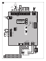 2
2
-
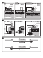 3
3
-
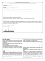 4
4
-
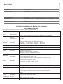 5
5
-
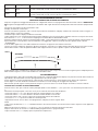 6
6
-
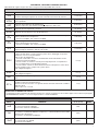 7
7
-
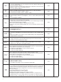 8
8
-
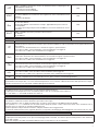 9
9
-
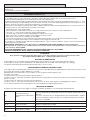 10
10
-
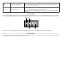 11
11
-
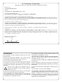 12
12
-
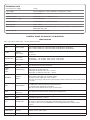 13
13
-
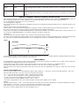 14
14
-
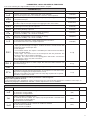 15
15
-
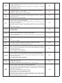 16
16
-
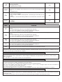 17
17
-
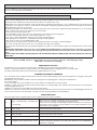 18
18
-
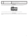 19
19
-
 20
20
-
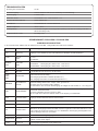 21
21
-
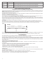 22
22
-
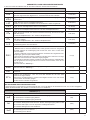 23
23
-
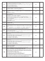 24
24
-
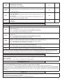 25
25
-
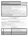 26
26
-
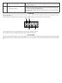 27
27
-
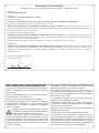 28
28
-
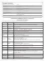 29
29
-
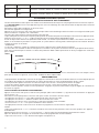 30
30
-
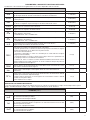 31
31
-
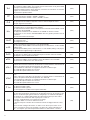 32
32
-
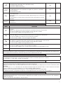 33
33
-
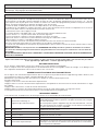 34
34
-
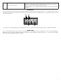 35
35
-
 36
36
-
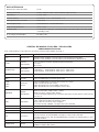 37
37
-
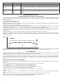 38
38
-
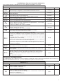 39
39
-
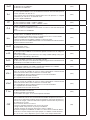 40
40
-
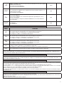 41
41
-
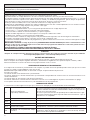 42
42
-
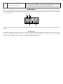 43
43
-
 44
44
-
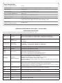 45
45
-
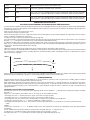 46
46
-
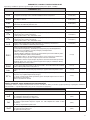 47
47
-
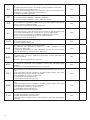 48
48
-
 49
49
-
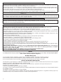 50
50
-
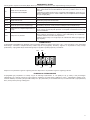 51
51
-
 52
52


Beninca CP.B24ESA Manual de usuario
- Tipo
- Manual de usuario
- Este manual también es adecuado para
en otros idiomas
- français: Beninca CP.B24ESA Manuel utilisateur
- italiano: Beninca CP.B24ESA Manuale utente
- English: Beninca CP.B24ESA User manual
- Deutsch: Beninca CP.B24ESA Benutzerhandbuch
- polski: Beninca CP.B24ESA Instrukcja obsługi
Artículos relacionados
-
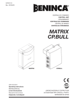 Beninca Matrix Operating Instructions Manual
-
 Beninca CP.B24 El manual del propietario
-
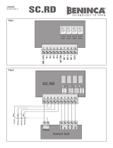 Beninca SCRD El manual del propietario
-
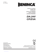 Beninca DA.24V Operating Instructions Manual
-
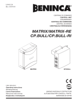 Beninca MATRIX and CP.BULL El manual del propietario
-
Beninca Heady El manual del propietario
-
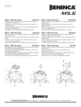 Beninca MSE Guía del usuario
-
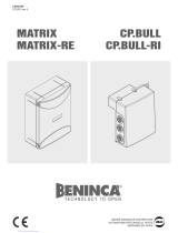 Beninca CP.BULL Manual de usuario
-
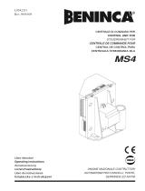 Beninca MS4 El manual del propietario
-
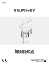 Beninca VNMT40V Guía del usuario


Otros documentos
-
DEA NET724 EVO El manual del propietario
-
BFT Rigel 6 El manual del propietario
-
-
BFT ALENA SW2 CPEM Manual de usuario
-
SEA Gate 2 DG R1B El manual del propietario
-
-
-
BFT LIBRA-C-MA El manual del propietario
-
-
Tau 250K-SLIM El manual del propietario