
NOTE: THIS INSTRUCTION
BOOKLET CONTAINS IMPORTANT
SAFETY INFORMATION.
PLEASE READ AND KEEP FOR
FUTURE REFERENCE.
Enlish p 1-32
Français p 33-37
Español p 38-43
Lot # 392791 08/25/16
Purchased: __________________
Be sure to ive us a rin before
makin any returns. 1-800-523-3987
Need help? Visit Sauder.com to view video assembly tips or chat with a live rep.
Prefer the phone? Call 1-800-523-3987.
Share your journey!
sauder.com
Executive Desk
Costa Collection | Model 419954
Business or pleasure.
Works both ways.

Table of Contents Assembly Tools Required
2-3
4
5-32
33-37
38-43
44-46
47
Part Identifi cation
Hardware Identifi cation
Assembly Steps
Français
Español
Safety
Warranty
Hammer
Not actual size
No. 2 Phillips Screwdriver
Tip Shown Actual Size
Skip the power trip.
This time.
419954 www.sauder.com/servicesPae 2
Part Identifi cation
å While not all parts are labeled, some of the parts will have a label or an inked letter on the ede
to help distinuish similar parts from each other. Use this part identifi cation to help identify similar parts.
A RIGHT END (1)
B LEFT END (1)
C BOTTOM (2)
D RIGHT UPRIGHT (1)
E LEFT UPRIGHT (1)
F BACK (2)
G MODESTY PANEL (1)
H RIGHT FRONT LEG (2)
I END MOLDING (4)
J BOTTOM MOLDING (2)
K BACK MOLDING (2)
L PENCIL DRAWER FRONT (1)
M PENCIL DRAWER MOLDING (1)
N SHELF (1)
O SHELF FRONT (1)
P LEFT FRONT LEG (2)
Q RIGHT REAR LEG (2)
R LEFT REAR LEG (2)
S MODESTY PANEL MOLDING (2)
T EXTENSION BLOCK (2)
U TOP (1)
V SMALL DRAWER FRONT (4)
W LARGE DRAWER FRONT (2)
B37 PENCIL DRAWER BOTTOM (1)
D24 SMALL DRAWER RIGHT SIDE (4)
D25 SMALL DRAWER LEFT SIDE (4)
D28 LARGE DRAWER RIGHT SIDE (2)
D29 LARGE DRAWER LEFT SIDE (2)
D78 LARGE DRAWER BACK (2)
D109 SMALL DRAWER BACK (4)
D425 PENCIL DRAWER BACK (1)
D427 PENCIL DRAWER RIGHT SIDE (1)
D428 PENCIL DRAWER LEFT SIDE (1)
D506 PENCIL DRAWER BOX FRONT (1)
D707 LARGE DRAWER BOTTOM (2)
D716 SMALL DRAWER BOTTOM (4)

Part Identifi cation
Now you know
our ABCs.
419954www.sauder.com/services
Pae 3
A
B
C
D
E
F
G
H
I
J
K
L
M
N
O
P
Q
R
S
T
U
V
W
B37
D428
D425
D427
D716
D24
D109
D25
V
D716
D24
D109
D25
D707
D28D78
D29
J
C
F
I
T
S
I
I
D506
Q
H
P
R
K

Hardware Identifi cation
å Screws are shown actual size. You may receive extra hardware with your unit.
(EXTENSION SET SHOWN SEPARATED)
WIDE EXTENSION
RAIL - 4
Y
WIDE EXTENSION
SLIDE - 4
Z
(EXTENSION SET SHOWN SEPARATED)
AA
NARROW EXTENSION
RAIL - 10
BB
NARROW EXTENSION
SLIDE - 10
FILE ROD - 4
8B
FILE GLIDE - 4
15B
10A
SLIDE CAM - 12
HIDDEN
CAM - 34
1F
CAM
SCREW - 34
8F 12F
TWIST-LOCK
®
FASTENER - 22
WOOD
DOWEL - 16
15F
GLUE - 1
54M
GROMMET CAP - 2
1P
GROMMET - 2
10P
3S
GOLD 5/16" FLAT HEAD SCREW - 48 BLACK 1-1/4" FLAT HEAD SCREW - 4
7S
BLACK 7/8" LARGE HEAD SCREW - 3
17S
BLACK 1-1/8" MACHINE SCREW - 6
21S
30S
BLACK 1-9/16" FLAT HEAD SCREW - 28 BLACK 9/16" FLAT HEAD SCREW - 18
32S
BLACK 7/8" MACHINE SCREW - 2
37S
BLACK 1-15/16" FLAT HEAD SCREW - 10
113S
KNOB SET - 8
136K
419954 www.sauder.com/servicesPae 4

Step 1
Look for this icon. It means a
video assembly tip is available at
www.sauder.com/services/tips
å
Assemble your unit on a carpeted fl oor or on the empty
carton to avoid scratchin your unit or the fl oor.
å
To bein assembly, push a SAUDER TWIST-LOCK®
FASTENER (12F) into the lare holes in the ENDS (A
and B) and UPRIGHTS (D and E).
å
Repeat this step for the BOTTOMS (C), MODESTY
PANEL (G), and SHELF (N).
419954www.sauder.com/services
Pae 5
A
B
D
E
Do not tihten the TWIST-LOCK® FASTENERS in this step.
(22 used)
12F

Step 2
419954 www.sauder.com/servicesPae 6
Arrow
Arrow
1F
The arrow in the HIDDEN
CAM must point toward the
hole in the ede of the board.
Hole
å
Push thirty-four HIDDEN CAMS (1F) into the ENDS (A
and B), UPRIGHTS (D and E), BACKS (F), and PENCIL
DRAWER FRONT (L).
(34 used)
1F
Arrow
A
B
D
E
L
F
F
Some assembly
(and snacks) required.

Step 3
419954www.sauder.com/services
Pae 7
M
H
P
Q
R
Q
H
P
R
8F
å
Turn thirty-four CAM SCREWS (8F) into the LEGS (H, P, Q,
and R) and PENCIL DRAWER MOLDING (M).
(34 used)
8F

Step 4
419954 www.sauder.com/servicesPae 8
å
Turn the ENDS (A and B), UPRIGHTS (D and E), and BACKS (F) over.
å
Turn twelve BLACK 9/16" FLAT HEAD SCREWS (32S) into the ENDS (A and B),
UPRIGHTS (D and E), and BACKS (F) until the shoulders of the SCREWS rest on the
surfaces of the ENDS, UPRIGHTS, and BACKS.
å
NOTE: Do not overtihten the SCREWS.
å
Slide the MOLDINGS (I and K) onto the ENDS (A and B), UPRIGHTS (D and E), and
BACKS (F). Line up the rooves in the MOLDINGS over the heads of the SCREWS in
the ENDS, UPRIGHTS, and BACKS.
å
NOTE: If the MOLDING comes up o of the SCREWS, remove it and slide it on aain.
The MOLDINGS should be centered over the ENDS, UPRIGHTS, and BACKS.
BLACK 9/16" FLAT HEAD SCREW
(12 used in this step)
32S
Shoulder
Apply pressure with your hands as you
uide the MOLDINGS over the SCREWS
and onto the ENDS, UPRIGHTS, and BACKS.
A
B
D
E
F
K
I
I
K
I
I
Surface
without
HIDDEN
CAMS
F
Surface
without
HIDDEN
CAMS
Surface without
HIDDEN CAMS
Surface
without
HIDDEN CAMS
Surface without
HIDDEN CAMS
Surface without
HIDDEN CAMS

Step 5
419954www.sauder.com/services
Pae 9
å
Turn three BLACK 9/16" FLAT HEAD SCREWS (32S) into the
MODESTY PANEL (G) until the shoulders of the SCREWS rest on
the surface of the MODESTY PANEL.
å
NOTE: Do not overtihten the SCREWS.
å
Slide a MODESTY PANEL MOLDING (S) onto the MODESTY
PANEL (G). Line up the roove in the MOLDING over the heads of
the SCREWS in the MODESTY PANEL.
å
NOTE: If the MOLDING comes up o of the SCREWS, remove it
and slide it on aain. The MOLDING should be centered
over the MODESTY PANEL.
å
Turn the MODESTY PANEL (G) over and
repeat this step to the other surface
of the MODESTY PANEL.
Shoulder
Apply pressure with your hands as you
uide the MOLDING over the SCREWS
and onto the MODESTY PANEL.
S
G
S
G
S
Surface with
TWIST-LOCK®
FASTENERS
BLACK 9/16" FLAT HEAD SCREW
(6 used in this step)
32S
32S
Surface
without
TWIST-LOCK®
FASTENERS

Step 6
419954 www.sauder.com/servicesPae 10
Fill the holes 1/4 to 1/2 full with GLUE.
Inspect the parts thorouhly before
assemblin. Disassembly of lued
parts is extremely di cult.
Caution
!
54M
15F
å
First, fi ll two holes in the ENDS (A and B) 1/4 to 1/2 full with GLUE (54M). Then,
insert two WOOD DOWELS (15F) into the holes. Wipe away the excess GLUE.
å
NOTE: Be sure to position the parts exactly as shown.
å
Now, fi ll the holes in the FRONT LEGS (H and P) 1/4 to 1/2 full with GLUE (54M).
å
Fasten the FRONT LEGS (H and P) to the ENDS (A and B). Tihten six
HIDDEN CAMS.
å
NOTE: Be sure the WOOD DOWELS in the ENDS insert into the FRONT LEGS.
Wipe away the excess GLUE.
15F
A
B
P
H
These surfaces
should be even.
These surfaces
should be even.
Surface with
TWIST-LOCK®
FASTENERS
Surface with
TWIST-LOCK®
FASTENERS
Ede with
TWIST-LOCK®
FASTENERS
Ede with
TWIST-LOCK®
FASTENERS
1
2
End without hole
End with hole

Step 7
419954www.sauder.com/services
Pae 11
Fill the holes 1/4 to 1/2 full with GLUE.
Inspect the parts thorouhly before
assemblin. Disassembly of lued
parts is extremely di cult.
Caution
!
54M
15F
å
First, fi ll two holes in the REAR LEGS (Q and R) 1/4 to 1/2 full
with GLUE (54M). Then, insert two WOOD DOWELS (15F)
into the holes. Wipe away the excess GLUE.
å
Now, fi ll the holes in the ENDS (A and B) 1/4 to 1/2 full
with GLUE (54M).
å
Fasten the REAR LEGS (Q and R) to the ENDS (A and B).
Tihten six HIDDEN CAMS.
å
NOTE: Be sure the WOOD DOWELS in the REAR LEGS
insert into the ENDS. Wipe away the excess GLUE.
15F
A
B
R
Q
These surfaces
should be even.
Surface with
TWIST-LOCK®
FASTENERS
Surface with
TWIST-LOCK®
FASTENERS
These surfaces
should be even.
Ede with
TWIST-LOCK®
FASTENERS
Ede with
TWIST-LOCK®
FASTENERS
End with hole
End without hole

Step 8
419954 www.sauder.com/servicesPae 12
Fill the holes 1/4 to 1/2 full with GLUE.
Inspect the parts thorouhly before
assemblin. Disassembly of lued
parts is extremely di cult.
Caution
!
54M
15F
å
First, fi ll two holes in the UPRIGHTS (D and E) 1/4 to 1/2 full with GLUE (54M).
Then, insert two WOOD DOWELS (15F) into the holes. Wipe away the
excess GLUE.
å
NOTE: Be sure to position the parts exactly as shown.
å
Now, fi ll the holes in the REAR LEGS (Q and R) 1/4 to 1/2 full with GLUE (54M).
å
Fasten the REAR LEGS (Q and R) to the UPRIGHTS (D
and E). Tihten six HIDDEN CAMS.
å
NOTE: Be sure the WOOD DOWELS in the UPRIGHTS insert into the REAR
LEGS. Wipe away the excess GLUE.
15F
D
E
Q
R
These surfaces
should be even.
These surfaces
should be even.
Surface with
TWIST-LOCK®
FASTENERS
Surface with
TWIST-LOCK®
FASTENERS
Ede with
TWIST-LOCK®
FASTENERS
Ede with
TWIST-LOCK®
FASTENERS
End without hole
End with hole

Step 9
419954www.sauder.com/services
Pae 13
Fill the holes 1/4 to 1/2 full with GLUE.
Inspect the parts thorouhly before
assemblin. Disassembly of lued
parts is extremely di cult.
Caution
!
54M
15F
å
First, fi ll two holes in the FRONT LEGS (H and P) 1/4 to 1/2
full with GLUE (54M). Then, insert two WOOD DOWELS (15F)
into the holes. Wipe away the excess GLUE.
å
Now, fi ll the holes in the UPRIGHTS (D and E) 1/4 to 1/2 full
with GLUE (54M).
å
Fasten the FRONT LEGS (P and H) to the UPRIGHTS (D
and E). Tihten six HIDDEN CAMS.
å
NOTE: Be sure the WOOD DOWELS in the FRONT LEGS
insert into the UPRIGHTS. Wipe away the excess GLUE.
15F
D
E
H
P
These surfaces
should be even.
Surface with
TWIST-LOCK®
FASTENERS
Surface with
TWIST-LOCK®
FASTENERS
These surfaces
should be even.
Ede with
TWIST-LOCK®
FASTENERS
Ede with
TWIST-LOCK®
FASTENERS
End with hole
End without hole

Step 10
419954 www.sauder.com/servicesPae 14
å
Separate the WIDE EXTENSION SLIDES (Z) from the WIDE EXTENSION RAILS (Y) as shown in the upper diaram below.
Be prepared, the parts are reasy.
å
Fasten the WIDE EXTENSION RAILS (Y) to the ENDS (A and B) and UPRIGHTS (D and E). Use eiht GOLD 5/16" FLAT
HEAD SCREWS (3S) throuh holes #1 and #3.
å
NOTE: For each WIDE EXTENSION RAIL, turn a SCREW into the hole shown in the enlared diaram. Then, slide the inner
cartride of the WIDE EXTENSION RAIL in to fi nd the other hole that lines up with the hole in the ENDS and UPRIGHTS.
Turn a SCREW into this hole.
å
NOTE: The WIDE EXTENSION SLIDES will be used later for the LARGE DRAWERS.
Open end
Open end
Push the black lever in and pull the SLIDE from the RAIL.
GOLD 5/16" FLAT HEAD SCREW
(8 used in this step)
3S
Open end
A
B
E
D
Y
Y
Y
Y
YZ
Ede with
TWIST-LOCK®
FASTENERS
Ede with
TWIST-LOCK®
FASTENERS
Surface with
TWIST-LOCK®
FASTENERS
Surface with
TWIST-LOCK®
FASTENERS
Surface with
TWIST-LOCK®
FASTENERS
Surface with
TWIST-LOCK®
FASTENERS
Open end
Separate the WIDE EXTENSION SET (Y and Z)
from the NARROW EXTENSION SET (AA and BB).
P
H
P
H
Ede with
TWIST-LOCK®
FASTENERS
1
3
2
4
1
3
2
4
1
3
2
4
1
3
2
4

Step 11
419954www.sauder.com/services
Pae 15
Push the black lever in and pull the SLIDE from the RAIL.
å
Separate the NARROW EXTENSION SLIDES (BB) from the NARROW EXTENSION RAILS (AA) as shown in the upper
diaram below. Be prepared, the parts are reasy.
å
Fasten eiht NARROW EXTENSION RAILS (AA) to the ENDS (A and B) and UPRIGHTS (D and E). Use sixteen GOLD 5/16"
FLAT HEAD SCREWS (3S) throuh holes #1 and #3.
å
NOTE: For each NARROW EXTENSION RAIL, turn a SCREW into the hole shown in the enlared diaram. Then, slide the
inner cartride of the NARROW EXTENSION RAIL in to fi nd the other hole that lines up with the hole in the ENDS and
UPRIGHTS. Turn a SCREW into this hole.
å
NOTE: The NARROW EXTENSION SLIDES will be used later for the SMALL DRAWERS and PENCIL DRAWER.
GOLD 5/16" FLAT HEAD SCREW
(16 used in this step)
3S
A
B
E
D
AA
AA
AABB
AA
AA
AA
AA
AA
AA
Open end
Open end
Open end
Open end
1
3
2
4
1
3
2
4
1
3
2
4
1
3
2
4
1
3
2
4
1
3
2
4
1
3
2
4
1
3
2
4

Step 12
419954 www.sauder.com/servicesPae 16
å
Turn the UPRIGHTS (D and E) over.
å
Fasten the EXTENSION BLOCKS (T) to the UPRIGHTS (D and E). Use four BLACK 1-1/4" FLAT HEAD SCREWS (7S).
å
Fasten the remainin two NARROW EXTENSION RAILS (AA) to the UPRIGHTS (D and E). Use four GOLD 5/16" FLAT
HEAD SCREWS (3S) throuh holes #1 and #3.
å
NOTE: For each NARROW EXTENSION RAIL, turn a SCREW into the hole shown in the enlared diaram. Then, slide the
inner cartride of the NARROW EXTENSION RAIL in to fi nd the other hole that lines up with the hole in the ENDS and
UPRIGHTS. Turn a SCREW into this hole.
GOLD 5/16" FLAT HEAD SCREW
(4 used for the RAILS)
3S
E
D
AA
AA
Open end
Open end
BLACK 1-1/4" FLAT HEAD SCREW
(4 used for the EXTENSION BLOCKS)
7S
T
T
Surface without
TWIST-LOCK®
FASTENERS
Surface without
TWIST-LOCK®
FASTENERS
The lare hole
must be here.
H
P
1
3
2
4
1
3
2
4
Surface with
more holes
Unfi nished
strip

å
Fasten the BOTTOMS (C) to the ENDS (A and B). Tihten
four TWIST-LOCK® FASTENERS.
å
Slide the BOTTOM MOLDINGS* (J) onto the notched
edes of the BOTTOMS (C).
å
*U.S. Patent No. 5,499,886
Step 13
419954www.sauder.com/services
Pae 17
Surface with
TWIST-LOCK®
FASTENERS
Surface with
TWIST-LOCK®
FASTENERS
J
C
J
C
How to use the SAUDER TWIST-LOCK
®
FASTENER
1. Insert the dowel end of the FASTENER into the hole of the
adjoinin part.
NOTE: The dowel end of the FASTENER must remain fully
inserted in the hole of the adjoinin part while lockin
the FASTENER.
2. Tihten the FASTENER with a Phillips screwdriver as tiht
as possible.
Dowel end
Slide the BOTTOM MOLDING (J)
onto the notched ede.
Notched ede
Notched ede
These surfaces
should be even.
Short ede
B
A
Short ede
H
P

Step 14
å
Fasten the BACKS (F) to the REAR LEGS (Q and R) that
are on the ENDS (A and B). Tihten four HIDDEN CAMS.
419954 www.sauder.com/servicesPae 18
F
Surface with
HIDDEN CAMS
Surface with
HIDDEN CAMS
F
B
A
K
K
R
Q
Don't worry. It isn't
Rome. This can be built
in a day.

å
Fasten the RIGHT UPRIGHT (D) to the BOTTOM (C)
and BACK (F). Tihten two HIDDEN CAMS and two
TWIST-LOCK® FASTENERS.
å
Fasten the LEFT UPRIGHT (E) to the BOTTOM (C)
and BACK (F). Tihten two HIDDEN CAMS and two
TWIST-LOCK® FASTENERS.
Step 15
419954www.sauder.com/services
Pae 19
F
F
C
C
D
E
B
A
The lare hole
must be here.
Surface without
TWIST-LOCK®
FASTENERS
Surface without
TWIST-LOCK®
FASTENERS

Step 16
å
Fasten the MODESTY PANEL (G) to the TOP (U). Tihten
two TWIST-LOCK® FASTENERS.
419954 www.sauder.com/servicesPae 20
Surface with
TWIST-LOCK®
FASTENERS
G
U
Surface with holes
The lare hole
must be here.
The lare hole
must be here.
Meet Part (U). This component has
been enineered to be lihter, stroner,
faster… well ok. Not technically faster.
But defi nitely makes for a sturdier
Executive Desk that’s easier to assemble
and friendlier to the environment.

Step 17
419954www.sauder.com/services
Pae 21
Fill the holes 1/4 to 1/2 full with GLUE.
Inspect the parts thorouhly before
assemblin. Disassembly of lued
parts is extremely di cult.
Caution
!
54M
15F
å
NOTE: You will need someone's help in this step.
å
First, fi ll eiht small holes in the TOP (U) 1/4 to 1/2 full with GLUE (54M). Then,
insert eiht WOOD DOWELS (15F) into the holes. Wipe away the excess GLUE.
å
Now, fi ll the holes in the LEGS (H, P, Q, and R) 1/4 to 1/2 full with GLUE (54M).
å
Fasten the ENDS (A and B) and UPRIGHTS (D and E) to the TOP (U). Tihten
eiht TWIST-LOCK® FASTENERS.
å
NOTE: Be sure the WOOD DOWELS in the TOP insert into the LEGS. Wipe
away the excess GLUE.
å
Fasten the UPRIGHTS (D and E) to the MODESTY PANEL (G). Use four BLACK
1-15/16" FLAT HEAD SCREWS (113S).
15F
U
(8 used)
A
B
D
E
H
P
Q
R
Q
H
P
R
G
BLACK 1-15/16" FLAT HEAD SCREW
(4 used for the MODESTY PANEL)
113S
NOTE: Before beinnin this step, be sure to separate the BLACK
1-9/16" FLAT HEAD SCREWS (30S) from the BLACK 1-15/16"
FLAT HEAD SCREWS (113S). Do not confuse these SCREWS.

Step 18
å
Fasten the SHELF (N) to the MODESTY PANEL (G).
Tihten two TWIST-LOCK® FASTENERS.
å
Fasten the SHELF (N) to the UPRIGHTS (D and E). Use
four BLACK 1-15/16" FLAT HEAD SCREWS (113S).
å
Fasten the SHELF FRONT (O) to the SHELF (N). Tihten
two TWIST-LOCK® FASTENERS.
å
Fasten the SHELF FRONT (O) to the UPRIGHTS (D and E).
Use two BLACK 1-15/16" FLAT HEAD SCREWS (113S).
419954 www.sauder.com/servicesPae 22
BLACK 1-15/16" FLAT HEAD SCREW
(6 used in this step)
113S
D
E
G
N
O
Surface with
TWIST-LOCK®
FASTENERS
Surface without holes
Finished ede

Step 19
419954www.sauder.com/services
Pae 23
å
Fasten the PENCIL DRAWER SIDES (D427 and D428)
to the PENCIL DRAWER BACK (D425). Use two
BLACK 1-9/16" FLAT HEAD SCREWS (30S).
å
Slide the PENCIL DRAWER BOTTOM (B37) into the
grooves in the PENCIL DRAWER SIDES (D427 and D428)
and PENCIL DRAWER BACK (D425).
å
Fasten the PENCIL DRAWER BOX FRONT (D506) to the
PENCIL DRAWER SIDES (D427 and D428). Use two BLACK
1-9/16" FLAT HEAD SCREWS (30S).
12
3
Groove
D425
D427
D428
Start each screw a few turns before
completely tihtenin any of them.
BLACK 1-9/16" FLAT HEAD SCREW
(2 used in this step)
30S
D425
D427
D428
B37
Finished surface
D427
D428
D506
30S
Start each screw a few turns before
completely tihtenin any of them.
BLACK 1-9/16" FLAT HEAD SCREW
(2 used in this step)
30S
Be sure the DRAWER
BOTTOM inserts into the
DRAWER BOX roove.
With the palm of your hand,
tap the DRAWER BOTTOM
down into the roove.

Step 20
å
Fasten the PENCIL DRAWER FRONT (L) to the PENCIL
DRAWER MOLDING (M). Tihten two HIDDEN CAMS.
å
Fasten two KNOB SETS (136K) to the PENCIL DRAWER
FRONT (L). Use two BLACK 7/8" MACHINE SCREWS (37S).
419954 www.sauder.com/servicesPae 24
Surface with HIDDEN CAMS
M
L
M
L
Surface without HIDDEN CAMS
136K
BLACK 7/8" MACHINE SCREW
(2 used in this step)
37S
These surfaces
should be even.
Curved ede

å
Fasten two NARROW EXTENSION SLIDES (BB) to the
PENCIL DRAWER SIDES (D427 and D428). Use four GOLD
5/16" FLAT HEAD SCREWS (3S) throuh holes #1 and #3.
å
Fasten the PENCIL DRAWER FRONT (L) to the PENCIL
DRAWER BOX FRONT (D506). Use three BLACK 7/8"
LARGE HEAD SCREWS (17S).
Step 21
419954www.sauder.com/services
Pae 25
L
D427
D428
D506
Open end
Open end
1
2
3
1
2
3
BB
BB
GOLD 5/16" FLAT HEAD SCREW
(4 used in this step)
3S
M
BLACK 7/8" LARGE HEAD SCREW
(3 used in this step)
17S
These edes
should be even.

Step 22
VIEW THE T-LOCK BOX VIDEO
å
Fasten the LARGE DRAWER BACK (D78) to the LARGE DRAWER SIDES (D28
and D29). Use four BLACK 1-9/16" FLAT HEAD SCREWS (30S).
å
NOTE: Be sure the LARGE DRAWER BOTTOM (D707) inserts into the roove
of the LARGE DRAWER BACK (D78).
å
Repeat this step for the other LARGE drawer.
12
3
å
Insert the LARGE DRAWER SIDES (D28 and D29)
at an anle into the slot at each end of the LARGE
DRAWER FRONT (W).
å
Slide the LARGE DRAWER BOTTOM (D707) into the
rooves in the LARGE DRAWER SIDES (D28 and D29)
and LARGE DRAWER FRONT (W).
The tabs should insert freely
into the slots. Gently tilt the
DRAWER SIDES side to side
until the tabs slip into the slots.
Groove
30S
Start each screw a few turns before
completely tihtenin any of them.
BLACK 1-9/16" FLAT HEAD SCREW
(8 used in this step)
Be sure the DRAWER
BOTTOM inserts into the
DRAWER FRONT roove.
D28
D29
D707
D707
D28
D29
D78
D29
W
W
Unfi nished
surface
D28
Be sure the
DRAWER
BOTTOM
inserts into
the DRAWER
BACK roove.
With the palm of your hand,
tap the DRAWER BOTTOM
down into the roove.
419954 www.sauder.com/servicesPae 26

Step 23
419954www.sauder.com/services
Pae 27
VIEW THE T-LOCK BOX VIDEO
å
NOTE: The SMALL drawers will only use two SCREWS per drawer. Refer to the diaram.
å
Fasten the SMALL DRAWER BACK (D109) to the SMALL DRAWER SIDES (D24 and D25). Use two BLACK 1-9/16" FLAT
HEAD SCREWS (30S).
å
NOTE: Be sure the SMALL DRAWER BOTTOM (D716) inserts into the roove of the SMALL DRAWER BACK (D109).
å
Repeat this step for the other SMALL drawers.
12
3
å
Insert the SMALL DRAWER SIDES (D24 and D25)
at an anle into the slot at each end of the SMALL
DRAWER FRONT (V).
å
Slide the SMALL DRAWER BOTTOM (D716) into the
rooves in the SMALL DRAWER SIDES (D24 and D25)
and SMALL DRAWER FRONT (V).
The tabs should insert freely
into the slots. Gently tilt the
DRAWER SIDES side to side
until the tabs slip into the slots.
Groove
30S
Start each screw a few turns before
completely tihtenin any of them.
BLACK 1-9/16" FLAT HEAD SCREW
(8 used in this step)
Be sure the DRAWER
BOTTOM inserts into the
DRAWER FRONT roove.
D24
D25
D716
D716
D24
D25
D109
D25
V
V
Unfi nished
surface
D24
Be sure the
DRAWER
BOTTOM
inserts into
the DRAWER
BACK roove.
NOTE: Do not use this hole
in the SMALL drawers. This
hole will be used in Step 25.
With the palm of your hand,
tap the DRAWER BOTTOM
down into the roove.

Step Step 24
419954 www.sauder.com/servicesPae 28
å
Insert a SLIDE CAM (10A) into the LARGE DRAWER SIDES (D28 and D29).
å
Fasten two WIDE EXTENSION SLIDES (Z) to the LARGE DRAWER SIDES (D28
and D29). Use four GOLD 5/16" FLAT HEAD SCREWS (3S) throuh
holes #1 and #4.
å
NOTE: The screw head in the CAM must be visible throuh the slotted hole in
the SLIDE.
å
Repeat this step for the other LARGE drawer.
D28
D29
Open end
Open end
1
2
3
1
2
3
Z
Z
Screw head - turn CAM to line up holes in
the SLIDES with holes in DRAWER SIDES
10A
10A
4
4
GOLD 5/16" FLAT HEAD SCREW
(8 used in this step)
3S
(4 screws per drawer)

Step Step 25
å
Insert a SLIDE CAM (10A) into the SMALL DRAWER SIDES (D24 and D25).
å
Fasten two NARROW EXTENSION SLIDES (BB) to the SMALL DRAWER SIDES (D24 and D25).
Use two BLACK 1-9/16" FLAT HEAD SCREWS (30S) throuh holes #1, throuh the SMALL
DRAWER SIDES, and into the SMALL DRAWER BACK (D109). Use two GOLD 5/16" FLAT
HEAD SCREWS (3S) throuh hole #3.
å
NOTE: The screw head in the CAM must be visible throuh the slotted hole in the SLIDE.
å
Repeat this step for the other SMALL drawers.
D24
D25
Open end
Open end
1
2
3
1
2
3
BB
BB
Screw head - turn CAM to line up holes in
the SLIDES with holes in DRAWER SIDES
10A
10A
D109
GOLD 5/16" FLAT HEAD SCREW
(8 used in this step)
3S
(2 screws per drawer)
BLACK 1-9/16" FLAT HEAD SCREW
(8 used in this step)
30S
(2 screws per drawer)
419954www.sauder.com/services
Pae 29

Step
If you're doin this to
help a friend, don't
leave without a bite.
Step 26
419954 www.sauder.com/servicesPae 30
å
Push a FILE GLIDE (15B) onto the LARGE DRAWER RIGHT SIDE (D28).
å
Slide the FILE RODS (8B) into the FILE GLIDE (15B) on the LARGE
DRAWER RIGHT SIDE (D28).
å
Slide another FILE GLIDE (15B) onto the other end of the FILE RODS (8B),
then press this FILE GLIDE over the LARGE DRAWER LEFT SIDE (D29).
å
Fasten a KNOB SET (136K) to the LARGE DRAWER FRONT (W). Use one
BLACK 1-1/8" MACHINE SCREW (21S).
å
Repeat fastenin a KNOB SET to all drawers.
å
Insert the remainin FILE GLIDES (15B) and FILE RODS (8B) into the other
LARGE DRAWER.
Insert the FILE RODS into
the holes in the FILE GLIDES
dependin on your fi le sizes.
15B
15B
8B
8B
D29
D28
BLACK 1-1/8" MACHINE SCREW
(6 used for the KNOB SETS)
21S
136K
W

Step Step 27
å
Carefully stand your unit upriht.
å
NOTE: Before insertin a drawer, be sure the INNER CARTRIDGE in the EXTENSION RAIL on your unit is all the way
forward. The INNER CARTRIDGE should click into place aainst the BLACK TAB.
å
To insert a drawer into your unit, line up the EXTENSION SLIDES on the drawer with the EXTENSION RAILS on the unit
and push the drawer into the unit until the drawer is fully inserted. The drawer will push in hard until it is all the way in, then
it will slide in and out easier.
å
Insert the GROMMET CAPS (1P) and GROMMETS (10P) into the lare holes in the TOP (U).
60 lbs.
25 lbs.
15 lbs.
35 lbs.
1P
10P
U
L
V
W
V
V
W
V
25 lbs.
25 lbs.
35 lbs.
25 lbs.
419954www.sauder.com/services
Pae 31
Extension Rail
Black tab
Click the inner cartride into place aainst the black tab.
Front
Inner cartride

Step
419954 www.sauder.com/servicesPae 32
Step 28
å
To make adjustments to the SMALL DRAWERS, loosen SCREW #3 in the SLIDES a 1/4 turn, then turn the CAM
clockwise or counter-clockwise. Notice how the drawer raises or lowers as you turn the CAM. The hiher the
screw in the oblon hole, the hiher your drawer front will be. The lower the screw, the lower the drawer front. By
adjustin the drawers this way, it will help the DRAWER FRONTS line up better when closed. Tihten the SCREW
when fi nished with adjustments.
å
NOTE: Loosen screw #4 to make adjustments to the LARGE DRAWERS.
å
NOTE: Please read the back paes of the instruction booklet for important safety information.
å
This completes assembly. Clean with your favorite furniture polish or a damp cloth. Wipe dry.
The hiher the screw in the oblon hole,
the hiher your drawer front will be. The
lower the screw, the lower the drawer front.
And to celebrate, why not share your success story?
Cam
Loosen screw #3 a 1/4 turn, turn the cam a 1/4 turn
maximum in both the clockwise and counter-clockwise
directions to make adjustments, and then tihten screw #3.
32

A l’usae exclusif du
Canada Noter la date
d’achat de cet élément
et conserver le livret
pour future référence.
Pour contacter Sauder
en ce qui concerne cet
élément, faire référence
au numéro de lot et
numéro de modèle en
appelant notre numéro
sans frais.
Lot nº : ____________
Date de
l’achat: ____________
LISTE DE PIÈCES
REFERENCE DESCRIPTION QUANTITÉ
LISTE DE PIÈCES
REFERENCE DESCRIPTION QUANTITÉ
NOUS SOMMES LA POUR VOUS AIDER!
Nous faisons de notre mieux pour nous assurer que votre meuble
arrive dans d’excellentes conditions. Nos représentants du service
Clientèle sont aimables et prêts à vous aider au cas où une pièce
aurait été endommaée ou manquerait (ou si vous aviez besoin
d’aide pour l’assemblae). NE RAMENEZ PAS LE MEUBLE AU
MAGASIN. Au Canada, composez ce numéro d’appel ratuit:
1-800-523-3987
Du lundi au vendredi, de 9 heures du matin à
5:30 heures du soir (horaire Côte Est)
(sauf jours fériés)
Si une pièce a besoin d’être remplacée, la pièce de remplacement
sera envoyée dans les 48 heures. (Sauf week-ends et jours fériés)
Utilisez les instructions d’assemblae en français avec les
schémas étape par étape du manuel d’instruction en anlais.
Chaque étape en français correspond à la même étape
en anlais. La pièce devant être attachée à l’élément est
représentée en ris sur les schémas de chaque étape pour plus
de précision. Comparer la “Liste de pièces” ci-dessous avec
la “PART IDENTIFICATION” du manuel en anlais pour vous
familiariser avec les pièces avant l’assemblae.
REMARQUE : CE MANUEL D’INSTRUCTIONS CONTIENT
D’IMPORTANTES INFORMATIONS RELATIVES À LA SÉCURITÉ.
À LIRE ET CONSERVER POUR TOUTE RÉFÉRENCE FUTURE.
Bureau MinistreModèle 419954
(ENSEMBLE DE GLISSIÈRE ILLUSTRÉ À PART)
Y GLISSIÈRE D'EXTENSION LARGE .................4
Z COULISSE D’EXTENSION LARGE .................4
(ENSEMBLE DE GLISSIÈRE ILLUSTRÉ À PART)
AA GLISSIÈRE D'EXTENSION ÉTROITE .........10
BB COULISSE D’EXTENSION ÉTROITE .........10
10A EXCENTRIQUE DE COULISSE .......................12
8B TIGE DE DOSSIER ......................................................4
15B ARMATURE POUR DOSSIERS .........................4
1F EXCENTRIQUE ESCAMOTABLE .................34
8F VIS D'EXCENTRIQUE ...........................................34
12F FIXATION TWIST-LOCK® ................................... 22
15F CHEVILLE EN BOIS ................................................16
136K ENSEMBLE DE BOUTONS ..................................8
54M COLLE ...................................................................................1
1P COUVERCLE DE PASSE-CÂBLES ................2
10P PASSE-CÂBLES ...........................................................2
3S VIS TÊTE PLATE 8 mm DORÉE ..................48
7S VIS TÊTE PLATE 32 mm NOIRE .....................4
17S VIS TÊTE LARGE 22 mm NOIRE ...................3
21S VIS À MÉTAUX 28 mm NOIRE .........................6
30S VIS TÊTE PLATE 40 mm NOIRE ................28
32S VIS TÊTE PLATE 14 mm NOIRE ...................18
37S VIS À MÉTAUX 22 mm NOIRE .........................2
113S VIS TÊTE PLATE 49 mm NOIRE ..................10
A EXTRÉMITÉ DROITE ..................................................1
B EXTRÉMITÉ GAUCHE ...............................................1
C DESSOUS ..........................................................................2
D MONTANT DROIT ........................................................1
E MONTANT GAUCHE .................................................1
F DOSSIER ............................................................................2
G VOILE DE FOND ...........................................................1
H PIED AVANT DROIT ...................................................2
I MOULURE D’EXTRÉMITÉ .....................................4
J MOULURE DE DESSOUS .....................................2
K MOULURE ARRIÈRE .................................................2
L DEVANT DE TIROIR À CRAYONS ...................1
M MOULURE DE TIROIR À CRAYONS ..............1
N TABLETTE ..........................................................................1
O DEVANT DE TABLETTE ...........................................1
P PIED AVANT GAUCHE ............................................2
Q PIED ARRIÈRE DROIT ..............................................2
R PIED ARRIÈRE GAUCHE ........................................2
S MOULURE DE VOILE DE FOND ......................2
T BLOC D'EXTENSION ................................................2
U DESSUS ...............................................................................1
V DEVANT DE PETIT TIROIR ..................................4
W DEVANT DE GRAND TIROIR ..............................2
B37 FOND DE TIROIR À CRAYONS .........................1
D24 CÔTÉ DROIT DE PETIT TIROIR .......................4
D25 CÔTÉ GAUCHE DE PETIT TIROIR.................4
D28 CÔTÉ DROIT DE GRAND TIROIR ...................2
D29 CÔTÉ GAUCHE DE GRAND TIROIR ............2
D78 ARRIÈRE DE GRAND TIROIR .............................2
D109
ARRIÈRE DE PETIT TIROIR ..................................4
D425
ARRIÈRE DE TIROIR À CRAYONS ...................1
D427
CÔTÉ DROIT DE TIROIR À CRAYONS ........1
D428
CÔTÉ GAUCHE DE TIROIR À CRAYONS .1
D506
DEVANT DE CAISSON DE
TIROIR À CRAYONS...................................................1
D707
FOND DE GRAND TIROIR ....................................2
D716
FOND DE PETIT TIROIR ........................................4
419954www.sauder.com/services
Pae 33

419954 www.sauder.com/servicesPae 34
ÉTAPE 1
Ne pas serrer les FIXATIONS TWIST-LOCK® à cette étape.
Assembler l'élément sur un sol à moquette ou sur le carton vide
pour éviter d'endommaer l'élément ou le sol.
Pour commencer l'assemblae, enfoncer une FIXATION
TWIST-LOCK® SAUDER (12F) dans les ros trous des
EXTRÉMITÉS (A et B) et les MONTANTS (D et E).
Répéter cette étape pour les DESSOUS (C), le VOILE DE
FOND (G) et la TABLETTE (N).
ÉTAPE 2
Enfoncer trente et quatre EXCENTRIQUES ESCAMOTABLES (1F)
dans les EXTRÉMITÉS (A et B), les MONTANTS (D et E), les
ARRIÈRES (F) et le DEVANT DE TIROIR À CRAYONS (L).
ÉTAPE 5 (SUITE)
REMARQUE : Si la MOULURE soulève au-dessus les VIS, l'enlever
et l'enfi ler de nouveau. La MOULURE devrait être centrée sur le
VOILE DE FOND.
Retourner le VOILE DE FOND (G) et répéter cette étape pour
l'autre surface du VOILE DE FOND.
ÉTAPE 6
Attention: Examiner bien les pièces avant d'assembler. Il est
di cile de séparer des pièces une fois encollées.
Tout d'abord, remplir les deux trous dans les EXTRÉMITÉS (A et B) de
1/4 à 1/2 pleins de COLLE (54M). Insérer ensuite deux CHEVILLES
EN BOIS (15F) dans les trous. Nettoyer l'excès de COLLE.
REMARQUE : S’assurer de positionner les pièces exactement
comme il l’est indiqué.
Maintenant, remplir les trous dans les PIEDS AVANT (H et P) de
1/4 à 1/2 pleins de COLLE (54M).
Fixer les PIEDS AVANT (H et P) aux EXTRÉMITÉS (A et B). Serrer
six EXCENTRIQUES ESCAMOTABLES.
REMARQUE : S'assurer de bien insérer les CHEVILLES EN BOIS
situées sur les EXTRÉMITÉS dans les PIEDS AVANT. Nettoyer
l'excès de COLLE.
ÉTAPE 3
Faire tourner trente et quatre VIS D'EXCENTRIQUE (8F) dans les
PIEDS (H, P, Q et R) et la MOULURE DE TIROIR À CRAYONS (M).
ÉTAPE 7
Attention: Examiner bien les pièces avant d'assembler. Il est
di cile de séparer des pièces une fois encollées.
Tout d'abord, remplir les deux trous dans les PIEDS ARRIÈRE (Q
et R) de 1/4 à 1/2 pleins de COLLE (54M). Insérer ensuite deux
CHEVILLES EN BOIS (15F) dans les trous. Nettoyer l'excès de COLLE.
Maintenant, remplir les trous dans les EXTRÉMITÉS (A et B) de
1/4 à 1/2 pleins de COLLE (54M).
Fixer les PIEDS ARRIÈRE (Q et R) aux EXTRÉMITÉS (A et B).
Serrer six EXCENTRIQUES ESCAMOTABLES.
REMARQUE : S’assurer d’insérer les CHEVILLES EN BOIS des
PIEDS ARRIÈRE dans les EXTRÉMITÉS. Nettoyer l'excès de COLLE.
ÉTAPE 4
Retourner les EXTRÉMITÉS (A et B), les MONTANTS (D et E) et
les ARRIÈRES (F).
Faire tourner douze VIS TÊTE PLATE 14 mm NOIRES (32S)
dans les EXTRÉMITÉS (A et B), les MONTANTS (D et E) et les
ARRIÈRES (F) jusqu'à ce que l'épaulement des VIS repose sur les
surfaces des EXTRÉMITÉS, MONTANTS et ARRIÈRES.
REMARQUE : Ne pas trop serrer les VIS.
Enfi ler les MOULURES (I et K) sur les EXTRÉMITÉS (A et B),
les MONTANTS (D et E) et les ARRIÈRES (F). Aliner la rainure
des MOULURES sur les têtes des VIS dans les EXTRÉMITÉS,
MONTANTS et ARRIÈRES.
REMARQUE :Si la MOULURE soulève au-dessus les VIS, l'enlever
et l'enfi ler de nouveau. Les MOULURES devraient être centrées
sur les EXTRÉMITÉS, MONTANTS et ARRIÈRES.
ÉTAPE 8
Attention: Examiner bien les pièces avant d'assembler. Il est
di cile de séparer des pièces une fois encollées.
Tout d'abord, remplir les deux trous dans les MONTANTS (D et E) de
1/4 à 1/2 pleins de COLLE (54M). Insérer ensuite deux CHEVILLES
EN BOIS (15F) dans les trous. Nettoyer l'excès de COLLE.
REMARQUE : S’assurer de positionner les pièces exactement
comme il l’est indiqué.
Maintenant, remplir les trous dans les PIEDS ARRIÈRE (Q et R) de
1/4 à 1/2 pleins de COLLE (54M).
ÉTAPE 5
Faire tourner trois VIS TÊTE PLATE 14 mm NOIRES (32S) dans le
VOILE DE FOND (G) jusqu'à ce que l'épaulement des VIS repose
sur la surface du VOILE DE FOND.
REMARQUE : Ne pas trop serrer les VIS.
Enfi ler une MOULURE DE VOILE DE FOND (S) sur le VOILE DE
FOND (G). Aliner la rainure de la MOULURE sur les têtes des VIS
dans le VOILE DE FOND.

ÉTAPE 8 (SUITE)
Fixer les PIEDS ARRIÈRE (Q et R) aux MONTANTS (D et E). Serrer
six EXCENTRIQUES ESCAMOTABLES.
REMARQUE : S'assurer de bien insérer les CHEVILLES EN BOIS
situées sur les MONTANTS dans les PIEDS ARRIÈRE. Nettoyer
l'excès de COLLE.
ÉTAPE 9
Attention: Examiner bien les pièces avant d'assembler. Il est
di cile de séparer des pièces une fois encollées.
Tout d'abord, remplir les deux trous dans les PIEDS AVANT (H et P)
de 1/4 à 1/2 pleins de COLLE (54M). Insérer ensuite deux
CHEVILLES EN BOIS (15F) dans les trous. Nettoyer l'excès de COLLE.
Maintenant, remplir les trous dans les MONTANTS (D et E) de 1/4
à 1/2 pleins de COLLE (54M).
Fixer les PIEDS AVANT (P et H) aux MONTANTS (D et E). Serrer
six EXCENTRIQUES ESCAMOTABLES.
REMARQUE : S’assurer d’insérer les CHEVILLES EN BOIS des
PIEDS AVANT dans les MONTANTS. Nettoyer l'excès de COLLE.
ÉTAPE 11 (SUITE)
REMARQUE : Les COULISSES D'EXTENSION ÉTROITES
seront utilisées ultérieurement pour les PETITS TIROIRS et le
TIROIR À CRAYONS.
ÉTAPE 12
Retourner les MONTANTS (D et E).
Fixer les BLOCS D'EXTENSION (T) aux MONTANTS (D et E).
Utiliser quatre VIS TÊTE PLATE 32 mm NOIRES (7S).
Fixer les autres deux GLISSIÈRES D'EXTENSION ÉTROITES (AA)
aux MONTANTS (D et E). Utiliser quatre VIS TÊTE PLATE 8 mm
DORÉES (3S) à travers les trous nº 1 et nº 3.
REMARQUE : Pour chaque GLISSIÈRE D'EXTENSION ÉTROITE,
faire tourner une VIS dans le trou indiqué dans le schéma
arandi. Ensuite, enfi ler la cartouche interne de la GLISSIÈRE
D'EXTENSION ÉTROITE vers l'intérieur pour trouver l'autre trou
qui est aliné sur le trou dans les EXTRÉMITÉS et les MONTANTS.
Faire tourner une VIS dans ce trou.
419954www.sauder.com/services
Pae 35
ÉTAPE 10
Séparer les COULISSES D'EXTENSION LARGE (Z) des
GLISSIÈRES D'EXTENSION LARGE (Y) comme l'indique le schéma
du haut ci-dessous. Faire attention car les pièces sont raissées.
Fixer les GLISSIÈRES D'EXTENSION LARGE (Y) aux
EXTRÉMITÉS (A et B) et aux MONTANTS (D et E). Utiliser huit VIS
TÊTE PLATE 8 mm DORÉES (3S) à travers les trous nº 1 et nº 3.
REMARQUE : Pour chaque GLISSIÈRE D'EXTENSION LARGE,
faire tourner une VIS dans le trou indiqué dans le schéma
arandi. Ensuite, enfi ler la cartouche interne de la GLISSIÈRE
D'EXTENSION LARGE vers l'intérieur pour trouver l'autre trou qui
est aliné sur le trou dans les EXTRÉMITÉS et les MONTANTS.
Faire tourner une VIS dans ce trou.
REMARQUE : Les COULISSES D'EXTENSION LARGE seront
utilisées ultérieurement pour les GRANDS TIROIRS.
ÉTAPE 13
Fixer les DESSOUS (C) aux EXTRÉMITÉS (A et B). Serrer quatre
FIXATIONS TWIST-LOCK®.
Enfi ler les MOULURES DE DESSOUS* (J) sur les chants crantés
des DESSOUS (C).
* Brevet État Unis n° 5,499,886
Utilisation de la FIXATION TWIST-LOCK® SAUDER
1. Insérer l'extrémité fi letée de la FIXATION dans le trou de la
pièce attenante.
REMARQUE : L'extrémité fi letée de la FIXATION doit rester
complètement insérée dans le trou de la pièce attenante lorsque
l'on bloque la FIXATION.
2. Bien serrer la FIXATION à l'aide d'un tournevis Phillips.
ÉTAPE 11
Séparer les COULISSES D'EXTENSION ÉTROITES (BB) des
GLISSIÈRES D'EXTENSION ÉTROITES (AA) comme l'indique le
schéma du haut. Faire attention car les pièces sont raissées.
Fixer huit GLISSIÈRES D'EXTENSION ÉTROITES (AA) aux
EXTRÉMITÉS (A et B) et aux MONTANTS (D et E). Utiliser seize VIS
TÊTE PLATE 8 mm DORÉES (3S) à travers les trous nº 1 et nº 3.
REMARQUE : Pour chaque GLISSIÈRE D'EXTENSION ÉTROITE,
faire tourner une VIS dans le trou indiqué dans le schéma
arandi. Ensuite, enfi ler la cartouche interne de la GLISSIÈRE
D'EXTENSION ÉTROITE vers l'intérieur pour trouver l'autre trou
qui est aliné sur le trou dans les EXTRÉMITÉS et les MONTANTS.
Faire tourner une VIS dans ce trou.
ÉTAPE 14
Fixer les ARRIÈRES (F) aux PIEDS ARRIÈRE (Q et R) aux
EXTRÉMITÉS (A et B). Serrer quatre EXCENTRIQUES ESCAMOTABLES.
ÉTAPE 15
Fixer le MONTANT DROIT (D) au DESSOUS (C) et à l'ARRIÈRE (F).
Serrer deux EXCENTRIQUES ESCAMOTABLES et deux FIXATIONS
TWIST-LOCK®.
Fixer le MONTANT GAUCHE (E) au DESSOUS (C) et à
l'ARRIÈRE (F). Serrer deux EXCENTRIQUES ESCAMOTABLES et
deux FIXATIONS TWIST-LOCK®.

419954 www.sauder.com/servicesPae 36
ÉTAPE 16
Fixer le VOILE DE FOND (G) au DESSUS (U). Serrer deux
FIXATIONS TWIST-LOCK®.
ÉTAPE 17
Attention: Examiner bien les pièces avant d'assembler. Il est
di cile de séparer des pièces une fois encollées.
REMARQUE : Avant de commencer cette étape, séparer les VIS
TÊTE PLATE 40 mm NOIRES (30S) des VIS TÊTE PLATE 49 mm
NOIRES (113S). Ne pas confondre ces VIS.
REMARQUE : Faire appel à une autre personne pour cette étape.
Tout d'abord, remplir les huit petits trous dans le DESSUS (U) de
1/4 à 1/2 pleins de COLLE (54M). Insérer ensuite huit CHEVILLES
EN BOIS (15F) dans les trous. Nettoyer l'excès de COLLE.
Maintenant, remplir les trous dans les PIEDS (H, P, Q et R) de 1/4 à
1/2 pleins de COLLE (54M).
Fixer les EXTRÉMITÉS (A et B) et les MONTANTS (D et E) au
DESSUS (U). Serrer huit FIXATIONS TWIST-LOCK®.
REMARQUE : S’assurer d’insérer les CHEVILLES EN BOIS du
DESSUS dans les PIEDS. Nettoyer l'excès de COLLE.
Fixer les MONTANTS (D et E) au VOILE DE FOND (G). Utiliser
quatre VIS TÊTE PLATE 49 mm NOIRES (113S).
ÉTAPE 20
Fixer le DEVANT DE TIROIR À CRAYONS (L) à la
MOULURE DE TIROIR À CRAYONS (M). Serrer deux
EXCENTRIQUES ESCAMOTABLES.
Fixer deux ENSEMBLES DE BOUTONS (136K) au
DEVANT DE TIROIR À CRAYONS (L). Utiliser deux VIS À
MÉTAUX 22 mm NOIRES (37S).
ÉTAPE 21
Fixer deux COULISSES D'EXTENSION ÉTROITES (BB) aux CÔTÉS
DE TIROIR À CRAYONS (D427 et D428). Utiliser quatre VIS TÊTE
PLATE 8 mm DORÉES (3S) à travers les trous nº 1 et nº 3.
Fixer le DEVANT DE TIROIR À CRAYONS (L) au DEVANT DE
CAISSON DE TIROIR À CRAYONS (D506). Utiliser trois VIS TÊTE
LARGE 22 mm NOIRES (17S).
ÉTAPE 18
Fixer la TABLETTE (N) au VOILE DE FOND (G). Serrer deux
FIXATIONS TWIST-LOCK®.
Fixer la TABLETTE (N) aux MONTANTS (D et E). Utiliser quatre
VIS TÊTE PLATE 49 mm NOIRES (113S).
Fixer le DEVANT DE TABLETTE (O) à la TABLETTE (N). Serrer
deux FIXATIONS TWIST-LOCK®.
Fixer le DEVANT DE TABLETTE (O) aux MONTANTS (D et E).
Utiliser deux VIS TÊTE PLATE 49 mm NOIRES (113S).
ÉTAPE 22
1 Insérer les CÔTÉS DE GRAND TIROIR (D28 et D29) en
biseau dans la fente dans chaque extrémité du DEVANT DE
GRAND TIROIR (W).
2 Enfi ler le FOND DE GRAND TIROIR (D707) dans les rainures
des CÔTÉS DE GRAND TIROIR (D28 et D29) et du DEVANT DE
GRAND TIROIR (W).
3 Fixer l'ARRIÈRE DE GRAND TIROIR (D78) aux CÔTÉS DE
GRAND TIROIR (D28 et D29). Utiliser quatre VIS TÊTE
PLATE 40 mm NOIRES (30S).
REMARQUE : S'assurer que le FOND DE GRAND TIROIR (D707)
s'encastre dans la rainure de l'ARRIÈRE DE GRAND TIROIR (D78).
Répéter cette étape pour l'autre GRAND tiroir.
ÉTAPE 19
1 Fixer les CÔTÉS DE TIROIR À CRAYONS (D427 et D428) à
l’ARRIÈRE DE TIROIR À CRAYONS (D425). Utiliser deux VIS TÊTE
PLATE 40 mm NOIRES (30S).
2 Enfi ler le FOND DE TIROIR À CRAYONS (B37) dans les rainures
des CÔTÉS DE TIROIR À CRAYONS (D427 et D428) et de
l'ARRIÈRE DE TIROIR À CRAYONS (D425).
3 Fixer le DEVANT DE CAISSON DE TIROIR À CRAYONS (D506)
aux CÔTÉS DE TIROIR À CRAYONS (D427 et D428). Utiliser deux
VIS TÊTE PLATE 40 mm NOIRES (30S).
ÉTAPE 23
1 Insérer les CÔTÉS DE PETIT TIROIR (D24 et D25) en biseau dans
la fente dans chaque extrémité du DEVANT DE PETIT TIROIR (V).
2 Enfi ler le FOND DE PETIT TIROIR (D716) dans les rainures
des CÔTÉS DE PETIT TIROIR (D24 et D25) et du DEVANT DE
PETIT TIROIR (V).
3 REMARQUE : Les PETITS tiroirs n’utiliseront que deux VIS par
tiroir. Consulter le schéma.
Fixer l'ARRIÈRE DE PETIT TIROIR (D109) aux CÔTÉS DE
PETIT TIROIR (D24 et D25). Utiliser deux VIS TÊTE
PLATE 40 mm NOIRES (30S).
REMARQUE : S'assurer que le FOND DE PETIT TIROIR (D716)
s'encastre dans la rainure de l'ARRIÈRE DE PETIT TIROIR (D109).
Répéter cette étape pour les autres PETITS tiroirs.

ÉTAPE 24
Insérer une EXCENTRIQUE DE COULISSE (10A) dans les CÔTÉS
DE GRAND TIROIR (D28 et D29).
Fixer deux COULISSES D'EXTENSION LARGES (Z) aux CÔTÉS
DE GRAND TIROIR (D28 et D29). Utiliser quatre VIS TÊTE
PLATE 8 mm DORÉES (3S) à travers les trous nº 1 et nº 4.
REMARQUE : La tête de vis dans l'EXCENTRIQUE doit être visible
à travers le trou fendu dans la COULISSE.
Répéter cette étape pour l'autre GRAND tiroir.
ÉTAPE 25
Insérer une EXCENTRIQUE DE COULISSE (10A) dans les CÔTÉS
DE PETIT TIROIR (D24 et D25).
Fixer deux COULISSES D'EXTENSION ÉTROITES (BB) aux CÔTÉS
DE PETIT TIROIR (D24 et D25). Utiliser deux VIS TÊTE PLATE 40 mm
NOIRES (30S) à travers le trou nº 1, à travers les CÔTÉS DE PETIT
TIROIR, et dans l'ARRIÈRE DE PETIT TIROIR (D109). Utiliser deux VIS
TÊTE PLATE 8 mm DORÉES (3S) à travers le trous nº 3.
REMARQUE : La tête de vis dans l'EXCENTRIQUE doit être visible
à travers le trou fendu dans la COULISSE.
Répéter cette étape pour les autres PETITS tiroirs.
ÉTAPE 26
Enfoncer une ARMATURE POUR DOSSIERS (15B) sur le CÔTÉ
DROIT DE GRAND TIROIR (D28).
Enfi ler les GUIDES POUR DOSSIERS (8B) dans l'ARMATURE
POUR DOSSIERS (15B) située sur le CÔTÉ DROIT DE
GRAND TIROIR (D28).
Enfi ler une autre ARMATURE POUR DOSSIERS (15B) sur l'autre
extrémité des GUIDES POUR DOSSIERS (8B) et appuyer cette
ARMATURE POUR DOSSIERS sur le CÔTÉ GAUCHE DE
GRAND TIROIR (D29).
Fixer un ENSEMBLE DE BOUTONS (136K) sur le DEVANT DE GRAND
TIROIR (W). Utiliser une VIS À MÉTAUX 28 mm NOIRE (21S).
Répéter la fi xation d'un ENSEMBLE DE BOUTONS sur tous
les tiroirs.
Insérer les autres ARMATURES POUR DOSSIERS (15B) et les
GUIDES POUR DOSSIERS (8B) dans l'autre GRAND TIROIR.
419954www.sauder.com/services
Pae 37
ÉTAPE 27
Relever, avec précaution, l'élément dans sa position verticale.
REMARQUE : Avant d’insérer un tiroir, s’assurer la CARTOUCHE
INTERNE de la GLISSIÈRE D'EXTENSION de l’unité est
complètement vers l'avant. La CARTOUCHE INTERNE doit cliquer
en place contre la PATTE NOIRE.
Pour insérer un tiroir dans l'élément, aliner les COULISSES
D'EXTENSION du tiroir sur les GLISSIÈRES D'EXTENSION de
l'élément et enfoncer le tiroir dans l'élément jusqu'à ce que le tiroir
soit complètement inséré. Le tiroir o rira une certaine résistance
jusqu'à ce qu'il soit complètement inséré dans l'élément, il lissera
ensuite sans di culté.
Insérer les COUVERCLES DE PASSE-CÂBLES (1P) et PASSE-
CÂBLES (10P) dans les ros trous du DESSUS (U).
ÉTAPE 28
Pour ajuster les PETITS TIROIRS, desserrer la VIS nº 3 dans les
COULISSES un quart de tour et tourner ensuite la CAME dans le
sens des aiuilles d'une montre ou dans le sens contraire. Noter
que le tiroir monte ou descend lorsque l'on tourne la CAME. Plus
la vis dans le trou oblon est haute, plus le devant de tiroir sera
haut. Plus la vis est basse, plus le devant de tiroir sera bas. Ajuster
les tiroirs de cette manière permet aux DEVANTS DE TIROIR
d'être mieux alinés une fois fermés. Resserrer la VIS après
d'avoir ajusté.
REMARQUE : Pour ajuster les GRANDS TIROIRS desserrer
la VIS nº 4.
REMARQUE : Prière de lire les informations importantes sur la
sécurité fi urant sur les paes arrière du manuel d’instructions.
Ceci complète l'assemblae. Nettoyer à l’aide d’une encaustique
pour meubles ou d’un chi on humide. Essuyer.

A l’usae exclusif du
Canada Noter la date
d’achat de cet élément
et conserver le livret
pour future référence.
Pour contacter Sauder
en ce qui concerne cet
élément, faire référence
au numéro de lot et
numéro de modèle en
appelant notre numéro
sans frais.
Lot nº : ____________
Date de
l’achat: ____________
(JUEGO DE EXTENSIÓN SE MUESTRA POR SEPARADO)
Y RIEL DE EXTENSIÓN ANCHO ...........................4
Z CORREDERA DE EXTENSIÓN ANCHA ......4
(JUEGO DE EXTENSIÓN SE MUESTRA POR SEPARADO)
AA RIEL DE EXTENSIÓN ESTRECHO ...............10
BB
CORREDERA DE EXTENSIÓN ESTRECHA
.. 10
10A EXCÉNTRICO DE CORREDERA .....................12
8B VARILLA DE ARCHIVERO ....................................4
15B CORRIMIENTO DE ARCHIVERO.....................4
1F EXCÉNTRICO ESCONDIDO ...........................34
8F BIELA DE EXCÉNTRICO ....................................34
12F SUJETADOR TWIST-LOCK® ............................ 22
15F PASADOR DE MADERA ......................................16
136K
JUEGO DE PERILLAS ..............................................8
54M PEGAMENTO ..................................................................1
1P CUBIERTA DE OJAL ..................................................2
10P OJAL ......................................................................................2
3S TORNILLO DORADO DE CABEZA
PERDIDA de 8 mm .................................................48
7S TORNILLO NEGRO DE CABEZA
PERDIDA de 32 mm .................................................4
17S TORNILLO NEGRO DE CABEZA
GRANDE de 22 mm ..................................................3
21S TORNILLO NEGRO PARA METAL
de 28 mm..........................................................................6
30S TORNILLO NEGRO DE CABEZA
PERDIDA de 40 mm .............................................28
32S TORNILLO NEGRO DE CABEZA
PERDIDA de 14 mm ............................................... 18
37S TORNILLO NEGRO PARA METAL
de 22 mm ..........................................................................2
113S TORNILLO NEGRO DE CABEZA
PERDIDA de 49 mm ..............................................10
A EXTREMO DERECHO ...............................................1
B EXTREMO IZQUIERDO ............................................1
C FONDO ................................................................................2
D PARAL DERECHO ........................................................1
E PARAL IZQUIERDO .....................................................1
F RESPALDO .......................................................................2
G VELO DE FONDO .........................................................1
H PATA DELANTERA DERECHA ...........................2
I MOLDURA DE EXTREMO .....................................4
J MOLDURA DE FONDO...........................................2
K MOLDURA POSTERIOR ........................................2
L CARA DE CAJÓN PARA LÁPICES .................1
M MOLDURA DE CAJÓN PARA LÁPICES .....1
N ESTANTE .............................................................................1
O CARA DE ESTANTE ....................................................1
P PATA DELANTERA IZQUIERDA ........................2
Q PATA POSTERIOR DERECHA ............................2
R PATA POSTERIOR IZQUIERDA .........................2
S MOLDURA DE VELO DE FONDO...................2
T BLOQUE DE EXTENSIÓN .....................................2
U PANEL SUPERIOR .......................................................1
V CARA DE CAJÓN PEQUEÑO ............................4
W CARA DE CAJÓN GRANDE ................................2
B37 FONDO DE CAJÓN PARA LÁPICES .............1
D24
LADO DERECHO DE CAJÓN PEQUEÑO
....4
D25
LADO IZQUIERDO DE CAJÓN PEQUEÑO
..4
D28 LADO DERECHO DE CAJÓN GRANDE ....2
D29 LADO IZQUIERDO DE CAJÓN GRANDE .2
D78 DORSO DE CAJÓN GRANDE ...........................2
D109
DORSO DE CAJÓN PEQUEÑO .......................4
D425
DORSO DE CAJÓN PARA LÁPICES .............1
D427
LADO DERECHO DE CAJÓN PARA LÁPICES
.1
D428
LADO IZQUIERDO DE CAJÓN PARA LÁPICES
1
D506
FRENTE DE CAJÓN PARA LÁPICES ............1
D707
FONDO DE CAJÓN GRANDE ...........................2
D716 FONDO DE CAJÓN PEQUEÑO .......................4
LISTA DE PARTES
ITEM DESCRIPCIÓN CANTIDAD
ESTAMOS AQUI PARA AYUDAR!
Tratamos de aseurar que su mueble llea en condición excelente.
Nuestros representantes de Servicio al Cliente son amables y
listos para ayudarle con servicio rápido y efi ciente si una parte
está defectuosa o ausente (o si necesita ayuda con el ensamblaje).
NO DEVUELVA LA UNIDAD A LA TIENDA. Llame este número sin
caro:
1-800-523-3987
Lunes a viernes, 9:00 a.m. - 5:30 p.m.
Hora ofi cial del Este
(excepto días festivos)
Si requiere un repuesto de una parte, será enviado dentro de
48 horas (excepto los fi nes de semana y días festivos)
Use estas instrucciones de ensamblaje en español junto con las
fi uras paso-a-paso provistas en el folleto inlés. Cada paso
en español corresponde al mismo paso en inlés. Se destacan
las fi uras de cada paso con una tonalidad oscura para mostrar
precisamente cual parte se debe montar a la unidad. Compare
la “Lista de Part” abajo con la “Part Identifi cation” en el folleto en
inlés para familiarizarse con Las partes de ensamblaje.
NOTA: ESTE FOLLETO DE INSTRUCCIONES CONTIENE
INFORMACIÓN IMPORTANTE SOBRE LA SEGURIDAD. POR
FAVOR LEA Y GUÁRDELO PARA REFERENCIA EN EL FUTURO.
LISTA DE PARTES
ITEM DESCRIPCIÓN CANTIDAD
Escritorio EjecutivoModelo 419954
419954 www.sauder.com/servicesPae 38

PASO 1
No apriete los SUJETADORES TWIST-LOCK® en este paso.
Ensamble la unidad sobre un piso alfombrado o sobre el cartón
vacío para evitar rayar la unidad o el piso.
Para comenzar el ensamblaje, empuje un SUJETADOR
TWIST-LOCK® SAUDER (12F) en los aujeros randes de los
EXTREMOS (A y B) y de los PARALES (D y E).
Repita este paso para los FONDOS (C), el VELO DE FONDO (G) y
el ESTANTE (H).
PASO 2
Empuje treinta y cuatro EXCÉNTRICOS ESCONDIDOS (1F) en los
EXTREMOS (A y B), los PARALES (D y E), los DORSOS (F) y la
CARA DE CAJÓN PARA LÁPICES (L).
PASO 5
Atornille tres TORNILLOS NEGROS DE CABEZA PERDIDA
de 14 mm (32S) dentro del VELO DE FONDO (G) hasta que
el resalto de los TORNILLOS repose sobre la superfi cie del VELO
DE FONDO.
NOTA: No apriete los TORNILLOS en exceso.
Deslice la MOLDURA DE VELO DE FONDO (S) sobre el VELO DE
FONDO (G). Alinee la ranura de la MOLDURA sobre la cabeza de
los TORNILLOS del VELO DE FONDO.
NOTA: Si la MOLDURA se levanta de los TORNILLOS, retírela y
deslícela sobre la parte otra vez. La MOLDURA debe centrarse
sobre el VELO DE FONDO.
Voltee el VELO DE FONDO (G) y repita este paso para la otra
superfi cie del VELO DE FONDO.
PASO 6
Precaución: Revise las partes cuidadosamente antes de
ensamblar. La separación de las piezas ya peadas es muy difícil.
Primero, llene los dos aujeros de los EXTREMOS (A y B) hasta
1/4 a 1/2 con PEGAMENTO (54M). A continuación, inserte dos
PASADORES DE MADERA (15F) dentro de los aujeros. Quite el
exceso de PEGAMENTO.
NOTA: Aseúrese de que las piezas están dispuestas exactamente
como se muestra.
Ahora, llene los aujeros de las PATAS DELANTERAS (H y P)
hasta 1/4 a 1/2 con PEGAMENTO (54M).
Fije las PATAS DELANTERAS (H y P) a los EXTREMOS (A y B).
Apriete seis EXCÉNTRICOS ESCONDIDOS.
NOTA: Aseúrese de que los PASADORES DE MADERA sujetados
a los EXTREMOS se inserten en las PATAS DELANTERAS. Quite
el exceso de PEGAMENTO.
PASO 3
Atornille treinta y cuatro BIELAS DE EXCÉNTRICO (8F)
dentro de las PATAS (H, P, Q y R) y de la MOLDURA DE
CAJÓN PARA LÁPICES (M).
PASO 4
Voltee los EXTREMOS (A y B), los PARALES (D y E) y
los DORSOS (F).
Atornille doce TORNILLOS NEGROS DE CABEZA PERDIDA de
14 mm (32S) dentro de los EXTREMOS (A y B), los PARALES (D
y E) y los DORSOS (F) hasta que el resalto de los TORNILLOS
repose sobre las superfi cies de los EXTREMOS, PARALES y de los
DORSOS.
NOTA: No apriete los TORNILLOS en exceso.
Deslice las MOLDURAS (I y K) sobre los EXTREMOS (A y B),
los PARALES (D y C) y los DORSOS (F). Alinee las ranuras de
las MOLDURAS sobre las cabezas de los TORNILLOS en los
EXTREMOS, los PARALES y los DORSOS.
NOTA:Si la MOLDURA se levanta de los TORNILLOS, retírela y
deslícela sobre la parte otra vez. Las MOLDURAS deben centrarse
sobre los EXTREMOS, los PARALES y los DORSOS.
419954www.sauder.com/services
Pae 39

419954 www.sauder.com/servicesPae 40
PASO 7
Precaución: Revise las partes cuidadosamente antes de
ensamblar. La separación de las piezas ya peadas es muy difícil.
Primero, llene los dos aujeros de las PATAS POSTERIORES (Q
y R) hasta 1/4 a 1/2 con PEGAMENTO (54M). A continuación,
inserte dos PASADORES DE MADERA (15F) dentro de los
aujeros. Quite el exceso de PEGAMENTO.
Ahora, llene los aujeros de los EXTREMOS (A y B) hasta 1/4 a
1/2 con PEGAMENTO (54M).
Fije las PATAS POSTERIORES (Q y R) a los EXTREMOS (A y B).
Apriete seis EXCÉNTRICOS ESCONDIDOS.
NOTA: Aseúrese de que los PASADORES DE MADERA de las
PATAS POSTERIORES se inserten en los EXTREMOS. Quite el
exceso de PEGAMENTO.
PASO 9
Precaución: Revise las partes cuidadosamente antes de
ensamblar. La separación de las piezas ya peadas es muy difícil.
Primero, llene los dos aujeros de las PATAS DELANTERAS (H
y P) hasta 1/4 a 1/2 con PEGAMENTO (54M). A continuación,
inserte dos PASADORES DE MADERA (15F) dentro de los
aujeros. Quite el exceso de PEGAMENTO.
Primero, llene los aujeros de los PARALES (D y E) hasta 1/4 a 1/2
con PEGAMENTO (54M).
Fije las PATAS DELANTERAS (P y H) a los PARALES (D y E).
Apriete seis EXCÉNTRICOS ESCONDIDOS.
NOTA: Zseúrese de que los PASADORES DE MADERA de las
PATAS DELANTERAS se inserten en los PARALES. Quite el
exceso de PEGAMENTO.
PASO 10
Separe las CORREDERAS DE EXTENSIÓN ANCHAS (Z) de los
RIELES DE EXTENSIÓN ANCHOS (Y) como se muestra en el
diarama superior mas abajo. Prepárese, las piezas son rasientas.
Fije los RIELES DE EXTENSIÓN ANCHOS (Y) a los EXTREMOS (A
y B) y a los PARALES (D y E). Utilice ocho TORNILLOS DORADOS
DE CABEZA PERDIDA de 8 mm (3S) a través de los aujeros
No. 1 y No. 3.
NOTA: Para cada RIEL DE EXTENSIÓN ANCHO, atornille
un TORNILLO dentro del aujero indicado en el diarama
ampliado. A continuación deslice el cartucho interno del RIEL
DE EXTENSIÓN ANCHO hacia el interior para encontrar el otro
aujero que se alinea con el aujero de los EXTREMOS y los
PARALES. Atornille un TORNILLO dentro de este aujero.
NOTA: Las CORREDERAS DE EXTENSIÓN ANCHAS se utilizarán
más tarde para los CAJONES GRANDES.
PASO 12
Vuelva los PARALES (D y E) al revés.
Fije los BLOQUES DE EXTENSIÓN (T) a los PARALES (D y E). Utilice
cuatro TORNILLOS NEGROS DE CABEZA PERDIDA de 32 mm (7S).
Fije los dos restantes RIELES DE EXTENSIÓN ESTRECHOS (AA)
a los PARALES (D y E). Utilice cuatro TORNILLOS DORADOS
DE CABEZA PERDIDA de 8 mm (3S) a través de los aujeros
No. 1 y No. 3.
NOTA: Para cada RIEL DE EXTENSIÓN ESTRECHO, atornille
un TORNILLO dentro del aujero indicado en el diarama
ampliado. A continuación deslice el cartucho interno del RIEL
DE EXTENSIÓN ESTRECHO hacia el interior para encontrar el
otro aujero que se alinea con el aujero de los EXTREMOS y los
PARALES. Atornille un TORNILLO dentro de este aujero.
PASO 11
Separe las CORREDERAS DE EXTENSIÓN ESTRECHAS (BB) de
los RIELES DE EXTENSIÓN ESTRECHOS (AA) como se muestra
en el diarama superior mas abajo. Prepárese, las piezas son
rasientas.
Fije ocho RIELES DE EXTENSIÓN ESTRECHOS (AA) a los
EXTREMOS (A y B) y a los PARALES (D y E). Utilice dieciséis
TORNILLOS DORADOS DE CABEZA PERDIDA de 8 mm (3S) a
través de los aujeros No. 1 y No. 3.
NOTA: Para cada RIEL DE EXTENSIÓN ESTRECHO, atornille
un TORNILLO dentro del aujero indicado en el diarama
ampliado. A continuación deslice el cartucho interno del RIEL
DE EXTENSIÓN ESTRECHO hacia el interior para encontrar el
otro aujero que se alinea con el aujero de los EXTREMOS y los
PARALES. Atornille un TORNILLO dentro de este aujero.
NOTA: Las CORREDERAS DE EXTENSIÓN ESTRECHAS se
utilizarán más tarde para los CAJONES PEQUEÑOS y el CAJÓN
PARA LÁPICES.
PASO 8
Precaución: Revise las partes cuidadosamente antes de
ensamblar. La separación de las piezas ya peadas es muy difícil.
Primero, llene los dos aujeros de los PARALES (D y E) hasta
1/4 a 1/2 con PEGAMENTO (54M). A continuación, inserte dos
PASADORES DE MADERA (15F) dentro de los aujeros. Quite el
exceso de PEGAMENTO.
NOTA: Aseúrese de que las piezas están dispuestas exactamente
como se muestra.
Ahora, llene los aujeros de las PATAS POSTERIORES (Q y R)
hasta 1/4 a 1/2 con PEGAMENTO (54M).
Fije las PATAS POSTERIORES (Q y R) a los PARALES (D y E).
Apriete seis EXCÉNTRICOS ESCONDIDOS.
NOTA: Aseúrese de que los PASADORES DE MADERA sujetados
a los PARALES se inserten en las PATAS POSTERIORES. Quite el
exceso de PEGAMENTO.

419954www.sauder.com/services
Pae 41
PASO 13
Fije los FONDOS (C) a los EXTREMOS (A y B). Apriete cuatro
SUJETADORES TWIST-LOCK®.
Deslice las MOLDURAS DE FONDO* (J) sobre los bordes con
muesca de los FONDOS (C).
*Patente EE. UU. No. 5,499,886
Cómo utilizar el SUJETADOR TWIST-LOCK® SAUDER
1. Inserte el extremo con cabilla del SUJETADOR en el aujero de
la parte adjunta.
NOTA: El extremo con cabilla del SUJETADOR debe quedarse
completamente insertado en el aujero de la parte adjunta
cuando se enclava el SUJETADOR.
2. Apriete el SUJETADOR lo más apretado posible con un
destornillador Phillips (cruz).
PASO 15
Fije el PARAL DERECHO (D) al FONDO (C) y al DORSO (F).
Apriete dos EXCÉNTRICOS ESCONDIDOS y dos SUJETADORES
TWIST-LOCK®.
Fije el PARAL IZQUIERDO (E) al FONDO (C) y al DORSO (F).
Apriete dos EXCÉNTRICOS ESCONDIDOS y dos SUJETADORES
TWIST-LOCK®.
PASO 17
Precaución: Revise las partes cuidadosamente antes de
ensamblar. La separación de las piezas ya peadas es muy difícil.
NOTA: Antes de comenzar este paso, separe los TORNILLOS
NEGROS DE CABEZA PERDIDA de 40 mm (30S) de los
TORNILLOS NEGROS DE CABEZA PERDIDA de 49 mm (113S).
No confunda estos TORNILLOS.
NOTA: Necesitar la ayuda de otra persona para este paso.
Primero, llene los ocho aujeros pequeños del PANEL
SUPERIOR (U) hasta 1/4 a 1/2 con PEGAMENTO (54M). A
continuación, inserte ocho PASADORES DE MADERA (15F)
dentro de los aujeros. Quite el exceso de PEGAMENTO.
Ahora, llene los aujeros de las PATAS (H, P, Q y R) hasta 1/4 a 1/2
con PEGAMENTO (54M).
Fije los EXTREMOS (A y B) y los PARALES (D y E) al PANEL
SUPERIOR (U). Apriete ocho SUJETADORES TWIST-LOCK®.
NOTA: Aseúrese de que los PASADORES DE MADERA en el
PANEL SUPERIOR se inserten en las PATAS. Quite el exceso
de PEGAMENTO.
Fije los PARALES (D y E) al VELO DE FONDO (G). Utilice cuatro
TORNILLOS NEGROS DE CABEZA PERDIDA de 49 mm (113S).
PASO 16
Fije el VELO DE FONDO (G) al PANEL SUPERIOR (U). Apriete dos
SUJETADORES TWIST-LOCK®.
PASO 19
1 Fije los LADOS DE CAJÓN PARA LÁPICES (D427 y D428)
al DORSO DE CAJÓN PARA LÁPICES (D425). Utilice dos
TORNILLOS NEGROS DE CABEZA PERDIDA de 40 mm (30S).
2 Deslice el FONDO DE CAJÓN PARA LÁPICES (B37) dentro
de las ranuras de los LADOS DE CAJÓN PARA LÁPICES (D427
y D428) y del DORSO DE CAJÓN PARA LÁPICES (D425).
3 Fije el FRENTE DE CAJÓN PARA LÁPICES (D506) a los
LADOS DE CAJÓN PARA LÁPICES (D427 y D428). Utilice dos
TORNILLOS NEGROS DE CABEZA PERDIDA de 40 mm (30S).
PASO 15
Fije los DORSOS (F) a las PATAS POSTERIORES (Q y R) sobre los
EXTREMOS (A y B). Apriete cuatro EXCÉNTRICOS ESCONDIDOS.
PASO 18
Fije el ESTANTE (N) al VELO DE FONDO (G). Apriete dos
SUJETADORES TWIST-LOCK®.
Fije el ESTANTE (N) a los PARALES (D y E). Utilice cuatro
TORNILLOS NEGROS DE CABEZA PERDIDA de 49 mm (113S).
Fije la CARA DE ESTANTE (O) al ESTANTE (N). Apriete dos
SUJETADORES TWIST-LOCK®.
Fije la CARA DE ESTANTE (O) a los PARALES (D y E). Utilice dos
TORNILLOS NEGROS DE CABEZA PERDIDA de 49 mm (113S).

PASO 20
Fije la CARA DE CAJÓN PARA LÁPICES (L) a la MOLDURA
DE CAJÓN PARA LÁPICES (M). Apriete dos
EXCÉNTRICOS ESCONDIDOS.
Fije dos JUEGOS DE PERILLAS (136K) a la CARA DE CAJÓN
PARA LÁPICES (L). Utilice dos TORNILLOS NEGROS PARA
METAL de 22 mm (37S).
PASO 21
Fije dos CORREDERAS DE EXTENSIÓN ESTRECHAS (BB) a los
LADOS DE CAJÓN PARA LÁPICES (D427 y D428). Utilice cuatro
TORNILLOS DORADOS DE CABEZA PERDIDA de 8 mm (3S) a
través de los aujeros No. 1 y No. 3.
Fije la CARA DE CAJÓN PARA LÁPICES (L) al FRENTE DE
CAJÓN PARA LÁPICES (D506). Utilice tres TORNILLOS NEGROS
DE CABEZA GRANDE de 22 mm (17S).
PASO 23
1 Inserte los LADOS DE CAJÓN PEQUEÑO (D24 y D25) en
ánulo dentro del encaje en cada extremo de la CARA DE
CAJÓN PEQUEÑO (V).
2 Deslice el FONDO DE CAJÓN PEQUEÑO (D716) dentro de las
ranuras de los LADOS DE CAJÓN PEQUEÑO (D24 y D25) y de la
CARA DE CAJÓN PEQUEÑO (V).
3 NOTA: Los cajones PEQUEÑOS sólo utilizan dos TORNILLOS
por cajón. Remítase al diarama.
Fije el DORSO DE CAJÓN PEQUEÑO (D109) a los LADOS DE
CAJÓN PEQUEÑO (D24 y D25). Utilice dos TORNILLOS NEGROS
DE CABEZA PERDIDA de 40 mm (30S).
NOTA: Aseúrese que el FONDO DE CAJÓN PEQUEÑO (D716)
ajuste dentro de la ranura del DORSO DE CAJÓN PEQUEÑO (D109).
Repita este paso para los otros cajones PEQUEÑOS.
PASO 24
Inserte un EXCÉNTRICO DE CORREDERA (10A) dentro de los
LADOS DE CAJÓN GRANDE (D28 y D29).
Fije dos CORREDERAS DE EXTENSIÓN ANCHAS (Z) a los
LADOS DE CAJÓN GRANDE (D28 y D29). Utilice cuatro
TORNILLOS DORADOS DE CABEZA PERDIDA de 8 mm (3S) a
través de los aujeros No. 1 y No. 4.
NOTA: La cabeza de tornillo del EXCÉNTRICO debe ser visible a
través del aujero alarado de la CORREDERA.
Repita este paso para el otro cajón GRANDE.
419954 www.sauder.com/servicesPae 42
PASO 22
1 Inserte los LADOS DE CAJÓN GRANDE (D28 y D29) en
ánulo dentro del encaje en cada extremo de la CARA DE
CAJÓN GRANDE (W).
2 Deslice el FONDO DE CAJÓN GRANDE (D707) dentro de las
ranuras de los LADOS DE CAJÓN GRANDE (D28 y D29) y de la
CARA DE CAJÓN GRANDE (W).
3 Fije el DORSO DE CAJÓN GRANDE (D78) a los LADOS
DE CAJÓN GRANDE (D28 y D29). Utilice cuatro TORNILLOS
NEGROS DE CABEZA PERDIDA de 40 mm (30S).
NOTA: Aseúrese de que el FONDO DE CAJÓN GRANDE (D707)
ajuste dentro de la ranura del DORSO DE CAJÓN GRANDE (D78).
Repita este paso para el otro cajón GRANDE.

PASO 25
Inserte un EXCÉNTRICO DE CORREDERA (10A) dentro de los
LADOS DE CAJÓN PEQUEÑO (D24 y D25).
Fije dos CORREDERAS DE EXTENSIÓN ESTRECHAS (BB)
a los LADOS DE CAJÓN PEQUEÑO (D24 y D25). Pase dos
TORNILLOS NEGROS DE CABEZA PERDIDA de 40 mm (30S)
a través de los aujeros No. 1, a través de los LADOS DE CAJÓN
PEQUEÑO, y en el DORSO DE CAJÓN PEQUEÑO (D109). Utilice
dos TORNILLOS DORADOS DE CABEZA PERDIDA de 8 mm (3S)
a través del aujero No. 3.
NOTA: La cabeza de tornillo del EXCÉNTRICO debe ser visible a
través del aujero alarado de la CORREDERA.
Repita este paso para los otros cajones PEQUEÑOS.
PASO 26
Empuje un CORRIMIENTO DE ARCHIVERO (15B) sobre el LADO
DERECHO DE CAJÓN GRANDE (D28).
Deslice las VARILLAS DE ARCHIVERO (8B) dentro del
CORRIMIENTO DE ARCHIVERO (15B) sujetada al LADO
DERECHO DE CAJÓN GRANDE (D28).
Deslice otro CORRIMIENTO DE ARCHIVERO (15B) sobre el otro
extremo de las VARILLAS DE ARCHIVERO (8B) y presione este
CORRIMIENTO DE ARCHIVERO sobre el LADO IZQUIERDO DE
CAJÓN GRANDE (D29).
Fije un JUEGO DE PERILLAS (136K) a la CARA DE CAJÓN
GRANDE (W). Utilice un TORNILLO NEGRO PARA METAL
de 28 mm (21S).
Repita la fi jación un JUEGO DE PERILLAS a todos los cajones.
Inserte los otros CORRIMIENTOS DE ARCHIVERO (15B) y las
VARILLAS DE ARCHIVERO (8B) en el otro CAJÓN GRANDE.
PASO 27
Cuidadosamente pona la unidad en posición vertical.
NOTA: Antes de insertar un cajón, aseúrese que el CARTUCHO
INTERNO del RIEL DE EXTENSIÓN en su unidad está hacia adelante.
El CARTUCHO INTERNO debe hacer clic en su luar contra la
LENGÜETA NEGRA.
Para insertar un cajón dentro de la unidad, alinee las
CORREDERAS DE EXTENSIÓN sujetadas al cajón con los RIELES
DE EXTENSIÓN sujetados a la unidad y empuje el cajón dentro
de la unidad hasta que el cajón esté completamente insertado. El
cajón mueve con difi cultad hasta que se inserte completamente
dentro de la unidad, después deslizará fácilmente hacia dentro y
hacia fuera.
Inserte las CUBIERTAS DE OJAL (1P) y los OJALES (10P) dentro
de los aujeros randes del PANEL SUPERIOR (U).
PASO 28
Para ajustar los CAJONES PEQUEÑOS, afl oje el TORNILLO No.
3 de las CORREDERAS una cuarta vuelta y después ire la LEVA
hacia la derecha o hacia la izquierda. Observe que el cajón sube o
baja al irar la LEVA. Entre más alto esté el tornillo en el aujero
oblono, más alto estará el frente del cajón. Entre más bajo esté el
tornillo, el frente del cajón estará más bajo. Al ajustar los cajones de
esta manera, mejorará la alineación de las CARAS DE CAJÓN una
vez cerrada. Apriete los TORNILLOS después de hacer los ajustes.
NOTA: Para ajustar los CAJONES GRANDES afl oje el tornillo No. 4.
NOTA: Por favor, lea las páinas de atrás del folleto de
instrucciones en cuanto a importante información de seuridad.
Esto completa el ensamblaje. Limpie con su pulimento para
muebles preferido o un paño húmedo. Seque con un paño.
419954www.sauder.com/services
Pae 43

419954 www.sauder.com/servicesPae 44
WARNING
Please use your furniture correctly and safely. Improper use can cause safety hazards,
or damae to your furniture or household items. Carefully read the following chart.
Look out for: What can happen: How to avoid the problem:
• Overloaded shelves and drawers.
• Improper loadin can cause the product
to be top-heavy.
• Risk of injury.
• Top-heavy furniture can tip over.
• Overloaded shelves and drawers can
break.
• Never exceed the weiht limits shown in
the instructions.
• Work from bottom to top when loadin
shelves and drawers. Place the heavier
items on the lower shelves or in lower
drawers.
• Improperly movin furniture that is not
desined and equipped with casters.
• Furniture can tip over or break if
improperly moved.
• Physical injury. Furniture can be very
heavy.
• Breakae of tops - particularly with
double pedestal furniture (drawers at both
ends).
• Unload shelves and drawers from top to
bottom before movin the unit.
• Do not push furniture, especially on a
carpeted fl oor. Have a friend help you lift
the item and set it in place.
• Provide support to the center section of
the top when liftin the furniture.
• Placin TVs on furniture items that are
not desined to support a television is
hazardous.
• Risk of injury or death. TVs can be very
heavy. Plus the weiht and location of the
picture tube tends to make TVs unbalanced
and prone to tippin forward.
• This product is not desined to support a
television.

419954www.sauder.com/services
Pae 45
AVERTISSEMENT
Prière d’utiliser le mobilier à bon escient et avec prudence. Une mauvaise utilisation peut être à l’oriine de risques
d’accident ou peut endommaer le mobilier et les articles ménaers. Lire attentivement le tableau suivant.
À surveiller : Daner éventuel : Solution :
• Tablettes et tiroirs surcharés.
• En cas de charement inadéquat
l’élément peut être lourd du haut.
• Risque de blessure.
• Du mobilier mal équilibré risque de se
renverser.
• Tablettes et tiroirs surcharés risquent de
casser.
• Ne jamais excéder les limites de poids
indiquées dans les instructions.
• Pour charer les tablettes et tiroirs,
commencer par remplir celui du bas pour
fi nir par celui du haut. Placer les articles
plus lourds sur les tablettes inférieures ou
dans les tiroirs inférieurs.
• Déplacement inadéquat d’un mobilier qui
n’est pas conçu pour avoir des roulettes et
n’en est pas équipé.
• Le mobilier risque de se renverser ou de
casser en cas de déplacement inadéquat.
• Blessure physique. Le mobilier peut être
très lourd.
• Défaillance des dessus surtout avec les
éléments de double piédestaux (tiroirs en
chaque extrémité).
• Décharer les tablettes et tiroirs en
commençant par celui du haut avant de
déplacer l’élément.
• Ne pas pousser le meuble, surtout sur
la moquette. Se faire aider par une autre
personne pour soulever l'élément et le
mettre en place.
• Supporter la section centrale du dessus
lorsque l’on soulève le meuble.
• Il est danereux de placer des téléviseurs
sur des meubles que ne sont pas prévus à
cet e et.
• Risque de blessures raves, voire mortelles.
Les téléviseurs peuvent être particulièrement
lourds. De plus, le poids et l’emplacement
du tube imae ont tendance à rendre les
téléviseurs instables et enclins à tomber vers
l’avant.
• Ce produit n’est pas destiné à supporter
un téléviseur.

419954 www.sauder.com/servicesPae 46
ADVERTENCIA
Por favor use el mobiliario correcta y seuramente. El mal uso puede causar riesos de seuridad
o daño a las unidades o artículos domésticos. Cuidadosamente lea la tabla a continuación.
Esté alerto de: Puede ocurrir: Evitar el problema:
• Estantes y cajones sobrecarados.
• Carar el producto de manera inadecuada
puede causar la inestabilidad.
• Rieso de lesiones.
• El mobiliario inestable puede volcarse.
• Estantes y cajones sobrecarados pueden
romperse.
• Nunca exceder los límites de peso
indicados en las instrucciones.
• Carue los estantes y cajones a partir de
la base y trabaje hacia arriba. Coloque los
artículos más pesados sobre los estantes
inferiores o en los cajones inferiores.
• Mover incorrectamente el mobiliario que
no está diseñado y provisto con ruedecitas.
• La inclinación o rotura del mobiliario es
posible si se mueve de manera inadecuada.
• Lesión física. El mobiliario puede ser muy
pesado.
• Rotura de las superfi cies especialmente
las unidades con dos pedestales (con
cajones en cada extremo).
• Descarue los estantes y cajones desde
arriba hacia abajo antes de mover la unidad.
• No empuje la unidad, especialmente sobre
un piso alfombrado. Pide la ayuda de otra
persona para levantar la unidad y colocarla
en luar.
• Soporte la sección central del panel
superior cuando levanta el mueble.
• Es peliroso colocar los televisores
sobre unidades de mobiliario que no están
diseñadas para soportar un televisor.
• Rieso de lesiones o muerte. Los
televisores pueden ser muy pesados.
Además, el peso y la ubicación del tubo de
imaen tienden a causar la inestabilidad
de televisores y propensa a volcarse hacia
adelante.
• Este producto no está diseñado para
soportar un televisor.

419954www.sauder.com/services
Pae 47
1. Sauder Woodworkin Co. (Sauder®) provee cobertura de arantía limitada al
comprador oriinal de este producto por un período de cinco años, a partir de la fecha
de compra, contra defectos en los materiales o de mano de obra en los componentes
de muebles Sauder. Como es utilizado en esta Garantía, “defecto” sinifi ca
imperfecciones en los componentes que de manera fundamental afecta la utilidad del
producto. Esta Garantía le permite a usted ciertos derechos leales, y usted también
podría poseer otros derechos adicionales, los cuales varían de estado a estado.
2. No hay cobertura de arantía para defectos o estados que resulten del
incumplimiento en seuir las instrucciones, la información o las advertencias sobre el
ensamblaje del producto; del uso incorrecto o maltrato, del daño intencional, incendio,
inundación, cambio o modifi cación del producto; o de la utilización del producto de
manera contradictoria con el uso para el cual fue fabricado, ni por ninún estado que
resulte del mantenimiento, limpieza o cuidado incorrecto o inadecuado. Tampoco no
hay cobertura de arantía para los productos rentados o para cualesquiera productos
comprados “de uso” o “como está”, en una venta de bienes embarados o en una
venta por salirse del neocio, o comprados a un liquidador.
3. Como un recurso exclusivo bajo esta Garantía, Sauder (sólo a su opción) reparará,
reemplazará o reembolsará el valor de cualquier componente defectuoso de mueble.
Sauder puede requerir una confi rmación independiente de un defecto reclamado y una
prueba de compra. Las piezas de repuesto serán arantizadas solamente por el período
de tiempo que queda de la Garantía oriinal. SAUDER NO TENDRÁ RESPONSABILIDAD
por NINGÚN DAÑO INCIDENTAL O CONSECUENTE DE NINGÚN TIPO y todos dichos
daños SE EXCLUYEN DE ESTA GARANTÍA, tales como pérdida de uso, desensamblaje,
transportación, trabajo o daño a la propiedad en o cerca del producto. Alunos estados
no permiten la exclusión o limitación de daños incidentales o consecuentes, en tales
instancias la limitación o exclusión antes mencionada podría no ser aplicable a usted.
4. Esta Garantía sólo es aplicable a defectos arantizados que primeramente surjan
y se informen a Sauder dentro del período de cobertura de arantía. La Garantía
no puede ser transferida a propietarios o usuarios subsiuientes del producto, y
ésta será inmediatamente invalidada en el caso que el producto sea revendido,
transferido, arrendado o rentado a cualquier tercero u otra persona que no sea el
comprador oriinal.
5. NO HAY OTRA GARANTÍA APLICABLE A ESTE PRODUCTO. Bajo las leyes
de ciertos estados, pueden no haber arantías implícitas de Sauder y se hace
renuncia de responsabilidad de todas las arantías implícitas donde lo permita la
ley, INCLUYENDO CUALQUIER GARANTÍA IMPLÍCITA DE MERCANTIBILIDAD O
DE APTITUD PARA UN PROPÓSITO EN PARTICULAR. EN LA MEDIDA CUALQUIER
GARANTÍA IMPLÍCITA ES APLICABLE, CUALESQUIERA GARANTÍAS IMPLÍCITAS,
INCLUYENDO AQUELLA DE MERCANTIBILIDAD O DE APTITUD PARA UN
PROPÓSITO EN PARTICULAR, SE LIMITAN EN DURACIÓN HASTA LA DURACIÓN
DE ESTA GARANTÍA IMPLÍCITA o hasta el periodo mínimo permitido por la ley,
la que sea más corta. Alunos estados no permiten limitaciones en cuanto a la
duración de una arantía implícita, por eso la limitación arriba citada pueda no ser
aplicable a usted.
6. Para solicitud de información o reclamación de Garantía, por favor, visite nuestro
sitio Web www.sauder.com. Usted también puede contactar a Sauder llamando al
1.800.523.3987. Sauder puede solicitar que las reclamaciones sean presentadas por
escrito a: Sauder Woodworkin Co., 502 Middle Street, Archbold, OH 43502 USA.
Por favor incluya su recibo de venta u otra prueba de compra y una descripción
detallada del defecto del producto.
GARANTÍA LIMITADA DE 5 AÑOS
1. Sauder Woodworkin Co. (Sauder®) o re une couverture de arantie limitée à l'acheteur
initial du présent produit pendant une période de cinq ans à compter de la date d'achat
contre tout défaut de matériaux ou de fabrication des composantes de mobilier Sauder.
Le mot « défaut », tel qu’il est utilisé sous les termes de la présente arantie, comprend
les imperfections des pièces qui empêchent substantiellement l’utilisation du produit. La
présente arantie vous donne des droits léaux spécifi ques et il est possible que vous
ayez des droits supplémentaires variant d’État en État ou de province en province.
2. La présente arantie ne saurait couvrir les défauts ou conditions qui surviendraient
à la suite du non respect des instructions, informations ou mises en arde de
montae, d’une mauvaise utilisation ou d’un abus, d’un dommae intentionnel, d’un
incendie, d’une inondation, d’une altération ou modifi cation du produit, d’une utilisation
du produit allant à l’encontre de son usae prévu, ni aucune condition résultant d'une
maintenance, d'un nettoyae ou d'un entretien inappropriés ou inadéquats. De plus,
il n'existe aucune arantie pour les produits loués ou tous les produits achetés «
d'occasion » ou « en l'état », dans le cadre d'une vente aux enchères ou de solde
pour cessation de commerce, ou auprès d'un liquidateur.
3. En tant que recours exclusif en vertu de la présente arantie, Sauder réparera,
remplacera ou rembourser (sur sa seule décision) la valeur de toute composante de
mobilier défectueuse. Sauder peut exier une confi rmation indépendante du défaut
revendiqué ainsi qu'une preuve d'achat. Les pièces de rechane seront aranties
uniquement pendant la période restante de la arantie oriinale. SAUDER NE SERA EN
AUCUN CAS RESPONSABLE de TOUT DOMMAGE ACCESSOIRE OU CONSÉCUTIF
DE TOUTE SORTE et lesdits dommaes sont EXCLUS DE LA PRÉSENTE GARANTIE,
à savoir perte d'utilisation, démontae, transport, main d'œuvre ou dommaes
matériels sur ou à proximité du produit. Certains États ou provinces ne permettant pas
l’exclusion ou la limite aux responsabilités pour dommaes accidentels ou consécutifs,
la limite ou l’exclusion ci -dessus peut ne pas être applicable.
4. La présente arantie ne s'applique qu'aux défauts arantis qui se produisent pour
la première fois et qui sont sinalés à Sauder dans les limites de couverture de la
arantie. La arantie ne peut pas être transférée à des propriétaires ou utilisateurs
subséquents du produit, et sera immédiatement invalidée dans le cas où le produit
est revendu, transféré, loué sous bail ou loué à une tierce partie ou personne autre
que l’acheteur oriinal.
5. IL N'EXISTE AUCUNE AUTRE GARANTIE EN VIGUEUR POUR LE PRÉSENT
PRODUIT. En vertu des lois de certains États ou provinces, il ne peut y avoir
de aranties implicites de la part de Sauder et toutes les aranties implicites,
Y COMPRIS TOUTE GARANTIE IMPLICITE DE COMMERCIABILITÉ OU
D'ADAPTATION À UN USAGE PARTICULIER sont déclinées partout où la
loi l'autorise. DANS LA MESURE OÙ TOUTE GARANTIE IMPLICITE EST
APPLICABLE, TOUTE GARANTIE IMPLICITE, Y COMPRIS TOUTE GARANTIE
DE COMMERCIABILITÉ OU D'ADAPTATION À UN USAGE PARTICULIER, EST
LIMITÉE À LA DURÉE DE LA PRÉSENTE GARANTIE EXPRESSE ou à la période
minimum autorisée par la loi, la période la plus courte étant retenue. Certains États
ne permettant pas que des limites soient imposées quant à la durée d’une arantie
implicite, la limite ci-dessus peut donc ne pas être applicable.
6. Pour toute question concernant la arantie ou toute demande de réclamation,
consulter le site Web www.sauder.com. Il est éalement possible de contacter Sauder
en composant le 1.800.523.3987. Sauder peut exier de soumettre les demandes de
réclamation sous arantie par écrit à : Sauder Woodworkin Co., 502 Middle Street,
Archbold, OH 43502 USA. Veuillez joindre votre ticket de caisse ou toute autre
preuve d’achat ainsi qu’une description spécifi que du défaut de produit.
GARANTIE LIMITÉE DE 5 ANS
1. Sauder Woodworkin Co. (Sauder®) provides limited warranty coverae to the
oriinal purchaser of this product for a period of fi ve years from the date of purchase
aainst defects in materials or workmanship of Sauder furniture components.
As used in this Warranty, “defect” means imperfections in components which
substantially impair the utility of the product. This Warranty ives you specifi c leal
rihts, and you may also have other rihts which vary from state to state.
2. There is no warranty coverae for defects or conditions that result from the failure
to follow product assembly instructions, information or warnins, misuse or abuse,
intentional damae, fi re, fl ood, alteration or modifi cation of the product, or use of the
product in a manner inconsistent with its intended use, nor any condition resultin
from incorrect or inadequate maintenance, cleanin, or care. There is also no
warranty coverae for rented products or any products purchased “used” or “as is”, at
a distress or oin-out-of business sale, or from a liquidator.
3. As the exclusive remedy under this Warranty, Sauder will (at its sole option) repair,
replace or refund the value of any defective furniture component. Sauder may require
independent confi rmation of the claimed defect and proof of purchase. Replacement
parts will be warranted for only the remainin period of the oriinal Warranty. SAUDER
SHALL HAVE NO LIABILITY for ANY INCIDENTAL OR CONSEQUENTIAL DAMAGES
OF ANY KIND and all such damaes are EXCLUDED FROM THIS WARRANTY, such
as loss of use, disassembly, transportation, labor or damae to property on or near
the product. Some states do not allow the exclusion or limitation of incidental or
consequential damaes, so the above limitation or exclusion may not apply to you.
4. This Warranty applies only to warranted defects that fi rst arise and are reported to
Sauder within the warranty coverae period. The Warranty cannot be transferred to
subsequent owners or users of the product, and it shall be immediately void in the
event the product is resold, transferred, leased or rented to any third party or person
other than the oriinal purchaser.
5. THERE ARE NO OTHER WARRANTIES APPLICABLE TO THIS PRODUCT. Under
the laws of certain states, there may be no implied warranties from Sauder and all
implied warranties, INCLUDING ANY IMPLIED WARRANTY OF MERCHANTABILITY
OR FITNESS FOR A PARTICULAR PURPOSE are disclaimed where allowed by law.
TO THE EXTENT ANY IMPLIED WARRANTIES ARE APPLICABLE, ANY IMPLIED
WARRANTIES, INCLUDING ANY IMPLIED WARRANTY OF MERCHANTABILITY OR
FITNESS FOR A PARTICULAR PURPOSE, ARE LIMITED IN DURATION TO THE
DURATION OF THIS EXPRESS WARRANTY or the minimum period allowed by law,
whichever is shorter. Some states do not allow limitations on how lon an implied
Warranty lasts, so the above limitation may not apply to you.
6. For Warranty inquiries or claims, please visit our website www.sauder.com. You
can also contact Sauder at 1.800.523.3987. Sauder may require Warranty claims to
be submitted in writin to: Sauder Woodworkin Co., 502 Middle Street, Archbold,
OH 43502 USA. Please include your sales receipt or other proof of purchase and a
specifi c description of the product defect.
5-YEAR LIMITED WARRANTY

Register your new
product online
For immediate service, our website is available
24 hours per day, seven days per week, to order
replacement parts, access assembly tips, reister your
product and view Sauder products. www.sauder.com
Customer Services in United States and Canada
Monday throuh Friday – 9 a.m. to 5:30 p.m. ET
(except holidays) 1-800-523-3987
Dear Valued Customer:
Thanks so much for choosin Sauder® furniture. I hope the
purchase and assembly process was a positive experience
and you feel ood about the furniture you just built. If you
need assistance or want to learn more, please contact our
award-winnin, Ohio-based customer service team at
800-523-3987 or Sauder.com.
My randfather, Erie Sauder, founded the company in 1934
and later invented and patented the fi rst commercially
successful ready-to-assemble tables. We strive to hold true
to his core values of innovation, interity, servanthood and
stewardship.
Sauder products are made with environmentally
responsible materials and world-class manufacturin
processes. Our 2,000+ dedicated employees in Archbold,
Ohio, alon with our lobal manufacturin partners, are
committed to providin you furniture with reat value, style
and quality.
From our family to you. Enjoy!
Kevin J. Sauder
President/CEO
So, how did it go?
Set a world record for speed?
Feelin ood about yourself?
Nice. Get social with it on any
of these quality share sites.
General Conformity Certifi cate
1. This certifi cate applies to the Sauder Woodworkin
Product identifi ed by this Instruction Book.
2. This certifi cate applies to compliance of this
product with the CPSC Ban on Lead-Containin
Paint (16 CFR 1303).
3. This product is manufactured by:
Sauder Woodworkin Company
502 Middle St.
Archbold, OH 43502
419-446-2711
4. Date of Manufacture: __________________________
And don’t foret to rate and
review your piece at Sauder.com
in the product detail pae.
March 2017
Transcripción de documentos
sauder.com Business or pleasure. Works both ways. Executive Desk Costa Collection | Model 419954 NOTE: THIS INSTRUCTION BOOKLET CONTAINS IMPORTANT SAFETY INFORMATION. Need help? Visit Sauder.com to view video assembly tips or chat with a live rep. Prefer the phone? Call 1-800-523-3987. Share your journey! PLEASE READ AND KEEP FOR FUTURE REFERENCE. English pg 1-32 Français pg 33-37 Español pg 38-43 Lot # 392791 08/25/16 Purchased: __________________ Be sure to give us a ring before making any returns. 1-800-523-3987 Table of Contents Part Identification 2-3 Hardware Identification Assembly Steps Assembly Tools Required No. 2 Phillips Screwdriver Tip Shown Actual Size 4 5-32 Hammer Français 33-37 Español 38-43 Safety 44-46 Warranty Not actual size Skip the power trip. This time. 47 Part Identification å While not all parts are labeled, some of the parts will have a label or an inked letter on the edge to help distinguish similar parts from each other. Use this part identification to help identify similar parts. A RIGHT END (1) M PENCIL DRAWER MOLDING (1) D24 SMALL DRAWER RIGHT SIDE (4) B LEFT END (1) N SHELF (1) D25 SMALL DRAWER LEFT SIDE (4) C BOTTOM (2) O SHELF FRONT (1) D28 LARGE DRAWER RIGHT SIDE (2) D RIGHT UPRIGHT (1) P LEFT FRONT LEG (2) D29 LARGE DRAWER LEFT SIDE (2) E LEFT UPRIGHT (1) Q RIGHT REAR LEG (2) D78 LARGE DRAWER BACK (2) F BACK (2) R LEFT REAR LEG (2) D109 SMALL DRAWER BACK (4) G MODESTY PANEL (1) S MODESTY PANEL MOLDING (2) D425 PENCIL DRAWER BACK (1) H RIGHT FRONT LEG (2) T EXTENSION BLOCK (2) D427 PENCIL DRAWER RIGHT SIDE (1) I END MOLDING (4) U TOP (1) D428 PENCIL DRAWER LEFT SIDE (1) J BOTTOM MOLDING (2) V SMALL DRAWER FRONT (4) D506 PENCIL DRAWER BOX FRONT (1) K BACK MOLDING (2) W LARGE DRAWER FRONT (2) D707 LARGE DRAWER BOTTOM (2) L PENCIL DRAWER FRONT (1) PENCIL DRAWER BOTTOM (1) D716 Page 2 B37 419954 SMALL DRAWER BOTTOM (4) www.sauder.com/services Now you know our ABCs. Part Identification U Q K R F T I S G D N C J O Q F S E K R P I T D427 I B D425 H C H A B37 J P D109 I D24 D428 D506 L M D716 V D25 D109 D24 D716 V D25 D78 D28 D707 D29 www.sauder.com/services W 419954 Page 3 Hardware Identification å Screws are shown actual size. You may receive extra hardware with your unit. Y (EXTENSION SET SHOWN SEPARATED) WIDE EXTENSION Z WIDE EXTENSION RAIL - 4 SLIDE - 4 10A SLIDE CAM - 12 15F WOOD DOWEL - 16 3S Page 4 8B 136K FILE ROD - 4 (EXTENSION SET SHOWN SEPARATED) NARROW EXTENSION NARROW EXTENSION AA BB RAIL - 10 SLIDE - 10 15B FILE GLIDE - 4 KNOB SET - 8 1F HIDDEN CAM - 34 1P 54M GLUE - 1 7S GOLD 5/16" FLAT HEAD SCREW - 48 8F CAM SCREW - 34 GROMMET CAP - 2 12F TWIST-LOCK® FASTENER - 22 10P GROMMET - 2 BLACK 1-1/4" FLAT HEAD SCREW - 4 17S BLACK 7/8" LARGE HEAD SCREW - 3 21S BLACK 1-1/8" MACHINE SCREW - 6 30S BLACK 1-9/16" FLAT HEAD SCREW - 28 32S BLACK 9/16" FLAT HEAD SCREW - 18 37S BLACK 7/8" MACHINE SCREW - 2 113S 419954 BLACK 1-15/16" FLAT HEAD SCREW - 10 www.sauder.com/services Look for this icon. It means a video assembly tip is available at www.sauder.com/services/tips Step 1 å Assemble your unit on a carpeted floor or on the empty carton to avoid scratching your unit or the floor. å To begin assembly, push a SAUDER TWIST-LOCK® FASTENER (12F) into the large holes in the ENDS (A and B) and UPRIGHTS (D and E). å Repeat this step for the BOTTOMS (C), MODESTY PANEL (G), and SHELF (N). Do not tighten the TWIST-LOCK® FASTENERS in this step. 12F (22 used) E D B A www.sauder.com/services 419954 Page 5 Step 2 å Push thirty-four HIDDEN CAMS (1F) into the ENDS (A and B), UPRIGHTS (D and E), BACKS (F), and PENCIL DRAWER FRONT (L). Some assembly (and snacks) required. Arrow 1F F F Arrow 1F (34 used) E D B A L Arrow Hole The arrow in the HIDDEN CAM must point toward the hole in the edge of the board. Page 6 419954 www.sauder.com/services Step 3 å Turn thirty-four CAM SCREWS (8F) into the LEGS (H, P, Q, and R) and PENCIL DRAWER MOLDING (M). (34 used) 8F Q Q R R P P H H M 8F www.sauder.com/services 419954 Page 7 Step 4 å å Turn the ENDS (A and B), UPRIGHTS (D and E), and BACKS (F) over. å å NOTE: Do not overtighten the SCREWS. å NOTE: If the MOLDING comes up off of the SCREWS, remove it and slide it on again. The MOLDINGS should be centered over the ENDS, UPRIGHTS, and BACKS. Turn twelve BLACK 9/16" FLAT HEAD SCREWS (32S) into the ENDS (A and B), UPRIGHTS (D and E), and BACKS (F) until the shoulders of the SCREWS rest on the surfaces of the ENDS, UPRIGHTS, and BACKS. Slide the MOLDINGS (I and K) onto the ENDS (A and B), UPRIGHTS (D and E), and BACKS (F). Line up the grooves in the MOLDINGS over the heads of the SCREWS in the ENDS, UPRIGHTS, and BACKS. S wi urfa HI tho ce CA DD ut M EN S wi Su rfa HI tho ce CA DD ut M EN S K F 32S BLACK 9/16" FLAT HEAD SCREW (12 used in this step) F S HI urfa DD ce EN wi CA tho M ut S K I A S HI urfa DD ce EN wi CA tho M ut S I S HI urfa DD ce EN wi CA tho M ut S D B S HI urfa DD ce EN wi CA tho M ut S E I Shoulder I Apply pressure with your hands as you guide the MOLDINGS over the SCREWS and onto the ENDS, UPRIGHTS, and BACKS. Page 8 419954 www.sauder.com/services Step 5 å Turn three BLACK 9/16" FLAT HEAD SCREWS (32S) into the MODESTY PANEL (G) until the shoulders of the SCREWS rest on the surface of the MODESTY PANEL. å å NOTE: Do not overtighten the SCREWS. Slide a MODESTY PANEL MOLDING (S) onto the MODESTY PANEL (G). Line up the groove in the MOLDING over the heads of the SCREWS in the MODESTY PANEL. å NOTE: If the MOLDING comes up off of the SCREWS, remove it and slide it on again. The MOLDING should be centered over the MODESTY PANEL. å Turn the MODESTY PANEL (G) over and repeat this step to the other surface of the MODESTY PANEL. 32S BLACK 9/16" FLAT HEAD SCREW (6 used in this step) Su TW rfa FA IS ce w ST T-L ith EN OC ER K® S G S Shoulder Apply pressure with your hands as you guide the MOLDING over the SCREWS and onto the MODESTY PANEL. Su TW rfa FA IS ce ST T-L wit EN OC hou ER K® t S G 32S S S www.sauder.com/services 419954 Page 9 Step 6 å First, fill two holes in the ENDS (A and B) 1/4 to 1/2 full with GLUE (54M). Then, insert two WOOD DOWELS (15F) into the holes. Wipe away the excess GLUE. å å å NOTE: Be sure to position the parts exactly as shown. å NOTE: Be sure the WOOD DOWELS in the ENDS insert into the FRONT LEGS. Wipe away the excess GLUE. Now, fill the holes in the FRONT LEGS (H and P) 1/4 to 1/2 full with GLUE (54M). Fasten the FRONT LEGS (H and P) to the ENDS (A and B). Tighten six HIDDEN CAMS. Fill the holes 1/4 to 1/2 full with GLUE. ! Caution Inspect the parts thoroughly before assembling. Disassembly of glued parts is extremely difficult. H End without hole These surfaces should be even. 54M Edge with TWIST-LOCK® FASTENERS 15F 15F A Sur f TW ace wi IS th FAS T-LO TEN CK® ERS P These surfaces should be even. End with hole B Sur f TW ace wi IS th FAS T-LO TEN CK® ERS 1 Edge with TWIST-LOCK® FASTENERS 2 Page 10 419954 www.sauder.com/services Step 7 å First, fill two holes in the REAR LEGS (Q and R) 1/4 to 1/2 full with GLUE (54M). Then, insert two WOOD DOWELS (15F) into the holes. Wipe away the excess GLUE. å Now, fill the holes in the ENDS (A and B) 1/4 to 1/2 full with GLUE (54M). å Fasten the REAR LEGS (Q and R) to the ENDS (A and B). Tighten six HIDDEN CAMS. å NOTE: Be sure the WOOD DOWELS in the REAR LEGS insert into the ENDS. Wipe away the excess GLUE. Fill the holes 1/4 to 1/2 full with GLUE. ! Caution Inspect the parts thoroughly before assembling. Disassembly of glued parts is extremely difficult. Edge with TWIST-LOCK® FASTENERS 54M A Sur f TW ace wi IS th FAS T-LO TEN CK® ERS B 15F Sur f TW ace wi IS th FAS T-LO TEN CK® ERS Q 15F Edge with TWIST-LOCK® FASTENERS These surfaces should be even. End without hole R These surfaces should be even. www.sauder.com/services End with hole 419954 Page 11 Step 8 å First, fill two holes in the UPRIGHTS (D and E) 1/4 to 1/2 full with GLUE (54M). Then, insert two WOOD DOWELS (15F) into the holes. Wipe away the excess GLUE. å å å NOTE: Be sure to position the parts exactly as shown. å NOTE: Be sure the WOOD DOWELS in the UPRIGHTS insert into the REAR LEGS. Wipe away the excess GLUE. Now, fill the holes in the REAR LEGS (Q and R) 1/4 to 1/2 full with GLUE (54M). Fasten the REAR LEGS (Q and R) to the UPRIGHTS (D and E). Tighten six HIDDEN CAMS. Fill the holes 1/4 to 1/2 full with GLUE. ! Caution Inspect the parts thoroughly before assembling. Disassembly of glued parts is extremely difficult. R End without hole These surfaces should be even. 54M Edge with TWIST-LOCK® FASTENERS 15F D 15F Sur f TW ace wi IS th FAS T-LO TEN CK® ERS Q These surfaces should be even. End with hole E Sur f TW ace wi IS th FAS T-LO TEN CK® ERS Page 12 Edge with TWIST-LOCK® FASTENERS 419954 www.sauder.com/services Step 9 å First, fill two holes in the FRONT LEGS (H and P) 1/4 to 1/2 full with GLUE (54M). Then, insert two WOOD DOWELS (15F) into the holes. Wipe away the excess GLUE. å Now, fill the holes in the UPRIGHTS (D and E) 1/4 to 1/2 full with GLUE (54M). å Fasten the FRONT LEGS (P and H) to the UPRIGHTS (D and E). Tighten six HIDDEN CAMS. å NOTE: Be sure the WOOD DOWELS in the FRONT LEGS insert into the UPRIGHTS. Wipe away the excess GLUE. Fill the holes 1/4 to 1/2 full with GLUE. ! Caution Inspect the parts thoroughly before assembling. Disassembly of glued parts is extremely difficult. Edge with TWIST-LOCK® FASTENERS 54M D Sur f TW ace wi IS th FAS T-LO TEN CK® ERS E 15F Sur f TW ace wi IS th FAS T-LO TEN CK® ERS P 15F Edge with TWIST-LOCK® FASTENERS These surfaces should be even. End without hole H These surfaces should be even. www.sauder.com/services End with hole 419954 Page 13 Step 10 Separate the WIDE EXTENSION SET (Y and Z) from the NARROW EXTENSION SET (AA and BB). å Separate the WIDE EXTENSION SLIDES (Z) from the WIDE EXTENSION RAILS (Y) as shown in the upper diagram below. Be prepared, the parts are greasy. å Fasten the WIDE EXTENSION RAILS (Y) to the ENDS (A and B) and UPRIGHTS (D and E). Use eight GOLD 5/16" FLAT HEAD SCREWS (3S) through holes #1 and #3. å NOTE: For each WIDE EXTENSION RAIL, turn a SCREW into the hole shown in the enlarged diagram. Then, slide the inner cartridge of the WIDE EXTENSION RAIL in to find the other hole that lines up with the hole in the ENDS and UPRIGHTS. Turn a SCREW into this hole. å NOTE: The WIDE EXTENSION SLIDES will be used later for the LARGE DRAWERS. Z Y Push the black lever in and pull the SLIDE from the RAIL. Open end 3S H 1 A GOLD 5/16" FLAT HEAD SCREW (8 used in this step) Su TW rfa FA IS ce w ST T-L ith EN OC ER K® S 2 Edge with TWIST-LOCK® FASTENERS 4 4 Open end 2 1 Y H Su TW rfa FA IS ce w ST T-L ith EN OC ER K® S Su TW rfa FA IS ce w ST T-L ith EN OC ER K® S P Y Edge with TWIST-LOCK® FASTENERS B 3 3 1 2 4 Open end 3 Y E Su TW rfa FA IS ce w ST T-L ith EN OC ER K® S Edge with TWIST-LOCK® FASTENERS P D 3 4 2 1 Y Open end Page 14 419954 www.sauder.com/services Step 11 å Separate the NARROW EXTENSION SLIDES (BB) from the NARROW EXTENSION RAILS (AA) as shown in the upper diagram below. Be prepared, the parts are greasy. å Fasten eight NARROW EXTENSION RAILS (AA) to the ENDS (A and B) and UPRIGHTS (D and E). Use sixteen GOLD 5/16" FLAT HEAD SCREWS (3S) through holes #1 and #3. å NOTE: For each NARROW EXTENSION RAIL, turn a SCREW into the hole shown in the enlarged diagram. Then, slide the inner cartridge of the NARROW EXTENSION RAIL in to find the other hole that lines up with the hole in the ENDS and UPRIGHTS. Turn a SCREW into this hole. å NOTE: The NARROW EXTENSION SLIDES will be used later for the SMALL DRAWERS and PENCIL DRAWER. BB AA Push the black lever in and pull the SLIDE from the RAIL. Open end 1 2 4 3S 3 1 AA 4 2 3 AA GOLD 5/16" FLAT HEAD SCREW (16 used in this step) 3 4 2 1 3 AA A 4 Open end 2 1 1 B AA 2 4 1 3 AA 4 2 3 AA Open end E 4 3 2 1 3 AA 4 2 1 AA D Open end www.sauder.com/services 419954 Page 15 Step 12 å å å Turn the UPRIGHTS (D and E) over. å NOTE: For each NARROW EXTENSION RAIL, turn a SCREW into the hole shown in the enlarged diagram. Then, slide the inner cartridge of the NARROW EXTENSION RAIL in to find the other hole that lines up with the hole in the ENDS and UPRIGHTS. Turn a SCREW into this hole. Fasten the EXTENSION BLOCKS (T) to the UPRIGHTS (D and E). Use four BLACK 1-1/4" FLAT HEAD SCREWS (7S). Fasten the remaining two NARROW EXTENSION RAILS (AA) to the UPRIGHTS (D and E). Use four GOLD 5/16" FLAT HEAD SCREWS (3S) through holes #1 and #3. Open end 3S 1 2 GOLD 5/16" FLAT HEAD SCREW (4 used for the RAILS) 3 Surface with more holes 4 The large hole must be here. 3 Open end 1 T BLACK 1-1/4" FLAT HEAD SCREW (4 used for the EXTENSION BLOCKS) Su TW rfa FA IS ce w ST T-L ith EN OC ou ER K® t S Unfinished strip 7S AA 4 P D 2 AA Su TW rfa FA IS ce w ST T-L ith EN OC ou ER K® t S T E H Page 16 419954 www.sauder.com/services Step 13 å Fasten the BOTTOMS (C) to the ENDS (A and B). Tighten four TWIST-LOCK® FASTENERS. å Slide the BOTTOM MOLDINGS* (J) onto the notched edges of the BOTTOMS (C). å *U.S. Patent No. 5,499,886 How to use the SAUDER TWIST-LOCK® FASTENER 1. Insert the dowel end of the FASTENER into the hole of the adjoining part. NOTE: The dowel end of the FASTENER must remain fully inserted in the hole of the adjoining part while locking the FASTENER. 2. Tighten the FASTENER with a Phillips screwdriver as tight as possible. Slide the BOTTOM MOLDING (J) onto the notched edge. J Sur f TW ace wi IS th FAS T-LO TEN CK® ERS Dowel end C A Notched edge H Short edge Short edge J These surfaces should be even. B ith e w K® c a C f Sur T-LO S IS TW TENER FAS C P Notched edge www.sauder.com/services 419954 Page 17 Step 14 å Fasten the BACKS (F) to the REAR LEGS (Q and R) that are on the ENDS (A and B). Tighten four HIDDEN CAMS. Don't worry. It isn't Rome. This can be built in a day. F K withMS e c fa A Sur DEN C HID Q A R F Sur HIDface w DEN ith CA MS K B Page 18 419954 www.sauder.com/services Step 15 å Fasten the RIGHT UPRIGHT (D) to the BOTTOM (C) and BACK (F). Tighten two HIDDEN CAMS and two TWIST-LOCK® FASTENERS. å Fasten the LEFT UPRIGHT (E) to the BOTTOM (C) and BACK (F). Tighten two HIDDEN CAMS and two TWIST-LOCK® FASTENERS. The large hole must be here. t ou th ® wi K ce OC rfa T-L RS Su IS ENE TW ST FA D F Su TW rfa FA IS ce w ST T-L ith EN OC ou ER K® t S E A C F B C www.sauder.com/services 419954 Page 19 Step 16 å Fasten the MODESTY PANEL (G) to the TOP (U). Tighten two TWIST-LOCK® FASTENERS. Sur f TW ace wi IS th FAS T-LO TEN CK® ERS The large hole must be here. G ce fa ur S U ith w The large hole must be here. es ol h Meet Part (U). This component has been engineered to be lighter, stronger, faster… well ok. Not technically faster. But definitely makes for a sturdier Executive Desk that’s easier to assemble and friendlier to the environment. Page 20 419954 www.sauder.com/services NOTE: Before beginning this step, be sure to separate the BLACK 1-9/16" FLAT HEAD SCREWS (30S) from the BLACK 1-15/16" FLAT HEAD SCREWS (113S). Do not confuse these SCREWS. Step 17 å å NOTE: You will need someone's help in this step. å å Now, fill the holes in the LEGS (H, P, Q, and R) 1/4 to 1/2 full with GLUE (54M). å NOTE: Be sure the WOOD DOWELS in the TOP insert into the LEGS. Wipe away the excess GLUE. å First, fill eight small holes in the TOP (U) 1/4 to 1/2 full with GLUE (54M). Then, insert eight WOOD DOWELS (15F) into the holes. Wipe away the excess GLUE. Fasten the ENDS (A and B) and UPRIGHTS (D and E) to the TOP (U). Tighten eight TWIST-LOCK® FASTENERS. Fill the holes 1/4 to 1/2 full with GLUE. Fasten the UPRIGHTS (D and E) to the MODESTY PANEL (G). Use four BLACK 1-15/16" FLAT HEAD SCREWS (113S). ! Caution Inspect the parts thoroughly before assembling. Disassembly of glued parts is extremely difficult. Q 113S 54M BLACK 1-15/16" FLAT HEAD SCREW (4 used for the MODESTY PANEL) R A Q H D P G R E H B P U 15F (8 used) 15F www.sauder.com/services 419954 Page 21 Step 18 å Fasten the SHELF (N) to the MODESTY PANEL (G). Tighten two TWIST-LOCK® FASTENERS. å Fasten the SHELF (N) to the UPRIGHTS (D and E). Use four BLACK 1-15/16" FLAT HEAD SCREWS (113S). å Fasten the SHELF FRONT (O) to the SHELF (N). Tighten two TWIST-LOCK® FASTENERS. å Fasten the SHELF FRONT (O) to the UPRIGHTS (D and E). Use two BLACK 1-15/16" FLAT HEAD SCREWS (113S). Surface with TWIST-LOCK® FASTENERS 113S BLACK 1-15/16" FLAT HEAD SCREW (6 used in this step) D G N O E Surface without holes Finished edge Page 22 419954 www.sauder.com/services Step 19 1 Start each screw a few turns before completely tightening any of them. 2 With the palm of your hand, tap the DRAWER BOTTOM down into the groove. 30S BLACK 1-9/16" FLAT HEAD SCREW (2 used in this step) D428 D425 D425 D428 ed h is n Fi B37 e ac rf su D427 Groove D427 å Fasten the PENCIL DRAWER SIDES (D427 and D428) to the PENCIL DRAWER BACK (D425). Use two BLACK 1-9/16" FLAT HEAD SCREWS (30S). å Slide the PENCIL DRAWER BOTTOM (B37) into the grooves in the PENCIL DRAWER SIDES (D427 and D428) and PENCIL DRAWER BACK (D425). 3 30S D428 D427 D506 Start each screw a few turns before completely tightening any of them. 30S Be sure the DRAWER BOTTOM inserts into the DRAWER BOX groove. å BLACK 1-9/16" FLAT HEAD SCREW (2 used in this step) Fasten the PENCIL DRAWER BOX FRONT (D506) to the PENCIL DRAWER SIDES (D427 and D428). Use two BLACK 1-9/16" FLAT HEAD SCREWS (30S). www.sauder.com/services 419954 Page 23 Step 20 å Fasten the PENCIL DRAWER FRONT (L) to the PENCIL DRAWER MOLDING (M). Tighten two HIDDEN CAMS. å Fasten two KNOB SETS (136K) to the PENCIL DRAWER FRONT (L). Use two BLACK 7/8" MACHINE SCREWS (37S). These surfaces should be even. HI DD EN CA M S L Su rfa ce wi th M Curved edge 37S BLACK 7/8" MACHINE SCREW (2 used in this step) Sur fac ew itho ut H IDD EN CA MS M L 136K Page 24 419954 www.sauder.com/services Step 21 å Fasten two NARROW EXTENSION SLIDES (BB) to the PENCIL DRAWER SIDES (D427 and D428). Use four GOLD 5/16" FLAT HEAD SCREWS (3S) through holes #1 and #3. å Fasten the PENCIL DRAWER FRONT (L) to the PENCIL DRAWER BOX FRONT (D506). Use three BLACK 7/8" LARGE HEAD SCREWS (17S). Open end 1 17S BB 3 BLACK 7/8" LARGE HEAD SCREW (3 used in this step) 2 D428 D506 Open end L 1 D427 BB M 3 These edges should be even. 2 3S GOLD 5/16" FLAT HEAD SCREW (4 used in this step) www.sauder.com/services 419954 Page 25 Step 22 VIEW THE T-LOCK BOX VIDEO 1 2 The tabs should insert freely into the slots. Gently tilt the DRAWER SIDES side to side until the tabs slip into the slots. With the palm of your hand, tap the DRAWER BOTTOM down into the groove. Un fi su nish rfa ed ce D707 D28 D28 D29 D29 W W Be sure the DRAWER BOTTOM inserts into the DRAWER FRONT groove. Groove å Insert the LARGE DRAWER SIDES (D28 and D29) at an angle into the slot at each end of the LARGE DRAWER FRONT (W). å 3 Slide the LARGE DRAWER BOTTOM (D707) into the grooves in the LARGE DRAWER SIDES (D28 and D29) and LARGE DRAWER FRONT (W). Start each screw a few turns before completely tightening any of them. 30S Be sure the DRAWER BOTTOM inserts into the DRAWER BACK groove. D78 BLACK 1-9/16" FLAT HEAD SCREW (8 used in this step) D28 D707 D29 å Fasten the LARGE DRAWER BACK (D78) to the LARGE DRAWER SIDES (D28 and D29). Use four BLACK 1-9/16" FLAT HEAD SCREWS (30S). å NOTE: Be sure the LARGE DRAWER BOTTOM (D707) inserts into the groove of the LARGE DRAWER BACK (D78). å Repeat this step for the other LARGE drawer. Page 26 419954 www.sauder.com/services Step 23 VIEW THE T-LOCK BOX VIDEO 1 2 The tabs should insert freely into the slots. Gently tilt the DRAWER SIDES side to side until the tabs slip into the slots. With the palm of your hand, tap the DRAWER BOTTOM down into the groove. Un fi su nish rfa ed ce D716 D24 D24 D25 D25 V V Be sure the DRAWER BOTTOM inserts into the DRAWER FRONT groove. Groove å Insert the SMALL DRAWER SIDES (D24 and D25) at an angle into the slot at each end of the SMALL DRAWER FRONT (V). å Slide the SMALL DRAWER BOTTOM (D716) into the grooves in the SMALL DRAWER SIDES (D24 and D25) and SMALL DRAWER FRONT (V). 3 Start each screw a few turns before completely tightening any of them. Be sure the DRAWER BOTTOM inserts into the DRAWER BACK groove. D109 30S BLACK 1-9/16" FLAT HEAD SCREW (8 used in this step) D24 D716 D25 NOTE: Do not use this hole in the SMALL drawers. This hole will be used in Step 25. å å NOTE: The SMALL drawers will only use two SCREWS per drawer. Refer to the diagram. å å NOTE: Be sure the SMALL DRAWER BOTTOM (D716) inserts into the groove of the SMALL DRAWER BACK (D109). Fasten the SMALL DRAWER BACK (D109) to the SMALL DRAWER SIDES (D24 and D25). Use two BLACK 1-9/16" FLAT HEAD SCREWS (30S). Repeat this step for the other SMALL drawers. www.sauder.com/services 419954 Page 27 Step 24 å å Insert a SLIDE CAM (10A) into the LARGE DRAWER SIDES (D28 and D29). å NOTE: The screw head in the CAM must be visible through the slotted hole in the SLIDE. å Repeat this step for the other LARGE drawer. Fasten two WIDE EXTENSION SLIDES (Z) to the LARGE DRAWER SIDES (D28 and D29). Use four GOLD 5/16" FLAT HEAD SCREWS (3S) through holes #1 and #4. Open end Screw head - turn CAM to line up holes in the SLIDES with holes in DRAWER SIDES 10A 1 2 10A Z 4 3 D29 D28 Open end 1 Z 4 2 3 (4 screws per drawer) 3S GOLD 5/16" FLAT HEAD SCREW (8 used in this step) Page 28 419954 www.sauder.com/services Step 25 å å Insert a SLIDE CAM (10A) into the SMALL DRAWER SIDES (D24 and D25). å å NOTE: The screw head in the CAM must be visible through the slotted hole in the SLIDE. Fasten two NARROW EXTENSION SLIDES (BB) to the SMALL DRAWER SIDES (D24 and D25). Use two BLACK 1-9/16" FLAT HEAD SCREWS (30S) through holes #1, through the SMALL DRAWER SIDES, and into the SMALL DRAWER BACK (D109). Use two GOLD 5/16" FLAT HEAD SCREWS (3S) through hole #3. Repeat this step for the other SMALL drawers. Screw head - turn CAM to line up holes in the SLIDES with holes in DRAWER SIDES Open end 10A 1 10A BB 3 2 D25 D109 Open end D24 1 BB 3 2 (2 screws per drawer) (2 screws per drawer) 30S 3S GOLD 5/16" FLAT HEAD SCREW (8 used in this step) www.sauder.com/services 419954 BLACK 1-9/16" FLAT HEAD SCREW (8 used in this step) Page 29 Step 26 å å Push a FILE GLIDE (15B) onto the LARGE DRAWER RIGHT SIDE (D28). å Slide another FILE GLIDE (15B) onto the other end of the FILE RODS (8B), then press this FILE GLIDE over the LARGE DRAWER LEFT SIDE (D29). å Fasten a KNOB SET (136K) to the LARGE DRAWER FRONT (W). Use one BLACK 1-1/8" MACHINE SCREW (21S). å å Repeat fastening a KNOB SET to all drawers. If you're doing this to help a friend, don't leave without a bite. Slide the FILE RODS (8B) into the FILE GLIDE (15B) on the LARGE DRAWER RIGHT SIDE (D28). Insert the remaining FILE GLIDES (15B) and FILE RODS (8B) into the other LARGE DRAWER. Insert the FILE RODS into the holes in the FILE GLIDES depending on your file sizes. 8B 15B 8B D29 136K 15B D28 W 21S BLACK 1-1/8" MACHINE SCREW (6 used for the KNOB SETS) Page 30 419954 www.sauder.com/services Step 27 å å Carefully stand your unit upright. å To insert a drawer into your unit, line up the EXTENSION SLIDES on the drawer with the EXTENSION RAILS on the unit and push the drawer into the unit until the drawer is fully inserted. The drawer will push in hard until it is all the way in, then it will slide in and out easier. å Insert the GROMMET CAPS (1P) and GROMMETS (10P) into the large holes in the TOP (U). NOTE: Before inserting a drawer, be sure the INNER CARTRIDGE in the EXTENSION RAIL on your unit is all the way forward. The INNER CARTRIDGE should click into place against the BLACK TAB. Click the inner cartridge into place against the black tab. Front Extension Rail Inner cartridge 1P Black tab 10P 25 lbs. U 60 lbs. 25 lbs. V V L 15 lbs. W 25 lbs. 25 lbs. V 35 lbs. V W 35 lbs. www.sauder.com/services 419954 Page 31 Step 28 å To make adjustments to the SMALL DRAWERS, loosen SCREW #3 in the SLIDES a 1/4 turn, then turn the CAM clockwise or counter-clockwise. Notice how the drawer raises or lowers as you turn the CAM. The higher the screw in the oblong hole, the higher your drawer front will be. The lower the screw, the lower the drawer front. By adjusting the drawers this way, it will help the DRAWER FRONTS line up better when closed. Tighten the SCREW when finished with adjustments. å å å NOTE: Loosen screw #4 to make adjustments to the LARGE DRAWERS. NOTE: Please read the back pages of the instruction booklet for important safety information. This completes assembly. Clean with your favorite furniture polish or a damp cloth. Wipe dry. And to celebrate, why not share your success story? Loosen screw #3 a 1/4 turn, turn the cam a 1/4 turn maximum in both the clockwise and counter-clockwise directions to make adjustments, and then tighten screw #3. 3 2 The higher the screw in the oblong hole, the higher your drawer front will be. The lower the screw, the lower the drawer front. Page 32 Cam 419954 www.sauder.com/services Modèle 419954 Utilisez les instructions d’assemblage en français avec les schémas étape par étape du manuel d’instruction en anglais. Chaque étape en français correspond à la même étape en anglais. La pièce devant être attachée à l’élément est représentée en gris sur les schémas de chaque étape pour plus de précision. Comparer la “Liste de pièces” ci-dessous avec la “PART IDENTIFICATION” du manuel en anglais pour vous familiariser avec les pièces avant l’assemblage. REMARQUE : CE MANUEL D’INSTRUCTIONS CONTIENT D’IMPORTANTES INFORMATIONS RELATIVES À LA SÉCURITÉ. À LIRE ET CONSERVER POUR TOUTE RÉFÉRENCE FUTURE. A l’usage exclusif du Canada Noter la date d’achat de cet élément et conserver le livret pour future référence. Pour contacter Sauder en ce qui concerne cet élément, faire référence au numéro de lot et numéro de modèle en appelant notre numéro sans frais. Lot nº : ____________ Date de l’achat: ____________ www.sauder.com/services Bureau Ministre NOUS SOMMES LA POUR VOUS AIDER! Nous faisons de notre mieux pour nous assurer que votre meuble arrive dans d’excellentes conditions. Nos représentants du service Clientèle sont aimables et prêts à vous aider au cas où une pièce aurait été endommagée ou manquerait (ou si vous aviez besoin d’aide pour l’assemblage). NE RAMENEZ PAS LE MEUBLE AU MAGASIN. Au Canada, composez ce numéro d’appel gratuit: 1-800-523-3987 Du lundi au vendredi, de 9 heures du matin à 5:30 heures du soir (horaire Côte Est) (sauf jours fériés) Si une pièce a besoin d’être remplacée, la pièce de remplacement sera envoyée dans les 48 heures. (Sauf week-ends et jours fériés) LISTE DE PIÈCES REFERENCE DESCRIPTION QUANTITÉ A EXTRÉMITÉ DROITE ..................................................1 B EXTRÉMITÉ GAUCHE ...............................................1 C DESSOUS..........................................................................2 D MONTANT DROIT........................................................1 E MONTANT GAUCHE .................................................1 F DOSSIER ............................................................................2 G VOILE DE FOND ...........................................................1 H PIED AVANT DROIT...................................................2 I MOULURE D’EXTRÉMITÉ .....................................4 J MOULURE DE DESSOUS .....................................2 K MOULURE ARRIÈRE .................................................2 L DEVANT DE TIROIR À CRAYONS ...................1 M MOULURE DE TIROIR À CRAYONS ..............1 N TABLETTE ..........................................................................1 O DEVANT DE TABLETTE ...........................................1 P PIED AVANT GAUCHE ............................................2 Q PIED ARRIÈRE DROIT ..............................................2 R PIED ARRIÈRE GAUCHE ........................................2 S MOULURE DE VOILE DE FOND......................2 T BLOC D'EXTENSION ................................................2 U DESSUS ...............................................................................1 V DEVANT DE PETIT TIROIR ..................................4 W DEVANT DE GRAND TIROIR ..............................2 B37 FOND DE TIROIR À CRAYONS .........................1 D24 CÔTÉ DROIT DE PETIT TIROIR .......................4 D25 CÔTÉ GAUCHE DE PETIT TIROIR.................4 D28 CÔTÉ DROIT DE GRAND TIROIR...................2 D29 CÔTÉ GAUCHE DE GRAND TIROIR ............2 D78 ARRIÈRE DE GRAND TIROIR .............................2 D109 ARRIÈRE DE PETIT TIROIR..................................4 D425 ARRIÈRE DE TIROIR À CRAYONS...................1 D427 CÔTÉ DROIT DE TIROIR À CRAYONS ........1 D428 CÔTÉ GAUCHE DE TIROIR À CRAYONS .1 D506 DEVANT DE CAISSON DE TIROIR À CRAYONS...................................................1 D707 FOND DE GRAND TIROIR ....................................2 D716 FOND DE PETIT TIROIR ........................................4 419954 LISTE DE PIÈCES REFERENCE DESCRIPTION QUANTITÉ (ENSEMBLE DE GLISSIÈRE ILLUSTRÉ À PART) Y GLISSIÈRE D'EXTENSION LARGE .................4 Z COULISSE D’EXTENSION LARGE .................4 (ENSEMBLE DE GLISSIÈRE ILLUSTRÉ À PART) AA GLISSIÈRE D'EXTENSION ÉTROITE .........10 BB COULISSE D’EXTENSION ÉTROITE .........10 10A EXCENTRIQUE DE COULISSE .......................12 8B TIGE DE DOSSIER ......................................................4 15B ARMATURE POUR DOSSIERS .........................4 1F EXCENTRIQUE ESCAMOTABLE ................. 34 8F VIS D'EXCENTRIQUE ........................................... 34 12F FIXATION TWIST-LOCK® ................................... 22 15F CHEVILLE EN BOIS ................................................ 16 136K ENSEMBLE DE BOUTONS ..................................8 54M COLLE ...................................................................................1 1P COUVERCLE DE PASSE-CÂBLES ................2 10P PASSE-CÂBLES ...........................................................2 3S VIS TÊTE PLATE 8 mm DORÉE .................. 48 7S VIS TÊTE PLATE 32 mm NOIRE .....................4 17S VIS TÊTE LARGE 22 mm NOIRE ...................3 21S VIS À MÉTAUX 28 mm NOIRE .........................6 30S VIS TÊTE PLATE 40 mm NOIRE ................ 28 32S VIS TÊTE PLATE 14 mm NOIRE ................... 18 37S VIS À MÉTAUX 22 mm NOIRE .........................2 113S VIS TÊTE PLATE 49 mm NOIRE..................10 Page 33 ÉTAPE 1 ÉTAPE 5 (SUITE) Ne pas serrer les FIXATIONS TWIST-LOCK® à cette étape. REMARQUE : Si la MOULURE soulève au-dessus les VIS, l'enlever et l'enfiler de nouveau. La MOULURE devrait être centrée sur le VOILE DE FOND. Assembler l'élément sur un sol à moquette ou sur le carton vide pour éviter d'endommager l'élément ou le sol. Pour commencer l'assemblage, enfoncer une FIXATION TWIST-LOCK® SAUDER (12F) dans les gros trous des EXTRÉMITÉS (A et B) et les MONTANTS (D et E). Répéter cette étape pour les DESSOUS (C), le VOILE DE FOND (G) et la TABLETTE (N). ÉTAPE 2 Enfoncer trente et quatre EXCENTRIQUES ESCAMOTABLES (1F) dans les EXTRÉMITÉS (A et B), les MONTANTS (D et E), les ARRIÈRES (F) et le DEVANT DE TIROIR À CRAYONS (L). ÉTAPE 3 Faire tourner trente et quatre VIS D'EXCENTRIQUE (8F) dans les PIEDS (H, P, Q et R) et la MOULURE DE TIROIR À CRAYONS (M). Retourner le VOILE DE FOND (G) et répéter cette étape pour l'autre surface du VOILE DE FOND. ÉTAPE 6 Attention: Examiner bien les pièces avant d'assembler. Il est difficile de séparer des pièces une fois encollées. Tout d'abord, remplir les deux trous dans les EXTRÉMITÉS (A et B) de 1/4 à 1/2 pleins de COLLE (54M). Insérer ensuite deux CHEVILLES EN BOIS (15F) dans les trous. Nettoyer l'excès de COLLE. REMARQUE : S’assurer de positionner les pièces exactement comme il l’est indiqué. Maintenant, remplir les trous dans les PIEDS AVANT (H et P) de 1/4 à 1/2 pleins de COLLE (54M). Fixer les PIEDS AVANT (H et P) aux EXTRÉMITÉS (A et B). Serrer six EXCENTRIQUES ESCAMOTABLES. ÉTAPE 4 REMARQUE : S'assurer de bien insérer les CHEVILLES EN BOIS situées sur les EXTRÉMITÉS dans les PIEDS AVANT. Nettoyer l'excès de COLLE. Retourner les EXTRÉMITÉS (A et B), les MONTANTS (D et E) et les ARRIÈRES (F). ÉTAPE 7 Faire tourner douze VIS TÊTE PLATE 14 mm NOIRES (32S) dans les EXTRÉMITÉS (A et B), les MONTANTS (D et E) et les ARRIÈRES (F) jusqu'à ce que l'épaulement des VIS repose sur les surfaces des EXTRÉMITÉS, MONTANTS et ARRIÈRES. REMARQUE : Ne pas trop serrer les VIS. Attention: Examiner bien les pièces avant d'assembler. Il est difficile de séparer des pièces une fois encollées. Tout d'abord, remplir les deux trous dans les PIEDS ARRIÈRE (Q et R) de 1/4 à 1/2 pleins de COLLE (54M). Insérer ensuite deux CHEVILLES EN BOIS (15F) dans les trous. Nettoyer l'excès de COLLE. Enfiler les MOULURES (I et K) sur les EXTRÉMITÉS (A et B), les MONTANTS (D et E) et les ARRIÈRES (F). Aligner la rainure des MOULURES sur les têtes des VIS dans les EXTRÉMITÉS, MONTANTS et ARRIÈRES. Maintenant, remplir les trous dans les EXTRÉMITÉS (A et B) de 1/4 à 1/2 pleins de COLLE (54M). REMARQUE :Si la MOULURE soulève au-dessus les VIS, l'enlever et l'enfiler de nouveau. Les MOULURES devraient être centrées sur les EXTRÉMITÉS, MONTANTS et ARRIÈRES. REMARQUE : S’assurer d’insérer les CHEVILLES EN BOIS des PIEDS ARRIÈRE dans les EXTRÉMITÉS. Nettoyer l'excès de COLLE. Fixer les PIEDS ARRIÈRE (Q et R) aux EXTRÉMITÉS (A et B). Serrer six EXCENTRIQUES ESCAMOTABLES. ÉTAPE 8 ÉTAPE 5 Faire tourner trois VIS TÊTE PLATE 14 mm NOIRES (32S) dans le VOILE DE FOND (G) jusqu'à ce que l'épaulement des VIS repose sur la surface du VOILE DE FOND. REMARQUE : Ne pas trop serrer les VIS. Enfiler une MOULURE DE VOILE DE FOND (S) sur le VOILE DE FOND (G). Aligner la rainure de la MOULURE sur les têtes des VIS dans le VOILE DE FOND. Page 34 Attention: Examiner bien les pièces avant d'assembler. Il est difficile de séparer des pièces une fois encollées. Tout d'abord, remplir les deux trous dans les MONTANTS (D et E) de 1/4 à 1/2 pleins de COLLE (54M). Insérer ensuite deux CHEVILLES EN BOIS (15F) dans les trous. Nettoyer l'excès de COLLE. REMARQUE : S’assurer de positionner les pièces exactement comme il l’est indiqué. Maintenant, remplir les trous dans les PIEDS ARRIÈRE (Q et R) de 1/4 à 1/2 pleins de COLLE (54M). 419954 www.sauder.com/services ÉTAPE 8 (SUITE) ÉTAPE 11 (SUITE) Fixer les PIEDS ARRIÈRE (Q et R) aux MONTANTS (D et E). Serrer six EXCENTRIQUES ESCAMOTABLES. REMARQUE : Les COULISSES D'EXTENSION ÉTROITES seront utilisées ultérieurement pour les PETITS TIROIRS et le TIROIR À CRAYONS. REMARQUE : S'assurer de bien insérer les CHEVILLES EN BOIS situées sur les MONTANTS dans les PIEDS ARRIÈRE. Nettoyer l'excès de COLLE. ÉTAPE 9 Attention: Examiner bien les pièces avant d'assembler. Il est difficile de séparer des pièces une fois encollées. Tout d'abord, remplir les deux trous dans les PIEDS AVANT (H et P) de 1/4 à 1/2 pleins de COLLE (54M). Insérer ensuite deux CHEVILLES EN BOIS (15F) dans les trous. Nettoyer l'excès de COLLE. Maintenant, remplir les trous dans les MONTANTS (D et E) de 1/4 à 1/2 pleins de COLLE (54M). Fixer les PIEDS AVANT (P et H) aux MONTANTS (D et E). Serrer six EXCENTRIQUES ESCAMOTABLES. REMARQUE : S’assurer d’insérer les CHEVILLES EN BOIS des PIEDS AVANT dans les MONTANTS. Nettoyer l'excès de COLLE. ÉTAPE 12 Retourner les MONTANTS (D et E). Fixer les BLOCS D'EXTENSION (T) aux MONTANTS (D et E). Utiliser quatre VIS TÊTE PLATE 32 mm NOIRES (7S). Fixer les autres deux GLISSIÈRES D'EXTENSION ÉTROITES (AA) aux MONTANTS (D et E). Utiliser quatre VIS TÊTE PLATE 8 mm DORÉES (3S) à travers les trous nº 1 et nº 3. REMARQUE : Pour chaque GLISSIÈRE D'EXTENSION ÉTROITE, faire tourner une VIS dans le trou indiqué dans le schéma agrandi. Ensuite, enfiler la cartouche interne de la GLISSIÈRE D'EXTENSION ÉTROITE vers l'intérieur pour trouver l'autre trou qui est aligné sur le trou dans les EXTRÉMITÉS et les MONTANTS. Faire tourner une VIS dans ce trou. ÉTAPE 13 ÉTAPE 10 Fixer les DESSOUS (C) aux EXTRÉMITÉS (A et B). Serrer quatre FIXATIONS TWIST-LOCK®. Séparer les COULISSES D'EXTENSION LARGE (Z) des GLISSIÈRES D'EXTENSION LARGE (Y) comme l'indique le schéma du haut ci-dessous. Faire attention car les pièces sont graissées. Enfiler les MOULURES DE DESSOUS* (J) sur les chants crantés des DESSOUS (C). Fixer les GLISSIÈRES D'EXTENSION LARGE (Y) aux EXTRÉMITÉS (A et B) et aux MONTANTS (D et E). Utiliser huit VIS TÊTE PLATE 8 mm DORÉES (3S) à travers les trous nº 1 et nº 3. REMARQUE : Pour chaque GLISSIÈRE D'EXTENSION LARGE, faire tourner une VIS dans le trou indiqué dans le schéma agrandi. Ensuite, enfiler la cartouche interne de la GLISSIÈRE D'EXTENSION LARGE vers l'intérieur pour trouver l'autre trou qui est aligné sur le trou dans les EXTRÉMITÉS et les MONTANTS. Faire tourner une VIS dans ce trou. REMARQUE : Les COULISSES D'EXTENSION LARGE seront utilisées ultérieurement pour les GRANDS TIROIRS. ÉTAPE 11 Séparer les COULISSES D'EXTENSION ÉTROITES (BB) des GLISSIÈRES D'EXTENSION ÉTROITES (AA) comme l'indique le schéma du haut. Faire attention car les pièces sont graissées. Fixer huit GLISSIÈRES D'EXTENSION ÉTROITES (AA) aux EXTRÉMITÉS (A et B) et aux MONTANTS (D et E). Utiliser seize VIS TÊTE PLATE 8 mm DORÉES (3S) à travers les trous nº 1 et nº 3. REMARQUE : Pour chaque GLISSIÈRE D'EXTENSION ÉTROITE, faire tourner une VIS dans le trou indiqué dans le schéma agrandi. Ensuite, enfiler la cartouche interne de la GLISSIÈRE D'EXTENSION ÉTROITE vers l'intérieur pour trouver l'autre trou qui est aligné sur le trou dans les EXTRÉMITÉS et les MONTANTS. Faire tourner une VIS dans ce trou. www.sauder.com/services * Brevet État Unis n° 5,499,886 Utilisation de la FIXATION TWIST-LOCK® SAUDER 1. Insérer l'extrémité filetée de la FIXATION dans le trou de la pièce attenante. REMARQUE : L'extrémité filetée de la FIXATION doit rester complètement insérée dans le trou de la pièce attenante lorsque l'on bloque la FIXATION. 2. Bien serrer la FIXATION à l'aide d'un tournevis Phillips. ÉTAPE 14 Fixer les ARRIÈRES (F) aux PIEDS ARRIÈRE (Q et R) aux EXTRÉMITÉS (A et B). Serrer quatre EXCENTRIQUES ESCAMOTABLES. ÉTAPE 15 Fixer le MONTANT DROIT (D) au DESSOUS (C) et à l'ARRIÈRE (F). Serrer deux EXCENTRIQUES ESCAMOTABLES et deux FIXATIONS TWIST-LOCK®. Fixer le MONTANT GAUCHE (E) au DESSOUS (C) et à l'ARRIÈRE (F). Serrer deux EXCENTRIQUES ESCAMOTABLES et deux FIXATIONS TWIST-LOCK®. 419954 Page 35 ÉTAPE 16 ÉTAPE 20 Fixer le VOILE DE FOND (G) au DESSUS (U). Serrer deux FIXATIONS TWIST-LOCK®. Fixer le DEVANT DE TIROIR À CRAYONS (L) à la MOULURE DE TIROIR À CRAYONS (M). Serrer deux EXCENTRIQUES ESCAMOTABLES. ÉTAPE 17 Fixer deux ENSEMBLES DE BOUTONS (136K) au DEVANT DE TIROIR À CRAYONS (L). Utiliser deux VIS À MÉTAUX 22 mm NOIRES (37S). Attention: Examiner bien les pièces avant d'assembler. Il est difficile de séparer des pièces une fois encollées. REMARQUE : Avant de commencer cette étape, séparer les VIS TÊTE PLATE 40 mm NOIRES (30S) des VIS TÊTE PLATE 49 mm NOIRES (113S). Ne pas confondre ces VIS. REMARQUE : Faire appel à une autre personne pour cette étape. Tout d'abord, remplir les huit petits trous dans le DESSUS (U) de 1/4 à 1/2 pleins de COLLE (54M). Insérer ensuite huit CHEVILLES EN BOIS (15F) dans les trous. Nettoyer l'excès de COLLE. Maintenant, remplir les trous dans les PIEDS (H, P, Q et R) de 1/4 à 1/2 pleins de COLLE (54M). Fixer les EXTRÉMITÉS (A et B) et les MONTANTS (D et E) au DESSUS (U). Serrer huit FIXATIONS TWIST-LOCK®. REMARQUE : S’assurer d’insérer les CHEVILLES EN BOIS du DESSUS dans les PIEDS. Nettoyer l'excès de COLLE. Fixer les MONTANTS (D et E) au VOILE DE FOND (G). Utiliser quatre VIS TÊTE PLATE 49 mm NOIRES (113S). ÉTAPE 18 Fixer la TABLETTE (N) au VOILE DE FOND (G). Serrer deux FIXATIONS TWIST-LOCK®. Fixer la TABLETTE (N) aux MONTANTS (D et E). Utiliser quatre VIS TÊTE PLATE 49 mm NOIRES (113S). Fixer le DEVANT DE TABLETTE (O) à la TABLETTE (N). Serrer deux FIXATIONS TWIST-LOCK®. Fixer le DEVANT DE TABLETTE (O) aux MONTANTS (D et E). Utiliser deux VIS TÊTE PLATE 49 mm NOIRES (113S). ÉTAPE 19 1 Fixer les CÔTÉS DE TIROIR À CRAYONS (D427 et D428) à l’ARRIÈRE DE TIROIR À CRAYONS (D425). Utiliser deux VIS TÊTE PLATE 40 mm NOIRES (30S). ÉTAPE 21 Fixer deux COULISSES D'EXTENSION ÉTROITES (BB) aux CÔTÉS DE TIROIR À CRAYONS (D427 et D428). Utiliser quatre VIS TÊTE PLATE 8 mm DORÉES (3S) à travers les trous nº 1 et nº 3. Fixer le DEVANT DE TIROIR À CRAYONS (L) au DEVANT DE CAISSON DE TIROIR À CRAYONS (D506). Utiliser trois VIS TÊTE LARGE 22 mm NOIRES (17S). ÉTAPE 22 1 Insérer les CÔTÉS DE GRAND TIROIR (D28 et D29) en biseau dans la fente dans chaque extrémité du DEVANT DE GRAND TIROIR (W). 2 Enfiler le FOND DE GRAND TIROIR (D707) dans les rainures des CÔTÉS DE GRAND TIROIR (D28 et D29) et du DEVANT DE GRAND TIROIR (W). 3 Fixer l'ARRIÈRE DE GRAND TIROIR (D78) aux CÔTÉS DE GRAND TIROIR (D28 et D29). Utiliser quatre VIS TÊTE PLATE 40 mm NOIRES (30S). REMARQUE : S'assurer que le FOND DE GRAND TIROIR (D707) s'encastre dans la rainure de l'ARRIÈRE DE GRAND TIROIR (D78). Répéter cette étape pour l'autre GRAND tiroir. ÉTAPE 23 1 Insérer les CÔTÉS DE PETIT TIROIR (D24 et D25) en biseau dans la fente dans chaque extrémité du DEVANT DE PETIT TIROIR (V). 2 Enfiler le FOND DE PETIT TIROIR (D716) dans les rainures des CÔTÉS DE PETIT TIROIR (D24 et D25) et du DEVANT DE PETIT TIROIR (V). 3 REMARQUE : Les PETITS tiroirs n’utiliseront que deux VIS par tiroir. Consulter le schéma. 2 Enfiler le FOND DE TIROIR À CRAYONS (B37) dans les rainures des CÔTÉS DE TIROIR À CRAYONS (D427 et D428) et de l'ARRIÈRE DE TIROIR À CRAYONS (D425). Fixer l'ARRIÈRE DE PETIT TIROIR (D109) aux CÔTÉS DE PETIT TIROIR (D24 et D25). Utiliser deux VIS TÊTE PLATE 40 mm NOIRES (30S). 3 Fixer le DEVANT DE CAISSON DE TIROIR À CRAYONS (D506) aux CÔTÉS DE TIROIR À CRAYONS (D427 et D428). Utiliser deux VIS TÊTE PLATE 40 mm NOIRES (30S). REMARQUE : S'assurer que le FOND DE PETIT TIROIR (D716) s'encastre dans la rainure de l'ARRIÈRE DE PETIT TIROIR (D109). Page 36 Répéter cette étape pour les autres PETITS tiroirs. 419954 www.sauder.com/services ÉTAPE 24 ÉTAPE 27 Insérer une EXCENTRIQUE DE COULISSE (10A) dans les CÔTÉS DE GRAND TIROIR (D28 et D29). Relever, avec précaution, l'élément dans sa position verticale. Fixer deux COULISSES D'EXTENSION LARGES (Z) aux CÔTÉS DE GRAND TIROIR (D28 et D29). Utiliser quatre VIS TÊTE PLATE 8 mm DORÉES (3S) à travers les trous nº 1 et nº 4. REMARQUE : La tête de vis dans l'EXCENTRIQUE doit être visible à travers le trou fendu dans la COULISSE. REMARQUE : Avant d’insérer un tiroir, s’assurer la CARTOUCHE INTERNE de la GLISSIÈRE D'EXTENSION de l’unité est complètement vers l'avant. La CARTOUCHE INTERNE doit cliquer en place contre la PATTE NOIRE. ÉTAPE 25 Pour insérer un tiroir dans l'élément, aligner les COULISSES D'EXTENSION du tiroir sur les GLISSIÈRES D'EXTENSION de l'élément et enfoncer le tiroir dans l'élément jusqu'à ce que le tiroir soit complètement inséré. Le tiroir offrira une certaine résistance jusqu'à ce qu'il soit complètement inséré dans l'élément, il glissera ensuite sans difficulté. Insérer une EXCENTRIQUE DE COULISSE (10A) dans les CÔTÉS DE PETIT TIROIR (D24 et D25). Insérer les COUVERCLES DE PASSE-CÂBLES (1P) et PASSECÂBLES (10P) dans les gros trous du DESSUS (U). Répéter cette étape pour l'autre GRAND tiroir. Fixer deux COULISSES D'EXTENSION ÉTROITES (BB) aux CÔTÉS DE PETIT TIROIR (D24 et D25). Utiliser deux VIS TÊTE PLATE 40 mm NOIRES (30S) à travers le trou nº 1, à travers les CÔTÉS DE PETIT TIROIR, et dans l'ARRIÈRE DE PETIT TIROIR (D109). Utiliser deux VIS TÊTE PLATE 8 mm DORÉES (3S) à travers le trous nº 3. REMARQUE : La tête de vis dans l'EXCENTRIQUE doit être visible à travers le trou fendu dans la COULISSE. Répéter cette étape pour les autres PETITS tiroirs. ÉTAPE 26 Enfoncer une ARMATURE POUR DOSSIERS (15B) sur le CÔTÉ DROIT DE GRAND TIROIR (D28). Enfiler les GUIDES POUR DOSSIERS (8B) dans l'ARMATURE POUR DOSSIERS (15B) située sur le CÔTÉ DROIT DE GRAND TIROIR (D28). Enfiler une autre ARMATURE POUR DOSSIERS (15B) sur l'autre extrémité des GUIDES POUR DOSSIERS (8B) et appuyer cette ARMATURE POUR DOSSIERS sur le CÔTÉ GAUCHE DE GRAND TIROIR (D29). ÉTAPE 28 Pour ajuster les PETITS TIROIRS, desserrer la VIS nº 3 dans les COULISSES un quart de tour et tourner ensuite la CAME dans le sens des aiguilles d'une montre ou dans le sens contraire. Noter que le tiroir monte ou descend lorsque l'on tourne la CAME. Plus la vis dans le trou oblong est haute, plus le devant de tiroir sera haut. Plus la vis est basse, plus le devant de tiroir sera bas. Ajuster les tiroirs de cette manière permet aux DEVANTS DE TIROIR d'être mieux alignés une fois fermés. Resserrer la VIS après d'avoir ajusté. REMARQUE : Pour ajuster les GRANDS TIROIRS desserrer la VIS nº 4. REMARQUE : Prière de lire les informations importantes sur la sécurité figurant sur les pages arrière du manuel d’instructions. Ceci complète l'assemblage. Nettoyer à l’aide d’une encaustique pour meubles ou d’un chiffon humide. Essuyer. Fixer un ENSEMBLE DE BOUTONS (136K) sur le DEVANT DE GRAND TIROIR (W). Utiliser une VIS À MÉTAUX 28 mm NOIRE (21S). Répéter la fixation d'un ENSEMBLE DE BOUTONS sur tous les tiroirs. Insérer les autres ARMATURES POUR DOSSIERS (15B) et les GUIDES POUR DOSSIERS (8B) dans l'autre GRAND TIROIR. www.sauder.com/services 419954 Page 37 Modelo 419954 Use estas instrucciones de ensamblaje en español junto con las figuras paso-a-paso provistas en el folleto inglés. Cada paso en español corresponde al mismo paso en inglés. Se destacan las figuras de cada paso con una tonalidad oscura para mostrar precisamente cual parte se debe montar a la unidad. Compare la “Lista de Part” abajo con la “Part Identification” en el folleto en inglés para familiarizarse con Las partes de ensamblaje. Escritorio Ejecutivo ESTAMOS AQUI PARA AYUDAR! Tratamos de asegurar que su mueble llega en condición excelente. Nuestros representantes de Servicio al Cliente son amables y listos para ayudarle con servicio rápido y eficiente si una parte está defectuosa o ausente (o si necesita ayuda con el ensamblaje). NO DEVUELVA LA UNIDAD A LA TIENDA. Llame este número sin cargo: 1-800-523-3987 NOTA: ESTE FOLLETO DE INSTRUCCIONES CONTIENE INFORMACIÓN IMPORTANTE SOBRE LA SEGURIDAD. POR FAVOR LEA Y GUÁRDELO PARA REFERENCIA EN EL FUTURO. Lunes a viernes, 9:00 a.m. - 5:30 p.m. Hora oficial del Este (excepto días festivos) Si requiere un repuesto de una parte, será enviado dentro de 48 horas (excepto los fines de semana y días festivos) A l’usage exclusif du Canada Noter la date d’achat de cet élément et conserver le livret pour future référence. Pour contacter Sauder en ce qui concerne cet élément, faire référence au numéro de lot et numéro de modèle en appelant notre numéro sans frais. Lot nº : ____________ Date de l’achat: ____________ Page 38 LISTA DE PARTES ITEM DESCRIPCIÓN CANTIDAD A EXTREMO DERECHO ...............................................1 B EXTREMO IZQUIERDO ............................................1 C FONDO................................................................................2 D PARAL DERECHO ........................................................1 E PARAL IZQUIERDO.....................................................1 F RESPALDO .......................................................................2 G VELO DE FONDO.........................................................1 H PATA DELANTERA DERECHA...........................2 I MOLDURA DE EXTREMO.....................................4 J MOLDURA DE FONDO...........................................2 K MOLDURA POSTERIOR ........................................2 L CARA DE CAJÓN PARA LÁPICES .................1 M MOLDURA DE CAJÓN PARA LÁPICES .....1 N ESTANTE .............................................................................1 O CARA DE ESTANTE ....................................................1 P PATA DELANTERA IZQUIERDA........................2 Q PATA POSTERIOR DERECHA ............................2 R PATA POSTERIOR IZQUIERDA .........................2 S MOLDURA DE VELO DE FONDO...................2 T BLOQUE DE EXTENSIÓN .....................................2 U PANEL SUPERIOR .......................................................1 V CARA DE CAJÓN PEQUEÑO ............................4 W CARA DE CAJÓN GRANDE ................................2 B37 FONDO DE CAJÓN PARA LÁPICES.............1 D24 LADO DERECHO DE CAJÓN PEQUEÑO ....4 D25 LADO IZQUIERDO DE CAJÓN PEQUEÑO ..4 D28 LADO DERECHO DE CAJÓN GRANDE ....2 D29 LADO IZQUIERDO DE CAJÓN GRANDE .2 D78 DORSO DE CAJÓN GRANDE ...........................2 D109 DORSO DE CAJÓN PEQUEÑO .......................4 D425 DORSO DE CAJÓN PARA LÁPICES .............1 D427 LADO DERECHO DE CAJÓN PARA LÁPICES .1 D428 LADO IZQUIERDO DE CAJÓN PARA LÁPICES 1 D506 FRENTE DE CAJÓN PARA LÁPICES ............1 D707 FONDO DE CAJÓN GRANDE ...........................2 D716 FONDO DE CAJÓN PEQUEÑO .......................4 419954 LISTA DE PARTES ITEM DESCRIPCIÓN CANTIDAD (JUEGO DE EXTENSIÓN SE MUESTRA POR SEPARADO) Y Z RIEL DE EXTENSIÓN ANCHO...........................4 CORREDERA DE EXTENSIÓN ANCHA......4 (JUEGO DE EXTENSIÓN SE MUESTRA POR SEPARADO) AA BB 10A 8B 15B 1F 8F 12F 15F 136K 54M 1P 10P RIEL DE EXTENSIÓN ESTRECHO ...............10 CORREDERA DE EXTENSIÓN ESTRECHA ..10 EXCÉNTRICO DE CORREDERA.....................12 VARILLA DE ARCHIVERO ....................................4 CORRIMIENTO DE ARCHIVERO.....................4 EXCÉNTRICO ESCONDIDO ........................... 34 BIELA DE EXCÉNTRICO .................................... 34 SUJETADOR TWIST-LOCK®............................ 22 PASADOR DE MADERA ...................................... 16 JUEGO DE PERILLAS ..............................................8 PEGAMENTO ..................................................................1 CUBIERTA DE OJAL ..................................................2 OJAL ......................................................................................2 3S TORNILLO DORADO DE CABEZA PERDIDA de 8 mm................................................. 48 TORNILLO NEGRO DE CABEZA PERDIDA de 32 mm .................................................4 TORNILLO NEGRO DE CABEZA GRANDE de 22 mm ..................................................3 TORNILLO NEGRO PARA METAL de 28 mm..........................................................................6 TORNILLO NEGRO DE CABEZA PERDIDA de 40 mm ............................................. 28 TORNILLO NEGRO DE CABEZA PERDIDA de 14 mm ............................................... 18 TORNILLO NEGRO PARA METAL de 22 mm..........................................................................2 TORNILLO NEGRO DE CABEZA PERDIDA de 49 mm ..............................................10 7S 17S 21S 30S 32S 37S 113S www.sauder.com/services PASO 1 PASO 5 No apriete los SUJETADORES TWIST-LOCK® en este paso. Ensamble la unidad sobre un piso alfombrado o sobre el cartón vacío para evitar rayar la unidad o el piso. Atornille tres TORNILLOS NEGROS DE CABEZA PERDIDA de 14 mm (32S) dentro del VELO DE FONDO (G) hasta que el resalto de los TORNILLOS repose sobre la superficie del VELO DE FONDO. Para comenzar el ensamblaje, empuje un SUJETADOR TWIST-LOCK® SAUDER (12F) en los agujeros grandes de los EXTREMOS (A y B) y de los PARALES (D y E). NOTA: No apriete los TORNILLOS en exceso. Repita este paso para los FONDOS (C), el VELO DE FONDO (G) y el ESTANTE (H). Deslice la MOLDURA DE VELO DE FONDO (S) sobre el VELO DE FONDO (G). Alinee la ranura de la MOLDURA sobre la cabeza de los TORNILLOS del VELO DE FONDO. PASO 2 NOTA: Si la MOLDURA se levanta de los TORNILLOS, retírela y deslícela sobre la parte otra vez. La MOLDURA debe centrarse sobre el VELO DE FONDO. Empuje treinta y cuatro EXCÉNTRICOS ESCONDIDOS (1F) en los EXTREMOS (A y B), los PARALES (D y E), los DORSOS (F) y la CARA DE CAJÓN PARA LÁPICES (L). PASO 3 Atornille treinta y cuatro BIELAS DE EXCÉNTRICO (8F) dentro de las PATAS (H, P, Q y R) y de la MOLDURA DE CAJÓN PARA LÁPICES (M). PASO 4 Voltee los EXTREMOS (A y B), los PARALES (D y E) y los DORSOS (F). Atornille doce TORNILLOS NEGROS DE CABEZA PERDIDA de 14 mm (32S) dentro de los EXTREMOS (A y B), los PARALES (D y E) y los DORSOS (F) hasta que el resalto de los TORNILLOS repose sobre las superficies de los EXTREMOS, PARALES y de los DORSOS. NOTA: No apriete los TORNILLOS en exceso. Deslice las MOLDURAS (I y K) sobre los EXTREMOS (A y B), los PARALES (D y C) y los DORSOS (F). Alinee las ranuras de las MOLDURAS sobre las cabezas de los TORNILLOS en los EXTREMOS, los PARALES y los DORSOS. Voltee el VELO DE FONDO (G) y repita este paso para la otra superficie del VELO DE FONDO. PASO 6 Precaución: Revise las partes cuidadosamente antes de ensamblar. La separación de las piezas ya pegadas es muy difícil. Primero, llene los dos agujeros de los EXTREMOS (A y B) hasta 1/4 a 1/2 con PEGAMENTO (54M). A continuación, inserte dos PASADORES DE MADERA (15F) dentro de los agujeros. Quite el exceso de PEGAMENTO. NOTA: Asegúrese de que las piezas están dispuestas exactamente como se muestra. Ahora, llene los agujeros de las PATAS DELANTERAS (H y P) hasta 1/4 a 1/2 con PEGAMENTO (54M). Fije las PATAS DELANTERAS (H y P) a los EXTREMOS (A y B). Apriete seis EXCÉNTRICOS ESCONDIDOS. NOTA: Asegúrese de que los PASADORES DE MADERA sujetados a los EXTREMOS se inserten en las PATAS DELANTERAS. Quite el exceso de PEGAMENTO. NOTA:Si la MOLDURA se levanta de los TORNILLOS, retírela y deslícela sobre la parte otra vez. Las MOLDURAS deben centrarse sobre los EXTREMOS, los PARALES y los DORSOS. www.sauder.com/services 419954 Page 39 PASO 7 PASO 10 Precaución: Revise las partes cuidadosamente antes de ensamblar. La separación de las piezas ya pegadas es muy difícil. Separe las CORREDERAS DE EXTENSIÓN ANCHAS (Z) de los RIELES DE EXTENSIÓN ANCHOS (Y) como se muestra en el diagrama superior mas abajo. Prepárese, las piezas son grasientas. Primero, llene los dos agujeros de las PATAS POSTERIORES (Q y R) hasta 1/4 a 1/2 con PEGAMENTO (54M). A continuación, inserte dos PASADORES DE MADERA (15F) dentro de los agujeros. Quite el exceso de PEGAMENTO. Ahora, llene los agujeros de los EXTREMOS (A y B) hasta 1/4 a 1/2 con PEGAMENTO (54M). Fije las PATAS POSTERIORES (Q y R) a los EXTREMOS (A y B). Apriete seis EXCÉNTRICOS ESCONDIDOS. NOTA: Asegúrese de que los PASADORES DE MADERA de las PATAS POSTERIORES se inserten en los EXTREMOS. Quite el exceso de PEGAMENTO. Fije los RIELES DE EXTENSIÓN ANCHOS (Y) a los EXTREMOS (A y B) y a los PARALES (D y E). Utilice ocho TORNILLOS DORADOS DE CABEZA PERDIDA de 8 mm (3S) a través de los agujeros No. 1 y No. 3. NOTA: Para cada RIEL DE EXTENSIÓN ANCHO, atornille un TORNILLO dentro del agujero indicado en el diagrama ampliado. A continuación deslice el cartucho interno del RIEL DE EXTENSIÓN ANCHO hacia el interior para encontrar el otro agujero que se alinea con el agujero de los EXTREMOS y los PARALES. Atornille un TORNILLO dentro de este agujero. NOTA: Las CORREDERAS DE EXTENSIÓN ANCHAS se utilizarán más tarde para los CAJONES GRANDES. PASO 8 PASO 11 Precaución: Revise las partes cuidadosamente antes de ensamblar. La separación de las piezas ya pegadas es muy difícil. Separe las CORREDERAS DE EXTENSIÓN ESTRECHAS (BB) de los RIELES DE EXTENSIÓN ESTRECHOS (AA) como se muestra en el diagrama superior mas abajo. Prepárese, las piezas son grasientas. Primero, llene los dos agujeros de los PARALES (D y E) hasta 1/4 a 1/2 con PEGAMENTO (54M). A continuación, inserte dos PASADORES DE MADERA (15F) dentro de los agujeros. Quite el exceso de PEGAMENTO. NOTA: Asegúrese de que las piezas están dispuestas exactamente como se muestra. Ahora, llene los agujeros de las PATAS POSTERIORES (Q y R) hasta 1/4 a 1/2 con PEGAMENTO (54M). Fije las PATAS POSTERIORES (Q y R) a los PARALES (D y E). Apriete seis EXCÉNTRICOS ESCONDIDOS. NOTA: Asegúrese de que los PASADORES DE MADERA sujetados a los PARALES se inserten en las PATAS POSTERIORES. Quite el exceso de PEGAMENTO. Fije ocho RIELES DE EXTENSIÓN ESTRECHOS (AA) a los EXTREMOS (A y B) y a los PARALES (D y E). Utilice dieciséis TORNILLOS DORADOS DE CABEZA PERDIDA de 8 mm (3S) a través de los agujeros No. 1 y No. 3. NOTA: Para cada RIEL DE EXTENSIÓN ESTRECHO, atornille un TORNILLO dentro del agujero indicado en el diagrama ampliado. A continuación deslice el cartucho interno del RIEL DE EXTENSIÓN ESTRECHO hacia el interior para encontrar el otro agujero que se alinea con el agujero de los EXTREMOS y los PARALES. Atornille un TORNILLO dentro de este agujero. NOTA: Las CORREDERAS DE EXTENSIÓN ESTRECHAS se utilizarán más tarde para los CAJONES PEQUEÑOS y el CAJÓN PARA LÁPICES. PASO 9 Precaución: Revise las partes cuidadosamente antes de ensamblar. La separación de las piezas ya pegadas es muy difícil. PASO 12 Primero, llene los dos agujeros de las PATAS DELANTERAS (H y P) hasta 1/4 a 1/2 con PEGAMENTO (54M). A continuación, inserte dos PASADORES DE MADERA (15F) dentro de los agujeros. Quite el exceso de PEGAMENTO. Fije los BLOQUES DE EXTENSIÓN (T) a los PARALES (D y E). Utilice cuatro TORNILLOS NEGROS DE CABEZA PERDIDA de 32 mm (7S). Primero, llene los agujeros de los PARALES (D y E) hasta 1/4 a 1/2 con PEGAMENTO (54M). Fije las PATAS DELANTERAS (P y H) a los PARALES (D y E). Apriete seis EXCÉNTRICOS ESCONDIDOS. NOTA: Zsegúrese de que los PASADORES DE MADERA de las PATAS DELANTERAS se inserten en los PARALES. Quite el exceso de PEGAMENTO. Page 40 Vuelva los PARALES (D y E) al revés. Fije los dos restantes RIELES DE EXTENSIÓN ESTRECHOS (AA) a los PARALES (D y E). Utilice cuatro TORNILLOS DORADOS DE CABEZA PERDIDA de 8 mm (3S) a través de los agujeros No. 1 y No. 3. NOTA: Para cada RIEL DE EXTENSIÓN ESTRECHO, atornille un TORNILLO dentro del agujero indicado en el diagrama ampliado. A continuación deslice el cartucho interno del RIEL DE EXTENSIÓN ESTRECHO hacia el interior para encontrar el otro agujero que se alinea con el agujero de los EXTREMOS y los PARALES. Atornille un TORNILLO dentro de este agujero. 419954 www.sauder.com/services PASO 13 PASO 17 Fije los FONDOS (C) a los EXTREMOS (A y B). Apriete cuatro SUJETADORES TWIST-LOCK®. Precaución: Revise las partes cuidadosamente antes de ensamblar. La separación de las piezas ya pegadas es muy difícil. Deslice las MOLDURAS DE FONDO* (J) sobre los bordes con muesca de los FONDOS (C). NOTA: Antes de comenzar este paso, separe los TORNILLOS NEGROS DE CABEZA PERDIDA de 40 mm (30S) de los TORNILLOS NEGROS DE CABEZA PERDIDA de 49 mm (113S). No confunda estos TORNILLOS. *Patente EE. UU. No. 5,499,886 Cómo utilizar el SUJETADOR TWIST-LOCK® SAUDER 1. Inserte el extremo con cabilla del SUJETADOR en el agujero de la parte adjunta. NOTA: El extremo con cabilla del SUJETADOR debe quedarse completamente insertado en el agujero de la parte adjunta cuando se enclava el SUJETADOR. 2. Apriete el SUJETADOR lo más apretado posible con un destornillador Phillips (cruz). PASO 15 Fije los DORSOS (F) a las PATAS POSTERIORES (Q y R) sobre los EXTREMOS (A y B). Apriete cuatro EXCÉNTRICOS ESCONDIDOS. PASO 15 Fije el PARAL DERECHO (D) al FONDO (C) y al DORSO (F). Apriete dos EXCÉNTRICOS ESCONDIDOS y dos SUJETADORES TWIST-LOCK®. NOTA: Necesitar la ayuda de otra persona para este paso. Primero, llene los ocho agujeros pequeños del PANEL SUPERIOR (U) hasta 1/4 a 1/2 con PEGAMENTO (54M). A continuación, inserte ocho PASADORES DE MADERA (15F) dentro de los agujeros. Quite el exceso de PEGAMENTO. Ahora, llene los agujeros de las PATAS (H, P, Q y R) hasta 1/4 a 1/2 con PEGAMENTO (54M). Fije los EXTREMOS (A y B) y los PARALES (D y E) al PANEL SUPERIOR (U). Apriete ocho SUJETADORES TWIST-LOCK®. NOTA: Asegúrese de que los PASADORES DE MADERA en el PANEL SUPERIOR se inserten en las PATAS. Quite el exceso de PEGAMENTO. Fije los PARALES (D y E) al VELO DE FONDO (G). Utilice cuatro TORNILLOS NEGROS DE CABEZA PERDIDA de 49 mm (113S). PASO 18 Fije el ESTANTE (N) al VELO DE FONDO (G). Apriete dos SUJETADORES TWIST-LOCK®. Fije el PARAL IZQUIERDO (E) al FONDO (C) y al DORSO (F). Apriete dos EXCÉNTRICOS ESCONDIDOS y dos SUJETADORES TWIST-LOCK®. Fije el ESTANTE (N) a los PARALES (D y E). Utilice cuatro TORNILLOS NEGROS DE CABEZA PERDIDA de 49 mm (113S). PASO 16 Fije la CARA DE ESTANTE (O) a los PARALES (D y E). Utilice dos TORNILLOS NEGROS DE CABEZA PERDIDA de 49 mm (113S). Fije el VELO DE FONDO (G) al PANEL SUPERIOR (U). Apriete dos SUJETADORES TWIST-LOCK®. Fije la CARA DE ESTANTE (O) al ESTANTE (N). Apriete dos SUJETADORES TWIST-LOCK®. PASO 19 1 Fije los LADOS DE CAJÓN PARA LÁPICES (D427 y D428) al DORSO DE CAJÓN PARA LÁPICES (D425). Utilice dos TORNILLOS NEGROS DE CABEZA PERDIDA de 40 mm (30S). 2 Deslice el FONDO DE CAJÓN PARA LÁPICES (B37) dentro de las ranuras de los LADOS DE CAJÓN PARA LÁPICES (D427 y D428) y del DORSO DE CAJÓN PARA LÁPICES (D425). 3 Fije el FRENTE DE CAJÓN PARA LÁPICES (D506) a los LADOS DE CAJÓN PARA LÁPICES (D427 y D428). Utilice dos TORNILLOS NEGROS DE CABEZA PERDIDA de 40 mm (30S). www.sauder.com/services 419954 Page 41 PASO 20 PASO 23 Fije la CARA DE CAJÓN PARA LÁPICES (L) a la MOLDURA DE CAJÓN PARA LÁPICES (M). Apriete dos EXCÉNTRICOS ESCONDIDOS. 1 Inserte los LADOS DE CAJÓN PEQUEÑO (D24 y D25) en ángulo dentro del encaje en cada extremo de la CARA DE CAJÓN PEQUEÑO (V). Fije dos JUEGOS DE PERILLAS (136K) a la CARA DE CAJÓN PARA LÁPICES (L). Utilice dos TORNILLOS NEGROS PARA METAL de 22 mm (37S). 2 Deslice el FONDO DE CAJÓN PEQUEÑO (D716) dentro de las ranuras de los LADOS DE CAJÓN PEQUEÑO (D24 y D25) y de la CARA DE CAJÓN PEQUEÑO (V). PASO 21 Fije dos CORREDERAS DE EXTENSIÓN ESTRECHAS (BB) a los LADOS DE CAJÓN PARA LÁPICES (D427 y D428). Utilice cuatro TORNILLOS DORADOS DE CABEZA PERDIDA de 8 mm (3S) a través de los agujeros No. 1 y No. 3. Fije la CARA DE CAJÓN PARA LÁPICES (L) al FRENTE DE CAJÓN PARA LÁPICES (D506). Utilice tres TORNILLOS NEGROS DE CABEZA GRANDE de 22 mm (17S). PASO 22 1 Inserte los LADOS DE CAJÓN GRANDE (D28 y D29) en ángulo dentro del encaje en cada extremo de la CARA DE CAJÓN GRANDE (W). 2 Deslice el FONDO DE CAJÓN GRANDE (D707) dentro de las ranuras de los LADOS DE CAJÓN GRANDE (D28 y D29) y de la CARA DE CAJÓN GRANDE (W). 3 Fije el DORSO DE CAJÓN GRANDE (D78) a los LADOS DE CAJÓN GRANDE (D28 y D29). Utilice cuatro TORNILLOS NEGROS DE CABEZA PERDIDA de 40 mm (30S). 3 NOTA: Los cajones PEQUEÑOS sólo utilizan dos TORNILLOS por cajón. Remítase al diagrama. Fije el DORSO DE CAJÓN PEQUEÑO (D109) a los LADOS DE CAJÓN PEQUEÑO (D24 y D25). Utilice dos TORNILLOS NEGROS DE CABEZA PERDIDA de 40 mm (30S). NOTA: Asegúrese que el FONDO DE CAJÓN PEQUEÑO (D716) ajuste dentro de la ranura del DORSO DE CAJÓN PEQUEÑO (D109). Repita este paso para los otros cajones PEQUEÑOS. PASO 24 Inserte un EXCÉNTRICO DE CORREDERA (10A) dentro de los LADOS DE CAJÓN GRANDE (D28 y D29). Fije dos CORREDERAS DE EXTENSIÓN ANCHAS (Z) a los LADOS DE CAJÓN GRANDE (D28 y D29). Utilice cuatro TORNILLOS DORADOS DE CABEZA PERDIDA de 8 mm (3S) a través de los agujeros No. 1 y No. 4. NOTA: La cabeza de tornillo del EXCÉNTRICO debe ser visible a través del agujero alargado de la CORREDERA. Repita este paso para el otro cajón GRANDE. NOTA: Asegúrese de que el FONDO DE CAJÓN GRANDE (D707) ajuste dentro de la ranura del DORSO DE CAJÓN GRANDE (D78). Repita este paso para el otro cajón GRANDE. Page 42 419954 www.sauder.com/services PASO 25 PASO 27 Inserte un EXCÉNTRICO DE CORREDERA (10A) dentro de los LADOS DE CAJÓN PEQUEÑO (D24 y D25). Cuidadosamente ponga la unidad en posición vertical. Fije dos CORREDERAS DE EXTENSIÓN ESTRECHAS (BB) a los LADOS DE CAJÓN PEQUEÑO (D24 y D25). Pase dos TORNILLOS NEGROS DE CABEZA PERDIDA de 40 mm (30S) a través de los agujeros No. 1, a través de los LADOS DE CAJÓN PEQUEÑO, y en el DORSO DE CAJÓN PEQUEÑO (D109). Utilice dos TORNILLOS DORADOS DE CABEZA PERDIDA de 8 mm (3S) a través del agujero No. 3. NOTA: La cabeza de tornillo del EXCÉNTRICO debe ser visible a través del agujero alargado de la CORREDERA. Repita este paso para los otros cajones PEQUEÑOS. PASO 26 NOTA: Antes de insertar un cajón, asegúrese que el CARTUCHO INTERNO del RIEL DE EXTENSIÓN en su unidad está hacia adelante. El CARTUCHO INTERNO debe hacer clic en su lugar contra la LENGÜETA NEGRA. Para insertar un cajón dentro de la unidad, alinee las CORREDERAS DE EXTENSIÓN sujetadas al cajón con los RIELES DE EXTENSIÓN sujetados a la unidad y empuje el cajón dentro de la unidad hasta que el cajón esté completamente insertado. El cajón mueve con dificultad hasta que se inserte completamente dentro de la unidad, después deslizará fácilmente hacia dentro y hacia fuera. Inserte las CUBIERTAS DE OJAL (1P) y los OJALES (10P) dentro de los agujeros grandes del PANEL SUPERIOR (U). Empuje un CORRIMIENTO DE ARCHIVERO (15B) sobre el LADO DERECHO DE CAJÓN GRANDE (D28). PASO 28 Deslice las VARILLAS DE ARCHIVERO (8B) dentro del CORRIMIENTO DE ARCHIVERO (15B) sujetada al LADO DERECHO DE CAJÓN GRANDE (D28). Para ajustar los CAJONES PEQUEÑOS, afloje el TORNILLO No. 3 de las CORREDERAS una cuarta vuelta y después gire la LEVA hacia la derecha o hacia la izquierda. Observe que el cajón sube o baja al girar la LEVA. Entre más alto esté el tornillo en el agujero oblongo, más alto estará el frente del cajón. Entre más bajo esté el tornillo, el frente del cajón estará más bajo. Al ajustar los cajones de esta manera, mejorará la alineación de las CARAS DE CAJÓN una vez cerrada. Apriete los TORNILLOS después de hacer los ajustes. Deslice otro CORRIMIENTO DE ARCHIVERO (15B) sobre el otro extremo de las VARILLAS DE ARCHIVERO (8B) y presione este CORRIMIENTO DE ARCHIVERO sobre el LADO IZQUIERDO DE CAJÓN GRANDE (D29). Fije un JUEGO DE PERILLAS (136K) a la CARA DE CAJÓN GRANDE (W). Utilice un TORNILLO NEGRO PARA METAL de 28 mm (21S). Repita la fijación un JUEGO DE PERILLAS a todos los cajones. Inserte los otros CORRIMIENTOS DE ARCHIVERO (15B) y las VARILLAS DE ARCHIVERO (8B) en el otro CAJÓN GRANDE. www.sauder.com/services NOTA: Para ajustar los CAJONES GRANDES afloje el tornillo No. 4. NOTA: Por favor, lea las páginas de atrás del folleto de instrucciones en cuanto a importante información de seguridad. Esto completa el ensamblaje. Limpie con su pulimento para muebles preferido o un paño húmedo. Seque con un paño. 419954 Page 43 WARNING Please use your furniture correctly and safely. Improper use can cause safety hazards, or damage to your furniture or household items. Carefully read the following chart. Look out for: What can happen: How to avoid the problem: • Overloaded shelves and drawers. • Improper loading can cause the product to be top-heavy. • Risk of injury. • Top-heavy furniture can tip over. • Overloaded shelves and drawers can break. • Never exceed the weight limits shown in the instructions. • Work from bottom to top when loading shelves and drawers. Place the heavier items on the lower shelves or in lower drawers. • Improperly moving furniture that is not designed and equipped with casters. • Furniture can tip over or break if improperly moved. • Physical injury. Furniture can be very heavy. • Breakage of tops - particularly with double pedestal furniture (drawers at both ends). • Unload shelves and drawers from top to bottom before moving the unit. • Do not push furniture, especially on a carpeted floor. Have a friend help you lift the item and set it in place. • Provide support to the center section of the top when lifting the furniture. • Placing TVs on furniture items that are not designed to support a television is hazardous. • Risk of injury or death. TVs can be very • This product is not designed to support a heavy. Plus the weight and location of the television. picture tube tends to make TVs unbalanced and prone to tipping forward. Page 44 419954 www.sauder.com/services AVERTISSEMENT Prière d’utiliser le mobilier à bon escient et avec prudence. Une mauvaise utilisation peut être à l’origine de risques d’accident ou peut endommager le mobilier et les articles ménagers. Lire attentivement le tableau suivant. À surveiller : Danger éventuel : Solution : • Tablettes et tiroirs surchargés. • En cas de chargement inadéquat l’élément peut être lourd du haut. • Risque de blessure. • Du mobilier mal équilibré risque de se renverser. • Tablettes et tiroirs surchargés risquent de casser. • Ne jamais excéder les limites de poids indiquées dans les instructions. • Pour charger les tablettes et tiroirs, commencer par remplir celui du bas pour finir par celui du haut. Placer les articles plus lourds sur les tablettes inférieures ou dans les tiroirs inférieurs. • Déplacement inadéquat d’un mobilier qui n’est pas conçu pour avoir des roulettes et n’en est pas équipé. • Le mobilier risque de se renverser ou de casser en cas de déplacement inadéquat. • Blessure physique. Le mobilier peut être très lourd. • Défaillance des dessus surtout avec les éléments de double piédestaux (tiroirs en chaque extrémité). • Décharger les tablettes et tiroirs en commençant par celui du haut avant de déplacer l’élément. • Ne pas pousser le meuble, surtout sur la moquette. Se faire aider par une autre personne pour soulever l'élément et le mettre en place. • Supporter la section centrale du dessus lorsque l’on soulève le meuble. • Il est dangereux de placer des téléviseurs sur des meubles que ne sont pas prévus à cet effet. • Risque de blessures graves, voire mortelles. Les téléviseurs peuvent être particulièrement lourds. De plus, le poids et l’emplacement du tube image ont tendance à rendre les téléviseurs instables et enclins à tomber vers l’avant. • Ce produit n’est pas destiné à supporter un téléviseur. www.sauder.com/services 419954 Page 45 ADVERTENCIA Por favor use el mobiliario correcta y seguramente. El mal uso puede causar riesgos de seguridad o daño a las unidades o artículos domésticos. Cuidadosamente lea la tabla a continuación. Esté alerto de: Puede ocurrir: Evitar el problema: • Estantes y cajones sobrecargados. • Riesgo de lesiones. • Cargar el producto de manera inadecuada • El mobiliario inestable puede volcarse. puede causar la inestabilidad. • Estantes y cajones sobrecargados pueden romperse. • Nunca exceder los límites de peso indicados en las instrucciones. • Cargue los estantes y cajones a partir de la base y trabaje hacia arriba. Coloque los artículos más pesados sobre los estantes inferiores o en los cajones inferiores. • Mover incorrectamente el mobiliario que no está diseñado y provisto con ruedecitas. • La inclinación o rotura del mobiliario es posible si se mueve de manera inadecuada. • Lesión física. El mobiliario puede ser muy pesado. • Rotura de las superficies especialmente las unidades con dos pedestales (con cajones en cada extremo). • Descargue los estantes y cajones desde arriba hacia abajo antes de mover la unidad. • No empuje la unidad, especialmente sobre un piso alfombrado. Pide la ayuda de otra persona para levantar la unidad y colocarla en lugar. • Soporte la sección central del panel superior cuando levanta el mueble. • Es peligroso colocar los televisores sobre unidades de mobiliario que no están diseñadas para soportar un televisor. • Riesgo de lesiones o muerte. Los televisores pueden ser muy pesados. Además, el peso y la ubicación del tubo de imagen tienden a causar la inestabilidad de televisores y propensa a volcarse hacia adelante. • Este producto no está diseñado para soportar un televisor. Page 46 419954 www.sauder.com/services 5-YEAR LIMITED WARRANTY 1. Sauder Woodworking Co. (Sauder®) provides limited warranty coverage to the original purchaser of this product for a period of five years from the date of purchase against defects in materials or workmanship of Sauder furniture components. As used in this Warranty, “defect” means imperfections in components which substantially impair the utility of the product. This Warranty gives you specific legal rights, and you may also have other rights which vary from state to state. 2. There is no warranty coverage for defects or conditions that result from the failure to follow product assembly instructions, information or warnings, misuse or abuse, intentional damage, fire, flood, alteration or modification of the product, or use of the product in a manner inconsistent with its intended use, nor any condition resulting from incorrect or inadequate maintenance, cleaning, or care. There is also no warranty coverage for rented products or any products purchased “used” or “as is”, at a distress or going-out-of business sale, or from a liquidator. 3. As the exclusive remedy under this Warranty, Sauder will (at its sole option) repair, replace or refund the value of any defective furniture component. Sauder may require independent confirmation of the claimed defect and proof of purchase. Replacement parts will be warranted for only the remaining period of the original Warranty. SAUDER SHALL HAVE NO LIABILITY for ANY INCIDENTAL OR CONSEQUENTIAL DAMAGES OF ANY KIND and all such damages are EXCLUDED FROM THIS WARRANTY, such as loss of use, disassembly, transportation, labor or damage to property on or near the product. Some states do not allow the exclusion or limitation of incidental or consequential damages, so the above limitation or exclusion may not apply to you. 4. This Warranty applies only to warranted defects that first arise and are reported to Sauder within the warranty coverage period. The Warranty cannot be transferred to subsequent owners or users of the product, and it shall be immediately void in the event the product is resold, transferred, leased or rented to any third party or person other than the original purchaser. 5. THERE ARE NO OTHER WARRANTIES APPLICABLE TO THIS PRODUCT. Under the laws of certain states, there may be no implied warranties from Sauder and all implied warranties, INCLUDING ANY IMPLIED WARRANTY OF MERCHANTABILITY OR FITNESS FOR A PARTICULAR PURPOSE are disclaimed where allowed by law. TO THE EXTENT ANY IMPLIED WARRANTIES ARE APPLICABLE, ANY IMPLIED WARRANTIES, INCLUDING ANY IMPLIED WARRANTY OF MERCHANTABILITY OR FITNESS FOR A PARTICULAR PURPOSE, ARE LIMITED IN DURATION TO THE DURATION OF THIS EXPRESS WARRANTY or the minimum period allowed by law, whichever is shorter. Some states do not allow limitations on how long an implied Warranty lasts, so the above limitation may not apply to you. 6. For Warranty inquiries or claims, please visit our website www.sauder.com. You can also contact Sauder at 1.800.523.3987. Sauder may require Warranty claims to be submitted in writing to: Sauder Woodworking Co., 502 Middle Street, Archbold, OH 43502 USA. Please include your sales receipt or other proof of purchase and a specific description of the product defect. GARANTIE LIMITÉE DE 5 ANS 1. Sauder Woodworking Co. (Sauder®) offre une couverture de garantie limitée à l'acheteur initial du présent produit pendant une période de cinq ans à compter de la date d'achat contre tout défaut de matériaux ou de fabrication des composantes de mobilier Sauder. Le mot « défaut », tel qu’il est utilisé sous les termes de la présente garantie, comprend les imperfections des pièces qui empêchent substantiellement l’utilisation du produit. La présente garantie vous donne des droits légaux spécifiques et il est possible que vous ayez des droits supplémentaires variant d’État en État ou de province en province. 2. La présente garantie ne saurait couvrir les défauts ou conditions qui surviendraient à la suite du non respect des instructions, informations ou mises en garde de montage, d’une mauvaise utilisation ou d’un abus, d’un dommage intentionnel, d’un incendie, d’une inondation, d’une altération ou modification du produit, d’une utilisation du produit allant à l’encontre de son usage prévu, ni aucune condition résultant d'une maintenance, d'un nettoyage ou d'un entretien inappropriés ou inadéquats. De plus, il n'existe aucune garantie pour les produits loués ou tous les produits achetés « d'occasion » ou « en l'état », dans le cadre d'une vente aux enchères ou de solde pour cessation de commerce, ou auprès d'un liquidateur. 3. En tant que recours exclusif en vertu de la présente garantie, Sauder réparera, remplacera ou rembourser (sur sa seule décision) la valeur de toute composante de mobilier défectueuse. Sauder peut exiger une confirmation indépendante du défaut revendiqué ainsi qu'une preuve d'achat. Les pièces de rechange seront garanties uniquement pendant la période restante de la garantie originale. SAUDER NE SERA EN AUCUN CAS RESPONSABLE de TOUT DOMMAGE ACCESSOIRE OU CONSÉCUTIF DE TOUTE SORTE et lesdits dommages sont EXCLUS DE LA PRÉSENTE GARANTIE, à savoir perte d'utilisation, démontage, transport, main d'œuvre ou dommages matériels sur ou à proximité du produit. Certains États ou provinces ne permettant pas l’exclusion ou la limite aux responsabilités pour dommages accidentels ou consécutifs, la limite ou l’exclusion ci -dessus peut ne pas être applicable. 4. La présente garantie ne s'applique qu'aux défauts garantis qui se produisent pour la première fois et qui sont signalés à Sauder dans les limites de couverture de la garantie. La garantie ne peut pas être transférée à des propriétaires ou utilisateurs subséquents du produit, et sera immédiatement invalidée dans le cas où le produit est revendu, transféré, loué sous bail ou loué à une tierce partie ou personne autre que l’acheteur original. 5. IL N'EXISTE AUCUNE AUTRE GARANTIE EN VIGUEUR POUR LE PRÉSENT PRODUIT. En vertu des lois de certains États ou provinces, il ne peut y avoir de garanties implicites de la part de Sauder et toutes les garanties implicites, Y COMPRIS TOUTE GARANTIE IMPLICITE DE COMMERCIABILITÉ OU D'ADAPTATION À UN USAGE PARTICULIER sont déclinées partout où la loi l'autorise. DANS LA MESURE OÙ TOUTE GARANTIE IMPLICITE EST APPLICABLE, TOUTE GARANTIE IMPLICITE, Y COMPRIS TOUTE GARANTIE DE COMMERCIABILITÉ OU D'ADAPTATION À UN USAGE PARTICULIER, EST LIMITÉE À LA DURÉE DE LA PRÉSENTE GARANTIE EXPRESSE ou à la période minimum autorisée par la loi, la période la plus courte étant retenue. Certains États ne permettant pas que des limites soient imposées quant à la durée d’une garantie implicite, la limite ci-dessus peut donc ne pas être applicable. 6. Pour toute question concernant la garantie ou toute demande de réclamation, consulter le site Web www.sauder.com. Il est également possible de contacter Sauder en composant le 1.800.523.3987. Sauder peut exiger de soumettre les demandes de réclamation sous garantie par écrit à : Sauder Woodworking Co., 502 Middle Street, Archbold, OH 43502 USA. Veuillez joindre votre ticket de caisse ou toute autre preuve d’achat ainsi qu’une description spécifique du défaut de produit. GARANTÍA LIMITADA DE 5 AÑOS 1. Sauder Woodworking Co. (Sauder®) provee cobertura de garantía limitada al comprador original de este producto por un período de cinco años, a partir de la fecha de compra, contra defectos en los materiales o de mano de obra en los componentes de muebles Sauder. Como es utilizado en esta Garantía, “defecto” significa imperfecciones en los componentes que de manera fundamental afecta la utilidad del producto. Esta Garantía le permite a usted ciertos derechos legales, y usted también podría poseer otros derechos adicionales, los cuales varían de estado a estado. 2. No hay cobertura de garantía para defectos o estados que resulten del incumplimiento en seguir las instrucciones, la información o las advertencias sobre el ensamblaje del producto; del uso incorrecto o maltrato, del daño intencional, incendio, inundación, cambio o modificación del producto; o de la utilización del producto de manera contradictoria con el uso para el cual fue fabricado, ni por ningún estado que resulte del mantenimiento, limpieza o cuidado incorrecto o inadecuado. Tampoco no hay cobertura de garantía para los productos rentados o para cualesquiera productos comprados “de uso” o “como está”, en una venta de bienes embargados o en una venta por salirse del negocio, o comprados a un liquidador. 3. Como un recurso exclusivo bajo esta Garantía, Sauder (sólo a su opción) reparará, reemplazará o reembolsará el valor de cualquier componente defectuoso de mueble. Sauder puede requerir una confirmación independiente de un defecto reclamado y una prueba de compra. Las piezas de repuesto serán garantizadas solamente por el período de tiempo que queda de la Garantía original. SAUDER NO TENDRÁ RESPONSABILIDAD por NINGÚN DAÑO INCIDENTAL O CONSECUENTE DE NINGÚN TIPO y todos dichos daños SE EXCLUYEN DE ESTA GARANTÍA, tales como pérdida de uso, desensamblaje, transportación, trabajo o daño a la propiedad en o cerca del producto. Algunos estados no permiten la exclusión o limitación de daños incidentales o consecuentes, en tales instancias la limitación o exclusión antes mencionada podría no ser aplicable a usted. www.sauder.com/services 4. Esta Garantía sólo es aplicable a defectos garantizados que primeramente surjan y se informen a Sauder dentro del período de cobertura de garantía. La Garantía no puede ser transferida a propietarios o usuarios subsiguientes del producto, y ésta será inmediatamente invalidada en el caso que el producto sea revendido, transferido, arrendado o rentado a cualquier tercero u otra persona que no sea el comprador original. 5. NO HAY OTRA GARANTÍA APLICABLE A ESTE PRODUCTO. Bajo las leyes de ciertos estados, pueden no haber garantías implícitas de Sauder y se hace renuncia de responsabilidad de todas las garantías implícitas donde lo permita la ley, INCLUYENDO CUALQUIER GARANTÍA IMPLÍCITA DE MERCANTIBILIDAD O DE APTITUD PARA UN PROPÓSITO EN PARTICULAR. EN LA MEDIDA CUALQUIER GARANTÍA IMPLÍCITA ES APLICABLE, CUALESQUIERA GARANTÍAS IMPLÍCITAS, INCLUYENDO AQUELLA DE MERCANTIBILIDAD O DE APTITUD PARA UN PROPÓSITO EN PARTICULAR, SE LIMITAN EN DURACIÓN HASTA LA DURACIÓN DE ESTA GARANTÍA IMPLÍCITA o hasta el periodo mínimo permitido por la ley, la que sea más corta. Algunos estados no permiten limitaciones en cuanto a la duración de una garantía implícita, por eso la limitación arriba citada pueda no ser aplicable a usted. 6. Para solicitud de información o reclamación de Garantía, por favor, visite nuestro sitio Web www.sauder.com. Usted también puede contactar a Sauder llamando al 1.800.523.3987. Sauder puede solicitar que las reclamaciones sean presentadas por escrito a: Sauder Woodworking Co., 502 Middle Street, Archbold, OH 43502 USA. Por favor incluya su recibo de venta u otra prueba de compra y una descripción detallada del defecto del producto. 419954 Page 47 Dear Valued Customer: So, how did it go? Thanks so much for choosing Sauder® furniture. I hope the purchase and assembly process was a positive experience and you feel good about the furniture you just built. If you need assistance or want to learn more, please contact our award-winning, Ohio-based customer service team at 800-523-3987 or Sauder.com. Set a world record for speed? Feeling good about yourself? Nice. Get social with it on any of these quality share sites. My grandfather, Erie Sauder, founded the company in 1934 and later invented and patented the first commercially successful ready-to-assemble tables. We strive to hold true to his core values of innovation, integrity, servanthood and stewardship. And don’t forget to rate and review your piece at Sauder.com in the product detail page. Sauder products are made with environmentally responsible materials and world-class manufacturing processes. Our 2,000+ dedicated employees in Archbold, Ohio, along with our global manufacturing partners, are committed to providing you furniture with great value, style and quality. From our family to you. Enjoy! Kevin J. Sauder President/CEO Register your new product online For immediate service, our website is available 24 hours per day, seven days per week, to order replacement parts, access assembly tips, register your product and view Sauder products. www.sauder.com Customer Services in United States and Canada Monday through Friday – 9 a.m. to 5:30 p.m. ET (except holidays) 1-800-523-3987 General Conformity Certificate 1. This certificate applies to the Sauder Woodworking Product identified by this Instruction Book. 2. This certificate applies to compliance of this product with the CPSC Ban on Lead-Containing Paint (16 CFR 1303). 3. This product is manufactured by: Sauder Woodworking Company 502 Middle St. Archbold, OH 43502 419-446-2711 March 2017 4. Date of Manufacture: __________________________-
 1
1
-
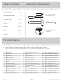 2
2
-
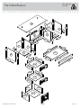 3
3
-
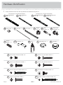 4
4
-
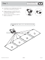 5
5
-
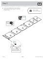 6
6
-
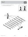 7
7
-
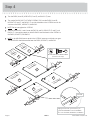 8
8
-
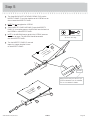 9
9
-
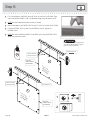 10
10
-
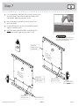 11
11
-
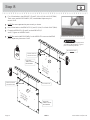 12
12
-
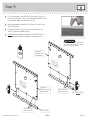 13
13
-
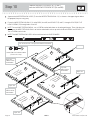 14
14
-
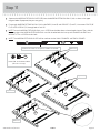 15
15
-
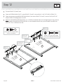 16
16
-
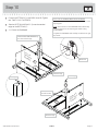 17
17
-
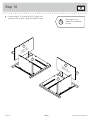 18
18
-
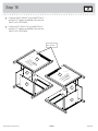 19
19
-
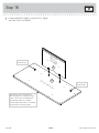 20
20
-
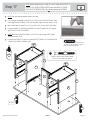 21
21
-
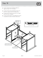 22
22
-
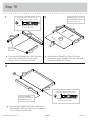 23
23
-
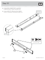 24
24
-
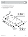 25
25
-
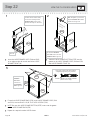 26
26
-
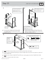 27
27
-
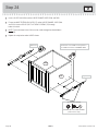 28
28
-
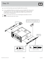 29
29
-
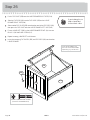 30
30
-
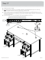 31
31
-
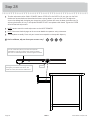 32
32
-
 33
33
-
 34
34
-
 35
35
-
 36
36
-
 37
37
-
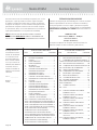 38
38
-
 39
39
-
 40
40
-
 41
41
-
 42
42
-
 43
43
-
 44
44
-
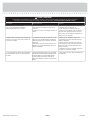 45
45
-
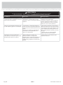 46
46
-
 47
47
-
 48
48


en otros idiomas
- français: Sauder 419954 Manuel utilisateur
- English: Sauder 419954 User manual
Artículos relacionados
-
Sauder Harbor View 417586 Manual de usuario
-
-
-
-
-
-
-
-
-
Otros documentos
-
 Closet Maid SSO2DW Manual de usuario
-
 John Louis Home JLH-805 Guía de instalación
-
Balt 91779-XXXX-XX Assembly Instructions
-
-
-
Insignia NS-HWG1641 Manual de usuario
-
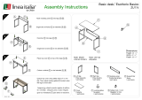 Linea Italia ZUD776 Guía de instalación
-
 Dateline Workshop PR250 Guía de instalación


