Sauder Costa L-Desk 419956 Assembly Manual
- Tipo
- Assembly Manual

Need help? Visit Sauder.com to view video assembly tips or chat with a live rep.
Prefer the phone? Call 1-800-523-3987.
Share your journey!
sauder.com
For all your
newfangled gadgetry.
NOTE: THIS INSTRUCTION
BOOKLET CONTAINS IMPORTANT
SAFETY INFORMATION.
PLEASE READ AND KEEP FOR
FUTURE REFERENCE.
English pg 1-44
Français pg 45-50
Español pg 51-56
Lot # 394629 09/27/16
Purchased: __________________
Be sure to give us a ring before
making any returns. 1-800-523-3987
L-Desk
Costa Collection | Model 419956

Part Identifi cation
Hardware Identifi cation
Assembly Steps
Français
Español
Safety
Warranty
Hammer
Not actual size
No. 2 Phillips Screwdriver
Tip Shown Actual Size
2-3
4-5
6-44
45-50
51-56
57-58
59
A RIGHT END (1)
B LEFT END (1)
C BOTTOM (2)
D RIGHT UPRIGHT (1)
D24 RIGHT DRAWER SIDE (2)
D25 LEFT DRAWER SIDE (2)
D28 LARGE RIGHT DRAWER SIDE (1)
D29 LARGE LEFT DRAWER SIDE (1)
D78 LARGE DRAWER BACK (1)
D109 DRAWER BACK (2)
D707 LARGE DRAWER BOTTOM (1)
D716 DRAWER BOTTOM (2)
E LEFT UPRIGHT (1)
F BACK (2)
G LEFT MODESTY PANEL (1)
H RIGHT FRONT LEG (2)
I END MOLDING (4)
J BOTTOM MOLDING (2)
K BACK MOLDING (2)
L
LONG MODESTY PANEL
MOLDING (2)
M KEYBOARD SHELF (1)
N RIGHT KEYBOARD UPRIGHT (1)
O RIGHT MODESTY PANEL (1)
P LEFT FRONT LEG (2)
Q RIGHT REAR LEG (2)
R LEFT REAR LEG (2)
S
SHORT MODESTY PANEL
MOLDING (2)
T ADJUSTABLE SHELF (1)
U LEFT KEYBOARD UPRIGHT (1)
V DRAWER FRONT (2)
W LARGE DRAWER FRONT (1)
X TOP (1)
Y RETURN TOP (1)
Z RIGHT PANEL (1)
AA LEFT PANEL (1)
BB DOOR (1)
Assembly Tools RequiredTable of Contents
Part Identifi cation
419956 www.sauder.com/servicesPage 2
Electric drill with 3/16" bit
(ONLY in indicated step)

å While not all parts are labeled, some of the parts will have a label or an inked letter on the edge
to help distinguish similar parts from each other. Use this part identifi cation to help identify similar parts.
Part Identifi cation
Now you know
our ABCs.
A
B
C
C
D
E
F
F
G
H
H
I
I
I
I
J
J
K
K
L
L
M
N
O
P
P
Q
Q
R
R
S
S
T
U
V
V
W
X
Y
Z
AA
BB
D109
D109
D716
D716
D707
D24
D24
D28
D29
D78
D25
D25
419956www.sauder.com/services
Page 3

Hardware Identifi cation
å Screws are shown actual size. You may receive extra hardware with your unit.
CONNECTOR PLATE - 2
14G
(EXTENSION SET SHOWN SEPARATED)
(EXTENSION SET SHOWN SEPARATED)
WIDE EXTENSION
RAIL - 2
CC
WIDE EXTENSION
SLIDE - 2
DD
EE
NARROW EXTENSION
RAIL - 4
FF
NARROW EXTENSION
SLIDE - 4
FILE ROD - 2
8B
40AW
CABINET RIGHT - 1
40AX
CABINET LEFT - 1
40AY
DRAWER RIGHT - 1
40AZ
DRAWER LEFT - 1
FILE GLIDE - 2
15B
12F
TWIST-LOCK
®
FASTENER - 24
10A
SLIDE CAM - 6
CAM SCREW - 37
8F
DOOR STOP - 1
4I
WOOD DOWEL - 16
15F
HIDDEN CAM - 37
1F
GLUE - 1
54M
14H
HINGE - 2
KNOB SET - 4
136K
419956 www.sauder.com/servicesPage 4

Hardware Identifi cation
å Screws are shown actual size. You may receive extra hardware with your unit.
BLACK 1-1/8" MACHINE SCREW - 4
21S
BLACK 9/16" LARGE HEAD SCREW - 16
1S
SILVER 1-1/8" FLAT HEAD SCREW - 4
10S
GROMMET CAP - 1
1P
18S
BROWN 1" FLAT HEAD SCREW - 4
CORD CLIP - 1
4P
3S
GOLD 5/16" FLAT HEAD SCREW - 24
METAL PIN - 4
1R
BLACK 1/2" FLAT HEAD SCREW - 4
11S
BLACK 9/16" FLAT HEAD SCREW - 26
32S
GROMMET - 1
10P
CAM COVER - 3
33P
RUBBER SLEEVE - 4
2R
BLACK 1-15/16" FLAT HEAD SCREW - 9
113S
30S
BLACK 1-9/16" FLAT HEAD SCREW - 12
419956www.sauder.com/services
Page 5

Step 1
Look for this icon. It means a
video assembly tip is available at
www.sauder.com/services/tips
A
B
(24 used)
12F
Do not tighten the TWIST-LOCK® FASTENERS in this step.
å
Assemble your unit on a carpeted fl oor or on the empty carton to
avoid scratching your unit or the fl oor.
å
To begin assembly, push a SAUDER TWIST-LOCK® FASTENER (12F)
into the large holes in the ENDS (A and B).
å
Repeat this step for the BOTTOMS (C), UPRIGHTS (D and E),
MODESTY PANELS (G and O), and KEYBOARD UPRIGHTS (N and U).
419956 www.sauder.com/servicesPage 6
STOP
If you purchased
the 419958
Hutch, assemble
that unit fi rst.

Step 2
A
D
B
E
å
Push thirty-seven HIDDEN CAMS (1F) into the edges of the
ENDS (A and B), UPRIGHTS (D and E), BACKS (F), LEFT
MODESTY PANEL (G), and RIGHT PANEL (Z).
1F
Arrow
(37 used)
Arrow
1F
Arrow
The arrow in the HIDDEN
CAM must point toward the
hole in the edge of the board.
Hole
F
F
G
Z
419956www.sauder.com/services
Page 7

Step 3
H
H
P
P
Q
Q
R
R
Z
AA
8F
8F
å
Turn thirty-seven CAM SCREWS (8F) into the LEGS (H, P, Q
and R) and PANELS (Z and AA).
(37 used)
419956 www.sauder.com/servicesPage 8

Step 4
å
Turn the ENDS (A and B), UPRIGHTS (D and E), and BACKS (F) over.
å
Turn twelve BLACK 9/16" FLAT HEAD SCREWS (32S) into the ENDS (A and B),
UPRIGHTS (D and E), and BACKS (F) until the shoulders of the SCREWS rest on the
surfaces of the ENDS, UPRIGHTS, and BACKS.
å
NOTE: Do not overtighten the SCREWS.
å
Slide the MOLDINGS (I) onto the ENDS (A and B) and UPRIGHTS (D and E). Slide the
MOLDINGS (K) onto the BACKS (F). Line up the grooves in the MOLDINGS over the
heads of the SCREWS in the ENDS, UPRIGHTS, and BACKS.
å
NOTE: If the MOLDING comes up o of the SCREWS, remove it and slide it on again.
The MOLDINGS should be centered over the ENDS, UPRIGHTS, and BACKS.
BLACK 9/16" FLAT HEAD SCREW
(12 used in this step)
32S
Shoulder
Apply pressure with your hands as you
guide the MOLDINGS over the SCREWS
and onto the ENDS, UPRIGHTS, and BACKS.
A
B
D
E
F
Surface
without
HIDDEN
CAMS
F
Surface
without
HIDDEN
CAMS
Surface without
HIDDEN CAMS
Surface without
HIDDEN CAMS
Surface without
HIDDEN CAMS
Surface without
HIDDEN CAMS
K
I
I
K
I
I
Shoulder
419956www.sauder.com/services
Page 9

Step 5
Shoulder
Apply pressure with your hands as you
guide the MOLDINGS over the SCREWS
and onto the ENDS, UPRIGHTS, and BACKS.
Shoulder
Apply pressure with your hands as you
guide the MOLDINGS over the SCREWS
and onto the ENDS, UPRIGHTS, and BACKS.
å
Turn six BLACK 9/16" FLAT HEAD SCREWS (32S) into the
MODESTY PANELS (G and O) until the shoulders of the SCREWS
rest on the surface of the MODESTY PANELS.
å
NOTE: Do not overtighten the SCREWS.
å
Slide the SHORT MODESTY PANEL MOLDINGS (S) onto the
MODESTY PANELS (G and O). Line up the groove in the MOLDING
over the heads of the SCREWS in the MODESTY PANELS.
å
NOTE: If the MOLDINGS come up o of the SCREWS, remove
them and slide them on again.
BLACK 9/16" FLAT HEAD SCREW
(6 used in this step)
32S
Be sure these edges
are even after the
MOLDING is slid on.
Be sure these edges
are even after the
MOLDING is slid on.
G
O
S
S
419956 www.sauder.com/servicesPage 10
Surface without TWIST-LOCK® FASTENERS
Surface without TWIST-LOCK® FASTENERS
Some assembly
(and snacks) required.

å
Flip the the MODESTY PANELS (G and O) over.
å
Turn eight BLACK 9/16" FLAT HEAD SCREWS (32S) into the MODESTY PANELS (G and O) until the shoulders of the
SCREWS rest on the surfaces of the MODESTY PANELS.
å
NOTE: Do not overtighten the SCREWS.
å
Slide the LONG MODESTY PANEL MOLDINGS (L) onto the MODESTY PANELS (G and O). Line up the groove in the
MOLDING over the heads of the SCREWS in the MODESTY PANEL.
å
NOTE: Be sure the MOLDINGS are positioned exactly as shown. If the MOLDINGS come up o of the SCREWS, remove
them and slide them on again. The MOLDINGS should be centered over the MODESTY PANELS.
Step 6
Be sure these edges
are even after the
MOLDING is slid on.
Be sure these edges
are even after the
MOLDING is slid on.
G
O
Apply pressure with your hands as you
guide the MOLDINGS over the SCREWS
and onto the ENDS, UPRIGHTS, and BACKS.
Apply pressure with your hands as you
guide the MOLDINGS over the SCREWS
and onto the ENDS, UPRIGHTS, and BACKS.
Shoulder
Shoulder
L
L
Angled edge
Angled edge
BLACK 9/16" FLAT HEAD SCREW
(8 used in this step)
32S
419956www.sauder.com/services
Page 11

Step 7
Fill the holes 1/4 to 1/2 full with GLUE.
Inspect the parts thoroughly before
assembling. Disassembly of glued
parts is extremely di cult.
Caution
!
54M
15F
These surfaces
should be even.
These surfaces
should be even.
Surface with
TWIST-LOCK®
FASTENERS
Edge with
TWIST-LOCK®
FASTENERS
1
2
End without hole
End without hole
419956 www.sauder.com/servicesPage 12
A
Q
H
å
First, fi ll two holes in the RIGHT END (A) 1/4 to 1/2 full with GLUE (54M). Then,
insert two WOOD DOWELS (15F) into the holes. Wipe away the excess GLUE.
å
NOTE: Be sure to position the parts exactly as shown and use the correct holes.
å
Now, fi ll the holes in the LEGS (H and Q) 1/4 to 1/2 full with GLUE (54M).
å
Fasten the LEGS (H and Q) to the RIGHT END (A). Tighten six HIDDEN CAMS.
å
NOTE: Be sure the WOOD DOWELS in the RIGHT END insert into the LEGS.
Wipe away the excess GLUE.

Step 8
Surface with
TWIST-LOCK®
FASTENERS
419956www.sauder.com/services
Page 13
Fill the holes 1/4 to 1/2 full with GLUE.
Inspect the parts thoroughly before
assembling. Disassembly of glued
parts is extremely di cult.
Caution
!
54M
15F
These surfaces
should be even.
Edge with
TWIST-LOCK®
FASTENERS
Edge with hole
These surfaces
should be even.
å
First, fi ll two holes in the LEFT END (B) 1/4 to 1/2 full with GLUE (54M). Then,
insert two WOOD DOWELS (15F) into the holes. Wipe away the excess GLUE.
å
NOTE: Be sure to position the parts exactly as shown and use the correct holes.
å
Now, fi ll the holes in the LEGS (P and R) 1/4 to 1/2 full with GLUE (54M).
å
Fasten the LEGS (P and R) to the LEFT END (B). Tighten six HIDDEN CAMS.
å
NOTE: Be sure the WOOD DOWELS in the LEFT END insert into the LEGS. Wipe
away the excess GLUE.
Edge with hole
15F
B
R
P

Step 9
E
419956 www.sauder.com/servicesPage 14
Fill the holes 1/4 to 1/2 full with GLUE.
Inspect the parts thoroughly before
assembling. Disassembly of glued
parts is extremely di cult.
Caution
!
54M
15F
These surfaces
should be even.
Edge with
TWIST-LOCK®
FASTENERS
End without hole
End without hole
å
First, fi ll two holes in the LEFT UPRIGHT (E) 1/4 to 1/2 full with GLUE (54M). Then,
insert two WOOD DOWELS (15F) into the holes. Wipe away the excess GLUE.
å
NOTE: Be sure to position the parts exactly as shown and use the correct holes.
å
Now, fi ll the holes in the LEGS (H and Q) 1/4 to 1/2 full with GLUE (54M).
å
Fasten the LEGS (H and Q) to the LEFT UPRIGHT (E). Tighten six HIDDEN CAMS.
å
NOTE: Be sure the WOOD DOWELS in the LEFT UPRIGHT insert into the LEGS.
Wipe away the excess GLUE.
Q
H
These surfaces
should be even.

Step 10
419956www.sauder.com/services
Page 15
Surface with
TWIST-LOCK®
FASTENERS
Fill the holes 1/4 to 1/2 full with GLUE.
Inspect the parts thoroughly before
assembling. Disassembly of glued
parts is extremely di cult.
Caution
!
54M
15F
These surfaces
should be even.
Edge with
TWIST-LOCK®
FASTENERS
Edge with hole
These surfaces
should be even.
å
First, fi ll two holes in the RIGHT UPRIGHT (D) 1/4 to 1/2 full with GLUE (54M). Then,
insert two WOOD DOWELS (15F) into the holes. Wipe away the excess GLUE.
å
NOTE: Be sure to position the parts exactly as shown.
å
Now, fi ll the holes in the LEGS (P and R) 1/4 to 1/2 full with GLUE (54M).
å
Fasten the LEGS (P and R) to the RIGHT UPRIGHT (D). Tighten six HIDDEN CAMS.
å
NOTE: Be sure the WOOD DOWELS in the RIGHT UPRIGHT insert into the
LEGS. Wipe away the excess GLUE.
Edge with hole
15F
R
P
D

Step 11
å
Separate the WIDE EXTENSION SLIDES (DD) from the WIDE EXTENSION RAILS (CC) as shown in the upper diagram
below. Be prepared, the parts are greasy.
å
Fasten the WIDE EXTENSION RAILS (CC) to the LEFT ENDS (B) and LEFT UPRIGHTS (E). Use four GOLD 5/16" FLAT
HEAD SCREWS (3S) through holes #1 and #3.
å
NOTE: For each WIDE EXTENSION RAIL, turn a SCREW into the hole shown in the enlarged diagram. Then, slide the inner
cartridge of the WIDE EXTENSION RAIL in to fi nd the other hole that lines up with the hole in the ENDS and UPRIGHTS.
Turn a SCREW into this hole.
å
NOTE: The WIDE EXTENSION SLIDES will be used later for the LARGE DRAWERS.
Open end
Push the black lever in and pull the SLIDE from the RAIL.
GOLD 5/16" FLAT HEAD SCREW
(4 used in this step)
3S
B
E
Edge with
TWIST-LOCK®
FASTENERS
Surface with
TWIST-LOCK®
FASTENERS
Surface with
TWIST-LOCK®
FASTENERS
Open end
Separate the WIDE EXTENSION SET (CC and DD)
from the NARROW EXTENSION SET (EE and FF).
P
H
1
3
2
4
1
3
2
4
DD CC
CC
CC
419956 www.sauder.com/servicesPage 16

Step 12
B
E
Push the black lever in and pull the SLIDE from the RAIL.
å
Separate the NARROW EXTENSION SLIDES (FF) from the NARROW EXTENSION RAILS (EE) as shown in the upper
diagram below. Be prepared, the parts are greasy.
å
Fasten four NARROW EXTENSION RAILS (EE) to the LEFT END (B) and UPRIGHT (E). Use eight GOLD 5/16" FLAT HEAD
SCREWS (3S) through holes #1 and #3.
å
NOTE: For each NARROW EXTENSION RAIL, turn a SCREW into the hole shown in the enlarged diagram. Then, slide the
inner cartridge of the NARROW EXTENSION RAIL in to fi nd the other hole that lines up with the hole in the ENDS and
UPRIGHTS. Turn a SCREW into this hole.
å
NOTE: The NARROW EXTENSION SLIDES will be used later for the SMALL DRAWERS.
GOLD 5/16" FLAT HEAD SCREW
(8 used in this step)
3S
EE
EE
EE
EE
EE
FF
Open end
Open end
1
3
2
4
1
3
2
4
1
3
2
4
1
3
2
4
419956www.sauder.com/services
Page 17
3
4

Step 13
å
Fasten the BACKS (F) to the ENDS (A and B). Tighten four
HIDDEN CAMS.
Surface with HIDDEN CAMS
Surface with HIDDEN CAMS
The BACK
MOLDINGS (K)
should be here.
B
A
F
F
419956 www.sauder.com/servicesPage 18

Step 14
A
B
å
Fasten the BOTTOMS (C) to the ENDS (A and B).
Tighten four TWIST-LOCK® FASTENERS.
å
Slide the BOTTOM MOLDINGS* (J) onto the
notched edges of the BOTTOMS (C).
å
*U.S. Patent No. 5,499,886
How to use the SAUDER TWIST-LOCK
®
FASTENER
1. Insert the dowel end of the FASTENER into the hole of the
adjoining part.
NOTE: The dowel end of the FASTENER must remain fully
inserted in the hole of the adjoining part while locking
the FASTENER.
2. Tighten the FASTENER with a Phillips screwdriver as tight
as possible.
Dowel end
The groove should be
closer to this edge.
The groove should be
closer to this edge.
C
C
J
J
419956www.sauder.com/services
Page 19
Surface with
TWIST-LOCK®
FASTENERS
Surface with
TWIST-LOCK®
FASTENERS

Step 15
å
Fasten the UPRIGHTS (D and E) to the BACKS (F) and
BOTTOMS (C). Tighten four TWIST-LOCK® FASTENERS
and four HIDDEN CAMS.
D
E
F
F
C
C
Surface without
TWIST-LOCK®
FASTENERS
Surface without
TWIST-LOCK®
FASTENERS
419956 www.sauder.com/servicesPage 20
Don't worry. It isn't
Rome. This can be built
in a day.

Step 16
419956www.sauder.com/services
Page 21
å
Skip this step and the next step if you did not purchase
the 419958 Hutch.
å
The 419956 L-Desk was made to hold the 419958 Hutch
There are two options for fastening the Hutch to the
L-Desk as shown.
419956 L-Desk
419958 Hutch
419956 L-Desk
Diagram 1
Diagram 2
419958 Hutch

Step 17
å
Locate the TOP (X) and RETURN TOP (Y) and
lay them on packing foam or magazines fl at on
the fl oor as shown.
å
With a drill and 3/16" drill bit, fi nish drilling
through the four holes shown based on your
Diagram 1 or 2 preference in step 16.
Drill through these two small
holes for Diagram 2 confi guration.
Drill through these two small
holes for Diagram 1 confi guration.
Drill through these two small
holes for Diagram 1 confi guration.
Drill through these two small
holes for Diagram 2 confi guration.
These eight
holes must
be here.
CAUTION
Make sure you have
packing foam or
throw away material
underneath the tops
near the drill area.
419956 www.sauder.com/servicesPage 22
X
Y
Meet Parts (X and Y). These components
have been engineered to be lighter,
stronger, faster… well ok. Not technically
faster. But defi nitely makes for a sturdier
L Desk that’s easier to assemble and
friendlier to the environment.

Step 18
419956www.sauder.com/services
Page 23
Fill the holes 1/4 to 1/2 full with GLUE.
Inspect the parts thoroughly before
assembling. Disassembly of glued
parts is extremely di cult.
Caution
!
15F
å
First, fi ll the holes in the LEGS (H, P, Q, and R) 1/4 to 1/2 full with
GLUE (54M). Then, insert the WOOD DOWELS (15F) into the holes.
Wipe away the excess GLUE (54M).
å
Now, fi ll the four holes in the TOP (X) 1/4 to 1/2 full with GLUE.
å
Fasten the LEFT END (B) and LEFT UPRIGHT (E) to the TOP (X).
Tighten four TWIST-LOCK® FASTENERS. Wipe away the excess glue.
å
NOTE: Be sure the WOOD DOWELS insert into the holes in the TOP.
B
E
X
This large hole must be here.
H
P
Q
R
STOP
If you purchased
the 419958
Hutch, assemble
that unit fi rst.
54M

å
Fasten the LEFT MODESTY PANEL (G) to the TOP (X).
Tighten two TWIST-LOCK® FASTENERS.
å
Fasten the LEFT MODESTY PANEL (G) to the LEFT
UPRIGHT (E). Use three BLACK 1-15/16" FLAT
HEAD SCREWS (113S).
Step 19
G
X
419956 www.sauder.com/servicesPage 24
BLACK 1-15/16" FLAT HEAD SCREW
(3 used in this step)
113S
E
Surface with TWIST-LOCK® FASTENERS

Step 20
G
X
419956www.sauder.com/services
Page 25
å
Fasten the RIGHT MODESTY PANEL (O) to the TOP (X).
Tighten one TWIST-LOCK® FASTENER.
å
Fasten the RIGHT MODESTY PANEL (O) to the LEFT
MODESTY PANEL (G). Use three BLACK 1-15/16" FLAT
HEAD SCREWS (113S).
BLACK 1-15/16" FLAT HEAD SCREW
(3 used in this step)
113S
O

Step 21
Z
AA
å
Fasten the LEFT PANEL (AA) to the RIGHT PANEL (Z).
Tighten three HIDDEN CAMS.
Surface with
HIDDEN CAMS
419956 www.sauder.com/servicesPage 26

Step 22
Z
AA
419956www.sauder.com/services
Page 27
å
Fasten the PANELS (Z and AA) to the MODESTY
PANELS (O and G). Use four SILVER 1-1/8" FLAT HEAD
SCREWS (10S). Tighten two HIDDEN CAMS.
å
Fasten two CONNECTOR PLATES (14G) to the TOP (X).
Use eight BLACK 9/16" LARGE HEAD SCREWS (1S).
SILVER 1-1/8" FLAT HEAD SCREW
(4 used in this step)
10S
14G
BLACK 9/16" LARGE HEAD SCREW
(8 used in this step)
1S
X
G
O

Step 23
Fill the holes 1/4 to 1/2 full with GLUE.
Y
419956 www.sauder.com/servicesPage 28
54M
15F
å
First, fi ll the holes in the LEGS (H, P, Q, and R) 1/4 to 1/2 full
with GLUE (54M). Then, insert the WOOD DOWELS (15F) into
the holes. Wipe away the excess GLUE (54M).
å
Now, fi ll the four holes in the TOP (Y) 1/4 to 1/2 full with GLUE.
å
Fasten the RIGHT END (A) and RIGHT UPRIGHT (D) to the
TOP (Y). Tighten four TWIST-LOCK® FASTENERS. Wipe away
the excess glue.
å
NOTE: Be sure the WOOD DOWELS insert into the holes in
the TOP.
Q
H
P
R
A
D
Inspect the parts thoroughly before
assembling. Disassembly of glued
parts is extremely di cult.
Caution
!

Step 24
419956www.sauder.com/services
Page 29
å
This step will require a second person. Carefully stand
your unit upright.
å
Fasten the RETURN TOP (Y) to the TOP (X). Use eight
BLACK 9/16" LARGE HEAD SCREWS (1S).
å
Fasten the MODESTY PANEL (O) to the RETURN TOP (Y).
Tighten the TWIST-LOCK® FASTENER.
BLACK 9/16" LARGE HEAD SCREW
(8 used in this step)
1S
Y
X
O

å
Fasten the RIGHT MODESTY PANEL (O) to the
RIGHT UPRIGHT (D). Use three BLACK 1-15/16"
FLAT HEAD SCREWS (113S).
Step 25
BLACK 1-15/16" FLAT HEAD SCREW
(3 used in this step)
113S
D
O
419956 www.sauder.com/servicesPage 30

Step Step 26
Surface with
TWIST-LOCK®
FASTENERS
Surface with
TWIST-LOCK®
FASTENERS
U
N
40AW
40AW
40AX
40AX
å
Fasten the CABINET RIGHT (40AW) to the RIGHT
UPRIGHT (N) and the CABINET LEFT (40AX) to
the LEFT UPRIGHT (U). Use four GOLD 5/16" FLAT
HEAD SCREWS (3S).
Roller end
Roller end
GOLD 5/16" FLAT HEAD SCREW
(4 used in this step)
3S
Finished edge
Finished edge
419956www.sauder.com/services
Page 31

Step Step 27
419956 www.sauder.com/servicesPage 32
å
You have the option to mount your KEYBOARD
SHELF (M) underneath the RETURN TOP (Y) or
TOP (X) as shown.
å
Follow the upper diagram to fasten your
KEYBOARD (M) on the right side or the
lower diagram to fasten your
KEYBOARD (M) to left side.
M
M
X
X
Y
Y
KEYBOARD ON THE LEFT
KEYBOARD ON THE RIGHT

Step
å
Fasten the KEYBOARD UPRIGHTS (N and U) to the TOP (X).
Tighten four TWIST-LOCK® FASTENERS.
å
Fasten the LEFT KEYBOARD UPRIGHT (U) to the TOP (X)
and the RIGHT KEYBOARD UPRIGHT (N) to the RETURN
TOP (Y). Tighten four TWIST-LOCK® FASTENERS.
Step 28
X
X
Y
Y
KEYBOARD ON THE LEFT
KEYBOARD ON THE RIGHT
N
N
U
U
The CABINET
RAILS should be
facing each other.
The CABINET
RAILS should be
facing each other.
419956www.sauder.com/services
Page 33

Step Step 29
M
å
Fasten the DRAWER RIGHT (40AY) and DRAWER LEFT (40AZ) to
the KEYBOARD SHELF (M). Use four BROWN 1" FLAT
HEAD SCREWS (18S).
å
Push a CORD CLIP (4P) into the hole in the KEYBOARD SHELF (M).
å
NOTE: The CORD CLIP is used to hold your keyboard cord against
the KEYBOARD SHELF.
Roller end
Roller end
40AZ
40AZ
40AY
40AY
4P
419956 www.sauder.com/servicesPage 34
BROWN 1" FLAT HEAD SCREW
(4 used in this step)
18S
This hole must be
closer to this edge.

Step 30
å
Fasten two HINGES (14H) to the DOOR (BB). Use four
BLACK 1/2" FLAT HEAD SCREWS (11S).
14H
BLACK 1/2" FLAT HEAD SCREW
(4 used in this step)
11S
BB
419956www.sauder.com/services
Page 35

Step Step 31
å
Before fastening the DOOR to your unit, be sure the mounting screw is against the
stops as shown in the right diagram. If it isn't, loosen the mounting screw to slide it
against the stops. Then tighten the mounting screw.
å
Fasten the DOOR (BB) to the RIGHT END (A) as shown in the lower diagram.
Use the screws in the HINGES. You should start each SCREW a few turns before
completely tightening any of them.
å
Fasten a KNOB SET (136K) to the DOOR (BB). Use a BLACK 1-1/8"
MACHINE SCREW (21S).
å
Push the DOOR STOP (4I) into the RIGHT UPRIGHT (D).
å
See the next step for DOOR adjustments.
Mounting
screw
Stop
Hinge
BLACK 1-1/8" MACHINE SCREW
(1 used in this step)
21S
419956 www.sauder.com/servicesPage 36
4I
136K
D
A
BB

Step Step 32
å
Refer to the enlarged diagram to identify the parts on
the HINGES.
å
The DOOR may need some adjustments. Follow the text
below to make needed adjustments.
å
DOOR ADJUSTMENTS:
To adjust the DOORS from side to side (horizontal), turn the
adjusting screw in or out.
å
To adjust the DOOR up and down (vertical), loosen both
vertical adjustment screws. Move the DOOR up or down to the
desired location. Tighten the screws after making adjustments.
å
To adjust the DOOR in or out (depth), loosen the mounting
screw one turn and move the DOOR in or out, as needed.
Tighten the mounting screw after making adjustments.
(vertical adjustment)
Adjusting screw (horizontal)
Mounting screw (depth)
419956www.sauder.com/services
Page 37

Step Step 33
VIEW THE T-LOCK BOX VIDEO
å
Fasten the LARGE DRAWER BACK (D78) to the LARGE DRAWER SIDES (D28
and D29). Use four BLACK 1-9/16" FLAT HEAD SCREWS (30S).
å
NOTE: Be sure the LARGE DRAWER BOTTOM (D707) inserts into the groove
of the LARGE DRAWER BACK (D78).
12
3
å
Insert the LARGE DRAWER SIDES (D28 and D29)
at an angle into the slot at each end of the LARGE
DRAWER FRONT (W).
å
Slide the LARGE DRAWER BOTTOM (D707) into the
grooves in the LARGE DRAWER SIDES (D28 and D29)
and LARGE DRAWER FRONT (W).
The tabs should insert freely
into the slots. Gently tilt the
DRAWER SIDES side to side
until the tabs slip into the slots.
Groove
30S
Start each screw a few turns before
completely tightening any of them.
BLACK 1-9/16" FLAT HEAD SCREW
(4 used in this step)
Be sure the DRAWER
BOTTOM inserts into the
DRAWER FRONT groove.
D28
D29
D707
D707
D28
D29
D78
D29
W
W
Unfi nished
surface
D28
Be sure the
DRAWER
BOTTOM
inserts into
the DRAWER
BACK groove.
With the palm of your hand,
tap the DRAWER BOTTOM
down into the groove.
419956 www.sauder.com/servicesPage 38

Step Step 34
å
NOTE: The SMALL drawers will only use two SCREWS per drawer. Refer to the diagram.
å
Fasten the SMALL DRAWER BACK (D109) to the SMALL DRAWER SIDES (D24 and D25). Use two BLACK 1-9/16" FLAT
HEAD SCREWS (30S).
å
NOTE: Be sure the SMALL DRAWER BOTTOM (D716) inserts into the groove of the SMALL DRAWER BACK (D109).
å
Repeat this step for the other SMALL drawer.
12
3
å
Insert the SMALL DRAWER SIDES (D24 and D25)
at an angle into the slot at each end of the SMALL
DRAWER FRONT (V).
å
Slide the SMALL DRAWER BOTTOM (D716) into the
grooves in the SMALL DRAWER SIDES (D24 and D25)
and SMALL DRAWER FRONT (V).
The tabs should insert freely
into the slots. Gently tilt the
DRAWER SIDES side to side
until the tabs slip into the slots.
Groove
30S
Start each screw a few turns before
completely tightening any of them.
BLACK 1-9/16" FLAT HEAD SCREW
(4 used in this step)
Be sure the DRAWER
BOTTOM inserts into the
DRAWER FRONT groove.
D24
D25
D716
D716
D24
D25
D109
D25
V
V
Unfi nished
surface
D24
Be sure the
DRAWER
BOTTOM
inserts into
the DRAWER
BACK groove.
NOTE: Do not use this hole
in the SMALL drawers. This
hole will be used in Step 37.
With the palm of your hand,
tap the DRAWER BOTTOM
down into the groove.
VIEW THE T-LOCK BOX VIDEO
419956www.sauder.com/services
Page 39

Step Step 35
å
Insert a SLIDE CAM (10A) into the LARGE DRAWER SIDES (D28 and D29).
å
Fasten two WIDE EXTENSION SLIDES (DD) to the LARGE DRAWER
SIDES (D28 and D29). Use four GOLD 5/16" FLAT HEAD SCREWS (3S)
through holes #1 and #4.
å
NOTE: The screw head in the CAM must be visible through the slotted hole
in the SLIDE.
D28
D29
Open end
Open end
1
2
3
3
1
2
Screw head - turn CAM to line up holes in
the SLIDES with holes in DRAWER SIDES
10A
10A
4
4
GOLD 5/16" FLAT HEAD SCREW
(4 used in this step)
3S
(4 screws per drawer)
419956 www.sauder.com/servicesPage 40
DD
DD
If you're doing this to
help a friend, don't
leave without a bite.

Step Step 36
å
Push a FILE GLIDE (15B) onto the LARGE RIGHT DRAWER SIDE (D28).
å
Slide the FILE RODS (8B) into the FILE GLIDE (15B) on the LARGE RIGHT
DRAWER SIDE (D28).
å
Slide another FILE GLIDE (15B) onto the other end of the FILE RODS (8B), then
press this FILE GLIDE over the LARGE LEFT DRAWER SIDE (D29).
å
Fasten a KNOB SET (136K) to the LARGE DRAWER FRONT (W). Use one
BLACK 1-1/8" MACHINE SCREW (21S).
Insert the FILE RODS into
the holes in the FILE GLIDES
depending on your fi le sizes.
15B
15B
8B
8B
D29
D28
BLACK 1-1/8" MACHINE SCREW
(1 used for the KNOB SET)
21S
136K
W
419956www.sauder.com/services
Page 41

Step Step 37
å
Insert a SLIDE CAM (10A) into the SMALL DRAWER SIDES (D24 and D25).
å
Fasten two NARROW EXTENSION SLIDES (FF) to the SMALL DRAWER SIDES (D24 and D25). Use
two BLACK 1-9/16" FLAT HEAD SCREWS (30S) through hole #1, through the SMALL DRAWER
SIDES, and into the SMALL DRAWER BACK (D109). Use two GOLD 5/16" FLAT HEAD SCREWS (3S)
through hole #3.
å
NOTE: The screw head in the CAM must be visible through the slotted hole in the SLIDE.
å
Fasten a KNOB SET (136K) to a DRAWER FRONT (V). Use a BLACK 1-1/8" MACHINE SCREW (21S).
å
Repeat this step for the other SMALL drawer.
D24
D25
Open end
Open end
1
2
3
1
2
3
FF
FF
Screw head - turn CAM to line up holes in
the SLIDES with holes in DRAWER SIDES
10A
10A
D109
GOLD 5/16" FLAT HEAD SCREW
(4 used in this step)
3S
(2 screws per drawer)
BLACK 1-9/16" FLAT HEAD SCREW
(4 used in this step)
30S
(2 screws per drawer)
BLACK 1-1/8" MACHINE SCREW
(2 used for the KNOB SET)
21S
419956 www.sauder.com/servicesPage 42
V
(4 used in this step)
136K

Step
å
Insert the GROMMET (10P) and GROMMET CAP (1P) into the large hole in the TOP (X).
å
To insert the KEYBOARD SHELF (M) into your unit, tip the front of the KEYBOARD SHELF down and drop the rollers on
the KEYBOARD SHELF behind the rollers on the unit. Lift the front of the KEYBOARD SHELF up and slide it into the unit.
å
NOTE: Before inserting the drawers, be sure the INNER CARTRIDGE in the EXTENSION RAILS on your unit is all the way
forward. The INNER CARTRIDGE should click into place against the BLACK TAB.
å
To insert the drawers into your unit, line up the EXTENSION SLIDES on the drawer with the EXTENSION RAILS on the unit
and push the drawers into the unit until the drawers are fully inserted. The drawers will push in hard until they are all the
way in, then they will slide in and out easier.
å
Push the RUBBER SLEEVES (2R) over the METAL PINS (1R). Insert the METAL PINS into the hole locations of your choice
in the RIGHT END (A) and RIGHT UPRIGHT (D). Set the ADJUSTABLE SHELF (T) onto the METAL PINS.
å
Push a CAM COVER (33P) onto each HIDDEN CAM.
Step 38
1P
10P
Place the roller on the SLIDE
behind the roller on the RAIL.
X
70 lbs.
50 lbs.
35 lbs.
20 lbs.
25 lbs.
BOTTOM
40 lbs.
20 lbs.
419956www.sauder.com/services
Page 43
(4 used)
2R
1R
(3 used)
To cover HIDDEN CAMS
33P
A
D
M
T
Extension Rail
Black tab
Click the inner cartridge into place against the black tab.
Front
Inner cartridge

Step 39
And to celebrate, why not share your success story?
å
To make adjustments to the small drawers, loosen SCREW #3 in the SLIDES a 1/4 turn, then turn the CAM clockwise or
counter-clockwise. Notice how the drawer raises or lowers as you turn the CAM. The higher the screw in the oblong hole,
the higher your drawer front will be. The lower the screw, the lower the drawer front. By adjusting the drawers this way, it
will help the DRAWER FRONTS line up better when closed. Tighten the SCREW when fi nished with adjustments.
å
To make adjustments to the large drawer, loosen SCREW #4 in the SLIDES a 1/4 turn, then turn the CAM clockwise or
counter-clockwise. Notice how the drawer raises or lowers as you turn the CAM. The higher the screw in the oblong hole,
the higher your drawer front will be. The lower the screw, the lower the drawer front. By adjusting the drawers this way, it
will help the DRAWER FRONTS line up better when closed. Tighten the SCREW when fi nished with adjustments.
å
NOTE: Please read the back pages of the instruction booklet for important safety information.
å
This completes assembly. Clean with your favorite furniture polish or a damp cloth. Wipe dry.
The higher the screw in the oblong hole,
the higher your drawer front will be. The
lower the screw, the lower the drawer front.
The higher the screw in the oblong hole,
the higher your drawer front will be. The
lower the screw, the lower the drawer front.
Loosen screw #3 a 1/4 turn, turn the cam a 1/4 turn
maximum in both the clockwise and counter-clockwise
directions to make adjustments, and then tighten screw #3.
Loosen screw #4 a 1/4 turn, turn the cam a 1/4 turn
maximum in both the clockwise and counter-clockwise
directions to make adjustments, and then tighten screw #4.
419956 www.sauder.com/servicesPage 44
The drawers should be in the unit
when making adjustments. They
are shown out of the unit for clarity.

A l’usage exclusif du
Canada Noter la date
d’achat de cet élément
et conserver le livret
pour future référence.
Pour contacter Sauder
en ce qui concerne cet
élément, faire référence
au numéro de lot et
numéro de modèle en
appelant notre numéro
sans frais.
Lot nº : ____________
Date de
l’achat: ____________
LISTE DE PIÈCES
REFERENCE DESCRIPTION QUANTITÉ
LISTE DE PIÈCES
REFERENCE DESCRIPTION QUANTITÉ
NOUS SOMMES LA POUR VOUS AIDER!
Nous faisons de notre mieux pour nous assurer que votre meuble
arrive dans d’excellentes conditions. Nos représentants du service
Clientèle sont aimables et prêts à vous aider au cas où une pièce
aurait été endommagée ou manquerait (ou si vous aviez besoin
d’aide pour l’assemblage). NE RAMENEZ PAS LE MEUBLE AU
MAGASIN. Au Canada, composez ce numéro d’appel gratuit:
1-800-523-3987
Du lundi au vendredi, de 9 heures du matin à
5:30 heures du soir (horaire Côte Est)
(sauf jours fériés)
Si une pièce a besoin d’être remplacée, la pièce de remplacement
sera envoyée dans les 48 heures. (Sauf week-ends et jours fériés)
Utilisez les instructions d’assemblage en français avec les
schémas étape par étape du manuel d’instruction en anglais.
Chaque étape en français correspond à la même étape
en anglais. La pièce devant être attachée à l’élément est
représentée en gris sur les schémas de chaque étape pour plus
de précision. Comparer la “Liste de pièces” ci-dessous avec
la “PART IDENTIFICATION” du manuel en anglais pour vous
familiariser avec les pièces avant l’assemblage.
REMARQUE : CE MANUEL D’INSTRUCTIONS CONTIENT
D’IMPORTANTES INFORMATIONS RELATIVES À LA SÉCURITÉ.
À LIRE ET CONSERVER POUR TOUTE RÉFÉRENCE FUTURE.
(ENSEMBLE DE GLISSIÈRE ILLUSTRÉ À PART)
CC GLISSIÈRE D'EXTENSION LARGE ..........................................2
DD COULISSE D’EXTENSION LARGE...........................................2
EE GLISSIÈRE D'EXTENSION ÉTROITE ......................................4
FF COULISSE D’EXTENSION ÉTROITE ......................................4
40AW ÉLÉMENT DROITE ................................................................................1
40AX ÉLÉMENT GAUCHE .............................................................................1
40AY TIROIR DROIT ..........................................................................................1
40AZ TIROIR GAUCHE ....................................................................................1
10A EXCENTRIQUE DE COULISSE ...................................................6
8B TIGE DE DOSSIER ...............................................................................2
15B ARMATURE POUR DOSSIERS ...................................................2
1F EXCENTRIQUE ESCAMOTABLE ...........................................37
8F VIS D'EXCENTRIQUE ......................................................................37
12F FIXATION TWIST-LOCK®..............................................................24
15F CHEVILLE EN BOIS ..........................................................................16
14G PLAQUE DE CONNECTEUR ........................................................2
14H CHARNIÈRE...............................................................................................2
4I ARRÊT DE PORTE .................................................................................1
136K ENSEMBLE DE BOUTONS ............................................................4
54M COLLE ............................................................................................................1
1P COUVERCLE DE PASSE-CÂBLES ...........................................1
4P CLIP POUR CORDONS.....................................................................1
10P PASSE-CÂBLES ......................................................................................1
33P COUVERCLE D'EXCENTRIQUE .................................................3
1R GOUPILLE EN MÉTAL .......................................................................4
2R MANCHON EN CAOUTCHOUC...............................................4
1S VIS TÊTE LARGE 14 mm NOIRE ............................................16
3S VIS TÊTE PLATE 8 mm DORÉE .............................................24
10S VIS TÊTE PLATE 28 mm ARGENTÉE ..................................4
11S VIS TÊTE PLATE 13 mm NOIRE ...............................................4
18S VIS TÊTE PLATE 25 mm MARRON .......................................4
21S VIS À MÉTAUX 28 mm NOIRE ..................................................4
30S VIS TÊTE PLATE 40 mm NOIRE ............................................12
32S VIS TÊTE PLATE 14 mm NOIRE ............................................26
113S VIS TÊTE PLATE 49 mm NOIRE ..............................................9
A EXTRÉMITÉ DROITE ............................................................................1
B EXTRÉMITÉ GAUCHE ........................................................................1
C DESSOUS ...................................................................................................2
D MONTANT DROIT .................................................................................1
D24 CÔTÉ DROIT DE TIROIR .................................................................2
D25 CÔTÉ GAUCHE DE TIROIR ..........................................................2
D28 CÔTÉ DROIT DE GRAND TIROIR .............................................1
D29 CÔTÉ GAUCHE DE GRAND TIROIR ....................................... 1
D78 ARRIÈRE DE GRAND TIROIR ........................................................1
D109 ARRIÈRE DE TIROIR ...........................................................................2
D707 FOND DE GRAND TIROIR...............................................................1
D716 FOND DE TIROIR ..................................................................................2
E MONTANT GAUCHE ...........................................................................1
F ARRIÈRE .......................................................................................................2
G VOILE DE FOND GAUCHE.............................................................1
H PIED AVANT DROIT ............................................................................2
I MOULURE D’EXTRÉMITÉ ...............................................................4
J MOULURE DE DESSOUS ..............................................................2
K MOULURE ARRIÈRE ...........................................................................2
L MOULURE DE LONG VOILE DE FOND .............................2
M TABLETTE DE CLAVIER ....................................................................1
N MONTANT DROIT POUR CLAVIER .........................................1
O VOILE DE FOND DROIT ...................................................................1
P PIED AVANT GAUCHE ......................................................................2
Q PIED ARRIÈRE DROIT ........................................................................2
R PIED ARRIÈRE GAUCHE .................................................................2
S MOULURE DE COURT VOILE DE FOND ...........................2
T TABLETTE RÉGLABLE .......................................................................1
U MONTANT GAUCHE DE TABLETTE DE CLAVIER ......1
V DEVANT DE TIROIR ............................................................................2
W DEVANT DE GRAND TIROIR .........................................................1
X DESSUS.........................................................................................................1
Y DESSUS DE RETOUR .........................................................................1
Z PANNEAU DROIT ...................................................................................1
AA PANNEAU GAUCHE ............................................................................1
BB PORTE ............................................................................................................1
Bureau en LModèle 419956
419956www.sauder.com/services
Page 45

ÉTAPE 7
ÉTAPE 8
Attention: Examiner bien les pièces avant d'assembler. Il est di cile de
séparer des pièces une fois encollées.
Tout d'abord, remplir les deux trous dans l’EXTRÉMITÉ GAUCHE (B) de
1/4 à 1/2 pleins de COLLE (54M). Insérer ensuite deux CHEVILLES EN
BOIS (15F) dans les trous. Nettoyer l'excès de COLLE.
REMARQUE : S’assurer de placer ces pièces exactement comme
l’indiquent le schéma et utiliser les trous appropriés.
Maintenant, remplir les trous dans les PIEDS (P et R) de 1/4 à 1/2 pleins
de COLLE (54M).
Fixer les PIEDS (P et R) à l'EXTRÉMITÉ GAUCHE (B). Serrer six
EXCENTRIQUES ESCAMOTABLES.
REMARQUE : S’assurer d’insérer les CHEVILLES EN BOIS de
l'EXTRÉMITÉ GAUCHE dans les PIEDS. Nettoyer l'excès de COLLE.
ÉTAPE 7
Attention: Examiner bien les pièces avant d'assembler. Il est di cile de
séparer des pièces une fois encollées.
Tout d'abord, remplir les deux trous dans l’EXTRÉMITÉ DROITE (A) de 1/4 à
1/2 pleins de COLLE (54M). Insérer ensuite deux CHEVILLES EN BOIS (15F)
dans les trous. Nettoyer l'excès de COLLE.
REMARQUE : S’assurer de placer ces pièces exactement comme
l’indiquent le schéma et utiliser les trous appropriés.
Maintenant, remplir les trous dans les PIEDS (H et Q) de 1/4 à 1/2 pleins
de COLLE (54M).
Fixer les PIEDS (H et Q) à l'EXTRÉMITÉ DROITE (A). Serrer six
EXCENTRIQUES ESCAMOTABLES.
REMARQUE : S’assurer d’insérer les CHEVILLES EN BOIS de
l'EXTRÉMITÉ DROITE dans les PIEDS. Nettoyer l'excès de COLLE.
ÉTAPE 6
Retourner les VOILES DE FOND (G et O).
Faire tourner huit VIS TÊTE PLATE 14 mm NOIRES (32S) dans les
VOILES DE FOND (G et O) jusqu'à ce que l'épaulement des VIS repose
sur la surface du VOILE DE FOND.
REMARQUE : Ne pas trop serrer les VIS.
Enfi ler les MOULURES DE LONG VOILE DE FOND (L) sur les VOILES DE
FOND (G et O). Aligner la rainure de la MOULURE sur les têtes des VIS
dans le VOILE DE FOND.
REMARQUE : S’assurer de positionner les MOULURES exactement
comme l’indique le schéma. Si la MOULURE soulève au-dessus les VIS,
l'enlever et l'enfi ler de nouveau. Les MOULURES devraient être centrées
sur les VOILES DE FOND.
ÉTAPE 4
Retourner les EXTRÉMITÉS (A et B), les MONTANTS (D et E) et
les ARRIÈRES (F).
Faire tourner douze VIS TÊTE PLATE 14 mm NOIRES (32S) dans les
EXTRÉMITÉS (A et B), les MONTANTS (D et E) et les ARRIÈRES (F) jusqu'à
ce que l'épaulement des VIS repose sur les surfaces des EXTRÉMITÉS,
MONTANTS et ARRIÈRES.
REMARQUE : Ne pas trop serrer les VIS.
Enfi ler les MOULURES (I) sur les EXTRÉMITÉS (A et B) et les
MONTANTS (D et E). Enfi ler les MOULURES (K) sur les
ARRIÈRES (F). Aligner la rainure des MOULURES sur les têtes des VIS
dans les EXTRÉMITÉS, MONTANTS et ARRIÈRES.
REMARQUE : Si la MOULURE soulève au-dessus les VIS, l'enlever et
l'enfi ler de nouveau. Les MOULURES devraient être centrées sur les
EXTRÉMITÉS, MONTANTS et ARRIÈRES.
ÉTAPE 5
Faire tourner six VIS TÊTE PLATE 14 mm NOIRES (32S) dans les VOILES
DE FOND (G et O) jusqu'à ce que l'épaulement des VIS repose sur la
surface des VOILES DE FOND.
REMARQUE : Ne pas trop serrer les VIS.
Enfi ler les MOULURES DE COURT VOILE DE FOND (S) sur les VOILES
DE FOND (G et O). Aligner la rainure de la MOULURE sur les têtes des
VIS dans les VOILES DE FOND.
REMARQUE : Si la MOULURE soulève au-dessus les VIS, l'enlever et
l'enfi ler de nouveau.
ÉTAPE 3
Faire tourner trente et sept VIS D'EXCENTRIQUE (8F) dans les
PIEDS (H, P, Q et R) et les PANNEAUX (Z et AA).
ÉTAPE 2
Enfoncer trente et sept EXCENTRIQUES ESCAMOTABLES (1F) dans les
chants des EXTRÉMITÉS (A et B), les MONTANTS (D et E), les ARRIÈRES (F),
le VOILE DE FOND GAUCHE (G) et le PANNEAU DROIT (Z).
ÉTAPE 1
Ne pas serrer les FIXATIONS TWIST-LOCK® à cette étape.
Assembler l'élément sur un sol à moquette ou sur le carton vide pour
éviter d'endommager l'élément ou le sol.
Pour commencer l'assemblage, enfoncer une FIXATION TWIST-LOCK®
SAUDER (12F) dans les gros trous des EXTRÉMITÉS (A et B).
Répéter cette étape pour les DESSOUS (C), les MONTANTS (D et E), les
VOILES DE FOND (G et O) et les MONTANTS DE TABLETTE (N et U).
419956 www.sauder.com/servicesPage 46

ÉTAPE 15
Fixer les MONTANTS (D et E) aux ARRIÈRES (F) et aux
DESSOUS (C). Serrer quatre FIXATIONS TWIST-LOCK® et quatre
EXCENTRIQUES ESCAMOTABLES.
ÉTAPE 16
Sauter cette étape et l’étape suivante si on n’a pas fait l’achat du
Surmeuble 419958.
Le Bureau en L 419956 est conçu pour maintenir le Surmeuble 419958.
Il y a deux possibilités pour monter le Surmeuble au Bureau en L comme
l’indique le schéma.
ÉTAPE 17
Poser le DESSUS (X) et le DESSUS DE RETOUR (Y) plat sur le sol sur
mousse d'emballage ou magazines comme l’indique le schéma.
À l'aide d'une perceuse et d'un foret de 5 mm, fi nir de percer
complètement les quatre trous indiqués en fonction de schéma 1 ou 2 de
votre préférence à l’étape 16.
ÉTAPE 14
Fixer les DESSOUS (C) aux EXTRÉMITÉS (A et B). Serrer quatre
FIXATIONS TWIST-LOCK®.
Enfi ler les MOULURES DE DESSOUS* (J) sur le chant cranté
des DESSOUS (C).
* Brevet État Unis n° 5,499,886
Utilisation de la FIXATION TWIST-LOCK® SAUDER
1. Insérer l'extrémité fi letée de la FIXATION dans le trou de la
pièce attenante.
REMARQUE : L'extrémité fi letée de la FIXATION doit rester
complètement insérée dans le trou de la pièce attenante lorsque l'on
bloque la FIXATION.
2. Bien serrer la FIXATION à l'aide d'un tournevis Phillips.
ÉTAPE 13
Fixer les ARRIÈRES (F) aux EXTRÉMITÉS (A et B). Serrer quatre
EXCENTRIQUES ESCAMOTABLES.
ÉTAPE 12 (SUITE)
REMARQUE : Pour chaque GLISSIÈRE D'EXTENSION ÉTROITE, faire
tourner une VIS dans le trou indiqué dans le schéma agrandi. Ensuite,
enfi ler la cartouche interne de la GLISSIÈRE D'EXTENSION ÉTROITE
vers l'intérieur pour trouver l'autre trou qui est aligné sur le trou dans les
EXTRÉMITÉS et les MONTANTS. Faire tourner une VIS dans ce trou.
REMARQUE : Les COULISSES D'EXTENSION ÉTROITES seront utilisées
ultérieurement pour les PETITS TIROIRS.
ÉTAPE 12
Séparer les COULISSES D'EXTENSION ÉTROITES (FF) des GLISSIÈRES
D'EXTENSION ÉTROITES (EE) comme l'indique le schéma du haut. Faire
attention car les pièces sont graissées.
Fixer quatre GLISSIÈRES D'EXTENSION ÉTROITES (EE) à l’EXTRÉMITÉ
GAUCHE (B) et au MONTANT (E). Utiliser huit VIS TÊTE PLATE 8 mm
DORÉES (3S) à travers les trous nº 1 et nº 3.
ÉTAPE 11
Séparer les COULISSES D'EXTENSION LARGES (DD) des GLISSIÈRES
D'EXTENSION LARGES (CC) comme l'indique le schéma du haut. Faire
attention car les pièces sont graissées.
Fixer les GLISSIÈRES D'EXTENSION LARGES (CC) aux EXTRÉMITÉS
GAUCHES (B) et aux MONTANTS GAUCHES (E). Utiliser quatre VIS
TÊTE PLATE 8 mm DORÉES (3S) à travers les trous nº 1 et nº 3.
REMARQUE : Pour chaque GLISSIÈRE D'EXTENSION LARGE, faire
tourner une VIS dans le trou indiqué dans le schéma agrandi. Ensuite,
enfi ler la cartouche interne de la GLISSIÈRE D'EXTENSION LARGE vers
l'intérieur pour trouver l'autre trou qui est aligné sur le trou dans les
EXTRÉMITÉS et les MONTANTS. Faire tourner une VIS dans ce trou.
REMARQUE : Les COULISSES D'EXTENSION LARGE seront utilisées
ultérieurement pour les GRANDS TIROIRS.
ÉTAPE 10
Attention: Examiner bien les pièces avant d'assembler. Il est di cile de
séparer des pièces une fois encollées.
Tout d'abord, remplir les deux trous dans le MONTANT DROIT (D) de 1/4 à
1/2 pleins de COLLE (54M). Insérer ensuite deux CHEVILLES EN BOIS (15F)
dans les trous. Nettoyer l'excès de COLLE.
REMARQUE : S’assurer de positionner les pièces exactement comme il
l’est indiqué.
Maintenant, remplir les trous dans les PIEDS (P et R) de 1/4 à 1/2 pleins
de COLLE (54M).
Fixer les PIEDS (P et R) au MONTANT DROIT (D). Serrer six
EXCENTRIQUES ESCAMOTABLES.
REMARQUE : S’assurer d’insérer les CHEVILLES EN BOIS du MONTANT
DROIT dans les PIEDS. Nettoyer l'excès de COLLE.
ÉTAPE 9
Attention: Examiner bien les pièces avant d'assembler. Il est di cile de
séparer des pièces une fois encollées.
Tout d'abord, remplir les deux trous dans le MONTANT GAUCHE (E) de 1/4 à
1/2 pleins de COLLE (54M). Insérer ensuite deux CHEVILLES EN BOIS (15F)
dans les trous. Nettoyer l'excès de COLLE.
REMARQUE : S’assurer de placer ces pièces exactement comme
l’indiquent le schéma et utiliser les trous appropriés.
Maintenant, remplir les trous dans les PIEDS (H et Q) de 1/4 à 1/2 pleins
de COLLE (54M).
Fixer les PIEDS (H et Q) au MONTANT GAUCHE (E). Serrer six
EXCENTRIQUES ESCAMOTABLES.
REMARQUE :S’assurer d’insérer les CHEVILLES EN BOIS du MONTANT
GAUCHE dans les PIEDS. Nettoyer l'excès de COLLE.
419956www.sauder.com/services
Page 47

ÉTAPE 26
Fixer l'ÉLÉMENT DROITE (40AW) au MONTANT DROIT (N) et l'ÉLÉMENT
GAUCHE (40AX) au MONTANT GAUCHE (U). Utiliser quatre VIS TÊTE
PLATE 8 mm DORÉES (3S).
ÉTAPE 27
Il est possible de monter la TABLETTE DE CLAVIER (M) sous le DESSUS
DE RETOUR (Y) ou DESSUS (X) comme l’indique le schéma.
Suivre le schéma supérieur pour fi xer la TABLETTE (M) sur la droite ou le
schéma inférieur pour fi xer la TABLETTE (M) sur la gauche.
ÉTAPE 28
TABLETTE DE CLAVIER SUR LA GAUCHE
Fixer les MONTANTS DE TABLETTE DE CLAVIER (N et U) au DESSUS (X).
Serrer quatre FIXATIONS TWIST-LOCK®.
TABLETTE DE CLAVIER SUR LA DROITE
Fixer le MONTANT GAUCHE DE TABLETTE DE CLAVIER (U) au DESSUS (X) et le
MONTANT DROIT DE TABLETTE DE CLAVIER (N) au DESSUS DE RETOUR (Y).
Serrer quatre FIXATIONS TWIST-LOCK®.
ÉTAPE 25
Fixer le VOILE DE FOND DROIT (O) au MONTANT DROIT (D). Utiliser
trois VIS TÊTE PLATE 49 mm NOIRES (113S).
ÉTAPE 24
Cette étape requiert l’aide d’une autre personne. Relever, avec précaution,
l'élément dans sa position verticale.
Fixer le DESSUS DE RETOUR (Y) au DESSUS (X). Utiliser huit VIS TÊTE
LARGE 14 mm NOIRES (1S).
Fixer le VOILE DE FOND (O) au DESSUS DE RETOUR (Y). Serrer la
FIXATION TWIST-LOCK®.
ÉTAPE 23
Tout d'abord, remplir les trous dans les PIEDS (H, P, Q et R) de 1/4 à 1/2
pleins de COLLE (54M). Insérer ensuite les CHEVILLES EN BOIS (15F)
dans les trous. Nettoyer l'excès de COLLE (54M).
Maintenant, remplir les quatre trous dans le DESSUS (Y) de 1/4 à 1/2
pleins de COLLE.
Fixer l'EXTRÉMITÉ DROITE (A) et le MONTANT DROIT (D) au DESSUS (Y).
Serrer quatre FIXATIONS TWIST-LOCK®. Nettoyer l'excès de colle.
REMARQUE : S’assurer d’insérer les CHEVILLES EN BOIS dans les trous
du DESSUS.
ÉTAPE 21
Fixer le PANNEAU GAUCHE (AA) au PANNEAU DROIT (Z). Serrer trois
EXCENTRIQUES ESCAMOTABLES.
ÉTAPE 22
Fixer les PANNEAUX (Z et AA) aux VOILES DE FOND (O et G). Utiliser
quatre VIS TÊTE PLATE 28 mm ARGENTÉES (10S). Serrer deux
EXCENTRIQUES ESCAMOTABLES.
Fixer deux PLAQUES DE CONNECTEUR (14G) au DESSUS (X). Utiliser
huit VIS TÊTE LARGE 14 mm NOIRES (1S).
ÉTAPE 20
Fixer le VOILE DE FOND DROIT (O) au DESSUS (X). Serrer une FIXATION
TWIST-LOCK®.
Fixer le VOILE DE FOND DROIT (O) au VOILE DE FOND GAUCHE (G).
Utiliser trois VIS TÊTE PLATE 49 mm NOIRES (113S).
ÉTAPE 19
Fixer le VOILE DE FOND GAUCHE (G) au DESSUS (X). Serrer deux
FIXATIONS TWIST-LOCK®.
Fixer le VOILE DE FOND GAUCHE (G) au MONTANT GAUCHE (E).
Utiliser trois VIS TÊTE PLATE 49 mm NOIRES (113S).
ÉTAPE 18
Attention: Examiner bien les pièces avant d'assembler. Il est di cile de
séparer des pièces une fois encollées.
Tout d'abord, remplir les trous dans les PIEDS (H, P, Q et R) de 1/4 à 1/2
pleins de COLLE (54M). Insérer ensuite les CHEVILLES EN BOIS (15F)
dans les trous. Nettoyer l'excès de COLLE (54M).
Maintenant, remplir les quatre trous dans le DESSUS (X) de 1/4 à 1/2
pleins de COLLE.
Fixer l'EXTRÉMITÉ GAUCHE (B) et le MONTANT GAUCHE (E) au DESSUS (X).
Serrer quatre FIXATIONS TWIST-LOCK®. Nettoyer l'excès de colle.
REMARQUE : S’assurer d’insérer les CHEVILLES EN BOIS dans les trous
du DESSUS.
419956 www.sauder.com/servicesPage 48

ÉTAPE 35
Insérer une EXCENTRIQUE DE COULISSE (10A) dans les CÔTÉS DE
GRAND TIROIR (D28 et D29).
Fixer deux COULISSES D'EXTENSION LARGES (DD) aux CÔTÉS DE
GRAND TIROIR (D28 et D29). Utiliser quatre VIS TÊTE PLATE 8 mm
DORÉES (3S) à travers les trous nº 1 et nº 4.
REMARQUE : La tête de vis dans l'EXCENTRIQUE doit être visible à
travers le trou fendu dans la COULISSE.
ÉTAPE 34
1. Insérer les CÔTÉS DE PETIT TIROIR (D24 et D25) en biseau dans la
fente dans chaque extrémité du DEVANT DE PETIT TIROIR (V).
2. Enfi ler le FOND DE PETIT TIROIR (D716) dans les rainures des CÔTÉS
DE PETIT TIROIR (D24 et D25) et du DEVANT DE PETIT TIROIR (V).
3. REMARQUE : Les PETITS tiroirs n’utiliseront que deux VIS par tiroir.
Consulter le schéma.
Fixer l'ARRIÈRE DE PETIT TIROIR (D109) aux CÔTÉS DE PETIT
TIROIR (D24 et D25). Utiliser deux VIS TÊTE PLATE 40 mm NOIRES (30S).
REMARQUE : S'assurer que le FOND DE PETIT TIROIR (D716) s'encastre
dans la rainure de l'ARRIÈRE DE PETIT TIROIR (D109).
Répéter cette étape pour l'autre PETIT tiroir.
ÉTAPE 33
1. Insérer les CÔTÉS DE GRAND TIROIR (D28 et D29) en biseau dans la
fente dans chaque extrémité du DEVANT DE GRAND TIROIR (W).
2. Enfi ler le FOND DE GRAND TIROIR (D707) dans les rainures des
CÔTÉS DE GRAND TIROIR (D28 et D29) et du DEVANT DE
GRAND TIROIR (W).
3. Fixer l'ARRIÈRE DE GRAND TIROIR (D78) aux CÔTÉS DE GRAND TIROIR (D28
et D29). Utiliser quatre VIS TÊTE PLATE 40 mm NOIRES (30S).
REMARQUE :S'assurer que le FOND DE GRAND TIROIR (D707)
s'encastre dans la rainure de l'ARRIÈRE DE GRAND TIROIR (D78).
ÉTAPE 32
Consulter le schéma agrandi pour identifi er les pièces des CHARNIÈRES.
Il faut peut-être ajuster la PORTE. Suivre les indications ci-dessous pour ajuster.
RÉGLAGES DES PORTES :
Pour ajuster les PORTES latéralement (horizontalement), tourner la vis de
réglage vers l'intérieur ou vers l'extérieur.
Pour ajuster la PORTE de haut en bas (verticalement), desserrer les deux
vis de réglage. Déplacer la PORTE verticalement à l'emplacement désiré.
Serrer les vis après avoir ajusté.
Pour ajuster la PORTE vers l'intérieur où vers l'extérieur (profondeur),
desserrer la vis de montage un tour et déplacer la PORTE vers l'intérieur
ou vers l'extérieur. Serrer la vis de montage après avoir ajusté.
ÉTAPE 31
Avant de fi xer la PORTE à l’unité, s’assurer que la vis de montage se
trouve contre les butées comme l’indique le schéma de droite. Si ce n’est
pas le cas, desserrer la vis de montage pour la faire glisser contre les
butées. Serrer ensuite la vis de montage.
Fixer la PORTE (BB) à l’EXTRÉMITÉ DROITE (A) comme l'indique le
schéma inférieur. Utiliser les vis fournies avec les CHARNIÈRES. Il est
préférable de donner quelques tours de tournevis à chaque VIS avant de
les serrer toutes à bloc.
Fixer l'ENSEMBLE DE BOUTONS (136K) à la PORTE (BB). Utiliser une VIS
À MÉTAUX 28 mm NOIRE (21S).
Enfoncer l'ARRÊT DE PORTE (4I) dans le MONTANT DROIT (D).
Voir l'étape suivante pour réglages des PORTES.
ÉTAPE 30
Fixer deux CHARNIÈRES (14H) à la PORTE (BB). Utiliser quatre VIS TÊTE
PLATE 13 mm NOIRES (11S).
ÉTAPE 29
Fixer le TIROIR DROIT (40AY) et le TIROIR GAUCHE (40AZ) à la
TABLETTE DE CLAVIER (M). Utiliser quatre VIS TÊTE
PLATE 25 mm MARRON (18S).
Enfoncer un CLIP POUR CORDON (4P) dans le trou de la TABLETTE
DE CLAVIER (M).
REMARQUE : Le CLIP POUR CORDONS est utilisé pour maintenir le
cordon de clavier contre la TABLETTE DE CLAVIER.
419956www.sauder.com/services
Page 49

ÉTAPE 39
Pour ajuster les petits tiroirs, desserrer la VIS nº 3 dans les COULISSES
un quart de tour et tourner ensuite la came dans le sens des aiguilles
d'une montre ou dans le sens contraire. Noter que le tiroir monte ou
descend lorsque l'on tourne la CAME. Plus la vis dans le trou oblong
est haute, plus le devant de tiroir sera haut. Plus la vis est basse, plus
le devant de tiroir sera bas. Ajuster le tiroir de cette manière permet au
DEVANT DE TIROIR d'être mieux aligné une fois fermé. Resserrer la VIS
après d'avoir ajusté.
Pour ajuster le grand tiroir, desserrer la VIS nº 4 dans les COULISSES un
quart de tour et tourner ensuite la CAME dans le sens des aiguilles d'une
montre ou dans le sens contraire. Noter que le tiroir monte ou descend
lorsque l'on tourne la CAME. Plus la vis dans le trou oblong est haute, plus
le devant de tiroir sera haut. Plus la vis est basse, plus le devant de tiroir
sera bas. Ajuster le tiroir de cette manière permet au DEVANT DE TIROIR
d'être mieux aligné une fois fermé. Resserrer la VIS après d'avoir ajusté.
REMARQUE : Prière de lire les informations importantes sur la sécurité
fi gurant sur les pages arrière du manuel d’instructions.
Ceci complète l'assemblage. Nettoyer à l’aide d’une encaustique pour
meubles ou d’un chi on humide. Essuyer.
ÉTAPE 38
Insérer le PASSE-CÂBLES (10P) et un COUVERCLE DE PASSE-CÂBLES (1P)
dans le gros trou du DESSUS (X).
Pour insérer la TABLETTE DE CLAVIER (M) dans l'élément, abaisser le
devant de la TABLETTE DE CLAVIER et faire passer les roulettes situées
sur la TABLETTE DE CLAVIER derrière les roulettes situées sur l'élément.
Relever le devant de la TABLETTE DE CLAVIER et l'enfi ler dans l'élément.
REMARQUE : Avant d’insérer un tiroir, s’assurer la CARTOUCHE INTERNE
de la GLISSIÈRE D'EXTENSION de l’unité est complètement vers l'avant.
La CARTOUCHE INTERNE doit cliquer en place contre la PATTE NOIRE.
Pour insérer les tiroirs dans l'élément, aligner les COULISSES
D'EXTENSION du tiroir sur les GLISSIÈRES D'EXTENSION de l'élément
et enfoncer les tiroirs dans l'élément jusqu'à ce que les tiroirs soient
complètement insérés. Les tiroirs o rirent une certaine résistance jusqu'à
ce qu'ils soient complètement insérés dans l'élément, glisserait ensuite
sans di culté.
Enfoncer les MANCHONS EN CAOUTCHOUC (2R) sur les GOUPILLES
EN MÉTAL (1R). Insérer les GOUPILLES EN MÉTAL dans les trous choisis
de l'EXTRÉMITÉ DROITE (A) et du MONTANT DROIT (D). Poser la
TABLETTE RÉGLABLE (T) sur les GOUPILLES EN MÉTAL.
Enfoncer un COUVERCLE D'EXCENTRIQUE (33P) sur chaque
EXCENTRIQUE ESCAMOTABLE.
ÉTAPE 37
Insérer une EXCENTRIQUE DE COULISSE (10A) dans les CÔTÉS DE
PETIT TIROIR (D24 et D25).
Fixer deux COULISSES D'EXTENSION ÉTROITES (FF) aux CÔTÉS DE
PETIT TIROIR (D24 et D25). Utiliser deux VIS TÊTE PLATE 40 mm
NOIRES (30S) à travers le trou nº 1, à travers les CÔTÉS DE PETIT
TIROIR, et dans l'ARRIÈRE DE PETIT TIROIR (D109). Utiliser deux VIS
TÊTE PLATE 8 mm DORÉES (3S) à travers le trous nº 3.
REMARQUE : La tête de vis dans l'EXCENTRIQUE doit être visible à
travers le trou fendu dans la COULISSE.
Fixer l'ENSEMBLE DE BOUTONS (136K) au DEVANT DE TIROIR (V).
Utiliser une VIS À MÉTAUX 28 mm NOIRE (21S).
Répéter cette étape pour l'autre PETIT tiroir.
ÉTAPE 36
Enfoncer une ARMATURE POUR DOSSIERS (15B) sur le CÔTÉ DROIT
DE GRAND TIROIR (D28).
Enfi ler les GUIDES POUR DOSSIERS (8B) dans l'ARMATURE POUR
DOSSIERS (15B) située sur le CÔTÉ DROIT DE GRAND TIROIR (D28).
Enfi ler une autre ARMATURE POUR DOSSIERS (15B) sur l'autre extrémité
des GUIDES POUR DOSSIERS (8B) et appuyer cette ARMATURE POUR
DOSSIERS sur le CÔTÉ GAUCHE DE GRAND TIROIR (D29).
Fixer un ENSEMBLE DE BOUTONS (136K) sur le DEVANT DE GRAND
TIROIR (W). Utiliser une VIS À MÉTAUX 28 mm NOIRE (21S).
419956 www.sauder.com/servicesPage 50

A l’usage exclusif du
Canada Noter la date
d’achat de cet élément
et conserver le livret
pour future référence.
Pour contacter Sauder
en ce qui concerne cet
élément, faire référence
au numéro de lot et
numéro de modèle en
appelant notre numéro
sans frais.
Lot nº : ____________
Date de
l’achat: ____________
LISTA DE PARTES
ITEM DESCRIPCIÓN CANTIDAD
ESTAMOS AQUI PARA AYUDAR!
Tratamos de asegurar que su mueble llega en condición excelente.
Nuestros representantes de Servicio al Cliente son amables y
listos para ayudarle con servicio rápido y efi ciente si una parte
está defectuosa o ausente (o si necesita ayuda con el ensamblaje).
NO DEVUELVA LA UNIDAD A LA TIENDA. Llame este número sin
cargo:
1-800-523-3987
Lunes a viernes, 9:00 a.m. - 5:30 p.m.
Hora ofi cial del Este
(excepto días festivos)
Si requiere un repuesto de una parte, será enviado dentro de
48 horas (excepto los fi nes de semana y días festivos)
Use estas instrucciones de ensamblaje en español junto con las
fi guras paso-a-paso provistas en el folleto inglés. Cada paso
en español corresponde al mismo paso en inglés. Se destacan
las fi guras de cada paso con una tonalidad oscura para mostrar
precisamente cual parte se debe montar a la unidad. Compare
la “Lista de Part” abajo con la “Part Identifi cation” en el folleto en
inglés para familiarizarse con Las partes de ensamblaje.
NOTA: ESTE FOLLETO DE INSTRUCCIONES CONTIENE
INFORMACIÓN IMPORTANTE SOBRE LA SEGURIDAD. POR
FAVOR LEA Y GUÁRDELO PARA REFERENCIA EN EL FUTURO.
LISTA DE PARTES
ITEM DESCRIPCIÓN CANTIDAD
(JUEGO DE EXTENSIÓN SE MUESTRA POR SEPARADO)
CC RIEL DE EXTENSIÓN ANCHO ....................................................2
DD CORREDERA DE EXTENSIÓN ANCHA ...............................2
EE RIEL DE EXTENSIÓN ESTRECHO ...........................................4
FF CORREDERA DE EXTENSIÓN ESTRECHA ......................4
40AW GABINETE DERECHO ........................................................................1
40AX GABINETE IZQUIERDO .....................................................................1
40AY CAJÓN DERECHO ................................................................................1
40AZ CAJÓN IZQUIERDO.............................................................................1
10A EXCÉNTRICO DE CORREDERA ................................................6
8B VARILLA DE ARCHIVERO ..............................................................2
15B CORRIMIENTO DE ARCHIVERO ..............................................2
1F EXCÉNTRICO ESCONDIDO ......................................................37
8F BIELA DE EXCÉNTRICO ...............................................................37
12F SUJETADOR TWIST-LOCK®. .....................................................24
15F PASADOR DE MADERA ................................................................16
14G PLACA DE CONECTOR ...................................................................2
14H BISAGRA .....................................................................................................2
4I TOPE DE LA PUERTA .........................................................................1
136K JUEGO DE PERILLAS ........................................................................4
54M PEGAMENTO ............................................................................................1
1P CUBIERTA DE OJAL ............................................................................1
4P GRAPA DE CABLE ................................................................................1
10P OJAL ................................................................................................................1
33P CUBIERTA DE EXCÉNTRICO .......................................................3
1R ESPIGA DE METAL ..............................................................................4
2R MANGUITO DE GOMA ....................................................................4
1S TORNILLO NEGRO DE CABEZA GRANDE
de 14 mm ..................................................................................................16
3S TORNILLO DORADO DE CABEZA PERDIDA
de 8 mm ...................................................................................................24
10S TORNILLO PLATEADO DE CABEZA PERDIDA
de 28 mm ...................................................................................................4
11S TORNILLO NEGRO DE CABEZA PERDIDA
de 13 mm ....................................................................................................4
18S TORNILLO MARRÓN DE CABEZA PERDIDA
de 25 mm ...................................................................................................4
21S TORNILLO NEGRO PARA METAL de 28 mm ................4
30S TORNILLO NEGRO DE CABEZA PERDIDA
de 40 mm .................................................................................................12
32S TORNILLO NEGRO DE CABEZA PERDIDA
de 14 mm .................................................................................................26
113S TORNILLO NEGRO DE CABEZA PERDIDA
de 49 mm ...................................................................................................9
A EXTREMO DERECHO .........................................................................1
B EXTREMO IZQUIERDO ......................................................................1
C FONDO .........................................................................................................2
D PARAL DERECHO .................................................................................1
D24 LADO DERECHO DE CAJÓN......................................................2
D25 LADO IZQUIERDO DE CAJÓN ..................................................2
D28 LADO DERECHO DE CAJÓN GRANDE ...............................1
D29 LADO IZQUIERDO DE CAJÓN GRANDE ............................1
D78 DORSO DE CAJÓN GRANDE ...................................................... 1
D109 DORSO DE CAJÓN .............................................................................2
D707 FONDO DE CAJÓN GRANDE ......................................................1
D716 FONDO DE CAJÓN.............................................................................2
E PARAL IZQUIERDO ..............................................................................1
F DORSO .........................................................................................................2
G VELO DE FONDO IZQUIERDO ...................................................1
H PATA DELANTERA DERECHA ....................................................2
I MOLDURA DE EXTREMO ..............................................................4
J MOLDURA DE FONDO ....................................................................2
K MOLDURA POSTERIOR ..................................................................2
L MOLDURA DE VELO DE FONDO LARGO ........................2
M ESTANTE DE TECLADO ...................................................................1
N PARAL DERECHO DE TECLADO ..............................................1
O VELO DE FONDO DERECHO .......................................................1
P PATA DELANTERA IZQUIERDA .................................................2
Q PATA POSTERIOR DERECHA .....................................................2
R PATA POSTERIOR IZQUIERDA ..................................................2
S MOLDURA DE VELO DE FONDO CORTO .......................2
T ESTANTE AJUSTABLE .......................................................................1
U PARAL IZQUIERDO DE TECLADO ..........................................1
V CARA DE CAJÓN .................................................................................2
W CARA DE CAJÓN GRANDE ..........................................................1
X PANEL SUPERIOR .................................................................................1
Y PANEL SUPERIOR DE MESA AUXILIAR ..............................1
Z PANEL DERECHO .................................................................................1
AA PANEL IZQUIERDO ..............................................................................1
BB PUERTA .........................................................................................................1
Escritorio en LModelo 419956
419956www.sauder.com/services
Page 51

PASO 8
Precaución: Revise las partes cuidadosamente antes de ensamblar. La
separación de las piezas ya pegadas es muy difícil.
Primero, llene los dos agujeros del EXTREMO IZQUIERDO (B) hasta
1/4 a 1/2 con PEGAMENTO (54M). A continuación, inserte dos
PASADORES DE MADERA (15F) dentro de los agujeros. Quite el exceso
de PEGAMENTO.
NOTA: Asegúrese de posicionar estas partes exactamente como se
muestra en el diagrama y utilice los agujeros correctos.
Ahora, llene los agujeros de las PATAS (P y R) hasta 1/4 a 1/2 con
PEGAMENTO (54M).
Fije las PATAS (P y R) al EXTREMO IZQUIERDO (B). Apriete seis
EXCÉNTRICOS ESCONDIDOS.
NOTA: Asegúrese de que los PASADORES DE MADERA del EXTREMO
IZQUIERDO se inserten en las PATAS. Quite el exceso de PEGAMENTO.
PASO 7
Precaución: Revise las partes cuidadosamente antes de ensamblar. La
separación de las piezas ya pegadas es muy difícil.
Primero, llene los dos agujeros del EXTREMO DERECHO (A)
hasta 1/4 a 1/2 con PEGAMENTO (54M). A continuación, inserte dos
PASADORES DE MADERA (15F) dentro de los agujeros. Quite el exceso
de PEGAMENTO.
NOTA: Asegúrese de posicionar estas partes exactamente como se
muestra en el diagrama y utilice los agujeros correctos.
Ahora, llene los agujeros de las PATAS (H y Q) hasta 1/4 a 1/2 con
PEGAMENTO (54M).
Fije las PATAS (H y Q) al EXTREMO DERECHO (A). Apriete seis
EXCÉNTRICOS ESCONDIDOS.
NOTA: Asegúrese de que los PASADORES DE MADERA del EXTREMO
DERECHO se inserten en las PATAS. Quite el exceso de PEGAMENTO.
PASO 6
Vuelva los VELOS DE FONDO (G y O) al revés.
Atornille ocho TORNILLOS NEGROS DE CABEZA PERDIDA de 14 mm (32S)
dentro de los VELOS DE FONDO (G y O) hasta que el resalto de los TORNILLOS
repose sobre la superfi cie del VELO DE FONDO.
NOTA: No apriete los TORNILLOS en exceso.
Deslice las MOLDURAS DE VELO DE FONDO LARGO (L) sobre los
VELOS DE FONDO (G y O). Alinee la ranura de la MOLDURA sobre la
cabeza de los TORNILLOS del VELO DE FONDO.
NOTA: Asegúrese de que las MOLDURAS están colocados exactamente
como se muestra. Si las MOLDURAS vienen salidas de los TORNILLOS,
retírelas y vuelva a deslizarlas otra vez. Las MOLDURAS deben centrarse
sobre los VELOS DE FONDO.
PASO 4
Voltee los EXTREMOS (A y B), los PARALES (D y E) y los DORSOS (F).
Atornille doce TORNILLOS NEGROS DE CABEZA PERDIDA de 14 mm (32S)
dentro de los EXTREMOS (A y B), los PARALES (D y E) y los DORSOS (F)
hasta que el resalto de los TORNILLOS repose sobre las superfi cies de los
EXTREMOS, PARALES y de los DORSOS.
NOTA: No apriete los TORNILLOS en exceso.
Deslice las MOLDURAS (I) sobre los EXTREMOS (A y B) y los
PARALES (D y E). Deslice las MOLDURAS (K) sobre los DORSOS (F). Alinee
las ranuras de las MOLDURAS sobre las cabezas de los TORNILLOS en los
EXTREMOS, los PARALES y los DORSOS.
NOTA: Si la MOLDURA se levanta de los TORNILLOS, retírela y deslícela
sobre la parte otra vez. Las MOLDURAS deben centrarse sobre los
EXTREMOS, los PARALES y los DORSOS.
PASO 5
Atornille seis TORNILLOS NEGROS DE CABEZA PERDIDA de 14 mm (32S)
dentro de los VELOS DE FONDO (G y O) hasta que el resalto de los TORNILLOS
repose sobre la superfi cie de los VELOS DE FONDO.
NOTA: No apriete los TORNILLOS en exceso.
Deslice las MOLDURAS DE VELO DE FONDO CORTO (S) sobre los
VELOS DE FONDO (G y O). Alinee la ranura de la MOLDURA sobre la
cabeza de los TORNILLOS de los VELOS DE FONDO.
NOTA: Si las MOLDURAS vienen salidas de los TORNILLOS, retírelas y
vuelva a deslizarlas otra vez.
PASO 3
Atornille treinta y siete BIELAS DE EXCÉNTRICO (8F) dentro de las
PATAS (H, P, Q y R) y de los PANELES (Z y AA).
PASO 2
Empuje treinta y siete EXCÉNTRICOS ESCONDIDOS (1F) en los bordes
de los EXTREMOS (A y B), los PARALES (D y E), el VELO DE FONDO
IZQUIERDO (G) y el PANEL DERECHO (Z).
PASO 1
No apriete los SUJETADORES TWIST-LOCK® en este paso.
Ensamble la unidad sobre un piso alfombrado o sobre el cartón vacío
para evitar rayar la unidad o el piso.
Para comenzar el ensamblaje, empuje un SUJETADOR TWIST-LOCK®
SAUDER (12F) dentro de los agujeros grandes de los EXTREMOS (A y B).
Repita este paso para los FONDOS (C), los PARALES (D y E), los VELOS
DE FONDO (G y O) y los PARALES DE ESTANTE DE TECLADO (N y U).
419956 www.sauder.com/servicesPage 52

PASO 15
Fije los PARALES (D y E) a los DORSOS (F) y a los FONDOS (C).
Apriete cuatro SUJETADORES TWIST-LOCK® y cuatro
EXCÉNTRICOS ESCONDIDOS.
PASO 16
Salte este paso y el siguiente paso si usted no adquirió
el Organizador 419958.
El Escritorio en L 419956 está diseñado para acomodar el Organizador
419958. Existen dos opciones para fi jar el Organizador al Escritorio en L
como se muestra.
PASO 14
Fije los FONDOS (C) a los EXTREMOS (A y B). Apriete cuatro
SUJETADORES TWIST-LOCK®.
Deslice las MOLDURAS DE FONDO* (J) sobre el borde con muesca de
los FONDOS (C).
*Patente EE. UU. No. 5,499,886
Cómo utilizar el SUJETADOR TWIST-LOCK® SAUDER
1. Inserte el extremo con cabilla del SUJETADOR en el agujero de la parte adjunta.
NOTA: El extremo con cabilla del SUJETADOR debe quedarse
completamente insertado en el agujero de la parte adjunta cuando se
enclava el SUJETADOR.
2. Apriete el SUJETADOR lo más apretado posible con un destornillador
Phillips (cruz).
PASO 13
Fije los DORSOS (F) a los EXTREMOS (A y B). Apriete cuatro
EXCÉNTRICOS ESCONDIDOS.
PASO 12
Separe las CORREDERAS DE EXTENSIÓN ESTRECHAS (FF) de los
RIELES DE EXTENSIÓN ESTRECHOS (EE) como se muestra en el
diagrama superior mas abajo. Prepárese, las piezas son grasientas.
Fije cuatro RIELES DE EXTENSIÓN ESTRECHOS (EE) al EXTREMO
IZQUIERDO (B) y al PARAL (E). Utilice ocho TORNILLOS DORADOS DE
CABEZA PERDIDA de 8 mm (3S) a través de los agujeros No. 1 y No. 3.
NOTA: Para cada RIEL DE EXTENSIÓN ESTRECHO, atornille un
TORNILLO dentro del agujero indicado en el diagrama ampliado. A
continuación deslice el cartucho interno del RIEL DE EXTENSIÓN
ESTRECHO hacia el interior para encontrar el otro agujero que se alinea
con el agujero de los EXTREMOS y los PARALES. Atornille un TORNILLO
dentro de este agujero.
NOTA: Las CORREDERAS DE EXTENSIÓN ESTRECHAS se utilizarán más
tarde para los CAJONES PEQUEÑOS.
PASO 11
Separe las CORREDERAS DE EXTENSIÓN LARGAS (DD) de los RIELES
DE EXTENSIÓN LARGAS (CC) como se muestra en el diagrama superior
mas abajo. Prepárese, las piezas son grasientas.
Fije los RIELES DE EXTENSIÓN LARGAS (CC) a los EXTREMOS
IZQUIERDOS (B) y a los PARALES IZQUIERDOS (E). Utilice cuatro
TORNILLOS DORADOS DE CABEZA PERDIDA de 8 mm (3S) a través de
los agujeros No. 1 y No. 3.
NOTA: Para cada RIEL DE EXTENSIÓN ANCHO, atornille un TORNILLO
dentro del agujero indicado en el diagrama ampliado. A continuación deslice
el cartucho interno del RIEL DE EXTENSIÓN ANCHO hacia el interior para
encontrar el otro agujero que se alinea con el agujero de los EXTREMOS y
los PARALES. Atornille un TORNILLO dentro de este agujero.
NOTA: Las CORREDERAS DE EXTENSIÓN ANCHAS se utilizarán más
tarde para los CAJONES GRANDES.
PASO 10
Precaución: Revise las partes cuidadosamente antes de ensamblar. La
separación de las piezas ya pegadas es muy difícil.
Primero, llene los dos agujeros del PARAL DERECHO (D) hasta 1/4 a 1/2
con PEGAMENTO (54M). A continuación, inserte dos PASADORES DE
MADERA (15F) dentro de los agujeros. Quite el exceso de PEGAMENTO.
NOTA: Asegúrese de que las piezas están dispuestas exactamente como
se muestra.
Ahora, llene los agujeros de las PATAS (P y R) hasta 1/4 a 1/2
con PEGAMENTO (54M).
Fije las PATAS (P y R) al PARAL DERECHO (D). Apriete seis
EXCÉNTRICOS ESCONDIDOS.
NOTA: Asegúrese de que los PASADORES DE MADERA del PARAL
DERECHO se inserten en las PATAS. Quite el exceso de PEGAMENTO.
PASO 9
Precaución: Revise las partes cuidadosamente antes de ensamblar. La
separación de las piezas ya pegadas es muy difícil.
Primero, llene los dos agujeros del EXTREMO IZQUIERDO (E) hasta
1/4 a 1/2 con PEGAMENTO (54M). A continuación, inserte dos
PASADORES DE MADERA (15F) dentro de los agujeros. Quite el exceso
de PEGAMENTO.
NOTA: Asegúrese de posicionar estas partes exactamente como se
muestra en el diagrama y utilice los agujeros correctos.
Ahora, llene los agujeros de las PATAS (H y Q) hasta 1/4 a 1/2 con
PEGAMENTO (54M).
Fije las PATAS (H y Q) al PARAL IZQUIERDO (E). Apriete seis
EXCÉNTRICOS ESCONDIDOS.
NOTA: Asegúrese de que los PASADORES DE MADERA del PARAL
IZQUIERDO se inserten en las PATAS. Quite el exceso de PEGAMENTO.
419956www.sauder.com/services
Page 53

PASO 25
Fije el VELO DE FONDO DERECHO (O) al PARAL DERECHO (D). Utilice
tres TORNILLOS NEGROS DE CABEZA PERDIDA de 49 mm (113S).
PASO 26
Fije el GABINETE DERECHO (40AW) al PARAL DERECHO (N) y el
GABINETE IZQUIERDO (40AX) al PARAL IZQUIERDO (U). Utilice cuatro
TORNILLOS DORADOS DE CABEZA PERDIDA de 8 mm (3S).
PASO 27
Usted tiene la opción de montar el ESTANTE DE TECLADO (M) debajo
del PANEL SUPERIOR DE MESA AUXILIAR (Y) o PANEL SUPERIOR (X)
come se muestra.
Siga el diagrama superior para fi jar el ESTANTE DE TECLADO (M) al lado
derecho o el diagrama inferior para fi jar el ESTANTE DE TECLADO (M) al
lado izquierdo.
PASO 24
Necesitar la ayuda de otra persona para este paso. Cuidadosamente
ponga la unidad en posición vertical.
Fije el PANEL SUPERIOR DE MESA AUXILIAR (Y) al PANEL SUPERIOR (X).
Utilice ocho TORNILLOS NEGROS DE CABEZA GRANDE de 14 mm (1S).
Fije el VELO DE FONDO (O) al PANEL SUPERIOR DE MESA AUXILIAR (Y).
Apriete el SUJETADOR TWIST-LOCK®.
PASO 23
Primero, llene los agujeros de las PATAS (H, P, Q y R) hasta 1/4 a 1/2 con
PEGAMENTO (54M). A continuación, inserte los PASADORES DE MADERA (15F)
dentro de los agujeros. Quite el exceso de PEGAMENTO (54M).
Ahora, llene los cuatro agujeros del PANEL SUPERIOR (Y) hasta 1/4 a 1/2
con PEGAMENTO.
Fije el EXTREMO DERECHO (A) y el PARAL DERECHO (D) al PANEL
SUPERIOR (Y). Apriete cuatro SUJETADORES TWIST-LOCK®. Quite el
exceso de pegamento.
NOTA: Asegúrese de que los PASADORES DE MADERA se inserten en
los agujeros en el PANEL SUPERIOR.
PASO 22
Fije los PANELES (Z y AA) a los VELOS DE FONDO (O y G). Utilice
cuatro TORNILLOS PLATEADOS DE CABEZA PERDIDA de 28 mm (10S).
Apriete dos EXCÉNTRICOS ESCONDIDOS.
Fije dos PLACAS DE CONECTOR (14G) al PANEL SUPERIOR (X). Utilice
ocho TORNILLOS NEGROS DE CABEZA GRANDE de 14 mm (1S).
PASO 20
Fije el VELO DE FONDO DERECHO (O) al PANEL SUPERIOR (X). Apriete
un SUJETADOR TWIST-LOCK®.
Fije el VELO DE FONDO DERECHO (O) al VELO DE FONDO IZQUIERDO (G).
Utilice tres TORNILLOS NEGROS DE CABEZA PERDIDA de 49 mm (113S).
PASO 21
Fije el VELO DE FONDO DERECHO (O) al PANEL SUPERIOR (X). Apriete
un SUJETADOR TWIST-LOCK®.
Fije el VELO DE FONDO DERECHO (O) al VELO DE FONDO IZQUIERDO (G).
Utilice tres TORNILLOS NEGROS DE CABEZA PERDIDA de 49 mm (113S).
PASO 19
Fije el VELO DE FONDO IZQUIERDO (G) al PANEL SUPERIOR (X).
Apriete dos SUJETADORES TWIST-LOCK®.
Fije el VELO DE FONDO IZQUIERDO (G) al PARAL IZQUIERDO (E). Utilice
tres TORNILLOS NEGROS DE CABEZA PERDIDA de 49 mm (113S).
PASO 18
Precaución: Revise las partes cuidadosamente antes de ensamblar. La
separación de las piezas ya pegadas es muy difícil.
Primero, llene los agujeros de las PATAS (H, P, Q y R) hasta 1/4 a 1/2 con
PEGAMENTO (54M). A continuación, inserte los PASADORES DE MADERA (15F)
dentro de los agujeros. Quite el exceso de PEGAMENTO (54M).
Ahora, llene los cuatro agujeros del PANEL SUPERIOR (X) hasta 1/4 a 1/2
con PEGAMENTO.
Fije el EXTREMO IZQUIERDO (B) y el PARAL IZQUIERDO (E) al PANEL
SUPERIOR (X). Apriete cuatro SUJETADORES TWIST-LOCK®. Quite el
exceso de pegamento.
NOTA: Asegúrese de que los PASADORES DE MADERA se inserten en
los agujeros en el PANEL SUPERIOR.
PASO 17
Coloque el PANEL SUPERIOR (X) y el PANEL SUPERIOR DE MESA
AUXILIAR (Y) planos sobre el suelo sobre espuma de empaque y unas
revistas como se muestra.
Con un taladro y una broca de 5 mm, termine de taladrar completamente
los cuatro agujeros que se muestran sobre la base de su preferencia del
diagrama 1 o 2 en el paso 16.
419956 www.sauder.com/servicesPage 54

PASO 34
1. Inserte los LADOS DE CAJÓN PEQUEÑO (D24 y D25) en ángulo dentro
del encaje en cada extremo de la CARA DE CAJÓN PEQUEÑO (V).
2. Deslice el FONDO DE CAJÓN PEQUEÑO (D716) dentro de las ranuras
de los LADOS DE CAJÓN PEQUEÑO (D24 y D25) y de la CARA DE
CAJÓN PEQUEÑO (V).
3. NOTA: Los cajones PEQUEÑOS sólo utilizan dos TORNILLOS por
cajón. Remítase al diagrama.
Fije el DORSO DE CAJÓN PEQUEÑO (D109) a los LADOS DE CAJÓN
PEQUEÑO (D24 y D25). Utilice dos TORNILLOS NEGROS DE CABEZA
PERDIDA de 40 mm (30S).
NOTA: Asegúrese que el FONDO DE CAJÓN PEQUEÑO (D716) ajuste
dentro de la ranura del DORSO DE CAJÓN PEQUEÑO (D109).
Repita este paso para el otro cajón PEQUEÑO.
PASO 33
1. Inserte los LADOS DE CAJÓN GRANDE (D28 y D29) en ángulo dentro
del encaje en cada extremo de la CARA DE CAJÓN GRANDE (W).
2. Deslice el FONDO DE CAJÓN GRANDE (D707) dentro de las ranuras
de los LADOS DE CAJÓN GRANDE (D28 y D29) y de la CARA DE
CAJÓN GRANDE (W).
3. Fije el DORSO DE CAJÓN GRANDE (D78) a los LADOS DE CAJÓN
GRANDE (D28 y D29). Utilice cuatro TORNILLOS NEGROS DE CABEZA
PERDIDA de 40 mm (30S).
NOTA: Asegúrese de que el FONDO DE CAJÓN GRANDE (D707) ajuste
dentro de la ranura del DORSO DE CAJÓN GRANDE (D78).
PASO 32
Consulte el diagrama ampliado para identifi car las piezas de
las BISAGRAS.
La PUERTA puede requerir ajustes. Siga el texto abajo para hacer los
ajustes necesarios.
AJUSTE DE LA PUERTA:
Para ajustar las PUERTAS de un lado al otro (horizontalmente), y gire el
tornillo de ajuste hacia el interior o hacia el exterior.
Para ajustar la PUERTA hacia arriba o hacia abajo (vertical), afl oje los
dos tornillos de ajuste. Mueva la PUERTA hacia arriba o hacia abajo a la
ubicación deseada. Apriete los tornillos después de hacer los ajustes.
Para ajustar la PUERTA hacia atrás o hacia adelante (profundidad), afl oje
el tornillo de montaje una vuelta y mueva la PUERTA hacia el interior
o hacia el exterior según sea necesario. Apriete el tornillo de montaje
después de hacer los ajustes.
PASO 31
Antes de ajustar la PUERTA a su unidad, asegúrese de que el tornillo de
montaje se encuentre contra los topes como se muestra en el diagrama
derecho. Si no lo está, afl oje el tornillo de montaje para que se deslice
contra los topes. Luego, apriete el tornillo de montaje.
Fije la PUERTA (BB) al EXTREMO DERECHO (A) como se muestra en el
diagrama inferior. Utilice los tornillos provistos de las BISAGRAS. Debe
apretar cada TORNILLO unas vueltas antes de apretar cualquier
tornillo fi rmemente.
Fije un JUEGO DE PERILLAS (136K) a la PUERTA (BB). Utilice un
TORNILLO NEGRO PARA METAL de 28 mm (21S).
Empuje el TOPE DE PUERTA (4I) dentro del PARAL DERECHO (D).
Consulte el próximo paso para ajustar la PUERTA.
PASO 30
Fije dos BISAGRAS (14H) a la PUERTA (BB). Utilice cuatro TORNILLOS
NEGROS DE CABEZA PERDIDA de 13 mm (11S).
PASO 29
Fije el CAJÓN DERECHO (40AY) y el CAJÓN IZQUIERDO (40AZ) al
ESTANTE DE TECLADO (M). Utilice cuatro TORNILLOS MARRONES DE
CABEZA PERDIDA de 25 mm (18S).
Inserte una GRAPA DEL CABLE (4P) en el agujero en el ESTANTE DE
TECLADO (M).
NOTA: Se utiliza la GRAPA DEL CABLE para mantener el cable de teclado
contra el ESTANTE DE TECLADO.
PASO 28
ESTANTE DE TECLADO A LA IZQUIERDA
Fije los PARALES DE ESTANTE DE TECLADO (N y U) al PANEL
SUPERIOR (X). Apriete cuatro SUJETADORES TWIST-LOCK®.
ESTANTE DE TECLADO A LA DERECHA
Fije el PARAL IZQUIERDO DE ESTANTE DE TECLADO (U) al PANEL
SUPERIOR (X) y el PARAL DERECHO DE ESTANTE DE TECLADO (N)
al PANEL SUPERIOR DE MESA AUXILIAR (Y). Apriete cuatro
SUJETADORES TWIST-LOCK®.
419956www.sauder.com/services
Page 55

PASO 39
Para ajustar los cajones pequeños, afl oje el TORNILLO No. 3 de las
CORREDERAS una cuarta vuelta y después gire la leva hacia la derecha
o hacia la izquierda. Observe que el cajón sube o baja al girar la LEVA.
Entre más alto esté el tornillo en el agujero oblongo, más alto estará el
frente del cajón. Entre más bajo esté el tornillo, el frente del cajón estará
más bajo. Al ajustar el cajón de esta manera, mejorará la alineación de la
CARA DE CAJÓN una vez cerrada. Apriete los TORNILLOS después de
hacer los ajustes.
Para ajustar el cajón grande, afl oje el TORNILLO No. 4 de las
CORREDERAS una cuarta vuelta y después gire la leva hacia la derecha
o hacia la izquierda. Observe que el cajón sube o baja al girar la LEVA.
Entre más alto esté el tornillo en el agujero oblongo, más alto estará el
frente del cajón. Entre más bajo esté el tornillo, el frente del cajón estará
más bajo. Al ajustar el cajón de esta manera, mejorará la alineación de la
CARA DE CAJÓN una vez cerrada. Apriete los TORNILLOS después de
hacer los ajustes.
NOTA: Por favor, lea las páginas de atrás del folleto de instrucciones en
cuanto a importante información de seguridad.
Esto completa el ensamblaje. Limpie con su pulimento para muebles
preferido o un paño húmedo. Seque con un paño.
PASO 38
Inserte un OJAL (10P) y la CUBIERTA DE OJAL (1P) dentro del agujero
grande del PANEL SUPERIOR (X).
Para insertar el ESTANTE DE TECLADO (M) dentro de la unidad, incline
la parte delantera del ESTANTE DE TECLADO hacia abajo y deje que
los rodillos del ESTANTE DE TECLADO caigan detrás de los rodillos de
la unidad. Levante la parte delantera del ESTANTE DE TECLADO hacia
arriba y deslícelo dentro de la unidad.
NOTA: Antes de insertar un cajón, asegúrese que el CARTUCHO INTERNO
del RIEL DE EXTENSIÓN en su unidad está hacia adelante. El CARTUCHO
INTERNO debe hacer clic en su lugar contra la LENGÜETA NEGRA.
Para insertar los cajones dentro de la unidad, alinee las CORREDERAS
DE EXTENSIÓN sujetadas al cajón con los RIELES DE EXTENSIÓN
sujetados a la unidad y empuje los cajones dentro de la unidad hasta
que los cajones estén completamente insertados. Los cajones mueven
con difi cultad hasta que se inserten completamente dentro de la unidad,
después deslizarán fácilmente hacia adentro y hacia afuera.
Empuje los MANGUITOS DE GOMA (2R) sobre las ESPIGAS DE
METAL (1R). Inserte las ESPIGAS DE METAL dentro de los agujeros al
nivel preferido del EXTREMO DERECHO (A) y el PARAL DERECHO (D).
Coloque el ESTANTE AJUSTABLE (T) sobre las ESPIGAS DE METAL.
Empuje una CUBIERTA DE EXCÉNTRICO (33P) sobre cada
EXCÉNTRICO ESCONDIDO.
PASO 36
Empuje un CORRIMIENTO DE ARCHIVERO (15B) sobre el LADO
DERECHO DE CAJÓN GRANDE (D28).
Deslice las VARILLAS DE ARCHIVERO (8B) dentro del CORRIMIENTO DE
ARCHIVERO (15B) sujetada al LADO DERECHO DE CAJÓN GRANDE (D28).
Deslice otro CORRIMIENTO DE ARCHIVERO (15B) sobre el otro extremo
de las VARILLAS DE ARCHIVERO (8B) y presione este CORRIMIENTO
DE ARCHIVERO sobre el LADO IZQUIERDO DE CAJÓN GRANDE (D29).
Fije un JUEGO DE PERILLAS (136K) a la CARA DE CAJÓN GRANDE (W). Utilice
un TORNILLO NEGRO PARA METAL de 28 mm (21S).
PASO 37
Inserte un EXCÉNTRICO DE CORREDERA (10A) dentro de los LADOS DE
CAJÓN PEQUEÑO (D24 y D25).
Fije dos CORREDERAS DE EXTENSIÓN ESTRECHAS (FF) a los LADOS
DE CAJÓN PEQUEÑO (D24 y D25). Pase dos TORNILLOS NEGROS
DE CABEZA PERDIDA de 40 mm (30S) a través del agujero No. 1, a
través de los LADOS DE CAJÓN PEQUEÑO, y en el DORSO DE CAJÓN
PEQUEÑO (D109). Utilice dos TORNILLOS DORADOS DE CABEZA
PERDIDA de 8 mm (3S) a través del agujero No. 3.
NOTA: La cabeza de tornillo del EXCÉNTRICO debe ser visible a través
del agujero alargado de la CORREDERA.
Fije un JUEGO DE PERILLAS (136K) a una CARA DE CAJÓN (V). Utilice
un TORNILLO NEGRO PARA METAL de 28 mm (21S).
Repita este paso para el otro cajón PEQUEÑO.
PASO 35
Inserte un EXCÉNTRICO DE CORREDERA (10A) dentro de los LADOS DE
CAJÓN GRANDE (D28 y D29).
Fije dos CORREDERAS DE EXTENSIÓN ANCHAS (DD) a los LADOS DE
CAJÓN GRANDE (D28 y D29). Utilice cuatro TORNILLOS DORADOS DE
CABEZA PERDIDA de 8 mm (3S) a través de los agujeros No. 1 y No. 4.
NOTA: La cabeza de tornillo del EXCÉNTRICO debe ser visible a través
del agujero alargado de la CORREDERA.
419956 www.sauder.com/servicesPage 56

419956www.sauder.com/services
Page 57
WARNING
Please use your furniture correctly and safely. Improper use can cause safety hazards,
or damage to your furniture or household items. Carefully read the following chart.
Look out for: What can happen: How to avoid the problem:
• Overloaded shelves and drawers.
• Improper loading can cause the product
to be top-heavy.
• Risk of injury.
• Top-heavy furniture can tip over.
• Overloaded shelves and drawers can
break.
• Never exceed the weight limits shown in
the instructions.
• Work from bottom to top when loading
shelves and drawers. Place the heavier
items on the lower shelves or in lower
drawers.
• Improperly moving furniture that is not
designed and equipped with casters.
• Furniture can tip over or break if
improperly moved.
• Physical injury. Furniture can be very
heavy.
• Breakage of tops - particularly with
double pedestal furniture (drawers at both
ends).
• Unload shelves and drawers from top to
bottom before moving the unit.
• Do not push furniture, especially on a
carpeted fl oor. Have a friend help you lift
the item and set it in place.
• Provide support to the center section of
the top when lifting the furniture.
• Placing TVs on furniture items that are
not designed to support a television is
hazardous.
• Risk of injury or death. TVs can be very
heavy. Plus the weight and location of the
picture tube tends to make TVs unbalanced
and prone to tipping forward.
• This product is not designed to support a
television.
AVERTISSEMENT
Prière d’utiliser le mobilier à bon escient et avec prudence. Une mauvaise utilisation peut être à l’origine de risques
d’accident ou peut endommager le mobilier et les articles ménagers. Lire attentivement le tableau suivant.
À surveiller : Danger éventuel : Solution :
• Tablettes et tiroirs surchargés.
• En cas de chargement inadéquat
l’élément peut être lourd du haut.
• Risque de blessure.
• Du mobilier mal équilibré risque de se
renverser.
• Tablettes et tiroirs surchargés risquent de
casser.
• Ne jamais excéder les limites de poids
indiquées dans les instructions.
• Pour charger les tablettes et tiroirs,
commencer par remplir celui du bas pour
fi nir par celui du haut. Placer les articles
plus lourds sur les tablettes inférieures ou
dans les tiroirs inférieurs.
• Déplacement inadéquat d’un mobilier qui
n’est pas conçu pour avoir des roulettes et
n’en est pas équipé.
• Le mobilier risque de se renverser ou de
casser en cas de déplacement inadéquat.
• Blessure physique. Le mobilier peut être
très lourd.
• Défaillance des dessus surtout avec les
éléments de double piédestaux (tiroirs en
chaque extrémité).
• Décharger les tablettes et tiroirs en
commençant par celui du haut avant de
déplacer l’élément.
• Ne pas pousser le meuble, surtout sur
la moquette. Se faire aider par une autre
personne pour soulever l'élément et le
mettre en place.
• Supporter la section centrale du dessus
lorsque l’on soulève le meuble.
• Il est dangereux de placer des téléviseurs
sur des meubles que ne sont pas prévus à
cet e et.
• Risque de blessures graves, voire mortelles.
Les téléviseurs peuvent être particulièrement
lourds. De plus, le poids et l’emplacement
du tube image ont tendance à rendre les
téléviseurs instables et enclins à tomber vers
l’avant.
• Ce produit n’est pas destiné à supporter
un téléviseur.

419956 www.sauder.com/servicesPage 58
ADVERTENCIA
Por favor use el mobiliario correcta y seguramente. El mal uso puede causar riesgos de seguridad
o daño a las unidades o artículos domésticos. Cuidadosamente lea la tabla a continuación.
Esté alerto de: Puede ocurrir: Evitar el problema:
• Estantes y cajones sobrecargados.
• Cargar el producto de manera inadecuada
puede causar la inestabilidad.
• Riesgo de lesiones.
• El mobiliario inestable puede volcarse.
• Estantes y cajones sobrecargados pueden
romperse.
• Nunca exceder los límites de peso
indicados en las instrucciones.
• Cargue los estantes y cajones a partir de
la base y trabaje hacia arriba. Coloque los
artículos más pesados sobre los estantes
inferiores o en los cajones inferiores.
• Mover incorrectamente el mobiliario que
no está diseñado y provisto con ruedecitas.
• La inclinación o rotura del mobiliario es
posible si se mueve de manera inadecuada.
• Lesión física. El mobiliario puede ser muy
pesado.
• Rotura de las superfi cies especialmente
las unidades con dos pedestales (con
cajones en cada extremo).
• Descargue los estantes y cajones desde
arriba hacia abajo antes de mover la unidad.
• No empuje la unidad, especialmente sobre
un piso alfombrado. Pide la ayuda de otra
persona para levantar la unidad y colocarla
en lugar.
• Soporte la sección central del panel
superior cuando levanta el mueble.
• Es peligroso colocar los televisores
sobre unidades de mobiliario que no están
diseñadas para soportar un televisor.
• Riesgo de lesiones o muerte. Los
televisores pueden ser muy pesados.
Además, el peso y la ubicación del tubo de
imagen tienden a causar la inestabilidad
de televisores y propensa a volcarse hacia
adelante.
• Este producto no está diseñado para
soportar un televisor.

419956www.sauder.com/services
Page 59
1. Sauder Woodworking Co. (Sauder®) provee cobertura de garantía limitada al
comprador original de este producto por un período de cinco años, a partir de la fecha
de compra, contra defectos en los materiales o de mano de obra en los componentes
de muebles Sauder. Como es utilizado en esta Garantía, “defecto” signifi ca
imperfecciones en los componentes que de manera fundamental afecta la utilidad del
producto. Esta Garantía le permite a usted ciertos derechos legales, y usted también
podría poseer otros derechos adicionales, los cuales varían de estado a estado.
2. No hay cobertura de garantía para defectos o estados que resulten del
incumplimiento en seguir las instrucciones, la información o las advertencias sobre el
ensamblaje del producto; del uso incorrecto o maltrato, del daño intencional, incendio,
inundación, cambio o modifi cación del producto; o de la utilización del producto de
manera contradictoria con el uso para el cual fue fabricado, ni por ningún estado que
resulte del mantenimiento, limpieza o cuidado incorrecto o inadecuado. Tampoco no
hay cobertura de garantía para los productos rentados o para cualesquiera productos
comprados “de uso” o “como está”, en una venta de bienes embargados o en una
venta por salirse del negocio, o comprados a un liquidador.
3. Como un recurso exclusivo bajo esta Garantía, Sauder (sólo a su opción) reparará,
reemplazará o reembolsará el valor de cualquier componente defectuoso de mueble.
Sauder puede requerir una confi rmación independiente de un defecto reclamado y una
prueba de compra. Las piezas de repuesto serán garantizadas solamente por el período
de tiempo que queda de la Garantía original. SAUDER NO TENDRÁ RESPONSABILIDAD
por NINGÚN DAÑO INCIDENTAL O CONSECUENTE DE NINGÚN TIPO y todos dichos
daños SE EXCLUYEN DE ESTA GARANTÍA, tales como pérdida de uso, desensamblaje,
transportación, trabajo o daño a la propiedad en o cerca del producto. Algunos estados
no permiten la exclusión o limitación de daños incidentales o consecuentes, en tales
instancias la limitación o exclusión antes mencionada podría no ser aplicable a usted.
4. Esta Garantía sólo es aplicable a defectos garantizados que primeramente surjan
y se informen a Sauder dentro del período de cobertura de garantía. La Garantía
no puede ser transferida a propietarios o usuarios subsiguientes del producto, y
ésta será inmediatamente invalidada en el caso que el producto sea revendido,
transferido, arrendado o rentado a cualquier tercero u otra persona que no sea el
comprador original.
5. NO HAY OTRA GARANTÍA APLICABLE A ESTE PRODUCTO. Bajo las leyes
de ciertos estados, pueden no haber garantías implícitas de Sauder y se hace
renuncia de responsabilidad de todas las garantías implícitas donde lo permita la
ley, INCLUYENDO CUALQUIER GARANTÍA IMPLÍCITA DE MERCANTIBILIDAD O
DE APTITUD PARA UN PROPÓSITO EN PARTICULAR. EN LA MEDIDA CUALQUIER
GARANTÍA IMPLÍCITA ES APLICABLE, CUALESQUIERA GARANTÍAS IMPLÍCITAS,
INCLUYENDO AQUELLA DE MERCANTIBILIDAD O DE APTITUD PARA UN
PROPÓSITO EN PARTICULAR, SE LIMITAN EN DURACIÓN HASTA LA DURACIÓN
DE ESTA GARANTÍA IMPLÍCITA o hasta el periodo mínimo permitido por la ley,
la que sea más corta. Algunos estados no permiten limitaciones en cuanto a la
duración de una garantía implícita, por eso la limitación arriba citada pueda no ser
aplicable a usted.
6. Para solicitud de información o reclamación de Garantía, por favor, visite nuestro
sitio Web www.sauder.com. Usted también puede contactar a Sauder llamando al
1.800.523.3987. Sauder puede solicitar que las reclamaciones sean presentadas por
escrito a: Sauder Woodworking Co., 502 Middle Street, Archbold, OH 43502 USA.
Por favor incluya su recibo de venta u otra prueba de compra y una descripción
detallada del defecto del producto.
GARANTÍA LIMITADA DE 5 AÑOS
1. Sauder Woodworking Co. (Sauder®) o re une couverture de garantie limitée à l'acheteur
initial du présent produit pendant une période de cinq ans à compter de la date d'achat
contre tout défaut de matériaux ou de fabrication des composantes de mobilier Sauder.
Le mot « défaut », tel qu’il est utilisé sous les termes de la présente garantie, comprend
les imperfections des pièces qui empêchent substantiellement l’utilisation du produit. La
présente garantie vous donne des droits légaux spécifi ques et il est possible que vous
ayez des droits supplémentaires variant d’État en État ou de province en province.
2. La présente garantie ne saurait couvrir les défauts ou conditions qui surviendraient
à la suite du non respect des instructions, informations ou mises en garde de
montage, d’une mauvaise utilisation ou d’un abus, d’un dommage intentionnel, d’un
incendie, d’une inondation, d’une altération ou modifi cation du produit, d’une utilisation
du produit allant à l’encontre de son usage prévu, ni aucune condition résultant d'une
maintenance, d'un nettoyage ou d'un entretien inappropriés ou inadéquats. De plus,
il n'existe aucune garantie pour les produits loués ou tous les produits achetés «
d'occasion » ou « en l'état », dans le cadre d'une vente aux enchères ou de solde
pour cessation de commerce, ou auprès d'un liquidateur.
3. En tant que recours exclusif en vertu de la présente garantie, Sauder réparera,
remplacera ou rembourser (sur sa seule décision) la valeur de toute composante de
mobilier défectueuse. Sauder peut exiger une confi rmation indépendante du défaut
revendiqué ainsi qu'une preuve d'achat. Les pièces de rechange seront garanties
uniquement pendant la période restante de la garantie originale. SAUDER NE SERA EN
AUCUN CAS RESPONSABLE de TOUT DOMMAGE ACCESSOIRE OU CONSÉCUTIF
DE TOUTE SORTE et lesdits dommages sont EXCLUS DE LA PRÉSENTE GARANTIE,
à savoir perte d'utilisation, démontage, transport, main d'œuvre ou dommages
matériels sur ou à proximité du produit. Certains États ou provinces ne permettant pas
l’exclusion ou la limite aux responsabilités pour dommages accidentels ou consécutifs,
la limite ou l’exclusion ci -dessus peut ne pas être applicable.
4. La présente garantie ne s'applique qu'aux défauts garantis qui se produisent pour
la première fois et qui sont signalés à Sauder dans les limites de couverture de la
garantie. La garantie ne peut pas être transférée à des propriétaires ou utilisateurs
subséquents du produit, et sera immédiatement invalidée dans le cas où le produit
est revendu, transféré, loué sous bail ou loué à une tierce partie ou personne autre
que l’acheteur original.
5. IL N'EXISTE AUCUNE AUTRE GARANTIE EN VIGUEUR POUR LE PRÉSENT
PRODUIT. En vertu des lois de certains États ou provinces, il ne peut y avoir
de garanties implicites de la part de Sauder et toutes les garanties implicites,
Y COMPRIS TOUTE GARANTIE IMPLICITE DE COMMERCIABILITÉ OU
D'ADAPTATION À UN USAGE PARTICULIER sont déclinées partout où la
loi l'autorise. DANS LA MESURE OÙ TOUTE GARANTIE IMPLICITE EST
APPLICABLE, TOUTE GARANTIE IMPLICITE, Y COMPRIS TOUTE GARANTIE
DE COMMERCIABILITÉ OU D'ADAPTATION À UN USAGE PARTICULIER, EST
LIMITÉE À LA DURÉE DE LA PRÉSENTE GARANTIE EXPRESSE ou à la période
minimum autorisée par la loi, la période la plus courte étant retenue. Certains États
ne permettant pas que des limites soient imposées quant à la durée d’une garantie
implicite, la limite ci-dessus peut donc ne pas être applicable.
6. Pour toute question concernant la garantie ou toute demande de réclamation,
consulter le site Web www.sauder.com. Il est également possible de contacter Sauder
en composant le 1.800.523.3987. Sauder peut exiger de soumettre les demandes de
réclamation sous garantie par écrit à : Sauder Woodworking Co., 502 Middle Street,
Archbold, OH 43502 USA. Veuillez joindre votre ticket de caisse ou toute autre
preuve d’achat ainsi qu’une description spécifi que du défaut de produit.
GARANTIE LIMITÉE DE 5 ANS
1. Sauder Woodworking Co. (Sauder®) provides limited warranty coverage to the
original purchaser of this product for a period of fi ve years from the date of purchase
against defects in materials or workmanship of Sauder furniture components.
As used in this Warranty, “defect” means imperfections in components which
substantially impair the utility of the product. This Warranty gives you specifi c legal
rights, and you may also have other rights which vary from state to state.
2. There is no warranty coverage for defects or conditions that result from the failure
to follow product assembly instructions, information or warnings, misuse or abuse,
intentional damage, fi re, fl ood, alteration or modifi cation of the product, or use of the
product in a manner inconsistent with its intended use, nor any condition resulting
from incorrect or inadequate maintenance, cleaning, or care. There is also no
warranty coverage for rented products or any products purchased “used” or “as is”, at
a distress or going-out-of business sale, or from a liquidator.
3. As the exclusive remedy under this Warranty, Sauder will (at its sole option) repair,
replace or refund the value of any defective furniture component. Sauder may require
independent confi rmation of the claimed defect and proof of purchase. Replacement
parts will be warranted for only the remaining period of the original Warranty. SAUDER
SHALL HAVE NO LIABILITY for ANY INCIDENTAL OR CONSEQUENTIAL DAMAGES
OF ANY KIND and all such damages are EXCLUDED FROM THIS WARRANTY, such
as loss of use, disassembly, transportation, labor or damage to property on or near
the product. Some states do not allow the exclusion or limitation of incidental or
consequential damages, so the above limitation or exclusion may not apply to you.
4. This Warranty applies only to warranted defects that fi rst arise and are reported to
Sauder within the warranty coverage period. The Warranty cannot be transferred to
subsequent owners or users of the product, and it shall be immediately void in the
event the product is resold, transferred, leased or rented to any third party or person
other than the original purchaser.
5. THERE ARE NO OTHER WARRANTIES APPLICABLE TO THIS PRODUCT. Under
the laws of certain states, there may be no implied warranties from Sauder and all
implied warranties, INCLUDING ANY IMPLIED WARRANTY OF MERCHANTABILITY
OR FITNESS FOR A PARTICULAR PURPOSE are disclaimed where allowed by law.
TO THE EXTENT ANY IMPLIED WARRANTIES ARE APPLICABLE, ANY IMPLIED
WARRANTIES, INCLUDING ANY IMPLIED WARRANTY OF MERCHANTABILITY OR
FITNESS FOR A PARTICULAR PURPOSE, ARE LIMITED IN DURATION TO THE
DURATION OF THIS EXPRESS WARRANTY or the minimum period allowed by law,
whichever is shorter. Some states do not allow limitations on how long an implied
Warranty lasts, so the above limitation may not apply to you.
6. For Warranty inquiries or claims, please visit our website www.sauder.com. You
can also contact Sauder at 1.800.523.3987. Sauder may require Warranty claims to
be submitted in writing to: Sauder Woodworking Co., 502 Middle Street, Archbold,
OH 43502 USA. Please include your sales receipt or other proof of purchase and a
specifi c description of the product defect.
5-YEAR LIMITED WARRANTY

Register your new
product online
For immediate service, our website is available
24 hours per day, seven days per week, to order
replacement parts, access assembly tips, register your
product and view Sauder products. www.sauder.com
Customer Services in United States and Canada
Monday through Friday – 9 a.m. to 5:30 p.m. ET
(except holidays) 1-800-523-3987
Dear Valued Customer:
Thanks so much for choosing Sauder® furniture. I hope the
purchase and assembly process was a positive experience
and you feel good about the furniture you just built. If you
need assistance or want to learn more, please contact our
award-winning, Ohio-based customer service team at
800-523-3987 or Sauder.com.
My grandfather, Erie Sauder, founded the company in 1934
and later invented and patented the fi rst commercially
successful ready-to-assemble tables. We strive to hold true
to his core values of innovation, integrity, servanthood and
stewardship.
Sauder products are made with environmentally
responsible materials and world-class manufacturing
processes. Our 2,000+ dedicated employees in Archbold,
Ohio, along with our global manufacturing partners, are
committed to providing you furniture with great value, style
and quality.
From our family to you. Enjoy!
Kevin J. Sauder
President/CEO
So, how did it go?
Set a world record for speed?
Feeling good about yourself?
Nice. Get social with it on any
of these quality share sites.
General Conformity Certifi cate
1. This certifi cate applies to the Sauder Woodworking
Product identifi ed by this Instruction Book.
2. This certifi cate applies to compliance of this
product with the CPSC Ban on Lead-Containing
Paint (16 CFR 1303).
3. This product is manufactured by:
Sauder Woodworking Company
502 Middle St.
Archbold, OH 43502
419-446-2711
4. Date of Manufacture: __________________________
And don’t forget to rate and
review your piece at Sauder.com
in the product detail page.
June 2018
Transcripción de documentos
sauder.com For all your newfangled gadgetry. L-Desk Costa Collection | Model 419956 NOTE: THIS INSTRUCTION BOOKLET CONTAINS IMPORTANT SAFETY INFORMATION. Need help? Visit Sauder.com to view video assembly tips or chat with a live rep. Prefer the phone? Call 1-800-523-3987. Share your journey! PLEASE READ AND KEEP FOR FUTURE REFERENCE. English pg 1-44 Français pg 45-50 Español pg 51-56 Lot # 394629 09/27/16 Purchased: __________________ Be sure to give us a ring before making any returns. 1-800-523-3987 Table of Contents Part Identification 2-3 Hardware Identification Assembly Steps Assembly Tools Required No. 2 Phillips Screwdriver Tip Shown Actual Size 4-5 6-44 Hammer Français 45-50 Español 51-56 Safety 57-58 Warranty Not actual size Electric drill with 3/16" bit (ONLY in indicated step) 59 Part Identification A RIGHT END (1) E LEFT UPRIGHT (1) Q RIGHT REAR LEG (2) B LEFT END (1) F BACK (2) R LEFT REAR LEG (2) C BOTTOM (2) G LEFT MODESTY PANEL (1) S D RIGHT UPRIGHT (1) H RIGHT FRONT LEG (2) SHORT MODESTY PANEL MOLDING (2) T ADJUSTABLE SHELF (1) D24 RIGHT DRAWER SIDE (2) I END MOLDING (4) U LEFT KEYBOARD UPRIGHT (1) D25 LEFT DRAWER SIDE (2) J BOTTOM MOLDING (2) V DRAWER FRONT (2) D28 LARGE RIGHT DRAWER SIDE (1) K BACK MOLDING (2) LARGE DRAWER FRONT (1) LARGE LEFT DRAWER SIDE (1) L X TOP (1) D78 LARGE DRAWER BACK (1) LONG MODESTY PANEL MOLDING (2) W D29 M KEYBOARD SHELF (1) Y RETURN TOP (1) N RIGHT KEYBOARD UPRIGHT (1) Z RIGHT PANEL (1) O RIGHT MODESTY PANEL (1) AA LEFT PANEL (1) P LEFT FRONT LEG (2) BB DOOR (1) D109 DRAWER BACK (2) D707 LARGE DRAWER BOTTOM (1) D716 DRAWER BOTTOM (2) Page 2 419956 www.sauder.com/services Now you know our ABCs. Part Identification å While not all parts are labeled, some of the parts will have a label or an inked letter on the edge to help distinguish similar parts from each other. Use this part identification to help identify similar parts. X Y Z AA S S O G K L T E I H R B I Q P I D109 A C P C J F D L Q F K R J D24 H I D716 D25 V D109 U D24 BB D716 D25 M V N D78 D28 D707 D29 www.sauder.com/services W 419956 Page 3 Hardware Identification å Screws are shown actual size. You may receive extra hardware with your unit. (EXTENSION SET SHOWN SEPARATED) (EXTENSION SET SHOWN SEPARATED) CC WIDE EXTENSION RAIL - 2 40AW CABINET RIGHT - 1 10A SLIDE CAM - 6 8F CAM SCREW - 37 14H HINGE - 2 Page 4 DD WIDE EXTENSION SLIDE - 2 40AX CABINET LEFT - 1 8B EE NARROW EXTENSION RAIL - 4 40AY DRAWER RIGHT - 1 DOOR STOP - 1 15F WOOD DOWEL - 16 136K 419956 KNOB SET - 4 NARROW EXTENSION SLIDE - 4 40AZ DRAWER LEFT - 1 15B FILE GLIDE - 2 FILE ROD - 2 12F TWIST-LOCK® FASTENER - 24 4I FF 1F HIDDEN CAM - 37 14G CONNECTOR PLATE - 2 54M GLUE - 1 www.sauder.com/services Hardware Identification å Screws are shown actual size. You may receive extra hardware with your unit. 1P GROMMET CAP - 1 33P CAM COVER - 3 1S 4P CORD CLIP - 1 10P GROMMET - 1 1R METAL PIN - 4 2R 3S BLACK 9/16" LARGE HEAD SCREW - 16 RUBBER SLEEVE - 4 GOLD 5/16" FLAT HEAD SCREW - 24 10S SILVER 1-1/8" FLAT HEAD SCREW - 4 11S BLACK 1/2" FLAT HEAD SCREW - 4 18S BROWN 1" FLAT HEAD SCREW - 4 21S BLACK 1-1/8" MACHINE SCREW - 4 30S BLACK 1-9/16" FLAT HEAD SCREW - 12 32S BLACK 9/16" FLAT HEAD SCREW - 26 113S BLACK 1-15/16" FLAT HEAD SCREW - 9 www.sauder.com/services 419956 Page 5 Look for this icon. It means a video assembly tip is available at www.sauder.com/services/tips Step 1 å Assemble your unit on a carpeted floor or on the empty carton to avoid scratching your unit or the floor. å To begin assembly, push a SAUDER TWIST-LOCK® FASTENER (12F) into the large holes in the ENDS (A and B). å Repeat this step for the BOTTOMS (C), UPRIGHTS (D and E), MODESTY PANELS (G and O), and KEYBOARD UPRIGHTS (N and U). STOP If you purchased the 419958 Hutch, assemble that unit first. Do not tighten the TWIST-LOCK® FASTENERS in this step. 12F (24 used) B A Page 6 419956 www.sauder.com/services Step 2 å Push thirty-seven HIDDEN CAMS (1F) into the edges of the ENDS (A and B), UPRIGHTS (D and E), BACKS (F), LEFT MODESTY PANEL (G), and RIGHT PANEL (Z). G Arrow 1F Arrow (37 used) 1F F F E Z D B A Arrow Hole The arrow in the HIDDEN CAM must point toward the hole in the edge of the board. www.sauder.com/services 419956 Page 7 Step 3 å Turn thirty-seven CAM SCREWS (8F) into the LEGS (H, P, Q and R) and PANELS (Z and AA). (37 used) 8F P P 8F H H Q Q R R AA Z Page 8 419956 www.sauder.com/services Step 4 å å Turn the ENDS (A and B), UPRIGHTS (D and E), and BACKS (F) over. å å NOTE: Do not overtighten the SCREWS. å NOTE: If the MOLDING comes up off of the SCREWS, remove it and slide it on again. The MOLDINGS should be centered over the ENDS, UPRIGHTS, and BACKS. Turn twelve BLACK 9/16" FLAT HEAD SCREWS (32S) into the ENDS (A and B), UPRIGHTS (D and E), and BACKS (F) until the shoulders of the SCREWS rest on the surfaces of the ENDS, UPRIGHTS, and BACKS. K 32S F BLACK 9/16" FLAT HEAD SCREW (12 used in this step) F I S HI urfa DD ce EN wi CA tho M ut S S wi urfa H tho ce CA IDD ut M EN S S wi urfa HI tho ce CA DD ut M EN S Slide the MOLDINGS (I) onto the ENDS (A and B) and UPRIGHTS (D and E). Slide the MOLDINGS (K) onto the BACKS (F). Line up the grooves in the MOLDINGS over the heads of the SCREWS in the ENDS, UPRIGHTS, and BACKS. D S HI urfa DD ce EN wi CA tho M ut S K Shoulder S HI urfa DD ce EN wi CA tho M ut S E I I S HI urfa DD ce EN wi CA tho M ut S A B Shoulder I Apply pressure with your hands as you guide the MOLDINGS over the SCREWS and onto the ENDS, UPRIGHTS, and BACKS. www.sauder.com/services 419956 Page 9 Step 5 å Turn six BLACK 9/16" FLAT HEAD SCREWS (32S) into the MODESTY PANELS (G and O) until the shoulders of the SCREWS rest on the surface of the MODESTY PANELS. å å NOTE: Do not overtighten the SCREWS. å NOTE: If the MOLDINGS come up off of the SCREWS, remove them and slide them on again. Some assembly (and snacks) required. Slide the SHORT MODESTY PANEL MOLDINGS (S) onto the MODESTY PANELS (G and O). Line up the groove in the MOLDING over the heads of the SCREWS in the MODESTY PANELS. 32S O th o ut TW IS TLO CK ®F AS TE NE RS BLACK 9/16" FLAT HEAD SCREW (6 used in this step) Su rfa ce wi Shoulder Be sure these edges are even after the MOLDING is slid on. S Be sure these edges are even after the MOLDING is slid on. Apply pressure with your hands as you guide the MOLDINGS over the SCREWS and onto the ENDS, UPRIGHTS, and BACKS. G Su rfa ce wi th o ut TW IS TLO CK ®F AS TE NE RS S Shoulder Apply pressure with your hands as you guide the MOLDINGS over the SCREWS and onto the ENDS, UPRIGHTS, and BACKS. Page 10 419956 www.sauder.com/services Step 6 å å Flip the the MODESTY PANELS (G and O) over. å å NOTE: Do not overtighten the SCREWS. å NOTE: Be sure the MOLDINGS are positioned exactly as shown. If the MOLDINGS come up off of the SCREWS, remove them and slide them on again. The MOLDINGS should be centered over the MODESTY PANELS. Turn eight BLACK 9/16" FLAT HEAD SCREWS (32S) into the MODESTY PANELS (G and O) until the shoulders of the SCREWS rest on the surfaces of the MODESTY PANELS. Slide the LONG MODESTY PANEL MOLDINGS (L) onto the MODESTY PANELS (G and O). Line up the groove in the MOLDING over the heads of the SCREWS in the MODESTY PANEL. 32S Be sure these edges are even after the MOLDING is slid on. BLACK 9/16" FLAT HEAD SCREW (8 used in this step) L Angled edge O Shoulder Apply pressure with your hands as you guide the MOLDINGS over the SCREWS and onto the ENDS, UPRIGHTS, and BACKS. G Be sure these edges are even after the MOLDING is slid on. Angled edge Shoulder L Apply pressure with your hands as you guide the MOLDINGS over the SCREWS and onto the ENDS, UPRIGHTS, and BACKS. www.sauder.com/services 419956 Page 11 Step 7 å First, fill two holes in the RIGHT END (A) 1/4 to 1/2 full with GLUE (54M). Then, insert two WOOD DOWELS (15F) into the holes. Wipe away the excess GLUE. å å å å NOTE: Be sure to position the parts exactly as shown and use the correct holes. Now, fill the holes in the LEGS (H and Q) 1/4 to 1/2 full with GLUE (54M). Fasten the LEGS (H and Q) to the RIGHT END (A). Tighten six HIDDEN CAMS. NOTE: Be sure the WOOD DOWELS in the RIGHT END insert into the LEGS. Wipe away the excess GLUE. Fill the holes 1/4 to 1/2 full with GLUE. ! Caution Inspect the parts thoroughly before assembling. Disassembly of glued parts is extremely difficult. H These surfaces should be even. Edge with TWIST-LOCK® FASTENERS End without hole Sur f TW ace wi IS th FAS T-LO TEN CK® ERS A 15F These surfaces should be even. Q 54M 1 End without hole 2 Page 12 419956 www.sauder.com/services Step 8 å First, fill two holes in the LEFT END (B) 1/4 to 1/2 full with GLUE (54M). Then, insert two WOOD DOWELS (15F) into the holes. Wipe away the excess GLUE. å å å å NOTE: Be sure to position the parts exactly as shown and use the correct holes. Now, fill the holes in the LEGS (P and R) 1/4 to 1/2 full with GLUE (54M). Fasten the LEGS (P and R) to the LEFT END (B). Tighten six HIDDEN CAMS. NOTE: Be sure the WOOD DOWELS in the LEFT END insert into the LEGS. Wipe away the excess GLUE. Fill the holes 1/4 to 1/2 full with GLUE. ! Caution Inspect the parts thoroughly before assembling. Disassembly of glued parts is extremely difficult. 15F P 54M Edge with hole These surfaces should be even. Sur f TW ace wi IS th FAS T-LO TEN CK® ERS B 15F Edge with TWIST-LOCK® FASTENERS R These surfaces should be even. Edge with hole www.sauder.com/services 419956 Page 13 Step 9 å First, fill two holes in the LEFT UPRIGHT (E) 1/4 to 1/2 full with GLUE (54M). Then, insert two WOOD DOWELS (15F) into the holes. Wipe away the excess GLUE. å å å å NOTE: Be sure to position the parts exactly as shown and use the correct holes. Now, fill the holes in the LEGS (H and Q) 1/4 to 1/2 full with GLUE (54M). Fasten the LEGS (H and Q) to the LEFT UPRIGHT (E). Tighten six HIDDEN CAMS. NOTE: Be sure the WOOD DOWELS in the LEFT UPRIGHT insert into the LEGS. Wipe away the excess GLUE. Fill the holes 1/4 to 1/2 full with GLUE. ! Caution Inspect the parts thoroughly before assembling. Disassembly of glued parts is extremely difficult. H These surfaces should be even. End without hole Edge with TWIST-LOCK® FASTENERS 54M E 15F These surfaces should be even. Q End without hole Page 14 419956 www.sauder.com/services Step 10 å First, fill two holes in the RIGHT UPRIGHT (D) 1/4 to 1/2 full with GLUE (54M). Then, insert two WOOD DOWELS (15F) into the holes. Wipe away the excess GLUE. å å å å NOTE: Be sure to position the parts exactly as shown. Now, fill the holes in the LEGS (P and R) 1/4 to 1/2 full with GLUE (54M). Fasten the LEGS (P and R) to the RIGHT UPRIGHT (D). Tighten six HIDDEN CAMS. NOTE: Be sure the WOOD DOWELS in the RIGHT UPRIGHT insert into the LEGS. Wipe away the excess GLUE. Fill the holes 1/4 to 1/2 full with GLUE. ! Caution Inspect the parts thoroughly before assembling. Disassembly of glued parts is extremely difficult. 15F P 54M Edge with hole These surfaces should be even. Sur f TW ace wi IS th FAS T-LO TEN CK® ERS D Edge with TWIST-LOCK® FASTENERS 15F These surfaces should be even. R Edge with hole www.sauder.com/services 419956 Page 15 Step 11 Separate the WIDE EXTENSION SET (CC and DD) from the NARROW EXTENSION SET (EE and FF). å Separate the WIDE EXTENSION SLIDES (DD) from the WIDE EXTENSION RAILS (CC) as shown in the upper diagram below. Be prepared, the parts are greasy. å Fasten the WIDE EXTENSION RAILS (CC) to the LEFT ENDS (B) and LEFT UPRIGHTS (E). Use four GOLD 5/16" FLAT HEAD SCREWS (3S) through holes #1 and #3. å NOTE: For each WIDE EXTENSION RAIL, turn a SCREW into the hole shown in the enlarged diagram. Then, slide the inner cartridge of the WIDE EXTENSION RAIL in to find the other hole that lines up with the hole in the ENDS and UPRIGHTS. Turn a SCREW into this hole. å NOTE: The WIDE EXTENSION SLIDES will be used later for the LARGE DRAWERS. DD CC Push the black lever in and pull the SLIDE from the RAIL. Open end Su TW rfa FA IS ce w ST T-L ith EN OC ER K® S H Su TW rfa FA IS ce w ST T-L ith EN OC ER K® S 1 2 E Edge with TWIST-LOCK® FASTENERS P CC 4 3 4 B 3 CC 2 1 Open end 3S GOLD 5/16" FLAT HEAD SCREW (4 used in this step) Page 16 419956 www.sauder.com/services Step 12 å Separate the NARROW EXTENSION SLIDES (FF) from the NARROW EXTENSION RAILS (EE) as shown in the upper diagram below. Be prepared, the parts are greasy. å Fasten four NARROW EXTENSION RAILS (EE) to the LEFT END (B) and UPRIGHT (E). Use eight GOLD 5/16" FLAT HEAD SCREWS (3S) through holes #1 and #3. å NOTE: For each NARROW EXTENSION RAIL, turn a SCREW into the hole shown in the enlarged diagram. Then, slide the inner cartridge of the NARROW EXTENSION RAIL in to find the other hole that lines up with the hole in the ENDS and UPRIGHTS. Turn a SCREW into this hole. å NOTE: The NARROW EXTENSION SLIDES will be used later for the SMALL DRAWERS. FF EE Push the black lever in and pull the SLIDE from the RAIL. Open end 3S 1 GOLD 5/16" FLAT HEAD SCREW (8 used in this step) EE 1 2 EE 2 3 4 3 4 3 EE 2 4 EE 1 E 3 4 2 1 B Open end 4 3 www.sauder.com/services 419956 Page 17 Step 13 å Fasten the BACKS (F) to the ENDS (A and B). Tighten four HIDDEN CAMS. Sur fac ew ith HID DEN CA MS F The BACK MOLDINGS (K) should be here. ith ew c a f F Sur A B Page 18 S AM C DEN HID 419956 www.sauder.com/services Step 14 å Fasten the BOTTOMS (C) to the ENDS (A and B). Tighten four TWIST-LOCK® FASTENERS. å Slide the BOTTOM MOLDINGS* (J) onto the notched edges of the BOTTOMS (C). å *U.S. Patent No. 5,499,886 The groove should be closer to this edge. The groove should be closer to this edge. J Sur f TW ace wi IS th FAS T-LO TEN CK® ERS C ith e w K® c a C f Sur T-LO S S I TW TENER FAS C J A B How to use the SAUDER TWIST-LOCK® FASTENER 1. Insert the dowel end of the FASTENER into the hole of the adjoining part. NOTE: The dowel end of the FASTENER must remain fully inserted in the hole of the adjoining part while locking the FASTENER. 2. Tighten the FASTENER with a Phillips screwdriver as tight as possible. www.sauder.com/services Dowel end 419956 Page 19 Step 15 å Fasten the UPRIGHTS (D and E) to the BACKS (F) and BOTTOMS (C). Tighten four TWIST-LOCK® FASTENERS and four HIDDEN CAMS. Don't worry. It isn't Rome. This can be built in a day. Su TW rfa FA IS ce w ST T-L ith EN OC ou ER K® t S D t ou th ® wi K ce OC rfa T-L RS Su IS ENE TW ST FA E F F C C Page 20 419956 www.sauder.com/services Step 16 Skip this step and the next step if you did not purchase the 419958 Hutch. å The 419956 L-Desk was made to hold the 419958 Hutch There are two options for fastening the Hutch to the L-Desk as shown. 41 9 9 5 8 H ut ch å 41 9 9 5 6 LD es k Diagram 1 9 41 8 5 9 ch ut H 41 9 9 5 6 LD es k Diagram 2 www.sauder.com/services 419956 Page 21 Step 17 å Locate the TOP (X) and RETURN TOP (Y) and lay them on packing foam or magazines flat on the floor as shown. å With a drill and 3/16" drill bit, finish drilling through the four holes shown based on your Diagram 1 or 2 preference in step 16. CAUTION Make sure you have packing foam or throw away material underneath the tops near the drill area. Drill through these two small holes for Diagram 1 configuration. X Drill through these two small holes for Diagram 2 configuration. These eight holes must be here. Drill through these two small holes for Diagram 1 configuration. Y Meet Parts (X and Y). These components have been engineered to be lighter, stronger, faster… well ok. Not technically faster. But definitely makes for a sturdier L Desk that’s easier to assemble and friendlier to the environment. Page 22 419956 Drill through these two small holes for Diagram 2 configuration. www.sauder.com/services Step 18 å First, fill the holes in the LEGS (H, P, Q, and R) 1/4 to 1/2 full with GLUE (54M). Then, insert the WOOD DOWELS (15F) into the holes. Wipe away the excess GLUE (54M). å å Now, fill the four holes in the TOP (X) 1/4 to 1/2 full with GLUE. å NOTE: Be sure the WOOD DOWELS insert into the holes in the TOP. Fasten the LEFT END (B) and LEFT UPRIGHT (E) to the TOP (X). Tighten four TWIST-LOCK® FASTENERS. Wipe away the excess glue. Fill the holes 1/4 to 1/2 full with GLUE. ! Caution STOP Inspect the parts thoroughly before assembling. Disassembly of glued parts is extremely difficult. Q If you purchased the 419958 Hutch, assemble that unit first. R E H This large hole must be here. 54M P B 15F X www.sauder.com/services 419956 Page 23 Step 19 å Fasten the LEFT MODESTY PANEL (G) to the TOP (X). Tighten two TWIST-LOCK® FASTENERS. å Fasten the LEFT MODESTY PANEL (G) to the LEFT UPRIGHT (E). Use three BLACK 1-15/16" FLAT HEAD SCREWS (113S). Surface with TWIS T-LO CK® FASTENERS E G X 113S BLACK 1-15/16" FLAT HEAD SCREW (3 used in this step) Page 24 419956 www.sauder.com/services Step 20 å Fasten the RIGHT MODESTY PANEL (O) to the TOP (X). Tighten one TWIST-LOCK® FASTENER. å Fasten the RIGHT MODESTY PANEL (O) to the LEFT MODESTY PANEL (G). Use three BLACK 1-15/16" FLAT HEAD SCREWS (113S). 113S BLACK 1-15/16" FLAT HEAD SCREW (3 used in this step) G O X www.sauder.com/services 419956 Page 25 Step 21 å Fasten the LEFT PANEL (AA) to the RIGHT PANEL (Z). Tighten three HIDDEN CAMS. S HI urfa DD ce EN wi CA th M S AA Z Page 26 419956 www.sauder.com/services Step 22 å Fasten the PANELS (Z and AA) to the MODESTY PANELS (O and G). Use four SILVER 1-1/8" FLAT HEAD SCREWS (10S). Tighten two HIDDEN CAMS. å Fasten two CONNECTOR PLATES (14G) to the TOP (X). Use eight BLACK 9/16" LARGE HEAD SCREWS (1S). 10S AA SILVER 1-1/8" FLAT HEAD SCREW (4 used in this step) Z G O X 14G 1S BLACK 9/16" LARGE HEAD SCREW (8 used in this step) www.sauder.com/services 419956 Page 27 Step 23 å First, fill the holes in the LEGS (H, P, Q, and R) 1/4 to 1/2 full with GLUE (54M). Then, insert the WOOD DOWELS (15F) into the holes. Wipe away the excess GLUE (54M). å å Now, fill the four holes in the TOP (Y) 1/4 to 1/2 full with GLUE. å NOTE: Be sure the WOOD DOWELS insert into the holes in the TOP. Fasten the RIGHT END (A) and RIGHT UPRIGHT (D) to the TOP (Y). Tighten four TWIST-LOCK® FASTENERS. Wipe away the excess glue. Fill the holes 1/4 to 1/2 full with GLUE. Q ! Caution Inspect the parts thoroughly before assembling. Disassembly of glued parts is extremely difficult. R H A P D 54M 15F Y Page 28 419956 www.sauder.com/services Step 24 å This step will require a second person. Carefully stand your unit upright. å Fasten the RETURN TOP (Y) to the TOP (X). Use eight BLACK 9/16" LARGE HEAD SCREWS (1S). å Fasten the MODESTY PANEL (O) to the RETURN TOP (Y). Tighten the TWIST-LOCK® FASTENER. Y X O 1S BLACK 9/16" LARGE HEAD SCREW (8 used in this step) www.sauder.com/services 419956 Page 29 Step 25 å Fasten the RIGHT MODESTY PANEL (O) to the RIGHT UPRIGHT (D). Use three BLACK 1-15/16" FLAT HEAD SCREWS (113S). O D 113S BLACK 1-15/16" FLAT HEAD SCREW (3 used in this step) Page 30 419956 www.sauder.com/services Step 26 å Fasten the CABINET RIGHT (40AW) to the RIGHT UPRIGHT (N) and the CABINET LEFT (40AX) to the LEFT UPRIGHT (U). Use four GOLD 5/16" FLAT HEAD SCREWS (3S). Roller end 3S A 40 GOLD 5/16" FLAT HEAD SCREW (4 used in this step) W A 40 Su TW rfa FA IS ce w ST T-L ith EN OC ER K® S Finished edge X N Roller end Su TW rfa FA IS ce w ST T-L ith EN OC ER K® S U Finished edge www.sauder.com/services 419956 Page 31 Step 27 å You have the option to mount your KEYBOARD SHELF (M) underneath the RETURN TOP (Y) or TOP (X) as shown. å Follow the upper diagram to fasten your KEYBOARD (M) on the right side or the lower diagram to fasten your KEYBOARD (M) to left side. KEYBOARD ON THE LEFT X Y M KEYBOARD ON THE RIGHT X Y M Page 32 419956 www.sauder.com/services Step 28 å Fasten the KEYBOARD UPRIGHTS (N and U) to the TOP (X). Tighten four TWIST-LOCK® FASTENERS. KEYBOARD ON THE LEFT X Y N U å The CABINET RAILS should be facing each other. Fasten the LEFT KEYBOARD UPRIGHT (U) to the TOP (X) and the RIGHT KEYBOARD UPRIGHT (N) to the RETURN TOP (Y). Tighten four TWIST-LOCK® FASTENERS. KEYBOARD ON THE RIGHT X Y U The CABINET RAILS should be facing each other. www.sauder.com/services 419956 N Page 33 Step 29 å Fasten the DRAWER RIGHT (40AY) and DRAWER LEFT (40AZ) to the KEYBOARD SHELF (M). Use four BROWN 1" FLAT HEAD SCREWS (18S). å å Push a CORD CLIP (4P) into the hole in the KEYBOARD SHELF (M). NOTE: The CORD CLIP is used to hold your keyboard cord against the KEYBOARD SHELF. 4 Z A 0 Roller end 4P M Roller end A 40 This hole must be closer to this edge. Y 18S BROWN 1" FLAT HEAD SCREW (4 used in this step) Page 34 419956 www.sauder.com/services Step 30 å Fasten two HINGES (14H) to the DOOR (BB). Use four BLACK 1/2" FLAT HEAD SCREWS (11S). BB 11S BLACK 1/2" FLAT HEAD SCREW (4 used in this step) 14H www.sauder.com/services 419956 Page 35 Step 31 å Before fastening the DOOR to your unit, be sure the mounting screw is against the stops as shown in the right diagram. If it isn't, loosen the mounting screw to slide it against the stops. Then tighten the mounting screw. å Fasten the DOOR (BB) to the RIGHT END (A) as shown in the lower diagram. Use the screws in the HINGES. You should start each SCREW a few turns before completely tightening any of them. å Fasten a KNOB SET (136K) to the DOOR (BB). Use a BLACK 1-1/8" MACHINE SCREW (21S). å å Push the DOOR STOP (4I) into the RIGHT UPRIGHT (D). Stop Mounting screw Hinge See the next step for DOOR adjustments. 4I 136K A BB D 21S BLACK 1-1/8" MACHINE SCREW (1 used in this step) Page 36 419956 www.sauder.com/services Step 32 å Refer to the enlarged diagram to identify the parts on the HINGES. Mounting screw (depth) Adjusting screw (horizontal) å The DOOR may need some adjustments. Follow the text below to make needed adjustments. å DOOR ADJUSTMENTS: To adjust the DOORS from side to side (horizontal), turn the adjusting screw in or out. å To adjust the DOOR up and down (vertical), loosen both vertical adjustment screws. Move the DOOR up or down to the desired location. Tighten the screws after making adjustments. å To adjust the DOOR in or out (depth), loosen the mounting screw one turn and move the DOOR in or out, as needed. Tighten the mounting screw after making adjustments. www.sauder.com/services 419956 (vertical adjustment) Page 37 Step 33 VIEW THE T-LOCK BOX VIDEO 1 The tabs should insert freely into the slots. Gently tilt the DRAWER SIDES side to side until the tabs slip into the slots. 2 With the palm of your hand, tap the DRAWER BOTTOM down into the groove. Un fi su nish rfa ed ce D707 D28 D28 D29 D29 W W Be sure the DRAWER BOTTOM inserts into the DRAWER FRONT groove. Groove å Insert the LARGE DRAWER SIDES (D28 and D29) at an angle into the slot at each end of the LARGE DRAWER FRONT (W). å 3 Slide the LARGE DRAWER BOTTOM (D707) into the grooves in the LARGE DRAWER SIDES (D28 and D29) and LARGE DRAWER FRONT (W). Start each screw a few turns before completely tightening any of them. 30S Be sure the DRAWER BOTTOM inserts into the DRAWER BACK groove. D78 BLACK 1-9/16" FLAT HEAD SCREW (4 used in this step) D28 D707 D29 å Fasten the LARGE DRAWER BACK (D78) to the LARGE DRAWER SIDES (D28 and D29). Use four BLACK 1-9/16" FLAT HEAD SCREWS (30S). å NOTE: Be sure the LARGE DRAWER BOTTOM (D707) inserts into the groove of the LARGE DRAWER BACK (D78). Page 38 419956 www.sauder.com/services Step 34 VIEW THE T-LOCK BOX VIDEO 1 2 The tabs should insert freely into the slots. Gently tilt the DRAWER SIDES side to side until the tabs slip into the slots. With the palm of your hand, tap the DRAWER BOTTOM down into the groove. Un fi su nish rfa ed ce D716 D24 D24 D25 D25 V V Be sure the DRAWER BOTTOM inserts into the DRAWER FRONT groove. Groove å Insert the SMALL DRAWER SIDES (D24 and D25) at an angle into the slot at each end of the SMALL DRAWER FRONT (V). å Slide the SMALL DRAWER BOTTOM (D716) into the grooves in the SMALL DRAWER SIDES (D24 and D25) and SMALL DRAWER FRONT (V). 3 Start each screw a few turns before completely tightening any of them. Be sure the DRAWER BOTTOM inserts into the DRAWER BACK groove. D109 D24 30S BLACK 1-9/16" FLAT HEAD SCREW (4 used in this step) D716 D25 NOTE: Do not use this hole in the SMALL drawers. This hole will be used in Step 37. å å NOTE: The SMALL drawers will only use two SCREWS per drawer. Refer to the diagram. å å NOTE: Be sure the SMALL DRAWER BOTTOM (D716) inserts into the groove of the SMALL DRAWER BACK (D109). Fasten the SMALL DRAWER BACK (D109) to the SMALL DRAWER SIDES (D24 and D25). Use two BLACK 1-9/16" FLAT HEAD SCREWS (30S). Repeat this step for the other SMALL drawer. www.sauder.com/services 419956 Page 39 Step 35 å å Insert a SLIDE CAM (10A) into the LARGE DRAWER SIDES (D28 and D29). å NOTE: The screw head in the CAM must be visible through the slotted hole in the SLIDE. If you're doing this to help a friend, don't leave without a bite. Fasten two WIDE EXTENSION SLIDES (DD) to the LARGE DRAWER SIDES (D28 and D29). Use four GOLD 5/16" FLAT HEAD SCREWS (3S) through holes #1 and #4. Open end Screw head - turn CAM to line up holes in the SLIDES with holes in DRAWER SIDES 10A 1 2 10A DD 4 3 D29 D28 Open end 1 DD 4 2 3 (4 screws per drawer) 3S GOLD 5/16" FLAT HEAD SCREW (4 used in this step) Page 40 419956 www.sauder.com/services Step 36 å å Push a FILE GLIDE (15B) onto the LARGE RIGHT DRAWER SIDE (D28). å Slide another FILE GLIDE (15B) onto the other end of the FILE RODS (8B), then press this FILE GLIDE over the LARGE LEFT DRAWER SIDE (D29). å Fasten a KNOB SET (136K) to the LARGE DRAWER FRONT (W). Use one BLACK 1-1/8" MACHINE SCREW (21S). Slide the FILE RODS (8B) into the FILE GLIDE (15B) on the LARGE RIGHT DRAWER SIDE (D28). Insert the FILE RODS into the holes in the FILE GLIDES depending on your file sizes. 8B 15B 8B D29 136K 15B D28 W 21S BLACK 1-1/8" MACHINE SCREW (1 used for the KNOB SET) www.sauder.com/services 419956 Page 41 Step 37 å å Insert a SLIDE CAM (10A) into the SMALL DRAWER SIDES (D24 and D25). å å å NOTE: The screw head in the CAM must be visible through the slotted hole in the SLIDE. Fasten two NARROW EXTENSION SLIDES (FF) to the SMALL DRAWER SIDES (D24 and D25). Use two BLACK 1-9/16" FLAT HEAD SCREWS (30S) through hole #1, through the SMALL DRAWER SIDES, and into the SMALL DRAWER BACK (D109). Use two GOLD 5/16" FLAT HEAD SCREWS (3S) through hole #3. Fasten a KNOB SET (136K) to a DRAWER FRONT (V). Use a BLACK 1-1/8" MACHINE SCREW (21S). Repeat this step for the other SMALL drawer. Screw head - turn CAM to line up holes in the SLIDES with holes in DRAWER SIDES Open end 10A 1 (4 used in this step) 10A FF 3 2 D25 D109 Open end 136K D24 V 1 FF 21S 3 BLACK 1-1/8" MACHINE SCREW (2 used for the KNOB SET) (2 screws per drawer) 3S GOLD 5/16" FLAT HEAD SCREW (4 used in this step) Page 42 419956 2 (2 screws per drawer) 30S BLACK 1-9/16" FLAT HEAD SCREW (4 used in this step) www.sauder.com/services Step 38 å å Insert the GROMMET (10P) and GROMMET CAP (1P) into the large hole in the TOP (X). å NOTE: Before inserting the drawers, be sure the INNER CARTRIDGE in the EXTENSION RAILS on your unit is all the way forward. The INNER CARTRIDGE should click into place against the BLACK TAB. å To insert the drawers into your unit, line up the EXTENSION SLIDES on the drawer with the EXTENSION RAILS on the unit and push the drawers into the unit until the drawers are fully inserted. The drawers will push in hard until they are all the way in, then they will slide in and out easier. å Push the RUBBER SLEEVES (2R) over the METAL PINS (1R). Insert the METAL PINS into the hole locations of your choice in the RIGHT END (A) and RIGHT UPRIGHT (D). Set the ADJUSTABLE SHELF (T) onto the METAL PINS. å Push a CAM COVER (33P) onto each HIDDEN CAM. To insert the KEYBOARD SHELF (M) into your unit, tip the front of the KEYBOARD SHELF down and drop the rollers on the KEYBOARD SHELF behind the rollers on the unit. Lift the front of the KEYBOARD SHELF up and slide it into the unit. Click the inner cartridge into place against the black tab. Front Extension Rail Inner cartridge Place the roller on the SLIDE behind the roller on the RAIL. Black tab 1P 10P 70 lbs. T 50 lbs. X 1R 20 lbs. (4 used) 2R M 20 lbs. D BOTTOM 40 lbs. 35 lbs. 25 lbs. A 33P (3 used) To cover HIDDEN CAMS www.sauder.com/services 419956 Page 43 Step 39 å To make adjustments to the small drawers, loosen SCREW #3 in the SLIDES a 1/4 turn, then turn the CAM clockwise or counter-clockwise. Notice how the drawer raises or lowers as you turn the CAM. The higher the screw in the oblong hole, the higher your drawer front will be. The lower the screw, the lower the drawer front. By adjusting the drawers this way, it will help the DRAWER FRONTS line up better when closed. Tighten the SCREW when finished with adjustments. å To make adjustments to the large drawer, loosen SCREW #4 in the SLIDES a 1/4 turn, then turn the CAM clockwise or counter-clockwise. Notice how the drawer raises or lowers as you turn the CAM. The higher the screw in the oblong hole, the higher your drawer front will be. The lower the screw, the lower the drawer front. By adjusting the drawers this way, it will help the DRAWER FRONTS line up better when closed. Tighten the SCREW when finished with adjustments. å å NOTE: Please read the back pages of the instruction booklet for important safety information. This completes assembly. Clean with your favorite furniture polish or a damp cloth. Wipe dry. And to celebrate, why not share your success story? Loosen screw #3 a 1/4 turn, turn the cam a 1/4 turn maximum in both the clockwise and counter-clockwise directions to make adjustments, and then tighten screw #3. The higher the screw in the oblong hole, the higher your drawer front will be. The lower the screw, the lower the drawer front. The drawers should be in the unit when making adjustments. They are shown out of the unit for clarity. Loosen screw #4 a 1/4 turn, turn the cam a 1/4 turn maximum in both the clockwise and counter-clockwise directions to make adjustments, and then tighten screw #4. The higher the screw in the oblong hole, the higher your drawer front will be. The lower the screw, the lower the drawer front. Page 44 419956 www.sauder.com/services Modèle 419956 Utilisez les instructions d’assemblage en français avec les schémas étape par étape du manuel d’instruction en anglais. Chaque étape en français correspond à la même étape en anglais. La pièce devant être attachée à l’élément est représentée en gris sur les schémas de chaque étape pour plus de précision. Comparer la “Liste de pièces” ci-dessous avec la “PART IDENTIFICATION” du manuel en anglais pour vous familiariser avec les pièces avant l’assemblage. REMARQUE : CE MANUEL D’INSTRUCTIONS CONTIENT D’IMPORTANTES INFORMATIONS RELATIVES À LA SÉCURITÉ. À LIRE ET CONSERVER POUR TOUTE RÉFÉRENCE FUTURE. A l’usage exclusif du Canada Noter la date d’achat de cet élément et conserver le livret pour future référence. Pour contacter Sauder en ce qui concerne cet élément, faire référence au numéro de lot et numéro de modèle en appelant notre numéro sans frais. Lot nº : ____________ Date de l’achat: ____________ www.sauder.com/services Bureau en L NOUS SOMMES LA POUR VOUS AIDER! Nous faisons de notre mieux pour nous assurer que votre meuble arrive dans d’excellentes conditions. Nos représentants du service Clientèle sont aimables et prêts à vous aider au cas où une pièce aurait été endommagée ou manquerait (ou si vous aviez besoin d’aide pour l’assemblage). NE RAMENEZ PAS LE MEUBLE AU MAGASIN. Au Canada, composez ce numéro d’appel gratuit: 1-800-523-3987 Du lundi au vendredi, de 9 heures du matin à 5:30 heures du soir (horaire Côte Est) (sauf jours fériés) Si une pièce a besoin d’être remplacée, la pièce de remplacement sera envoyée dans les 48 heures. (Sauf week-ends et jours fériés) LISTE DE PIÈCES REFERENCE A B C D D24 D25 D28 D29 D78 D109 D707 D716 E F G H I J K L M N O P Q R S T U V W X Y Z AA BB DESCRIPTION QUANTITÉ EXTRÉMITÉ DROITE............................................................................ 1 EXTRÉMITÉ GAUCHE ........................................................................ 1 DESSOUS ...................................................................................................2 MONTANT DROIT ................................................................................. 1 CÔTÉ DROIT DE TIROIR.................................................................2 CÔTÉ GAUCHE DE TIROIR ..........................................................2 CÔTÉ DROIT DE GRAND TIROIR ............................................. 1 CÔTÉ GAUCHE DE GRAND TIROIR....................................... 1 ARRIÈRE DE GRAND TIROIR ........................................................ 1 ARRIÈRE DE TIROIR ...........................................................................2 FOND DE GRAND TIROIR............................................................... 1 FOND DE TIROIR ..................................................................................2 MONTANT GAUCHE........................................................................... 1 ARRIÈRE .......................................................................................................2 VOILE DE FOND GAUCHE............................................................. 1 PIED AVANT DROIT ............................................................................2 MOULURE D’EXTRÉMITÉ ...............................................................4 MOULURE DE DESSOUS ..............................................................2 MOULURE ARRIÈRE ...........................................................................2 MOULURE DE LONG VOILE DE FOND .............................2 TABLETTE DE CLAVIER.................................................................... 1 MONTANT DROIT POUR CLAVIER ......................................... 1 VOILE DE FOND DROIT ................................................................... 1 PIED AVANT GAUCHE......................................................................2 PIED ARRIÈRE DROIT........................................................................2 PIED ARRIÈRE GAUCHE .................................................................2 MOULURE DE COURT VOILE DE FOND...........................2 TABLETTE RÉGLABLE....................................................................... 1 MONTANT GAUCHE DE TABLETTE DE CLAVIER ...... 1 DEVANT DE TIROIR ............................................................................2 DEVANT DE GRAND TIROIR......................................................... 1 DESSUS......................................................................................................... 1 DESSUS DE RETOUR ......................................................................... 1 PANNEAU DROIT................................................................................... 1 PANNEAU GAUCHE ............................................................................ 1 PORTE ............................................................................................................ 1 419956 LISTE DE PIÈCES REFERENCE DESCRIPTION QUANTITÉ (ENSEMBLE DE GLISSIÈRE ILLUSTRÉ À PART) CC GLISSIÈRE D'EXTENSION LARGE ..........................................2 DD COULISSE D’EXTENSION LARGE...........................................2 EE GLISSIÈRE D'EXTENSION ÉTROITE......................................4 FF COULISSE D’EXTENSION ÉTROITE......................................4 40AW ÉLÉMENT DROITE ................................................................................ 1 40AX ÉLÉMENT GAUCHE ............................................................................. 1 40AY TIROIR DROIT .......................................................................................... 1 40AZ TIROIR GAUCHE .................................................................................... 1 10A EXCENTRIQUE DE COULISSE ...................................................6 8B TIGE DE DOSSIER ...............................................................................2 15B ARMATURE POUR DOSSIERS ...................................................2 1F EXCENTRIQUE ESCAMOTABLE ........................................... 37 8F VIS D'EXCENTRIQUE ...................................................................... 37 12F FIXATION TWIST-LOCK®..............................................................24 15F CHEVILLE EN BOIS ..........................................................................16 14G PLAQUE DE CONNECTEUR ........................................................2 14H CHARNIÈRE...............................................................................................2 4I ARRÊT DE PORTE ................................................................................. 1 136K ENSEMBLE DE BOUTONS............................................................4 54M COLLE ............................................................................................................ 1 1P COUVERCLE DE PASSE-CÂBLES ........................................... 1 4P CLIP POUR CORDONS..................................................................... 1 10P PASSE-CÂBLES...................................................................................... 1 33P COUVERCLE D'EXCENTRIQUE.................................................3 1R GOUPILLE EN MÉTAL.......................................................................4 2R MANCHON EN CAOUTCHOUC...............................................4 1S VIS TÊTE LARGE 14 mm NOIRE ............................................16 3S VIS TÊTE PLATE 8 mm DORÉE .............................................24 10S VIS TÊTE PLATE 28 mm ARGENTÉE ..................................4 11S VIS TÊTE PLATE 13 mm NOIRE ...............................................4 18S VIS TÊTE PLATE 25 mm MARRON .......................................4 21S VIS À MÉTAUX 28 mm NOIRE ..................................................4 30S VIS TÊTE PLATE 40 mm NOIRE ............................................12 32S VIS TÊTE PLATE 14 mm NOIRE ............................................26 113S VIS TÊTE PLATE 49 mm NOIRE ..............................................9 Page 45 ÉTAPE 1 ÉTAPE 6 Ne pas serrer les FIXATIONS TWIST-LOCK® à cette étape. Retourner les VOILES DE FOND (G et O). Assembler l'élément sur un sol à moquette ou sur le carton vide pour éviter d'endommager l'élément ou le sol. Faire tourner huit VIS TÊTE PLATE 14 mm NOIRES (32S) dans les VOILES DE FOND (G et O) jusqu'à ce que l'épaulement des VIS repose sur la surface du VOILE DE FOND. Pour commencer l'assemblage, enfoncer une FIXATION TWIST-LOCK® SAUDER (12F) dans les gros trous des EXTRÉMITÉS (A et B). Répéter cette étape pour les DESSOUS (C), les MONTANTS (D et E), les VOILES DE FOND (G et O) et les MONTANTS DE TABLETTE (N et U). ÉTAPE 2 Enfoncer trente et sept EXCENTRIQUES ESCAMOTABLES (1F) dans les chants des EXTRÉMITÉS (A et B), les MONTANTS (D et E), les ARRIÈRES (F), le VOILE DE FOND GAUCHE (G) et le PANNEAU DROIT (Z). ÉTAPE 3 Faire tourner trente et sept VIS D'EXCENTRIQUE (8F) dans les PIEDS (H, P, Q et R) et les PANNEAUX (Z et AA). ÉTAPE 4 Retourner les EXTRÉMITÉS (A et B), les MONTANTS (D et E) et les ARRIÈRES (F). Faire tourner douze VIS TÊTE PLATE 14 mm NOIRES (32S) dans les EXTRÉMITÉS (A et B), les MONTANTS (D et E) et les ARRIÈRES (F) jusqu'à ce que l'épaulement des VIS repose sur les surfaces des EXTRÉMITÉS, MONTANTS et ARRIÈRES. REMARQUE : Ne pas trop serrer les VIS. Enfiler les MOULURES (I) sur les EXTRÉMITÉS (A et B) et les MONTANTS (D et E). Enfiler les MOULURES (K) sur les ARRIÈRES (F). Aligner la rainure des MOULURES sur les têtes des VIS dans les EXTRÉMITÉS, MONTANTS et ARRIÈRES. REMARQUE : Si la MOULURE soulève au-dessus les VIS, l'enlever et l'enfiler de nouveau. Les MOULURES devraient être centrées sur les EXTRÉMITÉS, MONTANTS et ARRIÈRES. REMARQUE : Ne pas trop serrer les VIS. Enfiler les MOULURES DE LONG VOILE DE FOND (L) sur les VOILES DE FOND (G et O). Aligner la rainure de la MOULURE sur les têtes des VIS dans le VOILE DE FOND. REMARQUE : S’assurer de positionner les MOULURES exactement comme l’indique le schéma. Si la MOULURE soulève au-dessus les VIS, l'enlever et l'enfiler de nouveau. Les MOULURES devraient être centrées sur les VOILES DE FOND. ÉTAPE 7 Attention: Examiner bien les pièces avant d'assembler. Il est difficile de séparer des pièces une fois encollées. Tout d'abord, remplir les deux trous dans l’EXTRÉMITÉ DROITE (A) de 1/4 à 1/2 pleins de COLLE (54M). Insérer ensuite deux CHEVILLES EN BOIS (15F) dans les trous. Nettoyer l'excès de COLLE. REMARQUE : S’assurer de placer ces pièces exactement comme l’indiquent le schéma et utiliser les trous appropriés. Maintenant, remplir les trous dans les PIEDS (H et Q) de 1/4 à 1/2 pleins de COLLE (54M). Fixer les PIEDS (H et Q) à l'EXTRÉMITÉ DROITE (A). Serrer six EXCENTRIQUES ESCAMOTABLES. ÉTAPE 7 REMARQUE : S’assurer d’insérer les CHEVILLES EN BOIS de l'EXTRÉMITÉ DROITE dans les PIEDS. Nettoyer l'excès de COLLE. ÉTAPE 8 Attention: Examiner bien les pièces avant d'assembler. Il est difficile de séparer des pièces une fois encollées. Tout d'abord, remplir les deux trous dans l’EXTRÉMITÉ GAUCHE (B) de 1/4 à 1/2 pleins de COLLE (54M). Insérer ensuite deux CHEVILLES EN BOIS (15F) dans les trous. Nettoyer l'excès de COLLE. ÉTAPE 5 REMARQUE : S’assurer de placer ces pièces exactement comme l’indiquent le schéma et utiliser les trous appropriés. Faire tourner six VIS TÊTE PLATE 14 mm NOIRES (32S) dans les VOILES DE FOND (G et O) jusqu'à ce que l'épaulement des VIS repose sur la surface des VOILES DE FOND. Maintenant, remplir les trous dans les PIEDS (P et R) de 1/4 à 1/2 pleins de COLLE (54M). REMARQUE : Ne pas trop serrer les VIS. Fixer les PIEDS (P et R) à l'EXTRÉMITÉ GAUCHE (B). Serrer six EXCENTRIQUES ESCAMOTABLES. Enfiler les MOULURES DE COURT VOILE DE FOND (S) sur les VOILES DE FOND (G et O). Aligner la rainure de la MOULURE sur les têtes des VIS dans les VOILES DE FOND. REMARQUE : S’assurer d’insérer les CHEVILLES EN BOIS de l'EXTRÉMITÉ GAUCHE dans les PIEDS. Nettoyer l'excès de COLLE. REMARQUE : Si la MOULURE soulève au-dessus les VIS, l'enlever et l'enfiler de nouveau. Page 46 419956 www.sauder.com/services ÉTAPE 9 ÉTAPE 12 (SUITE) Attention: Examiner bien les pièces avant d'assembler. Il est difficile de séparer des pièces une fois encollées. REMARQUE : Pour chaque GLISSIÈRE D'EXTENSION ÉTROITE, faire tourner une VIS dans le trou indiqué dans le schéma agrandi. Ensuite, enfiler la cartouche interne de la GLISSIÈRE D'EXTENSION ÉTROITE vers l'intérieur pour trouver l'autre trou qui est aligné sur le trou dans les EXTRÉMITÉS et les MONTANTS. Faire tourner une VIS dans ce trou. REMARQUE : Les COULISSES D'EXTENSION ÉTROITES seront utilisées ultérieurement pour les PETITS TIROIRS. Tout d'abord, remplir les deux trous dans le MONTANT GAUCHE (E) de 1/4 à 1/2 pleins de COLLE (54M). Insérer ensuite deux CHEVILLES EN BOIS (15F) dans les trous. Nettoyer l'excès de COLLE. REMARQUE : S’assurer de placer ces pièces exactement comme l’indiquent le schéma et utiliser les trous appropriés. Maintenant, remplir les trous dans les PIEDS (H et Q) de 1/4 à 1/2 pleins de COLLE (54M). Fixer les PIEDS (H et Q) au MONTANT GAUCHE (E). Serrer six EXCENTRIQUES ESCAMOTABLES. REMARQUE :S’assurer d’insérer les CHEVILLES EN BOIS du MONTANT GAUCHE dans les PIEDS. Nettoyer l'excès de COLLE. ÉTAPE 10 Attention: Examiner bien les pièces avant d'assembler. Il est difficile de séparer des pièces une fois encollées. Tout d'abord, remplir les deux trous dans le MONTANT DROIT (D) de 1/4 à 1/2 pleins de COLLE (54M). Insérer ensuite deux CHEVILLES EN BOIS (15F) dans les trous. Nettoyer l'excès de COLLE. REMARQUE : S’assurer de positionner les pièces exactement comme il l’est indiqué. Maintenant, remplir les trous dans les PIEDS (P et R) de 1/4 à 1/2 pleins de COLLE (54M). Fixer les PIEDS (P et R) au MONTANT DROIT (D). Serrer six EXCENTRIQUES ESCAMOTABLES. REMARQUE : S’assurer d’insérer les CHEVILLES EN BOIS du MONTANT DROIT dans les PIEDS. Nettoyer l'excès de COLLE. ÉTAPE 11 Séparer les COULISSES D'EXTENSION LARGES (DD) des GLISSIÈRES D'EXTENSION LARGES (CC) comme l'indique le schéma du haut. Faire attention car les pièces sont graissées. Fixer les GLISSIÈRES D'EXTENSION LARGES (CC) aux EXTRÉMITÉS GAUCHES (B) et aux MONTANTS GAUCHES (E). Utiliser quatre VIS TÊTE PLATE 8 mm DORÉES (3S) à travers les trous nº 1 et nº 3. REMARQUE : Pour chaque GLISSIÈRE D'EXTENSION LARGE, faire tourner une VIS dans le trou indiqué dans le schéma agrandi. Ensuite, enfiler la cartouche interne de la GLISSIÈRE D'EXTENSION LARGE vers l'intérieur pour trouver l'autre trou qui est aligné sur le trou dans les EXTRÉMITÉS et les MONTANTS. Faire tourner une VIS dans ce trou. REMARQUE : Les COULISSES D'EXTENSION LARGE seront utilisées ultérieurement pour les GRANDS TIROIRS. ÉTAPE 12 Séparer les COULISSES D'EXTENSION ÉTROITES (FF) des GLISSIÈRES D'EXTENSION ÉTROITES (EE) comme l'indique le schéma du haut. Faire attention car les pièces sont graissées. Fixer quatre GLISSIÈRES D'EXTENSION ÉTROITES (EE) à l’EXTRÉMITÉ GAUCHE (B) et au MONTANT (E). Utiliser huit VIS TÊTE PLATE 8 mm DORÉES (3S) à travers les trous nº 1 et nº 3. www.sauder.com/services ÉTAPE 13 Fixer les ARRIÈRES (F) aux EXTRÉMITÉS (A et B). Serrer quatre EXCENTRIQUES ESCAMOTABLES. ÉTAPE 14 Fixer les DESSOUS (C) aux EXTRÉMITÉS (A et B). Serrer quatre FIXATIONS TWIST-LOCK®. Enfiler les MOULURES DE DESSOUS* (J) sur le chant cranté des DESSOUS (C). * Brevet État Unis n° 5,499,886 Utilisation de la FIXATION TWIST-LOCK® SAUDER 1. Insérer l'extrémité filetée de la FIXATION dans le trou de la pièce attenante. REMARQUE : L'extrémité filetée de la FIXATION doit rester complètement insérée dans le trou de la pièce attenante lorsque l'on bloque la FIXATION. 2. Bien serrer la FIXATION à l'aide d'un tournevis Phillips. ÉTAPE 15 Fixer les MONTANTS (D et E) aux ARRIÈRES (F) et aux DESSOUS (C). Serrer quatre FIXATIONS TWIST-LOCK® et quatre EXCENTRIQUES ESCAMOTABLES. ÉTAPE 16 Sauter cette étape et l’étape suivante si on n’a pas fait l’achat du Surmeuble 419958. Le Bureau en L 419956 est conçu pour maintenir le Surmeuble 419958. Il y a deux possibilités pour monter le Surmeuble au Bureau en L comme l’indique le schéma. ÉTAPE 17 Poser le DESSUS (X) et le DESSUS DE RETOUR (Y) plat sur le sol sur mousse d'emballage ou magazines comme l’indique le schéma. À l'aide d'une perceuse et d'un foret de 5 mm, finir de percer complètement les quatre trous indiqués en fonction de schéma 1 ou 2 de votre préférence à l’étape 16. 419956 Page 47 ÉTAPE 18 ÉTAPE 23 Attention: Examiner bien les pièces avant d'assembler. Il est difficile de séparer des pièces une fois encollées. Tout d'abord, remplir les trous dans les PIEDS (H, P, Q et R) de 1/4 à 1/2 pleins de COLLE (54M). Insérer ensuite les CHEVILLES EN BOIS (15F) dans les trous. Nettoyer l'excès de COLLE (54M). Tout d'abord, remplir les trous dans les PIEDS (H, P, Q et R) de 1/4 à 1/2 pleins de COLLE (54M). Insérer ensuite les CHEVILLES EN BOIS (15F) dans les trous. Nettoyer l'excès de COLLE (54M). Maintenant, remplir les quatre trous dans le DESSUS (X) de 1/4 à 1/2 pleins de COLLE. Fixer l'EXTRÉMITÉ GAUCHE (B) et le MONTANT GAUCHE (E) au DESSUS (X). Serrer quatre FIXATIONS TWIST-LOCK®. Nettoyer l'excès de colle. REMARQUE : S’assurer d’insérer les CHEVILLES EN BOIS dans les trous du DESSUS. ÉTAPE 19 Fixer le VOILE DE FOND GAUCHE (G) au DESSUS (X). Serrer deux FIXATIONS TWIST-LOCK®. Fixer le VOILE DE FOND GAUCHE (G) au MONTANT GAUCHE (E). Utiliser trois VIS TÊTE PLATE 49 mm NOIRES (113S). ÉTAPE 20 Fixer le VOILE DE FOND DROIT (O) au DESSUS (X). Serrer une FIXATION TWIST-LOCK®. Fixer le VOILE DE FOND DROIT (O) au VOILE DE FOND GAUCHE (G). Utiliser trois VIS TÊTE PLATE 49 mm NOIRES (113S). ÉTAPE 21 Maintenant, remplir les quatre trous dans le DESSUS (Y) de 1/4 à 1/2 pleins de COLLE. Fixer l'EXTRÉMITÉ DROITE (A) et le MONTANT DROIT (D) au DESSUS (Y). Serrer quatre FIXATIONS TWIST-LOCK®. Nettoyer l'excès de colle. REMARQUE : S’assurer d’insérer les CHEVILLES EN BOIS dans les trous du DESSUS. ÉTAPE 24 Cette étape requiert l’aide d’une autre personne. Relever, avec précaution, l'élément dans sa position verticale. Fixer le DESSUS DE RETOUR (Y) au DESSUS (X). Utiliser huit VIS TÊTE LARGE 14 mm NOIRES (1S). Fixer le VOILE DE FOND (O) au DESSUS DE RETOUR (Y). Serrer la FIXATION TWIST-LOCK®. ÉTAPE 25 Fixer le VOILE DE FOND DROIT (O) au MONTANT DROIT (D). Utiliser trois VIS TÊTE PLATE 49 mm NOIRES (113S). ÉTAPE 26 Fixer le PANNEAU GAUCHE (AA) au PANNEAU DROIT (Z). Serrer trois EXCENTRIQUES ESCAMOTABLES. Fixer l'ÉLÉMENT DROITE (40AW) au MONTANT DROIT (N) et l'ÉLÉMENT GAUCHE (40AX) au MONTANT GAUCHE (U). Utiliser quatre VIS TÊTE PLATE 8 mm DORÉES (3S). ÉTAPE 22 ÉTAPE 27 Fixer les PANNEAUX (Z et AA) aux VOILES DE FOND (O et G). Utiliser quatre VIS TÊTE PLATE 28 mm ARGENTÉES (10S). Serrer deux EXCENTRIQUES ESCAMOTABLES. Il est possible de monter la TABLETTE DE CLAVIER (M) sous le DESSUS DE RETOUR (Y) ou DESSUS (X) comme l’indique le schéma. Fixer deux PLAQUES DE CONNECTEUR (14G) au DESSUS (X). Utiliser huit VIS TÊTE LARGE 14 mm NOIRES (1S). Suivre le schéma supérieur pour fixer la TABLETTE (M) sur la droite ou le schéma inférieur pour fixer la TABLETTE (M) sur la gauche. ÉTAPE 28 TABLETTE DE CLAVIER SUR LA GAUCHE Fixer les MONTANTS DE TABLETTE DE CLAVIER (N et U) au DESSUS (X). Serrer quatre FIXATIONS TWIST-LOCK®. TABLETTE DE CLAVIER SUR LA DROITE Fixer le MONTANT GAUCHE DE TABLETTE DE CLAVIER (U) au DESSUS (X) et le MONTANT DROIT DE TABLETTE DE CLAVIER (N) au DESSUS DE RETOUR (Y). Serrer quatre FIXATIONS TWIST-LOCK®. Page 48 419956 www.sauder.com/services ÉTAPE 29 ÉTAPE 33 Fixer le TIROIR DROIT (40AY) et le TIROIR GAUCHE (40AZ) à la TABLETTE DE CLAVIER (M). Utiliser quatre VIS TÊTE PLATE 25 mm MARRON (18S). 1. Insérer les CÔTÉS DE GRAND TIROIR (D28 et D29) en biseau dans la fente dans chaque extrémité du DEVANT DE GRAND TIROIR (W). Enfoncer un CLIP POUR CORDON (4P) dans le trou de la TABLETTE DE CLAVIER (M). 2. Enfiler le FOND DE GRAND TIROIR (D707) dans les rainures des CÔTÉS DE GRAND TIROIR (D28 et D29) et du DEVANT DE GRAND TIROIR (W). REMARQUE : Le CLIP POUR CORDONS est utilisé pour maintenir le cordon de clavier contre la TABLETTE DE CLAVIER. 3. Fixer l'ARRIÈRE DE GRAND TIROIR (D78) aux CÔTÉS DE GRAND TIROIR (D28 et D29). Utiliser quatre VIS TÊTE PLATE 40 mm NOIRES (30S). ÉTAPE 30 Fixer deux CHARNIÈRES (14H) à la PORTE (BB). Utiliser quatre VIS TÊTE PLATE 13 mm NOIRES (11S). ÉTAPE 31 Avant de fixer la PORTE à l’unité, s’assurer que la vis de montage se trouve contre les butées comme l’indique le schéma de droite. Si ce n’est pas le cas, desserrer la vis de montage pour la faire glisser contre les butées. Serrer ensuite la vis de montage. Fixer la PORTE (BB) à l’EXTRÉMITÉ DROITE (A) comme l'indique le schéma inférieur. Utiliser les vis fournies avec les CHARNIÈRES. Il est préférable de donner quelques tours de tournevis à chaque VIS avant de les serrer toutes à bloc. REMARQUE :S'assurer que le FOND DE GRAND TIROIR (D707) s'encastre dans la rainure de l'ARRIÈRE DE GRAND TIROIR (D78). ÉTAPE 34 1. Insérer les CÔTÉS DE PETIT TIROIR (D24 et D25) en biseau dans la fente dans chaque extrémité du DEVANT DE PETIT TIROIR (V). 2. Enfiler le FOND DE PETIT TIROIR (D716) dans les rainures des CÔTÉS DE PETIT TIROIR (D24 et D25) et du DEVANT DE PETIT TIROIR (V). 3. REMARQUE : Les PETITS tiroirs n’utiliseront que deux VIS par tiroir. Consulter le schéma. Fixer l'ARRIÈRE DE PETIT TIROIR (D109) aux CÔTÉS DE PETIT TIROIR (D24 et D25). Utiliser deux VIS TÊTE PLATE 40 mm NOIRES (30S). REMARQUE : S'assurer que le FOND DE PETIT TIROIR (D716) s'encastre dans la rainure de l'ARRIÈRE DE PETIT TIROIR (D109). Fixer l'ENSEMBLE DE BOUTONS (136K) à la PORTE (BB). Utiliser une VIS À MÉTAUX 28 mm NOIRE (21S). Répéter cette étape pour l'autre PETIT tiroir. Enfoncer l'ARRÊT DE PORTE (4I) dans le MONTANT DROIT (D). ÉTAPE 35 Voir l'étape suivante pour réglages des PORTES. ÉTAPE 32 Consulter le schéma agrandi pour identifier les pièces des CHARNIÈRES. Il faut peut-être ajuster la PORTE. Suivre les indications ci-dessous pour ajuster. RÉGLAGES DES PORTES : Pour ajuster les PORTES latéralement (horizontalement), tourner la vis de réglage vers l'intérieur ou vers l'extérieur. Insérer une EXCENTRIQUE DE COULISSE (10A) dans les CÔTÉS DE GRAND TIROIR (D28 et D29). Fixer deux COULISSES D'EXTENSION LARGES (DD) aux CÔTÉS DE GRAND TIROIR (D28 et D29). Utiliser quatre VIS TÊTE PLATE 8 mm DORÉES (3S) à travers les trous nº 1 et nº 4. REMARQUE : La tête de vis dans l'EXCENTRIQUE doit être visible à travers le trou fendu dans la COULISSE. Pour ajuster la PORTE de haut en bas (verticalement), desserrer les deux vis de réglage. Déplacer la PORTE verticalement à l'emplacement désiré. Serrer les vis après avoir ajusté. Pour ajuster la PORTE vers l'intérieur où vers l'extérieur (profondeur), desserrer la vis de montage un tour et déplacer la PORTE vers l'intérieur ou vers l'extérieur. Serrer la vis de montage après avoir ajusté. www.sauder.com/services 419956 Page 49 ÉTAPE 36 ÉTAPE 38 Enfoncer une ARMATURE POUR DOSSIERS (15B) sur le CÔTÉ DROIT DE GRAND TIROIR (D28). Insérer le PASSE-CÂBLES (10P) et un COUVERCLE DE PASSE-CÂBLES (1P) dans le gros trou du DESSUS (X). Enfiler les GUIDES POUR DOSSIERS (8B) dans l'ARMATURE POUR DOSSIERS (15B) située sur le CÔTÉ DROIT DE GRAND TIROIR (D28). Pour insérer la TABLETTE DE CLAVIER (M) dans l'élément, abaisser le devant de la TABLETTE DE CLAVIER et faire passer les roulettes situées sur la TABLETTE DE CLAVIER derrière les roulettes situées sur l'élément. Relever le devant de la TABLETTE DE CLAVIER et l'enfiler dans l'élément. Enfiler une autre ARMATURE POUR DOSSIERS (15B) sur l'autre extrémité des GUIDES POUR DOSSIERS (8B) et appuyer cette ARMATURE POUR DOSSIERS sur le CÔTÉ GAUCHE DE GRAND TIROIR (D29). Fixer un ENSEMBLE DE BOUTONS (136K) sur le DEVANT DE GRAND TIROIR (W). Utiliser une VIS À MÉTAUX 28 mm NOIRE (21S). ÉTAPE 37 Insérer une EXCENTRIQUE DE COULISSE (10A) dans les CÔTÉS DE PETIT TIROIR (D24 et D25). Fixer deux COULISSES D'EXTENSION ÉTROITES (FF) aux CÔTÉS DE PETIT TIROIR (D24 et D25). Utiliser deux VIS TÊTE PLATE 40 mm NOIRES (30S) à travers le trou nº 1, à travers les CÔTÉS DE PETIT TIROIR, et dans l'ARRIÈRE DE PETIT TIROIR (D109). Utiliser deux VIS TÊTE PLATE 8 mm DORÉES (3S) à travers le trous nº 3. REMARQUE : La tête de vis dans l'EXCENTRIQUE doit être visible à travers le trou fendu dans la COULISSE. Fixer l'ENSEMBLE DE BOUTONS (136K) au DEVANT DE TIROIR (V). Utiliser une VIS À MÉTAUX 28 mm NOIRE (21S). Répéter cette étape pour l'autre PETIT tiroir. REMARQUE : Avant d’insérer un tiroir, s’assurer la CARTOUCHE INTERNE de la GLISSIÈRE D'EXTENSION de l’unité est complètement vers l'avant. La CARTOUCHE INTERNE doit cliquer en place contre la PATTE NOIRE. Pour insérer les tiroirs dans l'élément, aligner les COULISSES D'EXTENSION du tiroir sur les GLISSIÈRES D'EXTENSION de l'élément et enfoncer les tiroirs dans l'élément jusqu'à ce que les tiroirs soient complètement insérés. Les tiroirs offrirent une certaine résistance jusqu'à ce qu'ils soient complètement insérés dans l'élément, glisserait ensuite sans difficulté. Enfoncer les MANCHONS EN CAOUTCHOUC (2R) sur les GOUPILLES EN MÉTAL (1R). Insérer les GOUPILLES EN MÉTAL dans les trous choisis de l'EXTRÉMITÉ DROITE (A) et du MONTANT DROIT (D). Poser la TABLETTE RÉGLABLE (T) sur les GOUPILLES EN MÉTAL. Enfoncer un COUVERCLE D'EXCENTRIQUE (33P) sur chaque EXCENTRIQUE ESCAMOTABLE. ÉTAPE 39 Pour ajuster les petits tiroirs, desserrer la VIS nº 3 dans les COULISSES un quart de tour et tourner ensuite la came dans le sens des aiguilles d'une montre ou dans le sens contraire. Noter que le tiroir monte ou descend lorsque l'on tourne la CAME. Plus la vis dans le trou oblong est haute, plus le devant de tiroir sera haut. Plus la vis est basse, plus le devant de tiroir sera bas. Ajuster le tiroir de cette manière permet au DEVANT DE TIROIR d'être mieux aligné une fois fermé. Resserrer la VIS après d'avoir ajusté. Pour ajuster le grand tiroir, desserrer la VIS nº 4 dans les COULISSES un quart de tour et tourner ensuite la CAME dans le sens des aiguilles d'une montre ou dans le sens contraire. Noter que le tiroir monte ou descend lorsque l'on tourne la CAME. Plus la vis dans le trou oblong est haute, plus le devant de tiroir sera haut. Plus la vis est basse, plus le devant de tiroir sera bas. Ajuster le tiroir de cette manière permet au DEVANT DE TIROIR d'être mieux aligné une fois fermé. Resserrer la VIS après d'avoir ajusté. REMARQUE : Prière de lire les informations importantes sur la sécurité figurant sur les pages arrière du manuel d’instructions. Ceci complète l'assemblage. Nettoyer à l’aide d’une encaustique pour meubles ou d’un chiffon humide. Essuyer. Page 50 419956 www.sauder.com/services Modelo 419956 Use estas instrucciones de ensamblaje en español junto con las figuras paso-a-paso provistas en el folleto inglés. Cada paso en español corresponde al mismo paso en inglés. Se destacan las figuras de cada paso con una tonalidad oscura para mostrar precisamente cual parte se debe montar a la unidad. Compare la “Lista de Part” abajo con la “Part Identification” en el folleto en inglés para familiarizarse con Las partes de ensamblaje. Escritorio en L ESTAMOS AQUI PARA AYUDAR! Tratamos de asegurar que su mueble llega en condición excelente. Nuestros representantes de Servicio al Cliente son amables y listos para ayudarle con servicio rápido y eficiente si una parte está defectuosa o ausente (o si necesita ayuda con el ensamblaje). NO DEVUELVA LA UNIDAD A LA TIENDA. Llame este número sin cargo: 1-800-523-3987 NOTA: ESTE FOLLETO DE INSTRUCCIONES CONTIENE INFORMACIÓN IMPORTANTE SOBRE LA SEGURIDAD. POR FAVOR LEA Y GUÁRDELO PARA REFERENCIA EN EL FUTURO. Lunes a viernes, 9:00 a.m. - 5:30 p.m. Hora oficial del Este (excepto días festivos) Si requiere un repuesto de una parte, será enviado dentro de 48 horas (excepto los fines de semana y días festivos) A l’usage exclusif du Canada Noter la date d’achat de cet élément et conserver le livret pour future référence. Pour contacter Sauder en ce qui concerne cet élément, faire référence au numéro de lot et numéro de modèle en appelant notre numéro sans frais. Lot nº : ____________ Date de l’achat: ____________ www.sauder.com/services ITEM A B C D D24 D25 D28 D29 D78 D109 D707 D716 E F G H I J K L M N O P Q R S T U V W X Y Z AA BB LISTA DE PARTES DESCRIPCIÓN CANTIDAD EXTREMO DERECHO......................................................................... 1 EXTREMO IZQUIERDO...................................................................... 1 FONDO .........................................................................................................2 PARAL DERECHO ................................................................................. 1 LADO DERECHO DE CAJÓN......................................................2 LADO IZQUIERDO DE CAJÓN ..................................................2 LADO DERECHO DE CAJÓN GRANDE ............................... 1 LADO IZQUIERDO DE CAJÓN GRANDE............................ 1 DORSO DE CAJÓN GRANDE ...................................................... 1 DORSO DE CAJÓN.............................................................................2 FONDO DE CAJÓN GRANDE...................................................... 1 FONDO DE CAJÓN.............................................................................2 PARAL IZQUIERDO .............................................................................. 1 DORSO .........................................................................................................2 VELO DE FONDO IZQUIERDO ................................................... 1 PATA DELANTERA DERECHA ....................................................2 MOLDURA DE EXTREMO ..............................................................4 MOLDURA DE FONDO ....................................................................2 MOLDURA POSTERIOR ..................................................................2 MOLDURA DE VELO DE FONDO LARGO........................2 ESTANTE DE TECLADO................................................................... 1 PARAL DERECHO DE TECLADO.............................................. 1 VELO DE FONDO DERECHO....................................................... 1 PATA DELANTERA IZQUIERDA .................................................2 PATA POSTERIOR DERECHA .....................................................2 PATA POSTERIOR IZQUIERDA ..................................................2 MOLDURA DE VELO DE FONDO CORTO .......................2 ESTANTE AJUSTABLE ....................................................................... 1 PARAL IZQUIERDO DE TECLADO .......................................... 1 CARA DE CAJÓN .................................................................................2 CARA DE CAJÓN GRANDE .......................................................... 1 PANEL SUPERIOR ................................................................................. 1 PANEL SUPERIOR DE MESA AUXILIAR .............................. 1 PANEL DERECHO ................................................................................. 1 PANEL IZQUIERDO .............................................................................. 1 PUERTA ......................................................................................................... 1 419956 ITEM LISTA DE PARTES DESCRIPCIÓN CANTIDAD (JUEGO DE EXTENSIÓN SE MUESTRA POR SEPARADO) CC RIEL DE EXTENSIÓN ANCHO ....................................................2 DD CORREDERA DE EXTENSIÓN ANCHA ...............................2 EE RIEL DE EXTENSIÓN ESTRECHO ...........................................4 FF CORREDERA DE EXTENSIÓN ESTRECHA ......................4 40AW GABINETE DERECHO........................................................................ 1 40AX GABINETE IZQUIERDO..................................................................... 1 40AY CAJÓN DERECHO................................................................................ 1 40AZ CAJÓN IZQUIERDO............................................................................. 1 10A EXCÉNTRICO DE CORREDERA ................................................6 8B VARILLA DE ARCHIVERO ..............................................................2 15B CORRIMIENTO DE ARCHIVERO ..............................................2 1F EXCÉNTRICO ESCONDIDO ...................................................... 37 8F BIELA DE EXCÉNTRICO ............................................................... 37 12F SUJETADOR TWIST-LOCK®. .....................................................24 15F PASADOR DE MADERA ................................................................16 14G PLACA DE CONECTOR...................................................................2 14H BISAGRA .....................................................................................................2 4I TOPE DE LA PUERTA ......................................................................... 1 136K JUEGO DE PERILLAS........................................................................4 54M PEGAMENTO ............................................................................................ 1 1P CUBIERTA DE OJAL ............................................................................ 1 4P GRAPA DE CABLE ................................................................................ 1 10P OJAL ................................................................................................................ 1 33P CUBIERTA DE EXCÉNTRICO .......................................................3 1R ESPIGA DE METAL ..............................................................................4 2R MANGUITO DE GOMA ....................................................................4 1S TORNILLO NEGRO DE CABEZA GRANDE de 14 mm ..................................................................................................16 3S TORNILLO DORADO DE CABEZA PERDIDA de 8 mm ...................................................................................................24 10S TORNILLO PLATEADO DE CABEZA PERDIDA de 28 mm ...................................................................................................4 11S TORNILLO NEGRO DE CABEZA PERDIDA de 13 mm ....................................................................................................4 18S TORNILLO MARRÓN DE CABEZA PERDIDA de 25 mm ...................................................................................................4 21S TORNILLO NEGRO PARA METAL de 28 mm ................4 30S TORNILLO NEGRO DE CABEZA PERDIDA de 40 mm.................................................................................................12 32S TORNILLO NEGRO DE CABEZA PERDIDA de 14 mm .................................................................................................26 113S TORNILLO NEGRO DE CABEZA PERDIDA de 49 mm ...................................................................................................9 Page 51 PASO 1 PASO 6 No apriete los SUJETADORES TWIST-LOCK® en este paso. Vuelva los VELOS DE FONDO (G y O) al revés. Ensamble la unidad sobre un piso alfombrado o sobre el cartón vacío para evitar rayar la unidad o el piso. Atornille ocho TORNILLOS NEGROS DE CABEZA PERDIDA de 14 mm (32S) dentro de los VELOS DE FONDO (G y O) hasta que el resalto de los TORNILLOS repose sobre la superficie del VELO DE FONDO. Para comenzar el ensamblaje, empuje un SUJETADOR TWIST-LOCK® SAUDER (12F) dentro de los agujeros grandes de los EXTREMOS (A y B). NOTA: No apriete los TORNILLOS en exceso. Repita este paso para los FONDOS (C), los PARALES (D y E), los VELOS DE FONDO (G y O) y los PARALES DE ESTANTE DE TECLADO (N y U). Deslice las MOLDURAS DE VELO DE FONDO LARGO (L) sobre los VELOS DE FONDO (G y O). Alinee la ranura de la MOLDURA sobre la cabeza de los TORNILLOS del VELO DE FONDO. PASO 2 NOTA: Asegúrese de que las MOLDURAS están colocados exactamente como se muestra. Si las MOLDURAS vienen salidas de los TORNILLOS, retírelas y vuelva a deslizarlas otra vez. Las MOLDURAS deben centrarse sobre los VELOS DE FONDO. Empuje treinta y siete EXCÉNTRICOS ESCONDIDOS (1F) en los bordes de los EXTREMOS (A y B), los PARALES (D y E), el VELO DE FONDO IZQUIERDO (G) y el PANEL DERECHO (Z). PASO 3 Atornille treinta y siete BIELAS DE EXCÉNTRICO (8F) dentro de las PATAS (H, P, Q y R) y de los PANELES (Z y AA). PASO 4 Voltee los EXTREMOS (A y B), los PARALES (D y E) y los DORSOS (F). Atornille doce TORNILLOS NEGROS DE CABEZA PERDIDA de 14 mm (32S) dentro de los EXTREMOS (A y B), los PARALES (D y E) y los DORSOS (F) hasta que el resalto de los TORNILLOS repose sobre las superficies de los EXTREMOS, PARALES y de los DORSOS. NOTA: No apriete los TORNILLOS en exceso. Deslice las MOLDURAS (I) sobre los EXTREMOS (A y B) y los PARALES (D y E). Deslice las MOLDURAS (K) sobre los DORSOS (F). Alinee las ranuras de las MOLDURAS sobre las cabezas de los TORNILLOS en los EXTREMOS, los PARALES y los DORSOS. NOTA: Si la MOLDURA se levanta de los TORNILLOS, retírela y deslícela sobre la parte otra vez. Las MOLDURAS deben centrarse sobre los EXTREMOS, los PARALES y los DORSOS. PASO 5 Atornille seis TORNILLOS NEGROS DE CABEZA PERDIDA de 14 mm (32S) dentro de los VELOS DE FONDO (G y O) hasta que el resalto de los TORNILLOS repose sobre la superficie de los VELOS DE FONDO. NOTA: No apriete los TORNILLOS en exceso. Deslice las MOLDURAS DE VELO DE FONDO CORTO (S) sobre los VELOS DE FONDO (G y O). Alinee la ranura de la MOLDURA sobre la cabeza de los TORNILLOS de los VELOS DE FONDO. NOTA: Si las MOLDURAS vienen salidas de los TORNILLOS, retírelas y vuelva a deslizarlas otra vez. Page 52 PASO 7 Precaución: Revise las partes cuidadosamente antes de ensamblar. La separación de las piezas ya pegadas es muy difícil. Primero, llene los dos agujeros del EXTREMO DERECHO (A) hasta 1/4 a 1/2 con PEGAMENTO (54M). A continuación, inserte dos PASADORES DE MADERA (15F) dentro de los agujeros. Quite el exceso de PEGAMENTO. NOTA: Asegúrese de posicionar estas partes exactamente como se muestra en el diagrama y utilice los agujeros correctos. Ahora, llene los agujeros de las PATAS (H y Q) hasta 1/4 a 1/2 con PEGAMENTO (54M). Fije las PATAS (H y Q) al EXTREMO DERECHO (A). Apriete seis EXCÉNTRICOS ESCONDIDOS. NOTA: Asegúrese de que los PASADORES DE MADERA del EXTREMO DERECHO se inserten en las PATAS. Quite el exceso de PEGAMENTO. PASO 8 Precaución: Revise las partes cuidadosamente antes de ensamblar. La separación de las piezas ya pegadas es muy difícil. Primero, llene los dos agujeros del EXTREMO IZQUIERDO (B) hasta 1/4 a 1/2 con PEGAMENTO (54M). A continuación, inserte dos PASADORES DE MADERA (15F) dentro de los agujeros. Quite el exceso de PEGAMENTO. NOTA: Asegúrese de posicionar estas partes exactamente como se muestra en el diagrama y utilice los agujeros correctos. Ahora, llene los agujeros de las PATAS (P y R) hasta 1/4 a 1/2 con PEGAMENTO (54M). Fije las PATAS (P y R) al EXTREMO IZQUIERDO (B). Apriete seis EXCÉNTRICOS ESCONDIDOS. NOTA: Asegúrese de que los PASADORES DE MADERA del EXTREMO IZQUIERDO se inserten en las PATAS. Quite el exceso de PEGAMENTO. 419956 www.sauder.com/services PASO 9 PASO 12 Precaución: Revise las partes cuidadosamente antes de ensamblar. La separación de las piezas ya pegadas es muy difícil. Separe las CORREDERAS DE EXTENSIÓN ESTRECHAS (FF) de los RIELES DE EXTENSIÓN ESTRECHOS (EE) como se muestra en el diagrama superior mas abajo. Prepárese, las piezas son grasientas. Primero, llene los dos agujeros del EXTREMO IZQUIERDO (E) hasta 1/4 a 1/2 con PEGAMENTO (54M). A continuación, inserte dos PASADORES DE MADERA (15F) dentro de los agujeros. Quite el exceso de PEGAMENTO. NOTA: Asegúrese de posicionar estas partes exactamente como se muestra en el diagrama y utilice los agujeros correctos. Ahora, llene los agujeros de las PATAS (H y Q) hasta 1/4 a 1/2 con PEGAMENTO (54M). Fije las PATAS (H y Q) al PARAL IZQUIERDO (E). Apriete seis EXCÉNTRICOS ESCONDIDOS. NOTA: Asegúrese de que los PASADORES DE MADERA del PARAL IZQUIERDO se inserten en las PATAS. Quite el exceso de PEGAMENTO. PASO 10 Precaución: Revise las partes cuidadosamente antes de ensamblar. La separación de las piezas ya pegadas es muy difícil. Primero, llene los dos agujeros del PARAL DERECHO (D) hasta 1/4 a 1/2 con PEGAMENTO (54M). A continuación, inserte dos PASADORES DE MADERA (15F) dentro de los agujeros. Quite el exceso de PEGAMENTO. NOTA: Asegúrese de que las piezas están dispuestas exactamente como se muestra. Ahora, llene los agujeros de las PATAS (P y R) hasta 1/4 a 1/2 con PEGAMENTO (54M). Fije las PATAS (P y R) al PARAL DERECHO (D). Apriete seis EXCÉNTRICOS ESCONDIDOS. NOTA: Asegúrese de que los PASADORES DE MADERA del PARAL DERECHO se inserten en las PATAS. Quite el exceso de PEGAMENTO. PASO 11 Separe las CORREDERAS DE EXTENSIÓN LARGAS (DD) de los RIELES DE EXTENSIÓN LARGAS (CC) como se muestra en el diagrama superior mas abajo. Prepárese, las piezas son grasientas. Fije los RIELES DE EXTENSIÓN LARGAS (CC) a los EXTREMOS IZQUIERDOS (B) y a los PARALES IZQUIERDOS (E). Utilice cuatro TORNILLOS DORADOS DE CABEZA PERDIDA de 8 mm (3S) a través de los agujeros No. 1 y No. 3. NOTA: Para cada RIEL DE EXTENSIÓN ANCHO, atornille un TORNILLO dentro del agujero indicado en el diagrama ampliado. A continuación deslice el cartucho interno del RIEL DE EXTENSIÓN ANCHO hacia el interior para encontrar el otro agujero que se alinea con el agujero de los EXTREMOS y los PARALES. Atornille un TORNILLO dentro de este agujero. NOTA: Las CORREDERAS DE EXTENSIÓN ANCHAS se utilizarán más tarde para los CAJONES GRANDES. www.sauder.com/services Fije cuatro RIELES DE EXTENSIÓN ESTRECHOS (EE) al EXTREMO IZQUIERDO (B) y al PARAL (E). Utilice ocho TORNILLOS DORADOS DE CABEZA PERDIDA de 8 mm (3S) a través de los agujeros No. 1 y No. 3. NOTA: Para cada RIEL DE EXTENSIÓN ESTRECHO, atornille un TORNILLO dentro del agujero indicado en el diagrama ampliado. A continuación deslice el cartucho interno del RIEL DE EXTENSIÓN ESTRECHO hacia el interior para encontrar el otro agujero que se alinea con el agujero de los EXTREMOS y los PARALES. Atornille un TORNILLO dentro de este agujero. NOTA: Las CORREDERAS DE EXTENSIÓN ESTRECHAS se utilizarán más tarde para los CAJONES PEQUEÑOS. PASO 13 Fije los DORSOS (F) a los EXTREMOS (A y B). Apriete cuatro EXCÉNTRICOS ESCONDIDOS. PASO 14 Fije los FONDOS (C) a los EXTREMOS (A y B). Apriete cuatro SUJETADORES TWIST-LOCK®. Deslice las MOLDURAS DE FONDO* (J) sobre el borde con muesca de los FONDOS (C). *Patente EE. UU. No. 5,499,886 Cómo utilizar el SUJETADOR TWIST-LOCK® SAUDER 1. Inserte el extremo con cabilla del SUJETADOR en el agujero de la parte adjunta. NOTA: El extremo con cabilla del SUJETADOR debe quedarse completamente insertado en el agujero de la parte adjunta cuando se enclava el SUJETADOR. 2. Apriete el SUJETADOR lo más apretado posible con un destornillador Phillips (cruz). PASO 15 Fije los PARALES (D y E) a los DORSOS (F) y a los FONDOS (C). Apriete cuatro SUJETADORES TWIST-LOCK® y cuatro EXCÉNTRICOS ESCONDIDOS. PASO 16 Salte este paso y el siguiente paso si usted no adquirió el Organizador 419958. El Escritorio en L 419956 está diseñado para acomodar el Organizador 419958. Existen dos opciones para fijar el Organizador al Escritorio en L como se muestra. 419956 Page 53 PASO 17 PASO 22 Coloque el PANEL SUPERIOR (X) y el PANEL SUPERIOR DE MESA AUXILIAR (Y) planos sobre el suelo sobre espuma de empaque y unas revistas como se muestra. Fije los PANELES (Z y AA) a los VELOS DE FONDO (O y G). Utilice cuatro TORNILLOS PLATEADOS DE CABEZA PERDIDA de 28 mm (10S). Apriete dos EXCÉNTRICOS ESCONDIDOS. Con un taladro y una broca de 5 mm, termine de taladrar completamente los cuatro agujeros que se muestran sobre la base de su preferencia del diagrama 1 o 2 en el paso 16. Fije dos PLACAS DE CONECTOR (14G) al PANEL SUPERIOR (X). Utilice ocho TORNILLOS NEGROS DE CABEZA GRANDE de 14 mm (1S). PASO 18 Precaución: Revise las partes cuidadosamente antes de ensamblar. La separación de las piezas ya pegadas es muy difícil. Primero, llene los agujeros de las PATAS (H, P, Q y R) hasta 1/4 a 1/2 con PEGAMENTO (54M). A continuación, inserte los PASADORES DE MADERA (15F) dentro de los agujeros. Quite el exceso de PEGAMENTO (54M). Ahora, llene los cuatro agujeros del PANEL SUPERIOR (X) hasta 1/4 a 1/2 con PEGAMENTO. PASO 23 Primero, llene los agujeros de las PATAS (H, P, Q y R) hasta 1/4 a 1/2 con PEGAMENTO (54M). A continuación, inserte los PASADORES DE MADERA (15F) dentro de los agujeros. Quite el exceso de PEGAMENTO (54M). Ahora, llene los cuatro agujeros del PANEL SUPERIOR (Y) hasta 1/4 a 1/2 con PEGAMENTO. Fije el EXTREMO DERECHO (A) y el PARAL DERECHO (D) al PANEL SUPERIOR (Y). Apriete cuatro SUJETADORES TWIST-LOCK®. Quite el exceso de pegamento. Fije el EXTREMO IZQUIERDO (B) y el PARAL IZQUIERDO (E) al PANEL SUPERIOR (X). Apriete cuatro SUJETADORES TWIST-LOCK®. Quite el exceso de pegamento. NOTA: Asegúrese de que los PASADORES DE MADERA se inserten en los agujeros en el PANEL SUPERIOR. NOTA: Asegúrese de que los PASADORES DE MADERA se inserten en los agujeros en el PANEL SUPERIOR. PASO 24 PASO 19 Fije el VELO DE FONDO IZQUIERDO (G) al PANEL SUPERIOR (X). Apriete dos SUJETADORES TWIST-LOCK®. Fije el VELO DE FONDO IZQUIERDO (G) al PARAL IZQUIERDO (E). Utilice tres TORNILLOS NEGROS DE CABEZA PERDIDA de 49 mm (113S). PASO 20 Fije el VELO DE FONDO DERECHO (O) al PANEL SUPERIOR (X). Apriete un SUJETADOR TWIST-LOCK®. Necesitar la ayuda de otra persona para este paso. Cuidadosamente ponga la unidad en posición vertical. Fije el PANEL SUPERIOR DE MESA AUXILIAR (Y) al PANEL SUPERIOR (X). Utilice ocho TORNILLOS NEGROS DE CABEZA GRANDE de 14 mm (1S). Fije el VELO DE FONDO (O) al PANEL SUPERIOR DE MESA AUXILIAR (Y). Apriete el SUJETADOR TWIST-LOCK®. PASO 25 Fije el VELO DE FONDO DERECHO (O) al PARAL DERECHO (D). Utilice tres TORNILLOS NEGROS DE CABEZA PERDIDA de 49 mm (113S). Fije el VELO DE FONDO DERECHO (O) al VELO DE FONDO IZQUIERDO (G). Utilice tres TORNILLOS NEGROS DE CABEZA PERDIDA de 49 mm (113S). PASO 26 PASO 21 Fije el GABINETE DERECHO (40AW) al PARAL DERECHO (N) y el GABINETE IZQUIERDO (40AX) al PARAL IZQUIERDO (U). Utilice cuatro TORNILLOS DORADOS DE CABEZA PERDIDA de 8 mm (3S). Fije el VELO DE FONDO DERECHO (O) al PANEL SUPERIOR (X). Apriete un SUJETADOR TWIST-LOCK®. Fije el VELO DE FONDO DERECHO (O) al VELO DE FONDO IZQUIERDO (G). Utilice tres TORNILLOS NEGROS DE CABEZA PERDIDA de 49 mm (113S). PASO 27 Usted tiene la opción de montar el ESTANTE DE TECLADO (M) debajo del PANEL SUPERIOR DE MESA AUXILIAR (Y) o PANEL SUPERIOR (X) come se muestra. Siga el diagrama superior para fijar el ESTANTE DE TECLADO (M) al lado derecho o el diagrama inferior para fijar el ESTANTE DE TECLADO (M) al lado izquierdo. Page 54 419956 www.sauder.com/services PASO 28 PASO 32 ESTANTE DE TECLADO A LA IZQUIERDA Consulte el diagrama ampliado para identificar las piezas de las BISAGRAS. Fije los PARALES DE ESTANTE DE TECLADO (N y U) al PANEL SUPERIOR (X). Apriete cuatro SUJETADORES TWIST-LOCK®. ESTANTE DE TECLADO A LA DERECHA Fije el PARAL IZQUIERDO DE ESTANTE DE TECLADO (U) al PANEL SUPERIOR (X) y el PARAL DERECHO DE ESTANTE DE TECLADO (N) al PANEL SUPERIOR DE MESA AUXILIAR (Y). Apriete cuatro SUJETADORES TWIST-LOCK®. PASO 29 Fije el CAJÓN DERECHO (40AY) y el CAJÓN IZQUIERDO (40AZ) al ESTANTE DE TECLADO (M). Utilice cuatro TORNILLOS MARRONES DE CABEZA PERDIDA de 25 mm (18S). Inserte una GRAPA DEL CABLE (4P) en el agujero en el ESTANTE DE TECLADO (M). NOTA: Se utiliza la GRAPA DEL CABLE para mantener el cable de teclado contra el ESTANTE DE TECLADO. PASO 30 Fije dos BISAGRAS (14H) a la PUERTA (BB). Utilice cuatro TORNILLOS NEGROS DE CABEZA PERDIDA de 13 mm (11S). PASO 31 Antes de ajustar la PUERTA a su unidad, asegúrese de que el tornillo de montaje se encuentre contra los topes como se muestra en el diagrama derecho. Si no lo está, afloje el tornillo de montaje para que se deslice contra los topes. Luego, apriete el tornillo de montaje. Fije la PUERTA (BB) al EXTREMO DERECHO (A) como se muestra en el diagrama inferior. Utilice los tornillos provistos de las BISAGRAS. Debe apretar cada TORNILLO unas vueltas antes de apretar cualquier tornillo firmemente. Fije un JUEGO DE PERILLAS (136K) a la PUERTA (BB). Utilice un TORNILLO NEGRO PARA METAL de 28 mm (21S). Empuje el TOPE DE PUERTA (4I) dentro del PARAL DERECHO (D). Consulte el próximo paso para ajustar la PUERTA. La PUERTA puede requerir ajustes. Siga el texto abajo para hacer los ajustes necesarios. AJUSTE DE LA PUERTA: Para ajustar las PUERTAS de un lado al otro (horizontalmente), y gire el tornillo de ajuste hacia el interior o hacia el exterior. Para ajustar la PUERTA hacia arriba o hacia abajo (vertical), afloje los dos tornillos de ajuste. Mueva la PUERTA hacia arriba o hacia abajo a la ubicación deseada. Apriete los tornillos después de hacer los ajustes. Para ajustar la PUERTA hacia atrás o hacia adelante (profundidad), afloje el tornillo de montaje una vuelta y mueva la PUERTA hacia el interior o hacia el exterior según sea necesario. Apriete el tornillo de montaje después de hacer los ajustes. PASO 33 1. Inserte los LADOS DE CAJÓN GRANDE (D28 y D29) en ángulo dentro del encaje en cada extremo de la CARA DE CAJÓN GRANDE (W). 2. Deslice el FONDO DE CAJÓN GRANDE (D707) dentro de las ranuras de los LADOS DE CAJÓN GRANDE (D28 y D29) y de la CARA DE CAJÓN GRANDE (W). 3. Fije el DORSO DE CAJÓN GRANDE (D78) a los LADOS DE CAJÓN GRANDE (D28 y D29). Utilice cuatro TORNILLOS NEGROS DE CABEZA PERDIDA de 40 mm (30S). NOTA: Asegúrese de que el FONDO DE CAJÓN GRANDE (D707) ajuste dentro de la ranura del DORSO DE CAJÓN GRANDE (D78). PASO 34 1. Inserte los LADOS DE CAJÓN PEQUEÑO (D24 y D25) en ángulo dentro del encaje en cada extremo de la CARA DE CAJÓN PEQUEÑO (V). 2. Deslice el FONDO DE CAJÓN PEQUEÑO (D716) dentro de las ranuras de los LADOS DE CAJÓN PEQUEÑO (D24 y D25) y de la CARA DE CAJÓN PEQUEÑO (V). 3. NOTA: Los cajones PEQUEÑOS sólo utilizan dos TORNILLOS por cajón. Remítase al diagrama. Fije el DORSO DE CAJÓN PEQUEÑO (D109) a los LADOS DE CAJÓN PEQUEÑO (D24 y D25). Utilice dos TORNILLOS NEGROS DE CABEZA PERDIDA de 40 mm (30S). NOTA: Asegúrese que el FONDO DE CAJÓN PEQUEÑO (D716) ajuste dentro de la ranura del DORSO DE CAJÓN PEQUEÑO (D109). Repita este paso para el otro cajón PEQUEÑO. www.sauder.com/services 419956 Page 55 PASO 35 PASO 38 Inserte un EXCÉNTRICO DE CORREDERA (10A) dentro de los LADOS DE CAJÓN GRANDE (D28 y D29). Inserte un OJAL (10P) y la CUBIERTA DE OJAL (1P) dentro del agujero grande del PANEL SUPERIOR (X). Fije dos CORREDERAS DE EXTENSIÓN ANCHAS (DD) a los LADOS DE CAJÓN GRANDE (D28 y D29). Utilice cuatro TORNILLOS DORADOS DE CABEZA PERDIDA de 8 mm (3S) a través de los agujeros No. 1 y No. 4. Para insertar el ESTANTE DE TECLADO (M) dentro de la unidad, incline la parte delantera del ESTANTE DE TECLADO hacia abajo y deje que los rodillos del ESTANTE DE TECLADO caigan detrás de los rodillos de la unidad. Levante la parte delantera del ESTANTE DE TECLADO hacia arriba y deslícelo dentro de la unidad. NOTA: La cabeza de tornillo del EXCÉNTRICO debe ser visible a través del agujero alargado de la CORREDERA. PASO 36 Empuje un CORRIMIENTO DE ARCHIVERO (15B) sobre el LADO DERECHO DE CAJÓN GRANDE (D28). Deslice las VARILLAS DE ARCHIVERO (8B) dentro del CORRIMIENTO DE ARCHIVERO (15B) sujetada al LADO DERECHO DE CAJÓN GRANDE (D28). Deslice otro CORRIMIENTO DE ARCHIVERO (15B) sobre el otro extremo de las VARILLAS DE ARCHIVERO (8B) y presione este CORRIMIENTO DE ARCHIVERO sobre el LADO IZQUIERDO DE CAJÓN GRANDE (D29). Fije un JUEGO DE PERILLAS (136K) a la CARA DE CAJÓN GRANDE (W). Utilice un TORNILLO NEGRO PARA METAL de 28 mm (21S). PASO 37 NOTA: Antes de insertar un cajón, asegúrese que el CARTUCHO INTERNO del RIEL DE EXTENSIÓN en su unidad está hacia adelante. El CARTUCHO INTERNO debe hacer clic en su lugar contra la LENGÜETA NEGRA. Para insertar los cajones dentro de la unidad, alinee las CORREDERAS DE EXTENSIÓN sujetadas al cajón con los RIELES DE EXTENSIÓN sujetados a la unidad y empuje los cajones dentro de la unidad hasta que los cajones estén completamente insertados. Los cajones mueven con dificultad hasta que se inserten completamente dentro de la unidad, después deslizarán fácilmente hacia adentro y hacia afuera. Empuje los MANGUITOS DE GOMA (2R) sobre las ESPIGAS DE METAL (1R). Inserte las ESPIGAS DE METAL dentro de los agujeros al nivel preferido del EXTREMO DERECHO (A) y el PARAL DERECHO (D). Coloque el ESTANTE AJUSTABLE (T) sobre las ESPIGAS DE METAL. Empuje una CUBIERTA DE EXCÉNTRICO (33P) sobre cada EXCÉNTRICO ESCONDIDO. Inserte un EXCÉNTRICO DE CORREDERA (10A) dentro de los LADOS DE CAJÓN PEQUEÑO (D24 y D25). PASO 39 Fije dos CORREDERAS DE EXTENSIÓN ESTRECHAS (FF) a los LADOS DE CAJÓN PEQUEÑO (D24 y D25). Pase dos TORNILLOS NEGROS DE CABEZA PERDIDA de 40 mm (30S) a través del agujero No. 1, a través de los LADOS DE CAJÓN PEQUEÑO, y en el DORSO DE CAJÓN PEQUEÑO (D109). Utilice dos TORNILLOS DORADOS DE CABEZA PERDIDA de 8 mm (3S) a través del agujero No. 3. Para ajustar los cajones pequeños, afloje el TORNILLO No. 3 de las CORREDERAS una cuarta vuelta y después gire la leva hacia la derecha o hacia la izquierda. Observe que el cajón sube o baja al girar la LEVA. Entre más alto esté el tornillo en el agujero oblongo, más alto estará el frente del cajón. Entre más bajo esté el tornillo, el frente del cajón estará más bajo. Al ajustar el cajón de esta manera, mejorará la alineación de la CARA DE CAJÓN una vez cerrada. Apriete los TORNILLOS después de hacer los ajustes. NOTA: La cabeza de tornillo del EXCÉNTRICO debe ser visible a través del agujero alargado de la CORREDERA. Fije un JUEGO DE PERILLAS (136K) a una CARA DE CAJÓN (V). Utilice un TORNILLO NEGRO PARA METAL de 28 mm (21S). Repita este paso para el otro cajón PEQUEÑO. Para ajustar el cajón grande, afloje el TORNILLO No. 4 de las CORREDERAS una cuarta vuelta y después gire la leva hacia la derecha o hacia la izquierda. Observe que el cajón sube o baja al girar la LEVA. Entre más alto esté el tornillo en el agujero oblongo, más alto estará el frente del cajón. Entre más bajo esté el tornillo, el frente del cajón estará más bajo. Al ajustar el cajón de esta manera, mejorará la alineación de la CARA DE CAJÓN una vez cerrada. Apriete los TORNILLOS después de hacer los ajustes. NOTA: Por favor, lea las páginas de atrás del folleto de instrucciones en cuanto a importante información de seguridad. Esto completa el ensamblaje. Limpie con su pulimento para muebles preferido o un paño húmedo. Seque con un paño. Page 56 419956 www.sauder.com/services WARNING Please use your furniture correctly and safely. Improper use can cause safety hazards, or damage to your furniture or household items. Carefully read the following chart. Look out for: What can happen: How to avoid the problem: • Overloaded shelves and drawers. • Improper loading can cause the product to be top-heavy. • Risk of injury. • Top-heavy furniture can tip over. • Overloaded shelves and drawers can break. • Never exceed the weight limits shown in the instructions. • Work from bottom to top when loading shelves and drawers. Place the heavier items on the lower shelves or in lower drawers. • Improperly moving furniture that is not designed and equipped with casters. • Furniture can tip over or break if improperly moved. • Physical injury. Furniture can be very heavy. • Breakage of tops - particularly with double pedestal furniture (drawers at both ends). • Unload shelves and drawers from top to bottom before moving the unit. • Do not push furniture, especially on a carpeted floor. Have a friend help you lift the item and set it in place. • Provide support to the center section of the top when lifting the furniture. • Placing TVs on furniture items that are not designed to support a television is hazardous. • Risk of injury or death. TVs can be very • This product is not designed to support a heavy. Plus the weight and location of the television. picture tube tends to make TVs unbalanced and prone to tipping forward. AVERTISSEMENT Prière d’utiliser le mobilier à bon escient et avec prudence. Une mauvaise utilisation peut être à l’origine de risques d’accident ou peut endommager le mobilier et les articles ménagers. Lire attentivement le tableau suivant. À surveiller : Danger éventuel : Solution : • Tablettes et tiroirs surchargés. • En cas de chargement inadéquat l’élément peut être lourd du haut. • Risque de blessure. • Du mobilier mal équilibré risque de se renverser. • Tablettes et tiroirs surchargés risquent de casser. • Ne jamais excéder les limites de poids indiquées dans les instructions. • Pour charger les tablettes et tiroirs, commencer par remplir celui du bas pour finir par celui du haut. Placer les articles plus lourds sur les tablettes inférieures ou dans les tiroirs inférieurs. • Déplacement inadéquat d’un mobilier qui n’est pas conçu pour avoir des roulettes et n’en est pas équipé. • Le mobilier risque de se renverser ou de casser en cas de déplacement inadéquat. • Blessure physique. Le mobilier peut être très lourd. • Défaillance des dessus surtout avec les éléments de double piédestaux (tiroirs en chaque extrémité). • Décharger les tablettes et tiroirs en commençant par celui du haut avant de déplacer l’élément. • Ne pas pousser le meuble, surtout sur la moquette. Se faire aider par une autre personne pour soulever l'élément et le mettre en place. • Supporter la section centrale du dessus lorsque l’on soulève le meuble. • Il est dangereux de placer des téléviseurs sur des meubles que ne sont pas prévus à cet effet. • Risque de blessures graves, voire mortelles. Les téléviseurs peuvent être particulièrement lourds. De plus, le poids et l’emplacement du tube image ont tendance à rendre les téléviseurs instables et enclins à tomber vers l’avant. • Ce produit n’est pas destiné à supporter un téléviseur. www.sauder.com/services 419956 Page 57 ADVERTENCIA Por favor use el mobiliario correcta y seguramente. El mal uso puede causar riesgos de seguridad o daño a las unidades o artículos domésticos. Cuidadosamente lea la tabla a continuación. Esté alerto de: Puede ocurrir: Evitar el problema: • Estantes y cajones sobrecargados. • Riesgo de lesiones. • Cargar el producto de manera inadecuada • El mobiliario inestable puede volcarse. puede causar la inestabilidad. • Estantes y cajones sobrecargados pueden romperse. • Nunca exceder los límites de peso indicados en las instrucciones. • Cargue los estantes y cajones a partir de la base y trabaje hacia arriba. Coloque los artículos más pesados sobre los estantes inferiores o en los cajones inferiores. • Mover incorrectamente el mobiliario que no está diseñado y provisto con ruedecitas. • La inclinación o rotura del mobiliario es posible si se mueve de manera inadecuada. • Lesión física. El mobiliario puede ser muy pesado. • Rotura de las superficies especialmente las unidades con dos pedestales (con cajones en cada extremo). • Descargue los estantes y cajones desde arriba hacia abajo antes de mover la unidad. • No empuje la unidad, especialmente sobre un piso alfombrado. Pide la ayuda de otra persona para levantar la unidad y colocarla en lugar. • Soporte la sección central del panel superior cuando levanta el mueble. • Es peligroso colocar los televisores sobre unidades de mobiliario que no están diseñadas para soportar un televisor. • Riesgo de lesiones o muerte. Los televisores pueden ser muy pesados. Además, el peso y la ubicación del tubo de imagen tienden a causar la inestabilidad de televisores y propensa a volcarse hacia adelante. • Este producto no está diseñado para soportar un televisor. Page 58 419956 www.sauder.com/services 5-YEAR LIMITED WARRANTY 1. Sauder Woodworking Co. (Sauder®) provides limited warranty coverage to the original purchaser of this product for a period of five years from the date of purchase against defects in materials or workmanship of Sauder furniture components. As used in this Warranty, “defect” means imperfections in components which substantially impair the utility of the product. This Warranty gives you specific legal rights, and you may also have other rights which vary from state to state. 2. There is no warranty coverage for defects or conditions that result from the failure to follow product assembly instructions, information or warnings, misuse or abuse, intentional damage, fire, flood, alteration or modification of the product, or use of the product in a manner inconsistent with its intended use, nor any condition resulting from incorrect or inadequate maintenance, cleaning, or care. There is also no warranty coverage for rented products or any products purchased “used” or “as is”, at a distress or going-out-of business sale, or from a liquidator. 3. As the exclusive remedy under this Warranty, Sauder will (at its sole option) repair, replace or refund the value of any defective furniture component. Sauder may require independent confirmation of the claimed defect and proof of purchase. Replacement parts will be warranted for only the remaining period of the original Warranty. SAUDER SHALL HAVE NO LIABILITY for ANY INCIDENTAL OR CONSEQUENTIAL DAMAGES OF ANY KIND and all such damages are EXCLUDED FROM THIS WARRANTY, such as loss of use, disassembly, transportation, labor or damage to property on or near the product. Some states do not allow the exclusion or limitation of incidental or consequential damages, so the above limitation or exclusion may not apply to you. GARANTIE LIMITÉE DE 5 ANS 1. Sauder Woodworking Co. (Sauder®) offre une couverture de garantie limitée à l'acheteur initial du présent produit pendant une période de cinq ans à compter de la date d'achat contre tout défaut de matériaux ou de fabrication des composantes de mobilier Sauder. Le mot « défaut », tel qu’il est utilisé sous les termes de la présente garantie, comprend les imperfections des pièces qui empêchent substantiellement l’utilisation du produit. La présente garantie vous donne des droits légaux spécifiques et il est possible que vous ayez des droits supplémentaires variant d’État en État ou de province en province. 2. La présente garantie ne saurait couvrir les défauts ou conditions qui surviendraient à la suite du non respect des instructions, informations ou mises en garde de montage, d’une mauvaise utilisation ou d’un abus, d’un dommage intentionnel, d’un incendie, d’une inondation, d’une altération ou modification du produit, d’une utilisation du produit allant à l’encontre de son usage prévu, ni aucune condition résultant d'une maintenance, d'un nettoyage ou d'un entretien inappropriés ou inadéquats. De plus, il n'existe aucune garantie pour les produits loués ou tous les produits achetés « d'occasion » ou « en l'état », dans le cadre d'une vente aux enchères ou de solde pour cessation de commerce, ou auprès d'un liquidateur. 3. En tant que recours exclusif en vertu de la présente garantie, Sauder réparera, remplacera ou rembourser (sur sa seule décision) la valeur de toute composante de mobilier défectueuse. Sauder peut exiger une confirmation indépendante du défaut revendiqué ainsi qu'une preuve d'achat. Les pièces de rechange seront garanties uniquement pendant la période restante de la garantie originale. SAUDER NE SERA EN AUCUN CAS RESPONSABLE de TOUT DOMMAGE ACCESSOIRE OU CONSÉCUTIF DE TOUTE SORTE et lesdits dommages sont EXCLUS DE LA PRÉSENTE GARANTIE, à savoir perte d'utilisation, démontage, transport, main d'œuvre ou dommages matériels sur ou à proximité du produit. Certains États ou provinces ne permettant pas l’exclusion ou la limite aux responsabilités pour dommages accidentels ou consécutifs, la limite ou l’exclusion ci -dessus peut ne pas être applicable. GARANTÍA LIMITADA DE 5 AÑOS 1. Sauder Woodworking Co. (Sauder®) provee cobertura de garantía limitada al comprador original de este producto por un período de cinco años, a partir de la fecha de compra, contra defectos en los materiales o de mano de obra en los componentes de muebles Sauder. Como es utilizado en esta Garantía, “defecto” significa imperfecciones en los componentes que de manera fundamental afecta la utilidad del producto. Esta Garantía le permite a usted ciertos derechos legales, y usted también podría poseer otros derechos adicionales, los cuales varían de estado a estado. 2. No hay cobertura de garantía para defectos o estados que resulten del incumplimiento en seguir las instrucciones, la información o las advertencias sobre el ensamblaje del producto; del uso incorrecto o maltrato, del daño intencional, incendio, inundación, cambio o modificación del producto; o de la utilización del producto de manera contradictoria con el uso para el cual fue fabricado, ni por ningún estado que resulte del mantenimiento, limpieza o cuidado incorrecto o inadecuado. Tampoco no hay cobertura de garantía para los productos rentados o para cualesquiera productos comprados “de uso” o “como está”, en una venta de bienes embargados o en una venta por salirse del negocio, o comprados a un liquidador. 3. Como un recurso exclusivo bajo esta Garantía, Sauder (sólo a su opción) reparará, reemplazará o reembolsará el valor de cualquier componente defectuoso de mueble. Sauder puede requerir una confirmación independiente de un defecto reclamado y una prueba de compra. Las piezas de repuesto serán garantizadas solamente por el período de tiempo que queda de la Garantía original. SAUDER NO TENDRÁ RESPONSABILIDAD por NINGÚN DAÑO INCIDENTAL O CONSECUENTE DE NINGÚN TIPO y todos dichos daños SE EXCLUYEN DE ESTA GARANTÍA, tales como pérdida de uso, desensamblaje, transportación, trabajo o daño a la propiedad en o cerca del producto. Algunos estados no permiten la exclusión o limitación de daños incidentales o consecuentes, en tales instancias la limitación o exclusión antes mencionada podría no ser aplicable a usted. www.sauder.com/services 4. This Warranty applies only to warranted defects that first arise and are reported to Sauder within the warranty coverage period. The Warranty cannot be transferred to subsequent owners or users of the product, and it shall be immediately void in the event the product is resold, transferred, leased or rented to any third party or person other than the original purchaser. 5. THERE ARE NO OTHER WARRANTIES APPLICABLE TO THIS PRODUCT. Under the laws of certain states, there may be no implied warranties from Sauder and all implied warranties, INCLUDING ANY IMPLIED WARRANTY OF MERCHANTABILITY OR FITNESS FOR A PARTICULAR PURPOSE are disclaimed where allowed by law. TO THE EXTENT ANY IMPLIED WARRANTIES ARE APPLICABLE, ANY IMPLIED WARRANTIES, INCLUDING ANY IMPLIED WARRANTY OF MERCHANTABILITY OR FITNESS FOR A PARTICULAR PURPOSE, ARE LIMITED IN DURATION TO THE DURATION OF THIS EXPRESS WARRANTY or the minimum period allowed by law, whichever is shorter. Some states do not allow limitations on how long an implied Warranty lasts, so the above limitation may not apply to you. 6. For Warranty inquiries or claims, please visit our website www.sauder.com. You can also contact Sauder at 1.800.523.3987. Sauder may require Warranty claims to be submitted in writing to: Sauder Woodworking Co., 502 Middle Street, Archbold, OH 43502 USA. Please include your sales receipt or other proof of purchase and a specific description of the product defect. 4. La présente garantie ne s'applique qu'aux défauts garantis qui se produisent pour la première fois et qui sont signalés à Sauder dans les limites de couverture de la garantie. La garantie ne peut pas être transférée à des propriétaires ou utilisateurs subséquents du produit, et sera immédiatement invalidée dans le cas où le produit est revendu, transféré, loué sous bail ou loué à une tierce partie ou personne autre que l’acheteur original. 5. IL N'EXISTE AUCUNE AUTRE GARANTIE EN VIGUEUR POUR LE PRÉSENT PRODUIT. En vertu des lois de certains États ou provinces, il ne peut y avoir de garanties implicites de la part de Sauder et toutes les garanties implicites, Y COMPRIS TOUTE GARANTIE IMPLICITE DE COMMERCIABILITÉ OU D'ADAPTATION À UN USAGE PARTICULIER sont déclinées partout où la loi l'autorise. DANS LA MESURE OÙ TOUTE GARANTIE IMPLICITE EST APPLICABLE, TOUTE GARANTIE IMPLICITE, Y COMPRIS TOUTE GARANTIE DE COMMERCIABILITÉ OU D'ADAPTATION À UN USAGE PARTICULIER, EST LIMITÉE À LA DURÉE DE LA PRÉSENTE GARANTIE EXPRESSE ou à la période minimum autorisée par la loi, la période la plus courte étant retenue. Certains États ne permettant pas que des limites soient imposées quant à la durée d’une garantie implicite, la limite ci-dessus peut donc ne pas être applicable. 6. Pour toute question concernant la garantie ou toute demande de réclamation, consulter le site Web www.sauder.com. Il est également possible de contacter Sauder en composant le 1.800.523.3987. Sauder peut exiger de soumettre les demandes de réclamation sous garantie par écrit à : Sauder Woodworking Co., 502 Middle Street, Archbold, OH 43502 USA. Veuillez joindre votre ticket de caisse ou toute autre preuve d’achat ainsi qu’une description spécifique du défaut de produit. 4. Esta Garantía sólo es aplicable a defectos garantizados que primeramente surjan y se informen a Sauder dentro del período de cobertura de garantía. La Garantía no puede ser transferida a propietarios o usuarios subsiguientes del producto, y ésta será inmediatamente invalidada en el caso que el producto sea revendido, transferido, arrendado o rentado a cualquier tercero u otra persona que no sea el comprador original. 5. NO HAY OTRA GARANTÍA APLICABLE A ESTE PRODUCTO. Bajo las leyes de ciertos estados, pueden no haber garantías implícitas de Sauder y se hace renuncia de responsabilidad de todas las garantías implícitas donde lo permita la ley, INCLUYENDO CUALQUIER GARANTÍA IMPLÍCITA DE MERCANTIBILIDAD O DE APTITUD PARA UN PROPÓSITO EN PARTICULAR. EN LA MEDIDA CUALQUIER GARANTÍA IMPLÍCITA ES APLICABLE, CUALESQUIERA GARANTÍAS IMPLÍCITAS, INCLUYENDO AQUELLA DE MERCANTIBILIDAD O DE APTITUD PARA UN PROPÓSITO EN PARTICULAR, SE LIMITAN EN DURACIÓN HASTA LA DURACIÓN DE ESTA GARANTÍA IMPLÍCITA o hasta el periodo mínimo permitido por la ley, la que sea más corta. Algunos estados no permiten limitaciones en cuanto a la duración de una garantía implícita, por eso la limitación arriba citada pueda no ser aplicable a usted. 6. Para solicitud de información o reclamación de Garantía, por favor, visite nuestro sitio Web www.sauder.com. Usted también puede contactar a Sauder llamando al 1.800.523.3987. Sauder puede solicitar que las reclamaciones sean presentadas por escrito a: Sauder Woodworking Co., 502 Middle Street, Archbold, OH 43502 USA. Por favor incluya su recibo de venta u otra prueba de compra y una descripción detallada del defecto del producto. 419956 Page 59 Dear Valued Customer: So, how did it go? Thanks so much for choosing Sauder® furniture. I hope the purchase and assembly process was a positive experience and you feel good about the furniture you just built. If you need assistance or want to learn more, please contact our award-winning, Ohio-based customer service team at 800-523-3987 or Sauder.com. Set a world record for speed? Feeling good about yourself? Nice. Get social with it on any of these quality share sites. My grandfather, Erie Sauder, founded the company in 1934 and later invented and patented the first commercially successful ready-to-assemble tables. We strive to hold true to his core values of innovation, integrity, servanthood and stewardship. And don’t forget to rate and review your piece at Sauder.com in the product detail page. Sauder products are made with environmentally responsible materials and world-class manufacturing processes. Our 2,000+ dedicated employees in Archbold, Ohio, along with our global manufacturing partners, are committed to providing you furniture with great value, style and quality. From our family to you. Enjoy! Kevin J. Sauder President/CEO Register your new product online For immediate service, our website is available 24 hours per day, seven days per week, to order replacement parts, access assembly tips, register your product and view Sauder products. www.sauder.com Customer Services in United States and Canada Monday through Friday – 9 a.m. to 5:30 p.m. ET (except holidays) 1-800-523-3987 General Conformity Certificate 1. This certificate applies to the Sauder Woodworking Product identified by this Instruction Book. 2. This certificate applies to compliance of this product with the CPSC Ban on Lead-Containing Paint (16 CFR 1303). 3. This product is manufactured by: Sauder Woodworking Company 502 Middle St. Archbold, OH 43502 419-446-2711 June 2018 4. Date of Manufacture: __________________________-
 1
1
-
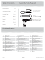 2
2
-
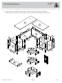 3
3
-
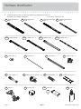 4
4
-
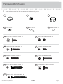 5
5
-
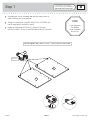 6
6
-
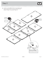 7
7
-
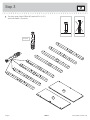 8
8
-
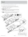 9
9
-
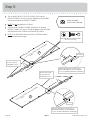 10
10
-
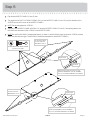 11
11
-
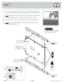 12
12
-
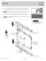 13
13
-
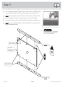 14
14
-
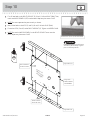 15
15
-
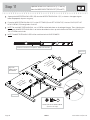 16
16
-
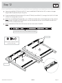 17
17
-
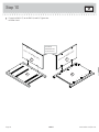 18
18
-
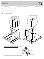 19
19
-
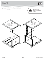 20
20
-
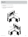 21
21
-
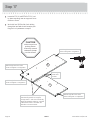 22
22
-
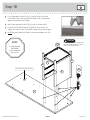 23
23
-
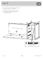 24
24
-
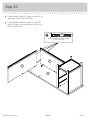 25
25
-
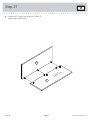 26
26
-
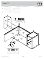 27
27
-
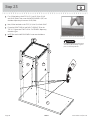 28
28
-
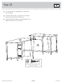 29
29
-
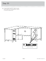 30
30
-
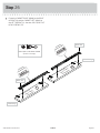 31
31
-
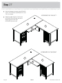 32
32
-
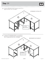 33
33
-
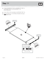 34
34
-
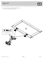 35
35
-
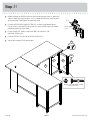 36
36
-
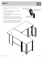 37
37
-
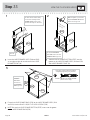 38
38
-
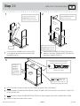 39
39
-
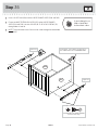 40
40
-
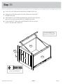 41
41
-
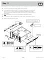 42
42
-
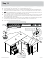 43
43
-
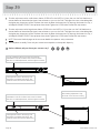 44
44
-
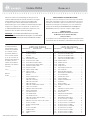 45
45
-
 46
46
-
 47
47
-
 48
48
-
 49
49
-
 50
50
-
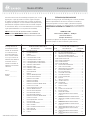 51
51
-
 52
52
-
 53
53
-
 54
54
-
 55
55
-
 56
56
-
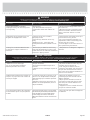 57
57
-
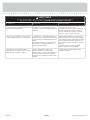 58
58
-
 59
59
-
 60
60


Sauder Costa L-Desk 419956 Assembly Manual
- Tipo
- Assembly Manual
En otros idiomas
- français: Sauder Costa L-Desk 419956
- English: Sauder Costa L-Desk 419956
Documentos relacionados
-
Sauder Harbor View 417586 Manual de usuario
-
-
-
-
-
-
-
-
-
Otros documentos
-
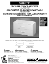 Closet Maid SSO2DW Manual de usuario
-
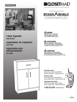 Closet Maid SO2DDW Manual de usuario
-
The Home Depot TV1379 Manual de usuario
-
Craftsman CMHT77633 El manual del propietario
-
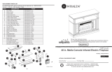 Whalen WSLWFP48-5/1031289 Manual de usuario
-
Crosley ST75-BK Instrucciones de operación
-
Balt 91779-XXXX-XX Assembly Instructions
-
Insignia NS-HWG1641 Manual de usuario
-
Init NT-C3105 Manual de usuario
-
 Closet Maid 12307 Manual de usuario


