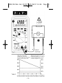
Wavetek 2020 2030 Autoranging digitalmultimeters Manual de usuario
- Categoría
- Multimetros
- Tipo
- Manual de usuario
Este manual también es adecuado para
La página se está cargando...

WARRANTY
The 2020 and 2030 Digital Multimeters are warranted against any defects of
material or workmanship within a period of one (1) year following the date of
purchase of the multimeter by the original purchaser or original user.
Any multimeter claimed to be defective during the warranty period should be
returned with proof of purchase to an authorized Wavetek Corp. Service Center
or to the local Wavetek dealer or distributor where your multimeter was
purchased. See maintenance section for details.
Any implied warranties arising out of the sale of a Wavetek multimeter,
including but not limited to implied warranties of merchantability and fitness for
a particular purpose, are limited in duration to the above stated one (1) year
period. Wavetek shall not be liable for loss of use of the multimeter or other
incidental or consequential damages, expenses, or economical loss or for any
claim or claims for such damage, expenses or economical loss.
Some states do not allow limitations on how long implied warranties last or
the exclusion or limitation of incidental or consequential damages, so the
above limitations or exclusions may not apply to you.
This warranty gives you specific legal rights, and you may also have other
rights which vary from state to state.
D GEWÄHRLEISTUNG
Auf die Digitalen Multimeter Modelle 2020 und 2030 gibt Wavetek ein Jahr
Gewährleistung ab Kaufdatum auf Material- und Herstellungsfehler. Siehe für
Einzelheiten Kapitel “Unterhalt und Reparatur”.
Für weiterführende Ansprüche aus Garantiefällen, wie Folgeschäden,
Gewinnausfälle usw. kommt Wavetek nicht auf.
E GARANTIA
Los Multímetros Digitales Modelos 2020 y 2030 están garantizados contra
cualquier defecto de material o de mano de obra durante un periodo de un (1) año
contado a partir de la fecha de adquisición. En la sección de “Mantenimiento y
Reparación” se explican los detalles relativos a reparaciones en garantía.
Cualquier otra garantía implícita está también limitada al periodo citado de un (1)
año. Wavetek no se hará responsable de pérdidas de uso del multímetro, ni de
ningún otro daño accidental o consecuencial, gastos o pérdidas económicas, en
ninguna reclamación a que pudiera haber lugar por dichos daños, gastos o pérdidas
económicas.
F GARANTIE
Les multimètres digitaux, Modèles 2020 et 2030 sont garantis pour un (1) an
à partir de la date d’achat contre les défauts de matériaux et de fabrication. Voir
chapitre “Maintenance et Réparation” pour plus de détails.
Toute garantie impliquée est également limitée à un an. Wavetek ne peut être
tenu responsable pour perte d’utilisation ou autres préjudices indirects, frais,
perte de bénéfice, etc.
2020/30.Man.3x5,25/XPr 19/06/97 14:35 Page 2

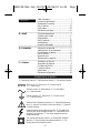
CONTENTS
D • Inhalt
E • Contenidos
F • Contenu
EPLANATION OF SYMBOLS
D • Erklärung der Symbole = E • Significado de los símbolos = F • Explication des Symboles
Safety Information ............................................... 2
Instrument Familiarization.................................... 4
Measurement Procedures ................................... 9
Menu Functions................................................. 22
Specifications ................................................... 28
Maintenance and Repair .................................... 40
Sicherheitsinformationen .................................... 2
Vorstellung des Gerätes....................................... 4
Meßprozeduren ................................................... 9
Menü Funktionen............................................... 23
Spezifikationen .................................................. 30
Unterhalt und Reparatur .....................................41
Información de seguridad ................................... 3
Familiarización con el instrumento......................4
Procedimientos de medida .................................. 9
Menu Functions................................................. 23
Especificaciones ............................................... 35
Mantenimiento y reparación .............................. 41
Informations de Sécurité ..................................... 3
Présentation de l’Appareil ................................... 4
Procédures de Mesure ...................................... 10
Fonctions de Menu............................................ 23
Spécifications ................................................... 39
Maintenance et Réparation ................................ 41
Attention! Refer to Operating Instructions •D• Achtung! Bitte Anleitung
lesen •E• ¡Atención! Consulte las Instrucciones de Uso •F• Attention!
Consultez le manuel.
Ground connection •D• Erdanschluß •E• Conexión a tierra
•F• Connection de terre.
Alernating current •D• Wechselstrom •E• Corriente alterna
•F• Courant alternatif.
Direct current •D• Gleichstrom •E• Corriente continua
•F• Courant continu.
Dangerous voltage may be present at terminals •D• Eine gefährliche
Spannung kann an den Eingängen anliegen •E• Puede haber tensión
peligrosa en los terminales •F• Une tension dangereuse peut être
présente aux entrées.
This instrument has double insulation •D• Dieses Gerät ist doppelt
geisoliert•E• Este instrumento tiene doble aislamiento •F• Cet
appareil est prévu d’une double isolation.
– 1 –
2020/30.Man.3x5,25/XPr 19/06/97 14:35 Page 3
La página se está cargando...
La página se está cargando...

– 4 –
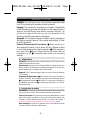
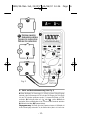
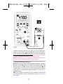
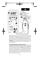
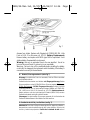
5 digit LCD
5 Digit LCD
LCD de
5
dígitos
LCD 5 digits
Menu bar – see “Menu Functions”, page xx
Menübalken – siehe “Menüffunktionen”, Seite xx
Barra de menú - ver “Funciones de menú”, página xx
Barre de menu - voir “Fonctions de Menu”, page xx
Unit Indicators
Einheitsanzeigen
indicadores de unidades
annonciateurs d’unités
41-Segment
Bargraph
41-Segment
Bargraf
Barra
analógica de
41 segmentos
Bargraphe 41-
segments
Function/Rang
e/Off Selector
Funktion-
/Bereich-/Aus
Schalter
Selector de
Función/Escal
a/Off
Sélecteur
fonctions/
calibres/march
e-arrêt
Special Function
Buttons
Spezielle
Funktions-
tasten
Teclas de
función especial
Boutons de
fonctions
spéciales
High input for
voltage and
resistance
VΩ Eingang.
Hoch für
Spannung und
Widerstand
Entrada “alta”
para tensión y
resistencia
Entrée VΩ. Haut
pour tension et
résistance
COM Input – common or low input for all
measurements
COM Eingang – Referenzpunkt für alle
Messungen
COM- entrada común o “baja” para todas
las medidas
Entrée COM – commun ou bas pour
toutes mesures
10 A Input
10 A Eingang
Entrada 10A
Entrée 10 A
100mA Input
100mA Eingang
Entrada 100mA
Entrée 100mA
2020/30.Man.3x5,25/XPr 19/06/97 14:35 Page 6
La página se está cargando...
La página se está cargando...
La página se está cargando...
La página se está cargando...
La página se está cargando...
La página se está cargando...
La página se está cargando...
La página se está cargando...
La página se está cargando...
La página se está cargando...

Stromfunktion steht. “FErr” wird angezeigt.
Echt-Effektivwertmessungen: Modelle 2020 und 2030 sind AC
gekoppelte Echt-Effektivwert-messende Geräte. Sie messen den echten
Effektivwert, auch von verzerrten Strom- und Spannungs-Wellenformen. Der
Crest-Faktorbereich wird in Tabelle 1 gezeigt. Der Crest Faktor ist der Spitzenwert
geteilt durch den Effektivwert.
Echt Effektivwert (AC + DC) Messungen: ❶ Meßkabel wie in Figur 1 gezeigt
verbinden. ❷ Funktionsschalter auf A stellen. Zweite Funktionstaste
drücken um Echt-Effektivwertmessung (AC + DC) zu aktivieren. AC und DC
Symbole werden angezeigt. ❸ Wie unter Punkt 3 oben weiter messen. Das Gerät
sperrt den Bereich gemäß höchstem Eingangssignal. Steigt die Spannung über
diesen Bereich hinaus (OL Anzeige), höheren Bereich mit
✔RNG Menüfunktion
wählen (Siehe Menüfunktionen, Seite xx). Eventuell von mA Eingang nach A
Eingang wechseln. (Messung zuerst unterbrechen und Meßkabel vom Schaltkreis
trennen.
E • Medidas de Corriente CC y CA (vea Fig. 2)
❶ Conecte la punta de prueba roja a la entrada de 100 mA para medidas de
corriente hasta 100 mA, o a la entrada de 10A para medidas hasta 10 A (up to 20A
can be measured for max 30s). Conecte la punta de prueba negra a la entrada
COM. ❷ Ponga el selector de función en la posición A o A ❸ Abra el
circuito sometido a prueba y conecte las puntas de prueba en serie con la carga.
❹ Conecte la alimentación del circuito. ➎ Lea el valor de la corriente en el
visualizador.
Aviso de entrada incorrecta: El zumbador avisa si se ha conectado la punta
de prueba a una entrada de corriente y el selector no está en una escala de
corriente. “FErr” is displayed.
Medidas de verdadero valor eficaz en CA: Los modelos 2020 y 2030 son
medidores de verdadero valor eficaz (TRMS), acoplados en CA. Miden el
verdadero valor eficaz de señales distorsionadas de tensión o corriente CA. En la
Tabla 1 se indica la capacidad de manejo de factores de cresta. El factor de cresta
es la tensión de pico dividida por la tensión eficaz.
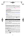
True RMS (AC + DC) Measurements: ❶ Connect test leads as shown in
figure 1. ❷ Turn function selector switch to A . Press second function key
to activate true RMS (AC + DC). The AC and DC symbols are displayed. ❸
Continue as under step 3 above. The meter range locks for highest AC signal
input. If the current is too high (OL displayed), select
✔RNGand up range until a
reading appears (see Menu Functions). Eventually change from mA to A input
(disconnect meter first).
F • Mesure de Courant CC et CA (voir fig. 2)
❶ Connectez le cordon rouge à l’entrée 100mA pour mesures jusqu’à 100mA et à
l’entrée 10A pour mesures jusqu’à 10A (max 20A peuvent être mesurés pendant
max 30 secondes). Connectez le cordon noir à l’entrée COM. ❷ Placez le
sélecteur sur A ou A . ❸ Ouvrez le circuit à mesurer et connectez les
– 15 –
2020/30.Man.3x5,25/XPr 19/06/97 14:36 Page 17
La página se está cargando...
La página se está cargando...

CONTINUITY TEST
The Continuity test checks electrical continuity between two contact
points. ❶ Set the Function switch to position. ❷ Connect black
test lead to COM input and red lead to VΩ input. ❸ Connect probe tips to
two circuit points. ❹ The internal beeper emits a tone when resistance is
less than approx. 100Ω.
D • Durchgangstest
❶ Funktionsschalter auf stellen. ❷ Rotes Meßkabel mit VΩ Eingang und
schwarzes mit COM Eingang verbinden. ❸ Meßspizen mit Schaltkreis verbinden.
❹ Akustisches Signal bei R ≤100Ω.
E • Prueba de continuidad
❶ Ponga el selector de función/escala en la posición . ❷ Conecte la punta
de prueba negra a la entrada COM y la punta de prueba roja a la entrada VΩ. ❸
Toque dos puntos del circuito con las puntas de prueba. ❹ El zumbador suena
cuando la resistencia es ≤100 Ω.
F • Test de Continuité
❶ Placez le sélecteur sur . ❷ Connectez le cordon rouge à l’entrée VΩ et
le noir à l’entrée COM. ❸ Connectez les pointes de touche au circuit. ❹ U n e
résistance de ≤100kΩ est indiquée par un signal sonore.
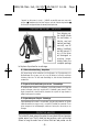
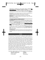
DIODE AND TRANSISTOR TEST (See Fig. 4)
The diode test measures the voltage drop across a diode junction. ❶
Connect the test leads as shown in figure 4. ❷ Set the Function/range
switch to . ❸ Apply probe tip of red lead to the anode and of black
lead to the cathode of the diode. The meter’s display indicates the forward
voltage drop (approx. 0.6V for silicon diode or 0.4V for germanium
diode). A short tone indicates a good diode. An open diode is indicated
by “OPEN”. ❹ Reverse test lead connections to the diode to perform a
reverse bias test. “OPEN” indicates a good diode. N o t e s : “OPEN” for
both reverse and forward bias tests indicates an open diode. A low
voltage reading for both bias tests indicates a shorted diode. If the diode
is shunted by a resistor of 1000 ohms or less, it must be removed from
the circuit before taking the measurement. Bipolar transistor junctions
may be tested in the same manner described above as emitter-base and
base-collector junctions are diode junctions.
D • Dioden- und Transistortest (siehe Fig. 4)
Der Diodentest zeigt den Spannungsabfall über den Diodendurchgang ❶
Meßkabel wie in Figur 4 verbinden. ❷ Funktionsschalter auf stellen. ❸
– 18 –
2020/30.Man.3x5,25/XPr 19/06/97 14:36 Page 20

Meßkabel mit Diode verbinden – rotes mit Anode; schwarzes mit Kathode.
Spannungsabfall in Durchlaßrichtung ablesen (ung. 0.6V für eine Silikon-Diode
und 0.4V für eine Germaniumdiode. Ein Biebton bigt eine gute Diode an. Eine
offene Diode wird mit “OPEN” angezeigt. ❹ Verbindung umdrehen um in
Sperrrichtung zu messen. Eine gute Diode wird mit “OPEN” angegeben.
A n m e r k u n g : “OPEN” in beiden Richtungen zeigt eine offene Diode an; eine
niedrige Ablesung eine kurzgeschlossene Diode. Transistorübergänge können wie
Dioden getestet werden.
E • Comprobación de diodos y transistores (vea Fig 4)
En esta prueba se mide la polarización directa de la unión de un diodo. ❶
Conecte las puntas de prueba como se muestra en la Figura 4. ❷ Ponga el
selector de función/escala en la posición . ❸ Aplique la punta de prueba
roja al ánodo y la negra al cátodo. El visualizador indica la caída de tensión
directa (aprox. 0.6 V para diodos de Si, o 0.4 V para diodos de Ge). Una unión
abierta se indica mediante una lectura “OPEN”. ❹ Invierta la conexión de las
puntas de prueba para comprobar la polarización inversa del diodo. “OPEN”
indica un diodo en buenas condiciones.
– 19 –
Fig. 4
2020/30.Man.3x5,25/XPr 19/06/97 14:36 Page 21
La página se está cargando...
La página se está cargando...
La página se está cargando...
La página se está cargando...
La página se está cargando...
La página se está cargando...
La página se está cargando...
La página se está cargando...
La página se está cargando...
La página se está cargando...
La página se está cargando...
La página se está cargando...
La página se está cargando...
La página se está cargando...
La página se está cargando...

Empfindlichkeit: 100mV in 19.999 und
199.99kHz Bereichen; 1.0V im
1.9999MHz Bereich
Ansprechzeit: <1.5s
Eingangsimpedanz: 51kΩ in Dioden, AC
gekoppelt
Überlastschutz: 300VDC oder AC effektiv
Bargraf: steht nicht zur Verfügung
Taktverhältnis
Frequenzbereiche: 40 bis 1000Hz, 1k bis
20kHz, 20 bis 100kHz
Prozent des Bereiches: 5 bis 95%
Auflösung: 0.1%
Genauigkeit,
40 bis 1000Hz: 2.0% vMW ±1Dgt
1k bis 20kHz: 1.0% vMW ±1Dgt
20 bis 100kHz: 5.0% vMW ±1Dgt
Ansprechzeit: <1.5 s
Eingangsimpedanz: 51kΩ in Dioden, AC
gekoppelt
Überlastschutz: 300VDC oder AC eff.
Bargraf: steht nicht zur Verfügung
Impulserfassung
Anzeige: 50ms Ton bei positiven
Übergängen. Dauerton bei Impulsrate
über 20Hz.
Erfassung: AC gekoppelt
Logikpegel: TTL, CMOS
Schwelle: 2.6V
Min Impulsbreite: 50ns
Max Ansteiggeschwindikeit: 10ns
Impulsrate: 1MPPS
Eingangsimpedanz: 10MΩ // 150pF
Optionszubehör
RF241 650MHz Hochfrequenzsonde
DL243B Standard Testkabelsatz
DL248B Deluxe Testkabelsatz
TC 253 Temperaturumsetzer
(900°C/1652°F)
TL245 Ersatz-Sicherheitsmeßkabel
CT231 150A Wechselstromzange
CT232 1000A Wechselstromzange
CT234A 400A Wechselstromzange
CT235 1000A AC/DC Stromzange
CT236 500A Wechselstromzange (mV
Ausgang)
CT237 200A AC/DC Stromzange
CT238 20A AC/DC Stromzange
FPC850 KIT : Fiber Optic Meßsatz
VC221 Gefütterte Vyniltasche. Für Meter
und Holster
VC231 Gefütterte Vyniltasche. Für Meter
ohne Holster
– 35 –
E ESPECIFICACIONES
Especificaciones Generales
Visualizador: LCD de 5 dígitos, 18888
cuentas, barra analógica de 41
segmentos, indicadores de función y
unidades
Indicación de polaridad: Automática
Ajuste de cero: Automático
Indicación de sobrecarga: OL
Indicación de “pila baja”: at 7.5V –
20 hours left. Low-battery-cut-off at
6.6V.
Frecuencia de refresco de la lectura: 2
veces/segundo nominal; 20 veces/s la
barra analógica.
Temp. de funcionamiento: 0 a 50 °C, 0 a
80% H.R.
Temp. de almacenamiento: -40 a 70 °C, 0
a 95% H.R., sin pila.
Coef. de temperatura: 0.1 x (precisión
espec.)/°C (0° a 20°C y 30° a 55°C)
Alimentación: Pila normal de 9 V, NEDA
1604, JIS 006P, IEC 6F22
Apagado automático: El medidor se
apaga transcurridos 30 minutos sin
actividad
Duración de la pila (típica): alcalina 200
hrs
Dimensiones: 175 x 90 x 34 mm
Peso (pila incluida): 568 g
Accesorios: Puntas de prueba, fusible de
repuesto, pila y Manual de
Instrucciones
Shock and vibration: MIL-T-28800, class
II
Case material: Flame retardant, high-
impact thermoplastic
Seguridad: Según normas EN61010-1:
1993/A2:1995 Cat III, UL3111, IP44.
EMC: Este producto cumple
los requisitos de las siguientes
Directivas de la Comunidad
Europea: 86/336/EEC (Compatibilidad
2020/30.Man.3x5,25/XPr 19/06/97 14:36 Page 37

Electromagnética) y 73/23/EEC (Baja
Tensión), con enmiendas según
93/68/EEC (Marcado CE).
No obstante, la presencia de ruido
eléctrico o campos electromagnéticos
intensos en las proximidades del equipo
pueden introducir perturbaciones en los
circuitos de medida. Los instrumentos de
medida también responden a las señales
no deseadas que puedan estar presentes
en los circuitos de medida. El usuario
deberá tomar las precauciones necesarias
para evitar obtener resultados incorrectos
cuando realiza medidas en presencia de
interferencias electromagnéticas.
Especificaciones eléctricas
Valores precisión a 23 ºC ±5 ºC, H.R. <75%
,
guaranteed for one year.
Voltios CC
Escalas:
100, 1000mV, 10, 100, 1000V
Resolución: 0.01 mV en esc. de 100 mV
Precisión (todas las escalas):
2020: ±(0.25% lect. +2 dígitos)
2030: ±(0.10% lect. +2 dígitos)
Imped. de entrada: 10MΩ
Tiempo de respuesta
: <2s
NMRR: >60dB a 50 o 60Hz
CMRR: >120dB up to 1000Vdc (≤ 1k
unbalance)
Protecc. sobrec.: 1000 V CC o pico CA.
Protección transitorios 6 KV
Lethal voltage indication: Ligthning bolt
in LCD and double beep when the
input exceeds 25V.
Voltios CA
Accuracies for 5% to full-scale on each
range.
Escalas: 100, 1000mV, 10, 100, 1000V
Resolución: 0.01 mV en esc. de 100 mV
Precisión: 2.0% lect ±8dgt, 45 a 2kHz (a
400Hz in escala 100mV)
Tiempo de respuesta
: <3s
Respuesta frecuencia
: 3dB >10kHz
Impedancia de entrada: 10MΩ // <100pF
Conversion type: True RMS, AC coupled;
True RMS (AC+DC) in V function
and pressing second function key
(same AC specifications as AC volts
plus DC volts accuracy of ±2% in all
ranges. If a high DC voltage is present,
the unit needs to be in Range-Lock to
get a correct reading.)
Crest factor: 1:1 through 5:1
Protecc. sobrec.: <10Hz: 400Vrms;
>10Hz: 1000Vrms. Protección
transitorios 6 KV
Corriente CC
Escalas: 1000µA, 10, 100, 1000mA, 10,
20A
Resolución: 0.1µA, escala de 1000µA
Escala Precisión Precisión
2020 2030
1000.0µA 1.0%±2dgt 0.5%±2dgt
10.000mA 0.5%±1dgt 0.35%±1dgt
100.00mA 0.5%±1dgt 0.35%±1dgt
1000.0mA 1.0%±2dgt 0.5%±1dgt
10.000A 1.0%±1dgt 1.0%±1dgt
20.00A 1.0%±1dgt 1.0%±1dgt
Lastre de tensión: Escalas 1000µA a
100mA: 15mV/mA. Escalas 1000mA a
20A: 40mV/A .
Tiempo de respuesta
: <3s
Protección sobrecorriente: Entrada mA:
fusible rápido de 0.25A/600V; nivel de
interrupción 1000A
Entrada A: 10A continuous, 20A for 30
seconds. Fusible rápido 15A/600V;
nivel de interrupción 100kA
Corriente CA (45 - 1000 Hz)
Escalas: 1000µA, 10, 100, 1000mA, 10,
20A
Resolución: 0.1µA en la esc. de 1000µA
Precisión: escalas 1000µA a 1000 mA:
±(1.7% lect. +8 dgt); escalas 10, 20 A:
±(1.7% lect ±3 dgt)
Lastre de tensión: vea Corriente CC
Tiempo de respuesta
: <3s
Respuesta frecuencia
: 3dB >10kHz
Conversion type: True RMS AC coupled;
True RMS (AC+DC) in A function
and pressing second function key
(same specifications as AC amps).
Crest factor 1:1 through 5:1
Protecc. sobrec.: vea Corriente CC
Resistencia
Escala Precisión Precisión
2020 2030
100.00Ω 0.7%±4dgt 0.5%±4dgt
1000.0Ω 0.5%±4dgt 0.3%±4dgt
10.000kΩ 0.5%±4dgt 0.3%±4dgt
100.00kΩ 0.5%±4dgt 0.3%±4dgt
1000.0kΩ 0.5%±4dgt 0.3%±4dgt
10.000MΩ 1.5%±4dgt 0.7%±4dgt
20.00MΩ 2.0%±4dgt 1.2%±4dgt
Max corriente de prueba: 1.0mA en esc.
– 36 –
2020/30.Man.3x5,25/XPr 19/06/97 14:36 Page 38

100Ω; 0.1 mA en esc. 1000Ω; 10µA
en esc. 10kΩ; 1.0µA en esc. 100kΩ;
0.1µA en otras escalas.
Max tensión de prueba: 100mV en esc.
100Ω a 1000kΩ; 1.0V en esc.10MΩ;
2.0V en esc 20MΩ.
Resolución, 0.01Ω en escala 100Ω
Tiempo de respuesta
: <2s below 1MΩ;
<3s above 1MΩ
Max tensión circuito abierto: 6.5V
Protección sobrecarga, todas las escalas:
500 V CC o CA ef.
Prueba de diodos y de continuidad
Escala: 2 V
Resolución: 0.2 mV
Corriente de prueba: 1.0 mA max.
Indicación: Tensión directa de la unión
Display response: <2s
Precisión: ±(1.0% lect +5 dgt)
Tensión circuito abierto: 5.5 V CC
Tiempo de respuesta, continuidad
: <200ms
Continuity threshold: <200mV
Umbral audible: R ≤100Ω
Indicación, circuito abierto
: “OPEN”
Protecc. sobrec.: 500 V CC o CA ef.
Capacidad
Escalas: 20, 200nF, 2, 20, 200µF; 2mF
Resolución: 100pF en escala 20nF
Precisión, escalas 20, 200nF: 2.0%lect ±
3dgt; esc. 2, 20µF: 2.0%lect ±2dgt;
esc. 200µF: 3.0%lect ±3dgt; esc. 2mF:
3.0%lect ±8dgt
Tiempo de respuesta,
(after 1st update):
<1s below 20µF; <2s below 200µF;
<25s to 2mF
Max tensión circuito abierto: 6.5V
Over-range indication: “OL” in autorange
and in range-lock for a capacitor too
large or leads are shorted together;
“OPEN” in range-lock for a capacitor
that is less than 10% of full scale
(except the 20nF range, which shows
to zero)
Protecc. sobrec.: 500 V CC o CA ef.
Contador de frecuencia
Escalas:
19.999, 199.99kHz, 1.9999MHz
Resolución: 1.0Hz en escala 19.999Hz
Precisión, esc. 19.999 Hz: ±(0.2% lect +1
dgt); otras esc.: ±(0.2% lect +2 dgt)
Nivel de disparo: 100mV en esc. 19.999
y 199.99kHz; 1.0V en esc. 1.9999MHz
Tiempo de respuesta
: <1.5s
Input impedance: 51kΩ into diodes, AC
coupled
Protecc. sobrec.: 300 V CC o CA ef.
Bargraph display: not present
Duty Cycle
Escalas de frecuencia: 40 a 1000Hz, 1k a
20kHz, 20 a100kHz
Percent of range: 5 to 95%
Resolución: 0.1%
Precisión,
40 a 1000Hz: 2.0% lect ±1dgt
1k a 20kHz: 1.0% lect ±1dgt
20 a 100kHz: 5.0%lect ±1dgt
Tiempo de respuesta
: <1.5sec
Imped. de entrada: 51kΩ into diodes, AC
coupled
Protección sobrecarga: 300V CC o CA ef.
Display bargraph: not present
Pulse Detector
Indication: positive transitions detected
emits a 50ms tone. Tone is continuous
if transition rate >20Hz.
Detector: AC coupled
Logic levels: TTL, CMOS
Threshold: 2.6V
Min pulse width: 50ns
Max pulse rise time: 10ns
Pulse repetition rate: 1MPPS
Imped. de entrada: 10MΩ // 150pF
Accesorios opcionales
RF241 Sonda de RF 650 MHz
DL243B Juego de puntas de prueba
(básico)
DL248B Juego de puntas de prueba
(especial)
TC253 Convertidor de temperatura
(900°C/1652°F)
TL245 Puntas de prueba de seguridad
de repuesto
CT231 Pinza de corriente 150 A CA
CT232 Pinza de corriente 1000 A CA
CT234A Pinza de corriente 400 A CA
CT235 Pinza 1000 A CA/CC
CT236 Pinza 500 A CA (salida mV)
CT237 Pinza de corriente 200 A CA/CC
CT238 Pinza de corriente 20 A CA/CC
KIT FPC850: Accesorio para pérdidas en
fibra óptica
VC221 Estuche de vinilo acolchado.
Cabe el medidor con funda protectora
VC231 Estuche de vinilo acolchado.
Cabe el medidor sin funda protectora
– 37 –
2020/30.Man.3x5,25/XPr 19/06/97 14:36 Page 39
La página se está cargando...
La página se está cargando...
La página se está cargando...

and water. Apply sparingly with a soft cloth and allow to dry completely
before using. Do not use aromatic hydrocarbons or chlorinated solvents
for cleaning.
D • Fehlersuche/Reparatur
Prüfen Sie zuerst folgende Fehlerquellen: Meßkabel (Brüche), Anschluß, Zustand
von Batterie und Sicherung, richtiger Meßvorgang, Eingangs- und
Bereichsgrenzen, usw.
Mit Ausnahme des Batterie- und Sicherungswechsels soll jede Reparatur nur
durch eine durch Wavetek anerkannte Servicestelle durchgeführt werden.
Das Gerät kann mit einer milden Seifenlösung gereinigt werden. Sparsam
auftragen und vor Gebrauch gut trocknen lassen. Keine Lösungsmittel zum
Reinigen verwenden.
E • Localización de Averías/Maintenimiento
Para identificar la causa del problema: Compruebe la pila; revise las instrucciones
de uso; inspeccione las puntas de prueba por si hay una conexión rota o
intermitente; inspeccione la pila y el fusible.
Excepto la sustitución de la pila o el fusible, cualquier trabajo de reparación del
multímetro debe hacerse exclusivamente por personal técnico cualificado para
este tipo de reparaciones.
Para limpiar la carcasa puede utilizarse una solución suave de agua y detergente.
F • Dépannage/Maintenance
Avant d’expédier votre multimètre pour réparation, vérifiez les cordons de mesure
(rupture), pile et fusible, connections, procédure de mesure, limites d’entrée et de
calibres, etc.
Excepté pour le remplacement de la pile et du fusible, toute réparation doit être
effectuée uniquement par un Centre de Services agrée par Wavetek.
Vous pouvez nettoyer le boîtier avec un détergent doux. Appliquez parcimonieu-
sement et laissez sécher complètement avant utilisation. Ne pas utiliser de
solvents.
BATTERY / FUSE REPLACEMENT (Fig. 7)
Warning: To prevent electrical shock hazard, turn off the multimeter and
any device or circuit under test and disconnect the test leads before
removing the rear cover.
Remove the rear case by unscrewing the three screws that secure it to the
front case. mA Input Fuse Replacement: Remove the blown fuse from
the fuse holder. Replace with a 0.25A/600V quick acting fuse. Wa v e t e k
replacement fuse part number is FP 250 (a pack of four fuses). 10/20A
Input Fuse Replacement: Remove the 15A/600V fuse from the 10/20
– 41 –
2020/30.Man.3x5,25/XPr 19/06/97 14:36 Page 43
La página se está cargando...
La página se está cargando...

9045 Balboa Ave. Hurricane Way
San Diego, CA 92123 Norwich, NR6 6JB, U.K.
Tel: (619) 279 2200 Tel: int + 44-1603-404824
Fax: (619) 627 0130 Fax: int + 44-603-483670
The DMM will be returned with the transportation charges paid by Wa v e t e k
Corporation.
D • Reparatur
Lesen Sie die Gewährleistung bevor Sie eine Reparatur unter oder außerhalb
Gewährleistung anfragen. Unter Gewährleistung bringen Sie bitte das defekte
Gerät zu einer anerkannten Wavetek Verkaufsstelle oder Servicestelle für einen
direkten Umtausch. Außerhalb Gewährleistung senden Sie das Gerät zu einer
Wavetek anerkannten Servicestelle. Bitte informieren Sie sich bei Wavetek oder
ihrem Fachhändler nach der nächst beiliegenden Adresse und nach aktuellen
Reparaturgebühren.
Bitte senden Sie folgende Informationen und Dokumente mit: Firmenname,
Kundenname, Adresse, Te l e f o n n u m m e r, Kaufnachweis (für Reparaturen unter
Gewährleistung), eine kurze Beschreibung der gewünschten Handlung, und die
geforderte Bezahlung (Eingriffe außerhalb der Gewährleistung). Bitte auch
Testkabel beifügen.
Bezahlungen in Form eines Checks, Bezahlungsformulieren, Kredietkarte mit
Verfalldatum, usw. bitte in Namen der Servicestelle aufstellen. Bitte Multimeter
(Frei) senden an:
U.S.A. und Canada: Europa:
Wavetek Corporation Wavetek Ltd
Instrument Repair Instrument Repair
9045 Balboa Ave. Hurricane Way
San Diego, CA 92123 Norwich, NR6 6JB, U.K.
Tel: (619) 279 2200 Tel: int + 44-1603-404824
Fax: (619) 627 0130 Fax: int + 44-603-483670
oder an die Ihnen mitgeteilte Adresse. Multimeter wird (Frei) zurück geschickt.
E • Reparación
Lea las condiciones de garantía, al principio de este manual, antes de solicitar
cualquier reparación dentro o fuera de garantía. Si la reparación es en garantía,
puede llevar el multímetro defectuoso a cualquier Distribuidor Autorizado o Centro
de Servicio de Wavetek, donde le cambiarán en mano el producto por otro igual o
similar. Para reparaciones fuera de garantía deberá enviar el multímetro a un Centro
de Servicio de Wavetek. En Wavetek, o en su Distribuidor o punto de venta, le
indicarán el Centro de Servicio más próximo y las tarifas de reparación vigentes.
La documentación que acompañe a todo multímetro enviado para reparación debe
incluir los siguientes datos: nombre de la empresa, persona de contacto, dirección,
número de teléfono, prueba de compra (para reparaciones en garantía), una breve
– 44 –
2020/30.Man.3x5,25/XPr 19/06/97 14:36 Page 46

descripción del problema o el servicio requerido y, en caso de reparaciones fuera de
garantía, si desea presupuesto previo. Por favor envíe las puntas de prueba con el
multímetro.
El importe de la reparación se enviará en forma de cheque, tarjeta de crédito con fecha
de expiración u orden de pago a favor de Wavetek o del Centro de Servicio específico.
El multímetro se enviará a portes pagados a una de las siguientes direcciones, o al
Centro de Servicio que le hayan indicado:
en EE.UU. y Canadá: en Europa:
Wavetek Corporation Wavetek Ltd
Instrument Repair Instrument Repair
9045 Balboa Ave. Hurricane Way
San Diego, CA 92123 Norwich, NR6 6JB, Inglaterra
Tel: (619) 279 2200 Tel: int + 44-1603-404824
Fax: (619) 627 0130 Fax: int + 44-603-483670
Wavetek devolverá el multimetro reparado a portes pagados.
F • Réparation
Lisez la garantie au début de ce manuel avant de demander une réparation sous
garantie ou hors garantie. Pour une réparation sous garantie, adressez-vous à
votre revendeur Wavetek ou à un centre de services agréé par Wavetek pour un
échange direct. Pour une réparation hors garantie, envoyez votre multimètre à un
Centre de Services agrée par Wavetek. Téléphonez à Wavetek ou demandez
l’adresse la plus proche à votre revendeur. Pour les réparations hors garantie,
demandez d’abord les tarifs.
Joignez les informations et documents suivants: nom de sociètè, nom du client,
adresse, numéro de téléphone, preuve d’achat (pour réparations sous garantie),
une brève description de l’intervention souhaitée et le payement (pour réparations
hors garantie). Ajoutez également les cordons de test.
Le payement, sous forme de chèque, virement, carte de crédit avec date
d’expiration, etc. doit être établi au nom du Centre de Services. Le multimètre doit
être envoyé port payé à:
aux U.S.A. et Canada: en Europe:
Wavetek Corporation Wavetek Ltd
Instrument Repair Instrument Repair
9045 Balboa Ave. Hurricane Way
San Diego, CA 92123 Norwich, NR6 6JB, U.K.
Tel: (619) 279 2200 Tel: int + 44-1603-404824
Fax: (619) 627 0130 Fax: int + 44-603-483670
ou à l’adresse communiquée. Le multimètre vous sera renvoyé port payé.
– 45 –
2020/30.Man.3x5,25/XPr 19/06/97 14:36 Page 47
La página se está cargando...
Transcripción de documentos
2020/30.Man.3x5,25/XPr 19/06/97 14:35 Page 2 WARRANTY The 2020 and 2030 Digital Multimeters are warranted against any defects of material or workmanship within a period of one (1) year following the date of purchase of the multimeter by the original purchaser or original user. Any multimeter claimed to be defective during the warranty period should be returned with proof of purchase to an authorized Wavetek Corp. Service Center or to the local Wavetek dealer or distributor where your multimeter was purchased. See maintenance section for details. Any implied warranties arising out of the sale of a Wavetek multimeter, including but not limited to implied warranties of merchantability and fitness for a particular purpose, are limited in duration to the above stated one (1) year period. Wavetek shall not be liable for loss of use of the multimeter or other incidental or consequential damages, expenses, or economical loss or for any claim or claims for such damage, expenses or economical loss. Some states do not allow limitations on how long implied warranties last or the exclusion or limitation of incidental or consequential damages, so the above limitations or exclusions may not apply to you. This warranty gives you specific legal rights, and you may also have other rights which vary from state to state. D GEWÄHRLEISTUNG Auf die Digitalen Multimeter Modelle 2020 und 2030 gibt Wavetek ein Jahr Gewährleistung ab Kaufdatum auf Material- und Herstellungsfehler. Siehe für Einzelheiten Kapitel “Unterhalt und Reparatur”. Für weiterführende Ansprüche aus Garantiefällen, wie Folgeschäden, Gewinnausfälle usw. kommt Wavetek nicht auf. E GARANTIA Los Multímetros Digitales Modelos 2020 y 2030 están garantizados contra cualquier defecto de material o de mano de obra durante un periodo de un (1) año contado a partir de la fecha de adquisición. En la sección de “Mantenimiento y Reparación” se explican los detalles relativos a reparaciones en garantía. Cualquier otra garantía implícita está también limitada al periodo citado de un (1) año. Wavetek no se hará responsable de pérdidas de uso del multímetro, ni de ningún otro daño accidental o consecuencial, gastos o pérdidas económicas, en ninguna reclamación a que pudiera haber lugar por dichos daños, gastos o pérdidas económicas. F GARANTIE Les multimètres digitaux, Modèles 2020 et 2030 sont garantis pour un (1) an à partir de la date d’achat contre les défauts de matériaux et de fabrication. Voir chapitre “Maintenance et Réparation” pour plus de détails. Toute garantie impliquée est également limitée à un an. Wavetek ne peut être tenu responsable pour perte d’utilisation ou autres préjudices indirects, frais, perte de bénéfice, etc. 2020/30.Man.3x5,25/XPr CONTENTS 19/06/97 14:35 Page 3 Safety Information ............................................... 2 Instrument Familiarization.................................... 4 Measurement Procedures ................................... 9 Menu Functions................................................. 22 Specifications ................................................... 28 Maintenance and Repair .................................... 40 D • Inhalt Sicherheitsinformationen .................................... 2 Vorstellung des Gerätes ....................................... 4 Meßprozeduren ................................................... 9 Menü Funktionen ............................................... 23 Spezifikationen .................................................. 30 Unterhalt und Reparatur .....................................41 E • Contenidos Información de seguridad ................................... 3 Familiarización con el instrumento ...................... 4 Procedimientos de medida .................................. 9 Menu Functions................................................. 23 Especificaciones ............................................... 35 Mantenimiento y reparación .............................. 41 F • Contenu Informations de Sécurité ..................................... 3 Présentation de l’Appareil ................................... 4 Procédures de Mesure ...................................... 10 Fonctions de Menu ............................................ 23 Spécifications ................................................... 39 Maintenance et Réparation ................................ 41 EPLANATION OF SYMBOLS D • Erklärung der Symbole = E • Significado de los símbolos = F • Explication des Symboles Direct current •D• Gleichstrom •E• Corriente continua •F• Courant continu. Alernating current •D• Wechselstrom •E• Corriente alterna •F• Courant alternatif. Ground connection •D• Erdanschluß •E• Conexión a tierra •F• Connection de terre. Attention! Refer to Operating Instructions •D• Achtung! Bitte Anleitung lesen •E• ¡Atención! Consulte las Instrucciones de Uso •F• Attention! Consultez le manuel. Dangerous voltage may be present at terminals •D• Eine gefährliche Spannung kann an den Eingängen anliegen •E• Puede haber tensión peligrosa en los terminales •F• Une tension dangereuse peut être présente aux entrées. This instrument has double insulation •D• Dieses Gerät ist doppelt geisoliert •E• Este instrumento tiene doble aislamiento •F• Cet appareil est prévu d’une double isolation. –1– 2020/30.Man.3x5,25/XPr 19/06/97 14:35 Menu bar – see “Menu Functions”, page xx Menübalken – siehe “Menüffunktionen”, Seite xx Barra de menú - ver “Funciones de menú”, página xx Barre de menu - voir “Fonctions de Menu”, page xx 5 digit LCD 5 Digit LCD LCD de 5 dígitos LCD 5 digits Page 6 Unit Indicators Einheitsanzeigen indicadores de unidades annonciateurs d’unités Special Function Buttons Spezielle Funktionstasten Teclas de función especial Boutons de fonctions spéciales 41-Segment Bargraph 41-Segment Bargraf Barra analógica de 41 segmentos Bargraphe 41segments High input for voltage and resistance Function/Rang e/Off Selector Funktion/Bereich-/Aus Schalter Selector de Función/Escal a/Off Sélecteur fonctions/ calibres/march e-arrêt 10 A Input 10 A Eingang Entrada 10A Entrée 10 A VΩ Eingang. Hoch für Spannung und Widerstand Entrada “alta” para tensión y resistencia Entrée VΩ. Haut pour tension et résistance 100mA Input 100mA Eingang Entrada 100mA Entrée 100mA COM Input – common or low input for all measurements COM Eingang – Referenzpunkt für alle Messungen COM- entrada común o “baja” para todas las medidas Entrée COM – commun ou bas pour toutes mesures –4– 2020/30.Man.3x5,25/XPr 19/06/97 14:36 Page 17 Stromfunktion steht. “FErr” wird angezeigt. Echt-Effektivwertmessungen: Modelle 2020 und 2030 sind AC gekoppelte Echt-Effektivwert-messende Geräte. Sie messen den echten Effektivwert, auch von verzerrten Strom- und Spannungs-Wellenformen. Der Crest-Faktorbereich wird in Tabelle 1 gezeigt. Der Crest Faktor ist der Spitzenwert geteilt durch den Effektivwert. Echt Effektivwert (AC + DC) Messungen: ❶ Meßkabel wie in Figur 1 gezeigt verbinden. ❷ Funktionsschalter auf A stellen. Zweite Funktionstaste drücken um Echt-Effektivwertmessung (AC + DC) zu aktivieren. AC und DC Symbole werden angezeigt. ❸ Wie unter Punkt 3 oben weiter messen. Das Gerät sperrt den Bereich gemäß höchstem Eingangssignal. Steigt die Spannung über diesen Bereich hinaus (OL Anzeige), höheren Bereich mit ✔RNG Menüfunktion wählen (Siehe Menüfunktionen, Seite xx). Eventuell von mA Eingang nach A Eingang wechseln. (Messung zuerst unterbrechen und Meßkabel vom Schaltkreis trennen. E • Medidas de Corriente CC y CA (vea Fig. 2) ❶ Conecte la punta de prueba roja a la entrada de 100 mA para medidas de corriente hasta 100 mA, o a la entrada de 10A para medidas hasta 10 A (up to 20A can be measured for max 30s). Conecte la punta de prueba negra a la entrada COM. ❷ Ponga el selector de función en la posición A o A ❸ Abra el circuito sometido a prueba y conecte las puntas de prueba en serie con la carga. ❹ Conecte la alimentación del circuito. ➎ Lea el valor de la corriente en el visualizador. Aviso de entrada incorrecta: El zumbador avisa si se ha conectado la punta de prueba a una entrada de corriente y el selector no está en una escala de corriente. “FErr” is displayed. Medidas de verdadero valor eficaz en CA: Los modelos 2020 y 2030 son medidores de verdadero valor eficaz (TRMS), acoplados en CA. Miden el verdadero valor eficaz de señales distorsionadas de tensión o corriente CA. En la Tabla 1 se indica la capacidad de manejo de factores de cresta. El factor de cresta es la tensión de pico dividida por la tensión eficaz. True RMS (AC + DC) Measurements: ❶ Connect test leads as shown in figure 1. ❷ Turn function selector switch to A . Press second function key to activate true RMS (AC + DC). The AC and DC symbols are displayed. ❸ Continue as under step 3 above. The meter range locks for highest AC signal input. If the current is too high (OL displayed), select ✔RNG and up range until a reading appears (see Menu Functions). Eventually change from mA to A input (disconnect meter first). F • Mesure de Courant CC et CA (voir fig. 2) ❶ Connectez le cordon rouge à l’entrée 100mA pour mesures jusqu’à 100mA et à l’entrée 10A pour mesures jusqu’à 10A (max 20A peuvent être mesurés pendant max 30 secondes). Connectez le cordon noir à l’entrée COM. ❷ Placez le sélecteur sur A ou A . ❸ Ouvrez le circuit à mesurer et connectez les – 15 – 2020/30.Man.3x5,25/XPr 19/06/97 14:36 Page 20 CONTINUITY TEST The Continuity test checks electrical continuity between two contact points. ❶ Set the Function switch to position. ❷ Connect black test lead to COM input and red lead to VΩ input. ❸ Connect probe tips to two circuit points. ❹ The internal beeper emits a tone when resistance is less than approx. 100Ω. D • Durchgangstest ❶ Funktionsschalter auf stellen. ❷ Rotes Meßkabel mit VΩ Eingang und schwarzes mit COM Eingang verbinden. ❸ Meßspizen mit Schaltkreis verbinden. ❹ Akustisches Signal bei R ≤100Ω. E • Prueba de continuidad ❶ Ponga el selector de función/escala en la posición . ❷ Conecte la punta de prueba negra a la entrada COM y la punta de prueba roja a la entrada VΩ. ❸ Toque dos puntos del circuito con las puntas de prueba. ❹ El zumbador suena cuando la resistencia es ≤100 Ω. F • Test de Continuité ❶ Placez le sélecteur sur . ❷ Connectez le cordon rouge à l’entrée VΩ et le noir à l’entrée COM. ❸ Connectez les pointes de touche au circuit. ❹ Une résistance de ≤100kΩ est indiquée par un signal sonore. DIODE AND TRANSISTOR TEST (See Fig. 4) The diode test measures the voltage drop across a diode junction. ❶ Connect the test leads as shown in figure 4. ❷ Set the Function/range switch to . ❸ Apply probe tip of red lead to the anode and of black lead to the cathode of the diode. The meter’s display indicates the forward voltage drop (approx. 0.6V for silicon diode or 0.4V for germanium diode). A short tone indicates a good diode. An open diode is indicated by “OPEN”. ❹ Reverse test lead connections to the diode to perform a reverse bias test. “OPEN” indicates a good diode. Notes: “OPEN” for both reverse and forward bias tests indicates an open diode. A low voltage reading for both bias tests indicates a shorted diode. If the diode is shunted by a resistor of 1000 ohms or less, it must be removed from the circuit before taking the measurement. Bipolar transistor junctions may be tested in the same manner described above as emitter-base and base-collector junctions are diode junctions. D • Dioden- und Transistortest (siehe Fig. 4) Der Diodentest zeigt den Spannungsabfall über den Diodendurchgang ❶ Meßkabel wie in Figur 4 verbinden. ❷ Funktionsschalter auf stellen. ❸ – 18 – 2020/30.Man.3x5,25/XPr 19/06/97 14:36 Page 21 Fig. 4 Meßkabel mit Diode verbinden – rotes mit Anode; schwarzes mit Kathode. Spannungsabfall in Durchlaßrichtung ablesen (ung. 0.6V für eine Silikon-Diode und 0.4V für eine Germaniumdiode. Ein Biebton bigt eine gute Diode an. Eine offene Diode wird mit “OPEN” angezeigt. ❹ Verbindung umdrehen um in Sperrrichtung zu messen. Eine gute Diode wird mit “OPEN” angegeben. Anmerkung: “OPEN” in beiden Richtungen zeigt eine offene Diode an; eine niedrige Ablesung eine kurzgeschlossene Diode. Transistorübergänge können wie Dioden getestet werden. E • Comprobación de diodos y transistores (vea Fig 4) En esta prueba se mide la polarización directa de la unión de un diodo. ❶ Conecte las puntas de prueba como se muestra en la Figura 4. ❷ Ponga el selector de función/escala en la posición . ❸ Aplique la punta de prueba roja al ánodo y la negra al cátodo. El visualizador indica la caída de tensión directa (aprox. 0.6 V para diodos de Si, o 0.4 V para diodos de Ge). Una unión abierta se indica mediante una lectura “OPEN”. ❹ Invierta la conexión de las puntas de prueba para comprobar la polarización inversa del diodo. “OPEN” indica un diodo en buenas condiciones. – 19 – 2020/30.Man.3x5,25/XPr Empfindlichkeit: 100mV in 19.999 und 199.99kHz Bereichen; 1.0V im 1.9999MHz Bereich Ansprechzeit: <1.5s Eingangsimpedanz: 51kΩ in Dioden, AC gekoppelt Überlastschutz: 300VDC oder AC effektiv Bargraf: steht nicht zur Verfügung Taktverhältnis Frequenzbereiche: 40 bis 1000Hz, 1k bis 20kHz, 20 bis 100kHz Prozent des Bereiches: 5 bis 95% Auflösung: 0.1% Genauigkeit, 40 bis 1000Hz: 2.0% vMW ±1Dgt 1k bis 20kHz: 1.0% vMW ±1Dgt 20 bis 100kHz: 5.0% vMW ±1Dgt Ansprechzeit: <1.5 s Eingangsimpedanz: 51kΩ in Dioden, AC gekoppelt Überlastschutz: 300VDC oder AC eff. Bargraf: steht nicht zur Verfügung Impulserfassung Anzeige: 50ms Ton bei positiven Übergängen. Dauerton bei Impulsrate über 20Hz. Erfassung: AC gekoppelt E 19/06/97 14:36 Page 37 Logikpegel: TTL, CMOS Schwelle: 2.6V Min Impulsbreite: 50ns Max Ansteiggeschwindikeit: 10ns Impulsrate: 1MPPS Eingangsimpedanz: 10MΩ // 150pF Optionszubehör RF241 650MHz Hochfrequenzsonde DL243B Standard Testkabelsatz DL248B Deluxe Testkabelsatz TC 253 Temperaturumsetzer (900°C/1652°F) TL245 Ersatz-Sicherheitsmeßkabel CT231 150A Wechselstromzange CT232 1000A Wechselstromzange CT234A 400A Wechselstromzange CT235 1000A AC/DC Stromzange CT236 500A Wechselstromzange (mV Ausgang) CT237 200A AC/DC Stromzange CT238 20A AC/DC Stromzange FPC850 KIT : Fiber Optic Meßsatz VC221 Gefütterte Vyniltasche. Für Meter und Holster VC231 Gefütterte Vyniltasche. Für Meter ohne Holster ESPECIFICACIONES Especificaciones Generales Visualizador: LCD de 5 dígitos, 18888 cuentas, barra analógica de 41 segmentos, indicadores de función y unidades Indicación de polaridad: Automática Ajuste de cero: Automático Indicación de sobrecarga: OL Indicación de “pila baja”: at 7.5V – 20 hours left. Low-battery-cut-off at 6.6V. Frecuencia de refresco de la lectura: 2 veces/segundo nominal; 20 veces/s la barra analógica. Temp. de funcionamiento: 0 a 50 °C, 0 a 80% H.R. Temp. de almacenamiento: -40 a 70 °C, 0 a 95% H.R., sin pila. Coef. de temperatura: 0.1 x (precisión espec.)/°C (0° a 20°C y 30° a 55°C) Alimentación: Pila normal de 9 V, NEDA 1604, JIS 006P, IEC 6F22 Apagado automático: El medidor se apaga transcurridos 30 minutos sin actividad Duración de la pila (típica): alcalina 200 hrs Dimensiones: 175 x 90 x 34 mm Peso (pila incluida): 568 g Accesorios: Puntas de prueba, fusible de repuesto, pila y Manual de Instrucciones Shock and vibration: MIL-T-28800, class II Case material: Flame retardant, highimpact thermoplastic Seguridad: Según normas EN61010-1: 1993/A2:1995 Cat III, UL3111, IP44. EMC: Este producto cumple los requisitos de las siguientes Directivas de la Comunidad Europea: 86/336/EEC (Compatibilidad – 35 – 2020/30.Man.3x5,25/XPr 19/06/97 14:36 Electromagnética) y 73/23/EEC (Baja Tensión), con enmiendas según 93/68/EEC (Marcado CE). No obstante, la presencia de ruido eléctrico o campos electromagnéticos intensos en las proximidades del equipo pueden introducir perturbaciones en los circuitos de medida. Los instrumentos de medida también responden a las señales no deseadas que puedan estar presentes en los circuitos de medida. El usuario deberá tomar las precauciones necesarias para evitar obtener resultados incorrectos cuando realiza medidas en presencia de interferencias electromagnéticas. Page 38 Crest factor: 1:1 through 5:1 Protecc. sobrec.: <10Hz: 400Vrms; >10Hz: 1000Vrms. Protección transitorios 6 KV Corriente CC Escalas: 1000µA, 10, 100, 1000mA, 10, 20A Resolución: 0.1µA, escala de 1000µA Escala Precisión Precisión 2020 2030 1000.0µA 1.0%±2dgt 0.5%±2dgt 10.000mA 0.5%±1dgt 0.35%±1dgt 100.00mA 0.5%±1dgt 0.35%±1dgt 1000.0mA 1.0%±2dgt 0.5%±1dgt 10.000A 1.0%±1dgt 1.0%±1dgt 20.00A 1.0%±1dgt 1.0%±1dgt Especificaciones eléctricas Lastre de tensión: Escalas 1000µA a Valores precisión a 23 ºC ±5 ºC, H.R. <75%, 100mA: 15mV/mA. Escalas 1000mA a guaranteed for one year. 20A: 40mV/A . Tiempo de respuesta: <3s Voltios CC Protección sobrecorriente: Entrada mA: Escalas: 100, 1000mV, 10, 100, 1000V fusible rápido de 0.25A/600V; nivel de Resolución: 0.01 mV en esc. de 100 mV interrupción 1000A Precisión (todas las escalas): Entrada A: 10A continuous, 20A for 30 2020: ±(0.25% lect. +2 dígitos) seconds. Fusible rápido 15A/600V; 2030: ±(0.10% lect. +2 dígitos) nivel de interrupción 100kA Imped. de entrada: 10MΩ Tiempo de respuesta: <2s Corriente CA (45 - 1000 Hz) NMRR: >60dB a 50 o 60Hz Escalas: 1000µA, 10, 100, 1000mA, 10, CMRR: >120dB up to 1000Vdc (≤ 1k 20A Resolución: 0.1µA en la esc. de 1000µA unbalance) Protecc. sobrec.: 1000 V CC o pico CA. Precisión: escalas 1000µA a 1000 mA: ±(1.7% lect. +8 dgt); escalas 10, 20 A: Protección transitorios 6 KV ±(1.7% lect ±3 dgt) Lethal voltage indication: Ligthning bolt Lastre de tensión: vea Corriente CC in LCD and double beep when the input exceeds 25V. Tiempo de respuesta: <3s Respuesta frecuencia: 3dB >10kHz Voltios CA Conversion type: True RMS AC coupled; Accuracies for 5% to full-scale on each True RMS (AC+DC) in A function range. and pressing second function key Escalas: 100, 1000mV, 10, 100, 1000V (same specifications as AC amps). Resolución: 0.01 mV en esc. de 100 mV Precisión: 2.0% lect ±8dgt, 45 a 2kHz (a Crest factor 1:1 through 5:1 Protecc. sobrec.: vea Corriente CC 400Hz in escala 100mV) Tiempo de respuesta: <3s Resistencia Respuesta frecuencia: 3dB >10kHz Escala Precisión Precisión Impedancia de entrada: 10MΩ // <100pF 2020 2030 Conversion type: True RMS, AC coupled; 100.00Ω 0.7%±4dgt 0.5%±4dgt True RMS (AC+DC) in V function 1000.0Ω 0.5%±4dgt 0.3%±4dgt and pressing second function key 10.000kΩ 0.5%±4dgt 0.3%±4dgt (same AC specifications as AC volts 100.00kΩ 0.5%±4dgt 0.3%±4dgt plus DC volts accuracy of ±2% in all 1000.0kΩ 0.5%±4dgt 0.3%±4dgt ranges. If a high DC voltage is present, 10.000MΩ 1.5%±4dgt 0.7%±4dgt the unit needs to be in Range-Lock to 20.00MΩ 2.0%±4dgt 1.2%±4dgt get a correct reading.) Max corriente de prueba: 1.0mA en esc. – 36 – 2020/30.Man.3x5,25/XPr 100Ω; 0.1 mA en esc. 1000Ω; 10µA en esc. 10kΩ; 1.0µA en esc. 100kΩ; 0.1µA en otras escalas. Max tensión de prueba: 100mV en esc. 100Ω a 1000kΩ; 1.0V en esc.10MΩ; 2.0V en esc 20MΩ. Resolución, 0.01Ω en escala 100Ω Tiempo de respuesta: <2s below 1MΩ; <3s above 1MΩ Max tensión circuito abierto: 6.5V Protección sobrecarga, todas las escalas: 500 V CC o CA ef. Prueba de diodos y de continuidad Escala: 2 V Resolución: 0.2 mV Corriente de prueba: 1.0 mA max. Indicación: Tensión directa de la unión Display response: <2s Precisión: ±(1.0% lect +5 dgt) Tensión circuito abierto: 5.5 V CC Tiempo de respuesta, continuidad: <200ms Continuity threshold: <200mV Umbral audible: R ≤100Ω Indicación, circuito abierto: “OPEN” Protecc. sobrec.: 500 V CC o CA ef. Capacidad Escalas: 20, 200nF, 2, 20, 200µF; 2mF Resolución: 100pF en escala 20nF Precisión, escalas 20, 200nF: 2.0%lect ± 3dgt; esc. 2, 20µF: 2.0%lect ±2dgt; esc. 200µF: 3.0%lect ±3dgt; esc. 2mF: 3.0%lect ±8dgt Tiempo de respuesta, (after 1st update): <1s below 20µF; <2s below 200µF; <25s to 2mF Max tensión circuito abierto: 6.5V Over-range indication: “OL” in autorange and in range-lock for a capacitor too large or leads are shorted together; “OPEN” in range-lock for a capacitor that is less than 10% of full scale (except the 20nF range, which shows to zero) Protecc. sobrec.: 500 V CC o CA ef. Contador de frecuencia Escalas: 19.999, 199.99kHz, 1.9999MHz Resolución: 1.0Hz en escala 19.999Hz Precisión, esc. 19.999 Hz: ±(0.2% lect +1 dgt); otras esc.: ±(0.2% lect +2 dgt) Nivel de disparo: 100mV en esc. 19.999 y 199.99kHz; 1.0V en esc. 1.9999MHz Tiempo de respuesta: <1.5s Input impedance: 51kΩ into diodes, AC 19/06/97 14:36 Page 39 coupled Protecc. sobrec.: 300 V CC o CA ef. Bargraph display: not present Duty Cycle Escalas de frecuencia: 40 a 1000Hz, 1k a 20kHz, 20 a100kHz Percent of range: 5 to 95% Resolución: 0.1% Precisión, 40 a 1000Hz: 2.0% lect ±1dgt 1k a 20kHz: 1.0% lect ±1dgt 20 a 100kHz: 5.0%lect ±1dgt Tiempo de respuesta: <1.5sec Imped. de entrada: 51kΩ into diodes, AC coupled Protección sobrecarga: 300V CC o CA ef. Display bargraph: not present Pulse Detector Indication: positive transitions detected emits a 50ms tone. Tone is continuous if transition rate >20Hz. Detector: AC coupled Logic levels: TTL, CMOS Threshold: 2.6V Min pulse width: 50ns Max pulse rise time: 10ns Pulse repetition rate: 1MPPS Imped. de entrada: 10MΩ // 150pF Accesorios opcionales RF241 Sonda de RF 650 MHz DL243B Juego de puntas de prueba (básico) DL248B Juego de puntas de prueba (especial) TC253 Convertidor de temperatura (900°C/1652°F) TL245 Puntas de prueba de seguridad de repuesto CT231 Pinza de corriente 150 A CA CT232 Pinza de corriente 1000 A CA CT234A Pinza de corriente 400 A CA CT235 Pinza 1000 A CA/CC CT236 Pinza 500 A CA (salida mV) CT237 Pinza de corriente 200 A CA/CC CT238 Pinza de corriente 20 A CA/CC KIT FPC850: Accesorio para pérdidas en fibra óptica VC221 Estuche de vinilo acolchado. Cabe el medidor con funda protectora VC231 Estuche de vinilo acolchado. Cabe el medidor sin funda protectora – 37 – 2020/30.Man.3x5,25/XPr 19/06/97 14:36 Page 43 and water. Apply sparingly with a soft cloth and allow to dry completely before using. Do not use aromatic hydrocarbons or chlorinated solvents for cleaning. D • Fehlersuche/Reparatur Prüfen Sie zuerst folgende Fehlerquellen: Meßkabel (Brüche), Anschluß, Zustand von Batter ie und Sicheru ng, richtiger Meßvorgang, Eingan gs- und Bereichsgrenzen, usw. Mit Ausnahme des Batterie- und Sicherungswechsels soll jede Reparatur nur durch eine durch Wavetek anerkannte Servicestelle durchgeführt werden. Das Gerät kann mit einer milden Seifenlösung gereinigt werden. Sparsam auftragen und vor Gebrauch gut trocknen lassen. Keine Lösungsmittel zum Reinigen verwenden. E • Localización de Averías/Maintenimiento Para identificar la causa del problema: Compruebe la pila; revise las instrucciones de uso; inspeccione las puntas de prueba por si hay una conexión rota o intermitente; inspeccione la pila y el fusible. Excepto la sustitución de la pila o el fusible, cualquier trabajo de reparación del multímetro debe hacerse exclusivamente por personal técnico cualificado para este tipo de reparaciones. Para limpiar la carcasa puede utilizarse una solución suave de agua y detergente. F • Dépannage/Maintenance Avant d’expédier votre multimètre pour réparation, vérifiez les cordons de mesure (rupture), pile et fusible, connections, procédure de mesure, limites d’entrée et de calibres, etc. Excepté pour le remplacement de la pile et du fusible, toute réparation doit être effectuée uniquement par un Centre de Services agrée par Wavetek. Vous pouvez nettoyer le boîtier avec un détergent doux. Appliquez parcimonieusement et laissez sécher complètement avant utilisation. Ne pas utiliser de solvents. BATTERY / FUSE REPLACEMENT (Fig. 7) Warning: To prevent electrical shock hazard, turn off the multimeter and any device or circuit under test and disconnect the test leads before removing the rear cover. Remove the rear case by unscrewing the three screws that secure it to the front case. mA Input Fuse Replacement: Remove the blown fuse from the fuse holder. Replace with a 0.25A/600V quick acting fuse. Wavetek replacement fuse part number is FP 250 (a pack of four fuses). 10/20A Input Fuse Replacement: Remove the 15A/600V fuse from the 10/20 – 41 – 2020/30.Man.3x5,25/XPr 19/06/97 14:36 9045 Balboa Ave. San Diego, CA 92123 Tel: (619) 279 2200 Fax: (619) 627 0130 Page 46 Hurricane Way Norwich, NR6 6JB, U.K. Tel: int + 44-1603-404824 Fax: int + 44-603-483670 The DMM will be returned with the transportation charges paid by Wa v e t e k Corporation. D • Reparatur Lesen Sie die Gewährleistung bevor Sie eine Reparatur unter oder außerhalb Gewährleistung anfragen. Unter Gewährleistung bringen Sie bitte das defekte Gerät zu einer anerkannten Wavetek Verkaufsstelle oder Servicestelle für einen direkten Umtausch. Außerhalb Gewährleistung senden Sie das Gerät zu einer Wavetek anerkannten Servicestelle. Bitte informieren Sie sich bei Wavetek oder ihrem Fachhändler nach der nächst beiliegenden Adresse und nach aktuellen Reparaturgebühren. Bitte senden Sie folgende Informationen und Dokumente mit: Firmenname, Kundenname, Adresse, Telefonnummer, Kaufnachweis (für Reparaturen unter Gewährleistung), eine kurze Beschreibung der gewünschten Handlung, und die geforderte Bezahlung (Eingriffe außerhalb der Gewährleistung). Bitte auch Testkabel beifügen. Bezahlungen in Form eines Checks, Bezahlungsformulieren, Kredietkarte mit Verfalldatum, usw. bitte in Namen der Servicestelle aufstellen. Bitte Multimeter (Frei) senden an: U.S.A. und Canada: Europa: Wavetek Corporation Wavetek Ltd Instrument Repair Instrument Repair 9045 Balboa Ave. Hurricane Way San Diego, CA 92123 Norwich, NR6 6JB, U.K. Tel: (619) 279 2200 Tel: int + 44-1603-404824 Fax: (619) 627 0130 Fax: int + 44-603-483670 oder an die Ihnen mitgeteilte Adresse. Multimeter wird (Frei) zurück geschickt. E • Reparación Lea las condiciones de garantía, al principio de este manual, antes de solicitar cualquier reparación dentro o fuera de garantía. Si la reparación es en garantía, puede llevar el multímetro defectuoso a cualquier Distribuidor Autorizado o Centro de Servicio de Wavetek, donde le cambiarán en mano el producto por otro igual o similar. Para reparaciones fuera de garantía deberá enviar el multímetro a un Centro de Servicio de Wavetek. En Wavetek, o en su Distribuidor o punto de venta, le indicarán el Centro de Servicio más próximo y las tarifas de reparación vigentes. La documentación que acompañe a todo multímetro enviado para reparación debe incluir los siguientes datos: nombre de la empresa, persona de contacto, dirección, número de teléfono, prueba de compra (para reparaciones en garantía), una breve – 44 – 2020/30.Man.3x5,25/XPr 19/06/97 14:36 Page 47 descripción del problema o el servicio requerido y, en caso de reparaciones fuera de garantía, si desea presupuesto previo. Por favor envíe las puntas de prueba con el multímetro. El importe de la reparación se enviará en forma de cheque, tarjeta de crédito con fecha de expiración u orden de pago a favor de Wavetek o del Centro de Servicio específico. El multímetro se enviará a portes pagados a una de las siguientes direcciones, o al Centro de Servicio que le hayan indicado: en EE.UU. y Canadá: Wavetek Corporation Instrument Repair 9045 Balboa Ave. San Diego, CA 92123 Tel: (619) 279 2200 Fax: (619) 627 0130 en Europa: Wavetek Ltd Instrument Repair Hurricane Way Norwich, NR6 6JB, Inglaterra Tel: int + 44-1603-404824 Fax: int + 44-603-483670 Wavetek devolverá el multimetro reparado a portes pagados. F • Réparation Lisez la garantie au début de ce manuel avant de demander une réparation sous garantie ou hors garantie. Pour une réparation sous garantie, adressez-vous à votre revendeur Wavetek ou à un centre de services agréé par Wavetek pour un échange direct. Pour une réparation hors garantie, envoyez votre multimètre à un Centre de Services agrée par Wavetek. Téléphonez à Wavetek ou demandez l’adresse la plus proche à votre revendeur. Pour les réparations hors garantie, demandez d’abord les tarifs. Joignez les informations et documents suivants: nom de sociètè, nom du client, adresse, numéro de téléphone, preuve d’achat (pour réparations sous garantie), une brève description de l’intervention souhaitée et le payement (pour réparations hors garantie). Ajoutez également les cordons de test. Le payement, sous forme de chèque, virement, carte de crédit avec date d’expiration, etc. doit être établi au nom du Centre de Services. Le multimètre doit être envoyé port payé à: aux U.S.A. et Canada: en Europe: Wavetek Corporation Wavetek Ltd Instrument Repair Instrument Repair 9045 Balboa Ave. Hurricane Way San Diego, CA 92123 Norwich, NR6 6JB, U.K. Tel: (619) 279 2200 Tel: int + 44-1603-404824 Fax: (619) 627 0130 Fax: int + 44-603-483670 ou à l’adresse communiquée. Le multimètre vous sera renvoyé port payé. – 45 –-
 1
1
-
 2
2
-
 3
3
-
 4
4
-
 5
5
-
 6
6
-
 7
7
-
 8
8
-
 9
9
-
 10
10
-
 11
11
-
 12
12
-
 13
13
-
 14
14
-
 15
15
-
 16
16
-
 17
17
-
 18
18
-
 19
19
-
 20
20
-
 21
21
-
 22
22
-
 23
23
-
 24
24
-
 25
25
-
 26
26
-
 27
27
-
 28
28
-
 29
29
-
 30
30
-
 31
31
-
 32
32
-
 33
33
-
 34
34
-
 35
35
-
 36
36
-
 37
37
-
 38
38
-
 39
39
-
 40
40
-
 41
41
-
 42
42
-
 43
43
-
 44
44
-
 45
45
-
 46
46
-
 47
47
-
 48
48


Wavetek 2020 2030 Autoranging digitalmultimeters Manual de usuario
- Categoría
- Multimetros
- Tipo
- Manual de usuario
- Este manual también es adecuado para
en otros idiomas
Artículos relacionados
-
Wavetek 2015 Manual de usuario
-
-
-
-
-
-
-
-
-
Otros documentos
-
KNOVA KN 8058 El manual del propietario
-
Milwaukee 2216-20-2235-20 Manual de usuario
-
-
 Chauvin-Arnoux CA5230G El manual del propietario
-
Milwaukee 2217-20 Manual de usuario
-
General Tools & Instruments TS04 Manual de usuario
-
General Tools & Instruments TS04 Instrucciones de operación
-
-
-
Steren MUL-115 El manual del propietario
