Binks Pressure Tanks Manual de usuario
- Categoría
- Rociador de pintura
- Tipo
- Manual de usuario

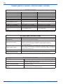
GALVANIZED 2-GALLON MODELS
Tank Model Regulation Agitation
183G-200 None None
183G-210 Single (Regulated air to tank only) None
183G-211 Single (Regulated air to tank only) Direct Drive
183G-213 Single (Regulated air to tank only) Gear-reduced (Heavy-duty)
183G-220 Double (Regulated air to tank and gun) None
183G-221 Double (Regulated air to tank and gun) Direct Drive
183G-223 Double (Regulated air to tank and gun) Gear-reduced (Heavy-duty)
183G-230 Extra Sensitive None
183G-231 Extra Sensitive Direct Drive
183G-233 Extra Sensitive Gear-reduced (Heavy-duty)
183G-240 Extra Sensitive w/ gun regulation None
183G-241 Extra Sensitive w/ gun regulation Direct Drive
183G-243 Extra Sensitive w/ gun regulation Gear-reduced (Heavy-duty)
STAINLESS STEEL 2-GALLON MODELS
Tank Model Regulation Agitation
183S-200 None None
183S-210 Single (Regulated air to tank only) None
183S-211 Single (Regulated air to tank only) Direct Drive
183S-213 Single (Regulated air to tank only) Gear-reduced (Heavy-duty)
183S-220 Double (Regulated air to tank and gun) None
183S-221 Double (Regulated air to tank and gun) Direct Drive
183S-223 Double (Regulated air to tank and gun) Gear-reduced (Heavy-duty)
183S-230 Extra Sensitive None
183S-231 Extra Sensitive Direct Drive
183S-233 Extra Sensitive Gear-reduced (Heavy-duty)
183S-240 Extra Sensitive w/ gun regulation None
183S-241 Extra Sensitive w/ gun regulation Direct Drive
183S-243 Extra Sensitive w/ gun regulation Gear-reduced (Heavy-duty)
Important:
Read and follow all
instructions and
SAFETY PRECAUTIONS
before using this
equipment. Retain for
future reference.
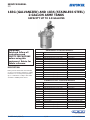
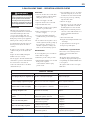
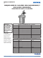
DESCRIPTION
Binks pressure feed tanks are intended
for use as a pressure container to supply
material at a constant preset pressure
up to a maximum of 110 psi. The tanks
are built to ASME specifications.
183G (GALVANIZED) AND 183S (STAINLESS STEEL)
2-GALLON ASME TANKS
CAPACITY UP TO 2.8 GALLONS
77-2927-R4.6 (5/2017) 1 / 14 www.carlisleft.com
EN
SERVICE MANUAL

Binks reserves the right to modify equipment specification without prior notice.
LOCK OUT / TAG-OUT
Failure to de-energize, disconnect, lock out and tag-out all power
sources before performing equipment maintenance could cause
serious injury or death.
OPERATOR TRAINING
All personnel must be trained before operating finishing
equipment.
EQUIPMENT MISUSE HAZARD
Equipment misuse can cause the equipment to rupture,
malfunction, or start unexpectedly and result in serious injury.
PROJECTILE HAZARD
You may be injured by venting liquids or gases that are released
under pressure, or flying debris.
PINCH POINT HAZARD
Moving parts can crush and cut. Pinch points are basically any
areas where there are moving parts.
INSPECT THE EQUIPMENT DAILY
Inspect the equipment for worn or broken parts on a daily basis.
Do not operate the equipment if you are uncertain about its
condition.
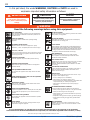
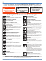
In this part sheet, the words WARNING, CAUTION and NOTE are used to
emphasize important safety information as follows:
Hazards or unsafe practices which
could result in minor personal injury,
product or property damage.
!
CAUTION
Hazards or unsafe practices which
could result in severe personal
injury, death or substantial property
damage.
!
WARNING
Important installation, operation or
maintenance information.
NOTE
Read the following warnings before using this equipment.
READ THE MANUAL
Before operating finishing equipment, read and understand all
safety, operation and maintenance information provided in the
operation manual.
WEAR SAFETY GLASSES
Failure to wear safety glasses with side shields could result in
serious eye injury or blindness.
NEVER MODIFY THE EQUIPMENT
Do not modify the equipment unless the manufacturer provides
written approval.
IT IS THE RESPONSIBILITY OF THE EMPLOYER TO PROVIDE THIS INFORMATION TO THE OPERATOR OF THE EQUIPMENT.
FOR FURTHER SAFETY INFORMATION REGARDING THIS EQUIPMENT, SEE THE GENERAL EQUIPMENT SAFETY BOOKLET (77-5300).
KNOW WHERE AND HOW TO SHUT OFF THE EQUIPMENT
IN CASE OF AN EMERGENCY
PRESSURE RELIEF PROCEDURE
Always follow the pressure relief procedure in the equipment
instruction manual.
NOISE HAZARD
You may be injured by loud noise. Hearing protection may be
required when using this equipment.
STATIC CHARGE
Fluid may develop a static charge that must be dissipated through
proper grounding of the equipment, objects to be sprayed and all
other electrically conductive objects in the dispensing area. Improper
grounding or sparks can cause a hazardous condition and result in
fire, explosion or electric shock and other serious injury.
PROP 65 WARNING
WARNING: This product contains chemicals known to the
State of California to cause cancer and birth defects or other
reproductive harm.
WEAR RESPIRATOR
Toxic fumes can cause serious injury or death if inhaled.
Wear a respirator as recommended by the fluid and solvent
manufacturer’s Safety Data Sheet.
TOXIC FLUID & FUMES
Hazardous fluid or toxic fumes can cause serious injury or death if
splashed in the eyes or on the skin, inhaled, injected or
swallowed. LEARN and KNOW the specific hazards or the fluids
you are using.
KEEP EQUIPMENT GUARDS IN PLACE
Do not operate the equipment if the safety devices have been
removed.
!
WARNING
AUTOMATIC EQUIPMENT
Automatic equipment may start suddenly without warning.
FIRE AND EXPLOSION HAZARD
Improper equipment grounding, poor ventilation, open flame or
sparks can cause a hazardous condition and result in fire or
explosion and serious injury.
MEDICAL ALERT
Any injury caused by high pressure liquid can be serious. If you
are injured or even suspect an injury:
• Go to an emergency room immediately.
• Tell the doctor you suspect an injection injury.
• Show the doctor this medical information or the medical alert
card provided with your airless spray equipment.
• Tell the doctor what kind of fluid you were spraying or
dispensing.
GET IMMEDIATE MEDICAL ATTENTION
To prevent contact with the fluid, please note the following:
• Never point the gun/valve at anyone or any part of the body.
• Never put hand or fingers over the spray tip.
• Never attempt to stop or deflect fluid leaks with your hand,
body, glove or rag.
• Always have the tip guard on the spray gun before spraying.
• Always ensure that the gun trigger safety operates before
spraying.
EN
77-2927-R4.6 (5/2017)2 / 14www.carlisleft.com

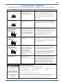
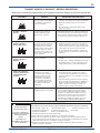
2-GALLON ASME TANKS – SAFEGUARDS
HAZARD CAUSE SAFEGUARDS
Fire
Solvents and coatings can be
highly flammable or combustible,
especially when sprayed.
1. Adequate exhaust must be provided to keep the air
free of accumulations of flammable vapors.
2. Smoking must never be allowed in the spray area.
3. Fire extinguishing equipment must be present in the
spray area.
Fire – Pressure tank
Vapors from flammable liquids can
catch fire or explode.
Keep tank at least 10 feet away from sources of ignition.
Ignition sources include hot objects, mechanical sparks,
and arcing (non -explosion proof) electrical equipment.
Explosion Hazard –
Pressure Tank –
Static Electricity
Static electricity is created by the
flow of fluid through the pressure
tank and hose. If all parts are not
properly grounded, sparking may
occur. Sparks can ignite vapors
from solvents and the fluid being
sprayed.
1. Ground the pressure tank by connecting one end of
12 gauge (minimum) ground wire to the pressure tank
and the other end to a true earth ground. Local codes
may have additional grounding requirements.
2. See illustration on page 6 for grounding and
grounding hardware required.
Explosion Hazard –
Pressure Tank –
Rupture
Making changes to a pressure tank
will weaken it.
1. Never drill into, weld, or modify the tank in any way.
2. Do not adjust, remove, or tamper with the safety
valve. If replacement is necessary, use the same type
and rating of valve.
Explosion Hazard –
Galvanized Tanks –
Material Compatibility
Halogenated hydrocarbon
solvents – for example 1-1-1
Trichloroethane and methylene
chloride – can chemically react
with aluminum parts and
components and cause an
explosion hazard. These solvents
will also corrode the galvanized
tank coating.
1. Read the label or data sheet for the material. Do
not use materials containing these solvents with
galvanized pressure tanks. Stainless steel tank models
may be used with halogenated solvents.
2. Refer to specifications chart to ensure that fluids are
chemically compatible with the tank wetted parts.
Before placing fluids or solvents in tank, always read
accompanying manufacturer’s literature.
General Safety
Improper operation or
maintenance may create a hazard.
Operators should be given adequate training in the safe
use and maintenance of the equipment (in accordance
with the requirements of NFPA-33, Chapter 15 in U.S.)
Users must comply with all local and national codes
governing ventilation, fire precautions, operation,
maintenance, and housekeeping (in the U.S., these are
OSHA sections 1910.94 and 1910.107, and NFPA-33.
The following hazards may occur during the normal use of this equipment. Please read the following chart.
WARNING
High pressure can cause
serious injury.
Pressure is maintained in a
pressure tank after the
system has been shut down.
Always follow this
procedure to relieve pressure
from the tank.
!
1. Turn off the main air supply to the tank.
2. Close the air inlet valve located on the tank air manifold.
3. Bleed off air in the tank by turning the air relief valve (5) thumb screw counterclockwise. Wait until all
the air has escaped through the valve before removing the pressure tank cover or fill port cap.
4. Leave the air relief valve open until you have reinstalled the tank cover or fill port cap.
PRESSURE RELIEF PROCEDURE
To reduce the risk of injury, follow the pressure relief procedure below
• Before checking or servicing
any part of the spray system
• Before attempting removal of
fill port cap or tank cover
• Whenever the tank is left
unattended
EN
77-2927-R4.6 (5/2017) 3 / 14 www.carlisleft.com

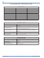
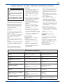
2-GALLON ASME TANKS – SPECIFICATIONS & OPTIONS
SPECIFICATIONS
GALVANIZED TANKS STAINLESS STEEL TANKS
Maximum Working Pressure 110 psi 110 psi
Tank Shell SA-414 Steel, Galvanized (Zinc) 304 Stainless Steel
Tank Lid SA-414 Steel, Galvanized (Zinc) 304 Stainless Steel
Fluid Tube 3/8 in. Steel Pipe, Galvanized 3/8 in. SS Pipe, 316 Stainless Steel
Fluid Outlet (Elbow) Steel, Zinc Plate 316 Stainless Steel
Fluid Valve, Outlet Brass, Nickel Plate 3/8-18 NPS(M) 316 Stainless Steel 3/8-18 NPS(M)
Agitator Paddle/Propeller Nylon, Glass Filled Nylon, Glass Filled
Agitator Shaft Steel, Zinc Plate 303 Stainless Steel
Agitator Shaft Seal Engineered PTFE, Stainless Steel Engineered PTFE, Stainless Steel
Air Manifold Steel, Zinc Plate Steel, Zinc Plate
Plug (Air Manifold Coupling) Steel, Zinc Plate 18-8 Stainless Steel
Bottom Outlet (Optional Kit) 304 Stainless Steel 3/4-14 NPS(M) 304 Stainless Steel 3/4-14 NPS(M)
AIR CONTROL OPTIONS
TYPE APPLICATION
No Regulation (Air inlet pressure gauge only)
Holding tanks, Transfer tanks, Used where precision fluid pressure control is
not required.
Standard Single Regulation
Provides standard fluid pressure control only. For use where precision control
of both fluid and air pressures is not required. Also Used where atomization
air can be taken from filter/regulator air lines.
Standard Double Regulation
Precision control for use with materials that are best applied at low, closely
controlled, fluid and atomization air pressures. Used with portable air
compressors or with air lines when no other means of air pressure regulation
is available.
Extra Sensitive Regulation Provides extremely accurate, low pressure, fluid pressure control
Extra Sensitive Regulation with
Standard Gun Regulation
Provides extremely accurate, low pressure, fluid pressure control plus precision
control of spray gun atomizing air.
AGITATION OPTIONS
TYPE APPLICATION
No Agitation
Materials that require minimal or no mixing and/or readily hold any solids in
suspension.
Direct Drive Agitation
Low to medium viscosity materials that require mixing and/or solids
suspension.
Gear-reduced Drive Agitation
Heavy-duty agitator for medium to high viscosity materials that require mixing
and/or solids suspension.
EN
77-2927-R4.6 (5/2017)4 / 14www.carlisleft.com

2-GALLON ASME TANKS – OPERATION & SERVICE CHECKS
PREPARATION
Mix and prepare material to be used
according to manufacturer’s instructions.
Strain material through a fine mesh
screen to remove lumps, skin, and
foreign matter that might enter and clog
fluid passages and/or spray equipment.
Follow pressure relief procedure above.
To add material to the tank, remove the
lid and pour directly into the tank or
container.
If desired, a U.S. or metric 1 gallon pail
of fluid can be placed directly into the
tank.
Replace the lid assembly and tighten
thumb screws (17) securely.
The air supply to the tank should include
a filter/water separator to filter dirt from
the air and remove water and oil.
Connect the material hose to the fluid
outlet ball valve (8).
OPERATION
1. Close the air inlet valve to tank. Turn
handle on regulator counterclockwise
until spring tension is relieved.
2. Turn on air supply to the tank.
3. Open the air inlet valve to the tank.
4. Open the fluid outlet valve.
5. Turn handle on tank pressure regulator
clockwise to pressurize tank.
6. Turn on atomization air to spray gun
at source of supply.
7. Test spray. For further instructions
consult literature provided with spray
gun.
8. If an air motor driven agitator is used,
start the agitator by slowly opening up
the needle valve. Air motor speed
should be regulated according to the
nature of the material being agitated.
MAINTENANCE
To clean equipment, proceed as follows:
1. Turn off the air supply.
2. Follow the pressure relief procedure.
3. Turn T-handle adjusting screw on tank
fluid pressure regulator
counterclockwise until no spring
pressure is felt.
4. Loosen thumb screws (17), tip clamps
(16) back and tip lid (11) to one side
of tank. Do not remove lid from tank.
5. Loosen spray gun air cap retaining
ring about three turns.
6. Turn on air supply.
7. Cup cloth over air cap on the gun and
pull trigger. This will force material
back through the hose into the tank.
8. Empty and clean tank and parts that
come into contact with material. Use a
solvent compatible with material
being used.
9. Pour solvent into tank.
10. Replace lid and tighten thumb screws
and clamps.
11. Spray until clean solvent appears.
12. Repeat steps 4 through 8.
LUBRICATION – Agitated Models
Refer to the service manual provided
with the air motor for lubrication
information.
The bearings in the agitator bearing
assembly are impregnated with special
non-gumming oil. Additional lubrication
is not required.
The agitator shaft seal does not require
lubrication.
WARNING
High pressure can cause serious injury.
Pressure is maintained in a pressure tank
after the system has been shut down.
Follow the pressure-relief procedure on
page 3 before opening the lid or fill port
or performing maintenance on the tank.
!
SERVICE CHECKS
CONDITION CAUSE CORRECTION
Air escaping from port on regulator cap. Broken or damaged diaphragm Replace diaphragm.
Pressure creepage registered on gauge. Dirty or worn valve seat in regulator. Clean or replace valve seat.
Material tends to settle out rapidly. Not enough agitation of material. Increase agitation.
Air leakage at agitator seal. Defective seal assembly. Replace.
Paint getting into bearing assembly of
agitator.
1. Paint level in tank too high.
2. Defective agitator shaft seal.
1. Keep fluid level under bearing ass’y.
2. Replace
Fluid or air leak at lid gasket.
1. Thumb screw not tight.
2. Defective lid gasket.
1. Tighten.
2. Replace.
Fluid or air leak at fill port gasket.
1. Fill port cap not tight.
2. Defective fill port gasket.
1. Tighten.
2. Replace.
Air mixing with paint
1. Fluid tube not sealed to lid.
2. Excessive agitation.
1. Tighten fluid tube into lid.
2. Reduce speed of agitator.
EN
77-2927-R4.6 (5/2017) 5 / 14 www.carlisleft.com

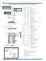
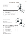
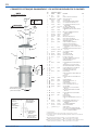
2-GALLON GALVANIZED AND STAINLESS STEEL TANK ASSEMBLIES
Grounding Diagram
Purchase hardware locally
5/16–18 x 3/4 Long
Hex Head Bolt
(1 Required)
2X
5/16–18 Hex Head Nut
(2 Required)
Sufficient Length
12 Gauge Wire
(Not Shown)
5/16 Lock Washer
(1 Required)
Tank Skirt (Ref)
ITEM
NO.
GALV. TANK
PART NO.
S.S. TANK
PART NO. DESCRIPTION QTY.
1
▲
QN-97 QN-97 HANDLE 1
2 QMG-17 QMS-2 PLUG (NON-AGITATED MODELS ONLY) 1
3
▲ ■
SSG-8184-K2 SSG-8184-K2 O-RING (KIT OF 2) 1
4 QMG-21 QMG-21 AIR MANIFOLD 1
5 SS-2707 SS-2707 AIR RELIEF VALVE 1/4 NPT-M 1
6 TIA-5110 TIA-5110 SAFETY VALVE ASSY, 110 PSI 1
6A TIA-5040 TIA-5040 SAFETY VALVE ASSY, 40 PSI (EXTRA SENSITIVE ONLY)
7 • ----- (Brass) SSP-1939 (S.S.) STR ELBOW (3/8-18) 1
8 VA-540 VA-527 BALL VALVE 3/8 NPS OUTLET 1
9 83-524-K 83-524-K FILL PORT CAP (INCL ITEM 10) 1
10 83-1207-K5 83-1207-K5 FILL PORT CAP GASKET (QTY PACK) 1
11 QMG-400-1 QMS-416-1 TANK LID 1
12 SSP-1439-ZN 20-6858 PLUG (1/2-14) 1
13 QMS-80-1 QMS-80-1 TANK GASKET 2 GAL 1
14 PT-31 QMS-9-1 FLUID TUBE (DIR DRIVE AGIT) 1
15 QMG-35 QMS-53-1 FLUID TUBE (GEAR REDUCED AGIT) 1
16 ----- ----- CLAMP (SEE ITEM 20) 4
17 QMG-46 QMG-46 THUMBSCREW (SEE ITEM 20) 4
18 ----- ----- CLEVIS PIN (SEE ITEM 20) 4
19 ----- ----- COTTER PIN, 1/8 DIA. X 1" LG. (SEE ITEM 20) 4
20 + KK-5013 KK-5013 CLAMP, PIN, & SCREW KIT (INCL 16, 17, 18, & 19) 4
21 PT-78-K10, K60 PT-78-K10, K60 DISPOSABLE TANK LINER (10 OR 60 EACH) 1
22 QMG-502-1 QMS-502-1 TANK & LUG ASSY 1
23 ----- ----- BOTTOM PLUG 1
24
▲
QMG-429 QMS-428 AIR MOTOR ASSY 1
25
▲
HAV-500-B HAV-500-B AIR ADJUSTING VALVE 1
26
▲
H-2008 H-2008 NIPPLE 1/4 NPS x 1/4 NPT 2
27
▲ •
----- ----- STREET ELBOW (1/4-18 NPT, BRASS) 2
28
▲
----- ----- SET SCREW (1/4-20 X 1/4) 2
29
▲ #
----- ----- ADAPTER (SEE ITEM 30) 1
30
▲
KK-4990 KK-4991 SEAL RETAINER KIT (INCL 28, 29, 34,35) 1
31
▲
----- ----- SHAFT SEAL 1/2 I.D. (DIR. DRIVE AGIT) 1
32
▲
----- ----- INTERNAL RETAINING RING (DIR. DRIVE AGIT) 1
33
▲
KK-5041 KK-5041 SHAFT SEAL KIT (DIR. DRIVE AGIT) 1
34
▲ •
----- ----- SET SCREW (1/4-20 X 1/4) S.S. 2
35
▲ #
----- ----- SHAFT COUPLING (SEE ITEM 30) 1
36
▲
QMG-56 QMS-73 AGITATOR SHAFT 1
37
▲ •
----- ----- SQ HD SET SCREW, 1/4-20 X 3/8, S.S. 1
38
▲
----- ----- PROPELLOR 1
39
▲
QMS-448 QMS-448 AGITATOR PROPELLER KIT (DIR. DRIVE) 1
40
■
QMS-46 QMS-46 RETAINING NUT 1
41
■
KK-5049 KK-5049 THRUST WASHER (KIT OF 2/EA) 1
42
■
----- ----- THRUST COLLAR 1
43 ■ • ----- ----- SET SCREW, 5/16-18 X 3/8 1
44
■
QMS-447 QMS-447 THRUST COLLAR KIT (INCL. 42 and 43) 1
45
■
QMG-409 QMS-407 BEARING ASSY. 1
46
■
----- ----- SHAFT SEAL 5/8 I.D. (GEAR REDUCED AGIT) 1
47
■
----- ----- INTERNAL RETAINING RING (GEAR REDUCED AGIT) 1
48
■
KK-5042 KK-5042 SHAFT SEAL KIT (GEAR REDUCED AGIT) 1
49
■
QMG-15 QMS-5 AGITATOR SHAFT 1
50
■
----- ----- AGITATOR PADDLE 1
51
■
----- ----- SOC HD CAP SCREW, 5/16-18 X 1-1/4, S.S. 1
52
■
QMS-449 QMS-449 AGITATOR PADDLE KIT (INCL 51 AND 52) 1
53 QS-5012-1 QS-5012-1 AIR MOTOR/GEARBOX DRIVE 1
54
▲
HA-57011 HA-57011 AIR HOSE ASSY 1
55 SSP-30-ZN SSP-30-ZN SWIVEL ELBOW 1
56 *** SEE PAGES 9 & 10 *** AIR CONTROL 1
57 • ----- ----- PLUG, 3/8 NPT, SS (NOT SHOWN) FOR USE 1
ONLY WITH BOTTOM OUTLET KIT. REPLACES
ITEMS 7 AND 8. PURCHASE LOCALLY.
PG
PETROLEUM
JELLY/GREASE
1
2
3
4
5
6 or 6A
7
8
9
10
11
12
13
19
18
17
16
15
14
20
21
22
23
PG
For bottom outlet
conversion remove
and discard plug.
NOTE
Use PTFE based thread sealant on all
air and fluid connections.
CAUTION
Use 40 PSI Safety Valve (6A) with an
extra sensitive regulator.
!
• Purchase locally.
+ KK-5013 Clamp, Pin, and Screw Kit includes 1 each of items 16, 17, 18, and 19.
# When replacing either Item Number 29 or 35, you must order KK-4990
(Galvanized) or KK-4991 (Stainless Steel) which include both parts.
▲ Items available separately or as a complete agitator assembly:
QMG-416 (for galvanized tanks)
QMS-430 (for S.S. tanks)
■ Items available separately or as a gear-reduced agitator (less drive):
QMG-417 (for galvanized tanks)
QMS-431 (for S.S. tanks)
EN
77-2927-R4.6 (5/2017)6 / 14www.carlisleft.com

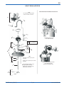
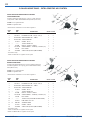
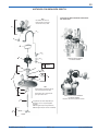
DIRECT DRIVE AGITATOR
STANDARD REGULATION
1 OR 2 REGULATORS
EXTRA SENSITIVE REGULATION
1 OR 2 REGULATORS
Requires 40 PSI Safety Valve
DIRECT DRIVE AGITATOR-REGULATOR HOOK-UP
Note
Open side of shaft seal (31) faces
downward.
Retainer (32) required only for vacuum
operation.
Note
Use PTFE based thread sealant
on all air and fluid connections
PG
PETROLEUM
JELLY/GREASE
56
55
54
1
25
26
27
24
28
29
30
3
31
28
32
34
35
36
39
38
37
PG
PG
33
Items available separately or as a
complete agitator assembly:
QMG-416 (for galvanized tanks)
QMS-430 (for S.S. tanks)
EN
77-2927-R4.6 (5/2017) 7 / 14 www.carlisleft.com

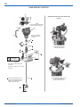
GEAR-REDUCED AGITATOR
EXTRA SENSITIVE REGULATION
1 OR 2 REGULATORS
Requires 40 PSI Safety Valve
STANDARD REGULATION
1 OR 2 REGULATORS
GEAR-REDUCED DRIVE AGITATOR-REGULATOR
HOOK-UP
Note
Open side of shaft seal (46) faces
downward.
Retainer (47) required only for vacuum
operation.
Note
Use PTFE based thread sealant
on all air and fluid connections
PG
PETROLEUM
JELLY/GREASE
56
40
54
53
43
42
44
41
41
45
48
3
46
47
50
49
51
PG
PG
52
55
Items available separately or as a
gear-reduced agitator (less drive):
QMG-417 (for galvanized tanks)
QMS-431 (for S.S. tanks)
Refer to 77-2990 for
information about the
drive unit.
EN
77-2927-R4.6 (5/2017)8 / 14www.carlisleft.com

2-GALLON ASME TANKS – AIR CONTROL
SINGLE REGULATOR AIR CONTROL
Control tank pressure only.
85-470 for non-agitated tanks
85-471 for agitated tanks
*Items with an asterisk are for use with an agitator.
1
2
2
4
3
6
3
10*
5
11*
ITEM
NO.
PART
NO. DESCRIPTION 85-470 85-471
1 + HAR-511 AIR REGULATOR 1 1
2 20-1753-1 BUSHING-STL-PLTD – 3/8 (m) x 1/4 (f) 2 2
3 VA-542 BALL VALVE 2 2
4 83-1290 GAUGE – 150 PSI 1 1
5 SSP-8217-ZN SWIVEL ADAPTER 1 1
6 • --------- 1/4 NPT PLUG (SUPPLIED W/ REGULATOR) 1 —
10 H-2008 NIPPLE 1/4 NPS x 1/4 NPT — 1
11 SSP-30-ZN SWIVEL ELBOW – 1/4 NPS(m) x 1/4 NPS (sw) — 1
• Purchase locally
+ Refer to 77-2781 for regulator service parts
DOUBLE REGULATOR AIR CONTROL
Control tank pressure and spray gun atomization pressure.
85-472 for non-agitated tanks
85-473 for agitated tanks
*Items with an asterisk are for use with an agitator.
1
8
6
3
3
2
2
4
5
6
7
9
10*
11*
ITEM
NO.
PART
NO. DESCRIPTION 85-472 85-473
1 + HAR-511 AIR REGULATOR 1 1
2 20-1753-1 BUSHING-STL-PLTD – 3/8 (m) x 1/4 (f) 2 2
3 VA-542 BALL VALVE 2 2
4 83-1290 GAUGE - 150 PSI 1 1
5 SSP-8217-ZN SWIVEL ADAPTER 1 1
6 • --------- 1/4 NPT PLUG (SUPPLIED W/ REGULATOR) 2 1
7 83-4233 D.M. NIPPLE 1/4 x 3/8 1 1
8 # HAR-507 AIR REGULATOR 1 1
9 83-1355 GAUGE - 100 PSI 1 1
10 H-2008 NIPPLE 1/4 NPS x 1/4 NPT — 1
11 SSP-30-ZN SWIVEL ELBOW – 1/4 NPS(m) x 1/4 NPS (sw) — 1
• Purchase locally
+ Refer to 77-2781 for regulator service parts
# Refer to SBBI-6-147 for regulator service parts
EN
77-2927-R4.6 (5/2017) 9 / 14 www.carlisleft.com

2-GALLON ASME TANKS – EXTRA SENSITIVE AIR CONTROL
EXTRA SENSITIVE REGULATOR AIR CONTROL
SINGLE REGULATOR
Provides extremely high precision control of tank pressure
(only) from 0 – 30 PSI. Includes 40 PSI Safety Valve (not shown.)
85-490 for non-agitated tanks
85-491 for agitated tanks
*Items with an asterisk are for use with an agitator.
5
6
2
2
9
1
6
*
3
4
7
*
8
*
ITEM
NO.
PART
NO. DESCRIPTION 85-490 85-491
1 + HAR-501 EXTRA-SENSITIVE REGULATOR 1 1
2 20-1753-1 BUSHING-STL-PLTD – 3/8 (m) x 1/4 (f) 2 2
3 SSP-2629-ZN MALE BRANCH TEE – 1/4NPT 1 1
4 SSP-8217-ZN SWIVEL ADAPTER 1 1
5 83-1414 GAUGE - 30 PSI 1 1
6 • --------- 1/4 NPT STREET TEE 1 2
7 H-2008 NIPPLE – 1/4 NPS x 1/4 NPT — 1
8 SSP-ZN-30 SWIVEL ELBOW – 1/4 NPS(m) x 1/4 NPS (sw) — 1
9 VA-542 BALL VALVE 2 2
10 TIA-5040 SAFETY VALVE, 40 PSI (NOT SHOWN) 1 1
• Purchase locally
+ Refer to SB-6-131 for regulator service parts
EXTRA SENSITIVE REGULATOR AIR CONTROL
DOUBLE REGULATOR
Provides extremely high precision control of tank pressure plus
standard regulation for a spray gun. Includes 40 PSI Safety
Valve (Not shown.)
85-492 for non-agitated tanks
85-493 for agitated tanks
*Items with an asterisk are for use with an agitator.
5
11
2
6*
3
4
7*
8
*
2
1
9
9
10
12
13
6
ITEM
NO.
PART
NO. DESCRIPTION 85-492 85-493
1 + HAR-501 EXTRA-SENSITIVE REGULATOR 1 1
2 20-1753-1 BUSHING-STL-PLTD – 3/8 (m) x 1/4 (f) 2 2
3 SSP-2629-ZN MALE BRANCH TEE – 1/4NPT 1 1
4 SSP-8217-ZN SWIVEL ADAPTER 1 1
5 83-1414 GAUGE - 30 PSI 1 1
6 • --------- 1/4 NPT STREET TEE 1 2
7 H-2008 NIPPLE – 1/4 NPS x 1/4 NPT — 1
8 SSP-ZN-30 SWIVEL ELBOW – 1/4 NPS(m) x 1/4 NPS (sw) — 1
9 VA-542 BALL VALVE 2 2
10 • --------- 1/4 NPT PLUG (SUPPLIED W/ REGULATOR) 2 2
11 83-4233 D.M. NIPPLE 1/4 x 3/8 1 1
12 # HAR-507 AIR REGULATOR 1 1
13 83-1355 GAUGE – 100 PSI 1 1
14 TIA-5040 SAFETY VALVE, 40 PSI (NOT SHOWN) 1 1
• Purchase locally
+ Refer to SB-6-131 for regulator service parts
# Refer to SBBI-6-147 for regulator service parts
EN
77-2927-R4.6 (5/2017)10 / 14www.carlisleft.com

Use when fluid pressure in tank is regulated by some other, separate, method of control.
ITEM
NO.
PART
NO. DESCRIPTION QTY.
1 • — ADAPTER, 1/4 NPT(F) X 1/4 NPS (SW) 1
2 • — STREET TEE 1
3 83-1290 GAUGE, 150 PSI 1
4 VA-542 BALL VALVE 1
•Purchase locally
3
2
4
1
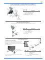
QMS-4003 NO REGULATION KIT
85-469 CONVERSION TO DOUBLE REGULATOR ASSEMBLY KIT
Convert standard single regulator or extra-sensitive air control to a double regulator air control.
ITEM
NO.
PART
NO. DESCRIPTION QTY.
6 • — 1/4 NPT PLUG (SUPPLIED W/ REGULATOR) 1
7 83-4233 D.M. NIPPLE 1/4 x 3/8 1
8 HAR-507 AIR REGULATOR 1
9 83-1355 GAUGE – 100 PSI 1
•Purchase locally
9
7
8
6
EXISTING
REGULATOR
1
2
3
4
1
5
ITEM
NO.
PART
NO. DESCRIPTION QTY.
1 — ADAPTER, 3/4 NPT-NPS UNIVERSAL 2
2 — ELBOW, 3/4 NPT (F) 1
3 — PIPE NIPPLE 1
4 — BALL VALVE, 3/4 NPT FULL PORT 1
5 183-3005 LEG KIT 3
BOTTOM OUTLET KIT WITH LEGS
Allows conversion of tank from standard top outlet to bottom
outlet. All bottom outlet wetted parts are stainless steel.
183-3000 for 2-gallon tanks with ¾” bottom outlets. Includes
three 183-3005 Leg Kits.
Legs can be oriented either inward or outward to provide
flexibility in mounting.
Outward orientation
Inward orientation
BOTTOM OUTLET KIT
EN
77-2927-R4.6 (5/2017) 11 / 14 www.carlisleft.com

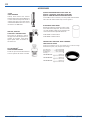
VS-534
FLUID STRAINER
Primary fluid strainer that attaches
between fluid outlet valve and fluid hose
to strain material. Components made of
stainless steel with a nylon filter. Comes
standard with 100-mesh screen. For more
information see SBBI-7-072.
HFRL-508, HFRL-509
CLEAN AIR™ CONTROL UNITS
These units are designed to remove
dirt, pipe scale and most liquid aerosol.
Includes an automatic drain which
expels liquids which accumulate in
the filter bowl.
29-3100 SCRUBS
®
HAND CLEANER TOWELS
Scrubs
®
are a pre-moistened hand cleaner
towel for painters. No water is needed.
DISPOSABLE TANK LINERS
Molded polyethylene tank liners reduce solvent
waste and tank cleanup time. The liner is made
of tough, durable, leakproof poly-ethylene and
can be used with all compatible materials.
PT-78-K10 Kit of 10 tank liners
PT-78-K60 Kit of 60 tank liners
Inner Diameter .................8.75" (222.25mm)
Outer Diameter ............10.625" (269.87mm)
Height/Depth ....................2.625" (66.67mm)
Case Qty ..................................................... 20
PTS-2Gal-K20-200 ........................200 micron
(approx. 65 wire mesh)
PTS-2Gal-K20-400 ........................400 micron
(approx. 37 wire mesh)
PTS-2Gal-K20-600 ........................600 micron
(approx. 28 wire mesh)
QMG-35 GALVANIZED BENT FLUID TUBE OR
QMS-53-1 STAINLESS STEEL BENT FLUID TUBE
QMS-79 SHORTER PROFILE AGITATOR PADDLE
If air bubbles form in material, a shorter paddle and bent fluid
tube takes the intake farther away from the agitator.
PROSPECTOR
™
PRESSURE TANK STRAINERS
FOR 2 GALLON TANKS
Prospector™ strainers are an economical way to remove foreign
material from paint, stain, lacquer and coatings.
ACCESSORIES
EN
77-2927-R4.6 (5/2017)12 / 14www.carlisleft.com

NOTES
EN
77-2927-R4.6 (5/2017) 13 / 14 www.carlisleft.com

EN
77-2927-R4.6 (5/2017)14 / 14www.carlisleft.com
WARRANTY POLICY
Binks products are covered by Carlisle Fluid Technologies one year materials and workmanship
limited warranty. The use of any parts or accessories, from a source other than
Carlisle Fluid Technologies, will void all warranties. For specic warranty information please contact
the closest Carlisle Fluid Technologies location listed below.
Binks is part of Carlisle Fluid Technologies, a global leader in innovative nishing technologies.
For technical assistance or to locate an authorized distributor, contact one of our international sales
and customer support locations.
USA/Canada
Tel: 1-888-992-4657
Fax: 1-888-246-5732
United Kingdom
Tel: +44 (0)1202 571 111
Fax: +44 (0)1202 573 488
China
Tel: +8621-3373 0108
Fax: +8621-3373 0308
Mexico
Tel: +52 55 5321 2300
Fax: +52 55 5310 4790
Japan
Tel: +81 45 785 6421
Fax: +81 45 785 6517
Brazil
Tel: +55 11 5641 2776
Fax: +55 11 5641 1256
Germany
Tel: +49 (0) 6074 403 1
Fax: +49 (0) 6074 403 281
Australia
Tel: +61 (0) 2 8525 7555
Fax: +61 (0) 2 8525 7575
Carlisle Fluid Technologies reserves the right to modify equipment specications without prior notice.
DeVilbiss
®
, Ransburg
®
, MS
®
, BGK
®
, and Binks
®
are registered trademarks of Carlisle Fluid Technologies, Inc.
©2017 Carlisle Fluid Technologies, Inc.
All rights reserved.
For the latest information about our products, visit www.carlisleft.com.

TANQUES ASME DE 2 GALONES 183G (GALVANIZADO) Y
183S (ACERO INOXIDABLE)
CAPACIDAD DE HASTA 2.8 GALONES
MODELOS GALVANIZADOS DE 2 GALONES
Modelo del tanque Regulación Agitación
183G-200 Ninguna Ninguna
183G-210 Única (aire regulado sólo al tanque) Ninguna
183G-211 Única (aire regulado sólo al tanque) Impulsión directa
183G-213 Única (aire regulado sólo al tanque) Engranaje reducido (reforzado)
183G-220 Doble (aire regulado al tanque y la pistola) Ninguna
183G-221 Doble (aire regulado al tanque y la pistola) Impulsión directa
183G-223 Doble (aire regulado al tanque y la pistola) Engranaje reducido (reforzado)
183G-230 Extra sensible Ninguna
183G-231 Extra sensible Impulsión directa
183G-233 Extra sensible Engranaje reducido (reforzado)
183G-240 Extra sensible c/regulación de pistola Ninguna
183G-241 Extra sensible c/regulación de pistola Impulsión directa
183G-243 Extra sensible c/regulación de pistola Engranaje reducido (reforzado)
MODELOS DE ACERO INOXIDABLE DE 2 GALONES
Modelo del tanque Regulación Agitación
183S-200 Ninguna Ninguna
183S-210 Única (aire regulado sólo al tanque) Ninguna
183S-211 Única (aire regulado sólo al tanque) Impulsión directa
183S-213 Única (aire regulado sólo al tanque) Engranaje reducido (reforzado)
183S-220 Doble (aire regulado al tanque y la pistola) Ninguna
183S-221 Doble (aire regulado al tanque y la pistola) Impulsión directa
183S-223 Doble (aire regulado al tanque y la pistola) Engranaje reducido (reforzado)
183S-230 Extra sensible Ninguna
183S-231 Extra sensible Impulsión directa
183S-233 Extra sensible Engranaje reducido (reforzado)
183S-240 Extra sensible c/regulación de pistola Ninguna
183S-241 Extra sensible c/regulación de pistola Impulsión directa
183S-243 Extra sensible c/regulación de pistola Engranaje reducido (reforzado)
Importante:
Lea y siga todas
las instrucciones
y PRECAUCIONES
DE SEGURIDAD
antes de usar este
equipo. Guardar
para referencia en
el futuro.
DESCRIPCIÓN
Los tanques alimentados a
presión de Binks están
destinados para ser
utilizados como un
recipiente a presión para
suministrar materiales a
una presión constante
prefijada hasta un máximo
de 110 psi. Los tanques son
fabricados siguiendo las
especificaciones de ASME.
77-2927-R4.6 (5/2017) ES-1 / 14 www.carlisleft.com
ES
MANUAL DE SERVICIO

Binks se reserva el derecho de modificar la especificación del equipo sin aviso previo.
BLOQUEO / ETIQUETADO
Desactivar, desconecte, bloquee y etiquete de espera de todas las
fuentes de alimentación antes de realizar el mantenimiento del
equipo. No hacerlo puede causar lesiones graves o la muerte.
CAPACITACIÓN DE LOS OPERADORES
Todos los miembros del personal deben ser capacitados antes de
operar los equipos de acabado.
PELIGRO DE USO INDEBIDO DEL EQUIPO
El uso indebido del equipo puede ocasionar averías, mal
funcionamiento o activación imprevista lo que a su vez puede
producir lesiones graves.
PELIGRO DE PROYECTILES
Usted puede resultar lesionado por dar salida a líquidos o gases
liberados bajo presión o por restos volanderos.
PELIGRO DE PUNTOS DE PRESIÓN
Las partes móviles pueden aplastar y ocasionar cortaduras. Los
puntos de presión son básicamente todas las áreas donde haya
partes móviles.
INSPECCIONE LOS EQUIPOS DIARIAMENTE
Inspeccione diariamente los equipos para verificar que no tengan
piezas gastadas o rotas. No opere los equipos si no está seguro
de esta condición.
En esta Hoja de piezas, las palabras ADVERTENCIA, PRECAUCIÓN y NOTA se
emplean para enfatizar información de seguridad importante de la siguiente forma:
Prácticas peligrosas o inseguras que
pueden ocasionar lesiones personales
leves, la muerte, daño al producto o
a la propiedad.
!
PRECAUCIÓN
Prácticas peligrosas o inseguras que
pueden ocasionar lesiones
personales graves, la muerte o daño
substancial a la propiedad.
!
ADVERTENCIA
Información importante de
instalación, operación o
mantenimiento.
NOTA
Lea las siguientes advertencias antes de usar este equipo.
LEA EL MANUAL
Antes de operar los equipos de acabado, lea y comprenda toda la
información de seguridad, operación y mantenimiento incluida en
el manual de operaciones.
USE GAFAS PROTECTORAS
No usar gafas protectoras con resguardos laterales puede
ocasionar lesiones graves en los ojos o ceguera.
NUNCA MODIFIQUE LOS EQUIPOS
No modifique el equipo sin la autorización escrita del fabricante.
ES RESPONSABILIDAD DEL EMPLEADOR SUMINISTRAR ESTA INFORMACIÓN AL OPERADOR DEL EQUIPO. PARA MÁS INFORMACIÓN DE
SEGURIDAD ACERCA DE LOS EQUIPOS, CONSULTE EL FOLLETO DE SEGURIDAD GENERAL DE LOS EQUIPOS (77-5300).
SEPA CÓMO Y DÓNDE DESACTIVAR LOS EQUIPOS EN
CASO DE EMERGENCIA.
PROCEDIMIENTO DE LIBERACIÓN DE PRESIÓN
Siga siempre el procedimiento de liberación de presión que
aparece en el manual de instrucciones del equipo.
NOISE HAZARD
You may be injured by loud noise. Hearing protection may be
required when using this equipment.
CARGA ESTÁTICA
Los fluidos pueden generar una carga estática que debe ser disipada mediante
la debida conexión a tierra del equipo, los objetos que van a ser atomizados y
todos los demás objetos electroconductores en el área de aplicación. La
conexión a tierra indebida o las chispas pueden ocasionar condiciones de peligro
y producir incendios, explosiones o descargas eléctricas y otras lesiones graves.
ADVERTENCIA PROP 65
ADVERTENCIA: Este producto contiene sustancias químicas que
según información en poder del estado de California producen
cáncer, defectos de nacimiento y otros daños al sistema reproductor.
USE UN RESPIRADOR
La inhalación de vapores tóxicos puede ocasionar lesiones graves
o la muerte. Use un respirador como lo recomienda la Hoja de
datos de seguridad del fabricante de fluido y el solvente.
FLUIDOS Y VAPORES TÓXICOS
Los fluidos peligrosos o los vapores tóxicos pueden ocasionar
lesiones graves o la muerte si se salpican a los ojos o la piel, se
inhalan, se inyectan o ingieren APRENDA y CONOZCA los peligros
específicos de los fluidos que está utilizando.
MANTENGA LAS DEFENSAS DEL EQUIPO EN SU LUGAR
No operar los equipos si los dispositivos de seguridad fueron
retirados.
!
ADVERTENCIA
EQUIPOS AUTOMÁTICOS
Los equipos automáticos pueden activarse súbitamente sin
advertencia.
PELIGRO DE INCENDIO Y EXPLOSIÓN
La conexión a tierra indebida de los equipos, la ventilación insuficiente,
la llama abierta o las chispas pueden ocasionar condiciones de peligro
y producir incendios, explosiones y otras lesiones graves.
ALERTA MÉDICA
Cualquier lesión ocasionada por líquido de alta presión puede ser
grave. Si sufre una lesión o sospecha haber sufrido una:
• Vaya a una sala de emergencia de inmediato.
• Informe al médico que sospecha haber sufrido una lesión por inyección.
• Muestre al médico esta información médica o la tarjeta de alerta médica
provista con su equipo de pulverización sin aire.
• Informe al médico acerca del tipo de fluido que estaba pulverizando o
aplicando.
• Consulte la información específica en la Hoja de datos de seguridad.
CONSIGA ATENCIÓN MÉDICA INMEDIATA
Para evitar el contacto con el fluido, tenga en cuenta lo siguiente:
• Nunca apunte la pistola/válvula hacia ninguna persona ni hacia ninguna
parte del cuerpo.
• Nunca ponga la mano ni los dedos sobre la punta pulverizadora.
• Nunca trate de detener ni desviar los escapes de fluido con la mano, el
cuerpo, guantes o trapos.
• Antes de atomizar, tenga siempre el resguardo de la punta puesto en la
pistola pulverizadora.
• Antes de atomizar, asegúrese siempre de que el seguro del disparador de
la pistola esté operativo.
• Cuando deje de atomizar, póngale siempre el seguro al disparador de la
pistola.
PROP
65
DE CA
ES
77-2927-R4.6 (5/2017)ES-2 / 14www.carlisleft.com

PELIGRO CAUSA MEDIDAS PREVENTIVAS
Incendio
Los solventes y recubrimientos
pueden ser altamente inflamables
o combustibles, especialmente
cuando se atomizan.
1. Debe proveerse de un escape adecuado para mantener
el aire libre de acumulaciones de vapores inflamables.
2. Nunca debe permitirse fumar en el área donde se
atomiza.
3. En el área donde se atomiza debe haber equipo
extintor de incendios.
Incendio – Tanque a
presión
Los vapores provenientes de
líquidos inflamables pueden
prender fuego o explotar.
Mantenga el tanque al menos a 10 pies de distancia de
las fuentes de ignición. Las fuentes de ignición incluyen
objetos calientes, chispas mecánicas y equipos eléctricos
con formación de arcos (no a prueba de explosiones).
Peligro de explosión –
Tanque a presión –
Electricidad estática
La electricidad estática se crea
por el flujo de fluido a través del
tanque a presión y la manguera.
Si todas las piezas no tienen la
debida conexión a tierra, podrían
producirse chispas. Las chispas
pueden encender los vapores de
los solventes y el fluido que está
siendo atomizado.
1. Haga la conexión a tierra del tanque a presión
acoplando un extremo del cable de tierra calibre 12
(mínimo) al tanque a presión y el otro extremo a una
conexión a tierra efectiva. Los códigos locales pueden
tener requisitos de conexión a tierra adicionales.
2. Ver en la ilustración de la página 6 los requisitos de
conexión a tierra y los accesorios de conexión a tierra
requeridos.
Peligro de explosión –
Tanque a presión –
Ruptura
Hacer cambios a un tanque a
presión lo debilitará.
1. Nunca perfore, solde o modifique de ninguna manera
el tanque.
2. No ajuste, quite o manipule indebidamente la válvula
de seguridad. Si fuese necesario reemplazar, use una
válvula del mismo tipo y con la misma clasificación.
Peligro de explosión –
Tanques galvanizados –
Compatibilidad del
material
Los solventes con hidrocarburos
halogenados –por ejemplo
1-1-1 tricloroetano y cloruro de
metileno– pueden reaccionar
químicamente con las piezas
y componentes de aluminio y
ocasionar peligro de explosión.
Estos solventes también corroen
el recubrimiento del tanque
galvanizado.
1. Lea la etiqueta y la hoja de información del material.
No use materiales que contengan estos solventes
con tanques a presión galvanizados. Se pueden usar
modelos de tanques de acero inoxidable con solventes
halogenados.
2. Consulte la tabla de especificaciones para asegurarse
de que los fluidos sean químicamente compatibles con
las partes mojadas del tanque. Antes de introducir
fluidos o solventes en el tanque, lea siempre los
materiales impresos del fabricante adjuntos.
Seguridad en general
La operación o mantenimiento
indebidos pueden crear un peligro.
Los operadores deben recibir la capacitación adecuada
en el uso y mantenimientos sin riesgos (de acuerdo
con los requisitos de NFPA-33, Capítulo 15 en EEUU)
del equipo. Los usuarios deben cumplir con todos los
códigos locales y nacionales que rigen la ventilación,
las precauciones contra incendios, la operación, el
mantenimiento y la limpieza (en EEUU, estas son las
secciones 1910.94 y 1910.107 de OSHA y NFPA-33.
Durante el uso normal de este equipo pueden ocurrir las siguientes situaciones de peligro. Sírvase leer la siguiente tabla.
ADVERTENCIA
La alta presión puede
ocasionar lesiones graves.
La presión se mantiene en
un tanque a presión después
de haber apagado el
sistema.
Siga siempre este
procedimiento para liberar la
presión del tanque.
!
1. Interrumpir el suministro de aire principal al tanque.
2. Cerrar la válvula de entrada de aire ubicada en el colector de aire del tanque.
3. Purgar el aire del tanque haciendo girar el tornillo de mariposa de la válvula de liberación de aire
(5) en sentido antihorario. Esperar hasta que todo el aire haya salido por la válvula antes de quitar la
cubierta del tanque a presión o el sombrerete del puerto de llenado.
4. Dejar abierta la válvula de liberación de aire hasta haber reinstalado la cubierta del tanque o el
sombrerete del puerto de llenado.
PROCEDIMIENTO DE LIBERACIÓN DE PRESIÓN
Para reducir el riesgo de sufrir una lesión, siga el procedimiento de liberación de presión a continuación
• Antes de revisar o reparar o dar
mantenimiento a cualquier parte
del sistema de pulverización
• Antes de intentar quitar
el sombrerete del puerto de
llenado o la cubierta del tanque
• Siempre que el tanque se deje
desatendido
TANQUES ASME DE 2 GALONES – MEDIDAS PREVENTIVAS
ES
77-2927-R4.6 (5/2017) ES-3 / 14 www.carlisleft.com

ESPECIFICACIONES
TANQUES GALVANIZADOS TANQUES DE ACERO INOXIDABLE
Presión máxima de trabajo 110 psi 110 psi
Casco del tanque Acero SA-414, galvanizado (Zinc) Acero inoxidable 304
Tapa del tanque Acero SA-414, galvanizado (Zinc) Acero inoxidable 304
Tubo de fluidos Tubo de acero, galvanizado 3/8 pulg. Tubo de AI, acero inoxidable 316 3/8 pulg.
Salida de fluido (codo) Acero, enchapado en zinc Acero inoxidable 316
Válvula de fluido, salida Latón, niquelado 3/8-18 NPS(M) Acero inoxidable 316, 3/8-18 NPS(M)
Paleta del agitador/Propulsor
Nylon, con refuerzo interior de fibra
de vidrio
Nylon, con refuerzo interior de fibra de vidrio
Eje del agitador Acero, enchapado en zinc Acero inoxidable 303
Obturador del eje del agitador PTFE tecnificado, acero inoxidable PTFE tecnificado, acero inoxidable
Colector de aire Acero, enchapado en zinc Acero, enchapado en zinc
Tapón (Acoplamiento del colector
de aire)
Acero, enchapado en zinc Acero inoxidable 18-8
Salida inferior (kit opcional) Acero inoxidable 304, 3/4-14 NPS(M) Acero inoxidable 304, 3/4-14 NPS(M)
OPCIONES PARA CONTROL DE AIRE
TIPO APLICACIÓN
Sin regulación (sólo manómetro de
entrada de aire)
Tanques de retención, tanques de transferencia, usado dónde no se requiera de
control de precisión de la presión de fluido.
Regulación única estándar
Proporciona control de presión de fluido estándar solamente. Para uso donde no
se requiera control de precisión tanto de fluido como de la presión de aire.
También usado donde el aire de atomización se pueda tomar de las líneas de
aire del filtro/regulador.
Regulación doble estándar
Control de precisión para uso con materiales que se aplican mejor a presiones de
fluido y aire de atomización bajas, estrechamente controladas. Usado con compresores
de aire portátiles o con líneas de aire cuando no esté disponible ningún otro medio de
regulación de la presión de aire.
Regulación extra sensible Proporciona un control sumamente preciso de presión baja, presión de fluido
Regulación extra sensible con
regulación de pistola estándar
Proporciona un control sumamente exacto de presión baja, presión de fluido además
de control de precisión del aire de atomización de la pistola pulverizadora.
OPCIONES DE AGITACIÓN
TIPO APLICACIÓN
Sin agitación
Materiales que requieran mezcla mínima o ninguna mezcla y/o mantienen de
inmediato cualquier sólido en suspenso.
Agitación con impulsión directa
Materiales con viscosidad de baja a mediana que requieran de mezcla y/o
suspensión de sólidos.
Agitación con impulsión de engranaje
reducido
Agitador resistente para materiales con viscosidad de mediana a alta que
requieran de mezcla y/o suspensión de sólidos.
TANQUES ASME DE 2 GALONES – ESPECIFICACIONES Y OPCIONES
ES
77-2927-R4.6 (5/2017)ES-4 / 14www.carlisleft.com

PREPARACIÓN
Mezcle y prepare el material que va a usar
siguiendo las instrucciones del fabricante.
Filtre el material a través de un tamiz de
malla fina para eliminar grumos, piel y
materias foráneas que puedan penetrar y
obstruir los conductos de fluido y/o el
equipo de pulverización.
Siga el proceso de liberación de presión
que antecede.
Para agregar material al tanque, quite la
tapa y vierta el material directamente en el
tanque o contenedor.
Si lo desea, se puede colocar directamente
sobre el tanque, un balde de 1 galón de
fluido en sistema estadounidense o
métrico.
Vuelva a colocar el conjunto de la tapa y
apriete los tornillos de mariposa (17) con
firmeza.
El suministro de aire al tanque debe incluir
un separador de agua/filtro para filtrar la
suciedad del aire y eliminar el agua y el
aceite.
Conecte la manguera del material a la
válvula esférica de salida de fluido (8).
OPERACIÓN
1. Cierre la válvula de entrada de aire al
tanque. Haga girar el mango del
regulador en sentido antihorario hasta
que se libere la tensión del resorte.
2. Abra el suministro de aire al tanque.
3. Abra la válvula de entrada de aire al
tanque.
4. Abra la válvula de salida de fluido.
5. Haga girar el mango del regulador de la
presión del tanque en sentido horario
para presurizar el tanque.
6. Active el aire de atomización hacia la
pistola pulverizadora en la fuente del
suministro.
7. Pruebe el pulverizador. Para más
instrucciones, consulte los materiales
impresos provistos con la pistola
pulverizadora.
8. Si se utiliza un agitador accionado por
motor de aire, ponga en marcha el
agitador abriendo lentamente la válvula
de aguja. La velocidad del motor de aire
se debe regular según la naturaleza del
material que se está agitando.
MANTENIMIENTO
Para limpiar el equipo, proceda de la
siguiente manera:
1. Interrumpa el suministro de aire.
2. Siga el procedimiento de liberación
de presión.
3. Haga girar el tornillo de ajuste del
mango en “T” en el regulador de
presión de fluido del tanque en sentido
antihorario hasta que no se sienta
presión del resorte.
4. Afloje los tornillos de mariposa (17), la
parte posterior de la abrazadera de la
punta (16) y la tapa de la punta (11) a un
lado del tanque. No quite la tapa del
tanque.
5. Afloje el anillo de retención de la tapa
de aire de la pistola pulverizadora dando
unas tres vueltas.
6. Active el suministro de aire.
7. Coloque un paño sobre la tapa de aire
en la pistola y accione el disparador.
Esto hará que el material retorne a
través de la manguera hacia el tanque.
8. Vacíe y limpie el tanque y las piezas que
tienen contacto con el material. Use un
solvente compatible con el material que
se está usando.
9. Vierta el solvente en el tanque.
10. Vuelva a colocar la tapa y apriete los
tornillos de mariposa y las abrazaderas.
11. Atomice hasta que aparezca el solvente
limpio.
12. Repita los pasos del 4 al 8.
LUBRICACIÓN – Modelos con
agitación
Consulte la información sobre lubricación
en el manual de servicio provisto con el
motor de aire.
Los cojinetes en el conjunto de cojinetes
del agitador están impregnados con aceite
especial no gomoso. No se necesita
lubricación adicional.
El obturador del eje del agitador no
requiere de lubricación.
ADVERTENCIA
La alta presión puede ocasionar lesiones
graves.
La presión se mantiene en un tanque a
presión después de haber apagado el
sistema.
Siga el procedimiento de liberación de
presión en la página 3 antes de abrir la
tapa o el puerto de llenado o realizar
labores de mantenimiento en el tanque.
!
REVISIONES DE SERVICIO
CONDICIÓN CAUSA CORRECCIÓN
Escape de aire del puerto en la tapa del
regulador.
Diafragma roto o dañado Reemplazar el diafragma.
Corrimiento de presión registrado en el
manómetro.
Asiento de válvula sucio o gastado
en el regulador.
Limpiar o reemplazar el asiento de la
válvula.
El material tiende a desprenderse
rápidamente.
Material sin agitación suficiente. Aumentar la agitación.
Escape de aire en el obturador del
agitador.
Conjunto del obturador defectuoso. Reemplazar.
Esparcimiento de la pintura al conjunto
de cojinete del agitador.
1. Nivel de pintura muy alto en el
tanque.
2. Obturador del eje del agitador
defectuoso.
1. Mantener el nivel de fluido debajo
del conjunto de cojinete.
2. Reemplazar.
Escape de fluido o aire en el empaque
de la tapa.
1. Tornillo de mariposa no apretado.
2. Empaque de la tapa defectuoso.
1. Apretar.
2. Reemplazar.
Escape de fluido o aire en el empaque
del puerto de llenado.
1. Sombrerete del puerto de llenado no
apretado.
2. Empaque del puerto de llenado
defectuoso.
1. Apretar.
2. Reemplazar.
Aire mezclado con pintura
1. Tubo de fluidos no sellado a la tapa.
2. Agitación excesiva.
1. Apretar el tubo de fluidos en la tapa.
2. Reducir la velocidad del agitador.
TANQUES ASME DE 2 GALONES – OPERACIÓN Y REVISIONES DE SERVICIO
ES
77-2927-R4.6 (5/2017) ES-5 / 14 www.carlisleft.com

Diagrama de conexión a tierra
Compre los accesorios
localmente
Perno de cabeza
hexagonal
5/16–18 x 3/4 largo
(se necesita 1)
2X
Tuerca de cabeza
hexagonal, 5/16–18
(se necesitan 2)
Longitud suficiente
Alambre calibre 12
(No ilustrado)
Arandela de seguridad,
5/16 (se necesita 1)
Reborde del tanque (ref.)
ART.
NO.
TANQUE GALV.
PIEZA NO.
TANQUE A.I.
PIEZA NO. DESCRIPCIÓN CANT.
1
▲
QN-97 QN-97 ASA 1
2 QMG-17 QMS-2 TAPÓN (SÓLO MODELOS SIN AGITACIÓN) 1
3
▲ ■
SSG-8184-K2 SSG-8184-K2 JUNTA TÓRICA (KIT de 2) 1
4 QMG-21 QMG-21 COLECTOR DE AIRE 1
5 SS-2707 SS-2707 VÁLVULA DE LIBERACIÓN DE AIRE, 1/4 NPT-M 1
6 TIA-5110 TIA-5110 CONJ. DE VÁLVULA DE SEGURIDAD, 110 PSI 1
6A TIA-5040 TIA-5040
CONJ. DE VÁLVULA DE SEGURIDAD, 40 PSI (SÓLO
EXTRA SENSIBLE)
7 • ----- (Latón) SSP-1939 (A.I.) CODO MACHO Y HEMBRA (3/8-18) 1
8 VA-540 VA-527 VÁLVULA ESFÉRICA, SALIDA 3/8 NPS 1
9 83-524-K 83-524-K
SOMBRERETE DEL PUERTO DE LLENADO (INCL ART.
10)
1
10 83-1207-K5 83-1207-K5
EMPAQUE DEL SOMBRERETE DEL PUERTO DE
LLENADO (PAQ.CANT.)
1
11 QMG-400-1 QMS-416-1 TAPA DEL TANQUE 1
12 SSP-1439-ZN 20-6858 TAPÓN (1/2-14) 1
13 QMS-80-1 QMS-80-1 EMPAQUE DEL TANQUE DE 2 GAL. 1
14 PT-31 QMS-9-1 TUBO DE FLUIDOS (AGIT. IMP. DIR.) 1
15 QMG-35 QMS-53-1 TUBO DE FLUIDOS (AGIT. ENGRAN. REDUCIDO) 1
16 ----- ----- ABRAZADERA (VER ART. 20) 4
17 QMG-46 QMG-46 TORNILLO DE MARIPOSA (VER ART. 20) 4
18 ----- ----- PASADOR DE HORQUILLA (VER ART. 20) 4
19 ----- ----- CHAVETA, 1/8 DIÁ. X 1" LARGO (VER ART. 20) 4
20 + KK-5013 KK-5013
KIT DE ABRAZADERA, CLAVIJA Y TORNILLO (INCL 16,
17, 18 y 19)
4
21 PT-78-K10, K60 PT-78-K10, K60
REVESTIMIENTO INTERIOR DESECHABLE DE TANQUE
(10 ó 60 c/u)
1
22 QMG-502-1 QMS-502-1 CONJ. DE TANQUE Y OREJETA 1
23 ----- ----- TAPÓN INFERIOR 1
24
▲
QMG-429 QMS-428 CONJ. DE MOTOR DE AIRE 1
25
▲
HAV-500-B HAV-500-B VÁLVULA DE AJUSTE DE AIRE 1
26
▲
H-2008 H-2008 BOQUILLA, 1/4 NPS x 1/4 NPT 2
27
▲ •
----- ----- CODO MACHO Y HEMBRA (1/4-18 NPT, LATÓN) 2
28
▲
----- ----- TORNILLO PRISIONERO (1/4-20 X 1/4) 2
29
▲ #
----- ----- ADAPTADOR (VER ART. 30) 1
30
▲
KK-4990 KK-4991
KIT DE RETENEDORES DEL OBTURADOR (INCL 28, 29,
34, 35)
1
31
▲
----- ----- OBTURADOR DEL EJE, D.I. 1/2 (AGIT. IMP. DIR.) 1
32
▲
----- ----- ANILLO DE RETENCIÓN INTERNO (AGIT. IMP. DIR.) 1
33
▲
KK-5041 KK-5041 KIT DE OBTURADORES DEL EJE (AGIT. IMP. DIR.) 1
34
▲ •
----- ----- TORNILLO PRISIONERO (1/4-20 X 1/4) A.I. 2
35
▲ #
----- ----- ACOPLAMIENTO DEL EJE (VER ART. 30) 1
36
▲
QMG-56 QMS-73 EJE DEL AGITADOR 1
37
▲ •
----- -----
TORNILLO PRISIONERO DE CABEZA CUADRADA (1/4-
20 X 3/8) A.I.
1
38
▲
----- ----- PROPULSOR 1
39
▲
QMS-448 QMS-448
KIT DE PROPULSORES DEL AGITADOR (IMPULSIÓN
DIR.)
1
40
■
QMS-46 QMS-46 TUERCA DE RETENCIÓN 1
41
■
KK-5049 KK-5049 ARANDELA DE EMPUJE (KIT DE 2, c/u) 1
42
■
----- ----- COLLAR DE EMPUJE 1
43 ■ • ----- ----- TORNILLO PRISIONERO, 5/16-18 X 3/8 1
44
■
QMS-447 QMS-447 KIT DEL COLLAR DE EMPUJE (INCL. 42 y 43) 1
45
■
QMG-409 QMS-407 CONJ. DE COJINETE 1
46
■
----- -----
OBTURADOR DEL EJE, D.I. 5/8 (AGIT. ENGRAN.
REDUCIDO)
1
47
■
----- -----
ANILLO DE RETENCIÓN INTERNO (AGIT. ENGRAN.
REDUCIDO)
1
48
■
KK-5042 KK-5042
KIT DE OBTURADORES DEL EJE (AGIT. ENGRAN.
REDUCIDO)
1
49
■
QMG-15 QMS-5 EJE DEL AGITADOR 1
50
■
----- ----- PALETA DEL AGITADOR 1
51
■
----- -----
TORNILLO DE CABEZA ENCASTRADA, 5/16-18 X 1-1/4,
A.I.
1
52
■
QMS-449 QMS-449 KIT DE PALETAS DEL AGITADOR (INCL 51 y 52) 1
53 QS-5012-1 QS-5012-1
MOTOR DE AIRE/UNIDAD DE LA CAJA DE
ENGRANAJES
1
54
▲
HA-57011 HA-57011 CONJ. DE MANGUERA NEUMÁTICA 1
55 SSP-30-ZN SSP-30-ZN PIEZA ACODADA GIRATORIA 1
56 *** VER PÁG. 9 y 10 *** CONTROL DE AIRE 1
57 • ----- ----- TAPÓN, 3/8 NPT, AI (NO ILUSTRADO) PARA USAR 1
SÓLO CON EL KIT DE SALIDA INFERIOR. REEMPLAZA
LOS ART. 7 y 8. SE VENDE LOCALMENTE.
PG
VASELINA/
GRASA
1
2
3
4
5
6 or 6A
7
8
9
10
11
12
13
19
18
17
16
15
14
20
21
22
23
PG
Para conversión de
salida inferior, quite
y deseche el tapón.
NOTA
Use sellador de rosca con base de
PTFE en todas las conexiones de
aire y fluido.
PRECAUCIÓN
Use una válvula de seguridad de 40
PSI (6A) con un regulador extra sen-
sible.
!
• Se vende localmente.
+ KK-5013 Kit de abrazadera, chaveta y tornillo incluye 1 de c/u de los art. 16, 17, 18 y 19.
# Al reemplazar el art. 29 ó 35, usted debe pedir KK-4990 (galvanizado) o KK-4991 (acero inoxidable) que
incluye ambas piezas.
▲ Los productos que están disponibles por separado o como un conjunto agitador completa:
QMG-416 (para tanques de galvanizado) QMS-430 (para tanques de acero inoxidable)
■ Los productos que están disponibles por separado o como un agitador engranaje reducido (sin actuador):
QMG-417 (para tanques de galvanizado) QMS-431 (para tanques de acero inoxidable)
CONJUNTOS DE TANQUE GALVANIZADO Y DE ACERO INOXIDABLE DE 2 GALONES
ES
77-2927-R4.6 (5/2017)ES-6 / 14www.carlisleft.com

REGULACIÓN ESTÁNDAR
1 ó 2 REGULADORES
REGULACIÓN EXTRA SENSIBLE
1 ó 2 REGULADORES
Requiere válvula de seguridad de 40 PSI
AGITADOR CON IMPULSIÓN DIRECTA-ENGANCHE
DEL REGULADOR
Nota
El lado abierto del obturador del eje
(31) está orientado hacia abajo.
El retenedor (32) se necesita sólo
para operación al vacío.
Nota
Use sellador de rosca con
base de PTFE en todas las
conexiones de aire y fluido
PG
VASELINA/
GRASA
56
55
54
1
25
26
27
24
28
29
30
3
31
28
32
34
35
36
39
38
37
PG
PG
33
Los productos que están disponibles por
separado o como un conjunto agitador
completa:
QMG-416 (para tanques de galvanizado)
QMS-430 (para tanques de acero inoxidable)
AGITADOR CON IMPULSIÓN DIRECTA
ES
77-2927-R4.6 (5/2017) ES-7 / 14 www.carlisleft.com

56
40
54
53
43
42
44
41
41
45
48
3
46
47
50
49
51
PG
PG
52
55
PG
VASELINA/
GRASA
Nota
El lado abierto del obturador del
eje (46) está orientado hacia abajo.
El retenedor (47) se necesita sólo
para operación al vacío.
Los productos que están disponibles por
separado o como un agitador engranaje
reducido (sin actuador):
QMG-417 (para tanques de galvanizado)
QMS-431 (para tanques de acero inoxidable)
REGULACIÓN ESTÁNDAR
1 ó 2 REGULADORES
REGULACIÓN EXTRA SENSIBLE
1 ó 2 REGULADORES
Requiere válvula de seguridad de 40 PSI
AGITADOR CON IMPULSIÓN DE ENGRANAJE
REDUCIDO-ENGANCHE DEL REGULADOR
Nota
Use sellador de rosca con
base de PTFE en todas las
conexiones de aire y fluido
Para información acerca
de la unidad de impulsión,
consulte 77-2990.
AGITADOR CON ENGRANAJE REDUCIDO
ES
77-2927-R4.6 (5/2017)ES-8 / 14www.carlisleft.com

CONTROL DE AIRE CON REGULADOR ÚNICO
Sólo controla la presión del tanque.
85-470 para tanques sin agitación
85-471 para tanques con agitación
*Los artículos con asterisco son para uso con un agitador.
1
2
2
4
3
6
3
10*
5
11*
ART.
NO. PIEZA NO. DESCRIPCIÓN 85-470 85-471
1 + HAR-511 REGULADOR DE AIRE 1 1
2 20-1753-1
MANGUITO-ACERO ENCHAPADO – 3/8 (m) x
1/4 (f)
2 2
3 VA-542 VÁLVULA ESFÉRICA 2 2
4 83-1290 MANÓMETRO – 150 PSI 1 1
5 SSP-8217-ZN ADAPTADOR GIRATORIO 1 1
6 • --------- TAPÓN, 1/4 NPT (PROVISTO C/REGULADOR) 1 —
10 H-2008 BOQUILLA, 1/4 NPS x 1/4 NPT — 1
11 SSP-30-ZN
CODO GIRATORIO – 1/4 NPS(m) x 1/4 NPS
(sw)
— 1
• Se vende localmente.
+ Para piezas de servicio del regulador, consulte 77-2781
CONTROL DE AIRE CON REGULADOR DOBLE
Presión del tanque de control y presión de atomización de la
pistola pulverizadora.
85-472 para tanques sin agitación
85-473 para tanques con agitación
*Los artículos con asterisco son para uso con un agitador.
1
8
6
3
3
2
2
4
5
6
7
9
10*
11*
ART.
NO. PIEZA NO. DESCRIPCIÓN 85-472 85-473
1 + HAR-511 REGULADOR DE AIRE 1 1
2 20-1753-1
MANGUITO-ACERO ENCHAPADO – 3/8 (m)
x 1/4 (f)
2 2
3 VA-542 VÁLVULA ESFÉRICA 2 2
4 83-1290 MANÓMETRO - 150 PSI 1 1
5 SSP-8217-ZN ADAPTADOR GIRATORIO 1 1
6 • --------- TAPÓN, 1/4 NPT (PROVISTO C/REGULADOR) 2 1
7 83-4233 BOQUILLA DE ENTRADA DM, 1/4 x 3/8 1 1
8 # HAR-507 REGULADOR DE AIRE 1 1
9 83-1355 MANÓMETRO - 100 PSI 1 1
10 H-2008 BOQUILLA, 1/4 NPS x 1/4 NPT — 1
11 SSP-30-ZN
CODO GIRATORIO – 1/4 NPS(m) x 1/4 NPS
(sw)
— 1
• Se vende localmente.
+ Consulte 77-2781 para piezas de servicio del regulador
# Para piezas de servicio del regulador, consulte SBBI-6-147
TANQUES ASME DE 2 GALONES – CONTROL DE AIRE
ES
77-2927-R4.6 (5/2017) ES-9 / 14 www.carlisleft.com

CONTROL DE AIRE CON REGULADOR EXTRA
SENSIBLE Y REGULADOR ÚNICO
Proporciona control de precisión sumamente alta (sólo) de la
presión del tanque de 0 – 30 PSI. Incluye válvula de seguridad
de 40 PSI (no ilustrada.)
85-490 para tanques sin agitación
85-491 para tanques con agitación
*Los artículos con asterisco son para uso con un agitador.
5
6
2
2
9
1
6*
3
4
7*
8
*
ART.
NO. PIEZA NO. DESCRIPCIÓN 85-490 85-491
1 + HAR-501 REGULADOR EXTRA SENSIBLE 1 1
2 20-1753-1
MANGUITO-ACERO ENCHAPADO – 3/8 (m) x 1/4 (f)
2 2
3 SSP-2629-ZN
T ROSCADA CON DERIVACIÓN MACHO – 1/4 NPT
1 1
4 SSP-8217-ZN ADAPTADOR GIRATORIO 1 1
5 83-1414 MANÓMETRO - 30 PSI 1 1
6 • --------- T ROSCADA MACHO Y HEMBRA, 1/4 NPT 1 2
7 H-2008 BOQUILLA – 1/4 NPS x 1/4 NPT — 1
8 SSP-ZN-30 CODO GIRATORIO – 1/4 NPS(m) x 1/4 NPS (sw) — 1
9 VA-542 VÁLVULA ESFÉRICA 2 2
10 TIA-5040
VÁLVULA DE SEGURIDAD, 40 PSI (NO
ILUSTRADA)
1 1
• Se vende localmente.
+ Para piezas de servicio del regulador, consulte SB-6-131
CONTROL DE AIRE CON REGULADOR EXTRA
SENSIBLE Y REGULADOR DOBLE
Proporciona control de precisión sumamente alta de la presión
del tanque además de regulación estándar para una pistola
pulverizadora. Incluye válvula de seguridad de 40 PSI (no
ilustrada.)
85-492 para tanques sin agitación
85-493 para tanques con agitación
*Los artículos con asterisco son para uso con un agitador.
5
11
2
6*
3
4
7*
8
*
2
1
9
9
10
12
13
6
ART.
NO. PIEZA NO. DESCRIPCIÓN 85-492 85-493
1 + HAR-501 REGULADOR EXTRA SENSIBLE 1 1
2 20-1753-1
MANGUITO-ACERO ENCHAPADO – 3/8 (m) x 1/4 (f)
2 2
3 SSP-2629-ZN
T ROSCADA CON DERIVACIÓN MACHO – 1/4 NPT
1 1
4 SSP-8217-ZN ADAPTADOR GIRATORIO 1 1
5 83-1414 MANÓMETRO - 30 PSI 1 1
6 • --------- T ROSCADA MACHO Y HEMBRA, 1/4 NPT 1 2
7 H-2008 BOQUILLA – 1/4 NPS x 1/4 NPT — 1
8 SSP-ZN-30 CODO GIRATORIO – 1/4 NPS(m) x 1/4 NPS (sw) — 1
9 VA-542 VÁLVULA ESFÉRICA 2 2
10 • --------- TAPÓN, 1/4 NPT (PROVISTO C/REGULADOR) 2 2
11 83-4233 BOQUILLA DE ENTRADA DM, 1/4 x 3/8 1 1
12 # HAR-507 REGULADOR DE AIRE 1 1
13 83-1355 MANÓMETRO – 100 PSI 1 1
14 TIA-5040
VÁLVULA DE SEGURIDAD, 40 PSI (NO
ILUSTRADA)
1 1
• Se vende localmente.
+ Para piezas de servicio del regulador, consulte SB-6-131
# Para piezas de servicio del regulador, consulte SBBI-6-147
TANQUES ASME DE 2 GALONES – CONTROL EXTRA SENSIBLE DE AIRE
ES
77-2927-R4.6 (5/2017)ES-10 / 14www.carlisleft.com

Usar cuando la presión de fluido en el tanque es regulada por algún otro método de control, separado.
ART.
NO.
PIEZA
NO. DESCRIPCIÓN CANT.
1 • —
ADAPTADOR, 1/4 NPT(F) X 1/4 NPS
(SW)
1
2 • — T ROSCADA MACHO Y HEMBRA 1
3 83-1290 MANÓMETRO, 150 PSI 1
4 VA-542 VÁLVULA ESFÉRICA 1
•Se vende localmente.
3
2
4
1
QMS-4003 KIT SIN REGULACIÓN
Convierte el regulador único estándar o control de aire extra sensible a control de aire con regulador doble.
ART.
NO.
PIEZA
NO. DESCRIPCIÓN CANT.
6 • —
TAPÓN, 1/4 NPT (PROVISTO C/
REGULADOR)
1
7 83-4233 BOQUILLA DM, 1/4 x 3/8 1
8 HAR-507 REGULADOR DE AIRE 1
9 83-1355 MANÓMETRO – 100 PSI 1
•Se vende localmente.
9
7
8
6
REGULADOR
EXISTENTE
1
2
3
4
1
5
ART.
NO.
PIEZA
NO. DESCRIPCIÓN CANT.
1 —
ADAPTADOR, 3/4 NPT-NPS
UNIVERSAL
2
2 — CODO, 3/4 NPT (F) 1
3 — BOQUILLA DE TUBO 1
4 —
VÁLVULA ESFÉRICA, 3/4 NPT
PUERTO COMPLETO
1
5 183-3005 KIT DE PATAS 3
KIT DE SALIDA INFERIOR CON PATAS
Permite la conversión del tanque de salida superior estándar
a salida inferior. Todas las piezas mojadas de la salida inferior
son de acero inoxidable.
183-3000 para tanques de 2 gal. c/salida inferior de ¾”. Incluye
tres kits de patas 183-3005.
Las patas se pueden orientar hacia adentro o hacia afuera para
proporcionar flexibilidad en el montaje.
Orientación hacia el
exterior
Orientación hacia el
interior
KIT DE SALIDA INFERIOR
85-469 KIT DE CONVERSIÓN AL CONJUNTO DE REGULADOR DOBLE
ES
77-2927-R4.6 (5/2017) ES-11 / 14 www.carlisleft.com

VS-534 FILTRO DE FLUIDO
Filtro de fluido primario que se fija
entre la válvula de salida de fluido y
la manguera de fluido para filtrar el
material. Componentes hechos de acero
inoxidable con filtro de nylon. Viene
estándar con tamiz de malla 100. Para
más información, ver SBBI-7-072.
UNIDADES DE CONTROL HFRL-
508, HFRL-509 CLEAN AIR™
Estas unidades están diseñadas
para eliminar la suciedad, el sarro
en los tubos y la mayoría de los
aerosoles líquidos. Incluye un drenaje
automático que expulsa los líquidos
que se acumulan en la cubeta del filtro.
29-3100 SCRUBS
®
TOALLAS PARA LIMPIARSE
LAS MANOS
Scrubs
®
son toallas para pintores,
prehumedecidas para limpiarse las manos.
No se necesita agua.
REVESTIMIENTO INTERIOR DESECHABLE DE
TANQUE
Los revestimientos interiores de tanque, de
polietileno moldeado, reducen el desperdicio de
solventes y el tiempo de limpieza del tanque. El
revestimiento interior está hecho de polietileno a
prueba de filtraciones, duradero y resistente y se
puede usar con todos los materiales compatibles.
PT-78-K10 Kit de 10 revestimientos interiores de
tanque
PT-78-K60 Kit de 60 revestimientos interiores de
tanque
Diámetro interior ...........8.75" (222.25 mm)
Diámetro exterior ........10.625" (269.87 mm)
Alt./Profundidad ............10.625" (66.67 mm)
Cantidad/caja ............................................. 20
PTS-2Gal-K20-200 .................... 200 micrones
(aprox. malla de alambre 65)
PTS-2Gal-K20-400 .................... 400 micrones
(aprox. malla de alambre 37)
PTS-2Gal-K20-600 .................... 600 micrones
(aprox. malla de alambre 28)
QMG-35 TUBO DE FLUIDOS CURVADO GALVANIZADO O
QMS-53-1 TUBO DE FLUIDOS CURVADO DE ACERO
INOXIDABLE
QMS-79 PALETA DEL AGITADOR DE PERFIL MÁS CORTO
Si se forman burbujas de aire en el material, una paleta más corta
y un tubo de fluidos curvado aleja la entrada de aire del agitador.
FILTROS DEL TANQUE A PRESIÓN PROSPECTOR
™
PARA TANQUES DE 2 GALONES
Los filtros de malla Prospector™ son una forma económica de
eliminar las materias foráneas de la pintura, manchas, barnices y
revestimientos.
ACCESORIOS
ES
77-2927-R4.6 (5/2017)ES-12 / 14www.carlisleft.com

NOTAS
ES
77-2927-R4.6 (5/2017) ES-13 / 14 www.carlisleft.com

ES
77-2927-R4.6 (5/2017)ES-14 / 14www.carlisleft.com
POLÍTICA DE GARANTÍAS
Los productos Binks están cubiertos por la garantía limitada de materiales y mano de obra por un
año de Carlisle Fluid Technologies. El uso de cualquier pieza o accesorio de una fuente que no sea
Carlisle Fluid Technologies, anulará todas las garantías. Para obtener información especíca sobre la
garantía, favor ponerse en contacto con el local de Carlisle Fluid Technologies más cercano a usted
entre los listados a continuación.
Binks es parte de Carlisle Fluid Technologies, un líder global en tecnologías de acabados pulverizados
innovadores. Para asistencia técnica o para localizar un distribuidor autorizado, póngase en contacto con
uno de nuestros centros internacionales de ventas y apoyo al cliente listados a continuación.
EE.UU/Canadá
Teléfono: 1-888-992-4657
Fax: 1-888-246-5732
Reino Unido
Teléfono: +44 (0)1202 571 111
Fax: +44 (0)1202 573 488
China
Teléfono: +8621-3373 0108
Fax: +8621-3373 0308
México
Teléfono: +52 55 5321 2300
Fax: +52 55 5310 4790
Japón
Teléfono: +81 45 785 6421
Fax: +81 45 785 6517
Brasil
Teléfono: +55 11 5641 2776
Fax: +55 11 5641 1256
Alemania
Teléfono: +49 (0) 6074 403 1
Fax: +49 (0) 6074 403 281
Australia
Teléfono: +61 (0) 2 8525 7555
Fax: +61 (0) 2 8525 7575
Carlisle Fluid Technologies se reserva el derecho de modicar las especicaciones del equipo sin previo aviso.
DeVilbiss
®
, Ransburg
®
, MS
®
, BGK
®
, y Binks
®
son marcas registradas de Carlisle Fluid Technologies, Inc.
©2017 Carlisle Fluid Technologies, Inc.
Reservados todos los derechos.
Para obtener la última información sobre nuestros productos, visite www.carlisleft.com.
-
 1
1
-
 2
2
-
 3
3
-
 4
4
-
 5
5
-
 6
6
-
 7
7
-
 8
8
-
 9
9
-
 10
10
-
 11
11
-
 12
12
-
 13
13
-
 14
14
-
 15
15
-
 16
16
-
 17
17
-
 18
18
-
 19
19
-
 20
20
-
 21
21
-
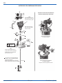 22
22
-
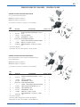 23
23
-
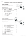 24
24
-
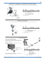 25
25
-
 26
26
-
 27
27
-
 28
28


Binks Pressure Tanks Manual de usuario
- Categoría
- Rociador de pintura
- Tipo
- Manual de usuario
Artículos relacionados
-
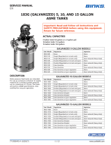 Binks Pressure Tanks Manual de usuario
-
Binks 183S-211 Manual de usuario
-
 Binks Pressure Tanks Manual de usuario
-
 Binks Air Accessories Manual de usuario
-
 Binks Agitators-Direct Drive Manual de usuario
-
 Binks MX High Pressure Outfits Manual de usuario
-
 Binks Pressure Tanks Manual de usuario
-
Carlisle BINKS 83C-210-CE Manual de usuario
-
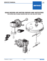 Binks Agitators-Indirect/Gear Drive Manual de usuario
-
 Binks MX High Pressure Outfits Manual de usuario


Otros documentos
-
-
-
-
-
 DeVilbiss Suction Feed Cups Manual de usuario
-
-
-
-
-
