Steren MUL-282 El manual del propietario
- Categoría
- Multimetros
- Tipo
- El manual del propietario

1
V0.0/1216v
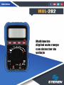
Multímetro
digital auto rango
con detector de
voltaje
MAX
10A
FUSED
FUSED
COM
MAX
200mA
AmA
V
600V
CAT III
mA
A
V
A
A
ºC/ºF
LINE
NCV
V
OFF
SEL RAN
HOLD

2
MUL-282
Antes de utilizar el producto, lea cuidadosamente este instructivo para
evitar cualquier mal funcionamiento.
La información presentada sirve únicamente como referencia sobre
el producto. Debido a actualizaciones pueden existir diferencias.
Consulte nuestra página web www.steren.com para obtener la versión
más reciente de este manual.
PRECAUCIONES
• El uso inapropiado de este multímetro puede causar daños, choque
eléctrico o lesiones graves.
• Siempre retire los cables de prueba antes de reemplazar las baterías
o los fusibles.
• Compruebe el estado de los cables de prueba y del medidor mismo
antes de operarlo.
• No mida voltajes que excedan 1000V sobre tierra física; puede ser
riesgoso.
• Tenga mucho cuidado al tomar medidas si los voltajes son mayores a
30 VCA RMS o 60V DC; estos voltajes son considerados un peligro de
descarga eléctrica.
• Siempre descargue los capacitores y corte la energía del dispositivo
antes de realizar pruebas de diodo, resistencia o continuidad.

3
• Para evitar daños al multímetro, no exceda los límites máximos de
los valores de entrada que se muestran en las especicaciones.
• En caso de un periodo prolongado de inactividad del equipo retire las
baterías.
• Este producto NO es un juguete; manténgalo fuera del alcance de
los niños.
• Este aparato NO está destinado a ser utilizado por personas con
capacidades diferentes, a menos que cuenten con la preparación y
supervisión adecuadas.

4
ÍNDICE
DESCRIPCIÓN
Partes
Perilla de selección
Símbolos en la pantalla
COLOCAR LAS BATERÍAS
MODO DE USO
Medición de voltaje
Medición de corriente
Prueba de diodos
Comprobación de continuidad
Medición de temperatura
Medición de voltaje sin contacto
(NCV)
MANTENIMIENTO
Sustitución de los fusibles
ESPECIFICACIONES DE
MEDICIÓN
Voltaje de Corriente Directa
Voltaje de Corriente Alterna
Corriente Directa (CD)
Corriente Alterna (CA)
Resistencia
Diodo y continuidad
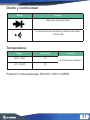
Temperatura
.....................................................5
.....................................................5
.....................................................7
.....................................................8
.....................................................9
...................................................10
...................................................10
...................................................11
...................................................13
...................................................14
...................................................15
...................................................16
...................................................17
...................................................17
...................................................18
...................................................18
...................................................19
...................................................19
...................................................20
...................................................20
...................................................21
...................................................21

5
MAX
10A
FUSED
FUSED
COM
MAX
200mA
AmA
V ºCºF
600V
CAT III
mA
A
V
A
A
ºC/ºF
NCV
V
OFF
SEL RAN
HOLD
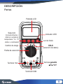
DESCRIPCIÓN
Partes
Pantalla LCD
Selección
Corriente Directa o
Alterna / unidad de
temperatura °C o °F /
diodos o continuidad
Cambio de rango
Perilla de selección
Terminal 10A
Terminal COM
Terminal µAmAV
ºCºF
HOLD
(retención de datos)
Luz de fondo
Indicador LED
V

6
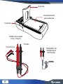
Soporte
Cubierta
Compartimento
para baterías
Cables de prueba
(rojo y negro)
Puntas
Conectores
Adaptador de
temperatura
(termopar)

7
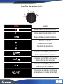
Perilla de selección
mA
A
V
A
ºC/ºF
LINE
NCV
V
OFF
Apagar
Voltaje de Corriente Directa (DC)
Voltaje de Corriente Alterna (AC)
Detección de voltaje sin contacto
Prueba de diodos
Prueba de continuidad
Medición de resistencia
Corriente Directa (DC) y Corriente
Alterna (AC) en micro amperes
Corriente Directa (DC) y Corriente
Alterna (AC) en mili amperes
Corriente Directa (DC) y Corriente
Alterna (AC) en amperes
Temperatura en grados centígrados
Temperatura en grados Fahrenheit
OFF
V
V
A
mA
A
ºC/ºF

8
VA
m
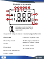
Símbolos en la pantalla
Indica que el valor de entrada es
demasiado grande para el rango
seleccionado
1. Detección de voltaje sin contacto
2. Batería baja
3. Autorrango activado
4. Diodos
5. Continuidad
6. Retención de datos activada
7. Lectura máxima
8. Grados Centígrados/Fahrenheit
9. Kilo ohm / mega ohm / ohm
10. Micro ampere / mili ampere /
ampere /volt /mili volt/ ampere
11. Corriente Alterna
12. Corriente Directa
NCV

9
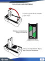
COLOCAR LAS BATERÍAS
Levante el soporte. Retire el tornillo
y quite la tapa
Extraiga el compartimento.
Coloque las baterías.
Coloque el compartimento. Baje la
tapa y atornille nuevamente.
Asegúrese de que la
polaridad sea la correcta

10
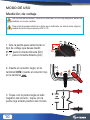
MODO DE USO
Medición de voltaje
Los circuitos de alta tensión, tanto de CA como de CD, son muy peligrosos; deben ser
medidos con mucho cuidado.
Para evitar descargas eléctricas o daños en el multímetro, no intente tomar ninguna
medida de tensión que supere los 600 V CD.
1. Gire la perilla para seleccionar el
tipo de voltaje que desea medir:
V - - - para Corriente Directa (DC)
V ~ para Corriente Alterna (AC)
2. Inserte el conector negro en la
terminal COM; inserte el conector rojo
en la terminal
3. Toque con la punta negra el lado
negativo del circuito; toque con la
punta roja el lado positivo del circuito.
mA
A
V
A
ºC/ºF
LINE
NCV
V
OFF
MAX
10A
FUSED
FUSED
COM
MAX
200mA
AmA
V
600V
CAT III
A

11
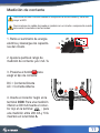
Medición de corriente
Nunca intente medir corriente cuando el voltaje entre el circuito abierto y tierra sea
mayor a 600V.
Nunca coloque los cables de prueba en paralelo con un circuito o componente cuando
éstos estén conectados a las terminales.
1. Retire el suministro de energía
eléctrica y descargue los capacito-
res del circuito.
2. Ajuste la perilla al rango de
medición de corriente: µA / mA / A.
3. Presione el botón para
elegir el tipo de corriente:
DC = Corriente Directa
AC = Corriente Alterna
4. Inserte el conector negro en la
terminal COM. Para una medición
inferior a 200 mA inserte el conec-
tor rojo en la terminal ; para
una medición entre 200 mA y 10 A
insértelo en la terminal A.
mA
A
V
A
ºC/ºF
LINE
NCV
V
OFF
SEL
MAX
10A
FUSED
FUSED
COM
MAX
200mA
AmA
V
600V
CAT III
A

12
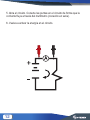
5. Abra el circuito. Conecte las puntas en el circuito de forma que la
corriente uya a través del multímetro (conexión en serie).
6. Vuelva a activar la energía en el circuito.

13
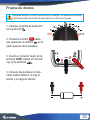
Prueba de diodos
Asegúrese de que los circuitos se encuentren sin energía y los capacitores completa-
mente descargados para evitar choques eléctricos o daños en el equipo.
1. Coloque la perilla de selección
en la posición
2. Presione el botón hasta
que aparezca el símbolo en la
parte superior de la pantalla.
3. Inserte el conector negro en la
terminal COM; inserte el conector
rojo en la terminal .
4. Conecte las puntas al compo-
nente semiconductor: la roja al
ánodo y la negra al cátodo.
SEL
mA
A
V
A
ºC/ºF
LINE
NCV
V
OFF
MAX
10A
FUSED
FUSED
COM
MAX
200mA
AmA
V
600V
CAT III
A

14
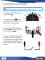
Comprobación de continuidad
Asegúrese de que los circuitos se encuentren sin energía y los capacitores completa-
mente descargados para evitar choques eléctricos o daños en el equipo.
1. Coloque la perilla de selección
en la posición
2. Presione el botón hasta
que aparezca el símbolo en la
parte superior de la pantalla.
3. Inserte el conector negro en la
terminal COM; inserte el conector
rojo en la terminal .
4. Toque con las puntas el circuito
o alambre que desee comprobar.
El valor de resistencia se mostrará
en la pantalla, si la resistencia es
menor a 70Ω ± 30Ω, la señal será
audible.
SEL
mA
A
V
A
ºC/ºF
LINE
NCV
V
OFF
MAX
10A
FUSED
FUSED
COM
MAX
200mA
AmA
V
600V
CAT III
A

15
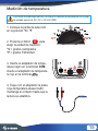
Medición de temperatura
Para evitar una descarga eléctrica, no realice la medición de temperatura si el voltaje
de entrada supera los 36 V CC o 36 V AC RMS.
1. Coloque la perilla de selección
en la posición °C / °F
2. Presione el botón para
elegir la unidad de medición:
°C = grados centígrados
°F = grados Fahrenheit
3. Inserte el adaptador de tempe-
ratura negro en la terminal COM;
inserte el adaptador de temperatu-
ra rojo en la terminal
4. Toque con el adaptador la pieza
cuya temperatura desea medir;
mantenga el contacto hasta que la
lectura se estabilice.
SEL
mA
A
V
A
ºC/ºF
LINE
NCV
V
OFF
MAX
10A
FUSED
FUSED
COM
MAX
200mA
AmA
V
600V
CAT III
A

16
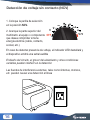
Detección de voltaje sin contacto (NCV)
1. Coloque la perilla de selección
en la posición NCV.
2. Acerque la parte superior del
multímetro al equipo o componente
que desea comprobar si tiene
energía eléctrica (cable, contacto,
socket, etc.).
mA
A
V
A
ºC/ºF
LINE
NCV
V
OFF
En caso de detectar presencia de voltaje, el indicador LED destellará y
el dispositivo emitirá una señal audible
El diseño del circuito, el grosor del aislamiento y otras condiciones
variables pueden interferir en la detección
Las fuentes de interferencia externas, tales como linternas, motores,
etc. pueden causar una detección errónea

17
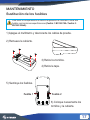
MANTENIMIENTO
Sustitución de los fusibles
Para evitar un choque eléctrico o daños a su persona o al multímetro, utilice sólo
fusibles con las mismas especicaciones (Fusible 1: BS1362 10A / Fusible 2:
BS1362 200mA).
1) Apague el multímetro y desconecte los cables de prueba.
2) Remueva la cubierta.
3) Retire los tornillos.
4) Retire la tapa.
5) Sustituya los fusibles.
6) Coloque nuevamente los
tornillos y la cubierta.
Fusible 1 Fusible 2

18
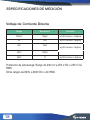
ESPECIFICACIONES DE MEDICIÓN
Voltaje de Corriente Directa
Rango Resolución Precisión
200mV 100µV ±(0.5% lectura + 2 digitos)
2V 1mV ±(0.5% lectura+ 3 digitos)
20V 10mV
±(0.8% lectura+ 3 digitos)
200V 100mV
500V 1V ±(0.8% lectura+ 5 digitos)
Protección de sobrecarga: Rango de 200 mV a 250 V DC o 250 V CA
RMS
Otros rangos de 600V a 600V DC o AC RMS

19
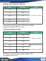
Rango Resolución Precisión
2 V 1mV
20V 10mV
200V 0.1V
±(0.8% lectura + 3 dígitos)
500V 1V
600V 1V
Voltaje de Corriente Alterna
±(1.0% lectura+ 10 digitos)
Protección de sobrecarga: 600 V DC o 600 V CA RMS
Rango de frecuencia: 400 Hz ~ 40 Hz
Rango Resolución Precisión
200µA 0.1µA
2mA 1µA
20mA 10µA
±(0.8% lectura + 3 dígitos)
200mA 100µA ±(2.0% lectura+ 5 digitos)
2A 1mA
10A 10mA
Corriente Directa (CD)
±(1.0% lectura+ 5 digitos)
Protección contra sobrecarga: fusible F200mA / 250V
Sin fusible de rango 10 A
±(3.0% lectura+ 5 digitos)

20
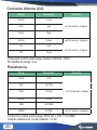
Rango Resolución Precisión
200µA 0.1µA
2mA 1µA
20mA 10µA
±(0.8% lectura + 3 dígitos)
200mA 100µA ±(2.5% lectura+ 5 digitos)
2A 1mA
10A 10mA
Corriente Alterna (CA)
±(1.8% lectura+ 5 digitos)
Protección contra sobrecarga: fusible F200mA / 250V
Sin fusible de rango 10 A
±(3.0% lectura+ 5 digitos)
Rango Resolución Precisión
200Ω 0.1Ω
2kΩ 0.001kΩ
20kΩ 0.01kΩ
±(0.8% lectura + 3 dígitos)
200kΩ 0.1kΩ
2MΩ 0.001MkΩ
20MΩ 0.01MΩ ±(1.0% lectura+ 2 digitos)
Resistencia
±(1.0% lectura+ 2 digitos)
Protección contra sobrecarga: 250V DC o 250 V CA RMS
Tensión máxima en circuito abierto: <3.2V

21
Diodo y continuidad
Rango Función
Voltaje aproximado del diodo
La función de alarma sonará si la resistencia es inferior
a 70Ω ± 30Ω
Rango Resolución Precisión
-20ºC~ 750ºC 1ºC
-4ºF ~ 1832ºF 1ºF
Temperatura
±(1.0% lectura+ 2 digitos )
Protección contra sobrecarga: 250V DC o 250 V CA RMS

22
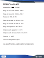
ESPECIFICACIONES
Alimentación: 3V - - - (2 x AAA)
Rango de voltaje CD: 200 mV – 500 V
Rango de voltaje CA: 200 mV – 500 V
Resistencia: 200 - 20 MΩ
Rango de corriente CA: 200 uA – 10 A
Rango de corriente CD: 200 uA – 10 A
Rango de temperatura: -20 - 750 °C
Temperatura de operación: 0 - 40 °C
Temperatura de almacenamiento: -10 a 60 °C
Consumo: 0,1 mW/h
Consumo en espera: No aplica
Las especicaciones pueden cambiar sin previo aviso

23
Producto: Multímetro digital auto rango con detector de voltaje
Modelo: MUL-282
Marca: Steren
Esta póliza garantiza el producto por el término de un año en todas sus partes y mano de obra contra cualquier
defecto de fabricación y funcionamiento a partir de la fecha de entrega.
CONDICIONES
1.- Para hacer efectiva la garantía, presente esta póliza y el producto, en donde fue adquirido o en Electrónica
Steren S.A. de C.V.
2.- Electrónica Steren S.A de C.V. se compromete a reparar el producto en caso de estar defectuoso sin ningún
cargo al consumidor. Los gastos de transportación serán cubiertos por el proveedor.
3.- El tiempo de reparación en ningún caso será mayor a 30 días,contados a partir de la recepción del producto en
cualquiera de los sitios donde pueda hacerse efectiva la garantía.
4.- El lugar donde puede adquirir partes, componentes, consumibles y accesorios, así como hacer válida esta
garantía es en cualquiera de las direcciones mencionadas posteriormente.
ESTA PÓLIZA NO SE HARÁ EFECTIVA EN LOS SIGUIENTES CASOS:
1.- Cuando el producto ha sido utilizado en condiciones distintas a las normales.
2.- Cuando el producto no ha sido operado de acuerdo con el instructivo de uso.
3.- Cuando el producto ha sido alterado o reparado por personal no autorizado por Electrónica Steren S.A. de
C.V. El consumidor podrá solicitar que se haga efectiva la garantía ante la propia casa comercial donde adquirió
el producto. Si la presente garantía se extraviara, el consumidor puede recurrir a su proveedor para que le expida
otra póliza, previa presentación de la nota de compra o factura respectiva.
DATOS DEL DISTRIBUIDOR
Nombre del Distribuidor
Domicilio
Producto
Marca
Modelo
Número de serie
Fecha de entrega
ELECTRÓNICA STEREN, S.A. DE C.V.
Biólogo Maximino Martínez No. 3408 San Salvador Xochimanca,
Del. Azcapotzalco, México, D.F. 02870,
RFC: EST850628-K51
STEREN PRODUCTO EMPACADO S.A. DE C.V.
Autopista México- Qro. Km 26.5 S/N Nave 3-A Col. Lomas de
Boulevares ,Tlalnepantla de Baz, Estado de México, México CP.
54020 RFC: SPE941215H43
CENTRO DE ATENCIÓN
A CLIENTES
01 800 500 9000

24

25
V0.0/1216v
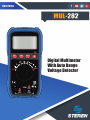
Digital Multimeter
With Auto Range
Voltage Detector
MAX
10A
FUSED
FUSED
COM
MAX
200mA
AmA
V
600V
CAT III
mA
A
V
A
A
ºC/ºF
LINE
NCV
V
OFF
SEL RAN
HOLD

26
MUL-282
Before to use the product, please read carefully this manual to avoid
any malfunction. The info in this manual is shown as reference. Due to
updates can exist differences. Consult our website www.steren.com to
obtain the most actual version of this manual.
CAUTIONS
• The inappropriate use of this multimeter may cause damages, shock
hazard or severe injuries.
• Always remove the test cables before to replace the batteries or fuse.
• Check the status of the test cables or the meter before to use it.
• Don’t measure voltage that exceed 1000V over sic ground; may be
dangerous.
• Be careful when you take measures over 30 VCA RMS o 60V DC;
this voltages may cause shock hazard.
• Always discharge the capacitors and cut the power of the device
before to make diode test, resistance or continuity.

27
• To avoid damages in the meter, do not exceed the maximum limits of
the input values that is shown in the specications.
• Remove the batteries, in case the device won’t be used for long
periods of time
• This product is NOT a toy; keep it away from children.
• This device cannot be used by people with different abilities, unless
they have preparation and supervision.

28
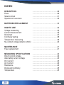
INDEX
DESCRIPTION
Parts
Selector knob
Symbols in the screen
BATTERIES REPLACEMENT
HOW TO USE
Voltage measuring
Current measurement
Diode test
Continuity testing
Temperature measuring
No-contact voltage detector (NVC)
MAINTENANCE
Fuse replacement
MEASURING SPECIFICATIONS
Direct current voltage
Alternating current voltage
DC Current
AC Current
Resistance
Diode and continuity
Temperature
...................................................29
...................................................29
...................................................31
...................................................32
...................................................33
...................................................34
...................................................34
...................................................35
...................................................37
...................................................38
...................................................39
...................................................40
...................................................41
...................................................41
...................................................42
...................................................42
...................................................43
...................................................43
...................................................44
...................................................44
...................................................45
...................................................45

29
MAX
10A
FUSED
FUSED
COM
MAX
200mA
AmA
V ºCºF
600V
CAT III
mA
A
V
A
A
ºC/ºF
NCV
V
OFF
SEL RAN
HOLD
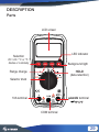
DESCRIPTION
Parts
LCD screen
Selection
DC / AC / °C or °F /
diodes or continuity
Range change
Selector knob
10A terminal
COM terminal
µAmAV terminal
ºCºF
HOLD
(data retention)
Background ligth
LED indicator
V

30
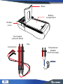
Base
Rubber
cover
Battery
comparment
Test cables
(red and black)
Tips
Connectors
Temperature
adapter
(thermocouple)

31
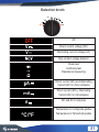
Selector knob
mA
A
V
A
ºC/ºF
LINE
NCV
V
OFF
Off
Direct current voltage (DC)
Alternating current voltage (AC)
Non-contact voltage detector
Diode test
Continuity test
Resistance measuring
Direct current (DC) and Alternating
Current (AC) in micro amperes
Direct current (DC) y Alternating
Current (AC) in mili amperes
DC and AC in amperes
Temperature in Centigrade grades
Temperature in Fahrenheit grades
OFF
V
V
A
mA
A
ºC/ºF

32
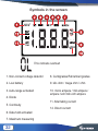
Symbols in the screen
This indicate overload
1. Non-contact voltage detector
2. Low battery
3. Auto-range activated
4. Diode
5. Continuity
6. Data hold activated
7. Maximum measuring
8. Centigrades/Fahrenheit grades
9. kilo ohm / mega ohm / ohm
10. micro ampere / mili ampere /
ampere /volt /mili volt/ ampere
11. Alternating current
12. Direct current
VA
m
NCV

33
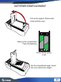
BATTERIES REMPLACEMENT
Pull up the support. Remove the
screw and the cover
Remove the compartment.
Place the batteries.
Set the compartment again. Down
the cover and screw it again.
Ensure that the polarity
is right

34
HOW TO USE
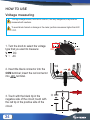
Voltage measuring
The high voltage circuits, such as AC and DC, are very dangerous; they must be
measured with cautions.
To avoid shock hazard or damage in the meter, performs measures higher than 600
V DC.
1. Turn the knob to select the voltage
type that you want to measure:
V - - - DC
V ~ AC
2. Insert the black connector into the
COM terminal; insert the red connector
into terminal.
3. Touch with the black tip in the
negative side of the circuit; touch with
the red tip in the positive side of the
circuit.
mA
A
V
A
ºC/ºF
LINE
NCV
V
OFF
MAX
10A
FUSED
FUSED
COM
MAX
200mA
AmA
V
600V
CAT III
A

35
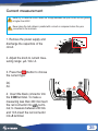
Current measurement
Never try to measure current when the voltage between the open circuit and the ground
is higher than 600V.
Never place the test cables in parallel with a circuit or component when they are
connected to the terminals.
1. Remove the power supply and
discharge the capacitors of the
circuit.
2. Adjust the knob to current mea-
suring range: µA / mA / A.
3. Press the button to choose
the current type:
DC
AC
4. Insert the black connector into
the COM terminal. To make a
measuring less than 200 mA insert
the red connector into termi-
nal; to measure between 200 mA
and 10 A insert the red connector
into A terminal.
mA
A
V
A
ºC/ºF
LINE
NCV
V
OFF
SEL
MAX
10A
FUSED
FUSED
COM
MAX
200mA
AmA
V
600V
CAT III
A

36
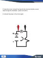
5. Open the circuit. Connect the tips into the circuit so that the current
ows through the multimeter. (serial connection)
6. Activate the power in the circuit again.

37
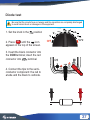
Diode test
Be sure that the circuits have not energy and the capacitors are completely discharged
to avoid hazard shock or damages in the equipment.
1. Set the knob in the position
2. Press until the icon
appears in the top of the screen.
3. Insert the black connector into
the COM terminal; insert the red
connector into terminal.
4. Connect the tips to the semi-
conductor component: the red to
anode and the black to cathode.
SEL
mA
A
V
A
ºC/ºF
LINE
NCV
V
OFF
MAX
10A
FUSED
FUSED
COM
MAX
200mA
AmA
V
600V
CAT III
A

38
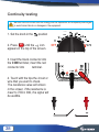
Continuity testing
Be sure that the circuits have not energy and the capacitors are completely discharged
to avoid hazard shock or damages in the equipment.
1. Set the knob in the position
2. Press until the icon
appears in the top of the screen.
3. Insert the black connector into
the COM terminal; insert the red
connector into terminal.
4. Touch with the tips the circuit or
wire that you want to check.
The resistance value will shown
in the screen, if the resistance is
lower to 70Ω ± 30Ω, the signal will
be audible.
SEL
mA
A
V
A
ºC/ºF
LINE
NCV
V
OFF
MAX
10A
FUSED
FUSED
COM
MAX
200mA
AmA
V
600V
CAT III
A

39
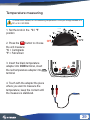
Temperature measuring
To avoid shock hazard, do not measuring temperature if the input voltage exceed 36 V
DC or 36 V AC RMS.
1. Set the knob in the °C / °F
position
2. Press the button to choose
the unit measure:
°C = Centigrade
°F = Fahrenheit
3. Insert the black temperature
adapter into COM terminal, insert
the red temperature adapter into
terminal
4. Touch with the adapter the piece
where you want to measure the
temperature; keep the contact until
the measure is stabilized.
SEL
mA
A
V
A
ºC/ºF
LINE
NCV
V
OFF
MAX
10A
FUSED
FUSED
COM
MAX
200mA
AmA
V
600V
CAT III
A

40
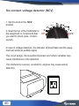
No-contact voltage detector (NCV)
1. Set the knob in the NCV
position.
2. Near the top of the multimeter to
the equipment or component that
you want to check (wire, contact,
socket).
mA
A
V
A
ºC/ºF
LINE
NCV
V
OFF
In case of voltage detection, the indicator LED will ash and the equip-
ment will emits an audible signal
The circuit design, the insulation thickness and others variables may
cause interference in the detection
The interference sources, as lanterns, engines may cause wrong
detection

41
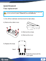
MAINTENANCE
Fuse replacement
To avoid a shock hazard or damages to yourself or to multimeter, use only fuses with
the same specications (Fuse 1 10ABS1362, Fuse 2 200mABS1362).
1) Turn off the multimeter and disconnect the test cables.
2) Remove the rubber cover.
3) Remove the screws.
4) Remove the cover.
5) Replace the fuses.
6) Set the screws and the
cover again.
Fuse 1 Fuse 2

42
MEASURING SPECIFICATIONS
Direct current voltage
Range Resolution Accuracy
200mV 100µV ±(0.5% reading + 2 digits)
2V 1mV ±(0.5% reading+ 3 digits)
20V 10mV
±(0.8% reading+ 3 digits)
200V 100mV
500V 1V ±(0.8% reading+ 5 digits)
Overload protection: Range from 200 mV to 250 V DC or 250 V AC
RMS
Other ranges: from 600V to 600V DC or AC RMS

43
Range Resolution Accuracy
2 V 1mV
20V 10mV
200V 0.1V
±(0.8% lectura + 3 dígitos)
500V 1V
600V 1V
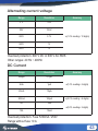
Alternating current voltage
±(1.0% reading+ 10 digits)
Overload protection: 600 V DC or 600 V AC RMS
Other ranges: 40 Hz ~ 400Hz
Range Resolution Accuracy
200µA 0.1µA
2mA 1µA
20mA 10µA
±(0.8% lectura + 3 dígitos)
200mA 100µA ±(2.0% reading + 5 digits)
2A 1mA
10A 10mA
DC Current
±(1.0% reading+ 5 digits)
Overload protection: Fuse F200mA / 250V
Range without fuse 10 A
±(3.0% reading+ 5 digits)

44
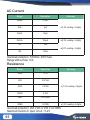
Range Resolution Accuracy
200µA 0.1µA
2mA 1µA
20mA 10µA
±(0.8% lectura + 3 dígitos)
200mA 100µA ±(2.5% reading+ 5 digits)
2A 1mA
10A 10mA
AC Current
±(1.8% reading+ 5 digits)
Overload protection: F200mA / 250V fuse
Range without fuse 10 A
±(3.0% reading+ 5 digits)
Range Resolution Accuracy
200Ω 0.1Ω
2kΩ 0.001kΩ
20kΩ 0.01kΩ
±(0.8% lectura + 3 dígitos)
200kΩ 0.1kΩ
2MΩ 0.001MkΩ
20MΩ 0.01MΩ ±(1.0% reading+ 2 digits)
Resistance
±(1.0% reading+ 2 digits)
Overload protection: 250 V DC or 250 V AC RMS
Maximum tension in open circuit: <3.2V

45
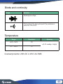
Diode and continuity
Range Function
Diode approx voltage
The function of the alarm will sound if the resistance is
lower than 70Ω ± 30Ω
Range Resolution Accuracy
-20ºC~ 750ºC 1ºC
-4ºF ~ 1832ºF 1ºF
Temperature
±(1.0% reading+ 2 digits)
Overload protection: 250V DC or 250 V AC RMS

46
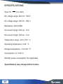
SPECIFICATIONS
Input: 3V - - - (2 x AAA)
DC voltage range: 200 mV - 500 V
AC voltage range: 200 mV - 500 V
Resistance: 200-20 MΩ
AC Current range: 200 uA - 10 A
DC Current range: 200 uA - 10 A
Temperature range: -20 to 750 ° C
Operating temperature: 0-40 ° C
Storage temperature: -10 to 60 ° C
Consumption: 0.1 mW / h
Standby power consumption: Not applicable
Specications may change without notice

47
Product: Digital Multi Meter With Auto Range Voltage Detector
Number part: MUL-282
Brand: Steren
This Steren product is warranted under normal usage against defects in workmanship and
materials to the original purchaser for one year from the date of purchase.
CONDITIONS
1. This warranty card with all the required information, invoice or purchase ticket, product box
or package, and product, must be presented when warranty service is required.
2. If the product is in the warranty time, the company will repair it free of charge.
3. The repairing time will not exceed 30 natural days, from the day the claim was received.
4. Steren sell parts, components, consumables and accessories to customer, as well as
warranty service, at any of the addresses mentioned later.
THIS WARRANTY IS VOID IN THE NEXT CASES:
If the product has been damaged by an accident, acts of God, mishandling, leaky batteries,
failure to follow enclosed instructions, improper repair by unauthorized personnel, improper
safe keeping, among others.
a) The consumer can also claim the warranty service in the purchase establishment.
b) If you lose the warranty card, we can reissue it, if you show the invoice or purchase ticket.
RETAILER INFORMATION
Name of the retailer _______________________________
Address ________________________________________
Product ________________________________________
Brand __________________________________________
Serial number ___________________________________
Date of delivery __________________________________
CUSTOM SERVICE CENTER
01 800 500 9000

48
-
 1
1
-
 2
2
-
 3
3
-
 4
4
-
 5
5
-
 6
6
-
 7
7
-
 8
8
-
 9
9
-
 10
10
-
 11
11
-
 12
12
-
 13
13
-
 14
14
-
 15
15
-
 16
16
-
 17
17
-
 18
18
-
 19
19
-
 20
20
-
 21
21
-
 22
22
-
 23
23
-
 24
24
-
 25
25
-
 26
26
-
 27
27
-
 28
28
-
 29
29
-
 30
30
-
 31
31
-
 32
32
-
 33
33
-
 34
34
-
 35
35
-
 36
36
-
 37
37
-
 38
38
-
 39
39
-
 40
40
-
 41
41
-
 42
42
-
 43
43
-
 44
44
-
 45
45
-
 46
46
-
 47
47
-
 48
48


Steren MUL-282 El manual del propietario
- Categoría
- Multimetros
- Tipo
- El manual del propietario
en otros idiomas
- English: Steren MUL-282 Owner's manual
Artículos relacionados
-
Steren MUL-110 El manual del propietario
-
-
Steren MUL-288 El manual del propietario
-
-
Steren MUL-605 El manual del propietario
-
Steren TER-100 El manual del propietario
-
Steren HER-403 El manual del propietario
-
-
-
Otros documentos
-
Amprobe 30XR-A Professional Digital Multimeter Manual de usuario
-
Southwire 10030S Instrucciones de operación
-
TACKLIFE DM02A El manual del propietario
-
-
Innova 3300 El manual del propietario
-
Craftsman 82312 El manual del propietario
-
Klein Tools M2O07105KIT Manual de usuario
-
-
Velleman DVM601 Manual de usuario
-
EEMB ER14505 Ficha de datos