Steren MUL-605 El manual del propietario
- Categoría
- Multimetros
- Tipo
- El manual del propietario
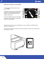
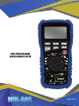
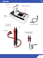
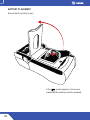
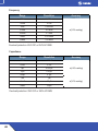
El Steren MUL-605 es un multímetro profesional con autorrango USB que mide voltaje, corriente, resistencia, capacitancia, frecuencia y temperatura. También tiene detección de voltaje sin contacto, prueba de diodos y continuidad, y puede medir el ciclo de trabajo. Con sus múltiples funciones, el Steren MUL-605 es una herramienta versátil para una variedad de aplicaciones, incluyendo la electrónica, la electricidad y la reparación de electrodomésticos.
El Steren MUL-605 es un multímetro profesional con autorrango USB que mide voltaje, corriente, resistencia, capacitancia, frecuencia y temperatura. También tiene detección de voltaje sin contacto, prueba de diodos y continuidad, y puede medir el ciclo de trabajo. Con sus múltiples funciones, el Steren MUL-605 es una herramienta versátil para una variedad de aplicaciones, incluyendo la electrónica, la electricidad y la reparación de electrodomésticos.


-
 1
1
-
 2
2
-
 3
3
-
 4
4
-
 5
5
-
 6
6
-
 7
7
-
 8
8
-
 9
9
-
 10
10
-
 11
11
-
 12
12
-
 13
13
-
 14
14
-
 15
15
-
 16
16
-
 17
17
-
 18
18
-
 19
19
-
 20
20
-
 21
21
-
 22
22
-
 23
23
-
 24
24
-
 25
25
-
 26
26
-
 27
27
-
 28
28
-
 29
29
-
 30
30
-
 31
31
-
 32
32
-
 33
33
-
 34
34
-
 35
35
-
 36
36
-
 37
37
-
 38
38
-
 39
39
-
 40
40
-
 41
41
-
 42
42
-
 43
43
-
 44
44
-
 45
45
-
 46
46
-
 47
47
-
 48
48
-
 49
49
-
 50
50
-
 51
51
-
 52
52


Steren MUL-605 El manual del propietario
- Categoría
- Multimetros
- Tipo
- El manual del propietario
El Steren MUL-605 es un multímetro profesional con autorrango USB que mide voltaje, corriente, resistencia, capacitancia, frecuencia y temperatura. También tiene detección de voltaje sin contacto, prueba de diodos y continuidad, y puede medir el ciclo de trabajo. Con sus múltiples funciones, el Steren MUL-605 es una herramienta versátil para una variedad de aplicaciones, incluyendo la electrónica, la electricidad y la reparación de electrodomésticos.
en otros idiomas
- English: Steren MUL-605 Owner's manual
Artículos relacionados
-
Steren MUL-100 El manual del propietario
-
-
-
-
-
-
-
Steren MUL-650 El manual del propietario
-
Steren ANT-9004 El manual del propietario
-
Steren MUL-288 El manual del propietario
Otros documentos
-
Amprobe AM-560 & AM-570 Mutimeter Manual de usuario
-
Klein Tools CL900 Manual de usuario
-
-
-
-
koban KMD-03 El manual del propietario
-
Ideal Insulation Tester, 250/400/1000V Manual de usuario