PPA Dog Steel Custom Lock Manual de usuario
- Tipo
- Manual de usuario

DOG STEEL CUSTOM
ELECTROMAGNETIC LOCK
TECHNICAL MANUAL
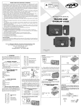
WARNING
Do not use the device without
referring to this manual rst.
P09520 - 09/2021
Rev. 0
TECHNICAL MANUAL
TECHNICAL MANUAL
TECHNICAL MANUAL
WARNING
Do not use the device without
referring to this manual rst.
GENERAL TERMS AND CONDITIONS OF WARRANTY
MOTOPPAR, Indury and Commerce of Automatic Gate Operators Ltd., regiered with
the CNPJ (National Regiry of Legal Entities) under Number 52.605.821/0001-55, located at
3526 Dr. Labieno da Coa Machado Avenue, Indurial Dirict, Garça – SP – Brazil, Zip Code
17400-000, manufacturer of PPA Products, hereby guarantees this product again design,
manufacturing or assembly defects and/or supportively as a result of material quality aws
that could make its intended use improper or inadequate, within a legal period of ninety days
from time of acquisition, provided that the inallation inructions described in the inruction
manual are observed.
Due to the credibility and tru placed on PPA products, we will add 275 more days to the period
mentioned above, reaching a warranty period of one year, likewise counted from the time of
acquisition proven by consumer through proof of purchase (Cuomer Receipt).
In case of defect, within the warranty period, PPA responsibilities are rericted to the repair
or subitution of the product manufactured by the company, under the following conditions:
1. Repair and readjument of equipment may only be carried out by PPA Technical Assiance,
which is qualied to open, remove, and subitute parts or components, as well as repair
defects covered by this warranty; thus, failure on observing this guideline and the veried use
of any non-original parts will cause the resignation of this warranty on the part of the user;
2. The warranty will not extend to accessories such as cables, screw kit, xing brackets, power
supplies etc.;
3. Expenses for packaging, transportation and product reinallation will be sole responsibility
of the consumer;
4. The equipment mu be sent directly to the Company responsible for the sale (manufacturer's
representative), through the address contained in the purchase invoice, properly packed, thus
avoiding loss of the warranty;
5. Within the additional period of 275 days, visits and transportation in places where authorized
technical assiance is not available will be charged. The co of transportation of the product
and/or technician will be sole responsibility of the consumer and
6. The subitution or repair of the product does not prolong the warranty time.
This warranty will be terminated if the product:
1. Is damaged by natural agents, such as atmospheric discharges, oods, wildres, landslides
etc.;
2. Is inalled in an improper electric power supply or if it is not according to any of the
inallation inructions displayed on the manual;
3. Shows defects caused by droppings, collisions or any other physical accident;
4. Shows signs of product violation or attempted repair by unauthorized personnel;
5. Is not used for its intended purpose;
6. Is not used under normal conditions;
7. Is damaged by accessories or equipment connected to it.
Recommendation:
We recommend that both the inallation and the maintenance of the operator to be performed
by an authorized PPA technical service. If the product fails or has an improper operation, seek
an Authorized Technical Service to x it.
DOG STEEL CUSTOM
ELECTROMAGNETIC LOCK
TECHNICAL MANUAL
WARNING
Do not use the device without
referring to this manual rst.
P09520 - 09/2021
Rev. 0
GENERAL TERMS AND CONDITIONS OF WARRANTY
MOTOPPAR, Indury and Commerce of Automatic Gate Operators Ltd., regiered with
the CNPJ (National Regiry of Legal Entities) under Number 52.605.821/0001-55, located at
3526 Dr. Labieno da Coa Machado Avenue, Indurial Dirict, Garça – SP – Brazil, Zip Code
17400-000, manufacturer of PPA Products, hereby guarantees this product again design,
manufacturing or assembly defects and/or supportively as a result of material quality aws
that could make its intended use improper or inadequate, within a legal period of ninety days
from time of acquisition, provided that the inallation inructions described in the inruction
manual are observed.
Due to the credibility and tru placed on PPA products, we will add 275 more days to the period
mentioned above, reaching a warranty period of one year, likewise counted from the time of
acquisition proven by consumer through proof of purchase (Cuomer Receipt).
In case of defect, within the warranty period, PPA responsibilities are rericted to the repair
or subitution of the product manufactured by the company, under the following conditions:
1. Repair and readjument of equipment may only be carried out by PPA Technical Assiance,
which is qualied to open, remove, and subitute parts or components, as well as repair
defects covered by this warranty; thus, failure on observing this guideline and the veried use
of any non-original parts will cause the resignation of this warranty on the part of the user;
2. The warranty will not extend to accessories such as cables, screw kit, xing brackets, power
supplies etc.;
3. Expenses for packaging, transportation and product reinallation will be sole responsibility
of the consumer;
4. The equipment mu be sent directly to the Company responsible for the sale (manufacturer's
representative), through the address contained in the purchase invoice, properly packed, thus
avoiding loss of the warranty;
5. Within the additional period of 275 days, visits and transportation in places where authorized
technical assiance is not available will be charged. The co of transportation of the product
and/or technician will be sole responsibility of the consumer and
6. The subitution or repair of the product does not prolong the warranty time.
This warranty will be terminated if the product:
1. Is damaged by natural agents, such as atmospheric discharges, oods, wildres, landslides
etc.;
2. Is inalled in an improper electric power supply or if it is not according to any of the
inallation inructions displayed on the manual;
3. Shows defects caused by droppings, collisions or any other physical accident;
4. Shows signs of product violation or attempted repair by unauthorized personnel;
5. Is not used for its intended purpose;
6. Is not used under normal conditions;
7. Is damaged by accessories or equipment connected to it.
Recommendation:
We recommend that both the inallation and the maintenance of the operator to be performed
by an authorized PPA technical service. If the product fails or has an improper operation, seek
an Authorized Technical Service to x it.
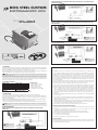
1. OVERVIEW
DOG STEEL CUSTOM electromagnetic lock has been developed to meet the user needs, in compliance
with the ricte quality, security and comfort andards for its users. It is produced with eel plates with
epoxy-coat nishing to increase its service life; It is available in 127 or 220 V.
The electromagnetic lock can be activated at the moment the gate operator is activated or manually by
means of a proper key. It automatically locks the gate after the gate is closed.
NOTE: We strongly recommend using a timer board when installing the ‘DOG STEEL CUSTOM’
ELECTROMAGNETIC LOCK.
The timer board has been developed to decrease electric energy consumption by the product. The
timer module is easy to inall; all one mu do is connect two specic wires to the control board of
the operator; whenever the motor is activated in order to open the gate, the timer activates the lock
during the average time of 5 seconds, and then it will turn itself o.
2. TECHNICAL FEATURES
SPECS - 127V SPECS - 220V
- Current of 0.95 A - Current of 0.95 A
- Inductance of 150 mH - Inductance of 230 mH
- Resiance of 109 Ohms - Resiance of 169 Ohms
- Output power of 125 W - Output power of 210 W
- Cycles/Hour 40 - Cycles/Hour 40
PRODUCT SIZE
- Length: 110 mm (~4.4 in)
- Width: 106 mm (~4.2 in)
- Height: 76 mm (~3 in)
- Pin size: 20 mm (~0.8 in)
- Pin diameter: 18 mm (~0.8 in)
MATERIAL
- 1020 Steel
COMPATIBLE WITH
- Overhead / Sliding / Swing gates
3. INSTALLATION
1. Carefully read all the inructions herein before arting the inallation procedures.
2. The electromagnetic lock mu be inalled on the inner side of the gate. Mounting depends on
each kind of gate. Therefore, the inaller is supposed to choose the proper manner / position for
every individual inallation.
3. Faen the mounting plate (base) on the gate leaf and use the pin to centralize the ramp (gate opper).
4. Faen the ramp and afterwards faen the lock by means of the screws.
5. Once the set is properly mounted, perform the teing, by manually opening and closing the gate.
NOTE: ‘DOG STEEL CUSTOM’ ELECTROMAGNETIC LOCK is endowed with a rectier bridge on
its electronic circuit.
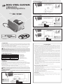
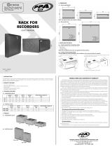
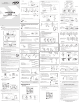
4. WIRING DIAGRAMS
WIRING DIAGRAM FOR AN OPERATOR WITH THE LOCK CONNECTOR ON THE CONTROL
BOARD ONLY
WIRING DIAGRAM FOR AN OPERATOR WITH TIMER, WITHOUT THE LOCK CONNECTOR ON
THE CONTROL BOARD
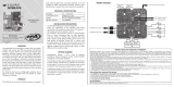
WIRING DIAGRAM FOR AN OPERATOR WITH TIMER AND THE LOCK CONNECTOR ON THE
CONTROL BOARD
WIRING DIAGRAM FOR AN OPERATOR WITH TWO LOCKS, TIMER AND LOCK CONNECTOR
ON THE CONTROL BOARD
NOTE: The PPA
RELAY MODULE is sold
separately.
NOTE: The PPA
RELAY MODULE is sold
separately.
NOTE: The PPA
RELAY MODULE is
sold separately.
BLACK WIRE AND WHITE WIRE = 127 V
BLACK WIRE AND RED WIRE = 220 V
BLACK WIRE AND WHITE WIRE = 127 V
BLACK WIRE AND RED WIRE = 220 V
BLACK WIRE AND WHITE WIRE = 127 V
BLACK WIRE AND RED WIRE = 220 V
BLACK WIRE AND WHITE WIRE = 127 V
BLACK WIRE AND RED WIRE = 220 V
PPA RELAY MODULE
LOCK CONNECTOR
OPERATOR’S CONTROL
BOARD
LOCK CONNECTOR
OPERATOR’S CONTROL
BOARD
LOCK CONNECTOR
OPERATOR’S CONTROL
BOARD
127 VAC
OR
220 VAC
According to the
electromagnetic lock voltage.
TIMER BOARD
TIMER BOARD
TIMER BOARD
PPA RELAY MODULE
PPA RELAY MODULE
CLOSING
OPENING
COMMON
SINGLE-PHASE
INDUCTION MOTOR
127 VAC
OR
220 VAC
According to the
electromagnetic lock voltage.
127 VAC
OR
220 VAC
According to the
electromagnetic lock voltage.
1. OVERVIEW
DOG STEEL CUSTOM electromagnetic lock has been developed to meet the user needs, in compliance
with the ricte quality, security and comfort andards for its users. It is produced with eel plates with
epoxy-coat nishing to increase its service life; It is available in 127 or 220 V.
The electromagnetic lock can be activated at the moment the gate operator is activated or manually by
means of a proper key. It automatically locks the gate after the gate is closed.
NOTE: We strongly recommend using a timer board when installing the ‘DOG STEEL CUSTOM’
ELECTROMAGNETIC LOCK.
The timer board has been developed to decrease electric energy consumption by the product. The
timer module is easy to inall; all one mu do is connect two specic wires to the control board of
the operator; whenever the motor is activated in order to open the gate, the timer activates the lock
during the average time of 5 seconds, and then it will turn itself o.
2. TECHNICAL FEATURES
SPECS - 127V SPECS - 220V
- Current of 0.95 A - Current of 0.95 A
- Inductance of 150 mH - Inductance of 230 mH
- Resiance of 109 Ohms - Resiance of 169 Ohms
- Output power of 125 W - Output power of 210 W
- Cycles/Hour 40 - Cycles/Hour 40
PRODUCT SIZE
- Length: 110 mm (~4.4 in)
- Width: 106 mm (~4.2 in)
- Height: 76 mm (~3 in)
- Pin size: 20 mm (~0.8 in)
- Pin diameter: 18 mm (~0.8 in)
MATERIAL
- 1020 Steel
COMPATIBLE WITH
- Overhead / Sliding / Swing gates
3. INSTALLATION
1. Carefully read all the inructions herein before arting the inallation procedures.
2. The electromagnetic lock mu be inalled on the inner side of the gate. Mounting depends on
each kind of gate. Therefore, the inaller is supposed to choose the proper manner / position for
every individual inallation.
3. Faen the mounting plate (base) on the gate leaf and use the pin to centralize the ramp (gate opper).
4. Faen the ramp and afterwards faen the lock by means of the screws.
5. Once the set is properly mounted, perform the teing, by manually opening and closing the gate.
NOTE: ‘DOG STEEL CUSTOM’ ELECTROMAGNETIC LOCK is endowed with a rectier bridge on
its electronic circuit.
4. WIRING DIAGRAMS
WIRING DIAGRAM FOR AN OPERATOR WITH THE LOCK CONNECTOR ON THE CONTROL
BOARD ONLY
WIRING DIAGRAM FOR AN OPERATOR WITH TIMER, WITHOUT THE LOCK CONNECTOR ON
THE CONTROL BOARD
WIRING DIAGRAM FOR AN OPERATOR WITH TIMER AND THE LOCK CONNECTOR ON THE
CONTROL BOARD
WIRING DIAGRAM FOR AN OPERATOR WITH TWO LOCKS, TIMER AND LOCK CONNECTOR
ON THE CONTROL BOARD
NOTE: The PPA
RELAY MODULE is sold
separately.
NOTE: The PPA
RELAY MODULE is sold
separately.
NOTE: The PPA
RELAY MODULE is
sold separately.
BLACK WIRE AND WHITE WIRE = 127 V
BLACK WIRE AND RED WIRE = 220 V
BLACK WIRE AND WHITE WIRE = 127 V
BLACK WIRE AND RED WIRE = 220 V
BLACK WIRE AND WHITE WIRE = 127 V
BLACK WIRE AND RED WIRE = 220 V
BLACK WIRE AND WHITE WIRE = 127 V
BLACK WIRE AND RED WIRE = 220 V
PPA RELAY MODULE
LOCK CONNECTOR
OPERATOR’S CONTROL
BOARD
LOCK CONNECTOR
OPERATOR’S CONTROL
BOARD
LOCK CONNECTOR
OPERATOR’S CONTROL
BOARD
127 VAC
OR
220 VAC
According to the
electromagnetic lock voltage.
TIMER BOARD
TIMER BOARD
TIMER BOARD
PPA RELAY MODULE
PPA RELAY MODULE
CLOSING
OPENING
COMMON
SINGLE-PHASE
INDUCTION MOTOR
127 VAC
OR
220 VAC
According to the
electromagnetic lock voltage.
127 VAC
OR
220 VAC
According to the
electromagnetic lock voltage.

PLAZO DE GARANTÍA
MOTOPPAR, Induria y Comercio de Automatizadores Ltda., regirada con CNPJ (CIF)
52.605.821/0001-55, localizada en la Avenida Dr. Labieno da Coa Machado número 3526, Dirito
Indurial, Garça – SP – Brasil, Código Poal 17.400-000, fabricante de los productos PPA, garantiza
eo aparato contra defectos de proyectos, fabricación, montaje y/o solidariamente en consecuencia
de vicios de calidad de material que se lo hagan impropio o inadecuado al consumo a cual se
deina por el plazo legal de noventa días desde la fecha de adquisición, siempre que se cumplan las
orientaciones de inalación descritas en el manual de inrucciones.
Como consecuencia de la credibilidad y de la conanza depositada en los productos PPA,
añadimos al plazo anteriormente descrito más 275 días, alcanzando el total de un año, igualmente
contados desde que la fecha de adquisición pueda ser comprobada por el consumidor a través do
comprobante de compra (Recibo).
En caso de defecto, en el período cubierto por la garantía, la responsabilidad de PPA se queda
reringida a la reparación o reemplazo del aparato por ella fabricada, bajo las siguientes condiciones:
1. La reparación y reajue de aparatos solo pueden realizarse por la Asiencia Técnica de PPA, que
eá habilitada a abrir, remover, suituir piezas o componentes, así como arreglar los defectos
cubiertos por la garantía, siendo que el incumplimiento de ee y cualquier utilización de piezas no
originales observadas en el uso, implicará en la exclusión de la garantía por parte del consumidor;
2. La garantía no se extenderá a accesorios como cables, kit de tornillos, soportes de jación, fuentes
de alimentación etc.;
3. Los coos de embalaje, transporte y reinalación del producto son responsabilidad exclusiva de
los consumidores nales;
4. Se debe enviar el aparato directamente a la empresa responsable de la venta (representante del
fabricante), a través de la dirección que gura en el recibo de compra, debidamente embalado,
evitando así la pérdida de la garantía;
5. En el período adicional de 275 días, las visitas y los transportes donde no haya servicios
autorizados serán cargadas. Los gaos de transporte del aparato y/o técnico son responsabilidad
del propietario y
6. La reparación o reemplazo del aparato no prorroga el plazo de garantía.
Ea garantía perderá su validez si el producto:
1. Sufrir daños provocados por agentes de la naturaleza, como descargas atmosféricas, inundaciones,
incendios, desmoronamientos etc.;
2. Sea inalado en red eléctrica inadecuada o en desacuerdo con cualquiera de las inrucciones de
inalación descritas en el manual;
3. Presenta defectos causados por caídas, golpes o cualquier otro accidente físico;
4. Presenta violación o intento de reparación o mantenimiento por parte de personal no autorizado;
5. No sea usado para lo que ha sido proyectado;
6. No sea usado en condiciones normales;
7. Sufrir daños causados por accesorios o aparatos conectados al producto.
Recomendación:
Recomendamos que la inalación y mantenimientos del aparato sean efectuados por servicio
técnico autorizado PPA.
Caso el producto presente defecto o funcionamiento anormal, busque un Servicio Técnico
especializado para los debidos arreglos.
DOG STEEL CUSTOM
CERRADURA
ELECTROMAGNÉTICA
MANUAL TÉCNICO
ADVERTENCIA
No utilice el equipo sin antes leer este
manual de instrucciones.
P09520 - 09/2021
Rev. 0
ELECTROMAGNÉTICA
ELECTROMAGNÉTICA
MANUAL TÉCNICO
MANUAL TÉCNICO
MANUAL TÉCNICO
ADVERTENCIA
No utilice el equipo sin antes leer este
manual de instrucciones.
No utilice el equipo sin antes leer este
manual de instrucciones.
No utilice el equipo sin antes leer este
PLAZO DE GARANTÍA
MOTOPPAR, Induria y Comercio de Automatizadores Ltda., regirada con CNPJ (CIF)
52.605.821/0001-55, localizada en la Avenida Dr. Labieno da Coa Machado número 3526, Dirito
Indurial, Garça – SP – Brasil, Código Poal 17.400-000, fabricante de los productos PPA, garantiza
eo aparato contra defectos de proyectos, fabricación, montaje y/o solidariamente en consecuencia
de vicios de calidad de material que se lo hagan impropio o inadecuado al consumo a cual se
deina por el plazo legal de noventa días desde la fecha de adquisición, siempre que se cumplan las
orientaciones de inalación descritas en el manual de inrucciones.
Como consecuencia de la credibilidad y de la conanza depositada en los productos PPA,
añadimos al plazo anteriormente descrito más 275 días, alcanzando el total de un año, igualmente
contados desde que la fecha de adquisición pueda ser comprobada por el consumidor a través do
comprobante de compra (Recibo).
En caso de defecto, en el período cubierto por la garantía, la responsabilidad de PPA se queda
reringida a la reparación o reemplazo del aparato por ella fabricada, bajo las siguientes condiciones:
1. La reparación y reajue de aparatos solo pueden realizarse por la Asiencia Técnica de PPA, que
eá habilitada a abrir, remover, suituir piezas o componentes, así como arreglar los defectos
cubiertos por la garantía, siendo que el incumplimiento de ee y cualquier utilización de piezas no
originales observadas en el uso, implicará en la exclusión de la garantía por parte del consumidor;
2. La garantía no se extenderá a accesorios como cables, kit de tornillos, soportes de jación, fuentes
de alimentación etc.;
3. Los coos de embalaje, transporte y reinalación del producto son responsabilidad exclusiva de
los consumidores nales;
4. Se debe enviar el aparato directamente a la empresa responsable de la venta (representante del
fabricante), a través de la dirección que gura en el recibo de compra, debidamente embalado,
evitando así la pérdida de la garantía;
5. En el período adicional de 275 días, las visitas y los transportes donde no haya servicios
autorizados serán cargadas. Los gaos de transporte del aparato y/o técnico son responsabilidad
del propietario y
6. La reparación o reemplazo del aparato no prorroga el plazo de garantía.
Ea garantía perderá su validez si el producto:
1. Sufrir daños provocados por agentes de la naturaleza, como descargas atmosféricas, inundaciones,
incendios, desmoronamientos etc.;
2. Sea inalado en red eléctrica inadecuada o en desacuerdo con cualquiera de las inrucciones de
inalación descritas en el manual;
3. Presenta defectos causados por caídas, golpes o cualquier otro accidente físico;
4. Presenta violación o intento de reparación o mantenimiento por parte de personal no autorizado;
5. No sea usado para lo que ha sido proyectado;
6. No sea usado en condiciones normales;
7. Sufrir daños causados por accesorios o aparatos conectados al producto.
Recomendación:
Recomendamos que la inalación y mantenimientos del aparato sean efectuados por servicio
técnico autorizado PPA.
Caso el producto presente defecto o funcionamiento anormal, busque un Servicio Técnico
especializado para los debidos arreglos.
DOG STEEL CUSTOM
CERRADURA
ELECTROMAGNÉTICA
MANUAL TÉCNICO
ADVERTENCIA
No utilice el equipo sin antes leer este
manual de instrucciones.
P09520 - 09/2021
Rev. 0
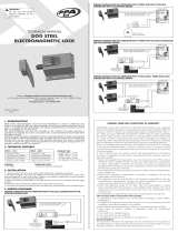
1. INTRODUCCIÓN
La cerradura electromagnética DOG STEEL CUSTOM ha sido desarrollada para atender las necesidades
del usuario, garantizando el cumplimiento de las más rigurosas normas de calidad, seguridad y confort
para los usuarios. Fabricada con chapas de acero y acabado en pintura epoxi para aumentar la vida útil
del producto; y disponible en versiones 127 y 220VAC.
Se puede activar la electrocerradura magnética en el momento del accionamiento del portón o
manualmente a través de una llave propia. Su trabamiento es automático tras el cierre del portón.
NOTA : Recomendamos el uso de la placa temporizadora para instalar la CERRADURA
ELECTROMAGNÉTICA DOG STEEL CUSTOM.
La placa temporizadora ha sido desarrollada para reducir el consumo de energía eléctrica del producto.
La inalación del módulo temporizador es sencilla; baa conectar dos cables apropiados a la central de
mando del automatizador; siempre que el motor sea accionado para abrir el portón, el temporizador
accionará la electrocerradura durante el tiempo medio de 5 segundos y después apagará.
2. CARACTERÍSTICAS TÉCNICAS
ESPECIFICACIONES 127V ESPECIFICACIONES 220V
- Corriente 0.95 A - Corriente 0.95 A
- Inductancia 150 mH - Inductancia 230 mH
- Resiencia 109 Ohms - Resiencia 169 Ohms
- Potencia 125 W - Potencia 210 W
- Ciclos/Hora 40 - Ciclos/Hora 40
DIMENSIONES
- Longitud: 110 mm
- Ancho: 106 mm
- Altura: 76 mm
- Tamaño del pin: 20 mm
- Diámetro del pin: 18 mm
MATERIAL
- Acero 1020
COMPATIBLE CON
- Portones Basculantes / Correderos / Abatibles
3. INSTALACIÓN
1. Lea atentamente todas las informaciones en ee manual antes de iniciar la inalación.
2. Se debe inalar la cerradura electromagnética en el lado interno del portón. Su jación depende
del tipo de portón. Por consiguiente, el inalador debe elegir la mejor manera y posición adecuada
para cada inalación.
3. Fije la base en el portón y use el pin para centralizar la rampa (batiente del portón).
4. Fije la rampa y después je la cerradura con los tornillos.
5. Una vez montado el conjunto, realice la prueba, manualmente abriendo y cerrando el portón.
NOTA : La CERRADURA ELECTROMAGNÉTICA DOG STEEL CUSTOM contiene un puente
recticador en su circuito electrónico.
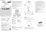
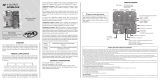
4. ESQUEMAS ELÉCTRICOS
DIAGRAMA DE CABLEADO - AUTOMATIZADOR CON SÓLO EL CONECTOR TRABA (CERRADURA)
EN LA TARJETA
DIAGRAMA DE CABLEADO - AUTOMATIZADOR CON TEMPORIZADOR, SIN CONECTOR TRABA
EN LA TARJETA ELECTRÓNICA
DIAGRAMA DE CABLEADO - AUTOMATIZADOR CON TEMPORIZADOR Y EL CONECTOR TRABA
EN LA TARJETA ELECTRÓNICA
DIAGRAMA DE CABLEADO - AUTOMATIZADOR CON DOS TRABAS, TEMPORIZADOR Y EL
CONECTOR TRABA EN LA TARJETA ELECTRÓNICA
NOTA : El MÓ-
DULO RELE PPA es
suministrado en sepa-
rado.
NOTA : El MÓ-
DULO RELE PPA es
suministrado en sepa-
rado.
NOTA : El MÓ-
DULO RELE PPA es
suministrado en sepa-
rado.
CABLE NEGRO Y CABLE BLANCO = 127 V
CABLE NEGRO Y CABLE ROJO = 220 V
PLACA TEMPORIZADORA
PLACA TEMPORIZADORA
PLACA TEMPORIZADORA
CABLE NEGRO Y CABLE BLANCO = 127 V
CABLE NEGRO Y CABLE ROJO = 220 V
CABLE NEGRO Y CABLE BLANCO = 127 V
CABLE NEGRO Y CABLE ROJO = 220 V
CABLE NEGRO Y CABLE BLANCO = 127 V
CABLE NEGRO Y CABLE ROJO = 220 V
CONECTOR TRABA
TARJETA ELECTRÓNICA
DEL AUTOMATIZADOR
CONECTOR TRABA
TARJETA ELECTRÓNICA
DEL AUTOMATIZADOR
CIERRE
APERTURA
COMÚN
MOTOR DE INDUCCIÓN
MONOFÁSICO
MÓDULO RELÉ PPA
CONECTOR TRABA
TARJETA ELECTRÓNICA
DEL AUTOMATIZADOR
127 VAC
O
220 VAC
de acuerdo con el voltaje de
la electrocerradura.
127 VAC
O
220 VAC
de acuerdo con el voltaje de
la electrocerradura.
127 VAC
O
220 VAC
de acuerdo con el voltaje de
la electrocerradura.
1. INTRODUCCIÓN
La cerradura electromagnética DOG STEEL CUSTOM ha sido desarrollada para atender las necesidades
del usuario, garantizando el cumplimiento de las más rigurosas normas de calidad, seguridad y confort
para los usuarios. Fabricada con chapas de acero y acabado en pintura epoxi para aumentar la vida útil
del producto; y disponible en versiones 127 y 220VAC.
Se puede activar la electrocerradura magnética en el momento del accionamiento del portón o
manualmente a través de una llave propia. Su trabamiento es automático tras el cierre del portón.
NOTA : Recomendamos el uso de la placa temporizadora para instalar la CERRADURA
ELECTROMAGNÉTICA DOG STEEL CUSTOM.
La placa temporizadora ha sido desarrollada para reducir el consumo de energía eléctrica del producto.
La inalación del módulo temporizador es sencilla; baa conectar dos cables apropiados a la central de
mando del automatizador; siempre que el motor sea accionado para abrir el portón, el temporizador
accionará la electrocerradura durante el tiempo medio de 5 segundos y después apagará.
2. CARACTERÍSTICAS TÉCNICAS
ESPECIFICACIONES 127V ESPECIFICACIONES 220V
- Corriente 0.95 A - Corriente 0.95 A
- Inductancia 150 mH - Inductancia 230 mH
- Resiencia 109 Ohms - Resiencia 169 Ohms
- Potencia 125 W - Potencia 210 W
- Ciclos/Hora 40 - Ciclos/Hora 40
DIMENSIONES
- Longitud: 110 mm
- Ancho: 106 mm
- Altura: 76 mm
- Tamaño del pin: 20 mm
- Diámetro del pin: 18 mm
MATERIAL
- Acero 1020
COMPATIBLE CON
- Portones Basculantes / Correderos / Abatibles
3. INSTALACIÓN
1. Lea atentamente todas las informaciones en ee manual antes de iniciar la inalación.
2. Se debe inalar la cerradura electromagnética en el lado interno del portón. Su jación depende
del tipo de portón. Por consiguiente, el inalador debe elegir la mejor manera y posición adecuada
para cada inalación.
3. Fije la base en el portón y use el pin para centralizar la rampa (batiente del portón).
4. Fije la rampa y después je la cerradura con los tornillos.
5. Una vez montado el conjunto, realice la prueba, manualmente abriendo y cerrando el portón.
NOTA : La CERRADURA ELECTROMAGNÉTICA DOG STEEL CUSTOM contiene un puente
recticador en su circuito electrónico.
4. ESQUEMAS ELÉCTRICOS
DIAGRAMA DE CABLEADO - AUTOMATIZADOR CON SÓLO EL CONECTOR TRABA (CERRADURA)
EN LA TARJETA
DIAGRAMA DE CABLEADO - AUTOMATIZADOR CON TEMPORIZADOR, SIN CONECTOR TRABA
EN LA TARJETA ELECTRÓNICA
DIAGRAMA DE CABLEADO - AUTOMATIZADOR CON TEMPORIZADOR Y EL CONECTOR TRABA
EN LA TARJETA ELECTRÓNICA
DIAGRAMA DE CABLEADO - AUTOMATIZADOR CON DOS TRABAS, TEMPORIZADOR Y EL
CONECTOR TRABA EN LA TARJETA ELECTRÓNICA
NOTA : El MÓ-
DULO RELE PPA es
suministrado en sepa-
rado.
NOTA : El MÓ-
DULO RELE PPA es
suministrado en sepa-
rado.
NOTA : El MÓ-
DULO RELE PPA es
suministrado en sepa-
rado.
CABLE NEGRO Y CABLE BLANCO = 127 V
CABLE NEGRO Y CABLE ROJO = 220 V
PLACA TEMPORIZADORA
PLACA TEMPORIZADORA
PLACA TEMPORIZADORA
CABLE NEGRO Y CABLE BLANCO = 127 V
CABLE NEGRO Y CABLE ROJO = 220 V
CABLE NEGRO Y CABLE BLANCO = 127 V
CABLE NEGRO Y CABLE ROJO = 220 V
CABLE NEGRO Y CABLE BLANCO = 127 V
CABLE NEGRO Y CABLE ROJO = 220 V
CONECTOR TRABA
TARJETA ELECTRÓNICA
DEL AUTOMATIZADOR
CONECTOR TRABA
TARJETA ELECTRÓNICA
DEL AUTOMATIZADOR
CIERRE
APERTURA
COMÚN
MOTOR DE INDUCCIÓN
MONOFÁSICO
MÓDULO RELÉ PPA
CONECTOR TRABA
TARJETA ELECTRÓNICA
DEL AUTOMATIZADOR
127 VAC
O
220 VAC
de acuerdo con el voltaje de
la electrocerradura.
127 VAC
O
220 VAC
de acuerdo con el voltaje de
la electrocerradura.
127 VAC
O
220 VAC
de acuerdo con el voltaje de
la electrocerradura.
-
 1
1
-
 2
2


PPA Dog Steel Custom Lock Manual de usuario
- Tipo
- Manual de usuario
en otros idiomas
Artículos relacionados
-
 PPA Dog Steel Lock Manual de usuario
-
 PPA BR1 - 500 Manual de usuario
-
 PPA Relay Module Manual de usuario
-
 PPA Rack for Recorders Manual de usuario
-
 PPA 2 Outputs Interlock Manual de usuario
-
 PPA Wind 24V Manual de usuario
-
 PPA Traver Uno Manual de usuario
-
 PPA Dz Hub R 350 Legero Manual de usuario
-
 PPA 4 Output Interlock Manual de usuario
-
 PPA LED RGB 10W Smart On Light Bulb Manual de usuario


Otros documentos
-
 USAutomatic Patriot II Troubleshooting guide
-
 USAutomatic Patriot II Installation & Owner's Manual
-
ACI Farfisa PL11G El manual del propietario
-
Renault Scenic 3 Equipamiento eléctrico Manual de usuario
-
Genius A274K Instrucciones de operación
-
BEA 10MATRIX Manual de usuario
-
BFT RIGEL 5 Installation and User Manual

