
Need help? Visit Sauder.com to view video assembly tips or chat with a live rep.
Prefer the phone? Call 1-800-523-3987.
Share your journey!
sauder.com
NOTE: THIS INSTRUCTION
BOOKLET CONTAINS IMPORTANT
SAFETY INFORMATION.
PLEASE READ AND KEEP FOR
FUTURE REFERENCE.
Enlish p 1-19
Français p 20-22
Español p 23-25
Lot # 369246 03/18/15
Purchased: __________________
Be sure to ive us a rin before
makin any returns. 1-800-523-3987
You could totally write
a novel on this.
Writin Desk
County Line Collection | 418213

Table of Contents Assembly Tools Required
Part Identifi cation
Hardware Identifi cation
Assembly Steps
Français
Español
Safety
Warranty
Hammer
Not actual size
No. 2 Phillips Screwdriver
Tip Shown Actual Size
Skip the power trip.
This time.
3
4
5-19
20-22
23-25
26
27
418213 www.sauder.com/servicesPae 2

Part Identifi cation
å While not all parts are labeled, some of the parts will have a label or an inked letter on the ede
to help distinuish similar parts from each other. Use this part identifi cation to help identify similar parts.
Now you know
our ABCs.
A RIGHT END (1)
B LEFT END (1)
B32 SMALL DRAWER BOTTOM (1)
B33 LARGE DRAWER BOTTOM (1)
C UPRIGHT (1)
D TOP (1)
D266 DRAWER RIGHT SIDE (2)
D267 DRAWER LEFT SIDE (2)
D440 SMALL DRAWER BACK (1)
D441 SMALL DRAWER BOX FRONT (1)
D478 LARGE DRAWER BOX FRONT (1)
D479 LARGE DRAWER BACK (1)
E BACK (1)
F BRACE (1)
G RIGHT FRONT LEG (1)
H LEFT FRONT LEG (1)
I RIGHT REAR LEG (1)
J LEFT REAR LEG (1)
K STRETCHER (1)
L RIGHT SKIRT (1)
M LEFT SKIRT (1)
N LARGE DRAWER FRONT (1)
O SMALL DRAWER FRONT (1)
P DRAWER BRACE (1)
A
B
C
D
E
F
G
H
I
J
K
L
M
N
O
D266
D266
D267
D267
D440
D441
D478
D479
B33
B32
P
418213www.sauder.com/services
Pae 3

Hardware Identifi cation
å Screws are shown actual size. You may receive extra hardware with your unit.
BLACK 7/8" LARGE HEAD SCREW - 4
17S
BLACK 1-7/8" FLAT HEAD SCREW - 1
2S
CAM COVER - 4
13P
3S
GOLD 5/16" FLAT HEAD SCREW - 16
CAM SCREW - 20
8F
WOOD DOWEL - 18
15F
HIDDEN CAM - 20
1F
SILVER 1-1/2" MACHINE SCREW - 2
95S
BLACK 2-3/8" FLAT HEAD BOLT - 2
103S
CROSS SLOTTED DOWEL - 2
24F
KNOB - 2
69K
GLUE - 1
54M
30S
BLACK 1-9/16" FLAT HEAD SCREW - 10
40CA
CABINET RIGHT - 2
40CB
CABINET LEFT - 2
40CC
DRAWER RIGHT - 2
40CD
DRAWER LEFT - 2
418213 www.sauder.com/servicesPae 4

Step 1
Look for this icon. It means a
video assembly tip is available at
www.sauder.com/services/tips
å
Assemble your unit on a carpeted fl oor or on the empty
carton to avoid scratchin your unit or the fl oor.
å
Push twenty HIDDEN CAMS (1F) into the ENDS (A and B)
UPRIGHT (C), BACK (E), BRACE (F), and SKIRTS (L and M).
418213www.sauder.com/services
Pae 5
Arrow
Arrow
1F
Arrow
1F
The arrow in the HIDDEN
CAM must point toward the
hole in the ede of the board.
Hole
(20used)
Arrow
1F
A
B
C
E
F
L
M

å
Turn twenty CAM SCREWS (8F) into the ENDS (A and B),
TOP (D), BACK (E), and LEGS (G, H, I, and J).
Step 2
418213 www.sauder.com/servicesPae 6
A
B
E
G
H
I
J
8F
8F
D
8F
(20 used)

Step 3
418213www.sauder.com/services
Pae 7
A
B
å
Fasten the CABINET RIGHT (40CA) to the RIGHT END (A)
and CABINET LEFT (40CB) to the LEFT END (B). Use four
GOLD 5/16" FLAT HEAD SCREWS (3S) throuh holes #1
and #3.
GOLD 5/16" FLAT HEAD SCREW
(4 used in this step)
3S
1
2
3
4
1
2
3
4
Roller end
Roller end
This CAM SCREW is
near the roller end.
This CAM SCREW is
near the roller end.
Surface with HIDDEN CAMS
Surface with HIDDEN CAMS
Remember:
Rihty tihty.
Lefty loosey.

Step 4
418213 www.sauder.com/servicesPae 8
Fill the holes 1/4 to 1/2
full with GLUE.
Inspect the parts thorouhly before
assemblin. Disassembly of lued
parts is extremely di cult.
Caution
!
54M
15F
15F
å
First, fi ll the holes in the RIGHT FRONT LEG (G) 1/4 to 1/2 full
with GLUE (54M). Then, insert the WOOD DOWELS (15F) into
the holes. Wipe away the excess GLUE.
å
Now, fi ll the holes in the RIGHT END (A) and RIGHT SKIRT (L),
1/4 to 1/2 full with GLUE. Then, insert the WOOD DOWELS in
the LEG into these holes. Tihten the HIDDEN CAMS in the
RIGHT END and RIGHT SKIRT. Wipe away the excess GLUE.
å
Repeat this step luin and fastenin the LEFT FRONT
LEG (H) to the LEFT END (B) and LEFT SKIRT (M) as
shown in the lower diaram.
A
B
L
M
Surface with HIDDEN CAMS
Surface with HIDDEN CAMS
G
H
1
2
Roller end
Roller end

Step 5
418213www.sauder.com/services
Pae 9
Fill the holes 1/4 to 1/2
full with GLUE.
15F
15F
å
First, fi ll the holes in the RIGHT REAR LEG (I) 1/4 to 1/2 full
with GLUE (54M). Then, insert the WOOD DOWELS (15F)
into the holes. Wipe away the excess GLUE.
å
Now, fi ll the holes in the RIGHT END (A) and RIGHT SKIRT (L),
1/4 to 1/2 full with GLUE. Then, insert the WOOD DOWELS in
the LEG into these holes. Tihten the HIDDEN CAMS in the
RIGHT END and RIGHT SKIRT. Wipe away the excess GLUE.
å
Repeat this step luin and fastenin the LEFT REAR
LEG (J) to the LEFT END (B) and LEFT SKIRT (M) as
shown in the lower diaram.
A
B
L
M
1
2
I
J
These holes must be here.
54M

Step 6
418213 www.sauder.com/servicesPae 10
Fill the holes 1/4 to 1/2
full with GLUE.
å
Fill the holes in the LEGS (G, H, I, and J), SKIRTS (L and M)
and TOP (D), 1/4 to 1/2 full with GLUE (54M). Then, insert
the WOOD DOWELS (15F) into the holes as shown. Wipe
away the excess GLUE.
15F
15F
15F
Do not lue this hole.
Do not lue this hole.
54M
D
G
H
I
J
M
L

å
First, fi ll the hole in one end of the BACK (E) and BRACE (F), 1/4
to 1/2 full with GLUE (54M). Then, insert the WOOD DOWELS
and CAM SCREWS in the RIGHT END (A) assembly into the
holes with GLUE. Tihten two HIDDEN CAMS and wipe away
the excess GLUE.
å
Repeat this step luin and tihtenin the HIDDEN CAMS
to the LEFT END (B) assembly.
Step 7
418213www.sauder.com/services
Pae 11
Roller end
Roller end
Surface with HIDDEN CAMS
Surface with HIDDEN CAMS
54M
Fill the holes 1/4 to 1/2
full with GLUE.
A
B
E
F
1
2

å
Fasten the UPRIGHT (C) to the BACK (E). Tihten the
HIDDEN CAM.
å
Fasten the UPRIGHT (C) to the BRACE (F). Use a BLACK
1-7/8" FLAT HEAD SCREW (2S).
Step 8
418213 www.sauder.com/servicesPae 12
E
F
BLACK 1-7/8" FLAT HEAD SCREW
(1 used in this step)
2S
1
2
Don't worry. It isn't
Rome. This can be built
in a day.
C
Surface with HIDDEN CAMS

å
Push two CROSS-SLOTTED DOWELS (24F) into the
STRETCHER (K) as shown in the upper diaram.
å
NOTE: The threads in the DOWEL should be pointed
toward the hole in ede of the STRETCHER.
å
Next, fi ll the holes in the short ede of the STRETCHER (K),
1/4 to 1/2 full with GLUE (54M).
å
Fasten the STRETCHER (K) to the SKIRTS (L and M). Use
two BLACK 2-3/8" FLAT HEAD BOLTS (103S). Wipe away
the excess GLUE.
å
NOTE: Be sure the WOOD DOWELS in the SKIRTS insert into
the holes in the STRETCHER. Wipe away the excess lue.
Step 9
418213www.sauder.com/services
Pae 13
The slot should face up and
toward the short edes of the
STRETCHER (K).
You will need to widen
the SKIRTS (L) slihtly to
fasten the STRETCHER (L)
between them.
T
U
R
N
9
0
D
E
G
R
E
E
S
T
U
R
N
9
0
D
E
G
R
E
E
S
Fill the holes 1/4 to 1/2
full with GLUE.
54M
54M
103S
BLACK 2-3/8" FLAT HEAD BOLT
(2 used in this step)
K
L
L
K
24F

Step 10
418213 www.sauder.com/servicesPae 14
å
Carefully stand your unit upriht.
å
Fasten the CABINET RIGHT (40CA) and CABINET
LEFT (40CB) to the UPRIGHT (C). Use four GOLD 5/16"
FLAT HEAD SCREWS (3S) throuh holes #1 and #3.
GOLD 5/16" FLAT HEAD SCREW
(4 used in this step)
3S
1
2
3
4
1
2
3
4
Roller end
C

å
Fill the holes in the LEGS (G, H, I, and J), 1/4 to 1/2 full with
GLUE (54M).
å
Fasten the TOP (D) to the UPRIGHT (C), BACK (E) and
LEGS (G, H, I, and J). Tihten seven HIDDEN CAMS. Wipe
away the excess lue.
Step 11
418213www.sauder.com/services
Pae 15
Fill the holes 1/4 to 1/2
full with GLUE.
54M
54M
D
E
G
H
I
J
C
1
2

Step 12
418213 www.sauder.com/servicesPae 16
å
Fasten the DRAWER SIDES (D266 and D267) and
DRAWER BRACE (P) to the LARGE DRAWER
BACK (D479). Use three BLACK 1-9/16" FLAT
HEAD SCREWS (30S).
å
Slide the LARGE DRAWER BOTTOM (B33) into the
grooves in the DRAWER SIDES (D266 and D267) and
LARGE DRAWER BACK (D479).
å
Fasten the LARGE DRAWER BOX FRONT (D478)
to the DRAWER SIDES (D266 and D267) and
DRAWER BRACE (P). Use three BLACK 1-9/16"
FLAT HEAD SCREWS (30S).
å
Fasten the LARGE DRAWER FRONT (N) to the LARGE
DRAWER BOX FRONT (D478). Use two BLACK 7/8"
LARGE HEAD SCREWS. (17S).
12
34
Be sure the PENCIL
DRAWER BOTTOM
inserts into the PENCIL
DRAWER BACK roove.
Groove
D479
D479
D266
D266
D478
D478
D266
D267
D267
D267
P
Start each screw a few turns before
completely tihtenin any of them.
BLACK 1-9/16" FLAT HEAD SCREW
(3 used in this step)
30S
Start each screw a few turns before
completely tihtenin any of them.
BLACK 1-9/16" FLAT HEAD SCREW
(3 used in this step)
30S
B33
BLACK 7/8" LARGE HEAD SCREW
(2 used in this step)
17S
N
The LARGE DRAWER
FRONT will over han
the LARGE DRAWER
BOX FRONT more on
the top ede.
This hole
must be
here.
Unfi nished surface

Step 13
418213www.sauder.com/services
Pae 17
å
Fasten the DRAWER SIDES (D266 and D267) to the
SMALL DRAWER BACK (D440). Use two BLACK
1-9/16" FLAT HEAD SCREWS (30S).
å
Slide the SMALL DRAWER BOTTOM (B32) into the
grooves in the DRAWER SIDES (D266 and D267) and
SMALL DRAWER BACK (D440).
å
Fasten the SMALL DRAWER BOX FRONT (D441)
to the DRAWER SIDES (D266 and D267). Use two
BLACK 1-9/16" FLAT HEAD SCREWS (30S).
å
Fasten the SMALL DRAWER FRONT (O) to the SMALL
DRAWER BOX FRONT (D441). Use two BLACK 7/8"
LARGE HEAD SCREWS. (17S).
12
34
Be sure the PENCIL
DRAWER BOTTOM
inserts into the PENCIL
DRAWER BACK roove.
Groove
D440
D440
D266
D266
D441
D441
D266
D267
D267
D267
Start each screw a few turns before
completely tihtenin any of them.
BLACK 1-9/16" FLAT HEAD SCREW
(2 used in this step)
30S
Start each screw a few turns before
completely tihtenin any of them.
BLACK 1-9/16" FLAT HEAD SCREW
(2 used in this step)
30S
B32
BLACK 7/8" LARGE HEAD SCREW
(2 used in this step)
17S
O
The SMALL DRAWER
FRONT will over han
the SMALL DRAWER
BOX FRONT.
Unfi nished surface

Step 14
418213 www.sauder.com/servicesPae 18
å
Fasten the DRAWER RIGHT (40CC) and DRAWER LEFT
(40CD) to the DRAWER SIDES (D266 and D267). Use
four GOLD 5/16" FLAT HEAD SCREWS (3S) throuh holes
#2 and #4.
å
Fasten a KNOB (69K) to the DRAWER FRONT (N). Use a
SILVER 1-1/2" MACHINE SCREW (95S).
å
Repeat this step for the small drawer.
1
2
3
4
1
2
3
4
Roller end
Roller end
GOLD 5/16" FLAT HEAD SCREW
(8 used in this step)
3S
(4 screws per drawer)
D266
D267
If you're doin this to
help a friend, don't
leave without a bite.
N
69K
SILVER 1-1/2" MACHINE SCREW
(2 used in this step)
95S
(1 screws per drawer)

Step 15
418213www.sauder.com/services
Pae 19
å
Push a CAM COVER (13P) onto each HIDDEN CAM.
å
To insert the drawers into your unit, tip the front of the
drawers down and drop the rollers on the drawers behind
the rollers on the unit. Lift the front of the drawers up and
slide them into the unit.
å
NOTE: Please read the back paes of the instruction
booklet for important safety information.
å
This completes assembly. Clean with your favorite
furniture polish or a damp cloth. Wipe dry.
Place the roller on the SLIDE
behind the roller on the RAIL.
And to celebrate, why not share your success story?
50 lbs.
5 lbs.
5 lbs.
(4 used)
To cover HIDDEN CAMS
13P

A l’usae exclusif du
Canada Noter la date
d’achat de cet élément
et conserver le livret
pour future référence.
Pour contacter Sauder
en ce qui concerne cet
élément, faire référence
au numéro de lot et
numéro de modèle en
appelant notre numéro
sans frais.
Lot nº : ____________
Date de
l’achat: ____________
LISTE DE PIÈCES
REFERENCE DESCRIPTION QUANTITÉ
LISTE DE PIÈCES
REFERENCE DESCRIPTION QUANTITÉ
NOUS SOMMES LA POUR VOUS AIDER!
Nous faisons de notre mieux pour nous assurer que votre meuble
arrive dans d’excellentes conditions. Nos représentants du service
Clientèle sont aimables et prêts à vous aider au cas où une pièce
aurait été endommaée ou manquerait (ou si vous aviez besoin
d’aide pour l’assemblae). NE RAMENEZ PAS LE MEUBLE AU
MAGASIN. Au Canada, composez ce numéro d’appel ratuit:
1-800-523-3987
Du lundi au vendredi, de 9 heures du matin à
5:30 heures du soir (horaire Côte Est)
(sauf jours fériés)
Si une pièce a besoin d’être remplacée, la pièce de remplacement
sera envoyée dans les 48 heures. (Sauf week-ends et jours fériés)
Utilisez les instructions d’assemblae en français avec les
schémas étape par étape du manuel d’instruction en anlais.
Chaque étape en français correspond à la même étape
en anlais. La pièce devant être attachée à l’élément est
représentée en ris sur les schémas de chaque étape pour plus
de précision. Comparer la “Liste de pièces” ci-dessous avec
la “PART IDENTIFICATION” du manuel en anlais pour vous
familiariser avec les pièces avant l’assemblae.
REMARQUE : CE MANUEL D’INSTRUCTIONS CONTIENT
D’IMPORTANTES INFORMATIONS RELATIVES À LA SÉCURITÉ.
À LIRE ET CONSERVER POUR TOUTE RÉFÉRENCE FUTURE.
40CA ÉLÉMENT DROITE .................................................2
40CB ÉLÉMENT GAUCHE ..............................................2
40CC TIROIR DROIT ............................................................2
40CD TIROIR GAUCHE .....................................................2
1F EXCENTRIQUE ESCAMOTABLE .............20
8F VIS D'EXCENTRIQUE .......................................20
15F CHEVILLE EN BOIS ............................................ 18
24F CHEVILLE EN FORME DE CROIX ..............2
69K BOUTON ........................................................................2
54M COLLE ..............................................................................1
13P COUVERCLE D'EXCENTRIQUE ...................4
2S VIS TÊTE PLATE 48 mm NOIRE .................1
3S VIS TÊTE PLATE 8 mm DORÉE ............... 16
17S VIS TÊTE LARGE 22 mm NOIRE ...............4
30S VIS TÊTE PLATE 40 mm NOIRE .............10
95S VIS À MÉTAUX 38 mm ARGENTÉE .........2
103S BOULON TÊTE PLATE 60 mm NOIRE ..2
A EXTRÉMITÉ DROITE ..............................................1
B EXTRÉMITÉ GAUCHE ...........................................1
B32 FOND DE PETIT TIROIR ......................................1
B33 FOND DE GRAND TIROIR .................................1
C MONTANT ......................................................................1
D DESSUS ...........................................................................1
D266 CÔTÉ DROIT DE TIROIR ...................................2
D267 CÔTÉ GAUCHE DE TIROIR .............................2
D440 ARRIÈRE DE PETIT TIROIR ...............................1
D441 DEVANT DE CAISSON DU
PETIT TIROIR ...............................................................1
D478 DEVANT DE CAISSON DU
GRAND TIROIR ...........................................................1
D479 ARRIÈRE DE GRAND TIROIR ...........................1
E ARRIÈRE ...........................................................................1
F ENTRETOISE ................................................................1
G PIED AVANT DROIT ................................................1
H PIED AVANT GAUCHE .........................................1
I PIED ARRIÈRE DROIT ...........................................1
J PIED ARRIÈRE GAUCHE .....................................1
K BARRE ...............................................................................1
L PLINTHE DROITE .....................................................1
M PLINTHE GAUCHE ..................................................1
N DEVANT DE GRAND TIROIR ...........................1
O DEVANT DE PETIT TIROIR ................................1
P ENTRETOISE DE TIROIR ....................................1
Bureau418213
418213 www.sauder.com/servicesPae 20

ÉTAPE 9
Fixer deux CHEVILLES EN FORME DE CROIX (24F) dans la
BARRE (K) comme l'indique le schéma du haut.
REMARQUE : Les fi lets dans le CHEVILLE doivent être diriées
vers le trou du chant de la BARRE.
Remplir ensuite les trous du chant court de la BARRE (K) de 1/4 à
1/2 pleins de COLLE (54M).
Fixer la BARRE (K) aux PLINTHES (L et M). Utiliser deux
BOULONS TÊTE PLATE 60 mm NOIRES (103S). Nettoyer l'excès
de COLLE.
REMARQUE : S'assurer de bien insérer les CHEVILLES EN BOIS
situées sur les PLINTHES dans les trous dans la BARRE. Nettoyer
l'excès de colle.
ÉTAPE 10
Relever, avec précaution, l'élément dans sa position verticale.
Fixer l'ÉLÉMENT DROITE (40CA) et l'ÉLÉMENT GAUCHE (40CB) au
MONTANT (C). Utiliser quatre VIS TÊTE PLATE 8 mm DORÉES (3S)
à travers les trous nº 1 et nº 3.
ÉTAPE 8
Fixer le MONTANT (C) à l’ARRIÈRE (E). Serrer l’EXCENTRIQUE
ESCAMOTABLE.
Fixer le MONTANT (C) à l'ENTRETOISE (F). Utiliser une VIS TÊTE
PLATE 48 mm NOIRE (2S).
ÉTAPE 7
Tout d'abord, remplir le trou situé sur l'une extrémité de l'ARRIÈRE (E)
et de l'ENTRETOISE (F) de 1/4 à 1/2 pleins de COLLE (54M). Insérer
ensuite les CHEVILLES EN BOIS et les VIS D'EXCENTRIQUE dans
l'EXTRÉMITÉ DROITE (A) dans les trous avec COLLE. Serrer deux
CONNECTEURS ESCAMOTABLE et nettoyer l'excès de COLLE.
Répéter cette étape en collant et serrant les CONNECTEURS
ESCAMOTABLE à l'EXTRÉMITÉ GAUCHE (B).
ÉTAPE 6
Remplir les trous des PIEDS (G, H, I et J), des PLINTHES (L et M)
et du DESSUS (D) de 1/4 à 1/2 pleins de COLLE (54M). Insérer
ensuite les CHEVILLES EN BOIS (15F) dans les trous comme
l'indique le schéma. Nettoyer l'excès de COLLE.
ÉTAPE 4
Attention
Examiner bien les pièces avant d'assembler. Il est di cile de
séparer des pièces une fois encollées.
Tout d’abord, remplir les trous dans le PIED AVANT DROIT (G) de
1/4 à 1/2 pleins de COLLE (54M). Insérer ensuite les CHEVILLES
EN BOIS (15F) dans les trous. Nettoyer l'excès de COLLE.
Tout d'abord, remplir les trous dans l'EXTRÉMITÉ DROITE (A) et
la PLINTHE DROITE (L) de 1/4 à 1/2 pleins de COLLE. Insérer
ensuite les CHEVILLES EN BOIS dans le PIED dans ces trous.
Serrer les EXCENTRIQUES ESCAMOTABLES dans l'EXTRÉMITÉ
DROITE et la PLINTHE DROITE. Nettoyer l'excès de COLLE.
Répéter cette étape en collant et en attachant le PIED AVANT
GAUCHE (H) à l'EXTRÉMITÉ GAUCHE (B) et à la PLINTHE
GAUCHE (M) comme l'indique le schéma du bas.
ÉTAPE 5
Tout d’abord, remplir les trous dans le PIED ARRIÈRE DROIT (I) de
1/4 à 1/2 pleins de COLLE (54M). Insérer ensuite les CHEVILLES
EN BOIS (15F) dans les trous. Nettoyer l'excès de COLLE.
Tout d'abord, remplir les trous dans l'EXTRÉMITÉ DROITE (A) et
la PLINTHE DROITE (L) de 1/4 à 1/2 pleins de COLLE. Insérer
ensuite les CHEVILLES EN BOIS dans le PIED dans ces trous.
Serrer les EXCENTRIQUES ESCAMOTABLES dans l'EXTRÉMITÉ
DROITE et la PLINTHE DROITE. Nettoyer l'excès de COLLE.
Répéter cette étape en collant et en attachant le PIED ARRIÈRE
GAUCHE (J) à l'EXTRÉMITÉ GAUCHE (B) et à la PLINTHE
GAUCHE (M) comme l'indique le schéma du bas.
ÉTAPE 3
Fixer l'ÉLÉMENT DROIT (40CA) à l’EXTRÉMITÉ DROITE (A) et
l'ÉLÉMENT GAUCHE (40CB) à l’EXTRÉMITÉ GAUCHE (B). Utiliser quatre
VIS TÊTE PLATE 8 mm DORÉES (3S) à travers les trous nº 1 et nº 3.
ÉTAPE 2
Faire tourner vint VIS D'EXCENTRIQUE (8F) dans les
EXTRÉMITÉS (A et B), le DESSUS (D), l'ARRIÈRE (E) et les
PIEDS (G, H, I et J).
ÉTAPE 1
Assembler l'élément sur un sol à moquette ou sur le carton vide
pour éviter d'endommaer l'élément ou le sol.
Enfoncer vint EXCENTRIQUES ESCAMOTABLES (1F) dans
les EXTRÉMITÉS (A et B), le MONTANT (C), l'ARRIÈRE (E),
l'ENTRETOISE (F) et les PLINTHES (L et M).
418213www.sauder.com/services
Pae 21

ÉTAPE 15
Enfoncer un COUVERCLE D'EXCENTRIQUE (13P) sur chaque
EXCENTRIQUE ESCAMOTABLE.
Pour insérer les tiroirs dans l'élément, abaisser le devant des
tiroirs et faire passer les roulettes situées sur les tiroirs derrière les
roulettes situées sur l'élément. Relever les devants du tiroir et les
enfi ler dans l'élément.
REMARQUE : Prière de lire les informations importantes sur la
sécurité fi urant sur les paes arrière du manuel d’instructions.
Ceci complète l'assemblae. Nettoyer à l’aide d’une encaustique
pour meubles ou d’un chi on humide. Essuyer.
ÉTAPE 14
Fixer le TIROIR DROIT (40CC) et TIROIR GAUCHE (40CD) aux
CÔTÉS DE TIROIR (D266 et D267). Utiliser quatre VIS TÊTE
PLATE 8 mm DORÉES (3S) à travers les trous nº 2 et nº 4.
Fixer une POIGNÉE (69K) sur le DEVANT DE TIROIR (N). Utiliser
une VIS À MÉTAUX 38 mm ARGENTÉE (95S).
Répéter cette étape pour le petit tiroir.
ÉTAPE 13
1. Fixer les CÔTÉS DE TIROIR (D266 et D267) à l'ARRIÈRE DE
PETIT TIROIR (D440). Utiliser deux VIS TÊTE PLATE 40 mm
NOIRES (30S).
2. Enfi ler le FOND DE PETIT TIROIR (B32) dans les rainures des
CÔTÉS DE TIROIR (D266 et D267) et de l'ARRIÈRE DE PETIT
TIROIR (D440).
3. Fixer le DEVANT DE CAISSON DE PETIT TIROIR (D441) aux
CÔTÉS DE TIROIR (D266 et D267). Utiliser deux VIS TÊTE PLATE
40 mm NOIRES (30S).
4. Fixer le DEVANT DE PETIT TIROIR (O) sur le DEVANT DE
CAISSON DE PETIT TIROIR (D441). Utiliser deux VIS TÊTE
LARGE 22 mm NOIRES (17S).
ÉTAPE 12
1. Fixer les CÔTÉS DE TIROIR (D266 et D267) et l'ENTRETOISE
DE TIROIR (P) à l’ARRIÈRE DE GRAND TIROIR (D479). Utiliser
trois VIS TÊTE PLATE 40 mm NOIRES (30S).
2. Enfi ler le FOND DE GRAND TIROIR (B33) dans les rainures des
CÔTÉS DE TIROIR (D266 et D267) et de l'ARRIÈRE DE GRAND
TIROIR (D479).
3. Fixer le DEVANT DE CAISSON DE GRAND TIROIR (D478) aux
CÔTÉS DE TIROIR (D266 et D267) et à l’ENTRETOISE DE TIROIR (P).
Utiliser trois VIS TÊTE PLATE 40 mm NOIRES (30S).
4. Fixer le DEVANT DE GRAND TIROIR (N) au DEVANT DE
CAISSON DE GRAND TIROIR (D478). Utiliser deux VIS TÊTE
LARGE 22 mm NOIRES (17S).
ÉTAPE 11
Remplir les trous dans les PIEDS (G, H, I et J) de 1/4 à 1/2 pleins
de COLLE (54M).
Fixer le DESSUS (D) au MONTANT (C), à l’ARRIÈRE (E) et aux
PIEDS (G, H, I et J). Serrer sept EXCENTRIQUES ESCAMOTABLES.
Nettoyer l'excès de colle.
418213 www.sauder.com/servicesPae 22

A l’usae exclusif du
Canada Noter la date
d’achat de cet élément
et conserver le livret
pour future référence.
Pour contacter Sauder
en ce qui concerne cet
élément, faire référence
au numéro de lot et
numéro de modèle en
appelant notre numéro
sans frais.
Lot nº : ____________
Date de
l’achat: ____________
LISTA DE PARTES
ITEM DESCRIPCIÓN CANTIDAD
ESTAMOS AQUI PARA AYUDAR!
Tratamos de aseurar que su mueble llea en condición excelente.
Nuestros representantes de Servicio al Cliente son amables y
listos para ayudarle con servicio rápido y efi ciente si una parte
está defectuosa o ausente (o si necesita ayuda con el ensamblaje).
NO DEVUELVA LA UNIDAD A LA TIENDA. Llame este número sin
caro:
1-800-523-3987
Lunes a viernes, 9:00 a.m. - 5:30 p.m.
Hora ofi cial del Este
(excepto días festivos)
Si requiere un repuesto de una parte, será enviado dentro de
48 horas (excepto los fi nes de semana y días festivos)
Use estas instrucciones de ensamblaje en español junto con las
fi uras paso-a-paso provistas en el folleto inlés. Cada paso
en español corresponde al mismo paso en inlés. Se destacan
las fi uras de cada paso con una tonalidad oscura para mostrar
precisamente cual parte se debe montar a la unidad. Compare
la “Lista de Part” abajo con la “Part Identifi cation” en el folleto en
inlés para familiarizarse con Las partes de ensamblaje.
NOTA: ESTE FOLLETO DE INSTRUCCIONES CONTIENE
INFORMACIÓN IMPORTANTE SOBRE LA SEGURIDAD. POR
FAVOR LEA Y GUÁRDELO PARA REFERENCIA EN EL FUTURO.
LISTA DE PARTES
ITEM DESCRIPCIÓN CANTIDAD
40CA GABINETE DERECHO.....................................2
40CB GABINETE IZQUIERDO .................................2
40CC CAJÓN DERECHO ............................................2
40CD CAJÓN IZQUIERDO .........................................2
1F EXCÉNTRICO ESCONDIDO ...................20
8F BIELA DE EXCÉNTRICO ............................20
15F PASADOR DE MADERA ............................. 18
24F PASADOR CRUZADO
CON RANURA .......................................................2
69K POMO ..........................................................................2
54M PEGAMENTO ..........................................................1
13P CUBIERTA DE EXCÉNTRICO .....................4
2S TORNILLO NEGRO DE CABEZA
PERDIDA de 48 mm .........................................1
3S TORNILLO DORADO DE
CABEZAPERDIDA de 8 mm ...................16
17S TORNILLO NEGRO DE CABEZA
GRANDE de 22 mm .........................................4
30S TORNILLO NEGRO DE CABEZA
PERDIDA de 40 mm .....................................10
95S TORNILLO PLATEADO PARA
METAL de 38 mm ..............................................2
103S PERNO NEGRO DE CABEZA
PERDIDA de 60 mm ........................................2
A EXTREMO DERECHO .........................................1
B EXTREMO IZQUIERDO ......................................1
B32 FONDO DE CAJÓN PEQUEÑO ..................1
B33 FONDO DE CAJÓN GRANDE ......................1
C PARAL .............................................................................1
D PANEL SUPERIOR .................................................1
D266 LADO DERECHO DE CAJÓN ......................2
D267 LADO IZQUIERDO DE CAJÓN ...................2
D440 DORSO DE CAJÓN PEQUEÑO ..................1
D441 FRENTE DE CAJÓN PEQUEÑO .................1
D478 FRENTE DE CAJÓN GRANDE .....................1
D479 DORSO DE CAJÓN GRANDE ......................1
E DORSO ...........................................................................1
F RIOSTRA .......................................................................1
G PATA DELANTERA DERECHA .....................1
H PATA DELANTERA IZQUIERDA ..................1
I PATA POSTERIOR DERECHA.......................1
J PATA POSTERIOR IZQUIERDA....................1
K BASTIDOR ...................................................................1
L FALDÓN DERECHO .............................................1
M FALDÓN IZQUIERDO ..........................................1
N CARA DE CAJÓN GRANDE ...........................1
O CARA DE CAJÓN PEQUEÑO.......................1
P RIOSTRA DE CAJÓN ..........................................1
Escritorio418213
418213www.sauder.com/services
Pae 23

PASO 8
Fije el PARAL (C) al DORSO (E). Apriete el EXCÉNTRICO ESCONDIDO.
Fije el PARAL (C) a la RIOSTRA (F). Utilice un TORNILLO NEGRO
DE CABEZA PERDIDA de 48 mm (2S).
PASO 7
Primero, llene los aujeros en uno extremo del DORSO (E) y
de la RIOSTRA (F) hasta 1/4 a 1/2 con PEGAMENTO (54M).
A continuación, inserte los PASADORES DE MADERA y las
BIELAS DE EXCÉNTRICO del EXTREMO DERECHO (A) dentro
de los aujeros con PEGAMENTO. Apriete dos EXCÉNTRICOS
ESCONDIDOS y quite el exceso de PEGAMENTO
Repita este paso por peado y de fi jación los EXCÉNTRICOS
ESCONDIDOS al EXTREMO IZQUIERDO (B).
PASO 6
Llene los aujeros en las PATAS (G, H, I y J), los FALDONES (L y M)
y el PANEL SUPERIOR (D) hasta 1/4 a 1/2 con PEGAMENTO (54M).
A continuación, inserte los PASADORES DE MADERA (15F) dentro
de los aujeros como se muestra. Quite el exceso de PEGAMENTO.
PASO 5
Primero, llene los aujeros de la PATA POSTERIOR DERECHA (I)
hasta 1/4 a 1/2 con PEGAMENTO (54M). A continuación, inserte
los PASADORES DE MADERA (15F) dentro de los aujeros. Quite
el exceso de PEGAMENTO.
Ahora, llene los aujeros del EXTREMO DERECHO (A) y del
FALDÓN DERECHO (L) hasta 1/4 a 1/2 con PEGAMENTO. A
continuación, inserte los PASADORES DE MADERA sujetados
a la PATA dentro de estos aujeros. Apriete los EXCÉNTRICOS
ESCONDIDOS en el EXTREMO DERECHO y en el FALDÓN
DERECHO. Quite el exceso de PEGAMENTO.
Repita este paso por peado y de fi jación la PATA POSTERIOR
IZQUIERDA (J) al EXTREMO IZQUIERDO (B) y al FALDÓN
IZQUIERDO (M) como se muestra en el diarama inferior.
PASO 4
Precaución
Revise las partes cuidadosamente antes de ensamblar. La
separación de las piezas ya peadas es muy difícil.
Primero, llene los aujeros de la PATA DELANTERA DERECHA (G)
hasta 1/4 a 1/2 con PEGAMENTO (54M). A continuación, inserte
los PASADORES DE MADERA (15F) dentro de los aujeros. Quite
el exceso de PEGAMENTO.
Ahora, llene los aujeros del EXTREMO DERECHO (A) y del
FALDÓN DERECHO (L) hasta 1/4 a 1/2 con PEGAMENTO. A
continuación, inserte los PASADORES DE MADERA sujetados
a la PATA dentro de estos aujeros. Apriete los EXCÉNTRICOS
ESCONDIDOS en el EXTREMO DERECHO y en el FALDÓN
DERECHO. Quite el exceso de PEGAMENTO.
Repita este paso por peado y de fi jación la PATA DELANTERA
IZQUIERDA (H) al EXTREMO IZQUIERDO (B) y al FALDÓN
IZQUIERDO (M) como se muestra en el diarama inferior.
PASO 3
Fije el GABINETE DERECHO (40CA) al EXTREMO DERECHO (A)
y el GABINETE IZQUIERDO (40CB) al EXTREMO IZQUIERDO (B).
Utilice cuatro TORNILLOS DORADOS DE CABEZA PERDIDA de 8
mm (3S) a través de los aujeros No. 1 y No. 3.
PASO 2
Gire veinte BIELAS DE EXCÉNTRICO (8F) dentro de los
EXTREMOS (A y B), del PANEL SUPERIOR (D), del DORSO (E) y
de las PATAS (G, H, I y J).
PASO 1
Ensamble la unidad sobre un piso alfombrado o sobre el cartón
vacío para evitar rayar la unidad o el piso.
Empuje veinte EXCÉNTRICOS ESCONDIDOS (1F) dentro de los
EXTREMOS (A y B), del PARAL (C), del DORSO (E), de la RIOSTRA (F)
y de los FALDONES (L y M).
418213 www.sauder.com/servicesPae 24

PASO 15
Empuje una CUBIERTA DE EXCÉNTRICO (13P) sobre cada
EXCÉNTRICO ESCONDIDO.
Para insertar los cajones en el unidad, incline la parte delantera
de los cajones hacia abajo y deje que los rodillos de los cajones
caian detrás de los rodillos de la unidad. Levante la parte
delantera de los cajones y deslícelos dentro de la unidad.
NOTA: Por favor, lea las páinas de atrás del folleto de
instrucciones en cuanto a importante información de seuridad.
Esto completa el ensamblaje. Limpie con su pulimento para
muebles preferido o un paño húmedo. Seque con un paño.
PASO 14
Fije el CAJÓN DERECHO (40CC) y el CAJÓN IZQUIERDO (40CD)
a los LADOS DE CAJÓN (D266 y D267). Utilice cuatro TORNILLOS
DORADOS DE CABEZA PERDIDA de 8 mm (3S) a través de los
aujeros No. 2 y No. 4.
Fije un POMO (69K) a la CARA DE CAJÓN (N). Utilice un
TORNILLO PLATEADO PARA METAL de 38 mm (95S).
Repita este paso para el cajón pequeño.
PASO 13
1. Fije los LADOS DE CAJÓN (D266 y D267) sobre el DORSO DE
CAJÓN PEQUEÑO (D440). Utilice dos TORNILLOS NEGROS DE
CABEZA PERDIDA de 40 mm (30S).
2. Deslice el FONDO DE CAJÓN PEQUEÑO (B32) dentro de las
ranuras de los LADOS DE CAJÓN (D266 y D267) y del DORSO
DE CAJÓN PEQUEÑO (D440).
3. Fije el FRENTE DE CAJÓN PEQUEÑO (D441) a los LADOS DE
CAJÓN (D266 y D267). Utilice dos TORNILLOS NEGROS DE
CABEZA PERDIDA de 40 mm (30S).
4. Fije la CARA DE CAJÓN PEQUEÑO (O) al FRENTE DE CAJÓN
PEQUEÑO (D441). Use dos TORNILLOS NEGROS DE CABEZA
GRANDE de 22 mm.
PASO 12
1. Fije los LADOS DE CAJÓN (D266 y D267) y la RIOSTRA DE
CAJÓN (P) al DORSO DE CAJÓN GRANDE (D479). Utilice tres
TORNILLOS NEGROS DE CABEZA PERDIDA de 40 mm (30S).
2. Deslice el FONDO DE CAJÓN GRANDE (B33) dentro de las
ranuras de los LADOS DE CAJÓN (D266 y D267) y del DORSO
DE CAJÓN GRANDE (D479).
3. Fije el FRENTE DE CAJÓN GRANDE (D478) a los LADOS DE
CAJÓN (D266 y D267) y a la RIOSTRA DE CAJÓN (P). Utilice tres
TORNILLOS NEGROS DE CABEZA PERDIDA de 40 mm (30S).
4. Fije la CARA DE CAJÓN GRANDE (N) al FRENTE DE CAJÓN
GRANDE (D478). Use dos TORNILLOS NEGROS DE CABEZA
GRANDE de 22 mm.
PASO 11
Llene los aujeros de las PATAS (G, H, I y J) hasta 1/4 a 1/2 con
PEGAMENTO (54M).
Fije el PANEL SUPERIOR (D) al PARAL (C), al DORSO (E) y a las
PATAS (G, H, I y J). Apriete siete EXCÉNTRICOS ESCONDIDOS.
Quite el exceso de peamento.
PASO 10
Cuidadosamente pona la unidad en posición vertical.
Fije el GABINETE DERECHO (40CA) y el GABINETE
IZQUIERDO (40CB) al PARAL (C). Utilice cuatro TORNILLOS
DORADOS DE CABEZA PERDIDA de 8 mm (3S) a través de los
aujeros No. 1 y No. 3.
PASO 9
Fije dos PASADORES CRUZADOS CON RANURA (24F) al
BASTIDOR (K) como se muestra en el diarama superior.
NOTA:Las roscas en el PASADOR deben estar orientadas hacia el
aujero en el borde del BASTIDOR.
A continuación, llene los aujeros del borde corto del BASTIDOR (K)
hasta 1/4 a 1/2 con PEGAMENTO (54M).
Fije el BASTIDOR (K) a los FALDONES (L y M). Utilice dos
PERNOS NEGROS DE CABEZA PERDIDA de 60 mm (103S).
Quite el exceso de PEGAMENTO.
NOTA: Aseúrese de insertar los PASADORES DE MADERA
sujetados a los FALDONES dentro de los aujeros del BASTIDOR.
Quite el exceso de peamento.
418213www.sauder.com/services
Pae 25

418213 www.sauder.com/servicesPae 26
WARNING
Please use your furniture correctly and safely. Improper use can cause safety hazards,
or damae to your furniture or household items. Carefully read the following chart.
Look out for: What can happen: How to avoid the problem:
• Overloaded drawers and shelves. • Risk of injury.
• Top-heavy furniture can tip over.
• Overloaded drawers or shelves can break.
• Never exceed the weiht limits shown in
the instructions.
• Work from bottom to top when loadin
shelves and drawers. Place the heavier
items on the lower shelves or in lower
drawers.
• Placin TVs on furniture items that are not
desined to support a television is
hazardous.
• Risk of injury or death. TVs can be very
heavy. Plus the weiht and location of the
picture tube tends to make TVs unbalanced
and prone to tippin forward.
• This product is not desined to support a
television.
AVERTISSEMENT
Prière d’utiliser le mobilier à bon escient et avec prudence. Une mauvaise utilisation peut être à l’oriine de risques
d’accident ou peut endommaer le mobilier et les articles ménaers. Lire attentivement le tableau suivant.
À surveiller : Daner éventuel : Solution :
• Tiroirs et tablettes surcharées. • Risque de blessure.
• Du mobilier mal équilibré risque de se
renverser.
• Tiroirs ou tablettes surcharées risquent
de casser.
• Ne jamais excéder les limites de poids
indiquées dans les instructions.
• Commencer a charer les tablettes et
tiroirs à partir du bas et fi nir au haut. Placer
les objets les plus lourds sur les
tablettes inférieures ou dans les tiroirs
inférieurs.
• Il est danereux de placer des téléviseurs
sur des meubles que ne sont pas prévus à
cet e et.
• Risque de blessures raves, voire
mortelles. Les téléviseurs peuvent être
particulièrement lourds. De plus, le poids et
l’emplacement du tube imae ont tendance
à rendre les téléviseurs
instables et enclins à tomber vers l’avant.
• Ce produit n’est pas destiné à supporter
un téléviseur.
ADVERTENCIA
Por favor use el mobiliario correcta y seuramente. El mal uso puede causar riesos de seuridad
o daño a las unidades o artículos domésticos. Cuidadosamente lea la tabla a continuación.
Esté alerto de: Puede ocurrir: Evitar el problema:
• Cajones y estantes sobrecarados. • Un rieso de lesiones.
• La caída de mobiliario inestable.
• Los cajones o estantes sobrecarados
pueden romperse.
• Nunca exceda los límites de peso
indicados en las instrucciones.
• Para carar los estantes y cajones,
comience al fondo y termine en la parte
superior. Coloque los artículos más pesados
sobre los estantes inferiores o en los
cajones inferiores.
• Es peliroso colocar los televisores sobre
muebles que no están diseñados para
soportar un televisor.
• Un rieso de lesiones o la muerte. Los
televisores pueden ser muy pesados.
Además, el peso y la ubicación del tubo de
imaen tienden a causar la inestabilidad
de televisores y son propensos a inclinarse
hacia adelante.
• Este producto no está diseñado para
soportar un televisor.

1. Sauder Woodworkin Co. (Sauder®) provee cobertura de arantía limitada al
comprador oriinal de este producto por un período de cinco años, a partir de la fecha
de compra, contra defectos en los materiales o de mano de obra en los componentes
de muebles Sauder. Como es utilizado en esta Garantía, “defecto” sinifi ca
imperfecciones en los componentes que de manera fundamental afecta la utilidad del
producto. Esta Garantía le permite a usted ciertos derechos leales, y usted también
podría poseer otros derechos adicionales, los cuales varían de estado a estado.
2. No hay cobertura de arantía para defectos o estados que resulten del
incumplimiento en seuir las instrucciones, la información o las advertencias sobre el
ensamblaje del producto; del uso incorrecto o maltrato, del daño intencional, incendio,
inundación, cambio o modifi cación del producto; o de la utilización del producto de
manera contradictoria con el uso para el cual fue fabricado, ni por ninún estado que
resulte del mantenimiento, limpieza o cuidado incorrecto o inadecuado. Tampoco no
hay cobertura de arantía para los productos rentados o para cualesquiera productos
comprados “de uso” o “como está”, en una venta de bienes embarados o en una
venta por salirse del neocio, o comprados a un liquidador.
3. Como un recurso exclusivo bajo esta Garantía, Sauder (sólo a su opción)
reparará o reemplazará cualquier componente defectuoso de mueble. Sauder
puede requerir una confi rmación independiente de un defecto reclamado y una
prueba de compra. Las piezas de repuesto serán arantizadas solamente por
el período de tiempo que queda de la Garantía oriinal. SAUDER NO TENDRÁ
RESPONSABILIDAD por NINGÚN DAÑO INCIDENTAL O CONSECUENTE DE
NINGÚN TIPO y todos dichos daños SE EXCLUYEN DE ESTA GARANTÍA, tales
como pérdida de uso, desensamblaje, transportación, trabajo o daño a la propiedad
en o cerca del producto. Alunos estados no permiten la exclusión o limitación de
daños incidentales o consecuentes, en tales instancias la limitación o exclusión antes
mencionada podría no ser aplicable a usted.
4. Esta Garantía sólo es aplicable a defectos arantizados que primeramente surjan
y se informen a Sauder dentro del período de cobertura de arantía. La Garantía
no puede ser transferida a propietarios o usuarios subsiuientes del producto, y
ésta será inmediatamente invalidada en el caso que el producto sea revendido,
transferido, arrendado o rentado a cualquier tercero u otra persona que no sea el
comprador oriinal.
5. NO HAY OTRA GARANTÍA APLICABLE A ESTE PRODUCTO. Bajo las leyes
de ciertos estados, pueden no haber arantías implícitas de Sauder y se hace
renuncia de responsabilidad de todas las arantías implícitas donde lo permita la
ley, INCLUYENDO CUALQUIER GARANTÍA IMPLÍCITA DE MERCANTIBILIDAD O
DE APTITUD PARA UN PROPÓSITO EN PARTICULAR. EN LA MEDIDA CUALQUIER
GARANTÍA IMPLÍCITA ES APLICABLE, CUALESQUIERA GARANTÍAS IMPLÍCITAS,
INCLUYENDO AQUELLA DE MERCANTIBILIDAD O DE APTITUD PARA UN
PROPÓSITO EN PARTICULAR, SE LIMITAN EN DURACIÓN HASTA LA DURACIÓN
DE ESTA GARANTÍA IMPLÍCITA o hasta el periodo mínimo permitido por la ley,
la que sea más corta. Alunos estados no permiten limitaciones en cuanto a la
duración de una arantía implícita, por eso la limitación arriba citada pueda no ser
aplicable a usted.
6. Para solicitud de información o reclamación de Garantía, por favor, visite nuestro
sitio Web www.sauder.com. Usted también puede contactar a Sauder llamando al
1-800-523-3987. Sauder puede solicitar que las reclamaciones sean presentadas
por escrito a Sauder Woodworkin Co., 502 Middle Street, Archbold, OH 43502
EE.UU. Por favor incluya su recibo de venta u otra prueba de compra y una
descripción detallada del defecto del producto.
GARANTÍA LIMITADA DE 5 AÑOS
1. Sauder Woodworkin Co. (Sauder®) o re une couverture de arantie limitée à l’acheteur
initial du présent produit pendant une période de cinq ans à compter de la date d’achat
contre tout défaut de matériaux ou de fabrication des composantes de mobilier Sauder.
Le mot « défaut », tel qu’il est utilisé sous les termes de la présente arantie, comprend
les imperfections des pièces qui empêchent substantiellement l’utilisation du produit. La
présente arantie vous donne des droits léaux spécifi ques et il est possible que vous
ayez des droits supplémentaires variant d’État en État ou de province en province.
2. La présente arantie ne saurait couvrir les défauts ou conditions qui surviendraient à la
suite du non respect des instructions, informations ou mises en arde de montae, d’une
mauvaise utilisation ou d’un abus, d’un dommae intentionnel, d’un incendie, d’une inondation,
d’une altération ou modifi cation du produit, d’une utilisation du produit allant à l’encontre de
son usae prévu, ni aucune condition résultant d’une maintenance, d’un nettoyae ou d’un
entretien inappropriés ou inadéquats. De plus, il n’existe aucune arantie pour les produits
loués ou tous les produits achetés « d’occasion » ou « en l’état », dans le cadre d’une vente
aux enchères ou de solde pour cessation de commerce, ou auprès d’un liquidateur.
3. En tant que recours exclusif en vertu de la présente arantie, Sauder réparera
ou remplacera (sur sa seule décision) toute composante de mobilier défectueuse.
Sauder peut exier une confi rmation indépendante du défaut revendiqué ainsi
qu’une preuve d’achat. Les pièces de rechane seront aranties uniquement pendant
la période restante de la arantie oriinale. SAUDER NE SERA EN AUCUN CAS
RESPONSABLE de TOUT DOMMAGE ACCESSOIRE OU CONSÉCUTIF DE TOUTE
SORTE et lesdits dommaes sont EXCLUS DE LA PRÉSENTE GARANTIE, à savoir
perte d’utilisation, démontae, transport, main d’ceuvre ou dommaes matériels sur
ou à proximité du produit. Certains États ou provinces ne permettant pas l’exclusion
ou la limite aux responsabilités pour dommaes accidentels ou consécutifs, la limite
ou l’exclusion ci-dessus peut ne pas être applicable.
4. La présente arantie ne s’applique qu’aux défauts arantis qui se produisent pour
la première fois et qui sont sinalés à Sauder dans les limites de ouverture de la
arantie. La arantie ne peut pas être transférée à des propriétaires ou utilisateurs
subséquents du produit, et sera immédiatement invalidée dans le cas où le produit
est revendu, transféré, loué sous bail ou loué à une tierce partie ou personne autre
que l’acheteur oriinal.
5. IL N’EXISTE AUCUNE AUTRE GARANTIE EN VIGUEUR POUR LE PRÉSENT PRODUIT.
En vertu des lois de certains États ou provinces, il ne peut y avoir de aranties implicites
de la part de Sauder et toutes les aranties implicites, Y COMPRIS TOUTE GARANTIE
IMPLICITE DE COMMERCIABILITÉ OU D’ADAPTATION À UN USAGE PARTICULIER
sont déclinées partout où la loi l’autorise. DANS LA MESURE OÙ TOUTE GARANTIE
IMPLICITE EST APPLICABLE, TOUTE GARANTIE IMPLICITE, Y COMPRIS TOUTE
GARANTIE DE COMMERCIABILITÉ OU D’ADAPTATION À UN USAGE PARTICULIER,
EST LIMITÉE À LA DURÉE DE LA PRÉSENTE GARANTIE EXPRESSE ou à la période
minimum autorisée par la loi, la période la plus courte étant retenue. Certains États
ne permettant pas que des limites soient imposées quant à la durée d’une arantie
implicite, la limite ci-dessus peut donc ne pas être applicable.
6. Pour toute question concernant la arantie ou toute demande de réclamation,
consulter le site Web www.sauder.com. Il est éalement possible de contacter Sauder
en composant le 1-800-523-3987. Sauder peut exier de soumettre les demandes
de réclamation sous arantie par écrit à Sauder Woodworkin Co., 502 Middle Street,
Archbold, OH 43502 USA. Veuillez joindre votre ticket de caisse ou toute autre preuve
d’achat ainsi qu’une description spécifi que du défaut de produit.
GARANTIE LIMITÉE DE 5 ANS
1. Sauder Woodworkin Co. (Sauder®) provides limited warranty coverae to the
oriinal purchaser of this product for a period of fi ve years from the date of purchase
aainst defects in materials or workmanship of Sauder furniture components.
As used in this Warranty, “defect” means imperfections in components which
substantially impair the utility of the product. This Warranty ives you specifi c leal
rihts, and you may also have other rihts which vary from state to state.
2. There is no warranty coverae for defects or conditions that result from the failure
to follow product assembly instructions, information or warnins, misuse or abuse,
intentional damae, fi re, fl ood, alteration or modifi cation of the product, or use of the
product in a manner inconsistent with its intended use, nor any condition resultin
from incorrect or inadequate maintenance, cleanin, or care. There is also no
warranty coverae for rented products or any products purchased “used” or “as is”, at
a distress or oin-out-of business sale, or from a liquidator.
3. As the exclusive remedy under this Warranty, Sauder will (at its sole option) repair
or replace any defective furniture component. Sauder may require independent
confi rmation of the claimed defect and proof of purchase. Replacement parts will be
warranted for only the remainin period of the oriinal Warranty. SAUDER SHALL
HAVE NO LIABILITY for ANY INCIDENTAL OR CONSEQUENTIAL DAMAGES OF
ANY KIND and all such damaes are EXCLUDED FROM THIS WARRANTY, such
as loss of use, disassembly, transportation, labor or damae to property on or near
the product. Some states do not allow the exclusion or limitation of incidental or
consequential damaes, so the above limitation or exclusion may not apply to you.
4. This Warranty applies only to warranted defects that fi rst arise and are reported to
Sauder within the warranty coverae period. The Warranty cannot be transferred to
subsequent owners or users of the product, and it shall be immediately void in the
event the product is resold, transferred, leased or rented to any third party or person
other than the oriinal purchaser.
5. THERE ARE NO OTHER WARRANTIES APPLICABLE TO THIS PRODUCT. Under
the laws of certain states, there may be no implied warranties from Sauder and all
implied warranties, INCLUDING ANY IMPLIED WARRANTY OF MERCHANTABILITY
OR FITNESS FOR A PARTICULAR PURPOSE are disclaimed where allowed by law.
TO THE EXTENT ANY IMPLIED WARRANTIES ARE APPLICABLE, ANY IMPLIED
WARRANTIES, INCLUDING ANY IMPLIED WARRANTY OF MERCHANTABILITY OR
FITNESS FOR A PARTICULAR PURPOSE, ARE LIMITED IN DURATION TO THE
DURATION OF THIS EXPRESS WARRANTY or the minimum period allowed by law,
whichever is shorter. Some states do not allow limitations on how lon an implied
Warranty lasts, so the above limitation may not apply to you.
6. For Warranty inquiries or claims, please visit our website www.sauder.com.
You can also contact Sauder at 1-800-523-3987. Sauder may require Warranty
claims to be submitted in writin to Sauder Woodworkin Co., 502 Middle Street,
Archbold, OH 43502 USA. Please include your sales receipt or other proof of
purchase and a specifi c description of the product defect.
5-YEAR LIMITED WARRANTY
418213www.sauder.com/services
Pae 27

Register your new
product online
For immediate service, our website is available
24 hours per day, seven days per week, to order
replacement parts, access assembly tips, reister your
product and view Sauder products. www.sauder.com
Customer Services in United States and Canada
Monday throuh Friday – 9 a.m. to 5:30 p.m. ET
(except holidays) 1-800-523-3987
Dear Valued Customer:
Thanks so much for choosin Sauder® furniture. I hope the
purchase and assembly process was a positive experience
and you feel ood about the furniture you just built. If you
need assistance or want to learn more, please contact our
award-winnin, Ohio-based customer service team at
800-523-3987 or Sauder.com.
My randfather, Erie Sauder, founded the company in 1934
and later invented and patented the fi rst commercially
successful ready-to-assemble tables. We strive to hold true
to his core values of innovation, interity, servanthood and
stewardship.
Sauder products are made with environmentally
responsible materials and world-class manufacturin
processes. Our 2,000+ dedicated employees in Archbold,
Ohio, alon with our lobal manufacturin partners, are
committed to providin you furniture with reat value, style
and quality.
From our family to you. Enjoy!
Kevin J. Sauder
President/CEO
So, how did it go?
Set a world record for speed?
Feelin ood about yourself?
Nice. Get social with it on any
of these quality share sites.
General Conformity Certifi cate
1. This certifi cate applies to the Sauder Woodworkin
Product identifi ed by this Instruction Book.
2. This certifi cate applies to compliance of this
product with the CPSC Ban on Lead-Containin
Paint (16 CFR 1303).
3. This product is manufactured by:
Sauder Woodworkin Company
502 Middle St.
Archbold, OH 43502
419-446-2711
4. Date of Manufacture: __________________________
And don’t foret to rate and
review your piece at Sauder.com
in the product detail pae.
Transcripción de documentos
sauder.com You could totally write a novel on this. Writing Desk County Line Collection | 418213 NOTE: THIS INSTRUCTION BOOKLET CONTAINS IMPORTANT SAFETY INFORMATION. Need help? Visit Sauder.com to view video assembly tips or chat with a live rep. Prefer the phone? Call 1-800-523-3987. Share your journey! PLEASE READ AND KEEP FOR FUTURE REFERENCE. English pg 1-19 Français pg 20-22 Español pg 23-25 Lot # 369246 03/18/15 Purchased: __________________ Be sure to give us a ring before making any returns. 1-800-523-3987 Table of Contents Part Identification Hardware Identification Assembly Steps Assembly Tools Required 3 No. 2 Phillips Screwdriver Tip Shown Actual Size 4 5-19 Hammer Français 20-22 Español 23-25 Safety 26 Warranty 27 Page 2 Not actual size Skip the power trip. This time. 418213 www.sauder.com/services Now you know our ABCs. Part Identification å While not all parts are labeled, some of the parts will have a label or an inked letter on the edge to help distinguish similar parts from each other. Use this part identification to help identify similar parts. A RIGHT END (1) D440 SMALL DRAWER BACK (1) I RIGHT REAR LEG (1) B LEFT END (1) D441 SMALL DRAWER BOX FRONT (1) J LEFT REAR LEG (1) B32 SMALL DRAWER BOTTOM (1) D478 LARGE DRAWER BOX FRONT (1) K STRETCHER (1) B33 LARGE DRAWER BOTTOM (1) D479 LARGE DRAWER BACK (1) L RIGHT SKIRT (1) C UPRIGHT (1) E BACK (1) M LEFT SKIRT (1) D TOP (1) F BRACE (1) N LARGE DRAWER FRONT (1) D266 DRAWER RIGHT SIDE (2) G RIGHT FRONT LEG (1) O SMALL DRAWER FRONT (1) D267 DRAWER LEFT SIDE (2) H LEFT FRONT LEG (1) P DRAWER BRACE (1) D A I E C G L F B D440 J K B32 D267 D266 D479 M D266 H D441 O B33 D267 P D478 N www.sauder.com/services 418213 Page 3 Hardware Identification å Screws are shown actual size. You may receive extra hardware with your unit. 40CA CABINET RIGHT - 2 1F HIDDEN CAM - 20 69K KNOB - 2 2S 40CB CABINET LEFT - 2 8F CAM SCREW - 20 54M GLUE - 1 BLACK 1-7/8" FLAT HEAD SCREW - 1 40CC DRAWER RIGHT - 2 15F WOOD DOWEL - 18 40CD DRAWER LEFT - 2 24F CROSS SLOTTED DOWEL - 2 13P CAM COVER - 4 3S GOLD 5/16" FLAT HEAD SCREW - 16 17S BLACK 7/8" LARGE HEAD SCREW - 4 30S BLACK 1-9/16" FLAT HEAD SCREW - 10 95S SILVER 1-1/2" MACHINE SCREW - 2 103S BLACK 2-3/8" FLAT HEAD BOLT - 2 Page 4 418213 www.sauder.com/services Look for this icon. It means a video assembly tip is available at www.sauder.com/services/tips Step 1 å Assemble your unit on a carpeted floor or on the empty carton to avoid scratching your unit or the floor. å Push twenty HIDDEN CAMS (1F) into the ENDS (A and B) UPRIGHT (C), BACK (E), BRACE (F), and SKIRTS (L and M). Arrow (20used) 1F M L B A Arrow F 1F E C Arrow 1F Arrow Hole The arrow in the HIDDEN CAM must point toward the hole in the edge of the board. www.sauder.com/services 418213 Page 5 Step 2 å Turn twenty CAM SCREWS (8F) into the ENDS (A and B), TOP (D), BACK (E), and LEGS (G, H, I, and J). 8F D E B A (20 used) 8F J I H G 8F Page 6 418213 www.sauder.com/services Step 3 å Fasten the CABINET RIGHT (40CA) to the RIGHT END (A) and CABINET LEFT (40CB) to the LEFT END (B). Use four GOLD 5/16" FLAT HEAD SCREWS (3S) through holes #1 and #3. Remember: Righty tighty. Lefty loosey. Roller end 1 2 3 CA M S 4 A 3 Roller end B HI DD EN CA M S 2 Su rfa ce 4 wi th HI DD EN This CAM SCREW is near the roller end. Su rfa ce wi th 1 3S This CAM SCREW is near the roller end. www.sauder.com/services GOLD 5/16" FLAT HEAD SCREW (4 used in this step) 418213 Page 7 Step 4 å First, fill the holes in the RIGHT FRONT LEG (G) 1/4 to 1/2 full with GLUE (54M). Then, insert the WOOD DOWELS (15F) into the holes. Wipe away the excess GLUE. å Now, fill the holes in the RIGHT END (A) and RIGHT SKIRT (L), 1/4 to 1/2 full with GLUE. Then, insert the WOOD DOWELS in the LEG into these holes. Tighten the HIDDEN CAMS in the RIGHT END and RIGHT SKIRT. Wipe away the excess GLUE. å Repeat this step gluing and fastening the LEFT FRONT LEG (H) to the LEFT END (B) and LEFT SKIRT (M) as shown in the lower diagram. Fill the holes 1/4 to 1/2 full with GLUE. 15F ! Caution Roller end Inspect the parts thoroughly before assembling. Disassembly of glued parts is extremely difficult. 54M G Su rfa ce wi th HI DD EN L Roller end CA M S A H HI DD EN Su rfa ce wi th M CA M S B 15F 1 2 Page 8 418213 www.sauder.com/services Step 5 å First, fill the holes in the RIGHT REAR LEG (I) 1/4 to 1/2 full with GLUE (54M). Then, insert the WOOD DOWELS (15F) into the holes. Wipe away the excess GLUE. å Now, fill the holes in the RIGHT END (A) and RIGHT SKIRT (L), 1/4 to 1/2 full with GLUE. Then, insert the WOOD DOWELS in the LEG into these holes. Tighten the HIDDEN CAMS in the RIGHT END and RIGHT SKIRT. Wipe away the excess GLUE. å Repeat this step gluing and fastening the LEFT REAR LEG (J) to the LEFT END (B) and LEFT SKIRT (M) as shown in the lower diagram. Fill the holes 1/4 to 1/2 full with GLUE. A 15F L These holes must be here. I 54M J B 15F M 1 2 www.sauder.com/services 418213 Page 9 Step 6 å Fill the holes in the LEGS (G, H, I, and J), SKIRTS (L and M) and TOP (D), 1/4 to 1/2 full with GLUE (54M). Then, insert the WOOD DOWELS (15F) into the holes as shown. Wipe away the excess GLUE. Fill the holes 1/4 to 1/2 full with GLUE. 15F G Do not glue this hole. L I J Do not glue this hole. H M 15F 54M D 15F Page 10 418213 www.sauder.com/services Step 7 å First, fill the hole in one end of the BACK (E) and BRACE (F), 1/4 to 1/2 full with GLUE (54M). Then, insert the WOOD DOWELS and CAM SCREWS in the RIGHT END (A) assembly into the holes with GLUE. Tighten two HIDDEN CAMS and wipe away the excess GLUE. å Repeat this step gluing and tightening the HIDDEN CAMS to the LEFT END (B) assembly. Fill the holes 1/4 to 1/2 full with GLUE. 54M A E Sur fac ew ith HID DEN CA MS Roller end ce rfa Su th wi EN DD HI S M CA F 1 B 2 www.sauder.com/services Roller end 418213 Page 11 Step 8 å å Fasten the UPRIGHT (C) to the BACK (E). Tighten the HIDDEN CAM. Don't worry. It isn't Rome. This can be built in a day. Fasten the UPRIGHT (C) to the BRACE (F). Use a BLACK 1-7/8" FLAT HEAD SCREW (2S). 1 2 E C F 2S BLACK 1-7/8" FLAT HEAD SCREW (1 used in this step) Page 12 Surface with HIDDEN CAMS 418213 www.sauder.com/services Step 9 å Push two CROSS-SLOTTED DOWELS (24F) into the STRETCHER (K) as shown in the upper diagram. å NOTE: The threads in the DOWEL should be pointed toward the hole in edge of the STRETCHER. å Next, fill the holes in the short edge of the STRETCHER (K), 1/4 to 1/2 full with GLUE (54M). å Fasten the STRETCHER (K) to the SKIRTS (L and M). Use two BLACK 2-3/8" FLAT HEAD BOLTS (103S). Wipe away the excess GLUE. å NOTE: Be sure the WOOD DOWELS in the SKIRTS insert into the holes in the STRETCHER. Wipe away the excess glue. Fill the holes 1/4 to 1/2 full with GLUE. 103S You will need to widen the SKIRTS (L) slightly to fasten the STRETCHER (L) between them. BLACK 2-3/8" FLAT HEAD BOLT (2 used in this step) 90 D R EG EE S K TU RN L L 54M K 24F 54M The slot should face up and toward the short edges of the STRETCHER (K). www.sauder.com/services 418213 Page 13 Step 10 å å Carefully stand your unit upright. Fasten the CABINET RIGHT (40CA) and CABINET LEFT (40CB) to the UPRIGHT (C). Use four GOLD 5/16" FLAT HEAD SCREWS (3S) through holes #1 and #3. 3S GOLD 5/16" FLAT HEAD SCREW (4 used in this step) 4 3 2 4 1 C 3 2 1 Page 14 418213 Roller end www.sauder.com/services Step 11 å Fill the holes in the LEGS (G, H, I, and J), 1/4 to 1/2 full with GLUE (54M). å Fasten the TOP (D) to the UPRIGHT (C), BACK (E) and LEGS (G, H, I, and J). Tighten seven HIDDEN CAMS. Wipe away the excess glue. Fill the holes 1/4 to 1/2 full with GLUE. D 54M I E C G 54M J H 1 2 www.sauder.com/services 418213 Page 15 Step 12 1 Start each screw a few turns before completely tightening any of them. 2 30S Un fin ish ed su rfa ce BLACK 1-9/16" FLAT HEAD SCREW (3 used in this step) D267 D267 D479 This hole must be here. B33 P D266 D266 Groove å Fasten the DRAWER SIDES (D266 and D267) and DRAWER BRACE (P) to the LARGE DRAWER BACK (D479). Use three BLACK 1-9/16" FLAT HEAD SCREWS (30S). 3 Be sure the PENCIL DRAWER BOTTOM inserts into the PENCIL DRAWER BACK groove. å D479 Slide the LARGE DRAWER BOTTOM (B33) into the grooves in the DRAWER SIDES (D266 and D267) and LARGE DRAWER BACK (D479). 4 17S D267 The LARGE DRAWER FRONT will over hang the LARGE DRAWER BOX FRONT more on the top edge. D478 BLACK 7/8" LARGE HEAD SCREW (2 used in this step) D266 Start each screw a few turns before completely tightening any of them. 30S N D478 BLACK 1-9/16" FLAT HEAD SCREW (3 used in this step) å Fasten the LARGE DRAWER BOX FRONT (D478) to the DRAWER SIDES (D266 and D267) and DRAWER BRACE (P). Use three BLACK 1-9/16" FLAT HEAD SCREWS (30S). Page 16 å Fasten the LARGE DRAWER FRONT (N) to the LARGE DRAWER BOX FRONT (D478). Use two BLACK 7/8" LARGE HEAD SCREWS. (17S). 418213 www.sauder.com/services Step 13 1 Start each screw a few turns before completely tightening any of them. 2 Un fin ish ed su rfa ce 30S BLACK 1-9/16" FLAT HEAD SCREW (2 used in this step) B32 D440 D267 D267 D440 D266 Groove å Fasten the DRAWER SIDES (D266 and D267) to the SMALL DRAWER BACK (D440). Use two BLACK 1-9/16" FLAT HEAD SCREWS (30S). 3 D266 Be sure the PENCIL DRAWER BOTTOM inserts into the PENCIL DRAWER BACK groove. å Slide the SMALL DRAWER BOTTOM (B32) into the grooves in the DRAWER SIDES (D266 and D267) and SMALL DRAWER BACK (D440). 4 17S D267 The SMALL DRAWER FRONT will over hang the SMALL DRAWER BOX FRONT. BLACK 7/8" LARGE HEAD SCREW (2 used in this step) D266 D441 Start each screw a few turns before completely tightening any of them. D441 30S O BLACK 1-9/16" FLAT HEAD SCREW (2 used in this step) å Fasten the SMALL DRAWER BOX FRONT (D441) to the DRAWER SIDES (D266 and D267). Use two BLACK 1-9/16" FLAT HEAD SCREWS (30S). www.sauder.com/services å Fasten the SMALL DRAWER FRONT (O) to the SMALL DRAWER BOX FRONT (D441). Use two BLACK 7/8" LARGE HEAD SCREWS. (17S). 418213 Page 17 Step 14 å Fasten the DRAWER RIGHT (40CC) and DRAWER LEFT (40CD) to the DRAWER SIDES (D266 and D267). Use four GOLD 5/16" FLAT HEAD SCREWS (3S) through holes #2 and #4. å Fasten a KNOB (69K) to the DRAWER FRONT (N). Use a SILVER 1-1/2" MACHINE SCREW (95S). å Repeat this step for the small drawer. If you're doing this to help a friend, don't leave without a bite. Roller end 1 (1 screws per drawer) 2 95S 4 3 SILVER 1-1/2" MACHINE SCREW (2 used in this step) D267 Roller end N D266 1 69K 2 4 3 (4 screws per drawer) 3S GOLD 5/16" FLAT HEAD SCREW (8 used in this step) Page 18 418213 www.sauder.com/services Step 15 å å Push a CAM COVER (13P) onto each HIDDEN CAM. å NOTE: Please read the back pages of the instruction booklet for important safety information. å This completes assembly. Clean with your favorite furniture polish or a damp cloth. Wipe dry. To insert the drawers into your unit, tip the front of the drawers down and drop the rollers on the drawers behind the rollers on the unit. Lift the front of the drawers up and slide them into the unit. And to celebrate, why not share your success story? Place the roller on the SLIDE behind the roller on the RAIL. 50 lbs. 5 lbs. 5 lbs. 13P (4 used) To cover HIDDEN CAMS www.sauder.com/services 418213 Page 19 418213 Utilisez les instructions d’assemblage en français avec les schémas étape par étape du manuel d’instruction en anglais. Chaque étape en français correspond à la même étape en anglais. La pièce devant être attachée à l’élément est représentée en gris sur les schémas de chaque étape pour plus de précision. Comparer la “Liste de pièces” ci-dessous avec la “PART IDENTIFICATION” du manuel en anglais pour vous familiariser avec les pièces avant l’assemblage. REMARQUE : CE MANUEL D’INSTRUCTIONS CONTIENT D’IMPORTANTES INFORMATIONS RELATIVES À LA SÉCURITÉ. À LIRE ET CONSERVER POUR TOUTE RÉFÉRENCE FUTURE. A l’usage exclusif du Canada Noter la date d’achat de cet élément et conserver le livret pour future référence. Pour contacter Sauder en ce qui concerne cet élément, faire référence au numéro de lot et numéro de modèle en appelant notre numéro sans frais. Lot nº : ____________ Date de l’achat: ____________ Bureau NOUS SOMMES LA POUR VOUS AIDER! Nous faisons de notre mieux pour nous assurer que votre meuble arrive dans d’excellentes conditions. Nos représentants du service Clientèle sont aimables et prêts à vous aider au cas où une pièce aurait été endommagée ou manquerait (ou si vous aviez besoin d’aide pour l’assemblage). NE RAMENEZ PAS LE MEUBLE AU MAGASIN. Au Canada, composez ce numéro d’appel gratuit: 1-800-523-3987 Du lundi au vendredi, de 9 heures du matin à 5:30 heures du soir (horaire Côte Est) (sauf jours fériés) Si une pièce a besoin d’être remplacée, la pièce de remplacement sera envoyée dans les 48 heures. (Sauf week-ends et jours fériés) LISTE DE PIÈCES REFERENCE DESCRIPTION QUANTITÉ DESCRIPTION QUANTITÉ A EXTRÉMITÉ DROITE ..............................................1 40CA ÉLÉMENT DROITE .................................................2 B EXTRÉMITÉ GAUCHE ...........................................1 40CB ÉLÉMENT GAUCHE ..............................................2 B32 FOND DE PETIT TIROIR......................................1 40CC TIROIR DROIT............................................................2 B33 FOND DE GRAND TIROIR .................................1 40CD TIROIR GAUCHE .....................................................2 C MONTANT ......................................................................1 1F EXCENTRIQUE ESCAMOTABLE.............20 D DESSUS ...........................................................................1 8F VIS D'EXCENTRIQUE .......................................20 D266 CÔTÉ DROIT DE TIROIR ...................................2 15F CHEVILLE EN BOIS............................................ 18 D267 CÔTÉ GAUCHE DE TIROIR .............................2 24F CHEVILLE EN FORME DE CROIX ..............2 D440 ARRIÈRE DE PETIT TIROIR ...............................1 69K BOUTON........................................................................2 D441 54M COLLE ..............................................................................1 13P COUVERCLE D'EXCENTRIQUE ...................4 2S VIS TÊTE PLATE 48 mm NOIRE .................1 3S VIS TÊTE PLATE 8 mm DORÉE ............... 16 17S VIS TÊTE LARGE 22 mm NOIRE ...............4 30S VIS TÊTE PLATE 40 mm NOIRE .............10 95S VIS À MÉTAUX 38 mm ARGENTÉE.........2 103S BOULON TÊTE PLATE 60 mm NOIRE..2 DEVANT DE CAISSON DU PETIT TIROIR ...............................................................1 D478 DEVANT DE CAISSON DU GRAND TIROIR...........................................................1 D479 ARRIÈRE DE GRAND TIROIR...........................1 Page 20 LISTE DE PIÈCES REFERENCE E ARRIÈRE...........................................................................1 F ENTRETOISE ................................................................1 G PIED AVANT DROIT ................................................1 H PIED AVANT GAUCHE .........................................1 I PIED ARRIÈRE DROIT ...........................................1 J PIED ARRIÈRE GAUCHE .....................................1 K BARRE ...............................................................................1 L PLINTHE DROITE .....................................................1 M PLINTHE GAUCHE ..................................................1 N DEVANT DE GRAND TIROIR ...........................1 O DEVANT DE PETIT TIROIR................................1 P ENTRETOISE DE TIROIR ....................................1 418213 www.sauder.com/services ÉTAPE 1 ÉTAPE 6 Assembler l'élément sur un sol à moquette ou sur le carton vide pour éviter d'endommager l'élément ou le sol. Remplir les trous des PIEDS (G, H, I et J), des PLINTHES (L et M) et du DESSUS (D) de 1/4 à 1/2 pleins de COLLE (54M). Insérer ensuite les CHEVILLES EN BOIS (15F) dans les trous comme l'indique le schéma. Nettoyer l'excès de COLLE. Enfoncer vingt EXCENTRIQUES ESCAMOTABLES (1F) dans les EXTRÉMITÉS (A et B), le MONTANT (C), l'ARRIÈRE (E), l'ENTRETOISE (F) et les PLINTHES (L et M). ÉTAPE 7 ÉTAPE 2 Faire tourner vingt VIS D'EXCENTRIQUE (8F) dans les EXTRÉMITÉS (A et B), le DESSUS (D), l'ARRIÈRE (E) et les PIEDS (G, H, I et J). Tout d'abord, remplir le trou situé sur l'une extrémité de l'ARRIÈRE (E) et de l'ENTRETOISE (F) de 1/4 à 1/2 pleins de COLLE (54M). Insérer ensuite les CHEVILLES EN BOIS et les VIS D'EXCENTRIQUE dans l'EXTRÉMITÉ DROITE (A) dans les trous avec COLLE. Serrer deux CONNECTEURS ESCAMOTABLE et nettoyer l'excès de COLLE. ÉTAPE 3 Répéter cette étape en collant et serrant les CONNECTEURS ESCAMOTABLE à l'EXTRÉMITÉ GAUCHE (B). Fixer l'ÉLÉMENT DROIT (40CA) à l’EXTRÉMITÉ DROITE (A) et l'ÉLÉMENT GAUCHE (40CB) à l’EXTRÉMITÉ GAUCHE (B). Utiliser quatre VIS TÊTE PLATE 8 mm DORÉES (3S) à travers les trous nº 1 et nº 3. ÉTAPE 8 ÉTAPE 4 Attention Examiner bien les pièces avant d'assembler. Il est difficile de séparer des pièces une fois encollées. Tout d’abord, remplir les trous dans le PIED AVANT DROIT (G) de 1/4 à 1/2 pleins de COLLE (54M). Insérer ensuite les CHEVILLES EN BOIS (15F) dans les trous. Nettoyer l'excès de COLLE. Tout d'abord, remplir les trous dans l'EXTRÉMITÉ DROITE (A) et la PLINTHE DROITE (L) de 1/4 à 1/2 pleins de COLLE. Insérer ensuite les CHEVILLES EN BOIS dans le PIED dans ces trous. Serrer les EXCENTRIQUES ESCAMOTABLES dans l'EXTRÉMITÉ DROITE et la PLINTHE DROITE. Nettoyer l'excès de COLLE. Répéter cette étape en collant et en attachant le PIED AVANT GAUCHE (H) à l'EXTRÉMITÉ GAUCHE (B) et à la PLINTHE GAUCHE (M) comme l'indique le schéma du bas. ÉTAPE 5 Tout d’abord, remplir les trous dans le PIED ARRIÈRE DROIT (I) de 1/4 à 1/2 pleins de COLLE (54M). Insérer ensuite les CHEVILLES EN BOIS (15F) dans les trous. Nettoyer l'excès de COLLE. Tout d'abord, remplir les trous dans l'EXTRÉMITÉ DROITE (A) et la PLINTHE DROITE (L) de 1/4 à 1/2 pleins de COLLE. Insérer ensuite les CHEVILLES EN BOIS dans le PIED dans ces trous. Serrer les EXCENTRIQUES ESCAMOTABLES dans l'EXTRÉMITÉ DROITE et la PLINTHE DROITE. Nettoyer l'excès de COLLE. Fixer le MONTANT (C) à l’ARRIÈRE (E). Serrer l’EXCENTRIQUE ESCAMOTABLE. Fixer le MONTANT (C) à l'ENTRETOISE (F). Utiliser une VIS TÊTE PLATE 48 mm NOIRE (2S). ÉTAPE 9 Fixer deux CHEVILLES EN FORME DE CROIX (24F) dans la BARRE (K) comme l'indique le schéma du haut. REMARQUE : Les filets dans le CHEVILLE doivent être dirigées vers le trou du chant de la BARRE. Remplir ensuite les trous du chant court de la BARRE (K) de 1/4 à 1/2 pleins de COLLE (54M). Fixer la BARRE (K) aux PLINTHES (L et M). Utiliser deux BOULONS TÊTE PLATE 60 mm NOIRES (103S). Nettoyer l'excès de COLLE. REMARQUE : S'assurer de bien insérer les CHEVILLES EN BOIS situées sur les PLINTHES dans les trous dans la BARRE. Nettoyer l'excès de colle. ÉTAPE 10 Relever, avec précaution, l'élément dans sa position verticale. Fixer l'ÉLÉMENT DROITE (40CA) et l'ÉLÉMENT GAUCHE (40CB) au MONTANT (C). Utiliser quatre VIS TÊTE PLATE 8 mm DORÉES (3S) à travers les trous nº 1 et nº 3. Répéter cette étape en collant et en attachant le PIED ARRIÈRE GAUCHE (J) à l'EXTRÉMITÉ GAUCHE (B) et à la PLINTHE GAUCHE (M) comme l'indique le schéma du bas. www.sauder.com/services 418213 Page 21 ÉTAPE 11 ÉTAPE 14 Remplir les trous dans les PIEDS (G, H, I et J) de 1/4 à 1/2 pleins de COLLE (54M). Fixer le TIROIR DROIT (40CC) et TIROIR GAUCHE (40CD) aux CÔTÉS DE TIROIR (D266 et D267). Utiliser quatre VIS TÊTE PLATE 8 mm DORÉES (3S) à travers les trous nº 2 et nº 4. Fixer le DESSUS (D) au MONTANT (C), à l’ARRIÈRE (E) et aux PIEDS (G, H, I et J). Serrer sept EXCENTRIQUES ESCAMOTABLES. Nettoyer l'excès de colle. Fixer une POIGNÉE (69K) sur le DEVANT DE TIROIR (N). Utiliser une VIS À MÉTAUX 38 mm ARGENTÉE (95S). Répéter cette étape pour le petit tiroir. ÉTAPE 12 1. Fixer les CÔTÉS DE TIROIR (D266 et D267) et l'ENTRETOISE DE TIROIR (P) à l’ARRIÈRE DE GRAND TIROIR (D479). Utiliser trois VIS TÊTE PLATE 40 mm NOIRES (30S). 2. Enfiler le FOND DE GRAND TIROIR (B33) dans les rainures des CÔTÉS DE TIROIR (D266 et D267) et de l'ARRIÈRE DE GRAND TIROIR (D479). 3. Fixer le DEVANT DE CAISSON DE GRAND TIROIR (D478) aux CÔTÉS DE TIROIR (D266 et D267) et à l’ENTRETOISE DE TIROIR (P). Utiliser trois VIS TÊTE PLATE 40 mm NOIRES (30S). 4. Fixer le DEVANT DE GRAND TIROIR (N) au DEVANT DE CAISSON DE GRAND TIROIR (D478). Utiliser deux VIS TÊTE LARGE 22 mm NOIRES (17S). ÉTAPE 15 Enfoncer un COUVERCLE D'EXCENTRIQUE (13P) sur chaque EXCENTRIQUE ESCAMOTABLE. Pour insérer les tiroirs dans l'élément, abaisser le devant des tiroirs et faire passer les roulettes situées sur les tiroirs derrière les roulettes situées sur l'élément. Relever les devants du tiroir et les enfiler dans l'élément. REMARQUE : Prière de lire les informations importantes sur la sécurité figurant sur les pages arrière du manuel d’instructions. Ceci complète l'assemblage. Nettoyer à l’aide d’une encaustique pour meubles ou d’un chiffon humide. Essuyer. ÉTAPE 13 1. Fixer les CÔTÉS DE TIROIR (D266 et D267) à l'ARRIÈRE DE PETIT TIROIR (D440). Utiliser deux VIS TÊTE PLATE 40 mm NOIRES (30S). 2. Enfiler le FOND DE PETIT TIROIR (B32) dans les rainures des CÔTÉS DE TIROIR (D266 et D267) et de l'ARRIÈRE DE PETIT TIROIR (D440). 3. Fixer le DEVANT DE CAISSON DE PETIT TIROIR (D441) aux CÔTÉS DE TIROIR (D266 et D267). Utiliser deux VIS TÊTE PLATE 40 mm NOIRES (30S). 4. Fixer le DEVANT DE PETIT TIROIR (O) sur le DEVANT DE CAISSON DE PETIT TIROIR (D441). Utiliser deux VIS TÊTE LARGE 22 mm NOIRES (17S). Page 22 418213 www.sauder.com/services 418213 Use estas instrucciones de ensamblaje en español junto con las figuras paso-a-paso provistas en el folleto inglés. Cada paso en español corresponde al mismo paso en inglés. Se destacan las figuras de cada paso con una tonalidad oscura para mostrar precisamente cual parte se debe montar a la unidad. Compare la “Lista de Part” abajo con la “Part Identification” en el folleto en inglés para familiarizarse con Las partes de ensamblaje. Escritorio ESTAMOS AQUI PARA AYUDAR! Tratamos de asegurar que su mueble llega en condición excelente. Nuestros representantes de Servicio al Cliente son amables y listos para ayudarle con servicio rápido y eficiente si una parte está defectuosa o ausente (o si necesita ayuda con el ensamblaje). NO DEVUELVA LA UNIDAD A LA TIENDA. Llame este número sin cargo: 1-800-523-3987 NOTA: ESTE FOLLETO DE INSTRUCCIONES CONTIENE INFORMACIÓN IMPORTANTE SOBRE LA SEGURIDAD. POR FAVOR LEA Y GUÁRDELO PARA REFERENCIA EN EL FUTURO. Lunes a viernes, 9:00 a.m. - 5:30 p.m. Hora oficial del Este (excepto días festivos) Si requiere un repuesto de una parte, será enviado dentro de 48 horas (excepto los fines de semana y días festivos) A l’usage exclusif du Canada Noter la date d’achat de cet élément et conserver le livret pour future référence. Pour contacter Sauder en ce qui concerne cet élément, faire référence au numéro de lot et numéro de modèle en appelant notre numéro sans frais. Lot nº : ____________ Date de l’achat: ____________ www.sauder.com/services LISTA DE PARTES ITEM DESCRIPCIÓN CANTIDAD LISTA DE PARTES ITEM DESCRIPCIÓN CANTIDAD A EXTREMO DERECHO .........................................1 40CA GABINETE DERECHO.....................................2 B EXTREMO IZQUIERDO ......................................1 40CB GABINETE IZQUIERDO .................................2 B32 FONDO DE CAJÓN PEQUEÑO ..................1 40CC CAJÓN DERECHO ............................................2 B33 FONDO DE CAJÓN GRANDE ......................1 40CD CAJÓN IZQUIERDO .........................................2 C PARAL .............................................................................1 1F EXCÉNTRICO ESCONDIDO...................20 D PANEL SUPERIOR .................................................1 8F BIELA DE EXCÉNTRICO............................20 D266 LADO DERECHO DE CAJÓN ......................2 15F PASADOR DE MADERA ............................. 18 D267 LADO IZQUIERDO DE CAJÓN...................2 24F D440 DORSO DE CAJÓN PEQUEÑO ..................1 PASADOR CRUZADO CON RANURA.......................................................2 D441 FRENTE DE CAJÓN PEQUEÑO .................1 69K POMO..........................................................................2 D478 FRENTE DE CAJÓN GRANDE .....................1 54M PEGAMENTO..........................................................1 D479 DORSO DE CAJÓN GRANDE ......................1 13P CUBIERTA DE EXCÉNTRICO .....................4 E DORSO...........................................................................1 2S TORNILLO NEGRO DE CABEZA PERDIDA de 48 mm .........................................1 F RIOSTRA .......................................................................1 3S G PATA DELANTERA DERECHA .....................1 TORNILLO DORADO DE CABEZAPERDIDA de 8 mm ................... 16 H PATA DELANTERA IZQUIERDA ..................1 17S I PATA POSTERIOR DERECHA.......................1 TORNILLO NEGRO DE CABEZA GRANDE de 22 mm .........................................4 J PATA POSTERIOR IZQUIERDA....................1 30S K BASTIDOR ...................................................................1 TORNILLO NEGRO DE CABEZA PERDIDA de 40 mm .....................................10 L FALDÓN DERECHO .............................................1 95S TORNILLO PLATEADO PARA METAL de 38 mm..............................................2 M FALDÓN IZQUIERDO ..........................................1 103S N CARA DE CAJÓN GRANDE...........................1 PERNO NEGRO DE CABEZA PERDIDA de 60 mm ........................................2 O CARA DE CAJÓN PEQUEÑO.......................1 P RIOSTRA DE CAJÓN ..........................................1 418213 Page 23 PASO 1 PASO 5 Ensamble la unidad sobre un piso alfombrado o sobre el cartón vacío para evitar rayar la unidad o el piso. Primero, llene los agujeros de la PATA POSTERIOR DERECHA (I) hasta 1/4 a 1/2 con PEGAMENTO (54M). A continuación, inserte los PASADORES DE MADERA (15F) dentro de los agujeros. Quite el exceso de PEGAMENTO. Empuje veinte EXCÉNTRICOS ESCONDIDOS (1F) dentro de los EXTREMOS (A y B), del PARAL (C), del DORSO (E), de la RIOSTRA (F) y de los FALDONES (L y M). PASO 2 Gire veinte BIELAS DE EXCÉNTRICO (8F) dentro de los EXTREMOS (A y B), del PANEL SUPERIOR (D), del DORSO (E) y de las PATAS (G, H, I y J). PASO 3 Fije el GABINETE DERECHO (40CA) al EXTREMO DERECHO (A) y el GABINETE IZQUIERDO (40CB) al EXTREMO IZQUIERDO (B). Utilice cuatro TORNILLOS DORADOS DE CABEZA PERDIDA de 8 mm (3S) a través de los agujeros No. 1 y No. 3. PASO 4 Precaución Revise las partes cuidadosamente antes de ensamblar. La separación de las piezas ya pegadas es muy difícil. Primero, llene los agujeros de la PATA DELANTERA DERECHA (G) hasta 1/4 a 1/2 con PEGAMENTO (54M). A continuación, inserte los PASADORES DE MADERA (15F) dentro de los agujeros. Quite el exceso de PEGAMENTO. Ahora, llene los agujeros del EXTREMO DERECHO (A) y del FALDÓN DERECHO (L) hasta 1/4 a 1/2 con PEGAMENTO. A continuación, inserte los PASADORES DE MADERA sujetados a la PATA dentro de estos agujeros. Apriete los EXCÉNTRICOS ESCONDIDOS en el EXTREMO DERECHO y en el FALDÓN DERECHO. Quite el exceso de PEGAMENTO. Repita este paso por pegado y de fijación la PATA DELANTERA IZQUIERDA (H) al EXTREMO IZQUIERDO (B) y al FALDÓN IZQUIERDO (M) como se muestra en el diagrama inferior. Page 24 Ahora, llene los agujeros del EXTREMO DERECHO (A) y del FALDÓN DERECHO (L) hasta 1/4 a 1/2 con PEGAMENTO. A continuación, inserte los PASADORES DE MADERA sujetados a la PATA dentro de estos agujeros. Apriete los EXCÉNTRICOS ESCONDIDOS en el EXTREMO DERECHO y en el FALDÓN DERECHO. Quite el exceso de PEGAMENTO. Repita este paso por pegado y de fijación la PATA POSTERIOR IZQUIERDA (J) al EXTREMO IZQUIERDO (B) y al FALDÓN IZQUIERDO (M) como se muestra en el diagrama inferior. PASO 6 Llene los agujeros en las PATAS (G, H, I y J), los FALDONES (L y M) y el PANEL SUPERIOR (D) hasta 1/4 a 1/2 con PEGAMENTO (54M). A continuación, inserte los PASADORES DE MADERA (15F) dentro de los agujeros como se muestra. Quite el exceso de PEGAMENTO. PASO 7 Primero, llene los agujeros en uno extremo del DORSO (E) y de la RIOSTRA (F) hasta 1/4 a 1/2 con PEGAMENTO (54M). A continuación, inserte los PASADORES DE MADERA y las BIELAS DE EXCÉNTRICO del EXTREMO DERECHO (A) dentro de los agujeros con PEGAMENTO. Apriete dos EXCÉNTRICOS ESCONDIDOS y quite el exceso de PEGAMENTO Repita este paso por pegado y de fijación los EXCÉNTRICOS ESCONDIDOS al EXTREMO IZQUIERDO (B). PASO 8 Fije el PARAL (C) al DORSO (E). Apriete el EXCÉNTRICO ESCONDIDO. Fije el PARAL (C) a la RIOSTRA (F). Utilice un TORNILLO NEGRO DE CABEZA PERDIDA de 48 mm (2S). 418213 www.sauder.com/services PASO 9 PASO 13 Fije dos PASADORES CRUZADOS CON RANURA (24F) al BASTIDOR (K) como se muestra en el diagrama superior. 1. Fije los LADOS DE CAJÓN (D266 y D267) sobre el DORSO DE CAJÓN PEQUEÑO (D440). Utilice dos TORNILLOS NEGROS DE CABEZA PERDIDA de 40 mm (30S). NOTA:Las roscas en el PASADOR deben estar orientadas hacia el agujero en el borde del BASTIDOR. A continuación, llene los agujeros del borde corto del BASTIDOR (K) hasta 1/4 a 1/2 con PEGAMENTO (54M). 2. Deslice el FONDO DE CAJÓN PEQUEÑO (B32) dentro de las ranuras de los LADOS DE CAJÓN (D266 y D267) y del DORSO DE CAJÓN PEQUEÑO (D440). Fije el BASTIDOR (K) a los FALDONES (L y M). Utilice dos PERNOS NEGROS DE CABEZA PERDIDA de 60 mm (103S). Quite el exceso de PEGAMENTO. 3. Fije el FRENTE DE CAJÓN PEQUEÑO (D441) a los LADOS DE CAJÓN (D266 y D267). Utilice dos TORNILLOS NEGROS DE CABEZA PERDIDA de 40 mm (30S). NOTA: Asegúrese de insertar los PASADORES DE MADERA sujetados a los FALDONES dentro de los agujeros del BASTIDOR. Quite el exceso de pegamento. 4. Fije la CARA DE CAJÓN PEQUEÑO (O) al FRENTE DE CAJÓN PEQUEÑO (D441). Use dos TORNILLOS NEGROS DE CABEZA GRANDE de 22 mm. PASO 10 PASO 14 Cuidadosamente ponga la unidad en posición vertical. Fije el CAJÓN DERECHO (40CC) y el CAJÓN IZQUIERDO (40CD) a los LADOS DE CAJÓN (D266 y D267). Utilice cuatro TORNILLOS DORADOS DE CABEZA PERDIDA de 8 mm (3S) a través de los agujeros No. 2 y No. 4. Fije el GABINETE DERECHO (40CA) y el GABINETE IZQUIERDO (40CB) al PARAL (C). Utilice cuatro TORNILLOS DORADOS DE CABEZA PERDIDA de 8 mm (3S) a través de los agujeros No. 1 y No. 3. PASO 11 Fije un POMO (69K) a la CARA DE CAJÓN (N). Utilice un TORNILLO PLATEADO PARA METAL de 38 mm (95S). Repita este paso para el cajón pequeño. Llene los agujeros de las PATAS (G, H, I y J) hasta 1/4 a 1/2 con PEGAMENTO (54M). PASO 15 Fije el PANEL SUPERIOR (D) al PARAL (C), al DORSO (E) y a las PATAS (G, H, I y J). Apriete siete EXCÉNTRICOS ESCONDIDOS. Quite el exceso de pegamento. Empuje una CUBIERTA DE EXCÉNTRICO (13P) sobre cada EXCÉNTRICO ESCONDIDO. PASO 12 1. Fije los LADOS DE CAJÓN (D266 y D267) y la RIOSTRA DE CAJÓN (P) al DORSO DE CAJÓN GRANDE (D479). Utilice tres TORNILLOS NEGROS DE CABEZA PERDIDA de 40 mm (30S). 2. Deslice el FONDO DE CAJÓN GRANDE (B33) dentro de las ranuras de los LADOS DE CAJÓN (D266 y D267) y del DORSO DE CAJÓN GRANDE (D479). Para insertar los cajones en el unidad, incline la parte delantera de los cajones hacia abajo y deje que los rodillos de los cajones caigan detrás de los rodillos de la unidad. Levante la parte delantera de los cajones y deslícelos dentro de la unidad. NOTA: Por favor, lea las páginas de atrás del folleto de instrucciones en cuanto a importante información de seguridad. Esto completa el ensamblaje. Limpie con su pulimento para muebles preferido o un paño húmedo. Seque con un paño. 3. Fije el FRENTE DE CAJÓN GRANDE (D478) a los LADOS DE CAJÓN (D266 y D267) y a la RIOSTRA DE CAJÓN (P). Utilice tres TORNILLOS NEGROS DE CABEZA PERDIDA de 40 mm (30S). 4. Fije la CARA DE CAJÓN GRANDE (N) al FRENTE DE CAJÓN GRANDE (D478). Use dos TORNILLOS NEGROS DE CABEZA GRANDE de 22 mm. www.sauder.com/services 418213 Page 25 WARNING Please use your furniture correctly and safely. Improper use can cause safety hazards, or damage to your furniture or household items. Carefully read the following chart. Look out for: What can happen: How to avoid the problem: • Overloaded drawers and shelves. • Risk of injury. • Never exceed the weight limits shown in • Top-heavy furniture can tip over. the instructions. • Overloaded drawers or shelves can break. • Work from bottom to top when loading shelves and drawers. Place the heavier items on the lower shelves or in lower drawers. • Placing TVs on furniture items that are not • Risk of injury or death. TVs can be very • This product is not designed to support a designed to support a television is heavy. Plus the weight and location of the television. hazardous. picture tube tends to make TVs unbalanced and prone to tipping forward. AVERTISSEMENT Prière d’utiliser le mobilier à bon escient et avec prudence. Une mauvaise utilisation peut être à l’origine de risques d’accident ou peut endommager le mobilier et les articles ménagers. Lire attentivement le tableau suivant. À surveiller : Danger éventuel : Solution : • Tiroirs et tablettes surchargées. • Risque de blessure. • Du mobilier mal équilibré risque de se renverser. • Tiroirs ou tablettes surchargées risquent de casser. • Ne jamais excéder les limites de poids indiquées dans les instructions. • Commencer a charger les tablettes et tiroirs à partir du bas et finir au haut. Placer les objets les plus lourds sur les tablettes inférieures ou dans les tiroirs inférieurs. • Il est dangereux de placer des téléviseurs sur des meubles que ne sont pas prévus à cet effet. • Risque de blessures graves, voire • Ce produit n’est pas destiné à supporter mortelles. Les téléviseurs peuvent être un téléviseur. particulièrement lourds. De plus, le poids et l’emplacement du tube image ont tendance à rendre les téléviseurs instables et enclins à tomber vers l’avant. ADVERTENCIA Por favor use el mobiliario correcta y seguramente. El mal uso puede causar riesgos de seguridad o daño a las unidades o artículos domésticos. Cuidadosamente lea la tabla a continuación. Esté alerto de: Puede ocurrir: Evitar el problema: • Cajones y estantes sobrecargados. • Un riesgo de lesiones. • La caída de mobiliario inestable. • Los cajones o estantes sobrecargados pueden romperse. • Nunca exceda los límites de peso indicados en las instrucciones. • Para cargar los estantes y cajones, comience al fondo y termine en la parte superior. Coloque los artículos más pesados sobre los estantes inferiores o en los cajones inferiores. • Es peligroso colocar los televisores sobre muebles que no están diseñados para soportar un televisor. • Un riesgo de lesiones o la muerte. Los televisores pueden ser muy pesados. Además, el peso y la ubicación del tubo de imagen tienden a causar la inestabilidad de televisores y son propensos a inclinarse hacia adelante. • Este producto no está diseñado para soportar un televisor. Page 26 418213 www.sauder.com/services 5-YEAR LIMITED WARRANTY 1. Sauder Woodworking Co. (Sauder®) provides limited warranty coverage to the original purchaser of this product for a period of five years from the date of purchase against defects in materials or workmanship of Sauder furniture components. As used in this Warranty, “defect” means imperfections in components which substantially impair the utility of the product. This Warranty gives you specific legal rights, and you may also have other rights which vary from state to state. 2. There is no warranty coverage for defects or conditions that result from the failure to follow product assembly instructions, information or warnings, misuse or abuse, intentional damage, fire, flood, alteration or modification of the product, or use of the product in a manner inconsistent with its intended use, nor any condition resulting from incorrect or inadequate maintenance, cleaning, or care. There is also no warranty coverage for rented products or any products purchased “used” or “as is”, at a distress or going-out-of business sale, or from a liquidator. 3. As the exclusive remedy under this Warranty, Sauder will (at its sole option) repair or replace any defective furniture component. Sauder may require independent confirmation of the claimed defect and proof of purchase. Replacement parts will be warranted for only the remaining period of the original Warranty. SAUDER SHALL HAVE NO LIABILITY for ANY INCIDENTAL OR CONSEQUENTIAL DAMAGES OF ANY KIND and all such damages are EXCLUDED FROM THIS WARRANTY, such as loss of use, disassembly, transportation, labor or damage to property on or near the product. Some states do not allow the exclusion or limitation of incidental or consequential damages, so the above limitation or exclusion may not apply to you. 4. This Warranty applies only to warranted defects that first arise and are reported to Sauder within the warranty coverage period. The Warranty cannot be transferred to subsequent owners or users of the product, and it shall be immediately void in the event the product is resold, transferred, leased or rented to any third party or person other than the original purchaser. 5. THERE ARE NO OTHER WARRANTIES APPLICABLE TO THIS PRODUCT. Under the laws of certain states, there may be no implied warranties from Sauder and all implied warranties, INCLUDING ANY IMPLIED WARRANTY OF MERCHANTABILITY OR FITNESS FOR A PARTICULAR PURPOSE are disclaimed where allowed by law. TO THE EXTENT ANY IMPLIED WARRANTIES ARE APPLICABLE, ANY IMPLIED WARRANTIES, INCLUDING ANY IMPLIED WARRANTY OF MERCHANTABILITY OR FITNESS FOR A PARTICULAR PURPOSE, ARE LIMITED IN DURATION TO THE DURATION OF THIS EXPRESS WARRANTY or the minimum period allowed by law, whichever is shorter. Some states do not allow limitations on how long an implied Warranty lasts, so the above limitation may not apply to you. 6. For Warranty inquiries or claims, please visit our website www.sauder.com. You can also contact Sauder at 1-800-523-3987. Sauder may require Warranty claims to be submitted in writing to Sauder Woodworking Co., 502 Middle Street, Archbold, OH 43502 USA. Please include your sales receipt or other proof of purchase and a specific description of the product defect. GARANTIE LIMITÉE DE 5 ANS 1. Sauder Woodworking Co. (Sauder®) offre une couverture de garantie limitée à l’acheteur initial du présent produit pendant une période de cinq ans à compter de la date d’achat contre tout défaut de matériaux ou de fabrication des composantes de mobilier Sauder. Le mot « défaut », tel qu’il est utilisé sous les termes de la présente garantie, comprend les imperfections des pièces qui empêchent substantiellement l’utilisation du produit. La présente garantie vous donne des droits légaux spécifiques et il est possible que vous ayez des droits supplémentaires variant d’État en État ou de province en province. 2. La présente garantie ne saurait couvrir les défauts ou conditions qui surviendraient à la suite du non respect des instructions, informations ou mises en garde de montage, d’une mauvaise utilisation ou d’un abus, d’un dommage intentionnel, d’un incendie, d’une inondation, d’une altération ou modification du produit, d’une utilisation du produit allant à l’encontre de son usage prévu, ni aucune condition résultant d’une maintenance, d’un nettoyage ou d’un entretien inappropriés ou inadéquats. De plus, il n’existe aucune garantie pour les produits loués ou tous les produits achetés « d’occasion » ou « en l’état », dans le cadre d’une vente aux enchères ou de solde pour cessation de commerce, ou auprès d’un liquidateur. 3. En tant que recours exclusif en vertu de la présente garantie, Sauder réparera ou remplacera (sur sa seule décision) toute composante de mobilier défectueuse. Sauder peut exiger une confirmation indépendante du défaut revendiqué ainsi qu’une preuve d’achat. Les pièces de rechange seront garanties uniquement pendant la période restante de la garantie originale. SAUDER NE SERA EN AUCUN CAS RESPONSABLE de TOUT DOMMAGE ACCESSOIRE OU CONSÉCUTIF DE TOUTE SORTE et lesdits dommages sont EXCLUS DE LA PRÉSENTE GARANTIE, à savoir perte d’utilisation, démontage, transport, main d’ceuvre ou dommages matériels sur ou à proximité du produit. Certains États ou provinces ne permettant pas l’exclusion ou la limite aux responsabilités pour dommages accidentels ou consécutifs, la limite ou l’exclusion ci-dessus peut ne pas être applicable. 4. La présente garantie ne s’applique qu’aux défauts garantis qui se produisent pour la première fois et qui sont signalés à Sauder dans les limites de ouverture de la garantie. La garantie ne peut pas être transférée à des propriétaires ou utilisateurs subséquents du produit, et sera immédiatement invalidée dans le cas où le produit est revendu, transféré, loué sous bail ou loué à une tierce partie ou personne autre que l’acheteur original. 5. IL N’EXISTE AUCUNE AUTRE GARANTIE EN VIGUEUR POUR LE PRÉSENT PRODUIT. En vertu des lois de certains États ou provinces, il ne peut y avoir de garanties implicites de la part de Sauder et toutes les garanties implicites, Y COMPRIS TOUTE GARANTIE IMPLICITE DE COMMERCIABILITÉ OU D’ADAPTATION À UN USAGE PARTICULIER sont déclinées partout où la loi l’autorise. DANS LA MESURE OÙ TOUTE GARANTIE IMPLICITE EST APPLICABLE, TOUTE GARANTIE IMPLICITE, Y COMPRIS TOUTE GARANTIE DE COMMERCIABILITÉ OU D’ADAPTATION À UN USAGE PARTICULIER, EST LIMITÉE À LA DURÉE DE LA PRÉSENTE GARANTIE EXPRESSE ou à la période minimum autorisée par la loi, la période la plus courte étant retenue. Certains États ne permettant pas que des limites soient imposées quant à la durée d’une garantie implicite, la limite ci-dessus peut donc ne pas être applicable. 6. Pour toute question concernant la garantie ou toute demande de réclamation, consulter le site Web www.sauder.com. Il est également possible de contacter Sauder en composant le 1-800-523-3987. Sauder peut exiger de soumettre les demandes de réclamation sous garantie par écrit à Sauder Woodworking Co., 502 Middle Street, Archbold, OH 43502 USA. Veuillez joindre votre ticket de caisse ou toute autre preuve d’achat ainsi qu’une description spécifique du défaut de produit. GARANTÍA LIMITADA DE 5 AÑOS 1. Sauder Woodworking Co. (Sauder®) provee cobertura de garantía limitada al comprador original de este producto por un período de cinco años, a partir de la fecha de compra, contra defectos en los materiales o de mano de obra en los componentes de muebles Sauder. Como es utilizado en esta Garantía, “defecto” significa imperfecciones en los componentes que de manera fundamental afecta la utilidad del producto. Esta Garantía le permite a usted ciertos derechos legales, y usted también podría poseer otros derechos adicionales, los cuales varían de estado a estado. 2. No hay cobertura de garantía para defectos o estados que resulten del incumplimiento en seguir las instrucciones, la información o las advertencias sobre el ensamblaje del producto; del uso incorrecto o maltrato, del daño intencional, incendio, inundación, cambio o modificación del producto; o de la utilización del producto de manera contradictoria con el uso para el cual fue fabricado, ni por ningún estado que resulte del mantenimiento, limpieza o cuidado incorrecto o inadecuado. Tampoco no hay cobertura de garantía para los productos rentados o para cualesquiera productos comprados “de uso” o “como está”, en una venta de bienes embargados o en una venta por salirse del negocio, o comprados a un liquidador. 3. Como un recurso exclusivo bajo esta Garantía, Sauder (sólo a su opción) reparará o reemplazará cualquier componente defectuoso de mueble. Sauder puede requerir una confirmación independiente de un defecto reclamado y una prueba de compra. Las piezas de repuesto serán garantizadas solamente por el período de tiempo que queda de la Garantía original. SAUDER NO TENDRÁ RESPONSABILIDAD por NINGÚN DAÑO INCIDENTAL O CONSECUENTE DE NINGÚN TIPO y todos dichos daños SE EXCLUYEN DE ESTA GARANTÍA, tales como pérdida de uso, desensamblaje, transportación, trabajo o daño a la propiedad en o cerca del producto. Algunos estados no permiten la exclusión o limitación de daños incidentales o consecuentes, en tales instancias la limitación o exclusión antes mencionada podría no ser aplicable a usted. www.sauder.com/services 4. Esta Garantía sólo es aplicable a defectos garantizados que primeramente surjan y se informen a Sauder dentro del período de cobertura de garantía. La Garantía no puede ser transferida a propietarios o usuarios subsiguientes del producto, y ésta será inmediatamente invalidada en el caso que el producto sea revendido, transferido, arrendado o rentado a cualquier tercero u otra persona que no sea el comprador original. 5. NO HAY OTRA GARANTÍA APLICABLE A ESTE PRODUCTO. Bajo las leyes de ciertos estados, pueden no haber garantías implícitas de Sauder y se hace renuncia de responsabilidad de todas las garantías implícitas donde lo permita la ley, INCLUYENDO CUALQUIER GARANTÍA IMPLÍCITA DE MERCANTIBILIDAD O DE APTITUD PARA UN PROPÓSITO EN PARTICULAR. EN LA MEDIDA CUALQUIER GARANTÍA IMPLÍCITA ES APLICABLE, CUALESQUIERA GARANTÍAS IMPLÍCITAS, INCLUYENDO AQUELLA DE MERCANTIBILIDAD O DE APTITUD PARA UN PROPÓSITO EN PARTICULAR, SE LIMITAN EN DURACIÓN HASTA LA DURACIÓN DE ESTA GARANTÍA IMPLÍCITA o hasta el periodo mínimo permitido por la ley, la que sea más corta. Algunos estados no permiten limitaciones en cuanto a la duración de una garantía implícita, por eso la limitación arriba citada pueda no ser aplicable a usted. 6. Para solicitud de información o reclamación de Garantía, por favor, visite nuestro sitio Web www.sauder.com. Usted también puede contactar a Sauder llamando al 1-800-523-3987. Sauder puede solicitar que las reclamaciones sean presentadas por escrito a Sauder Woodworking Co., 502 Middle Street, Archbold, OH 43502 EE.UU. Por favor incluya su recibo de venta u otra prueba de compra y una descripción detallada del defecto del producto. 418213 Page 27 Dear Valued Customer: So, how did it go? Thanks so much for choosing Sauder® furniture. I hope the purchase and assembly process was a positive experience and you feel good about the furniture you just built. If you need assistance or want to learn more, please contact our award-winning, Ohio-based customer service team at 800-523-3987 or Sauder.com. Set a world record for speed? Feeling good about yourself? Nice. Get social with it on any of these quality share sites. My grandfather, Erie Sauder, founded the company in 1934 and later invented and patented the first commercially successful ready-to-assemble tables. We strive to hold true to his core values of innovation, integrity, servanthood and stewardship. And don’t forget to rate and review your piece at Sauder.com in the product detail page. Sauder products are made with environmentally responsible materials and world-class manufacturing processes. Our 2,000+ dedicated employees in Archbold, Ohio, along with our global manufacturing partners, are committed to providing you furniture with great value, style and quality. From our family to you. Enjoy! Kevin J. Sauder President/CEO Register your new product online For immediate service, our website is available 24 hours per day, seven days per week, to order replacement parts, access assembly tips, register your product and view Sauder products. www.sauder.com Customer Services in United States and Canada Monday through Friday – 9 a.m. to 5:30 p.m. ET (except holidays) 1-800-523-3987 General Conformity Certificate 1. This certificate applies to the Sauder Woodworking Product identified by this Instruction Book. 2. This certificate applies to compliance of this product with the CPSC Ban on Lead-Containing Paint (16 CFR 1303). 3. This product is manufactured by: Sauder Woodworking Company 502 Middle St. Archbold, OH 43502 419-446-2711 4. Date of Manufacture: __________________________-
 1
1
-
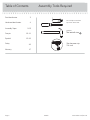 2
2
-
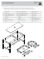 3
3
-
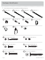 4
4
-
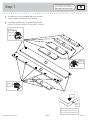 5
5
-
 6
6
-
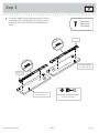 7
7
-
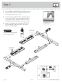 8
8
-
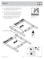 9
9
-
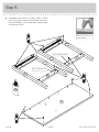 10
10
-
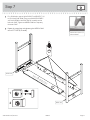 11
11
-
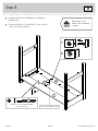 12
12
-
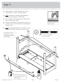 13
13
-
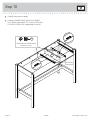 14
14
-
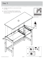 15
15
-
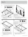 16
16
-
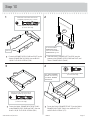 17
17
-
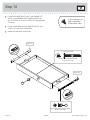 18
18
-
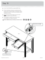 19
19
-
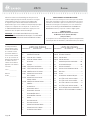 20
20
-
 21
21
-
 22
22
-
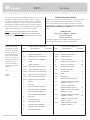 23
23
-
 24
24
-
 25
25
-
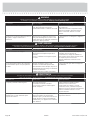 26
26
-
 27
27
-
 28
28


en otros idiomas
- français: Sauder 418213
- English: Sauder 418213
Artículos relacionados
-
Sauder New Grange 419128 Instrucciones de operación
-
-
-
-
-
-
-
-
-