
sauder.com
Queen Platform Bed
Model 423450
NOTE: THIS INSTRUCTION
BOOKLET CONTAINS IMPORTANT
SAFETY INFORMATION.
PLEASE READ AND KEEP FOR
FUTURE REFERENCE.
Enlish p 1-30
Français p 31-34
Español p 35-38
Lot # 532896 08/27/19
Purchased: __________________
sauder.com
CONTACT US FIRST
BEFORE MAKING ANY RETURNS TO THE STORE.
Share your journey!
sauder.com
CONTACT US FIRST
BEFORE MAKING ANY RETURNS TO THE STORE.
Visit sauder.com/service to order replacement parts, view video assembly tips, or chat with a live rep.
Prefer the phone? Give us a rin at
1-800-523-3987.
Customer Service is available Monday-Friday - 9 a.m. to 5:30 p.m. EST (except holidays)
You won't just fall in
love with it. You'll fall
asleep in it.

Table of Contents Assembly Tools Required
2-3
4
5-30
31-34
35-38
39
Part Identifi cation
Hardware Identifi cation
Assembly Steps
Français
Español
Warranty
Hammer
Not actual size
No. 2 Phillips Screwdriver
Tip Shown Actual Size
Skip the power trip.
This time.
423450 www.sauder.com/servicePae 2
Part Identifi cation
å While not all parts are labeled, some of the parts will have a label or an inked letter on the ede
to help distinuish similar parts from each other. Use this part identifi cation to help identify similar parts.
A HEADBOARD (1)
B SIDE PANEL (4)
B49 DRAWER BOTTOM (2)
C HEADBOARD LEFT LEG (1)
D HEADBOARD RIGHT LEG (1)
D270 DRAWER SIDE (4)
D528 DRAWER BOX FRONT (2)
D530 DRAWER BOX FRONT (2)
E CENTER LEG (2)
F FOOTBOARD LEFT LEG (1)
G FOOTBOARD RIGHT LEG (1)
H UPPER SIDE RAIL (4)
J LOWER SIDE RAIL (4)
K CENTER SUPPORT (1)
L SHORT CLEAT (2)
M CLEAT (5)
N TOP LEFT MOLDING (2)
O TOP RIGHT MOLDING (2)
P FOOTBOARD TOP MOLDING (1)
Q UPRIGHT (1)
R PLATFORM (5)
S PLATFORM SUPPORT (5)
T FOOTBOARD LOWER RAIL (1)
U FOOTBOARD UPPER RAIL (1)
V DRAWER FRONT (2)
W
DRAWER BRACE (2)
(Hidden part usin recycled
material. Color may vary.)
Now you know
our ABCs.
Tape Measure

Part Identifi cation
423450www.sauder.com/service
Pae 3
D270
B49
A
B
C
D
E
F
G
H
J
K
L
M
O
N
P
Q
R
S
T
U
V
W
B
E
H
L
M
S
S
S
S
D270
D528
D530
B
J
O
H
M
J
H
M
N
B
J
M
D270
B49
V
W
D270
D530
D528

Hardware Identifi cation
å Screws are shown actual size. You may receive extra hardware with your unit.
423450 www.sauder.com/servicePae 4
40DA
UNIVERSAL
CABINET RAIL - 4
40DC
DRAWER
RIGHT - 2
40DD
DRAWER
LEFT - 2
PULL - 2
149K
HIDDEN CAM - 42
1F
CAM SCREW - 42
8F
HIDDEN
CONNECTOR - 16
9F
WOOD DOWEL - 18
15F
GLUE - 1
54M
CONNECTOR SCREW - 16
8S
BLACK 1-1/8" PAN HEAD SCREW - 31
9S
12S
BROWN 1" FLAT HEAD SCREW - 24
BLACK 7/8" LARGE HEAD SCREW - 4
17S
SILVER 3/4" MACHINE SCREW - 4
20S
30S
BLACK 1-9/16" FLAT HEAD SCREW - 20
BLACK 1-1/2" FLAT HEAD SCREW - 16
101S
BLACK 1-15/16" FLAT HEAD SCREW - 12
113S
TACK GLIDE - 12
13E
3S
GOLD 5/16" FLAT HEAD SCREW - 16

Step 1
Look for this icon. It means a
video assembly tip is available at
www.sauder.com/service/tips
423450www.sauder.com/service
Pae 5
å
Assemble your unit on a carpeted fl oor or on the empty carton to avoid
scratchin your unit or the fl oor.
å
Insert a CONNECTOR SCREW (8S) into each HIDDEN CONNECTOR (9F).
å
Use your hammer to tap sixteen HIDDEN
CONNECTORS (9F) with SCREWS into the SIDE
PANELS (B) and FOOTBOARD UPPER RAIL (U).
Step 2
9F
8S
8S
B
U
9F
(16 used)
B
B
B

Step 3
å
Push forty-two HIDDEN CAMS (1F) into the HEADBOARD (A),
SIDE PANELS (B), CENTER SUPPORT (K), UPRIGHT (Q), and
FOOTBOARD RAILS (T and U).
423450 www.sauder.com/servicePae 6
B
U
B
B
B
Q
A
K
T
1F
Arrow
(42 used)
Arrow
1F
Arrow
The arrow in the HIDDEN
CAM must point toward the
hole in the ede of the board.
Hole

å
Turn forty-two CAM SCREWS (8F) into the LEGS (C, D, E, F,
and G) and FOOTBOARD RAILS (T and U).
å
NOTE: Use the exact holes shown.
Step 4
423450www.sauder.com/service
Pae 7
U
T
C
D
E
E
F
G
8F
(42 used)
8F
8F

Step 5
å
Fasten one UNIVERSAL CABINET RAIL* (40DA) to each
side of the UPRIGHT (Q). Use four GOLD 5/16" FLAT
HEAD SCREWS (3S) throuh holes #1 and #4.
å
*patent pendin lide system
423450 www.sauder.com/servicePae 8
Q
VIEW THE DRAWER GLIDE VIDEO
1
2
3
4
1
2
3
4
Finished ede
Glide end
GOLD 5/16" FLAT HEAD SCREW
(4 used in this step)
3S

å
Fasten the FOOTBOARD TOP MOLDING (P) to
the FOOTBOARD UPPER RAIL (U). Tihten four
HIDDEN CONNECTORS.
Step 6
423450www.sauder.com/service
Pae 9
Surface with HIDDEN
CONNECTORS
U
P
How to use the HIDDEN CONNECTOR
To fasten two parts toether usin the HIDDEN
CONNECTORS, insert your screwdriver, at an anle,
into the slot in the HIDDEN CONNECTOR. While
pushin the screw into the hole of the adjoinin
part, turn the screwdriver clockwise to tihten.
Surface with holes
The holes in the
MOLDING are closer
to the top ede.

Step 7
å
Fasten the TOP MOLDINGS (N and O) to the SIDE
PANELS (B). Tihten twelve HIDDEN CONNECTORS.
423450 www.sauder.com/servicePae 10
B
N
B
N
B
O
B
O
This end
has a hole.
This end
has a hole.
Surface with
HIDDEN
CONNECTORS
Surface with
HIDDEN
CONNECTORS
Surface with
HIDDEN
CONNECTORS
Surface with
HIDDEN
CONNECTORS
The holes in the
MOLDING are closer
to the top ede.

å
Fasten the LOWER SIDE RAILS (J) to the SIDE PANELS (B).
Use twelve BROWN 1" FLAT HEAD SCREWS (12S).
å
NOTE: Do not overtihten the SCREWS.
Step 8
423450www.sauder.com/service
Pae 11
B
J
B
J
B
J
B
J
BROWN 1" FLAT HEAD SCREW
(12 used in this step)
12S
Surface with holes
Surface with holes
Surface with holes
Surface with holes
Surface with
HIDDEN
CONNECTORS
Surface with
HIDDEN
CONNECTORS
Surface with
HIDDEN
CONNECTORS
Surface with
HIDDEN
CONNECTORS

Step 9
å
NOTE: The WOOD DOWELS (15F) will be inserted into the
ede with two CAM SCREWS in each CENTER LEG (E).
å
First, fi ll the holes in the CENTER LEGS (E) 1/4 to 1/2 full with
GLUE (54M). Then, insert the WOOD DOWELS (15F) into the
holes. Wipe away the excess GLUE.
å
Now, fi ll the holes in the CENTER SUPPORT (K) 1/4 to 1/2 full
with GLUE.
å
Fasten the CENTER LEGS (E) to the CENTER SUPPORT (K).
Tihten four HIDDEN CAMS. Wipe away the excess GLUE.
å
NOTE: Be sure the WOOD DOWELS in the CENTER LEGS
insert into the CENTER SUPPORT.
423450 www.sauder.com/servicePae 12
Fill the holes 1/4 to 1/2 full with GLUE.
Inspect the parts thorouhly before
assemblin. Disassembly of lued
parts is extremely di cult.
Caution
!
54M
15F
15F
1
2
These surfaces
should be even.
Surface with
HIDDEN CAMS
E
K
E
These surfaces
should be even.
This hole is closer
to this ede.

Step 10
423450www.sauder.com/service
Pae 13
Fill the holes 1/4 to 1/2 full with GLUE.
Inspect the parts thorouhly before
assemblin. Disassembly of lued
parts is extremely di cult.
Caution
!
å
NOTE: The WOOD DOWELS (15F) will be inserted into the ede
with two CAM SCREWS in each HEADBOARD LEG (C and D).
å
First, fi ll the holes in the HEADBOARD LEGS (C and D) 1/4 to 1/2
full with GLUE (54M). Then, insert the WOOD DOWELS (15F) into
the holes. Wipe away the excess GLUE.
å
Now, fi ll the holes in the HEADBOARD (A) 1/4 to 1/2 full with GLUE.
å
Fasten the HEADBOARD LEGS (C and D) to the HEADBOARD (A).
Tihten four HIDDEN CAMS. Wipe away the excess GLUE.
å
NOTE: Be sure the WOOD DOWELS in the HEADBOARD LEGS
insert into the HEADBOARD.
Surface with
HIDDEN CAMS
D
A
C
15F
54M
15F
These surfaces
should be even.
These surfaces
should be even.
These holes are
closer to this ede.

Step 11
423450 www.sauder.com/servicePae 14
å
NOTE: The WOOD DOWELS (15F) will be inserted into the ede
with two holes in each FOOTBOARD LEG (F and G).
å
First, fi ll the holes in the FOOTBOARD LEGS (F and G) 1/4 to 1/2
full with GLUE (54M). Then, insert the WOOD DOWELS (15F)
into the holes. Wipe away the excess GLUE.
å
Now, fi ll the holes in the FOOTBOARD RAILS (T and U) 1/4 to
1/2 full with GLUE.
å
Fasten the FOOTBOARD LEGS (F and G) to the FOOTBOARD
RAILS (T and U). Tihten six HIDDEN CAMS. Wipe away the
excess GLUE.
å
NOTE: Be sure the WOOD DOWELS in the FOOTBOARD LEGS
insert into the FOOTBOARD RAILS.
Fill the holes 1/4 to 1/2 full with GLUE.
Inspect the parts thorouhly before
assemblin. Disassembly of lued
parts is extremely di cult.
Caution
!
54M
15F
15F
Surface with
HIDDEN CAMS
U
P
Surface with HIDDEN CAMS
T
G
F
These surfaces
should be even.
These surfaces
should be even.
Finished ede

å
With a hammer, tap six TACK GLIDES (13E) into the edes
of the HEADBOARD (A), CENTER SUPPORT (K), and
FOOTBOARD LOWER RAIL (T).
å
With a hammer, tap six TACK GLIDES (13E) into the
centers of the LEGS (C, D, E, F, and G).
Step 12
423450www.sauder.com/service
Pae 15
T
G
F
E
K
E
C
A
D
13E
13E
13E

Step 13
å
Fasten the UPRIGHT (Q) to the FOOTBOARD
RAILS (T and U). Tihten four HIDDEN CAMS.
423450 www.sauder.com/servicePae 16
U
T
Q
Surface with
HIDDEN CAMS

Step 14
423450www.sauder.com/service
Pae 17
U
T
B
B
Surface with
HIDDEN CAMS
Surface without
HIDDEN CAMS
å
NOTE: The remainin WOOD DOWELS will not be lued. If you
need to relocate your bed, disassembly and reassembly will be
easier without lue.
å
Insert two WOOD DOWELS (15F) into the holes in the
FOOTBOARD LEGS (F and G).
å
Fasten two di erent SIDE PANELS (B) to the FOOTBOARD LEGS (F
and G). Tihten six HIDDEN CAMS.
å
NOTE: One SIDE PANEL (B) will have a TOP LEFT MOLDING (N),
and the other will have a TOP RIGHT MOLDING (O).
å
NOTE: Be sure the WOOD DOWELS in the FOOTBOARD LEGS
insert into the SIDE PANELS.
å
Insert two WOOD DOWELS (15F) into the holes in the ends of the
TOP MOLDINGS (N and O).
O
N
F
G
15F
15F
15F
15F
For support, place packin
foam and maazines here.
For support, place packin
foam and maazines here.
Do not use lue
for the remainin
WOOD DOWELS.

Step 15
å
Insert two WOOD DOWELS (15F) into the holes in the
CENTER LEGS (E).
å
Fasten the CENTER LEGS (E) to the SIDE PANELS (B).
Tihten six HIDDEN CAMS.
å
NOTE: Be sure the WOOD DOWELS in the CENTER LEGS
insert into the SIDE PANELS.
å
Fasten the CENTER SUPPORT (K) to the UPRIGHT (Q).
Use two BLACK 1-15/16" FLAT HEAD SCREWS (113S).
423450 www.sauder.com/servicePae 18
B
B
15F
15F
Surface with
HIDDEN CAMS
K
Q
E
E
BLACK 1-15/16" FLAT HEAD SCREW
(2 used for the UPRIGHT)
113S

å
Insert two WOOD DOWELS (15F) into the holes in the
CENTER LEGS (E).
å
Fasten the remainin SIDE PANELS (B) to the CENTER
LEGS (E). Tihten six HIDDEN CAMS.
å
NOTE: Be sure the WOOD DOWELS in the CENTER LEGS
and TOP MOLDINGS insert into the remainin SIDE
PANELS and TOP MOLDINGS.
Step 16
423450www.sauder.com/service
Pae 19
O
N
O
N
B
B
Surface with
HIDDEN CAMS
Surface without
HIDDEN CAMS
For support, place packin
foam and maazines here.
For support, place packin
foam and maazines here.
15F
15F
E
E

Step 17
å
Insert two WOOD DOWELS (15F) into the holes in the
HEADBOARD LEGS (C and D).
å
Fasten the HEADBOARD LEGS (C and D) to the SIDE
PANELS (B). Tihten six HIDDEN CAMS.
å
NOTE: Be sure the WOOD DOWELS in the HEADBOARD
LEGS insert into the SIDE PANELS.
423450 www.sauder.com/servicePae 20
C
A
D
Surface without
HIDDEN CAMS
B
B
15F
15F

Step 18
423450www.sauder.com/service
Pae 21
VIEW THE DRAWER GLIDE VIDEO
B
B
å
Fasten two UNIVERSAL CABINET RAILS* (40DA) to the
SIDE PANELS (B). Use four GOLD 5/16" FLAT HEAD
SCREWS (3S) throuh holes #1 and #4.
å
*patent pendin lide system
1
2
3
4
1
2
3
4
Glide end
Glide end
GOLD 5/16" FLAT HEAD SCREW
(4 used in this step)
3S

Step 19
å
Fasten the UPPER SIDE RAILS (H) to the SIDE PANELS (B).
Use twelve BROWN 1" FLAT HEAD SCREWS (12S).
å
NOTE: Do not overtihten the SCREWS.
423450 www.sauder.com/servicePae 22
BROWN 1" FLAT HEAD SCREW
(12 used in this step)
12S
B
B
B
B
H
H
H
Unfi nished ede
Surface without holes
Surface without holes
Surface with holes
H
Surface with holes
Unfi nished ede
Use the upper hole.

å
Fasten the CLEATS (M) to the HEADBOARD (A) and
SIDE PANELS (B). Use fi fteen BLACK 1-1/8" PAN
HEAD SCREWS (9S).
å
NOTE: Do not overtihten the SCREWS.
Step 20
423450www.sauder.com/service
Pae 23
9S
BLACK 1-1/8" PAN HEAD SCREW
(15 used in this step)
A
B
B
B
B
M
M
M
M
M

Step 21
å
Fasten the SHORT CLEATS (L) to two of the
PLATFORM SUPPORTS (S). Use four BLACK 1-15/16"
FLAT HEAD SCREWS (113S).
å
Fasten the SHORT CLEATS (L) to the FOOTBOARD
UPPER RAIL (U). Use six BLACK 1-1/8" PAN
HEAD SCREWS (9S).
å
NOTE: Do not overtihten the SCREWS.
å
NOTE: The PLATFORM SUPPORTS (S) will rest on the
CENTER SUPPORT (K).
423450 www.sauder.com/servicePae 24
BLACK 1-15/16" FLAT HEAD SCREW
(4 used for the PLATFORM SUPPORTS)
113S
1
st
2
nd
9S
BLACK 1-1/8" PAN HEAD SCREW
(6 used for the SHORT CLEATS)
L
L
S
S
L
L
U
K
S
S
These holes
should be closer
to each other.
This hole
should be to the
riht of center.
This hole
should be to the
left of center.

å
NOTE: Position the PLATFORM SUPPORTS exactly as shown.
å
Fasten one of the PLATFORM SUPPORTS (S) to the UPRIGHT (Q).
Use two BLACK 1-1/8" PAN HEAD SCREWS (9S).
å
Fasten the remainin two PLATFORM SUPPORTS (S) to the
PLATFORM SUPPORTS (S) that are fastened to the SHORT
CLEATS (L). Use eiht BLACK 1-1/8" PAN HEAD SCREWS (9S).
å
Fasten the HEADBOARD (A) to three PLATFORM SUPPORTS (S).
Use six BLACK 1-15/16" FLAT HEAD SCREWS (113S).
Step 22
423450www.sauder.com/service
Pae 25
BLACK 1-15/16" FLAT HEAD SCREW
(6 used for the HEADBOARD)
113S
Q
S
S
S
S
S
A
9S
BLACK 1-1/8" PAN HEAD SCREW
(10 used in this step)
L
L

Step 23
423450 www.sauder.com/servicePae 26
å
Fasten two DRAWER SIDES (D270) to one of the
DRAWER BOX FRONTS (D528). Use four BLACK
1-9/16" FLAT HEAD SCREWS (30S).
å
Slide a DRAWER BOTTOM (B49) into the grooves in the
DRAWER SIDES (D270) and DRAWER BOX FRONT (D528).
å
Fasten a DRAWER BOX FRONT (D530) to the
DRAWER SIDES (D270). Use four BLACK 1-9/16"
FLAT HEAD SCREWS (30S).
å
Fasten a DRAWER BRACE (W) to the DRAWER BOX
FRONTS (D528 and D530). Use two BLACK 1-9/16"
FLAT HEAD SCREWS (30S).
å
Repeat this step for the other drawer.
12
34
Be sure the DRAWER
BOTTOM inserts
into the DRAWER
BOX FRONT roove.
Groove
B49
W
VIEW THE T-LOCK BOX VIDEO
Finished surface
Be sure the DRAWER
BOTTOM inserts into
the DRAWER BOX
FRONT roove.
30S
Start each screw a few turns before
completely tihtenin any of them.
BLACK 1-9/16" FLAT HEAD SCREW
(4 used in this section)
With the palm of your hand,
tap the DRAWER BOTTOM
into the rooves.
30S
Start each screw a few turns before
completely tihtenin any of them.
BLACK 1-9/16" FLAT HEAD SCREW
(8 used in this section)
D270
D270
D270
D270
D528
D528
D270
D270
D530
30S
Start each screw a few turns before
completely tihtenin any of them.
BLACK 1-9/16" FLAT HEAD SCREW
(8 used in this section)
D528
D530
Hidden part usin
recycled material.
Color may vary.

å
Fasten a DRAWER FRONT (V) to one of the DRAWER
BOX FRONTS (D530). Use two BLACK 7/8" LARGE
HEAD SCREWS (17S).
å
NOTE: This drawer will now be the RIGHT drawer.
å
Fasten the remainin DRAWER FRONT (V) to the
DRAWER BOX FRONT (D528) on the other drawer. Use
two BLACK 7/8" LARGE HEAD SCREWS (17S).
å
NOTE: This drawer will now be the LEFT drawer.
Step 24
423450www.sauder.com/service
Pae 27
D530
D528
This hole is closer
to this ede.
V
BLACK 7/8" LARGE HEAD SCREW
(4 used in this step)
17S
V
This hole is closer
to this ede.
RIGHT drawer
LEFT drawer

Step 25
423450 www.sauder.com/servicePae 28
å
Fasten a DRAWER RIGHT (40DC) and a DRAWER LEFT (40DD)
to the DRAWER SIDES (D270). Use four GOLD 5/16" FLAT
HEAD SCREWS (3S) throuh holes #1 and #2.
å
NOTE: The lides are not intended to rotate.
å
Fasten a PULL (149K) to the DRAWER FRONT (V). Use two
SILVER 3/4" MACHINE SCREWS (20S).
å
Repeat this step for the other drawer.
1
2
Glide end
VIEW THE DRAWER GLIDE VIDEO
Glide end
1
2
D270
D270
149K
V
SILVER 3/4" MACHINE SCREW
(4 used for the PULLS)
20S
GOLD 5/16" FLAT HEAD SCREW
(8 used in this step)
3S

å
NOTE: First, fasten the top and bottom PLATFORMS (R) makin
sure they are fl ush with the HEADBOARD and FOOTBOARD.
å
Fasten the PLATFORMS (R) to the HEADBOARD (A) and CLEATS (L
and M). Use sixteen BLACK 1-1/2" FLAT HEAD SCREWS (101S).
å
NOTE: Evenly space the three middle PLATFORMS (R) between the
top and bottom PLATFORMS. There should be approximately a 2"
ap between the PLATFORMS.
Step 26
423450www.sauder.com/service
Pae 29
BLACK 1-1/2" FLAT HEAD SCREW
(16 used in this step)
101S
101S
101S
101S
R
R
R
R
101S
R
A
M
M
L
L
M
The edes of the top and bottom
PLATFORMS should be fl ush with
the HEADBOARD and FOOTBOARD.
1
st
1
st

Step 27
å
To insert the drawers into your unit, tip the front of the drawer down and drop the lides on the
drawer behind the lides on the unit. Lift the front of the drawer up and slide it into the unit.
å
This completes assembly. Clean with a damp cloth. Wipe dry.
423450 www.sauder.com/servicePae 30
RIGHT drawer
LEFT drawer
35 lbs.
35 lbs.
And to celebrate, why not share your success story at Walmart.com or

Noter la date d’achat
de cet élément et
conserver le livret pour
future référence. Pour
contacter Sauder en
ce qui concerne cet
élément, faire référence
au numéro de lot et
numéro de modèle en
appelant notre numéro
sans frais.
Lot nº : ____________
Date de
l'achet : ____________
LISTE DE PIÈCES
REFERENCE DESCRIPTION QUANTITÉ
LISTE DE PIÈCES
REFERENCE DESCRIPTION QUANTITÉ
NOUS SOMMES LA POUR VOUS AIDER!
Nous faisons de notre mieux pour nous assurer que votre meuble
arrive dans d’excellentes conditions. Nos représentants du service
Clientèle sont aimables et prêts à vous aider au cas où une pièce
aurait été endommaée ou manquerait (ou si vous aviez besoin
d’aide pour l’assemblae). NE RAMENEZ PAS LE MEUBLE AU
MAGASIN. Au Canada, composez ce numéro d’appel ratuit:
1-800-523-3987
Du lundi au vendredi, de 9 heures du matin à
5:30 heures du soir (horaire Côte Est)
(sauf jours fériés)
Si une pièce a besoin d’être remplacée, la pièce de remplacement
sera envoyée dans les 48 heures. (Sauf week-ends et jours fériés)
Utilisez les instructions d’assemblae en français avec les
schémas étape par étape du manuel d’instruction en anlais.
Chaque étape en français correspond à la même étape
en anlais. La pièce devant être attachée à l’élément est
représentée en ris sur les schémas de chaque étape pour plus
de précision. Comparer la “Liste de pièces” ci-dessous avec
la “PART IDENTIFICATION” du manuel en anlais pour vous
familiariser avec les pièces avant l’assemblae.
REMARQUE : CE MANUEL D’INSTRUCTIONS CONTIENT
D’IMPORTANTES INFORMATIONS RELATIVES À LA SÉCURITÉ.
À LIRE ET CONSERVER POUR TOUTE RÉFÉRENCE FUTURE.
Lit Plate-forme Grand litModèle 423450
W ENTRETOISE DE TIROIR
(Pièce cachée utilisant des matériaux
recyclés. La couleur peut varier.) ......................2
40DA
GLISSIÈRE D'ÉLÉMENT UNIVERSELLE.....4
40DC
TIROIR DROIT ................................................................2
40DD
TIROIR GAUCHE ..........................................................2
13E PATIN ...................................................................................12
1F EXCENTRIQUE ESCAMOTABLE .................42
8F VIS D'EXCENTRIQUE ...........................................42
9F CONNECTEUR ESCAMOTABLE ..................16
15F CHEVILLE EN BOIS ................................................ 18
149K POIGNÉE ............................................................................2
54M COLLE ...................................................................................1
3S VIS TÊTE PLATE 8 mm DORÉE ................... 16
8S VIS DE CONNECTEUR ......................................... 16
9S VIS TÊTE GOUTTE DE
SUIF 28 mm NOIRE ................................................31
12S VIS TÊTE PLATE 25 mm MARRON ..........24
17S VIS TÊTE LARGE 22 mm NOIRE ...................4
20S VIS À MÉTAUX 19 mm ARGENTÉE ..............4
30S VIS TÊTE PLATE 40 mm NOIRE ................20
101S VIS TÊTE PLATE 38 mm NOIRE ..................16
113S VIS TÊTE PLATE 49 mm NOIRE ...................12
A TÊTE DE LIT .....................................................................1
B PANNEAU LATÉRAL..................................................4
B49 FOND DE TIROIR .........................................................2
C PIED GAUCHE DE LA TÊTE DE LIT ...............1
D PIED DROIT DE LA TÊTE DE LIT .....................1
D270
CÔTÉ DE TIROIR .........................................................4
D528
DEVANT DE CAISSON DE TIROIR ................2
D530
DEVANT DE CAISSON DE TIROIR ................2
E PIED CENTRAL .............................................................2
F PIED GAUCHE DU PIED DE LIT ........................1
G PIED DROIT DU PIED DE LIT ..............................1
H TRAVERSE LATÉRALE SUPÉRIEURE ..........4
J TRAVERSE LATÉRALE INFÉRIEURE .............4
K SUPPORT CENTRAL .................................................1
L TASSEAU COURT .......................................................2
M TASSEAU ...........................................................................5
N MOULURE SUPÉRIEURE GAUCHE ..............2
O MOULURE SUPÉRIEURE DROITE .................2
P
MOULURE SUPÉRIEURE DU PIED DE LIT
....1
Q MONTANT..........................................................................1
R PLATEFORME ................................................................5
S SUPPORT DE PLATEFORME .............................5
T
TRAVERSE INFÉRIEURE DU PIED DE LIT
....1
U
TRAVERSE SUPÉRIEURE DU PIED DE LIT
... 1
V DEVANT DE TIROIR ...................................................2
423450www.sauder.com/service
Pae 31

ÉTAPE 1
Assembler l'élément sur un sol à moquette ou sur le carton vide
pour éviter d'endommaer l'élément ou le sol.
Insérer une VIS DE CONNECTEUR (8S) dans chaque
CONNECTEUR ESCAMOTABLE (9F).
ÉTAPE 2
À l'aide d’un marteau, enfoncer seize CONNECTEURS
ESCAMOTABLES (9F) avec VIS dans les PANNEAUX
LATÉRAUX (B) et la TRAVERSE SUPÉRIEURE DU PIED DE LIT (U).
ÉTAPE 7
Fixer les MOULURES SUPÉRIEURES (N et O) aux PANNEAUX
LATÉRAUX (B). Serrer douze CONNECTEURS ESCAMOTABLES.
ÉTAPE 9
Attention: Examiner bien les pièces avant d'assembler. Il est
di cile de séparer des pièces une fois encollées.
REMARQUE : Les CHEVILLES EN BOIS (15F) seront insérées
dans le chant avec deux VIS D'EXCENTRIQUE dans chaque
PIED CENTRAL (E).
Tout d'abord, remplir les trous dans les PIEDS CENTRAUX (E) de
1/4 à 1/2 pleins de COLLE (54M). Insérer ensuite les CHEVILLES
EN BOIS (15F) dans les trous. Nettoyer l'excès de COLLE.
Maintenant, remplir les trous dans le SUPPORT CENTRAL (K)
de 1/4 à 1/2 pleins de COLLE.
Fixer les PIEDS CENTRAUX (E) au SUPPORT CENTRAL (K).
Serrer quatre EXCENTRIQUES ESCAMOTABLES. Nettoyer l'excès
de COLLE.
REMARQUE : S’assurer de bien insérer les CHEVILLES EN BOIS
des PIEDS CENTRAUX dans le SUPPORT CENTRAL.
ÉTAPE 3
Enfoncer quarante-deux EXCENTRIQUES ESCAMOTABLES (1F)
dans la TÊTE DE LIT (A), les PANNEAUX LATÉRAUX (B), le
SUPPORT CENTRAL (K), le MONTANT (Q) et les TRAVERSES DU
PIED DE LIT (T et U).
ÉTAPE 10
Attention: Examiner bien les pièces avant d'assembler. Il est
di cile de séparer des pièces une fois encollées.
REMARQUE : Les CHEVILLES EN BOIS (15F) seront insérées
dans le chant avec deux VIS D'EXCENTRIQUE dans chaque PIED
DE LA TÊTE DE LIT (C et D).
Tout d'abord, remplir les trous dans les PIEDS DE LA TÊTE DE
LIT (C et D) de 1/4 à 1/2 pleins de COLLE (54M). Insérer
ensuite les CHEVILLES EN BOIS (15F) dans les trous. Nettoyer
l'excès de COLLE.
Maintenant, remplir les trous dans la TÊTE DE LIT (A) de 1/4 à 1/2
pleins de COLLE.
Fixer les PIEDS DE LA TÊTE DE LIT (C et D) à la TÊTE DE LIT (A).
Serrer quatre EXCENTRIQUES ESCAMOTABLES. Nettoyer l'excès
de COLLE.
REMARQUE : S’assurer d’insérer les CHEVILLES EN BOIS des
PIEDS DE LA TÊTE DE LIT dans la TÊTE DE LIT.
ÉTAPE 4
Faire tourner quarante-deux VIS D'EXCENTRIQUE (8F) dans les
PIEDS (C, D, E, F et G) et les TRAVERSES DU PIED DE LIT (T et U).
REMARQUE : Utiliser les trous exacts indiqués.
ÉTAPE 8
Fixer les TRAVERSES LATÉRALES INFÉRIEURES (J) aux
PANNEAUX LATÉRAUX (B). Utiliser douze VIS TÊTE
PLATE 25 mm MARRON (12S).
REMARQUE : Ne pas trop serrer les VIS.
423450 www.sauder.com/servicePae 32
ÉTAPE 5
Fixer une GLISSIÈRE D'ÉLÉMENT UNIVERSELLES * (40DA) de
chaque côté du MONTANT (Q). Utiliser quatre VIS TÊTE
PLATE 8 mm DORÉES (3S) à travers les trous nº 1 et nº 4.
*système de coulisse en instance de brevet
ÉTAPE 6
Fixer la MOULURE SUPÉRIEURE DU PIED DE LIT (P) à la
TRAVERSE SUPÉRIEURE DU PIED DE LIT (U). Serrer quatre
CONNECTEURS ESCAMOTABLES.
Utilisation des CONNECTEURS ESCAMOTABLES
Pour attacher deux pièces ensemble à l'aide des CONNECTEURS
ESCAMOTABLES, il su t d'insérer la pointe d'un tournevis en
biseau dans la fente du CONNECTEUR ESCAMOTABLE. Tout en
enfonçant la vis dans le trou dans la planche adjacente, tourner le
tournevis, en biseau, dans le sens des aiuilles d'une montre pour
serrer à bloc.

ÉTAPE 11
Attention: Examiner bien les pièces avant d'assembler. Il est
di cile de séparer des pièces une fois encollées.
REMARQUE : Les CHEVILLES EN BOIS (15F) seront
insérées dans le chant avec deux trous dans chaque PIED DU
PIED DE LIT (F et G).
Tout d'abord, remplir les trous dans les PIEDS DU PIED DE
LIT (F et G) de 1/4 à 1/2 pleins de COLLE (54M). Insérer
ensuite les CHEVILLES EN BOIS (15F) dans les trous. Nettoyer
l'excès de COLLE.
Maintenant, remplir les trous dans les TRAVERSES DU PIED DE
LIT (T et U) de 1/4 à 1/2 pleins de COLLE.
Fixer les PIEDS DU PIED DE LIT (F et G) aux TRAVERSES DU PIED
DE LIT (T et U). Serrer six EXCENTRIQUES ESCAMOTABLES.
Nettoyer l'excès de COLLE.
REMARQUE : S’assurer de bien insérer les CHEVILLES EN BOIS
des PIEDS DU PIED DE LIT dans les TRAVERSES DU PIED DE LIT.
ÉTAPE 12
À l’aide d’un marteau, enfoncer six PATINS (13E) dans les chants
de la TÊTE DE LIT (A), du SUPPORT CENTRAL (K) et de la
TRAVERSE INFÉRIEURE DU PIED DE LIT (T).
À l'aide d'un marteau, léèrement enfoncer six PATINS (13E) dans
les centres des PIEDS (C, D, E, F et G).
ÉTAPE 15
Insérer deux CHEVILLES EN BOIS (15F) dans les trous des
PIEDS CENTRAUX (E).
Fixer les PIEDS CENTRAUX (E) aux PANNEAUX LATÉRAUX (B).
Serrer six EXCENTRIQUES ESCAMOTABLES.
REMARQUE : S’assurer de bien insérer les CHEVILLES EN BOIS
des PIEDS CENTRAUX dans les PANNEAUX LATÉRAUX.
Fixer le SUPPORT CENTRAL (K) au MONTANT (Q). Utiliser deux
VIS TÊTE PLATE 49 mm NOIRES (113S).
ÉTAPE 16
Insérer deux CHEVILLES EN BOIS (15F) dans les trous des
PIEDS CENTRAUX (E).
Fixer les autres PANNEAUX LATÉRAUX (B) aux PIEDS
CENTRAUX (E). Serrer six EXCENTRIQUES ESCAMOTABLES.
REMARQUE : S’assurer de bien insérer les CHEVILLES EN BOIS
des PIEDS CENTRAUX et des MOULURES SUPÉRIEURES dans
les autres PANNEAUX LATÉRAUX et MOULURES SUPÉRIEURES.
ÉTAPE 13
Fixer le MONTANT (Q) aux TRAVERSES DU PIED DE LIT (T et U).
Serrer quatre EXCENTRIQUES ESCAMOTABLES.
ÉTAPE 17
Insérer deux CHEVILLES EN BOIS (15F) dans les trous des PIEDS
DE LA TÊTE DE LIT (C et D).
Fixer les PIEDS DE LA TÊTE DE LIT (C et D) aux PANNEAUX
LATÉRAUX (B). Serrer six EXCENTRIQUES ESCAMOTABLES.
REMARQUE : S’assurer de bien insérer les CHEVILLES EN BOIS
des PIEDS DE LA TÊTE DE LIT dans les PANNEAUX LATÉRAUX.
ÉTAPE 14
REMARQUE : Ne pas utiliser de colle dans les CHEVILLES EN
BOIS restantes. Si vous devez déplacer votre lit, démontae et
remontae sera plus facile sans colle.
Insérer deux CHEVILLES EN BOIS (15F) dans les trous des PIEDS
DU PIED DE LIT (F et G).
Fixer deux autres PANNEAUX LATÉRAUX (B) aux PIEDS DU PIED
DE LIT (F et G). Serrer six EXCENTRIQUES ESCAMOTABLES.
REMARQUE : Un PANNEAU LATÉRAL (B) comporte une
MOULURE SUPÉRIEURE GAUCHE (N), et l’autre comporte
une MOULURE SUPÉRIEURE DROITE (O).
REMARQUE : S’assurer de bien insérer les CHEVILLES EN BOIS
des PIEDS DU PIED DE LIT dans les PANNEAUX LATÉRAUX.
Insérer deux CHEVILLES EN BOIS (15F) dans les trous dans les
extrémités des MOULURES SUPÉRIEURES (N et O).
ÉTAPE 18
Fixer deux GLISSIÈRES D'ÉLÉMENT UNIVERSELLES* (40DA) aux
PANNEAUX LATÉRAUX (B). Utiliser quatre VIS TÊTE PLATE 8 mm
DORÉES (3S) à travers les trous nº 1 et nº 4.
*système de coulisse en instance de brevet
423450www.sauder.com/service
Pae 33
ÉTAPE 19
Fixer les TRAVERSES LATÉRALES SUPÉRIEURES (H) aux
PANNEAUX LATÉRAUX (B). Utiliser douze VIS TÊTE
PLATE 25 mm MARRON (12S).
REMARQUE : Ne pas trop serrer les VIS.

ÉTAPE 20
Fixer les TASSEAUX (M) à la TÊTE DE LIT (A) et aux PANNEAUX
LATÉRAUX (B). Utiliser quinze VIS TÊTE GOUTTE DE
SUIF 28 mm NOIRES (9S).
REMARQUE : Ne pas trop serrer les VIS.
ÉTAPE 24
Fixer un DEVANT DE TIROIR (V) sur l'un des DEVANTS DE
CAISSON DU TIROIR (D530). Utiliser deux VIS TÊTE
LARGE 22 mm NOIRES (17S).
REMARQUE : Ce tiroir sera désormais le tiroir DROIT.
Fixer l’autre DEVANT DE TIROIR (V) sur le DEVANT DE CAISSON
DE TIROIR (D528) sur l’autre tiroir. Utiliser deux VIS TÊTE
LARGE 22 mm NOIRES (17S).
REMARQUE : Ce tiroir sera désormais le tiroir GAUCHE.
ÉTAPE 25
Fixer un TIROIR DROIT (40DC) et un TIROIR GAUCHE (40DD)
aux CÔTÉS DE TIROIR (D270). Utiliser quatre VIS TÊTE
PLATE 8 mm DORÉES (3S) à travers les trous nº 1 et nº 2.
REMARQUE : Les coulisses ne sont pas sensées tourner.
Fixer un POIGNÉE (149K) au DEVANT DE TIROIR (V). Utiliser deux
VIS À MÉTAUX 19 mm ARGENTÉES (20S).
Répéter cette étape pour l'autre tiroir.
ÉTAPE 21
Fixer les TASSEAUX COURTS (L) aux deux SUPPORTS
DE PLATEFORME (S). Utiliser quatre VIS TÊTE
PLATE 49 mm NOIRES (113S).
Fixer les TASSEAUX COURTS (L) à la TRAVERSE SUPÉRIEURE
DU PIED DE LIT (U). Utiliser six VIS TÊTE GOUTTE DE
SUIF 28 mm NOIRES (9S).
REMARQUE : Ne pas trop serrer les VIS.
REMARQUE : Les SUPPORTS DE PLATEFORME (S) reposeront
sur le SUPPORT CENTRAL (K).
ÉTAPE 26
REMARQUE : Tout d'abord, fi xer les PLATEFORMES (R) supérieures
et inférieures à fl eur avec la TÊTE DE LIT et le PIED DE LIT
Fixer les PLATEFORMES (R) à la TÊTE DE LIT (A)
et aux TASSEAUX (L et M). Utiliser seize VIS TÊTE
PLATE 38 mm NOIRES (101S).
REMARQUE : Espacer éalement les trois PLATEFORMES (R)
intermédiaires entre les PLATEFORMES supérieures et inférieures Il
devrait y avoir un espace d'environ 51 mm entre les PLATEFORMES.
ÉTAPE 22
REMARQUE : Positionner les SUPPORTS DE PLATEFORME
exactement comme il l’est indiqué.
Fixer l’un des SUPPORTS DE PLATEFORME (S) au MONTANT (Q).
Utiliser deux VIS TÊTE GOUTTE DE SUIF 28 mm NOIRES (9S).
Fixer les deux autres SUPPORTS DE PLATEFORME (S) sur
les SUPPORTS DE PLATEFORME (S) qui ont été fi xés sur les
TASSEAUX COURTS (L). Utiliser huit VIS TÊTE GOUTTE DE
SUIF 28 mm NOIRES (9S).
Fixer la TÊTE DE LIT (A) aux SUPPORTS DE PLATEFORME (S).
Utiliser six VIS TÊTE PLATE 49 mm NOIRES (113S).
ÉTAPE 27
Pour insérer les tiroirs dans l’unité, incliner le devant du tiroir vers
le bas et faire tomber les coulisses du tiroir derrière les coulisses
de l’unité. Relever le devant du tiroir et l'enfi ler dans l'élément.
Ceci complète l'assemblae. Nettoyer avec un tissu humide. Essuyer.
423450 www.sauder.com/servicePae 34
ÉTAPE 23
1 Fixer deux CÔTÉS DE TIROIR (D270) sur l'un des DEVANTS DE
CAISSON DU TIROIR (D528). Utiliser quatre VIS TÊTE
PLATE 40 mm NOIRES (30S).
2
Enfi ler le FOND DE TIROIR (B49) dans les rainures des CÔTÉS
DE TIROIR (D270) et du DEVANT DE CAISSON DU TIROIR (D528).
3
Fixer un DEVANT DE CAISSON DE TIROIR (D530) aux CÔTÉS DE
TIROIR (D270). Utiliser quatre VIS TÊTE PLATE 40 mm NOIRES (30S).
4 Fixer l'ENTRETOISE DE TIROIR (W) aux DEVANTS DE
CAISSON DE TIROIR (D528 et D530). Utiliser deux VIS TÊTE
PLATE 40 mm NOIRES (30S).
Répéter cette étape pour l'autre tiroir.

40DA
RIEL UNIVERSAL DE GABINETE ....................4
40DC
CAJÓN DERECHO .....................................................2
40DD
CAJÓN IZQUIERDO ..................................................2
13E TACHUELA DESLIZANTE ...................................12
1F EXCÉNTRICO ESCONDIDO ...........................42
8F BIELA DE EXCÉNTRICO .................................... 42
9F CONECTOR INVISIBLE .......................................16
15F PASADOR DE MADERA ......................................18
149K TIRADOR ............................................................................2
54M PEGAMENTO ..................................................................1
3S TORNILLO DORADO DE CABEZA
PERDIDA de 8 mm ..................................................16
8S TORNILLO CONECTOR ......................................16
9S TORNILLO NEGRO DE CABEZA
REDONDA de 28 mm ............................................31
12S TORNILLO MARRÓN DE CABEZA
PERDIDA de 25 mm ..............................................24
17S TORNILLO NEGRO DE CABEZA
GRANDE de 22 mm ..................................................4
20S TORNILLO PLATEADO PARA
METAL de 19 mm........................................................4
30S TORNILLO NEGRO DE CABEZA
PERDIDA de 40 mm .............................................20
101S TORNILLO NEGRO DE CABEZA
PERDIDA de 38 mm .............................................. 16
113S TORNILLO NEGRO DE CABEZA
PERDIDA de 49 mm ...............................................12
A CABECERA DE CAMA .............................................1
B PANEL LATERAL ..........................................................4
B49 FONDO DE CAJÓN ...................................................2
C PATA IZQUIERDA DE CABECERA ...................1
D PATA DERECHA DE CABECERA ......................1
D270
LADO DE CAJÓN ........................................................4
D528
FRENTE DE CAJÓN ..................................................2
D530
FRENTE DE CAJÓN ..................................................2
E PATA CENTRAL.............................................................2
F PATA IZQUIERDA DEL PIE DE CAMA ..........1
G PATA DERECHA DEL PIE DE CAMA .............1
H RIEL SUPERIOR LATERAL....................................4
J RIEL INFERIOR LATERAL ......................................4
K SOPORTE DEL CENTRO .......................................1
L LISTÓN CORTO ...........................................................2
M LISTÓN ................................................................................5
N MOLDURA SUPERIOR IZQUIERDA ..............2
O MOLDURA SUPERIOR DERECHA .................2
P
MOLDURA SUPERIOR DEL PIE DE CAMA
... 1
Q PARAL ...................................................................................1
R PLATAFORMA ................................................................5
S SOPORTE DE PLATAFORMA ............................5
T RIEL INFERIOR DEL PIE DE CAMA ................1
U RIEL SUPERIOR DEL PIE DE CAMA ..............1
V CARA DE CAJÓN ........................................................2
W RIOSTRA DE CAJÓN
(Parte oculta utilizando material reciclado.
El color puede variar.) ...............................................2
LISTA DE PARTES
ITEM DESCRIPCIÓN CANTIDAD
ESTAMOS AQUI PARA AYUDAR!
Tratamos de aseurar que su mueble llea en condición excelente.
Nuestros representantes de Servicio al Cliente son amables y
listos para ayudarle con servicio rápido y efi ciente si una parte
está defectuosa o ausente (o si necesita ayuda con el ensamblaje).
NO DEVUELVA LA UNIDAD A LA TIENDA. Llame este número sin
caro:
1-800-523-3987
Lunes a viernes, 9:00 a.m. - 5:30 p.m.
Hora ofi cial del Este
(excepto días festivos)
Si requiere un repuesto de una parte, será enviado dentro de
48 horas (excepto los fi nes de semana y días festivos)
Use estas instrucciones de ensamblaje en español junto con las
fi uras paso-a-paso provistas en el folleto inlés. Cada paso
en español corresponde al mismo paso en inlés. Se destacan
las fi uras de cada paso con una tonalidad oscura para mostrar
precisamente cual parte se debe montar a la unidad. Compare
la “Lista de Part” abajo con la “Part Identifi cation” en el folleto en
inlés para familiarizarse con Las partes de ensamblaje.
NOTA: ESTE FOLLETO DE INSTRUCCIONES CONTIENE
INFORMACIÓN IMPORTANTE SOBRE LA SEGURIDAD. POR
FAVOR LEA Y GUÁRDELO PARA REFERENCIA EN EL FUTURO.
LISTA DE PARTES
ITEM DESCRIPCIÓN CANTIDAD
Cama con plataforma tamaño QueenModelo 423450
423450www.sauder.com/service
Pae 35
Anote la fecha de
comprar esta unidad y
uarde el folleto para
su referencia futura. Si
necesita ponerse en
contacto con Sauder en
cuanto a esta unidad,
refi érase al número
de lote y al número de
modelo cuando llame a
nuestro número ratis.
No. lote: ____________
Fecha de
compra: ____________

PASO 1
Ensamble la unidad sobre un piso alfombrado o sobre el cartón
vacío para evitar rayar la unidad o el piso.
Inserte un TORNILLO CONECTOR (8S) dentro de cada
CONECTOR INVISIBLE (9F).
PASO 2
Utilizando un martillo, lieramente olpee dieciséis CONECTORES
INVISIBLES (9F) con TORNILLOS dentro de los PANELES
LATERALES (B) y el RIEL SUPERIOR DEL PIE DE CAMA (U).
PASO 7
Fije las MOLDURAS SUPERIORES (N y O) a los PANELES
LATERALES (B). Apriete doce CONECTORES INVISIBLES.
PASO 8
Fije los RIELES INFERIORES LATERALES (J) a los PANELES
LATERALES (B). Utilice doce TORNILLOS MARRONES DE
CABEZA PERDIDA de 25 mm (12S).
NOTA: No apriete los TORNILLOS en exceso.
PASO 3
Empuje cuarenta y dos EXCÉNTRICOS ESCONDIDOS (1F) en
la CABECERA DE CAMA (A), los PANELES LATERALES (B), el
SOPORTE DEL CENTRO (K), el PARAL (Q) y los RIELES DEL PIE
DE CAMA (T y U).
PASO 9
Precaución: Revise las partes cuidadosamente antes de
ensamblar. La separación de las piezas ya peadas es muy difícil.
NOTA: Los PASADORES DE MADERA (15F) se insertan en el borde
con dos BIELAS DE EXCÉNTRICO en cada PATA CENTRAL (E).
Primero, llene los aujeros de las PATAS CENTRALES (E) hasta
1/4 a 1/2 con PEGAMENTO (54M). A continuación, inserte los
PASADORES DE MADERA (15F) dentro de los aujeros. Quite el
exceso de PEGAMENTO.
Ahora, llene los aujeros del SOPORTE CENTRAL (K) hasta 1/4
a 1/2 con PEGAMENTO.
Fije las PATAS CENTRALES (E) al SOPORTE CENTRAL (K).
Apriete cuatro EXCÉNTRICOS ESCONDIDOS. Quite el exceso
de PEGAMENTO.
NOTA: Aseúrese de que los PASADORES DE MADERA en las
PATAS CENTRALES se introduzca en el SOPORTE CENTRAL.
PASO 4
Atornille cuarenta y dos BIELAS DE EXCÉNTRICO (8F) dentro de
las PATAS (C, D, E, F y G) y de los RIELES DEL PIE DE CAMA (T y U).
NOTA: Utilice los aujeros correspondientes indicados.
PASO 10
Precaución: Revise las partes cuidadosamente antes de
ensamblar. La separación de las piezas ya peadas es muy difícil.
NOTA: Los PASADORES DE MADERA (15F) se insertan en el
borde con dos BIELAS DE EXCÉNTRICO en cada PATA DE
LA CABECERA (C y D).
Primero, llene los aujeros de las PATAS DE LA CABECERA (C
y D) hasta 1/4 a 1/2 con PEGAMENTO (54M). A continuación,
inserte los PASADORES DE MADERA (15F) dentro de los
aujeros. Quite el exceso de PEGAMENTO.
Ahora, llene los aujeros de la CABECERA (A) hasta 1/4 a 1/2
con PEGAMENTO.
Fije las PATAS DE LA CABECERA (C y D) a la CABECERA (A).
Apriete cuatro EXCÉNTRICOS ESCONDIDOS. Quite el exceso
de PEGAMENTO.
NOTA: Aseúrese de que los PASADORES DE MADERA de las
PATAS DE LA CABECERA se inserten en la CABECERA.
423450 www.sauder.com/servicePae 36
PASO 5
Fije el RIEL UNIVERSAL DE GABINETE * (40DA) a cada lado del
PARAL (Q). Utilice cuatro TORNILLOS DORADOS DE CABEZA
PERDIDA de 8 mm (3S) a través de los aujeros No. 1 y No. 4.
*La patente del sistema de deslizamiento se encuentra en trámite.
PASO 6
Fije la MOLDURA SUPERIOR DEL PIE DE CAMA (P) al RIEL
SUPERIOR DEL PIE DE CAMA (U). Apriete cuatro
CONECTORES INVISIBLES.
Cómo utilizar los CONECTORES INVISIBLES
Para juntar dos partes usando los CONECTORES INVISIBLES,
inserte su destornillador, en ánulo, dentro del encaje del
CONECTOR INVISIBLE. Mientras empuje el tornillo dentro del
aujero del tablero adjunto, ire el destornillador hacia la derecha
para apretar.

PASO 11
Precaución: Revise las partes cuidadosamente antes de
ensamblar. La separación de las piezas ya peadas es muy difícil.
NOTA: Los PASADORES DE MADERA (15F) se insertan en el
borde con dos aujeros en cada PATA DEL PIE DE CAMA (F y G).
Primero, llene los aujeros de las PATAS DEL PIE DE CAMA (F
y G) hasta 1/4 a 1/2 con PEGAMENTO (54M). A continuación,
inserte los PASADORES DE MADERA (15F) dentro de los
aujeros. Quite el exceso de PEGAMENTO.
Ahora, llene los aujeros de los RIELES DEL PIE DE CAMA (T y U)
hasta 1/4 a 1/2 con PEGAMENTO.
Fije las PATAS DEL PIE DE CAMA (F y G) a los RIELES DEL PIE
DE CAMA (T y U). Apriete seis EXCÉNTRICOS ESCONDIDOS.
Quite el exceso de PEGAMENTO.
NOTA: Aseúrese de que los PASADORES DE MADERA en las
PATAS DEL PIE DE CAMA se inserten en los RIELES DEL PIE
DE CAMA.
PASO 12
Utilizando un martillo, lieramente olpee seis TACHUELAS
DESLIZANTES (13E) en los bordes de la CABECERA (A), del
SOPORTE DEL CENTRO (K) y del RIEL INFERIOR DEL PIE
DE CAMA (T).
Con un martillo, suavemente introduzca olpeando seis TACHUELAS
DESLIZANTES (13E) en los centros de las PATAS (C, D, E, F y G).
PASO 15
Inserte dos PASADORES DE MADERA (15F) dentro de los
aujeros de las PATAS CENTRALES (E).
Fije las PATAS CENTRALES (E) a los PANELES SUPERIORES (B).
Apriete seis EXCÉNTRICOS ESCONDIDOS.
NOTA: Aseúrese de que los PASADORES DE MADERA en las
PATAS CENTRALES se inserten en los PANELES LATERALES.
Fije el SOPORTE DEL CENTRO (K) al PARAL (Q). Utilice dos
TORNILLOS NEGROS DE CABEZA PERDIDA de 49 mm (113S).
PASO 16
Inserte dos PASADORES DE MADERA (15F) dentro de los
aujeros de las PATAS CENTRALES (E).
Fije los otros PANELES LATERALES (B) a las PATAS
CENTRALES (E). Apriete seis EXCÉNTRICOS ESCONDIDOS.
NOTA: Aseúrese de que los PASADORES DE MADERA en las
PATAS CENTRALES y las MOLDURAS SUPERIORES se inserten
en los PANELES LATERALES y las MOLDURAS SUPERIORES.
PASO 13
Fije el PARAL (Q) a los RIELES DEL PIE DE CAMA (T y U). Apriete
cuatro EXCÉNTRICOS ESCONDIDOS.
PASO 17
Inserte dos PASADORES DE MADERA (15F) dentro de los
aujeros de las PATAS DE LA CABECERA (C y D).
Fije las PATAS DE LA CABECERA (C y D) a los PANELES
LATERALES (B). Apriete seis EXCÉNTRICOS ESCONDIDOS.
NOTA: Aseúrese de que los PASADORES DE MADERA en las
PATAS DE LA CABECERA se inserten en los PANELES LATERALES.
PASO 14
NOTA: No peue los PASADORES DE MADERA restantes. Si
aluna vez tiene que mover su cama, el desmontaje y montaje
será más fácil sin peamento.
Inserte dos PASADORES DE MADERA (15F) dentro de los
aujeros de las PATAS DEL PIE DE CAMA (F y G).
Fije dos diferentes PANELES LATERALES (B) a las PATAS DEL PIE
DE CAMA (F y G). Apriete seis EXCÉNTRICOS ESCONDIDOS.
NOTA: Uno PANEL LATERAL (B) tiene una MOLDURA SUPERIOR
IZQUIERDA (N), y el otro tiene una MOLDURA SUPERIOR DERECHA (O).
NOTA: Aseúrese de que los PASADORES DE MADERA en las
PATAS DEL PIE DE CAMA se inserten en los PANELES LATERALES.
Introduzca dos PASADORES DE MADERA (15F) en los aujeros
en los extremos de las MOLDURAS SUPERIORES (N y O).
PASO 18
Fije dos RIELES UNIVERSALES DE GABINETE* (40DA) a
los PANELES LATERALES (B). Utilice cuatro TORNILLOS
DORADOS DE CABEZA PERDIDA de 8 mm (3S) a través de los
aujeros No. 1 y No. 4.
*La patente del sistema de deslizamiento se encuentra en trámite.
423450www.sauder.com/service
Pae 37
PASO 19
Fije los RIELES SUPERIORES LATERALES (H) a los PANELES
LATERALES (B). Utilice doce TORNILLOS MARRONES DE
CABEZA PERDIDA de 25 mm (12S).
NOTA: No apriete los TORNILLOS en exceso.

PASO 20
Fije los LISTONES (M) a la CABECERA (A) y a los PANELES
LATERALES (B). Utilice quince TORNILLOS NEGROS DE CABEZA
REDONDA de 28 mm (9S).
NOTA: No apriete los TORNILLOS en exceso.
PASO 21
Fije los LISTONES CORTOS (L) a dos de los SOPORTES DE
PLATAFORMA (S). Utilice cuatro TORNILLOS NEGROS DE
CABEZA PERDIDA de 49 mm (113S).
Fije los LISTONES CORTOS (L) al RIEL SUPERIOR DEL PIE
DE CAMA (U). Utilice seis TORNILLOS NEGROS DE CABEZA
REDONDA de 28 mm (9S).
NOTA: No apriete los TORNILLOS en exceso.
NOTA: Los SOPORTES DE PLATAFORMA (S) descansarán sobre
el SOPORTE DEL CENTRO (K).
PASO 24
Fije una CARA DE CAJÓN (V) a uno de los FRENTES DE
CAJÓN (D530). Utilice dos TORNILLOS NEGROS DE CABEZA
GRANDE de 22 mm (17S).
NOTA: Este cajón ahora será el cajón DERECHO.
Fije la otra CARA DE CAJÓN (V) al FRENTE DE CAJÓN (D528)
de otro cajón. Utilice dos TORNILLOS NEGROS DE CABEZA
GRANDE de 22 mm (17S).
NOTA: Este cajón ahora será el cajón IZQUIERDO.
PASO 25
Fije un CAJÓN DERECHO (40DC) y un CAJÓN IZQUIERDO (40DD)
a los LADOS DE CAJÓN (D270). Utilice cuatro TORNILLOS
DORADOS DE CABEZA PERDIDA de 8 mm (3S) a través de los
aujeros No. 1 y No. 2.
NOTA: Los corrimientos no están concebidos para rotar.
Fije un POMO (149K) a la CARA DE CAJÓN (V). Utilice dos
TORNILLOS PLATEADOS PARA METAL de 19 mm (20S).
Repita este paso para el otro cajón.
PASO 22
NOTA: Coloque los SOPORTES DE PLATAFORMA exactamente
como se muestra.
Fije uno de los SOPORTES DE PLATAFORMA (S) al PARAL (Q).
Utilice dos TORNILLOS NEGROS DE CABEZA REDONDA
de 28 mm (9S).
Fije los dos SOPORTES DE PLATAFORMA (S) restantes a los
SOPORTES DE PLATAFORMA (S) que se fi jan a los LISTONES
CORTOS (L). Utilice ocho TORNILLOS NEGROS DE CABEZA
REDONDA de 28 mm (9S).
Fije la CABECERA (A) a tres SOPORTES DE PLATAFORMA (S).
Utilice seis TORNILLOS NEGROS DE CABEZA PERDIDA
de 49 mm (113S).
PASO 26
NOTA: Primero, fi je las PLATAFORMES (R) superior e inferior al
ras con la CABECERA y el PIE DE CAMA.
Fije las PLATAFORMAS (R) a la CABECERA (A) y a los
LISTONES (L y M). Utilice dieciséis TORNILLOS NEGROS DE
CABEZA PERDIDA de 38 mm (101S).
NOTA: Distribuir uniformemente las tres PLATAFORMAS (R)
centrales entre las PLATAFORMAS superior e inferior. Debe haber
un espacio de aproximadamente 51 mm entre las PLATAFORMAS.
PASO 23
1 Fije dos LADOS DE CAJÓN (D270) a uno de los FRENTES DE
CAJÓN (D528). Utilice cuatro TORNILLOS NEGROS DE CABEZA
PERDIDA de 40 mm (30S).
2 Deslice el FONDO DE CAJÓN (B49) dentro de las ranuras de
los LADOS DE CAJÓN (D270) y del FRENTE DE CAJÓN (D528).
3 Fije un FRENTE DE CAJÓN (D530) a los LADOS DE
CAJÓN (D270). Utilice cuatro TORNILLOS NEGROS DE CABEZA
PERDIDA de 40 mm (30S).
4 Fije una RIOSTRA DE CAJÓN (W) a los FRENTES DE
CAJÓN (D528 y D530). Utilice dos TORNILLOS NEGROS DE
CABEZA PERDIDA de 40 mm (30S).
Repita este paso para el otro cajón.
PASO 27
Para insertar los cajones en la unidad, incline la parte delantera
del cajón hacia abajo y deje que los corrimientos del cajón caian
detrás de los corrimientos de la unidad. Levante la parte delantera
del cajón y deslícelo dentro de la unidad.
Esto completa el ensamblaje. Limpiar con un trapo húmedo.
Seque con un paño.
423450 www.sauder.com/servicePae 38

423450www.sauder.com/service
Pae 39
1. Sauder Woodworkin Co. (Sauder®) provee cobertura de arantía limitada al
comprador oriinal de este producto por un período de un año, a partir de la fecha de
compra, contra defectos en los materiales o de mano de obra en los componentes de
muebles Sauder. Como es utilizado en esta Garantía, “defecto” sinifi ca imperfecciones
en los componentes que de manera fundamental afecta la utilidad del producto. Esta
Garantía le permite a usted ciertos derechos leales, y usted también podría poseer
otros derechos adicionales, los cuales varían de estado a estado.
2. No hay cobertura de arantía para defectos o estados que resulten del
incumplimiento en seuir las instrucciones, la información o las advertencias sobre el
ensamblaje del producto; del uso incorrecto o maltrato, del daño intencional, incendio,
inundación, cambio o modifi cación del producto; o de la utilización del producto de
manera contradictoria con el uso para el cual fue fabricado, ni por ninún estado que
resulte del mantenimiento, limpieza o cuidado incorrecto o inadecuado. Tampoco no
hay cobertura de arantía para los productos rentados o para cualesquiera productos
comprados “de uso” o “como está”, en una venta de bienes embarados o en una
venta por salirse del neocio, o comprados a un liquidador.
3. Como un recurso exclusivo bajo esta Garantía, Sauder (sólo a su opción) reparará,
reemplazará o reembolsará el valor de cualquier componente defectuoso de mueble.
Sauder puede requerir una confi rmación independiente de un defecto reclamado y una
prueba de compra. Las piezas de repuesto serán arantizadas solamente por el período
de tiempo que queda de la Garantía oriinal. SAUDER NO TENDRÁ RESPONSABILIDAD
por NINGÚN DAÑO INCIDENTAL O CONSECUENTE DE NINGÚN TIPO y todos dichos
daños SE EXCLUYEN DE ESTA GARANTÍA, tales como pérdida de uso, desensamblaje,
transportación, trabajo o daño a la propiedad en o cerca del producto. Alunos estados
no permiten la exclusión o limitación de daños incidentales o consecuentes, en tales
instancias la limitación o exclusión antes mencionada podría no ser aplicable a usted.
4. Esta Garantía sólo es aplicable a defectos arantizados que primeramente surjan
y se informen a Sauder dentro del período de cobertura de arantía. La Garantía
no puede ser transferida a propietarios o usuarios subsiuientes del producto, y
ésta será inmediatamente invalidada en el caso que el producto sea revendido,
transferido, arrendado o rentado a cualquier tercero u otra persona que no sea el
comprador oriinal.
5. NO HAY OTRA GARANTÍA APLICABLE A ESTE PRODUCTO. Bajo las leyes
de ciertos estados, pueden no haber arantías implícitas de Sauder y se hace
renuncia de responsabilidad de todas las arantías implícitas donde lo permita la
ley, INCLUYENDO CUALQUIER GARANTÍA IMPLÍCITA DE MERCANTIBILIDAD O
DE APTITUD PARA UN PROPÓSITO EN PARTICULAR. EN LA MEDIDA CUALQUIER
GARANTÍA IMPLÍCITA ES APLICABLE, CUALESQUIERA GARANTÍAS IMPLÍCITAS,
INCLUYENDO AQUELLA DE MERCANTIBILIDAD O DE APTITUD PARA UN
PROPÓSITO EN PARTICULAR, SE LIMITAN EN DURACIÓN HASTA LA DURACIÓN
DE ESTA GARANTÍA IMPLÍCITA o hasta el periodo mínimo permitido por la ley,
la que sea más corta. Alunos estados no permiten limitaciones en cuanto a la
duración de una arantía implícita, por eso la limitación arriba citada pueda no ser
aplicable a usted.
6. Para solicitud de información o reclamación de Garantía, por favor, visite nuestro
sitio Web www.sauder.com. Usted también puede contactar a Sauder llamando al
1.800.523.3987. Sauder puede solicitar que las reclamaciones sean presentadas por
escrito a: Sauder Woodworkin Co., 502 Middle Street, Archbold, OH 43502 USA.
Por favor incluya su recibo de venta u otra prueba de compra y una descripción
detallada del defecto del producto.
GARANTÍA LIMITADA DE 1 AÑO
1. Sauder Woodworkin Co. (Sauder®) o re une couverture de arantie limitée à l'acheteur
initial du présent produit pendant une période de un an à compter de la date d'achat
contre tout défaut de matériaux ou de fabrication des composantes de mobilier Sauder.
Le mot « défaut », tel qu’il est utilisé sous les termes de la présente arantie, comprend
les imperfections des pièces qui empêchent substantiellement l’utilisation du produit. La
présente arantie vous donne des droits léaux spécifi ques et il est possible que vous
ayez des droits supplémentaires variant d’État en État ou de province en province.
2. La présente arantie ne saurait couvrir les défauts ou conditions qui surviendraient
à la suite du non respect des instructions, informations ou mises en arde de
montae, d’une mauvaise utilisation ou d’un abus, d’un dommae intentionnel, d’un
incendie, d’une inondation, d’une altération ou modifi cation du produit, d’une utilisation
du produit allant à l’encontre de son usae prévu, ni aucune condition résultant d'une
maintenance, d'un nettoyae ou d'un entretien inappropriés ou inadéquats. De plus,
il n'existe aucune arantie pour les produits loués ou tous les produits achetés «
d'occasion » ou « en l'état », dans le cadre d'une vente aux enchères ou de solde
pour cessation de commerce, ou auprès d'un liquidateur.
3. En tant que recours exclusif en vertu de la présente arantie, Sauder réparera,
remplacera ou rembourser (sur sa seule décision) la valeur de toute composante de
mobilier défectueuse. Sauder peut exier une confi rmation indépendante du défaut
revendiqué ainsi qu'une preuve d'achat. Les pièces de rechane seront aranties
uniquement pendant la période restante de la arantie oriinale. SAUDER NE SERA EN
AUCUN CAS RESPONSABLE de TOUT DOMMAGE ACCESSOIRE OU CONSÉCUTIF
DE TOUTE SORTE et lesdits dommaes sont EXCLUS DE LA PRÉSENTE GARANTIE,
à savoir perte d'utilisation, démontae, transport, main d'œuvre ou dommaes
matériels sur ou à proximité du produit. Certains États ou provinces ne permettant pas
l’exclusion ou la limite aux responsabilités pour dommaes accidentels ou consécutifs,
la limite ou l’exclusion ci -dessus peut ne pas être applicable.
4. La présente arantie ne s'applique qu'aux défauts arantis qui se produisent pour
la première fois et qui sont sinalés à Sauder dans les limites de couverture de la
arantie. La arantie ne peut pas être transférée à des propriétaires ou utilisateurs
subséquents du produit, et sera immédiatement invalidée dans le cas où le produit
est revendu, transféré, loué sous bail ou loué à une tierce partie ou personne autre
que l’acheteur oriinal.
5. IL N'EXISTE AUCUNE AUTRE GARANTIE EN VIGUEUR POUR LE PRÉSENT
PRODUIT. En vertu des lois de certains États ou provinces, il ne peut y avoir
de aranties implicites de la part de Sauder et toutes les aranties implicites,
Y COMPRIS TOUTE GARANTIE IMPLICITE DE COMMERCIABILITÉ OU
D'ADAPTATION À UN USAGE PARTICULIER sont déclinées partout où la
loi l'autorise. DANS LA MESURE OÙ TOUTE GARANTIE IMPLICITE EST
APPLICABLE, TOUTE GARANTIE IMPLICITE, Y COMPRIS TOUTE GARANTIE
DE COMMERCIABILITÉ OU D'ADAPTATION À UN USAGE PARTICULIER, EST
LIMITÉE À LA DURÉE DE LA PRÉSENTE GARANTIE EXPRESSE ou à la période
minimum autorisée par la loi, la période la plus courte étant retenue. Certains États
ne permettant pas que des limites soient imposées quant à la durée d’une arantie
implicite, la limite ci-dessus peut donc ne pas être applicable.
6. Pour toute question concernant la arantie ou toute demande de réclamation,
consulter le site Web www.sauder.com. Il est éalement possible de contacter Sauder
en composant le 1.800.523.3987. Sauder peut exier de soumettre les demandes de
réclamation sous arantie par écrit à : Sauder Woodworkin Co., 502 Middle Street,
Archbold, OH 43502 USA. Veuillez joindre votre ticket de caisse ou toute autre
preuve d’achat ainsi qu’une description spécifi que du défaut de produit.
GARANTIE LIMITÉE DE 1 AN
1. Sauder Woodworkin Co. (Sauder®) provides limited warranty coverae to the
oriinal purchaser of this product for a period of one year from the date of purchase
aainst defects in materials or workmanship of Sauder furniture components.
As used in this Warranty, “defect” means imperfections in components which
substantially impair the utility of the product. This Warranty ives you specifi c leal
rihts, and you may also have other rihts which vary from state to state.
2. There is no warranty coverae for defects or conditions that result from the failure
to follow product assembly instructions, information or warnins, misuse or abuse,
intentional damae, fi re, fl ood, alteration or modifi cation of the product, or use of the
product in a manner inconsistent with its intended use, nor any condition resultin
from incorrect or inadequate maintenance, cleanin, or care. There is also no
warranty coverae for rented products or any products purchased “used” or “as is”, at
a distress or oin-out-of business sale, or from a liquidator.
3. As the exclusive remedy under this Warranty, Sauder will (at its sole option) repair,
replace or refund the value of any defective furniture component. Sauder may require
independent confi rmation of the claimed defect and proof of purchase. Replacement
parts will be warranted for only the remainin period of the oriinal Warranty. SAUDER
SHALL HAVE NO LIABILITY for ANY INCIDENTAL OR CONSEQUENTIAL DAMAGES
OF ANY KIND and all such damaes are EXCLUDED FROM THIS WARRANTY, such
as loss of use, disassembly, transportation, labor or damae to property on or near
the product. Some states do not allow the exclusion or limitation of incidental or
consequential damaes, so the above limitation or exclusion may not apply to you.
4. This Warranty applies only to warranted defects that fi rst arise and are reported to
Sauder within the warranty coverae period. The Warranty cannot be transferred to
subsequent owners or users of the product, and it shall be immediately void in the
event the product is resold, transferred, leased or rented to any third party or person
other than the oriinal purchaser.
5. THERE ARE NO OTHER WARRANTIES APPLICABLE TO THIS PRODUCT. Under
the laws of certain states, there may be no implied warranties from Sauder and all
implied warranties, INCLUDING ANY IMPLIED WARRANTY OF MERCHANTABILITY
OR FITNESS FOR A PARTICULAR PURPOSE are disclaimed where allowed by law.
TO THE EXTENT ANY IMPLIED WARRANTIES ARE APPLICABLE, ANY IMPLIED
WARRANTIES, INCLUDING ANY IMPLIED WARRANTY OF MERCHANTABILITY OR
FITNESS FOR A PARTICULAR PURPOSE, ARE LIMITED IN DURATION TO THE
DURATION OF THIS EXPRESS WARRANTY or the minimum period allowed by law,
whichever is shorter. Some states do not allow limitations on how lon an implied
Warranty lasts, so the above limitation may not apply to you.
6. For Warranty inquiries or claims, please visit our website www.sauder.com. You
can also contact Sauder at 1.800.523.3987. Sauder may require Warranty claims to
be submitted in writin to: Sauder Woodworkin Co., 502 Middle Street, Archbold,
OH 43502 USA. Please include your sales receipt or other proof of purchase and a
specifi c description of the product defect.
1-YEAR LIMITED WARRANTY

General Conformity Certifi cate
1. This certifi cate applies to the Sauder Woodworkin
Product identifi ed by this Instruction Book.
2. This certifi cate applies to compliance of this
product with the CPSC Ban on Lead-Containin
Paint (16 CFR 1303).
3. This product is manufactured by:
Sauder Woodworkin Company
502 Middle St.
Archbold, OH 43502
419-446-2711
4. Date of Manufacture: __________________________
So, how did it go?
Set a world record for speed?
Feelin ood about yourself?
Nice. Get social with it on any of these
quality share sites.
And don’t foret to rate
and review your piece at Walmart.com
in the product detail pae.
If you need assistance please contact customer service at 800-523-3987 Monday-Friday - 9 a.m. to
5:30 p.m. EST (except holidays) or at
sauder.com/service.
Register your new
product online
For immediate service, 24 hours per day, 7 days per
week, to order replacement parts, access assembly tips
and reister your product, visit www.sauder.com/service
Transcripción de documentos
CONTACT US FIRST sauder.com BEFORE MAKING ANY RETURNS TO THE STORE. Visit sauder.com/service to order replacement parts, view video assembly tips, or chat with a live rep. Prefer the phone? Give us a ring at 1-800-523-3987. Customer Service is available Monday-Friday - 9 a.m. to 5:30 p.m. EST (except holidays) You won't just fall in love with it. You'll fall asleep in it. Queen Platform Bed NOTE: THIS INSTRUCTION BOOKLET CONTAINS IMPORTANT SAFETY INFORMATION. PLEASE READ AND KEEP FOR FUTURE REFERENCE. Model 423450 Share your journey! English pg 1-30 Français pg 31-34 Español pg 35-38 Lot # 532896 08/27/19 Purchased: __________________ Table of Contents Part Identification Assembly Tools Required 2-3 Hardware Identification No. 2 Phillips Screwdriver Tip Shown Actual Size 4 Assembly Steps 5-30 Hammer Not actual size Français 31-34 Español 35-38 Warranty Tape Measure 39 Skip the power trip. This time. Now you know our ABCs. Part Identification å While not all parts are labeled, some of the parts will have a label or an inked letter on the edge to help distinguish similar parts from each other. Use this part identification to help identify similar parts. A HEADBOARD (1) F FOOTBOARD LEFT LEG (1) P FOOTBOARD TOP MOLDING (1) B SIDE PANEL (4) G FOOTBOARD RIGHT LEG (1) Q UPRIGHT (1) DRAWER BOTTOM (2) H UPPER SIDE RAIL (4) R PLATFORM (5) C HEADBOARD LEFT LEG (1) J LOWER SIDE RAIL (4) S PLATFORM SUPPORT (5) D HEADBOARD RIGHT LEG (1) K CENTER SUPPORT (1) T FOOTBOARD LOWER RAIL (1) D270 DRAWER SIDE (4) L SHORT CLEAT (2) U FOOTBOARD UPPER RAIL (1) D528 DRAWER BOX FRONT (2) M CLEAT (5) V DRAWER FRONT (2) D530 DRAWER BOX FRONT (2) N TOP LEFT MOLDING (2) W DRAWER BRACE (2) (Hidden part using recycled material. Color may vary.) B49 E Page 2 CENTER LEG (2) O TOP RIGHT MOLDING (2) 423450 www.sauder.com/service Part Identification O D R H A J B M N M S H S N C B M S B J J S M H E K O E M H Q S P L G U B L T J F D528 D270 B49 W D270 D530 www.sauder.com/service V D270 B49 D270 D530 D528 W V 423450 Page 3 Hardware Identification å Screws are shown actual size. You may receive extra hardware with your unit. 40DA 8F UNIVERSAL CABINET RAIL - 4 CAM SCREW - 42 3S 9F DRAWER RIGHT - 2 40DD HIDDEN CONNECTOR - 16 DRAWER LEFT - 2 13E TACK GLIDE - 12 15F WOOD DOWEL - 18 8S GOLD 5/16" FLAT HEAD SCREW - 16 149K 1F HIDDEN CAM - 42 PULL - 2 54M GLUE - 1 CONNECTOR SCREW - 16 9S BLACK 1-1/8" PAN HEAD SCREW - 31 12S BROWN 1" FLAT HEAD SCREW - 24 17S BLACK 7/8" LARGE HEAD SCREW - 4 20S SILVER 3/4" MACHINE SCREW - 4 30S BLACK 1-9/16" FLAT HEAD SCREW - 20 101S 113S Page 4 40DC BLACK 1-1/2" FLAT HEAD SCREW - 16 BLACK 1-15/16" FLAT HEAD SCREW - 12 423450 www.sauder.com/service Look for this icon. It means a video assembly tip is available at www.sauder.com/service/tips Step 1 å Assemble your unit on a carpeted floor or on the empty carton to avoid scratching your unit or the floor. å Insert a CONNECTOR SCREW (8S) into each HIDDEN CONNECTOR (9F). 9F 8S 8S Step 2 å Use your hammer to tap sixteen HIDDEN CONNECTORS (9F) with SCREWS into the SIDE PANELS (B) and FOOTBOARD UPPER RAIL (U). (16 used) 9F U B B B B www.sauder.com/service 423450 Page 5 Step 3 å Push forty-two HIDDEN CAMS (1F) into the HEADBOARD (A), SIDE PANELS (B), CENTER SUPPORT (K), UPRIGHT (Q), and FOOTBOARD RAILS (T and U). Arrow A 1F K (42 used) T U B B B B Q Arrow Arrow 1F Hole The arrow in the HIDDEN CAM must point toward the hole in the edge of the board. Page 6 423450 www.sauder.com/service Step 4 å Turn forty-two CAM SCREWS (8F) into the LEGS (C, D, E, F, and G) and FOOTBOARD RAILS (T and U). å NOTE: Use the exact holes shown. 8F (42 used) T U G F E 8F E D C 8F www.sauder.com/service 423450 Page 7 Step 5 VIEW THE DRAWER GLIDE VIDEO å Fasten one UNIVERSAL CABINET RAIL* (40DA) to each side of the UPRIGHT (Q). Use four GOLD 5/16" FLAT HEAD SCREWS (3S) through holes #1 and #4. å *patent pending glide system 3S GOLD 5/16" FLAT HEAD SCREW (4 used in this step) Q 4 3 2 1 Finished edge 4 3 2 1 Glide end Page 8 423450 www.sauder.com/service Step 6 å Fasten the FOOTBOARD TOP MOLDING (P) to the FOOTBOARD UPPER RAIL (U). Tighten four HIDDEN CONNECTORS. How to use the HIDDEN CONNECTOR To fasten two parts together using the HIDDEN CONNECTORS, insert your screwdriver, at an angle, into the slot in the HIDDEN CONNECTOR. While pushing the screw into the hole of the adjoining part, turn the screwdriver clockwise to tighten. The holes in the MOLDING are closer to the top edge. P es hol h t i ew fac r u S U EN IDD H ith RS e w CTO c a E f Sur ONN C www.sauder.com/service 423450 Page 9 Step 7 å Fasten the TOP MOLDINGS (N and O) to the SIDE PANELS (B). Tighten twelve HIDDEN CONNECTORS. The holes in the MOLDING are closer to the top edge. N with e RS c fa DEN CTO r u S ID NNE H O C B N ith S ew c a N TOR f Sur IDDENNEC H O C B O This end has a hole. This end has a hole. ith S ew c OR a N f T r E C u S IDD NNE H O C B ith S ew c OR a N f T r E C Su IDD NNE H O C O B Page 10 423450 www.sauder.com/service Step 8 å Fasten the LOWER SIDE RAILS (J) to the SIDE PANELS (B). Use twelve BROWN 1" FLAT HEAD SCREWS (12S). å NOTE: Do not overtighten the SCREWS. 12S BROWN 1" FLAT HEAD SCREW (12 used in this step) B ith S ew c OR a N f T r E C u S IDD NNE H O C es hol h t i ew fac r u S J B with e RS c fa DEN CTO r u S ID NNE H O C es hol h t i ew fac Sur J B with e RS c fa DEN CTO r u S ID NNE H O C es hol h t i ew fac Sur J B with e RS c fa DEN CTO r u S ID NNE H O C es hol h t i ew fac Sur J www.sauder.com/service 423450 Page 11 Step 9 å NOTE: The WOOD DOWELS (15F) will be inserted into the edge with two CAM SCREWS in each CENTER LEG (E). å First, fill the holes in the CENTER LEGS (E) 1/4 to 1/2 full with GLUE (54M). Then, insert the WOOD DOWELS (15F) into the holes. Wipe away the excess GLUE. å Now, fill the holes in the CENTER SUPPORT (K) 1/4 to 1/2 full with GLUE. å Fasten the CENTER LEGS (E) to the CENTER SUPPORT (K). Tighten four HIDDEN CAMS. Wipe away the excess GLUE. å NOTE: Be sure the WOOD DOWELS in the CENTER LEGS insert into the CENTER SUPPORT. Fill the holes 1/4 to 1/2 full with GLUE. ! Caution Inspect the parts thoroughly before assembling. Disassembly of glued parts is extremely difficult. 1 E 15F 2 54M withCAMS e c fa N Sur IDDE H This hole is closer to this edge. These surfaces should be even. K 15F E These surfaces should be even. Page 12 423450 www.sauder.com/service Step 10 å NOTE: The WOOD DOWELS (15F) will be inserted into the edge with two CAM SCREWS in each HEADBOARD LEG (C and D). å First, fill the holes in the HEADBOARD LEGS (C and D) 1/4 to 1/2 full with GLUE (54M). Then, insert the WOOD DOWELS (15F) into the holes. Wipe away the excess GLUE. å å Now, fill the holes in the HEADBOARD (A) 1/4 to 1/2 full with GLUE. å NOTE: Be sure the WOOD DOWELS in the HEADBOARD LEGS insert into the HEADBOARD. Fasten the HEADBOARD LEGS (C and D) to the HEADBOARD (A). Tighten four HIDDEN CAMS. Wipe away the excess GLUE. Fill the holes 1/4 to 1/2 full with GLUE. ! Caution Inspect the parts thoroughly before assembling. Disassembly of glued parts is extremely difficult. D 15F These holes are closer to this edge. withCAMS e c fa N Sur IDDE H 54M These surfaces should be even. A 15F C These surfaces should be even. www.sauder.com/service 423450 Page 13 Step 11 å NOTE: The WOOD DOWELS (15F) will be inserted into the edge with two holes in each FOOTBOARD LEG (F and G). å First, fill the holes in the FOOTBOARD LEGS (F and G) 1/4 to 1/2 full with GLUE (54M). Then, insert the WOOD DOWELS (15F) into the holes. Wipe away the excess GLUE. å Now, fill the holes in the FOOTBOARD RAILS (T and U) 1/4 to 1/2 full with GLUE. å Fasten the FOOTBOARD LEGS (F and G) to the FOOTBOARD RAILS (T and U). Tighten six HIDDEN CAMS. Wipe away the excess GLUE. å NOTE: Be sure the WOOD DOWELS in the FOOTBOARD LEGS insert into the FOOTBOARD RAILS. Fill the holes 1/4 to 1/2 full with GLUE. ! Caution Inspect the parts thoroughly before assembling. Disassembly of glued parts is extremely difficult. 15F F withCAMS e c fa N Sur IDDE H P 54M U with e c fa Sur S AM C DEN HID These surfaces should be even. T 15F Finished edge G Page 14 These surfaces should be even. 423450 www.sauder.com/service Step 12 å With a hammer, tap six TACK GLIDES (13E) into the edges of the HEADBOARD (A), CENTER SUPPORT (K), and FOOTBOARD LOWER RAIL (T). å With a hammer, tap six TACK GLIDES (13E) into the centers of the LEGS (C, D, E, F, and G). F E T C K G A E 13E 13E www.sauder.com/service D 13E 423450 Page 15 Step 13 å Fasten the UPRIGHT (Q) to the FOOTBOARD RAILS (T and U). Tighten four HIDDEN CAMS. U withMS e c fa A Sur DEN C HID T Q Page 16 423450 www.sauder.com/service Step 14 å NOTE: The remaining WOOD DOWELS will not be glued. If you need to relocate your bed, disassembly and reassembly will be easier without glue. å Insert two WOOD DOWELS (15F) into the holes in the FOOTBOARD LEGS (F and G). å Fasten two different SIDE PANELS (B) to the FOOTBOARD LEGS (F and G). Tighten six HIDDEN CAMS. å NOTE: One SIDE PANEL (B) will have a TOP LEFT MOLDING (N), and the other will have a TOP RIGHT MOLDING (O). å NOTE: Be sure the WOOD DOWELS in the FOOTBOARD LEGS insert into the SIDE PANELS. å Insert two WOOD DOWELS (15F) into the holes in the ends of the TOP MOLDINGS (N and O). G Do not use glue for the remaining WOOD DOWELS. N 15F B ith e w AMS c a f Sur DEN C D I H U 15F T F For support, place packing foam and magazines here. O ut itho S w e fac AM Sur DEN C HID 15F B 15F For support, place packing foam and magazines here. www.sauder.com/service 423450 Page 17 Step 15 å Insert two WOOD DOWELS (15F) into the holes in the CENTER LEGS (E). å Fasten the CENTER LEGS (E) to the SIDE PANELS (B). Tighten six HIDDEN CAMS. å NOTE: Be sure the WOOD DOWELS in the CENTER LEGS insert into the SIDE PANELS. å Fasten the CENTER SUPPORT (K) to the UPRIGHT (Q). Use two BLACK 1-15/16" FLAT HEAD SCREWS (113S). 15F B E Q K B Sur HIDface w DEN ith CA MS E 113S BLACK 1-15/16" FLAT HEAD SCREW (2 used for the UPRIGHT) Page 18 15F 423450 www.sauder.com/service Step 16 å Insert two WOOD DOWELS (15F) into the holes in the CENTER LEGS (E). å Fasten the remaining SIDE PANELS (B) to the CENTER LEGS (E). Tighten six HIDDEN CAMS. å NOTE: Be sure the WOOD DOWELS in the CENTER LEGS and TOP MOLDINGS insert into the remaining SIDE PANELS and TOP MOLDINGS. 15F N O B E withMS e c fa A Sur DEN C HID O N For support, place packing foam and magazines here. ut itho S w e fac AM Sur DEN C HID E B 15F For support, place packing foam and magazines here. www.sauder.com/service 423450 Page 19 Step 17 å Insert two WOOD DOWELS (15F) into the holes in the HEADBOARD LEGS (C and D). å Fasten the HEADBOARD LEGS (C and D) to the SIDE PANELS (B). Tighten six HIDDEN CAMS. å NOTE: Be sure the WOOD DOWELS in the HEADBOARD LEGS insert into the SIDE PANELS. 15F B D A Sur HIDface w DEN itho CA ut MS B C 15F Page 20 423450 www.sauder.com/service Step 18 VIEW THE DRAWER GLIDE VIDEO å Fasten two UNIVERSAL CABINET RAILS* (40DA) to the SIDE PANELS (B). Use four GOLD 5/16" FLAT HEAD SCREWS (3S) through holes #1 and #4. å *patent pending glide system 3S Glide end GOLD 5/16" FLAT HEAD SCREW (4 used in this step) B Glide end 2 4 1 3 2 4 1 3 B www.sauder.com/service 423450 Page 21 Step 19 å Fasten the UPPER SIDE RAILS (H) to the SIDE PANELS (B). Use twelve BROWN 1" FLAT HEAD SCREWS (12S). å NOTE: Do not overtighten the SCREWS. 12S BROWN 1" FLAT HEAD SCREW (12 used in this step) Unfinished edge ith ew c a f Sur es hol h t i ce w a f r Su es hol H B H B es hol t u o with e c fa Sur B H B H e fac Sur es hol t u o with Unfinished edge Use the upper hole. Page 22 423450 www.sauder.com/service Step 20 å Fasten the CLEATS (M) to the HEADBOARD (A) and SIDE PANELS (B). Use fifteen BLACK 1-1/8" PAN HEAD SCREWS (9S). å NOTE: Do not overtighten the SCREWS. 9S BLACK 1-1/8" PAN HEAD SCREW (15 used in this step) M B B M M B M M B A www.sauder.com/service 423450 Page 23 Step 21 å Fasten the SHORT CLEATS (L) to two of the PLATFORM SUPPORTS (S). Use four BLACK 1-15/16" FLAT HEAD SCREWS (113S). å Fasten the SHORT CLEATS (L) to the FOOTBOARD UPPER RAIL (U). Use six BLACK 1-1/8" PAN HEAD SCREWS (9S). å å NOTE: Do not overtighten the SCREWS. 113S BLACK 1-15/16" FLAT HEAD SCREW (4 used for the PLATFORM SUPPORTS) L 1st NOTE: The PLATFORM SUPPORTS (S) will rest on the CENTER SUPPORT (K). This hole should be to the right of center. S L This hole should be to the left of center. S These holes should be closer to each other. 9S BLACK 1-1/8" PAN HEAD SCREW (6 used for the SHORT CLEATS) L U 2nd S L K Page 24 S 423450 www.sauder.com/service Step 22 å å NOTE: Position the PLATFORM SUPPORTS exactly as shown. å Fasten the remaining two PLATFORM SUPPORTS (S) to the PLATFORM SUPPORTS (S) that are fastened to the SHORT CLEATS (L). Use eight BLACK 1-1/8" PAN HEAD SCREWS (9S). å Fasten the HEADBOARD (A) to three PLATFORM SUPPORTS (S). Use six BLACK 1-15/16" FLAT HEAD SCREWS (113S). Fasten one of the PLATFORM SUPPORTS (S) to the UPRIGHT (Q). Use two BLACK 1-1/8" PAN HEAD SCREWS (9S). 9S BLACK 1-1/8" PAN HEAD SCREW (10 used in this step) L L S Q S S S S A 113S BLACK 1-15/16" FLAT HEAD SCREW (6 used for the HEADBOARD) www.sauder.com/service 423450 Page 25 Step 23 1 VIEW THE T-LOCK BOX VIDEO Start each screw a few turns before completely tightening any of them. 2 Be sure the DRAWER BOTTOM inserts into the DRAWER BOX FRONT groove. 30S BLACK 1-9/16" FLAT HEAD SCREW (8 used in this section) D270 D528 Fin ishe ds urfa ce B49 D270 D270 D528 With the palm of your hand, tap the DRAWER BOTTOM into the grooves. D270 Groove å Fasten two DRAWER SIDES (D270) to one of the DRAWER BOX FRONTS (D528). Use four BLACK 1-9/16" FLAT HEAD SCREWS (30S). 3 Start each screw a few turns before completely tightening any of them. å Slide a DRAWER BOTTOM (B49) into the grooves in the DRAWER SIDES (D270) and DRAWER BOX FRONT (D528). 4 Start each screw a few turns before completely tightening any of them. 30S 30S BLACK 1-9/16" FLAT HEAD SCREW (8 used in this section) BLACK 1-9/16" FLAT HEAD SCREW (4 used in this section) D270 D530 W D270 Be sure the DRAWER BOTTOM inserts into the DRAWER BOX FRONT groove. å Fasten a DRAWER BOX FRONT (D530) to the DRAWER SIDES (D270). Use four BLACK 1-9/16" FLAT HEAD SCREWS (30S). Page 26 D528 D530 Hidden part using recycled material. Color may vary. å Fasten a DRAWER BRACE (W) to the DRAWER BOX FRONTS (D528 and D530). Use two BLACK 1-9/16" FLAT HEAD SCREWS (30S). å Repeat this step for the other drawer. 423450 www.sauder.com/service Step 24 å Fasten a DRAWER FRONT (V) to one of the DRAWER BOX FRONTS (D530). Use two BLACK 7/8" LARGE HEAD SCREWS (17S). å å NOTE: This drawer will now be the RIGHT drawer. å NOTE: This drawer will now be the LEFT drawer. Fasten the remaining DRAWER FRONT (V) to the DRAWER BOX FRONT (D528) on the other drawer. Use two BLACK 7/8" LARGE HEAD SCREWS (17S). 17S BLACK 7/8" LARGE HEAD SCREW (4 used in this step) This hole is closer to this edge. RIGHT drawer D530 V LEFT drawer D528 V This hole is closer to this edge. www.sauder.com/service 423450 Page 27 Step 25 VIEW THE DRAWER GLIDE VIDEO å Fasten a DRAWER RIGHT (40DC) and a DRAWER LEFT (40DD) to the DRAWER SIDES (D270). Use four GOLD 5/16" FLAT HEAD SCREWS (3S) through holes #1 and #2. å å NOTE: The glides are not intended to rotate. å Repeat this step for the other drawer. Fasten a PULL (149K) to the DRAWER FRONT (V). Use two SILVER 3/4" MACHINE SCREWS (20S). Glide end 20S 1 SILVER 3/4" MACHINE SCREW (4 used for the PULLS) 2 D270 Glide end V 149K D270 1 2 3S GOLD 5/16" FLAT HEAD SCREW (8 used in this step) Page 28 423450 www.sauder.com/service Step 26 å NOTE: First, fasten the top and bottom PLATFORMS (R) making sure they are flush with the HEADBOARD and FOOTBOARD. å Fasten the PLATFORMS (R) to the HEADBOARD (A) and CLEATS (L and M). Use sixteen BLACK 1-1/2" FLAT HEAD SCREWS (101S). å NOTE: Evenly space the three middle PLATFORMS (R) between the top and bottom PLATFORMS. There should be approximately a 2" gap between the PLATFORMS. 101S BLACK 1-1/2" FLAT HEAD SCREW (16 used in this step) L M 1st M R 101S L 101S R 101S R st 1 R R A 101S M The edges of the top and bottom PLATFORMS should be flush with the HEADBOARD and FOOTBOARD. www.sauder.com/service 423450 Page 29 Step 27 å To insert the drawers into your unit, tip the front of the drawer down and drop the glides on the drawer behind the glides on the unit. Lift the front of the drawer up and slide it into the unit. å This completes assembly. Clean with a damp cloth. Wipe dry. And to celebrate, why not share your success story at Walmart.com or RIGHT drawer 35 lbs. LEFT drawer 35 lbs. Page 30 423450 www.sauder.com/service Modèle 423450 Lit Plate-forme Grand lit Utilisez les instructions d’assemblage en français avec les schémas étape par étape du manuel d’instruction en anglais. Chaque étape en français correspond à la même étape en anglais. La pièce devant être attachée à l’élément est représentée en gris sur les schémas de chaque étape pour plus de précision. Comparer la “Liste de pièces” ci-dessous avec la “PART IDENTIFICATION” du manuel en anglais pour vous familiariser avec les pièces avant l’assemblage. REMARQUE : CE MANUEL D’INSTRUCTIONS CONTIENT D’IMPORTANTES INFORMATIONS RELATIVES À LA SÉCURITÉ. À LIRE ET CONSERVER POUR TOUTE RÉFÉRENCE FUTURE. Noter la date d’achat de cet élément et conserver le livret pour future référence. Pour contacter Sauder en ce qui concerne cet élément, faire référence au numéro de lot et numéro de modèle en appelant notre numéro sans frais. Lot nº : ____________ Date de l'achet : ____________ NOUS SOMMES LA POUR VOUS AIDER! Nous faisons de notre mieux pour nous assurer que votre meuble arrive dans d’excellentes conditions. Nos représentants du service Clientèle sont aimables et prêts à vous aider au cas où une pièce aurait été endommagée ou manquerait (ou si vous aviez besoin d’aide pour l’assemblage). NE RAMENEZ PAS LE MEUBLE AU MAGASIN. Au Canada, composez ce numéro d’appel gratuit: 1-800-523-3987 Du lundi au vendredi, de 9 heures du matin à 5:30 heures du soir (horaire Côte Est) (sauf jours fériés) Si une pièce a besoin d’être remplacée, la pièce de remplacement sera envoyée dans les 48 heures. (Sauf week-ends et jours fériés) LISTE DE PIÈCES REFERENCE DESCRIPTION QUANTITÉ A TÊTE DE LIT .....................................................................1 B PANNEAU LATÉRAL..................................................4 LISTE DE PIÈCES REFERENCE W B49 FOND DE TIROIR.........................................................2 C PIED GAUCHE DE LA TÊTE DE LIT ...............1 D PIED DROIT DE LA TÊTE DE LIT .....................1 DESCRIPTION QUANTITÉ ENTRETOISE DE TIROIR (Pièce cachée utilisant des matériaux recyclés. La couleur peut varier.) ......................2 40DA GLISSIÈRE D'ÉLÉMENT UNIVERSELLE.....4 D270 CÔTÉ DE TIROIR .........................................................4 40DC TIROIR DROIT ................................................................2 D528 DEVANT DE CAISSON DE TIROIR ................2 40DD TIROIR GAUCHE..........................................................2 D530 DEVANT DE CAISSON DE TIROIR ................2 13E PATIN...................................................................................12 E PIED CENTRAL .............................................................2 1F EXCENTRIQUE ESCAMOTABLE ................. 42 F PIED GAUCHE DU PIED DE LIT ........................1 8F VIS D'EXCENTRIQUE ........................................... 42 G PIED DROIT DU PIED DE LIT ..............................1 9F CONNECTEUR ESCAMOTABLE .................. 16 H TRAVERSE LATÉRALE SUPÉRIEURE ..........4 15F CHEVILLE EN BOIS ................................................ 18 J TRAVERSE LATÉRALE INFÉRIEURE.............4 149K POIGNÉE............................................................................2 K SUPPORT CENTRAL .................................................1 54M COLLE ...................................................................................1 L TASSEAU COURT.......................................................2 M TASSEAU ...........................................................................5 N MOULURE SUPÉRIEURE GAUCHE ..............2 O MOULURE SUPÉRIEURE DROITE .................2 P MOULURE SUPÉRIEURE DU PIED DE LIT ....1 Q MONTANT..........................................................................1 R PLATEFORME ................................................................5 S SUPPORT DE PLATEFORME .............................5 T TRAVERSE INFÉRIEURE DU PIED DE LIT ....1 U TRAVERSE SUPÉRIEURE DU PIED DE LIT ...1 V DEVANT DE TIROIR...................................................2 3S VIS TÊTE PLATE 8 mm DORÉE ................... 16 8S VIS DE CONNECTEUR......................................... 16 9S VIS TÊTE GOUTTE DE SUIF 28 mm NOIRE................................................31 12S VIS TÊTE PLATE 25 mm MARRON ..........24 17S VIS TÊTE LARGE 22 mm NOIRE ...................4 20S VIS À MÉTAUX 19 mm ARGENTÉE ..............4 30S VIS TÊTE PLATE 40 mm NOIRE ................20 101S VIS TÊTE PLATE 38 mm NOIRE.................. 16 113S VIS TÊTE PLATE 49 mm NOIRE...................12 www.sauder.com/service 423450 Page 31 ÉTAPE 1 ÉTAPE 7 Assembler l'élément sur un sol à moquette ou sur le carton vide pour éviter d'endommager l'élément ou le sol. Fixer les MOULURES SUPÉRIEURES (N et O) aux PANNEAUX LATÉRAUX (B). Serrer douze CONNECTEURS ESCAMOTABLES. Insérer une VIS DE CONNECTEUR (8S) dans chaque CONNECTEUR ESCAMOTABLE (9F). ÉTAPE 2 À l'aide d’un marteau, enfoncer seize CONNECTEURS ESCAMOTABLES (9F) avec VIS dans les PANNEAUX LATÉRAUX (B) et la TRAVERSE SUPÉRIEURE DU PIED DE LIT (U). ÉTAPE 3 Enfoncer quarante-deux EXCENTRIQUES ESCAMOTABLES (1F) dans la TÊTE DE LIT (A), les PANNEAUX LATÉRAUX (B), le SUPPORT CENTRAL (K), le MONTANT (Q) et les TRAVERSES DU PIED DE LIT (T et U). ÉTAPE 4 Faire tourner quarante-deux VIS D'EXCENTRIQUE (8F) dans les PIEDS (C, D, E, F et G) et les TRAVERSES DU PIED DE LIT (T et U). REMARQUE : Utiliser les trous exacts indiqués. ÉTAPE 5 ÉTAPE 8 Fixer les TRAVERSES LATÉRALES INFÉRIEURES (J) aux PANNEAUX LATÉRAUX (B). Utiliser douze VIS TÊTE PLATE 25 mm MARRON (12S). REMARQUE : Ne pas trop serrer les VIS. ÉTAPE 9 Attention: Examiner bien les pièces avant d'assembler. Il est difficile de séparer des pièces une fois encollées. REMARQUE : Les CHEVILLES EN BOIS (15F) seront insérées dans le chant avec deux VIS D'EXCENTRIQUE dans chaque PIED CENTRAL (E). Tout d'abord, remplir les trous dans les PIEDS CENTRAUX (E) de 1/4 à 1/2 pleins de COLLE (54M). Insérer ensuite les CHEVILLES EN BOIS (15F) dans les trous. Nettoyer l'excès de COLLE. Maintenant, remplir les trous dans le SUPPORT CENTRAL (K) de 1/4 à 1/2 pleins de COLLE. Fixer les PIEDS CENTRAUX (E) au SUPPORT CENTRAL (K). Serrer quatre EXCENTRIQUES ESCAMOTABLES. Nettoyer l'excès de COLLE. Fixer une GLISSIÈRE D'ÉLÉMENT UNIVERSELLES * (40DA) de chaque côté du MONTANT (Q). Utiliser quatre VIS TÊTE PLATE 8 mm DORÉES (3S) à travers les trous nº 1 et nº 4. REMARQUE : S’assurer de bien insérer les CHEVILLES EN BOIS des PIEDS CENTRAUX dans le SUPPORT CENTRAL. *système de coulisse en instance de brevet ÉTAPE 10 ÉTAPE 6 Attention: Examiner bien les pièces avant d'assembler. Il est difficile de séparer des pièces une fois encollées. Fixer la MOULURE SUPÉRIEURE DU PIED DE LIT (P) à la TRAVERSE SUPÉRIEURE DU PIED DE LIT (U). Serrer quatre CONNECTEURS ESCAMOTABLES. REMARQUE : Les CHEVILLES EN BOIS (15F) seront insérées dans le chant avec deux VIS D'EXCENTRIQUE dans chaque PIED DE LA TÊTE DE LIT (C et D). Utilisation des CONNECTEURS ESCAMOTABLES Tout d'abord, remplir les trous dans les PIEDS DE LA TÊTE DE LIT (C et D) de 1/4 à 1/2 pleins de COLLE (54M). Insérer ensuite les CHEVILLES EN BOIS (15F) dans les trous. Nettoyer l'excès de COLLE. Pour attacher deux pièces ensemble à l'aide des CONNECTEURS ESCAMOTABLES, il suffit d'insérer la pointe d'un tournevis en biseau dans la fente du CONNECTEUR ESCAMOTABLE. Tout en enfonçant la vis dans le trou dans la planche adjacente, tourner le tournevis, en biseau, dans le sens des aiguilles d'une montre pour serrer à bloc. Maintenant, remplir les trous dans la TÊTE DE LIT (A) de 1/4 à 1/2 pleins de COLLE. Fixer les PIEDS DE LA TÊTE DE LIT (C et D) à la TÊTE DE LIT (A). Serrer quatre EXCENTRIQUES ESCAMOTABLES. Nettoyer l'excès de COLLE. REMARQUE : S’assurer d’insérer les CHEVILLES EN BOIS des PIEDS DE LA TÊTE DE LIT dans la TÊTE DE LIT. Page 32 423450 www.sauder.com/service ÉTAPE 11 ÉTAPE 15 Attention: Examiner bien les pièces avant d'assembler. Il est difficile de séparer des pièces une fois encollées. Insérer deux CHEVILLES EN BOIS (15F) dans les trous des PIEDS CENTRAUX (E). REMARQUE : Les CHEVILLES EN BOIS (15F) seront insérées dans le chant avec deux trous dans chaque PIED DU PIED DE LIT (F et G). Fixer les PIEDS CENTRAUX (E) aux PANNEAUX LATÉRAUX (B). Serrer six EXCENTRIQUES ESCAMOTABLES. Tout d'abord, remplir les trous dans les PIEDS DU PIED DE LIT (F et G) de 1/4 à 1/2 pleins de COLLE (54M). Insérer ensuite les CHEVILLES EN BOIS (15F) dans les trous. Nettoyer l'excès de COLLE. Maintenant, remplir les trous dans les TRAVERSES DU PIED DE LIT (T et U) de 1/4 à 1/2 pleins de COLLE. Fixer les PIEDS DU PIED DE LIT (F et G) aux TRAVERSES DU PIED DE LIT (T et U). Serrer six EXCENTRIQUES ESCAMOTABLES. Nettoyer l'excès de COLLE. REMARQUE : S’assurer de bien insérer les CHEVILLES EN BOIS des PIEDS DU PIED DE LIT dans les TRAVERSES DU PIED DE LIT. ÉTAPE 12 À l’aide d’un marteau, enfoncer six PATINS (13E) dans les chants de la TÊTE DE LIT (A), du SUPPORT CENTRAL (K) et de la TRAVERSE INFÉRIEURE DU PIED DE LIT (T). À l'aide d'un marteau, légèrement enfoncer six PATINS (13E) dans les centres des PIEDS (C, D, E, F et G). ÉTAPE 13 Fixer le MONTANT (Q) aux TRAVERSES DU PIED DE LIT (T et U). Serrer quatre EXCENTRIQUES ESCAMOTABLES. REMARQUE : S’assurer de bien insérer les CHEVILLES EN BOIS des PIEDS CENTRAUX dans les PANNEAUX LATÉRAUX. Fixer le SUPPORT CENTRAL (K) au MONTANT (Q). Utiliser deux VIS TÊTE PLATE 49 mm NOIRES (113S). ÉTAPE 16 Insérer deux CHEVILLES EN BOIS (15F) dans les trous des PIEDS CENTRAUX (E). Fixer les autres PANNEAUX LATÉRAUX (B) aux PIEDS CENTRAUX (E). Serrer six EXCENTRIQUES ESCAMOTABLES. REMARQUE : S’assurer de bien insérer les CHEVILLES EN BOIS des PIEDS CENTRAUX et des MOULURES SUPÉRIEURES dans les autres PANNEAUX LATÉRAUX et MOULURES SUPÉRIEURES. ÉTAPE 17 Insérer deux CHEVILLES EN BOIS (15F) dans les trous des PIEDS DE LA TÊTE DE LIT (C et D). Fixer les PIEDS DE LA TÊTE DE LIT (C et D) aux PANNEAUX LATÉRAUX (B). Serrer six EXCENTRIQUES ESCAMOTABLES. REMARQUE : S’assurer de bien insérer les CHEVILLES EN BOIS des PIEDS DE LA TÊTE DE LIT dans les PANNEAUX LATÉRAUX. ÉTAPE 18 ÉTAPE 14 REMARQUE : Ne pas utiliser de colle dans les CHEVILLES EN BOIS restantes. Si vous devez déplacer votre lit, démontage et remontage sera plus facile sans colle. Insérer deux CHEVILLES EN BOIS (15F) dans les trous des PIEDS DU PIED DE LIT (F et G). Fixer deux autres PANNEAUX LATÉRAUX (B) aux PIEDS DU PIED DE LIT (F et G). Serrer six EXCENTRIQUES ESCAMOTABLES. REMARQUE : Un PANNEAU LATÉRAL (B) comporte une MOULURE SUPÉRIEURE GAUCHE (N), et l’autre comporte une MOULURE SUPÉRIEURE DROITE (O). Fixer deux GLISSIÈRES D'ÉLÉMENT UNIVERSELLES* (40DA) aux PANNEAUX LATÉRAUX (B). Utiliser quatre VIS TÊTE PLATE 8 mm DORÉES (3S) à travers les trous nº 1 et nº 4. *système de coulisse en instance de brevet ÉTAPE 19 Fixer les TRAVERSES LATÉRALES SUPÉRIEURES (H) aux PANNEAUX LATÉRAUX (B). Utiliser douze VIS TÊTE PLATE 25 mm MARRON (12S). REMARQUE : Ne pas trop serrer les VIS. REMARQUE : S’assurer de bien insérer les CHEVILLES EN BOIS des PIEDS DU PIED DE LIT dans les PANNEAUX LATÉRAUX. Insérer deux CHEVILLES EN BOIS (15F) dans les trous dans les extrémités des MOULURES SUPÉRIEURES (N et O). www.sauder.com/service 423450 Page 33 ÉTAPE 20 ÉTAPE 24 Fixer les TASSEAUX (M) à la TÊTE DE LIT (A) et aux PANNEAUX LATÉRAUX (B). Utiliser quinze VIS TÊTE GOUTTE DE SUIF 28 mm NOIRES (9S). Fixer un DEVANT DE TIROIR (V) sur l'un des DEVANTS DE CAISSON DU TIROIR (D530). Utiliser deux VIS TÊTE LARGE 22 mm NOIRES (17S). REMARQUE : Ne pas trop serrer les VIS. REMARQUE : Ce tiroir sera désormais le tiroir DROIT. ÉTAPE 21 Fixer l’autre DEVANT DE TIROIR (V) sur le DEVANT DE CAISSON DE TIROIR (D528) sur l’autre tiroir. Utiliser deux VIS TÊTE LARGE 22 mm NOIRES (17S). Fixer les TASSEAUX COURTS (L) aux deux SUPPORTS DE PLATEFORME (S). Utiliser quatre VIS TÊTE PLATE 49 mm NOIRES (113S). Fixer les TASSEAUX COURTS (L) à la TRAVERSE SUPÉRIEURE DU PIED DE LIT (U). Utiliser six VIS TÊTE GOUTTE DE SUIF 28 mm NOIRES (9S). REMARQUE : Ne pas trop serrer les VIS. REMARQUE : Ce tiroir sera désormais le tiroir GAUCHE. ÉTAPE 25 Fixer un TIROIR DROIT (40DC) et un TIROIR GAUCHE (40DD) aux CÔTÉS DE TIROIR (D270). Utiliser quatre VIS TÊTE PLATE 8 mm DORÉES (3S) à travers les trous nº 1 et nº 2. REMARQUE : Les SUPPORTS DE PLATEFORME (S) reposeront sur le SUPPORT CENTRAL (K). REMARQUE : Les coulisses ne sont pas sensées tourner. ÉTAPE 22 Répéter cette étape pour l'autre tiroir. REMARQUE : Positionner les SUPPORTS DE PLATEFORME exactement comme il l’est indiqué. Fixer un POIGNÉE (149K) au DEVANT DE TIROIR (V). Utiliser deux VIS À MÉTAUX 19 mm ARGENTÉES (20S). ÉTAPE 26 Fixer l’un des SUPPORTS DE PLATEFORME (S) au MONTANT (Q). Utiliser deux VIS TÊTE GOUTTE DE SUIF 28 mm NOIRES (9S). REMARQUE : Tout d'abord, fixer les PLATEFORMES (R) supérieures et inférieures à fleur avec la TÊTE DE LIT et le PIED DE LIT Fixer les deux autres SUPPORTS DE PLATEFORME (S) sur les SUPPORTS DE PLATEFORME (S) qui ont été fixés sur les TASSEAUX COURTS (L). Utiliser huit VIS TÊTE GOUTTE DE SUIF 28 mm NOIRES (9S). Fixer les PLATEFORMES (R) à la TÊTE DE LIT (A) et aux TASSEAUX (L et M). Utiliser seize VIS TÊTE PLATE 38 mm NOIRES (101S). Fixer la TÊTE DE LIT (A) aux SUPPORTS DE PLATEFORME (S). Utiliser six VIS TÊTE PLATE 49 mm NOIRES (113S). REMARQUE : Espacer également les trois PLATEFORMES (R) intermédiaires entre les PLATEFORMES supérieures et inférieures Il devrait y avoir un espace d'environ 51 mm entre les PLATEFORMES. ÉTAPE 23 ÉTAPE 27 1 Fixer deux CÔTÉS DE TIROIR (D270) sur l'un des DEVANTS DE CAISSON DU TIROIR (D528). Utiliser quatre VIS TÊTE PLATE 40 mm NOIRES (30S). Pour insérer les tiroirs dans l’unité, incliner le devant du tiroir vers le bas et faire tomber les coulisses du tiroir derrière les coulisses de l’unité. Relever le devant du tiroir et l'enfiler dans l'élément. 2 Enfiler le FOND DE TIROIR (B49) dans les rainures des CÔTÉS DE TIROIR (D270) et du DEVANT DE CAISSON DU TIROIR (D528). Ceci complète l'assemblage. Nettoyer avec un tissu humide. Essuyer. 3 Fixer un DEVANT DE CAISSON DE TIROIR (D530) aux CÔTÉS DE TIROIR (D270). Utiliser quatre VIS TÊTE PLATE 40 mm NOIRES (30S). 4 Fixer l'ENTRETOISE DE TIROIR (W) aux DEVANTS DE CAISSON DE TIROIR (D528 et D530). Utiliser deux VIS TÊTE PLATE 40 mm NOIRES (30S). Répéter cette étape pour l'autre tiroir. Page 34 423450 www.sauder.com/service Modelo 423450 Cama con plataforma tamaño Queen Use estas instrucciones de ensamblaje en español junto con las figuras paso-a-paso provistas en el folleto inglés. Cada paso en español corresponde al mismo paso en inglés. Se destacan las figuras de cada paso con una tonalidad oscura para mostrar precisamente cual parte se debe montar a la unidad. Compare la “Lista de Part” abajo con la “Part Identification” en el folleto en inglés para familiarizarse con Las partes de ensamblaje. ESTAMOS AQUI PARA AYUDAR! Tratamos de asegurar que su mueble llega en condición excelente. Nuestros representantes de Servicio al Cliente son amables y listos para ayudarle con servicio rápido y eficiente si una parte está defectuosa o ausente (o si necesita ayuda con el ensamblaje). NO DEVUELVA LA UNIDAD A LA TIENDA. Llame este número sin cargo: 1-800-523-3987 NOTA: ESTE FOLLETO DE INSTRUCCIONES CONTIENE INFORMACIÓN IMPORTANTE SOBRE LA SEGURIDAD. POR FAVOR LEA Y GUÁRDELO PARA REFERENCIA EN EL FUTURO. Lunes a viernes, 9:00 a.m. - 5:30 p.m. Hora oficial del Este (excepto días festivos) Si requiere un repuesto de una parte, será enviado dentro de 48 horas (excepto los fines de semana y días festivos) Anote la fecha de comprar esta unidad y guarde el folleto para su referencia futura. Si necesita ponerse en contacto con Sauder en cuanto a esta unidad, refiérase al número de lote y al número de modelo cuando llame a nuestro número gratis. No. lote: ____________ Fecha de compra: ____________ www.sauder.com/service LISTA DE PARTES ITEM A B B49 C D D270 D528 D530 E F G H J K L M N O P Q R S T U V W DESCRIPCIÓN CANTIDAD CABECERA DE CAMA .............................................1 PANEL LATERAL ..........................................................4 FONDO DE CAJÓN ...................................................2 PATA IZQUIERDA DE CABECERA ...................1 PATA DERECHA DE CABECERA ......................1 LADO DE CAJÓN........................................................4 FRENTE DE CAJÓN ..................................................2 FRENTE DE CAJÓN ..................................................2 PATA CENTRAL.............................................................2 PATA IZQUIERDA DEL PIE DE CAMA ..........1 PATA DERECHA DEL PIE DE CAMA .............1 RIEL SUPERIOR LATERAL....................................4 RIEL INFERIOR LATERAL ......................................4 SOPORTE DEL CENTRO .......................................1 LISTÓN CORTO ...........................................................2 LISTÓN ................................................................................5 MOLDURA SUPERIOR IZQUIERDA ..............2 MOLDURA SUPERIOR DERECHA .................2 MOLDURA SUPERIOR DEL PIE DE CAMA ...1 PARAL ...................................................................................1 PLATAFORMA................................................................5 SOPORTE DE PLATAFORMA ............................5 RIEL INFERIOR DEL PIE DE CAMA ................1 RIEL SUPERIOR DEL PIE DE CAMA..............1 CARA DE CAJÓN ........................................................2 RIOSTRA DE CAJÓN (Parte oculta utilizando material reciclado. El color puede variar.) ...............................................2 423450 LISTA DE PARTES ITEM DESCRIPCIÓN CANTIDAD 40DA RIEL UNIVERSAL DE GABINETE ....................4 40DC CAJÓN DERECHO .....................................................2 40DD CAJÓN IZQUIERDO ..................................................2 13E TACHUELA DESLIZANTE ...................................12 1F EXCÉNTRICO ESCONDIDO ........................... 42 8F BIELA DE EXCÉNTRICO .................................... 42 9F CONECTOR INVISIBLE ....................................... 16 15F PASADOR DE MADERA ...................................... 18 149K TIRADOR............................................................................2 54M PEGAMENTO ..................................................................1 3S 8S 9S 12S 17S 20S 30S 101S 113S TORNILLO DORADO DE CABEZA PERDIDA de 8 mm.................................................. 16 TORNILLO CONECTOR ...................................... 16 TORNILLO NEGRO DE CABEZA REDONDA de 28 mm ............................................31 TORNILLO MARRÓN DE CABEZA PERDIDA de 25 mm ..............................................24 TORNILLO NEGRO DE CABEZA GRANDE de 22 mm ..................................................4 TORNILLO PLATEADO PARA METAL de 19 mm........................................................4 TORNILLO NEGRO DE CABEZA PERDIDA de 40 mm .............................................20 TORNILLO NEGRO DE CABEZA PERDIDA de 38 mm .............................................. 16 TORNILLO NEGRO DE CABEZA PERDIDA de 49 mm ...............................................12 Page 35 PASO 1 PASO 7 Ensamble la unidad sobre un piso alfombrado o sobre el cartón vacío para evitar rayar la unidad o el piso. Fije las MOLDURAS SUPERIORES (N y O) a los PANELES LATERALES (B). Apriete doce CONECTORES INVISIBLES. Inserte un TORNILLO CONECTOR (8S) dentro de cada CONECTOR INVISIBLE (9F). PASO 8 PASO 2 Utilizando un martillo, ligeramente golpee dieciséis CONECTORES INVISIBLES (9F) con TORNILLOS dentro de los PANELES LATERALES (B) y el RIEL SUPERIOR DEL PIE DE CAMA (U). PASO 3 Empuje cuarenta y dos EXCÉNTRICOS ESCONDIDOS (1F) en la CABECERA DE CAMA (A), los PANELES LATERALES (B), el SOPORTE DEL CENTRO (K), el PARAL (Q) y los RIELES DEL PIE DE CAMA (T y U). PASO 4 Atornille cuarenta y dos BIELAS DE EXCÉNTRICO (8F) dentro de las PATAS (C, D, E, F y G) y de los RIELES DEL PIE DE CAMA (T y U). NOTA: Utilice los agujeros correspondientes indicados. PASO 5 Fije los RIELES INFERIORES LATERALES (J) a los PANELES LATERALES (B). Utilice doce TORNILLOS MARRONES DE CABEZA PERDIDA de 25 mm (12S). NOTA: No apriete los TORNILLOS en exceso. PASO 9 Precaución: Revise las partes cuidadosamente antes de ensamblar. La separación de las piezas ya pegadas es muy difícil. NOTA: Los PASADORES DE MADERA (15F) se insertan en el borde con dos BIELAS DE EXCÉNTRICO en cada PATA CENTRAL (E). Primero, llene los agujeros de las PATAS CENTRALES (E) hasta 1/4 a 1/2 con PEGAMENTO (54M). A continuación, inserte los PASADORES DE MADERA (15F) dentro de los agujeros. Quite el exceso de PEGAMENTO. Ahora, llene los agujeros del SOPORTE CENTRAL (K) hasta 1/4 a 1/2 con PEGAMENTO. Fije las PATAS CENTRALES (E) al SOPORTE CENTRAL (K). Apriete cuatro EXCÉNTRICOS ESCONDIDOS. Quite el exceso de PEGAMENTO. Fije el RIEL UNIVERSAL DE GABINETE * (40DA) a cada lado del PARAL (Q). Utilice cuatro TORNILLOS DORADOS DE CABEZA PERDIDA de 8 mm (3S) a través de los agujeros No. 1 y No. 4. NOTA: Asegúrese de que los PASADORES DE MADERA en las PATAS CENTRALES se introduzca en el SOPORTE CENTRAL. *La patente del sistema de deslizamiento se encuentra en trámite. PASO 10 PASO 6 Precaución: Revise las partes cuidadosamente antes de ensamblar. La separación de las piezas ya pegadas es muy difícil. Fije la MOLDURA SUPERIOR DEL PIE DE CAMA (P) al RIEL SUPERIOR DEL PIE DE CAMA (U). Apriete cuatro CONECTORES INVISIBLES. NOTA: Los PASADORES DE MADERA (15F) se insertan en el borde con dos BIELAS DE EXCÉNTRICO en cada PATA DE LA CABECERA (C y D). Cómo utilizar los CONECTORES INVISIBLES Primero, llene los agujeros de las PATAS DE LA CABECERA (C y D) hasta 1/4 a 1/2 con PEGAMENTO (54M). A continuación, inserte los PASADORES DE MADERA (15F) dentro de los agujeros. Quite el exceso de PEGAMENTO. Para juntar dos partes usando los CONECTORES INVISIBLES, inserte su destornillador, en ángulo, dentro del encaje del CONECTOR INVISIBLE. Mientras empuje el tornillo dentro del agujero del tablero adjunto, gire el destornillador hacia la derecha para apretar. Ahora, llene los agujeros de la CABECERA (A) hasta 1/4 a 1/2 con PEGAMENTO. Fije las PATAS DE LA CABECERA (C y D) a la CABECERA (A). Apriete cuatro EXCÉNTRICOS ESCONDIDOS. Quite el exceso de PEGAMENTO. NOTA: Asegúrese de que los PASADORES DE MADERA de las PATAS DE LA CABECERA se inserten en la CABECERA. Page 36 423450 www.sauder.com/service PASO 11 PASO 15 Precaución: Revise las partes cuidadosamente antes de ensamblar. La separación de las piezas ya pegadas es muy difícil. Inserte dos PASADORES DE MADERA (15F) dentro de los agujeros de las PATAS CENTRALES (E). NOTA: Los PASADORES DE MADERA (15F) se insertan en el borde con dos agujeros en cada PATA DEL PIE DE CAMA (F y G). Fije las PATAS CENTRALES (E) a los PANELES SUPERIORES (B). Apriete seis EXCÉNTRICOS ESCONDIDOS. Primero, llene los agujeros de las PATAS DEL PIE DE CAMA (F y G) hasta 1/4 a 1/2 con PEGAMENTO (54M). A continuación, inserte los PASADORES DE MADERA (15F) dentro de los agujeros. Quite el exceso de PEGAMENTO. NOTA: Asegúrese de que los PASADORES DE MADERA en las PATAS CENTRALES se inserten en los PANELES LATERALES. Ahora, llene los agujeros de los RIELES DEL PIE DE CAMA (T y U) hasta 1/4 a 1/2 con PEGAMENTO. Fije las PATAS DEL PIE DE CAMA (F y G) a los RIELES DEL PIE DE CAMA (T y U). Apriete seis EXCÉNTRICOS ESCONDIDOS. Quite el exceso de PEGAMENTO. NOTA: Asegúrese de que los PASADORES DE MADERA en las PATAS DEL PIE DE CAMA se inserten en los RIELES DEL PIE DE CAMA. PASO 12 Utilizando un martillo, ligeramente golpee seis TACHUELAS DESLIZANTES (13E) en los bordes de la CABECERA (A), del SOPORTE DEL CENTRO (K) y del RIEL INFERIOR DEL PIE DE CAMA (T). Fije el SOPORTE DEL CENTRO (K) al PARAL (Q). Utilice dos TORNILLOS NEGROS DE CABEZA PERDIDA de 49 mm (113S). PASO 16 Inserte dos PASADORES DE MADERA (15F) dentro de los agujeros de las PATAS CENTRALES (E). Fije los otros PANELES LATERALES (B) a las PATAS CENTRALES (E). Apriete seis EXCÉNTRICOS ESCONDIDOS. NOTA: Asegúrese de que los PASADORES DE MADERA en las PATAS CENTRALES y las MOLDURAS SUPERIORES se inserten en los PANELES LATERALES y las MOLDURAS SUPERIORES. PASO 17 Inserte dos PASADORES DE MADERA (15F) dentro de los agujeros de las PATAS DE LA CABECERA (C y D). Con un martillo, suavemente introduzca golpeando seis TACHUELAS DESLIZANTES (13E) en los centros de las PATAS (C, D, E, F y G). Fije las PATAS DE LA CABECERA (C y D) a los PANELES LATERALES (B). Apriete seis EXCÉNTRICOS ESCONDIDOS. PASO 13 NOTA: Asegúrese de que los PASADORES DE MADERA en las PATAS DE LA CABECERA se inserten en los PANELES LATERALES. Fije el PARAL (Q) a los RIELES DEL PIE DE CAMA (T y U). Apriete cuatro EXCÉNTRICOS ESCONDIDOS. PASO 18 PASO 14 NOTA: No pegue los PASADORES DE MADERA restantes. Si alguna vez tiene que mover su cama, el desmontaje y montaje será más fácil sin pegamento. Inserte dos PASADORES DE MADERA (15F) dentro de los agujeros de las PATAS DEL PIE DE CAMA (F y G). Fije dos diferentes PANELES LATERALES (B) a las PATAS DEL PIE DE CAMA (F y G). Apriete seis EXCÉNTRICOS ESCONDIDOS. NOTA: Uno PANEL LATERAL (B) tiene una MOLDURA SUPERIOR IZQUIERDA (N), y el otro tiene una MOLDURA SUPERIOR DERECHA (O). Fije dos RIELES UNIVERSALES DE GABINETE* (40DA) a los PANELES LATERALES (B). Utilice cuatro TORNILLOS DORADOS DE CABEZA PERDIDA de 8 mm (3S) a través de los agujeros No. 1 y No. 4. *La patente del sistema de deslizamiento se encuentra en trámite. PASO 19 Fije los RIELES SUPERIORES LATERALES (H) a los PANELES LATERALES (B). Utilice doce TORNILLOS MARRONES DE CABEZA PERDIDA de 25 mm (12S). NOTA: No apriete los TORNILLOS en exceso. NOTA: Asegúrese de que los PASADORES DE MADERA en las PATAS DEL PIE DE CAMA se inserten en los PANELES LATERALES. Introduzca dos PASADORES DE MADERA (15F) en los agujeros en los extremos de las MOLDURAS SUPERIORES (N y O). www.sauder.com/service 423450 Page 37 PASO 20 PASO 24 Fije los LISTONES (M) a la CABECERA (A) y a los PANELES LATERALES (B). Utilice quince TORNILLOS NEGROS DE CABEZA REDONDA de 28 mm (9S). Fije una CARA DE CAJÓN (V) a uno de los FRENTES DE CAJÓN (D530). Utilice dos TORNILLOS NEGROS DE CABEZA GRANDE de 22 mm (17S). NOTA: No apriete los TORNILLOS en exceso. NOTA: Este cajón ahora será el cajón DERECHO. PASO 21 Fije la otra CARA DE CAJÓN (V) al FRENTE DE CAJÓN (D528) de otro cajón. Utilice dos TORNILLOS NEGROS DE CABEZA GRANDE de 22 mm (17S). Fije los LISTONES CORTOS (L) a dos de los SOPORTES DE PLATAFORMA (S). Utilice cuatro TORNILLOS NEGROS DE CABEZA PERDIDA de 49 mm (113S). Fije los LISTONES CORTOS (L) al RIEL SUPERIOR DEL PIE DE CAMA (U). Utilice seis TORNILLOS NEGROS DE CABEZA REDONDA de 28 mm (9S). NOTA: No apriete los TORNILLOS en exceso. NOTA: Los SOPORTES DE PLATAFORMA (S) descansarán sobre el SOPORTE DEL CENTRO (K). PASO 22 NOTA: Coloque los SOPORTES DE PLATAFORMA exactamente como se muestra. Fije uno de los SOPORTES DE PLATAFORMA (S) al PARAL (Q). Utilice dos TORNILLOS NEGROS DE CABEZA REDONDA de 28 mm (9S). Fije los dos SOPORTES DE PLATAFORMA (S) restantes a los SOPORTES DE PLATAFORMA (S) que se fijan a los LISTONES CORTOS (L). Utilice ocho TORNILLOS NEGROS DE CABEZA REDONDA de 28 mm (9S). Fije la CABECERA (A) a tres SOPORTES DE PLATAFORMA (S). Utilice seis TORNILLOS NEGROS DE CABEZA PERDIDA de 49 mm (113S). PASO 23 NOTA: Este cajón ahora será el cajón IZQUIERDO. PASO 25 Fije un CAJÓN DERECHO (40DC) y un CAJÓN IZQUIERDO (40DD) a los LADOS DE CAJÓN (D270). Utilice cuatro TORNILLOS DORADOS DE CABEZA PERDIDA de 8 mm (3S) a través de los agujeros No. 1 y No. 2. NOTA: Los corrimientos no están concebidos para rotar. Fije un POMO (149K) a la CARA DE CAJÓN (V). Utilice dos TORNILLOS PLATEADOS PARA METAL de 19 mm (20S). Repita este paso para el otro cajón. PASO 26 NOTA: Primero, fije las PLATAFORMES (R) superior e inferior al ras con la CABECERA y el PIE DE CAMA. Fije las PLATAFORMAS (R) a la CABECERA (A) y a los LISTONES (L y M). Utilice dieciséis TORNILLOS NEGROS DE CABEZA PERDIDA de 38 mm (101S). NOTA: Distribuir uniformemente las tres PLATAFORMAS (R) centrales entre las PLATAFORMAS superior e inferior. Debe haber un espacio de aproximadamente 51 mm entre las PLATAFORMAS. PASO 27 1 Fije dos LADOS DE CAJÓN (D270) a uno de los FRENTES DE CAJÓN (D528). Utilice cuatro TORNILLOS NEGROS DE CABEZA PERDIDA de 40 mm (30S). Para insertar los cajones en la unidad, incline la parte delantera del cajón hacia abajo y deje que los corrimientos del cajón caigan detrás de los corrimientos de la unidad. Levante la parte delantera del cajón y deslícelo dentro de la unidad. 2 Deslice el FONDO DE CAJÓN (B49) dentro de las ranuras de los LADOS DE CAJÓN (D270) y del FRENTE DE CAJÓN (D528). Esto completa el ensamblaje. Limpiar con un trapo húmedo. Seque con un paño. 3 Fije un FRENTE DE CAJÓN (D530) a los LADOS DE CAJÓN (D270). Utilice cuatro TORNILLOS NEGROS DE CABEZA PERDIDA de 40 mm (30S). 4 Fije una RIOSTRA DE CAJÓN (W) a los FRENTES DE CAJÓN (D528 y D530). Utilice dos TORNILLOS NEGROS DE CABEZA PERDIDA de 40 mm (30S). Repita este paso para el otro cajón. Page 38 423450 www.sauder.com/service 1-YEAR LIMITED WARRANTY 1. Sauder Woodworking Co. (Sauder®) provides limited warranty coverage to the original purchaser of this product for a period of one year from the date of purchase against defects in materials or workmanship of Sauder furniture components. As used in this Warranty, “defect” means imperfections in components which substantially impair the utility of the product. This Warranty gives you specific legal rights, and you may also have other rights which vary from state to state. 2. There is no warranty coverage for defects or conditions that result from the failure to follow product assembly instructions, information or warnings, misuse or abuse, intentional damage, fire, flood, alteration or modification of the product, or use of the product in a manner inconsistent with its intended use, nor any condition resulting from incorrect or inadequate maintenance, cleaning, or care. There is also no warranty coverage for rented products or any products purchased “used” or “as is”, at a distress or going-out-of business sale, or from a liquidator. 3. As the exclusive remedy under this Warranty, Sauder will (at its sole option) repair, replace or refund the value of any defective furniture component. Sauder may require independent confirmation of the claimed defect and proof of purchase. Replacement parts will be warranted for only the remaining period of the original Warranty. SAUDER SHALL HAVE NO LIABILITY for ANY INCIDENTAL OR CONSEQUENTIAL DAMAGES OF ANY KIND and all such damages are EXCLUDED FROM THIS WARRANTY, such as loss of use, disassembly, transportation, labor or damage to property on or near the product. Some states do not allow the exclusion or limitation of incidental or consequential damages, so the above limitation or exclusion may not apply to you. 4. This Warranty applies only to warranted defects that first arise and are reported to Sauder within the warranty coverage period. The Warranty cannot be transferred to subsequent owners or users of the product, and it shall be immediately void in the event the product is resold, transferred, leased or rented to any third party or person other than the original purchaser. 5. THERE ARE NO OTHER WARRANTIES APPLICABLE TO THIS PRODUCT. Under the laws of certain states, there may be no implied warranties from Sauder and all implied warranties, INCLUDING ANY IMPLIED WARRANTY OF MERCHANTABILITY OR FITNESS FOR A PARTICULAR PURPOSE are disclaimed where allowed by law. TO THE EXTENT ANY IMPLIED WARRANTIES ARE APPLICABLE, ANY IMPLIED WARRANTIES, INCLUDING ANY IMPLIED WARRANTY OF MERCHANTABILITY OR FITNESS FOR A PARTICULAR PURPOSE, ARE LIMITED IN DURATION TO THE DURATION OF THIS EXPRESS WARRANTY or the minimum period allowed by law, whichever is shorter. Some states do not allow limitations on how long an implied Warranty lasts, so the above limitation may not apply to you. 6. For Warranty inquiries or claims, please visit our website www.sauder.com. You can also contact Sauder at 1.800.523.3987. Sauder may require Warranty claims to be submitted in writing to: Sauder Woodworking Co., 502 Middle Street, Archbold, OH 43502 USA. Please include your sales receipt or other proof of purchase and a specific description of the product defect. GARANTIE LIMITÉE DE 1 AN 1. Sauder Woodworking Co. (Sauder®) offre une couverture de garantie limitée à l'acheteur initial du présent produit pendant une période de un an à compter de la date d'achat contre tout défaut de matériaux ou de fabrication des composantes de mobilier Sauder. Le mot « défaut », tel qu’il est utilisé sous les termes de la présente garantie, comprend les imperfections des pièces qui empêchent substantiellement l’utilisation du produit. La présente garantie vous donne des droits légaux spécifiques et il est possible que vous ayez des droits supplémentaires variant d’État en État ou de province en province. 2. La présente garantie ne saurait couvrir les défauts ou conditions qui surviendraient à la suite du non respect des instructions, informations ou mises en garde de montage, d’une mauvaise utilisation ou d’un abus, d’un dommage intentionnel, d’un incendie, d’une inondation, d’une altération ou modification du produit, d’une utilisation du produit allant à l’encontre de son usage prévu, ni aucune condition résultant d'une maintenance, d'un nettoyage ou d'un entretien inappropriés ou inadéquats. De plus, il n'existe aucune garantie pour les produits loués ou tous les produits achetés « d'occasion » ou « en l'état », dans le cadre d'une vente aux enchères ou de solde pour cessation de commerce, ou auprès d'un liquidateur. 3. En tant que recours exclusif en vertu de la présente garantie, Sauder réparera, remplacera ou rembourser (sur sa seule décision) la valeur de toute composante de mobilier défectueuse. Sauder peut exiger une confirmation indépendante du défaut revendiqué ainsi qu'une preuve d'achat. Les pièces de rechange seront garanties uniquement pendant la période restante de la garantie originale. SAUDER NE SERA EN AUCUN CAS RESPONSABLE de TOUT DOMMAGE ACCESSOIRE OU CONSÉCUTIF DE TOUTE SORTE et lesdits dommages sont EXCLUS DE LA PRÉSENTE GARANTIE, à savoir perte d'utilisation, démontage, transport, main d'œuvre ou dommages matériels sur ou à proximité du produit. Certains États ou provinces ne permettant pas l’exclusion ou la limite aux responsabilités pour dommages accidentels ou consécutifs, la limite ou l’exclusion ci -dessus peut ne pas être applicable. 4. La présente garantie ne s'applique qu'aux défauts garantis qui se produisent pour la première fois et qui sont signalés à Sauder dans les limites de couverture de la garantie. La garantie ne peut pas être transférée à des propriétaires ou utilisateurs subséquents du produit, et sera immédiatement invalidée dans le cas où le produit est revendu, transféré, loué sous bail ou loué à une tierce partie ou personne autre que l’acheteur original. 5. IL N'EXISTE AUCUNE AUTRE GARANTIE EN VIGUEUR POUR LE PRÉSENT PRODUIT. En vertu des lois de certains États ou provinces, il ne peut y avoir de garanties implicites de la part de Sauder et toutes les garanties implicites, Y COMPRIS TOUTE GARANTIE IMPLICITE DE COMMERCIABILITÉ OU D'ADAPTATION À UN USAGE PARTICULIER sont déclinées partout où la loi l'autorise. DANS LA MESURE OÙ TOUTE GARANTIE IMPLICITE EST APPLICABLE, TOUTE GARANTIE IMPLICITE, Y COMPRIS TOUTE GARANTIE DE COMMERCIABILITÉ OU D'ADAPTATION À UN USAGE PARTICULIER, EST LIMITÉE À LA DURÉE DE LA PRÉSENTE GARANTIE EXPRESSE ou à la période minimum autorisée par la loi, la période la plus courte étant retenue. Certains États ne permettant pas que des limites soient imposées quant à la durée d’une garantie implicite, la limite ci-dessus peut donc ne pas être applicable. 6. Pour toute question concernant la garantie ou toute demande de réclamation, consulter le site Web www.sauder.com. Il est également possible de contacter Sauder en composant le 1.800.523.3987. Sauder peut exiger de soumettre les demandes de réclamation sous garantie par écrit à : Sauder Woodworking Co., 502 Middle Street, Archbold, OH 43502 USA. Veuillez joindre votre ticket de caisse ou toute autre preuve d’achat ainsi qu’une description spécifique du défaut de produit. GARANTÍA LIMITADA DE 1 AÑO 1. Sauder Woodworking Co. (Sauder®) provee cobertura de garantía limitada al comprador original de este producto por un período de un año, a partir de la fecha de compra, contra defectos en los materiales o de mano de obra en los componentes de muebles Sauder. Como es utilizado en esta Garantía, “defecto” significa imperfecciones en los componentes que de manera fundamental afecta la utilidad del producto. Esta Garantía le permite a usted ciertos derechos legales, y usted también podría poseer otros derechos adicionales, los cuales varían de estado a estado. 2. No hay cobertura de garantía para defectos o estados que resulten del incumplimiento en seguir las instrucciones, la información o las advertencias sobre el ensamblaje del producto; del uso incorrecto o maltrato, del daño intencional, incendio, inundación, cambio o modificación del producto; o de la utilización del producto de manera contradictoria con el uso para el cual fue fabricado, ni por ningún estado que resulte del mantenimiento, limpieza o cuidado incorrecto o inadecuado. Tampoco no hay cobertura de garantía para los productos rentados o para cualesquiera productos comprados “de uso” o “como está”, en una venta de bienes embargados o en una venta por salirse del negocio, o comprados a un liquidador. 3. Como un recurso exclusivo bajo esta Garantía, Sauder (sólo a su opción) reparará, reemplazará o reembolsará el valor de cualquier componente defectuoso de mueble. Sauder puede requerir una confirmación independiente de un defecto reclamado y una prueba de compra. Las piezas de repuesto serán garantizadas solamente por el período de tiempo que queda de la Garantía original. SAUDER NO TENDRÁ RESPONSABILIDAD por NINGÚN DAÑO INCIDENTAL O CONSECUENTE DE NINGÚN TIPO y todos dichos daños SE EXCLUYEN DE ESTA GARANTÍA, tales como pérdida de uso, desensamblaje, transportación, trabajo o daño a la propiedad en o cerca del producto. Algunos estados no permiten la exclusión o limitación de daños incidentales o consecuentes, en tales instancias la limitación o exclusión antes mencionada podría no ser aplicable a usted. www.sauder.com/service 4. Esta Garantía sólo es aplicable a defectos garantizados que primeramente surjan y se informen a Sauder dentro del período de cobertura de garantía. La Garantía no puede ser transferida a propietarios o usuarios subsiguientes del producto, y ésta será inmediatamente invalidada en el caso que el producto sea revendido, transferido, arrendado o rentado a cualquier tercero u otra persona que no sea el comprador original. 5. NO HAY OTRA GARANTÍA APLICABLE A ESTE PRODUCTO. Bajo las leyes de ciertos estados, pueden no haber garantías implícitas de Sauder y se hace renuncia de responsabilidad de todas las garantías implícitas donde lo permita la ley, INCLUYENDO CUALQUIER GARANTÍA IMPLÍCITA DE MERCANTIBILIDAD O DE APTITUD PARA UN PROPÓSITO EN PARTICULAR. EN LA MEDIDA CUALQUIER GARANTÍA IMPLÍCITA ES APLICABLE, CUALESQUIERA GARANTÍAS IMPLÍCITAS, INCLUYENDO AQUELLA DE MERCANTIBILIDAD O DE APTITUD PARA UN PROPÓSITO EN PARTICULAR, SE LIMITAN EN DURACIÓN HASTA LA DURACIÓN DE ESTA GARANTÍA IMPLÍCITA o hasta el periodo mínimo permitido por la ley, la que sea más corta. Algunos estados no permiten limitaciones en cuanto a la duración de una garantía implícita, por eso la limitación arriba citada pueda no ser aplicable a usted. 6. Para solicitud de información o reclamación de Garantía, por favor, visite nuestro sitio Web www.sauder.com. Usted también puede contactar a Sauder llamando al 1.800.523.3987. Sauder puede solicitar que las reclamaciones sean presentadas por escrito a: Sauder Woodworking Co., 502 Middle Street, Archbold, OH 43502 USA. Por favor incluya su recibo de venta u otra prueba de compra y una descripción detallada del defecto del producto. 423450 Page 39 If you need assistance please contact customer service at 800-523-3987 Monday-Friday - 9 a.m. to 5:30 p.m. EST (except holidays) or at sauder.com/service. Register your new product online For immediate service, 24 hours per day, 7 days per week, to order replacement parts, access assembly tips and register your product, visit www.sauder.com/service So, how did it go? Set a world record for speed? Feeling good about yourself? Nice. Get social with it on any of these quality share sites. And don’t forget to rate and review your piece at Walmart.com in the product detail page. General Conformity Certificate 1. This certificate applies to the Sauder Woodworking Product identified by this Instruction Book. 2. This certificate applies to compliance of this product with the CPSC Ban on Lead-Containing Paint (16 CFR 1303). 3. This product is manufactured by: Sauder Woodworking Company 502 Middle St. Archbold, OH 43502 419-446-2711 4. Date of Manufacture: __________________________-
 1
1
-
 2
2
-
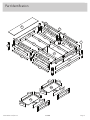 3
3
-
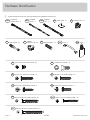 4
4
-
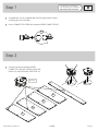 5
5
-
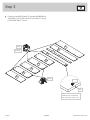 6
6
-
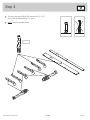 7
7
-
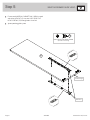 8
8
-
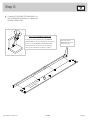 9
9
-
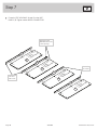 10
10
-
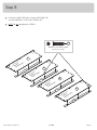 11
11
-
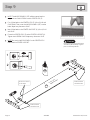 12
12
-
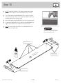 13
13
-
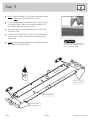 14
14
-
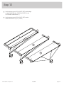 15
15
-
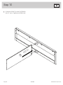 16
16
-
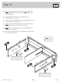 17
17
-
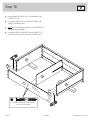 18
18
-
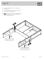 19
19
-
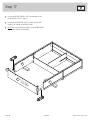 20
20
-
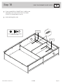 21
21
-
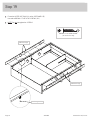 22
22
-
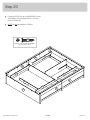 23
23
-
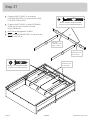 24
24
-
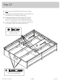 25
25
-
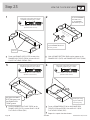 26
26
-
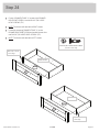 27
27
-
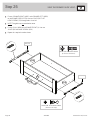 28
28
-
 29
29
-
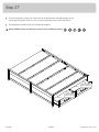 30
30
-
 31
31
-
 32
32
-
 33
33
-
 34
34
-
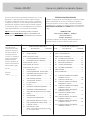 35
35
-
 36
36
-
 37
37
-
 38
38
-
 39
39
-
 40
40


en otros idiomas
- français: Sauder 423450 Mode d'emploi
- English: Sauder 423450 Operating instructions
Artículos relacionados
-
Sauder Litter Box Credenza Manual de usuario
-
-
-
-
-
-
-
-
-