sauder.com
Dresser
Model 422893
NOTE: THIS INSTRUCTION
BOOKLET CONTAINS IMPORTANT
SAFETY INFORMATION.
PLEASE READ AND KEEP FOR
FUTURE REFERENCE.
Enlish p 1-28
Français p 29-32
Español p 33-36
Lot # 530655 06/19/19
Purchased: __________________
sauder.com
CONTACT US FIRST
BEFORE MAKING ANY RETURNS TO THE STORE.
Share your journey!
sauder.com
CONTACT US FIRST
BEFORE MAKING ANY RETURNS TO THE STORE.
Visit sauder.com/service to order replacement parts, view video assembly tips, or chat with a live rep.
Prefer the phone? Give us a rin at
1-800-523-3987.
Customer Service is available Monday-Friday - 9 a.m. to 5:30 p.m. EST (except holidays)
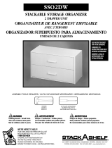
WARNING
CHOKING HAZARD - Small Parts
Not for children under 3 years.
Adult assembly required.

Table of Contents Assembly Tools Required
3
4-5
6-28
29-32
33-36
37-38
39
Part Identifi cation
Hardware Identifi cation
Assembly Steps
Français
Español
Safety
Warranty
Hammer
Not actual size
No. 2 Phillips Screwdriver
Tip Shown Actual Size
Skip the power trip.
This time.
422893 www.sauder.com/servicePae 2

Part Identifi cation
å While not all parts are labeled, some of the parts will have a label or an inked letter on the ede
to help distinuish similar parts from each other. Use this part identifi cation to help identify similar parts.
A END (2)
B RIGHT FRONT/LEFT REAR LEG (2)
C LEFT FRONT/RIGHT REAR LEG (2)
D CENTER LEG (1)
D68 DRAWER BACK (6)
D132 RIGHT DRAWER SIDE (6)
D138
LEFT DRAWER SIDE (6) - 1 with label
D730 DRAWER BOTTOM (6)
E UPRIGHT (1)
F BOTTOM (1)
G SKIRT (2)
H TOP (1)
J RIGHT DRAWER FRONT (3)
K LEFT DRAWER FRONT (3)
L BACK (1)
M65
DRAWER BRACE (6)
(Hidden part usin recycled
material. Color may vary.)
Now you know
our ABCs.
422893www.sauder.com/service
Pae 3
A
B
C
D
E
F
G
H
J
K
L
M65
D132
D68
D138
D730
B
C
G
M65
D132
D68
D138
D730
A

Hardware Identifi cation
å You may receive extra hardware with your unit.
PULL - 6
149K
10A
SLIDE CAM - 12 HIDDEN CAM - 33
1F
CAM SCREW - 22
8F
WOOD DOWEL - 5
15F
METAL BRACKET - 4
4G 19G
LARGE METAL BRACKET - 1
FELT DISC CARD - 2
1M
GLUE - 1
54M
BROWN PLASTIC
WASHER - 12
151M
422893 www.sauder.com/servicePae 4
40DA
UNIVERSAL CABINET RAIL - 12
40DC
DRAWER RIGHT - 6
40DD
DRAWER LEFT - 6
NAIL - 44
1N
CAM DOWEL - 11
2F
FURNITURE TIPPING
RESTRAINT KIT - 1
97

Hardware Identifi cation
å Screws are shown actual size. You may receive extra hardware with your unit.
422893www.sauder.com/service
Pae 5
BLACK 9/16" LARGE HEAD SCREW - 10
1S 3S
GOLD 5/16" FLAT HEAD SCREW - 48
30S
BLACK 1-9/16" FLAT HEAD SCREW - 30 SILVER 1/4" MACHINE SCREW - 12
61S
BLACK 1-15/16" FLAT HEAD SCREW - 3
113S

Step 1
Look for this icon. It means a
video assembly tip is available at
www.sauder.com/service/tips
å
Assemble your unit on a carpeted fl oor or on the empty
carton to avoid scratchin your unit or the fl oor.
å
To bein assembly, push eleven HIDDEN CAMS (1F) into
the ENDS (A), UPRIGHT (E), and BOTTOM (F). Then,
insert the metal end of a CAM DOWEL (2F) into each
HIDDEN CAM.
422893 www.sauder.com/servicePae 6
A
A
E
F
Insert the metal end of the CAM
DOWEL into the HIDDEN CAM.
Arrow
Arrow
1F
2F
(11 used)
Do not tihten the HIDDEN CAMS in this step.

å
Push twenty-two HIDDEN CAMS (1F) into the ENDS (A),
SKIRTS (G), and DRAWER BRACES (M65).
Step 2
422893www.sauder.com/service
Pae 7
Arrow
1F
Arrow
1F
The arrow in the HIDDEN
CAM must point toward the
hole in the ede of the board.
Hole
1F
Arrow
1F
Arrow
(22 used)
Arrow
A
G
M65
G
M65
A
M65
M65
M65
M65
Some assembly
(and snacks) required.

Step 3
å
Turn twenty-two CAM SCREWS (8F) into the LEGS (B, C,
and D) and DRAWER FRONTS (J and K).
å
NOTE: Be sure to use the exact holes shown.
422893 www.sauder.com/servicePae 8
8F
B
C
D
J
K
B
C
J
K
J
K
8F
(22 used)
8F
Do not use these holes.

å
First, fi ll the holes in two of the LEGS (B and C) 1/4 to 1/2 full
with GLUE (54M). Then, insert the WOOD DOWELS (15F)
into the holes. Wipe away the excess GLUE.
å
Now, fi ll the holes in one of the ENDS (A) 1/4 to 1/2 full with
GLUE. Then, insert the WOOD DOWELS in the LEGS into
these holes. Wipe away the excess GLUE.
å
Fasten the two LEGS (B and C) to this END (A). Tihten six
HIDDEN CAMS.
Step 4
422893www.sauder.com/service
Pae 9
Fill the holes 1/4 to 1/2 full with GLUE.
Inspect the parts thorouhly before
assemblin. Disassembly of lued
parts is extremely di cult.
Caution
!
54M
15F
A
Surface with
HIDDEN CAMS
Ede with
CAM DOWELS
B
C
1
2
These surfaces
should be even.
This END (A) will
be the left END.
15F
The LEGS
will overhan
this ede.
This CAM SCREW
must be here.
This hole must be here.

Step 5
422893 www.sauder.com/servicePae 10
Fill the holes 1/4 to 1/2 full with GLUE.
Inspect the parts thorouhly before
assemblin. Disassembly of lued
parts is extremely di cult.
Caution
!
This END (A) will
be the riht END.
å
First, fi ll the holes in the remainin two LEGS (B and C)
1/4 to 1/2 full with GLUE (54M). Then, insert the WOOD
DOWELS (15F) into the holes. Wipe away the excess GLUE.
å
Now, fi ll the holes in the remainin END (A) 1/4 to 1/2 full
with GLUE. Then, insert the WOOD DOWELS in the LEGS
into these holes. Wipe away the excess GLUE.
å
Fasten the LEGS (B and C) to the remainin END (A).
Tihten six HIDDEN CAMS.
A
Surface with
HIDDEN CAMS
C
B
These surfaces
should be even.
15F
15F
The LEGS
will overhan
this ede.
This CAM SCREW
must be here.
This hole must be here.
54M
Ede with
CAM DOWELS

Step Step 6
A
C
A
B
VIEW THE DRAWER GLIDE VIDEO
å
Fasten six UNIVERSAL CABINET RAILS* (40DA) to
the ENDS (A). Use twelve GOLD 5/16" FLAT HEAD
SCREWS (3S) throuh holes #1 and #4.
å
*patent pendin lide system
GOLD 5/16" FLAT HEAD SCREW
(12 used in this step)
3S
3
2
1
1
2
3
4
4
Glide end
3
2
1
4
3
2
1
4
Surface with
HIDDEN CAMS
Surface with
HIDDEN CAMS
1
2
3
4
1
2
3
4
Glide end
422893www.sauder.com/service
Pae 11
This CAM SCREW
must be here.
This CAM SCREW
must be here.

Step
å
Fasten six UNIVERSAL CABINET RAILS* (40DA) to
the UPRIGHT (E). Use twelve GOLD 5/16" FLAT HEAD
SCREWS (3S) throuh holes #1 and #4.
å
*patent pendin lide system
Step 7
GOLD 5/16" FLAT HEAD SCREW
(12 used in this step)
3S
VIEW THE DRAWER GLIDE VIDEO
Glide end
Surface with
HIDDEN CAMS
E
3
2
1
4
3
2
1
4
3
2
1
4
3
2
1
4
1
1
422893 www.sauder.com/servicePae 12
Ede with
CAM DOWELS

Step Step 8
å
First, fi ll the hole in the end of the CENTER LEG (D) 1/4 to 1/2
full with GLUE (54M). Then, insert the WOOD DOWEL (15F)
into the hole. Wipe away the excess GLUE.
å
Fasten the LARGE METAL BRACKET (19G) to the CENTER
LEG (D). Use one BLACK 9/16" LARGE HEAD SCREW (1S) in
the exact hole shown.
å
NOTE: Position the BRACKET exactly as shown.
Fill the holes 1/4 to 1/2 full with GLUE.
Inspect the parts thorouhly before
assemblin. Disassembly of lued
parts is extremely di cult.
Caution
!
15F
19G
BLACK 9/16" LARGE HEAD SCREW
(1 used for the BRACKET)
1S
D
54M
422893www.sauder.com/service
Pae 13

Step
å
First, fi ll the hole in the BOTTOM (F) 1/4 to 1/2 full with
GLUE (54M). Then, insert the WOOD DOWEL (15F) in the
CENTER LEG into the hole. Wipe away the excess GLUE.
å
Fasten the CENTER LEG (D) to the BOTTOM (F). Use one
BLACK 9/16" LARGE HEAD SCREW (1S) throuh the
BRACKET on the CENTER LEG and into the hole in
the BOTTOM.
Step 9
54M
F
BLACK 9/16" LARGE HEAD SCREW
(1 used for the BRACKET)
1S
D
Fill the holes 1/4 to 1/2 full with GLUE.
Inspect the parts thorouhly before
assemblin. Disassembly of lued
parts is extremely di cult.
Caution
!
422893 www.sauder.com/servicePae 14
Surface with
HIDDEN CAMS

Step Step 10
å
Fasten the METAL BRACKETS (4G) to the SKIRTS (G).
Use four BLACK 9/16" LARGE HEAD SCREWS (1S).
å
NOTE: Be sure the BRACKETS are even with the edes of
the SKIRTS.
BLACK 9/16" LARGE HEAD SCREW
(4 used in this step)
1S
4G
G
G
422893www.sauder.com/service
Pae 15

Step Step 11
å
Fasten the SKIRTS (G) to the CENTER LEG (D). Tihten
two HIDDEN CAMS.
å
Fasten the SKIRTS (G) to the BOTTOM (F). Use four
BLACK 9/16" LARGE HEAD SCREWS (1S) throuh the
METAL BRACKETS on the SKIRTS and into the holes in
the BOTTOM.
G
G
D
F
BLACK 9/16" LARGE HEAD SCREW
(4 used for BRACKETS)
1S
Surface with HIDDEN CAMS
Surface with HIDDEN CAMS
Just think. The sooner
you do this, the sooner
you do somethin else.
422893 www.sauder.com/servicePae 16

Step Step 12
å
Open the FURNITURE TIPPING RESTRAINT KIT (97) and
fasten the SAFETY STRAP to the TOP (H). Use the provided
BLACK 9/16" LARGE HEAD SCREW.
å
NOTE: Position the SAFETY STRAP exactly as shown.
H
Surface with holes
Meet Part (H). This component has
been enineered to be lihter, stroner,
faster… well ok. Not technically faster.
But defi nitely makes for a sturdier
Dresser that’s easier to assemble and
friendlier to the environment.
422893www.sauder.com/service
Pae 17
BLACK 9/16" LARGE HEAD SCREW
(1 used for the SAFETY STRAP)
97
Safety strap

Step
å
Fasten the Left END (A) to the TOP (H). Tihten two
HIDDEN CAMS.
Step 13
A
H
C
The SAFETY STRAP
should be here.
Do not stand the unit upriht without the
BACK fastened. The unit may collapse.
Caution
422893 www.sauder.com/servicePae 18
Start Tighten
Arrow
Minimum
190 derees
Caution
Risk of damae or
injury. HIDDEN CAMS
must be completely
tihtened. HIDDEN
CAMS that are not
completely tihtened
may loosen, and parts
may separate. To
completely tihten:
Arrow
Maximum
210 derees

Step Step 14
å
Fasten the UPRIGHT (E) to the TOP (H). Tihten three
HIDDEN CAMS.
E
H
422893www.sauder.com/service
Pae 19
Arrow
Minimum
190 derees
Maximum
210 derees
Surface
with
HIDDEN
CAMS

Step
å
Fasten the BOTTOM (F) to the left END (A). Tihten two
HIDDEN CAMS.
å
Fasten the SKIRT (G) to the LEFT FRONT/RIGHT REAR
LEG (C). Tihten one HIDDEN CAM.
å
Fasten the BOTTOM (F) to the UPRIGHT (E). Use three
BLACK 1-15/16" FLAT HEAD SCREWS (113S).
Step 15
E
F
A
G
C
BLACK 1-15/16" FLAT HEAD SCREW
(3 used for the UPRIGHT)
113S
422893 www.sauder.com/servicePae 20
Arrow
Minimum
190 derees
Maximum
210 derees
Surface with
HIDDEN CAMS

Step Step 16
å
Fasten the RIGHT END (A) to the BOTTOM (F) and
TOP (H). Tihten four HIDDEN CAMS.
å
Fasten the RIGHT FRONT/LEFT REAR LEG (B) to the
SKIRT (G). Tihten one HIDDEN CAM.
H
F
A
B
G
422893www.sauder.com/service
Pae 21
Arrow
Minimum
190 derees
Maximum
210 derees

Step Step 17
å
Carefully turn your unit over onto its front edes. Unfold the
BACK (L) and lay it over your unit.
å
A perforation in the BACK (L) has been provided for access
to the SAFETY STRAP. Punch out the perforation and push
the SAFETY STRAP throuh the hole.
å
Make the bottom ede of the BACK (L) even with the
bottom ede of the BOTTOM (F). Then, make equal
marins alon the side edes of the BACK (L). Push on
opposite corners of your unit if needed to make it "square".
å
Fasten the BACK (L) to your unit usin the NAILS (1N).
å
NOTE: Be sure to tap NAILS into the holes that line up over
the UPRIGHT (E).
å
Peel the FELT DISC from the FELT DISC CARD (1M). Stick a
FELT DISC on the bottom of each LEG (B, C, and D).
Do not stand the unit upriht without the
BACK fastened. The unit may collapse.
Caution
These holes must line up
over the UPRIGHT (E).
Before fastenin the
BACK, punch out the
perforation and push
the SAFETY STRAP
throuh the hole.
NAIL
(44 used for the BACK)
1N
L
1M
B
B
C
C
D
F
422893 www.sauder.com/servicePae 22
Safety strap

Step Step 18
å
Insert the DRAWER SIDES (D132 and D138) at an angle
into the slot at each end of the LEFT DRAWER FRONT (K).
å
Slide the DRAWER BOTTOM (D730) into the grooves
in the DRAWER SIDES (D132 and D138) and LEFT
DRAWER FRONT (K).
å
Fasten the DRAWER BRACE (M65) to the LEFT
DRAWER FRONT (K). Tighten one HIDDEN CAM.
å
Fasten the DRAWER BACK (D68) to the DRAWER
SIDES (D132 and D138) and DRAWER BRACE (M65).
Use five BLACK 1-9/16" FLAT HEAD SCREWS (30S).
Repeat this step for the other DRAWERS.
Surface with
HIDDEN CAM
12
34
Be sure the DRAWER
BOTTOM inserts into the
DRAWER FRONT roove.
Groove
Arrow
Maximum
210 derees
Minimum
190 derees
K
K
D68
K
VIEW THE T-LOCK BOX VIDEO
D138
D132
D138
D730
D132
D132
D138
M65
Unfi nished
surface
Be sure the
DRAWER
BOTTOM
inserts into
the DRAWER
BACK roove.
30S
Start each screw a few turns before
completely tihtenin any of them.
BLACK 1-9/16" FLAT HEAD SCREW
(30 used in this step)
The tabs should insert freely
into the slots. Gently tilt the
DRAWER SIDES side to side
until the tabs slip into the slots.
With the palm of your hand,
tap the DRAWER BOTTOM
down into the roove.
M65
422893www.sauder.com/service
Pae 23
Hidden part usin
recycled material.
Color may vary.

Step
å
Insert a SLIDE CAM (10A) into the DRAWER SIDES (D132 and D138).
å
Fasten a DRAWER RIGHT (40DC) to the RIGHT DRAWER SIDE (D132)
and a DRAWER LEFT (40DD) to the LEFT DRAWER SIDE (D138). Use
four GOLD 5/16" FLAT HEAD SCREWS (3S) throuh holes #1 and #2.
å
NOTE: The screw head in the CAM must be visible throuh the slotted
hole in the SLIDE.
å
NOTE: The lides are not intended to rotate.
å
Repeat this step for the other DRAWERS.
Step 19
VIEW THE DRAWER GLIDE VIDEO
1
2
1
2
Glide end
Glide end
Screw head - turn CAM to line up holes in
the SLIDES with holes in DRAWER SIDES
10A
10A
GOLD 5/16" FLAT HEAD SCREW
(24 used in this step)
3S
D132
D138
422893 www.sauder.com/servicePae 24

Step Step 20
å
Fasten a PULL (149K) to the LEFT DRAWER FRONT (K).
Use two SILVER 1/4" MACHINE SCREWS (61S) and two
BROWN PLASTIC WASHERS (151M).
å
Repeat this step for the other DRAWERS.
If you're doin this to
help a friend, don't
leave without a bite.
149K
151M
SILVER 1/4" MACHINE SCREW
(12 used in this step)
61S
K
422893www.sauder.com/service
Pae 25

Step Step 21
422893 www.sauder.com/servicePae 26
å
Carefully stand your unit upriht in its fi nal location. We recommend usin the SAFETY STRAP for added stability.
å
NOTE: Do not turn the SAFETY DRYWALL ANCHOR into a wall stud. If you prefer to fasten the SAFETY STRAP to a wall
stud, o to your local hardware store for proper hardware.
å
INSTALLATION INSTRUCTIONS:
1. Insert the SAFETY DRYWALL ANCHOR throuh the WASHER and the end of the SAFETY STRAP.
2. Usin a Phillips screwdriver or a hand drill, press the screw slihtly onto the drywall just below the top surface of your
unit so the SAFETY STRAP will not be visible.
3. Apply pressure; turn the screw until a pilot hole is made and the nylon sheath slips throuh.
4. Turn the screw until it is fl ush aainst the wall and you feel a fi rm resistance.
5. Continue to turn until the screw starts spinnin freely.
å
NOTE: Before movin your unit to a di erent location, unscrew the SAFETY DRYWALL ANCHOR from your wall. The
nylon sheath will remain behind your wall.
Safety
drywall
anchor
Safety strap
Washer

Step
WAR
N
IN
G
AVER
T
IS
S
EM
E
N
T
ADVERTENC
IA
occur from furniture tip-o
ve
r
. To help
prevent tip-o
ver:
• Install tip-over restraint provided.
• Place heaviest items in the lower
drawers.
•
D
o
n
o
t
s
e
t
T
V
’s
o
r
o
t
h
e
r
h
e
a
v
y
o
b
j
e
c
t
s
o
n
t
o
p
o
f
t
h
is
p
r
o
d
u
c
t
, u
n
le
s
s
t
h
e
p
r
o
d
u
c
t
is
drawers
,
doors
, or shelves.
• Never open more than one drawer
at a time.
Use of tip-over restraints may only
reduce, but not elim
inate
, the risk
of tip-over
.
This is a permanent label. Do not rem
o
ve!
écrasement peuvent su
rvenir si le mobilier
bascule. Pour prévenir le basculement :
• Installer le dispositif anti-basculem
ent fourni.
• Placer les articles plus lourds dans les
tiroirs inférieurs.
• Ne pas mettre de téléviseur ou d’
autre objets
lourds sur le dessus de ce m
eu
ble, sauf si le
• Ne jamais ouvrir plus
d
’un tiroir à la fois
.
L
’utilisation de dispositifs anti-basculement
peut réduire le risque de basculem
ent
, mais
pas l’éliminer
.
Cette étiquette est permanente. Ne pas
l
’enlever!
pueden ocurrir por el volcar de los muebles.
Para ayudar a prevenir que se volqué:
• Instalar la contención brindada para evitar
que se volqué.
• Coloque los artículos más pesados en los
cajones inferiores.
• No coloque televisores u otros objetos
pesados en la parte superior de este producto,
diseñado para acomodarlos.
• Nunca perm
ita que los niños se suban o se
• Nunca abra más de un cajón a la vez.
El uso de la contención puede solam
ente
Esta es una etiqueta permanente. ¡No remover!
Step 22
K
J
K
J
J
K
å
To insert the drawers into your unit, tip the front
of the drawer down and drop the lides on the
drawer behind the lides on the unit. Lift the
front of the drawer up and slide it into the unit.
å
NOTE: Be sure the label on the LEFT DRAWER
SIDE is in one of the UPPER drawers.
Place the lide on the SLIDE
behind the lide on the RAIL.
422893www.sauder.com/service
Pae 27
40 lbs.
30 lbs.
30 lbs.
30 lbs.
each
WARNING
Children have died from
furniture tipover. To reduce
the risk of furniture tipover:
• ALWAYS install tipover
restraint provided.
• NEVER put a TV on this
product.
• NEVER allow children to
stand, climb, or hang on
drawers, doors, or shelves.
• NEVER open more than one
drawer at a time.
• Place heaviest items in the
lowest drawers.
This is a permanent label.
Do not remove!
1/19 526119

Step Step 23
å
To make adjustments to the drawers, loosen SCREW #2 in the SLIDES a 1/4 turn, then turn the CAM clockwise or
counter-clockwise. Notice how the drawer raises or lowers as you turn the CAM. The hiher the screw in the oblon hole,
the hiher your drawer front will be. The lower the screw, the lower the drawer front. By adjustin the drawers this way, it
will help the DRAWER FRONTS line up better when closed. Tihten the SCREW when fi nished with adjustments.
å
NOTE: Please read the back paes of the instruction booklet for important safety information.
å
This completes assembly. Clean with a damp cloth. Wipe dry.
422893 www.sauder.com/servicePae 28
CamThe hiher the screw in the oblon hole,
the hiher your drawer front will be. The
lower the screw, the lower the drawer front.
Loosen screw #2 a 1/4 turn, turn the cam a 1/4 turn
maximum in both the clockwise and counter-clockwise
directions to make adjustments, and then tihten screw #2.
And to celebrate, why not share your success story at Walmart.com or

A l’usae exclusif du
Canada Noter la date
d’achat de cet élément
et conserver le livret
pour future référence.
Pour contacter Sauder
en ce qui concerne cet
élément, faire référence
au numéro de lot et
numéro de modèle en
appelant notre numéro
sans frais.
Lot nº : ____________
Date de
l’achat: ____________
LISTE DE PIÈCES
REFERENCE DESCRIPTION QUANTITÉ
LISTE DE PIÈCES
REFERENCE DESCRIPTION QUANTITÉ
NOUS SOMMES LA POUR VOUS AIDER!
Nous faisons de notre mieux pour nous assurer que votre meuble
arrive dans d’excellentes conditions. Nos représentants du service
Clientèle sont aimables et prêts à vous aider au cas où une pièce
aurait été endommaée ou manquerait (ou si vous aviez besoin
d’aide pour l’assemblae). NE RAMENEZ PAS LE MEUBLE AU
MAGASIN. Au Canada, composez ce numéro d’appel ratuit:
1-800-523-3987
Du lundi au vendredi, de 9 heures du matin à
5:30 heures du soir (horaire Côte Est)
(sauf jours fériés)
Si une pièce a besoin d’être remplacée, la pièce de remplacement
sera envoyée dans les 48 heures. (Sauf week-ends et jours fériés)
Utilisez les instructions d’assemblae en français avec les
schémas étape par étape du manuel d’instruction en anlais.
Chaque étape en français correspond à la même étape
en anlais. La pièce devant être attachée à l’élément est
représentée en ris sur les schémas de chaque étape pour plus
de précision. Comparer la “Liste de pièces” ci-dessous avec
la “PART IDENTIFICATION” du manuel en anlais pour vous
familiariser avec les pièces avant l’assemblae.
REMARQUE : CE MANUEL D’INSTRUCTIONS CONTIENT
D’IMPORTANTES INFORMATIONS RELATIVES À LA SÉCURITÉ.
À LIRE ET CONSERVER POUR TOUTE RÉFÉRENCE FUTURE.
CommodeModèle 422893
40DA
GLISSIÈRE D'ÉLÉMENT UNIVERSELLE...12
40DC
TIROIR DROIT ................................................................6
40DD
TIROIR GAUCHE ..........................................................6
10A EXCENTRIQUE DE COULISSE .......................12
1F EXCENTRIQUE ESCAMOTABLE .................33
2F CHEVILLE D'EXCENTRIQUE .............................11
8F VIS D'EXCENTRIQUE ........................................... 22
15F CHEVILLE EN BOIS ...................................................5
4G CONSOLE EN MÉTAL .............................................4
19G GRANDE CONSOLE EN MÉTAL.......................1
149K POIGNÉE ............................................................................6
1M FICHE DE TAMPONS EN FEUTRE.................2
54M COLLE ...................................................................................1
151M RONDELLE EN PLASTIQUE MARRON ....12
1N CLOU ................................................................................44
97 KIT DE RETENUE ANTI-BASCULEMENT
POUR MOBILIER...........................................................1
1S VIS TÊTE LARGE 14 mm NOIRE ..................10
3S VIS TÊTE PLATE 8 mm DORÉE ..................48
30S VIS TÊTE PLATE 40 mm NOIRE ................30
61S VIS À MÉTAUX 6 mm ARGENTÉE ..............12
113S VIS TÊTE PLATE 49 mm NOIRE .....................3
A EXTRÉMITÉ ......................................................................2
B PIED AVANT DROIT/ARRIÈRE GAUCHE ..2
C PIED AVANT GAUCHE/ARRIÈRE DROIT ..2
D PIED CENTRAL ..............................................................1
D68 ARRIÈRE DE TIROIR ..................................................6
D132 CÔTÉ DROIT DE TIROIR .......................................6
D138
CÔTÉ GAUCHE DE TIROIR .................................6
1 avec étiquette
D730
FOND DE TIROIR .........................................................6
E MONTANT..........................................................................1
F DESSOUS ...........................................................................1
G PLINTHE .............................................................................2
H DESSUS ...............................................................................1
J DEVANT DE TIROIR DROIT .................................3
K DEVANT DE TIROIR GAUCHE ..........................3
L ARRIÈRE ..............................................................................1
M65 ENTRETOISE DE TIROIR
(Pièce cachée utilisant des matériaux
recyclés. La couleur peut varier.) ....................6
422893www.sauder.com/service
Pae 29

ÉTAPE 1
Ne pas serrer les EXCENTRIQUES ESCAMOTABLES dans
cette étape.
Assembler l'élément sur un sol à moquette ou sur le carton vide
pour éviter d'endommaer l'élément ou le sol.
Pour commencer l'assemblae, enfoncer onze EXCENTRIQUES
ESCAMOTABLES (1F) dans les EXTRÉMITÉS (A), le MONTANT (E)
et le DESSOUS (F). Ensuite, insérer l'extrémité en métal de la CHEVILLE
D'EXCENTRIQUE (2F) dans chaque EXCENTRIQUE ESCAMOTABLE.
ÉTAPE 2
Enfoncer vint-deux EXCENTRIQUES ESCAMOTABLES (1F)
dans les EXTRÉMITÉS (A), les PLINTHES (G) et les ENTRETOISES
DE TIROIR (M65).
ÉTAPE 6
Fixer six GLISSIÈRES D'ÉLÉMENT UNIVERSELLES* (40DA) aux
EXTRÉMITÉS (A). Utiliser douze VIS TÊTE PLATE 8 mm
DORÉES (3S) à travers les trous nº 1 et nº 4.
*système de coulisse en instance de brevet
ÉTAPE 9
Attention: Examiner bien les pièces avant d'assembler. Il est
di cile de séparer des pièces une fois encollées.
Tout d'abord, remplir le trou dans le DESSOUS (F) de 1/4 à 1/2
pleins de COLLE (54M). Insérer ensuite la CHEVILLE EN BOIS (15F)
dans le PIED CENTRAL dans le trou. Nettoyer l'excès de COLLE.
Fixer le PIED CENTRAL (D) au DESSOUS (F). Utiliser une VIS
TÊTE LARGE 14 mm NOIRE (1S) à travers la CONSOLE située sur
le PIED CENTRAL, et dans le trou du DESSOUS.
ÉTAPE 3
Faire tourner vint-deux VIS D'EXCENTRIQUE (8F) dans les
PIEDS (B, C et D) et les DEVANTS DE TIROIR (J et K).
REMARQUE : S’assurer d’utiliser les trous exacts indiqués.
ÉTAPE 7
Fixer six GLISSIÈRES D'ÉLÉMENT UNIVERSELLES* (40DA) au
MONTANT (E). Utiliser douze VIS TÊTE PLATE 8 mm
DORÉES (3S) à travers les trous nº 1 et nº 4.
*système de coulisse en instance de brevet
ÉTAPE 4
Attention: Examiner bien les pièces avant d'assembler. Il est
di cile de séparer des pièces une fois encollées.
Tout d'abord, remplir les trous dans deux des PIEDS (B et C) de
1/4 à 1/2 pleins de COLLE (54M). Insérer ensuite les CHEVILLES
EN BOIS (15F) dans les trous. Nettoyer l'excès de COLLE.
Maintenant, remplir les trous dans l’une des EXTRÉMITÉS (A)
de 1/4 à 1/2 pleins de COLLE. Insérer ensuite les CHEVILLES EN
BOIS dans les PIEDS dans ces trous. Nettoyer l'excès de COLLE.
Fixer les deux PIEDS (B et C) à cette EXTRÉMITÉ (A). Serrer six
EXCENTRIQUES ESCAMOTABLES.
ÉTAPE 8
Attention: Examiner bien les pièces avant d'assembler. Il est
di cile de séparer des pièces une fois encollées.
Tout d’abord, remplir le trou dans l’extrémité du PIED CENTRAL (D)
de 1/4 à 1/2 pleins de COLLE (54M). Insérer ensuite la CHEVILLE
EN BOIS (15F) dans le trou. Nettoyer l'excès de COLLE.
Fixer la GRANDE CONSOLE EN MÉTAL (19G) au PIED
CENTRAL (D). Utiliser une VIS TÊTE LARGE 14 mm NOIRE (1S)
dans le trou exact indiqué.
REMARQUE : Placer la CONSOLE exactement comme l'indique
le schéma.
422893 www.sauder.com/servicePae 30
ÉTAPE 5
Attention: Examiner bien les pièces avant d'assembler. Il est
di cile de séparer des pièces une fois encollées.
Tout d'abord, remplir les trous dans les deux autres PIEDS (B
et C) de 1/4 à 1/2 pleins de COLLE (54M). Insérer ensuite les
CHEVILLES EN BOIS (15F) dans les trous. Nettoyer l'excès
de COLLE.
Maintenant, remplir les trous dans l’autre EXTRÉMITÉ (A) de 1/4
à 1/2 pleins de COLLE. Insérer ensuite les CHEVILLES EN BOIS
dans les PIEDS dans ces trous. Nettoyer l'excès de COLLE.
Fixer les PIEDS (B et C) sur l’autre EXTRÉMITÉ (A). Serrer six
EXCENTRIQUES ESCAMOTABLES.

ÉTAPE 10
Fixer les CONSOLES EN MÉTAL (4G) aux PLINTHES (G). Utiliser
quatre VIS TÊTE LARGE 14 mm NOIRES (1S).
REMARQUE : S'assurer que les SUPPORTS sont à fl eur des
chants des PLINTHES.
ÉTAPE 13
Attention: Ne pas relever l'élément dans sa position verticale
avant d'avoir fi xé l’ARRIÈRE. L'élément risque de s'e ondrer.
Fixer l'EXTRÉMITÉ (A) auche au DESSUS (H). Serrer deux
EXCENTRIQUES ESCAMOTABLES.
Attention: Risque des déâts ou blessures. Les Excentriques
Escamotables doivent être serrés à bloc. Les Excentriques
Escamotables que ne sont pas serrées à bloc peuvent desserrer
et les pièces peuvent séparer. Pour serrer à bloc, faire tourner
l'excentrique escamotable de 210 derés.
ÉTAPE 14
Fixer le MONTANT (E) au DESSUS (H). Serrer trois
EXCENTRIQUES ESCAMOTABLES.
ÉTAPE 17
Attention: Ne pas relever l'élément dans sa position verticale
avant d'avoir fi xé l’ARRIÈRE. L'élément risque de s'e ondrer.
Avec précaution, retourner l'élément sur ses chants avant. Déplier
l'ARRIÈRE (L) et le placer sur l'élément.
Une perforation a été prévue pour accès à travers l’ARRIÈRE (L)
pour la SANGLE DE SÉCURITÉ. Découper soineusement la
perforation et enfoncer la SANGLE DE SÉCURITÉ à travers le trou.
Faire le chant inférieur de l'ARRIÈRE (L) à fl eur avec le chant inférieur
du DESSOUS (F). Ensuite, veiller à avoir des mares éales le lon
des chants latéraux de l'ARRIÈRE (L). Si besoin est, enfoncer sur les
coins opposés de l'élément pour s'assurer d'être « d'équerre ».
Fixer l'ARRIÈRE (L) à l'élément à l'aide des CLOUS (1N).
REMARQUE : S'assurer de bien enfoncer les CLOUS dans les
trous qui sont alinés au-dessus le MONTANT (E).
Décoller le TAMPON EN FEUTRE de la FICHE DE TAMPONS EN
FEUTRE (1M). Faire coller un TAMPON EN FEUTRE dans le bas de
chaque PIED (B, C et D).
ÉTAPE 11
Fixer les PLINTHES (G) au PIED CENTRAL (D). Serrer deux
EXCENTRIQUES ESCAMOTABLES.
Fixer les PLINTHES (G) au DESSOUS (F). Utiliser quatre VIS TÊTE
LARGE 14 mm NOIRES (1S) à travers les CONSOLES EN MÉTAL
situées sur les PLINTHES, et dans les trous du DESSOUS.
ÉTAPE 15
Fixer le DESSOUS (F) à l'EXTRÉMITÉ (A) auche. Serrer deux
EXCENTRIQUES ESCAMOTABLES.
Fixer la PLINTHE (G) au PIED AVANT GAUCHE/ARRIÈRE
DROIT (C). Serrer un EXCENTRIQUE ESCAMOTABLE.
Fixer le DESSOUS (F) au MONTANT (E). Utiliser trois VIS TÊTE
PLATE 49 mm NOIRES (113S).
ÉTAPE 12
Ouvrir le KIT DE RETENUE ANTI-BASCULEMENT POUR
MOBILIER (97) et fi xer la SANGLE DE SÉCURITÉ au
DESSUS (H). Utiliser la VIS TÊTE LARGE 14 mm fourni.
REMARQUE : Placer la SANGLE DE SÉCURITÉ exactement
comme l'indique le schéma.
ÉTAPE 16
Fixer l'EXTRÉMITÉ (A) droite au DESSOUS (F) et au DESSUS (H).
Serrer quatre EXCENTRIQUES ESCAMOTABLES.
Fixer le PIED AVANT DROIT/ARRIÈRE GAUCHE (B) à la
PLINTHE (G). Serrer un EXCENTRIQUE ESCAMOTABLE.
422893www.sauder.com/service
Pae 31

ÉTAPE 18
1 Insérer les CÔTÉS DE TIROIR (D132 et D138) en biseau dans la
fente dans chaque extrémité du DEVANT DE TIROIR GAUCHE (K).
2
Enfi ler le FOND DE TIROIR (D730) dans les rainures des CÔTÉS
DE TIROIR (D132 et D138) et du DEVANT DE TIROIR GAUCHE (K).
3 Fixer l’ENTRETOISE DE TIROIR (M65) au DEVANT DE TIROIR
GAUCHE (K). Serrer un EXCENTRIQUE ESCAMOTABLE.
4 Fixer l'ARRIÈRE DE TIROIR (D68) aux CÔTÉS DE TIROIR (D132
et D138) et à l’ENTRETOISE DE TIROIR (M65). Utiliser cinq VIS
TÊTE PLATE 40 mm NOIRES (30S). Répéter cette étape pour les
autres TIROIRS.
ÉTAPE 21 (SUITE)
4. Faire tourner la vis jusqu’à ce qu’elle soit à fl eur du mur et
qu'une résistance ferme se fasse sentir.
5. Continuer de tourner jusqu’à ce que la vis commence à
pivoter librement.
REMARQUE : Avant de déplacer l’unité vers un emplacement
di érent, dévisser le DISPOSITIF DE SÉCURITÉ POUR
PLACOPLÂTRE du mur. La aine en nylon restera derrière le mur.
ÉTAPE 22
AVERTISSEMENT :
Le renversement de meubles a causé la mort d’enfants. Pour
réduire le risque de renversement de meubles :
• TOUJOURS installer le dispositif anti-basculement fourni.
• NE JAMAIS mettre de téléviseur sur ce produit.
• NE JAMAIS laisser les enfants se tenir debout, monter sur les
tiroirs, les portes ou les tablettes ni s’y suspendre.
• NE JAMAIS ouvrir plus d’un tiroir à la fois.
• Placer les articles plus lourds dans les tiroirs inférieurs.
Cette étiquette est permanente. Ne pas l’enlever!
Relever, avec précaution, l'élément dans sa position verticale.
Pour insérer les tiroirs dans l’unité, incliner le devant du tiroir vers
le bas et faire tomber les coulisses du tiroir derrière les coulisses
de l’unité. Relever le devant du tiroir et l'enfi ler dans l'élément.
REMARQUE : S'assurer l'étiquette sur le CÔTÉ GAUCHE DE
TIROIR est dans l'un des tiroirs SUPÉRIEURS.
ÉTAPE 19
Insérer une EXCENTRIQUE DE COULISSE (10A) dans les CÔTÉS
DE TIROIR (D132 et D138).
Fixer un TIROIR DROIT (40DC) sur le CÔTÉ DROIT DE
TIROIR (D132) et un TIROIR GAUCHE (40DD) sur le CÔTÉ
GAUCHE DE TIROIR (D138). Utiliser quatre VIS TÊTE
PLATE 8 mm DORÉES (3S) à travers les trous nº 1 et nº 2.
REMARQUE : La tête de vis dans l'EXCENTRIQUE doit être visible
à travers le trou fendu dans la COULISSE.
REMARQUE : Les coulisses ne sont pas sensées tourner.
Répéter cette étape pour les autres TIROIRS.
ÉTAPE 23
Pour ajuster les tiroirs, desserrer la VIS nº 2 dans les COULISSES
un quart de tour et tourner ensuite la CAME dans le sens des
aiuilles d'une montre ou dans le sens contraire. Noter que le tiroir
monte ou descend lorsque l'on tourne la CAME. Plus la vis dans le
trou oblon est haute, plus le devant de tiroir sera haut. Plus la vis
est basse, plus le devant de tiroir sera bas. Ajuster le tiroir de cette
manière permet au DEVANT DE TIROIR d'être mieux aliné une
fois fermé. Resserrer la VIS après d'avoir ajusté.
REMARQUE : Prière de lire les informations importantes sur la
sécurité fi urant sur les paes arrière du manuel d’instructions.
Ceci complète l'assemblae.
Nettoyer avec un tissu humide. Essuyer.
ÉTAPE 20
Fixer une POIGNÉE (149K) sur le DEVANT DE TIROIR
GAUCHE (K). Utiliser deux VIS À MÉTAUX 6 mm ARGENTÉES (61S)
et deux RONDELLES EN PLASTIQUE MARRON (151M).
Répéter cette étape pour les autres TIROIRS.
422893 www.sauder.com/servicePae 32
ÉTAPE 21
Relever, avec précaution, l'élément dans sa position verticale et
placer l'élément dans son emplacement fi nal. Il est recommandé
d'utiliser la SANGLE DE SÉCURITÉ pour renforcer la stabilité.
REMARQUE : Ne pas tourner le DISPOSITIF DE SÉCURITÉ POUR
PLACOPLÂTRE dans un montant mural. Si on préfère fi xer la
SANGLE DE SÉCURITÉ à un montant mural, obtenir la visserie
appropriée auprès d’une quincaillerie locale.
INSTRUCTIONS D’INSTALLATION :
1.
Insérer le DISPOSITIF DE SÉCURITÉ POUR PLACOPLÂTRE
à travers la RONDELLE et l'extrémité de la SANGLE
DE SÉCURITÉ.
2. À l’aide d’un tournevis cruciforme ou d’une perceuse à main,
visser léèrement la vis contre le placoplâtre.
3. Appliquer une certaine pression ; faire tourner la vis jusqu’à la
aine en nylon lisse à travers.

Para uso exclusivo de
Canadá Anote la fecha
de comprar esta unidad
y uarde el folleto para
su referencia futura. Si
necesita ponerse en
contacto con Sauder en
cuanto a esta unidad,
refi érase al número
de lote y al número de
modelo cuando llame a
nuestro número ratis.
No. lote: ____________
Fecha de
compra: ____________
1F EXCÉNTRICO ESCONDIDO ...........................33
2F PASADOR DE EXCÉNTRICO .............................11
8F BIELA DE EXCÉNTRICO .................................... 22
15F PASADOR DE MADERA .........................................5
4G SOPORTE DE METAL ..............................................4
19G SOPORTE DE METAL GRANDE .......................1
149K TIRADOR ............................................................................6
1M TARJETA CON TOPES DE FIELTRO .............2
54M PEGAMENTO ..................................................................1
151M ARANDELA DE PLÁSTICO MARRÓN .......12
1N CLAVO ............................................................................. 44
97 KIT DE CONTROL ANTI-INCLINACIÓN
PARA MOBILIARIO .....................................................1
1S TORNILLO NEGRO DE CABEZA
GRANDE de 14 mm ................................................10
3S TORNILLO DORADO DE CABEZA
PERDIDA de 8 mm .................................................48
30S TORNILLO NEGRO DE CABEZA
PERDIDA de 40 mm .............................................30
61S TORNILLO PLATEADO PARA
METAL de 6 mm ........................................................12
113S TORNILLO NEGRO DE CABEZA
PERDIDA de 49 mm .................................................3
A EXTREMO ..........................................................................2
B PATA DERECHA DELANTERA/PATA
IZQUIERDA POSTERIOR .......................................2
C PATA IZQUIERDA DELANTERA/PATA
DERECHA POSTERIOR ..........................................2
D PATA CENTRAL..............................................................1
D68 DORSO DE CAJÓN ...................................................6
D132 LADO DERECHO DE CAJÓN ............................6
D138 LADO IZQUIERDO DE CAJÓN .........................6
1 con etiqueta
D730
FONDO DE CAJÓN ...................................................6
E PARAL ...................................................................................1
F FONDO .................................................................................1
G FALDÓN ..............................................................................2
H PANEL SUPERIOR .......................................................1
J CARA DERECHA DE CAJÓN .............................3
K CARA IZQUIERDA DE CAJÓN ..........................3
L DORSO .................................................................................1
M65 RIOSTRA DE CAJÓN
(Parte oculta utilizando material reciclado.
El color puede variar.) ...............................................6
40DA
RIEL UNIVERSAL DE GABINETE ..................12
40DC
CAJÓN DERECHO .....................................................6
40DD
CAJÓN IZQUIERDO ..................................................6
10A EXCÉNTRICO DE CORREDERA .....................12
LISTA DE PARTES
ITEM DESCRIPCIÓN CANTIDAD
ESTAMOS AQUI PARA AYUDAR!
Tratamos de aseurar que su mueble llea en condición excelente.
Nuestros representantes de Servicio al Cliente son amables y
listos para ayudarle con servicio rápido y efi ciente si una parte
está defectuosa o ausente (o si necesita ayuda con el ensamblaje).
NO DEVUELVA LA UNIDAD A LA TIENDA. Llame este número sin
caro:
1-800-523-3987
Lunes a viernes, 9:00 a.m. - 5:30 p.m.
Hora ofi cial del Este
(excepto días festivos)
Si requiere un repuesto de una parte, será enviado dentro de
48 horas (excepto los fi nes de semana y días festivos)
Use estas instrucciones de ensamblaje en español junto con las
fi uras paso-a-paso provistas en el folleto inlés. Cada paso
en español corresponde al mismo paso en inlés. Se destacan
las fi uras de cada paso con una tonalidad oscura para mostrar
precisamente cual parte se debe montar a la unidad. Compare
la “Lista de Part” abajo con la “Part Identifi cation” en el folleto en
inlés para familiarizarse con Las partes de ensamblaje.
NOTA: ESTE FOLLETO DE INSTRUCCIONES CONTIENE
INFORMACIÓN IMPORTANTE SOBRE LA SEGURIDAD. POR
FAVOR LEA Y GUÁRDELO PARA REFERENCIA EN EL FUTURO.
LISTA DE PARTES
ITEM DESCRIPCIÓN CANTIDAD
CómodaModelo 422893
422893www.sauder.com/service
Pae 33

PASO 1
No apriete los EXCÉNTRICOS ESCONDIDOS en este paso.
Ensamble la unidad sobre un piso alfombrado o sobre el cartón
vacío para evitar rayar la unidad o el piso.
Para comenzar el ensamblaje, empuje once EXCÉNTRICOS
ESCONDIDOS (1F) en los EXTREMOS (A), la PARAL (E) y la
FONDO (F). A continuación, inserte el extremo de metal de
un PASADOR DE EXCÉNTRICO (2F) dentro de cada
EXCÉNTRICO ESCONDIDO.
PASO 2
Empuje veintidós EXCÉNTRICOS ESCONDIDOS (1F) en los
EXTREMOS (A), los FALDONES (G) y de las RIOSTRAS
DE CAJÓN (M65).
PASO 6
Fije seis RIELES UNIVERSALES DE GABINETE* (40DA) a los
EXTREMOS (A). Utilice doce TORNILLOS DORADOS DE CABEZA
PERDIDA de 8 mm (3S) a través de los aujeros No. 1 y No. 4.
*La patente del sistema de deslizamiento se encuentra en trámite.
PASO 7
Fije seis RIELES UNIVERSALES DE GABINETE* (40DA) al
PARAL (E). Utilice doce TORNILLOS DORADOS DE CABEZA
PERDIDA de 8 mm (3S) a través de los aujeros No. 1 y No. 4.
*La patente del sistema de deslizamiento se encuentra en trámite.
PASO 3
Atornille veintidós BIELAS DE EXCÉNTRICO (8F) en las
PATAS (B, C y D) y de las CARAS DE CAJÓN (J y K).
NOTA: Aseúrese de utilizar los aujeros correspondientes indicados.
PASO 8
Precaución: Revise las partes cuidadosamente antes de
ensamblar. La separación de las piezas ya peadas es muy difícil.
Primero, llene los aujeros en los extremos de la PATA
CENTRAL (D) hasta 1/4 a 1/2 con PEGAMENTO (54M). A
continuación, inserte el PASADOR DE MADERA (15F) dentro del
aujero. Quite el exceso de PEGAMENTO.
Fije el SOPORTE DE METAL GRANDE (19G) a la PATA
CENTRAL (D). Utilice uno TORNILLO NEGRO DE CABEZA
GRANDE de 14 mm (1S) en el aujero correspondiente indicado.
NOTA: Coloque el SOPORTE exactamente como se muestra.
PASO 4
Precaución: Revise las partes cuidadosamente antes de
ensamblar. La separación de las piezas ya peadas es muy difícil.
Primero, llene los aujeros en dos de las PATAS (B y C)
hasta 1/4 a 1/2 con PEGAMENTO (54M). A continuación, inserte
los PASADORES DE MADERA (15F) dentro de los aujeros. Quite
el exceso de PEGAMENTO.
Ahora, llene los aujeros en uno de los EXTREMOS (A) hasta 1/4
a 1/2 con PEGAMENTO. A continuación, inserte los PASADORES
DE MADERA sujetados a las PATAS en estos aujeros. Quite el
exceso de PEGAMENTO.
Fije las dos PATAS (B y C) a este EXTREMO (A). Apriete seis
EXCÉNTRICOS ESCONDIDOS.
PASO 9
Precaución: Revise las partes cuidadosamente antes de
ensamblar. La separación de las piezas ya peadas es muy difícil.
Primero, llene el aujero del FONDO (F) hasta 1/4 a 1/2 con
PEGAMENTO (54M). A continuación, inserte el PASADOR DE
MADERA (15F) sujetado a la PATA CENTRAL en el aujero. Quite
el exceso de PEGAMENTO.
Fije el PATA CENTRAL (D) al FONDO (F). Pase uno TORNILLO
NEGRO DE CABEZA GRANDE de 14 mm (1S) a través el
SOPORTE situado a la PATA CENTRAL y en el aujero del FONDO.
422893 www.sauder.com/servicePae 34
PASO 5
Precaución: Revise las partes cuidadosamente antes de
ensamblar. La separación de las piezas ya peadas es muy difícil.
Primero, llene los aujeros en las dos otras PATAS (B y C)
hasta 1/4 a 1/2 con PEGAMENTO (54M). A continuación, inserte
los PASADORES DE MADERA (15F) dentro de los aujeros. Quite
el exceso de PEGAMENTO.
Ahora, llene los aujeros en el otro EXTREMO (A) hasta 1/4 a
1/2 con PEGAMENTO. A continuación, inserte los PASADORES
DE MADERA sujetados a las PATAS en estos aujeros. Quite el
exceso de PEGAMENTO.
Fije las PATAS (B y C) al otro EXTREMO (A). Apriete seis
EXCÉNTRICOS ESCONDIDOS.

422893www.sauder.com/service
Pae 35
PASO 10
Fije los SOPORTES DE METAL (4G) a los FALDONES (G). Utilice
cuatro TORNILLOS NEGROS DE CABEZA GRANDE de 14 mm (1S).
NOTA: Aseúrese que los SOPORTES estén nivelados con los
bordes de los FALDONES.
PASO 11
Fije los FALDONES (G) a la PATA CENTRAL (D). Apriete dos
EXCÉNTRICOS ESCONDIDOS.
Fije los FALDONES (G) al FONDO (F). Pase cuatro TORNILLOS
NEGROS DE CABEZA GRANDE de 14 mm (1S) a través de los
SOPORTES DE METAL situados a los FALDONES y dentro de los
aujeros del FONDO.
PASO 14
Fije el PARAL (E) al PANEL SUPERIOR (H). Apriete tres
EXCÉNTRICOS ESCONDIDOS.
PASO 15
Fije el FONDO (F) al EXTREMO (A) izquierdo. Apriete dos
EXCÉNTRICOS ESCONDIDOS
.
Fije el FALDÓN (G) a la PATA IZQUIERDA DELANTERA / DERECHA
POSTERIOR (C). Apriete un EXCÉNTRICO ESCONDIDO.
Fije el FONDO (F) al PARAL (E). Utilice tres TORNILLOS NEGROS
DE CABEZA PERDIDA de 49 mm (113S).
PASO 12
Abrir el KIT DE CONTROL ANTI-INCLINACIÓN PARA
MOBILIARIO (97) y fi jar la CORREA DE SEGURIDAD al PANEL
SUPERIOR (H). Utilice el TORNILLO DE CABEZA GRANDE de
14 mm provisto.
NOTA: Coloque la CORREA DE SEGURIDAD (60M) exactamente
como se muestra.
PASO 16
Fije el EXTREMO (A) derecho al FONDO (F) y al PANEL
SUPERIOR (H). Apriete cuatro EXCÉNTRICOS ESCONDIDOS.
Fije la PATA DERECHA DELANTERA / PATA IZQUIERDA
POSTERIOR (B) al FALDÓN (G). Apriete un
EXCÉNTRICO ESCONDIDO.
PASO 13
Precaución: No coloque la unidad en posición vertical hasta que se
fi je el DORSO. La unidad podría caerse.
Fije el EXTREMO (A) izquierdo al PANEL SUPERIOR (H). Apriete
dos EXCÉNTRICOS ESCONDIDOS.
Precaución: Rieso de daños o heridas. Los Excéntricos Escondidos
deben apretarse completamente. Los Excéntricos Escondidos que
no se aprieten completamente se afl ojarán y las partes pueden
separarse. Para apretar completamente, atornille el excéntrico
escondido 210 rados.
PASO 17
Precaución: No coloque la unidad en posición vertical hasta que se
fi je el DORSO. La unidad podría caerse.
Cuidadosamente voltee la unidad para que repose sobre los bordes
delanteros. Desdoble el DORSO (L) y colóquelo sobre la unidad.
Se ha provisto una perforación para acceso a través del DORSO (L)
para la CORREA DE SEGURIDAD. Perforar la perforación y empuje
a través de la CORREA DE SEGURIDAD a través el aujero.
Hacer que el borde inferior del DORSO (L) nivelado con el borde
inferior del FONDO (F). A continuación, los márenes a lo laro
de los dos bordes laterales del DORSO (L) deben estar uniformes.
Empuje sobre las esquinas opuestas de la unidad si es requerido
para hacerla "cuadrada."
Fije el DORSO (L) a la unidad utilizando los CLAVOS (1N).
NOTA: Aseúrese de clavar lieramente los CLAVOS en los
aujeros que se alinean sobre el PARAL (E).
Separe el TOPE DE FIELTRO de la TARJETA CON TOPES DE
FIELTRO (1M). Aplique un TOPE DE FIELTRO sobre de fondo de
cada PATA (B, C y D).

PASO 18
1
Inserte los LADOS DE CAJÓN (D132 y D138) en ánulo dentro
del encaje en cada extremo de la CARA IZQUIERDA DE CAJÓN (K).
2 Deslice el FONDO DE CAJÓN (D730) en las ranuras de los
LADOS DE CAJÓN (D132 y D138) y de la CARA IZQUIERDA
DE CAJÓN (K).
3 Fije la RIOSTRA DE CAJÓN (M65) a la CARA IZQUIERDA DE
CAJÓN (K). Apriete un EXCÉNTRICO ESCONDIDO.
4
Fije el DORSO DE CAJÓN (D68) a los LADOS DE CAJÓN (D132
y D138) y a la RIOSTRA DE CAJÓN (M65). Utilice cinco
TORNILLOS NEGROS DE CABEZA PERDIDA de 40 mm (30S).
Repita este paso para los otros CAJONES.
PASO 19
Inserte un EXCÉNTRICO DE CORREDERA (10A) dentro de los
LADOS DE CAJÓN (D132 y D138).
Fije un CAJÓN DERECHO (40DC) al LADO DERECHO DE
CAJÓN (D132) y un CAJÓN IZQUIERDO (40DD) al LADO
IZQUIERDO DE CAJÓN (D138). Utilice cuatro TORNILLOS
DORADOS DE CABEZA PERDIDA de 8 mm (3S) a través de los
aujeros No. 1 y No. 2.
NOTA: La cabeza de tornillo del EXCÉNTRICO debe ser visible a
través del aujero alarado de la CORREDERA.
NOTA: Los corrimientos no están concebidos para rotar.
Repita este paso para los otros CAJONES.
PASO 21 (CONTINUACIÓN)
3. Presione; ire el tornillo hasta que se haa un aujero piloto y
se cuele la cubierta de nailon.
4. Gire el tornillo hasta que quede al ras contra la pared y usted
sienta una resistencia fi rme.
5. Continúe irando hasta que el tornillo comience a
rotar libremente.
NOTA: Antes de trasladar la unidad a otra ubicación, desatornille
el ANCLAJE DE SEGURIDAD PARA EL DRYWALL de su pared. La
cubierta de nailon permanecerá detrás de su pared.
PASO 22
ADVERTENCIA:
Niños han muerto a causa de muebles que se han volcado. Para
reducir el rieso de que se vuelquen los muebles:
• SIEMPRE instalar la contención brindada para evitar que se
volqué.
• NUNCA pona un televisor encima de este producto.
• NUNCA permita que los niños se ponan de pie, se suban o
cueluen de cajones, puertas o estantes.
• NUNCA abra más de un cajón a la vez.
• Coloque los artículos más pesados en los cajones inferiores.
Esta es una etiqueta permanente. ¡No remover!
Cuidadosamente pona la unidad en posición vertical.
Para insertar los cajones en la unidad, incline la parte delantera
del cajón hacia abajo y deje que los corrimientos del cajón caian
detrás de los corrimientos de la unidad. Levante la parte delantera
del cajón y deslícelo dentro de la unidad.
NOTA: Aseúrese de que la etiqueta al LADO IZQUIERDO DE
CAJÓN esté en uno de los cajones SUPERIORES.
PASO 20
Fije un TIRADOR (149K) a la CARA IZQUIERDA DE CAJÓN (K).
Utilice dos TORNILLOS PLATEADOS DE METAL de 6 mm (61S) y
dos ARANDELAS DE PLÁSTICO MARRÓN (151M).
Repita este paso para los otros CAJONES.
PASO 23
Para ajustar el cajón, afl oje el TORNILLO No. 2 de las
CORREDERAS una cuarta vuelta y después ire la LEVA hacia la
derecha o hacia la izquierda. Observe que el cajón sube o baja al
irar la LEVA. Entre más alto esté el tornillo en el aujero oblono,
más alto estará el frente del cajón. Entre más bajo esté el tornillo,
el frente del cajón estará más bajo. Al ajustar el cajón de esta
manera, mejorará la alineación de la CARA DE CAJÓN una vez
cerrada. Apriete los TORNILLOS después de hacer los ajustes.
NOTA: Por favor, lea las páinas de atrás del folleto de
instrucciones en cuanto a importante información de seuridad.
Esto completa el ensamblaje. Limpiar con un trapo húmedo.
Seque con un paño.
422893 www.sauder.com/servicePae 36
PASO 21
Cuidadosamente pona la unidad en posición vertical y coloque
su unidad en su posición fi nal. Se recomienda que utilice la
CORREA DE SEGURIDAD para aumentar la estabilidad.
NOTA: No ire el ANCLAJE DE SEGURIDAD PARA EL
DRYWALL en un montante de la pared. Si prefi ere ajustar la
CORREA DE SEGURIDAD a un montante de la pared, vaya a su
ferretería local para obtener las herramientas adecuadas.
INSTRUCCIONES DE INSTALACIÓN:
1. Inserte el ANCLAJE DE SEGURIDAD PARA EL DRYWALL a
través la ARANDELA y el extremo de la CORREA
DE SEGURIDAD.
2. Con un destornillador Phillips o un taladro, presione lieramente
el tornillo en el drywall.

422893www.sauder.com/service
Pae 37
WARNING
Please use your furniture correctly and safely. Improper use can cause safety hazards,
or damae to your furniture or household items. Carefully read the followin safety information.
Death or serious injury may occur when children climb on furniture. A remote control, toys or other items placed on
the furniture may encourae a child to climb on the furniture which could cause it to tip-over and result in serious injury
or death.
NEVER allow children to climb on furniture.
NEVER place toys, food, remote, etc. on top of furniture.
ALWAYS use either the safety hardware as instructed or other wall anchorin device.
Placin audio and/or video equipment onto furniture not specifi cally desined to support audio and/or video equipment
may result in death or serious injury due to furniture collapse or tip over.
NEVER place a TV on furniture that is not intended to support a TV.
This product is not designed to support a television unless a TV warning label is included and the instructions
specifi cally state the size and weight of the television.
Overloadin drawers and shelves may result in furniture that can break or sa, or tip-over which may result in injury.
NEVER exceed the weiht limits shown in the instructions.
Place the heavier items on lower shelves as far back from the front as possible.
Load the bottom surfaces fi rst to avoid top-heavy furniture.
Movin furniture that is not desined to be moved or equipped with casters may result in injury or damae to furnishins
or personal property.
ALWAYS unload shelves and drawers, startin with the top surfaces, before movin.
NEVER push or pull furniture on carpet. Have a friend help lift properly to move and/or reposition it.
AVERTISSEMENT
Prière d'utiliser le mobilier à bon escient et avec prudence. Une mauvaise utilisation
peut être à l'oriine de risques d'accident ou peut endommaer le mobilier et les articles ménaers.
Lire attentivement l'information suivante sur la sécurité.
La mort voire de raves blessures peuvent se produire lorsque des enfants rimpent sur les meubles. Une télécommande,
des jouets ou d’autres articles placés sur un meuble peuvent encouraer un enfant à rimper sur le meuble qui pourrait le
renverser et résulter en raves blessures voire la mort.
NE JAMAIS laisser les enfants rimper sur les meubles.
NE JAMAIS placer de jouets, d'aliments, de télécommande, etc. sur les meubles.
TOUJOURS utiliser soit la visserie de sécurité comme il l’est indiqué soit un autre dispositif d’ancrae mural.
Placer du matériel audio et/ou vidéo sur un meuble non spécifi quement conçu pour supporter du matériel audio et/ou
vidéo peut entraîner la mort voire de raves blessures en raison de l’e ondrement du meuble ou de son renversement sur
un enfant.
NE JAMAIS placer de téléviseur sur un meuble non conçu pour supporter un téléviseur.
Ce produit n’est pas conçu pour supporter un téléviseur à moins qu’une étiquette d’avertissement de téléviseur ne soit
incluse et que les instructions indiquent spécifi quement la taille et le poids du téléviseur.
Surcharer les tiroirs et tablettes peut provoquer la casse, l’a aissement ou encore le renversement du meuble entraînant
ainsi des blessures.
NE JAMAIS excéder les limites de poids indiquées sur les instructions.
Placer les articles plus lourds sur les tablettes inférieures aussi loin que possible de l'avant.
Charer les surfaces inférieures en premier pour éviter un meuble trop lourd en haut.
Déplacer un meuble qui n’est pas conçu pour être déplacé ou qui est équipé de roulettes peut entraîner des blessures voire
des dommaes de meuble ou de matériel personnel.
TOUJOURS décharer les tablettes et les tiroirs, en commençant par les surface supérieures, avant de déplacer
le meuble.
NE JAMAIS pousser ou tirer un meuble sur de la moquette. Demander à une autre personne de le soulever correctement
pour le déplacer et/ou le repositionner.

422893 www.sauder.com/servicePae 38
ADVERTENCIA
Por favor use el mobiliario correcta y seuramente. El mal uso puede causar riesos de seuridad o daño a las
unidades o artículos domésticos. Lea cuidadosamente la siuiente información de seuridad.
Pueden suceder lesiones raves o la muerte cuando los niños se suben en los muebles. Un control remoto, juuetes u otros
artículos colocados en los muebles pueden alentar a un niño a subirse en el mueble, lo cual podría causar que se derribe y
resultaría en lesiones raves o la muerte.
NUNCA permita que los niños se suban en los muebles.
NUNCA coloque juuetes, comida, control remoto, etc. encima de los muebles.
SIEMPRE utilice el soporte físico de seuridad seún las instrucciones u otro dispositivo de anclaje en la pared.
La colocación de equipos de audio y/o video en muebles que no estén específi camente diseñados para soportar equipos de
audio y/o video puede resultar en muerte o lesiones raves debido al colapso de los muebles o al derribarse.
NUNCA coloque un televisor en muebles que no estén diseñados para soportar un televisor.
Este producto no está diseñado para soportar un televisor a menos que se incluya una etiqueta de advertencia de
televisor y las instrucciones específi camente indiquen el tamaño y peso del televisor.
El sobrecarar los cajones y estantes puede resultar en muebles que se puedan romper o colapsar o derribar, lo que puede
resultar en lesiones.
NUNCA exceda los límites de peso indicados en las instrucciones.
Coloque los artículos más pesados en los estantes inferiores cuanto lejos de la parte delantera sea posible.
Carue las superfi cies inferiores primero para evitar muebles con la parte superior pesada.
El mover muebles que no estén diseñados para ser movidos o equipados con ruedas puede resultar en lesiones o daños al
mueble o a los bienes personales.
SIEMPRE descarue los estantes y cajones, empezando con las superfi cies superiores, antes de moverlo.
NUNCA empuje ni tire de los muebles sobre una alfombra. Obtena que un amio le ayude a levantarlo correctamente
para moverlo y/o reposicionarlo.

422893www.sauder.com/service
Pae 39
1. Sauder Woodworkin Co. (Sauder®) provee cobertura de arantía limitada al
comprador oriinal de este producto por un período de un año, a partir de la fecha de
compra, contra defectos en los materiales o de mano de obra en los componentes de
muebles Sauder. Como es utilizado en esta Garantía, “defecto” sinifi ca imperfecciones
en los componentes que de manera fundamental afecta la utilidad del producto. Esta
Garantía le permite a usted ciertos derechos leales, y usted también podría poseer
otros derechos adicionales, los cuales varían de estado a estado.
2. No hay cobertura de arantía para defectos o estados que resulten del
incumplimiento en seuir las instrucciones, la información o las advertencias sobre el
ensamblaje del producto; del uso incorrecto o maltrato, del daño intencional, incendio,
inundación, cambio o modifi cación del producto; o de la utilización del producto de
manera contradictoria con el uso para el cual fue fabricado, ni por ninún estado que
resulte del mantenimiento, limpieza o cuidado incorrecto o inadecuado. Tampoco no
hay cobertura de arantía para los productos rentados o para cualesquiera productos
comprados “de uso” o “como está”, en una venta de bienes embarados o en una
venta por salirse del neocio, o comprados a un liquidador.
3. Como un recurso exclusivo bajo esta Garantía, Sauder (sólo a su opción) reparará,
reemplazará o reembolsará el valor de cualquier componente defectuoso de mueble.
Sauder puede requerir una confi rmación independiente de un defecto reclamado y una
prueba de compra. Las piezas de repuesto serán arantizadas solamente por el período
de tiempo que queda de la Garantía oriinal. SAUDER NO TENDRÁ RESPONSABILIDAD
por NINGÚN DAÑO INCIDENTAL O CONSECUENTE DE NINGÚN TIPO y todos dichos
daños SE EXCLUYEN DE ESTA GARANTÍA, tales como pérdida de uso, desensamblaje,
transportación, trabajo o daño a la propiedad en o cerca del producto. Alunos estados
no permiten la exclusión o limitación de daños incidentales o consecuentes, en tales
instancias la limitación o exclusión antes mencionada podría no ser aplicable a usted.
4. Esta Garantía sólo es aplicable a defectos arantizados que primeramente surjan
y se informen a Sauder dentro del período de cobertura de arantía. La Garantía
no puede ser transferida a propietarios o usuarios subsiuientes del producto, y
ésta será inmediatamente invalidada en el caso que el producto sea revendido,
transferido, arrendado o rentado a cualquier tercero u otra persona que no sea el
comprador oriinal.
5. NO HAY OTRA GARANTÍA APLICABLE A ESTE PRODUCTO. Bajo las leyes
de ciertos estados, pueden no haber arantías implícitas de Sauder y se hace
renuncia de responsabilidad de todas las arantías implícitas donde lo permita la
ley, INCLUYENDO CUALQUIER GARANTÍA IMPLÍCITA DE MERCANTIBILIDAD O
DE APTITUD PARA UN PROPÓSITO EN PARTICULAR. EN LA MEDIDA CUALQUIER
GARANTÍA IMPLÍCITA ES APLICABLE, CUALESQUIERA GARANTÍAS IMPLÍCITAS,
INCLUYENDO AQUELLA DE MERCANTIBILIDAD O DE APTITUD PARA UN
PROPÓSITO EN PARTICULAR, SE LIMITAN EN DURACIÓN HASTA LA DURACIÓN
DE ESTA GARANTÍA IMPLÍCITA o hasta el periodo mínimo permitido por la ley,
la que sea más corta. Alunos estados no permiten limitaciones en cuanto a la
duración de una arantía implícita, por eso la limitación arriba citada pueda no ser
aplicable a usted.
6. Para solicitud de información o reclamación de Garantía, por favor, visite nuestro
sitio Web www.sauder.com. Usted también puede contactar a Sauder llamando al
1.800.523.3987. Sauder puede solicitar que las reclamaciones sean presentadas por
escrito a: Sauder Woodworkin Co., 502 Middle Street, Archbold, OH 43502 USA.
Por favor incluya su recibo de venta u otra prueba de compra y una descripción
detallada del defecto del producto.
GARANTÍA LIMITADA DE 1 AÑO
1. Sauder Woodworkin Co. (Sauder®) o re une couverture de arantie limitée à l'acheteur
initial du présent produit pendant une période de un an à compter de la date d'achat
contre tout défaut de matériaux ou de fabrication des composantes de mobilier Sauder.
Le mot « défaut », tel qu’il est utilisé sous les termes de la présente arantie, comprend
les imperfections des pièces qui empêchent substantiellement l’utilisation du produit. La
présente arantie vous donne des droits léaux spécifi ques et il est possible que vous
ayez des droits supplémentaires variant d’État en État ou de province en province.
2. La présente arantie ne saurait couvrir les défauts ou conditions qui surviendraient
à la suite du non respect des instructions, informations ou mises en arde de
montae, d’une mauvaise utilisation ou d’un abus, d’un dommae intentionnel, d’un
incendie, d’une inondation, d’une altération ou modifi cation du produit, d’une utilisation
du produit allant à l’encontre de son usae prévu, ni aucune condition résultant d'une
maintenance, d'un nettoyae ou d'un entretien inappropriés ou inadéquats. De plus,
il n'existe aucune arantie pour les produits loués ou tous les produits achetés «
d'occasion » ou « en l'état », dans le cadre d'une vente aux enchères ou de solde
pour cessation de commerce, ou auprès d'un liquidateur.
3. En tant que recours exclusif en vertu de la présente arantie, Sauder réparera,
remplacera ou rembourser (sur sa seule décision) la valeur de toute composante de
mobilier défectueuse. Sauder peut exier une confi rmation indépendante du défaut
revendiqué ainsi qu'une preuve d'achat. Les pièces de rechane seront aranties
uniquement pendant la période restante de la arantie oriinale. SAUDER NE SERA EN
AUCUN CAS RESPONSABLE de TOUT DOMMAGE ACCESSOIRE OU CONSÉCUTIF
DE TOUTE SORTE et lesdits dommaes sont EXCLUS DE LA PRÉSENTE GARANTIE,
à savoir perte d'utilisation, démontae, transport, main d'œuvre ou dommaes
matériels sur ou à proximité du produit. Certains États ou provinces ne permettant pas
l’exclusion ou la limite aux responsabilités pour dommaes accidentels ou consécutifs,
la limite ou l’exclusion ci -dessus peut ne pas être applicable.
4. La présente arantie ne s'applique qu'aux défauts arantis qui se produisent pour
la première fois et qui sont sinalés à Sauder dans les limites de couverture de la
arantie. La arantie ne peut pas être transférée à des propriétaires ou utilisateurs
subséquents du produit, et sera immédiatement invalidée dans le cas où le produit
est revendu, transféré, loué sous bail ou loué à une tierce partie ou personne autre
que l’acheteur oriinal.
5. IL N'EXISTE AUCUNE AUTRE GARANTIE EN VIGUEUR POUR LE PRÉSENT
PRODUIT. En vertu des lois de certains États ou provinces, il ne peut y avoir
de aranties implicites de la part de Sauder et toutes les aranties implicites,
Y COMPRIS TOUTE GARANTIE IMPLICITE DE COMMERCIABILITÉ OU
D'ADAPTATION À UN USAGE PARTICULIER sont déclinées partout où la
loi l'autorise. DANS LA MESURE OÙ TOUTE GARANTIE IMPLICITE EST
APPLICABLE, TOUTE GARANTIE IMPLICITE, Y COMPRIS TOUTE GARANTIE
DE COMMERCIABILITÉ OU D'ADAPTATION À UN USAGE PARTICULIER, EST
LIMITÉE À LA DURÉE DE LA PRÉSENTE GARANTIE EXPRESSE ou à la période
minimum autorisée par la loi, la période la plus courte étant retenue. Certains États
ne permettant pas que des limites soient imposées quant à la durée d’une arantie
implicite, la limite ci-dessus peut donc ne pas être applicable.
6. Pour toute question concernant la arantie ou toute demande de réclamation,
consulter le site Web www.sauder.com. Il est éalement possible de contacter Sauder
en composant le 1.800.523.3987. Sauder peut exier de soumettre les demandes de
réclamation sous arantie par écrit à : Sauder Woodworkin Co., 502 Middle Street,
Archbold, OH 43502 USA. Veuillez joindre votre ticket de caisse ou toute autre
preuve d’achat ainsi qu’une description spécifi que du défaut de produit.
GARANTIE LIMITÉE DE 1 AN
1. Sauder Woodworkin Co. (Sauder®) provides limited warranty coverae to the
oriinal purchaser of this product for a period of one year from the date of purchase
aainst defects in materials or workmanship of Sauder furniture components.
As used in this Warranty, “defect” means imperfections in components which
substantially impair the utility of the product. This Warranty ives you specifi c leal
rihts, and you may also have other rihts which vary from state to state.
2. There is no warranty coverae for defects or conditions that result from the failure
to follow product assembly instructions, information or warnins, misuse or abuse,
intentional damae, fi re, fl ood, alteration or modifi cation of the product, or use of the
product in a manner inconsistent with its intended use, nor any condition resultin
from incorrect or inadequate maintenance, cleanin, or care. There is also no
warranty coverae for rented products or any products purchased “used” or “as is”, at
a distress or oin-out-of business sale, or from a liquidator.
3. As the exclusive remedy under this Warranty, Sauder will (at its sole option) repair,
replace or refund the value of any defective furniture component. Sauder may require
independent confi rmation of the claimed defect and proof of purchase. Replacement
parts will be warranted for only the remainin period of the oriinal Warranty. SAUDER
SHALL HAVE NO LIABILITY for ANY INCIDENTAL OR CONSEQUENTIAL DAMAGES
OF ANY KIND and all such damaes are EXCLUDED FROM THIS WARRANTY, such
as loss of use, disassembly, transportation, labor or damae to property on or near
the product. Some states do not allow the exclusion or limitation of incidental or
consequential damaes, so the above limitation or exclusion may not apply to you.
4. This Warranty applies only to warranted defects that fi rst arise and are reported to
Sauder within the warranty coverae period. The Warranty cannot be transferred to
subsequent owners or users of the product, and it shall be immediately void in the
event the product is resold, transferred, leased or rented to any third party or person
other than the oriinal purchaser.
5. THERE ARE NO OTHER WARRANTIES APPLICABLE TO THIS PRODUCT. Under
the laws of certain states, there may be no implied warranties from Sauder and all
implied warranties, INCLUDING ANY IMPLIED WARRANTY OF MERCHANTABILITY
OR FITNESS FOR A PARTICULAR PURPOSE are disclaimed where allowed by law.
TO THE EXTENT ANY IMPLIED WARRANTIES ARE APPLICABLE, ANY IMPLIED
WARRANTIES, INCLUDING ANY IMPLIED WARRANTY OF MERCHANTABILITY OR
FITNESS FOR A PARTICULAR PURPOSE, ARE LIMITED IN DURATION TO THE
DURATION OF THIS EXPRESS WARRANTY or the minimum period allowed by law,
whichever is shorter. Some states do not allow limitations on how lon an implied
Warranty lasts, so the above limitation may not apply to you.
6. For Warranty inquiries or claims, please visit our website www.sauder.com. You
can also contact Sauder at 1.800.523.3987. Sauder may require Warranty claims to
be submitted in writin to: Sauder Woodworkin Co., 502 Middle Street, Archbold,
OH 43502 USA. Please include your sales receipt or other proof of purchase and a
specifi c description of the product defect.
1-YEAR LIMITED WARRANTY

General Conformity Certifi cate
1. This certifi cate applies to the Sauder Woodworkin
Product identifi ed by this Instruction Book.
2. This certifi cate applies to compliance of this
product with the CPSC Ban on Lead-Containin
Paint (16 CFR 1303).
3. This product is manufactured by:
Sauder Woodworkin Company
502 Middle St.
Archbold, OH 43502
419-446-2711
4. Date of Manufacture: __________________________
So, how did it go?
Set a world record for speed?
Feelin ood about yourself?
Nice. Get social with it on any of these
quality share sites.
And don’t foret to rate
and review your piece at Walmart.com
in the product detail pae.
If you need assistance please contact customer service at 800-523-3987 Monday-Friday - 9 a.m. to
5:30 p.m. EST (except holidays) or at
sauder.com/service.
Register your new
product online
For immediate service, 24 hours per day, 7 days per
week, to order replacement parts, access assembly tips
and reister your product, visit www.sauder.com/service
Transcripción de documentos
CONTACT US FIRST sauder.com BEFORE MAKING ANY RETURNS TO THE STORE. Visit sauder.com/service to order replacement parts, view video assembly tips, or chat with a live rep. Prefer the phone? Give us a ring at 1-800-523-3987. Customer Service is available Monday-Friday - 9 a.m. to 5:30 p.m. EST (except holidays) WARNING CHOKING HAZARD - Small Parts Not for children under 3 years. Adult assembly required. Dresser NOTE: THIS INSTRUCTION BOOKLET CONTAINS IMPORTANT SAFETY INFORMATION. Model 422893 PLEASE READ AND KEEP FOR FUTURE REFERENCE. English pg 1-28 Français pg 29-32 Español pg 33-36 Share your journey! Lot # 530655 06/19/19 Purchased: __________________ Table of Contents Part Identification Hardware Identification Assembly Steps Assembly Tools Required 3 No. 2 Phillips Screwdriver Tip Shown Actual Size 4-5 6-28 Hammer Français 29-32 Español 33-36 Safety 37-38 Warranty Page 2 Not actual size Skip the power trip. This time. 39 422893 www.sauder.com/service Now you know our ABCs. Part Identification å While not all parts are labeled, some of the parts will have a label or an inked letter on the edge to help distinguish similar parts from each other. Use this part identification to help identify similar parts. A END (2) D138 LEFT DRAWER SIDE (6) - 1 with label J RIGHT DRAWER FRONT (3) B RIGHT FRONT/LEFT REAR LEG (2) D730 DRAWER BOTTOM (6) K LEFT DRAWER FRONT (3) C LEFT FRONT/RIGHT REAR LEG (2) E UPRIGHT (1) L BACK (1) D CENTER LEG (1) F BOTTOM (1) DRAWER BACK (6) G SKIRT (2) D132 RIGHT DRAWER SIDE (6) H TOP (1) D68 DRAWER BRACE (6) (Hidden part using recycled material. Color may vary.) M65 H C A B L E B F G A D C D132 D68 G D730 D138 M65 J D132 D68 D730 K D138 M65 www.sauder.com/service 422893 Page 3 Hardware Identification å You may receive extra hardware with your unit. 40DA UNIVERSAL CABINET RAIL - 12 10A SLIDE CAM - 12 1F 40DC DRAWER RIGHT - 6 15F WOOD DOWEL - 5 149K PULL - 6 151M BROWN PLASTIC WASHER - 12 Page 4 2F HIDDEN CAM - 33 4G METAL BRACKET - 4 1M 1N FELT DISC CARD - 2 NAIL - 44 422893 40DD DRAWER LEFT - 6 CAM DOWEL - 11 8F CAM SCREW - 22 19G LARGE METAL BRACKET - 1 54M GLUE - 1 97 FURNITURE TIPPING RESTRAINT KIT - 1 www.sauder.com/service Hardware Identification å Screws are shown actual size. You may receive extra hardware with your unit. 1S 3S BLACK 9/16" LARGE HEAD SCREW - 10 30S BLACK 1-9/16" FLAT HEAD SCREW - 30 113S GOLD 5/16" FLAT HEAD SCREW - 48 61S SILVER 1/4" MACHINE SCREW - 12 BLACK 1-15/16" FLAT HEAD SCREW - 3 www.sauder.com/service 422893 Page 5 Look for this icon. It means a video assembly tip is available at www.sauder.com/service/tips Step 1 å Assemble your unit on a carpeted floor or on the empty carton to avoid scratching your unit or the floor. å To begin assembly, push eleven HIDDEN CAMS (1F) into the ENDS (A), UPRIGHT (E), and BOTTOM (F). Then, insert the metal end of a CAM DOWEL (2F) into each HIDDEN CAM. Do not tighten the HIDDEN CAMS in this step. Arrow 2F (11 used) 1F F E A A Arrow Insert the metal end of the CAM DOWEL into the HIDDEN CAM. Page 6 422893 www.sauder.com/service Step 2 å Push twenty-two HIDDEN CAMS (1F) into the ENDS (A), SKIRTS (G), and DRAWER BRACES (M65). Some assembly (and snacks) required. Arrow 1F Arrow (22 used) 1F G G A Arrow 1F A M65 M65 M65 M65 M65 M65 Arrow 1F Arrow Hole The arrow in the HIDDEN CAM must point toward the hole in the edge of the board. www.sauder.com/service 422893 Page 7 Step 3 å Turn twenty-two CAM SCREWS (8F) into the LEGS (B, C, and D) and DRAWER FRONTS (J and K). å NOTE: Be sure to use the exact holes shown. 8F (22 used) K K K J J C J C B B D 8F Do not use these holes. 8F Page 8 422893 www.sauder.com/service Step 4 å First, fill the holes in two of the LEGS (B and C) 1/4 to 1/2 full with GLUE (54M). Then, insert the WOOD DOWELS (15F) into the holes. Wipe away the excess GLUE. å Now, fill the holes in one of the ENDS (A) 1/4 to 1/2 full with GLUE. Then, insert the WOOD DOWELS in the LEGS into these holes. Wipe away the excess GLUE. å Fasten the two LEGS (B and C) to this END (A). Tighten six HIDDEN CAMS. Fill the holes 1/4 to 1/2 full with GLUE. This END (A) will be the left END. This CAM SCREW must be here. ! Caution Inspect the parts thoroughly before assembling. Disassembly of glued parts is extremely difficult. C Edge with CAM DOWELS 54M 15F A ith e w AMS c a f Sur DEN C D HI These surfaces should be even. The LEGS will overhang this edge. B 1 15F 2 This hole must be here. www.sauder.com/service 422893 Page 9 Step 5 å First, fill the holes in the remaining two LEGS (B and C) 1/4 to 1/2 full with GLUE (54M). Then, insert the WOOD DOWELS (15F) into the holes. Wipe away the excess GLUE. å Now, fill the holes in the remaining END (A) 1/4 to 1/2 full with GLUE. Then, insert the WOOD DOWELS in the LEGS into these holes. Wipe away the excess GLUE. å Fasten the LEGS (B and C) to the remaining END (A). Tighten six HIDDEN CAMS. Fill the holes 1/4 to 1/2 full with GLUE. ! Caution This END (A) will be the right END. Inspect the parts thoroughly before assembling. Disassembly of glued parts is extremely difficult. This CAM SCREW must be here. B Edge with CAM DOWELS 54M A Sur HIDface w DEN ith CA MS 15F These surfaces should be even. The LEGS will overhang this edge. C 15F This hole must be here. Page 10 422893 www.sauder.com/service Step 6 VIEW THE DRAWER GLIDE VIDEO å Fasten six UNIVERSAL CABINET RAILS* (40DA) to the ENDS (A). Use twelve GOLD 5/16" FLAT HEAD SCREWS (3S) through holes #1 and #4. å *patent pending glide system 3S GOLD 5/16" FLAT HEAD SCREW (12 used in this step) Glide end 1 2 1 3 withCAMS e c fa N Sur IDDE 3 H 4 2 B 4 2 A 4 3 4 3 2 1 1 4 3 ith S e w CAM 2 c a N f Sur IDDE H 1 This CAM SCREW must be here. 4 3 A 2 1 C Glide end This CAM SCREW must be here. www.sauder.com/service 422893 Page 11 Step 7 VIEW THE DRAWER GLIDE VIDEO å Fasten six UNIVERSAL CABINET RAILS* (40DA) to the UPRIGHT (E). Use twelve GOLD 5/16" FLAT HEAD SCREWS (3S) through holes #1 and #4. å *patent pending glide system 3S GOLD 5/16" FLAT HEAD SCREW (12 used in this step) 4 3 Edge with CAM DOWELS 2 1 4 3 withCAMS e c fa N 2 Sur I D D E H 1 4 3 E 2 1 1 4 3 1 2 1 Glide end Page 12 422893 www.sauder.com/service Step 8 å First, fill the hole in the end of the CENTER LEG (D) 1/4 to 1/2 full with GLUE (54M). Then, insert the WOOD DOWEL (15F) into the hole. Wipe away the excess GLUE. å Fasten the LARGE METAL BRACKET (19G) to the CENTER LEG (D). Use one BLACK 9/16" LARGE HEAD SCREW (1S) in the exact hole shown. å NOTE: Position the BRACKET exactly as shown. Fill the holes 1/4 to 1/2 full with GLUE. ! Caution Inspect the parts thoroughly before assembling. Disassembly of glued parts is extremely difficult. 1S BLACK 9/16" LARGE HEAD SCREW (1 used for the BRACKET) 19G D 15F 54M www.sauder.com/service 422893 Page 13 Step 9 å First, fill the hole in the BOTTOM (F) 1/4 to 1/2 full with GLUE (54M). Then, insert the WOOD DOWEL (15F) in the CENTER LEG into the hole. Wipe away the excess GLUE. å Fasten the CENTER LEG (D) to the BOTTOM (F). Use one BLACK 9/16" LARGE HEAD SCREW (1S) through the BRACKET on the CENTER LEG and into the hole in the BOTTOM. Fill the holes 1/4 to 1/2 full with GLUE. ! Caution Inspect the parts thoroughly before assembling. Disassembly of glued parts is extremely difficult. 1S BLACK 9/16" LARGE HEAD SCREW (1 used for the BRACKET) D 54M S HID urfac DEN e w CA ith MS F Page 14 422893 www.sauder.com/service Step 10 å Fasten the METAL BRACKETS (4G) to the SKIRTS (G). Use four BLACK 9/16" LARGE HEAD SCREWS (1S). å NOTE: Be sure the BRACKETS are even with the edges of the SKIRTS. 1S BLACK 9/16" LARGE HEAD SCREW (4 used in this step) 4G G G www.sauder.com/service 422893 Page 15 Step 11 å Fasten the SKIRTS (G) to the CENTER LEG (D). Tighten two HIDDEN CAMS. å Fasten the SKIRTS (G) to the BOTTOM (F). Use four BLACK 9/16" LARGE HEAD SCREWS (1S) through the METAL BRACKETS on the SKIRTS and into the holes in the BOTTOM. Just think. The sooner you do this, the sooner you do something else. 1S BLACK 9/16" LARGE HEAD SCREW (4 used for BRACKETS) Sur fac ew ith HID DEN CA MS G D G F Page 16 Sur fac ew ith HID DEN CA MS 422893 www.sauder.com/service Step 12 å å Open the FURNITURE TIPPING RESTRAINT KIT (97) and fasten the SAFETY STRAP to the TOP (H). Use the provided BLACK 9/16" LARGE HEAD SCREW. 97 NOTE: Position the SAFETY STRAP exactly as shown. Meet Part (H). This component has been engineered to be lighter, stronger, faster… well ok. Not technically faster. But definitely makes for a sturdier Dresser that’s easier to assemble and friendlier to the environment. Sur fac ew ith hol es H Safety strap BLACK 9/16" LARGE HEAD SCREW (1 used for the SAFETY STRAP) www.sauder.com/service 422893 Page 17 Step 13 å Fasten the Left END (A) to the TOP (H). Tighten two HIDDEN CAMS. Caution Do not stand the unit upright without the BACK fastened. The unit may collapse. C A H The SAFETY STRAP should be here. Caution Risk of damage or injury. HIDDEN CAMS must be completely tightened. HIDDEN CAMS that are not completely tightened may loosen, and parts may separate. To completely tighten: Page 18 Start Tighten Arrow Maximum 210 degrees Arrow Minimum 190 degrees 422893 www.sauder.com/service Step 14 å Fasten the UPRIGHT (E) to the TOP (H). Tighten three HIDDEN CAMS. Maximum 210 degrees Arrow Minimum 190 degrees H E e fac Sur withDEN HID S M CA www.sauder.com/service 422893 Page 19 Step 15 å Fasten the BOTTOM (F) to the left END (A). Tighten two HIDDEN CAMS. å Fasten the SKIRT (G) to the LEFT FRONT/RIGHT REAR LEG (C). Tighten one HIDDEN CAM. å Fasten the BOTTOM (F) to the UPRIGHT (E). Use three BLACK 1-15/16" FLAT HEAD SCREWS (113S). Maximum 210 degrees Arrow Minimum 190 degrees C A G E F Sur HIDface w DEN ith CA MS 113S BLACK 1-15/16" FLAT HEAD SCREW (3 used for the UPRIGHT) Page 20 422893 www.sauder.com/service Step 16 å Fasten the RIGHT END (A) to the BOTTOM (F) and TOP (H). Tighten four HIDDEN CAMS. å Fasten the RIGHT FRONT/LEFT REAR LEG (B) to the SKIRT (G). Tighten one HIDDEN CAM. Maximum 210 degrees Arrow Minimum 190 degrees H F G B A www.sauder.com/service 422893 Page 21 Step 17 å Carefully turn your unit over onto its front edges. Unfold the BACK (L) and lay it over your unit. å A perforation in the BACK (L) has been provided for access to the SAFETY STRAP. Punch out the perforation and push the SAFETY STRAP through the hole. å Make the bottom edge of the BACK (L) even with the bottom edge of the BOTTOM (F). Then, make equal margins along the side edges of the BACK (L). Push on opposite corners of your unit if needed to make it "square". å å Fasten the BACK (L) to your unit using the NAILS (1N). å Peel the FELT DISC from the FELT DISC CARD (1M). Stick a FELT DISC on the bottom of each LEG (B, C, and D). Caution Do not stand the unit upright without the BACK fastened. The unit may collapse. 1N NAIL (44 used for the BACK) NOTE: Be sure to tap NAILS into the holes that line up over the UPRIGHT (E). These holes must line up over the UPRIGHT (E). Safety strap Before fastening the BACK, punch out the perforation and push the SAFETY STRAP through the hole. C L B F B D 1M Page 22 C 422893 www.sauder.com/service Step 18 VIEW THE T-LOCK BOX VIDEO 1 The tabs should insert freely into the slots. Gently tilt the DRAWER SIDES side to side until the tabs slip into the slots. 2 With the palm of your hand, tap the DRAWER BOTTOM down into the groove. Unfi sur nished fac e D132 D730 D132 D138 K Be sure the DRAWER BOTTOM inserts into the DRAWER FRONT groove. Groove å D138 K Insert the DRAWER SIDES (D132 and D138) at an angle into the slot at each end of the LEFT DRAWER FRONT (K). 3 Maximum 210 degrees Arrow å Slide the DRAWER BOTTOM (D730) into the grooves in the DRAWER SIDES (D132 and D138) and LEFT DRAWER FRONT (K). 4 Start each screw a few turns before completely tightening any of them. 30S Minimum 190 degrees BLACK 1-9/16" FLAT HEAD SCREW (30 used in this step) Hidden part using recycled material. Color may vary. M65 D132 D68 M65 D138 Surface with HIDDEN CAM å K Fasten the DRAWER BRACE (M65) to the LEFT DRAWER FRONT (K). Tighten one HIDDEN CAM. www.sauder.com/service å Be sure the DRAWER BOTTOM inserts into the DRAWER BACK groove. Fasten the DRAWER BACK (D68) to the DRAWER SIDES (D132 and D138) and DRAWER BRACE (M65). Use five BLACK 1-9/16" FLAT HEAD SCREWS (30S). Repeat this step for the other DRAWERS. 422893 Page 23 Step 19 VIEW THE DRAWER GLIDE VIDEO å å Insert a SLIDE CAM (10A) into the DRAWER SIDES (D132 and D138). å NOTE: The screw head in the CAM must be visible through the slotted hole in the SLIDE. å å NOTE: The glides are not intended to rotate. Fasten a DRAWER RIGHT (40DC) to the RIGHT DRAWER SIDE (D132) and a DRAWER LEFT (40DD) to the LEFT DRAWER SIDE (D138). Use four GOLD 5/16" FLAT HEAD SCREWS (3S) through holes #1 and #2. Repeat this step for the other DRAWERS. Glide end 10A 1 Screw head - turn CAM to line up holes in the SLIDES with holes in DRAWER SIDES 2 10A D138 Glide end D132 1 2 3S GOLD 5/16" FLAT HEAD SCREW (24 used in this step) Page 24 422893 www.sauder.com/service Step 20 å Fasten a PULL (149K) to the LEFT DRAWER FRONT (K). Use two SILVER 1/4" MACHINE SCREWS (61S) and two BROWN PLASTIC WASHERS (151M). å Repeat this step for the other DRAWERS. If you're doing this to help a friend, don't leave without a bite. 61S SILVER 1/4" MACHINE SCREW (12 used in this step) 151M K 149K www.sauder.com/service 422893 Page 25 Step 21 å å Carefully stand your unit upright in its final location. We recommend using the SAFETY STRAP for added stability. NOTE: Do not turn the SAFETY DRYWALL ANCHOR into a wall stud. If you prefer to fasten the SAFETY STRAP to a wall stud, go to your local hardware store for proper hardware. å INSTALLATION INSTRUCTIONS: 1. Insert the SAFETY DRYWALL ANCHOR through the WASHER and the end of the SAFETY STRAP. 2. Using a Phillips screwdriver or a hand drill, press the screw slightly onto the drywall just below the top surface of your unit so the SAFETY STRAP will not be visible. 3. Apply pressure; turn the screw until a pilot hole is made and the nylon sheath slips through. 4. Turn the screw until it is flush against the wall and you feel a firm resistance. 5. Continue to turn until the screw starts spinning freely. å NOTE: Before moving your unit to a different location, unscrew the SAFETY DRYWALL ANCHOR from your wall. The nylon sheath will remain behind your wall. Washer Safety drywall anchor Safety strap Page 26 422893 www.sauder.com/service Step 22 å å To insert the drawers into your unit, tip the front of the drawer down and drop the glides on the drawer behind the glides on the unit. Lift the front of the drawer up and slide it into the unit. WARNING Children have died from furniture tipover. To reduce the risk of furniture tipover: • ALWAYS install tipover restraint provided. • NEVER put a TV on this product. • NEVER allow children to stand, climb, or hang on drawers, doors, or shelves. • NEVER open more than one drawer at a time. • Place heaviest items in the lowest drawers. NOTE: Be sure the label on the LEFT DRAWER SIDE is in one of the UPPER drawers. 1/19 526119 This is a permanent label. Do not remove! Place the glide on the SLIDE behind the glide on the RAIL. CIA es. EN ebl mu VERT los AD de qué: tar carse volpara evi el vol e por ir qu ndada s en los rrirpreven n bri ado a ció , n ocu darconten más pes jetos ducto puede AV G cul me nt sur bas ule s les uve ir le i-bascdan jets nt pe venf ant rds utre oble me pré siti s lou d’a f si ase Pour po plu ou sau écr cule. le disicles eur e, bas tallerles art . télévis meubl • Ins cer érieurs de de ce . • Plairs inf mettre sus la fois nt tiro pas le des ir à uleme is • Nerds sur n tiro asc , ma lou s d’uanti-bement rir plusitifsbascul pas ouv po Ne ais dis de jamon de risque nente. ma • Ne ati e le L’utilisréduiriner. est per peutl’élimuette pas étiq IN p RN hel WA To er. tip-ov ed. vid niture pro lower on m furer: traint the ectsis ur frotip-over res s in t vy obj occvent tip -ov st item duc pre tall vie er hea pro • Ins ce hea ’s or othess the • Plawers. set TV t, unl dra not produc wer • Doof this lves. e dra ttever! she on Cenle top , orre than y only l’e ma doorsmo ints the risk ove! wers, en rem te, dra ver op restra ina not • Netime. -over elim Do el. at a of tip not t lab Useuce, but er. nen red -ov perma of tip is This ayu la los os ob e pro ENT Paratalar qué.artícu u otr est los res. ores r de SSEM mobilier . • Insse vol o se le : rni que loque erio vis superio ERTI an te ir si ent fou . se sub • Co es inf e tele par ven em nt los la cajoncoloqu . dar os en mo niñ la vez e • Noados a ent a aco los pes par que cajón solam over! do mita per s de unpuede ¡No rem diseña n nca te. • Nu abra mátenció nen nca la con a perma • Nu de uet El uso a etiq Esta es un 40 a 30 lbs. lbs. K K 30 lbs. K J J 30 lbs. each J www.sauder.com/service 422893 Page 27 Step 23 å To make adjustments to the drawers, loosen SCREW #2 in the SLIDES a 1/4 turn, then turn the CAM clockwise or counter-clockwise. Notice how the drawer raises or lowers as you turn the CAM. The higher the screw in the oblong hole, the higher your drawer front will be. The lower the screw, the lower the drawer front. By adjusting the drawers this way, it will help the DRAWER FRONTS line up better when closed. Tighten the SCREW when finished with adjustments. å å NOTE: Please read the back pages of the instruction booklet for important safety information. This completes assembly. Clean with a damp cloth. Wipe dry. And to celebrate, why not share your success story at Walmart.com or Loosen screw #2 a 1/4 turn, turn the cam a 1/4 turn maximum in both the clockwise and counter-clockwise directions to make adjustments, and then tighten screw #2. The higher the screw in the oblong hole, the higher your drawer front will be. The lower the screw, the lower the drawer front. Page 28 Cam 422893 www.sauder.com/service Modèle 422893 Commode Utilisez les instructions d’assemblage en français avec les schémas étape par étape du manuel d’instruction en anglais. Chaque étape en français correspond à la même étape en anglais. La pièce devant être attachée à l’élément est représentée en gris sur les schémas de chaque étape pour plus de précision. Comparer la “Liste de pièces” ci-dessous avec la “PART IDENTIFICATION” du manuel en anglais pour vous familiariser avec les pièces avant l’assemblage. REMARQUE : CE MANUEL D’INSTRUCTIONS CONTIENT D’IMPORTANTES INFORMATIONS RELATIVES À LA SÉCURITÉ. À LIRE ET CONSERVER POUR TOUTE RÉFÉRENCE FUTURE. A l’usage exclusif du Canada Noter la date d’achat de cet élément et conserver le livret pour future référence. Pour contacter Sauder en ce qui concerne cet élément, faire référence au numéro de lot et numéro de modèle en appelant notre numéro sans frais. Lot nº : ____________ Date de l’achat: ____________ NOUS SOMMES LA POUR VOUS AIDER! Nous faisons de notre mieux pour nous assurer que votre meuble arrive dans d’excellentes conditions. Nos représentants du service Clientèle sont aimables et prêts à vous aider au cas où une pièce aurait été endommagée ou manquerait (ou si vous aviez besoin d’aide pour l’assemblage). NE RAMENEZ PAS LE MEUBLE AU MAGASIN. Au Canada, composez ce numéro d’appel gratuit: 1-800-523-3987 Du lundi au vendredi, de 9 heures du matin à 5:30 heures du soir (horaire Côte Est) (sauf jours fériés) Si une pièce a besoin d’être remplacée, la pièce de remplacement sera envoyée dans les 48 heures. (Sauf week-ends et jours fériés) LISTE DE PIÈCES REFERENCE DESCRIPTION QUANTITÉ LISTE DE PIÈCES REFERENCE DESCRIPTION QUANTITÉ A EXTRÉMITÉ ......................................................................2 40DA GLISSIÈRE D'ÉLÉMENT UNIVERSELLE...12 B PIED AVANT DROIT/ARRIÈRE GAUCHE..2 40DC TIROIR DROIT ................................................................6 C PIED AVANT GAUCHE/ARRIÈRE DROIT..2 40DD TIROIR GAUCHE..........................................................6 D PIED CENTRAL ..............................................................1 10A EXCENTRIQUE DE COULISSE .......................12 D68 ARRIÈRE DE TIROIR ..................................................6 D132 CÔTÉ DROIT DE TIROIR .......................................6 D138 CÔTÉ GAUCHE DE TIROIR .................................6 1 avec étiquette 1F EXCENTRIQUE ESCAMOTABLE ................. 33 2F CHEVILLE D'EXCENTRIQUE .............................11 8F VIS D'EXCENTRIQUE ........................................... 22 15F CHEVILLE EN BOIS ...................................................5 D730 FOND DE TIROIR.........................................................6 4G E MONTANT..........................................................................1 19G GRANDE CONSOLE EN MÉTAL.......................1 F DESSOUS...........................................................................1 G PLINTHE .............................................................................2 H DESSUS ...............................................................................1 J DEVANT DE TIROIR DROIT .................................3 K DEVANT DE TIROIR GAUCHE ..........................3 L ARRIÈRE ..............................................................................1 M65 ENTRETOISE DE TIROIR (Pièce cachée utilisant des matériaux recyclés. La couleur peut varier.) ....................6 CONSOLE EN MÉTAL .............................................4 149K POIGNÉE............................................................................6 1M FICHE DE TAMPONS EN FEUTRE.................2 54M COLLE ...................................................................................1 151M RONDELLE EN PLASTIQUE MARRON ....12 1N CLOU ................................................................................ 44 97 KIT DE RETENUE ANTI-BASCULEMENT POUR MOBILIER...........................................................1 1S VIS TÊTE LARGE 14 mm NOIRE..................10 3S VIS TÊTE PLATE 8 mm DORÉE .................. 48 30S VIS TÊTE PLATE 40 mm NOIRE ................30 61S VIS À MÉTAUX 6 mm ARGENTÉE ..............12 113S VIS TÊTE PLATE 49 mm NOIRE.....................3 www.sauder.com/service 422893 Page 29 ÉTAPE 1 ÉTAPE 6 Ne pas serrer les EXCENTRIQUES ESCAMOTABLES dans cette étape. Fixer six GLISSIÈRES D'ÉLÉMENT UNIVERSELLES* (40DA) aux EXTRÉMITÉS (A). Utiliser douze VIS TÊTE PLATE 8 mm DORÉES (3S) à travers les trous nº 1 et nº 4. Assembler l'élément sur un sol à moquette ou sur le carton vide pour éviter d'endommager l'élément ou le sol. Pour commencer l'assemblage, enfoncer onze EXCENTRIQUES ESCAMOTABLES (1F) dans les EXTRÉMITÉS (A), le MONTANT (E) et le DESSOUS (F). Ensuite, insérer l'extrémité en métal de la CHEVILLE D'EXCENTRIQUE (2F) dans chaque EXCENTRIQUE ESCAMOTABLE. ÉTAPE 2 Enfoncer vingt-deux EXCENTRIQUES ESCAMOTABLES (1F) dans les EXTRÉMITÉS (A), les PLINTHES (G) et les ENTRETOISES DE TIROIR (M65). ÉTAPE 3 Faire tourner vingt-deux VIS D'EXCENTRIQUE (8F) dans les PIEDS (B, C et D) et les DEVANTS DE TIROIR (J et K). REMARQUE : S’assurer d’utiliser les trous exacts indiqués. ÉTAPE 4 Attention: Examiner bien les pièces avant d'assembler. Il est difficile de séparer des pièces une fois encollées. Tout d'abord, remplir les trous dans deux des PIEDS (B et C) de 1/4 à 1/2 pleins de COLLE (54M). Insérer ensuite les CHEVILLES EN BOIS (15F) dans les trous. Nettoyer l'excès de COLLE. Maintenant, remplir les trous dans l’une des EXTRÉMITÉS (A) de 1/4 à 1/2 pleins de COLLE. Insérer ensuite les CHEVILLES EN BOIS dans les PIEDS dans ces trous. Nettoyer l'excès de COLLE. Fixer les deux PIEDS (B et C) à cette EXTRÉMITÉ (A). Serrer six EXCENTRIQUES ESCAMOTABLES. ÉTAPE 5 *système de coulisse en instance de brevet ÉTAPE 7 Fixer six GLISSIÈRES D'ÉLÉMENT UNIVERSELLES* (40DA) au MONTANT (E). Utiliser douze VIS TÊTE PLATE 8 mm DORÉES (3S) à travers les trous nº 1 et nº 4. *système de coulisse en instance de brevet ÉTAPE 8 Attention: Examiner bien les pièces avant d'assembler. Il est difficile de séparer des pièces une fois encollées. Tout d’abord, remplir le trou dans l’extrémité du PIED CENTRAL (D) de 1/4 à 1/2 pleins de COLLE (54M). Insérer ensuite la CHEVILLE EN BOIS (15F) dans le trou. Nettoyer l'excès de COLLE. Fixer la GRANDE CONSOLE EN MÉTAL (19G) au PIED CENTRAL (D). Utiliser une VIS TÊTE LARGE 14 mm NOIRE (1S) dans le trou exact indiqué. REMARQUE : Placer la CONSOLE exactement comme l'indique le schéma. ÉTAPE 9 Attention: Examiner bien les pièces avant d'assembler. Il est difficile de séparer des pièces une fois encollées. Tout d'abord, remplir le trou dans le DESSOUS (F) de 1/4 à 1/2 pleins de COLLE (54M). Insérer ensuite la CHEVILLE EN BOIS (15F) dans le PIED CENTRAL dans le trou. Nettoyer l'excès de COLLE. Fixer le PIED CENTRAL (D) au DESSOUS (F). Utiliser une VIS TÊTE LARGE 14 mm NOIRE (1S) à travers la CONSOLE située sur le PIED CENTRAL, et dans le trou du DESSOUS. Attention: Examiner bien les pièces avant d'assembler. Il est difficile de séparer des pièces une fois encollées. Tout d'abord, remplir les trous dans les deux autres PIEDS (B et C) de 1/4 à 1/2 pleins de COLLE (54M). Insérer ensuite les CHEVILLES EN BOIS (15F) dans les trous. Nettoyer l'excès de COLLE. Maintenant, remplir les trous dans l’autre EXTRÉMITÉ (A) de 1/4 à 1/2 pleins de COLLE. Insérer ensuite les CHEVILLES EN BOIS dans les PIEDS dans ces trous. Nettoyer l'excès de COLLE. Fixer les PIEDS (B et C) sur l’autre EXTRÉMITÉ (A). Serrer six EXCENTRIQUES ESCAMOTABLES. Page 30 422893 www.sauder.com/service ÉTAPE 10 ÉTAPE 14 Fixer les CONSOLES EN MÉTAL (4G) aux PLINTHES (G). Utiliser quatre VIS TÊTE LARGE 14 mm NOIRES (1S). Fixer le MONTANT (E) au DESSUS (H). Serrer trois EXCENTRIQUES ESCAMOTABLES. REMARQUE : S'assurer que les SUPPORTS sont à fleur des chants des PLINTHES. ÉTAPE 15 ÉTAPE 11 Fixer le DESSOUS (F) à l'EXTRÉMITÉ (A) gauche. Serrer deux EXCENTRIQUES ESCAMOTABLES. Fixer les PLINTHES (G) au PIED CENTRAL (D). Serrer deux EXCENTRIQUES ESCAMOTABLES. Fixer la PLINTHE (G) au PIED AVANT GAUCHE/ARRIÈRE DROIT (C). Serrer un EXCENTRIQUE ESCAMOTABLE. Fixer les PLINTHES (G) au DESSOUS (F). Utiliser quatre VIS TÊTE LARGE 14 mm NOIRES (1S) à travers les CONSOLES EN MÉTAL situées sur les PLINTHES, et dans les trous du DESSOUS. Fixer le DESSOUS (F) au MONTANT (E). Utiliser trois VIS TÊTE PLATE 49 mm NOIRES (113S). ÉTAPE 12 Ouvrir le KIT DE RETENUE ANTI-BASCULEMENT POUR MOBILIER (97) et fixer la SANGLE DE SÉCURITÉ au DESSUS (H). Utiliser la VIS TÊTE LARGE 14 mm fourni. REMARQUE : Placer la SANGLE DE SÉCURITÉ exactement comme l'indique le schéma. ÉTAPE 16 Fixer l'EXTRÉMITÉ (A) droite au DESSOUS (F) et au DESSUS (H). Serrer quatre EXCENTRIQUES ESCAMOTABLES. Fixer le PIED AVANT DROIT/ARRIÈRE GAUCHE (B) à la PLINTHE (G). Serrer un EXCENTRIQUE ESCAMOTABLE. ÉTAPE 17 ÉTAPE 13 Attention: Ne pas relever l'élément dans sa position verticale avant d'avoir fixé l’ARRIÈRE. L'élément risque de s'effondrer. Attention: Ne pas relever l'élément dans sa position verticale avant d'avoir fixé l’ARRIÈRE. L'élément risque de s'effondrer. Avec précaution, retourner l'élément sur ses chants avant. Déplier l'ARRIÈRE (L) et le placer sur l'élément. Fixer l'EXTRÉMITÉ (A) gauche au DESSUS (H). Serrer deux EXCENTRIQUES ESCAMOTABLES. Une perforation a été prévue pour accès à travers l’ARRIÈRE (L) pour la SANGLE DE SÉCURITÉ. Découper soigneusement la perforation et enfoncer la SANGLE DE SÉCURITÉ à travers le trou. Attention: Risque des dégâts ou blessures. Les Excentriques Escamotables doivent être serrés à bloc. Les Excentriques Escamotables que ne sont pas serrées à bloc peuvent desserrer et les pièces peuvent séparer. Pour serrer à bloc, faire tourner l'excentrique escamotable de 210 degrés. Faire le chant inférieur de l'ARRIÈRE (L) à fleur avec le chant inférieur du DESSOUS (F). Ensuite, veiller à avoir des marges égales le long des chants latéraux de l'ARRIÈRE (L). Si besoin est, enfoncer sur les coins opposés de l'élément pour s'assurer d'être « d'équerre ». Fixer l'ARRIÈRE (L) à l'élément à l'aide des CLOUS (1N). REMARQUE : S'assurer de bien enfoncer les CLOUS dans les trous qui sont alignés au-dessus le MONTANT (E). Décoller le TAMPON EN FEUTRE de la FICHE DE TAMPONS EN FEUTRE (1M). Faire coller un TAMPON EN FEUTRE dans le bas de chaque PIED (B, C et D). www.sauder.com/service 422893 Page 31 ÉTAPE 18 ÉTAPE 21 (SUITE) 1 Insérer les CÔTÉS DE TIROIR (D132 et D138) en biseau dans la fente dans chaque extrémité du DEVANT DE TIROIR GAUCHE (K). 4. Faire tourner la vis jusqu’à ce qu’elle soit à fleur du mur et qu'une résistance ferme se fasse sentir. 2 Enfiler le FOND DE TIROIR (D730) dans les rainures des CÔTÉS DE TIROIR (D132 et D138) et du DEVANT DE TIROIR GAUCHE (K). 5. Continuer de tourner jusqu’à ce que la vis commence à pivoter librement. 3 Fixer l’ENTRETOISE DE TIROIR (M65) au DEVANT DE TIROIR GAUCHE (K). Serrer un EXCENTRIQUE ESCAMOTABLE. REMARQUE : Avant de déplacer l’unité vers un emplacement différent, dévisser le DISPOSITIF DE SÉCURITÉ POUR PLACOPLÂTRE du mur. La gaine en nylon restera derrière le mur. 4 Fixer l'ARRIÈRE DE TIROIR (D68) aux CÔTÉS DE TIROIR (D132 et D138) et à l’ENTRETOISE DE TIROIR (M65). Utiliser cinq VIS TÊTE PLATE 40 mm NOIRES (30S). Répéter cette étape pour les autres TIROIRS. ÉTAPE 19 Insérer une EXCENTRIQUE DE COULISSE (10A) dans les CÔTÉS DE TIROIR (D132 et D138). Fixer un TIROIR DROIT (40DC) sur le CÔTÉ DROIT DE TIROIR (D132) et un TIROIR GAUCHE (40DD) sur le CÔTÉ GAUCHE DE TIROIR (D138). Utiliser quatre VIS TÊTE PLATE 8 mm DORÉES (3S) à travers les trous nº 1 et nº 2. REMARQUE : La tête de vis dans l'EXCENTRIQUE doit être visible à travers le trou fendu dans la COULISSE. ÉTAPE 22 AVERTISSEMENT : Le renversement de meubles a causé la mort d’enfants. Pour réduire le risque de renversement de meubles : • TOUJOURS installer le dispositif anti-basculement fourni. • NE JAMAIS mettre de téléviseur sur ce produit. • NE JAMAIS laisser les enfants se tenir debout, monter sur les tiroirs, les portes ou les tablettes ni s’y suspendre. • NE JAMAIS ouvrir plus d’un tiroir à la fois. • Placer les articles plus lourds dans les tiroirs inférieurs. REMARQUE : Les coulisses ne sont pas sensées tourner. Cette étiquette est permanente. Ne pas l’enlever! Répéter cette étape pour les autres TIROIRS. Relever, avec précaution, l'élément dans sa position verticale. ÉTAPE 20 Pour insérer les tiroirs dans l’unité, incliner le devant du tiroir vers le bas et faire tomber les coulisses du tiroir derrière les coulisses de l’unité. Relever le devant du tiroir et l'enfiler dans l'élément. Fixer une POIGNÉE (149K) sur le DEVANT DE TIROIR GAUCHE (K). Utiliser deux VIS À MÉTAUX 6 mm ARGENTÉES (61S) et deux RONDELLES EN PLASTIQUE MARRON (151M). REMARQUE : S'assurer l'étiquette sur le CÔTÉ GAUCHE DE TIROIR est dans l'un des tiroirs SUPÉRIEURS. Répéter cette étape pour les autres TIROIRS. ÉTAPE 21 Relever, avec précaution, l'élément dans sa position verticale et placer l'élément dans son emplacement final. Il est recommandé d'utiliser la SANGLE DE SÉCURITÉ pour renforcer la stabilité. REMARQUE : Ne pas tourner le DISPOSITIF DE SÉCURITÉ POUR PLACOPLÂTRE dans un montant mural. Si on préfère fixer la SANGLE DE SÉCURITÉ à un montant mural, obtenir la visserie appropriée auprès d’une quincaillerie locale. INSTRUCTIONS D’INSTALLATION : 1. Insérer le DISPOSITIF DE SÉCURITÉ POUR PLACOPLÂTRE à travers la RONDELLE et l'extrémité de la SANGLE DE SÉCURITÉ. ÉTAPE 23 Pour ajuster les tiroirs, desserrer la VIS nº 2 dans les COULISSES un quart de tour et tourner ensuite la CAME dans le sens des aiguilles d'une montre ou dans le sens contraire. Noter que le tiroir monte ou descend lorsque l'on tourne la CAME. Plus la vis dans le trou oblong est haute, plus le devant de tiroir sera haut. Plus la vis est basse, plus le devant de tiroir sera bas. Ajuster le tiroir de cette manière permet au DEVANT DE TIROIR d'être mieux aligné une fois fermé. Resserrer la VIS après d'avoir ajusté. REMARQUE : Prière de lire les informations importantes sur la sécurité figurant sur les pages arrière du manuel d’instructions. Ceci complète l'assemblage. Nettoyer avec un tissu humide. Essuyer. 2. À l’aide d’un tournevis cruciforme ou d’une perceuse à main, visser légèrement la vis contre le placoplâtre. 3. Appliquer une certaine pression ; faire tourner la vis jusqu’à la gaine en nylon glisse à travers. Page 32 422893 www.sauder.com/service Modelo 422893 Use estas instrucciones de ensamblaje en español junto con las figuras paso-a-paso provistas en el folleto inglés. Cada paso en español corresponde al mismo paso en inglés. Se destacan las figuras de cada paso con una tonalidad oscura para mostrar precisamente cual parte se debe montar a la unidad. Compare la “Lista de Part” abajo con la “Part Identification” en el folleto en inglés para familiarizarse con Las partes de ensamblaje. Cómoda ESTAMOS AQUI PARA AYUDAR! Tratamos de asegurar que su mueble llega en condición excelente. Nuestros representantes de Servicio al Cliente son amables y listos para ayudarle con servicio rápido y eficiente si una parte está defectuosa o ausente (o si necesita ayuda con el ensamblaje). NO DEVUELVA LA UNIDAD A LA TIENDA. Llame este número sin cargo: 1-800-523-3987 NOTA: ESTE FOLLETO DE INSTRUCCIONES CONTIENE INFORMACIÓN IMPORTANTE SOBRE LA SEGURIDAD. POR FAVOR LEA Y GUÁRDELO PARA REFERENCIA EN EL FUTURO. Lunes a viernes, 9:00 a.m. - 5:30 p.m. Hora oficial del Este (excepto días festivos) Si requiere un repuesto de una parte, será enviado dentro de 48 horas (excepto los fines de semana y días festivos) Para uso exclusivo de Canadá Anote la fecha de comprar esta unidad y guarde el folleto para su referencia futura. Si necesita ponerse en contacto con Sauder en cuanto a esta unidad, refiérase al número de lote y al número de modelo cuando llame a nuestro número gratis. LISTA DE PARTES ITEM DESCRIPCIÓN CANTIDAD LISTA DE PARTES ITEM DESCRIPCIÓN CANTIDAD EXTREMO ..........................................................................2 1F EXCÉNTRICO ESCONDIDO ........................... 33 PATA DERECHA DELANTERA/PATA IZQUIERDA POSTERIOR .......................................2 2F PASADOR DE EXCÉNTRICO.............................11 8F BIELA DE EXCÉNTRICO .................................... 22 C PATA IZQUIERDA DELANTERA/PATA DERECHA POSTERIOR ..........................................2 15F PASADOR DE MADERA .........................................5 D PATA CENTRAL..............................................................1 19G SOPORTE DE METAL GRANDE .......................1 D68 DORSO DE CAJÓN ...................................................6 149K TIRADOR............................................................................6 D132 LADO DERECHO DE CAJÓN ............................6 1M No. lote: ____________ D138 LADO IZQUIERDO DE CAJÓN .........................6 1 con etiqueta 54M PEGAMENTO ..................................................................1 Fecha de compra: ____________ D730 FONDO DE CAJÓN ...................................................6 1N CLAVO ............................................................................. 44 E PARAL ...................................................................................1 97 F FONDO.................................................................................1 KIT DE CONTROL ANTI-INCLINACIÓN PARA MOBILIARIO .....................................................1 G FALDÓN ..............................................................................2 1S H PANEL SUPERIOR .......................................................1 TORNILLO NEGRO DE CABEZA GRANDE de 14 mm ................................................10 J CARA DERECHA DE CAJÓN .............................3 3S TORNILLO DORADO DE CABEZA PERDIDA de 8 mm................................................. 48 K CARA IZQUIERDA DE CAJÓN ..........................3 L DORSO .................................................................................1 A B M65 RIOSTRA DE CAJÓN (Parte oculta utilizando material reciclado. El color puede variar.) ...............................................6 4G SOPORTE DE METAL ..............................................4 TARJETA CON TOPES DE FIELTRO .............2 151M ARANDELA DE PLÁSTICO MARRÓN.......12 30S TORNILLO NEGRO DE CABEZA PERDIDA de 40 mm .............................................30 61S TORNILLO PLATEADO PARA METAL de 6 mm........................................................12 113S TORNILLO NEGRO DE CABEZA PERDIDA de 49 mm .................................................3 40DA RIEL UNIVERSAL DE GABINETE ..................12 40DC CAJÓN DERECHO .....................................................6 40DD CAJÓN IZQUIERDO ..................................................6 10A EXCÉNTRICO DE CORREDERA.....................12 www.sauder.com/service 422893 Page 33 PASO 1 PASO 6 No apriete los EXCÉNTRICOS ESCONDIDOS en este paso. Fije seis RIELES UNIVERSALES DE GABINETE* (40DA) a los EXTREMOS (A). Utilice doce TORNILLOS DORADOS DE CABEZA PERDIDA de 8 mm (3S) a través de los agujeros No. 1 y No. 4. Ensamble la unidad sobre un piso alfombrado o sobre el cartón vacío para evitar rayar la unidad o el piso. *La patente del sistema de deslizamiento se encuentra en trámite. Para comenzar el ensamblaje, empuje once EXCÉNTRICOS ESCONDIDOS (1F) en los EXTREMOS (A), la PARAL (E) y la FONDO (F). A continuación, inserte el extremo de metal de un PASADOR DE EXCÉNTRICO (2F) dentro de cada EXCÉNTRICO ESCONDIDO. PASO 7 Fije seis RIELES UNIVERSALES DE GABINETE* (40DA) al PARAL (E). Utilice doce TORNILLOS DORADOS DE CABEZA PERDIDA de 8 mm (3S) a través de los agujeros No. 1 y No. 4. PASO 2 *La patente del sistema de deslizamiento se encuentra en trámite. Empuje veintidós EXCÉNTRICOS ESCONDIDOS (1F) en los EXTREMOS (A), los FALDONES (G) y de las RIOSTRAS DE CAJÓN (M65). PASO 8 Precaución: Revise las partes cuidadosamente antes de ensamblar. La separación de las piezas ya pegadas es muy difícil. PASO 3 Atornille veintidós BIELAS DE EXCÉNTRICO (8F) en las PATAS (B, C y D) y de las CARAS DE CAJÓN (J y K). NOTA: Asegúrese de utilizar los agujeros correspondientes indicados. PASO 4 Precaución: Revise las partes cuidadosamente antes de ensamblar. La separación de las piezas ya pegadas es muy difícil. Primero, llene los agujeros en dos de las PATAS (B y C) hasta 1/4 a 1/2 con PEGAMENTO (54M). A continuación, inserte los PASADORES DE MADERA (15F) dentro de los agujeros. Quite el exceso de PEGAMENTO. Ahora, llene los agujeros en uno de los EXTREMOS (A) hasta 1/4 a 1/2 con PEGAMENTO. A continuación, inserte los PASADORES DE MADERA sujetados a las PATAS en estos agujeros. Quite el exceso de PEGAMENTO. Fije las dos PATAS (B y C) a este EXTREMO (A). Apriete seis EXCÉNTRICOS ESCONDIDOS. PASO 5 Primero, llene los agujeros en los extremos de la PATA CENTRAL (D) hasta 1/4 a 1/2 con PEGAMENTO (54M). A continuación, inserte el PASADOR DE MADERA (15F) dentro del agujero. Quite el exceso de PEGAMENTO. Fije el SOPORTE DE METAL GRANDE (19G) a la PATA CENTRAL (D). Utilice uno TORNILLO NEGRO DE CABEZA GRANDE de 14 mm (1S) en el agujero correspondiente indicado. NOTA: Coloque el SOPORTE exactamente como se muestra. PASO 9 Precaución: Revise las partes cuidadosamente antes de ensamblar. La separación de las piezas ya pegadas es muy difícil. Primero, llene el agujero del FONDO (F) hasta 1/4 a 1/2 con PEGAMENTO (54M). A continuación, inserte el PASADOR DE MADERA (15F) sujetado a la PATA CENTRAL en el agujero. Quite el exceso de PEGAMENTO. Fije el PATA CENTRAL (D) al FONDO (F). Pase uno TORNILLO NEGRO DE CABEZA GRANDE de 14 mm (1S) a través el SOPORTE situado a la PATA CENTRAL y en el agujero del FONDO. Precaución: Revise las partes cuidadosamente antes de ensamblar. La separación de las piezas ya pegadas es muy difícil. Primero, llene los agujeros en las dos otras PATAS (B y C) hasta 1/4 a 1/2 con PEGAMENTO (54M). A continuación, inserte los PASADORES DE MADERA (15F) dentro de los agujeros. Quite el exceso de PEGAMENTO. Ahora, llene los agujeros en el otro EXTREMO (A) hasta 1/4 a 1/2 con PEGAMENTO. A continuación, inserte los PASADORES DE MADERA sujetados a las PATAS en estos agujeros. Quite el exceso de PEGAMENTO. Fije las PATAS (B y C) al otro EXTREMO (A). Apriete seis EXCÉNTRICOS ESCONDIDOS. Page 34 422893 www.sauder.com/service PASO 10 PASO 14 Fije los SOPORTES DE METAL (4G) a los FALDONES (G). Utilice cuatro TORNILLOS NEGROS DE CABEZA GRANDE de 14 mm (1S). Fije el PARAL (E) al PANEL SUPERIOR (H). Apriete tres EXCÉNTRICOS ESCONDIDOS. NOTA: Asegúrese que los SOPORTES estén nivelados con los bordes de los FALDONES. PASO 15 PASO 11 Fije el FONDO (F) al EXTREMO (A) izquierdo. Apriete dos EXCÉNTRICOS ESCONDIDOS. Fije los FALDONES (G) a la PATA CENTRAL (D). Apriete dos EXCÉNTRICOS ESCONDIDOS. Fije el FALDÓN (G) a la PATA IZQUIERDA DELANTERA / DERECHA POSTERIOR (C). Apriete un EXCÉNTRICO ESCONDIDO. Fije los FALDONES (G) al FONDO (F). Pase cuatro TORNILLOS NEGROS DE CABEZA GRANDE de 14 mm (1S) a través de los SOPORTES DE METAL situados a los FALDONES y dentro de los agujeros del FONDO. Fije el FONDO (F) al PARAL (E). Utilice tres TORNILLOS NEGROS DE CABEZA PERDIDA de 49 mm (113S). PASO 12 Fije el EXTREMO (A) derecho al FONDO (F) y al PANEL SUPERIOR (H). Apriete cuatro EXCÉNTRICOS ESCONDIDOS. Abrir el KIT DE CONTROL ANTI-INCLINACIÓN PARA MOBILIARIO (97) y fijar la CORREA DE SEGURIDAD al PANEL SUPERIOR (H). Utilice el TORNILLO DE CABEZA GRANDE de 14 mm provisto. Fije la PATA DERECHA DELANTERA / PATA IZQUIERDA POSTERIOR (B) al FALDÓN (G). Apriete un EXCÉNTRICO ESCONDIDO. NOTA: Coloque la CORREA DE SEGURIDAD (60M) exactamente como se muestra. PASO 17 PASO 13 Precaución: No coloque la unidad en posición vertical hasta que se fije el DORSO. La unidad podría caerse. PASO 16 Precaución: No coloque la unidad en posición vertical hasta que se fije el DORSO. La unidad podría caerse. Cuidadosamente voltee la unidad para que repose sobre los bordes delanteros. Desdoble el DORSO (L) y colóquelo sobre la unidad. Fije el EXTREMO (A) izquierdo al PANEL SUPERIOR (H). Apriete dos EXCÉNTRICOS ESCONDIDOS. Se ha provisto una perforación para acceso a través del DORSO (L) para la CORREA DE SEGURIDAD. Perforar la perforación y empuje a través de la CORREA DE SEGURIDAD a través el agujero. Precaución: Riesgo de daños o heridas. Los Excéntricos Escondidos deben apretarse completamente. Los Excéntricos Escondidos que no se aprieten completamente se aflojarán y las partes pueden separarse. Para apretar completamente, atornille el excéntrico escondido 210 grados. Hacer que el borde inferior del DORSO (L) nivelado con el borde inferior del FONDO (F). A continuación, los márgenes a lo largo de los dos bordes laterales del DORSO (L) deben estar uniformes. Empuje sobre las esquinas opuestas de la unidad si es requerido para hacerla "cuadrada." Fije el DORSO (L) a la unidad utilizando los CLAVOS (1N). NOTA: Asegúrese de clavar ligeramente los CLAVOS en los agujeros que se alinean sobre el PARAL (E). Separe el TOPE DE FIELTRO de la TARJETA CON TOPES DE FIELTRO (1M). Aplique un TOPE DE FIELTRO sobre de fondo de cada PATA (B, C y D). www.sauder.com/service 422893 Page 35 PASO 18 PASO 21 (CONTINUACIÓN) 1 Inserte los LADOS DE CAJÓN (D132 y D138) en ángulo dentro del encaje en cada extremo de la CARA IZQUIERDA DE CAJÓN (K). 3. Presione; gire el tornillo hasta que se haga un agujero piloto y se cuele la cubierta de nailon. 2 Deslice el FONDO DE CAJÓN (D730) en las ranuras de los LADOS DE CAJÓN (D132 y D138) y de la CARA IZQUIERDA DE CAJÓN (K). 4. Gire el tornillo hasta que quede al ras contra la pared y usted sienta una resistencia firme. 5. Continúe girando hasta que el tornillo comience a rotar libremente. 3 Fije la RIOSTRA DE CAJÓN (M65) a la CARA IZQUIERDA DE CAJÓN (K). Apriete un EXCÉNTRICO ESCONDIDO. NOTA: Antes de trasladar la unidad a otra ubicación, desatornille el ANCLAJE DE SEGURIDAD PARA EL DRYWALL de su pared. La cubierta de nailon permanecerá detrás de su pared. 4 Fije el DORSO DE CAJÓN (D68) a los LADOS DE CAJÓN (D132 y D138) y a la RIOSTRA DE CAJÓN (M65). Utilice cinco TORNILLOS NEGROS DE CABEZA PERDIDA de 40 mm (30S). Repita este paso para los otros CAJONES. PASO 22 PASO 19 ADVERTENCIA: Niños han muerto a causa de muebles que se han volcado. Para reducir el riesgo de que se vuelquen los muebles: Inserte un EXCÉNTRICO DE CORREDERA (10A) dentro de los LADOS DE CAJÓN (D132 y D138). • SIEMPRE instalar la contención brindada para evitar que se volqué. Fije un CAJÓN DERECHO (40DC) al LADO DERECHO DE CAJÓN (D132) y un CAJÓN IZQUIERDO (40DD) al LADO IZQUIERDO DE CAJÓN (D138). Utilice cuatro TORNILLOS DORADOS DE CABEZA PERDIDA de 8 mm (3S) a través de los agujeros No. 1 y No. 2. • NUNCA ponga un televisor encima de este producto. • NUNCA permita que los niños se pongan de pie, se suban o cuelguen de cajones, puertas o estantes. NOTA: La cabeza de tornillo del EXCÉNTRICO debe ser visible a través del agujero alargado de la CORREDERA. • NUNCA abra más de un cajón a la vez. • Coloque los artículos más pesados en los cajones inferiores. NOTA: Los corrimientos no están concebidos para rotar. Esta es una etiqueta permanente. ¡No remover! Repita este paso para los otros CAJONES. Cuidadosamente ponga la unidad en posición vertical. Para insertar los cajones en la unidad, incline la parte delantera del cajón hacia abajo y deje que los corrimientos del cajón caigan detrás de los corrimientos de la unidad. Levante la parte delantera del cajón y deslícelo dentro de la unidad. PASO 20 Fije un TIRADOR (149K) a la CARA IZQUIERDA DE CAJÓN (K). Utilice dos TORNILLOS PLATEADOS DE METAL de 6 mm (61S) y dos ARANDELAS DE PLÁSTICO MARRÓN (151M). Repita este paso para los otros CAJONES. NOTA: Asegúrese de que la etiqueta al LADO IZQUIERDO DE CAJÓN esté en uno de los cajones SUPERIORES. PASO 21 PASO 23 Cuidadosamente ponga la unidad en posición vertical y coloque su unidad en su posición final. Se recomienda que utilice la CORREA DE SEGURIDAD para aumentar la estabilidad. Para ajustar el cajón, afloje el TORNILLO No. 2 de las CORREDERAS una cuarta vuelta y después gire la LEVA hacia la derecha o hacia la izquierda. Observe que el cajón sube o baja al girar la LEVA. Entre más alto esté el tornillo en el agujero oblongo, más alto estará el frente del cajón. Entre más bajo esté el tornillo, el frente del cajón estará más bajo. Al ajustar el cajón de esta manera, mejorará la alineación de la CARA DE CAJÓN una vez cerrada. Apriete los TORNILLOS después de hacer los ajustes. NOTA: No gire el ANCLAJE DE SEGURIDAD PARA EL DRYWALL en un montante de la pared. Si prefiere ajustar la CORREA DE SEGURIDAD a un montante de la pared, vaya a su ferretería local para obtener las herramientas adecuadas. INSTRUCCIONES DE INSTALACIÓN: 1. Inserte el ANCLAJE DE SEGURIDAD PARA EL DRYWALL a través la ARANDELA y el extremo de la CORREA DE SEGURIDAD. NOTA: Por favor, lea las páginas de atrás del folleto de instrucciones en cuanto a importante información de seguridad. 2. Con un destornillador Phillips o un taladro, presione ligeramente el tornillo en el drywall. Page 36 Esto completa el ensamblaje. Limpiar con un trapo húmedo. Seque con un paño. 422893 www.sauder.com/service WARNING Please use your furniture correctly and safely. Improper use can cause safety hazards, or damage to your furniture or household items. Carefully read the following safety information. Death or serious injury may occur when children climb on furniture. A remote control, toys or other items placed on the furniture may encourage a child to climb on the furniture which could cause it to tip-over and result in serious injury or death. NEVER allow children to climb on furniture. NEVER place toys, food, remote, etc. on top of furniture. ALWAYS use either the safety hardware as instructed or other wall anchoring device. Placing audio and/or video equipment onto furniture not specifically designed to support audio and/or video equipment may result in death or serious injury due to furniture collapse or tip over. NEVER place a TV on furniture that is not intended to support a TV. This product is not designed to support a television unless a TV warning label is included and the instructions specifically state the size and weight of the television. Overloading drawers and shelves may result in furniture that can break or sag, or tip-over which may result in injury. NEVER exceed the weight limits shown in the instructions. Place the heavier items on lower shelves as far back from the front as possible. Load the bottom surfaces first to avoid top-heavy furniture. Moving furniture that is not designed to be moved or equipped with casters may result in injury or damage to furnishings or personal property. ALWAYS unload shelves and drawers, starting with the top surfaces, before moving. NEVER push or pull furniture on carpet. Have a friend help lift properly to move and/or reposition it. AVERTISSEMENT Prière d'utiliser le mobilier à bon escient et avec prudence. Une mauvaise utilisation peut être à l'origine de risques d'accident ou peut endommager le mobilier et les articles ménagers. Lire attentivement l'information suivante sur la sécurité. La mort voire de graves blessures peuvent se produire lorsque des enfants grimpent sur les meubles. Une télécommande, des jouets ou d’autres articles placés sur un meuble peuvent encourager un enfant à grimper sur le meuble qui pourrait le renverser et résulter en graves blessures voire la mort. NE JAMAIS laisser les enfants grimper sur les meubles. NE JAMAIS placer de jouets, d'aliments, de télécommande, etc. sur les meubles. TOUJOURS utiliser soit la visserie de sécurité comme il l’est indiqué soit un autre dispositif d’ancrage mural. Placer du matériel audio et/ou vidéo sur un meuble non spécifiquement conçu pour supporter du matériel audio et/ou vidéo peut entraîner la mort voire de graves blessures en raison de l’effondrement du meuble ou de son renversement sur un enfant. NE JAMAIS placer de téléviseur sur un meuble non conçu pour supporter un téléviseur. Ce produit n’est pas conçu pour supporter un téléviseur à moins qu’une étiquette d’avertissement de téléviseur ne soit incluse et que les instructions indiquent spécifiquement la taille et le poids du téléviseur. Surcharger les tiroirs et tablettes peut provoquer la casse, l’affaissement ou encore le renversement du meuble entraînant ainsi des blessures. NE JAMAIS excéder les limites de poids indiquées sur les instructions. Placer les articles plus lourds sur les tablettes inférieures aussi loin que possible de l'avant. Charger les surfaces inférieures en premier pour éviter un meuble trop lourd en haut. Déplacer un meuble qui n’est pas conçu pour être déplacé ou qui est équipé de roulettes peut entraîner des blessures voire des dommages de meuble ou de matériel personnel. TOUJOURS décharger les tablettes et les tiroirs, en commençant par les surface supérieures, avant de déplacer le meuble. NE JAMAIS pousser ou tirer un meuble sur de la moquette. Demander à une autre personne de le soulever correctement pour le déplacer et/ou le repositionner. www.sauder.com/service 422893 Page 37 ADVERTENCIA Por favor use el mobiliario correcta y seguramente. El mal uso puede causar riesgos de seguridad o daño a las unidades o artículos domésticos. Lea cuidadosamente la siguiente información de seguridad. Pueden suceder lesiones graves o la muerte cuando los niños se suben en los muebles. Un control remoto, juguetes u otros artículos colocados en los muebles pueden alentar a un niño a subirse en el mueble, lo cual podría causar que se derribe y resultaría en lesiones graves o la muerte. NUNCA permita que los niños se suban en los muebles. NUNCA coloque juguetes, comida, control remoto, etc. encima de los muebles. SIEMPRE utilice el soporte físico de seguridad según las instrucciones u otro dispositivo de anclaje en la pared. La colocación de equipos de audio y/o video en muebles que no estén específicamente diseñados para soportar equipos de audio y/o video puede resultar en muerte o lesiones graves debido al colapso de los muebles o al derribarse. NUNCA coloque un televisor en muebles que no estén diseñados para soportar un televisor. Este producto no está diseñado para soportar un televisor a menos que se incluya una etiqueta de advertencia de televisor y las instrucciones específicamente indiquen el tamaño y peso del televisor. El sobrecargar los cajones y estantes puede resultar en muebles que se puedan romper o colapsar o derribar, lo que puede resultar en lesiones. NUNCA exceda los límites de peso indicados en las instrucciones. Coloque los artículos más pesados en los estantes inferiores cuanto lejos de la parte delantera sea posible. Cargue las superficies inferiores primero para evitar muebles con la parte superior pesada. El mover muebles que no estén diseñados para ser movidos o equipados con ruedas puede resultar en lesiones o daños al mueble o a los bienes personales. SIEMPRE descargue los estantes y cajones, empezando con las superficies superiores, antes de moverlo. NUNCA empuje ni tire de los muebles sobre una alfombra. Obtenga que un amigo le ayude a levantarlo correctamente para moverlo y/o reposicionarlo. Page 38 422893 www.sauder.com/service 1-YEAR LIMITED WARRANTY 1. Sauder Woodworking Co. (Sauder®) provides limited warranty coverage to the original purchaser of this product for a period of one year from the date of purchase against defects in materials or workmanship of Sauder furniture components. As used in this Warranty, “defect” means imperfections in components which substantially impair the utility of the product. This Warranty gives you specific legal rights, and you may also have other rights which vary from state to state. 2. There is no warranty coverage for defects or conditions that result from the failure to follow product assembly instructions, information or warnings, misuse or abuse, intentional damage, fire, flood, alteration or modification of the product, or use of the product in a manner inconsistent with its intended use, nor any condition resulting from incorrect or inadequate maintenance, cleaning, or care. There is also no warranty coverage for rented products or any products purchased “used” or “as is”, at a distress or going-out-of business sale, or from a liquidator. 3. As the exclusive remedy under this Warranty, Sauder will (at its sole option) repair, replace or refund the value of any defective furniture component. Sauder may require independent confirmation of the claimed defect and proof of purchase. Replacement parts will be warranted for only the remaining period of the original Warranty. SAUDER SHALL HAVE NO LIABILITY for ANY INCIDENTAL OR CONSEQUENTIAL DAMAGES OF ANY KIND and all such damages are EXCLUDED FROM THIS WARRANTY, such as loss of use, disassembly, transportation, labor or damage to property on or near the product. Some states do not allow the exclusion or limitation of incidental or consequential damages, so the above limitation or exclusion may not apply to you. 4. This Warranty applies only to warranted defects that first arise and are reported to Sauder within the warranty coverage period. The Warranty cannot be transferred to subsequent owners or users of the product, and it shall be immediately void in the event the product is resold, transferred, leased or rented to any third party or person other than the original purchaser. 5. THERE ARE NO OTHER WARRANTIES APPLICABLE TO THIS PRODUCT. Under the laws of certain states, there may be no implied warranties from Sauder and all implied warranties, INCLUDING ANY IMPLIED WARRANTY OF MERCHANTABILITY OR FITNESS FOR A PARTICULAR PURPOSE are disclaimed where allowed by law. TO THE EXTENT ANY IMPLIED WARRANTIES ARE APPLICABLE, ANY IMPLIED WARRANTIES, INCLUDING ANY IMPLIED WARRANTY OF MERCHANTABILITY OR FITNESS FOR A PARTICULAR PURPOSE, ARE LIMITED IN DURATION TO THE DURATION OF THIS EXPRESS WARRANTY or the minimum period allowed by law, whichever is shorter. Some states do not allow limitations on how long an implied Warranty lasts, so the above limitation may not apply to you. 6. For Warranty inquiries or claims, please visit our website www.sauder.com. You can also contact Sauder at 1.800.523.3987. Sauder may require Warranty claims to be submitted in writing to: Sauder Woodworking Co., 502 Middle Street, Archbold, OH 43502 USA. Please include your sales receipt or other proof of purchase and a specific description of the product defect. GARANTIE LIMITÉE DE 1 AN 1. Sauder Woodworking Co. (Sauder®) offre une couverture de garantie limitée à l'acheteur initial du présent produit pendant une période de un an à compter de la date d'achat contre tout défaut de matériaux ou de fabrication des composantes de mobilier Sauder. Le mot « défaut », tel qu’il est utilisé sous les termes de la présente garantie, comprend les imperfections des pièces qui empêchent substantiellement l’utilisation du produit. La présente garantie vous donne des droits légaux spécifiques et il est possible que vous ayez des droits supplémentaires variant d’État en État ou de province en province. 2. La présente garantie ne saurait couvrir les défauts ou conditions qui surviendraient à la suite du non respect des instructions, informations ou mises en garde de montage, d’une mauvaise utilisation ou d’un abus, d’un dommage intentionnel, d’un incendie, d’une inondation, d’une altération ou modification du produit, d’une utilisation du produit allant à l’encontre de son usage prévu, ni aucune condition résultant d'une maintenance, d'un nettoyage ou d'un entretien inappropriés ou inadéquats. De plus, il n'existe aucune garantie pour les produits loués ou tous les produits achetés « d'occasion » ou « en l'état », dans le cadre d'une vente aux enchères ou de solde pour cessation de commerce, ou auprès d'un liquidateur. 3. En tant que recours exclusif en vertu de la présente garantie, Sauder réparera, remplacera ou rembourser (sur sa seule décision) la valeur de toute composante de mobilier défectueuse. Sauder peut exiger une confirmation indépendante du défaut revendiqué ainsi qu'une preuve d'achat. Les pièces de rechange seront garanties uniquement pendant la période restante de la garantie originale. SAUDER NE SERA EN AUCUN CAS RESPONSABLE de TOUT DOMMAGE ACCESSOIRE OU CONSÉCUTIF DE TOUTE SORTE et lesdits dommages sont EXCLUS DE LA PRÉSENTE GARANTIE, à savoir perte d'utilisation, démontage, transport, main d'œuvre ou dommages matériels sur ou à proximité du produit. Certains États ou provinces ne permettant pas l’exclusion ou la limite aux responsabilités pour dommages accidentels ou consécutifs, la limite ou l’exclusion ci -dessus peut ne pas être applicable. 4. La présente garantie ne s'applique qu'aux défauts garantis qui se produisent pour la première fois et qui sont signalés à Sauder dans les limites de couverture de la garantie. La garantie ne peut pas être transférée à des propriétaires ou utilisateurs subséquents du produit, et sera immédiatement invalidée dans le cas où le produit est revendu, transféré, loué sous bail ou loué à une tierce partie ou personne autre que l’acheteur original. 5. IL N'EXISTE AUCUNE AUTRE GARANTIE EN VIGUEUR POUR LE PRÉSENT PRODUIT. En vertu des lois de certains États ou provinces, il ne peut y avoir de garanties implicites de la part de Sauder et toutes les garanties implicites, Y COMPRIS TOUTE GARANTIE IMPLICITE DE COMMERCIABILITÉ OU D'ADAPTATION À UN USAGE PARTICULIER sont déclinées partout où la loi l'autorise. DANS LA MESURE OÙ TOUTE GARANTIE IMPLICITE EST APPLICABLE, TOUTE GARANTIE IMPLICITE, Y COMPRIS TOUTE GARANTIE DE COMMERCIABILITÉ OU D'ADAPTATION À UN USAGE PARTICULIER, EST LIMITÉE À LA DURÉE DE LA PRÉSENTE GARANTIE EXPRESSE ou à la période minimum autorisée par la loi, la période la plus courte étant retenue. Certains États ne permettant pas que des limites soient imposées quant à la durée d’une garantie implicite, la limite ci-dessus peut donc ne pas être applicable. 6. Pour toute question concernant la garantie ou toute demande de réclamation, consulter le site Web www.sauder.com. Il est également possible de contacter Sauder en composant le 1.800.523.3987. Sauder peut exiger de soumettre les demandes de réclamation sous garantie par écrit à : Sauder Woodworking Co., 502 Middle Street, Archbold, OH 43502 USA. Veuillez joindre votre ticket de caisse ou toute autre preuve d’achat ainsi qu’une description spécifique du défaut de produit. GARANTÍA LIMITADA DE 1 AÑO 1. Sauder Woodworking Co. (Sauder®) provee cobertura de garantía limitada al comprador original de este producto por un período de un año, a partir de la fecha de compra, contra defectos en los materiales o de mano de obra en los componentes de muebles Sauder. Como es utilizado en esta Garantía, “defecto” significa imperfecciones en los componentes que de manera fundamental afecta la utilidad del producto. Esta Garantía le permite a usted ciertos derechos legales, y usted también podría poseer otros derechos adicionales, los cuales varían de estado a estado. 2. No hay cobertura de garantía para defectos o estados que resulten del incumplimiento en seguir las instrucciones, la información o las advertencias sobre el ensamblaje del producto; del uso incorrecto o maltrato, del daño intencional, incendio, inundación, cambio o modificación del producto; o de la utilización del producto de manera contradictoria con el uso para el cual fue fabricado, ni por ningún estado que resulte del mantenimiento, limpieza o cuidado incorrecto o inadecuado. Tampoco no hay cobertura de garantía para los productos rentados o para cualesquiera productos comprados “de uso” o “como está”, en una venta de bienes embargados o en una venta por salirse del negocio, o comprados a un liquidador. 3. Como un recurso exclusivo bajo esta Garantía, Sauder (sólo a su opción) reparará, reemplazará o reembolsará el valor de cualquier componente defectuoso de mueble. Sauder puede requerir una confirmación independiente de un defecto reclamado y una prueba de compra. Las piezas de repuesto serán garantizadas solamente por el período de tiempo que queda de la Garantía original. SAUDER NO TENDRÁ RESPONSABILIDAD por NINGÚN DAÑO INCIDENTAL O CONSECUENTE DE NINGÚN TIPO y todos dichos daños SE EXCLUYEN DE ESTA GARANTÍA, tales como pérdida de uso, desensamblaje, transportación, trabajo o daño a la propiedad en o cerca del producto. Algunos estados no permiten la exclusión o limitación de daños incidentales o consecuentes, en tales instancias la limitación o exclusión antes mencionada podría no ser aplicable a usted. www.sauder.com/service 4. Esta Garantía sólo es aplicable a defectos garantizados que primeramente surjan y se informen a Sauder dentro del período de cobertura de garantía. La Garantía no puede ser transferida a propietarios o usuarios subsiguientes del producto, y ésta será inmediatamente invalidada en el caso que el producto sea revendido, transferido, arrendado o rentado a cualquier tercero u otra persona que no sea el comprador original. 5. NO HAY OTRA GARANTÍA APLICABLE A ESTE PRODUCTO. Bajo las leyes de ciertos estados, pueden no haber garantías implícitas de Sauder y se hace renuncia de responsabilidad de todas las garantías implícitas donde lo permita la ley, INCLUYENDO CUALQUIER GARANTÍA IMPLÍCITA DE MERCANTIBILIDAD O DE APTITUD PARA UN PROPÓSITO EN PARTICULAR. EN LA MEDIDA CUALQUIER GARANTÍA IMPLÍCITA ES APLICABLE, CUALESQUIERA GARANTÍAS IMPLÍCITAS, INCLUYENDO AQUELLA DE MERCANTIBILIDAD O DE APTITUD PARA UN PROPÓSITO EN PARTICULAR, SE LIMITAN EN DURACIÓN HASTA LA DURACIÓN DE ESTA GARANTÍA IMPLÍCITA o hasta el periodo mínimo permitido por la ley, la que sea más corta. Algunos estados no permiten limitaciones en cuanto a la duración de una garantía implícita, por eso la limitación arriba citada pueda no ser aplicable a usted. 6. Para solicitud de información o reclamación de Garantía, por favor, visite nuestro sitio Web www.sauder.com. Usted también puede contactar a Sauder llamando al 1.800.523.3987. Sauder puede solicitar que las reclamaciones sean presentadas por escrito a: Sauder Woodworking Co., 502 Middle Street, Archbold, OH 43502 USA. Por favor incluya su recibo de venta u otra prueba de compra y una descripción detallada del defecto del producto. 422893 Page 39 If you need assistance please contact customer service at 800-523-3987 Monday-Friday - 9 a.m. to 5:30 p.m. EST (except holidays) or at sauder.com/service. Register your new product online For immediate service, 24 hours per day, 7 days per week, to order replacement parts, access assembly tips and register your product, visit www.sauder.com/service So, how did it go? Set a world record for speed? Feeling good about yourself? Nice. Get social with it on any of these quality share sites. And don’t forget to rate and review your piece at Walmart.com in the product detail page. General Conformity Certificate 1. This certificate applies to the Sauder Woodworking Product identified by this Instruction Book. 2. This certificate applies to compliance of this product with the CPSC Ban on Lead-Containing Paint (16 CFR 1303). 3. This product is manufactured by: Sauder Woodworking Company 502 Middle St. Archbold, OH 43502 419-446-2711 4. Date of Manufacture: __________________________-
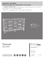 1
1
-
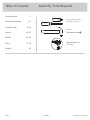 2
2
-
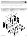 3
3
-
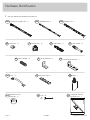 4
4
-
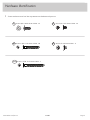 5
5
-
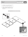 6
6
-
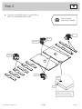 7
7
-
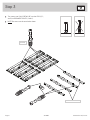 8
8
-
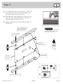 9
9
-
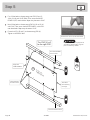 10
10
-
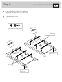 11
11
-
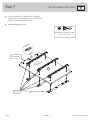 12
12
-
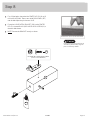 13
13
-
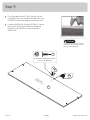 14
14
-
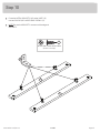 15
15
-
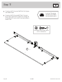 16
16
-
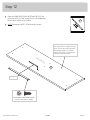 17
17
-
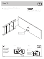 18
18
-
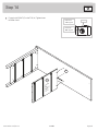 19
19
-
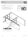 20
20
-
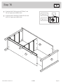 21
21
-
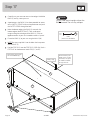 22
22
-
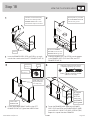 23
23
-
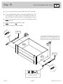 24
24
-
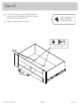 25
25
-
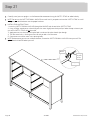 26
26
-
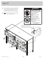 27
27
-
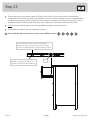 28
28
-
 29
29
-
 30
30
-
 31
31
-
 32
32
-
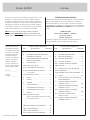 33
33
-
 34
34
-
 35
35
-
 36
36
-
 37
37
-
 38
38
-
 39
39
-
 40
40


en otros idiomas
- français: Sauder 422893 Mode d'emploi
- English: Sauder 422893 Operating instructions
Artículos relacionados
-
Sauder 423408 Instrucciones de operación
-
-
-
-
-
-
-
-
-