
Need help? Visit Sauder.com to view video assembly tips or chat with a live rep.
Prefer the phone? Call 1-800-523-3987.
Share your journey!
sauder.com
NOTE: THIS INSTRUCTION
BOOKLET CONTAINS IMPORTANT
SAFETY INFORMATION.
PLEASE READ AND KEEP FOR
FUTURE REFERENCE.
Enlish p 1-22
Français p 23-25
Español p 26-28
Lot # 373317 06/15/15
Purchased: __________________
Be sure to ive us a rin before
makin any returns. 1-800-523-3987
4-Drawer Chest
Shoal Creek Collection | Model 411197
WARNING
CHOKING HAZARD - Small Parts
Not for children under 3 years.
Adult assembly required.

Table of Contents Assembly Tools Required
Part Identifi cation
Hardware Identifi cation
Assembly Steps
Français
Español
Safety
Warranty
Hammer
Not actual size
No. 2 Phillips Screwdriver
Tip Shown Actual Size
Skip the power trip.
This time.
2-3
4
5-22
23-25
26-28
29-30
31
411197 www.sauder.com/servicesPae 2
Now you know
our ABCs.
Part Identifi cation
å While not all parts are labeled, some of the parts will have a label or an inked letter on the ede
to help distinuish similar parts from each other. Use this part identifi cation to help identify similar parts.
A2 RIGHT END (1)
B2 LEFT END (1)
C2 TOP (1)
D BOTTOM (2)
E BACK (1)
G RIGHT FRONT LEG (1)
H LEFT FRONT LEG (1)
I REAR LEG (2)
J2 DRAWER FRONT (1)
O2 LARGE DRAWER FRONT (3)
D10 RIGHT DRAWER SIDE (1)
D11 LEFT DRAWER SIDE (1)
D132 LARGE RIGHT DRAWER SIDE (3)
D138 LARGE LEFT DRAWER SIDE (3)
D174 DRAWER BACK (1)
D175 LARGE DRAWER BACK (3)
D983 DRAWER BOTTOM (4)
M65 DRAWER BRACE (4)
M73 END MOLDING (2)
VV LARGE BACK (1)

Part Identifi cation
411197www.sauder.com/services
Pae 3
M65
D10
D983
D11
D132
D983
D138
D175
D174
M65
A2
B2
C2
D
E
G
H
I
D
I
VV
M73
M73
J2
O2

Hardware Identifi cation
å Screws are shown actual size. You may receive extra hardware with your unit.
411197 www.sauder.com/servicesPae 4
40DA
UNIVERSAL CABINET RAIL - 8
40DC
DRAWER RIGHT - 4
40DD
DRAWER LEFT - 4
SAFETY STRAP - 1
Locate this nylon SAFETY
STRAP (60M) to be used
later in assembly. Do not
accidentally throw away.
60M
SAFETY DRYWALL
ANCHOR - 1
61M
WASHER - 1
13M
BLACK 1-1/8" MACHINE SCREW - 3
NN
METAL
BRACKET - 4
AA
SILVER 3/4" MACHINE SCREW - 12
OO
BLACK 9/16" LARGE HEAD SCREW - 15
PP
BLACK 2-1/4" FLAT HEAD SCREW - 6
MM
X
TWIST-LOCK
®
FASTENER - 8
TT
GOLD 5/16" FLAT HEAD SCREW - 32
METAL PIN - 4
EE
PULL - 6
FF
DD
SLIDE
CAM - 8
BLACK 9/16" FLAT HEAD SCREW - 4
QQ
CAM SCREW - 10
Z2
KNOB - 3
BB
NAIL - 16
UU
HIDDEN
CAM - 10
Y2
30S
BLACK 1-9/16" FLAT HEAD SCREW - 20
KK
WARNING LABEL - 1
(Refer to Step 17 for proper
location and application)
WARNING
Serious or fatal crushing injuries can occur
from furniture tip-over. To help prevent
tip-over:
• Place heaviest items in the lowest drawers.
• Unless specifi cally desined to accommodate, do not
set TVs or other heavy objects on top of this product.
• Never allow children to climb or han on drawers,
doors, or shelves.
• Never open more than one drawer at a time.
• If equipped with a drawer interlock system, do not
defeat or remove it.
Use of tip-over restraints may only reduce, but not
eliminate, the risk of tip-over.
This is a permanent label. Do not attempt to remove!
04/10 332296

Step 1
Look for this icon. It means a
video assembly tip is available at
www.sauder.com/services/tips
411197www.sauder.com/services
Pae 5
Do not tihten the TWIST-LOCK® FASTENERS in this step.
(8 used)
X
å
Assemble your unit on a carpeted fl oor or on the empty
carton to avoid scratchin your unit or the fl oor.
å
To bein assembly, push a SAUDER TWIST-LOCK®
FASTENER (X) into the lare holes in the ENDS (A2
and B2). Repeat this step for the BOTTOMS (D).
A2
B2

Step 2
411197 www.sauder.com/servicesPae 6
Arrow
Arrow
Y2
The arrow in the HIDDEN
CAM must point toward the
hole in the ede of the board.
Hole
å
Push ten HIDDEN CAMS (Y2) into the ENDS (A2 and B2)
and DRAWER BRACES (M65).
Arrow
Y2
(10 used)
Y2
Arrow
A2
B2
M65
M65
M65
M65

Step 3
411197www.sauder.com/services
Pae 7
Z2
å
Turn ten CAM SCREWS (Z2) into the FRONT LEGS (G
and H) and DRAWER FRONTS (J2 and O2).
G
H
O2
O2
O2
J2
(10 used)

Step 4
411197 www.sauder.com/servicesPae 8
Remember:
Rihty tihty.
Lefty loosey.
å
Fasten the REAR LEGS (I) to the ENDS (A2 and B2). Use
six BLACK 2-1/4" FLAT HEAD SCREWS (MM).
A2
B2
I
I
Surface
without
TWIST
-
LOCK®
FASTENERS
Surface
without
TWIST
-
LOCK®
FASTENERS
Anled ede
BLACK 2-1/4" FLAT HEAD SCREW
(6 used in this step)
MM
Ede with
TWIST-LOCK®
FASTENERS
Ede with
TWIST-LOCK®
FASTENERS

Step 5
411197www.sauder.com/services
Pae 9
å
Turn four BLACK 9/16" FLAT HEAD SCREWS (QQ) into
the ENDS (A2 and B2) until the shoulders of the SCREWS
rest on the surfaces of the ENDS.
å
Slide the END MOLDINGS (M73) onto the ENDS (A2
and B2). Line up the rooves in the MOLDINGS over the
heads of the SCREWS in the ENDS.
A2
B2
M73
M73
Apply pressure with your hands
as you uide the MOLDINGS over
the SCREWS and onto the ENDS.
These edes
should be even.
These edes
should be even.
Shoulder
BLACK 9/16" FLAT HEAD SCREW
(4 used in this step)
QQ

Step 6
411197 www.sauder.com/servicesPae 10
å
NOTE: Carefully turn your ENDS (A2 and B2) over.
å
Fasten the FRONT LEGS (G and H) to the
ENDS (A2 and B2). Tihten six HIDDEN CAMS.
1
2
A2
B2
H
G
Surface
with
TWIST
-
LOCK®
FASTENERS
Surface
with
TWIST
-
LOCK®
FASTENERS
Anled ede
These surfaces
should be even.
These surfaces
should be even.
Anled ede

Step 7
411197www.sauder.com/services
Pae 11
å
Fasten the UNIVERSAL CABINET RAILS* (40DA) to the
ENDS (A2 and B2). Use sixteen GOLD 5/16" FLAT HEAD
SCREWS (TT) throuh holes #1 and #4.
å
*patent pendin lide system
GOLD 5/16" FLAT HEAD SCREW
(16 used in this step)
TT
3
2
1
1
2
3
4
4
Glide end
Glide end
A2
B2
H
G
1
2
3
4
1
2
3
4
1
2
3
4
3
2
1
4
3
2
1
4
3
2
1
4
Surface
with
TWIST
-
LOCK®
FASTENERS
Surface
with
TWIST
-
LOCK®
FASTENERS

Step 8
411197 www.sauder.com/servicesPae 12
Do not stand the unit upriht without the
BACK fastened. The unit may collapse.
Caution
å
Fasten the LEFT END (B2) to the TOP (C2). Tihten
two TWIST-LOCK® FASTENERS.
Dowel end
How to use the SAUDER TWIST-LOCK
®
FASTENER
1. Insert the dowel end of the FASTENER into the hole of the
adjoinin part.
NOTE: The dowel end of the FASTENER must remain fully
inserted in the hole of the adjoinin part while lockin
the FASTENER.
2. Tihten the FASTENER with a Phillips screwdriver as tiht
as possible.
B2
C2
Finished ede
Surface
with holes
H
This hole
must be here.
Surface with
TWIST-LOCK®
FASTENERS

å
Fasten four METAL BRACKETS (AA) to the BACK (E). Use four BLACK 9/16" LARGE HEAD SCREWS (PP).
å
NOTE: Be sure the METAL BRACKETS are even with the ede of the BACK.
å
Fasten the BACK (E) to the LEFT END (B2). Use two BLACK 9/16" LARGE HEAD SCREWS (PP) throuh the METAL
BRACKETS on the BACK and into the LEFT END.
Step 9
411197www.sauder.com/services
Pae 13
B2
E
E
The six holes on
other surface should
be located here.
AA
AA
BLACK 9/16" LARGE HEAD SCREW
(6 used in this step)
PP
Surface with
METAL BRACKETS

Step 10
411197 www.sauder.com/servicesPae 14
å
Insert a METAL PIN (EE) into the hole in each short ede
of the BOTTOMS (D).
å
Fasten the BOTTOMS (D) to the LEFT END (B2). Tihten
two TWIST-LOCK® FASTENERS.
å
NOTE: Be sure the METAL PINS in the BOTTOMS insert
into the holes in the LEFT END.
Don't worry. It isn't
Rome. This can be built
in a day.
D
D
EE
EE
Surface without
TWIST-LOCK®
FASTENERS
Surface without
TWIST-LOCK®
FASTENERS
Finished ede
Finished ede
B2

Step 11
411197www.sauder.com/services
Pae 15
å
Fasten the RIGHT END (A2) to the TOP (C2) and BOTTOMS (D). Tihten four
TWIST-LOCK® FASTENERS.
å
NOTE: Be sure the METAL PINS in the BOTTOMS insert into the holes
in the RIGHT END.
å
Fasten the RIGHT END (A2) to the BACK (E). Use two BLACK 9/16" LARGE HEAD
SCREWS (PP) throuh the METAL BRACKETS on the BACK and into the RIGHT END.
D
D
C2
A2
E
Surface without
TWIST-LOCK®
FASTENERS
G
BLACK 9/16" LARGE HEAD SCREW
(2 used in this step)
PP

Step 12
411197 www.sauder.com/servicesPae 16
å
Carefully turn your unit over onto its front edes. Lay the LARGE
BACK (VV) over your unit.
å
Fasten the bottom ede of the LARGE BACK (VV) to the
BACK (E). Use six BLACK 9/16" LARGE HEAD SCREWS (PP).
å
Fasten the top and side edes of the LARGE BACK (VV) to your
unit usin the NAILS (UU).
å
NOTE: A perforation has been provided for access throuh the
LARGE BACK.
E
Printed
information
must be
facin up.
NAIL
(16 used in this step)
UU
VV
BLACK 9/16" LARGE HEAD SCREW
(6 used in this step)
PP
The perforation
should be here.
Do not stand the unit upriht without the
BACK fastened. The unit may collapse.
Caution

Step 13
411197www.sauder.com/services
Pae 17
å
Insert the LARGE DRAWER SIDES (D132 and D138)
at an angle into the slot at each end of the LARGE
DRAWER FRONT (O2).
å
Slide the DRAWER BOTTOM (D983) into the grooves
in the LARGE DRAWER SIDES (D132 and D138) and
LARGE DRAWER FRONT (O2).
å
Fasten the DRAWER BRACE (M65) to the LARGE
DRAWER FRONT (O2). Tighten one HIDDEN CAM.
å
Fasten the LARGE DRAWER BACK (D175) to the LARGE
DRAWER SIDES (D132 and D138) and DRAWER
BRACE (M65). Use five BLACK 1-9/16" FLAT HEAD
SCREWS (30S). Repeat this step for the other large drawers.
The smaller drawer will use DRAWER FRONT (J2), DRAWER
SIDES (D10 and D11), and DRAWER BACK (D174).
The tabs should insert freely into the
slots. Gently tilt the DRAWER SIDES side
to side until the tabs slip into the slots.
Surface with
HIDDEN CAM
12
34
Be sure the DRAWER
BOTTOM inserts into the
DRAWER FRONT roove.
With the palm of your hand, tap the
DRAWER BOTTOM down into the roove.
Groove
O2
M65
VIEW THE T-LOCK BOX VIDEO
D138
D132
D138
D983
D132
D132
D138
D175
Unfi nished
surface
O2
O2
Start each screw a few turns before
completely tihtenin any of them.
BLACK 1-9/16" FLAT HEAD SCREW
(20 used in this step)
30S
M65
1
2
Be sure the
DRAWER
BOTTOM
inserts into
the DRAWER
BACK roove.

Step 14
411197 www.sauder.com/servicesPae 18
å
Insert a SLIDE CAM (DD) into the LARGE DRAWER SIDES (D132 and D138).
å
Fasten a DRAWER RIGHT (40DC) to the LARGE RIGHT DRAWER SIDE (D132) and a DRAWER LEFT (40DD) to the LARGE
LEFT DRAWER SIDE (D138). Use four GOLD 5/16" FLAT HEAD SCREWS (TT) throuh holes #1 and #2.
å
NOTE: The parts are marked "DRAWER RIGHT" and "DRAWER LEFT" for easy identifi cation.
å
NOTE: The lides are not intended to rotate.
å
NOTE: The screw head in the CAM must be visible throuh the slotted hole in the SLIDE.
å
Repeat this step for the other drawers.
1
2
1
2
GOLD 5/16" FLAT HEAD SCREW
(16 used in this step)
TT
(4 screws per drawer)
Glide end
Glide end
D138
D132
Screw head - turn CAM to line up holes in
the SLIDES with holes in DRAWER SIDES
DD
DD

Step 15
411197www.sauder.com/services
Pae 19
å
Fasten three KNOBS (BB) to the DRAWER FRONT (J2). Use
three BLACK 1-1/8" MACHINE SCREWS (NN).
å
Fasten two PULLS (FF) to the LARGE DRAWER FRONT (O2).
Use four SILVER 3/4" MACHINE SCREWS (OO).
å
Repeat this step for the other lare drawers.
FF
BB
BLACK 1-1/8" MACHINE SCREW
(3 used for the KNOBS)
NN
SILVER 3/4" MACHINE SCREW
(12 used for the PULLS)
OO
O2
J2
Want options? Customize
your item with add-on
hardware kits available
on sauder.com.

Step 16
411197 www.sauder.com/servicesPae 20
60M
61M
BLACK 9/16" LARGE HEAD SCREW
(1 used in this step)
PP
13M
å
Carefully stand your unit upriht.
å
Position your unit in its fi nal location. We recommend usin the SAFETY STRAP (60M) for added stability.
å
NOTE: Do not turn the SAFETY DRYWALL ANCHOR (61M) into a wall stud. If you prefer to fasten the SAFETY
STRAP (60M) to a wall stud, o to your local hardware store for proper hardware.
å
INSTALLATION INSTRUCTIONS: (Also available at www.yl-anchors.com)
1. Insert the SAFETY DRYWALL ANCHOR (61M) throuh the WASHER (13M) and one end of the SAFETY STRAP (60M).
2. Usin a Phillips screwdriver or a hand drill, press the screw slihtly onto the drywall.
3. Apply pressure; turn the screw until a pilot hole is made and the nylon sheath slips throuh.
4. Turn the screw until it is fl ush aainst the wall and you feel a fi rm resistance.
5. Continue to turn until the screw starts spinnin freely.
å
Carefully cut out the perforated hole in the LARGE BACK (F). Insert the other end of the SAFETY STRAP (60M) throuh
this hole, then use a BLACK 9/16" LARGE HEAD SCREW (PP) throuh the SAFETY STRAP and into the pre-drilled hole in
the underside of the TOP.
å
NOTE: Before movin your unit to a di erent location, unscrew the SAFETY DRYWALL ANCHOR (61M) from your wall.
The nylon sheath will remain behind your wall.
F

å
To insert the drawers into your unit, tip the front of the
drawers down and drop the lides on the drawers behind
the lides on the unit. Lift the front of the drawers up and
slide them into the unit
å
Apply the WARNING LABEL (KK) to the upper LEFT
DRAWER SIDE (D11). You should be able to read the label
when the drawer is open. When the drawer is closed, it will
hide the label. Peel o the backin and apply the label as
shown in the diaram.
Step 17
411197www.sauder.com/services
Pae 21
Serious or fatal crushin injuries can
occur from furniture tip-over. To help
prevent tip-over:
-Place heaviest items in the lowest drawers.
-Unless specifi cally desined to accommodate,
do not set TVs or other heavy objects on top of
this product.
-Never allow children to climb or han on
drawers, doors, or shelves.
-Never open more than one drawer at a time.
-If equipped with a drawer interlock system, do not
defeat or remove it.
Use of tip-over restraints may only reduce,
but not eliminate, the risk of tip-over.
WARNING
KK
D11
40 lbs.
20 lbs.
35 lbs. each

Step 18
411197 www.sauder.com/servicesPae 22
å
To make adjustments to the drawers, loosen SCREW #2 in the SLIDES a 1/4 turn, then turn the CAM clockwise or
counter-clockwise. Notice how the drawer raises or lowers as you turn the CAM. The hiher the screw in the oblon hole,
the hiher your drawer front will be. The lower the screw, the lower the drawer front. By adjustin the drawers this way, it
will help the DRAWER FRONTS line up better when closed. Tihten the SCREW when fi nished with adjustments.
å
NOTE: Please read the back paes of the instruction booklet for important safety information.
å
This completes assembly. Clean with your favorite furniture polish or a damp cloth. Wipe dry.
The hiher the screw in the oblon hole,
the hiher your drawer front will be. The
lower the screw, the lower the drawer front.
And to celebrate, why not share your success story?
Loosen screw #2 a 1/4 turn, turn the cam a 1/4 turn
maximum in both the clockwise and counter-clockwise
directions to make adjustments, and then tihten screw #2.
Cam

A l’usae exclusif du
Canada Noter la date
d’achat de cet élément
et conserver le livret
pour future référence.
Pour contacter Sauder
en ce qui concerne cet
élément, faire référence
au numéro de lot et
numéro de modèle en
appelant notre numéro
sans frais.
Lot nº : ____________
Date de
l’achat: ____________
LISTE DE PIÈCES
REFERENCE DESCRIPTION QUANTITÉ
LISTE DE PIÈCES
REFERENCE DESCRIPTION QUANTITÉ
NOUS SOMMES LA POUR VOUS AIDER!
Nous faisons de notre mieux pour nous assurer que votre meuble
arrive dans d’excellentes conditions. Nos représentants du service
Clientèle sont aimables et prêts à vous aider au cas où une pièce
aurait été endommaée ou manquerait (ou si vous aviez besoin
d’aide pour l’assemblae). NE RAMENEZ PAS LE MEUBLE AU
MAGASIN. Au Canada, composez ce numéro d’appel ratuit:
1-800-523-3987
Du lundi au vendredi, de 9 heures du matin à
5:30 heures du soir (horaire Côte Est)
(sauf jours fériés)
Si une pièce a besoin d’être remplacée, la pièce de remplacement
sera envoyée dans les 48 heures. (Sauf week-ends et jours fériés)
Utilisez les instructions d’assemblae en français avec les
schémas étape par étape du manuel d’instruction en anlais.
Chaque étape en français correspond à la même étape
en anlais. La pièce devant être attachée à l’élément est
représentée en ris sur les schémas de chaque étape pour plus
de précision. Comparer la “Liste de pièces” ci-dessous avec
la “PART IDENTIFICATION” du manuel en anlais pour vous
familiariser avec les pièces avant l’assemblae.
REMARQUE : CE MANUEL D’INSTRUCTIONS CONTIENT
D’IMPORTANTES INFORMATIONS RELATIVES À LA SÉCURITÉ.
À LIRE ET CONSERVER POUR TOUTE RÉFÉRENCE FUTURE.
X FIXATION TWIST-LOCK® .......................................8
Y2 EXCENTRIQUE ESCAMOTABLE ..................10
Z2 VIS D'EXCENTRIQUE ............................................10
AA CONSOLE EN MÉTAL .............................................4
BB BOUTON ............................................................................3
DD EXCENTRIQUE DE COULISSE .........................8
EE GOUPILLE EN MÉTAL .............................................4
FF POIGNÉE ............................................................................6
KK ÉTIQUETTE DE MISE EN GARDE....................1
(Consulter l'étape 17 pour l'emplacement
et application appropriées)
13M RONDELLE ........................................................................1
60M SANGLE DE SÉCURITÉ ...........................................1
Localiser cette SANGLE DE SÉCURITÉ (60M)
à utiliser ultérieurement dans l’assemblae.
Ne pas la jeter accidentellement.
61M DISPOSITIF DE SÉCURITÉ
POUR PLACOPLÂTRE ..............................................1
MM VIS TÊTE PLATE 57 mm NOIRE .....................6
NN VIS À MÉTAUX 28 mm NOIRE .........................3
OO VIS À MÉTAUX 19 mm ARGENTÉE ............12
PP VIS TÊTE LARGE 14 mm NOIRE ..................15
QQ VIS TÊTE PLATE 14 mm NOIRE ......................4
TT VIS TÊTE PLATE 8 mm DORÉE .................. 32
UU CLOU .................................................................................16
30S VIS TÊTE PLATE 40 mm NOIRE ................20
A2 EXTRÉMITÉ DROITE ..................................................1
B2 EXTRÉMITÉ GAUCHE ...............................................1
C2 DESSUS ...............................................................................1
D DESSOUS ..........................................................................2
E ARRIÈRE ..............................................................................1
G PIED AVANT DROIT ....................................................1
H PIED AVANT GAUCHE .............................................1
I PIED ARRIÈRE ................................................................2
J2 DEVANT DE TIROIR ....................................................1
O2 DEVANT DE GRAND TIROIR ..............................3
D10 CÔTÉ DROIT DE TIROIR ........................................1
D11 CÔTÉ GAUCHE DE TIROIR ..................................1
D132 CÔTÉ DROIT DE GRAND TIROIR ...................3
D138 CÔTÉ GAUCHE DE GRAND TIROIR ............3
D174 ARRIÈRE DE TIROIR ...................................................1
D175 ARRIÈRE DE GRAND TIROIR .............................3
D983 FOND DE TIROIR .........................................................4
M65 ENTRETOISE DE TIROIR .......................................4
M73
MOULURE D’EXTRÉMITÉ .....................................2
VV GRAND ARRIÈRE ..........................................................1
40DA GLISSIÈRE D'ÉLÉMENT UNIVERSELLE.....8
40DC TIROIR DROIT ................................................................4
40DD TIROIR GAUCHE .......................................................... 4
Commode 4 TiroirsModèle 411197
411197www.sauder.com/services
Pae 23

ÉTAPE 8
Attention: Ne pas relever l'élément dans sa position verticale
avant d'avoir fi xé l’ARRIÈRE. L'élément risque de s'e ondrer.
Fixer l'EXTRÉMITÉ GAUCHE (B2) au DESSUS (C2). Serrer deux
FIXATIONS TWIST-LOCK®.
Utilisation de la FIXATION TWIST-LOCK® SAUDER
1. Insérer l'extrémité fi letée de la FIXATION dans le trou de la pièce attenante.
REMARQUE : L'extrémité fi letée de la FIXATION doit rester
complètement insérée dans le trou de la pièce attenante lorsque
l'on bloque la FIXATION.
2. Bien serrer la FIXATION à l'aide d'un tournevis Phillips.
ÉTAPE 9
Fixer quatre CONSOLES EN MÉTAL (AA) à l’ARRIÈRE (E). Utiliser
quatre VIS TÊTE LARGE 14 mm NOIRES (PP).
REMARQUE : S'assurer que les CONSOLES EN MÉTAL sont à
fl eur du chant du DESSOUS.
Fixer l'ARRIÈRE (E) à l'EXTRÉMITÉ GAUCHE (B2). Utiliser deux
VIS TÊTE LARGE 14 mm NOIRES (PP) à travers les CONSOLES
EN MÉTAL sur l’ARRIÈRE et dans l'EXTRÉMITÉ GAUCHE.
ÉTAPE 4
Fixer les PIEDS ARRIÈRE (I) aux EXTRÉMITÉS (A2 et B2). Utiliser
six VIS TÊTE PLATE 57 mm NOIRES (MM).
ÉTAPE 2
Enfoncer dix EXCENTRIQUES ESCAMOTABLES (Y2) dans les
EXTRÉMITÉS (A2 et B2) et les ENTRETOISES DE TIROIR (M65).
ÉTAPE 3
Faire tourner dix VIS D'EXCENTRIQUE (Z2) dans les PIEDS
AVANT (G et H) et les DEVANTS DE TIROIR (J2 et O2).
ÉTAPE 1
Ne pas serrer les FIXATIONS TWIST-LOCK® à cette étape.
Assembler l'élément sur un sol à moquette ou sur le carton vide
pour éviter d'endommaer l'élément ou le sol.
Pour commencer l'assemblae, enfoncer une FIXATION TWIST-LOCK®
SAUDER (X) dans les ros trous des EXTRÉMITÉS (A2 et B2). Répéter
cette étape pour les DESSOUS (D).
411197 www.sauder.com/servicesPae 24
ÉTAPE 5
Faire tourner quatre VIS TÊTE PLATE 14 mm NOIRES (QQ) dans
les EXTRÉMITÉS (A2 et B2) jusqu'à ce que les épaulements des
VIS repose sur les surfaces des EXTRÉMITÉS.
Enfi ler les MOULURES D'EXTRÉMITÉ (M73) sur les
EXTRÉMITÉS (A2 et B)2. Aliner les rainures des
MOULURES sur les têtes des VIS dans les EXTRÉMITÉS.
ÉTAPE 10
Insérer une GOUPILLE EN MÉTAL (EE) dans le trou de chaque
chant court des DESSOUS (D).
Fixer les DESSOUS (D) à l'EXTRÉMITÉ GAUCHE (B2). Serrer deux
FIXATIONS TWIST-LOCK®.
REMARQUE : S'assurer de bien insérer les GOUPILLES EN MÉTAL
situées sur les DESSOUS dans les trous dans l'EXTRÉMITÉ GAUCHE.
ÉTAPE 6
REMARQUE : Avec précaution, retourner les EXTRÉMITÉS (A2 et B2).
Fixer les PIEDS AVANT (G et H) aux EXTRÉMITÉS (A2 et B2).
Serrer six EXCENTRIQUES ESCAMOTABLES.
ÉTAPE 7
Fixer les GLISSIÈRES D'ÉLÉMENT UNIVERSELLES* (40DA) aux
EXTRÉMITÉS (A2 et B2). Utiliser seize VIS TÊTE PLATE 8 mm
DORÉES (TT) à travers les trous nº 1 et nº 4.
*système de coulisse en instance de brevet
ÉTAPE 11
Fixer l'EXTRÉMITÉ DROITE (A2) au DESSUS (C2) et aux
DESSOUS (D). Serrer quatre FIXATIONS TWIST-LOCK®.
REMARQUE : S'assurer de bien insérer les GOUPILLES EN MÉTAL
situées sur les DESSOUS dans les trous dans l'EXTRÉMITÉ DROITE.
Fixer l'EXTRÉMITÉ DROITE (A2) à l’ARRIÈRE (E). Utiliser deux VIS
TÊTE LARGE 14 mm NOIRES (PP) à travers les CONSOLES EN
MÉTAL sur l’ARRIÈRE et dans l'EXTRÉMITÉ DROITE.

ÉTAPE 16
Relever, avec précaution, l'élément dans sa position verticale.
Placer l'élément dans son emplacement fi nal. Il est recommandé d’utiliser
la SANGLE DE SÉCURITÉ (60M) pour stabilité additionnelle.
REMARQUE : Ne pas tourner le DISPOSITIF DE SÉCURITÉ POUR
PLACOPLÂTRE (61M) dans un montant mural. Si on préfère fi xer
la SANGLE DE SÉCURITÉ (60M) à un montant mural, obtenir la
visserie appropriée auprès d’une quincaillerie locale.
INSTRUCTIONS D’INSTALLATION : (Éalement disponible à www.
yl-anchors.com)
1. Insérer le DISPOSITIF DE SÉCURITÉ POUR PLACOPLÂTRE (61M)
à travers la RONDELLE (13M) et une extrémité de la SANGLE DE
SÉCURITÉ (60M).
2. À l’aide d’un tournevis cruciforme ou d’une perceuse à main,
visser léèrement la vis contre le placoplâtre.
3. Appliquer une certaine pression ; faire tourner la vis jusqu’à la
aine en nylon lisse à travers.
4. Faire tourner la vis jusqu’à ce qu’elle soit à fl eur du mur et
qu'une résistance ferme se fasse sentir.
5. Continuer de tourner jusqu’à ce que la vis commence à pivoter librement.
Avec précaution, découper le trou pré-percé dans le GRAND ARRIÈRE (F).
Insérer l’autre extrémité de la SANGLE DE SÉCURITÉ (60M) à travers ce trou,
puis utiliser une VIS TÊTE LARGE NOIRE 14 mm (PP) à travers la SANGLE
DE SÉCURITÉ et dans le trou pré-percé sur le dessous du DESSUS.
REMARQUE : Avant de déplacer l’unité vers un emplacement di érent,
dévisser le DISPOSITIF DE SÉCURITÉ POUR PLACOPLÂTRE (61M) du
mur. La aine en nylon restera derrière le mur.
ÉTAPE 17
Pour insérer les tiroirs dans l’unité, incliner le devant des tiroirs vers le bas
et faire tomber les coulisses des tiroirs derrière les coulisses de l’unité.
Relever le devant du tiroir et les enfi ler dans l'élément.
Apposer l'ÉTIQUETTE DE MISE EN GARDE (KK) sur le CÔTÉ
GAUCHE DE TIROIR (D11) supérieure. Cette étiquette doit être
lisible lorsque le tiroir est ouvert. Lorsque le tiroir est fermé, il doit
la dissimuler. Décoller le fi lm protecteur et apposer l'étiquette
comme l'indique le schéma.
ÉTAPE 18
Pour ajuster les tiroirs, desserrer la VIS nº 2 dans les COULISSES
un quart de tour et tourner ensuite la CAME dans le sens des
aiuilles d'une montre ou dans le sens contraire. Noter que le tiroir
monte ou descend lorsque l'on tourne la CAME. Plus la vis dans
le trou oblon est haute, plus le devant de tiroir sera haut. Plus la
vis est basse, plus le devant de tiroir sera bas. Ajuster les tiroirs
de cette manière permet aux DEVANTS DE TIROIR d'être mieux
alinés une fois fermés. Resserrer la VIS après d'avoir ajusté.
REMARQUE : Prière de lire les informations importantes sur la
sécurité fi urant sur les paes arrière du manuel d’instructions.
Ceci complète l'assemblae. Nettoyer à l’aide d’une encaustique
pour meubles ou d’un chi on humide. Essuyer.
ÉTAPE 14
Insérer une EXCENTRIQUE DE COULISSE (DD) dans les CÔTÉS
DE GRAND TIROIR (D132 et D138).
Fixer un TIROIR DROIT (40DC) sur le CÔTÉ DROIT DE GRAND
TIROIR (D132) et un TIROIR GAUCHE (40DD) sur le CÔTÉ
GAUCHE DE GRAND TIROIR (D138). Utiliser quatre VIS TÊTE
PLATE 8 mm DORÉES (TT) à travers les trous nº 1 et nº 2.
REMARQUE : Les pièces ont une inscription « DRAWER RIGHT »
(droite) et une inscription « DRAWER LEFT » (auche) pour faciliter
leur identifi cation.
REMARQUE : Les coulisses ne sont pas sensées tourner.
REMARQUE : La tête de vis dans l'EXCENTRIQUE doit être visible
à travers le trou fendu dans la COULISSE.
Répéter cette étape pour les autres tiroirs.
ÉTAPE 13
1 Insérer les CÔTÉS DE GRAND TIROIR (D132 et D138) en biseau dans
la fente dans chaque extrémité du DEVANT DE GRAND TIROIR (O2).
2 Enfi ler le FOND DE TIROIR (D983) dans les rainures des
CÔTÉS DE GRAND TIROIR (D132 et D138) et du DEVANT DE
GRAND TIROIR (O2).
3 Fixer une ENTRETOISE DE TIROIR (M65) au DEVANT DE
GRAND TIROIR (O2). Serrer un EXCENTRIQUE ESCAMOTABLE.
4 Fixer l'ARRIÈRE DE GRAND TIROIR (D175) aux CÔTÉS DE GRAND
TIROIR (D132 et D138) et à l’ENTRETOISE DE TIROIR (M65). Utiliser cinq
VIS TÊTE PLATE 40 mm NOIRES (30S). Répéter cette étape pour les
autres rands tiroirs. Le petit tiroir utilisera le DEVANT DE TIROIR (J2), les
CÔTÉS DE TIROIR (D10 et D11) et l'ARRIÈRE DE TIROIR (D174).
ÉTAPE 12
Attention: Ne pas relever l'élément dans sa position verticale
avant d'avoir fi xé l’ARRIÈRE. L'élément risque de s'e ondrer.
Avec précaution, retourner l'élément sur ses chants avant. Placer
le GRAND ARRIÈRE (VV) sur l'élément.
Fixer le chant inférieur du GRAND ARRIÈRE (VV) à l’ARRIÈRE (E).
Utiliser six VIS TÊTE LARGE 14 mm NOIRES (PP).
Fixer les chants supérieur et latéraux du GRAND ARRIÈRE (VV) à
l'élément à l'aide des CLOUS (UU).
REMARQUE : Des perforations ont été prévues pour accès à
travers le GRAND ARRIÈRE.
411197www.sauder.com/services
Pae 25
ÉTAPE 15
Fixer trois BOUTONS (BB) au DEVANT DE TIROIR (J2). Utiliser
trois VIS À MÉTAUX 28 mm NOIRES (NN).
Fixer deux POIGNÉES (FF) au DEVANT DE GRAND TIROIR (O2).
Utiliser quatre VIS À MÉTAUX 19 mm ARGENTÉES (OO).
Répéter cette étape pour les autres rands tiroirs.

A l’usae exclusif du
Canada Noter la date
d’achat de cet élément
et conserver le livret
pour future référence.
Pour contacter Sauder
en ce qui concerne cet
élément, faire référence
au numéro de lot et
numéro de modèle en
appelant notre numéro
sans frais.
Lot nº : ____________
Date de
l’achat: ____________
LISTA DE PARTES
ITEM DESCRIPCIÓN CANTIDAD
ESTAMOS AQUI PARA AYUDAR!
Tratamos de aseurar que su mueble llea en condición excelente.
Nuestros representantes de Servicio al Cliente son amables y
listos para ayudarle con servicio rápido y efi ciente si una parte
está defectuosa o ausente (o si necesita ayuda con el ensamblaje).
NO DEVUELVA LA UNIDAD A LA TIENDA. Llame este número sin
caro:
1-800-523-3987
Lunes a viernes, 9:00 a.m. - 5:30 p.m.
Hora ofi cial del Este
(excepto días festivos)
Si requiere un repuesto de una parte, será enviado dentro de
48 horas (excepto los fi nes de semana y días festivos)
Use estas instrucciones de ensamblaje en español junto con las
fi uras paso-a-paso provistas en el folleto inlés. Cada paso
en español corresponde al mismo paso en inlés. Se destacan
las fi uras de cada paso con una tonalidad oscura para mostrar
precisamente cual parte se debe montar a la unidad. Compare
la “Lista de Part” abajo con la “Part Identifi cation” en el folleto en
inlés para familiarizarse con Las partes de ensamblaje.
NOTA: ESTE FOLLETO DE INSTRUCCIONES CONTIENE
INFORMACIÓN IMPORTANTE SOBRE LA SEGURIDAD. POR
FAVOR LEA Y GUÁRDELO PARA REFERENCIA EN EL FUTURO.
LISTA DE PARTES
ITEM DESCRIPCIÓN CANTIDAD
BB POMO ..................................................................................3
DD EXCÉNTRICO DE CORREDERA .......................8
EE ESPIGA DE METAL ....................................................4
FF TIRADOR ............................................................................6
KK ETIQUETA DE ADVERTENCIA ...........................1
(Consulte el para 17 la ubicación e
instalación apropiada)
13M ARANDELA ........................................................................1
60M CORREA DE SEGURIDAD .....................................1
Ubique esta CORREA DE SEGURIDAD de
nailon (60M) que más tarde se utilizará en
el ensamblaje. No la tire por accidente.
61M ANCLAJE DE SEGURIDAD PARA
EL DRYWALL ....................................................................1
MM TORNILLO NEGRO DE CABEZA
PERDIDA de 57 mm ..................................................6
NN TORNILLO NEGRO PARA METAL
de 28 mm ........................................................................3
OO TORNILLO PLATEADO PARA
METAL de 19 mm......................................................12
PP TORNILLO NEGRO DE CABEZA
GRANDE de 14 mm ................................................15
QQ TORNILLO NEGRO DE CABEZA
PERDIDA de 14 mm ..................................................4
TT TORNILLO DORADO DE CABEZA
PERDIDA de 8 mm .................................................32
UU CLAVO .............................................................................. 16
30S TORNILLO NEGRO DE CABEZA
PERDIDA de 40 mm .............................................20
A2 EXTREMO DERECHO ...............................................1
B2 EXTREMO IZQUIERDO ............................................1
C2 PANEL SUPERIOR .......................................................1
D FONDO ................................................................................2
E DORSO .................................................................................1
G PATA DELANTERA DERECHA ............................1
H PATA DELANTERA IZQUIERDA .........................1
I PATA POSTERIOR .......................................................2
J2 CARA DE CAJÓN .........................................................1
O2 CARA DE CAJÓN GRANDE ................................3
D10 LADO DERECHO DE CAJÓN .............................1
D11 LADO IZQUIERDO DE CAJÓN ..........................1
D132 LADO DERECHO DE CAJÓN GRANDE ....3
D138 LADO IZQUIERDO DE CAJÓN GRANDE .3
D174 DORSO DE CAJÓN ....................................................1
D175 DORSO DE CAJÓN GRANDE ...........................3
D983 FONDO DE CAJÓN ...................................................4
M65 RIOSTRA DE CAJÓN ................................................4
M73
MOLDURA DE EXTREMO .....................................2
VV DORSO GRANDE .........................................................1
40DA RIEL UNIVERSAL DE GABINETE ....................8
40DC CAJÓN DERECHO ..................................................... 4
40DD CAJÓN IZQUIERDO .................................................. 4
X SUJETADOR TWIST-LOCK® ................................8
Y2 EXCÉNTRICO ESCONDIDO ............................10
Z2 BIELA DE EXCÉNTRICO .....................................10
AA SOPORTE DE METAL ..............................................4
Cómoda con 4 cajonesModelo 411197
411197 www.sauder.com/servicesPae 26

PASO 8
Precaución: No coloque la unidad en posición vertical hasta que se
fi je el DORSO. La unidad podría caerse.
Fije el EXTREMO IZQUIERDO (B2) al PANEL SUPERIOR (C2).
Apriete dos SUJETADORES TWIST-LOCK®.
Cómo utilizar el SUJETADOR TWIST-LOCK® SAUDER
1. Inserte el extremo con cabilla del SUJETADOR en el aujero de
la parte adjunta.
NOTA: El extremo con cabilla del SUJETADOR debe quedarse
completamente insertado en el aujero de la parte adjunta
cuando se enclava el SUJETADOR.
2. Apriete el SUJETADOR lo más apretado posible con un
destornillador Phillips (cruz).
PASO 9
Fije cuatro SOPORTES DE METAL (AA) al DORSO (E). Utilice
cuatro TORNILLOS NEGROS DE CABEZA GRANDE de 14 mm (PP).
NOTA: Aseúrese que los SOPORTES DE METAL estén nivelados
con el borde del DORSO.
Fije el DORSO (E) al EXTREMO IZQUIERDO (B2). Utilice dos
TORNILLOS NEGROS DE CABEZA GRANDE de 14 mm (PP)
a través de los SOPORTES DE METAL sujetados al DORSO y
dentro del EXTREMO IZQUIERDO.
PASO 4
Fije las PATAS POSTERIORES (I) a los EXTREMOS (A2 y B2). Utilice
seis TORNILLOS NEGROS DE CABEZA PERDIDA de 57 mm (MM).
PASO 3
Apriete diez BIELAS DE EXCÉNTRICO (Z2) dentro de las PATAS
DELANTERAS (G y H) y de las CARAS DE CAJÓN (J2 y O2).
PASO 2
Empuje diez EXCÉNTRICOS ESCONDIDOS (Y2) dentro de los
EXTREMOS (A2 y B2) y de las RIOSTRAS DE CAJÓN (M65).
PASO 1
No apriete los SUJETADORES TWIST-LOCK® en este paso.
Ensamble la unidad sobre un piso alfombrado o sobre el cartón
vacío para evitar rayar la unidad o el piso.
Para comenzar el ensamblaje, empuje un SUJETADOR TWIST-LOCK®
SAUDER (X) dentro de los aujeros randes de los EXTREMOS (A2 y B2).
Repita este paso para los FONDOS (D).
411197www.sauder.com/services
Pae 27
PASO 5
Atornille cuatro TORNILLOS NEGROS DE CABEZA PERDIDA
de 14 mm (QQ) en los EXTREMOS (A2 y B2) hasta que los resaltos
de los TORNILLOS repose sobre las superfi cies de los EXTREMOS.
Deslice las MOLDURAS DE EXTREMO (M73) sobre los
EXTREMOS (A2 y B2). Alinee las ranuras de las MOLDURAS
sobre las cabezas de los TORNILLOS de los EXTREMOS.
PASO 10
Inserte una ESPIGA DE METAL (EE) dentro del aujero dentro de
cada borde corto de los FONDOS (D).
Fije los FONDOS (D) al EXTREMO IZQUIERDO (B2). Apriete dos
SUJETADORES TWIST-LOCK®.
NOTA: Aseúrese de insertar las ESPIGAS DE METAL de los
FONDOS dentro de los aujeros del EXTREMO IZQUIERDO.
PASO 6
NOTA: Cuidadosamente vuelva los EXTREMOS (A2 y B2) al revés.
Fije las PATAS DELANTERAS (G y H) a los EXTREMOS (A2 y B2).
Apriete seis EXCÉNTRICOS ESCONDIDOS.
PASO 7
Fije los RIELES UNIVERSALES DE GABINETE* (40DA) a los
EXTREMOS (A2 y B2). Utilice dieciséis TORNILLOS DORADOS DE
CABEZA PERDIDA de 8 mm (TT) a través de los aujeros No. 1 y No. 4.
*La patente del sistema de deslizamiento se encuentra en trámite.
PASO 11
Fije el EXTREMO DERECHO (A2) al PANEL SUPERIOR (C2) y a
los FONDOS (D). Apriete cuatro SUJETADORES TWIST-LOCK®.
NOTA: Aseúrese de insertar las ESPIGAS DE METAL de los
FONDOS dentro de los aujeros del EXTREMO DERECHO.
Fije el EXTREMO DERECHO (A2) al DORSO (E). Utilice dos
TORNILLOS NEGROS DE CABEZA GRANDE de 14 mm (PP)
a través de los SOPORTES DE METAL sujetados al DORSO y
dentro del EXTREMO DERECHO.

PASO 16
Cuidadosamente pona la unidad en posición vertical.
Coloque su unidad en su posición fi nal. Se recomienda utilizar la
CORREA DE SEGURIDAD (60M) para mayor estabilidad.
NOTA: No ire el ANCLAJE DE SEGURIDAD PARA EL DRYWALL (61M) en
un montante de la pared. Si prefi ere ajustar la CORREA DE
SEGURIDAD (60M) a un montante de la pared, vaya a su ferretería local
para obtener las herramientas adecuadas.
INSTRUCCIONES DE INSTALACIÓN: (También disponible en
www.yl-anchors.com)
1. Inserte el ANCLAJE DE SEGURIDAD PARA EL DRYWALL (61M)
a través la ARANDELA (13M) y de un extremo de la CORREA DE
SEGURIDAD (60M).
2. Con un destornillador Phillips o un taladro, presione lieramente
el tornillo en el drywall.
3. Presione; ire el tornillo hasta que se haa un aujero piloto y
se cuele la cubierta de nailon.
4. Gire el tornillo hasta que quede al ras contra la pared y usted
sienta una resistencia fi rme.
5. Continúe irando hasta que el tornillo comience a rotar libremente.
Cuidadosamente corte el aujero perforado del DORSO GRANDE (F).
Inserte el otro extremo de la CORREA DE SEGURIDAD (60M) a través
de este aujero, lueo use un TORNILLO NEGRO DE CABEZA GRANDE
de 14 mm (PP) a través de la CORREA DE SEGURIDAD y en el aujero
pre-perforado en el fondo del PANEL SUPERIOR.
NOTA: Antes de trasladar la unidad a otra ubicación, desatornille
el ANCLAJE DE SEGURIDAD PARA EL DRYWALL (61M) de su
pared. La cubierta de nailon permanecerá detrás de su pared.
PASO 17
Para insertar los cajones en el unidad, incline la parte delantera de
los cajones hacia abajo y deje que los corrimientos de los cajones
caian detrás de los corrimientos de la unidad. Levante la parte
delantera de los cajones y deslícelos dentro de la unidad.
Aplique la ETIQUETA DE ADVERTENCIA (KK) al LADO
IZQUIERDO DE CAJÓN (D11) superior. Usted debe poder leer
la etiqueta cuando el cajón está abierto. Cuando el cajón está
cerrado, éste ocultará la etiqueta. Quite el material protector y
aplique la etiqueta tal como se muestra en el diarama.
PASO 18
Para ajustar los cajones, afl oje el TORNILLO No. 2 de las
CORREDERAS una cuarta vuelta y después ire la leva hacia la
derecha o hacia la izquierda. Observe que el cajón sube o baja al
irar la LEVA. Entre más alto esté el tornillo en el aujero oblono,
más alto estará el frente del cajón. Entre más bajo esté el tornillo,
el frente del cajón estará más bajo. Al ajustar los cajones de esta
manera, mejorará la alineación de las CARAS DE CAJÓN una vez
cerrada. Apriete los TORNILLOS después de hacer los ajustes.
NOTA: Por favor, lea las páinas de atrás del folleto de
instrucciones en cuanto a importante información de seuridad.
Esto completa el ensamblaje. Limpie con su pulimento para
muebles preferido o un paño húmedo. Seque con un paño.
PASO 15
Fije tres POMOS (BB) a la CARA DE CAJÓN (J2). Utilice tres
TORNILLOS NEGROS PARA METAL de 28 mm (NN).
Fije dos TIRADORES (FF) a la CARA DE CAJÓN GRANDE (O2). Utilice
cuatro TORNILLOS PLATEADOS PARA METAL de 19 mm (OO).
Repita este paso para los otros cajones randes.
PASO 14
Inserte un EXCÉNTRICO DE CORREDERA (DD) dentro de los
LADOS DE CAJÓN GRANDE (D132 y D138).
Fije un CAJÓN DERECHO (40DC) al LADO DERECHO DE
CAJÓN GRANDE (D132) y un CAJÓN IZQUIERDO (40DD) al
LADO IZQUIERDO DE CAJÓN GRANDE (D138). Utilice cuatro
TORNILLOS DORADOS DE CABEZA PERDIDA de 8 mm (TT) a
través de los aujeros No. 1 y No. 2.
NOTA: Las partes tienen la inscripción "CABINET RIGHT"
(derecho) y la inscripción "CABINET LEFT" (izquierdo) para
identifi carlos fácilmente.
NOTA: Los corrimientos no están concebidos para rotar.
NOTA: La cabeza de tornillo del EXCÉNTRICO debe ser visible a
través del aujero alarado de la CORREDERA.
Repita este paso para los otros cajones.
PASO 13
1 Inserte los LADOS DE CAJÓN GRANDE (D132 y D138) en
ánulo dentro del encaje en cada extremo de la CARA DE
CAJÓN GRANDE (O2).
2 Deslice el FONDO DE CAJÓN (D983) en las ranuras de los
LADOS DE CAJÓN GRANDE (D132 y D138) y de la CARA DE
CAJÓN GRANDE (O2).
3 Fije la RIOSTRA DE CAJÓN (M65) a la CARA DE CAJÓN
GRANDE (O2). Apriete un EXCÉNTRICO ESCONDIDO.
4 Fije el DORSO DE CAJÓN GRANDE (D175) a los LADOS DE
CAJÓN GRANDE (D132 y D138) y a la RIOSTRA DE CAJÓN (M65).
Utilice cinco TORNILLOS NEGROS DE CABEZA PERDIDA de
40 mm (30S). Repita este paso para los otros cajones randes. El
cajón pequeño utilizara la CARA DE CAJÓN (J2), los LADOS DE
CAJÓN (D10 y D11) y el DORSO DE CAJÓN (D174).
PASO 12
Precaución: No coloque la unidad en posición vertical hasta que se
fi je el DORSO. La unidad podría caerse.
Cuidadosamente voltee la unidad para que repose sobre los bordes
delanteros. Coloque el DORSO GRANDE (VV) sobre la unidad.
Fije el borde inferior del DORSO GRANDE (VV) al DORSO (E). Utilice
seis TORNILLOS NEGROS DE CABEZA GRANDE de 14 mm (PP).
Fije los bordes superior y laterales del DORSO GRANDE (VV) a la
unidad utilizando los CLAVOS (UU).
NOTA: Se ha provisto una perforación para acceso a través del
DORSO GRANDE.
411197 www.sauder.com/servicesPae 28

WARNING
Please use your furniture correctly and safely. Improper use can cause safety hazards,
or damae to your furniture or household items. Carefully read the following chart.
Look out for: What can happen: How to avoid the problem:
• Overloaded dresser drawers and
shelves.
• Risk of injury.
• Top-heavy furniture can tip over.
• Overloaded drawers and shelves can
break.
• Never exceed the weiht limits shown in
the instructions.
• Work from bottom to top when loadin
shelves and drawers. Place the heavier
items on the lower shelves or in lower
drawers.
• Children climbin on furniture.
• A child may try to reach a toy or other
object by climbin on furniture.
• Risk of injury or death.
• A child climbin on a piece of furniture
can make it top-heavy and cause it to tip
over.
• Never allow children to climb on or play
with furniture. Do not place toys, food, etc.
on the top shelves or upper drawers.
• Use the supplied safety strap for added
stability.
• Placin TVs on furniture items that are
not desined to support a television is
hazardous.
• Risk of injury or death. TVs can be
heavy and the location of the picture tube
tends to make TVs unbalanced and prone
to tippin forward.
• This product is not desined to
support a television.
• Improperly movin furniture that is
not desined and equipped with casters.
• Furniture can tip over or break if
improperly moved.
• Physical injury. Furniture can be very
heavy.
• Unload drawers and shelves from top to
bottom before movin the furniture.
• Do not push furniture, especially on a
carpeted fl oor. Have a friend help you lift
the unit and set it in place.
• This unit must be positioned aainst a
wall.
AVERTISSEMENT
Prière d’utiliser le mobilier à bon escient et avec prudence. Une mauvaise utilisation peut être à l’oriine de risques
d’accident ou peut endommaer le mobilier et les articles ménaers. Lire attentivement le tableau suivant.
À surveiller : Daner éventuel : Solution :
• Tiroirs et tablettes de commodes
surcharées.
• Risque de blessure.
• Du mobilier mal équilibré risque de
se renverser.
• Des tiroirs et tablettes surcharées
peuvent casser.
• Ne jamais excéder les limites de poids
indiquées dans les instructions.
• Commencer a charer les tablettes et
tiroirs à partir du bas et fi nir au haut. Placer
les articles plus lourds sur les tablettes
inférieures ou dans les tiroirs inférieurs.
• Les enfants qui rimpent sur
le mobilier.
• Un enfant peut rimper sur le mobilier
pour essayer d’attraper un jouet ou tout
autre objet.
• Risque de blessures raves,
voire mortelles.
• Un enfant qui rimpe sur un meuble
risque de déséquilibrer ce dernier et de le
faire tomber.
• Ne jamais laisser les enfants rimper sur
le mobilier ou jouer avec. Ne pas placer
de jouets, d'aliments, etc. sur les tablettes
supérieures ou dans les tiroirs supérieurs.
• Utiliser la console de sécurité fournie pour
renforcer la stabilité.
• Il est danereux de placer des
téléviseurs sur des meubles qui ne
sont pas prévus à cet e et.
• Risque de blessures raves, voire mortelles.
Les téléviseurs peuvent être très lourds. De
plus, le poids et l’emplacement du tube imae
ont tendance à rendre les téléviseurs instables
et enclins à tomber vers l’avant.
• Ce produit n’est pas destiné à supporter
un téléviseur.
• Déplacement inadéquat d’un
mobilier qui n’est pas conçu pour
avoir des roulettes et n’en est pas
équipé.
• Le mobilier risque de se renverser ou
de casser en cas de déplacement
inadéquat.
• Blessure physique. Le mobilier peut
être très lourd.
• Décharer les tiroirs et les tablettes en
commençant par celui du haut avant de
déplacer le mobilier.
• Ne pas pousser le mobilier, surtout sur la
moquette. Se faire aider par une autre
personne pour soulever l’élément et le
mettre en place.
•
Cette unité doit être placée contre un mur.
411197www.sauder.com/services
Pae 29

ADVERTENCIA
Por favor use el mobiliario correcta y seuramente. El mal uso puede causar riesos de seuridad
o daño a las unidades o artículos domésticos. Cuidadosamente lea la tabla a continuación.
Esté alerto de: Puede ocurrir: Evitar el problema:
• Cajones y estantes sobrecarados. • Un rieso de lesiones.
• El mobiliario inestable puede volcarse.
• Los cajones o estantes sobrecarados
pueden romperse.
• Nunca exceder los límites de peso
indicados en las instrucciones.
• Para carar los estantes y cajones,
comience al fondo y termine en la parte
superior. Coloque los artículos más pesados
sobre los estantes inferiores o dentro de los
cajones inferiores.
• Los niños subiendo al mobiliario.
• El niño que intenta a alcanzar un juuete
u otro objeto subiendo al mobiliario.
• Un rieso de lesiones o la muerte.
• Un niño subiendo al mobiliario puede
causar la inestabilidad y la unidad puede
volcarse.
• Nunca permita que los niños suban al
o jueuen sobre el mobiliario. No coloque
los juuetes, alimentos, etc. encima de los
estantes superiores ni dentro de los cajones
superiores.
• Utilice la ménsula de seuridad
proporcionada para añadir más estabilidad.
• La colocación de televisores
sobre unidades no intencionadas
para su soporte es pelirosa.
• Un rieso de lesiones o la muerte.
Los televisores pueden ser muy
pesados. Además, el peso y la
ubicación del tubo de imaen tienden
a causar la inestabilidad de
televisores y propensa a inclinarse
hacia adelante.
• Este producto no está diseñado para
soportar un televisor.
• Mover incorrectamente el
mobiliario que no está diseñado
y provisto con ruedecitas.
• La inclinación o rotura de
mobiliario si se mueve
inapropiadamente.
• Lesión física. El mobiliario puede
ser muy pesado.
• Descarue los cajones y estantes desde
arriba hacia abajo antes de mover el
mobiliario.
• No empuje la unidad, especialmente sobre
un piso alfombrado. Pide la ayuda de otra
persona para levantar la unidad y colocarla
en luar.
• Esta unidad debe ser colocada contra una
pared.
411197 www.sauder.com/servicesPae 30

1. Sauder Woodworkin Co. (Sauder®) provee cobertura de arantía limitada al
comprador oriinal de este producto por un período de cinco años, a partir de la fecha
de compra, contra defectos en los materiales o de mano de obra en los componentes
de muebles Sauder. Como es utilizado en esta Garantía, “defecto” sinifi ca
imperfecciones en los componentes que de manera fundamental afecta la utilidad del
producto. Esta Garantía le permite a usted ciertos derechos leales, y usted también
podría poseer otros derechos adicionales, los cuales varían de estado a estado.
2. No hay cobertura de arantía para defectos o estados que resulten del
incumplimiento en seuir las instrucciones, la información o las advertencias sobre el
ensamblaje del producto; del uso incorrecto o maltrato, del daño intencional, incendio,
inundación, cambio o modifi cación del producto; o de la utilización del producto de
manera contradictoria con el uso para el cual fue fabricado, ni por ninún estado que
resulte del mantenimiento, limpieza o cuidado incorrecto o inadecuado. Tampoco no
hay cobertura de arantía para los productos rentados o para cualesquiera productos
comprados “de uso” o “como está”, en una venta de bienes embarados o en una
venta por salirse del neocio, o comprados a un liquidador.
3. Como un recurso exclusivo bajo esta Garantía, Sauder (sólo a su opción)
reparará o reemplazará cualquier componente defectuoso de mueble. Sauder
puede requerir una confi rmación independiente de un defecto reclamado y una
prueba de compra. Las piezas de repuesto serán arantizadas solamente por
el período de tiempo que queda de la Garantía oriinal. SAUDER NO TENDRÁ
RESPONSABILIDAD por NINGÚN DAÑO INCIDENTAL O CONSECUENTE DE
NINGÚN TIPO y todos dichos daños SE EXCLUYEN DE ESTA GARANTÍA, tales
como pérdida de uso, desensamblaje, transportación, trabajo o daño a la propiedad
en o cerca del producto. Alunos estados no permiten la exclusión o limitación de
daños incidentales o consecuentes, en tales instancias la limitación o exclusión antes
mencionada podría no ser aplicable a usted.
4. Esta Garantía sólo es aplicable a defectos arantizados que primeramente surjan
y se informen a Sauder dentro del período de cobertura de arantía. La Garantía
no puede ser transferida a propietarios o usuarios subsiuientes del producto, y
ésta será inmediatamente invalidada en el caso que el producto sea revendido,
transferido, arrendado o rentado a cualquier tercero u otra persona que no sea el
comprador oriinal.
5. NO HAY OTRA GARANTÍA APLICABLE A ESTE PRODUCTO. Bajo las leyes
de ciertos estados, pueden no haber arantías implícitas de Sauder y se hace
renuncia de responsabilidad de todas las arantías implícitas donde lo permita la
ley, INCLUYENDO CUALQUIER GARANTÍA IMPLÍCITA DE MERCANTIBILIDAD O
DE APTITUD PARA UN PROPÓSITO EN PARTICULAR. EN LA MEDIDA CUALQUIER
GARANTÍA IMPLÍCITA ES APLICABLE, CUALESQUIERA GARANTÍAS IMPLÍCITAS,
INCLUYENDO AQUELLA DE MERCANTIBILIDAD O DE APTITUD PARA UN
PROPÓSITO EN PARTICULAR, SE LIMITAN EN DURACIÓN HASTA LA DURACIÓN
DE ESTA GARANTÍA IMPLÍCITA o hasta el periodo mínimo permitido por la ley,
la que sea más corta. Alunos estados no permiten limitaciones en cuanto a la
duración de una arantía implícita, por eso la limitación arriba citada pueda no ser
aplicable a usted.
6. Para solicitud de información o reclamación de Garantía, por favor, visite nuestro
sitio Web www.sauder.com. Usted también puede contactar a Sauder llamando al
1-800-523-3987. Sauder puede solicitar que las reclamaciones sean presentadas
por escrito a Sauder Woodworkin Co., 502 Middle Street, Archbold, OH 43502
EE.UU. Por favor incluya su recibo de venta u otra prueba de compra y una
descripción detallada del defecto del producto.
GARANTÍA LIMITADA DE 5 AÑOS
1. Sauder Woodworkin Co. (Sauder®) o re une couverture de arantie limitée à l’acheteur
initial du présent produit pendant une période de cinq ans à compter de la date d’achat
contre tout défaut de matériaux ou de fabrication des composantes de mobilier Sauder.
Le mot « défaut », tel qu’il est utilisé sous les termes de la présente arantie, comprend
les imperfections des pièces qui empêchent substantiellement l’utilisation du produit. La
présente arantie vous donne des droits léaux spécifi ques et il est possible que vous
ayez des droits supplémentaires variant d’État en État ou de province en province.
2. La présente arantie ne saurait couvrir les défauts ou conditions qui surviendraient à la
suite du non respect des instructions, informations ou mises en arde de montae, d’une
mauvaise utilisation ou d’un abus, d’un dommae intentionnel, d’un incendie, d’une inondation,
d’une altération ou modifi cation du produit, d’une utilisation du produit allant à l’encontre de
son usae prévu, ni aucune condition résultant d’une maintenance, d’un nettoyae ou d’un
entretien inappropriés ou inadéquats. De plus, il n’existe aucune arantie pour les produits
loués ou tous les produits achetés « d’occasion » ou « en l’état », dans le cadre d’une vente
aux enchères ou de solde pour cessation de commerce, ou auprès d’un liquidateur.
3. En tant que recours exclusif en vertu de la présente arantie, Sauder réparera
ou remplacera (sur sa seule décision) toute composante de mobilier défectueuse.
Sauder peut exier une confi rmation indépendante du défaut revendiqué ainsi
qu’une preuve d’achat. Les pièces de rechane seront aranties uniquement pendant
la période restante de la arantie oriinale. SAUDER NE SERA EN AUCUN CAS
RESPONSABLE de TOUT DOMMAGE ACCESSOIRE OU CONSÉCUTIF DE TOUTE
SORTE et lesdits dommaes sont EXCLUS DE LA PRÉSENTE GARANTIE, à savoir
perte d’utilisation, démontae, transport, main d’ceuvre ou dommaes matériels sur
ou à proximité du produit. Certains États ou provinces ne permettant pas l’exclusion
ou la limite aux responsabilités pour dommaes accidentels ou consécutifs, la limite
ou l’exclusion ci-dessus peut ne pas être applicable.
4. La présente arantie ne s’applique qu’aux défauts arantis qui se produisent pour
la première fois et qui sont sinalés à Sauder dans les limites de ouverture de la
arantie. La arantie ne peut pas être transférée à des propriétaires ou utilisateurs
subséquents du produit, et sera immédiatement invalidée dans le cas où le produit
est revendu, transféré, loué sous bail ou loué à une tierce partie ou personne autre
que l’acheteur oriinal.
5. IL N’EXISTE AUCUNE AUTRE GARANTIE EN VIGUEUR POUR LE PRÉSENT PRODUIT.
En vertu des lois de certains États ou provinces, il ne peut y avoir de aranties implicites
de la part de Sauder et toutes les aranties implicites, Y COMPRIS TOUTE GARANTIE
IMPLICITE DE COMMERCIABILITÉ OU D’ADAPTATION À UN USAGE PARTICULIER
sont déclinées partout où la loi l’autorise. DANS LA MESURE OÙ TOUTE GARANTIE
IMPLICITE EST APPLICABLE, TOUTE GARANTIE IMPLICITE, Y COMPRIS TOUTE
GARANTIE DE COMMERCIABILITÉ OU D’ADAPTATION À UN USAGE PARTICULIER,
EST LIMITÉE À LA DURÉE DE LA PRÉSENTE GARANTIE EXPRESSE ou à la période
minimum autorisée par la loi, la période la plus courte étant retenue. Certains États
ne permettant pas que des limites soient imposées quant à la durée d’une arantie
implicite, la limite ci-dessus peut donc ne pas être applicable.
6. Pour toute question concernant la arantie ou toute demande de réclamation,
consulter le site Web www.sauder.com. Il est éalement possible de contacter Sauder
en composant le 1-800-523-3987. Sauder peut exier de soumettre les demandes
de réclamation sous arantie par écrit à Sauder Woodworkin Co., 502 Middle Street,
Archbold, OH 43502 USA. Veuillez joindre votre ticket de caisse ou toute autre preuve
d’achat ainsi qu’une description spécifi que du défaut de produit.
GARANTIE LIMITÉE DE 5 ANS
1. Sauder Woodworkin Co. (Sauder®) provides limited warranty coverae to the
oriinal purchaser of this product for a period of fi ve years from the date of purchase
aainst defects in materials or workmanship of Sauder furniture components.
As used in this Warranty, “defect” means imperfections in components which
substantially impair the utility of the product. This Warranty ives you specifi c leal
rihts, and you may also have other rihts which vary from state to state.
2. There is no warranty coverae for defects or conditions that result from the failure
to follow product assembly instructions, information or warnins, misuse or abuse,
intentional damae, fi re, fl ood, alteration or modifi cation of the product, or use of the
product in a manner inconsistent with its intended use, nor any condition resultin
from incorrect or inadequate maintenance, cleanin, or care. There is also no
warranty coverae for rented products or any products purchased “used” or “as is”, at
a distress or oin-out-of business sale, or from a liquidator.
3. As the exclusive remedy under this Warranty, Sauder will (at its sole option) repair
or replace any defective furniture component. Sauder may require independent
confi rmation of the claimed defect and proof of purchase. Replacement parts will be
warranted for only the remainin period of the oriinal Warranty. SAUDER SHALL
HAVE NO LIABILITY for ANY INCIDENTAL OR CONSEQUENTIAL DAMAGES OF
ANY KIND and all such damaes are EXCLUDED FROM THIS WARRANTY, such
as loss of use, disassembly, transportation, labor or damae to property on or near
the product. Some states do not allow the exclusion or limitation of incidental or
consequential damaes, so the above limitation or exclusion may not apply to you.
4. This Warranty applies only to warranted defects that fi rst arise and are reported to
Sauder within the warranty coverae period. The Warranty cannot be transferred to
subsequent owners or users of the product, and it shall be immediately void in the
event the product is resold, transferred, leased or rented to any third party or person
other than the oriinal purchaser.
5. THERE ARE NO OTHER WARRANTIES APPLICABLE TO THIS PRODUCT. Under
the laws of certain states, there may be no implied warranties from Sauder and all
implied warranties, INCLUDING ANY IMPLIED WARRANTY OF MERCHANTABILITY
OR FITNESS FOR A PARTICULAR PURPOSE are disclaimed where allowed by law.
TO THE EXTENT ANY IMPLIED WARRANTIES ARE APPLICABLE, ANY IMPLIED
WARRANTIES, INCLUDING ANY IMPLIED WARRANTY OF MERCHANTABILITY OR
FITNESS FOR A PARTICULAR PURPOSE, ARE LIMITED IN DURATION TO THE
DURATION OF THIS EXPRESS WARRANTY or the minimum period allowed by law,
whichever is shorter. Some states do not allow limitations on how lon an implied
Warranty lasts, so the above limitation may not apply to you.
6. For Warranty inquiries or claims, please visit our website www.sauder.com.
You can also contact Sauder at 1-800-523-3987. Sauder may require Warranty
claims to be submitted in writin to Sauder Woodworkin Co., 502 Middle Street,
Archbold, OH 43502 USA. Please include your sales receipt or other proof of
purchase and a specifi c description of the product defect.
5-YEAR LIMITED WARRANTY
411197www.sauder.com/services
Pae 31

Dear Valued Customer:
Thanks so much for choosin Sauder® furniture. I hope the
purchase and assembly process was a positive experience
and you feel ood about the furniture you just built. If you
need assistance or want to learn more, please contact our
award-winnin, Ohio-based customer service team at
800-523-3987 or Sauder.com.
My randfather, Erie Sauder, founded the company in 1934
and later invented and patented the fi rst commercially
successful ready-to-assemble tables. We strive to hold true
to his core values of innovation, interity, servanthood and
stewardship.
Sauder products are made with environmentally
responsible materials and world-class manufacturin
processes. Our 2,000+ dedicated employees in Archbold,
Ohio, alon with our lobal manufacturin partners, are
committed to providin you furniture with reat value, style
and quality.
From our family to you. Enjoy!
Kevin J. Sauder
President/CEO
Reister your new
product online
For immediate service, our website is available
24 hours per day, seven days per week, to order
replacement parts, access assembly tips, reister your
product and view Sauder products. www.sauder.com
Customer Services in United States and Canada
Monday throuh Friday – 9 a.m. to 5:30 p.m. ET
(except holidays) 1-800-523-3987
And don’t foret to rate and
review your piece at Sauder.com
in the product detail pae.
So, how did it o?
Set a world record for speed?
Feelin ood about yourself?
Nice. Get social with it on any
of these quality share sites.
Children’s Product Certifi cate
Model: 409714, 410288, 411197, 414760, 414762 Shoal Creek
4-Drawer Chest
These products Comply with the following CPSC Regulations
:
• Ban on Lead Containing Paint (16CFR1303)
• Lead Content (Section 101(a) (2) (c) – CPSIA 2008)
• Sharp Point in Toys and Other Articles Intended for Children
Under 8. (16CFR 1500.48)
• Sharp Metal or Glass Edge in Toys and Other Articles
Intended for Use by Children Under 8. (16 CFR 1500.49)
• Method for Identifying Toys and Other Articles Intended for
Children under 3 Years of Age Which Represent Choking,
Aspiration, or Ingestion Hazards because of Small Parts
(16 CFR 1501)
• Tracking Labels (Section 103(a) – CPSIA-2008)
Manufactured by:
Sauder Woodworking Company
502 Middle Street
Archbold, Ohio 43502
(419) 446-2711
Compliance Records Contact:
A.L. Kruse, Product Safety Manager
Sauder Woodworking Company
502 Middle Street
Archbold, Ohio 43502
(419) 446-3256 akruse@sauder.com
Third-Party Test Laboratory:
Consumer Testing Laboratories, Inc.
611 Dream Valley Road
Rogers, AR 72756
(479) 636-8782
Test Dates: December 29, 2015
Report No. ARHL0462746
Report No. ARHL0462097 (pulls)
Report No. ARHL0462098 (pulls)
Date of Manufacture: __________________________
August 2016
Transcripción de documentos
sauder.com WARNING CHOKING HAZARD - Small Parts Not for children under 3 years. Adult assembly required. 4-Drawer Chest Shoal Creek Collection | Model 411197 NOTE: THIS INSTRUCTION BOOKLET CONTAINS IMPORTANT SAFETY INFORMATION. Need help? Visit Sauder.com to view video assembly tips or chat with a live rep. Prefer the phone? Call 1-800-523-3987. Share your journey! PLEASE READ AND KEEP FOR FUTURE REFERENCE. English pg 1-22 Français pg 23-25 Español pg 26-28 Lot # 373317 06/15/15 Purchased: __________________ Be sure to give us a ring before making any returns. 1-800-523-3987 Table of Contents Part Identification 2-3 Hardware Identification Assembly Steps Assembly Tools Required No. 2 Phillips Screwdriver Tip Shown Actual Size 4 5-22 Hammer Français 23-25 Español 26-28 Safety 29-30 Warranty Not actual size Skip the power trip. This time. 31 Now you know our ABCs. Part Identification å While not all parts are labeled, some of the parts will have a label or an inked letter on the edge to help distinguish similar parts from each other. Use this part identification to help identify similar parts. A2 RIGHT END (1) I REAR LEG (2) D174 B2 LEFT END (1) C2 J2 DRAWER FRONT (1) D175 LARGE DRAWER BACK (3) TOP (1) O2 LARGE DRAWER FRONT (3) D983 DRAWER BOTTOM (4) D BOTTOM (2) D10 RIGHT DRAWER SIDE (1) M65 DRAWER BRACE (4) E BACK (1) D11 LEFT DRAWER SIDE (1) M73 END MOLDING (2) G RIGHT FRONT LEG (1) D132 LARGE RIGHT DRAWER SIDE (3) H LEFT FRONT LEG (1) D138 LARGE LEFT DRAWER SIDE (3) Page 2 411197 VV DRAWER BACK (1) LARGE BACK (1) www.sauder.com/services Part Identification C2 I VV A2 G M73 E I D B2 D H D10 D174 D983 M73 D11 M65 J2 D132 D175 D983 D138 www.sauder.com/services M65 411197 O2 Page 3 Hardware Identification å Screws are shown actual size. You may receive extra hardware with your unit. 40DA UNIVERSAL CABINET RAIL - 8 40DC DRAWER RIGHT - 4 Y2 HIDDEN CAM - 10 Z2 FF PULL - 6 KK WARNING LABEL - 1 CAM SCREW - 10 AA METAL BRACKET - 4 13M WASHER - 1 40DD DRAWER LEFT - 4 BB KNOB - 3 60M DD SLIDE CAM - 8 SAFETY STRAP - 1 TWIST-LOCK® FASTENER - 8 X EE 61M METAL PIN - 4 SAFETY DRYWALL ANCHOR - 1 WARNING Serious or fatal crushing injuries can occur from furniture tip-over. To help prevent tip-over: • Place heaviest items in the lowest drawers. Locate this nylon SAFETY STRAP (60M) to be used later in assembly. Do not accidentally throw away. • Unless specifically designed to accommodate, do not set TVs or other heavy objects on top of this product. • Never allow children to climb or hang on drawers, doors, or shelves. • Never open more than one drawer at a time. • If equipped with a drawer interlock system, do not defeat or remove it. Use of tip-over restraints may only reduce, but not eliminate, the risk of tip-over. This is a permanent label. Do not attempt to remove! 04/10 332296 (Refer to Step 17 for proper location and application) MM BLACK 2-1/4" FLAT HEAD SCREW - 6 NN BLACK 1-1/8" MACHINE SCREW - 3 OO SILVER 3/4" MACHINE SCREW - 12 PP BLACK 9/16" LARGE HEAD SCREW - 15 QQ BLACK 9/16" FLAT HEAD SCREW - 4 TT GOLD 5/16" FLAT HEAD SCREW - 32 UU NAIL - 16 Page 4 30S BLACK 1-9/16" FLAT HEAD SCREW - 20 411197 www.sauder.com/services Look for this icon. It means a video assembly tip is available at www.sauder.com/services/tips Step 1 å Assemble your unit on a carpeted floor or on the empty carton to avoid scratching your unit or the floor. å To begin assembly, push a SAUDER TWIST-LOCK® FASTENER (X) into the large holes in the ENDS (A2 and B2). Repeat this step for the BOTTOMS (D). Do not tighten the TWIST-LOCK® FASTENERS in this step. X (8 used) A2 B2 www.sauder.com/services 411197 Page 5 Step 2 å Push ten HIDDEN CAMS (Y2) into the ENDS (A2 and B2) and DRAWER BRACES (M65). Arrow Y2 A2 B2 M65 M65 Arrow (10 used) Y2 M65 M65 Arrow Arrow Y2 Hole The arrow in the HIDDEN CAM must point toward the hole in the edge of the board. Page 6 411197 www.sauder.com/services Step 3 å Turn ten CAM SCREWS (Z2) into the FRONT LEGS (G and H) and DRAWER FRONTS (J2 and O2). (10 used) Z2 H G O2 O2 O2 J2 www.sauder.com/services 411197 Page 7 Step 4 å Fasten the REAR LEGS (I) to the ENDS (A2 and B2). Use six BLACK 2-1/4" FLAT HEAD SCREWS (MM). Remember: Righty tighty. Lefty loosey. MM BLACK 2-1/4" FLAT HEAD SCREW (6 used in this step) Edge with TWIST-LOCK® FASTENERS S TW urfa FA IS ce ST T- wi EN LO tho ER CK ut S ® B2 Edge with TWIST-LOCK® FASTENERS I I S TW urfa FA IS ce ST T- wi EN LO tho ER CK ut S ® A2 Angled edge Page 8 411197 www.sauder.com/services Step 5 å Turn four BLACK 9/16" FLAT HEAD SCREWS (QQ) into the ENDS (A2 and B2) until the shoulders of the SCREWS rest on the surfaces of the ENDS. å Slide the END MOLDINGS (M73) onto the ENDS (A2 and B2). Line up the grooves in the MOLDINGS over the heads of the SCREWS in the ENDS. These edges should be even. B2 M73 A2 Shoulder M73 These edges should be even. QQ Apply pressure with your hands as you guide the MOLDINGS over the SCREWS and onto the ENDS. BLACK 9/16" FLAT HEAD SCREW (4 used in this step) www.sauder.com/services 411197 Page 9 Step 6 å å NOTE: Carefully turn your ENDS (A2 and B2) over. Fasten the FRONT LEGS (G and H) to the ENDS (A2 and B2). Tighten six HIDDEN CAMS. 1 2 These surfaces should be even. G These surfaces should be even. Angled edge Su TW rfa FA IS ce ST T- wit EN LO h ER CK S ® A2 Su TW rfa FA IS ce ST T- wit EN LO h ER CK S ® B2 H Angled edge Page 10 411197 www.sauder.com/services Step 7 å Fasten the UNIVERSAL CABINET RAILS* (40DA) to the ENDS (A2 and B2). Use sixteen GOLD 5/16" FLAT HEAD SCREWS (TT) through holes #1 and #4. å *patent pending glide system TT GOLD 5/16" FLAT HEAD SCREW (16 used in this step) 1 Glide end 2 1 3 4 2 1 3 4 3 2 1 3 4 4 2 A2 3 4 3 4 2 3 1 G Su TW rfa FA IS ce ST T- wit EN LO h ER CK S ® 2 1 4 2 3 1 4 2 B2 Su TW rfa FA IS ce ST T- wit EN LO h ER CK S ® 1 Glide end www.sauder.com/services H 411197 Page 11 Step 8 å Fasten the LEFT END (B2) to the TOP (C2). Tighten two TWIST-LOCK® FASTENERS. Caution Do not stand the unit upright without the BACK fastened. The unit may collapse. How to use the SAUDER TWIST-LOCK® FASTENER 1. Insert the dowel end of the FASTENER into the hole of the adjoining part. NOTE: The dowel end of the FASTENER must remain fully inserted in the hole of the adjoining part while locking the FASTENER. 2. Tighten the FASTENER with a Phillips screwdriver as tight as possible. Dowel end Finished edge C2 H Su witrface hh ole s B2 ith e w CK® c a f SurIST-LORS TW TENE FAS Page 12 This hole must be here. 411197 www.sauder.com/services Step 9 å å å Fasten four METAL BRACKETS (AA) to the BACK (E). Use four BLACK 9/16" LARGE HEAD SCREWS (PP). NOTE: Be sure the METAL BRACKETS are even with the edge of the BACK. Fasten the BACK (E) to the LEFT END (B2). Use two BLACK 9/16" LARGE HEAD SCREWS (PP) through the METAL BRACKETS on the BACK and into the LEFT END. AA PP E BLACK 9/16" LARGE HEAD SCREW (6 used in this step) AA B2 The six holes on other surface should be located here. TS th KE wi AC ce BR rfa L Su ETA M E www.sauder.com/services 411197 Page 13 Step 10 å Insert a METAL PIN (EE) into the hole in each short edge of the BOTTOMS (D). å Fasten the BOTTOMS (D) to the LEFT END (B2). Tighten two TWIST-LOCK® FASTENERS. å NOTE: Be sure the METAL PINS in the BOTTOMS insert into the holes in the LEFT END. Don't worry. It isn't Rome. This can be built in a day. Finished edge B2 EE D D Su TWrface FA IST- with ST LO ou EN CK t ER ® S Su TWrface FA IST- with ST LO ou EN CK t ER ® S EE Finished edge Page 14 411197 www.sauder.com/services Step 11 å Fasten the RIGHT END (A2) to the TOP (C2) and BOTTOMS (D). Tighten four TWIST-LOCK® FASTENERS. å NOTE: Be sure the METAL PINS in the BOTTOMS insert into the holes in the RIGHT END. å Fasten the RIGHT END (A2) to the BACK (E). Use two BLACK 9/16" LARGE HEAD SCREWS (PP) through the METAL BRACKETS on the BACK and into the RIGHT END. C2 D G E D A2 ut itho® w e fac CK SurIST-LORS TW TENE FAS PP BLACK 9/16" LARGE HEAD SCREW (2 used in this step) www.sauder.com/services 411197 Page 15 Step 12 å Carefully turn your unit over onto its front edges. Lay the LARGE BACK (VV) over your unit. å Fasten the bottom edge of the LARGE BACK (VV) to the BACK (E). Use six BLACK 9/16" LARGE HEAD SCREWS (PP). å Fasten the top and side edges of the LARGE BACK (VV) to your unit using the NAILS (UU). å NOTE: A perforation has been provided for access through the LARGE BACK. Caution Do not stand the unit upright without the BACK fastened. The unit may collapse. UU NAIL (16 used in this step) PP BLACK 9/16" LARGE HEAD SCREW (6 used in this step) The perforation should be here. n d tio te a n ri rm e . P fo t b up in us g m cin fa VV E Page 16 411197 www.sauder.com/services Step 13 VIEW THE T-LOCK BOX VIDEO The tabs should insert freely into the slots. Gently tilt the DRAWER SIDES side to side until the tabs slip into the slots. 1 2 With the palm of your hand, tap the DRAWER BOTTOM down into the groove. Un fi su nish rfa ed ce D132 D983 D132 O2 D138 O2 Be sure the DRAWER BOTTOM inserts into the DRAWER FRONT groove. Groove å D138 Insert the LARGE DRAWER SIDES (D132 and D138) at an angle into the slot at each end of the LARGE DRAWER FRONT (O2). 3 å Slide the DRAWER BOTTOM (D983) into the grooves in the LARGE DRAWER SIDES (D132 and D138) and LARGE DRAWER FRONT (O2). Start each screw a few turns before completely tightening any of them. 4 1 30S BLACK 1-9/16" FLAT HEAD SCREW (20 used in this step) 2 D132 D175 M65 M65 D138 Surface with HIDDEN CAM å O2 Fasten the DRAWER BRACE (M65) to the LARGE DRAWER FRONT (O2). Tighten one HIDDEN CAM. www.sauder.com/services å Be sure the DRAWER BOTTOM inserts into the DRAWER BACK groove. Fasten the LARGE DRAWER BACK (D175) to the LARGE DRAWER SIDES (D132 and D138) and DRAWER BRACE (M65). Use five BLACK 1-9/16" FLAT HEAD SCREWS (30S). Repeat this step for the other large drawers. The smaller drawer will use DRAWER FRONT (J2), DRAWER SIDES (D10 and D11), and DRAWER BACK (D174). 411197 Page 17 Step 14 å å Insert a SLIDE CAM (DD) into the LARGE DRAWER SIDES (D132 and D138). å å å å NOTE: The parts are marked "DRAWER RIGHT" and "DRAWER LEFT" for easy identification. Fasten a DRAWER RIGHT (40DC) to the LARGE RIGHT DRAWER SIDE (D132) and a DRAWER LEFT (40DD) to the LARGE LEFT DRAWER SIDE (D138). Use four GOLD 5/16" FLAT HEAD SCREWS (TT) through holes #1 and #2. NOTE: The glides are not intended to rotate. NOTE: The screw head in the CAM must be visible through the slotted hole in the SLIDE. Repeat this step for the other drawers. Glide end Screw head - turn CAM to line up holes in the SLIDES with holes in DRAWER SIDES DD 1 DD 2 D138 Glide end D132 1 2 (4 screws per drawer) TT GOLD 5/16" FLAT HEAD SCREW (16 used in this step) Page 18 411197 www.sauder.com/services Step 15 å Fasten three KNOBS (BB) to the DRAWER FRONT (J2). Use three BLACK 1-1/8" MACHINE SCREWS (NN). å Fasten two PULLS (FF) to the LARGE DRAWER FRONT (O2). Use four SILVER 3/4" MACHINE SCREWS (OO). å Repeat this step for the other large drawers. Want options? Customize your item with add-on hardware kits available on sauder.com. NN BLACK 1-1/8" MACHINE SCREW (3 used for the KNOBS) J2 BB OO SILVER 3/4" MACHINE SCREW (12 used for the PULLS) O2 FF www.sauder.com/services 411197 Page 19 Step 16 å å å Carefully stand your unit upright. å INSTALLATION INSTRUCTIONS: (Also available at www.yl-anchors.com) 1. Insert the SAFETY DRYWALL ANCHOR (61M) through the WASHER (13M) and one end of the SAFETY STRAP (60M). 2. Using a Phillips screwdriver or a hand drill, press the screw slightly onto the drywall. 3. Apply pressure; turn the screw until a pilot hole is made and the nylon sheath slips through. 4. Turn the screw until it is flush against the wall and you feel a firm resistance. 5. Continue to turn until the screw starts spinning freely. å Carefully cut out the perforated hole in the LARGE BACK (F). Insert the other end of the SAFETY STRAP (60M) through this hole, then use a BLACK 9/16" LARGE HEAD SCREW (PP) through the SAFETY STRAP and into the pre-drilled hole in the underside of the TOP. å NOTE: Before moving your unit to a different location, unscrew the SAFETY DRYWALL ANCHOR (61M) from your wall. The nylon sheath will remain behind your wall. Position your unit in its final location. We recommend using the SAFETY STRAP (60M) for added stability. NOTE: Do not turn the SAFETY DRYWALL ANCHOR (61M) into a wall stud. If you prefer to fasten the SAFETY STRAP (60M) to a wall stud, go to your local hardware store for proper hardware. F 13M 61M 60M PP BLACK 9/16" LARGE HEAD SCREW (1 used in this step) Page 20 411197 www.sauder.com/services Step 17 å å To insert the drawers into your unit, tip the front of the drawers down and drop the glides on the drawers behind the glides on the unit. Lift the front of the drawers up and slide them into the unit WARNING Serious or fatal crushing injuries can occur from furniture tip-over. To help prevent tip-over: -Place heaviest items in the lowest drawers. -Unless specifically designed to accommodate, do not set TVs or other heavy objects on top of this product. -Never allow children to climb or hang on drawers, doors, or shelves. -Never open more than one drawer at a time. -If equipped with a drawer interlock system, do not defeat or remove it. Use of tip-over restraints may only reduce, but not eliminate, the risk of tip-over. Apply the WARNING LABEL (KK) to the upper LEFT DRAWER SIDE (D11). You should be able to read the label when the drawer is open. When the drawer is closed, it will hide the label. Peel off the backing and apply the label as shown in the diagram. KK D11 40 lbs. 20 lbs. 35 lbs. each www.sauder.com/services 411197 Page 21 Step 18 å To make adjustments to the drawers, loosen SCREW #2 in the SLIDES a 1/4 turn, then turn the CAM clockwise or counter-clockwise. Notice how the drawer raises or lowers as you turn the CAM. The higher the screw in the oblong hole, the higher your drawer front will be. The lower the screw, the lower the drawer front. By adjusting the drawers this way, it will help the DRAWER FRONTS line up better when closed. Tighten the SCREW when finished with adjustments. å å NOTE: Please read the back pages of the instruction booklet for important safety information. This completes assembly. Clean with your favorite furniture polish or a damp cloth. Wipe dry. And to celebrate, why not share your success story? Loosen screw #2 a 1/4 turn, turn the cam a 1/4 turn maximum in both the clockwise and counter-clockwise directions to make adjustments, and then tighten screw #2. The higher the screw in the oblong hole, the higher your drawer front will be. The lower the screw, the lower the drawer front. Page 22 Cam 411197 www.sauder.com/services Modèle 411197 Utilisez les instructions d’assemblage en français avec les schémas étape par étape du manuel d’instruction en anglais. Chaque étape en français correspond à la même étape en anglais. La pièce devant être attachée à l’élément est représentée en gris sur les schémas de chaque étape pour plus de précision. Comparer la “Liste de pièces” ci-dessous avec la “PART IDENTIFICATION” du manuel en anglais pour vous familiariser avec les pièces avant l’assemblage. REMARQUE : CE MANUEL D’INSTRUCTIONS CONTIENT D’IMPORTANTES INFORMATIONS RELATIVES À LA SÉCURITÉ. À LIRE ET CONSERVER POUR TOUTE RÉFÉRENCE FUTURE. A l’usage exclusif du Canada Noter la date d’achat de cet élément et conserver le livret pour future référence. Pour contacter Sauder en ce qui concerne cet élément, faire référence au numéro de lot et numéro de modèle en appelant notre numéro sans frais. Lot nº : ____________ Date de l’achat: ____________ Commode 4 Tiroirs NOUS SOMMES LA POUR VOUS AIDER! Nous faisons de notre mieux pour nous assurer que votre meuble arrive dans d’excellentes conditions. Nos représentants du service Clientèle sont aimables et prêts à vous aider au cas où une pièce aurait été endommagée ou manquerait (ou si vous aviez besoin d’aide pour l’assemblage). NE RAMENEZ PAS LE MEUBLE AU MAGASIN. Au Canada, composez ce numéro d’appel gratuit: 1-800-523-3987 Du lundi au vendredi, de 9 heures du matin à 5:30 heures du soir (horaire Côte Est) (sauf jours fériés) Si une pièce a besoin d’être remplacée, la pièce de remplacement sera envoyée dans les 48 heures. (Sauf week-ends et jours fériés) LISTE DE PIÈCES REFERENCE DESCRIPTION QUANTITÉ A2 EXTRÉMITÉ DROITE ..................................................1 B2 EXTRÉMITÉ GAUCHE ...............................................1 C2 DESSUS ...............................................................................1 D DESSOUS..........................................................................2 E ARRIÈRE ..............................................................................1 G PIED AVANT DROIT....................................................1 H PIED AVANT GAUCHE .............................................1 I PIED ARRIÈRE ................................................................2 J2 DEVANT DE TIROIR....................................................1 O2 DEVANT DE GRAND TIROIR ..............................3 D10 CÔTÉ DROIT DE TIROIR ........................................1 D11 CÔTÉ GAUCHE DE TIROIR ..................................1 D132 CÔTÉ DROIT DE GRAND TIROIR...................3 D138 CÔTÉ GAUCHE DE GRAND TIROIR ............3 D174 ARRIÈRE DE TIROIR ...................................................1 D175 ARRIÈRE DE GRAND TIROIR .............................3 D983 FOND DE TIROIR.........................................................4 M65 ENTRETOISE DE TIROIR .......................................4 M73 MOULURE D’EXTRÉMITÉ .....................................2 VV GRAND ARRIÈRE ..........................................................1 40DA GLISSIÈRE D'ÉLÉMENT UNIVERSELLE.....8 40DCTIROIR DROIT ................................................................4 40DD TIROIR GAUCHE..........................................................4 www.sauder.com/services 411197 LISTE DE PIÈCES REFERENCE DESCRIPTION QUANTITÉ X Y2 Z2 AA BB DD EE FF KK FIXATION TWIST-LOCK® .......................................8 EXCENTRIQUE ESCAMOTABLE ..................10 VIS D'EXCENTRIQUE ............................................10 CONSOLE EN MÉTAL .............................................4 BOUTON ............................................................................3 EXCENTRIQUE DE COULISSE .........................8 GOUPILLE EN MÉTAL .............................................4 POIGNÉE............................................................................6 ÉTIQUETTE DE MISE EN GARDE....................1 (Consulter l'étape 17 pour l'emplacement et application appropriées) 13M RONDELLE ........................................................................1 60M SANGLE DE SÉCURITÉ ...........................................1 Localiser cette SANGLE DE SÉCURITÉ (60M) à utiliser ultérieurement dans l’assemblage. Ne pas la jeter accidentellement. 61M DISPOSITIF DE SÉCURITÉ POUR PLACOPLÂTRE..............................................1 MM NN OO PP QQ TT UU 30S VIS TÊTE PLATE 57 mm NOIRE .....................6 VIS À MÉTAUX 28 mm NOIRE .........................3 VIS À MÉTAUX 19 mm ARGENTÉE ............12 VIS TÊTE LARGE 14 mm NOIRE.................. 15 VIS TÊTE PLATE 14 mm NOIRE ......................4 VIS TÊTE PLATE 8 mm DORÉE .................. 32 CLOU ................................................................................. 16 VIS TÊTE PLATE 40 mm NOIRE ................20 Page 23 ÉTAPE 1 ÉTAPE 8 Ne pas serrer les FIXATIONS TWIST-LOCK® à cette étape. Assembler l'élément sur un sol à moquette ou sur le carton vide pour éviter d'endommager l'élément ou le sol. Pour commencer l'assemblage, enfoncer une FIXATION TWIST-LOCK® SAUDER (X) dans les gros trous des EXTRÉMITÉS (A2 et B2). Répéter cette étape pour les DESSOUS (D). Attention: Ne pas relever l'élément dans sa position verticale avant d'avoir fixé l’ARRIÈRE. L'élément risque de s'effondrer. Fixer l'EXTRÉMITÉ GAUCHE (B2) au DESSUS (C2). Serrer deux FIXATIONS TWIST-LOCK®. Utilisation de la FIXATION TWIST-LOCK® SAUDER 1. Insérer l'extrémité filetée de la FIXATION dans le trou de la pièce attenante. REMARQUE : L'extrémité filetée de la FIXATION doit rester complètement insérée dans le trou de la pièce attenante lorsque l'on bloque la FIXATION. 2. Bien serrer la FIXATION à l'aide d'un tournevis Phillips. ÉTAPE 2 Enfoncer dix EXCENTRIQUES ESCAMOTABLES (Y2) dans les EXTRÉMITÉS (A2 et B2) et les ENTRETOISES DE TIROIR (M65). ÉTAPE 3 Faire tourner dix VIS D'EXCENTRIQUE (Z2) dans les PIEDS AVANT (G et H) et les DEVANTS DE TIROIR (J2 et O2). ÉTAPE 4 Fixer les PIEDS ARRIÈRE (I) aux EXTRÉMITÉS (A2 et B2). Utiliser six VIS TÊTE PLATE 57 mm NOIRES (MM). ÉTAPE 5 ÉTAPE 9 Fixer quatre CONSOLES EN MÉTAL (AA) à l’ARRIÈRE (E). Utiliser quatre VIS TÊTE LARGE 14 mm NOIRES (PP). REMARQUE : S'assurer que les CONSOLES EN MÉTAL sont à fleur du chant du DESSOUS. Fixer l'ARRIÈRE (E) à l'EXTRÉMITÉ GAUCHE (B2). Utiliser deux VIS TÊTE LARGE 14 mm NOIRES (PP) à travers les CONSOLES EN MÉTAL sur l’ARRIÈRE et dans l'EXTRÉMITÉ GAUCHE. ÉTAPE 10 Faire tourner quatre VIS TÊTE PLATE 14 mm NOIRES (QQ) dans les EXTRÉMITÉS (A2 et B2) jusqu'à ce que les épaulements des VIS repose sur les surfaces des EXTRÉMITÉS. Enfiler les MOULURES D'EXTRÉMITÉ (M73) sur les EXTRÉMITÉS (A2 et B)2. Aligner les rainures des MOULURES sur les têtes des VIS dans les EXTRÉMITÉS. Insérer une GOUPILLE EN MÉTAL (EE) dans le trou de chaque chant court des DESSOUS (D). Fixer les DESSOUS (D) à l'EXTRÉMITÉ GAUCHE (B2). Serrer deux FIXATIONS TWIST-LOCK®. REMARQUE : S'assurer de bien insérer les GOUPILLES EN MÉTAL situées sur les DESSOUS dans les trous dans l'EXTRÉMITÉ GAUCHE. ÉTAPE 6 ÉTAPE 11 REMARQUE : Avec précaution, retourner les EXTRÉMITÉS (A2 et B2). Fixer les PIEDS AVANT (G et H) aux EXTRÉMITÉS (A2 et B2). Serrer six EXCENTRIQUES ESCAMOTABLES. Fixer l'EXTRÉMITÉ DROITE (A2) au DESSUS (C2) et aux DESSOUS (D). Serrer quatre FIXATIONS TWIST-LOCK®. REMARQUE : S'assurer de bien insérer les GOUPILLES EN MÉTAL situées sur les DESSOUS dans les trous dans l'EXTRÉMITÉ DROITE. Fixer l'EXTRÉMITÉ DROITE (A2) à l’ARRIÈRE (E). Utiliser deux VIS TÊTE LARGE 14 mm NOIRES (PP) à travers les CONSOLES EN MÉTAL sur l’ARRIÈRE et dans l'EXTRÉMITÉ DROITE. ÉTAPE 7 Fixer les GLISSIÈRES D'ÉLÉMENT UNIVERSELLES* (40DA) aux EXTRÉMITÉS (A2 et B2). Utiliser seize VIS TÊTE PLATE 8 mm DORÉES (TT) à travers les trous nº 1 et nº 4. *système de coulisse en instance de brevet Page 24 411197 www.sauder.com/services ÉTAPE 12 ÉTAPE 16 Attention: Ne pas relever l'élément dans sa position verticale avant d'avoir fixé l’ARRIÈRE. L'élément risque de s'effondrer. 1 Insérer les CÔTÉS DE GRAND TIROIR (D132 et D138) en biseau dans la fente dans chaque extrémité du DEVANT DE GRAND TIROIR (O2). 2 Enfiler le FOND DE TIROIR (D983) dans les rainures des CÔTÉS DE GRAND TIROIR (D132 et D138) et du DEVANT DE GRAND TIROIR (O2). 3 Fixer une ENTRETOISE DE TIROIR (M65) au DEVANT DE GRAND TIROIR (O2). Serrer un EXCENTRIQUE ESCAMOTABLE. 4 Fixer l'ARRIÈRE DE GRAND TIROIR (D175) aux CÔTÉS DE GRAND TIROIR (D132 et D138) et à l’ENTRETOISE DE TIROIR (M65). Utiliser cinq VIS TÊTE PLATE 40 mm NOIRES (30S). Répéter cette étape pour les autres grands tiroirs. Le petit tiroir utilisera le DEVANT DE TIROIR (J2), les CÔTÉS DE TIROIR (D10 et D11) et l'ARRIÈRE DE TIROIR (D174). Relever, avec précaution, l'élément dans sa position verticale. Placer l'élément dans son emplacement final. Il est recommandé d’utiliser la SANGLE DE SÉCURITÉ (60M) pour stabilité additionnelle. REMARQUE : Ne pas tourner le DISPOSITIF DE SÉCURITÉ POUR PLACOPLÂTRE (61M) dans un montant mural. Si on préfère fixer la SANGLE DE SÉCURITÉ (60M) à un montant mural, obtenir la visserie appropriée auprès d’une quincaillerie locale. INSTRUCTIONS D’INSTALLATION : (Également disponible à www. yl-anchors.com) 1. Insérer le DISPOSITIF DE SÉCURITÉ POUR PLACOPLÂTRE (61M) à travers la RONDELLE (13M) et une extrémité de la SANGLE DE SÉCURITÉ (60M). 2. À l’aide d’un tournevis cruciforme ou d’une perceuse à main, visser légèrement la vis contre le placoplâtre. 3. Appliquer une certaine pression ; faire tourner la vis jusqu’à la gaine en nylon glisse à travers. 4. Faire tourner la vis jusqu’à ce qu’elle soit à fleur du mur et qu'une résistance ferme se fasse sentir. 5. Continuer de tourner jusqu’à ce que la vis commence à pivoter librement. Avec précaution, découper le trou pré-percé dans le GRAND ARRIÈRE (F). Insérer l’autre extrémité de la SANGLE DE SÉCURITÉ (60M) à travers ce trou, puis utiliser une VIS TÊTE LARGE NOIRE 14 mm (PP) à travers la SANGLE DE SÉCURITÉ et dans le trou pré-percé sur le dessous du DESSUS. REMARQUE : Avant de déplacer l’unité vers un emplacement différent, dévisser le DISPOSITIF DE SÉCURITÉ POUR PLACOPLÂTRE (61M) du mur. La gaine en nylon restera derrière le mur. ÉTAPE 14 ÉTAPE 17 Insérer une EXCENTRIQUE DE COULISSE (DD) dans les CÔTÉS DE GRAND TIROIR (D132 et D138). Fixer un TIROIR DROIT (40DC) sur le CÔTÉ DROIT DE GRAND TIROIR (D132) et un TIROIR GAUCHE (40DD) sur le CÔTÉ GAUCHE DE GRAND TIROIR (D138). Utiliser quatre VIS TÊTE PLATE 8 mm DORÉES (TT) à travers les trous nº 1 et nº 2. REMARQUE : Les pièces ont une inscription « DRAWER RIGHT » (droite) et une inscription « DRAWER LEFT » (gauche) pour faciliter leur identification. REMARQUE : Les coulisses ne sont pas sensées tourner. REMARQUE : La tête de vis dans l'EXCENTRIQUE doit être visible à travers le trou fendu dans la COULISSE. Répéter cette étape pour les autres tiroirs. Pour insérer les tiroirs dans l’unité, incliner le devant des tiroirs vers le bas et faire tomber les coulisses des tiroirs derrière les coulisses de l’unité. Relever le devant du tiroir et les enfiler dans l'élément. Apposer l'ÉTIQUETTE DE MISE EN GARDE (KK) sur le CÔTÉ GAUCHE DE TIROIR (D11) supérieure. Cette étiquette doit être lisible lorsque le tiroir est ouvert. Lorsque le tiroir est fermé, il doit la dissimuler. Décoller le film protecteur et apposer l'étiquette comme l'indique le schéma. Avec précaution, retourner l'élément sur ses chants avant. Placer le GRAND ARRIÈRE (VV) sur l'élément. Fixer le chant inférieur du GRAND ARRIÈRE (VV) à l’ARRIÈRE (E). Utiliser six VIS TÊTE LARGE 14 mm NOIRES (PP). Fixer les chants supérieur et latéraux du GRAND ARRIÈRE (VV) à l'élément à l'aide des CLOUS (UU). REMARQUE : Des perforations ont été prévues pour accès à travers le GRAND ARRIÈRE. ÉTAPE 13 ÉTAPE 15 Fixer trois BOUTONS (BB) au DEVANT DE TIROIR (J2). Utiliser trois VIS À MÉTAUX 28 mm NOIRES (NN). Fixer deux POIGNÉES (FF) au DEVANT DE GRAND TIROIR (O2). Utiliser quatre VIS À MÉTAUX 19 mm ARGENTÉES (OO). Répéter cette étape pour les autres grands tiroirs. www.sauder.com/services ÉTAPE 18 Pour ajuster les tiroirs, desserrer la VIS nº 2 dans les COULISSES un quart de tour et tourner ensuite la CAME dans le sens des aiguilles d'une montre ou dans le sens contraire. Noter que le tiroir monte ou descend lorsque l'on tourne la CAME. Plus la vis dans le trou oblong est haute, plus le devant de tiroir sera haut. Plus la vis est basse, plus le devant de tiroir sera bas. Ajuster les tiroirs de cette manière permet aux DEVANTS DE TIROIR d'être mieux alignés une fois fermés. Resserrer la VIS après d'avoir ajusté. REMARQUE : Prière de lire les informations importantes sur la sécurité figurant sur les pages arrière du manuel d’instructions. Ceci complète l'assemblage. Nettoyer à l’aide d’une encaustique pour meubles ou d’un chiffon humide. Essuyer. 411197 Page 25 Modelo 411197 Use estas instrucciones de ensamblaje en español junto con las figuras paso-a-paso provistas en el folleto inglés. Cada paso en español corresponde al mismo paso en inglés. Se destacan las figuras de cada paso con una tonalidad oscura para mostrar precisamente cual parte se debe montar a la unidad. Compare la “Lista de Part” abajo con la “Part Identification” en el folleto en inglés para familiarizarse con Las partes de ensamblaje. Cómoda con 4 cajones ESTAMOS AQUI PARA AYUDAR! Tratamos de asegurar que su mueble llega en condición excelente. Nuestros representantes de Servicio al Cliente son amables y listos para ayudarle con servicio rápido y eficiente si una parte está defectuosa o ausente (o si necesita ayuda con el ensamblaje). NO DEVUELVA LA UNIDAD A LA TIENDA. Llame este número sin cargo: 1-800-523-3987 NOTA: ESTE FOLLETO DE INSTRUCCIONES CONTIENE INFORMACIÓN IMPORTANTE SOBRE LA SEGURIDAD. POR FAVOR LEA Y GUÁRDELO PARA REFERENCIA EN EL FUTURO. Lunes a viernes, 9:00 a.m. - 5:30 p.m. Hora oficial del Este (excepto días festivos) Si requiere un repuesto de una parte, será enviado dentro de 48 horas (excepto los fines de semana y días festivos) A l’usage exclusif du Canada Noter la date d’achat de cet élément et conserver le livret pour future référence. Pour contacter Sauder en ce qui concerne cet élément, faire référence au numéro de lot et numéro de modèle en appelant notre numéro sans frais. Lot nº : ____________ Date de l’achat: ____________ LISTA DE PARTES ITEM DESCRIPCIÓN CANTIDAD A2 EXTREMO DERECHO ...............................................1 B2 EXTREMO IZQUIERDO ............................................1 C2 PANEL SUPERIOR .......................................................1 D FONDO................................................................................2 E DORSO .................................................................................1 G PATA DELANTERA DERECHA............................1 H PATA DELANTERA IZQUIERDA.........................1 I PATA POSTERIOR .......................................................2 J2 CARA DE CAJÓN .........................................................1 O2 CARA DE CAJÓN GRANDE ................................3 D10 LADO DERECHO DE CAJÓN .............................1 D11 LADO IZQUIERDO DE CAJÓN ..........................1 D132 LADO DERECHO DE CAJÓN GRANDE ....3 D138 LADO IZQUIERDO DE CAJÓN GRANDE .3 D174 DORSO DE CAJÓN ....................................................1 D175 DORSO DE CAJÓN GRANDE ...........................3 D983 FONDO DE CAJÓN ...................................................4 M65 RIOSTRA DE CAJÓN................................................4 M73 MOLDURA DE EXTREMO.....................................2 VV DORSO GRANDE .........................................................1 40DA RIEL UNIVERSAL DE GABINETE ....................8 40DCCAJÓN DERECHO .....................................................4 40DD CAJÓN IZQUIERDO ..................................................4 X SUJETADOR TWIST-LOCK®................................8 Y2 EXCÉNTRICO ESCONDIDO ............................10 Z2 BIELA DE EXCÉNTRICO .....................................10 AA SOPORTE DE METAL ..............................................4 Page 26 411197 LISTA DE PARTES ITEM DESCRIPCIÓN CANTIDAD BB DD EE FF KK POMO ..................................................................................3 EXCÉNTRICO DE CORREDERA.......................8 ESPIGA DE METAL ....................................................4 TIRADOR............................................................................6 ETIQUETA DE ADVERTENCIA ...........................1 (Consulte el para 17 la ubicación e instalación apropiada) 13M ARANDELA........................................................................1 60M CORREA DE SEGURIDAD .....................................1 Ubique esta CORREA DE SEGURIDAD de nailon (60M) que más tarde se utilizará en el ensamblaje. No la tire por accidente. 61M ANCLAJE DE SEGURIDAD PARA EL DRYWALL....................................................................1 MM TORNILLO NEGRO DE CABEZA PERDIDA de 57 mm ..................................................6 NN TORNILLO NEGRO PARA METAL de 28 mm ........................................................................3 OO TORNILLO PLATEADO PARA METAL de 19 mm......................................................12 PP TORNILLO NEGRO DE CABEZA GRANDE de 14 mm ................................................ 15 QQ TORNILLO NEGRO DE CABEZA PERDIDA de 14 mm ..................................................4 TT TORNILLO DORADO DE CABEZA PERDIDA de 8 mm................................................. 32 UU CLAVO .............................................................................. 16 30S TORNILLO NEGRO DE CABEZA PERDIDA de 40 mm .............................................20 www.sauder.com/services PASO 1 PASO 8 No apriete los SUJETADORES TWIST-LOCK® en este paso. Ensamble la unidad sobre un piso alfombrado o sobre el cartón vacío para evitar rayar la unidad o el piso. Para comenzar el ensamblaje, empuje un SUJETADOR TWIST-LOCK® SAUDER (X) dentro de los agujeros grandes de los EXTREMOS (A2 y B2). Repita este paso para los FONDOS (D). Precaución: No coloque la unidad en posición vertical hasta que se fije el DORSO. La unidad podría caerse. Fije el EXTREMO IZQUIERDO (B2) al PANEL SUPERIOR (C2). Apriete dos SUJETADORES TWIST-LOCK®. Cómo utilizar el SUJETADOR TWIST-LOCK® SAUDER 1. Inserte el extremo con cabilla del SUJETADOR en el agujero de la parte adjunta. NOTA: El extremo con cabilla del SUJETADOR debe quedarse completamente insertado en el agujero de la parte adjunta cuando se enclava el SUJETADOR. 2. Apriete el SUJETADOR lo más apretado posible con un destornillador Phillips (cruz). PASO 2 Empuje diez EXCÉNTRICOS ESCONDIDOS (Y2) dentro de los EXTREMOS (A2 y B2) y de las RIOSTRAS DE CAJÓN (M65). PASO 3 Apriete diez BIELAS DE EXCÉNTRICO (Z2) dentro de las PATAS DELANTERAS (G y H) y de las CARAS DE CAJÓN (J2 y O2). PASO 4 Fije las PATAS POSTERIORES (I) a los EXTREMOS (A2 y B2). Utilice seis TORNILLOS NEGROS DE CABEZA PERDIDA de 57 mm (MM). PASO 5 Atornille cuatro TORNILLOS NEGROS DE CABEZA PERDIDA de 14 mm (QQ) en los EXTREMOS (A2 y B2) hasta que los resaltos de los TORNILLOS repose sobre las superficies de los EXTREMOS. Deslice las MOLDURAS DE EXTREMO (M73) sobre los EXTREMOS (A2 y B2). Alinee las ranuras de las MOLDURAS sobre las cabezas de los TORNILLOS de los EXTREMOS. PASO 6 NOTA: Cuidadosamente vuelva los EXTREMOS (A2 y B2) al revés. Fije las PATAS DELANTERAS (G y H) a los EXTREMOS (A2 y B2). Apriete seis EXCÉNTRICOS ESCONDIDOS. PASO 7 Fije los RIELES UNIVERSALES DE GABINETE* (40DA) a los EXTREMOS (A2 y B2). Utilice dieciséis TORNILLOS DORADOS DE CABEZA PERDIDA de 8 mm (TT) a través de los agujeros No. 1 y No. 4. *La patente del sistema de deslizamiento se encuentra en trámite. www.sauder.com/services PASO 9 Fije cuatro SOPORTES DE METAL (AA) al DORSO (E). Utilice cuatro TORNILLOS NEGROS DE CABEZA GRANDE de 14 mm (PP). NOTA: Asegúrese que los SOPORTES DE METAL estén nivelados con el borde del DORSO. Fije el DORSO (E) al EXTREMO IZQUIERDO (B2). Utilice dos TORNILLOS NEGROS DE CABEZA GRANDE de 14 mm (PP) a través de los SOPORTES DE METAL sujetados al DORSO y dentro del EXTREMO IZQUIERDO. PASO 10 Inserte una ESPIGA DE METAL (EE) dentro del agujero dentro de cada borde corto de los FONDOS (D). Fije los FONDOS (D) al EXTREMO IZQUIERDO (B2). Apriete dos SUJETADORES TWIST-LOCK®. NOTA: Asegúrese de insertar las ESPIGAS DE METAL de los FONDOS dentro de los agujeros del EXTREMO IZQUIERDO. PASO 11 Fije el EXTREMO DERECHO (A2) al PANEL SUPERIOR (C2) y a los FONDOS (D). Apriete cuatro SUJETADORES TWIST-LOCK®. NOTA: Asegúrese de insertar las ESPIGAS DE METAL de los FONDOS dentro de los agujeros del EXTREMO DERECHO. Fije el EXTREMO DERECHO (A2) al DORSO (E). Utilice dos TORNILLOS NEGROS DE CABEZA GRANDE de 14 mm (PP) a través de los SOPORTES DE METAL sujetados al DORSO y dentro del EXTREMO DERECHO. 411197 Page 27 PASO 12 PASO 16 Precaución: No coloque la unidad en posición vertical hasta que se fije el DORSO. La unidad podría caerse. Cuidadosamente voltee la unidad para que repose sobre los bordes delanteros. Coloque el DORSO GRANDE (VV) sobre la unidad. Fije el borde inferior del DORSO GRANDE (VV) al DORSO (E). Utilice seis TORNILLOS NEGROS DE CABEZA GRANDE de 14 mm (PP). Fije los bordes superior y laterales del DORSO GRANDE (VV) a la unidad utilizando los CLAVOS (UU). NOTA: Se ha provisto una perforación para acceso a través del DORSO GRANDE. 1 Inserte los LADOS DE CAJÓN GRANDE (D132 y D138) en ángulo dentro del encaje en cada extremo de la CARA DE CAJÓN GRANDE (O2). 2 Deslice el FONDO DE CAJÓN (D983) en las ranuras de los LADOS DE CAJÓN GRANDE (D132 y D138) y de la CARA DE CAJÓN GRANDE (O2). 3 Fije la RIOSTRA DE CAJÓN (M65) a la CARA DE CAJÓN GRANDE (O2). Apriete un EXCÉNTRICO ESCONDIDO. 4 Fije el DORSO DE CAJÓN GRANDE (D175) a los LADOS DE CAJÓN GRANDE (D132 y D138) y a la RIOSTRA DE CAJÓN (M65). Utilice cinco TORNILLOS NEGROS DE CABEZA PERDIDA de 40 mm (30S). Repita este paso para los otros cajones grandes. El cajón pequeño utilizara la CARA DE CAJÓN (J2), los LADOS DE CAJÓN (D10 y D11) y el DORSO DE CAJÓN (D174). Cuidadosamente ponga la unidad en posición vertical. Coloque su unidad en su posición final. Se recomienda utilizar la CORREA DE SEGURIDAD (60M) para mayor estabilidad. NOTA: No gire el ANCLAJE DE SEGURIDAD PARA EL DRYWALL (61M) en un montante de la pared. Si prefiere ajustar la CORREA DE SEGURIDAD (60M) a un montante de la pared, vaya a su ferretería local para obtener las herramientas adecuadas. INSTRUCCIONES DE INSTALACIÓN: (También disponible en www.yl-anchors.com) 1. Inserte el ANCLAJE DE SEGURIDAD PARA EL DRYWALL (61M) a través la ARANDELA (13M) y de un extremo de la CORREA DE SEGURIDAD (60M). 2. Con un destornillador Phillips o un taladro, presione ligeramente el tornillo en el drywall. 3. Presione; gire el tornillo hasta que se haga un agujero piloto y se cuele la cubierta de nailon. 4. Gire el tornillo hasta que quede al ras contra la pared y usted sienta una resistencia firme. 5. Continúe girando hasta que el tornillo comience a rotar libremente. Cuidadosamente corte el agujero perforado del DORSO GRANDE (F). Inserte el otro extremo de la CORREA DE SEGURIDAD (60M) a través de este agujero, luego use un TORNILLO NEGRO DE CABEZA GRANDE de 14 mm (PP) a través de la CORREA DE SEGURIDAD y en el agujero pre-perforado en el fondo del PANEL SUPERIOR. NOTA: Antes de trasladar la unidad a otra ubicación, desatornille el ANCLAJE DE SEGURIDAD PARA EL DRYWALL (61M) de su pared. La cubierta de nailon permanecerá detrás de su pared. PASO 14 PASO 17 Inserte un EXCÉNTRICO DE CORREDERA (DD) dentro de los LADOS DE CAJÓN GRANDE (D132 y D138). Fije un CAJÓN DERECHO (40DC) al LADO DERECHO DE CAJÓN GRANDE (D132) y un CAJÓN IZQUIERDO (40DD) al LADO IZQUIERDO DE CAJÓN GRANDE (D138). Utilice cuatro TORNILLOS DORADOS DE CABEZA PERDIDA de 8 mm (TT) a través de los agujeros No. 1 y No. 2. NOTA: Las partes tienen la inscripción "CABINET RIGHT" (derecho) y la inscripción "CABINET LEFT" (izquierdo) para identificarlos fácilmente. NOTA: Los corrimientos no están concebidos para rotar. NOTA: La cabeza de tornillo del EXCÉNTRICO debe ser visible a través del agujero alargado de la CORREDERA. Repita este paso para los otros cajones. Para insertar los cajones en el unidad, incline la parte delantera de los cajones hacia abajo y deje que los corrimientos de los cajones caigan detrás de los corrimientos de la unidad. Levante la parte delantera de los cajones y deslícelos dentro de la unidad. Aplique la ETIQUETA DE ADVERTENCIA (KK) al LADO IZQUIERDO DE CAJÓN (D11) superior. Usted debe poder leer la etiqueta cuando el cajón está abierto. Cuando el cajón está cerrado, éste ocultará la etiqueta. Quite el material protector y aplique la etiqueta tal como se muestra en el diagrama. PASO 13 PASO 15 Fije tres POMOS (BB) a la CARA DE CAJÓN (J2). Utilice tres TORNILLOS NEGROS PARA METAL de 28 mm (NN). Fije dos TIRADORES (FF) a la CARA DE CAJÓN GRANDE (O2). Utilice cuatro TORNILLOS PLATEADOS PARA METAL de 19 mm (OO). Repita este paso para los otros cajones grandes. Page 28 PASO 18 Para ajustar los cajones, afloje el TORNILLO No. 2 de las CORREDERAS una cuarta vuelta y después gire la leva hacia la derecha o hacia la izquierda. Observe que el cajón sube o baja al girar la LEVA. Entre más alto esté el tornillo en el agujero oblongo, más alto estará el frente del cajón. Entre más bajo esté el tornillo, el frente del cajón estará más bajo. Al ajustar los cajones de esta manera, mejorará la alineación de las CARAS DE CAJÓN una vez cerrada. Apriete los TORNILLOS después de hacer los ajustes. NOTA: Por favor, lea las páginas de atrás del folleto de instrucciones en cuanto a importante información de seguridad. Esto completa el ensamblaje. Limpie con su pulimento para muebles preferido o un paño húmedo. Seque con un paño. 411197 www.sauder.com/services WARNING Please use your furniture correctly and safely. Improper use can cause safety hazards, or damage to your furniture or household items. Carefully read the following chart. Look out for: What can happen: How to avoid the problem: • Overloaded dresser drawers and shelves. • Risk of injury. • Top-heavy furniture can tip over. • Overloaded drawers and shelves can break. • Never exceed the weight limits shown in the instructions. • Work from bottom to top when loading shelves and drawers. Place the heavier items on the lower shelves or in lower drawers. • Children climbing on furniture. • A child may try to reach a toy or other object by climbing on furniture. • Risk of injury or death. • A child climbing on a piece of furniture can make it top-heavy and cause it to tip over. • Never allow children to climb on or play with furniture. Do not place toys, food, etc. on the top shelves or upper drawers. • Use the supplied safety strap for added stability. • Placing TVs on furniture items that are not designed to support a television is hazardous. • Risk of injury or death. TVs can be heavy and the location of the picture tube tends to make TVs unbalanced and prone to tipping forward. • This product is not designed to support a television. • Improperly moving furniture that is not designed and equipped with casters. • Furniture can tip over or break if improperly moved. • Physical injury. Furniture can be very heavy. • Unload drawers and shelves from top to bottom before moving the furniture. • Do not push furniture, especially on a carpeted floor. Have a friend help you lift the unit and set it in place. • This unit must be positioned against a wall. AVERTISSEMENT Prière d’utiliser le mobilier à bon escient et avec prudence. Une mauvaise utilisation peut être à l’origine de risques d’accident ou peut endommager le mobilier et les articles ménagers. Lire attentivement le tableau suivant. À surveiller : Danger éventuel : Solution : • Tiroirs et tablettes de commodes surchargées. • Risque de blessure. • Du mobilier mal équilibré risque de se renverser. • Des tiroirs et tablettes surchargées peuvent casser. • Ne jamais excéder les limites de poids indiquées dans les instructions. • Commencer a charger les tablettes et tiroirs à partir du bas et finir au haut. Placer les articles plus lourds sur les tablettes inférieures ou dans les tiroirs inférieurs. • Les enfants qui grimpent sur le mobilier. • Un enfant peut grimper sur le mobilier pour essayer d’attraper un jouet ou tout autre objet. • Risque de blessures graves, voire mortelles. • Un enfant qui grimpe sur un meuble risque de déséquilibrer ce dernier et de le faire tomber. • Ne jamais laisser les enfants grimper sur le mobilier ou jouer avec. Ne pas placer de jouets, d'aliments, etc. sur les tablettes supérieures ou dans les tiroirs supérieurs. • Utiliser la console de sécurité fournie pour renforcer la stabilité. • Il est dangereux de placer des téléviseurs sur des meubles qui ne sont pas prévus à cet effet. • Risque de blessures graves, voire mortelles. Les téléviseurs peuvent être très lourds. De plus, le poids et l’emplacement du tube image ont tendance à rendre les téléviseurs instables et enclins à tomber vers l’avant. • Ce produit n’est pas destiné à supporter un téléviseur. • Déplacement inadéquat d’un mobilier qui n’est pas conçu pour avoir des roulettes et n’en est pas équipé. • Le mobilier risque de se renverser ou de casser en cas de déplacement inadéquat. • Blessure physique. Le mobilier peut être très lourd. • Décharger les tiroirs et les tablettes en commençant par celui du haut avant de déplacer le mobilier. • Ne pas pousser le mobilier, surtout sur la moquette. Se faire aider par une autre personne pour soulever l’élément et le mettre en place. • Cette unité doit être placée contre un mur. www.sauder.com/services 411197 Page 29 ADVERTENCIA Por favor use el mobiliario correcta y seguramente. El mal uso puede causar riesgos de seguridad o daño a las unidades o artículos domésticos. Cuidadosamente lea la tabla a continuación. Esté alerto de: Puede ocurrir: Evitar el problema: • Cajones y estantes sobrecargados. • Un riesgo de lesiones. • El mobiliario inestable puede volcarse. • Los cajones o estantes sobrecargados pueden romperse. • Nunca exceder los límites de peso indicados en las instrucciones. • Para cargar los estantes y cajones, comience al fondo y termine en la parte superior. Coloque los artículos más pesados sobre los estantes inferiores o dentro de los cajones inferiores. • Los niños subiendo al mobiliario. • El niño que intenta a alcanzar un juguete u otro objeto subiendo al mobiliario. • Un riesgo de lesiones o la muerte. • Un niño subiendo al mobiliario puede causar la inestabilidad y la unidad puede volcarse. • Nunca permita que los niños suban al o jueguen sobre el mobiliario. No coloque los juguetes, alimentos, etc. encima de los estantes superiores ni dentro de los cajones superiores. • Utilice la ménsula de seguridad proporcionada para añadir más estabilidad. • La colocación de televisores sobre unidades no intencionadas para su soporte es peligrosa. • Un riesgo de lesiones o la muerte. Los televisores pueden ser muy pesados. Además, el peso y la ubicación del tubo de imagen tienden a causar la inestabilidad de televisores y propensa a inclinarse hacia adelante. • Este producto no está diseñado para soportar un televisor. • Mover incorrectamente el mobiliario que no está diseñado y provisto con ruedecitas. • La inclinación o rotura de mobiliario si se mueve inapropiadamente. • Lesión física. El mobiliario puede ser muy pesado. • Descargue los cajones y estantes desde arriba hacia abajo antes de mover el mobiliario. • No empuje la unidad, especialmente sobre un piso alfombrado. Pide la ayuda de otra persona para levantar la unidad y colocarla en lugar. • Esta unidad debe ser colocada contra una pared. Page 30 411197 www.sauder.com/services 5-YEAR LIMITED WARRANTY 1. Sauder Woodworking Co. (Sauder®) provides limited warranty coverage to the original purchaser of this product for a period of five years from the date of purchase against defects in materials or workmanship of Sauder furniture components. As used in this Warranty, “defect” means imperfections in components which substantially impair the utility of the product. This Warranty gives you specific legal rights, and you may also have other rights which vary from state to state. 2. There is no warranty coverage for defects or conditions that result from the failure to follow product assembly instructions, information or warnings, misuse or abuse, intentional damage, fire, flood, alteration or modification of the product, or use of the product in a manner inconsistent with its intended use, nor any condition resulting from incorrect or inadequate maintenance, cleaning, or care. There is also no warranty coverage for rented products or any products purchased “used” or “as is”, at a distress or going-out-of business sale, or from a liquidator. 3. As the exclusive remedy under this Warranty, Sauder will (at its sole option) repair or replace any defective furniture component. Sauder may require independent confirmation of the claimed defect and proof of purchase. Replacement parts will be warranted for only the remaining period of the original Warranty. SAUDER SHALL HAVE NO LIABILITY for ANY INCIDENTAL OR CONSEQUENTIAL DAMAGES OF ANY KIND and all such damages are EXCLUDED FROM THIS WARRANTY, such as loss of use, disassembly, transportation, labor or damage to property on or near the product. Some states do not allow the exclusion or limitation of incidental or consequential damages, so the above limitation or exclusion may not apply to you. 4. This Warranty applies only to warranted defects that first arise and are reported to Sauder within the warranty coverage period. The Warranty cannot be transferred to subsequent owners or users of the product, and it shall be immediately void in the event the product is resold, transferred, leased or rented to any third party or person other than the original purchaser. 5. THERE ARE NO OTHER WARRANTIES APPLICABLE TO THIS PRODUCT. Under the laws of certain states, there may be no implied warranties from Sauder and all implied warranties, INCLUDING ANY IMPLIED WARRANTY OF MERCHANTABILITY OR FITNESS FOR A PARTICULAR PURPOSE are disclaimed where allowed by law. TO THE EXTENT ANY IMPLIED WARRANTIES ARE APPLICABLE, ANY IMPLIED WARRANTIES, INCLUDING ANY IMPLIED WARRANTY OF MERCHANTABILITY OR FITNESS FOR A PARTICULAR PURPOSE, ARE LIMITED IN DURATION TO THE DURATION OF THIS EXPRESS WARRANTY or the minimum period allowed by law, whichever is shorter. Some states do not allow limitations on how long an implied Warranty lasts, so the above limitation may not apply to you. 6. For Warranty inquiries or claims, please visit our website www.sauder.com. You can also contact Sauder at 1-800-523-3987. Sauder may require Warranty claims to be submitted in writing to Sauder Woodworking Co., 502 Middle Street, Archbold, OH 43502 USA. Please include your sales receipt or other proof of purchase and a specific description of the product defect. GARANTIE LIMITÉE DE 5 ANS 1. Sauder Woodworking Co. (Sauder®) offre une couverture de garantie limitée à l’acheteur initial du présent produit pendant une période de cinq ans à compter de la date d’achat contre tout défaut de matériaux ou de fabrication des composantes de mobilier Sauder. Le mot « défaut », tel qu’il est utilisé sous les termes de la présente garantie, comprend les imperfections des pièces qui empêchent substantiellement l’utilisation du produit. La présente garantie vous donne des droits légaux spécifiques et il est possible que vous ayez des droits supplémentaires variant d’État en État ou de province en province. 2. La présente garantie ne saurait couvrir les défauts ou conditions qui surviendraient à la suite du non respect des instructions, informations ou mises en garde de montage, d’une mauvaise utilisation ou d’un abus, d’un dommage intentionnel, d’un incendie, d’une inondation, d’une altération ou modification du produit, d’une utilisation du produit allant à l’encontre de son usage prévu, ni aucune condition résultant d’une maintenance, d’un nettoyage ou d’un entretien inappropriés ou inadéquats. De plus, il n’existe aucune garantie pour les produits loués ou tous les produits achetés « d’occasion » ou « en l’état », dans le cadre d’une vente aux enchères ou de solde pour cessation de commerce, ou auprès d’un liquidateur. 3. En tant que recours exclusif en vertu de la présente garantie, Sauder réparera ou remplacera (sur sa seule décision) toute composante de mobilier défectueuse. Sauder peut exiger une confirmation indépendante du défaut revendiqué ainsi qu’une preuve d’achat. Les pièces de rechange seront garanties uniquement pendant la période restante de la garantie originale. SAUDER NE SERA EN AUCUN CAS RESPONSABLE de TOUT DOMMAGE ACCESSOIRE OU CONSÉCUTIF DE TOUTE SORTE et lesdits dommages sont EXCLUS DE LA PRÉSENTE GARANTIE, à savoir perte d’utilisation, démontage, transport, main d’ceuvre ou dommages matériels sur ou à proximité du produit. Certains États ou provinces ne permettant pas l’exclusion ou la limite aux responsabilités pour dommages accidentels ou consécutifs, la limite ou l’exclusion ci-dessus peut ne pas être applicable. 4. La présente garantie ne s’applique qu’aux défauts garantis qui se produisent pour la première fois et qui sont signalés à Sauder dans les limites de ouverture de la garantie. La garantie ne peut pas être transférée à des propriétaires ou utilisateurs subséquents du produit, et sera immédiatement invalidée dans le cas où le produit est revendu, transféré, loué sous bail ou loué à une tierce partie ou personne autre que l’acheteur original. 5. IL N’EXISTE AUCUNE AUTRE GARANTIE EN VIGUEUR POUR LE PRÉSENT PRODUIT. En vertu des lois de certains États ou provinces, il ne peut y avoir de garanties implicites de la part de Sauder et toutes les garanties implicites, Y COMPRIS TOUTE GARANTIE IMPLICITE DE COMMERCIABILITÉ OU D’ADAPTATION À UN USAGE PARTICULIER sont déclinées partout où la loi l’autorise. DANS LA MESURE OÙ TOUTE GARANTIE IMPLICITE EST APPLICABLE, TOUTE GARANTIE IMPLICITE, Y COMPRIS TOUTE GARANTIE DE COMMERCIABILITÉ OU D’ADAPTATION À UN USAGE PARTICULIER, EST LIMITÉE À LA DURÉE DE LA PRÉSENTE GARANTIE EXPRESSE ou à la période minimum autorisée par la loi, la période la plus courte étant retenue. Certains États ne permettant pas que des limites soient imposées quant à la durée d’une garantie implicite, la limite ci-dessus peut donc ne pas être applicable. 6. Pour toute question concernant la garantie ou toute demande de réclamation, consulter le site Web www.sauder.com. Il est également possible de contacter Sauder en composant le 1-800-523-3987. Sauder peut exiger de soumettre les demandes de réclamation sous garantie par écrit à Sauder Woodworking Co., 502 Middle Street, Archbold, OH 43502 USA. Veuillez joindre votre ticket de caisse ou toute autre preuve d’achat ainsi qu’une description spécifique du défaut de produit. GARANTÍA LIMITADA DE 5 AÑOS 1. Sauder Woodworking Co. (Sauder®) provee cobertura de garantía limitada al comprador original de este producto por un período de cinco años, a partir de la fecha de compra, contra defectos en los materiales o de mano de obra en los componentes de muebles Sauder. Como es utilizado en esta Garantía, “defecto” significa imperfecciones en los componentes que de manera fundamental afecta la utilidad del producto. Esta Garantía le permite a usted ciertos derechos legales, y usted también podría poseer otros derechos adicionales, los cuales varían de estado a estado. 2. No hay cobertura de garantía para defectos o estados que resulten del incumplimiento en seguir las instrucciones, la información o las advertencias sobre el ensamblaje del producto; del uso incorrecto o maltrato, del daño intencional, incendio, inundación, cambio o modificación del producto; o de la utilización del producto de manera contradictoria con el uso para el cual fue fabricado, ni por ningún estado que resulte del mantenimiento, limpieza o cuidado incorrecto o inadecuado. Tampoco no hay cobertura de garantía para los productos rentados o para cualesquiera productos comprados “de uso” o “como está”, en una venta de bienes embargados o en una venta por salirse del negocio, o comprados a un liquidador. 3. Como un recurso exclusivo bajo esta Garantía, Sauder (sólo a su opción) reparará o reemplazará cualquier componente defectuoso de mueble. Sauder puede requerir una confirmación independiente de un defecto reclamado y una prueba de compra. Las piezas de repuesto serán garantizadas solamente por el período de tiempo que queda de la Garantía original. SAUDER NO TENDRÁ RESPONSABILIDAD por NINGÚN DAÑO INCIDENTAL O CONSECUENTE DE NINGÚN TIPO y todos dichos daños SE EXCLUYEN DE ESTA GARANTÍA, tales como pérdida de uso, desensamblaje, transportación, trabajo o daño a la propiedad en o cerca del producto. Algunos estados no permiten la exclusión o limitación de daños incidentales o consecuentes, en tales instancias la limitación o exclusión antes mencionada podría no ser aplicable a usted. www.sauder.com/services 4. Esta Garantía sólo es aplicable a defectos garantizados que primeramente surjan y se informen a Sauder dentro del período de cobertura de garantía. La Garantía no puede ser transferida a propietarios o usuarios subsiguientes del producto, y ésta será inmediatamente invalidada en el caso que el producto sea revendido, transferido, arrendado o rentado a cualquier tercero u otra persona que no sea el comprador original. 5. NO HAY OTRA GARANTÍA APLICABLE A ESTE PRODUCTO. Bajo las leyes de ciertos estados, pueden no haber garantías implícitas de Sauder y se hace renuncia de responsabilidad de todas las garantías implícitas donde lo permita la ley, INCLUYENDO CUALQUIER GARANTÍA IMPLÍCITA DE MERCANTIBILIDAD O DE APTITUD PARA UN PROPÓSITO EN PARTICULAR. EN LA MEDIDA CUALQUIER GARANTÍA IMPLÍCITA ES APLICABLE, CUALESQUIERA GARANTÍAS IMPLÍCITAS, INCLUYENDO AQUELLA DE MERCANTIBILIDAD O DE APTITUD PARA UN PROPÓSITO EN PARTICULAR, SE LIMITAN EN DURACIÓN HASTA LA DURACIÓN DE ESTA GARANTÍA IMPLÍCITA o hasta el periodo mínimo permitido por la ley, la que sea más corta. Algunos estados no permiten limitaciones en cuanto a la duración de una garantía implícita, por eso la limitación arriba citada pueda no ser aplicable a usted. 6. Para solicitud de información o reclamación de Garantía, por favor, visite nuestro sitio Web www.sauder.com. Usted también puede contactar a Sauder llamando al 1-800-523-3987. Sauder puede solicitar que las reclamaciones sean presentadas por escrito a Sauder Woodworking Co., 502 Middle Street, Archbold, OH 43502 EE.UU. Por favor incluya su recibo de venta u otra prueba de compra y una descripción detallada del defecto del producto. 411197 Page 31 Dear Valued Customer: Thanks so much for choosing Sauder® furniture. I hope the purchase and assembly process was a positive experience and you feel good about the furniture you just built. If you need assistance or want to learn more, please contact our award-winning, Ohio-based customer service team at 800-523-3987 or Sauder.com. So, how did it go? Set a world record for speed? Feeling good about yourself? Nice. Get social with it on any of these quality share sites. My grandfather, Erie Sauder, founded the company in 1934 and later invented and patented the first commercially successful ready-to-assemble tables. We strive to hold true to his core values of innovation, integrity, servanthood and stewardship. And don’t forget to rate and review your piece at Sauder.com in the product detail page. Sauder products are made with environmentally responsible materials and world-class manufacturing processes. Our 2,000+ dedicated employees in Archbold, Ohio, along with our global manufacturing partners, are committed to providing you furniture with great value, style and quality. Model: 409714, 410288, 411197, 414760, 414762 Shoal Creek 4-Drawer Chest Children’s Product Certificate These products Comply with the following CPSC Regulations: • Ban on Lead Containing Paint (16CFR1303) • Lead Content (Section 101(a) (2) (c) – CPSIA 2008) From our family to you. Enjoy! • Sharp Point in Toys and Other Articles Intended for Children Under 8. (16CFR 1500.48) • Sharp Metal or Glass Edge in Toys and Other Articles Intended for Use by Children Under 8. (16 CFR 1500.49) Kevin J. Sauder President/CEO • Method for Identifying Toys and Other Articles Intended for Children under 3 Years of Age Which Represent Choking, Aspiration, or Ingestion Hazards because of Small Parts (16 CFR 1501) • Tracking Labels (Section 103(a) – CPSIA-2008) Manufactured by: Sauder Woodworking Company 502 Middle Street Archbold, Ohio 43502 (419) 446-2711 Register your new product online For immediate service, our website is available 24 hours per day, seven days per week, to order replacement parts, access assembly tips, register your product and view Sauder products. www.sauder.com Customer Services in United States and Canada Monday through Friday – 9 a.m. to 5:30 p.m. ET (except holidays) 1-800-523-3987 Compliance Records Contact: A.L. Kruse, Product Safety Manager Sauder Woodworking Company 502 Middle Street Archbold, Ohio 43502 (419) 446-3256 [email protected] Third-Party Test Laboratory: Consumer Testing Laboratories, Inc. 611 Dream Valley Road Rogers, AR 72756 (479) 636-8782 Test Dates: December 29, 2015 Report No. ARHL0462746 Report No. ARHL0462097 (pulls) Report No. ARHL0462098 (pulls) Date of Manufacture: August 2016 __________________________-
 1
1
-
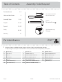 2
2
-
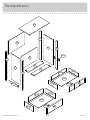 3
3
-
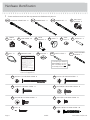 4
4
-
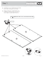 5
5
-
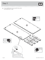 6
6
-
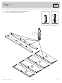 7
7
-
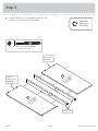 8
8
-
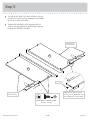 9
9
-
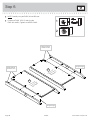 10
10
-
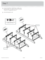 11
11
-
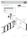 12
12
-
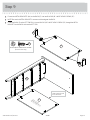 13
13
-
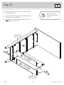 14
14
-
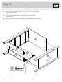 15
15
-
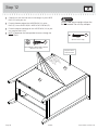 16
16
-
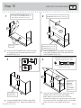 17
17
-
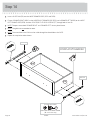 18
18
-
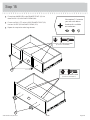 19
19
-
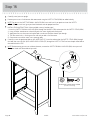 20
20
-
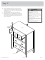 21
21
-
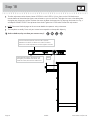 22
22
-
 23
23
-
 24
24
-
 25
25
-
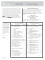 26
26
-
 27
27
-
 28
28
-
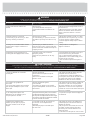 29
29
-
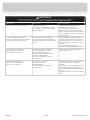 30
30
-
 31
31
-
 32
32


Sauder Shoal Creek Series Instrucciones de operación
- Tipo
- Instrucciones de operación
en otros idiomas
Artículos relacionados
-
Sauder 420566 Instrucciones de operación
-
-
-
-
-
-
-
-
-