APRILIA RS 250 Service and Repair Manual
- Categoría
- Motocicletas
- Tipo
- Service and Repair Manual

RS 250
Manuale d'officina
Manual de taller
Service and repair manual
945W

Las figuras de este manual están puestas al lado del idioma italiano que siempre
precede de una página a la versión traducida (véase el ejemplo).
The pictures in this manual are positioned beside the Italian text, which is always
one page before the translated text (see example).
Ejemplo / Example:
Consultazione.fm Page 1 Monday, April 12, 1999 8:42 AM

This motorcycle is not legal for use on public streets or highways in the United States. This motorcycle is sold as a
racing motorcycle only. It can never be registered for legal use on public streets.
This is an extremely high performance racing motorcycle, and its use on public streets would be both illegal and dan-
gerous. It is not provided with the equipment necessary for safe and legal street use and does not meet U.S. safety,
noise, or emissions standards for street motorcycles.
By accepting possession of this motorcycle the buyer represents that he is expert in the art of race motorcycle prepa-
ration and will permit only experienced, trained professional races to operate this motorcycle in only those locations
where it is legal to do so.
The material in this manual is pertinent to motorcycles similar to the RS 250 Challenge Series, bu not identical.
Therefore, some of the material in this manual will not be applicable to your motorcycle.
There may be operations necessary for the safe and efficient operation of this motorcycle which are not included in
this manual. The manual is presented for guidance only.
If you have any uncertainty whatsoever about any maintenance operation, contact your aprilia Official Dealer.
This manual is intended for use only by persons expert in the arts of motorcycle racing and racing motorcycle mainte-
nance, and therefore does not contain all steps necessary to complete each maintenance operation. It also does not
contain those warnings normally contained in manuals intended for use by the general consumer.
Wide differences in competition use make it impossible for aprilia s.p.a. to set out a maintenance operation schedule.
The owner of this racing motorcycle is responsible for determining when maintenance operations are required.

0
-1
RS 250
INDICE GENERALE
0
INFORMAZIONI GENERALI
1
OPERAZIONI DI MANUTENZIONE
PERIODICA E DI MESSA A PUNTO
2
MOTORE
3
SISTEMA DI ALIMENTAZIONE
E LUBRIFICAZIONE
4
IMPIANTO DI RAFFREDDAMENTO
5
IMPIANTO ELETTRICO
6
TELAIO
7
INFORMAZIONI PER LE RIPARAZIONI
8
AGGIORNAMENTI
9

0
-2
RS 250
–Questo manuale fornisce le informazioni principali per
le procedure di normale intervento.
–Le informazioni e le illustrazioni che compongono que-
sto manuale, sono aggiornate al momento della divul-
gazione del manuale stesso.
Prima di procedere nella consultazione controllare il
modello del veicolo e i relativi aggiornamenti nella se-
zione 9 “AGGIORNAMENTI”.
–Questa pubblicazione è indirizzata ai tecnici del settore;
molte nozioni sono state volutamente omesse, perché
giudicate superflue.
Per eventuali informazioni, interpellare aprilia Consu-
mer Service.
–Per ulteriori informazioni vedi:
–CATALOGO RICAMBI MOTORE, N° 801W
–CATALOGHI RICAMBI “CICLISTICA”:
N° 380 (Modello 1994)
N° 380T (Modello 1995)
N° 380T rel. 01 (Modelli 1995-1996-1997)
N° 381W (Modello 1998)
–Libretto di uso e manutenzione (aprilia part# 8102854)
La ditta aprilia s.p.a. si riserva il diritto di apportare modi-
fiche in qualsiasi momento ai propri modelli, fermo restan-
do le caratteristiche essenziali qui descritte e illustrate.
I diritti di memorizzazione elettronica, di riproduzione e di
adattamento totale o parziale, con qualsiasi mezzo sono
riservati per tutti i Paesi.
La citazione di prodotti o servizi di terze parti è solo a sco-
po informativo e non costituisce nessun impegno.
aprilia s.p.a. non si assume la responsabilità riguardo le
prestazioni o l’uso di questi prodotti.
Prima edizione: 1994
Prodotto da:
Centro commerciale Piero della Francesca -
Fabbricato n° 1/I - Corso Svizzera 185
10149 Torino - Italia
Tel. 011 77 14 640
Fax 011 74 87 66
Seconda edizione: ottobre 1998
Prodotto e stampato da:
Viale del Progresso - 37038 Soave (VR) - Italia
Tel. +39 - 045 76 11 911
Fax +39 - 045 76 12 241
www.stp.it
E-mail: [email protected]
Ristampa:
per conto di:
Via Noalese, 156 - 30036 Santa Maria di Sala (Ve) - Italia
Tel. +39 - 041 5786101
Fax +39 - 041 5786100
www.aprilia.com
NORME PER LA CONSULTAZIONE
–Se non espressamente descritto, il riassemblaggio dei
gruppi segue in senso inverso le operazioni di smontag-
gio.
–Consultare il libretto “USO E MANUTENZIONE” per le
operazioni di normale manutenzione.
SIMBOLOGIA
Osservare scrupolosamente gli avvertimenti preceduti
dalle seguenti simbologie:
Norme e misure di sicurezza che proteggono il
pilota, l’operatore e altre persone da lesioni o
rischi gravi e/o danni al veicolo.
Indicazioni per facilitare lo svolgimento delle
operazioni. Informazioni tecniche.
Le operazioni precedute da questo simbolo de-
vono essere ripetute dal lato opposto del vei-
colo.
In questo manuale le varianti sono indicate con i seguenti
simboli:
versione accensione automatica luci
(Automatic Switch-on Device)
versione potenza libera (Free Power)
opzionale
versione catalitica
VERSIONE:
Italia Olanda Bermuda
Regno Unito Svizzera
Stati Uniti
d’America
Austria Danimarca Australia
Portogallo Giappone Brasile
Finlandia Singapore
Repubblica
del Sud Africa
Belgio Polonia Nuova Zelanda
Germania
Israele
Canada
Francia
Corea del Sud
Ungheria
Spagna Malaysia Slovenia
Grecia Cile

0 -3
RS 250
INDICE GENERAL
0
INFORMACIONES GENERALES
1
OPERACIONES DE MANTENIMIENTO
PERIODICO Y DE PUESTA A PUNTO
2
MOTOR
3
SISTEMAS DE ALIMENTACION Y
LUBRICACION
4
SISTEMA DE REFRIGERACION
5
INSTALACION ELECTRICA
6
CHASIS
7
INFORMACIONES
PARA LAS REPARACIONES
8
ACTUALIZACIONES
9

0 -4
RS 250
– Este manual suministra las informaciones principales
para los procedimientos de intervención corriente.
– Las informaciones y las ilustraciones que forman parte
de este manual, están puestas al día en el momento
de la divulgación del manual mismo.
Antes de consultar el manual, controle el modelo del
vehículo y si acaso la parte puesta al día correspon-
diente, en la sección 9 “ACTUALIZACIÓN”.
– Esta publicación se dirige a los técnicos del sector, por
lo tanto se han omitido voluntariamente muchas opcio-
nes en cuanto las consideramos superfluas.
Para otras informaciones, llame al
aprilia
Consumer
Service
.
– Para otras informaciones véase:
– CATALOGO REPUESTOS MOTOR, N° 801W
– CATALOGO REPUESTOS "PARTE CICLO":
N° 380 (Modelo 1994)
N° 380T (Modelo 1995)
N° 380T rel. 01 (Modelos 1995-1996-1997)
N° 381W (Modelo 1998)
– Manual uso y mantenimiento (aprilia part# 8102854)
La empresa aprilia s.p.a. se reserva el derecho de apor-
tar modificaciones a sus modelos en cualquier momento,
guardando siempre las características esenciales descri-
tas e ilustradas en este manual.
A todos los países se les reserva los derechos de memo-
rización electrónica, de reproducción y de adaptación to-
tal y parcial, con cualquier medio.
El hecho de citar productos o servicios por cuenta ajena
tiene el solo fin de informar y no constituye ningún com-
promiso.
La empresa
aprilia s.p.a.
no se hace cargo de ninguna
responsabilidad en cuanto a las prestaciones o al uso de
estos productos..
Primera edición: 1994
Producido por:
Centro commerciale Piero della Francesca -
Fabbricato n° 1/I - Corso Svizzera 185
10149 Torino - Italia
Tel. 011 77 14 640
Fax 011 74 87 66
Segunda edición: octubre 1998
Producido e impreso por:
Viale del Progresso - 37038 Soave (VR) - Italia
Tel. +39 - 045 76 11 911
Fax +39 - 045 76 12 241
www.stp.it
E-mail: [email protected]
Nueva edición:
por parte de:
Via Noalese, 156 - 30036 Santa Maria di Sala (Ve) - Italia
Tel. +39 - 041 5786101
Fax +39 - 041 5786100
www.aprilia.com
NORMAS PARA LA CONSULTA
– De no estar expresamente descrito, hay que realizar el
reensamblaje de los grupos siguiendo en orden contra-
rio las operaciones que se han efectuado para el des-
montaje.
– Para cada intervención sobre el motor, consulte el ma-
nual específico.
– Consulte el manual "USO Y MANTENIMIENTO" para
las operaciones de mantenimiento corriente.
SIMBOLOS
Observe esmeradamente las advertencias precedidas
por los siguientes símbolos:
Normas y medidas de seguridad que protegen
al piloto, al operador u a otras personas de le-
siones o riesgos graves y/o daños al vehículo.
Indicaciones para facilitar el desarrollo de las
operaciones. Informaciones técnicas.
Hay que repetir las operaciones que están
precedidas por este símbolo en el lado opues-
to del vehículo.
En este manual las variantes están indicadas por los
siguientes símbolos:
versión encendido automático luces
(Automatic Switch-on Device)
versión potencia libre (Free Power)
opcional
versión catalítica
VERSIÓN:
Italia Holanda Bermudas
Reino Unido Suiza
Estados Unidos
de América
Austria Dinamarca Australia
Portugal Japón Brasil
Finlandia Singapur
República
del
Bélgica Polonia Nueva Zelanda
Alemania
Israel
Canadá
Francia
Corea del Sur
Hungría
España Malasia Eslovenia
Grecia Chile

0 -5
RS 250
TABLE OF CONTENTS
GENERAL INFORMATION
1
PERIODIC MAINTENANCE AND
TUNE-UP PROCEDURES
2
ENGINE
3
FUEL AND LUBRICATION SYSTEM
4
COOLING SYSTEM
5
ELECTRICAL SYSTEM
6
CHASSIS
7
SERVICING INFORMATION
8
UPDATES
9

0 -6
RS 250
– This manual supplies the main information for normal
servicing procedures.
– The information and illustrations contained in this man-
ual are updated to the moment of its publication.
Before consulting the manual, check the vehicle model
and the relevant updates in section 9 “UPDATES”.
– This publication is meant for professional mechanics,
therefore many notions have been intentionally omit-
ted, as they were regarded as superfluous.
For any further information, contact
aprilia
Consumer
Service.
– For any further information see:
– ENGINE SPARE PARTS CATALOGUE, N° 801W
– "CHASSIS PARTS" SPARE PARTS CATALOGUE:
N° 380 (Model 1994)
N° 380T (Model 1995)
N° 380T rel. 01 (Models 1995-1996-1997)
N° 381W (Model 1998)
– Use and maintenance manual (aprilia part# 8102854)
aprilia s.p.a.
reserves the right to modify its models at
any time, without prejudice to the main characteristics
here described.
All rights as to electronic storage, reproduction and total
or partial adaptation, with any means, are reserved for all
Countries.
The mention to products or services supplied by third par-
ties is made only for information purposes and is not bind-
ing in any case.
aprilia s.p.a.
takes no responsibility as to the perfor-
mance or the use of said products.
First edition: 1994
Produced by:
Centro commerciale Piero della Francesca -
Fabbricato n° 1/I - Corso Svizzera 185
10149 Torino - Italia
Tel. 011 77 14 640
Fax 011 74 87 66
Second edition: october 1998
Produced and printed by:
Viale del Progresso - 37038 Soave (VR) - Italia
Tel. +39 - 045 76 11 911
Fax +39 - 045 76 12 241
www.stp.it
E-mail: [email protected]
Reprint:
On behalf of:
Via Noalese, 156 - 30036 Santa Maria di Sala (Ve) - Italia
Tel. +39 - 041 5786101
Fax +39 - 041 5786100
www.aprilia.com
ADVICE FOR CONSULTATION
– If not expressly described otherwise, the reassembly of
the groups is to be carried out repeating the disassem-
bly phases in the reverse order.
– For each single operation on the engine, consult the
specific manual.
– For ordinary maintenance, consult the "USE AND
MAINTENANCE” manual.
Remember: 1 mile = 1.6 km
1 km = 0.625 miles
SYMBOLS
Carefully observe the instructions preceded by the fol-
lowing warning signs:
Safety norms and regulations to protect the
pilot, the mechanic and other people from se-
vere injuries or grave risks.
Indications to make the operations easier.
Technical information.
The operations preceded by this symbol must
be repeated on the opposite side of the vehi-
cle.
In this manual the various versions are indicated
by the following symbols:
automatic light switching version
(Automatic Switch-on Device)
Free Power version
optional
catalytic version
VERSION:
Italy Holland Bermuda
United King-
dom
Switzerland
United States
of America
Austria Denmark Australia
Portugal Japan Brazil
Finland Singapore South Africa
Belgium Poland New Zealand
Germany
Israel
Canada
France
South Korea
Hungary
Spain Malaysia Slovenia
Greece Chile

4972/94 - APRILIA - FILE DIVISORI - IT - FR - TED - PAG. 1
1
INFORMAZIONI GENERALI
GENERAL INFORMATION
INFORMACIONES GENERALES

INDICE
POSICION DE LOS NUMEROS
DE SERIE ................................... 1-2
ADVERTENCIAS PARA EL
COMBUSTIBLE, LOS
LUBRICANTES Y EL LIQUIDO
DE REFRIGERACION ................ 1-2
COMBUSTIBLE ........................ 1-2
ACEITE DEL MOTOR ................ 1-2
ACEITE DEL CAMBIO ............... 1-2
ACEITE DE LA HORQUILLA
DELANTERA ............................. 1-4
LIQUIDO DE LOS FRENOS ...... 1-4
LIQUIDO DE
REFRIGERACION ..................... 1-4
NORMAS PARA EL RODAJE ... 1-6
IDENTIFICACION DE LOS
CILINDROS ............................... 1-8
PRECAUCIONES
E INFORMACIONES
GENERALES ............................. 1-8
PIEZAS DE RECAMBIO .......... 1-12
CARACTERISTICAS
TECNICAS ............................... 1-12
DIMENSIONES Y PESOS ....... 1-12
MOTOR ................................... 1-12
TRANSMISION ...................... 1-14
REPOSTAJES ......................... 1-14
CHASIS ................................... 1-14
ENCENDIDO ........................... 1-16
INSTALACION ELECTRICA .... 1-16
INFORMACIONES GENERALES
CONTENTS
SERIAL NUMBER LOCATION
..
1-2
FUEL, LUBRICANT
AND COOLANT
INFORMATION
.........................
1-2
FUEL ......................................... 1-2
ENGINE OIL .............................. 1-2
TRANSMISSION OIL ............... 1-2
FRONT FORK OIL ..................... 1-4
BRAKE FLUID ........................... 1-4
COOLANT ................................. 1-4
BREAKING-IN
PROCEDURES
..........................
1-6
CYLINDER IDENTIFICATION
....
1-8
PRECAUTIONS AND
GENERAL INSTRUCTIONS
......
1-8
REPLACEMENT PARTS
..........
1-12
TECHNICAL
SPECIFICATIONS
...................
1-12
SIZES AND WEIGHTS ............ 1-12
ENGINE .................................. 1-12
TRANSMISSION .................... 1-14
REFUELLING .......................... 1-14
CHASSIS ................................ 1-14
IGNITION ................................ 1-16
ELECTRIC SYSTEM ................ 1-16
GENERAL INFORMATION
1

GENERAL INFORMATION
1 - 2INFORMACIONES GENERALES
POSICION DE LOS NUMEROS DE
SERIE
El número de serie del chasis está marcado sobre
el tubo de la dirección.
SERIAL NUMBER LOCATION
The frame serial number is stamped on the stee-
ring head pipe.
The engine serial number is located on the rear si-
de of the crankcase.
These numbers are required especially for registe-
ring the machine and ordering spare parts.
FUEL, LUBRICANT AND COOLANT
INFORMATION
FUEL
Gasoline used should be graded 91 octane (R.O.N.)
or higher. An unleaded gasoline type is recom-
mended.
ENGINE OIL
Use synthetic oil with ISO-L-ETC++A.P.I. TC++ spe-
cifications for unleaded gasoline. This oil is formu-
lated to give best engine performance with least
combustion chamber deposits, least preignition,
maximum spark plug life and best lubrication.
TRANSMISSION OIL
Use semisynthetic oil for 4-stroke engines with
SAE 20W/50-A.P.I. SG-CCMC G-4 specifications.
El número de serie del motor está situado en la
parte trasera del cárter.
Estos números son necesarios para la matricula-
ción de la motocicleta y para pedir las piezas de re-
cambio.
ADVERTENCIAS PARA EL
COMBUSTIBLE, LOS LUBRICANTES Y
EL LIQUIDO DE REFRIGERACION
COMBUSTIBLE
Se recomienda el empleo exclusivo de gasolina
sin plomo de 91 octanos (R.O.N.).
ACEITE DEL MOTOR
Utilizar aceite sintético con las características ISO-
L-ETC++A.P.I. TC++, especial para gasolina sin plo-
mo.
Este aceite ha sido estudiado para obtener las
máximas prestaciones del motor con menos resi-
duos en la cámara de explosión, menos autoen-
cendidos, máxima duración de las bujías y mejor
lubricación.
ACEITE DEL CAMBIO
Utilizar aceite semisintético para motores de 4
tiempos, con características SAE 20W/50-A.P.I.
SG-CCMC G-4.

GENERAL INFORMATION
1 - 4INFORMACIONES GENERALES
FRONT FORK OIL
Use SAE 10W grade fork oil. At very low or very hi-
gh ambient temperatures, it is possible to use SAE
5W or 20W oils respectively.
BRAKE FLUID
Use brake fluids with DOT4-SAE S1703 specifica-
tions.
WARNING:
●
Do not use or mix different types of fluid for re-
filling the system, otherwise serious damage
will result.
●
Do not use any brake fluid taken from old or
used or unsealed containers.
●
Never re-use brake fluid left over from the
previous servicing and stored for a long pe-
riod.
COOLANT
Use an anti-freeze/coolant compatible with an alu-
minium radiator, mixed with distilled water only,
at the ratio of 50%
.
WATER FOR MIXING
Use distilled water only.
Water other than distilled water can corrode and
clog the aluminium radiator.
ANTI-FREEZE/COOLANT
The coolant performs as a corrosion and rust
inhibitor as well as an anti-freeze.
Therefore, the coolant should be used at all times
even through the atmospheric temperature in your
area does not go down to freezing point.
REQUIRED AMOUNT OF WATER/COOLANT
Solution capacity (total): 1,9 litres.
CAUTION:
Mixing of anti-freeze/coolant should not exceed a
ratio of 60%. Mixing beyond it would reduce its ef-
ficiency. If the anti-freeze/coolant mixing ratio is
below 50%, the rust inhibiting performance is
greatly reduced. Be sure to mix the solution at
50%, even though the atmospheric temperature
does not go down to freezing point.
ACEITE DE LA HORQUILLA DELANTERA
Usar un aceite para horquillas con una graduación
SAE 10W. Con temperatura ambiente muy baja o
muy alta, se puede usar aceite para horquillas con
graduación respectivamente SAE 5W o 20W.
LIQUIDO FRENOS
Usar un líquido para sistemas frenantes, con ca-
racteristicas DOT4-SAE S1703.
ATENCION:
●
No utilizar líquidos que no estén recomenda-
dos y no mezclar líquidos diferentes durante el
llenado, para no dañar seriamente el sistema
frenante.
●
No utilizar líquidos de recipientes viejos o
abiertos anteriormente.
●
No usar líquidos que hayan sobrado en repara-
ciones anteriores, si ha pasado mucho tiempo.
LIQUIDO DE REFRIGERACION
Utilizar un anticongelante/líquido de refrigeración
adecuado para radiadores de aluminio, mezclado
exclusivamente con agua destilada con la propor-
ción del 50%.
AGUA PARA LA MEZCLA
Utilizar exclusivamente agua destilada.
Otros tipos de agua pueden corroer u obturar el ra-
diador de aluminio.
ANTICONGELANTE/LIQUIDO DE
REGFRIGERACION
El líquido de refrigeración tiene la función de im-
pedir la corrosión y la oxidación, tanto como el an-
ticongelante.
Por éso, tiene que usarse de manera permanente
aunque la temperatura no descienda hasta el pun-
to de congelación.
CAPACIDAD DEL CIRCUITO DE
REFRIGERACION
La cantidad total de la mezcla agua/liquido de refri-
geración es de 1,9 l.
ADVERTENCIA:
La mezcla anticongelante/líquido de refrigeración
no tiene que superar el 60%. Una mezcla que su-
pere este valor disminuye su propia eficacia. Si la
relación de la mezcla anticongelante/líquido de
refrigeración es inferior al 50%, las propiedades de
antioxidación disminuyen notablemente Verifi-
quen que la mezcla de la solución sea al 50%, aun-
que la temperatura ambiente no descienda por de-
bajo del punto de congelación.

GENERAL INFORMATION
1 - 6INFORMACIONES GENERALES
BREAKING-IN PROCEDURES
During manufacture only the best possible ma-
terials are used and all machined parts are finish-
ed to a very high standard, but it is still necessary
to allow the moving parts to "BREAK-IN" before
subjecting the engine to maximum stresses. The
future performance and reliability of the engine
depends on the care and restraint exercised during
its early life.
The general rules are as follows:
●
Do not exceed these engine speeds:
NORMAS PARA EL RODAJE
Para esta motocicleta se han utilizado los mejores
materiales actualmente a disposición y todas las
piezas han sido acabadas con una precisión muy
elevada, pero de todas formas, es necesario que
las piezas en movimiento se " AJUSTEN" antes de
que podamos pedir al motor sus máximas presta-
ciones. Las prestaciones futuras y la duración del
motor dependen del cuidado y de las precauciones
que se tienen durante el primer periodo de uso.
Las normas generales son las siguientes:
●
No hay que superar estos límites de revolucio-
nes del motor:
Initial 800 km below 6.000 rpm
Up to 1.600 km below 9.000 rpm
Over 1.600 km below 12.000 rpm
●
Una vez alcanzados los 1.600 kms, se puede
utilizar el motor al máximo de sus prestacio-
nes. De todas maneras, no hay que superar
nunca las 12.000 rpm.
●
Upon reaching an odometer reading of 1.600
km you can subject the motorcycle to full
throttle operation.
However, do not exceed 12.000 rpm at any
time.
Primeros 800 kms menos de 6.000 rpm
Hasta 1.600 kms menos de 9.000 rpm
Después de 1.600 kms menos de 12.000 rpm

GENERAL INFORMATION
1 - 8INFORMACIONES GENERALES
CYLINDER IDENTIFICATION
The two cylinders of this engine are identified as
Left and Right cylinder, as shown in the photo-
graph (as viewed by the rider on the seat).
IDENTIFICACION DE LOS CILINDROS
Los dos cilindros del motor se identifican con L pa-
ra el cilindro izquierdo y R para el derecho (vistos
por el conductor desde el sillín), como se ilustra.
PRECAUTIONS AND GENERAL
INSTRUCTIONS
Observe the following items without fail when
servicing, disassembling and reassembling the
motorcycle.
❑
Do not run the engine indoors with little or no
ventilation.
❑
Be sure to replace packings, gaskets, circlips,
O-rings (OR) and cotter pins with new ones.
CAUTION:
Never reuse a circlip. After a circlip has been
removed from a shaft, it should be discarded and a
new circlip must be installed.
When installing a new circlip, care must be taken
not to expand the end gap larger than required to
slip the circlip over the shaft.
After installing a circlip, always ensure that it is
completely seated in its groove and securely
fitted.
❑
Tighten cylinder head and case bolts and nuts
to the specified tightening torque beginning
with larger diameter and ending with smaller
diameter, and from inside to outside diagonal-
ly.
❑
Use special tools where specified.
❑
Use genuine parts and recommended oils.
❑
When 2 or more persons work together, pay
attention to the safety of each other.
❑
After the reassembly, check parts for tightness
and operation.
❑
Treat gasoline, which is extremely flammable
and highly explosive, with greatest care. Never
use gasoline as a cleaning solvent.
PRECAUCIONES E INFORMACIONES
GENERALES
Cuando se realiza le reparación, el desmontaje y el
montaje de la motocicleta, hay que atenerse a las
recomendaciones siguientes:
❑
No hay que dejar en marcha el motor en luga-
res cerrados o poco ventilados.
❑
Hay que substituir siempre las juntas, retenes,
los anillos elásticos, los anillos tóricos (OR) y
las clavijas con otros nuevos.
ADVERTENCIA:
No hay que re-utilizar nunca un anillo elástico.
Cuando se desmonta de un eje hay que tirarlo y
substituirlo con uno nuevo.
Cuando se monta un anillo elástico nuevo, hay
que tener cuidado en separar sus extremidades lo
mínimamente necesario para introducirlo en el
eje.
Después del montaje de un anillo elástico, hay que
verificar siempre que esté bien encajado en su
alojamiento.
❑
Apretar los tornillos y las tuercas de la culata y
del cárter al par de apriete establecido, empe-
zando por los de diámetro mayor y acabando
por los de diámetro menor, procediendo de
manera diagonal, desde el interior hacia el ex-
terior.
❑
Usar las herramientas especiales para cada
ocasión.
❑
Usar solamente piezas de recambio originales
y lubricantes recomendados.
❑
Cuando dos o más personas trabajan al mismo
tiempo, hay que prestar atención a la seguri-
dad de cada una de ellas.
❑
Después del remontaje, hay que verificar el
apriete y el funcionamiento de las piezas.
❑
Manejar la gasolina, que es muy inflamable y
explosiva, con mucho cuidado. No utilizar nun-
ca gasolina como disolvente para la limpieza
de la motocicleta.

GENERAL INFORMATION
1 - 10INFORMACIONES GENERALES
WARNING, CAUTION and
NOTE
are included in
this manual occasionally, describing the following
contents:
WARNING:
The personal safety of the rider or bystanders may
be involved. Disregarding this information could
result in personal injury.
CAUTION:
These instructions point out special service
procedures or precautions that must be followed
to avoid damaging the machine.
NOTE:
This provides special information to make
maintenance easier or important instructions clea-
rer.
En este manual, todos los textos que estén antece-
didos por las palabras ATENCION, ADVERTENCIA
y
NOTA
, tienen el significado siguiente:
ATENCION:
La seguridad personal del piloto y de las personas
presentes puede estar en peligro. Si no se respe-
tan las informaciones indicadas, se pueden origi-
nar lesiones personales.
ADVERTENCIA:
Las instrucciones indicadas describen los procedi-
mientos o las precauciones que hay que adoptar
para evitar daños en la motocicleta.
NOTA:
Las informaciones facilitan las operaciones de
mantenimiento o permiten una comprensión
mejor de las instrucciones más importantes.

GENERAL INFORMATION
1 - 12INFORMACIONES GENERALES
REPLACEMENT PARTS
When you replace any parts, use only genuine
APRILIA replacement parts. Genuine APRILIA
parts are high quality parts which are designed
and built specifically for APRILIA vehicles.
CAUTION:
The use of spare parts that are not APRILIA origi-
nals may cause problems of performance and
even damage.
TECHNICAL SPECIFICATIONS
NOTE:
Technical specifications may vary without prior
warning.
SIZES AND WEIGHTS
Max length ................................................1.980 mm
Max width ...................................................690 mm
Max height (front cowling).......................1.090 mm
Height (seat)................................................ 810 mm
Wheelbase ................................................1.370 mm
Min. ground clearance.................................135 mm
Steering diameter.................................... 4.090 mm
Weight without fuel and oil............................141 kg
Max load
(driver+passenger+luggage).........................160 kg
Seats .......................................................................2
ENGINE
Type........... 2V 90° cylinders, 2-stroke with lamella
suction and exhaust valve.
Separate lubrication with
variable automatic mixer
(0,9 ÷ 2%). Liquid cooling.
N° cylinders (V 90°) ................................................ 2
Total displacement ........................................ 249 cc
Bore x stroke ......................................56 x 50,6 mm
Compression ratio ..............................12,00 ± 0,7 : 1
Starting ...................................................... kick-start
Carburettors ............................ 2 MIKUNI TM 34 SS
Air filter ............... with polyurethane filter element
Lubrication system ...................................oil pump
with separate circuit
Cooling system ............................ liquid with pump
PIEZAS DE REPUESTO
En caso de substituciones, utilizar solamente pie-
zas de repuesto originales APRILIA. Las piezas de
repuesto originales APRILIA son de alta calidad y
han sido creadas y construídas especialmente pa-
ra las motocicletas APRILIA.
ADVERTENCIA:
El uso de piezas de repuesto no originales APRILIA
puede causar problemas en las prestaciones o
daños.
CARACTERISTICAS TECNICAS
NOTA:
Las características técnicas pueden variar sin aviso
previo.
DIMENSIONES Y PESOS
Longitud máxima .................................... 1.980 mm
Anchura máxima ........................................ 690 mm
Altura máxima en la cúpula .................... 1.090 mm
Altura en el sillín ......................................... 810 mm
Distancia entre ejes ................................. 1.370 mm
Altura libre mínima desde el suelo ........... 135 mm
Diámetro de giro ..................................... 4.090 mm
Peso en seco .................................................. 141 kg
Carga máxima de la motocicleta
(piloto + pasajero + equipaje) ....................... 160 kg
Número de plazas .................................................. 2
MOTOR
Tipo .............. Bicilídrico en V de 90°, 2 tiempos con
aspiración laminar y válvula en el
escape. Lubricación separada con
mezclador automático con capaci-
dad variable (0,9 ÷ 2%). Refrigera-
ción con líquido.
Número de cilindros (en V de 90°) ........................ 2
Cilindrada total ............................................ 249 cm
3
Diámetro interior y carrera ................ 56 x 50,6 mm
Relación de compresión ................... 12,00 ± 0,7 : 1
Arranque ...................................................... a pedal
Carburadores ...................... n° 2 MIKUNI TM 34 SS
Filtro aire ... con elemento filtrante de poliruretano
Sistema de lubricación ........ bomba del aceite con
circuito separado
Sistema de refrigeración .... de líquido con bomba

GENERAL INFORMATION
1 - 14INFORMACIONES GENERALES
TRANSMISSION
Clutch .................................. oil bath, multiple-disc,
with lever control on handlebars
Gear box.................................. 6-speed, direct drive
Gear change ........................ with pedal (L), 1st low,
other 5 high
Primary reduction..................... Z = 23/59 (1 : 2,565)
Secondary reduction (chain).... Z = 14/42 (1 : 3,000)
Total ratio (engine/wheel) ..........................1 : 6,464
Gear ratios............................1st-Z = 11/27 (1 : 2,454)
2nd-Z = 16/26 (1 : 1,625)
3rd-Z = 21/17 (1 : 1,235)
4th-Z = 22/23 (1 : 1,045)
5th-Z = 24/22 (1 : 0,916)
6th-Z = 25/21 (1 : 0,840)
Chain ............................................. sealed, jointless,
DID model 520 V6
REFUELLING
Fuel tank capacity
(including reserve)............................................16,5 l
Reserve............................................................... 3,5 l
Type of fuel.............. lead-free petrol R.O.N. min 95
Fork oil ......................420 cc (left tube with spring);
the right tube with hydraulic brake has to be
filled up to 6 cm from edge (with inner tube fully
compressed and cartridge fitted)
Gear oil ............................................................... 0,7 l
Oil mixer (reserve included)...............................1,6 l
Oil mixer reserve................................................ 0,6 l
Coolant .........................1,9 l (0,95 l distilled water +
0,95 l coolant)
CHASSIS
Type..................................... double-beam with cast
...........................elements and stamped steel sheet
Drive inclination angle .................................. 25°30'
Forward stroke ........................................... 102 mm
Front suspension .............adjustable telehydraulic
fork with helical spring
and upside-down tubes,
travel 120 mm
Rear suspension ............................ rocker arm with
adjustable hydraulic
single shock absorber,
wheel travel 130 mm
Front brake ...................... twin disc Ø 298 mm with
hydraulic circuit
Rear brake ................................ Ø 220 mm disc with
hydraulic circuit
Rims (light alloy) ........................... front: 3.00" x 17"
rear: 4.50" x 17"
Front tyre..............................................110/70 ZR17"
Rear tyre...........................................150/60 ZR17" or
160/60 ZR17"
Inflation pressure (cold) ...................... front 1,9 bar
rear 2,2 bar
TRANSMISION
Embrague ................................ de discos múltiples
en baño de aceite con
mando de palanca en el manillar
Cambio .................. de 6 marchas siempre de toma
Accionamiento
del cambio ............. con pedal en el lado izquierdo,
la primera hacia abajo, las otras
5 marchas hacia arriba.
Reducción primaria .................. Z = 23/59 (1 : 2,565)
Reducción secundaria
(de cadena) ............................... Z = 14/42 (1 : 3,000)
Relación total (motor/rueda) ..................... 1 : 6,464
Relaciones del cambio ........1ª - Z = 11/27 (1 : 2,454)
2ª - Z = 16/26 (1 : 1,625)
3ª - Z = 21/17 (1 : 1,235)
4ª - Z = 22/23 (1 : 1,045)
5ª - Z = 24/22 (1 : 0,916)
6ª - Z = 25/21 (1 : 0,840)
Cadena ......................................... sellada, sin junta
marca DID modelo 520 V6
REPOSTAJES
Capacidad del depósito del combustible
(incluída la reserva) ......................................... 16,5 l
Reserva de combustible ................................... 3,5 l
Tipo de combustible ............... gasolina sin plomo,
número de octanos (R.ON.) mín. 95
Aceite de la horquilla .......420 cm
3
(barra jequierda
con muelle); la barra derecha con freno
hidraùlico debe ser 6 cm de borde llena
da hasta unos (con barra completamente
compirmida y cartucho accionado)
Aceite del cambio .............................................. 0,7 l
Aceite del mezclador (incluído la reserva) ....... 1,6 l
Reserva de aceite de mezcla ............................. 0,6 l
Líquido de refrigeración ............... 1,9 l (0,95 l agua
destilada + 0,95 l líquido refrigerante)
CHASIS
Tipo ................................ bilarguero con elementos
fundidos de chapa estampada
Angulo de inclinación de la dirección ......... 25° 30’
Lanzamiento ............................................... 102 mm
Suspensión delantera .............horquilla hidráulica
con muella helicoidal y
barras invertidas, regulable,
carrera 120 mmm
Suspensión trasera ............ horquilla oscilante con
monoamortiguador hidráulico
regulable, carrera de la rueda 130 mm
Freno delantero ............ de doble disco D. 298 mm,
con circuito hidráulico
Freno trasero...........................de disco D. 220 mm,
con circuito hidráulico
Llantas (de aleación ligera).. delantera: 3.00” x 17”
trasera: 4.50” x 17”
Neumático delantero ......................... 110/70 ZR17”
Neumático trasero .................. 150/60 ZR17” o bien
160/60 ZR17”
Presión de hinchado (en frío) ...... delantera 1,9 bar
trasera 2,2 bar

GENERAL INFORMATION
1 - 16INFORMACIONES GENERALES
IGNITION
Type .................................................................... CDI
Advance ......................... 14 ° B.T.D.C. at 1.300 rpm
Standard spark plug ......................... NGK BR9ECM
Spark plug with lower
thermal degree ................................. NGK BR8ECM
Spark plug with higher
thermal degree ............................... NGK BR10ECM
Gap between spark plug electrodes... 0,7 ÷ 0,8 mm
Idle speed ........................................1.300 ± 150 rpm
ELECTRIC SYSTEM
Battery.......................................................12V – 4Ah
Fuses .................................................. 20 – 15 – 7,5A
Generator ............................................... 12V –180W
Lamp
Dipped beam .................................12V – 55W H1
High beam .....................................12V – 55W H3
Parking light ..........................................12V – 5W
Turn indicators....................................12V – 10W
Rear parking/brake ..........................12V – 5/21W
Numberplate light ................................12V – 5W
Tachometer light ..................................12V – 2W
Rev counter lighting .............................12V – 2W
Multifunction computer
display lighting .....................................12V – 2W
Warning lights
Neutral...................................................12V – 2W
High beam ............................................12V – 2W
Parking light .......................................12V – 1,2W
Turn indicators .....................................12V – 2W
Oil mixer level ....................................... Red LED
ENCENDIDO
Tipo ..................................................................... CDI
Avance del encendido ............ 14° antes del P.M.S.
a 1.300 rpm
Bujía standard .................................. NGK BR9ECM
Bujía con grado térmico
inferior .............................................. NGK BR8ECM
Bujía con grado térmico
superior ........................................... NGK BR10ECM
Distancia entre los
electrodos bujía .................................. 0,7 ÷ 0,8 mm
Régimen del motor
al ralentí ......................................... 1.300 ± 150 rpm
INSTALACION ELECTRICA
Batería ...................................................... 12V – 4Ah
Fusibles ............................................... 20 –15 – 7,5A
Generador ............................................. 12V – 180W
Lámparas
De cruce ........................................ 12V – 55W H1
De carretera .................................. 12V – 55W H3
Posición ............................................... 12V – 5W
Indicadores de dirección ................... 12V – 10W
Posición/freno trasero .................... 12V – 5/21W
Iluminación de la matricula ................ 12V – 5W
Iluminación velocímetro ..................... 12V – 2W
Iluminación cuentarevoluciones ........ 12V – 2W
Iluminación display ordenador
multifunción ..........................................12V - 2W
Testigos
Punto muerto ....................................... 12V – 2W
De carretera ......................................... 12V – 2W
De posición ....................................... 12V – 1,2W
Indicadores de dirección ..................... 12V – 2W
Nivel del aceite del mezclador .... Diodo led rojo

2
OPERAZIONI DI MANUTENZIONE
PERIODICA E DI MESSA A PUNTO
PERIODIC MAINTENANCE AND
TUNE-UP PROCEDURES
OPERACIONES DE MANTENIMIENTO
PERIODICO Y DE PUESTA A PUNTO

INDICE
PLAN DE MANTENIMIENTO
PERIODICO ............................... 2-5
PUNTOS A LUBRICAR ............. 2-6
OPERACIONES DE
MANTENIMIENTO Y
DE PUESTA A PUNTO ............. 2-8
BATERIA ...................................2-8
PERNOS Y TUERCAS
DEL MOTOR ............................. 2-8
TUERCAS DE LA CULATA ....... 2-8
TUERCAS DE LOS
COLECTORES DE ESCAPE .... 2-10
CULATA, CILINDRO Y
LUMBRERA DE ESCAPE ....... 2-10
FILTRO DE AIRE ..................... 2-10
BUJÍAS ................................... 2-12
CARBURADORES...................2-16
CABLE DEL ACELERADOR .... 2-16
REGULACION DE RALENTÍ ... 2-18
CABLE DEL STARTER ............ 2-18
TUBOS DEL COMBUSTIBLE . 2-18
BOMBA DEL MEZCALDOR ... 2-20
EMBRAGUE ........................... 2-22
ACEITE DEL CAMBIO ............ 2-22
SISTEMA DE
REFRIGERACION ................... 2-24
CADENA DE TRANSMISION . 2-26
FRENOS.................................. 2-30
NEUMATICOS ........................ 2-36
SILENCIADORES TUBOS
DE ESCAPE ............................ 2-36
DIRECCION ............................ 2-38
HORQUILLA............................2-38
SUSPENSION TRASERA ....... 2-38
APRIETE DE TORNILLOS
Y TUERCAS DEL CHASIS ...... 2-41
OPERACIONES DE MANTENIMIENTO
PERIODICO Y DE PUESTA A PUNTO
CONTENTS
PERIODIC MAINTENANCE
SCHEDULE ............................... 2-3
LUBRICATION POINTS ............ 2-4
MAINTENANCE AND
TUNE-UP PROCEDURES ......... 2-8
BATTERY ..................................2-8
ENGINE BOLTS AND NUTS .... 2-8
CYLINDER HEAD NUTS .......... 2-8
EXHAUST MANIFOLD NUTS . 2-10
CYLINDER HEAD, CYLINDER
AND MUFFLER ...................... 2-10
AIR FILTER .............................. 2-10
SPARK PLUGS ....................... 2-12
CARBURETTORS ................... 2-16
THROTTLE CABLE.................. 2-16
IDLE SPEED ADJUSTMENT .. 2-18
CHOKE CABLE........................ 2-18
FUEL HOSES .......................... 2-18
MIXER PUMP ......................... 2-20
CLUTCH ................................. 2-22
GEAR OIL ............................... 2-22
COOLING SYSTEM ............... 2-24
DRIVE CHAIN ......................... 2-26
BRAKES ................................. 2-30
TYRES..................................... 2-36
EXHAUST PIPE
SILENCERS ............................ 2-36
STEERING .............................. 2-38
FRONT FORK ......................... 2-38
REAR SUSPENSION .............. 2-38
CHASSIS BOLTS AND
NUTS TIGHTENING .............. 2-40
PERIODIC MAINTENANCE AND
TUNE-UP PROCEDURES
2

PERIODIC MAINTENANCE SCHEDULE
The chart below lists the recommended intervals for all the required periodic service work necessary to
keep the motorcycle operating at peak performance and economy. Mileages are expressed in terms of kilo-
meters.
PERIODIC MAINTENANCE CHART
2 - 3 PERIODIC MAINTENANCE AND TUNE-UP PROCEDURES
Checking operations
After running-in Every 4.000 km Every 8.000 km
(1.000 km or 4 months) or 8 months or 16 months
Battery fluid level C C
Spark plugs P P every 6.000 km: S
Carburettors C P
Drive chain C every 1.000 km: P/every 4.000 km: C
Wheels centering C
Steering bearings and steering C C
Wheel bearings C
Air filter P every 12.000 km: S
Clutch play R R
Braking systems C C
Cooling system C C
Lighting system C C
Coolant every 2 years: S
Brake fluid every year: S
Mixer oil level every 500 km: C
Front fork oil every 12.000 km: S
Transmission oil S C every 12.000 km: S
Mixer pump and air bleeding R R
Tyres inflation pressure every mounth: R
Minimum rpm R R
Fuel tap C C
Nut, bolt, screw tightening C C
Suspensions and attitude C C
Brake fluid drain C
Drive chain tension and lubrication every 500 km: C
Fuel pipes C every 4 years: S
Pistons and rings every 8.000 km: C/every16.000 km: S
Exhaust pipe silencers P P
Kick starter pivot every 8.000 km: C (water-repellent grease)
C = check, clean, adjust, lubricate or replace as necessary
P = clean S = replace R = adjust
Carry out the maintenance operations more frequently if you use the motorcycle in rainy and dusty areas or on
uneven roads.
Remember:
1 mi = 1,6 km
1 km = 0,625 mi

PERIODIC MAINTENANCE AND TUNE-UP PROCEDURESM2 - 4
LUBRICATION POINTS
Proper lubrication is important for smooth operation and long life of each working part of the motorcycle.
NOTE:
●
Before lubricating each part, clean off any rusty spots and wipe off any grease, oil, dirt or grime.
●
Lubricate exposed parts which are subject to rust, with motor oil or grease.
Exhaust valves
control cable
Brake lever holder
Throttle
cable
Throttle
grip
Rear brake link pivots
G
O
Grease
Oil
O
O
O
G
G
G
O
G
O
Clutch lever holder
G
Swingarm pivot
G
O
Speedometer
cable
Speedometer
gearbox
G
Gearshifting
link pivots
Side stand
pivot
Drive
chain
Steering
stem bearing
G
Kick starter pivot

PLAN DE MANTENIMIENTO PERIODICO
El plan de mantenimiento indicado más adelante, indica los espacios de tiempo recomendados, necesarios
para las operaciones de mantenimiento periódico para mantener la motocicleta en las mejores condiciones
de funcionamiento y de economía de uso. Las distancias están expresadas en kilómetros.
ESQUEMA DE MANTENIMIENTO PERIODICO
2 - 5MOPERACIONES DE MANTENIMIENTO PERIODICO Y DE PUESTA A PUNTO
Operaciones de control
Final del rodaje Cada 4.000 kms Cada 8.000 kms
(1.000 kms o 4 meses) o 8 meses o 16 meses
Batería - nivel del líquido C C
Bujías P P cada 6.000 kms: S
Carburadores C P
Cadena C cada 1.000 kms: P/cada 4.000 kms: C
Centrado de las ruedas C
Cojinetes de dirección y dirección C C
Cojinetes de las ruedas C
Filtro de aire P cada 12.000 kms: S
Juego del embrague R R
Sistemas de frenos C C
Sistema de refrigeración C C
Sistema de luces C C
Líquido de refrigeración cada dos años: S
Líquido de frenos cada año: S
Nivel del aceite del mezclador cada 500 kms: C
Aceite de la horquilla cada 12.000 kms: S
Aceite del cambio S C cada 12.000 kms: S
Bomba del mezclador y purga de aire R R
Presión neumáticos cada mes: R
Ralentí R R
Grifo del combustible C C
Apriete de tuercas C C
Suspensiones y equilibrado C C
Purgación del líquido de los frenos C
Tensión y lubricación de la cadena cada 500 kms: C
Tubos del combustible C cada 4 años: S
Pistones y segmentos cada 8.000 kms: C/cada 16.000 kms: S
Silenciadores tubos de escape P P
Perno pedal de arranque cada 8.000 kms: C (con grasa hidrorrepelente)
C = controlar y limpiar, regular, lubricar o substituir si es necesario
P = limpiar S = substituir R = regular
Realizar las operaciones de mantenimiento con mayor frecuencia, si la motocicleta se utiliza en zonas lluviosas, con
mucho polvo o en recorridos muy accidentados.

2 - 6
PUNTOS A LUBRICAR
Una lubricación correcta es muy importante para un buen funcionamiento y para una larga duración de las
partes que están en movimiento de la motocicleta.
NOTA:
●
Antes de lubricar, limpiar completamente todas las partes que tengan puntos de oxidación, quitar toda
la grasa, la suciedad y el polvo.
●
Las partes que están muy expuestas a la oxidación, tienen que ser lubricadas con aceite del motor o
grasa.
Cable accionamiento
válvulas en el escape
Perno palanca freno
Cable
acelerador
Puño
acelerador
G
O
Grasa
Aceite
O
O
O
G
G
G
O
G
O
Pernos palanca
embrague
G
Perno horquilla trasera
G
O
Cable taquímetro
Toma taquímetro
G
Pernos
palanca cambio
Perno
caballete
Cadena de
transmisión
Cojinetes
dirección
OPERACIONES DE MANTENIMIENTO PERIODICO Y DE PUESTA A PUNTO
Pernos pedal freno
G
Perno pedal de arranque

●
Quitar el sillín del piloto.
●
Controlar con el tester portátil la tensión de la
batería. Si la tensión es inferior a 12,0V, la ba-
tería tiene que ser recargada.
Tensión de la batería: superior a 12,0V
●
Desconectar los cables 0–0 y 0+0 de la batería,
quitar el elástico y extraer la batería de su
alojamiento.
ADVERTENCIA:
Para el mantenimiento de la batería hay que hacer
referencia al capítulo "INSTALACION ELECTRI-
CA".
NOTA:
La tensión de la batería se puede detectar con el
ordenador multifunción instalado en la motocicle-
ta (veáse el libro de Uso y Mantenimiento).
2 - 8
MAINTENANCE AND TUNE-UP
PROCEDURES
This section describes the service procedures for
the main section of periodic maintenance.
●
Remove the driving seat.
●
Check the battery voltage with a pocket tester.
If the voltage reading is below 12,0V, this
battery needs recharging.
Battery voltage: above 12,0V
●
Remove the battery 0–0and 0+0 lead wires and
the elastic and extract the battery from the fra-
me.
CAUTION:
Read the "ELECTRICAL SYSTEM", for servicing
the battery.
NOTE:
It is possible to check battery voltage using the
multifunction computer installed on the cycle (see
Owner's Manual).
CYLINDER HEAD NUTS
●
Remove the lower fairings.
●
First loosen nuts by 1/4 turn and tighten the
cylinder nuts to the specified torque in ascen-
ding numerical order as shown in the illustra-
tion.
Nut tightening torque: 23 – 27 Nm (2,3 – 2,7 kgm)
OPERACIONES DE MANTENIMIENTO
Y DE PUESTA A PUNTO
Esta sección describe las modalidades de inter-
vención para las principales partes del manteni-
miento periódico.
BATTERY
ENGINE BOLTS AND NUTS
Inspect at initially 1.000 km (or 4 months)
and every 4.000 km (or 8 months).
Tighten at initially 1.000 km (or 4 months)
and every 4.000 km (or 8 months).
PERIODIC MAINTENANCE AND
TUNE-UP PROCEDURES
OPERACIONES DE MANTENIMIENTO
PERIODICO Y DE PUESTA A PUNTO
BATERIA
Verificar después de los primeros 1.000
kms (o 4 meses) y después cada 4.000 kms
(o 8 meses).
PERNOS Y TUERCAS DEL MOTOR
Apretar después de los primeros 1.000 kms
(o 4 meses) y después cada 4.000 kms (o 8
meses).
TUERCAS DE LA CULATA
●
Desmontar el carenado inferior.
●
Apretar las tuercas inicialmente 1/4 de vuelta y
sucesivamente al par establecido, siguiendo
un orden creciente de los números, como se
ilustra en la figura.
Par de apriete de las tuercas:
23 - 27 Nm (2,3 - 2,7 kgm)

●
Quitar el sillín del piloto.
●
Quitar el depósito del combustible.
●
Quitar la tapa de la caja del filtro, desenroscan-
do los 8 tornillos.
●
Extraer el elemento filtrante y la redecilla.
●
Lavar 010 el elemento filtrante con disolventes
adecuados limpios, no inflamables o con alto
índice de volatilidad, y secarlo 020 con cuida-
do.
●
Aplicar 030 sobre toda la superficie un aceite
para filtros, escurrirlo bien 040 para eliminar el
aceite excesivo. El elemento filtrante debe
estar bien impregnado, pero no tiene que go-
tear.
●
Volver a poner el elemento filtrante en su aloja-
miento con la redecilla y volver a montar la ta-
pa de la caja del filtro.
PERIODIC MAINTENANCE AND
TUNE-UP PROCEDURES
2 - 10
EXHAUST MANIFOLD NUTS
●
Tighten the exhaust pipe nuts to the specified
torque.
Tightening torque: 18 – 28 Nm (1,8 – 2,8 kgm)
●
Remove the driving seat.
●
Remove the fuel tank.
●
Remove the filter case cover, loosening the 8
screws.
●
Remove the air filter element and the grid.
●
Wash 010 air filter element with suitable clean
solvents, non-inflammable and with a low vo-
latility level, and then allow to dry 020 throrou-
ghly.
●
Apply 030 a filter oil all over the surface, then
wring 040 to eliminate all excess oil. The filter
element must be well soaked but must not
drip.
●
Replace the filter element in its housing with
the grid and reassemble the filter case cover.
AIR FILTER
●
Carbon deposits in the combustion chamber of
the cylinder head and at the piston crown will
raise the compression ratio and may cause
preignition or overheating.
●
Carbon deposited at the exhaust port of the
cylinder will prevent the flow of exhaust gas,
reducing the output. Remove carbon deposits
periodically.
CYLINDER HEAD, CYLINDER AND
MUFFLER
TUERCAS DE LOS COLECTORES DE ESCAPE
●
Apretar las tuercas de los colectores de escape
al par establecido.
Par de apriete: 18 – 28 Nm (1,8 – 2,8 kgm)
Clean every 6.000 km (or 12 months).
Clean every 4.000 km. Change every 12.000
km.
OPERACIONES DE MANTENIMIENTO
PERIODICO Y DE PUESTA A PUNTO
CULATA, CILINDRO Y LUMBRERA DE
ESCAPE
Limpiar las incrustaciones cada 6.000 kms
(o 12 meses).
●
Los depósitos carbonosos en las cámaras de
combustión de las culatas y de las cabezas de
los pistones aumentan la relación de compre-
sión y pueden causar autoencendidos y reca-
lentamientos.
●
Los depósitos carbonosos acumulados en las
lumbreras de descarga impiden la salida de los
gases de escape, causando una pérdida de po-
tencia. Deben ser eliminados con regularidad.
FILTRO DEL AIRE
Limpiar cada 4.000 kms. Substituir cada
12.000 kms.

2 - 12
CAUTION:
●
Before and during the cleaning operation,
inspect the element for tears. A torn element
must be replaced.
●
Be sure to position the element snugly and
correctly, so that no incoming air will bypass
it. Remember, rapid wear of piston rings and
cylinder bore is often caused by a defective or
poorly fitted element.
CAUTION:
If driving under dusty conditions, clean the air
cleaner element more frequently. The surest way
to accelerate engine wear is to use the engine
without the element or to use a ruptured element.
Make sure that the air cleaner is in good condition
at all times. Life of the engine depends largely on
this component!
ADVERTENCIA:
●
Antes y durante las operaciones de limpieza
del elemento filtrante, hay que verificar que no
hayan desgarraduras. En caso contrario, sub-
stituir el elemento filtrante.
●
Cercionarse de que el elemento filtrante esté
colocado correctamente, de manera que no
deje pasar el aire no filtrado. No olvidar que el
desgaste precoz de los segmentos de los pisto-
nes y de los cilindros suele estar causado por un
elemento filtrante defectuoso o mal colocado.
ADVERTENCIA:
Si se utiliza la motocicleta en zonas muy polvo-
rientas, limpiar el elemento filtrante con más fre-
cuencia. El empleo della motocicleta sin el ele-
mento filtrante o con uno que esté dañado, au-
menta de manera muy notable el desgaste del
motor. Hay que cercionarse de que el elemento fil-
trante esté siempre en perfectas condiciones.¡ La
duración del motor depende en gran medida de
esta pieza!
SPARK PLUGS
Inspect at initially 1.000 km (or 4 months)
and replace every 6.000 km.
●
Remove the driving seat.
●
Remove the fuel tank.
●
Take off the spark plug caps.
●
Remove the spark plugs.
The plug gap is adjusted to 0,7 – 0,8 mm. The gap
is correclty adjusted using a thickness gauge.
When carbon is deposited on the spark plug, re-
move the carbon with a spark plug cleaning machi-
ne or by carefully using a tool with a pointed end.
If electrodes ar extremely worn or burnt, replace
the plug. Also replace the plug if it has a broken in-
sulator, damaged thread etc.
PERIODIC MAINTENANCE AND
TUNE-UP PROCEDURES
OPERACIONES DE MANTENIMIENTO
PERIODICO Y PUESTA A PUNTO
BUJIAS
Verificar después de los primeros 1.000 kms
(o 4 meses) y substituir sucesivamente ca-
da 6.000 kms.
●
Sacar el sillín del piloto.
●
Sacar el depósito del combustible.
●
Sacar las pipas de las bujías.
●
Desmontar las bujías.
La distancia entre los electrodos de la bujía tiene
que ser de 0,7 – 0,8 mm. Controlar la distancia con
una galga para los espesores. Si la bujía tiene
depósitos carbonosos, eliminarlos con una máqui-
na especial para la limpieza o utilizando una herra-
mienta con punta, con gran cuidado. Si los electro-
dos están muy desgastados o quemados, substi-
tuir la bujía. Substituir la bujía si el aislante se rom-
pe, si se daña la rosca, etc.

2 - 14
NGK BR9ECM listed in the table should be used as
the standard plug.
However, the heat range of the plug should be se-
lected to meet the requirements of speed, actual
load, fuel etc.
If the plugs need to be replaced, it is recommended
that the standard plugs listed in the table be selec-
ted.
Remove the plugs and inspect the insulators. Pro-
per heat range would be indicated if both insula-
tors were light brown in colour. If they are blacke-
ned by carbon, they should be replaced by a hot ty-
pe BR8ECM if baked white, by a cold type
BR10ECM.
Plugs with high heat range number are used for
high speed running. These plugs are designed to
be sufficiently cooled to prevent overheating and
are called cold type plugs.
Recommended spark plug
Las bujías standard son las NGK BR9ECM como se
indica en el cuadro inferior.
De todas maneras, el grado térmico de las bujías
debe ser elegido en base a las condiciones de velo-
cidad, carga usual, combustible, etc.
Si se substituyen las bujías, se recomienda el em-
pleo de las bujías standard indicadas en el cuadro.
Desmontar las bujías y controlar el aislante. La
graduación térmica es correcta si ambos aislantes
son de color marrón claro. Si los aislantes resultan
un poco negros por los depósitos carbonosos, uti-
lizar bujías con un grado térmico inferior BR8ECM.
Si los aislantes se presentan blancos, substituir las
bujías con otras que tengan un grado térmico su-
perior BR10ECM. Las bujías con un grado térmico
muy elevado se usan para marchas de alta veloci-
dad. Están concebidas para tener un suficiente en-
friamiento y para prevenir el recalentamiento, se
denominan bujías de tipo "frío".
Bujías recomendadas
NOTE:
The "R" type spark plugs has a resistor located at
the center electrode to prevent radio noise.
CAUTION:
Confirm the thread size and reach when replacing
the plug. If the reach is too short, carbon will be
deposited on the thread portion of the plug hole
and engine damage may result.
PERIODIC MAINTENANCE AND
TUNE-UP PROCEDURES
OPERACIONES DE MANTENIMIENTO
PERIODICO Y DE PUESTA A PUNTO
NOTA:
Las bujías de tipo "R" tienen una resistencia en el
electrodo central para evitar radio interferencias.
ADVERTENCIA:
Cuando se substituyen las bujías, controlar el pa-
so y la longitud de la rosca. Si la rosca es demasia-
do corta, los depósitos carbonosos se sedimen-
tarán sobre la sede de la rosca, pudiendo, de esta
manera, dañar el motor.
NGK REMARKS
BR8ECM If the standard plug is apt to get
wet, replace with this plug. Hot
type.
BR9ECM Standard plug.
BR10ECM
If the standard plug is apt to overheat,
replace with this plug. Cold type.
NGK NOTAS
BR8ECM Si las bujías standard tienden a po-
nerse negras, substituirlas con las
de tipo “caliente”.
BR9ECM Bujías standard.
BR10ECM
Si las bujías standard tienden a reca-
lentarse o son blancas, substiuirlas
con las de tipo “frío”.

THROTTLE CABLE
ADJUSTMENT OF CONTROL PLAY
The throttle cable 010should be adjusted to have a
play 020of 0,5 - 1,0 mm at the entrance to the cable
splitting box. If the adjustment is necessary, adjust
the play in the following way:
●
Loosen the lock nut 030 and turn the adjuster
040 in or out to obtain the correct play 020 of
0,5 - 1,0 mm.
●
After adjusting the cable play, tighten the lock
nut 030 and re-check cable play.
CAUTION:
This adjustment could affect the oil pump control
cable play; so readjust the oil pump control cable
play if necessary.
ADJUSTMENT OF CARBURETTOR PLAY
The throttle cable should be adjusted to have a
play 010of 0,5 - 1,0 mm.
If the adjustment is necessary, adjust the play in
the following way:
●
Remove the driving seat.
●
Remove the fuel tank.
●
Loosen the lock nut 020 and turn the adjuster
030 in or out to obtain the correct play 010 of
0,5 - 1,0 mm.
●
After adjusting the play, tighten the lock nut
020.
CAUTION:
After the adjustment is completed, check that
handlebar movement does not raise the engine id-
le speed and that the throttle grip returns
smoothly and automatically.
2 - 16
CARBURETTORS CARBURADORES
Inspect at initially 1.000 km (or 4 months)
and every 4.000 km (or 8 months).
PERIODIC MAINTENANCE AND
TUNE-UP PROCEDURES
OPERACIONES DE MANTENIMIENTO
PERIODICO Y DE PUESTA A PUNTO
Verificar después de los primeros 1.000 kms
(o 4 meses) y sucesivamente cada 4.000
kms (o 8 meses).
CABLE DEL ACELERADOR
REGULACION DEL JUEGO EN EL MANDO
El cable del acelerador 010 tiene que ser regulado
de manera que haya un juego 020de 0,5 - 1,0 mm a
la entrada de la caja del desdoblador de los cables.
Si hay que regular el juego, proceder de la manera
siguiente:
●
Aflojar la controtuerca 030 y girar el regulador
040 en uno de los dos sentidos para obtener el
juego establecido 020 de 0,5 - 1,0 mm.
●
Después de haber regulado el juego del cable,
apretar la controtuerca 030 y volver a controlar
el juego.
ADVERTENCIA:
Esta regulación puede modificar el juego del cable
de la bomba del aceite: regular el juego del cable
de la bomba, si es necesario.
REGULACION DEL JUEGO EN EL
CARBURADOR
El cable del acelerador en el carburador tiene que
tener un juego 010 de 0,5 - 1,0 mm.
Si es necesario regular el juego, proceder de la
manera siguiente:
●
Sacar el sillín del piloto.
●
Desmontar el depósito del combustible.
●
Aflojar la controtuerca 020 y girar el regulador
030 en uno de los sentidos para obtener el jue-
go establecido 010 de 0,5 - 1,0 mm.
●
Después de la regulación, apretar la contro-
tuerca 020.
ADVERTENCIA:
Después de haber acabado la regulación, verificar
que los movimientos del manillar no modifiquen
el régimen mínimo del motor y que el puño de ga-
ses vuelva poco a poco y automáticamente a la
posición de reposo, cuando se suelta.

2 - 18
IDLE SPEED ADJUSTMENT
NOTE:
Make this adjustment when the engine is hot, after
checking that the throttle cable free play is correct
and holding the motorcycle in a vertical position.
●
Start up the engine and set its speed at
anywhere between 1.300 ± 150 rpm by turning
the knob on the left of the cycle rear the fuel tap
in both directions.
●
When adjusting, accelerate and decelerate re-
peatedly to verify the correct idle speed of the
engine.
Engine idle speed: 1.300 ± 150 rpm.
CHOKE CABLE
The choke cable should be adjusted so that lever
010 has an idle stroke 020 of 4 - 5 mm. If the adjust-
ment is necessary, adjust the play in the following
way:
●
Loosen the lock nut 030 and turn the adjuster
040 in or out to obtain the lever 010 idle stroke
prescribed.
●
After adjusting the play, tighten the lock nut
030 and re-check the lever play.
CAUTION:
After the adjustment is completed, check that the
handlebar movement does not raise the engine id-
le speed and that the throttle grip returns
smoothly and automatically.
REGULACION DE RALENTÍ
NOTA:
Realizar esta regulación con el motor caliente y
después de haber verificado que el juego del cable
del acelerador sea correcto y manteniendo la mo-
tocicleta en posición vertical.
●
Poner en marcha el motor y regular el régimen
entre los valores 1.300 ± 150 rpm, girando en
uno de los dos sentidos el puño situado en la
parte izquierda de la motocicleta cerca del
grifo del combustible.
●
Durante la regulación acelerar y decelerar va-
rias veces, para verificar el correcto ralentí del
motor.
Régimen mínimo del motor: 1.300 ± 150 rpm.
CABLE DEL STARTER
El cable del starter debe ser regulado de manera
que la palanca 010tenga un recorrido en vacio 020
de 4 - 5 mm. Si se necesita una regulación, proce-
der de la manera siguiente:
●
Aflojar la controtuerca 030 y girar el regulador
040 en uno de los dos sentidos para obtener el
recorrido en vacio prescrito de la palanca 010.
●
Después de la regulación, apretar la contro-
tuerca 030y volver a controlar el juego.
ADVERTENCIA:
Después de haber realizado la regulación, verifi-
car que los movimientos del manillar no influyan
en el régimen del motor y que el puño de gas vuel-
va poco a poco y automáticamente a la posición
de reposo, cuando se suelta.
FUEL HOSES
Inspect every 4.000 km (or 8 months).
Replace every 4 years.
PERIODIC MAINTENANCE AND
TUNE-UP PROCEDURES
OPERACIONES DE MANTENIMIENTO
PERIODICO Y DE PUESTA A PUNTO
TUBOS DEL COMBUSTIBLE
Controlar cada 4.000 kms (o 8 meses). Sub-
stituir cada 4 años.

1 Throttle valve
2 1/2 opening mark
3 1/2 opening mark
4 Reference mark on the pump body
5 Adjuster
6 Mixer pump
7 Full opening mark
8 Full close mark
La bomba del mezclador envía el aceite al motor.
La cantidad de aceite que se envía es regulada por
el número de revoluciones del motor y por la pa-
lanca de mando de la bomba, que a su vez está re-
gulada por la apertura del acelerador.
Controlar la bomba del mezclador en la manera in-
dicada más adelante, para estar seguros de que
funcione correctamente con todas las posiciones
de apertura del acelerador.
●
Sacar la tapa del piñon.
●
Sacar la tapa de inspección de la bomba.
●
Sacar la tapa de la caja del filtro de aire, el ele-
mento filtrante y la redecilla.
●
Girar progresivamente el puño de gas hasta
que el borde inferior 010 de las válvulas de los
carburadores esté alineado con las referencias
020 en el cuerpo de los carburadores.
Mantener el acelerador en esta posición.
●
Proceder con el dispositivo de regulación del
cable de la bomba del mezclador 050, de ma-
nera que la referencia 030 de la palanca de la
bomba corresponda a la señal 040 del cuerpo.
ADVERTENCIA:
La regulación del cable de la bomba del mezclador
debe realizarse después de haber regulado el ca-
ble del acelerador.
2 - 20
MIXER PUMP BOMBA DEL MEZCLADOR
PERIODIC MAINTENANCE AND
TUNE-UP PROCEDURES
Adjust at initially 1.000 km (or 4 months)
and every 8.000 km (or 16 months).
The engine oil is fed by the mixer pump to the en-
gine.
The amount of oil fed to it is regulated by engine
speed and the mixer pump control lever which is
controlled by the amount of throttle opening.
Check the mixer pump in the following manner to
confirm correct operation for all throttle valve ope-
ning positions.
●
Remove the sprocket cover.
●
Remove the mixer pump inspection cover.
●
Remove the air filter cap, air filter element and
grid.
●
Turn the throttle grip gradually and raise the
throttle valve 010 until the valve's lower end
aligns with the line 020 on the carburetor bore.
Hold the throttle in this position.
●
Adjust the mixer pump cable adjuster 050 so
that the line 030 on the pump lever aligns with
the notch line 040 on the body.
CAUTION:
Mixer pump cable adjustment must be done after
throttle cable adjustment.
OPERACIONES DE MANTENIMIENTO
PERIODICO Y DE PUESTA A PUNTO
Regular después de los primeros 1.000 kms
(o 4 meses) y sucesivamente cada 8.000
kms (o 16 meses).
1 Válvula del carburador
2 Referencia de mitad apertura
3 Referencia de mitad apertura
4 Señal de referencia en el cuerpo de la bomba
5 Dispositivo de regulación
6 Bomba del mezclador
7 Referencia de todo abierto
8 Referencia de todo cerrado

2 - 22
EMBRAGUE
PERIODIC MAINTENANCE AND
TUNE-UP PROCEDURES
Adjust at initially 1.000 km (or 4 months)
and every 4.000 km (or 8 months).
CLUTCH
●
Remove the right side fairing.
●
Loosen the ring nut 010 and turn the adjust nut
020 fully in on the clutch lever side.
●
Loosen the cable lock nut 030 on the motor, ti-
ghten the adjusting nut 040 to provide play in
the outer cable. Adjust the play of the cable
with adjusting nut 040 until play 0A0 of the
clutch lever is 2 - 3 mm.
Next, secure the lock nut.
Cable play 0A0: 2 - 3 mm
●
If the specified play can not be obtained with
adjusting nut 040, carry out the adjustment
using the adjusting nut 020 on the clutch lever
side.
GEAR OIL
Change at initially 1.000 km (or 4 months)
and every 12.000 km (or 24 months). Check
every 4.000 km (or 8 months).
After a long period of use, the gear oil will deterio-
rate and quicken the wear of sliding and inter-
locking surfaces. Replace the transmission oil pe-
riodically following the procedure below.
●
Remove the right side fairing.
●
Start the engine to warm up the oil, this will
facilitate draining of oil. Shut off the engine.
●
Unscrew the oil filler cap 010 and drain plug
020, and drain the oil completely.
●
Tighten the drain plug.
Tightening torque: 20 – 25 Nm (2,0 – 2,5 kgm)
●
Fill with semisynthetic 4-stroke engine oil with
SAE 20W/50-A.P.I. SG-CCMC G-4 specifica-
tions and tighten the filler plug.
Capacity: 0,7 litres
●
Check oil level with level screw 030 after run-
ning the engine for about 3 mins.
OPERACIONES DE MANTENIMIENTO
PERIODICO Y DE PUESTA A PUNTO
Regular después de los primeros 1.000 kms
(o 4 meses) y sucesivamente cada 4.000
kms (ou 8 meses).
●
Sacar el carenado lateral derecho.
●
Aflojar el casquillo 010 y enroscar a tope el re-
gulador 020 en la palanca del manillar.
●
Aflojar la contratuerca del cable 030 en el mo-
tor, apretar el regulador 040 para dejar juego
en la vaina. Regular el juego del cable con el re-
gulador 040 hasta cuando el juego 0A0 de la
palanca en el manillar sea 2 - 3 mms.
Bloquear después la contratuerca.
Juego 0A0 del cable: 2 - 3 mm
●
Si no se logra obtener el juego establecido con
el regulador 040, efectuar la regulación con el
regulador 020en la palanca del embrague.
ACEITE DEL CAMBIO
Substituir después de los primeros 1.000
kms (o 4 meses) y sucesivamente cada
12.000 kms (o 24 meses). Controlar cada
4.000 kms (o 8 meses).
Después de un largo periodo de empleo, el aceite
del cambio se deteriora y acelera el desgaste de
las superficies acopladas o de deslizamiento. Sub-
stituir periódicamente el aceite del cambio proce-
diendo de la manera siguiente:
●
Sacar el carenado lateral derecho.
●
Poner en marcha el motor para calentar el acei-
te y facilitar su salida. Parar el motor.
●
Sacar los tapones de llenado 010 y de vaciado
020 y dejar salir el aceite completamente.
●
Volver a montar el tapón de vaciado.
Par de apriete: 20 – 25 Nm (2,0 – 2,5 kgm)
●
Repostar con aceite semiseintético para moto-
res de 4 tiempos, con características SAE
20W/50-A.P.I. SG-CCMC G-4, y volver a montar
el tapón de llenado.
Capacidad: 0,7 litros
●
Controlar el nivel del aceite quitando el tornillo
030, después de haber puesto en marcha el
motor durante unos 3 minutos.

SUBSTITUCION DEL LIQUIDO DE
REFRIGERACION
●
Sacar el sillín del piloto y del pasajero.
●
Desmontar el depósito del combustible.
●
Sacar el carenado lateral derecho e izquierdo.
●
Sacar el tapón 010 del radiador.
●
Sacar los manguitos 020 del radiador y del ci-
lindro inferior.
●
Extraer los tapones de vaciado 030 de los cilin-
dros derecho e izquierdo.
ADVERTENCIA:
Los tapones de vaciado de los cilindros tienen que
sacarse cuando se substituye el líquido de refrige-
ración.
Tapones de vaciado: 8 – 12 Nm (0,8 – 1,2 kgm)
ATENCION:
No abrir el tapón del radiador con el motor calien-
te; el líquido caliente o el vapor, al salir pueden
causar quemaduras.
ATENCION:
El líquido de refrigeración puede ser nocivo si se
traga, o si toca la piel o los ojos. Si el líquido toca
la piel o los ojos, aclarar con agua abundante.
Si se traga, provocar el vómito y consultar inme-
diatamente a un médico.
●
Aclarar el radiador con agua limpia.
●
Montar los manguitos 020del radiador y del ci-
lindro inferior y apretar a tope los abrazaderas.
Montar los tapones 030 en los cilindros.
●
Llenar el radiador hasta la boca con el líquido
de refrigeración establecido.
●
Aflojar los tapones de purga 050 y 060 de la
bomba y del radiador para vaciar el aire.
●
Inclinar la motocicleta hacia la derecha para
que el aire atrapado salga.
●
Apretar los tapones de purga cuando el aire
haya salido y empiece a salir el líquido.
Tapón de purga del radiador:
2 – 3 Nm (0,2 – 0,3 kgm)
Tapón de purga de la bomba:
8 – 12 Nm (0,8 – 1,2 kgm)
2 - 24
COOLING SYSTEM SISTEMA DE REFRIGERACION
Inspect at initially 1.000 km (or 4 months)
and every 4.000 km (or 8 months). Change
coolant every 2 years.
CHANGE THE COOLANT
●
Remove driving and passenger seats.
●
Disassemble the fuel tank.
●
Remove the right and left side fairings.
●
Remove radiator cap 010.
●
Remove radiator and lower cylinder manifolds
020.
●
Remove drain plugs 030 from right and left cy-
linders.
CAUTION:
The cylinder drain plugs must be removed when
replacing the coolant.
Drain plug: 8 – 12 Nm (0,8 – 1,2 kgm)
WARNING:
Do not open the radiator cap when the engine is
hot, as you may be injured by escaping hot liquid
or vapor.
WARNING:
Coolant may be harmful if swallowed or if it
comes into contact with skin or eyes. If coolant
gets into the eyes or contact with the skin, it
should be soaked thoroughly with plenty of wa-
ter. If swallowed, induce vomiting and call physi-
cian immediately!
●
Flush the radiator with clean water.
●
Reassemble radiator and lower cylinder ma-
nifolds 020 and tighten clamps securely. Reas-
semble plugs 030 to cylinders.
●
Pour the specified coolant up to the radiator in-
let hole.
●
Loosen the air bleeder bolt 050, 060 for water
pump and for radiator to expel air.
●
Attempt to tip the motorcycle to the right side
to let the trapped air go out.
●
Tighten the bleeder bolts when air has been
bled and coolant comes out.
Radiator expel bolt tightening torque:
2 – 3 Nm (0,2 – 0,3 kgm)
Water pump expel bolt tightening torque:
8 – 12 Nm (0,8 – 1,2 kg)
PERIODIC MAINTENANCE AND
TUNE-UP PROCEDURES
OPERACIONES DE MANTENIMIENTO
PERIODICO Y DE PUESTA A PUNTO
Verificar después de los 1.000 kms (o 4 me-
ses) y sucesivamente cada 4.000 kms (o 8
meses). Substituir el líquido de refrigera-
ción cada 2 años.

2 - 26
●
Set the motorcycle on the lateral stand.
●
Fill the reservoir tank with coolant until latter is
visible through filler hole 010.
●
Close the radiator and reservoir tank caps se-
curely.
●
After warming up then cooling down the engi-
ne, check the coolant level of the reservoir
tank.
●
Top up if necessary.
Total quantity: 1,9 litres including reservoir tank
NOTE:
For coolant information, refer to "COOLING SY-
STEM" section.
●
Poner la motocicleta sobre el caballete lateral.
●
Llenar el depósito de expansión hasta que se
vea el líquido a través del orificio de llenado.
●
Apretar a tope el tapón del radiador y del depó-
sito de expansión.
●
Después de haber calentado el motor, dejarlo
enfriar y controlar otra vez el nivel del líquido
en el depósito de expansión.
●
Eventualmente llenar hasta el tope.
Cantidad total:
1,9 litros incluído el depósito de expansión
NOTA:
Para informaciones sobre el líquido de refrigera-
ción, hay que referirse a la sección "SISTEMA DE
REFRIGERACION".
DRIVE CHAIN
Inspect at initially 1.000 (or 4 months) and
every 4.000 km (or 8 months). Clean and lu-
bricate every 1.000 km.
Support the motorcycle and turn the rear wheel
slowly by hand with the transmission shifted to
neutral. Visually check the drive chain for the be-
low-listed possible malconditions.
●
Loose pins
●
Damaged rollers
●
Dry or rusted links
●
Kinked or binding links
●
Excessive wear
●
Improper chain adjustment
●
Missing O-ring seals
If any one of these defects are found, the drive
chain must be replaced.
PERIODIC MAINTENANCE AND
TUNE-UP PROCEDURES
OPERACIONES DE MANTENIMIENTO
PERIODICO Y DE PUESTA A PUNTO
CADENA DE TRANSMISION
Sostener la motocicleta, y girar lentamente a ma-
no la rueda trasera con el cambio en punto muerto.
Controlar que visualmente la cadena no presente
ninguno de los defectos indicados más adelante.
●
Pernos aflojados
●
Rodillos dañados
●
Eslabones oxidados o agarrotados
●
Eslabones deformados o con rebordeados
●
Desgaste excesivo
●
Cadena que no se puede regular de manera
correcta
●
Pérdida de anillos OR
Si la cadena presenta incluso sólo uno de los de-
fectos mencionados, debe ser substituída.
Controlar después de los primeros 1.000 km
(o 4 meses) y después cada 4.000 km (o 8
meses). Limpiar y lubricar cada 1.000 km.

2 - 28
CHECKING
●
Loosen axle nut 010 .
●
Loosen lock nuts 030or right and left adjusters.
●
Stretch chain fully by operating adjusters 020.
●
Count out 21 pins (20-pitch) on the chain and
measure the distance between the two.
If the distance exceeds following limit, the chain
must be replaced.
Service limit: 304 mm
CONTROL
●
Aflojar la tuerca de fijación 010 del perno de la
rueda trasera.
●
Aflojar las contratuercas 030 de los regulado-
res derecho e izquierdo.
●
Tensar la cadena completamente, utilizando
los dos reguladores 020.
●
Contar 21 pernos (20 pasos) en una parte de la
cadena y medir la distancia entre los dos per-
nos extremos.
Si la distancia es superior al límite indicado a conti-
nuación, substituir la cadena.
Límite de desgaste: 304 mm
ADJUSTING
●
Loosen the adjusters until the chain has 25 ÷ 30
mm of sag at the middle between engine and
rear sprockets.
The reference marks on the fork must corre-
spond on both sides to the front edge of the
movable boards 040.
●
At the end of the operation, tighten the axle nut
and the adjuster lock nuts.
●
After tightening, recheck free play.
Rear axle nut tightening torque:
85 – 115 Nm (8,5 – 11,5 kgm)
CLEANING AND LUBRICATING
●
Wash the chain with kerosene. If the chain
tends to rust faster, the intervals must be
shortened.
CAUTION:
Do not use trichlene, gasoline or any similar fluids:
these fluids have too great a dissolving power for
this chain and, what is more important, can spoil
the O-rings (or seals) confining the grease in the
bush to pin clearance.
●
After washing and drying the chain, lubricate
with a greasy spray for sealed chains.
CAUTION:
In no case use commercial lubricants that are not
specifically for sealed chains: they may damage
the O-rings.
CAUTION:
The standard drive chain is DID 520 V6. Aprilia re-
commends that the above-mentioned standard
drive chain be used for the replacement.
PERIODIC MAINTENANCE AND
TUNE-UP PROCEDURES
OPERACIONES DE MANTENIMIENTO
PERIODICO Y DE PUESTA A PUNTO
REGULACION
●
Retocar los reguladores hasta que la oscilación
vertical, en el punto intermedio entre el piñon y
la corona en la parte inferior de la cadena, esté
comprendida entre los 25 ÷ 30 mm.
Las referencias fijas situadas en el basculante,
tienen que coincidir en los dos lados con el
borde delantero de las plaquitas móviles 040.
●
Al final de la operación, apretar la tuerca del
perno de la rueda trasera y las contratuercas
de los reguladores.
●
Después del apriete, controlar el juego.
Par de apriete de la tuerca del perno de la rueda
trasera: 85 – 115 Nm (8,5 – 11,5 kgm)
LIMPIEZA Y LUBRICACION
●
Lavar la cadena con keroseno. Si tiende a oxi-
darse rápidamente, los intermedios entre un
mantenimiento y otro tienen que ser más cor-
tos.
ADVERTENCIA:
No utilizar tricloroetileno, gasolina u otros líqui-
dos parecidos: pueden tener un poder disolvente
excesivo para esta cadena y, lo que es más impor-
tante, pueden dañar los anillos OR (anillos de re-
tención) que retienen la grasa en los intersticios
entre los rodillos y los pernos.
●
Después de haber lavado y secado la cadena,
lubricar con aceite graso spray para cadenas
selladas.
ADVERTENCIA:
No usar lubricantes que se encuentran en comer-
cio que no son específicos para cadenas "sella-
das": pueden dañar los anillos de retención (OR).
ADVERTENCIA:
La cadena standard es del tipo DID, modelo 520
V6. Para la substitución, Aprilia recomienda el em-
pleo de una cadena igual.

2 - 30
BRAKES FRENOS
Inspect at initially 1.000 km (or 4 months)
and every 4.000 km (or 8 months).
Replace fluid every year.
BRAKE FLUID LEVEL
●
Keep the motorcycle upright and place the
handlebars straight.
●
Check that the level is between the MIN and
MAX marks on the front and rear brake fluid
tank.
●
When the level is below the MIN limit, repleni-
sh with brake fluid that meets the following
specification.
Prescribed fluid: DOT4-SAE S1703.
CAUTION:
The brake system of this motorcycle is filled with a
glycol-based brake fluid. Do not use or mix
different types of fluid such as silicone-based and
petroleum-based. Do not use any brake fluid
taken from old, used or unsealed containers.
Never re-use the brake fluid left over from the last
servicing and stored for long periods.
CAUTION:
Brake fluid, if it leaks, will interfere with safe
running and immediately discolor painted surfa-
ces.
Check the brake hoses for cracks and hose joints
for leakage before riding.
PERIODIC MAINTENANCE AND
TUNE-UP PROCEDURES
OPERACIONES DE MANTENIMIENTO
PERIODICO Y DE PUESTA A PUNTO
Controlar después de los primeros 1.000
kms (o 4 meses) y sucesivamente cada
4.000 kms (o 8 meses). Substituir el líquido
de los frenos una vez al año.
NIVEL DEL LIQUIDO DE LOS FRENOS
●
Poner la motocicleta en posición vertical y con
el manillar derecho.
●
Verificar que el nivel se encuentre entre las re-
ferencias MIN y MAX en el depósito del líquido
de los frenos delantero y trasero.
●
Si el nivel del líquido está por debajo del nivel
MIN, llenar con el líquido establecido.
Líquido establecido: DOT4-SAE S1703.
ADVERTENCIA:
Los sistemas frenantes de esta motocicleta han si-
do llenados con líquido a base de glicol. No usar o
mezclar tipos diferentes de líquidos a base de sili-
cona o de petroleo. No usar líquido de los frenos
de recipientes viejos, usados o que no estén sella-
dos. No utilizar el líquido sobrante de reparacio-
nes anteriores o almacenado durante periodos de
tiempo muy largos.
ADVERTENCIA:
Las pérdidas de líquido de los frenos son peligro-
sas y descoloran inmediatamente las superficies
pintadas.
Antes de la puesta en marcha, hay que verificar
que los tubos no presenten grietas y que los ra-
cords no pierdan.

2 - 32
BRAKE PADS
Wearing condition of brake pads can be checked
through the slits in the brake caliper. On the rear
brake caliper the slit is closed by a chick-on cover
which has to be removed (raise the side of the co-
ver with a flot screwdriver).
When the thickness (even if only of a single pad) is
down to about 1 mm, replace both pads.
PASTILLAS DEL FRENO
El desgaste de las pastillas puede ser controlado
visualmente, através de la ranura que hay en la
pinza del freno. Sobre la pinza trasera la ranura
está cerrada por una tada encajada, que tiene que
ser extraída (levantar el lado delatada con un de-
stornillador plano).
Cuando el espesor (incluso de sólo una pastilla) es
de 1 mm, hay que substituire las dos pastillas.
BRAKE PEDAL HEIGHT ADJUSTMENT
●
Loosen the lock nut and turn the adjuster screw
010 to adjust pedal height. When the operation
is over, tighten the lock nut.
●
Loosen the lock nut and turn the brake pump
adjuster 020 to reset the correct pedal idle
stroke.
●
Once the operation is over, check that the rear
wheel does not continue to brake when the
brake pedal is released.
PERIODIC MAINTENANCE AND
TUNE-UP PROCEDURES
OPERACIONES DE MANTENIMIENTO
PERIODICO Y DE PUESTA A PUNTO
REGULACION DE LA ALTURA DEL PEDAL DE
FRENO
●
Aflojar la contratuerca y maniobrar el tornillo
de reglaje 010 para regular la altura del pedal.
Una vez terminada la operación apretar la con-
tratuerca.
●
Aflojar la contratuerca y maniobrar el reglaje
020 de la bomba del freno para restablecer el
recorrido en vacío correcto del pedal.
●
Al terminar la operación comprobar que la rue-
da trasera no queda frenada cuando se suelta
el pedal del freno.

2 - 34
AIR BLEEDING FROM THE HYDRAULIC
BRAKE CIRCUIT
Air trapped in the fluid circuit acts like a cushion to
absorb a large proportion of the pressure develo-
pedby the master cylinder and thus interferes with
the full braking performance of the brake caliper.
The presence of air is indicated by "sponginess" of
the brake lever and also by lack of braking force.
Considering the danger to which such trapped air
exposes the machine and rider, it is essential that,
after remounting the brake and restoring the brake
system to the normal condition, the brake fluid cir-
cuit be purged of air in the following manner:
●
Fill up the master cylinder reservoir to the MAX
limit. Replace the reservoir cap to prevent en-
try of dirt.
●
Attach a clean plastic pipe to the caliper blee-
der valve 010, and insert the free end of the pi-
pe into a receptacle containing brake fluid.
●
Squeeze and release the brake lever several ti-
mes in rapid succession, and squeeze the lever
fully without releasing it. Loosen the bleeder
valve by turning it a quarter of a turn so that the
brake fluid runs into the receptacle; this will re-
move the tension of the brake lever causing it
to touch the handle-bar grip. Then, close the
valve 010, pump and squeeze the lever, and
open the valve. Repeat this process until the
fluid flowing into the receptacle no longer con-
tains air bubbles.
NOTE:
Replenish the brake fluid reservoir as necessary
while bleeding the brake system. Make sure that
there is always some fluid visible in the reservoir.
●
Close the bleeder valve, and disconnect the
pipe. Fill the reservoir to the MAX limit.
●
Rear brake: the only difference between front
and rear are that the master cylinder is actua-
ted by a pedal.
Bleeder valve tightening torque:
12 - 16 Nm (1,2 - 1,6 kgm)
CAUTION:
Handle the brake fluid with care: the fluid reacts
chemically with paint, plastics, rubber materials,
etc.
PURGA DEL AIRE DEL CIRCUITO
HIDRAULICO DE LOS FRENOS
El aire que ha quedado atrapado en el circuito hi-
dráulico actúa como un cojinete, pues absorve
gran parte de la presión ejercida por la bomba de
los frenos y reduce la eficacia de la pastillas duran-
te el frenado. La presencia de aire se manifiesta
con la "esponjosidad" del mando del freno y con la
reducción de la capacidad de frenado.
Considerando el peligro que supone para la moto-
cicleta y el piloto, es indispensable, después del
montaje de los frenos y el restablecimiento del si-
stema frenante a sus condiciones de uso norma-
les, que se elimine el aire que ha quedado en el si-
stema hidráulico, de la manera siguiente:
●
Llenar el depósito de la bomba hasta su nivel
máximo. Volver a montar el tapón sobre el
depósito para impedir la entrada de suciedad.
●
Introducir un tubito de plástico transparente en
el tornillo de purga 010 de la pinza y poner la
otra extremidad del tubito dentro de un reci-
piente.
●
Apretar y soltar rápidamente y varias veces la
palanca, y después mantenerla completamen-
te apretada. Aflojar el tornillo de purga 1/4 de
vuelta, de manera que el líquido de los frenos
llegue al recipiente; esto eliminará la tensión
en la palanca del freno y hará que llegue hasta
la manecilla.
Apretar el tornillo de purga 010, apretar varias
veces la palanca, mantenerla apretada hasta el
tope, y desenroscar otra vez el tornillo de pur-
ga. Repetir la operación hasta que el líquido
que llega al recipiente no tenga ninguna bur-
buja de aire.
NOTA:
Durante la purga del circuito hidráulico, llenar el
depósito con líquido de los frenos cuando es nece-
sario. Verificar que en el depósito haya siempre lí-
quido de los frenos durante la operación.
●
Apretar el tornillo de purga y quitar el tubito.
Llenar el depósito hasta el nivel máximo.
●
Para el freno trasero, la única diferencia re-
specto al freno delantero es que la bomba es
accionada por el pedal.
Par de apriete de los tornillos de purga:
12 - 16 Nm (1,2 - 1,6 kgm)
ADVERTENCIA:
Manipular el líquido de los frenos con cuidado: al-
tera químicamente la pintura y las piezas de plá-
stico, goma, etc.
PERIODIC MAINTENANCE AND
TUNE-UP PROCEDURES
OPERACIONES DE MANTENIMIENTO
PERIODICO Y DE PUESTA A PUNTO

2 - 36
TYRES NEUMATICOS
Inspect at initially 1.000 km (or 4 months)
and every 4.000 km (or 8 months). Check ty-
re pressure every month.
TYRE TREAD CONDITION
Operating the motorcycle with excessively worn
tyres will decrease riding stability and consequen-
tly invite a dangerous situation. It is highly recom-
mended to replace the tyre when the remaining
depth of tyre tread reaches the following specifica-
tions.
Tread depth limit
FRONT: 2,0 mm
REAR: 2,0 mm
TYRE PRESSURE
If the tyre pressure is too high or too low, steering
will be adversely affected and tyre wear increased.
Therefore, maintain the correct tyre pressure for
good roadholding or short tyre life will result. Cold
tyre inflation pressure is as follows.
Inflation pressure (in bar)
FRONT: 1,9
REAR: 2,2
WARNING:
The standard tyres fitted on this motorcycle are
110/70 ZR17" for front and 150/60 ZR17" or 160/60
ZR17" for rear. The use of tyres other than the
standard may cause instability. It is highly recom-
mended to use the tyres prescribed by Aprilia.
PERIODIC MAINTENANCE AND
TUNE-UP PROCEDURES
OPERACIONES DE MANTENIMIENTO
PERIODICO Y DE PUESTA A PUNTO
Controlar las condiciones después de los
primeros 1.000 kms (o 4 meses) y sucesiva-
mente cada 4.000 kms (o 8 meses). La pre-
sión de hinchado tiene que ser controlada
cada mes.
CONDICIONES DE LA BANDA DE
RODAMIENTO
El empleo de la motocicleta con unos neumáticos
excesivamente desgastados, disminuye la adhe-
rencia en carretera, siendo muy peligroso. Se re-
comienda la substitución del neumático cuando la
profundidad de la banda de rodamiento alcanza el
límite indicado a continuación.
Límite de la profundidad de la banda de roda-
miento: DELANTERO: 2,0 mm – TRASERO: 2,0 mm
PRESION DE HINCHADO
Si la presión de hinchado de los neumáticos es ex-
cesiva o insuficiente, la adherencia en carretera se
altera negativamente y el desgaste de los neumáti-
cos se acelera. Por éso, hay que mantener una pre-
sión de hinchado correcta para obtener una buena
adherencia en carretera y una mayor duración de
los neumáticos.
Presión de hinchado (bar):
DELANTERA: 1,9 –TRASERA: 2,2
ATENCION:
Los neumáticos standard que se montan en este
motociclo son 110/70 ZR17" (delantero) y 150/60
ZR17", o bien, 160/60 ZR17 " (trasero). El empleo
de neumáticos de dimensiones diferentes puede
causar la inestabilidad del motociclo. Se reco-
mienda, por ello, el empleo de los neumáticos se-
leccionados por Aprilia.
EXHAUST PIPE SILENCERS
Clear after the first 1.000 km (or 4 months)
and subsequently every 4.000 km (or 8
months)
●
To assemble the silencers, unscrew the 3 faste-
ning nuts 010 and remove the fastening bolt
from the clamps 020.
●
For cleaning purpose, use a metal brush to re-
move carbon deposits throught the silencer in-
lets.
●
When reassembling the silencers, spread heat-
resistant silicone on both surfaces of the ga-
sket 030 and at the base of the 3 fastening
sprockets.
SILENCIADORES TUBOS DE ESCAPE
Limpiar después de los primeros 1.000 km
(o 4 meses) y después cada 4.000 km (o 8
meses).
●
Para desmontar los silenciadores, desenroscar
las 3 tuercas de fijación 010 y sacar el perno de
sujeción de las abrazaderas 020.
●
Para la limpieza, usar un cepillo metálico para
eliminar los depósitos carbonosos, através del
orificio de entrada de los silenciadores.
●
Cuando se vuelven a montar los silenciadores,
poner silicona para aitas temperaturas en am-
bas superfícies de la junta 030 y en la base de
los 3 pernos prisioneros de fijación.

2 - 38
STEERING DIRECCION
Inspect at initially 1.000 km (or 4 months)
and every 4.000 km (or 8 months).
Bearings are applied on the steering system for
better handling. Steering should be adjusted
properly for smooth turning of handlebars and
safe running. Too stiff steering prevents smooth
turning of handlebars and too loose steering will
cause poor stability.
Check that there is no play in the front fork
assembly by grasping the lower fork tubes near
the axle and pulling forward when the machine is
supported with the front wheel off the ground and
positioned straight ahead. If play is found, perform
steering bearing adjustment.
If it were necessary to adjust free play, loosen nut
010 and turn the ring nut 020 with the special key.
Once the operation has been completed, and after
tightening nut 010, recheck the free play.
Steering head nut tightening torque:
60 - 100 Nm (6,0 - 10,0 kgm)
WARNING:
After adjusting steering free play, check that
handlebar rotation is smooth to avoid damaging
the bearings and making the cycle uncontrollable.
FRONT FORK
Inspect every 12.000 km (or 24 months).
Inspect the front forks for oil leakage, scoring and
scratches on the outer surface of the inner tubes.
Replace any defective parts, if necessary.
REAR SUSPENSION
Inspect every 12.000 km (or 24 months).
Inspect the rear shock absorber for oil leakage and
check that there is no play in the swingarm assem-
bly.
PERIODIC MAINTENANCE AND
TUNE-UP PROCEDURES
OPERACIONES DE MANTENIMIENTO
PERIODICO Y DE PUESTA A PUNTO
Para obtener una buena adherencia en carretera,
la dirección está equipada con rodamientos.
Para una rotación fácil del manillar y para una con-
ducción segura, la dirección debe estar regulada
de manera correcta. Una dirección demasiado du-
ra impide una rotación fácil del manillar, mientras
una dirección demasiado libre implica una estabi-
lidad muy escasa.
Con el motociclo apoyado de manera que la rueda
delantera quede levantada del suelo y derecha ha-
cia adelante, verificar que no haya juego en el
conjunto horquilla, cogiendo los vástagos en su
parte inferior, cerca del perno de la rueda, estiran-
do hacia adelante. Si hay juego, hay que regular
los rodamientos de la dirección.
Si se tuviese que regular el juego, aflojar la tuerca
010 y enroscar el casquillo con la llave apropiada.
Al final de la operación, después de haber apreta-
do la tuerca 010, volver a controlar el juego.
Par de apriete de la tuerca de la pipa de la dirección:
60 - 100 Nm (6,0 - 10,0 kgm)
ATENCION:
Después de haber regulado el juego de la direc-
ción, cercionarse de que la rotación del manillar se
a suelta, para evitar el daño de los cojinetes y que
la motocicleta no se pueda controlar bien.
HORQUILLA
Controlar cada 12.000 kms ( o 24 meses).
Verificar que la horquilla no tenga pérdidas de
aceite y que la superficie exterior de las barras no
presente rascaduras o ranuras. En este caso sub-
stituir las partes dañadas.
SUSPENSION TRASERA
Controlar cada 12.000 kms (o 24 meses)
Verificar que el amortiguador no tenga pérdidas
de aceite y controlar que el conjunto de los brazos
oscilantes no tenga juego.
Controlar después de los primeros 1.000
kms (o 4 meses) y sucesivamente cada
4.000 kms (o 8 meses)

2 - 40PERIODIC MAINTENANCE AND TUNE-UP PROCEDURES
CHASSIS BOLTS AND NUTS TIGHTENING
Tighten at initially 1.000 km (or 4 months) and every 4.000 km (or 8 months).
The nuts and bolts listed below are important safety parts. They must be retightened when necessary to the
specified torque with a torque wrench.
CHASSIS NUT AND SCREW TIGHTENING TORQUES
Item Nm kgm
Steering stem head nut 60 - 100 6,0 - 10,0
Handlebars set screw (M6) 6 - 10 0,6 - 1,0
Front fork upper clamp screw 25 2,5
Front fork lower clamp screw 25 2,5
Front fork cap bolt 20 2,0
Front axle shaft 80 8,0
Front axle clamp screws 10 1,0
Handlebars mounting bolt 15 - 25 1,5 - 2,5
Front brake master cylinder mounting bolt 5 - 8 0,5 - 0,8
Front caliper mounting bolt 45 - 55 4,5 - 5,5
Front and rear caliper housing bolt 25 - 29 2,5 - 2,9
Front brake caliper hose union bolt 17 - 20 1,7 - 2,0
Air bleeder valve (front and rear) 12 - 16 1,2 - 1,6
Front and rear disc bolt
15 - 25 1,5 - 2,5
(with medium Loctite
®
thread restrainer)
Swingarm pin 85 - 110 8,5 - 11,0
Swingarm pin adjuster bush contact + 1/4 turn of bush
Rear shock absorber mounting nut (upper) 80 8,0
Rear shock absorber mounting bolt (lower) 45 - 50 4,5 - 5,0
Rear shock absorber connecting rod (upper and lower)
fastening nuts 90 9,0
Chassis double connecting rod pin nut 90 9,0
Rear brake caliper (to the support) fastening screws 25 2,5
Rear brake caliper housing bolt 8 - 12 0,8 - 1,2
Rear axle nut 85 - 115 8,5 - 11,5
Rear sprocket nuts 20 - 30 2,0 - 3,0
Front footrest bolt 35 3,5
Rear brake master cylinder hose union bolt 13 - 17 1,3 - 1,7
Rear brake caliper hose union bolt 17 - 20 1,7 - 2,0
Front engine fastening screw 50 5,0
Upper engine fastening screw 50 5,0
Lower engine fastening screw 25 2,5

2 - 41MOPERACIONES DE MANTENIMIENTO PERIODICO Y DE PUESTA A PUNTO
APRIETE DE TORNILLOS Y TUERCAS DEL CHASIS
Apretar después de los primeros 1.000 kms (o 4 meses) y sucesivamente cada 4.000 kms (o 8 meses).
Los tornillos y las tuercas indicados en el cuadro, pertenecen a componentes de seguridad. En caso de ne-
cesidad apretarlos al par establecido, utilizando una llave dinamométrica.
PARES DE APRIETE DE TORNILLOS Y TUERCAS DEL CHASIS
Componente Nm kgm
Tuerca de la pipa de la dirección 60 - 100 6,0 - 10,0
Tornillo del manillar (M6) 6 - 10 0,6 - 1,0
Tornillo de la placa superior de la horquilla 25 2,5
Tornillo de la placa inferior de la horquilla 25 2,5
Tapón de la barra de la horquilla 20 2,0
Perno de la rueda delantera 80 8,0
Tornillos de bloqueo del perno de la rueda delantera 10 1,0
Tornillo de fijación del manillar 15 - 25 1, 5 - 2,5
Tornillo de fijación de la bomba del freno delantera 5 - 8 0,5 - 0,8
Tornillo de fijación de la pinza delantera 45 - 55 4,5 - 5,5
Tornillo del cuerpo de la pinza delantera y trasera 25 - 29 2,5 - 2,9
Tornillo del racor de los tubos de la pinza del freno delantero 17 - 20 1,7 - 2,0
Tornillo de purga delantero y trasero 12 - 16 1,2 - 1,6
Tornillos de fijación del disco del freno (delant. y trasero)
15 - 25 1,5 - 2,5
(con Loctite
®
frena roscas medio)
Perno del basculante 85 - 110 8,5 - 11,0
Casquillo para la regulación del perno del basculante contacto + 1/4 de vuelta del casquillo
Tuerca de fijación sup. del amortiguador trasero 80 8,0
Tornillo de fijación inferior del amortiguador trasero 45 - 50 4,5 - 5,0
Tuercas de fijación (sup. e inf.) biela del amortiguador tras. 90 9,0
Tornillo del perno biela doble en el acoplamiento del chasis 90 9,0
Tornillos de fijación (en el soporte) de la pinza freno trasero 25 2,5
Tornillos de fijación de la bomba del freno trasero 8 - 12 0,8 - 1,2
Perno de la rueda trasera 85 - 115 8,5 - 11,5
Tuercas de la corona 20 - 30 2,0 - 3,0
Tornillo de la peana de apoyo del pie delantera 35 3,5
Tornillo del racor de los tubos de la bomba del freno trasero 13 - 17 1, 3 - 1,7
Tornillo del racor de los tubos de la pinza del freno trasero 17 - 20 1,7 - 2,0
Tornillo de anclaje delantero del motor 50 5,0
Tornillo de anclaje superior del motor 50 5,0
Tornillo de anclaje inferior del motor 25 2,5

3
MOTORE
ENGINE
MOTOR

INDICE
COMPONENTES DEL MOTOR
QUE PUEDEN SER DESMONTA-
DOS SIN SACAR EL MOTOR
... 3-2
EXTRACCION Y RE-INSTALACION
DEL MOTOR EN EL CHASIS .... 3-4
EXTRACCION DEL MOTOR ..... 3-4
RE-INSTALACION DEL MOTOR. 3-14
MOTOR ACCIONADOR DE LAS
VALVULAS EN EL ESCAPE .... 3-18
POLEA DE LA BOMBA
DEL ACEITE ............................ 3-18
FUNCIONAMIENTO DE
LA BOMBA DEL ACEITE ........ 3-18
DESMONTAJE DE LAS POLEAS .3-18
MONTAJE DE LAS POLEAS .. 3-20
INSTALACION ACCIONADOR
Y CABLES ............................... 3-22
REGULACION DE LOS CABLES
DE LAS VALVULAS
DE ESCAPE ............................. 3-28
DISPOSITIVOS DE
REGULACION ........................ 3-28
PROCEDIMIEINTO DE REGU-
LACION DE LOS CABLES ...... 3-30
CONTROL DEL FUNCIONAMIEN-
TO DEL ACCIONADOR Y DE LAS
VALVULAS DE ESCAPE ......... 3-32
REGULACION DEL CABLE ACCIO-
NADOR /BOMBA ACEITE ...... 3-34
DESMONTAJE DEL MOTOR . 3-36
CONTROL Y MANTENIMIENTO
DE LOS ORGANOS
DEL MOTOR ........................... 3-56
CULATA ..................................3-56
CILINDRO Y VALVULA
DE ESCAPE............................. 3-56
CUERPO DEL CILINDRO ........ 3-58
PISTON ................................... 3-58
SEGMENTOS DEL EMBOLO . 3-60
COJINETES ............................ 3-62
COLECTORES ........................ 3-62
EJE DEL MOTOR .................... 3-64
EMBRAGUE ........................... 3-64
JUEGO DE LAS HORQUILLAS
DEL CAMBIO .......................... 3-66
MONTAJE DEL MOTOR ......... 3-70
ENGRANAJES Y COMPO-
NENTES DEL CAMBIO .......... 3-74
KICK STARTER ....................... 3-84
EMBRAGUE............................ 3-86
MONTAJE DE LA VALVULA
DE ESCAPE........................... 3-102
MOTOR
CONTENTS
ENGINE COMPONENTS
REMOVABLE WITH
ENGINE IN PLACE .................... 3-2
ENGINE REMOVAL AND REIN-
STALLATION TO CHASSIS....... 3-4
ENGINE REMOVAL ..................3-4
ENGINE REINSTALLATION.... 3-14
EXHAUST VALVES
ACTUATOR MOTOR............... 3-18
OIL PUMP PULLEY................. 3-18
OPERATION OF OIL PUMP..... 3-18
PULLEY DISASSEMBLY......... 3-18
PULLEY REASSEMBLY .......... 3-20
ACTUATOR AND CABLES
ASSEMBLY ............................. 3-22
EXHAUST VALVE CABLES
ADJUSTMENT........................ 3-28
ADJUSTER DEVICES ............. 3-28
CABLES ADJUSTMENT
PROCEDURE........................... 3-30
ACTUATOR AND EXHAUST
VALVES FUNCTIONING
CHECK..................................... 3-32
OIL PUMP/ACTUATOR
CABLE ADJUSTMENT ........... 3-34
ENGINE DISASSEMBLY ......... 3-36
ENGINE COMPONENTS
INSPECTION AND
SERVICING ............................. 3-56
CYLINDER HEAD .................... 3-56
CYLINDER AND EXHAUST
VALVE...................................... 3-56
CYLINDER LINER.................... 3-58
PISTON ................................... 3-58
PISTON RINGS ....................... 3-60
BEARINGS .............................. 3-62
OIL SEALS............................... 3-62
CRANK SHAFT........................ 3-64
CLUTCH .................................. 3-64
GEARSHIFT FORK
CLEARANCE ........................... 3-66
ENGINE REASSEMBLY .......... 3-70
TRANSMISSION GEARS
AND RELATED PARTS............ 3-74
KICK STARTER ....................... 3-84
CLUTCH .................................. 3-86
EXHAUST VALVE
REASSEMBLY....................... 3-102
ENGINE
3

ENGINE
3 - 2MOTOR
ENGINE COMPONENTS REMOVABLE
WITH ENGINE IN PLACE
The parts listed below can be removed and
reinstalled without removing the engine from the
frame. Refer to the page listed in the section for
removal and reinstallation instructions.
ENGINE LEFT SIDE
see page
●
Engine sprocket and drive chain .................. 3-10
●
Oil pump ........................................................ 3-42
●
Magneto rotor ............................................... 3-40
●
Pick-up coil .................................................... 3-98
●
Neutral indicator switch ............................... 3-42
ENGINE CENTER
see page
●
Carburettors .................................................... 3-6
●
Radiator ........................................................... 3-6
●
Muffler ........................................................... 3-12
●
Exhaust valve actuator ........................ 3-10; 3-36
●
Cylinder head ................................................ 3-36
●
Cylinder and exhaust valve .......................... 3-36
●
Piston ............................................................. 3-40
●
Crankshafts ................................................... 3-54
●
Upper crankcase ........................................... 3-54
ENGINE RIGHT SIDE
see page
●
Clutch cover................................................... 3-44
●
Water pump................................................... 3-42
●
Clutch ............................................................ 3-46
●
Gearshift shaft .............................................. 3-48
●
Transmission assembly ............................... 3-50
●
Primary drive and driven gears ................... 3-50
COMPONENTES DEL MOTOR QUE
PUEDEN SER DESMONTADOS SIN
SACAR EL MOTOR
Las piezas indicadas más adelante pueden ser de-
smontadas y montadas sin sacar el motor del cha-
sis. Para los procedimientos de desmontaje y
montaje, hay que seguir las instrucciones indica-
das en las páginas de este capítulo.
LADO IZQUIERDO DEL MOTOR veáse pág.
●
Piñón y cadena de transmisión .................... 3-10
●
Bomba del aceite........................................... 3-42
●
Rotor del generador ..................................... 3-40
●
Bobina generadora de impulsos ..................3-98
●
Interruptor indicador de punto muerto ....... 3-42
PARTE CENTRAL DEL MOTOR veáse pág.
●
Carburadores .................................................. 3-6
●
Radiador .......................................................... 3-6
●
Tubo de escape ............................................. 3-12
●
Dispositivo de mando de las válvulas
de escape ............................................. 3-10; 3-36
●
Culata ............................................................ 3-36
●
Cilindro y válvula de escape ........................ 3-36
●
Pistón ............................................................. 3-40
●
Eje del motor ................................................. 3-54
●
Cárter superior .............................................. 3-54
LADO DERECHO DEL MOTOR veáse pág.
●
Tapa del embrague ....................................... 3-44
●
Bomba del líquido de refrigeración ............. 3-42
●
Embrague ...................................................... 3-46
●
Eje del cambio ............................................... 3-48
●
Grupo completo del cambio ........................3-50
●
Engranajes conductores y conductos
de la transmisión primaria ........................... 3-50

●
Remove the air cleaner case screws.
●
Remove the battery 0–0 and 0+0 lead wires.
ENGINE
3 - 4MOTOR
ENGINE REMOVAL AND
REINSTALLATION TO CHASSIS
ENGINE REMOVAL
Before taking the engine out of the frame, wash the
engine with a steam cleaner, and drain transmis-
sion oil and cooling solution etc.
The procedure of engine removal is sequentially
explained in the following steps, and engine instal-
lation is effected by reversing the removal proce-
dure.
●
Remove the fairing.
●
Remove driver’s seat.
●
Turn the fuel cock to the OFF position.
●
Remove the fuel tank.
●
Place a container under the engine and remove
the oil drain plug and filler plug to drain out
transmission oil.
1
Transmission oil drain plug
EXTRACCION Y RE-INSTALACION
DEL MOTOR EN EL CHASIS
EXTRACCION DEL MOTOR
Antes de desmontar el motor del chasis, hay que
lavarlo con un pulidor de vapor y sacar el aceite del
cambio, el líquido de refrigeración etc.
El procedimiento de desmontaje del motor del
chasis está indicado a continuación, la re-instala-
ción se realiza efectuando las operaciones para la
extracción, pero en orden contrario.
●
Sacar el carenado.
●
Sacar el sillín del piloto.
●
Hacer girar el grifo del combustible en la posi-
ción OFF.
●
Desmontar el depósito del combustible.
●
Poner un recipiente debajo del motor y sacar
los tapones de llenado y de vaciado del aceite
del cambio para que salga todo el aceite.
1 Tapón de vaciado del aceite del cambio.
●
Remove the idle adjustment bracket screws.
●
Shift the hose clip sideways and disconnect the
intake pulse control hoses.
●
Sacar los tornillos de fijación de la caja del fil-
tro de aire.
●
Desconectar los terminales 0–0 y 0+0 de la ba-
tería.
●
Desmontar el soporte del botón esférico de re-
gulación del ralentí.
●
Mover lateralmente la junta del tubo y desco-
nectar los tubos del control de impulsos de as-
piración.

ENGINE
3 - 6MOTOR
●
Loosen the carburettor clamp screws.
●
Move the air cleaner case rearward, and remo-
ve the carburettors.
●
Aflojar los tornillos de las juntas de los carbu-
radores.
●
Poner hacia atrás la caja del filtro de aire y sa-
car los carburadores.
●
Aflojar las juntas y desconectar los hilos del ca-
bleo siguientes.
– Hilo del interruptor del testigo de
punto muerto
– Conector del generador
– Conector del regulador/rectificador.
●
Sacar los casquillos de las bujías.
●
Desconectar las otras conexiones del cableo.
●
Desconectar el tubo de ventilación del cambio.
●
Loosen the clamps and disconnect the
following lead wires.
– Neutral indicator switch lead
– Magneto connector
– Regulator/rectifier lead.
●
Disconnect the spark plug caps from the spark
plugs.
●
Disconnect the other lead wires.
●
Detach the gearbox breather hose.
●
Shift the hose clip sideways and disconnect the
oil hose.
●
Unclamp the radiator hoses at engine side and
remove the radiator from the chassis.
Radiator fastening screw tightening torque:
7 – 9 Nm (0,7 – 0,9 kgm)
●
Mover lateralmente la junta y desconectar el
tubo del aceite.
●
Aflojar las juntas de los tubos del radiador de la
parte del motor y desmontar el radiador del
chasis.
Par de apriete de los tornillos de fijación del radia-
dor: 7 – 9 Nm (0,7 – 0,9 kgm)

ENGINE
3 - 8MOTOR
●
Disconnect the clutch cable 010.
●
Desconectar el cable del embrague 010.
●
Remove the splitting box bracket screws 020.
●
Remove the splitting box cap 030 by levering
with a screwdriver.
●
Disconnect the oil pump control cable 010.
●
Disconnect the carburettor cables 020 and 030.
●
Disconnect the actuator cable 040.
●
Disconnect the throttle cable 050.
●
Sacar los tornillos del soporte de la caja 020 del
duplicador de los cables.
●
Sacar la tapa 030 de la caja del duplicador, ha-
ciendo palanca con un destornillador.
●
Desconectar el cable de control de la bomba
del aceite 010.
●
Desconectar los cables 020 y 030 de los carbu-
radores.
●
Desconectar el cable 040 del accionador.
●
Desconectar el cable del acelerador 050.

ENGINE
3 - 10MOTOR
●
Loosen the exhaust valve cable adjusters 010.
●
Remove the exhaust valve cables bracket 020.
●
Remove the exhaust valve cables 030 from the
pulley.
●
Repeat on the other exhaust valve.
●
Aflojar los dispositivos de regulación de los ca-
bles de la válvula de escape 010.
●
Sacar el soporte de los cables 020.
●
Sacar los cables 030 de la polea.
●
Proceder de la misma manera para la otra vál-
vula de escape.
●
Remove the thermostat case 040.
●
Remove the electric parts holder 050 from the
frame.
●
Remove the actuator assembly 060.
●
Remove the sprocket cover.
●
Remove the gear shift lever.
●
Loosen the rear axle nut and drive chain
adjusters.
●
Push the rear wheel forward or remove the
rear wheel, and disengage the drive chain from
the rear sprocket.
●
Disengage the drive chain from the engine
sprocket.
●
Remove the engine sprocket from the drive
shaft using the snap ring pliers.
●
Remove the oil pump cover.
●
Desmontar el cuerpo 040 del termóstato.
●
Sacar el soporte de los componentes eléctricos
050 del chasis.
●
Desmontar el grupo accionador 060.
●
Desmontar la tapa del piñón.
●
Desmontar la palanca del cambio.
●
Aflojar el perno de la rueda trasera y los regula-
dores de los tensores de la cadena.
●
Empujar la rueda trasera hacia adelante o de-
smontarla y bajar la cadena de la corona.
●
Soltar la cadena del piñón del motor.
●
Desmontar el piñón del árbol, después de ha-
ber sacado el anillo de fijación con la pinza
apropiada.
●
Sacar la tapa de la bomba del aceite.

ENGINE
3 - 12MOTOR
●
Slightly pry the tab on the oil pump lever to re-
move the control cable.
●
Forzar de forma ligera la palanca de la bomba
del aceite, para sacar el cable de mando.
●
Remove the side stand switch.
●
Remove the right and left mufflers by un-
screwing muffler mounting bolts and exhaust
pipe clamp nuts.
NOTE:
When reinstalling the mufflers, always use a new
exhaust pipe gasket.
●
Remove the front engine mounting bolt 010 .
●
Disassemble the chassis cradle 020.
●
Remove the engine mounting bolts 030 and
040.
CAUTION:
Care should be taken not to drop the engine acci-
dentally when the engine mounting bolts are re-
moved.
●
Desmontar el interruptor del caballete lateral.
●
Desmontar los tubos de escape derecho e iz-
quierdo, desatornillando los pernos de fijación
y las tuercas del colector de escape.
NOTA:
Cuando se montan los tubos de escape utilizar
siempre juntas nuevas para los colectores de esca-
pe.
●
Desmontar el perno delantero 010 de fijación
del motor.
●
Desmontar el apoyo del chasis 020.
●
Sacar los pernos de fijación del motor 030 y
040.
ADVERTENCIA:
Cuando se quitan los pernos de fijación, hay que
tener cuidado en que no se caiga el motor.

ENGINE
3 - 14MOTOR
ENGINE REINSTALLATION
Reinstall the engine in the reverse order of engine
removal.
●
When remounting the engine, engage the dri-
ve chain to the sprocket and mount the engine
sprocket to the drive shaft.
●
Position the engine assembly on the frame and
insert the rear mounting bolt 010 then the un-
der mounting bolt 020.
●
Attach the cradle 040 on the frame and insert
the engine front mounting bolt 030.
●
Tighten the cradle/chassis attaching screws
temporarily.
●
When all the fasteners are positioned properly,
tighten them to the specified torque.
Tightering torques:
Front bolt 030: 50 Nm (5,0 kgm)
Inside bolt 020: 25 Nm (2,5 kgm)
Outside bolt 010: 50 Nm (5,0 kgm)
Transmission oil drain plug:
20 – 25 Nm (2,0 – 2,5 kgm)
Chassis cradle screws:
22 – 28 Nm (2,2 – 2,8 kgm)
●
Install the water hoses.
●
Secure the water hoses with clamp properly.
●
Install the radiator.
●
Install the water hoses, to the radiator.
●
Secure the water hoses with clamp properly.
RE-INSTALACION DEL MOTOR
Volver a montar el motor sobre el chasis realizan-
do, en sentido contrario, el procedimiento del de-
smontaje.
●
Cuando se vuelve a montar el motor, hay que
colocar la cadena sobre el piñón e instalar el
piñón sobre el eje.
●
Colocar el motor sobre el chasis e introducir,
en primer lugar, el perno de fijación trasero
010 y después, el perno de fijación inferior 020.
●
Hay que fijar el apoyo 040 al chasis e introdui-
cir el perno delantero 030 de fijación del motor.
●
Apretar los tornillos de fijación del apoyo al
chasis.
●
Cuando todos los elementos de fijación estén
colocados correctamente, hay que apretarlos
al par establecido.
Pares de apriete:
Perno delantero 030: 50 Nm (5,0 kgm)
Perno inferior 020: 25 Nm (2,5 kgm)
Perno trasero 010: 50 Nm (5,0 kgm)
Tapón de vaciado del aceite del cambio:
20 – 25 Nm (2,0 – 2,5 kgm)
Tornillos de fijación del apoyo al chasis:
22 – 28 Nm (2,2 – 2,8 kgm)
●
Instalar los tubos del circuito de refrigeración.
●
Bloquear sólidamente los tubos con las juntas.
●
Montar el radiador.
●
Montar los tubos del circuito de refrigeración
sobre el radiador.
●
Bloquear sólidamente los tubos con las juntas.

ENGINE
3 - 16MOTOR
●
Connect the transmission oil overflow hose
010.
●
Pour 0,7 litres (after engine overhaul) of semi-
synthetic 4-stroke engine oil (specifications
SAE 20W/50-A.P.I. SG-CCMC G-4) into the en-
gine through the filler plug 010.
Check the level of the oil by removing the
screw 030.
●
Reassemble the gear lever to the correct posi-
tion, checking that the pedal is in the most sui-
table position for use. If necessary, adjust the
position with the special adjuster.
●
After reinstalling the engine, connect the har-
ness, hoses and cables properly by following
the appropriate sections and adjust to parts be-
low to the prescribed values.
●
Clutch cable
●
Throttle cables
●
Starter cable
●
Idling adjustment
●
Coolant filler
●
Exhaust valve
●
Oil pump control cable
●
Oil pump bleeder.
●
Empalmar el tubo respiradero 010 del cambio.
●
Poner 0,7 litros (después de la revisión del mo-
tor) de aceite semisintético para motores de 4
tiempos (características SAE 20W/50-A.P.I. SG-
CCMC G-4) en el motor a través del tapón de
llenado 010. Verificar el nivel del aceite, quitan-
do el tornillo 030.
●
Volver a montar en la posición correcta la pa-
lanca del cambio, verificando que el pedal esté
en la posición más idónea para el uso. Si es ne-
cesario, regular la posición con el regulador
apropiado.
●
Después de haber instalado el motor, conectar
de manera correcta el cableo, los tubos y los
cables teniendo en cuenta las secciones corre-
spondientes y regular las piezas indicadas a
continuación según los valores establecidos.
●
Cable del embrague
●
Cables del acelerador
●
Cable del starter
●
Ralentí del motor
●
Repostaje del líquido de refrigeración
●
Válvula de escape
●
Cable de control de la bomba del aceite
●
Purgación de la bomba del aceite.

ENGINE
3 - 18MOTOR
EXHAUST VALVES
ACTUATOR MOTOR
OIL PUMP PULLEY
The oil pump pulley
0
1
0
is separated from the ac-
tuator pulley.
OPERATION OF OIL PUMP
When the actuator motor pulley turns, the lug 0A0
on the actuator motor pulley pushes the oil pump
pulley groove 0B0(the oil pump is operated by the
oil pump pulley when the exhaust valve is over
half opening condition).
PULLEY DISASSEMBLY
Remove the oil pump pulley by removing the bolt
010 while holding the actuator motor pulley with
an adjuster wrench.
MOTOR ACCIONADOR DE LAS
VALVULAS EN EL ESCAPE
POLEA DE LA BOMBA DEL ACEITE
La polea 010 de la bomba del aceite está separada
de la polea del accionador.
FUNCIONAMIENTO DE LA BOMBA DEL
ACEITE
Cuando la polea del motor accionador gira, la espi-
ga 0A0 sobre la polea del motor accionador em-
puja la ranura de la polea 0B0 de la bomba del
aceite (la bomba del aceite está controlada por la
polea cuando la válvula de escape está a mitad de
apertura).
DESMONTAJE DE LAS POLEAS
Desmontar la polea de la bomba del aceite, de-
spués de haber sacado la tuerca 010, sujetando la
polea del motor accionador con una llave regula-
ble.

ENGINE
3 - 20MOTOR
●
Remove the oil pump pulley 020, spring 030,
and actuator motor pulley 040 from the actua-
tor body.
PULLEY REASSEMBLY
●
Align the index lines 0A0 and 0B0.
●
Align cable ends 0C0 sideways with index 0D0
on the bracket.
●
Desmontar la polea 020 de la bomba del aceite,
el resorte 030 y la polea del motor accionador
040 del cuerpo del accionador.
MONTAJE DE LAS POLEAS
●
Alinear las señales de referencia 0A0 y 0B0.
●
Alinear las extremidades 0C0 de los cables la-
teralmente con la referencia 0D0 que hay sobre
el estribo.

ENGINE
3 - 22MOTOR
●
Install the ends of the spring into the hole 0A0
in the oil pump pulley and hole 0B0 in the ac-
tuator pulley.
●
Set the groove 0C0 in the oil pump pulley to the
lug 0D0 on the actuator pulley.
●
Apply LOCTITE
N°221 on the fastening screw
and tighten.
Pulley screw tightening torque:
4 – 6 Nm (0,4 – 0,6 kgm)
ACTUATOR AND CABLES ASSEMBLY
●
Connect all the cables to the actuator pulley
050 properly.
●
Cable 010 L = 230 mm
●
Cable 020 L = 220 mm
●
Cable 030 L = 580 mm
●
Cable 040 L = 530 mm
●
Oil pump cable
●
Install the actuator assembly 060 to the electric
parts holder.
●
With the actuator mounted, install the electric
part holder 050 on the frame.
●
Install the thermostat case 040.
●
Introducir las extremidades del resorte en el
orificio 0A0 sobre la polea de la bomba de acei-
te y en el orificio 0B0 sobre la polea del accio-
nador.
●
Alinear la ranura 0C0 sobre la polea de la bom-
ba de aceite con la espiga 0D0 sobre la polea
del accionador.
●
Aplicar LOCTITE
N° 221 sobre el tornillo de
fijación y apretarlo.
Par de apriete del tornillo de la polea:
4 – 6 Nm (0,4 – 0,6 kgm)
INSTALACION ACCIONADOR Y CABLES
●
Conectar correctamente todos los cables a la
polea 050 del accionador.
●
Cable 010 L = 230 mm
●
Cable 020 L = 220 mm
●
Cable 030 L = 580 mm
●
Cable 040 L = 530 mm
●
Cable de la bomba del aceite
●
Instalar el grupo accionador 060 sobre la placa
de los componentes eléctricos.
●
Con el accionador montado, instalar la placa
050 sobre el chasis.
●
Instalar el cuerpo 040 del termóstato.

ENGINE
3 - 24MOTOR
●
Install the splitting box 020.
CAUTION:
Do not remove the throttle sensor 010 from the
splitting box 020. This component is pre-set at the
factory with very specialized equipment.
●
Connect the cables:
●
Right carburettor cable (R) 030
●
Left carburettor cable (L) 010
●
Throttle control cable 050
●
Actuator cable 040
●
Oil pump cable 020
●
Cover the splitting box properly with its cap.
010 Actuator pulley cable
020 Throttle control cable
030 Oil pump cable
040 Left carburettor cable
050 Right carburettor cable
060 Splitting box
070 Exhaust valves actuator
080 Left valve pulley
090 Right valve pulley
●
Instalar la caja 020 del duplicador de los cables.
ADVERTENCIA:
No hay que desmontar el sensor del acelerador
010 de la caja del duplicador 020. Este componen-
te se regula en la fábrica con equipos muy sofisti-
cados.
●
Conectar los cables:
●
Cable del carburador derecho (R) 030
●
Cable del carburador izquierdo (L) 010
●
Cable del mando del acelerador 050
●
Cable del accionador 040
●
Cable de la bomba del aceite 010
●
Cubrir correctamente la caja del duplicador
con su tapa.
010 Cable de la polea del accionador
020 Cable de control del acelerador
030 Cable de la bomba del aceite
040 Cable del carburador izquierdo
050 Cable del carburador derecho
060 Caja del duplicador de cables
070 Accionador de las válvulas en el escape
080 Polea de la válvula izqiuerda
090 Polea de la válvula derecha

ENGINE
3 - 26MOTOR
●
Connect the exhaust valve control cables to the
pulleys.
●
Hitch the spring end 020 to the pulley lever 010
and tighten the pulley mounting screw.
●
Slacken the cable by loosening the cable adju-
sters 030.
●
Do the same with the pulley on the other
exhaust valve.
●
Conectar los cables de control de las válvulas
de escape a las poleas.
●
Enganchar las extremidades del resorte 020 a
la polea 010 y apretar el tornillo de la polea.
●
Aflojar los cables desatornillando los dispositi-
vos de regulación 030.
●
Proceder de la misma manera para la polea de
la otra válvula de escape.

ENGINE
3 - 28MOTOR
EXHAUST VALVE CABLES
ADJUSTMENT
ADJUSTER DEVICES
10 Adjuster throttle cables on carburettors
20 Oil pump cable adjuster
30 Actuator motor cable adjuster
40 Throttle cable control adjuster
50 Exhaust valve cable adjuster n. 1 (L)
60 Exhaust valve cable adjuster n. 2 (R)
REGULACION DE LOS CABLES DE
LAS VALVULAS DE ESCAPE
DISPOSITIVOS DE REGULACION
10 Reguladores de cables del acelerador sobre los
carburadores
20 Regulador del cable de la bomba del aceite
30 Regulador del cable del accionador
40 Regulador del cable de control del acelerador
50 Reguladores de los cables de la válvula de
escape n. 1 (L)
60 Reguladores de los cables de la válvula de
escape n. 2 (R)

ENGINE
3 - 30MOTOR
CABLES ADJUSTMENT PROCEDURE
●
Turn “ON” the ignition switch.
●
Engine kill switch is in“RUN” position.
PROCEDIMIENTO DE REGULACION DE LOS
CABLES
●
Girar el interruptor del encendido en la posi-
ción “ON”.
●
El interruptor de parada del motor tiene que
estar en la posición “RUN”.
●
Connect the free lead wire 010 (Grey) near the
right side of the battery to the battery 0–0 ter-
minal.
*
Actuator slightly moves.
●
In this condition, turn “OFF” the ignition
switch.
●
Disconnect the lead wire from the battery 0–0
terminal.
*
Actuator does not move.
●
Loosen the lock nuts and turn the exhaust val-
ve cable adjusters 010 and 020, until the index
line 0A0 on the exhaust valve pulley aligns
with the index line 0B0 on the bracket.
For left cylinder exhaust valve cable (L):
●
Give the cable slack 030 as measured by de-
flection when the inner cable is lightly pushed
sideways by finger.
For right cylinder exhaust valve cable (R):
●
Give the cable play 040, pulling the sheat with
the fingers.
●
Tighten the lock nuts.
Lateral cable free play 030: approx. 3,5 mm
Cable play 040: 0,8 – 1,2 mm
●
Conectar el terminal libre 010 (Gris), situado
cerca del lado derecho de la batería, al terminal
0–0 de la batería.
* El accionador se mueve un poquito.
●
En estas condiciones, girar el interruptor de en-
cendido en la posición “OFF”.
●
Desconectar el terminal 0–0 de la batería.
* El accionador se queda inmóvil.
●
Aflojar las controtuercas y girar los regulado-
res 010 y 020 de los cables de la válvula de es-
cape hasta que la referencia 0A0 de la polea de
la válvula de escape se alinee con la referencia
0B0 que hay sobre la abrazadera.
Para el cable de la válvula de escape del cilindro iz-
quierdo (L):
●
Regular la tensión del cable 030, midiendo el
desplazamiento del cable interior cuando es
espujado lateralmente con los dedos.
Para el cable de la válvula de escape del cilindro
derecho (R):
●
Regular el juego del cable 040, estirando la vai-
na con los dedos.
●
Apretar las controtuercas.
Desplazamiento lateral del cable 030: unos 3,5 mm
aproximadamente
Juego del cable 040: 0,8 – 1,2 mm

ENGINE
3 - 32MOTOR
10 Inspected position
20 Fit securely
30 For right cylinder 0,8 – 1,2 mm
40 For left cylinder, the lateral cable free play is ap-
prox. 3,5 mm
ACTUATOR AND EXHAUST VALVES
FUNCTION CHECK
NOTE:
The ignitor checker can be used for this check.
●
When the ignition switch is turned ON, the ac-
tuator slowly turns until it reaches the full close
position 0A0 (from which the operation be-
gins). The mark 0B0 on the pulley aligns with
full close mark 0A0 on the bracket.
0C0 = Full open mark
●
Start the engine and raise the revolutions to
more than 9.000 ÷ 9.500 rpm and check that the
actuator pulley returns to the full open position
0C0. With the actuator held in this position, the
exhaust valve pulley index line should be ap-
proximately at the full open mark 0C0 on the
bracket.
CONTROL DEL FUNCIONAMEINTO DEL AC-
CIONADOR Y DE LAS VALVULAS DE ESCAPE
NOTA:
Para este control se puede utilizar el “ignition
checker”.
●
Cuando el interruptor de encendido se pone en
posición “ON”, el accionador lentamente gira
hasta alcanzar la posición de cierre máximo
0A0 (a partir de la que empieza el funciona-
miento). La referencia que hay sobre la polea
0B0 se alinea con la referencia de cierre máxi-
mo 0A0 que hay sobre la abrazadera.
0C0 = Referencia de apertura máxima
●
Poner en marcha el motor y ponerlo a más de
9.000 - 9.500 rpm y verificar que la polea del ac-
cionador se ponga en la posición de apertura
máxima 0C0.
Con el accionador en esta posición, la línea de
referencia que hay sobre la polea de la válvula
de escape tendría que corresponder aproxima-
damente con la referencia de apertura máxima
0C0que hay sobre la abrazadera.
10 Posición de control
20 Apretar a tope
30 Para el cilindro derecho 0,8 – 1,2 mm
40 Para el cilindro izquierdo el desplazamiento la-
teral del cable es de unos 3,5 mm

ENGINE
3 - 34MOTOR
OIL PUMP/ACTUATOR CABLE ADJUSTMENT
●
Verify that the actuator pulley adjustment is
properly made.
●
Verify that the oil pump cable 040 is properly
adjusted relative to the throttle cable (adjusted
at the 1/2 opening).
●
Verify that the throttle cable is not tensioned.
●
Turn the actuator cable adjuster 010 to pull the
cable and stop it at the position where the oil
pump cable pulley 020 begins to move.
At this position, set the actuator cable adjuster
and tighten the lock nut.
CAUTION:
This adjustment must be made when the splitting
box is positioned in the actual location.
NOTE:
030 Actuator cable play: 0 mm
040 Oil pump cable
050 Actuator pulley cable
060 Actuator cable
●
The oil pump lever line 070 must come ap-
proximately to the line 080 on the body when
the engine is revved over 9.500 rpm.
REGULACION DEL CABLE DEL ACCIONADOR/
BOMBA DEL ACEITE
●
Verificar que la regulación de la polea del ac-
cionador sea correcta.
●
Verificar que el cable de la bomba del aceite
040 esté bien regulado respecto al cable del
acelerador (regulado a mitad de apertura).
●
Verificar que el cable del acelerador no esté en
tensión.
●
Girar el regulador del cable del accionador 010
para tensar el cable y fijarlo en la posición don-
de la polea del cable de la bomba del aceite 020
empieza a moverse. En esta posición, regular
el regulador del cable del accionador y apretar
la controtuerca.
ADVERTENCIA:
Esta regulación tiene que ser realizada con la caja
del duplicador de los cables en la posición de fun-
cionamiento real.
NOTA:
030 Juego del cable del accionador: 0 mm
040 Cable de la bomba del aceite
050 Cable de la polea del accionador
060 Cable del accionador
●
La refencia que hay sobre la palanca de la bom-
ba del aceite 070 tiene que estar alineado apro-
ximadamente con la referencia 080 que hay so-
bre el cuerpo, cuando el motor va a más de
9.500 rpm.

ENGINE
3 - 36MOTOR
ENGINE DISASSEMBLY
●
Remove the kick starter lever.
Tightening torque: 18 – 28 Nm (1,8 – 2,8 kgm)
●
Remove the cylinder heads.
●
Remove the cylinders.
●
Remove the exhaust valve pulley 0A0.
●
Remove the exhaust valve lever set screw 020
and washer 030.
●
Remove the exhaust valve pulley lever 010.
●
Remove the cover 040 from the cylinder.
DESMONTAJE DEL MOTOR
●
Desmontar el pedal de arranque.
Par de apriete: 18 – 28 Nm (1,8 – 2,8 kgm)
●
Desmontar las culatas.
●
Desmontar los cilindros.
●
Desmontar la polea 0A0 de la válvula de esca-
pe.
●
Desmontar el tornillo de bloqueo de la palanca
de la válvula de escape 020 y la arandela 030.
●
Sacar la palanca 010 de la polea de la válvula
de escape.
●
Desmontar la tapa 040 del cilindro.

ENGINE
3 - 38MOTOR
●
Aflojar el tornillo 050 del brazo del eje de la vál-
vula de escape.
●
Extraer el eje 060.
●
Sacar el distanciador 070.
●
Sacar el brazo 080 del eje de la válvula de esca-
pe.
●
Extraer el grupo de la válvula de escape 090.
●
Desmontar las piezas siguientes:
1 Muelle
2 Pasador
3 Distanciador
4 Guía de la válvula
5 Válvula n. 1
6 Válvula n. 2
●
Desmontar la abrazadera 0140.
●
Desmontar el colector de aceite 0150.
Extractor del casquillo: 8600392
NOTA:
El desmontaje del cilindro derecho (R) e izquierdo
(L) se efectúa de la misma manera.
ADVERTENCIA:
No intercambiar las piezas desmontadas de los ci-
lindros derecho e izquierdo.
●
Loosen the exhaust valve shaft arm screw 050.
●
Pull out the shaft 060.
●
Remove the spacer 070.
●
Remove the exhaust valve shaft arm 080.
●
Slide out the exhaust valve assembly 090.
●
Remove the following parts:
1 Spring
2 Pin
3 Spacer
4 Valve guide
5 No. 1 valve
6 No. 2 valve
●
Remove the bracket 0140.
●
Remove the oil seal 0150.
Bush remover: 8600392
NOTE:
Disassemble the Right cylinder in the same way as
the Left.
CAUTION:
Do not confuse the disassembled parts from the
Left and Right cylinders.

ENGINE
3 - 40MOTOR
●
Poner un trapo limpio debajo del pistón para
evitar que pueda caer algo en el interior del
carter y desmontar el anillo elástico.
●
Desmontar el pistón, el pasador y las arandelas
de apoyo lateral.
Extractor del pasador del pistón: 8600388
NOTA:
Poner en la cabeza del pistón el número del cilin-
dro correspondiente.
●
Sacar la tuerca 010 del rotor del generador,
bloqueando el rotor con la herramienta espe-
cial.
Retén para rotor: 8600395
●
Desmontar el rotor con la herramienta espe-
cial.
Extractor para rotor: 8600396
●
Place a cloth beneath the piston so as not to
drop the parts in the crankcase, and remove
the circlip.
●
Remove the piston, piston pin bearing and
thrust washers.
Piston pin pulley: 8600388
NOTE:
Inscribe the corresponding cylinder No. on the pi-
ston crown.
●
Remove the magneto rotor nut 010, holding
the rotor with the special tool.
Rotor holder: 8600395
●
Remove the rotor with the special tool.
Rotor remover: 8600396

ENGINE
3 - 42MOTOR
●
Sacar el anillo elástico del eje secundario con
una pinza para anillos.
●
Desmontar la bomba del aceite.
●
Desmontar el interruptor del punto muerto, el
anillo OR, el contacto del interruptor y el muel-
le.
●
Sacar los colectores de aspiración 010 y 020.
●
Sacar las válvulas de delgas.
●
Desmontar la tapa de la bomba del líquido de
refrigeración.
●
Desmontar el rotor de la bomba.
●
Remove the circlip from the drive shaft with
snap ring pliers.
●
Remove the oil pump.
●
Remove the neutral switch, O-ring, switch con-
tact and spring.
●
Remove the intake pipes 010 and 020.
●
Remove the reed valves.
●
Remove the water pump case.
●
Remove the impeller.

ENGINE
3 - 44MOTOR
●
Desmontar la tapa del embrague y la junta.
●
Sacar el anillo elástico 010 del engranaje con-
ducto de la bomba del líquido de refrigeración.
●
Sacar la arandela ondulada 020.
●
Sacar el engranaje conducto 030 de la bomba.
●
Sacar el posador y la arandela.
●
Sacar el eje 040 de la bomba del líquido de re-
frigeración.
●
Sacar el colector de aceite 050 del eje de la
bomba.
●
Sacar la junta metálica.
Tampón de montaje del cojinete: 8600393
●
Remove the clutch cover and gasket.
●
Remove the water pump driven gear circlip
010.
●
Remove the wave washer 020.
●
Remove the water pump driven gear 030.
●
Remove the pin and washer.
●
Remove the water pump shaft 040.
●
Remove the water pump shaft oil seal 050.
●
Remove the mechanical seal.
Bearing installer: 8600393

ENGINE
3 - 46MOTOR
●
Desmontar los muelles del embrague, el plato
de empuje y el plato de control del embrague.
Retén para biella: 8600387
●
Enderezar la arandela de seguridad de la tuer-
ca del embrague con un buril.
●
Bloquear sólidamente el cubo de embrague
con la herramienta especifica y aflojar la tuerca
con una llave de tubo.
Tope para el cubo de embrague: 8600391
●
Desmontar el cubo de embrague, la arandela
de apoyo lateral y el engranaje primario con-
ducto.
●
Sacar el cubo de embrague y desmontar las
piezas siguientes:
1 Anillo
2 Disco conducto n. 2
3 Disco elástico
4 Alojamiento disco elástico
●
Remove the clutch springs and pressure plate
with clutch release rack.
Conrod holder: 8600387
●
Flatten the clutch sleeve hub nut lock washer
with a chisel.
●
Hold the clutch sleeve hub securely with a clut-
ch sleeve hub holder and loosen the hub nut
with a socket wrench.
Clutch sleeve hub holder: 8600391
●
Remove the clutch sleeve hub, thrust washer
and primary driven gear.
●
Remove the clutch sleeve hub assembly and
disassemble the following parts:
1 Ring
2 Driven plate No. 2
3 Wave washer
4 Wave washer seat

ENGINE
3 - 48MOTOR
●
Remove the kick spring stopper nut 010.
●
Remove the spring hook.
●
Remove the spring guide
.
●
Remove the spring.
●
Remove the kick gear.
●
Remove the kick shaft.
●
Remove the gearshift shaft.
●
Remove the circlip with the special pliers and
detach the flat washer or wave washer, whi-
chever is fitted. Then, draw out the kick starter
idle gear and washer.
●
Remove the pawl lifter 010, cam guide 020,
cam stopper 030 and driven gear 040.
●
Remove the transmission oil pipe.
●
Loosen the nuts of the transmission gearcase.
●
Sacar la tuerca 010 de retén del muelle del kit
del starter.
●
Sacar el retén del muelle.
●
Sacar la guía del muelle.
●
Sacar el muelle.
●
Sacar el engranaje del kick starter.
●
Sacar el eje del kick starter.
●
Sacar el eje del cambio.
●
Sacar el anillo elástico con la pinza especial y
sacar la arandela plana o la arandela elástica,
según el tipo de arandela montada. Extraer
después el piñón de retroceso del kick del star-
ter y la arandela.
●
Desmontar la placa del cambio 010, la placa de
dirección del desmodrómico 020, el retén del
desmodrómico 030 y el engranaje del control
del desmodrómico 040.
●
Sacar el conducto del aceite del cambio.
●
Desatornillar las tuercas del carter del cambio.

ENGINE
3 - 50MOTOR
●
Remove the oil pump driven gear 010.
●
Pull out the gearshift fork shafts 020 and 030,
and remove the gearshift forks 040 and 050.
●
Pull out the gearshift cam shaft 060.
●
Remove the countershaft 070 and drive shaft
080.
●
Disassemble the gears following the instruc-
tions below.
●
Countershaft gears: to disassemble the 2nd
drive gear, the ring 0B0 should be removed af-
ter the circlip 0A0.
●
Remove the oil pump strainer 0C0.
●
Remove the oil pump cover 0D0.
●
Pull off the pump shaft 0E0 and pin 0F0.
●
Sacar el engranaje conducto 010 de la bomba
de aceite.
●
Extraer los ejes de las horquillas del cambio
020y 030, y luego sacar las horquillas 040 y 05 .
●
Extraer el desmodrómico del cambio 060.
●
Desmontar el eje primario 070 y el eje secunda-
rio 080.
●
Desmontar los engranajes siguiendo las ins-
trucciones indicadas a continuación.
●
Engranajes del eje primario: para desmontar el
engranaje conductor de la 2a, el anillo 0B0 tiene
que ser extraído después del anillo elástico 0A0.
●
Desmontar el filtro de la bomba del aceite 0C0.
●
Desmontar la tapa de la bomba del aceite 0D0.
●
Extraer el eje 0E0 de la bomba y el perno 0F0.

ENGINE
3 - 52MOTOR
●
Remove the drive shaft bearing retainer 010.
●
Carefully force out the drive shaft bearing with
the special tool.
Bearing installer: 8600394
●
Remove the countershaft bearing in the same
manner as the drive shaft bearing.
Bearing installer: 8600390
●
Flatten the lock washer and remove the pri-
mary drive gear nut with the special tool.
Conrod holder: 8600387
●
Remove the primary shaft gear and washer.
●
Loosen the crankcase bolts.
●
Desmontar la placa de retén del cojinete del eje
secundario 010.
●
Extraer con cuidado el cojinete del eje secun-
dario, con la herramienta especial.
Tampón de montaje del cojinete: 8600394
●
Desmontar el cojinete del eje primario de la mi-
sma manera que el eje secundario.
Tampón de montaje del cojinete: 8600390
●
Enderezar la arandela de retén y desmontar la
tuerca del engranaje del eje primario, con la
herramienta especial.
Retén para biela: 8600387
●
Desmontar el engranaje del eje primario y la
arandela.
●
Desatornillar los tornillos del carter.

ENGINE
3 - 54MOTOR
NOTE:
When loosening the bolts, proceed with smaller
diameter bolts first. Also, loosen them evenly little
by little in a diagonal fashion.
●
Separate the crankcase halves evenly at front
and at rear.
Crankcase disassembling tool: 8600389
●
Remove the crankshaft 0A0 from the crankca-
se.
●
Remove the countershaft bearing retainer 010.
●
Remove the oil seal 020 from the retainer.
●
Carefully force out the drive shaft left bearing
030.
●
Remove the countershaft left bearing 040 after
slightly heating the crankcase.
NOTA:
Cuando se desatornillan los tornillos, hay que em-
pezar por los de diámetro menor. Además, hay
que aflojar los tornillos de manera uniforme, poco
a poco, siguiendo un orden diagonal.
●
Separar los semicarters de manera uniforme,
por la parte delantera y trasera.
Separador del carter: 8600389
●
Sacar el eje del motor 0A0 del carter.
●
Desmontar la placa de retén del cojinete del eje
primario 010.
●
Sacar el colector de aceite 020 de la placa.
●
Extraer de manera delicada el cojinete izquier-
do del eje secundario 030.
●
Sacar el cojinete izquierdo 040 del eje primario,
después de haber calentado un poco el carter.

ENGINE
3 - 56MOTOR
ENGINE COMPONENTS INSPECTION
AND SERVICING
CYLINDER HEAD
Remove the carbon and clean the cylinder head.
Check for scratches on the mating surface.
Check the gasketed surface of the cylinder head for
distortion with a straightedge gauge or faceplate
and thickness gauge, taking a clearance reading at
several places indicated.
If the higher of the values recorded exceeds the li-
mit indicated, replace the head.
Service limit: 0,1 mm
If the highest reading at any portion of the straigh-
tedge does not exceed the limit, rework the surface
by rubbing it against emery paper (of about # 400)
laid flat on the surface plate in a lapping manner.
The gasketed surface must be smooth and perfec-
tly flat in order to secure a tight joint. A leaky joint
can be the cause of reduced power output and
increased fuel consumption.
CONTROL Y MANTENIMIENTO DE
LOS ORGANOS DEL MOTOR
CULATA
Sacar los depósitos carbonosos y limpiar la culata.
Verificar que la superficie en contacto no esté ralla-
da. Con una varilla rectilínea o de un plano de con-
tacto y de una plantilla de espesor, controlar la co-
planaridad de la superficie en contacto de la cula-
ta, midiéndola en los varios puntos indicados.
Si el mayor de los valores encontrados supera el lí-
mite indicado, substituir la culata.
Valor máximo admisible: 0,1 mm
Si el mayor de los valores indicados no supera el lí-
mite indicado, aplanar la superficie frotar con un
papel abrasivo (con granos de unos # 400) apoya-
do sobre una superficie plana, con movimientos
circulares.
La superficie en contacto tendrá que ser lisa y per-
fectamente plana, para garantizar una buena es-
tanqueidad. Una escasa estanqueidad puede cau-
sar pérdidas de potencia y un mayor consumo de
combustible.
CYLINDER AND EXHAUST VALVE
Move the exhaust valve by hand and check that it
rotates smoothly.
Remove the exhaust valves from the respective
cylinders.
Decarbon the exhaust port, exhaust valves and the
upper part of the cylinder, taking care not to dama-
ge the cylinder liner surface.
Inspect the exhaust valve and cylinder sliding sur-
face for nicks, scratches, wear or other damage.
CILINDRO Y VALVULA DE ESCAPE
Accionar a mano la válvula de escape y verificar
que gire despacio.
Sacar las válvulas de escape de sus respectivos ci-
lindros.
Eliminar las incrustaciones de carbonilla de la lum-
brera de escape, de las válvulas de escape y de las
partes superiores del cilindro, teniendo cuidado en
no dañar la superficie de la superficie del cuerpo
del cilindro.
Controlar que la válvula de escape y la superficie
de deslizamiento del cilindro no presenten mues-
cas, arañazos, señales de desgaste u otros daños.

ENGINE
3 - 58MOTOR
CYLINDER LINER
Inspect the cylinder liner for nicks, scratches or
other damage.
CUERPO DEL CILINDRO
Verificar que el cuerpo del cilindro no presente ra-
yas, arañazos u otros daños.
PISTON
DECARBONING
Decarbon the crown of the piston and piston ring
grooves. After cleaning the grooves, fit the rings
and rotate them in their respective grooves to be
sure that they move smoothly.
Carbon in groove is liable to cause the piston ring
to get stuck in the groove, and this condition will
lead to reduced engine power output.
A piston whose sliding surface is badly grooved or
scuffed due to overheating must be replaced.
●
Shallow grooves or minor scuff can be remo-
ved by grinding with emery paper of about #
400.
PISTON DIAMETER
Using a micrometer, measure the piston outside
diameter at the place 19 mm from the skirt end as
shown in the illustration.
If the measurement is less than the limit, replace
the piston with a new one.
Service limit: 55,880 mm
PISTON
ELIMINACION DE INCRUSTACIONES DE
CARBONILLA
Limpiar las incrustaciones de carbonilla de la ca-
beza del pistón y de los alojamientos de los seg-
mentos.
Después de haber limpiado los alojamientos sobre
el pistón, montar los segmentos y hacerlos girar
en sus alojamientos, para verificar que se deslicen
con facilidad.
Las incrustaciones de carbonilla en los alojamien-
tos del pistón pueden causar el pegado de los seg-
mentos, causando una pérdida de potencia del
motor.
Si el pistón presenta ranuras o rayas marcadas en
el cuerpo, debidas a un recalentamiento, hay que
substituirlo.
●
Las rayas poco profundas o las ranuras peque-
ñas pueden ser eliminadas con papel abrasivo
con un granos de unos # 400.
DIAMETRO DEL PISTON
Con un micrómetro, medir el diámetro exterior del
pistón a una distancia de unos 19 mm del borde in-
ferior del cuerpo del pistón, como se indica en la fi-
gura. Si el diámetro es inferior al límite, hay que
substituir el pistón con uno nuevo.
Medida mínima admisible: 55,880 mm

ENGINE
3 - 60MOTOR
PISTON-CYLINDER CLEARANCE
As a result of the above measurement, check that
the piston to cylinder clearance does not exceed
the limit shown below.
Service limit: 0,120 mm
JUEGO ENTRE EL PISTON Y EL CILINDRO
Después de haber medido lo anterior, hay que ve-
rificar que el juego entre el pistón y el cilindro no
supere el valor indicado.
Juego máximo: 0,120 mm
PISTON PIN BORE
Using a caliper gauge, measure the piston pin bore
inside diameter.
If reading exceeds the following service limit, re-
place the piston with a new one.
Service limit: 16,036 mm
PISTON PIN OUTSIDE DIAMETER
Using a micrometer, measure the piston pin outsi-
de diameter at the three positions indicated.
Service limit: 15,980 mm
PISTON RINGS
PISTON RING END GAP
Check each ring for cutting clearance, reading the
gap with a thickness gauge as shown in the illu-
stration. If the cutting clearance is found to exceed
the limit, indicated below, replace it with a new
one.
The cutting clearance of each ring is to be measu-
red with the ring fitted squarely into the cylinder
bore and held at the least worn part near the cylin-
der bottom, as shown in the illustration.
Service limit: 0,70 mm
DIAMETRO DEL ALOJAMIENTO DEL PASADOR
DEL PISTON
Usando una galga para orificios, medir el diámetro
interior del alojamiento del pasador.
Si el valor supera el límite indicado, hay que subs-
tituir el pistón con uno nuevo.
Valor máximo: 16,036 mm
DIAMETRO EXTERIOR DEL PASADOR DEL
PISTON
Con un micrómetro, medir el diámetro del pasador
en las tres posiciones indicadas.
Valor máximo: 15,980 mm
SEGMENTOS DEL PISTON
JUEGO EN EL CORTE DEL SEGMENTO
MONTADO
Con un calibre de espesor, verificar el juego en el
corte de cada uno de los segmentos montados, co-
mo se muestra en la figura. Si el valor supera el lí-
mite indicado, hay que substituir el segmento con
uno nuevo. El juego en el corte de cada segmento
tiene que ser medido ortogonalmente con el seg-
mento dentro del cilindro en la parte menos des-
gastada de su base, como se muestra en la figura.
Valor máximo: 0,70 mm

PISTON RING TO GROOVE CLEARANCE
Fix the piston ring in the piston ring groove,
measure the ring side clearance with the thickness
gauge while matching the sliding surface of piston
and ring.
Standard clearance
Top ring: 0,02 - 0,06 mm
2nd: 0,02 - 0,06 mm
ENGINE
3 - 62MOTOR
PISTON RING FREE CUTTING CLEARANCE
As the piston ring wears, its end gap increases re-
ducing engine power output because of the resul-
tant blowby through the enlarged gap. Here lies
the importance of using piston rings with cutting
clearance within the limit.
Measure the piston ring free cutting clearance to
check the spring tension.
Service limit (top ring): 4,0 mm
Service limit (2nd ring): 4,8 mm
JUEGO EN EL CORTE DEL SEGMENTO LIBRE
A causa del desgaste, el espacio en los extremos de
cada segmento del pistón aumenta, causando una
disminución de la potencia del motor debida al es-
cape de gases a través de ese espacio. Por lo tanto,
es importante montar los segmentos que tengan
un juego en el corte inferior al límite indicado.
Medir el juego en el corte del segmento libre para
verificar la carga elástica.
Valor máximo (segmento superior): 4,0 mm
Valor máximo (segundo segmento): 4,8 mm
NOTE:
Top ring and 2nd ring differ in the shape.
Be sure to bring the “T”-marked side to top when
fitting them to the piston.
1 Top ring
2 2nd ring
3 Expander ring
BEARINGS
Wash the bearing with cleaning solvent and lubri-
cate with motor oil before inspecting.
Turn the inner race and check to see that it turns
smoothly.
If it does not turn lightly, quietly and smoothly, or if
noise is heard, the bearing is defective and must
be replaced with a new one.
0A0 Clearance
OIL SEALS
Damage to the lip 010 of the oil seal may result in
leakage of the fuel-air mixture or oil. Inspect for
damage and be sure to replace damaged oil seals
with new ones.
JUEGO ENTRE EL SEGMENTO Y EL
ALOJAMIENTO
Montar el segmento en su alojamiento en el pistón
y medir el juego lateral del segmento con un cali-
bre de espesores con las superficies de desplaza-
miento del pistón y del segmento en línea.
Juego standard
Segmento superior: 0,02 - 0,06 mm
Segundo segmento: 0,02 - 0,06 mm
NOTA:
El segmento superior y el segundo, tienen perfiles
diferentes. Cuando se montan en el pistón, hay
que verificar que la "T" marcada en el borde esté
arriba.
1 Segmento superior
2 Segundo segmento
3 Anillo de expansión
COJINETES
Antes de controlar los cojinetes, hay que lavarlos
con un disolvente adecuado y lubricarlos con acei-
te del motor.
Girar el anillo interior y controlar que gire sin tro-
piezos. Si el anillo interior no gira de manera regu-
lar y silenciosa, sin tropiezos, o si se oyen ruidos
anormales, significa que el cojinete es defectuoso
y que hay que substiuirlo con uno nuevo.
0A0 Juego
COLECTORES
Si el labio 010 del colector está dañado, hay una
pérdida de mezcla de combustible/aire o de aceite.
Controlar las condiciones de los colectores y subs-
tituir todos los que esté dañados.

ENGINE
3 - 64MOTOR
CRANKSHAFT
CRANKSHAFT RUNOUT
Support crankshaft on “V“ blocks, with the dial
gauge rigged to read the runout as shown.
Service limit: 0,05 mm
Excessive crankshaft runout is often responsible
for abnormal engine vibration. Such vibration
shortens engine life.
CONDITION OF BIG END BEARING
Turn the crankshaft with the conrod to feel the
smoothness of rotary motion in the big end. Move
the rod up and down while holding the crankshaft
rigidly to be sure that there is no rattle from the big
end.
Wear on the big end of the conrod can be esti-
mated by checking the movement of the small end
of the rod. This method can also check the extent
of wear on the parts in contact with the conrod's
big end.
If wear exceeds the limit, conrod, crank pin and
crank pin bearing should all be replaced.
Service limit: 3,0 mm
EJE DEL MOTOR
EXCENTRICIDAD DEL EJE DEL MOTOR
Poner el eje del motor sobre dos soportes en “V”
con el comparador situado como se indica en la fi-
gura, para medir el valor de la excentricidad.
Valor máximo: 0,05 mm
La excentricidad excesiva del eje del motor suele
ser la causa de vibraciones anormales del motor.
Estas vibraciones reducen la duración del motor.
CONDICIONES DEL COJINETE DE LA
CABEZA DE BIELA
Hacer girar el eje del motor con la biela para verifi-
car que el movimiento de rotación de la cabeza de
biela sea suave. Sujetando sólidamente el eje del
motor, mover la biela hacia arriba y hacia abajo
para verificar si hay ruidos procedentes de la cabe-
za de biela.
El desgaste de la cabeza de biela se puede ver,
controlando el movimiento del pie de biela. De
esta manera, también se puede controlar el desga-
ste de las piezas que están en contacto con la cabe-
za de biela. Si el desgaste supera el valor máximo,
hay que substituir la biela, el perno de cigüeña y el
cojinete corresponsiente.
Valor máximo: 3,0 mm
CONROD SMALL END BORE I.D.
Using a caliper gauge, measure the conrod small
end diameter.
Service limit: 20,047 mm
CLUTCH
CLUTCH PLATES
Clutch plates in service remain oily as they are lu-
bricated with oil. Because of this condition, both
drive and driven plates are subject to little wearing
action and therefore last much longer. Their life
depends largely on the quality of oil used in the
clutch and also on the way the clutch is operated.
Checking thickness
DIAMETRO INTERIOR DEL PIE DE BIELA
Con un calibre de compás, medir el diámetro inte-
rior del pie de biela.
Valor máximo: 20,047 mm
EMBRAGUE
DISCOS DEL EMBRAGUE
Los discos del embrague trabajan en baño de aceite.
Por lo tanto, tanto los discos conductores como los
conducidos están expuestos a un desgaste limita-
do y por éso, duran mucho tiempo. Su duración
depende de la calidad del aceite empleado y tam-
bién de la manera en la cual se usa el embrague.
Control espesor del disco

ENGINE
3 - 66MOTOR
These plates are expendable: they are meant to be
replaced when found worn down or distorted to
the respective limit: use a caliper to check thick-
ness and a thickness gauge and surface plate to
measure distortion.
Los discos de embrague tienen que ser substituí-
dos cuando el desgaste o deformación supera el
valor máximo: usar un calibre para medir el espe-
sor y un calibre de espesores para medir la defor-
mación.
Service Drive Driven
Limit plate plate
Thickness 2,69 mm –
Distortion – 0,1 mm
Claw width 15,3 mm –
Distortion limit
Checking claw width
CLUTCH SPRING FREE LENGTH
Measure the free length of each coil spring with
vernier calipers to compare the elastic strength of
each with the specified limit. Replace all the
springs that are not within the limit.
Clutch spring free length
Service limit: 34,77 mm
CLUTCH BEARING
Inspect clutch bearing for any abnormality, parti-
cularly cracks, upon removal from the clutch, to
decide whether it can be reused or should be repla-
ced. Smooth engagement and disengagement of
the clutch depends much on the condition of this
bearing.
NOTE:
Thrust washer is located between the pressure pla-
te and thrust bearing.
GEARSHIFT FORK CLEARANCE
Using a thickness gauge, check the shifting fork
clearance in the groove of its gear.
This clearance for each of the three shifting forks
plays an important role in the smoothness and po-
sitiveness of shifting action. Each fork has its
prongs fitted into the annular groove provided in
its gear.
Valor máximo Disco conductor
Disco
conducido
Espesor 2,69 mm –
Deformación – 0,1 mm
Anchura de los
dientes
15,3 mm –
Control de la deformación
Control de la anchura de los dientes
LONGITUD LIBRE DE LOS RESORTES DE
EMBRAGUE
Medir la longitud libre de todos los resortes heli-
coidales con un calibre para controlar la resisten-
cia elástica de cada resorte en relación al valor má-
ximo. Substituir todos los resortes que no respe-
ten este valor.
Longitud libre del resorte de embrague:
Valor máximo: 34,77 mm
COJINETE DE EMPUJE DEL EMBRAGUE
Cuando se desmonta el embrague, hay que con-
trolar que el cojinete de empuje no presente ano-
malías, especialmente grietas, para decidir si se
puede ser reutilizado o si hay que substituirlo. La
suavidad del embrague y del desembrague depen-
de de las condiciones de este cojinete.
NOTA:
La arandela de empuje se monta entre el plato de
empuje y el cojinete de empuje.
JUEGO DE LAS HORQUILLAS DEL CAMBIO
Usando un calibre de espesores, hay que controlar
el juego de todas las horquillas en el alojamiento
de engranaje correspondiente.
El juego de cada una de las tres horquillas tiene un
papel muy importante en la suavidad y en la preci-
sión de los cambios de marcha. Cada horquilla tie-
ne sus extremos dentro del alojamiento circular
del engranaje correspondiente.

ENGINE
3 - 68MOTOR
In operation, there is sliding contact between the
fork end and gear and, when a shifting action is ini-
tiated, the fork pushes the gear axially.
Too much a clearance is, therefore, liable to cause
the meshed gears to disengage.
If the clearance checked is noted to exceed the
limit specified, replace the fork or its gear, or both.
Shift fork-groove clearance:
Service limit: 0,5 mm
Shift fork groove width
Standard
No. 1 & No. 2 4,0 - 4,1 mm
No. 3 5,5 - 5,6 mm
Standard
No. 1 & No. 2 3,8 - 3,9 mm
No. 3 5,3 - 5,4 mm
Shift fork thickness
Durante la marcha hay un roce entre los extremos
de la horquilla y el engranaje y durante los cambios
de marcha la horquilla empuja axialmente al en-
granaje. Por lo tanto, si el juego es excesivo, puede
producirse el desembrague de los engranajes.
Si el juego supera el valor máximo, hay que substi-
tuir la horquilla o el engranaje correspondiente, o
bien ambos.
Juego de la horquilla en el alojamiento:
Valor máximo: 0,5 mm
Anchura del alojamiento de la horquilla
Standard
1 y 2 4,0 - 4,1 mm
3 5,5 - 5,6 mm
Standard
1 y 2 3,8 - 3,9 mm
3 5,3 - 5,4 mm
Espesor de los extremos de la horquilla

ENGINE
3 - 70MOTOR
ENGINE REASSEMBLY
This engine is reassembled by carrying out the
steps of disassembly in the reverse order, but
there are a number of steps which demand special
descriptions or precautionary measures.
NOTE:
Apply engine oil to each running and sliding part
before reassembling.
●
Apply a little grease to the oil seal lip.
●
Install the drive shaft bearing retainer together
with the gasket.
●
When tightening the screws, apply THREE
BOND No. 1215 to threads.
THREE BOND No. 1215: 8600403
●
Position the crankshaft 020 in the crankcase
lower half 010. Fit the bearing locating pins
0A0, 0B0 and 0C0 at the mating face as shown.
Also, insert the O-ring 030 into the crankcase
groove properly.
CAUTION:
Position the oil seal squarely to the crankshaft.
●
Apply oil to the bearings.
NOTE:
Keep the crankcase mating surface clean, free
from oil.
MONTAJE DEL MOTOR
El montaje del motor se efectúa realizando en or-
den contrario las operaciones de desmontaje, pero
hay algunos pasos que necesitan explicaciones
más detalladas o precauciones especiales.
NOTA:
Antes del montaje, hay que lubricar todas las piezas
rodantes o de deslizamiento con aceite del motor.
●
Poner un poco de grasa en el labio de los colec-
tores.
●
Montar la placa de sujeción del eje secundario
junto a la junta.
●
Cuando se aprietan los tornillos, hay que apli-
car THREE BOND N. 1215 sobre la rosca.
THREE BOND N. 1215: 8600403
●
Poner el eje motor 020 en el semicárter inferior
010. Introducir los pasadores de ensamblaje de
los cojinetes 0A0,0B0 y 0C0 en corresponden-
cia a la superficie de ensambladura, como se
muestra. Además, encajar el anillo elástico 030
corrrectamente en el alojamiento del cárter.
ADEVERTENCIA:
Poner el colector perpendicularmente sobre el eje
motor.
●
Lubricar los cojinetes.
NOTA:
Controlar que la superficie de ensambladura de los
cárters esté limpia y sin residuos de aceite.

ENGINE
3 - 72MOTOR
●
Coat the crankcase upper half mating surface
040 with THREE BOND No. 1215.
NOTE:
* THREE BOND No. 1215 should be coated
evenly and continuously.
* Care should be taken not to apply THREE
BOND No. 1215 so thick as to block the oil pas-
sage 0A0.
* Do not coat THREE BOND No. 1215 in the area
shown as 0B0.
●
Press in the dowel pin 050 by hand.
●
Position the upper crankcase half properly and
tighten the bolts. When tightening, proceed
with larger diameter bolts, then smaller bolts.
With the same diameter bolts in one group, ti-
ghten them evenly in a diagonal fashion.
●
Assemble the following parts:
primary drive gear washer 060; key 070; pri-
mary drive gear 080; lock washer 090 and pri-
mary drive gear nut 0100.
Tightening torque: 60 - 80 Nm (6 - 8 kgm)
Initial 12 - 16 Nm
Crankcase
8
tightening (1,2 - 1,6 kgm)
bolt
mm
Final 20 - 24 Nm
tightening
tightening (2,0 - 2,4 kgm)
torque
6 mm
9 - 13 Nm
(0,9 - 1,3 kgm)
●
Aplicar THREE BOND N. 1215 sobre la superfi-
cie de ensambladura del semicárter superior
040.
NOTA:
* El THREE BOND N. 1215 tiene que ser extendi-
do de manera uniforme y sin interrupciones.
* El espesor del THREE BOND N. 1215 no debe
ser excesivo, para no obstruir el paso del aceite
0
A
0
.
* No hay que poner el THREE BOND N. 1215 en
la zona indicada con
0
B
0
.
●
Colocar manualmente los pasadores de cen-
traje 050.
●
Posicionar de manera correcta el semicárter
superior y apretar los tornillos. Durante el
apriete, empezar por los tornillos de diámetro
mayor, y continuar con los de diámetro menor.
Para un grupo de tornillos con el mismo diá-
metro, realizar la operación de apriete en or-
den cruzado.
Apriete 12 - 16 Nm
Par de
8
inicial (1,2 - 1,6 kgm)
apriete de
mm
Apriete 20 - 24 Nm
los tornillos
final (2,0 - 2,4 kgm)
del cárter
6 mm
9 - 13 Nm
motor
(0,9 - 1,3 kgm)
●
Montar las piezas siguientes:
Arandela del engranaje de la transmisión pri-
maria 060; chaveta 070; engranaje transmisión
primaria 080; arandela de bloqueo 090 y tuerca
de engranaje de la transmisión primaria 0100.
Par de apriete: 60 - 80 Nm (6 - 8 kgm)

ENGINE
3 - 74MOTOR
●
Tightening the nut 0100 with the crankshaft
locked with the special tool.
Conrod holder: 8600387
●
Bend the washer 090 to prevent the nut from
loosening.
NOTE:
Check that the crankshaft rotates smoothly by
hand.
●
Assemble the following oil pump parts:
trochoid oil pump outer rotor 010; trochoid oil
pump inner rotor 020; pump shaft 030; pin 040
(to be installed as shown in the photograph);
oil pump cover 050 and oil strainer 060.
●
Apretar la tuerca 0100 con el eje del motor blo-
queado con la herramienta especial.
Retén para biella: 8600387
●
Doblar la arandela 090 para que la tuerca no se
desenrosque.
NOTA:
Verificar que eje motor gire suavemente a mano.
●
Montar las piezas siguientes de la bomba del
aceite:
Rotor exterior de la bomba trocoidal 010; rotor
interior 020; eje de la bomba 030; pasador 040
(hay que montarlo como en la figura); tapa de
la bomba de aceite 050 y filtro de aceite 060.
ENGRANAJES Y COMPONENTES DEL
CAMBIO
TRANSMISSION GEARS AND RELATED PARTS

ENGINE
3 - 76MOTOR
DRIVESHAFT
COUNTERSHAFT
EJE PRIMARIO
EJE SECUNDARIO
EJE PRIMARIO
●
Montar los engranajes del eje primario. El anil-
lo elástico 0B0, que mantiene en posición el
engranaje de la segunda 0A0, tiene que mon-
tarse antes de montar el anillo elástico 0C0 en
el alojamiento del eje.
●
Cuando se monta el anillo elástico, hay que te-
ner cuidado con el sentido del montaje. Hay
que instalarlo en el lado que recibe el empuje,
como se muestra, con el borde redondeado
contra la superficie del engranaje.
010 Empuje 020 Canto
NOTA:
Emplear siempre anillos elásticos nuevos.
ADVERTENCIA:
No hay que utilizar anillos elásticos desmontados
de un eje. Un anillo elástico usado debe ser de-
scartado y substituído con uno nuevo. Cuando se
monta un anillo elástico nuevo, hay que tener cui-
dado y ensanchar solamente el mínimo indispen-
sable para que el anillo resbale en el eje. Después
de haber montado el anillo elástico, hay que verifi-
car que esté correctamente y sólidamente encaja-
do en su alojamiento.
EJE SECUNDARIO
●
Deslizar el casquillo 0D0 en el eje con los pasos
para el aceite alineados con los del eje.
COUNTERSHAFT
●
Assemble the countershaft gears. The circlip
0B0 locating the 2nd drive gear 0A0 in position
should be fitted before the circlip 0C0 is fitted
in the shaft groove.
●
When mounting circlip, pay attention to the di-
rection of the circlip. Fit it to the side where the
thrust is as shown in the figure with the roun-
ded side against the gear surface.
010 Thrust 020 Sharp edge
NOTE:
Always use a new circlip.
CAUTION:
Never reuse a circlip after a circlip has been remo-
ved from a shaft. A used circlip should be discar-
ded and a new circlip must be installed.
When installing a new circlip, care must be taken
not to expand the end gap larger than required to
slip the circlip over the shaft.
After installing a circlip, always insure that it is
completely seated in its groove and securely fit-
ted
.
DRIVESHAFT
●
Slide the bushing 0D0 over the shaft with its oil
holes aligned with the driveshaft oil holes.

●
Assemble the drive shaft gears, countershaft
gears and the following shifter parts on the
transmission case:
shifting cam shaft 010; shifting forks 020 & 030;
shifting fork 040 and shifting fork shafts 050 &
060.
NOTE:
The three forks 020, 030 and 040 are different one
from the other.
Fork 040's shape makes it easily distinguishable
from the other two.
To distinguish forks 020 and 030, pay particular at-
tention to the following points:
* Fork 030 (positioned on the chain sprocket si-
de) has a painted yellow stamp dot and both fa-
ces of the hole machined.
* Fork 020 has only one face machined whereas
the other is rough.
* If both forks 020 and 030 have an unmachined
hole surface, they may be assembled indiffe-
rently. In this case there is no painted stamp.
CAUTION:
If it is necessary to replace fork 030 and/or the 6th
secondary gear, bear in mind that the pieces are
not interchangeable.
It is thus necessary to check that fork 030 and 6th
secondary gear codes mate as shown in the table.
ENGINE
3 - 78MOTOR
●
Montar los engranajes del eje secundario, los
engranajes del eje primario y las siguientes pie-
zas del selector en el cárter del cambio:
Eje desmodrónico 010; horquillas 020 y 030;
horquilla 040 y ejes de las horquillas 050 y 060.
NOTA:
Las tres horquillas 020, 030 y 040 son distintas en-
tre si.
La horquilla 040 es facil de distinguir, porque tiene
una forma distinta de las otras dos.
Para distinguir las horquillas 020 y 030 prestar
atención a los detalles siguientes:
* La horquilla 030 (colocada por el lado del piñón
de la cadena) presenta una señal de pintura
amarilla y lleva las dos caras del orificio meca-
nicadas.
* La horquilla 020 tiene sólo una cara del orificio
mecanizada mientras que la otra esta en bruto.
* Cuando las dos horquillas 020 y 030 presentan
una superficie sin mecanizar del orificio, éstas
pueden montarse indistintamente. En este ca-
so no hay ninguna señal de pintura.
ADVERTENCIA:
De tener que sustituir la horquilla 030 y/o el engra-
naje de la 6
a
del secundario, tener en cuenta que
las piezas no son intercambiables.
Por lo tanto es preciso prestar atención a empa-
rejar correctamente los códigos de la horquilla 030
y del engranaje de la 6
a
del secundario, segun lo
que se indica en la tabla.
A Superficie mecanizada
B Superficie sin mecanizar
C Señal de pintura amarilla
2 3 Horquillas
Tipo de
Horquillas
Engranaje
cambio 6ª secundario
1 ....................cod. 8600329
A 2 3 ..............cod. 8600328 Cod. 8600304
(una cara mecanizar)
1 ....................cod. 8600329
2 ....................cod. 8600328
B (una cara mecanizar) Cod. 8600405
3 .....................cod. 8600404
(los dos caras sin mecanizar)
A Machined surface
B Unmachined surface
C Painted yellow dot
2 3 Forks
Gear
Forks
6th secondary
type gear
1 ....................cod. 8600329
A 2 3 ..............cod. 8600328 Cod. 8600304
(one face unmachined)
1 ....................cod. 8600329
2 ....................cod. 8600328
B (one face unmachined) Cod. 8600405
3 .....................cod. 8600404
(both faces machined)

ENGINE
3 - 80MOTOR
●
Fit the springs 020, pins 030 and pawls 040 on
the shifting cam driven gear 010.
●
The pawl shape is not symmetrical. Install the
wider width side facing the gear as shown.
●
Insert the counter shaft bearing retainer 050
and shifting cam driven gear subassembly into
the shifting cam shaft.
Apply LOCTITE
221
●
Install the gearshift pawl filter 060.
●
Install the gearshift cam stopper 070 and
spring 080.
Tightening torque: 15 – 23 Nm (1,5 – 2,3 kgm)
●
With the spring hook 0A0 hitched on the shif-
ting cam guide 090, install the guide by first ti-
ghtening the nut 0100 lightly and then tighten
the screw 0110.
NOTE:
Verify that all gears and shifting parts function
smoothly as designed by manually operating the
mechanism.
●
Install the oil pump gear 0120 .
●
All threads must be secured with thread lock
cement.
Apply LOCTITE
221
●
Instalar los muelles 020, los rodillos 030 y las
placas 040 en el engranaje conducido del eje
desmodrómico 010.
●
La forma de la placa no es simétrica. Instalar el
lado más ancho de cara al engranaje como se
indica en la figura.
●
Introducir el retén 050 del cojinete del eje pri-
mario y el subgrupo engranaje conducido del
eje desmodrómico en el eje del desmodrómi-
co.
Aplicar LOCTITE
221
●
Montar la placa del cambio 060.
●
Montar el retén del desmodrómico 070 y el
muelle 080.
Par de apriete: 15 – 23 Nm (1,5 – 2,3 kgm)
●
Con el gancho del muelle 0A0 unido a la placa
guía del desmodrómico 090, montar la guía
apretando suavemente la tuerca 0100 y luego
apretar el tornillo 0110.
●
Todas las roscas deben ser bloqueadas con un
producto especial para bloquear roscas.
Aplicar LOCTITE
221
NOTA:
Accionando a mano el mecanismo, hay que verifi-
car que todos los engranajes y componentes del
cambio funcionen de manera correcta y suave.
●
Instalar el engranaje 0120 de la bomba de acei-
te.

ENGINE
3 - 82MOTOR
●
Install the transmission subassembly into the
crankcase.
●
Care must be taken at this time not to cause da-
mage on the oil seal lip by the drive shaft being
inserted 0130.
●
Insert the oil pump spacer 0140.
●
Apply oil to the spacer.
●
Tighten all the nuts 0A0 and 0B0 except for
0C0 which is tightened after the kick starter
shaft is installed.
Tightening torque: 8 – 12 Nm (0,8 – 1,2 kgm)
●
Insert the oil guide 0150.
●
Install the oil guide stopper 0160.
NOTE:
When inserting the oil guide, be sure that the open
end faces inside, with the oil dump holes facing
downwards.
It is possible to check that the oil pipe is in the right
position by marking sure that hole 0D0 in the part
of the pipe which sticks out faces towards the bea-
ring.
●
Instalar el subgrupo del cambio nel cárter.
●
Tener cuidado en no dañar el labio del colector
de aceite, cuando se instala el eje secundario
0130.
●
Introducir el distanciador de la bomba de acei-
te 0140.
●
Engrasar el distanciador.
●
Apretar todas las tuercas 0A0 y 0B0, menos la
0C0que tiene que ser apretada después de que
se ha montado el eje del kick starter.
Par de apriete: 8 – 12 Nm (0,8 – 1,2 kgm)
●
Introducir el conducto de aceite 0150.
●
Instalar el retén 0160 del conducto del aceite.
NOTA:
Cuando se introduce el conducto del aceite, hay
que asegurarse de que el extremo abierto esté de
cara al interior con los orificios de salida del aceite
hacia abajo.
La colocación correcta del conducto del aceite pue-
de comprobarse controlando que el orificio 0D0,
situado en la parte del conducto saliente, está diri-
gido hacia el rodamiento.

ENGINE
3 - 84MOTOR
KICK STARTER
●
Install the kick starter idler gear together with
washers, bushing, spring washer and circlip as
shown.
●
Install the kick starter shaft stopper. Thread
lock should be applied to the screw threads.
Apply LOCTITE
221
●
Fit the return spring 040 on the gearshift shaft
050.
●
Insert the gearshift shaft and engage its gear
with the driven gear so that the center teeth of
these two gears mesh as shown.
KICK STARTER
●
Instalar el engranaje de reenvío del kick starter
con las arandelas, el casquillo, la arandela elá-
stica, la arandela y el anillo elástico como se in-
dica en la figura.
●
Instalar el retén del eje del kick starter. Sobre la
rosca de los tornillos, hay que aplicar un produc-
to que bloquee la rosca.
Aplicar LOCTITE
221
●
Introducir el muelle de retorno 040 en el eje del
cambio 050.
●
Instalar el eje del cambio y poner su engranaje
en engrane con el engranaje conducido de ma-
nera que los dientes centrales de los dos en-
granajes se acoplen en la posición indicada.

ENGINE
3 - 86MOTOR
●
Install the following parts:
kick starter shaft 060; kick starter gear 070;
washer 080; spring 090; spring guide 0100 and
spacer 0110.
●
Fit the kick starter gear spring hook 0A0 to the
spacer 0110.
●
Also fit the kick starter gear spring hook 0B0 to
the spacer 0110.
●
Tighten the kick starter spring stopper nut
0120.
CLUTCH
●
Montar las piezas siguientes:
eje del kick starter 060; engranaje 070 del kick
starter; arandela 080; muelle 090; guía del
muelle 0100 y distanciador 0110.
●
Introducir el gancho 0A0 del muelle del engra-
naje del kick starter en el distanciador.
●
Introducir también el gancho 0B0 del muelle
del engranaje en el separador 0110.
●
Apretar la tuerca de retén 0120 del muelle del
kick starter.
EMBRAGUE

ENGINE
3 - 88MOTOR
●
Install the following clutch housing parts:
washer 010; clutch housing 020; spacer 030
and washer 040.
NOTE:
The washer 010 is 3 mm thick and washer 040 is 2
mm thick.
●
Prepare the clutch sleeve hub subassembly
050 using the following parts:
wave washer seat 060; wave washer 070;
clutch driven plate No. 2 080 and ring 090.
●
Install the clutch sleeve hub subassembly 050
using lock washer 0100 and nut 0110.
●
When tightening the nut 0110, lock the sleeve
hub rotation with special tool.
Tightening toque: 40 – 60 Nm (4,0 – 6,0 kgm)
Clutch sleeve hub holder: 8600391
●
Bend the washer to prevent the nut from
loosening.
●
Install alternately a clutch drive plate and a dri-
ven plate in the clutch housing. Oil all the pla-
tes.
●
Prepare the pressure plate subassembly using
the following parts:
washer 0150; bearing 0160; release rack 0170
and circlip 0180.
●
Montar las piezas siguientes de la campana del
embrague: arandela 010; campana del embra-
gue 020; distanciador 030 y arandela 040.
NOTA:
La arandela 010 tiene un espesor de 3 mm y la
arandela 040 tiene un espesor de 2 mm.
●
Preparar el subgrupo del cubo del embrague
050 con las piezas siguientes:
alojamiento del disco elástico del embrague
060; disco elástico del embrague 070; disco del
embrague conducido N. 2 080 y anillo 090.
●
Montar el subgrupo 050 del cubo del embra-
gue con la arandela de seguridad 0100 y la
tuerca 0110.
●
Cuando se aprieta la tuerca 0110, hay que blo-
quear la rotación del cubo con la herramienta
especial.
Par de apriete: 40 – 60 Nm (4,0 – 6,0 kgm)
Retén para cubo del embrague: 8600391
●
Doblar la arandela para prevenir el aflojamien-
to de la tuerca.
●
Instalar alternativamente un disco de embra-
gue conductor y un disco conducido en la cam-
pana del embrague. Engrasar los discos.
●
Preparar el subgrupo del plato de empuje con
las piezas siguientes:
arandela 0150; cojinete 0160; plato para el de-
sembrague 0170y anillo elástico 0180.

ENGINE
3 - 90MOTOR
●
Position the pressure plate subassembly 0140
and springs 0190 and tighten the bolts to speci-
fication.
Tightening torque: 8 - 12 Nm (0,8 - 1,2 kgm)
●
Apply THREE BOND No. 1215 to the water
pump mechanical seal housing 010 and press
in the clutch cover with the special tool.
THREE BOND No. 1215 : 8600403
Bearing installer: 8600390
●
Install the oil seal 020.
●
Posicionar el subgrupo del plato de empuje
0140 y los muelles 0190 y apretar los pernos al
par establecido.
Par de apriete: 8 – 12 Nm (0,8 – 1,2 kgm)
●
Extender THREE BOND N. 1215 en el aloja-
miento 010 del cierre mecánico de la bomba
del líquido de refrigeración y ponerlo en la tapa
del embrague con la herramienta especial.
THREE BOND N. 1215: 8600403
Tampón de montaje del cojinete: 8600390
●
Montar el colector de aceite 020.

ENGINE
3 - 92MOTOR
●
Insert the water pump shaft assembly 030.
●
At this time, use care not to bend the oil seal
lip.
Bearing installer: 8600393
●
Assemble the following parts on the pump
shaft:
washer 040; pin 050; water pump gear 060;
spring washer 070 and circlip 080.
●
Insert the clutch release pinion 090 into the
clutch cover and tighten the stopper bolt 0100.
010 Oil seal
●
Introducir el grupo 030 del eje de la bomba del
líquido de refrigeración.
●
Cuando se realiza esta operación, hay que te-
ner cuidado en no doblar el labio del colector
de aceite.
Tampón de montaje del cojinete: 8600393
●
Montar las piezas siguientes en el eje de la
bomba: arandela 040; pasador 050; engranaje
de la bomba del líquido de refrigeración 060;
arandela elástica 070 y anillo elástico 080.
●
Poner el eje de desembrague del embrague
090sobre la tapa del embrague y apretar el tor-
nillo de bloqueo 0100.
010 Colector de aceite

ENGINE
3 - 94MOTOR
●
Apply THREE BOND No. 1215 to the crankcase
mating surface at the areas 0A0, each 20-30
mm in length.
NOTE:
* When assembled, position the clutch release
rack so that the teeth face the release pinion.
* Fit the clutch cover subassembly to the crank-
case so that the water pump gear and clutch re-
lease rack engage properly with the respective
gears in the crankcase.
Tightening torque: 6 – 10 Nm (0,6 – 1,0 kgm)
●
In position 0B0 the clamp must be assembled
with the screw.
●
Position the impeller 0110 on the shaft.
●
When installing the mechanical seal, make su-
re that the painted mark faces inside. Also, ap-
ply soapsuds for initial lubrication.
●
Using the bolt, wave washer 0120 and gasket
washer 0130, tighten the impeller.
Tightening torque: 7 – 9 Nm (0,7 – 0,9 kgm)
●
The gasket should be positioned with its sea-
ling face contacting the impeller.
●
Install the water pump case 0140.
Tightening torque: 6 – 10 Nm (0,6 – 1,0 kgm)
●
Extender THREE BOND N. 1215 en las zonas
0A0 de la superficie de acoplamiento del cár-
ter, cada tira con una longitud de 20-30 mm.
NOTA:
* Cuando se realiza el montaje, hay que posicio-
nar el plato de mando del embrague de mane-
ra que los dientes estén en frente del eje de de-
sembrague.
* Instalar el subgrupo de la tapa del embrague
sobre el cárter de maner aque el engranaje de
la bomba del líquido de refrigeración y el plato
de mando del embrague engranen correcta-
mente con sus engranajes en el cárter.
Par de apriete: 6 – 10 Nm (0,6 – 1,0 kgm)
●
En la posición 0B0 la abrazadera ha de montar-
se junto al tornillo.
●
Posicionar el rotor 0110 en el eje.
●
Cuando se monta la junta mecánica, hay que
cercionarse de que la referencia pintada esté
hacia el interior. Además, hay que aplicar
espuma de jabón para la lubricación inicial.
●
Usando el tornillo, la arandela ondulada 0120 y
la arandela junta 0130, fijar el rodete.
Par de apriete: 7 – 9 Nm (0,7 – 0,9 kgm)
●
La arandela de la junta tiene que ser montada
con la superficie de retén en contacto con el ro-
dete.
●
Montar la tapa de la bomba del líquido de refri-
geración 0140.
Par de apriete: 6 – 10 Nm (0,6 – 1,0 kgm)

ENGINE
3 - 96MOTOR
●
Install the left and right reed valve assemblies
010 and 020 on the crankcase.
●
Install the intake pipes 030 and 040.
●
The clamp should be installed together with
the screw.
●
Assemble the following parts on the case:
spring 050; contact piece 060; O-ring 070 and
switch body 080.
●
After the switch body is tightened, route the
lead wire through the clearance.
●
Secure the lead wire with the clamp located on
the intake pipe.
●
Install the oil pump 090 on the engine.
●
Connect the oil hoses 0100 and 0110 to cylin-
ders as shown.
●
Secure the hose with clamp at the connection.
●
Connect the oil hoses 0120 and 0130 to crank-
case as shown.
●
Fit the circlip 0140 on the drive shaft.
●
Mount the sprocket 0150.
●
Secure the sprocket with the circlip 0160.
NOTE:
Position the circlip with the rounded edge against
the surface of the sprocket.
●
Montar sobre el cárter el grupo 010 y 020 de las
válvulas de delgas derecha e izquierda.
●
Montar los colectores de aspiración 030 y 040.
●
La abrazadera se monta junto al tornillo.
●
Montar las piezas siguientes sobre el cárter:
muelle 050: perno de contacto 060; anillo OR
070 y cuerpo del interruptor 080.
●
Después de haber fijado el interruptor, poner el
hilo en el espacio previsto.
●
Fijar el hilo con la abrazadera situada sobre el
colector de aspiración.
●
Montar la bomba del aceite 090 sobre el motor.
●
Conectar los tubos de aceite 0100 y 0110 a los
cilindros como se indica.
●
Fijar el tubo de conexión con la abrazadera.
●
Conectar los tubos de aceite 0120 y 0130 con el
cárter, como se indica.
●
Instalar el anillo elástico 0140 sobre el eje se-
cundario.
●
Montar el piñón 0150.
●
Fijar el piñón con el anillo elástico 0160.
NOTA:
Colocar el anillo elástico con el borde rebondeado
contra la superficie del piñón.

ENGINE
3 - 98MOTOR
●
Wipe off all traces of oil from the tapered
portion of the rotor and also the crankshaft.
●
Apply LOCTITE
648 to the nut and tighten it to
the specified torque.
Tightening torque: 75 – 85 Nm (7,5 – 8,5 kgm)
Rotor holder 0A0: 8600395
Apply LOCTITE
648
●
Apply LOCTITE
221 to the pick-up coil and
stator bolts, and tighten them to the specified
torque.
1 Stator coil
2 Signal generator (pick-up)
Tightening torque: 6 – 10 Nm (0,6 – 1,0 kgm)
Apply LOCTITE
221
●
Mount the piston rings in the order of expan-
der ring, 2nd ring and top ring.
1 Expander ring
2 2nd ring
3 Top ring
●
Top and 2nd rings have the letter “T“ marked
on the side. When fitting them to the piston be
sure to bring the marked side to top.
●
Limpiar con un trapo la parte cónica del rotor y
del eje motor para eliminar los residuos de
aceite.
●
Aplicar LOCTITE
648 sobre la tuerca y apretar
al par establecido.
Par de apriete: 75 – 85 Nm (7,5 – 8,5 kgm)
Retén para rodete 0A0: 8600395
Aplicar LOCTITE
648
●
Aplicar LOCTITE
221 sobre los tornillos de las
bobinas pick-up y sobre los tornillos del estator
y apretarlos al par establecido.
1 Bobina estator
2 Generador de impulsos (pick-up)
Par de apriete: 6 – 10 Nm (0,6 – 1,0 kgm)
Aplicar LOCTITE
221
●
Montar los segmentos del pistón en este or-
den: anillo de expansión, segundo segmento y
segmento superior.
1 Anillo de expansión
2 Segundo segmento
3 Segmento superior
●
El segundo segmento y el superior tienen la le-
tra "T" marcada en un lado.
Cuando se monta el segmento sobre el pistón,
hay que cercionarse de que el lado con la letra
marcada esté hacia arriba.

ENGINE
3 - 100MOTOR
●
Install the bearing 010 and two thrust washers
020 to the conrod.
●
Be sure to install the pistons in the cylinders
from which they were taken out in disassem-
bly, and refer to the letter marks, “1” e “2”
inscribed on the piston during assembly.
●
Apply engine oil to the conrod and crankshaft
bearings.
●
The arrow mark on the piston crown points to
the exhaust port side.
●
The pin circlip should be mounted in such a po-
sition that the mating ends of the circlip do not
coincide with the groove portion 030 of the pi-
ston.
●
Before inserting the piston in the cylinder, be
sure to apply oil to the outer surface of the pi-
ston ring grooves.
●
It is extremely important that, when the piston
is fed into the cylinder, each ring in place
should be so positioned as to hug the locating
pin.
●
Install new gaskets and positioning pins pro-
perly.
●
Press in the oil seal 010. Apply oil to the lip part
of oil seal.
●
Instalar la jaula 010 y las dos arandelas de
apoyo lateral sobre la biela.
●
Hay que cercionarse de montar los pistones en
sus cilindros correspondientes de los cuales se
han desmontado, siguiendo las referencias "1"
y "2" marcadas sobre los pistones durante el
desmontaje.
●
Lubricar con aceite del motor la jaula de la bie-
la y los cojinetes del eje del motor.
●
La flecha marcada sobre la cabeza del pistón
tiene que estar hacia la lumbrera de escape.
●
El anillo elástico del pasador debe ser montado
de manera que los extremos no se encuentren
en correspondencia con la muesca 030 del pi-
stón.
●
Antes de introducir el pistón en el cilindro, hay
que poner aceite en la superficie exterior de los
alojamientos de los segmentos.
●
Es muy importante que, cuando el pistón está
dentro del cilindro, cada segmento esté colo-
cado de manera que los extremos se encuen-
tren en correspondencia con el retén de posi-
cionamiento.
●
Montar de manera correcta las nuevas juntas y
pasadores de referencia.
●
Introducir el colector de aceite 010. Engrasar el
labio del colector de aceite.

ENGINE
3 - 102MOTOR
●
Install the oil seal retainer 020.
EXHAUST VALVE REASSEMBLY
1 Spring
2 Stopper
3 No. 2 valve
4 No. 1 valve
5 Valve guide
OPERATION
A0 Low speed range
B0 Middle speed range
C0 High speed range
●
Instalar el retén del colector de aceite 020.
MONTAJE DE LA VALVULA DE ESCAPE
1 Muelle
2 Retén
3 Válvula N. 2
4 Válvula N. 1
5 Guía de la válvula
FUNCIONAMIENTO
A0 Marcha lenta
B0 Marcha media
C0 Marcha alta

ENGINE
3 - 104MOTOR
1 Spring
2 Valve guide
3 No. 2 Valve
4 No. 1 Valve
5 Valve shaft arm
6 Valve shaft
7 Spacer
8 Spring stopper
9 Lock screw
●
Apply LOCTITE
221 to the lock screw 090 and
tighten it.
Tightening torque: 8 – 12 Nm (0,8 – 1,2 kgm)
Apply LOCTITE
221
●
Set the exhaust valve lever 0A0 onto the valve
shaft 0B0.
●
Apply LOCTITE
221 to the exhaust valve lever
set screw.
Apply LOCTITE
221
●
Instalar la palanca 0A0 de la válvula de escape
sobre el eje 0B0 de la válvula.
●
Aplicar LOCTITE
221 sobre el tornillo de retén
090 y apretarlo.
Par de apriete: 8 – 12 Nm (0,8 – 1,2 kgm)
Aplicar LOCTITE
221
●
Aplicar LOCTITE
221 sobre el tornillo de posi-
cionamiento de la palanca de la válvula de
escape.
Aplicar LOCTITE
221
1 Muelle
2 Guía de la válvula
3 Válvula N. 2
4 Válvula N. 1
5 Brazo del eje de la válvula
6 Eje de la válvula
7 Distanciador
8 Retén del muelle
9 Tornillo de retén

ENGINE
3 - 106MOTOR
●
Install the cylinder cover.
●
Position the cylinder gasket 010 on the crank-
case.
●
Apply oil to the piston and cylinder sliding sur-
faces.
NOTE:
Make sure that each piston ring end gap position is
properly matching the locating pin.
●
Push in the dowel pin 020 into the cylinder by
hand.
●
Install the cylinder over the piston slowly and
carefully so as not to damage the piston ring.
●
Position the head gasket 030on the cylinder.
Tightening torque: 23 – 27 Nm (2,3 – 2,7 kgm)
●
Install the cylinder head 040. On the five stud
bolts the copper washer and the cap nut 050
should be fitted.
●
Install the water pipe elbow connector 060.
Tightening torque: 23 – 27 Nm (2,3 – 2,7 kgm)
NOTE:
Carry out the same procedures to assemble the
Left cylinder parts (L).
●
Montar la tapa del alojamiento de la válvula.
●
Posicionar la junta del cilindro 010 sobre el cár-
ter.
●
Lubricar las superficies de desplazamiento del
pistón y del cilindro.
NOTA:
Hay que cercionarse de que cada segmento esté
situado de manera que los extremos correspon-
dan al retén del pistón.
●
Introducir manualmente el pasador 020 en el
cilindro.
●
Instalar el cilindro sobre el pistón lentamente y
con cuidado, sin dañar los segmentos del pi-
stón.
●
Posicionar la junta 030 sobre la culata.
Par de apriete: 23 – 27 Nm (2,3 – 2,7 kgm)
●
Instalar la culata 040. Montar una arandela de
cobre y una tuerca ciega 050 sobre los cinco
pernos prisioneros.
●
Montar el racord de salida del líquido de refri-
geración 060.
Par de apriete: 23 – 27 Nm (2,3 – 2,7 kgm)
NOTA:
Proceder de la misma manera para montar las pie-
zas del cilindro izquierdo (L).

4
SISTEMI DI ALIMENTAZIONE E
LUBRIFICAZIONE
FUEL AND LUBRICATION SYSTEM
SISTEMAS DE ALIMENTACION Y
LUBRICACION

SISTEMAS DE ALIMENTACION Y
LUBRICACION
FUEL AND LUBRICATION
SYSTEM
4
CONTENTS
FUEL TANK AND FUEL
COCK ......................................... 4-2
MAINTENANCE ....................... 4-2
INSPECTION ............................ 4-2
CARBURETTORS ..................... 4-4
CARBURETTOR
SPECIFICATIONS .....................4-6
I.D. NO. LOCATION .................. 4-8
REMOVAL OF
CARBURETTORS ..................... 4-8
DISASSEMBLY .......................4-12
INSPECTION .......................... 4-14
NEEDLE VALVE
INSPECTION .......................... 4-14
FLOAT HEIGHT
ADJUSTMENT ....................... 4-14
ADJUSTMENT OF
CARBURETTOR IDLE ANGLE
WITH THROTTLE GRIP
RELEASED .............................. 4-16
FUEL LEVEL INSPECTION ..... 4-18
REMOUNTING ....................... 4-18
THROTTLE CABLE
ADJUSTMENT........................ 4-20
CARBURETTOR AIR
CONTROL SYSTEM ............... 4-22
DESCRIPTION ........................ 4-22
STARTER CABLE .................... 4-26
OIL PUMP ............................... 4-26
BLEEDING AIR FROM
OIL PUMP CIRCUIT ................ 4-26
CHECKING OIL PUMP ............ 4-26
INDICE
DEPOSITO Y GRIFO DEL
COMBUSTIBLE ......................... 4-2
MANTENIMIENTO ................... 4-2
CONTROL ................................. 4-2
CARBURADORES ..................... 4-4
CARACTERISTICAS DE LOS
CARBURADORES .................... 4-6
COLOCACION DEL NUMERO
DE IDENTIFICACION ................ 4-8
EXTRACCION DE LOS
CARBURADORES .................... 4-8
DESMONTAJE .......................4-12
CONTROL ............................... 4-14
CONTROL DE LA VALVULA
DE AGUJA .............................. 4-14
REGULACION DE LA
ALTURA DEL FLOTADOR ...... 4-14
REGULACION DE LA APERTURA
MINIMA DE LA VALVULA DEL
CARBURADOR CON
ACELERADOR SOLTADO ...... 4-16
CONTROL DEL NIVEL DEL
COMBUSTIBLE ...................... 4-18
REINSTALACION ................... 4-18
REGULACION DEL CABLE
DEL ACELERADOR ................ 4-20
SISTEMA DE CONTROL
DEL AIRE EN LOS
CARBURADORES ................... 4-22
DESCRIPCION ........................ 4-22
CABLE DEL STARTER ............ 4-26
BOMBA DEL ACEITE .............. 4-26
PURGA DEL AIRE DEL CIRCUITO
DE LA BOMBA DE ACEITE ..... 4-26
CONTROL DE LA BOMBA
DE ACEITE .............................. 4-26

FUEL AND LUBRICATION SYSTEM
4 - 2
SISTEMAS DE ALIMENTACION Y
LUBRICACION
FUEL TANK AND FUEL COCK
The fuel tank is equipped with a tank cap, a fuel
cock and a fuel filter. The tank cap has an air vent
which allows gasoline to flow to the carburettors
smoothly. The fuel cock construction is as shown
in the illustrations. The fuel cock has three posi-
tions, OFF, ON and RES, each of which can be se-
lected by operating the cock lever. With the lever
in ON position (normal), the main passage opens.
With the lever in RES position, an auxiliary passa-
ge opens for supplying reserve fuel. With the lever
in the OFF position, both of the passages are clo-
sed.
010 Fuel tank breather hole
020 Fuel tank
030 Fuel cock
040 Filter
050 Right carburettor
060 Filter
070 Left carburettor
080 Fuel tank cap water
drain hose
MAINTENANCE
The fuel filter will collect foreign particles, and the-
refore must be periodically checked and cleaned.
The fuel tank should be cleaned at the same time
the fuel filter is being cleaned.
INSPECTION
If the fuel leaks from around the fuel cock, the ga-
sket may be damaged. Visually inspect the gasket,
and replace it if necessary. Examine the air vent in
the fuel tank cap to see if it is obstructed. Use com-
pressed air to clean an obstructed vent.
DEPOSITO Y GRIFO DEL
COMBUSTIBLE
El depósito del combustible está equipado con un
tapón, un grifo y un filtro. El tapón del depósito tie-
ne un purgador que deja salir muy lentamente el
combustible hacia los carburadores. El grifo ilu-
strado en el dibujo tiene tres posiciones (OFF, ON,
RES) que se pueden seleccionar tocando la palan-
ca del grifo. Con la palanca en la posición ON (nor-
mal), se abre el paso principal. Si la palanca está
en la posición RES, se abre un paso auxiliar, que
proporciona la reserva de combustible. Con la pa-
lanca en la posición OFF, los dos pasos están cer-
rados.
010 Orificio de purga del aire del
depósito del combustible
020 Depósito del combustible
030 Grifo del combustible
040 Filtro
050 Carburador derecho
060 Filtro
070 Carburador izquierdo
080 Tubo de drenaje del agua del
tapón del depósito del
combustible
MANTENIMIENTO
El filtro del combustible detiene las impurezas, por
lo tanto, tiene que ser controlado y limpiado perió-
dicamente. Cuando se limpia el filtro del combusti-
ble, se tendría que limpiar también el depósito del
combustible.
CONTROL
Si hay pérdidas de combustible en la zona del
grifo, podría ser que la guarnición estuviese daña-
da. Controlar visualmente la guarnición y substi-
tuirla si es necesario. Controlar que el purgador
del tapón del depósito no esté obturado. Para de-
satascar el orificio obturado hay que usar el aire
comprimido.

FUEL AND LUBRICATION SYSTEM
4 - 4
SISTEMAS DE ALIMENTACION Y
LUBRICACION
CARBURETTORS
CARBURADORES
0 10 Cap
0 20 Spring
0 30 Jet needle
0 40 Throttle valve
0 50 Ring
0 60 Needle jet
0 70 Pilot air jet
0 80 Right throttle valve stop adjuster
0 90 Needle valve
0100 O-ring
0110 Main jet
0120 Pilot jet
0130 Float
0140 Power jet
0150 Main air jet
0160 Filter
0170 Pilot air hose L = 80 mm
0180 Main air hose L = 350 mm
0190 Main air hose L = 350 mm
0200 Joint
0210 Right pilot air hose L = 100 mm
0220 Left pilot air hose L = 175 mm
0230 Left throttle valve stop screw
0240 Starter plunger
0 10 Tapa
0 20 Muelle
0 30 Aguja
0 40 Válvula
0 50 Anillo
0 60 Atomizador de combustible
0 70 Chorro aire mínimo
0 80 Regulador de la válvula derecha
0 90 Válvula de aguja
0100 O-Ring
0110 Chorro máximo
0120 Chorro mínimo
0130 Flotador
0140 Chorro de potencia
0150 Chorro de aire máximo
0160 Filtro
0170 Tubo de aire mínimo L = 80 mm
0180 Tubo de aire principal L = 350 mm
0190 Tubo de aire principal L = 350 mm
0200 Racord
0210 Tubo de aire mínimo derecho L = 100 mm
0220 Tubo de aire mínimo izquierdo L = 175 mm
0230 Tornillo regulador válvula izquierda
0240 Obturador stárter

FUEL AND LUBRICATION SYSTEM
4 - 6
SISTEMAS DE ALIMENTACION Y
LUBRICACION
CARBURETTOR
CARACTERISTICAS DE LOS CARBURADORES
ITEM SPECIFICATIONS
Standard Catalysed
version
Carburettor type MIKUNI TM 34SS
Bore size 34 mm
I.D. Number 23D4
Idle rpm 1.300 ± 150 rpm
Fuel level 7,1 ± 0,5 mm
Float height 8 ± 1,0 mm
Main jet (M.J.) L: #270, R: #280
Jet needle (J.N.) 6GH8-55-3
Needle jet (N.J.) 0 - 8 0 - 9
Cut-away (C.A.) 1,5 mm
Pilot jet (P.J.) #27,5 #20
By-Pass (B.P.) 0,6 mm
Pilot outlet (P.O.) 0,6 mm
Valve seat (V.S.) 2,5 mm
Starter jet (G.S.) #45
Power jet No. 1 L:#55, R:#35
Power jet No. 2 0,7 mm
Air screw (A.S.) –
Throttle cable play 0,5 - 1 mm
COMPONENTES CARACTERISTICAS
Standard Versión
con
catalizador
Tipo de carburador MIKUNI TM 34SS
Diámetro 34 mm
Número de identificación 23D4
Régimen mínimo 1.300 ± 150 rpm
Nivel del combustible 7,1 ± 0,5 mm
Altura del flotador 8 ± 1,0 mm
Chorro principal (M.J.) L: #270, R: #280
Aguja (J.N.) 6GH8-55-3
Atomizador del
combustible (N.J.) 0 - 8 0 - 9
Interceptor (C.A.) 1,5 mm
Chorro mínimo (P.J.) #27,5 #20
By-pass (B.P.) 0,6 mm
Salida mínimo (P.O.) 0,6 mm
Alojamiento de la
válvula (V.S.) 2,5 mm
Chorro arranque (G.S.) #45
Chorro de potencia N° 1 L:#55, R:#35
Chorro de potencia N° 2 0,7 mm
Tornillo del aire (A.S.) –
Juego del cable del
acelerador 0,5 - 1 mm

FUEL AND LUBRICATION SYSTEM
4 - 8
SISTEMAS DE ALIMENTACION Y
LUBRICACION
I.D. NO. LOCATION
Each carburettor has I.D. Number 010 stamped on
the body to identify to its specifications.
COLOCACION DEL NUMERO DE
IDENTIFICACION
Cada carburador posee un número de identifica-
ción 010 marcado sobre el cuerpo, que identifica
sus caracteristicas.
REMOVAL OF CARBURETTORS
●
Remove the fairing.
●
Remove the driver's seat.
●
Remove the fuel tank.
●
Remove the air cleaner case.
EXTRACCION DE LOS CARBURADORES
●
Quitar el carenado.
●
Desmontar el sillín del piloto.
●
Desmontar el depósito del combustible.
●
Desmontar la caja del filtro de aire.
●
Remove the screws 020 and the splitting box
cap 030.
●
Quitar los tornillos 020 y desmontar la tapa de
la caja del duplicador de cables 030.
●
Remove the throttle cables 020 and 030 and oil
pump cable 010.
●
Desmontar los cables del acelerador 020 y 030
y el cable de la bomba del aceite 010.

FUEL AND LUBRICATION SYSTEM
4 - 10
SISTEMAS DE ALIMENTACION Y
LUBRICACION
●
Sacar los carburadores 010 y 020 y los tubos de
purga.
●
Desmontar los cables del starter 030.
●
Remove the carburettors 010 and 020 and pull
out the overflow hoses.
●
Remove the starter cables 030.
●
Remove the idle adjustment knob bracket bolt.
●
Sacar la tuerca del soporte del puño de regula-
ción del mínimo.
NOTE:
When disconnecting the throttle cables and choke
cable, it is necessary to remove the carburettor top
caps and starter plunger.
NOTA:
Cuando se desconectan los cables del acelerador y
del starter, es necesario desmontar las tapas supe-
riores de los carburadores y el obturador del star-
ter.

FUEL AND LUBRICATION SYSTEM
4 - 12
SISTEMAS DE ALIMENTACION Y
LUBRICACION
DISASSEMBLY
●
Remove the carburettor cap and take out the
throttle valve 010 and return spring 020.
DESMONTAJE
●
Sacar la tapa del carburador y extraer la válvu-
la 010 y el muelle de retorno 020.
●
Remove the throttle cable 030.
●
Sacar el cable del acelerador 030.
010 Throttle valve
020 Jet needle
030 E-ring
040 Ring
050 Return spring
060 O-ring
070 Cap
010 Válvula
020 Aguja
030 Seeger retén aguja
040 Anillo
050 Muelle de retorno
060 Anillo OR (tórico)
070 Tapa
●
Remove the float chamber screws.
●
Desmontar los tornillos de la cámara.
●
Remove the float pin 080 and float.
CAUTION:
When removing the float pin, be careful not to da-
mage the carburettor body
.
●
Sacar el perno del flotador 080 y el flotador.
ADVERTENCIA:
Cuando se desmonta el perno del flotador, hay
que tener cuidado en no dañar el cuerpo del acele-
rador.

FUEL AND LUBRICATION SYSTEM
4 - 14
SISTEMAS DE ALIMENTACION Y
LUBRICACION
●
Remove the main jet 010 and take out the
needle jet from the bore side.
●
Remove the pilot jet 020.
●
Remove the needle valve retainer screw 030
and take out the needle valve 040.
●
Sacar el chorro principal 010 y extraer el atomi-
zador del combustible de la parte con orificios.
●
Desmontar el chorro del mínimo 020.
●
Sacar el tornillo de bloqueo de la válvula de
aguja 030 y extraer la válvula de aguja 040.
INSPECTION
Check following items for any damage or clogging.
* Pilot jet
* Main jet
* Main air jet
* Needle valve jet air bleeding holes
* Float
* Needle valve O-ring
* Gasket and O-ring
* Pilot outlet and by-pass hole
* Fuel pipe O-rings
* Power jet
* Air jet
CONTROL
Verificar que las piezas mencionadas no estén
dañadas u obturadas.
* Chorro del mínimo
* Chorro del máximo
* Chorro de aire del máximo
* Tubos de paso del aire válvula e aguja
* Flotador
* OR válvula de aguja
* Guarnición y anillo tórico
* Salida de aire mínimo y tubo de by-pass (deri-
vación)
* Anillos tóricos tubos del combustible
* Chorro de potencia
* Chorro de aire
NEEDLE VALVE INSPECTION
If foreign matter is caught between the valve seat
and the needle, gasoline will continue flowing and
cause it to overflow. If the seat and needle are
worn beyond the permissible limits, similar
trouble will occur. Conversely, if the needle fits
properly, gasoline will not flow into the float cham-
ber. Clean the float chamber and float parts with
gasoline. If the needle is worn as shown in the illu-
stration, replace it together with the valve seat.
Clean the fuel passage in the mixing chamber with
compressed air.
A = Incorrect B = Correct
FLOAT HEIGHT ADJUSTMENT
●
Place the carburettor body upside down and
lift up the float by hand.
●
Gradually lower the float and observe the
clearance between the float tongue and the
end of the needle valve.
●
Stop lowering the float and hold it when the
tongue just begins to contact the end of needle
valve.
●
Measure the float height 0A0 from the float
chamber body closure surface.
Float height 0A0: 8 ± 1,0 mm
CONTROL DE LA VALVULA DE AGUJA
Si se introduce material extraño entre el aloja-
miento de la aguja y la aguja, el combustible se-
guirá entrando, provocando su derrame. Si el
alojamiento y la aguja están desgastandos - supe-
ran el límite de tolerancia-, pueden originarse los
mismo problemas. Al contrario, si la aguja se in-
troduce correctamente en el alojamiento, el com-
bustible no entrará en la cámara del flotador. Lim-
piar la cámara del flotador y las piezas del flotador
con gasolina. Si la aguja está desgastada, como se
muestra en la figura, substituirla junto a su aloja-
miento. Limpiar el paso del combustible a la cáma-
ra de mezcla con aire comprimido.
A = Incorrecto B = Correcto
REGULACION DE LA ALTURA DEL FLOTADOR
●
Poner el cuerpo del carburador volcado y le-
vantar el flotador manualmente.
●
Bajar gradualmente el flotador y observar el
espacio entre la lengüeta del flotador y la ex-
tremidad de la válvula de aguja.
●
No bajar más el flotador, cuando la lengüeta
empiece a tocar la extremidad de la válvula de
aguja.
●
Medir la altura del flotador 0A0 de la superficie
de cierre del cuerpo de la cámara del flotador.
Altura del flotador 0A0: 8 ± 1,0 mm
010 Float valve 020 Float
010 Válvula del flotador 020 Flotador

FUEL AND LUBRICATION SYSTEM
4 - 16
SISTEMAS DE ALIMENTACION Y
LUBRICACION
ADUSTMENT OF CARBURETTOR IDLE
ANGLE WITH THROTTLE GRIP RELEASED
(Carburettor synchronization)
●
Remove the driver's seat and the fuel tank.
●
Remove the air cleaner case.
●
Remove the throttle cables from the splitting
box.
REGULACION DE LA APERTURA MINIMA DE
LA VALVULA DEL CARBURADOR CON
ACELERADOR SOLTADO
(Sincronizador del carburador)
●
Desmontar el sillín del piloto y el depósito del
combustible.
●
Sacar la caja del filtro del aire.
●
Sacar los cables del acelerador de la caja del
duplicador de cables.
●
Remove the carburettors.
●
Loosen the lock nut and turn in the cable adju-
ster 030.
●
Turn back the throttle stop screw knob 040 on
the right carburettor (R) to lower the throttle
valve 050 to the full close position.
●
Likewise, tighten the throttle stop screw on the
left carburettor (L) after loosening the lock nut.
●
Desmontar los carburadores.
●
Aflojar la contratuerca y enroscar el regulador
030 del cable.
●
Girar el puño 040 del retén de la válvula del car-
burador derecho (R), hasta bajar la válvula 050
en posición de cierre completo.
●
Análogamente, desatornillar el tornillo del
retén de la válvula sobre el carburador izquier-
po (L), después de haber aflojado la contro-
tuerca.
●
Adjust the throttle valve idle position by tur-
ning the knob (right carburettor) or the screw
(left carburettor) so that the minimum clearan-
ce between the throttle valve 050 and the bore
comes to the specification.
Use a piece of 0,7 mm wire 060 or a drill bit for
checking the clearance.
Throttle valve clearance: 0,7 mm
●
Regular la posición de apertura mínima de la
válvula, haciendo girar el puño (carburador de-
recho) o el tornillo (carburador izquierdo) de
retén de la válvula, de manera que la distancia
mínima entre la válvula 050 y el conducto esté
conforme con el valor establecido.
Para controlar la distancia, usar un trozo de hi-
lo metálico 060 con diámetro de 0,7 mm, o bien
una punta de taladro.
Apertura mínima de la válvula: 0,7 mm
●
Install both carburettors to the engine.
●
Adjust the cable slack of right and left carburet-
tor turning each cable adjuster to 0,5 – 1,0 mm.
Cable slack: 0,5 – 1,0 mm
●
Tighten each lock nut 070.
●
Instalar los dos carburadores en el motor.
●
Regular el juego de los cables de los carbura-
dores derecho e izquierdo a 0,5 - 1,0 mm ha-
ciendo girar el regulador de cada carburador.
Juego del cable: 0,5 - 1,0 mm
●
Apretar las dos contratuercas 070.

FUEL AND LUBRICATION SYSTEM
4 - 18
SISTEMAS DE ALIMENTACION Y
LUBRICACION
FUEL LEVEL INSPECTION
●
Remove carburettor drain plug and install the
fuel measurement gauge.
●
Incline the carburettor forward at an angle of
30°from vertical line when measured at the bo-
re end face.
●
Set the fuel level gauge vertically and measure
the fuel level from the reference point (protru-
sion).
Distance 0A0: 7,1 ± 1,0 mm
10 Fuel level mark
REMOUNTING
●
Reassemble the carburettor components, per-
forming disassembly operations in reverse or-
der.
●
Install the choke plungers 010 and 020.
●
Position the right and left carburettors properly
and tighten their clamp screws.
●
Connect the fuel hoses 030.
●
Connect the drain hoses.
CONTROL DEL NIVEL DEL COMBUSTIBLE
●
Sacar el tapón de vaciado del carburador y
montar el instrumento para medir el nivel del
combustible.
●
Inclinar hacia adelante el carburador con un án-
gulo de 30° respecto a la vertical medido re-
specto a la superficie del extremo del conducto.
●
Colocar el instrumento para el nivel del com-
bustible en posición vertical y medir el nivel
del combustible respecto al punto de referen-
cia (resalto).
Distancia 0A0: 7,1 ± 1,0 mm
10 Referencia nivel combustible
REINSTALACION
●
Montar los componentes de los carburadores,
invirtiendo las operaciones del desmontaje.
●
Introducir los obturadores del starter 010 y 020.
●
Colocar los carburadores derecho e izquierdo
correctamente y apretar los tornillos de sus
abrazaderas de fijación.
●
Empalmar los tubos del combustible 030.
●
Empalmar los tubos de purga.

FUEL AND LUBRICATION SYSTEM
4 - 20
SISTEMAS DE ALIMENTACION Y
LUBRICACION
●
Install the idle adjuster knob bracket.
●
Instalar el soporte del puño de regulación del
ralentí.
THROTTLE CABLE ADJUSTMENT
●
See adjustment procedure on page 2-16.
●
Adjust the cable slack 010 of right and left car-
burettors to 0,5 – 1,0 mm.
●
Loosen the lock nut 020 of carburettor and turn
in or out the adjuster 030 of the carburettor un-
til the specified clearance is obtained.
●
After adjusting, tighten the lock nut.
Throttle cable free play on carburettor:
0,5 – 1,0 mm
REGULACION DEL CABLE DEL ACELERADOR
●
Vease el procedimiento indicado en la pág. 2-
16.
●
Regular el juego 010 de los cables del acele-
rador del carburador derecho e izquierdo a
0,5 – 1,0 mm.
●
Aflojar la contratuerca 020 sobre el carburador
y enroscar o desenroscar el regulador 030 del
carburador hasta que se obtenga el juego esta-
blecido.
●
Después de la regulación, apretar la contra-
tuerca.
Juego cable del acelerador sobre el carburador:
0,5 – 1,0 mm

FUEL AND LUBRICATION SYSTEM
4 - 22
SISTEMAS DE ALIMENTACION Y
LUBRICACION
0 10 Stator coil
0 20 Magnet rotor
0 30 Control unit
0 40 Throttle cable splitting box
0 50 Throttle sensor
0 60 Air suction cleaner
0 70 Main air solenoid
0 80 RH carburettor
0 90 Leading into main air passage
0100 Leading into pilot air passage
0110 Pilot air solenoid
0120 Air suction cleaner
0130 Main air solenoid
0140 LH carburettor
0150 Pick-up coil
(Impulse generator)
0 10 Bobina estator
0 20 Magneto del rotor
0 30 Centralita electrónica
0 40 Caja duplicador de cables del acelerador
0 50 Sensor de mariposa
0 60 Filtro de aspiración de aire
0 70 Solenoide de aire del máximo
0 80 Carburador derecho
0 90 Paso al chorro principal de aire
0100 Paso al chorro mínimo de aire
0110 Solenoide del aire del mínimo
0120 Filtro de aspiración de aire
0130 Solenoide de aire del máximo
0140 Carburador izquierdo
0150 Bobina pick-up (generador de impulsos)
CARBURETTOR AIR CONTROL
SYSTEM
DESCRIPTION
The carburettor uses a flat slide type throttle valve
which helps make main bore air flow immediate
and provide better fuel atomisation, ensuring
quicker engine response. This carburettor is in its
air control system which supplies electronically
controlled auxiliary air through the pilot air and
main air passages. This control is performed by
the control unit which receives the throttle sensor
and engine revolution input signals. And after pro-
cessing these signals, the unit outputs an ON/OFF
signal to supply the engine with the optimum
amount of air through the main air and pilot air so-
lenoides.
SISTEMA DE CONTROL DEL AIRE EN
LOS CARBURADORES
DESCRIPCION
Los carburadores están equipados con una válvula
plana de guillotina que favorece el flujo inmediato
del aire en el conducto principal, con una mejor
atomización del combustible que garantiza una re-
spuesta más rápida del motor.
Estos carburadores tienen un sistema de control
del aire de gestión electrónica, que proporciona ai-
re suplementario a través de los pasos de aire del
mínimo y del máximo. Este control es realizado
por una centralita electrónica que recibe las seña-
les de los sensores de mariposa y las revoluciones
del motor. Después de haber elaborado estas
señales, la centralita envía una señal ON/OFF, de
manera que proporciona al motor la cantidad ópti-
ma de aire a través de los solenoides de aire del
máximo y del mínimo.

FUEL AND LUBRICATION SYSTEM
4 - 24
SISTEMAS DE ALIMENTACION Y
LUBRICACION
PILOT AIR PASSAGE
10 Air
20 Fuel/Air mixture
30 Fuel
PASO DEL AIRE AL MINIMO
10 Aire
20 Mezcla combustible/aire
30 Combustible
MAIN AIR PASSAGE
10 Air
20 Fuel/Air mixture
30 Fuel
PASO PRINCIPAL DEL AIRE
10 Aire
20 Mezcla combustible/aire
30 Combustible

FUEL AND LUBRICATION SYSTEM
4 - 26
SISTEMAS DE ALIMENTACION Y
LUBRICACION
STARTER CABLE
●
Refer to page 2-18 for adjustment procedure.
CABLE DEL STARTER
●
Veáse el procedimiento de regulación indicado
en la pág. 2-18.
●
Regulate actuator, throttle and oil pump cables
(see pages 2-16 and 3-34).
●
Regular los cables del actuador, acelerador y
de la bomba de aceite. (Veáse pág. 2-16 y 3-34).
OIL PUMP
BLEEDING AIR FROM THE OIL PUMP
CIRCUIT
Whenever evidence is noted of some air having
leaked into the oil pipe from the oil tank in a machi-
ne brought in for servicing, or if the oil pump has to
be removed for servicing, before returning the ma-
chine to the user be sure to carry out an air blee-
ding operation on the oil pump in place.
To bleed the air, hold the machine in standstill con-
dition. Loosen the screw 010 to let out the air and
after making sure that the trapped air has all been
bled, tighten the screw good and hard.
CHECKING OIL PUMP
Check the pump for capacity by measuring the
amount of oil the pump draws during the specified
interval.
●
Check a milimetre-gauged container filled with
specified engine oil to the pump suction hose.
●
Start the engine and run at 2.000 rpm.
●
Holding engine speed at the same 2.000 rpm,
move the pump lever up to the fully open posi-
tion and hold for 2 minutes. In these condi-
tions, the quantity of oil extracted from the
milimetre-gauged container should be 4,8 - 6,0
ml.
Oil discharge amount:
4,8 - 6,0 ml at 2.000 rpm (for 2 minutes)
NOTE:
Adjust both throttle and oil pump control cables’
play after replacing the oil pump.
BOMBA DEL ACEITE
PURGA DEL AIRE DEL CIRCUITO DE LA
BOMBA DE ACEITE
Todas las veces que se nota la presencia de filtra-
ciones de aire en el conducto del depósito de acei-
te hacia la bomba (en una motocicleta que se está
arreglando) o si hay que desmontar la bomba de
aceite para repararla antes de volver a poner en
marcha la motocicleta hay que cercionarse de ha-
ber efectuado la purga de aire sobre la bomba
montada.
Para realizar la purga del aire, la motocicleta tiene
que estar parada. Aflojar el tornillo 010 para que
salga el aire y apretarlo a tope cuando estemos se-
guros de que ya haya salido todo el aire.
CONTROL DE LA BOMBA DE ACEITE
El control de la bomba se realiza midiendo la canti-
dad de aceite que la bomba extrae durante el pe-
riodo de tiempo establecido.
●
Conectar un recipiente milimetrado con aceite
del motor establecido al tubo de aspiración.
●
Arrancar el motor y ponerlo a 2.000 rpm.
●
Con el motor a 2.000 rpm, levantar la palanca
de la bomba en posición de completa apertura
unos dos minutos. En esta condiciones la can-
tidad de aceite extraido del recipiente milime-
trado debe ser de 4,8 - 6,0 ml.
Cantidad de aceite extraída:
4,8 - 6,0 ml a 2.000 rpm (en dos minutos)
NOTA:
Después de haber substituído la bomba de aceite,
regular el juego de los cables del acelerador y el
mando de la bomba del aceite.

5
IMPIANTO DI RAFFREDDAMENTO
COOLING SYSTEM
SISTEMA DE REFRIGERACION

SISTEMA DE REFRIGERACION
COOLING SYSTEM
5
CONTENTS
COOLING SYSTEM
..................
5-2
DESCRIPTION .......................... 5-2
COOLING SOLUTION
...............
5-4
RADIATOR
................................
5-4
REMOVAL ................................. 5-4
INSTALLATION ........................5-4
THERMOSTAT
..........................
5-6
REMOVAL ................................. 5-6
INSPECTION ............................ 5-6
COOLANT SENSOR
AND TEMPERATURE
GAUGE
.....................................
5-8
INSPECTION............................. 5-8
REASSEMBLY ..........................5-8
INDICE
SISTEMA DE
REFRIGERACION ...................... 5-2
DESCRIPCION .......................... 5-2
LIQUIDO DE
REFRIGERACION ...................... 5-4
RADIADOR ................................ 5-4
EXTRACCION ........................... 5-4
REINSTALACION ..................... 5-4
TERMOSTATO .......................... 5-6
EXTRACCION ........................... 5-6
CONTROL ................................. 5-6
SENSOR E INDICADOR DE LA
TEMPERATURA DEL LIQUIDO
DE REFRIGERACION ................ 5-8
CONTROL ................................. 5-8
MONTAJE................................. 5-8

COOLING SYSTEM
5 - 2SISTEMA DE REFRIGERACION
COOLING SYSTEM
DESCRIPTION
The engine is cooled by the coolant set in forced
recirculation through jackets formed in the cylin-
ders and heads, and through the radiator. To make
the fluid circulate, a high-capacity centrifugal
pump is used. The radiator is of the tube and fin ty-
pe in aluminium material and is characterized by li-
ghtness in weight and good heat dispersion.
The thermostat is of wax pellet type, complete
with a valve as the means of temperature-depen-
dent regulation over the flow of water through the
radiator. The valve is actuated by the temperature-
sensitive wax contained in the pellet.
Referring to the following illustration, the thermo-
stat is in closed condition, so that water recircula-
tes through the route comprising pump, engine,
by-pass holes of the thermostat and only partially
radiator.
As the coolant temperature rises to 50°C and the
thermostat valve unseats, the normal water flow is
established. At about 65°C of rising coolant tempe-
rature, the thermostat becomes completely open
and most of the heat is released to the atmosphere
through the radiator core.
010 Thermostat
020 Radiator cap
030 Radiator
040 Water pump
050 Reservoir tank
060 Reservoir tank breather hose
010 Termóstato
020 Tapón del radiador
030 Radiador
040 Bomba del líquido de refrigeración
050 Depósito del líquido
060 Tubo respiradero del depósito del
líquido
SISTEMA DE REFRIGERACION
DESCRIPCION
El motor es enfriado por medio de la circulación
forzada del líquido a través de las cavidades obte-
nidas en los cilindros, en las culatas, y a través del
radiador. La bomba empleada para hacer circular
el líquido es centrífuga y posee una capacidad
muy elevada. El radiador es de tubos y aletas de
aluminio, material que lo hace muy ligero y con
una gran capacidad de dispersión del calor. El
termóstato de pastillas de cera regula con su vál-
vula el paso del líquido hacia el radiador, según la
temperatura. La válvula es accionada por la pastil-
la de cera, sensible al calor.
En la figura se ve el termóstato en posición de cier-
re; el líquido circula a través de la bomba, el motor,
las cavidades de by-pass del termóstato y, parcial-
mente, en el radiador.
Cuando la temperatura del líquido de refrigeración
alcanza los 50 °C, la válvula del termóstato se abre,
y así, se restablece el circuito de refrigeración nor-
mal. Cuando la temperatura del líquido alcanza los
65°C, el termóstato está completamente abierto y
el calor se dispersa en la atmósfera a través del ra-
diador.

COOLING SYSTEM
5 - 4SISTEMA DE REFRIGERACION
COOLING SOLUTION
At the time of manufacture, the cooling system is
filled with a 50 : 50 solution of distilled water and
anti-freeze/summer coolant. This 50 : 50 mixture
will provide excellent heat protection, and will
protect the cooling system from freezing at
temperatures above –20°C.
NOTE:
The characteristics of different anti-freezes are dif-
ferent. Read the label to know the protection it
guarantees.
LIQUIDO DE REFRIGERACION
En la fábrica, el circuito de refrigeración es llenado
con una solución de agua destilada y líquido de re-
frigeración anticongelante/verano en partes igua-
les (50 : 50). Esta mezcla al 50 : 50 garantiza una
protección térmica excelente y evita que el circuito
de refrigeración se congele, al menos hasta una
temperatura de –20°C.
NOTA:
Las características de los varios tipos de productos
anticongelantes son diferentes. Leer en la etiqueta
del producto el grado de protección que éste pue-
de garantizar.
RADIADOR
EXTRACCION
●
Desmontar el carenado.
●
Vaciar el circuito de refrigeración quitando los
tapones del radiador y de los cilindros.
●
Aflojar las abrazaderas y sacar los manguitos
del radiador.
●
Sacar los tornillos de fijación y desmontar el
radiador.
Presión de regulación de la válvula del tapón del
radiador:
110 ± 10 kPa (1,1 ± 0,1 kg/cm
2
)
Hay que eliminar la suciedad y las impurezas que
hay sobre las aletas con aire comprimido.
Enderezar las aletas dobladas y aplanadas em-
pleando un pequeño destornillador plano.
Todos los tubos del agua que presentan grietas o
fisuras hay que substituirlos.
REINSTALACION
La reinstalación del radiador se realiza efectuando
en sentido contrario la secuencia de la extracción.
Después del montaje del radiador, hay que llenar
el circuito de refrigeración con el líquido.
RADIATOR
REMOVAL
●
Remove the fairing.
●
Drain the cooling circuit by removing the plugs
from the radiator and cylinders.
●
Loosen the clamps and disconnect the ma-
nifolds from the radiator.
●
Remove the fastening screws and remove the
radiator.
Radiator cap valve gauge pressure:
110 ± 10 kPa (1,1 ± 0,1 kg/cm
2
)
Road dirt or trash stuck to the fins must be remo-
ved. Use of compressed air is recommended for
this cleaning.
Fins bent down or dented cab be repaired by strai-
ghtening them with the blade of a small screwdri-
ver.
Any water hose found in cracked condition or
flattened must be replaced.
REINSTALLATION
The radiator is reinstalled in the reverse order of
the removal procedure.
After installing the radiator, be sure to add cooling
water.

COOLING SYSTEM
5 - 6SISTEMA DE REFRIGERACION
THERMOSTAT
REMOVAL
●
Remove the driver's seat and the fuel tank.
●
Drain the coolant.
●
Remove the water hose and thermostat cover
010.
INSPECTION
●
Inspect the thermostat pellet for signs of
cracking.
TERMOSTATO
EXTRACCION
●
Desmontar el sillín del piloto y el depósito del
combustible.
●
Vaciar el circuito de refrigeración.
●
Desempalmar los tubos del agua y la tapa 010
del termóstato.
CONTROL
●
Verificar que la pastilla del termóstato no pre-
sente fisuras.
Verificar el funcionamiento correcto del termósta-
to 010 de la manera siguiente:
●
Pasar un hilo 020 a través de la brida, como se
muestra.
●
Sumergir el termóstato en un recipiente con
agua, el termóstato tiene que quedar suspen-
dido en el agua. Calentar el agua con un hornil-
lo, controlando el aumento de la temperatura
con un termómetro.
●
Leer la temperatura cuando el termóstato baja
hacia el fondo del recipiente. Esta temperatura,
que corresponde a la temperatura en la cual la
válvula del termóstato empieza a abrirse, tiene
que estar entre 48° C y 52°C.
Temperatura de apertura de la válvula del termó-
stato: 50 ± 2°C
●
Calentar hasta llegar a 65°C.
●
Cuando la temperatura del agua alcanza los 65
°C, la apertura de la válvula del termóstato ten-
dría que ser 7,0 mm, como mínimo.
10 Hornillo
20 Termómetro
Apertura de la válvula del termóstato: igual o
mayor de 7,0 mm (a 65°C)
●
Si el termóstato no satisface una de las dos
condiciones (temperatura inicial de apertura y
apertura máxima de la válvula) debe ser sub-
stituído.
●
Apretar los tornillos de la tapa del termóstato
al par establecido.
10 Apertura de la válvula
Test the thermostat at the bench for control action,
in the following manner:
●
Pass a string 020 through flange, as shown in
the figure.
●
Immerse the thermostat in the water contained
in the jar. The immersed thermostat must re-
main in suspension. Heat the water by placing
the jar on a stove and observe the rising tem-
perature on the thermometer.
●
Read the thermometer just when the thermo-
stat drops towards the bottom of the jar. This
reading, which is the temperature level at whi-
ch the thermostat valve begins to open, should
be anywhere between 48° and 52°C.
Thermostat valve opening temperature: 50 ± 2°C
●
Keep on heating the water to raise its tempera-
ture to and beyond 65°C.
●
Just when the water reaches 65°C, the thermo-
stat valve should have lifted by at least 7,0 mm.
10 Stove
20 Thermometer
Thermostat valve lift: 7,0 mm (at 65°C) or over
●
A thermostat failing to satisfy either of the two
requirements (start-to-open temperature and
valve lift) must be replaced.
●
Tighten the thermostat cover bolts to the speci-
fication.
10 Valve lift

COOLING SYSTEM
5 - 8SISTEMA DE REFRIGERACION
COOLANT SENSOR AND
TEMPERATURE GAUGE
The following circuit diagram shows the electrical
wiring for the thermometer. The major compo-
nents are: temperature gauge (in contact with coo-
ling water); and temperature indicator .
10 Multifuncion computer display
20 Coolant sensor
SENSOR E INDICADOR DE LA
TEMPERATURA DEL LIQUIDO DE
REFRIGERACION
El esquema ilustrado muestra las conexiones eléc-
tricas del indicador de temperatura. Los compo-
nentes principales son el sensor de la temperatura
(en contacto con el líquido de refrigeración) y el in-
dicador de temperatura.
010 Display del computer multifunción
020 Sensor de la temperatura del líquido
CONTROL
Verificar que la resistencia del sensor de la tempe-
ratura varíe según la temperatura, como se ha
especificado. El control se realiza de la manera si-
guiente. Conectar el tester (regulado como óhme-
tro) al sensor de la temperatura y sumergir el sen-
sor en un recipiente con agua. Poner el recipiente
en un hornillo y calentar el agua lentamente; con-
trolar la temperatura, indicada por un termóstato
sumergido dentro del recipiente, y el valor de la re-
sistencia, indicada por el tester.
Substituir el sensor de la temperatura, si su resi-
stencia no varía como se indica a continuación.
Temperatura del Resistencia standard
agua (°C) (Ω)
50 unos 226 ± 50
115 unos 26 ± 10
Características del sensor de la temperatura
Substituir el sensor de la temperatura del líquido,
si su resistencia es infinita, o si se aleja demasiado
de los valores indicados anteriormente. Para el
control del indicador de la temperatura del líquido
de refrigeración, veáse el capítulo 6°.
MONTAJE
Aplicar LOCTITE
547 sobre la rosca del sensor de
la temperatura y montarlo sobre la tapa del termó-
stato.
Par de apriete del sensor de la temperatura:
6 – 10 Nm (0,6 – 1,0 kgm)
INSPECTION
Test the temperature guage sensor at the bench to
see if its ohmic value changes, as specified, with
temperature. The test is to be run as follows: con-
nect the tester (set like an ohnmeter) to the coolant
sensor and place it in the water contained in a jar,
which is placed on a stove, and heat the water to
raise its temperature slowly, reading the thermo-
meter immersed in the jar and also the tester.
A coolant sensor whose ohmic value does not
change in the proportion indicated below must be
replaced.
Water temp. Standard resistance
(°C
)
(
Ω
)
50 Approx. 226 ± 50
115 Approx. 26 ± 10
Coolant sensor specifications
If the resistance is noted to show infinity or too
much different resistance value, the coolant sen-
sor must be replaced. For inspecting the coolant
temperature gauge, refer to chapter 6.
REASSEMBLY
Apply
LOCTITE
547
to the thread portion of the
coolant temperature sensor and install it to ther-
mostat cover.
Tightening torque: 6 – 10 Nm (0,6 – 1,0 kgm
)

6
IMPIANTO ELETTRICO
ELECTRICAL SYSTEM
INSTALACION ELECTRICA

INSTALACION ELECTRICA
ELECTRICAL SYSTEM
6
CONTENTS
CHARGING SYSTEM
INSPECTION
.............................
6-2
CHARGING OUTPUT
CHECK
......................................
6-2
AC GENERATOR NO-LOAD
PERFORMANCE
.......................
6-2
AC GENERATOR
CONTINUITY CHECK
...............
6-4
REGULATOR/RECTIFIER
.........
6-4
IGNITION SYSTEM
..................
6-6
DIAGRAM OF THE
IGNITION SYSTEM
..................
6-6
CONTROL UNIT AND USE OF
THE IGNITION CHECKER
.........
6-8
IGNITION COILS AND REV
COUNTER SIGNAL
................
6-10
EXHAUST VALVE
ACTUATOR MOTOR
..............
6-10
AIR SOLENOIDS
....................
6-12
NEUTRAL LIGHT
....................
6-14
C.D.I. UNIT
..............................
6-14
IGNITION COILS ..................... 6-16
PICK-UP .................................. 6-16
THROTTLE SENSOR ................. 6-18
EXHAUST VALVES
ACTUATOR MOTOR .............. 6-18
AIR SOLENOIDS ..................... 6-20
OIL LEVEL GAUGE ................. 6-20
COOLANT TEMPERATURE
GAUGE ................................... 6-20
SWITCHES
..............................
6-24
BATTERY
.................................
6-26
ACTIVATION AND
MAINTENANCE
.....................
6-26
INSPECTION
...........................
6-28
RETURN UNDER
GUARANTEE
..........................
6-28
SAFETY STANDARDS
...........
6-28
MULTIFUNCTION
COMPUTER ............................ 6-30
ELECTRONIC REV
COUNTER ............................... 6-34
BULB REPLACEMENT ............ 6-36
HEADLIGHT SETTING ............ 6-40
FUSE REPLACEMENT ............ 6-40
WIRING DIAGRAM ................. 6-41
INDICE
CONTROL DEL SISTEMA
DE CARGA ............................... 6-2
CONTROL DE LA TENSION
DE CARGA ................................ 6-2
FUNCIONAMIENTO EN VACIO
DEL ALTERNADOR .................. 6-2
CONTROL DE LA CONTINUIDAD
DEL ALTERNADOR .................. 6-4
REGULADOR/RECTIFICADOR 6-4
SISTEMA DE ENCENDIDO ...... 6-6
ESQUEMA DEL SISTEMA
DE ENCENDIDO ......................6-6
CENTRALITA DE CONTROL
Y USO DEL TESTER PARA EL
ENCENDIDO
(IGNITION CHECKER) .............. 6-8
BOBINAS DE ENCENDIDO
Y SEÑAL PARA EL
CUENTARREVOLUCIONES ... 6-10
MOTOR ACCIONADOR DE LAS
VALVULAS EN EL ESCAPE .... 6-10
SOLENOIDES AIRE ................ 6-12
TESTIGO DEL PUNTO
MUERTO ..................................... 6-14
CENTRALITA C.D.I. ................ 6-14
BOBINAS DE ENCENDIDO .... 6-16
PICK-UP .................................. 6-16
SENSOR DEL ACELERADOR . 6-18
MOTOR ACCIONADOR DE LAS
VALVULAS EN EL ESCAPE .... 6-18
SOLENOIDES AIRE ............... 6-20
INDICADOR DEL NIVEL
DEL ACEITE ............................ 6-20
INDICADOR DE LA
TEMPERATURA DEL LIQUIDO
DE REFRIGERACION .............. 6-20
INTERRUPTORES .................. 6-24
BATERIA.................................. 6-26
FUNCIONAMIENTO Y
MANTENIMIENTO .................6-26
CONTROL ............................... 6-28
DEVOLUCION DURANTE
LA GARANTIA ........................ 6-28
NORMAS DE SEGURIDAD ........ 6-28
ORDENADOR
MULTIFUNCION ..................... 6-30
CUENTARREVOLUCIONES
ELECTRONICO ....................... 6-34
SUBSTITUCION DE LAS
LAMPARAS ............................ 6-36
ORIENTACION DE
LOS FAROS ............................ 6-40
SUBSTITUCION DE LOS
FUSIBLES ............................... 6-40
ESQUEMA ELECTRICO .......... 6-41

ELECTRICAL SYSTEM
6 - 2INSTALACION ELECTRICA
CHARGING SYSTEM INSPECTION
CHARGING OUTPUT CHECK
●
Remove the driving seat.
●
Start the engine and keep it running at 5.000
rpm with lighting switch turned "ON" and
dimmer switch turned to "HI" position.
●
Using the pocket tester, measure the DC
voltage between the battery terminal 0+0 and
0–0. If the tester reads under 13,0 V or over 15,0
V, check the AC generator no-load performan-
ce and regulator/rectifier.
010 Regulator/rectifier 020 Battery
030 Ignition switch
NOTE:
When making this test, be sure that the battery is in
fully-charged condition.
Standard charging output:
13,0 – 15,0 V (DC) at 5.000 rpm
AC GENERATOR NO-LOAD PERFORMANCE
●
Remove the driving seat, couling and central
fairing (under the driving seat).
●
Disconnect the AC generator lead wire coupler.
●
Start the engine and keep it running at 5.000
rpm.
●
Using the pocket tester, measure the AC volta-
ge between the three yellow lead wires.
If the tester reads under 53 V, the AC generator
is faulty.
Standard no-load performance:
more than 49 V (AC) at 5.000 rpm
CONTROL DEL SISTEMA DE CARGA
CONTROL DE LA TENSION DE CARGA
●
Desmontar el sillín del piloto.
●
Poner en marcha el motor y ponerlo a 5.000
rpm, con el interruptor de las luces en la posi-
ción "ON" y el conmutador de los faros en la
posición "HI".
●
Con el tester de bolsillo, medir la tensión conti-
nua entre los terminales 0+0 y 0–0 de la batería.
Si el tester indica unos valores de tensión infe-
riores a 13,0 V o superiores a 15,0 V, controlar
el funcionamiento del alternador y del regu-
lador/rectificador.
010 Regulador/rectificador 020Batería
030 Interruptor de encendido
NOTA:
Antes de realizar este control, hay que asegurarse
de que la batería esté completamente cargada.
Tensión de carga standard:
13,0 – 15,0 V (CC) a 5.000 rpm
FUNCIONAMIENTO EN VACIO DEL
ALTERNADOR
●
Desmontar el sillín del piloto, la cola y el care-
nado central (debajo del sillín del piloto).
●
Desconectar el conector de los cables del alter-
nador.
●
Poner en marcha el motor y ponerlo a 5.000
rpm.
●
Con el tester de bolsillo medir la tensión (cor-
riente alternada) entre los tres cables amaril-
los. Si el valor indicado por el tester es inferior
a 53 V, el alternador es defectuoso.
Tensión en vacío standard:
superior a 49 V (AC) a 5.000 rpm

ELECTRICAL SYSTEM
6 - 4INSTALACION ELECTRICA
AC GENERATOR CONTINUITY CHECK
●
Using the pocket tester, check the continuity
between the yellow lead wires of the stator (with the
lead wire coupler disconnected).
Also check that the stator support is insulated.
NOTE:
When making this test, it is not necessary to remove the
AC generator.
Standard resistance: 0,1 - 1
Ω
Standard resistance between wires and
stator support =
∞
(infinite)
REGULATOR/RECTIFIER
●
Remove the driving seat and cowling.
●
Disconnect the regulator/rectifier couplers from the
electric.
●
Using the pocket tester (x 1 k
Ω
range), measure the
resistance between the lead wires in the following
table (from the regulator/rectifier side). If the resi-
stance checked is incorrect, replace the
regulator/rectifier.
0+0
Probe of tester to:
N N N R/N N/Bi
N
∞ ∞
1 -
∞ ∞
N
∞ ∞
1 -
∞ ∞
N
∞ ∞
1 -
∞ ∞
R/N
∞ ∞ ∞ ∞
N/Bi 1 -
∞
1 -
∞
1 -
∞
2 -
∞
0–0 Probe of tester to:
CAUTION:
This method of measuring is only approximate. If possi-
ble check that the recharging works properly using
another correctly functioning regulator/rectifier.
CONTROL DE LA CONTINUIDAD
DEL ALTERNADOR
●
Con el tester de bolsillo verificar la continuidad en-
tre los cables amarillos del estator (con el conector
de los cables desconectado). Verificar también el ai-
slamiento del soporte del estator.
NOTA:
Para efectuar este control, no es necesario desmontar el
alternador.
Valor standard de la resistencia: 0,1 – 1 Ω
Valor standard de la resistencia entre los
cables y el soporte del estator = ∞ (infinito)
REGULADOR/RECTIFICADOR
●
Desmontar el sillín del piloto y la cola.
●
Desconectar los conectores del regulador/rectifica-
dor de la instalación eléctrica.
●
Con el tester de bolsillo (escala x 1 kΩ), medir la resi-
stencia entre los cables indicados en la tabla indica-
da a continuación (del lado regulador/rectificador).
Si la resistencia medida no es correcta, hay que sub-
stituir el regulador/rectificador.
ADVERTENCIA:
Este método de medición es aproximado; si es posible,
verificar el funcionamiento correcto de la recarga em-
pleando otro regulador/rectificador que funcione bien.
Terminal 0+0 del tester en:
N N N R/N N/Bi
N ∞ ∞ 1 - ∞ ∞
N ∞ ∞ 1 - ∞ ∞
N ∞ ∞ 1 - ∞ ∞
R/N ∞ ∞ ∞ ∞
N/Bi 1 - ∞ 1 - ∞ 1 - ∞ 2 - ∞
Terminal 0–0 del tester en:
0+0 Probe of tester of:
G G G R R/V B
G
∞ ∞ ∞
1 -
∞
1 -
∞
G
∞ ∞ ∞
1 -
∞
1 -
∞
G
∞ ∞ ∞
1 -
∞
1 -
∞
R 1 -
∞
1 -
∞
1 -
∞
1 -
∞
1 -
∞
R/V
∞ ∞ ∞ ∞
1 -
∞
B
∞ ∞ ∞ ∞
1 -
∞
0–0 Probe of tester of:
ONLY FOR MODEL 1996
Using the pocket tester (x 1
Ω
range), measure the resi-
stance between the lead wires in the following table
(from the regulator/rectifier side). If the resistance
checked is incorrect, replace the regulator/rectifier.
Value in
Ω
0+0 Probe of tester of:
G G G R R/V B
G
∞ ∞ ∞
1 -
∞
1 -
∞
G
∞ ∞ ∞
1 -
∞
1 -
∞
G
∞ ∞ ∞
1 -
∞
1 -
∞
R 1 -
∞
1 -
∞
1 -
∞
1 -
∞
1 -
∞
R/V
∞ ∞ ∞ ∞
1 -
∞
B
∞ ∞ ∞ ∞
1 -
∞
0–0 Probe of tester of:
SÓLO PARA MODELO 1996
Con el tester de bolsillo (escala x 1 Ω), medir la resisten-
cia entre los cables indicados en la tabla indicada a con-
tinuación (del lado regulador/rectificador). Si la resi-
stencia medida no es correcta, hay que substituir el re-
gulador/rectificador.
Valor en
Ω

ELECTRICAL SYSTEM
6 - 6INSTALACION ELECTRICA
IGNITION SYSTEM
DIAGRAM OF THE IGNITION SYSTEM
0 10 Battery
0 20 C.D.I. Unit
0 30 Engine emergency stop switch
0 40 Coils
0 50 To auxiliary services (lights)
0 60 Cylinders
0 70 Regulator/rectifier
0 80 Flywheel
0 90 Side stand switch
0100 Neutral indicator switch
0110 Exhaust valves
0120 Control unit
0130 Throttle sensor
0140 Carburettors
0150 Min. air solenoid
0160 Max. air solenoids
SISTEMA DE ENCENDIDO
ESQUEMA DEL SISTEMA DE ENCENDIDO
0 10 Batería
0 20 Centralita C.D.I.
0 30 Interruptor de parada de emergencia del motor
0 40 Bobinas
0 50 A los servicios auxiliares (faros)
0 60 Cilindros
0 70 Regulador/rectificador
0 80 Volante
0 90 Interruptor del caballete lateral
0100 Interruptor del punto muerto
0110 Válvulas de escape
0120 Centralita de control
0130 Sensor del acelerador
0140 Carburadores
0150 Solenoides aire mínimo
0160 Solenoides aire máximo

ELECTRICAL SYSTEM
6 - 8INSTALACION ELECTRICA
CONTROL UNIT AND USE OF THE
IGNITION CHECKER
The unit is to be found under the driving seat.
CONTROL PROCEDURES
The control unit functions properly if it controls:
●
The front and rear cylinder ignition coils and
the rev counter signal.
●
The functioning of the exhaust valve actuator
motor.
●
Air solenoids.
●
Neutral light.
The control unit may be checked by replacing it
with another known to function or by using the
ignition checker with the following accessories:
Ignition checker: 8600397 + Adapter: 8600398 +
Harness: 8600399
CONTROL PROCEDURES WITH IGNITION
CHECKER
●
Remove the driving seat.
●
Remove the fuel tank.
●
Remove the right side cowling.
●
Remove the spark plugs from the cylinders.
●
Connect the adapter and ignition checker with
the harness as shown in the photograph.
010Adapter 020 Ignition checker
030Harness
●
Set the ignition checker to "MODE 3" and the
adapter to "MODE 4".
●
Disconnect the coupler pick-up coil going to
the control unit and connect the ignition
checker to the control unit coupler.
●
Connect the power source leads from the igni-
tion checker to a battery.
CAUTION:
* Do not use the battery equipped on the
motorcycle.
* Be sure to connect the black lead to the bat-
tery 0–0 terminal and red lead to the 0+0 ter-
minal.
* Make sure START switch is in OFF position
before connecting the power source lead.
NOTE:
Before making this test, be sure that the battery is
fully charged condition.
CENTRALITA DE CONTROL Y USO
DEL TESTER PARA EL ENCENDIDO
(IGNITION CHECKER)
La centralita está debajo del sillín del piloto.
MODALIDADES DE CONTROL
La centralita de control funciona cuando controla
correctamente:
●
Bobinas de encendido de los cilindros delante-
ro y trasero y señal para el cuentarrevolucio-
nes.
●
Funcionamiento del motor accionador de las
válvulas de escape.
●
Solenoides del aire.
●
Testigo del punto muerto.
El control de la centralita puede realizarse substi-
tuyéndola con otra que funcione bien, o emplean-
do el ignition checker con los accesorios siguien-
tes:
Ignition checker: 8600397 + Adaptador: 8600398 +
Cableo: 8600399
MODALIDADES DE CONTROL CON
EL IGNITION CHECKER
●
Desmontar el sillín del piloto.
●
Desmontar el depósito del combustible.
●
Desmontar el carenado.
●
Desmontar las bujías de los cilindros.
●
Conectar el adaptador al ignition checker con
el cableo, como se muestra en la figura.
010Adaptador 020 Ignition checker
030Cableo
●
Regular en el ignition checker el "MODE 3 " y el
"MODE 4" en el adaptador.
●
Desconectar el conector de la bobina pick-up
que va a la centralita de control y conectar el
cableo del ignition checker al conector de la
centralita.
●
Conectar los cables de alimentación del igni-
tion checker a una batería.
ADVERTENCIA:
* No usar la batería instalada en la motocicleta.
* Hay que asegurarse en conectar el cable negro
al terminal 0–0 de la batería y el cable rojo al
terminal 0+0.
* Hay que asegurarse de que el interruptor
START esté en posición OFF antes de conectar
los cables de alimentación.
NOTA:
Antes de realizar este control, hay que asegurarse
de que la batería esté completamente cargada.

ELECTRICAL SYSTEM
6 - 10INSTALACION ELECTRICA
IGNITION COILS AND REV COUNTER SIGNAL
●
Place the spark plugs on each cylinder head.
●
Turn on the ignition switch and set the engine stop
switch to “RUN” position.
●
Turn the “REVOLUTION” dial knob to “2” position.
●
Depress the “MODE 3” button on the ignition
checker.
●
Turn the “MODE” knob on the adaptor to “4” position.
●
Depress the “POWER” button.
●
Turn the switch to “START” position.
●
Check the sparking condition of No. 1 cylinder’s
plug and No. 2 cylinder’s plug.
●
Check the sparking condition at a high revolution range
(turn the “REVOLUTION” dial knob to high rpm side).
●
Check the tachometer.
●
If no ignition occurs, check or replace the ignition
coil and, successively, the CDI unit, the rev counter
the harnesses and the control unit.
EXHAUST VALVE ACTUATOR MOTOR
Make sure “START” switch and “POWER” button are in
“OFF” positions after checking points 1 and 2.
●
Depress the “MODE 3” button on the ignitor checker.
●
Set the “MODE” knob on the adaptor to “4” position.
●
Depress the “POWER” button.
●
Turn the switch to “START” position.
●
Moving the “REVOLUTION” knob gradually to check
the following positions by moving the exhaust valve.
At 2.000 rpm - Cleaning operation of exhaust
valve (only one time).
At 8.000 rpm (only for model 1996 , 10000 rpm)
Exhaust valve is set on the half
open position.
At 10.000 rpm (only for model 1996 , 11000 rpm)
Exhaust valve is set on the full
open.
010 Half opening position
020 Full opening position
BOBINAS DE ENCENDIDO Y SEÑAL PARA EL
CUENTARREVOLUCIONES
●
Montar las bujías en los dos cilindros.
●
Girar el interruptor de encendido en la posición "ON"
y poner el interruptor de parada del motor en la posi-
ción "RUN".
●
Girar la manecilla del cuadrante "REVOLUTION" en
la posición "2".
●
Apretar la tecla "MODE 3" del ignition checker.
●
Girar la manecilla "MODE" del adaptator en la posición "4".
●
Apretar la tecla "POWER".
●
Girar el interruptor en la posición "START".
●
Controlar el encendido de la bujía del cilindro N.1 y N.2.
●
Controlar el encendido a un número de revoluciones
alto (desplazar la manecilla del cuadrante "REVOLU-
TION" a un número elevado de revoluciones).
●
Controlar el cuentarrevoluciones.
●
Si no se produce el encendido, hay que verificar o sub-
stituir la bobina de encendido correspondiente y po-
steriormente la centralita C.D.I., el cuentarrevolucio-
nes, los cableos y la centralita de control.
MOTOR ACCIONADOR DE LAS VALVULAS EN EL
ESCAPE
Verificar que las teclas "START" y "POWER" estén en la po-
sición OFF después de haber controlado los puntos 1 y 2.
●
Apretar la tecla "MODE 3" del tester.
●
Poner la manecilla "MODE" del adaptador en la posición "4".
●
Apretar la tecla "POWER".
●
Girar el interruptor en la posición "START".
●
Desplazar gradualmente la manecilla del cuadrante
"REVOLUTION" para controlar las siguientes posi-
ciones de la válvula de descarga.
A 2.000 rpm - Operación de limpieza de la válvu-
la de escape (sólo una vez).
A 8.000 rpm (sólo para modelo 1996
,
10000 rpm)
Válvula de escape en posición de
mitad de apertura.
A 10.000 rpm (sólo para modelo 1996
,
11000 rpm)
Válvula de escape en posición de
completa apertura.
010 Posición de mitad de apertura
020 Posición completa apertura
ONLY FOR MODEL 1996 VERSION 25 kW
●
With released accelerator:
- there is a continuous spark on the spark plugs.
●
With completely rotated accelerator:
- Up to 8000 rpm there is spark on the spark plugs.
- At 8000 rpm the sparks on the spark plugs start
decreasing.
- At 10000 rpm there are almost no sparks on the
spark plugs.
- Over 11000 rpm there is no spark at all on the
spark plugs.
SÓLO PARA MODELO 1996 VERSIÓN 25 kW
●
Con acelerador soltado:
- hay siempre encendido en las bujías.
●
Con acelerador totalmente girado:
- Hasta las 8000 rpm hay chispa en las bujías.
- A 8000 rpm empiezan a faltar algunas chispas en
las bujías.
- A 10000 rpm faltan casi todas las chispas en las bujías.
- Por encima de las 11000 rpm faltan del todo las
chispas en las bujías.
ONLY FOR MODEL 1996 VERSION 25 Kw
At 2.000 rpm - Cleaning operation of exhaust valve
(only once in completely open posi-
tion; any other time in half-open po-
sition).
At 10.000 rpm - Exhaust valve is set on the full open.
SÓLO PARA MODELO 1996 VERSIÓN 25 kW
A 2.000 rpm - Operación de limpieza de la válvula de
escape (sólo una vez en posición de
completa apertura; todas las otras ve-
ces en posición de mitad de apertura).
A 10.000 rpm - Válvula de escape en posición de
completa apertura.

ELECTRICAL SYSTEM
6 - 12INSTALACION ELECTRICA
AIR SOLENOIDS
●
Set the ignition checker on "MODE 3" and the
adaptor on "MODE 4".
MINIMUM AIR SOLENOID
●
Check the operation of solenoid with a pocket
tester (range: DC 25V).
●
Insert a 0–0 probe of pocket tester to the G/V
lead wire’s coupler and a 0+0 probe of pocket
tester to the Ar/N lead wire’s coupler.
●
Turning the “REVOLUTION” dial knob gra-
dually to check the following operations at the
specified rpm.
at 500 rpm = “OFF”
at 1.000 rpm = “ON”
at 2.000 rpm = “OFF”
MAXIMUM AIR SOLENOIDS
●
Depress the ignition checker “MODE 3“ button
and turn "MODE 4" adaptor button .
●
Depress the “POWER” button.
●
Turn the switch to “START” position.
●
Check the operation of max air solenoids by
“click” sound emitted y the solenoids when
they are fed.
●
The normal functioning of the solenoids in re-
lation to the opening angle of the throttle knob
is as follows:
at 4.000 rpm
throttle
opening
knob
0
1/4 1/2 3/4
complete
opening
only one "click"
at 6.000 rpm
throttle
opening
knob
0
1/4 1/2 3/4
complete
opening
continuous series of "click"
at 8.000 rpm
throttle
opening
knob
0
1/4 1/2 3/4
complete
opening
continuous series of "clicks"
SOLENOIDES AIRE
●
Poner el ignition checker en el "MODE 3" y el
adaptador en el "MODE 4".
SOLENOIDE AIRE MINIMO
●
Controlar el funcionamiento del solenoide aire
mínimo con un tester de bolsillo (escala: DC 25 V).
●
Introducir el terminal 0–0 del tester en el termi-
nal del cable G/V del conector y el terminal 0+0
en el terminal Ar/N del conector.
●
Girando de manera gradual la manecilla del
cuadrante "REVOLUTION" verificar las siguien-
tes condiciones según el número de revolucio-
nes correspondiente:
a 500 rpm = OFF
a 1.000 rpm = ON
a 2.000 rpm = OFF
SOLENOIDES AIRE MAXIMO
●
Apretar la tecla "MODE 3" en el ignition checker
y girar la manecilla del adaptador en el "MODE
4".
●
Apretar la tecla "POWER".
●
Girar el interruptor en la posición "START".
●
Controlar el funcionamiento de los solenoides
aire máximo por el sonido "click" emitido por los
solenoides cuando son alimentados.
●
El funcionamiento normal de los solenoides en
relación al ángulo de apertura de la manecilla del
acelerador es el siguiente:
a 4.000 rpm
apertura
puño de
gases
0
1/4 1/2 3/4
apertura
completa
sólo un "click"
a 6.000 rpm
apertura
puño de
gases
0
1/4 1/2 3/4
apertura
completa
serie continua de "click"
a 8.000 rpm
apertura
puño de
gases
0
1/4 1/2 3/4
apertura
completa
serie continua de "click"

ELECTRICAL SYSTEM
6 - 14INSTALACION ELECTRICA
NEUTRAL LIGHT
In the event of anomalous functioning, proceed as fol-
lows.
a) The light stays on (ever with gear engaged):
●
Check the electric connections.
●
Check and/or replace the neutral switch.
●
Check and/or replace the control unit.
b) The light fails to go on in neutral:
●
Check and/or replace the bulb.
●
Check the electric connections.
●
Check and/or replace the neutral switch.
●
Check and/or replace the control unit.
C.D.I. UNIT
Checking with a pocket tester.
●
Connect the 0+0 probe and the 0–0 probe with each
lead wire of the C.D.I. unit, check continuity and
measure the resistance value.
●
If the continuity and the resistance values are as
shown in the following table, the C.D.I. unit is may
be judged to be normal (see "CAUTION").
●
Measure the resistance between the leads.
●
Tester range: x k
Ω
.
CAUTION:
Swice the C.D.I. unit contains diodes, condensers and
other electronic components, the measuring method
indicated is only approximate. It is advisable to make a
further inspection, replacing the unit with another
known to function correctly, or perform the controls en-
visaged in the paragraph on the control unit (with the
ignition checker).
In case of replacement of the C.D.I. unit, for the 25kW
version, contact the
aprilia
consumer service.
The unit in question (code 8124347) is fixed to the vehi-
cle by means of a lead seal with the
aprilia
mark stam-
ped on it. The description of this tamper-proof seal is gi-
ven in the vehicle's logbook.
In case of failure of the unit, it is necessary to replace
and restore the seal; otherwise, the vehicle may be
subject to precautionary seizure. The sealing must be
carried out exclusively at the
aprilia
premises and can
be performed only after the delivery of the mudguard
together with the C.D.I. unit. The mudguard will be re-
turned with the new unit already positioned and duly
sealed.
TESTIGO DEL PUNTO MUERTO
En caso de funcionamiento anómalo hay que proceder
de la manera siguiente.
a) El testigo se queda siempre encendido (incluso con
la marcha puesta):
●
Controlar las conexiones eléctricas.
●
Controlar y/o substituir el interruptor del punto muerto.
●
Controlar y/o substituir la centralita de control.
b) El testigo no se enciende con el cambio en punto
muerto:
●
Controlar y/o substituir la lámpara.
●
Controlar las conexiones eléctricas.
●
Controlar y/o substituir el interruptor del punto
muerto.
●
Controlar y/o substituir la centralita de control.
CENTRALITA C.D.I.
Realizar el control con tester de bolsillo.
●
Conectar los terminales 0+0 y 0–0 del tester a todos
los cables de la centralita C.D.I., verificando la conti-
nuidad y midiendo el valor de resistencia.
●
Si la continuidad y los valores de resistencia corre-
sponden a los indicados en la tabla siguiente, la
centralita C.D.I. puede ser considerada normal (veá-
se la "ADVERTENCIA").
●
Medir la resistencia entre los terminales.
●
Escala del tester: x kΩ.
ADVERTENCIA:
Puesto que dentro de la centralita C.D.I. hay diodos,
condensadores y otros componentes electrónicos, el
método de medida indicado es aproximado. Se acon-
seja realizar otro control substituyendo la centralita
con otra que funcione con seguridad, o bien realizar los
controles previstos en el párrafo dedicado a la centrali-
ta de control (con el ignition checker).
En caso de sustitución de la centralita, para la versión
25 kW , hay que dirigirse a apriliaconsumer service.
La centralita en objeto (cód. 8124347) está vinculada al
vehículo por medio de un sello de plomo en el que está
impresa la marca aprilia.
La descripción de este sello anti-adulteración está espe-
cificada en el permiso de circulación del vehículo.
En caso de daño en la centralita es necesario sustituir y
restablecer el sello; en caso contrario el usuario podría
sufrir el secuestro preventivo del vehículo.
El sellado debe efectuarse exclusivamente en aprilia y
se realizará previo envío de guardabarros con centrali-
ta. Se le devolverá el guardabarros con la nueva centra-
lita ya instalada y sellada
0+0 Probe of tester to:
M/Bi R/Bi N/Bi Ar/N Bi/B N/G N/Bi
M/Bi 0,1-
∞
0,1-
∞ ∞ ∞ ∞
0,1-
∞
R/Bi 0,1-
∞
0,1-
∞ ∞ ∞ ∞
0,1-
∞
N/Bi 0,1-
∞
0,1-
∞ ∞ ∞ ∞
0
Ar/N 1-
∞
1-
∞ ∞ ∞ ∞
1-
∞
Bi/B 1-
∞
1-
∞
1-
∞ ∞ ∞
1-
∞
N/G 1-
∞
1-
∞
1-
∞ ∞ ∞
1-
∞
N/Bi 0,1-
∞
0,1-
∞
0
∞ ∞ ∞
0–0 Probe of tester to:
Terminal 0+0 del tester en:
M/Bi R/Bi N/Bi Ar/N Bi/B N/G N/Bi
M/Bi 0,1-
∞
0,1-
∞ ∞ ∞ ∞
0,1-
∞
R/Bi 0,1-
∞
0,1-
∞ ∞ ∞ ∞
0,1-
∞
N/Bi 0,1-
∞
0,1-
∞ ∞ ∞ ∞
0
Ar/N 1-
∞
1-
∞ ∞ ∞ ∞
1-
∞
Bi/B 1-
∞
1-
∞
1-
∞ ∞ ∞
1-
∞
N/G 1-
∞
1-
∞
1-
∞ ∞ ∞
1-
∞
N/Bi 0,1-
∞
0,1-
∞
0
∞ ∞ ∞
0 0
Terminal – del tester en:

ELECTRICAL SYSTEM
6 - 16INSTALACION ELECTRICA
IGNITION COILS
A pocket tester or an ohmmeter may be used. In
either case, the ignition coil is to be checked for
continuity in both primary and secondary win-
dings. Exact ohmic readings are not necessary,
but, if the windings are in sound condition, their
continuity will be noted with these approximate
ohmic values.
CAUTION:
This measuring method is only approximate. If
possible check that the coils are functioning cor-
rectly by replacing them with others known to
function.
PICK-UP
●
Disconnect the pick-up lead coupler 010.
●
Using a pocket tester (x 100
Ω
) measure the re-
sistance between Black and Brown lead wires.
●
If the resistance is infinity or less than the spe-
cification, the pick-ups must be replaced.
Ignition coil resistance
Primary 0,17 - 0,53
Ω
Secondary 5 - 30 k
Ω
Tester connected to: Resistance Tester range
R - Bi 20 - 200
Ω
x 10
Ω
Bi - M 20 - 200
Ω
x 10
Ω
BOBINAS DE ENCENDIDO
Para el control se puede usar un tester de bolsillo,
de todas maneras, hay que controlar la continui-
dad de los devanados primario y segundario. No
es necesario que la lectura en ohm sea axacta, pe-
ro, si los devanados están íntegros, su continui-
dad debe ser medida con estos valores aproxima-
dos de resistencia en ohm.
Resistencia de los devanados de la bobina
Primario 0,17 - 0,53 Ω
Segundario 5 - 30 kΩ
ADVERTENCIA:
Este método de medida es aproximado; si es posi-
ble, verificar el funcionamiento correcto de las bo-
binas, substituyéndolas con otras que funcionen
con seguridad.
PICK-UP
●
Desconectar el conector 010 de los terminales
de los pick-up.
●
Con un tester de bolsillo (x 100 Ω) medir la resi-
stencia entre los terminales de los cables Ne-
gro y Marrón.
●
Si la resistencia es infinita o inferior al valor
establecido, los pick-up deben ser substituí-
dos.
Tester conectado Resistencia Escala
a: tester
R - Bi 20 - 200 Ω x 10 Ω
Bi - M 20 - 200 Ω x 10 Ω

ELECTRICAL SYSTEM
6 - 18INSTALACION ELECTRICA
THROTTLE SENSOR
CAUTION:
Do not remove the throttle sensor 010 from the
splitting case 020. This component is set at the
factory with very sophisticated equipment.
EXHAUST VALVES ACTUATOR
MOTOR
ADJUSTMENT AND ASSEMBLY
PROCEDURES
For adjustment and assembly procedures, see
chapter 3.
ACTUATOR PULLEY CONTROL PROCEDURE
●
Using a pocket tester, check the actuator resi-
stance values.
Tester connected to: Resistance Tester range
R/N - N/R 1 - 60
Ω
x 1
Ω
Ar - N/Bi 3 - 6 k
Ω
x k
Ω
NOTE:
Do not move the pulley during measurement.
●
The pulley should move within the angle range
indicated by the arrow.
CAUTION:
Do not force the pulley in an attempt to move it
beyond the angle range indicated by the arrow.
CONTROL PROCEDURES
●
Using a pocket tester, bring the 0+0 probe and
the 0–0 probe into contact with each lead wire
of the throttle sensor, check for continuity, and
measure the resistance value.
SENSOR DEL ACELERADOR
ADVERTENCIA:
No hay que desmontar el sensor del acelerador
010 de la caja del duplicador de los cables del ace-
lerador 020. Este componente es regulado en la fá-
brica con equipos muy sofisticados.
MODALIDADES DE CONTROL
●
Conectar los terminales 0+0 y 0–0 de un tester
de bolsillo a todos los terminales de los cables
del sensor del acelerador, para verificar la conti-
nuidad y medir el valor de resistencia.
MOTOR ACCIONADOR DE LAS
VALVULAS EN EL ESCAPE
MODALIDADES DE MONTAJE Y DE
REGULACION
Para las modalidades de montaje y de regulación
hacer referencia al capítulo 3°.
MODALIDADES DE CONTROL DE LA POLEA
DEL ACCIONADOR
●
Verificar los valores de resistencia del acciona-
dor con un tester de bolsillo.
Tester conectado Resistencia Escala
a: tester
R/N - N/R 1 - 60 Ω x 1 Ω
Ar - N/Bi 3 - 6 kΩ x kΩ
NOTA:
No hay que mover la polea durante las mediciones.
●
Hay que girar la polea con un ángulo compren-
dido dentro de los límites indicados por las fle-
chas.
ADVERTENCIA:
No hay que forzar la polea más allá de los límites
indicados por la flecha.
010 Referencia de apertura máxima
020 Referencia de cierre completo
030 Línea de referencia
010 Full open mark
020 Full close mark
030 Reference mark
Resistance standard value (kΩ)
CLOSED OPENED
R - N 3,6 3,6
N - B 1 3,7
B - R 3 0,3
Valor standard de la resistencia (kΩ)
CERRADO ABIERTO
R - N 3,6 3,6
N - B 1 3,7
B - R 3 0,3

INDICADOR DEL NIVEL DEL ACEITE
Controlar el interruptor del nivel del aceite verifi-
cando con un tester de bolsillo la continuidad en-
tre los terminales de los cables Vi y Bi/N. Si el te-
ster no indica un valor de 0 - 1 Ω cuando el flotador
del interruptor está bajado, limpiar la superficie de
los contactos y substituir el indicador.
NOTA:
Girando la llave de encendido en "ON", el testigo
del nivel del aceite debe encenderse durante un
segundo y apagarse después (si el aceite en el
depósito no está en reserva).
ELECTRICAL SYSTEM
6 - 20INSTALACION ELECTRICA
AIR SOLENOIDS
CONTROL PROCEDURE
With a pocket tester set as an ohmmeter, check
that the resistance has the value indicated.
OIL LEVEL GAUGE
Using a pocket tester check the oil level switch for
continuity between Vi and Bi/N lead wires. If the te-
ster does not show the value of 0 - 1
Ω
when the
switch float is in bottom, file the contact surface or
replace the unit.
NOTE:
Turning the ignition key to "ON", the oil level light
must turn or for 1 second, then go off (if the oil in
the tank is not in reserve).
COOLANT TEMPERATURE GAUGE
010 Temperature gauge display
020 Thermistor
Resistance standard value
Min air solenoid 010 39 ± 10
Ω
Max air solenoids 020 35 ± 10
Ω
SOLENOIDES AIRE
MODALIDADES DE CONTROL
Con un tester de bolsillo regulado como óhmetro,
verificar que la resistencia tenga el valor indicado.
Valor standard de la resistencia
Solenoide aire mínimo010 39 ± 10 Ω
Solenoides aire máximo 020 35 ± 10 Ω
INDICADOR DE LA TEMPERATURA
DEL LIQUIDO DE REFRIGERACION
010 Display indicador de temperatura
020 Termistor

ELECTRICAL SYSTEM
6 - 22INSTALACION ELECTRICA
010 Temperature gauge
display
020 Thermistor
030 Battery
Disconnect the V/Gr cable of the thermistor and
connect the three resistances 1.000
Ω
, 50
Ω
and
15
Ω
respectively as shown in the figure.
The temperatures or indications listed below will
appear or the display (with the ignition key on
"ON").
Connected resistance Display indication
1.000
Ω
COLD
50
Ω
90 ÷ 95°C
15
Ω
120 ÷ 130°C
010 Resistance
020 Thermistor
010 Display indicador de
la temperatura
020 Termistor
030 Batería
Desconectar el cable V/Gr del termistor y conectar,
como se muestra en la figura, tres resistencias re-
spectivamente de 1.000 Ω , 50 Ω , 15 Ω .
En el display se visualizan las temperaturas o los
mensajes indicados a continuación (con la llave
del interruptor de encendido en la posición "ON").
Resistencia Indicación del
conectada display
1.000 Ω COLD
50 Ω 90 ÷ 95°C
15 Ω 120 ÷ 130°C
010 Resistencia
020 Termistor

ELECTRICAL SYSTEM
6 - 24INSTALACION ELECTRICA
Ar V B Bi
ON
OFF
LOCK
SWITCHES
Using a pocket tester check the continuity of the
switches in accordance with the specific table be-
low. If any abnormality is noted, replace the corre-
sponding switch unit.
Ar/RAr/N Gr/GG/Bi V/R M/G V/R
LIGHTS OFF
LIGHTS P
LIGHTS H
PASSING
RUN
OFF
RIGHT LIGHT SWITCH UNIT
LEFT LIGHT SWITCH UNIT
G/Bi Gr/Bi Gr/G Bi/N G/R G/Az Gr/B Bi/N N/Vi
HI - LO
H - HI
LAP
R TURN
L TURN
HORN
FRONT STOP SWITCH
N N
ON
OFF
IGNITION SWITCH
Ar V B Bi/R
ON
OFF
LOCK
INTERRUPTORES
Con un tester de bolsillo hay que verificar la conti-
nuidad de los interruptores, haciendo referencia al
esquema específico indicado. Si se detecta algo
anormal, hay que substituir el grupo de interrupto-
res corespondiente.
Ar/RAr/NGr/GG/Bi V/R M/G V/R
LIGHTS OFF
LIGHTS P
LIGHTS H
PASSING
RUN
OFF
GRUPO DERECHO INTERRUPTOR DE LAS
LUCES
GRUPO IZQUIERDO INTERRUPTOR DE LAS
LUCES
G/Bi Gr/Bi Gr/G Bi/V G/R G/Az Gr/B Bi/N N/Vi
HI - LO
H - HI
LAP
TURN R
TURN L
HORN
INTERRUPTOR DE STOP DELANTERO
N N
ON
OFF
INTERRUPTOR DE ENCENDIDO

ELECTRICAL SYSTEM
6 - 26INSTALACION ELECTRICA
NEUTRAL SWITCH
B –
ON
OFF
SIDE STAND SWITCH
M V N
ON
OFF
REAR STOP SWITCH
G G
ON
OFF
BATTERY
Type : 12 V - 4 Ah
ACTIVATION AND MAINTENANCE
●
Remove the battery from the motorcycle.
●
Remove the plugs from the elements and the
breather plug.
●
Fill the cells with electrolyte fluid with a speci-
fic weight of 1,3.
●
Charge the battery slowly (with an amperage
of 1/10 its capacity) for at least 10 hours and
reassemble it on the motorcycle at the moment
of delivery to the customer (when a distance of
some kilometres is expected to be covered).
●
Reassemble the battery on the motorcycle, and
connect the battery terminals and the breather
hose.
●
If the motorcycle stands idle for a considerable
amount of time, it is necessary to recharge the
battery periodically (at least once a month) for
at least 10 hours (eg during prolonged winter
stoppages).
●
Top up the level of the electrolyte periodically
(once a month) only with distilled water.
INTERRUPTOR DEL PUNTO MUERTO
B –
ON
OFF
INTERRUPTOR DEL CABALLETE LATERAL
M V N
ON
OFF
INTERRUPTOR DE STOP TRASERO
G G
ON
OFF
BATERIA
TIPO : 12 V - 4 Ah
FUNCIONAMIENTO Y MANTENIMIENTO
●
Desmontar la batería de la motocicleta.
●
Sacar los tapones de los elementos y el tapón
de desfogue.
●
Llenar las células de líquido electrólito con pe-
so específico 1,3.
●
Poner la batería a una carga lenta (con ampe-
raje igual a 1/10 de la capacidad de la batería)
por unas 10 horas como mínimo y volverla a
montar en la motocicleta en el momento de la
entrega al cliente, es decir, cuando se cree que
se realizará un recorrido kilométrico.
●
Instalar la batería en la motocicleta, conectar
los terminales y el tubo de desfogue.
●
En caso de una parada muy larga de la motoci-
cleta, es necesario recargar periódicamente
(una vez al mes como mínimo) la batería por
unas 10 horas (caso típico la parada invernal
muy larga).
●
Restablecer periódicamente (una vez al mes) el
nivel del líquido electrolítico solamente con
agua destilada.

ELECTRICAL SYSTEM
6 - 28INSTALACION ELECTRICA
INSPECTION
In the event of anomalies, check first of all that the
recharging system is working properly. To inspect
the battery, remove it from the cycle and proceed
as follows:
●
Look to see that:
– there are no evident signs of sulphatisation
(visible from the whitening of one or more
elements);
– the level of the electrolyte is between the two
reference nothces MIN and MAX;
– there are no leaks from the container (exter-
nal casing).
●
Charge the battery slowly for at least 10 hours.
●
Then check the density of the electrolyte in ea-
ch element using a densimeter. If the density is
lower than 1,26 in some elements, or if the id-
ling output is lower than 12V, the battery needs
to be replaced.
RETURN UNDER GUARANTEE
Batteries with the following characteristics will not
be recognised as being under guarantee:
●
mechanical damage (eg broken container, bent
poles etc);
●
general sulphatisation (due to wrong activita-
tion or use of the battery);
●
insufficient electrolyte level (to solve to pro-
blem of delivery, it is sufficient to close the
breather with the special rubber plug).
SAFETY STANDARDS
WARNING:
Remember that the electrolyte fluid contains
sulphuric acid. Avoid contact with the skin and
clothes and always deep the batteries well away
from sources of excessive heat or sparks, especial-
ly during charging, since the hydrogen released
might cause explosions.
CONTROL
En caso de anomalías, controlar, antes de todo,
que el sistema de recarga funcione correctamente.
Para controlar la batería, hay que extraerla de la
motocicleta y proceder de la manera siguiente:
●
Verificar visualmente que:
– no haya señales evidentes de sulfatación
(que se manifiesta con una coloración blanca
de uno o más de un elemento);
– que el nivel del electrólito esté comprendido
entre las dos muescas de referencia MIN y
MAX;
– que no hayan pérdidas del recipiente (envol-
tura externa).
●
Poner la batería a una carga lenta por unas 10
horas como mínimo.
●
Controlar la densidad del electrólito en cada
elemento, después de la recarga, con un densí-
metro. Si la densidad es inferior a 1,26 en
algún elemento, o bien si la tensión en vacío es
inferior a 12V, hay que substituir la batería.
DEVOLUCION DURANTE LA GARANTIA
No se aceptarán durante la garantía las baterías
que presenten:
●
roturas mecánicas (como por ejemplo: reci-
piente abollado, polos doblados, etc);
●
sulfatación generalizada (causada por un uso o
funcionamiento erróneo de la batería);
●
nivel del electrólito insuficiente (para solucio-
nar el problema del envío es suficiente cerrar el
purgador con el tapón especial de goma).
NORMAS DE SEGURIDAD
ATENCION:
Recordamos que el líquido electrólito contiene
ácido sulfúrico. Por lo tanto, hay que evitar el con-
tacto con la piel o la ropa y mantener las baterías
lejos de fuentes excesivas de calor, o de chispas,
especialmente cuando la batería es sometida a
carga, pues el hidrógeno que se dispersa podría
originar explosiones.

ELECTRICAL SYSTEM
6 - 30INSTALACION ELECTRICA
MULTIFUNCTION COMPUTER
1) MODE button
2) LOCK button
3) START button
4) LAP RESET button (on left handle)
5) Top display
6) Bottom display
CAUTION:
If the letters "LLL" appear on the display check the
sensor and/or electric connection circuit for faults.
DESCRIPTION OF FUNCTIONS
Pressing the "M" button in sequence the functions
are obtained in the order shown in the figure.
"TEMP H
2
O" (Coolant temperature)
Turning the ignition key to "ON", the top display
normally visualises the coolant temperature in de-
grees Centigrade (°C), while the bottom display
shows the time. If the temperature exceeds 115°C,
the top display flashes, even if a function other
than "TEMP H
2
O" is set. If the temperature is lower
than 30°C, "COLD" appears on the display.
Plage de lecture: 0 ÷ 130°C.
"V BATT" (Battery output)
Pressing button "M" a second time, the battery out-
put in Volts is visualised on the top display.
The recharging system works properly if, at 4.000
rpm, battery output with the dipped light on is
between 13 and 15 Volts.
"TIME" (Hour/minute setting)
Pressing button "M" a third time, hour and minutes
are visualised.
To alter them, proceed as follows:
ORDENADOR MULTIFUNCION
1) Pulsador MODE
2) Pulsador LOCK
3) Pulsador START
4) Pulsador LAP RESET (en el semimanillar
izquierdo)
5) Display superior
6) Display inferior
ADVERTENCIA:
En caso de que aparezca el mensaje "LLL" en el di-
splay, hay que controlar el sensor y/o el circuito
de conexión eléctrica (posibilidad de avería).
DESCRIPCION DE LAS FUNCIONES
Apretando en secuencia la tecla "M" se obtienen
las funciones indicadas en la figura.
“TEMP H
2
O”(Temperatura del líquido de
refrigeración)
Girando la llave de encendido en "ON", el display
superior visualiza normalmente la temperatura en
grados centígrados (°C) del líquido de refrigera-
ción, mientras en el display inferior se visualiza la
hora.
Si la temperatura supera los 115 °C, el display su-
perior da una luz intermitente, aunque haya una
función diferente de "TEMP H
2
O". Si la temperatu-
ra es inferior a 30 °C, en el display aparece el men-
saje "COLD".
Campo de lectura: 0 ÷ 130°C.
"V BATT" (Tensión de la batería)
Apretando otra vez la tecla "M", se visualiza en el
display superior la tensión de la batería en Volt. El
sistema de recarga funciona correctamente si a
4.000 rpm la tensión de la batería, con la luz de cru-
ce encendida, está comprendida entre los 13 y 15
Volt.
"TIME" (Regulación de la hora/minutos)
Apretando por tercera vez la tecla "M", se visuali-
zan la hora y los minutos.
Para modificarlos, hay que proceder de la manera
siguiente:

ELECTRICAL SYSTEM
6 - 32INSTALACION ELECTRICA
●
Press button "L": the hour time will start to fla-
sh.
●
Press button "S" to move it forward.
●
To set the minute time, press button "M".
●
Press button "S" to move it forward.
●
To memorise the hour and minute setting,
press central button "L".
"LAP" (Chronometer)
Pressing button "M" a fourth time, the "LAP" func-
tion is visualised. This function times laps of the
track, memorising them for future reference.
"LAP" FUNCTION USE PROCEDURES
(Only for races in places that are closed to traffic)
●
To initialise the computer to the lap timer func-
tion, press button "S": "L" (LAP) will begin to
flash on the screen.
●
To start the function, press button "LAP RE-
SET" on the left handlebar.
●
To visualise the lap time, press button "LAP
RESET" button once more.
After pressing the "LAP RESET" button for
about 15 seconds, the time taken in the pre-
vious lap is visualised, after which the current
time is revisualised.
●
To terminate the lap timing, press button "S".
NOTE:
It is possible to perform up to a maximum of 10 lap
timings. At the last "L10" will appear on the screen.
LAP MEMORY
●
To recall lap times, press button "L". "Ld" will
appear on the display.
●
To consult lap times stored in the memory,
press button "LAP RESET". "Ld 01" corre-
sponds to the first lap, "Ld 02" to the second lap
and so on.
CANCELLATION OF MEMORY-STORED DATA
●
To cancel data stored in the memory, press
button "L". "L10" or "L9" or "L8" and so on will
appear on the display.
●
Press button "S" continuously and, at the same
time, press the "LAP RESET" button on the left
handlebar. In this way the data stored in the
memory will be totally cancelled.
●
Apretar la tecla "L": el número de las horas apa-
rece de manera intermitente.
●
Apretar la tecla "S", para aumentar el valor.
●
Para regular el valor de los minutos, apretar la
tecla "M".
●
Apretar la tecla "S", para aumentar el valor.
●
Para memorizar la regulación de la hora y de
los minutos, apretar la tecla central "L".
"LAP" (Cronómetro)
Apretando por cuarta vez la tecla "M", se visualiza
la función "LAP", que permite cronometrar el tiem-
po por vuelta (en pista) y memorizar los datos para
poderlos consultar posteriormente.
MODALIDADES DE USO PARA LA FUNCION "LAP"
(Sólo para competiciones en un lugar cerrado al
tráfico)
●
Para inicializar el ordenador en la función de
cronometraje, hay que apretar la tecla "S": apa-
recerá el mensaje intermitente "L" (LAP) en el
display.
●
Para que el cronómetro se ponga en marcha,
hay que apretar el pulsador "LAP RESET", si-
tuado en el semimanillar izquierdo.
●
Para visualizar el tiempo empleado para una
vuelta, hay que apretar de nuevo el pulsador
"LAP RESET". Después de haber apretado la te-
cla "LAP RESET", durante unos 15 segundos
permanece visualizado el tiempo obtenido en
la vuelta anterior, después aparece la visualiza-
ción del tiempo corrente.
●
Para acabar el cronometraje, hay que apretar
la tecla "S".
NOTA:
Es posible efectuar un máximo de 10 mediciones.
Aparecerá en el display, como última medición
"L10".
MEMORIA DE LOS TIEMPOS DURANTE LA
VUELTA (LAP MEMORY)
●
Para que vuelvan a aparecer los tiempos obte-
nidos durante la vuelta, hay que apretar la tecla
"L". Aparecerá "Ld" en el display.
●
Para que corran sobre la pantalla los tiempos
memorizados durante la vuelta, hay que apre-
tar el pulsador "LAP RESET". El mensaje "Ld
01" corresponde a la vuelta n° 1, "Ld 02" corre-
sponde a la vuelta n° 2, etc.
CANCELACION DE LOS DATOS EN MEMORIA
●
Para cancelar los datos memorizados, hay que
apretar la tecla "L". Aparecerá el mensaje "L10"
o "L9" o "L8", etc.
●
Ahora, hay que apretar el pulsador "S" y, man-
teniéndolo apretado, hay que apretar contem-
poráneamente la tecla en el semimanillar iz-
quierdo "LAP RESET". De esta manera, los da-
tos que hay en la memoria se cancelan definiti-
vamente.

ELECTRICAL SYSTEM
6 - 34INSTALACION ELECTRICA
ELECTRONIC REV COUNTER
WIRING DIAGRAM
010 Rev counter
020 C.D.I. Unit
030 Cylinder ignition coil (R)
If anomalies are noted in the functioning of the rev
counter:
●
The supply voltage (11 ÷ 15V DC), measuring it
between the Green/Red cable and the
White/Black cable with the ignition key at "ON"
and the engine on.
●
The connection with the cylinder ignition coil
(R).
●
Perform the tests listed in paragraph "Ignition
coils and rev counter signal" in this chapter.
●
If these checks produce negative results, repla-
ce the rev counter.
CUENTARREVOLUCIONES
ELECTRONICO
ESQUEMA DE LAS CONEXIONES
010 Cuentarrevoluciones
020 Centralita C.D.I.
030 Bobina de encendido del cilindro derecho (R)
En caso de funcionamiento anormal del cuentarre-
voluciones comprobar:
●
La tensión de alimentación (11 ÷ 15V D.C.), mi-
diéndola entre el cable Verde/Rojo y el cable
Blanco/Negro con la llave de contacto en "ON"
y el motor en marcha.
●
La conexión con la bobina de encendido y el ci-
lindro derecho (R).
●
Realizar las pruebas indicadas en el párrafo
"Bobinas de encendido y señal para el cuentar-
revoluciones" de este capítulo.
●
Si los controles dan un resultado negativo, hay
que substituir el cuentarrevoluciones.

ELECTRICAL SYSTEM
6 - 36INSTALACION ELECTRICA
BULB REPLACEMENT
CAUTION:
Before replacing a bulb, turn the ignition key to
"OFF".
To replace bulbs wear clean gloves.
NOTE:
Do not touch the bulbs with the fingers. Finger-
marks cause overheating and the filament may
thus break prematurely.
If a bulb has been touched with the fingers, clean it
carefully with alcohol before reassembling.
HEADLIGHTS
To replace the high-beam or dipped light bulb,
proceed as follows:
●
Remove the rubber cover 010 on the rear of the
headlight in question.
●
Disconnect the bulb lead wire.
●
Free the bulb holder by releasing the "V"
spring.
●
Replace the bulb.
●
Reassemble by performing disassembly ope-
rations in reverse order.
NOTE:
The right-hand bulb corresponds to the high-beam
light, the left-hand bulb to the dipped light.
FRONT PARKING LIGHT
This light is situated in a central position with re-
spect to the high-beam and dipped headlights.
●
Remove the rubber lampholder 010.
●
Replace the bulb.
●
Reassemble the bulbholder with the bulb.
SUBSTITUCION DE LAS LAMPARAS
ADVERTENCIA:
Antes de substituir una lámpara, girar la llave de
encendido en posición "OFF". Para la substitución
de la lámpara hay que ponerse unos guantes lim-
pios.
NOTA:
No hay que tocar las lámparas con los dedos. Las
huellas causan el recalentamiento y la rotura pre-
coz de los filamentos.
Si se ha tocado una lámpara con los dedos, hay
que limpiarla cuidadosamente con alcohol antes
de montarla.
FAROS
Para la substitución de la lámpara de la luz de cru-
ce o de carretera, hay que proceder de la manera
siguiente:
●
Quitar el revestimiento de goma 010 de la par-
te trasera del faro interesado.
●
Desconectar el conector de la lámpara.
●
Soltar el portalámparas desenganchando el
muelle en "V".
●
Substituir la lámpara.
●
Montar realizando en sentido contrario las
operaciones del desmontaje.
NOTA:
La lámpara derecha corresponde a la luz de carre-
tera, la lámpara izquierda a la luz de cruce.
LUZ DE POSICION DELANTERA
Se encuentra en posición central respecto a los fa-
ros de carretera/cruce.
●
Extraer el portalámparas 010 de goma.
●
Substituir la lámpara.
●
Volver a montar el portalámparas con la lám-
para.

ELECTRICAL SYSTEM
6 - 38INSTALACION ELECTRICA
INSTRUMENTATION LIGHTS
To have access to the instrument light bulbs, re-
move the cup from the cowling.
●
Remove the lamp holder from the light in que-
stion.
●
Replace a bulb.
TAIL LIGHT
●
Remove the glass fastening screws 010.
●
Remove the glass 020.
●
Press the lamp and turn in an anticlockwise di-
rection.
●
Fit in the new lamp, press it and turn in a
clockwise direction.
NOTE:
The bulb may be fitted only in one direction becau-
se the two guide pins are not aligned.
INDICATORS
●
Remove the fastening screw 010.
●
Remove the glass 020.
●
Press the lamp and turn in an anticlockwise di-
rection.
●
Fit in the new lamp, press it and turn in a
clockwise direction.
●
Fit the flap of the glass into its housing to the
body of the indicator and tighten the fastening
screw.
CAUTION:
While tightening the screw 010, hold the glass
firmly in position. The torque of screw 010 must
not be excessive so as not to break the glass.
LUCES DEL EQUIPO
Para acceder a la lámpara de las luces del equipo,
hay que desmontar la cúpola del carenado.
●
Extraer el portalámparas de la luz interesada.
●
Substituir la lámpara.
FARO TRASERO
●
Sacar los tornillos 010 de fijación del transpa-
rente.
●
Desmontar el transparente 020.
●
Apretar la lámpara y girarla en sentido contra-
rio al de las agujas del reloj.
●
Introducir la nueva lámpara, apretarla y girarla
en el sentido de las agujas del reloj.
NOTA:
La lámpara puede montarse solamente en un sen-
tido, pues los dos pasadores guía no están en lí-
nea.
INDICADORES DE DIRECCION
●
Sacar los tornillos de fijación 010.
●
Desmontar el transparente 020.
●
Apretar la lámpara y girarla en el sentido con-
trario al de las agujas del reloj.
●
Introducir la nueva lámpara, apretarla y girarla
en el sentido de las agujas del reloj.
●
Introducir la aleta del transparente en su aloja-
miento en el cuerpo del indicador y enroscar el
tornillo de fijación.
ADVERTENCIA:
Mientras se enrosca el tornillo 010, hay que suje-
tar sólidamente el transparente en posición. El
apriete del tornillo 010 no debe ser excesivo, para
evitar que el transparente se rompa.

ELECTRICAL SYSTEM
6 - 40INSTALACION ELECTRICA
HEADLIGHT SETTING
It is possible to set the front headlights vertically
by turning the screw 010.
●
Clockwise rotation of screw 010: the beam ri-
ses.
●
Anticlockwise rotation of screw 010: the beam
lowers.
To check the setting of the headlights, set the mo-
torcycle on a level surface, with the headlights 10
metres from the wall and the driver on the mo-
torcycle.
Turn on the dipped lights to check that the top of
the beam projected on the wall is slightly below
the line of the light (about 90% the height of the li-
ght).
FUSE REPLACEMENT
WARNING:
Do not use fuses of an amperage other than that
prescribed so as not to damage the electric sy-
stem or cause a fire.
If a component in the electric system does not
work or the engine does not start, check the condi-
tions of the fuses.
●
Turn the ignition key to "OFF".
●
Remove the driving seat.
●
Remove the fuses one at a time and check that
the filament is not broken.
●
Before replacing the fuse, try to identify the
cause of the fault.
●
Replace the fuse with another of the same am-
perage.
●
Start the engine and fit all the electric circuits,
checking that they function correctly.
●
Reassemble the driving seat.
FUSE CAPACITY AND PROTECTED CIRCUITS
010 20A Fuse - From the battery to:
ignition switch, regulator, digital clock.
020 15A Fuse - From ignition switch to:
all light loads.
030 7,5A Fuse - From ignition switch to:
ignition, solenoids, valves motor, side stand,
throttle sensor.
ORIENTACION DE LOS FAROS
La orientación vertical de los faros delanteros se
obtiene girando el tornillo 010.
●
Rotación en el sentido de las agujas del reloj
del tornillo 010: el haz luminoso se alza.
●
Rotación en sentido contrario al de las agujas
del reloj del tornillo 010: el haz luminoso se
baja.
Para controlar la orientación de los faros, hay que
poner la motocicleta sobre una superficie plana,
con los faros a unos 10 metros de una pared y el pi-
loto sentado sobre el sillín.
Encender la luz de cruce y verificar que el haz lumi-
noso proyectado en la pared, esté un poco por de-
bajo de la línea del faro (aproximadamente a un
90% de la altura del faro).
SUBSTITUCION DE LOS FUSIBLES
ATENCION:
No hay que usar fusibles de amperaje diferente al
recomendado, para no dañar la instalación eléctri-
ca o causar el incendio de la motocicleta.
Si un componente de la instalación eléctrica no
funciona o si el motor no se pone en marcha, hay
que controlar las condiciones de los fusibles.
●
Girar la llave de encendido en la posición
"OFF".
●
Desmontar el sillín del piloto.
●
Extraer los fusibles uno por uno y controlar
que el filamento no esté interrumpido.
●
Antes de substituir el fusible hay que localizar
la causa de la avería.
●
Substituir el fusible con uno que tenga el mi-
smo amperaje.
●
Poner en marcha el motor y conectar todos los
circuitos eléctricos, verificando que funcionen
correctamente.
●
Volver a monta el sillín del piloto.
CAPACIDAD DE LOS FUSIBLES Y
CIRCUITOS PROTEGIDOS
010 Fusible 20A - De la batería a:
interruptor de encendido, regulador, reloj di-
gital.
020 Fusible 15A - Del interruptor de encendido a:
todas las cargas de las luces.
030 Fusible 7,5A - Del interruptor de encendido a:
encendido, solenoides, motor de las válvulas,
caballete lateral, sensor del acelerador.

SCHEMA ELETTRICO -
WIRING DIAGRAM
- ESQUEMA ELECTRICO
6 - 41MIMPIANTO ELETTRICO
Mod.1996

LEGEND
1.
Generator
2.
C.D.I. unit
3.
Front cylinder coil (R)
4.
Rear cylinder coil (L)
5.
Spark plugs
6.
Thermistor
7.
Control unit
8.
Max solenoid 1
9.
Min solenoid
10.
Max solenoid 2
11.
Exhaust valves motor
12.
Throttle sensor
13.
Output regulator
14.
Neutral switch
15.
Side stand switch
16.
Fuses
17.
Battery
18.
Front headlights
19.
Instrument panel
20.
Tail light
21.
Blinking
22
. Rear indicator (R)
23.
Rear indicator (L)
24.
Horn
25.
Light switch (R)
26.
Light switch (L)
27.
Oil level sensor
28.
Front stop switch
29.
Rear stop switch
30.
Ignition switch
31.
Lights relay switch
32.
Number plate light
33.
Exhaust valves motor check
34.
Front parking light
35.
High-beam headlight
36.
Dipped headlight
37.
Front indicator (R)
38.
Front indicator (L)
39.
Rev counter
40.
Instrument light
41.
Oil level LCD light
42.
Chronometer/coolant temperature/clock display
43.
Instruments light
44.
Parking light warning light
45.
High-beam headlight warning light
46.
Neutral light
47.
Indicators light
48.
Front cylinder pick-up (R)
49.
Rear cylinder pick-up (L)
50.
Multiple connectors
CABLE COLOURS
Ar
orange
Az
light blue
B
blue
Bi
white
G
yellow
Gr
grey
M
brown
N
black
R
red
V
green
Vi
purple
ELECTRICAL SYSTEM
6 - 42INSTALACION ELECTRICA
ALEYENDA
1. Generador
2. Centralita C.D.I.
3. Bobina del cilindro delantero (R)
4. Bobina del cilindro trasero (L)
5. Bujías
6. Termistor
7. Centralita de control
8. Solenoide del máximo 1
9. Solenoide del mínimo
10. Solenoide del máximo 2
11. Motor de las válvulas de escape
12. Sensor del acelerador
13. Regulador de tensión
14. Interruptor del punto muerto
15. Interruptor del caballete lateral
16. Fusibles
17. Batería
18. Faros delanteros
19. Salpicadero
20. Faro trasero
21. Intermitencia
22. Indicador de dirección trasero derecho
23. Indicador de dirección trasero izquierdo
24. Bocina
25. Interruptor derecho de las luces
26. Interruptor izquierdo de las luces
27. Sensor del nivel del aceite
28. Interruptor de stop delantero
29. Interruptor de stop trasero
30. Conmutador de llave
31. Relé de las luces
32. Luz de la matrícula
33. Check motor de las válvulas de escape
34. Lámpara de posición delantera
35. Lámpara de carretera
36. Lámpara de cruce
37. Indicador de dirección delantero derecho
38. Indicador de dirección delantero izquierdo
39. Cuentarrevolucioones
40. Luz de los instrumentos
41. Testigo LCD del nivel del aceite
42. Display cronóm./temp. agua/reloj
43. Luz de los instrumentos
44. Testigo de las luces de posición
45. Testigo de las luces de carretera
46. Testigo del cambio en punto muerto
47. Testigo indicadores de dirección
48. Pick up cilindro delantero (R)
49. Pick up cilindro trasero (L)
50. Conectores múltiples
COLOR DE LOS CABLES
Ar Naranja
Az Azul claro
B Azul marino
Bi Blanco
G Amarillo
Gr Gris
M Marrón
N Negro
R Rojo
V Verde
Vi Violeta
LEGENDA
1. Generatore
2. Centralina CDI
3. Bobina cilindro ant. (R)
4. Bobina cilindro post. (L)
5. Candele
6. Termistore
7. Centralina di controllo
8. Solenoide del massimo 1
9. Solenoide del minimo
10. Solenoide del massimo 2
11. Motorino valvole scarico
12. Sensore acceleratore
13. Regolatore di tensione
14. Interruttore folle
15. Interruttore cavalletto laterale
16. Fusibili
17. Batteria
18. Fari anteriori
19. Cruscotto
20. Fanale posteriore
21. Intermittenza
22. Indicatore di direzione post. dx
23. Indicatore di direzione post. sx
24. Claxon
25. Interruttore dx luci
26. Interruttore sx luci
27. Sensore livello olio
28. Interruttore stop anteriore
29. Interruttore stop posteriore
30. Interruttore di accensione
31. Relé luci
32. Luce targa
33. Check motorino valvole scarico
34. Lampada di posizione ant.
35. Lampada abbagliante
36. Lampada anabbagliante
37. Indicatore di direzione ant. dx
38. Indicatore di direzione ant. sx
39. Contagiri
40. Luce strumenti
41. Spia LCD livello olio
42. Display cronom./temp. H20/orologio
43. Luce strumenti
44. Spia luci di posizione
45. Spia luci abbaglianti
46. Spia cambio in folle
47. Spia indicatori di direzione
48. Pick up cilindro ant. (R)
49. Pick up cilindro post. (L)
50. Connettori multipli
COLORE DEI CAVI
Ar arancio
Az azzurro
B blu
Bi bianco
G giallo
Gr grigio
M marrone
N nero
R rosso
V verde
Vi viola

7
TELAIO
CHASSIS
CHASIS

CHASIS
CHASSIS
7
INDICE
CARROCERIA ....................................... 7-1
DESMONTAJE DEL CARENADO ......... 7-4
DESMONTAJE DEL SILLIN
DEL PILOTO .......................................... 7-6
MONTAJE DE LA CUBIERTA
DEL CARENADO TRASERO ................. 7-6
DESMONTAJE DEL DEPOSITO
DEL COMBUSTIBLE ............................. 7-6
DESMONTAJE DEL CARENADO
TRASERO .............................................. 7-8
DESMONTAJE DEL CARENADO
CENTRAL TRASERO ............................7-8
RUEDA DELANTERA.......................... 7-10
DESMONTAJE ................................... 7-12
SUBSTITUCION DE LOS COJINETES . 7-12
CONTROL - REMONTAJE................... 7-14
RUEDA TRASERA .............................. 7-18
DESMONTAJE ................................... 7-20
SUBSTITUCION DE LOS COJINETES . 7-20
CONTROL - REMONTAJE................... 7-20
NEUMATICOS ................................... 7-22
DESMONTAJE ................................... 7-22
CONTROL ........................................... 7-26
MONTAJE DE LA VALVULA .............. 7-28
MONTAJE DEL NEUMATICO ............ 7-28
FRENO DELANTERO.......................... 7-32
SUBSTITUCION DE LAS PASTILLAS
DEL FRENO ......................................... 7-34
CONTROL DEL DISCO DEL FRENO.... 7-34
PURGACION DEL AIRE DEL
CIRCUITO HIDRAULICO ..................... 7-34
FRENO TRASERO .............................. 7-36
SUBSTITUCION DE LAS PASTILLAS
DEL FRENO ......................................... 7-38
CONTROL DEL DISCO DEL FRENO.... 7-38
PURGACION DEL AIRE DEL
CIRCUITO HIDRAULICO ..................... 7-38
ARTICULACION DEL PEDAL
DE MANDO DEL FRENO..................... 7-38
DIRECCION ........................................ 7-40
DESMONTAJE ................................... 7-42
CONTROL ........................................... 7-44
REMONTAJE - REGULACION ........... 7-44
HORQUILLA ....................................... 7-46
EXTRACCION DE LOS BRAZOS
DE LA HORQUILLA ............................. 7-48
DESMONTAJE DEL BRAZO
DERECHO DE LA HORQUILLA
(FRENO HIDRAULICO)........................ 7-50
DESMONTAJE DEL BRAZO IZQUIER-
DO DE LA HORQUILLA (MUELLE) ..... 7-54
ACEITE DE LA HORQUILLA ...............7-56
CONTROL DE LOS COMPONENTES . 7-56
INSTALACION DE LOS BRAZOS
DE LA HORQUILLA ............................. 7-60
SUSPENSION TRASERA .................. 7-62
EXTRACCION Y DESMONTAJE......... 7-64
CONTROL ........................................... 7-66
REMONTAJE E INSTALACION.......... 7-68
REGULACION DE LA HORQUILLA Y
DEL AMORTIGUADOR TRASERO..... 7-70
CONTENTS
BODY .................................................... 7-1
FAIRING DISASSEMBLY ..................... 7-4
DRIVER'S SEAT DISASSEMBLY ......... 7-6
REAR FAIRING COVER ASSEMBLY..... 7-6
FUEL TANK DISASSEMBLY................. 7-6
REAR FAIRING DISASSEMBLY ........... 7-8
REAR CENTRAL COWLING
DISASSEMBLY...................................... 7-8
FRONT WHEEL .................................. 7-10
DISASSEMBLY ................................... 7-12
BEARING REPLACEMENT.................. 7-12
INSPECTION - REASSEMBLY ............ 7-14
REAR WHEEL ..................................... 7-18
DISASSEMBLY ................................... 7-20
BEARING REPLACEMENT.................. 7-20
INSPECTION - REASSEMBLY ............ 7-20
TYRES..................................................7-22
TYRE REMOVAL ................................. 7-22
INSPECTION ....................................... 7-26
VALVE INSTALLATION ...................... 7-28
TYRE MOUNTING .............................. 7-28
FRONT BRAKE ................................... 7-32
BRAKE PADS REPLACEMENT ........... 7-34
BRAKE DISC INSPECTION.................. 7-34
AIR BLEEDING FROM THE
HYDRAULIC CIRCUIT.......................... 7-34
REAR BRAKE ..................................... 7-36
BRAKE PADS REPLACEMENT...........
7-38
BRAKE DISC CONTROL.......................
7-38
AIR BLEEDING FROM THE
HYDRAULIC CIRCUIT..........................
7-38
BRAKE CONTROL PEDAL
BALL JOINT ........................................
7-38
STEERING .......................................... 7-40
DISASSEMBLY ................................... 7-42
INSPECTION ....................................... 7-44
REASSEMBLY - ADJUSTMENT......... 7-44
FRONT FORK ..................................... 7-46
LEG GUARDS REMOVAL ................... 7-48
RIGHT LEG GUARD DISASSEMBLY
(HYDRAULIC BRAKE) ......................... 7-50
LEFT LEG GUARD DISASSEMBLY
(SPRING) ............................................. 7-54
FORK OIL ............................................ 7-56
COMPONENTS INSPECTION ............ 7-56
LEG GUARDS REINSTALLATION...... 7-60
REAR SUSPENSION .......................... 7-62
REMOVAL AND DISASSEMBLY........ 7-64
INSPECTION ....................................... 7-66
REASSEMBLY AND
REINSTALLATION .............................. 7-68
FRONT FORK AND REAR SHOCK
ABSORBER ADJUSTMENT............... 7-70

010 Parabrisas
020 Carenado superior
030 Semicarenados laterales
040 Carenado inferior central
050 Flancos interiores
060 Guardabarro delantero
010 Parabrezza
020 Cupolino
030 Semicarene laterali
040 Carena inferiore centrale
050 Fianchetti interni
060 Parafango anteriore
010 Windshield
020 Front fairing
030 Side half-fairings
040 Lower central fairing
050 Internal panels
060 Front mudguard
CARROZZERIA -
BODY
- CARROCERIA
7 - 1MTELAIO
1
3
2
3
5
4
6

CHASSIS
7 - 2CHASIS
010 Codone
020 Portatarga
030 Vasca portaoggetti posteriore
040 Parafango posteriore
050 Carena centrale posteriore
060 Sella pilota e passeggero
070 Supporto batteria/parafango
010 Rear fairing
020 Number plate holder
030 Rear oddments tray
040 Rear mudguard
050 Rear central cowling
060 Driver's and passenger's seat
070 Battery/mudguard holder
010 Carenado trasero
020 Porta-matrícula
030 Equipaje trasero
040 Guardabarro trasero
050 Carenado central trasero
060 Sillín del piloto y del pasajero
070 Soporte de la batería/guardabarro
2
3
4
7
6
5
1

RIGHT SIDE HALF-FAIRING
●
Remove the inside clip 010.
●
Remove the screw 020 fastening half-fairing to
front fairing.
●
Remove the three screws 030.
●
Remove the three screws 040 fastening the
half-fairing to the lower fairing.
●
Remove half-fairing.
NOTE:
If the left half-fairing has already been removed, it
is unnecessary to remove the three screws 040.
FRONT FAIRING
●
Remove the four screws 010.
●
Remove the central screw 020.
●
Disconnect the indicator connectors.
●
Disconnect the headlight connector from the
connector plate on the front chassis.
NOTE:
To disassemble the front fairing without removing
the side half-fairings, remove the two front screws
which fix the front fairing to the half-fairings.
REASSEMBLY
Perform disassembly operations in reverse order.
CHASSIS
7 - 4CHASIS
FAIRING DISASSEMBLY
LEFT SIDE HALF-FAIRING
●
Remove the inside clip 010.
●
Remove the screw 020 fastening half-fairing to
front fairing.
●
Remove the three screws 030.
●
Remove the three screws 040 fastening half-
fairing to the lower fairing.
●
Remove half-fairing.
●
Unscrew tachometer cable fastening ring nut
050, remove from housing and from the two
fairleads inside the half-fairing.
NOTE:
If the right half-fairing has already been removed,
it is unnecessary to remove the three screws 040.
DESMONTAJE DEL CARENADO
SEMICARENADO LATERAL IZQUIERDO
●
Sacar el muelle interior 010.
●
Sacar el tornillo 020 que fija el semicarenado al
carenado superior.
●
Sacar los tres tornillos 030.
●
Sacar los tres tornillos 040 que fijan el semica-
renado al carenado inferior.
●
Sacar el semicarenado.
●
Desatornillar la tuerca 050 de fijación del cable
del taquímetro, sacarlo de su alojamiento y de
los dos pasacabos en el interior del semicare-
nado.
NOTA:
Si ya se ha sacado el semicarenado derecho, no
hay que sacar los tres tornillos 040.
SEMICARENADO LATERAL DERECHO
●
Sacar el muelle interior 010.
●
Sacar el tornillo 020 que fija el semicarenado al
carenado superior.
●
Sacar los tre tornillos 030.
●
Sacar los tres tornillos 040 que fijan el semica-
renado al carenado inferior.
●
Sacar el semicarenado.
NOTA:
Si ya se ha sacado el semicarenado izquierdo, no
hay que sacar los tres tornillos 040.
CARENADO SUPERIOR
●
Sacar los cuatro tornillos 010.
●
Sacar el tornillo central 020.
●
Sacar los conectores de los indicadores de di-
rección.
●
Desconectar el conector de los faros de la placa
portaconectores en el chasis delantero.
NOTA:
Si se quiere desmontar el carenado superior sin sa-
car los semicarenados laterales, hay que sacar tam-
bién los dos tornillos delanteros que fijan el carena-
do superior a los semicarenados.
REMONTAJE
Realizar en sentido contrario las operaciones de
desmontaje.

CHASSIS
7 - 6CHASIS
DRIVER'S SEAT DISASSEMBLY
●
Raise the front of the seat upholstery 010.
●
Remove screw 020 and remove the seat from
the front.
REASSEMBLY
●
Fit the rear flaps into their housings.
●
Lower the front of the seat.
●
Tighten screw 020 securely.
REAR FAIRING COVER ASSEMBLY
To replace the passenger's seat upholstery with
the rigid fairing cover, proceed as follows:
●
Disassemble the passenger's seat 010.
●
Remove the four nuts 020 which fasten the seat
upholstery.
●
Assemble the rigid fairing cover to the base of
the seat and fix with the self-tapping screws
supplied with the cover.
FUEL TANK DISASSEMBLY
WARNING:
Before disassembling the tank, check that the fuel
cock is closed and the engine cold. Check also that
there are no lit cigarettes, free flames or incande-
scent bodies in the vicinity: DANGER OF FIRE!
●
Turn the fuel cock to "OFF".
●
Disassemble the driver's seat.
●
Carefully raise the rear part of the tank and pu-
sh back to release the front check tab.
●
Slightly incline the tank on its left side.
●
Remove the fuel hose 010 and water drain ho-
se 020 fastened with an elastic clamp.
REASSEMBLY
Perform the disassembly operations in reverse or-
der.
DESMONTAJE DEL SILLIN DEL PILOTO
●
Levantar la parte delantera del revestimiento
del sillín 010.
●
Sacar el tornillo 020 y extraer el sillín por la par-
te delantera.
REMONTAJE
●
Introducir las aletas traseras en sus alojamien-
tos.
●
Bajar la parte delantera del sillín.
●
Enroscar a tope el tornillo 020.
MONTAJE DE LA CUBIERTA DEL CARENADO
TRASERO
Para substituir el revestimiento del sillín del pa-
sajero con la cubierta rígida del carenado trasero,
hay que seguir el siguiente procedimiento:
●
Desmontar el sillín del pasajero 010.
●
Sacar las cuatro tuercas 020 que fijan el reve-
stimiento del sillín.
●
Montar la cubierta rígida del carenado trasero
en la base del sillín y fijarla con los seis tornil-
los autofileteados que van con la cubierta.
DESMONTAJE DEL DEPOSITO DEL
COMBUSTIBLE
ATENCION:
Antes de desmontar el depósito, hay que asegu-
rarse de que el grifo del combustible esté cerrado
y que el motor esté frío. Cercionarse de que no
hayan cigarrillos encendidos, llamas libres o cuer-
pos incandescentes, cerca de la motocicleta: PELI-
GRO DE INCENDIO !
●
Girar el grifo del combustible en la posición
"OFF".
●
Desmontar el sillín del piloto.
●
Levantar con cuidado la parte superior del
depósito y empujarlo hacia atrás para soltar la
aleta delantera de retén.
●
Inclinar un poquito el depósito hacia el flanco
izquierdo.
●
Sacar el tubo del combustible 010 y el tubo de
vaciado del agua 020 fijado con una abrazade-
ra elástica.
REMONTAJE
Realizar en sentido inverso las operaciones del de-
smontaje.

CHASSIS
7 - 8CHASIS
REAR FAIRING DISASSEMBLY
●
Disassemble the passenger's seat.
●
Remove the four screws 010.
●
Remove the two screws 020.
●
Remove the two screws 030.
●
Remove the rear fairing from the rear of the
motorcycle, carefully widening the bottom part
to release it from the passenger seat lock.
●
Disconnect tail light connector 040.
REASSEMBLY
Perform the disassembly operations in reverse or-
der, being careful not to widen the lower part of
the rear fairing excessively.
REAR CENTRAL COWLING DISASSEMBLY
●
Disassemble the driver's seat.
●
Disassemble the passenger's seat.
●
Disassemble the rear fairing.
●
Disassemble the four screws 010 and bushes
which fasten the rear part of the chassis.
●
Remove the rear central cowling from above.
REASSEMBLY
Perform the disassembly operations in reverse or-
der, being careful to centre the bushes correctly
over the four fastening screws.
Fully tighten the screws which fasten the rear part
of the chassis.
DESMONTAJE DEL CARENADO TRASERO
●
Desmontar el sillín del pasajero.
●
Sacar los cuatro tornillos 010.
●
Sacar los dos tornillos 020.
●
Sacar los dos tornillos 030.
●
Extraer el carenado trasero de la parte trasera
de la motocicleta, ensanchando con cuidado la
parte inferior para soltarlo de la cerradura del
sillín del pasajero.
●
Desconectar el conector 040 del faro trasero.
REMONTAJE
Realizar en sentido contrario las operaciones del
desmontaje, teniendo cuidado en no ensanchar
excesivamente la parte inferior del carenado trase-
ro.
DESMONTAJE DEL CARENADO CENTRAL
TRASERO
●
Desmontar el sillín del piloto.
●
Desmontar el sillín del pasajero.
●
Desmontar el carenado trasero.
●
Desmontar los cuatro tornillos 010 y sus ca-
squillos correspondientes que fijan también la
parte trasera del chasis.
●
Extraer por arriba el carenado central trasero.
REMONTAJE
Realizar en sentido contrario las operaciones de
desmontaje, teniendo cuidado en centrar correcta-
mente los casquillos en los cuatro tornillos de fija-
ción.
Apretar a tope los tornillos que fijan también la
parte trasera del chasis.

CHASSIS
7 - 10CHASIS
010 Wheel pin
020 Tachometer socket
030 Brake disc
040 Wheel rim
050 Bearings spacer
060 Bearings
070 External spacer
080 Wheel pin screw
0A0 =Apply LOCTITE
medium thread lock:
15 - 25 Nm (1,5 - 2,5 kgm)
0B0 = Apply lithium grease
0C0 = Wheel pin screw:
80 Nm (8,0 kgm)
010 Perno de la rueda
020 Toma para taquímetro
030 Disco del freno
040 Llanta de la rueda
050 Separador para cojinetes
060 Cojinetes
070 Separador exterior
080 Tornillo del perno de la rueda
0A0 =Aplicar LOCTITE
frena roscas medio:
15 - 25 Nm (1,5 - 2,5 kgm)
0B0 = Aplicar grasa a base de litio
0C0 = Tornillo del perno de la rueda:
80 Nm (8,0 kgm)
RUEDA DELANTERA
FRONT WHEEL

CHASSIS
7 - 12CHASIS
DISASSEMBLY
WARNING:
Before disassembling the wheel, set the motorcy-
cle securely on the special stand whose support
pins should be fitted into the holes on the chassis.
●
Remove the fastening screws 010 and disas-
semble both the front brake calipers.
CAUTION:
When the calipers are disassembled do not pull
the brake lever as the caliper pistons might leave
their housings, and this might cause the brake
fluid to leak.
●
Detach the tachometer cable, unscrewing the
ring nut 020.
●
Loosen the wheel pin screw 050.
●
Loosen the four screws 030 at the basis of the
fork tubes.
●
Remove the wheel pin screw 050.
●
Unscrew and remove the wheel pin 040.
●
Remove the wheel.
BEARING REPLACEMENT
NOTE:
After every disassembly operation, the bearings
must be replaced.
●
Clean the wheel hub.
●
Remove the bearing by hitting the internal ring
of the bearing itself with a copper or alumi-
nium punch.
●
Remove the spacer and proceed as before to
remove the other bearing.
●
Clean the wheel hub thoroughly.
NOTE:
Begin assembling the new bearings starting from
the one on the right (opposite the tachometer
socket), setting it against the hub housing.
●
With a pad of the same diameter as the exter-
nal ring, push the new bearing firmly into its
housing.
●
Fit the spacer into the hub body.
●
Using the pad, push the other bearing into its
housing.
CAUTION:
Do not hammer the bearing balls or inner ring.
DESMONTAJE
ATENCION:
Antes de realizar el desmontaje de la rueda, hay
que apoyar correctamente la motocicleta con el
caballete especial, introduciendo los pernos de
sujeción del mismo en los foros del chasis.
●
Sacar los tornillos de fijación 010 y desmontar
las dos pinzas de los frenos delanteros.
ADVERTENCIA:
Cuando las pinzas del freno están desmontadas
no hay que tirar la palanca del freno, pues los pi-
stones de la pinza podrían salir de su alojamiento
causando la salida del líquido de los frenos.
●
Desempalmar el cable del taquímetro, desen-
roscando la tuerca 020.
●
Aflojar el tornillo del perno de la rueda 050.
●
Aflojar los cuatro tornillos 030 en la base de las
barras de la horquilla.
●
Sacar el tornillo 050 del perno de la rueda.
●
Desatornillar y extraer el perno de la rueda 040.
●
Sacar la rueda.
SUBSTITUCION DE LOS COJINETES
NOTA:
Después de cada desmontaje, los cojinetes deben
ser substituídos.
●
Limpiar el cubo de la rueda.
●
Extraer el cojinete golpeando el anillo interior
del mismo cojinete con un punzón de cobre o
de aluminio.
●
Extraer el separador y operar del mismo modo
como para la extracción del otro cojinete.
●
Limpiar perfectamente el cubo de la rueda.
NOTA:
Comenzar el montaje de los nuevos rodamientos
desde el derecho (lado opuesto a la toma del ve-
locímetro), hasta que se apoye en el alojamiento
del buje.
●
Con un tampón de diámetro igual al del anillo
exterior, empujar el nuevo cojinete a tope en
su alojamiento.
●
Introducir el separador en el cuerpo del cubo.
●
Empleando el tampón, empujar en su aloja-
miento el otro cojinete.
ADVERTENCIA:
No golpear las esferas o el anillo del cojinete. El
apoyo del golpe debe ser sobre el anillo exterior.

CHASSIS
7 - 14CHASIS
INSPECTION
BEARINGS
After assembling the wheel hub bearings, check
the inner ring clearance by hand.
Turn the inner ring by hand to check that it rotates
smoothly and silently.
Replace any faulty bearings.
WHEEL PIN
Using a dial gauge, check the runout limit of the
wheel pin. If the runout limit exceeds the maxi-
mum value, replace the pin.
Maximum runout limit: 0,25 mm
RIM
Check that the axial and radial runout of the rim
does not exceed the maximum value. Excess ru-
nout is usually caused by consumed or worn or
loose wheel bearings and decreases when the bea-
rings are replaced. If after replacing the bearings
the runout does not return to the value indicated,
replace the rim.
Maximum runout limit (radial and axial): 2,0 mm
REASSEMBLY
Reassemble the front wheel by performing the di-
sassembly operations in reverse order and paying
attention to the following points:
BEARINGS
●
Apply lithium grease before reassembling the
bearings.
TACHOMETER SOCKET
●
Before reassembling the tachometer socket,
rub it with lithium grease.
●
When the socket is installed on the hub, check
that the socket tab fits the hub housing pro-
perly.
●
Before tightening the wheel pin, place the ta-
chometer socket into position properly, with
the cable housing in contact with the ledge on
the front fork leg guard.
CONTROL
COJINETES
Después de haber montado los cojinetes en el cu-
bo de la rueda, hay que controlar manualmente el
juego del anillo interior.
Girar con la mano el anillo interior, para verificar
que ruede de manera suave y sin ruido.
Substituir los cojinetes anomarles.
PERNO DE LA RUEDA
Usando un comparador, controlar la excentricidad
del perno de la rueda. Si la excentricidad supera el
valor límite, substituir el perno.
Excentricidad máxima: 0,25 mm
LLANTA
Verificar que la excentricidad axial o radial de la
llanta no supere el valor límite. Una excentricidad
excesiva normalmente está causada por los coji-
netes de la rueda desgastados o aflojados y dismi-
nuye substituyendo los cojinetes. Si después de
haber substituído los cojinetes la excentricidad no
vuelve al límite indicado, hay que substituir la llanta.
Excentricidad máxima (axial y radial): 2,0 mm
REMONTAJE
Volver a montar la rueda delantera siguiendo en
sentido contrario las mismas operaciones de de-
smontaje y teniendo cuidado con los puntos si-
guientes:
COJINETES
●
Aplicar grasa a base de litio antes de volver a
montar los cojinetes.
TOMA DEL TAQUIMETRO
●
Antes de volver a montar la toma del taquíme-
tro, hay que engrasarla con grasa a base de li-
tio.
●
Cuando se instala la toma en el cubo, hay que
verificar que la lengüeta de la toma se intro-
duzca correctamente en el alojamiento que
hay en el cubo.
●
Antes de apretar el perno de la rueda, hay que
colocar correctamente la toma del taquímetro,
con el alojamiento del cable en contacto con el
tope que hay en los brazos de la horquilla.

CHASSIS
7 - 16CHASIS
WHEEL PIN
●
Grease the wheel pin 040 with lithium grease
and fit it into the wheel hub.
●
Fit and tighten the wheel pin screw 050.
●
Tighten the four screws 030 at the base of the
fork tubes.
●
Tighten the wheel pin screw 050 to the requi-
red torque.
Tightening torques
Wheel pin screw: 80 Nm (8,0 kgm)
Wheel pin locking screws: 10 Nm (1,0 kgm)
BRAKE CALIPERS
Assemble the brake calipers, tightening the screws
010 to the required torque.
Brake caliper screw tightening torque:
45 - 55 Nm (4,5 - 5,5 kgm)
PERNO DE LA RUEDA
●
Engrasar el perno de la rueda 040 con grasa a
base de litio e introducirlo en el cubo de la rue-
da.
●
Introducir y enroscar el tornillo 050 del perno
de la rueda.
●
Apretar los cuatro tornillos 030 en la base de
las barras de la horquilla.
●
Apretar los tornillos 050 del perno de la rueda
al par de apriete establecido.
Pares de apriete
Tornillo del perno de la rueda: 80 Nm (8,0 kgm)
Tornillos de bloqueo del perno de la rueda:
10 Nm (1,0 kgm)
PINZAS DEL FRENO
Montar las pinzas del freno, apretando los tornillos
010 al par establecido.
Par de apriete de los tornillos de las pinzas del fre-
no: 45 - 55 Nm (4,5 - 5,5 kgm)

CHASSIS
7 - 18CHASIS
REAR WHEEL
010 Wheel pin
020 Chain tightness adjuster
030 Spacer
040 Bearing
050 Central spacer
060 Jerk guard
070 Crownholder hub
080 Crown
090 Wheel pin nut
0A0 =Apply LOCTITE
medium thread lock:
15 - 25 Nm (1,5 - 2,5 kgm)
0B0 = Crown nuts:
20 - 30 Nm (2,0 - 3,0 kgm)
0C0 = Wheel pin nut:
85 - 115 (8,5 - 11,5 kgm)
0D0 =Apply lithium grease
RUEDA TRASERA
010 Perno de la rueda
020 Regulador del tensor de la cadena
030 Separador
040 Cojinete
050 Separador central
060 Junta amortiguadora
070 Cubo portacorona
080 Corona
090 Tuerca del perno de la rueda
0A0 =Aplicar LOCTITE
frena roscas medio:
15 - 25 Nm (1,5 - 2,5 kgm)
0B0 = Tuercas de la corona:
20 - 30 Nm (2,0 - 3,0 kgm)
0C0 = Tuerca del perno de la rueda:
85 -115 Nm (8,5 - 11,5 kgm)
0D0 =Aplicar grasa a base de litio

CHASSIS
7 - 20CHASIS
DISASSEMBLY
WARNING:
Before disassembling the wheel, set the motorcy-
cle up securely on the special stand, whose sup-
port pins should be fitted into the holes on the
chassis.
●
Remove nut 010.
●
Remove pin 020.
●
Push the wheel forward and remove the crown
chain.
●
Remove the wheel from the rear swingarm.
CAUTION:
When the wheel is disassembled do not press the
brake pedal as the caliper pistons might leave
their housing and this might cause the brake fluid
to leak.
BEARING REPLACEMENT
See page 7-12.
NOTE:
Begin assembling the new bearings starting from
the one on the left (crown side), setting it against
the hub housing.
INSPECTION
BEARINGS ......................................... see page 7-14
WHEEL PIN ........................................ see page 7-14
RIM .................................................... see page 7-14
JERK GUARD: Check that the jerk guard blocks are
not worn or damaged and that the crown holder
hub does not turn excessively with respect to the
wheel hub. Otherwise, replace the jerk guard.
CROWN: Check the conditions of the crown and
sprocket teeth. If they are excessively worn, repla-
ce the sprocket, crown and drive chain together.
0A0 = Normal profile 0B0 = Excessive wear
NOTE:
Do not replace separately the transmission drive
components to avoid premature wear of the new
components.
REASSEMBLY
●
Apply lithium grease before assembling the
bearings.
●
Fit the wheel between the fork arms with the
crownholder hub and all spacers correctly in
place.
●
Push the wheel forward and put the chain on
the crown.
DESMONTAJE
ATENCION:
Antes de realizar el desmontaje de la rueda, hay
que sujetar correctamente la motocicleta con el
caballete especial para ello, cuyos pernos de suje-
ción están dentro de los orificios el chasis.
●
Sacar la tuerca 010.
●
Extraer el perno 020.
●
Empujar hacia adelante la rueda y quitar la ca-
dena de la corona.
●
Extraer la rueda de la horquilla.
ADVERTENCIA:
Cuando la rueda está desmontada no hay que
apretar el pedal del freno, pues los pistones de la
pinza podrían salir de sus alojamientos causando
la salida del líquido de los frenos.
SUBSTITUCION DE LOS COJINETES
Veáse pág. 7-12.
NOTA:
Comenzar el montaje de los nuevos rodamientos
empezando desde el izquierdo (lado de la corona),
empujándolo hasta que se apoye en el alojamiento
del buje.
CONTROL
COJINETES .................................... veáse pág. 7-14
PERNO DE LA RUEDA ................... veáse pág. 7-14
LLANTA .......................................... veáse pág. 7-14
JUNTA AMORTIGUADORA: Verificar que los tornil-
los de la junta amortiguadora no estén desgastados
o dañados y que el cubo portacorona no gire excesi-
vamente respecto al cubo de la rueda; en caso con-
trario, substituir la junta amortiguadora.
CORONA: Verificar las condiciones de los dientes
de la corona y del piñón. Si el desgaste es excesi-
vo, hay que substituir también el piñón, la corona y
la cadena de transmisión.
0A0 = Perfil normal 0B0 = Desgaste excesivo
NOTA:
No substituir separadamente los componentes de
la transmisión, para evitar el desgaste precoz de
los nuevos componentes.
REMONTAJE
●
Aplicar grasa a base de litio antes de volver a
montar los cojinetes.
●
Introducir la rueda entre los brazos de la hor-
quilla, con el cubo portacorona y todos los se-
paradores correctamente colocados.

CHASSIS
7 - 22CHASIS
●
Properly fit the fork lock plate into the brake ca-
liper antirotation plate.
●
Set the chain tightening adjusters in place.
●
Apply lithium grease to the wheel pin and fit it
securely into its housing, checking that the
spacers are properly in place.
●
Screw the wheel pin nut, set the chain tight-
ness and tighten the nut to the prescribed tor-
que.
Wheel pin nut tightening torque:
85 - 115 Nm (8,5 - 11,5 kgm)
TYRES
TYRE REMOVAL
The most critical factor of a tubeless tyre is the seal
between the wheel rim and the tyre bead. Because
of this, we recommend using a tyre changer which
is also more efficient than tyre levers.
For tyre removal the following tools are required.
1 Tyre changer stand
2 Operation arm
3 Tyre lever
4 Center shaft
5 Bead pushing roller
6 Rim guide roller
7 Bead breaker
8 Rim protector
9 Core remover
10 Air pressure gauge
11 Tyre lubricant
●
Empujar la rueda hacia adelante y poner la ca-
dena sobre la corona.
●
Colocar correctamente la tija del retén de la
horquilla en la tija anti-rotación de la pinza del
freno.
●
Colocar los reguladores del tensor de la cade-
na.
●
Aplicar grasa a base de litio sobre el perno de
la rueda e introducirlo a tope en su alojamien-
to, verificando que los separadores estén cor-
rectamente colocados.
●
Enroscar la tuerca del perno de la rueda, regu-
lar la tensión de la cadena y apretar la tuerca al
par establecido.
Par de apriete de la tuerca de la rueda:
85 - 115 Nm (8,5 - 11,5 kgm)
NEUMATICOS
DESMONTAJE
El factor más crítico para un neumático tubeless es
la adherencia entre la llanta de la rueda y el talón
del neumático. Por este motivo se aconseja el em-
pleo de la herramienta especial para la substitu-
ción de los neumáticos, mucho más eficaz que los
simples sacaneumáticos.
Para desmontar el neumático de su llanta, es in-
prescindible emplear las herramientas indicadas.
1 Soporte
2 Palanca de mando
3 Sacaneumáticos
4 Eje de centrado
5 Rodillo aprieta-talón
6 Rodillo guía-llanta
7 Separa-talón
8 Protección de la llanta
9 Extractor de la válvula
10 Manómetro
11 Lubricante para neumáticos

●
Instalar el rodillo guía-llanta 050.
●
Instalar la protección de la llanta 060 y sacar el
talón del neumático con la ayuda del saca-
neumáticos 070.
●
Fijar el separa-talón 040 a la palanca de mando
y separar el talón del neumático de la llanta. Gi-
rar la rueda y separar el otro talón del pneumá-
tico de la llanta.
●
Fijar la palanca de mando 030 al eje de centra-
do.
●
Poner el eje de centrado 010 sobre la rueda y
después bloquearla con el soporte de la rueda
020.
CHASSIS
7 - 24CHASIS
●
Remove the valve core from the valve stem,
and deflate the tyre completely.
NOTE:
Mark the tyre with chalk to note the position of the
tyre on the rim and rotational direction of the tyre.
●
Place the center shaft 010 to the wheel, and fix
the wheel with the rim holder 020.
●
Attach the operation arm 030 to the center
shaft.
●
Attach the bead breaker 040 to the operation
arm, and dismount the bead from the rim. Turn
the wheel over and dismount the other bead
from the rim.
●
Install the rim guide roller 050.
●
Install the rim protector 060, and raise the tyre
bead with the tyre lever 070.
●
Sacar el cuerpo de la válvula de la válvula y de-
shinchar el neumático completamente.
NOTA:
Marcar el neumático con una tiza, para marcar la
posición del neumático respecto a la llanta y el
sentido de rotación.

CHASSIS
7 - 26CHASIS
●
Set the tyre lever against the operation arm,
and rotate the lever around the rim.
●
Repeat this procedure to remove the other
bead from the rim.
INSPECTION
WHEEL
Wipe off any rubber substance or rust from the
wheel, and inspect the wheel rim. If any one of the
following items is observed, replace it with a new
wheel.
* A distortion or crack
* Any scratches or flaws in the bead seating area
* Wheel runout (axial & radial) fo more than 2,0
mm.
TYRE
Thoroughly inspect the removed tyre, and if any
one of the following items is observed, do not re-
pair the tyre. Replace with a new one.
*
A puncture or a split whose total length or dia-
meter exceeds 5,0 mm
*
A scratch or split at the side wall
*
Tread depth less than 2,0 mm
*
Ply separation
*
Tread separation
*
Tread wear is extraordinarily deformed or di-
stributed around the tyre
*
Scratches at the bead
*
Cord is cut
*
Damage from skidding (flat spots)
*
Abnormality in the inner liner.
NOTE:
When repairing a flat tyre, follow the repair in-
structions and use only recommended repairing
materials.
VALVE INSPECTION
Inspect the valve after the tyre is removed from the
rim, and replace with a new valve if the seal rubber
has any splits or scratches.
Inspect the removed valve core and replace with
the new one if the seal rubber is abnormally defor-
med or worn.
0A0 = Valve
0B0 = Seal
●
Colocar el sacaneumáticos contra la palanca
de mando y hacerlo girar alrededor de la llanta.
●
Repetir este procedimiento para desmontar el
otro talón de la llanta
.
CONTROL
RUEDA
Antes de controlar la rueda, hay que eliminar to-
dos los restos de goma o de oxidación. Si se pre-
senta tan sólo uno de estos defectos citados, hay
que substituir la rueda con una nueva.
* Deformaciones o grietas
* Rayas o defectos en los alojamientos de los ta-
lones
* Excentricidad de la rueda (axial o radial) supe-
rior a 2,0 mm.
NEUMATICO
Controlar con cuidado el neumático después de
haberlo desmontado. Si presenta uno de los defec-
tos mencionados, no hay que reparar el neumáti-
co, sino que hay que substituirlo con uno nuevo:
* Agujero o grieta de diámetro o longitud supe-
rior a 5,0 mm
* Raya o grieta del lado
* Profundidad de la banda de rodamiento infe-
rior a 2,0 mm
* Telas despegadas
* Separación de la banda de rodamiento
* Deformación o desgaste no uniforme de la
banda de rodamiento
* Rayas del talón
* Cables interrumpidos
* Daños debidos a deslizamientos (zonas apla-
nadas)
* Anomalías de la adherencia interior.
NOTA:
Cuando se repara un neumático agujereado, se-
guir las instrucciones para la reparación y emplear
solamente componentes recomendados para la
reparación.
CONTROL DE LA VALVULA
Después de haber desmontado el neumático de la
llanta, controlar la válvula y substituirla con una
nueva si la junta de goma está agrietada o rayada.
Controlar el cuerpo de la válvula y substituirlo con
uno nuevo si la junta de goma está desgastada o
deformada de manera anómala.
0A0 = Válvula
0B0 = Junta

CHASSIS
7 - 28CHASIS
VALVE INSTALLATION
Any dust or rust around the valve hole must be
cleaned off. Then install the valve in the rim.
WARNING:
When installing the valve, do not overtighten the
nut as this may distort the valve and cause an air
leak.
TYRE MOUNTING
●
Apply a special tyre lubricant or neutral soapy
liquid to the tyre bead.
WARNING:
Never apply grease, oil or gasoline to the tyre
bead.
●
When installing the tyre, make certain that the
directional arrow faces the direction of wheel
rotation and align the balancing mark of the ty-
re with the valve as shown.
010 = Valve
020 = Tyre mark
●
Set the bead pushing roller 030.
●
Rotate the operation arm around the rim to
mount the bead completely. Do the bottom
bead first, then the upper bead.
●
Remove the wheel from the tyre changer, and
install the valve core in the valve stem.
NOTE:
Before installing the valve core, inspect the core.
●
Bounce the tyre several times while rotating.
This makes the tyre bead expand outwards,
and thus makes inflation easier.
NOTE:
Before inflating, confirm that the balance mark li-
nes up with the valve.
MONTAJE DE LA VALVULA
Eliminar cualquier resto de suciedad o de oxida-
ción del alojamiento de la válvula. Instalar la válvu-
la (sin el cuerpo de la válvula) en la llanta.
ATENCION:
No apretar excesivamente la tuerca de fijación de
la válvula, para no deformar la válvula y causar
una pérdida de aire.
MONTAJE DEL NEUMATICO
●
Aplicar el lubricante especial para neumáticos
o agua con jabón sobre los talones del neumá-
tico.
ATENCION:
No aplicar nunca, por ningún motivo, grasa, aceite
o gasolina sobre los talones del neumático.
●
Si se vuelve a montar el neumático que se ha
desmontado antes, cercionarse de que la fle-
cha esté orientada en el sentido de rotación y
hacer coincidir la señal marcada sobre el
neumático con la válvula.
010 = Vávula
020 = Señal de referencia en el neumático
●
Colocar el rodillo aprieta-talón 030.
●
Hacer girar la palanca de mando en torno a la
llanta para introducir completamente el talón
en la llanta.
●
Montar antes el talón inferior, después el supe-
rior.
NOTA:
Antes de montar el cuerpo de la válvula, verificar
las condiciones de la misma.
●
Hacer rebotar varias veces el neumático mien-
tras se hace girar. Esta operación empuja los
talones hacia los alojamienitos sobre la llanta,
haciendo más fácil el hinchado.
NOTA:
Antes de hinchar el neumático, hay que asegurar-
se de que la referencia que hay sobre el neumático
esté en correspondencia con la válvula.

CHASSIS
7 - 30CHASIS
●
Pump up the tyre with air.
WARNING:
Do not inflate the tyre to more than 4,0 bar (4,0
kg/cm
2
). The tyre could burst with sufficient force
to cause severe injury. Never stand directly over
the tyre while inflating it.
NOTE:
Check the "rim line" cast on the tyre side walls. It
must be equidistant from the wheel rim all the way
around. If the distance between the rim line and
wheel rim varies, this indicates that the bead is not
properly seated. If this is so, deflate the tyre com-
pletely, and unseat the bead for both sides. Coat
the bead with lubricant, and try again.
●
After tyre is properly seated to the wheel rim,
adjust the air-pressure to the recommended
pressure.
●
Correct the wheel balance if necessary.
WARNING:
*
Do not run a repaired tyre more than 50 km/h
(30 mph) within 24 hours after tyre repairing,
since the patch may not be completely cured.
*
Do not exceed 130 km/h (80 mph) with a repai-
red tyre.
●
Inflar el neumático.
ATENCION:
No inflar el neumático más de 4,0 bar (4,0 kg/cm
2
).
Podría explotar causando graves heridas. No hay
que ponerse encima del neumático durante el in-
flado.
NOTA:
Controlar la "línea" de la llanta en el lado del
neumático. Debe resultar equidistante del borde
de la llanta a lo largo de toda la circunferencia.
Si la distancia entre la línea del neumático y la llan-
ta varía a lo largo de la circunferencia, significa
que el talón no está correctamente en su posición.
En este caso hay que desinflar completamente el
neumático y separar los dos talones de la llanta.
Extender sobre los talones el lubricante especial e
inflar nuevamente el neumático.
●
Cuando el neumático está montado correcta-
mente sobre la llanta, hay que regular la pre-
sión al valor establecido.
●
Si es necesario, equilibrar la rueda.
ATENCION:
* No hay que superar los 50 km/h durante las
primeras 24 horas después de la reparación del
neumático; la pieza intercalada o el remiendo
podrían no estar completamente pegados.
* Con un neumático reparado no hay que supe-
rar la velocidad de 130 km/h.

CHASSIS
7 - 32CHASIS
10 Master cylinder adjuster screw
20 Brake control lever
30 Master cylinder
40 Reservoir cap
50 Reservoir tank
60 Fluid hose splitter
70 Right caliper assembly
80 Brake disc
90 Left caliper assembly
100Pads
Tightening torques:
A0 = 5 - 8 Nm (0,5 - 0,8 kgm)
B0 = 45 - 55 Nm (4,5 - 5,5 kgm)
C0= 12 - 16 Nm (1,2 - 1,6 kgm)
D0= 17 - 20 Nm (1,7 - 2,0 kgm)
E0= 15 - 25 Nm (1,5 - 2,5 kgm)
= with LOCTITE
medium
= thread lock
FRONT BRAKE
10 Tornillo regulador de la bomba del freno
20 Palanca de mando del freno
30 Bomba del freno
40 Tapa del depósito del líquido
50 Depósito del líquido
60 Duplicador de la tubería del líquido
70 Grupo de la pinza derecha
80 Disco del freno
90 Grupo de la pinza izquierda
100Pastillas
Pares de apriete:
A0 = 5 - 8 Nm (0,5 - 0,8 kgm)
B0 = 45 - 55 Nm (4,5 - 5,5 kgm)
C0= 12 - 16 Nm (1,2 - 1,6 kgm)
D0= 17 - 20 Nm (1,7 - 2,0 kgm)
E0= 15 - 25 Nm (1,5 - 2,5 kgm)
= aplicar LOCTITE
frena
= roscas medio
FRENO DELANTERO

CHASSIS
7 - 34CHASIS
BRAKE PAD REPLACEMENT
●
Remove the pin stopper clip 010.
●
Remove the pin 020.
●
Remove pads press spring 030.
●
Remove the pads.
●
Move back the pistons, being careful not to da-
mage them.
●
Fit the new pads.
●
Place the pads press spring on the pads and fit
the pin 020.
●
Assemble the safety clip 010 to the end of the
pin.
Pad wear limit: 1 mm
CAUTION:
*
Do not pull the brake lever when the pads are
disassembled.
*
Always replace both pads to ensure maximum
braking effectiveness.
BRAKE DISC INSPECTION
Check disc wear by measuring minimum thickness
at different points of the disc with a micrometer.
If the minimum thickness even at a single point of
the disc, is below the limit, replace the disc.
Minimum disc thickness value: 3,5 mm
With the disc assembled on the wheel, use a com-
parator to check that maximum disc wobble does
not exceed the indicated limit.
Maximum disc wobble: 0,30 mm
AIR BLEEDING FROM THE HYDRAULIC
CIRCUIT
See page 2-34.
SUBSTITUCION DE LAS PASTILLAS DEL
FRENO
●
Sacar el resorte 010 del retén del perno.
●
Extraer el perno 020.
●
Sacar el muelle aprietapastillas 030.
●
Extraer las pastillas.
●
Empujar hacia atrás los pistones, sin dañarlos.
●
Introducir las pastillas nuevas.
●
Colocar el muelle aprietapastillas 010 en la ex-
tremidad del perno 020.
●
Montar el resorte de seguridad 010 en la extre-
midad del perno.
Límite de desgaste de las pastillas: 1 mm
ADVERTENCIA:
* No hay que tirar de la palanca del freno cuando
las pastillas están desmontadas.
* Substituir siempre las dos pastillas, para ga-
rantizar la eficacia máxima durante el frenado.
CONTROL DEL DISCO DEL FRENO
Controlar el desgaste de los discos midiendo con
un micrómetro el espesor mínimo en varios pun-
tos del disco.
Si el espesor mínimo, incluso en un sólo punto del
disco, es inferior al valor límite, hay que substituir
el disco.
Valor mínimo del espesor del disco: 3,5 mm
Con el disco montado sobre la rueda, hay que veri-
ficar con un comparador que la oscilación máxima
del disco no supere el valor límite indicado.
Oscilación máxima del disco:
0,30 mm
PURGACION DEL AIRE DEL CIRCUITO
HIDRAULICO
Veáse pág. 2-34.

CHASSIS
7 - 36CHASIS
Tightening torques:
A0 = 13 - 17 Nm (1,3 - 1,7 kgm)
B0 = 13 - 17 Nm (1,3 - 1,7 kgm)
C0= 8 - 12 Nm (0,8 - 1,2 kgm)
D0= Block with LOCTITE
270
E0= 15 - 25 Nm (1,5 - 2,5 kgm)
= with LOCTITE
medium thread lock
F0 = 17 - 20 Nm (1,7 - 2,0 kgm)
G0= 12 - 16 Nm (1,2 - 1,6 kgm)
H0= 25 Nm (2,5 kgm)
10 Reservoir tank
20 Master cylinder
30 Ball joint
40 Brake control pedal
50 Brake disc
60 Pads
70 Caliper holder bracket
(antirotation)
REAR BRAKE
Pares de apriete:
A0 = 13 - 17 Nm (1,3 - 1,7 kgm)
B0 = 13 - 17 Nm (1,3 - 1,7 kgm)
C0= 8 - 12 Nm (0,8 - 1,2 kgm)
D0= Bloquear con LOCTITE
270
E0= 15 - 25 Nm (1,5 - 2,5 kgm)
= aplicar LOCTITE
frena roscas medio
F0 = 17 - 20 Nm (1,7 - 2,0 kgm)
G0= 12 - 16 Nm (1,2 - 1,6 kgm)
H0= 25 Nm (2,5 kgm)
10 Depósito del líquido
20 Bomba del freno
30 Articulación de bola
40 Pedal del mando del freno
50 Disco del freno
60 Pastillas
70 Abrazadera portapinza
(anti-rotación)
FRENO TRASERO

CHASSIS
7 - 38CHASIS
BRAKE PADS REPLACEMENT
●
Remove the press-in cover.
●
Remove the pin 010 and the pads presser
spring.
●
Remove the pads.
●
Pull back the pistons, being careful not to da-
mage them.
●
Fit the new pads.
●
Place the pads presser spring on the pads and
fit the pin securely 010.
Pad wear limit: 1 mm
CAUTION:
*
Do not press the brake pedal when the pads
are disassembled.
*
Always replace both pads to ensure maximum
braking efficiency.
BRAKE DISC CONTROL
See page 7-34.
Minimum disc thickness: 4,0 mm
Maximum disc wobble: 0,30 mm
AIR BLEEDING FROM HYDRAULIC CIRCUIT
See page 2-34.
BRAKE CONTROL PEDAL BALL JOINT
Only disassemble the brake pedal ball joint when
absolutely necessary.
If the joint is disassembled, before reassembling
apply LOCTITE
270 to the thread and tighten secu-
rely.
SUBSTITUCION DE LAS PASTILLAS DEL
FRENO
●
Sacar la tapa a presión.
●
Sacar el perno 010 y el muelle aprietapastillas.
●
Extraer las pastillas.
●
Poner hacia atrás los pistones sin dañarlos.
●
Poner las pastillas nuevas.
●
Colocar el muelle aprietapastillas sobre las pa-
stillas e introducir a tope el perno 010.
Límite de desgaste de las pastillas: 1 mm
ADVERTENCIA:
*
No apretar el pedal del freno cuando las pastil-
las están desmontadas.
*
Substituir las dos pastillas, para garantizar la
máxima eficacia durante el frenado.
CONTROL DEL DISCO DEL FRENO
Veáse pág. 7-34.
Valor mínimo del espesor del disco: 4,0 mm
Oscilación máxima del disco: 0,30 mm
PURGACION DEL AIRE DEL CIRCUITO
HIDRAULICO
Veáse pág. 2-34.
ARTICULACION DEL PEDAL DE MANDO DEL
FRENO
Evitar el desmontaje de la articulación del pedal
del freno cuando no sea absolutamente necesario.
Si la articualción se ha desmontado, cuando se
vuelva a montar, aplicar LOCTITE
270 sobre la ro-
sca y apretar a tope.

CHASSIS
7 - 40CHASIS
Tightening torques:
A0 = 60 - 100 Nm
(6,0 - 10,0 kgm)
B0 = 25 Nm (2,5 kgm)
C0= 25 Nm (2,5 kgm)
10 Plug
20 Upper steering nut
30 Upper plate
40 Steering adjustment ring nut
50 Dust seal
60 Spacer
70 Bearing
80 Dust seal
90 Lower plate
STEERING
Pares de apriete:
A0 = 60 - 100 Nm
(6,0 - 10,0 kgm)
B0 = 25 Nm (2,5 kgm)
C0= 25 Nm (2,5 kgm)
10 Tapón
20 Tuerca superior de la dirección
30 Tija superior
40 Tuerca de regulación de la dirección
50 Guardapolvo
60 Separador
70 Cojinete
80 Guardapolvo
90 Tija inferior
DIRECCION

CHASSIS
7 - 42CHASIS
DISASSEMBLY
●
Remove the fairing and front fairing.
●
Remove the fuel tank.
●
Support the motorcycle properly with the spe-
cial stand.
●
Remove the front wheel.
●
Disassemble the front mudguard.
●
Remove the screw 010 which fastens the front
brake hydraulic circuit splitter to the lower pla-
te.
●
Loosen the screws 020 which fasten the hand-
lebars.
●
Remove the screws 030 which fasten the hand-
lebars to the upper plate.
●
Loosen the screws 040 which tighten the fork
leg guards to the lower plate and upper plate
screws 050.
●
Remove the front fork leg guards and the hand-
lebars.
●
Unscrew the steering head nut 060.
●
Disassemble upper plate 070.
●
Unscrew ring nut 080.
●
Remove dust seal 090.
●
Disassemble lower plate 0100 with the steering
axle.
●
Pull out the bearings and lower dust seal.
DESMONTAJE
●
Sacar el carenado y el carenado superior.
●
Sacar el depósito del combustible.
●
Sujetar correctamente la motocicleta con el ca-
ballete especial.
●
Sacar la rueda delantera.
●
Desmontar el guardabarro delantero.
●
Sacar el tornillo 010 que fija el duplicador del
circuito hidráulico del freno delantero a la tija
inferior.
●
Aflojar los tornillos 020 que fijan los semima-
nillares.
●
Sacar los tornillos 030 que fijan los semimanil-
lares a la tija superior.
●
Aflojar los tornillos 040 que aprietan los brazos
de la horquilla a la tija inferior y los tornillos
050 de la tija superior.
●
Sacar los brazos de la horquilla y los semima-
nillares.
●
Desatornillar la tuerca 060 de la cabeza de la di-
rección.
●
Desmontar la tija superior 070.
●
Desatornillar la tuerca 080.
●
Sacar el guardapolvo 090.
●
Desmontar la tija inferior 0100 con el eje de la
dirección.
●
Extraer los cojinetes y el guardapolvo inferior.

CHASSIS
7 - 44CHASIS
INSPECTION
Clean the bearings and dust seals thoroughly and
check their conditions.
Turn the inner bearing ring by hand to check that it
rotates smoothly and silently. Replace any faulty
bearings.
The dust seals must be devoid of cavities or cracks.
Replace damaged dust seals.
REASSEMBLY
Perform the disassembly operations in reverse or-
der, paying special atention to the following opera-
tions.
●
Lubricate the bearings and dust seals with
lithium grease.
●
Before tightening the steering head nut, rotate
the steering fully right and left several times to
allow the bearings to set.
●
Check that the upper and lower plates are per-
fectly aligned.
Tightening torques:
Steering head nut:
60 - 100 Nm (6,0 - 10,0 kgm)
Upper and lower plate screws:
25 Nm (2,5 kgm)
Screw fastening handlebar to sleeve:
15 - 25 Nm (1,5 - 2,5 kgm)
Screw fastening handlebar to upper plate (M6):
6 - 10 Nm (0,6 - 1,0 kgm)
ADJUSTMENT
See page 2-38.
CONTROL
Limpiar con cuidado los cojinetes y el guardapolvo
y controlar las condiciones.
Hacer girar con la mano el anillo interior del cojine-
te, para verificar que ruede suavemente sin ruido.
Substituir los cojinetes anómalos.
Los guardapolvos no deben presentar muescas o
grietas. Substituir los guardapolvos dañados.
REMONTAJE
Realizar en sentido contrario las mismas operacio-
nes del desmontaje, prestando atención en las
operaciones siguientes.
●
Lubricar los cojinetes y los guardapolvos con
grasa a base de litio.
●
Antes de apretar la tuerca de la cabeza de la di-
rección, girar varias veces la dirección hacia la
derecha y hacia la izquierda, para que los coji-
netes se ajusten.
●
Verificar que la tija superior y la tija inferior
estén perfectamente alineadas.
Pares de apriete:
Tuerca de la cabeza de la dirección:
60 - 100 Nm (6,0 - 10,0 kgm)
Tornillos de las tijas superior e inferior:
25 Nm (2,5 kgm)
Tornillo de fijación del semimanillar a la camisa:
15 - 25 Nm (1,5 - 2,5 kgm)
Tornillo de fijación del semimanillar a la placa su-
perior (M6): 6 - 10 Nm (0,6 - 1,0 kgm)
REGULACION
Veáse pág. 2-38.

CHASSIS
7 - 46CHASIS
FRONT FORK
1 Cap with hydraulic adjustment
2 Steering head nut
3 Cap with spring adjustment
4 Steering adjustment ring nut
5 Upper plate
6 Spring guide hose
7 Spring presser assembly
8 Spring
9 Tube
10 Hub
11 Lower seal
12 Sleeve
13 Slide bush
14 Cup
15 Oil seal
16 Stopper ring
17 Dust seal
18 Pumper
Tightening torques
A 20 Nm (2,0 kgm)
B 25 Nm (2,5 kgm)
C 10 Nm (1,0 kgm)
D 30 Nm (3,0 kgm)
HORQUILLA
01 Tapón con regulación hidráulica
02 Tuerca de la cabeza de la dirección
03 Tapón con regulación de muelle
04 Tuerca regulación de la dirección
05 Tija superior
06 Tubo guíamuellen
07 Grupo aprietamuelle
08 Muelle
0 9 Barra
0100Cubo
0110Tija inferior
0120Camisa
0130Casquillo de deslizamiento
0140Tejuelo
0150Colector de aceite
0160Anillo de retén
0170Guardapolvo
0180Bombeante
0Pares de apriete
0 A020 Nm (2,0 kgm)
0 B025 Nm (2,5 kgm)
0 C010 Nm (1,0 kgm)
0 D030 Nm (3,0 kgm)

CHASSIS
7 - 48CHASIS
LEG GUARDS REMOVAL
NOTE:
The upper caps of the sleeves must be loosened
when the leg guards are still on the vehicle, fixed
to the lower plate and released from the upper pla-
te (loosened screws).
●
Remove the fairing and the front fairing.
●
Support the motorcycle securely on the special
stand.
●
Remove the front wheel.
●
Remove the front mudguard.
●
Loosen the screws 010 which fasten the hand-
lebars to the sleeves.
●
Loosen the screws 020 and 030 which fasten
the fork leg guards respectively to the lower
and upper fork plates.
●
Slide out the plate leg guards.
NOTE:
The leg guards are completely different one from
the other: the right guard 040 performs the func-
tion of a hydraulic brake in extension, the left
guard 050 that of a spring in compression.
EXTRACCION DE LOS BRAZOS DE LA
HORQUILLA
NOTA:
Los tapones superiores de las botellas deben estar
aflojados si las barras están aún instaladas en el
vehículo, bloqueadas por la tija inferior y desblo-
queadas por la tija superior (tornillos aflojados).
●
Sacar el carenado y el carenado superior.
●
Sujetar correctamente la motocicleta con el ca-
ballete especial.
●
Sacar la rueda delantera.
●
Desmontar el guardabarro delantero.
●
Aflojar los tornillos 010 que aprietan los semi-
manillares a las camisas.
●
Aflojar los tornillos 020 y 030 que aprietan los
brazos de la horquilla a la tija inferior y supe-
rior de la horquilla.
●
Extraer los brazos de la horquilla de las tijas.
NOTA:
Los brazos de la horquilla son diferentes entre sí: el
derecho 040 tiene la función de freno hidráulico
durante la extensión, el izquierdo 050 la de muelle
durante la compresión.

CHASSIS
7 - 50CHASIS
RIGHT LEG GUARD DISASSEMBLY
(HYDRAULIC BRAKE)
●
Unscrew the sleeve upper cap completely.
NOTE:
The upper caps of the sleeves must be loosened
when the leg guards are still on the vehicle, fixed
to the lower plate and released from the upper pla-
te (loosened screws).
●
Refit the tube firmly into the sleeve and dump
all the oil from the leg guard by holding the leg
guard upside down for a few minutes.
NOTE:
Wheel-holder, tube and pumper are supplied as a
single element. For the disassembly, do not turn
the screw positioned on the wheel-holder.
●
Push the wheel-holder until the pumper head
comes out.
●
Withdraw the wheel-holder complete with tu-
be and pumper.
●
Remove the dust seal
1
from the sleeve
6
.
●
Using the special pliers, slide out the stopper
ring
2
.
●
Carefully pull out the oil seal
3
being careful
not to damage the housing.
●
Pull out the cup
4
and slide bush
5
.
RIGHT LEG GUARD REASSEMBLY
Perform the disassembly operations in reverse or-
der, paying particular attention to the following
points.
●
Wash all parts with clean solvent.
●
Replace the oil seal, the dust seal and the slide
bush with new ones at every disassembly ope-
ration.
DESMONTAJE DEL BRAZO DERECHO DE LA
HORQUILLA (FRENO HIDRAULICO)
●
Desatornillar completamente el tapón superior
de la camisa.
NOTA:
Los tapones superiores de las botellas deben estar
aflojados si las barras están aún instaladas en el
vehículo, bloqueadas por la tija inferior y desblo-
queadas por la tija superior (tornillos aflojados).
●
Introducir completamente la barra en la cami-
sa y vaciar todo el aceite del brazo de la hor-
quilla, manteniendo el brazo de la horquilla in-
vertido durante unos minutos.
NOTA:
Portarrueda, varilla y bombeante están sumini-
strados como único elemento. Para desmontar no
hay que actuar sobre el tornillo colocado sobre el
portarrueda.
●
Empujar el portarrueda hasta que salga la ca-
beza del bombeante.
●
Extraer el portarrueda completo de varilla y
bombeante.
●
Sacar el guardapolvo
1
de la camisa
6
.
●
Con la pinza especial sacar el anillo de retén
2
.
●
Extraer con cuidado el colector de aceite
3
sin
dañar su alojamiento.
●
Extraer el tejuelo
4
y el casquillo de desliza-
miento
5
.
MONTAJE DEL BRAZO DERECHO DE LA
HORQILLA
Realizar en sentido contrario las operaciones de
desmontaje, prestando atención a las siguientes
operaciones.
●
Lavar todas las partes con un disolvente lim-
pio.
●
Substituir en cada desmontaje el guardapolvo,
el colector de aceite y el casquillo de desliza-
miento con unos nuevos.

CHASSIS
7 - 52CHASIS
CAUTION:
When assembling the slide bush 010, be careful
not to damage the slide surfaces in any way.
●
Tighten the cap of the sleeve on the pumper
shaft thread, holding the shaft head with a
plain wrench.
Pumper shaft sleeve cap tightening torque:
30 Nm (3,0 kgm)
●
Through the upper sleeve cap housing, refill
the leg guard with the prescribed oil upt to
60 mm from the upper rim border of the sleeve
(with the tube firmly fitted into the sleeve and
the pumper fitted).
●
Screw the upper sleeve cap without tightening.
NOTE:
The upper caps of the sleeves must be loosened
when the leg guards are still on the vehicle, fixed
to the lower plate and released from the upper pla-
te (loosened screws).
Upper sleeve cap tightening torque:
20 Nm (2,0 kgm)
ADVERTENCIA:
Cuando se monta el casquillo de deslizamiento
010 prestar atención en no dañar las superficies de
deslizamiento.
●
Apretar el tapón de la camisa en la rosca de la
varilla del bombeante, sujetando la cabeza de
la barilla con una llave plana.
Par de apriete del tapón de la camisa sobre la varil-
la del bombeante: 30 Nm (3,0 kgm)
●
Repostar el brazo de la horquilla, a través del
alojamiento del tapón superior de la camisa,
con aceite establecido hasta 60 mms del borde
superior de la camisa (con la barra completa-
mente introducida en la camisa y el bombean-
te conectado).
●
Enroscar el tapón superior de la camisa sin
apretarlo.
NOTA:
Los tapones superiores de las botellas deben estar
aflojados si las barras están aún instaladas en el
vehículo, bloqueadas por la tija inferior y desblo-
queadas por la tija superior (tornillos aflojados).
Par de apriete del tapón superior de la camisa:
20 Nm (2,0 kgm)

CHASSIS
7 - 54CHASIS
LEFT LEG GUARD DISASSEMBLY
(SPRING)
●
Completely unscrew the upper sleeve cap 010.
NOTE:
The cap must be loosened when the leg guard is
still assembled on the motorcycle, hence blocked
by the plates.
●
Refit the tube firmly into the sleeve and dump
all the oil from the leg guard by holding the lat-
ter upside down for a few minutes.
●
Remove the stopper ring 020 with the special
pliers.
●
Remove the whole presser spring assembly.
NOTE:
The upper sleeve cap 010 is screwed to the presser
screw rod 030 with LOCTITE
638. It must therefore
be disassembled only if absolutely necessary.
●
Pull the spring 040 and spring guide tube hose
050 from the tube.
●
Remove the dust seal 010 from the sleeve 060.
●
Slide out the stopper ring 020 using the special
pliers.
●
Carefully remove the oil seal 030 being careful
not to damage the housing.
●
Pull out the cup 040 and the slide bush 050.
LEFT LEG GUARD REASSEMBLY
Perform the disassembly operations in reverse or-
der, paying particular attention to the following
points.
●
Wash all parts with clean solvent.
●
Replace the dust seal, oil seal and slide bush
with new ones at every disasembly operation.
DESMONTAJE DEL BRAZO IZQUIERDO DE
LA HORQUILLA (MUELLE)
●
Desatornillar el tapón superior 010 de la cami-
sa.
NOTA:
El tapón debe ser aflojado cuando el brazo de la
horquilla está todavía montado y bloqueado por
las tijas.
●
Introducir completamente la barra dentro de la
camisa y vaciar todo el aceite del brazo de la
horquilla, con el brazo de la horquilla invertido
durante unos minutos.
●
Sacar con la pinza especial el anillo de retén
020.
●
Sacar el grupo aprietamuelle.
NOTA:
El tapón superior 010 de la camisa está enroscado
sobre la varilla aprietamuelle 030 con la interposi-
ción de LOCTITE
638, por lo tanto, debe ser de-
smontado sólamente en caso de necesidad.
●
Extraer el muelle 040 y el tubo guía muelle 050
de dentro de la barra.
●
Sacar el guardapolvo 010 de la camisa 060.
●
Con la pinza especial, sacar el anillo de retén
020.
●
Extraer con cuidado el colector de aceite 030
sin dañar su alojamiento.
●
Extraer el tejuelo 040 y el casquillo de desliza-
miento 050.
MONTAJE DEL BRAZO IZQUIERDO DE LA
HORQUILLA
Realizar en sentido contrario las operaciones de
desmontaje, prestando atención en los siguientes
puntos.
●
Lavar todas las partes con un disolvente lim-
pio.
●
Substituir en cada desmontaje el guardapolvo,
el colector de aceite y el casquillo de desliza-
miento con otros nuevos.

CHASSIS
7 - 56CHASIS
CAUTION:
When disassembling the slide bush 010, be careful
not to damage the slide surfaces in any way.
●
If previously disassembled, tighten the sleeve
cap 010 on the spring presser assembly rod th-
read 020, after spreading applying LOCTITE
638 to the shaft thread.
Rod sleeve cap tightening torque:
30 Nm (3,0 kgm)
●
Through the upper sleeve cap housing, refill
the leg guard with 420 cc of the prescribed oil.
●
Screw the upper sleeve cap without tightening.
NOTE:
The upper sleeve cap must be tightened when the
leg guard is assembled on the cycle and locked by
the plates.
Upper sleeve cap tightening torque:
20 Nm (2,0 kgm)
FORK OIL
Use fork oil with a grading of SAE 10W.
At a very low or very high ambient temperature, it
is possible to use fork oil with gradings of SAE 5W
and 20W respectively.
COMPONENTS INSPECTION
CAUTION:
The proper functioning of the fork will be adver-
sely affected by the presence of foreign matter.
Be particularly careful to prevent foreign matter
from entering during oil changes or when the fork
is being disassembled or reassembled.
ADVERTENCIA:
Cuando se monta el casquillo de deslizamiento
010, hay que prestar la máxima atención en no
dañar las superficies de deslizamiento.
●
Si antes se ha desmontado, apretar el tapón
010 de la camisa en la rosca de la varilla del
grupo aprietamuelle, después de haber exten-
dido sobre la rosca de la varilla un poco de
LOCTITE
638.
Par de apriete del tapón de la camisa en la varilla:
30 Nm (3,0 kgm)
●
Repostar el brazo de la horquilla, a través del
alojamiento del tapón superior de la camisa,
con 420 cm
3
de aceite recomendado.
●
Enroscar el tapón superior de la camisa sin
apretarlo.
NOTA:
El tapón superior de la camisa debe ser apretado
cuando el brazo de la horquilla está montado en la
motocicleta y bloqueado por las tijas.
Par de apriete del tapón superior de la camisa:
20 Nm (2,0 kgm)
ACEITE DE LA HORQUILLA
Usar aceite para horquilla con gradación SAE
10W. Con temperatura ambiente muy baja o muy
alta se puede usar aceite para horquillas con una
graduación respectivamente SAE 5W o 20W.
CONTROL DE LOS COMPONENTES
ADVERTENCIA:
El funcionamiento correcto de la horquilla depen-
de mucho de la presencia de materiales extraños.
Prestar la máxima atención para impedir que cual-
quier tipo de material extraño entre cuando se
cambia el aceite o cuando se desmonta y monta
de nuevo la horquilla.

CHASSIS
7 - 58CHASIS
TUBE
●
Check the conditions of the slide surface. There
must be no grooves or scratches.
●
Grooves that are not excessively deep may be
removed using damp sandpaper with a grain
of 1,000.
●
If the grooves are deep the tube must be repla-
ced.
●
Set the tube on two V-shaped supports and,
using a comparator, check that any bending of
the tube is below the limit.
Tube bending limit: 0,2 mm
NOTE:
The bending value corresponds to half the compa-
rator reading.
●
If the bending is higher than the minimum va-
lue, replace the tube.
WARNING:
Never straighten a bent tube as this might weaken
it and make the motorcycle dangerous.
SLEEVE
●
Check that it is not cracked or damaged.
●
The sleeve must be replaced if it is damaged,
or if the oil seal or upper cap housings are
deformed or damaged.
SPRING
●
Measure the free length of the spring. If it is
lower than the limit value, replace the spring.
Minimum spring free length = 247 mm
PUMPER BAR
●
Check that the shaft is not damaged or bent. If
damaged, replace.
SLEEVE CAP
●
Check that the O-ring is not damaged. If it is, re-
place.
●
Replace the cap if the thread is damaged or if
the adjustment device does not rotate freely.
DUST SEAL, OIL SEAL, SLIDE BUSH
●
These must be replaced with new ones after
every disassembly operation.
BARRA
●
Controlar las condiciones de la superficie de
deslizamiento. No tienen que haber ni rayas, ni
rascaduras.
●
Las rayas poco profundas pueden ser elimina-
das usando papel abrasivo mojado, con gra-
nos de 1,000.
●
Si las rayas son profundas, hay que substituir
la barra.
●
Colocar la barra sobre dos soportes en "V" y
con un comparador verificar que el arqueado
de la barra sea inferior al valor límite.
Límite del arqueado de la barra: 0,2 mm
NOTA:
El valor del arqueado está representado por la mi-
tad de la lectura del comparador.
●
Si el arqueado de la barra es superior al valor
mínimo, hay que substituir la barra.
ATENCION:
No hay que enderezar nunca una barra arqueada,
pues podría aflojarse y la motocicleta sería muy pe-
ligrosa.
CAMISA
●
Controlar que no presente grietas o daños.
●
La camisa debe ser substituída si resulta daña-
da, o si los alojamientos del colector de aceite y
del tapón superior están deformados o daña-
dos.
MUELLE
●
Medir la longitud libre del muelle; si resulta in-
ferior al valor límite, hay que substituir el muel-
le.
Longitud mínima del muelle libre = 247 mm
VARILLA DEL BOMBEANTE
●
Controlar que la varilla no esté dañada o ar-
queada. En caso de que esté dañada, substi-
tuirla.
TAPON DE LA CAMISA
●
Verificar que el anillo OR no esté dañado; en
caso contrario substituirlo.
●
Substituir el tapón si la rosca resulta dañada o
si el dispositivo de regulación no gira libre-
mente.
GUARDAPOLVO, COLECTOR DE ACEITE,
CASQUILLO DE DESLIZAMIENTO
●
Hay que substituirlos con otros nuevos, de-
spués de cada desmontaje.

CHASSIS
7 - 60CHASIS
LEG GUARDS REINSTALLATION
Perform the assembly operations in reverse order,
paying careful attention to the following points.
●
Before fitting the leg guards, check that the up-
per and lower plates are perfectly aligned.
●
The leg guards must be fitted into the plates in
such a way that the edge of the sleeve juts out
by about 10 -11 mm from the surface of the up-
per plate, excluding the thickness of the lining
caps.
●
Tighten the plate screws 010 and 020 to the
prescribed torque.
Fork plate screw tightening torque:
25 Nm (2,5 kgm)
Tighten the screws 010 which fasten the handle-
bars to the sleeves at the prescribed torque.
Handlebar screw tightening torque:
15 - 25 Nm (1,5 - 2,5 kgm)
●
Tighten the upper sleeve caps after locking the
sleeves between the plates.
Sleeve cap tightening torque:
20 Nm (2,0 kgm)
●
After reassembling, check with the front brake
locked and operating the fork repeatedly that
the functioning is smooth and progressive and
that there are no traces of oil on the tubes.
INSTALACION DE LOS BRAZOS DE LA
HORQUILLA
Realizar en orden contrario las operaciones del de-
smontaje, prestando atención en los puntos si-
guientes.
●
Antes de poner los brazos de las horquillas,
hay que verificar que la tija superior e inferior
estén perfectamente en línea.
●
Los brazos de la horquilla deben ser introduci-
dos en las tijas, de manera que el borde de la
camisa resalte cerca de 10 -11 mm de la super-
ficie de la chapa superior, excepto el espesor
de los tapones de las camisas.
●
Apretar los tornillos 010 y 020 de las tijas al par
establecido.
Par de apriete de los tornillos de la horquilla:
25 Nm (2,5 kgm)
Apretar los tornillos 010 que fijan los semimanilla-
res con las camisas, al par establecido.
Par de apriete de tornillo del semimanillar:
15 - 25 Nm (1,5 - 2,5 kgm)
●
Apretar los tapones superiores de las camisas
después de haber bloqueado las camisas entre
las tijas.
Par de apriete de los tapones de las camisas:
20 Nm (2,0 kgm)
●
Al final del montaje hay que verificar, con el
freno delantero bloqueado y accionando va-
rias veces la horquilla, que el funcionamiento
sea suave y progresivo y que no hayan resi-
duos de aceite en las barras.

CHASSIS
7 - 62CHASIS
REAR SUSPENSION
01 Swingarm
02 Spacer
03 Bush
04 Needle bearing
05 Shoulder washer
06 Adjuster bush
0 7 Washer
0 8 Ring nut
0 9 Shoulder bush
010 Swingarm pin
011 Rear shock absorber
012 Seal ring
013 Double connecting rod
014 Roller bearing
015 Single connecting rod
016 Roller case
017 Pin
Tightening torques:
0A = 85 - 110 Nm (8,5-11,0 kgm)
0B = Contact + 1/4 bush turn
0C = 80 Nm (8,0 kgm)
0D = 45 - 50 Nm (4,5 - 5,0 kgm)
0E = 90 Nm (9,0 kgm)
SUSPENSION TRASERA
01 Horquilla
02 Separador
03 Casquillo
04 Cojinete de agujas
05 Arandela de apoyo lateral
06 Casquillo de regulación
0 7 Arandela
0 8 Tuerca
0 9 Casquillo de apoyo lateral
010 Perno de la horquilla
011 Amortiguador trasero
012 Anillo de retén
013 Biela doble
014 Cojinete de rodillos
015 Biela individual
016 Estuche de rodillos
017 Pasador
Pares de apriete:
0A = 85 - 110 Nm (8,5 - 11,0 kgm)
0B = Contacto + 1/4 vuelta del casquillo
0C = 80 Nm (8,0 kgm)
0D = 45 - 50 Nm (4,5 - 5,0 kgm)
0E = 90 Nm (9,0 kgm)

CHASSIS
7 - 64CHASIS
REMOVAL AND DISASSEMBLY
●
Disassemble the seat and fuel tank.
●
Disassemble the air filter case.
●
Support the motorcycle securely with the spe-
cial stand.
●
Disassemble the rear wheel.
●
Release the rear brake hose from the three fair
leads.
●
Loosen the clamps 010 which fasten the rear
shock absorber tank.
●
Remove the bolt 020 from the upper shock ab-
sorber attachment.
●
Remove the bolt 030 which fastens the double
connecting rod to the chassis.
●
Loosen the ring nut 040 and the fork pin adju-
ster bush 050.
●
Remove the fork pin.
●
Remove the fork-shock absorber-double con-
necting rod-single connecting rod from the
chassis.
●
Detach the shock absorber by removing the
lower attachment screw.
●
Separate the single connecting rods 060 from
the fork and double connecting rod 070.
●
Disassemble the seal rings 080, bush 090, pins
100, needle bearings 0110, roller bearings 0120
and roller cases 0130
.
NOTE:
All the bearings and roller cases disassembled mu-
st be replaced with new ones.
EXTRACCION Y DESMONTAJE
●
Desmontar el sillín y el depósito del combusti-
ble.
●
Desmontar la caja del filtro de aire.
●
Sujetar sólidamente la motocicleta con el ca-
ballete apropiado.
●
Desmontar la rueda trasera.
●
Soltar el tubo de freno trasero de los tres pasa-
cabos.
●
Aflojar las abrazaderas 010 que fijan el depósi-
to del amortiguador trasero.
●
Extraer el perno 020 de la fijación superior del
amortiguador.
●
Extraer el perno 030 que fija la biela doble al
chasis.
●
Aflojar la tuerca 040 y el casquillo 050 de regu-
lación del perno de la horquilla.
●
Extraer el perno de la horquilla.
●
Extraer el conjunto de horquilla-amortiguador-
biela doble- bielas individuales del chasis.
●
Desmontar el amortiguador sacando los tornil-
los de la fijación inferior.
●
Separar las bielas individuales 060 de la hor-
quilla y de la biela doble 070.
●
Desmontar los anillos de retén 080, el casquillo
090, los pasadores 0100, los cojinetes de
agujas 0110, los cojinetes de rodillos 0120 y los
estuches de rodillos 0130.
NOTA:
Después de cada desmontaje, los cojinetes y los
estuches de rodillos tienen que ser substituídos
con otros nuevos.

CHASSIS
7 - 66CHASIS
INSPECTION
●
Check that the suspension components (rear
swingarm, double connecting rod, single con-
necting rods) are not deformed, broken or
cracked. Replace all damaged components.
●
Check that pins, bushes and seal springs are
not worn or damaged. In this case, replace
them.
●
Check that the movement of each articulation
is smooth, unhampered and devoid of excessi-
ve free play. Otherwise, replace the bearings
and bush pins in question.
NOTE:
Always replace the bearings and roller cases di-
sassembled with new ones.
REAR SWINGARM PIN
Using a comparator check that the runout limit of
the front fork does not exceed the indicated limit.
Otherwise, replace the pin with a new one.
Maximum swingarm pin turnout limit: 0,3 mm
SHOCK ABSORBER
●
Check that no oil leaks from the shock absorber
and that it works smoothly and progressively.
●
The shock absorber can be neither recharged
nor repaired. If it breaks or is rundown, it must
be replaced with a new one complete with
tank.
WARNING:
*
Do not force or try to open the shock absorber
and tank.
*
Do not expose the shock absorber to naked
flames or other sources of heat.
CONTROL
●
Verificar que los componentes de la suspen-
sión (horquilla, biela doble, bielas individua-
les) no estén deformados o presenten roturas
o grietas. Substituir todos los componentes
dañados.
●
Verificar que los pasadores, los casquillos y los
anillos de retén no estén desgastados o daña-
dos. En este caso hay que substituirlos.
●
Verificar que el movimiento de cada articula-
ción sea suave, sin tropiezos o juegos excesi-
vos. En caso contrario, hay que subtituir los
cojinetes y los pasadores/casquillos interesa-
dos.
NOTA:
Substituir siempre los cojinetes y los estuches de
rodillos desmontados con otros nuevos.
PERNO DE LA HORQUILLA
Controlar con un comparador que la excentreci-
dad del perno de la horquilla no supere el valor lí-
mite indicado. En caso contrario hay que substituir
el perno con uno nuevo.
Excentricidad máxima del perno de la horquilla:
0,3 mm
AMORTIGUADOR
●
Controlar que el amortiguador no presente
pérdidas de aceite y que el funcionamiento sea
suave y progresivo.
●
El amortiguador no puede ser recargado ni re-
parado. En caso de avería o cuando esté de-
scargado, hay que substituirlo con uno nuevo
junto al depósito.
ATENCION:
* No hay que forzar o intentar abrir el amorti-
guador y el depósito.
* No hay que exponer el amortiguador a la llama
viva o a otras fuentes de calor.

CHASSIS
7 - 68CHASIS
REASSEMBLY AND REINSTALLATION
Perform the removal and disassembly operations
in reverse order, paying attention to the following
points.
●
Thoroughly clean all the rear swingarm articu-
lation components and grease them with
lithium grease.
●
Assemble the rear swingarm-double connec-
ting rod-single connecting rods-shock absor-
ber unit to the chassis starting with the rear
swingarm pin.
●
Set the rear swingarm free play by tuning the
adjuster bush 010 and screwing it by a further
1/4 turn.
●
Holding the bush securely with the key, tighten
the lock nut 020.
Rear swingarm adjuster bush 010 tightening:
Contact + 1/4 turn of bush
Rear swingarm pin lock nut 020 tightening torque:
85 - 110 Nm (8,5 - 11,0 kgm)
●
Before fastenig the double connecting rod to
the chassis, check that the front fork moves
smoothly without lateral free play.
If lateral free play is excessive or movement
excessively stiff, repeate the adjustment proce-
dure.
●
Tighten the articulation bolts to the prescribed
torque.
Tightening torques:
Double connecting rod pin nut 030 on the chassis
attachment: 90 Nm (9,0 kgm)
Link rod (upper and lower) fastening nuts 040:
90 Nm (9,0 kgm)
Lower shock absorber fastening screw 050:
45 - 50 Nm (4,5 - 5,0 kgm)
Upper shock absorber fastening nut 060:
80 Nm (8,0 kgm)
REMONTAJE E INSTALACION
Realizar en sentido contrario las operaciones de
extracción y de desmontaje, prestando atención
en los siguientes puntos.
●
Limpiar completamente todos los componen-
tes de la articulación de la horquilla y engrasar-
los con grasa a base de litio.
●
Empezar el montaje en el chasis del grupo hor-
quilla- biela doble-bielas individuales-amorti-
guador, empezando por el perno de la horquil-
la.
●
La regulación correcta del juego del perno de
la horquilla se obtiene poniendo a tope el ca-
squillo de regulación 010 enroscándolo to-
davía de 1/4 de vuelta.
●
Sujetando el casquillo con la llave, apretar la
tuerca de bloqueo 020.
Apriete del casquillo 010 de regulación del perno
de la horquilla:
Contacto + 1/4 vuelta del casquillo
Par de apriete de la tuerca 020 del perno de la hor-
quilla: 85 - 110 Nm (8,5 - 11,0 kgm)
●
Antes de realizar la fijación de la biela doble al
chasis, hay que verificar que el movimiento de
la horquilla sea suave y sin juego lateral.
Si el juego lateral es excesivo o si el movimien-
to es excesivamente duro, hay que repetir el
procedimiento de regulación.
●
Apretar los pernos de la articulación al par
establecido.
Pares de apriete:
Tuerca del perno de la biela doble 030 en la fijación
del chasis: 90 Nm (9,0 kgm)
Tuercas 040 de fijación (sup. e inf.) de las bielas:
90 Nm (9,0 kgm)
Tornillo 050 de fijación inferior del amortiguador:
45 - 50 Nm (4,5 - 5,0 kgm)
Tuerca 060 de fijación superior del amortiguador:
80 Nm (8,0 kgm)

CHASSIS
7 - 70CHASIS
FRONT FORK AND REAR SHOCK
ABSORBER ADJUSTMENT
WARNING:
When the fork spring preload and/or rear shock
absorber preload is increased, it is necessary to in-
crease the corresponding hydraulic break too to
avoid uncontrollable reactions by the motorcycle
while driving.
FRONT FORK
The right tube of the fork performs a hydraulic
breaking function in extension, the left tube a com-
pression spring function.
●
To increase the spring preload, turn the adju-
ster 020 clockwise (+). To decrease the preload
turn the adjuster anticlockwise (–).
●
To increase the hydraulic brake, turn the adju-
ster 010 clockwise (+). To decrease the hydrau-
lic brake turn the adjuster anticlockwise (–).
REAR SHOCK ABSORBER
The shock absorber has three possible adjust-
ments:
010 = Adjuster screw of hydraulic brake in exten-
sion (25 positions).
020 = Knob (on the shock absorber tank) to adju-
st the hydraulic brake in compression (40
positions).
030 = Spring preload adjuster ring nut.
●
Turn the screw 010 clockwise (H) to increase
the hydraulic brake in extension, turn it anti-
clockwise (S) to reduce the hydraulic brake.
●
Turn the knob 020 clockwise (+) to increase the
hydraulic brake in compression, turn it anti-
clockwise (–) to reduce the hydraulic brake.
●
To increase the spring preload, screw the ring
nut 030. To decrease the preload, unscrew the
ring nut 030.
NOTE:
To screw or unscrew the ring nut 030, first loosen
the lock nut 040. Tighten the lock nut after adjust-
ment.
REGULACION DE LA HORQUILLA Y
DEL AMORTIGUADOR TRASERO
ATENCION:
Cuando se aumenta la precarga del muelle de la
horquilla y/o del amortiguador trasero, es necesa-
rio aumentar también el freno hidráulico corre-
spondiente, para evitar reacciones incontrolables
de la motocicleta durante la conducción.
HORQUILLA
La barra derecha de la horquilla tiene la función de
freno hidráulico durante la extensión, la barra iz-
quierza la de muelle durante la compresión.
●
Para aumentar la precarga del muelle, hay que
girar el regulador 020 en sentido de las agujas
del reloj (+); para disminuir la precarga, hay
que girar el regulador en sentido contrario al
de las agujas del reloj (–).
●
Para aumentar el freno hidráulico, hay que gi-
rar el regulador 010 en sentido de las agujas
del reloj (+), para disminuir el freno hidráulico,
hay que girar el regulador en sentido contrario
al de las agujas del reloj (–).
AMORTIGUADOR TRASERO
El amortiguador tiene tres regulaciones posibles:
010 = Tornillo de regulación del freno hidráulico
en extensión (25 posiciones).
020 = Manecilla (en el depósito del amortigua-
dor) para la regulación del freno hidráulico
en compresión (40 posiciones).
030 = Tuerca de regulación de la precarga del
muelle.
●
Girando el tornillo 010 en sentido de las agujas
del reloj (H) se aumenta el freno hidráulico en
extensión, girando en sentido contrario (S) el
freno hidráulico disminuye.
●
Girando la manecilla 020 en sentido de las
agujas del reloj (+) se aumenta el freno hidráu-
lico en compresión, girándola en sentido con-
trario (–) el freno hidráulico disminuye.
●
Para aumentar la precarga del muelle, hay que
enroscar la tuerca 030. Para disminuir la pre-
carga, hay que desenroscar la tuerca 030.
NOTA:
Para enroscar o desenroscar la tuerca 030, hay que
aflojar antes la tuerca de bloqueo 040. Apretar la
tuerca de bloqueo, cuando se termine de realizar la
regulación.

8
INFORMAZIONI PER LE RIPARAZIONI
SERVICING INFORMATION
INFORMACIONES PARA LAS
REPARACIONES

INFORMACIONES PARA LAS
REPARACIONES
SERVICING INFORMATION
8
CONTENTS
TROUBLESHOOTING .............. 8-7
ENGINE .................................... 8-7
CARBURETTOR - RADIATOR... 8-9
ELECTRICAL SYSTEM ........... 8-10
BATTERY - BRAKES ............... 8-11
CHASSIS ................................ 8-12
WIRING DIAGRAM ................ 8-19
ELECTRICAL SYSTEM
INSPECTION .......................... 8-22
BATTERY RECHARGING
INSPECTION - REGULATOR -
GENERATOR -
SPARK PLUGS........................ 8-22
CARBURATION -
EXHAUST VALVES CONTROL
MOTOR - EXHAUST VALVES
PHASE CONTROL .................. 8-28
THROTTLE SENSOR -
ELECTRONIC REV COUNTER -
NEUTRAL SWITCH AND
LATERAL STAND
SWITCH INSPECTION ........... 8-28
CABLE, WIRE, HOSE
ROUTING PASSAGE AND
FASTENING ............................ 8-29
COOLING CIRCUIT................. 8-32
MIXER OIL HOSE ROUTING.. 8-33
CARBURETTORS AIR
CIRCUIT .................................. 8-34
FUEL HOSE ROUTING .......... 8-35
SPECIAL TOOLS .................... 8-37
TIGHTENING TORQUES ....... 8-41
TECHNICAL
SPECIFICATIONS ................... 8-50
INDICE
BUSQUEDA DE LAS
AVERIAS ................................. 8-13
MOTOR .................................. 8-13
CARBURADOR - RADIADOR . 8-15
INSTALACION ELECTRICA .... 8-16
BATERIA - FRENOS ................ 8-17
CHASIS ................................... 8-18
ESQUEMA ELECTRICO .......... 8-19
CONTROL DE LA
INSTALACION ELECTRICA .... 8-22
CONTROL DE LA RECARGA
DE LA BATERIA - REGULADOR -
GENERADOR - BUJIAS ......... 8-22
CABURACION - MOTOR DE
CONTROL DE LAS VALVULAS
EN EL ESCAPE -
CONTROL FASE VALVULAS .. 8-26
SENSOR DEL GAS
CUENTARREVOLUCIONES
ELECTRONICO - CONTROL DEL
FUNCIONAMIENTO DEL
INTERRUPTOR DEL PUNTO
MUERTO E INTERRUPTOR
DEL CABALLETE LATERAL ... 8-28
RECORRIDO, PASO Y
FIJACIONES DEL CABLEO -
CABLES - TUBOS ................... 8-29
CIRCUITO DE
REFRIGERACION ................... 8-32
TUBOS DEL CIRCUITO DEL
ACEITE DEL MEZCLADOR .... 8-33
CIRCUITO DEL AIRE DE
LOS CARBURADORES........... 8-34
TUBOS DEL COMBUSTIBLE . 8-35
HERRAMIENTAS
ESPECIALES ........................... 8-37
PARES DE APRIETE ................ 8-43
CARACTERISTICAS
TECNICAS .............................. 8-55

8 - 7MSERVICING INFORMATION
Complaint Symptom and possible causes Remedy
Engine will not start, Compression too low
or is hard to start 1. Excessively worn cylinder or piston rings. Replace.
2. Stiff piston ring in place. Repair or replace.
3. Gas leaks from the joint in crankcase, cylinder or
cylinder head. Repair or replace.
4. Spark plug too loose. Tighten.
5. Broken, cracked or otherwise failed piston. Replace.
6. Worn crankshaft oil seal. Replace.
Plug not sparking
1. Fouled spark plug. Replace.
2. Wet spark plug. Clean and dry.
3. Defective ignition coil. Replace.
4. Open or short in high-tension cord. Replace.
5. Defective ignition system. Repair or replace.
No fuel reaching the carburettor
1. Clogged air vent hole in the fuel tank cap. Clean.
2. Clogged or defective fuel cock. Clean or replace.
3. Defective carburettor needle valve. Replace.
4. Clogged fuel pipe. Clean.
Engine stalls 1. Fouled spark plug. Clean.
easily 2. Defective ignition system. Repair or replace.
3. Clogged fuel pipe. Replace.
4. Clogged jets in carburettor. Clean.
Noisy engine Noise appears to come from piston
1. Piston or cylinder worn down. Replace.
2. Combustion chamber fouled with carbon. Clean.
3. Piston pin or piston pin bore worn. Replace.
4. Piston ring groove worn. Replace.
5. Piston pin bearing worn. Replace.
Noise seems to come from clutch
1. Worn splines of countershaft or hub. Replace.
2. Worn teeth of clutch plates. Replace.
3. Distorted clutch plates, driven and drive. Replace.
Noise seems to come from crankshaft
1. Rattling bearings due to wear. Replace.
2. Big-end bearings worn and burnt. Replace.
3. Crankshaft bearing worn and burnt. Replace.
Noise seems to come from transmission
1. Gears worn or rubbing. Replace.
2. Badly worn splines. Replace.
3. Primary gears worn or rubbing. Replace.
TROUBLESHOOTING
ENGINE

SERVICING INFORMATIONM8 - 8
Complaint Symptom and possible causes Remedy
Slipping clutch 1. Clutch control out of adjustment or loss of play. Adjust.
2. Weakened clutch springs. Replace.
3. Worn or distorted pressure plate. Replace.
4. Distorted clutch plates, driven and drive. Replace.
Dragging clutch 1. Clutch control out of adjustment or too much play. Adjust.
2. Some clutch springs weakened while others are not. Replace.
3. Distorted pressure plate or clutch plates. Replace.
Transmission will 1. Broken gearshift cam. Replace.
not shift 2. Distorted gearshift forks. Replace.
Transmission will 1. Broken return spring on gearshift fork shaft. Replace.
not shift back 2. Gearshift fork shafts are rubbing or sticky. Repair or replace.
Transmission jumps 1. Worn shifting gears on drive shaft or countershaft. Replace.
ou of gear 2. Distorted or worn gearshift forks. Replace.
3. Weakened stopper spring on gearshift stopper. Replace.
Engine idles 1. Spark plug gap too wide. Adjust.
poorly 2. Defective ignition coil. Replace.
3. Defective ignition system. Repair or replace.
4. Float-chamber fuel level out of adjustment in
carburettor. Adjust.
5. Clogged jets. Clean.
Engine runs 1. Spark plug gap too narrow. Adjust.
poorly in 2. Clogged jets. Clean.
high-speed range 3. Defective ignition coil. Replace.
4. Defective ignition system. Repair or replace.
5. Float-chamber fuel level too low. Adjust.
6. Clogged air cleaner element. Clean.
7. Clogged fuel pipe, resulting in inadequate fuel
supply to carburettor. Clean and refuel.
8. Exaust valve control out of adjustment. Adjust.
9. Defective exhaust valve control unit, actuator or
exhaust valve. Replace.
Dirty or heavy 1. Oil pump out of adjustment. Adjust.
exhaust smoke 2. Damaged or worn crankshaft oil seal. Replace.
Engine lacks 1. Worn piston rings or cylinder. Replace.
power 2. Spark plug gap incorrect or defective ignition system. Adjust or replace.
3. Clogged jets in carburettors. Clean.
4. Float-chamber fuel level out of adjustment. Adjust.
5. Clogged air cleaner element. Clean.
6. Imbalance of the carburettors. Adjust.
7. Sucking air from intake pipe. Retighten or replace.
8. Supplying too much engine oil. Adjust oil pump.
Engine overheats 1. Heavy carbon deposit on piston crown. Clean.
2. Not enough oil supply. Adjust oil pump.
3. Defective oil pump or clogged oil lines. Replace or clean.
4. Fuel level too low in float chambers. Adjust.
5. Sucking air from intake pipes. Retighten or replace.
6. Using incorrect engine oil. Use prescribed oil.
7. Defective cooling system. See radiator section.

8 - 9MSERVICING INFORMATION
Complaint Symptom and possible causes Remedy
Trouble with starting 1. Starter jet is clogged. Clean.
2. Starter pipe is clogged. Clean.
3. Air leaking from a joint between starter body
and carburettor. Check and retighten.
4. Starter plunger is not operating properly. Repair.
Idling or low-speed 1. Pilot jet is clogged or loose. Check and clean.
trouble 2. Air leaking from carburettor's S.I.P.C. hose or starter. Check.
3. Pilot outlet or by-pass is clogged. Check and clean.
4. Starter plunger is not fully closed. Check and adjust.
5. Imbalance of carburetors. Adjust the carburettors.
Medium- or high- 1. Main jet is clogged. Check and clean.
speed trouble 2. Jet needle is clogged. Check and clean.
3. Throttle valve is not operating properly. Check throttle valve
for operation.
4. Filter is clogged. Check and clean.
Overflow and fuel 1. Needle valve is worn or damaged. Replace.
level fluctuations 2. Float is not working properly. Check and adjust.
3. Foreign matter has adhered to needle valve. Clean.
4. Fuel level is too high or low. Adjust float height.
5. Clogged carburettor air vent pipe. Clean.
6. Spring in needle valve is broken. Replace.
CARBURETTOR
Complaint Symptom and possible causes Remedy
Engine overheats 1. Not enough cooling water. Add.
2. Radiator core is clogged with dirt or trashes. Clean.
3. Defective thermostat, stuck in closed position. Replace.
4. Clogged water passages. Clean.
5. Air trapped in the cooling circuit. Bleed out air.
6. Defective water pump. Replace.
7. Incorrect cooling water used. Change coolant.
Engine overcools 1. Defective thermostat, stuck in full-open position. Replace.
2. Extremely cold weather. Put on the radiator
cover.
RADIATOR

SERVICING INFORMATIONM8 - 10
Complaint Symptom and possible causes Remedy
Spark plugs soon 1. Mixture too rich. Adjust carburettor.
becomes fouled 2. Idling speed set too high. Adjust carburettor.
with carbon 3. Incorrect gasoline. Change the gasoline.
4. Clogged air cleaner element. Clean.
5. Spark plugs type too cold. Replace by hot type
plug.
Spark plugs become 1. Worn piston rings. Replace.
fouled too soon 2. Piston or cylinder worn. Replace.
Spark plug electrodes 1. Spark plug too hot. Replace by cold type
overheat or burn plug.
2. The engine overheats. Turn up.
3. Spark plug loose. Retighten.
4. Mixture too lean. Adjust carburettors.
Generator does 1. Open or short in lead wires, or loose lead Repair or replace or
not charge connections. retighten.
2. Shorted, grounded or open generator coils. Replace.
3. Shorted or defective regulator/rectifier. Replace.
Generator charges, 1. Lead wires tend to get shorted or open-circuited or
but charging rate is loosely connected at terminals. Repair or retighten.
below the 2. Grounded or open-circuited stator coils of generator. Replace.
specification 3. Defective regulator/rectifier. Replace.
4. Defective battery. Replace.
Generator 1. Internal short-circuit in the battery. Replace the battery.
overcharges 2. Regulator/rectifier damaged or defective. Replace.
3. Regulator/rectifier poorly grounded. Clean and tighten
ground connection.
Unstable charging 1. Lead wire insulation frayed due to vibration, resulting
in intermittent shorting. Repair or replace.
2. Generator internally shorted. Replace.
3. Defective regulator/rectifier. Replace.
ELECTRICAL SYSTEM

8 - 11MSERVICING INFORMATION
Complaint Symptom and possible causes Remedy
Battery runs down 1. The charging system is defective. Check the generator,
quickly regulator/rectifier and
circuit connections,
and make necessary
adjustments to obtain
specified charging
operation.
2. Cell plates have lost much of their active Replace the battery,
material as a result of over-charging. and correct the
charging system.
3. A short-circuit condition exists within the battery
due to excessive accumulation of sediments caused
by the incorrect electrolyte. Replace the battery.
4. Battery is too old. Replace the battery.
Reversed battery The battery has been connected the wrong way round Replace the battery
polarity in the system. and be sure to connect
the battery properly.
Battery discharges 1. Dirty container top and sides. Clean.
too rapidly 2. Battery si too old. Replace.
BATTERY
Complaint Symptom and possible causes Remedy
Insufficient brake 1. Leakage of brake fluid from hydraulic system. Repair or replace.
power 2. Worn pads. Replace.
3. Oil adhesion on engaging surface of pads. Replace.
4. Worn disc. Replace.
5. Air in hydraulic system. Bleed air.
Brake squeaking 1. Glazed pad surface. Repair surface with
sandpaper.
2. Tilted pad. Modify pad fitting.
3. Damaged wheel bearing. Replace.
4. Loose front-wheel axle or rear-wheel axle. Tighten to specified
torque.
5. Worn pads. Replace.
6. Foreign material in brake fluid. Replace brake fluid.
7. Clogged return port of master cylinder. Disassemble and clean
master cylinder.
Excessive brake 1. Air in hydraulic system. Bleed air.
lever stroke 2. Insufficient brake fluid. Replenish fluid to
specified level;
bleed air.
3. Improper quality of brake fluid. Replace with correct
fluid.
Leakage of brake fluid 1. Insufficient tightening of connection joints. Tighten to specified
torque.
2. Cracked hose. Replace.
3. Worn piston and/or cup. Replace piston and/
or cup.
BRAKES

SERVICING INFORMATIONM8 - 12
Complaint Symptom and possible causes Remedy
Heavy steering 1. Steering stem nut overtightened. Adjust.
2. Broken bearing in steering stem. Replace.
3. Distorted steering stem. Replace.
4. Not enough pressure in tyres. Adjust.
Wobbly handle 1. Loss of balance between right and left front forks. Adjust.
2. Distorted front fork. Replace.
3. Distorted front axle or crooked tyre. Replace.
Wobbly front wheel 1. Distorted wheel rim. Replace.
2. Worn-down front wheel bearings. Replace.
3. Defective or incorrect tyre. Replace.
4. Loose nut on axle. Retighten.
5. Incorrect front fork oil. Adjust.
Front suspension 1. Weakened springs. Replace.
too soft 2. Not enough fork oil. Refill.
Front suspension 1. Fork oil too viscous. Replace.
too stiff 2. Too much fork oil. Drain excess oil.
Noisy front 1. Not enough fork oil. Refill.
suspension 2. Loosen nuts on suspension. Retighten.
Wobbly rear wheel 1. Distorted wheel rim. Replace.
2. Worn-down rear wheel bearings or
swingarm bearings. Replace.
3. Defective or incorrect tyre. Replace.
4. Worn swingarm and rear cushion related bearings. Replace.
5. Loose nuts or bolts on rear suspension. Retighten.
Rear suspension 1. Weakened shock absorber spring. Replace.
too soft 2. Rear suspension adjuster improperly set. Adjust.
3. Oil leakage of shock absorber. Replace.
Rear suspension 1. Rear suspension adjuster improperly set. Adjust.
too stiff 2. Shock absorber shaft bent. Replace.
3. Swingarm bent. Replace.
4. Worn swingarm and rear cushion related bearings. Replace.
Noisy rear suspension 1. Loose nuts or bolts on rear suspension. Retighten.
2. Worn swingarm and rear cushion related bearings. Replace.
CHASSIS

8 - 13MINFORMACIONES PARA LAS REPARACIONES
Defecto Síntomas y posibles causas Remedio
El motor no se pone Compresión insuficiente
en marcha o arranca 1. Desgaste excesivo de los cilindros o de
con dificultad los segmentos del pistón. Substituir.
2. Segmento del pistón pegado a su alojamiento. Reparar o substituir.
3. Pérdidas de la junta del cárter,
cilindro y culata. Reparar o substituir.
4. Apriete insuficiente de la bujía. Apretar.
5. Pistón roto, con grietas o dañado. Substituir.
6. Anillo de retén del eje del motor desgastado. Substituir.
Falta de chispa en la bujía
1. Bujía sucia. Substituir.
2. Bujía mojada. Limpiar y secar.
3. Bobina defectuosa. Substituir.
4. Cable de alta tensión interrumpido o en corto circuito. Substituir.
5. Sistema de encendido defectuoso. Reparar o substituir.
La gasolina no llega al carburador
1. Orificio de ventilación del tapón del depósito obstruído. Limpiar.
2. Grifo del combustible obstruído o defectuoso. Limpiar o substituir.
3. Válvula de agujas del carburador defectuosa. Substituir.
4. Tubo del combustible obstruído. Limpiar.
El motor se para 1. Bujía sucia. Limpiar.
con facilidad 2. Sistema de encendido defectuoso. Reparar o substituir.
3. Tubo del combustible obstruído. Substituir.
4. Chorros del carburador obstruídos. Limpiar.
Motor ruidoso El ruido parece que venga del pistón
1. Pistón o cilindro excesivamente desgastados. Substituir.
2. Cámara de combustión incrustada con depósitos. Limpiar.
3. Pasador del pistón o alojamientos del
pasador desgastados. Substituir.
4. Alojamiento del segmento del pistón desgastado. Substituir.
5. Jaula de rodillos del pasador del pistón desgastada. Substituir.
El ruido parece que venga del embrague
1. Desgaste de las chavetas del contraeje o cubo. Substituir.
2. Desgaste de los dientes de los discos del embrague. Substituir.
3. Deformación de los discos del embrague
conductores y conducidos. Substituir.
El ruido parece que venga del eje del motor
1. Tintineo de los cojinetes desgastados. Substituir.
2. Cojinetes principales desgastados y quemados. Substituir.
3. Cojinete del eje del motor desgastado y quemado. Substituir.
El ruido parece que venga del cambio
1. Engranajes desgastados o rayados. Substituir.
2. Chavetas mal desgastadas. Substituir.
3. Engranajes de la transmisión primaria
desgastados o rayados. Substituir.
BUSQUEDA DE LAS AVERIAS
DEFECTO

INFORMACIONES PARA LAS REPARACIONESM8 - 14
Defecto Síntomas y posibles causas Remedio
El embrague resbala 1. Mando del embrague desajustado o con
un juego excesivo. Regular.
2. Muelles del embrague deformados. Substituir.
3. Deformación del plato de presión desgastado
o deformado. Substituir.
4. Deformación de los discos del embrague
conductores y conducidos. Substituir.
El embrague 1. Mando del embrague desajustado o con
no desembraga un juego excesivo. Regular.
2. Algunos muelles del embrague están deformados
mientras otros son normales. Substituir.
3. Deformación del plato de presión o de los discos
del embrague. Substituir.
El cambio está 1. Se ha roto el desmodrónico. Substituir.
bloqueado 2. Las horquillas del cambio están deformadas. Substituir.
El pedal del cambio 1. Se ha roto el muelle de retorno en el eje
no retorna de la horquilla del cambio. Substituir.
2. Los ejes de las horquillas del cambio están
ayados o pegados. Reparar o substiuir.
Las marchas se 1. Engranajes del eje primario o segundario desgastados. Substituir.
desengranan solas 2. Horquillas del cambio deformadas o desgastadas. Substituir.
3. Muelle de retén deformado en el retén del cambio. Substituir.
El motor mantiene el 1. Juego excesivo entre los electrodos de las bujías. Regular.
ralentí con dificultad 2. Bobina de encendido defectuosa. Substiuir.
3. Sistema de encendido defectuoso. Reparar o substiuir.
4. Nivel del combustible en el depósito del flotador
del carburador incorrecto. Regular.
5. Chorros obstruídos. Limpiar.
El motor no alcanza el 1. Juego insuficiente entre los electrodos de las bujías. Regular.
máximo de 2. Chorros obstruídos. Limpiar.
revoluciones 3. Bobina de encendido defectuosa. Substituir.
4. Sistema de encendido defectuoso. Reparar o substituir.
5. Nivel del combustible en el depósito del flotador
del carburador demasiado bajo. Regular.
6. Filtro del aire obstruído. Limpiar.
7. Tubos del combustible obstruídos, con un paso
de gasolina al carburador muy escaso. Limpiar y llenar.
8. Válvula en el escape desajustada. Regular.
9. Centralita de la válvula en el escape, accionador
o válvula en el escape defectuosos. Substiuir.
Gases de escape sucios 1. Bomba del aceite desajustada. Regular.
u oleosos 2. Colector de aceite del eje motor dañado o desgastado. Substituir.
Potencia escasa 1. Desgaste de los segmentos del pistón o del cilindro. Substituir.
del motor 2. Juego entre los electrodos de la bujía incorrecto
o sistema de encendido defectuoso. Regular o substituir.
3. Chorros de los carburadores obstruídos. Limpiar.
4. Nivel del combustible en el depósito del flotador
del carburador incorrecto. Regular.
5. Filtro del aire obstruído. Limpiar.
6. Carburadores no sincronizados. Regular.
7. Filtraciones de aire desde el conducto de aspiración. Apretar o substituir.
8. Entrada excesiva de aceite en el motor. Regular la bomba
de aceite.
El motor se recalienta 1. Depósitos carbonosos excesivos en la cabeza del pistón. Limpiar.
2. Entrada de aceite en el motor insuficiente. Regular la bomba
de aceite.
3. Bomba del aceite defectuosa o conductos obstruídos. Substituir o limpiar.
4. Nivel del combustible en el depósito del flotador
de los carburadores demasiado bajo. Regular.
5. Filtraciones de aire desde los conductos de aspiración. Apretar o substituir.
6. Empleo de aceite del motor inadecuado. Emplear el aceite del
motor establecido.
7. Sistema de refrigeración defectuoso. Veáse la sección
del radiador.

8 - 15MINFORMACIONES PARA LAS REPARACIONES
Defecto Síntomas y posibles causas Remedio
Arranque dificultoso 1. Chorro de arranque obstruído. Limpiar.
2. Conducto de arranque obstruído. Limpiar.
3. Filtración de aire de la junta entre el cuerpo
del starter y el carburador. Controlar y apretar.
4. El obturador del starter no funciona correctamente. Reparar.
Funcionamiento irregular 1. Chorro del mínimo obstruído o aflojado. Controlar y limpiar.
en el rallentí o en 2. Filtración de aire del tubo S.I.P.C. del carburador
regímenes bajos o del starter. Controlar.
3. Salida mínimo o by pass obstruído. Controlar y limpiar.
4. El obturador del starter no está completamente cerrado. Controlar y regular.
5. Carburadores no sincronizados. Regular los
carburadores.
Funcionamiento irregular 1. Chorro del máximo obstruído. Controlar y limpiar.
en regímenes medianos 2. Alfiler cónico con incrustaciones. Controlar y limpiar.
o altos 3. Válvula del acelerador no funciona correctamente. Controlar el funciona-
miento de la válvula
del acelerador.
4. Filtro obstruído. Controlar y limpiar.
Variaciones de 1. Válvula de agujas desgastada o dañada. Substituir.
demasiadolleno y del 2. El flotador no trabaja correctamente. Controlar y regular.
nivel del combustible 3. Material extraño pegado a la válvula de agujas. Limpiar.
4. Nivel del combustible demasiado alto o bajo. Regular la altura
del flotador.
5. Tubo de ventilación del carburador obstruído. Limpiar.
6. Se ha roto el muelle de la válvula de agujas. Substituir.
CARBURADOR
Defecto Síntomas y posibles causas Remedio
El motor se recalienta 1. Líquido de refrigeración insuficiente. Añadir.
2. Paquete de delgas del radiador obstruído por suciedad
o materiales extraños. Limpiar.
3. Termóstato defectuoso, bloqueado en posición de cierre. Substituir.
4. Pasos del líquido de refrigeración obstruídos. Limpiar.
5. Aire en el circuito de refrigeración. Expurgar.
6. Bomba de agua defectuosa. Substituir.
7. Empleo de un líquido de refrigeración inadecuado. Cambiar el líquido.
El motor no se pone 1. Termóstato defectuoso, bloqueado en posición
en temperatura de apertura completa. Substituir.
2. Temperatura ambiente excesivamente fría. Montar la pantalla
en el radiador.
RADIADOR

INFORMACIONES PARA LAS REPARACIONESM8 -16
Defecto Síntomas y posibles causas Remedio
Las bujías se ensucian 1. Carburación demasiado rica. Regular el carburador.
rápidamente con 2. Ralentí demasiado alto. Regular el carburador.
depósitos carbonosos 3. Combustible inadecuado. Cambiar el combustible.
4. Elemento del filtro de aire sucio. Limpiar.
5. Bujías demasiado frías. Substituir con bujías
de tipo caliente.
Las bujías se ensucian 1. Segmentos del pistón desgastados. Substituir.
demasiado deprisa 2. Pistón o cilindro desgastados. Substituir.
Electrodos de la bujía 1. Bujía demasiado caliente. Substituir con una
recalentados bujía de tipo frío.
o quemados 2. El motor se recalienta. Regular.
3. Bujía aflojada. Apretar.
4. Carburación demasiado pobre. Regular los
carburadores.
El generador no carga 1. Terminales de las conexiones interrumpidos, en corto Reparar, substituir
circuito o aflojados. o apretar.
2. Bobinas del generador en corto circuito,
en masa o interrumpidas. Substituir.
3. Regulador/rectificator en corto circuito o defectoso. Substituir.
El generador carga, 1. Los terminales tienden a ir en corto circuito o a
pero la intesidad de interrumpirse o a aflojarse. Reparar o apretar.
la corriente es inferior 2. Bobinas del estator del generador en masa
al valor establecido o interrumpidas. Substituir.
3. Regulador/rectificador defectuoso. Substituir.
4. Batería defectuosa. Substituir.
El generador 1. Corto circuito interior a la batería. Substituir la batería.
carga demasiado 2. Regulador/rectificador dañado o defectuoso. Substituir.
3. Masa incierta del regulador/rectificador. Limpiar y apretar los
terminales de masa.
Carga inconstante 1. Aislamiento de los terminales desgastado a causa
de las vibraciones, con corto circuitos temporales. Reparar o substituir.
2. Generador con corto circuitos interiores. Substituir.
3. Regulador/rectificador defectuoso. Substituir.
INSTALACION ELECTRICA

8 - 17MINFORMACIONES PARA LAS REPARACIONES
Defecto Síntomas y posibles causas Remedio
La batería se descarga 1. El sistema de carga es defectuoso. Controlar el generador,
rápidamente el regulador/rectifica-
dor y las conexiones del
circuito, y hacer las in-
tervenciones oportunas
para restablecer la
recarga correcta.
2. Los elementos de la batería han perdido mucho Substituir la batería
material activo por la carga excesiva. y reparar el circuito
de carga.
3. Existencia de corto circuitos en el interior de la batería
a causa de la acumulación excesiva de sedimentos
debidos al electrolito incorrecto. Substituir la batería.
4. Batería demasiado vieja. Substituir la batería.
Inversión de la La batería ha sido conectada de manera equivocada Substituir la batería
polaridad de a la instalación. y cercionarse de que
la batería esté bien conectada.
La batería se descarga 1. Suciedad en la cabeza y en los lados del recipiente. Limpiar.
demasiado rápidamente 2. Batería demasiado vieja. Substituir la batería.
BATERIA
Defecto Síntomas y posibles causas Remedio
Potencia de frenado 1. Pérdida de líquido de frenos del sistema hidraúlico. Reparar o substituir.
muy escasa 2. Pastillas desgastadas. Substituir.
3. Superficies de contacto de las pastillas sucias de aceite. Substituir.
4. Disco desgastado. Substituir.
5. Aire en el circuito hidraúlico. Expurgar el aire.
Los frenos chirrían 1. Superficies de contacto de las pastillas vitrificadas. Restablecer las superfi-
cies con papel de lija.
2. Pastillas montadas al contrario. Montar correctamente.
3. Cojinete de la rueda dañado. Substituir.
4. Perno de la rueda delantera o trasera aflojado. Apretar al par
establecido.
5. Pastillas desgastadas. Substituir.
6. Material extraño en el líquido de los frenos. Substituir el líquido de
los frenos.
7. Orificio de retorno de la bomba del freno obstruído. Desmontar y limpiar la
bomba del freno.
Carrera excesiva de la 1. Aire en el circuito hidraúlico. Expurgar el aire.
palanca del freno 2. Líquido de los frenos insuficiente. Llenar hasta el nivel
establecido; expurgar
el aire.
3. Líquido de los frenos no adecuado. Substituir con el líquido
de los frenos
establecido.
Pérdida del líquido 1. Apriete insuficiente de las juntas de conexión. Apretar al par
de los frenos establecido.
2. Tubos con grietas. Substituir.
3. Pistón y/o cuerpo desgastados. Substituir el pistón y/o
el cuerpo.
FRENOS

INFORMACIONES PARA LAS REPARACIONESM8 -18
Defecto Síntomas y posibles causas Remedio
Dirección dura 1. Tuerca de la dirección excesivamente apretada. Regular.
2. Cojinete de la dirección roto. Substituir.
3. Eje de la dirección deformado. Substituir.
4. Presión del neumático insuficiente. Regular.
Oscilaciones del 1. Regulación desequilibrada de las barras de la horquilla. Regular.
manillar 2. Horquilla deformada. Substituir.
3. Perno de la rueda delantera deformado o
neumático deformado. Substituir.
Oscilación de la 1. Llanta deformada. Substituir.
rueda delantera 2. Cojinetes de la rueda delantera desgastados. Substituir.
3. Neumático defectuoso o incorrecto. Substituir.
4. Tuerca del perno de la rueda aflojada. Apretar.
5. Aceite de la horquilla incorrecto. Regular.
Horquilla demasiado 1. Muelles deformados. Substituir.
floja 2. Aceite de la horquilla insuficiente. Repostar.
Horquilla demasiado 1. Aceite de la horquilla demasiado viscoso. Substiuir.
rígida 2. Exceso de aceite en la horquilla. Sacar el aceite
excesivo.
Horquilla ruidosa 1. Aceite de la horquilla insuficeinte. Repostar.
2. Tuercas de la suspensión aflojados. Apretar.
Oscilaciones de la 1. Llanta de la rueda deformada. Substituir.
rueda trasera 2. Cojinetes de la rueda trasera o cojinetes de la
horquilla desgastados. Substituir.
3. Neumático defectuoso o incorrecto. Substituir.
4. Cojinetes de la horquilla y del amortiguador desgastados. Substituir.
5. Tuercas o pernos de la suspensión trasera aflojados. Apretar.
Suspensión trasera 1. Muelle del amortiguador deformado. Substituir.
demasiado suave 2. Dispositivo de regulación mal regulado. Regular.
3. Pérdida de aceite del amortiguador. Substituir.
Suspensión trasera 1. Dispositivo de regulación mal regulado. Regular.
demasiado rígida 2. Perno amortiguador deformado. Substituir.
3. Horquilla deformada. Substituir.
4. Cojinetes de la horquilla y del amortiguador desgastados. Substituir.
Suspensión trasera 1. Tuercas o pernos de la suspensión trasera aflojados. Apretar.
ruidosa 2. Cojinetes de la horquilla y del amortiguador desgastados. Substituir.
CHASIS

8 - 19MINFORMAZIONI PER LE RIPARAZIONI
SCHEMA ELETTRICO - WIRING DIAGRAM - ESQUEMA ELECTRICO
Mod.1996

SERVICING INFORMATION 8 - 20
INFORMACIONES PARA LAS
REPARACIONES
LEGENDA
1. Generatore
2. Centralina CDI
3. Bobina cilindro ant. (R)
4. Bobina cilindro post. (L)
5. Candele
6. Termistore
7. Centralina di controllo
8. Solenoide del massimo 1
9. Solenoide del minimo
10. Solenoide del massimo 2
11. Motorino valvole scarico
12. Sensore acceleratore
13. Regolatore di tensione
14. Interruttore folle
15. Interruttore cavalletto laterale
16. Fusibili
17. Batteria
18. Fari anteriori
19. Cruscotto
20. Fanale posteriore
21. Intermittenza
22. Indicatore di direzione post. dx
23. Indicatore di direzione post. sx
24. Claxon
25. Interruttore dx luci
26. Interruttore sx luci
27. Sensore livello olio
28. Interruttore stop anteriore
29. Interruttore stop posteriore
30. Interruttore di accensione
31. Relé luci
32. Luce targa
33. Check motorino valvole scarico
34. Lampada di posizione ant.
35. Lampada abbagliante
36. Lampada anabbagliante
37. Indicatore di direzione ant. dx
38. Indicatore di direzione ant. sx
39. Contagiri
40. Luce strumenti
41. Spia LCD livello olio
42. Display cronom./temp. H20/orologio
43. Luce strumenti
44. Spia luci di posizione
45. Spia luci abbaglianti
46. Spia cambio in folle
47. Spia indicatori di direzione
48. Pick up cilindro ant. (R)
49. Pick up cilindro post. (L)
50. Connettori multipli
COLORE DEI CAVI
Ar arancio
Az azzurro
B blu
Bi bianco
G giallo
Gr grigio
M marrone
N nero
R rosso
V verde
Vi viola
LEGEND
1. Generator
2. C.D.I. unit
3. Front cylinder coil (R)
4. Rear cylinder coil (L)
5. Spark plugs
6. Thermistor
7. Control unit
8. Max solenoid 1
9. Min solenoid
10. Max solenoid 2
11. Exhaust valves motor
12. Throttle sensor
13. Output regulator
14. Neutral switch
15. Side stand switch
16. Fuses
17. Battery
18. Front headlights
19. Instrument panel
20. Tail light
21. Blinking
22. Rear indicator (R)
23. Rear indicator (L)
24. Horn
25. Light switch (R)
26. Light switch (L)
27. Oil level sensor
28. Front stop switch
29. Rear stop switch
30. Ignition switch
31. Lights relay switch
32. Number plate light
33. Exhaust valves motor check
34. Front parking light
35. High-beam headlight
36. Dipped headlight
37. Front indicator (R)
38. Front indicator (L)
39. Rev counter
40. Instruments light
41. Oil level LCD light
42. Chronometer/coolant temperature/clock display
43. Instruments light
44. Parking light warning light
45. High-beam headlight warning light
46. Neutral light
47. Indicators light
48. Front cylinder pick-up (R)
49. Rear cylinder pick-up (L)
50. Multiple connectors
CABLE COLOURS
Ar orange
Az light blue
B blue
Bi white
G yellow
Gr grey
M brown
N black
R red
V green
Vi purple
ALEYENDA
1. Generador
2. Centralita C.D.I.
3. Bobina del cilindro delantero (R)
4. Bobina del cilindro trasero (L)
5. Bujías
6. Termistor
7. Centralita de control
8. Solenoide del máximo 1
9. Solenoide del mínimo
10. Solenoide del máximo 2
11. Motor de las válvulas de escape
12. Sensor del acelerador
13. Regulador de tensión
14. Interruptor del punto muerto
15. Interruptor del caballete lateral
16. Fusibles
17. Batería
18. Faros delanteros
19. Salpicadero
20. Faro trasero
21. Intermitencia
22. Indicador de dirección trasero derecho
23. Indicador de dirección trasero izquierdo
24. Bocina
25. Interruptor derecho de las luces
26. Interruptor izquierdo de las luces
27. Sensor del nivel del aceite
28. Interruptor de stop delantero
29. Interruptor de stop trasero
30. Conmutador de llave
31. Relé de las luces
32. Luz de la matrícula
33. Check motor de las válvulas de escape
34. Lámpara de posición delantera
35. Lámpara de carretera
36. Lámpara de cruce
37. Indicador de dirección delantero derecho
38. Indicador de dirección delantero izquierdo
39. Cuentarrevoluciones
40. Luz de los instrumentos
41. Testigo LCD del nivel del aceite
42. Display cronóm./temp. agua/reloj
43. Luz de los instrumentos
44. Testigo de las luces de posición
45. Testigo de las luces de carretera
46. Testigo del cambio en punto muerto
47. Testigo indicadores de dirección
48. Pick up cilindro delantero (R)
49. Pick up cilindro trasero (L)
50. Conectores múltiples
COLOR DE LOS CABLES
Ar Naranja
Az Azul claro
B Azul marino
Bi Blanco
G Amarillo
Gr Gris
M Marrón
N Negro
R Rojo
V Verde
Vi Violeta

SERVICING INFORMATION 8 - 22
INFORMACIONES PARA LAS
REPARACIONES
Test conditions Indication of proper
functioning conditions
– Engine running at 13 - 15 Volts on display
5.000 rpm
– Lights on
– Press "M" button on
multipurpose
computer
Test conditions Indication of proper
functioning conditions
– Rotation check Tester indication =
of generator ‘ (infinite)
side connectors
– Tester on Ω
Test conditions Indication of proper
functioning conditions
– Rotation check Tester indication =
of yellow generator 0,1 - 1 Ω
connector cables
(left, beside
battery)
– Tester on Ω
– Connector check Tester indication =
(left, beside 53 Volts upwards
battery)
– Tester on Volt
(AC)
– Check that ground
cable is connected
Test conditions Indication of proper
functioning conditions
First inspection
– Check fuses
– Check spark plugs
– Check neutral
switch
– Check lateral
stand switch
Second inspection
(coil)
– Inspection from Tester indication =
coil high tension 5 - 30 KΩ
cable to
coil mass
– Tester on KΩ
ELECTRICAL SYSTEM INSPECTION
BATTERY RECHARGING INSPECTION
REGULATOR (with engine off and regulator
disconnected)
GENERATOR (with engine off and generator
disconnected)
With engine running at 5.000 rpm
SPARK PLUGS (no spark)
With engine off and coil disconnected
Condiciones de prueba Indicación de
funcionamiento correcto
– Motor en marcha a Indicación en el display
5.000 rpm de 13 a 15 Volts
– Luces encendidas
– Apretar la tecla "M"
del ordenador
multifunción
Condiciones de prueba Indicación de
funcionamiento correcto
– Control a rotación en Indicación tester = ‘
los conectores lado (infinito)
del generador
– Tester en Ω
Condiciones de prueba Indicación de
funcionamiento correcto
– Control a rotación de Indicación tester =
los cables amarillos del de 0,1 a 1 Ω
conector generador
(a la izquierda, cerca
de la batería)
– Tester en Ω
– Control del conector Indicación tester =
(a la izquierda, cerca de 53 Volts en adelante
de la batería)
– Tester en Volt
(c. alternada)
– Verificar el cable
masa conectado
Condiciones de prueba Indicación de
funcionamiento correcto
Primer control
– Control de los fusibles
– Control de las bujías
– Control del interruptor
del punto muerto
– Control del interruptor
del caballete lateral
2. Segundo control
(bobina)
– Control del cable de Indicación tester =
alta tensión bobina en de 5 a 30 KΩ
la masa de la bobina
– Tester en KΩ
CONTROL DE LA INSTALACION
ELECTRICA
CONTROL DE LA RECARGA DE LA BATERIA
REGULADOR (con motor apagado y
regulador desconectado)
GENERADOR (con motor apagado y
generador desconectado)
Con motor en marcha a 5.000 rpm
BUJIAS (falta de chispa)
Con el motor apagado y la bobina
desconectada

SERVICING INFORMATION 8 - 24
INFORMACIONES PARA LAS
REPARACIONES
Fourth inspection
(pick-up)
– Inspection three-way Tester indication =
pick-up connector 20 – 200 Ω
near fuses
– Tester on Ω
– Inspect from White
cable to Red cable
With engine off and pick-up disconnected
Fifth inspection (C.D.I.)
– Inspection four-way Tester indication =
C.D.I. connector 0,1 – ‘ (infinite)
– Tester on KΩ
– Inspect from
White/Black cable to
White/Blue cable
Sixth inspection (C.D.I.)
– Inspect from Tester indication =
White/Black cable to 0,1 – ‘ (infinite)
Yellow/Black cable
Seventh inspection
(C.D.I.)
– Inspection three-way
C.D.I. connector
– Tester on KΩ
– Rotation inspection Indication tester =
of cables:
Brown/White and
Red/White 1.016 Ω±5%
Red/White and
Black/White 506 Ω ±5%
Brown/White and
Black/White 509 Ω ±5%
With engine off and C.D.I. unit disconnected
Eighth inspection
– Lack of spark in Tester indication =
lower cylinder 0 Ω
– Disconnect the three-
way connector of
the rev counter and
check spark
– Tester on kΩ
– Inspect from
White/Purple cable to
Light Blue/White cable
Third inspection
(pick-up)
– Inspection three-way Tester indication =
pick-up connector 20 - 200 Ω
near fuses
– Tester on Ω
– Inspect from White
cable to Brown cable
With engine off and pick-up disconnected
With engine on
Cuarto control
(pick-up)
– Control del conector Indicación tester =
pick-up de tres vías de 20 a 200 Ω
cerca de los fusibles
– Tester en Ω
– Verificar desde el cable
Blanco hasta el Rojo
Con motor apagado y pick-up desconectado
Quinto control (C.D.I.)
– Control del conector Indicación tester =
C.D.I. de 4 vías de 0,1 a ‘ (infinito)
– Tester en KΩ
– Verificar desde el cable
Blanco/Negro hasta el
cable Blanco/Azul
Sexto control (C.D.I.)
– Verificar desde el Indicación tester =
cable Blanco/Negro de 0,1 a ‘ (infinito)
hasta el cable
Amarillo/Negro
Séptimo control (C.D.I.)
– Control del conector
C.D.I. de tres vías
– Tester en KΩ
– Control a rotación de Indicación tester =
los cables
Marrón/Blanco y
Rojo/Blanco 1.016 Ω ±5%
Rojo/Blanco y
Negro/Blanco 506 Ω ±5%
Marrón/Blanco y
Negro/Blanco 509 Ω ±5%
Con motor apagado y centralita C.D.I.
desconectada
Octavo control
– Falta la chispa en Indicación tester =
el cilindro inferior 0 Ω
– Desconectar el
conector de tres vías
del cuentarrevolu-
ciones y verificar
la chispa
– Tester en KΩ
– Verificar desde el
cable Blanco/Violeta
hasta el cable
Azul/Blanco
Tercer control
(pick-up)
– Control conector Indicación tester =
pick-up de tres vías, de 20 a 200 Ω
cerca de los fusibles
– Tester en Ω
– Verificar desde el
cable Blanco
al Marrón
Con motor apagado y pick-up desconectado
Con el motor encendido

SERVICING INFORMATION 8 - 26
INFORMACIONES PARA LAS
REPARACIONES
Second inspection
(main air solenoids)
– Inspection of air Tester indication =
solenoid with green 35 Ω ±10
support
– Tester on Ω
– Check at air solenoid
heads
With engine off and main air solenoid
disconnected
Test conditions Indication of proper
functioning conditions
First inspection
– Inspection two-way Tester indication =
motor connector 1 – 60 Ω
– Tester on Ω
– Inspect from
Red/Black cable to
Black/Red cable
Second inspection
– Inspection three-way Tester indication =
motor connector 3 – 6 KΩ
– Tester on KΩ
– Inspect from
White/Black cable to
Orange cable
EXHAUST VALVES CONTROL MOTOR
(with engine off and exhaust valves control
motor disconnected)
Test conditions Indication of proper
functioning conditions
– Earth the free Check that reference
Grey cable near the marks comply
battery (right)
– The valves must time
EXHAUST VALVES PHASE CONTROL (with
engine off, ignition key at "ON", switch at
"RUN" and gear in neutral)
Test conditions Indication of proper
functioning conditions
First inspection
(minimum air solenoid)
– Inspection of air Tester indication =
solenoid with black 39 Ω ±10
support
– Tester on Ω
– Check at air solenoid
heads
CARBURATION (with engine off and
minimum air solenoid disconnected)
Segundo control
(solenoide de máxima)
– Control solenoides Indicación tester =
con soporte verde 35 Ω ±10
– Tester en Ω
– Verificar en las
cabezas del solenoide
Con motor apagado y solenoide de máxima
desconectado
Condiciones de prueba Indicación de
funcionamiento correcto
Primer control
– Control conector de Indicación tester =
dos vías del motor de 1 a 60 Ω
de las válvulas
– Tester en Ω
– Verificar desde el
cable Rojo/Negro hasta
el cable Negro/Rojo
Segundo control
– Control del conector Indicación tester =
de tres vías de 3 a 6 KΩ
– Tester en KΩ
– Verificar desde el
cable Blanco/Negro
hasta el cable Naranja
MOTOR DEL MANDO DE LAS VALVULAS EN
EL ESCAPE
(con motor apagado y motor de mando de
las válvulas escape desconectado)
Condiciones de prueba Indicación de
funcionamiento correcto
– Poner en masa el Verificar el punto de
cable Gris libre contacto de las
cerca de la batería referencias
(a la derecha)
– Las válvulas deben
ir en fase
CONTROL FASE DE LAS VALVULAS (con
motor apagado, llave de contacto en "ON",
interruptor en "RUN" y cambio en punto
muerto)
Condiciones de prueba Indicación de
funcionamiento correcto
Primer control
(solenoide de mínima)
– Control solenoide Indicación tester =
con soporte negro 39 Ω ±10
– Tester en Ω
– Verificar en las
cabezas del solenoide
CARBURACION (con motor apagado y
solenoide de mínima desconectado)

SERVICING INFORMATION 8 - 28
INFORMACIONES PARA LAS
REPARACIONES
Test conditions Indication of proper
functioning conditions
First inspection
– Inspection three-way Tester indication =
rev counter voltage equal to
connector battery's
– Tester on Volt
– Inspect from
White/Black cable to
Green/Red cable
ELECTRONIC REV COUNTER (with engine off
and ignition key at "ON")
Second inspection
– Inspection Tester indication =
White/Purple cable 0 Ω
(signal for rev
counter)
– Tester on Ω
– Inspect from
White/Purple cable to
Light Blue/White
cable (C.D.I.)
Third inspection
– Check from Tester indication =
White/Purple cable 0 Ω
to Light Blue/White
cable (near right coil)
With engine off and all connections made
NOTE:
The earthed cable in the harness is White/Black in
colour.
Stand Gear Plug
open in neutral spark
YES YES YES
YES NO NO
NO YES YES
NO NO YES
NEUTRAL SWITCH AND LATERAL STAND
SWITCH INSPECTION
Test conditions Indication of proper
functioning conditions
– Inspection three-way Tester indication =
throttle sensor 3,5 – 6,5 KΩ
connector
– Tester on KΩ
– Inspect from Red From the Blue cable to
cable to Black cable the Red cable, the value
drops progressively
from that measured to
almost ‘ (infinite)
THROTTLE SENSOR (with engine off and
throttle sensor disconnected)
Condiciones de prueba Indicación de
funcionamiento correcto
Primer control
– Control del conector Indicación tester =
de tres vías del tensión igual a la
cuentarrevoluciones de la batería
– Tester en Volt
– Verificar desde el cable
Blanco/Negro hasta el
cable Verde/Rojo
CUENTARREVOLUCIONES ELECTRONICO
(con motor apagado y llave de encendido en
"ON")
Segundo control
– Control del cable
Blanco/Violeta Indicación tester =
(señal para el 0 Ω
cuentarrevoluciones)
– Tester en Ω
– Verificar desde el cable
Blanco/Violeta hasta el
cableAzul/Blanco(C.D.I.)
Tercer control
– Verificar desde el cable Indicación tester =
Blanco/Violeta hasta el 0 Ω
cable Azul/Blanco (cerca
de la bobina derecha)
Con motor apagado, todo conectado
NOTA:
El cable de masa del cableo es de color Blanco/
Negro.
Caballete Cambio en Chispa en
abierto punto muerto la bujía
SI SI SI
SI NO NO
NO SI SI
NO NO SI
CONTROL DEL FUNCIONAMIENTO DEL
INTERRUPTOR DEL PUNTO MUERTO Y DEL
INTERRUPTOR DEL CABALLETE LATERAL
Condiciones de prueba Indicación de
funcionamiento correcto
– Control del conector Indicaciones tester =
de tres vías del de 3,5 a 6,5 KΩ
sensor del gas
– Tester en KΩ
– Verificar desde el Desde el cable Azul
cable Rojo hasta hasta el cable Rojo el
el cable Negro valor desciende
progresivamente del
valor medido hasta casi
‘ (infinito)
SENSOR DEL GAS (con motor apagado y
sensor del gas desconectado)

8 - 29MINFORMAZIONI PER LE RIPARAZIONI
PERCORSO, PASSAGGIO E FISSAGGI CABLAGGIO - CAVI - TUBI
CABLE, WIRE, HOSE ROUTING PASSAGE AND FASTENING
RECORRIDO, PASO Y FIJACIONES DEL CABLEO - CABLES - TUBOS

SERVICING INFORMATION 8 - 30
INFORMACIONES PARA LAS
REPARACIONES

8 - 31MINFORMAZIONI PER LE RIPARAZIONI

SERVICING INFORMATION 8 - 32
INFORMACIONES PARA LAS
REPARACIONES
CIRCUITO DI RAFFREDDAMENTO
COOLING CIRCUIT
CIRCUITO DE REFRIGERACION
Tubo sfiato serbatoio
Coolant reservoir tank overflow
hose
Tubo de ventilación del depósito
del líquido de refrigeración
Fascetta
Clamp
Abrazadera
Coppia di serraggio
Tightening torque
Par de apriete
5,5 - 8,0 Nm (0,55 - 0,8 kgm)
Valvola di sfiato
Bleeding hole upper side
Válvula de ventilación

8 - 33MINFORMAZIONI PER LE RIPARAZIONI
TUBI CIRCUITO OLIO MISCELATORE
MIXER OIL HOSE ROUTING
TUBOS DEL CIRCUITO DE ACEITE DEL MEZCLADOR
Valvola ritenuta olio
Oil check valve
Válvula de retención del
aceite
Fascetta tubo olio
Oil hose clamp
Abrazadera del tubo de aceite
Cilindro destro
Right cylinder
Cilindro derecho
Tubo olio
Oil hose
Tubo del aceite
Valvola ritenuta olio
Oil check valve
Válvula de retención del aceite
Tubo olio
Oil hose
Tubo del aceite
Cilindro sinistro
Left cylinder
Cilindro izquierdo
Fascetta tubo olio
Oil hose clamp
Abrazadera del tubo
del aceite
Tubo di aspirazione
Brether hose
Tubo de aspiración
Fermo albero secondario
Drive shaft retainer
Retén del eje segundario
Tubo olio n. 1
Oil hose No. 1
Tubo del aceite n. 1
Tubo olio n. 2
Oil hose No. 2
Tubo del aceite n. 2
Tubo olio
Oil hose
Tubo del aceite
Coperchio tubo olio n. 2
Oil hose cover No. 2
Tapa del tubo del aceite n. 2
Carter superiore
Upper crankcase
Carter superior
Valvola ritenuta olio
Oil check valve
Válvula de retención
del aceite

SERVICING INFORMATION 8 - 34
INFORMACIONES PARA LAS
REPARACIONES
Valvola solenoide aria massimo
Main air solenoid valve
Válvula del solenoide principal
del aire
Tubo carburante
Fuel hose
Tubo del combustible
Tubo n. 2 solenoide aria minimo
Pilot air solenoid hose No. 2
Tubo n. 2 solenoide mínimo aire
Filtro solenoide aria minimo/massimo
Main/pilot air solenoid filter
Filtro del solenoide principal/minimo aire
Tubo n. 1 solenoide aria massimo
Main air solenoid hose No. 1
Tubo n. 1 solneoide principal aire
Cavo carburatore n. 1
Throttle No. 1 cable
Cable del carburador n. 1
Cavo carburatore n. 2
Throttle No. 2 cable
Cable del carburador n. 2
Tubo n. 2 solenoide
aria massimo
Main air solenoid
hose No. 2
Tubo n. 2 solenoide
principal aire
Tubo carburante
Fuel hose
Tubo del combustible
Valvola solenoide aria
massimo
Main air solenoid valve
Válvula solenoide
principal aire
Valvola solenoide
aria minimo
Pilot air solenoid
valve
Válvula solenoide
mínimo aire
Tubo n. 2 solenoide aria minimo
Pilot air solenoid hose No. 2
Tubo n. 2 solenoide mínimo aire
Tubo n. 2 solenoide aria massimo
Main air solenoid hose No. 2
Tubo n. 2 solenoide principal aire
Tubo n. 1 solenoide aria minimo
Pilot air solenoid hose No. 1
Tubo n. 1 solenoide mínimo aire
Filtro solenoidi aria minimo/massimo
Main/pilot air solenoids filter
Filtro solenoides principal/mínimo aire
Tubo n. 1 solenoide aria massimo
Main air solenoid hose No. 1
Tubo n. 1 solenoide principal aire
Tubo n. 4 solenoide aria massimo
Main air solenoid hose No. 4
Tubo n. 4 solenoide principal aire
Valvola solenoide aria massimo
Main air solenoid valve
Válvula solenoide principal aire
Filtro solenoide aria massimo
Main air solenoid filter
Filtro solenoide principal aire
Tubo n. 3 solenoide aria massimo
Main air solenoid hose No. 3
Tubo n. 3 solenoide principal aire
Tubo n. 4 solenoide aria massimo
Main air solenoid hose No. 4
Tubo n. 4 solenoide principal aire
CIRCUITO ARIA CARBURATORI
CARBURETTORS AIR CIRCUIT
CIRCUITO DEL AIRE DE LOS CARBURADORES

8 - 35MINFORMAZIONI PER LE RIPARAZIONI
TUBI CARBURANTE
FUEL HOSE ROUTING
TUBOS DEL COMBUSTIBLE
Al serbatoio carburante
To fuel tank
Hacia el depósito del combustible
Tubi
Hoses
Tubos
Cavo regolazione minimo
Throttle stop adjustment cable
Cable de regulación del retén de la válvula del
carburador
Al rubinetto carburante
To fuel cock
Hacia el grifo del
combustible
Scatola sdoppiatore cavi
Cables splitting box
Caja del duplicador de cables
Tubo scarico acqua dal tappo serbatoio
Fuel tank cap water drain hose
Tubo de vaciado del agua del tapón del
depósito del combustible
Tubo carburante
Fuel hose
Tubo de combustible

SERVICING INFORMATION 8 - 36
INFORMACIONES PARA LAS
REPARACIONES
Valvola aspirazione aria serbatoio
Fuel tank breather valve
Válvula de aspiración del aire del depósito
Serbatoio carburante
Fuel tank
Depósito del combustible
Rubinetto carburante
Fuel cock
Grifo del combustible
Tubo scarico acqua dal tappo carburante
Fuel tank cap water drain hose
Tubo de vaciado del agua del tapón
del combustible
Carburatore sinistro
Left carburettor
Carburador izquierdo
Carburatore destro
Right carburettor
Carburador derecho

8 - 37MINFORMAZIONI PER LE RIPARAZIONI
ATTREZZI SPECIALI - SPECIAL TOOLS - HERRAMIENTAS ESPECIALES
1
2
3
4
5
6
7
8
9
10
11
12
13
14

SERVICING INFORMATION 8 - 38
INFORMACIONES PARA LAS
REPARACIONES
POS. N.
ATTREZZI SPECIAL HERRAMIENTAS
N. CODICE POS. N.
POS. N.
SPECIALI TOOLS ESPECIALES
N. CODE POS. N.
POS. N. CODE POS. N.
1 Electro tester Electro tester Electro tester 86 00 386 1
2 Bloccaggio biella Connecting rod stopper Bloqueo de la biela 86 00 387 2
3 Estrattore spinotto Piston pin puller Extractor del pasador 86 00 388 3
4 Separatore carter Crankcase disassembly tool Separador del carter 86 00 389 4
5 Tampone montaggio Bearing installer Tampón de montaje de 86 00 390 5
cuscinetti (D. 32) (D. 32) los cojinetes (D. 32)
6 Bloccaggio frizione Clutch sleeve hub holder Bloqueo del embrague 86 00 391 6
7 Estrattore (D. 10) Bearing remover (D. 10) Extractor (D. 10) 86 00 392 7
8 Tampone montaggio Bearing installer Tampón de montaje de 86 00 393 8
cuscinetti (D. 26) (D. 26) los cojinetes (D. 26)
9 Tampone montaggio Bearing installer Tampón de montaje de 86 00 394 9
cuscinetti (D. 21,9) (D. 21,9) los cojinetes (D. 21.9)
10 Fermo volano Rotor holder Retén del volante 86 00 395 10
11 Estrattore volano Rotor remover Extractor del volante 86 00 396 11
(M33 x 1,5) (M33 x 1,5) (M33 x 1,5)
12 Ignition checker Ignition checker Ignition checker 86 00 397 12
13 Adattatore elettronico Adapter Adaptador electrónico 86 00 398 13
14 Cablaggio per test P.E.I. tester Cableo para test 86 00 399 14
centralina lead de la centralita

8 - 41MSERVICING INFORMATION
TIGHTENING TORQUES
ENGINE
Item Nm kgm
Transmission oil drain plug 14 mm 20 - 25 2,0 - 2,5
Coolant drain plug 8 - 12 0,8 - 1,2
Exhaust pipe clamp nut 18 - 28 1,8 - 2,8
Muffler mounting bolt 18 - 28 1,8 - 2,8
Engine mounting nut 10 mm 60 - 72 6,0 - 7,2
8 mm 28 - 34 2,8 - 3,4
Engine mounting bracket bolt 18 - 28 1,8 - 2,8
Down tube 22 - 28 2,2 - 2,8
Kick starter lever bolt 18 - 28 1,8 - 2,8
Cylinder head nut 23 - 27 2,3 - 2,7
Cylinder nut 18 ÷ 22 1,8 ÷ 2,2
Crankcase bolt 6 mm 9 - 13 0,9 - 1,3
8 mm 20 - 24 2,0 - 2,4
Gearshift arm stopper 15 - 23 1,5 - 2,3
Primary drive gear nut 60 - 80 6,0 - 8,0
Water pump cover bolt 6 - 10 0,6 - 1,0
Transmission cover nut 8 - 12 0,8 - 1,2
Clutch sleeve hub nut 40 - 60 4,0 - 6,0
Clutch spring bolt 8 - 12 0,8 - 1,2
Clutch cover bolt 6 - 10 0,6 - 1,0
Magneto rotor nut 85 - 105 8,5 - 10,5
Water pump impeller bolt 7 - 9 0,7 - 0,9
Water temperature gauge 6 - 10 0,6 - 1,0
Radiator mounting nut 7 - 9 0,7 - 0,9
Carburettor mounting bolt 7 - 9 0,7 - 0,9

8 - 42SERVICING INFORMATION
CHASSIS
Item Nm kgm
Steering stem head nut 60 - 100 6,0 - 10,0
Handlebars set screw (M6) 6 - 10 0,6 - 1,0
Front fork upper clamp screw 25 2,5
Front fork lower clamp screw 25 2,5
Front fork cap bolt 20 2,0
Front axle shaft 80 8,0
Front axle clamp screws 10 1,0
Handlebars mounting bolt 15 - 25 1,5 - 2,5
Front brake master cylinder mounting bolt 5 - 8 0,5 - 0,8
Front caliper mounting bolt 45 - 55 4,5 - 5,5
Front and rear caliper housing bolt 25 - 29 2,5 - 2,9
Front brake caliper hose union bolt 17 - 20 1,7 - 2,0
Air bleeder valve (front and rear) 12 - 16 1,2 - 1,6
Front and rear disc bolt
15 - 25 1,5 - 2,5
(with medium Loctite
®
thread restrainer)
Swingarm pin 85 - 110 8,5 - 11,0
Swingarm pin adjuster bush contact + 1/4 turn of bush
Rear shock absorber mounting nut (upper) 80 8,0
Rear shock absorber mounting bolt (lower) 45 - 50 4,5 - 5,0
Rear shock absorber connecting rod (upper and lower)
fastening nuts 90 9,0
Chassis double connecting rod pin nut 90 9,0
Rear brake caliper (to the support) fastening screws 25 2,5
Rear brake caliper housing bolt 8 - 12 0,8 - 1,2
Rear axle nut 85 - 115 8,5 - 11,5
Rear sprocket nuts 20 - 30 2,0 - 3,0
Front footrest bolt 35 3,5
Rear brake master cylinder hose union bolt 13 - 17 1,3 - 1,7
Rear brake caliper hose union bolt 17 - 20 1,7 - 2,0
Front engine fastening screw 50 5,0
Upper engine fastening screw 50 5,0
Lower engine fastening screw 25 2,5

8 - 43MINFORMACIONES PARA LAS REPARACIONES
PARES DE APRIETE
MOTOR
Componente Nm kgm
Tapón de vaciado del aceite del cambio 14 mm 20 - 25 2,0 - 2,5
Tapón de vaciado del líquido de refrigeración 8 - 12 0,8 - 1,2
Tuerca de la abrazadera del tubo de escape 18 - 28 1,8 - 2,8
Perno de fijación del tubo de escape 18 - 28 1,8 - 2,8
Tuerca de fijación del motor 10 mm 60 - 72 6,0 - 7,2
8 mm 28 - 34 2,8 - 3,4
Perno de la abrazadera de fijación del motor 18 - 28 1,8 - 2,8
Casquillo inferior del chasis 22 - 28 2,2 - 2,8
Perno pedal de arranque 18 - 28 1,8 - 2,8
Tuerca de la culata 23 - 27 2,3 - 2,7
Tuerca del cilindro 18 ÷ 22 1,8 ÷ 2,2
Perno del carter 6 mm 9 - 13 0,9 - 1,3
8 mm 20 - 24 2,0 - 2,4
Retén del brazo del cambio de marchas 15 - 23 1,5 - 2,3
Tuerca piñón de la transmisión primaria 60 - 80 6,0 - 8,0
Perno de la tapa de la bomba del líquido de refrigeración 6 - 10 0,6 - 1,0
Tuerca de la tapa del cambio 8 - 12 0,8 - 1,2
Tuerca del cubo del embrague 40 - 60 4,0 - 6,0
Perno del muelle del embrague 8 - 12 0,8 - 1,2
Perno de la tapa del embrague 6 - 10 0,6 - 1,0
Tuerca del rotor del magneto 85 - 105 8,5 - 10,5
Perno del rotor de la bomba del líquido de refrigeración 7 - 9 0,7 - 0,9
Sensor de la temperatura del líquido de refrigeración 6 - 10 0,6 - 1,0
Tuerca de fijación del radiador 7 - 9 0,7 - 0,9
Perno de fijación del carburador 7 - 9 0,7 - 0,9

8 - 44INFORMACIONES PARA LAS REPARACIONES
CHASIS
PARES DE APRIETE DE TORNILLOS Y TUERCAS DEL CHASIS
Componente Nm kgm
Tuerca de la pipa de la dirección 60 - 100 6,0 - 10,0
Tornillo del manillar (M6) 6 - 10 0,6 - 1,0
Tornillo de la placa superior de la horquilla 25 2,5
Tornillo de la placa inferior de la horquilla 25 2,5
Tapón de la barra de la horquilla 20 2,0
Perno de la rueda delantera 80 8,0
Tornillos de bloqueo del perno de la rueda delantera 10 1,0
Tornillo de fijación del manillar 15 - 25 1, 5 - 2,5
Tornillo de fijación de la bomba del freno delantera 5 - 8 0,5 - 0,8
Tornillo de fijación de la pinza delantera 45 - 55 4,5 - 5,5
Tornillo del cuerpo de la pinza delantera y trasera 25 - 29 2,5 - 2,9
Tornillo del racor de los tubos de la pinza del freno delantero 17 - 20 1,7 - 2,0
Tornillo de purga delantero y trasero 12 - 16 1,2 - 1,6
Tornillos de fijación del disco del freno (delant. y trasero)
15 - 25 1,5 - 2,5
(con Loctite
®
frena roscas medio)
Perno del basculante 85 - 110 8,5 - 11,0
Casquillo para la regulación del perno del basculante contacto + 1/4 de vuelta del casquillo
Tuerca de fijación sup. del amortiguador trasero 80 8,0
Tornillo de fijación inferior del amortiguador trasero 45 - 50 4,5 - 5,0
Tuercas de fijación (sup. e inf.) biela del amortiguador tras. 90 9,0
Tornillo del perno biela doble en el acoplamiento del chasis 90 9,0
Tornillos de fijación (en el soporte) de la pinza freno trasero 25 2,5
Tornillos de fijación de la bomba del freno trasero 8 - 12 0,8 - 1,2
Perno de la rueda trasera 85 - 115 8,5 - 11,5
Tuercas de la corona 20 - 30 2,0 - 3,0
Tornillo de la peana de apoyo del pie delantera 35 3,5
Tornillo del racor de los tubos de la bomba del freno trasero 13 - 17 1, 3 - 1,7
Tornillo del racor de los tubos de la pinza del freno trasero 17 - 20 1,7 - 2,0
Tornillo de anclaje delantero del motor 50 5,0
Tornillo de anclaje superior del motor 50 5,0
Tornillo de anclaje inferior del motor 25 2,5

SERVICING INFORMATIONM8 - 50
Item Standard Limit
Piston to cylinder clearance 0,055 - 0,071 0,120
Cylinder bore 56,000 - 56,023 Nicks or scratches
Piston diameter 55,936 - 55,961 55,880
Measure at 19 mm from the skirt end
Cylinder distortion – 0,05
Cylinder head distortion – 0,05
Piston ring free 1st T Approx. 5,0 4,0
end gap
2nd T Approx. 6,0 4,8
Piston ring
1st and 2nd 0,15 - 0,30 0,70
end gap
Piston ring to groove clearance 1st and 2nd 0,02 - 0,06 –
Piston pin bore 16,002 - 16,010 16,036
Piston pin O.D. 15,995 - 16,000 15,980
Item Standard Limit
Conrod small end I.D. 20,003 - 20,011 20,047
Conrod deflection – 3,0
Crank web to 48,5 –
web width
Crankshaft runout – 0,05
+0,2
–0
Item Standard Limit
Oil pump reduction ratio 4,897 (59/23 x 27/11 x 21/27) –
CCI pump discharge rate 4,8 - 6,0 ml –
for 2 minutes at 2.000 rpm
Item Standard Limit
Clutch lever play 2 - 3 (at lever stop) –
Drive plate thickness 2,99 - 3,01 2,69
Drive plate claw width 15,8 - 16,0 15,3
Driven plate distortion – 0,1
Clutch spring free length – 34,8
TECHNICAL SPECIFICATIONS
CYLINDER - PISTON - PISTON RING Unit: mm
CONROD - CRANKSHAFT
MIXER OIL PUMP
CLUTCH

8 - 51MSERVICING INFORMATION
Item Standard Limit
Thermostat valve opening
50 ± 2°C –
temperature
Thermostat valve lift Over 7 mm at 65°C –
Radiator cap valve
110 kPa (1,1 kg/cm
2
)–
opening pressure
THERMOSTAT - RADIATOR
Item Standard Limit
Primary reduction ratio 2,565 (59/23) –
Final reduction ratio 3,071 (43/14) –
Gear ratios Low 2,454 (27/11) –
2nd 1,625 (26/16) –
3rd 1,235 (21/17) –
4th 1,045 (23/22) –
5th 0,916 (22/24) –
Top 0,840 (21/25) –
Shift fork to groove clearance 0,1 - 0,3 0,5
Shift fork groove width No. 1 & No. 2 4,0 - 4,1 –
No. 3 5,5 - 5,6 –
Shift fork thickness No. 1 & No. 2 3,8 - 3,9 –
No. 3 5,3 - 5,4 –
TRANSMISSION
Item Standard Limit
Drive chain Type D.I.D. 520 V6 –
Links No. 110 –
20-pitch lenght 304
Drive chain slack 25 - 30 –
DRIVE CHAIN

SERVICING INFORMATIONM8 - 52
Item Standard Catalysed version
Carburetor type MIKUNI TM34SS
Bore size 34 mm
I.D. No. 23D4
Idle rpm 1.300 ± 150 rpm
Fuel level 7,1 ± 0,5 mm
Float height 8 ± 1,0 mm
Main jet (M.J.) L : # 270, R : # 280
Jet needle (J.N.) 6GH8 - 55 - 3
Needle jet (N.J.) 0 - 8 0 - 9
Cut-away (C.A.) 1,5 mm
Pilot jet (P.J.) # 27,5 # 20
By - pass (B.P.) 0,6 mm
Pilot outlet (P.O.) 0,6 mm
Valve seat (V.S.) 2,5 mm
Starter jet (G.S.) # 45
Power jet No. 1 L : # 55, R: # 35
No. 2 0,7 mm
Air screw (A.S.) –
Throttle cable play 0,5 - 1 mm
CARBURETTOR
Item Specification
Ignition timing 10° B.T.D.C. at 1.300 rpm
Spark plug Standard type NGK BR9ECM
Upper heat
range type NGK BR8ECM
Lower heat
range type NGK BR10ECM
Gap 0,7 - 0,8 mm
Spark performance Over 8 mm at 1 atm.
Ignition coil resistance Primary 0,17 - 0,5 Ω (B/Y - W/L)
Secondary 5 - 30 kΩ
(Plug cap - Terminal)
Generator coil resistance 0,1 - 1 Ω (Y - Y)
Magneto coil resistance Pick-up 20 - 200 Ω (Br - W)
coil
20 - 200 Ω (R - W)
Generator no-load voltage More than 49 V (AC) at 5.000 rpm (Y - Y)
Regulated voltage 13,0 - 15,5 V at 5.000 rpm
Water temperature gauge 50 Ω at 90 ÷95°C
resistance
15 Ω at 120 ÷130°C
ELECTRICAL

8 - 53MSERVICING INFORMATION
Item Specifications
Battery Type 12 V - 4 Ah
Standard
electrolyte S.G. 1,30 at 20°C (68°F)
Fuse size Main 20 A
Ignition system 7,5 A
Others 15 A
Item Specification
Headlight HI 55 (H3)
LO 55 (H1)
Tail/Brake light 5/21
Number plate light 5
Turn indicator 10
Tachometer light 2
Rev counter light 2
Turn indicators warning light 2
High beam warning light 2
Neutral warning light 2
Oil mixer level warning light Red LED
Parking lights warning light 1,2
Parking light 5
Multifunction computer display light 2
WATTAGE Unit: W
Item Standard Limit
Brake disc thickness Front 3,9 - 4,1 3,5
Rear 4,3 - 4,7 4,0
Wheel rim runout Axial – 2,0
Radial – 2,0
Wheel axle runout Front – 0,25
Rear – 0,25
Wheel rim size Front 3,00” x 17” –
Rear 4,50” x 17” –
BRAKE - WHEEL Unit: mm

SERVICING INFORMATIONM8 - 54
Item Standard Limit
Tyre size Front 110/70 ZR 17” –
Rear 150/60 ZR 17” or –
160/60 ZR 17”
Tyre inflation pressure Front 1,9 bar –
Rear 2,2 bar –
Tyre tread depth Front – 2,0
Rear – 2,0
Item Standard Limit
Front fork stroke 120 –
Front fork spring free lenght 255 247
Rear wheel travel 130 –
SUSPENSION Unit: mm
Item Specification
Fuel type Lead-free petrol R.O.N. min 91
Fuel tank including reserve 16,5 l
Réservoir carburant compris reserve 3,5 l
Mixer oil type (synthetic) ISO - L - ETC ++ A.P.I. - TC ++
Mixer oil tank capacity
including reserve 1,6 l
Serbatoio carburante compres reserve 0,6 l
Transmission oil type (semisynthetic) SAE 20W/50 - A.P.I. SG - CCMC G-4
Transmission oil capacity 0,7 l
Front fork oil type Standard SAE 10W (at very low or very high ambient
temperatures SAE 5W or SAE 20W)
Brake fluid type DOT 4 - SAE S1703
Coolant type Use an anti-freeze & summer coolant compatible with aluminium
radiator, mixed with distilled water only, at the ratio of 50 : 50
Cooling system capacity 1,9 l
FUEL - OIL - COOLANT

8 - 55MINFORMACIONES PARA LAS REPARACIONES
Componente Valor standard Valor límite
Juego del pistón/cilindro 0,055 - 0,071 0,120
Diámetro interior del cilindro 56,000 - 56,023 muescas o rascaduras
Diámetro del pistón 55,936 - 55,961 55,880
Medido a 19 mm de la extremidad del cuerpo
Deformación del cilindro – 0,05
Deformación de la culata – 0,05
Juego en las extremidades libres 1° T unos 5,0 4,0
del segmento del pistón
2° T unos 6,0 4,8
Juego en las extremidades del
1° y 2° 0,15 - 0,30 0,70
segmento del pistón montado
Juego entre el segmento del pistón
y alojamiento 1° y 2° 0,02 - 0,06 –
Diámetro interior del alojamiento
del pasador del pistón 16,002 - 16,010 16,036
Diámetro exterior del pasador del pistón 15,995 - 16,000 15,980
Componente Valor standard Valor límite
Diámetro interior del pie de biela 20,003 - 20,011 20,047
Deformación de la biela – 3,0
Anchura entre el brazo y 48,5 –
el brazo de la manivela
Desalineación del eje motor – 0,05
+0,2
–0
Componente Valor standard Valor límite
Relación de reducción de la
bomba del aceite 4,897 (59/23 x 27/11 x 21/27) –
Valor de vaciado de la bomba 4,8 - 6,0 ml –
Por 2 minutos a 2.000 rpm
Componente Valor standard Valor límite
Juego de la palanca del embrague 2 - 3 (en la percusión de la palanca) –
Espesor del disco conductor 2,99 - 3,01 2,69
Anchura del diente del disco conductor 15,8 - 16,0 15,3
Deformación del disco conducido – 0,1
Loongitud libre del muelle del embrague – 34,8
CARACTERISTICAS TECNICAS
CILINDRO - PISTON - SEGMENTOS DEL PISTON Unidad de medida = mm
BIELA - EJE DEL MOTOR
BOMBA DEL ACEITE MEZCLADOR
EMBRAGUE

INFORMACIONES PARA LAS REPARACIONESM8 - 56
Componente Valor standard Valor límite
Temperatura de apertura de
50 ± 2°C –
la válvula del termóstato
Apertura de la válvula del termóstato Más de 7 mm a 65 C° –
Presión de apertura de la válvula
110 kPa (1,1 kg/cm
2
)–
del tapón del radiador
TERMOSTATO - RADIADOR
Componente Valor standard Valor límite
Relación de reducción primaria 2,565 (59/23) –
Relación de reducción final 3,071 (43/14) –
Relaciones del cambio 1. 2,454 (27/11) –
2. 1,625 (26/16) –
3. 1,235 (21/17) –
4. 1,045 (23/22) –
5. 0,916 (22/24) –
6. 0,840 (21/25) –
Juego horquilla cambio marchas/
alojamiento 0,1 - 0,3 0,5
Anchura del alojamiento de la N. 1 & 2 4,0 - 4,1 –
horquilla del cambio de marchas
N. 3 5,5 - 5,6 –
Espesor de la horquilla del cambio N. 1 & 2 3,8 - 3,9 –
de marchas
N. 3 5,3 - 5,4 –
CAMBIO
Componente Valor standard Valor límite
Cadena de transmision Tipo D.I.D. 520 V6 –
N. eslabones 110 –
Longitud 20 pasos 304
Juego de la cadena 25 - 30 –
CADENA DE TRANSMISION

8 - 57MINFORMACIONES PARA LAS REPARACIONES
Componente Standard Versión con catalizador
Tipo de carburador MIKUNI TM34SS
Diámetro 34 mm
Número de identificación 23D4
Régimen del ralentí 1.300 ± 150 rpm
Nivel del combustible 7,1 ± 0,5 mm
Altura del flotador 8 ± 1,0 mm
Chorro principal (M.J.) L : # 270, R : # 280
Aguja (J.N.) 6GH8 - 55 - 3
Atomizador (N.J.) 0 - 8 0 - 9
Interceptor (C.A.) 1,5 mm
Chorro mínimo (P.J.) # 27,5 # 20
By - pass (B.P.) 0,6 mm
Salida mínimo (P.O.) 0,6 mm
Alojamiento de la válvula (V.S.) 2,5 mm
Chorro de arranque (G.S.) # 45
Chorro de potencia N.1 L : # 55, R: # 35
N.2 0,7 mm
Tornillo del aire (A.S.) –
Juego del cable del acelerador 0,5 - 1 mm
CARBURADOR
Componente Características
Avance del encendido 10° antes del P.M.S. a 1.300 rpm
Bujías Tipo standard NGK BR9ECM
Tipo con grado térmico
superior NGK BR8ECM
Tipo con grado térmico
inferior NGK BR10ECM
Distancia electrodos 0,7 - 0,8 mm
Prestación de la bujía Mas de 8 mm a 1 atm.
Resistencia de la bobina de encendido Primario 0,17 - 0,5 Ω(B/Y - W/L)
Segundario 5 - 30 kΩ(Capuchón de la bujía -
Terminal)
Resistencia de la bobina
del generador 0,1 - 1 Ω (Y - Y)
Resistencia de la bobina magneto Bobina 20 - 200 Ω (Br - W)
pick-up
20 - 200 Ω (R - W)
Tensión en vacío del
generador Más de 49 V a 5.000 rpm
Tensión regulada 13,0 - 15,5 V a 5.000 rpm
INSTALACION ELECTRICA

INFORMACIONES PARA LAS REPARACIONESM8 - 58
Componente Características
Resistencia del termómetro 50 Ω a 90 ÷ 95°C
del líquido de refrigeración
15 Ω a 120 ÷ 130°C
Batería Tipo 12 V - 4 Ah
Densidad standard
electrolito 1,30 a 20 °C (68°F)
Fusibles Principal 20 A
Sistema de encendido 7,5 A
Servicios 15 A
Componente Características
Faro HI 55 (H3)
LO 55 (H1)
Farol/luz stop 5/21
Iluminación de la matricula 5
Indicador de dirección 10
Luz del taquímetro 2
Luz del cuentarrevoluciones 2
Testigo de los indicadores de dirección 2
Testigo de la luz de carretera 2
Testigo del punto muerto 2
Testigo indicador aceite del mezclador Diodo Led rojo
Testigo de las luces de posición 1,2
Luz de posición 5
Luz del display ordenador multifunción 2
ABSORCIONES Unidad de medida: Watt
Componente Valor standard Valor límite
Espesor del disco del freno Delantero 3,9 - 4,1 3,5
Trasero 4,3 - 4,7 4,0
Excentricidad de la llanta de la rueda Axial – 2,0
Radial – 2,0
Excentricidad del perno de la rueda Delantero – 0,25
Trasero – 0,25
Medida de las llantas Delantero 3.00” x 17” –
Trasero 4.50” x 17” –
FRENOS - RUEDAS Unidad de medida: mm

8 - 59MINFORMACIONES PARA LAS REPARACIONES
Componente Valor standard Valor límite
Medida de los neumáticos Delantero 110/70 ZR 17” –
Trasero 150/60 ZR 17” en alternativa –
160/60 ZR 17”
Presión de los neumáticos Delantero 1,9 bar –
Trasero 2,2 bar –
Límite de la altura de la banda de
rodamiento de los neumáticos Delantero – 2,0
Trasero – 2,0
Componente Valor standard Valor límite
Carrera de la horquilla 120 –
Longitud libre del muelle de la horquilla 255 247
Carrera de la rueda trasera 130 –
SUSPENSIONES Unidad de medida: mm
Componente Características
Tipo de combustible Gasolina sin plomo con un número de octanos (R.O.N.) mínimo = 91
Depósito del comb. incluída la reserva 16,5 l
Serbatoio carburante compresareserva 3,5 l
Tipo de aceite del mezclador (sintético) ISO - L - ETC ++ A.P.I. - TC ++
Capacidad del depósito del aceite del
mezclador incluida la reserva 1,6 l
Serbatoio carburante compresareserva 0,6 l
Tipo aceite del cambio (semisintético) SAE 20W/50 - A.P.I. SG - CCMC G-4
Capacidad del aceite del cambio 0,7 l
Tipo de aceite para la horquilla Standard SAE 10W (en condiciones
extremas SAE 5W o bien SAE 20W)
Tipo de líquido de los frenos DOT 4 - SAE S1703
Tipo de refrigerante Emplear un anticongelante/líquido de refrigeración adecuado para
radiadores de aluminio, mezclado exclusivamente con agua destilada
en proporción del 50%
Capacidad del circuito de refrigeración 1,9 l
COMBUSTIBLE - ACEITE - LIQUIDO DE REFRIGERACION

9 -1
1
1
3
4
5
6
7
8
9
RS 250
AGGIORNAMENTI
ACTUALIZACIONES
UPDATES

9 -3
9
-1
9
-2
9
-3
4
9
-5
9
-6
9
-7
9
-8
RS 250
INDICE DELLE SOTTOSEZIONI
INDICE DE LOS SUBSECCIONES
SUBSECTION INDEX
INFORMAZIONI GENERALI
INFORMACIONES GENERALES
GENERAL INFORMATION
OPERAZIONI DI MANUTENZIONE PERIODICA E DI MESSA A PUNTO
PERIODIC MAINTENANCE AND TUNE-UP PROCEDURES
OPERACIONES DE MANTENIMIENTO PERIODICO Y DE PUESTA A PUNTO
MOTORE
MOTOR
ENGINE
IMPIANTO DI RAFFREDDAMENTO
SISTEMA DE REFRIGERACION
COOLING SYSTEM
IMPIANTO ELETTRICO
INSTALACION ELECTRICA
ELECTRICAL SYSTEM
TELAIO
CHASIS
CHASSIS
INFORMAZIONI PER LE RIPARAZIONI
INFORMACIONES PARA LAS REPARACIONES
SERVICING INFORMATION

9 -4
9
-1
RS 250
Pagine
Pagina
Pages
Riferimento pagine aggiornate
Referencia paginas puestas al dia
Updated page reference
1-1
9-6
9-8
1-2
9-7
9-10
9-12
1-3
9-8
9-9
1-4
9-10
9-11
9-12
9-13
1-5 9-14
1-6
9-15
9-16
1-7 9-14
1-8
9-15
9-16
1-9 9-14
1-10
9-15
9-16
1-11
9-17
1-12
1-13
9-18
1-14
1-15
9-19
1-16
9-20

9 -5
RS 250
9
-1
ACTUALIZACIONES
Modelo 1998
LISTA DE LAS PAGINAS PUESTAS AL DIA
...........9-4
POSICIÓN DE LOS NÚMEROS DE SERIE
...............9-7
NUMERO DE BASTIDOR .......................................9-7
NUMERO DEL MOTOR ..........................................9-7
IDENTIFICACION DE LOS CILINDROS
....................9-7
ADVERTENCIAS PARA EL COMBUSTIBLE,
LUBRICANTES Y LÍQUIDO REFRIGERANTE
..........9-7
COMBUSTIBLE.......................................................9-7
ACEITE CAMBIO...................................................9-10
ACEITE MEZCLADOR..........................................9-10
ACEITE PARA HORQUILLA.................................9-10
LÍQUIDO DE FRENOS..........................................9-11
LÍQUIDO REFRIGERANTE...................................9-11
RODAJE
...................................................................9-15
PRECAUCIONES E INFORMACIONES
GENERALES
............................................................9-15
PIEZAS DE REPUESTO
..........................................9-17
FICHA TECNICA
......................................................9-17
TABLA DE LUBRIFICANTES
..................................9-20
UPDATES
Model 1998
LIST OF THE UPDATED PAGES
..............................9-4
POSITION OF SERIAL NUMBERS
............................9-7
FRAME NUMBER....................................................9-7
ENGINE NUMBER ..................................................9-7
CYLINDER IDENTIFICATION
....................................9-7
INSTRUCTIONS FOR USE OF FUEL,
LUBRICANTS AND COOLANT
.................................9-7
FUEL........................................................................9-7
TRANSMISSION OIL.............................................9-12
MIXER OIL.............................................................9-12
FORK OIL..............................................................9-12
BRAKE FLUID.......................................................9-13
COOLANT .............................................................9-13
RUNNING-IN
.............................................................9-16
PRECAUTIONS AND GENERAL INFORMATION
..9-16
SPARE PARTS
.........................................................9-17
TECHNICAL SPECIFICATIONS
..............................9-17
LUBRICANT CHART
...............................................9-20
AGGIORNAMENTI
Modello 1998
LISTA DELLE PAGINE AGGIORNATE
.................... 9-4
POSIZIONE DEI NUMERI DI SERIE
.........................9-6
NUMERO DI TELAIO .............................................9-6
NUMERO DI MOTORE ..........................................9-6
IDENTIFICAZIONE DEI CILINDRI
............................9-6
AVVERTENZE PER CARBURANTE,
LUBRIFICANTI E LIQUIDO REFRIGERANTE
.........9-6
CARBURANTE....................................................... 9-6
OLIO CAMBIO........................................................ 9-8
OLIO MISCELATORE ............................................ 9-8
OLIO FORCELLA................................................... 9-8
LIQUIDO FRENI..................................................... 9-9
LIQUIDO REFRIGERANTE....................................9-9
RODAGGIO
.............................................................9-14
PRECAUZIONI E INFORMAZIONI GENERALI
...... 9-14
PARTI DI RICAMBIO
...............................................9-17
CARATTERISTICHE TECNICHE
............................9-17
TABELLA LUBRIFICANTI
...................................... 9-19

9 -7
RS 250
Estos números son necesarios para matricular el vehícu-
lo.
La alteración de los números de identificación
puede provocar graves sanciones penales y
administrativas; en particular, la alteración del núme-
ro del bastidor produce la anulación inmediata de la
garantía.
NUMERO DE BASTIDOR
El número del bastidor está impreso en el manguito de la
dirección, lado derecho.
NUMERO DEL MOTOR
El número del motor está impreso en el lado trasero, cer-
ca del piñón.
Los dos cilindros del motor se identifican con “L” para el
cilindro izquierdo y “R” para el derecho.
COMBUSTIBLE
El combustible para la propulsión de los mo-
tores de explosión, es muy inflamable y puede
volverse explosivo en determinadas condicio-
nes. Es oportuno reponer gasolina y realizar las ope-
raciones de mantenimiento en una zona ventilada y
con el motor apagado. No fume durante la provisión
de gasolina y cerca de los vapores del combustible;
evite el contacto con llamas, chispas y cualquier otra
fuente que pueda causar el encendido o la explosión.
Además, evite que el combustible salga de la boca de
llenado, ya que éste podría incendiarse si toca las su-
perficies candentes del motor.
En caso que se vierta accidentalmente combustible,
antes de arrancar el vehículo, controle que la zona
esté completamente seca.
El combustible se dilata con el calor y bajo la acción
de los rayos solares. Por lo tanto, nunca llene el de-
pósito hasta el tope. Cierre cuidadosamente la tapa al
finalizar las operaciones de reposición.
Evite el contacto del combustible con la piel, la inha-
lación de los vapores, la ingestión y el trasiego de un
recipiente a otro por medio de un tubo.
NO VIERTA EL COMBUSTIBLE EN EL MEDIO
AMBIENTE.
MANTÉNGASE LEJOS DEL ALCANCE DE LOS NIÑOS.
Utilice exclusivamente gasolina super sin plomo según
DIN 51 607, mínimo de octano 95 (N.O.R.M.) y 85
(N.O.M.M.).
These numbers are necessary in order to register the ve-
hicle.
Do not alter the identification numbers if you
do not want to incur severe penal and admin-
istrative sanctions. In particular, the alteration of the
frame number results in the immediate invalidity of
the guarantee.
FRAME NUMBER
The frame number is stamped on the right side of the
steering column.
ENGINE NUMBER
The engine number is stamped on the rear part of the
engine, near the pinion.
The two cylinders of this engine are identified as “L” left
cylinder and “R” right cylinder.
FUEL
The fuel used for internal combustion engines
is extremely inflammable and in certain con-
ditions can become explosive.
It is advisable to perform the operations of refuelling
and maintenance in a well-ventilated area with the en-
gine switched off. Do not smoke while refuelling or
when near fuel vapours and, in any case, avoid con-
tact with naked flames, sparks and any other source
of heat that might cause the fuel to catch fire or to
explode. Avoid escape of fuel from the fuel filler as it
could ignite on contact with the red-hot surfaces of
the engine.
In case fuel has accidentally been spilt, make sure
that the area is completely dry before starting the ve-
hicle.
Never fill the tank to the brim as fuel expands under
the heat of the sun and reacts to the effects of sun ra-
diation .
Close the cap securely after refuelling.
Avoid contact of the fuel with the skin and inhalation
of the fumes; do not swallow fuel or pour it from one
container into another by means of a tube.
DO NOT DISPOSE OF FUEL IN THE ENVIRONMENT.
KEEP FUEL AWAY FROM CHILDREN.
Use only premium grade unleaded petrol according to the
DIN 51 607, min. O.N. 95 (N.O.R.M.) and 85 (N.O.M.M.).

9 -10
RS 250
ACEITE CAMBIO
El aceite puede dañar gravemente a la piel si
es manejado durante mucho tiempo y diaria-
mente. Se aconseja lávarse las manos con
mucho cuidado tras haberlo manejado.
No esparza el aceite en el ambiente.
Se aconseja llevarlo en un recipiente sellado a la es-
tación de servicio donde lo compra normalmente o a
un centro de recogida de aceites.
En caso de intervenciones de mantenimiento, se
aconseja el uso de guantes de látex.
Controle cada 4000 km (2500 mi) el nivel del aceite cam-
bio, véase pág. 2-22 (ACEITE DEL CAMBIO).
Hay que sustituir el aceite del motor tras los primeros
1000 kilómetros (625 mi) y sucesivamente cada 12000
km (7500 mi), véase pág. 2-22 (ACEITE DEL CAMBIO).
Aceite cambio
(
aconsejado
):
F.C. SAE 75W - 90.
Alternativamente al aceite aconsejado, pueden utilizarse
aceites de marca con prestaciones conformes o superio-
res a las especificaciones A.P.I. GL-4.
ACEITE MEZCLADOR
Utilizar aceite sintético con las características ISO-L-
ETC++A.P.I. TC++ especial para gasolina sin plomo.
Aceite mezclador (aconsejado):
MAX 2T COMPETITION.
Este aceite ha sido estudiado para obtener las máximas
prestaciones del motor con menos residuos en la cámara
de explosión, menos autoencendidos, máxima duración
de las bujías y mejor lubricación.
ACEITE PARA HORQUILLA
El aceite para horquilla puede causar graves
daños a la piel si es manipulado por mucho
tiempo y diariamente. Se aconseja lavarse las
manos tras haberlo manipulado.
No esparza el aceite en el medio ambiente.
Entréguelo o hágalo retirar por la empresa de recupe-
ración de aceites usados más cercana o por el pro-
veedor.
En caso de intervenciones de mantenimiento, se
aconseja el uso de guantes de látex.
Modificando la regulación de los dispositivos de amor-
tiguación y/o la viscosidad del aceite contenido en és-
tos, se puede variar parcialmente la respuesta de la
suspensión.
Viscosidad aceite estándar: SAE 20W.
F.A. está disponible en dos gradaciones de vis-
cosidad que se pueden elegir según el tipo de ajuste
que se quiere dar al vehículo (SAE 5W blando, 20W
rígido).
Es posible utilizar los dos productos en porcentajes
variables hasta alcanzar el tipo de respuesta
deseado.
F.A. se caracteriza por variar poco su viscosidad
según la temperatura, y por lo tanto mantiene con-
stante la respuesta de amortiguación.
Aceite para horquilla (aconsejado):
aceite para horqui-
llas
F.A. 5W o bien F.A. 20W.
Si se desea utilizar un aceite con comportamiento inter-
medio, entre aquéllos ofrecidos por
F.A. 5W y por IP
F.A. 20W, pueden mezclarse los productos como indica-
do a continuación:
SAE 10W
F.A. 5W 67% del volumen, +
F.A. 20W 33% del volumen
SAE 15W
F.A. 5W 33% del volumen, +
F.A. 20W 67% del volumen

9 -11
RS 250
LÍQUIDO DE FRENOS
Este vehículo está equipado con frenos de
disco delantero y trasero, con circuitos hi-
dráulicos separados. Las siguientes informaciones
se refieren a un solo sistema de frenado, pero tienen
validez incluso para ambos sistemas.
El líquido de frenos puede producir irritacio-
nes si tiene contacto con la piel o con los
ojos. Lávese muy bien las partes del cuerpo
que hayan tenido contacto con el líquido y diríjase a
un oftalmólogo o a un médico si el líquido entrara en
contacto con los ojos.
NO ESPARZA EL LÍQUIDO EN EL MEDIO AMBIENTE.
MANTÉNGASE LEJOS DEL ALCANCE DE LOS NI-
ÑOS
Utilizando el líquido de los frenos, tenga cui-
dado con no verterlo sobre las partes de plás-
tico y pintadas porque podría dañarlas.
Controle cada 1000 km (625 mi) el líquido frenos, véa-
se pág. 2-30 (FRENOS); substitúyalo cada año.
Líquido de frenos (aconsejado):
F.F. DOT 5 (Compatible DOT 4)
Para no dañar el sistema de frenado, no utilice
líquidos diferentes de aquéllos indicados y no
los mezcle para rellenar.
No utilice líquidos de frenos que hayan estado en re-
cipientes viejos o ya abiertos. No use líquidos de fre-
nos que hayan sobrado de reparaciones anteriores,
si ya ha pasado mucho tiempo.
Variaciones imprevistas del juego o la resistencia
elástica sobre las palancas de los frenos, se deben a
incovenientes en el sistema hidráulico.
Tenga cuidado que los discos de freno y las pastillas
de freno no estén untadas o engrasadas, especial-
mente tras las operaciones de mantenimiento o de
control. Controle que los tubos de los frenos no es-
tén estrangulados o desgastados.
Tenga cuidado que no entre accidentalmente agua o
polvo en el interior del circuito.
En caso de intervenciones de mantenimiento en el
circuito hidráulico, se aconseja use guantes de látex.
LÍQUIDO REFRIGERANTE
El líquido refrigerante es nocivo si es tragado;
si llega a contacto con la piel o con los ojos
podría causar irritaciones. Si el líquido llegara
a contacto con la piel o los ojos, lávelos con mucha
agua y diríjase a un médico.
De tragarlo accidentalmente, produzca el vómito, en-
juáguese la boca y la garganta con mucha agua y di-
ríjase inmediatamente a un médico.
NO ESPARZA EL LÍQUIDO EN EL MEDIO AMBIENTE.
MANTÉNGASE LEJOS DEL ALCANCE DE LOS NI-
ÑOS
Tenga cuidado con no verter el líquido refrige-
rante sobre las piezas candentes del motor;
podría incendiarse emitiendo llamas invisi-
bles.
En caso de intervenciones de mantenimiento, se
aconseja usar guantes de látex.
No quite la tapa del depósito de expansión con el mo-
tor caliente ya que el líquido refrigerante está bajo
presión y a temperatura elevada.
No utilice el vehículo si el nivel del líquido refrigeran-
te está por debajo del nivel mínimo.
Controle el líquido refrigerante cada 2000 km (1250 mi),
substitúyalo cada dos años, véase pág. 2-24 (SISTEMA
DE REFRIGERACIÓN).
La solución del líquido refrigerante está compuesta por un
50% de agua y un 50% de anticongelante. Esta mezcla es
ideal para casi todas las temperaturas de funcionamiento y
garantiza una buena protección contra la corrosión.
Se aconseja mantener la misma mezcla incluso durante el
verano pues, de esta manera, se reducen las pérdidas por
evaporación y no es necesario rellenar frecuentemente.
De esta manera disminuyen los depósitos de sales mine-
rales que deja el agua evaporada en el radiador y se man-
tiene inalterada la eficacia del sistema de refrigeración.
En caso de que la temperatura exterior fuera inferior a
cero grados centígrados, controle frecuentemente el cir-
cuito de refrigeración añadiendo, si es necesario, una
mayor concentración de anticongelante (hasta un máxi-
mo del 60%).
Para no arruinar el motor, usar agua destilada para la so-
lución refrigerante.
Líquido refrigerante (aconsejado):
ECOBLU -40°
De acuerdo con la temperatura de congelamiento de la
mezcla refrigerante que se quiere obtener, agregue al
agua, el porcentaje de líquido refrigerante indicado por la
siguiente tabla:
Las características de los diferentes líquidos
anticongelantes son distintas. Lea en la eti-
queta del producto, cuál es el grado de protección
que garantiza.
Utilice sólo anticongelante y antioxidante sin
nitrito, que proteja por lo menos hasta -35 °C.
Punto
de congelamiento °C
Líquido refrigerante
% del volumen
-20° 35
-30° 45
-40° 55

9 -12
RS 250
TRANSMISSION OIL
The oil can cause serious damage to the skin
if handled every day and for long periods.
Wash your hands carefully after using the oil.
Do not dispose of the oil in the environment.
Put it in a sealed container and take it to the filling
station where you usually buy it or to an oil salvage
center.
In case any maintenance operation has to be carried
out, it is advisable to use latex gloves.
Check the transmission oil level every 4000 km (2500
mi), see p. 2-22 (GEAR OIL).
Change the transmission oil after the first 1000 km (625
mi) and successively every 12000 km (7500 mi), see
p. 2-22 (GEAR OIL).
Transmission oil
(recommended):
F.C. SAE 75W - 90.
As an alternative to the recommended oil, it is possible to
use high-quality oils with characteristics in compliance
with or superior to the A.P.I. GL-4.
MIXER OIL
Use synthetic oil with ISO-L-ETC++A.P.I. TC++ specifica-
tions for unleaded gasoline.
Mixer oil (
recommended
):
MAX 2T COMPETITION.
This oil is formulated to give best engine performance
with least combustion chamber deposits, least preigni-
tion, maximum spark plug life and best lubrication.
FORK OIL
Fork oil may cause serious damage to the skin
if handled daily and for long periods.
It is advisable to wash your hands thoroughly
after using.
Do not dispose of oil in the environment.
Deliver it to or have it collected by the nearest used
oil recovery firm or by the supplier.
In case any maintenance operation has to be carried
out, it is advisable to use latex gloves.
By changing the setting of the damping elements
and/or the viscosity of the oil they contain, it is possi-
ble to partially vary the response of the suspension.
Standard oil viscosity: SAE 20W.
F.A. is available in two discosity degrees that can
be chosen according to the kind of vehicle attitude
required (SAE 5W soft, 20W rigid).
It is possible to use the two products in variable per-
centages until obtaining the desired response.
The viscosity of
F.A. does not depend on its tem-
perature excessively and therefore its damping re-
sponse is almost constant.
Recommended fork oil:
F.A. 5W or F.A. 20W fork
oil.
If an intermediate performance is desired (between those
of
F.A. 5W and IP F.A. 20W, the products can be
mixed as follows:
SAE 10W
F.A. 5W 67% of volume, +
F.A. 20W 33% of volume
SAE 15W
F.A. 5W 33% of volume, +
F.A. 20W 67% of volume

9 -13
RS 250
BRAKE FLUID
This vehicle is provided with front and rear
disc brakes, with separate hydraulic circuits.
The following information refers to a single braking
system, but is valid for both.
Brake fluid may cause irritation if it comes into
contact with the skin or eyes.
Carefully wash the part of the body that has
come into contact with the fluid.
Consult an oculist or a physician if the fluid comes
into contact with your eyes.
DO NOT DISPOSE OF BRAKE FLUID IN THE ENVI-
RONMENT.
KEEP BRAKE FLUID AWAY FROM CHILDREN
When using the brake fluid, take care not to
spill it on the plastic or painted parts, since it
can damage them.
Check every 1000 km (625 mi) the brakes fluid level;
see p. 2-30 (BRAKES); change it every year.
Recommended brake fluid:
F.F. DOT 5 (compatible DOT 4)
To avoid serious damage to the braking sys-
tem, do not use fluids other than the recom-
mended ones nor mix different fluids for top-
ping up.
Do not use brake fluid taken from old or already
opened containers. Do not use brake fluid left from
previous repairs if they were done some time ago.
Sudden variations in clearance or an elastic resist-
ance in the brake levers may be due to trouble in the
hydraulic circuits.
Make sure that the brake discs and the friction pads
are completely free of grease or oil, especially after
maintenance or checking operations.
Check that the brake cables are not twisted or worn.
Make sure that neither water nor dust accidentally en-
ter the circuit.
In case maintenance operations are to be performed
on the hydraulic circuit, it is advisable to use latex
gloves.
COOLANT
The coolant is noxious: do not swallow it; if
the coolant gets in contact with the skin or the
eyes, it can cause serious irritations. If the
coolant gets in contact with your skin or eyes, rinse
with plenty of water and consult a doctor. If it is swal-
lowed, induce vomit, rinse mouth and throat with
plenty of water and consult a doctor without delay.
DO NOT DISPOSE OF BRAKE FLUID IN THE ENVI-
RONMENT.
KEEP BRAKE FLUID AWAY FROM CHILDREN
Be careful not to spill the coolant on the red-
hot parts of the engine: it may catch fire and
send out invisible flames.
In case maintenance operations are to be performed,
it is advisable to use latex gloves.
Do not remove the expansion tank cap when the en-
gine is hot as the coolant is under pressure and at a
very high temperature.
Do not use vehicle if the coolant level is below the
minimum prescribed.
Check coolant level every 2000 km (1250 mi) and change
it every 2 years, see p. 2-24 (COOLING SYSTEM).
The coolant is composed of 50% water and 50% anti-
freeze. This mixture is ideal for most running tempera-
tures and ensures good protection against corrosion.
It is advisable to keep the same mixture in the hot season
as well, since in this way losses due to evaporation are
reduced and it is not necessary to top up so frequently.
The mineral salt deposits left in the radiator by evaporat-
ed water are thus lessened and the efficiency of the cool-
ing system remains unaltered.
If the outdoor temperature is below 0°, check th cooling
circuit frequently and inf necessary increase the anti-
freeze concentration (up to maximum 60%).
Use distilled water for the cooling solution so as not to
damage the engine.
Recommended coolant:
ECOBLU -40°
On the basis of the desired freezing temperature of the
coolant mixture, add to the water the percentage of cool-
ant indicated in the following table:
The characteristics of the various antifreeze
liquids are different. Be sure to read the label
on the product to learn the degree of protection it
guarantees.
Use only antifreeze and anticorrosive without
nitrite in order to ensure protection at at least
-35°C.
Freezing point
°C
Coolant
of the volume %
-20° 35
-30° 45
-40° 55

9 -15
RS 250
El rodaje del motor es fundamental para garantizar una
larga duración y un correcto funcionamiento.
Recorra, si es posible, carreteras con muchas curvas y/o
onduladas para someter el motor, las suspensiones y los
frenos a un rodaje más eficaz. Durante el rodaje, varíe la
velocidad de conducción para permitir “cargar” el trabajo
de los componentes y sucesivamente “descargarlo”, en-
friando las piezas del motor. Aunque sea importante soli-
citar los componentes del motor durante el rodaje, ponga
mucho cuidado en no exagerar.
Sólo tras los primeros 1500 km (937 mi) de ro-
daje se pueden obtener las mejores prestacio-
nes del vehículo.
Siga las siguientes indicaciones:
No acelere bruscamente y del todo cuando el motor
está en función con un bajo régimen de revoluciones,
sea durante que después del rodaje.
Durante los primeros 100 km (62 mi), actúe con cuida-
do sobre los frenos y evite frenazos repentinos y pro-
longados.
Todo esto para permitir un ajuste correcto del material
de fricción de las pastillas sobre los discos del freno.
Durante los primeros 800 km (500 mi) de recorrido, no
supere nunca las 6000 rpm.
Tras los primeros 1000 km (625 mi) de funcio-
namiento haga realizar los controles indica-
dos en la columna “fin rodaje” de la FICHA DE
MANTENIMIENTO PERIÓDICO, véase pág. 9-25 (FI-
CHA DE MANTENIMIENTO PERIÓDICO), a fin de evi-
tar daños a sí mismo, a los demás y/o al vehículo.
Entre los 800 km (500 mi) y los 1600 km (1000 mi) de
recorrido, conduzca más vivamente, varíe la velocidad
y utilice la máxima aceleración sólo durante ratos bre-
ves, para permitir un mejor acoplamiento de los compo-
nentes; no supere las 9000 rpm del motor (véase ta-
bla).
Tras los primeros 1600 km (1000 mi) se pueden exigir
mayores prestaciones del motor; sin embargo, las re-
voluciones del motor no deben superar el régimen
máximo permitido (12000 rpm).
Cuando realice la reparación, el desmontaje o el remon-
taje del vehículo, aténgase escrupulosamente a los si-
guientes consejos.
Está prohibido utilizar llama viva para cual-
quier tipo de operación.
Antes de empezar cualquier tipo de interven-
ción de mantenimiento o inspección en el vehículo,
apague el motor y quite la llave, espere a que el motor
y el sistema de escape se hayan enfríado; si es posi-
ble levante el vehículo mediante un equipo adecuado,
sobre un piso sólido y nivelado.
En particular, preste atención a las piezas del motor y
del sistema de escape que aún estén calientes, para
evitar quemaduras. El vehículo está fabricado con
piezas no comestibles. Por ninguna razón, muerda,
chupe, mastique ni trague ninguna pieza del mismo.
Si no está indicado expresamente, la reinstalación de
los grupos se realiza en el sentido contrario al de las
operaciones de desmontaje.
No haga funcionar el motor en locales cerrados o
poco ventilados.
Maneje el combustible con mucho cuidado.
Nunca utilice el combustible como disolvente para
limpiar el vehículo.
En el caso de que deba efectuar soldaduras eléctri-
cas, desconecte el cable negativo (–) de la batería.
Cuando dos o más personas trabajan simultánea-
mente, preste atención a la seguridad de cada una de
ellas.
– Utilice exclusivamente REPUESTOS ORIGINALES
aprilia
.
– Utilice los lubricantes aconsejados.
– Utilice, en donde está previsto, las herramientas espe-
ciales
proyectadas para este vehículo.
– Utilice siempre el caballete central si el vehículo está
equipado con éste.
– Para llevar a cabo algunas intervenciones, es aconseja-
ble utilizar un caballete
para sostener el vehículo en
posición vertical.
– Al apretar los tornillos y las tuercas, empiece por los
que tienen el diámetro mayor o por los que están en el
interior, siguiendo en diagonal.
Apriete con pasajes sucesivos antes de aplicar el par
de apriete.
– Limpie y lave cuidadosamente con detergente de bajo
nivel de inflamabilidad, los componentes desmontados.
– Lubrique las piezas (cuando es posible) antes de reins-
talarlas.
– Controle que cada componente haya sido montado co-
rrectamente.
– Siempre substituya las juntas, anillos aislantes, anillos
elásticos, juntas tóricas (OR) y grupillas por otros nue-
vos.
– Marque la posición sobre todos los empalmes de co-
nexión (tubos, cables, etc.) antes de soltarlos e identifí-
quelos con signos distintos.
Hay que marcar claramente cada pieza para poder
identificarla en fase de instalación.
Los cojinetes deben girar libremente, sin tropiezos
ni/o ruidos, en caso contrario deben substituirse.
No vuelva a utilizar nunca un anillo elástico,
cuando se desmonta hay que sustituirlo con
otro nuevo. Cuando se monta un anillo elástico
nuevo, tenga cuidado en no estirar los extremos más
de lo necesario para introducirlo en el eje.
Tras haber montado un anillo elástico, controle que
esté total y firmemente introducido en su alojamiento.
Números máximos de revoluciones
del motor recomendados
Recorrido km (mi) rpm
0÷800 (0÷500) 6000
800÷1600 (500÷1000) 9000
oltre 1600 (1000) 12000

9 -16
RS 250
The running-in of the engine is important to ensure its
correct functioning.
If possible, drive on hilly roads and/or roads with many
bends, so that the engine, the suspensions and the
brakes undergo a more effective running-in.
During running-in, change speed. In this way the compo-
nents are first ìloadedî and then ìrelievedî and the en-
gine parts can thus cool down. Even if it is important to
stress the engine components during running-in, take
care not to exceed.
Only after the first 1500 km (937 mi) of run-
ning-in you can expect the best performance
levels from the vehicle.
Keep to the following indications:
Do not open the throttle completely if the speed is low,
both during and after the running-in.
During the first 100 km (62 mi) put on the brakes with
caution, avoiding sharp and prolonged brakings.
This ensures a correct bedding-in of the pads on the
brake disc.
During the first 800 km (500 mi) never exceed 6000
rpm.
After the first 1000 km (625 mi), carry out the
checks indicated in the column “After run-
ning-in” of the REGULAR SERVICE INTER-
VALS CHART, see p. 9-25 (PERIODIC SERVICE
CHART FOR THE COMPONENTS), in order to avoid
hurting yourself or other people and/or damaging the
vehicle.
Between the first 800 km (500 mi) and 1600 km (1000
mi) drive more briskly, change speed and use the max-
imum acceleration only for a few seconds, in order to
ensure better coupling of the components; never ex-
ceed 9000 rpm (see table).
After the first 1600 km (1000 mi) you can expect better
performance from the engine, however, without ex-
ceeding the maximum allowed rpm (12000 rpm).
Follow with care these recommendations when repairing,
disassembling and reassembling the vehicle.
The use of naked flames is forbidden for any
type of operation.
Before commencing any service or inspection
operation on the vehicle, switch off the engine and
remove the key, wait until the engine and the exhaust
system have cooled down and, if possible, raise the
vehicle with the suitable equipment onto firm flat
ground.
In order to avoid burns, be careful not to touch any
parts of engine or exhaust system which have not
cooled down completely.
The vehicle is constructed of inedible parts.
Do not bite, suck, chew or swallow any part of the ve-
hicle for any reason whatever.
If not expressly described, the reassembly of the
units is carried out by reversing the order of opera-
tions. Do not run the engine in closed or badly venti-
lated places.
Handle fuel with the greatest caution.
Never use fuel as a solvent for cleaning the vehicle.
Disconnect the negative cable (–) from the battery
when electric welding.
When two or more persons are working together,
make sure that each is working in safe conditions.
– Use only original
aprilia
SPARE PARTS.
– Use the recommended lubricants.
– Use, when necessary, the special tools
designed
for this vehicle.
– Always use the centre stand, if the vehicle is provided
with it.
– In order to carry out certain interventions we recom-
mend using a stand
to hold the vehicle in a vertical
position.
– When tightening screws and nuts, begin with those
having greater diameters or with inner ones, proceed-
ing diagonally.
Tighten screws or nuts in successive passages before
applying driving torque.
– Clean and wash carefully any disassembled parts with
low inflammability detergents.
– Whenever possible, lubricate the parts before reas-
sembly.
– Make sure that each component has been reassem-
bled correctly.
– Always replace gaskets, grommets, circlips, O-rings
and split pins with new ones.
– Before disconnecting the joints (pipes, cables, etc.),
mark the positions on all of them and mark them with
different distinguishing signs.
Each piece must be marked clearly, in order not to
have problems during installation.
The bearings must rotate freely, without halting a/o
noise otherwise they must be replaced.
Never use a circlip twice. When a circlip is re-
moved, it must be replaced with a new one.
When assembling a new circlip be careful not
to stretch its ends more than strictly necessary to put
it on the shaft.
After installing a circlip, make sure that it is com-
pletely and firmly inserted in its seat.
Engine maximum rpm
recommended
Mileage km (mi) rpm
0÷800 (0÷500) 6000
800÷1600 (500÷1000) 9000
oltre 1600 (1000) 12000

9 -17
RS 250
En caso de substitución, utilice sólo
Repuestos Originales
aprilia
. Los Re-
puestos Originales
aprilia
son de alta
calidad, proyectados y fabricados ex-
presamente oara vehículos
aprilia
.
Utilizar repuestos NO origi-
nales , puede causar
daños y problemas de rendi-
mientos.
For any replacement, use
aprilia
Gen-
uine Spare Parts only.
aprilia
Genuine Spare Parts are high-
quality parts, expressly designed and
manufactured for
aprilia
vehicles.
Failure to use Genu-
ine Spare Parts may result in
incorrect performance and
damages.
In caso di sostituzione, utiizzare solo
Ricambi Originali
aprilia
.
I Ricambi Originali
aprilia
sono di alta
qualità, progettati e costruiti espressa-
mente per i veicoli
aprilia
.
L’impiego di ricambi NON
originali può causare
problemi di prestazioni e
danneggiamenti.
DIMENSIONI /
DIMENSIONES
/
DIMENSIONS
Lunghezza max /
Longitud máx.
/ Max. length 1975 mm
Larghezza max /
Anchura máx.
/ Max. width 690 mm
Altezza max (al cupolino) /
Altura máx. (hasta la cúpula)
/
Max. height (front part of the fairing included)
1180 mm
Altezza alla sella /
Altura hasta el sillín
/ Saddle height 810 mm
Interasse /
Distancia entre los ejes
/ Distance between centres 1360 mm
Altezza libera minima dal suolo /
Altura libre mínima del suelo
/ Min. ground clear-
ance
135 mm
Peso in ordine di marcia /
Peso en orden de marcha
/ Weight ready for starting 167 kg
MOTORE
/
MOTOR
/ ENGINE
Tipo /
Tipo
/ Type Bicilindrico a V di 90° 2 tempi con aspirazione lamellare
e valvola alla luce di scarico. Lubrificazione separata con
miscelatore automatico a titolo variabile (0,9 - 2%) /
Bicilíndrico en V de 90° de 2 tiempos con aspiración
laminar y válvula en la abertura de escape. Lubricación
separada con mezclador automático de flujo variable
(0,9 - 2%)
/ 90°V two-cylinder with laminar suction and
valve on the exhaust port. Separate lubrication with
automatic, variable oil titer mixer (0.9-2%).
Numero cilindri /
Número cilindros
/ Number of cylinders 2
Cilindrata complessiva /
Cilindrada total
/ Total displacement 249,25 cm
Alesaggio e corsa /
Diámetro y carrera
/ Bore and stroke 56 mm / 50,6 mm
Rapporto di compressione /
Relación de compresión
/ Compression ratio 12 ± 0,7 : 1
Avviamento /
Arranque
/ Starting a pedale /
por pedal
/
With pedal
N° giri del motore al minimo /
N° revoluciones del motor al mínimo
/ Idling engine 1300 ± 100 giri/min /
rpm
/ rpm
Frizione /
Embrague
/ Clutch multidisco in bagno d’olio con comando a mano sul lato
sinistro del manubrio /
multidisco en baño de aceite con mando manual en el
lado izquierdo del manillar /
multidisc in oil bath, with
manual control on the left side of the handlebar
Cambio /
Cambio
/ Change gear meccanico a 6 rapporti con comando a pedale sul lato
sinistro del motore /
mecánico con 6 relaciones con mando de pedal en el
lado izquierdo del motor
/
mechanical, 6 gears with foot control on the left side of
the engine
Raffreddamento /
Refrigeración
/ Cooling a liquido /
por líquido
/ liquid-cooled
Filtro aria /
Filtro aire
/ Air filter con elemento filtrante in poliuretano /
con elemento fil-
trante de poliuretano
/ with polyurethane filter element
Sistema di lubrificazione /
Sistema de lubricación
/ Lubrication system pompa olio con circuito separato /
bomba del aceite
con circuito separado
/ oil pump with separate circuit
CAPACITÀ /
CAPACIDAD
/ CAPACITY
Carburante (inclusa riserva) /
Combustible (reserva incluida)
/
Fuel (reserve included)
19,5
Riserva carburante /
Reserva combustible
/ Fuel reserve 3,6 (riserva meccanica) /
3,6 (reserva mecánica) /
3.6 (mechanical reserve)
Olio miscelatore (inclusa riserva) /
Aceite mezclador (reserva incluida)
/
Mixer oil (reserve included)
1,6
Riserva olio miscelatore /
Reserva aceite mezclador
/ Mixer oil reserve
0,3
Olio cambio /
Aceite cambio
/ Change gear oil 700 cm
Olio forcella (stelo destro e stelo sinistro) /
Aceite horquilla (barra derecha y
barra izquierda)
/ Fork oil (right fork tube and left fork tube)
431 cm
Liquido refrigerante /
Líquido refrigerante
/ Coolant 1,9 (50% acqua + 50% antigelo con glicole etilenico)
1,9 (50% agua + 50% anticongelante con glicol etilénico)
1.9 (50% water + 50% antifreeze with ethylene glycol)
Posti /
Asientos
/ Seats 2
MAX CARICO VEICOLO /
MÁX. CARGA VEHÍCULO
/ VEHICLE MAX. LOAD
(pilota + passeggero + bagaglio) /
(piloto + pasajero + equipaje)
/
(driver + passenger + luggage)
160 kg

9 -18
RS 250
TRASMISSIONE
RAPPORTI DI
TRASMISSIONE
Rapporto Primaria Secondaria
1ª 23/59 = 1 : 2,565 11 / 27 = 1: 2,454
2ª 16 / 26 = 1: 1,625
3ª 17 / 21 = 1: 1,235
4ª 22 / 23 = 1: 1,045
5ª 24 / 22 = 1: 0,916
6ª 25 / 21 = 1: 0,840
Rapporto finale Rapporto totale
14 / 42 = 1 : 3,00 (14/43 = 1 : 3,071) 1 : 18,889 (1 : 19,330)
1 : 12,505 (1 : 12,803)
1 : 9,506 (1 : 9,728)
1 : 8,045 (1 : 8,231)
1 : 7,054 (1 : 7,215)
1 : 6,464 (1 : 6,617)
TRANSMISION
RELACIONES
DE TRANSMISION
Relación Primaria Secundaria
1ª 23/59 = 1 : 2,565 11 / 27 = 1: 2,454
2ª 16 / 26 = 1: 1,625
3ª 17 / 21 = 1: 1,235
4ª 22 / 23 = 1: 1,045
5ª 24 / 22 = 1: 0,916
6ª 25 / 21 = 1: 0,840
Relacion final Relacion total
14 / 42 = 1 : 3,00 (14/43 = 1 : 3,071) 1 : 18,889 (1 : 19,330)
1 : 12,505 (1 : 12,803)
1 : 9,506 (1 : 9,728)
1 : 8,045 (1 : 8,231)
1 : 7,054 (1 : 7,215)
1 : 6,464 (1 : 6,617)
TRANSMISSION
GEAR RATIOS Ratio Primary Secondary
1
st
23/59 = 1 : 2.565 11 / 27 = 1: 2.454
2
nd
16 / 26 = 1: 1.625
3
th
17 / 21 = 1: 1.235
4
th
22 / 23 = 1: 1.045
5
th
24 / 22 = 1: 0.916
6
th
25 / 21 = 1: 0.840
Final ratio Total ratio
14 / 42 = 1 : 3.00 (14/43 = 1 : 3.071) 1 : 18.889 (1 : 19.330)
1 : 12.505 (1 : 12.803)
1 : 9.506 (1 : 9.728)
1 : 8.045 (1 : 8.231)
1 : 7.054 (1 : 7.215)
1 : 6.464 (1 : 6.617)
CATENA DI TRASMISSIONE /
CADENA DE TRANSMISION
/ DRIVE CHAIN
Tipo /
Tipo
/ Type Senza fine (senza maglia di giunzione) con maglie sigillate /
Sin fin (sin enganche), sellada
/ Sealed, an endless chain (in
which a ring link joint is not used)
Modello /
Modelo
/ Model DID 520 V6
CARBURATORI /
CARBURADORES
/ CARBURETTORS
Modello /
Modelo
/ Model N° 2 carburatori tipo MIKUNI TM 34
Diffusore /
Difusor
/ Choke tube Ø 34 mm
ALIMENTAZIONE /
ALIMENTACION
/ FUEL SUPPLY
Carburante /
Combustible
/ Fuel Benzina super senza piombo secondo DIN 51 607, numero di
ottano minimo 95 (N.O.R.M.) e 85 (N.O.M.M.) /
Gasolina super
sin plomo según DIN 51 607, mínimo octano 95 (N.O.R.M) y
85 (N.O.M.M.)
/ unleaded petrol according to the DIN 51607
standard, min. O.N. 95 (N.O.R.M.) and 85 (N.O.M.M.)
TELAIO /
BASTIDOR
/ FRAME
Tipo /
Tipo
/ Type Bitrave a elementi fusi e in lamiera stampata /
Doble viga de elementos fundidos y de chapa estampada
/
Two-beam, with cast and stamped sheet elements
Angolo inclinazione sterzo /
Ángulo inclinación dirección
/
Steering inclination angle
25° 30’
Avancorsa /
Lanzamiento
/ Fore stroke 102 mm
SOSPENSIONI /
SUSPENSIONES
/ SUSPENSIONS
Anteriore /
Delantera
/ Front Forcella telescopica regolabile a funzionamento idraulico /
Horquilla telescópica ajustable con funcionamiento hidráulico
/
Hydraulically operated adjustable telescopic fork
Escursione /
Carrera
/ Stroke 120 mm
Posteriore /
Trasera
/ Rear Monoammortizzatore idraulico regolabile /
Monoamortiguador hidráulico ajustable
/
Hydraulic adjustable mono-shock absorber
Escursione /
Carrera
/ Stroke 64 mm
FRENI /
FRENOS
/ BRAKES
Anteriore /
Delantero
/ Front A doppio disco - Ø 298 mm - con trasmissione idraulica /
De doble disco - Ø 298 mm - con transmisión hidráulica
/
Two-disc brake - Ø 298 mm - with hydraulic transmission
Posteriore /
Trasero
/ Rear A disco - Ø 220 mm - con trasmissione idraulica /
De disco - Ø 220 mm - con transmisión hidráulica
/
Disc brake - Ø 220 mm - with hydraulic transmission
RUOTE /
RUEDAS
/ WHEELS
CERCHI /
LLANTAS
/ RIMS
Tipo /
Tipo
/ Type in lega leggera /
de aleación ligera
/ light alloy
Anteriore /
Delantera
/ Front 3,5 x 17’’
Posteriore /
Trasera
/ Rear 4,5 x 17’’
PNEUMATICI /
NEUMATICOS
/ TYRES
ANTERIORE /
DELANTERA
/ FRONT 120 / 60 ZR x 17’’
POSTERIORE /
TRASERA
/ REAR 150 / 60 ZR x 17’’
PRESSIONE DI GONFIAGGIO STANDARD /
PRESION DE HINCHADO ESTANDARD
/ STANDARD INFLATION PRESSURE
Anteriore /
Delantera
/ Front 190 kPa (1,9 bar)
Posteriore /
Trasera
/ Rear 220 kPa (2,2 bar)
PRES. DI GONFIAGGIO CON PASSEGGERO /
PRESION DE HINCHADO CON PASAJERO
/ INFLATION PRES. WITH PASSENGER
Anteriore /
Delantera
/ Front 190 ± 10 kPa (1,9 ± 0,1 bar)
Posteriore /
Trasera
/ Rear 240 ± 10 kPa (2,4 ± 0,1 bar)

9 -19
RS 250
ACCENSIONE /
ENCENDIDO
/ IGNITION
Tipo /
Tipo
/ Type C.D.I. /
C.D.I.
/ C.D.I.
Anticipo d’accensione /
Avance de encendido
/ Spark advance 10° ± 2°
(prima del P.M.S. /
antes del P.M.S.
/ before TDC)
Candela standard /
Bujía estándard
/ Standard spark plug NGK BR9 ECM
In alternativa (grado termico inferiore) /
Alternativa (grado térmico inferior)
/
Alternative (lower heat rating)
NGK BR8 ECM
In alternativa (grado termico superiore) /
Alternativa (grado térmico superior)
/
Alternative (higher heat rating)
NGK BR10 ECM
Distanza elettrodi candela /
Distancia electrodos bujía
/ Spark plug gap 0,7 ÷ 0,8 mm
IMPIANTO ELETTRICO /
INSTALACION ELECTRICA
/ ELECTRIC SYSTEM
Batteria /
Batería
/ Battery 12 V - 4 Ah
Fusibili /
Fusibles
/ Fuses 20 - 15 - 7,5 A
Generatore /
Generador
/ Generator 12 V - 180 W
LAMPADINE /
BOMBILLAS
/ BULBS
Luce anabbagliante (alogena) /
Luz de cruce (halógena)
/ Low beam (halogen) 12 V - 55 W H1
Luce abbagliante (alogena) /
Luz larga (halógena)
/ High beam (halogen) 12 V - 55 W H3
Luce posizione /
Luz de posición
/ Parking light 12 V - 5 W
Indicatori di direzione /
Indicadores de dirección
/ Direction indicators 12 V - 10 W
Luce di posizione posteriore-targa-stop /
Luz de posición trasera-placa de
matrícula-freno
/ Rear parking, plate and stop light
12 V - 5/21 W
Illuminazione contagiri /
Alumbrado cuentarrevoluciones
/ Revolution counter 12 V - 2 W
Illuminazione display multifunzione sinistro /
Alumbrado display multifunción izquierdo
/ Left multifunction display
12 V - 2 W
Illuminazione display multifunzione destro /
Alumbrado display multifunción derecho
/ Right multifunction display
12 V - 2 W
SPIE /
LUCES INDICADORAS
/ WARNING LIGHTS
Indicatori di direzione /
Indicadores de dirección
/ Direction indicators 12 V - 3 W
Cambio in folle /
Cambio en punto muerto
/ Gear in neutral 12 V - 3 W
Luci abbaglianti /
Luces largas
/ High beam 12 V - 3 W
Cavalletto abbassato /
Caballete bajado
/ Stand down 12 V - 3 W
Riserva olio miscelatore /
Reserva aceite mezclador
/ Mixer oil reserve LED
Fuorigiri /
Sobre-régimen
/ Red line LED
Olio cambio (consigliato):
F.C., SAE 75W - 90.
In alternativa all’olio consigliato, si possono utilizzare olî di marca con prestazioni conformi o superiori alle specifiche A.P.I.
GL-4.
Olio miscelatore (consigliato):
MAX 2T COMPETITION.
In alternativa all’olio consigliato, utilizzare olî di marca con prestazioni conformi o superiori alle specifiche ISO-L-ETC ++,
A.P.I. TC ++.
Olio forcella (consigliato):
olio per forcelle F.A. 5W oppure F.A. 20W.
Qualora si intendesse disporre di un comportamento intermedio tra quelli offerti da
F.A. 5W e da F.A. 20W, si pos-
sono miscelare i prodotti come sotto indicato:
SAE 10W
F.A. 5W 67% del volume, + F.A. 20W 33% del volume
SAE 15W
F.A. 5W 33% del volume, + F.A. 20W 67% del volume
Cuscinetti e altri punti di lubrificazione (consigliato):
AUTOGREASE MP.
In alternativa al prodotto consigliato, utilizzare grasso di marca per cuscinetti volventi, campo di temperatura utile
-30 °C…+140 °C, punto di gocciolamento 150 °C…230 °C, elevata protezione anticorrosiva, buona resistenza
all’acqua e all’ossidazione.
Protezione poli batteria:
Grasso neutro oppure vaselina.
Grasso spray per catene (consigliato):
CHAIN SPRAY.
Liquido freni / frizione (consigliato):
F.F., DOT 5 (Compatibile DOT 4)
Impiegare solo liquido freni nuovo.
Liquido refrigerante motore (consigliato):
ECOBLU - 40 °C.
Impiegare solo antigelo e anticorrosivo senza nitrito, che assicuri una protezione almeno ai -35 °C.

9 -20
RS 250
Aceite cambio (aconsejado):
F.C., SAE 75W - 90.
Alternativamente al aceite aconsejado, pueden utilizarse aceites de marca con prestaciones conformes o superiores a las
especificaciones A.P.I. GL-4.
Aceite mezclador (aconsejado):
MAX 2T COMPETITION.
Utilice aceites de marca con prestaciones conformes o superiores a las especificaciones ISO-L-ETC ++, A.P.I. TC ++.
Aceite horquilla (aconsejado):
aceite para horquillas F.A. 5W o F.A. 20W.
En caso de que se quiera disponer de un comportamiento intermedio entre los ofrecidos por
F.A. 5W y por F.A.
20W, se pueden mezclar los productos según lo indicado a continuación:
SAE 10W F.A. 5W 67% del volumen, + F.A. 20W 33% del volumen.
SAE 15W
F.A. 5W 33% del volumen, + F.A. 20W 67% del volumen.
Cojinetes y otros puntos de lubricación (aconsejado):
AUTOGREASE MP.
Alternativamente al producto aconsejado, utilise grasa de marca para cojinetes rodantes, campo de temperatura util:
-30 °C... + 140 °C, punto de goteo 150 °C...230 °C, elevada protección antioxidante, buena resistencia al agua y a la
oxidación.
Protección polos batería:
Grasa neutra o vaselina.
Grasa spray para cadenas (aconsejada):
CHAIN SPRAY.
Líquido frenos (aconsejado):
F.F., DOT 5 (Compatible DOT 4).
Utilice sólo líquido frenos nuevo.
Líquido refrigerante del motor (aconsejado):
ECOBLU -40 °C.
Utilice sólo anticongelante y antioxidante sin nitrito que garantice una protección por lo menos a los
-35 °C.
Gearbox oil (recommended):
F.C., SAE 75W - 90
As an alternative to the recommended oil, it is possible to use high-quality oils with characteristics in compliance with or
superior to the A.P.I. GL-4 specifications.
2 stroke oil (recommended):
MAX 2T COMPETITION
As an alternative to the recommended oil, use high-quality oils with characteristics in compliance with or superior to the
ISO-L-ETC++, A.P.I. TC++ specifications.
Fork oil (recommended):
F.A. 5W or F.A. 20W fork oil.
If you need an oil with intermediate characteristics in comparison with the two recommended products, these can be mixed
as indicated below:
SAE 10W
F.A. 5W 67% of the volume, + F.A. 20W 33% of the volume.
SAE 15W
F.A. 5W 33% of the volume, + F.A. 20W 67% of the volume.
Bearings and other lubrication points (recommended):
AUTOGREASE MP.
As an alternative to the recommended product, use high-quality grease for rolling bearings, working temperature range
-30 °C.... +140 °C, dripping point 150 °C... 230 °C, high protection against corrosion, good resistance to water and oxi-
dation.
Protection of the battery poles:
neutral grease or vaseline.
Spray grease for chains (recommended):
CHAIN SPRAY.
Brake fluid (recommended):
F.F., DOT 5 (DOT 4 compatible).
Use new brake fluid only.
Engine coolant (recommended):
ECOBLU - 40 °C.
Use only antifreeze and anticorrosive without nitrite, ensuring protection at -35 °C at least.

9 -21
9
-2
3
4
5
6
7
8
RS 250
OPERAZIONI DI MANUTENZIONE
PERIODICA E DI MESSA A PUNTO
OPERACIONES DE MANTENIMIENTO
PERIODICO Y DE PUESTA A PUNTO
PERIODIC MAINTENANCE AND
TUNE-UP PROCEDURES
Cap09-2.fm Page 21 Wednesday, April 7, 1999 3:03 PM

9 -22
9
-2
RS 250
Pagine
Pagina
Pages
Riferimento pagine aggiornate
Referencia paginas puestas al dia
Updated page reference
2-1
9-24
9-25
2-2
9-26
9-27
2-3
9-24
9-25
2-4
9-26
9-27
2-5
9-24
9-25
2-6
9-26
9-27
2-7
2-8
2-9
2-10
2-11
2-12
2-13
2-14
2-15
2-16
2-17
2-18
2-19
2-20
2-21
2-22
2-23
2-24
2-25 9-28
2-26 9-29
2-27
2-28
2-29
2-30
2-31 9-30
2-32 9-31
2-33
2-34
2-35
9-32
9-34
2-36
9-33
9-35
2-37
9-36
9-38
9-40
9-42
9-44
9-46
2-38
9-37
9-39
9-41
9-43
9-45
9-47
2-39
2-40
2-41
Pagine
Pagina
Pages
Riferimento pagine aggiornate
Referencia paginas puestas al dia
Updated page reference
Cap09-2.fm Page 22 Wednesday, April 7, 1999 3:03 PM

9 -23
RS 250
9
-2
AGGIORNAMENTI
Modello 1998
LISTA DELLE PAGINE AGGIORNATE................... 9-22
PIANO PER LA MANUTENZIONE PERIODICA...... 9-24
SCHEDA DI MANUTENZIONE PERIODICA......... 9-25
PUNTI DA LUBRIFICARE........................................ 9-26
LEGENDA SCHEDA
DI LUBRIFICAZIONE.......................................... 9-26
SCHEDA DI LUBRIFICAZIONE............................ 9-27
CATENA DI TRASMISSIONE.................................. 9-28
VERIFICA USURA PASTIGLIE................................ 9-30
REGOLAZIONE FRENO POSTERIORE.................. 9-30
PNEUMATICI............................................................ 9-32
CONDIZIONI DEL BATTISTRADA........................ 9-32
LIMITE MINIMO DI
PROFONDITÀ BATTISTRADA............................. 9-32
PRESSIONE DI GONFIAGGIO............................. 9-32
SILENZIATORI TUBI DI SCARICO.......................... 9-34
STERZO.................................................................... 9-36
CONTROLLO GIOCO CUSCINETTI..................... 9-36
REGOLAZIONE GIOCO CUSCINETTI................. 9-36
STEERING................................................................ 9-37
ISPEZIONE SOSPENSIONE ANTERIORE.............. 9-38
SOSPENSIONE ANTERIORE............................... 9-38
REGOLAZIONE FORCELLA ANTERIORE........... 9-40
REGOLAZIONE ALTEZZA AVANTRENO............. 9-42
ISPEZIONE SOSPENSIONE POSTERIORE........... 9-44
SOSPENSIONE POSTERIORE............................ 9-44
REGOLAZIONE AMMORTIZZATORE
POSTERIORE....................................................... 9-44
ACTUALIZACIONES
Modelo 1998
LISTA DE LAS PAGINAS PUESTAS AL DIA..........9-22
PLAN PARA EL MANTENIMIENTO PERIÓDICO....9-24
FICHA DE MANTENIMIENTO PERIÓDICO ..........9-25
PUNTOS POR LUBRICAR .......................................9-26
PIE DE LA ILUSTRACIÓN
DE LA FICHA DE LUBRICACIÓN..........................9-26
FICHA DE LUBRICACIÓN.....................................9-27
CADENA DE TRANSMISIÓN ...................................9-29
COMPROBACION DESGASTE PASTILLAS...........9-31
AJUSTE DEL FRENO TRASERO ............................9-31
NEUMÁTICOS...........................................................9-33
CONDICIONES DE LA BANDA DE RODADURA..9-33
PRESIÓN DE INFLADO.........................................9-33
SILENCIADORES TUBOS DE ESCAPE..................9-35
DIRECCIÓN...............................................................9-37
CONTROL JUEGO COJINETES ...........................9-37
AJUSTE JUEGO COJINETES...............................9-37
INSPECCION SUSPENSION DELANTERA.............9-39
SUSPENSION DELANTERA .................................9-39
AJUSTE HORQUILLA DELANTERA .....................9-41
AJUSTE ALTURA TREN DELANTERO.................9-43
INSPECCION SUSPENSION TRASERA..................9-45
SUSPENSION TRASERA......................................9-45
AJUSTE AMORTIGUADOR TRASERO.................9-45
UPDATES
Model 1998
LIST OF THE UPDATED PAGES.............................9-22
PERIODIC SERVICE PLAN......................................9-24
PERIODIC SERVICE CHART
FOR THE COMPONENTS.....................................9-25
POINTS TO LUBRICATE..........................................9-26
LUBRICATRION CHART KEY...............................9-26
LUBRICATION CHART..........................................9-27
DRIVING CHAIN........................................................9-29
CHECKING THE BRAKE PAD WEAR .....................9-31
REAR BRAKE ADJUSTMENT .................................9-31
TYRES.......................................................................9-33
CONDITION OF TREAD........................................9-33
INFLATION PRESSURE........................................9-33
EXHAUST PIPE SILENCERS...................................9-35
CHECKING THE BEARING TIGHTNESS..............9-37
ADJUSTING THE BEARING TIGHTNESS............9-37
INSPECTING THE FRONT SUSPENSIONS ............9-39
FRONT SUSPENSIONS........................................9-39
ADJUSTING THE FRONT FORK...........................9-41
ADJUSTING THE HEIGHT
OF THE FRONT PART OF THE VEHICLE............9-43
INSPECTING REAR SUSPENSION .........................9-45
REAR SUSPENSION.............................................9-45
ADJUSTING THE REAR SHOCK ABSORBER.....9-45
Cap09-2.fm Page 23 Wednesday, April 7, 1999 3:03 PM

9 -24
RS 250
Questa sezione descrive le procedure
d’intervento per la manutenzione pe-
riodica dei principali componenti del
veicolo.
Prima di iniziare qualsiasi in-
tervento di manutenzione o
ispezione al veicolo, arre-
stare il motore e togliere la chiave,
attendere che motore e impianto di
scarico si siano raffreddati, solleva-
re possibilmente il veicolo con ap-
posita attrezzatura, su di un terreno
solido e in piano.
Porre particolare attenzione alle
parti ancora calde del motore e
dell’impianto di scarico, in modo
tale da evitare ustioni.
Il veicolo è costruito con parti non
commestibili. Non mordere, suc-
chiare, masticare o ingerire nessu-
na parte dello stesso per nessun
motivo.
Se non espressamente de-
scritto, il rimontaggio dei
gruppi segue in senso inverso le
operazioni di smontaggio.
Per mantenere ottimali le condizioni di
funzionamento del veicolo, aprilia rac-
comanda di rispettare gli intervalli pre-
visti per gli interventi di manutenzione
periodica dei vari componenti.
Esta sección describe los procedi-
mientos de mantenimiento periódico
de los principales componentes del
vehículo.
Antes de comenzar con
cualquier tipo de manteni-
miento o inspección del ve-
hículo, apague el motor y quite la
llave, espere a que el motor y el sis-
tema de escape se hayan enfriado y
levante el vehículo con un equipo
adecuado, sobre una superficie só-
lida y plana.
Para evitar quemaduras, tenga cui-
dado con las piezas del motor y del
sistema de escape que aún estén
caliente.
El vehículo está fabricado con pie-
zas no comestibles.
No muerda, chupe, mastique ni tra-
gue ninguna pieza del mismo por
ningún motivo.
Si no está expresamente in-
dicado, la reinstalación de
los grupos sigue el orden contrario
a las operaciones de desmontaje.
Para que las condiciones de funciona-
miento del vehículo se mantengan óp-
timas, aprilia aconseja respetar los in-
tervalos previstos para las
intervenciones de mantenimiento pe-
riódico de los diferentes componentes.
This section describes the procedures
for periodic service on the principal
components of the vehicle.
Before beginning any serv-
ice operations or inspection
of the vehicle, switch off the
engine and remove the key, wait
until the engine and the exhaust
system have cooled down and, if
possible, lift the vehicles with the
proper equipment onto firm and flat
ground.
In order to avoid burns, be careful
not to touch any parts of the engine
or exhaust system which have not
cooled down completely.
The vehicle is constructed of non-
edible parts.
Do not bite, suck, chew or low any
part of the vehicle for any reason
whatever.
If not expressly described
otherwise, reassembly of
the units is carried out repeating
the disassembly operations in the
reverse order.
Remember:
1 mile = 1.6 km
1 km = 0.625 miles
aprilia recommends respecting the in-
tervals indicated for the periodic serv-
ice on the various components in or-
der to ensure the best operating
conditions of the vehicle.
Cap09-2.fm Page 24 Wednesday, April 7, 1999 3:03 PM

9 -25
RS 250
FICHA DE MANTENIMIENTO
PERIÓDICO
PERIODIC SERVICE CHART FOR
THE COMPONENTS
SCHEDA DI MANUTENZIONE
PERIODICA
COMPONENTI
COMPONENTES
SERVICE
Fine rodaggio 1000 km (625
mi) o 4 mesi /
Fin rodaje 1000 km
(625 mi) o 4 meses /
After running-in 1000 km
(625 mi) or 4 months
Ogni 4000 km (2500 mi)
o 8 mesi /
Cada 4000 km (2500 mi)
o 8 meses /
Every 4000 km (2500 mi)
or 8 months
Ogni 8000 km (5000 mi)
o 16 mesi /
Cada 8000 km (5000 mi)
o 16 meses /
Every 8000 km (5000 mi)
or 16 months
Batteria - livello liquido /
Batería - nivel líquido
/ Battery
- liquid level
CC
Candele /
Bujía
s / Spark plugs P P
ogni /
cada
/ every
6000 km (3700 mi): S
Carburatori /
Carburadores
/ Carburettors C P
Catena di trasmissione /
Cadena de transmisión
/
Driving chain
ogni /
cada
/ every
500 km (312 mi): C
Centratura ruote /
Centrado de las ruedas
/
Wheel truing
C
Cuscinetti di sterzo e sterzo /
Cojinetes de dirección y
dirección
/ Steering bearings and steering
CC
Cuscinetti ruote /
Cojinetes de las ruedas
/
Wheel bearings
C
Filtro aria /
Filtro del aire
/ Air cleaner P S
Forcella /
Horquilla
/ Fork C
Gioco frizione /
Juego del embrague
/ Clutch clearance R R
Impianti frenanti /
Sistema de frenado
/ Braking system C C
Impianto di raffreddamento /
Sistema de refrigeración
/
Cooling system
CC
Impianto luci /
Instalación de las luces
/ Lighting system C C
Liquido freni /
Líquido de frenos
/ Brake fluid ogni /
cada
/ every 1000 km (625 mi): C - ogni anno /
cada año
/ every year: S
Liquido refrigerante /
Líquido refrigerante
/ Coolant ogni /
cada
/ every 2000 km (1250 mi): C - ogni 2 anni /
cada 2 años
/every 2 year: S
Livello olio miscelatore /
Nivel aceite mezclador
/
Mixer oil level
ogni /
cada
/ every 500 km (312 mi): C
Olio forcella /
Aceite de la horquilla
/ Fork oil
dopo i primi /
tras los primeros
/ after the first 4000 km (2500 mi) e
ogni /
cada
/ every 20000 km (12500 mi): S
Olio cambio /
Aceite cambio
/ Trasmission oil S C
ogni /
cada
/ every
12000 km (7500 mi): S
Perno leva avviamento /
Perno palanca arranque
/
Start lever pin
ogni /
cada
/ every 8000 km (5000 mi): C (*)
Pistoni e segmenti /
Embolos y segmentos
/
Pistons and linings
ogni /
cada
/ every 8000 km (5000 mi): C /
ogni /
cada
/ every 16000 km (10000 mi): S
Pompa miscelatore e spurgo aria /
Bomba mezclador y
purga aire
/ Mixer pump and air bleeding
RR
Pressione dei pneumatici /
Presión de los neumáticos
/
Tyre pressure
R
ogni mese /
cada meses
/ every month: R
Regime minimo di giri motore /
Régimen de ralentí
/
Engine idling rpm
RR
Serraggio bulloneria /
Apriete del conjunto de pernos
/
Tightening bolts and nuts
CC
Silenziatori di scarico (esclusa versione catalitica) /
Silenciadores de escape (versión catalítica excluida)
/
Exhaust silencers (catalytic version excluded)
PP
Sospensioni e assetto /
Suspensiones y posición
/
Suspensions and position
CC
Spia LED riserva olio miscelatore /
testigo LED reserva aceite mezclador
/
2 stroke oil reserve warning light LED
CC
Spurgo liquido freni /
Purga del líquido de frenos
/
Brake fluid bleeding
C
Tensione e lubrificazione catena /
Tensión y lubricación
cadena
/ Drive chain tension and lubrication
ogni /
cada
/ every 500 km (312 mi): C
Tubi carburante /
Tubos del combustible
/ Fuel pipes C
ogni 4 anni /
cada 4 años
/
every 4 year: S
Valvole di scarico /
Válvulas de escape
/
Exhaust valves / C C P + R
C
= controllare e pulire, regolare, lubrificare o sostituire se necessario /
controle y limpie, ajuste, lubrique o substituya si es necesario
/
check and clean, adjust, lubricate or change, if necessary.
P
= pulire /
limpie
/ clean
S
= sostituire /
substituya
/ change
R
= regolare /
ajuste
/ adjust
Eseguire le operazioni di manutenzione più frequentemente se il veicolo viene utilizzato in zone piovose, polverose o su percorsi acci-
dentati /
Si el vehículo se utiliza en zonas lluviosas, polvorientas o en carreteras accidentadas, realice las operaciones de mantenimien-
to más frecuentemente
/ Carry out service operations more frequently if the vehicle is used in rainy, dusty areas or on uneven roads.
(*)
Utilizzare grasso /
utilice grasa
/ use the grease MOLYCOTE 6 Rapidplus (grasso idrorepellente /
grasa hidrófuga
/ water repellent grease).
Cap09-2.fm Page 25 Wednesday, April 7, 1999 3:03 PM

9 -26
RS 250
Una lubrificazione corretta è importan-
te per un funzionamento scorrevole e
una lunga durata del veicolo.
Prima della lubrificazione, ri-
pulire completamente ogni
parte da eventuale ruggine e rimuo-
vere tutto il grasso, la sporcizia e la
polvere.
Le parti esposte che sono soggette
alla ruggine, devono essere lubrifi-
cate con olio motore o grasso, vedi
pag. 9-19 (TABELLA LUBRIFICAN-
TI).
Nella “SCHEDA DI LUBRIFICAZIO-
NE” sono riportati i punti da lubrifi-
care.
LEGENDA SCHEDA
DI LUBRIFICAZIONE
1) Cavo azionamento valvole allo
scarico
2) Perno leva freno
3) Cavo acceleratore
4) Manopola acceleratore
5) Perno leva avviamento
6) Perni pedale freno
7) Perno leva frizione
8) Perno forcellone
9) Catena trasmissione
10) Perni leva cambio
11) Perno cavalletto
12) Cuscinetti sterzo
Una lubricación correcta es importante
para que las piezas no se agarroten y
garantizar una larga duración del vehí-
culo.
Antes de lubricar, limpie el
herrumbre de cada pieza y
quite toda la grasa, la suciedad y el
polvo.
Las piezas expuestas, que están su-
jetas al herrumbre, deben lubricar-
se con aceite motor o grasa, véase
pág. 9-20 (TABLA DE LUBRIFICAN-
TES).
En la “FICHA DE LUBRICACIÓN”
están indicados los puntos por lu-
bricar.
PIE DE LA ILUSTRACIÓN
DE LA FICHA DE LUBRICACIÓN
1) Cable accionamiento válvulas de
escape
2) Perno palanca freno
3) Cable acelerador
4) Puño acelerador
5) Perno pedal de arranque
6) Pernos palanca freno
7) Pernos palanca embrague
8) Perno horquilla trasera
9) Cadena de transmisión
10) Perno palanca cambio
11) Perno caballete
12) Cojinetes dirección
Correct lubrication is important for a
good performance and long life of the
vehicle.
Before lubricating, com-
pletely clean all parts, re-
moving rust, grease, dirt and
dust.
The exposed parts subject to rust
are to be lubricated with engine oil
or grease, see p. 9-20 (LUBRICANT
CHART).
The points to be lubricated are indi-
cated in the "LUBRICATION
CHART".
LUBRICATRION CHART
KEY
1) Exhaust valves control cable
2) Brake lever holder
3) Throttle cable
4) Throttle grip
5) Kick starter pin
6) Rear brake link pin
7) Clutch lever holder
8) Swing arm pin
9) Drive chain
10) Gearshifting
11) Side stand pin
12) Steering stem bearing
Cap09-2.fm Page 26 Wednesday, April 7, 1999 3:03 PM

9 -27
RS 250
SCHEDA DI LUBRIFICAZIONE
■
= Grasso
▲
= Olio
FICHA DE LUBRICACIÓN
■
= Grasa
▲
= Aceite
LUBRICATION CHART
■
= Grease
▲
= Oil
MIN
MIN
12
7
91011
8
1
2
5
6
3
4
Cap09-2.fm Page 27 Wednesday, April 7, 1999 3:03 PM

9 -29
RS 250
◆
Mantenga el vehículo en posición vertical con las dos
ruedas apoyadas sobre el suelo.
◆
Desenrosque y quite el tapón de llenado (1).
◆
Rellene con líquido refrigerante, véase pág. 9-20 (TA-
BLA DE LUBRIFICANTES) hasta que el nivel del líqui-
do esté comprendido entre las referencias “
MIN
” y
"
MAX
" impresas sobre el tubo transparente de control
(2).
No supere este nivel, porque en caso contrario puede
haber una salida del líquido durante el funcionamiento
del motor.
◆
Vuelva a poner el tapón de llenado (1).
◆
Arranque el motor y hágalo funcionar por algunos mi-
nutos, déjelo enfriar y controle nuevamente el nivel del
líquido en el depósito de expansión.
◆
Eventualmente rellene.
Cantidad total: 1,9 (incluido el depósito de expan-
sión).
En caso de un excesivo consumo de líquido
refrigerante y en caso de que el depósito que-
de vacío, controle que no haya pérdidas en el
circuito.
Para más informaciones, véase pág 5-2 (SISTEMA DE
REFRIGERACIÓN).
Lea con mucha atención pág. 9-15 (PRECAUCIONES
E INFORMACIONES GENERALES).
Controle cada 500 km (312 mi). Lubrique cada 500 km
(625 mi).
El vehículo está equipado con una cadena sin fin rema-
chada (sin enganche).
Tipo de cadena: DID modelo 520 V6
La cadena de transmisión está equipada de
juntas toricas entre los eslabones, que sirven
para mantener la grasa en el interior.
Tenga mucho cuidado cuando realice el ajuste, lubri-
cación, limpieza y substitución de la cadena.
Coloque el vehículo sobre un caballete de sostén y gire
con la mano la rueda trasera con el cambio en punto
muerto.
Controle visualmente que la cadena de transmisión no
tenga ninguno de los defectos indicados a continuación.
◆
Pernos flojos.
◆
Rodillos dañados.
◆
Eslabones oxidados o agarrotados.
◆
Eslabones deformados o aplastados.
◆
Desgaste excesivo.
◆
Cadena no ajustada correctamente.
◆
Pérdida de juntas tóricas.
Hay que substituir la cadena si presenta uno solo de los
defectos indicados.
◆
Keep the vehicle in vertical position, with the two
wheels resting on the ground.
◆
Unscrew and remove the filling plug (1).
◆
Top up with coolant, see p. 9-20 (LUBRICANT
CHART) until the coolant level is included between the
“MIN”
and
“MAX”
marks stamped on the transparent
pipe (2).
Do not exceed this level, otherwise the fluid will flow
out of the tank when the engine is running.
◆
Put back the filling plug (1).
◆
Start the engine and let it run for a few minutes, then let
it cool down and check the level of coolant in the ex-
pansion tank again.
◆
If necessary, top up.
Total quantity: 1.9
(including the expansion tank).
In case of excessive consumption of coolant
and in case the tank remains empty, make
sure that there are no leaks in the circuit.
For further information see p. 5-2 (COOLING SYS-
TEM).
Read p. 9-16 carefully (PRECAUTIONS AND GENER-
AL INFORMATION).
Check every 500 km (625 mi). Lubricate every 500 km
(625 mi).
The vehicle is fitted with an endless chain, which does not
utilise the connecting link.
Chain type: DID mod. 520 V6
The driving chain is equipped with O rings be-
tween the links designed to keep the grease
on the inside.
Use the maximum caution in adjusting, lubricating,
washing and replacing the chain.
Position the vehicle on the special stand and slowly ro-
tate, manually, the rear wheel with the gear in neutral.
Visually check that the chain presents none of the defects
listed below:
◆
Pins loosened
◆
Rollers damaged
◆
Links rusted or seized
◆
Links deformed or with rims
◆
Excessive wear
◆
Chain not adjustable correctly
◆
Leak of O rings
If the chain presents even one of the listed defects, it
must be replaced.
Cap09-2.fm Page 29 Wednesday, April 7, 1999 3:03 PM

9 -31
RS 250
Lea con cuidado pág. 9-11 (LÍQUIDO DE FRENOS).
Las siguientes informaciones se refieren a un solo
sistema de frenado pero tienen validez incluso para
ambos.
Controle el desgaste de las pastillas del freno después
de los primeros 1000 km (625 mi), luego cada 4000 km
(2500 mi).
El desgaste de las pastillas del freno de disco depende
del uso, del tipo de conducción y de la carretera.
Controle el desgaste de las pastillas de los
frenos sobre todo antes de cada viaje.
Para realizar un control rápido del desgaste de las pasti-
llas hay que:
◆
Colocar el vehículo sobre el caballete.
◆
Efectuar un control visual entre la pinza del freno y las
pastillas, actuando:
– desde abajo en la parte delantera para las pinzas de
los frenos delanteros (1);
– desde abajo en la parte trasera para la pinza del fre-
no trasero (2).
◆
Si el espesor del material de fricción (incluso de una
sola pastilla) queda reducido al valor aproximado de 1
mm, sustituya ambas pastillas.
– Pastilla delantera (3).
– Pastilla trasera (4).
El pedal del freno está colocado ergonómicamente en
fase de ensamblaje del vehículo.
Si es necesario, se puede personalizar la posición, en al-
tura, del pedal del freno:
◆
Afloje la contratuerca (5).
◆
Atornille del todo el tensor del freno (6).
◆
Atornille del todo la contratuerca (7) sobre la varilla
mando bomba (8).
◆
Atornille del todo la varilla mando bomba (8), luego
desenrósquela dándole 3 - 4 vueltas.
◆
Destornille el tensor del freno (6) hasta que el pedal
del freno (9) alcance la altura deseada.
◆
Bloquee el tensor del freno (6) por medio de la contra-
tuerca (5).
◆
Desenrosque la varilla mando bomba (8) y llévela a
contacto con el pistón bomba.
◆
Enrosque la varilla para garantizar un juego mínimo de
0,5 ÷ 1 mm entre la varilla mando bomba (8) y el pistón
bomba.
Controle que haya juego entre el tensor del
freno (2) y el elemento de contacto, para evitar
que el freno quede accionado causando un
desgaste prematuro de los elementos de frenado.
Juego entre el tensor del freno y el elemento de con-
tacto: 0,5 ÷ 1 mm.
◆
Bloquee la varilla mando bomba por medio de la con-
tratuerca (7).
Después del ajuste, al soltar el freno controle que la
rueda gire libremente.
Carefully read p. 9-13 (BRAKE FLUID).
The following information refer to a single braking
system, but are valid for both.
Check the brake pad wear after the first 1000 km (625 mi)
and successively every 4000 km (2500 mi).
The wear of the brake pads depends on the use, on the
kind of drive and on the road.
Check the wear of the brake pads, especially
before every trip.
To carry out a rapid checking of the wear of the pads, pro-
ceed as follows:
◆
Position the vehicle on the stand.
◆
Carry out a visual checking of the friction material
thickness by looking between the brake caliper and the
pads.
Proceed:
– from below, on the front part, for the front brake cali-
pers (1);
– from below, on the rear part, for the rear brake cali-
per (2).
◆
If the thickness of the friction material (even of one pad
only) has reduced to about 1 mm, replace both pads.
– Front pad (3).
– Rear pad (4).
The brake pedal is positioned ergonomically during the
assembly of the vehicle.
If necessary, it is possible to adjust the height of the brake
pedal:
◆
Loosen the lock nut (5).
◆
Screw the brake adjuster (6) completely.
◆
Screw the lock nut (7) completely on the pump control
rod (8).
◆
Screw the pump control rod (8) completely, then un-
screw it by giving 3-4 turns.
◆
Unscrew the brake adjuster (6) until the brake pedal (9)
reaches the desired height.
◆
Lock the brake adjuster (6) by means of the lock nut
(5).
◆
Unscrew the pump control rod (8) and bring it in con-
tact with the pump piston.
◆
Screw the rod in order to ensure a minimum clearance
of 0.5÷1 mm between the pump control rod (8) and the
pump piston.
Make sure that there is a certain clearance be-
tween the brake adjuster (2) and the point of
contact, to prevent the brake from remaining
operated and the consequent untimely wear of the
braking elements.
Clearance between brake adjuster and point of con-
tact: 0.5 ÷ 1 mm.
◆
Lock the pump control rod by means of the lock nut (7).
After the adjustment, make sure that the wheel ro-
tates freely with released brake.
Cap09-2.fm Page 31 Wednesday, April 7, 1999 3:03 PM

9 -33
RS 250
Read p. 9-16 carefully (PRECAUTIONS AND GENER-
AL INFORMATION).
Check condition of tyres after the first 1000 km (625 mi)
and then after every 4000 km (2500 mi).
The inflation pressure must be checked every month and
at room temperature.
This vehicle is provided with tubeless tyres.
CONDITION OF TREAD
Check the surface of tyres and their wear in as
a faulty condition of the tyres compromises
their grip as well as the manoeuvrability of the
vehicle.
Change the tyre if worn or if an eventual puncture in
the area of the tread is larger than 5 mm.
LIMIT OF TREAD THICKNESS
front: ........................................................................2 mm
rear: .........................................................................2 mm
INFLATION PRESSURE
Periodically check the pressure of the tyres at
room temperature. If the tyres are hot, the
measurement is not correct.
Measure pressure without fail after every long jour-
ney.
If the inflation pressure is too high, the bumps in the
road/ground are not absorbed and are therefore
transmitted to the handlebar, compromising the com-
fort of the drive as well as reducing roadholding in
curves.
If, contrarily, the inflation pressure is insufficient, the
sides of the tyres are more exposed and may slip on
the rim or even become detached from it, with the
consequent loss of control of the vehicle.
In case of abrupt braking, the tyres can come away
from the rims.
Moreover the vehicle may easily skid in curves.
Inflation pressure
Front: ....................................................190 kPa (1.9 bar)
[at full load 190±10 kPa (1.9 ±0.1 bar)]
Rear: ....................................................220 kPa (2.2 bar)
[at full load 240±10 kPa (2.4±0.1 bar)]
Lea con mucha atención pág. 9-15 (PRECAUCIONES
E INFORMACIONES GENERALES).
Controle las condiciones tras los primeros 1000 km (625
mi) y, sucesivamente, cada 4000 km (2500 mi).
La presión de inflado debe controlarse todos los meses y
a temperatura ambiente.
Este vehículo está equipado con neumáticos sin cámara
(tubeless).
CONDICIONES DE LA BANDA DE RODADURA
Controle el estado superficial y el desgaste,
ya que una mala condición de los neumáticos
compromete la adherencia al pavimento y la
maniobrabilidad del vehículo.
Substituya el neumático si el mismo está gastado o
si hay un pinchazo más ancho de 5 mm en la zona de
la banda de rodadura.
LÍMITE DE LA PROFUNDIDAD DE LA BANDA
DE RODADURA
delantera: ................................................................2 mm
trasera: ....................................................................2 mm
PRESIÓN DE INFLADO
Controle periódicamente la presión de inflado
de los neumáticos a la temperatura ambiente.
La medición será incorrecta si los neumáticos
están calientes. Sobre todo, efectúe la medición des-
pués de cada viaje largo.
Si la presión de inflado es demasiado alta, las irregu-
laridades del terreno no serán amortiguadas y, por lo
tanto, serán transmitidas al manillar, compromen-
tiendo el confort de la marcha y reduciendo también
la adherencia en curva.
Si al contrario, la presión de inflado es insuficiente,
los flancos del neumático trabajarán más, y la goma
podría resbalar o salirse de la llanta, provocando la
pérdida de control del vehículo. Además, en el caso
de frenadas bruscas, los neumáticos podrían salir de
la llanta. Además, en las curvas el vehículo podría
derrapar.
Presión de inflado
Delantero: .............................................190 kPa (1,9 bar)
[cargado totalmente 190±10 kPa (1,9 ±0,1 bar)]
Trasero: ................................................220 kPa (2,2 bar)
[cargado totalmente 240±10 kPa (2,4±0,1 bar)]
Cap09-2.fm Page 33 Wednesday, April 7, 1999 3:03 PM

9 -35
RS 250
Tras haber reparado un neumático, haga equi-
librar la rueda.
Controle que las válvulas de inflado tengan
los taponcitos para evitar que los neumáticos se des-
inflen de manera imprevista. Las substituciones, re-
paraciones, mantenimiento y equilibrado son muy
importantes; deben realizarse con herramientas ade-
cuadas y con la experiencia necesaria.
Si los neumáticos son nuevos, pueden estar recu-
biertos con una película resbaladiza, por lo tanto,
conduzca con cuidado durante los primeros kilóme-
tros.
No moje los neumáticos con líquidos no idóneos.
Los neumáticos estándar montados en este
vehículo son:
delantero.............................................120/60 ZR
trasero ................................................150/60 ZR
La medida de los neumáticos está indicada en la do-
cumentación del vehículo y cualquier diferencia pue-
de ser punible por la Ley.
El empleo de neumáticos con dimensiones diferen-
tes puede causar la inestabilidad del vehículo, com-
prometiendo la maniobrabilidad y la seguridad en la
conducción.
Utilice exclusivamente los neumáticos escogidos ini-
cialmente por .
Para más informaciones, véase pág 7-22 (NEUMATI-
COS).
Lea con mucha atención pág. 9-15 (PRECAUCIONES
E INFORMACIONES GENERALES).
Limpiar después de los primeros 1000 km (625 mi) y des-
pués cada 4000 km (2500 mi).
◆
Para desmontar los silenciadores, desenroscar las 3
tuercas de fijación (1) y sacar el perno de sujeción de
las abrazaderas (2).
◆
Para la limpieza, usar un cepillo metálico para eliminar
los depósitos carbonosos, a través del orificio de entra-
da de los silenciadores.
◆
Cuando se vuelven a montar los silenciadores, poner
silicona para altas temperaturas en ambas superfícies
de la junta (3) y en la base de los 3 pernos prisioneros
de fijación.
After repairing a tyre, have the wheel bal-
anced.
Make sure the tyres always have their valve
sealing caps to prevent them from suddenly going
flat. The operations of changing, repairing, mainte-
nance and balancing are very important and must be
performed with the proper equipment and necessary
experience.
When tyres are new they may still be covered with a
slippery film therefore drive carefully for the first kilo-
metres.
Do not oil tyres with unsuitable liquids.
This vehicle is equipped with standard tyres:
front.....................................................120/60 ZR
rear .....................................................150/60 ZR
The size of the tyres is indicated in the log-book and
any dissimilarity is punishable by law.
Using tyres with different dimensions may cause the
instability of the vehicle, endangering its driving
safety and manoeuvrability.
Use only tyres recommended by .
For further information see p. 7-22 (TYRES).
Read p. 9-16 carefully (PRECAUTIONS AND GENER-
AL INFORMATION).
Clear after the first 1000 km (625 mi) and subsequently
every 4000 km (2500 mi).
◆
To assemble the silencers, unscrew the 3 fastening
nuts (1) and remove the fastening bolt from the clamps
(2).
◆
For cleaning purpose, use a metal brush to remove
carbon deposits throught the silencer inlets.
◆
When reassembling the silencers, spread heat-resist-
ant silicone on both surfaces of the gasket (3) and at
the base of the 3 fastening sprockets.
Cap09-2.fm Page 35 Wednesday, April 7, 1999 3:03 PM

9 -37
RS 250
Lea con mucha atención pág. 9-15 (PRECAUCIONES
E INFORMACIONES GENERALES).
Controle tras los primeros 1000 km (625 mi) o 4 meses y
sucesivamente, cada 4000 km (2500 mi) o 8 meses.
Para una mejor maniobrabilidad, la dirección está equi-
pada con cojinetes de rodadura.
Para una fácil rotación del manillar y una conducción se-
gura, hay que ajustar correctamente la dirección.
Si la dirección es demasiado dura, obstaculiza la rotación
fácil del manillar, mientras que si es demasiado blanda el
vehículo tiene poca estabilidad.
CONTROL JUEGO COJINETES
A causa del peso y del espacio que ocupa el
vehículo la operación que sigue a continua-
ción necesita la intervención de un segundo
operador. Siga adelante con cuidado y compruebe si
puede soportar el peso del vehículo.
Peso en vacío del vehículo (en orden de mar-
cha): 167 kg.
◆
Coloque el vehículo sobre el caballete de soporte tra-
sero
correspondiente.
◆
Levante la parte delantera y coloque un soporte ade-
cuado (con altura 250 mm) bajo el carenado para mo-
verse libremente y para evitar la caída del vehículo.
◆
Mantenga bajada la parte trasera del vehículo.
◆
Sacuda la horquilla en el sentido de marcha (véase fi-
gura).
◆
Ajuste en caso de que note un juego.
AJUSTE JUEGO COJINETES
◆
★
Afloje el tornillo (1).
◆
★
Afloje el tornillo (2).
◆
Afloje la tuerca superior (3).
◆
Ajuste el juego mediante la tuerca de regulación (4)
con la llave correspondiente.
◆
Controle varias veces hasta que haya solucionado el
problema.
◆
Apriete hasta el fondo la tuerca superior (3).
Par de apriete de la tuerca superior (3):
60 ÷ 100 Nm (1 ÷ 10 kgm)
◆
★
Apriete el tornillo (2).
Par de apriete del tornillo (2): 25 Nm (2,5 kgm).
◆
★
Apriete el tornillo (1).
Par de apriete del tornillo (1): 25 Nm (2,5 kgm).
Cuando haya finalizado la operación, cerció-
rese que la rotación del manillar sea fluida,
para evitar que las bolas se dañen y que el ve-
hículo pierda maniobrabilidad.
Read p. 9-16 carefully (PRECAUTIONS AND GENER-
AL INFORMATION).
Check after the first 1000 km (625 mi) or 4 months and
then after every 4000 km (2500 mi) or 8 months.
To ensure improved handling the steering is equipped
with rolling bearings.
The steering must be adjusted correctly to provide
smooth rotation of the handlebar and safe driving.
A tight steering hinders the smooth rotation of the handle-
bar whereas a slack steering implies inadequate stability.
CHECKING THE BEARING TIGHTNESS
Due to the weight and dimensions of the vehi-
cle, the following operation cannot be per-
formed by one person only.
Proceed with care and make sure that you can sup-
port the weight of the vehicle.
Weight of the vehicle without driver (ready for
starting): 167 kg.
◆
Position the vehicle on the appropriate rear support
stand
.
◆
Raise the front part of the vehicle and have a suitable
support (the weight of which should be about 250 mm)
placed under the fairing, so that the front wheel can ro-
tate freely and the vehicle cannot fall down.
◆
Keep the rear part of the vehicle down.
◆
Shake the fork in the direction of travel (see figure).
◆
In case you find any slack, adjust the steering.
ADJUSTING THE BEARING TIGHTNESS
◆
★
Loosen the screw (1).
◆
★
Loosen the screw (2).
◆
Loosen the upper screw (3).
◆
Tighten the ring nut (4) with the suitable spanner, elim-
inating the slack.
◆
Repeat the check-up until the inconvenience is reme-
died.
◆
Completely tighten the upper screw (3).
Driving torque of upper screw (3):
60 ÷ 100 Nm (1 ÷ 10 kgm)
◆
★
Tighten the screw (2).
Driving torque of screw (2): 25 Nm (2.5 kgm).
◆
★
Tighten the screw (1).
Driving torque of screw (1): 25 Nm (2.5 kgm).
On completion of operation make sure that
the rotation of the handlebar is smooth in or-
der to avoid damage to the balls and the loss
of manoeuvrability of the vehicle.
Cap09-2.fm Page 37 Wednesday, April 7, 1999 3:03 PM

9 -39
RS 250
SUSPENSION DELANTERA
La suspensión delantera se compone de una horquilla hi-
dráulica conectada por medio de dos placas al manguito
de la dirección.
Para programar el ajuste del vehículo, cada barra de la
horquilla está equipada con un tornillo superior (1) para
ajustar el frenado hidráulico en extensión, uno inferior (2)
para ajustar el frenado hidráulico en compresión y con
una tuerca superior (3) para ajustar la precarga del mue-
lle.
Es posible personalizar el ajuste del vehículo, variando la
altura del tren delantero.
Lea con mucha atención pág. 9-15 (PRECAUCIONES
E INFORMACIONES GENERALES).
Sustituya el aceite de la horquilla delantera tras los pri-
meros 4000 km (2500 mi) y sucesivamente cada 20000
km (12500 mi).
Cada 8000 km (5000 mi) realice los siguientes controles:
◆
Con la palanca del freno delantero accionada, presio-
ne varias veces sobre el manillar de manera que la
horquilla se hunda. La carrera debe ser suave y no
debe haber rastro de aceite sobre las barras.
En caso de que note o si alguien se queja de que la hor-
quilla se hunde excesivamente, es necesario sustituir el
aceite, véase pág. 9-139 (SUSTITUCIÓN ACEITE HOR-
QUILLA).
Controle que la horquilla no tenga pérdidas de aceite y
que la superficie exterior de las barras no estén rayadas
o tengan ranuras.
En este caso sustituya todos los componentes dañados
que no puedan ser arreglados, véase pág. 9-141 (DES-
MONTAJE BARRA PORTARRUEDA – BOTELLA).
◆
Controle el apriete de todos los órganos y la funciona-
lidad de las articulaciones de la suspensión delantera y
trasera.
FRONT SUSPENSION
The front suspension consists of an hydraulic fork con-
nected to the steering column by means of two plates.
For the setting of the vehicle attitude, each rod of the fork
is provided with an upper screw (1) for the adjustment of
the hydraulic braking with extended shock absorber, a
lower screw (2) for the adjustment of the hydraulic brak-
ing with compressed shock absorber and an upper nut (3)
for the adjustment of the spring preload.
It is possible to personalize the attitude of the vehicle, by
varying the height of the front part of the vehicle.
Read p. 9-16 carefully (PRECAUTIONS AND GENER-
AL INFORMATION).
Change the front fork oil after the first 4000 km (2500 mi)
and then every 20000 km (12500 mi).
Carry out the following checks every 8000 km (5000 mi):
◆
With pulled front brake lever, press the handlebar re-
peatedly, thrusting the fork downwards.
The stroke must be gentle and there must be no trace
of oil on the rods.
If the fork can be thrusted to the end of its stroke, it is nec-
essary to change the oil, see p. 9-139 (CHANGING THE
FORK OIL).
Make sure there are no oil leaks and that the outer sur-
face of the tubes is neither scratched nor grooved.
In this case, change all the damaged components that
cannot be repaired, see p. 9-141 (DISASSEMBLING THE
WHEEL-HOLDER TUBE - SLIDER UNIT).
◆
Check the fastening of all the components and the
functionality of the front and rear suspension joints.
Cap09-2.fm Page 39 Wednesday, April 7, 1999 3:03 PM

9 -41
RS 250
AJUSTE HORQUILLA DELANTERA
El ajuste estándar de la horquilla delantera está previsto
para satisfacer la mayoría de las condiciones de conduc-
ción a velocidad moderada o elevada, tanto con poca
carga como con carga máxima del vehículo.
Sin embargo, se puede personalizar el ajuste según el
empleo del vehículo.
Para la regulación empiece siempre por el
ajuste más rígido.
No gire los tensores de ajuste (1-2) más allá
de la posición máxima para evitar posibles daños a la
rosca.
Como referencia para el ajuste del frenado hidráulico
en compresión y extensión, utilice las muescas pre-
sentes en los tensores de ajuste (1-2).
Gire gradualmente los tensores de ajuste (1-2) por 1/8
de revolución a la vez y la tuerca de ajuste (3) por 1
muesca a la vez. Pruebe varias veces el vehículo en
la carretera hasta obtener el ajuste óptimo.
Ajuste ambas barras con el mismo valor de precarga
del muelle y de frenado hidráulico: de conducir el ve-
hículo con un ajuste diferente entre las barras se re-
duce la estabilidad del vehículo.
Aumentando la precarga del muelle, es necesario au-
mentar incluso el frenado hidráulico para evitar rebo-
tes imprevistos durante la conducción.
Tensores supe-
riores de tornillo
(1) (2,5 revolucio-
nes total)
Girándolos
en sentido
horario (H)
Girándolos
en sentido
antihorario (S)
Función Aumento del
frenado hidráulico
en extensión
Reducción del
frenado hidráulico
en extensión
Tipo
de carretera
aconsejado
Carreteras lisas o
normales
Carreteras
estropeadas
Notas Conducción con
pasajero
Conducción sin
pasajero
Tensores inferio-
res de tornillo (2)
(3 revoluciones
total)
Girándolos
en sentido
horario (H)
Girándolos
en sentido
antihorario (S)
Función Aumento del
frenado hidráulico
en compresión
Reducción del
frenado hidráulico
en compresión
Tipo
de carretera
aconsejado
Carreteras lisas o
normales
Carreteras
estropeadas
Notas Conducción con
pasajero
Conducción sin
pasajero
Tuercas superio-
res de ajuste (3)
(8 muescas tota-
les)
Girándolos
en sentido
horario
(atornillándolos)
Girándolos
en sentido
antihorario
(destornillándolos)
Función Aumento de la
precarga del
muelle
Reducción de la
precarga del muelle
Tipo
de arreglo
El arreglo del
vehículo es más
rígido
El arreglo del
vehículo es más
suave
Tipo
de carretera
aconsejado
Carreteras lisas o
normales
Carreteras
estropeadas
Notas Conducción con
pasajero
Conducción sin
pasajero
ADJUSTING THE FRONT FORK
The standard setting of the front fork is such as to satisfy
most driving conditions at low and high speed, either with
reduced load and full load.
However, it is also possible to adjust the setting accord-
ing to the intended use of the vehicle.
For the adjustment, always start from the
most rigid setting.
Do not rotate the adjusters (1-2) beyond their
limit position, to avoid damaging the thread.
Use the notches (1-2) provided on the adjusters as
reference marks for the adjustment of the hydraulic
braking with compressed and extended shock ab-
sorber.
Give the adjusters (1-2) 1/8 turn at a time and turn the
adjusting nut (3) one notch at a time. Test the vehicle
repeatedly on the road, until obtaining the optimal ad-
justment.
Set the same spring preload and hydraulic braking
for both rods: a different setting of the rods decreas-
es the stability of the vehicle while riding.
When the spring preload is increased, it is necessary
to increase also the hydraulic braking, in order to
avoid sudden jerks while riding.
Upper screw
adjusters (1)
(2.5 turns in total)
By rotating
them
clockwise (H)
By rotating
them
anticlockwise (S)
Function Increase of the
hydraulic braking
with extended
shock absorber
Decrease of the
hydraulic braking
with extended shock
absorber
Recommended
kind
of road
Smooth or normal
roads
Roads with uneven
surface
Notes Rider and
passenger
Solo rider
Lower screw
adjusters (2)
(3 turns in total)
By rotating
them
clockwise (H)
By rotating
them
anticlockwise (S)
Function Increase of the
hydraulic braking
with compressed
shock absorber
Decrease of the
hydraulic braking
with compressed
shock absorber
Recommended
kind
of road
Smooth or normal
roads
Roads with uneven
surface
Notes Rider and
passenger
Solo rider
Upper adjusting
nuts (3)
(8 notches
in total)
By rotating
them
clockwise
(screwing)
By rotating
them
anticlockwise
(unscrewing)
Function Spring preload
increase
Spring preload
decrease
Attitude The vehicle is
more rigid
The vehicle is less
rigid
Recommended
kind
of road
Smooth or normal
roads
Roads with uneven
surface
Notes Rider and
passenger
Solo rider
Cap09-2.fm Page 41 Wednesday, April 7, 1999 3:03 PM

9 -43
RS 250
AJUSTE ALTURA TREN DELANTERO
Lea con mucha atención pág. 9-15 (PRECAUCIONES
E INFORMACIONES GENERALES).
◆
Coloque el vehículo sobre los correspondientes caba-
lletes de soporte trasero y central .
Prepare unos elementos de espesor que hay
que interponer entre el neumático delantero y
el soporte (1).
El número de los elementos de espesor varía según
el ajuste que se quiere obtener (máximo tres como el
número de las posibles variaciones, en progresión
de 5 mm).
Espesor por cada elemento: 5 mm.
◆
Ponga por debajo del neumático delantero un soporte
(1) para mantener el tren delantero en posición, tras
haberlo soltado.
◆
Extraiga la cúpula, véase pág. 9-103 (DESMONTAJE
CÚPULA).
◆
★
Afloje del todo los dos tornillos (2) que sujetan la tija
inferior (3) a la horquilla (4).
Par de apriete tornillos (2): 25 Nm (2,5 kgm)
◆
★
Afloje del todo el tornillo (5) que sujeta la tija superi-
or (6) a la horquilla (4).
Par de apriete tornillos (5): 25 Nm (2,5 kgm)
◆
★
Afloje del todo el tornillo (7) que sujeta el semimanil-
lar (8) a la horquilla (4).
Par de apriete tornillos (7): 25 Nm (2,5 kgm)
A causa del peso del tren delantero, las opera-
ciones que siguen a continuación necesitan la
intervención de un segundo operador. Pónga-
se antes de acuerdo sobre las operaciones a realizar.
La operación de desmontaje hay que realizarla po-
niendo mucho cuidado.
◆
Soporte fijamente el tren delantero y levántelo mode-
radamente en el sentido de introducción de la horquilla
(4) sobre las dos tijas de fijación (3-6).
◆
Interponga entre el neumático y el soporte (1) uno o
distintos elementos de espesor según el tipo de vari-
ación que se quiere conseguir.
◆
Suelte el tren delantero.
En la parte superior de cada botella de la
horquilla hay tres muescas de referencia para
tres distintas posiciones.
◆
Controle que en la tija superior las muescas que se en-
cuentran en las botellas de horquilla correspondan a la
variación que se quiere conseguir.
Ambas botellas de horquilla deben tener en la
parte superior la misma correspondencia en-
tre la muesca de referencia y la tija superior.
La variación en un sentido u otro debe efectuarse
siempre dentro del límite de espacio comprendido
entre la primera muesca de referencia y la última.
Variación altura
tren delantero
Aumentando Disminuyendo
Tipo de ajuste
El ajuste del
vehículo es más
alto
El ajuste del
vehículo es más
bajo
Tipo de carretera
aconsejado
Recorrido
lento/tortuoso
Recorrido
rápido
Notas
Conducción con
pasajero
Conducción sin
pasajero
ADJUSTING THE HEIGHT OF THE FRONT PART OF
THE VEHICLE
Read p. 9-16 carefully (PRECAUTIONS AND GENER-
AL INFORMATION).
◆
Position the vehicle on the appropriate rear and
centre
support stands.
Prepare appropriate shims to be positioned
between the front tyre and the support (1).
The number of shims varies in accordance with the
vehicle attitude required (maximum three shims, cor-
responding to the number of possible variations, in 5
mm progression).
Thickness of each element: 5 mm.
◆
Position a support (1) under the front tyre, in order to
keep the front part of the vehicle in the correct position
after releasing it.
◆
Remove the front part of the fairing, see p. 9-103 (RE-
MOVING THE FRONT PART OF THE FAIRING)
◆
★
Loosen the two screws (2) that fasten the lower
plate (3) to the fork (4) completely.
Screw (2) driving torque: 25 Nm (2.5 kgm)
◆
★
Loosen the screw (5) that fastens the upper plate (6)
to the fork (4) completely.
Screw (5) driving torque: 25 Nm (2.5 kgm)
◆
★
Loosen the screw (7) that fastens the half-handlebar
(8) to the fork (4) completely.
Screw (7) driving torque: 25 Nm (2.5 kgm)
Due to the weight of the front part of the vehi-
cle, the following operations must be per-
formed by two persons. Fix the operating pro-
cedure before starting work.
The removal must be carried out very carefully.
◆
Grasp the front part of the vehicle firmly and raise it
moderately in the direction in which the fork (4) is in-
serted on the two fastening plates (3-6).
◆
Position one or more shims between the tyre and the
support (1), in accordance with the variation to be ob-
tained.
◆
Release the front part of the vehicle.
The upper part of each fork slider is provided
with three reference notches corresponding
to three different positions.
◆
Check on the upper plate if the appropriate notches
provided on the fork sliders correspond with the varia-
tion to be obtained.
In the upper part of both fork sliders the same
correspondence between reference notch and
upper plate must be observed.
The variation in one sense or the other must always
remain within the limit of the space included between
the first and last reference notch.
Change of the
height of the
front part of the
vehicle
By increasing By decreasing
Attitude
The vehicle
is higher
The vehicle
is lower
Recommended
kind of road
Slow/twisted
route
Quick route
Notes
Rider and
passenger
Solo rider
Cap09-2.fm Page 43 Wednesday, April 7, 1999 3:03 PM

9 -45
RS 250
SUSPENSION TRASERA
La suspensión trasera se compone de un grupo muelle-
amortiguador, conectado por medio de silent-block al
bastidor y por medio de los mecanismos de palancas al
basculante trasero. Para programar el ajuste del vehícu-
lo, el amortiguador está equipado con un tensor de torni-
llo (1) para ajustar el frenado hidráulico en extensión, con
un tensor de pomo (2) para ajustar el frenado hidráulico
en compresión, con una tuerca para la regulación de la
precarga del muelle (3) y con una contratuerca (4).
Lea con mucha atención pág. 9-15 (PRECAUCIONES
E INFORMACIONES GENERALES).
Controle tras los primeros 1000 km (625 mi) y sucesiva-
mente, cada 8000 km (5000 mi) o 16 meses.
◆
Controle el apriete de todos los órganos y la funcionali-
dad de las articulaciones de la suspensión trasera.
AJUSTE AMORTIGUADOR TRASERO
El ajuste estándar del amortiguador trasero está previsto
para satisfacer la mayoría de las condiciones de conduc-
ción a velocidad moderada o elevada, tanto con poca
carga como con carga máxima del vehículo.
Sin embargo, se puede personalizar el ajuste según el
empleo del vehículo.
Para la regulación empiece siempre por el
ajuste más rígido.
No gire el tensor de ajuste (1) más allá de la
posición máxima para evitar posibles daños a la ros-
ca.
Compruebe que el tensor de tornillo (1) se encuentre
siempre en la posición de resorte y no en posiciones
intermedias.
No enrosque la tuerca de ajuste (3) por más de 25 mm
desde el principio de la rosca (véase figura). Si se su-
pera esta medida, las irregularidades, aun mínimas,
del terreno producirán rebotes imprevistos durante
la conducción y toda intervención sobre el tornillo (1)
resultará inútil.
◆
Utilizando la llave , correspondiente, destornille
moderadamente la contratuerca (4).
◆
Actúe sobre la tuerca de ajuste (3) (ajuste precarga del
muelle amortiguador) (véase tabla).
◆
Eventualmente, intervenga en el tornillo (1) (ajuste fre-
nado hidráulico en extensión amortiguador) (véase ta-
bla).
◆
Una vez alcanzadas las condiciones óptimas de arre-
glo, apriete completamente la contratuerca (4).
Ajuste la precarga del muelle y del frenado hi-
dráulico en extensión del amortiguador según
las condiciones de uso del vehículo.
Aumentando la precarga del muelle, es necesario au-
mentar incluso el frenado hidráulico en extensión del
amortiguador para evitar rebotes imprevistos duran-
te la conducción.
REAR SUSPENSION
The rear suspension consists of a spring-shock absorber
unit, fixed to the frame by means of silent-blocks and to
the rear fork by means of lever systems. For the setting of
the vehicle attitude, the shock absorber is provided with a
screw adjuster (1) for the adjustment of the hydraulic
braking with extended shock absorber, a knob adjuster
(2) for the adjustment of the hydraulic braking with com-
pressed shock absorber, a ring nut for the adjustment of
the spring preload (3) and a locking ring nut (4).
Read p. 9-16 carefully (PRECAUTIONS AND GENER-
AL INFORMATION).
Check after the first 1000 km (625 mi) and then after eve-
ry 8000 km (5000 mi) or 16 months.
◆
Check the tightening of all the components and the
functionality of the rear supension joints.
ADJUSTING THE REAR SHOCK ABSORBER
The standard setting of the rear shock absorber is such
as to satisfy most driving conditions at low and high
speed, either with reduced load and full load.
However, it is also possible to adjust the setting accord-
ing to the intended use of the vehicle.
For the adjustment, always start from the
most rigid setting.
Do not rotate the screw adjuster (1) beyond its
limit position, to avoid damaging the thread.
Make sure that the screw adjuster (1) always snaps
and is not in any intermediate position.
The adjusting ring nut (3) must not be screwed for
more than 25 mm from the beginning of the thread
(see figure). If this measure is exceeded, even the
slightest unevenness on the road surface will cause
sudden jerks and it will be useless to adjust the
screw (1).
◆
Slightly unscrew the locking ring nut (4) by means of
the appropriate spanner
.
◆
Act on the adjusting ring nut (3) (shock absorber spring
preload adjustment) (see figure).
◆
If necessary, adjust the screw (1) (adjustment of the
hydraulic braking with extended shock absorber) (see
table).
◆
Once the optimal attitude has been obtained, tighten
the locking ring nut (4) completely.
Adjust the spring preload and the hydraulic
braking with extended shock absorber ac-
cording to the conditions of use of the vehicle.
When the spring preload is increased, it is necessary
to increase also the hydraulic braking with extended
shock absorber, in order to avoid sudden jerks while
riding.
Cap09-2.fm Page 45 Wednesday, April 7, 1999 3:03 PM

9 -47
RS 250
Si el vehículo ha sido ajustado para una con-
ducción con carga máxima, se desaconseja
girar el tornillo (1) hacia la izquierda (sentido
antihorario) para evitar rebotes imprevistos durante
la conducción.
Para no perjudicar el arreglo correcto del vehículo,
no quite el taponcito (5), ni tampoco intervenga en la
válvula situada por debajo, porque en caso contrario
se producirá una salida del nitrógeno; peligro de ac-
cidente.
Gire gradualmente el tensor de tornillo (1) por 2-3 pa-
sos a la vez, el tensor de pomo (2) por 5-6 pasos a la
vez y la tuerca de ajuste (3) por 1 revolución a la vez.
Pruebe varias veces el vehículo en la carretera hasta
obtener el ajuste óptimo.
Tensor de tornillo
(1) (18 unos 18
pasos)
Girándolos en
sentido
horario (H)
Girándolos en
sentido
antihorario (S)
Función Aumento del frena-
do
hidráulico en ex-
tensión
Reducción del fre-
nado
hidráulico en ex-
tensión
Tipo de carretera
aconsejado
Carreteras lisas o
normales
Carreteras estro-
peadas
Notas Conducción con
pasajero
Conducción sin pa-
sajero
Tensor de pomo
(2)
(unos 42 pasos)
Girándolos en
sentido
horario (+)
Girándolos en
sentido
antihorario (–)
Función Aumento del frena-
do
hidráulico en com-
presión
Reducción del fre-
nado
hidráulico en com-
presión
Tipo de carretera
aconsejado
Carreteras lisas o
normales
Carreteras estro-
peadas
Notas Conducción con
pasajero
Conducción sin
pasajero
Tuerca de ajuste
(3)
Atornillándola Destornillándola
Función Aumento de la pre-
carga
del muelle
Reducción de la
precarga del mue-
lle
Tipo de arreglo El arreglo del vehí-
culo es más rígido
El arreglo del vehí-
culo es más suave
Tipo de carretera
aconsejado
Carreteras lisas o
normales
Carreteras estro-
peadas
Notas Conducción con
pasajero
Conducción sin pa-
sajero
If the vehicle attitude is set for full-load riding,
it is advisable not to rotate the screw (1) left-
wards (anticlockwise), in order to avoid sud-
den jerks while riding.
In order not to affect the correct attitude of the vehi-
cle, neither remove the small plug (5), nor adjust the
underlying valve, otherwise there will be a nitrogen
outflow; danger of accident.
Turn the screw adjuster (1) 2-3 clicks at a time, the
knob adjuster (2) 5-6 clicks at a time and the adjust-
ing ring nut (3) one turn at a time.
Test the vehicle repeatedly on the road, until obtain-
ing the optimal adjustment.
Screw adjuster (1)
(about 18 clicks)
By rotating it
clockwise
(H)
By rotating it
anticlockwise
(S)
Function Increase of the
hydraulic braking
with extended
shock absorber
Decrease of the
hydraulic braking
with extended
shock absorber
Recommended
kind of road
Smooth or normal
roads
Roads with uneven
surface
Notes Rider and
passenger
Solo rider
Knob adjuster (2)
(about 42 clicks)
By rotating it
clockwise
(+)
By rotating it
anticlockwise
(–)
Function Increase of the
hydraulic braking
with compressed
shock absorber
Decrease of the
hydraulic braking
with compressed
shock absorber
Recommended
kind of road
Smooth or normal
roads
Roads with uneven
surface
Notes Rider and
passenger
Solo rider
Adjusting ring nut
(3)
By screwing it By unscrewing it
Function Spring preload
increase
Spring preload
decrease
Attitude The vehicle is more
rigid
The vehicle is less
rigid
Recommended
kind of road
Smooth or normal
roads
Roads with uneven
surface
Notes Rider and
passenger
Solo rider
Cap09-2.fm Page 47 Wednesday, April 7, 1999 3:03 PM

9 -48
RS 250
NOTE
NOTAS NOTES
Cap09-2.fm Page 48 Wednesday, April 7, 1999 3:03 PM

9 -49
9
-3
4
5
6
7
8
RS 250
MOTORE
MOTOR
ENGINE
Cap09-3.fm Page 49 Wednesday, April 7, 1999 3:01 PM

9 -50
9
-3
RS 250
Pagine
Pagina
Pages
Riferimento pagine aggiornate
Referencia paginas puestas al dia
Updated page reference
3-1
3-2
3-3 9-52
3-4 9-53
3-5
9-54
9-56
3-6
9-55
9-57
3-7
3-8
3-9
3-10
3-11
3-12
3-13
3-14
3-15
3-16
3-17
3-18
3-19
3-20
3-21
3-22
3-23
3-24
3-25
3-26
3-27
3-28
3-29
3-30
3-31
3-32
3-33
3-34
3-35
3-36
3-37
3-38
3-39
3-40
3-41
3-42
3-43
3-44
3-45
3-46
3-47
3-48
3-49
3-50
3-51
3-52
3-53
3-54
3-55
3-56
3-57
3-58
3-59
3-60
3-61
3-62
3-63
3-64
3-65
3-66
3-67
3-68
3-69
3-70
3-71
3-72
3-73
3-74
3-75
3-76
3-77
3-78
3-79
3-80
3-81
3-82
3-83
3-84
3-85
3-86
3-87
3-88
3-89
3-90
3-91
3-92
3-93
3-94
3-95
3-96
3-97
3-98
3-99
3-100
3-101
3-102
3-103
3-104
3-105
3-106
Pagine
Pagina
Pages
Riferimento pagine aggiornate
Referencia paginas puestas al dia
Updated page reference
Cap09-3.fm Page 50 Wednesday, April 7, 1999 3:01 PM

9 -51
RS 250
9
-3
AGGIORNAMENTI
Modello 1998
LISTA DELLE PAGINE AGGIORNATE................... 9-50
RIMOZIONE E REINSTALLAZIONE
DEL MOTORE SUL TELAIO.................................... 9-52
RIMOZIONE DEL MOTORE.................................. 9-52
ACTUALIZACIONES
Modelo 1998
LISTA DE LAS PAGINAS PUESTAS AL DIA......... 9-50
EXTRACCION Y RE-INSTALACION
DEL MOTOR EN EL CHASIS .................................. 9-53
EXTRACCION DEL MOTOR................................. 9-53
UPDATES
Model 1998
LIST OF THE UPDATED PAGES............................ 9-50
ENGINE REMOVAL AND
REINSTALLATION TO CHASSIS............................ 9-53
ENGINE REMOVAL.............................................. 9-53
Cap09-3.fm Page 51 Wednesday, April 7, 1999 3:01 PM

9 -53
RS 250
EXTRACCION DEL MOTOR
Lea con mucha atención pág. 9-15 (PRECAUCIONES
E INFORMACIONES GENERALES).
Deje enfriar el motor hasta que el mismo al-
cance la temperatura ambiente.
El procedimiento de desmontaje del motor del chasis
está indicado a continuación, la re-instalación se realiza
efectuando las operaciones para la extracción, pero en
orden contrario.
◆
Coloque el interruptor de encendido en “ ”.
◆
Saque los carenados laterales, véase pág. 9-101
(DESMONTAJE CARENADOS LATERALES).
◆
Saque los carenados interiores, véase pág. 9-101
(DESMONTAJE CARENADOS INTERIORES).
◆
Saque la parte delantera del carenado inferior, véase
pág. 9-103 (DESMONTAJE PARTE DELANTERA
DEL CARENADO INFERIOR).
◆
Extraiga el sillín piloto, véase pág. 9-105 (DESMON-
TAJE SILLIN PILOTO).
◆
Saque el depósito del combustible, véase pág. 9-107
(DESMONTAJE DEPÓSITO COMBUSTIBLE).
Para limpiar las partes exteriores del motor,
utilice detergente desengrasante, pinceles y
trapos.
Detergentes y disolventes corrosivos o penetrantes
pueden dañar las partes de goma y de plástico.
En caso de que use una maquina limpiadora de va-
por, no dirija chorros de agua o de aire a alta presión
o chorros de vapor sobre las siguientes partes: cu-
bos de las ruedas, mandos colocados en el lado de-
recho e izquierdo del manillar, bombas de los frenos,
instrumentos e indicadores, salidas de los silencia-
dores, vano portadocumentos, interruptor de encen-
dido/seguro de dirección, componentes eléctricos.
◆
Limpie con cuidado el motor.
◆
Descargue del todo el aceite cambio, véase pág. 2-22
(ACEITE DEL CAMBIO).
◆
Destornille y quite los tornillos (1) de la caja filtro aire
(2).
◆
Desconecte el terminal negativo (–) (3) de la batería.
◆
Desconecte el terminal positivo (+) (4) de la batería.
Durante la instalación, conecte antes el cable
positivo (+) y luego el negativo (–).
Conecte siempre el respiradero de la batería
para evitar que los vapores del ácido sulfúrico, al sa-
lir del respiradero, puedan corroer la instalación eléc-
trica, las partes pintadas, las piezas de goma o las
juntas.
◆
Desmonte el soporte del pomo de regulación del ralen-
tí.
◆
Mover lateralmente la junta del tubo y desconectar los
tubos del control de impulsos de aspiración.
ENGINE REMOVAL
Read p. 9-16 carefully (PRECAUTIONS AND GENER-
AL INFORMATION).
Let the engine cool down until it reaches room
temperature.
The procedure of engine removal is sequentially ex-
plained in the following steps, and engine installation is
effected by reversing the removal procedure.
◆
Turn the ignition switch to position “ ”.
◆
Remove the side fairings, see p. 9-101 (REMOVING
THE SIDE FAIRINGS).
◆
Remove the inner fairings, see p. 9-101 (REMOVING
THE INNER FAIRINGS).
◆
Remove the front part of the lower fairingsee p. 9-103
(REMOVING THE FRONT PART OF THE LOWER
FAIRING).
◆
Remove the rider saddle, see p. 9-105 (REMOVING
THE RIDER SADDLE).
◆
Remove the fuel tank, see p. 9-107 (REMOVING THE
FUEL TANK).
To clean the outer parts of the engine, use a
degreaser, brushes and cloths.
Do not use corrosive detergents and solvents
or penetrants, in order to avoid damaging the rubber
and plastic parts.
If it is necessary to use a steam cleaning machine, do
not direct high pressure water or air jets towards the
following parts: wheel hubs, controls on the right and
left side of the handlebar, brake pumps, instruments
and indicators, silencer outlets, glove compartment,
ignition switch/steering lock, electrical components.
◆
Clean the engine thoroughly.
◆
Drain the transmission oil completely, see p. 2-22
(TRANSMISSION OIL).
◆
Unscrew and remove the screws (1) of the air filter
case (2).
◆
Disconnect the battery negative terminal (–) (3).
◆
Disconnect the battery positive terminal (+) (4).
Upon reassembly, connect first the positive
cable (+) and then the negative cable (–).
Always connect the battery breather pipe, to
prevent the sulphuric acid vapours from corroding
the electric system, painted parts, rubber elements or
gaskets when they exit the breather pipe itself.
◆
Remove the support of the idle speed adjusting knob.
◆
Shift the hose clip sideways and disconnect the intake
pulse control hoses.
Cap09-3.fm Page 53 Wednesday, April 7, 1999 3:01 PM

9 -55
RS 250
◆
Aflojar los tornillosde las juntas de los carburadores.
◆
Poner hacia atrás la caja del filtro de aire y sacar los
carburadores.
Tape las aberturas del motor, los tubos y los
manguitos, impidiendo la entrada de cuerpos
extraños.
Marque los cables, los manguitos, los tubos etc. para
evitar confusiones al instalarlos
.
Suelte todos los cables y los tubos de las co-
rrespondientes abrazaderas.
Luego, prepare el mismo número de abrazaderas
para utilizarlas durante la instalación.
◆
Corte las abrazaderas del cableado y desconecte los
conectores eléctricos:
– Conector interruptor luz testigo cambio en punto
muerto (1)
– Conector del generador (2)
– Conector del regulador/rectificador (3)
◆
Desconecte las pipetas de las bujías.
◆
Desconecte las otras conexiones del cableado.
Durante la reinstalación controle que los
conectores eléctricos estén acoplados
correctamente.
◆
Extraiga el tubo de purga del cambio.
◆
Destornille y quite el tornillo (4).
◆
Extraiga el gancho (5).
◆
Extraiga el tapón (6).
◆
Loosen the carburettor clamp screws.
◆
Move the air cleaner case rearward, and remove the
carburettor.
Plug all the engine openings, pipes and pipe
couplings, in order to avoid any accidental in-
troduction of foreign matters.
Mark the cables, couplings, pipes, etc., in order to
avoid confusing them during the reassembly.
Release all the cables and pipes from the rele-
vant fastening clamps.
Get other clamps to be used for the reassembly.
◆
Cut the cable clamps and disconnect the electric con-
nectors:
– Neutral warning light switch connector (1)
– Generator connector (2)
– Regulator / rectifier (3) connector
◆
Disconnect the spark plug caps.
◆
Disconnect the other connections of the wiring.
Upon reassembly, make sure that the electric
connectors are correctly coupled.
◆
Withdraw the transmission breather pipe.
◆
Unscrew and remove the screw (4).
◆
Remove the clip (5).
◆
Remove the cover (6).
Cap09-3.fm Page 55 Wednesday, April 7, 1999 3:01 PM

9 -57
RS 250
◆
Position a container with at least 2 capacity under the
filter coupling (1), to gather the oil.
Get a screwdriver-type pipe clamp, to replace
the original one (special type without screw).
◆
Cut the clamp (2) of the filter (1).
Upon reassembly, replace the clamp with a
new one.
◆
Disconnect the filter (1) from the mixer oil tank (4).
Position and fix the filter (1) vertically, so that
the residual oil left in the pipe (5) cannot flow
out.
◆
Gather the oil in the container.
◆
Withdraw the breather pipe (6).
◆
Disconnect the electric connector of the sensor (7).
◆
Unscrew and remove the two screws (8).
◆
Unscrew and remove the screw (9) and take the spe-
cial bushing (10).
◆
Remove the mixer oil tank (4).
◆
Drain the coolant completely, see p. 2-24 (CHANGING
THE COOLANT).
◆
Move the clamp (11) and withdraw the mixer oil pipe
(12).
◆
Withdraw the breather pipe (13).
◆
Unscrew and remove the screw (14).
◆
Unscrew and remove the screw (15) and take the spe-
cial bushing (16).
◆
Remove the expansion tank (17) complete with air in-
take.
Prepare screwdriver-type pipe clamps, which
must be used to replace the original ones
(special type without screw).
◆
Cut the head of the radiator pipe clamps on the engine
side.
◆
Unscrew and remove the two screws (18).
Driving torque of the radiator fastening screws: 10
Nm (1 kgm).
◆
Remove the radiator (19) by rotating and lifting it fron-
tally.
◆
Coloque un recipiente con capacidad no inferior a 2
por debajo del empalme filtro (1), para recuperar el
aceite.
Prepare una abrazadera de destornillador
para sustituirla la original (de tipo especial sin
tornillo).
◆
Corte la abrazadera (2) del filtro (1).
Durante la instalación sustituya la abrazadera
con una nueva.
◆
Desconecte el filtro (1) del depósito aceite mezclador
(4).
Instale y fije el filtro (1) verticalmente de modo
que el aceite residual que ha quedado en los
tubos (5) no se salga.
◆
Recupere el aceite en el recipiente de recogida.
◆
Extraiga el tubo de purga (6).
◆
Desconecte el conector eléctrico de la sonda (7).
◆
Destornille y quite los dos tornillos (8).
◆
Destornille y quite el tornillo (9) y guarde el casquillo
especial (10).
◆
Saque el depósito aceite mezclador (4).
◆
Vacíe del todo el líquido refrigerante, véase pág. 2-24
(SUBSTITUCIÓN DEL LÍQUIDO DE REFRIGERA-
CIÓN).
◆
Desplace la abrazadera (11) y extraiga el tubo aceite
mezclador (12).
◆
Extraiga el tubo de purga (13).
◆
Extraiga y quite el tornillo (14).
◆
Extraiga y quite el tornillo (15) y guarde el casquillo es-
pecial (16).
◆
Saque el depósito de expansión (17) completo de
toma de aire.
Prepare unas abrazaderas de tipo destornilla-
dor y sustitúyalas a las originales (de tipo es-
pecial sin tornillo).
◆
Corte la cabeza de las abrazaderas de los tubos del
radiador desde la parte del motor.
◆
Destornille y quite los dos tornillos (18).
Par de apriete tornillos de sujeción radiador: 10 Nm
(1 kgm).
◆
Saque el radiador (19) girándolo y levantándolo por
delante.
Cap09-3.fm Page 57 Wednesday, April 7, 1999 3:01 PM

9 -58
RS 250
NOTE
NOTAS NOTES
Cap09-3.fm Page 58 Wednesday, April 7, 1999 3:01 PM

9 -59
4
9
-5
6
7
8
RS 250
IMPIANTO DI RAFFREDDAMENTO
SISTEMA DE REFRIGERACION
COOLING SYSTEM
Cap09-5.fm Page 59 Wednesday, April 7, 1999 3:09 PM

9 -60
9
-5
RS 250
Pagine
Pagina
Pages
Riferimento pagine aggiornate
Referencia paginas puestas al dia
Updated page reference
5-1 9-62
5-2 9-63
5-3
5-4
5-5
5-6
5-7
5-8
Cap09-5.fm Page 60 Wednesday, April 7, 1999 3:09 PM

9 -61
RS 250
9
-5
AGGIORNAMENTI
Modello 1998
LISTA DELLE PAGINE AGGIORNATE................... 9-60
IMPIANTO DI RAFFREDDAMENTO........................ 9-62
DESCRIZIONE...................................................... 9-62
LIQUIDO REFRIGERANTE................................... 9-62
ACTUALIZACIONES
Modelo 1998
LISTA DE LAS PAGINAS PUESTAS AL DIA......... 9-60
SISTEMA DE REFRIGERACION............................. 9-63
DESCRIPCION...................................................... 9-63
LIQUIDO REFRIGERANTE................................... 9-63
UPDATES
Model 1998
LIST OF THE UPDATED PAGES............................ 9-60
COOLING SYSTEM.................................................. 9-63
DESCRIPTION...................................................... 9-63
COOLANT ............................................................. 9-63
Cap09-5.fm Page 61 Wednesday, April 7, 1999 3:09 PM

9 -63
RS 250
DESCRIPCION
El motor es enfriado por medio de la circulación forzada
del líquido a través de las cavidades obtenidas en los ci-
lindros, en las culatas, y a través del radiador. La bomba
empleada para hacer circular el líquido es centrífuga y
posee una capacidad muy elevada. El radiador es de tu-
bos y aletas de aluminio, material que lo hace muy ligero
y con una gran capacidad de dispersión del calor.
El termóstato de pastillas de cera regula con su válvula el
paso del líquido hacia el radiador, según la temperatura.
La válvula es accionada por la pastilla de cera, sensible
al calor.
En la figura se ve el termóstato en posición de cierre; el
líquido circula a través de la bomba, el motor, las cavida-
des de by-pass del termóstato y, parcialmente, en el ra-
diador.
Cuando la temperatura del líquido de refrigeración alcan-
za los 50 °C (122 °F), la válvula del termóstato se abre, y
así, se restablece el circuito de refrigeración normal.
Cuando la temperatura del líquido alcanza los 65 °C (149
°F), el termóstato está completamente abierto y el calor
se dispersa en la atmósfera a través del radiador.
LIQUIDO REFRIGERANTE
Para informaciones sobre el líquido refrigerante, véase
pág. 9-11 (LÍQUIDO REFRIGERANTE).
Pie de la ilustración
:
1) Termóstato.
2) Tapón del radiador.
3) Radiador.
4) Bomba del líquido de refrigeración.
5) Depósito del líquido.
6) Tubo respiradero del depósito del líquido.
DESCRIPTION
The engine is cooled by the coolant set in forced recircu-
lation through jackets formed in the cylinders and heads,
and through the radiator. To make the fluid circulate, a
high-capacity centrifugal pump is used. The radiator is of
the tube and fin type in aluminium material and is charac-
terized by lightness in weight and good heat dispersion.
The thermostat is of wax pellet type, complete with a val-
ve as the means of temperature-dependent regulation
over the flow of water through the radiator.
The valve is actuated by the temperature-sensitive wax
contained in the pellet.
Referring to the following illustration, the thermostat is in
closed condition, so that water recirculates through the
route comprising pump, engine, by-pass holes of the
thermostat and only partially radiator.
As the coolant temperature rises to 50 °C (122 °F) and
the thermostat valve unseats, the normal water flow is
established. At about 65 °C (149 °F) of rising coolant tem-
perature, the thermostat becomes completely open and
most of the heat is released to the atmosphere through
the radiator core.
COOLANT
For any information regarding the coolant, see p. 9-13
(COOLANT).
Key:
1) Thermostat.
2) Radiator cap.
3) Radiator.
4) Water pump.
5) Reservoir tank.
6) Reservoir tank breather hose.
Cap09-5.fm Page 63 Wednesday, April 7, 1999 3:09 PM

9 -64
RS 250
NOTE
NOTAS NOTES
Cap09-5.fm Page 64 Wednesday, April 7, 1999 3:09 PM

9 -65
4
5
9
-6
7
8
RS 250
IMPIANTO ELETTRICO
INSTALACION ELECTRICA
ELECTRICAL SYSTEM
Cap09-6.fm Page 65 Wednesday, April 7, 1999 3:14 PM

9 -66
9
-6
RS 250
Pagine
Pagina
Pages
Riferimento pagine aggiornate
Referencia paginas puestas al dia
Updated page reference
6-1
6-2
6-3
6-4
6-5
6-6
6-7
6-8
6-9
6-10
6-11
6-12
6-13 9-68
6-14 9-69
6-15
6-16
6-17
6-18
6-19
6-20
6-21
6-22
6-23 9-72
6-24 9-73
6-25
6-26
6-27
6-28
9-74
9-75
6-29
6-30
6-31
6-32
9-76
9-77
9-78
9-79
9-80
9-81
9-82
9-83
9-84
9-85
6-33
6-34
6-35
6-36
6-37
9-86
6-38
9-87
6-39 9-88
6-40 9-89
6-41 9-90
6-42 9-91
Cap09-6.fm Page 66 Wednesday, April 7, 1999 3:14 PM

9 -67
RS 250
9
-6
LARGA INACTIVIDAD DE LA BATERIA...................... 9-75
CONTROL INTERRUPTOR CABALLETE..................9-75
ORDENADOR MULTIFUNCION....................................9-77
COMPROBACION
FUNCIONAMIENTO SEGMENTOS...........................9-77
CONMUTACION KM, MI (KM/H, MPH) O
VICEVERSA (DISPLAY IZQUIERDO)........................9-77
PROGRAMACION VELOCIDAD INSTANTANEA,
MAXIMA Y MEDIA (DISPLAY IZQUIERDO) .............. 9-79
REGULACION UMBRAL SOBRE-REGIMEN
(SOLO CON MOTOR APAGADO) ............................. 9-81
MULTIFUNCION (DISPLAY DERECHO)...................9-81
PROGRAMACIÓN ESTÁNDAR:
TEMPERATURA LIQUIDO
REFRIGERANTE Y RELOJ DIGITAL.........................9-83
TENSION BATERIA - V BATT.................................... 9-83
PROGRAMACION HORAS........................................ 9-83
PROGRAMACION MINUTOS ....................................9-83
PROGRAMACION °C O °F ........................................9-83
CRONOMETRO (DISPLAY DERECHO)....................9-85
SUSTITUCIÓN BOMBILLAS / LUCES
INDICADORAS SALPICADERO ................................9-87
REGULACIÓN HAZ LUMINOSO...................................9-89
SUSTITUCIÓN DE LOS FUSIBLES..............................9-89
DISPOSICIÓN DE LOS FUSIBLES............................9-89
ESQUEMA ELECTRICO - RS 250 ................................9-90
LEYENDA ESQUEMA ELECTRICO - RS 250 .............9-91
UPDATES
Model 1998
LIST OF THE UPDATED PAGES..................................9-66
NEUTRAL WARNING LIGHT........................................9-69
C.D.I. UNIT.................................................................9-69
AIR SOLENOIDS...........................................................9-71
CONTROL PROCEDURE ..........................................9-71
OIL LEVEL GAUGE....................................................9-71
COOLANT TEMPERATURE GAUGE ........................9-71
SWITCHES..................................................................... 9-73
IGNITION SWITCH.....................................................9-73
RIGHT SIDE SWITCH SET........................................9-73
RIGHT SIDE SWITCH SET
.................................9-73
LEFT SIDE SWITCH SET...........................................9-73
FRONT BRAKE STOPLIGHT SWITCH...................... 9-73
RECHARGING THE BATTERY.....................................9-75
LONG INACTIVITY OF THE BATTERY........................9-75
CHECKING THE STAND SWITCH ............................9-75
MULTIFUNCTION COMPUTER ....................................9-77
SEGMENT OPERATION CHECK ..............................9-77
SWITCHING FROM KM TO MI (FROM KM/H TO MPH)
AND VICEVERSA (LEFT DISPLAY) ..........................9-77
SETTING THE INSTANTANEOUS, MAXIMUM AND
AVERAGE SPEED (LEFT DISPLAY).........................9-79
SETTING THE RED LINE THRESHOLD
(WITH ENGINE OFF ONLY)....................................... 9-81
MULTIFUNCTION (RIGHT DISPLAY)........................9-81
STANDARD SETTING:
COOLANT TEMPERATURE AND DIGITAL CLOCK . 9-83
BATTERY VOLTAGE - VBATT...................................9-83
SETTING THE HOUR.................................................9-83
SETTING THE MINUTES...........................................9-83
SETTING °C OR °F....................................................9-83
CHRONOMETER (RIGHT DISPLAY)......................... 9-85
CHANGING THE DASHBOARD
BULBS/WARNING LIGHTS........................................9-87
ADJUSTING HEADLIGHT BEAM................................. 9-89
CHANGING THE FUSES...............................................9-89
ARRANGEMENT OF THE FUSES.............................9-89
WIRING DIAGRAM - RS 250.........................................9-90
WIRING DIAGRAM KEY - RS 250 ................................ 9-91
AGGIORNAMENTI
Modello 1998
LISTA DELLE PAGINE AGGIORNATE
..................... 9-66
SPIA CAMBIO IN FOLLE..............................................9-68
CENTRALINA C.D.I.................................................... 9-68
SOLENOIDI ARIA..........................................................9-70
MODALITÀ DI CONTROLLO......................................9-70
INDICATORE LIVELLO OLIO..................................... 9-70
INDICATORE TEMPERATURA
LIQUIDO DI RAFFREDDAMENTO.............................9-70
INTERRUTTORI.............................................................9-72
INTERRUTTORE DI ACCENSIONE ..........................9-72
GRUPPO INTERRUTTORI LATO DESTRO.............. 9-72
GRUPPO INTERRUTTORI LATO DESTRO
.......9-72
GRUPPO INTERRUTTORI LATO SINISTRO............9-72
INTERRUTTORE LUCE STOP
SU FRENO ANTERIORE ...........................................9-72
RICARICA BATTERIA................................................... 9-74
LUNGA INATTIVITÀ DELLA BATTERIA...................... 9-74
CONTROLLO INTERRUTTORE CAVALLETTO........9-74
COMPUTER MULTIFUNZIONE.....................................9-76
LEGENDA...................................................................9-76
COMMUTAZIONE KM, MI (KM/H, MPH) O VICEVERSA
(DISPLAY SINISTRO)................................................9-76
IMPOSTAZIONE VELOCITÀ ISTANTANEA,
MASSIMA E MEDIA (DISPLAY SINISTRO)............... 9-78
REGOLAZIONE SOGLIA FUORIGIRI
(SOLO CON MOTORE SPENTO)..............................9-80
MULTIFUNZIONE (DISPLAY DESTRO)....................9-80
IMPOSTAZIONE STANDARD:
TEMPERATURA LIQUIDO REFRIGERANTE E
OROLOGIO DIGITALE...............................................9-82
TENSIONE BATTERIA - V BATT...............................9-82
IMPOSTAZIONE ORE................................................ 9-82
IMPOSTAZIONE MINUTI ...........................................9-82
IMPOSTAZIONE °C OPPURE °F...............................9-82
CRONOMETRO (DISPLAY DESTRO).......................9-84
SOSTITUZIONE LAMPADINE / SPIE CRUSCOTTO... 9-86
REGOLAZIONE VERTICALE FASCIO LUMINOSO..... 9-88
SOSTITUZIONE FUSIBILI............................................. 9-88
DISPOSIZIONE FUSIBILI...........................................9-88
SCHEMA ELETTRICO - RS 250 ................................... 9-90
LEGENDA SCHEMA ELETTRICO - RS 250................. 9-91
ACTUALIZACIONES
Modelo 1998
LISTA DE LAS PAGINAS PUESTAS AL DIA...............9-66
LUZ TESTIGO CAMBIO EN PUNTO MUERTO............9-69
CENTRALITA C.D.I.................................................... 9-69
SOLENOIDES AIRE......................................................9-71
MODALIDADES DE CONTROL.................................9-71
INDICADOR DEL NIVEL DEL ACEITE ......................9-71
INDICADOR DE LA TEMPERATURA
DEL LIQUIDO DE REFRIGERACION........................ 9-71
INTERRUPTORES......................................................... 9-73
INTERRUPTOR DE ENCENDIDO .............................9-73
GRUPO DE INTERRUPTORES
DEL LADO DERECHO...............................................9-73
GRUPO DE INTERRUPTORES
DEL LADO DERECHO
........................................ 9-73
GRUPO DE INTERRUPTORES
DEL LADO IZQUIERDO.............................................9-73
INTERRUPTOR DE LA LUZ PARE
DEL FRENO DELANTERO ........................................9-73
RECARGA BATERIA ....................................................9-75
Cap09-6.fm Page 67 Wednesday, April 7, 1999 3:14 PM

9 -69
RS 250
En caso de funcionamiento anómalo hay que proceder
de la manera siguiente.
a) El testigo se queda siempre encendido (incluso con la
marcha puesta):
◆
Controlar las conexiones eléctricas.
◆
Controle y/o sustituya el interruptor cambio en pun-
to muerto.
◆
Controlar y/o substituir la centralita de control.
b) El testigo no se enciende con el cambio en punto
muerto:
◆
Controlar las conexiones eléctricas.
◆
Controlar y/o substituir el interruptor del punto
muerto.
◆
Controlar y/o substituir la centralita de control.
CENTRALITA C.D.I.
Realizar el control con tester de bolsillo.
◆
Conectar los terminales y del tester a todos los
cables de la centralita C.D.I., verificando la continuidad
y midiendo el valor de resistencia.
◆
Si la continuidad y los valores de resistencia corres-
ponden a los indicados en la tabla siguiente, la centra-
lita C.D.I. puede ser considerada normal (veáse la
"ADVERTENCIA").
◆
Medir la resistencia entre los terminales.
◆
Escala del tester: x k
Ω
.
Puesto que dentro de la centralita C.D.I. hay
diodos, condensadores y otros componentes
electrónicos, el método de medida indicado
es aproximado. Se aconseja realizar otro control
substituyendo la centralita con otra que funcione con
seguridad, o bien realizar los controles previstos en
el párrafo dedicado a la centralita de control (con el
ignition checker).
Terminal del tester sobre:
M/Bi R/Bi N/Bi Ar/N Bi/B
N/G N/Bi
Terminal del tester sobre:
M/Bi
0,1-
∞
0,1-
∞∞∞∞
0,1-
∞
R/Bi
0,1-
∞
0,1-
∞∞∞∞
0,1-
∞
N/Bi
0,1-
∞
0,1-
∞ ∞∞∞
0
Ar/N
1-
∞
1-
∞∞ ∞ ∞
1-
∞
Bi/B
1-
∞
1-
∞
1-
∞∞ ∞
1-
∞
N/G
1-
∞
1-
∞
1-
∞∞ ∞
1-
∞
N/Bi
0,1-
∞
0,1-
∞
0
∞∞∞
+ –
+
In the event of anomalous functioning, proceed as fol-
lows.
a) The light stays on (ever with gear engaged):
◆
Check the electric connections.
◆
Check and/or replace the neutral switch.
◆
Check and/or replace the control unit.
b) The light fails to go on in neutral:
◆
Check the electric connections.
◆
Check and/or replace the neutral switch.
◆
Check and/or replace the control unit.
C.D.I. UNIT
Checking with a pocket tester.
◆
Connect the and the probe with each lead wire
of the C.D.I. unit, check continuity and measure the re-
sistance value.
◆
If the continuity and the resistance values are as
shown in the following table, the C.D.I. unit is may be
judged to be normal (see "CAUTION").
◆
Measure the resistance between the leads.
◆
Tester range: x k
Ω
.
Whilst the C.D.I. unit contains diodes, con-
densers and other electronic components, the
measuring method indicated is only approxi-
mate. It is advisable to make a further inspection, re-
placing the unit with another known to function cor-
rectly, or perform the controls envisaged in the
paragraph on the control unit (with the ignition
checker).
Terminal of the tester on:
M/Bi R/Bi N/Bi Ar/N Bi/B
N/G N/Bi
Terminal of the tester on:
M/Bi
0,1-
∞
0,1-
∞∞∞∞
0,1-
∞
R/Bi
0,1-
∞
0,1-
∞∞∞∞
0,1-
∞
N/Bi
0,1-
∞
0,1-
∞ ∞∞∞
0
Ar/N
1-
∞
1-
∞∞ ∞ ∞
1-
∞
Bi/B
1-
∞
1-
∞
1-
∞∞ ∞
1-
∞
N/G
1-
∞
1-
∞
1-
∞∞ ∞
1-
∞
N/Bi
0,1-
∞
0,1-
∞
0
∞∞∞
+ –
+
Cap09-6.fm Page 69 Wednesday, April 7, 1999 3:14 PM

9 -71
RS 250
MODALIDADES DE CONTROL
Con un tester de bolsillo regulado como óhmetro, verifi-
car que la resistencia tenga el valor indicado.
INDICADOR DEL NIVEL DEL ACEITE
Controlar el interruptor del nivel del aceite verificando
con un tester de bolsillo la continuidad entre los termi-
nales de los cables Vi y Bi/N. Si el tester no indica un
valor de 0 - 1
Ω
cuando el flotador del interruptor está
bajado, limpiar la superficie de los contactos y substi-
tuir el indicador.
Gire la llave de encendido en “
”, la luz indi-
cadora reserva aceite mezclador “
” debe
encenderse por 1 segundo y luego apagarse (si el
aceite en el depósito no está en reserva).
INDICADOR DE LA TEMPERATURA DEL LIQUIDO
DE REFRIGERACION
3) Display indicador de temperatura
4) Termistor
Valor standard de la resistencia
Solenoide aire mínimo (1) 39 ± 10
Ω
Solenoides aire máximo (2) 35 ± 10
Ω
CONTROL PROCEDURE
With a pocket tester set as an ohmmeter, check that the
resistance has the value indicated.
OIL LEVEL GAUGE
Using a pocket tester check the oil level switch for conti-
nuity between Vi and Bi/N lead wires.
If the tester does not show the value of 0 - 1
Ω
when the
switch float is in bottom, file the contact surface or replace
the unit.
When the ignition key is turned to position
“
”, the mixer oil reserve warning light “ ”
must come on for 1 second and then go out (if the oil
reserve is not being used).
COOLANT TEMPERATURE GAUGE
3) Temperature gauge display
4) Thermistor
Resistance standard value
Min air solenoid (1) 39 ± 10
Ω
Max air solenoids (2) 35 ± 10
Ω
Cap09-6.fm Page 71 Wednesday, April 7, 1999 3:14 PM

9 -73
RS 250
Using a tester, check the continuity of the switches, refer-
ring to the specific diagram below.
In case any anomalies are observed, change the corre-
sponding switch set.
IGNITION SWITCH
RIGHT SIDE SWITCH SET
RIGHT SIDE SWITCH SET
LEFT SIDE SWITCH SET
FRONT BRAKE STOPLIGHT SWITCH
Pos.
cables
Ar V B Bi/R
Pos.
cables
Ar/R Ar/Ni Gr/G G/Bi V/R M/G V/R
•
Pos.
cables
Ar/R Ar/N Gr/G V/R
Pos.
cables
G/Bi Gr/Bi Gr/G Bi/V G/R G/Az Gr/B Bi/N N/Vi
LAP
Pos.
cables
NN
ON
OFF
Con un tester, compruebe la continuidad de los interrup-
tores; refiérase al esquema específico indicado.
Si detecta alguna anormalidad, substituya el grupo de in-
terruptores correspondiente.
INTERRUPTOR DE ENCENDIDO
GRUPO DE INTERRUPTORES DEL LADO DERECHO
GRUPO DE INTERRUPTORES DEL LADO
DERECHO
GRUPO DE INTERRUPTORES DEL LADO IZQUIERDO
INTERRUPTOR DE LA LUZ PARE DEL FRENO
DELANTERO
Pos.
cables
Ar V B Bi/R
Pos.
cables
Ar/R Ar/Ni Gr/G G/Bi V/R M/G V/R
•
Pos.
cables
Ar/R Ar/N Gr/G V/R
Pos.
cables
G/Bi Gr/Bi Gr/G Bi/V G/R G/Az Gr/B Bi/N N/Vi
LAP
Pos.
cables
NN
ON
OFF
Cap09-6.fm Page 73 Wednesday, April 7, 1999 3:14 PM

9 -75
RS 250
Lea con cuidado pág. 2-8 (BATERIA).
◆
Desmonte la batería.
◆
Quite los tapones de los elementos.
◆
Conecte la batería a un carga-baterías.
◆
Se aconseja una recarga utilizando un amperaje de
1/10 de la capacidad de la misma batería.
◆
Tras haber realizado la recarga, vuelva a controlar el
nivel del electrolito y de resultar necesario rellene con
agua destilada.
◆
Vuelva a instalar los tapones de los elementos.
Vuelva a instalar la batería sólo 5/10 minutos
después de haberla desconectada del carga-
dor, ya que, durante un breve periodo de tiem-
po, la batería sigue produciendo gas.
En caso de que el vehículo quede inactivo du-
rante más de 20 días, desconecte el fusible de
20A, para evitar que la batería pueda degradarse a
causa del consumo de corriente del ordenador multi-
función.
En caso de que el vehículo quede inactivo durante una
larga temporada:
◆
Desmonte la batería y colóquela en un lugar fresco y
seco.
◆
Recárguela completamente, usando una recarga len-
ta, véase arriba (RECARGA BATERIA).
Si la batería queda en el vehículo, desconecte los cables
de los terminales. Es importante controlar la carga perió-
dicamente (más o menos una vez cada mes) durante el
invierno o cuando el vehículo se queda parado, para evi-
tar que pueda degradarse.
CONTROL INTERRUPTOR CABALLETE
El caballete lateral (1) ha de girar libremente sin obstácu-
los.
Realice los siguientes controles:
◆
Los muelles (2) no tienen que estar dañados, desgas-
tados, oxidados o aflojados.
◆
El caballete ha de girar libremente, si acaso engrase la
articulación, véase pág. 9-20 (TABLA DE LUBRIFI-
CANTES).
En el caballete lateral (1) está instalado un interruptor de
seguridad (3) con la función de impedir o interrumpir el
funcionamiento del motor si se ha metido la marcha y si
se ha bajado el caballete lateral (1). Para controlar el fun-
cionamiento del interruptor de seguridad (3):
◆
Siéntese sobre el vehículo en posición de marcha.
◆
Levante el caballete lateral (1).
◆
Ponga en marcha el motor.
◆
Con el puño de gas (4) suelto (
Pos. A
)
y el motor al
ralentí, accione completamente la palanca del embra-
gue (5).
◆
Meta la primera marcha empujando hacia abajo la pa-
lanca del cambio (6).
◆
Baje el caballete lateral (1) que accionará el interruptor
de seguridad (3).
A este punto el motor ha de pararse.
A este punto:
– el motor debe pararse;
– en el salpicadero debe encenderse la luz indicadora
caballete lateral bajado “
”.
Si el motor no se para, sustituya el interruptor (3).
Carefully read p. 2-8 (BATTERY).
◆
Remove the battery.
◆
Remove the element plugs.
◆
Connect the battery with a battery charger.
◆
A recharge with an amperage equal to 1/10th of the
battery capacity is recommended.
◆
After the recharging operation, check the electrolyte
level again and if necessary top up with distilled water.
◆
Put back the element plugs.
Reassemble the battery only 5/10 minutes af-
ter disconnecting the recharge apparatus,
since the battery continues to produce gas for
a short lapse of time.
If the vehicle remains unused for more than 20
days, disconnect the 20A fuse, in order to
avoid the battery deterioration resulting from the cur-
rent consumption due to the multifunction computer.
If the vehicle remains unused for a long period:
◆
Remove the battery and put it in a cool and dry place.
◆
Recharge it completely, by using a trickle charge, see
above (RECHARGING THE BATTERY).
If the battery remains on the vehicle, disconnect the ca-
bles from the terminals.
It is important to check the charge periodically (about
once a month), during the winter or when the vehicle re-
mains unused, in order to prevent the deterioration of the
battery.
CHECKING THE STAND SWITCH
The side stand (1) must rotate freely, without any hin-
drance.
Carry out the following checks:
◆
The springs (2) must not be damaged, worn, rusty or
weakened.
◆
The side stand must rotate freely, if necessary grease
the joint, see p. 9-20 (LUBRICANT CHART).
The side stand (1) is provided with a safety switch (3) that
has the function to prevent or interrupt the operation of
the engine with the gears on and the side stand (1) down.
To check the proper functioning of the safety switch (3),
proceed as follows:
◆
Seat on the vehicle in driving position.
◆
Fold the side stand (1).
◆
Start the engine.
◆
With released throttle grip (4) (Pos. A) and engine
idling, pull the clutch lever (5) completely.
◆
Engage the first gear, pushing the shifting lever (6)
downwards.
◆
Lower the side stand (1), thus operating the safety
switch (3).
At this point:
– the engine must stop;
– the "side stand down" warning light “
” must come on.
If the engine does not stop, change the switch (3).
Cap09-6.fm Page 75 Wednesday, April 7, 1999 3:14 PM

9 -77
RS 250
LEGENDA
A) Display digital multifunción izquierdo
(velocímetro – cuentakilómetros – cuentamillas)
B) Teclas programación ordenador multifunción
C) Display digital multifunción derecho (temperatura líqui-
do refrigerante – reloj – tensión batería – cronómetro)
Girando la llave de encendido (1) en la posición “
”, en
el salpicadero se encienden:
– Luz testigo LED roja sobre-régimen “
max
” (2).
– Luz testigo LED roja reserva aceite mezclador (
) (3)
- por unos 0,5 segundos.
La aguja del cuentarrevoluciones (4) se pone en el valor
máximo (rpm), programado por el usuario. Tras unos 3
segundos se apaga la luz testigo LED roja sobre-régimen
“
max
” (2); la aguja cuentarrevoluciones (4) regresa a su
posición inicial.
De este modo se efectúa un control del funcionamiento
de los componentes.
Tras los primeros 1000 km (625 mi) y sucesi-
vamente cada 4000 km (2500 mi), en el display
derecho aparece la inscripción “SERVICE”
(5). En este caso diríjase a un Concesionario Oficial
que realizará las intervenciones indicadas en
la ficha de mantenimiento periódico, véase pág. 9-25
(FICHA DE MANTENIMIENTO PERIÓDICO). Para des-
activar la inscripción “SERVICE” en el display, pre-
sione el pulsador “LAP” (6) e inmedíatamente des-
pués la tecla
y mantenerlos presionados por unos
5 segundos.
Con la llave de encendido (1) en posición “ ” las progra-
maciones estándar en el salpicadero son:
Display derecho: Reloj (7), Temperatura líquido refrige-
rante en °C (8).
Display izquierdo: Velocidad instantánea en km/h (9), Par-
cial 1 (cuentakilómetros parcial) (10), Totalizador (11).
Al instalar la batería o el fusible de 20A:
– La aguja del cuentarrevoluciones (4) realiza 12 pasos
en sentido horario, efectuando un control del funciona-
miento.
– La función de la velocidad instantánea máxima o media
está programada en “km/h”.
– La temperatura líquido refrigerante está programada en °C.
– El reloj digital está ajustado a cero.
– El sobre-régimen está programado a 6000 rpm, encendi-
do luz indicadora LED (roja) sobre-régimen “máx” (2).
Si necesario, ajuste de manera adecuada.
COMPROBACION FUNCIONAMIENTO SEGMENTOS
◆
Presione simultáneamente las teclas y .
◆
Gire la llave de encendido de la posición “ ” a la posi-
ción “ ”.
Todos los segmentos quedarán encendidos, hasta que
se dejen las teclas
y .
CONMUTACION KM, MI (KM/H, MPH) O VICEVERSA
(DISPLAY IZQUIERDO)
◆
Presione la tecla hasta que, tras unos 5 segundos,
todas las inscripciones (12) del display izquierdo cen-
telleen.
◆
Deje la tecla .
◆
Presione la tecla para conmutar la unidad de medi-
da de “km” a “mi “(“km/h” en “MPH”) o viceversa.
◆
Para confirmar la programación presione la tecla
por unos 5 segundos.
KEY
A) Left multifunction digital display
(speedometer – odometer)
B) Multifunction computer programming keys
C) Right multifunction digital display (coolant temperature
– clock – battery voltage – chronometer)
When the ignition key (1) is rotated to position “ ”, the
following warning lights come on on the dashboard:
– red line warning light LED “
max
” (2).
– red mixer oil reserve warning light LED (
) (3) - for
about 0.5 seconds.
The pointer (4) of the revolution counter shifts to the max-
imum value (rpm) set by the user.
After about 3 seconds the red line warning light LED
“
max
” (2) goes off; the pointer (4) of the revolution coun-
ter returns to its initial position.
In this way the component operation is tested.
After the first 1000 km (625 mi) and succes-
sively every 4000 km (2500 mi), the writing
“SERVICE” (5) appears on the right display. In
this case contact an Official Dealer, who will
carry out the operations indicated in the regular serv-
ice intervals chart, see p. 9-25 (PERIODIC SERVICE
CHART FOR THE COMPONENTS).
To make the writing “SERVICE” disappear, press the
“LAP” push button (6) and then the push button
and keep them pressed for about 5 seconds.
With the ignition key (1) in position
“ ”
the standard set-
tings on the dashboard are the following:
Right display: Clock (7), coolant temperature in °C (8).
Left display: Instantaneous speed in km/h (9), trip 1 (trip
odometer) (10), total kilometres/miles odometer (11).
Upon installation of the battery or of the 20A fuse:
– The revolution counter pointer (4) makes 12 clockwise
clicks, thus checking the operation of the revolution
counter itself.
– The instantaneous, maximum and average speed func-
tion is set in “km/h”.
– The coolant temperature is set in °C.
– The digital clock is set to zero.
– The red line is set at 6000 rpm, indicated by the coming
on of the red line warning light LED “
max
” (red) (2).
If necessary, carry out the appropriate adjust-
ments.
SEGMENT OPERATION CHECK
◆
Press the push buttons and at the same time.
◆
Rotate the ignition key (1) from position “ ” to position
“ ”.
All the segments will remain on until the push buttons
and are released.
SWITCHING FROM KM TO MI (FROM KM/H TO MPH)
AND VICEVERSA (LEFT DISPLAY)
◆
Press the push button until, after about 5 seconds,
all the writings (12) on the left display start blinking.
◆
Release the push button .
◆
Press the push button to change the unit of meas-
urement from “km” to “mi” (from “km” to “MPH”) and
viceversa.
◆
To confirm the setting, press the push button for
about 5 seconds.
Cap09-6.fm Page 77 Wednesday, April 7, 1999 3:14 PM

9 -79
RS 250
PROGRAMACION VELOCIDAD INSTANTANEA,
MAXIMA Y MEDIA (DISPLAY IZQUIERDO)
Tras 2 segundos de avance del vehículo, el
display muestra automáticamente la veloci-
dad instantánea, aunque esté programada una fun-
ción diferente.
Girando la llave de encendido en la posición “ ”, el dis-
play izquierdo muestra la velocidad instantánea (1) y el
cuentakilómetros/cuentamillas parcial (parcial 1) (2).
Reset “parcial 1” (2): con el cuentakilómetros/cuentami-
llas programado en la función velocidad instantánea, pre-
sione la tecla
por unos 2 segundos.
◆
Para mostrar la velocidad máxima (3) y la distancia
“parcial 1” (2), presione la tecla
por 1 segundo
aproximadamente.
El display
muestra
la inscripción “
V max
” (4), la veloci-
dad máxima (3) y la distancia “parcial 1” (2).
Reset velocidad máxima (3): con el cuentakilóme-
tros/cuentamillas programado en la función “
V max
”, pre-
sione la tecla
por unos 2 segundos.
La medida de la velocidad máxima se refiere
al trecho del último reset de la velocidad máxi-
ma. La distancia “parcial 1” (2), mostrada en el dis-
play, indica los kilómetros/millas recorridos desde el
último reset de la distancia “parcial 1”.
◆
Para mostrar la velocidad media (5) y la distancia “par-
cial 2” (6), presione otra vez la tecla por 1 segundo
aproximadamente.
◆
El display
muestra
la inscripción “
AVS
” (7), la velocidad
media (5) y la distancia “parcial 2” (6).
Reset velocidad media (5) y “parcial 2” (6): con el cuenta-
kilómetros/cuentamillas programado en la función “
AVS
”,
presione la tecla
por 1 segundo aproximadamente.
La medida de la velocidad media se refiere al
trecho “parcial 2” (cuentakilómetros / cuenta-
millas).
La distancia “parcial 2” (6), mostrada en el display,
indica los kilómetros/millas recorridos desde el últi-
mo reset.
Si se recorren más de 1000 km (625 mi) sin resetar
“parcial 2”, el valor de la velocidad media resultará
incorrecto.
Para mostrar la velocidad instantánea (1) y la distancia
“parcial 1” (2), presione otra vez la tecla
.
SETTING THE INSTANTANEOUS, MAXIMUM AND
AVERAGE SPEED (LEFT DISPLAY)
Two seconds after the vehicle has started
moving, the instantaneous speed is automati-
cally shown on the display, even if a different func-
tion is set.
When the ignition key is rotated to position “ ”, the in-
stantaneous speed (1) and the partial number of kilome-
tres/miles covered (trip 1) (2) appear on the left display.
Resetting “trip 1” (2): with the odometer set on the instan-
taneous speed function, press the push button
for
about 2 seconds.
◆
To display the maximum speed (3) and the distance
“trip 1” (2), press the push button
for about 1 sec-
ond.
The writing “
V max
” (4), the maximum speed (3) and
the distance “trip 1” (2) are displayed.
Resetting the maximum speed (3): with the odometer set
on the “
V max
” function, press the push button
for
about 2 seconds.
The measurement of the maximum speed is rel-
evant to the distance covered from the last set-
ting to zero fo the maximum speed itself. The distance
“trip 1” (2) shown on the display indicates the number
of kilometres/miles covered from the last setting to ze-
ro.
◆
To display the average speed (5) and the distance “trip
2” (6), press the push button
again for about 1 sec-
ond.
◆
The writing “
AVS
” (7), the average speed (5) and the
distance “trip 2” (6) are displayed.
Resetting the average speed (5) and the distance “trip 2”
(6): with the odometer set on the “
AVS
” function, press
the push button
for about 1 second.
The measurement of the average speed is rel-
evant to the distance “trip 2” (odometer).
The distance “trip 2” (6) shown on the display indi-
cates the number of kilometres/miles covered from
the last setting to zero.
If more than 1000 km (625 mi) are covered without
setting “trip 2” to zero, the value of the average
speed will be wrong.
To display the instantaneous speed (1) and the distance
“trip 1” (2), press the push button
again.
Cap09-6.fm Page 79 Wednesday, April 7, 1999 3:14 PM

9 -81
RS 250
REGULACION UMBRAL SOBRE-REGIMEN
(SOLO CON MOTOR APAGADO)
Al superar el número máximo de revoluciones pro-
gramado, la luz testigo LED roja sobre-régimen
“
max
” (2) empieza a centellear en el salpicadero.
Pulsando la tecla
por un tiempo inferior a un segundo,
la aguja del cuentarrevoluciones (1) se pone en el valor
de sobre-regimen programado por 3 segundos, luego re-
gresa a su posición inicial.
Para la regulación:
◆
Presione la tecla , déjela y dentro de 3 segundos
presiónela otra vez .
La aguja (1) se mueve incrementando el valor de 1000
rpm a cada paso, mientras
queda presionado; una
vez alcanzado el valor máximo, vuelve a ponerse en
marcha desde el principio.
No es posible programar el sobre-régimen
con valores inferiores a 2000 rpm y superiores
a 14000 rpm.
◆
Presione la tecla hasta que se haya programado el
número de revoluciones deseado.
◆
Dejando la tecla y volviendo a presionarla dentro de
3 segundos, de modo intermitente, la aguja (1) se
mueve incrementando el valor de 100 rpm a cada pul-
sación; una vez alcanzado el valor máximo, vuelve a
ponerse en marcha desde el principio.
◆
Para confirmar, deje la tecla .
Tras 3 segundos se memoriza la programación del
umbral de sobre-régimen.
La confirmación de la programación se indica
por el encendido de la luz testigo LED roja so-
bre-régimen ”
max
” (2).
MULTIFUNCION (DISPLAY DERECHO)
El display derecho (multifunción) muestra, como progra-
maciones estándar, la temperatura líquido refrigerante en
°C (°F) (1) y reloj digital (2).
Con el motor frío centellea la inscripción
“ ”.
Presionando la tecla
, se obtienen en secuencia las
funciones siguientes:
Programación estándar:
Temperatura en °C y reloj digital
Tensión batería (V BATT)
Programación horas
Programación minutos
Programación °C o °F
SETTING THE RED LINE THRESHOLD
(WITH ENGINE OFF ONLY)
When the maximum rpm set is exceeded, the red line
warning light LED “
max
” (2) positioned on the dash-
board starts blinking.
If the push button is pressed for less than one second,
the pointer (1) of the revolution counter (1) shifts to the
red line value set for 3 seconds, after which it returns to
its initial position.
For the setting:
◆
Press the push button , release it and press it again
within 3 seconds.
The pointer (1) moves increasing the value by 1000
rpm at each step, as long as
is kept pressed; when
it has reached the maximum value, it starts again from
the beginning.
It is not possible to set the red line at values
lower than 2000 rpm or higher than 14000 rpm.
◆
Press the push button until the desired rpm value
has been set.
◆
If the push button is released and then pressed
again within 3 seconds, intermittently, the pointer (1)
moves increasing the value by 100 rpm per pulsation;
when it has reached the maximum value, it starts again
from the beginning.
◆
To confirm, release the push button .
After 3 seconds, the red line threshold setting is stored.
The setting is confirmed by the coming on of
the red line warning light LED “
max
” (2).
MULTIFUNCTION (RIGHT DISPLAY)
The right display (multifunction) includes the coolant tem-
perature in °C (°F) (1) and the digital clock (2) as stand-
ard settings.
When the engine is cold, the writing “ ”
blinks.
By pressing the push button , the following functions
can be obtained in sequence:
Standard setting:
temperature in °C and digital clock
Battery voltage (V BATT)
Hour setting
Minute setting
°C or °F setting
Cap09-6.fm Page 81 Wednesday, April 7, 1999 3:14 PM

9 -83
RS 250
PROGRAMACIÓN ESTÁNDAR:
TEMPERATURA LIQUIDO
REFRIGERANTE Y RELOJ DIGITAL
El valor de la temperatura del líquido refrigerante (1) se
muestra en la parte superior del display derecho.
Es posible conmutar °C en °F y viceversa, véase abajo
(PROGRAMACION °C O °F).
– A una temperatura inferior a 35°C (95°F), en el display
derecho centellea la inscripción “
” (1).
– A una temperatura superior a 115°C (239°F), en el dis-
play derecho centellea el valor (1), aunque esté progra-
mada una función diferente de la programación están-
dar.
– A una temperatura superior a 130°C (266°F), en el dis-
play derecho aparece la inscripción “
” (1).
Campo de lectura termómetro: 0 - 130°C (32 - 266°F).
El reloj digital (2) se muestra en la parte inferior del dis-
play derecho. Para programar o modificar la hora y los
minutos véase abajo (PROGRAMACION HORAS) y
(PROGRAMACION MINUTOS).
TENSION BATERIA - V BATT
◆
Presionando una vez la tecla , en la parte inferior del
display derecho se muestra la tensión de la batería in-
dicada en volt (3); en la parte superior se muestra la
temperatura del líquido refrigerante (1).
Aparece la inscripción “
V BATT
” (4).
El circuito de recarga funciona correctamente si a 4000
rpm la tensión de la batería, con luz de cruce encendi-
da, está comprendida entre 13 y 15 V.
PROGRAMACION HORAS
◆
Presionando una segunda vez la tecla , en la parte
inferior del display derecho (reloj digital) centellean los
segmentos de las horas (5).
◆
Para modificar la programación de la hora, presione el
pulsador “LAP” (6) en el lado izquierdo del manillar.
◆
Para confirmar la programación de la hora, presione la
tecla
.
PROGRAMACION MINUTOS
◆
Presionando una tercera vez la tecla , en la parte in-
ferior del display derecho (reloj digital) centellean los
segmentos de los minutos (7).
◆
Para modificar la programación de los minutos, presio-
ne el pulsador “LAP” (6) en el lado izquierdo del mani-
llar.
◆
Para confirmar la programación de los minutos, presio-
ne la tecla
.
PROGRAMACION °C O °F
◆
Presionando una cuarta vez la tecla , en la parte su-
perior del display centellean los segmentos de la tem-
peratura líquida refrigerante indicada en °C o °F (8).
◆
Para modificar la programación °C con °F, o viceversa,
presione el pulsador “LAP” (6) en el lado izquierdo del
manillar.
◆
Para confirmar la programación, presione la tecla .
STANDARD SETTING:
COOLANT TEMPERATURE
AND DIGITAL CLOCK
The coolant temperature value (1) is shown in the upper
part of the right display.
It is possible to switch from °C to °F and viceversa, see
below (SETTING °C OR °F).
– When the temperature is below 35°C (95°F), the writing
“ ” (1) blinks on the right display.
– When the temperature is over 115°C (239°F), the value
(1) blinks on the right display, even if a function different
from the standard setting has been set.
– When the temperature is over 130°C (266°F), the writ-
ing “ ” (1) appears on the right display.
Thermometer range: 0 - 130°C (32 - 266 °F).
The digital clock (2) appears in the lower part of the right
display.
To set or modify hour and minutes, see below (SETTING
THE HOUR) and (SETTING THE MINUTES).
BATTERY VOLTAGE - VBATT
◆
If the push button is pressed once, the battery volt-
age expressed in volt (3) appears in the lower part of
the right display, while the coolant temperature (1) is
displayed in the upper part.
The writing “
V BATT
” (4) is displayed.
The recharge circuit functions correctly if at 4000 rpm
the battery voltage with low beam on is included be-
tween 13 and 15 V.
SETTING THE HOUR
◆
When the push button is pressed for the second
time, the hour segments (5) start blinking in the lower
part of the right display (digital clock).
◆
To modify the hour setting, press the “LAP” push but-
ton (6) on the left part of the handlebar.
◆
To confirm the hour setting, press the push button .
SETTING THE MINUTES
◆
When the push button is pressed for the third time,
the minute segments (7) start blinking in the lower part
of the right display (digital clock).
◆
To modify the minute setting, press the “LAP” push
button (6) on the left part of the handlebar.
◆
To confirm the minute setting, press the push button
.
SETTING °C OR °F
◆
When the push button is pressed for the fourth time,
the segments of the coolant temperature in °C or °F (8)
start blinking in the upper part of the display.
◆
To modify from °C to °F setting, or vice versa, press
the “LAP” push button (6) on the left part of the handle-
bar.
◆
To confirm the setting, press the push button .
Cap09-6.fm Page 83 Wednesday, April 7, 1999 3:14 PM

9 -85
RS 250
CRONOMETRO (DISPLAY DERECHO)
El cronómetro permite medir el tiempo por vuelta con el
vehículo en pista.
Los datos memorizados pueden consultarse sucesiva-
mente.
En la función “CRONOMETRO” no se pueden activar las
funciones siguientes:
◆
Velocidad máxima “
V max
”.
◆
Velocidad media “
AVS
”.
◆
Distancia “parcial 2”.
◆
Para activar el cronómetro, presione el pulsador “LAP”
(1) y, dentro de 0,7 segundos, la tecla .
◆
Para empezar el cronometraje, presione el pulsador
“LAP” (1) y déjelo inmediatamente.
◆
Para memorizar el tiempo adquirido, presione el pulsa-
dor “LAP” (1).
Por 10 segundos el pulsador “LAP” (1) no está habilitado
y el display muestra el último tiempo memorizado (2).
Luego aparece el cronómetro con la medición en curso
(3), que empieza de 10 segundos.
◆
Para mostrar el primer tiempo memorizado (4), presio-
ne la tecla
desde la función cronometraje.
◆
Para volver a ver secuencialmente los tiempos memo-
rizados, presione el pulsador “LAP” (1).
El display muestra las inscripciones
, , , ,
etc. (5).
◆
Para regresar al cronometraje, presione la tecla .
Se pueden memorizar 40 tiempos como máxi-
mo, luego el pulsador “LAP” (1) no tiene más
efecto.
◆
Para resetar la memoria, presione simultáneamente la
tecla
y el pulsador “LAP” (1) por 2 segundos.
◆
Para salir de la función cronómetro, presione el pulsa-
dor “LAP” (1) y la tecla .
El display derecho (multifunción) muestra la temperatura
líquido refrigerante (6) y el reloj digital (7).
Con el motor frío centellea la inscripción
“ ”.
CHRONOMETER (RIGHT DISPLAY)
The chronometer makes it possible to measure the time
per lap with the vehicle on a racetrack and to store the
data, in such a way as to be able to consult them succes-
sively.
When the “CHRONOMETER” function has been select-
ed, it is not possible to recall the following functions:
◆
Maximum speed “
V max
”.
◆
Average speed “
AVS
”.
◆
Distance “trip 2”.
◆
To operate the chronometer, press the “LAP” push but-
ton (1) and, within 0.7 seconds, the push button .
◆
To start timing, press the “LAP” push button (1) and re-
lease it immediately.
◆
To store the time acquired, press the “LAP” push but-
ton (1).
The “LAP” push button (1) is not enabled for 10 seconds
and the last time stored (2) is shown on the display.
After which, the chronometer with the current timing (3) is
displayed, starting from 10 seconds.
◆
To display the first time stored (4), press the push but-
ton
.
◆
To be able to see the stored times in sequence, press
the “LAP” push button (1).
The writings
, , , , etc. (5) are displayed.
◆
To start timing again, press the push button .
It is possible to store max. 40 times, after
which the “LAP” push button (1) is not effec-
tive any longer.
◆
To set the memory to zero, press the push button
and the “LAP” push button (1) at the same time for 2
seconds.
◆
To leave the chronometer function, press the “LAP”
push button (1) and the push button .
The coolant temperature (6) and the digital clock (7) ap-
pear on the right display (multifunction).
When the engine is cold, the writing “ ”
is displayed.
Cap09-6.fm Page 85 Wednesday, April 7, 1999 3:14 PM

9 -87
RS 250
SUSTITUCIÓN BOMBILLAS / LUCES INDICADORAS
SALPICADERO
Antes de sustituir una bombilla/luz indicadora
y/o un LED controle los fusibles, véase pág. 9-
89 (SUSTITUCIÓN DE LOS FUSIBLES).
Para la sustitución:
◆
Extraiga la cúpula, véase pág. 9-103 (DESMONTAJE
CÚPULA).
◆
Afloje y quite las tres tuercas de sujeción salpicadero.
◆
Desmonte el salpicadero.
◆
Destornille y quite los ocho tornillos de sujeción (1).
◆
Quite la tapa trasera (2).
◆
Extraiga el casquillo porta-lámpara interesado y, de re-
sultar necesario, sustituya la bombilla:
Si tras haber sustituido la bombilla/luz indica-
dora permanece el defecto, controle el corres-
pondiente sensor/interruptor.
No se pueden quitar los dos LED (11) y (12).
Pos. Descripción
3 Bombillas alumbrado display derecho
4 Bombillas alumbrado display izquierdo
5 Bombilla alumbrado cuentarrevoluciones
Pos. Luz
indicadora
Descripción
6
Caballete lateral bajado
7
Luz indicadora luces de posición
y de cruce
8 luces largas
9
indicadores de dirección
10 cambio en punto muerto
Pos. LED Descripción
11
reserva aceite mezclador
12
max
sobre-régimen
CHANGING THE DASHBOARD BULBS/WARNING
LIGHTS
Before changing a bulb/warning light and/or a
LED, check the fuses, see p. 9-89 (CHANGING
THE FUSES).
To change the fuses, proceed as follows:
◆
Remove the front part of the fairing, see p. 9-103 (RE-
MOVING THE FRONT PART OF THE FAIRING).
◆
Loosen and remove the three dashboard fastening
nuts.
◆
Remove the dashboard.
◆
Unscrew and remove the eight fastening screws (1).
◆
Remove the rear cover (2).
◆
Withdraw the bulb socket and if necessary change the
bulb:
If the fault persists after changing the
bulb/warning light, check the relevant sen-
sor/switch.
The two LEDS (11) and (12) cannot be re-
moved.
Pos. Description
3 Right display bulbs
4 Left display bulbs
5 Revolution counter bulb
Pos. Warning
light
Description
6
Side stand down
7
Parking lights and low beam
8
high beam
9 direction indicators
10
gears in neutral
Pos. LED Description
11
mixer oil reserve
12
max
red line
Cap09-6.fm Page 87 Wednesday, April 7, 1999 3:14 PM

9 -89
RS 250
Para verificar rápidamente si el faro está bien orientado,
coloque el vehículo a diez metros de distancia de una pa-
red vertical, cerciorándose de que el piso esté plano.
Encienda la luz de cruce, siéntese en el vehículo y con-
trole que el haz de luz proyectado sobre la pared esté un
poco por debajo de la línea horizontal del proyector (9/10
de la altura total aproximadamente - véase figura).
Para regular el haz luminoso:
◆
Actúe con una llave fija de 8 mm sobre el tornillo co-
rrespondiente (1).
ATORNILLANDO (sentido horario) el haz luminoso se
levanta.
DESTORNILLANDO (en sentido antihorario) el haz lu-
minoso baja.
No repare fusibles dañados.
No utilice nunca fusibles diferentes de los in-
dicados para no causar daños al sistema eléc-
trico o incluso un incendio en caso de cortocircuito.
Cuando el fusible se estropea frecuentemente
es posible que haya un cortocircuito o una so-
brecarga. En este caso consulte un Concesionario
Oficial .
Lea con mucha atención pág. 9-15 (PRECAUCIONES
E INFORMACIONES GENERALES).
Si comprueba que un componente eléctrico no funciona
o funciona mal, o que el motor no arranca, es necesario
controlar los fusibles:
◆
Coloque el interruptor de encendido en la posición
“
”, para evitar un cortocircuito accidental.
◆
Quite el sillín, véase pág. 9-105 (DESMONTAJE
SILLIN PILOTO).
El desmontaje de los fusibles de 30A compor-
ta la puesta a cero de las funciones: reloj digi-
tal y programación sobre-régimen. Para volver a pro-
gramar estas funciones, véase pág. 9-77
(ORDENADOR MULTIFUNCION).
◆
Extraiga un fusible por vez y controle que el filamento
(5) no esté quemado (véase figura).
◆
Antes de substituir un fusible, trate de localizar, si es
posible, la causa que ha provocado el inconveniente.
◆
Luego, substituya el fusible quemado con otro con el
mismo amperaje.
Si se utiliza un fusible de reserva, proceda a
introducir otro igual en la sede correspon-
diente.
DISPOSICIÓN DE LOS FUSIBLES
2) Fusible 20A
De batería a interruptor de encendido, regulador de
tensión, reloj.
3) Fusible 15A
De interruptor de encendido a todas las cargas luz y
bocina.
4) Fusible 7,5A
De interruptor de encendido a encendido, solenoides,
motor RAVE, dispositivo de seguridad arranque, sen-
sor acelerador.
For a rapid check on the correct direction of the beam,
place the vehicle on flat ground 10 metres away from a
wall.
Turn on the low beam, sit on the vehicle and make sure
that the beam projected on the wall is slightly under the
horizontal line of the headlight (approx. 9/10 of the total
height - see figure).
To adjust the headlight beam:
◆
Adjust the screw (1) with an 8 mm fixed spanner.
By SCREWING IT (clockwise), you set the beam up-
wards.
By UNSCREWING IT (anticlockwise), you set the
beam downwards
Do not repair faulty fuses.
Never use fuses different from the recom-
mended ones.
The use of unsuitable fuses may cause damages to
the electric system or, in case of short circuit, even a
fire.
If a fuse blows frequently, there probably is a
short circuit or an overload in the electric sys-
tem. In this case it is advisable to consult an
Official Dealer.
Read p. 9-16 carefully (PRECAUTIONS AND GENERAL
INFORMATION).
If an electric component does not work or works irregular-
ly , or if the vehicle fails to start, the fuses must be
checked:
◆
Turn the ignition switch to the “ ” position to prevent
any accidental short circuit.
◆
Remove saddle, see p. 9-105 (REMOVING THE RIDER
SADDLE).
The removal of the 30A fuses requires the set-
ting to zero of the following functions: digital
clock and red line setting. To reset these functions,
see p. 9-77 (MULTIFUNCTION COMPUTER).
◆
Extract one fuse at a time and check to see if the fila-
ment (5) is interrupted (see figure).
◆
Before replacing a fuse, try to discover the cause of the
trouble, if possible.
◆
Replace the damaged fuse with a new one having the
same amperage.
If you use one of the spare fuses, put a new
fuse in the proper seat.
ARRANGEMENT OF THE FUSES
2) 20A fuse
From the battery to key switch, voltage regulator,
clock.
3) 15A fuse
From the key switch to all light loads and horn.
4) 7.5A fuse
From the key switch to ignition, solenoid valves, RAVE
motor, start safety device, accelerator sensor.
Cap09-6.fm Page 89 Wednesday, April 7, 1999 3:14 PM

9 -90
RS 250
Cap09-6.fm Page 90 Wednesday, April 7, 1999 3:14 PM

9 -91
RS 250
1) Generatore
2) CDI
3) Bobina cilindro anteriore
4) Bobina cilindro posteriore
5) Candele
6) Termistore temperatura liquido
refrigerante
7) Centralina elettronica di controllo
8) Solenoide del massimo 1
9) Solenoide del minimo
10) Solenoide del massimo 2
11) Motorino RAVE
12) Sensore acceleratore
13) Regolatore di tensione
14) Interruttore cambio in folle
15) Interruttore cavalletto laterale
16) Fusibili
17) Batteria
18) Fanale anteriore
19) Cruscotto
20) Fanale posteriore
21) Intermittenza
22) Indicatore di direzione posteriore
destro
23) Indicatore di direzione posteriore
sinistro
24) Avvisatore acustico
25) Devioluci destro
26) Devioluci sinistro
27) Sensore riserva olio miscelatore
28) Interruttore stop anteriore
29) Interruttore stop posteriore
30) Interruttore d’accensione
32) Display multifunzione (lato destro)
33) Connettore CHECK motorino RAVE
34) Lampada di posizione anteriore
35) Lampada abbagliante
36) Lampada anabbagliante
37) Indicatore di direzione anteriore destro
38) Indicatore di direzione anteriore
sinistro
39) Contagiri
40) Sensore velocità
41) Spia LED riserva olio miscelatore
42) Spia cavalletto laterale abbassato
43) Lampade illuminazione cruscotto
44) Display multifunzione (lato sinistro)
45) Spia luci abbaglianti
46) Spia cambio in folle
47) Spia indicatori di direzione
48) Pick up cilindro anteriore
49) Pick up cilindro posteriore
50) Connettori multipli
51) Spia LED fuorigiri
52) Relè luci
53) Spia accensione luci
54) Predisposizione per antifurto
COLORE DEI CAVI
Ar arancio
Az azzurro
B blu
Bi bianco
G giallo
Gr grigio
M marrone
N nero
R rosso
V verde
Vi viola
1) Generador
2) CDI
3) Bobina cilindro delantero
4) Bobina cilindro trasero
5) Bujías
6) Termistor temperatura líquido
refrigerante
7) Centralita electrónica de control
8) Solenoide del máximo 1
9) Solenoide del mínimo
10) Solenoide del máximo 2
11) Motor RAVE
12) Sensor acelerador
13) Regulador de tensión
14) Interruptor cambio en punto muerto
15) Interruptor caballete lateral
16) Fusibles
17) Batería
18) Faro delantero
19) Salpicadero
20) Faro trasero
21) Intermitencia
22) Indicador de dirección trasero derecho
23) Indicador de dirección trasero izquierdo
24) Bocina
25) Desviador luces derecho
26) Desviador luces izquierdo
27) Sensor reserva aceite mezclador
28) Interruptor stop delantero
29) Interruptor stop trasero
30) Interruptor de encendido
32) Display multifunción (lado derecho)
33) Conector CHECK motor RAVE
34) Bombilla de posición delantera
35) Bombilla luz larga
36) Bombilla luz de cruce
37) Indicador de dirección delantero
derecho
38) Indicador de dirección delantero
izquierdo
39) Cuentarrevoluciones
40) Sensor velocidad
41) Luz testigo LED reserva aceite
mezclador
42) Luz testigo caballete lateral bajado
43) Bombillas alumbrado salpicadero
44) Display multifunción (lado izquierdo)
45) Luz indicadora luces largas
46) Luz testigo cambio en punto muerto
47) Luz testigo indicadores de dirección
48) Pick up cilindro delantero
49) Pick up cilindro trasero
50) Conectores múltiples
51) Luz testigo LED sobre-régimen
52) Relé luces
53) Luz testigo encendido luces
54) Preajuste para el montaje del
dispositivo antirrobo
COLORES DE LOS CABLES
Ar naranja
Az azul claro
B azul marino
Bi blanco
G amarillo
Gr gris
M marrón
N negro
R rojo
V verde
Vi violeta
1) Generator
2) CDI
3) Front cylinder ignition coil
4) Rear cylinder ignition coil
5) Spark plugs
6) Coolant temperature thermistor
7) Control electronic unit
8) Max. 1 solenoid valve
9) Min. solenoid valve
10) Max. 2 solenoid valve
11) Rave motor
12) Accelerator sensor
13) Voltage regulator
14) Neutral switch
15) Side stand switch
16) Fuses
17) Battery
18) Headlight
19) Dashboard
20) Rear light
21) Blinking
22) Rear right direction indicator
23) Rear left direction indicator
24) Horn
25) Right dimmer switch
26) Left dimmer switch
27) 2 stroke oil reserve sensor
28) Front stoplight switch
29) Rear stoplight switch
30) Ignition switch
32) Multifunction display (right side)
33) RAVE motor CHECK connector
34) Front parking light
35) High beam bulb
36) Low beam bulb
37) Front right direction indicator
38) Front left direction indicator
39) Revolution counter
40) Speed sensor
41) 2 stroke oil reserve warning light LED
42) Side stand down warning light
43) Dashboard lights
44) Multifunction display (left side)
45) High beam warning light
46) Neutral warning light
47) Direction indicator warning light
48) Front cylinder pick-up
49) Rear cylinder pick-up
50) Multiple connectors
51) Red line warning light LED
52) Light relay
53) Lights on warning light
54) Anti-theft device installation point
CABLE COLOURS
Ar Orange
Az Light blue
B Blue
Bl White
G Yellow
Gr Grey
M Brown
N Black
R Red
V Green
Vi Viole
Cap09-6.fm Page 91 Wednesday, April 7, 1999 3:14 PM

9 -92
RS 250
NOTE NOTAS NOTES
Cap09-6.fm Page 92 Wednesday, April 7, 1999 3:14 PM

9 -93
4
5
9
-7
8
RS 250
TELAIO
CHASIS
CHASSIS
Cap09-7.fm Page 93 Wednesday, April 7, 1999 3:22 PM

9 -94
9
-7
RS 250
Pagine
Pagina
Pages
Riferimento pagine aggiornate
Referencia paginas puestas al dia
Updated page reference
7-1 9-98
7-2 9-99
7-3
9-100
9-102
7-4
9-101
9-103
7-5
9-104
9-106
7-6
9-105
9-107
7-7 9-108
7-8 9-109
7-9 9-110
7-10 9-111
7-11 9-112
7-12 9-113
7-13 9-114
7-14 9-115
7-15 9-116
7-16 9-117
7-17
7-18
7-19
7-20
7-21
7-22
7-23
7-24
7-25
7-26
7-27
7-28
7-29
7-30
7-31 9-118
7-32 9-119
7-33
9-120
9-122
7-34
9-121
9-123
7-35 9-124
7-36 9-125
7-37
9-126
9-128
7-38
9-127
9-129
7-39 9-130
7-40 9-131
7-41 9-132
7-42 9-133
7-43 9-134
7-44 9-135
7-45 9-136
7-46 9-137
7-47 9-138
7-48 9-139
7-49
7-50
7-51
7-52
7-53
7-54
7-55
7-56
7-57
7-58
7-59
7-60
9-140
9-141
9-142
9-143
9-144
9-145
9-146
9-147
9-148
9-149
9-150
9-151
9-152
9-153
9-154
9-155
9-156
9-157
9-158
9-159
9-160
9-161
9-162
9-163
7-61
7-62
7-63
7-64
7-65
7-66
7-67
7-68
7-69
7-70
Pagine
Pagina
Pages
Riferimento pagine aggiornate
Referencia paginas puestas al dia
Updated page reference
Cap09-7.fm Page 94 Wednesday, April 7, 1999 3:22 PM

9 -96
9
-7
RS 250
ACTUALIZACIONES
Modelo 1998
LISTA DE LAS PAGINAS PUESTAS AL DIA
..........9-94
CARROCERIA
..........................................................9-98
DESMONTAJE CARENADOS LATERALES
.........9-101
DESMONTAJE CARENADOS INTERIORES
........9-101
DESMONTAJE PARTE DELANTERA
DEL CARENADO INFERIOR
.................................9-103
DESMONTAJE CÚPULA
........................................9-103
DESMONTAJE SILLIN PILOTO
.............................9-105
DESMONTAJE SILLIN PASAJERO
......................9-105
DESMONTAJE DEPÓSITO COMBUSTIBLE
.........9-107
DESMONTAJE DEL COLÍN
...................................9-109
DESMONTAJE CARENADO TRASERO
...............9-109
RUEDA DELANTERA
.............................................9-111
DESMONTAJE RUEDA COMPLETA..................9-113
SUSTITUCION COJINETES................................9-113
CONTROL COMPONENTES
..................................9-115
COJINETES.........................................................9-115
RETÉNES............................................................9-115
EJE DE LA RUEDA .............................................9-115
LLANTA ...............................................................9-115
NEUMATICO .......................................................9-115
REINSTALACIÓN RUEDA...................................9-117
FRENO DELANTERO
.............................................9-119
SUSTITUCION PASTILLAS FRENO...................9-121
CONTROL DISCOS DE FRENO.........................9-123
DESMONTAJE DISCOS DE FRENO..................9-123
FRENO TRASERO
.................................................9-125
SUSTITUCIÓN PASTILLAS FRENO...................9-127
CONTROL DISCO FRENO..................................9-127
DESMONTAJE DISCO FRENO...........................9-129
DESMONTAJE BOMBA FRENO.........................9-129
DIRECCION
............................................................9-130
DESMONTAJE DIRECCIÓN ...............................9-133
CONTROL COMPONENTES ..............................9-135
REINSTALACIÓN DIRECCIÓN..........................9-135
HORQUILLA DELANTERA
....................................9-136
SUSTITUCIÓN ACEITE HORQUILLA.................9-139
DESMONTAJE BARRAS
PORTARRUEDA – BOTELLAS...........................9-139
DESMONTAJE BARRA
PORTARRUEDA – BOTELLA.............................9-141
CONTROL DE LOS COMPONENTES................9-151
REINSTALACIÓN BARRA
PORTARRUEDA – BOTELLA.............................9-153
INSTALACIÓN BARRAS
PORTARRUEDA-BOTELLAS..............................9-163
Cap09-7.fm Page 96 Wednesday, April 7, 1999 3:22 PM

9 -97
RS 250
9
-7
UPDATES
Model 1998
LIST OF THE UPDATED PAGES...........................9-94
BODY....................................................................... 9-98
REMOVING THE SIDE FAIRINGS........................9-101
REMOVING THE INNER FAIRINGS.....................9-101
REMOVING THE FRONT PART
OF THE LOWER FAIRING....................................9-103
REMOVING THE FRONT PART
OF THE FAIRING..................................................9-103
REMOVING THE RIDER SADDLE .......................9-105
REMOVING THE PASSENGER SEAT................. 9-105
REMOVING THE FUEL TANK..............................9-107
REMOVING THE REAR PART
OF THE FAIRING..................................................9-109
REMOVING THE REAR FAIRING ........................9-109
FRONT WHEEL.....................................................9-111
REMOVING THE WHOLE WHEEL.................... 9-113
CHANGING THE BEARINGS.............................9-113
CHECKING THE COMPONENTS.........................9-115
BEARINGS......................................................... 9-115
SEALS................................................................9-115
EJE DE LA RUEDA............................................9-115
RIM.....................................................................9-115
TYRE..................................................................9-115
REASSEMBLING THE WHEEL......................... 9-117
FRONT BRAKE.....................................................9-119
CHANGING THE BRAKE PADS........................ 9-121
CHECKING THE BRAKE DISCS .......................9-123
REMOVING THE BRAKE DISCS.......................9-123
REAR BRAKE .......................................................9-125
CHANGING THE BRAKE PADS........................ 9-127
CHECKING THE BRAKE DISC.......................... 9-127
REMOVING THE BRAKE DISC.........................9-129
REMOVING THE BRAKE PUMP. ......................9-129
STEERING.............................................................9-130
DISASSEMBLING THE STEERING................... 9-133
CHECKING THE COMPONENTS......................9-135
REASSEMBLING THE STEERING.................... 9-135
FRONT FORK........................................................9-136
CHANGING THE FORK OIL.............................. 9-139
REMOVING THE WHEEL -
HOLDER TUBE – SLIDER UNITS .....................9-139
DISASSEMBLING THE WHEEL -
HOLDER TUBE – SLIDER UNIT........................ 9-141
CHECKING THE COMPONENTS......................9-151
REASSEMBLING THE WHEEL -
HOLDER TUBE – SLIDER UNIT........................ 9-153
INSTALLING THE WHEEL -
HOLDER TUBE – SLIDER UNITS .....................9-163
Cap09-7.fm Page 97 Wednesday, April 7, 1999 3:22 PM

9 -98
RS 250
1) Parabrezza
2) Cupolino
3) Carenature laterali
4) Puntale carenatura
5) Carenature interne
6) Parafango anteriore
7) Serbatoio carburante
1) Cúpola
2) Carenado frontal
3) Carenados laterales
4) Parte delantera del carenado
inferior
5) Carenados interiores
6) Guardabarros delantero
7) Depósito combustible
1) Windshield
2) Front part of the fairing
3) Side fairings
4) Front part of the lower fairing
5) Inner fairings
6) Front mudguard
7) Fuel tank
Cap09-7.fm Page 98 Wednesday, April 7, 1999 3:22 PM

9 -99
RS 250
1) Rear fairing
2) Number plate holder
3) Glove / tool kit compartment
4) Rear mudguard
5) Rear central cowling
6) Driver’s seat
7) Battery/mudguard holder
8) Passenger’s seat
9) Glove / tool kit compartment cover
1) Colín
2) Porta-matrícula
3) Vano portadocumentos/kit herra-
mientas
4) Guardabarros trasero
5) Carenado central trasero
6) Sillín del piloto
7) Soporte de la batería/guardabarro
8) Sillín del pasajero
9) Cierre vano portadocumentos/kit
herramientas
1) Codone
2) Portatarga
3) Vano portadocumenti/Kit attrezzi
4) Parafango posteriore
5) Carenatura posteriore
6) Sella pilota
7) Supporto batteria/parafango
8) Sellino passeggero
9) Chiusura vano portadocumenti/Kit
attrezzi
6
5
9
3
7
2
1
8
4
Cap09-7.fm Page 99 Wednesday, April 7, 1999 3:22 PM

RS 250
9 -101
Lea con cuidado pág. 9-15 (PRECAUCIONES E IN-
FORMACIONES GENERALES).
◆
Coloque el vehículo sobre el caballete.
◆
Ponga el interruptor de encendido en “ ”.
◆
Destornille y quite los cuatro tornillos (1) delanteros in-
teriores.
◆
Destornille y quite los siete tornillos (2).
◆
Extraiga el pasador elástico (3).
Maneje con cuidado los componentes pinta-
dos para no rayarlos o dañarlos.
◆
Desplace moderadamente hacia el exterior el carena-
do lateral (4).
◆
Desconecte los dos terminales eléctricos (5-6).
Durante la reinstalación controle el correcto
acoplamiento de los terminales eléctricos.
◆
Desmonte el carenado lateral (4) completo de indica-
dor de dirección.
Eventualmente repita las operaciones para el
desmontaje del otro carenado lateral.
Lea con cuidado pág. 9-15 (PRECAUCIONES E IN-
FORMACIONES GENERALES).
◆
Coloque el vehículo sobre el caballete.
◆
Destornille y quite el tornillo (7).
◆
Destornille y quite los cuatro tornillos (8).
◆
Destornille y quite el tornillo (9).
◆
Desmonte el carenado interiore (10).
Eventualmente repita las operaciones para el
desmontaje del otro carenado interior.
Read p. 9-16 carefully (PRECAUTIONS AND GENER-
AL INFORMATION).
◆
Position the vehicle on the stand.
◆
Turn the ignition switch to position “ ”.
◆
Unscrew and remove the four front inner screws (1).
◆
Unscrew and remove the seven screws (2).
◆
Withdraw the elastic pin (3).
Handle the painted components with care and
avoid scraping or damaging them.
◆
Moderately shift the side fairing (4) toward the outside.
◆
Disconnect the two electric terminals (5-6).
Upon reassembly, make sure that the electric
terminals are correctly coupled.
◆
Remove the side fairing (4) complete with the direction
indicator.
If necessary, repeat the same operations for
the removal of the other side fairing.
Read p. 9-16 carefully (PRECAUTIONS AND GENER-
AL INFORMATION).
◆
Position the vehicle on the stand.
◆
Unscrew and remove the screw (7).
◆
Unscrew and remove the four screws (8).
◆
Unscrew and remove the screw (9).
◆
Remove the inner fairing (10).
If necessary, repeat the same operations for
the removal of the other inner fairing.
Cap09-7.fm Page 101 Wednesday, April 7, 1999 3:22 PM

RS 250
9 -103
Read p. 9-16 (PRECAUTIONS AND GENERAL INFOR-
MATION) carefully.
◆
Position the vehicle on the stand.
◆
★
Unscrew and remove the screw (1).
◆
★
Unscrew and remove the two screws (2).
◆
Remove the front part of the lower fairing (3).
Read p. 9-16 carefully (PRECAUTIONS AND GENER-
AL INFORMATION).
◆
Position the vehicle on the stand.
◆
Turn the ignition switch to position “ ”.
◆
★
Unscrew and remove the screw (4).
◆
★
Unscrew and remove the three screws (5).
◆
★
Unscrew and remove the two screws (6).
Upon reassembly, rotate the rear-view mirror
support so that the fastening holes coincide
with those provided on the front part of the fairing.
The whole unit must be correctly positioned on the
support.
◆
Unscrew and remove the screw (7).
Handle the painted components with care and
avoid scraping or damaging them.
◆
Move the front part of the fairing (8) slightly forward.
◆
Disconnect the electric connector (9).
Upon reassembly, make sure that the electric
connector is correctly coupled.
◆
Remove the front part of the fairing (8) completely, to-
gether with the headlight and the rear-view mirrors.
Lea con cuidado pág. 9-15 (PRECAUCIONES E IN-
FORMACIONES GENERALES).
◆
Coloque el vehículo sobre el caballete.
◆
★
Destornille y quite el tornillo (1).
◆
★
Destornille y quite los dos tornillos (2).
◆
Extraiga la parte delantera del carenado inferior (3).
Lea con cuidado pág. 9-15 (PRECAUCIONES E IN-
FORMACIONES GENERALES).
◆
Coloque el vehículo sobre el caballete.
◆
Ponga el interruptor de encendido en “ ”.
◆
★
Destornille y quite el tornillo (4).
◆
★
Destornille y saque los tres tornillos (5).
◆
★
Destornille y quite los dos tornillos (6).
Durante la instalación gire el soporte retrovi-
sor hasta hacer coincidir los agujeros de fija-
ción con los de la cúpula.
Este conjunto debe ser colocado correctamente so-
bre el soporte.
◆
Destornille y quite el tornillo (7).
Maneje con cuidado los componentes pinta-
dos para no rayarlos o dañarlos.
◆
Desplace moderadamente adelante la cúpula (8).
◆
Desconecte el conector eléctrico (9).
Durante la instalación asegúrese del correcto
acoplamiento del conector eléctrico.
◆
Desmonte completamente la cúpula (8) equipada con
faro delantero y retrovisores.
Cap09-7.fm Page 103 Wednesday, April 7, 1999 3:22 PM

RS 250
9 -105
◆
Coloque el vehículo sobre el caballete.
◆
Levante parcialmente el borde delantero del sillín (véa-
se figura).
◆
Destornille y quite el tornillo (1) y guarde el casquillo.
Par de apriete tornillo (1): 7 Nm (0,7 kgm).
◆
Levante y desmonte el sillín (2).
Durante la instalación, introduzca las lengüe-
tas traseras del sillín (2) en sus sedes (véase
figura).
Antes de empezar a conducir, asegúrese de
que el sillín (2) esté instalado y bloqueado co-
rrectamente.
◆
Saque la tapa del vano portadocumentos / kit herra-
mientas.
◆
★
Destornille y quite el tornillo (3).
Par de apriete tornillo (3): 12 Nm (1,2 kgm).
No utilice ninguna herramienta (destornilla-
dor, etc.) para sacar e introducir el sujetador
de correa (4).
◆
★
Extraiga la correa pasajero (5) y empújela desde el
interior del vano para sacar el sujetador de correa (4).
◆
Destornille y quite el tornillo (6) y guarde el casquillo y
la tuerca.
Par de apriete tornillo (6): 7 Nm (0,7 kgm).
◆
Actuando dentro del vano, afloje, quite y guarde la
tuerca (7).
◆
Levante y saque el sillín pasajero (8).
Si no está instalado el sillín pasajero, actúe de la siguien-
te manera:
◆
Afloje y quite las dos tuercas (9).
◆
Extraiga los dos tornillos (10) y guarde los dos taponci-
tos de cierre (11) y (12).
Par de apriete tornillos (10): 1,5 Nm (0,15 kgm).
◆
Position the vehicle on the stand..
◆
Partially lift the front edge of the saddle (see figure).
◆
Unscrew and remove the screw (1) and take the bush-
ing.
Screw (1) driving torque: 7 Nm (0.7 kgm).
◆
Raise and remove the saddle (2).
Upon reassembly, insert the rear tangs of the
saddle (2) in the relevant seats (see figure).
Before leaving, make sure that the saddle (2) is
properly positioned and locked.
◆
Remove the glove/tool kit compartment cover.
◆
★
Unscrew and remove the screw (3).
Screw (3) driving torque: 12 Nm (1.2 kgm)
Do not use any tool (screwdriver, etc.) for the
removal and insertion of the grab strap loop
(4).
◆
★
Withdraw the passenger grab strap (5), push it from
the inside of the compartment removing the grab strap
loop (4).
◆
Unscrew and remove the screw (6) and take the bush-
ing and the nut.
Screw (6) driving torque: 7 Nm (0.7 kgm).
◆
Working inside the compartment, unscrew and remove
the nut (7), taking care not to lose it.
◆
Raise and remove the passenger seat (8).
If the passenger seat is not installed, proceed as follows:
◆
Loosen and remove the two nuts (9).
◆
Withdraw the two screws (10) and take the two small
plugs (11) and (12).
Screw (10) driving torque: 1.5 Nm (0.15 kgm).
Cap09-7.fm Page 105 Wednesday, April 7, 1999 3:22 PM

RS 250
9 -107
Lea con cuidado pág. 9-7 (COMBUSTIBLE) y pág. 9-15
(PRECAUCIONES E INFORMACIONES GENERALES).
Peligro de incendio.
Espere a que el motor y el silenciador de esca-
pe se hayan enfriado del todo.
Los vapores del combustible perjudican la sa-
lud.
Antes de seguir adelante controle que el lugar
donde trabaja tenga un adecuado cambio de aire.
No inhale los vapores de combustible.
No fume ni utilice llamas libres.
No esparza el combustible en el ambiente.
◆
Ponga en posición "OFF" la palanca del grifo com-
bustible (1)
Es posible desmontar el depósito del vehículo
con o sin el combustible en el interior del mis-
mo. En el primer caso, antes de empezar con las si-
guientes operaciones, véase manual “USO Y MANU-
TENCIÓN”.
◆
Saque el sillín piloto, véase pág. 9-105 (DESMONTA-
JE SILLIN PILOTO).
◆
Por el lado izquierdo del vehículo, agarre firmemente
con ambas manos el depósito combustible (2), extrái-
galo por la parte trasera y levántelo.
◆
Incline ligeramente hacia la izquierda el depósito com-
bustible (2) (véase figura).
◆
Extraiga el tubo combustible (4) del grifo (3).
◆
Extraiga el tubo (5) de drenaje agua del tapón depósito
combustible.
◆
Saque completamente el depósito combustible (2).
Durante la instalación asegúrese de que la
lengüeta (6) esté introducida correctamente
en su sede (véase figura).
Carefully read p. 9-7 (FUEL) and p. 9-16 (PRECAU-
TIONS AND GENERAL INFORMATION) carefully.
Risk of fire.
Wait until the engine and the exhaust silencer
have completely cooled down.
Fuel vapours are noxious for your health.
Before proceeding, make sure that the room in
which you are working is properly ventilated.
Do not inhale fuel vapours.
Do not smoke and do not use naked flames.
Do not dispose of fuel in the environment.
◆
Move the fuel tap lever (1) to position “OFF”.
It is possible to remove the tank from the vehi-
cle either with or without fuel inside it.
If the tank is full, before proceeding with the follow-
ing operations, empty it, see “USE AND MAINTE-
NANCE” manual.
◆
Remove the rider saddle, see p. 9-105 (REMOVING
THE RIDER SADDLE).
◆
From the left side of the vehicle, seize the fuel tank (2)
firmly with both hands, withdraw it from behind and lift
it.
◆
Incline the fuel tank (2) slightly leftwards (see figure).
◆
Withdraw the fuel pipe (4) from the cock (3).
◆
Withdraw the water drain pipe (5) from the fuel tank
plug.
◆
Remove the fuel tank (2) completely.
Upon reassembly, make sure that the protrud-
ing element (6) is correctly inserted in the
frame mounting lug (see figure).
Cap09-7.fm Page 107 Wednesday, April 7, 1999 3:22 PM

RS 250
9 -109
Lea con cuidado pág. 9-15 (PRECAUCIONES E IN-
FORMACIONES GENERALES).
◆
Coloque el vehículo sobre el caballete.
◆
Ponga el interruptor de encendido en
“ ”.
◆
Saque el sillín piloto, véase pág. 9-105 (DESMONTA-
JE SILLIN PILOTO).
◆
Extraiga el sillín pasajero, véase pág. 9-105 (DES-
MONTAJE SILLIN PASAJERO).
◆
Desconecte el conector eléctrico (1).
Durante la instalación asegúrese del correcto
acoplamiento del conector eléctrico.
◆
★
Destornille y quite el tornillo superior (2) y guarde la
tuerca que está debajo.
◆
★
Destornille y quite el tornillo lateral (3).
Maneje con cuidado los componentes pinta-
dos para no rayarlos o dañarlos.
◆
Extraiga la cola (4) completa de faro trasero, vano por-
ta-herramientas y porta-matrícula.
Lea con cuidado pág. 9-15 (PRECAUCIONES E IN-
FORMACIONES GENERALES).
◆
Coloque el vehículo sobre el caballete.
◆
Extraiga el colín, véase arriba (DESMONTAJE DEL
COLÍN).
En el lado izquierdo del vehículo la tuerca (5)
no está presente.
◆
Mantenga bloqueada la tuerca interior (5).
◆
Destornille y quite el tornillo (6).
Par de apriete tornillo (6): 5 Nm (0,5 Kgm).
◆
Guarde la tuerca (5) y el casquillo (7).
◆
Desplace moderadamente hacia el exterior la parte
delantera del carenado trasero y provisionalmente in-
troduzca en sede el tornillo (6) y enrosque la tuerca
(5).
◆
Mantenga bloqueada la tuerca interior (8).
◆
Destornille y quite el tornillo (9).
Par de apriete tornillo (9): 5 Nm (0,5 Kgm).
◆
Guarde la tuerca (8) y el casquillo (10).
Maneje con cuidado los componentes pinta-
dos para no rayarlos o dañarlos.
◆
Extraiga el carenado trasero (11).
Read p. 9-16 (PRECAUTIONS AND GENERAL INFOR-
MATION) carefully.
◆
Position the vehicle on the stand.
◆
Unscrew and remove the four screws “ ”.
◆
Remove the rider saddle, see p. 9-105 (REMOVING
THE RIDER SADDLE).
◆
Remove the passenger seat, see p. 9-105 (REMOV-
ING THE PASSENGER SEAT).
◆
Disconnect the electric connector (1).
Upon reassembly, make sure that the electric
connector (6) is correctly coupled.
◆
★
Unscrew and remove the upper screw (2) and take
the nut positioned under it.
◆
★
Unscrew and remove the side screw (3).
Handle the painted components with care and
avoid scraping or damaging them.
◆
Remove the rear part of the fairing (4) complete with
rear light, glove compartment and number-plate holder.
Read p. 9-16 (PRECAUTIONS AND GENERAL INFOR-
MATION) carefully.
◆
Position the vehicle on the stand.
◆
Remove the rear part of the fairing, see above (RE-
MOVING THE REAR PART OF THE FAIRING).
The nut (5) is not present on the left side of the
vehicle.
◆
Keep the inner nut (5) in its position.
◆
Unscrew and remove the screw (6).
Screw (6) driving torque: 5 Nm (0.5 Kgm).
◆
Take the nut (5) and the bushing (7).
◆
Shift the front part of the rear fairing moderately to-
wards the outside and temporarily insert the screw (6)
in its seat and tighten the nut (5).
◆
Keep the inner nut (8) in its position.
◆
Unscrew and remove the screw (9).
Screw (9) driving torque: 5 Nm (0.5 Kgm).
◆
Take the nut (8) and the bushing (10).
Handle the painted components with care and
avoid scraping or damaging them.
◆
Remove the rear fairing (11).
Cap09-7.fm Page 109 Wednesday, April 7, 1999 3:22 PM

RS 250
9 -111
Pie de la ilustración
1) Eje de la rueda
2) Anillo seeger
3) Cojinetes
4) Rueda completa
5) Distanciador interior
6) Distanciador derecho
7) Arandela
8) Tuerca
■
= GRASA, véase pág. 9-20 (TABLA DE LUBRIFI-
CANTES).
Key
1) Wheel pin
2) Seeger ring
3) Bearings
4) Complete wheel
5) Inner spacer
6) Right spacer
7) Washer
8) Nut
■
= GREASE, see p. 9-20 (LUBRICANT CHART).
Cap09-7.fm Page 111 Wednesday, April 7, 1999 3:22 PM

RS 250
9 -113
DESMONTAJE RUEDA COMPLETA
Lea con cuidado pág. 9-15 (PRECAUCIONES E IN-
FORMACIONES GENERALES).
Durante el desmontaje y el montaje ponga cui-
dado en no dañar los tubos, los discos y las
pastillas de los frenos.
Para sacar la rueda delantera es necesario
preparar los caballetes de soporte delantero
y trasero correspondientes.
◆
Coloque el vehículo sobre el caballete de soporte tra-
sero correspondiente
.
◆
Coloque el vehículo sobre el caballete de soporte de-
lantero correspondiente
.
Compruebe la estabilidad del vehículo.
◆
Bloquee el manillar en posición de marcha de manera
que la dirección quede bloqueada.
Par de apirte tornillos (1) pinza freno:
50 Nm (5 kgm).
◆
★
Afloje y apriete los dos tornillos (1) de fijación pinza
freno delantero (2).
◆
★
Extraiga la pinza freno (2) del disco, dejándola vin-
culada al tubo (3).
No accione la palanca del freno delantero tras
haber extraído las pinzas porque en caso con-
trario los émbolos podrían salirse de sus se-
des, causando la pérdida del líquido de los frenos.
Par de apriete tuerca rueda (4):
80 Nm (8 kgm).
◆
Destornille y quite la tuerca (4) y guarde la arandela.
◆
★
Destornille parcialmente los dos tornillos (5) de la
brida eje rueda.
◆
Coloque por debajo del neumático un soporte (6) para
mantener la rueda en posición tras haberla soltado.
◆
Extraiga el eje rueda (7) del lado izquierdo.
◆
Saque la rueda extrayéndola por la parte delantera y
guarde el distanciador izquierdo (8) en caso de que
haya salido de su alojamiento.
SUSTITUCION COJINETES
Lea con cuidado pág. 9-15 (PRECAUCIONES E IN-
FORMACIONES GENERALES).
◆
Extraiga la rueda, véase arriba (DESMONTAJE RUE-
DA COMPLETA).
◆
Con un trapo limpie los dos lados del cubo.
◆
Extraiga el anillo seeger (11).
◆
Utilizando el adecuado extractor (opcional), extrai-
ga el cojinete izquierdo (12) y el derecho (13).
Después de cada desmontaje controle los co-
jinetes y, si es necesario, sustitúyalos.
◆
Guarde el distanciador interior (14).
◆
Limpie muy bien el interior del cubo.
Lave todos los componentes con detergente
limpio.
Para montar nuevamente los cojinetes, utilice
una herramienta con diámetro igual al anillo
exterior de los cojinetes.
No golpee sobre las bolas y/o sobre el anillo interior
Los componentes deben montarse del lado contrario
al disco de freno, controlando que el cojinete (13)
haga tope perfectamente.
REMOVING THE WHOLE WHEEL
Read p. 9-16 (PRECAUTIONS AND GENERAL INFOR-
MATION) carefully.
While disassembling and reassembling the
wheel, be careful not to damage the brake
pipes, the discs and the pads.
To remove the front wheel it is necessary to
use the appropriate front and rear support
stands
.
◆
Position the vehicle on the appropriate rear support
stand
.
◆
Position the vehicle on the appropriate front support
stand
.
Make sure that the vehicle is stable.
◆
Have someone keep the handlebar steady in running
position, so that the steering is locked.
Brake caliper screw (1) driving torque:
50 Nm (5 kgm).
◆
★
Unscrew and remove the two screws (1) that fasten
the front brake caliper (2).
◆
★
Withdraw the brake caliper (2) from the disc, leaving
it attached to the pipe (3).
Never pull the front brake lever after removing
the calipers, otherwise the pistons may go out
of their seats, thus causing the outflow of the
brake fluid.
Wheel nut (4) driving torque:
80 Nm (8 kgm).
◆
Loosen and remove the nut (4), taking the washer.
◆
★
Partially unscrew the two screws (5) from the wheel
pin clamp.
◆
Put a support (6) under the tyre, in such a way as to
keep the wheel in its position after loosening it.
◆
Withdraw the wheel pin (7) from the left side.
◆
Remove the wheel withdrawing it from the front and
take the left spacer ring (8) if it has come out of its
seat.
CHANGING THE BEARINGS
Read p. 9-16 (PRECAUTIONS AND GENERAL INFOR-
MATION) carefully.
◆
Remove the wheel, see above (REMOVING THE
WHOLE WHEEL).
◆
Clean both sides of hub with a clean cloth.
◆
Remove the snap ring (11).
◆
By means of the appropriate extractor , extract the
left bearing (12) and the rear bearing (13).
The bearings must be checked and if neces-
sary changed every time they are disassem-
bled.
◆
Take the inner spacer (14).
◆
Thoroughly clean the inside of the hub.
Wash all the components with a clean deter-
gent.
Upon reassembly, to insert the bearings use a
punch with diameter equal to the outer ring of
the bearings.
Do not strike against the balls and/or the inner ring.
The components must be reassembled from the op-
posite side of the brake disc, making sure that the
bearing (13) is perfectly in contact.
Cap09-7.fm Page 113 Wednesday, April 7, 1999 3:22 PM

RS 250
9 -115
Controle la integridad de todos los compo-
nentes y, especialmente, de los indicados a
continuación.
COJINETES
◆
Gire con la mano el anillo interior (1) el cual tiene que
girar suavemente, sin bloquearse ni hacer ruido.
No deben notarse desajustes.
Hay que sustituir los cojinetes que muestren tales in-
convenientes.
Engrase las bolas (o los rodillos), en los lados
de cada cojinete, véase pág. 9-20 (TABLA DE
LUBRIFICANTES).
RETENES
◆
Controle la integridad de las juntas: hay que sustituir-
las si resultan dañadas o desgastadas excesivamente.
EJE DE LA RUEDA
◆
Utilizando un comparador, controle la excentricidad
del eje (2). si la excentricidad supera el valor límite,
sustituya el eje (2).
Excentricidad máxima: 0,2 mm
LLANTA
◆
Utilizando un comparador, controle que la excentrici-
dad radial (A) y axial (B) de la llanta (3) no supere el
valor límite. Normalmente, una excentricidad excesiva
se debe a cojinetes desgastados o dañados.
Si tras haber sustituido los cojinetes el valor no retorna
dentro de los límites indicados, sustituya la llanta (3).
Excentricidad radial y axial máxima: 2 mm
NEUMATICO
Controle las condiciones del neumático, véase pág.
9-33 y pág. 7-22 (NEUMATICOS).
Make sure that all the components are sound,
particularly the following.
BEARINGS
◆
Manually rotate the inner ring (1). It should rotate
smoothly, without jamming and/or noise.
There should be no axial clearance.
The bearings showing the defects mentioned above
should be changed.
Apply grease on the balls (or rollers) on both
sides of the bearings, see p. 9-20 (LUBRI-
CANT CHART).
SEALS
◆
Check the integrity of the gaskets: change them if they
are damaged or excessively worn.
EJE DE LA RUEDA
◆
Check the eccentricity of the pin (2) by means of a
comparator. If the eccentricity exceeds the limit value,
change the pin (2).
Maximum eccentricity: 0.2 mm
RIM
◆
Using a comparator, make sure that the radial (A) and
axial (B) eccentricity of the rim (3) do not exceed the
limit value. Excessive eccentricity is usually caused by
worn or damaged bearings.
If, after changing the bearings, the value does not re-
turn within the indicated limit, change the rim. (3).
Maximum radial and axial eccentricity: 2 mm
TYRE
Check the conditions of the tyre, see p. 9-33 and p. 7-
22 (TYRES).
Cap09-7.fm Page 115 Wednesday, April 7, 1999 3:22 PM

RS 250
9 -117
REINSTALACIÓN RUEDA
Lea con cuidado pág. 9-15 (PRECAUCIONES E IN-
FORMACIONES GENERALES).
Durante el desmontaje y el montaje ponga cui-
dado en no dañar los tubos, los discos y las
pastillas de los frenos.
La flecha en el flanco de la rueda indica el sentido de
rotación. Durante la instalación asegúrese de que la
rueda sea montada correctamente; flecha en el lado
izquierdo del vehículo (véase figura).
◆
Extienda una capa sutil de grasa lubricante en toda la
longitud del eje rueda (7), véase pág. 9-20 (TABLA DE
LUBRIFICANTES).
El distanciador (8) debe ser colocado con el
lado de diámetro mayor orientado hacia la ba-
rra derecha de la horquilla.
◆
Coloque el distanciador (8) en su sede en la rueda.
◆
Coloque la rueda entre las barras de la horquilla sobre
el soporte (6).
◆
Desplace la rueda hasta alinear el agujero central con
los agujeros de la horquilla.
Peligro de lesiones.
No introduzca los dedos para alinear los agu-
jeros.
◆
Introduzca completamente el eje rueda (7).
◆
Coloque la arandela y apriete la tuerca (4) manual-
mente.
◆
Apriete definitivamente la tuerca (4).
Par de apriete tuerca rueda (4):
80 Nm (8 kgm).
Opere con precaución para no dañar las pasti-
llas de los frenos.
◆
★
Introduzca la pinza freno (2) en el disco y colóquela
con los agujeros de fijación alineados con los del so-
porte.
Durante la reinstalación de la pinza freno, sus-
tituya los tornillos (1) de sujeción pinza con
dos tornillos nuevos del mismo tipo.
◆
★
Atornille y apriete los dos tornillos (1) de fijación pin-
za freno.
Par de apriete tornillos (1) pinza freno:
50 Nm (5 kgm)
◆
Con la palanca del freno delantera accionada, presio-
ne varias veces sobre el manillar empujando hacia el
fondo la horquilla.
De tal forma las barras de la horquilla se ajustarán de
manera apropiada.
◆
★
Apriete los dos tornillos (5) de la brida eje rueda.
Par de apriete tornillos brida (5) eje rueda:
25 Nm (2,5 kgm)
Tras haber instalado la rueda, accione varias
veces la palanca del freno delantero y contro-
le el funcionamiento correcto del sistema de
frenado.
REASSEMBLING THE WHEEL
Read p. 9-16 (PRECAUTIONS AND GENERAL INFOR-
MATION) carefully.
While disassembling and reassembling the
wheel, be careful not to damage the brake
pipes, the discs and the pads.
The arrow on the side of the wheel indicates the rota-
tion direction. Be careful to reassemble the wheel
correctly, as indicated by the arrow on the left side of
the vehicle (see figure).
◆
Spread a film of lubricating grease on the whole length
of the wheel pin (7), see p. 9-20 (LUBRICANT
CHART).
The spacer ring (8) must be positioned with
the side having wider diameter facing the fork
right rod.
◆
Position the spacer ring (8) in its seat on the wheel.
◆
Position the wheel between the fork rods on the sup-
port (6).
◆
Move the wheel until its central hole and the holes on
the fork are aligned.
Danger of injury.
Do not introduce your fingers to align the
holes.
◆
Introduce the wheel pin (7) completely.
◆
Position the washer and tighten the nut (4) manually.
◆
Tighten the nut (4) definitively.
Wheen nut (4) driving torque:
80 Nm (8 kgm).
Proceed with care, in order not to damage the
brake pads.
◆
★
Insert the brake caliper (2) on the disc and position it
so that its fastening holes and the holes on the support
are aligned.
Upon reassembly of the brake caliper, replace
the caliper fastening screws (1) with two new
screws of the same type.
◆
★
Screw and tighten the two screws (1) that fasten the
brake caliper.
Brake caliper screw (1) driving torque:
50 Nm (5 kgm)
◆
With pulled front brake lever, press the handlebar re-
peatedly, thrusting the fork downwards.
In this way the fork rods will settle properly.
◆
★
Tighten the two screws (5) of the wheel pin clamp.
Wheel pin clamp screw (5) driving torque:
25 Nm (2.5 kgm)
After reassembly, pull the front brake lever re-
peatedly and check the correct functioning of
the braking system.
Cap09-7.fm Page 117 Wednesday, April 7, 1999 3:22 PM

RS 250
9 -119
Pie de la ilustración
1) Palanca mando frenos
2) Bomba líquido frenos
3) Depósito líquido frenos
4) Tubo líquido frenos de depósito a bomba
5) Interruptor luz stop trasera
6) Tubos líquido frenos de bomba a pinzas
7) Válvula de purga
8) Pinzas frenos
9) Pastillas frenos
10) Discos frenos
Para más informaciones, véase:
– Líquido frenos, véase pág. 9-11 (LÍQUIDO DE FRE-
NOS).
– Control y relleno líquido frenos, véase 2-29 (FRENOS).
– Purga aire sistema de frenado, véase 2-33 (PURGA
DEL AIRE DESDE EL CIRCUITO HIDRÁULICO DE
LOS FRENOS).
– Comprobación desgaste pastillas, véase 2-31 (PASTI-
LLAS FRENOS).
– Componentes sistema de frenado, véase pág. 8-58
(FRENOS-RUEDAS).
Key
1) Brake control lever
2) Brake fluid pump
3) Brake fluid tank
4) Brake fluid pipe from tank to pump
5) Rear stoplight switch
6) Brake fluid pipes from pump to calipers
7) Air valves
8) Brake calipers
9) Brake pads
10) Brake discs
For information on, see:
– Brake fluid, see p. 9-13 (BRAKE FLUID).
– Brake fluid checking and topping up, see p. 2-30
(BRAKES).
– Braking system bleeding, see p. 2-34 (BLEEDING THE
BRAKE HYDRAULIC CIRCUIT).
– Brake pad wear, see p. 2-32 (BRAKE PADS).
– Braking system components, see p. 8-53 (BRAKES-
WHEELS).
Cap09-7.fm Page 119 Wednesday, April 7, 1999 3:22 PM

RS 250
9 -121
SUSTITUCION PASTILLAS FRENO
Lea con cuidado pág. 9-15 (PRECAUCIONES E INFOR-
MACIONES GENERALES) y pág. 2-32 (PASTILLAS
FRENOS).
◆
Coloque el vehículo sobre el caballete.
Las siguientes operaciones se refieren a una
sola pinza pero tienen validez incluso para
ambas.
◆
Utilizando una pinza tome la cabeza antes de un eje y
luego del otro y gírelos lo suficiente para poner en po-
sición de extracción los dos pasadores elásticos de
bloqueo (1).
◆
Extraiga los dos pasadores elásticos de bloqueo (1).
◆
Extraiga los dos ejes (2).
◆
Guarde la tapa (3) de protección.
Utilizando una pinza coja antes una pastilla y
luego la otra, sacúdalas moderadamente en
sentido transversal para eliminar la eventual presión
de los émbolos y para extraer más fácilmente las
pastillas.
◆
Extraiga las dos pastillas (4).
Tras haber quitado las pastillas, no accione la
palanca mando freno en cuanto los émbolos
de la pinza podrían salirse de su sede con
consiguiente pérdida del líquido frenos.
◆
Introduzca dos nuevas pastillas, colocándolas de ma-
nera que los agujeros queden alineados con los agu-
jeros de la pinza.
Sustituya siempre ambas pastillas y controle
su correcta posición en el interior de la pinza.
◆
Coloque la tapa (3) de protección con la flecha impre-
sa dirigida hacia arriba.
◆
Introduzca los dos ejes (2).
◆
Introduzca los dos pasadores elásticos de bloqueo (1).
Controle el nivel líquido frenos, véase pág. 2-30 (FRE-
NOS).
CHANGING THE BRAKE PADS
Carefully read p. 9-16 (PRECAUTIONS AND GENER-
AL INFORMATION) and page 2-31 (BRAKE PADS).
◆
Position the vehicle on the stand.
The following operations are referred to a sin-
gle caliper, but are valid for both.
◆
By means of a spanner, take the head of one pin and
then the head of the other and rotate them as much as
necessary to bring the two locking pins (1) in a position
from which they can be withdrawn.
◆
Withdraw the two locking pins (1).
◆
Withdraw the two pins (2).
◆
Take the protection cover (3).
By means of a spanner, take one pad and then
the other and moderately shake them in the
transversal direction, in such a way as to eliminate
any pressure exerted by the pins and make it easier
to extract the pads.
◆
Extract the two pads (4).
After removing the pads, do not operate the
brake control lever, otherwise the caliper pins
may go out of their seats with a consequent
leakage of brake fluid.
◆
Insert two new pads, positioning them so that the holes
are aligned with the holes present on the caliper.
Always change both pads and make sure that
they are correctly positioned inside the cali-
per.
◆
Position the protection cover (3) with the stamped ar-
row directed upwards.
◆
Insert the two pins (2).
◆
Insert the two locking elastic pins (1).
Check the brake fluid level, see p. 2-30 (BRAKES).
Cap09-7.fm Page 121 Wednesday, April 7, 1999 3:22 PM

RS 250
9 -123
CONTROL DISCOS DE FRENO
Hay que realizar las siguientes operaciones
con los discos de freno instalados en la rue-
da; éstas se refieren a un solo disco pero tienen vali-
dez incluso para ambos.
◆
Controle el desgaste del disco midiendo con un micró-
metro, en varios puntos, el espesor mínimo.
Si el espesor mínimo fuera inferior al valor mínimo,
aunque en un solo punto, sustituya el disco.
Valor mínimo del espesor del disco: 3,5 mm
◆
Utilizando un comparador, controle que la oscilación
máxima del disco no supere la tolerancia, en caso
contrario sustitúyalo, véase abajo (DESMONTAJE
DISCO FRENO).
Tolerancia de oscilación del disco: 0,3 mm
En cuanto a la purga aire sistemas de frenado,
véase pág. 2-34 (PURGA DEL AIRE DESDE EL
CIRCUITO HIDRÁULICO DE LOS FRENOS).
DESMONTAJE DISCOS DE FRENO
Lea con cuidado pág. 9-15 (PRECAUCIONES E IN-
FORMACIONES GENERALES).
◆
Desmonte la rueda delantera, véase pág. 9-113 (DES-
MONTAJE RUEDA COMPLETA).
Las siguientes operaciones se refieren a un
solo disco, pero tienen validez incluso para
ambos.
Para destornillar los tornillos (1) se aconseja utilizar
una pistola atornilladora de aire que dará un golpe
seco desbloqueando la acción del LOCTITE
®
243.
◆
Destornille y quite los seis tornillos disco freno (1).
Par de apriete tornillos disco freno (1):
30 Nm (3 kgm) + LOCTITE
®
243.
Durante la reinstalación aplique LOCTITE
®
243 sobre la rosca de los tornillos disco freno
(1).
Durante la reinstalación atornille todos los
tornillos (1) manualmente y apriételos actuan-
do en diagonal siguiendo el orden: A-B-C-D-E-F.
◆
Extraiga el disco freno (2).
CHECKING THE BRAKE DISCS
The following operations must be performed
with the brake discs installed on the wheel;
they are referred to a single disc, but are valid for
both.
◆
Check the wear on the disc by measuring the minimum
thickness in several places by means of a micrometer.
If, even in one point of the disc only, the minimum thick-
ness is below the minimum value, change the disc.
Brake disc min. thickness: 3.5 mm
◆
Using a comparator, make sure that the maximum run
out of the disc does not exceed the limit value, other-
wise change it, see below (REMOVING THE BRAKE
DISCS).
Brake disc max. run out: 0.3 mm
To bleed the braking systems, see p. 2-34
(BLEEDING THE BRAKE HYDRAULIC CIR-
CUIT).
REMOVING THE BRAKE DISCS
Carefully read p. 9-16 (PRECAUTIONS AND GENER-
AL INFORMATION).
◆
Remove the front wheel, see p. 9-113 (REMOVING
THE WHOLE WHEEL).
The following operations are referred to a sin-
gle disc, but are valid for both.
To unscrew the screws (1), it is advisable to use a
pneumatic screwer to release them from the LOC-
TITE
®
243.
◆
Unscrew and remove the six brake disc screws (1).
Brake disc screw (1) driving torque:
30 Nm (3 kgm) + LOCTITE
®
243.
Upon reassembly, apply LOCTITE
®
243on the
thread of the brake disc screws (1).
Upon reassembly, screw all the screws (1)
manually and tighten them proceeding in the
diagonal direction and in the following order: A-B-C-
D-E-F.
◆
Remove the brake disc (2).
Cap09-7.fm Page 123 Wednesday, April 7, 1999 3:22 PM

RS 250
9 -125
Pie de la ilustración
1) Depósito líquido de frenos
2) Tubo líquido de frenos desde el depósito a la bomba
3) Disco de freno
4) Válvula de purga
5) Pinza de freno
6) Pastillas de freno
7) Tubo líquido de frenos desde la bomba a la pinza
8) Interruptor luz de freno trasera
9) Pedal de mando freno
10) Bomba de freno
Para más informaciones, véase:
– Líquido frenos, véase pág. 9-11 (LÍQUIDO DE FRE-
NOS).
– Control y relleno líquido frenos, véase pág. 2-30 (FRE-
NOS).
– Purga aire sistema de frenado, véase pág. 2-34 (PUR-
GA DEL AIRE DESDE EL CIRCUITO HIDRÁULICO
DE LOS FRENOS).
– Ajuste palanca freno, véase pág. 9-31 (AJUSTE DEL
FRENO TRASERO).
– Control desgaste pastillas, véase pág. 2-32 (DESGAS-
TE PASTILLAS).
– Componentes sistema de frenado, véase pág. 8-58
(FRENOS-RUEDAS).
Key
1) Brake fluid tank
2) Brake fluid pipe from tank to pump
3) Brake disc
4) Bleeder
5) Brake caliper
6) Brake pads
7) Brake fluid pipe from pump to caliper
8) Rear stop light switch
9) Brake control pedal
10) Brake pump
For information on, see:
– Brake fluid, see p. 9-13 (BRAKE FLUID).
– Brake fluid checking and topping up, see p. 2-30
(BRAKES).
– Braking system bleeding, see p. 2-34 (BLEEDING THE
BRAKE HYDRAULIC CIRCUIT).
– Brake pedal adjustment, see pág. 9-31 (REAR BRAKE
ADJUSTMENT).
– Brake pad wear, see p. 2-32 (BRAKE PAD WEAR).
– Braking system components, see p. 8-53 (BRAKES-
WHEELS).
Cap09-7.fm Page 125 Wednesday, April 7, 1999 3:22 PM

RS 250
9 -127
SUSTITUCIÓN PASTILLAS FRENO
Lea con cuidado pág. 9-15 (PRECAUCIONES E INFOR-
MACIONES GENERALES) y pág. 2-31 (PASTILLAS
FRENOS).
◆
Coloque el vehículo sobre el caballete.
◆
Quite la tapa de plástico (1).
◆
Extraiga el eje (2) y guarde el muelle aprieta-pastillas
(3).
Utilizando una pinza tome antes una pastilla y
luego la otra y sacúdalas moderadamente en
sentido transversal para eliminar la eventual presión
de los émbolos y para extraer más fácilmente las pas-
tillas.
◆
Extraiga las dos pastillas (4).
Tras haber quitado las pastillas no accione la
palanca mando freno en cuanto los émbolos
de la pinza podrían salirse de su sede con
consiguiente pérdida del líquido frenos.
◆
Introduzca dos nuevas pastillas colocándolas de ma-
nera que los agujeros queden alineados con los aguje-
ros de la pinza.
Sustituya siempre ambas pastillas y controle
su correcta posición en el interior de la pinza.
◆
Coloque el muelle aprieta-pastillas (3).
◆
Manteniendo el muelle aprieta-pastillas (3) apretado
en la parte central, introduzca el eje (2) de manera que
pase por encima del mismo.
◆
Coloque la tapa de plástico (1).
◆
Controle el nivel del líquido frenos, véase pág. 2-29
(FRENOS).
CONTROL DISCO FRENO
Operaciones a realizar con disco freno insta-
lado en la rueda.
◆
Controle el desgaste del disco midiendo con un micró-
metro, en varios puntos, el espesor mínimo.
Si el espesor mínimo fuera inferior al valor mínimo,
aunque en un solo punto, sustituya el disco, véase
pág. 9-123 (DESMONTAJE DISCOS DE FRENO).
Valor mínimo del espesor del disco: 4 mm
◆
Utilizando un comparador, controle que la oscilación
máxima del disco no supere la tolerancia, en caso
contrario sustitúyalo, véase pág. 9-123 (DESMONTA-
JE DISCOS DE FRENO).
Tolerancia de oscilación del disco: 0,3 mm
CHANGING THE BRAKE PADS
Carefully read p. 9-16 (PRECAUTIONS AND GENER-
AL INFORMATION) and page 2-31 (BRAKE PADS).
◆
Position the vehicle on the stand.
◆
Remove the plastic cover (1).
◆
Withdraw the pin (2) and take the pad pressing spring
(3).
By means of a spanner, take one pad and then
the other and moderately shake them in the
transversal direction, in such a way as to eliminate
any pressure exerted by the pins and make it easier
to extract the pads.
◆
Extract the two pads (4).
After removing the pads, do not operate the
brake control lever, otherwise the caliper pins
may go out of their seats with a consequent
leakage of brake fluid.
◆
Insert two new pads, positioning them so that the holes
are aligned with the holes present on the caliper.
Always change both pads and make sure that
they are correctly positioned inside the cali-
per.
◆
Position the pad pressing spring (3).
◆
Keeping the pad pressing spring (3) compressed in the
central part, insert the pin (2) so that it passes over the
spring.
◆
Position the plastic cover (1).
◆
Check the brake fluid level, see p. 2-30 (BRAKES).
CHECKING THE BRAKE DISC
Operations to be performed with the brake
disc installed on the wheel.
◆
Check the wear on the disc by measuring the minimum
thickness in several places by means of a micrometer.
If, even in one point of the disc only, the minimum thick-
ness is below the minimum value, change the disc,
p. 9-123 (REMOVING THE BRAKE DISCS).
Brake disc min. thickness: 4 mm
◆
Using a comparator, make sure that the maximum run
out of the disc does not exceed the limit value, other-
wise change it, p. 9-123 (REMOVING THE BRAKE
DISCS).
Brake disc max. run out : 0.3 mm
Cap09-7.fm Page 127 Wednesday, April 7, 1999 3:22 PM

RS 250
9 -129
DESMONTAJE DISCO FRENO
Lea con cuidado pág. 9-15 (PRECAUCIONES E IN-
FORMACIONES GENERALES).
◆
Extraiga la rueda trasera, véase pág. 9-113 (DES-
MONTAJE RUEDA COMPLETA).
Para destornillar los tornillos (1) se aconseja
utilizar una pistola atornilladora de aire que
dará un golpe seco desbloqueando la acción del
LOCTITE
®
243.
◆
Destornille y quite los cinco tornillos disco freno (1).
Par de apriete tornillos disco freno (1):
25 Nm (2,5 kgm) + LOCTITE
®
243.
Durante la reinstalación aplique
LOCTITE
®
243 en la rosca de los tornillos dis-
co freno.
Durante la reinstalación atornille todos los
tornillos manualmente y apriételos actuando
en diagonal siguiendo el orden: A-B-C-D-E.
◆
Extraiga el disco freno (2).
DESMONTAJE BOMBA FRENO
Maneje con cuidado el líquido: altera química-
mente la pintura y las partes de plástico, go-
mas, etc.
NO ESPARZA EL LÍQUIDO EN EL AMBIENTE
◆
Quite el casquillo protector de goma.
◆
Introduzca un tubo de plástico transparente en la vál-
vula de purga (3) de la pinza e introduzca la otra extre-
midad del tubo en un recipiente de recogida.
◆
Afloje la válvula de purga (3) más o menos de una
vuelta.
◆
Cuando todo el líquido habrá salido, destornille y quite
el tornillo (4) y guarde las dos arandelas de estanquei-
dad.
Par de apriete tornillo (4): 20 Nm (2kgm).
◆
Afloje y desplace la abrazadera (5).
◆
Extraiga el tubo (6) del empalme en la bomba.
◆
Destornille y quite los dos tornillos (7).
Par de apriete tornillos (7): 12 Nm (1,2 kgm).
◆
Saque la bomba (8) extrayéndola hacia adelante.
De no resultar necesario, evite desmontar la
articulación desde el pedal freno. Si ya se ha
desmontado la articulación, al reinstalarla
aplique LOCTITE
®
270 en la rosca y apriete completa-
mente.
Durante la reinstalación efectúe el relleno lí-
quido freno, véase pág. 2-30 (FRENOS) y la
purga aire sistema de frenado, véase pág. 2-34 (PUR-
GA DEL AIRE DESDE EL CIRCUITO HIDRÁULICO DE
LOS FRENOS).
REMOVING THE BRAKE DISC
Carefully read p. 9-16 (PRECAUTIONS AND GENER-
AL INFORMATION).
◆
Remove the rear wheel, see pág. 9-113 (REMOVING
THE WHOLE WHEEL).
To unscrew the screws (1), it is advisable to
use a pneumatic screwer to release them from
the LOCTITE
®
243.
◆
Unscrew and remove the five brake disc screws (1).
Brake disc screw (1) driving torque:
25 Nm (2.5 kgm) + LOCTITE
®
243.
Upon reassembly, apply LOCTITE
®
243 on the
thread of the brake disc screws.
Upon reassembly, screw all the screws manu-
ally and tighten them proceeding in the diago-
nal direction and in the following order: A-B-C-D-E.
◆
Remove the brake disc (2).
REMOVING THE BRAKE PUMP.
Handle the fluid with care: it chemically alters
paints, plastic parts, rubber, etc.
DO NOT DISPOSE OF THE FLUID
IN THE ENVIRONMENT
◆
Remove the rubber protection cap.
◆
Insert a transparent plastic pipe in the caliper air valve
(3) and insert the other end of the pipe in a container.
◆
Loosen the air valve (3) by giving it approximately one
turn.
◆
When all the fluid has flown out, unscrew and remove
the screw (4) and take the two sealing washers.
Screw (4) driving torque: 20 Nm (2 kgm).
◆
Loosen and move the pipe clamp (5).
◆
Withdraw the pipe (6) from the coupling on the pump.
◆
Unscrew and remove the two screws (7).
Screw (7) driving torque: 12 Nm (1.2 kgm).
◆
Remove the pump (8) by withdrawing it in the forward
direction.
Avoid removing the joint from the brake pedal,
unless it is absolutely necessary. If the joint
has been removed, upon reassembly apply
LOCTITE
®
270 on the thread and tighten thoroughly.
Upon reassembly, top up the brake fluid, see
p. 2-30 (BRAKES) and bleed the braking sys-
tem, see p. 2-34 (BLEEDING THE BRAKE HYDRAULIC
CIRCUIT).
Cap09-7.fm Page 129 Wednesday, April 7, 1999 3:41 PM

9 - 130
RS 250
Cap09-7.fm Page 130 Wednesday, April 7, 1999 3:41 PM

RS 250
9 -131
Pie de la ilustración
1) Tapón superior
2) Tuerca superior dirección
3) Placa superior
4) Tuerca de regulación dirección
5) Guardapolvo
6) Distanciador
7) Retenes
8) Cojinete
9) Cojinete
10) Placa inferior
11) Tornillos sujeción tijas
■
= GRASA, véase pág. 9-20 (TA-
BLA DE LUBRIFICANTES)
Key
1) Upper plug
2) Steerin upper nut
3) Upper plate
4) Steering adjustment metal ring
5) Antidust gasket
6) Spacer
7) Seals
8) Bearing
9) Bearing
10) Lower plate
11) Plate fastening screws
■
= GREASE, see pág. 9-20 (LU-
BRICANT CHART)
Legenda
1) Tappo superiore
2) Dado superiore sterzo
3) Piastra superiore
4) Ghiera di registro sterzo
5) Parapolvere
6) Distanziale
7) Guarnizioni di tenuta
8) Cuscinetto
9) Cuscinetto
10) Piastra inferiore
11) Viti fissaggio piastre
■
= GRASSO, vedi pag. 9-19 (TA-
BELLA LUBRIFICANTI)
Cap09-7.fm Page 131 Wednesday, April 7, 1999 3:41 PM

RS 250
9 -133
DESMONTAJE DIRECCIÓN
Lea con cuidado pág. 9-15 (PRECAUCIONES E IN-
FORMACIONES GENERALES) y véase pág. 9-130 (DI-
RECCION).
◆
Coloque el vehículo sobre el caballete de soporte cen-
tral
sobre una plataforma de elevación con la rue-
da delantera que sobresalga del borde de la platafor-
ma.
◆
Levante la plataforma de elevación de unos 230 mm.
Maneje con cuidado el líquido: altera química-
mente la pintura y las partes de plástico, go-
mas, etc.
NO ESPARZA EL LÍQUIDO EN EL AMBIENTE
◆
★
Quite el casquillo protector de goma.
◆
★
Introduzca un tubo de plástico transparente en la
válvula de purga (1) de la pinza e introduzca la otra ex-
tremidad del tubo en un recipiente de recogida.
◆
★
Afloje la válvula de purga (1) más o menos de una
vuelta.
◆
Cuando todo el líquido habrá salido, destornille y quite
el tornillo (2) y guarde las dos arandelas de estanquei-
dad.
Par de apriete tornillo (2): 20 Nm (2 kgm).
Para realizar las operaciones que siguen a
continuación no es necesario desmontar la
cúpula, sin embargo se aconseja hacerlo para mover-
se más libremente, véase pág. 9-103 (DESMONTAJE
CÚPULA).
◆
★
Destornille y quite el tornillo (3) que fija el semimani-
llar (4) en la tija superior (5).
◆
★
Destornille del todo el tornillo (6) que fija la tija supe-
rior (5) en la horquilla delantera.
◆
Extraiga el tapón superior (7).
◆
Desenrosque y quite la tuerca superior (8).
◆
Extraiga desde arriba la tija superior (5) completa de
interruptor de encendido/seguro de dirección.
◆
Doble hacia adelante la tija (5) interponiendo un trapo
para no dañar el salpicadero.
A causa del peso del tren delantero, las opera-
ciones que siguen a continuación necesitan la
intervención de un segundo operador. Pónga-
se antes de acuerdo sobre las operaciones a realizar.
La operación de desmontaje hay que realizarla po-
niendo mucho cuidado.
Soporte el tren delantero para que no caiga
accidentalmente.
◆
Mientras un operador mantiene en posición el tren de-
lantero, afloje la tuerca de ajuste (9).
Durante la fase de desmontaje del tren delan-
tero ponga cuidado en que los tubos líquido
frenos no se enreden.
◆
Extraiga el tren delantero del manguito de la dirección.
◆
Guarde según el orden:
– Tuerca de regulación (9)
– Guardapolvo (10)
– Separador (11)
– Retén (12)
– Cojinetes (13)
– Retén (14)
Lave todos los componentes con detergente
limpio.
DISASSEMBLING THE STEERING
Carefully read p. 9-16 (PRECAUTIONS AND GENER-
AL INFORMATION) and p. 9-130 (STEERING).
◆
Position the vehicle on the appropriate centre support
stand
on a lifting platform, with the front wheel pro-
truding from the platform edge.
◆
Raise the lifting platform to a height of approx. 230
mm.
Handle the fluid with care: it chemically alters
paints, plastic parts, rubber, etc.
DO NOT DISPOSE OF THE FLUID
IN THE ENVIRONMENT
◆
★
Remove the rubber protection cap.
◆
★
Insert a transparent plastic pipe in the caliper air
valve (1) and insert the other end of the pipe in a con-
tainer.
◆
★
Loosen the air valve (1) by giving it approximately
one turn.
◆
When all the fluid has flown out, unscrew and remove
the screw (2) and take the two sealing washers.
Screw (2) driving torque: 20 Nm (2 kgm).
To carry out the following operations it is not
necessary to remove the front part of the fair-
ing, but it is advisable to do it in order to have more
freedom of movement, see pág. 9-103 (REMOVING
THE FRONT PART OF THE FAIRING).
◆
★
Unscrew and remove the screw (3) that fixes the
half-handlebar (4) to the upper plate (5).
◆
★
Completely unscrew the screw (6) that fixes the up-
per plate (5) to the front fork.
◆
Remove the upper plug (7).
◆
Unscrew and remove the upper nut (8).
◆
Withdraw the upper plate (5) complete with ignition
switch / steering lock from above.
◆
Bend the plate (5) forward, interposing a cloth in order
to avoid damaging the dashboard.
Due to the weight of the front part of the vehi-
cle, the following operations must be per-
formed by two persons. Fix the operating pro-
cedure before starting work.
The removal must be carried out very carefully.
Support the front part of the vehicle, in order
to prevent it from accidentally falling down.
◆
While one of the two operators keeps the front part of
the vehicle in the correct position, the other must loos-
en the adjusting metal ring (9).
During the removal of the front part of the ve-
hicle, take care to prevent the brake fluid
pipes from getting entangled.
◆
Withdraw the front part of the vehicle from the steering
tube.
◆
Take the following components, in the given order:
– Adjusting metal ring (9)
– Antidust gasket (10)
– Spacer ring (11)
– Seal (12)
– Bearings (13)
– Seal (14)
Wash all the components with a clean deter-
gent.
Cap09-7.fm Page 133 Wednesday, April 7, 1999 3:41 PM

RS 250
9 -135
CONTROL COMPONENTES
COJINETES
Véase pág. 9-115 (CONTROL COMPONENTES, COJI-
NETES).
JUNTAS
Véase pág. 9-115 (CONTROL COMPONENTES, RETE-
NES).
REINSTALACIÓN DIRECCIÓN
◆
Extienda una capa de grasa lubricante sobre toda la
longitud del eje dirección (1), véase pág. 9-20 (TABLA
DE LUBRIFICANTES).
Durante la reinstalación actúe en sentido con-
trario al desmontaje.
◆
Antes de apretar definitivamente la tuerca de regula-
ción (2), gire distintas veces, en los dos sentidos, el
manillar para que los cojinetes se coloquen correcta-
mente.
◆
Siga adelante ajustando el juego de los cojinetes, véa-
se pág. 9-37 (AJUSTE JUEGO COJINETES).
◆
Girando el manillar controle que los cables y los tubos
no vayan en tensión y que los mismos no se enreden
y/o no se sobrepongan de manera incorrecta.
◆
Efectúe el relleno líquido frenos, véase pág. 2-30
(FRENOS).
◆
Efectúe la purga aire sistema de frenado, véase pág.
2-34 (PURGA DEL AIRE DESDE EL CIRCUITO HI-
DRÁULICO DE LOS FRENOS).
CHECKING THE COMPONENTS
BEARINGS
See p. 9-115 (CHECKING THE COMPONENTS, BEAR-
INGS).
GASKETS
See p. 9-115 (CHECKING THE COMPONENTS,
SEALS).
REASSEMBLING THE STEERING
◆
Spread a layer of lubricating grease on the whole
length of the steering pin (1), see p. 9-20 (LUBRICANT
CHART).
For the reassembly, carry out the operations
described for the disassembly in the reverse
order.
◆
Before definitively tightening the adjusting metal ring
(2), turn the handlebar repeatedly in both directions, in
order to ensure the setting of the bearings.
◆
Adjust the bearing tightness, see p. 9-37 (ADJUSTING
THE BEARING TIGHTNESS).
◆
Turning the handlebar, make sure that the cables and
pipes are not stretched and that they are neither
crossed, nor twisted incorrectly.
◆
Top up the brake fluid, see p. 2-30 (BRAKES).
◆
Bleed the braking system, see p. 2-34 (BLEEDING
THE BRAKE HYDRAULIC CIRCUIT).
Cap09-7.fm Page 135 Wednesday, April 7, 1999 3:41 PM

9 - 136
RS 250
20
10
17
16
15
14
6
3
1
5
13
12
19
18
11
8
4
7
2
9
Cap09-7.fm Page 136 Wednesday, April 7, 1999 3:41 PM

RS 250
9 -137
Pie de la ilustración
1) Anillo de retén
2) Regulador
3) Empujador
4) Tapón superior botella
5) Arandela
6) Cursor
7) Tupo aprieta-muelle
8) Muelle
9) Bombeante completo
10) Casquillo de centrado
11) Botella
12) Casquillo de deslizamiento
13) Casquillo de guía
14) Anillo de tope
15) Junta
16) Anillo de retén
17) Junta guardapolvo
18) Barra portarrueda
19) Arandela de cobre
20) Tornillo central
Key
1) Stop ring
2) Adjusting element
3) Pushing element
4) Slider upper plug
5) Washer
6) Sliding ring
7) Spring pressing tube
8) Spring
9) Complete pumping element
10) Centering bushing
11) Slider
12) Sliding bush
13) Guide bush
14) Ring
15) Gasket
16) Stop ring
17) Antidust gasket
18) Wheel-holder tube
19) Copper washer
20) Centre screw
Legenda
1) Anello di fermo
2) Regolatore
3) Spintore
4) Tappo superiore fodero
5) Rondella
6) Cursore
7) Tubo premimolla
8) Molla
9) Pompante completo
10) Bussola di centraggio
11) Fodero
12) Boccola di scorrimento
13) Boccola di guida
14) Anello di battuta
15) Guarnizione
16) Anello di fermo
17) Guarnizione parapolvere
18) Stelo portaruota
19) Rondella in rame
20) Vite centrale
Cap09-7.fm Page 137 Wednesday, April 7, 1999 3:41 PM

RS 250
9 -139
SUSTITUCIÓN ACEITE HORQUILLA
Lea con cuidado pág. 9-10 (ACEITE PARA HORQUI-
LLA) y pág. 9-39 (INSPECCION SUSPENSION DELAN-
TERA).
◆
Efectúe las operaciones marcadas con el símbolo "
✱
"
descritas en el capítulo de pág. 9-141 (DESMONTAJE
BARRA PORTARRUEDA – BOTELLA).
◆
Efectúe las operaciones marcadas con el símbolo "
✱
"
descritas en el capítulo de pág. 9-153 (REINSTALA-
CIÓN BARRA PORTARRUEDA – BOTELLA).
DESMONTAJE BARRAS PORTARRUEDA –
BOTELLAS
Lea con cuidado pág. 9-15 (PRECAUCIONES E IN-
FORMACIONES GENERALES) y pág. 9-39 (INSPEC-
CION SUSPENSION DELANTERA).
Las operaciones que siguen a continuación
se refieren a una sola barra portarrueda – bo-
tella, sin embargo tiene validez incluso para ambas.
No desmonte una barra portarrueda – botella
si antes no se ha reinstalado correctamente
en el vehículo la otra barra portarrueda – bote-
lla.
◆
Desmonte la rueda delantera, véase pág. 9-113 (DES-
MONTAJE RUEDA COMPLETA).
◆
Desmonte el guardabarros delantero.
◆
Coloque el vehículo sobre el caballete de soporte cen-
tral
y quite el caballete de soporte delantero .
◆
Destornille del todo el tornillo (4) que sujeta la tija su-
perior (5) a la botella (1).
◆
Desmonte la cúpula, véase pág. 9-103 (DESMONTA-
JE CÚPULA).
◆
Destornille del todo los dos tornillos (6) que sujetan la
tija inferior (7) a la botella (1).
◆
Extraiga la barra portarrueda (2) completa de botella
(1) desde la tija superior (5) y desde la inferior (7).
Eventualmente desmonte la otra barra porta-
rrueda – botella.
CHANGING THE FORK OIL
Carefully read p. 9-12 (FORK OIL) and p. 9-39 (IN-
SPECTING THE FRONT SUSPENSION).
◆
Carry out the operations marked with the symbol "
✱
"
described at p. 9-141 (DISASSEMBLING THE
WHEEL-HOLDER TUBE - SLIDER UNIT).
◆
Carry out the operations marked with the symbol "
✱
"
described at p. 9-153 (REASSEMBLING THE
WHEEL-HOLDER TUBE - SLIDER UNIT).
REMOVING THE WHEEL-HOLDER TUBE –
SLIDER UNITS
Carefully read p. 9-16 (PRECAUTIONS AND GENER-
AL INFORMATION) and p. 9-39 (INSPECTING THE
FRONT SUSPENSION).
The operations described below are referred
to a single wheel-holder tube - slider unit, but
are valid for both.
Do not remove a wheel-holder tube - slider
unit before having correctly reinstalled the
other wheel-holder tube - slider unit on the ve-
hicle.
◆
Remove the front wheel, see p. 9-113 (REMOVING
THE WHOLE WHEEL).
◆
Remove the front mudguard.
◆
Position the vehicle on the appropriate centre support
stand
and remove the front support stand .
◆
Completely unscrew the screw (4) that fixes the upper
plate (5) to the slider (1).
◆
Remove the front part of the fairing, see p. 9-103 (RE-
MOVING THE FRONT PART OF THE FAIRING).
◆
Completely unscrew the two screws (6) that fix the low-
er plate (7) to the slider (1).
◆
Withdraw the wheel-holder tube (2) complete with the
slider (1) from the upper plate (5) and from the lower
plate (7).
If necessary, remove the other wheel-holder
tube - slider unit.
Cap09-7.fm Page 139 Wednesday, April 7, 1999 3:41 PM

RS 250
9 -141
DESMONTAJE BARRA PORTARRUEDA – BOTELLA
Lea con cuidado pág. 9-10 (ACEITE PARA HORQUI-
LLA), pág. 9-15 (PRECAUCIONES E INFORMACIO-
NES GENERALES) y pág. 9-39 (INSPECCION SUS-
PENSION DELANTERA).
Las operaciones marcadas con el símbolo
“
✱
”
tienen validez incluso para la sustitución
del aceite horquilla.
La barra portarrueda – botella derecha e iz-
quierda tienen en su interior los mismos com-
ponentes.
Las operaciones que siguen a continuación se refie-
ren a una sola barra portarrueda – botella, sin embar-
go tienen validez para ambas.
◆
✱
Desmonte el grupo barra portarrueda – botella, véa-
se pág. 9-139 (DESMONTAJE BARRAS PORTA-
RRUEDA – BOTELLAS).
◆
✱
Limpie con cuidado toda la barra portarrueda – bo-
tella.
Antes de seguir adelante con las operaciones
descritas a continuación equípese con las co-
rrespondientes herramientas especiales
(A), (B),
(C) y con un recipiente de recogida con capacidad
superior a 450 cm .
Hay que poner mucho cuidado durante la ope-
ración de desmontaje.
◆
✱
Gire del todo en sentido antihorario el regulador su-
perior de tornillo (1) para disminuir el frenado hidráuli-
co en extensión.
◆
✱
Gire el anillo de retén (2).
◆
✱
Destornille y quite el regulador (3).
◆
✱
Extraiga el empujador (4) de precarga muelle.
◆
✱
Coloque la barra portarrueda en una morsa interpo-
niendo los dos semicascos de la herramienta especial
(C).
El grupo barra portarrueda – botella está lleno
de aceite; no lo vuelque, ni lo incline excesiva-
mente durante el desmontaje.
◆
✱
Afloje el tapón superior botella (5).
◆
✱
Saque de la morsa la barra portarrueda – botella.
◆
✱
Manteniendo la barra portarrueda – botella en posi-
ción vertical, desenrosque del todo el tapón superior
botella (5).
◆
✱
Destornille y quite de la herramienta (A) la espiga
roscada (A1).
◆
✱
Coloque la parte fija de la herramienta (A) sobre el
tubo aprieta-muelle (6) de manera que la muesca en-
tre en el agujero.
◆
✱
Coloque la espiga roscada (A1) en el agujero sobre
la parte fija de la herramienta (A) asegurándose de
que, atornillándola completamente, entre en el aguje-
ro.
DISASSEMBLING THE WHEEL-HOLDER TUBE -
SLIDER UNIT
Carefully read p. 9-12 (FORK OIL), p. 9-16 (PRECAU-
TIONS AND GENERAL INFORMATION) and p. 9-39
(INSPECTING THE FRONT SUSPENSION).
The operations marked with the symbol “
✱
”
are valid also for the fork oil change.
The right and left wheel-holder tube - slider
units have the same inner components.
The operations described below are referred to a sin-
gle wheel-holder tube - slider unit, but are valid for
both.
◆
✱
Remove the wheel-holder tube - slider unit, see
p. 9-139 (REMOVING THE WHEEL-HOLDER TUBE –
SLIDER UNITS).
◆
✱
Carefully clean the whole wheel-holder tube - slider
unit.
Before proceeding with the following opera-
tions, prepare the appropriate special tools
(A), (B), (C) and a container with capacity exceed-
ing 450 cu.cm.
The disassembly must be performed very
carefully.
◆
✱
Rotate the upper screw adjuster (1) completely anti-
clockwise, in order to reduce the hydraulic braking with
extended unit.
◆
✱
Remove the stop ring (2).
◆
✱
Unscrew and remove the adjusting element (3).
◆
✱
Withdraw the spring preload pushing element (4).
◆
✱
Position the wheel-holder tube - slider unit on a vice,
interposing the two half-shells of the special tool (C).
The wheel-holder tube - slider unit is full of oil;
do not overturn or incline it excessively dur-
ing disassembly.
◆
✱
Loosen the slider upper plug (5).
◆
✱
Remove the wheel-holder tube - slider unit from the
vice.
◆
✱
Keeping the wheel-holder tube - slider unit in vertical
position, unscrew the slider upper plug (5) completely.
◆
✱
Unscrew and remove the threaded pin (A1) from the
tool (A).
◆
✱
Position the fixed part of the tool (A) on the spring
pressing tube (6), so that the tooth fits in the hole.
◆
✱
Position the threaded pin (A1) in the hole on the
fixed part of the tool (A), making sure that when
screwed completely it fits in the hole.
Cap09-7.fm Page 141 Wednesday, April 7, 1999 3:41 PM

RS 250
9 -143
Las operaciones que siguen a continuación
necesitan la intervención de un segundo ope-
rador. Póngase antes de acuerdo sobre las
operaciones a realizar.
◆
✱
Apoye las dos manos en la herramienta (A).
◆
✱
Empuje hacia abajo y simultaneamente introduzca
la herramienta (B) entre la tuerca de bloqueo (7) y la
arandela (8).
◆
✱
Manteniendo bloqueado el bombeante (9) por me-
dio de una llave de horquilla introducida en su sede
correspondiente, desenrosque el tapón superior bote-
lla (5).
◆
✱
Apoye las dos manos en la herramienta (A).
◆
✱
Empuje hacia abajo y simultaneamente extraiga la
herramienta (B).
◆
✱
Quite la herramienta (A).
◆
✱
Quite la arandela (8).
◆
✱
Quite el cursor (10).
Antes de quitarlos completamente, mantenga
por algún segundo el tubo aprieta-muelle (6) y
el muelle (11) apenas fuera de la barra de manera que
una parte de aceite gotee dentro de la misma.
◆
Extraiga el tubo aprieta-muelle (6) completo de aprie-
ta-muelle.
The following operations must be performed
by two persons. Fix the operating procedure
before starting work.
◆
✱
Rest both hands on the tool (A).
◆
✱
Push downwards and at the same time insert the
tool (B) between the locking nut (7) and the washer
(8).
◆
✱
Keeping the pumping element (9) still, unscrew the
slider upper plug (5) by means of a fork spanner insert-
ed in the appropriate seat.
◆
✱
Rest both hands on the tool (A).
◆
✱
Push downwards and at the same time withdraw the
tool (B).
◆
✱
Remove the tool (A).
◆
✱
Remove the washer (8).
◆
✱
Remove the sliding ring (10).
Before removing them completely, keep the
spring pressing tube (6) and the spring (11)
out of the fork tube for a few seconds, so that part of
the oil drops inside the fork tube itself.
◆
Remove the spring pressing tube (6) together with the
spring pressing element.
Cap09-7.fm Page 143 Wednesday, April 7, 1999 3:41 PM

RS 250
9 -145
◆
✱
Extraiga y saque el muelle (11).
◆
✱
Vuelque la barra portarrueda completa de botella
vaciando el aceite dentro del contenedor (12).
✱
Para vaciar todo el aceite bombee despacio
y alternativamente el bombeante (9) en la bo-
tella (ocho-diez veces).
Al final la barra correrá libremente dentro de la bote-
lla.
◆
Levantando con un destornillador de corte alternativa-
mente en distintos puntos, saque el guardapolvo (13)
de la botella.
◆
✱
Withdraw and remove the spring (11).
◆
✱
Overturn the wheel-holder tube together with the
slider, pouring the oil inside the container (12).
✱
In order to have all the oil flow out, slowly
and alternately push the pumping element (9)
in the slider (eight-ten times).
At the end of this operation, the tube will slide inside
the slider freely.
◆
Remove the antidust gasket (13) from the slider by al-
ternately levering on more points with a cut-tipped
screwdriver.
Cap09-7.fm Page 145 Wednesday, April 7, 1999 3:41 PM

RS 250
9 -147
◆
Utilizando un destornillador de corte extraiga el anillo
de retén (14).
La operación que sigue debe ser realizada
con decisión puesto que el casquillo de desli-
zamiento (15) tendrá que empujar, durante la
extracción, la junta (16) el anillo de tope (17) y el cas-
quillo de guía (18), los cuales harán un poco de resis-
tencia.
◆
Extraiga la barra portarrueda (19) de la botella (20).
Al extraer el casquillo de deslizamiento (17)
ponga mucho cuidado en no dañarlo (sobre
todo en la superficie de deslizamiento).
◆
Levantando moderadamente con un destornillador de
corte, extraiga el casquillo de deslizamiento (15) des-
de la barra (19).
◆
Extraiga y saque desde la barra (19) siguiendo este or-
den los siguientes componentes:
– Casquillo de guía (18)
– Anillo de tope (17)
– Reten (16)
– Anillo de retén (14)
– Guardapolvo (13)
◆
Remove the stop ring (14) by means of a cut-tipped
screwdriver.
The following operation must be performed
with force, since the slide bushing (15) must
push the gasket (16), the ring (17) and the
guide bushing (18), which will all resist the withdraw-
ing action.
◆
Withdraw the whole wheel-holder tube (19) from the
slider (20).
When withdrawing the slide bushing (17), be
careful not to damage it (especially its sliding
surface).
◆
Withdraw the slide bushing (15) from the tube (19), by
moderately levering with a cut-tipped screwdriver.
◆
Withdraw and remove the following components from
the tube (19), in the given order:
– Guide bushing (18)
–Ring (17)
– Gasket (16)
– Stop ring (14)
– Antidust gasket (13)
Cap09-7.fm Page 147 Wednesday, April 7, 1999 3:41 PM

RS 250
9 -149
◆
Coloque la barra portarrueda (19) en un tornillo de
banco interponiendo unas zapatas de material blando
(aluminio).
◆
Destornille y quite el tornillo central (21) y guarde la
arandela de cobre (22).
◆
Extraiga el bombeante completo (9) desde la barra
(19).
No hay que desmontar el bombeante (9).
◆
Guarde el casquillo de centrado (23).
Lave todos los componentes con detergente
limpio.
◆
Position the wheel-holder tube (19) on a vice, interpos-
ing clamps made of soft material (aluminium).
◆
Unscrew and remove the centre screw (21) and take
the copper washer (22).
◆
Withdraw the complete pumping element (9) from the
tube (19).
The pumping element (9) must not be re-
moved.
◆
Take the centering bushing (23).
Wash all the components with a clean deter-
gent.
Cap09-7.fm Page 149 Wednesday, April 7, 1999 3:41 PM

RS 250
9 -151
CONTROL DE LOS COMPONENTES
BARRA PORTARUEDA
◆
Controle que la superficie de deslizamiento no esté
nunca rayada y/o estriada. En caso de que haya rayas
muy sutiles éstas pueden ser eliminadas lijando con
papel de lija (de grano 1) mojado.
Si las rayas son profundas, sustituya la barra (19).
◆
Utilizando un comparador controle que la eventual cur-
vatura de la barra (19) sea inferior al valor límite.
De superar el nivel límite, sustituya la barra
Límite de curvatura: 0,2 mm
No hay que enderezar NUNCA una barra en-
corvada en cuanto su estructura podría hacer-
se más débil y por lo tanto resultaría peligroso
utilizar el vehículo.
BOTELLA
◆
Controle que no haya daños y/o fisuras; en tal caso
sustitúyala.
MUELLE
Antes de medir, golpee el muelle algunas ve-
ces sobre una superficie limpia para que se
restablezca.
◆
Compruebe la integridad del muelle (11), controlando
la longitud que debe estar dentro del valor límite.
◆
Si la longitud no corresponde al valor límite, sustituya
el muelle (11).
Longitud mínima del muelle suelto: 237 mm
◆
Controle las condiciones de los siguientes componen-
tes:
– Casquillo de deslizamiento (15)
– Casquillo de guía (18)
– Bombeante (9)
De encontrar signos de excesivo desgaste o daños,
sustituya el componente interesado.
Limpie los casquillos de eventuales impure-
zas, poniendo cuidado en no rayar sus super-
ficies.
◆
Sustituya los siguientes componentes con otros nue-
vos:
– Junta (16)
– Junta guardapolvo (13)
– Las dos juntas tóricas en el regulador (3)
CHECKING THE COMPONENTS
WHEEL-HOLDER TUBE
◆
Check the sliding surface, which must be neither lined,
nor scratched.
Slight lines can be eliminated by sanding the surface
with wet sandpaper (grain 1).
If the lines are deep, change the tube (19).
◆
By means of a comparator, make sure that any curving
of the tube (19) be lower than the limit value.
If it exceeds the limit value, change the tube.
Curving limit: 0.2 mm
NEVER straighten a curved tube, since its
structure would be weakened, thus making
the use of the vehicle quite dangerous
SLIDER
◆
Make sure that there are neither damages, nor cracks.
Otherwise, change it.
SPRING
Before carrying out the measurement, strike
the spring a few times on a clean surface, so
that it returns to its normal dimensions.
◆
Check the integrity of the spring (11), making sure that
its length does not exceed the limit value.
◆
If the length does not correspond to the limit value,
change the spring (11).
Minimum length of the spring when not compressed:
237 mm
◆
Check the condition of the following components:
– Slide bushing (15)
– Guide bushing (18)
– Pumping element (9)
If excessive wear or any damage are observed,
change the component in question.
Remove any accumulation of impurities from
the bushings, taking care not to scratch their
surfaces.
◆
Replace the following components with new ones:
– Gasket (16)
– Antidust gasket (13)
– The two O rings on the adjusting element (3)
Cap09-7.fm Page 151 Wednesday, April 7, 1999 3:41 PM

RS 250
9 -153
REINSTALACIÓN BARRA PORTARRUEDA –
BOTELLA
Lea con cuidado pág. 9-10 (ACEITE PARA HORQUI-
LLA), pág. 9-15 (PRECAUCIONES E INFORMACIO-
NES GENERALES) y pág. 9-39 (INSPECCION SUS-
PENSION DELANTERA).
Las operaciones marcadas con el símbolo
“
✱
” tienen validez incluso para sustituir el
aceite horquilla.
Durante la reinstalación ponga mucho cuida-
do y controle que las superficies de desliza-
miento estén en perfectas condiciones (no de-
ben haber signos de desgaste, rayas, etc.), en caso
contrario sustituya el componente.
Ponga mucho cuidado en que no entren en su inte-
rior cuerpos extraños.
No vuelva a utilizar el aceite desechado anteriormen-
te.
Sustituya siempre las juntas.
La operación de reinstalación debe realizarse po-
niendo mucho cuidado.
Antes de seguir adelante con las operaciones
que siguen, prepare las herramientas especia-
les
(A), (B), (C), (D) y antes de reinstalar las juntas
y los casquillos extienda una capa de aceite horqui-
lla, véase pág. 9-20 (TABLA DE LUBRIFICANTES).
◆
Interponiendo unas zapatas de material blando (alumi-
nio), coloque en un tornillo de banco la barra porta-
rrueda (21) con la apertura dirigida hacia arriba.
Aplique una capa de grasa dentro del casqui-
llo de centrado (23), véase pág. 9-20 (TABLA
DE LUBRIFICANTES).
◆
Introduzca el casquillo de centrado (23) en la base del
bombeante (9).
◆
Introduzca el bombeante (9) en la barra portarrueda
(19) asegurándose de que apoye perfectamente en la
base.
◆
Coloque sobre el tornillo central (21) la arandela de co-
bre (22).
◆
Introduzca y apriete el tornillo central (21).
Par de apriete tornillo central (21):
30÷40 Nm (3÷4 kgm).
◆
Extraiga la barra portarrueda (19) de la morsa.
◆
Aplique, sin sobreponer, un poco de cinta adhesiva en
la extremidad de la barra portarrueda (19) para prote-
ger los retenes durante la reinstalación.
REASSEMBLING THE WHEEL-HOLDER TUBE -
SLIDER UNIT
Carefully read p. 9-12 (FORK OIL), p. 9-16 (PRECAU-
TIONS AND GENERAL INFORMATION) and p. 9-39
(INSPECTING THE FRONT SUSPENSION).
The operations marked with the symbol “
✱
”
are valid also for the fork oil change.
Upon reassembly, proceed with the greatest
care and make sure that the sliding surfaces
are in perfect conditions (there must no be
signs of wear, lines, etc.), otherwise change the com-
ponent.
Be careful to prevent any foreign matter from getting
inside.
Do not reuse any oil that has already been drained.
Always replace the gaskets.
The reassembly must be carried out with the greatest
care.
Before proceeding with the following opera-
tions, prepare the appropriate special tools
(A), (B), (C), (D) and before reinstalling the gas-
kets and bushings cover them with a layer of fork oil,
see p. 9-20 (LUBRICANT CHART).
◆
Position the wheel-holder tube (21) on a vice with the
open part facing upwards, interposing clamps made of
soft material (aluminium).
Apply some grease inside the centering bush-
ing (23), see p. 9-20 (LUBRICANT CHART).
◆
Insert the centering bushing (23) on the bottom of the
pumping element (9).
◆
Insert the pumping element (9) in the wheel-holder
tube, making sure that it rests on the base.
◆
Position the copper washer (22) on the centre screw
(21).
◆
Insert and tighten the centre screw (21).
Centre screw (21) driving torque:
30÷40 Nm (3÷4 kgm).
◆
Remove the wheel-holder tube (19) from the vice.
◆
Taking care not to form tape layers, apply some adhe-
sive tape on the end of the wheel-holder tube (19), in
such a way as to protect the gaskets during the reas-
sembly.
Cap09-7.fm Page 153 Wednesday, April 7, 1999 3:41 PM

RS 250
9 -155
◆
Introduzca en la barra portarrueda (19) según este or-
den los siguientes componentes:
– Junta guardapolvo (13)
– Anillo de retén (14)
Introduzca el reten (16) dirigiendo el lado con
las inscripciones hacia el anillo de retén (14).
◆
– Reten (16)
◆
– Anillo de tope (17)
◆
– Casquillo de guía (18)
◆
Desplace hasta el fondo, hacia el portarrueda, los cin-
co componentes arriba citados.
◆
Extraiga la cinta adhesiva desde la extremidad de la
barra portarrueda (19).
◆
Bloquee en posición el casquillo de guía (18) con cinta
adhesiva.
◆
Reinstale en la barra portarrueda (19) el casquillo de
deslizamiento (15).
◆
Introduzca la barra (19) en la botella (20).
◆
Quite la cinta adhesiva.
◆
Insert the following components on the wheel-holder
tube (19), in the given order:
– Antidust gasket (13)
– Stop ring (14)
Introduce the gasket (16), positioning the side
with the writings towards the stop ring (14).
◆
–Gasket (16)
◆
– Ring (17)
◆
– Guide bushing (18)
◆
Move the five components mentioned above complete-
ly towards the wheel-holder.
◆
Remove the adhesive tape from the end of the wheel-
holder tube (19).
◆
Lock the guide bushing (18) in its position by means of
some adhesive tape.
◆
Put back the slide bushing (15) on the wheel-holder
tube (19).
◆
Insert the tube (19) in the slider (20).
◆
Remove the adhesive tape.
Cap09-7.fm Page 155 Wednesday, April 7, 1999 3:41 PM

RS 250
9 -157
◆
Coloque sobre la barra portarrueda (19), delante del
casquillo de guía (18), los dos semicascos de la herra-
mienta (D).
◆
Empuñando la herramienta (D), empuje en posición en
su propia sede en la botella (20) el casquillo de guía
(18).
◆
Quite la herramienta (D).
◆
Introduzca el anillo de tope (17), asegurándose de que
se coloque correctamente hasta el tope.
◆
Coloque en la barra portarrueda (19), delante de el re-
ten (16), los dos semicascos de la herramienta (D).
◆
Empuñando la herramienta (D), empuje con decisión
el reten (19) en sede en la botella (20) asegurándose
de que se coloque correctamente hasta el tope.
◆
Quite la herramienta (D).
◆
Introduzca en su sede correspondiente en la botella
(20) el anillo de retén (14).
◆
Coloque en la barra portarrueda (19), delante de la
junta guardapolvo (13) los dos semicascos de la he-
rramienta (D).
◆
Empuñando la herramienta (D), empuje la junta guar-
dapolvo (13) en su correspondiente sede en la botella
(20), asegurándose de que se coloque correctamente.
◆
★
Sujete la barra (16) y muévala despacio y alternati-
vamente distintas veces.
La barra (16) debe correr en la botella (20) li-
bremente sin obstáculos; de no pasar esto,
significa que pueden estar dañados el casqui-
llo de guía (18) o el casquillo de deslizamiento (15) o
la junta (16).
◆
✱
Mantenga la botella (20) en posición vertical.
◆
✱
Vierta aceite horquilla dentro de la barra, véase pág.
9-20 (TABLA DE LUBRIFICANTES) hasta el nivel co-
rrecto que puede ser detectado introduciendo en la
barra una varilla graduada (26).
Cantidad aceite: 431 ±2,5 cm
Nivel aceite: 96 ± 2 mm (desde borde botella)
Para medir correctamente el nivel aceite, la
botella (20) debe estar perfectamente en posi-
ción vertical; el nivel aceite debe ser igual en ambas
barras.
◆
Position the two half-shells of the tool (D) on the wheel-
holder tube (19), before the guide bushing (18).
◆
Grasping the tool (D), push the guide bushing (18) in
the correct position in its seat on the slider (20).
◆
Remove the tool (D).
◆
Insert the ring (17), making sure that it is in the correct
position.
◆
Position the two half-shells of the tool (D) on the wheel-
holder tube (19), before the gasket (16).
◆
Grasping the tool (D), push the gasket (16) in its seat
on the slider (20) with force, making sure that it is in
the correct position.
◆
Remove the tool (D).
◆
Insert the stop ring (14) in the appropriate seat on the
slider (20).
◆
Position the two half-shells of the tool (D) on the wheel-
holder tube (19), before the antidust gasket (13).
◆
Grasping the tool (D), push the antidust gasket (13) in
the appropriate seat on the slider (20) and make sure
that it is correctly positioned.
◆
★
Grasp the tube (19) and move it slowly and alter-
nately more than once.
The tube (19) must slide inside the slider (20)
smoothly, without finding any obstacle; if this
does not happen, it means that the guide
bushing (18), the slide bushing (15) or the gasket (16)
are damaged.
◆
✱
Keep the slider (20) in vertical position.
◆
✱
Pour fork oil inside the tube, see p. 9-20 (LUBRI-
CANT CHART) until reaching the correct level, which
can be measured by introducing a graduated stick (26)
in the tube.
Oil quantity: 431 ± 2.5 cm
Oil level: 96 ± 2 mm (from the slider edge)
In order to obtain a correct measurement of
the oil level, the slider (20) must be perfectly
vertical; the oil level must be the same for both tubes.
Cap09-7.fm Page 157 Wednesday, April 7, 1999 3:41 PM

RS 250
9 -159
◆
✱
Sujete la botella (20) y hágala deslizar despacio y
alternativamente, por una carrera de unos 150 mm,
por unas diez vueltas, de esta manera saldrá todo el
aire interior.
◆
✱
Empuje la botella (20) hasta el fin de carrera en el
fondo.
◆
✱
Espere algunos minutos y controle otra vez el nivel
del aceite y de resultar necesario rellene.
◆
✱
Introduzca en la barra (19) siguiendo este orden los
siguientes componentes:
◆
– Muelle (11)
◆
– Tubo aprieta-muelle (6) completo de aprieta-muelle
◆
– Cursor (10)
◆
– Arandela (8)
◆
✱
Destornille y saque desde la herramienta (A) la espi-
ga roscada (A1).
◆
✱
Coloque la parte fija de la herramienta (A) en el tubo
aprieta-muelle (6) de manera que la muesca entre en
el agujero.
◆
✱
Coloque la espiga roscada (A1) en el agujero en la
parte fija de la herramienta (A) asegurándose de que,
enroscándola completamente, se introduzca en el
agujero.
◆
✱
Grasp the slider (20) and make it slide slowly and al-
ternately, with a stroke of approx. 150 mm, about 10
times, thus letting out all the air that is inside the slider.
◆
✱
Push the slider (20) to the end of its stroke.
◆
✱
Wait for a few minutes and check the oil level again;
top up if necessary.
◆
✱
Insert the following components in the tube (19) in
the given order:
◆
– Spring (11)
◆
– Spring pressing tube (6) complete with spring press-
ing element.
◆
– Sliding ring (10)
◆
– Washer (8)
◆
✱
Unscrew and remove the threaded pin (A1) from the
tool (A).
◆
✱
Position the fixed part of the tool (A) on the spring
pressing tube (6), so that the tooth fits in the hole.
◆
✱
Position the threaded pin (A1) in the hole on the
fixed part of the tool (A), making sure that when
screwed completely it fits in the hole.
Cap09-7.fm Page 159 Wednesday, April 7, 1999 3:41 PM

RS 250
9 -161
Las operaciones que siguen necesitan la in-
tervención de un segundo operador. Póngase
antes de acuerdo sobre las operaciones a rea-
lizar.
◆
✱
Apoye las dos manos en la herramineta (A).
◆
✱
Empuje hacia abajo y simultaneamente introduzca
la herramienta (B) entre la tuerca de bloqueo (7) y la
arandela (8).
◆
✱
Manteniendo bloqueado el bombeante (9), por me-
dio de una llave de horquilla introducida en su sede
correspondiente, apriete el tapón superior botella (5)
en el bombeante (9).
Par de apriete tapón superior botella (5):
30÷40 Nm (3÷4 kgm).
◆
✱
Apoye las dos manos en la herramienta (A).
◆
✱
Empuje hacia abajo y simultaneamente extraiga la
herramienta (B).
◆
✱
Quite la herramienta (A).
◆
✱
Coloque la barra portarrueda-botella en un tornillo
de banco interponiendo los dos semicascos de la he-
rramienta especial (C).
◆
✱
Enrosque y apriete el tapón superior botella (5).
Par de apriete tapón superior botella (5):
30÷40 Nm (3÷4 kgm).
◆
✱
Introduzca el empujador (4) de precarga muelle.
◆
✱
Atornille el regulador (3).
◆
✱
Coloque en su sede el anillo de retén (2).
◆
✱
Actúe sobre el regulador (3) y sobre el tornillo de re-
gulación (1) para ajustar la correcta posición, igual que
la otra barra portarrueda-botella, véase pág. 9-41
(AJUSTE HORQUILLA DELANTERA).
The following operations must be performed
by two persons. Fix the operating procedure
before starting work.
◆
✱
Rest both hands on the tool (A).
◆
✱
Push downwards and at the same time insert the
tool (B) between the locking nut (7) and the washer (8).
◆
✱
Keeping the pumping element (9) still, tighten the
slider upper plug (5) on the pumping element (9) by
means of a fork spanner inserted in the appropriate
seat.
Slider upper plug driving torque (5):
30÷40 Nm (3÷4 kgm).
◆
✱
Rest both hands on the tool (A).
◆
✱
Push downwards and at the same time withdraw the
tool (B).
◆
✱
Remove the tool(A).
◆
✱
Position the wheel-holder tube - slider unit on a vice,
interposing the two half-shells of the special tool (C).
◆
✱
Screw and tighten the slider upper plug (5).
Slider upper plug (5) driving torque:
30÷40 Nm (3÷4 kgm).
◆
✱
Insert the spring preload pushing element (4).
◆
✱
Screw the adjusting element (3).
◆
✱
Position the stop ring (2) in its seat.
◆
✱
Act on the adjusting element (3) and on the adjuster
(1) to restore the correct attitude, which must be the
same as that of the other wheel-holder tube - slider
unit, see p. 9-41 (ADJUSTING THE FRONT FORK).
Cap09-7.fm Page 161 Wednesday, April 7, 1999 3:41 PM

RS 250
9 -163
INSTALACIÓN BARRAS PORTARRUEDA-BOTELLAS
Lea con cuidado pág. 9-15 (PRECAUCIONES E IN-
FORMACIONES GENERALES) y pág. 9-39 (INSPEC-
CION SUSPENSION DELANTERA).
◆
Introduzca la botella (1) completa de barra portarrueda
(2) en la tija inferior (3) y en la tija superior (4).
◆
Introduzca el eje rueda (5) en ambas barras para ali-
near el agujero de la barra portarrueda (2) al agujero
de la otra barra portarrueda.
◆
Controle que la botella (1) haya sido introducida co-
rrectamente en la tija inferior (3) y en la superior (4),
véase pág. 9-43 (AJUSTE ALTURA TREN DELANTE-
RO).
◆
Apriete los dos tornillos (6) que bloquean la tija inferior
(3) en la botella (1).
Par de apriete tornillos (6): 25 Nm (2,5 kgm).
◆
Apriete el tornillo (7) que bloquea la tija superior (4) en
la botella (1).
Par de apriete tornillo (7): 25 Nm (2,5 kgm).
◆
Extraiga el eje rueda (5).
◆
Reinstale la rueda, pág. 9-113 (DESMONTAJE RUE-
DA COMPLETA).
◆
Reinstale la cúpula, véase pág. 9-103 (DESMONTAJE
CÚPULA).
◆
Baje el vehículo del correspondiente caballete de so-
porte central .
Tras la reinstalación, accione el freno delante-
ro y empuje distintas veces sobre la horquilla.
El funcionamiento debe ser suave y progresi-
vo y no deben quedar trazas de aceite en las barras.
INSTALLING THE WHEEL-HOLDER TUBE - SLIDER
UNITS
Carefully read p. 9-16 (PRECAUTIONS AND GENER-
AL INFORMATION) and p. 9-39 (INSPECTING THE
FRONT SUSPENSION).
◆
Insert the slider (1) complete with the wheel-holder
tube (2) on the lower plate (3) and on the upper plate
(4).
◆
Insert the wheel pin (5) on both tubes in order to align
the hole of the wheel-holder tube (2) with the hole of
the other wheel-holder tube.
◆
Make sure that the slider (1) is correctly inserted on the
lower plate (3) and on the upper plate (4), see p. 9-43
(ADJUSTING THE HEIGHT OF THE FRONT PART
OF THE VEHICLE).
◆
Tighten the two screws (6) that fix the lower plate (3) to
the slider (1).
Screw (6) driving torque: 25 Nm (2.5 kgm).
◆
Tighten the screw (7) that fixes the upper plate (4) to
the slider (1).
Screw (7) driving torque: 25 Nm (2.5 kgm).
◆
Withdraw the wheel pin (5).
◆
Reassemble the wheel, see p. 9-113 (REMOVING
THE WHOLE WHEEL).
◆
Reassemble the front part of the fairing, see p. 9-103
(REMOVING THE FRONT PART OF THE FAIRING).
◆
Remove the vehicle from the centre support stand .
After the reassembly, operate the front brake
and thrust the fork repeatedly downwards.
The operation must be smooth and progres-
sive and there must be no trace of oil on the tubes.
Cap09-7.fm Page 163 Wednesday, April 7, 1999 3:41 PM

9 - 164
RS 250
NOTE
NOTAS NOTES
Cap09-7.fm Page 164 Wednesday, April 7, 1999 3:41 PM

9 -165
4
5
9
-8
RS 250
INFORMAZIONI
PER LE RIPARAZIONI
INFORMACIONES
PARA LAS REPARACIONES
SERVICING INFORMATION
Cap09-8.fm Page 165 Wednesday, April 7, 1999 3:45 PM

9 - 166
9
-8
RS 250
Pagine
Pagina
Pages
Riferimento pagine aggiornate
Referencia paginas puestas al dia
Updated page reference
8-1
8-2
8-3
8-4
8-5
8-6
8-7
8-8
8-9
8-10
8-11
8-12
8-13
8-14
8-15
8-16
8-17
8-18
8-19
8-20
8-21 9-168
8-22 9-169
8-23
8-24
8-25
8-26
8-27
8-28
8-29 9-170
8-30 9-171
8-31 9-172
8-32 9-173
8-33
8-34
8-35
8-36
8-37 9-174
8-38 9-175
8-39
8-40
8-41
8-42
8-43
8-44
9-176
9-177
9-178
9-179
9-180
9-181
9-182
9-183
9-184
8-45
8-46 9-185
8-47
8-48
8-49
9-186
9-187
9-188
8-50
8-51 9-185
8-52
8-53
8-54
9-186
9-187
9-188
8-55
8-56 9-185
8-57
8-58
8-59
9-186
9-187
9-188
Pagine
Pagina
Pages
Riferimento pagine aggiornate
Referencia paginas puestas al dia
Updated page reference
Cap09-8.fm Page 166 Wednesday, April 7, 1999 3:45 PM

9 -167
RS 250
9
-8
AGGIORNAMENTI
Modello 1998
LISTA DELLE PAGINE AGGIORNATE................9-166
CONTROLLO IMPIANTO ELETTRICO ................9-168
CONTROLLO RICARICA BATTERIA................. 9-168
GENERATORE (CON MOTORE SPENTO E
REGOLATORE SCOLLEGATO)........................9-168
CON MOTORE IN MOTO A 5.000 GIRI/MIN.....9-168
CANDELE (MANCANZA DI SCINTILLA) ...........9-168
CON MOTORE SPENTO
E BOBINA SCOLLEGATA..................................9-168
PERCORSO, PASSAGGIO
E FISSAGGI CABLAGGIO - CAVI - TUBI............ 9-170
CIRCUITO DI RAFFREDDAMENTO.....................9-173
ATTREZZI SPECIALI............................................9-174
COPPIE DI SERRAGGIO......................................9-176
TERMOSTATO - RADIATORE...........................9-185
CAMBIO..............................................................9-185
CATENA DI TRASMISSIONE ............................9-185
ASSORBIMENTI ................................................ 9-186
FRENI - RUOTE ................................................ 9-187
SOSPENSIONI...................................................9-187
CARBURANTE - OLIO -
LIQUIDO REFRIGERANTE................................9-188
ACTUALIZACIONES
Modelo 1998
LISTA DE LAS PAGINAS PUESTAS AL DIA ...... 9-166
CONTROL DE LA INSTALACION
ELECTRICA........................................................... 9-170
CONTROL DE LA RECARGA
DE LA BATERIA.................................................9-170
GENERADOR (CON MOTOR APAGADO Y
GENERADOR DESCONECTADO).................... 9-170
CON MOTOR EN MARCHA A 5.000 RPM ........9-170
BUJIAS (FALTA DE CHISPA)............................9-170
CON EL MOTOR APAGADO
Y LA BOBINA DESCONECTADA ......................9-170
RECORRIDO, PASO Y FIJACIONES DEL CABLEADO
- CABLES - TUBOS ..............................................9-171
CIRCUITO DE REFRIGERACION.........................9-174
HERRAMIENTAS ESPECIALES .......................... 9-175
PARES DE APRIETE ............................................9-177
TERMOSTATO - RADIADOR............................. 9-186
CAMBIO..............................................................9-186
CADENA DE TRANSMISSION ..........................9-186
SISTEMA ELÉCTRICO ......................................9-187
FRENOS - RUEDAS...........................................9-188
SUSPENSIONES ...............................................9-188
COMBUSTIBLE - ACEITE -
LIQUIDO DE REFRIGERACION........................ 9-189
UPDATES
Model 1998
LIST OF THE UPDATED PAGES......................... 9-166
ELECTRICAL SYSTEM INSPECTION.................. 9-170
BATTERY RECHARGING INSPECTION........... 9-170
GENERATOR (WITH ENGINE OFF
AND GENERATOR DISCONNECTED) .............9-170
WITH ENGINE RUNNING AT 5.000 RPM ......... 9-170
SPARK PLUGS (NO SPARK) ............................9-170
WITH ENGINE OFF AND
COIL DISCONNECTED......................................9-170
CABLE, WIRW, HOSE ROUTING PASSAGE
AND FASTENING..................................................9-171
COOLING CIRCUIT...............................................9-174
SPECIAL TOOLS..................................................9-175
DRIVING TORQUES .............................................9-177
THERMOSTAT - RADIATOR............................. 9-186
TANSMISSION...................................................9-186
DRIVE CHAIN.....................................................9-186
WATTAGE..........................................................9-187
BRAKES - WHEELS........................................... 9-188
SUSPENSIONS..................................................9-188
Cap09-8.fm Page 167 Wednesday, April 7, 1999 3:45 PM

RS 250
9 -169
CONTROL DE LA RECARGA DE LA BATERIA
GENERADOR
(con motor apagado y generador desconectado)
Con motor en marcha a 5.000 rpm
BUJIAS (falta de chispa)
Con el motor apagado y la bobina desconectada
Condiciones de prueba Indicación
de funcionamiento
correcto
– Motor en marcha
a 4.000 rpm
– Luces encendidas
– Apretar la tecla “
” del
ordenador multifunción
Indicación en el display
de 13 a 15 Volt
Condiciones de prueba Indicación
de funcionamiento
correcto
– Control a rotación de los ca-
bles amarillos del conector
generador (a la izquierda,
cerca de la batería)
– Tester en
Ω
Indicación tester =
de 0,1 a 1
Ω
– Control del conector a la
izquierda, cerca de la batería)
– Tester en Volt
(c. alterna)
– Verificar el cable masa
conectado
Indicación tester =
de 53 Volt en adelante
Condiciones de prueba Indicación
de funcionamiento
correcto
Primer control
– Control de los fusibles
– Control de las bujías
– Control del interruptor
del punto muerto
– Control del interruptor
del caballete lateral
Segundo control
– Control del cable de alta ten-
sión bobina en la masa de la
bobina
– Tester en k
Ω
Indicación tester =
de 5 a 30 k
Ω
BATTERY RECHARGING INSPECTION
GENERATOR
(with engine off and generator disconnected)
With engine running at 5.000 rpm
SPARK PLUGS (no spark)
With engine off and coil disconnected
Test conditions Indication
of proper functioning
conditions
– Engine running
at 4.000 rpm
– Lights on
–Press “
” button on multi-
purpose computer
13 - 15 Volts on display
Test conditions Indication
of proper functioning
conditions
– Rotation check
of yellow generator con-
nector cables left, beside
battery)
– Tester on
Ω
Tester indication =
0,1 - 1
Ω
– Connector check
(left, beside battery)
– Tester on Volt (AC)
– Check that ground cable
is connected
Tester indication =
53 Volts upwards
Test conditions Indication
of proper functioning
conditions
First inspection
– Check fuses
– Check spark plugs
– Check neutral switch
– Check lateral stand switch
Second inspection (coil)
– Inspection from coil high
tension cable to coil mass
– Tester on k
Ω
Tester indication =
5 - 30 k
Ω
Cap09-8.fm Page 169 Wednesday, April 7, 1999 3:45 PM

9 - 170
RS 250
Cap09-8.fm Page 170 Wednesday, April 7, 1999 3:45 PM

RS 250
9 -171
Cap09-8.fm Page 171 Wednesday, April 7, 1999 3:45 PM

9 - 172
RS 250
Cap09-8.fm Page 172 Wednesday, April 7, 1999 3:45 PM

9 -173
RS 250
Cap09-8.fm Page 173 Wednesday, April 7, 1999 4:21 PM

9 - 174
RS 250
Cap09-8.fm Page 174 Wednesday, April 7, 1999 3:45 PM

RS 250
9 -175
POS. N°
POS. N°
POS. N°
ATTREZZO /
HERRAMIENTA
/ TOOL
N° CODICE
N° CODE
CODE
1
Cavalletto di sostegno posteriore /
Caballete de soporte trasero
trasero
/ Rear support stand
81 40 194
2
Cavalletto di sostegno anteriore /
Caballete de soporte delantero
delantero
/ Front support stand
81 40 195
3 (A)
Attrezzo per ritegno tubo precarica molla forcella /
Herramienta para retén tubo pre-
carga muelle horquilla
/ Check tool for the fork spring preload tube
81 40 147
4 (B)
Attrezzo per ritegno asta pompante forcella /
Herramienta para retén varilla bom-
beante horquilla
/ Check tool for the fork pumping element rod
81 40 148
5 (C)
Semigusci fissaggio fodero forcella in morsa /
Semicascos sujeción botella horquilla
en morsa
/ Half-shells for the fastening of the fork slider in the vice
81 40 149
6 (D)
Attrezzo per inserimento guarnizioni forcella /
Herramienta para introducción juntas
horquilla
/ Fork gasket insertion tool
81 40 145
7 Electro tester /
Electro tester
/ Electro tester 86 00 386
8 Bloccaggio biella /
Connecting rod stopper
/ Bloqueo de la biela 86 00 387
9 Estrattore spinotto /
Piston pin puller
/ Extractor del pasador 86 00 388 3 86 00 388
10 Separatore carter /
Crankcase disassembly tool
/ Separador del carter 86 00 389
11
Tampone montaggio cuscinetti (D. 32) /
Bearing installer (D. 32)
/
Tampón de montaje de los cojinetes (D. 32)
86 00 390
12 Bloccaggio frizione /
Clutch sleeve hub holder
/ Bloqueo del embrague 86 00 391
13 Estrattore (D. 10) /
Bearing remover (D. 10)
/ Extractor (D. 10) 86 00 392
14
Tampone montaggio cuscinetti (D. 26) /
Bearing installer (D. 26)
/
Tampón de montaje de los cojinetes (D. 26)
86 00 393
15
Tampone montaggio cuscinetti (D. 21,9) /
Bearing installer (D. 21,9)
/
Tampón de montaje de los cojinetes (D. 21.9)
86 00 394
16 Fermo volano /
Rotor holder
/ Retén del volante 86 00 395
17
Estrattore volano (M33 x 1,5) /
Rotor remover (M33 x 1,5)
/
Extractor del volante (M33 x 1,5)
86 00 396
18 Ignition checker /
Ignition checker
/ Ignition checker 86 00 397
19 Adattatore elettronico /
Adapter
/ Adaptador electrónico 86 00 398
20 Cablaggio per test centralina /
P.E.I. tester lead
/ Cableo para test de la centralita 86 00 399
21 Barra di trazione /
Barra de tracción
/ Drawrod 81 40 150
22 Battitoio /
Herramienta para batir
/ Beating tool 81 40 146
Cap09-8.fm Page 175 Wednesday, April 7, 1999 3:45 PM

9 - 176
RS 250
MOTORE /
MOTOR
/ ENGINE
Fissaggio motore al telaio /
Sujeción motor al bastidor
/ Fastening of the engine to the frame
Descrizione /
Descripción
/ Description
Q.tà
Cant
.
Q.ty
Vite / dado
Tornillo/tuerca
Screw/nut
Nm kgm
Rif.
Ref.
Attacco anteriore /
Enganche delantero
/
Front coupling
1 TE M10x250 40 4,0
Attacco posteriore /
Enganche trasero
/
Rear coupling
1 TCEI M10x130 50 5,0
Fissaggio bielletta posteriore attacco motore /
Sujeción elemento de conexión trasero enganche motor
/
Fastening of the engine coupling rear connection element
2 TE flang. M8x70 12 1,2
Particolari fissati al motore /
Piezas sujetadas al motor
/ Components fixed to the engine
Descrizione /
Descripción
/ Description
Q.tà
Cant
.
Q.ty
Vite / dado
Tornillo/tuerca
Screw/nut
Nm kgm
Rif.
Ref.
Fissaggio leva e cavo frizione /
Sujeción palanca y cable embrague
/
Clutch cable and lever fastening
1 TE flang. M6x16 12 1,2
Fissaggio staffa sdoppiatore /
Sujeción estribo desdoblador
/
Splitter bracket fastening
2 TE flang. M5x12 5 0,5
Fissaggio centraline valvole /
Sujeción centralitas válvulas
/
Valve central unit fastening
2 TE flang. M6x16 5 0,5
Fissaggio supporto attuatori /
Sujeción soporte accionadores
/
Actuator support fastening
4 TE flang. M6x30 5 0,5
Fissaggio leva avviamento /
Sujeción palanca de arranque
/
Starting lever fastening
1 TE flang. M8x25
Fissaggio carter copripignone /
Sujeción cárter cubrepiñón
/
Pinion covering case fastening
1 TE flang. M6x25 5 0,5
Fissaggio solenoide max su supporto /
Sujeción solenoide máx. en soporte
/
Fastening of the max. solenoid to the support
1 TE flang. M6 5 0,5
FORCELLONE POSTERIORE /
BASCULANTE
/ REAR FORK
Descrizione /
Descripción
/ Description
Q.tà
Cant
.
Q.ty
Vite / dado
Tornillo/tuerca
Screw/nut
Nm kgm
Rif.
Ref.
Fissaggio ghiera perno forcellone /
Sujeción tuerca eje basculante
/
Fork pin metal ring fastening
1 M20x1 50 5,0
Fissaggio perno forcellone /
Sujeción eje basculante
/
Fork pin fastening
1 M20x1.5 100 10,0
Fissaggio passatubo liquido freno posteriore su parafango /
Sujeción pasatubo líquido freno trasero en guardabarros
/
Fastening of the rear brake fluid pipe ring to the mudguard
1
TBEI M5x16
flang.
50,5
Fissaggio parafango a forcellone /
Sujeción guardabarros a basculante
/
Fastening of the mudguard to the rear fork
2
TBEI M5x16
flang.
50,5
Fissaggio pattino catena (con scodellini) /
Sujeción patín cadena (con tejuelos)
/
Chain pad fastening (with cups)
2
TBEI M5x16
flang.
40,4
Fissaggio carter copricatena /
Sujeción cárter cubrecadena
/
Chain cover case fastening
1
TBEI M5x16
flang.
20,2
Montaggio viti tendicatena su forcellone /
Montaje tornillos tensor de cadena en basculante
/
Installation of the chain tightener screws to the rear fork
1 + 1 M8 5 0,5
Cap09-8.fm Page 176 Wednesday, April 7, 1999 3:45 PM

RS 250
9 -177
CAVALLETTO LATERALE /
CABALLETE LATERAL
/ SIDE STAND
Descrizione /
Descripción
/ Description
Q.tà
Cant
.
Q.ty
Vite / dado
Tornillo/tuerca
Screw/nut
Nm kgm
Rif.
Ref.
Fissaggio piastra supporto cavalletto al telaio /
Sujeción tija soporte caballete al bastidor
/
Fastening of the stand support plate to the frame
2 TE flang. M8x25 40 4,0
Fissaggio cavalletto alla staffa di supporto /
Sujeción caballete al estribo de soporte
/
Fastening of the stand to the support bracket
1 TE M10x18 10 1,0
Dado basso e controdado /
Tuerca baja y contratuerca
/
Short nut and lock nut
2 M10x1.25 10 1,0
Fissaggio interruttore /
Sujeción interruptor
/
Switch fastening
2 TE flang. M5x20 25 2,5
SOSPENSIONE ANTERIORE /
SUSPENSIÓN DELANTERA
/ FRONT SUSPENSION
Forcella anteriore /
Horquilla delantera
/ Front fork
Descrizione /
Descripción
/ Description
Q.tà
Cant
.
Q.ty
Vite / dado
Tornillo/tuerca
Screw/nut
Nm kgm
Rif.
Ref.
Fissaggio steli forcella su piastra superiore /
Sujeción barras horquilla en tija superior
/
Fastening of the fork tubes to the upper plate
1 + 1 TE flang. M8x35 25 2,5
Fissaggio steli forcella su piastra inferiore /
Sujeción barras horquilla en tija inferior
/
Fastening of the fork tubes to the lower plate
2 + 2 TE flang. M8x35 25 2,5
Ghiera cannotto sterzo /
Tuerca manguito dirección
/
Steering tube metal ring
1 M25x1 Man.
Fissaggio sdoppiatore impianto freni anteriori su piastra inferiore /
Sujeción desdoblador sistema de frenado delantero a tija inferior
/
Fastening of the front braking system splitter to the lower plate
1 TE flang. M5x12 3 0,3
Fissaggio convogliatore aria /
Sujeción conductor aire
/
Air conveyor fastening
3 TE flang. M6x12 7 0,7
Fissaggio bussola finecorsa piastra inferiore /
Sujeción casquillo fin de carrera tija inferior
/
Lower plate end-of-stroke bush fastening
1 + 1 TCEI M8x16 22 2,2 L243
Chiusura mozzetti forcella /
Cierre cubos pequeños horquilla
/
Fork hub plug
2 + 2 TCEI M8x35 25 2,5
Fissaggio tappo cannotto sterzo /
Sujeción tapón manguito dirección
/
Steering tube plug fastening
1 M22x1 2,5
SOSPENSIONE POSTERIORE /
SUSPENSIÓN TRASERA
/ REAR SUSPENSION
Ammortizzatore /
Amortiguador
/ Shock absorber
Descrizione /
Descripción
/ Description
Q.tà
Cant
.
Q.ty
Vite / dado
Tornillo/tuerca
Screw/nut
Nm kgm
Rif.
Ref.
Fissaggio vite supporto ammortizzatore all’attacco telaio /
Sujeción tornillo soporte amortiguador enganche bastidor /
Fastening of the shock absorber support screw to the frame coupling
1 TCEI M10x105 50 5,0
Biellismi /
Mecanismos de palancas
/ Connection elements
Fissaggio bielle singole al forcellone /
Sujeción elementos de conexión individuales al basculante
/
Fastening of the single connection elements to the rear fork
1 TCEI M12x115 100 10,0
Fissaggio biella singola/biella doppia /
Sujeción elemento de conexión individual/elemento de conexión doble
/
Single/Double connection element fastening
1 TCEI M12x115 100 10,0
Fissaggio biella doppia al telaio /
Sujeción elemento de conexión doble al bastidor
/
Fastening of the double connection element to the frame
1 TCEI M12x75 100 10,0
Fissaggio vite inferiore ammortizzatore (biella doppia) /
Sujeción tornillo inferior amortiguador (elemento de conexión doble)
/
Shock absorber lower screw fastening (double connection element)
1 TCEI M10x45 35 3,5
Cap09-8.fm Page 177 Wednesday, April 7, 1999 3:45 PM

9 - 178
RS 250
CRUSCOTTO E FANALE ANTERIORE /
SALPICADERO Y FARO DELANTERO
/ DASHBOARD AND HEADLIGHT
Descrizione /
Descripción
/ Description
Q.tà
Cant
.
Q.ty
Vite / dado
Tornillo/tuerca
Screw/nut
Nm kgm
Rif.
Ref.
Fissaggio piastra supporto connettori a supporto cupolino/cruscotto /
Sujeción placa soporte conectores a soporte cúpula/salpicadero
/
Fastening of the connector support plate to the front part of the fairing/dashboard
support
2 TE flang. M5x12 3 3,0
Fissaggio cruscotto a supporto cupolino/cruscotto (+ dado autobloccante M6) /
Sujeción salpicadero a soporte cúpula/salpicadero (+ tuerca de seguridad M6)
/
Fastening of the dashboard to the front part of the fairing/dashboard support
(+ M6 self-locking nut)
3
Rosetta /
Arandela
/
Washer
6.6x18x1.6
12 1,2
Fissaggio indicatori di direzione anteriori/posteriori (+ dado autobloccante M5) /
Sujeción indicadores de dirección delanteros/traseros (+ tuerca de seguridad M5)
/
Front/rear direction indicator fastening (+ M5 self-locking nut)
4TCEI M5x2050,5
Fissaggio fanale anteriore al cupolino /
Sujeción faro delantero a la cúpula
/
Fastening of the headlight to the front part of the fairing
3 TCB 4.2x20 1 0,1
Fissaggio vetro fanale anteriore al portafanale /
Sujeción cristal faro delantero al portafaro
/
Fastening of the headlight glass to the light holder
2 TCB 4.2x25 1 0,1
IMPIANTO ELETTRICO /
INSTALACIÓN ELÉCTRICA
/ ELECTRICAL SYSTEM
Descrizione /
Descripción
/ Description
Q.tà
Cant
.
Q.ty
Vite / dado
Tornillo/tuerca
Screw/nut
Nm kgm
Rif.
Ref.
Fissaggio sensore velocità /
Sujeción sensor velocidad
/
Speed sensor fastening
2 TE flang. M6x16 12 1,2
Fissaggio bobina destra e cavi massa /
Sujeción bobina derecha y cables masa
/
Right coil and earth cable fastening
2 TE flang. M6x45 5 0,5
Fissaggio bobina sinistra /
Sujeción bobina izquierda
/
Left coil fastening
2 TE flang. m6x45 5 0,5
Fissaggio interruttore d’accensione /
Sujeción interruptor de encendido
/
Ignition switch fastening
2
Vite a strappo /
Tornillo de tirón
/
Special screw
m8x16
50,5
Fissaggio indicatori di direzione posteriori al portatarga /
Sujeción indicadores de dirección traseros al portamatrícula
/
Fastening of the rear direction indicators to the number plate holder
2 TBEI M5x20 spec 5 0,5
Fissaggio indicatori di direzione anteriori /
Sujeción indicadores de dirección delanteros
/
Front direction indicator fastening
2TCEI M6x1650,5
Fissaggio regolatore a reggisella /
Sujeción regulador al vástago del sillín
/
Fastening of the governor to the pillar
2 TE flang. M6x25 12 1,2
Fissaggio piastra supporto connettori /
Sujeción placa soporte conectores
/
Connector support plate fastening
2 TE flang. M5x12 5 0,5
CASSA FILTRO /
CAJA FILTRO
/ FILTER CASE
Descrizione /
Descripción
/ Description
Q.tà
Cant
.
Q.ty
Vite / dado
Tornillo/tuerca
Screw/nut
Nm kgm
Rif.
Ref.
Fissaggio cassa filtro /
Sujeción caja filtro
/
Filter case fastening
2 TE flang. M6x16 4 0,4
Fissaggio viti accoppiamento cassafiltro (con dadi M5) /
Sujeción tornillos acoplamiento caja filtro (con tuercas M5)
/
Filter case coupling screw fastening (with M5 nuts)
8 TE flang. M5x20 2 0,2
Cap09-8.fm Page 178 Wednesday, April 7, 1999 3:45 PM

RS 250
9 -179
RUOTA ANTERIORE /
RUEDA DELANTERA
/ FRONT WHEEL
Descrizione /
Descripción
/ Description
Q.tà
Cant
.
Q.ty
Vite / dado
Tornillo/tuerca
Screw/nut
Nm kgm
Rif.
Ref.
Dado perno ruota /
Tuerca eje rueda
/
Wheel pin nut
1 M25x1,5 80 8,0
RUOTA POSTERIORE /
RUEDA TRASERA
/ REAR WHEEL
Descrizione /
Descripción
/ Description
Q.tà
Cant
.
Q.ty
Vite / dado
Tornillo/tuerca
Screw/nut
Nm kgm
Rif.
Ref.
Fissaggio corona /
Sujeción corona
/
Crown fastening
5 TE flang. M8x30 25 2,5
Dado perno ruota posteriore /
Tuerca eje rueda trasera
/
Rear wheel pin nut
1 M20x1,5 100 10,0
IMPIANTO DI RAFFREDDAMENTO /
SISTEMA DE REFRIGERACIÓN
/ COOLING SYSTEM
Descrizione /
Descripción
/ Description
Q.tà
Cant
.
Q.ty
Vite / dado
Tornillo/tuerca
Screw/nut
Nm kgm
Rif.
Ref.
Fissaggio supporto superiore radiatore a telaio /
Sujeción soporte superior radiador al bastidor
/
Fastening of the radiator upper support to the frame
2 TE flang. M6x12 10 1,0
Fissaggio superiore sinistro radiatore a supporto /
Sujeción superior izquierda radiador al soporte
/
Fastening of the radiator left upper part to the support
1 TE flang. M6x16 10 1,0
Fissaggio superiore destro radiatore a supporto (+ dado autobloccante M6) /
Sujeción superior derecha radiador al soporte (+ tuerca de seguridad M6)
/
Fastening of the radiator right upper part to the support (+M6 self-locking nut)
1 TE flang. M6x25 10 1,0
Fissaggio anteriore vaso espansione (+ dado autobloccante M6) /
Sujeción delantera depósito de expansión (+ tuerca de seguridad M6)
/
Expansion tank front fastening (+ M6 self-locking nut)
1 TBEI M6x16 flang. 4 0,4
IMPIANTI FRENANTI /
SISTEMAS DE FRENADO
/ BRAKING SYSTEMS
Impianto anteriore /
Sistema delantero
/ Front braking system
Descrizione /
Descripción
/ Description
Q.tà
Cant
.
Q.ty
Vite / dado
Tornillo/tuerca
Screw/nut
Nm kgm
Rif.
Ref.
Fissaggio pinze freni /
Sujeción pinzas frenos
/
Brake caliper fastening
2+2
TE flang
M10x1,25x35
50 5,0
Fissaggio staffa supporto serbatoio liquido freni su pompa freni /
Sujeción estribo soporte depósito líquido frenos en bomba frenos
/
Fastening of the brake fluid tank support bracket to the brake pump
1 TE flang. M6x12 10 1,0
Fissaggio serbatoio liquido freni a staffa supporto /
Sujeción depósito líquido frenos a estribo soporte
/
Fastening of the brake fluid tank to the support bracket
1 TE flang. M6x20 10 1,0
Fissaggio dischi freni /
Sujeción discos frenos
/
Brake disc fastening
6+6 TE flang. M8x16 30 3,0
Fissaggio tubo freni anteriori /
Sujeción tubo frenos delanteros
/
Front brake pipe fastening
1 M10x1 20 2,0
Impianto posteriore /
Sistema trasero
/ Rear braking system
Fissaggio pinza freno posteriore /
Sujeción pinza freno trasero
/
Rear brake caliper fastening
2 TE flang. M8x25 25 2,5
Fissaggio serbatoio liquido freno a chiusura inferiore /
Sujeción depósito líquido freno de cierre inferior
/
Fastening of the brake fluid tank to the lower cover
1 TE flang. M5x12 3 0,3
Cap09-8.fm Page 179 Wednesday, April 7, 1999 3:45 PM

9 - 180
RS 250
Fissaggio vite azionamento interruttore stop /
Sujeción tornillo accionamiento interruptor stop
/
Stop switch screw fastening
1 TE M6x25 man.
Controdado asta freno posteriore /
Contratuerca varilla freno trasero
/
Rear brake rod lock nut
1 M6 man.
Fissaggio disco freno /
Sujeción disco freno
/
Brake disc fastening
6 TE flang. M8x16 25 2,5
Fissaggio pompa freno a supporto poggiapiedi destro /
Sujeción bomba freno a soporte estribo derecho
/
Fastening of the brake pump to the right footrest support
2 TE flang. M6x30 12 1,2
Fissaggio vite raccordo tubo liquido freno a pompa freno /
Sujeción tornillo empalme tubo líquido freno a bomba freno
/
Fastening of the brake fluid pipe coupling screw to the brake pump
1 M10x12 Z.V. 20 2,0
SISTEMA DI SCARICO /
SISTEMA DE ESCAPE
/ EXHAUST SYSTEM
Descrizione /
Descripción
/ Description
Q.tà
Cant
.
Q.ty
Vite / dado
Tornillo/tuerca
Screw/nut
Nm kgm
Rif.
Ref.
Fissaggio tubi di scarico al motore /
Sujeción tubos de escape al motor
/
Fastening of the exhaust pipes to the engine
1
Dado /
Tuerca
/
Nut
/
M8
40,4
Fissaggio centrale tubi di scarico al telaio /
Sujeción central tubos de escape al bastidor
/
Central fastening of the exhaust pipes to the frame
1 TCEI M8x100 4 0,4
Fissaggio tubi di scarico a silenziatori /
Sujeción tubos de escape a silenciadores
/
Fastening of the exhaust pipes to the exhaust silencers
1
Dado /
Tuerca
/
Nut
/
M6
50,5
Fissaggio piastrina attacco silenziatori a supporto poggiapiedi /
Sujeción placa enganche silenciadores a soporte estribo
/
Fastening of the exhaust silencer coupling plate to the footrest support
1 TE flang. M8x16 5 0,5
Fissaggio fascetta silenziatori /
Sujeción abrazadera silenciadores
/
Exhaust silencer clamp fastening
1 TE flang. M8x40 5 0,5
SELLA PILOTA E SELLINO PASSEGGERO /
SILLÍN PILOTO Y SILLÍN PASAJERO
/
RIDER SADDLE AND PASSENGER SEAT
Descrizione /
Descripción
/ Description
Q.tà
Cant
.
Q.ty
Vite / dado
Tornillo/tuerca
Screw/nut
Nm kgm
Rif.
Ref.
Fissaggio sella pilota e serbatoio a reggisella con rosetta 6.6x18x1.6 /
Sujeción sillín piloto y depósito a vástago del sillín con arandela 6.6x18x1.6
/
Fastening of the rider saddle and tank to the pillar with washer 6.6 x 18 x 1.6
1
TCEI flang.
M6x45
70,7
Fissaggio anteriore sellino passeggero /
Sujeción delantera sillín pasajero
/
Passenger seat front fastening
1
Dado cieco M6
Tuerca ciega M6
Nut
70,7
Fissaggio posteriore sellino passeggero con dado M6 flangiato autobloccante /
Sujeción trasera sillín pasajero con tuerca M6 roscada de seguridad
/
Passenger seat rear fastening with M6 flanged self-locking nut
1TCEI M6x6070,7
Fissaggio cinghia passeggero a reggisella /
Sujeción correa pasajero a vástago del sillín
/
Fastening of the passenger belt to the pillar
2 TE flang. M6x20 12 1,2
Fissaggio sellino passeggero /
Sujeción sillín pasajero
/
Passenger seat fastening
2
Dado aut. M5
Tuerca M5
Nut M5
20,2
IMPIANTI FRENANTI /
SISTEMAS DE FRENADO
/ BRAKING SYSTEMS
Impianto anteriore /
Sistema delantero
/ Front braking system
Descrizione /
Descripción
/ Description
Q.tà
Cant
.
Q.ty
Vite / dado
Tornillo/tuerca
Screw/nut
Nm kgm
Rif.
Ref.
Cap09-8.fm Page 180 Wednesday, April 7, 1999 3:45 PM

RS 250
9 -181
SERBATOIO CARBURANTE /
DEPÓSITO COMBUSTIBLE
/ FUEL TANK
Tappo serbatoio /
Tapón depósito
/ Filler cap
Descrizione /
Descripción
/ Description
Q.tà
Cant
.
Q.ty
Vite / dado
Tornillo/tuerca
Screw/nut
Nm kgm
Rif.
Ref.
Fissaggio tappo a serbatoio /
Sujeción tapón a depósito
/
Fastening of the filler cap to the tank
3 M5x30 5 0,5
Fissaggio estetico tappo a serbatoio /
Sujeción estética tapón a depósito
/
Finish fastening of the filler cap to the tank
3 M5x16 5 0,5
Fissaggio sicurezza tappo a serbatoio /
Sujeción seguridad tapón a depósito
/
Safety fastening of the filler cap to the tank
1 M5x16 5 0,5
Aggancio anteriore /
Enganche delantero
/ Front coupling
Fissaggio supporto anteriore serbatoio /
Sujeción soporte delantero depósito
/
Tank front support fastening
2 M6x12 5 0,5
Rubinetto benzina /
Grifo gasolina
/ Fuel cock
Fissaggio rubinetto /
Sujeción grifo
/
Cock fastening
2 M6x12 7 0,7
Sfiato troppo pieno /
Purgador demasiado lleno
/ Overflow
Fissaggio raccordo portagomma sfiato /
Sujeción empalme portagoma purgador
/
Overflow rubber-holder coupling fastening
1
SERBATOIO OLIO MISCELATORE /
DEPÓSITO ACEITE MEZCLADOR
/ MIXER OIL TANK
Descrizione /
Descripción
/ Description
Q.tà
Cant
.
Q.ty
Vite / dado
Tornillo/tuerca
Screw/nut
Nm kgm
Rif.
Ref.
Fissaggio a supporto superiore radiatore /
Sujeción a soporte superior radiador
/
Fastening to the radiator upper support
1 TBEI M6x16 flang. 4 0,4
Fissaggio a culla supporto motore /
Sujeción a cuna soporte motor
/
Fastening to the engine support cradle
1 TBEI M6x16 flang. 4 0,4
Fissaggio a telaio /
Sujeción a bastidor
/
Fastening to the frame
1 TCEI M6x25 5 0,5
Fissaggio fermaglio sicurezza serbatoio /
Sujeción gancho seguridad depósito
/
Tank safety clip fastening
1 TBEIM6x16 flang. 5 0,5
CARENATURE /
CARENADOS
/ FAIRINGS
Descrizione /
Descripción
/ Description
Q.tà
Cant
.
Q.ty
Vite / dado
Tornillo/tuerca
Screw/nut
Nm kgm
Rif.
Ref.
Fissaggio frontale cupolino al supporto cupolino/cruscotto /
Sujeción frontal cúpula al soporte cúpula/salpicadero
/
Front fastening of the front part of the fairing to the front part of the fairing/-
dashboard support
4 TBEI M6x16 spec. 3 0,3 3
Fissaggio frontale cupolino su puntale al supporto cupolino/cruscotto /
Sujeción frontal cúpula en parte delantera del carenado inferior al soporte cúpu-
la/salpicadero
/
Front fastening of the front part of the fairing to the front part of the lower fairing
1 TBEI M5x16 flang. 3 0,3 3
Fissaggi carenature laterali al cupolino /
Sujeciones carenados laterales a la cúpula
/
Fastenings of the side fairings to the front part of the fairing
3+3 TBEI M5x12 coll. 4 0,4 4
Fissaggi interni carenature laterali /
Sujeciones interiores carenados laterales
/
Side fairing inner fastenings
4+4 aut. inox 3.9x14 1 0,1 1
Fissaggi carenature laterali al puntale /
Sujeciones carenados laterales a la parte delantera del carenado inferior
/
Fastenings of the side fairings to the front part of the lower fairing
1+2 TBEI M5x12 coll. 4 0,4 4
Cap09-8.fm Page 181 Wednesday, April 7, 1999 3:45 PM

9 - 182
RS 250
Fissaggio laterale sinistro al puntale /
Sujeción lateral izquierdo a la parte delantera del carenado inferior- trasera
/
Left fastening to the front part of the lower fairing
1 TBEI M5x9 coll. 3 0,3 3
Fissaggi interni carenature laterali al cupolino /
Sujeciones interiores carenados laterales a la cúpula
/
Inner fastenings of the side fairings to the front part of the fairing
1+1 TBEI M5x12 coll. 4 0,4 4
Fissaggio interni carenature interne al puntale inferiore /
Sujeciones interiores carenados interiores a la parte delantera del carenado inferior
/
Inner fastening of the inner fairings to the lower part of the fairing
2 TBEI M5x16 flang. 3 0,3 3
Fissaggio laterale sinistro a spoiler carenatura inferiore /
Sujeción lateral izquierda a spoiler carenado inferior
/
Left fastening to the lower fairing spoiler
2 TBEI M5x16 flang. 3 0,3 3
Fissaggio spoiler carenatura inferiore a piastrina inferiore sinistra /
Sujeción spoiler carenado inferior a tija inferior izquierda
/
Fastening of the lower fairing spoiler to the left lower plate
1 TBEI M5x12 coll. 4 0,4 4
Fissaggi laterali carenatura inferiore a piastrine attacco telaio /
Sujeciones laterales carenado inferior a tijas enganche bastidor
/
Side fastenings of the lower fairing to the frame coupling plates
1+2 TBEI M5x12 coll. 4 0,4 4
Fissaggio convogliatore aria a vaso espansione /
Sujeción conductor aire a depósito de expansión
/
Fastening of the air conveyor to the expansion tank
1 TBEI M5x16 flang. 3 0,3 3
Fissaggio palpebra cruscotto su supporto cupolino/cruscotto /
Sujeción cierre superior salpicadero en soporte cúpula/salpicadero
/
Fastening of the dashboard upper cover to the front part of the fairing/dashboard
support
2 TBEI M5x12 coll. 4 0,4 4
Fissaggio parafango anteriore /
Sujeción guardabarros delantero
/
Front mudguard fastening
4 TBEI M5x16 flang. 3 0,3 3
Fissaggio prolunga parafango anteriore /
Sujeción elemento de prolongación guardabarros delantero
/
Front mudguard extension fastening
3 Rivetto /
Remache
/ Rivet
0207.AAOO
Fissaggio chiusura inferiore a reggisella: vite + gommino + bussola a T + dado
autobloccante M6 /
Sujeción cierre inferior a vástago del sillín: tornillo + goma + casquillo de T + tuer-
ca de seguridad M6
/
Fastening of the lower cover to the pillar: screw + rubber + T-bushing + M6 self-
locking nut
4 TE flang. M6x25 7 0,7 7
Fissaggio coprireggisella ad archetto anteriore reggisella con rosetta 5.3x10.1 e
clip M5 /
Sujeción cubrevástago del sillín de arco delantero vástago del sillín con arandela
5.3x10.1 y clip M5
/
Fastening of the pillar cover to the pillar front arch with washer 5.3 x 10.1 and M5
clip
2 TBEI M5x12 coll. 4 0,4 4
Fissaggio codone a coprireggisella con clip M5 /
Sujeción cola a cubrevástago del sillín con clip M5
/
Fastening of the rear part of the fairing to the pillar cover with M5 clip
4 TBEI M5x12 coll. 4 0,4 4
Fissaggio portatarga e portaoggetti su codone /
Sujeción portamatrícula y portaobjetos en cola
/
Fastening of the number plate-holder and glove compartment to the rear part of
the fairing
3 TBEI M5x20 spec. 3 0,3 3
Fissaggio catadiaottro posteriore: con rosetta 4.3x9x0.8 /
Sujeción catafaro trasero: con arandela 4.3x9x0.8
/
Rear reflector fastening: with washer 4.3 x 9 x 0.8
2
Dado aut. basso /
Tuerca seg. Baja
/
Nut
M4
20,22
Fissaggio cavo portacasco /
Sujeción cable portacasco
/
Crash helmet holder cable fastening – M4 short self-locking nut
1 TE flang. M6x30 10 1,0 10
Fissaggio specchietti retrovisori ai supporti (dado aut. M6) /
Sujeción retrovisores a los soportes (tuerca seg. M6)
/
Fastening of the rear-view mirrors to the supports (M6 self-locking nut)
2
Inserto filettato /
Encastre roscado
/
Readed insert
M6
80,88
CARENATURE /
CARENADOS
/ FAIRINGS
Descrizione /
Descripción
/ Description
Q.tà
Cant
.
Q.ty
Vite / dado
Tornillo/tuerca
Screw/nut
Nm kgm
Rif.
Ref.
Cap09-8.fm Page 182 Wednesday, April 7, 1999 3:45 PM

RS 250
9 -183
SEMIMANUBRI E COMANDI /
SEMIMANILLARES Y MANDOS
/ HALF-HANDLEBARS AND CONTROLS
Descrizione /
Descripción
/ Description
Q.tà
Cant
.
Q.ty
Vite / dado
Tornillo/tuerca
Screw/nut
Nm kgm
Rif.
Ref.
Fissaggio pesi antivibranti /
Sujeción pesos antivibración
/
Antivibration weight fastening
2 M6x30 12 1,2
Fissaggio semimanubri a steli forcella /
Sujeción semimanillares a barra horquilla
/
Fastening of the half-handlebars to the fork tubes
2 M8x30 25 2,5
Vite sicurezza semimanubri /
Tornillo de seguridad semimanillares
/
Half-handlebar safety screw
2 M6x30 12 1,2
Devioluci sinistro /
Mando cruce izquierdo
/
Left dimmer switch
2 M5x1 2 0,2
Devioluci destro /
Mando cruce derecho
/
Right dimmer switch
2 M5x1 2 0,2
Fissaggio leva comando freno anteriore /
Sujeción palanca mando freno delantero
/
Front brake control lever fastening
2TCEI M6x30121,2
Fissaggio leva comando frizione /
Sujeción palanca mando embrague
/
Clutch control lever fastening
2 TE M6x30 flang. 12 1,2
Fissaggio serbatoio liquido freni su supporto /
Sujeción depósito líquido frenos en soporte
/
Fastening of the brake fluid tank to the support
1 M6x20 5 0,5
Fissaggio supporto serbatoio liquido freni /
Sujeción soporte depósito líquido frenos
/
Brake fluid tank support fastening
1 M6x12 12 1,2
Montaggio cavo comando avviamento a freddo su deviatore /
Montaje cable mando arranque en frío en desviador
/
Assembly of the cold start control cable on the dimmer switch
120,2
Fissaggio comando acceleratore /
Sujeción mando acelerador
/
Accelerator control fastening
120,2
SEMIMANUBRI E COMANDI /
SEMIMANILLARES Y MANDOS
/ HALF-HANDLEBARS AND CONTROLS
Fissaggio particolari al telaio /
Sujeción piezas al bastidor
/ Fastening of the components to the frame
Descrizione /
Descripción
/ Description
Q.tà
Cant
.
Q.ty
Vite / dado
Tornillo/tuerca
Screw/nut
Nm kgm
Rif.
Ref.
Fissaggio viti attacco posteriori /
Sujeción tornillos enganche traseros
/
Rear coupling screw fastening
2+2 TCEI M8x40 40 4,0
Fissaggio viti attacco anteriori /
Sujeción tornillos enganche delanteros
/
Front coupling screw fastening
2+2 TCEI M8x35 40 4,0
Fissaggio supporto cupolino/cruscotto /
Sujeción soporte cúpula/salpicadero
/
Front part of the fairing/dashboard support fastening
2 TE flang. M6x45 12 1,2
Attacco superiore sinistro reggisella /
Enganche superior izquierdo vástago del sillín
/
Pillar left upper coupling
1TCEI M8x35505,0
Attacchi inferiori reggisella /
Enganches inferiores vástago del sillín
/
Pillar lower couplings
2TCEI M8x50505,0
Attacchi superiori destri reggisella /
Enganches superiores derechos vástago del sillín
/
Pillar right upper couplings
1TCEI M8x45505,0
Fissaggio traversino supporto termostato motorino /
Sujeción travesaño pequeño soporte termostato motor eléctrico
/
Electric motor thermostat support beam fastening
2 M5x12 con coll. 5 0,5
Fissaggio supporto poggiapiedi pilota /
Sujeción soporte estribo piloto
/
Rider footrest support fastening
3TCEI M8x25252,5
Cap09-8.fm Page 183 Wednesday, April 7, 1999 3:45 PM

9 - 184
RS 250
Note:
aut.
= autobloccante
flang.
= con flangiatura
man.
= fissaggio manuale
L243
= fissare con LOCTITE
®
243
coll.
= con collarino
spec.
= speciale
Fissaggio inferiore supporto poggiapiedi destro pilota /
Sujeción inferior soporte estribo derecho piloto
/
Rider right footrest support lower fastening
1TCEI M8x30252,5
Fissaggio anteriore supporto poggiapiedi passeggero /
Sujeción delantera soporte estribo pasajero
/
Passenger footrest support front fastening
2 TE flang. M8x45 25 2,5
Fissaggio posteriore supporto poggiapiedi passeggero /
Sujeción trasera soporte estribo pasajero
/
Passenger footrest support rear fastening
1 TE flang. M8x30 25 2,5
Dado autobloccante (Fissaggio poggiapiedi sinistro passeggero) /
Tuerca de seguridad (Sujeción estribo izquierdo pasajero)
/
Self-locking nut (passenger left footrest fastening)
1 M10 25 2,5
Viti fissaggio protezione poggiapiedi sinistro pilota /
Tornillos de sujeción protección estribo izquierdo piloto
/
Rider left footrest protection element fastening screws
2 TE flang. M5x12 5 0,5
Fissaggio pompa freno e protezione pedana destra su supporto poggiapiedi
destro pilota /
Sujeción bomba freno y protección plataforma derecha en soporte estribo
derecho piloto
/
Fastening of the brake pump and of the right footboard protection element to the
rider right footrest support
2 TE flang. M6x30 5 0,5
Perno poggiapiedi pilota /
Eje estribo piloto
/
Rider footrest pin
1M8252,5
Fissaggio leva comando cambio a supporto poggiapiedi sinistro pilota /
Sujeción palanca mando cambio a soporte estribo izquierdo piloto
/
Fastening of the gear lever to the rider left footrest support
1 TE M8x30 12 1,2
Fissaggio leva comando freno a supporto poggiapiedi destro pilota /
Sujeción palanca mando freno a soporte estribo derecho piloto
/
Fastening of the gear lever to the rider right footrest support
1 TE M8x30 12 1,2
Fissaggio leva rinvio comando cambio a motore /
Sujeción palanca transmisión mando cambio a motor
/
Fastening of the gearshift linkage lever to the engine
1 TE flang. M6x20 12 1,2
Fissaggio asta di collegamento su leva comando cambio /
Sujeción eje de conexión en palanca mando cambio
/
Fastening of the connecting rod to the gear lever
1
Dado aut. basso /
Tuerca seg. baja
/
Nut
M6
12 1,2
Collegamento/Registro asta leva comando cambio /
Conexión/Regulador eje palanca mando cambio
/
Gear lever rod adjuster/connection
1
Dado aut. basso /
Tuerca seg. baja
/
Nut
M6
12 1,2
Fissaggio bussole attacco carenature laterali /
Sujeción casquillos enganche carenados laterales
/
Side fairing coupling bush fastening
2TCEI M6x2050,5
Fissaggio cassa filtro al telaio /
Sujeción caja filtro al bastidor
/
Fastening of the filter case to the frame
2 TE flang. M6x16 4 0,4
SEMIMANUBRI E COMANDI /
SEMIMANILLARES Y MANDOS
/ HALF-HANDLEBARS AND CONTROLS
Fissaggio particolari al telaio /
Sujeción piezas al bastidor
/ Fastening of the components to the frame
Descrizione /
Descripción
/ Description
Q.tà
Cant
.
Q.ty
Vite / dado
Tornillo/tuerca
Screw/nut
Nm kgm
Rif.
Ref.
Notas:
aut.
= autoblocante
flang.
= con rebordeado
man.
= apriete manual
L243
= fijar con LOCTITE
®
243
coll.
= con collar
spec.
= especial
Notes:
aut.
= self-locking
flang.
= flanged
man.
= manual fastening
L243
= fasten with LOCTITE
®
243
coll.
= with collar
spec.
= special
Cap09-8.fm Page 184 Wednesday, April 7, 1999 3:45 PM

9 -185
RS 250
TERMOSTATO - RADIATORE
CAMBIO
CATENA DI TRASMISSIONE
Componente /
Componente /
Item
Valore standard
Valor standard
Standard
Valore limite
Valor límite
Limit
Temperatura apertura valvola termostato
Temperatura de apertura de la válvula de termóstato
Thermostat valve opening temperature
50 ± 2°C –
Apertura valvola termostato
Apertura de la válvula del termóstato
Thermostat valve lift
Oltre /
Más de
/ Over
7 mm a 65°C
–
Pressione di apertura valvola tappo radiatore
Pressión de apertura de la válvula del tapón del radiador
Radiator cap valve opening pressure
110 k Pa (1,1 kg/cm
2
)–
Componente /
Componente /
Item
Valore standard
Valor standard
Standard
Valore limite
Valor límite
Limit
Rapporto riduzione primaria
Relación de reducción primaria
Primary reduction ratio
2,565 (59/23) –
Rapporto riduzione finale
Relación de reducción final
Final reduction ratio
3,071 (43/14) –
Rapporti cambio
Rlaciones del cambio
Gear ratios
1
a
2
a
3
a
4
a
5
a
6
a
2,454 (27/11)
1,625 (26/16)
1,235 (21/17)
1,045 (23/22)
0,916 (22/24)
0,840 (21/25)
–
–
–
–
–
–
Gioco forchetta cambio marce/sede
Juego horquilla cambio marchas/alojamiento
Shift fork to groove clearance
0,1 - 0,3 0,5
Larghezza sede forchetta cambio marce
Anchura del alojamiento de la horquilla del cambio
de marchas
Shift fork groove width
N. 1 e 2 4,0 - 4,1 –
N. 3 5,5 - 5,6 –
Spessore forchetta cambio marce
Espesor de la horquilla del cambio de marchas
Shift fork thickness
N. 1 e 2 3,8 - 3,9 –
N. 3 5,3 - 5,4 –
Componente /
Componente /
Item
Valore standard
Valor standard
Standard
Valore limite
Valor límite
Limit
Catena di trasmissione
Cadena de transmission
Drive chain
Tipo
Tipo
Type
–
N. maglie
N. eslabones
Lonks. No.
110 –
Lunghezza 20 passi
Longitud 20 pasos
20-pitch lenght
304
Gioco catena
Juego de la cadena
Drive chain slock
25 - 35 –
TERMOSTATO - RADIADOR
CAMBIO
CADENA DE TRANSMISSION
THERMOSTAT - RADIATOR
TRANSMISSION
DRIVE CHAIN
Cap09-8.fm Page 185 Wednesday, April 7, 1999 3:45 PM

9 - 186
RS 250
ASSORBIMENTI
Unità di misura: Watt
Componente /
Componente /
Item Caratteristiche /
Características /
Specifications
Batteria
Batería
Battery
Tipo /
Tipo
/ Type 12 V - 4 Ah
Densità standard elettrolito
Densidad standard electrolito
Standard electrolyte S.G.
1,30 a 20°C (68°F)
Fusibili
Fusibles
Fuse size
Principale /
Principal /
Main 20 A
Sistema di accensione
Sistema de encendido
Ignition system
7,5 A
Servizi /
Servicios
/ Others 15 A
Componente /
Componente /
Item Caratteristiche /
Características /
Specifications
Luce anabbagliante
Luz de cruce
Low beam
55 (H3)
Luce abbagliante
Luz de carretera
High beam light
55 (H1)
Fanalino luce stop - luce targa
Luz de posición trasera - luz matrícula
Rear stop light - number plate light
5/21
Indicatore di direzione
Indicador de dirección
Turn indicator
10
Luce di posizione
Luz de posición
Parking light
5
Luce illuminazione contagiri
Luz alumbrado cuentarrevoluciones
Revolution counter beam
2
Luce display multifunzione sinistro
Luz display multifunción izquierdo
Left beam multifunction display
2
Luce display multifunzione destro
Luz display multifunción derecho
Right beam multifunction display
2
Spia indicatori di direzione
Testigo de los indicadores de dirección
Turn indicators warning light
3
Spia abbagliante
Testigo de la luz de carretera
High beam warning light
3
Spia folle
Testigo del punto muerto
Neutral warning light
3
Spia cavalletto abbassato
Testigo indicadora caballete bajado
Stand down warning light
3
Spia LED livello olio miscelatore
Testigo LED aceite del mezclador
Oil mixer level warning light LED
LED rosso
Diodo LED rojo
Red LED
Spia LED fuorigiri
Testigo LED sobre-régimen
Red line warning light LED
LED rosso
Diodo LED rojo
Red LED
SISTEMA ELÉCTRICO
Unidad de medida: Watt
WATTAGE
Unit: Watt
Cap09-8.fm Page 186 Wednesday, April 7, 1999 3:45 PM

9 -187
RS 250
FRENI - RUOTE
Unità di misura: mm
SOSPENSIONI
Unità di misura: mm
Componente /
Componente /
Item
Valore standard
Valor standard
Standard
Valore limite
Valor límite
Limit
Spessore disco freno
Espesor del disco del freno
Brake disc thickness
Anteriore /
Delantero
/ Front 3,9 - 4,1 3,5
Posteriore /
Trasero
/ Rear 4,3 - 4,7
4,0
Eccentricità cerchio ruota
Excentricidad de la llanta de la rueda
Wheel rim runout
Assiale /
Axial
/ Axial – 2,0
Radiale /
Radial
/ Radial –
2,0
Eccentricità perno ruota
Excentricidad del perno de la rueda
Wheel axle runout
Anteriore /
Delantero
/ Front – 0,2
Posteriore /
Trasero
/ Rear –
0,2
Misura cerchi
Medida de las llantas
Wheel rim size
Anteriore /
Delantero
/ Front 3.50” x 17” –
Posteriore /
Trasero
/ Rear 4.50” x 17”
–
Misura pneumatici
Medida de los neumáticos
Tyre size
Anteriore /
Delantero
/ Front 120/60 ZRx17” –
Posteriore /
Trasero
/ Rear 150/60 ZRx17”
–
Pressione pneumatici
Presión del los neumaticos
Tyre inflation pressure
Anteriore /
Delantero
/ Front 190 kPa ±10
(1,9 ±0,1 bar)
con passengero /
con pasajero / with
passenger
190 kPa (1,9 bar)
–
Posteriore /
Trasero
/ Rear
220 kPa ±10
(2,2 ±0,1 bar)
con passeggero /
con pasajero / with
passenger
240 kPa (2,4 bar)
–
Limite altezza battistrada pneumatici
Límite de la altura de la banda
de rodamiento de los neumaticos
Tyre tread deprh
Anteriore /
Delantero
/ Front – 2,0
Posteriore /
Trasero
/ Rear
–2,0
Componente /
Componente /
Item
Valore standard
Valor standard
Standard
Valore limite
Valor límite
Limit
Corsa forcella
Carrera de la horquilla
Front fork stroke
120
–
Lunghezza libera molla forcella
Longitud libre del muelle de la horquilla
Front fork spring free lenght
244,3
237
Corsa ammortizzatore posteriore
Carrera amortiguador trasero
Rear shock-absorber stroke
64
237
Corsa ruota posteriore
Carrera de la rueda trasera
Rear wheel travel
133
–
FRENOS - RUEDAS
Unidad de medida: mm
SUSPENSIONES
Unidad de medida : mm
BRAKES - WHEELS
Unit: mm
SUSPENSIONS
Unit: mm
Cap09-8.fm Page 187 Wednesday, April 7, 1999 3:45 PM

9 - 188
RS 250
COMBUSTIBLE - ACEITE -
LIQUIDO DE REFRIGERACION
FUEL - OIL - COOLANTCARBURANTE - OLIO -
LIQUIDO REFRIGERANTE
Componente /
Componente /
Item Caratteristiche /
Características /
Specifications
Tipo carburante
Tipo de combustible
Fuel type
Benzina super senza piombo secondo DIN 51 607,
numero di ottano minimo 95 (N.O.R.M.) e 85 (N.O.M.M.)
Gasolina super sin plomo secondo DIN 51 607, mínimo de
octano 95 (N.O.R.M.) y 85 (N.O.M.M.)
Premium grade unleaded petrol secondo DIN 51 607, min.
O.N. 95 (N.O.R.M.) and 85 (N.O.M.M.)
Serbatoio carburante compresa riserva
Depósito del comb. incluída la reserva
Fuel tank including reserve
19,5
riserva /
reserva
/ reserve 3,6
Tipo olio miscelatore (sintetico)
Tipo de aceite del mezclador (sintético)
Mixer oil type (synthetic)
;
MAX 2T COMPETITION
ISO - L - ETC ++ A.P.I. TC ++
Capacità serbatoio olio miscelatore compresa riserva
Capacidad del déposito del aceite del mezclador
incluída la reserva
Mixer oil tank capacity including reserve
1,6
riserva /
reserva
/ reserve 0,3
Tipo olio cambio
Tipo aceite del cambio
Transmission oil type
;
F.C., SAE 75W-90 A.P.I. GL-4
Capacità olio cambio
Capacidad del aceite del cambio
Transmission oil capacity
700 cm
3
Tipo olio per forcella
Tipo de aceite para la horquilla
Front fork oil type
;
F.A. SW
oppure /
o bien
/ or
F.A. 20W
Tipo liquido freni
Tipo de líquido de los frenos
Brake fluid type
;
F.F., DOT 5
(compatibile DOT 4)
Tipo refrigerante
Tipo de refrigerante
Coolant type
;
ECOBLU -40 °C
Utilizzare un anticongelante/liquido di raffreddamento
adatto per radiatori in alluminio, miscelato esclusivamente
con acqua distillata in proporzione del 50%
Emplear un anticongelante/líquido de refrigeración
adecuado para radiadores de aluminio, mezclado
exclusivamente con agua destilada en proporción del 50%.
Use an anti-freeze & summer coolant compatible with
aluminium radiator, mixed with distilled water only, at the
ratio of 50%.
Capacità circuito di raffreddamento
Capacidad del circuito de refrigeración
Cooling system capacity
1,9
Cap09-8.fm Page 188 Wednesday, April 7, 1999 3:45 PM
-
 1
1
-
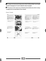 2
2
-
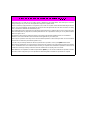 3
3
-
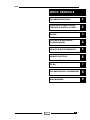 4
4
-
 5
5
-
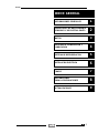 6
6
-
 7
7
-
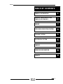 8
8
-
 9
9
-
 10
10
-
 11
11
-
 12
12
-
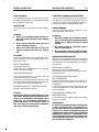 13
13
-
 14
14
-
 15
15
-
 16
16
-
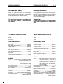 17
17
-
 18
18
-
 19
19
-
 20
20
-
 21
21
-
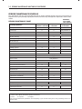 22
22
-
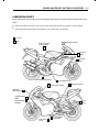 23
23
-
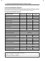 24
24
-
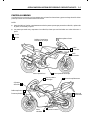 25
25
-
 26
26
-
 27
27
-
 28
28
-
 29
29
-
 30
30
-
 31
31
-
 32
32
-
 33
33
-
 34
34
-
 35
35
-
 36
36
-
 37
37
-
 38
38
-
 39
39
-
 40
40
-
 41
41
-
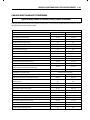 42
42
-
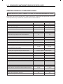 43
43
-
 44
44
-
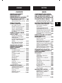 45
45
-
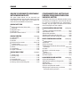 46
46
-
 47
47
-
 48
48
-
 49
49
-
 50
50
-
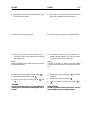 51
51
-
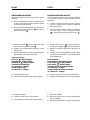 52
52
-
 53
53
-
 54
54
-
 55
55
-
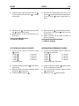 56
56
-
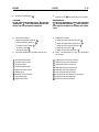 57
57
-
 58
58
-
 59
59
-
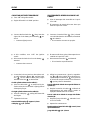 60
60
-
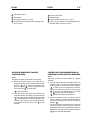 61
61
-
 62
62
-
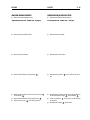 63
63
-
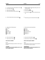 64
64
-
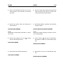 65
65
-
 66
66
-
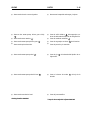 67
67
-
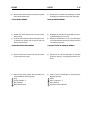 68
68
-
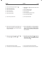 69
69
-
 70
70
-
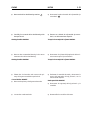 71
71
-
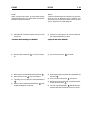 72
72
-
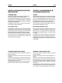 73
73
-
 74
74
-
 75
75
-
 76
76
-
 77
77
-
 78
78
-
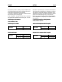 79
79
-
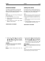 80
80
-
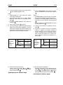 81
81
-
 82
82
-
 83
83
-
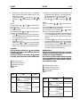 84
84
-
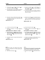 85
85
-
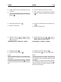 86
86
-
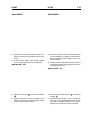 87
87
-
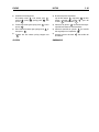 88
88
-
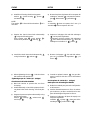 89
89
-
 90
90
-
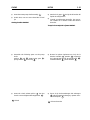 91
91
-
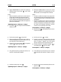 92
92
-
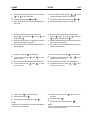 93
93
-
 94
94
-
 95
95
-
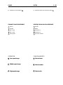 96
96
-
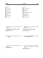 97
97
-
 98
98
-
 99
99
-
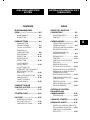 100
100
-
 101
101
-
 102
102
-
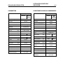 103
103
-
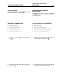 104
104
-
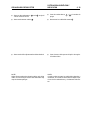 105
105
-
 106
106
-
 107
107
-
 108
108
-
 109
109
-
 110
110
-
 111
111
-
 112
112
-
 113
113
-
 114
114
-
 115
115
-
 116
116
-
 117
117
-
 118
118
-
 119
119
-
 120
120
-
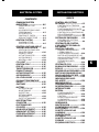 121
121
-
 122
122
-
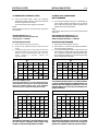 123
123
-
 124
124
-
 125
125
-
 126
126
-
 127
127
-
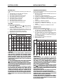 128
128
-
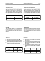 129
129
-
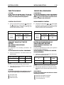 130
130
-
 131
131
-
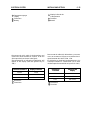 132
132
-
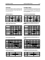 133
133
-
 134
134
-
 135
135
-
 136
136
-
 137
137
-
 138
138
-
 139
139
-
 140
140
-
 141
141
-
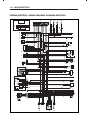 142
142
-
 143
143
-
 144
144
-
 145
145
-
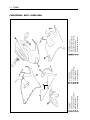 146
146
-
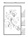 147
147
-
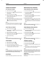 148
148
-
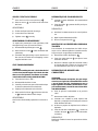 149
149
-
 150
150
-
 151
151
-
 152
152
-
 153
153
-
 154
154
-
 155
155
-
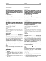 156
156
-
 157
157
-
 158
158
-
 159
159
-
 160
160
-
 161
161
-
 162
162
-
 163
163
-
 164
164
-
 165
165
-
 166
166
-
 167
167
-
 168
168
-
 169
169
-
 170
170
-
 171
171
-
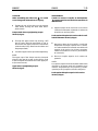 172
172
-
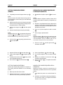 173
173
-
 174
174
-
 175
175
-
 176
176
-
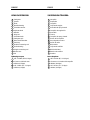 177
177
-
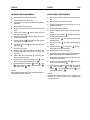 178
178
-
 179
179
-
 180
180
-
 181
181
-
 182
182
-
 183
183
-
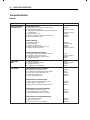 184
184
-
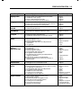 185
185
-
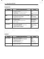 186
186
-
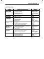 187
187
-
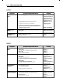 188
188
-
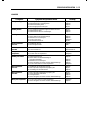 189
189
-
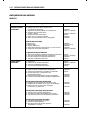 190
190
-
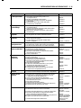 191
191
-
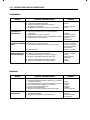 192
192
-
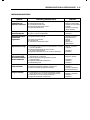 193
193
-
 194
194
-
 195
195
-
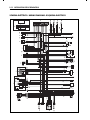 196
196
-
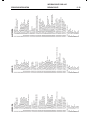 197
197
-
 198
198
-
 199
199
-
 200
200
-
 201
201
-
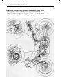 202
202
-
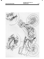 203
203
-
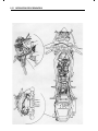 204
204
-
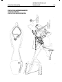 205
205
-
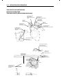 206
206
-
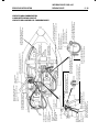 207
207
-
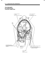 208
208
-
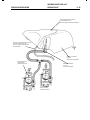 209
209
-
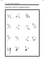 210
210
-
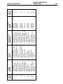 211
211
-
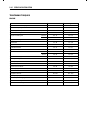 212
212
-
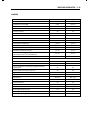 213
213
-
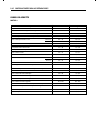 214
214
-
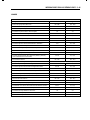 215
215
-
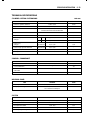 216
216
-
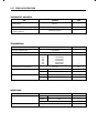 217
217
-
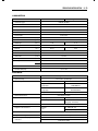 218
218
-
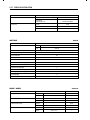 219
219
-
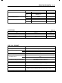 220
220
-
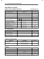 221
221
-
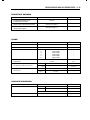 222
222
-
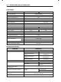 223
223
-
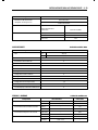 224
224
-
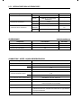 225
225
-
 226
226
-
 227
227
-
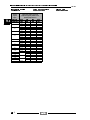 228
228
-
 229
229
-
 230
230
-
 231
231
-
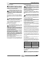 232
232
-
 233
233
-
 234
234
-
 235
235
-
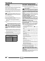 236
236
-
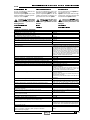 237
237
-
 238
238
-
 239
239
-
 240
240
-
 241
241
-
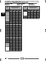 242
242
-
 243
243
-
 244
244
-
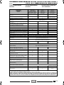 245
245
-
 246
246
-
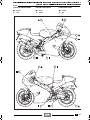 247
247
-
 248
248
-
 249
249
-
 250
250
-
 251
251
-
 252
252
-
 253
253
-
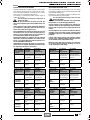 254
254
-
 255
255
-
 256
256
-
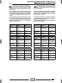 257
257
-
 258
258
-
 259
259
-
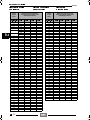 260
260
-
 261
261
-
 262
262
-
 263
263
-
 264
264
-
 265
265
-
 266
266
-
 267
267
-
 268
268
-
 269
269
-
 270
270
-
 271
271
-
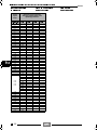 272
272
-
 273
273
-
 274
274
-
 275
275
-
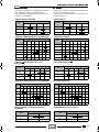 276
276
-
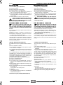 277
277
-
 278
278
-
 279
279
-
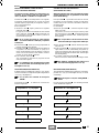 280
280
-
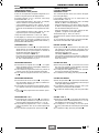 281
281
-
 282
282
-
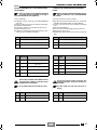 283
283
-
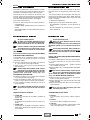 284
284
-
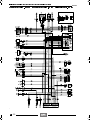 285
285
-
 286
286
-
 287
287
-
 288
288
-
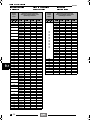 289
289
-
 290
290
-
 291
291
-
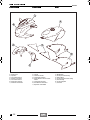 292
292
-
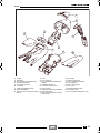 293
293
-
 294
294
-
 295
295
-
 296
296
-
 297
297
-
 298
298
-
 299
299
-
 300
300
-
 301
301
-
 302
302
-
 303
303
-
 304
304
-
 305
305
-
 306
306
-
 307
307
-
 308
308
-
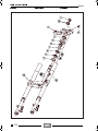 309
309
-
 310
310
-
 311
311
-
 312
312
-
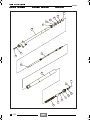 313
313
-
 314
314
-
 315
315
-
 316
316
-
 317
317
-
 318
318
-
 319
319
-
 320
320
-
 321
321
-
 322
322
-
 323
323
-
 324
324
-
 325
325
-
 326
326
-
 327
327
-
 328
328
-
 329
329
-
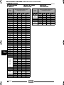 330
330
-
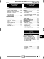 331
331
-
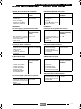 332
332
-
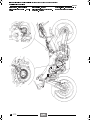 333
333
-
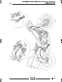 334
334
-
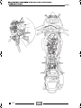 335
335
-
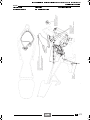 336
336
-
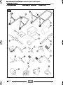 337
337
-
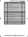 338
338
-
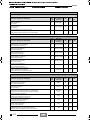 339
339
-
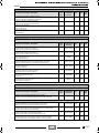 340
340
-
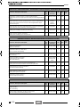 341
341
-
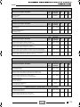 342
342
-
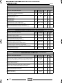 343
343
-
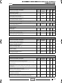 344
344
-
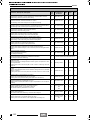 345
345
-
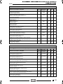 346
346
-
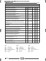 347
347
-
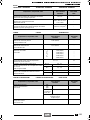 348
348
-
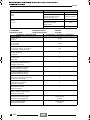 349
349
-
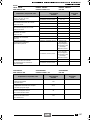 350
350
-
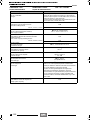 351
351


APRILIA RS 250 Service and Repair Manual
- Categoría
- Motocicletas
- Tipo
- Service and Repair Manual
en otros idiomas
- English: APRILIA RS 250
Artículos relacionados
-
APRILIA MX 50 Manual de usuario
-
-
-
APRILIA LEONARDO 150 Use And Maintenance Book
-
-
-
-
-
-
APRILIA SR 50 STREET 2009 Service and Repair Manual
Otros documentos
-
Logosol Loncin 15HP Manual de usuario
-
 Annovi Reverberi HPV-M 90517-EX Manual de usuario
-
WEG Brake Motor Manual de usuario
-
Workzone DC-1 / 650080 Manual de usuario
-
Actron CP7827 Instrucciones de operación
-
 AZUNO Cylinder Compression Tester Kit, 200 PSI Digital Compression Gauge Manual de usuario
-
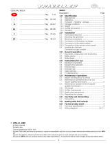 WTA 5500 Ficha de datos
-
Ingersoll-Rand M-Series Installation And Operation Manua
-
Dometic GFA2303 Manual de usuario
-
Topeak DeFender M3 El manual del propietario


