Actron CP7827 Instrucciones de operación

Categoría
Probadores de redes de cable
Tipo
Instrucciones de operación
No.
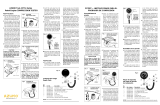
ref. No. de pieza Descripción
1 0031-000-0246 Manómetro de compresión
2 0180-000-0772 Conj. válvula y acoplador rápido
3 0032-000-0109 Conj. manguera de bujía
4 0180-000-0775 (2 c/u) Válvula aire (alta presión)*
5 0400-000-1350 Anillo “O”
6 0400-000-1349 (2 c/u) Anillo “O”
7 0180-000-0895 Adaptador alcance profundo
0002-004-2018
Manual de instrucciones (no se ilustra)
*NOTA: No usar válvulas de neumáticos de automóviles como pieza de repuesto.
2
3
4
7
6
5
0
0
30
60
90
120
150
210
180
240
270
300
2
4
6
8
10
12
14
16
18
20
kPa x 100
Compression
Tester
LBS.
per sq. in.
1
CP7827 – INSTRUCTIONS FOR
COMPRESSION TESTER
Test Procedure
1. Run the engine for about ten min-
utes or until it reaches normal
operating temperature before per-
forming the compression test.
2. Stop the engine. Disconnect all
the spark plug wires and number
them in the order in which they
were removed; this makes them
easy to identify for reconnection.
3. Loosen all spark plugs about one
turn, but do not remove them.
Use an air hose or stiff brush to
remove all the dirt from the spark
plug wells. Remove the spark
plugs and place them on a clean,
flat surface in the order in which
they were removed. This proce-
dure will help to correlate any
compression or cylinder problems
with the condition of the plug from
the particular cylinder involved.
4. Remove the air filter and set the
carburetor throttle plates to the
wide open throttle position using
a string or wire. See Figure 1.
en el mismo valor por varias
carreras y luego comienza a
subir, el cilindro tiene una válvula
pegada.
3. Si la lectura de compresión es
considerablemente mayor que
la especificación del fabricante,
significa que hay depósitos de
carbón en el cilindro.
4. Si la lectura en dos cilindros
adyacentes es 20 libras (1,4 kg/
cm
2
) o más baja que el resto de
los cilindros, significa que la
empaquetadura de la culata de
cilindros está defectuosa. Se
puede encontrar agua
(refrigerante) y/o aceite en los
dos cilindros en estas
condiciones.
5. Si las lecturas son bajas o varían
mucho entre los cilindros, verter
una cucharadita de aceite #30
S.A.E. en cada cilindro y repetir
la prueba. Si las lecturas
aumentan considerablemente,
la avería es anillos mal asenta-
dos o desgastados. Si las
lecturas permanecen más o
menos iguales, las válvulas y/o
componentes asociados están
averiadas.
6. Limpiar, ajustar la abertura de
los electrodos y reinstalar las
bujías en el mismo orden en que
se sacaron, o instalar bujías
nuevas. Reconectar todos los
cables de bujías en el orden
correcto. Quitar el bloque de
madera de las placas del
acelerador y asegurar que re-
gresan a la posición cerrada.
Reconectar el sistema de en-
cendido que fue desconectado
en el paso 5, Procedimiento de
prueba.
CP7827 — INSTRUCCIONES PARA EL
PROBADOR DE COMPRESIÓN
Procedimiento de
prueba
1. Hacer funcionar el motor por
unos tres minutos o hasta que
llegue a la temperatura normal
de operación antes de probar
la compresión.
2. Parar el motor. Desconectar todos
los cables de bujías y numerarlos
en el orden en que fueron sacados
para facilitar la reconexión.
3.
Aflojar todas las bujías aproxi-
madamente una vuelta, sin
sacarlas. Usar una manguera de
aire comprimido o escobilla de
cerdas duras para limpiar toda la
suciedad de las cavidades de las
bujías. Ponerlas en una superficie
plana limpia en el mismo orden
en que fueron sacadas. Eso
ayudará a correlacionar cualquier
problema de compresión con la
condición de la bujía del cilindro
en particular.
4. Sacar el filtro de aire y bloquear
abiertas al máximo las placas
del acelerador del carburador,
usando un bloque de madera
teniendo cuidado de no dañar
el mecanismo o componentes
del carburador. Ver figura 1.
PRECAUCION!
CABLE DE
PUENTE
5. Sacar el conductor de alta
tensión del centro del distribui-
dor y conectarlo a tierra en el
motor, como se muestra en la
figura 2. Para inhabilitar el
sistema de encendido elec-
trónico, desconectar el módulo
de encendido electrónico o
sacar el borne primario de la
batería de la bobina de
encendido. En los motor V-8 y
V-6 HEI GM, desconectar el con-
ductor primario de la tapa del
distribuidor (figura 3).
Fig. 2
Grounded
High Tension Lead
CONDUCTOR
DE ALTA
TENSIÓN
VÁLVULA
DE
LIBERACIÓN
Oprimir la
válvula de
descarga
para aliviar
la presión
Fig. 5
9. Anotar la lectura de compresión
y en seguida, oprimir la válvula
de descarga lateral para
descargar presión, como se
muestra en la figura 5. Repetir
la prueba. Anotar la lectura,
aliviar la presión, desconectar
el manómetro de la manguera y
sacar ésta de la cavidad de la
bujía.
10.
Reconectar la manguera a la
próxima cavidad de bujía a ser
probada y repetir los pasos 6 a
10 para el resto de los cilindros
a ser probados.
Resultados de la prueba
1. En un cilindro normal, la aguja
del manómetro debe moverse
hacia arriba en la escala en cada
carrera de compresión hasta
llegar a un valor máximo. Todos
los cilindros deberán indicar
dentro de las especificaciones
del fabricante del motor y las
lecturas no deberán variar más
de un 10% entre un cilindro y
otro.
2. Si la aguja no avanza como se
indica en el paso 1 ó permanece
Fig. 2
Conductor de alta
tensión a tierra
CORDEL O
ALAMBRE
CARBURADOR
Placas del
acelerador abiertas
Fig. 1
El no volver a colocar las
placas del acelerador del
carburador en la posición
cerrada antes del arranque
puede causar serios daños al
motor.
Fig. 3
7. Insertar la manguera de la bujía
en el manómetro, tirando hacia
arriba el manguito externo del
acoplador rápido del manómetro
y dejar que salte cuando el
conector encaja en el adaptador.
8. Hacer girar el motor por unas
cuatro carreras de compresión
o hasta que la lectura de presión
cese de subir en el manómetro.
CABLE
PRIMARIO
Sistema de encendido
HEI GM inhabilitado
6. Desconectar la manguera del
manómetro. Atornillar la
manguera adaptadora de la
bujía (ref. 3, figura 6) en la
cavidad de la bujia. Apretar a
mano solamente - NO USAR
UNA LLAVE. Ver figura 4.
NOTA: En motores con bujías de
alcance de 1,4 cm de largo, usar
un adaptador de alcance largo (ref.
7, figura 6). No usar el adaptador
en los agujeros de alcance corto
- puede tocar la parte superior
del pistón y dañar el motor.
Instalación del
manómetro de
compresión
Fig. 4
Piezas de repuesto
del juego de prueba
de compresión
JUMPER
WIRE
HIGH
TENSION
LEAD
6. Disconnect the hose from the
gauge. Screw the spark plug
adapter hose (Item 3, Figure 6)
into a spark plug well. Hand tighten
only – DO NOT USE A WRENCH.
See Figure 4.
NOTE: On engines with 14mm long
reach plugs, use the long reach
adapter (Item 7, Figure 6). Do not
use the adapter in short reach
holes – it may hit the top of the
piston and damage the engine.
CAUTION!
Failure to return the carbure-
tor throttle plates to the closed
throttle position before start-
ing the engine can cause seri-
ous engine damage.
Fig. 1
Hold Open
Throttle Plates
STRING OR WIRE
CARBURETOR
Fig. 4
Installation of
Compression Gauge
Fig. 3
Disabled GM HEI Ignition
System
PRIMARY
WIRE
5. Remove the high tension lead
from the center of the distributor
and connect to ground as shown
in Figure 2. To disable electronic
ignition systems, disconnect the
electronic ignition module or re-
move the primary battery termi-
nal from the ignition coil. On GM
HEI V-8 and V-6, disconnect the
primary lead from the distributor
cap. (Figure 3.)
reaches a peak value. All cylinders
should indicate a pressure that is
within the vehicle manufacturer's
specifications, and the reading
should not vary more than 10%
from cylinder to cylinder.
2. If the needle fails to travel up-scale
as described in Step 1, or if it re-
mains at the same value for sev-
eral strokes and then starts to climb,
the cylinder has a sticking valve.
3. If the compression reading is con-
siderably higher than the vehicle
manufacturer's specification, it in-
dicates carbon buildup in the cyl-
inder.
4. If a reading on two adjacent cylin-
ders is 20 pounds (or more) lower
than the other cylinders, a defec-
tive head gasket is indicated.
Water (coolant) and/or oil may be
found in the two cylinders under
these conditions.
5. If the readings are low or vary
widely between cylinders, pour a
teaspoon of clear S.A.E. grade 30
oil into each cylinder and retest. If
the readings increase consider-
ably, the fault may be due to poorly
seated or worn piston rings. If the
readings remain about the same,
the valves and/or associated com-
ponents are likely the cause.
6. Clean, regap and reinstall the spark
plugs in the same order in which
they were removed, or install new
spark plugs. Reconnect all spark
plug wires in the proper order.
Remove the string or wire from
the carburetor throttle plates and
make certain it returns to closed
throttle position. Reconnect the
ignition system.
Fig. 5
Push
Release
Valve to
Relieve
Pressure
7. Insert the spark plug hose into
the gauge by pulling up on the
outer sleeve of the gauge's quick
disconnect coupling and allow it
to snap back as the fitting en-
gages the adapter.
8. Crank the engine for at least four
compression strokes or until the
pressure reading stops rising on
the gauge.
9. Record the compression read-
ing, then push the side release
valve to relieve the pressure as
shown in Figure 5. Repeat the
test. Record the reading, relieve
the pressure, remove the gauge
from the hose, and remove the
hose from the spark plug well.
Compression Gauge
Repair Parts
Key
No. Part No. Description
1 0031-000-0246 Compression Gauge
2 0180-000-0772 Quick Disconnect Coupling & Valve Assembly
3 0032-000-0109 Spark Plug Hose Assembly
4 0180-000-0775 (2 ea) Air Valve (High Pressure)*
5 0400-000-1350 O-ring
6 0400-000-1349 (2 ea) O-ring
7 0180-000-0895 Deep Reach Adapter
0002-004-2018 Instruction Manual (Not illustrated)
*NOTE: Do not use automotive tire air valve as a replacement part.
RELEASE
VALVE
Fig. 6
10.
Reconnect the hose to the next
spark plug well to be tested and
repeat steps 6 through 10 for the
remainder of the cylinders to be
tested.
Test Results
1. On a normal cylinder, the gauge
needle should travel up-scale on
each compression stroke until it
2
3
4
7
6
5
0
0
30
60
90
120
150
210
180
240
270
300
2
4
6
8
10
12
14
16
18
20
kPa x 100
Compression
Tester
LBS.
per sq. in.
1
Fig. 6

Transcripción de documentos

CP7827 – INSTRUCTIONS FOR COMPRESSION TESTER Test Procedure 1. Run the engine for about ten minutes or until it reaches normal operating temperature before performing the compression test. Fig. 2 Grounded High Tension Lead HIGH TENSION LEAD JUMPER WIRE 2. Stop the engine. Disconnect all the spark plug wires and number them in the order in which they were removed; this makes them easy to identify for reconnection. 3. Loosen all spark plugs about one turn, but do not remove them. Use an air hose or stiff brush to remove all the dirt from the spark plug wells. Remove the spark plugs and place them on a clean, flat surface in the order in which they were removed. This procedure will help to correlate any compression or cylinder problems with the condition of the plug from the particular cylinder involved. 4. Remove the air filter and set the carburetor throttle plates to the wide open throttle position using a string or wire. See Figure 1. 5. Remove the high tension lead from the center of the distributor and connect to ground as shown in Figure 2. To disable electronic ignition systems, disconnect the electronic ignition module or remove the primary battery terminal from the ignition coil. On GM HEI V-8 and V-6, disconnect the primary lead from the distributor cap. (Figure 3.) STRING OR WIRE 8. Crank the engine for at least four compression strokes or until the pressure reading stops rising on the gauge. 2. If the needle fails to travel up-scale as described in Step 1, or if it remains at the same value for several strokes and then starts to climb, the cylinder has a sticking valve. 9. Record the compression reading, then push the side release valve to relieve the pressure as shown in Figure 5. Repeat the test. Record the reading, relieve the pressure, remove the gauge from the hose, and remove the hose from the spark plug well. Fig. 5 RELEASE VALVE Push Release Valve to Relieve Pressure System PRIMARY WIRE 10.Reconnect the hose to the next spark plug well to be tested and repeat steps 6 through 10 for the remainder of the cylinders to be tested. Test Results Hold Open Throttle Plates CARBURETOR reaches a peak value. All cylinders should indicate a pressure that is within the vehicle manufacturer's specifications, and the reading should not vary more than 10% from cylinder to cylinder. Fig. 3 Disabled GM HEI Ignition CAUTION! Failure to return the carburetor throttle plates to the closed throttle position before starting the engine can cause serious engine damage. Fig. 1 7. Insert the spark plug hose into the gauge by pulling up on the outer sleeve of the gauge's quick disconnect coupling and allow it to snap back as the fitting engages the adapter. 6. Disconnect the hose from the gauge. Screw the spark plug adapter hose (Item 3, Figure 6) into a spark plug well. Hand tighten only – DO NOT USE A WRENCH. See Figure 4. NOTE: On engines with 14mm long reach plugs, use the long reach adapter (Item 7, Figure 6). Do not use the adapter in short reach holes – it may hit the top of the piston and damage the engine. Fig. 4 1. On a normal cylinder, the gauge needle should travel up-scale on each compression stroke until it 3. If the compression reading is considerably higher than the vehicle manufacturer's specification, it indicates carbon buildup in the cylinder. 4. If a reading on two adjacent cylinders is 20 pounds (or more) lower than the other cylinders, a defective head gasket is indicated. Water (coolant) and/or oil may be found in the two cylinders under these conditions. 5. If the readings are low or vary widely between cylinders, pour a teaspoon of clear S.A.E. grade 30 oil into each cylinder and retest. If the readings increase considerably, the fault may be due to poorly seated or worn piston rings. If the readings remain about the same, the valves and/or associated components are likely the cause. 6. Clean, regap and reinstall the spark plugs in the same order in which they were removed, or install new spark plugs. Reconnect all spark plug wires in the proper order. Remove the string or wire from the carburetor throttle plates and make certain it returns to closed throttle position. Reconnect the ignition system. CP7827 — INSTRUCCIONES PARA EL PROBADOR DE COMPRESIÓN Procedimiento de prueba 1. Hacer funcionar el motor por unos tres minutos o hasta que llegue a la temperatura normal de operación antes de probar la compresión. 2. Parar el motor. Desconectar todos los cables de bujías y numerarlos en el orden en que fueron sacados para facilitar la reconexión. 3. Aflojar todas las bujías aproximadamente una vuelta, sin sacarlas. Usar una manguera de aire comprimido o escobilla de cerdas duras para limpiar toda la suciedad de las cavidades de las bujías. Ponerlas en una superficie plana limpia en el mismo orden en que fueron sacadas. Eso ayudará a correlacionar cualquier problema de compresión con la condición de la bujía del cilindro en particular. 4. Sacar el filtro de aire y bloquear abiertas al máximo las placas del acelerador del carburador, usando un bloque de madera teniendo cuidado de no dañar el mecanismo o componentes del carburador. Ver figura 1. PRECAUCION! El no volver a colocar las placas del acelerador del carburador en la posición cerrada antes del arranque puede causar serios daños al motor. Fig. 1 Fig. 6 120 150 180 90 8 10 12 14 16 4 18 2 20 0 kPa x 100 210 6 60 30 0 LBS. Compression Tester per sq. in. Placas del acelerador abiertas CARBURADOR 7 240 270 300 4 5. Sacar el conductor de alta tensión del centro del distribuidor y conectarlo a tierra en el motor, como se muestra en la figura 2. Para inhabilitar el sistema de encendido electrónico, desconectar el módulo de encendido electrónico o sacar el borne primario de la batería de la bobina de encendido. En los motor V-8 y V-6 HEI GM, desconectar el conductor primario de la tapa del distribuidor (figura 3). Fig. 3 Sistema de encendido HEI GM inhabilitado CABLE PRIMARIO VÁLVULA DE LIBERACIÓN Oprimir la válvula de descarga para aliviar la presión 9. Anotar la lectura de compresión y en seguida, oprimir la válvula de descarga lateral para descargar presión, como se muestra en la figura 5. Repetir la prueba. Anotar la lectura, aliviar la presión, desconectar el manómetro de la manguera y sacar ésta de la cavidad de la bujía. 10.Reconectar la manguera a la próxima cavidad de bujía a ser probada y repetir los pasos 6 a 10 para el resto de los cilindros a ser probados. Resultados de la prueba 6. Desconectar la manguera del manómetro. Atornillar la manguera adaptadora de la bujía (ref. 3, figura 6) en la cavidad de la bujia. Apretar a mano solamente - NO USAR UNA LLAVE. Ver figura 4. NOTA: En motores con bujías de alcance de 1,4 cm de largo, usar un adaptador de alcance largo (ref. 7, figura 6). No usar el adaptador en los agujeros de alcance corto - puede tocar la parte superior del pistón y dañar el motor. en el mismo valor por varias carreras y luego comienza a subir, el cilindro tiene una válvula pegada. Fig. 5 1. En un cilindro normal, la aguja del manómetro debe moverse hacia arriba en la escala en cada carrera de compresión hasta llegar a un valor máximo. Todos los cilindros deberán indicar dentro de las especificaciones del fabricante del motor y las lecturas no deberán variar más de un 10% entre un cilindro y otro. 2. Si la aguja no avanza como se indica en el paso 1 ó permanece 3. Si la lectura de compresión es considerablemente mayor que la especificación del fabricante, significa que hay depósitos de carbón en el cilindro. 4. Si la lectura en dos cilindros adyacentes es 20 libras (1,4 kg/ cm2) o más baja que el resto de los cilindros, significa que la empaquetadura de la culata de cilindros está defectuosa. Se puede encontrar agua (refrigerante) y/o aceite en los dos cilindros en estas condiciones. 5. Si las lecturas son bajas o varían mucho entre los cilindros, verter una cucharadita de aceite #30 S.A.E. en cada cilindro y repetir la prueba. Si las lecturas aumentan considerablemente, la avería es anillos mal asentados o desgastados. Si las lecturas permanecen más o menos iguales, las válvulas y/o componentes asociados están averiadas. 6. Limpiar, ajustar la abertura de los electrodos y reinstalar las bujías en el mismo orden en que se sacaron, o instalar bujías nuevas. Reconectar todos los cables de bujías en el orden correcto. Quitar el bloque de madera de las placas del acelerador y asegurar que regresan a la posición cerrada. Reconectar el sistema de encendido que fue desconectado en el paso 5, Procedimiento de prueba. Fig. 4 Instalación del manómetro de compresión Fig. 6 120 150 180 90 6 0 Key No. 1 2 3 4 5 6 7 Compression Tester LBS. per sq. in. Compression Gauge Repair Parts 5 2 4 30 1 Installation of Compression Gauge 8 10 12 14 16 18 2 20 0 kPa x 100 Part No. Description 0031-000-0246 0180-000-0772 0032-000-0109 0180-000-0775 0400-000-1350 0400-000-1349 0180-000-0895 0002-004-2018 Compression Gauge Quick Disconnect Coupling & Valve Assembly Spark Plug Hose Assembly (2 ea) Air Valve (High Pressure)* O-ring (2 ea) O-ring Deep Reach Adapter Instruction Manual (Not illustrated) *NOTE: Do not use automotive tire air valve as a replacement part. Piezas de repuesto del juego de prueba de compresión CORDEL O ALAMBRE 3 Fig. 2 CONDUCTOR DE ALTA TENSIÓN Conductor de alta tensión a tierra CABLE DE PUENTE No. ref. 7. Insertar la manguera de la bujía en el manómetro, tirando hacia arriba el manguito externo del acoplador rápido del manómetro y dejar que salte cuando el conector encaja en el adaptador. 8. Hacer girar el motor por unas cuatro carreras de compresión o hasta que la lectura de presión cese de subir en el manómetro. 210 6 60 1 2 3 4 5 6 7 7 240 270 300 4 6 1 5 2 3 No. de pieza Descripción 0031-000-0246 0180-000-0772 0032-000-0109 0180-000-0775 0400-000-1350 0400-000-1349 0180-000-0895 0002-004-2018 Manómetro de compresión Conj. válvula y acoplador rápido Conj. manguera de bujía (2 c/u) Válvula aire (alta presión)* Anillo “O” (2 c/u) Anillo “O” Adaptador alcance profundo Manual de instrucciones (no se ilustra) *NOTA: No usar válvulas de neumáticos de automóviles como pieza de repuesto.
  • Page 1 1

Actron CP7827 Instrucciones de operación

Categoría
Probadores de redes de cable
Tipo
Instrucciones de operación

En otros idiomas