APRILIA 1997 Leonardo 125 Service and Repair Manual
- Categoría
- Motocicletas
- Tipo
- Service and Repair Manual
Este manual también es adecuado para
La página se está cargando...
La página se está cargando...

0
- 2
Primera edición: septiembre 1996
Nueva edición: enero 1997
Producido e impreso por:
Studio Tecno Public
Viale del Progresso - 37038 Soave (VR) - Italia
Tel. 045 - 76 11 911
Fax 045 - 76 12 241
por parte de:
aprilia s.p.a.
via G. Galilei, 1 - 30033 Noale (VE)
Tel. 041 - 58 29 111
Fax 041 - 44 10 54
INDICE GENERAL
1
INFORMACIONES GENERALES
2
OPERACIONES DE MANTENIMIENTO
PERIODICO Y DE PUESTA A PUNTO
3
MOTOR
4
SISTEMA DE ALIMENTACION
5
INSTALACION DE REFRIGERACION
6
INSTALACION ELECTRICA
7
PARTE CICLO
8
INFORMACIONES
PARA LAS REPARACIONES
9
ACTUALIZACIÓNES
PREMISA
– Este manual suministra las informaciones principales
para los procedimientos de intervención corriente.
– Las informaciones y las ilustraciones que forman parte
de este manual, están puestas al día en el momento
de la divulgación del manual mismo.
Antes de consultar el manual, controle el modelo del
vehículo y si acaso la parte puesta al día correspon-
diente, en la sección 9 “ACTUALIZACIÓN”.
– Esta publicación se dirige a los técnicos del sector, por
lo tanto se han omitido voluntariamente muchas opcio-
nes en cuanto las consideramos superfluas.
Para otras informaciones, llame al DEPARTAMENTO
ASISTENCIA
aprilia s.p.a.
– Para otras informaciones véase el MANUAL DE TA-
LLER MOTOR, N˚ 929 (D-I) / N˚ 930 (UK-E-F), el CA-
TALOGO REPUESTOS MOTOR, N˚ 919 y el CATA-
LOGO REPUESTOS "PARTE CICLO", N˚ 650.
La empresa aprilia s.p.a. se reserva el derecho de apor-
tar modificaciones a sus modelos en cualquier momento,
guardando siempre las características esenciales descri-
tas e ilustradas en este manual.
A todos los países se les reserva los derechos de memo-
rización electrónica, de reproducción y de adaptación to-
tal y parcial, con cualquier medio.
El hecho de citar productos o servicios por cuenta ajena
tiene el solo fin de informar y no constituye ningún com-
promiso.
La empresa
aprilia s.p.a.
no se hace cargo de ninguna
responsabilidad en cuanto a las prestaciones o al uso de
estos productos.
USO DEL MANUAL
◆
NORMAS PARA LA CONSULTA
– De no estar expresamente descrito, hay que
realizar el reensamblaje de los grupos siguien-
do en orden contrario las operaciones que se
han efectuado para el desmontaje.
– Para cada intervención sobre el motor, consulte el
manual específico: N˚ 929 (D-I) y N˚ 930 (UK-E-F).
– Consulte el manual "USO Y MANTENIMIENTO" en
cuanto al uso del vehículo y para las corrientes ope-
raciones de mantenimiento.
◆
SIMBOLOS
Observe esmeradamente las advertencias precedidas
por los siguientes símbolos:
Normas y medidas de seguridad que protegen
al piloto, al operador u a otras personas de le-
siones o riesgos graves y/o daños al vehículo.
Indicaciones para facilitar el desarrollo de las
operaciones. Informaciones técnicas.
Hay que repetir las operaciones que están
precedidas por este símbolo en el lado opues-
to del vehículo.
a
c
★
La página se está cargando...
La página se está cargando...
La página se está cargando...
La página se está cargando...
La página se está cargando...
La página se está cargando...

1
- 5
GENERAL INFORMATIONINFORMACIONES GENERALES
1.1 POSICION DE LOS NUMEROS DE SERIE
Estos números son necesarios para matricular el vehícu-
lo.
1.1.1 NUMERO BASTIDOR
El numero del bastidor está impreso en el tubo central del
bastidor. Para leerlo es necesario quitar la tapa (1).
1.1.2 NUMERO MOTOR
El numero del motor está impreso en lado trasero, cerca
del tapón de llenado aceite transmisión.
1.2 ADVERTENCIAS POR LO QUE SE REFIERE
AL COMBUSTIBLE, A LOS LUBRICANTES
Y AL LIQUIDO REFRIGERANTE
1.2.1 COMBUSTIBLE
El combustible utilizado para la propulsión de
los motores de explosión es muy inflamable y
puede volverse explosivo en algunas condi-
ciones. Los vapores de combustible perjudican la sa-
lud. Antes de seguir adelante, asegúrese de que el lu-
gar donde va a actuar tenga un adecuado cambio de
aire. Es oportuno reponer gasolina y realizar las ope-
raciones de mantenimiento en una zona ventilada, y
con el motor apagado. No fume durante la provisión
de gasolina y cerca de los vapores del combustible;
de todas formas evite absolutamente el contacto con
llamas libres, chispas y cualquier otra fuente que po-
dría causar el encendido o la explosión. Además, evi-
te la salida del combustible de la boca de llenado, ya
que podría incendiarse al llegar a contacto con las
superficies muy calientes del motor. En caso de que
se vertiera accidentalmente algo de gasolina, contro-
le que la zona esté completamente seca; antes de
arrancar asegúrese de que no haya quedado nada de
combustible en el manguito de la boca de llenado.
La gasolina se dilata con el calor y bajo la acción de
los rayos solares. Por lo tanto no llene nunca el de-
pósito hasta el tope. Una vez que se haya terminado
la operación de provisión de gasolina, cierre con cui-
dado el tapón. Evite el contacto del combustible con
la piel, la inhalación de vapores, la ingestión y el tra-
siego de un recipiente a otro por medio de un tubo.
No esparza el combustible en el ambiente.
MANTENGASE LEJOS DEL ALCANCE DE LOS NIÑOS
Utilice exclusivamente gasolina super con o sin plomo, mí-
nimo octano 95 (N.O.R.M.) y 85 (N.O.M.M.) (4 Stars
U
).
1.2.2 ACEITE MOTOR
Controle cada 1000 kilómetros el nivel del aceite motor,
véase 2.9 (COMPROBACION NIVEL ACEITE MOTOR
Y RELLENO). Hay que sustituir el aceite del motor tras
los primeros 1000 kilómetros y sucesivamente cada
6000 km, véase 2.10 (SUSTITUCION ACEITE MOTOR
Y FILTRO ACEITE MOTOR).
a
1.1 POSITION OF THE SERIAL NUMBERS
These numbers are necessary for the registration of the
vehicle.
1.1.1 FRAME NUMBER
The frame number is stamped on the central tube of the
frame. To be able to read it, it is necessary to remove the
cover (1).
1.1.2 ENGINE NUMBER
The engine number is stamped on the rear part of the ve-
hicle, near the transmission oil filling plug.
1.2 ADVICE FOR THE USE OF FUEL,
LUBRICANTS AND COOLANT
1.2.1 FUEL
The fuel used for internal combustion engines
is extremely inflammable and in particular
conditions it can become explosive.
Fuel vapours are noxious for the health.
It is important to carry out the refuelling and the
maintenance operations in a well-ventilated area,
with the engine off.
Do not smoke while refuelling or near fuel vapours, in
any case avoid any contact with naked flames,
sparks and any other heat source to prevent the fuel
from catching fire or from exploding.
Further, prevent fuel from flowing out of the fuel filler,
as it could catch fire when getting in contact with the
red-hot surfaces of the engine.
In case some fuel has accidentally been spilt, make
sure that the area has completely dried and before
starting the vehicle verify that there is no fuel inside
the fuel filler neck.
Since petrol expands under the heat of the sun and
due to the effects of sun radiation, never fill the tank
to the brim.
Screw the plug up carefully after refuelling.
Avoid any contact of the fuel with the skin and the in-
halation of vapours; do not swallow fuel or pour it
from a receptacle into another by means of a tube.
Do not dispose of fuel in the environment.
KEEP AWAY FROM CHILDREN
Use only leaded or unleaded premium grade petrol (4
Stars
U
), min. O.N. 95 (N.O.R.M.) and 85 (N.O.M.M.).
1.2.2 ENGINE OIL
Check the engine oil level every 1000 km, see 2.9 (CHE-
CKING THE ENGINE OIL LEVEL AND TOPPING UP).
It is necessary to change the engine oil after the first
1000 km and successively every 6000 km, see 2.10
(CHANGING THE ENGINE OIL AND THE OIL FILTER).
a
La página se está cargando...

1 - 7
GENERAL INFORMATIONINFORMACIONES GENERALES
Utilice aceites con buena calidad de grada-
ción 5W-40, véase 1.7 (TABLA LUBRICAN-
TES). El uso de aceites de gradación SAE 15W
o 20W podría plantear algún problema durante la fase
de arranque del vehículo, si la temperatura ambiente
es inferior a +5˚C.
En caso de relleno del aceite del motor, le re-
comendamos que no supere el nivel “MAX”.
El aceite del motor puede dañar a la piel si ma-
nejado durante mucho tiempo y diariamente.
Se aconseja lávese las manos con mucho cui-
dado tras haberlo manejado.
NO ESPARZA EL ACEITE EN EL AMBIENTE.
Pida que pasen a recogerlo o entréguelo a la empre-
sa de recuperación aceites usados más cercana o al
abastecedor.
1.2.3 ACEITE TRANSMISION
El aceite transmisión puede dañar gravemen-
te a la piel si manejado durante mucho tiempo
y diariamente. Se aconseja lávese las manos
con mucho cuidado tras haberlo manejado.
Controle el nivel aceite transmisión cada 6000 km o cada
8 meses.
Sustituya el aceite transmisión tras los primeros 1000 km
y sucesivamente cada 12000 km o cada 16 meses.
Aceite transmisión (aconsejado): véase 1.7 (TABLA
LUBRICANTES)
1.2.4 ACEITE HORQUILLA
El aceite transmisión puede dañar gravemen-
te a la piel si manejado durante mucho tiempo
y diariamente. Se aconseja lávese las manos
con mucho cuidado tras haberlo manejado.
En caso de que note o en caso de que alguien se queje
de que la horquilla se hunda excesivamente, controle el
nivel aceite de las varillas.
Aceite horquilla (aconsejado): véase 1.7 (TABLA LU-
BRICANTES)
1.2.5 LIQUIDO FRENOS
Este vehículo está dotado de frenos de disco
delantero y trasero, con circuitos hidráulicos
separados.
Las siguientes informaciones se refieren a un solo
sistema de frenado, pero tienen validez incluso para
ambos sistemas.
No utilice líquidos distintos de los prescritos
ni mezcle líquidos diferentes para rellenar,
porque en caso contrario se puede dañar el
sistema de frenado.
No use líquido frenos sacado de recipientes viejos o
ya abiertos. No utilice líquido frenos que haya sobra-
do de reparaciones anteriores si ya ha transcurrido
mucho tiempo.
a
a
a
a
a
c
a
Use high-quality 5W-40 oil, see 1.7 (LUBRI-
CANT CHART).
The use of oils with SAE number 15W or 20W
may create problems when starting the vehicle, if
room temperature is lower than +5˚C.
When topping up the engine oil, never exceed
the “MAX” level.
Engine oil can cause serious damages to the
skin if handled every day and for long periods.
Wash your hands carefully after using the oil.
DO NOT DISPOSE OF THE ENGINE OIL IN THE ENVI-
RONMENT.
Take it to the nearest company specialized in the dis-
posal of used oils or to the filling station where you
usually buy it.
1.2.3 TRANSMISSION OIL
Transmission oil can cause serious damages
to the skin if handled every day and for long
periods. Wash your hands carefully after us-
ing the oil.
Check the transmission oil level every 6000 km or every 8
months.
Change the transmission oil after the first 1000 km and
successively every 12000 km or every 16 months.
Transmission oil (recommended): see 1.7 (LUBRI-
CANT CHART)
1.2.4 FORK OIL
Fork oil can cause serious damages to the
skin if handled every day and for long periods.
Wash your hands carefully after using the oil.
If the fork rods sink excessively, it is advisable to check
the rod oil level.
Fork oil (recommended): see 1.7 (LUBRICANT
CHART)
1.2.5 BRAKE FLUID
This vehicle is provided with front and rear
disc brakes, with separate hydraulic circuits.
The following information refers to a single braking
system, but is valid for both.
Do not use fluids different from the recom-
mended ones and do not mix different fluids
for topping up, to avoid serious damages to
the braking system.
Do not use brake fluid taken from old or already open
containers. Do not use brake fluid left from previous
repairs if these were carried out long ago.
a
a
a
a
a
c
a
La página se está cargando...

1 - 9
GENERAL INFORMATIONINFORMACIONES GENERALES
Ponga cuidado, sobre todo, en que el disco
del freno no esté untado o engrasado, sobre
todo tras las operaciones de mantenimiento o
de control. Variaciones improvisas del juego o una
resistencia elástica sobre las palancas de los frenos,
se deben a defectos en el sistema hidráulico. Contro-
le que el tubo del freno no resulte enroscado o des-
gastado. Tenga cuidado con que agua o polvo no en-
tren accidentalmente en el interior del circuito.
El líquido de los frenos podría causar irritaciones si
llega a contacto con la piel o con los ojos. Lávese
con mucho cuidado las partes del cuerpo que hayan
estado en contacto con el líquido, y, además, diríjase
a un oculista o a un médico si el líquido llegara a con-
tacto con los ojos.
No esparza el líquido en el ambiente.
MANTENGASE LEJOS DEL ALCANCE DE LOS NIÑOS.
Utilizando el líquido de los frenos, tenga cuida-
do con no verterlo sobre las partes de plástico
y/o barnizadas, porque podría estropearlas.
Líquido frenos (aconsejado): véase 1.7 (TABLA LU-
BRICANTES)
1.2.6 LIQUIDO REFRIGERANTE
No utilice el vehículo si el nivel del líquido re-
frigerante está por debajo del nivel mínimo.
Controle cada 2000 km y tras largos viajes el nivel del lí-
quido refrigerante; sustitúyalo cada 16 meses.
La solución del líquido refrigerante está compuesta por
50% de agua y por 50% de anticongelante. Esta mezcla
es ideal para casi todas las temperaturas de funciona-
miento y garantiza una buena protección contra la corro-
sión. Se aconseja mantenga la misma mezcla incluso du-
rante la temporada caliente porque, de tal forma, se
reducen las pérdidas por evaporación y la necesidad de
frecuentes rellenos. De tal manera disminuyen las incrus-
taciones de sales minerales, dejadas en el radiador por el
agua evaporada y se conserva inalterada la eficiencia del
sistema de refrigeración. En caso de que la temperatura
exterior esté por debajo de cero grados centígrados, con-
trole frecuentemente el circuito de refrigeración añadien-
do, si necesario, una mayor concentración de anticonge-
lante (hasta un máximo de 60%). Para la solución
refrigerante use agua destilada, para no dañar el motor.
No quite el tapón del depósito de expansión
con el motor aún caliente, porque el líquido
refrigerante está bajo presión y a temperatura
elevada. Si llega a contacto con la piel o con la ropa
puede causar graves quemaduras y/o daños. Lávese
con mucho cuidado las partes del cuerpo que hayan
estado en contacto con el líquido, y, además, diríjase
a un oculista o a un médico si el líquido llegara a con-
tacto con los ojos.
El líquido refrigerante es nocivo: NO LO TRAGUE.
MANTENGASE LEJOS DEL ALCANCE DE LOS NIÑOS
Provoque el vómito y consulte al médico en caso de
que trague una parte del líquido refrigerante.
Líquido refrigerante del motor (aconsejado): véase 1.7
(TABLA LUBRICANTES).
Utilice sólo anticongelante y antioxidante sin
nitrito que garantice una protección por lo
menos a los -35˚C.
a
a
a
a
a
Make sure that the brake disc is neither oily,
nor greasy, especially after maintenance or
checking operations. Sudden resistance or
clearance problems on the brake lever may be due to
troubles in the hydraulic system.
Check that the brake cable is neither twisted, nor
worn out.
Prevent water or dust from accidentally getting into
the circuit.
If the brake fluid gets in contact with the skin or the
eyes, it can cause serious irritations.
Carefully wash the parts of your body that get in con-
tact with the fluid. Consult a doctor or an oculist if the
fluid gets in contact with your eyes.
Do not dispose of the brake fluid in the environment.
KEEP AWAY FROM CHILDREN.
When using the brake fluid, take care not to
spill it on the plastic and/or painted parts,
since it can damage them.
Brake fluid (recommended): see 1.7 (LUBRICANT
CHART)
1.2.6 COOLANT
Do not use the vehicle if the coolant is below
the minimum prescribed level.
Check the coolant level every 2000 km and after long
rides; change it every 16 months.
The coolant is made up of 50% water and 50% anti-
freeze. This mixture is ideal for most running tempera-
tures and ensures good protection against corrosion.
It is advisable to keep the same mixture also in the hot
season, since in this way losses due to evaporation are
reduced and it is not necessary to top up very frequently.
The mineral salt deposits left in the radiator by evaporat-
ed water are thus reduced and the efficiency of the cool-
ing system remains unchanged.
If the outdoor temperature is below 0˚, check the cooling
circuit frequently and if necessary increase the antifreeze
concentration (up to maximum 60%).
For the cooling solution use distilled water, in order not to
damage the engine.
Do not remove the expansion tank cap when
the engine is hot, since the coolant is under
pressure and its temperature is high.
If it gets in contact with the skin or with clothes it may
cause severe burns and/or damages.
Carefully wash the parts of your body that get in con-
tact with the coolant. Consult a doctor or an oculist if
the coolant gets in contact with your eyes.
The coolant is noxious: DO NOT SWALLOW IT.
KEEP AWAY FROM CHILDREN
If someone swallows the coolant, make him/her vom-
it and consult a doctor without delay.
Engine coolant (recommended): see 1.7 (LUBRICANT
CHART).
Use only antifreeze and anticorrosive without
nitrite, in order to ensure protection at -35˚C at
least.
a
a
a
a
a
La página se está cargando...

1 - 11
GENERAL INFORMATIONINFORMACIONES GENERALES
1.3 NORMAS PARA EL RODAJE
El rodaje del motor es fundamental para garantizar una
duración larga y el correcto funcionamiento.
Sólo tras los primeros 500 kilómetros de rodaje
es posible conseguir las mejores prestaciones
de aceleración y de velocidad del vehículo.
Siga las siguientes indicaciones:
◆ No gire del todo el puño de gas durante bajos régime-
nes, sea durante que después del rodaje.
◆ Durante los primeros 1000 km, no conduzca por enci-
ma del 80% de la velocidad máxima.
◆ Evite mantener, durante largos trechos, una velocidad
constante.
Después de los primeros 1000 km de funcio-
namiento, realice los controles señalados en
la columna “fin rodaje” de la FICHA DE MAN-
TENIMIENTO PERIODICO, véase 2.1.1 (FICHA DE
MANTENIMIENTO PERIODICO), para evitar daños a
los demás, a sí mismo y/o al vehículo.
a
a
1.3 RUNNING-IN
The running-in of the engine is primary to ensure its cor-
rect functioning.
Only after the first 500 km of running-in it is
possible to obtain the best performance from
the vehicle speed and acceleration.
Keep to the following indications:
◆ Do not open the throttle completely if the speed is low,
both during and after the running-in.
◆ During the first 1000 km, do not exceed the 80% of the
maximum allowed speed.
◆ Avoid driving at constant speed for long distances.
After the first 1000 kilometres, carry out the
checking operations indicated in the column
“After running-in” of the REGULAR SERVICE
INTERVALS CHART, see 2.1.1 (REGULAR SERVICE
INTERVALS CHART), in order to avoid hurting your-
self or other people and/or damaging the vehicle.
a
a
La página se está cargando...

1 - 13
GENERAL INFORMATIONINFORMACIONES GENERALES
1.4 PRECAUCIONES E INFORMACIONES
GENERALES
Cuando realiza las operaciones de reparación, de des-
montaje y de instalación del vehículo, siga esmerada-
mente las siguientes recomendaciones.
Para cualquier tipo de operación está prohibi-
do el uso de llama viva.
Antes de empezar cualquier tipo de interven-
ción de mantenimiento o de inspección al vehículo,
pare el motor, y quite la llave, espere a que el motor y
el sistema de escape se hayan enfriado, levante el ve-
hículo posiblemente por medio del equipo adecuado,
sobre una superficie sólida y llana.
Ponga cuidado sobre todo en las partes aún muy ca-
lientes del motor y del sistema de escape, para evitar
quemaduras. El vehículo está construido con partes
no comestibles. No muerda, no chupe, no mastique ni
trague ninguna parte del mismo por ninguna razón.
De no resultar expresamente descrito, hay que insta-
lar los grupos siguiendo en orden contrario las ope-
raciones que se han efectuado para el desmontaje.
No haga funcionar el motor en lugares cerrados o
con poco aire.
Maneje con mucho cuidado la gasolina porque es ex-
tremadamente inflamable y muy explosiva.
No utilice nunca la gasolina como disolvente para
limpiar el vehículo.
Cuando dos o más personas trabajan contemporá-
neamente, ponga cuidado en la seguridad de cada
uno de ellas.
– Utilice exclusivamente REPUESTOS ORIGINALES
aprilia.
– Utilice los lubricantes aconsejados.
– Use, donde previsto, las herramientas especiales pro-
yectadas para este vehículo.
– Al apretar los tornillos y las tuercas, empiece por los
que tienen el diámetro mayor o por los que están en el
interior, siguiendo en diagonal con pasajes sucesivos.
– Limpie con mucho cuidado los componentes desmon-
tados, con detergente a bajo nivel de inflamabilidad.
– Lubrique las partes (claramente cuando es posible)
antes de instalarlas.
– Controle que cada componente haya sido instalado de
manera correcta.
– Sustituya siempre las juntas, los aros tóricos, los ani-
llos elásticos, las empaquetaduras de anillo (OR) y las
clavijas con otros nuevos.
– Marque la posición sobre todos los empalmes de co-
nexión (tubos, cables, etc.) antes de dividirlos e identi-
fíquelos con signos distintos.
Hay que marcar claramente cada pieza para poder
identificarla en fase de instalación.
No vuelva a utilizar nunca un anillo elástico.
Hay que sustituirlo con otro nuevo cuando se
desmonta de un eje.
Cuando se instala un anillo elástico nuevo, ponga
cuidado en no alejar sus extremidades más de lo ne-
cesario para introducirlo en el eje.
Tras haber instalado un anillo elástico, compruebe
que esté introducido del todo y fijamente en su sede.
a
a
1.4 PRECAUTIONS AND GENERAL
INFORMATION
Keep to the following instructions when repairing, disas-
sembling and reassembling the vehicle.
The use of naked flames is forbidden for any
kind of operation.
Before performing any maintenance operation
or any inspection of the vehicle, stop the engine, ex-
tract the key, wait until the engine and the exhaust
system have cooled down and if possible lift up the
vehicle by means of the proper equipment, on firm
and flat ground.
Keep away from the red-hot parts of the engine and
of the exhaust system, in order to avoid burns.
The vehicle is made up of not edible parts.
Never bite, suck, chew or swallow any part of the ve-
hicle for any reason.
If not expressly indicated otherwise, for the reassem-
bly of the units repeat the disassembly operations in
the reverse order.
Do not let the engine run in close or badly ventilated
places.
Petrol is highly inflammable and explosive, therefore
always handle it with care.
Never use petrol as a solvent to clean the vehicle.
When two or more people are working together, make
sure that everyone is working in safe conditions.
– Use aprilia GENUINE SPARE PARTS only.
– Use the recommended lubricants.
– When provided, use the special tools designed for this
vehicle.
– In the tightening of screws and nuts, start with those
having greater diameter or with the inner ones, procee-
ding diagonally with successive passages.
– Carefully clean the disassembled components, with
low inflammability detergents.
– When possible, lubricate the parts before reassembly.
– Make sure that each component has been properly
reassembled.
– Always replace gaskets, seals, grommets, circlips, O-
rings and split pins with new ones.
– Before disconnecting the joints (pipes, cables, etc.),
mark the positions on all of them and mark them with
different distinguishing signs.
Each piece must be marked clearly, in order not to
have problems during installation.
Never use an circlip twice.
When it is removed from a shaft, it must be re-
placed with a new one.
When installing a new circlip, be careful not to sepa-
rate its ends more than necessary to insert it on the
shaft.
After installing an circlip, make sure that it is com-
pletely and firmly inserted in its seat.
a
a

INFORMAZIONI GENERALI /
INFORMACIONES GENERALES
/ GENERAL INFORMATION
1 - 14
1.5 PARTI DI RICAMBIO
In caso di sostituzione, utiizzare solo
Ricambi Originali aprilia. I Ricambi
Originali aprilia sono di alta qualità,
progettati e costruiti espressamente
per i veicoli aprilia.
L’impiego di ricambi NON
originali aprilia può cau-
sare problemi di prestazio-
ni e danneggiamenti.
1.6 CARATTERISTICHE
TECNICHE
a
DIMENSIONI /
DIMENSIONS
/ DIMENSIONS
Lunghezza max /
Longitud máx.
/ Max. length 1940 mm
Larghezza max /
Anchura máx.
/ Max. width (rear-view mirrors included) 720 mm
Altezza max (al cupolino) /
Altura máx. (hasta el elemento frontal)
/ Max. height (front
part of the fairing included)
1200 mm
Altezza alla sella /
Altura hasta el sillín
/ Seat height 800 mm
Interasse /
Distancia entre los ejes
/ Distance between centres 1320 mm
Altezza libera minima dal suolo /
Altura libre mínima del suelo
/ Min. ground clearance 155 mm
Peso a vuoto (in ordine di marcia) /
Peso en vacío (en orden de marcha)
/
Weight without driver (ready for starting)
136 kg
MOTORE /
MOTOR
/ ENGINE
Tipo /
Tipo
/ Type ROTAX 120 - monocilindrico 4 tempi con 4 valvole, lubrifi-
cazione forzata a carter umido, albero a camme in testa. /
ROTAX 120-monocilíndrico de 4 tiempos con 4 válvulas,
lubricación forzada con cárter húmedo, árbol de levas en la
culata
/ ROTAX 120 - one-cylinder, 4-stroke with 4 valves,
forced lubrication with wet crankcase, camshaft at the
head
Numero cilindri /
Número cilindros
/ Number of cylinders 1
Cilindrata /
Cilindrada total
/ Total displacement 124,91 cm∏
Alesaggio e corsa /
Diámetro y carrera
/ Bore and stroke 56,4 mm / 50 mm
Rapporto di compressione /
Relación de compresión
/ Compression ratio 12,5 ± 0,5 : 1
Avviamento / Arranque / Starting elettrico /
eléctrico
/ electric
Frizione /
Embrague
/ Clutch centrifuga /
centrífuga
/ centrifugal
Cambio /
Cambio
/ Change gear automatico /
automático
/ automatic
Raffreddamento /
Refrigeración
/ Cooling a liquido (50% acqua + 50% di liquido refrigerante) /
por
líquido (50% agua + 50% líquido refrigerante)
/
liquid-cooled (50% water + 50% coolant)
CAPACITÀ /
CAPACIDAD
/ CAPACITY
Carburante (inclusa riserva) /
Combustible (reserva incluida)
/ Fuel (reserve
included)
9,5l
Riserva carburante /
Reserva combustible
/ Fuel reserve 2,5l
Olio motore /
Aceite motor
/ Engine oil 1050 cmC cambio olio, 1100 cmC cambio olio e filtro,
1150 cmC revisione del motore /
1050 cm
C
cambio aceite,
1100 cm
C
cambio aceite y filtro, 1150 cm
C
revisión del
motor
/ 1050 cmC oil change, 1100 cmC oil and filter
change, 1150 cmC engine overhaul
Olio trasmissione /
Aceite transmisión
/ Transmission oil 90 cmC
Impianto di raffreddamento / Instalacion de refrigeracion / Cooling system 1200 cmC
Posti /
Asientos
/ Seats 2
Max carico veicolo (pilota + passeggero + bagaglio) /
Máx. carga vehículo (piloto + pasa-
jero + equipaje)
/ Vehicle max. load (driver + passenger + luggage)
180 kg
1.5 PIEZAS DE REPUESTO
En caso de sustitución, utilice sólo
Repuestos Originales aprilia. Los
Repuestos Originales aprilia son de
calidad superior, proyectados y
construidos expresamente para ve-
hículos aprilia.
Lo de utilizar repuestos NO
originales aprilia puede
causar daños y graves pro-
blemas en las prestaciones.
1.6 FICHA TECNICA
a
1.5 SPARE PARTS
For any replacement, use aprilia
Genuine Spare Parts only. aprilia
Genuine Spare Parts are high-quality
parts, expressly designed and manu-
factured for aprilia vehicles.
Failure to use aprilia Gen-
uine Spare Parts may result
in incorrect performance
and damages.
1.6 TECHNICAL
SPECIFICATIONS
a

INFORMAZIONI GENERALI /
INFORMACIONES GENERALES
/ GENERAL INFORMATION
1 - 15
TRASMISSIONE /
TRANSMISION
/ TRANSMISSION
Variatore /
Variador
/ Speed change gear continuo automatico /
continuo automático
/ automatic
stepless
Primaria /
Primaria
/ Primary a cinghia trapezoidale /
por correa trapecial
/ V-belt
Secondaria /
Secundaria
/ Secondary a ingranaggi /
por engranajes
/ with gears
Rapporto totale motore/ruota /
Relación total motor/rueda-mínimo
/ Total engine/
wheel ratio
minimo 26,88 - massimo 8,06 /
26,88 - máximo: 8,06
/ min-
imum 26,88 - maximum 8,06
CARBURATORE /
CARBURADOR
/ CARBURETTOR
Modello /
Modelo
/ Model Mikuni BS 26-49 (Mikuni BS 26-61
C
)
Diffusore (ovale) /
Difusor (oval)
/ Choke tube (oval) diametro equivalente 22 mm /
Diámetro equivalente 22 mm
/
equivalent Ø22 mm
ALIMENTAZIONE /
ALIMENTACION
/ FUEL SUPPLY
Tipo /
Tipo
/ Type pompa a depressione /
Bomba de depresión
/ vacuum pump
Carburante /
Combustible /
benzina con o senza piombo, con numero di ottano minimo 95
(N.O.R.M.) e 85 (N.O.M.M.) (4 Stars
U) /
gasolina con o sin plomo, mínimo octano 95 (N.O.R.M.) y 85
(N.O.M.M.) (4 Stars
U
) /
leaded or unleaded premium grade petrol, min. O.N. 95
(N.O.R.M.) and 85 (N.O.M.M.) (4 Stars
U)
TELAIO /
BASTIDOR
/ FRAME
Tipo /
Tipo
/ Type monotrave a doppia culla sovrapposta /
monoviga de doble
cuna sobrepuesta
/ one-beam, split in two overlapping cradles
Angolo inclinazione sterzo /
Ángulo inclinación dirección
/ Steering inclination angle 25˚
Avancorsa /
Lanzamiento
/ Fore stroke 88 mm
SOSPENSIONI /
SUSPENSIONES
/ SUSPENSIONS
Anteriore /
Delantera
/ Front forcella telescopica a funzionamento idraulico /
horquilla tel-
escópica con funcionamiento hidráulico
/ hydraulically operated
telescopic fork
Escursione /
Carrera
/ Stroke 90 mm
Posteriore /
Trasera
/ Rear n˚2 ammortizzatori idraulici /
n˚ 2 amortiguadores hidráulicos
/
n.2 hydraulic shock absorbers
Escursione /
Carrera
/ Stroke 104 mm
FRENI /
FRENOS
/ BRAKES
Anteriore /
Delantero
/ Front a disco Ø 220 mm con trasmissione idraulica /
de disco Ø 220
mm - con transmisión hidráulica
/ disc brake, 220 mm with
hydraulic transmission
Posteriore /
Trasero
/ Rear a disco Ø 190 mm con trasmissione idraulica /
de disco
Ø190 mm - con transmisión hidráulica
/ disc brake, Ø190 mm,
with hydraulic transmission
RUOTE /
RUEDAS
/ WHEELS
CERCHI /
LLANTAS
/ RIMS
Anteriore /
Delantera
/ Front E - 12 x 3.00 DOT - D
Posteriore /
Trasera
/ Rear E - 12 x 3.50 DOT - D
PNEUMATICI /
NEUMATICOS
/ TYRES
Anteriore /
Delantera
/ Front 130 / 70 - 12” 56 L
In alternativa /
En sustitución
/ Alternatively 130 / 70 - 12” 56 P; 120 / 70 - 12” 51 P; 130 / 70 - 12” 56 J
Posteriore /
Trasero
/ Rear 140 / 70 - 12” 60 P
In alternativa /
En sustitución
/ Alternatively 140 / 70 - 12” 60 L; 140 / 70 - 12” 60 J
PRESSIONE DI GONFIAGGIO STANDARD /
PRESION DE HINCHADO ESTANDARD
/ STANDARD INFLATION PRESSURE
Anteriore /
Delantera
/ Front 190 kPa (1,9 bar)
Posteriore /
Trasero
/ Rear 200 kPa (2,0 bar)
PRESSIONE DI GONFIAGGIO CON PASSEGGERO /
PRESION DE HINCHADO CON PASAJERO
/ INFLATION PRESSURE WITH PASSENGER
Anteriore /
Delantera
/ Front 190 kPa (1,9 bar)
Posteriore /
Trasero
/ Rear 220 kPa (2,2 bar)
La página se está cargando...

INFORMAZIONI GENERALI /
INFORMACIONES GENERALES
/ GENERAL INFORMATION
1 - 17
1.7 LUBRICANT CHART
Engine oil (recommended):
0
SUPERBIKE 4, SAE 5W-40.
As an alternative to the recommended oil, it is possible to use high-quality oils with characteristics in compliance with or
superior to the CCMC G-4, A.P.I. SG specifications.
Fork oil (recommended): fork oil
0 F.A. 5W or 0 F.A. 20 W.
If you need an oil with intermediate characteristics in comparison with the two recommended products, these can be mixed
as indicated below:
SAE 10W
0 F.A. 5W 67% of the volume, + 0 F.A. 20W 33% of the volume.
SAE 15W
0 F.A. 5W 33% of the volume, + 0 F.A. 20W 67% of the volume.
Bearings and other lubrication points (recommended):
0 AUTOGREASE MP.
As an alternative to the recommended product, use high-quality grease for rolling bearings, working temperature range -30
˚C…+140 ˚C, dripping point 150 ˚C…230 ˚C, high protection against corrosion, good resistance to water and oxidation.
Protection of the battery poles: neutral grease or Vaseline.
Spray grease for chains (recommended):
0 CHAIN SPRAY.
Brake fluid (recommended):
0 F.F., DOT 5 (compatible with DOT 4).
Use new brake fluid only.
Engine coolant (recommended):
0 ECOBLU -40 ˚C.
Use only antifreeze and anticorrosive without nitrite, ensuring protection at -35 ˚C at least.
a
a
1.7 TABLA LUBRICANTES
Aceite motor (aconsejado):
0
SUPERBIKE 4, SAE 5W - 40.
En sustitución al aceite aconsejado pueden utilizarse aceites de marca con prestaciones conformes o superiores a las es-
pecificaciones CCMC G-4, A.P.I. SG.
Aceite horquilla (aconsejado): aceite para horquillas
0
F.A. 5W o
0
F.A. 20W.
En caso de que se quiera conseguir un comportamiento intermedia entre las ofrecidas por
0
F.A. 5W y por
0
F.A.
20W, pueden mezclarse los productos según lo indicado a continuación:
SAE 10W
0
F.A. 5W 67% del volumen, +
0
F.A. 20W 33% del volumen.
SAE 15W
0
F.A. 5W 33% del volumen, +
0
F.A. 20W 67% del volumen.
Cojinetes y otros puntos de lubricación (aconsejado):
0
AUTOGREASE MP.
En sustitución al producto aconsejado, utilice grasa de marca para cojinetes rodantes, campo de temperatura útil
-30˚C…+140˚C, punto de goteo 150˚C…230˚C, elevada protección antioxidante, buena resistencia al agua y a la oxida-
ción.
Protección polos batería: Grasa neutra o vaselina.
Grasa spray para cadenas (aconsejada):
0
CHAIN SPRAY.
Líquido frenos (aconsejado):
0
F.F., DOT 5 (Compatible DOT 4).
Utilice sólo líquido frenos nuevo.
Líquido refrigerante del motor (aconsejado):
0
ECOBLU -40˚C.
Utilice sólo anticongelante y antioxidante sin nitrito que garantice una protección por lo menos a los
-35˚C.
a
a
La página se está cargando...
La página se está cargando...
La página se está cargando...
La página se está cargando...

OPERAZIONI DI MANUTENZIONE PERIODICA E DI MESSA A PUNTO /
OPERACIONES DE MANTENIMIENTO PERIODICO
Y DE PUESTA A PUNTO
/ SERVICE AND SETTING UP
2 - 4
Questa sezione descrive le procedu-
re d’intervento per la manutenzione
periodica dei principali componenti
del veicolo.
Prima di iniziare qualsiasi
intervento di manutenzione
o ispezione al veicolo, fer-
mare il motore e togliere la chiave,
attendere che motore e impianto
di scarico si siano raffreddati, sol-
levare possibilmente il veicolo con
apposita attrezzatura, su di un ter-
reno solido e in piano.
Porre particolare attenzione alle
parti ancora calde del motore e
dell’impianto di scarico, in modo
tale da evitare ustioni.
Se non espressamente de-
scritto, il rimontaggio dei
gruppi segue in senso inverso le
operazioni di smontaggio.
2.1 PIANO PER LA
MANUTENZIONE
PERIODICA
Per mantenere ottimali le condizioni
di funzionamento del veicolo, aprilia
raccomanda di rispettare gli intervalli
previsti per gli interventi di manuten-
zione periodica ai vari componenti.
a
c
Esta sección describe los procedi-
mientos de intervención para el man-
tenimiento periódico de los principa-
les componentes del vehículo.
Antes de empezar cual-
quier tipo de intervención
de mantenimiento o de ins-
pección al vehículo, pare el motor,
y quite la llave, espere a que el
motor y el sistema de escape se
hayan enfriado, levante el vehícu-
lo posiblemente por medio del
equipo adecuado, sobre una su-
perficie sólida y llana. Ponga cui-
dado sobre todo en las partes muy
calientes del motor y del sistema
de escape, para evitar quemadu-
ras.
De no resultar expresa-
mente descrito, hay que
instalar los grupos siguiendo en
orden contrario las operaciones
que se han efectuado para el des-
montaje.
2.1 PLAN PARA EL
MANTENIMIENTO
PERIODICO
Para que las condiciones del vehícu-
lo sigan manteniéndose óptimas,
aprilia le recomienda respete los in-
tervalos previstos para las interven-
ciones de mantenimiento periódico
en los distintos componentes.
a
c
This section describes the proce-
dures for the periodic service on the
main components of the vehicle.
Before beginning any
maintenance operation or
any inspection of the vehi-
cle, stop the engine, extract the
key from the ignition block, wait
until the engine and the exhaust
system have cooled down and if
possible lift the vehicle by means
of the proper equipment, on firm
and flat ground.
Keep away from the red-hot parts
of the engine and of the exhaust
system, in order to avoid burns.
If not expressly indicated
otherwise, for the reassem-
bly of the units repeat the disas-
sembly operations in the reverse
order.
2.1 PERIODIC SERVICE IN-
TERVALS PLAN
aprilia recommends to respect the
intervals indicated for the periodic
service on the various components,
in order to ensure the best operating
conditions of the vehicle.
a
c

OPERAZIONI DI MANUTENZIONE PERIODICA E DI MESSA A PUNTO /
OPERACIONES DE MANTENIMIENTO PERIODICO
Y DE PUESTA A PUNTO
/ SERVICE AND SETTING UP
2 - 5
2.1.1 SCHEDA DI MANUTENZIONE
PERIODICA
COMPONENTI
COMPONENTES
COMPONENT
Fine rodaggio
Fin rodaje
After running-in
(1000 km)
Ogni 6000 km o 8 mesi
Cada 6000 km o 8 meses
Every 6000 km or
8 mounths
Ogni 12000 km o 16 mesi
Cada 12000 km o 16 meses
Every 12000 km or
16 mounths
Ammortizzatori posteriori /
Amortiguadores traseros
/
Rear shock absorbers
C C
Batteria-Livello elettrolita /
Batería-Nivel electrólito
/
Battery-Electrolyte level
C C
Candela /
Bujía
/ Spark plug
C S
Carburatore - regime del minimo /
Carburador-régimen del ralentí
/
Carburettor - idling
R C
Cinghia trasmissione
Correa transmisión
Transmission belts
S
Cuscinetti cannotto sterzo /
Cojinetes manguito dirección
/
Steering column bearings
C C
Cuscinetti ruote /
Cojinetes ruedas
/ Wheel bearings
C
Filtro aria /
Filtro aire
/ Air cleaner
P
Filtro olio motore /
Filtro aceite motor
/ Engine oil filter
S S
Filtro variatore /
Filtro variador
/ Variator grease
P
Funzionamento acceleratore /
Funcionamiento acelerador
/
Accelerator operation
C C
Funzionamento bloccaggio freni /
Funcionamiento bloqueo frenos
/
Brake locking operation
C C
Ganasce frizione /
Zapatas embrague
/ Clutch shoes
C
Gioco valvole /
Juego válvulas
/ Valve clearance
R R
Grasso variatore /
Grasa variador
/ Variator filter
S
Interruttore luce stop /
Interruptor luz stop
/ Stop light switch
C
Liquido freni /
Líquido frenos
/ Brake fluid
C
ogni 6000 km: C / ogni anno : S
cada 6000 km: C / cada año : S
every 6000 km: C / every year : S
Liquido refrigerante /
Líquido refrigerante
/ Coolant
C
ogni 2000 km: C / ogni 16 mesi : S
cada 2000 km: C / cada 16 mes : S
every 2000 km: C / every 16 month : S
Olio motore /
Aceite motor
/ Engine oil
S
ogni 1000 km: C / ogni 6000 km: S
ogni 1000 km: C / ogni 6000 km: S
ogni 1000 km: C / ogni 6000 km: S
Olio sospensione anteriore /
Aceite suspensión delantera
/
Front suspension oil
C C S
Olio trasmissione /
Aceite transmisión
/ Transmission oil
S C S
Orientamento luci-funzionamento /
Orientación luces-funcionamiento
/
Light direction-operation
C
Pneumatici-pressione di gonfiaggio /
Neumáticos-presión de hinchado
/
Tyres - inflation pressure
ogni mese /
cada mes
/ every month : C
Retino filtro olio motore e vite magnetica /
Redecilla filtro aceite motor y tornillo magnético
/
Engine oil filter grid and magnetic screw
C C
Rulli variatore e guide plastica variatore /
Rodillos variador y guías plástico variador
/
Variator rollers and variator plastic guides
C S
Ruote - pneumatici /
Ruedas - neumáticos
/ Wheels - tyres
C
Serraggio dadi, bulloni, viti /
Par de apriete tuercas, pernos, tornillos
/
Nut, bolt, screw tightening
C C
Serraggio dadi testa motore /
Par de apriete tuercas culata motor
/
Engine head nut tightening
C
Sospensione anteriore /
Suspensión delantera
/ Front suspension
C C
Spurgo liquido freni /
Purga líquido frenos
/ Brake fluid bleeding
C
Tubazione carburante /
Tubos combustible
/ Fuel pipe
C
ogni 4 anni /
cada 4 años
/ every 4 years : S
Usura pastiglie freni /
Desgaste pastillas frenos
/ Brake pad wear
C ogni /
cada
/ every 2000 km: C
C = controllare e pulire, regolare, lubrificare o sostituire se necessario; P = pulire; S = sostituire; R = regolare.
Eseguire le operazioni di manutenzione più’ frequentemente se il veicolo viene utilizzato in zone piovose, polverose o su percorsi accidentati.
C = controle, limpie, ajuste, lubrique o sustituya si es necesario; P = limpie; S = sustituya; R = ajuste.
Realice las operaciones de mantenimiento más frecuentemente si se utiliza el vehículo en zonas lluviosas, polvorientas o sobre recorridos acci-
dentados.
C = check, clean, adjust, lubricate or change, if necessary; P = clean; S = change; R = adjust.
Carry out the maintenance operations more frequently if you use the vehicle in rainy and dusty areas or on uneven ground.
2.1.1 FICHA DE MANTENIMIENTO
PERIODICO
2.1.1 REGULAR SERVICE
INTERVALS CHART

OPERAZIONI DI MANUTENZIONE PERIODICA E DI MESSA A PUNTO /
OPERACIONES DE MANTENIMIENTO PERIODICO
Y DE PUESTA A PUNTO
/ SERVICE AND SETTING UP
2 - 6
2.2 PUNTI DA LUBRIFICARE
Una lubrificazione corretta è impor-
tante per un funzionamento scorre-
vole e una lunga durata dei compo-
nenti in movimento del veicolo.
Prima della lubrificazione,
ripulire completamente
ogni parte di eventuale ruggine e
rimuovere tutto il grasso, la spor-
cizia e la polvere.
Le parti esposte che sono sogget-
te alla ruggine, devono essere lu-
brificate con olio motore o grasso,
vedi 1.7 (TABELLA LUBRIFICAN-
TI).
Nella “SCHEDA DI LUBRIFICAZIO-
NE” sono riportati i punti da lubri-
ficare.
LEGENDA SCHEDA DI LUBRIFI-
CAZIONE
1) Perno leva freno
2) Cuscinetti sterzo
3) Perno cavalletto laterale
4) Perno cavalletto centrale
5) Comando acceleratore
6) Cavo acceleratore
7) Cavo tachimetro-contachilometri
8) Comando tachimetro-contachilo-
metri
9) Perno ruota posteriore
c
2.2 PUNTOS A LUBRICAR
Una lubricación correcta es impor-
tante para un funcionamiento desli-
zante y una larga duración de los
componentes en movimiento del ve-
hículo.
Antes de lubricar, limpie
completamente cada parte
de eventual herrumbre y quite
toda la grasa, la suciedad y el pol-
vo.
Hay que lubricar con aceite motor
o con grasa las partes expuestas
que están sometidas a la herrum-
bre, véase 1.7 (TABLA LUBRICAN-
TES).
En la “FICHA DE LUBRICACION”
están señalados los puntos que
hay que lubricar.
PIE DE LA FIGURA FICHA DE LU-
BRICACION
1) Perno palanca freno
2) Cojinetes de la dirección
3) Perno caballete lateral
4) Perno caballete central
5) Mando acelerador
6) Cable acelerador
7) Cable
taquímetro-cuentakilómetros
8) Mando
taquímetro-cuentakilómetros
9) Perno rueda trasera
c
2.2 LUBRICATING POINTS
Correct lubrication is important for
the good operation and long life of
the moving parts of the vehicle.
Before lubrication, remove rust,
grease, dirt and dust completely.
It is advisable to lubricate the
parts that are subject to rusting
with engine oil or grease, see 1.7
(LUBRICANT CHART).
The points that need lubricating
are indicated in the “LUBRICA-
TION CHART”.
LUBRICATION CHART KEY
1) Brake lever pin
2) Steering bearings
3) Side stand pin
4) Central stand pin
5) Accelerator control
6) Accelerator cable
7) Speedometer-odometer cable
8) Speedometer-odometer control
9) Rear wheel pin
La página se está cargando...
La página se está cargando...

2 - 9
OPERACIONES DE MANTENIMIENTO PERIODICO Y DE
PUESTA A PUNTO
SERVICE AND SETTING UP
2.3 BATERIA
Lea con mucho cuidado 1.4 (PRECAUCIONES E IN-
FORMACIONES GENERALES).
Controle tras los primeros 1000 km y cada 6000 km el ni-
vel del electrólito y el apretamiento de los bornes.
El electrólito de la batería es tóxico, cáustico
y en contacto con la epidermis puede causar
quemaduras por contener ácido sulfúrico.
Lleve ropa protectora, una máscara para la cara y/o
gafas en el caso de mantenimiento.
Si algo del líquido electrolítico viniera a contacto con
la piel, lávese con abundante agua corriente.
De llegar a contacto con los ojos, lávese con abun-
dante agua durante quince minutos, luego diríjase
enseguida a un oculista.
De tragarlo accidentalmente, beba mucha agua o le-
che, siga con leche de magnesia o aceite vegetal, lue-
go diríjase enseguida a un médico.
La batería emana gases explosivos, por lo tanto es
conveniente mantener lejos llamas, chispas, cigarri-
llos y cualquier otra fuente de calor.
Durante la recarga o el uso, provea a una ventilación
adecuada del local, evite la inhalación de gases emi-
tidos durante la recarga de la misma.
No invierta nunca la conexión de los cables
de la batería.
Ponga cuidado en no inclinar demasiado el
vehículo, para evitar salidas peligrosas del lí-
quido de la batería.
MANTENGASE LEJOS DEL ALCANCE DE LOS NI-
ÑOS.
Conecte y desconecte la batería con el inte-
rruptor de encendido en posición “
m”.
Conecte antes el cable positivo (+) y luego el
negativo (–).
Desconecte siguiendo el orden contrario.
El líquido de la batería es corrosivo.
No lo vierta ni lo esparza, sobre todo sobre las
partes de plástico.
a
a
a
a
a
2.3 BATTERY
Carefully read 1.4 (PRECAUTIONS AND GENERAL IN-
FORMATION)
Check the electrolyte level and the tightening of the termi-
nals after the first 1000 km and then every 6000 km.
The electrolyte in the battery is toxic and
caustic and if it gets in contact with the skin it
can cause burns, since it contains sulphuric
acid. Wear protection clothes, a face mask and/or
goggles during maintenance operations.
In case of contact with the skin, rinse with plenty of
water.
In case of contact with the eyes, rinse with plenty of
water for 15 minutes, then consult an oculist without
delay.
If the electrolyte is accidentally swallowed, drink a lot
of water or milk, then continue drinking milk of mag-
nesia or vegetable oil and consult a doctor without
delay.
The battery gives off explosive gases; keep it away
from flames, sparks, cigarettes and any other source
of heat.
During the recharging or the use, make sure that the
room is properly ventilated and avoid inhaling the
gases released during the recharging.
Never invert the connection of the battery ca-
bles.
Do not incline the vehicle too much, in order
to avoid dangerous leaks of the battery fluid.
KEEP AWAY FROM CHILDREN.
Connect and disconnect the battery with the
ignition switch in position “
m”.
Connect first the positive cable (+) and then
the negative cable (–).
Disconnect following the reverse order.
The electrolyte is corrosive.
Take care not to pour or spill it, especially on
the plastic parts.
a
a
a
a
a
La página se está cargando...

2 - 11
OPERACIONES DE MANTENIMIENTO PERIODICO Y DE
PUESTA A PUNTO
SERVICE AND SETTING UP
2.3.1 CONTROL NIVEL ELECTROLITO
Lea con cuidado 2.3 (BATERIA).
Para el control del nivel del electrólito hay que:
◆ Levantar el sillín.
◆ Destornillar y quitar los dos tornillos (1).
◆ Quitar la tapa batería (2).
◆ Controlar que el nivel del líquido esté entre las dos
muescas “MIN” y “MAX” , impresas sobre el lado de la
batería. Eventualmente, restaure el nivel añadiendo
agua destilada.
No supere la referencia “MAX” , ya que el nivel au-
menta durante la recarga.
2.3.2 RECARGA BATERIA
Lea con cuidado 2.3 (BATERIA).
◆ Controle que el interruptor de encendido esté en posi-
ción “
m”.
◆ Controle con un tester la tensión de la batería.
Hay que recargar la batería si la tensión es inferior a
12 V.
◆ Desconecte antes el cable negativo (–) (3) y luego el
positivo (+) (4).
◆ Extraiga el tubo respiradero batería.
◆ Saque la batería de su alojamiento y colóquela en un
lugar fresco y seco.
◆ Destornille y quite los tapones de los elementos.
◆ Se aconseja una recarga utilizando un amperaje de
1/10 de la capacidad de la misma batería.
◆ Tras haber realizado la recarga, controle el nivel del
electrólito y de resultar necesario rellene con agua
destilada.
Tras la recarga controle la densidad del elec-
trólito utilizando un densímetro. Sustituya la
batería si en uno de los vanos la densidad es
inferior a 1,26 y la tensión en vacío es inferior a 12V.
◆ Apriete los tapones de los elementos.
◆ Coloque la batería en su alojamiento.
◆ Conecte el tubo respiradero batería.
Conecte siempre el respiradero de la batería
para evitar que los vapores del ácido sulfúri-
co, al salir del respiradero, puedan corroer la
instalación eléctrica, las partes barnizadas, los deta-
lles de goma o las juntas.
◆ Conecte antes el cable positivo (+) (4) y luego el nega-
tivo (–) (3).
2.3.3 LARGA INACTIVIDAD DE LA BATERIA
Lea con cuidado 2.3 (BATERIA).
En caso de que el vehículo quede inactivo durante una
larga temporada, saque la batería y colóquela en un lu-
gar fresco y seco. Recárguela completamente, usando
una recarga lenta.
Si la batería queda en el vehículo, desconecte los cables
de los terminales.
Es importante controlar la carga periódicamente (más o
menos una vez cada mes) durante el invierno o cuando
el vehículo se queda parado, para evitar que pueda de-
gradarse.
a
a
2.3.1 CHECKING THE ELECTROLYTE LEVEL
Carefully read 2.3 (BATTERY).
To check the electrolyte level, proceed as follows:
◆ Raise the saddle.
◆ Unscrew and remove the two screws (1).
◆ Remove the battery cover (2).
◆ Make sure that the fluid level is included between the
two “MIN” and “MAX” notches stamped on the battery
side. If necessary, top up by adding distilled water.
Never exceed the “MAX” notch, since the level in-
creases during the recharge.
2.3.2 RECHARGING THE BATTERY
Carefully read 2.3 (BATTERY).
◆ Make sure that the ignition switch is in position “m”.
◆ Check the battery voltage by means of a tester.
If the voltage is lower than 12V, the battery needs
recharging.
◆ Disconnect, in order, the negative (–) (3) and positive
(+) (4) cable.
◆ Remove the battery breather pipe.
◆ Extract the battery from its container and put it in a cool
and dry place.
◆ Unscrew and remove the element plugs.
◆ A recharge with an amperage equal to 1/10th of the
battery capacity is recommended.
◆ After the recharging operation, check the electrolyte
level again and if necessary top up with distilled water.
After recharging, check the density of the
electrolyte by means of a densimeter. Change
the battery if in any of the battery compart-
ments the density of the electrolyte is lower than 1,26
and the no-load voltage is lower than 12V.
◆ Tighten the element plugs.
◆ Put back the battery in its container.
◆ Connect the battery breather pipe.
Always connect the battery breather pipe, to
prevent the sulphuric acid vapours from cor-
roding the electric system, painted parts, rub-
ber elements or gaskets when they exit the breather
pipe itself.
◆ Connect, in order, the positive (+) (4) and negative (–)
(3) cable.
2.3.3 LONG INACTIVITY OF THE BATTERY
Carefully read 2.3 (BATTERY).
If the vehicle remains unused for a long period, remove
the battery and place it in a cool and dry place. Recharge
it completely, by using a trickle charge.
If the battery remains on the vehicle, disconnect the ca-
bles from the terminals.
It is important to check the charge periodically (about
once a month), during the winter or when the vehicle re-
mains unused, in order to prevent the deterioration of the
battery.
a
a
La página se está cargando...

2 - 13
OPERACIONES DE MANTENIMIENTO PERIODICO Y DE
PUESTA A PUNTO
SERVICE AND SETTING UP
2.4 BUJIA
Lea con cuidado 1.4 (PRECAUCIONES E INFORMA-
CIONES GENERALES).
Sustituya la bujía cada 6000 km.
Desmonte periódicamente la bujía, límpiela de las incrus-
taciones de carbonilla y sustitúyala si es necesario.
Para acceder a la bujía:
◆ Quite la tapa de inspección izquierda, véase 7.1.2
(DESMONTAJE TAPAS DE INSPECCION DERECHA
E IZQUIERDA).
Para el desmontaje y la limpieza:
◆ Desconecte la pipeta de la bujía (1).
◆ Limpie muy bien la base de la bujía, luego destorníllela
utilizando la llave que forma parte del equipamiento
base del kit herramientas, y extráigala de su sede, te-
niendo cuidado que polvo u otras sustancias no entren
en el interior del cilindro.
◆ Controle que sobre el electrodo y sobre la porcelana
central de la bujía no haya costras de carbonilla o sig-
nos de corrosión. Eventualmente, limpie con los lim-
piadores adecuados para bujías, con un alambre y/o
con un cepillo metálico.
◆ Sople muy fuerte con un chorro de aire para evitar que
residuos removidos entren en el motor. Hay que susti-
tuir la bujía si ésta presenta hendiduras en el aislador,
electrodos oxidados o incrustaciones excesivas.
La gradación térmica es correcta si ambos aislantes
son de color marrón claro. En caso de que los aislan-
tes resulten ennegrecidos por las costras de carboni-
lla, utilice bujía con grado térmico inferior.
Si el aislante se presenta de color blanco, sustituya la
bujía con otra con grado térmico superior.
Las bujías con elevado grado térmico se utilizan para
marcha a alta velocidad. Han sido construidas para te-
ner un suficiente enfriamiento y para prevenir el sobre-
calentamiento y se llaman bujías de tipo “frío”.
◆ Controle la distancia entre los electrodos por medio de
un calibre de espesor.
Esta tiene que ser de 0,6 mm, si acaso ajústela cur-
vando con cuidado el electrodo de masa.
◆ Compruebe que la arandela esté en buenas condicio-
nes. Con la arandela instalada, atornille a mano la bu-
jía para no dañar la rosca.
◆ Apriete con la llave del kit herramientas del equipa-
miento base, dándole 1/2 vuelta a la bujía, para com-
primir la arandela.
Hay que atornillar muy bien la bujía para que
el motor no se sobrecaliente, dañándose gra-
vemente.
Utilice sólo bujías del tipo aconsejado, véase 1.6 (CA-
RATTERISTICHE TECNICHE) para no perjudicar el
rendimiento y la duración del motor.
Cuando se sustituye la bujía, controle el paso
y la longitud de la rosca. Si la parte roscada es
demasiado corta, las costras de carbonilla se
van a depositar sobre la sede de la rosca, con el ries-
go, de tal manera, de dañar el motor.
◆ Instale correctamente la pipeta de la bujía de manera
que no se despegue con las vibraciones del motor.
◆ Vuelva a instalar la tapa de inspección.
Standard Tipo frío Tipo caliente
NGK
CR8E CR9E CR7E
a
a
2.4 SPARK PLUG
Carefully read 1.4 (PRECAUTIONS AND GENERAL IN-
FORMATION)
Change the spark plug every 6000 km.
Periodically remove the spark plug and clean it carefully,
removing carbon deposits; change it if necessary.
To reach the spark plug:
◆ Remove the left inspection cover, see 7.1.2 (REMO-
VING THE RIGHT AND LEFT INSPECTION CO-
VERS).
To remove and clean the spark plug:
◆ Take off the spark plug cap (1).
◆ Remove all the dirt from the base of the spark plug,
then unscrew it with the spanner you will find in the tool
kit and extract it from its seat, taking care that neither
dust nor other substances enter the cylinder.
◆ Make sure that there are neither carbon deposits, nor
corrosion marks on the electrode and on the central
porcelain part ; if necessary, clean them with the spe-
cial cleaners for spark plugs, with an iron wire and/or a
metal brush.
◆ Energetically blow some air, in order to prevent the re-
moved residues from getting into the engine.
If the spark plug has crackings on the insulating mate-
rial, corroded electrodes or excessive deposits, it must
be changed. The thermal rating is correct if both the in-
sulating materials are light brown. If they tend to be
black due to carbon deposits, use spark plugs with
lower thermal rating.
If the insulating material is white, change the spark
plug with a new one having higher thermal rating.
Spark plugs with high thermal rating are used for high
speeds. They are designed in order to ensure suffi-
cient cooling and avoid overheating and are called
“cold” plugs.
◆ Check the spark plug gap with a thickness gauge.
The gap must be 0,6 mm; if necessary adjust it, care-
fully bending the earth electrode.
◆ Make sure that the washer is in good conditions.
With the washer on, screw the spark plug by hand in
order not to damage the thread.
◆ Tighten the spark plug by means of the spanner you
will find in the tool kit, giving it half a turn to compress
the washer.
The spark plug must be well tightened, other-
wise the engine may overheat and be serious-
ly damaged.
Use the recommended type of spark plug only, see
1.6 (CARATTERISTICHE TECNICHE), in order not to
reduce the life and performance of the engine.
When replacing the spark plug, check the
pitch and length of the thread. If the threaded
part is too short, carbon deposits will settle
on the thread seat, which may result in damages to
the engine.
◆ Position the spark plug cap properly, so that it does not
come off due to the vibrations of the engine.
◆ Put back the inspection cover.
Standard Cold type Hot type
NGK
CR8E CR9E CR7E
a
a
La página se está cargando...

2 - 15
OPERACIONES DE MANTENIMIENTO PERIODICO Y DE
PUESTA A PUNTO
SERVICE AND SETTING UP
2.5 AJUSTE DEL RALENTI
Lea con cuidado 1.4 (PRECAUCIONES E INFORMA-
CIONES GENERALES).
Ajuste el ralentí cada vez que resulte irregular.
Para realizar esta operación:
◆ Haga funcionar el motor hasta que alcance la tempe-
ratura normal de funcionamiento.
◆ Coloque el vehículo sobre el caballete central.
◆ Quite la tapa de inspección izquierda, véase 7.1.2
(DESMONTAJE TAPAS DE INSPECCION DERECHA
E IZQUIERDA).
◆ Conecte un cuentarrevoluciones electrónico al cable
de la bujía.
◆ Actúe sobre el tornillo de regulación (1) colocado so-
bre el carburador.
ATORNILLANDO (en sentido horario) aumenta el nú-
mero de las revoluciones.
DESTORNILLANDO (en sentido antihorario) disminu-
ye el número de las revoluciones.
El régimen mínimo de las revoluciones del motor ten-
drá que ser de unas 1600 ± 100 rpm; en este caso la
rueda trasera no está puesta en rotación por el motor.
◆ Actuando sobre el puño de gas, acelere y decelere al-
gunas veces para controlar el funcionamiento correcto
y si el ralentí queda estable.
No actúe sobre el tornillo de regulación aire
para evitar variaciones en la regulación de la
carburación.
2.6 AJUSTE MANDO ACELERADOR
Lea con cuidado 1.4 (PRECAUCIONES E INFORMA-
CIONES GENERALES).
El juego óptimo del mando acelerador ha de ser de unos
2-3 mm.
Para el ajuste:
◆ Extraiga el elemento de protección (2).
◆ Afloje (atornillándola) la tuerca (3).
◆ Actúe sobre el regulador (4) colocado en la entrada
del cable mando acelerador.
Tras haber realizado el ajuste, apriete (destornillándola)
la tuerca (3) bloqueando el regulador (4) y coloque el ele-
mento de protección (2).
c
2.5 IDLING ADJUSTMENT
Carefully read 1.4 (PRECAUTIONS AND GENERAL IN-
FORMATION)
Adjust the idling every time it is irregular.
To carry out this operation, proceed as follows:
◆ Warm the engine up until it reaches the normal running
temperature.
◆ Position the vehicle on the stand.
◆ Remove the left inspection cover, see 7.1.2 (REMO-
VING THE RIGHT AND LEFT INSPECTION CO-
VERS).
◆ Connect an electronic revolution counter to the spark
plug cable.
◆ Adjust the screw (1) positioned on the carburettor.
By SCREWING IT (clockwise), you increase the en-
gine rpm.
By UNSCREWING IT (anticlockwise), you decrease
the engine rpm.
The minimum speed of the engine (idling) must be
about 1600 ± 100 rpm; in this case the engine does not
make the rear wheel rotate.
◆ Twist the throttle grip, accelerating and decelerating a
few times to make sure that it functions correctly and
to check if the idling speed is constant.
Do not act on the air adjusting screw, to avoid
variations of the carburation setting.
2.6 ADJUSTING THE ACCELERATOR CONTROL
Carefully read 1.4 (PRECAUTIONS AND GENERAL IN-
FORMATION)
The ideal slack of the accelerator control should be about
2-3 mm.
To adjust the slack, proceed as follows:
◆ Remove the protection element (2).
◆ Loosen the nut (3) (by screwing it).
◆ Act on the adjuster (4) placed at the beginning of the
accelerator control cable.
Once you have carried out the adjustment, tighten the nut
(3) (by unscrewing it), thus locking the adjuster (4) and
put back the protection element (2).
c
La página se está cargando...

2 - 17
OPERACIONES DE MANTENIMIENTO PERIODICO Y DE
PUESTA A PUNTO
SERVICE AND SETTING UP
2.7 FILTRO AIRE
Lea con cuidado 1.4 (PRECAUCIONES E INFORMA-
CIONES GENERALES).
No use gasolina o disolventes inflamables
para lavar el elemento filtrante para evitar el
riesgo de incendios o explosiones.
Limpie y controle las condiciones del filtro del aire cada
6000 km.
De utilizar el vehículo en carreteras llenas de polvo o mo-
jadas, las operaciones de limpieza o de sustitución ten-
drán que efectuarse con mayor frecuencia.
Para el desmontaje:
◆ Coloque el vehículo sobre el caballete central.
◆ Destornille y quite los cinco tornillos (1).
◆ Quite la tapa caja filtro (2), el filtro (3) y la redecilla (4).
Controle la junta caja filtro y si acaso sustitúyala.
◆ Para limpiar el elemento filtrante utilice disolventes
limpios, no inflamables o con alto punto de volatilidad
y déjelo secar del todo.
Aplique sobre toda la superficie un aceite para filtros o
un aceite espeso (SAE 80W - 90); luego escúrralo
para eliminar el exceso de aceite.
El filtro debe quedar bien impregnado pero no
debe gotear.
2.8 FILTRO AIRE CAJA CORREA
DE TRANSMISION
Lea con cuidado 1.4 (PRECAUCIONES E INFORMA-
CIONES GENERALES).
No use gasolina o disolventes inflamables
para lavar el elemento filtrante, para evitar el
riesgo de incendios o explosiones.
Limpie y controle las condiciones del filtro aire de la caja
de la correa cada 6000 km.
De utilizar el vehículo en carreteras llenas de polvo o mo-
jadas, las operaciones de limpieza tendrán que efectuar-
se con mayor frecuencia.
Para el desmontaje:
◆ Coloque el vehículo sobre el caballete central.
◆ Destornille y quite los tres tornillos (5).
◆ Quite la tapa del filtro (6) y el filtro (7).
◆ Para limpiar el elemento filtrante utilice disolventes
limpios, no inflamables o con alto punto de volatilidad
y déjelo secar del todo.
NO ENGRASE EL ELEMENTO FILTRANTE,
porque en caso contrario el aceite, entrando
en la caja de la correa, podría dañarla o hacer-
la deslizar.
a
c
a
a
2.7 AIR CLEANER
Carefully read page 1.4 (PRECAUTIONS AND GENER-
AL INFORMATION)
Do not use petrol or inflammable solvents to
wash the air cleaner, in order to avoid fires or
explosions.
Check the conditions of the air cleaner and clean it every
6000 km.
If the vehicle is used on dusty or wet roads, the cleaning
operations and any replacement should be carried out
more frequently.
To remove the filter, proceed as follows:
◆ Position the vehicle on the stand.
◆ Unscrew and remove the five screws (1).
◆ Remove the filter case cover (2), the filter (3) and the
grid (4).
Check the filter case seal and if necessary change it.
◆ To clean the filtering element use clean, non-inflam-
mable solvents or solvents with high volatility point,
then let it dry thoroughly.
Apply a filter oil or a thick oil (SAE 80W - 90) on the
whole surface of the filtering element, then squeeze it
to eliminate the oil in excess.
The filter must be well impregnated, though
not dripping.
2.8 DRIVING BELT CASING AIR CLEANER
Carefully read 1.4 (PRECAUTIONS AND GENERAL IN-
FORMATION).
Do not use petrol or inflammable solvents to
wash the air cleaner, in order to avoid fires or
explosions.
Check the conditions of the belt casing air cleaner and
clean it every 6000 km.
If the vehicle is used on dusty or wet roads, the cleaning
operations and any replacement should be carried out
more frequently.
To remove the filter, proceed as follows:
◆ Position the vehicle on the stand.
◆ Unscrew and remove the three screws (5).
◆ Remove the filter cover (6) and the filter (7).
◆ To clean the filtering element use clean, non-inflam-
mable solvents or solvents with high volatility point,
then let it dry thoroughly.
DO NOT OIL THE FILTERING ELEMENT, since
the oil may penetrate the belt casing and dam-
age the belt or make it slip.
a
c
a
a
La página se está cargando...

2 - 19
OPERACIONES DE MANTENIMIENTO PERIODICO Y DE
PUESTA A PUNTO
SERVICE AND SETTING UP
2.9 COMPROBACION NIVEL ACEITE MOTOR
Y RELLENO
NO ESPARZA EL ACEITE EN EL AMBIENTE.
Lea con cuidado 1.2.2 (ACEITE MOTOR) y 1.4 (PRE-
CAUCIONES E INFORMACIONES GENERALES).
Controle el nivel aceite motor cada 1000 km, sustitúyalo
cada 6000 km, véase 2.10 (SUSTITUCION ACEITE MO-
TOR Y FILTRO ACEITE MOTOR).
Para el control:
◆ Apague el motor y déjelo enfriar unos diez minutos por
lo menos para permitir el drenaje del aceite en el cár-
ter y el enfriamiento del aceite mismo.
◆ Mantenga el vehículo en posición vertical con las dos
ruedas apoyadas en el suelo.
De no realizar las operaciones anteriores la
medición del nivel puede resultar no correcta.
◆ Quite la tapa de inspección derecha, véase 7.1.2 (DE-
SMONTAJE TAPAS DE INSPECCION DERECHA E
IZQUIERDA).
◆ Destornille y extraiga el tapón-varilla de medida (1).
◆ Limpie la parte en contacto con el aceite utilizando un
paño limpio.
◆ Introduzca del todo y sin enroscarlo el tapón-varilla en
el orificio de introducción (2).
◆ Extraiga otra vez el tapón-varilla y lea en la varilla el ni-
vel alcanzado por el aceite.
MAX = nivel máximo.
MIN = nivel mínimo.
La diferencia entre “MAX” y “MIN” es de unos 150 cm
C.
◆ El nivel es correcto si alcanza aproximadamente el ni-
vel “MAX” , indicado en la varilla de medida.
No supere la muesca “MAX” ni vaya por deba-
jo de la muesca “MIN”, para no causar graves
daños al motor.
◆ De resultar necesario, restaure el nivel del aceite mo-
tor a través del orificio de introducción (2), tras haber
quitado el tapón-varilla de medida (1).
c
a
2.9 CHECKING THE ENGINE OIL LEVEL AND
TOPPING UP
DO NOT DISPOSE OF ENGINE OIL IN THE ENVIRON-
MENT.
Carefully read 1.2.2 (ENGINE OIL) and 1.4 (PRE-
CAUTIONS AND GENERAL INFORMATION)
Check the engine oil level every 1000 km, change it every
6000 km, see 2.10 (CHANGING THE ENGINE OIL AND
THE OIL FILTER).
To carry out the checking:
◆ Stop the engine and let it cool down for at least 10 min-
utes, in order to allow the oil to flow back to the oil pan
and to cool down.
◆ Keep the vehicle in vertical position, with the two
wheels resting on the ground.
The non-performance of the operations de-
scribed above may result in a wrong measure-
ment of the level.
◆ Remove the right inspection cover, see 7.1.2 (REMO-
VING THE RIGHT AND LEFT INSPECTION CO-
VERS).
◆ Unscrew and extract the plug/dipstick (1).
◆ Clean the part in contact with the oil with a clean cloth.
◆ Insert the plug/dipstick in the relevant hole (2) com-
pletely, without tightening it.
◆ Withdraw the plug/dipstick again and read the oil level
on the graduated marking:
MAX = maximum level.
MIN = minimum level.
The difference between “MAX” and “MIN” is about
150 cm
C.
◆ The level is correct if the oil reaches approx. the “MAX”
marking on the dipstick.
Never exceed the “MAX” marking, nor leave
the oil below the “MIN” marking, in order to
avoid serious damages to the engine.
◆ If necessary, top up the engine oil tank through the fill-
ing hole (2), after extracting the plug/dipstick (1).
c
a
La página se está cargando...

2 - 21
OPERACIONES DE MANTENIMIENTO PERIODICO Y DE
PUESTA A PUNTO
SERVICE AND SETTING UP
2.10 SUSTITUCION ACEITE MOTOR
Y FILTRO ACEITE MOTOR
NO ESPARZA EL ACEITE EN EL AMBIENTE
Lea con cuidado 1.2.2 (ACEITE MOTOR) y 1.4 (PRE-
CAUCIONES E INFORMACIONES GENERALES).
Controle el nivel aceite motor cada 1000 km, sustitúyalo
cada 6000 km.
Para la sustitución:
◆ Apague el motor y déjelo enfriar unos 10 minutos por
lo menos, para permitir el drenaje del aceite en el cár-
ter y el enfriamiento del aceite mismo.
◆ Coloque el vehículo sobre el caballete central.
El motor caliente contiene aceite a altas tem-
peraturas, ponga cuidado en no quemarse du-
rante el desarrollo de las operaciones sucesi-
vas.
◆ Quite la tapa de inspección derecha, véase 7.1.2 (DE-
SMONTAJE TAPAS DE INSPECCION DERECHA E
IZQUIERDA).
◆ Desenrosque y extraiga el tapón-varilla de medida (1).
◆ Coloque un recipiente con capacidad no inferior a
1300 cm
C, por debajo de la base, en correspondencia
con el tapón de vaciado (3).
◆ Desenrosque y quite el tapón de vaciado (3).
◆ Descargue el aceite dentro del recipiente y déjelo go-
tear por unos minutos dentro del recipiente.
◆ Quite los residuos metálicos pegados al imán del ta-
pón de vaciado (3).
◆ Desenrosque y quite el tapón filtro del fondo (4) y lim-
pie el filtro del fondo de eventuales residuos.
Sustituya el filtro del aceite motor cada 6000 km (o
cada vez que se cambia el aceite).
◆ Destornille los dos tornillos (5) y quite la tapa (6).
◆ Saque el filtro aceite motor y sustitúyalo.
◆ Aplique una ligera capa de aceite sobre el aro tórico
del nuevo filtro aceite.
◆ Vuelva a instalar la tapa (6) y apriete los dos tornillos
(5).
◆ Controle la arandela de junta del tapón de vaciado (3),
enrosque y apriete el tapón.
◆ Controle la arandela de junta del tapón filtro del fondo
(4), enrosque y apriete el tapón.
◆ Vierta en la abertura de llenado (2) unos 900 cmC de
aceite motor, véase 1.7 (TABLA LUBRICANTES).
◆ Enrosque el tapón - varilla (1).
◆ Ponga en marcha el motor y déjelo funcionar al ralentí
hasta que se apague la luz indicadora presión aceite
motor “
j”.
◆ Pare el motor y controle el nivel del aceite (con el vehí-
culo sobre el caballete central), véase 2.9 (COMPRO-
BACION NIVEL ACEITE MOTOR Y RELLENO).
◆ A este punto será necesario añadir otros 200 cmC de
aceite para alcanzar aproximadamente el nivel “MAX”.
a
2.10 CHANGING THE ENGINE OIL AND THE
OIL FILTER
DO NOT DISPOSE OF THE ENGINE OIL IN THE ENVI-
RONMENT.
Carefully read 1.2.2 (ENGINE OIL) and 1.4 (PRECAU-
TIONS AND GENERAL INFORMATION)
Check the engine oil level every 1000 km and change it
every 6000 km.
To change the oil, proceed as follows:
◆ Stop the engine and let it cool down for at least 10 min-
utes, in order to allow the oil to flow back to the oil pan
and to cool down.
◆ Position the vehicle on the central stand.
When warmed up, the engine contains hot oil;
therefore, while carrying out the operations
described here below be particularly careful,
in order to avoid burns.
◆ Remove the right inspection cover, see 7.1.2 (REMO-
VING THE RIGHT AND LEFT INSPECTION CO-
VERS).
◆ Unscrew and extract the plug/dipstick (1).
◆ Put a container with at least 1300 cmC capacity under
the base, in correspondence with the drain plug (3).
◆ Unscrew and remove the drain plug (3).
◆ Drain the oil and let it drip into the container for a few
minutes.
◆ Remove the metal residues from the drain plug mag-
net (3).
◆ Unscrew and remove the bottom filter plug (4) and re-
move any residue from the bottom filter.
Change the engine oil filter every 6000 km (or every
time you change the oil).
◆ Unscrew the two screws (5) and remove the cover (6).
◆ Remove the engine oil filter and change it.
◆ Spread an oil film on the sealing ring of the new oil fil-
ter.
◆ Put back the cover (6) and tighten the two screws (5).
◆ Check the sealing washer of the drain plug (3), screw
the plug and tighten it.
◆ Check the sealing washer of the bottom filter plug (4),
screw the plug and tighten it.
◆ Pour about 900 cmC of engine oil through the filling
opening (2), see 1.7 (LUBRICANT CHART).
◆ Tighten the plug/dipstick (1).
◆ Start the engine and let it run idly until the engine oil
pressure warning light “
j” goes off.
◆ Stop the engine and check the oil level (with the vehi-
cle resting on the central stand), see 2.9 (CHECKING
THE ENGINE OIL LEVEL AND TOPPING UP).
◆ At this point it will be necessary to add other 200 cmC of
oil, in order to reach approximately the “MAX” mark-
ing.
a
La página se está cargando...

2 - 23
OPERACIONES DE MANTENIMIENTO PERIODICO Y DE
PUESTA A PUNTO
SERVICE AND SETTING UP
2.11 CONTROL NIVEL ACEITE TRANSMISION
NO ESPARZA EL ACEITE EN EL AMBIENTE
Lea con cuidado 1.4 (PRECAUCIONES E INFORMA-
CIONES GENERALES).
Para el control del nivel del aceite transmisión, hay que
efectuar las siguientes operaciones cada 6000 km de re-
corrido o cada 8 meses:
◆ Recorra algunos kilómetros hasta alcanzar la tempe-
ratura normal de funcionamiento y luego pare el mo-
tor.
◆ Coloque el vehículo sobre el caballete central.
◆ Coloque un recipiente graduado con capacidad no in-
ferior a 100 cm
C, por debajo del tapón de vaciado (1).
◆ Desenrosque el tapón de llenado (2) y el tapón de va-
ciado (1).
◆ Deje salir el aceite completamente del cárter, mida la
cantidad; si ésta resultara inferior a 90 cm
C, restaure el
nivel añadiendo la cantidad que falta, véase 1.7 (TA-
BLA LUBRICANTES).
◆ Cierre el tapón de vaciado (1).
◆ Utilizando una jeringa o un sistema semejante, inyecte
el aceite a través del orificio de introducción.
Para facilitar el llenado del cárter, gire la rue-
da con las manos.
◆ Enrosque y apriete el tapón de llenado (2).
2.12 SUSTITUCION ACEITE TRANSMISION
NO ESPARZA EL ACEITE EN EL AMBIENTE
Lea con cuidado 1.4 (PRECAUCIONES E INFORMA-
CIONES GENERALES)
Para una buena eficiencia y duración del vehículo, susti-
tuya el aceite tras los primeros 1000 km y sucesivamente
cada 12000 km o cada 16 meses.
◆ Realice las cuatro primeras operaciones de 2.11
(CONTROL NIVEL ACEITE TRANSMISION).
◆ Deje salir el aceite completamente del cárter.
◆ Cierre el tapón de vaciado (1).
◆ Utilizando una jeringa o un sistema semejante, inyecte
90 cm
C de aceite a través del orificio de introducción,
véase 1.7 (TABLA LUBRICANTES).
Para facilitar el llenado del cárter, gire la rue-
da con las manos.
◆ Enrosque y apriete el tapón de llenado (2).
Cierre con cuidado los tapones de llenado y
de vaciado y controle que el aceite no se sal-
ga.
Controle periódicamente que no haya pérdidas en
correspondencia con la junta de la tapa del cárter.
No utilice el vehículo con lubricación insuficiente o
con lubrificantes contaminados o no adecuados, por-
que aceleran el desgaste de las partes en movimien-
to y pueden crear daños irreparables.
c
c
a
2.11 CHECKING THE TRANSMISSION OIL
LEVEL
DO NOT DISPOSE OF THE TRANSMISSION OIL IN
THE ENVIRONMENT.
Carefully read 1.4 (PRECAUTIONS AND GENERAL IN-
FORMATION)
To check the transmission oil level, carry out the following
operations every 6000 km or every 8 months:
◆ Drive for a few miles until the engine reaches the nor-
mal running temperature, then stop it.
◆ Position the vehicle on the stand.
◆ Put a graduated container with at least 100 cmC capac-
ity under the drain plug (1).
◆ Unscrew the filling cap (2) and the oil drain plug (1).
◆ Let all the oil flow out of the oil pan, measure the quan-
tity and if it is less than 90 cm
C, top up by adding the
lacking quantity, see 1.7 (LUBRICANT CHART).
◆ Tighten the drain plug (1).
◆ Inject the oil through the filling hole by means of a sy-
ringe or a similar system.
To facilitate the filling of the oil pan, rotate the
wheel with your hands.
◆ Screw and tighten the filling cap (2).
2.12 CHANGING THE TRANSMISSION OIL
DO NOT DISPOSE OF THE TRANSMISSION OIL IN
THE ENVIRONMENT.
Carefully read 1.4 (PRECAUTIONS AND GENERAL IN-
FORMATION)
To ensure the efficiency and long life of the vehicle, it is
necessary to change the oil after the first 1000 km and
successively every 12000 km or every 16 months.
◆ Carry out the first four operations described in 2.11
(CHECKING THE TRANSMISSION OIL LEVEL).
◆ Let all the oil flow out of the oil pan.
◆ Tighten the drain plug (1).
◆ Pour 90 cmC of oil through the filling hole, by means of
a syringe or a similar system, see 1.7 (LUBRICANT
CHART).
To facilitate the filling of the oil pan, rotate the
wheel with your hands.
◆ Screw and tighten the filling cap (2).
Tighten the filling cap and the drain plug thor-
oughly and make sure that there are no oil
leaks.
Periodically make sure that there are no leaks in cor-
respondence with the oil pan cover seal.
Do not use the vehicle with insufficient lubrication or
with contaminated or unsuitable lubricants, since
this would accelerate the wear of the moving parts
and may also cause irreparable failures.
c
c
a
La página se está cargando...

2 - 25
OPERACIONES DE MANTENIMIENTO PERIODICO Y DE
PUESTA A PUNTO
SERVICE AND SETTING UP
2.13 FRENOS DE DISCO
Lea con cuidado 1.2.5 (LIQUIDO FRENOS) y 1.4 (PRE-
CAUCIONES E INFORMACIONES GENERALES).
Los frenos son los órganos que garantizan ma-
yormente la seguridad, por lo tanto hay que
conservarlos siempre en perfecta eficacia. Hay
que sustituir el líquido de los frenos una vez cada año.
Este vehículo está dotado de frenos delanteros y trase-
ros hídraulicos de disco. Gastándose las pastillas del fre-
no, el nivel del líquido disminuye para compensar auto-
máticamente el desgaste. Los depósitos del líquido
frenos se encuentran debajo del cubremanillar, cerca de
los enganches palancas freno.
Controle periódicamente el nivel del líquido frenos en los
depósitos, véase 2.13.1 (CONTROL NIVEL LIQUIDO
FRENOS) y desgaste pastillas, véase 2.13.3 (COMPRO-
BACION DESGASTE PASTILLAS).
Controle la eficiencia de frenado. En caso de
una carrera excesiva de la palanca del freno,
de excesiva elasticidad o en caso de presencia
de burbujas de aire en el circuito, controle las juntas y
los componentes del sistema de frenado; luego efec-
túe la purga del aire del sistema, véase 2.14 (PURGA
AIRE SISTEMA DE FRENADO). De todas formas hay
que realizar la purga tras los primeros 1000 km.
2.13.1 CONTROL NIVEL LIQUIDO FRENOS
Lea con cuidado 2.13 (FRENOS DE DISCO)
◆ Saque los retrovisores, véase 7.1.9 (DESMONTAJE
RETROVISORES).
◆ Mantenga el vehículo en posición vertical y gire el mani-
llar de manera que el líquido contenido en el depósito
quede paralelo a la tapa del depósito del líquido frenos.
◆ Compruebe que el líquido contenido en el depósito su-
pere la referencia “MIN” indicada en el cristal (1).
Si el líquido no llega por lo menos hasta la referencia
“MIN”:
◆ Rellene enseguida.
2.13.2 RELLENO LIQUIDO FRENOS
Lea con cuidado 2.13 (FRENOS DE DISCO).
◆ Quite el elemento frontal (2), véase 7.1.10 (DESMON-
TAJE ELEMENTO FRONTAL).
◆ Destornille los dos tornillos (3) del depósito del líquido
frenos (4).
◆ Quite la tapa (5).
Para no verter el líquido de los frenos durante
el relleno, mantenga el líquido en el depósito
paralelo al borde del depósito (en posición horizontal).
◆ Quite la junta (6).
Como referencia para alcanzar el nivel máxi-
mo "MAX", rellene hasta cubrir del todo el
cristal (1), con el borde del depósito líquido de los
frenos paralelo al suelo.
Hay que efectuar el relleno hasta el nivel
"MAX" sólo con pastillas nuevas.
El nivel del líquido disminuye progresivamen-
te con el desgaste de las pastillas.
Se recomienda no rellene hasta el nivel "MAX" con las
pastillas desgastadas, porque en caso de sustitución
de las pastillas del freno el líquido podría salirse.
◆ Llene el depósito (4) con líquido frenos, véase 1.7 (TA-
BLA LUBRICANTES), hasta cubrir del todo el cristal (1).
◆ Para volver a instalar los componentes, actúe siguien-
do el procedimiento en orden contrario.
a
a
c
c
a
2.13 DISC BRAKES
Carefully read 1.2.5 (BRAKE FLUID) and 1.4 (PRE-
CAUTIONS AND GENERAL INFORMATION)
The brakes are the parts that most ensure
your safety and for this reason they must al-
ways be perfectly working.
The brake fluid must be changed once a year.
This vehicle is provided with front and rear hydraulic disc
brakes. When the disc pads wear out, the level of the fluid
decreases to automatically compensate for their wear.
The brake fluid tanks are positioned under the handlebar
cover, near the brake lever couplings.
Periodically check the brake fluid level in the tanks, see
2.13.1 (CHECKING THE BRAKE FLUID LEVEL) and the
brake pad wear, see 2.13.3 (CHECKING THE BRAKE
PAD WEAR).
Check the braking efficiency.
In case of excessive stroke of the brake lever,
of excessive elasticity or in case there is air in
the circuit, check the seals and the braking system
components; then bleed the system, 2.14 (BLEEDING
THE BRAKING SYSTEM).
In any case, the bleeding must be carried out after the
first 1000 km.
2.13.1 CHECKING THE BRAKE FLUID LEVEL
Carefully read 2.13 (DISC BRAKES)
◆ Remove the rear-view mirrors, see 7.1.9 (REMOVING
THE REAR-VIEW MIRRORS).
◆ Keep the vehicle in vertical position and rotate the han-
dlebar so that the fluid contained in the tank is parallel
to the brake fluid tank cover.
◆ Make sure that the fluid level exceeds the “MIN” notch
on the glass (1).
If the fluid does not reach the “MIN” notch:
◆ Provide for topping up.
2.13.2 TOPPING UP
Carefully read 2.13 (DISC BRAKES)
◆ Remove the front part of the fairing (2), see 7.1.10
(REMOVING THE FRONT PART OF THE FAIRING).
◆ Unscrew the two screws (3) of the brake fluid tank (4).
◆ Remove the cover (5).
In order not to spill the brake fluid while top-
ping up, keep the fluid in the reservoir parallel
to the reservoir rim (in horizontal position).
◆ Remove the gasket (6).
In order to reach the "MAX" level, top up until
covering the glass (1) completely, with the
brake fluid reservoir rim parallel to the ground.
The topping up to the "MAX" level can be car-
ried out only with new pads.
The fluid level decreases progressively with
the pad wear.
Do not top up to the "MAX" level with worn pads,
since this may cause an outflow of liquid when the
brake pads are changed.
◆ Fill the tank (4) with brake fluid, see 1.7 (LUBRICANT
CHART), until it covers the glass (1) completely.
◆ To reassemble the components, follow the reverse or-
der.
a
a
c
c
a
La página se está cargando...

2 - 27
OPERACIONES DE MANTENIMIENTO PERIODICO Y DE
PUESTA A PUNTO
SERVICE AND SETTING UP
2.13.3 COMPROBACION DESGASTE PASTILLAS
Lea con cuidado 2.13 (FRENOS DE DISCO).
Las siguientes informaciones se refieren a un solo
sistema de frenado pero tienen validez incluso para
ambos.
Controle el desgaste de las pastillas del freno después
de los primeros 1000 km; luego cada 2000 km.
El desgaste de las pastillas del freno de disco depende
del uso, del tipo de conducción y de carretera.
El desgaste es mayor cuando se conduce en carreteras
sucias o mojadas.
Para realizar un control rápido del desgaste de las pasti-
llas hay que:
◆ Colocar el vehículo sobre el caballete central.
◆ Quitar la tapa zapatas freno (1).
Para controlar el desgaste pastillas freno tra-
sero, no hace falta quitar la tapa zapatas freno
(1), sino que es suficiente controlar visualmente el
espesor de las pastillas a través de la pinza de freno,
mirando desde la parte trasera del vehículo.
◆ Efectúe un control visual entre la pinza de freno y las
pastillas. Si el espesor del material de fricción (incluso
de una sola pastilla) queda reducido al valor aproxi-
mado de 1 mm, sustituya ambas pastillas.
c
2.13.3 CHECKING THE BRAKE PAD WEAR
Carefully read 2.13 (DISC BRAKES).
The following information refers to a single braking
system, but is valid for both.
Check the brake pad wear after the first 1000 km and
successively every 2000 km. The wear of the brake pads
depends on the use, on the kind of drive and on the road.
The wear will be greater when the vehicle is driven on
dirty or wet roads.
To carry out a rapid checking of the wear of the pads, pro-
ceed as follows:
◆ Position the vehicle on the stand.
◆ Remove the brake calliper cover (1).
To check the rear brake pad wear, it is not
necessary to remove the brake calliper cover
(1), but it is sufficient to check the pad thickness vis-
ually, by looking through the brake calliper from the
rear part of the vehicle.
◆ Carry out a visual checking of the friction material
thickness by looking between the brake calliper and
the pads. If the thickness of the friction material (even
of one pad only) has reduced to about 1 mm, replace
both pads.
c
La página se está cargando...

2 - 29
OPERACIONES DE MANTENIMIENTO PERIODICO Y DE
PUESTA A PUNTO
SERVICE AND SETTING UP
2.14 PURGA AIRE SISTEMA DE FRENADO
Lea con cuidado 2.13 (FRENOS DE DISCO)
El aire, si presente en el circuito hidráulico, actúa como
cojinete y absorbe gran parte de la presión ejercida por la
bomba frenos reduciendo la eficiencia de las pinzas al
frenar. La presencia del aire se manifiesta: con la “espon-
josidad” del mando del freno y con la reducción de la ca-
pacidad de frenado.
Si tomamos en cuenta lo peligroso que resul-
ta para el vehículo y para el piloto, es absolu-
tamente imprescindible que el circuito hidráu-
lico esté purgado del aire tras haber instalado los
frenos y restablecido el sistema de frenado según las
normales condiciones de uso.
◆ Extraiga el elemento frontal (1), véase 7.1.10 (DE-
SMONTAJE ELEMENTO FRONTAL).
◆ Destornille los dos tornillos (2) del depósito líquido fre-
nos (3).
◆ Extraiga la tapa (4).
Para no derramar el líquido de los frenos du-
rante el relleno, se recomienda mantenga el lí-
quido en el depósito paralelo al suelo.
◆ Extraiga la junta (5).
◆ Compruebe que el nivel del líquido cubra del todo el
cristal (6), rellene si es necesario.
◆ Extraiga la caperucita de protección de la válvula de
purga (7).
◆ Conecte a la válvula de purga (8) un tubo transparente
(9).
No ensucie con el líquido freno las pastillas o
el disco.
◆ Coloque la extremidad suelta del tubo transparente
dentro de un recipiente (10).
◆ Accione, despacio y hasta el fondo, la palanca freno
dos o tres veces, manténgala luego accionada.
◆ Afloje la válvula de purga (8), apriete la palanca y com-
pruebe si desde el tubo transparente salen burbujas
de aire junto con el líquido freno.
Antes de dejar suelta la palanca freno, apriete
la válvula de purga (8), para que el aire no en-
tre en el circuito de los frenos.
◆ Al salir sólo el líquido freno, apriete la válvula de purga
(8) y suelte la palanca freno.
Par de apriete válvula de purga (8): 14 Nm (1,4 kgm).
Repita las últimas tres operaciones hasta eli-
minar del todo las burbujas de aire.
Tras haber instalado, accione varias veces la
palanca freno y controle el funcionamiento
correcto del sistema de frenado.
a
c
a
a
c
a
2.14 BLEEDING THE BRAKING SYSTEM
Carefully read 2.13 (DISC BRAKES)
The air, when present in the hydraulic circuit, absorbs
most of the pressure exerted by the brake pump and
therefore reduces the effectiveness of the calliper action
during the braking. The presence of air is signalled by the
elasticity of the brake control and by reduced braking ca-
pacity.
Since these conditions would be extremely
dangerous for the vehicle and for the pilot, it
is absolutely important to bleed the hydraulic
circuit after the reassembly of the brakes and the res-
toration of the normal conditions of use.
◆ Remove the front part of the fairing (1), see 7.1.10
(REMOVING THE FRONT PART OF THE FAIRING).
◆ Unscrew the two screws (2) of the brake fluid tank (3).
◆ Remove the cover (4).
It is advisable to keep the fluid in the tank par-
allel to the ground, in order not to spill it while
topping up.
◆ Remove the gasket (5).
◆ Make sure that the fluid covers the glass (6) complete-
ly and top up if necessary.
◆ Remove the protection cap (7) of the air valve.
◆ Connect a transparent pipe (9) to the air valve (8).
Do not dirt the pads or the disc with brake flu-
id.
◆ Put the free end of the transparent pipe inside a con-
tainer (10).
◆ Slowly and thoroughly pull the brake lever for two or
three times and do not release it.
◆ Loosen the air valve (8), press the lever and check if
air bubbles still come out of the transparent pipe to-
gether with the brake fluid.
Before releasing the brake lever, close the air
valve (8) in order to prevent air from entering
the brake circuit.
◆ When only brake fluid flows out of the pipe, tighten the
air valve (8) and release the front brake lever.
Air valve (8) driving torque: 14 Nm (1.4 kgm).
Repeat the last three operations until total
elimination of the air bubbles.
After reassembly, pull the brake lever repeat-
edly and check the proper functioning of the
braking system.
a
c
a
a
c
a
La página se está cargando...

2 - 31
OPERACIONES DE MANTENIMIENTO PERIODICO Y DE
PUESTA A PUNTO
SERVICE AND SETTING UP
2.15 CONTROL Y RELLENO
LIQUIDO REFRIGERANTE
Lea con cuidado 1.2.6 (LIQUIDO REFRIGERANTE) y
1.4 (PRECAUCIONES E INFORMACIONES GENERA-
LES).
No utilice el vehículo si el líquido refrigerante
está por debajo del nivel mínimo.
Controle cada 2000 km y tras largos viajes el nivel del lí-
quido refrigerante; sustitúyalo cada 16 meses.
NO ESPARZA EL LIQUIDO EN EL AMBIENTE
◆ Coloque el vehículo sobre el caballete central.
◆ Destornille y quite los cuatro tornillos (1).
◆ Saque el capó delantero (2), extrayéndolo hacia abajo.
◆ Controle que el nivel del líquido, contenido en el depó-
sito de expansión (3), esté comprendido entre las refe-
rencias “MIN” y “MAX” (véase figura).
No quite el tapón del depósito de expansión
con el motor aún caliente, porque el líquido
refrigerante está bajo presión y a temperatura
elevada. Si llega a contacto con la piel o con la ropa
puede causar graves quemaduras y/o daños.
◆ En caso contrario, desenrosque y quite el tapón de lle-
nado (4).
◆ Rellene hasta que el nivel del líquido alcance aproxi-
madamente el nivel “MAX”.
No supere este nivel, porque en caso contrario puede
haber una salida del líquido durante el funcionamiento
del motor.
◆ Vuelva a poner el tapón de llenado (4).
◆ Vuelva a colocar el capó delantero (2).
◆ Atornille los cuatro tornillos (1).
En caso de un excesivo consumo de líquido
refrigerante y en caso de que el depósito que-
de vacío, controle que no haya pérdidas en el
circuito.
El líquido refrigerante es nocivo: NO LO TRAGUE
MANTENGASE LEJOS DEL ALCANCE DE LOS NI-
ÑOS.
Utilice solo anticongelante y antioxidante sin
nitrito, que garantice una protección por lo
menos a los -35°C.
a
a
a
a
2.15 CHECKING THE COOLANT LEVEL AND
TOPPING UP
Carefully read 1.2.6 (COOLANT) and 1.4 (PRECAU-
TIONS AND GENERAL INFORMATION)
Do not use the vehicle if the coolant is below
the minimum prescribed level.
Check the coolant level every 2000 km and after long
rides; change it every 16 months.
DO NOT DISPOSE OF COOLANT IN THE ENVIRON-
MENT
◆ Position the vehicle on the stand.
◆ Unscrew and remove the four screws (1).
◆ Remove the front cover (2), by pulling it downwards.
◆ Make sure that the level of the fluid contained in the
expansion tank (3) is included between the “MIN” and
“MAX” notches (see figure).
Do not remove the expansion tank cap when
the engine is hot, since the coolant is under
pressure and its temperature is high. If it gets
in contact with the skin or with clothes, it may cause
severe burns and/or damages.
◆ If not, unscrew and remove the filling cap (4).
◆ Top up until the fluid reaches approx. the “MAX” notch.
Do not exceed this level, otherwise the fluid will flow
out of the tank when the engine is running.
◆ Put back the filling cap (4).
◆ Put back the front cover (2).
◆ Tighten the four screws (1).
In case of excessive consumption of coolant
and in case the tank remains empty, make
sure that there are no leaks in the circuit.
The coolant is noxious: DO NOT SWALLOW.
KEEP AWAY FROM CHILDREN.
Use only antifreeze and anticorrosive without
nitrite, ensuring protection at -35°C at least.
a
a
a
a
La página se está cargando...

2 - 33
OPERACIONES DE MANTENIMIENTO PERIODICO Y DE
PUESTA A PUNTO
SERVICE AND SETTING UP
2.16 SUSTITUCION LIQUIDO REFRIGERANTE
Lea con cuidado
1.2.6 (LIQUIDO REFRIGERANTE) y 1.4
(PRECAUCIONES E INFORMACIONES GENERALES).
No utilice el vehículo si el nivel del líquido re-
frigerante está por debajo del nivel mínimo.
Controle cada 2.000 km y tras largos viajes el nivel del lí-
quido refrigerante; sustitúyalo cada 16 meses.
Pare el motor y espere a que el motor y el sis-
tema de escape se hayan enfriado.
NO ESPARZA EL LIQUIDO EN EL AMBIENTE.
◆ Coloque el vehículo sobre el caballete central.
◆ Destornille y quite los cuatro tornillos (1).
◆ Saque el capó delantero (2), extrayéndolo hacia abajo.
No quite el tapón del depósito de expansión
con el motor aún caliente, porque el líquido
refrigerante está bajo presión y a temperatura
elevada. Si llega a contacto con la piel o con la ropa
puede causar graves quemaduras y/o daños.
◆ Desenrosque y quite el tapón de llenado (4) del depó-
sito de expansión (3).
◆ Coloque un recipiente con capacidad no inferior a
1500 cm
C, por debajo de la base en correspondencia
con el tornillo de vaciado (5).
◆ Destornille y quite el tornillo de vaciado (5).
◆ Vacíe del todo el líquido refrigerante dentro del reci-
piente, efectúe luego el trasiego en un recipiente de
recogida para recuperación de líquidos.
◆ Atornille y apriete el tornillo de vaciado (5).
◆ Vierta en el depósito de expansión (3) 1200 cmC de lí-
quido refrigerante.
◆ Rellene hasta que el nivel del líquido alcance aproxi-
madamente el nivel “MAX”.
No supere este nivel, porque en caso contrario puede
haber una salida del líquido durante el funcionamiento
del motor.
◆ Vuelva a poner el tapón de llenado (4).
◆ Extraiga la tapa de inspección derecha, véase 7.1.2
(DESMONTAJE TAPAS DE INSPECCION DERECHA
E IZQUIERDA).
Los gases de escape perjudican la salud.
No deje el motor en marcha en lugares ce-
rrados o con poco aire.
✱◆ Arranque el motor y déjelo en marcha al ralentí.
✱◆ Coloque un recipiente por debajo del motor para re-
coger el líquido refrigerante que ha salido del tornillo
de purga (6).
El líquido refrigerante está bajo presión,
afloje despacio y con moderación el torni-
llo de purga (6) para evitar que el líquido
salpique peligrosamente.
✱◆ Afloje el tornillo de purga (6) en la válvula termoestá-
tica (7); deje salir una reducida cantidad del líquido y
eventuales burbujas de aire, apriete luego el tornillo
de purga (6).
✱◆ Controle el nivel del líquido en el depósito de expan-
sión (3) y rellénelo hasta el nivel “MAX”.
◆ Recorra algunos kilómetros hasta alcanzar la tempe-
ratura normal de funcionamiento.
Pare el motor y espere a que el motor y el sis-
tema de escape se hayan enfriado.
◆ Repita las operaciones de purga válvula termoestática
marcadas con el símbolo “
✱”.
a
a
a
a
✱
a
✱
a
2.16 CHANGING THE COOLANT
Carefully read
1.2.6 (COOLANT) and 1.4 (PRECAUTIO-
NS AND GENERAL INFORMATION).
Do not use the vehicle if the coolant is below
the minimum prescribed level.
Check the coolant level every 2000 km and after long
rides; change it every 16 months.
Stop the engine and wait until the engine and
the exhaust system have cooled down.
DO NOT DISPOSE OF COOLANT IN THE ENVIRON-
MENT
◆ Position the vehicle on the stand.
◆ Unscrew and remove the four screws (1).
◆ Remove the front cover (2), by pulling it downwards.
Do not remove the expansion tank cap when
the engine is hot, since the coolant is under
pressure and its temperature is high. If it gets
in contact with the skin or with clothes, it may cause
severe burns and/or damages.
◆ Unscrew and remove the filling cap (4) from the expan-
sion tank (3).
◆ Put a container with at least 1500 cmC capacity under
the base, in correspondence with the drain screw (5).
◆ Unscrew and remove the drain screw (5).
◆ Drain the coolant and let it drip into the container, then
put it in a container for the collection of fluids.
◆ Screw and tighten the drain screw (5).
◆ Put 1200 cmC of coolant in the expansion tank (3).
◆ Top up until the coolant reaches the “MAX” level ap-
proximately.
Do not exceed this level, otherwise the coolant will
overflow while the engine is running.
◆ Put back the filling cap (4).
◆ Remove the right inspection cover, see 7.1.2 (REMO-
VING THE RIGHT AND LEFT INSPECTION CO-
VERS).
The exhaust gases are noxious for the
health. Do not let the engine run in close or
badly ventilated places.
✱◆ Start the engine and let it idle.
✱◆ Put a container under the engine to collect the cool-
ant that flows out of the air screw (6).
The coolant is under pressure, therefore
loosen the air screw (6) very carefully, in
order to avoid dangerous splashes.
✱◆ Loosen the air screw (6) on the thermal expansion
valve (7); let a small quantity of coolant and any air
bubble flow out, then tighten the air screw (6).
✱◆ Check the coolant level in the expansion tank (3) and
top up until it reaches the”MAX” notch.
◆ Ride for a few miles until reaching the normal running
temperature.
Stop the engine and wait until the engine and
the exhaust system have cooled down.
◆ Repeat the bleeding operations marked with “✱”.
a
a
a
a
✱
a
✱
a
La página se está cargando...

2 - 35
OPERACIONES DE MANTENIMIENTO PERIODICO Y DE
PUESTA A PUNTO
SERVICE AND SETTING UP
◆ Vuelva a instalar la tapa de inspección derecha.
◆ Coloque otra vez el capó delantero (2).
◆ Atornille los cuatro tornillos (1).
En caso de un consumo excesivo del líquido
refrigerante y en caso de que el depósito que-
de vacío, controle que no haya pérdidas en el
circuito.
El líquido refrigerante es nocivo: NO LO TRAGUE
MANTENGASE LEJOS DEL ALCANCE DE LOS NIÑOS.
Utilice solo anticongelante y antioxidante sin
nitrito, que garantice una protección por lo
menos a los -35°C.
Para informaciones sobre la instalación de refrigeración
véase 5.0 (INSTALACION DE REFRIGERACION).
2.17 CONTROL Y AJUSTE
DE LA DIRECCION
2.17.1 CONTROL JUEGO COJINETES
Lea con cuidado 1.4 (PRECAUCIONES E INFORMA-
CIONES GENERALES).
De vez en cuando es oportuno realizar un control para
ver si hay eventuales juegos en la dirección.
Para realizar este control es necesario que:
◆ Coloque el vehículo sobre el caballete central.
◆ Sacuda la horquilla en el sentido de marcha (véase fi-
gura).
Si se nota que el juego resulta evidente efectúe el ajuste.
2.17.2 AJUSTE JUEGO COJINETES
◆ Extraiga el escudo delantero interior, véase 7.1.4 (DE-
SMONTAJE ESCUDO DELANTERO INTERIOR).
◆ Destornille y quite los tornillos (3).
◆ Extraiga y saque el elemento de protección (4).
◆ Desplace la junta de goma (5).
◆ Afloje la contratuerca (6).
No apriete ni atornille con fuerza la tuerca de
regulación (7) para no dañar los cojinetes de
la dirección.
◆ Atornille la tuerca de regulación (7) hasta recuperar el
juego de los cojinetes.
◆ Controle el juego sacudiendo la horquilla en el sentido
de marcha y comprobando que la dirección resulte
suelta y libre durante la rotación.
◆ Bloquee en posición la tuerca de regulación (7) y con
una llave apriete la contratuerca (6).
Par de apriete contratuerca (6): 110 Nm (11 kgm).
◆ Repita la penúltima operación.
a
a
a
◆ Put back the right inspection cover.
◆ Put back the front cover (2).
◆ Screw the four screws (1).
In case of excessive consumption of coolant
and in case the tank remains empty, make
sure that there are no leaks in the circuit.
The coolant is noxious: DO NOT SWALLOW.
KEEP AWAY FROM CHILDREN.
Use only antifreeze and anticorrosive without
nitrite, ensuring protection at -35°C at least.
For information on the cooling system, see 5.0 (COO-
LING SYSTEM).
2.17 CHECKING AND ADJUSTING
THE STEERING
2.17.1 CHECKING THE BEARING SLACKS
Carefully read 1.4 (PRECAUTIONS AND GENERAL IN-
FORMATION)
Every now and then it is advisable to check the steering,
in order to verify if there are slacks.
To check the steering it is necessary to:
◆ Position the vehicle on the stand.
◆ Shake the fork in the driving direction (see figure).
If you find any slack, adjust the steering.
2.17.2 ADJUSTING THE BEARING SLACKS
◆ Remove the front inner shield, see 7.1.4 (REMOVING
THE FRONT INNER SHIELD).
◆ Unscrew and remove the screws (3).
◆ Unscrew and remove the protection element (4).
◆ Move the rubber gasket (5).
◆ Loosen the lock nut (6).
Neither tighten, nor screw the adjusting nut
(7) too firmly, in order not to damage the bear-
ings.
◆ Screw the adjusting nut (7) until you take up the slack.
◆ Check the slack by shaking the fork in the driving di-
rection and make sure that the steering rotates without
problems.
◆ Hold the adjusting nut (7) and tighten the lock nut (6)
by means of a spanner.
Lock nut (6) driving torque:110 Nm (11 kgm).
◆ Repeat the second-last operation.
a
a
a
La página se está cargando...

2 - 37
OPERACIONES DE MANTENIMIENTO PERIODICO Y DE
PUESTA A PUNTO
SERVICE AND SETTING UP
2.18 CONTROL EJE TRANSMISION MOTOR
Lea con cuidado 1.4 (PRECAUCIONES E INFORMA-
CIONES GENERALES).
Realice periódicamente el control del juego presente en-
tre los casquillos del perno del motor y el perno motor.
Para el control:
◆ Coloque el vehículo sobre el caballete central.
◆ Sacuda la rueda perpendicularmente al sentido de
marcha.
◆ En caso de que note un juego, compruebe que todos
los órganos para fijar el eje transmisión estén bien
apretados, véase 7.1.23 (DESMONTAJE ELEMENTO
DE CONEXION ENGANCHE MOTOR).
2.19 INSPECCION SUSPENSION DELANTERA
Lea con cuidado 1.4 (PRECAUCIONES E INFORMA-
CIONES GENERALES).
Controle la suspensión delantera tras los primeros
1000 km, luego cada 6000 km o 8 meses.
Sustituya el aceite de la suspensión delantera cada
12000 km, véase 7.8 (SUSPENSION TRASERA).
◆ Controle que la horquilla no presente pérdidas de
aceite y que la superficie exterior de las barras no esté
rayada o tenga hendiduras; en este caso sustituya to-
das las partes dañadas.
Además realice los siguientes controles:
◆ Con la palanca del freno delantero accionada, presio-
ne varias veces sobre el manillar de manera que la
horquilla se hunda.
La carrera debe ser suave y no debe haber rastro de
aceite sobre las barras.
◆ Controle el apriete de todos los órganos y la funciona-
lidad de las articulaciones de la suspensión delantera,
véase 7.8 (SUSPENSION TRASERA).
2.20 INSPECCION SUSPENSION TRASERA
Lea con cuidado 1.4 (PRECAUCIONES E INFORMA-
CIONES GENERALES).
Controle la suspensión trasera tras los primeros
1000 km, luego cada 6000 km o 8 meses.
◆ Controle que los amortiguadores no presenten pérdi-
das de aceite.
◆ Controle el apriete de todos los órganos y la funciona-
lidad de las articulaciones de la suspensión trasera,
véase 7.8 (SUSPENSION TRASERA).
Controle que ambos amortiguadores estén re-
gulados en la misma posición.
Para el ajuste, véase 7.8.1 (AJUSTE).
a
2.18 CHECKING THE ENGINE FULCRUM AXIS
Carefully read 1.4 (PRECAUTIONS AND GENERAL IN-
FORMATION)
Periodically check the slack existing between the engine
pin bushings and the engine pin.
To carry out this operation, proceed as follows:
◆ Position the vehicle on the stand.
◆ Shake the wheel perpendicularly to the direction of
travel.
◆ If you find any slack, make sure that all the fastening
elements of the fulcrum axis are well tightened, see
7.1.23 (REMOVING THE ENGINE CONNECTION
ELEMENT).
2.19 INSPECTING THE FRONT SUSPENSION
Carefully read 1.4 (PRECAUTIONS AND GENERAL IN-
FORMATION)
Check the front suspension after the first 1000 km and
successively every 6000 km or 8 months.
Change the front suspension oil every 12000 km, see 7.8
(REAR SUSPENSION).
◆ Make sure that there are no oil leaks on the fork and
that the outer surface of the rods in neither scratched
nor grooved. Otherwise, provide for replacing all the
damaged parts.
Carry out also the following checking operations:
◆ With pulled front brake lever, push the fork repeatedly
downwards.
The stroke must be gentle and there must be no trace
of oil on the rods.
◆ Check the fastening of all the components and the
functionality of the front suspension joints, see 7.8
(REAR SUSPENSION).
2.20 INSPECTING THE REAR SUSPENSION
Carefully read 1.4 (PRECAUTIONS AND GENERAL IN-
FORMATION)
Check the front suspension after the first 1000 km and
successively every 6000 km or 8 months.
◆ Make sure that there are no oil leaks on the shock ab-
sorbers.
◆ Check the fastening of all the components and the
functionality of the rear suspension joints, see 7.8 (RE-
AR SUSPENSION).
Make sure that both shock absorbers are set
on the same position.
For the adjustment, see 7.8.1 (ADJUSTMENT).
a
La página se está cargando...

2 - 39
OPERACIONES DE MANTENIMIENTO PERIODICO Y DE
PUESTA A PUNTO
SERVICE AND SETTING UP
2.21 RUEDAS/NEUMATICOS
Lea con cuidado 1.4 (PRECAUCIONES E INFORMA-
CIONES GENERALES).
2.21.1 INSPECCION RUEDAS
◆ Controle que las llantas rueda no presenten resque-
braduras o deformaciones. Si es necesario sustitúya-
las.
◆ Controle la excentricidad de la rueda.
De resultar deformada superando los límites de tole-
rancia, controle las condiciones de la llanta y de los
cojinetes.
De resultar necesario sustituya la rueda.
Límite de excentricidad:
Vertical: 2 mm
Lateral: 2 mm
◆ Controle el equilibrado de la rueda.
Gire despacio la rueda varias veces y observe el pun-
to donde se para.
Si la rueda no está equilibrada estáticamente se para-
rá siempre en el mismo punto. Ponga un peso de equi-
librado en el punto más ligero (en lo alto).
2.21.2 NEUMATICOS
Este vehículo está equipado de neumáticos tubeless.
Controle periódicamente la presión de hin-
chado de los neumáticos a temperatura am-
biente (una vez cada mes).
Si los neumáticos están calientes, la medición no es
correcta, la presión debe medirse cuando éstos es-
tán a temperatura ambiente, es decir, cuando el vehí-
culo no ha recorrido durante las últimas 2 o 3 horas
más de 1 km. Mida a menudo la profundidad de la
banda de rodamiento y si ésta resultara desgastada
más del límite permitido (2 mm), sustituya el neumáti-
co.
Hinchazones y ondulaciones indican daños interio-
res que exigen la sustitución rápida del neumático.
Controle las condiciones de las superficies y del des-
gaste, porque una pésima condición de los neumáti-
cos puede comprometer su adherencia a la carretera
y la maniobrabilidad del vehículo.
Sustituya el neumático si está desgastado o si un
eventual pinchazo en la zona de la banda de roda-
miento resulta más ancho de 5 mm.
Tras haber reparado un neumático, ejecute el equili-
brado de las ruedas.
Utilice exclusivamente neumáticos según las medi-
das indicadas por la empresa, véase 1.6 (FICHA TEC-
NICA).
No instale neumáticos del tipo con cámara en llantas
para neumáticos tubeless, y al revés.
Controle que las válvulas de hinchado estén siempre
equipadas con taponcitos para evitar un repentino
deshinchamiento de los neumáticos.
Si los neumáticos son nuevos pueden estar cubier-
tos de una substancia resbaladiza, por lo tanto con-
duzca con cuidado durante los primeros kilómetros.
No engrase los neumáticos con un líquido no ade-
cuado.
a
2.21 WHEELS/TYRES
Carefully read 1.4 (PRECAUTIONS AND GENERAL IN-
FORMATION)
2.21.1 INSPECTING THE WHEELS
◆ Make sure that the wheel rims are neither cracked, nor
deformed. Change them if necessary.
◆ Check the eccentricity of the wheel.
If it is deformed beyond the tolerance limits, check the
rim and the bearings.
If necessary, change the wheel.
Eccentricity limit:
Vertical: 2 mm
Lateral: 2 mm
◆ Check the wheel balancing.
Make the wheel rotate several times and observe the
point on which it stops.
If the wheel is not statically balanced, it will always
stop on the same point. Put a balancing weight on the
lightest (highest) point.
2.21.2 TYRES
This vehicle is provided with tubeless tyres.
Periodically check the tyre inflation pressure
at room temperature (once a month).
If the tyres are hot, the measurement is not
correct. The pressure must be measured with the
tyres at room temperature, that is, when the vehicle
has not covered more than 1 km in the last 2 or 3
hours. Check the tread depth often and if this is worn
beyond the allowed limit (2 mm), change the tyre.
Swelling and waves indicate that there are internal
damages, therefore the tyre must be immediately re-
placed.
Check the surface and the wear of the tyres, since
tyres in bad conditions can impair both the grip and
the controllability of the vehicle.
Change the tyre when it is worn out or in case of
puncture on the tread side, if the puncture is larger
than 5 mm.
After repairing a tyre, have the wheels balanced.
Use only tyres in the size suggested by aprilia, see
1.6 (TECHNICAL SPECIFICATIONS).
Do not install tyres with air tube on rims for tubeless
tyres and viceversa.
Make sure that the tyres always have their valve seal-
ing caps on, to prevent them from suddenly going
flat.
If the tyres are new, they may still be covered with a
slippery film: drive carefully for the first miles.
Do not oil the tyres with unsuitable fluids.
a

OPERAZIONI DI MANUTENZIONE PERIODICA E DI MESSA A PUNTO /
OPERACIONES DE MANTENIMIENTO PERIODICO
Y DE PUESTA A PUNTO
/ SERVICE AND SETTING UP
2 - 40
2.22 PARES DE APRIETE 2.22 DRIVING TORQUES2.22 COPPIE DI SERRAGGIO
Componente /
Componentes
/ Component Nm kgm
Vite serraggio morsetto forcella - perno ruota anteriore (M6) /
Tornillo apretamiento abrazadera horquilla - perno
rueda delantera (M6)
/ Front wheel fork - pin clamp fastening screw (M6)
12 1,2
Dado perno ruota anteriore (M12) /
Tuerca perno rueda delantera (M12)
/ Front wheel pin nut (M12) 50 5
Vite fissaggio pinza freno anteriore (M8) /
Tornillo fijación zapatas freno delantero (M8)
/ Front brake calliper
fastening screw (M8)
27 2,7
Vite raccordo tubazione - pinza freno (M10) /
Tornillo empalme tubos - zapatas freno (M10)
/ Brake pipe-calliper
connection screw (M10)
18,5 1,85
Valvola di sfiato pinza freno (M8) /
Válvula de purga zapatas freno (M8)
/ Brake calliper air valve (M8) 14 1,4
Vite fissaggio disco freno anteriore (M8) (montare con LOCTITE
®
270) /
Tornillo fijación disco freno
delantero (M8)
(Instale con LOCTITE
®
270)
/ Front brake disc fastening screw (M8) (Fit with LOCTITE
®
270)
27 2,7
Vite serraggio morsetto piastra forcella - steli (M8) /
Tornillo apretamiento abrazadera placa horquilla - varillas
(M8)
/ Fork plate - rods clamp fastening screw (M8)
25 2,5
Controdado autobloccante cannotto sterzo (M36) /
Contratuerca de seguridad manguito dirección (M36)
/
Steering tube self-locking nut (M36)
110 11
Vite fissaggio manubrio (M10) /
Tornillo fijación manillar (M10)
/ Handlebar fastening screw (M10) 35 3,5
Vite contrappesi manubrio (M6) /
Tornillo contrapesos manillar (M6)
/
Handlebar counterweight screw (M6)
9 0,9
Vite fissaggio morsetto pompa freno (M6) /
Tornillo fijación enganche bomba - palanca freno (M6)
/ Brake lever-
pump coupling fastening screw (M6)
9 0,9
Vite raccordo tubazione - pompa freno (M10) /
Tornillo empalme tubos - bomba freno (M10)
/ Brake pump-pipe
connection screw (M10)
18,5 1,85
Vite fissaggio cavalletto laterale (M10) /
Tornillo fijación caballete lateral (M10)
/ Side stand fastening
screw (M10)
35 3,5
Vite fissaggio cavalletto centrale (M10) /
Tornillo fijación caballete central (M10)
/ Central stand fastening screw
(M10)
35 3,5
Vite fissaggio flangia cavalletto - motore (M8) /
Tornillo fijación brida caballete - motor (M8)
/ Engine - stand
flange fastening screw (M8)
27 2,7
Dado fissaggio bielletta - telaio (M12) /
Tuerca fijación elemento de conexión - bastidor (M12)
/ Frame -
connection link fastening nut (M12)
50 5
Dado fissaggio bielletta - snodo (M12) /
Tuerca fijación elemento de conexión - articulación (M12)
/
Joint - connection link fastening nut (M12)
50 5
Dado fissaggio bielletta - motore (M12) /
Tuerca fijación elemento de fijación - motor (M12)
/ Engine -
connection link fastening nut (M12)
50 5
Dado fissaggio silent block - bielletta (M10) /
Tuerca fijación silent block - elemento de fijación (M10)
/
Connection link - silent block fastening nut (M10)
42 4,2
Vite fissaggio silent block - telaio (M10) /
Tornillo fijación silent block - bastidor (M10)
/ Frame - silent block
fastening screw (M10)
42 4,2
Dado fissaggio collettore di scarico (M8) /
Tuerca fijación colector de escape (M8)
/ Exhaust manifold fastening
nut (M8)
30 3
Vite fissaggio protezione silenziatore (M6) /
Tornillo fijación protección silenciador (M6)
/ Silencer protection
fastening screw (M6)
9 0,9
Dado fissaggio silenziatore di scarico - flangia silenziatore (M8) /
Tuerca fijación silenciador de escape - brida
silenciador (M8)
/ Silencer flange - exhaust silencer fastening nut (M8)
27 2,7
Vite fissaggio flangia silenziatore - motore (M8) /
Tornillo fijación brida silenciador - motor (M8)
/ Engine -
silencer flange fastening screw (M8)
27 2,7
Vite fissaggio flangia silenziatore - staffa pinza ammortizzatore (M8) /
Tornillo fijación brida silenciador -
abrazadera pinzas amortiguador (M8)
/ Shock absorber calliper bracket - silencer flange fastening screw (M8)
27 2,7
Vite fissaggio pinza freno posteriore (M8) /
Tornillo fijación zapatas freno trasero (M8)
/ Rear brake calliper
fastening screw (M8)
27 2,7
Vite fissaggio disco freno posteriore (M8) (montare con LOCTITE
®
270) /
Tornillo fijación disco freno
trasero (M8)
(Instale con LOCTITE
®
270) / Rear brake disc fastening screw (M8) (Fit with LOCTITE
®
270)
27 2,7
Vite inferiore fissaggio ammortizzatore (M8) /
Tornillo inferior fijación amortiguador (M8)
/ Shock absorber lower
fastening screw (M8)
20 2
Vite superiore fissaggio ammortizzatore (M8) /
Tornillo superior fijación amortiguador (M8)
/ Shock absorber
upper fastening screw (M8)
20 2
Dado ruota posteriore (M14) /
Tuerca rueda trasera (M14)
/ Rear wheel nut (M14) 110 11
Vite fissaggio maniglione passeggero (M8) /
Tornillo fijación asa pasajero (M8)
/ Passenger grab rail fastening
screw (M8)
27 2,7
Vite scarico liquido refrigerante (M16) /
Tornillo vaciado líquido refrigerante (M16)
/ Coolant drain screw (M16) 10 1
Tappo di scarico olio motore (M12) /
Tapón de vaciado aceite motor (M12)
/ Engine oil drain plug (M12) 13÷15 1,3÷1,5
Tappo filtro di fondo (M16) / Tapón filtro del fondo (M16) / Bottom filter plug (M16) 26÷30 2,6÷3
Vite sfiato valvola termostatica (vite autofilettante) / Tornillo de purga válvula thermoestática (tornillo
autorroscante) / Air screw thermal expansion valve (self-tapping screw)
4÷5 0,4÷0,5
Termistore liquido refrigerante (Fibro gas 10x1) (montare con LOCTITE
®
515) /
Thermistor líquido refrigerante
(Fibro gas 10x1) (instale con LOCTITE
®
515)
/ Coolant thermistor (Fibro gas 10x1) (fit with LOCTITE
®
515)
13÷15 1,3÷1,5
Vite fissaggio coperchietto filtro olio motore (M6) /
Tornillo fijación tapa filtro aceite motor (M6)
/ Engine oil filter
cover fastening screw (M6)
8÷12 0,8÷1,2
Tappo scarico olio trasmissione (M12) /
Tapón vaciado aceite transmisión (M12)
/
Transmission oil drain plug (M12)
13÷15 1,3÷1,5
Termointerruttore liquido refrigerante (M14) (montare con LOCTITE
®
572) / Termointerruptor liquido refrigerante
(M14) (instale con LOCTITE
®
572) / Coolant thermal switch (M14) (fit with LOCTITE
®
572)
20 2
La página se está cargando...
La página se está cargando...
La página se está cargando...
La página se está cargando...

3
- 5
MOTOR ENGINE
3.1 COMPONENTES QUE SE PUEDEN
DESMONTAR SIN SACAR EL MOTOR
Las partes indicadas a continuación se pueden desmon-
tar sin sacar el motor del bastidor.
LADO SUPERIOR
– Carburador (1) véase 4.4 (CARBURADOR).
– Manguito colector de aspiración (2).
– Motor de arranque (3).
– Termistor temperatura líquido refrigerante (4) (sobre la
culata).
LADO DELANTERO
– Tapa botadores de válvula (5).
– Culata (6).
– Cilindro (7).
LADO INFERIOR
– Sensor presión aceite (8) (debajo de la culata).
– Silenciador de escape (12) véase 7.1.20 (DESMON-
TAJE SILENCIADOR DE ESCAPE).
– Filtro aceite motor (9).
LADO DERECHO
– Cárter encendido (13).
– Volante.
– Bobina estator.
– Generador de impulsos (pick-up).
LADO IZQUIERDO
– Filtro aire caja correa transmisión (10).
– Cárter motor (11).
– Grupo variador de velocidad.
– Grupo embrague.
– Correa de transmisión.
Donde no está indicado, para el desmontaje de los deta-
lles véase MANUAL DE TALLER MOTOR n˚ 929 (I-D) y
n˚ 930 (UK-E-F).
3.1 COMPONENTS THAT CAN BE
DISASSEMBLED WITHOUT REMOVING
THE ENGINE
The parts listed below can be disassembled without re-
moving the engine from the frame.
UPPER SIDE
– Carburettor (1), see 4.4 (CARBURETTOR).
– Suction manifold coupling (2).
– Starter (3).
– Coolant temperature thermistor (4) (over the head).
FRONT SIDE
– Tappet cover (5).
– Head (6).
– Cylinder (7).
LOWER SIDE
– Oil pressure sensor (8) (under the head).
– Silencer (12), see 7.1.20 (REMOVING THE EXHAUST
SILENCER).
– Engine oil filter (9).
RIGHT SIDE
– Ignition casing (13).
– Flywheel.
– Stator coil.
– Impulse generator (pick-up).
LEFT SIDE
– Driving belt casing air cleaner (10).
– Engine casing (11).
– Speed variator unit.
– Clutch unit.
– Driving belt.
If not indicated otherwise, for the removal of the parts see
the ENGINE SERVICE MANUAL n. 929 (I-D) and n. 930
(UK-E-F).
La página se está cargando...

3
- 7
MOTOR ENGINE
3.2 EXTRACCION DEL MOTOR DEL BASTIDOR
Lea con cuidado 1.4 (PRECAUCIONES E INFORMA-
CIONES GENERALES).
Pare el motor y espere a que el motor y el sis-
tema de escape se hayan enfriado.
◆
Vacíe del todo el carburador, véase 4.4.3 (EXTRAC-
CION CARBURADOR).
◆
Vacíe del todo la instalación de refrigeración, véase
2.16 (SUSTITUCION LIQUIDO REFRIGERANTE).
◆
Quite las tapas de inspección derecha e izquierda,
véase 7.1.2 (DESMONTAJE TAPAS DE INSPEC-
CION DERECHA E IZQUIERDA).
◆
Saque el vano portacasco completo de sillín, véase
7.1.16 (DESMONTAJE VANO PORTACASCO).
Para limpiar las partes exteriores del motor,
utilice detergente desengrasante, pinceles y
trapos.
Detergentes y disolventes corrosivos y penetrantes
no deben dañar las partes de goma y de plástico.
En caso de que se necesite el uso de un pulidor de
vapor, no dirija chorros de agua o de aire a alta pre-
sión o chorros de vapor sobre las siguientes partes:
cubos de las ruedas, mandos colocados en el lado
derecho e izquierdo del manillar, bomba del freno,
instrumentos e indicadores, escape del silenciador
de escape, vano portadocumentos, interruptor de en-
cendido/seguro de dirección.
◆
Limpie los componentes que están conectados al mo-
tor y el motor.
Marque los cables, los manguitos, los tubos,
etc. para que no se confunda al instalarlos.
◆
Afloje el tornillo (1) y conecte, desde el motor, el man-
guito colector de aspiración (2).
◆
Extraiga la pipeta bujía (3) y suelte el cable de la mis-
ma de eventuales enganches.
◆
Desconecte, desde el tubo de goma (4), el manguito
recuperación gas de escape (5).
◆
Desconecte, desde los tubos rígidos, los manguitos
(6) y (7) del circuito de refrigeración, y suéltelos de los
enganches.
◆
Destornille y quite la tuerca de fijación relé de arran-
que (8) y desconecte el cable motor de arranque (9).
a
a
a
3.2 REMOVING THE ENGINE
FROM THE FRAME
Carefully read 1.4 (PRECAUTIONS AND GENERAL IN-
FORMATION).
Stop the engine and wait until the engine and
the exhaust system have cooled down.
◆
Empty the carburettor completely, see 4.4.3 (REMO-
VING THE CARBURETTOR).
◆
Empty the cooling system completely, see 2.16
(CHANGING THE COOLANT).
◆
Remove the right and left inspection covers, see 7.1.2
(REMOVING THE RIGHT AND LEFT INSPECTION
COVERS).
◆
Remove the crash helmet compartment with the sad-
dle, see 7.1.16 (REMOVING THE CRASH HELMET
COMPARTMENT).
To clean the outer parts of the engine, use a
degreaser, brushes and cloths.
Do not use corrosive detergents and solvents
or penetrants, in order to avoid damaging the rubber
and plastic parts.
If it is necessary to use a steam cleaning machine, do
not direct high pressure water or air jets towards the
following parts: wheel hubs, controls and the right
and left side of the handlebar, brake pump, instru-
ments and indicators, silencer exhaust, glove com-
partment, ignition switch/steering lock.
◆
Clean the engine and the components connected with
it.
Mark the cables, couplings, pipes, etc., in or-
der to avoid confusing them during the reas-
sembly.
◆
Loosen the screw (1) and disconnect the suction man-
ifold (2) from the engine.
◆
Withdraw the spark plug cap (3) and release its cable.
◆
Disconnect the exhaust recovery coupling (5) from the
rubber pipe (4).
◆
Disconnect the couplings (6) and (7) of the cooling cir-
cuit from the rigid pipes and release them.
◆
Unscrew and remove the starting relay fastening nut
(8) and disconnect the starter cable (9).
a
a
a
La página se está cargando...

3 - 9
MOTOR ENGINE
◆ Desconecte el conector (10) del cable aire automático.
◆ Extraiga la protección de goma (11) y desconecte el
conector del cable sensor presión aceite motor.
◆ Desconecte el tubo de vacío (12) del colector aspira-
ción.
◆ Destornille y quite el tornillo (13) y desconecte los dos
cables masa motor.
◆ Desconecte el conector (14) del cable termistor tem-
peratura líquido refrigerante (15).
◆ Desconecte los tres conectores de encendido (16)
(17) (18).
Durante el desmontaje ponga cuidado en no
dañar los tubos, el disco y las pastillas del fre-
no.
◆ Fuerce, con cuidado, el tubo pinza de freno trasero
(19) soltándolo del todo del enganche guardabarros
trasero (20).
No accione la palanca del freno tras haber sa-
cado las pinza de freno; los émbolos de las
pinza podrían salirse de sus sedes causando
la pérdida del líquido frenos.
◆ Destornille y quite los dos tornillos pinza de freno tra-
sero (21).
Par de apriete tornillos pinza de freno:
27 Nm (2,7 kgm).
◆ Saque con cuidado las pinza de freno trasero (22) del
disco freno.
◆ ★ Destornille y quite el tornillo inferior de fijación amor-
tiguador (23).
Par de apriete tornillo inferior de fijación amorti-
guador: 20 Nm (2 kgm).
◆ ★ Gire el amortiguador y sujételo al bastidor.
a
a
◆ Disconnect the connector (10) of the automatic air ca-
ble.
◆ Withdraw the rubber protection (11) and disconnect
the connector of the engine oil pressure sensor cable.
◆ Disconnect the vacuum pipe (12) from the suction
manifold.
◆ Unscrew and remove the screw (13) and disconnect
the two earth cables of the engine.
◆ Disconnect the connector (14) of the coolant tempera-
ture thermistor cable (15).
◆ Disconnect the three ignition connectors (16) (17) (18).
Upon reassembly, take care not to damage the
brake pipe, disc and pads.
◆ Carefully exert a light pressure on the rear brake calli-
per pipe (19), releasing it from the rear mudguard cou-
pling (20) completely.
Do not operate the brake lever after removing
the brake calliper; the calliper pins may go out
of their seats, thus causing brake fluid leaks.
◆ Unscrew and remove the two rear brake calliper
screws (21).
Brake calliper screw driving torque:
27 Nm (2,7 kgm).
◆ Remove the rear brake calliper (22), by carefully with-
drawing it from the brake disc.
◆ ★ Unscrew and remove the shock absorber lower fas-
tening screw (23).
Driving torque of the shock absorber lower faste-
ning screw: 20 Nm (2 kgm).
◆ ★ Rotate the shock absorber and fasten it to the frame.
a
a
La página se está cargando...

3 - 11
MOTOR ENGINE
◆ Destornille y quite la tuerca perno transmisión motor -ele-
mento de conexión (24) con correspondiente arandela.
Par de apriete tuerca perno transmisión motor - ele-
mento de conexión: 50 Nm (5 kgm).
Prepare un soporte (25) para introducirlo en-
tre los enganches perno transmisión motor -
elemento de conexión para sostener el vehículo sin
el motor, la rueda trasera, el silenciador de escape y
el caballete central.
A causa del peso y del espacio de ocupación
de los componentes y del vehículo, las opera-
ciones que siguen a continuación necesitan a
un segundo operador.
Establezca previamente la repartición de las opera-
ciones (que nosotros hemos indicado con “A” opera-
ciones 1˚ operador y “B” operaciones 2˚ operador) su
desarrollo y eventuales señales de cuidado.
ACTUE CON MUCHO CUIDADO
El peso y el espacio de ocupación del vehícu-
lo en fase de levantamiento pueden causar
desequilibrios peligrosos con posible vuelco
del vehículo mismo.
SIGA ADELANTE CON CUIDADO Y COMPRUEBE SI
CONSIGUE SOSTENER EL PESO DEL VEHICULO
◆ “A” Levante, actuando sobre el bastidor, la parte trase-
ra del vehículo.
◆ “B” Extraiga del todo el perno transmisión motor - ele-
mento de conexión (26) con correspondiente arandela.
Avanzando controle la rueda delantera por-
que podría virar perjudicando la estabilidad
del vehículo y la seguridad de los operadores.
◆ “A” y “B” Agarren el manillar y avancen con el vehículo
lo suficiente para salir del espacio de ocupación del
motor.
◆ “A” Aguante el vehículo.
◆ “B” Coloque entre los enganches perno transmisión
motor - elemento de conexión el soporte preparado
anteriormente.
◆ “B” Introduzca del todo el perno transmisión motor -
elemento de conexión (26) (conectando el elemento
de conexión y el soporte (25)) y enrosque la tuerca
(24).
◆ “A” Baje el vehículo y controle que apoye de manera
estable.
El motor completo de rueda trasera y silenciador de es-
cape quedará en posición sobre el caballete central.
Maneje con cuidado. Cuidado en los dedos y
en los miembros articulados. Ponga cuidado
en las operaciones de levantamiento y despla-
zamiento porque el caballete, volviendo a su posi-
ción de reposo, puede causar aplastamientos o con-
tusiones en los dedos o en los miembros articulados.
Tape el colector de aspiración del motor impi-
diendo la entrada de impurezas y de cuerpos
exteriores.
◆ “A” y “B” Levanten el motor completo de rueda, silen-
ciador de escape y de caballete central, y colóquenlo
sobre el banco de trabajo.
c
a
a
a
a
a
◆ Unscrew and remove the connection link-engine ful-
crum pin nut (24) with the relevant washer.
Driving torque of the connection link-engine fulcrum
pin nut: 50 Nm (5 kgm)
Provide a support (25) that is to be inserted
between the connection link-engine fulcrum
pin couplings to support the vehicle when the en-
gine, the rear wheel, the exhaust silencer and the
central stand have been removed.
Since the components and the vehicle itself
are heavy and cumbersome, the following op-
erations must be carried out by two persons.
Define the respective tasks of each operator in ad-
vance (we shall call “A” the operations carried out by
the 1st operator and “B” the operations carried out
by the 2nd operator). Define also the procedures and
any warning signal.
PROCEED VERY CAREFULLY
When the vehicle is lifted, its weight and di-
mensions can cause dangerous unbalancing
of the vehicle itself, which may also make it tip
over.
PROCEED CAREFULLY AND BE SURE THAT YOU
CAN BEAR THE WEIGHT OF THE VEHICLE.
◆ “A” Lift the rear part of the vehicle, by acting on the
frame.
◆ “B” Withdraw the connection link-engine fulcrum pin
(26) with the relevant washer completely.
If the front wheel advances without being con-
trolled, it may steer and impair the stability of
the vehicle and the safety of the operators.
◆ “A” and “B” Hold the handlebar and advance of the dis-
tance necessary to get out of the engine casing.
◆ “A” Support the vehicle.
◆ “B” Position the support (25) between the connection
link-engine fulcrum pin couplings.
◆ “B” Insert the connection link-engine fulcrum pin (26)
completely (by coupling connection link and support
(25)) and screw the nut (24).
◆ “A” Lower the vehicle and make sure that it rests firm-
ly.
The engine, complete with rear wheel and exhaust silenc-
er, will remain on the central stand.
Handle with care.
Avoid crushing your fingers or other parts of
your body.
Be particularly careful when lifting and moving the
vehicle, since the stand may crush or injury your fin-
gers or other parts of your body when it returns to its
rest position.
Plug the suction manifold, in order to prevent
the introduction of impurities and foreign mat-
ters.
◆ “A” and “B” Lift the engine complete with wheel, ex-
haust silencer and central stand and position it on the
work bench.
c
a
a
a
a
a
La página se está cargando...
La página se está cargando...
La página se está cargando...
La página se está cargando...

SISTEMA DI ALIMENTAZIONE /
SISTEMA DE ALIMENTACION
/ FUEL SYSTEM
4
- 4
4.1 SERBATOIO E POMPA
CARBURANTE
Esistono due versioni di impianto ali-
mentazione.
La prima (superata) definita:
– INDICE MODIFICA “A-96”
La seconda (attuale):
– INDICE MODIFICA “B-96”.
La descrizione che segue si riferisce
all’IMPIANTO ALIMENTAZIONE -
INDICE MODIFICA “B-96”
La pompa carburante (1), alloggiata
all’interno del serbatoio carburante
(2), è azionata dalla depressione pul-
sante prelevata, tramite il tubo de-
pressione (3), dal collettore aspira-
zione (4).
Il carburante, spinto dalla pompa,
fluisce nel tubo alimentazione carbu-
rante (5) e raggiunge la vaschetta di
non ritorno carburante (6) riempien-
dola. Da qui attraverso il tubo va-
schetta-carburatore (7) alimenta il
carburatore.
Il livello della vaschetta è mantenuto
costante dallo sfiato (8) che ha due
funzioni:
a) permettere l’accesso dell’aria nel-
la vaschetta a motore spento (e il
deflusso del carburante al carbu-
ratore);
b) recuperare il carburante in ecces-
so e riportarlo nel serbatoio.
La valvola di non ritorno (9), inserita
sul tubo sfiato aria, (10), impedisce il
reflusso di aria (ed eventualmente
carburante) nel serbatoio.
Il flusso nel tubo recupero carburante
(11) è regolato dal getto stabilizzato-
re (12).
Il filtro pompa carburante (13) impe-
disce che eventuali impurità presenti
nel carburante o nel serbatoio entrino
nel circuito di alimentazione.
Il livello del carburante presente nel
serbatoio è rilevato dalla sonda livel-
lo carburante (14) che comanda l’in-
dicatore sul cruscotto.
4.1 DEPOSITO Y BOMBA
COMBUSTIBLE
Existen dos versiones de instalación
de alimentación.
La primera (fuera de producción) de-
finida:
– INDICE MODIFICACION “A-96”
La segunda (actual):
– INDICE MODIFICACION “B-96”.
La descripción que sigue a continua-
ción se refiere a la INSTALACION
ALIMENTACION INDICE MODIFI-
CACION “B-96”.
La bomba combustible (1) alojada
dentro del depósito combustible (2),
está accionada por el vacío pulsante
extraído, por medio del colector aspi-
ración (4), a través del tubo de vacío
(3).
El combustible, empujado por la
bomba, fluye en el tubo alimentación
combustible (5) y alcanza el recipien-
te de retención combustible (6) lle-
nándolo. Desde aquí alimenta el car-
burador a través del tubo recipiente-
carburador (7).
El purgador (8) mantiene constante
el nivel del recipiente y desempeña
dos funciones:
a) permite el acceso del aire en el
recipiente con el motor apagado
(y el flujo del combustible al car-
burador);
b) recupera el combustible que so-
bra y lo lleva al depósito.
La válvula de retención (9) introduci-
da en el tubo de purga aire (10), im-
pide el reflujo de aire (y eventual-
mente del combustible) en el
depósito.
El flujo en el tubo de recuperación
combustible (11) está regulado por el
surtidor estabilizador (12).
El filtro bomba combustible (13) impi-
de la entrada en el circuito de alimen-
tación de eventuales impurezas pre-
sentes en el combustible o en el
depósito.
El nivel de combustible presente en
el depósito está registrado por la
sonda nivel combustible (14) que da
el mando al indicador en el salpica-
dero.
4.1 FUEL TANK AND PUMP
There are two versions of the fuel
system.
The first one (out-of-date) is called:
– MODIFICATION INDEX “A-96”
The second (currently used) is
called:
– MODIFICATION INDEX “B-96”.
The following description refers to
the FUEL SYSTEM - MODIFICA-
TION INDEX “B-96”.
The fuel pump (1), positioned inside
the fuel tank (2), is operated by the
pulsating vacuum drawn from the in-
duction manifold (4) through the vac-
uum pipe (3).
The fuel, driven by the pump, flows
into the fuel supply pipe (5) and
reaches the fuel header tank (6), fill-
ing it up. From here the fuel feeds the
carburettor through the fuel feed pipe
(7).
The fuel level in the fuel header tank
is constant thanks to the presence of
the vent (8), which has two functions:
a) it lets air into the fuel header tank
with the engine off (and ensures
the flow of fuel to the carburettor);
b) it takes the excess fuel and brings
it back to the tank.
The one-way fuel valve (9), inserted
on the breather pipe (10), prevents
the air (and the fuel, if any) from flow-
ing back to the tank.
The flow in the fuel recovery pipe
(11) is controlled by the stabilizer jet
(12).
The fuel pump filter (13) prevents any
impurities that may be present in the
fuel or in the tank from entering the
fuel supply circuit.
The fuel level in the tank is taken by
the fuel level gauge unit (14) that
controls the indicator positioned on
the dashboard.

SISTEMA DI ALIMENTAZIONE /
SISTEMA DE ALIMENTACION
/ FUEL SYSTEM
4
- 5
INSTALACION DE ALIMENTACION
- INDICE MODIFICACION “B-96”
PIE DE LA ILUSTRACION INSTA-
LACION DE ALIMENTACION - IN-
DICE MODIFICACION “B-96”
1) Bomba combustible
2) Depósito combustible
3) Tubo vacío
4) Colector aspiración
5) Tubo alimentación combustible
6) Recipiente de retención combustible
7) Tubo recipiente-carburador
8) Purgador aire-combustible
9) Válvula de retención
10) Tubo de purga aire
11) Tubo recuperación combustible
12) Surtidor estabilizador
13) Filtro bomba combustible
14) Sonda nivel combustible
FUEL SYSTEM - MODIFICATION
INDEX “B-96”
FUEL SYSTEM KEY - MODIFICA-
TION INDEX “B-96”
1) Fuel pump
2) Fuel tank
3) Vacuum pipe
4) Induction manifold
5) Fuel supply pipe
6) Fuel header tank
7) Fuel feed pipe to carburettor
8) Air-fuel vent
9) One-way fuel valve
10) Breather pipe
11) Fuel recovery pipe
12) Stabilizer jet
13) Fuel pump filter
14) Fuel level gauge unit
IMPIANTO ALIMENTAZIONE -
INDICE MODIFICA “B-96”
LEGENDA IMPIANTO ALIMENTA-
ZIONE - INDICE MODIFICA “B-96”
1) Pompa carburante
2) Serbatoio carburante
3) Tubo depressione
4) Collettore aspirazione
5) Tubo alimentazione carburante
6) Vaschetta di non ritorno
carburante
7) Tubo vaschetta-carburatore
8) Sfiato aria-carburante
9) Valvola di non ritorno
10) Tubo sfiato aria
11) Tubo recupero carburante
12) Getto stabilizzatore
13) Filtro pompa carburante
14) Sonda livello carburante

SISTEMA DI ALIMENTAZIONE /
SISTEMA DE ALIMENTACION
/ FUEL SYSTEM
4
- 6
IMPIANTO ALIMENTAZIONE -
INDICE MODIFICA “A-96”
LEGENDA IMPIANTO ALIMENTA-
ZIONE - INDICE MODIFICA “A-96”
1) Pompa carburante
2) Serbatoio carburante
3) Tubo depressione
4) Collettore aspirazione
5) Tubo alimentazione carburante
6) Vaschetta di non ritorno
carburante
7) Tubo vaschetta-carburatore
8) Sfiato aria
9) Valvola di non ritorno
10) Tubo sfiato aria
11) Filtro pompa carburante
12) Sonda livello carburante
INSTALACION DE ALIMENTACION
- INDICE MODIFICACION “A-96”
PIE DE LA ILUSTRACION INSTA-
LACION DE ALIMENTACION - IN-
DICE MODIFICACION “A-96”
1) Bomba combustible
2) Depósito combustible
3) Tubo vacío
4) Colector aspiración
5) Tubo alimentación combustible
6) Recipiente de retención combu-
stible
7) Tubo recipiente-carburador
8) Purgador aire
9) Válvula de retención
10) Tubo de purga aire
11) Filtro bomba combustible
12) Sonda nivel combustible
FUEL SYSTEM - MODIFICATION
INDEX “A-96”
FUEL SYSTEM KEY - MODIFICA-
TION INDEX “A-96”
1) Fuel pump
2) Fuel tank
3) Vacuum pipe
4) Induction manifold
5) Fuel supply pipe
6) Fuel header tank
7) Fuel feed pipe to carburettor
8) Air vent
9) One-way fuel valve
10) Breather pipe
11) Fuel pump filter
12) Fuel level gauge unit
La página se está cargando...

SISTEMA DE ALIMENTACION
4 - 8
4.1.1 MANTENIMIENTO
Controle las condiciones de los tubos de la instalación de
alimentación cada 6000 km o cada 8 meses. Hay que su-
stituir los tubos que presentan señales de desecación,
hendiduras o cortes. Controle que los tubos NO estén
estrangulados y que NO presenten estrechamientos.
Periódicamente controle y limpie el filtro bomba combu-
stible, véase 4.2.1 (EXTRACCION GRUPO BOMBA).
4.1.2 CONTROL ALIMENTACION COMBUSTIBLE
Lea con cuidado 1.4 (PRECAUCIONES E INFORMA-
CIONES GENERALES) y 1.2.1 (COMBUSTIBLE).
Los vapores del combustible perjudican la sa-
lud. Antes de seguir adelante, asegúrese de
que el lugar donde va a trabajar tenga un ade-
cuado cambio de aire. No inhale los vapores de com-
bustible. Evite el contacto del combustible con la piel.
No fume ni utilice llamas libres.
No esparza el combustible en el ambiente.
◆ Coloque el vehículo sobre el caballete central.
◆ Controle que haya combustible en el depósito.
◆ Quite la tapa de inspección lateral izquierda, véase
7.1.2 (DESMONTAJE TAPAS DE INSPECCION DE-
RECHA E IZQUIERDA).
◆ Ponga al lado del vehículo un recipiente cuya capacidad
sea de alrededor de 1l para recuperar el combustible.
Actúe con cuidado. Acuérdese de que hay
que recuperar el combustible que saldrá del
tubo recipiente-carburador (1) desconectado.
◆ Doble con los dedos el tubo recipiente-carburador (1)
estrangulándolo.
◆ Desconecte el tubo recipiente-carburador (1) del car-
burador.
◆ Coloque la extremidad suelta del tubo dentro del reci-
piente de recogida.
◆ Suelte el tubo y deje correr el combustible en el reci-
piente.
◆ Ponga en “n” el interruptor de encendido.
a
a
◆ Sin acelerar, haga funcionar el motor de arranque por al-
gunos segundos y contemporáneamente controle el flujo
del combustible que sale del tubo (1).
En caso de que el flujo resulte irregular o nulo, compruebe
la integridad y la eficiencia de los componentes que siguen
a continuación:
NO INVIERTA LOS TUBOS DURANTE LA INS-
TALACION. Marque con una señal los tubos y
sus enganches correspondientes para poder
instalarlos correctamente.
Controle que los tubos NO estén estrangulados y que NO
presenten estrechamientos.
◆ Tubo recipiente-carburador (1).
◆ Recipiente de retención (2) (enganche tubos atascados).
◆ Tubos alimentación combustible (3).
Fíjese dónde están colocados la válvula de re-
tención (4) y el surtidor estabilizador (5) e instá-
lelos en la misma posición. El sentido de la fle-
cha en la válvula de retención (4) indica el flujo del aire
cuya dirección ha de ser siempre: desde el depósito
combustible hacia el recipiente de retención.
◆ Compruebe la presencia de los orificio de purga aire (Ø
3 mm) en la boca de llenado, a inicio rosca y que no
esté atascado.
◆ Válvula de retención (4).
◆ Tubos recuperación combustible (7), surtidor estabiliza-
dor (5).
◆ Tubo (8) y empalme correspondiente.
◆ Tubo vacío (9).
Si los componentes resultan estar íntegros y eficientes:
◆ Extraiga la bomba combustible (10), véase 4.2.1 (EX-
TRACCION GRUPO BOMBA).
◆ Compruebe la eficiencia del filtro bomba combustible
(11) y del tubo de empalme (12).
◆ Compruebe la integridad y la eficiencia de los tubos de
empalme: vacío aire (13), alimentación combustible (14).
En caso de que ninguna de estas operación tenga buen éxito:
◆ Sustituya la bomba combustible (10), véase 4.2.2 (DES-
MONTAJE BOMBA).
a
a
La página se está cargando...
La página se está cargando...

4 - 11
SISTEMA DE ALIMENTACION FUEL SYSTEM
4.2 EXTRACCION/DESMONTAJE BOMBA
COMBUSTIBLE
Lea con cuidado 1.4 (PRECAUCIONES E INFORMA-
CIONES GENERALES) y 1.2.1 (COMBUSTIBLE)
4.2.1 EXTRACCION GRUPO BOMBA
◆ Extraiga el depósito combustible, véase 7.1.13 (EX-
TRACCION DEPOSITO COMBUSTIBLE).
Maneje con cuidado. No dañe la sonda duran-
te la operación de extracción.
◆ Levante y saque el anillo contenedor sonda (1).
◆ Gire la sonda nivel combustible (2) en sentido antiho-
rario y extráigala con cuidado.
Antes de instalar la sonda introduzca el anillo
contenedor (1) en la sonda misma.
◆ Destornille y quite las diez tuercas (3) que sujetan la
tapa (4) al depósito combustible (5).
Maneje con cuidado.
No dañe el filtro bomba combustible (6) du-
rante la instalación.
◆ Extraiga la brida (4) junto con el grupo bomba com-
bustible.
◆ Controle que el filtro (6) esté limpio de depósitos o im-
purezas, de resultar necesario límpielo.
◆ Lave el interior del depósito combustible.
◆ Extraiga la junta (7); de resultar dañada o aumentada
de volumen, sustitúyala.
4.2.2 DESMONTAJE BOMBA
◆ Extraiga el grupo bomba combustible, véase 4.2.1
(EXTRACCION GRUPO BOMBA).
Antes de desconectar los tubos márquelos
con una señal para volver a conectarlos de
manera correcta.
◆ Desconecte los tres tubos (8-9-10) de la bomba com-
bustible.
◆ Destornille y quite los dos tornillos (11) y guarde las
correspondientes tuercas.
◆ Extraiga la bomba combustible (12).
4.3 EXTRACCION SONDA NIVEL
COMBUSTIBLE
Lea con cuidado 1.4 (PRECAUCIONES E INFORMA-
CIONES GENERALES) y 1.2.1 (COMBUSTIBLE).
◆ Coloque el vehículo sobre el caballete central.
◆ Extraiga el estribo, véase 7.1.7 (EXTRACCION
ESTRIBO).
◆ Desconecte el conector eléctrico (13).
Maneje con cuidado. No dañe la sonda duran-
te la operación de extracción.
◆ Levante y saque el anillo contenedor sonda (1).
Gire la sonda nivel combustible (2) en sentido antiho-
rario y extráigala con cuidado.
Durante la instalación introduzca el anillo
contenedor (1) en la sonda antes de instalarla.
Tape la sede sonda sobre el depósito com-
bustible para que no entren impurezas, cuer-
pos exteriores y para que no salgan los vapo-
res del combustible.
4.3.1 CONTROL
◆ Controle la integridad de los componentes.
◆ Para controlar el funcionamiento sonda, véase 6.6
(CIRCUITO NIVEL COMBUSTIBLE).
a
c
a
a
a
c
a
4.2 REMOVING/DISASSEMBLING
THE FUEL PUMP
Carefully read 1.4 (PRECAUTIONS AND GENERAL IN-
FORMATION) and 1.2.1 (FUEL).
4.2.1 REMOVING THE PUMP UNIT
◆ Remove the fuel tank, see 7.1.9 (REMOVING THE
REAR-VIEW MIRRORS).
Handle with care. Upon removal, take care not
to damage the fuel gauge unit.
◆ Lift and disconnect the fuel gauge unit container ring (1).
◆ Rotate the fuel gauge unit (2) anticlockwise and ex-
tract it with care.
Before reassembly, insert the container ring
(1) on the fuel gauge unit.
◆ Unscrew and remove the ten nuts (3) that fasten the
flange (4) to the fuel tank (5).
Handle with care.
Upon removal, take care not to damage the
fuel pump filter (6).
◆ Withdraw the flange (4) complete with the fuel pump
unit.
◆ Make sure that there are neither deposits, nor impuri-
ties on the filter (6) and if necessary clean it.
◆ Wash the inside of the fuel tank.
◆ Withdraw the gasket (7); if it is damaged or its volume
has increased, replace it.
4.2.2 DISASSEMBLING THE PUMP
◆ Remove the fuel pump unit, see 4.2.1 (REMOVING
THE PUMP UNIT).
Before disconnecting the pipes, mark them in
order to be able to connect them correctly lat-
er on.
◆ Disconnect the three pipes (8-9-10) from the fuel
pump.
◆ Unscrew and remove the two screws (11) and take the
relevant nuts.
◆ Remove the fuel pump (12).
4.3 REMOVING THE FUEL LEVEL
GAUGE UNIT
Carefully read 1.4 (PRECAUTIONS AND GENERAL IN-
FORMATION) and 1.2.1 (FUEL).
◆ Position the vehicle on the stand.
◆ Remove the footrest, see 7.1.7 (REMOVING THE FO-
OTREST).
◆ Disconnect the electric connector (13).
Handle with care. Take care not to damage the
fuel gauge unit upon removal.
◆ Lift and disconnect the fuel gauge unit container ring (1).
Rotate the fuel gauge unit (2) anticlockwise and ex-
tract it with care.
Before reassembly, insert the container ring
(1) on the fuel gauge unit.
Plug the fuel gauge unit housing on the fuel
tank, to avoid the introduction of impurities
and foreign matters and the coming out of fuel
vapours.
4.3.1 CHECK
◆ Check the integrity of the components.
◆ To check the operation of the fuel gauge unit, see 6.6
(FUEL LEVEL CIRCUIT).
a
c
a
a
a
c
a
La página se está cargando...

4 - 13
SISTEMA DE ALIMENTACION FUEL SYSTEM
4.4 CARBURADOR
1) Empalme tubo de alimentación combustible
2) Tapa superior
3) Tornillo de purga
4) Placa anclaje curva rígida cable acelerador
5) Dispositivo aire automático (arranque en frío)
6) Tornillo mando válvula de mariposa
7) Tornillo regulación carburación (aire)
8) Recipiente combustible
9) Empalme tubo de drenaje
10) Empalme tubo purga
11) Filtro aire
12) Pomo regulador ralentí (abertura válvula de maripo-
sa)
4.4.1 COLOCACION NUMERO DE IDENTIFICACION
El carburador lleva punzonado en su cuerpo (lado trase-
ro/izquierdo) el número de identificación (13) que identifi-
ca sus características.
4.4.2 FICHA TECNICA
En la tabla a continuación están indicadas las caracterís-
ticas de los componentes principales del carburador.
Para las referencias, véanse figuras y texto 4.4.4 (DES-
MONTAJE CARBURADOR).
(*) véase 4.4.7 (CONTROL ALTURA FLOTADOR)
COMPONENTES
CARACTERISTICAS
Versión
I
Versión
C
Tipo carburador MIKUNI
BS26-49
MIKUNI
BS26-61
Diámetro difusor (oval) 22,2 mm
Número de identificación E611
Régimen ralentí 1600 ± 100 rpm
Altura flotador (*) 21,4 mm
Masa flotador 8,6 g
Aguja flotador 1 mm
Surtidor principal (13) 107,5
Aguja cónica (6) 4DX8-3 4DX8-4
Atomizador (15) 0 - 7 (728)
Surtidor del ralentí (18) 42,5
Surtidor de aire (9) 135 155
By-pass Ø 0,8 mm
Surtidor arranque Ø 0,8 mm
Sede válvula 1 mm
Surtidor arranque 25
Tornillo regulación
carburación (aire)
27
Juego cable acelerador 2 - 3 mm
4.4 CARBURETTOR
1) Fuel supply pipe fitting
2) Upper cover
3) Drain screw
4) Anchorage plate for the rigid bend of the accelerator
cable
5) Automatic air device (cold start)
6) Throttle valve control screw
7) Carburetion adjusting screw (air)
8) Fuel chamber
9) Drain pipe fitting
10) Breather pipe fitting
11) Air cleaner
12) Idling adjustment knob (throttle valve opening).
4.4.1 POSITION OF THE IDENTIFICATION NUMBER
The carburettor’s identification number (13) identifies its
characteristics and is stamped on its body (left/rear side).
4.4.2 CHARACTERISTICS
The characteristics of the main components of the carbu-
rettor are indicated in the following table. For references,
see figures and text 4.4.4 (DISASSEMBLING THE CAR-
BURETTOR).
(*) see 4.4.7 (CHECKING THE FLOAT HEIGHT)
COMPONENTS
CHARACTERISTICS
Version
I
Version
C
Carburettor type MIKUNI
BS26-49
MIKUNI
BS26-61
Choke diameter (oval) 22,2 mm
Identification number E611
Idling rpm 1600 ± 100 rpm
Float height (*) 21,4 mm
Float weight 8,6 g
Float needle 1 mm
Main jet (13) 107,5
Conical needle (6) 4DX8-3 4DX8-4
Spray nozzle (15) 0 - 7 (728)
Idling mixture jet (18) 42,5
Air jet (9) 135 155
By-pass Ø 0,8 mm
Idling mixture outlet Ø 0,8 mm
Valve seating 1 mm
Starting jet 25
Carburetion
adjusting screw (air)
27
Accelerator cable clearan-
ce
2 - 3 mm
La página se está cargando...

4 - 15
SISTEMA DE ALIMENTACION FUEL SYSTEM
4.4.3 EXTRACCION CARBURADOR
Lea con cuidado 1.4 (PRECAUCIONES E INFORMA-
CIONES GENERALES) y 1.2.1 (COMBUSTIBLE).
◆ Coloque el vehículo sobre el caballete central.
◆ Coloque la extremidad suelta del tubo de drenaje (1)
en un recipiente de recogida.
◆ Afloje el tornillo de purga (2) y espere a que el com-
bustible (presente en el carburador y en el recipiente
de retención) se salga del todo.
◆ Atornille del todo el tornillo de purga (2).
◆ Desconecte el tubo de alimentación combustible (3)
del carburador.
◆ Desconecte el conector (4) del cable aire automático.
◆ Afloje la abrazadera (5) del colector filtro aire-carbura-
dor (6).
◆ Afloje la abrazadera (7) del manguito colector de aspi-
ración (8).
A este punto el carburador aún está conecta-
do al cable acelerador.
Actúe con cuidado para no dañar los componentes.
◆ Deje libre el carburador del colector (6) y del manguito
(8) y extráigalo parcialmente.
Actúe con cuidado.
No dañe las lengüetas de acoplamiento du-
rante la extracción.
◆ Desenganche la tapa (9) de la palanca cable acelera-
dor de los tres acoplamientos de presión.
◆ Destornille del todo la tuerca (10) que bloquea la curva
rígida cable acelerador (11).
◆ Extraiga de su sede la curva rígida cable acelerador
(11).
◆ Extraiga la cabeza cable acelerador (12) del enganche
palanca.
◆ Extraiga del todo el carburador.
c
a
4.4.3 REMOVING THE CARBURETTOR
Carefully read 1.4 (PRECAUTIONS AND GENERAL IN-
FORMATION) and 1.2.1 (FUEL).
◆ Position the vehicle on the stand.
◆ Position the free end of the drain pipe (1) inside the
collection tank.
◆ Loosen the drain screw (2) and wait until all the fuel
has flowed out (fuel present in the carburettor and in
the fuel header tank).
◆ Tighten the drain screw (2) completely.
◆ Disconnect the fuel delivery pipe (3) from the carburet-
tor.
◆ Disconnect the connector (4) of the automatic air ca-
ble.
◆ Loosen the clamp (5) of the air filter-carburettor mani-
fold (6).
◆ Loosen the clamp (7) of the induction manifold cou-
pling (8).
At this point the carburettor is still connected
with the accelerator cable.
Proceed with care in order not to damage the compo-
nents.
◆ Release the carburettor from the manifold (6) and from
the coupling (8) and extract it partially.
Proceed with care.
During removal, take care not to damage the
tangs.
◆ Release the cover (9) of the accelerator cable lever
from the three pressure cogs.
◆ Completely unscrew the nut (10) that fixes the rigid
bend of the accelerator cable (11).
◆ Withdraw the rigid bend of the accelerator cable (11)
from its seat.
◆ Withdraw the accelerator cable head (12) from the le-
ver coupling.
◆ Remove the carburettor completely.
c
a
La página se está cargando...

4 - 17
SISTEMA DE ALIMENTACION FUEL SYSTEM
4.4.4 DESMONTAJE CARBURADOR
◆ Extraiga el carburador del vehículo, véase 4.4.3 (EX-
TRACCION CARBURADOR).
No mezcle los componentes del carburador
entre ellos y/o con otros.
Limpie y ponga en orden el banco de trabajo.
◆ Destornille y quite los dos tornillos (1) y guarde la
abrazadera que bloquea el tubo (2).
◆ Quite la tapa (3).
◆ Extraiga el muelle (4).
Maneje con cuidado.
Durante la extracción (o durante la instala-
ción) no dañe la membrana (5) o la aguja cóni-
ca (6) de la válvula (7).
◆ Extraiga la válvula (7).
Al instalar la válvula (7) coloque correctamen-
te las referencias membrana-sede (8).
◆ Destornille y quite el surtidor de aire (9).
◆ Destornille y quite los cuatro tornillos (10) con corres-
pondientes arandelas.
◆ Saque el recipiente combustible (11).
En caso de que se haya desplazado la junta
(12), vuelva a colocarla correctamente en la
sede recipiente durante la instalación.
◆ Desenrosque y saque el surtidor principal (13) con co-
rrespondiente arandela (14).
Instale la arandela (14) con la parte de los ra-
dios contra el surtidor principal.
◆ Empuje, desde el lado sede surtidor principal, el atomi-
zador (15) y extráigalo.
Instale el atomizador desde el lado tapa com-
bustible (lado opuesto del surtidor principal).
Haga coincidir la ranura (16) del atomizador con la re-
ferencia fija (17) del carburador.
◆ Desenrosque y quite el surtidor del ralentí (18).
Actúe con cuidado. No dañe las sedes perno
flotador sobre el cuerpo carburador.
◆ Extraiga el perno flotador (19).
◆ Saque el flotador (20) y extraiga la aguja (21).
◆ Destornille y quite el tornillo (22).
◆ Saque el soporte flotador (23).
◆ Extraiga la sede aguja (24) completa de junta torica
(25) y filtro (26).
◆ Destornille de todo el tornillo de regulación carbura-
ción (aire) (27).
En el tornillo de regulación carburación (aire)
están ensamblados en este orden: el muelle
(28), la arandela (29) y la junta torica (30).
Durante la operación de extracción ponga cuidado
en no perder ningún componente.
Durante la operación de instalación respete el orden
de ensamblaje.
◆ Extraiga el tornillo de regulación carburación (aire)
(27).
c
a
a
a
a
c
a
a
4.4.4 DISASSEMBLING THE CARBURETTOR
◆ Remove the carburettor from the vehicle, see 4.4.3
(REMOVING THE CARBURETTOR).
Do not mix the carburettor components up
with one another and/or with other compo-
nents. Clean and tidy up the work bench.
◆ Unscrew and remove the two screws (1) and take the
pipe clamp (2).
◆ Remove the cover (3).
◆ Withdraw the spring (4).
Handle with care.
Upon removal (and upon reassembly, as well),
take care not to damage the diaphragm (5) or
the conical needle (6) of the valve (7).
◆ Withdraw the valve (7).
Upon reassembly of the valve (7), position the
diaphragm-seat references (8) correctly.
◆ Unscrew and remove the air jet (9).
◆ Unscrew and remove the four screws (10) with the rel-
evant washers.
◆ Remove the fuel chamber (11).
If you have removed the gasket (12), upon re-
assembly position it correctly on the chamber
seat.
◆ Unscrew and remove the main jet (13) with the rele-
vant washer (14).
The washer (14) must be positioned with the
radial part resting against the main jet.
◆ Push the spray nozzle (15) from the main jet side and
extraxt it.
Reassemble the spray nozzle on the fuel cov-
er side (side opposite the main jet). Make the
groove (16) of the spray nozzle coincide with the
fixed reference (17) on the carburettor.
◆ Unscrew and remove the idling mixture jet (18).
Proceed with care. Do not damage the float
pin seats on the body of the carburettor.
◆ Withdraw the float pin (19).
◆ Remove the float (20) and withdraw the needle (21).
◆ Unscrew and remove the screw (22).
◆ Remove the float support (23).
◆ Withdraw the needle seat (24) complete with O-ring
(25) and filter (26).
◆ Unscrew the carburetion adjusting screw (air) (27)
completely.
The following components are positioned, in
the given order, on the carburetion adjusting
screw (air): spring (28), washer (29) and O-ring
(30). Upon extraction, take care not to lose any of
these components.
Upon reassembly, respect the assembly order.
◆ Extract the carburetion adjusting screw (air) (27).
c
a
a
a
a
c
a
a
La página se está cargando...

4 - 19
SISTEMA DE ALIMENTACION FUEL SYSTEM
◆ Destornille los dos tornillos (31).
◆ Saque el dispositivo aire automático (32).
◆ Guarde la placa fijación (33) y los dos tornillos (31).
Durante la instalación coloque la placa de fija-
ción antes de introducir el dispositivo aire au-
tomático en la sede carburador.
◆ Extraiga de la sede de goma (34) el filtro aire (35).
4.4.5 CONTROLES
Compruebe la integridad y la eficiencia de las siguientes
piezas (para las referencias, véanse figuras y texto 4.4.4
(DESMONTAJE CARBURADOR).
– Membrana (5)
– Aguja cónica (6)
– Junta recipiente combustible (7)
– Surtidor aire (9)
– Surtidor principal (13)
– Atomizador (15)
– Surtidor del ralentí (18)
– Flotador (20)
– Aguja (21)
– Sede aguja (24)
– Junta torica (25)
– Filtro (26)
– Tornillo regulación carburación (aire) (27) (completo)
– Componentes dispositivo aire automático (32)
– Filtro aire (35)
4.4.6 CONTROL VALVULA DE AGUJA
Si algún material exterior se introdujera entre la sede
aguja y la aguja, el combustible seguirá saliendo derra-
mándose.
Si la sede y la aguja están desgastadas más allá del lími-
te de tolerancia, pueden pasar los mismos problemas.
Limpie el recipiente del flotador y las partes del flotador
con gasolina.
Si la aguja resulta estar desgastada según lo ilustrado en
la figura, sustitúyala junto con la sede.
Limpie el tubo del combustible en la cámara de mezcla
con aire comprimido.
4.4.7 CONTROL ALTURA FLOTADOR
◆ Vuelque el carburador y coloque la base del colector
caja filtro sobre una superficie llana y horizontal (véa-
se figura).
◆ Coloque el flotador (20) de manera que el soporte flo-
tador esté en posición perpendicular con respecto a la
superficie de apoyo. En esta posición el punzón debe
estar completamente bajado.
◆ Mida la altura del flotador desde la superficie de cierre
cuerpo recipiente hasta el soporte flotador.
Altura (A): 21,4 ± 1 mm
c
◆ Unscrew the two screws (31).
◆ Extract the automatic air device (32).
◆ Take the fastening plate (33) and the two screws (31).
Upon reassembly, position the fastening plate
before introducing the automatic air device in
the carburettor seat.
◆ Remove the air filter (35) from the rubber seat (34).
4.4.5 CHECKS
Check the integrity and the efficiency of the following par-
ticulars (for any reference, see figures and text 4.4.4
(DISASSEMBLING THE CARBURETTOR).
– Diaphragm (5)
– Conical needle (6)
– Fuel chamber gasket (7)
– Air jet (9)
– Main jet (13)
– Spray nozzle (15)
– Idling mixture jet (18)
– Float (20)
– Needle (21)
– Needle seat (24)
– O-ring (25)
– Filter (26)
– Carburetion adjusting screw (air) (27) (complete)
– Automatic air device components (32)
– Air filter (35).
4.4.6 CHECKING THE NEEDLE VALVE
If any foreign matters get between the needle seat and
the needle, the fuel will keep flowing until it overflows.
If the seat and the needle are worn beyond the tolerance
limit, the same problems may arise.
Clean the float chamber and the float itself with petrol.
If the needle is worn as shown in the figure, change it to-
gether with its seat.
Clean the fuel duct in the mixing chamber with com-
pressed air.
4.4.7 CHECKING THE FLOAT HEIGHT
◆ Overturn the carburettor and position the filter case
header base on a flat and horizontal surface (see fig-
ure).
◆ Position the float (20) so that the float support is per-
pendicular to the bearing surface.
In this position the needle must be completely down.
◆ Measure the float height from the closing surface of
the float chamber body to the float support.
Height (A): 21.4 ± 1 mm
c
La página se está cargando...
La página se está cargando...
La página se está cargando...
La página se está cargando...
La página se está cargando...

5
- 5
INSTALACION DE REFRIGERACION COOLING SYSTEM
5.1 DESCRIPCION
La bomba centrífuga (interior al motor y accionada por el
mismo) aspira el líquido refrigerante del tubo (1) y lo
bombea a través de los conductos colocados en el cilin-
dro y en la culata para enfriar las partes del motor que se
han sobrecalentado.
El líquido caliente, al salir de la culata, encuentra:
– El termistor (2) que registra la temperatura y la trans-
mite al indicador temperatura líquido refrigerante (3)
(en el salpicadero) que la visualiza.
– La válvula termoestática (4) que, según la temperatura
del líquido, regula el flujo en el radiador (5).
Por debajo de los 74˚C esta válvula es "pasiva" y deja
correr una cantidad mínima de líquido; al superar los
74˚C la válvula se "acciona" y aumenta proporcional-
mente el flujo en el radiador.
Una vez que haya llegado en el radiador, a través del
tubo (6), el líquido va a llenar la mitad superior para pasar
luego en la inferior y salir del tubo (7).
En el radiador está colocado el termointerruptor (8) que
al ser accionado pone en función el electroventilador (9),
si la temperatura del líquido en esta zona llega a los
95˚C.
Cuando, por medio de la acción del electroventilador, la
temperatura del líquido alcanza los 90˚C el termointe-
rruptor se pone en función otra vez desconecta el electro-
ventilador.
El aumento de volumen del líquido (debido al incremento
de la temperatura) se compensa en el depósito de ex-
pansión (10) al que está conectado el tubo de purga ra-
diador (11).
5.1.1 LIQUIDO REFRIGERANTE
Para informaciones sobre el líquido refrigerante, véanse
1.2.6 (LIQUIDO REFRIGERANTE), 2.15 (CONTROL Y
RELLENO LIQUIDO REFRIGERANTE) y 2.16 (SUSTI-
TUCION LIQUIDO REFRIGERANTE).
Pie de la ilustración:
1) Tubo retorno
2) Termistor
3) Indicador temperatura líquido refrigerante
4) Válvula termoestática
5) Radiador
6) Tubo alimentación
7) Tubo retorno
8) Termointerruptor
9) Electroventilador
10) Depósito de expansión
11) Tubo de purga radiador
5.1 DESCRIPTION
The centrifugal pump (positioned inside the engine and
driven by this latter) draws coolant from the pipe (1) and
distributes it under pressure to the galleries in the cylinder
and in the head, in order to cool the overheated parts of
the engine.
The warmed liquid that comes out of the head meets:
– The thermistor (2) that takes its temperature and trans-
mits the relevant value to the coolant temperature indi-
cator (3) (on the dashboard) that displays it.
– The thermostat (4) that, according to the coolant tem-
perature, regulates its flow in the radiator (5).
Below 74 ˚C this valve is “passive” and allows the flow
of a minimum quantity of coolant; over 74˚C the valve
becomes “active” and proportionally increases the
coolant flow in the radiator.
Once it has reached the radiator through the pipe (6), the
coolant first occupies its upper part, then flows down to its
lower part and out of the pipe (7).
The radiator is provided with the thermal switch (8), which
snaps and operates the electrofan (9) if the coolant tem-
perature in this area reaches 95˚C.
When the operation of the electrofan brings the liquid
temperature back to 90˚C, the thermal switch snaps
again and disconnects the electrofan.
The coolant volume increase (caused by the temperature
increase) is compensated for in the expansion tank (10),
to which also the radiator breather pipe (11) is connected.
5.1.1 COOLANT
For any information regarding the coolant, see 1.2.6
(COOLANT), 2.15 (CHECKING THE COOLANT LEVEL
AND TOPPING UP) and 2.16 (CHANGING THE
COOLANT).
Key:
1) Return pipe
2) Thermistor
3) Coolant temperature indicator
4) Thermostat valve
5) Radiator
6) Delivery pipe
7) Return pipe
8) Thermal switch
9) Electrofan
10) Expansion tank
11) Radiator breather pipe
La página se está cargando...

5
- 7
INSTALACION DE REFRIGERACION COOLING SYSTEM
5.2 EXTRACCION RADIADOR
Lea con cuidado 1.2.6 (LIQUIDO REFRIGERANTE) y
1.4 (PRECAUCIONES E INFORMACIONES GENERA-
LES).
◆
Descargue del todo el líquido refrigerante, véase 2.16
(SUSTITUCION LIQUIDO REFRIGERANTE).
◆
Extraiga el escudo delantero interior, véase 7.1.4 (DE-
SMONTAJE ESCUDO DELANTERO INTERIOR).
◆
Extraiga parcialmente el escudo delantero exterior,
véase 7.1.6 (DESMONTAJE ESCUDO DELANTERO
EXTERIOR, desmontaje parcial).
◆
Desconecte los dos conectores eléctricos (1) y (2) del
termointerruptor (3).
Prepare unas abrazaderas ajustables, para
bloquear el tubo para sustituirlas a las origi-
nales (de tipo especial sin tornillo).
◆
Corte la cabeza de las abrazaderas que bloquean el
tubo (4) y (5).
Durante la instalación sustituya las abrazade-
ras (4) y (5) con otras nuevas.
◆
Extraiga los dos manguitos (6) y (7) de los enganches
radiador.
◆
Corte la cabeza de la abrazadera que bloquea el tubo
(8).
Durante la instalación sustituya la abrazadera
que bloquea el tubo (8) con otra nueva.
◆
Extraiga el tubo de purga (9) del enganche radiador.
◆
Destornille y quite los dos tornillos (10).
◆ Destornille y quite las tres tuercas de seguridad (11) y
guarde las arandelas (12).
◆ Extraiga la parte interior del soporte (13) desde el per-
no roscado, ladéela soltando el soporte electroventila-
dor (14).
Durante la instalación, introduzca en el perno
roscado antes el soporte electroventilador
(14) y luego la parte inferior del soporte (13) .
◆ Extraiga (en el sentido de marcha) el grupo electro-
ventilador de enfriamiento soltándolo de los pernos
roscados.
◆ Levante y saque el soporte (15).
◆ Levante el soporte (13) lo suficiente para poder soltar-
lo del perno radiador.
◆ Extraiga la parte superior de la junta (16) de los dos
pernos radiador y desplácela (en el sentido de mar-
cha) soltando el radiador.
Actúe con cuidado. No dañe las aletas del ra-
diador.
◆ Levante el radiador y sáquelo de las dos sedes perno
inferiores.
c
c
c
c
a
5.2 REMOVING THE RADIATOR
Carefully read 1.2.6 (COOLANT) and 1.4 (PRECAU-
TIONS AND GENERAL INFORMATION).
◆ Drain the coolant completely, see 2.16 (CHANGING
THE COOLANT).
◆ Remove the front inner shield, see 7.1.4 (REMOVING
THE FRONT INNER SHIELD).
◆ Partially remove the front outer shield, see 7.1.6 (RE-
MOVING THE FRONT OUTER SHIELD, partial remo-
val).
◆ Disconnect the the two electric connectors (1) and (2)
from the thermal switch (3).
Get screwdriver-type pipe clamps, to replace
the original ones (special type without screw).
◆ Cut the head of the pipe clamps (4) and (5).
Upon reassembly, replace the clamps (4) and
(5) with the new ones.
◆ Withdraw the two hoses (6) and (7) from the radiator
couplings.
◆ Cut the head of the pipe clamp (8).
Upon reassembly, replace the clamp (8) with
the new one.
◆ Withdraw the breather pipe (9) from the radiator cou-
pling.
◆ Unscrew and remove the two screws (10).
◆ Unscrew and remove the three self-locking nuts (11)
and take the washers (12).
◆ Withdraw the lower part of the bracket (13) from the
threaded pin and move it sidewards, thus releasing the
electrofan support (14).
Upon reassembly, insert first the electrofan
support (14) and then the lower part of the
bracket (13) in the threaded pin.
◆ Withdraw the cooling electrofan unit (in the direction of
travel), thus releasing it from the threaded pins.
◆ Lift and remove the bracket (15).
◆ Lift the bracket (13) as much as necessary to release it
from the radiator pin.
◆ Withdraw the upper part of the gasket (16) from the
two radiator pins and move it (in the direction of travel),
thus releasing the radiator.
Proceed with care.
Do not damage the radiator fins.
◆ Lift the radiator and withdraw it from the two lower pin
seatings.
c
c
c
c
a
La página se está cargando...

5 - 9
INSTALACION DE REFRIGERACION COOLING SYSTEM
5.3 EXTRACCION ELECTROVENTILADOR DE
ENFRIAMIENTO
Lea con cuidado 1.4 (PRECAUCIONES E INFORMA-
CIONES GENERALES).
Extracción grupo electroventilador
◆ Saque el capó delantero, véase 7.1.5 (DESMONTAJE
CAPO DELANTERO).
◆ Destornille y quite los dos tornillos (1) (junto con sus
arandelas).
◆ Extraiga el elemento de canalización aire (2).
◆ Desconecte el conector eléctrico (3).
◆ Destornille y quite las tres tuercas de seguridad (4) y
guarde las arandelas (5).
◆ Extraiga la parte inferior del soporte (6) desde el perno
roscado y ladéela soltando el soporte electroventilador
(7).
Durante la instalación, introduzca en el perno
roscado antes el soporte electroventilador
(7), luego la parte inferior del soporte (6).
Al extraer el grupo electroventilador ayude el
pasaje del conector eléctrico (3) a través de la
correspondiente abertura de la junta (8).
◆ Extraiga (en el sentido de marcha) el grupo electro-
ventilador de enfriamiento soltándolo de los pernos
roscados.
Durante la instalación, introduzca antes el co-
nector eléctrico (3) en la abertura correspon-
diente de la junta (8).
Extracción electroventilador del soporte
◆ Saque el grupo electroventilador del vehículo.
◆ Destornille y quite los tres tornillos (9) y guarde las
arandelas (10).
Prepare una abrazadera para sustituirla a la
original.
◆ Corte y quite la abrazadera (11).
◆ Extraiga el electroventilador del soporte.
c
c
c
c
5.3 REMOVING THE COOLING ELECTROFAN
Carefully read 1.4 (PRECAUTIONS AND GENERAL IN-
FORMATION).
Removing the electrofan unit
◆ Remove the front hood, see 7.1.5 (REMOVING THE
FRONT COVER).
◆ Unscrew and remove the two screws (1) (complete
with washer).
◆ Remove the air conveyor (2).
◆ Disconnect the electric connector (3).
◆ Unscrew and remove the three self-locking nuts (4)
and take the washers (5).
◆ Withdraw the lower part of the bracket (6) from the
threaded pin and move it sidewards, thus releasing the
electrofan support (7).
Upon reassembly, insert first the electrofan
support (7) and then the lower part of the
bracket (6) in the threaded pin.
When withdrawing the electrofan unit, guide
the electric connector (3) through the suitable
opening in the gasket (8).
◆ Withdraw the cooling electrofan unit (in the direction of
travel), releasing it from the threaded pins.
Upon reassembly, first insert the electric con-
nector (3) in the suitable opening in the gasket
(8).
Removing the electrofan from its support
◆ Remove the electrofan unit from the vehicle.
◆ Unscrew and remove the three screws (9) and take the
washers (10).
Get a clamp to replace the original one.
◆ Cut and remove the clamp (11).
◆ Withdraw the electrofan from its support.
c
c
c
c
La página se está cargando...

5 - 11
INSTALACION DE REFRIGERACION COOLING SYSTEM
5.4 DESMONTAJE TERMOINTERRUPTOR
LIQUIDO REFRIGERANTE
Lea con cuidado 1.2.6 (LIQUIDO REFRIGERANTE) y
1.4 (PRECAUCIONES E INFORMACIONES GENERA-
LES).
◆ Coloque el vehículo sobre el caballete central.
Pare el motor y espere a que el radiador se
haya enfriado.
◆ Saque el escudo delantero interior, véase 7.1.4 (DE-
SMONTAJE ESCUDO DELANTERO INTERIOR).
◆ Desconecte los dos terminales eléctricos (1) y (2).
NO ESPARZA EL LIQUIDO REFRIGERANTE
EN EL AMBIENTE.
Al destornillar y al sacar el termointerruptor
(3) saldrá, de la sede de éste, una reducida cantidad
de líquido refrigerante.
Prepare un recipiente con capacidad de alrededor de
1 litro para recuperar el líquido que va a salir.
Coloque un paño absorbente en la base del radiador
para recoger el líquido refrigerante en caso de que se
derrame.
◆ Desenrosque y saque el termointerruptor (3) y guarde
la arandela.
Par de apriete termointerruptor: 20 Nm (2 kgm).
Durante la instalación aplique LOCTITE
®
572
en la rosca del termointerruptor (3).
5.5 DESMONTAJE TERMISTOR LIQUIDO
REFRIGERANTE
Lea con cuidado 1.2.6 (LIQUIDO REFRIGERANTE) y
1.4 (PRECAUCIONES E INFORMACIONES GENERA-
LES).
◆ Descargue del todo el líquido refrigerante, véase 2.16
(SUSTITUCION LIQUIDO REFRIGERANTE).
◆ Quite la tapa de inspección derecha, véase 7.1.2 (DE-
SMONTAJE TAPAS DE INSPECCION DERECHA E
IZQUIERDA).
◆ Desconecte el conector eléctrico (1).
◆ Destornille y quite el termistor (2).
Par de apriete termistor: 13 ÷ 15 Nm (1,3 ÷ 1,5 kgm).
Durante la instalación aplique LOCTITE
®
515
en la rosca del termistor (2).
a
a
a
a
5.4 REMOVING THE COOLANT THERMAL
SWITCH
Carefully read 1.2.6 (COOLANT) and 1.4 (PRECAU-
TIONS AND GENERAL INFORMATION).
◆ Position the vehicle on the central stand.
Stop the engine and wait until the radiator has
cooled down.
◆ Remove the front inner shield, see 7.1.4 (REMOVING
THE FRONT INNER SHIELD).
◆ Disconnect the two electric terminals (1) and (2).
DO NOT DISPOSE OF THE COOLANT IN THE
ENVIRONMENT.
When the thermal switch (3) is unscrewed and
removed, a small quantity of coolant will flow out of
the thermal switch seating.
Get a container with at least 1
l capacity to collect the
coolant.
Put a cloth at the base of the radiator, to absorb the
coolant that might have been spilt.
◆ Unscrew and remove the thermal switch (3) and take
the washer.
Thermal switch driving torque: 20 Nm (2 kgm).
Upon reassembly, apply LOCTITE
®
572 on the
threading of the thermal switch (3).
5.5 REMOVING THE COOLANT THERMISTOR
Carefully read 1.2.6 (COOLANT) and 1.4 (PRECAU-
TIONS AND GENERAL INFORMATION).
◆ Drain the coolant completely, see 2.16 (CHANGING
THE COOLANT).
◆ Remove the right inspection cover, see 7.1.2 (REMO-
VING THE RIGHT AND LEFT INSPECTION CO-
VERS).
◆ Disconnect the electric connector (1).
◆ Unscrew and remove the thermistor (2).
Thermistor driving torque: 13 ÷ 15 Nm (1,3 ÷ 1,5 kgm).
Upon reassembly, apply LOCTITE
®
515 on the
threading of the thermistor (2).
a
a
a
a
La página se está cargando...

5 - 13
INSTALACION DE REFRIGERACION COOLING SYSTEM
5.6 EXTRACCION DEPOSITO DE EXPANSION
Lea con cuidado 1.2.6 (LIQUIDO REFRIGERANTE) y
1.4 (PRECAUCIONES E INFORMACIONES GENERA-
LES).
◆ Coloque el vehículo sobre el caballete central.
◆ Extraiga el escudo delantero interior, véase 7.1.4 (DE-
SMONTAJE ESCUDO DELANTERO INTERIOR).
NO ESPARZA EL LIQUIDO REFRIGERANTE
EN EL AMBIENTE.
Al extraer el manguito (1) saldrá del depósito de
expansión (2) el líquido refrigerante presente en éste.
Prepare un recipiente con capacidad de alrededor de
1 litro para recuperar el líquido que va a salir.
Coloque, por debajo del depósito de expansión, un
paño absorbente para recoger el líquido refrigerante
en caso de que se derrame.
Prepare unas abrazaderas ajustables para
bloquear el tubo para sustituirlas a las origi-
nales (de tipo especial sin tornillo).
◆ Corte la cabeza de la abrazadera (3).
◆ Extraiga el manguito (4) del enganche depósito de ex-
pansión.
◆ Corte la cabeza de la abrazadera (5).
◆ Extraiga el manguito (1) del enganche depósito de ex-
pansión.
◆ Ponga, rápidamente, por debajo del depósito de ex-
pansión el recipiente y recupere el líquido refrigerante.
El líquido refrigerante es nocivo.
Coloque el recipiente en un lugar seguro.
MANTENGASE LEJOS DEL ALCANCE DE LOS NI-
ÑOS
◆ Destornille y quite los dos tornillos (6).
◆ Saque el depósito de expansión.
5.7 VALVULA TERMOESTATICA
Para informaciones sobre la válvula termoestática, véase
MANUAL DE TALLER MOTOR n˚ 929 (I-D) y n˚ 930 (UK-
E-F).
5.8 BOMBA LIQUIDO REFRIGERANTE
Para informaciones sobre la bomba líquido refrigerante,
véase MANUAL DE TALLER MOTOR n˚ 929 (D-I) y n˚
930 (UK-E-F).
a
c
a
5.6 REMOVING THE EXPANSION TANK
Carefully read 1.2.6 (COOLANT) and 1.4 (PRECAU-
TIONS AND GENERAL INFORMATION).
◆ Position the vehicle on the central stand.
◆ Remove the front inner shield, see 7.1.4 (REMOVING
THE FRONT INNER SHIELD).
DO NOT DISPOSE OF THE COOLANT IN THE
ENVIRONMENT.
When the hose (1) is withdrawn, the coolant
present in the expansion tank (2) will flow out.
Get a container with at least 1
l capacity to collect the
coolant.
Put a cloth under the expansion tank, to absorb the
coolant that might have been spilt.
Get pipe clamps screwdriver-type to replace
the original ones (special type without screw).
◆ Cut the clamp head (3).
◆ Withdraw the hose (4) from the expansion tank cou-
pling.
◆ Cut the clamp head (5).
◆ Withdraw the hose (1) from the expansion tank cou-
pling (1).
◆ Promptly put the container under the expansion tank
and collect the coolant.
The coolant is noxious.
Keep the container in a safe place.
KEEP AWAY FROM CHILDREN
◆ Unscrew and remove the two screws (6).
◆ Remove the expansion tank.
5.7 THERMOSTAT VALVE
For any information regarding the thermostat valve, see
the ENGINE SERVICE MANUAL n. 929 (I-D) and n. 930
(UK-E-F).
5.8 COOLANT PUMP
For any information regarding the coolant pump, see the
ENGINE SERVICE MANUAL n. 929 (D-I) and n. 930
(UK-E-F).
a
c
a
La página se está cargando...
La página se está cargando...
La página se está cargando...
La página se está cargando...
La página se está cargando...

6 - 5
INSTALACION ELECTRICA ELECTRICAL SYSTEM
6.1 CONTROL SISTEMA DE RECARGA
La siguiente leyenda resultará útil al consultar esta
sección.
COLOR DE LOS CABLES
Ar naranja
Az azul claro
B azul marino
Bi blanco
G amarillo
Gr gris
M marrón
N negro
R rojo
V verde
Vi violeta
6.1.1 CONTROL TENSION DE RECARGA
◆ Controle el nivel electrólito, véase 2.3.1 (CONTROL
NIVEL ELECTROLITO).
◆ Controle la tensión de la batería, véase 2.3.2 (RECAR-
GA BATERIA).
◆ Ponga en marcha el motor y llévelo a 3000 rpm (puño
de gas girado de alrededor de 1/4 de la carrera).
◆ Ponga el interruptor luces en posición “o” y el conmu-
tador luces en posición “
a”.
◆ Con un tester de bolsillo registre la tensión continua
entre los terminales positivo (+) y negativo (–) de la
batería.
Si el tester indica valores de tensión inferiores a 13 V o
superiores a 15 V:
◆ Controle el funcionamiento en vacío y la continuidad
del alternador, véanse 6.1.2 (CONTROL FUNCIONA-
MIENTO EN VACIO ALTERNADOR) y 6.1.3 (CON-
TROL CONTINUIDAD ALTERNADOR), y del regula-
dor de tensión, véase 6.1.4 (REGULADOR DE
TENSION).
Pie de la segunda ilustración
1) Regulador de tensión
2) Batería
3) Interruptor de encendido
4) Fusible
Tensión de carga estándard:
13 ÷ 15V (c.c.) a 3000 rpm.
6.1.2 CONTROL FUNCIONAMIENTO EN VACIO
ALTERNADOR
◆ Quiete la tapa de inspección derecha, véase 7.1.2
(DESMONTAJE TAPAS DE INSPECCION DERECHA
E IZQUIERDA).
◆ Desconecte el conector cables alternador (1).
◆ Ponga en marcha el motor y llévelo a 3000 rpm (puño
de gas girado de alrededor de 1/4 de la carrera).
◆ Con un tester de bolsillo mida a rotación la tensión (co-
rriente alterna c.a.) entre los cables amarillos (G).
Si el valor indicado por el tester es inferior a 45 V, el
alternador no funciona correctamente.
Tensión en vacío estándard: superior a 45 V (c.a.) a
3000 rpm.
6.1 CHECKING THE RECHARGING SYSTEM
The following key will be useful for the consultation
of this section.
CABLE COLOURS
Ar orange
Az light blue
B blue
Bi white
G yellow
Gr gey
M brown
N black
R red
V green
Vi violet
6.1.1 CHECKING THE RECHARGING VOLTAGE
◆ Check the electrolyte level, see 2.3.1 (CHECKING
THE ELECTROLYTE LEVEL).
◆ Check the battery voltage, see 2.3.2 (RECHARGING
THE BATTERY).
◆ Start the engine and let it run until it reaches 3000 rpm
(twist grip rotated of at least one fourth its stroke).
◆ Move the light switch to position “o” and the dimmer
switch to position “
a”.
◆ Take the direct voltage between the positive (+) and
negative (–) terminals of the battery by means of a
pocket tester.
If the tester indicates voltage values lower than 13V or
higher than 15V, proceed as follows:
◆ Check the loadless operation and the continuity of the
alternator, see 6.1.2 (CHECKING THE ALTERNATOR
LOADLESS OPERATION) and 6.1.3 (CHECKING
THE ALTERNATOR CONTINUITY) and of the voltage
regulator, see 6.1.4 (VOLTAGE REGULATOR).
Second figure key
1) Voltage regulator
2) Battery
3) Ignition switch
4) Fuse
Standard charging voltage:
13 ÷ 15V (d.c.) at 3000 rpm.
6.1.2 CHECKING THE ALTERNATOR LOADLESS
OPERATION
◆ Remove the right inspection cover, see 7.1.2 (REMO-
VING THE RIGHT AND LEFT INSPECTION CO-
VERS).
◆ Disconnect the alternator cable connector (1).
◆ Start the engine and let it run until it reaches 3000 rpm
(twist grip rotated at least one fourth its stroke).
◆ Take the voltage (a.c.) among the three yellow cables
(G) in rotation, by means of a pocket tester.
If the value indicated by the tester is lower than 45V,
the alternator is faulty.
Standard loadless voltage: over 45V (a.c.) at
3000 rpm.
La página se está cargando...

6 - 7
INSTALACION ELECTRICA ELECTRICAL SYSTEM
6.1.3 CONTROL CONTINUIDAD ALTERNADOR
Con el motor parado:
◆ Quiete la tapa de inspección derecha, véase 7.1.2
(DESMONTAJE TAPAS DE INSPECCION DERECHA
E IZQUIERDA).
◆ Desconecte el conector cables alternador (1).
◆ Con un tester de bolsillo compruebe la continuidad en-
tre los cables amarillos (G) del estator.
Compruebe también el aislamiento del soporte del es-
tator.
Valor estándard de la resistencia: 0,1 -1Ω
Valor estándard de la resistencia entre cables y so-
porte estator:
∞ (infinito)
6.1.4 REGULADOR DE TENSION
◆ Extraiga la cola, véase 7.1.3 (DESMONTAJE COLA).
◆ Desconecte el conector (2).
◆ Destornille y retire el tornillo (3) y desconecte el termi-
nal del cable (4) y del cable (5).
Durante la instalación vuelva a conectar am-
bos cables (4) y (5).
◆ Con un tester de bolsillo (escala x 1 kΩ), mida (desde
el lado regulador) la resistencia entre los cables indi-
cados en la tabla a continuación.
Si la resistencia que se ha medido no resulta ser correc-
ta, sustituya el regulador.
Este método de medida es aproximado; si es
posible compruebe el funcionamiento correc-
to de la recarga utilizando otro regulador que
funcione con seguridad.
Terminal positivo (+) del tester sobre:
GGGRBR/V
Terminal negativo (–)
del tester sobre:
G
∞∞∞∞∞
G
∞ ∞∞∞∞
G
∞∞ ∞∞∞
R
∞∞∞ ∞∞
B
∞∞∞∞
1-∞
R/V
∞∞∞∞
1-∞
a
a
6.1.3 CHECKING THE ALTERNATOR CONTINUITY
With the engine off, proceed as follows:
◆ Remove the right inspection cover, see 7.1.2 (REMO-
VING THE RIGHT AND LEFT INSPECTION CO-
VERS).
◆ Disconnect the alternator cable connector (1).
◆ Check the voltage continuity between the yellow ca-
bles (G) of the stator, by means of a pocket tester.
Check also the insulation of the stator support.
Standard resistance value: 0,1-1Ω
Standard value of the resistance between the stator
cables and support:
∞ (infinite)
6.1.4 VOLTAGE REGULATOR
◆ Remove the rear part of the fairing, see 7.1.3 (REMO-
VING THE REAR PART OF THE FAIRING).
◆ Disconnect the connector (2).
◆ Unscrew and remove the screw (3) and disconnect the
terminal of the cables (4) and (5).
Upon reassembly, connect both cables (4)
and (5).
◆ Take (from the regulator side) the resistance between
the cables indicated in the following table (scale x 1
kΩ), by means of a pocket tester.
If the resistance is not correct, change the regulator.
This measuring method is approximate: if
possible, check the correct operation of the
recharging system by using another regula-
tor, the operation of which must be certainly correct.
Positive terminal (+) of the tester on:
GGGRBR/V
Negative terminal (–)
of the tester on:
G
∞∞∞∞∞
G
∞ ∞∞∞∞
G
∞∞ ∞∞∞
R
∞∞∞ ∞∞
B
∞∞∞∞
1-∞
R/V
∞∞∞∞
1-∞
a
a
La página se está cargando...

6 - 9
INSTALACION ELECTRICA ELECTRICAL SYSTEM
6.2 SISTEMA DE ENCENDIDO
6.2.1 ESQUEMA ELECTRICO
Pie de la ilustración esquema eléctrico
1) Batería
2) Centralita C.D.I.
3) Pick-up
4) Bobina AT
5) A los servicios auxiliares (faros)
6) Pipeta bujía
7) Regulador de tensión
8) Generador
9) Bujía
10) Interruptor de encendido
11) Stop/arranque
6.2.2 CONTROL BOBINA AT
◆ Desmonte la tapa de inspección lateral derecha, véa-
se 7.1.2 (DESMONTAJE TAPAS DE INSPECCION
DERECHA E IZQUIERDA).
◆ Desconecte el terminal (12).
◆ Desmonte la pipeta bujía del cable.
◆ Realice las mediciones (A) y (B) indicadas en figura
con un tester de bolsillo.
Pie de la ilustración
A) Medida 1
B) Medida 2
12) Lengüeta
13) Medidor de resistencia
14) Cable negro AT
15) Bobina AT
Valores estándards:
Medida 1: 0,5 ÷ 2Ω
Medida 2: 6kΩ ± 20%
Este método de medida es aproximado; si es
posible compruebe el funcionamiento correc-
to de la bobina sustituyéndola con otra que
funcione con seguridad.
a
6.2 IGNITION SYSTEM
6.2.1 WIRING DIAGRAM
Wiring diagram key
1) Battery
2) C.D.I.
3) Pick-up
4) H.V. coil
5) To the auxiliary equipment (lights)
6) Spark plug cap
7) Voltage regulator
8) Generator
9) Spark plug
10) Ignition switch
11) Stop/start
6.2.2 CHECKING THE H.V. COIL
◆ Remove the right inspection cover, see 7.1.2 (REMO-
VING THE RIGHT AND LEFT INSPECTION CO-
VERS).
◆ Disconnect the terminal (12).
◆ Disconnect the spark plug cap from the cable.
◆ Measure the values of (A) and (B) indicated in the fig-
ure by means of a pocket tester.
Figure key
A) Measure 1
B) Measure 2
12) Tang
13) Resistance meter
14) Black H.V. cable
15) H.V. coil
Standard values:
Measure 1: 0.5 ÷ 2Ω
Measure 2: 6 kΩ ± 20%
This measuring method is approximate:
if possible, check the correct operation of the
coil by replacing it with another coil, the oper-
ation of which must be certainly correct.
a
La página se está cargando...

6 - 11
INSTALACION ELECTRICA ELECTRICAL SYSTEM
6.2.3 CONTROL DEL PICK-UP
Con el motor parado:
◆ Desconecte el conector (1) y realice las mediciones
(en el terminal cables pick-up).
◆ Con un tester de bolsillo (escala x 100Ω), mida la re-
sistencia entre los terminales de los cables azul mari-
no/amarillo (B/G) y verde/blanco (V/Bi).
Valor estándard: 240 Ω ± 20%
Si la resistencia es infinita o inferior al valor prescrito, hay
que sustituir el pick-up.
6.2.4 CONTROL CENTRALITA C.D.I.
◆ Extraiga la cola, véase 7.1.3 (DESMONTAJE COLA).
◆ Desconecte el conector eléctrico (2) de la centralita
C.D.I.
◆ Conecte los terminales positivo (+) y negativo (–) de
un tester de bolsillo a todos los terminales de la cen-
tralita C.D.I. (3), comprobando la continuidad y midien-
do el valor de resistencia.
Si la continuidad y los valores de resistencia correspon-
den a los indicados en la tabla a continuación, la centrali-
ta C.D.I. puede considerarse normal.
◆ Mida la resistencia entre los terminales.
◆ Escala del tester : x kΩ
Ya que dentro de la centralita C.D.I. hay unos
diodos, condensadores y otros componentes
electrónicos, el método de medida indicado
es aproximado.
Se aconseja seguir adelante con otro control sustitu-
yendo la centralita con otra que funcione seguramen-
te, o realizar los controles previstos en el capítulo 6.3
(CONTROL INSTALACION ELECTRICA DE CONEC-
TOR CENTRALITA C.D.I.).
Terminal positivo (+) del tester sobre:
ABCEFG
Terminal negativo (–)
del tester sobre:
A1-∞ 1-∞ 1-∞ 1-∞ 1-∞
B1-∞ 01-∞ 1-∞ 1-∞
C1-∞ 01-∞ 1-∞ 1-∞
E
∞∞∞ ∞∞
F1-∞ 1-∞ 1-∞ 1-∞ 1-∞
G1-
∞
∞∞∞∞
a
6.2.3 CHECKING THE PICK-UP
With the engine off, proceed as follows:
◆ Disconnect the connector (1) and take the measure-
ment (on the pick-up cable terminal).
◆ Take the value of the resistance between the terminals
of the blue/yellow (B/G) and green/white (V/Bi) cables,
by means of a pocket tester.
Standard value: 240 Ω ± 20%
If the resistance is infinite or lower than the prescribed
level, the pick-up must be changed.
6.2.4 CHECKING THE C.D.I.
◆ Remove the rear part of the fairing, see 7.1.3 (REMO-
VING THE REAR PART OF THE FAIRING).
◆ Disconnect the electric connector (2) from the C.D.I.
◆ Connect the positive (+) and negative (–) terminals of a
pocket tester to all the C.D.I. (3) terminals, checking
the voltage continuity and measuring the resistance
value.
If the continuity and the resistance values correspond to
those indicated in the following table, the C.D.I. can be
considered normal.
◆ Measure the resistance between the terminals.
◆ Tester scale: x kΩ.
The measuring method indicated is approx-
imative, since inside the C.D.I. there are di-
odes, condensators and other electronic com-
ponents.
It is advisable to carry out a further check by replac-
ing the C.D.I. with another one, the operation of
which must be certainly correct, or to carry out the
cheking operations indicated in chapter 6.3 (CHECK-
ING THE ELECTRICAL SYSTEM FROM THE C.D.I.
CONNECTOR).
Positive terminal (+) of the tester on:
ABCEFG
Negative terminal (–)
of the tester on:
A1-∞ 1-∞ 1-∞ 1-∞ 1-∞
B1-∞ 01-∞ 1-∞ 1-∞
C1-∞ 01-∞ 1-∞ 1-∞
E
∞∞∞ ∞∞
F1-∞ 1-∞ 1-∞ 1-∞ 1-∞
G1-
∞
∞∞∞∞
a
La página se está cargando...

6 - 13
INSTALACION ELECTRICA ELECTRICAL SYSTEM
6.3 CONTROL INSTALACION ELECTRICA DE
CONECTOR CENTRALITA C.D.I.
◆ Extraiga la cola, véase 7.1.3 (DESMONTAJE COLA).
◆ Desconecte el conector eléctrico (1) de la centralita
C.D.I.
◆ Con un tester de bolsillo, realice en el conector eléctri-
co (1) las medidas indicadas en la tabla.
2) Terminal pick-up (cable amarillo/gris (G/Gr)).
3) Terminal fusible 7,5 (cable rojo/negro (R/N)).
4) Terminal masa (cable azul marino (B)).
5) Terminal bobina AT (cable blanco/violeta (Bi/Vi)).
6) Terminal masa volante (cable amarillo/negro (G/N)).
7) Terminal pick-up (cable amarillo/azul marino (G/B)).
En caso de que los valores resulten correctos y si se no-
tara un malfuncionamiento, sustituya la centralita C.D.I.
que seguramente estará estropeada.
(*) El valor ha de indicar la tensión de la batería.
Cables
Interruptor
de encendido
en posición
Medida Valor
Si el valor resulta ser
distinto controle
amarillo/gris (G/Gr) y
azul marino/amarillo (B/G)
m
ohm (Ω) 240 ± 48 conjunto de cables pick-up
azul marino (B) y masa motor
m
ohm (Ω) 0 ÷ 1 haconjunto de cables
amarillo/negro (G/N) y masa motor
m
ohm (Ω) 0 ÷ 1 conjunto de cables
blanco/violeta (Bi/Vi) y masa motor
m
ohm (Ω) 0 ÷ 2
conjunto de cables bobina
AT
blanco/violeta (Bi/Vi) y masa motor
m
(arrollamiento pri-
mario bobina
desconectado)
ohm (Ω) infinito conjunto de cables
rojo/negro (R/N) y amarillo/negro
(G/N)
n
(motor parado)
volt (V) 12 V*
conjunto de cables alterna-
dor-masa, fusibles
gris/amarillo (Gr/G) y masa motor
m
ohm (Ω) infinito conjunto de cables del pick-up
6.3 CHECKING THE ELECTRICAL SYSTEM
FROM THE C.D.I. CONNECTOR
◆ Remove the rear part of the fairing, see 7.1.3 (REMO-
VING THE REAR PART OF THE FAIRING).
◆ Disconnect the electric connector (1) of the C.D.I.
◆ Carry out the measurements indicated in the following
table on the electric connector (1), by means of a
pocket tester.
2) Pick-up terminal (yellow/grey cable (G/Gr)).
3) 7,5 fuse terminal (red/black cable (R/N)).
4) Earth terminal (blue cable (B)).
5) H.V. coil terminal (white/violet cable (Bi/Vi)).
6) Flywheel earth terminal (yellow/black cable (G/N)).
7) Pick-up terminal (yellow/blue cable (G/B)).
If the taken values are correct, but there still is a malfunc-
tion, change the C.D.I., which is certainly faulty.
(*) The value must indicate the battery voltage.
Cables
Ignition switch in
position
Unit of meas-
urement
Value
If the value is different,
check
If the value is different, check yel-
low/grey (G/Gr) and blue/yellow
(B/G)
m
ohm (Ω) 240 ± 48 pick-up harness
blue (B) and engine earth
m
ohm (Ω) 0 ÷ 1 harness
yellow/black (G/N) and engine earth
m
ohm (Ω) 0 ÷ 1 harness
white/violet (Bi/Vi) and engine earth
m
ohm (Ω) 0 ÷ 2 H.V. coil harness
white/violet (Bi/Vi) and engine earth
m
(coil primary winding
disconnected)
ohm (Ω) infinite harness
red/black (R/N) and yellow/black
(G/N)
n
(engine off)
volt (V) 12 V*
alternator-earth,
fuse harness
grey/yellow (Gr/G) and engine earth
m
ohm (Ω) infinite pick-up harness
La página se está cargando...

6 - 15
INSTALACION ELECTRICA ELECTRICAL SYSTEM
6.4 INDICADOR TEMPERATURA LIQUIDO
REFRIGERANTE
6.4.1 ESQUEMA ELECTRICO
Pie de la ilustración esquema eléctrico
1) Indicador temperatura líquido refrigerante
2) Termistor
3) Batería
4) Interruptor de encendido
5) Al regulador de tensión
6) Encendido
6.4.2 CONTROL INSTRUMENTO
◆ Desmonte la tapa de inspección derecha, véase 7.1.2
(DESMONTAJE TAPAS DE INSPECCION DERECHA
E IZQUIERDA).
◆ Desconecte el terminal (7) (cable blanco/azul marino
(Bi/B)) del termistor (2).
◆ Conecte al terminal (7) una resistencia de 25 Ω (8).
◆ Gire el interruptor de encendido en posición "n".
◆ Compruebe que la aguja (9) se ponga al principio de la
zona roja ("Máx") con una tolerancia de ± 5˚.
6.4 COOLANT TEMPERATURE INDICATOR
6.4.1 WIRING DIAGRAM
Wiring diagram key
1) Coolant temperature indicator
2) Thermistor
3) Battery
4) Ignition switch
5) To voltage regulator
6) Ignition
6.4.2 CHECKING THE INSTRUMENT
◆ Remove the right inspection cover, see 7.1.2 (REMO-
VING THE RIGHT AND LEFT INSPECTION CO-
VERS).
◆ Disconnect the terminal (7) (white/blu cable (Bi/B))
from the thermistor (2).
◆ Connect a 25Ω resistance (8) to the terminal (7).
◆ Rotate the ignition switch to position “n”.
◆ Make sure that the pointer (9) is positioned at the be-
ginning of the red area (“Max”) with a tolerance of ± 5˚.
La página se está cargando...

6 - 17
INSTALACION ELECTRICA ELECTRICAL SYSTEM
6.4.3 CONTROL FUNCIONAMIENTO TERMISTOR
◆ Desmonte el termistor (1), véase 5.5 (DESMONTAJE
TERMISTOR LIQUIDO REFRIGERANTE).
◆ Conecte, según lo indicado en figura, un tester de bol-
sillo (2) (programado como ohmetro) al termistor (1).
◆ Introduzca el termistor dentro de un recipiente (3) con
líquido refrigerante.
◆ Introduzca en el mismo recipiente un termómetro (4)
con campo de medida 0˚ ÷ 150˚C.
◆ Coloque el recipiente sobre un hornillo (5) y caliente
despacio el líquido.
◆ Controle la temperatura indicada por el termómetro y
el valor del termistor indicado en el tester.
Compruebe que el termistor varíe según la temperatura,
como lo indicado.
Si los valores no varían o se alejan demasiado
de lo indicado en la tabla, sustituya el termis-
tor.
Temperatura líquido
refrigerante (˚C)
Valores estándards
( Ω )
50˚ unos 226 ± 50
115˚ unos 26 ± 10
a
6.4.3 CHECKING THE THERMISTOR OPERATION
◆ Remove the thermistor (1), see 5.5 (REMOVING THE
COOLANT THERMISTOR).
◆ Connect a pocket tester (2) (set as an ohmmeter) to
the thermistor (1) as indicated in the figure.
◆ Dip the thermistor into a container (3) containing cool-
ant.
◆ Dip a thermometer (4) with range 0˚ ÷ 150˚C
◆ Put the container on a burner (5) and slowly warm up
the coolant.
◆ Check the temperature indicated by the thermometer
and the thermistor value indicated by the tester.
Make sure that the thermistor varies according to the
temperature, as indicated.
If the values do not vary, or if they depart ex-
cessively from those indicated in the table,
change the thermistor.
Coolant tenmperature
(˚C)
Standard value
( Ω )
50˚ about 226 ± 50
115˚ about 26 ± 10
a
La página se está cargando...

6 - 19
INSTALACION ELECTRICA ELECTRICAL SYSTEM
6.5 ELECTROVENTILADOR DE
ENFRIAMIENTO
6.5.1 ESQUEMA ELECTRICO
Pie de la ilustración esquema eléctrico
1) Electroventilador
2) Termointerruptor
3) Batería
4) Fusible principal
5) Al regulador de tensión
6) Al interruptor de encendido
6.5.2 CONTROL FUNCIONAMIENTO
ELECTROVENTILADOR
Para comprobar el funcionamiento del electroventilador
(1):
◆ Extraiga el escudo delantero interior, véase 7.1.4 (DE-
SMONTAJE ESCUDO DELANTERO INTERIOR).
◆ Desconecte los dos terminales eléctricos (7) y (8) del
termointerruptor (2) y conéctelos juntos.
Si no funciona:
◆ Compruebe la conexión del conector (9).
◆ Gire manualmente el ventilador y controle que las pa-
las no vayan a tocar el soporte.
Si la rotación no está obstaculizada:
◆ Controle el sistema de recarga, véase 6.1 (CONTROL
SISTEMA DE RECARGA) y el fusible principal, véase
6.13 (SUSTITUCION FUSIBLES).
6.5.3 CONTROL FUNCIONAMIENTO
TERMOINTERRUPTOR
◆ Extraiga el escudo delantero interior, véase 7.1.4 (DE-
SMONTAJE ESCUDO DELANTERO INTERIOR).
◆ Desmonte el termointerruptor (2), véase 5.4 (DE-
SMONTAJE TERMOINTERRUPTOR LIQUIDO RE-
FRIGERANTE).
◆ Conecte, según lo indicado en figura, un tester de bol-
sillo (10) (programado como ohmetro) al termointe-
rruptor (2).
◆ Introduzca el termointerruptor en un recipiente (11)
con líquido refrigerante.
◆ Introduzca en el mismo recipiente un termómetro (12)
con campo de medida 0˚.
◆ Coloque el recipiente sobre un hornillo (13) y caliente
despacio el líquido.
◆ Controle que la temperatura indicada por el termóme-
tro y el valor del termointerruptor indicado en el tester
correspondan a los datos de la tabla.
Si los valores se alejan demasiado de los indi-
cados en la tabla, sustituya el termointerrup-
tor.
Temperatura líquido
refrigerante (˚C)
Valores estándards
(Ω)
inferior a 95˚
∞
superior a 90˚ 0
a
6.5 COOLING ELECTROFAN
6.5.1 WIRING DIAGRAM
Wiring diagram key
1) Electrofan
2) Thermal switch
3) Battery
4) Main fuse
5) To voltage regulator
6) To ignition switch
6.5.2 CHECKING THE ELECTROFAN
OPERATION
To check the operation of the electrofan (1), proceed as
follows:
◆ Remove the front inner shield, see 7.1.4 (REMOVING
THE FRONT INNER SHIELD).
◆ Disconnect the two electric terminals (7) and (8) from
the thermal switch (2) and connect them.
If the electrofan does not function:
◆ Make sure that the connector (9) is inserted.
◆ Manually rotate the electrofan and make sure that the
blades do not touch the support.
If there are no obstacles to the rotation of the electrofan,
proceed as follows:
◆ Check the recharging system, see 6.1 (CHECKING
THE RECHARGING SYSTEM) and the main fuse, see
6.13 (CHANGING THE FUSES).
6.5.3 CHECKING THE OPERATION OF THE THERMAL
SWITCH
◆ Remove the front inner shield, see 7.1.4 (REMOVING
THE FRONT INNER SHIELD).
◆ Remove the thermal switch (2), see 5.4 (REMOVING
THE COOLANT THERMAL SWITCH).
◆ Connect a pocket tester (10) (set as an ohmmeter) to
the thermal switch (2) as indicated in the figure.
◆ Dip the thermal switch into a container (11) containing
coolant.
◆ Dip a thermometer (12) with range 0˚.
◆ Put the container on a burner (13) and slowly warm up
the coolant.
◆ Check that the temperature indicated by the thermom-
eter and the thermal switch value indicated by the test-
er correspond to the data indicated in the table.
If the values depart excessively from those in-
dicated in the table, change the thermal
switch.
Coolant temperature (˚C) Standard value (Ω)
below 95˚
∞
over 90˚ 0
a
La página se está cargando...

6 - 21
INSTALACION ELECTRICA ELECTRICAL SYSTEM
6.6 CIRCUITO NIVEL COMBUSTIBLE
6.6.1 ESQUEMA ELECTRICO
Pie de la ilustración esquema eléctrico
1) Indicador nivel combustible
2) Sonda nivel combustible
3) Batería
4) Interruptor de encendido
5) Luz testigo reserva combustible (color amarillo ámbar)
6) Al regulador de tensión
7) Al encendido
6.6.2 INDICADOR NIVEL COMBUSTIBLE
◆ Extraiga el estribo, véase 7.1.7 (EXTRACCION
ESTRIBO).
◆ Desconecte el conector de tres vías (8) de la sonda ni-
vel combustible (2).
Control funcionamiento aguja indicadora
◆ Conecte, con una resistencia de 10Ω los cables
gris/verde (Gr/V) y azul marino (B) del conector (8) (la-
do conjunto de cables). Compruebe que la aguja (9)
se coloque en 4/4 con una tolerancia de ± 5˚.
◆ Repita la operación utilizando una resistencia de 90Ω
y compruebe que la aguja (9) se coloque en 0 (cero)
con una tolerancia de ± 5˚.
Control funcionamiento luz testigo reserva combusti-
ble
◆ Conecte directamente (resistencia 0Ω) los cables na-
ranja/negro (Ar/N) y azul marino (B) del conector (8)
(lado conjunto de cables); compruebe que la luz testi-
go reserva combustible se encienda.
Pie de la ilustración esquema eléctrico
8) Conector de tres vías
9) Aguja
10) Luz testigo reserva combustible
11) Indicador nivel combustible
Entre los cables Resistencia
Indicación
correcta
gris/verde (Gr/V) -
azul marino (B)
10 Ω 4/4 ± 5˚
gris/verde (Gr/V) -
azul marino (B)
90 Ω 0 ± 5˚
naranja/negro (Ar/N) -
azul marino (B)
0 Ω
luz testigo
encendida
6.6 FUEL LEVEL CIRCUIT
6.6.1 WIRING DIAGRAM
Wiring diagram key
1) Fuel level indicator
2) Fuel level gauge unit
3) Battery
4) Ignition switch
5) Low fuel warning light (amber yellow)
6) To voltage regulator
7) To ignition
6.6.2 FUEL LEVEL INDICATOR
◆ Remove the footrest, see 7.1.7 (REMOVING THE FO-
OTREST).
◆ Disconnect the three-way connector (8) from the fuel
level gauge unit (2).
Checking the operation of the pointer
◆ Connect the grey/green (Gr/V) and blue (B) cables of
the connector (8) (harness side) with a 10Ω resist-
ance. Make sure that the pointer (9) is positioned on
4/4 with a tolerance of ± 5˚.
◆ Repeat the operation using a 90Ω resistance and
make sure that the pointer (9) is positioned on 0 (zero)
with a tolerance of ± 5˚.
Checking the operation of the low fuel warning light
◆ Directly connect (resistance 0Ω) the orange/black
(Ar/N) and blue (B) cables of the connector (8) (har-
ness side); make sure that the low fuel warning light
comes on.
Wiring diagram key
8) Three-way connector
9) Indicator pointer
10) Low fuel warning light
11) Fuel level indicator
Between cables Resistance
Correct
indication
grey/green (Gr/V) -
blue (B)
10 Ω 4/4 ± 5˚
grey/green (Gr/V) -
blue (B)
90 Ω 0 ± 5˚
orange/black (Ar/N) -
blue (B)
0 Ω
warning light
on
La página se está cargando...

6 - 23
INSTALACION ELECTRICA ELECTRICAL SYSTEM
6.6.3 SONDA NIVEL COMBUSTIBLE
Control funcionamiento
◆ Extraiga el estribo, véase 7.1.7 (EXTRACCION
ESTRIBO).
◆ Desconecte el conector de tres vías (1) de la sonda ni-
vel combustible (2).
Con un tester de bolsillo (3) (programado como ohmetro)
actuando sobre el conector (1) (lado sonda):
◆ Conecte los cables gris/verde (Gr/V) y azul marino (B)
y compruebe la correspondencia con los datos en la
tabla en las dos posiciones sonda (vertical e inverti-
da).
◆ Conecte los cables naranja/negro (Ar/N) y azul marino
(B) y compruebe la correspondencia con los datos en
la tabla en las dos posiciones sonda (vertical e inverti-
da).
6.7 CONTROL DISPOSITIVO AIRE
AUTOMATICO (ARRANQUE EN FRIO)
◆ Saque el vano portacasco, véase 7.1.16 (DESMON-
TAJE VANO PORTACASCO).
◆ Desconecte el conector eléctrico (1).
◆ Desmonte el dispositivo aire automático (2) del carbu-
rador, véase 4.4.4 (DESMONTAJE CARBURADOR).
◆ Ponga a temperatura ambiente (10˚÷ 25˚C) el disposi-
tivo.
◆ Alimente el dispositivo con 12 V c.c.
◆ Compruebe que después de tres minutos la aguja (3)
haya avanzado por lo menos de 3 mm.
Comprobación instalación
Esta comprobación puede realizarse:
◆ con motor parado, utilizando un multímetro específico;
o:
◆ on el motor al ralentí (1600 rpm), comprobando que en
los terminales del conector (1) (lado instalación) haya
tensión (una bombilla de 10 W debe encenderse si la
instalación funciona correctamente).
Entre
los cables
Colocación
sonda
Indicación
correcta
gris/verde (Gr/V) -
azul marino (B)
VERTICAL 80 ÷ 100 Ω
gris/verde (Gr/V) -
azul marino (B)
INVERTIDA 4 ÷ 10 Ω
naranja/negro (Ar/N) -
azul marino (B)
VERTICAL 0 Ω
naranja/negro (Ar/N) -
azul marino (B)
INVERTIDA
∞ Ω
6.6.3 FUEL LEVEL GAUGE UNIT
Checking the operation of the fuel level gauge unit
◆ Remove the footrest, see 7.1.7 (REMOVING THE FO-
OTREST).
◆ Disconnect the three-way connector (1) of the fuel lev-
el gauge unit (2).
Act on the connector (1) (gauge unit side) by means of a
pocket tester (3) (set as an ohmmeter) and:
◆ Connect the grey/green (Gr/V) and blue (B) cables and
check the correspondence with the table data in the
two positions of the fuel gauge unit (vertical and up-
side down).
◆ Connect the orange/black (Ar/N) and blue (B) cables
and check the correspondence with the table data in
the two positions of the fuel gauge unit (vertical and
upside down).
6.7 CHECKING THE AUTOMATIC AIR DEVICE
(COLD START)
◆ Remove the crash helmet compartment, see 7.1.16
(REMOVING THE CRASH HELMET COMPART-
MENT).
◆ Disconnect the electric connector (1).
◆ Remove the automatic air device (2) from the carburet-
tor, see 4.4.4 (DISASSEMBLING THE CARBURET-
TOR).
◆ Make the device reach room temperature (10˚÷ 25˚C)
◆ Power the device with 12V d.c.
◆ Make sure that after three minutes the needle (3) has
advanced of at least 3 mm.
Checking the system
This check can be carried out:
◆ with the engine off, by means of a specific multimeter;
or:
◆ with the engine idling (1600 rpm), making sure that
there is voltage on the connector (1) terminals (system
side) (if the system functions properly, a 10W lamp
must come on).
Between
the cables
Fuel gauge unit
position
Correct
indication
grey/green
(Gr/V) - blue (B)
VERTICAL 80 ÷ 100 Ω
grey/green
(Gr/V) - blue (B)
UPSIDE DOWN 4 ÷ 10 Ω
orange/black
(Ar/N) - blue (B)
VERTICAL 0 Ω
orange/black
(Ar/N) - blue (B)
UPSIDE DOWN
∞ Ω
La página se está cargando...

6 - 25
INSTALACION ELECTRICA ELECTRICAL SYSTEM
6.8 INTERRUPTORES
Con un tester de bolsillo compruebe la continuidad de los
interruptores, tomando como referencia el esquema es-
pecífico indicado a continuación.
En caso de que se noten algunas anomalías, sustituya el
elemento correspondiente.
1) PULSADOR BOCINA (
f)
2) DESVIADOR LUCES (
a - b)
3) INTERRUPTOR INDICADORES DE DIRECCION (
c)
4) INTERRUPTOR LUCES (
o - p - ● )
5) PULSADOR DE ARRANQUE (
r)
6) INTERRUPTOR DE ENCENDIDO
7) INTERRUPTOR STOP DELANTERO
8) INTERRUPTOR STOP TRASERO
Cables
Pos.
GR B
f
Cables
Pos.
N Bi G/N
b
a
Cables
Pos.
B/N Az R
k
l
Cables
Pos.
V G V G/N
●
p
o
Cables
Pos.
G/V G/R
r
Cables
Pos.
Ar V B Bi/R
n
m
s
Cables
Pos.
R/N V/G
ON
Cables
Pos.
R/N V/G
ON
6.8 SWITCHES
Check the continuity of the switches by means of a pock-
et tester, making reference to the specific diagram be-
low.
If you observe any anomalies, change the corresponding
element.
1) HORN PUSH BUTTON (
f)
2) DIMMER SWITCH (
a - b)
3) DIRECTION INDICATOR SWITCH (
c)
4) LIGHT SWITCH (
o - p - ● )
5) START PUSH BUTTON (
r)
6) IGNITION SWITCH
7) FRONT STOPLIGHT SWITCH
8) REAR STOPLIGHT SWITCH
Cables
Pos.
GR B
f
Cables
Pos.
N Bi G/N
b
a
Cables
Pos.
B/N Az R
k
l
Cables
Pos.
V G V G/N
●
p
o
Cables
Pos.
G/V G/R
r
Cables
Pos.
Ar V B Bi/R
n
m
s
Cables
Pos.
R/N V/G
ON
Cables
Pos.
R/N V/G
ON
La página se está cargando...

6 - 27
INSTALACION ELECTRICA ELECTRICAL SYSTEM
6.9 BATERIA
Batería tipo: véase 1.6 (FICHA TECNICA, instalación
eléctrica).
Para las normas de seguridad y las informaciones
generales sobre la batería, véase 2.3 (BATERIA).
Para otras informaciones, véanse 2.3.1 (CONTROL NI-
VEL ELECTROLITO), 2.3.2 (RECARGA BATERIA) y
2.3.3 (LARGA INACTIVIDAD DE LA BATERIA).
6.9.1 ACTIVACION BATERIA
Lea con cuidado 2.3 (BATERIA).
◆ Coloque el vehículo sobre el caballete central.
◆ Levante el sillín.
◆ Destornille y retire los dos tornillos (1).
◆ Extraiga la tapa batería (2).
◆ Saque la batería de su alojamiento (o de su embalaje
si es nueva), véase 2.3 (BATERIA) y colóquela en un
lugar fresco y seco.
◆ Quite el tapón (3) del respiradero.
◆ Quite los tapones (4) de los elementos.
Se aconseja utilice líquido electrolítico con
peso específico 1,3.
No supere la referencia "MAX" ya que el nivel
aumenta durante la carga.
◆ Llene los vasos de los elementos con líquido electrolí-
tico hasta alcanzar la referencia "MAX".
◆ Someta la batería a una carga lenta (con amperaje
igual a 1/10 de la capacidad de la misma batería) du-
rante diez horas como mínimo.
◆ Habiendo realizado la carga, vuelva a controlar el nivel
del electrólito y si acaso rellene con agua destilada.
◆ Apriete los tapones de los elementos.
◆ Coloque la batería en su alojamiento.
◆ Conecte el tubo respiradero batería.
Conecte siempre el respiradero de la batería
para evitar que los vapores de ácido sulfúrico,
al salir del respiradero, puedan corroer la ins-
talación eléctrica, las partes barnizadas, los elemen-
tos de goma o las juntas.
◆ Conecte según este orden el cable positivo (+) y el
neativo (
–).
a
a
6.9 BATTERY
Battery type: see 1.6 (TECHNICAL SPECIFICATIONS,
electrical system).
As regards the safety rules and general information
on the battery, see 2.3 (BATTERY).
For further information, see 2.3.1 (CHECKING THE
ELECTROLYTE LEVEL), 2.3.2 (RECHARGING THE
BATTERY) and 2.3.3 (LONG INACTIVITY OF THE BAT-
TERY).
6.9.1 ACTIVATING THE BATTERY
Carefully read 2.3 (BATTERY).
◆ Position the vehicle on the central stand.
◆ Lift the saddle.
◆ Unscrew and remove the two screws (1).
◆ Remove the battery cover (2).
◆ Remove the battery from its box (or from the packag-
ing, if it is new), see 2.3 (BATTERY) and put it in a cool
and dry place.
◆ Remove the plug (3) from the vent.
◆ Remove the plugs (4) from the elements.
Use electrolyte with 1.3 specific weight.
Do not exceed the “MAX” notch, since the
electrolyte level increases during the re-
charge.
◆ Fill the element cells with electrolyte until reaching
the”MAX” notch.
◆ Recharge the battery by using a trickle charge for at
least 10 hours (an amperage equal to 1/10th of the
battery capacity is recommended).
◆ After the recharging operation, check the electrolyte
level again and if necessary top up with distilled water.
◆ Tighten the element plugs.
◆ Put back the battery in its box.
◆ Connect the battery breather pipe.
Always connect the battery breather pipe, to
prevent the sulphuric acid vapours from cor-
roding the electric system, painted parts, rub-
ber elements or gaskets when they exit the breather
pipe itself.
◆ Connect, in order, the positive (+) and negative (–) ca-
bles.
a
a
La página se está cargando...

6 - 29
INSTALACION ELECTRICA ELECTRICAL SYSTEM
6.9.2 CONTROL
En caso de anomalía:
◆ Realice ante todo un control del sistema de recarga,
véase 6.1 (CONTROL SISTEMA DE RECARGA).
◆ Controle el nivel electrólito, véase 2.3.1 (CONTROL
NIVEL ELECTROLITO).
◆ Compruebe además que:
– Los elementos no presenten señales de sulfatación
(color blanquecino).
– No estén dañados (revestimiento exterior con grie-
tas) y que no haya salida de líquido. Si acaso susti-
tuya la batería.
– Los cables estén conectados fijamente a los bornes.
◆ Recargue la batería, véase 2.3.2 (RECARGA BATE-
RIA), o en caso de sustitución acciónela, véase 6.9.1
(ACTIVACION BATERIA).
Tras la recarga controle la densidad del elec-
trólito utilizando un densímetro. Sustituya la
batería si en algunos de los vasos la densidad
es inferior a 1,26 y la tensión en vacío es inferior a
12V.
6.9.3 DEVOLUCION EN GARANTIA
La garantía pierde validez en caso de que la batería pre-
sente:
◆ Daños (recipiente con abolladura, polos doblados,
etc.).
◆ Sulfatación difundida (activación y/o uso de la batería
incorrectos).
◆ Nivel insuficiente del líquido electrolítico (para evitar la
salida durante el envío es suficiente cerrar el respira-
dero con el tapón (3) correspondiente).
◆ Falta de componentes (tapones, etc.).
a
6.9.2 CHECK
In case any anomalies are observed:
◆ First of all, check the recharging system, see 6.1
(CHECKING THE RECHARGING SYSTEM).
◆ Check the electrolyte level, see 2.3.1 (CHECKING
THE ELECTROLYTE LEVEL).
◆ Further, make sure that:
– The elements do not present any sign of sulphation
(whitish colour).
– There are no signs of damages (external case
cracked) and no electrolyte leakages. If necessary,
change the battery.
– The cables are firmly connected to the terminals.
◆ Recharge the battery, see 2.3.2 (RECHARGING THE
BATTERY) or, if you have changed it, activate it, see
6.9.1 (ACTIVATING THE BATTERY).
After recharging, check the density of the
electrolyte by means of the densimeter.
Change the battery if in any of the battery
compartments the density of the electrolyte is lower
than 1,26 and the no-load voltage is lower than 12V.
6.9.3 RETURN UNDER GUARANTEE
The guarantee shall not be valid if the battery shows:
◆ Damages (dented box, bent poles, etc.).
◆ Diffuse sulphation (wrong operation and/or use of the
battery).
◆ Insufficient electrolyte (to avoid any electrolyte leakage
during the shipment, it is sufficient to close the vent
with the suitable plug (3)).
◆ Lacking components (plugs, etc.).
a
La página se está cargando...

6 - 31
INSTALACION ELECTRICA ELECTRICAL SYSTEM
6.10 SUSTITUCION BOMBILLAS
Lea con cuidado la introducción de la sección 2.
Antes de sustituir una bombilla, ponga el inte-
rruptor de encendido en la posición "
m". Sus-
tituya la bombilla utilizando guantes limpios o
utilizando un trapo limpio y seco. No deje huellas so-
bre la bombilla, ya que podrían causar el sobrecalen-
tamiento y, por lo tanto, su ruptura. Si toca la bombi-
lla con las manos sin protección, límpiela con
alcohol de eventuales huellas, para evitar que se fun-
da frecuentemente.
NO FUERCE LOS CABLES ELECTRICOS
6.10.1 SUSTITUCION BOMBILLAS FARO
DELANTERO
Lea con cuidado 6.10 (SOSTITUZIONE LAMPADINE).
En el faro delantero están alojadas:
◆ Dos bombillas luz de cruce/luz larga (4).
◆ Dos bombillas luz de posición (5).
Para la sustitución:
◆ Quite el capó delantero, véase pág. 7.1.5 (DESMON-
TAJE CAPO DELANTERO).
◆ Destornille y quite los dos tornillos (1) y saque el ele-
mento de canalización aire (2).
No saque del todo el elemento de protección
(3) en cuanto está fijado en el cuerpo del faro
con dos remaches.
◆ Levantando la correspondiente lengüeta de fijación
superior, desplace con las manos el elemento de pro-
tección (3).
Bombillas luz de cruce/luz larga
◆ Gire la lengüeta de retención colocada detrás del cas-
quillo portalámparas (6).
◆ Extraiga la bombilla (4) y sustitúyala.
Bombillas luz de posición
Para extraer el casquillo portalámparas no tire
de los cables eléctricos.
◆ Agarre el casquillo portalámparas (7), estírelo y desco-
néctelo de su sede.
◆ Extraiga la bombilla de posición (5) y sustitúyala con
otra del mismo tipo.
6.10.2 SUSTITUCION BOMBILLA FARO TRASERO
Lea con cuidado 6.10 (SUSTITUCION BOMBILLAS).
Para la sustitución:
◆ Destornille y quite los dos tornillos (8).
◆ Tire del cristal de protección (9) hacia el exterior ac-
tuando en la zona inferior (luz matrícula).
◆ Presione moderadamente la bombilla (10) y gírela en
sentido antihorario.
◆ Extraiga la bombilla de su sede.
Para la instalación:
Introduzca la bombilla en el casquillo porta-
lámparas haciendo coincidir las dos espigas
guía con las correspondientes guías sobre el casqui-
llo portalámparas.
◆ Instale correctamente una bombilla del mismo tipo.
a
c
c
c
6.10 CHANGING THE BULBS
Carefully read the introduction to section 2.
Before changing a bulb, turn the ignition
switch to position “
m”. Change the bulb wear-
ing clean gloves or using a clean and dry
cloth. Do not leave fingerprints on the bulb, since
these may cause its overheating and consequent
breakage.
If you touch the bulb with bare hands, remove any
fingerprint with alcohol, in order to prevent it from
blowing frequently.
DO NOT FORCE THE ELECTRIC CABLES
6.10.1 CHANGING THE HEADLIGHT
BULBS
Carefully read 6.10 (CHANGING THE BULBS).
The headlight contains:
◆ Two low/high beam bulbs (4).
◆ Two parking light bulbs (5).
To change the bulbs, proceed as follows:
◆ Remove the front hood, see 7.1.5 (REMOVING THE
FRONT COVER).
◆ Unscrew and remove the two screws (1) and remove
the air conveyor (2).
Do not remove the protection element (3)
completely, since it is fixed to the headlight
body with two rivets.
◆ By lifting the upper fastening tang, move the protection
element (3) with your hands.
Low/high beam bulbs
◆ Rotate the check tang positioned at the rear of the bulb
socket (6).
◆ Extract the bulb (4) and change it.
Parking light bulbs
To extract the bulb socket, do not pull its elec-
tric wires.
◆ Grasp the bulb socket (7), pull it and take it out of its
seat.
◆ Extract the parking light bulb (5) and replace it with one
of the same type.
6.10.2 CHANGING THE REAR LIGHT BULB
Carefully read 6.10 (CHANGING THE BULBS).
To change the bulb, proceed as follows:
◆ Unscrew and remove the two screws (8).
◆ Pull the protection glass outwards (9), by working on
the lower area (number plate light).
◆ Press the bulb (10) slightly and rotate it anticlockwise.
◆ Remove the bulb from its seat.
For the installation:
Insert the bulb in the socket making the two
bulb pins coincide with the relevant guides on
the socket.
◆ Correctly install a new bulb of the same kind.
a
c
c
c
La página se está cargando...

6 - 33
INSTALACION ELECTRICA ELECTRICAL SYSTEM
6.10.3 SUSTITUCION BOMBILLAS INDICADORES DE
DIRECCION DELANTEROS
Lea con cuidado 6.10 (SUSTITUCION BOMBILLAS).
Para la sustitución:
◆ Destornille y quite los dos tornillos (1).
◆ Extraiga el cristal de protección (2).
Durante el reensamblaje, apriete con cuidado
y moderadamente los dos tornillos (1) para no
dañar el cristal de protección.
◆ Presione moderadamente la bombilla (3) y gírela en
sentido antihorario.
◆ Extraiga la bombilla de su sede.
Introduzca la bombilla en el casquillo porta-
lámparas haciendo coincidir las dos espigas
guía con las correspondientes guías sobre el casqui-
llo portalámparas.
◆ Instale correctamente una bombilla del mismo tipo.
6.10.4 SUSTITUCION BOMBILLAS INDICADORES DE
DIRECCION TRASEROS
Lea con cuidado 6.10 (SUSTITUCION BOMBILLAS).
Para la sustitución:
Destornille y quite el tornillo (4).
Extraiga el cristal de protección (5).
Durante el reensamblaje, apriete con cuidado
y moderadamente el tornillo (4) para no dañar
el cristal de protección.
◆ Presione moderadamente la bombilla (6) y gírela en
sentido antihorario.
◆ Extraiga la bombilla de su sede.
Introduzca la bombilla en el casquillo porta-
lámparas haciendo coincidir las dos espigas
guía con las correspondientes guías sobre el casqui-
llo portalámparas.
◆ Instale correctamente una bombilla del mismo tipo.
a
c
a
c
6.10.3 CHANGING THE FRONT DIRECTION
INDICATOR BULBS
Carefully read 6.10 (CHANGING THE BULBS).
To change the bulbs, proceed as follows:
◆ Unscrew and remove the two screws (1).
◆ Remove the protection glass (2).
Upon reassembly, tighten the two screws (1)
carefully, in order not to damage the protec-
tion glass.
◆ Press the bulb (3) slightly and turn it anticlockwise.
◆ Remove the bulb from its seat.
Insert the bulb in the socket making the two
bulb pins coincide with the relevant guides on
the socket.
◆ Correctly install a new bulb of the same type.
6.10.4 CHANGING THE REAR DIRECTION
INDICATOR BULBS
Carefully read 6.10 (CHANGING THE BULBS).
To change the bulbs, proceed as follows:
◆ Unscrew and remove the screw (4).
◆ Remove the protection glass (5).
Upon reassembly, tighten the screws (4) care-
fully, in order not to damage the protection
glass.
◆ Press the bulb (6) slightly and turn it anticlockwise.
◆ Remove the bulb from its seat.
Insert the bulb in the socket making the two
bulb pins coincide with the relevant guides on
the socket.
◆ Correctly install a new bulb of the same type.
a
c
a
c
La página se está cargando...

6 - 35
INSTALACION ELECTRICA ELECTRICAL SYSTEM
6.10.5 SUSTITUCION BOMBILLAS SALPICADERO
Lea con cuidado 6.10 (SUSTITUCION BOMBILLAS).
En el salpicadero están alojadas:
las bombillas luces de aviso, las luces de alumbrado sal-
picadero, la pila reloj, véase 6.11 (SUSTITUCION PILA
RELOJ).
Para la sustitución:
◆ Quite el elemento frontal, véase 7.1.10 (DESMON-
TAJE ELEMENTO FRONTAL).
Bombillas luz de aviso
◆ Extraiga el casquillo portalámparas correspondiente:
◆ Extraiga y sustituya la bombilla con otra del mismo ti-
po.
Bombillas alumbrado salpicadero
Extraiga el casquillo portalámparas de la parte donde se
ha notado una disminución de luz:
◆ Extraiga y sustituya la bombilla con otra del mismo ti-
po.
6.11 SUSTITUCION PILA RELOJ
◆ Quite el elemento frontal, véase 7.1.10 (DESMON-
TAJE ELEMENTO FRONTAL).
◆ Suelte el soporte reloj (9) en la parte trasera del salpi-
cadero actuando sobre el enganche de resorte (10).
◆ Saque el reloj y sustituya la pila.
6.12 REGULACION HAZ LUMINOSO
Para comprobar rápidamente la orientación correcta del
haz luminoso delantero, coloque el vehículo a diez me-
tros de distancia de una pared vertical, asegurándose de
que el suelo esté llano.
Encienda la luz de cruce, siéntese sobre el vehículo y
compruebe que el haz luminoso proyectado en la pared
esté muy poco por debajo de la recta horizontal del pro-
yector (unos 9/10 de la altura total).
Para regular el haz luminoso:
◆ Actúe con un destornillador sobre el tornillo correspon-
diente (11).
ATORNILLANDO (sentido horario) el haz luminoso se
levanta.
DESTORNILLANDO (en sentido antihorario) el haz lu-
minoso baja.
Pos. Luz de aviso Color
1 Indicadores de dirección verde
2 Presión aceite motor rojo
3 Luz de cruce verde
4 Luz larga azul marino
5 Reserva combustible amarillo ámbar
Pos. Zona alumbrada
6 Hacia lo alto a la derecha
7 Hacia abajo a la derecha
8 Hacia abajo a la izquierda
6.10.5 CHANGING THE DASHBOARD BULBS
Carefully read 6.10 (CHANGING THE BULBS).
The dashboard contains:
the warning light bulbs, the dashboard lighting bulbs, the
clock cell, see 6.11 (CHANGING THE CLOCK CELL).
To change the bulbs, proceed as follows:
◆ Remove the front part of the fairing, see 7.1.10 (RE-
MOVING THE FRONT PART OF THE FAIRING).
Warning light bulbs
◆ Extract the relative bulb socket:
◆ Extract the bulb and replace it with one of the same
type.
Dashboard lighting bulbs
Extract the bulb socket of the dashboard part in which
there has been a light decrease:
◆ Extract the bulb and replace it with one of the same
type.
6.11 CHANGING THE CLOCK CELL
◆ Remove the front part of the fairing, see 7.1.10 (RE-
MOVING THE FRONT PART OF THE FAIRING).
◆ Release the clock support (9) on the rear part of the
dashboard, acting on the snap coupling (10).
◆ Extract the clock and change the cell.
6.12 ADJUSTING THE HEADLIGHT BEAM
To rapidly check the correct direction of the beam, place
the vehicle on flat ground, 10 m away from a wall.
Turn on the low beam, sit on the vehicle and make sure
that the beam projected on the wall is slightly under the
horizontal line of the headlight (about 9/10th of the total
height).
To adjust the headlight beam:
◆ Turn the suitable screw (11) with a screwdriver.
By TURNING IT CLOCKWISE, you set the beam up-
wards.
By TURNING IT ANTICLOCKWISE, you set the beam
downwards.
Pos. Warning light Colour
1 Direction indicators green
2 Engine oil pressure red
3 Low beam green
4 High beam blue
5 Low fuel amber yellow
Pos. Lit part
6 Upper right part
7 Lower right part
8 Lower left part
La página se está cargando...

6 - 37
INSTALACION ELECTRICA ELECTRICAL SYSTEM
6.13 SUSTITUCION FUSIBLES
No repare fusibles dañados.
No utilice nunca fusibles diferentes de los in-
dicados para no causar daños al sistema
eléctrico o incluso un incendio en caso de cortocir-
cuito.
Cuando el fusible se estropea frecuentemente
es posible que haya un cortocircuito o una so-
brecarga.
Si se da cuenta de que un componente eléctrico no fun-
ciona o funciona de manera no correcta, o de que el mo-
tor no se pone en marcha, es necesario que controle los
fusibles.
Controle antes los fusibles de 7,5 A y 15 A y luego el fu-
sible de 20 A.
Fusibles de 7,5 A (1) y 15 A (2):
◆ Ponga en "m" el interruptor de encendido, para evitar
un cortocircuito accidental.
◆ Quite el capó delantero, véase 7.1.5 (DESMONTAJE
CAPO DELANTERO).
◆ Extraiga un fusible uno por uno (1-2) y controle si el fi-
lamento está interrumpido.
◆ Antes de sustituir un fusible, busque, si es posible, la
causa que ha ocasionado la avería.
◆ Sustituya el fusible, si resulta dañado, con otro del
mismo amperaje.
Si se utiliza un fusible de reserva (3 o 4), pro-
vea a introducir otro igual en la sede corres-
pondiente.
Fusible de 20 A (5):
◆ Ponga en "m" el interruptor de encendido, para evitar
un cortocircuito accidental.
◆ Levante el sillín.
◆ Quite la tapa batería, véase 2.3.1 (CONTROL NIVEL
ELECTROLITO).
◆ Extraiga el fusible (5) y controle si el filamento está in-
terrumpido.
◆ Antes de sustituir el fusible, busque, si es posible, la
causa que ha ocasionado la avería.
◆ Sustituya el fusible, si resulta dañado, con otro del
mismo amperaje.
Si se utiliza el fusible de reserva (6), provea a
introducir otro igual en su sede correspon-
diente.
COLOCACION FUSIBLES
Fusible 20 A (5) De batería a:
conmutador de llave, regulador, ventilador.
Fusible 15 A (1) De conmutador de llave a:
todas las cargas luz.
Fusible 7,5 A (2) De conmutador de llave a:
encendido, interruptores, stop.
a
c
c
c
6.13 CHANGING THE FUSES
Do not repair faulty fuses.
Never use fuses different from the recom-
mended ones. The use of unsuitable fuses
may cause damages to the electric system or, in case
of short circuit, even a fire.
If a fuse blows frequently, there probably is a
short circuit or an overload in the electric sys-
tem.
If an electric component does not work or works irregular-
ly, or if the vehicle fails to start, it is necessary to check
the fuses.
Check the 7,5 A and the 15 A fuses first and then the 20A
fuse.
7,5 A (1) and 15 A (2) fuses:
◆ Turn the ignition switch to position “m”, to avoid any
accidental short circuit.
◆ Remove the front hood, see 7.1.5 (REMOVING THE
FRONT COVER).
◆ Extract the fuses (1-2) one by one and check if the fila-
ment is broken.
◆ Before replacing a fuse, try to find out the cause of the
trouble, if possible.
◆ Then replace the damaged fuse with a new one having
the same amperage.
If you use one of the spare fuses (3 or 4), put
a new fuse in the suitable seat.
20 A fuse (5):
◆ Turn the ignition switch to position “m”, to avoid any
accidental short circuit.
◆ Raise the saddle.
◆ Remove the battery cover, see 2.3.1 (CHECKING THE
ELECTROLYTE LEVEL).
◆ Extract the fuse (5) and check if the filament is broken.
◆ Before replacing the fuse, try to find out the cause of
the trouble, if possible.
◆ Then replace the damaged fuse with a new one having
the same amperage.
If you use the spare fuse (6), put a new fuse in
the suitable seat.
ARRANGEMENT OF THE FUSES
20 A fuse (5) - From the battery to:
key switch, regulator, electrofan.
15 A fuse (1) - From the key switch to:
all light loads.
7,5 A fuse (2) - From the key switch to:
ignition stoplight switches.
a
c
c
c
La página se está cargando...

IMPIANTO ELETTRICO /
INSTALACION ELECTRICA
/ ELECTRICAL SYSTEM
6 - 39
Legenda schema elettrico
Leonardo 125
1) Alternatore
2) Bobina d’accensione
3) Motorino d’avviamento
4) Regolatore di tensione
5) Fusibili
6) Batteria
7) Relé d’avviamento
8) Interruttore stop anteriore
9) Interruttore stop posteriore
10) Termistore temperatura acqua
11) Sensore pressione olio
12) Spia luci anabbaglianti
13) Sensore carburante
14) Indicatore di direzione posteriore
sinistro
15) Fanale posteriore
16) Indicatore di direzione posteriore
destro
17) Intermittenza
18) Commutatore a chiave
19) Interruttore luci
20) Deviatore luci
21) Cruscotto completo
22) Pulsante avvisatore acustico
23) Lampade illuminazione cruscot-
to
24) Spia riserva carburante
25) Deviatore indicatori di direzione
26) Pulsante di avviamento
27) Indicatore temperatura liquido
refrigerante
28) Spia luce abbagliante
29) Spia indicatori di direzione
30) Avvisatore acustico
31) Indicatore di direzione anteriore
destro
32) Lampada anabbagliante / abba-
gliante
33) Lampada posizione anteriore
34) Indicatore di direzione anteriore
sinistro
35) Spia pressione olio
36) Connettori multipli
37) Candela
38) Dispositivo automatico avvia-
mento a freddo
39) Fanale anteriore completo
40) Indicatore livello carburante
41) Elettroventola di raffreddamento
42) Centralina CDI
43) Termointerruttore
44) Pick-up
COLORE DEI CAVI
Ar arancio
Az azzurro
B blu
Bi bianco
G giallo
Gr grigio
M marrone
N nero
R rosso
V verde
Vi viola
Wiring diagram key
Leonardo 125
1) Alternator
2) Ignition coil
3) Starter
4) Voltage regulator
5) Fuses
6) Battery
7) Start relay
8) Front stoplight switch
9) Rear stoplight switch
10) Water temperature thermistor
11) Oil pressure sensor
12) Low beam warning light
13) Fuel sensor
14) Rear left direction indicator
15) Rear light
16) Rear right direction indicator
17) Blinking
18) Key switch
19) Light switches
20) Dimmer switch
21) Complete dashboard
22) Horn push button
23) Dashboard lamps
24) Low fuel warning light
25) Direction indicator switch
26) Start push button
27) Coolant temperature indicator
28) High beam warning light
29) Direction indicator warning light
30) Horn
31) Front right direction indicator
32) Low/high beam lamp
33) Front parking light
34) Front left direction indicator
35) Oil pressure warning light
36) Multiple connectors
37) Spark plug
38) Cold start automatic device
39) Complete headlight
40) Fuel level indicator
41) Cooling electrofan
42) CDI
43) Thermal switch
44) Pick-up
CABLE COLOURS
Ar orange
Az light blue
B blue
Bi white
G yellow
Gr
M brown
N black
R red
V green
Vi violet
Leyenda esquema eléctrico
Leonardo 125
1) Alternador
2) Bobina de encendido
3) Motor de arranque
4) Regulador de tensión
5) Fusibles
6) Batería
7) Relé de arranque
8) Interruptor stop delantero
9) Interruptor stop trasero
10) Termistor temperatura agua
11) Sensor presión aceite
12) Luz indicadora luces de cruce
13) Sensor combustible
14) Indicador de dirección trasero
izquierdo
15) Faro trasero
16) Indicador de dirección trasero
derecho
17) Intermitencia
18) Conmutador de llave
19) Interruptores luces
20) Desviador luces
21) Salpicadero completo
22) Pulsador bocina
23) Bombillas alumbrado salpicadero
24) Luz testigo reserva combustible
25) Desviador indicadores de direc-
ción
26) Pulsador de arranque
27) Indicador temperatura líquido re-
frigerante
28) Luz indicadora luz larga
29) Luz testigo indicadores de direc-
ción
30) Bocina
31) Indicador de dirección delantero
derecho
32) Bombilla luz de cruce/luz larga
33) Bombilla luz de posición delante-
ra
34) Indicador de dirección delantero
izquierdo
35) Luz indicadora presión aceite
36) Conectores múltiples
37) Bujía
38) Dispositivo automático de ar-
ranque en frío
39) Faro delantero completo
40) Indicador nivel combustible
41) Electroventilador de enfriamiento
42) Centralita CDI
43) Termointerruptor
44) Pick-up
COLORES DE LOS CABLES
Ar naranja
Az azul claro
B azul marino
Bi blanco
G amarillo
Gr gris
M marrón
N negro
R rojo
V verde
Vi violeta
La página se está cargando...
La página se está cargando...
La página se está cargando...
La página se está cargando...
La página se está cargando...

7 - 5
PARTE CICLO CHASSIS PARTS
7.1 CARROCERIA
7.1.1 DESMONTAJE ASA PASAJERO
◆ Coloque el vehículo sobre el caballete central.
Actúe con cuidado.
No dañe la tapa cromada.
◆ Usando un destornillador pequeño presione y levante
la tapa cromada (1).
◆ Destornille y quite los dos tornillos (2).
Par de apriete tornillo (2): 27 Nm (2,7 kgm).
◆ Extraiga el asa pasajero (3).
7.1.2 DESMONTAJE TAPAS DE INSPECCION
DERECHA E IZQUIERDA
Lea con cuidado 1.4 (PRECAUCIONES E INFORMA-
CIONES GENERALES).
◆ Coloque el vehículo sobre el caballete central.
◆ ★ Quite la alfombra (4) levantándola con las manos.
Actúe con cuidado.
No dañe las lengüetas y/o las correspondien-
tes sedes de acoplamiento.
Maneje con cuidado los componentes barnizados
para no rayarlos o dañarlos.
◆ ★ Destornille y quite los dos tornillos (5).
◆ ★ Usando un destornillador levante con fuerza la parte
inferior de la tapa de inspección (6) hasta que se salga
de su alojamiento.
◆ ★ Extraiga la tapa de inspección.
a
a
7.1 BODY
7.1.1 REMOVING THE PASSENGER GRAB RAIL
◆ Position the vehicle on the central stand.
Proceed with care.
Do not damage the chromium-plated cover.
◆ Lever the chromium-plated cover (1) and lift it by
means of a small, flat-tip screwdriver.
◆ Unscrew and remove the two screws (2).
Screw (2) driving torque: 27 Nm (2,7) kgm.
◆ Remove the passenger grab rail (3).
7.1.2 REMOVING THE RIGHT AND LEFT INSPECTION
COVERS
Carefully read 1.4 (PRECAUTIONS AND GENERAL IN-
FORMATION).
◆ Position the vehicle on the central stand.
◆ ★ Remove the mat (4) by lifting it with your hands.
Proceed with care.
Do not damage the tangs and/or the relevant
seatings.
Handle the painted components with care and avoid
scraping or damaging them.
◆ ★ Unscrew and remove the two screws (5).
◆ ★ Use a flat-tip screwdriver to lever the lower part of
the inspection cover (6) upwards, until it comes out of
its seat.
◆ ★ Remove the inspection cover.
a
a
La página se está cargando...

7 - 7
PARTE CICLO CHASSIS PARTS
7.1.3 DESMONTAJE COLA
Lea con cuidado 1.4 (PRECAUCIONES E INFORMA-
CIONES GENERALES).
◆ Coloque el vehículo sobre el caballete central.
◆ Extraiga el asa pasajero, véase 7.1.1 (DESMONTAJE
ASA PASAJERO).
Actúe con cuidado.
No dañe las lengüetas y/o las correspondien-
tes sedes de acoplamiento.
Maneje con cuidado los componentes barnizados
para no rayarlos o dañarlos.
◆ ★ Extraiga la tapa de inspección lateral, véase 7.1.2
(DESMONTAJE TAPAS DE INSPECCION DERECHA
E IZQUIERDA).
◆ ★ Destornille y quite el tornillo (1) que sujeta la cola al
carenado inferior.
◆ ★ Destornille y quite el tornillo (2) que sujeta la cola en
la parte delantera.
◆ Levante el sillín.
◆ ★ Destornille y quite los cuatro tornillos (3) que sujetan
la cola al vano portacasco.
◆ ★ Destornille y quite el tornillo inferior traseros (4).
Maneje con cuidado.
No fuerce los cables eléctricos.
◆ Extraiga parcialmente la cola (junto con el faro) del
lado trasero.
◆ Desconecte el conector principal luces traseras (5).
◆ Extraiga del todo la cola.
7.1.4 DESMONTAJE ESCUDO DELANTERO
INTERIOR
Lea con cuidado 1.4 (PRECAUCIONES E INFORMA-
CIONES GENERALES).
◆ Coloque el vehículo sobre el caballete central.
◆ ★ Quite la alfombra estribo (6).
◆ Destornille y quite los dos tornillos de sujeción gancho
portabolsos (7).
◆ Desmonte el gancho portabolsos (8).
◆ Destornille y quite el tornillo (9).
◆ Extraiga el capó delantero, véase 7.1.5 (DESMONTA-
JE CAPO DELANTERO).
◆ ★ Destornille y quite el tornillo (10).
◆ ★ Destornille y quite el tornillo (11).
◆ ★ Destornille y quite los tres tornillos (12).
◆ ★ Destornille y quite el tornillo (13) y guarde la arande-
la correspondiente.
Actúe con cuidado.
No dañe las lengüetas y/o las correspondien-
tes sedes de acoplamiento.
Maneje con cuidado los componentes barnizados
para no rayarlos o dañarlos.
◆ Extraiga y quite el escudo delantero interior girándolo
hacia el sillín.
a
a
a
7.1.3 REMOVING THE REAR PART OF THE FAIRING
Carefully read 1.4 (PRECAUTIONS AND GENERAL IN-
FORMATION).
◆ Position the vehicle on the central stand.
◆ Remove the passenger grab rail, see 7.1.1 (REMOV-
ING THE PASSENGER GRAB RAIL).
Proceed with care.
Do not damage the tangs and/or the relevant
seatings.
Handle the painted components with care and avoid
scraping or damaging them.
◆ ★ Remove the side inspection cover, see 7.1.2 (RE-
MOVING THE RIGHT AND LEFT INSPECTION COV-
ERS).
◆ ★ Unscrew and remove the screw (1) that fastens the
rear part to the lower part of the fairing.
◆ ★ Unscrew and remove the screw (2) that fastens the
rear part of the fairing to the front part.
◆ Lift the saddle.
◆ ★ Unscrew and remove the four screws (3) that fasten
the rear part of the fairing to the crash helmet compart-
ment.
◆ ★ Unscrew and remove the lower rear screw (4).
Handle with care.
Do not force the electric cables.
◆ Partially withdraw the rear part of the fairing (complete
with light) from the rear side.
◆ Disconnect the rear light main connector (5).
◆ Withdraw the rear part of the fairing completely.
7.1.4 REMOVING THE FRONT INNER SHIELD
Carefully read 1.4 (PRECAUTIONS AND GENERAL IN-
FORMATION).
◆ Position the vehicle on the central stand.
◆ ★ Remove the footrest mat (6).
◆ Unscrew and remove the two fastening screws (7) of
the bag hook.
◆ Remove the bag hook (8).
◆ Unscrew and remove the screw (9).
◆ Remove the front cover, see 7.1.5 (REMOVING THE
FRONT COVER).
◆ ★ Unscrew and remove the screw (10).
◆ ★ Unscrew and remove the screw (11).
◆ ★ Unscrew and remove the three screws (12).
◆ ★ Unscrew and remove the screw (13) and take the
relevant washer.
Proceed with care.
Do not damage the tangs and/or the relevant
seatings.
Handle the painted components with care and avoid
scraping or damaging them.
◆ Withdraw and remove the front inner shield by rotating
it towards the saddle.
a
a
a
La página se está cargando...

7 - 9
PARTE CICLO CHASSIS PARTS
7.1.5 DESMONTAJE CAPO DELANTERO
Lea con cuidado 1.4 (PRECAUCIONES E INFORMA-
CIONES GENERALES).
◆ Coloque el vehículo sobre el caballete central.
◆ Destornille y quite los cuatro tornillos (1).
Actúe con cuidado.
No dañe las lengüetas y/o las correspondien-
tes sedes de acoplamiento.
Maneje con cuidado los componentes barnizados
para no rayarlos o dañarlos.
◆ Saque el capó delantero (2), extrayéndolo hacia abajo.
7.1.6 DESMONTAJE ESCUDO DELANTERO EXTERIOR
Lea con cuidado 1.4 (PRECAUCIONES E INFORMA-
CIONES GENERALES).
Desmontaje parcial
◆ Coloque el vehículo sobre el caballete central.
◆ Extraiga el capó delantero, véase 7.1.5 (DESMONTA-
JE CAPO DELANTERO).
◆ ★ Destornille y quite el tornillo (3).
◆ ★ Destornille y quite el tornillo (4).
◆ ★ Destornille y quite los tres tornillos (5).
◆ ★ Destornille y quite el tornillo (6).
◆ Destornille y quite el tornillo inferior (7).
◆ Suelte de su soporte el portafusibles (8).
Ponga un paño blando en la parte superior del
guardabarros delantero. Aguante el escudo
delantero exterior (a la altura del faro).
◆ Destornille y quite el tornillo frontal (9) (debajo del fa-
ro).
Actúe con cuidado. No dañe las lengüetas y/o
las correspondientes sedes de acoplamiento.
Maneje con cuidado los componentes barni-
zados para no rayarlos o dañarlos.
◆ Desplace hacia adelante el escudo (10) apoyándolo
en el guardabarros delantero.
Desmontaje total
Ponga un soporte adecuado por debajo del
vehículo para que no caiga.
◆ Coloque el vehículo sobre el caballete central, encima
de una plataforma de elevación, con la rueda delante-
ra que salga más allá del borde de la plataforma.
◆ Desmonte el guardabarros delantero, véase 7.1.24
(DESMONTAJE GUARDABARROS DELANTERO).
◆ Extraiga la rueda delantera, véase 7.2 (RUEDA DE-
LANTERA).
◆ Realice el desmontaje parcial.
◆ Desconecte el conector principal luces delanteras
(11).
Coloque un soporte adecuado por debajo del
vehículo para que no caiga.
◆ Levante la plataforma, a unos 50-60 cm del suelo,
para poder extraer fácilmente el escudo delantero ex-
terior de la horquilla delantera.
◆ Extraiga el escudo exterior (junto con el grupo faro e
indicadores de dirección) de la horquilla delantera.
a
a
a
a
a
7.1.5 REMOVING THE FRONT COVER
Carefully read 1.4 (PRECAUTIONS AND GENERAL IN-
FORMATION).
◆ Position the vehicle on the central stand.
◆ Unscrew and remove the four screws (1).
Proceed with care.
Do not damage the tangs and/or the relevant
seatings.
Handle the painted components with care and avoid
scraping or damaging them.
◆ Remove the front cover (2), withdrawing it downwards.
7.1.6 REMOVING THE FRONT OUTER SHIELD
Carefully read 1.4 (PRECAUTIONS AND GENERAL IN-
FORMATION).
Partial removal
◆ Position the vehicle on the central stand.
◆ Remove the front cover, see 7.1.5 (REMOVING THE
FRONT COVER).
◆ ★ Unscrew and remove the screw (3).
◆ ★ Unscrew and remove the screw (4).
◆ ★ Unscrew and remove the three screws (5).
◆ ★ Unscrew and remove the screw (6).
◆ Unscrew and remove the lower screw (7).
◆ Free the fuse carrier (8) from its support.
Put a soft cloth on the upper part of the front
mudguard. Support the front outer shield (at
the headlight height).
◆ Unscrew and remove the front screw (9) (under the
headlight).
Proceed with care.
Do not damage the tangs and/or the relevant
seatings.
Handle the painted components with care and avoid
scraping or damaging them.
◆ Move the shield (10) forwards, resting it on the front
mudguard.
Total removal
Put a proper support under the vehicle, in or-
der to prevent it from falling down.
◆ Position the vehicle on the central stand on a lifting
platform, with the front wheel protruding from the plat-
form edge.
◆ Remove the front mudguard, see 7.1.24 (REMOVING
THE FRONT MUDGUARD).
◆ Remove the front wheel, see 7.2 (FRONT WHEEL).
◆ Carry out the partial removal.
◆ Disconnect the front light main connector (11).
Put a proper support under the vehicle, in or-
der to prevent it from falling down.
◆ Lift the platform at 50-60 cm from the ground, in order
to be able to withdraw the front outer shield from the
front fork comfortably.
◆ Withdraw the outer shield (complete with headlight unit
and direction indicators) from the front fork.
a
a
a
a
a
La página se está cargando...

7 - 11
PARTE CICLO CHASSIS PARTS
7.1.7 EXTRACCION ESTRIBO
Lea con cuidado 1.4 (PRECAUCIONES E INFORMA-
CIONES GENERALES), 1.2.1 (COMBUSTIBLE).
◆ Coloque el vehículo sobre el caballete central.
◆ ★ Extraiga la alfombra estribo (1).
◆ ★ Desmonte la tapa de inspección lateral, véase 7.1.2
(DESMONTAJE TAPAS DE INSPECCION DERECHA
E IZQUIERDA).
◆ Quite el escudo delantero interior, véase 7.1.4 (DES-
MONTAJE ESCUDO DELANTERO INTERIOR).
◆ ★ Destornille y quite los cuatro tornillos (2).
◆ ★ Destornille y quite el tornillo (3) y guarde la arandela
correspondiente.
◆ ★ Destornille y quite los dos tornillos (4) y guarde las
arandelas correspondientes.
◆ Abra la tapa tapón depósito combustible (5).
Los vapores del combustible perjudican la sa-
lud. Antes de seguir adelante, asegúrese de
que el lugar donde va a trabajar tenga un ade-
cuado cambio de aire.
No inhale los vapores de combustible.
No fume ni utilice llamas libres.
◆ Destornille y quite el tapón (6).
◆ Extraiga la junta (7).
◆ Levante la parte delantera del estribo (8) y extráigala
del enganche cola.
◆ Enrosque el tapón (6) en el depósito combustible.
7.1.8 DESMONTAJE ESCUDO INFERIOR
Lea con cuidado 1.4 (PRECAUCIONES E INFORMA-
CIONES GENERALES).
◆ Coloque el vehículo sobre el caballete central.
◆ ★ Quite la alfombra estribo (1).
◆ ★ Destornille y quite el tornillo (13).
◆ ★ Destornille y quite los cuatro tornillos (2).
◆ Destornille y quite los cuatro tornillos (14).
◆ ★ Destornille y quite el tornillo (15).
◆ ★ Gire, en posición de uso, el estribo pasajero (9).
◆ ★ Quite la clavija (10).
◆ ★ Levante el borde superior goma estribo (11).
◆ ★ Extraiga y quite el perno (12).
Actúe con cuidado.
No dañe las lengüetas y/o las correspondien-
tes sedes de acoplamiento.
Maneje con cuidado los componentes barnizados
para no rayarlos o dañarlos.
◆ Extraiga el tubo respiradero batería del empalme de
escape sobre el carenado inferior.
◆ Extraiga el carenado inferior izquierdo del caballete la-
teral y sáquelo.
◆ Saque el carenado inferior derecho.
a
a
7.1.7 REMOVING THE FOOTREST
Carefully read 1.4 (PRECAUTIONS AND GENERAL IN-
FORMATION) and 1.2.1 (FUEL).
◆ Position the vehicle on the central stand.
◆ ★ Remove the footrest mat (1).
◆ ★ Remove the side inspection cover, see 7.1.2 (RE-
MOVING THE RIGHT AND LEFT INSPECTION COV-
ERS).
◆ Remove the front inner shield, see 7.1.4 (REMOVING
THE FRONT INNER SHIELD).
◆ ★ Unscrew and remove the four screws (2).
◆ ★ Unscrew and remove the screw (3) and take the rel-
evant washer.
◆ ★ Unscrew and remove the two screws (4) and take
the relevant washers.
◆ Open the fuel tank flap (5).
Fuel vapours are noxious.
Before proceeding, make sure that the room
in which you are working is properly ventilat-
ed. Do not inhale fuel vapours.
Neither smoke, nor use free flames.
◆ Unscrew and remove the plug (6).
◆ Withdraw the gasket (7).
◆ Lift the front part of the footrest (8) and withdraw it from
the coupling of the rear part of the fairing.
◆ Screw the plug (6) on the fuel tank.
7.1.8 REMOVING THE LOWER SHIELD
Carefully read 1.4 (PRECAUTIONS AND GENERAL IN-
FORMATION).
◆ Position the vehicle on the central stand.
◆ ★ Remove the footrest mat (1).
◆ ★ Unscrew and remove the screw (13).
◆ ★ Unscrew and remove the four screws (2).
◆ Unscrew and remove the four screws (14).
◆ ★ Unscrew and remove the screw (15).
◆ ★ Rotate the passenger footrest (9) in the position of
use.
◆ ★ Remove the split pin (10).
◆ ★ Lift the upper edge of the footrest rubber part (11).
◆ ★ Withdraw and remove the pin (12).
Proceed with care.
Do not damage the tangs and/or the relevant
seatings.
Handle the painted components with care and avoid
scraping or damaging them.
◆ Withdraw the battery breather pipe from the exhaust
connection on the lower left part of the fairing.
◆ Withdraw the lower left part of the fairing from the side
stand and remove it.
◆ Remove the lower right part of the fairing.
a
a
La página se está cargando...

7 - 13
PARTE CICLO CHASSIS PARTS
7.1.9 DESMONTAJE RETROVISORES
Lea con cuidado 1.4 (PRECAUCIONES E INFORMA-
CIONES GENERALES).
◆ Coloque el vehículo sobre el caballete central.
◆ Extraiga la tapa (1).
◆ Destornille el tornillo (2).
◆ Extraiga el retrovisor guardando: el tornillo (2), el so-
porte (3) y el elemento de protección (4).
7.1.10 DESMONTAJE ELEMENTO FRONTAL
Lea con cuidado 1.4 (PRECAUCIONES E INFORMA-
CIONES GENERALES).
◆ Coloque el vehículo sobre el caballete central.
◆ Desmonte los retrovisores, véase 7.1.9 (DESMONTA-
JE RETROVISORES).
◆ ★ Destornille y quite el tornillo (5).
◆ Destornille y quite los cuatro tornillos (6).
◆ Extraiga el cristal del elemento frontal (7).
◆ ★ Destornille y quite los tres tornillos (8).
Actúe con cuidado.
No dañe las lengüetas y/o las correspondien-
tes sedes de acoplamiento.
Maneje con cuidado los componentes barnizados
para no rayarlos o dañarlos.
◆ Extraiga el elemento frontal (9).
7.1.11 DESMONTAJE SALPICADERO
Lea con cuidado 1.4 (PRECAUCIONES E INFORMA-
CIONES GENERALES).
◆ Desmonte el elemento frontal, véase 7.1.10 (DES-
MONTAJE ELEMENTO FRONTAL).
◆ Desconecte los dos conectores eléctricos (10-11).
◆ Desconecte el cable taquímetro-cuentakilómetros (12)
del salpicadero.
◆ Destornille y quite los cinco tornillos (13).
◆ Extraiga el salpicadero (14) en el sentido de marcha.
Desmontaje cristal salpicadero
Maneje con cuidado.
Durante el desmontaje no dañe el cristal o los
enganches.
◆ Suelte el cristal (15) de los enganches (16).
◆ Extraiga el cristal (15).
◆ Guarde la junta (17).
a
a
7.1.9 REMOVING THE REAR-VIEW MIRRORS
Carefully read 1.4 (PRECAUTIONS AND GENERAL IN-
FORMATION).
◆ Position the vehicle on the central stand.
◆ Remove the cover (1).
◆ Withdraw the screw (2).
◆ Remove the rear-view mirror, taking the screw (2), the
support (3) and the protection element (4).
7.1.10 REMOVING THE FRONT PART OF THE
FAIRING
Carefully read 1.4 (PRECAUTIONS AND GENERAL IN-
FORMATION).
◆ Position the vehicle on the central stand.
◆ Remove the rear-view mirrors, see 7.1.9 (REMOVING
THE REAR-VIEW MIRRORS).
◆ ★ Unscrew and remove the screw (5).
◆ Unscrew and remove the four screws (6).
◆ Remove the glass part (7).
◆ ★ Unscrew and remove the three screws (8).
Proceed with care.
Do not damage the tangs and/or the relevant
seatings.
Handle the painted components with care and avoid
scraping or damaging them.
◆ Remove the front part of the fairing (9).
7.1.11 REMOVING THE DASHBOARD
Carefully read 1.4 (PRECAUTIONS AND GENERAL IN-
FORMATION).
◆ Remove the front part of the fairing, see 7.1.10 (RE-
MOVING THE FRONT PART OF THE FAIRING).
◆ Disconnect the two electric connectors (10-11).
◆ Disconnect the speedometer/odometer cable (12)
from the dashboard.
◆ Unscrew and remove the five screws (13).
◆ Withdraw the dashboard (14) in the direction of travel.
Removing the dahsboard glass cover
Handle with care.
Upon disassembly, take care not to damage
the glass cover or the hooks.
◆ Free the glass cover (15) from the hooks (16).
◆ Remove the glass cover (15).
◆ Take the gasket (17).
a
a
La página se está cargando...

7 - 15
PARTE CICLO CHASSIS PARTS
7.1.12 DESMONTAJE CUBREMANILLAR INTERIOR
Lea con cuidado 1.4 (PRECAUCIONES E INFORMA-
CIONES GENERALES).
◆ Desmonte el elemento frontal, véase 7.1.10 (DES-
MONTAJE ELEMENTO FRONTAL).
◆ Desmonte el salpicadero, véase 7.1.11 (DESMONTA-
JE SALPICADERO).
No destornille el tornillo (1).
◆ Destornille y quite los dos tornillos (2).
Actúe con cuidado.
No fuerce los cables eléctricos.
◆ Extraiga parcialmente el cubremanillar interior.
Marque con una señal los conectores eléctri-
cos (según lo indicado en la tabla) para poder
instalarlos correctamente.
◆ Desconecte los seis conectores eléctricos (A-B-C-D-
E-F).
◆ Extraiga del todo el cubremanillar interior.
El cubre manillar interior se compone de:
– una parte de metal (3) (como enganche al manillar);
– una parte de plástico (4) (en la que está alojado el sal-
picadero).
Para separar las dos partes:
◆ Destornille y quite los cuatro tornillos (1).
Pos. Descripción
A Interruptor luces (
o - p - ●) conexión superior
B Interruptor luces (
o - p - ●) conexión inferior
C Pulsador de arranque (
r)
D Conmutador luces (
a - b)
E Interruptor indicadores de dirección (
c)
F Pulsador bocina (
f)
a
a
a
7.1.12 REMOVING THE INNER HANDLEBAR COVER
Carefully read 1.4 (PRECAUTIONS AND GENERAL IN-
FORMATION).
◆ Remove the front part of the fairing, see 7.1.10 (RE-
MOVING THE FRONT PART OF THE FAIRING).
◆ Remove the dashboard, see 7.1.11 (REMOVING THE
DASHBOARD).
Do not unscrew the screw (1).
◆ Unscrew and remove the two screws (2).
Proceed with care.
Do not force the electric cables.
◆ Partially remove the inner handlebar cover.
Mark the electric connectors (as indicated in
the table), in order to be able to reconnect
them correctly.
◆ Disconnect the six electric connectors (A-B-C-D-E-F).
◆ Remove the inner handlebar cover completely.
The inner handlebar cover comprises:
– a metal part (3) (for the connection with the handle-
bars);
– a plastic part (4) (which houses the dashboard).
To separate these two parts:
◆ Unscrew and remove the four screws (1).
Pos. Description
A Light switch (
o - p - ●) upper coupling
B Light switch (
o - p - ●) lower coupling
C Start push button (
r)
D Dimmer switch (
a - b)
E Direction indicator switch (
c)
F Horn push button (
f)
a
a
a
La página se está cargando...

7 - 17
PARTE CICLO CHASSIS PARTS
7.1.13 EXTRACCION DEPOSITO COMBUSTIBLE
Lea con cuidado 1.4 (PRECAUCIONES E INFORMA-
CIONES GENERALES) y 1.2.1 (COMBUSTIBLE).
◆ Coloque el vehículo sobre el caballete central.
Espere a que el motor y el silenciador de es-
cape se hayan enfriado del todo.
◆ Extraiga el estribo, véase 7.1.7 (EXTRACCION ES-
TRIBO).
◆ Desmonte el escudo inferior, véase 7.1.8 (DESMON-
TAJE ESCUDO INFERIOR).
Los vapores del combustible perjudican la sa-
lud. Antes de seguir adelante, asegúrese de
que el lugar donde va a trabajar tenga un ade-
cuado cambio de aire.
No inhale los vapores de combustible.
No fume ni utilice llamas libres.
No esparza el combustible en el ambiente.
◆ Vacíe del todo el depósito combustible.
◆ Guarde el combustible en un bidón, tápelo y póngalo
en un lugar seguro.
Marque con una señal los tubos (según lo in-
dicado en la tabla) para poder empalmarlos
correctamente.
◆ Extraiga los cuatro tubos (1-2-3-4) de los empalmes
en la boca del depósito.
◆ Desconecte el conector eléctrico (5) de la sonda nivel
combustible.
◆ ★ Actuando desde el lado inferior del vehículo, destor-
nille y quite el tornillo (6) y guarde la arandela corres-
pondiente.
◆ ★ Destornille y quite el tornillo (7) y guarde la arandela
correspondiente.
Antes de introducir el tornillo (7) (lado dere-
cho vehículo) interponga la guía del cable
acelerador y tubo freno trasero.
◆ Saque el depósito combustible completo, extrayéndo-
lo desde abajo.
Pos. Descripción
1 Tubo de vacío
2 Tubo purga aire
3 Tubo recuperación combustible
4 Tubo alimentación combustible
a
a
a
a
7.1.13 REMOVING THE FUEL TANK
Carefully read 1.4 (PRECAUTIONS AND GENERAL IN-
FORMATION) and 1.2.1 (FUEL).
◆ Position the vehicle on the central stand.
Wait until the engine and the exhaust silencer
have completely cooled down.
◆ Remove the footrest, see 7.1.7 (REMOVING THE
FOOTREST).
◆ Remove the lower shield, see 7.1.8 (REMOVING THE
LOWER SHIELD).
Fuel vapours are noxious.
Before proceeding, make sure that the room
in which you are working is properly ventilat-
ed. Do not inhale fuel vapours.
Neither smoke, nor use free flames.
Do not dispose of fuel in the environment.
◆ Drain the fuel tank completely.
◆ Put the fuel in a container, plug it and keep it in a safe
place.
Mark the pipes (as indicated in the table), in
order to be able to reconnect them correctly.
◆ Withdraw the four pipes (1-2-3-4) from the connections
on the filler neck.
◆ Disconnect the electric connector (5) from the fuel lev-
el gauge unit.
◆ ★ Working on the lower part of the vehicle, unscrew
and remove the screw (6) and take the relevant wash-
er.
◆ ★ Unscrew and remove the screw (7) and take the rel-
evant washer.
Before inserting the screw (7) (right side of
the vehicle), position the guide of the acceler-
ator cable and of the rear brake pipe.
◆ Remove the whole fuel tank, withdrawing it from be-
low.
Pos. Description
1 Vacuum pipe
2 Breather pipe
3 Fuel recovery pipe
4 Fuel feed pipe
a
a
a
a
La página se está cargando...

7 - 19
PARTE CICLO CHASSIS PARTS
7.1.14 DESMONTAJE SILLIN
Lea con cuidado 1.4 (PRECAUCIONES E INFORMA-
CIONES GENERALES).
◆ Coloque el vehículo sobre el caballete central.
◆ Levante el sillín.
◆ Destornille y quite los cuatro tornillos (1).
◆ Extraiga el sillín.
Para extraer también el soporte sillín:
◆ Desmonte la cola, véase 7.1.3 (DESMONTAJE CO-
LA).
◆ Extraiga la clavija de seguridad (2).
◆ Utilizando un punzón empuje el perno (3) y extráigalo.
◆ Extraiga el soporte sillín (4).
7.1.15 EXTRACCION BATERIA
Lea con cuidado 1.4 (PRECAUCIONES E INFORMA-
CIONES GENERALES) y 2.3 (BATERIA).
◆ Coloque el vehículo sobre el caballete central.
◆ Controle que el interruptor de encendido esté en posi-
ción “
m”.
◆ Levante el sillín.
◆ Destornille y quite los dos tornillos (5).
◆ Quite la tapa batería (6).
◆ Desconecte según este orden el cable negativo (–) (7)
y el positivo (+) (8).
◆ Desconecte el tubo respiradero de la batería.
Conecte siempre el respiradero de la batería,
para evitar que los vapores de ácido sulfúrico,
al salir del respiradero, puedan corroer la ins-
talación eléctrica, las partes barnizadas, los detalles
de goma o las juntas.
Durante el desmontaje, mantenga la batería
en posición horizontal para evitar que el líqui-
do se salga.
◆ Saque la batería.
Coloque la batería en un lugar seguro, lejos
del alcance de los niños.
a
a
a
7.1.14 REMOVING THE SADDLE
Carefully read 1.4 (PRECAUTIONS AND GENERAL IN-
FORMATION).
◆ Position the vehicle on the central stand.
◆ Lift the saddle.
◆ Unscrew and remove the four screws (1).
◆ Remove the saddle.
To remove also the saddle support, proceed as follows:
◆ Remove the rear part of the fairing, see 7.1.3 (RE-
MOVING THE REAR PART OF THE FAIRING).
◆ Withdraw the safety pin (2).
◆ Push the pin (3) by means of a punch and extract it.
◆ Remove the saddle support (4).
7.1.15 REMOVING THE BATTERY
Carefully read 1.4 (PRECAUTIONS AND GENERAL IN-
FORMATION) and 2.3 (BATTERY).
◆ Position the vehicle on the central stand.
◆ Make sure that the ignition switch is in position “m”.
◆ Lift the saddle.
◆ Unscrew and remove the two screws (5).
◆ Remove the battery cover (6).
◆ Disconnect, in order, the negative (–) (7) and the posi-
tive cable (+) (8).
◆ Withdraw the breather pipe from the battery.
Always connect the battery breather pipe, to
prevent the sulphuric acid vapours from cor-
roding the electric system, painted parts, rub-
ber elements or gaskets when they exit the breather
pipe itself.
During the removal keep the battery in hori-
zontal position, in order to avoid any leakage
of electrolyte.
◆ Remove the battery.
Keep the battery in a safe place, away from
children.
a
a
a
La página se está cargando...

7 - 21
PARTE CICLO CHASSIS PARTS
7.1.16 DESMONTAJE VANO PORTACASCO
Lea con cuidado 1.4 (PRECAUCIONES E INFORMA-
CIONES GENERALES).
Saque eventuales objetos del vano portacasco (cas-
co, kit herramientas, manual de instrucciones, etc.).
◆ Saque la batería, véase 7.1.15 (EXTRACCION BATE-
RIA).
◆ Desmonte la cola, véase 7.1.3 (DESMONTAJE CO-
LA).
◆ Extraiga el bloque cierre sillín, véase 7.1.17 (DES-
MONTAJE BLOQUE CIERRE SILLIN).
◆ Destornille y quite los cuatro tornillos de sujeción (1)
(lado derecho vehículo) del soporte componentes
eléctricos (2) y guarde las correspondientes arande-
las.
Actúe con cuidado.
No fuerce los cables eléctricos.
◆ Ladee, sin forzar, el soporte componentes eléctricos
(2).
◆ Desconecte los dos conectores eléctricos (3-4) del
portafusible.
◆ Extraiga, a través de los correspondientes agujeros,
los cables eléctricos de la batería, del portafusible, y el
tubo respiradero de la batería.
◆ Destornille y quite los dos tornillos (5) (base del vano
batería).
◆ Destornille y quite el tornillo (6) (lado delantero del
vano batería).
Durante la instalación, antes de apretar defini-
tivamente el tornillo (6), coloque correctamen-
te el soporte delantero cola. (Levántelo o bájelo lige-
ramente buscando la posición óptima para que los
elementos de plástico coincidan exactamente).
◆ Destornille y quite los dos tornillos (7) (lado trasero
bastidor).
◆ Destornille y quite los dos tornillos (8) que sujetan el
grupo cámara de aspiración aire/recipiente de reten-
ción combustible.
Ponga cuidado durante la instalación.
El grupo queda conectado y está soportado
sólo por el manguito.
◆ Baje el sillín.
◆ Levantándolo verticalmente saque el vano portacasco
junto con el sillín.
a
c
a
7.1.16 REMOVING THE CRASH HELMET
COMPARTMENT
Carefully read 1.4 (PRECAUTIONS AND GENERAL IN-
FORMATION).
Remove any object (crash helmet, tool kit, use and
maintenance manual, etc.) from the crash helmet
compartment.
◆ Remove the battery, see 7.1.15 (REMOVING THE
BATTERY).
◆ Remove the rear part of the fairing, see 7.1.3 (RE-
MOVING THE REAR PART OF THE FAIRING).
◆ Remove the saddle lock unit, see 7.1.17 (REMOVING
THE SADDLE LOCK UNIT).
◆ Unscrew and remove the four tightening screws (1)
(right side of the vehicle) of the electric component
support (2) and take the relevant washers.
Proceed with care.
Do not force the electric cables.
◆ Move the electric component support (2) sidewards,
without exerting too much pressure.
◆ Disconnect the two electric connectors (3-4) of the
fuse carrier.
◆ Withdraw the electric cables of the battery, fuse carrier
and battery breather pipe through the suitable holes.
◆ Unscrew and remove the two screws (5) (bottom of the
battery box).
◆ Unscrew and remove the screw (6) (front side of the
battery box).
Upon reassembly, position the front support
of the rear part of the fairing correctly before
tightening the screw (6) definitively. (Slightly lift or
lower it and try to find the optimal position to make
the plastic parts coincide perfectly).
◆ Unscrew and remove the two screws (7) (rear part of
the frame).
◆ Unscrew and remove the two screws (8) that fasten
the air suction chamber/fuel header tank unit.
Be careful upon reassembly.
The unit remains connected to and supported
by the coupling only.
◆ Lower the saddle.
◆ Remove the crash helmet compartment complete with
the saddle, by lifting it vertically.
a
c
a
La página se está cargando...

7 - 23
PARTE CICLO CHASSIS PARTS
7.1.17 DESMONTAJE BLOQUE CIERRE SILLIN
Lea con cuidado 1.4 (PRECAUCIONES E INFORMA-
CIONES GENERALES).
◆ Desmonte la cola, véase 7.1.3 (DESMONTAJE CO-
LA).
◆ Destornille y quite los dos tornillos (1) guardando (del
lado inferior) las tuercas correspondientes.
◆ Extraiga el bloque cierre sillín (2).
7.1.18 DESMONTAJE INTERRUPTOR DE
ENCENDIDO/SEGURO DE DIRECCION
Lea con cuidado 1.4 (PRECAUCIONES E INFORMA-
CIONES GENERALES).
◆ Extraiga el escudo delantero interior, véase 7.1.4
(DESMONTAJE ESCUDO DELANTERO INTERIOR).
◆ Desconecte el conector eléctrico (3).
◆ Destornille y quite los dos tornillos (4).
◆ Extraiga el interruptor de encendido/seguro de direc-
ción (5).
7.1.19 DESMONTAJE GRUPO FILTRO AIRE
Lea con cuidado 1.4 (PRECAUCIONES E INFORMA-
CIONES GENERALES).
Espere a que el motor y el silenciador de es-
cape se hayan enfriado del todo.
◆ Desmonte la cola, véase 7.1.3 (DESMONTAJE COLA).
◆ Afloje la abrazadera (6).
◆ Destornille y quite los dos tornillos (7).
◆ Extraiga el manguito (8) de la cámara de aspiración
aire (9).
Actúe con cuidado.
No fuerce los tubos combustible.
◆ Fuerce moderadamente, empujando hacia el interior,
el lado izquierdo del vano portacasco (en correspon-
dencia con la cámara de aspiración) y extraiga, hacia
el exterior, la cámara de aspiración junto con el reci-
piente de retención combustible.
◆ Destornille y quite los dos tornillos de sujeción (10) re-
cipiente de retención (11).
◆ Vuelva a colocar el recipiente (11) entre el bastidor y el
vano portaobjetos fijándolo provisionalmente.
◆ Extraiga la cámara de aspiración aire (9).
◆ Afloje la abrazadera (12).
◆ Destornille y quite los dos tornillos (13) de sujeción
caja filtro (14) guardando los elementos de goma y los
distanciadores.
◆ Desconecte, del manguito (15), la caja filtro aire (14) y
extráigala junto con el manguito (8).
Para limpiar el filtro aire, véase 2.7 (FILTRO
AIRE).
Desmontaje tubos de purga vapores aceite motor.
Prepare unas abrazaderas ajustables, para bloquear
el tubo para sustituirlas a las originales (de tipo espe-
cial sin tornillo).
◆ Corte la cabeza de la abrazadera que bloquea el tubo
(16).
◆ Desconecte el tubo (17) del enganche motor.
◆ Corte la cabeza de la abrazadera que bloquea el tubo
(18).
◆ Extraiga el tubo (19) del enganche manguito.
◆ Extraiga los dos tubos (18) y (19) junto con sus empal-
mes (20) y abrazaderas (21).
a
a
c
7.1.17 REMOVING THE SADDLE LOCK UNIT
Carefully read 1.4 (PRECAUTIONS AND GENERAL IN-
FORMATION).
◆ Remove the rear part of the fairing, see 7.1.3 (RE-
MOVING THE REAR PART OF THE FAIRING).
◆ Unscrew and remove the two screws (1), taking the
relevant nuts (from the lower side).
◆ Remove the saddle lock unit (2).
7.1.18 REMOVING THE IGNITION SWITCH/STEERING
LOCK
Carefully read 1.4 (PRECAUTIONS AND GENERAL IN-
FORMATION).
◆ Remove the front inner shield, see 7.1.4 (REMOVING
THE FRONT INNER SHIELD).
◆ Disconnect the electric connector (3).
◆ Unscrew and remove the two screws (4).
◆ Remove the ignition switch/steering lock (5).
7.1.19 REMOVING THE AIR CLEANER UNIT
Carefully read 1.4 (PRECAUTIONS AND GENERAL IN-
FORMATION).
Wait until the engine and the exhaust silencer
have completely cooled down.
◆ Remove the rear part of the fairing, see 7.1.3 (RE-
MOVING THE REAR PART OF THE FAIRING).
◆ Loosen the clamp (6).
◆ Unscrew and remove the two screws (7).
◆ Withdraw the coupling (8) from the air suction chamber
(9).
Proceed with care.
Do not force the fuel pipes.
◆ Slightly force the left side of the crash helmet compart-
ment (in correspondence with the suction chamber) by
pushing inwards and withdraw the suction chamber
complete with fuel header tank by pulling it outwards.
◆ Unscrew and remove the two fastening screws (10) of
the fuel header tank (11).
◆ Put back the fuel header tank (11) between the frame
and the glove compartment, fixing it temporarily.
◆ Remove the air suction chamber (9).
◆ Loosen the clamp (12).
◆ Unscrew and remove the two fastening screws (13) of
the air cleaner casing (14), taking the rubber elements
and the spacer rings.
◆ Disconnect the air cleaner casing (14) from the cou-
pling (15) and remove it together with the coupling (8).
To clean the air cleaner, see 2.7 (AIR CLEA-
NER).
Removing the engine oil vapour breather pipes.
Get screwdriver-type pipe clamps, to replace the
original ones (special type without screw).
◆ Cut the head of the pipe clamp (16).
◆ Disconnect the pipe (17) from the engine connection.
◆ Cut the head of the pipe clamp (18).
◆ Withdraw the pipe (19) from the coupling connection.
◆ Remove the two pipes (18) and (19) complete with fit-
tings (20) and clamps (21).
a
a
c
La página se está cargando...

7 - 25
PARTE CICLO CHASSIS PARTS
7.1.20 DESMONTAJE SILENCIADOR DE ESCAPE
Lea con cuidado 1.4 (PRECAUCIONES E INFORMA-
CIONES GENERALES).
◆ Coloque el vehículo sobre el caballete central.
Espere a que el motor y el silenciador de es-
cape se hayan enfriado del todo.
◆ Destornille y quite las dos tuercas (1) del colector de
escape.
Par de apriete tuercas colector de escape:
30 Nm (3 kgm).
Durante la instalación sustituya la junta colector
de escape - silenciador con otra nueva.
◆ Destornille y quite los tres tornillos (2) de la brida (3).
◆ Destornille y quite el tornillo (4) y guarde la arandela.
Par de apriete tornillos brida: 27 Nm (2,7 kgm).
◆ Extraiga la brida (3) junto con el silenciador.
◆ Destornille y quite las cuatro tuercas que sujetan el si-
lenciador de escape (5) a la brida (3).
◆ Extraiga el silenciador de escape.
7.1.21 DESMONTAJE CABALLETE LATERAL
Lea con cuidado 1.4 (PRECAUCIONES E INFORMA-
CIONES GENERALES).
◆ Coloque el vehículo sobre el caballete central.
◆ Desmonte el escudo inferior izquierdo, véase 7.1.8
(DESMONTAJE ESCUDO INFERIOR).
Trabaje con el caballete lateral en posición de
reposo.
◆ Extraiga la placa (6) del perno de anclaje (7).
Durante la instalación vuelva a colocar co-
rrectamente la placa (6) sobre los muelles (8)
y (9) antes de sujetarla al perno (7).
◆ Destornille y quite el tornillo (10) y guarde la tuerca (11).
Par de apriete tornillo caballete lateral:
35 Nm (3,5 kgm).
◆ Extraiga el caballete lateral (12).
7.1.22 DESMONTAJE CABALLETE CENTRAL
Lea con cuidado 1.4 (PRECAUCIONES E INFORMA-
CIONES GENERALES).
◆ Coloque el vehículo sobre el caballete lateral.
Espere a que el motor y el silenciador de es-
cape se hayan enfriado del todo.
◆ ★ Desconecte el muelle (13) del enganche caballete
(14).
◆ ★ Destornille y quite los tornillos (15) y (16).
◆ Extraiga el caballete central (17) junto con su soporte
(18).
◆ ★ Destornille y quite el tornillo (19) y guarde la tuerca
de seguridad.
Par de apriete tornillo (19): 35 Nm (3,5 kgm).
◆ Extraiga el caballete central (17) del soporte (18).
a
a
c
a
7.1.20 REMOVING THE EXHAUST SILENCER
Carefully read 1.4 (PRECAUTIONS AND GENERAL IN-
FORMATION).
◆ Position the vehicle on the central stand.
Wait until the engine and the exhaust silencer
have completely cooled down.
◆ Unscrew and remove the two nuts (1) of the exhaust
manifold.
Exhaust manifold nut driving torque:
30 Nm (3 kgm).
Upon reassembly, replace the exhaust manifold-
silencer gasket with a new one.
◆ Unscrew and remove the three screws (2) of the flange
(3).
◆ Unscrew and remove the screw (4), taking the washer.
Flange screw driving torque: 27 Nm (2.7 kgm).
◆ Remove the flange (3) complete with silencer.
◆ Unscrew and remove the four nuts that fasten the ex-
haust silencer (5) to the flange (3).
◆ Remove the exhaust silencer.
7.1.21 REMOVING THE SIDE STAND
Carefully read 1.4 (PRECAUTIONS AND GENERAL IN-
FORMATION).
◆ Position the vehicle on the central stand.
◆ Remove the lower left shield, see 7.1.8 (REMOVING
THE LOWER SHIELD).
Work with the side stand in rest position.
◆ Withdraw the plate (6) from the anchorage pin (7).
Upon reassembly, correctly position the plate
(6) on the springs (8) and (9) before anchoring
it to the pin (7).
◆ Unscrew and remove the screw (10) and take the nut
(11).
Side stand screw driving torque:
35 Nm (3.5 kgm).
◆ Remove the side stand (12).
7.1.22 REMOVING THE CENTRAL STAND
Carefully read 1.4 (PRECAUTIONS AND GENERAL IN-
FORMATION).
◆ Position the vehicle on the side stand.
Wait until the engine and the exhaust silencer
have completely cooled down.
◆ ★ Disconnect the spring (13) from the stand hook (14).
◆ ★ Unscrew and remove the screws (15) and (16).
◆ Remove the central stand (17) complete with its sup-
port (18).
◆ ★ Unscrew and remove the screw (19) and take the
self-locking nut.
Screw (19) driving torque: 35 Nm (3.5 kgm).
◆ Remove the central stand (17) from its support (18).
a
a
c
a
La página se está cargando...

7 - 27
PARTE CICLO CHASSIS PARTS
7.1.23 DESMONTAJE ELEMENTO DE CONEXION
ENGANCHE MOTOR
Lea con cuidado 1.4 (PRECAUCIONES E INFORMA-
CIONES GENERALES).
◆ Desmonte el escudo inferior, véase 7.1.8 (DESMON-
TAJE ESCUDO INFERIOR).
Peligro de caída vehículo.
Hay que poner un soporte por debajo de la
parte trasera si el vehículo se encuentra sin
elemento de conexión enganche motor.
◆ Coloque dos soportes ajustables (A) en los lados del
vehículo.
◆ Introduzca dentro de los enganches superiores amorti-
guadores traseros una varilla (B) de dimensiones ade-
cuadas para soportar el vehículo y para sujetarla a los
enganches amortiguadores.
Controle que el vehículo quede estable.
◆ Ponga en contacto la varilla (B) con el enganche
amortiguador levantando los dos soportes (A).
No destornille la tuerca (1) perno brazo ele-
mento de conexión/elemento de conexión.
◆ Destornille y quite la tuerca (2) guardando la arandela.
Par de apriete tuerca (2): 50 Nm (5 kgm).
◆ Baje el caballete lateral (3) y manténgalo bajado.
◆ Extraiga el perno (4).
◆ Destornille y quite la tuerca (5) guardando la arandela.
Par de apriete tuerca (5): 50 Nm (5 kgm).
◆ Extraiga el perno (6).
◆ ★ Destornille y quite el tornillo (7) guardando la aran-
dela.
Par de apriete tornillo (7): 42 Nm (4,2 kgm).
◆ Extrayéndolo desde abajo quite el elemento de co-
nexión (8) junto con los dos silent-block (9) y con el
brazo (10).
◆ Extraiga los dos campanas fin de carrera silent-block
(11) con sus casquillos correspondientes (12).
Controle la integridad de los silent-block (9).
Sustitúyalos si presentan aplastamientos,
grietas u otras señales de desgaste o degra-
dación.
◆ ★ Destornille y quite la tuerca (13).
Par de apriete tuerca (13): 42 Nm (4,2 kgm).
◆ ★ Extraiga el silent-block (9) guardando el casquillo
(14).
Controle la integridad de los casquillos de re-
sina (15). De resultar necesario sustitúyalos.
◆ Destornille y quite la tuerca (16) guardando la arande-
la.
Par de apriete tuerca (16): 50 Nm (5 kgm).
◆ Extraiga el perno (17).
◆ ★ Extraiga el casquillo de resina (15).
a
a
a
a
a
7.1.23 REMOVING THE ENGINE CONNECTION
ELEMENT
Carefully read 1.4 (PRECAUTIONS AND GENERAL IN-
FORMATION).
◆ Remove the lower shield, see 7.1.8 (REMOVING THE
LOWER SHIELD).
Warning! The vehicle may fall down.
After the removal of the engine connection el-
ement, the rear part of the vehicle needs a
support.
◆ Position the two adjustable stands (A) at the sides of
the vehicle.
◆ Insert a rod (B) of suitable dimensions for supporting
the vehicle inside the upper couplings of the rear
shock absorbers and anchor it to the shock absorber
couplings.
Make sure that the vehicle is stable.
◆ Lift the two stands (A) and make the rod (B) touch the
shock absorber coupling.
Do not unscrew the nut (1) of the connection
element arm/connection element pin.
◆ Unscrew and remove the nut (2), taking the washer.
Nut (2) driving torque: 50 Nm (5 kgm).
◆ Lower the side stand (3) and keep it down.
◆ Withdraw the pin (4).
◆ Unscrew and remove the nut (5), taking the washer.
Nut (5) driving torque: 50 Nm (5 kgm).
◆ Withdraw the pin (6).
◆ ★ Unscrew and remove the screw (7), taking the wash-
er.
Screw (7) driving torque: 42 Nm (4.2 kgm).
◆ Remove the connection element (8) complete with the
two silent-blocks (9) and with the arm (10), by with-
drawing it from below.
◆ Withdraw the two silent-block end-of-stroke caps (11)
with the relevant bushings (12).
Check the integrity of the silent-blocks (9).
If they show dents, cracks or other signs of
wear or deterioration, change them.
◆ ★ Unscrew and remove the nut (13).
Nut (13) driving torque: 42 Nm (4.2 kgm).
◆ ★ Withdraw the silent-block (9) taking the bushing
(14).
Check the integrity of the resin bushings (15).
If necessary, change them.
◆ Unscrew and remove the nut (16) taking the washer.
Nut (16) driving torque: 50 Nm (5 kgm).
◆ Withdraw the pin (17).
◆ ★ Withdraw the resin bushing (15).
a
a
a
a
a
La página se está cargando...

7 - 29
PARTE CICLO CHASSIS PARTS
7.1.24 DESMONTAJE GUARDABARROS
DELANTERO
◆ Coloque el vehículo sobre el caballete central.
◆ ★ Destornille y quite los dos tornillos (1).
◆ Extraiga de la sede guardabarros el elemento de
goma tubo freno delantero y el elemento de goma ca-
ble transmisión taquímetro/cuentakilómetros.
◆ Quite el guardabarros (2) extrayéndolo desde la parte
delantera.
7.1.25 DESMONTAJE GUARDABARROS TRASERO
Lea con cuidado 1.4 (PRECAUCIONES E INFORMA-
CIONES GENERALES).
◆ Coloque el vehículo sobre el caballete central.
Espere a que el motor y el silenciador de es-
cape se hayan enfriado del todo.
◆ Destornille y quite los dos tornillos de sujeción caja fil-
tro (3).
Actúe con cuidado.
No fuerce el enganche manguito aire-carbura-
dor.
◆ Desplace hacia el exterior la caja filtro aire (4).
◆ Destornille y quite el tornillo (5) y guarde el casquillo
(6).
Durante la instalación vuelva a colocar co-
rrectamente el casquillo (6).
◆ Destornille y quite el tornillo (7).
◆ Destornille y quite el tornillo (8) y guarde la arandela.
◆ Extraiga de la sede guardabarros el elemento de
goma tubo freno trasero (9).
◆ Desplace hacia el exterior, en correspondencia con el
agujero tornillo (8), el guardabarros soltándolo.
◆ Extraiga el guardabarros desde la parte trasera del ve-
hículo.
a
a
a
7.1.24 REMOVING THE FRONT MUDGUARD
◆ Position the vehicle on the central stand.
◆ ★ Unscrew and remove the two screws (1).
◆ Remove the front brake pipe rubber element and the
speedometer/odometer control cable rubber element
from the mudguard seat.
◆ Remove the mudguard (2) by withdrawing it from the
front part of the vehicle.
7.1.25 REMOVING THE REAR MUDGUARD
Carefully read 1.4 (PRECAUTIONS AND GENERAL IN-
FORMATION).
◆ Position the vehicle on the central stand.
Wait until the engine and the exhaust silencer
have completely cooled down.
◆ Unscrew and remove the two fastening screws (3) of
the air cleaner casing.
Proceed with care.
Do not force the air-carburettor coupling con-
nection.
◆ Move the air cleaner casing (4) outwards.
◆ Unscrew and remove the screw (5) and take the bush-
ing (6).
Upon reassembly, position the bushing (6)
correctly.
◆ Unscrew and remove the screw (7).
◆ Unscrew and remove the screw (8) and take the wash-
er.
◆ Remove the rear brake pipe rubber element (9) from
the mudguard seat.
◆ Move the mudguard (8) outwards, in correspondence
with the screw (8) hole, thus releasing it.
◆ Withdraw the mudguard from the rear part of the vehi-
cle.
a
a
a
La página se está cargando...

7 - 31
PARTE CICLO CHASSIS PARTS
7.1.26 DESMONTAJE FARO DELANTERO
Lea con cuidado 1.4 (PRECAUCIONES E INFORMA-
CIONES GENERALES).
◆ Desmonte el escudo delantero interior, véase 7.1.4
(DESMONTAJE ESCUDO DELANTERO INTERIOR).
◆ Destornille y quite los dos tornillos (1) junto con sus
arandelas.
◆ Extraiga el elemento de canalización aire (2).
◆ ★ Desconecte los dos terminales eléctricos indicador
de dirección (3).
◆ Desconecte el conector principal luces delanteras (4).
◆ ★ Destornille y quite los dos tornillos (5).
◆ Extraiga, desde la parte delantera, el faro delantero y
sáquelo.
7.1.27 DESMONTAJE INDICADORES DE DIRECCION
DELANTEROS
Lea con cuidado 1.4 (PRECAUCIONES E INFORMA-
CIONES GENERALES).
◆ Coloque el vehículo sobre el caballete central.
◆ Destornille y quite los dos tornillos (6).
◆ Extraiga el cristal de protección (7).
Durante el reensamblaje apriete con cuidado
y moderadamente los dos tornillos (6) para no
dañar el cristal de protección.
Maneje con cuidado.
No fuerce los cables eléctricos.
◆ Extraiga el indicador (8) lo suficiente para desconectar
los dos terminales eléctricos.
◆ Extraiga el indicador junto con la bombilla (9).
7.1.28 DESMONTAJE INDICADORES DE DIRECCION
TRASEROS
Lea con cuidado 1.4 (PRECAUCIONES E INFORMA-
CIONES GENERALES).
◆ Coloque el vehículo sobre el caballete central.
◆ Destornille y quite el tornillo (10).
◆ Extraiga el cristal de protección (11).
Durante el reensamblaje apriete con cuidado
y moderadamente el tornillo (10) para no da-
ñar el cristal de protección.
Maneje con cuidado.
No fuerce los cables eléctricos.
◆ Extraiga la parábola (12) lo suficiente para desconec-
tar los dos terminales eléctricos.
◆ Destornille el tornillo (13) y guarde la tuerca (14).
Maneje con cuidado.
No fuerce los cables eléctricos.
◆ Extraiga el soporte indicador (15) soltándolo de los ca-
bles (16).
Durante el reensamblaje coloque correcta-
mente el casquillo (17) en la sede soporte in-
dicador.
a
a
a
a
a
a
7.1.26 REMOVING THE HEADLIGHT
Carefully read 1.4 (PRECAUTIONS AND GENERAL IN-
FORMATION).
◆ Remove the front inner shield, see 7.1.4 (REMOVING
THE FRONT INNER SHIELD).
◆ Unscrew and remove the two screws (1) complete with
washer.
◆ Remove the air deflector (2).
◆ ★ Disconnect the two electric terminals of the direction
indicator (3).
◆ Disconnect the front light main connector (4).
◆ ★ Unscrew and remove the two screws (5).
◆ Withdraw the headlight from the front part of the vehi-
cle and remove it.
7.1.27 REMOVING THE FRONT DIRECTION
INDICATORS
Carefully read 1.4 (PRECAUTIONS AND GENERAL IN-
FORMATION).
◆ Position the vehicle on the central stand.
◆ Unscrew and remove the two screws (6).
◆ Remove the glass protection cover (7).
Upon reassembly, tighten the two screws (6)
carefully, without exerting too much pressure,
in order to avoid damaging the glass protec-
tion cover.
Handle with care.
Do not force the electric cables.
◆ Extract the indicator (8) as much as necessary to dis-
connect its two electric terminals.
◆ Remove the indicator complete with bulb (9).
7.1.28 REMOVING THE REAR DIRECTION
INDICATORS
Carefully read 1.4 (PRECAUTIONS AND GENERAL IN-
FORMATION).
◆ Position the vehicle on the central stand.
◆ Unscrew and remove the screw (10).
◆ Remove the glass protection cover (11).
Upon reassembly, tighten the screw (10) care-
fully, without exerting too much pressure, in
order to avoid damaging the glass protection
cover.
Handle with care.
Do not force the electric cables.
◆ Extract the bulb holder from the indicator (12) as much
as necessary to disconnect its two electric terminals.
◆ Unscrew the screw (13) and take the nut (14).
Handle with care.
Do not force the electric cables.
◆ Remove the indicator support (15) and withdraw it from
the cables (16).
Upon reassembly, correctly position the
bushing (17) in the indicator support seat.
a
a
a
a
a
a
La página se está cargando...

7 - 33
PARTE CICLO CHASSIS PARTS
7.1.29 DESMONTAJE FARO TRASERO
Lea con cuidado 1.4 (PRECAUCIONES E INFORMA-
CIONES GENERALES).
◆ Desmonte la cola, véase 7.1.3 (DESMONTAJE CO-
LA).
Marque los terminales eléctricos faro trasero
con las letras (A) (B) (C), según lo indicado en
la figura, para poder instalarlos correctamen-
te.
◆ Desconecte los terminales eléctricos faro trasero (A)
(B) (C) y suelte los cables de eventuales enganches al
faro.
◆ Destornille y quite los tres tornillos (1).
◆ Extraiga el faro trasero.
7.1.30 DESMONTAJE SOPORTE PORTAMATRÍCULA
Lea con cuidado 1.4 (PRECAUCIONES E INFORMA-
CIONES GENERALES).
◆ Extraiga la cola, véase 7.1.3 (DESMONTAJE COLA).
Marque con las letras (D) (E), según lo indica-
do en la figura, los dos conectores eléctricos
de los indicadores de dirección, para poder
instalarlos correctamente.
◆ Desconecte los dos conectores eléctricos (D) (E) y
suelte los cables de eventuales enganches al faro tra-
sero.
◆ Destornille y quite las cuatro tuercas (2) y guarde los
tornillos correspondientes.
◆ Desmonte el soporte portamatrícula junto con los indi-
cadores de dirección traseros y el catafaro.
a
a
7.1.29 REMOVING THE REAR LIGHT
Carefully read 1.4 (PRECAUTIONS AND GENERAL IN-
FORMATION).
◆ Remove the rear part of the fairing, see 7.1.3 (RE-
MOVING THE REAR PART OF THE FAIRING).
Mark the electric terminals of the rear light
with the letters (A) (B) (C), as indicated in the
figure, in order to be able to reconnect them
correctly.
◆ Disconnect the electric terminals of the rear light (A)
(B) (C) and release the cables from any couplings to
the light.
◆ Unscrew and remove the three screws (1).
◆ Remove the rear light.
7.1.30 REMOVING THE NUMBER PLATE-HOLDER
Carefully read 1.4 (PRECAUTIONS AND GENERAL IN-
FORMATION).
◆ Remove the rear part of the fairing, see 7.1.3 (RE-
MOVING THE REAR PART OF THE FAIRING).
Mark the two electric connectors of the direc-
tion indicators with the letters (D) (E), as indi-
cated in the figure, in order to be able to re-
connect them correctly.
◆ Disconnect the two electric connectors (D) (E) and re-
lease the cables from any couplings to the rear light.
◆ Unscrew and remove the four nuts (2) and take the rel-
evant screws.
◆ Remove the number plate-holder complete with the
rear direction indicators and the reflector.
a
a
La página se está cargando...

7 - 35
PARTE CICLO CHASSIS PARTS
7.2 RUEDA DELANTERA
Pie de la ilustración:
1) Perno rueda
2) Reenvio taquímetro
3) Coijnete
4) Distanciador interior
5) Rueda completa
6) Distanciador exterior
7) Arandela
8) Tuerca
■ = Grasa, véase 1.7 (TABLA LUBRICANTES).
Para a instalacion véase 7.2.4 (INSTALACION).
7.2.1 DESMONTAJE
Lea con cuidado 1.4 (PRECAUCIONES E INFORMA-
CIONES GENERALES).
Durante el desmontaje/instalación ponga cui-
dado en no dañar los tubos, el disco y las pas-
tillas del freno.
◆ Coloque el vehículo sobre el caballete central.
Coloque un soporte por debajo del vehículo,
de manera que la rueda delantera tenga espa-
cio suficiente para moverse libremente y para
evitar la caída del vehículo.
◆ Destornille y quite los dos tornillos (9).
◆ Saque la pinza de freno (10) extrayéndolas con cuida-
do del disco freno.
◆ Afloje el tornillo de la abrazadera perno rueda (11).
◆ Bloquee con una llave hexagonal el perno rueda (12).
◆ Destornille y quite la tuerca (13) y guarde la arandela.
◆ Empuje el perno rueda (12), actuando con cuidado so-
bre la extremidad roscada y utilizando un martillo de
goma si es necesario.
Controle la disposición de los detalles, de las
arandelas y del distanciador, para poder ins-
talarlos correctamente.
◆ Aguante la rueda delantera y extraiga manualmente el
perno rueda.
◆ Extraiga la rueda.
◆ Desconecte la lengüeta del mando taquímetro/cuenta-
kilómetros (14).
No accione la palanca del freno delantero tras
haber extraído la rueda, porque en caso con-
trario el émbolo de la pinza de freno podría sa-
lirse de su sede, causando la pérdida del líquido de
los frenos.
◆ Guarde la arandela y el distanciador.
a
a
c
a
7.2 FRONT WHEEL
Key:
1) Wheel pin
2) Speedometer control
3) Bearing
4) Inner spacer ring
5) Complete wheel
6) Outer spacer ring
7) Washer
8) Nut
■ = Grease, see 1.7 (LUBRICANT CHART).
To carry out the reassembly see 7.2.4 (REASSEMBLY).
7.2.1 REMOVAL
Carefully read 1.4 (PRECAUTIONS AND GENERAL IN-
FORMATION).
While disassembling/reassembling the wheel,
take care not to damage the brake pipe, the
disc and the pads.
◆ Position the vehicle on the central stand.
Place a support under the vehicle, so that the
front wheel has enough space to move and
the vehicle cannot fall down.
◆ Unscrew and remove the two screws (9).
◆ Remove the brake caliper (10), by carefully withdraw-
ing it from the brake disc.
◆ Loosen the screw of the wheel pin clamp (11).
◆ Lock the wheel pin (12) by means of an hexagon span-
ner.
◆ Unscrew and remove the nut (13), taking the washer.
◆ Push the wheel pin (12), by carefully working on the
threaded end and using a rubber hammer if neces-
sary.
Check the arrangement of the parts, washers
and spacer ring, in order to be able to reas-
semble them correctly.
◆ Support the front wheel and extract the wheel pin man-
ually.
◆ Remove the wheel.
◆ Disconnect the tang of the speedometer/odometer
control (14).
Never pull the front brake lever after removing
the wheel, otherwise the caliper piston may go
out of its seat, thus causing the outflow of the
brake fluid.
◆ Take the washer and the spacer ring.
a
a
c
a
La página se está cargando...

7 - 37
PARTE CICLO CHASSIS PARTS
7.2.2 SUSTITUCION COJINETES
Lea con cuidado 1.4 (PRECAUCIONES E INFORMA-
CIONES GENERALES).
Después de cada desmontaje controle los cojinetes y
si acaso sustitúyalos.
◆ Con un trapo limpie los dos lados del cubo.
Desmontaje
Actúe desde el lado izquierdo del vehículo:
◆ Introduzca en el cubo rueda un punzón (sin punta), ac-
túe sobre el anillo interior cojinete derecho (1), cam-
biando en rotación (de 90˚) los puntos de contacto
para no desalinear el cojinete mismo.
◆ Extraiga el cojinete derecho (1).
◆ Extraiga el distanciador (2).
Actúe desde el lado derecho del vehículo:
Mantenga el útil perpendicularmente al cojine-
te (coaxial al eje rueda) para no desalinear el
cojinete mismo y para no dañarlo.
◆ Introduzca en el cubo rueda un útil con el diámetro de
15 mm y apóyelo sobre el anillo interior cojinete iz-
quierdo (3).
◆ Golpee el útil varias veces y moderadamente con un
martillo de goma y extraiga el cojinete.
Instalación
Actúe desde el lado derecho del vehículo:
◆ Apoye el cojinete en el cubo rueda.
Mantenga el útil perpendicularmente al cojine-
te (coaxial al eje rueda) para no desalinear el
cojinete mismo y para no dañarlo.
◆ Apoye en el diámetro exterior del cojinete un útil con
diámetro de 31 mm.
◆ Golpee el útil varias veces y moderadamente con un
martillo de goma e introduzca del todo el cojinete de-
recho (1).
◆ Introduzca el distanciador (2).
Actúe desde el lado izquierdo del vehículo:
◆ Repita las tres primeras operaciones para el cojinete
izquierdo (3).
Compruebe el centrado de los cojinetes con
respecto al cubo rueda.
a
a
a
7.2.2 CHANGING THE BEARINGS
Carefully read 1.4 (PRECAUTIONS AND GENERAL IN-
FORMATION).
The bearings must be checked and if necessary
changed every time they are removed.
◆ Clean the two sides of the hub with a cloth.
Disassembly
Work on the left side of the vehicle:
◆ Insert a punch (not pointed) in the wheel hub, act on
the inner ring of the right bearing (1), changing the
contact points in rotation (90˚), in order not to misalign
the bearing itself.
◆ Extract the right bearing (1).
◆ Extract the spacer ring (2).
Work on the right side of the vehicle:
Keep the punch perpendicular to the bearing
(coaxial to the wheel axis), in order not to mis-
align and damage the bearing itself.
◆ Insert a punch with 15 mm diameter in the wheel hub
and place it on the inner ring of the left bearing (3).
◆ Strike the punch more than once and not too violently
with a rubber hammer and extract the bearing.
Reassembly
Work on the right side of the vehicle:
◆ Rest the bearing on the wheel hub.
Keep the punch perpendicular to the bearing
(coaxial to the wheel axis), in order not to mis-
align and damage the bearing itself.
◆ Put a punch with 31 mm diameter on the outer edge of
the bearing.
◆ Strike the punch more than once and not too violently
with a rubber hammer and insert the right bearing (1)
completely.
◆ Insert the spacer ring (2).
Work on the left side of the vehicle:
◆ Repeat the first three operations for the left bearing
(3).
Check the centering of the bearings with res-
pect to the wheel hub.
a
a
a
La página se está cargando...

7 - 39
PARTE CICLO CHASSIS PARTS
7.2.3 CONTROL
Controle la integridad de todos los compo-
nentes y, sobre todo, los que están indicados
a continuación.
Cojinetes
◆ Gire manualmente el anillo interior (1) que ha de girar
sin bloquearse y/o sin ruido.
No deben notarse juegos axiales.
Hay que sustituir los cojinetes que presenten estos in-
convenientes.
Aplique una capa de grasa sobre las bolas (o
rodillos) sobre los lados de cada cojinete,
véase 1.7 (TABLA LUBRICANTES). Esta ope-
ración no es necesaria si el cojinete es de tipo autolu-
bricante.
Perno rueda
◆ Utilizando un comparador, controle la excentricidad
del perno.
Si la excentricidad supera el valor límite, sustituya el
perno.
Excentricidad máxima: 0,25 mm
Aplique una capa de grasa sobre el perno (só-
lo en la zona de contacto con los cojinetes),
véase 1.7 (TABLA LUBRICANTES).
Llanta
◆ Utilizando un comparador, controle que la excentrici-
dad radial y axial de la llanta no supere el valor límite.
Una excesiva excentricidad normalmente se debe a
cojinetes desgastados o dañados. Si tras haber susti-
tuido los cojinetes el valor no vuelve dentro del límite
indicado, sustituya la llanta.
Excentricidad radial y axial máxima: 2 mm
Cable transmisión taquímetro
◆ Controle que no esté dañado y/o desgastado.
Aplique en su interior una capa de grasa, véa-
se 1.7 (TABLA LUBRICANTES).
Neumático
◆ Controle las condiciones del neumático, véase 2.21.2
(NEUMATICOS).
a
a
a
a
7.2.3 CHECK
Check the integrity of all the components and
in particular those indicated below.
Bearings
◆ Manually rotate the inner ring (1), which should rotate
without jamming and/or noise.
There should be no axial slacks.
The bearings that show signs of the malfunctions men-
tioned above must be changed.
Apply grease on the balls (or rollers) on both
sides of each bearing, see 1.7 (LUBRICANT
CHART). This operation is not necessary if the
bearing is self-lubricating.
Wheel pin
◆ Check the eccentricity of the pin by means of a compa-
rator.
If the eccentricity exceeds the limit value, change the
pin.
Max. eccentricity: 0.25 mm
Apply grease on the pin (only in the area of
contact with the bearings), see 1.7 (LUBRI-
CANT CHART).
Rim
◆ Using a comparator, make sure that the radial and axi-
al eccentricity of the rim do not exceed the limit value.
Excessive eccentricity is usually caused by worn or
damaged bearings. If after changing the bearings the
value still exceeds the indicated limit, change the rim.
Max. radial and axial eccentricity: 2 mm
Speedometer control
◆ Make sure that there are no evident signs of damage
and/or excessive wear.
Apply grease on the inner side, see 1.7 (LU-
BRICANT CHART).
Tyre
◆ Check the conditions of the tyre, see 2.21.2 (TYRES).
a
a
a
a
La página se está cargando...

7 - 41
PARTE CICLO CHASSIS PARTS
7.2.4 INSTALACION
Durante la instalación ponga cuidado en no
dañar los tubos, el disco y las pastillas del fre-
no.
◆ Coloque la rueda entre las botellas de la horquilla.
◆ Coloque la lengüeta del cable transmisión cuentakiló-
metros (6) en su sede correspondiente sobre el cubo
rueda.
◆ Coloque la sede del cable transmisión cuentakilóme-
tros en correspondencia con la espiga antirrotación.
◆ Introduzca el perno rueda (4), desde el lado derecho
del vehículo.
◆ Introduzca el distanciador entre el cubo y la varilla iz-
quierda de la horquilla.
◆ Introduzca la arandela, enrosque y apriete la tuerca
(5), bloqueando la rotación del perno rueda (4) por
medio de una llave hexagonal.
Par de apriete tuerca perno rueda (5):
50 Nm (5 kgm).
◆ Vuelva a instalar la pinza de freno (2) introduciéndolas
con cuidado en el disco freno.
◆ Atornille y apriete los dos tornillos (1).
Par de apriete tornillos zapatas freno (1): 27 Nm
(2,7 kgm).
◆ Con la palanca del freno delantera accionada, presio-
ne varias veces sobre el manillar hundiendo la horqui-
lla. De tal manera las botellas de la horquilla se colo-
can de manera correcta.
◆ Apriete el tornillo de la abrazadera perno rueda (3).
Par de apriete tornillo abrazadera perno rueda (3):
12 Nm (1,2 kgm).
Tras haber instalado la rueda, accione varias
veces la palanca del freno delantero y contro-
le el funcionamiento correcto del sistema de
frenado.
Controle el centrado y el equilibrado de la rueda, véa-
se 2.21 (RUEDAS/NEUMATICOS).
a
a
7.2.4 REASSEMBLY
While reassembling the wheel, be careful not
to damage the brake pipe, the disc and the
pads.
◆ Position the wheel between the fork tubes.
◆ Position the odometer control tang (6) in the suitable
seat in the wheel hub.
◆ Position the odometer control seat in correspondence
with the special antirotation pin.
◆ Insert the wheel pin (4) from the right side of the vehi-
cle.
◆ Insert the spacer ring between the hub and the fork left
tube.
◆ Insert the washer, screw and tighten the nut (5), lock-
ing the rotation of the wheel pin (4) by means of an
hexagon spanner.
Wheel pin nut (5) driving torque:
50 Nm (5 kgm).
◆ Reassemble the brake caliper (2), by carefully insert-
ing it in the brake disc.
◆ Screw and tighten the two screws (1).
Brake caliper screw (1) driving torque:
27 Nm (2.7 kgm).
◆ With pulled front brake lever, press the handlebar re-
peatedly, thrusting the fork downwards. In this way the
fork tubes will properly bed-in.
◆ Tighten the wheel pin clamp screw (3).
Wheel pin clamp screw (3) driving torque:
12 Nm (1.2 kgm).
After reassembly, pull the front brake lever re-
peatedly and check the correct functioning of
the braking system.
Check the centering and balancing of the wheel, see
2.21 (WHEELS/TYRES).
a
a
La página se está cargando...

7 - 43
PARTE CICLO CHASSIS PARTS
7.3 RUEDA TRASERA
Pie de la ilustración:
1) Rueda completa
2) Distanciador
3) Placa soporte zapatas freno
4) Tuerca
■ = Grasa, véase 1.7 (TABLA LUBRICANTES).
7.3.1 DESMONTAJE
Lea con cuidado 1.4 (PRECAUCIONES E INFORMA-
CIONES GENERALES).
Espere a que el motor y el silenciador de es-
cape se hayan enfriado del todo. Durante el
desmontaje/instalación ponga cuidado en no
dañar los tubos, el disco y las pastillas del freno.
◆ Destornille y quite las dos tuercas (5) del colector de
escape.
Par de apriete tuercas colector de escape (5):
30 Nm (3 kgm).
Durante la instalación sustituya la junta colector
de escape-silenciador con otra nueva.
◆ Manteniendo accionado el freno trasero, destornille y
quite la tuerca rueda (6).
Durante la instalación sustituya la tuerca rueda (de
tipo especial) con otra nueva.
Par de apriete tuerca rueda (6): 110 Nm (11 kgm).
◆ Destornille y quite los dos tornillos (7) de la pinza de
freno (8).
Par de apriete tornillos zapatas freno (7):
27 Nm (2,7 kgm).
◆ Destornille y quite los cuatro tornillos (9) de la brida
(10).
Par de apriete tornillos del soporte (9):
27 Nm (2,7 kgm).
◆ Extraiga la brida (10) junto con el silenciador.
◆ Quite la pinza de freno (8) extrayéndola con cuidado
del disco freno.
◆ Destornille y quite el tornillo inferior sujeción amorti-
guador (11) y desplace el amortiguador soltándolo del
enganche inferior.
Par de apriete tornillo inferior sujeción amortigua-
dor (11): 20 Nm (2 kgm).
◆ Extraiga la placa soporte zapatas-amortiguador (12).
Dentro del soporte zapatas/amortiguador (12)
están alojados dos cojinetes. En caso de que
los cojinetes estén desgastados excesiva-
mente sustituya el soporte completo.
◆ Extraiga el distanciador y la rueda.
Después del montaje:
◆ Coloque el vehículo sobre el cavallete central
◆ Haga girar la rueda posterior a baja velocidad
◆ Controle que el soporte pinza/amortiguador (12) no
oscile transversalmente
En caso de que se produzca este problema:
◆ Afloje la tuerca de la rueda (6)
◆ Cambie la posición de la rueda
◆ Apriete la tuerca de la rueda.
Par de apriete de la tuerca de la rueda:
110 Nm (11 kgm).
a
a
7.3 REAR WHEEL
Key:
1) Complete wheel
2) Spacer ring
3) Brake caliper support plate
4) Nut
■ = Grease, see 1.7 (LUBRICANT CHART).
7.3.1 REMOVAL
Carefully read 1.4 (PRECAUTIONS AND GENERAL IN-
FORMATION).
Wait until the engine and the exhaust silencer
have completely cooled down. While disas-
sembling/ reassembling the wheel, be careful
not to damage the brake pipe, the disc and the pads.
◆ Unscrew and remove the two nuts (5) of the exhaust
manifold.
Exhaust manifold nut (5) driving torque:
30 Nm (3 kgm).
Upon reassembly, change the exhaust manifold-
silencer gasket with a new one.
◆ On the rear brake, unscrew and remove the wheel nut
(6).
Upon reassembly, change the wheel nut (special
type) with a new one.
Wheel nut (6) driving torque: 110 Nm (11 kgm).
◆ Unscrew and remove the two screws (7) of the brake
caliper (8).
Brake caliper screw (7) driving torque:
27 Nm (2.7 kgm).
◆ Unscrew and remove the four screws (9) of the flange
(10).
Support screw (9) driving torque:
27 Nm (2.7 kgm).
◆ Remove the flange (10) complete with the silencer.
◆ Remove the brake caliper (8), by carefully withdrawing
it from the brake disc.
◆ Unscrew and remove the shock absorber lower fasten-
ing screw (11) and move the shock absorber, thus re-
leasing it from the lower coupling.
Driving torque of the shock absorber lower fasten-
ing screw (11): 20 Nm (2 kgm).
◆ Withdraw the caliper-shock absorber support plate (12).
Inside the caliper/shock absorber support (12)
there are two bearings. In case the bearings are
excessively worn, change the whole support.
◆ Withdraw the spacer ring and the wheel.
After reassembly follow the instrcutions below:
◆ Position the vehicle on the central stand
◆ Make the rear wheel rotate at low speed
◆ Check that the caliper/shock absorber support (12) is
not oscillating transversely.
Should the problem arise:
◆ Unloose the wheel nut (6)
◆ Change the wheel position
◆ Tighten the wheel nut (6)
Torque wrench setting for the wheel nut:
110 Nm (11kgm)
a
a

CICLISTICA /
PARTE CICLO
/ CHASSIS PARTS
7 - 44
7.3.2 CONTROLLO
Controllare l'integrità di tut-
ti i componenti e in partico-
lar modo quelli che sono
indicati di seguito.
Cuscinetti
◆ Girare manualmente l'anello inter-
no (1) che deve ruotare senza im-
puntamenti e/o rumorosità.
Non si devono riscontrare giochi
assiali.
I cuscinetti che presentano questi
inconvenienti devono essere so-
stituiti.
Applicare del grasso sulle
sfere (o rulli) ai lati di ogni
cuscinetto, vedi 1.7 (TA-
BELLA LUBRIFICANTI). Operazio-
ne non necessaria se il cuscinetto
è di tipo autolubrificante.
Perno ruota
Vedi MANUALE D’OFFICINA MO-
TORE n˚929 (I-D), n˚ 930 (UK-E-F).
Cerchio
◆ Utilizzando un comparatore, con-
trollare che l'eccentricità radiale e
assiale del cerchio non superi il
valore limite.
Una eccessiva eccentricità è di
solito causata dai cuscinetti usura-
ti o danneggiati. Se dopo la sosti-
tuzione dei cuscinetti il valore non
rientra nel limite indicato, sostitui-
re il cerchio.
Eccentricità radiale e assiale
massima: 2 mm
Pneumatico
◆ Controllare lo stato del pneumati-
co, vedi 2.21.2 (PNEUMATICI).
7.4 FRENO ANTERIORE
Per informazioni generali, vedi 1.2.6
(LIQUIDO REFRIGERANTE).
Per informazioni riguardanti:
– Componenti impianto frenante
vedi 8.6.5 (IMPIANTO FRENAN-
TE).
– Verifica usura pastiglie, vedi
2.13.3 (VERIFICA USURA PASTI-
GLIE).
– Spurgo aria impianto frenante,
vedi 2.14 (SPURGO ARIA IM-
PIANTO FRENANTE).
a
a
7.3.2 CONTROL
Controle la integridad de
todos los componentes y,
sobre todo, los que están
indicados a continuación.
Cojinetes
◆ Gire manualmente el anillo interior
que ha de girar sin bloquearse y/o
sin ruido.
No deben notarse juegos axiales.
Hay que sustituir los cojinetes que
presenten estos inconvenientes.
Aplique una capa de grasa
sobre las bolas (o rodillos)
sobre los lados de cada co-
jinete, véase 1.7 (TABLA LUBRI-
CANTES). Esta operación no es
necesaria si el cojinete es de tipo
autolubricante.
Perno rueda
Véase MANUAL DE TALLER MO-
TOR n˚ 929 (I-D), n˚ 930 (UK-E-F).
Llanta
◆ Utilizando un comparador, contro-
le que la excentricidad radial y
axial de la llanta no supere el valor
límite.
Una excesiva excentricidad nor-
malmente se debe a cojinetes
desgastados o dañados. Si tras
haber sustituido los cojinetes el
valor no vuelve dentro del límite
indicado, sustituya la llanta.
Excentricidad radial y axial
máxima: 2 mm
Neumático
◆ Controle las condiciones del neu-
mático, véase 2.21.2 (NEUMATI-
COS).
7.4 FRENO DELANTERO
Para informaciones generales, véa-
se 1.2.6 (LIQUIDO REFRIGERAN-
TE).
Para informaciones en cuanto a:
– Componentes sistema de frenado,
véase 8.6.5 (SISTEMA DE FRE-
NADO).
– Comprobación desgaste pastillas,
véase 2.13.3 (COMPROBACION
DESGASTE PASTILLAS).
– Purga aire sistema de frenado,
véase 2.14 (PURGA AIRE SISTE-
MA DE FRENADO).
a
a
7.3.2 CHECK
Check the integrity of all
the components and in par-
ticular those indicated be-
low.
Bearings
◆ Manually rotate the inner ring,
which should rotate without jam-
ming and/or noise.
There should be no axial slacks.
The bearings that show signs of
the malfunctions mentioned above
must be changed.
Apply grease on the balls
(or rollers) on both sides of
each bearing, see 1.7 (LU-
BRICANT CHART). This operation
is not necessary if the bearing is
self-lubricating.
Wheel pin
See the ENGINE SERVICE MANU-
AL n. 929 (I-D), n. 930 (UK-E-F).
Rim
◆ Using a comparator, make sure
that the radial and axial eccentrici-
ty of the rim do not exceed the lim-
it value.
Excessive eccentricity is usually
caused by worn or damaged bear-
ings. If after changing the bear-
ings the value still exceeds the in-
dicated limit, change the rim.
Max. radial and axial eccentrici-
ty: 2 mm
Tyre
◆ Check the conditions of the tyre,
see 2.21.2 (TYRES).
7.4 FRONT BRAKE
For general information, see 1.2.6
(COOLANT).
For information on:
– Braking system components, see
8.6.5 (BRAKING SYSTEM).
– Brake pad wear, see 2.13.3 (CHE-
CKING THE BRAKE PAD WEAR).
– Braking system bleeding, see 2.14
(BLEEDING THE BRAKING SY-
STEM).
a
a

CICLISTICA /
PARTE CICLO
/ CHASSIS PARTS
7 - 45
Legenda:
1) Leva comando freno
2) Pompa/serbatoio liquido freno
3) Tubo liquido freno
4) Valvola di sfiato
5) Vite raccordo tubazione
6) Pinza freno
7) Perno pastiglie
8) Anello di arresto
9) Pastiglie freno
10) Piastrine antivibranti
11) Molla pastiglie
12) Disco freno
Pie de la ilustración:
1) Palanca mando freno
2) Bomba/depósito líquido freno
3) Tubo líquido freno
4) Válvula
5) Tornillo empalme tubos
6) Zapatas freno
7) Perno pastillas
8) Anillo de seguridad
9) Pastillas freno
10) Placas antivibración
11) Muelle pastillas
12) Disco freno
Key:
1) Brake control lever
2) Brake fluid pump/tank
3) Brake fluid pipe
4) Air valve
5) Pipe fitting screw
6) Brake caliper
7) Pad pin
8) Stop ring
9) Brake pads
10) Antivibration plates
11) Pad spring
12) Brake disc
La página se está cargando...

7 - 47
PARTE CICLO CHASSIS PARTS
7.4.1 SUSTITUCION PASTILLAS FRENO
Lea con cuidado 1.4 (PRECAUCIONES E INFORMA-
CIONES GENERALES).
◆ Coloque el vehículo sobre el caballete central.
◆ Desmonte la tapa zapatas freno (1).
◆ Extraiga el anillo de seguridad (2).
◆ Extraiga el perno (3).
◆ Quite el muelle (4).
Junto con las pastillas hay que extraer tam-
bién las placas antivibración.
◆ Saque las pastillas (5) (junto con las placas antivibra-
ción (6)) extrayéndolas una a la vez.
No accione la palanca mando freno tras haber
extraído las pastillas, porque en caso contrario
el émbolo de la pinza de freno podría salirse de
su sede, causando la pérdida del líquido de los frenos.
◆ Sustituya las placas antivibración (6) si están desgas-
tadas.
Sustituya siempre ambas pastillas y controle
que estén colocadas correctamente dentro de
la pinza de freno.
◆ Introduzca dos pastillas nuevas.
◆ Introduzca correctamente el muelle (4).
◆ Introduzca el perno (3).
◆ Instale el anillo de seguridad (2).
◆ Vuelva a poner la tapa zapatas freno (1).
7.4.2 CONTROL DISCO FRENO
Hay que realizar las siguientes operaciones
con el disco freno instalado en la rueda.
◆ Realice un control visivo de las superficies del disco
freno. Sustituya el disco si está rayado o si presenta
señales de degradación, véase 7.4.3 (DESMONTAJE
DISCO FRENO).
◆ Controle el desgaste del disco freno midiendo con un
micrómetro el espesor mínimo en distintos puntos.
Si el espesor mínimo, incluso en un solo punto del dis-
co, es inferior al valor límite, sustituya el disco.
Valor mínimo espesor disco freno: 3,6 mm
◆ Utilizando un comparador, controle que la oscilación
del disco no supere la tolerancia, en caso contrario
sustitúyalo.
Tolerancia de oscilación disco freno: 0,3 mm.
7.4.3 DESMONTAJE DISCO FRENO
Lea con cuidado 1.4 (PRECAUCIONES E INFORMA-
CIONES GENERALES).
◆ Extraiga la rueda delantera, véase 7.2.1 (RUEDA DE-
LANTERA - DESMONTAJE).
◆ Destornille y quite los cinco tornillos disco freno (7).
Par de apriete tornillos disco freno:
27 Nm (2,7 kgm).
Atornille todos los tornillos manualmente y
apriételos actuando en diagonal según el si-
guiente orden: A-B-C-D-E.
Durante la instalación aplique LOCTITE
®
270
en la rosca de los tornillos disco freno.
◆ Extraiga el disco freno.
a
a
a
a
c
a
7.4.1 CHANGING THE BRAKE PADS
Carefully read 1.4 (PRECAUTIONS AND GENERAL IN-
FORMATION).
◆ Position the vehicle on the central stand.
◆ Remove the brake caliper cover (1).
◆ Remove the stop ring (2).
◆ Withdraw the pin (3).
◆ Remove the spring (4).
The antivibration plates will come out togeth-
er with the pads.
◆ Extract the pads (5) (complete with the antivibration
plates (6)) one by one.
After removing the pads, do not operate the
brake control lever, otherwise the caliper pin
may go out of its seat and cause the outflow
of the brake fluid.
◆ If the antivibration plates (6) are worn, change them.
Always change both pads and make sure that
they are correctly positioned inside the cali-
per.
◆ Insert two new pads.
◆ Correctly insert the spring (4).
◆ Insert the pin (3).
◆ Put back the stop ring (2).
◆ Put back the brake caliper cover (1).
7.4.2 CHECKING THE BRAKE DISC
These operations must be performed with the
brake disc installed on the wheel.
◆ Carry out a visual checking of the brake disc surface. If
scratches or signs of deterioration are visible, change
the disc, see 7.4.3 (REMOVING THE BRAKE DISC).
◆ Check the wear of the brake disc by measuring the
minimum thickness in several points by means of a mi-
crometer.
If the minimum thickness, even in one point of the disc
only, is lower than the limit value, change the disc.
Min. brake disc thickness: 3.6 mm
◆ By means of a comparator, make sure that the oscilla-
tion of the disc does not exceed the tollerance limit,
otherwise change it.
Brake disc oscillation limit: 0.3 mm
7.4.3 REMOVING THE BRAKE DISC
Carefully read 1.4 (PRECAUTIONS AND GENERAL IN-
FORMATION).
◆ Remove the front wheel, see 7.2.1 (FRONT WHEEL -
REMOVAL).
◆ Unscrew and remove the five brake disc screws (7).
Brake disc screw driving torque:
27 Nm (2.7 kgm).
Screw all the screws manually and tighten
them proceeding diagonally in the following
order: A-B-C-D-E.
Upon reassembly, apply LOCTITE
®
270
on the
threading of the brake disc screws.
◆ Remove the brake disc.
a
a
a
a
c
a

CICLISTICA /
PARTE CICLO
/ CHASSIS PARTS
7 - 48
7.5 FRENO TRASERO
Para informaciones generales, véa-
se 1.2.6 (LIQUIDO REFRIGERAN-
TE).
Para informaciones en cuanto a:
– Componentes sistema de frenado,
véase 8.6.5 (SISTEMA DE FRE-
NADO).
– Comprobación desgaste pastillas,
véase 2.13.3 (COMPROBACION
DESGASTE PASTILLAS).
– Purga aire sistema de frenado,
véase 2.14 (PURGA AIRE SISTE-
MA DE FRENADO).
7.5 REAR BRAKE
For general information, see 1.2.6
(COOLANT).
For information on:
– Braking system components, see
8.6.5 (BRAKING SYSTEM).
– Brake pad wear, see 2.13.3 (CHE-
CKING THE BRAKE PAD WEAR).
– Braking system bleeding, see 2.14
(BLEEDING THE BRAKING SY-
STEM).
7.5 FRENO POSTERIORE
Per informazioni generali, vedi 1.2.6
(LIQUIDO REFRIGERANTE)
Per informazioni riguardanti:
– Componenti impianto frenante,
vedi 8.6.5 (IMPIANTO FRENAN-
TE).
– Verifica usura pastiglie, vedi
2.13.3 (VERIFICA USURA PASTI-
GLIE).
– Spurgo aria impianto frenante,
vedi 2.14 (SPURGO ARIA IM-
PIANTO FRENANTE).

CICLISTICA /
PARTE CICLO
/ CHASSIS PARTS
7 - 49
Legenda:
1) Leva comando freno
2) Pompa/serbatoio liquido freno
3) Tubo liquido freno
4) Valvola
5) Vite raccordo tubazione
6) Pinza freno
7) Perno pastiglie
8) Anello di arresto
9) Pastiglie freno
10) Piastrine antivibranti
11) Molla pastiglie
12) Disco freno
Pie de la ilustración
1) Palanca mando freno
2) Bomba/depósito líquido freno
3) Tubo líquido freno
4) Válvula
5) Tornillo empalme tubos
6) Zapatas freno
7) Perno pastillas
8) Anillo de seguridad
9) Pastillas freno
10) Placas antivibración
11) Muelle pastillas
12) Disco freno
Key:
1) Brake control lever
2) Brake fluid pump/tank
3) Brake fluid pipe
4) Valve
5) Pipe fitting screw
6) Brake caliper
7) Pad pin
8) Stop ring
9) Brake pads
10) Antivibration plates
11) Pad spring
12) Brake disc
La página se está cargando...

7 - 51
PARTE CICLO CHASSIS PARTS
7.5.1 SUSTITUCION PASTILLAS FRENO
Lea con cuidado 1.4 (PRECAUCIONES E INFORMA-
CIONES GENERALES).
◆ Desmonte el silenciador de escape, véase 7.1.20
(DESMONTAJE SILENCIADOR DE ESCAPE).
◆ Desmonte la tapa zapatas freno (1).
◆ Extraiga el anillo de seguridad (2).
◆ Extraiga el perno (3).
◆ Quite el muelle (4).
Junto con las pastillas hay que extraer tam-
bién las placas antivibración.
◆ Saque las pastillas (5) (junto con las placas antivibra-
ción (6)) extrayéndolas una a la vez.
No accione la palanca mando freno tras haber
extraído las pastillas, porque en caso contrario
el émbolo de la pinza de freno podría salirse de
su sede, causando la pérdida del líquido de los frenos.
◆ Sustituya las placas antivibración (6) si están desgas-
tadas.
Sustituya siempre ambas pastillas y controle
que estén colocadas correctamente dentro de
la pinza de freno.
◆ Introduzca dos pastillas nuevas.
◆ Introduzca correctamente el muelle (4).
◆ Introduzca el perno (3).
◆ Instale el anillo de seguridad (2).
◆ Vuelva a poner la tapa zapatas freno (1).
◆ Controle el nivel del liquido de los frenos, véase 2.13.1
(CONTROL NIVEL LIQUIDO FRENOS).
7.5.2 CONTROL DISCO FRENO
Hay que realizar las siguientes operaciones
con el disco freno instalado en la rueda.
◆ Realice un control visivo de las superficies del disco
freno. Sustituya el disco si está rayado o si presenta
señales de degradación, véase 7.5.3 (DESMONTAJE
DISCO FRENO).
◆ Controle el desgaste del disco freno midiendo con un
micrómetro el espesor mínimo en distintos puntos.
Si el espesor mínimo, incluso en un solo punto del dis-
co, es inferior al valor límite, sustituya el disco.
Valor mínimo espesor disco freno: 3,6 mm
◆ Utilizando un comparador, controle que la oscilación
del disco no supere la tolerancia, en caso contrario
sustitúyalo.
Tolerancia de oscilación disco freno: 0,3 mm.
7.5.3 DESMONTAJE DISCO FRENO
Lea con cuidado 1.4 (PRECAUCIONES E INFORMA-
CIONES GENERALES).
◆ Extraiga la rueda trasera, véase 7.3.1 (RUEDA TRA-
SERA - DESMONTAJE).
◆ Destornille y quite los tres tornillos disco freno (7).
Par de apriete tornillos disco freno:
27 Nm (2,7 kgm).
Atornille los tres tornillos manualmente y
apriételos.
Durante la instalación aplique LOCTITE
®
270
en la rosca de los tornillos disco freno.
◆ Extraiga el disco freno.
a
a
a
a
c
a
7.5.1 CHANGING THE BRAKE PADS
Carefully read 1.4 (PRECAUTIONS AND GENERAL IN-
FORMATION).
◆ Remove the exhaust silencer, see 7.1.20 (REMOVING
THE EXHAUST SILENCER).
◆ Remove the brake caliper cover (1).
◆ Remove the stop ring (2).
◆ Withdraw the pin (3).
◆ Remove the spring (4).
The antivibration plates will come out togeth-
er with the pads.
◆ Extract the pads (5) (complete with the antivibration
plates (6)) one by one.
After removing the pads, do not operate the
brake control lever, otherwise the caliper pin
may go out of its seat and cause the outflow
of the brake fluid.
◆ If the antivibration plates (6) are worn, change them.
Always change both pads and make sure that
they are correctly positioned inside the cali-
per.
◆ Insert two new pads.
◆ Correctly insert the spring (4).
◆ Insert the pin (3).
◆ Put back the stop ring (2).
◆ Put back the brake caliper cover (1).
◆ Check the brake fluid level, see 2.13.1 (CHECKING
THE BRAKE FLUID LEVEL).
7.5.2 CHECKING THE BRAKE DISC
These operations must be performed with the
brake disc installed on the wheel.
◆ Carry out a visual checking of the brake disc surface. If
scratches or signs of deterioration are visible, change
the disc, see 7.5.3 (REMOVING THE BRAKE DISC).
◆ Check the wear of the brake disc by measuring the
minimum thickness in several points by means of a mi-
crometer.
If the minimum thickness, even in one point of the disc
only, is lower than the limit value, change the disc.
Min. brake disc thickness: 3.6 mm
◆ By means of a comparator, make sure that the oscilla-
tion of the disc does not exceed the tollerance limit,
otherwise change it.
Brake disc oscillation limit: 0.3 mm
7.5.3 REMOVING THE BRAKE DISC
Carefully read 1.4 (PRECAUTIONS AND GENERAL IN-
FORMATION).
◆ Remove the rear wheel, see 7.3.1 (REAR WHEEL -
REMOVAL).
◆ Unscrew and remove the three brake disc screws (7).
Brake disc screw driving torque:
27 Nm (2.7 kgm).
Screw the three screws manually and tighten
them.
Upon reassembly, apply LOCTITE
®
270 on the
threading of the brake disc screws.
◆ Remove the brake disc.
a
a
a
a
c
a
La página se está cargando...

7 - 53
PARTE CICLO CHASSIS PARTS
7.6 DIRECCION
Para informaciones en cuanto a el control y el ajuste
de la dirección, véase 2.17 (CONTROL Y AJUSTE DE
LA DIRECCION).
7.6.1 DESMONTAJE
Lea con cuidado 1.4 (PRECAUCIONES E INFORMA-
CIONES GENERALES).
◆ Desmonte los retrovisores, véase 7.1.9 (DESMONTA-
JE RETROVISORES).
◆ Desmonte el elemento frontal, véase 7.1.10 (DES-
MONTAJE ELEMENTO FRONTAL).
◆ Desmonte el escudo inferior, véase 7.1.8 (DESMON-
TAJE ESCUDO INFERIOR).
◆ Coloque el vehículo sobre el caballete central sobre
una plataforma de elevación, con la rueda delantera
que salga más allá del borde plataforma.
Coloque un soporte adecuado por debajo del
vehículo para que no caiga.
El vehículo ha de apoyarse en el bastidor y
por ninguna razón en el depósito combustible.
Asegúrese de que el vehículo quede estable.
◆ Desmonte el escudo delantero exterior, véase 7.1.6
(DESMONTAJE ESCUDO DELANTERO EXTE-
RIOR).
◆ Con la plataforma de elevación levantada a unos 50 ÷
60 cm del suelo, destornille y quite la tuerca (1).
Par de apriete tuerca sujeción manillar (1):
35 Nm (3,5 kgm)
◆ Extraiga el tornillo (2).
Prepare un soporte adecuado para soportar el
manillar que queda conectado al vehículo por
medio de los cables eléctricos y por medio de
los tubos freno.
No fuerce los cables eléctricos o los tubos freno.
◆ Extraiga hacia arriba completamente el manillar (3)
(junto con el salpicadero, interruptores y cubremanillar
interior).
Nota (A) véase 7.6.3 (INSTALACION).
◆ Afloje los dos tornillos (4).
◆ Extraiga y quite la contratuerca (5).
Nota (B) véase 7.6.3 (INSTALACION).
◆ Extraiga y quite la junta de goma (6).
◆ Extraiga y quite la contratuerca (7).
Aguante la horquilla para que no se caiga ac-
cidentalmente.
Ponga cuidado en que, al extraer la horquilla,
no salgan las bolas del cojinete inferior.
◆ Extraiga y quite la tuerca de regulación (8).
Nota (C) véase 7.6.3 (INSTALACION).
◆ Extraiga la horquilla del manguito dirección.
◆ Extraiga la sede giratoria (9) y las bolas (10) del coji-
nete superior.
◆ Extraiga la sede giratoria (11) y las bolas del cojinete
inferior (12).
◆ Limpie todos los componentes cojinetes de la grasa
junto con las sedes fijas (13) y (14).
◆ Controle el nivel de desgaste de los componentes y si
acaso sustitúyalos.
En cuanto al tipo de grasa para cojinetes, véa-
se 1.7 (TABLA LUBRICANTES).
◆ Engrase y siga adelante con la instalación.
a
a
a
c
c
7.6 STEERING
For information on the checking and adjustment of
the steering, see 2.17 (CHECKING AND ADJUSTING
THE STEERING).
7.6.1 DISASSEMBLY
Carefully read 1.4 (PRECAUTIONS AND GENERAL IN-
FORMATION).
◆ Remove the rear-view mirrors, see 7.1.9 (REMOVING
THE REAR-VIEW MIRRORS).
◆ Remove the front part of the fairing, see 7.1.10 (RE-
MOVING THE FRONT PART OF THE FAIRING).
◆ Remove the lower shield, see 7.1.8 (REMOVING THE
LOWER SHIELD).
◆ Position the vehicle on the central stand on a lifting
platform, with the front wheel protruding from the plat-
form edge.
Put a proper support under the vehicle, in or-
der to prevent it from falling down.
The vehicle must rest on the frame and not on
the fuel tank. Make sure that the vehicle is stable.
◆ Remove the front outer shield, see 7.1.6 (REMOVING
THE FRONT OUTER SHIELD).
◆ Lift the platform at 50 ÷ 60 cm from the ground, then
unscrew and remove the nut (1).
Driving torque of the handlebar fastening nut (1):
35 Nm (3.5 kgm)
◆ Withdraw the screw (2).
Provide a proper support for the handlebars,
which remain connected to the vehicle
through the electric cables and the brake
pipes. Proceed with care.
Do not force the electric cables or the brake pipes.
◆ Withdraw the handlebars (3) (complete with dash-
board, switches and inner handlebar cover) complete-
ly upwards.
Note (A) see 7.6.3 (REASSEMBLY).
◆ Loosen the two screws (4).
◆ Withdraw and remove the protection element (5).
Note (B) see 7.6.3 (REASSEMBLY).
◆ Withdraw and remove the rubber gasket (6).
◆ Unscrew and remove the lock nut (7).
Support the fork, in order to prevent it from
accidentally falling down.
When withdrawing the fork, pay attention to
the lower bearing balls, since they may go out
of their seats.
◆ Unscrew and remove the adjusting nut (8).
Note (C) see 7.6.3 (REASSEMBLY).
◆ Withdraw the fork from the steering tube.
◆ Remove the rotating seat (9) and the balls (10) of the
upper bearing.
◆ Remove the rotating seat (11) and the balls (12) of the
lower bearing.
◆ Remove the grease from all the bearing components,
including the fixed seats (13) and (14).
◆ Check the conditions of the components and if they
are worn change them.
For the type of grease to use for the bearings,
see 1.7 (LUBRICANT CHART).
◆ Grease and proceed to the reassembly.
a
a
a
c
c
La página se está cargando...

7 - 55
PARTE CICLO CHASSIS PARTS
7.6.2 CONTROL COJINETES
Controle la integridad de los componentes.
◆ Controle que la zona en contacto con las bolas (1) (so-
bre la sede giratoria (2) y sobre la sede fija (3)) no esté
dañada o desgastada excesivamente. En caso de que
note estas anomalías sustituya el cojinete completo.
Aplique una capa de grasa sobre la zona en
contacto con las bolas en las dos sedes (2-3),
véase 1.7 (TABLA LUBRICANTES).
7.6.3 INSTALACION
Para la instalación actúe en orden contrario con res-
pecto a las operaciones realizadas para el desmonta-
je introduciendo los siguientes puntos.
Nota A:
Controle que los tubos y los cables no estén
enroscados.
El agujero para la fijación sobre el sujetador
manillar debe estar en eje con la ranura sobre
el perno horquilla.
Nota B:
Los cables y los tubos deben alojar en la sede
delantera elemento de protección (5).
Nota C:
No apriete ni atornille con fuerza la tuerca de
regulación (8) para no dañar los cojinetes de
la dirección.
◆ Atornille la tuerca de regulación (8) hasta recuperar el
juego de los cojinetes.
◆ Controle el juego sacudiendo la horquilla en el sentido
de marcha y comprobando que la dirección resulte
fluida y suelta durante la rotación.
◆ Mantenga bloqueada en posición la tuerca de regula-
ción (8) y con una llave apriete la contratuerca (7).
Par de apriete contratuerca (7):
110 Nm (11 kgm).
◆ Repita la segunda operación.
a
a
a
c
a
a
7.6.2 CHECKING THE BEARINGS
Check the integrity of the components.
◆ Make sure that the area in contact with the balls (1) (on
the rotating seat (2) and on the fixed seat (3)) is neither
damaged, nor excessively worn out. Otherwise,
change the whole bearing.
Apply grease on the area in contact with the
balls on the two seats (2-3), see 1.7 (LUBRI-
CANT CHART).
7.6.3 REASSEMBLY
For the reassembly, carry out the same operations
described for the disassembly, reversing the order
and inserting the operations indicated here below.
Note A:
Make sure that pipes and cables are not twist-
ed.
The hole for the fastening on the handlebar
clamp must be aligned with the recess on the
fork pin.
Note B:
Pipes and cables must be housed in the front
seat of the protection element (5).
Note C:
Neither tighten, nor screw the adjusting nut
(8) with force, in order not to damage the
steering bearings.
◆ Screw the adjusting nut (8), until you take up the bear-
ing slack.
◆ Check the slack by shaking the fork in the direction of
travel and making sure that the steering rotates freely
and smoothly.
◆ Hold the adjusting nut (8) in its position and tighten the
lock nut (7) by means of a spanner.
Lock nut (7) driving torque:
110 Nm (11 kgm).
◆ Repeat the second operation.
a
a
a
c
a
a
La página se está cargando...

7 - 57
PARTE CICLO CHASSIS PARTS
7.7 HORQUILLA DELANTERA
Pie de la ilustración
1) Base horquilla
2) Tornillos abrazadera horquilla
3) Anillo elástico de retención
4) Tapón de goma
5) Anillo elástico de retención
6) Tapón de estanqueidad
7) Guía tubo freno
8) Anillo “GACO” tipo junta tórica
9) Muelle
10) Hidráulico
11) Contramuelle
12) Útil de fondo
13) Varilla izquierda
14) Guardapolvo
15) Anillo elástico de seguridad (seeger)
16) Retén
17) Distanciador
18) Casquillo
19) Vástago izquierdo
20) Arandela de estanqueidad
21) Tornillo inferior
22) Varilla derecha
23) Vástago derecho
24) Tornillo de sujeción
7.7 FRONT FORK
Key
1) Fork base
2) Fork clamp screws
3) Snap ring
4) Rubber plug
5) Snap ring
6) Seal plug
7) Brake pipe guide
8) “GACO” O-ring
9) Spring
10) Pumping element
11) Counterspring
12) Bottom buffer
13) Left tube
14) Antidust gasket
15) Retaining ring (seeger)
16) Seal
17) Cap
18) Bushing
19) Left slider
20) Seal washer
21) Lower screw
22) Right tube
23) Right slider
24) Locking screw
La página se está cargando...

7 - 59
PARTE CICLO CHASSIS PARTS
7.7.1 CONTROL NIVEL ACEITE
En caso de que note o en caso de que alguien se queje
de que la horquilla se hunda excesivamente, controle el
nivel aceite de las botellas.
◆ Desmonte el escudo delantero interior, véase 7.1.4
(DESMONTAJE ESCUDO DELANTERO INTERIOR).
Para facilitar la salida de los dos tapones de
estanqueidad (3) es necesario extraerlos con-
temporáneamente.
◆ ★ Quite el tapón de goma (1).
◆ ★ Quite el anillo elástico de retención (2).
◆ Bombee despacio la horquilla hasta que se salgan los
dos tapones de estanqueidad (3) junto con los anillos
“GACO” tipo junta tórica (4).
Controle la integridad de los anillos “GACO”
tipo junta tórica, si acaso sustitúyalos.
Controle la posición del muelle (5) (espiras
con diámetro inferior y más acercadas en la
parte superior).
El muelle está introducido en el aceite.
Al extraerlo evite que gotee.
◆ ★ Extraiga el muelle (5).
◆ Lleve hasta el tope la carrera de la horquilla, introduz-
ca una barra calibrada (metro) en una de las dos bote-
llas y compruebe que queden 80 mm de aire desde el
borde superior de la varilla.
◆ Si es necesario restaure el nivel aceite horquilla, véa-
se 1.7 (TABLA LUBRICANTES).
Repita estas dos operaciones para la segunda varilla.
c
c
c
a
7.7.1 CHECKING THE OIL LEVEL
If the fork stroke is excessive, it is necessary to check the
fork oil level.
◆ Remove the front inner shield, see 7.1.4 (REMOVING
THE FRONT INNER SHIELD).
To facilitate the extraction of the two seal
plugs (3), it is necessary to remove both of
them at the same time.
◆ ★ Remove the rubber plug (1).
◆ ★ Remove the snap ring (2).
◆ Push the fork slowly downwards until the two seal
plugs (3) come out together with the “GACO” O-rings
(4).
Check the integrity of the”GACO” O-rings and
if necessary change them.
Check the position of the spring (5) (coils with
shorter diameter and closer to one another in
the upper part).
The spring is dipped in the oil.
Avoid dripping oil during the extraction.
◆ ★ Withdraw the spring (5).
◆ Bring the fork to the end-of-stroke, insert a calibrated
dipstick (meter) in one of the two tubes and make sure
that the distance between the upper edge of the tube
and the oil level is 80 mm.
◆ Top up if necessary, see 1.7 (LUBRICANT CHART).
Repeat the last two operations for the second tube.
c
c
c
a
La página se está cargando...

7 - 61
PARTE CICLO CHASSIS PARTS
7.7.2 DESMONTAJE HORQUILLA COMPLETA
Para desmontar la horquilla completa (en caso de susti-
tución) siga las correspondientes instrucciones, véase
7.6.1 (DESMONTAJE).
7.7.3 DESMONTAJE GRUPO VARILLA-VASTAGO
(con horquilla instalada)
◆ Coloque el vehículo sobre el caballete.
Coloque un soporte adecuado por debajo del
vehículo para que no se caiga.
◆ Extraiga la rueda delantera, véase 7.2.1 (RUEDA DE-
LANTERA - DESMONTAJE).
◆ (Sólo para el grupo varilla-vástago izquierdo) Destorni-
lle y quite los dos tornillos zapatas freno (1).
No accione la palanca freno delantero tras ha-
ber extraído la pinza de freno, porque en caso
contrario el émbolo de la pinza podría salirse
de su sede causando la pérdida del líquido freno.
◆ (Sólo para el grupo varilla-vástago izquierdo) Desmon-
te la pinza de freno (sin desconectar el tubo líquido
freno).
◆ Destornille los dos tornillos guardabarros (2).
◆ Desmonte el escudo delantero interior, véase 7.1.4
(DESMONTAJE ESCUDO DELANTERO INTERIOR).
◆ Afloje los tornillos (3) de la abrazadera varilla.
◆ Extraiga el anillo elástico de retención (4) desde la va-
rilla horquilla.
◆ Extraiga del todo, bajándola, la varilla horquilla junto
con el vástago.
Repita las últimas tres operaciones para la segunda vari-
lla.
a
a
7.7.2 REMOVING THE WHOLE FORK
To remove the whole fork (in case of replacement), keep
to the instructions, see 7.6.1 (DISASSEMBLY).
7.7.3 REMOVING THE TUBE/SLIDER UNIT (with
installed fork)
◆ Position the vehicle on the stand.
Place a proper support under the vehicle, in
order to prevent it from falling down.
◆ Remove the front wheel, see 7.2.1 (FRONT WHEEL -
REMOVAL).
◆ (Only for the left tube/slider) Unscrew and remove the
two brake caliper screws (1).
Do not operate the front brake lever after re-
moving the brake caliper, since the piston
may go out of its seat, thus causing the out-
flow of the brake fluid.
◆ (Only for the left tube/slider) Remove the brake caliper
(without disconnecting the brake fluid pipe).
◆ Unscrew the two mudguard screws (2).
◆ Remove the front inner shield, see 7.1.4 (REMOVING
THE FRONT INNER SHIELD).
◆ Loosen the screws (3) of the tube clamp.
◆ Remove the snap ring (4) from the fork tube.
◆ Lower the fork tube together with the slider and with-
draw it completely.
For the second tube, repeat the last three operations.
a
a
La página se está cargando...

7 - 63
PARTE CICLO CHASSIS PARTS
7.7.4 DESMONTAJE VARILLA-VASTAGO
Lea con cuidado 1.4 (PRECAUCIONES E INFORMA-
CIONES GENERALES).
◆ Para desmontar los detalles: tapón de goma (1), anillo
elástico de seguridad (seeger) (2), tapón de estan-
queidad (3), junto con el anillo “GACO” tipo junta tórica
(4) y muelle (5), realice las operaciones descritas en
7.7.1 (CONTROL NIVEL ACEITE) sobre la varilla vás-
tago que quiere desmontar, omitiendo las últimas dos
(de control nivel aceite).
Peligro de salida aceite.
El grupo varilla-vástago está lleno de aceite.
Al extraerlo no lo vuelque ni lo incline excesi-
vamente.
◆ Desmonte el grupo varilla-vástago, véase 7.7.3 (DES-
MONTAJE GRUPO VARILLA-VASTAGO (con horqui-
lla instalada)).
◆ Prepare un recipiente graduado con capacidad no in-
ferior a 200 cm
C.
◆ Introduzca del todo la varilla en el vástago, gire el gru-
po varilla-vástago y vacíe el aceite en el recipiente.
Controle la cantidad de aceite.
En caso de que ésta resulte inferior a 148 cm
C,
rellene o sustituya.
◆ Destornille y quite el tornillo (6) (fondo vástago) y guar-
de la arandela de cobre (7).
◆ Extraiga la varilla (8) junto con el hidráulico (9).
◆ Girando el vástago (10), recupere el útil de fondo (11)
y la contramuelle (12).
◆ Extraiga el guardapolvo (13).
◆ Extraiga el anillo elástico de seguridad (seeger) (14).
Durante la instalación ensamble el anillo elás-
tico de seguridad (seeger) (14) con la arista
viva contra la sede de la horquilla (mira figura).
◆ Extraiga el retén (15).
◆ Extraiga el distanciador (16).
◆ Extraiga el casquillo (17).
7.7.5 CONTROL DE LOS COMPONENTES
Varilla
◆ Controle que la superficie de deslizamiento no esté ra-
yada o tenga hendiduras.
Si las rayas son de tipo superficial, pueden eliminarse
utilizando papel de lija (tipo grano 1) mojado.
Si las rayas son profundas, sustituya la varilla.
◆ Utilizando un comparador controle que la eventual cur-
vatura de la varilla esté por debajo del valor límite.
En caso de que supere el valor límite, sustituya la varilla.
Límite de curvatura: 0,2 mm.
No hay que enderezar NUNCA una varilla cur-
vada porque se puede debilitar la estructura,
volviendo peligroso el uso del vehículo.
Vástago
◆ Controle que no esté dañado o que tenga hendiduras,
si acaso sustitúyalo.
Muelle
◆ Controle la integridad del muelle.
Hidráulico
Controle su integridad.
Si está dañado, sustitúyalo.
a
a
a
a
7.7.4 DISASSEMBLING THE TUBE/SLIDER UNIT
Carefully read 1.4 (PRECAUTIONS AND GENERAL IN-
FORMATION).
◆ For the disassembly of the rubber plug (1), retaining ring
(seeger) (2), seal plug (3) complete with “GACO” O-ring
(4), spring (5), carry out the operations described in
section 7.7.1 (CHECKING THE OIL LEVEL) on the
tube/slider unit that must be disassembled, excluding
the last two operations (oil level check).
Warning! The oil may flow out.
The tube/slider unit is full of oil. Neither over-
turn it, nor incline it excessively during the re-
moval.
◆ Remove the tube/slider unit, see 7.7.3 (REMOVING
THE TUBE/SLIDER UNIT (with installed fork)).
◆ Prepare a graduated container with at least 200 cmC
capacity.
◆ Make the tube get into the slider completely, rotate the
tube/slider unit and drain the oil in the container.
Check the oil quantity.
If it is lower than 148 cmC, top up or change.
◆ Unscrew and remove the screw (6) (slider bottom) and
take the copper washer (7).
◆ Withdraw the tube (8) complete with pumping element
(9).
◆ Take the bottom buffer (11) and the counterspring (12)
by rotating the slider (10).
◆ Remove the antidust gasket (13).
◆ Remove the retaining ring (seeger) (14).
Upon reassembly, position the retaining ring
(seeger) (14) with its sharp edge resting on
the adjacent elements (see figure).
◆ Remove the seal (15).
◆ Extract the cap (16).
◆ Extract the bushing (17).
7.7.5 CHECKING THE COMPONENTS
Tube
◆ Check the sliding surface, that must be neither lined,
nor scratched. Slight lines can be eliminated by sand-
ing the surface with wet sandpaper (grain 1).
If the lines are deep, change the tube.
◆ By means of a comparator, make sure that any curving
of the tube be lower than the limit value.
If it exceeds the limit value, change the tube.
Curving limit: 0.2 mm.
NEVER straighten a curved tube, since its
structure would be weakened, thus making
the use of the vehicle quite dangerous.
Slider
◆ Make sure that there are neither damages, nor cracks.
Otherwise, change it.
Spring
◆ Check the integrity of the spring.
Pumping element
Check the integrity of the pumping element.
If you observe any damage, change it.
a
a
a
a
La página se está cargando...

7 - 65
PARTE CICLO CHASSIS PARTS
7.8 SUSPENSION TRASERA
7.8.1 AJUSTE
La suspensión trasera está compuesta por un par de gru-
pos muelles - amortiguador, fijados en el motor por medio
del silent-block.
Los amortiguadores están equipados con una virola de
tres posiciones para el ajuste de la precarga del muelle.
El ajuste estándard, establecido por la empresa, está
preajustado para un piloto que pese unos 70 kg.
Según el peso y las distintas exigencias, actúe sobre la
tuerca (1) con un llave de espigón (del equipamiento ba-
se) definiendo, de tal forma, las condiciones ideales de
marcha (véase tabla).
TABLA AJUSTE PRECARGA MUELLE SUSPENSION
TRASERA
Regule ambos amortiguadores en la misma
posición.
7.8.2 DESMONTAJE AMORTIGUADOR
Lea con cuidado 1.4 (PRECAUCIONES E INFORMA-
CIONES GENERALES).
◆ Coloque el vehículo sobre el caballete central.
Espere a que el motor y el silenciador de es-
cape se hayan enfriado del todo.
Desmonte un amortiguador a la vez.
Para mantener en posición el vehículo deje
siempre un amortiguador instalado.
◆ ★ Destornille y quite el tornillo superior (2) y guarde la
tuerca (3).
Par de apriete tornillo superior: 20 Nm (2 kgm).
Para facilitar la extracción del tornillo superior
presione moderadamente sobre el sillín.
◆ ★ Destornille y quite el tornillo inferior (4).
Par de apriete tornillo inferior: 20 Nm (2 kgm).
◆ ★ Extraiga el amortiguador.
VIROLA
DE AJUSTE
ENROSCANDO (fle-
cha A)
DESENROSCANDO
(flecha B)
Función Aumento de la pre-
carga muelle
Disminución de la
precarga muelle
Tipo de estabilidad La estabilidad del
vehículo es más rí-
gida
La estabilidad del
vehículo es más
suave
Tipo de carretera
aconsejado
Carreteras con fir-
me liso o normales
Carreteras con fir-
me destartalado
Notas Conducción con
pasajero
Conducción sin pa-
sajero
a
a
c
c
7.8 REAR SUSPENSION
7.8.1 ADJUSTMENT
The rear suspension consists of a pair of spring-shock
absorber units, fixed to the engine by means of silent-
blocks.
The shock absorbers are provided with a metal ring with
three positions, for the adjustment of the spring preload.
The standard adjustment, set by the manufacturer, is
suitable for a driver weighing about 70 kg.
If your weight and needs are different, act on the nut (1)
with the suitable spanner provided in the tool kit, thus set-
ting the ideal travelling conditions (see table).
ADJUSTMENT OF THE REAR SUSPENSION SPRING
PRELOAD
Set both shock absorbers on the same posi-
tion.
7.8.2 REMOVING THE SHOCK ABSORBER
Carefully read 1.4 (PRECAUTIONS AND GENERAL IN-
FORMATION).
◆ Position the vehicle on the central stand.
Wait until the engine and the exhaust silencer
have completely cooled down.
Remove the shock absorbers one by one.
To keep the vehicle in its position, always
leave one shock absorber installed on the vehicle.
◆ ★ Unscrew and remove the upper screw (2) and take
the nut (3).
Upper screw driving torque: 20 Nm (2 kgm).
Slightly press the saddle, in order to facilitate
the extraction of the upper screw.
◆ ★ Unscrew and remove the lower screw (4).
Lower screw driving torque: 20 Nm (2 kgm).
◆ ★ Remove the shock absorber (5).
ADJUSTING RING BY SCREWING IT
(arrow A)
BY UNSCREWING IT
(arrow B)
Function Spring preload in-
crease
Spring preload de-
crease
Attitude The vehicle is more
rigid
The vehicle is less
rigid
Recommended
kind of road
Smooth or normal
roads
Roads with uneven
surface
Notes Rider and one pas-
senger
Solo rider
a
a
c
c
La página se está cargando...
La página se está cargando...
La página se está cargando...
La página se está cargando...
La página se está cargando...
La página se está cargando...
La página se está cargando...

8 - 7
INFORMACIONES PARA LAS REPARACIONES
8.1 IDENTIFICACION DE LAS AVERIAS
8.1.1 MOTOR
8.1.2 CARBURADOR
DEFECTO SINTOMA Y POSIBLES CAUSAS REMEDIO
El motor no se pone en
marcha o se pone en
marcha con dificultad.
Compresión insuficiente.
1) Excesivo desgaste del cilindro o de los segmentos del pistón.
2) Segmento del pistón pegado en la sede.
3) Pérdidas desde la junta del cárter, cilindro o culata cilindro.
4) Bujía apretada insuficientemente.
5) Pistón roto, agrietado o dañado.
6) Anillo aislador del cigüeñal desgastado.
La bujía no da chispa.
1) Bujía sucia.
2) Bujía mojada.
3) Bobina defectuosa.
4) Cable alta tensión interrumpido o en cortocircuito.
5) Sistema de encendido defectuoso.
El combustible no llega al carburador.
1) Agujero de purga del tapón depósito atascado.
2) Filtro bomba combustible atascado o defectuoso.
3) Válvula de aguja del carburador defectuosa.
4) Tubos instalación combustible atascados.
5) Bomba combustible defectuosa.
6) Recipiente de retención combustible atascado.
Sustituya.
Repare o sustituya.
Repare o sustituya.
Apriete.
Sustituya.
Sustituya.
Límpiela y sustituya.
Límpiela y séquela.
Sustituya.
Sustituya.
Repare o sustituya.
Limpie.
Limpie y sustituya.
Sustituya.
Limpie.
Limpie.
Limpie y sustituya.
El motor se para
fácilmente.
1) Bujía sucia.
2) Sistema de encendido defectuoso.
3) Tubos instalación combustible atascados.
4) Surtidores carburador atascados.
5) Filtro aire atascado.
6) Filtro bomba combustible atascado.
Limpie o sustituya.
Repare o sustituya.
Sustituya.
Limpie.
Limpie.
Limpie o sustituya.
Motor ruidoso. Parece que el ruido proceda del pistón.
1) Pistón o cilindro excesivamente desgastados.
2) Cámara de combustión incrustada por la presencia de depósitos.
3) Pasador pistón o sedes pistón desgastados.
4) Sede segmento pistón desgastada.
5) Jaula de agujas pasador pistón desgastada.
Parece que el ruido proceda del cigüeñal.
1) Tintineo de los cojinetes desgastados.
2) Cojinetes principales desgastados o quemados.
3) Cojinete cigüeñal desgastado o quemado.
Sustituya.
Limpie.
Sustituya.
Sustituya.
Sustituya.
Sustituya.
Sustituya.
Sustituya.
El motor mantiene el
ralentí con dificultad.
1) Excesiva distancia entre los electrodos de la bujía.
2) Bobina de encendido defectuosa.
3) Sistema de encendido defectuoso.
4) Nivel combustible en el recipiente del flotador del carburador no correcto.
5) Surtidores atascados.
Ajuste.
Sustituya.
Repare o sustituya.
Ajuste.
Limpie.
El motor no alcanza las
máximas revoluciones.
1) Distancia insuficiente entre los electrodos de la bujía.
2) Surtidores atascados.
3) Bobina de encendido defectuosa.
4) Sistema de encendido defectuoso.
5) Nivel del combustible en el recipiente del flotador del carburador demasiado bajo.
6) Filtro aire atascado.
7) Tubos combustible atascados: insuficiente flujo de combustible al carburador.
Ajuste.
Limpie.
Sustituya.
Repare o sustituya.
Ajuste.
Limpie.
Limpie y llene.
Gases de escape sucios u
oleosos.
1) Elementos de sujeción, guías válvulas, segmento rascador y juntas, desgastados o
dañados.
2) Eventuales porosidades.
Controle.
Controle.
Potencia del motor
insuficiente.
1) Desgaste de los segmentos del pistón o del cilindro.
2) Distancia entre los electrodos de la bujía no correcta o instalación de encendido defec-
tuosa.
3) Surtidores del carburador atascados.
4) Nivel del combustible en el recipiente del flotador del carburador no correcto.
5) Filtro aire atascado.
6) Infiltración de aire desde el tubo de aspiración.
Sustituya.
Ajuste o sustituya.
Limpie.
Ajuste.
Limpie.
Apriete o sustituya.
El motor se sobrecalienta. 1) Nivel del combustible en el recipiente del flotador del carburador demasiado bajo.
2) Infiltraciones de aire en los tubos de aspiración.
3) Uso de aceite motor no adecuado
4) Instalación de refrigeración defectuosa.
Ajuste.
Apriete o sustituya.
Use el aceite motor prescrito.
Véase la sección radiador.
DEFECTO SINTOMA Y POSIBLES CAUSAS REMEDIO
Se arranca con dificultad. 1) Surtidor arranque atascado.
2) Tubo arranque atascado.
3) Infiltración de aire desde la junta entre el cuerpo del starter y el carburador.
4) El obturador del starter no funciona correctamente.
5) Batería descargada parcialmente.
Limpie.
Limpie.
Controle y apriete.
Repare.
Controle y cárguela.
Funcionamiento irregular
al ralentí o a bajos
régimenes.
1) Surtidor del ralentí atascado o aflojado.
2) Infiltración de aire desde el tubo S.I.P.C. del carburador o del starter.
3) Salida ralentí o by-pass atascado.
4) El obturador del starter no está cerrado del todo.
Controle y limpie.
Controle.
Controle y limpie..
Controle y ajuste.

INFORMACIONES PARA LAS REPARACIONES
8 - 8
8.1.3 RADIADOR
8.1.4 INSTALACION ELECTRICA
8.1.5 BATERIA
Funcionamiento irregular a
medios o altos régimenes.
1) Surtidor del máximo atascado..
2) Aguja cónica incrustada..
3) La válvula del acelerador no funciona correctamente.
4) Filtro atascado.
Controle y limpie.
Controle y limpie.
Controle el funcionamiento de
la válvula del acelerador.
Controle y limpie.
Variaciones de rebosadero
y del nivel combustible.
1) Válvula de aguja desgastada o dañada.
2) El flotador no trabaja correctamente.
3) Material extraño pegado en la válvula de aguja.
4) Nivel combustible demasiado alto o demasiado bajo.
5) Tubo de purga del carburador atascado.
6) Ruptura del muelle de la válvula de aguja.
7) Surtidor sobre el tubo de recuperación combustible atascado.
Sustituya.
Controle y ajuste.
Limpie.
Ajuste la altura flotador.
Limpie.
Sustituya.
Controle y limpie.
DEFECTO SINTOMA Y POSIBLES CAUSAS REMEDIO
El motor se sobrecalienta. 1) Líquido refrigerante insuficiente.
2) Grupo láminas del radiador atascado por suciedad o por material extraño.
3) Válvula termoestática defectuosa, bloqueada en posición de cierre.
4) Pasajes líquido refrigerante atascados.
5) Aire en el circuito de refrigeración.
6) Bomba líquido refrigerante defectuosa.
7) Uso de líquido refrigerante no adecuado.
8) Termointerruptor defectuoso.
9) Terminales eléctricos invertidos sobre el termointerruptor.
10) Electroventilador desconectado o defectuoso.
Añada líquido refrigerante..
Limpie.
Sustituya.
Limpie.
Purgue.
Sustituya.
Cambie el líquido.
Sustituya.
Conecte correctamente.
Conecte o sustituya.
El motor no consigue al-
canzar la temperatura.
1) Válvula termoestática defectuosa, bloqueada en posición de abertura total.
2) Temperatura ambiente muy fría.
Sustituya.
Instale el elemento de protec-
ción sobre el radiador.
DEFECTO SINTOMA Y POSIBLES CAUSAS REMEDIO
La bujía empieza a
ensuciarse enseguida con
depósitos de carbonilla.
1) Carburación demasiado rica.
2) Régimen del ralentí demasiado alto.
3) Combustible no adecuado.
4) Filtro aire sucio.
5) Bujía demasiado fría.
Ajuste el carburador.
Ajuste el carburador.
Cambie el combustible.
Limpie.
Sustituya con bujía de tipo ca-
liente.
La bujía se ensucia
rápidamente.
1) Segmentos pistón desgastados.
2) Pistón o cilindro desgastados.
Sustituya.
Sustituya.
Electrodos de la bujía
sobrecalentados o
quemados.
1) Bujía demasiado caliente.
2) El motor se sobrecalienta.
3) Bujía aflojada.
4) Carburación demasiado pobre.
Sustituya con bujía de tipo frío.
Ajuste.
Apriete.
Ajuste el carburador.
El alternador no carga. 1) Terminales de la conexión interrumpidos, en cortocircuito o aflojados.
2) Bobinas del alternador en cortocircuito, a masa o interrumpidas.
3) Regulador/rectificador en cortocircuito o defectuoso.
Repare, sustituya o apriete.
Sustituya.
Sustituya.
El alternador carga pero la
intensidad de la corriente
es inferior al valor
prescrito.
1) Los terminales tienden a cortocircuitarse, a interrumpirse o a alejarse.
2) Bobinas del estator del alternador a masa o interrumpidas.
3) Regulador/ rectificador defectuoso.
4) Batería defectuosa.
Repare o apriete.
Sustituya.
Sustituya.
Sustituya.
El alternador carga
demasiado.
1) Cortocircuito interior a la batería.
2) Regulador/rectificador dañado o defectuoso.
3) Regulador/rectificador defectuoso.
Repare o sustituya.
Sustituya.
Sustituya.
DEFECTO SINTOMA Y POSIBLES CAUSAS REMEDIO
La batería se descarga
rápidamente.
1) El sistema de recarga es defectuoso.
2) Los elementos de la batería han perdido mucho material activo por una excesiva car-
ga.
3) Existencia de cortocircuitos en el interior de la batería por una excesiva acumulación
de sedimentos debidos al electrólito no correcto.
4) Batería vieja.
Controle el alternador, el regu-
lador/rectificador, las conexio-
nes del circuito e intervenga
oportunamente para restable-
cer la recarga correcta.
Sustituya la batería y repare el
sistema de carga.
Sustituya la batería.
Sustituya la batería.
Inversión de la polaridad de
la batería.
1) La batería ha sido conectada de manera no correcta a la instalación. Sustituya la batería y conécte-
la correctamente.
La batería se descarga
demasiado rápidamente.
1) Suciedad en la parte superior y en los lados del recipiente.
2) Batería vieja.
Limpie.
Sustituya la batería.
DEFECTO SINTOMA Y POSIBLES CAUSAS REMEDIO

8 - 9
INFORMACIONES PARA LAS REPARACIONES
8.1.6 FRENOS
8.1.7 BASTIDOR
DEFECTO SINTOMA Y POSIBLES CAUSAS REMEDIO
Insuficiente potencia de
frenado.
1) Pérdida de líquido frenos desde la instalación hidráulica.
2) Pastillas desgastadas.
3) Superficies de contacto de las pastillas sucias de aceite, de grasa o de líqui-
do frenos.
4) Disco freno desgastado.
5) Aire en el circuito hidráulico.
6) Disco freno sucio de aceite, de grasa o de líquido frenos.
Repare o sustituya.
Sustituya.
Sustituya las pastillas.
Sustituya el disco.
Purgue el circuito.
Limpie.
Los frenos chirrían. 1) Superficies de contacto de las pastillas endurecidas.
2) Pastillas instaladas al revés.
3) Cojinete rueda dañado.
4) Perno rueda delantera o trasera aflojado.
5) Pastillas desgastadas.
6) Material extraño en el líquido frenos.
7) Agujero de retorno de la bomba frenos atascado.
Restablezca las superficies con
papel de lija.
Instale correctamente.
Sustituya.
Apriete según el par prescrito.
Sustituya.
Sustituya el líquido frenos.
Desmonte y limpie la bomba freno.
Excesiva carrera de la palanca
freno.
1) Aire en el circuito hidráulico.
2) Líquido frenos insuficiente.
3) Líquido frenos no adecuado.
4) Émbolos pinza de freno bloqueados.
Apriete según el par prescrito.
Sustituya.
Sustituya el pistón y/o el cuerpo.
Controle.
Pérdida de líquido frenos. 1) Empalmes de conexión apretados insuficientemente.
2) Tubos agrietados.
3) Pistón y/o cuerpo desgastados.
Apriete según el par prescrito.
Sustituya.
Sustituya el pistón y/o el cuerpo.
DEFECTO SINTOMA Y POSIBLES CAUSAS REMEDIO
Dirección dura. 1) Tuerca de regulación dirección apretada excesivamente.
2) Cojinete de la dirección roto.
3) Eje de la dirección deformado.
4) Insuficiente presión del neumático.
Ajuste.
Sustituya.
Sustituya.
Ajuste.
Dirección no fluida. 1) Sedes o bolas cojinetes dirección dañadas. Sustituya.
Oscilación del manillar. 1) Ajuste desequilibrado de las varillas horquilla.
2) Horquilla deformada.
3) Perno rueda delantera deformado o neumático deformado.
4) Tuerca del manguito de la dirección aflojada.
Ajuste.
Sustituya.
Sustituya.
Apriete.
Oscilación de la rueda
delantera.
1) Llanta rueda deformada.
2) Cojinetes rueda delantera desgastados.
3) Neumático defectuoso o de tipo no correcto.
4) Tuerca perno rueda aflojada.
5) Aceite horquilla no correcto.
Sustituya.
Sustituya.
Sustituya.
Apriete.
Ajuste o sustituya.
Horquilla demasiado flexible. 1) Muelles deformados más allá del límite elástico.
2) Aceite horquilla insuficiente.
Sustituya.
Rellene.
Horquilla demasiado rígida. 1) Aceite horquilla demasiado viscoso.
2) Exceso de aceite en la horquilla.
Sustituya.
Quite el aceite que sobra
Horquilla ruidosa. 1) Aceite horquilla insuficiente
2) Tornillos y tuercas elemento de conexión enganche motor, amortiguador
aflojados
Rellene.
Apriete.
Oscilación de la rueda trasera. 1) Llanta rueda deformada
2) Cojinetes rueda trasera desgastados.
3) Neumático defectuoso o de tipo no correcto
4) Silent-block elemento de conexión enganche motor dañados o desgastados
5) Silent-block enganche amortiguador (en el motor) dañados o desgastados.
6) Silent-block enganche amortiguador (en el amortiguador) dañados o desga-
stados.
7) Tornillos y tuercas elemento de conexión enganche motor, amortiguador,
aflojados.
8) Oscilación transversal soporte pinza/amortiguador.
Sustituya.
Sustituya.
Sustituya.
Sustituya.
Sustituya.
Sustituya.
Apriete.
Desenrosque la tuerca de
sujeción de la rueda, cambie la
posición de la rueda y apriete nue-
vamente la tuerca de sujeción de
la misma.
Suspensión trasera demasiado
flexible.
1) Muelle amortiguador deformado más allá del límite elástico.
2) Dispositivo de ajuste regulado de manera no correcta.
3) Pérdida de aceite desde el amortiguador.
Sustituya.
Ajuste.
Sustituya.
Suspensión trasera demasiado
rígida.
1) Dispositivo de ajuste regulado de manera no correcta.
2) Perno amortiguador deformado.
3) Elemento de conexión enganche motor deformado.
4) Silent-block elemento de conexión enganche motor dañados o desgastados.
5) Silent-block enganche amortiguador (en el motor) dañados o desgastados.
6) Silent-block enganche amortiguador (en el amortiguador) dañados o desga-
stados.
Ajuste.
Sustituya.
Sustituya.
Sustituya.
Sustituya.
Sustituya.
Suspensión trasera ruidosa. 1) Tornillos y tuercas elemento de conexión enganche motor, amortiguador
aflojados.
2) Silent-block elemento de conexión enganche motor dañados o desgastados.
3) Silent-block enganche amortiguador (en el motor) dañados o desgastados.
4) Silent-block enganche amortiguador (en el amortiguador) dañados o desga-
stados.
Apriete.
Sustituya.
Sustituya.
Sustituya.
La página se está cargando...
La página se está cargando...
La página se está cargando...

INFORMAZIONI PER LE RIPARAZIONI /
INFORMACIONES PARA LAS REPARACIONES
/ REPAIRS
8 - 13
8.2 SCHEMA ELETTRICO
Vedi 6.14 (SCHEMA ELETTRICO
Leonardo 125).
8.3 CONTROLLO IMPIANTO
ELETTRICO
8.3.1 Vedi 6.1.1 (CONTROLLO
TENSIONE DI RICARICA)
8.3.2 Vedi 6.1.2 (CONTROLLO
FUNZIONAMENTO A VUOTO
ALTERNATORE)
8.3.3 Vedi 6.1.3 (CONTROLLO
CONTINUITÀ
ALTERNATORE)
8.3.4 Vedi 6.1.4 (REGOLATORE DI
TENSIONE)
8.3.5 CANDELA (mancanza di
scintilla)
Primo controllo:
◆ Verifica fusibili.
◆ Verifica candela.
◆ Verifica interruttori luce stop e luce
stop.
Secondo controllo:
◆ Vedi 6.2.2 (CONTROLLO BOBI-
NA AT).
Terzo controllo:
◆ Vedi 6.2.3 (CONTROLLO DEL
PICK-UP).
Quarto controllo:
◆ Vedi 6.2.4 (CONTROLLO CEN-
TRALINA C.D.I.).
8.3.6 Vedi 6.3 (CONTROLLO
IMPIANTO ELETTRICO DA
CONNETTORE
CENTRALINA C.D.I.)
8.2 ESQUEMA ELECTRICO
Véase 6.14 (ESQUEMA ELECTRI-
CO - Leonardo 125).
8.3 CONTROL INSTALACION
ELECTRICA
8.3.1 VÉASE 6.1.1 (CONTROL
TENSION DE RECARGA)
8.3.2 VÉASE 6.1.2 (CONTROL
FUNCIONAMIENTO EN VA-
CIO ALTERNADOR)
8.3.3 VÉASE 6.1.3 (CONTROL
CONTINUIDAD ALTERNA-
DOR)
8.3.4 VÉASE 6.1.4 (REGULADOR
DE TENSION)
8.3.5 BUJIA (NO DA CHISPA)
Primer control:
◆ Comprobación fusibles.
◆ Comprobación bujía.
◆ Comprobación interruptores luz
stop y luz stop.
Segundo control:
◆ Véase 6.2.2 (CONTROL BOBINA
AT).
Tercer control:
◆ Véase 6.2.3 (CONTROL DEL
PICK-UP).
Cuarto control:
◆ Véase 6.2.4 (CONTROL CEN-
TRALITA C.D.I.).
8.3.6 Véase 6.3 (CONTROL INSTA-
LACION ELECTRICA DE CO-
NECTOR CENTRALITA
C.D.I.)
8.2 WIRING DIAGRAM
See 6.14 (WIRING DIAGRAM Leo-
nardo 125).
8.3 CHECKING THE WIRING
DIAGRAM
8.3.1 SEE 6.1.1 (CHECKING THE
RECHARGING VOLTAGE)
8.3.2 SEE 6.1.2 (CHECKING THE
ALTERNATOR LOADLESS
OPERATION)
8.3.3 SEE 6.1.3 (CHECKING THE
ALTERNATOR CONTINUITY)
8.3.4 SEE 6.1.4 (VOLTAGE REGU-
LATOR)
8.3.5 SPARK PLUG (NO SPARK)
First check:
◆ Check fuses.
◆ Check spark plug.
◆ Check stoplight switches and
stoplight.
Second check:
◆ See 6.2.2 (CHECKING THE H.V.
COIL).
Third check:
◆ See 6.2.3 (CHECKING THE
PICK-UP).
Fourth check:
◆ See 6.2.4 (CHECKING THE
C.D.I.).
8.3.6 See 6.3 (CHECKING THE
ELECTRICAL SYSTEM
FROM THE C.D.I. CON-
NECTOR)
La página se está cargando...
La página se está cargando...
La página se está cargando...
La página se está cargando...
La página se está cargando...
La página se está cargando...
La página se está cargando...
La página se está cargando...

INFORMAZIONI PER LE RIPARAZIONI /
INFORMACIONES PARA LAS REPARACIONES
/ REPAIRS
8 - 22
8.5 POSIZIONAMENTO
COMPONENTI ELETTRICI
Legenda
1) Indicatore di direzione anteriore
sinistro
2) Faro anteriore
3) Elettroventola di raffreddamento
4) Interruttore luce stop (su leva co-
mando freno posteriore)
5) Cruscotto
6) Interruttori lato sinistro del ma-
nubrio (luci “
a - b” indicatori di
direzione “
c”, avvisatore acu-
stico “
f”)
7) Batteria
8) Fusibile (20A)
9) Fanale posteriore
10) Indicatore di direzione posteriore
sinistro
11) Motorino avviamento
12) Sensore pressione olio motore
13) Candela
14) Sonda livello carburante
15) Termointerruttore
8.5 COLOCACION COMPO-
NENTES ELECTRICOS
Pie de la ilustración
1) Indicador de dirección delantero
izquierdo
2) Faro delantero
3) Electroventilador de enfriamien-
to
4) Interruptor luz stop (sobre la pa-
lanca mando freno trasero)
5) Salpicadero
6) Interruptores lado izquierdo del
manillar (luces "
a - b", indica-
dores de dirección "
c", bocina
"
f")
7) Batería
8) Fusible (20A)
9) Faro trasero
10) Indicador de dirección trasero
izquierdo
11) Motor de arranque
12) Sensor presión aceite motor
13) Bujía
14) Sonda nivel combustible
15) Termo interruptor
8.5 POSITION OF THE
ELECTRIC COMPONENTS
Key
1) Front left direction indicator
2) Headlight
3) Cooling electrofan
4) Stoplight switch (on the rear
brake control lever)
5) Dashboard
6) Switches on the left side of the
handlebars (lights "
a - b", di-
rection indicators "
c", horn
"
f")
7) Battery
8) Fuse (20A)
9) Rear light
10) Rear left direction indicator
11) Starter
12) Engine oil pressure sensor
13) Spark plug
14) Fuel level gauge unit
15) Thermal switch
5
6
4
15
1
2
3
11121314
78
9
10

INFORMAZIONI PER LE RIPARAZIONI /
INFORMACIONES PARA LAS REPARACIONES
/ REPAIRS
8 - 23
Legenda
16) Regolatore di tensione
17) Centralina C.D.I.
18) Relé d’avviamento
19) Interruttori lato destro del manu-
brio (luci “
o - p - •”, avviamen-
to “
s”)
20) Blocchetto accensione / blocca-
sterzo
21) Interruttore luce stop (su leva co-
mando freno anteriore)
22) Fusibili (15A - 7,5A)
23) Avvisatore acustico
24) Indicatore di direzione anteriore
destro
25) Dispositivo avviamento a freddo
26) Termistore liquido refrigerante
27) Bobina d’accensione
28) Alternatore
29) Indicatore di direzione posteriore
destro
Pie de la ilustración
16) Regulador de tensión
17) Centralita C.D.I.
18) Relé de arranque
19) Interruptores lado derecho del
manillar (luces "
o - p - •",
arranque "
s")
20) Bloque encendido/seguro de di-
rección
21) Interruptor luz stop (sobre la pa-
lanca mando freno delantero)
22) Fusibles (15A - 7,5A)
23) Bocina
24) Indicador de dirección delantero
derecho
25) Dispositivo de arranque en frío
26) Termistor líquido refrigerante
27) Bobina de encendido
28) Alternador
29) Indicador de dirección trasero
derecho
Key
16) Voltage regulator
17) C.D.I.
18) Start relay
19) 19) Switches on the right side of
the handlebars (lights "
o -
p - •", start "s")
20) Ignition block/steering lock
21) Stoplight switch (on the front
brake control lever)
22) Fuses (15A -7.5A)
23) Horn
24) Front right direction indicator
25) Cold start device
26) Coolant thermistor
27) Ignition coil
28) Alternator
29) Rear right direction indicator

INFORMAZIONI PER LE RIPARAZIONI /
INFORMACIONES PARA LAS REPARACIONES
/ REPAIRS
8 - 24
8.6 DATI E SPECIFICHE
TECNICHE
8.6.1 COMPONENTI MOTORE
Per i dati e le specifiche tecniche dei
componenti motore, vedi 1.6 (CA-
RATTERISTICHE TECNICHE) e
MANUALE D’OFFICINA MOTORE
n˚ 929 (I-D), n˚ 930 (UK-E-F).
8.6.2 COMPONENTI
CARBURATORE
Per i dati e le specifiche tecniche dei
componenti carburatore, vedi 4.4
(CARBURATORE) e relativi capitoli.
8.6.3 IMPIANTO ELETTRICO
Anticipo di accensione:
vedi 1.6 (CARATTERISTICHE TEC-
NICHE).
Candela:
vedi 1.6 (CARATTERISTICHE TEC-
NICHE).
Tensione di ricarica:
vedi 6.1.1 (CONTROLLO TENSIO-
NE DI RICARICA).
Tensione a vuoto alternatore:
vedi 6.1.2 (CONTROLLO FUNZIO-
NAMENTO A VUOTO ALTERNATO-
RE).
Continuità alternatore:
vedi 6.1.3 (CONTROLLO CONTI-
NUITÀ ALTERNATORE).
Regolatore di tensione:
vedi 6.1.4 (REGOLATORE DI TEN-
SIONE).
Bobina AT:
vedi 6.2.2 (CONTROLLO BOBINA
AT).
Pick-up:
vedi 6.2.3 (CONTROLLO DEL PICK-
UP).
Centralina C.D.I.:
vedi 6.2.4 (CONTROLLO CENTRA-
LINA C.D.I.).
Indicatore temperatura liquido re-
frigerante:
vedi 6.4.2 (CONTROLLO STRU-
MENTO).
Termistore liquido refrigerante:
vedi 6.4.3 (CONTROLLO FUNZIO-
NAMENTO TERMISTORE).
Termointerruttore liquido refrige-
rante:
vedi 6.5.3 (CONTROLLO FUNZIO-
NAMENTO TERMOINTERRUTTO-
RE).
Indicatore livello carburante:
vedi 6.6.2 (INDICATORE LIVELLO
CARBURANTE).
Sonda livello carburante:
vedi 6.6.3 (SONDA LIVELLO CAR-
BURANTE).
8.6 DATOS Y ESPECIFICACIO-
NES TECNICAS
8.6.1 COMPONENTES MOTOR
Para los datos y las especificaciones
técnicas en cuanto a los componentes
del motor, véanse 1.6 (FICHA TECNI-
CA) y MANUAL DE TALLER MOTOR
n˚ 929 (I-D), n˚ 930 (UK-E-F).
8.6.2 COMPONENTES
CARBURADOR
Para los datos y las especificaciones
técnicas en cuanto a los componen-
tes del carburador, véanse 4.4 (CAR-
BURADOR) y capítulos correspon-
dientes.
8.6.3 INSTALACION ELECTRICA
Avance del encendido:
véase 1.6 (FICHA TECNICA).
Bujía:
véase 1.6 (FICHA TECNICA).
Tensión de recarga
véase 6.1.1 (CONTROL TENSION
DE RECARGA).
Tensión en vacío alternador:
véase 6.1.2 (CONTROL FUNCIONA-
MIENTO EN VACIO ALTERNA-
DOR).
Continuidad alternador:
véase 6.1.3 (CONTROL CONTINUI-
DAD ALTERNADOR).
Regulador de tensión:
véase 6.1.4 (REGULADOR DE TEN-
SION).
Bobina AT:
véase 6.2.2 (CONTROL BOBINA AT).
Pick-up:
véase 6.2.3 (CONTROL DEL PICK-UP).
Centralita C.D.I.:
véase 6.2.4 (CONTROL CENTRALI-
TA C.D.I.).
Indicador de temperatura líquido
refrigerante:
véase 6.4.2 (CONTROL INSTRU-
MENTO).
Termistor líquido refrigerante:
véase 6.4.3 (CONTROL FUNCIONA-
MIENTO TERMISTOR).
Termointerruptor líquido refrige-
rante:
véase 6.5.3 (CONTROL FUNCIONA-
MIENTO TERMOINTERRUPTOR).
Indicador nivel combustible:
véase 6.6.2 (INDICADOR NIVEL
COMBUSTIBLE).
Sonda nivel combustible:
véase 6.6.3 (SONDA NIVEL COM-
BUSTIBLE).
8.6 TECHNICAL DATA AND
SPECIFICATIONS
8.6.1 ENGINE COMPONENTS
For the data and technical specifica-
tions of the engine components, see
1.6 (TECHNICAL SPECIFICATIONS)
and the ENGINE SERVICE MANUAL
n. 929 (I-D), n. 930 (UK-E-F).
8.6.2 CARBURETTOR
COMPONENTS
For the data and technical specifica-
tions of the carburettor components,
see 4.4 (CARBURETTOR) and rele-
vant chapters.
8.6.3 ELECTRICAL SYSTEM
Spark plug advance:
see 1.6 (TECHNICAL SPECIFICA-
TIONS).
Spark plug:
see 1.6 (TECHNICAL SPECIFICA-
TIONS).
Recharging voltage:
see 6.1.1 (CHECKING THE RE-
CHARGING VOLTAGE).
Alternator loadless voltage:
see 6.1.2 (CHECKING THE ALTER-
NATOR LOADLESS OPERATION).
Alternator continuity:
see 6.1.3 (CHECKING THE ALTER-
NATOR CONTINUITY).
Voltage regulator:
see 6.1.4 (VOLTAGE REGULATOR)
H.V. coil:
see 6.2.2 (CHECKING THE H.V. COIL).
Pick-up:
see 6.2.3 (CHECKING THE PICK-UP).
C.D.I.:
see 6.2.4 (CHECKING THE C.D.I.).
Coolant temperature indicator:
see 6.4.2 (CHECKING THE IN-
STRUMENT).
Coolant thermistor:
see 6.4.3 (CHECKING THE THER-
MISTOR OPERATION).
Coolant thermal switch:
see 6.5.3 (CHECKING THE OPERA-
TION OF THE THERMAL SWITCH).
Fuel level indicator:
see 6.6.2 (FUEL LEVEL INDICA-
TOR).
Fuel level gauge unit:
see 6.6.3 (FUEL LEVEL GAUGE
UNIT).

INFORMAZIONI PER LE RIPARAZIONI /
INFORMACIONES PARA LAS REPARACIONES
/ REPAIRS
8 - 25
Dispositivo aria automatica (avvia-
mento a freddo):
Vedi 6.7 (CONTROLLO DISPOSITI-
VO ARIA AUTOMATICA (AVVIA-
MENTO A FREDDO)).
Batteria - Tipo:
vedi 1.6 (CARATTERISTICHE TEC-
NICHE).
Fusibili:
vedi 1.6 (CARATTERISTICHE TEC-
NICHE).
8.6.4 ASSORBIMENTI
Vedi 1.6 (CARATTERISTICHE TEC-
NICHE), voci LAMPADINE e SPIE.
8.6.5 IMPIANTO FRENANTE
Anteriore:
◆ Disco freno: Ø220 mm, spessore
4 mm (spessore minimo 3,6 mm).
◆ Pinza freno: 1 pistoncino Ø32 mm.
◆ Pastiglie: 38 x 29 mm, spessore
4,5 mm (spessore minimo 1 mm).
Materiale d’attrito: FERODO ID459.
In alternativa: FERODO ID410.
◆ Tubo freno: Ø 10 mm, Ø 3,2 mm.
◆ Pompa freno: pistoncino comando
Ø12 mm.
Posteriore:
◆ Disco freno: Ø190 mm, spessore
4 mm (spessore minimo 3,6 mm).
◆ Pinza freno: 1 pistoncino Ø30 mm.
◆ Pastiglie: 38 x 29 mm, spessore
4,5 mm (spessore minimo 1 mm).
Materiale d’attrito: FERODO ID459.
In alternativa: FERODO ID410.
◆ Tubo freno: Ø 10 mm, Ø 3,2 mm.
◆ Pompa freno: pistoncino comando
Ø12 mm.
8.6.6 RUOTE
Cerchi:
vedi 1.6 (CARATTERISTICHE TEC-
NICHE).
Eccentricità cerchio:
– anteriore, vedi 7.2.3 (CONTROL-
LO).
– posteriore, vedi 7.3.2 (CONTROL-
LO).
Eccentricità perno ruota:
– anteriore, vedi 7.2.3 (CONTROL-
LO).
– posteriore, vedi 7.3.2 (CONTROL-
LO)
Pneumatici:
vedi 1.6 (CARATTERISTICHE TEC-
NICHE).
8.6.7 SOSPENSIONI
Vedi 1.6 (CARATTERISTICHE TEC-
NICHE).
8.6.8 CAPACITÀ -
CARATTERISTICHE LIQUIDI
Vedi 1.6 (CARATTERISTICHE TEC-
NICHE) e 1.7 (TABELLA LUBRIFI-
CANTI).
ei
ei
Dispositivo aire automático (arran-
que en frío):
Véase 6.7 (CONTROL DISPOSITI-
VO AIRE AUTOMATICO (ARRAN-
QUE EN FRIO)).
Batería - Tipo:
véase 1.6 (FICHA TECNICA).
Fusibles:
véase 1.6 (FICHA TECNICA).
8.6.4 ABSORCIONES
véase 1.6 (FICHA TECNICA), en los
puntos BOMBILLAS y LUCES INDI-
CADORAS.
8.6.5 SISTEMA DE FRENADO
Delantero:
◆ Disco freno: Ø220 mm, espesor
4 mm (espesor mínimo 3,6 mm).
◆ Pinza de freno: 1 pistón Ø32 mm.
◆ Pastillas: 38 x 29 mm, espesor
4,5 mm (espesor mínimo 1 mm).
Material de fricción: FERODO
ID459.
En sustitución: FERODO ID410.
◆ Tubo freno: Ø 10 mm, Ø 3,2 mm.
◆ Bomba freno; pistón mando
Ø 12 mm.
Trasero:
◆ Disco freno: Ø190 mm, espesor
4 mm (espesor mínimo 3,6 mm).
◆ Pinza de freno: 1 pistón Ø30 mm.
◆ Pastillas: 38 x 29 mm, espesor
4,5 mm (espesor mínimo 1 mm).
Material de fricción: FERODO
ID459.
En sustitución: FERODO ID410.
◆ Tubo freno: Ø 10 mm, Ø 3,2 mm.
◆ Bomba freno; pistón mando
Ø12 mm.
8.6.6 RUEDAS
Llantas:
véase 1.6 (FICHA TECNICA).
Excentricidad llanta:
– delantero, véase 7.2.3 (CON-
TROL).
– trasero, véase 7.3.2 (CONTROL).
Excentricidad perno rueda:
– delantero, véase 7.2.3 (CON-
TROL).
– trasero, véase 7.3.2 (CONTROL).
Neumáticos:
véase 1.6 (FICHA TECNICA).
8.6.7 SUSPENSIONES
Véase 1.6 (FICHA TECNICA).
8.6.8 CAPACIDADES -
CARACTERISTICAS
LIQUIDOS
Véanse 1.6 (FICHA TECNICA) y 1.7
(TABLA LUBRICANTES).
ei
ei
Automatic air device (cold start):
See 6.7 (CHECKING THE AUTOMA-
TIC AIR DEVICE (COLD START)).
Battery - Type:
see 1.6 (TECHNICAL SPECIFICA-
TIONS).
Fuses:
see 1.6 (TECHNICAL SPECIFICA-
TIONS).
8.6.4 ABSORPTIONS
See 1.6 (TECHNICAL SPECIFICA-
TIONS), items LIGHTS and WARN-
ING LIGHTS.
8.6.5 BRAKING SYSTEM
Front:
◆ Brake disc: Ø220 mm, thickness
4 mm (min. thickness 3.6 mm).
◆ Brake calliper: 1 pin Ø32 mm.
◆ Pads: 38x29 mm, thickness
4.5 mm (min. thickness 1 mm).
Friction material: FERODO ID459.
Alternatively: FERODO ID410.
◆ Brake pipe: Ø 10 mm, Ø 3.2 mm.
◆ Brake pump: control pin Ø 12 mm.
Rear:
◆ Brake disc: Ø 190 mm, thickness
4 mm (min. thickness 3.6 mm).
◆ Brake calliper: 1 pin Ø 30 mm.
◆ Pads: 38x29 mm, thickness
4.5 mm (min. thickness 1 mm).
Friction material: FERODO ID459.
Alternatively: FERODO ID410.
◆ Brake pipe: Ø 10 mm, Ø 3.2 mm.
◆ Brake pump: control pin Ø 12 mm.
8.6.6 WHEELS
Rims:
see 1.6 (TECHNICAL SPECIFICA-
TIONS).
Rim eccentricity:
– Front, see 7.2.3 (CHECK).
– Rear, see 7.3.2 (CHECK).
Wheel pin eccentricity:
– Front, see 7.2.3 (CHECK).
– Rear, see 7.3.2 (CHECK).
Tyres:
see 1.6 (TECHNICAL SPECIFICA-
TIONS).
8.6.7 SUSPENSIONS
See 1.6 (TECHNICAL SPECIFICA-
TIONS).
8.6.8 CAPACITIES - CHARACTER-
ISTICS OF THE FLUIDS
See 1.6 (TECHNICAL SPECIFICA-
TIONS) and 1.7 (LUBRICANT
CHART).
ei
ei
La página se está cargando...
La página se está cargando...
La página se está cargando...
La página se está cargando...
La página se está cargando...
La página se está cargando...

AGGIORNAMENTI Modello 1997 /
ACTUALIZACIONES Modelo 1997
/ UPDATES Model 1997
9
- 6
2.2 PUNTI DA LUBRIFICARE
Una lubrificazione corretta è impor-
tante per un funzionamento scorre-
vole e una lunga durata dei compo-
nenti in movimento del veicolo.
Prima della lubrificazione,
ripulire completamente
ogni parte di eventuale ruggine e
rimuovere tutto il grasso, la spor-
cizia e la polvere.
Le parti esposte che sono sogget-
te alla ruggine, devono essere lu-
brificate con olio motore o grasso,
vedi 1.7 (TABELLA LUBRIFICAN-
TI).
Nella “SCHEDA DI LUBRIFICAZIO-
NE” sono riportati i punti da lubri-
ficare.
LEGENDA
SCHEDA DI LUBRIFICAZIONE
1) Perno leva freno
2) Cuscinetti sterzo
3) Perno cavalletto laterale
4) Perno cavalletto centrale
5) Comando acceleratore
6) Cavo acceleratore
7) Cavo tachimetro-contachilometri
8) Comando tachimetro-contachilo-
metri
9) Perno ruota posteriore
c
2.2 PUNTOS A LUBRICAR
Una lubricación correcta es importan-
te para un funcionamiento deslizante
y una larga duración de los compo-
nentes en movimiento del vehículo.
Antes de lubricar, limpie
completamente cada parte
de eventual herrumbre y quite
toda la grasa, la suciedad y el pol-
vo.
Hay que lubricar con aceite motor
o con grasa las partes expuestas
que están sometidas a la herrum-
bre, véase 1.7 (TABLA LUBRICAN-
TES).
En la “FICHA DE LUBRICACION”
están señalados los puntos que
hay que lubricar.
PIE DE LA FIGURA FICHA DE LU-
BRICACION
1) Perno palanca freno
2) Cojinetes de la dirección
3) Perno caballete lateral
4) Perno caballete central
5) Mando acelerador
6) Cable acelerador
7) Cable
taquímetro-cuentakilómetros
8) Mando
taquímetro-cuentakilómetros
9) Perno rueda trasera
c
2.2 LUBRICATING POINTS
Correct lubrication is important for
the good operation and long life of
the moving parts of the vehicle.
Before lubrication, remove
rust, grease, dirt and dust
completely.
It is advisable to lubricate the
parts that are subject to rusting
with engine oil or grease, see 1.7
(LUBRICANT CHART).
The points that need lubricating
are indicated in the “LUBRICA-
TION CHART”.
LUBRICATION CHART KEY
1) Brake lever pin
2) Steering bearings
3) Side stand pin
4) Central stand pin
5) Accelerator control
6) Accelerator cable
7) Speedometer-odometer cable
8) Speedometer-odometer control
9) Rear wheel pin
c
La página se está cargando...
La página se está cargando...

9 - 9
ACTUALIZACIONES Modelo 1997 UPDATES Model 1997
2.3.1 CONTROL NIVEL ELECTROLITO BATERIA
Lea con cuidado 2.3 (BATERIA).
Para el control del nivel del electrólito hay que:
◆ Levantar el sillín.
◆ Destornillar y quitar los dos tornillos (1).
◆ Quitar la tapa batería (2).
◆ Controlar que el nivel del líquido esté entre las dos
muescas “MIN” y “MAX” , impresas sobre el lado de la
batería. Eventualmente, restaure el nivel añadiendo
agua destilada.
No supere la referencia “MAX” , ya que el nivel au-
menta durante la recarga.
2.3.2 RECARGA BATERIA
Lea con cuidado 2.3 (BATERIA).
◆ Controle que el interruptor de encendido esté en posi-
ción “
m”.
◆ Controle con un tester la tensión de la batería.
Hay que recargar la batería si la tensión es inferior a
12 V.
◆ Desconecte antes el cable negativo (–) (3) y luego el
positivo (+) (4).
◆ Extraiga el tubo respiradero batería.
◆ Saque la batería de su alojamiento y colóquela en un
lugar fresco y seco.
◆ Destornille y quite los tapones de los elementos.
◆ Se aconseja una recarga utilizando un amperaje de
1/10 de la capacidad de la misma batería.
◆ Tras haber realizado la recarga, controle el nivel del
electrólito y de resultar necesario rellene con agua
destilada.
Tras la recarga controle la densidad del elec-
trólito utilizando un densímetro. Sustituya la
batería si en uno de los vanos la densidad es
inferior a 1,26 y la tensión en vacío es inferior a 12V.
◆ Apriete los tapones de los elementos.
◆ Coloque la batería en su alojamiento.
◆ Conecte el tubo respiradero batería.
Conecte siempre el respiradero de la batería
para evitar que los vapores del ácido sulfúri-
co, al salir del respiradero, puedan corroer la
instalación eléctrica, las partes barnizadas, los deta-
lles de goma o las juntas.
◆ Conecte antes el cable positivo (+) (4) y luego el nega-
tivo (–) (3).
2.3.3 LARGA INACTIVIDAD DE LA BATERIA
Lea con cuidado 2.3 (BATERIA).
En caso de que el vehículo quede inactivo durante una
larga temporada, saque la batería y colóquela en un lu-
gar fresco y seco. Recárguela completamente, usando
una recarga lenta.
Si la batería queda en el vehículo, desconecte los cables
de los terminales.
Es importante controlar la carga periódicamente (más o
menos una vez cada mes) durante el invierno o cuando
el vehículo se queda parado, para evitar que pueda de-
gradarse.
a
a
2.3.1 CHECKING THE BATTERY ELECTROLYTE
LEVEL
Carefully read 2.3 (BATTERY).
To check the electrolyte level, proceed as follows:
◆ Raise the saddle.
◆ Unscrew and remove the two screws (1).
◆ Remove the battery cover (2).
◆ Make sure that the fluid level is included between the
two “MIN” and “MAX” notches stamped on the battery
side. If necessary, top up by adding distilled water.
Never exceed the “MAX” notch, since the level in-
creases during the recharge.
2.3.2 RECHARGING THE BATTERY
Carefully read 2.3 (BATTERY).
◆ Make sure that the ignition switch is in position “m”.
◆ Check the battery voltage by means of a tester.
If the voltage is lower than 12V, the battery needs
recharging.
◆ Disconnect, in order, the negative (–) (3) and positive
(+) (4) cable.
◆ Remove the battery breather pipe.
◆ Extract the battery from its container and put it in a cool
and dry place.
◆ Unscrew and remove the element plugs.
◆ A recharge with an amperage equal to 1/10th of the
battery capacity is recommended.
◆ After the recharging operation, check the electrolyte
level again and if necessary top up with distilled water.
After recharging, check the density of the
electrolyte by means of a densimeter. Change
the battery if in any of the battery compart-
ments the density of the electrolyte is lower than 1,26
and the no-load voltage is lower than 12V.
◆ Tighten the element plugs.
◆ Put back the battery in its container.
◆ Connect the battery breather pipe.
Always connect the battery breather pipe, to
prevent the sulphuric acid vapours from cor-
roding the electric system, painted parts, rub-
ber elements or gaskets when they exit the breather
pipe itself.
◆ Connect, in order, the positive (+) (4) and negative (–)
(3) cable.
2.3.3 LONG INACTIVITY OF THE BATTERY
Carefully read 2.3 (BATTERY).
If the vehicle remains unused for a long period, remove
the battery and place it in a cool and dry place. Recharge
it completely, by using a trickle charge.
If the battery remains on the vehicle, disconnect the ca-
bles from the terminals.
It is important to check the charge periodically (about
once a month), during the winter or when the vehicle
remains unused, in order to prevent the deterioration of
the battery.
a
a
La página se está cargando...

9 - 11
ACTUALIZACIONES Modelo 1997 UPDATES Model 1997
2.7 FILTRO AIRE
Lea con cuidado 1.4 (PRECAUCIONES E INFORMA-
CIONES GENERALES).
No use gasolina o disolventes inflamables
para lavar el elemento filtrante para evitar el
riesgo de incendios o explosiones.
Limpie y controle las condiciones del filtro del aire cada
6000 km.
De utilizar el vehículo en carreteras llenas de polvo o mo-
jadas, las operaciones de limpieza o de sustitución ten-
drán que efectuarse con mayor frecuencia.
Para el desmontaje:
◆ Coloque el vehículo sobre el caballete central.
◆ Destornille y quite los cinco tornillos (1).
◆ Quite la tapa caja filtro (2), la red trampa de llamas (3),
el filtro (4) y la redecilla (5).
Controle la junta caja filtro (6) y si acaso sustitúyala.
◆ Para limpiar el elemento filtrante utilice disolventes
limpios, no inflamables o con alto punto de volatilidad
y déjelo secar del todo.
Aplique sobre toda la superficie un aceite para filtros o
un aceite espeso (SAE 80W - 90); luego escúrralo
para eliminar el exceso de aceite.
El filtro debe quedar bien impregnado pero no
debe gotear.
2.8 FILTRO AIRE CAJA CORREA
DE TRANSMISION
Lea con cuidado 1.4 (PRECAUCIONES E INFORMA-
CIONES GENERALES).
No use gasolina o disolventes inflamables
para lavar el elemento filtrante, para evitar el
riesgo de incendios o explosiones.
Limpie y controle las condiciones del filtro aire de la caja
de la correa cada 6000 km.
De utilizar el vehículo en carreteras llenas de polvo o mo-
jadas, las operaciones de limpieza tendrán que efectuar-
se con mayor frecuencia.
Para el desmontaje:
◆ Coloque el vehículo sobre el caballete central.
◆ Destornille y quite los tres tornillos (7).
◆ Quite la tapa del filtro (8) y el filtro (9).
◆ Para limpiar el elemento filtrante utilice disolventes
limpios, no inflamables o con alto punto de volatilidad
y déjelo secar del todo.
NO ENGRASE EL ELEMENTO FILTRANTE,
porque en caso contrario el aceite, entrando
en la caja de la correa, podría dañarla o hacer-
la deslizar.
a
c
a
a
2.7 AIR CLEANER
Carefully read page 1.4 (PRECAUTIONS AND GENE-
RAL INFORMATION).
Do not use petrol or inflammable solvents to
wash the air cleaner, in order to avoid fires or
explosions.
Check the conditions of the air cleaner and clean it every
6000 km.
If the vehicle is used on dusty or wet roads, the cleaning
operations and any replacement should be carried out
more frequently.
To remove the filter, proceed as follows:
◆ Position the vehicle on the stand.
◆ Unscrew and remove the five screws (1).
◆ Remove the filter case cover (2), the flame trap (3), the
filter (4) and the grid (5).
Check the filter case seal (6) and if necessary change
it.
◆ To clean the filtering element use clean, non-inflam-
mable solvents or solvents with high volatility point,
then let it dry thoroughly.
Apply a filter oil or a thick oil (SAE 80W - 90) on the
whole surface of the filtering element, then squeeze it
to eliminate the oil in excess.
The filter must be well impregnated, though
not dripping.
2.8 DRIVING BELT CASING AIR CLEANER
Carefully read 1.4 (PRECAUTIONS AND GENERAL IN-
FORMATION).
Do not use petrol or inflammable solvents to
wash the air cleaner, in order to avoid fires or
explosions.
Check the conditions of the belt casing air cleaner and
clean it every 6000 km.
If the vehicle is used on dusty or wet roads, the cleaning
operations and any replacement should be carried out
more frequently.
To remove the filter, proceed as follows:
◆ Position the vehicle on the stand.
◆ Unscrew and remove the three screws (7).
◆ Remove the filter cover (8) and the filter (9).
◆ To clean the filtering element use clean, non-inflam-
mable solvents or solvents with high volatility point,
then let it dry thoroughly.
DO NOT OIL THE FILTERING ELEMENT, since
the oil may penetrate the belt casing and da-
mage the belt or make it slip.
a
c
a
a
La página se está cargando...

9 - 13
ACTUALIZACIONES Modelo 1997 UPDATES Model 1997
3.1 COMPONENTES QUE SE PUEDEN
DESMONTAR SIN SACAR EL MOTOR
Las partes indicadas a continuación se pueden desmon-
tar sin sacar el motor del bastidor.
LADO SUPERIOR
– Carburador (1) véase 4.4 (CARBURADOR).
– Manguito colector de aspiración (2).
– Motor de arranque (3).
– Termistor temperatura líquido refrigerante (4) (sobre la
culata).
LADO DELANTERO
– Tapa botadores de válvula (5).
– Culata (6).
– Cilindro (7).
LADO INFERIOR
– Sensor presión aceite (8) (debajo de la culata).
– Silenciador de escape (12) véase 7.1.20 (DESMON-
TAJE SILENCIADOR DE ESCAPE).
– Filtro aceite motor (9).
LADO DERECHO
– Cárter encendido (13).
– Volante.
– Bobina estator.
– Generador de impulsos (pick-up).
LADO IZQUIERDO
– Filtro aire caja correa transmisión (10).
– Cárter motor (11).
– Grupo variador de velocidad.
– Grupo embrague.
– Correa de transmisión.
Donde no está indicado, para el desmontaje de los detal-
les véase MANUAL DE TALLER MOTOR n˚ 929 (D-I) y
n˚ 930 (UK-E-F).
3.1 COMPONENTS THAT CAN BE
DISASSEMBLED WITHOUT REMOVING
THE ENGINE
The parts listed below can be disassembled without re-
moving the engine from the frame.
UPPER SIDE
– Carburettor (1), see 4.4 (CARBURETTOR).
– Suction manifold coupling (2).
– Starter (3).
– Coolant temperature thermistor (4) (over the head).
FRONT SIDE
– Tappet cover (5).
– Head (6).
– Cylinder (7).
LOWER SIDE
– Oil pressure sensor (8) (under the head).
– Silencer (12), see 7.1.20 (REMOVING THE EXHAUST
SILENCER).
– Engine oil filter (9).
RIGHT SIDE
– Ignition casing (13).
– Flywheel.
– Stator coil.
– Impulse generator (pick-up).
LEFT SIDE
– Driving belt casing air cleaner (10).
– Engine casing (11).
– Speed variator unit.
– Clutch unit.
– Driving belt.
If not indicated otherwise, for the removal of the parts see
the ENGINE SERVICE MANUAL n. 929 (D-I) and n. 930
(UK-E-F).
La página se está cargando...

9 - 15
ACTUALIZACIONES Modelo 1997 UPDATES Model 1997
6.13 SUSTITUCION FUSIBLES
No repare fusibles dañados.
No utilice nunca fusibles diferentes de los in-
dicados para no causar daños al sistema
eléctrico o incluso un incendio en caso de cortocir-
cuito.
Cuando el fusible se estropea frecuentemente
es posible que haya un cortocircuito o una so-
brecarga.
Si se da cuenta de que un componente eléctrico no fun-
ciona o funciona de manera no correcta, o de que el mo-
tor no se pone en marcha, es necesario que controle los
fusibles.
Controle antes los fusibles de 7,5 A y 15 A y luego el fu-
sible de 20 A.
Para el control:
◆ Ponga en "m" el interruptor de encendido, para evitar
un cortocircuito accidental.
◆ Levante el sillín.
◆ Quite la tapa batería, véase 2.3.1 (CONTROL NIVEL
ELECTROLITO BATERIA).
◆ Extraiga un fusible a la vez y controle si el filamento
está interrumpido.
◆ Antes de sustituir el fusible, busque, si es posible, la
causa que ha ocasionado la avería.
◆ Sustituya el fusible, si resulta dañado, con otro del
mismo amperaje.
Si se utiliza el fusible de reserva (4), (5), (6),
provea a introducir otro igual en su sede co-
rrespondiente.
COLOCACION FUSIBLES
Fusible 7,5 A (1) De conmutador de llave a:
encendido, interruptores stop.
Fusible 15 A (2) De conmutador de llave a:
todas las cargas luz.
Fusible 20 A (3) De batería a:
conmutador de llave, regulador, ventilador.
a
c
c
6.3 CHANGING THE FUSES
Do not repair faulty fuses.
Never use fuses different from the recom-
mended ones. The use of unsuitable fuses
may cause damages to the electric system or, in case
of short circuit, even a fire.
If a fuse blows frequently, there probably is a
short circuit or an overload in the electric sys-
tem.
If an electric component does not work or works irregular-
ly, or if the vehicle fails to start, it is necessary to check
the fuses.
Check the 7,5 A and the 15 A fuses first and then the 20A
fuse.
To carry aout the checking:
◆ Turn the ignition switch to position “m”, to avoid any
accidental short circuit.
◆ Raise the saddle.
◆ Remove the battery cover, see 2.3.1 (CHECKING THE
BATTERY ELECTROLYTE LEVEL).
◆ Extract the fuse one by one and check if the filament is
broken.
◆ Before replacing the fuse, try to find out the cause of
the trouble, if possible.
◆ Then replace the damaged fuse with a new one having
the same amperage.
If you use the spare fuse (4), (5), (6), put a new
fuse in the suitable seat.
ARRANGEMENT OF THE FUSES
7,5 A fuse (1) - From the key switch to:
ignition stoplight switches.
15 A fuse (2) - From the key switch to:
all light loads.
20 A fuse (3) - From the battery to:
key switch, regulator, electrofan.
a
c
c

AGGIORNAMENTI Modello 1997 /
ACTUALIZACIONES Modelo 1997
/ UPDATES Model 1997
9 - 16
6.14 SCHEMA ELETTRICO
Leonardo 125
6.14 ESQUEMA ELECTRICO
Leonardo 125
6.4 WIRING DIAGRAM
Leonardo 125

AGGIORNAMENTI Modello 1997 /
ACTUALIZACIONES Modelo 1997
/ UPDATES Model 1997
9 - 17
Leyenda esquema eléctrico
Leonardo 125
1) Alternador
2) Bobina de encendido
3) Motor de arranque
4) Regulador de tensión
5) Fusibles
6) Batería
7) Relé de arranque
8) Interruptor stop delantero
9) Interruptor stop trasero
10) Termistor temperatura agua
11) Sensor presión aceite
12) Luz indicadora luces de cruce
13) Sensor combustible
14) Indicador de dirección trasero
izquierdo
15) Faro trasero
16) Indicador de dirección trasero
derecho
17) Intermitencia
18) Conmutador de llave
19) Interruptores luces
20) Desviador luces
21) Salpicadero completo
22) Pulsador bocina
23) Bombillas alumbrado salpicadero
24) Luz testigo reserva combustible
25) Desviador indicadores de direc-
ción
26) Pulsador de arranque
27) Indicador temperatura líquido re-
frigerante
28) Luz indicadora luz larga
29) Luz testigo indicadores de direc-
ción
30) Bocina
31) Indicador de dirección delantero
derecho
32) Bombilla luz de cruce/luz larga
33) Bombilla luz de posición delante-
ra
34) Indicador de dirección delantero
izquierdo
35) Luz indicadora presión aceite
36) Conectores múltiples
37) Bujía
38) Dispositivo automático de ar-
ranque en frío
39) Faro delantero completo
40) Indicador nivel combustible
41) Electroventilador de enfriamiento
42) Centralita CDI
43) Termointerruptor
44) Pick-up
COLORES DE LOS CABLES
Ar naranja
Az azul claro
B azul marino
Bi blanco
G amarillo
Gr gris
M marrón
N negro
R rojo
V verde
Vi violeta
Wiring diagram key
Leonardo 125
1) Alternator
2) Ignition coil
3) Starter
4) Voltage regulator
5) Fuses
6) Battery
7) Start relay
8) Front stoplight switch
9) Rear stoplight switch
10) Water temperature thermistor
11) Oil pressure sensor
12) Low beam warning light
13) Fuel sensor
14) Rear left direction indicator
15) Rear light
16) Rear right direction indicator
17) Blinking
18) Key switch
19) Light switches
20) Dimmer switch
21) Complete dashboard
22) Horn push button
23) Dashboard lamps
24) Low fuel warning light
25) Direction indicator switch
26) Start push button
27) Coolant temperature indicator
28) High beam warning light
29) Direction indicator warning light
30) Horn
31) Front right direction indicator
32) Low/high beam lamp
33) Front parking light
34) Front left direction indicator
35) Oil pressure warning light
36) Multiple connectors
37) Spark plug
38) Cold start automatic device
39) Complete headlight
40) Fuel level indicator
41) Cooling electrofan
42) CDI
43) Thermal switch
44) Pick-up
CABLE COLOURS
Ar orange
Az light blue
B blue
Bi white
G yellow
Gr grey
M brown
N black
R red
V green
Vi violet
Legenda schema elettrico
Leonardo 125
1) Alternatore
2) Bobina d’accensione
3) Motorino d’avviamento
4) Regolatore di tensione
5) Fusibili
6) Batteria
7) Relé d’avviamento
8) Interruttore stop anteriore
9) Interruttore stop posteriore
10) Termistore temperatura acqua
11) Sensore pressione olio
12) Spia luci anabbaglianti
13) Sensore carburante
14) Indicatore di direzione posteriore
sinistro
15) Fanale posteriore
16) Indicatore di direzione posteriore
destro
17) Intermittenza
18) Commutatore a chiave
19) Interruttore luci
20) Deviatore luci
21) Cruscotto completo
22) Pulsante avvisatore acustico
23) Lampade illuminazione cruscot-
to
24) Spia riserva carburante
25) Deviatore indicatori di direzione
26) Pulsante di avviamento
27) Indicatore temperatura liquido
refrigerante
28) Spia luce abbagliante
29) Spia indicatori di direzione
30) Avvisatore acustico
31) Indicatore di direzione anteriore
destro
32) Lampada anabbagliante / abba-
gliante
33) Lampada posizione anteriore
34) Indicatore di direzione anteriore
sinistro
35) Spia pressione olio
36) Connettori multipli
37) Candela
38) Dispositivo automatico avvia-
mento a freddo
39) Fanale anteriore completo
40) Indicatore livello carburante
41) Elettroventola di raffreddamento
42) Centralina CDI
43) Termointerruttore
44) Pick up
COLORE DEI CAVI
Ar arancio
Az azzurro
B blu
Bi bianco
G giallo
Gr grigio
M marrone
N nero
R rosso
V verde
Vi viola

AGGIORNAMENTI Modello 1997 /
ACTUALIZACIONES Modelo 1997
/ UPDATES Model 1997
9 - 18
8.5 POSIZIONAMENTO
COMPONENTI ELETTRICI
Legenda
1) Indicatore di direzione anteriore
sinistro
2) Faro anteriore
3) Elettroventola di raffreddamento
4) Interruttore luce stop (su leva co-
mando freno posteriore)
5) Cruscotto
6) Interruttori lato sinistro del ma-
nubrio (luci “
a - b” indicatori di
direzione “
c”, avvisatore acu-
stico “
f”)
7) Batteria
8) Fusibili (7,5A - 15A - 20A)
9) Fanale posteriore
10) Indicatore di direzione posteriore
sinistro
11) Motorino avviamento
12) Sensore pressione olio motore
13) Candela
14) Sonda livello carburante
15) Termointerruttore
8.5 COLOCACION
COMPONENTES
ELECTRICOS
Pie de la ilustración
1) Indicador de dirección delantero
izquierdo
2) Faro delantero
3) Electroventilador de enfriamien-
to
4) Interruptor luz stop (sobre la pa-
lanca mando freno trasero)
5) Salpicadero
6) Interruptores lado izquierdo del
manillar (luces "
a - b", indica-
dores de dirección "
c", bocina
"
f")
7) Batería
8) Fusibles (7,5A - 15A - 20A)
9) Faro trasero
10) Indicador de dirección trasero
izquierdo
11) Motor de arranque
12) Sensor presión aceite motor
13) Bujía
14) Sonda nivel combustible
15) Termo interruptor
8.5 POSITION OF THE
ELECTRIC COMPONENTS
Key
1) Front left direction indicator
2) Headlight
3) Cooling electrofan
4) Stoplight switch (on the rear
brake control lever)
5) Dashboard
6) Switches on the left side of the
handlebars (lights "
a - b", di-
rection indicators "
c", horn
"
f")
7) Battery
8) Fuses (7,5A - 15A - 20A)
9) Rear light
10) Rear left direction indicator
11) Starter
12) Engine oil pressure sensor
13) Spark plug
14) Fuel level gauge unit
15) Thermal switch

AGGIORNAMENTI Modello 1997 /
ACTUALIZACIONES Modelo 1997
/ UPDATES Model 1997
9 - 19
Pie de la ilustración
16) Regulador de tensión
17) Centralita C.D.I.
18) Relé de arranque
19) Interruptores lado derecho del
manillar (luces "
o - p - •",
arranque "
r")
20) Bloque encendido/seguro de di-
rección (“
n” - “m” - “s”)
21) Interruptor luz stop (sobre la pa-
lanca mando freno delantero)
22) Bocina
23) Indicador de dirección delantero
derecho
24) Dispositivo de arranque en frío
25) Termistor líquido refrigerante
26) Bobina de encendido
27) Alternador
28) Indicador de dirección trasero
derecho
Key
16) Voltage regulator
17) C.D.I.
18) Start relay
19) 19) Switches on the right side of
the handlebars (lights "
o -
p - •", start "r")
20) Ignition block/steering lock
(“
n” - “m” - “s”)
21) Stoplight switch (on the front
brake control lever)
22) Horn
23) Front right direction indicator
24) Cold start device
25) Coolant thermistor
26) Ignition coil
27) Alternator
28) Rear right direction indicator
Legenda
16) Regolatore di tensione
17) Centralina C.D.I.
18) Relé d’avviamento
19) Interruttori lato destro del manu-
brio (luci “
o - p - •”, avviamen-
to “
r”)
20) Blocchetto accensione / blocca-
sterzo (“
n” - “m” - “s”)
21) Interruttore luce stop (su leva co-
mando freno anteriore)
22) Avvisatore acustico
23) Indicatore di direzione anteriore
destro
24) Dispositivo avviamento a freddo
25) Termistore liquido refrigerante
26) Bobina d’accensione
27) Alternatore
28) Indicatore di direzione posteriore
destro
La página se está cargando...

ACTUALIZACIONES Modelo 1997 UPDATES Model 1997
ACTUALIZACIONES Modelo 1997 UPDATES Model 1997
ACTUALIZACIONES Modelo 1997 UPDATES Model 1997
ACTUALIZACIONES Modelo 1997 UPDATES Model 1997
ACTUALIZACIONES Modelo 1997 UPDATES Model 1997
ACTUALIZACIONES Modelo 1997 UPDATES Model 1997
ACTUALIZACIONES Modelo 1997 UPDATES Model 1997
ACTUALIZACIONES Modelo 1997 UPDATES Model 1997
ACTUALIZACIONES Modelo 1997 UPDATES Model 1997
ACTUALIZACIONES Modelo 1997 UPDATES Model 1997
ACTUALIZACIONES Modelo 1997 UPDATES Model 1997
ACTUALIZACIONES Modelo 1997 UPDATES Model 1997
ACTUALIZACIONES Modelo 1997 UPDATES Model 1997
ACTUALIZACIONES Modelo 1997 UPDATES Model 1997
ACTUALIZACIONES Modelo 1997 UPDATES Model 1997
ACTUALIZACIONES Modelo 1997 UPDATES Model 1997
ACTUALIZACIONES Modelo 1997 UPDATES Model 1997
ACTUALIZACIONES Modelo 1997 UPDATES Model 1997
Transcripción de documentos
PREMISA INDICE GENERAL 1 INFORMACIONES GENERALES 2 OPERACIONES DE MANTENIMIENTO PERIODICO Y DE PUESTA A PUNTO 3 MOTOR 4 SISTEMA DE ALIMENTACION 5 INSTALACION DE REFRIGERACION 6 INSTALACION ELECTRICA 7 PARTE CICLO 8 INFORMACIONES PARA LAS REPARACIONES 9 ACTUALIZACIÓNES Primera edición: septiembre 1996 Nueva edición: enero 1997 Producido e impreso por: Studio Tecno Public Viale del Progresso - 37038 Soave (VR) - Italia Tel. 045 - 76 11 911 Fax 045 - 76 12 241 por parte de: aprilia s.p.a. via G. Galilei, 1 - 30033 Noale (VE) Tel. 041 - 58 29 111 Fax 041 - 44 10 54 0 -2 – Este manual suministra las informaciones principales para los procedimientos de intervención corriente. – Las informaciones y las ilustraciones que forman parte de este manual, están puestas al día en el momento de la divulgación del manual mismo. Antes de consultar el manual, controle el modelo del vehículo y si acaso la parte puesta al día correspondiente, en la sección 9 “ACTUALIZACIÓN”. – Esta publicación se dirige a los técnicos del sector, por lo tanto se han omitido voluntariamente muchas opciones en cuanto las consideramos superfluas. Para otras informaciones, llame al DEPARTAMENTO ASISTENCIA aprilia s.p.a. – Para otras informaciones véase el MANUAL DE TALLER MOTOR, N˚ 929 (D-I) / N˚ 930 (UK-E-F), el CATALOGO REPUESTOS MOTOR, N˚ 919 y el CATALOGO REPUESTOS "PARTE CICLO", N˚ 650. La empresa aprilia s.p.a. se reserva el derecho de aportar modificaciones a sus modelos en cualquier momento, guardando siempre las características esenciales descritas e ilustradas en este manual. A todos los países se les reserva los derechos de memorización electrónica, de reproducción y de adaptación total y parcial, con cualquier medio. El hecho de citar productos o servicios por cuenta ajena tiene el solo fin de informar y no constituye ningún compromiso. La empresa aprilia s.p.a. no se hace cargo de ninguna responsabilidad en cuanto a las prestaciones o al uso de estos productos. USO DEL MANUAL ◆ NORMAS PARA LA CONSULTA – De no estar expresamente descrito, hay que realizar el reensamblaje de los grupos siguiendo en orden contrario las operaciones que se han efectuado para el desmontaje. – Para cada intervención sobre el motor, consulte el manual específico: N˚ 929 (D-I) y N˚ 930 (UK-E-F). – Consulte el manual "USO Y MANTENIMIENTO" en cuanto al uso del vehículo y para las corrientes operaciones de mantenimiento. ◆ SIMBOLOS Observe esmeradamente las advertencias precedidas por los siguientes símbolos: a c Normas y medidas de seguridad que protegen al piloto, al operador u a otras personas de lesiones o riesgos graves y/o daños al vehículo. Indicaciones para facilitar el desarrollo de las operaciones. Informaciones técnicas. ★ Hay que repetir las operaciones que están precedidas por este símbolo en el lado opuesto del vehículo. INFORMACIONES GENERALES GENERAL INFORMATION 1.1 POSICION DE LOS NUMEROS DE SERIE 1.1 POSITION OF THE SERIAL NUMBERS Estos números son necesarios para matricular el vehículo. These numbers are necessary for the registration of the vehicle. 1.1.1 NUMERO BASTIDOR 1.1.1 FRAME NUMBER El numero del bastidor está impreso en el tubo central del bastidor. Para leerlo es necesario quitar la tapa (1). The frame number is stamped on the central tube of the frame. To be able to read it, it is necessary to remove the cover (1). 1.1.2 NUMERO MOTOR 1.1.2 ENGINE NUMBER El numero del motor está impreso en lado trasero, cerca del tapón de llenado aceite transmisión. The engine number is stamped on the rear part of the vehicle, near the transmission oil filling plug. 1.2 ADVERTENCIAS POR LO QUE SE REFIERE AL COMBUSTIBLE, A LOS LUBRICANTES Y AL LIQUIDO REFRIGERANTE 1.2 ADVICE FOR THE USE OF FUEL, LUBRICANTS AND COOLANT 1.2.1 COMBUSTIBLE 1.2.1 FUEL El combustible utilizado para la propulsión de los motores de explosión es muy inflamable y puede volverse explosivo en algunas condiciones. Los vapores de combustible perjudican la salud. Antes de seguir adelante, asegúrese de que el lugar donde va a actuar tenga un adecuado cambio de aire. Es oportuno reponer gasolina y realizar las operaciones de mantenimiento en una zona ventilada, y con el motor apagado. No fume durante la provisión de gasolina y cerca de los vapores del combustible; de todas formas evite absolutamente el contacto con llamas libres, chispas y cualquier otra fuente que podría causar el encendido o la explosión. Además, evite la salida del combustible de la boca de llenado, ya que podría incendiarse al llegar a contacto con las superficies muy calientes del motor. En caso de que se vertiera accidentalmente algo de gasolina, controle que la zona esté completamente seca; antes de arrancar asegúrese de que no haya quedado nada de combustible en el manguito de la boca de llenado. La gasolina se dilata con el calor y bajo la acción de los rayos solares. Por lo tanto no llene nunca el depósito hasta el tope. Una vez que se haya terminado la operación de provisión de gasolina, cierre con cuidado el tapón. Evite el contacto del combustible con la piel, la inhalación de vapores, la ingestión y el trasiego de un recipiente a otro por medio de un tubo. a The fuel used for internal combustion engines is extremely inflammable and in particular conditions it can become explosive. Fuel vapours are noxious for the health. It is important to carry out the refuelling and the maintenance operations in a well-ventilated area, with the engine off. Do not smoke while refuelling or near fuel vapours, in any case avoid any contact with naked flames, sparks and any other heat source to prevent the fuel from catching fire or from exploding. Further, prevent fuel from flowing out of the fuel filler, as it could catch fire when getting in contact with the red-hot surfaces of the engine. In case some fuel has accidentally been spilt, make sure that the area has completely dried and before starting the vehicle verify that there is no fuel inside the fuel filler neck. Since petrol expands under the heat of the sun and due to the effects of sun radiation, never fill the tank to the brim. Screw the plug up carefully after refuelling. Avoid any contact of the fuel with the skin and the inhalation of vapours; do not swallow fuel or pour it from a receptacle into another by means of a tube. No esparza el combustible en el ambiente. Do not dispose of fuel in the environment. MANTENGASE LEJOS DEL ALCANCE DE LOS NIÑOS KEEP AWAY FROM CHILDREN Utilice exclusivamente gasolina super con o sin plomo, mínimo octano 95 (N.O.R.M.) y 85 (N.O.M.M.) (4 Stars U). Use only leaded or unleaded premium grade petrol (4 Stars U), min. O.N. 95 (N.O.R.M.) and 85 (N.O.M.M.). 1.2.2 ACEITE MOTOR 1.2.2 ENGINE OIL Controle cada 1000 kilómetros el nivel del aceite motor, véase 2.9 (COMPROBACION NIVEL ACEITE MOTOR Y RELLENO). Hay que sustituir el aceite del motor tras los primeros 1000 kilómetros y sucesivamente cada 6000 km, véase 2.10 (SUSTITUCION ACEITE MOTOR Y FILTRO ACEITE MOTOR). Check the engine oil level every 1000 km, see 2.9 (CHECKING THE ENGINE OIL LEVEL AND TOPPING UP). It is necessary to change the engine oil after the first 1000 km and successively every 6000 km, see 2.10 (CHANGING THE ENGINE OIL AND THE OIL FILTER). a 1 -5 INFORMACIONES GENERALES GENERAL INFORMATION a Use high-quality 5W-40 oil, see 1.7 (LUBRICANT CHART). The use of oils with SAE number 15W or 20W may create problems when starting the vehicle, if room temperature is lower than +5˚C. Utilice aceites con buena calidad de gradación 5W-40, véase 1.7 (TABLA LUBRICANTES). El uso de aceites de gradación SAE 15W o 20W podría plantear algún problema durante la fase de arranque del vehículo, si la temperatura ambiente es inferior a +5˚C. a a En caso de relleno del aceite del motor, le recomendamos que no supere el nivel “MAX”. El aceite del motor puede dañar a la piel si manejado durante mucho tiempo y diariamente. Se aconseja lávese las manos con mucho cuidado tras haberlo manejado. NO ESPARZA EL ACEITE EN EL AMBIENTE. Pida que pasen a recogerlo o entréguelo a la empresa de recuperación aceites usados más cercana o al abastecedor. a a a When topping up the engine oil, never exceed the “MAX” level. Engine oil can cause serious damages to the skin if handled every day and for long periods. Wash your hands carefully after using the oil. DO NOT DISPOSE OF THE ENGINE OIL IN THE ENVIRONMENT. Take it to the nearest company specialized in the disposal of used oils or to the filling station where you usually buy it. 1.2.3 ACEITE TRANSMISION 1.2.3 TRANSMISSION OIL El aceite transmisión puede dañar gravemente a la piel si manejado durante mucho tiempo y diariamente. Se aconseja lávese las manos con mucho cuidado tras haberlo manejado. a Transmission oil can cause serious damages to the skin if handled every day and for long periods. Wash your hands carefully after using the oil. Controle el nivel aceite transmisión cada 6000 km o cada 8 meses. Sustituya el aceite transmisión tras los primeros 1000 km y sucesivamente cada 12000 km o cada 16 meses. Check the transmission oil level every 6000 km or every 8 months. Change the transmission oil after the first 1000 km and successively every 12000 km or every 16 months. Aceite transmisión (aconsejado): véase 1.7 (TABLA LUBRICANTES) Transmission oil (recommended): see 1.7 (LUBRICANT CHART) 1.2.4 ACEITE HORQUILLA 1.2.4 FORK OIL a a El aceite transmisión puede dañar gravemente a la piel si manejado durante mucho tiempo y diariamente. Se aconseja lávese las manos con mucho cuidado tras haberlo manejado. En caso de que note o en caso de que alguien se queje de que la horquilla se hunda excesivamente, controle el nivel aceite de las varillas. a Fork oil can cause serious damages to the skin if handled every day and for long periods. Wash your hands carefully after using the oil. If the fork rods sink excessively, it is advisable to check the rod oil level. Fork oil (recommended): see 1.7 (LUBRICANT CHART) Aceite horquilla (aconsejado): véase 1.7 (TABLA LUBRICANTES) 1.2.5 LIQUIDO FRENOS 1.2.5 BRAKE FLUID Este vehículo está dotado de frenos de disco delantero y trasero, con circuitos hidráulicos separados. Las siguientes informaciones se refieren a un solo sistema de frenado, pero tienen validez incluso para ambos sistemas. This vehicle is provided with front and rear disc brakes, with separate hydraulic circuits. The following information refers to a single braking system, but is valid for both. c a No utilice líquidos distintos de los prescritos ni mezcle líquidos diferentes para rellenar, porque en caso contrario se puede dañar el sistema de frenado. No use líquido frenos sacado de recipientes viejos o ya abiertos. No utilice líquido frenos que haya sobrado de reparaciones anteriores si ya ha transcurrido mucho tiempo. c a Do not use fluids different from the recommended ones and do not mix different fluids for topping up, to avoid serious damages to the braking system. Do not use brake fluid taken from old or already open containers. Do not use brake fluid left from previous repairs if these were carried out long ago. 1 -7 INFORMACIONES GENERALES GENERAL INFORMATION Ponga cuidado, sobre todo, en que el disco del freno no esté untado o engrasado, sobre todo tras las operaciones de mantenimiento o de control. Variaciones improvisas del juego o una resistencia elástica sobre las palancas de los frenos, se deben a defectos en el sistema hidráulico. Controle que el tubo del freno no resulte enroscado o desgastado. Tenga cuidado con que agua o polvo no entren accidentalmente en el interior del circuito. El líquido de los frenos podría causar irritaciones si llega a contacto con la piel o con los ojos. Lávese con mucho cuidado las partes del cuerpo que hayan estado en contacto con el líquido, y, además, diríjase a un oculista o a un médico si el líquido llegara a contacto con los ojos. No esparza el líquido en el ambiente. a Make sure that the brake disc is neither oily, nor greasy, especially after maintenance or checking operations. Sudden resistance or clearance problems on the brake lever may be due to troubles in the hydraulic system. Check that the brake cable is neither twisted, nor worn out. Prevent water or dust from accidentally getting into the circuit. If the brake fluid gets in contact with the skin or the eyes, it can cause serious irritations. Carefully wash the parts of your body that get in contact with the fluid. Consult a doctor or an oculist if the fluid gets in contact with your eyes. Do not dispose of the brake fluid in the environment. MANTENGASE LEJOS DEL ALCANCE DE LOS NIÑOS. KEEP AWAY FROM CHILDREN. a a Utilizando el líquido de los frenos, tenga cuidado con no verterlo sobre las partes de plástico y/o barnizadas, porque podría estropearlas. a When using the brake fluid, take care not to spill it on the plastic and/or painted parts, since it can damage them. Líquido frenos (aconsejado): véase 1.7 (TABLA LUBRICANTES) Brake fluid (recommended): see 1.7 (LUBRICANT CHART) 1.2.6 LIQUIDO REFRIGERANTE 1.2.6 COOLANT a a No utilice el vehículo si el nivel del líquido refrigerante está por debajo del nivel mínimo. Controle cada 2000 km y tras largos viajes el nivel del líquido refrigerante; sustitúyalo cada 16 meses. La solución del líquido refrigerante está compuesta por 50% de agua y por 50% de anticongelante. Esta mezcla es ideal para casi todas las temperaturas de funcionamiento y garantiza una buena protección contra la corrosión. Se aconseja mantenga la misma mezcla incluso durante la temporada caliente porque, de tal forma, se reducen las pérdidas por evaporación y la necesidad de frecuentes rellenos. De tal manera disminuyen las incrustaciones de sales minerales, dejadas en el radiador por el agua evaporada y se conserva inalterada la eficiencia del sistema de refrigeración. En caso de que la temperatura exterior esté por debajo de cero grados centígrados, controle frecuentemente el circuito de refrigeración añadiendo, si necesario, una mayor concentración de anticongelante (hasta un máximo de 60%). Para la solución refrigerante use agua destilada, para no dañar el motor. a No quite el tapón del depósito de expansión con el motor aún caliente, porque el líquido refrigerante está bajo presión y a temperatura elevada. Si llega a contacto con la piel o con la ropa puede causar graves quemaduras y/o daños. Lávese con mucho cuidado las partes del cuerpo que hayan estado en contacto con el líquido, y, además, diríjase a un oculista o a un médico si el líquido llegara a contacto con los ojos. El líquido refrigerante es nocivo: NO LO TRAGUE. MANTENGASE LEJOS DEL ALCANCE DE LOS NIÑOS Provoque el vómito y consulte al médico en caso de que trague una parte del líquido refrigerante. Do not use the vehicle if the coolant is below the minimum prescribed level. Check the coolant level every 2000 km and after long rides; change it every 16 months. The coolant is made up of 50% water and 50% antifreeze. This mixture is ideal for most running temperatures and ensures good protection against corrosion. It is advisable to keep the same mixture also in the hot season, since in this way losses due to evaporation are reduced and it is not necessary to top up very frequently. The mineral salt deposits left in the radiator by evaporated water are thus reduced and the efficiency of the cooling system remains unchanged. If the outdoor temperature is below 0˚, check the cooling circuit frequently and if necessary increase the antifreeze concentration (up to maximum 60%). For the cooling solution use distilled water, in order not to damage the engine. a Do not remove the expansion tank cap when the engine is hot, since the coolant is under pressure and its temperature is high. If it gets in contact with the skin or with clothes it may cause severe burns and/or damages. Carefully wash the parts of your body that get in contact with the coolant. Consult a doctor or an oculist if the coolant gets in contact with your eyes. The coolant is noxious: DO NOT SWALLOW IT. KEEP AWAY FROM CHILDREN If someone swallows the coolant, make him/her vomit and consult a doctor without delay. Líquido refrigerante del motor (aconsejado): véase 1.7 (TABLA LUBRICANTES). Engine coolant (recommended): see 1.7 (LUBRICANT CHART). a a Utilice sólo anticongelante y antioxidante sin nitrito que garantice una protección por lo menos a los -35˚C. Use only antifreeze and anticorrosive without nitrite, in order to ensure protection at -35˚C at least. 1 -9 INFORMACIONES GENERALES GENERAL INFORMATION 1.3 NORMAS PARA EL RODAJE 1.3 RUNNING-IN El rodaje del motor es fundamental para garantizar una duración larga y el correcto funcionamiento. The running-in of the engine is primary to ensure its correct functioning. a a Sólo tras los primeros 500 kilómetros de rodaje es posible conseguir las mejores prestaciones de aceleración y de velocidad del vehículo. Siga las siguientes indicaciones: ◆ ◆ ◆ No gire del todo el puño de gas durante bajos régimenes, sea durante que después del rodaje. Durante los primeros 1000 km, no conduzca por encima del 80% de la velocidad máxima. Evite mantener, durante largos trechos, una velocidad constante. a Después de los primeros 1000 km de funcionamiento, realice los controles señalados en la columna “fin rodaje” de la FICHA DE MANTENIMIENTO PERIODICO, véase 2.1.1 (FICHA DE MANTENIMIENTO PERIODICO), para evitar daños a los demás, a sí mismo y/o al vehículo. Only after the first 500 km of running-in it is possible to obtain the best performance from the vehicle speed and acceleration. Keep to the following indications: ◆ ◆ ◆ Do not open the throttle completely if the speed is low, both during and after the running-in. During the first 1000 km, do not exceed the 80% of the maximum allowed speed. Avoid driving at constant speed for long distances. a After the first 1000 kilometres, carry out the checking operations indicated in the column “After running-in” of the REGULAR SERVICE INTERVALS CHART, see 2.1.1 (REGULAR SERVICE INTERVALS CHART), in order to avoid hurting yourself or other people and/or damaging the vehicle. 1 - 11 INFORMACIONES GENERALES GENERAL INFORMATION 1.4 PRECAUCIONES E INFORMACIONES GENERALES 1.4 PRECAUTIONS AND GENERAL INFORMATION Cuando realiza las operaciones de reparación, de desmontaje y de instalación del vehículo, siga esmeradamente las siguientes recomendaciones. Keep to the following instructions when repairing, disassembling and reassembling the vehicle. a Para cualquier tipo de operación está prohibido el uso de llama viva. Antes de empezar cualquier tipo de intervención de mantenimiento o de inspección al vehículo, pare el motor, y quite la llave, espere a que el motor y el sistema de escape se hayan enfriado, levante el vehículo posiblemente por medio del equipo adecuado, sobre una superficie sólida y llana. Ponga cuidado sobre todo en las partes aún muy calientes del motor y del sistema de escape, para evitar quemaduras. El vehículo está construido con partes no comestibles. No muerda, no chupe, no mastique ni trague ninguna parte del mismo por ninguna razón. De no resultar expresamente descrito, hay que instalar los grupos siguiendo en orden contrario las operaciones que se han efectuado para el desmontaje. No haga funcionar el motor en lugares cerrados o con poco aire. Maneje con mucho cuidado la gasolina porque es extremadamente inflamable y muy explosiva. a The use of naked flames is forbidden for any kind of operation. Before performing any maintenance operation or any inspection of the vehicle, stop the engine, extract the key, wait until the engine and the exhaust system have cooled down and if possible lift up the vehicle by means of the proper equipment, on firm and flat ground. Keep away from the red-hot parts of the engine and of the exhaust system, in order to avoid burns. The vehicle is made up of not edible parts. Never bite, suck, chew or swallow any part of the vehicle for any reason. If not expressly indicated otherwise, for the reassembly of the units repeat the disassembly operations in the reverse order. Do not let the engine run in close or badly ventilated places. Petrol is highly inflammable and explosive, therefore always handle it with care. Never use petrol as a solvent to clean the vehicle. No utilice nunca la gasolina como disolvente para limpiar el vehículo. Cuando dos o más personas trabajan contemporáneamente, ponga cuidado en la seguridad de cada uno de ellas. – Utilice exclusivamente REPUESTOS ORIGINALES aprilia. – Utilice los lubricantes aconsejados. – Use, donde previsto, las herramientas especiales proyectadas para este vehículo. – Al apretar los tornillos y las tuercas, empiece por los que tienen el diámetro mayor o por los que están en el interior, siguiendo en diagonal con pasajes sucesivos. – Limpie con mucho cuidado los componentes desmontados, con detergente a bajo nivel de inflamabilidad. – Lubrique las partes (claramente cuando es posible) antes de instalarlas. – Controle que cada componente haya sido instalado de manera correcta. – Sustituya siempre las juntas, los aros tóricos, los anillos elásticos, las empaquetaduras de anillo (OR) y las clavijas con otros nuevos. – Marque la posición sobre todos los empalmes de conexión (tubos, cables, etc.) antes de dividirlos e identifíquelos con signos distintos. Hay que marcar claramente cada pieza para poder identificarla en fase de instalación. a No vuelva a utilizar nunca un anillo elástico. Hay que sustituirlo con otro nuevo cuando se desmonta de un eje. Cuando se instala un anillo elástico nuevo, ponga cuidado en no alejar sus extremidades más de lo necesario para introducirlo en el eje. Tras haber instalado un anillo elástico, compruebe que esté introducido del todo y fijamente en su sede. When two or more people are working together, make sure that everyone is working in safe conditions. – Use aprilia GENUINE SPARE PARTS only. – Use the recommended lubricants. – When provided, use the special tools designed for this vehicle. – In the tightening of screws and nuts, start with those having greater diameter or with the inner ones, proceeding diagonally with successive passages. – Carefully clean the disassembled components, with low inflammability detergents. – When possible, lubricate the parts before reassembly. – Make sure that each component has been properly reassembled. – Always replace gaskets, seals, grommets, circlips, Orings and split pins with new ones. – Before disconnecting the joints (pipes, cables, etc.), mark the positions on all of them and mark them with different distinguishing signs. Each piece must be marked clearly, in order not to have problems during installation. a Never use an circlip twice. When it is removed from a shaft, it must be replaced with a new one. When installing a new circlip, be careful not to separate its ends more than necessary to insert it on the shaft. After installing an circlip, make sure that it is completely and firmly inserted in its seat. 1 - 13 INFORMAZIONI GENERALI / INFORMACIONES GENERALES / GENERAL INFORMATION 1.5 PARTI DI RICAMBIO 1.5 PIEZAS DE REPUESTO 1.5 SPARE PARTS In caso di sostituzione, utiizzare solo Ricambi Originali aprilia. I Ricambi Originali aprilia sono di alta qualità, progettati e costruiti espressamente per i veicoli aprilia. En caso de sustitución, utilice sólo Repuestos Originales aprilia. Los Repuestos Originales aprilia son de calidad superior, proyectados y construidos expresamente para vehículos aprilia. For any replacement, use aprilia Genuine Spare Parts only. aprilia Genuine Spare Parts are high-quality parts, expressly designed and manufactured for aprilia vehicles. a L’impiego di ricambi NON originali aprilia può causare problemi di prestazioni e danneggiamenti. 1.6 CARATTERISTICHE TECNICHE a Lo de utilizar repuestos NO originales aprilia puede causar daños y graves problemas en las prestaciones. 1.6 FICHA TECNICA a Failure to use aprilia Genuine Spare Parts may result in incorrect performance and damages. 1.6 TECHNICAL SPECIFICATIONS DIMENSIONI / DIMENSIONS / DIMENSIONS 1940 mm Lunghezza max / Longitud máx. / Max. length 720 mm Larghezza max / Anchura máx. / Max. width (rear-view mirrors included) Altezza max (al cupolino) / Altura máx. (hasta el elemento frontal) / Max. height (front 1200 mm part of the fairing included) 800 mm Altezza alla sella / Altura hasta el sillín / Seat height 1320 mm Interasse / Distancia entre los ejes / Distance between centres 155 mm Altezza libera minima dal suolo / Altura libre mínima del suelo / Min. ground clearance 136 kg Peso a vuoto (in ordine di marcia) / Peso en vacío (en orden de marcha) / Weight without driver (ready for starting) MOTORE / MOTOR / ENGINE Tipo / Tipo / Type Numero cilindri / Número cilindros / Number of cylinders Cilindrata / Cilindrada total / Total displacement Alesaggio e corsa / Diámetro y carrera / Bore and stroke Rapporto di compressione / Relación de compresión / Compression ratio Avviamento / Arranque / Starting Frizione / Embrague / Clutch Cambio / Cambio / Change gear Raffreddamento / Refrigeración / Cooling CAPACITÀ / CAPACIDAD / CAPACITY Carburante (inclusa riserva) / Combustible (reserva incluida) / Fuel (reserve included) Riserva carburante / Reserva combustible / Fuel reserve Olio motore / Aceite motor / Engine oil ROTAX 120 - monocilindrico 4 tempi con 4 valvole, lubrificazione forzata a carter umido, albero a camme in testa. / ROTAX 120-monocilíndrico de 4 tiempos con 4 válvulas, lubricación forzada con cárter húmedo, árbol de levas en la culata / ROTAX 120 - one-cylinder, 4-stroke with 4 valves, forced lubrication with wet crankcase, camshaft at the head 1 124,91 cm∏ 56,4 mm / 50 mm 12,5 ± 0,5 : 1 elettrico / eléctrico / electric centrifuga / centrífuga / centrifugal automatico / automático / automatic a liquido (50% acqua + 50% di liquido refrigerante) / por líquido (50% agua + 50% líquido refrigerante) / liquid-cooled (50% water + 50% coolant) 9,5 l 2,5 l 1050 cmC cambio olio, 1100 cmC cambio olio e filtro, 1150 cmC revisione del motore / 1050 cmC cambio aceite, 1100 cmC cambio aceite y filtro, 1150 cmC revisión del motor / 1050 cmC oil change, 1100 cmC oil and filter change, 1150 cmC engine overhaul 90 cmC Olio trasmissione / Aceite transmisión / Transmission oil Impianto di raffreddamento / Instalacion de refrigeracion / Cooling system 1200 cmC 2 Posti / Asientos / Seats Max carico veicolo (pilota + passeggero + bagaglio) / Máx. carga vehículo (piloto + pasa- 180 kg jero + equipaje) / Vehicle max. load (driver + passenger + luggage) 1 - 14 INFORMAZIONI GENERALI / INFORMACIONES GENERALES / GENERAL INFORMATION TRASMISSIONE / TRANSMISION / TRANSMISSION Variatore / Variador / Speed change gear Primaria / Primaria / Primary Secondaria / Secundaria / Secondary Rapporto totale motore/ruota / Relación total motor/rueda-mínimo / Total engine/ wheel ratio CARBURATORE / CARBURADOR / CARBURETTOR Modello / Modelo / Model Diffusore (ovale) / Difusor (oval) / Choke tube (oval) ALIMENTAZIONE / ALIMENTACION / FUEL SUPPLY Tipo / Tipo / Type Carburante / Combustible / continuo automatico / continuo automático / automatic stepless a cinghia trapezoidale / por correa trapecial / V-belt a ingranaggi / por engranajes / with gears minimo 26,88 - massimo 8,06 / 26,88 - máximo: 8,06 / minimum 26,88 - maximum 8,06 Mikuni BS 26-49 (Mikuni BS 26-61 C) diametro equivalente 22 mm / Diámetro equivalente 22 mm / equivalent Ø22 mm pompa a depressione / Bomba de depresión / vacuum pump benzina con o senza piombo, con numero di ottano minimo 95 (N.O.R.M.) e 85 (N.O.M.M.) (4 Stars U) / gasolina con o sin plomo, mínimo octano 95 (N.O.R.M.) y 85 (N.O.M.M.) (4 Stars U) / leaded or unleaded premium grade petrol, min. O.N. 95 (N.O.R.M.) and 85 (N.O.M.M.) (4 Stars U) TELAIO / BASTIDOR / FRAME Tipo / Tipo / Type Angolo inclinazione sterzo / Ángulo inclinación dirección / Steering inclination angle Avancorsa / Lanzamiento / Fore stroke SOSPENSIONI / SUSPENSIONES / SUSPENSIONS Anteriore / Delantera / Front Escursione / Carrera / Stroke Posteriore / Trasera / Rear Escursione / Carrera / Stroke FRENI / FRENOS / BRAKES Anteriore / Delantero / Front Posteriore / Trasero / Rear monotrave a doppia culla sovrapposta / monoviga de doble cuna sobrepuesta / one-beam, split in two overlapping cradles 25˚ 88 mm forcella telescopica a funzionamento idraulico / horquilla telescópica con funcionamiento hidráulico / hydraulically operated telescopic fork 90 mm n˚2 ammortizzatori idraulici / n˚ 2 amortiguadores hidráulicos / n.2 hydraulic shock absorbers 104 mm a disco Ø 220 mm con trasmissione idraulica / de disco Ø 220 mm - con transmisión hidráulica / disc brake, 220 mm with hydraulic transmission a disco Ø 190 mm con trasmissione idraulica / de disco Ø190 mm - con transmisión hidráulica / disc brake, Ø190 mm, with hydraulic transmission RUOTE / RUEDAS / WHEELS CERCHI / LLANTAS / RIMS Anteriore / Delantera / Front E - 12 x 3.00 DOT - D Posteriore / Trasera / Rear E - 12 x 3.50 DOT - D PNEUMATICI / NEUMATICOS / TYRES Anteriore / Delantera / Front 130 / 70 - 12” 56 L In alternativa / En sustitución / Alternatively 130 / 70 - 12” 56 P; 120 / 70 - 12” 51 P; 130 / 70 - 12” 56 J Posteriore / Trasero / Rear 140 / 70 - 12” 60 P In alternativa / En sustitución / Alternatively 140 / 70 - 12” 60 L; 140 / 70 - 12” 60 J PRESSIONE DI GONFIAGGIO STANDARD / PRESION DE HINCHADO ESTANDARD / STANDARD INFLATION PRESSURE Anteriore / Delantera / Front 190 kPa (1,9 bar) Posteriore / Trasero / Rear 200 kPa (2,0 bar) PRESSIONE DI GONFIAGGIO CON PASSEGGERO / PRESION DE HINCHADO CON PASAJERO / INFLATION PRESSURE WITH PASSENGER Anteriore / Delantera / Front 190 kPa (1,9 bar) Posteriore / Trasero / Rear 220 kPa (2,2 bar) 1 - 15 INFORMAZIONI GENERALI / INFORMACIONES GENERALES / GENERAL INFORMATION 1.7 TABLA LUBRICANTES 0 SUPERBIKE 4, SAE 5W - 40. Aceite motor (aconsejado): En sustitución al aceite aconsejado pueden utilizarse aceites de marca con prestaciones conformes o superiores a las especificaciones CCMC G-4, A.P.I. SG. 0 0 F.A. 5W o F.A. 20W. Aceite horquilla (aconsejado): aceite para horquillas En caso de que se quiera conseguir un comportamiento intermedia entre las ofrecidas por 20W, pueden mezclarse los productos según lo indicado a continuación: F.A. 5W 67% del volumen, + F.A. 20W 33% del volumen. SAE 10W F.A. 5W 33% del volumen, + F.A. 20W 67% del volumen. SAE 15W 0 0 0 0 0 F.A. 5W y por 0 F.A. 0 AUTOGREASE MP. Cojinetes y otros puntos de lubricación (aconsejado): En sustitución al producto aconsejado, utilice grasa de marca para cojinetes rodantes, campo de temperatura útil -30˚C…+140˚C, punto de goteo 150˚C…230˚C, elevada protección antioxidante, buena resistencia al agua y a la oxidación. Protección polos batería: Grasa neutra o vaselina. Grasa spray para cadenas (aconsejada): Líquido frenos (aconsejado): 0 CHAIN SPRAY. 0 F.F., DOT 5 (Compatible DOT 4). a Utilice sólo líquido frenos nuevo. Líquido refrigerante del motor (aconsejado): 0 ECOBLU -40˚C. a Utilice sólo anticongelante y antioxidante sin nitrito que garantice una protección por lo menos a los -35˚C. 1.7 LUBRICANT CHART 0 SUPERBIKE 4, SAE 5W-40. Engine oil (recommended): As an alternative to the recommended oil, it is possible to use high-quality oils with characteristics in compliance with or superior to the CCMC G-4, A.P.I. SG specifications. 0 0 F.A. 5W or F.A. 20 W. Fork oil (recommended): fork oil If you need an oil with intermediate characteristics in comparison with the two recommended products, these can be mixed as indicated below: F.A. 5W 67% of the volume, + F.A. 20W 33% of the volume. SAE 10W F.A. 5W 33% of the volume, + F.A. 20W 67% of the volume. SAE 15W 0 0 0 0 0 AUTOGREASE MP. Bearings and other lubrication points (recommended): As an alternative to the recommended product, use high-quality grease for rolling bearings, working temperature range -30 ˚C…+140 ˚C, dripping point 150 ˚C…230 ˚C, high protection against corrosion, good resistance to water and oxidation. Protection of the battery poles: neutral grease or Vaseline. Spray grease for chains (recommended): Brake fluid (recommended): 0 CHAIN SPRAY. 0 F.F., DOT 5 (compatible with DOT 4). a Use new brake fluid only. a Use only antifreeze and anticorrosive without nitrite, ensuring protection at -35 ˚C at least. Engine coolant (recommended): 0 ECOBLU -40 ˚C. 1 - 17 OPERAZIONI DI MANUTENZIONE PERIODICA E DI MESSA A PUNTO / OPERACIONES DE MANTENIMIENTO PERIODICO Y DE PUESTA A PUNTO / SERVICE AND SETTING UP Questa sezione descrive le procedure d’intervento per la manutenzione periodica dei principali componenti del veicolo. Esta sección describe los procedimientos de intervención para el mantenimiento periódico de los principales componentes del vehículo. a Antes de empezar cualquier tipo de intervención de mantenimiento o de inspección al vehículo, pare el motor, y quite la llave, espere a que el motor y el sistema de escape se hayan enfriado, levante el vehículo posiblemente por medio del equipo adecuado, sobre una superficie sólida y llana. Ponga cuidado sobre todo en las partes muy calientes del motor y del sistema de escape, para evitar quemaduras. Prima di iniziare qualsiasi intervento di manutenzione o ispezione al veicolo, fermare il motore e togliere la chiave, attendere che motore e impianto di scarico si siano raffreddati, sollevare possibilmente il veicolo con apposita attrezzatura, su di un terreno solido e in piano. Porre particolare attenzione alle parti ancora calde del motore e dell’impianto di scarico, in modo tale da evitare ustioni. c Se non espressamente descritto, il rimontaggio dei gruppi segue in senso inverso le operazioni di smontaggio. 2.1 PIANO PER LA MANUTENZIONE PERIODICA Per mantenere ottimali le condizioni di funzionamento del veicolo, aprilia raccomanda di rispettare gli intervalli previsti per gli interventi di manutenzione periodica ai vari componenti. 2 -4 a c De no resultar expresamente descrito, hay que instalar los grupos siguiendo en orden contrario las operaciones que se han efectuado para el desmontaje. 2.1 PLAN PARA EL MANTENIMIENTO PERIODICO Para que las condiciones del vehículo sigan manteniéndose óptimas, aprilia le recomienda respete los intervalos previstos para las intervenciones de mantenimiento periódico en los distintos componentes. This section describes the procedures for the periodic service on the main components of the vehicle. a Before beginning any maintenance operation or any inspection of the vehicle, stop the engine, extract the key from the ignition block, wait until the engine and the exhaust system have cooled down and if possible lift the vehicle by means of the proper equipment, on firm and flat ground. Keep away from the red-hot parts of the engine and of the exhaust system, in order to avoid burns. c If not expressly indicated otherwise, for the reassembly of the units repeat the disassembly operations in the reverse order. 2.1 PERIODIC SERVICE INTERVALS PLAN aprilia recommends to respect the intervals indicated for the periodic service on the various components, in order to ensure the best operating conditions of the vehicle. OPERAZIONI DI MANUTENZIONE PERIODICA E DI MESSA A PUNTO / OPERACIONES DE MANTENIMIENTO PERIODICO Y DE PUESTA A PUNTO / SERVICE AND SETTING UP 2.1.1 SCHEDA DI MANUTENZIONE PERIODICA 2.1.1 FICHA DE MANTENIMIENTO PERIODICO COMPONENTI COMPONENTES COMPONENT Ammortizzatori posteriori / Amortiguadores traseros / Rear shock absorbers Batteria-Livello elettrolita / Batería-Nivel electrólito / Battery-Electrolyte level Candela / Bujía / Spark plug Carburatore - regime del minimo / Carburador-régimen del ralentí / Carburettor - idling Cinghia trasmissione Correa transmisión Transmission belts Cuscinetti cannotto sterzo / Cojinetes manguito dirección / Steering column bearings Ogni 6000 km o 8 mesi Ogni 12000 km o 16 mesi Fine rodaggio Fin rodaje Cada 6000 km o 8 meses Cada 12000 km o 16 meses After running-in Every 6000 km or Every 12000 km or (1000 km) 8 mounths 16 mounths C C C C C S R C S C Cuscinetti ruote / Cojinetes ruedas / Wheel bearings P S Filtro variatore / Filtro variador / Variator grease Funzionamento acceleratore / Funcionamiento acelerador / Accelerator operation Funzionamento bloccaggio freni / Funcionamiento bloqueo frenos / Brake locking operation C C Filtro aria / Filtro aire / Air cleaner Filtro olio motore / Filtro aceite motor / Engine oil filter 2.1.1 REGULAR SERVICE INTERVALS CHART S P C C C C R R Ganasce frizione / Zapatas embrague / Clutch shoes Gioco valvole / Juego válvulas / Valve clearance C Grasso variatore / Grasa variador / Variator filter S Interruttore luce stop / Interruptor luz stop / Stop light switch C Liquido freni / Líquido frenos / Brake fluid C ogni 6000 km: C / ogni anno : S cada 6000 km: C / cada año : S every 6000 km: C / every year : S Liquido refrigerante / Líquido refrigerante / Coolant C ogni 2000 km: C / ogni 16 mesi : S cada 2000 km: C / cada 16 mes : S every 2000 km: C / every 16 month : S Olio motore / Aceite motor / Engine oil S ogni 1000 km: C / ogni 6000 km: S ogni 1000 km: C / ogni 6000 km: S ogni 1000 km: C / ogni 6000 km: S Olio sospensione anteriore / Aceite suspensión delantera / Front suspension oil C C S Olio trasmissione / Aceite transmisión / Transmission oil S C S Orientamento luci-funzionamento / Orientación luces-funcionamiento / Light direction-operation Pneumatici-pressione di gonfiaggio / Neumáticos-presión de hinchado / Tyres - inflation pressure Retino filtro olio motore e vite magnetica / Redecilla filtro aceite motor y tornillo magnético / Engine oil filter grid and magnetic screw Rulli variatore e guide plastica variatore / Rodillos variador y guías plástico variador / Variator rollers and variator plastic guides C ogni mese / cada mes / every month : C C C Ruote - pneumatici / Ruedas - neumáticos / Wheels - tyres Serraggio dadi, bulloni, viti / Par de apriete tuercas, pernos, tornillos / Nut, bolt, screw tightening Serraggio dadi testa motore / Par de apriete tuercas culata motor / Engine head nut tightening S C C C C Sospensione anteriore / Suspensión delantera / Front suspension C Spurgo liquido freni / Purga líquido frenos / Brake fluid bleeding C Tubazione carburante / Tubos combustible / Fuel pipe Usura pastiglie freni / Desgaste pastillas frenos / Brake pad wear C C C C ogni 4 anni / cada 4 años / every 4 years : S ogni / cada / every 2000 km: C C = controllare e pulire, regolare, lubrificare o sostituire se necessario; P = pulire; S = sostituire; R = regolare. Eseguire le operazioni di manutenzione più’ frequentemente se il veicolo viene utilizzato in zone piovose, polverose o su percorsi accidentati. C = controle, limpie, ajuste, lubrique o sustituya si es necesario; P = limpie; S = sustituya; R = ajuste. Realice las operaciones de mantenimiento más frecuentemente si se utiliza el vehículo en zonas lluviosas, polvorientas o sobre recorridos accidentados. C = check, clean, adjust, lubricate or change, if necessary; P = clean; S = change; R = adjust. Carry out the maintenance operations more frequently if you use the vehicle in rainy and dusty areas or on uneven ground. 2 -5 OPERAZIONI DI MANUTENZIONE PERIODICA E DI MESSA A PUNTO / OPERACIONES DE MANTENIMIENTO PERIODICO Y DE PUESTA A PUNTO / SERVICE AND SETTING UP 2.2 PUNTI DA LUBRIFICARE 2.2 PUNTOS A LUBRICAR 2.2 LUBRICATING POINTS Una lubrificazione corretta è importante per un funzionamento scorrevole e una lunga durata dei componenti in movimento del veicolo. Una lubricación correcta es importante para un funcionamiento deslizante y una larga duración de los componentes en movimiento del vehículo. Correct lubrication is important for the good operation and long life of the moving parts of the vehicle. c Prima della lubrificazione, ripulire completamente ogni parte di eventuale ruggine e rimuovere tutto il grasso, la sporcizia e la polvere. Le parti esposte che sono soggette alla ruggine, devono essere lubrificate con olio motore o grasso, vedi 1.7 (TABELLA LUBRIFICANTI). Nella “SCHEDA DI LUBRIFICAZIONE” sono riportati i punti da lubrificare. LEGENDA SCHEDA DI LUBRIFICAZIONE 1) 2) 3) 4) 5) 6) 7) 8) Perno leva freno Cuscinetti sterzo Perno cavalletto laterale Perno cavalletto centrale Comando acceleratore Cavo acceleratore Cavo tachimetro-contachilometri Comando tachimetro-contachilometri 9) Perno ruota posteriore 2 -6 c Antes de lubricar, limpie completamente cada parte de eventual herrumbre y quite toda la grasa, la suciedad y el polvo. Hay que lubricar con aceite motor o con grasa las partes expuestas que están sometidas a la herrumbre, véase 1.7 (TABLA LUBRICANTES). En la “FICHA DE LUBRICACION” están señalados los puntos que hay que lubricar. PIE DE LA FIGURA FICHA DE LUBRICACION 1) 2) 3) 4) 5) 6) 7) Perno palanca freno Cojinetes de la dirección Perno caballete lateral Perno caballete central Mando acelerador Cable acelerador Cable taquímetro-cuentakilómetros 8) Mando taquímetro-cuentakilómetros 9) Perno rueda trasera Before lubrication, remove rust, grease, dirt and dust completely. It is advisable to lubricate the parts that are subject to rusting with engine oil or grease, see 1.7 (LUBRICANT CHART). The points that need lubricating are indicated in the “LUBRICATION CHART”. LUBRICATION CHART KEY 1) 2) 3) 4) 5) 6) 7) 8) 9) Brake lever pin Steering bearings Side stand pin Central stand pin Accelerator control Accelerator cable Speedometer-odometer cable Speedometer-odometer control Rear wheel pin OPERACIONES DE MANTENIMIENTO PERIODICO Y DE PUESTA A PUNTO SERVICE AND SETTING UP 2.3 BATERIA 2.3 BATTERY Lea con mucho cuidado 1.4 (PRECAUCIONES E INFORMACIONES GENERALES). Carefully read 1.4 (PRECAUTIONS AND GENERAL INFORMATION) Controle tras los primeros 1000 km y cada 6000 km el nivel del electrólito y el apretamiento de los bornes. Check the electrolyte level and the tightening of the terminals after the first 1000 km and then every 6000 km. El electrólito de la batería es tóxico, cáustico y en contacto con la epidermis puede causar quemaduras por contener ácido sulfúrico. Lleve ropa protectora, una máscara para la cara y/o gafas en el caso de mantenimiento. a The electrolyte in the battery is toxic and caustic and if it gets in contact with the skin it can cause burns, since it contains sulphuric acid. Wear protection clothes, a face mask and/or goggles during maintenance operations. Si algo del líquido electrolítico viniera a contacto con la piel, lávese con abundante agua corriente. In case of contact with the skin, rinse with plenty of water. De llegar a contacto con los ojos, lávese con abundante agua durante quince minutos, luego diríjase enseguida a un oculista. In case of contact with the eyes, rinse with plenty of water for 15 minutes, then consult an oculist without delay. De tragarlo accidentalmente, beba mucha agua o leche, siga con leche de magnesia o aceite vegetal, luego diríjase enseguida a un médico. If the electrolyte is accidentally swallowed, drink a lot of water or milk, then continue drinking milk of magnesia or vegetable oil and consult a doctor without delay. La batería emana gases explosivos, por lo tanto es conveniente mantener lejos llamas, chispas, cigarrillos y cualquier otra fuente de calor. Durante la recarga o el uso, provea a una ventilación adecuada del local, evite la inhalación de gases emitidos durante la recarga de la misma. a a No invierta nunca la conexión de los cables de la batería. Ponga cuidado en no inclinar demasiado el vehículo, para evitar salidas peligrosas del líquido de la batería. MANTENGASE LEJOS DEL ALCANCE DE LOS NIÑOS. a a The battery gives off explosive gases; keep it away from flames, sparks, cigarettes and any other source of heat. During the recharging or the use, make sure that the room is properly ventilated and avoid inhaling the gases released during the recharging. a a Never invert the connection of the battery cables. Do not incline the vehicle too much, in order to avoid dangerous leaks of the battery fluid. KEEP AWAY FROM CHILDREN. a Conecte y desconecte la batería con el interruptor de encendido en posición “m”. Conecte antes el cable positivo (+) y luego el negativo (–). Desconecte siguiendo el orden contrario. Connect and disconnect the battery with the ignition switch in position “m”. Connect first the positive cable (+) and then the negative cable (–). Disconnect following the reverse order. a a El líquido de la batería es corrosivo. No lo vierta ni lo esparza, sobre todo sobre las partes de plástico. The electrolyte is corrosive. Take care not to pour or spill it, especially on the plastic parts. 2 -9 OPERACIONES DE MANTENIMIENTO PERIODICO Y DE PUESTA A PUNTO SERVICE AND SETTING UP 2.3.1 CONTROL NIVEL ELECTROLITO 2.3.1 CHECKING THE ELECTROLYTE LEVEL Lea con cuidado 2.3 (BATERIA). Carefully read 2.3 (BATTERY). Para el control del nivel del electrólito hay que: To check the electrolyte level, proceed as follows: ◆ ◆ ◆ ◆ Levantar el sillín. Destornillar y quitar los dos tornillos (1). Quitar la tapa batería (2). Controlar que el nivel del líquido esté entre las dos muescas “MIN” y “MAX” , impresas sobre el lado de la batería. Eventualmente, restaure el nivel añadiendo agua destilada. No supere la referencia “MAX” , ya que el nivel aumenta durante la recarga. ◆ ◆ ◆ ◆ Raise the saddle. Unscrew and remove the two screws (1). Remove the battery cover (2). Make sure that the fluid level is included between the two “MIN” and “MAX” notches stamped on the battery side. If necessary, top up by adding distilled water. Never exceed the “MAX” notch, since the level increases during the recharge. 2.3.2 RECARGA BATERIA 2.3.2 RECHARGING THE BATTERY Lea con cuidado 2.3 (BATERIA). Carefully read 2.3 (BATTERY). ◆ ◆ ◆ ◆ ◆ ◆ ◆ ◆ Controle que el interruptor de encendido esté en posición “m”. Controle con un tester la tensión de la batería. Hay que recargar la batería si la tensión es inferior a 12 V. Desconecte antes el cable negativo (–) (3) y luego el positivo (+) (4). Extraiga el tubo respiradero batería. Saque la batería de su alojamiento y colóquela en un lugar fresco y seco. Destornille y quite los tapones de los elementos. Se aconseja una recarga utilizando un amperaje de 1/10 de la capacidad de la misma batería. Tras haber realizado la recarga, controle el nivel del electrólito y de resultar necesario rellene con agua destilada. a Tras la recarga controle la densidad del electrólito utilizando un densímetro. Sustituya la batería si en uno de los vanos la densidad es inferior a 1,26 y la tensión en vacío es inferior a 12V. ◆ ◆ ◆ ◆ ◆ ◆ ◆ ◆ a After recharging, check the density of the electrolyte by means of a densimeter. Change the battery if in any of the battery compartments the density of the electrolyte is lower than 1,26 and the no-load voltage is lower than 12V. ◆ ◆ ◆ ◆ Apriete los tapones de los elementos. Coloque la batería en su alojamiento. Conecte el tubo respiradero batería. a Conecte siempre el respiradero de la batería para evitar que los vapores del ácido sulfúrico, al salir del respiradero, puedan corroer la instalación eléctrica, las partes barnizadas, los detalles de goma o las juntas. ◆ ◆ Conecte antes el cable positivo (+) (4) y luego el negativo (–) (3). Tighten the element plugs. Put back the battery in its container. Connect the battery breather pipe. a Always connect the battery breather pipe, to prevent the sulphuric acid vapours from corroding the electric system, painted parts, rubber elements or gaskets when they exit the breather pipe itself. ◆ ◆ Make sure that the ignition switch is in position “m”. Check the battery voltage by means of a tester. If the voltage is lower than 12V, the battery needs recharging. Disconnect, in order, the negative (–) (3) and positive (+) (4) cable. Remove the battery breather pipe. Extract the battery from its container and put it in a cool and dry place. Unscrew and remove the element plugs. A recharge with an amperage equal to 1/10th of the battery capacity is recommended. After the recharging operation, check the electrolyte level again and if necessary top up with distilled water. Connect, in order, the positive (+) (4) and negative (–) (3) cable. 2.3.3 LARGA INACTIVIDAD DE LA BATERIA 2.3.3 LONG INACTIVITY OF THE BATTERY Lea con cuidado 2.3 (BATERIA). Carefully read 2.3 (BATTERY). En caso de que el vehículo quede inactivo durante una larga temporada, saque la batería y colóquela en un lugar fresco y seco. Recárguela completamente, usando una recarga lenta. Si la batería queda en el vehículo, desconecte los cables de los terminales. Es importante controlar la carga periódicamente (más o menos una vez cada mes) durante el invierno o cuando el vehículo se queda parado, para evitar que pueda degradarse. If the vehicle remains unused for a long period, remove the battery and place it in a cool and dry place. Recharge it completely, by using a trickle charge. If the battery remains on the vehicle, disconnect the cables from the terminals. It is important to check the charge periodically (about once a month), during the winter or when the vehicle remains unused, in order to prevent the deterioration of the battery. 2 - 11 OPERACIONES DE MANTENIMIENTO PERIODICO Y DE PUESTA A PUNTO SERVICE AND SETTING UP 2.4 BUJIA 2.4 SPARK PLUG Lea con cuidado 1.4 (PRECAUCIONES E INFORMACIONES GENERALES). Carefully read 1.4 (PRECAUTIONS AND GENERAL INFORMATION) Sustituya la bujía cada 6000 km. Desmonte periódicamente la bujía, límpiela de las incrustaciones de carbonilla y sustitúyala si es necesario. Change the spark plug every 6000 km. Periodically remove the spark plug and clean it carefully, removing carbon deposits; change it if necessary. Para acceder a la bujía: To reach the spark plug: ◆ Quite la tapa de inspección izquierda, véase 7.1.2 (DESMONTAJE TAPAS DE INSPECCION DERECHA E IZQUIERDA). ◆ Remove the left inspection cover, see 7.1.2 (REMOVING THE RIGHT AND LEFT INSPECTION COVERS). Para el desmontaje y la limpieza: ◆ ◆ ◆ ◆ Desconecte la pipeta de la bujía (1). Limpie muy bien la base de la bujía, luego destorníllela utilizando la llave que forma parte del equipamiento base del kit herramientas, y extráigala de su sede, teniendo cuidado que polvo u otras sustancias no entren en el interior del cilindro. Controle que sobre el electrodo y sobre la porcelana central de la bujía no haya costras de carbonilla o signos de corrosión. Eventualmente, limpie con los limpiadores adecuados para bujías, con un alambre y/o con un cepillo metálico. Sople muy fuerte con un chorro de aire para evitar que residuos removidos entren en el motor. Hay que sustituir la bujía si ésta presenta hendiduras en el aislador, electrodos oxidados o incrustaciones excesivas. La gradación térmica es correcta si ambos aislantes son de color marrón claro. En caso de que los aislantes resulten ennegrecidos por las costras de carbonilla, utilice bujía con grado térmico inferior. Si el aislante se presenta de color blanco, sustituya la bujía con otra con grado térmico superior. Las bujías con elevado grado térmico se utilizan para marcha a alta velocidad. Han sido construidas para tener un suficiente enfriamiento y para prevenir el sobrecalentamiento y se llaman bujías de tipo “frío”. NGK ◆ ◆ ◆ Standard Tipo frío Tipo caliente CR8E CR9E CR7E Controle la distancia entre los electrodos por medio de un calibre de espesor. Esta tiene que ser de 0,6 mm, si acaso ajústela curvando con cuidado el electrodo de masa. Compruebe que la arandela esté en buenas condiciones. Con la arandela instalada, atornille a mano la bujía para no dañar la rosca. Apriete con la llave del kit herramientas del equipamiento base, dándole 1/2 vuelta a la bujía, para comprimir la arandela. To remove and clean the spark plug: ◆ ◆ ◆ ◆ Take off the spark plug cap (1). Remove all the dirt from the base of the spark plug, then unscrew it with the spanner you will find in the tool kit and extract it from its seat, taking care that neither dust nor other substances enter the cylinder. Make sure that there are neither carbon deposits, nor corrosion marks on the electrode and on the central porcelain part ; if necessary, clean them with the special cleaners for spark plugs, with an iron wire and/or a metal brush. Energetically blow some air, in order to prevent the removed residues from getting into the engine. If the spark plug has crackings on the insulating material, corroded electrodes or excessive deposits, it must be changed. The thermal rating is correct if both the insulating materials are light brown. If they tend to be black due to carbon deposits, use spark plugs with lower thermal rating. If the insulating material is white, change the spark plug with a new one having higher thermal rating. Spark plugs with high thermal rating are used for high speeds. They are designed in order to ensure sufficient cooling and avoid overheating and are called “cold” plugs. NGK ◆ ◆ ◆ Standard Cold type Hot type CR8E CR9E CR7E Check the spark plug gap with a thickness gauge. The gap must be 0,6 mm; if necessary adjust it, carefully bending the earth electrode. Make sure that the washer is in good conditions. With the washer on, screw the spark plug by hand in order not to damage the thread. Tighten the spark plug by means of the spanner you will find in the tool kit, giving it half a turn to compress the washer. a a The spark plug must be well tightened, otherwise the engine may overheat and be seriously damaged. Use the recommended type of spark plug only, see 1.6 (CARATTERISTICHE TECNICHE), in order not to reduce the life and performance of the engine. a When replacing the spark plug, check the pitch and length of the thread. If the threaded part is too short, carbon deposits will settle on the thread seat, which may result in damages to the engine. Hay que atornillar muy bien la bujía para que el motor no se sobrecaliente, dañándose gravemente. Utilice sólo bujías del tipo aconsejado, véase 1.6 (CARATTERISTICHE TECNICHE) para no perjudicar el rendimiento y la duración del motor. Cuando se sustituye la bujía, controle el paso y la longitud de la rosca. Si la parte roscada es demasiado corta, las costras de carbonilla se van a depositar sobre la sede de la rosca, con el riesgo, de tal manera, de dañar el motor. ◆ ◆ Instale correctamente la pipeta de la bujía de manera que no se despegue con las vibraciones del motor. Vuelva a instalar la tapa de inspección. a ◆ ◆ Position the spark plug cap properly, so that it does not come off due to the vibrations of the engine. Put back the inspection cover. 2 - 13 OPERACIONES DE MANTENIMIENTO PERIODICO Y DE PUESTA A PUNTO SERVICE AND SETTING UP 2.5 AJUSTE DEL RALENTI 2.5 IDLING ADJUSTMENT Lea con cuidado 1.4 (PRECAUCIONES E INFORMACIONES GENERALES). Carefully read 1.4 (PRECAUTIONS AND GENERAL INFORMATION) Ajuste el ralentí cada vez que resulte irregular. Adjust the idling every time it is irregular. Para realizar esta operación: To carry out this operation, proceed as follows: ◆ ◆ ◆ ◆ ◆ ◆ Haga funcionar el motor hasta que alcance la temperatura normal de funcionamiento. Coloque el vehículo sobre el caballete central. Quite la tapa de inspección izquierda, véase 7.1.2 (DESMONTAJE TAPAS DE INSPECCION DERECHA E IZQUIERDA). Conecte un cuentarrevoluciones electrónico al cable de la bujía. Actúe sobre el tornillo de regulación (1) colocado sobre el carburador. ATORNILLANDO (en sentido horario) aumenta el número de las revoluciones. DESTORNILLANDO (en sentido antihorario) disminuye el número de las revoluciones. El régimen mínimo de las revoluciones del motor tendrá que ser de unas 1600 ± 100 rpm; en este caso la rueda trasera no está puesta en rotación por el motor. Actuando sobre el puño de gas, acelere y decelere algunas veces para controlar el funcionamiento correcto y si el ralentí queda estable. c No actúe sobre el tornillo de regulación aire para evitar variaciones en la regulación de la carburación. ◆ ◆ ◆ ◆ ◆ ◆ Warm the engine up until it reaches the normal running temperature. Position the vehicle on the stand. Remove the left inspection cover, see 7.1.2 (REMOVING THE RIGHT AND LEFT INSPECTION COVERS). Connect an electronic revolution counter to the spark plug cable. Adjust the screw (1) positioned on the carburettor. By SCREWING IT (clockwise), you increase the engine rpm. By UNSCREWING IT (anticlockwise), you decrease the engine rpm. The minimum speed of the engine (idling) must be about 1600 ± 100 rpm; in this case the engine does not make the rear wheel rotate. Twist the throttle grip, accelerating and decelerating a few times to make sure that it functions correctly and to check if the idling speed is constant. c Do not act on the air adjusting screw, to avoid variations of the carburation setting. 2.6 AJUSTE MANDO ACELERADOR 2.6 ADJUSTING THE ACCELERATOR CONTROL Lea con cuidado 1.4 (PRECAUCIONES E INFORMACIONES GENERALES). El juego óptimo del mando acelerador ha de ser de unos 2-3 mm. Carefully read 1.4 (PRECAUTIONS AND GENERAL INFORMATION) The ideal slack of the accelerator control should be about 2-3 mm. Para el ajuste: ◆ ◆ ◆ Extraiga el elemento de protección (2). Afloje (atornillándola) la tuerca (3). Actúe sobre el regulador (4) colocado en la entrada del cable mando acelerador. Tras haber realizado el ajuste, apriete (destornillándola) la tuerca (3) bloqueando el regulador (4) y coloque el elemento de protección (2). To adjust the slack, proceed as follows: ◆ ◆ ◆ Remove the protection element (2). Loosen the nut (3) (by screwing it). Act on the adjuster (4) placed at the beginning of the accelerator control cable. Once you have carried out the adjustment, tighten the nut (3) (by unscrewing it), thus locking the adjuster (4) and put back the protection element (2). 2 - 15 OPERACIONES DE MANTENIMIENTO PERIODICO Y DE PUESTA A PUNTO SERVICE AND SETTING UP 2.7 FILTRO AIRE 2.7 AIR CLEANER Lea con cuidado 1.4 (PRECAUCIONES E INFORMACIONES GENERALES). Carefully read page 1.4 (PRECAUTIONS AND GENERAL INFORMATION) a a No use gasolina o disolventes inflamables para lavar el elemento filtrante para evitar el riesgo de incendios o explosiones. Do not use petrol or inflammable solvents to wash the air cleaner, in order to avoid fires or explosions. Limpie y controle las condiciones del filtro del aire cada 6000 km. De utilizar el vehículo en carreteras llenas de polvo o mojadas, las operaciones de limpieza o de sustitución tendrán que efectuarse con mayor frecuencia. Check the conditions of the air cleaner and clean it every 6000 km. If the vehicle is used on dusty or wet roads, the cleaning operations and any replacement should be carried out more frequently. Para el desmontaje: To remove the filter, proceed as follows: ◆ ◆ ◆ ◆ Coloque el vehículo sobre el caballete central. Destornille y quite los cinco tornillos (1). Quite la tapa caja filtro (2), el filtro (3) y la redecilla (4). Controle la junta caja filtro y si acaso sustitúyala. Para limpiar el elemento filtrante utilice disolventes limpios, no inflamables o con alto punto de volatilidad y déjelo secar del todo. Aplique sobre toda la superficie un aceite para filtros o un aceite espeso (SAE 80W - 90); luego escúrralo para eliminar el exceso de aceite. c El filtro debe quedar bien impregnado pero no debe gotear. 2.8 FILTRO AIRE CAJA CORREA DE TRANSMISION Lea con cuidado 1.4 (PRECAUCIONES E INFORMACIONES GENERALES). a No use gasolina o disolventes inflamables para lavar el elemento filtrante, para evitar el riesgo de incendios o explosiones. Limpie y controle las condiciones del filtro aire de la caja de la correa cada 6000 km. De utilizar el vehículo en carreteras llenas de polvo o mojadas, las operaciones de limpieza tendrán que efectuarse con mayor frecuencia. ◆ ◆ ◆ ◆ Position the vehicle on the stand. Unscrew and remove the five screws (1). Remove the filter case cover (2), the filter (3) and the grid (4). Check the filter case seal and if necessary change it. To clean the filtering element use clean, non-inflammable solvents or solvents with high volatility point, then let it dry thoroughly. Apply a filter oil or a thick oil (SAE 80W - 90) on the whole surface of the filtering element, then squeeze it to eliminate the oil in excess. c The filter must be well impregnated, though not dripping. 2.8 DRIVING BELT CASING AIR CLEANER Carefully read 1.4 (PRECAUTIONS AND GENERAL INFORMATION). a Do not use petrol or inflammable solvents to wash the air cleaner, in order to avoid fires or explosions. Check the conditions of the belt casing air cleaner and clean it every 6000 km. If the vehicle is used on dusty or wet roads, the cleaning operations and any replacement should be carried out more frequently. To remove the filter, proceed as follows: Para el desmontaje: ◆ ◆ ◆ ◆ Coloque el vehículo sobre el caballete central. Destornille y quite los tres tornillos (5). Quite la tapa del filtro (6) y el filtro (7). Para limpiar el elemento filtrante utilice disolventes limpios, no inflamables o con alto punto de volatilidad y déjelo secar del todo. a NO ENGRASE EL ELEMENTO FILTRANTE, porque en caso contrario el aceite, entrando en la caja de la correa, podría dañarla o hacerla deslizar. ◆ ◆ ◆ ◆ Position the vehicle on the stand. Unscrew and remove the three screws (5). Remove the filter cover (6) and the filter (7). To clean the filtering element use clean, non-inflammable solvents or solvents with high volatility point, then let it dry thoroughly. a DO NOT OIL THE FILTERING ELEMENT, since the oil may penetrate the belt casing and damage the belt or make it slip. 2 - 17 OPERACIONES DE MANTENIMIENTO PERIODICO Y DE PUESTA A PUNTO SERVICE AND SETTING UP 2.9 COMPROBACION NIVEL ACEITE MOTOR Y RELLENO 2.9 CHECKING THE ENGINE OIL LEVEL AND TOPPING UP NO ESPARZA EL ACEITE EN EL AMBIENTE. DO NOT DISPOSE OF ENGINE OIL IN THE ENVIRONMENT. Lea con cuidado 1.2.2 (ACEITE MOTOR) y 1.4 (PRECAUCIONES E INFORMACIONES GENERALES). Controle el nivel aceite motor cada 1000 km, sustitúyalo cada 6000 km, véase 2.10 (SUSTITUCION ACEITE MOTOR Y FILTRO ACEITE MOTOR). Carefully read 1.2.2 (ENGINE OIL) and 1.4 (PRECAUTIONS AND GENERAL INFORMATION) Check the engine oil level every 1000 km, change it every 6000 km, see 2.10 (CHANGING THE ENGINE OIL AND THE OIL FILTER). Para el control: ◆ ◆ Apague el motor y déjelo enfriar unos diez minutos por lo menos para permitir el drenaje del aceite en el cárter y el enfriamiento del aceite mismo. Mantenga el vehículo en posición vertical con las dos ruedas apoyadas en el suelo. c De no realizar las operaciones anteriores la medición del nivel puede resultar no correcta. ◆ ◆ ◆ ◆ ◆ ◆ Quite la tapa de inspección derecha, véase 7.1.2 (DESMONTAJE TAPAS DE INSPECCION DERECHA E IZQUIERDA). Destornille y extraiga el tapón-varilla de medida (1). Limpie la parte en contacto con el aceite utilizando un paño limpio. Introduzca del todo y sin enroscarlo el tapón-varilla en el orificio de introducción (2). Extraiga otra vez el tapón-varilla y lea en la varilla el nivel alcanzado por el aceite. MAX = nivel máximo. MIN = nivel mínimo. La diferencia entre “MAX” y “MIN” es de unos 150 cmC. El nivel es correcto si alcanza aproximadamente el nivel “MAX” , indicado en la varilla de medida. a ◆ To carry out the checking: ◆ ◆ c The non-performance of the operations described above may result in a wrong measurement of the level. ◆ ◆ ◆ ◆ ◆ ◆ No supere la muesca “MAX” ni vaya por debajo de la muesca “MIN”, para no causar graves daños al motor. De resultar necesario, restaure el nivel del aceite motor a través del orificio de introducción (2), tras haber quitado el tapón-varilla de medida (1). Stop the engine and let it cool down for at least 10 minutes, in order to allow the oil to flow back to the oil pan and to cool down. Keep the vehicle in vertical position, with the two wheels resting on the ground. Remove the right inspection cover, see 7.1.2 (REMOVING THE RIGHT AND LEFT INSPECTION COVERS). Unscrew and extract the plug/dipstick (1). Clean the part in contact with the oil with a clean cloth. Insert the plug/dipstick in the relevant hole (2) completely, without tightening it. Withdraw the plug/dipstick again and read the oil level on the graduated marking: MAX = maximum level. MIN = minimum level. The difference between “MAX” and “MIN” is about 150 cmC. The level is correct if the oil reaches approx. the “MAX” marking on the dipstick. a ◆ Never exceed the “MAX” marking, nor leave the oil below the “MIN” marking, in order to avoid serious damages to the engine. If necessary, top up the engine oil tank through the filling hole (2), after extracting the plug/dipstick (1). 2 - 19 OPERACIONES DE MANTENIMIENTO PERIODICO Y DE PUESTA A PUNTO SERVICE AND SETTING UP 2.10 SUSTITUCION ACEITE MOTOR Y FILTRO ACEITE MOTOR 2.10 CHANGING THE ENGINE OIL AND THE OIL FILTER NO ESPARZA EL ACEITE EN EL AMBIENTE DO NOT DISPOSE OF THE ENGINE OIL IN THE ENVIRONMENT. Lea con cuidado 1.2.2 (ACEITE MOTOR) y 1.4 (PRECAUCIONES E INFORMACIONES GENERALES). Controle el nivel aceite motor cada 1000 km, sustitúyalo cada 6000 km. Carefully read 1.2.2 (ENGINE OIL) and 1.4 (PRECAUTIONS AND GENERAL INFORMATION) Check the engine oil level every 1000 km and change it every 6000 km. Para la sustitución: ◆ ◆ Apague el motor y déjelo enfriar unos 10 minutos por lo menos, para permitir el drenaje del aceite en el cárter y el enfriamiento del aceite mismo. Coloque el vehículo sobre el caballete central. a ◆ ◆ ◆ ◆ ◆ ◆ ◆ ◆ ◆ ◆ ◆ ◆ ◆ ◆ ◆ ◆ ◆ ◆ ◆ El motor caliente contiene aceite a altas temperaturas, ponga cuidado en no quemarse durante el desarrollo de las operaciones sucesivas. Quite la tapa de inspección derecha, véase 7.1.2 (DESMONTAJE TAPAS DE INSPECCION DERECHA E IZQUIERDA). Desenrosque y extraiga el tapón-varilla de medida (1). Coloque un recipiente con capacidad no inferior a 1300 cmC, por debajo de la base, en correspondencia con el tapón de vaciado (3). Desenrosque y quite el tapón de vaciado (3). Descargue el aceite dentro del recipiente y déjelo gotear por unos minutos dentro del recipiente. Quite los residuos metálicos pegados al imán del tapón de vaciado (3). Desenrosque y quite el tapón filtro del fondo (4) y limpie el filtro del fondo de eventuales residuos. Sustituya el filtro del aceite motor cada 6000 km (o cada vez que se cambia el aceite). ◆ To change the oil, proceed as follows: Destornille los dos tornillos (5) y quite la tapa (6). Saque el filtro aceite motor y sustitúyalo. Aplique una ligera capa de aceite sobre el aro tórico del nuevo filtro aceite. Vuelva a instalar la tapa (6) y apriete los dos tornillos (5). Controle la arandela de junta del tapón de vaciado (3), enrosque y apriete el tapón. Controle la arandela de junta del tapón filtro del fondo (4), enrosque y apriete el tapón. Vierta en la abertura de llenado (2) unos 900 cmC de aceite motor, véase 1.7 (TABLA LUBRICANTES). Enrosque el tapón - varilla (1). Ponga en marcha el motor y déjelo funcionar al ralentí hasta que se apague la luz indicadora presión aceite motor “j”. Pare el motor y controle el nivel del aceite (con el vehículo sobre el caballete central), véase 2.9 (COMPROBACION NIVEL ACEITE MOTOR Y RELLENO). A este punto será necesario añadir otros 200 cmC de aceite para alcanzar aproximadamente el nivel “MAX”. Stop the engine and let it cool down for at least 10 minutes, in order to allow the oil to flow back to the oil pan and to cool down. Position the vehicle on the central stand. a When warmed up, the engine contains hot oil; therefore, while carrying out the operations described here below be particularly careful, in order to avoid burns. ◆ ◆ ◆ ◆ ◆ ◆ ◆ Remove the right inspection cover, see 7.1.2 (REMOVING THE RIGHT AND LEFT INSPECTION COVERS). Unscrew and extract the plug/dipstick (1). Put a container with at least 1300 cmC capacity under the base, in correspondence with the drain plug (3). Unscrew and remove the drain plug (3). Drain the oil and let it drip into the container for a few minutes. Remove the metal residues from the drain plug magnet (3). Unscrew and remove the bottom filter plug (4) and remove any residue from the bottom filter. Change the engine oil filter every 6000 km (or every time you change the oil). ◆ ◆ ◆ ◆ ◆ ◆ ◆ ◆ ◆ ◆ ◆ Unscrew the two screws (5) and remove the cover (6). Remove the engine oil filter and change it. Spread an oil film on the sealing ring of the new oil filter. Put back the cover (6) and tighten the two screws (5). Check the sealing washer of the drain plug (3), screw the plug and tighten it. Check the sealing washer of the bottom filter plug (4), screw the plug and tighten it. Pour about 900 cmC of engine oil through the filling opening (2), see 1.7 (LUBRICANT CHART). Tighten the plug/dipstick (1). Start the engine and let it run idly until the engine oil pressure warning light “j” goes off. Stop the engine and check the oil level (with the vehicle resting on the central stand), see 2.9 (CHECKING THE ENGINE OIL LEVEL AND TOPPING UP). At this point it will be necessary to add other 200 cmC of oil, in order to reach approximately the “MAX” marking. 2 - 21 OPERACIONES DE MANTENIMIENTO PERIODICO Y DE PUESTA A PUNTO SERVICE AND SETTING UP 2.11 CONTROL NIVEL ACEITE TRANSMISION 2.11 CHECKING THE TRANSMISSION OIL LEVEL NO ESPARZA EL ACEITE EN EL AMBIENTE Lea con cuidado 1.4 (PRECAUCIONES E INFORMACIONES GENERALES). Para el control del nivel del aceite transmisión, hay que efectuar las siguientes operaciones cada 6000 km de recorrido o cada 8 meses: ◆ ◆ ◆ ◆ ◆ ◆ ◆ Recorra algunos kilómetros hasta alcanzar la temperatura normal de funcionamiento y luego pare el motor. Coloque el vehículo sobre el caballete central. Coloque un recipiente graduado con capacidad no inferior a 100 cmC, por debajo del tapón de vaciado (1). Desenrosque el tapón de llenado (2) y el tapón de vaciado (1). Deje salir el aceite completamente del cárter, mida la cantidad; si ésta resultara inferior a 90 cmC, restaure el nivel añadiendo la cantidad que falta, véase 1.7 (TABLA LUBRICANTES). Cierre el tapón de vaciado (1). Utilizando una jeringa o un sistema semejante, inyecte el aceite a través del orificio de introducción. c Para facilitar el llenado del cárter, gire la rueda con las manos. ◆ DO NOT DISPOSE OF THE TRANSMISSION OIL IN THE ENVIRONMENT. Carefully read 1.4 (PRECAUTIONS AND GENERAL INFORMATION) To check the transmission oil level, carry out the following operations every 6000 km or every 8 months: ◆ ◆ ◆ ◆ ◆ ◆ ◆ Drive for a few miles until the engine reaches the normal running temperature, then stop it. Position the vehicle on the stand. Put a graduated container with at least 100 cmC capacity under the drain plug (1). Unscrew the filling cap (2) and the oil drain plug (1). Let all the oil flow out of the oil pan, measure the quantity and if it is less than 90 cmC, top up by adding the lacking quantity, see 1.7 (LUBRICANT CHART). Tighten the drain plug (1). Inject the oil through the filling hole by means of a syringe or a similar system. c To facilitate the filling of the oil pan, rotate the wheel with your hands. ◆ Screw and tighten the filling cap (2). Enrosque y apriete el tapón de llenado (2). 2.12 CHANGING THE TRANSMISSION OIL 2.12 SUSTITUCION ACEITE TRANSMISION NO ESPARZA EL ACEITE EN EL AMBIENTE DO NOT DISPOSE OF THE TRANSMISSION OIL IN THE ENVIRONMENT. Lea con cuidado 1.4 (PRECAUCIONES E INFORMACIONES GENERALES) Carefully read 1.4 (PRECAUTIONS AND GENERAL INFORMATION) Para una buena eficiencia y duración del vehículo, sustituya el aceite tras los primeros 1000 km y sucesivamente cada 12000 km o cada 16 meses. To ensure the efficiency and long life of the vehicle, it is necessary to change the oil after the first 1000 km and successively every 12000 km or every 16 months. ◆ ◆ ◆ ◆ Realice las cuatro primeras operaciones de 2.11 (CONTROL NIVEL ACEITE TRANSMISION). Deje salir el aceite completamente del cárter. Cierre el tapón de vaciado (1). Utilizando una jeringa o un sistema semejante, inyecte 90 cmC de aceite a través del orificio de introducción, véase 1.7 (TABLA LUBRICANTES). c Para facilitar el llenado del cárter, gire la rueda con las manos. ◆ Enrosque y apriete el tapón de llenado (2). a Cierre con cuidado los tapones de llenado y de vaciado y controle que el aceite no se salga. ◆ ◆ ◆ ◆ Carry out the first four operations described in 2.11 (CHECKING THE TRANSMISSION OIL LEVEL). Let all the oil flow out of the oil pan. Tighten the drain plug (1). Pour 90 cmC of oil through the filling hole, by means of a syringe or a similar system, see 1.7 (LUBRICANT CHART). c To facilitate the filling of the oil pan, rotate the wheel with your hands. ◆ Screw and tighten the filling cap (2). a Tighten the filling cap and the drain plug thoroughly and make sure that there are no oil leaks. Controle periódicamente que no haya pérdidas en correspondencia con la junta de la tapa del cárter. Periodically make sure that there are no leaks in correspondence with the oil pan cover seal. No utilice el vehículo con lubricación insuficiente o con lubrificantes contaminados o no adecuados, porque aceleran el desgaste de las partes en movimiento y pueden crear daños irreparables. Do not use the vehicle with insufficient lubrication or with contaminated or unsuitable lubricants, since this would accelerate the wear of the moving parts and may also cause irreparable failures. 2 - 23 OPERACIONES DE MANTENIMIENTO PERIODICO Y DE PUESTA A PUNTO SERVICE AND SETTING UP 2.13 FRENOS DE DISCO 2.13 DISC BRAKES Lea con cuidado 1.2.5 (LIQUIDO FRENOS) y 1.4 (PRECAUCIONES E INFORMACIONES GENERALES). Carefully read 1.2.5 (BRAKE FLUID) and 1.4 (PRECAUTIONS AND GENERAL INFORMATION) Los frenos son los órganos que garantizan mayormente la seguridad, por lo tanto hay que conservarlos siempre en perfecta eficacia. Hay que sustituir el líquido de los frenos una vez cada año. a The brakes are the parts that most ensure your safety and for this reason they must always be perfectly working. The brake fluid must be changed once a year. Este vehículo está dotado de frenos delanteros y traseros hídraulicos de disco. Gastándose las pastillas del freno, el nivel del líquido disminuye para compensar automáticamente el desgaste. Los depósitos del líquido frenos se encuentran debajo del cubremanillar, cerca de los enganches palancas freno. This vehicle is provided with front and rear hydraulic disc brakes. When the disc pads wear out, the level of the fluid decreases to automatically compensate for their wear. The brake fluid tanks are positioned under the handlebar cover, near the brake lever couplings. Controle periódicamente el nivel del líquido frenos en los depósitos, véase 2.13.1 (CONTROL NIVEL LIQUIDO FRENOS) y desgaste pastillas, véase 2.13.3 (COMPROBACION DESGASTE PASTILLAS). a Periodically check the brake fluid level in the tanks, see 2.13.1 (CHECKING THE BRAKE FLUID LEVEL) and the brake pad wear, see 2.13.3 (CHECKING THE BRAKE PAD WEAR). a Controle la eficiencia de frenado. En caso de una carrera excesiva de la palanca del freno, de excesiva elasticidad o en caso de presencia de burbujas de aire en el circuito, controle las juntas y los componentes del sistema de frenado; luego efectúe la purga del aire del sistema, véase 2.14 (PURGA AIRE SISTEMA DE FRENADO). De todas formas hay que realizar la purga tras los primeros 1000 km. a Check the braking efficiency. In case of excessive stroke of the brake lever, of excessive elasticity or in case there is air in the circuit, check the seals and the braking system components; then bleed the system, 2.14 (BLEEDING THE BRAKING SYSTEM). In any case, the bleeding must be carried out after the first 1000 km. 2.13.1 CONTROL NIVEL LIQUIDO FRENOS 2.13.1 CHECKING THE BRAKE FLUID LEVEL Lea con cuidado 2.13 (FRENOS DE DISCO) Carefully read 2.13 (DISC BRAKES) Saque los retrovisores, véase 7.1.9 (DESMONTAJE RETROVISORES). ◆ Mantenga el vehículo en posición vertical y gire el manillar de manera que el líquido contenido en el depósito quede paralelo a la tapa del depósito del líquido frenos. ◆ Compruebe que el líquido contenido en el depósito supere la referencia “MIN” indicada en el cristal (1). Si el líquido no llega por lo menos hasta la referencia “MIN”: ◆ Rellene enseguida. Remove the rear-view mirrors, see 7.1.9 (REMOVING THE REAR-VIEW MIRRORS). ◆ Keep the vehicle in vertical position and rotate the handlebar so that the fluid contained in the tank is parallel to the brake fluid tank cover. ◆ Make sure that the fluid level exceeds the “MIN” notch on the glass (1). If the fluid does not reach the “MIN” notch: ◆ Provide for topping up. 2.13.2 RELLENO LIQUIDO FRENOS 2.13.2 TOPPING UP Lea con cuidado 2.13 (FRENOS DE DISCO). Carefully read 2.13 (DISC BRAKES) ◆ ◆ ◆ Quite el elemento frontal (2), véase 7.1.10 (DESMONTAJE ELEMENTO FRONTAL). Destornille los dos tornillos (3) del depósito del líquido frenos (4). Quite la tapa (5). c ◆ Para no verter el líquido de los frenos durante el relleno, mantenga el líquido en el depósito paralelo al borde del depósito (en posición horizontal). c ◆ Quite la junta (6). Como referencia para alcanzar el nivel máximo "MAX", rellene hasta cubrir del todo el cristal (1), con el borde del depósito líquido de los frenos paralelo al suelo. a Hay que efectuar el relleno hasta el nivel "MAX" sólo con pastillas nuevas. El nivel del líquido disminuye progresivamente con el desgaste de las pastillas. Se recomienda no rellene hasta el nivel "MAX" con las pastillas desgastadas, porque en caso de sustitución de las pastillas del freno el líquido podría salirse. ◆ ◆ Llene el depósito (4) con líquido frenos, véase 1.7 (TABLA LUBRICANTES), hasta cubrir del todo el cristal (1). Para volver a instalar los componentes, actúe siguiendo el procedimiento en orden contrario. ◆ ◆ ◆ Remove the front part of the fairing (2), see 7.1.10 (REMOVING THE FRONT PART OF THE FAIRING). Unscrew the two screws (3) of the brake fluid tank (4). Remove the cover (5). c ◆ In order not to spill the brake fluid while topping up, keep the fluid in the reservoir parallel to the reservoir rim (in horizontal position). c ◆ Remove the gasket (6). In order to reach the "MAX" level, top up until covering the glass (1) completely, with the brake fluid reservoir rim parallel to the ground. a The topping up to the "MAX" level can be carried out only with new pads. The fluid level decreases progressively with the pad wear. Do not top up to the "MAX" level with worn pads, since this may cause an outflow of liquid when the brake pads are changed. ◆ ◆ Fill the tank (4) with brake fluid, see 1.7 (LUBRICANT CHART), until it covers the glass (1) completely. To reassemble the components, follow the reverse order. 2 - 25 OPERACIONES DE MANTENIMIENTO PERIODICO Y DE PUESTA A PUNTO SERVICE AND SETTING UP 2.13.3 COMPROBACION DESGASTE PASTILLAS 2.13.3 CHECKING THE BRAKE PAD WEAR Lea con cuidado 2.13 (FRENOS DE DISCO). Carefully read 2.13 (DISC BRAKES). Las siguientes informaciones se refieren a un solo sistema de frenado pero tienen validez incluso para ambos. The following information refers to a single braking system, but is valid for both. Controle el desgaste de las pastillas del freno después de los primeros 1000 km; luego cada 2000 km. El desgaste de las pastillas del freno de disco depende del uso, del tipo de conducción y de carretera. El desgaste es mayor cuando se conduce en carreteras sucias o mojadas. Para realizar un control rápido del desgaste de las pastillas hay que: ◆ ◆ Colocar el vehículo sobre el caballete central. Quitar la tapa zapatas freno (1). c Para controlar el desgaste pastillas freno trasero, no hace falta quitar la tapa zapatas freno (1), sino que es suficiente controlar visualmente el espesor de las pastillas a través de la pinza de freno, mirando desde la parte trasera del vehículo. ◆ Efectúe un control visual entre la pinza de freno y las pastillas. Si el espesor del material de fricción (incluso de una sola pastilla) queda reducido al valor aproximado de 1 mm, sustituya ambas pastillas. Check the brake pad wear after the first 1000 km and successively every 2000 km. The wear of the brake pads depends on the use, on the kind of drive and on the road. The wear will be greater when the vehicle is driven on dirty or wet roads. To carry out a rapid checking of the wear of the pads, proceed as follows: ◆ ◆ Position the vehicle on the stand. Remove the brake calliper cover (1). c To check the rear brake pad wear, it is not necessary to remove the brake calliper cover (1), but it is sufficient to check the pad thickness visually, by looking through the brake calliper from the rear part of the vehicle. ◆ Carry out a visual checking of the friction material thickness by looking between the brake calliper and the pads. If the thickness of the friction material (even of one pad only) has reduced to about 1 mm, replace both pads. 2 - 27 OPERACIONES DE MANTENIMIENTO PERIODICO Y DE PUESTA A PUNTO SERVICE AND SETTING UP 2.14 PURGA AIRE SISTEMA DE FRENADO 2.14 BLEEDING THE BRAKING SYSTEM Lea con cuidado 2.13 (FRENOS DE DISCO) Carefully read 2.13 (DISC BRAKES) El aire, si presente en el circuito hidráulico, actúa como cojinete y absorbe gran parte de la presión ejercida por la bomba frenos reduciendo la eficiencia de las pinzas al frenar. La presencia del aire se manifiesta: con la “esponjosidad” del mando del freno y con la reducción de la capacidad de frenado. The air, when present in the hydraulic circuit, absorbs most of the pressure exerted by the brake pump and therefore reduces the effectiveness of the calliper action during the braking. The presence of air is signalled by the elasticity of the brake control and by reduced braking capacity. a Since these conditions would be extremely dangerous for the vehicle and for the pilot, it is absolutely important to bleed the hydraulic circuit after the reassembly of the brakes and the restoration of the normal conditions of use. Si tomamos en cuenta lo peligroso que resulta para el vehículo y para el piloto, es absolutamente imprescindible que el circuito hidráulico esté purgado del aire tras haber instalado los frenos y restablecido el sistema de frenado según las normales condiciones de uso. a ◆ ◆ ◆ ◆ Extraiga el elemento frontal (1), véase 7.1.10 (DESMONTAJE ELEMENTO FRONTAL). Destornille los dos tornillos (2) del depósito líquido frenos (3). Extraiga la tapa (4). c Para no derramar el líquido de los frenos durante el relleno, se recomienda mantenga el líquido en el depósito paralelo al suelo. ◆ ◆ c It is advisable to keep the fluid in the tank parallel to the ground, in order not to spill it while topping up. ◆ ◆ ◆ ◆ ◆ ◆ Extraiga la junta (5). Compruebe que el nivel del líquido cubra del todo el cristal (6), rellene si es necesario. Extraiga la caperucita de protección de la válvula de purga (7). Conecte a la válvula de purga (8) un tubo transparente (9). a ◆ ◆ ◆ Coloque la extremidad suelta del tubo transparente dentro de un recipiente (10). Accione, despacio y hasta el fondo, la palanca freno dos o tres veces, manténgala luego accionada. Afloje la válvula de purga (8), apriete la palanca y compruebe si desde el tubo transparente salen burbujas de aire junto con el líquido freno. a ◆ ◆ ◆ Antes de dejar suelta la palanca freno, apriete la válvula de purga (8), para que el aire no entre en el circuito de los frenos. Remove the gasket (5). Make sure that the fluid covers the glass (6) completely and top up if necessary. Remove the protection cap (7) of the air valve. Connect a transparent pipe (9) to the air valve (8). a ◆ No ensucie con el líquido freno las pastillas o el disco. Remove the front part of the fairing (1), see 7.1.10 (REMOVING THE FRONT PART OF THE FAIRING). Unscrew the two screws (2) of the brake fluid tank (3). Remove the cover (4). ◆ ◆ Put the free end of the transparent pipe inside a container (10). Slowly and thoroughly pull the brake lever for two or three times and do not release it. Loosen the air valve (8), press the lever and check if air bubbles still come out of the transparent pipe together with the brake fluid. a ◆ Do not dirt the pads or the disc with brake fluid. Before releasing the brake lever, close the air valve (8) in order to prevent air from entering the brake circuit. When only brake fluid flows out of the pipe, tighten the air valve (8) and release the front brake lever. Air valve (8) driving torque: 14 Nm (1.4 kgm). Al salir sólo el líquido freno, apriete la válvula de purga (8) y suelte la palanca freno. Par de apriete válvula de purga (8): 14 Nm (1,4 kgm). c a Repita las últimas tres operaciones hasta eliminar del todo las burbujas de aire. c a Repeat the last three operations until total elimination of the air bubbles. After reassembly, pull the brake lever repeatedly and check the proper functioning of the braking system. Tras haber instalado, accione varias veces la palanca freno y controle el funcionamiento correcto del sistema de frenado. 2 - 29 OPERACIONES DE MANTENIMIENTO PERIODICO Y DE PUESTA A PUNTO SERVICE AND SETTING UP 2.15 CONTROL Y RELLENO LIQUIDO REFRIGERANTE 2.15 CHECKING THE COOLANT LEVEL AND TOPPING UP Lea con cuidado 1.2.6 (LIQUIDO REFRIGERANTE) y 1.4 (PRECAUCIONES E INFORMACIONES GENERALES). Carefully read 1.2.6 (COOLANT) and 1.4 (PRECAUTIONS AND GENERAL INFORMATION) a No utilice el vehículo si el líquido refrigerante está por debajo del nivel mínimo. Controle cada 2000 km y tras largos viajes el nivel del líquido refrigerante; sustitúyalo cada 16 meses. NO ESPARZA EL LIQUIDO EN EL AMBIENTE ◆ ◆ ◆ ◆ Coloque el vehículo sobre el caballete central. Destornille y quite los cuatro tornillos (1). Saque el capó delantero (2), extrayéndolo hacia abajo. Controle que el nivel del líquido, contenido en el depósito de expansión (3), esté comprendido entre las referencias “MIN” y “MAX” (véase figura). a No quite el tapón del depósito de expansión con el motor aún caliente, porque el líquido refrigerante está bajo presión y a temperatura elevada. Si llega a contacto con la piel o con la ropa puede causar graves quemaduras y/o daños. ◆ ◆ ◆ ◆ ◆ En caso contrario, desenrosque y quite el tapón de llenado (4). Rellene hasta que el nivel del líquido alcance aproximadamente el nivel “MAX”. No supere este nivel, porque en caso contrario puede haber una salida del líquido durante el funcionamiento del motor. Vuelva a poner el tapón de llenado (4). Vuelva a colocar el capó delantero (2). Atornille los cuatro tornillos (1). a En caso de un excesivo consumo de líquido refrigerante y en caso de que el depósito quede vacío, controle que no haya pérdidas en el circuito. El líquido refrigerante es nocivo: NO LO TRAGUE MANTENGASE LEJOS DEL ALCANCE DE LOS NIÑOS. a a Do not use the vehicle if the coolant is below the minimum prescribed level. Check the coolant level every 2000 km and after long rides; change it every 16 months. DO NOT DISPOSE OF COOLANT IN THE ENVIRONMENT ◆ ◆ ◆ ◆ Position the vehicle on the stand. Unscrew and remove the four screws (1). Remove the front cover (2), by pulling it downwards. Make sure that the level of the fluid contained in the expansion tank (3) is included between the “MIN” and “MAX” notches (see figure). a Do not remove the expansion tank cap when the engine is hot, since the coolant is under pressure and its temperature is high. If it gets in contact with the skin or with clothes, it may cause severe burns and/or damages. ◆ ◆ ◆ ◆ ◆ If not, unscrew and remove the filling cap (4). Top up until the fluid reaches approx. the “MAX” notch. Do not exceed this level, otherwise the fluid will flow out of the tank when the engine is running. Put back the filling cap (4). Put back the front cover (2). Tighten the four screws (1). a In case of excessive consumption of coolant and in case the tank remains empty, make sure that there are no leaks in the circuit. The coolant is noxious: DO NOT SWALLOW. KEEP AWAY FROM CHILDREN. a Use only antifreeze and anticorrosive without nitrite, ensuring protection at -35°C at least. Utilice solo anticongelante y antioxidante sin nitrito, que garantice una protección por lo menos a los -35°C. 2 - 31 OPERACIONES DE MANTENIMIENTO PERIODICO Y DE PUESTA A PUNTO SERVICE AND SETTING UP 2.16 SUSTITUCION LIQUIDO REFRIGERANTE 2.16 CHANGING THE COOLANT Lea con cuidado 1.2.6 (LIQUIDO REFRIGERANTE) y 1.4 (PRECAUCIONES E INFORMACIONES GENERALES). Carefully read 1.2.6 (COOLANT) and 1.4 (PRECAUTIONS AND GENERAL INFORMATION). a No utilice el vehículo si el nivel del líquido refrigerante está por debajo del nivel mínimo. a Do not use the vehicle if the coolant is below the minimum prescribed level. a Pare el motor y espere a que el motor y el sistema de escape se hayan enfriado. a Stop the engine and wait until the engine and the exhaust system have cooled down. Controle cada 2.000 km y tras largos viajes el nivel del líquido refrigerante; sustitúyalo cada 16 meses. NO ESPARZA EL LIQUIDO EN EL AMBIENTE. ◆ ◆ ◆ Coloque el vehículo sobre el caballete central. Destornille y quite los cuatro tornillos (1). Saque el capó delantero (2), extrayéndolo hacia abajo. a No quite el tapón del depósito de expansión con el motor aún caliente, porque el líquido refrigerante está bajo presión y a temperatura elevada. Si llega a contacto con la piel o con la ropa puede causar graves quemaduras y/o daños. ◆ ◆ ◆ ◆ ◆ ◆ ◆ ◆ ◆ ✱ Desenrosque y quite el tapón de llenado (4) del depósito de expansión (3). Coloque un recipiente con capacidad no inferior a 1500 cmC, por debajo de la base en correspondencia con el tornillo de vaciado (5). Destornille y quite el tornillo de vaciado (5). Vacíe del todo el líquido refrigerante dentro del recipiente, efectúe luego el trasiego en un recipiente de recogida para recuperación de líquidos. Atornille y apriete el tornillo de vaciado (5). Vierta en el depósito de expansión (3) 1200 cmC de líquido refrigerante. Rellene hasta que el nivel del líquido alcance aproximadamente el nivel “MAX”. No supere este nivel, porque en caso contrario puede haber una salida del líquido durante el funcionamiento del motor. Vuelva a poner el tapón de llenado (4). Extraiga la tapa de inspección derecha, véase 7.1.2 (DESMONTAJE TAPAS DE INSPECCION DERECHA E IZQUIERDA). a ✱ ◆ ✱ ◆ Los gases de escape perjudican la salud. No deje el motor en marcha en lugares cerrados o con poco aire. Arranque el motor y déjelo en marcha al ralentí. Coloque un recipiente por debajo del motor para recoger el líquido refrigerante que ha salido del tornillo de purga (6). a El líquido refrigerante está bajo presión, afloje despacio y con moderación el tornillo de purga (6) para evitar que el líquido salpique peligrosamente. ✱ Afloje el tornillo de purga (6) en la válvula termoestática (7); deje salir una reducida cantidad del líquido y eventuales burbujas de aire, apriete luego el tornillo de purga (6). ◆ Controle el nivel del líquido en el depósito de expansión (3) y rellénelo hasta el nivel “MAX”. Recorra algunos kilómetros hasta alcanzar la temperatura normal de funcionamiento. ✱ ◆ ✱ ◆ a ◆ Pare el motor y espere a que el motor y el sistema de escape se hayan enfriado. Check the coolant level every 2000 km and after long rides; change it every 16 months. DO NOT DISPOSE OF COOLANT IN THE ENVIRONMENT ◆ ◆ ◆ Position the vehicle on the stand. Unscrew and remove the four screws (1). Remove the front cover (2), by pulling it downwards. a Do not remove the expansion tank cap when the engine is hot, since the coolant is under pressure and its temperature is high. If it gets in contact with the skin or with clothes, it may cause severe burns and/or damages. ◆ ◆ ◆ ◆ ◆ ◆ ◆ ◆ ◆ ✱ Unscrew and remove the filling cap (4) from the expansion tank (3). Put a container with at least 1500 cmC capacity under the base, in correspondence with the drain screw (5). Unscrew and remove the drain screw (5). Drain the coolant and let it drip into the container, then put it in a container for the collection of fluids. Screw and tighten the drain screw (5). Put 1200 cmC of coolant in the expansion tank (3). Top up until the coolant reaches the “MAX” level approximately. Do not exceed this level, otherwise the coolant will overflow while the engine is running. Put back the filling cap (4). Remove the right inspection cover, see 7.1.2 (REMOVING THE RIGHT AND LEFT INSPECTION COVERS). a The exhaust gases are noxious for the health. Do not let the engine run in close or badly ventilated places. Start the engine and let it idle. Put a container under the engine to collect the coolant that flows out of the air screw (6). ✱ ◆ ✱ ◆ ✱ a The coolant is under pressure, therefore loosen the air screw (6) very carefully, in order to avoid dangerous splashes. Loosen the air screw (6) on the thermal expansion valve (7); let a small quantity of coolant and any air bubble flow out, then tighten the air screw (6). ◆ Check the coolant level in the expansion tank (3) and top up until it reaches the”MAX” notch. Ride for a few miles until reaching the normal running temperature. ✱ ◆ ✱ ◆ a ◆ Stop the engine and wait until the engine and the exhaust system have cooled down. Repeat the bleeding operations marked with “✱”. Repita las operaciones de purga válvula termoestática marcadas con el símbolo “✱”. 2 - 33 OPERACIONES DE MANTENIMIENTO PERIODICO Y DE PUESTA A PUNTO ◆ ◆ ◆ Vuelva a instalar la tapa de inspección derecha. Coloque otra vez el capó delantero (2). Atornille los cuatro tornillos (1). a En caso de un consumo excesivo del líquido refrigerante y en caso de que el depósito quede vacío, controle que no haya pérdidas en el circuito. SERVICE AND SETTING UP ◆ ◆ ◆ Put back the right inspection cover. Put back the front cover (2). Screw the four screws (1). a In case of excessive consumption of coolant and in case the tank remains empty, make sure that there are no leaks in the circuit. The coolant is noxious: DO NOT SWALLOW. El líquido refrigerante es nocivo: NO LO TRAGUE KEEP AWAY FROM CHILDREN. MANTENGASE LEJOS DEL ALCANCE DE LOS NIÑOS. a Utilice solo anticongelante y antioxidante sin nitrito, que garantice una protección por lo menos a los -35°C. Para informaciones sobre la instalación de refrigeración véase 5.0 (INSTALACION DE REFRIGERACION). a Use only antifreeze and anticorrosive without nitrite, ensuring protection at -35°C at least. For information on the cooling system, see 5.0 (COOLING SYSTEM). 2.17 CONTROL Y AJUSTE DE LA DIRECCION 2.17 CHECKING AND ADJUSTING THE STEERING 2.17.1 CONTROL JUEGO COJINETES 2.17.1 CHECKING THE BEARING SLACKS Lea con cuidado 1.4 (PRECAUCIONES E INFORMACIONES GENERALES). Carefully read 1.4 (PRECAUTIONS AND GENERAL INFORMATION) De vez en cuando es oportuno realizar un control para ver si hay eventuales juegos en la dirección. Every now and then it is advisable to check the steering, in order to verify if there are slacks. Para realizar este control es necesario que: To check the steering it is necessary to: Coloque el vehículo sobre el caballete central. ◆ Sacuda la horquilla en el sentido de marcha (véase figura). Si se nota que el juego resulta evidente efectúe el ajuste. Position the vehicle on the stand. Shake the fork in the driving direction (see figure). If you find any slack, adjust the steering. 2.17.2 AJUSTE JUEGO COJINETES 2.17.2 ADJUSTING THE BEARING SLACKS ◆ ◆ ◆ ◆ ◆ ◆ Extraiga el escudo delantero interior, véase 7.1.4 (DESMONTAJE ESCUDO DELANTERO INTERIOR). Destornille y quite los tornillos (3). Extraiga y saque el elemento de protección (4). Desplace la junta de goma (5). Afloje la contratuerca (6). a ◆ ◆ ◆ No apriete ni atornille con fuerza la tuerca de regulación (7) para no dañar los cojinetes de la dirección. Atornille la tuerca de regulación (7) hasta recuperar el juego de los cojinetes. Controle el juego sacudiendo la horquilla en el sentido de marcha y comprobando que la dirección resulte suelta y libre durante la rotación. Bloquee en posición la tuerca de regulación (7) y con una llave apriete la contratuerca (6). ◆ ◆ ◆ ◆ ◆ ◆ ◆ Remove the front inner shield, see 7.1.4 (REMOVING THE FRONT INNER SHIELD). Unscrew and remove the screws (3). Unscrew and remove the protection element (4). Move the rubber gasket (5). Loosen the lock nut (6). a ◆ ◆ ◆ Neither tighten, nor screw the adjusting nut (7) too firmly, in order not to damage the bearings. Screw the adjusting nut (7) until you take up the slack. Check the slack by shaking the fork in the driving direction and make sure that the steering rotates without problems. Hold the adjusting nut (7) and tighten the lock nut (6) by means of a spanner. Lock nut (6) driving torque:110 Nm (11 kgm). Par de apriete contratuerca (6): 110 Nm (11 kgm). ◆ ◆ Repeat the second-last operation. Repita la penúltima operación. 2 - 35 OPERACIONES DE MANTENIMIENTO PERIODICO Y DE PUESTA A PUNTO SERVICE AND SETTING UP 2.18 CONTROL EJE TRANSMISION MOTOR 2.18 CHECKING THE ENGINE FULCRUM AXIS Lea con cuidado 1.4 (PRECAUCIONES E INFORMACIONES GENERALES). Carefully read 1.4 (PRECAUTIONS AND GENERAL INFORMATION) Realice periódicamente el control del juego presente entre los casquillos del perno del motor y el perno motor. Periodically check the slack existing between the engine pin bushings and the engine pin. Para el control: To carry out this operation, proceed as follows: ◆ ◆ ◆ Coloque el vehículo sobre el caballete central. Sacuda la rueda perpendicularmente al sentido de marcha. En caso de que note un juego, compruebe que todos los órganos para fijar el eje transmisión estén bien apretados, véase 7.1.23 (DESMONTAJE ELEMENTO DE CONEXION ENGANCHE MOTOR). ◆ ◆ ◆ Position the vehicle on the stand. Shake the wheel perpendicularly to the direction of travel. If you find any slack, make sure that all the fastening elements of the fulcrum axis are well tightened, see 7.1.23 (REMOVING THE ENGINE CONNECTION ELEMENT). 2.19 INSPECCION SUSPENSION DELANTERA 2.19 INSPECTING THE FRONT SUSPENSION Lea con cuidado 1.4 (PRECAUCIONES E INFORMACIONES GENERALES). Carefully read 1.4 (PRECAUTIONS AND GENERAL INFORMATION) Controle la suspensión delantera tras los primeros 1000 km, luego cada 6000 km o 8 meses. Check the front suspension after the first 1000 km and successively every 6000 km or 8 months. Sustituya el aceite de la suspensión delantera cada 12000 km, véase 7.8 (SUSPENSION TRASERA). Change the front suspension oil every 12000 km, see 7.8 (REAR SUSPENSION). ◆ Controle que la horquilla no presente pérdidas de aceite y que la superficie exterior de las barras no esté rayada o tenga hendiduras; en este caso sustituya todas las partes dañadas. Además realice los siguientes controles: ◆ ◆ Con la palanca del freno delantero accionada, presione varias veces sobre el manillar de manera que la horquilla se hunda. La carrera debe ser suave y no debe haber rastro de aceite sobre las barras. Controle el apriete de todos los órganos y la funcionalidad de las articulaciones de la suspensión delantera, véase 7.8 (SUSPENSION TRASERA). ◆ Make sure that there are no oil leaks on the fork and that the outer surface of the rods in neither scratched nor grooved. Otherwise, provide for replacing all the damaged parts. Carry out also the following checking operations: ◆ ◆ With pulled front brake lever, push the fork repeatedly downwards. The stroke must be gentle and there must be no trace of oil on the rods. Check the fastening of all the components and the functionality of the front suspension joints, see 7.8 (REAR SUSPENSION). 2.20 INSPECCION SUSPENSION TRASERA 2.20 INSPECTING THE REAR SUSPENSION Lea con cuidado 1.4 (PRECAUCIONES E INFORMACIONES GENERALES). Carefully read 1.4 (PRECAUTIONS AND GENERAL INFORMATION) Controle la suspensión trasera tras los primeros 1000 km, luego cada 6000 km o 8 meses. Check the front suspension after the first 1000 km and successively every 6000 km or 8 months. ◆ ◆ Controle que los amortiguadores no presenten pérdidas de aceite. Controle el apriete de todos los órganos y la funcionalidad de las articulaciones de la suspensión trasera, véase 7.8 (SUSPENSION TRASERA). a Controle que ambos amortiguadores estén regulados en la misma posición. Para el ajuste, véase 7.8.1 (AJUSTE). ◆ ◆ Make sure that there are no oil leaks on the shock absorbers. Check the fastening of all the components and the functionality of the rear suspension joints, see 7.8 (REAR SUSPENSION). a Make sure that both shock absorbers are set on the same position. For the adjustment, see 7.8.1 (ADJUSTMENT). 2 - 37 OPERACIONES DE MANTENIMIENTO PERIODICO Y DE PUESTA A PUNTO SERVICE AND SETTING UP 2.21 RUEDAS/NEUMATICOS 2.21 WHEELS/TYRES Lea con cuidado 1.4 (PRECAUCIONES E INFORMACIONES GENERALES). Carefully read 1.4 (PRECAUTIONS AND GENERAL INFORMATION) 2.21.1 INSPECCION RUEDAS 2.21.1 INSPECTING THE WHEELS ◆ ◆ Controle que las llantas rueda no presenten resquebraduras o deformaciones. Si es necesario sustitúyalas. Controle la excentricidad de la rueda. De resultar deformada superando los límites de tolerancia, controle las condiciones de la llanta y de los cojinetes. De resultar necesario sustituya la rueda. Límite de excentricidad: Vertical: 2 mm Lateral: 2 mm ◆ Controle el equilibrado de la rueda. Gire despacio la rueda varias veces y observe el punto donde se para. Si la rueda no está equilibrada estáticamente se parará siempre en el mismo punto. Ponga un peso de equilibrado en el punto más ligero (en lo alto). ◆ ◆ Make sure that the wheel rims are neither cracked, nor deformed. Change them if necessary. Check the eccentricity of the wheel. If it is deformed beyond the tolerance limits, check the rim and the bearings. If necessary, change the wheel. Eccentricity limit: Vertical: 2 mm Lateral: 2 mm ◆ Check the wheel balancing. Make the wheel rotate several times and observe the point on which it stops. If the wheel is not statically balanced, it will always stop on the same point. Put a balancing weight on the lightest (highest) point. 2.21.2 NEUMATICOS 2.21.2 TYRES Este vehículo está equipado de neumáticos tubeless. This vehicle is provided with tubeless tyres. a Periodically check the tyre inflation pressure at room temperature (once a month). If the tyres are hot, the measurement is not correct. The pressure must be measured with the tyres at room temperature, that is, when the vehicle has not covered more than 1 km in the last 2 or 3 hours. Check the tread depth often and if this is worn beyond the allowed limit (2 mm), change the tyre. Swelling and waves indicate that there are internal damages, therefore the tyre must be immediately replaced. Check the surface and the wear of the tyres, since tyres in bad conditions can impair both the grip and the controllability of the vehicle. Change the tyre when it is worn out or in case of puncture on the tread side, if the puncture is larger than 5 mm. After repairing a tyre, have the wheels balanced. Use only tyres in the size suggested by aprilia, see 1.6 (TECHNICAL SPECIFICATIONS). Do not install tyres with air tube on rims for tubeless tyres and viceversa. Make sure that the tyres always have their valve sealing caps on, to prevent them from suddenly going flat. If the tyres are new, they may still be covered with a slippery film: drive carefully for the first miles. Do not oil the tyres with unsuitable fluids. Controle periódicamente la presión de hinchado de los neumáticos a temperatura ambiente (una vez cada mes). Si los neumáticos están calientes, la medición no es correcta, la presión debe medirse cuando éstos están a temperatura ambiente, es decir, cuando el vehículo no ha recorrido durante las últimas 2 o 3 horas más de 1 km. Mida a menudo la profundidad de la banda de rodamiento y si ésta resultara desgastada más del límite permitido (2 mm), sustituya el neumático. Hinchazones y ondulaciones indican daños interiores que exigen la sustitución rápida del neumático. Controle las condiciones de las superficies y del desgaste, porque una pésima condición de los neumáticos puede comprometer su adherencia a la carretera y la maniobrabilidad del vehículo. Sustituya el neumático si está desgastado o si un eventual pinchazo en la zona de la banda de rodamiento resulta más ancho de 5 mm. Tras haber reparado un neumático, ejecute el equilibrado de las ruedas. Utilice exclusivamente neumáticos según las medidas indicadas por la empresa, véase 1.6 (FICHA TECNICA). No instale neumáticos del tipo con cámara en llantas para neumáticos tubeless, y al revés. Controle que las válvulas de hinchado estén siempre equipadas con taponcitos para evitar un repentino deshinchamiento de los neumáticos. Si los neumáticos son nuevos pueden estar cubiertos de una substancia resbaladiza, por lo tanto conduzca con cuidado durante los primeros kilómetros. No engrase los neumáticos con un líquido no adecuado. a 2 - 39 OPERAZIONI DI MANUTENZIONE PERIODICA E DI MESSA A PUNTO / OPERACIONES DE MANTENIMIENTO PERIODICO Y DE PUESTA A PUNTO / SERVICE AND SETTING UP 2.22 COPPIE DI SERRAGGIO 2.22 PARES DE APRIETE 2.22 DRIVING TORQUES Componente / Componentes / Component Vite serraggio morsetto forcella - perno ruota anteriore (M6) / Tornillo apretamiento abrazadera horquilla - perno rueda delantera (M6) / Front wheel fork - pin clamp fastening screw (M6) Dado perno ruota anteriore (M12) / Tuerca perno rueda delantera (M12) / Front wheel pin nut (M12) Vite fissaggio pinza freno anteriore (M8) / Tornillo fijación zapatas freno delantero (M8) / Front brake calliper fastening screw (M8) Vite raccordo tubazione - pinza freno (M10) / Tornillo empalme tubos - zapatas freno (M10) / Brake pipe-calliper connection screw (M10) Valvola di sfiato pinza freno (M8) / Válvula de purga zapatas freno (M8) / Brake calliper air valve (M8) Vite fissaggio disco freno anteriore (M8) (montare con LOCTITE ® 270) / Tornillo fijación disco freno delantero (M8) (Instale con LOCTITE® 270) / Front brake disc fastening screw (M8) (Fit with LOCTITE ® 270) Vite serraggio morsetto piastra forcella - steli (M8) / Tornillo apretamiento abrazadera placa horquilla - varillas (M8) / Fork plate - rods clamp fastening screw (M8) Controdado autobloccante cannotto sterzo (M36) / Contratuerca de seguridad manguito dirección (M36) / Steering tube self-locking nut (M36) Vite fissaggio manubrio (M10) / Tornillo fijación manillar (M10) / Handlebar fastening screw (M10) Vite contrappesi manubrio (M6) / Tornillo contrapesos manillar (M6) / Handlebar counterweight screw (M6) Vite fissaggio morsetto pompa freno (M6) / Tornillo fijación enganche bomba - palanca freno (M6) / Brake leverpump coupling fastening screw (M6) Vite raccordo tubazione - pompa freno (M10) / Tornillo empalme tubos - bomba freno (M10) / Brake pump-pipe connection screw (M10) Vite fissaggio cavalletto laterale (M10) / Tornillo fijación caballete lateral (M10) / Side stand fastening screw (M10) Vite fissaggio cavalletto centrale (M10) / Tornillo fijación caballete central (M10) / Central stand fastening screw (M10) Vite fissaggio flangia cavalletto - motore (M8) / Tornillo fijación brida caballete - motor (M8) / Engine - stand flange fastening screw (M8) Dado fissaggio bielletta - telaio (M12) / Tuerca fijación elemento de conexión - bastidor (M12) / Frame connection link fastening nut (M12) Dado fissaggio bielletta - snodo (M12) / Tuerca fijación elemento de conexión - articulación (M12) / Joint - connection link fastening nut (M12) Dado fissaggio bielletta - motore (M12) / Tuerca fijación elemento de fijación - motor (M12) / Engine connection link fastening nut (M12) Dado fissaggio silent block - bielletta (M10) / Tuerca fijación silent block - elemento de fijación (M10) / Connection link - silent block fastening nut (M10) Vite fissaggio silent block - telaio (M10) / Tornillo fijación silent block - bastidor (M10) / Frame - silent block fastening screw (M10) Dado fissaggio collettore di scarico (M8) / Tuerca fijación colector de escape (M8) / Exhaust manifold fastening nut (M8) Vite fissaggio protezione silenziatore (M6) / Tornillo fijación protección silenciador (M6) / Silencer protection fastening screw (M6) Dado fissaggio silenziatore di scarico - flangia silenziatore (M8) / Tuerca fijación silenciador de escape - brida silenciador (M8) / Silencer flange - exhaust silencer fastening nut (M8) Vite fissaggio flangia silenziatore - motore (M8) / Tornillo fijación brida silenciador - motor (M8) / Engine silencer flange fastening screw (M8) Vite fissaggio flangia silenziatore - staffa pinza ammortizzatore (M8) / Tornillo fijación brida silenciador abrazadera pinzas amortiguador (M8) / Shock absorber calliper bracket - silencer flange fastening screw (M8) Vite fissaggio pinza freno posteriore (M8) / Tornillo fijación zapatas freno trasero (M8) / Rear brake calliper fastening screw (M8) Vite fissaggio disco freno posteriore (M8) (montare con LOCTITE ® 270) / Tornillo fijación disco freno trasero (M8) (Instale con LOCTITE® 270) / Rear brake disc fastening screw (M8) (Fit with LOCTITE ® 270) Vite inferiore fissaggio ammortizzatore (M8) / Tornillo inferior fijación amortiguador (M8) / Shock absorber lower fastening screw (M8) Vite superiore fissaggio ammortizzatore (M8) / Tornillo superior fijación amortiguador (M8) / Shock absorber upper fastening screw (M8) Dado ruota posteriore (M14) / Tuerca rueda trasera (M14) / Rear wheel nut (M14) Vite fissaggio maniglione passeggero (M8) / Tornillo fijación asa pasajero (M8) / Passenger grab rail fastening screw (M8) Vite scarico liquido refrigerante (M16) / Tornillo vaciado líquido refrigerante (M16) / Coolant drain screw (M16) Tappo di scarico olio motore (M12) / Tapón de vaciado aceite motor (M12) / Engine oil drain plug (M12) Tappo filtro di fondo (M16) / Tapón filtro del fondo (M16) / Bottom filter plug (M16) Vite sfiato valvola termostatica (vite autofilettante) / Tornillo de purga válvula thermoestática (tornillo autorroscante) / Air screw thermal expansion valve (self-tapping screw) Termistore liquido refrigerante (Fibro gas 10x1) (montare con LOCTITE ® 515) / Thermistor líquido refrigerante (Fibro gas 10x1) (instale con LOCTITE® 515) / Coolant thermistor (Fibro gas 10x1) (fit with LOCTITE ® 515) Vite fissaggio coperchietto filtro olio motore (M6) / Tornillo fijación tapa filtro aceite motor (M6) / Engine oil filter cover fastening screw (M6) Tappo scarico olio trasmissione (M12) / Tapón vaciado aceite transmisión (M12) / Transmission oil drain plug (M12) Termointerruttore liquido refrigerante (M14) (montare con LOCTITE ® 572) / Termointerruptor liquido refrigerante (M14) (instale con LOCTITE® 572) / Coolant thermal switch (M14) (fit with LOCTITE ® 572) 2 - 40 Nm kgm 12 1,2 50 5 27 2,7 18,5 1,85 14 1,4 27 2,7 25 2,5 110 11 35 3,5 9 0,9 9 0,9 18,5 1,85 35 3,5 35 3,5 27 2,7 50 5 50 5 50 5 42 4,2 42 4,2 30 3 9 0,9 27 2,7 27 2,7 27 2,7 27 2,7 27 2,7 20 2 20 2 110 11 27 2,7 10 13÷15 26÷30 1 1,3÷1,5 2,6÷3 4÷5 0,4÷0,5 13÷15 1,3÷1,5 8÷12 0,8÷1,2 13÷15 1,3÷1,5 20 2 MOTOR ENGINE 3.1 COMPONENTES QUE SE PUEDEN DESMONTAR SIN SACAR EL MOTOR 3.1 COMPONENTS THAT CAN BE DISASSEMBLED WITHOUT REMOVING THE ENGINE Las partes indicadas a continuación se pueden desmontar sin sacar el motor del bastidor. The parts listed below can be disassembled without removing the engine from the frame. LADO SUPERIOR – Carburador (1) véase 4.4 (CARBURADOR). – Manguito colector de aspiración (2). – Motor de arranque (3). – Termistor temperatura líquido refrigerante (4) (sobre la culata). UPPER SIDE – Carburettor (1), see 4.4 (CARBURETTOR). – Suction manifold coupling (2). – Starter (3). – Coolant temperature thermistor (4) (over the head). LADO DELANTERO – Tapa botadores de válvula (5). – Culata (6). – Cilindro (7). FRONT SIDE – Tappet cover (5). – Head (6). – Cylinder (7). LADO INFERIOR – Sensor presión aceite (8) (debajo de la culata). – Silenciador de escape (12) véase 7.1.20 (DESMONTAJE SILENCIADOR DE ESCAPE). – Filtro aceite motor (9). LOWER SIDE – Oil pressure sensor (8) (under the head). – Silencer (12), see 7.1.20 (REMOVING THE EXHAUST SILENCER). – Engine oil filter (9). LADO DERECHO – Cárter encendido (13). – Volante. – Bobina estator. – Generador de impulsos (pick-up). RIGHT SIDE – Ignition casing (13). – Flywheel. – Stator coil. – Impulse generator (pick-up). LADO IZQUIERDO – Filtro aire caja correa transmisión (10). – Cárter motor (11). – Grupo variador de velocidad. – Grupo embrague. – Correa de transmisión. LEFT SIDE – Driving belt casing air cleaner (10). – Engine casing (11). – Speed variator unit. – Clutch unit. – Driving belt. Donde no está indicado, para el desmontaje de los detalles véase MANUAL DE TALLER MOTOR n˚ 929 (I-D) y n˚ 930 (UK-E-F). If not indicated otherwise, for the removal of the parts see the ENGINE SERVICE MANUAL n. 929 (I-D) and n. 930 (UK-E-F). 3 -5 MOTOR ENGINE 3.2 EXTRACCION DEL MOTOR DEL BASTIDOR 3.2 REMOVING THE ENGINE FROM THE FRAME Lea con cuidado 1.4 (PRECAUCIONES E INFORMACIONES GENERALES). a ◆ ◆ ◆ ◆ Pare el motor y espere a que el motor y el sistema de escape se hayan enfriado. Vacíe del todo el carburador, véase 4.4.3 (EXTRACCION CARBURADOR). Vacíe del todo la instalación de refrigeración, véase 2.16 (SUSTITUCION LIQUIDO REFRIGERANTE). Quite las tapas de inspección derecha e izquierda, véase 7.1.2 (DESMONTAJE TAPAS DE INSPECCION DERECHA E IZQUIERDA). Saque el vano portacasco completo de sillín, véase 7.1.16 (DESMONTAJE VANO PORTACASCO). a Para limpiar las partes exteriores del motor, utilice detergente desengrasante, pinceles y trapos. Detergentes y disolventes corrosivos y penetrantes no deben dañar las partes de goma y de plástico. En caso de que se necesite el uso de un pulidor de vapor, no dirija chorros de agua o de aire a alta presión o chorros de vapor sobre las siguientes partes: cubos de las ruedas, mandos colocados en el lado derecho e izquierdo del manillar, bomba del freno, instrumentos e indicadores, escape del silenciador de escape, vano portadocumentos, interruptor de encendido/seguro de dirección. ◆ Limpie los componentes que están conectados al motor y el motor. a ◆ ◆ ◆ ◆ ◆ Marque los cables, los manguitos, los tubos, etc. para que no se confunda al instalarlos. Afloje el tornillo (1) y conecte, desde el motor, el manguito colector de aspiración (2). Extraiga la pipeta bujía (3) y suelte el cable de la misma de eventuales enganches. Desconecte, desde el tubo de goma (4), el manguito recuperación gas de escape (5). Desconecte, desde los tubos rígidos, los manguitos (6) y (7) del circuito de refrigeración, y suéltelos de los enganches. Destornille y quite la tuerca de fijación relé de arranque (8) y desconecte el cable motor de arranque (9). Carefully read 1.4 (PRECAUTIONS AND GENERAL INFORMATION). a ◆ ◆ ◆ ◆ Stop the engine and wait until the engine and the exhaust system have cooled down. Empty the carburettor completely, see 4.4.3 (REMOVING THE CARBURETTOR). Empty the cooling system completely, see 2.16 (CHANGING THE COOLANT). Remove the right and left inspection covers, see 7.1.2 (REMOVING THE RIGHT AND LEFT INSPECTION COVERS). Remove the crash helmet compartment with the saddle, see 7.1.16 (REMOVING THE CRASH HELMET COMPARTMENT). a To clean the outer parts of the engine, use a degreaser, brushes and cloths. Do not use corrosive detergents and solvents or penetrants, in order to avoid damaging the rubber and plastic parts. If it is necessary to use a steam cleaning machine, do not direct high pressure water or air jets towards the following parts: wheel hubs, controls and the right and left side of the handlebar, brake pump, instruments and indicators, silencer exhaust, glove compartment, ignition switch/steering lock. ◆ Clean the engine and the components connected with it. a ◆ ◆ ◆ ◆ ◆ Mark the cables, couplings, pipes, etc., in order to avoid confusing them during the reassembly. Loosen the screw (1) and disconnect the suction manifold (2) from the engine. Withdraw the spark plug cap (3) and release its cable. Disconnect the exhaust recovery coupling (5) from the rubber pipe (4). Disconnect the couplings (6) and (7) of the cooling circuit from the rigid pipes and release them. Unscrew and remove the starting relay fastening nut (8) and disconnect the starter cable (9). 3 -7 MOTOR ◆ ◆ ◆ ◆ ◆ ◆ Desconecte el conector (10) del cable aire automático. Extraiga la protección de goma (11) y desconecte el conector del cable sensor presión aceite motor. Desconecte el tubo de vacío (12) del colector aspiración. ◆ Destornille y quite el tornillo (13) y desconecte los dos cables masa motor. Desconecte el conector (14) del cable termistor temperatura líquido refrigerante (15). Desconecte los tres conectores de encendido (16) (17) (18). ◆ a ◆ Durante el desmontaje ponga cuidado en no dañar los tubos, el disco y las pastillas del freno. Fuerce, con cuidado, el tubo pinza de freno trasero (19) soltándolo del todo del enganche guardabarros trasero (20). a No accione la palanca del freno tras haber sacado las pinza de freno; los émbolos de las pinza podrían salirse de sus sedes causando la pérdida del líquido frenos. ◆ ENGINE Destornille y quite los dos tornillos pinza de freno trasero (21). ◆ ◆ ◆ ◆ ◆ Saque con cuidado las pinza de freno trasero (22) del disco freno. ★ Destornille y quite el tornillo inferior de fijación amortiguador (23). ◆ ◆ ★ Gire el amortiguador y sujételo al bastidor. Upon reassembly, take care not to damage the brake pipe, disc and pads. Carefully exert a light pressure on the rear brake calliper pipe (19), releasing it from the rear mudguard coupling (20) completely. a Do not operate the brake lever after removing the brake calliper; the calliper pins may go out of their seats, thus causing brake fluid leaks. Unscrew and remove the two rear brake calliper screws (21). Brake calliper screw driving torque: 27 Nm (2,7 kgm). ◆ ◆ Par de apriete tornillo inferior de fijación amortiguador: 20 Nm (2 kgm). ◆ Unscrew and remove the screw (13) and disconnect the two earth cables of the engine. Disconnect the connector (14) of the coolant temperature thermistor cable (15). Disconnect the three ignition connectors (16) (17) (18). a Par de apriete tornillos pinza de freno: 27 Nm (2,7 kgm). ◆ Disconnect the connector (10) of the automatic air cable. Withdraw the rubber protection (11) and disconnect the connector of the engine oil pressure sensor cable. Disconnect the vacuum pipe (12) from the suction manifold. Remove the rear brake calliper (22), by carefully withdrawing it from the brake disc. ★ Unscrew and remove the shock absorber lower fastening screw (23). Driving torque of the shock absorber lower fastening screw: 20 Nm (2 kgm). ◆ ★ Rotate the shock absorber and fasten it to the frame. 3 -9 MOTOR ◆ Destornille y quite la tuerca perno transmisión motor -elemento de conexión (24) con correspondiente arandela. ENGINE ◆ Unscrew and remove the connection link-engine fulcrum pin nut (24) with the relevant washer. Par de apriete tuerca perno transmisión motor - elemento de conexión: 50 Nm (5 kgm). Driving torque of the connection link-engine fulcrum pin nut: 50 Nm (5 kgm) Prepare un soporte (25) para introducirlo entre los enganches perno transmisión motor elemento de conexión para sostener el vehículo sin el motor, la rueda trasera, el silenciador de escape y el caballete central. Provide a support (25) that is to be inserted between the connection link-engine fulcrum pin couplings to support the vehicle when the engine, the rear wheel, the exhaust silencer and the central stand have been removed. A causa del peso y del espacio de ocupación de los componentes y del vehículo, las operaciones que siguen a continuación necesitan a un segundo operador. Establezca previamente la repartición de las operaciones (que nosotros hemos indicado con “A” operaciones 1˚ operador y “B” operaciones 2˚ operador) su desarrollo y eventuales señales de cuidado. a Since the components and the vehicle itself are heavy and cumbersome, the following operations must be carried out by two persons. Define the respective tasks of each operator in advance (we shall call “A” the operations carried out by the 1st operator and “B” the operations carried out by the 2nd operator). Define also the procedures and any warning signal. ACTUE CON MUCHO CUIDADO PROCEED VERY CAREFULLY a c c a El peso y el espacio de ocupación del vehículo en fase de levantamiento pueden causar desequilibrios peligrosos con posible vuelco del vehículo mismo. a over. SIGA ADELANTE CON CUIDADO Y COMPRUEBE SI CONSIGUE SOSTENER EL PESO DEL VEHICULO PROCEED CAREFULLY AND BE SURE THAT YOU CAN BEAR THE WEIGHT OF THE VEHICLE. ◆ ◆ “A” Levante, actuando sobre el bastidor, la parte trasera del vehículo. “B” Extraiga del todo el perno transmisión motor - elemento de conexión (26) con correspondiente arandela. a ◆ ◆ ◆ ◆ ◆ Avanzando controle la rueda delantera porque podría virar perjudicando la estabilidad del vehículo y la seguridad de los operadores. “A” y “B” Agarren el manillar y avancen con el vehículo lo suficiente para salir del espacio de ocupación del motor. “A” Aguante el vehículo. “B” Coloque entre los enganches perno transmisión motor - elemento de conexión el soporte preparado anteriormente. “B” Introduzca del todo el perno transmisión motor elemento de conexión (26) (conectando el elemento de conexión y el soporte (25)) y enrosque la tuerca (24). “A” Baje el vehículo y controle que apoye de manera estable. El motor completo de rueda trasera y silenciador de escape quedará en posición sobre el caballete central. a Maneje con cuidado. Cuidado en los dedos y en los miembros articulados. Ponga cuidado en las operaciones de levantamiento y desplazamiento porque el caballete, volviendo a su posición de reposo, puede causar aplastamientos o contusiones en los dedos o en los miembros articulados. a ◆ Tape el colector de aspiración del motor impidiendo la entrada de impurezas y de cuerpos exteriores. “A” y “B” Levanten el motor completo de rueda, silenciador de escape y de caballete central, y colóquenlo sobre el banco de trabajo. ◆ ◆ “A” Lift the rear part of the vehicle, by acting on the frame. “B” Withdraw the connection link-engine fulcrum pin (26) with the relevant washer completely. a ◆ ◆ ◆ ◆ ◆ When the vehicle is lifted, its weight and dimensions can cause dangerous unbalancing of the vehicle itself, which may also make it tip If the front wheel advances without being controlled, it may steer and impair the stability of the vehicle and the safety of the operators. “A” and “B” Hold the handlebar and advance of the distance necessary to get out of the engine casing. “A” Support the vehicle. “B” Position the support (25) between the connection link-engine fulcrum pin couplings. “B” Insert the connection link-engine fulcrum pin (26) completely (by coupling connection link and support (25)) and screw the nut (24). “A” Lower the vehicle and make sure that it rests firmly. The engine, complete with rear wheel and exhaust silencer, will remain on the central stand. a Handle with care. Avoid crushing your fingers or other parts of your body. Be particularly careful when lifting and moving the vehicle, since the stand may crush or injury your fingers or other parts of your body when it returns to its rest position. a ◆ Plug the suction manifold, in order to prevent the introduction of impurities and foreign matters. “A” and “B” Lift the engine complete with wheel, exhaust silencer and central stand and position it on the work bench. 3 - 11 SISTEMA DI ALIMENTAZIONE / SISTEMA DE ALIMENTACION / FUEL SYSTEM 4.1 SERBATOIO E POMPA CARBURANTE 4.1 DEPOSITO Y BOMBA COMBUSTIBLE Esistono due versioni di impianto alimentazione. La prima (superata) definita: – INDICE MODIFICA “A-96” La seconda (attuale): – INDICE MODIFICA “B-96”. La descrizione che segue si riferisce all’IMPIANTO ALIMENTAZIONE INDICE MODIFICA “B-96” La pompa carburante (1), alloggiata all’interno del serbatoio carburante (2), è azionata dalla depressione pulsante prelevata, tramite il tubo depressione (3), dal collettore aspirazione (4). Il carburante, spinto dalla pompa, fluisce nel tubo alimentazione carburante (5) e raggiunge la vaschetta di non ritorno carburante (6) riempiendola. Da qui attraverso il tubo vaschetta-carburatore (7) alimenta il carburatore. Il livello della vaschetta è mantenuto costante dallo sfiato (8) che ha due funzioni: a) permettere l’accesso dell’aria nella vaschetta a motore spento (e il deflusso del carburante al carburatore); b) recuperare il carburante in eccesso e riportarlo nel serbatoio. La valvola di non ritorno (9), inserita sul tubo sfiato aria, (10), impedisce il reflusso di aria (ed eventualmente carburante) nel serbatoio. Il flusso nel tubo recupero carburante (11) è regolato dal getto stabilizzatore (12). Il filtro pompa carburante (13) impedisce che eventuali impurità presenti nel carburante o nel serbatoio entrino nel circuito di alimentazione. Il livello del carburante presente nel serbatoio è rilevato dalla sonda livello carburante (14) che comanda l’indicatore sul cruscotto. Existen dos versiones de instalación de alimentación. La primera (fuera de producción) definida: – INDICE MODIFICACION “A-96” La segunda (actual): – INDICE MODIFICACION “B-96”. La descripción que sigue a continuación se refiere a la INSTALACION ALIMENTACION INDICE MODIFICACION “B-96”. La bomba combustible (1) alojada dentro del depósito combustible (2), está accionada por el vacío pulsante extraído, por medio del colector aspiración (4), a través del tubo de vacío (3). El combustible, empujado por la bomba, fluye en el tubo alimentación combustible (5) y alcanza el recipiente de retención combustible (6) llenándolo. Desde aquí alimenta el carburador a través del tubo recipientecarburador (7). El purgador (8) mantiene constante el nivel del recipiente y desempeña dos funciones: a) permite el acceso del aire en el recipiente con el motor apagado (y el flujo del combustible al carburador); b) recupera el combustible que sobra y lo lleva al depósito. La válvula de retención (9) introducida en el tubo de purga aire (10), impide el reflujo de aire (y eventualmente del combustible) en el depósito. El flujo en el tubo de recuperación combustible (11) está regulado por el surtidor estabilizador (12). El filtro bomba combustible (13) impide la entrada en el circuito de alimentación de eventuales impurezas presentes en el combustible o en el depósito. El nivel de combustible presente en el depósito está registrado por la sonda nivel combustible (14) que da el mando al indicador en el salpicadero. 4 -4 4.1 FUEL TANK AND PUMP There are two versions of the fuel system. The first one (out-of-date) is called: – MODIFICATION INDEX “A-96” The second (currently used) is called: – MODIFICATION INDEX “B-96”. The following description refers to the FUEL SYSTEM - MODIFICATION INDEX “B-96”. The fuel pump (1), positioned inside the fuel tank (2), is operated by the pulsating vacuum drawn from the induction manifold (4) through the vacuum pipe (3). The fuel, driven by the pump, flows into the fuel supply pipe (5) and reaches the fuel header tank (6), filling it up. From here the fuel feeds the carburettor through the fuel feed pipe (7). The fuel level in the fuel header tank is constant thanks to the presence of the vent (8), which has two functions: a) it lets air into the fuel header tank with the engine off (and ensures the flow of fuel to the carburettor); b) it takes the excess fuel and brings it back to the tank. The one-way fuel valve (9), inserted on the breather pipe (10), prevents the air (and the fuel, if any) from flowing back to the tank. The flow in the fuel recovery pipe (11) is controlled by the stabilizer jet (12). The fuel pump filter (13) prevents any impurities that may be present in the fuel or in the tank from entering the fuel supply circuit. The fuel level in the tank is taken by the fuel level gauge unit (14) that controls the indicator positioned on the dashboard. SISTEMA DI ALIMENTAZIONE / SISTEMA DE ALIMENTACION / FUEL SYSTEM IMPIANTO ALIMENTAZIONE INDICE MODIFICA “B-96” INSTALACION DE ALIMENTACION - INDICE MODIFICACION “B-96” FUEL SYSTEM - MODIFICATION INDEX “B-96” LEGENDA IMPIANTO ALIMENTAZIONE - INDICE MODIFICA “B-96” PIE DE LA ILUSTRACION INSTALACION DE ALIMENTACION - INDICE MODIFICACION “B-96” FUEL SYSTEM KEY - MODIFICATION INDEX “B-96” 1) 2) 3) 4) 5) 6) 7) 8) 9) 10) 11) 12) 13) 14) Pompa carburante Serbatoio carburante Tubo depressione Collettore aspirazione Tubo alimentazione carburante Vaschetta di non ritorno carburante Tubo vaschetta-carburatore Sfiato aria-carburante Valvola di non ritorno Tubo sfiato aria Tubo recupero carburante Getto stabilizzatore Filtro pompa carburante Sonda livello carburante 1) Bomba combustible 2) Depósito combustible 3) Tubo vacío 4) Colector aspiración 5) Tubo alimentación combustible 6) Recipiente de retención combustible 7) Tubo recipiente-carburador 8) Purgador aire-combustible 9) Válvula de retención 10) Tubo de purga aire 11) Tubo recuperación combustible 12) Surtidor estabilizador 13) Filtro bomba combustible 14) Sonda nivel combustible 1) 2) 3) 4) 5) 6) 7) 8) 9) 10) 11) 12) 13) 14) Fuel pump Fuel tank Vacuum pipe Induction manifold Fuel supply pipe Fuel header tank Fuel feed pipe to carburettor Air-fuel vent One-way fuel valve Breather pipe Fuel recovery pipe Stabilizer jet Fuel pump filter Fuel level gauge unit 4 -5 SISTEMA DI ALIMENTAZIONE / SISTEMA DE ALIMENTACION / FUEL SYSTEM IMPIANTO ALIMENTAZIONE INDICE MODIFICA “A-96” INSTALACION DE ALIMENTACION - INDICE MODIFICACION “A-96” FUEL SYSTEM - MODIFICATION INDEX “A-96” LEGENDA IMPIANTO ALIMENTAZIONE - INDICE MODIFICA “A-96” PIE DE LA ILUSTRACION INSTALACION DE ALIMENTACION - INDICE MODIFICACION “A-96” 1) Bomba combustible 2) Depósito combustible 3) Tubo vacío 4) Colector aspiración 5) Tubo alimentación combustible 6) Recipiente de retención combustible 7) Tubo recipiente-carburador 8) Purgador aire 9) Válvula de retención 10) Tubo de purga aire 11) Filtro bomba combustible 12) Sonda nivel combustible FUEL SYSTEM KEY - MODIFICATION INDEX “A-96” 1) 2) 3) 4) 5) 6) 7) 8) 9) 10) 11) 12) Pompa carburante Serbatoio carburante Tubo depressione Collettore aspirazione Tubo alimentazione carburante Vaschetta di non ritorno carburante Tubo vaschetta-carburatore Sfiato aria Valvola di non ritorno Tubo sfiato aria Filtro pompa carburante Sonda livello carburante 4 -6 1) 2) 3) 4) 5) 6) 7) 8) 9) 10) 11) 12) Fuel pump Fuel tank Vacuum pipe Induction manifold Fuel supply pipe Fuel header tank Fuel feed pipe to carburettor Air vent One-way fuel valve Breather pipe Fuel pump filter Fuel level gauge unit SISTEMA DE ALIMENTACION 4.1.1 MANTENIMIENTO Controle las condiciones de los tubos de la instalación de alimentación cada 6000 km o cada 8 meses. Hay que sustituir los tubos que presentan señales de desecación, hendiduras o cortes. Controle que los tubos NO estén estrangulados y que NO presenten estrechamientos. Periódicamente controle y limpie el filtro bomba combustible, véase 4.2.1 (EXTRACCION GRUPO BOMBA). 4.1.2 CONTROL ALIMENTACION COMBUSTIBLE Lea con cuidado 1.4 (PRECAUCIONES E INFORMACIONES GENERALES) y 1.2.1 (COMBUSTIBLE). a Los vapores del combustible perjudican la salud. Antes de seguir adelante, asegúrese de que el lugar donde va a trabajar tenga un adecuado cambio de aire. No inhale los vapores de combustible. Evite el contacto del combustible con la piel. No fume ni utilice llamas libres. No esparza el combustible en el ambiente. ◆ ◆ ◆ ◆ Coloque el vehículo sobre el caballete central. Controle que haya combustible en el depósito. Quite la tapa de inspección lateral izquierda, véase 7.1.2 (DESMONTAJE TAPAS DE INSPECCION DERECHA E IZQUIERDA). Ponga al lado del vehículo un recipiente cuya capacidad sea de alrededor de 1l para recuperar el combustible. a ◆ ◆ ◆ ◆ ◆ Actúe con cuidado. Acuérdese de que hay que recuperar el combustible que saldrá del tubo recipiente-carburador (1) desconectado. Doble con los dedos el tubo recipiente-carburador (1) estrangulándolo. Desconecte el tubo recipiente-carburador (1) del carburador. Coloque la extremidad suelta del tubo dentro del recipiente de recogida. Suelte el tubo y deje correr el combustible en el recipiente. Ponga en “n” el interruptor de encendido. 4 -8 Sin acelerar, haga funcionar el motor de arranque por algunos segundos y contemporáneamente controle el flujo del combustible que sale del tubo (1). En caso de que el flujo resulte irregular o nulo, compruebe la integridad y la eficiencia de los componentes que siguen a continuación: ◆ a NO INVIERTA LOS TUBOS DURANTE LA INSTALACION. Marque con una señal los tubos y sus enganches correspondientes para poder instalarlos correctamente. Controle que los tubos NO estén estrangulados y que NO presenten estrechamientos. ◆ Tubo recipiente-carburador (1). ◆ Recipiente de retención (2) (enganche tubos atascados). ◆ Tubos alimentación combustible (3). a Fíjese dónde están colocados la válvula de retención (4) y el surtidor estabilizador (5) e instálelos en la misma posición. El sentido de la flecha en la válvula de retención (4) indica el flujo del aire cuya dirección ha de ser siempre: desde el depósito combustible hacia el recipiente de retención. Compruebe la presencia de los orificio de purga aire (Ø 3 mm) en la boca de llenado, a inicio rosca y que no esté atascado. ◆ Válvula de retención (4). ◆ Tubos recuperación combustible (7), surtidor estabilizador (5). ◆ Tubo (8) y empalme correspondiente. ◆ Tubo vacío (9). Si los componentes resultan estar íntegros y eficientes: ◆ Extraiga la bomba combustible (10), véase 4.2.1 (EXTRACCION GRUPO BOMBA). ◆ Compruebe la eficiencia del filtro bomba combustible (11) y del tubo de empalme (12). ◆ Compruebe la integridad y la eficiencia de los tubos de empalme: vacío aire (13), alimentación combustible (14). En caso de que ninguna de estas operación tenga buen éxito: ◆ Sustituya la bomba combustible (10), véase 4.2.2 (DESMONTAJE BOMBA). ◆ SISTEMA DE ALIMENTACION FUEL SYSTEM 4.2 EXTRACCION/DESMONTAJE BOMBA COMBUSTIBLE 4.2 REMOVING/DISASSEMBLING THE FUEL PUMP Lea con cuidado 1.4 (PRECAUCIONES E INFORMACIONES GENERALES) y 1.2.1 (COMBUSTIBLE) Carefully read 1.4 (PRECAUTIONS AND GENERAL INFORMATION) and 1.2.1 (FUEL). 4.2.1 EXTRACCION GRUPO BOMBA 4.2.1 REMOVING THE PUMP UNIT ◆ Extraiga el depósito combustible, véase 7.1.13 (EXTRACCION DEPOSITO COMBUSTIBLE). a ◆ ◆ Maneje con cuidado. No dañe la sonda durante la operación de extracción. Levante y saque el anillo contenedor sonda (1). Gire la sonda nivel combustible (2) en sentido antihorario y extráigala con cuidado. c Antes de instalar la sonda introduzca el anillo contenedor (1) en la sonda misma. ◆ Destornille y quite las diez tuercas (3) que sujetan la tapa (4) al depósito combustible (5). a ◆ ◆ ◆ ◆ Maneje con cuidado. No dañe el filtro bomba combustible (6) durante la instalación. Extraiga la brida (4) junto con el grupo bomba combustible. Controle que el filtro (6) esté limpio de depósitos o impurezas, de resultar necesario límpielo. Lave el interior del depósito combustible. Extraiga la junta (7); de resultar dañada o aumentada de volumen, sustitúyala. 4.2.2 DESMONTAJE BOMBA ◆ Extraiga el grupo bomba combustible, véase 4.2.1 (EXTRACCION GRUPO BOMBA). a ◆ ◆ ◆ Antes de desconectar los tubos márquelos con una señal para volver a conectarlos de manera correcta. Desconecte los tres tubos (8-9-10) de la bomba combustible. Destornille y quite los dos tornillos (11) y guarde las correspondientes tuercas. Extraiga la bomba combustible (12). ◆ a ◆ ◆ Lea con cuidado 1.4 (PRECAUCIONES E INFORMACIONES GENERALES) y 1.2.1 (COMBUSTIBLE). ◆ ◆ ◆ Coloque el vehículo sobre el caballete central. Extraiga el estribo, véase 7.1.7 (EXTRACCION ESTRIBO). Desconecte el conector eléctrico (13). a ◆ Levante y saque el anillo contenedor sonda (1). Gire la sonda nivel combustible (2) en sentido antihorario y extráigala con cuidado. c a Durante la instalación introduzca el anillo contenedor (1) en la sonda antes de instalarla. Tape la sede sonda sobre el depósito combustible para que no entren impurezas, cuerpos exteriores y para que no salgan los vapores del combustible. 4.3.1 CONTROL ◆ ◆ Controle la integridad de los componentes. Para controlar el funcionamiento sonda, véase 6.6 (CIRCUITO NIVEL COMBUSTIBLE). Lift and disconnect the fuel gauge unit container ring (1). Rotate the fuel gauge unit (2) anticlockwise and extract it with care. Before reassembly, insert the container ring (1) on the fuel gauge unit. ◆ Unscrew and remove the ten nuts (3) that fasten the flange (4) to the fuel tank (5). a ◆ ◆ ◆ ◆ Handle with care. Upon removal, take care not to damage the fuel pump filter (6). Withdraw the flange (4) complete with the fuel pump unit. Make sure that there are neither deposits, nor impurities on the filter (6) and if necessary clean it. Wash the inside of the fuel tank. Withdraw the gasket (7); if it is damaged or its volume has increased, replace it. 4.2.2 DISASSEMBLING THE PUMP ◆ Remove the fuel pump unit, see 4.2.1 (REMOVING THE PUMP UNIT). a ◆ ◆ Before disconnecting the pipes, mark them in order to be able to connect them correctly later on. Disconnect the three pipes (8-9-10) from the fuel pump. Unscrew and remove the two screws (11) and take the relevant nuts. Remove the fuel pump (12). 4.3 REMOVING THE FUEL LEVEL GAUGE UNIT Carefully read 1.4 (PRECAUTIONS AND GENERAL INFORMATION) and 1.2.1 (FUEL). ◆ ◆ ◆ Maneje con cuidado. No dañe la sonda durante la operación de extracción. Handle with care. Upon removal, take care not to damage the fuel gauge unit. c ◆ 4.3 EXTRACCION SONDA NIVEL COMBUSTIBLE Remove the fuel tank, see 7.1.9 (REMOVING THE REAR-VIEW MIRRORS). Position the vehicle on the stand. Remove the footrest, see 7.1.7 (REMOVING THE FOOTREST). Disconnect the electric connector (13). a ◆ Handle with care. Take care not to damage the fuel gauge unit upon removal. Lift and disconnect the fuel gauge unit container ring (1). Rotate the fuel gauge unit (2) anticlockwise and extract it with care. c a Before reassembly, insert the container ring (1) on the fuel gauge unit. Plug the fuel gauge unit housing on the fuel tank, to avoid the introduction of impurities and foreign matters and the coming out of fuel vapours. 4.3.1 CHECK ◆ ◆ Check the integrity of the components. To check the operation of the fuel gauge unit, see 6.6 (FUEL LEVEL CIRCUIT). 4 - 11 SISTEMA DE ALIMENTACION FUEL SYSTEM 4.4 CARBURADOR 4.4 CARBURETTOR 1) 2) 3) 4) 5) 6) 7) 8) 9) 10) 11) 12) Empalme tubo de alimentación combustible Tapa superior Tornillo de purga Placa anclaje curva rígida cable acelerador Dispositivo aire automático (arranque en frío) Tornillo mando válvula de mariposa Tornillo regulación carburación (aire) Recipiente combustible Empalme tubo de drenaje Empalme tubo purga Filtro aire Pomo regulador ralentí (abertura válvula de mariposa) 1) 2) 3) 4) 5) 6) 7) 8) 9) 10) 11) 12) Fuel supply pipe fitting Upper cover Drain screw Anchorage plate for the rigid bend of the accelerator cable Automatic air device (cold start) Throttle valve control screw Carburetion adjusting screw (air) Fuel chamber Drain pipe fitting Breather pipe fitting Air cleaner Idling adjustment knob (throttle valve opening). 4.4.1 COLOCACION NUMERO DE IDENTIFICACION 4.4.1 POSITION OF THE IDENTIFICATION NUMBER El carburador lleva punzonado en su cuerpo (lado trasero/izquierdo) el número de identificación (13) que identifica sus características. The carburettor’s identification number (13) identifies its characteristics and is stamped on its body (left/rear side). 4.4.2 FICHA TECNICA 4.4.2 CHARACTERISTICS En la tabla a continuación están indicadas las características de los componentes principales del carburador. Para las referencias, véanse figuras y texto 4.4.4 (DESMONTAJE CARBURADOR). The characteristics of the main components of the carburettor are indicated in the following table. For references, see figures and text 4.4.4 (DISASSEMBLING THE CARBURETTOR). CARACTERISTICAS COMPONENTES Tipo carburador Versión I Versión MIKUNI BS26-49 MIKUNI BS26-61 Diámetro difusor (oval) C CHARACTERISTICS COMPONENTS Carburettor type Version I Version MIKUNI BS26-49 MIKUNI BS26-61 C 22,2 mm Choke diameter (oval) 22,2 mm E611 Identification number E611 Número de identificación Régimen ralentí 1600 ± 100 rpm Altura flotador (*) 21,4 mm Idling rpm 1600 ± 100 rpm Float height (*) 21,4 mm Masa flotador 8,6 g Float weight 8,6 g Aguja flotador 1 mm Float needle 1 mm Surtidor principal (13) 107,5 Main jet (13) 107,5 Aguja cónica (6) Atomizador (15) 4DX8-3 0 - 7 (728) Surtidor del ralentí (18) Surtidor de aire (9) 4DX8-4 42,5 135 Conical needle (6) Spray nozzle (15) 4DX8-3 0 - 7 (728) Idling mixture jet (18) 155 Air jet (9) 4DX8-4 42,5 135 155 By-pass Ø 0,8 mm By-pass Ø 0,8 mm Surtidor arranque Ø 0,8 mm Idling mixture outlet Ø 0,8 mm Sede válvula 1 mm Valve seating 1 mm Surtidor arranque 25 Starting jet 25 Tornillo regulación carburación (aire) 27 Carburetion adjusting screw (air) 27 Juego cable acelerador 2 - 3 mm Accelerator cable clearance 2 - 3 mm (*) véase 4.4.7 (CONTROL ALTURA FLOTADOR) (*) see 4.4.7 (CHECKING THE FLOAT HEIGHT) 4 - 13 SISTEMA DE ALIMENTACION FUEL SYSTEM 4.4.3 EXTRACCION CARBURADOR 4.4.3 REMOVING THE CARBURETTOR Lea con cuidado 1.4 (PRECAUCIONES E INFORMACIONES GENERALES) y 1.2.1 (COMBUSTIBLE). Carefully read 1.4 (PRECAUTIONS AND GENERAL INFORMATION) and 1.2.1 (FUEL). ◆ ◆ ◆ ◆ ◆ ◆ ◆ ◆ Coloque el vehículo sobre el caballete central. Coloque la extremidad suelta del tubo de drenaje (1) en un recipiente de recogida. Afloje el tornillo de purga (2) y espere a que el combustible (presente en el carburador y en el recipiente de retención) se salga del todo. Atornille del todo el tornillo de purga (2). Desconecte el tubo de alimentación combustible (3) del carburador. ◆ Desconecte el conector (4) del cable aire automático. Afloje la abrazadera (5) del colector filtro aire-carburador (6). Afloje la abrazadera (7) del manguito colector de aspiración (8). ◆ c A este punto el carburador aún está conectado al cable acelerador. Actúe con cuidado para no dañar los componentes. ◆ Deje libre el carburador del colector (6) y del manguito (8) y extráigalo parcialmente. a ◆ ◆ ◆ ◆ ◆ ◆ ◆ ◆ ◆ ◆ ◆ Desenganche la tapa (9) de la palanca cable acelerador de los tres acoplamientos de presión. Destornille del todo la tuerca (10) que bloquea la curva rígida cable acelerador (11). Extraiga de su sede la curva rígida cable acelerador (11). Extraiga la cabeza cable acelerador (12) del enganche palanca. Extraiga del todo el carburador. Disconnect the connector (4) of the automatic air cable. Loosen the clamp (5) of the air filter-carburettor manifold (6). Loosen the clamp (7) of the induction manifold coupling (8). c At this point the carburettor is still connected with the accelerator cable. Proceed with care in order not to damage the components. ◆ Actúe con cuidado. No dañe las lengüetas de acoplamiento durante la extracción. Position the vehicle on the stand. Position the free end of the drain pipe (1) inside the collection tank. Loosen the drain screw (2) and wait until all the fuel has flowed out (fuel present in the carburettor and in the fuel header tank). Tighten the drain screw (2) completely. Disconnect the fuel delivery pipe (3) from the carburettor. Release the carburettor from the manifold (6) and from the coupling (8) and extract it partially. a Proceed with care. During removal, take care not to damage the tangs. ◆ Release the cover (9) of the accelerator cable lever from the three pressure cogs. ◆ Completely unscrew the nut (10) that fixes the rigid bend of the accelerator cable (11). Withdraw the rigid bend of the accelerator cable (11) from its seat. Withdraw the accelerator cable head (12) from the lever coupling. Remove the carburettor completely. ◆ ◆ ◆ 4 - 15 SISTEMA DE ALIMENTACION FUEL SYSTEM 4.4.4 DESMONTAJE CARBURADOR 4.4.4 DISASSEMBLING THE CARBURETTOR ◆ Extraiga el carburador del vehículo, véase 4.4.3 (EXTRACCION CARBURADOR). c No mezcle los componentes del carburador entre ellos y/o con otros. Limpie y ponga en orden el banco de trabajo. ◆ ◆ ◆ Destornille y quite los dos tornillos (1) y guarde la abrazadera que bloquea el tubo (2). Quite la tapa (3). Extraiga el muelle (4). a Maneje con cuidado. Durante la extracción (o durante la instalación) no dañe la membrana (5) o la aguja cónica (6) de la válvula (7). ◆ Extraiga la válvula (7). a ◆ ◆ ◆ Destornille y quite el surtidor de aire (9). Destornille y quite los cuatro tornillos (10) con correspondientes arandelas. Saque el recipiente combustible (11). a ◆ En caso de que se haya desplazado la junta (12), vuelva a colocarla correctamente en la sede recipiente durante la instalación. Desenrosque y saque el surtidor principal (13) con correspondiente arandela (14). a ◆ Al instalar la válvula (7) coloque correctamente las referencias membrana-sede (8). Instale la arandela (14) con la parte de los radios contra el surtidor principal. Empuje, desde el lado sede surtidor principal, el atomizador (15) y extráigalo. c Instale el atomizador desde el lado tapa combustible (lado opuesto del surtidor principal). Haga coincidir la ranura (16) del atomizador con la referencia fija (17) del carburador. ◆ Desenrosque y quite el surtidor del ralentí (18). a ◆ ◆ ◆ ◆ ◆ ◆ Actúe con cuidado. No dañe las sedes perno flotador sobre el cuerpo carburador. Extraiga el perno flotador (19). Saque el flotador (20) y extraiga la aguja (21). Destornille y quite el tornillo (22). Saque el soporte flotador (23). Extraiga la sede aguja (24) completa de junta torica (25) y filtro (26). Destornille de todo el tornillo de regulación carburación (aire) (27). a En el tornillo de regulación carburación (aire) están ensamblados en este orden: el muelle (28), la arandela (29) y la junta torica (30). Durante la operación de extracción ponga cuidado en no perder ningún componente. Durante la operación de instalación respete el orden de ensamblaje. ◆ c Do not mix the carburettor components up with one another and/or with other components. Clean and tidy up the work bench. ◆ ◆ ◆ Unscrew and remove the two screws (1) and take the pipe clamp (2). Remove the cover (3). Withdraw the spring (4). a Handle with care. Upon removal (and upon reassembly, as well), take care not to damage the diaphragm (5) or the conical needle (6) of the valve (7). ◆ Withdraw the valve (7). a ◆ ◆ ◆ ◆ If you have removed the gasket (12), upon reassembly position it correctly on the chamber seat. Unscrew and remove the main jet (13) with the relevant washer (14). a ◆ Upon reassembly of the valve (7), position the diaphragm-seat references (8) correctly. Unscrew and remove the air jet (9). Unscrew and remove the four screws (10) with the relevant washers. Remove the fuel chamber (11). a The washer (14) must be positioned with the radial part resting against the main jet. Push the spray nozzle (15) from the main jet side and extraxt it. c Reassemble the spray nozzle on the fuel cover side (side opposite the main jet). Make the groove (16) of the spray nozzle coincide with the fixed reference (17) on the carburettor. ◆ Unscrew and remove the idling mixture jet (18). a ◆ ◆ ◆ ◆ ◆ ◆ Proceed with care. Do not damage the float pin seats on the body of the carburettor. Withdraw the float pin (19). Remove the float (20) and withdraw the needle (21). Unscrew and remove the screw (22). Remove the float support (23). Withdraw the needle seat (24) complete with O-ring (25) and filter (26). Unscrew the carburetion adjusting screw (air) (27) completely. a The following components are positioned, in the given order, on the carburetion adjusting screw (air): spring (28), washer (29) and O-ring (30). Upon extraction, take care not to lose any of these components. Upon reassembly, respect the assembly order. ◆ ◆ Remove the carburettor from the vehicle, see 4.4.3 (REMOVING THE CARBURETTOR). Extract the carburetion adjusting screw (air) (27). Extraiga el tornillo de regulación carburación (aire) (27). 4 - 17 SISTEMA DE ALIMENTACION ◆ ◆ ◆ Destornille los dos tornillos (31). Saque el dispositivo aire automático (32). Guarde la placa fijación (33) y los dos tornillos (31). c Durante la instalación coloque la placa de fijación antes de introducir el dispositivo aire automático en la sede carburador. ◆ Extraiga de la sede de goma (34) el filtro aire (35). FUEL SYSTEM ◆ ◆ ◆ Unscrew the two screws (31). Extract the automatic air device (32). Take the fastening plate (33) and the two screws (31). c Upon reassembly, position the fastening plate before introducing the automatic air device in the carburettor seat. ◆ Remove the air filter (35) from the rubber seat (34). 4.4.5 CONTROLES 4.4.5 CHECKS Compruebe la integridad y la eficiencia de las siguientes piezas (para las referencias, véanse figuras y texto 4.4.4 (DESMONTAJE CARBURADOR). Check the integrity and the efficiency of the following particulars (for any reference, see figures and text 4.4.4 (DISASSEMBLING THE CARBURETTOR). – – – – – – – – – – – – – – – – – – – – – – – – – – – – – – Membrana (5) Aguja cónica (6) Junta recipiente combustible (7) Surtidor aire (9) Surtidor principal (13) Atomizador (15) Surtidor del ralentí (18) Flotador (20) Aguja (21) Sede aguja (24) Junta torica (25) Filtro (26) Tornillo regulación carburación (aire) (27) (completo) Componentes dispositivo aire automático (32) Filtro aire (35) Diaphragm (5) Conical needle (6) Fuel chamber gasket (7) Air jet (9) Main jet (13) Spray nozzle (15) Idling mixture jet (18) Float (20) Needle (21) Needle seat (24) O-ring (25) Filter (26) Carburetion adjusting screw (air) (27) (complete) Automatic air device components (32) Air filter (35). 4.4.6 CONTROL VALVULA DE AGUJA 4.4.6 CHECKING THE NEEDLE VALVE Si algún material exterior se introdujera entre la sede aguja y la aguja, el combustible seguirá saliendo derramándose. Si la sede y la aguja están desgastadas más allá del límite de tolerancia, pueden pasar los mismos problemas. Limpie el recipiente del flotador y las partes del flotador con gasolina. Si la aguja resulta estar desgastada según lo ilustrado en la figura, sustitúyala junto con la sede. Limpie el tubo del combustible en la cámara de mezcla con aire comprimido. If any foreign matters get between the needle seat and the needle, the fuel will keep flowing until it overflows. If the seat and the needle are worn beyond the tolerance limit, the same problems may arise. Clean the float chamber and the float itself with petrol. If the needle is worn as shown in the figure, change it together with its seat. Clean the fuel duct in the mixing chamber with compressed air. 4.4.7 CONTROL ALTURA FLOTADOR 4.4.7 CHECKING THE FLOAT HEIGHT Vuelque el carburador y coloque la base del colector caja filtro sobre una superficie llana y horizontal (véase figura). ◆ Coloque el flotador (20) de manera que el soporte flotador esté en posición perpendicular con respecto a la superficie de apoyo. En esta posición el punzón debe estar completamente bajado. ◆ Mida la altura del flotador desde la superficie de cierre cuerpo recipiente hasta el soporte flotador. Altura (A): 21,4 ± 1 mm ◆ ◆ Overturn the carburettor and position the filter case header base on a flat and horizontal surface (see figure). ◆ Position the float (20) so that the float support is perpendicular to the bearing surface. In this position the needle must be completely down. ◆ Measure the float height from the closing surface of the float chamber body to the float support. Height (A): 21.4 ± 1 mm 4 - 19 INSTALACION DE REFRIGERACION COOLING SYSTEM 5.1 DESCRIPCION 5.1 DESCRIPTION La bomba centrífuga (interior al motor y accionada por el mismo) aspira el líquido refrigerante del tubo (1) y lo bombea a través de los conductos colocados en el cilindro y en la culata para enfriar las partes del motor que se han sobrecalentado. The centrifugal pump (positioned inside the engine and driven by this latter) draws coolant from the pipe (1) and distributes it under pressure to the galleries in the cylinder and in the head, in order to cool the overheated parts of the engine. El líquido caliente, al salir de la culata, encuentra: – El termistor (2) que registra la temperatura y la transmite al indicador temperatura líquido refrigerante (3) (en el salpicadero) que la visualiza. – La válvula termoestática (4) que, según la temperatura del líquido, regula el flujo en el radiador (5). Por debajo de los 74˚C esta válvula es "pasiva" y deja correr una cantidad mínima de líquido; al superar los 74˚C la válvula se "acciona" y aumenta proporcionalmente el flujo en el radiador. The warmed liquid that comes out of the head meets: – The thermistor (2) that takes its temperature and transmits the relevant value to the coolant temperature indicator (3) (on the dashboard) that displays it. – The thermostat (4) that, according to the coolant temperature, regulates its flow in the radiator (5). Below 74 ˚C this valve is “passive” and allows the flow of a minimum quantity of coolant; over 74˚C the valve becomes “active” and proportionally increases the coolant flow in the radiator. Una vez que haya llegado en el radiador, a través del tubo (6), el líquido va a llenar la mitad superior para pasar luego en la inferior y salir del tubo (7). Once it has reached the radiator through the pipe (6), the coolant first occupies its upper part, then flows down to its lower part and out of the pipe (7). En el radiador está colocado el termointerruptor (8) que al ser accionado pone en función el electroventilador (9), si la temperatura del líquido en esta zona llega a los 95˚C. The radiator is provided with the thermal switch (8), which snaps and operates the electrofan (9) if the coolant temperature in this area reaches 95˚C. Cuando, por medio de la acción del electroventilador, la temperatura del líquido alcanza los 90˚C el termointerruptor se pone en función otra vez desconecta el electroventilador. El aumento de volumen del líquido (debido al incremento de la temperatura) se compensa en el depósito de expansión (10) al que está conectado el tubo de purga radiador (11). When the operation of the electrofan brings the liquid temperature back to 90˚C, the thermal switch snaps again and disconnects the electrofan. The coolant volume increase (caused by the temperature increase) is compensated for in the expansion tank (10), to which also the radiator breather pipe (11) is connected. 5.1.1 LIQUIDO REFRIGERANTE 5.1.1 COOLANT Para informaciones sobre el líquido refrigerante, véanse 1.2.6 (LIQUIDO REFRIGERANTE), 2.15 (CONTROL Y RELLENO LIQUIDO REFRIGERANTE) y 2.16 (SUSTITUCION LIQUIDO REFRIGERANTE). For any information regarding the coolant, see 1.2.6 (COOLANT), 2.15 (CHECKING THE COOLANT LEVEL AND TOPPING UP) and 2.16 (CHANGING THE COOLANT). Pie de la ilustración: Key: 1) 2) 3) 4) 5) 6) 7) 8) 9) 10) 11) 1) 2) 3) 4) 5) 6) 7) 8) 9) 10) 11) Tubo retorno Termistor Indicador temperatura líquido refrigerante Válvula termoestática Radiador Tubo alimentación Tubo retorno Termointerruptor Electroventilador Depósito de expansión Tubo de purga radiador Return pipe Thermistor Coolant temperature indicator Thermostat valve Radiator Delivery pipe Return pipe Thermal switch Electrofan Expansion tank Radiator breather pipe 5 -5 INSTALACION DE REFRIGERACION COOLING SYSTEM 5.2 EXTRACCION RADIADOR 5.2 REMOVING THE RADIATOR Lea con cuidado 1.2.6 (LIQUIDO REFRIGERANTE) y 1.4 (PRECAUCIONES E INFORMACIONES GENERALES). Carefully read 1.2.6 (COOLANT) and 1.4 (PRECAUTIONS AND GENERAL INFORMATION). ◆ ◆ ◆ ◆ ◆ Descargue del todo el líquido refrigerante, véase 2.16 (SUSTITUCION LIQUIDO REFRIGERANTE). Extraiga el escudo delantero interior, véase 7.1.4 (DESMONTAJE ESCUDO DELANTERO INTERIOR). Extraiga parcialmente el escudo delantero exterior, véase 7.1.6 (DESMONTAJE ESCUDO DELANTERO EXTERIOR, desmontaje parcial). Desconecte los dos conectores eléctricos (1) y (2) del termointerruptor (3). c Prepare unas abrazaderas ajustables, para bloquear el tubo para sustituirlas a las originales (de tipo especial sin tornillo). ◆ Corte la cabeza de las abrazaderas que bloquean el tubo (4) y (5). c Durante la instalación sustituya las abrazaderas (4) y (5) con otras nuevas. ◆ ◆ Extraiga los dos manguitos (6) y (7) de los enganches radiador. Corte la cabeza de la abrazadera que bloquea el tubo (8). c ◆ ◆ ◆ c Get screwdriver-type pipe clamps, to replace the original ones (special type without screw). ◆ Extraiga el tubo de purga (9) del enganche radiador. ◆ Destornille y quite los dos tornillos (10). Destornille y quite las tres tuercas de seguridad (11) y guarde las arandelas (12). Extraiga la parte interior del soporte (13) desde el perno roscado, ladéela soltando el soporte electroventilador (14). ◆ ◆ c Durante la instalación, introduzca en el perno roscado antes el soporte electroventilador (14) y luego la parte inferior del soporte (13) . ◆ ◆ ◆ ◆ Extraiga (en el sentido de marcha) el grupo electroventilador de enfriamiento soltándolo de los pernos roscados. Levante y saque el soporte (15). Levante el soporte (13) lo suficiente para poder soltarlo del perno radiador. Extraiga la parte superior de la junta (16) de los dos pernos radiador y desplácela (en el sentido de marcha) soltando el radiador. a ◆ Actúe con cuidado. No dañe las aletas del radiador. Levante el radiador y sáquelo de las dos sedes perno inferiores. Cut the head of the pipe clamps (4) and (5). c Upon reassembly, replace the clamps (4) and (5) with the new ones. ◆ ◆ Withdraw the two hoses (6) and (7) from the radiator couplings. Cut the head of the pipe clamp (8). c Upon reassembly, replace the clamp (8) with the new one. ◆ Withdraw the breather pipe (9) from the radiator coupling. ◆ Unscrew and remove the two screws (10). Unscrew and remove the three self-locking nuts (11) and take the washers (12). Withdraw the lower part of the bracket (13) from the threaded pin and move it sidewards, thus releasing the electrofan support (14). Durante la instalación sustituya la abrazadera que bloquea el tubo (8) con otra nueva. ◆ Drain the coolant completely, see 2.16 (CHANGING THE COOLANT). Remove the front inner shield, see 7.1.4 (REMOVING THE FRONT INNER SHIELD). Partially remove the front outer shield, see 7.1.6 (REMOVING THE FRONT OUTER SHIELD, partial removal). Disconnect the the two electric connectors (1) and (2) from the thermal switch (3). ◆ ◆ c Upon reassembly, insert first the electrofan support (14) and then the lower part of the bracket (13) in the threaded pin. ◆ ◆ ◆ ◆ Withdraw the cooling electrofan unit (in the direction of travel), thus releasing it from the threaded pins. Lift and remove the bracket (15). Lift the bracket (13) as much as necessary to release it from the radiator pin. Withdraw the upper part of the gasket (16) from the two radiator pins and move it (in the direction of travel), thus releasing the radiator. a ◆ Proceed with care. Do not damage the radiator fins. Lift the radiator and withdraw it from the two lower pin seatings. 5 -7 INSTALACION DE REFRIGERACION COOLING SYSTEM 5.3 EXTRACCION ELECTROVENTILADOR DE ENFRIAMIENTO 5.3 REMOVING THE COOLING ELECTROFAN Lea con cuidado 1.4 (PRECAUCIONES E INFORMACIONES GENERALES). Extracción grupo electroventilador ◆ Saque el capó delantero, véase 7.1.5 (DESMONTAJE CAPO DELANTERO). ◆ Destornille y quite los dos tornillos (1) (junto con sus arandelas). ◆ Extraiga el elemento de canalización aire (2). ◆ Desconecte el conector eléctrico (3). ◆ ◆ Destornille y quite las tres tuercas de seguridad (4) y guarde las arandelas (5). Extraiga la parte inferior del soporte (6) desde el perno roscado y ladéela soltando el soporte electroventilador (7). Carefully read 1.4 (PRECAUTIONS AND GENERAL INFORMATION). Removing the electrofan unit ◆ Remove the front hood, see 7.1.5 (REMOVING THE FRONT COVER). ◆ Unscrew and remove the two screws (1) (complete with washer). ◆ Remove the air conveyor (2). ◆ Disconnect the electric connector (3). ◆ ◆ Unscrew and remove the three self-locking nuts (4) and take the washers (5). Withdraw the lower part of the bracket (6) from the threaded pin and move it sidewards, thus releasing the electrofan support (7). c Durante la instalación, introduzca en el perno roscado antes el soporte electroventilador (7), luego la parte inferior del soporte (6). Upon reassembly, insert first the electrofan support (7) and then the lower part of the bracket (6) in the threaded pin. c c Al extraer el grupo electroventilador ayude el pasaje del conector eléctrico (3) a través de la correspondiente abertura de la junta (8). ◆ Extraiga (en el sentido de marcha) el grupo electroventilador de enfriamiento soltándolo de los pernos roscados. c c When withdrawing the electrofan unit, guide the electric connector (3) through the suitable opening in the gasket (8). ◆ Withdraw the cooling electrofan unit (in the direction of travel), releasing it from the threaded pins. c Upon reassembly, first insert the electric connector (3) in the suitable opening in the gasket Durante la instalación, introduzca antes el conector eléctrico (3) en la abertura correspondiente de la junta (8). (8). Extracción electroventilador del soporte ◆ Saque el grupo electroventilador del vehículo. ◆ Destornille y quite los tres tornillos (9) y guarde las arandelas (10). Removing the electrofan from its support ◆ Remove the electrofan unit from the vehicle. ◆ Unscrew and remove the three screws (9) and take the washers (10). c Prepare una abrazadera para sustituirla a la original. ◆ ◆ Corte y quite la abrazadera (11). Extraiga el electroventilador del soporte. c Get a clamp to replace the original one. ◆ ◆ Cut and remove the clamp (11). Withdraw the electrofan from its support. 5 -9 INSTALACION DE REFRIGERACION COOLING SYSTEM 5.4 DESMONTAJE TERMOINTERRUPTOR LIQUIDO REFRIGERANTE 5.4 REMOVING THE COOLANT THERMAL SWITCH Lea con cuidado 1.2.6 (LIQUIDO REFRIGERANTE) y 1.4 (PRECAUCIONES E INFORMACIONES GENERALES). Carefully read 1.2.6 (COOLANT) and 1.4 (PRECAUTIONS AND GENERAL INFORMATION). ◆ ◆ Coloque el vehículo sobre el caballete central. a ◆ ◆ Pare el motor y espere a que el radiador se haya enfriado. a NO ESPARZA EL LIQUIDO REFRIGERANTE EN EL AMBIENTE. Al destornillar y al sacar el termointerruptor (3) saldrá, de la sede de éste, una reducida cantidad de líquido refrigerante. Prepare un recipiente con capacidad de alrededor de 1 litro para recuperar el líquido que va a salir. Coloque un paño absorbente en la base del radiador para recoger el líquido refrigerante en caso de que se derrame. ◆ Desenrosque y saque el termointerruptor (3) y guarde la arandela. Par de apriete termointerruptor: 20 Nm (2 kgm). a Durante la instalación aplique LOCTITE® 572 en la rosca del termointerruptor (3). 5.5 DESMONTAJE TERMISTOR LIQUIDO REFRIGERANTE Lea con cuidado 1.2.6 (LIQUIDO REFRIGERANTE) y 1.4 (PRECAUCIONES E INFORMACIONES GENERALES). ◆ ◆ ◆ ◆ Descargue del todo el líquido refrigerante, véase 2.16 (SUSTITUCION LIQUIDO REFRIGERANTE). Quite la tapa de inspección derecha, véase 7.1.2 (DESMONTAJE TAPAS DE INSPECCION DERECHA E IZQUIERDA). Desconecte el conector eléctrico (1). Destornille y quite el termistor (2). Par de apriete termistor: 13 ÷ 15 Nm (1,3 ÷ 1,5 kgm). a a ◆ Saque el escudo delantero interior, véase 7.1.4 (DESMONTAJE ESCUDO DELANTERO INTERIOR). Desconecte los dos terminales eléctricos (1) y (2). Durante la instalación aplique LOCTITE® 515 en la rosca del termistor (2). Position the vehicle on the central stand. ◆ Stop the engine and wait until the radiator has cooled down. Remove the front inner shield, see 7.1.4 (REMOVING THE FRONT INNER SHIELD). Disconnect the two electric terminals (1) and (2). a DO NOT DISPOSE OF THE COOLANT IN THE ENVIRONMENT. When the thermal switch (3) is unscrewed and removed, a small quantity of coolant will flow out of the thermal switch seating. Get a container with at least 1l capacity to collect the coolant. Put a cloth at the base of the radiator, to absorb the coolant that might have been spilt. ◆ Unscrew and remove the thermal switch (3) and take the washer. Thermal switch driving torque: 20 Nm (2 kgm). a Upon reassembly, apply LOCTITE® 572 on the threading of the thermal switch (3). 5.5 REMOVING THE COOLANT THERMISTOR Carefully read 1.2.6 (COOLANT) and 1.4 (PRECAUTIONS AND GENERAL INFORMATION). ◆ ◆ ◆ ◆ Drain the coolant completely, see 2.16 (CHANGING THE COOLANT). Remove the right inspection cover, see 7.1.2 (REMOVING THE RIGHT AND LEFT INSPECTION COVERS). Disconnect the electric connector (1). Unscrew and remove the thermistor (2). Thermistor driving torque: 13 ÷ 15 Nm (1,3 ÷ 1,5 kgm). a Upon reassembly, apply LOCTITE® 515 on the threading of the thermistor (2). 5 - 11 INSTALACION DE REFRIGERACION COOLING SYSTEM 5.6 EXTRACCION DEPOSITO DE EXPANSION 5.6 REMOVING THE EXPANSION TANK Lea con cuidado 1.2.6 (LIQUIDO REFRIGERANTE) y 1.4 (PRECAUCIONES E INFORMACIONES GENERALES). Carefully read 1.2.6 (COOLANT) and 1.4 (PRECAUTIONS AND GENERAL INFORMATION). ◆ ◆ ◆ Coloque el vehículo sobre el caballete central. Extraiga el escudo delantero interior, véase 7.1.4 (DESMONTAJE ESCUDO DELANTERO INTERIOR). a NO ESPARZA EL LIQUIDO REFRIGERANTE EN EL AMBIENTE. Al extraer el manguito (1) saldrá del depósito de expansión (2) el líquido refrigerante presente en éste. Prepare un recipiente con capacidad de alrededor de 1 litro para recuperar el líquido que va a salir. Coloque, por debajo del depósito de expansión, un paño absorbente para recoger el líquido refrigerante en caso de que se derrame. c Prepare unas abrazaderas ajustables para bloquear el tubo para sustituirlas a las originales (de tipo especial sin tornillo). ◆ ◆ ◆ ◆ ◆ Corte la cabeza de la abrazadera (3). Extraiga el manguito (4) del enganche depósito de expansión. Corte la cabeza de la abrazadera (5). Extraiga el manguito (1) del enganche depósito de expansión. Ponga, rápidamente, por debajo del depósito de expansión el recipiente y recupere el líquido refrigerante. a El líquido refrigerante es nocivo. Coloque el recipiente en un lugar seguro. MANTENGASE LEJOS DEL ALCANCE DE LOS NIÑOS ◆ ◆ ◆ Position the vehicle on the central stand. Remove the front inner shield, see 7.1.4 (REMOVING THE FRONT INNER SHIELD). a DO NOT DISPOSE OF THE COOLANT IN THE ENVIRONMENT. When the hose (1) is withdrawn, the coolant present in the expansion tank (2) will flow out. Get a container with at least 1l capacity to collect the coolant. Put a cloth under the expansion tank, to absorb the coolant that might have been spilt. c Get pipe clamps screwdriver-type to replace the original ones (special type without screw). ◆ ◆ ◆ ◆ ◆ Cut the clamp head (3). Withdraw the hose (4) from the expansion tank coupling. Cut the clamp head (5). Withdraw the hose (1) from the expansion tank coupling (1). Promptly put the container under the expansion tank and collect the coolant. a The coolant is noxious. Keep the container in a safe place. KEEP AWAY FROM CHILDREN ◆ ◆ Unscrew and remove the two screws (6). Remove the expansion tank. Destornille y quite los dos tornillos (6). Saque el depósito de expansión. 5.7 THERMOSTAT VALVE 5.7 VALVULA TERMOESTATICA Para informaciones sobre la válvula termoestática, véase MANUAL DE TALLER MOTOR n˚ 929 (I-D) y n˚ 930 (UKE-F). For any information regarding the thermostat valve, see the ENGINE SERVICE MANUAL n. 929 (I-D) and n. 930 (UK-E-F). 5.8 COOLANT PUMP 5.8 BOMBA LIQUIDO REFRIGERANTE Para informaciones sobre la bomba líquido refrigerante, véase MANUAL DE TALLER MOTOR n˚ 929 (D-I) y n˚ 930 (UK-E-F). For any information regarding the coolant pump, see the ENGINE SERVICE MANUAL n. 929 (D-I) and n. 930 (UK-E-F). 5 - 13 INSTALACION ELECTRICA ELECTRICAL SYSTEM 6.1 CONTROL SISTEMA DE RECARGA 6.1 CHECKING THE RECHARGING SYSTEM La siguiente leyenda resultará útil al consultar esta sección. The following key will be useful for the consultation of this section. COLOR DE LOS CABLES Ar naranja Az azul claro B azul marino Bi blanco G amarillo Gr gris M marrón N negro R rojo V verde Vi violeta CABLE COLOURS Ar orange Az light blue B blue Bi white G yellow Gr gey M brown N black R red V green Vi violet 6.1.1 CONTROL TENSION DE RECARGA 6.1.1 CHECKING THE RECHARGING VOLTAGE ◆ ◆ ◆ ◆ ◆ Controle el nivel electrólito, véase 2.3.1 (CONTROL NIVEL ELECTROLITO). Controle la tensión de la batería, véase 2.3.2 (RECARGA BATERIA). Ponga en marcha el motor y llévelo a 3000 rpm (puño de gas girado de alrededor de 1/4 de la carrera). Ponga el interruptor luces en posición “o” y el conmutador luces en posición “ a”. Con un tester de bolsillo registre la tensión continua entre los terminales positivo (+) y negativo (–) de la batería. ◆ ◆ ◆ ◆ ◆ Check the electrolyte level, see 2.3.1 (CHECKING THE ELECTROLYTE LEVEL). Check the battery voltage, see 2.3.2 (RECHARGING THE BATTERY). Start the engine and let it run until it reaches 3000 rpm (twist grip rotated of at least one fourth its stroke). Move the light switch to position “o” and the dimmer switch to position “ a”. Take the direct voltage between the positive (+) and negative (–) terminals of the battery by means of a pocket tester. Si el tester indica valores de tensión inferiores a 13 V o superiores a 15 V: ◆ Controle el funcionamiento en vacío y la continuidad del alternador, véanse 6.1.2 (CONTROL FUNCIONAMIENTO EN VACIO ALTERNADOR) y 6.1.3 (CONTROL CONTINUIDAD ALTERNADOR), y del regulador de tensión, véase 6.1.4 (REGULADOR DE TENSION). If the tester indicates voltage values lower than 13V or higher than 15V, proceed as follows: ◆ Check the loadless operation and the continuity of the alternator, see 6.1.2 (CHECKING THE ALTERNATOR LOADLESS OPERATION) and 6.1.3 (CHECKING THE ALTERNATOR CONTINUITY) and of the voltage regulator, see 6.1.4 (VOLTAGE REGULATOR). Pie de la segunda ilustración 1) Regulador de tensión 2) Batería 3) Interruptor de encendido 4) Fusible Second figure key 1) Voltage regulator 2) Battery 3) Ignition switch 4) Fuse Tensión de carga estándard: 13 ÷ 15V (c.c.) a 3000 rpm. Standard charging voltage: 13 ÷ 15V (d.c.) at 3000 rpm. 6.1.2 CONTROL FUNCIONAMIENTO EN VACIO ALTERNADOR 6.1.2 CHECKING THE ALTERNATOR LOADLESS OPERATION ◆ ◆ ◆ ◆ Quiete la tapa de inspección derecha, véase 7.1.2 (DESMONTAJE TAPAS DE INSPECCION DERECHA E IZQUIERDA). Desconecte el conector cables alternador (1). Ponga en marcha el motor y llévelo a 3000 rpm (puño de gas girado de alrededor de 1/4 de la carrera). Con un tester de bolsillo mida a rotación la tensión (corriente alterna c.a.) entre los cables amarillos (G). Si el valor indicado por el tester es inferior a 45 V, el alternador no funciona correctamente. Tensión en vacío estándard: superior a 45 V (c.a.) a 3000 rpm. ◆ ◆ ◆ ◆ Remove the right inspection cover, see 7.1.2 (REMOVING THE RIGHT AND LEFT INSPECTION COVERS). Disconnect the alternator cable connector (1). Start the engine and let it run until it reaches 3000 rpm (twist grip rotated at least one fourth its stroke). Take the voltage (a.c.) among the three yellow cables (G) in rotation, by means of a pocket tester. If the value indicated by the tester is lower than 45V, the alternator is faulty. Standard loadless voltage: over 45V (a.c.) at 3000 rpm. 6 -5 INSTALACION ELECTRICA ELECTRICAL SYSTEM 6.1.3 CONTROL CONTINUIDAD ALTERNADOR 6.1.3 CHECKING THE ALTERNATOR CONTINUITY Con el motor parado: With the engine off, proceed as follows: ◆ ◆ ◆ Quiete la tapa de inspección derecha, véase 7.1.2 (DESMONTAJE TAPAS DE INSPECCION DERECHA E IZQUIERDA). Desconecte el conector cables alternador (1). Con un tester de bolsillo compruebe la continuidad entre los cables amarillos (G) del estator. Compruebe también el aislamiento del soporte del estator. ◆ ◆ ◆ Remove the right inspection cover, see 7.1.2 (REMOVING THE RIGHT AND LEFT INSPECTION COVERS). Disconnect the alternator cable connector (1). Check the voltage continuity between the yellow cables (G) of the stator, by means of a pocket tester. Check also the insulation of the stator support. Standard resistance value: 0,1-1Ω Valor estándard de la resistencia: 0,1 -1Ω Valor estándard de la resistencia entre cables y soporte estator: ∞ (infinito) 6.1.4 VOLTAGE REGULATOR 6.1.4 REGULADOR DE TENSION ◆ ◆ ◆ Extraiga la cola, véase 7.1.3 (DESMONTAJE COLA). Desconecte el conector (2). Destornille y retire el tornillo (3) y desconecte el terminal del cable (4) y del cable (5). a ◆ Standard value of the resistance between the stator cables and support: ∞ (infinite) Durante la instalación vuelva a conectar ambos cables (4) y (5). Con un tester de bolsillo (escala x 1 kΩ), mida (desde el lado regulador) la resistencia entre los cables indicados en la tabla a continuación. Si la resistencia que se ha medido no resulta ser correcta, sustituya el regulador. ◆ ◆ ◆ Remove the rear part of the fairing, see 7.1.3 (REMOVING THE REAR PART OF THE FAIRING). Disconnect the connector (2). Unscrew and remove the screw (3) and disconnect the terminal of the cables (4) and (5). a ◆ Upon reassembly, connect both cables (4) and (5). Take (from the regulator side) the resistance between the cables indicated in the following table (scale x 1 kΩ), by means of a pocket tester. If the resistance is not correct, change the regulator. Terminal positivo (+) del tester sobre: Terminal negativo (–) del tester sobre: G a G G R B R/V ∞ ∞ ∞ ∞ ∞ ∞ ∞ ∞ ∞ ∞ ∞ ∞ ∞ ∞ G ∞ G ∞ ∞ R ∞ ∞ ∞ B ∞ ∞ ∞ ∞ R/V ∞ ∞ ∞ ∞ 1-∞ 1-∞ Este método de medida es aproximado; si es posible compruebe el funcionamiento correcto de la recarga utilizando otro regulador que funcione con seguridad. G G Negative terminal (–) of the tester on: G Positive terminal (+) of the tester on: G G R B R/V ∞ ∞ ∞ ∞ ∞ ∞ ∞ ∞ ∞ ∞ ∞ ∞ ∞ ∞ G ∞ G ∞ ∞ R ∞ ∞ ∞ B ∞ ∞ ∞ ∞ R/V ∞ ∞ ∞ ∞ 1-∞ 1-∞ a This measuring method is approximate: if possible, check the correct operation of the recharging system by using another regulator, the operation of which must be certainly correct. 6 -7 INSTALACION ELECTRICA ELECTRICAL SYSTEM 6.2 SISTEMA DE ENCENDIDO 6.2 IGNITION SYSTEM 6.2.1 ESQUEMA ELECTRICO 6.2.1 WIRING DIAGRAM Pie de la ilustración esquema eléctrico 1) Batería 2) Centralita C.D.I. 3) Pick-up 4) Bobina AT 5) A los servicios auxiliares (faros) 6) Pipeta bujía 7) Regulador de tensión 8) Generador 9) Bujía 10) Interruptor de encendido 11) Stop/arranque Wiring diagram key 1) Battery 2) C.D.I. 3) Pick-up 4) H.V. coil 5) To the auxiliary equipment (lights) 6) Spark plug cap 7) Voltage regulator 8) Generator 9) Spark plug 10) Ignition switch 11) Stop/start 6.2.2 CONTROL BOBINA AT 6.2.2 CHECKING THE H.V. COIL ◆ ◆ ◆ ◆ Desmonte la tapa de inspección lateral derecha, véase 7.1.2 (DESMONTAJE TAPAS DE INSPECCION DERECHA E IZQUIERDA). Desconecte el terminal (12). Desmonte la pipeta bujía del cable. Realice las mediciones (A) y (B) indicadas en figura con un tester de bolsillo. ◆ ◆ ◆ ◆ Remove the right inspection cover, see 7.1.2 (REMOVING THE RIGHT AND LEFT INSPECTION COVERS). Disconnect the terminal (12). Disconnect the spark plug cap from the cable. Measure the values of (A) and (B) indicated in the figure by means of a pocket tester. Pie de la ilustración A) Medida 1 B) Medida 2 12) Lengüeta 13) Medidor de resistencia 14) Cable negro AT 15) Bobina AT Figure key A) Measure 1 B) Measure 2 12) Tang 13) Resistance meter 14) Black H.V. cable 15) H.V. coil Valores estándards: Medida 1: 0,5 ÷ 2Ω Medida 2: 6kΩ ± 20% Standard values: Measure 1: 0.5 ÷ 2Ω Measure 2: 6 kΩ ± 20% a This measuring method is approximate: if possible, check the correct operation of the coil by replacing it with another coil, the operation of which must be certainly correct. Este método de medida es aproximado; si es posible compruebe el funcionamiento correcto de la bobina sustituyéndola con otra que funcione con seguridad. a 6 -9 INSTALACION ELECTRICA ELECTRICAL SYSTEM 6.2.3 CONTROL DEL PICK-UP 6.2.3 CHECKING THE PICK-UP Con el motor parado: With the engine off, proceed as follows: ◆ ◆ Desconecte el conector (1) y realice las mediciones (en el terminal cables pick-up). Con un tester de bolsillo (escala x 100Ω), mida la resistencia entre los terminales de los cables azul marino/amarillo (B/G) y verde/blanco (V/Bi). ◆ ◆ Valor estándard: 240 Ω ± 20% Disconnect the connector (1) and take the measurement (on the pick-up cable terminal). Take the value of the resistance between the terminals of the blue/yellow (B/G) and green/white (V/Bi) cables, by means of a pocket tester. Standard value: 240 Ω ± 20% Si la resistencia es infinita o inferior al valor prescrito, hay que sustituir el pick-up. If the resistance is infinite or lower than the prescribed level, the pick-up must be changed. 6.2.4 CONTROL CENTRALITA C.D.I. 6.2.4 CHECKING THE C.D.I. ◆ ◆ ◆ Extraiga la cola, véase 7.1.3 (DESMONTAJE COLA). Desconecte el conector eléctrico (2) de la centralita C.D.I. Conecte los terminales positivo (+) y negativo (–) de un tester de bolsillo a todos los terminales de la centralita C.D.I. (3), comprobando la continuidad y midiendo el valor de resistencia. Si la continuidad y los valores de resistencia corresponden a los indicados en la tabla a continuación, la centralita C.D.I. puede considerarse normal. ◆ ◆ Mida la resistencia entre los terminales. Escala del tester : x kΩ ◆ ◆ ◆ Remove the rear part of the fairing, see 7.1.3 (REMOVING THE REAR PART OF THE FAIRING). Disconnect the electric connector (2) from the C.D.I. Connect the positive (+) and negative (–) terminals of a pocket tester to all the C.D.I. (3) terminals, checking the voltage continuity and measuring the resistance value. If the continuity and the resistance values correspond to those indicated in the following table, the C.D.I. can be considered normal. ◆ ◆ Measure the resistance between the terminals. Tester scale: x kΩ. Terminal positivo (+) del tester sobre: Terminal negativo (–) del tester sobre: A a B C E F G 1-∞ 1-∞ 1-∞ 1-∞ 1-∞ 0 1-∞ 1-∞ 1-∞ 1-∞ 1-∞ 1-∞ ∞ ∞ B 1-∞ C 1-∞ 0 E ∞ ∞ ∞ F 1-∞ 1-∞ 1-∞ 1-∞ G 1-∞ ∞ ∞ ∞ 1-∞ ∞ Ya que dentro de la centralita C.D.I. hay unos diodos, condensadores y otros componentes electrónicos, el método de medida indicado es aproximado. Se aconseja seguir adelante con otro control sustituyendo la centralita con otra que funcione seguramente, o realizar los controles previstos en el capítulo 6.3 (CONTROL INSTALACION ELECTRICA DE CONECTOR CENTRALITA C.D.I.). A A Negative terminal (–) of the tester on: A Positive terminal (+) of the tester on: B C E F G 1-∞ 1-∞ 1-∞ 1-∞ 1-∞ 0 1-∞ 1-∞ 1-∞ 1-∞ 1-∞ 1-∞ ∞ ∞ B 1-∞ C 1-∞ 0 E ∞ ∞ ∞ F 1-∞ 1-∞ 1-∞ 1-∞ G 1-∞ ∞ ∞ ∞ 1-∞ ∞ a The measuring method indicated is approximative, since inside the C.D.I. there are diodes, condensators and other electronic components. It is advisable to carry out a further check by replacing the C.D.I. with another one, the operation of which must be certainly correct, or to carry out the cheking operations indicated in chapter 6.3 (CHECKING THE ELECTRICAL SYSTEM FROM THE C.D.I. CONNECTOR). 6 - 11 INSTALACION ELECTRICA ELECTRICAL SYSTEM 6.3 CONTROL INSTALACION ELECTRICA DE CONECTOR CENTRALITA C.D.I. 2) Terminal pick-up (cable amarillo/gris (G/Gr)). 3) Terminal fusible 7,5 (cable rojo/negro (R/N)). 4) Terminal masa (cable azul marino (B)). 5) Terminal bobina AT (cable blanco/violeta (Bi/Vi)). 6) Terminal masa volante (cable amarillo/negro (G/N)). 7) Terminal pick-up (cable amarillo/azul marino (G/B)). ◆ ◆ ◆ Extraiga la cola, véase 7.1.3 (DESMONTAJE COLA). Desconecte el conector eléctrico (1) de la centralita C.D.I. Con un tester de bolsillo, realice en el conector eléctrico (1) las medidas indicadas en la tabla. Cables amarillo/gris (G/Gr) y azul marino/amarillo (B/G) azul marino (B) y masa motor amarillo/negro (G/N) y masa motor blanco/violeta (Bi/Vi) y masa motor Interruptor de encendido en posición Medida Valor Si el valor resulta ser distinto controle m ohm (Ω) 240 ± 48 conjunto de cables pick-up ohm (Ω) 0÷1 haconjunto de cables ohm (Ω) 0÷1 conjunto de cables ohm (Ω) 0÷2 conjunto de cables bobina AT ohm (Ω) infinito conjunto de cables volt (V) 12 V* conjunto de cables alternador-masa, fusibles ohm (Ω) infinito conjunto de cables del pick-up m m m m blanco/violeta (Bi/Vi) y masa motor rojo/negro (R/N) y amarillo/negro (G/N) gris/amarillo (Gr/G) y masa motor (arrollamiento primario bobina desconectado) n (motor parado) m En caso de que los valores resulten correctos y si se notara un malfuncionamiento, sustituya la centralita C.D.I. que seguramente estará estropeada. (*) El valor ha de indicar la tensión de la batería. 6.3 CHECKING THE ELECTRICAL SYSTEM FROM THE C.D.I. CONNECTOR 2) 3) 4) 5) 6) 7) ◆ ◆ ◆ Remove the rear part of the fairing, see 7.1.3 (REMOVING THE REAR PART OF THE FAIRING). Disconnect the electric connector (1) of the C.D.I. Carry out the measurements indicated in the following table on the electric connector (1), by means of a pocket tester. Pick-up terminal (yellow/grey cable (G/Gr)). 7,5 fuse terminal (red/black cable (R/N)). Earth terminal (blue cable (B)). H.V. coil terminal (white/violet cable (Bi/Vi)). Flywheel earth terminal (yellow/black cable (G/N)). Pick-up terminal (yellow/blue cable (G/B)). Cables Ignition switch in position Unit of measurement Value If the value is different, check If the value is different, check yellow/grey (G/Gr) and blue/yellow (B/G) m ohm (Ω) 240 ± 48 pick-up harness ohm (Ω) 0÷1 harness ohm (Ω) 0÷1 harness ohm (Ω) 0÷2 H.V. coil harness ohm (Ω) infinite harness volt (V) 12 V* alternator-earth, fuse harness ohm (Ω) infinite pick-up harness blue (B) and engine earth yellow/black (G/N) and engine earth white/violet (Bi/Vi) and engine earth white/violet (Bi/Vi) and engine earth red/black (R/N) and yellow/black (G/N) grey/yellow (Gr/G) and engine earth m m m m (coil primary winding disconnected) n (engine off) m If the taken values are correct, but there still is a malfunction, change the C.D.I., which is certainly faulty. (*) The value must indicate the battery voltage. 6 - 13 INSTALACION ELECTRICA ELECTRICAL SYSTEM 6.4 INDICADOR TEMPERATURA LIQUIDO REFRIGERANTE 6.4 COOLANT TEMPERATURE INDICATOR 6.4.1 ESQUEMA ELECTRICO 6.4.1 WIRING DIAGRAM Pie de la ilustración esquema eléctrico Wiring diagram key 1) Coolant temperature indicator 2) Thermistor 3) Battery 4) Ignition switch 5) To voltage regulator 6) Ignition 1) 2) 3) 4) 5) 6) Indicador temperatura líquido refrigerante Termistor Batería Interruptor de encendido Al regulador de tensión Encendido 6.4.2 CONTROL INSTRUMENTO ◆ ◆ ◆ ◆ ◆ Desmonte la tapa de inspección derecha, véase 7.1.2 (DESMONTAJE TAPAS DE INSPECCION DERECHA E IZQUIERDA). Desconecte el terminal (7) (cable blanco/azul marino (Bi/B)) del termistor (2). Conecte al terminal (7) una resistencia de 25 Ω (8). Gire el interruptor de encendido en posición "n". Compruebe que la aguja (9) se ponga al principio de la zona roja ("Máx") con una tolerancia de ± 5˚. 6.4.2 CHECKING THE INSTRUMENT ◆ ◆ ◆ ◆ ◆ Remove the right inspection cover, see 7.1.2 (REMOVING THE RIGHT AND LEFT INSPECTION COVERS). Disconnect the terminal (7) (white/blu cable (Bi/B)) from the thermistor (2). Connect a 25Ω resistance (8) to the terminal (7). Rotate the ignition switch to position “n”. Make sure that the pointer (9) is positioned at the beginning of the red area (“Max”) with a tolerance of ± 5˚. 6 - 15 INSTALACION ELECTRICA ELECTRICAL SYSTEM 6.4.3 CONTROL FUNCIONAMIENTO TERMISTOR 6.4.3 CHECKING THE THERMISTOR OPERATION Desmonte el termistor (1), véase 5.5 (DESMONTAJE TERMISTOR LIQUIDO REFRIGERANTE). ◆ Conecte, según lo indicado en figura, un tester de bolsillo (2) (programado como ohmetro) al termistor (1). ◆ Introduzca el termistor dentro de un recipiente (3) con líquido refrigerante. ◆ Introduzca en el mismo recipiente un termómetro (4) con campo de medida 0˚ ÷ 150˚C. ◆ Coloque el recipiente sobre un hornillo (5) y caliente despacio el líquido. ◆ Controle la temperatura indicada por el termómetro y el valor del termistor indicado en el tester. Compruebe que el termistor varíe según la temperatura, como lo indicado. ◆ ◆ ◆ ◆ ◆ ◆ ◆ Remove the thermistor (1), see 5.5 (REMOVING THE COOLANT THERMISTOR). Connect a pocket tester (2) (set as an ohmmeter) to the thermistor (1) as indicated in the figure. Dip the thermistor into a container (3) containing coolant. Dip a thermometer (4) with range 0˚ ÷ 150˚C Put the container on a burner (5) and slowly warm up the coolant. Check the temperature indicated by the thermometer and the thermistor value indicated by the tester. Make sure that the thermistor varies according to the temperature, as indicated. Temperatura líquido refrigerante (˚C) Valores estándards (Ω) Coolant tenmperature (˚C) Standard value (Ω) 50˚ unos 226 ± 50 50˚ about 226 ± 50 115˚ unos 26 ± 10 115˚ about 26 ± 10 a Si los valores no varían o se alejan demasiado de lo indicado en la tabla, sustituya el termistor. a If the values do not vary, or if they depart excessively from those indicated in the table, change the thermistor. 6 - 17 INSTALACION ELECTRICA ELECTRICAL SYSTEM 6.5 ELECTROVENTILADOR DE ENFRIAMIENTO 6.5 COOLING ELECTROFAN 6.5.1 ESQUEMA ELECTRICO 6.5.1 WIRING DIAGRAM Pie de la ilustración esquema eléctrico 1) Electroventilador 2) Termointerruptor 3) Batería 4) Fusible principal 5) Al regulador de tensión 6) Al interruptor de encendido Wiring diagram key 1) Electrofan 2) Thermal switch 3) Battery 4) Main fuse 5) To voltage regulator 6) To ignition switch 6.5.2 CONTROL FUNCIONAMIENTO ELECTROVENTILADOR 6.5.2 CHECKING THE ELECTROFAN OPERATION Para comprobar el funcionamiento del electroventilador (1): ◆ Extraiga el escudo delantero interior, véase 7.1.4 (DESMONTAJE ESCUDO DELANTERO INTERIOR). ◆ Desconecte los dos terminales eléctricos (7) y (8) del termointerruptor (2) y conéctelos juntos. To check the operation of the electrofan (1), proceed as follows: ◆ Remove the front inner shield, see 7.1.4 (REMOVING THE FRONT INNER SHIELD). ◆ Disconnect the two electric terminals (7) and (8) from the thermal switch (2) and connect them. Si no funciona: ◆ Compruebe la conexión del conector (9). ◆ Gire manualmente el ventilador y controle que las palas no vayan a tocar el soporte. Si la rotación no está obstaculizada: ◆ Controle el sistema de recarga, véase 6.1 (CONTROL SISTEMA DE RECARGA) y el fusible principal, véase 6.13 (SUSTITUCION FUSIBLES). 6.5.3 CONTROL FUNCIONAMIENTO TERMOINTERRUPTOR ◆ ◆ ◆ ◆ ◆ ◆ ◆ Extraiga el escudo delantero interior, véase 7.1.4 (DESMONTAJE ESCUDO DELANTERO INTERIOR). Desmonte el termointerruptor (2), véase 5.4 (DESMONTAJE TERMOINTERRUPTOR LIQUIDO REFRIGERANTE). Conecte, según lo indicado en figura, un tester de bolsillo (10) (programado como ohmetro) al termointerruptor (2). Introduzca el termointerruptor en un recipiente (11) con líquido refrigerante. Introduzca en el mismo recipiente un termómetro (12) con campo de medida 0˚. Coloque el recipiente sobre un hornillo (13) y caliente despacio el líquido. Controle que la temperatura indicada por el termómetro y el valor del termointerruptor indicado en el tester correspondan a los datos de la tabla. If the electrofan does not function: Make sure that the connector (9) is inserted. ◆ Manually rotate the electrofan and make sure that the blades do not touch the support. ◆ If there are no obstacles to the rotation of the electrofan, proceed as follows: ◆ Check the recharging system, see 6.1 (CHECKING THE RECHARGING SYSTEM) and the main fuse, see 6.13 (CHANGING THE FUSES). 6.5.3 CHECKING THE OPERATION OF THE THERMAL SWITCH ◆ ◆ ◆ ◆ ◆ ◆ ◆ Remove the front inner shield, see 7.1.4 (REMOVING THE FRONT INNER SHIELD). Remove the thermal switch (2), see 5.4 (REMOVING THE COOLANT THERMAL SWITCH). Connect a pocket tester (10) (set as an ohmmeter) to the thermal switch (2) as indicated in the figure. Dip the thermal switch into a container (11) containing coolant. Dip a thermometer (12) with range 0˚. Put the container on a burner (13) and slowly warm up the coolant. Check that the temperature indicated by the thermometer and the thermal switch value indicated by the tester correspond to the data indicated in the table. Temperatura líquido refrigerante (˚C) inferior a 95˚ Valores estándards (Ω) Coolant temperature (˚C) below 95˚ Standard value (Ω) ∞ over 90˚ 0 superior a 90˚ 0 a Si los valores se alejan demasiado de los indicados en la tabla, sustituya el termointerruptor. a ∞ If the values depart excessively from those indicated in the table, change the thermal switch. 6 - 19 INSTALACION ELECTRICA ELECTRICAL SYSTEM 6.6 CIRCUITO NIVEL COMBUSTIBLE 6.6 FUEL LEVEL CIRCUIT 6.6.1 ESQUEMA ELECTRICO 6.6.1 WIRING DIAGRAM Pie de la ilustración esquema eléctrico 1) Indicador nivel combustible 2) Sonda nivel combustible 3) Batería 4) Interruptor de encendido 5) Luz testigo reserva combustible (color amarillo ámbar) 6) Al regulador de tensión 7) Al encendido Wiring diagram key 1) Fuel level indicator 2) Fuel level gauge unit 3) Battery 4) Ignition switch 5) Low fuel warning light (amber yellow) 6) To voltage regulator 7) To ignition 6.6.2 INDICADOR NIVEL COMBUSTIBLE 6.6.2 FUEL LEVEL INDICATOR ◆ ◆ Extraiga el estribo, véase 7.1.7 (EXTRACCION ESTRIBO). Desconecte el conector de tres vías (8) de la sonda nivel combustible (2). ◆ ◆ Remove the footrest, see 7.1.7 (REMOVING THE FOOTREST). Disconnect the three-way connector (8) from the fuel level gauge unit (2). Control funcionamiento aguja indicadora ◆ Conecte, con una resistencia de 10Ω los cables gris/verde (Gr/V) y azul marino (B) del conector (8) (lado conjunto de cables). Compruebe que la aguja (9) se coloque en 4/4 con una tolerancia de ± 5˚. ◆ Repita la operación utilizando una resistencia de 90Ω y compruebe que la aguja (9) se coloque en 0 (cero) con una tolerancia de ± 5˚. Checking the operation of the pointer ◆ Connect the grey/green (Gr/V) and blue (B) cables of the connector (8) (harness side) with a 10Ω resistance. Make sure that the pointer (9) is positioned on 4/4 with a tolerance of ± 5˚. ◆ Repeat the operation using a 90Ω resistance and make sure that the pointer (9) is positioned on 0 (zero) with a tolerance of ± 5˚. Control funcionamiento luz testigo reserva combustible ◆ Conecte directamente (resistencia 0Ω) los cables naranja/negro (Ar/N) y azul marino (B) del conector (8) (lado conjunto de cables); compruebe que la luz testigo reserva combustible se encienda. Checking the operation of the low fuel warning light ◆ Directly connect (resistance 0Ω) the orange/black (Ar/N) and blue (B) cables of the connector (8) (harness side); make sure that the low fuel warning light comes on. Wiring diagram key 8) Three-way connector 9) Indicator pointer 10) Low fuel warning light 11) Fuel level indicator Pie de la ilustración esquema eléctrico 8) Conector de tres vías 9) Aguja 10) Luz testigo reserva combustible 11) Indicador nivel combustible Entre los cables Resistencia Indicación correcta Between cables Resistance Correct indication gris/verde (Gr/V) azul marino (B) 10 Ω 4/4 ± 5˚ grey/green (Gr/V) blue (B) 10 Ω 4/4 ± 5˚ gris/verde (Gr/V) azul marino (B) 90 Ω 0 ± 5˚ grey/green (Gr/V) blue (B) 90 Ω 0 ± 5˚ naranja/negro (Ar/N) azul marino (B) 0Ω luz testigo encendida orange/black (Ar/N) blue (B) 0Ω warning light on 6 - 21 INSTALACION ELECTRICA ELECTRICAL SYSTEM 6.6.3 SONDA NIVEL COMBUSTIBLE 6.6.3 FUEL LEVEL GAUGE UNIT Control funcionamiento Checking the operation of the fuel level gauge unit Extraiga el estribo, véase 7.1.7 (EXTRACCION ESTRIBO). Desconecte el conector de tres vías (1) de la sonda nivel combustible (2). ◆ ◆ Con un tester de bolsillo (3) (programado como ohmetro) actuando sobre el conector (1) (lado sonda): ◆ Conecte los cables gris/verde (Gr/V) y azul marino (B) y compruebe la correspondencia con los datos en la tabla en las dos posiciones sonda (vertical e invertida). ◆ Conecte los cables naranja/negro (Ar/N) y azul marino (B) y compruebe la correspondencia con los datos en la tabla en las dos posiciones sonda (vertical e invertida). Entre los cables gris/verde (Gr/V) azul marino (B) gris/verde (Gr/V) azul marino (B) Colocación sonda VERTICAL INVERTIDA 4 ÷ 10 Ω 0Ω naranja/negro (Ar/N) azul marino (B) INVERTIDA ∞Ω 6.7 CONTROL DISPOSITIVO AIRE AUTOMATICO (ARRANQUE EN FRIO) ◆ ◆ ◆ ◆ Act on the connector (1) (gauge unit side) by means of a pocket tester (3) (set as an ohmmeter) and: ◆ Connect the grey/green (Gr/V) and blue (B) cables and check the correspondence with the table data in the two positions of the fuel gauge unit (vertical and upside down). ◆ Connect the orange/black (Ar/N) and blue (B) cables and check the correspondence with the table data in the two positions of the fuel gauge unit (vertical and upside down). 80 ÷ 100 Ω VERTICAL ◆ ◆ Between the cables Fuel gauge unit position Correct indication grey/green (Gr/V) - blue (B) VERTICAL 80 ÷ 100 Ω grey/green (Gr/V) - blue (B) UPSIDE DOWN 4 ÷ 10 Ω orange/black (Ar/N) - blue (B) VERTICAL 0Ω orange/black (Ar/N) - blue (B) UPSIDE DOWN ∞Ω Indicación correcta naranja/negro (Ar/N) azul marino (B) ◆ Remove the footrest, see 7.1.7 (REMOVING THE FOOTREST). Disconnect the three-way connector (1) of the fuel level gauge unit (2). ◆ Saque el vano portacasco, véase 7.1.16 (DESMONTAJE VANO PORTACASCO). Desconecte el conector eléctrico (1). Desmonte el dispositivo aire automático (2) del carburador, véase 4.4.4 (DESMONTAJE CARBURADOR). Ponga a temperatura ambiente (10˚÷ 25˚C) el dispositivo. Alimente el dispositivo con 12 V c.c. Compruebe que después de tres minutos la aguja (3) haya avanzado por lo menos de 3 mm. 6.7 CHECKING THE AUTOMATIC AIR DEVICE (COLD START) ◆ ◆ ◆ ◆ ◆ ◆ Remove the crash helmet compartment, see 7.1.16 (REMOVING THE CRASH HELMET COMPARTMENT). Disconnect the electric connector (1). Remove the automatic air device (2) from the carburettor, see 4.4.4 (DISASSEMBLING THE CARBURETTOR). Make the device reach room temperature (10˚÷ 25˚C) Power the device with 12V d.c. Make sure that after three minutes the needle (3) has advanced of at least 3 mm. Checking the system Comprobación instalación Esta comprobación puede realizarse: ◆ con motor parado, utilizando un multímetro específico; o: ◆ This check can be carried out: ◆ with the engine off, by means of a specific multimeter; or: ◆ on el motor al ralentí (1600 rpm), comprobando que en los terminales del conector (1) (lado instalación) haya tensión (una bombilla de 10 W debe encenderse si la instalación funciona correctamente). with the engine idling (1600 rpm), making sure that there is voltage on the connector (1) terminals (system side) (if the system functions properly, a 10W lamp must come on). 6 - 23 INSTALACION ELECTRICA ELECTRICAL SYSTEM 6.8 INTERRUPTORES 6.8 SWITCHES Con un tester de bolsillo compruebe la continuidad de los interruptores, tomando como referencia el esquema específico indicado a continuación. En caso de que se noten algunas anomalías, sustituya el elemento correspondiente. Check the continuity of the switches by means of a pocket tester, making reference to the specific diagram below. If you observe any anomalies, change the corresponding element. 1) PULSADOR BOCINA (f) 1) HORN PUSH BUTTON (f) Cables Pos. GR Cables Pos. B f N Bi 2) DIMMER SWITCH (a - b) Cables Pos. G/N b b a a 3) INTERRUPTOR INDICADORES DE DIRECCION (c) Cables Pos. B/N Az Cables Pos. R k l l 4) INTERRUPTOR LUCES (o - p - ● ) V G V G/N Cables Pos. ● p p o o 5) PULSADOR DE ARRANQUE (r) G/V Cables Pos. G/R Ar V B Bi/R Cables Pos. n m m s s 7) INTERRUPTOR STOP DELANTERO R/N V/G ON R V G V G/N G/V B Bi/R G/R Ar V 7) FRONT STOPLIGHT SWITCH Cables Pos. R/N V/G ON 8) INTERRUPTOR STOP TRASERO ON Az 6) IGNITION SWITCH n Cables Pos. B/N r 6) INTERRUPTOR DE ENCENDIDO Cables Pos. G/N 5) START PUSH BUTTON (r) r Cables Pos. Bi 4) LIGHT SWITCH (o - p - ● ) ● Cables Pos. N 3) DIRECTION INDICATOR SWITCH (c) k Cables Pos. B f 2) DESVIADOR LUCES (a - b) Cables Pos. GR R/N V/G 8) REAR STOPLIGHT SWITCH Cables Pos. R/N V/G ON 6 - 25 INSTALACION ELECTRICA ELECTRICAL SYSTEM 6.9 BATERIA 6.9 BATTERY Batería tipo: véase 1.6 (FICHA TECNICA, instalación eléctrica). Battery type: see 1.6 (TECHNICAL SPECIFICATIONS, electrical system). Para las normas de seguridad y las informaciones generales sobre la batería, véase 2.3 (BATERIA). As regards the safety rules and general information on the battery, see 2.3 (BATTERY). Para otras informaciones, véanse 2.3.1 (CONTROL NIVEL ELECTROLITO), 2.3.2 (RECARGA BATERIA) y 2.3.3 (LARGA INACTIVIDAD DE LA BATERIA). For further information, see 2.3.1 (CHECKING THE ELECTROLYTE LEVEL), 2.3.2 (RECHARGING THE BATTERY) and 2.3.3 (LONG INACTIVITY OF THE BATTERY). 6.9.1 ACTIVACION BATERIA 6.9.1 ACTIVATING THE BATTERY Lea con cuidado 2.3 (BATERIA). Carefully read 2.3 (BATTERY). ◆ ◆ ◆ ◆ ◆ ◆ ◆ Coloque el vehículo sobre el caballete central. Levante el sillín. Destornille y retire los dos tornillos (1). Extraiga la tapa batería (2). Saque la batería de su alojamiento (o de su embalaje si es nueva), véase 2.3 (BATERIA) y colóquela en un lugar fresco y seco. Quite el tapón (3) del respiradero. Quite los tapones (4) de los elementos. a Se aconseja utilice líquido electrolítico con peso específico 1,3. No supere la referencia "MAX" ya que el nivel aumenta durante la carga. ◆ ◆ ◆ ◆ ◆ ◆ Llene los vasos de los elementos con líquido electrolítico hasta alcanzar la referencia "MAX". Someta la batería a una carga lenta (con amperaje igual a 1/10 de la capacidad de la misma batería) durante diez horas como mínimo. Habiendo realizado la carga, vuelva a controlar el nivel del electrólito y si acaso rellene con agua destilada. Apriete los tapones de los elementos. Coloque la batería en su alojamiento. Conecte el tubo respiradero batería. a Conecte siempre el respiradero de la batería para evitar que los vapores de ácido sulfúrico, al salir del respiradero, puedan corroer la instalación eléctrica, las partes barnizadas, los elementos de goma o las juntas. ◆ Conecte según este orden el cable positivo (+) y el neativo (–). ◆ ◆ ◆ ◆ ◆ ◆ ◆ Position the vehicle on the central stand. Lift the saddle. Unscrew and remove the two screws (1). Remove the battery cover (2). Remove the battery from its box (or from the packaging, if it is new), see 2.3 (BATTERY) and put it in a cool and dry place. Remove the plug (3) from the vent. Remove the plugs (4) from the elements. a Use electrolyte with 1.3 specific weight. Do not exceed the “MAX” notch, since the electrolyte level increases during the recharge. ◆ ◆ ◆ ◆ ◆ ◆ Fill the element cells with electrolyte until reaching the”MAX” notch. Recharge the battery by using a trickle charge for at least 10 hours (an amperage equal to 1/10th of the battery capacity is recommended). After the recharging operation, check the electrolyte level again and if necessary top up with distilled water. Tighten the element plugs. Put back the battery in its box. Connect the battery breather pipe. a Always connect the battery breather pipe, to prevent the sulphuric acid vapours from corroding the electric system, painted parts, rubber elements or gaskets when they exit the breather pipe itself. ◆ Connect, in order, the positive (+) and negative (–) cables. 6 - 27 INSTALACION ELECTRICA ELECTRICAL SYSTEM 6.9.2 CONTROL 6.9.2 CHECK En caso de anomalía: ◆ Realice ante todo un control del sistema de recarga, véase 6.1 (CONTROL SISTEMA DE RECARGA). ◆ Controle el nivel electrólito, véase 2.3.1 (CONTROL NIVEL ELECTROLITO). ◆ Compruebe además que: – Los elementos no presenten señales de sulfatación (color blanquecino). – No estén dañados (revestimiento exterior con grietas) y que no haya salida de líquido. Si acaso sustituya la batería. – Los cables estén conectados fijamente a los bornes. ◆ Recargue la batería, véase 2.3.2 (RECARGA BATERIA), o en caso de sustitución acciónela, véase 6.9.1 (ACTIVACION BATERIA). In case any anomalies are observed: ◆ First of all, check the recharging system, see 6.1 (CHECKING THE RECHARGING SYSTEM). ◆ Check the electrolyte level, see 2.3.1 (CHECKING THE ELECTROLYTE LEVEL). ◆ Further, make sure that: – The elements do not present any sign of sulphation (whitish colour). – There are no signs of damages (external case cracked) and no electrolyte leakages. If necessary, change the battery. – The cables are firmly connected to the terminals. ◆ Recharge the battery, see 2.3.2 (RECHARGING THE BATTERY) or, if you have changed it, activate it, see 6.9.1 (ACTIVATING THE BATTERY). a After recharging, check the density of the electrolyte by means of the densimeter. Change the battery if in any of the battery compartments the density of the electrolyte is lower than 1,26 and the no-load voltage is lower than 12V. Tras la recarga controle la densidad del electrólito utilizando un densímetro. Sustituya la batería si en algunos de los vasos la densidad es inferior a 1,26 y la tensión en vacío es inferior a 12V. a 6.9.3 RETURN UNDER GUARANTEE 6.9.3 DEVOLUCION EN GARANTIA La garantía pierde validez en caso de que la batería presente: ◆ Daños (recipiente con abolladura, polos doblados, etc.). ◆ Sulfatación difundida (activación y/o uso de la batería incorrectos). ◆ Nivel insuficiente del líquido electrolítico (para evitar la salida durante el envío es suficiente cerrar el respiradero con el tapón (3) correspondiente). ◆ Falta de componentes (tapones, etc.). The guarantee shall not be valid if the battery shows: Damages (dented box, bent poles, etc.). ◆ Diffuse sulphation (wrong operation and/or use of the battery). ◆ Insufficient electrolyte (to avoid any electrolyte leakage during the shipment, it is sufficient to close the vent with the suitable plug (3)). ◆ Lacking components (plugs, etc.). ◆ 6 - 29 INSTALACION ELECTRICA ELECTRICAL SYSTEM 6.10 SUSTITUCION BOMBILLAS 6.10 CHANGING THE BULBS Lea con cuidado la introducción de la sección 2. Carefully read the introduction to section 2. Antes de sustituir una bombilla, ponga el interruptor de encendido en la posición "m". Sustituya la bombilla utilizando guantes limpios o utilizando un trapo limpio y seco. No deje huellas sobre la bombilla, ya que podrían causar el sobrecalentamiento y, por lo tanto, su ruptura. Si toca la bombilla con las manos sin protección, límpiela con alcohol de eventuales huellas, para evitar que se funda frecuentemente. a Before changing a bulb, turn the ignition switch to position “m”. Change the bulb wearing clean gloves or using a clean and dry cloth. Do not leave fingerprints on the bulb, since these may cause its overheating and consequent breakage. If you touch the bulb with bare hands, remove any fingerprint with alcohol, in order to prevent it from blowing frequently. NO FUERCE LOS CABLES ELECTRICOS DO NOT FORCE THE ELECTRIC CABLES 6.10.1 SUSTITUCION BOMBILLAS FARO DELANTERO 6.10.1 CHANGING THE HEADLIGHT BULBS Lea con cuidado 6.10 (SOSTITUZIONE LAMPADINE). Carefully read 6.10 (CHANGING THE BULBS). ◆ En el faro delantero están alojadas: Dos bombillas luz de cruce/luz larga (4). ◆ Dos bombillas luz de posición (5). ◆ Para la sustitución: ◆ Quite el capó delantero, véase pág. 7.1.5 (DESMONTAJE CAPO DELANTERO). ◆ Destornille y quite los dos tornillos (1) y saque el elemento de canalización aire (2). To change the bulbs, proceed as follows: ◆ Remove the front hood, see 7.1.5 (REMOVING THE FRONT COVER). ◆ Unscrew and remove the two screws (1) and remove the air conveyor (2). No saque del todo el elemento de protección (3) en cuanto está fijado en el cuerpo del faro con dos remaches. Do not remove the protection element (3) completely, since it is fixed to the headlight body with two rivets. c ◆ Levantando la correspondiente lengüeta de fijación superior, desplace con las manos el elemento de protección (3). a The headlight contains: Two low/high beam bulbs (4). ◆ Two parking light bulbs (5). c ◆ By lifting the upper fastening tang, move the protection element (3) with your hands. Bombillas luz de cruce/luz larga ◆ Gire la lengüeta de retención colocada detrás del casquillo portalámparas (6). ◆ Extraiga la bombilla (4) y sustitúyala. Low/high beam bulbs ◆ Rotate the check tang positioned at the rear of the bulb socket (6). ◆ Extract the bulb (4) and change it. Bombillas luz de posición Parking light bulbs c Para extraer el casquillo portalámparas no tire de los cables eléctricos. ◆ ◆ Agarre el casquillo portalámparas (7), estírelo y desconéctelo de su sede. Extraiga la bombilla de posición (5) y sustitúyala con otra del mismo tipo. c To extract the bulb socket, do not pull its electric wires. ◆ ◆ Grasp the bulb socket (7), pull it and take it out of its seat. Extract the parking light bulb (5) and replace it with one of the same type. 6.10.2 SUSTITUCION BOMBILLA FARO TRASERO 6.10.2 CHANGING THE REAR LIGHT BULB Lea con cuidado 6.10 (SUSTITUCION BOMBILLAS). Carefully read 6.10 (CHANGING THE BULBS). Para la sustitución: ◆ Destornille y quite los dos tornillos (8). ◆ Tire del cristal de protección (9) hacia el exterior actuando en la zona inferior (luz matrícula). ◆ Presione moderadamente la bombilla (10) y gírela en sentido antihorario. ◆ Extraiga la bombilla de su sede. To change the bulb, proceed as follows: ◆ Unscrew and remove the two screws (8). ◆ Pull the protection glass outwards (9), by working on the lower area (number plate light). ◆ Press the bulb (10) slightly and rotate it anticlockwise. ◆ Remove the bulb from its seat. Para la instalación: c For the installation: Introduzca la bombilla en el casquillo portalámparas haciendo coincidir las dos espigas guía con las correspondientes guías sobre el casquillo portalámparas. Insert the bulb in the socket making the two bulb pins coincide with the relevant guides on the socket. ◆ c ◆ Correctly install a new bulb of the same kind. Instale correctamente una bombilla del mismo tipo. 6 - 31 INSTALACION ELECTRICA ELECTRICAL SYSTEM 6.10.3 SUSTITUCION BOMBILLAS INDICADORES DE DIRECCION DELANTEROS 6.10.3 CHANGING THE FRONT DIRECTION INDICATOR BULBS Lea con cuidado 6.10 (SUSTITUCION BOMBILLAS). Carefully read 6.10 (CHANGING THE BULBS). Para la sustitución: ◆ Destornille y quite los dos tornillos (1). ◆ Extraiga el cristal de protección (2). To change the bulbs, proceed as follows: ◆ Unscrew and remove the two screws (1). ◆ Remove the protection glass (2). a a ◆ ◆ Durante el reensamblaje, apriete con cuidado y moderadamente los dos tornillos (1) para no dañar el cristal de protección. Presione moderadamente la bombilla (3) y gírela en sentido antihorario. Extraiga la bombilla de su sede. c Introduzca la bombilla en el casquillo portalámparas haciendo coincidir las dos espigas guía con las correspondientes guías sobre el casquillo portalámparas. ◆ ◆ ◆ Upon reassembly, tighten the two screws (1) carefully, in order not to damage the protection glass. Press the bulb (3) slightly and turn it anticlockwise. Remove the bulb from its seat. c Insert the bulb in the socket making the two bulb pins coincide with the relevant guides on the socket. ◆ Correctly install a new bulb of the same type. Instale correctamente una bombilla del mismo tipo. 6.10.4 SUSTITUCION BOMBILLAS INDICADORES DE DIRECCION TRASEROS 6.10.4 CHANGING THE REAR DIRECTION INDICATOR BULBS Lea con cuidado 6.10 (SUSTITUCION BOMBILLAS). Carefully read 6.10 (CHANGING THE BULBS). Para la sustitución: Destornille y quite el tornillo (4). Extraiga el cristal de protección (5). To change the bulbs, proceed as follows: ◆ Unscrew and remove the screw (4). ◆ Remove the protection glass (5). a a ◆ ◆ Durante el reensamblaje, apriete con cuidado y moderadamente el tornillo (4) para no dañar el cristal de protección. Presione moderadamente la bombilla (6) y gírela en sentido antihorario. Extraiga la bombilla de su sede. c Introduzca la bombilla en el casquillo portalámparas haciendo coincidir las dos espigas guía con las correspondientes guías sobre el casquillo portalámparas. ◆ ◆ ◆ Upon reassembly, tighten the screws (4) carefully, in order not to damage the protection glass. Press the bulb (6) slightly and turn it anticlockwise. Remove the bulb from its seat. c Insert the bulb in the socket making the two bulb pins coincide with the relevant guides on the socket. ◆ Correctly install a new bulb of the same type. Instale correctamente una bombilla del mismo tipo. 6 - 33 INSTALACION ELECTRICA ELECTRICAL SYSTEM 6.10.5 SUSTITUCION BOMBILLAS SALPICADERO 6.10.5 CHANGING THE DASHBOARD BULBS Lea con cuidado 6.10 (SUSTITUCION BOMBILLAS). Carefully read 6.10 (CHANGING THE BULBS). En el salpicadero están alojadas: las bombillas luces de aviso, las luces de alumbrado salpicadero, la pila reloj, véase 6.11 (SUSTITUCION PILA RELOJ). The dashboard contains: the warning light bulbs, the dashboard lighting bulbs, the clock cell, see 6.11 (CHANGING THE CLOCK CELL). Para la sustitución: ◆ Quite el elemento frontal, véase 7.1.10 (DESMONTAJE ELEMENTO FRONTAL). To change the bulbs, proceed as follows: ◆ Remove the front part of the fairing, see 7.1.10 (REMOVING THE FRONT PART OF THE FAIRING). Bombillas luz de aviso Warning light bulbs ◆ ◆ Extraiga el casquillo portalámparas correspondiente: ◆ Extract the relative bulb socket: Pos. Luz de aviso Color Pos. Warning light Colour 1 Indicadores de dirección verde 1 Direction indicators green 2 Presión aceite motor rojo 2 Engine oil pressure red 3 Luz de cruce verde 3 Low beam green 4 Luz larga azul marino 4 High beam blue 5 Reserva combustible amarillo ámbar 5 Low fuel amber yellow Extraiga y sustituya la bombilla con otra del mismo tipo. ◆ Extract the bulb and replace it with one of the same type. Bombillas alumbrado salpicadero Dashboard lighting bulbs Extraiga el casquillo portalámparas de la parte donde se ha notado una disminución de luz: Extract the bulb socket of the dashboard part in which there has been a light decrease: ◆ Pos. Zona alumbrada Pos. Lit part 6 Hacia lo alto a la derecha 6 Upper right part 7 Hacia abajo a la derecha 7 Lower right part 8 Hacia abajo a la izquierda 8 Lower left part Extraiga y sustituya la bombilla con otra del mismo tipo. 6.11 SUSTITUCION PILA RELOJ ◆ ◆ ◆ Quite el elemento frontal, véase 7.1.10 (DESMONTAJE ELEMENTO FRONTAL). Suelte el soporte reloj (9) en la parte trasera del salpicadero actuando sobre el enganche de resorte (10). Saque el reloj y sustituya la pila. ◆ Extract the bulb and replace it with one of the same type. 6.11 CHANGING THE CLOCK CELL ◆ ◆ ◆ Remove the front part of the fairing, see 7.1.10 (REMOVING THE FRONT PART OF THE FAIRING). Release the clock support (9) on the rear part of the dashboard, acting on the snap coupling (10). Extract the clock and change the cell. 6.12 REGULACION HAZ LUMINOSO 6.12 ADJUSTING THE HEADLIGHT BEAM Para comprobar rápidamente la orientación correcta del haz luminoso delantero, coloque el vehículo a diez metros de distancia de una pared vertical, asegurándose de que el suelo esté llano. Encienda la luz de cruce, siéntese sobre el vehículo y compruebe que el haz luminoso proyectado en la pared esté muy poco por debajo de la recta horizontal del proyector (unos 9/10 de la altura total). To rapidly check the correct direction of the beam, place the vehicle on flat ground, 10 m away from a wall. Para regular el haz luminoso: ◆ Actúe con un destornillador sobre el tornillo correspondiente (11). ATORNILLANDO (sentido horario) el haz luminoso se levanta. DESTORNILLANDO (en sentido antihorario) el haz luminoso baja. Turn on the low beam, sit on the vehicle and make sure that the beam projected on the wall is slightly under the horizontal line of the headlight (about 9/10th of the total height). To adjust the headlight beam: ◆ Turn the suitable screw (11) with a screwdriver. By TURNING IT CLOCKWISE, you set the beam upwards. By TURNING IT ANTICLOCKWISE, you set the beam downwards. 6 - 35 INSTALACION ELECTRICA ELECTRICAL SYSTEM 6.13 SUSTITUCION FUSIBLES 6.13 CHANGING THE FUSES No repare fusibles dañados. No utilice nunca fusibles diferentes de los indicados para no causar daños al sistema eléctrico o incluso un incendio en caso de cortocircuito. a Do not repair faulty fuses. Never use fuses different from the recommended ones. The use of unsuitable fuses may cause damages to the electric system or, in case of short circuit, even a fire. Cuando el fusible se estropea frecuentemente es posible que haya un cortocircuito o una sobrecarga. If a fuse blows frequently, there probably is a short circuit or an overload in the electric sys- c a c tem. Si se da cuenta de que un componente eléctrico no funciona o funciona de manera no correcta, o de que el motor no se pone en marcha, es necesario que controle los fusibles. Controle antes los fusibles de 7,5 A y 15 A y luego el fusible de 20 A. If an electric component does not work or works irregularly, or if the vehicle fails to start, it is necessary to check the fuses. Check the 7,5 A and the 15 A fuses first and then the 20A fuse. Fusibles de 7,5 A (1) y 15 A (2): ◆ Ponga en "m" el interruptor de encendido, para evitar un cortocircuito accidental. ◆ Quite el capó delantero, véase 7.1.5 (DESMONTAJE CAPO DELANTERO). ◆ Extraiga un fusible uno por uno (1-2) y controle si el filamento está interrumpido. ◆ Antes de sustituir un fusible, busque, si es posible, la causa que ha ocasionado la avería. ◆ Sustituya el fusible, si resulta dañado, con otro del mismo amperaje. 7,5 A (1) and 15 A (2) fuses: ◆ Turn the ignition switch to position “m”, to avoid any accidental short circuit. ◆ Remove the front hood, see 7.1.5 (REMOVING THE FRONT COVER). ◆ Extract the fuses (1-2) one by one and check if the filament is broken. ◆ Before replacing a fuse, try to find out the cause of the trouble, if possible. ◆ Then replace the damaged fuse with a new one having the same amperage. Si se utiliza un fusible de reserva (3 o 4), provea a introducir otro igual en la sede correspondiente. If you use one of the spare fuses (3 or 4), put a new fuse in the suitable seat. c Fusible de 20 A (5): Ponga en "m" el interruptor de encendido, para evitar un cortocircuito accidental. ◆ Levante el sillín. ◆ Quite la tapa batería, véase 2.3.1 (CONTROL NIVEL ELECTROLITO). ◆ Extraiga el fusible (5) y controle si el filamento está interrumpido. ◆ Antes de sustituir el fusible, busque, si es posible, la causa que ha ocasionado la avería. ◆ Sustituya el fusible, si resulta dañado, con otro del mismo amperaje. ◆ c Si se utiliza el fusible de reserva (6), provea a introducir otro igual en su sede correspon- c 20 A fuse (5): Turn the ignition switch to position “m”, to avoid any accidental short circuit. ◆ Raise the saddle. ◆ Remove the battery cover, see 2.3.1 (CHECKING THE ELECTROLYTE LEVEL). ◆ Extract the fuse (5) and check if the filament is broken. ◆ Before replacing the fuse, try to find out the cause of the trouble, if possible. ◆ Then replace the damaged fuse with a new one having the same amperage. ◆ c If you use the spare fuse (6), put a new fuse in the suitable seat. diente. COLOCACION FUSIBLES ARRANGEMENT OF THE FUSES Fusible 20 A (5) De batería a: conmutador de llave, regulador, ventilador. 20 A fuse (5) - From the battery to: key switch, regulator, electrofan. Fusible 15 A (1) De conmutador de llave a: todas las cargas luz. 15 A fuse (1) - From the key switch to: all light loads. Fusible 7,5 A (2) De conmutador de llave a: encendido, interruptores, stop. 7,5 A fuse (2) - From the key switch to: ignition stoplight switches. 6 - 37 IMPIANTO ELETTRICO / INSTALACION ELECTRICA / ELECTRICAL SYSTEM Legenda schema elettrico Leonardo 125 Leyenda esquema eléctrico Leonardo 125 Wiring diagram key Leonardo 125 1) 2) 3) 4) 5) 6) 7) 8) 9) 10) 11) 12) 13) 14) 1) 2) 3) 4) 5) 6) 7) 8) 9) 10) 11) 12) 13) 14) 1) 2) 3) 4) 5) 6) 7) 8) 9) 10) 11) 12) 13) 14) 15) 16) 17) 18) 19) 20) 21) 22) 23) 24) 25) 26) 27) 28) 29) 30) 31) 32) 33) 34) 35) 36) 37) 38) 39) 40) 41) 42) 43) 44) 15) 16) 17) 18) 19) 20) 21) 22) 23) 24) 25) 26) 27) 28) 29) 30) 31) 32) 33) 34) 35) 36) 37) 38) 39) 40) 41) 42) 43) 44) Alternatore Bobina d’accensione Motorino d’avviamento Regolatore di tensione Fusibili Batteria Relé d’avviamento Interruttore stop anteriore Interruttore stop posteriore Termistore temperatura acqua Sensore pressione olio Spia luci anabbaglianti Sensore carburante Indicatore di direzione posteriore sinistro Fanale posteriore Indicatore di direzione posteriore destro Intermittenza Commutatore a chiave Interruttore luci Deviatore luci Cruscotto completo Pulsante avvisatore acustico Lampade illuminazione cruscotto Spia riserva carburante Deviatore indicatori di direzione Pulsante di avviamento Indicatore temperatura liquido refrigerante Spia luce abbagliante Spia indicatori di direzione Avvisatore acustico Indicatore di direzione anteriore destro Lampada anabbagliante / abbagliante Lampada posizione anteriore Indicatore di direzione anteriore sinistro Spia pressione olio Connettori multipli Candela Dispositivo automatico avviamento a freddo Fanale anteriore completo Indicatore livello carburante Elettroventola di raffreddamento Centralina CDI Termointerruttore Pick-up 15) 16) 17) 18) 19) 20) 21) 22) 23) 24) 25) 26) 27) 28) 29) 30) 31) 32) 33) 34) 35) 36) 37) 38) 39) 40) 41) 42) 43) 44) Alternador Bobina de encendido Motor de arranque Regulador de tensión Fusibles Batería Relé de arranque Interruptor stop delantero Interruptor stop trasero Termistor temperatura agua Sensor presión aceite Luz indicadora luces de cruce Sensor combustible Indicador de dirección trasero izquierdo Faro trasero Indicador de dirección trasero derecho Intermitencia Conmutador de llave Interruptores luces Desviador luces Salpicadero completo Pulsador bocina Bombillas alumbrado salpicadero Luz testigo reserva combustible Desviador indicadores de dirección Pulsador de arranque Indicador temperatura líquido refrigerante Luz indicadora luz larga Luz testigo indicadores de dirección Bocina Indicador de dirección delantero derecho Bombilla luz de cruce/luz larga Bombilla luz de posición delantera Indicador de dirección delantero izquierdo Luz indicadora presión aceite Conectores múltiples Bujía Dispositivo automático de arranque en frío Faro delantero completo Indicador nivel combustible Electroventilador de enfriamiento Centralita CDI Termointerruptor Pick-up CABLE COLOURS COLORE DEI CAVI Ar Az B Bi G Gr M N R V Vi arancio azzurro blu bianco giallo grigio marrone nero rosso verde viola Alternator Ignition coil Starter Voltage regulator Fuses Battery Start relay Front stoplight switch Rear stoplight switch Water temperature thermistor Oil pressure sensor Low beam warning light Fuel sensor Rear left direction indicator Rear light Rear right direction indicator Blinking Key switch Light switches Dimmer switch Complete dashboard Horn push button Dashboard lamps Low fuel warning light Direction indicator switch Start push button Coolant temperature indicator High beam warning light Direction indicator warning light Horn Front right direction indicator Low/high beam lamp Front parking light Front left direction indicator Oil pressure warning light Multiple connectors Spark plug Cold start automatic device Complete headlight Fuel level indicator Cooling electrofan CDI Thermal switch Pick-up COLORES DE LOS CABLES Ar Az B Bi G Gr M N R V Vi naranja azul claro azul marino blanco amarillo gris marrón negro rojo verde violeta Ar Az B Bi G Gr orange light blue blue white yellow M N R V Vi brown black red green violet 6 - 39 PARTE CICLO CHASSIS PARTS 7.1 CARROCERIA 7.1 BODY 7.1.1 DESMONTAJE ASA PASAJERO 7.1.1 REMOVING THE PASSENGER GRAB RAIL ◆ Coloque el vehículo sobre el caballete central. a ◆ ◆ Actúe con cuidado. No dañe la tapa cromada. Usando un destornillador pequeño presione y levante la tapa cromada (1). Destornille y quite los dos tornillos (2). ◆ a ◆ ◆ Par de apriete tornillo (2): 27 Nm (2,7 kgm). ◆ Extraiga el asa pasajero (3). Position the vehicle on the central stand. Proceed with care. Do not damage the chromium-plated cover. Lever the chromium-plated cover (1) and lift it by means of a small, flat-tip screwdriver. Unscrew and remove the two screws (2). Screw (2) driving torque: 27 Nm (2,7) kgm. ◆ Remove the passenger grab rail (3). 7.1.2 DESMONTAJE TAPAS DE INSPECCION DERECHA E IZQUIERDA 7.1.2 REMOVING THE RIGHT AND LEFT INSPECTION COVERS Lea con cuidado 1.4 (PRECAUCIONES E INFORMACIONES GENERALES). Carefully read 1.4 (PRECAUTIONS AND GENERAL INFORMATION). ◆ ◆ Coloque el vehículo sobre el caballete central. ★ Quite la alfombra (4) levantándola con las manos. a Actúe con cuidado. No dañe las lengüetas y/o las correspondientes sedes de acoplamiento. Maneje con cuidado los componentes barnizados para no rayarlos o dañarlos. ◆ ★ Destornille y quite los dos tornillos (5). ★ Usando un destornillador levante con fuerza la parte ◆ inferior de la tapa de inspección (6) hasta que se salga de su alojamiento. ★ Extraiga la tapa de inspección. ◆ ◆ ◆ Position the vehicle on the central stand. ★ Remove the mat (4) by lifting it with your hands. a Proceed with care. Do not damage the tangs and/or the relevant seatings. Handle the painted components with care and avoid scraping or damaging them. ◆ ★ Unscrew and remove the two screws (5). ★ Use a flat-tip screwdriver to lever the lower part of ◆ the inspection cover (6) upwards, until it comes out of its seat. ★ Remove the inspection cover. ◆ 7 -5 PARTE CICLO CHASSIS PARTS 7.1.3 DESMONTAJE COLA 7.1.3 REMOVING THE REAR PART OF THE FAIRING Lea con cuidado 1.4 (PRECAUCIONES E INFORMACIONES GENERALES). Carefully read 1.4 (PRECAUTIONS AND GENERAL INFORMATION). ◆ ◆ Coloque el vehículo sobre el caballete central. Extraiga el asa pasajero, véase 7.1.1 (DESMONTAJE ASA PASAJERO). a Actúe con cuidado. No dañe las lengüetas y/o las correspondientes sedes de acoplamiento. Maneje con cuidado los componentes barnizados para no rayarlos o dañarlos. ◆ ◆ ◆ ◆ ◆ ◆ ★ Extraiga la tapa de inspección lateral, véase 7.1.2 (DESMONTAJE TAPAS DE INSPECCION DERECHA E IZQUIERDA). ★ Destornille y quite el tornillo (1) que sujeta la cola al carenado inferior. ★ Destornille y quite el tornillo (2) que sujeta la cola en la parte delantera. Levante el sillín. ★ Destornille y quite los cuatro tornillos (3) que sujetan la cola al vano portacasco. ★ Destornille y quite el tornillo inferior traseros (4). a ◆ ◆ ◆ ◆ ◆ a Proceed with care. Do not damage the tangs and/or the relevant seatings. Handle the painted components with care and avoid scraping or damaging them. ◆ ◆ ◆ ◆ ◆ ◆ Maneje con cuidado. No fuerce los cables eléctricos. Extraiga parcialmente la cola (junto con el faro) del lado trasero. Desconecte el conector principal luces traseras (5). Extraiga del todo la cola. Position the vehicle on the central stand. Remove the passenger grab rail, see 7.1.1 (REMOVING THE PASSENGER GRAB RAIL). ★ Remove the side inspection cover, see 7.1.2 (RE- MOVING THE RIGHT AND LEFT INSPECTION COVERS). ★ Unscrew and remove the screw (1) that fastens the rear part to the lower part of the fairing. ★ Unscrew and remove the screw (2) that fastens the rear part of the fairing to the front part. Lift the saddle. ★ Unscrew and remove the four screws (3) that fasten the rear part of the fairing to the crash helmet compartment. ★ Unscrew and remove the lower rear screw (4). a ◆ ◆ ◆ Handle with care. Do not force the electric cables. Partially withdraw the rear part of the fairing (complete with light) from the rear side. Disconnect the rear light main connector (5). Withdraw the rear part of the fairing completely. 7.1.4 DESMONTAJE ESCUDO DELANTERO INTERIOR 7.1.4 REMOVING THE FRONT INNER SHIELD Lea con cuidado 1.4 (PRECAUCIONES E INFORMACIONES GENERALES). Carefully read 1.4 (PRECAUTIONS AND GENERAL INFORMATION). ◆ ◆ ◆ ◆ ◆ ◆ ◆ ◆ ◆ ◆ Coloque el vehículo sobre el caballete central. ★ Quite la alfombra estribo (6). Destornille y quite los dos tornillos de sujeción gancho portabolsos (7). Desmonte el gancho portabolsos (8). Destornille y quite el tornillo (9). Extraiga el capó delantero, véase 7.1.5 (DESMONTAJE CAPO DELANTERO). ★ Destornille y quite el tornillo (10). ★ Destornille y quite el tornillo (11). ★ Destornille y quite los tres tornillos (12). ★ Destornille y quite el tornillo (13) y guarde la arandela correspondiente. a Actúe con cuidado. No dañe las lengüetas y/o las correspondientes sedes de acoplamiento. Maneje con cuidado los componentes barnizados para no rayarlos o dañarlos. ◆ Extraiga y quite el escudo delantero interior girándolo hacia el sillín. ◆ ◆ ◆ ◆ ◆ ◆ ◆ ◆ ◆ ◆ Position the vehicle on the central stand. ★ Remove the footrest mat (6). Unscrew and remove the two fastening screws (7) of the bag hook. Remove the bag hook (8). Unscrew and remove the screw (9). Remove the front cover, see 7.1.5 (REMOVING THE FRONT COVER). ★ Unscrew and remove the screw (10). ★ Unscrew and remove the screw (11). ★ Unscrew and remove the three screws (12). ★ Unscrew and remove the screw (13) and take the relevant washer. a Proceed with care. Do not damage the tangs and/or the relevant seatings. Handle the painted components with care and avoid scraping or damaging them. ◆ Withdraw and remove the front inner shield by rotating it towards the saddle. 7 -7 PARTE CICLO CHASSIS PARTS 7.1.5 DESMONTAJE CAPO DELANTERO 7.1.5 REMOVING THE FRONT COVER Lea con cuidado 1.4 (PRECAUCIONES E INFORMACIONES GENERALES). Carefully read 1.4 (PRECAUTIONS AND GENERAL INFORMATION). ◆ ◆ Coloque el vehículo sobre el caballete central. Destornille y quite los cuatro tornillos (1). a Actúe con cuidado. No dañe las lengüetas y/o las correspondientes sedes de acoplamiento. Maneje con cuidado los componentes barnizados para no rayarlos o dañarlos. ◆ Saque el capó delantero (2), extrayéndolo hacia abajo. ◆ ◆ Position the vehicle on the central stand. Unscrew and remove the four screws (1). a Proceed with care. Do not damage the tangs and/or the relevant seatings. Handle the painted components with care and avoid scraping or damaging them. ◆ Remove the front cover (2), withdrawing it downwards. 7.1.6 DESMONTAJE ESCUDO DELANTERO EXTERIOR 7.1.6 REMOVING THE FRONT OUTER SHIELD Lea con cuidado 1.4 (PRECAUCIONES E INFORMACIONES GENERALES). Carefully read 1.4 (PRECAUTIONS AND GENERAL INFORMATION). Desmontaje parcial Partial removal ◆ ◆ ◆ ◆ ◆ ◆ ◆ ◆ Coloque el vehículo sobre el caballete central. Extraiga el capó delantero, véase 7.1.5 (DESMONTAJE CAPO DELANTERO). ★ Destornille y quite el tornillo (3). ★ Destornille y quite el tornillo (4). ★ Destornille y quite los tres tornillos (5). ★ Destornille y quite el tornillo (6). Destornille y quite el tornillo inferior (7). Suelte de su soporte el portafusibles (8). a ◆ Ponga un paño blando en la parte superior del guardabarros delantero. Aguante el escudo delantero exterior (a la altura del faro). Destornille y quite el tornillo frontal (9) (debajo del faro). a Actúe con cuidado. No dañe las lengüetas y/o las correspondientes sedes de acoplamiento. Maneje con cuidado los componentes barnizados para no rayarlos o dañarlos. ◆ Desplace hacia adelante el escudo (10) apoyándolo en el guardabarros delantero. ◆ ◆ ◆ ◆ ◆ ◆ ◆ ◆ Position the vehicle on the central stand. Remove the front cover, see 7.1.5 (REMOVING THE FRONT COVER). ★ Unscrew and remove the screw (3). ★ Unscrew and remove the screw (4). ★ Unscrew and remove the three screws (5). ★ Unscrew and remove the screw (6). Unscrew and remove the lower screw (7). Free the fuse carrier (8) from its support. a ◆ Put a soft cloth on the upper part of the front mudguard. Support the front outer shield (at the headlight height). Unscrew and remove the front screw (9) (under the headlight). a Proceed with care. Do not damage the tangs and/or the relevant seatings. Handle the painted components with care and avoid scraping or damaging them. ◆ Move the shield (10) forwards, resting it on the front mudguard. Desmontaje total a ◆ ◆ ◆ ◆ ◆ Coloque el vehículo sobre el caballete central, encima de una plataforma de elevación, con la rueda delantera que salga más allá del borde de la plataforma. Desmonte el guardabarros delantero, véase 7.1.24 (DESMONTAJE GUARDABARROS DELANTERO). Extraiga la rueda delantera, véase 7.2 (RUEDA DELANTERA). Realice el desmontaje parcial. Desconecte el conector principal luces delanteras (11). a ◆ ◆ Total removal Ponga un soporte adecuado por debajo del vehículo para que no caiga. Coloque un soporte adecuado por debajo del vehículo para que no caiga. Levante la plataforma, a unos 50-60 cm del suelo, para poder extraer fácilmente el escudo delantero exterior de la horquilla delantera. Extraiga el escudo exterior (junto con el grupo faro e indicadores de dirección) de la horquilla delantera. a ◆ ◆ ◆ ◆ ◆ Position the vehicle on the central stand on a lifting platform, with the front wheel protruding from the platform edge. Remove the front mudguard, see 7.1.24 (REMOVING THE FRONT MUDGUARD). Remove the front wheel, see 7.2 (FRONT WHEEL). Carry out the partial removal. Disconnect the front light main connector (11). a ◆ ◆ Put a proper support under the vehicle, in order to prevent it from falling down. Put a proper support under the vehicle, in order to prevent it from falling down. Lift the platform at 50-60 cm from the ground, in order to be able to withdraw the front outer shield from the front fork comfortably. Withdraw the outer shield (complete with headlight unit and direction indicators) from the front fork. 7 -9 PARTE CICLO CHASSIS PARTS 7.1.7 EXTRACCION ESTRIBO 7.1.7 REMOVING THE FOOTREST Lea con cuidado 1.4 (PRECAUCIONES E INFORMACIONES GENERALES), 1.2.1 (COMBUSTIBLE). Carefully read 1.4 (PRECAUTIONS AND GENERAL INFORMATION) and 1.2.1 (FUEL). ◆ ◆ ◆ ◆ ◆ ◆ ◆ ◆ Coloque el vehículo sobre el caballete central. ★ Extraiga la alfombra estribo (1). ★ Desmonte la tapa de inspección lateral, véase 7.1.2 (DESMONTAJE TAPAS DE INSPECCION DERECHA E IZQUIERDA). Quite el escudo delantero interior, véase 7.1.4 (DESMONTAJE ESCUDO DELANTERO INTERIOR). ★ Destornille y quite los cuatro tornillos (2). ★ Destornille y quite el tornillo (3) y guarde la arandela correspondiente. ★ Destornille y quite los dos tornillos (4) y guarde las arandelas correspondientes. Abra la tapa tapón depósito combustible (5). a Los vapores del combustible perjudican la salud. Antes de seguir adelante, asegúrese de que el lugar donde va a trabajar tenga un adecuado cambio de aire. No inhale los vapores de combustible. No fume ni utilice llamas libres. ◆ ◆ ◆ ◆ ◆ ◆ ◆ ◆ a Fuel vapours are noxious. Before proceeding, make sure that the room in which you are working is properly ventilated. Do not inhale fuel vapours. Neither smoke, nor use free flames. ◆ ◆ ◆ ◆ ◆ Destornille y quite el tapón (6). Extraiga la junta (7). Levante la parte delantera del estribo (8) y extráigala del enganche cola. Enrosque el tapón (6) en el depósito combustible. Position the vehicle on the central stand. ★ Remove the footrest mat (1). ★ Remove the side inspection cover, see 7.1.2 (REMOVING THE RIGHT AND LEFT INSPECTION COVERS). Remove the front inner shield, see 7.1.4 (REMOVING THE FRONT INNER SHIELD). ★ Unscrew and remove the four screws (2). ★ Unscrew and remove the screw (3) and take the relevant washer. ★ Unscrew and remove the two screws (4) and take the relevant washers. Open the fuel tank flap (5). ◆ ◆ ◆ Unscrew and remove the plug (6). Withdraw the gasket (7). Lift the front part of the footrest (8) and withdraw it from the coupling of the rear part of the fairing. Screw the plug (6) on the fuel tank. 7.1.8 DESMONTAJE ESCUDO INFERIOR 7.1.8 REMOVING THE LOWER SHIELD Lea con cuidado 1.4 (PRECAUCIONES E INFORMACIONES GENERALES). Carefully read 1.4 (PRECAUTIONS AND GENERAL INFORMATION). ◆ ◆ ◆ ◆ ◆ ◆ ◆ ◆ ◆ ◆ Coloque el vehículo sobre el caballete central. ★ Quite la alfombra estribo (1). ★ Destornille y quite el tornillo (13). ★ Destornille y quite los cuatro tornillos (2). Destornille y quite los cuatro tornillos (14). ★ Destornille y quite el tornillo (15). ★ Gire, en posición de uso, el estribo pasajero (9). ★ Quite la clavija (10). ★ Levante el borde superior goma estribo (11). ★ Extraiga y quite el perno (12). a Actúe con cuidado. No dañe las lengüetas y/o las correspondientes sedes de acoplamiento. Maneje con cuidado los componentes barnizados para no rayarlos o dañarlos. ◆ ◆ ◆ Extraiga el tubo respiradero batería del empalme de escape sobre el carenado inferior. Extraiga el carenado inferior izquierdo del caballete lateral y sáquelo. Saque el carenado inferior derecho. ◆ ◆ ◆ ◆ ◆ ◆ ◆ ◆ ◆ ◆ Position the vehicle on the central stand. ★ Remove the footrest mat (1). ★ Unscrew and remove the screw (13). ★ Unscrew and remove the four screws (2). Unscrew and remove the four screws (14). ★ Unscrew and remove the screw (15). ★ Rotate the passenger footrest (9) in the position of use. ★ Remove the split pin (10). ★ Lift the upper edge of the footrest rubber part (11). ★ Withdraw and remove the pin (12). a Proceed with care. Do not damage the tangs and/or the relevant seatings. Handle the painted components with care and avoid scraping or damaging them. ◆ ◆ ◆ Withdraw the battery breather pipe from the exhaust connection on the lower left part of the fairing. Withdraw the lower left part of the fairing from the side stand and remove it. Remove the lower right part of the fairing. 7 - 11 PARTE CICLO CHASSIS PARTS 7.1.9 DESMONTAJE RETROVISORES 7.1.9 REMOVING THE REAR-VIEW MIRRORS Lea con cuidado 1.4 (PRECAUCIONES E INFORMACIONES GENERALES). Carefully read 1.4 (PRECAUTIONS AND GENERAL INFORMATION). ◆ ◆ ◆ ◆ Coloque el vehículo sobre el caballete central. Extraiga la tapa (1). Destornille el tornillo (2). Extraiga el retrovisor guardando: el tornillo (2), el soporte (3) y el elemento de protección (4). 7.1.10 DESMONTAJE ELEMENTO FRONTAL Lea con cuidado 1.4 (PRECAUCIONES E INFORMACIONES GENERALES). ◆ ◆ ◆ ◆ ◆ ◆ Coloque el vehículo sobre el caballete central. Desmonte los retrovisores, véase 7.1.9 (DESMONTAJE RETROVISORES). ★ Destornille y quite el tornillo (5). Destornille y quite los cuatro tornillos (6). Extraiga el cristal del elemento frontal (7). ★ Destornille y quite los tres tornillos (8). ◆ ◆ ◆ a Position the vehicle on the central stand. Remove the cover (1). Withdraw the screw (2). Remove the rear-view mirror, taking the screw (2), the support (3) and the protection element (4). 7.1.10 REMOVING THE FRONT PART OF THE FAIRING Carefully read 1.4 (PRECAUTIONS AND GENERAL INFORMATION). ◆ ◆ ◆ ◆ ◆ ◆ Actúe con cuidado. No dañe las lengüetas y/o las correspondientes sedes de acoplamiento. Maneje con cuidado los componentes barnizados para no rayarlos o dañarlos. ◆ ◆ Position the vehicle on the central stand. Remove the rear-view mirrors, see 7.1.9 (REMOVING THE REAR-VIEW MIRRORS). ★ Unscrew and remove the screw (5). Unscrew and remove the four screws (6). Remove the glass part (7). ★ Unscrew and remove the three screws (8). a Proceed with care. Do not damage the tangs and/or the relevant seatings. Handle the painted components with care and avoid scraping or damaging them. Extraiga el elemento frontal (9). ◆ Remove the front part of the fairing (9). 7.1.11 DESMONTAJE SALPICADERO 7.1.11 REMOVING THE DASHBOARD Lea con cuidado 1.4 (PRECAUCIONES E INFORMACIONES GENERALES). Carefully read 1.4 (PRECAUTIONS AND GENERAL INFORMATION). ◆ ◆ ◆ ◆ ◆ Desmonte el elemento frontal, véase 7.1.10 (DESMONTAJE ELEMENTO FRONTAL). Desconecte los dos conectores eléctricos (10-11). Desconecte el cable taquímetro-cuentakilómetros (12) del salpicadero. Destornille y quite los cinco tornillos (13). Extraiga el salpicadero (14) en el sentido de marcha. ◆ ◆ ◆ ◆ ◆ Remove the front part of the fairing, see 7.1.10 (REMOVING THE FRONT PART OF THE FAIRING). Disconnect the two electric connectors (10-11). Disconnect the speedometer/odometer cable (12) from the dashboard. Unscrew and remove the five screws (13). Withdraw the dashboard (14) in the direction of travel. Desmontaje cristal salpicadero Removing the dahsboard glass cover a a ◆ ◆ ◆ Maneje con cuidado. Durante el desmontaje no dañe el cristal o los enganches. Suelte el cristal (15) de los enganches (16). Extraiga el cristal (15). Guarde la junta (17). ◆ ◆ ◆ Handle with care. Upon disassembly, take care not to damage the glass cover or the hooks. Free the glass cover (15) from the hooks (16). Remove the glass cover (15). Take the gasket (17). 7 - 13 PARTE CICLO CHASSIS PARTS 7.1.12 DESMONTAJE CUBREMANILLAR INTERIOR 7.1.12 REMOVING THE INNER HANDLEBAR COVER Lea con cuidado 1.4 (PRECAUCIONES E INFORMACIONES GENERALES). Carefully read 1.4 (PRECAUTIONS AND GENERAL INFORMATION). ◆ ◆ Desmonte el elemento frontal, véase 7.1.10 (DESMONTAJE ELEMENTO FRONTAL). Desmonte el salpicadero, véase 7.1.11 (DESMONTAJE SALPICADERO). a No destornille el tornillo (1). a Actúe con cuidado. No fuerce los cables eléctricos. ◆ ◆ Destornille y quite los dos tornillos (2). Extraiga parcialmente el cubremanillar interior. a ◆ ◆ Marque con una señal los conectores eléctricos (según lo indicado en la tabla) para poder instalarlos correctamente. ◆ ◆ Remove the front part of the fairing, see 7.1.10 (REMOVING THE FRONT PART OF THE FAIRING). Remove the dashboard, see 7.1.11 (REMOVING THE DASHBOARD). a Do not unscrew the screw (1). a Proceed with care. Do not force the electric cables. ◆ ◆ Unscrew and remove the two screws (2). Partially remove the inner handlebar cover. a Mark the electric connectors (as indicated in the table), in order to be able to reconnect them correctly. Pos. Descripción Pos. A Interruptor luces (o - p - ●) conexión superior A Light switch (o - p - ●) upper coupling B Interruptor luces (o - p - ●) conexión inferior B Light switch (o - p - ●) lower coupling C Pulsador de arranque (r) C Start push button (r) D Conmutador luces (a - b) D Dimmer switch (a - b) E Interruptor indicadores de dirección (c) E Direction indicator switch (c) F Pulsador bocina (f) F Horn push button (f) Desconecte los seis conectores eléctricos (A-B-C-DE-F). Extraiga del todo el cubremanillar interior. El cubre manillar interior se compone de: – una parte de metal (3) (como enganche al manillar); – una parte de plástico (4) (en la que está alojado el salpicadero). Para separar las dos partes: ◆ Destornille y quite los cuatro tornillos (1). ◆ ◆ Description Disconnect the six electric connectors (A-B-C-D-E-F). Remove the inner handlebar cover completely. The inner handlebar cover comprises: – a metal part (3) (for the connection with the handlebars); – a plastic part (4) (which houses the dashboard). To separate these two parts: ◆ Unscrew and remove the four screws (1). 7 - 15 PARTE CICLO CHASSIS PARTS 7.1.13 EXTRACCION DEPOSITO COMBUSTIBLE 7.1.13 REMOVING THE FUEL TANK Lea con cuidado 1.4 (PRECAUCIONES E INFORMACIONES GENERALES) y 1.2.1 (COMBUSTIBLE). Carefully read 1.4 (PRECAUTIONS AND GENERAL INFORMATION) and 1.2.1 (FUEL). ◆ Coloque el vehículo sobre el caballete central. a ◆ ◆ Espere a que el motor y el silenciador de escape se hayan enfriado del todo. Extraiga el estribo, véase 7.1.7 (EXTRACCION ESTRIBO). Desmonte el escudo inferior, véase 7.1.8 (DESMONTAJE ESCUDO INFERIOR). a Los vapores del combustible perjudican la salud. Antes de seguir adelante, asegúrese de que el lugar donde va a trabajar tenga un adecuado cambio de aire. No inhale los vapores de combustible. No fume ni utilice llamas libres. No esparza el combustible en el ambiente. ◆ a ◆ ◆ ◆ Vacíe del todo el depósito combustible. Guarde el combustible en un bidón, tápelo y póngalo en un lugar seguro. a Marque con una señal los tubos (según lo indicado en la tabla) para poder empalmarlos correctamente. Pos. ◆ ◆ ◆ ◆ Remove the footrest, see 7.1.7 (REMOVING THE FOOTREST). Remove the lower shield, see 7.1.8 (REMOVING THE LOWER SHIELD). a ◆ Drain the fuel tank completely. Put the fuel in a container, plug it and keep it in a safe place. a Descripción Mark the pipes (as indicated in the table), in order to be able to reconnect them correctly. Pos. Description 1 Tubo de vacío 1 Vacuum pipe 2 Tubo purga aire 2 Breather pipe 3 Tubo recuperación combustible 3 Fuel recovery pipe 4 Tubo alimentación combustible 4 Fuel feed pipe Extraiga los cuatro tubos (1-2-3-4) de los empalmes en la boca del depósito. Desconecte el conector eléctrico (5) de la sonda nivel combustible. ★ Actuando desde el lado inferior del vehículo, destornille y quite el tornillo (6) y guarde la arandela correspondiente. ★ Destornille y quite el tornillo (7) y guarde la arandela correspondiente. a ◆ Wait until the engine and the exhaust silencer have completely cooled down. Fuel vapours are noxious. Before proceeding, make sure that the room in which you are working is properly ventilated. Do not inhale fuel vapours. Neither smoke, nor use free flames. Do not dispose of fuel in the environment. ◆ ◆ Position the vehicle on the central stand. Antes de introducir el tornillo (7) (lado derecho vehículo) interponga la guía del cable acelerador y tubo freno trasero. Saque el depósito combustible completo, extrayéndolo desde abajo. ◆ ◆ ◆ ◆ Withdraw the four pipes (1-2-3-4) from the connections on the filler neck. Disconnect the electric connector (5) from the fuel level gauge unit. ★ Working on the lower part of the vehicle, unscrew and remove the screw (6) and take the relevant washer. ★ Unscrew and remove the screw (7) and take the relevant washer. a ◆ Before inserting the screw (7) (right side of the vehicle), position the guide of the accelerator cable and of the rear brake pipe. Remove the whole fuel tank, withdrawing it from below. 7 - 17 PARTE CICLO CHASSIS PARTS 7.1.14 DESMONTAJE SILLIN 7.1.14 REMOVING THE SADDLE Lea con cuidado 1.4 (PRECAUCIONES E INFORMACIONES GENERALES). Carefully read 1.4 (PRECAUTIONS AND GENERAL INFORMATION). ◆ ◆ ◆ ◆ Coloque el vehículo sobre el caballete central. Levante el sillín. Destornille y quite los cuatro tornillos (1). Extraiga el sillín. ◆ ◆ ◆ ◆ Position the vehicle on the central stand. Lift the saddle. Unscrew and remove the four screws (1). Remove the saddle. Para extraer también el soporte sillín: ◆ Desmonte la cola, véase 7.1.3 (DESMONTAJE COLA). ◆ Extraiga la clavija de seguridad (2). ◆ Utilizando un punzón empuje el perno (3) y extráigalo. ◆ Extraiga el soporte sillín (4). To remove also the saddle support, proceed as follows: ◆ Remove the rear part of the fairing, see 7.1.3 (REMOVING THE REAR PART OF THE FAIRING). ◆ Withdraw the safety pin (2). ◆ Push the pin (3) by means of a punch and extract it. ◆ Remove the saddle support (4). 7.1.15 EXTRACCION BATERIA 7.1.15 REMOVING THE BATTERY Lea con cuidado 1.4 (PRECAUCIONES E INFORMACIONES GENERALES) y 2.3 (BATERIA). Carefully read 1.4 (PRECAUTIONS AND GENERAL INFORMATION) and 2.3 (BATTERY). ◆ ◆ ◆ ◆ ◆ ◆ ◆ Coloque el vehículo sobre el caballete central. Controle que el interruptor de encendido esté en posición “m”. Levante el sillín. Destornille y quite los dos tornillos (5). Quite la tapa batería (6). Desconecte según este orden el cable negativo (–) (7) y el positivo (+) (8). Desconecte el tubo respiradero de la batería. a Conecte siempre el respiradero de la batería, para evitar que los vapores de ácido sulfúrico, al salir del respiradero, puedan corroer la instalación eléctrica, las partes barnizadas, los detalles de goma o las juntas. a ◆ Durante el desmontaje, mantenga la batería en posición horizontal para evitar que el líquido se salga. ◆ ◆ ◆ ◆ ◆ ◆ Coloque la batería en un lugar seguro, lejos del alcance de los niños. Position the vehicle on the central stand. Make sure that the ignition switch is in position “m”. Lift the saddle. Unscrew and remove the two screws (5). Remove the battery cover (6). Disconnect, in order, the negative (–) (7) and the positive cable (+) (8). Withdraw the breather pipe from the battery. a Always connect the battery breather pipe, to prevent the sulphuric acid vapours from corroding the electric system, painted parts, rubber elements or gaskets when they exit the breather pipe itself. a ◆ Saque la batería. a ◆ During the removal keep the battery in horizontal position, in order to avoid any leakage of electrolyte. Remove the battery. a Keep the battery in a safe place, away from children. 7 - 19 PARTE CICLO CHASSIS PARTS 7.1.16 DESMONTAJE VANO PORTACASCO 7.1.16 REMOVING THE CRASH HELMET COMPARTMENT Lea con cuidado 1.4 (PRECAUCIONES E INFORMACIONES GENERALES). Saque eventuales objetos del vano portacasco (casco, kit herramientas, manual de instrucciones, etc.). ◆ ◆ ◆ ◆ Saque la batería, véase 7.1.15 (EXTRACCION BATERIA). Desmonte la cola, véase 7.1.3 (DESMONTAJE COLA). Extraiga el bloque cierre sillín, véase 7.1.17 (DESMONTAJE BLOQUE CIERRE SILLIN). Destornille y quite los cuatro tornillos de sujeción (1) (lado derecho vehículo) del soporte componentes eléctricos (2) y guarde las correspondientes arandelas. a ◆ ◆ ◆ ◆ ◆ Actúe con cuidado. No fuerce los cables eléctricos. Ladee, sin forzar, el soporte componentes eléctricos (2). Desconecte los dos conectores eléctricos (3-4) del portafusible. Extraiga, a través de los correspondientes agujeros, los cables eléctricos de la batería, del portafusible, y el tubo respiradero de la batería. Destornille y quite los dos tornillos (5) (base del vano batería). Destornille y quite el tornillo (6) (lado delantero del vano batería). c Durante la instalación, antes de apretar definitivamente el tornillo (6), coloque correctamente el soporte delantero cola. (Levántelo o bájelo ligeramente buscando la posición óptima para que los elementos de plástico coincidan exactamente). Carefully read 1.4 (PRECAUTIONS AND GENERAL INFORMATION). Remove any object (crash helmet, tool kit, use and maintenance manual, etc.) from the crash helmet compartment. ◆ ◆ ◆ ◆ Remove the battery, see 7.1.15 (REMOVING THE BATTERY). Remove the rear part of the fairing, see 7.1.3 (REMOVING THE REAR PART OF THE FAIRING). Remove the saddle lock unit, see 7.1.17 (REMOVING THE SADDLE LOCK UNIT). Unscrew and remove the four tightening screws (1) (right side of the vehicle) of the electric component support (2) and take the relevant washers. a ◆ ◆ ◆ ◆ ◆ Proceed with care. Do not force the electric cables. Move the electric component support (2) sidewards, without exerting too much pressure. Disconnect the two electric connectors (3-4) of the fuse carrier. Withdraw the electric cables of the battery, fuse carrier and battery breather pipe through the suitable holes. Unscrew and remove the two screws (5) (bottom of the battery box). Unscrew and remove the screw (6) (front side of the battery box). c Upon reassembly, position the front support of the rear part of the fairing correctly before tightening the screw (6) definitively. (Slightly lift or lower it and try to find the optimal position to make the plastic parts coincide perfectly). ◆ Destornille y quite los dos tornillos (7) (lado trasero bastidor). ◆ Unscrew and remove the two screws (7) (rear part of the frame). ◆ Destornille y quite los dos tornillos (8) que sujetan el grupo cámara de aspiración aire/recipiente de retención combustible. ◆ Unscrew and remove the two screws (8) that fasten the air suction chamber/fuel header tank unit. a ◆ ◆ Ponga cuidado durante la instalación. El grupo queda conectado y está soportado sólo por el manguito. Baje el sillín. Levantándolo verticalmente saque el vano portacasco junto con el sillín. a ◆ ◆ Be careful upon reassembly. The unit remains connected to and supported by the coupling only. Lower the saddle. Remove the crash helmet compartment complete with the saddle, by lifting it vertically. 7 - 21 PARTE CICLO CHASSIS PARTS 7.1.17 DESMONTAJE BLOQUE CIERRE SILLIN 7.1.17 REMOVING THE SADDLE LOCK UNIT Lea con cuidado 1.4 (PRECAUCIONES E INFORMACIONES GENERALES). Carefully read 1.4 (PRECAUTIONS AND GENERAL INFORMATION). ◆ ◆ ◆ Desmonte la cola, véase 7.1.3 (DESMONTAJE COLA). Destornille y quite los dos tornillos (1) guardando (del lado inferior) las tuercas correspondientes. Extraiga el bloque cierre sillín (2). ◆ ◆ ◆ Remove the rear part of the fairing, see 7.1.3 (REMOVING THE REAR PART OF THE FAIRING). Unscrew and remove the two screws (1), taking the relevant nuts (from the lower side). Remove the saddle lock unit (2). 7.1.18 DESMONTAJE INTERRUPTOR DE ENCENDIDO/SEGURO DE DIRECCION 7.1.18 REMOVING THE IGNITION SWITCH/STEERING LOCK Lea con cuidado 1.4 (PRECAUCIONES E INFORMACIONES GENERALES). Carefully read 1.4 (PRECAUTIONS AND GENERAL INFORMATION). ◆ ◆ ◆ ◆ Extraiga el escudo delantero interior, véase 7.1.4 (DESMONTAJE ESCUDO DELANTERO INTERIOR). Desconecte el conector eléctrico (3). Destornille y quite los dos tornillos (4). Extraiga el interruptor de encendido/seguro de dirección (5). ◆ ◆ ◆ ◆ Remove the front inner shield, see 7.1.4 (REMOVING THE FRONT INNER SHIELD). Disconnect the electric connector (3). Unscrew and remove the two screws (4). Remove the ignition switch/steering lock (5). 7.1.19 DESMONTAJE GRUPO FILTRO AIRE 7.1.19 REMOVING THE AIR CLEANER UNIT Lea con cuidado 1.4 (PRECAUCIONES E INFORMACIONES GENERALES). Carefully read 1.4 (PRECAUTIONS AND GENERAL INFORMATION). a ◆ ◆ ◆ ◆ Desmonte la cola, véase 7.1.3 (DESMONTAJE COLA). Afloje la abrazadera (6). Destornille y quite los dos tornillos (7). Extraiga el manguito (8) de la cámara de aspiración aire (9). a ◆ ◆ ◆ ◆ ◆ ◆ ◆ Espere a que el motor y el silenciador de escape se hayan enfriado del todo. Actúe con cuidado. No fuerce los tubos combustible. Fuerce moderadamente, empujando hacia el interior, el lado izquierdo del vano portacasco (en correspondencia con la cámara de aspiración) y extraiga, hacia el exterior, la cámara de aspiración junto con el recipiente de retención combustible. Destornille y quite los dos tornillos de sujeción (10) recipiente de retención (11). Vuelva a colocar el recipiente (11) entre el bastidor y el vano portaobjetos fijándolo provisionalmente. Extraiga la cámara de aspiración aire (9). Afloje la abrazadera (12). Destornille y quite los dos tornillos (13) de sujeción caja filtro (14) guardando los elementos de goma y los distanciadores. Desconecte, del manguito (15), la caja filtro aire (14) y extráigala junto con el manguito (8). c Para limpiar el filtro aire, véase 2.7 (FILTRO AIRE). Desmontaje tubos de purga vapores aceite motor. Prepare unas abrazaderas ajustables, para bloquear el tubo para sustituirlas a las originales (de tipo especial sin tornillo). ◆ ◆ ◆ ◆ ◆ Corte la cabeza de la abrazadera que bloquea el tubo (16). Desconecte el tubo (17) del enganche motor. Corte la cabeza de la abrazadera que bloquea el tubo (18). Extraiga el tubo (19) del enganche manguito. Extraiga los dos tubos (18) y (19) junto con sus empalmes (20) y abrazaderas (21). a ◆ ◆ ◆ ◆ Remove the rear part of the fairing, see 7.1.3 (REMOVING THE REAR PART OF THE FAIRING). Loosen the clamp (6). Unscrew and remove the two screws (7). Withdraw the coupling (8) from the air suction chamber (9). a ◆ ◆ ◆ ◆ ◆ ◆ ◆ Wait until the engine and the exhaust silencer have completely cooled down. Proceed with care. Do not force the fuel pipes. Slightly force the left side of the crash helmet compartment (in correspondence with the suction chamber) by pushing inwards and withdraw the suction chamber complete with fuel header tank by pulling it outwards. Unscrew and remove the two fastening screws (10) of the fuel header tank (11). Put back the fuel header tank (11) between the frame and the glove compartment, fixing it temporarily. Remove the air suction chamber (9). Loosen the clamp (12). Unscrew and remove the two fastening screws (13) of the air cleaner casing (14), taking the rubber elements and the spacer rings. Disconnect the air cleaner casing (14) from the coupling (15) and remove it together with the coupling (8). c To clean the air cleaner, see 2.7 (AIR CLEANER). Removing the engine oil vapour breather pipes. Get screwdriver-type pipe clamps, to replace the original ones (special type without screw). ◆ ◆ ◆ ◆ ◆ Cut the head of the pipe clamp (16). Disconnect the pipe (17) from the engine connection. Cut the head of the pipe clamp (18). Withdraw the pipe (19) from the coupling connection. Remove the two pipes (18) and (19) complete with fittings (20) and clamps (21). 7 - 23 PARTE CICLO CHASSIS PARTS 7.1.20 DESMONTAJE SILENCIADOR DE ESCAPE 7.1.20 REMOVING THE EXHAUST SILENCER Lea con cuidado 1.4 (PRECAUCIONES E INFORMACIONES GENERALES). Carefully read 1.4 (PRECAUTIONS AND GENERAL INFORMATION). ◆ Coloque el vehículo sobre el caballete central. a ◆ ◆ ◆ Espere a que el motor y el silenciador de escape se hayan enfriado del todo. Destornille y quite las dos tuercas (1) del colector de escape. ◆ ◆ Position the vehicle on the central stand. a ◆ Wait until the engine and the exhaust silencer have completely cooled down. Unscrew and remove the two nuts (1) of the exhaust manifold. Par de apriete tuercas colector de escape: 30 Nm (3 kgm). Exhaust manifold nut driving torque: 30 Nm (3 kgm). Durante la instalación sustituya la junta colector de escape - silenciador con otra nueva. Upon reassembly, replace the exhaust manifoldsilencer gasket with a new one. Destornille y quite los tres tornillos (2) de la brida (3). Destornille y quite el tornillo (4) y guarde la arandela. Par de apriete tornillos brida: 27 Nm (2,7 kgm). ◆ ◆ Extraiga la brida (3) junto con el silenciador. Destornille y quite las cuatro tuercas que sujetan el silenciador de escape (5) a la brida (3). Extraiga el silenciador de escape. ◆ ◆ Unscrew and remove the three screws (2) of the flange (3). Unscrew and remove the screw (4), taking the washer. Flange screw driving torque: 27 Nm (2.7 kgm). ◆ ◆ ◆ Remove the flange (3) complete with silencer. Unscrew and remove the four nuts that fasten the exhaust silencer (5) to the flange (3). Remove the exhaust silencer. 7.1.21 DESMONTAJE CABALLETE LATERAL Lea con cuidado 1.4 (PRECAUCIONES E INFORMACIONES GENERALES). ◆ ◆ Coloque el vehículo sobre el caballete central. Desmonte el escudo inferior izquierdo, véase 7.1.8 (DESMONTAJE ESCUDO INFERIOR). a c Trabaje con el caballete lateral en posición de reposo. ◆ Extraiga la placa (6) del perno de anclaje (7). Durante la instalación vuelva a colocar correctamente la placa (6) sobre los muelles (8) y (9) antes de sujetarla al perno (7). ◆ Destornille y quite el tornillo (10) y guarde la tuerca (11). 7.1.21 REMOVING THE SIDE STAND Carefully read 1.4 (PRECAUTIONS AND GENERAL INFORMATION). ◆ ◆ a c Work with the side stand in rest position. ◆ Withdraw the plate (6) from the anchorage pin (7). Upon reassembly, correctly position the plate (6) on the springs (8) and (9) before anchoring it to the pin (7). ◆ Par de apriete tornillo caballete lateral: 35 Nm (3,5 kgm). ◆ Position the vehicle on the central stand. Remove the lower left shield, see 7.1.8 (REMOVING THE LOWER SHIELD). Unscrew and remove the screw (10) and take the nut (11). Side stand screw driving torque: 35 Nm (3.5 kgm). Extraiga el caballete lateral (12). ◆ Remove the side stand (12). 7.1.22 DESMONTAJE CABALLETE CENTRAL Lea con cuidado 1.4 (PRECAUCIONES E INFORMACIONES GENERALES). ◆ Coloque el vehículo sobre el caballete lateral. a 7.1.22 REMOVING THE CENTRAL STAND Carefully read 1.4 (PRECAUTIONS AND GENERAL INFORMATION). ◆ Position the vehicle on the side stand. ◆ ★ Desconecte el muelle (13) del enganche caballete a (14). ◆ ◆ ★ Destornille y quite los tornillos (15) y (16). ◆ ◆ Extraiga el caballete central (17) junto con su soporte (18). ★ Destornille y quite el tornillo (19) y guarde la tuerca de seguridad. ◆ ◆ Espere a que el motor y el silenciador de escape se hayan enfriado del todo. ◆ Par de apriete tornillo (19): 35 Nm (3,5 kgm). ◆ Extraiga el caballete central (17) del soporte (18). Wait until the engine and the exhaust silencer have completely cooled down. ★ Disconnect the spring (13) from the stand hook (14). ★ Unscrew and remove the screws (15) and (16). Remove the central stand (17) complete with its support (18). ★ Unscrew and remove the screw (19) and take the self-locking nut. Screw (19) driving torque: 35 Nm (3.5 kgm). ◆ Remove the central stand (17) from its support (18). 7 - 25 PARTE CICLO CHASSIS PARTS 7.1.23 DESMONTAJE ELEMENTO DE CONEXION ENGANCHE MOTOR 7.1.23 REMOVING THE ENGINE CONNECTION ELEMENT Lea con cuidado 1.4 (PRECAUCIONES E INFORMACIONES GENERALES). Carefully read 1.4 (PRECAUTIONS AND GENERAL INFORMATION). ◆ Desmonte el escudo inferior, véase 7.1.8 (DESMONTAJE ESCUDO INFERIOR). a Peligro de caída vehículo. Hay que poner un soporte por debajo de la parte trasera si el vehículo se encuentra sin elemento de conexión enganche motor. ◆ ◆ Coloque dos soportes ajustables (A) en los lados del vehículo. Introduzca dentro de los enganches superiores amortiguadores traseros una varilla (B) de dimensiones adecuadas para soportar el vehículo y para sujetarla a los enganches amortiguadores. a Controle que el vehículo quede estable. a No destornille la tuerca (1) perno brazo elemento de conexión/elemento de conexión. ◆ ◆ Ponga en contacto la varilla (B) con el enganche amortiguador levantando los dos soportes (A). Destornille y quite la tuerca (2) guardando la arandela. ◆ a Warning! The vehicle may fall down. After the removal of the engine connection element, the rear part of the vehicle needs a support. ◆ ◆ ◆ ◆ Baje el caballete lateral (3) y manténgalo bajado. Extraiga el perno (4). Destornille y quite la tuerca (5) guardando la arandela. Make sure that the vehicle is stable. a Do not unscrew the nut (1) of the connection element arm/connection element pin. ◆ ◆ ◆ Extraiga el perno (6). ★ Destornille y quite el tornillo (7) guardando la arandela. ◆ ◆ ◆ ◆ ◆ ◆ a ◆ Controle la integridad de los silent-block (9). Sustitúyalos si presentan aplastamientos, grietas u otras señales de desgaste o degradación. ◆ ★ Extraiga el silent-block (9) guardando el casquillo (14). a ◆ Controle la integridad de los casquillos de resina (15). De resultar necesario sustitúyalos. Destornille y quite la tuerca (16) guardando la arandela. Par de apriete tuerca (16): 50 Nm (5 kgm). ◆ ◆ ◆ Withdraw the pin (6). ★ Unscrew and remove the screw (7), taking the washer. Remove the connection element (8) complete with the two silent-blocks (9) and with the arm (10), by withdrawing it from below. Withdraw the two silent-block end-of-stroke caps (11) with the relevant bushings (12). a ◆ Check the integrity of the silent-blocks (9). If they show dents, cracks or other signs of wear or deterioration, change them. ★ Unscrew and remove the nut (13). Nut (13) driving torque: 42 Nm (4.2 kgm). ★ Destornille y quite la tuerca (13). Par de apriete tuerca (13): 42 Nm (4,2 kgm). Lower the side stand (3) and keep it down. Withdraw the pin (4). Unscrew and remove the nut (5), taking the washer. Screw (7) driving torque: 42 Nm (4.2 kgm). ◆ Extrayéndolo desde abajo quite el elemento de conexión (8) junto con los dos silent-block (9) y con el brazo (10). Extraiga los dos campanas fin de carrera silent-block (11) con sus casquillos correspondientes (12). Unscrew and remove the nut (2), taking the washer. Nut (5) driving torque: 50 Nm (5 kgm). Par de apriete tornillo (7): 42 Nm (4,2 kgm). ◆ Lift the two stands (A) and make the rod (B) touch the shock absorber coupling. Nut (2) driving torque: 50 Nm (5 kgm). Par de apriete tuerca (5): 50 Nm (5 kgm). ◆ Position the two adjustable stands (A) at the sides of the vehicle. Insert a rod (B) of suitable dimensions for supporting the vehicle inside the upper couplings of the rear shock absorbers and anchor it to the shock absorber couplings. a Par de apriete tuerca (2): 50 Nm (5 kgm). ◆ Remove the lower shield, see 7.1.8 (REMOVING THE LOWER SHIELD). ◆ ★ Withdraw the silent-block (9) taking the bushing (14). a ◆ Check the integrity of the resin bushings (15). If necessary, change them. Unscrew and remove the nut (16) taking the washer. Nut (16) driving torque: 50 Nm (5 kgm). ◆ ◆ Withdraw the pin (17). ★ Withdraw the resin bushing (15). Extraiga el perno (17). ★ Extraiga el casquillo de resina (15). 7 - 27 PARTE CICLO CHASSIS PARTS 7.1.24 DESMONTAJE GUARDABARROS DELANTERO 7.1.24 REMOVING THE FRONT MUDGUARD ◆ ◆ ◆ ◆ Coloque el vehículo sobre el caballete central. ★ Destornille y quite los dos tornillos (1). Extraiga de la sede guardabarros el elemento de goma tubo freno delantero y el elemento de goma cable transmisión taquímetro/cuentakilómetros. Quite el guardabarros (2) extrayéndolo desde la parte delantera. ◆ ◆ ◆ ◆ Position the vehicle on the central stand. ★ Unscrew and remove the two screws (1). Remove the front brake pipe rubber element and the speedometer/odometer control cable rubber element from the mudguard seat. Remove the mudguard (2) by withdrawing it from the front part of the vehicle. 7.1.25 DESMONTAJE GUARDABARROS TRASERO 7.1.25 REMOVING THE REAR MUDGUARD Lea con cuidado 1.4 (PRECAUCIONES E INFORMACIONES GENERALES). Carefully read 1.4 (PRECAUTIONS AND GENERAL INFORMATION). ◆ Coloque el vehículo sobre el caballete central. a ◆ Destornille y quite los dos tornillos de sujeción caja filtro (3). a ◆ ◆ ◆ ◆ ◆ ◆ Actúe con cuidado. No fuerce el enganche manguito aire-carburador. Desplace hacia el exterior la caja filtro aire (4). Destornille y quite el tornillo (5) y guarde el casquillo (6). a ◆ Espere a que el motor y el silenciador de escape se hayan enfriado del todo. Durante la instalación vuelva a colocar correctamente el casquillo (6). Destornille y quite el tornillo (7). Destornille y quite el tornillo (8) y guarde la arandela. Extraiga de la sede guardabarros el elemento de goma tubo freno trasero (9). Desplace hacia el exterior, en correspondencia con el agujero tornillo (8), el guardabarros soltándolo. Extraiga el guardabarros desde la parte trasera del vehículo. ◆ Position the vehicle on the central stand. a ◆ Unscrew and remove the two fastening screws (3) of the air cleaner casing. a ◆ ◆ ◆ ◆ ◆ ◆ Proceed with care. Do not force the air-carburettor coupling connection. Move the air cleaner casing (4) outwards. Unscrew and remove the screw (5) and take the bushing (6). a ◆ Wait until the engine and the exhaust silencer have completely cooled down. Upon reassembly, position the bushing (6) correctly. Unscrew and remove the screw (7). Unscrew and remove the screw (8) and take the washer. Remove the rear brake pipe rubber element (9) from the mudguard seat. Move the mudguard (8) outwards, in correspondence with the screw (8) hole, thus releasing it. Withdraw the mudguard from the rear part of the vehicle. 7 - 29 PARTE CICLO CHASSIS PARTS 7.1.26 DESMONTAJE FARO DELANTERO 7.1.26 REMOVING THE HEADLIGHT Lea con cuidado 1.4 (PRECAUCIONES E INFORMACIONES GENERALES). Carefully read 1.4 (PRECAUTIONS AND GENERAL INFORMATION). ◆ ◆ ◆ ◆ ◆ ◆ ◆ Desmonte el escudo delantero interior, véase 7.1.4 (DESMONTAJE ESCUDO DELANTERO INTERIOR). Destornille y quite los dos tornillos (1) junto con sus arandelas. Extraiga el elemento de canalización aire (2). ★ Desconecte los dos terminales eléctricos indicador de dirección (3). Desconecte el conector principal luces delanteras (4). ★ Destornille y quite los dos tornillos (5). Extraiga, desde la parte delantera, el faro delantero y sáquelo. ◆ ◆ ◆ ◆ ◆ ◆ ◆ Remove the front inner shield, see 7.1.4 (REMOVING THE FRONT INNER SHIELD). Unscrew and remove the two screws (1) complete with washer. Remove the air deflector (2). ★ Disconnect the two electric terminals of the direction indicator (3). Disconnect the front light main connector (4). ★ Unscrew and remove the two screws (5). Withdraw the headlight from the front part of the vehicle and remove it. 7.1.27 DESMONTAJE INDICADORES DE DIRECCION DELANTEROS 7.1.27 REMOVING THE FRONT DIRECTION INDICATORS Lea con cuidado 1.4 (PRECAUCIONES E INFORMACIONES GENERALES). Carefully read 1.4 (PRECAUTIONS AND GENERAL INFORMATION). ◆ ◆ ◆ Coloque el vehículo sobre el caballete central. Destornille y quite los dos tornillos (6). Extraiga el cristal de protección (7). a a ◆ ◆ ◆ ◆ ◆ Position the vehicle on the central stand. Unscrew and remove the two screws (6). Remove the glass protection cover (7). a Durante el reensamblaje apriete con cuidado y moderadamente los dos tornillos (6) para no dañar el cristal de protección. Upon reassembly, tighten the two screws (6) carefully, without exerting too much pressure, in order to avoid damaging the glass protection cover. Maneje con cuidado. No fuerce los cables eléctricos. a Extraiga el indicador (8) lo suficiente para desconectar los dos terminales eléctricos. Extraiga el indicador junto con la bombilla (9). ◆ ◆ Handle with care. Do not force the electric cables. Extract the indicator (8) as much as necessary to disconnect its two electric terminals. Remove the indicator complete with bulb (9). 7.1.28 DESMONTAJE INDICADORES DE DIRECCION TRASEROS 7.1.28 REMOVING THE REAR DIRECTION INDICATORS Lea con cuidado 1.4 (PRECAUCIONES E INFORMACIONES GENERALES). Carefully read 1.4 (PRECAUTIONS AND GENERAL INFORMATION). ◆ ◆ ◆ Coloque el vehículo sobre el caballete central. Destornille y quite el tornillo (10). Extraiga el cristal de protección (11). a a ◆ ◆ Maneje con cuidado. No fuerce los cables eléctricos. Maneje con cuidado. No fuerce los cables eléctricos. Extraiga el soporte indicador (15) soltándolo de los cables (16). a ◆ ◆ Position the vehicle on the central stand. Unscrew and remove the screw (10). Remove the glass protection cover (11). a a Upon reassembly, tighten the screw (10) carefully, without exerting too much pressure, in order to avoid damaging the glass protection cover. Extraiga la parábola (12) lo suficiente para desconectar los dos terminales eléctricos. Destornille el tornillo (13) y guarde la tuerca (14). a ◆ Durante el reensamblaje apriete con cuidado y moderadamente el tornillo (10) para no dañar el cristal de protección. ◆ Durante el reensamblaje coloque correctamente el casquillo (17) en la sede soporte indicador. ◆ ◆ Extract the bulb holder from the indicator (12) as much as necessary to disconnect its two electric terminals. Unscrew the screw (13) and take the nut (14). a ◆ Handle with care. Do not force the electric cables. Handle with care. Do not force the electric cables. Remove the indicator support (15) and withdraw it from the cables (16). a Upon reassembly, correctly position the bushing (17) in the indicator support seat. 7 - 31 PARTE CICLO CHASSIS PARTS 7.1.29 DESMONTAJE FARO TRASERO 7.1.29 REMOVING THE REAR LIGHT Lea con cuidado 1.4 (PRECAUCIONES E INFORMACIONES GENERALES). Carefully read 1.4 (PRECAUTIONS AND GENERAL INFORMATION). ◆ Desmonte la cola, véase 7.1.3 (DESMONTAJE COLA). a ◆ ◆ ◆ Marque los terminales eléctricos faro trasero con las letras (A) (B) (C), según lo indicado en la figura, para poder instalarlos correctamente. Desconecte los terminales eléctricos faro trasero (A) (B) (C) y suelte los cables de eventuales enganches al faro. Destornille y quite los tres tornillos (1). Extraiga el faro trasero. ◆ Remove the rear part of the fairing, see 7.1.3 (REMOVING THE REAR PART OF THE FAIRING). a Mark the electric terminals of the rear light with the letters (A) (B) (C), as indicated in the figure, in order to be able to reconnect them correctly. ◆ ◆ ◆ Disconnect the electric terminals of the rear light (A) (B) (C) and release the cables from any couplings to the light. Unscrew and remove the three screws (1). Remove the rear light. 7.1.30 DESMONTAJE SOPORTE PORTAMATRÍCULA 7.1.30 REMOVING THE NUMBER PLATE-HOLDER Lea con cuidado 1.4 (PRECAUCIONES E INFORMACIONES GENERALES). Carefully read 1.4 (PRECAUTIONS AND GENERAL INFORMATION). ◆ Extraiga la cola, véase 7.1.3 (DESMONTAJE COLA). a Marque con las letras (D) (E), según lo indicado en la figura, los dos conectores eléctricos de los indicadores de dirección, para poder instalarlos correctamente. ◆ ◆ ◆ Desconecte los dos conectores eléctricos (D) (E) y suelte los cables de eventuales enganches al faro trasero. Destornille y quite las cuatro tuercas (2) y guarde los tornillos correspondientes. Desmonte el soporte portamatrícula junto con los indicadores de dirección traseros y el catafaro. ◆ Remove the rear part of the fairing, see 7.1.3 (REMOVING THE REAR PART OF THE FAIRING). a Mark the two electric connectors of the direction indicators with the letters (D) (E), as indicated in the figure, in order to be able to reconnect them correctly. ◆ ◆ ◆ Disconnect the two electric connectors (D) (E) and release the cables from any couplings to the rear light. Unscrew and remove the four nuts (2) and take the relevant screws. Remove the number plate-holder complete with the rear direction indicators and the reflector. 7 - 33 PARTE CICLO CHASSIS PARTS 7.2 RUEDA DELANTERA 7.2 FRONT WHEEL Pie de la ilustración: 1) Perno rueda 2) Reenvio taquímetro 3) Coijnete 4) Distanciador interior 5) Rueda completa 6) Distanciador exterior 7) Arandela 8) Tuerca ■ = Grasa, véase 1.7 (TABLA LUBRICANTES). Key: 1) Wheel pin 2) Speedometer control 3) Bearing 4) Inner spacer ring 5) Complete wheel 6) Outer spacer ring 7) Washer 8) Nut ■ = Grease, see 1.7 (LUBRICANT CHART). Para a instalacion véase 7.2.4 (INSTALACION). To carry out the reassembly see 7.2.4 (REASSEMBLY). 7.2.1 DESMONTAJE 7.2.1 REMOVAL Lea con cuidado 1.4 (PRECAUCIONES E INFORMACIONES GENERALES). Carefully read 1.4 (PRECAUTIONS AND GENERAL INFORMATION). a a ◆ Durante el desmontaje/instalación ponga cuidado en no dañar los tubos, el disco y las pastillas del freno. Coloque el vehículo sobre el caballete central. a Coloque un soporte por debajo del vehículo, de manera que la rueda delantera tenga espacio suficiente para moverse libremente y para evitar la caída del vehículo. ◆ ◆ ◆ ◆ ◆ ◆ Destornille y quite los dos tornillos (9). Saque la pinza de freno (10) extrayéndolas con cuidado del disco freno. Afloje el tornillo de la abrazadera perno rueda (11). Bloquee con una llave hexagonal el perno rueda (12). Destornille y quite la tuerca (13) y guarde la arandela. Empuje el perno rueda (12), actuando con cuidado sobre la extremidad roscada y utilizando un martillo de goma si es necesario. c Controle la disposición de los detalles, de las arandelas y del distanciador, para poder instalarlos correctamente. ◆ ◆ ◆ Aguante la rueda delantera y extraiga manualmente el perno rueda. Extraiga la rueda. Desconecte la lengüeta del mando taquímetro/cuentakilómetros (14). a No accione la palanca del freno delantero tras haber extraído la rueda, porque en caso contrario el émbolo de la pinza de freno podría salirse de su sede, causando la pérdida del líquido de los frenos. ◆ ◆ ◆ ◆ ◆ Place a support under the vehicle, so that the front wheel has enough space to move and the vehicle cannot fall down. Unscrew and remove the two screws (9). Remove the brake caliper (10), by carefully withdrawing it from the brake disc. Loosen the screw of the wheel pin clamp (11). Lock the wheel pin (12) by means of an hexagon spanner. Unscrew and remove the nut (13), taking the washer. Push the wheel pin (12), by carefully working on the threaded end and using a rubber hammer if necessary. c Check the arrangement of the parts, washers and spacer ring, in order to be able to reassemble them correctly. ◆ ◆ ◆ Support the front wheel and extract the wheel pin manually. Remove the wheel. Disconnect the tang of the speedometer/odometer control (14). a Never pull the front brake lever after removing the wheel, otherwise the caliper piston may go out of its seat, thus causing the outflow of the brake fluid. ◆ ◆ Position the vehicle on the central stand. a ◆ ◆ While disassembling/reassembling the wheel, take care not to damage the brake pipe, the disc and the pads. Take the washer and the spacer ring. Guarde la arandela y el distanciador. 7 - 35 PARTE CICLO CHASSIS PARTS 7.2.2 SUSTITUCION COJINETES 7.2.2 CHANGING THE BEARINGS Lea con cuidado 1.4 (PRECAUCIONES E INFORMACIONES GENERALES). Carefully read 1.4 (PRECAUTIONS AND GENERAL INFORMATION). Después de cada desmontaje controle los cojinetes y si acaso sustitúyalos. The bearings must be checked and if necessary changed every time they are removed. ◆ Con un trapo limpie los dos lados del cubo. ◆ Clean the two sides of the hub with a cloth. Desmontaje Disassembly Actúe desde el lado izquierdo del vehículo: ◆ Introduzca en el cubo rueda un punzón (sin punta), actúe sobre el anillo interior cojinete derecho (1), cambiando en rotación (de 90˚) los puntos de contacto para no desalinear el cojinete mismo. ◆ Extraiga el cojinete derecho (1). ◆ Extraiga el distanciador (2). Work on the left side of the vehicle: ◆ Insert a punch (not pointed) in the wheel hub, act on the inner ring of the right bearing (1), changing the contact points in rotation (90˚), in order not to misalign the bearing itself. ◆ Extract the right bearing (1). ◆ Extract the spacer ring (2). Actúe desde el lado derecho del vehículo: Work on the right side of the vehicle: a a ◆ ◆ Mantenga el útil perpendicularmente al cojinete (coaxial al eje rueda) para no desalinear el cojinete mismo y para no dañarlo. Introduzca en el cubo rueda un útil con el diámetro de 15 mm y apóyelo sobre el anillo interior cojinete izquierdo (3). Golpee el útil varias veces y moderadamente con un martillo de goma y extraiga el cojinete. Instalación Actúe desde el lado derecho del vehículo: ◆ Apoye el cojinete en el cubo rueda. a ◆ ◆ ◆ Mantenga el útil perpendicularmente al cojinete (coaxial al eje rueda) para no desalinear el cojinete mismo y para no dañarlo. Apoye en el diámetro exterior del cojinete un útil con diámetro de 31 mm. Golpee el útil varias veces y moderadamente con un martillo de goma e introduzca del todo el cojinete derecho (1). Introduzca el distanciador (2). Actúe desde el lado izquierdo del vehículo: ◆ Repita las tres primeras operaciones para el cojinete izquierdo (3). a Compruebe el centrado de los cojinetes con respecto al cubo rueda. ◆ ◆ Keep the punch perpendicular to the bearing (coaxial to the wheel axis), in order not to misalign and damage the bearing itself. Insert a punch with 15 mm diameter in the wheel hub and place it on the inner ring of the left bearing (3). Strike the punch more than once and not too violently with a rubber hammer and extract the bearing. Reassembly Work on the right side of the vehicle: ◆ Rest the bearing on the wheel hub. a ◆ ◆ ◆ Keep the punch perpendicular to the bearing (coaxial to the wheel axis), in order not to misalign and damage the bearing itself. Put a punch with 31 mm diameter on the outer edge of the bearing. Strike the punch more than once and not too violently with a rubber hammer and insert the right bearing (1) completely. Insert the spacer ring (2). Work on the left side of the vehicle: ◆ Repeat the first three operations for the left bearing (3). a Check the centering of the bearings with respect to the wheel hub. 7 - 37 PARTE CICLO CHASSIS PARTS 7.2.3 CONTROL 7.2.3 CHECK a a Controle la integridad de todos los componentes y, sobre todo, los que están indicados a continuación. Check the integrity of all the components and in particular those indicated below. Cojinetes ◆ Gire manualmente el anillo interior (1) que ha de girar sin bloquearse y/o sin ruido. No deben notarse juegos axiales. Hay que sustituir los cojinetes que presenten estos inconvenientes. Bearings ◆ Manually rotate the inner ring (1), which should rotate without jamming and/or noise. There should be no axial slacks. The bearings that show signs of the malfunctions mentioned above must be changed. Aplique una capa de grasa sobre las bolas (o rodillos) sobre los lados de cada cojinete, véase 1.7 (TABLA LUBRICANTES). Esta operación no es necesaria si el cojinete es de tipo autolubricante. a Apply grease on the balls (or rollers) on both sides of each bearing, see 1.7 (LUBRICANT CHART). This operation is not necessary if the bearing is self-lubricating. Perno rueda ◆ Utilizando un comparador, controle la excentricidad del perno. Si la excentricidad supera el valor límite, sustituya el perno. Excentricidad máxima: 0,25 mm ◆ a Aplique una capa de grasa sobre el perno (sólo en la zona de contacto con los cojinetes), véase 1.7 (TABLA LUBRICANTES). Llanta ◆ Utilizando un comparador, controle que la excentricidad radial y axial de la llanta no supere el valor límite. Una excesiva excentricidad normalmente se debe a cojinetes desgastados o dañados. Si tras haber sustituido los cojinetes el valor no vuelve dentro del límite indicado, sustituya la llanta. Excentricidad radial y axial máxima: 2 mm Cable transmisión taquímetro Controle que no esté dañado y/o desgastado. ◆ a Aplique en su interior una capa de grasa, véase 1.7 (TABLA LUBRICANTES). Neumático ◆ Controle las condiciones del neumático, véase 2.21.2 (NEUMATICOS). a Wheel pin Check the eccentricity of the pin by means of a comparator. If the eccentricity exceeds the limit value, change the pin. Max. eccentricity: 0.25 mm a Apply grease on the pin (only in the area of contact with the bearings), see 1.7 (LUBRICANT CHART). Rim Using a comparator, make sure that the radial and axial eccentricity of the rim do not exceed the limit value. Excessive eccentricity is usually caused by worn or damaged bearings. If after changing the bearings the value still exceeds the indicated limit, change the rim. Max. radial and axial eccentricity: 2 mm ◆ Speedometer control ◆ Make sure that there are no evident signs of damage and/or excessive wear. a Apply grease on the inner side, see 1.7 (LUBRICANT CHART). Tyre Check the conditions of the tyre, see 2.21.2 (TYRES). ◆ 7 - 39 PARTE CICLO CHASSIS PARTS 7.2.4 INSTALACION 7.2.4 REASSEMBLY a a ◆ ◆ ◆ ◆ ◆ ◆ Durante la instalación ponga cuidado en no dañar los tubos, el disco y las pastillas del freno. Coloque la rueda entre las botellas de la horquilla. Coloque la lengüeta del cable transmisión cuentakilómetros (6) en su sede correspondiente sobre el cubo rueda. Coloque la sede del cable transmisión cuentakilómetros en correspondencia con la espiga antirrotación. Introduzca el perno rueda (4), desde el lado derecho del vehículo. Introduzca el distanciador entre el cubo y la varilla izquierda de la horquilla. Introduzca la arandela, enrosque y apriete la tuerca (5), bloqueando la rotación del perno rueda (4) por medio de una llave hexagonal. Par de apriete tuerca perno rueda (5): 50 Nm (5 kgm). ◆ ◆ Vuelva a instalar la pinza de freno (2) introduciéndolas con cuidado en el disco freno. Atornille y apriete los dos tornillos (1). Par de apriete tornillos zapatas freno (1): 27 Nm (2,7 kgm). ◆ ◆ Con la palanca del freno delantera accionada, presione varias veces sobre el manillar hundiendo la horquilla. De tal manera las botellas de la horquilla se colocan de manera correcta. Apriete el tornillo de la abrazadera perno rueda (3). Par de apriete tornillo abrazadera perno rueda (3): 12 Nm (1,2 kgm). a Tras haber instalado la rueda, accione varias veces la palanca del freno delantero y controle el funcionamiento correcto del sistema de frenado. ◆ ◆ ◆ ◆ ◆ ◆ While reassembling the wheel, be careful not to damage the brake pipe, the disc and the pads. Position the wheel between the fork tubes. Position the odometer control tang (6) in the suitable seat in the wheel hub. Position the odometer control seat in correspondence with the special antirotation pin. Insert the wheel pin (4) from the right side of the vehicle. Insert the spacer ring between the hub and the fork left tube. Insert the washer, screw and tighten the nut (5), locking the rotation of the wheel pin (4) by means of an hexagon spanner. Wheel pin nut (5) driving torque: 50 Nm (5 kgm). ◆ ◆ Reassemble the brake caliper (2), by carefully inserting it in the brake disc. Screw and tighten the two screws (1). Brake caliper screw (1) driving torque: 27 Nm (2.7 kgm). ◆ ◆ With pulled front brake lever, press the handlebar repeatedly, thrusting the fork downwards. In this way the fork tubes will properly bed-in. Tighten the wheel pin clamp screw (3). Wheel pin clamp screw (3) driving torque: 12 Nm (1.2 kgm). a After reassembly, pull the front brake lever repeatedly and check the correct functioning of the braking system. Check the centering and balancing of the wheel, see 2.21 (WHEELS/TYRES). Controle el centrado y el equilibrado de la rueda, véase 2.21 (RUEDAS/NEUMATICOS). 7 - 41 PARTE CICLO CHASSIS PARTS 7.3 RUEDA TRASERA 7.3 REAR WHEEL Pie de la ilustración: 1) Rueda completa 2) Distanciador 3) Placa soporte zapatas freno 4) Tuerca Key: 1) Complete wheel 2) Spacer ring 3) Brake caliper support plate 4) Nut ■ = Grasa, véase 1.7 (TABLA LUBRICANTES). ■ = Grease, see 1.7 (LUBRICANT CHART). 7.3.1 DESMONTAJE 7.3.1 REMOVAL Lea con cuidado 1.4 (PRECAUCIONES E INFORMACIONES GENERALES). Carefully read 1.4 (PRECAUTIONS AND GENERAL INFORMATION). a Wait until the engine and the exhaust silencer have completely cooled down. While disassembling/ reassembling the wheel, be careful not to damage the brake pipe, the disc and the pads. Espere a que el motor y el silenciador de escape se hayan enfriado del todo. Durante el desmontaje/instalación ponga cuidado en no dañar los tubos, el disco y las pastillas del freno. ◆ ◆ ◆ ◆ ◆ ◆ ◆ ◆ Destornille y quite las dos tuercas (5) del colector de escape. Par de apriete tuercas colector de escape (5): 30 Nm (3 kgm). Durante la instalación sustituya la junta colector de escape-silenciador con otra nueva. Manteniendo accionado el freno trasero, destornille y quite la tuerca rueda (6). Durante la instalación sustituya la tuerca rueda (de tipo especial) con otra nueva. Par de apriete tuerca rueda (6): 110 Nm (11 kgm). Destornille y quite los dos tornillos (7) de la pinza de freno (8). Par de apriete tornillos zapatas freno (7): 27 Nm (2,7 kgm). Destornille y quite los cuatro tornillos (9) de la brida (10). Par de apriete tornillos del soporte (9): 27 Nm (2,7 kgm). Extraiga la brida (10) junto con el silenciador. Quite la pinza de freno (8) extrayéndola con cuidado del disco freno. Destornille y quite el tornillo inferior sujeción amortiguador (11) y desplace el amortiguador soltándolo del enganche inferior. Par de apriete tornillo inferior sujeción amortiguador (11): 20 Nm (2 kgm). Extraiga la placa soporte zapatas-amortiguador (12). a Dentro del soporte zapatas/amortiguador (12) están alojados dos cojinetes. En caso de que los cojinetes estén desgastados excesivamente sustituya el soporte completo. a ◆ ◆ ◆ ◆ ◆ ◆ ◆ ◆ Unscrew and remove the two nuts (5) of the exhaust manifold. Exhaust manifold nut (5) driving torque: 30 Nm (3 kgm). Upon reassembly, change the exhaust manifoldsilencer gasket with a new one. On the rear brake, unscrew and remove the wheel nut (6). Upon reassembly, change the wheel nut (special type) with a new one. Wheel nut (6) driving torque: 110 Nm (11 kgm). Unscrew and remove the two screws (7) of the brake caliper (8). Brake caliper screw (7) driving torque: 27 Nm (2.7 kgm). Unscrew and remove the four screws (9) of the flange (10). Support screw (9) driving torque: 27 Nm (2.7 kgm). Remove the flange (10) complete with the silencer. Remove the brake caliper (8), by carefully withdrawing it from the brake disc. Unscrew and remove the shock absorber lower fastening screw (11) and move the shock absorber, thus releasing it from the lower coupling. Driving torque of the shock absorber lower fastening screw (11): 20 Nm (2 kgm). Withdraw the caliper-shock absorber support plate (12). a Inside the caliper/shock absorber support (12) there are two bearings. In case the bearings are excessively worn, change the whole support. Withdraw the spacer ring and the wheel. After reassembly follow the instrcutions below: ◆ Position the vehicle on the central stand ◆ Make the rear wheel rotate at low speed ◆ Check that the caliper/shock absorber support (12) is not oscillating transversely. Should the problem arise: ◆ Unloose the wheel nut (6) ◆ Change the wheel position ◆ Tighten the wheel nut (6) Torque wrench setting for the wheel nut: 110 Nm (11kgm) ◆ Extraiga el distanciador y la rueda. Después del montaje: ◆ Coloque el vehículo sobre el cavallete central ◆ Haga girar la rueda posterior a baja velocidad ◆ Controle que el soporte pinza/amortiguador (12) no oscile transversalmente En caso de que se produzca este problema: ◆ Afloje la tuerca de la rueda (6) ◆ Cambie la posición de la rueda ◆ Apriete la tuerca de la rueda. Par de apriete de la tuerca de la rueda: 110 Nm (11 kgm). ◆ 7 - 43 CICLISTICA / PARTE CICLO / CHASSIS PARTS 7.3.2 CONTROLLO 7.3.2 CONTROL 7.3.2 CHECK Controllare l'integrità di tutti i componenti e in particolar modo quelli che sono indicati di seguito. a Controle la integridad de todos los componentes y, sobre todo, los que están indicados a continuación. a a Cuscinetti Cojinetes ◆ Girare manualmente l'anello interno (1) che deve ruotare senza impuntamenti e/o rumorosità. Non si devono riscontrare giochi assiali. I cuscinetti che presentano questi inconvenienti devono essere sostituiti. a Applicare del grasso sulle sfere (o rulli) ai lati di ogni cuscinetto, vedi 1.7 (TABELLA LUBRIFICANTI). Operazione non necessaria se il cuscinetto è di tipo autolubrificante. Perno ruota Vedi MANUALE D’OFFICINA MOTORE n˚929 (I-D), n˚ 930 (UK-E-F). Cerchio ◆ Utilizzando un comparatore, controllare che l'eccentricità radiale e assiale del cerchio non superi il valore limite. Una eccessiva eccentricità è di solito causata dai cuscinetti usurati o danneggiati. Se dopo la sostituzione dei cuscinetti il valore non rientra nel limite indicato, sostituire il cerchio. Eccentricità radiale e assiale massima: 2 mm Pneumatico ◆ Controllare lo stato del pneumatico, vedi 2.21.2 (PNEUMATICI). 7.4 FRENO ANTERIORE Per informazioni generali, vedi 1.2.6 (LIQUIDO REFRIGERANTE). Per informazioni riguardanti: – Componenti impianto frenante vedi 8.6.5 (IMPIANTO FRENANTE). – Verifica usura pastiglie, vedi 2.13.3 (VERIFICA USURA PASTIGLIE). – Spurgo aria impianto frenante, vedi 2.14 (SPURGO ARIA IMPIANTO FRENANTE). 7 - 44 ◆ Gire manualmente el anillo interior que ha de girar sin bloquearse y/o sin ruido. No deben notarse juegos axiales. Hay que sustituir los cojinetes que presenten estos inconvenientes. a Aplique una capa de grasa sobre las bolas (o rodillos) sobre los lados de cada cojinete, véase 1.7 (TABLA LUBRICANTES). Esta operación no es necesaria si el cojinete es de tipo autolubricante. Check the integrity of all the components and in particular those indicated be- low. Bearings ◆ Manually rotate the inner ring, which should rotate without jamming and/or noise. There should be no axial slacks. The bearings that show signs of the malfunctions mentioned above must be changed. a Apply grease on the balls (or rollers) on both sides of each bearing, see 1.7 (LUBRICANT CHART). This operation is not necessary if the bearing is self-lubricating. Wheel pin Perno rueda Véase MANUAL DE TALLER MOTOR n˚ 929 (I-D), n˚ 930 (UK-E-F). See the ENGINE SERVICE MANUAL n. 929 (I-D), n. 930 (UK-E-F). Rim Llanta ◆ Utilizando un comparador, controle que la excentricidad radial y axial de la llanta no supere el valor límite. Una excesiva excentricidad normalmente se debe a cojinetes desgastados o dañados. Si tras haber sustituido los cojinetes el valor no vuelve dentro del límite indicado, sustituya la llanta. Excentricidad radial y axial máxima: 2 mm ◆ Tyre ◆ Neumático ◆ Using a comparator, make sure that the radial and axial eccentricity of the rim do not exceed the limit value. Excessive eccentricity is usually caused by worn or damaged bearings. If after changing the bearings the value still exceeds the indicated limit, change the rim. Max. radial and axial eccentricity: 2 mm Check the conditions of the tyre, see 2.21.2 (TYRES). Controle las condiciones del neumático, véase 2.21.2 (NEUMATICOS). 7.4 FRENO DELANTERO 7.4 FRONT BRAKE Para informaciones generales, véase 1.2.6 (LIQUIDO REFRIGERANTE). For general information, see 1.2.6 (COOLANT). Para informaciones en cuanto a: – Componentes sistema de frenado, véase 8.6.5 (SISTEMA DE FRENADO). – Comprobación desgaste pastillas, véase 2.13.3 (COMPROBACION DESGASTE PASTILLAS). – Purga aire sistema de frenado, véase 2.14 (PURGA AIRE SISTEMA DE FRENADO). For information on: – Braking system components, see 8.6.5 (BRAKING SYSTEM). – Brake pad wear, see 2.13.3 (CHECKING THE BRAKE PAD WEAR). – Braking system bleeding, see 2.14 (BLEEDING THE BRAKING SYSTEM). CICLISTICA / PARTE CICLO / CHASSIS PARTS Legenda: Pie de la ilustración: Key: 1) 2) 3) 4) 5) 6) 7) 8) 9) 10) 11) 12) 1) 2) 3) 4) 5) 6) 7) 8) 9) 10) 11) 12) 1) 2) 3) 4) 5) 6) 7) 8) 9) 10) 11) 12) Leva comando freno Pompa/serbatoio liquido freno Tubo liquido freno Valvola di sfiato Vite raccordo tubazione Pinza freno Perno pastiglie Anello di arresto Pastiglie freno Piastrine antivibranti Molla pastiglie Disco freno Palanca mando freno Bomba/depósito líquido freno Tubo líquido freno Válvula Tornillo empalme tubos Zapatas freno Perno pastillas Anillo de seguridad Pastillas freno Placas antivibración Muelle pastillas Disco freno Brake control lever Brake fluid pump/tank Brake fluid pipe Air valve Pipe fitting screw Brake caliper Pad pin Stop ring Brake pads Antivibration plates Pad spring Brake disc 7 - 45 PARTE CICLO CHASSIS PARTS 7.4.1 SUSTITUCION PASTILLAS FRENO 7.4.1 CHANGING THE BRAKE PADS Lea con cuidado 1.4 (PRECAUCIONES E INFORMACIONES GENERALES). Carefully read 1.4 (PRECAUTIONS AND GENERAL INFORMATION). ◆ ◆ ◆ ◆ ◆ Coloque el vehículo sobre el caballete central. Desmonte la tapa zapatas freno (1). Extraiga el anillo de seguridad (2). Extraiga el perno (3). Quite el muelle (4). a ◆ Junto con las pastillas hay que extraer también las placas antivibración. Saque las pastillas (5) (junto con las placas antivibración (6)) extrayéndolas una a la vez. a No accione la palanca mando freno tras haber extraído las pastillas, porque en caso contrario el émbolo de la pinza de freno podría salirse de su sede, causando la pérdida del líquido de los frenos. ◆ Sustituya las placas antivibración (6) si están desgastadas. a ◆ ◆ ◆ ◆ ◆ Sustituya siempre ambas pastillas y controle que estén colocadas correctamente dentro de la pinza de freno. 7.4.2 CONTROL DISCO FRENO ◆ ◆ ◆ ◆ ◆ ◆ Hay que realizar las siguientes operaciones con el disco freno instalado en la rueda. Realice un control visivo de las superficies del disco freno. Sustituya el disco si está rayado o si presenta señales de degradación, véase 7.4.3 (DESMONTAJE DISCO FRENO). Controle el desgaste del disco freno midiendo con un micrómetro el espesor mínimo en distintos puntos. Si el espesor mínimo, incluso en un solo punto del disco, es inferior al valor límite, sustituya el disco. ◆ Utilizando un comparador, controle que la oscilación del disco no supere la tolerancia, en caso contrario sustitúyalo. The antivibration plates will come out together with the pads. Extract the pads (5) (complete with the antivibration plates (6)) one by one. a After removing the pads, do not operate the brake control lever, otherwise the caliper pin may go out of its seat and cause the outflow of the brake fluid. ◆ If the antivibration plates (6) are worn, change them. a ◆ ◆ ◆ ◆ Always change both pads and make sure that they are correctly positioned inside the caliper. Insert two new pads. Correctly insert the spring (4). Insert the pin (3). Put back the stop ring (2). Put back the brake caliper cover (1). 7.4.2 CHECKING THE BRAKE DISC a ◆ ◆ These operations must be performed with the brake disc installed on the wheel. Carry out a visual checking of the brake disc surface. If scratches or signs of deterioration are visible, change the disc, see 7.4.3 (REMOVING THE BRAKE DISC). Check the wear of the brake disc by measuring the minimum thickness in several points by means of a micrometer. If the minimum thickness, even in one point of the disc only, is lower than the limit value, change the disc. Min. brake disc thickness: 3.6 mm Valor mínimo espesor disco freno: 3,6 mm ◆ Position the vehicle on the central stand. Remove the brake caliper cover (1). Remove the stop ring (2). Withdraw the pin (3). Remove the spring (4). a ◆ Introduzca dos pastillas nuevas. Introduzca correctamente el muelle (4). Introduzca el perno (3). Instale el anillo de seguridad (2). Vuelva a poner la tapa zapatas freno (1). a ◆ ◆ By means of a comparator, make sure that the oscillation of the disc does not exceed the tollerance limit, otherwise change it. Brake disc oscillation limit: 0.3 mm Tolerancia de oscilación disco freno: 0,3 mm. 7.4.3 DESMONTAJE DISCO FRENO 7.4.3 REMOVING THE BRAKE DISC Lea con cuidado 1.4 (PRECAUCIONES E INFORMACIONES GENERALES). Carefully read 1.4 (PRECAUTIONS AND GENERAL INFORMATION). ◆ ◆ Extraiga la rueda delantera, véase 7.2.1 (RUEDA DELANTERA - DESMONTAJE). Destornille y quite los cinco tornillos disco freno (7). Par de apriete tornillos disco freno: 27 Nm (2,7 kgm). c a ◆ ◆ Remove the front wheel, see 7.2.1 (FRONT WHEEL REMOVAL). Unscrew and remove the five brake disc screws (7). Brake disc screw driving torque: 27 Nm (2.7 kgm). c a Atornille todos los tornillos manualmente y apriételos actuando en diagonal según el siguiente orden: A-B-C-D-E. Screw all the screws manually and tighten them proceeding diagonally in the following order: A-B-C-D-E. Durante la instalación aplique LOCTITE® 270 en la rosca de los tornillos disco freno. Upon reassembly, apply LOCTITE® 270 on the threading of the brake disc screws. ◆ Extraiga el disco freno. ◆ Remove the brake disc. 7 - 47 CICLISTICA / PARTE CICLO / CHASSIS PARTS 7.5 FRENO POSTERIORE 7.5 FRENO TRASERO 7.5 REAR BRAKE Per informazioni generali, vedi 1.2.6 (LIQUIDO REFRIGERANTE) Para informaciones generales, véase 1.2.6 (LIQUIDO REFRIGERANTE). For general information, see 1.2.6 (COOLANT). Per informazioni riguardanti: – Componenti impianto frenante, vedi 8.6.5 (IMPIANTO FRENANTE). – Verifica usura pastiglie, vedi 2.13.3 (VERIFICA USURA PASTIGLIE). – Spurgo aria impianto frenante, vedi 2.14 (SPURGO ARIA IMPIANTO FRENANTE). 7 - 48 Para informaciones en cuanto a: – Componentes sistema de frenado, véase 8.6.5 (SISTEMA DE FRENADO). – Comprobación desgaste pastillas, véase 2.13.3 (COMPROBACION DESGASTE PASTILLAS). – Purga aire sistema de frenado, véase 2.14 (PURGA AIRE SISTEMA DE FRENADO). For information on: – Braking system components, see 8.6.5 (BRAKING SYSTEM). – Brake pad wear, see 2.13.3 (CHECKING THE BRAKE PAD WEAR). – Braking system bleeding, see 2.14 (BLEEDING THE BRAKING SYSTEM). CICLISTICA / PARTE CICLO / CHASSIS PARTS Legenda: Pie de la ilustración Key: 1) 2) 3) 4) 5) 6) 7) 8) 9) 10) 11) 12) 1) 2) 3) 4) 5) 6) 7) 8) 9) 10) 11) 12) 1) 2) 3) 4) 5) 6) 7) 8) 9) 10) 11) 12) Leva comando freno Pompa/serbatoio liquido freno Tubo liquido freno Valvola Vite raccordo tubazione Pinza freno Perno pastiglie Anello di arresto Pastiglie freno Piastrine antivibranti Molla pastiglie Disco freno Palanca mando freno Bomba/depósito líquido freno Tubo líquido freno Válvula Tornillo empalme tubos Zapatas freno Perno pastillas Anillo de seguridad Pastillas freno Placas antivibración Muelle pastillas Disco freno Brake control lever Brake fluid pump/tank Brake fluid pipe Valve Pipe fitting screw Brake caliper Pad pin Stop ring Brake pads Antivibration plates Pad spring Brake disc 7 - 49 PARTE CICLO CHASSIS PARTS 7.5.1 SUSTITUCION PASTILLAS FRENO 7.5.1 CHANGING THE BRAKE PADS Lea con cuidado 1.4 (PRECAUCIONES E INFORMACIONES GENERALES). Carefully read 1.4 (PRECAUTIONS AND GENERAL INFORMATION). ◆ ◆ ◆ ◆ ◆ Desmonte el silenciador de escape, véase 7.1.20 (DESMONTAJE SILENCIADOR DE ESCAPE). Desmonte la tapa zapatas freno (1). Extraiga el anillo de seguridad (2). Extraiga el perno (3). Quite el muelle (4). a ◆ Junto con las pastillas hay que extraer también las placas antivibración. Saque las pastillas (5) (junto con las placas antivibración (6)) extrayéndolas una a la vez. a No accione la palanca mando freno tras haber extraído las pastillas, porque en caso contrario el émbolo de la pinza de freno podría salirse de su sede, causando la pérdida del líquido de los frenos. ◆ Sustituya las placas antivibración (6) si están desgastadas. a ◆ ◆ ◆ ◆ ◆ ◆ Sustituya siempre ambas pastillas y controle que estén colocadas correctamente dentro de la pinza de freno. Introduzca dos pastillas nuevas. Introduzca correctamente el muelle (4). Introduzca el perno (3). Instale el anillo de seguridad (2). Vuelva a poner la tapa zapatas freno (1). Controle el nivel del liquido de los frenos, véase 2.13.1 (CONTROL NIVEL LIQUIDO FRENOS). 7.5.2 CONTROL DISCO FRENO a ◆ ◆ Hay que realizar las siguientes operaciones con el disco freno instalado en la rueda. Realice un control visivo de las superficies del disco freno. Sustituya el disco si está rayado o si presenta señales de degradación, véase 7.5.3 (DESMONTAJE DISCO FRENO). Controle el desgaste del disco freno midiendo con un micrómetro el espesor mínimo en distintos puntos. Si el espesor mínimo, incluso en un solo punto del disco, es inferior al valor límite, sustituya el disco. ◆ ◆ ◆ ◆ ◆ a ◆ Utilizando un comparador, controle que la oscilación del disco no supere la tolerancia, en caso contrario sustitúyalo. The antivibration plates will come out together with the pads. Extract the pads (5) (complete with the antivibration plates (6)) one by one. a After removing the pads, do not operate the brake control lever, otherwise the caliper pin may go out of its seat and cause the outflow of the brake fluid. ◆ If the antivibration plates (6) are worn, change them. a ◆ ◆ ◆ ◆ ◆ ◆ Always change both pads and make sure that they are correctly positioned inside the caliper. Insert two new pads. Correctly insert the spring (4). Insert the pin (3). Put back the stop ring (2). Put back the brake caliper cover (1). Check the brake fluid level, see 2.13.1 (CHECKING THE BRAKE FLUID LEVEL). 7.5.2 CHECKING THE BRAKE DISC a ◆ ◆ These operations must be performed with the brake disc installed on the wheel. Carry out a visual checking of the brake disc surface. If scratches or signs of deterioration are visible, change the disc, see 7.5.3 (REMOVING THE BRAKE DISC). Check the wear of the brake disc by measuring the minimum thickness in several points by means of a micrometer. If the minimum thickness, even in one point of the disc only, is lower than the limit value, change the disc. Min. brake disc thickness: 3.6 mm Valor mínimo espesor disco freno: 3,6 mm ◆ Remove the exhaust silencer, see 7.1.20 (REMOVING THE EXHAUST SILENCER). Remove the brake caliper cover (1). Remove the stop ring (2). Withdraw the pin (3). Remove the spring (4). ◆ Tolerancia de oscilación disco freno: 0,3 mm. By means of a comparator, make sure that the oscillation of the disc does not exceed the tollerance limit, otherwise change it. Brake disc oscillation limit: 0.3 mm 7.5.3 DESMONTAJE DISCO FRENO 7.5.3 REMOVING THE BRAKE DISC Lea con cuidado 1.4 (PRECAUCIONES E INFORMACIONES GENERALES). Carefully read 1.4 (PRECAUTIONS AND GENERAL INFORMATION). ◆ ◆ Extraiga la rueda trasera, véase 7.3.1 (RUEDA TRASERA - DESMONTAJE). Destornille y quite los tres tornillos disco freno (7). Par de apriete tornillos disco freno: 27 Nm (2,7 kgm). c a Atornille los tres tornillos manualmente y apriételos. Durante la instalación aplique LOCTITE® 270 en la rosca de los tornillos disco freno. ◆ Extraiga el disco freno. ◆ ◆ Remove the rear wheel, see 7.3.1 (REAR WHEEL REMOVAL). Unscrew and remove the three brake disc screws (7). Brake disc screw driving torque: 27 Nm (2.7 kgm). c a Screw the three screws manually and tighten them. Upon reassembly, apply LOCTITE® 270 on the threading of the brake disc screws. ◆ Remove the brake disc. 7 - 51 PARTE CICLO CHASSIS PARTS 7.6 DIRECCION 7.6 STEERING Para informaciones en cuanto a el control y el ajuste de la dirección, véase 2.17 (CONTROL Y AJUSTE DE LA DIRECCION). For information on the checking and adjustment of the steering, see 2.17 (CHECKING AND ADJUSTING THE STEERING). 7.6.1 DESMONTAJE 7.6.1 DISASSEMBLY Lea con cuidado 1.4 (PRECAUCIONES E INFORMACIONES GENERALES). Carefully read 1.4 (PRECAUTIONS AND GENERAL INFORMATION). ◆ ◆ ◆ ◆ Desmonte los retrovisores, véase 7.1.9 (DESMONTAJE RETROVISORES). Desmonte el elemento frontal, véase 7.1.10 (DESMONTAJE ELEMENTO FRONTAL). Desmonte el escudo inferior, véase 7.1.8 (DESMONTAJE ESCUDO INFERIOR). Coloque el vehículo sobre el caballete central sobre una plataforma de elevación, con la rueda delantera que salga más allá del borde plataforma. a Coloque un soporte adecuado por debajo del vehículo para que no caiga. El vehículo ha de apoyarse en el bastidor y por ninguna razón en el depósito combustible. Asegúrese de que el vehículo quede estable. ◆ ◆ ◆ Desmonte el escudo delantero exterior, véase 7.1.6 (DESMONTAJE ESCUDO DELANTERO EXTERIOR). Con la plataforma de elevación levantada a unos 50 ÷ 60 cm del suelo, destornille y quite la tuerca (1). Par de apriete tuerca sujeción manillar (1): 35 Nm (3,5 kgm) Extraiga el tornillo (2). a Prepare un soporte adecuado para soportar el manillar que queda conectado al vehículo por medio de los cables eléctricos y por medio de los tubos freno. No fuerce los cables eléctricos o los tubos freno. Extraiga hacia arriba completamente el manillar (3) (junto con el salpicadero, interruptores y cubremanillar interior). Nota (A) véase 7.6.3 (INSTALACION). ◆ Afloje los dos tornillos (4). ◆ Extraiga y quite la contratuerca (5). Nota (B) véase 7.6.3 (INSTALACION). ◆ Extraiga y quite la junta de goma (6). ◆ Extraiga y quite la contratuerca (7). ◆ a c Aguante la horquilla para que no se caiga accidentalmente. Ponga cuidado en que, al extraer la horquilla, no salgan las bolas del cojinete inferior. Extraiga y quite la tuerca de regulación (8). Nota (C) véase 7.6.3 (INSTALACION). ◆ Extraiga la horquilla del manguito dirección. ◆ Extraiga la sede giratoria (9) y las bolas (10) del cojinete superior. ◆ Extraiga la sede giratoria (11) y las bolas del cojinete inferior (12). ◆ Limpie todos los componentes cojinetes de la grasa junto con las sedes fijas (13) y (14). ◆ Controle el nivel de desgaste de los componentes y si acaso sustitúyalos. ◆ c En cuanto al tipo de grasa para cojinetes, véase 1.7 (TABLA LUBRICANTES). ◆ Engrase y siga adelante con la instalación. ◆ ◆ ◆ ◆ Remove the rear-view mirrors, see 7.1.9 (REMOVING THE REAR-VIEW MIRRORS). Remove the front part of the fairing, see 7.1.10 (REMOVING THE FRONT PART OF THE FAIRING). Remove the lower shield, see 7.1.8 (REMOVING THE LOWER SHIELD). Position the vehicle on the central stand on a lifting platform, with the front wheel protruding from the platform edge. a Put a proper support under the vehicle, in order to prevent it from falling down. The vehicle must rest on the frame and not on the fuel tank. Make sure that the vehicle is stable. ◆ ◆ Remove the front outer shield, see 7.1.6 (REMOVING THE FRONT OUTER SHIELD). Lift the platform at 50 ÷ 60 cm from the ground, then unscrew and remove the nut (1). Driving torque of the handlebar fastening nut (1): 35 Nm (3.5 kgm) ◆ Withdraw the screw (2). a Provide a proper support for the handlebars, which remain connected to the vehicle through the electric cables and the brake pipes. Proceed with care. Do not force the electric cables or the brake pipes. Withdraw the handlebars (3) (complete with dashboard, switches and inner handlebar cover) completely upwards. Note (A) see 7.6.3 (REASSEMBLY). ◆ Loosen the two screws (4). ◆ Withdraw and remove the protection element (5). Note (B) see 7.6.3 (REASSEMBLY). ◆ Withdraw and remove the rubber gasket (6). ◆ Unscrew and remove the lock nut (7). ◆ a c Support the fork, in order to prevent it from accidentally falling down. When withdrawing the fork, pay attention to the lower bearing balls, since they may go out of their seats. ◆ Unscrew and remove the adjusting nut (8). Note (C) see 7.6.3 (REASSEMBLY). ◆ Withdraw the fork from the steering tube. ◆ Remove the rotating seat (9) and the balls (10) of the upper bearing. ◆ Remove the rotating seat (11) and the balls (12) of the lower bearing. ◆ Remove the grease from all the bearing components, including the fixed seats (13) and (14). ◆ Check the conditions of the components and if they are worn change them. c For the type of grease to use for the bearings, see 1.7 (LUBRICANT CHART). ◆ Grease and proceed to the reassembly. 7 - 53 PARTE CICLO CHASSIS PARTS 7.6.2 CONTROL COJINETES 7.6.2 CHECKING THE BEARINGS a Controle la integridad de los componentes. a Check the integrity of the components. a Aplique una capa de grasa sobre la zona en contacto con las bolas en las dos sedes (2-3), véase 1.7 (TABLA LUBRICANTES). a Apply grease on the area in contact with the balls on the two seats (2-3), see 1.7 (LUBRICANT CHART). ◆ Controle que la zona en contacto con las bolas (1) (sobre la sede giratoria (2) y sobre la sede fija (3)) no esté dañada o desgastada excesivamente. En caso de que note estas anomalías sustituya el cojinete completo. ◆ Make sure that the area in contact with the balls (1) (on the rotating seat (2) and on the fixed seat (3)) is neither damaged, nor excessively worn out. Otherwise, change the whole bearing. 7.6.3 INSTALACION 7.6.3 REASSEMBLY Para la instalación actúe en orden contrario con respecto a las operaciones realizadas para el desmontaje introduciendo los siguientes puntos. For the reassembly, carry out the same operations described for the disassembly, reversing the order and inserting the operations indicated here below. Nota A: Note A: a c El agujero para la fijación sobre el sujetador manillar debe estar en eje con la ranura sobre el perno horquilla. a c The hole for the fastening on the handlebar clamp must be aligned with the recess on the fork pin. Nota B: Note B: a a Controle que los tubos y los cables no estén enroscados. Los cables y los tubos deben alojar en la sede delantera elemento de protección (5). Make sure that pipes and cables are not twisted. Pipes and cables must be housed in the front seat of the protection element (5). Nota C: Note C: a a ◆ ◆ ◆ No apriete ni atornille con fuerza la tuerca de regulación (8) para no dañar los cojinetes de la dirección. Atornille la tuerca de regulación (8) hasta recuperar el juego de los cojinetes. Controle el juego sacudiendo la horquilla en el sentido de marcha y comprobando que la dirección resulte fluida y suelta durante la rotación. Mantenga bloqueada en posición la tuerca de regulación (8) y con una llave apriete la contratuerca (7). ◆ ◆ ◆ Par de apriete contratuerca (7): 110 Nm (11 kgm). ◆ Repita la segunda operación. Neither tighten, nor screw the adjusting nut (8) with force, in order not to damage the steering bearings. Screw the adjusting nut (8), until you take up the bearing slack. Check the slack by shaking the fork in the direction of travel and making sure that the steering rotates freely and smoothly. Hold the adjusting nut (8) in its position and tighten the lock nut (7) by means of a spanner. Lock nut (7) driving torque: 110 Nm (11 kgm). ◆ Repeat the second operation. 7 - 55 PARTE CICLO CHASSIS PARTS 7.7 HORQUILLA DELANTERA 7.7 FRONT FORK Pie de la ilustración Key 1) 2) 3) 4) 5) 6) 7) 8) 9) 10) 11) 12) 13) 14) 15) 16) 17) 18) 19) 20) 21) 22) 23) 24) 1) 2) 3) 4) 5) 6) 7) 8) 9) 10) 11) 12) 13) 14) 15) 16) 17) 18) 19) 20) 21) 22) 23) 24) Base horquilla Tornillos abrazadera horquilla Anillo elástico de retención Tapón de goma Anillo elástico de retención Tapón de estanqueidad Guía tubo freno Anillo “GACO” tipo junta tórica Muelle Hidráulico Contramuelle Útil de fondo Varilla izquierda Guardapolvo Anillo elástico de seguridad (seeger) Retén Distanciador Casquillo Vástago izquierdo Arandela de estanqueidad Tornillo inferior Varilla derecha Vástago derecho Tornillo de sujeción Fork base Fork clamp screws Snap ring Rubber plug Snap ring Seal plug Brake pipe guide “GACO” O-ring Spring Pumping element Counterspring Bottom buffer Left tube Antidust gasket Retaining ring (seeger) Seal Cap Bushing Left slider Seal washer Lower screw Right tube Right slider Locking screw 7 - 57 PARTE CICLO CHASSIS PARTS 7.7.1 CONTROL NIVEL ACEITE 7.7.1 CHECKING THE OIL LEVEL En caso de que note o en caso de que alguien se queje de que la horquilla se hunda excesivamente, controle el nivel aceite de las botellas. ◆ Desmonte el escudo delantero interior, véase 7.1.4 (DESMONTAJE ESCUDO DELANTERO INTERIOR). If the fork stroke is excessive, it is necessary to check the fork oil level. ◆ Remove the front inner shield, see 7.1.4 (REMOVING THE FRONT INNER SHIELD). c Para facilitar la salida de los dos tapones de estanqueidad (3) es necesario extraerlos contemporáneamente. c To facilitate the extraction of the two seal plugs (3), it is necessary to remove both of them at the same time. ◆ ◆ ◆ ◆ ★ Quite el tapón de goma (1). ★ Quite el anillo elástico de retención (2). Bombee despacio la horquilla hasta que se salgan los dos tapones de estanqueidad (3) junto con los anillos “GACO” tipo junta tórica (4). c c Controle la integridad de los anillos “GACO” tipo junta tórica, si acaso sustitúyalos. Controle la posición del muelle (5) (espiras con diámetro inferior y más acercadas en la parte superior). a El muelle está introducido en el aceite. Al extraerlo evite que gotee. ◆ ★ Extraiga el muelle (5). ◆ Lleve hasta el tope la carrera de la horquilla, introduzca una barra calibrada (metro) en una de las dos botellas y compruebe que queden 80 mm de aire desde el borde superior de la varilla. Si es necesario restaure el nivel aceite horquilla, véase 1.7 (TABLA LUBRICANTES). ◆ ◆ ◆ ★ Remove the rubber plug (1). ★ Remove the snap ring (2). Push the fork slowly downwards until the two seal plugs (3) come out together with the “GACO” O-rings (4). c c Check the integrity of the”GACO” O-rings and if necessary change them. Check the position of the spring (5) (coils with shorter diameter and closer to one another in the upper part). a The spring is dipped in the oil. Avoid dripping oil during the extraction. ◆ ★ Withdraw the spring (5). ◆ Bring the fork to the end-of-stroke, insert a calibrated dipstick (meter) in one of the two tubes and make sure that the distance between the upper edge of the tube and the oil level is 80 mm. Top up if necessary, see 1.7 (LUBRICANT CHART). ◆ Repeat the last two operations for the second tube. Repita estas dos operaciones para la segunda varilla. 7 - 59 PARTE CICLO CHASSIS PARTS 7.7.2 DESMONTAJE HORQUILLA COMPLETA 7.7.2 REMOVING THE WHOLE FORK Para desmontar la horquilla completa (en caso de sustitución) siga las correspondientes instrucciones, véase 7.6.1 (DESMONTAJE). To remove the whole fork (in case of replacement), keep to the instructions, see 7.6.1 (DISASSEMBLY). 7.7.3 DESMONTAJE GRUPO VARILLA-VASTAGO (con horquilla instalada) 7.7.3 REMOVING THE TUBE/SLIDER UNIT (with installed fork) ◆ Coloque el vehículo sobre el caballete. a ◆ ◆ Coloque un soporte adecuado por debajo del vehículo para que no se caiga. Extraiga la rueda delantera, véase 7.2.1 (RUEDA DELANTERA - DESMONTAJE). (Sólo para el grupo varilla-vástago izquierdo) Destornille y quite los dos tornillos zapatas freno (1). a No accione la palanca freno delantero tras haber extraído la pinza de freno, porque en caso contrario el émbolo de la pinza podría salirse de su sede causando la pérdida del líquido freno. ◆ ◆ ◆ ◆ ◆ ◆ (Sólo para el grupo varilla-vástago izquierdo) Desmonte la pinza de freno (sin desconectar el tubo líquido freno). Destornille los dos tornillos guardabarros (2). Desmonte el escudo delantero interior, véase 7.1.4 (DESMONTAJE ESCUDO DELANTERO INTERIOR). Afloje los tornillos (3) de la abrazadera varilla. Extraiga el anillo elástico de retención (4) desde la varilla horquilla. Extraiga del todo, bajándola, la varilla horquilla junto con el vástago. ◆ Position the vehicle on the stand. a ◆ ◆ Place a proper support under the vehicle, in order to prevent it from falling down. Remove the front wheel, see 7.2.1 (FRONT WHEEL REMOVAL). (Only for the left tube/slider) Unscrew and remove the two brake caliper screws (1). a Do not operate the front brake lever after removing the brake caliper, since the piston may go out of its seat, thus causing the outflow of the brake fluid. ◆ ◆ ◆ ◆ ◆ ◆ (Only for the left tube/slider) Remove the brake caliper (without disconnecting the brake fluid pipe). Unscrew the two mudguard screws (2). Remove the front inner shield, see 7.1.4 (REMOVING THE FRONT INNER SHIELD). Loosen the screws (3) of the tube clamp. Remove the snap ring (4) from the fork tube. Lower the fork tube together with the slider and withdraw it completely. For the second tube, repeat the last three operations. Repita las últimas tres operaciones para la segunda varilla. 7 - 61 PARTE CICLO CHASSIS PARTS 7.7.4 DESMONTAJE VARILLA-VASTAGO 7.7.4 DISASSEMBLING THE TUBE/SLIDER UNIT Lea con cuidado 1.4 (PRECAUCIONES E INFORMACIONES GENERALES). Carefully read 1.4 (PRECAUTIONS AND GENERAL INFORMATION). ◆ Para desmontar los detalles: tapón de goma (1), anillo elástico de seguridad (seeger) (2), tapón de estanqueidad (3), junto con el anillo “GACO” tipo junta tórica (4) y muelle (5), realice las operaciones descritas en 7.7.1 (CONTROL NIVEL ACEITE) sobre la varilla vástago que quiere desmontar, omitiendo las últimas dos (de control nivel aceite). a Peligro de salida aceite. El grupo varilla-vástago está lleno de aceite. Al extraerlo no lo vuelque ni lo incline excesivamente. ◆ ◆ ◆ Desmonte el grupo varilla-vástago, véase 7.7.3 (DESMONTAJE GRUPO VARILLA-VASTAGO (con horquilla instalada)). Prepare un recipiente graduado con capacidad no inferior a 200 cmC. Introduzca del todo la varilla en el vástago, gire el grupo varilla-vástago y vacíe el aceite en el recipiente. a ◆ ◆ ◆ ◆ ◆ Destornille y quite el tornillo (6) (fondo vástago) y guarde la arandela de cobre (7). Extraiga la varilla (8) junto con el hidráulico (9). Girando el vástago (10), recupere el útil de fondo (11) y la contramuelle (12). Extraiga el guardapolvo (13). Extraiga el anillo elástico de seguridad (seeger) (14). a ◆ ◆ ◆ Controle la cantidad de aceite. En caso de que ésta resulte inferior a 148 cmC, rellene o sustituya. Durante la instalación ensamble el anillo elástico de seguridad (seeger) (14) con la arista viva contra la sede de la horquilla (mira figura). Extraiga el retén (15). Extraiga el distanciador (16). Extraiga el casquillo (17). ◆ For the disassembly of the rubber plug (1), retaining ring (seeger) (2), seal plug (3) complete with “GACO” O-ring (4), spring (5), carry out the operations described in section 7.7.1 (CHECKING THE OIL LEVEL) on the tube/slider unit that must be disassembled, excluding the last two operations (oil level check). a Warning! The oil may flow out. The tube/slider unit is full of oil. Neither overturn it, nor incline it excessively during the re- moval. ◆ ◆ ◆ Remove the tube/slider unit, see 7.7.3 (REMOVING THE TUBE/SLIDER UNIT (with installed fork)). Prepare a graduated container with at least 200 cmC capacity. Make the tube get into the slider completely, rotate the tube/slider unit and drain the oil in the container. a ◆ ◆ ◆ ◆ ◆ Unscrew and remove the screw (6) (slider bottom) and take the copper washer (7). Withdraw the tube (8) complete with pumping element (9). Take the bottom buffer (11) and the counterspring (12) by rotating the slider (10). Remove the antidust gasket (13). Remove the retaining ring (seeger) (14). a ◆ ◆ ◆ Check the oil quantity. If it is lower than 148 cmC, top up or change. Upon reassembly, position the retaining ring (seeger) (14) with its sharp edge resting on the adjacent elements (see figure). Remove the seal (15). Extract the cap (16). Extract the bushing (17). 7.7.5 CHECKING THE COMPONENTS 7.7.5 CONTROL DE LOS COMPONENTES Varilla ◆ Controle que la superficie de deslizamiento no esté rayada o tenga hendiduras. Si las rayas son de tipo superficial, pueden eliminarse utilizando papel de lija (tipo grano 1) mojado. Si las rayas son profundas, sustituya la varilla. ◆ Utilizando un comparador controle que la eventual curvatura de la varilla esté por debajo del valor límite. En caso de que supere el valor límite, sustituya la varilla. Límite de curvatura: 0,2 mm. a No hay que enderezar NUNCA una varilla curvada porque se puede debilitar la estructura, volviendo peligroso el uso del vehículo. Vástago ◆ Controle que no esté dañado o que tenga hendiduras, si acaso sustitúyalo. Muelle ◆ Controle la integridad del muelle. Hidráulico Controle su integridad. Si está dañado, sustitúyalo. Tube ◆ Check the sliding surface, that must be neither lined, nor scratched. Slight lines can be eliminated by sanding the surface with wet sandpaper (grain 1). If the lines are deep, change the tube. ◆ By means of a comparator, make sure that any curving of the tube be lower than the limit value. If it exceeds the limit value, change the tube. Curving limit: 0.2 mm. a NEVER straighten a curved tube, since its structure would be weakened, thus making the use of the vehicle quite dangerous. Slider Make sure that there are neither damages, nor cracks. Otherwise, change it. ◆ Spring ◆ Check the integrity of the spring. Pumping element Check the integrity of the pumping element. If you observe any damage, change it. 7 - 63 PARTE CICLO CHASSIS PARTS 7.8 SUSPENSION TRASERA 7.8 REAR SUSPENSION 7.8.1 AJUSTE 7.8.1 ADJUSTMENT La suspensión trasera está compuesta por un par de grupos muelles - amortiguador, fijados en el motor por medio del silent-block. Los amortiguadores están equipados con una virola de tres posiciones para el ajuste de la precarga del muelle. El ajuste estándard, establecido por la empresa, está preajustado para un piloto que pese unos 70 kg. Según el peso y las distintas exigencias, actúe sobre la tuerca (1) con un llave de espigón (del equipamiento base) definiendo, de tal forma, las condiciones ideales de marcha (véase tabla). The rear suspension consists of a pair of spring-shock absorber units, fixed to the engine by means of silentblocks. The shock absorbers are provided with a metal ring with three positions, for the adjustment of the spring preload. The standard adjustment, set by the manufacturer, is suitable for a driver weighing about 70 kg. If your weight and needs are different, act on the nut (1) with the suitable spanner provided in the tool kit, thus setting the ideal travelling conditions (see table). TABLA AJUSTE PRECARGA MUELLE SUSPENSION TRASERA ADJUSTMENT OF THE REAR SUSPENSION SPRING PRELOAD VIROLA DE AJUSTE ENROSCANDO (flecha A) DESENROSCANDO (flecha B) ADJUSTING RING BY SCREWING IT (arrow A) BY UNSCREWING IT (arrow B) Función Aumento de la pre- Disminución de la carga muelle precarga muelle Function Spring preload in- Spring preload decrease crease Tipo de estabilidad La estabilidad del La estabilidad del vehículo es más rí- v e h í c u l o e s m á s gida suave Attitude The vehicle is more The vehicle is less rigid rigid Recommended kind of road Smooth or normal Roads with uneven roads surface Notes Rider and one pas- Solo rider senger Tipo de carretera Carreteras con fir- Carreteras con firaconsejado me liso o normales me destartalado Notas a C o n d u c c i ó n c o n Conducción sin papasajero sajero Regule ambos amortiguadores en la misma posición. a Set both shock absorbers on the same position. 7.8.2 DESMONTAJE AMORTIGUADOR 7.8.2 REMOVING THE SHOCK ABSORBER Lea con cuidado 1.4 (PRECAUCIONES E INFORMACIONES GENERALES). Carefully read 1.4 (PRECAUTIONS AND GENERAL INFORMATION). ◆ Coloque el vehículo sobre el caballete central. a c Espere a que el motor y el silenciador de escape se hayan enfriado del todo. Desmonte un amortiguador a la vez. Para mantener en posición el vehículo deje siempre un amortiguador instalado. ◆ ★ Destornille y quite el tornillo superior (2) y guarde la a c Wait until the engine and the exhaust silencer have completely cooled down. Remove the shock absorbers one by one. To keep the vehicle in its position, always leave one shock absorber installed on the vehicle. ◆ ★ Unscrew and remove the upper screw (2) and take the nut (3). Par de apriete tornillo superior: 20 Nm (2 kgm). Upper screw driving torque: 20 Nm (2 kgm). Para facilitar la extracción del tornillo superior presione moderadamente sobre el sillín. ★ Destornille y quite el tornillo inferior (4). c Slightly press the saddle, in order to facilitate the extraction of the upper screw. ◆ ★ Unscrew and remove the lower screw (4). ◆ ★ Remove the shock absorber (5). Par de apriete tornillo inferior: 20 Nm (2 kgm). ◆ Position the vehicle on the central stand. tuerca (3). c ◆ ◆ ★ Extraiga el amortiguador. Lower screw driving torque: 20 Nm (2 kgm). 7 - 65 INFORMACIONES PARA LAS REPARACIONES 8.1 IDENTIFICACION DE LAS AVERIAS 8.1.1 MOTOR DEFECTO SINTOMA Y POSIBLES CAUSAS REMEDIO El motor no se pone en marcha o se pone en marcha con dificultad. Compresión insuficiente. 1) Excesivo desgaste del cilindro o de los segmentos del pistón. 2) Segmento del pistón pegado en la sede. 3) Pérdidas desde la junta del cárter, cilindro o culata cilindro. 4) Bujía apretada insuficientemente. 5) Pistón roto, agrietado o dañado. 6) Anillo aislador del cigüeñal desgastado. Sustituya. Repare o sustituya. Repare o sustituya. Apriete. Sustituya. Sustituya. La bujía no da chispa. 1) Bujía sucia. 2) Bujía mojada. 3) Bobina defectuosa. 4) Cable alta tensión interrumpido o en cortocircuito. 5) Sistema de encendido defectuoso. Límpiela y sustituya. Límpiela y séquela. Sustituya. Sustituya. Repare o sustituya. El combustible no llega al carburador. 1) Agujero de purga del tapón depósito atascado. 2) Filtro bomba combustible atascado o defectuoso. 3) Válvula de aguja del carburador defectuosa. 4) Tubos instalación combustible atascados. 5) Bomba combustible defectuosa. 6) Recipiente de retención combustible atascado. Limpie. Limpie y sustituya. Sustituya. Limpie. Limpie. Limpie y sustituya. El motor se para fácilmente. 1) 2) 3) 4) 5) 6) Limpie o sustituya. Repare o sustituya. Sustituya. Limpie. Limpie. Limpie o sustituya. Motor ruidoso. Parece que el ruido proceda del pistón. 1) Pistón o cilindro excesivamente desgastados. 2) Cámara de combustión incrustada por la presencia de depósitos. 3) Pasador pistón o sedes pistón desgastados. 4) Sede segmento pistón desgastada. 5) Jaula de agujas pasador pistón desgastada. Sustituya. Limpie. Sustituya. Sustituya. Sustituya. Parece que el ruido proceda del cigüeñal. 1) Tintineo de los cojinetes desgastados. 2) Cojinetes principales desgastados o quemados. 3) Cojinete cigüeñal desgastado o quemado. Sustituya. Sustituya. Sustituya. El motor mantiene el ralentí con dificultad. 1) 2) 3) 4) 5) Excesiva distancia entre los electrodos de la bujía. Bobina de encendido defectuosa. Sistema de encendido defectuoso. Nivel combustible en el recipiente del flotador del carburador no correcto. Surtidores atascados. Ajuste. Sustituya. Repare o sustituya. Ajuste. Limpie. El motor no alcanza las máximas revoluciones. 1) 2) 3) 4) 5) 6) 7) Distancia insuficiente entre los electrodos de la bujía. Surtidores atascados. Bobina de encendido defectuosa. Sistema de encendido defectuoso. Nivel del combustible en el recipiente del flotador del carburador demasiado bajo. Filtro aire atascado. Tubos combustible atascados: insuficiente flujo de combustible al carburador. Ajuste. Limpie. Sustituya. Repare o sustituya. Ajuste. Limpie. Limpie y llene. Gases de escape sucios u oleosos. 1) Elementos de sujeción, guías válvulas, segmento rascador y juntas, desgastados o dañados. 2) Eventuales porosidades. Controle. Potencia del motor insuficiente. 1) Desgaste de los segmentos del pistón o del cilindro. 2) Distancia entre los electrodos de la bujía no correcta o instalación de encendido defectuosa. 3) Surtidores del carburador atascados. 4) Nivel del combustible en el recipiente del flotador del carburador no correcto. 5) Filtro aire atascado. 6) Infiltración de aire desde el tubo de aspiración. Sustituya. Ajuste o sustituya. 1) 2) 3) 4) Ajuste. Apriete o sustituya. Use el aceite motor prescrito. Véase la sección radiador. El motor se sobrecalienta. Bujía sucia. Sistema de encendido defectuoso. Tubos instalación combustible atascados. Surtidores carburador atascados. Filtro aire atascado. Filtro bomba combustible atascado. Nivel del combustible en el recipiente del flotador del carburador demasiado bajo. Infiltraciones de aire en los tubos de aspiración. Uso de aceite motor no adecuado Instalación de refrigeración defectuosa. Controle. Limpie. Ajuste. Limpie. Apriete o sustituya. 8.1.2 CARBURADOR DEFECTO SINTOMA Y POSIBLES CAUSAS REMEDIO Se arranca con dificultad. 1) 2) 3) 4) 5) Surtidor arranque atascado. Tubo arranque atascado. Infiltración de aire desde la junta entre el cuerpo del starter y el carburador. El obturador del starter no funciona correctamente. Batería descargada parcialmente. Limpie. Limpie. Controle y apriete. Repare. Controle y cárguela. Funcionamiento irregular al ralentí o a bajos régimenes. 1) 2) 3) 4) Surtidor del ralentí atascado o aflojado. Infiltración de aire desde el tubo S.I.P.C. del carburador o del starter. Salida ralentí o by-pass atascado. El obturador del starter no está cerrado del todo. Controle y limpie. Controle. Controle y limpie.. Controle y ajuste. 8 -7 INFORMACIONES PARA LAS REPARACIONES DEFECTO SINTOMA Y POSIBLES CAUSAS REMEDIO Funcionamiento irregular a medios o altos régimenes. 1) Surtidor del máximo atascado.. 2) Aguja cónica incrustada.. 3) La válvula del acelerador no funciona correctamente. 4) Filtro atascado. Controle y limpie. Controle y limpie. Controle el funcionamiento de la válvula del acelerador. Controle y limpie. Variaciones de rebosadero y del nivel combustible. 1) 2) 3) 4) 5) 6) 7) Sustituya. Controle y ajuste. Limpie. Ajuste la altura flotador. Limpie. Sustituya. Controle y limpie. Válvula de aguja desgastada o dañada. El flotador no trabaja correctamente. Material extraño pegado en la válvula de aguja. Nivel combustible demasiado alto o demasiado bajo. Tubo de purga del carburador atascado. Ruptura del muelle de la válvula de aguja. Surtidor sobre el tubo de recuperación combustible atascado. 8.1.3 RADIADOR DEFECTO SINTOMA Y POSIBLES CAUSAS REMEDIO El motor se sobrecalienta. 1) 2) 3) 4) 5) 6) 7) 8) 9) 10) Añada líquido refrigerante.. Limpie. Sustituya. Limpie. Purgue. Sustituya. Cambie el líquido. Sustituya. Conecte correctamente. Conecte o sustituya. El motor no consigue alcanzar la temperatura. 1) Válvula termoestática defectuosa, bloqueada en posición de abertura total. 2) Temperatura ambiente muy fría. Líquido refrigerante insuficiente. Grupo láminas del radiador atascado por suciedad o por material extraño. Válvula termoestática defectuosa, bloqueada en posición de cierre. Pasajes líquido refrigerante atascados. Aire en el circuito de refrigeración. Bomba líquido refrigerante defectuosa. Uso de líquido refrigerante no adecuado. Termointerruptor defectuoso. Terminales eléctricos invertidos sobre el termointerruptor. Electroventilador desconectado o defectuoso. Sustituya. Instale el elemento de protección sobre el radiador. 8.1.4 INSTALACION ELECTRICA DEFECTO SINTOMA Y POSIBLES CAUSAS REMEDIO La bujía empieza a ensuciarse enseguida con depósitos de carbonilla. 1) 2) 3) 4) 5) Ajuste el carburador. Ajuste el carburador. Cambie el combustible. Limpie. Sustituya con bujía de tipo caliente. La bujía se ensucia rápidamente. 1) Segmentos pistón desgastados. 2) Pistón o cilindro desgastados. Sustituya. Sustituya. Electrodos de la bujía sobrecalentados o quemados. 1) 2) 3) 4) Sustituya con bujía de tipo frío. Ajuste. Apriete. Ajuste el carburador. El alternador no carga. 1) Terminales de la conexión interrumpidos, en cortocircuito o aflojados. 2) Bobinas del alternador en cortocircuito, a masa o interrumpidas. 3) Regulador/rectificador en cortocircuito o defectuoso. Repare, sustituya o apriete. Sustituya. Sustituya. El alternador carga pero la intensidad de la corriente es inferior al valor prescrito. 1) 2) 3) 4) Repare o apriete. Sustituya. Sustituya. Sustituya. El alternador carga demasiado. 1) Cortocircuito interior a la batería. 2) Regulador/rectificador dañado o defectuoso. 3) Regulador/rectificador defectuoso. Repare o sustituya. Sustituya. Sustituya. DEFECTO SINTOMA Y POSIBLES CAUSAS REMEDIO La batería se descarga rápidamente. 1) El sistema de recarga es defectuoso. Controle el alternador, el regulador/rectificador, las conexiones del circuito e intervenga oportunamente para restablecer la recarga correcta. Sustituya la batería y repare el sistema de carga. Sustituya la batería. Carburación demasiado rica. Régimen del ralentí demasiado alto. Combustible no adecuado. Filtro aire sucio. Bujía demasiado fría. Bujía demasiado caliente. El motor se sobrecalienta. Bujía aflojada. Carburación demasiado pobre. Los terminales tienden a cortocircuitarse, a interrumpirse o a alejarse. Bobinas del estator del alternador a masa o interrumpidas. Regulador/ rectificador defectuoso. Batería defectuosa. 8.1.5 BATERIA 2) Los elementos de la batería han perdido mucho material activo por una excesiva carga. 3) Existencia de cortocircuitos en el interior de la batería por una excesiva acumulación de sedimentos debidos al electrólito no correcto. 4) Batería vieja. Sustituya la batería. Inversión de la polaridad de la batería. 1) La batería ha sido conectada de manera no correcta a la instalación. Sustituya la batería y conéctela correctamente. La batería se descarga demasiado rápidamente. 1) Suciedad en la parte superior y en los lados del recipiente. 2) Batería vieja. Limpie. Sustituya la batería. 8 -8 INFORMACIONES PARA LAS REPARACIONES 8.1.6 FRENOS DEFECTO SINTOMA Y POSIBLES CAUSAS REMEDIO Insuficiente potencia de frenado. 1) Pérdida de líquido frenos desde la instalación hidráulica. 2) Pastillas desgastadas. 3) Superficies de contacto de las pastillas sucias de aceite, de grasa o de líquido frenos. 4) Disco freno desgastado. 5) Aire en el circuito hidráulico. 6) Disco freno sucio de aceite, de grasa o de líquido frenos. Repare o sustituya. Sustituya. Sustituya las pastillas. 1) Superficies de contacto de las pastillas endurecidas. Los frenos chirrían. Sustituya el disco. Purgue el circuito. Limpie. 2) 3) 4) 5) 6) 7) Pastillas instaladas al revés. Cojinete rueda dañado. Perno rueda delantera o trasera aflojado. Pastillas desgastadas. Material extraño en el líquido frenos. Agujero de retorno de la bomba frenos atascado. Restablezca las superficies con papel de lija. Instale correctamente. Sustituya. Apriete según el par prescrito. Sustituya. Sustituya el líquido frenos. Desmonte y limpie la bomba freno. Excesiva carrera de la palanca freno. 1) 2) 3) 4) Aire en el circuito hidráulico. Líquido frenos insuficiente. Líquido frenos no adecuado. Émbolos pinza de freno bloqueados. Apriete según el par prescrito. Sustituya. Sustituya el pistón y/o el cuerpo. Controle. Pérdida de líquido frenos. 1) Empalmes de conexión apretados insuficientemente. 2) Tubos agrietados. 3) Pistón y/o cuerpo desgastados. Apriete según el par prescrito. Sustituya. Sustituya el pistón y/o el cuerpo. DEFECTO SINTOMA Y POSIBLES CAUSAS REMEDIO Dirección dura. 1) 2) 3) 4) Ajuste. Sustituya. Sustituya. Ajuste. Dirección no fluida. 1) Sedes o bolas cojinetes dirección dañadas. Sustituya. Oscilación del manillar. 1) 2) 3) 4) Ajuste desequilibrado de las varillas horquilla. Horquilla deformada. Perno rueda delantera deformado o neumático deformado. Tuerca del manguito de la dirección aflojada. Ajuste. Sustituya. Sustituya. Apriete. Oscilación de la rueda delantera. 1) 2) 3) 4) 5) Llanta rueda deformada. Cojinetes rueda delantera desgastados. Neumático defectuoso o de tipo no correcto. Tuerca perno rueda aflojada. Aceite horquilla no correcto. Sustituya. Sustituya. Sustituya. Apriete. Ajuste o sustituya. Horquilla demasiado flexible. 1) Muelles deformados más allá del límite elástico. 2) Aceite horquilla insuficiente. Sustituya. Rellene. Horquilla demasiado rígida. 1) Aceite horquilla demasiado viscoso. 2) Exceso de aceite en la horquilla. Sustituya. Quite el aceite que sobra Horquilla ruidosa. 1) Aceite horquilla insuficiente 2) Tornillos y tuercas elemento de conexión enganche motor, amortiguador aflojados Rellene. Apriete. Oscilación de la rueda trasera. 1) 2) 3) 4) 5) 6) Llanta rueda deformada Cojinetes rueda trasera desgastados. Neumático defectuoso o de tipo no correcto Silent-block elemento de conexión enganche motor dañados o desgastados Silent-block enganche amortiguador (en el motor) dañados o desgastados. Silent-block enganche amortiguador (en el amortiguador) dañados o desgastados. 7) Tornillos y tuercas elemento de conexión enganche motor, amortiguador, aflojados. 8) Oscilación transversal soporte pinza/amortiguador. Sustituya. Sustituya. Sustituya. Sustituya. Sustituya. Sustituya. Suspensión trasera demasiado flexible. 1) Muelle amortiguador deformado más allá del límite elástico. 2) Dispositivo de ajuste regulado de manera no correcta. 3) Pérdida de aceite desde el amortiguador. Sustituya. Ajuste. Sustituya. Suspensión trasera demasiado rígida. 1) 2) 3) 4) 5) 6) Ajuste. Sustituya. Sustituya. Sustituya. Sustituya. Sustituya. Suspensión trasera ruidosa. 1) Tornillos y tuercas elemento de conexión enganche motor, amortiguador aflojados. 2) Silent-block elemento de conexión enganche motor dañados o desgastados. 3) Silent-block enganche amortiguador (en el motor) dañados o desgastados. 4) Silent-block enganche amortiguador (en el amortiguador) dañados o desgastados. 8.1.7 BASTIDOR Tuerca de regulación dirección apretada excesivamente. Cojinete de la dirección roto. Eje de la dirección deformado. Insuficiente presión del neumático. Dispositivo de ajuste regulado de manera no correcta. Perno amortiguador deformado. Elemento de conexión enganche motor deformado. Silent-block elemento de conexión enganche motor dañados o desgastados. Silent-block enganche amortiguador (en el motor) dañados o desgastados. Silent-block enganche amortiguador (en el amortiguador) dañados o desgastados. Apriete. Desenrosque la tuerca de sujeción de la rueda, cambie la posición de la rueda y apriete nuevamente la tuerca de sujeción de la misma. Apriete. Sustituya. Sustituya. Sustituya. 8 -9 INFORMAZIONI PER LE RIPARAZIONI / INFORMACIONES PARA LAS REPARACIONES / REPAIRS 8.2 SCHEMA ELETTRICO 8.2 ESQUEMA ELECTRICO 8.2 WIRING DIAGRAM Vedi 6.14 (SCHEMA ELETTRICO Leonardo 125). Véase 6.14 (ESQUEMA ELECTRICO - Leonardo 125). See 6.14 (WIRING DIAGRAM Leonardo 125). 8.3 CONTROLLO IMPIANTO ELETTRICO 8.3 CONTROL INSTALACION ELECTRICA 8.3 CHECKING THE WIRING DIAGRAM 8.3.1 Vedi 6.1.1 (CONTROLLO TENSIONE DI RICARICA) 8.3.1 VÉASE 6.1.1 (CONTROL TENSION DE RECARGA) 8.3.1 SEE 6.1.1 (CHECKING THE RECHARGING VOLTAGE) 8.3.2 Vedi 6.1.2 (CONTROLLO FUNZIONAMENTO A VUOTO ALTERNATORE) 8.3.2 VÉASE 6.1.2 (CONTROL FUNCIONAMIENTO EN VACIO ALTERNADOR) 8.3.2 SEE 6.1.2 (CHECKING THE ALTERNATOR LOADLESS OPERATION) 8.3.3 Vedi 6.1.3 (CONTROLLO CONTINUITÀ ALTERNATORE) 8.3.3 VÉASE 6.1.3 (CONTROL CONTINUIDAD ALTERNADOR) 8.3.3 SEE 6.1.3 (CHECKING THE ALTERNATOR CONTINUITY) 8.3.4 Vedi 6.1.4 (REGOLATORE DI TENSIONE) 8.3.4 VÉASE 6.1.4 (REGULADOR DE TENSION) 8.3.5 CANDELA (mancanza di scintilla) 8.3.5 BUJIA (NO DA CHISPA) 8.3.4 SEE 6.1.4 (VOLTAGE REGULATOR) 8.3.5 SPARK PLUG (NO SPARK) Primo controllo: ◆ Verifica fusibili. ◆ Verifica candela. ◆ Verifica interruttori luce stop e luce stop. Secondo controllo: ◆ Vedi 6.2.2 (CONTROLLO BOBINA AT). Terzo controllo: ◆ Vedi 6.2.3 (CONTROLLO DEL PICK-UP). Primer control: ◆ Comprobación fusibles. ◆ Comprobación bujía. ◆ Comprobación interruptores luz stop y luz stop. Segundo control: ◆ Véase 6.2.2 (CONTROL BOBINA AT). Tercer control: ◆ Véase 6.2.3 (CONTROL DEL PICK-UP). ◆ Cuarto control: ◆ Véase 6.2.4 (CONTROL CENTRALITA C.D.I.). 8.3.6 Vedi 6.3 (CONTROLLO IMPIANTO ELETTRICO DA CONNETTORE CENTRALINA C.D.I.) 8.3.6 Véase 6.3 (CONTROL INSTALACION ELECTRICA DE CON E C TO R C E N T R A L I TA C.D.I.) Quarto controllo: Vedi 6.2.4 (CONTROLLO CENTRALINA C.D.I.). First check: Check fuses. ◆ Check spark plug. ◆ Check stoplight switches and stoplight. ◆ Second check: ◆ See 6.2.2 (CHECKING THE H.V. COIL). Third check: ◆ See 6.2.3 (CHECKING THE PICK-UP). Fourth check: ◆ See 6.2.4 (CHECKING THE C.D.I.). 8.3.6 See 6.3 (CHECKING THE ELECTRICAL SYSTEM F R O M T H E C . D. I . C O N NECTOR) 8 - 13 INFORMAZIONI PER LE RIPARAZIONI / INFORMACIONES PARA LAS REPARACIONES / REPAIRS 8.5 POSIZIONAMENTO COMPONENTI ELETTRICI 8.5 POSITION OF THE ELECTRIC COMPONENTS 8.5 COLOCACION COMPONENTES ELECTRICOS 5 4 6 7 8 3 9 2 15 10 1 14 Legenda 1) Indicatore di direzione anteriore sinistro 2) Faro anteriore 3) Elettroventola di raffreddamento 4) Interruttore luce stop (su leva comando freno posteriore) 5) Cruscotto 6) Interruttori lato sinistro del manubrio (luci “a - b” indicatori di direzione “c”, avvisatore acustico “ f”) 7) Batteria 8) Fusibile (20A) 9) Fanale posteriore 10) Indicatore di direzione posteriore sinistro 11) Motorino avviamento 12) Sensore pressione olio motore 13) Candela 14) Sonda livello carburante 15) Termointerruttore 8 - 22 13 12 11 Pie de la ilustración 1) Indicador de dirección delantero izquierdo 2) Faro delantero 3) Electroventilador de enfriamiento 4) Interruptor luz stop (sobre la palanca mando freno trasero) 5) Salpicadero 6) Interruptores lado izquierdo del manillar (luces "a - b", indicadores de dirección "c", bocina " f") 7) Batería 8) Fusible (20A) 9) Faro trasero 10) Indicador de dirección trasero izquierdo 11) Motor de arranque 12) Sensor presión aceite motor 13) Bujía 14) Sonda nivel combustible 15) Termo interruptor Key 1) Front left direction indicator 2) Headlight 3) Cooling electrofan 4) Stoplight switch (on the rear brake control lever) 5) Dashboard 6) Switches on the left side of the handlebars (lights "a - b", direction indicators " c ", horn "f") 7) Battery 8) Fuse (20A) 9) Rear light 10) Rear left direction indicator 11) Starter 12) Engine oil pressure sensor 13) Spark plug 14) Fuel level gauge unit 15) Thermal switch INFORMAZIONI PER LE RIPARAZIONI / INFORMACIONES PARA LAS REPARACIONES / REPAIRS Legenda 16) Regolatore di tensione 17) Centralina C.D.I. 18) Relé d’avviamento 19) Interruttori lato destro del manubrio (luci “o - p - •”, avviamento “s”) 20) Blocchetto accensione / bloccasterzo 21) Interruttore luce stop (su leva comando freno anteriore) 22) Fusibili (15A - 7,5A) 23) Avvisatore acustico 24) Indicatore di direzione anteriore destro 25) Dispositivo avviamento a freddo 26) Termistore liquido refrigerante 27) Bobina d’accensione 28) Alternatore 29) Indicatore di direzione posteriore destro Pie de la ilustración 16) Regulador de tensión 17) Centralita C.D.I. 18) Relé de arranque 19) Interruptores lado derecho del manillar (luces " o - p - •", arranque "s") 20) Bloque encendido/seguro de dirección 21) Interruptor luz stop (sobre la palanca mando freno delantero) 22) Fusibles (15A - 7,5A) 23) Bocina 24) Indicador de dirección delantero derecho 25) Dispositivo de arranque en frío 26) Termistor líquido refrigerante 27) Bobina de encendido 28) Alternador 29) Indicador de dirección trasero derecho Key 16) Voltage regulator 17) C.D.I. 18) Start relay 19) 19) Switches on the right side of the handlebars (lights " o p - •", start "s") 20) Ignition block/steering lock 21) Stoplight switch (on the front brake control lever) 22) Fuses (15A -7.5A) 23) Horn 24) Front right direction indicator 25) Cold start device 26) Coolant thermistor 27) Ignition coil 28) Alternator 29) Rear right direction indicator 8 - 23 INFORMAZIONI PER LE RIPARAZIONI / INFORMACIONES PARA LAS REPARACIONES / REPAIRS 8.6 DATI E SPECIFICHE TECNICHE 8.6 DATOS Y ESPECIFICACIONES TECNICAS 8.6 TECHNICAL DATA AND SPECIFICATIONS 8.6.1 COMPONENTI MOTORE 8.6.1 COMPONENTES MOTOR 8.6.1 ENGINE COMPONENTS Per i dati e le specifiche tecniche dei componenti motore, vedi 1.6 (CARATTERISTICHE TECNICHE) e MANUALE D’OFFICINA MOTORE n˚ 929 (I-D), n˚ 930 (UK-E-F). Para los datos y las especificaciones técnicas en cuanto a los componentes del motor, véanse 1.6 (FICHA TECNICA) y MANUAL DE TALLER MOTOR n˚ 929 (I-D), n˚ 930 (UK-E-F). For the data and technical specifications of the engine components, see 1.6 (TECHNICAL SPECIFICATIONS) and the ENGINE SERVICE MANUAL n. 929 (I-D), n. 930 (UK-E-F). 8.6.2 COMPONENTI CARBURATORE 8.6.2 COMPONENTES CARBURADOR 8.6.2 CARBURETTOR COMPONENTS Per i dati e le specifiche tecniche dei componenti carburatore, vedi 4.4 (CARBURATORE) e relativi capitoli. Para los datos y las especificaciones técnicas en cuanto a los componentes del carburador, véanse 4.4 (CARBURADOR) y capítulos correspondientes. For the data and technical specifications of the carburettor components, see 4.4 (CARBURETTOR) and relevant chapters. 8.6.3 IMPIANTO ELETTRICO Anticipo di accensione: vedi 1.6 (CARATTERISTICHE TECNICHE). Candela: vedi 1.6 (CARATTERISTICHE TECNICHE). Tensione di ricarica: vedi 6.1.1 (CONTROLLO TENSIONE DI RICARICA). Tensione a vuoto alternatore: vedi 6.1.2 (CONTROLLO FUNZIONAMENTO A VUOTO ALTERNATORE). Continuità alternatore: vedi 6.1.3 (CONTROLLO CONTINUITÀ ALTERNATORE). Regolatore di tensione: vedi 6.1.4 (REGOLATORE DI TENSIONE). Bobina AT: vedi 6.2.2 (CONTROLLO BOBINA AT). 8.6.3 INSTALACION ELECTRICA Avance del encendido: véase 1.6 (FICHA TECNICA). Bujía: véase 1.6 (FICHA TECNICA). Tensión de recarga véase 6.1.1 (CONTROL TENSION DE RECARGA). Tensión en vacío alternador: véase 6.1.2 (CONTROL FUNCIONAMIENTO EN VACIO ALTERNADOR). Continuidad alternador: véase 6.1.3 (CONTROL CONTINUIDAD ALTERNADOR). Regulador de tensión: véase 6.1.4 (REGULADOR DE TENSION). Bobina AT: véase 6.2.2 (CONTROL BOBINA AT). Pick-up: vedi 6.2.3 (CONTROLLO DEL PICKUP). Pick-up: véase 6.2.3 (CONTROL DEL PICK-UP). Centralina C.D.I.: vedi 6.2.4 (CONTROLLO CENTRALINA C.D.I.). Centralita C.D.I.: véase 6.2.4 (CONTROL CENTRALITA C.D.I.). Indicatore temperatura liquido refrigerante: vedi 6.4.2 (CONTROLLO STRUMENTO). Indicador de temperatura líquido refrigerante: véase 6.4.2 (CONTROL INSTRUMENTO). Termistore liquido refrigerante: vedi 6.4.3 (CONTROLLO FUNZIONAMENTO TERMISTORE). Termistor líquido refrigerante: véase 6.4.3 (CONTROL FUNCIONAMIENTO TERMISTOR). 8.6.3 ELECTRICAL SYSTEM Spark plug advance: see 1.6 (TECHNICAL SPECIFICATIONS). Spark plug: see 1.6 (TECHNICAL SPECIFICATIONS). Recharging voltage: see 6.1.1 (CHECKING THE RECHARGING VOLTAGE). Alternator loadless voltage: see 6.1.2 (CHECKING THE ALTERNATOR LOADLESS OPERATION). Alternator continuity: see 6.1.3 (CHECKING THE ALTERNATOR CONTINUITY). Voltage regulator: see 6.1.4 (VOLTAGE REGULATOR) H.V. coil: see 6.2.2 (CHECKING THE H.V. COIL). Pick-up: see 6.2.3 (CHECKING THE PICK-UP). C.D.I.: see 6.2.4 (CHECKING THE C.D.I.). Coolant temperature indicator: see 6.4.2 (CHECKING THE INSTRUMENT). Coolant thermistor: see 6.4.3 (CHECKING THE THERMISTOR OPERATION). Termointerruttore liquido refrigerante: vedi 6.5.3 (CONTROLLO FUNZIONAMENTO TERMOINTERRUTTORE). Termointerruptor líquido refrigerante: véase 6.5.3 (CONTROL FUNCIONAMIENTO TERMOINTERRUPTOR). Coolant thermal switch: see 6.5.3 (CHECKING THE OPERATION OF THE THERMAL SWITCH). Indicatore livello carburante: vedi 6.6.2 (INDICATORE LIVELLO CARBURANTE). Indicador nivel combustible: véase 6.6.2 (INDICADOR NIVEL COMBUSTIBLE). Fuel level indicator: see 6.6.2 (FUEL LEVEL INDICATOR). Sonda livello carburante: vedi 6.6.3 (SONDA LIVELLO CARBURANTE). Sonda nivel combustible: véase 6.6.3 (SONDA NIVEL COMBUSTIBLE). Fuel level gauge unit: see 6.6.3 (FUEL LEVEL GAUGE UNIT). 8 - 24 INFORMAZIONI PER LE RIPARAZIONI / INFORMACIONES PARA LAS REPARACIONES / REPAIRS Dispositivo aria automatica (avviamento a freddo): Vedi 6.7 (CONTROLLO DISPOSITIVO ARIA AUTOMATICA (AVVIAMENTO A FREDDO)). Dispositivo aire automático (arranque en frío): Véase 6.7 (CONTROL DISPOSITIVO AIRE AUTOMATICO (ARRANQUE EN FRIO)). Batteria - Tipo: vedi 1.6 (CARATTERISTICHE TECNICHE). Batería - Tipo: véase 1.6 (FICHA TECNICA). Fusibili: vedi 1.6 (CARATTERISTICHE TECNICHE). Fusibles: véase 1.6 (FICHA TECNICA). 8.6.4 ABSORCIONES 8.6.4 ASSORBIMENTI Vedi 1.6 (CARATTERISTICHE TECNICHE), voci LAMPADINE e SPIE. 8.6.5 IMPIANTO FRENANTE Anteriore: ◆ Disco freno: Ø220 mm, spessore 4 mm (spessore minimo 3,6 mm). ◆ Pinza freno: 1 pistoncino Ø32 mm. ◆ Pastiglie: 38 x 29 mm, spessore 4,5 mm (spessore minimo 1 mm). Materiale d’attrito: FERODO ID459. In alternativa: FERODO ID410. ◆ Tubo freno: Ø e 10 mm, Ø i 3,2 mm. ◆ Pompa freno: pistoncino comando Ø12 mm. véase 1.6 (FICHA TECNICA), en los puntos BOMBILLAS y LUCES INDICADORAS. Automatic air device (cold start): See 6.7 (CHECKING THE AUTOMATIC AIR DEVICE (COLD START)). Battery - Type: see 1.6 (TECHNICAL SPECIFICATIONS). Fuses: see 1.6 (TECHNICAL SPECIFICATIONS). 8.6.4 ABSORPTIONS See 1.6 (TECHNICAL SPECIFICATIONS), items LIGHTS and WARNING LIGHTS. 8.6.5 SISTEMA DE FRENADO Delantero: ◆ Disco freno: Ø220 mm, espesor 4 mm (espesor mínimo 3,6 mm). ◆ Pinza de freno: 1 pistón Ø32 mm. ◆ Pastillas: 38 x 29 mm, espesor 4,5 mm (espesor mínimo 1 mm). Material de fricción: FERODO ID459. En sustitución: FERODO ID410. ◆ Tubo freno: Ø e 10 mm, Ø i 3,2 mm. ◆ Bomba freno; pistón mando Ø 12 mm. 8.6.5 BRAKING SYSTEM Front: ◆ Brake disc: Ø220 mm, thickness 4 mm (min. thickness 3.6 mm). ◆ Brake calliper: 1 pin Ø32 mm. ◆ Pads: 38x29 mm, thickness 4.5 mm (min. thickness 1 mm). Friction material: FERODO ID459. Alternatively: FERODO ID410. ◆ Brake pipe: Ø e 10 mm, Ø i 3.2 mm. ◆ Brake pump: control pin Ø 12 mm. Posteriore: ◆ Disco freno: Ø190 mm, spessore 4 mm (spessore minimo 3,6 mm). ◆ Pinza freno: 1 pistoncino Ø30 mm. ◆ Pastiglie: 38 x 29 mm, spessore 4,5 mm (spessore minimo 1 mm). Materiale d’attrito: FERODO ID459. In alternativa: FERODO ID410. ◆ Tubo freno: Ø e 10 mm, Ø i 3,2 mm. ◆ Pompa freno: pistoncino comando Ø12 mm. Trasero: ◆ Disco freno: Ø190 mm, espesor 4 mm (espesor mínimo 3,6 mm). ◆ Pinza de freno: 1 pistón Ø30 mm. ◆ Pastillas: 38 x 29 mm, espesor 4,5 mm (espesor mínimo 1 mm). Material de fricción: FERODO ID459. En sustitución: FERODO ID410. ◆ Tubo freno: Ø e 10 mm, Ø i 3,2 mm. ◆ Bomba freno; pistón mando Ø12 mm. Rear: ◆ Brake disc: Ø 190 mm, thickness 4 mm (min. thickness 3.6 mm). ◆ Brake calliper: 1 pin Ø 30 mm. ◆ Pads: 38x29 mm, thickness 4.5 mm (min. thickness 1 mm). Friction material: FERODO ID459. Alternatively: FERODO ID410. ◆ Brake pipe: Ø e 10 mm, Ø i 3.2 mm. ◆ Brake pump: control pin Ø 12 mm. 8.6.6 RUOTE 8.6.6 RUEDAS 8.6.6 WHEELS Cerchi: vedi 1.6 (CARATTERISTICHE TECNICHE). Llantas: véase 1.6 (FICHA TECNICA). Eccentricità cerchio: – anteriore, vedi 7.2.3 (CONTROLLO). – posteriore, vedi 7.3.2 (CONTROLLO). Rims: see 1.6 (TECHNICAL SPECIFICATIONS). Excentricidad llanta: – delantero, véase 7.2.3 (CONTROL). – trasero, véase 7.3.2 (CONTROL). Rim eccentricity: – Front, see 7.2.3 (CHECK). – Rear, see 7.3.2 (CHECK). Eccentricità perno ruota: – anteriore, vedi 7.2.3 (CONTROLLO). – posteriore, vedi 7.3.2 (CONTROLLO) Excentricidad perno rueda: – delantero, véase 7.2.3 (CONTROL). – trasero, véase 7.3.2 (CONTROL). Pneumatici: vedi 1.6 (CARATTERISTICHE TECNICHE). Neumáticos: véase 1.6 (FICHA TECNICA). 8.6.7 SOSPENSIONI Vedi 1.6 (CARATTERISTICHE TECNICHE). Wheel pin eccentricity: – Front, see 7.2.3 (CHECK). – Rear, see 7.3.2 (CHECK). Tyres: see 1.6 (TECHNICAL SPECIFICATIONS). 8.6.7 SUSPENSIONS 8.6.7 SUSPENSIONES Véase 1.6 (FICHA TECNICA). 8.6.8 CAPACITÀ CARATTERISTICHE LIQUIDI 8.6.8 CAPACIDADES CARACTERISTICAS LIQUIDOS Vedi 1.6 (CARATTERISTICHE TECNICHE) e 1.7 (TABELLA LUBRIFICANTI). Véanse 1.6 (FICHA TECNICA) y 1.7 (TABLA LUBRICANTES). See 1.6 (TECHNICAL SPECIFICATIONS). 8.6.8 CAPACITIES - CHARACTERISTICS OF THE FLUIDS See 1.6 (TECHNICAL SPECIFICATIONS) and 1.7 (LUBRICANT CHART). 8 - 25 AGGIORNAMENTI Modello 1997 / ACTUALIZACIONES Modelo 1997 / UPDATES Model 1997 2.2 PUNTI DA LUBRIFICARE 2.2 PUNTOS A LUBRICAR 2.2 LUBRICATING POINTS Una lubrificazione corretta è importante per un funzionamento scorrevole e una lunga durata dei componenti in movimento del veicolo. Una lubricación correcta es importante para un funcionamiento deslizante y una larga duración de los componentes en movimiento del vehículo. Correct lubrication is important for the good operation and long life of the moving parts of the vehicle. Prima della lubrificazione, ripulire completamente ogni parte di eventuale ruggine e rimuovere tutto il grasso, la sporcizia e la polvere. Le parti esposte che sono soggette alla ruggine, devono essere lubrificate con olio motore o grasso, vedi 1.7 (TABELLA LUBRIFICANTI). Antes de lubricar, limpie completamente cada parte de eventual herrumbre y quite toda la grasa, la suciedad y el polvo. Hay que lubricar con aceite motor o con grasa las partes expuestas que están sometidas a la herrumbre, véase 1.7 (TABLA LUBRICANTES). Nella “SCHEDA DI LUBRIFICAZIONE” sono riportati i punti da lubrificare. En la “FICHA DE LUBRICACION” están señalados los puntos que hay que lubricar. LEGENDA SCHEDA DI LUBRIFICAZIONE PIE DE LA FIGURA FICHA DE LUBRICACION 1) 2) 3) 4) 5) 6) 7) 8) 1) 2) 3) 4) 5) 6) 7) c Perno leva freno Cuscinetti sterzo Perno cavalletto laterale Perno cavalletto centrale Comando acceleratore Cavo acceleratore Cavo tachimetro-contachilometri Comando tachimetro-contachilometri 9) Perno ruota posteriore 9 -6 c Perno palanca freno Cojinetes de la dirección Perno caballete lateral Perno caballete central Mando acelerador Cable acelerador Cable taquímetro-cuentakilómetros 8) Mando taquímetro-cuentakilómetros 9) Perno rueda trasera c Before lubrication, remove rust, grease, dirt and dust completely. It is advisable to lubricate the parts that are subject to rusting with engine oil or grease, see 1.7 (LUBRICANT CHART). The points that need lubricating are indicated in the “LUBRICATION CHART”. LUBRICATION CHART KEY 1) 2) 3) 4) 5) 6) 7) 8) 9) Brake lever pin Steering bearings Side stand pin Central stand pin Accelerator control Accelerator cable Speedometer-odometer cable Speedometer-odometer control Rear wheel pin ACTUALIZACIONES Modelo 1997 UPDATES Model 1997 2.3.1 CONTROL NIVEL ELECTROLITO BATERIA 2.3.1 CHECKING THE BATTERY ELECTROLYTE LEVEL Lea con cuidado 2.3 (BATERIA). Carefully read 2.3 (BATTERY). Para el control del nivel del electrólito hay que: ◆ ◆ ◆ ◆ Levantar el sillín. Destornillar y quitar los dos tornillos (1). Quitar la tapa batería (2). Controlar que el nivel del líquido esté entre las dos muescas “MIN” y “MAX” , impresas sobre el lado de la batería. Eventualmente, restaure el nivel añadiendo agua destilada. No supere la referencia “MAX” , ya que el nivel aumenta durante la recarga. To check the electrolyte level, proceed as follows: ◆ ◆ ◆ ◆ Raise the saddle. Unscrew and remove the two screws (1). Remove the battery cover (2). Make sure that the fluid level is included between the two “MIN” and “MAX” notches stamped on the battery side. If necessary, top up by adding distilled water. Never exceed the “MAX” notch, since the level increases during the recharge. 2.3.2 RECARGA BATERIA 2.3.2 RECHARGING THE BATTERY Lea con cuidado 2.3 (BATERIA). Carefully read 2.3 (BATTERY). ◆ ◆ ◆ ◆ ◆ ◆ ◆ ◆ Controle que el interruptor de encendido esté en posición “m”. Controle con un tester la tensión de la batería. Hay que recargar la batería si la tensión es inferior a 12 V. Desconecte antes el cable negativo (–) (3) y luego el positivo (+) (4). Extraiga el tubo respiradero batería. Saque la batería de su alojamiento y colóquela en un lugar fresco y seco. Destornille y quite los tapones de los elementos. Se aconseja una recarga utilizando un amperaje de 1/10 de la capacidad de la misma batería. Tras haber realizado la recarga, controle el nivel del electrólito y de resultar necesario rellene con agua destilada. a Tras la recarga controle la densidad del electrólito utilizando un densímetro. Sustituya la batería si en uno de los vanos la densidad es inferior a 1,26 y la tensión en vacío es inferior a 12V. ◆ ◆ ◆ ◆ ◆ ◆ ◆ ◆ a After recharging, check the density of the electrolyte by means of a densimeter. Change the battery if in any of the battery compartments the density of the electrolyte is lower than 1,26 and the no-load voltage is lower than 12V. ◆ ◆ ◆ ◆ Apriete los tapones de los elementos. Coloque la batería en su alojamiento. Conecte el tubo respiradero batería. a Conecte siempre el respiradero de la batería para evitar que los vapores del ácido sulfúrico, al salir del respiradero, puedan corroer la instalación eléctrica, las partes barnizadas, los detalles de goma o las juntas. ◆ ◆ Conecte antes el cable positivo (+) (4) y luego el negativo (–) (3). Tighten the element plugs. Put back the battery in its container. Connect the battery breather pipe. a Always connect the battery breather pipe, to prevent the sulphuric acid vapours from corroding the electric system, painted parts, rubber elements or gaskets when they exit the breather pipe itself. ◆ ◆ Make sure that the ignition switch is in position “m”. Check the battery voltage by means of a tester. If the voltage is lower than 12V, the battery needs recharging. Disconnect, in order, the negative (–) (3) and positive (+) (4) cable. Remove the battery breather pipe. Extract the battery from its container and put it in a cool and dry place. Unscrew and remove the element plugs. A recharge with an amperage equal to 1/10th of the battery capacity is recommended. After the recharging operation, check the electrolyte level again and if necessary top up with distilled water. Connect, in order, the positive (+) (4) and negative (–) (3) cable. 2.3.3 LARGA INACTIVIDAD DE LA BATERIA 2.3.3 LONG INACTIVITY OF THE BATTERY Lea con cuidado 2.3 (BATERIA). Carefully read 2.3 (BATTERY). En caso de que el vehículo quede inactivo durante una larga temporada, saque la batería y colóquela en un lugar fresco y seco. Recárguela completamente, usando una recarga lenta. Si la batería queda en el vehículo, desconecte los cables de los terminales. Es importante controlar la carga periódicamente (más o menos una vez cada mes) durante el invierno o cuando el vehículo se queda parado, para evitar que pueda degradarse. If the vehicle remains unused for a long period, remove the battery and place it in a cool and dry place. Recharge it completely, by using a trickle charge. If the battery remains on the vehicle, disconnect the cables from the terminals. It is important to check the charge periodically (about once a month), during the winter or when the vehicle remains unused, in order to prevent the deterioration of the battery. 9 -9 ACTUALIZACIONES Modelo 1997 UPDATES Model 1997 2.7 FILTRO AIRE 2.7 AIR CLEANER Lea con cuidado 1.4 (PRECAUCIONES E INFORMACIONES GENERALES). Carefully read page 1.4 (PRECAUTIONS AND GENERAL INFORMATION). a a No use gasolina o disolventes inflamables para lavar el elemento filtrante para evitar el riesgo de incendios o explosiones. Do not use petrol or inflammable solvents to wash the air cleaner, in order to avoid fires or explosions. Limpie y controle las condiciones del filtro del aire cada 6000 km. De utilizar el vehículo en carreteras llenas de polvo o mojadas, las operaciones de limpieza o de sustitución tendrán que efectuarse con mayor frecuencia. Check the conditions of the air cleaner and clean it every 6000 km. If the vehicle is used on dusty or wet roads, the cleaning operations and any replacement should be carried out more frequently. Para el desmontaje: To remove the filter, proceed as follows: ◆ ◆ ◆ ◆ Coloque el vehículo sobre el caballete central. Destornille y quite los cinco tornillos (1). Quite la tapa caja filtro (2), la red trampa de llamas (3), el filtro (4) y la redecilla (5). Controle la junta caja filtro (6) y si acaso sustitúyala. Para limpiar el elemento filtrante utilice disolventes limpios, no inflamables o con alto punto de volatilidad y déjelo secar del todo. Aplique sobre toda la superficie un aceite para filtros o un aceite espeso (SAE 80W - 90); luego escúrralo para eliminar el exceso de aceite. c El filtro debe quedar bien impregnado pero no debe gotear. 2.8 FILTRO AIRE CAJA CORREA DE TRANSMISION Lea con cuidado 1.4 (PRECAUCIONES E INFORMACIONES GENERALES). a No use gasolina o disolventes inflamables para lavar el elemento filtrante, para evitar el riesgo de incendios o explosiones. Limpie y controle las condiciones del filtro aire de la caja de la correa cada 6000 km. De utilizar el vehículo en carreteras llenas de polvo o mojadas, las operaciones de limpieza tendrán que efectuarse con mayor frecuencia. ◆ ◆ ◆ ◆ Position the vehicle on the stand. Unscrew and remove the five screws (1). Remove the filter case cover (2), the flame trap (3), the filter (4) and the grid (5). Check the filter case seal (6) and if necessary change it. To clean the filtering element use clean, non-inflammable solvents or solvents with high volatility point, then let it dry thoroughly. Apply a filter oil or a thick oil (SAE 80W - 90) on the whole surface of the filtering element, then squeeze it to eliminate the oil in excess. c The filter must be well impregnated, though not dripping. 2.8 DRIVING BELT CASING AIR CLEANER Carefully read 1.4 (PRECAUTIONS AND GENERAL INFORMATION). a Do not use petrol or inflammable solvents to wash the air cleaner, in order to avoid fires or explosions. Check the conditions of the belt casing air cleaner and clean it every 6000 km. If the vehicle is used on dusty or wet roads, the cleaning operations and any replacement should be carried out more frequently. To remove the filter, proceed as follows: Para el desmontaje: ◆ ◆ ◆ ◆ Coloque el vehículo sobre el caballete central. Destornille y quite los tres tornillos (7). Quite la tapa del filtro (8) y el filtro (9). Para limpiar el elemento filtrante utilice disolventes limpios, no inflamables o con alto punto de volatilidad y déjelo secar del todo. a NO ENGRASE EL ELEMENTO FILTRANTE, porque en caso contrario el aceite, entrando en la caja de la correa, podría dañarla o hacerla deslizar. ◆ ◆ ◆ ◆ Position the vehicle on the stand. Unscrew and remove the three screws (7). Remove the filter cover (8) and the filter (9). To clean the filtering element use clean, non-inflammable solvents or solvents with high volatility point, then let it dry thoroughly. a DO NOT OIL THE FILTERING ELEMENT, since the oil may penetrate the belt casing and damage the belt or make it slip. 9 - 11 ACTUALIZACIONES Modelo 1997 UPDATES Model 1997 3.1 COMPONENTES QUE SE PUEDEN DESMONTAR SIN SACAR EL MOTOR 3.1 COMPONENTS THAT CAN BE DISASSEMBLED WITHOUT REMOVING THE ENGINE Las partes indicadas a continuación se pueden desmontar sin sacar el motor del bastidor. The parts listed below can be disassembled without removing the engine from the frame. LADO SUPERIOR – Carburador (1) véase 4.4 (CARBURADOR). – Manguito colector de aspiración (2). – Motor de arranque (3). – Termistor temperatura líquido refrigerante (4) (sobre la culata). UPPER SIDE – Carburettor (1), see 4.4 (CARBURETTOR). – Suction manifold coupling (2). – Starter (3). – Coolant temperature thermistor (4) (over the head). LADO DELANTERO – Tapa botadores de válvula (5). – Culata (6). – Cilindro (7). FRONT SIDE – Tappet cover (5). – Head (6). – Cylinder (7). LADO INFERIOR – Sensor presión aceite (8) (debajo de la culata). – Silenciador de escape (12) véase 7.1.20 (DESMONTAJE SILENCIADOR DE ESCAPE). – Filtro aceite motor (9). LOWER SIDE – Oil pressure sensor (8) (under the head). – Silencer (12), see 7.1.20 (REMOVING THE EXHAUST SILENCER). – Engine oil filter (9). LADO DERECHO – Cárter encendido (13). – Volante. – Bobina estator. – Generador de impulsos (pick-up). RIGHT SIDE – Ignition casing (13). – Flywheel. – Stator coil. – Impulse generator (pick-up). LADO IZQUIERDO – Filtro aire caja correa transmisión (10). – Cárter motor (11). – Grupo variador de velocidad. – Grupo embrague. – Correa de transmisión. LEFT SIDE – Driving belt casing air cleaner (10). – Engine casing (11). – Speed variator unit. – Clutch unit. – Driving belt. Donde no está indicado, para el desmontaje de los detalles véase MANUAL DE TALLER MOTOR n˚ 929 (D-I) y n˚ 930 (UK-E-F). If not indicated otherwise, for the removal of the parts see the ENGINE SERVICE MANUAL n. 929 (D-I) and n. 930 (UK-E-F). 9 - 13 ACTUALIZACIONES Modelo 1997 UPDATES Model 1997 6.13 SUSTITUCION FUSIBLES 6.3 CHANGING THE FUSES No repare fusibles dañados. No utilice nunca fusibles diferentes de los indicados para no causar daños al sistema eléctrico o incluso un incendio en caso de cortocircuito. a Do not repair faulty fuses. Never use fuses different from the recommended ones. The use of unsuitable fuses may cause damages to the electric system or, in case of short circuit, even a fire. Cuando el fusible se estropea frecuentemente es posible que haya un cortocircuito o una sobrecarga. If a fuse blows frequently, there probably is a short circuit or an overload in the electric sys- c a c tem. Si se da cuenta de que un componente eléctrico no funciona o funciona de manera no correcta, o de que el motor no se pone en marcha, es necesario que controle los fusibles. Controle antes los fusibles de 7,5 A y 15 A y luego el fusible de 20 A. If an electric component does not work or works irregularly, or if the vehicle fails to start, it is necessary to check the fuses. Check the 7,5 A and the 15 A fuses first and then the 20A fuse. Para el control: ◆ Ponga en "m" el interruptor de encendido, para evitar un cortocircuito accidental. ◆ Levante el sillín. ◆ Quite la tapa batería, véase 2.3.1 (CONTROL NIVEL ELECTROLITO BATERIA). ◆ Extraiga un fusible a la vez y controle si el filamento está interrumpido. ◆ Antes de sustituir el fusible, busque, si es posible, la causa que ha ocasionado la avería. ◆ Sustituya el fusible, si resulta dañado, con otro del mismo amperaje. To carry aout the checking: ◆ Turn the ignition switch to position “m”, to avoid any accidental short circuit. ◆ Raise the saddle. ◆ Remove the battery cover, see 2.3.1 (CHECKING THE BATTERY ELECTROLYTE LEVEL). ◆ Extract the fuse one by one and check if the filament is broken. ◆ Before replacing the fuse, try to find out the cause of the trouble, if possible. ◆ Then replace the damaged fuse with a new one having the same amperage. Si se utiliza el fusible de reserva (4), (5), (6), provea a introducir otro igual en su sede correspondiente. c If you use the spare fuse (4), (5), (6), put a new fuse in the suitable seat. COLOCACION FUSIBLES ARRANGEMENT OF THE FUSES Fusible 7,5 A (1) De conmutador de llave a: encendido, interruptores stop. 7,5 A fuse (1) - From the key switch to: ignition stoplight switches. Fusible 15 A (2) De conmutador de llave a: todas las cargas luz. 15 A fuse (2) - From the key switch to: all light loads. Fusible 20 A (3) De batería a: conmutador de llave, regulador, ventilador. 20 A fuse (3) - From the battery to: key switch, regulator, electrofan. c 9 - 15 AGGIORNAMENTI Modello 1997 / ACTUALIZACIONES Modelo 1997 / UPDATES Model 1997 6.14 SCHEMA ELETTRICO Leonardo 125 9 - 16 6.14 ESQUEMA ELECTRICO Leonardo 125 6.4 WIRING DIAGRAM Leonardo 125 AGGIORNAMENTI Modello 1997 / ACTUALIZACIONES Modelo 1997 / UPDATES Model 1997 Legenda schema elettrico Leonardo 125 Leyenda esquema eléctrico Leonardo 125 Wiring diagram key Leonardo 125 1) 2) 3) 4) 5) 6) 7) 8) 9) 10) 11) 12) 13) 14) 1) 2) 3) 4) 5) 6) 7) 8) 9) 10) 11) 12) 13) 14) 1) 2) 3) 4) 5) 6) 7) 8) 9) 10) 11) 12) 13) 14) 15) 16) 17) 18) 19) 20) 21) 22) 23) 24) 25) 26) 27) 28) 29) 30) 31) 32) 33) 34) 35) 36) 37) 38) 39) 40) 41) 42) 43) 44) 15) 16) 17) 18) 19) 20) 21) 22) 23) 24) 25) 26) 27) 28) 29) 30) 31) 32) 33) 34) 35) 36) 37) 38) 39) 40) 41) 42) 43) 44) Alternatore Bobina d’accensione Motorino d’avviamento Regolatore di tensione Fusibili Batteria Relé d’avviamento Interruttore stop anteriore Interruttore stop posteriore Termistore temperatura acqua Sensore pressione olio Spia luci anabbaglianti Sensore carburante Indicatore di direzione posteriore sinistro Fanale posteriore Indicatore di direzione posteriore destro Intermittenza Commutatore a chiave Interruttore luci Deviatore luci Cruscotto completo Pulsante avvisatore acustico Lampade illuminazione cruscotto Spia riserva carburante Deviatore indicatori di direzione Pulsante di avviamento Indicatore temperatura liquido refrigerante Spia luce abbagliante Spia indicatori di direzione Avvisatore acustico Indicatore di direzione anteriore destro Lampada anabbagliante / abbagliante Lampada posizione anteriore Indicatore di direzione anteriore sinistro Spia pressione olio Connettori multipli Candela Dispositivo automatico avviamento a freddo Fanale anteriore completo Indicatore livello carburante Elettroventola di raffreddamento Centralina CDI Termointerruttore Pick up 15) 16) 17) 18) 19) 20) 21) 22) 23) 24) 25) 26) 27) 28) 29) 30) 31) 32) 33) 34) 35) 36) 37) 38) 39) 40) 41) 42) 43) 44) Alternador Bobina de encendido Motor de arranque Regulador de tensión Fusibles Batería Relé de arranque Interruptor stop delantero Interruptor stop trasero Termistor temperatura agua Sensor presión aceite Luz indicadora luces de cruce Sensor combustible Indicador de dirección trasero izquierdo Faro trasero Indicador de dirección trasero derecho Intermitencia Conmutador de llave Interruptores luces Desviador luces Salpicadero completo Pulsador bocina Bombillas alumbrado salpicadero Luz testigo reserva combustible Desviador indicadores de dirección Pulsador de arranque Indicador temperatura líquido refrigerante Luz indicadora luz larga Luz testigo indicadores de dirección Bocina Indicador de dirección delantero derecho Bombilla luz de cruce/luz larga Bombilla luz de posición delantera Indicador de dirección delantero izquierdo Luz indicadora presión aceite Conectores múltiples Bujía Dispositivo automático de arranque en frío Faro delantero completo Indicador nivel combustible Electroventilador de enfriamiento Centralita CDI Termointerruptor Pick-up COLORE DEI CAVI Ar Az B Bi G Gr M N R V Vi arancio azzurro blu bianco giallo grigio marrone nero rosso verde viola Alternator Ignition coil Starter Voltage regulator Fuses Battery Start relay Front stoplight switch Rear stoplight switch Water temperature thermistor Oil pressure sensor Low beam warning light Fuel sensor Rear left direction indicator Rear light Rear right direction indicator Blinking Key switch Light switches Dimmer switch Complete dashboard Horn push button Dashboard lamps Low fuel warning light Direction indicator switch Start push button Coolant temperature indicator High beam warning light Direction indicator warning light Horn Front right direction indicator Low/high beam lamp Front parking light Front left direction indicator Oil pressure warning light Multiple connectors Spark plug Cold start automatic device Complete headlight Fuel level indicator Cooling electrofan CDI Thermal switch Pick-up CABLE COLOURS COLORES DE LOS CABLES Ar Az B Bi G Gr M N R V Vi naranja azul claro azul marino blanco amarillo gris marrón negro rojo verde violeta Ar Az B Bi G Gr M N R V Vi orange light blue blue white yellow grey brown black red green violet 9 - 17 AGGIORNAMENTI Modello 1997 / ACTUALIZACIONES Modelo 1997 / UPDATES Model 1997 8.5 POSIZIONAMENTO COMPONENTI ELETTRICI 8.5 COLOCACION COMPONENTES ELECTRICOS 8.5 POSITION OF THE ELECTRIC COMPONENTS Legenda 1) Indicatore di direzione anteriore sinistro 2) Faro anteriore 3) Elettroventola di raffreddamento 4) Interruttore luce stop (su leva comando freno posteriore) 5) Cruscotto 6) Interruttori lato sinistro del manubrio (luci “a - b” indicatori di direzione “c”, avvisatore acustico “f”) 7) Batteria 8) Fusibili (7,5A - 15A - 20A) 9) Fanale posteriore 10) Indicatore di direzione posteriore sinistro 11) Motorino avviamento 12) Sensore pressione olio motore 13) Candela 14) Sonda livello carburante 15) Termointerruttore Pie de la ilustración 1) Indicador de dirección delantero izquierdo 2) Faro delantero 3) Electroventilador de enfriamiento 4) Interruptor luz stop (sobre la palanca mando freno trasero) 5) Salpicadero 6) Interruptores lado izquierdo del manillar (luces "a - b", indicadores de dirección "c", bocina " f") 7) Batería 8) Fusibles (7,5A - 15A - 20A) 9) Faro trasero 10) Indicador de dirección trasero izquierdo 11) Motor de arranque 12) Sensor presión aceite motor 13) Bujía 14) Sonda nivel combustible 15) Termo interruptor Key 1) Front left direction indicator 2) Headlight 3) Cooling electrofan 4) Stoplight switch (on the rear brake control lever) 5) Dashboard 6) Switches on the left side of the handlebars (lights "a - b", direction indicators " c ", horn "f") 7) Battery 8) Fuses (7,5A - 15A - 20A) 9) Rear light 10) Rear left direction indicator 11) Starter 12) Engine oil pressure sensor 13) Spark plug 14) Fuel level gauge unit 15) Thermal switch 9 - 18 AGGIORNAMENTI Modello 1997 / ACTUALIZACIONES Modelo 1997 / UPDATES Model 1997 Legenda 16) Regolatore di tensione 17) Centralina C.D.I. 18) Relé d’avviamento 19) Interruttori lato destro del manubrio (luci “o - p - •”, avviamento “r”) 20) Blocchetto accensione / bloccasterzo (“n” - “m” - “s”) 21) Interruttore luce stop (su leva comando freno anteriore) 22) Avvisatore acustico 23) Indicatore di direzione anteriore destro 24) Dispositivo avviamento a freddo 25) Termistore liquido refrigerante 26) Bobina d’accensione 27) Alternatore 28) Indicatore di direzione posteriore destro Pie de la ilustración 16) Regulador de tensión 17) Centralita C.D.I. 18) Relé de arranque 19) Interruptores lado derecho del manillar (luces " o - p - •", arranque "r") 20) Bloque encendido/seguro de dirección (“n” - “m” - “s”) 21) Interruptor luz stop (sobre la palanca mando freno delantero) 22) Bocina 23) Indicador de dirección delantero derecho 24) Dispositivo de arranque en frío 25) Termistor líquido refrigerante 26) Bobina de encendido 27) Alternador 28) Indicador de dirección trasero derecho Key 16) Voltage regulator 17) C.D.I. 18) Start relay 19) 19) Switches on the right side of the handlebars (lights " o p - •", start "r") 20) Ignition block/steering lock (“n” - “m” - “s”) 21) Stoplight switch (on the front brake control lever) 22) Horn 23) Front right direction indicator 24) Cold start device 25) Coolant thermistor 26) Ignition coil 27) Alternator 28) Rear right direction indicator 9 - 19 ACTUALIZACIONES Modelo 1997 UPDATES Model 1997 ACTUALIZACIONES Modelo 1997 UPDATES Model 1997 ACTUALIZACIONES Modelo 1997 UPDATES Model 1997 ACTUALIZACIONES Modelo 1997 UPDATES Model 1997 ACTUALIZACIONES Modelo 1997 UPDATES Model 1997 ACTUALIZACIONES Modelo 1997 UPDATES Model 1997 ACTUALIZACIONES Modelo 1997 UPDATES Model 1997 ACTUALIZACIONES Modelo 1997 UPDATES Model 1997 ACTUALIZACIONES Modelo 1997 UPDATES Model 1997 ACTUALIZACIONES Modelo 1997 UPDATES Model 1997 ACTUALIZACIONES Modelo 1997 UPDATES Model 1997 ACTUALIZACIONES Modelo 1997 UPDATES Model 1997 ACTUALIZACIONES Modelo 1997 UPDATES Model 1997 ACTUALIZACIONES Modelo 1997 UPDATES Model 1997 ACTUALIZACIONES Modelo 1997 UPDATES Model 1997 ACTUALIZACIONES Modelo 1997 UPDATES Model 1997 ACTUALIZACIONES Modelo 1997 UPDATES Model 1997 ACTUALIZACIONES Modelo 1997 UPDATES Model 1997-
 1
1
-
 2
2
-
 3
3
-
 4
4
-
 5
5
-
 6
6
-
 7
7
-
 8
8
-
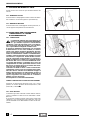 9
9
-
 10
10
-
 11
11
-
 12
12
-
 13
13
-
 14
14
-
 15
15
-
 16
16
-
 17
17
-
 18
18
-
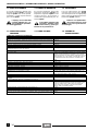 19
19
-
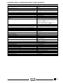 20
20
-
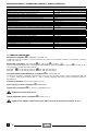 21
21
-
 22
22
-
 23
23
-
 24
24
-
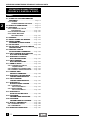 25
25
-
 26
26
-
 27
27
-
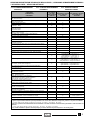 28
28
-
 29
29
-
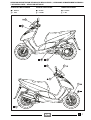 30
30
-
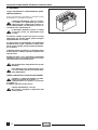 31
31
-
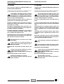 32
32
-
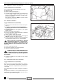 33
33
-
 34
34
-
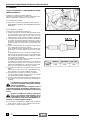 35
35
-
 36
36
-
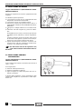 37
37
-
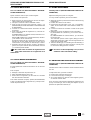 38
38
-
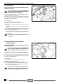 39
39
-
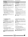 40
40
-
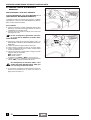 41
41
-
 42
42
-
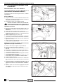 43
43
-
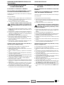 44
44
-
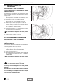 45
45
-
 46
46
-
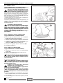 47
47
-
 48
48
-
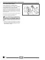 49
49
-
 50
50
-
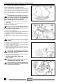 51
51
-
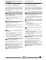 52
52
-
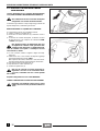 53
53
-
 54
54
-
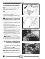 55
55
-
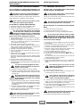 56
56
-
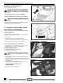 57
57
-
 58
58
-
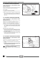 59
59
-
 60
60
-
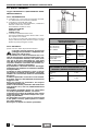 61
61
-
 62
62
-
 63
63
-
 64
64
-
 65
65
-
 66
66
-
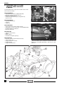 67
67
-
 68
68
-
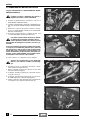 69
69
-
 70
70
-
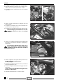 71
71
-
 72
72
-
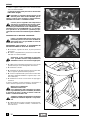 73
73
-
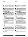 74
74
-
 75
75
-
 76
76
-
 77
77
-
 78
78
-
 79
79
-
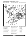 80
80
-
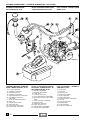 81
81
-
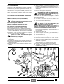 82
82
-
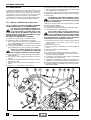 83
83
-
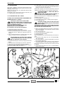 84
84
-
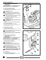 85
85
-
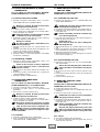 86
86
-
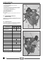 87
87
-
 88
88
-
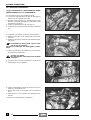 89
89
-
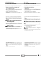 90
90
-
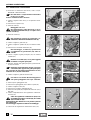 91
91
-
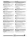 92
92
-
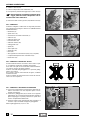 93
93
-
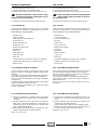 94
94
-
 95
95
-
 96
96
-
 97
97
-
 98
98
-
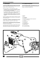 99
99
-
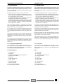 100
100
-
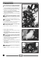 101
101
-
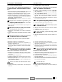 102
102
-
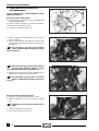 103
103
-
 104
104
-
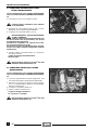 105
105
-
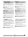 106
106
-
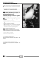 107
107
-
 108
108
-
 109
109
-
 110
110
-
 111
111
-
 112
112
-
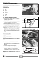 113
113
-
 114
114
-
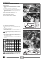 115
115
-
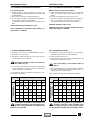 116
116
-
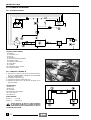 117
117
-
 118
118
-
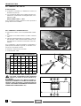 119
119
-
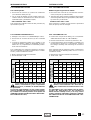 120
120
-
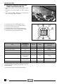 121
121
-
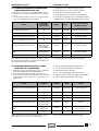 122
122
-
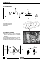 123
123
-
 124
124
-
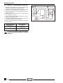 125
125
-
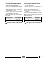 126
126
-
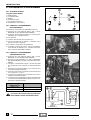 127
127
-
 128
128
-
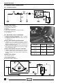 129
129
-
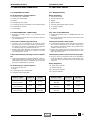 130
130
-
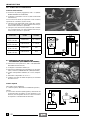 131
131
-
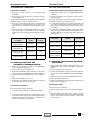 132
132
-
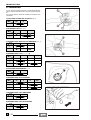 133
133
-
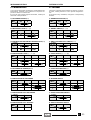 134
134
-
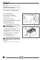 135
135
-
 136
136
-
 137
137
-
 138
138
-
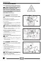 139
139
-
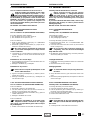 140
140
-
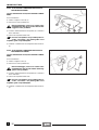 141
141
-
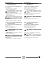 142
142
-
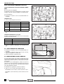 143
143
-
 144
144
-
 145
145
-
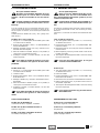 146
146
-
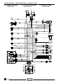 147
147
-
 148
148
-
 149
149
-
 150
150
-
 151
151
-
 152
152
-
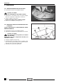 153
153
-
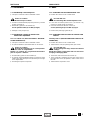 154
154
-
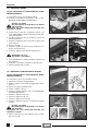 155
155
-
 156
156
-
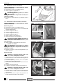 157
157
-
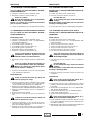 158
158
-
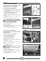 159
159
-
 160
160
-
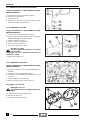 161
161
-
 162
162
-
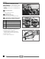 163
163
-
 164
164
-
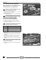 165
165
-
 166
166
-
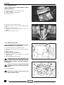 167
167
-
 168
168
-
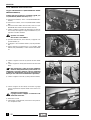 169
169
-
 170
170
-
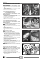 171
171
-
 172
172
-
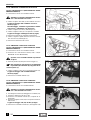 173
173
-
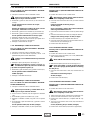 174
174
-
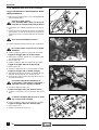 175
175
-
 176
176
-
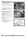 177
177
-
 178
178
-
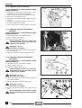 179
179
-
 180
180
-
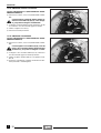 181
181
-
 182
182
-
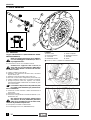 183
183
-
 184
184
-
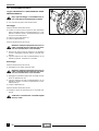 185
185
-
 186
186
-
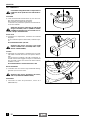 187
187
-
 188
188
-
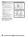 189
189
-
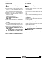 190
190
-
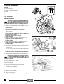 191
191
-
 192
192
-
 193
193
-
 194
194
-
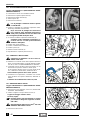 195
195
-
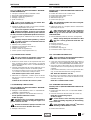 196
196
-
 197
197
-
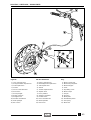 198
198
-
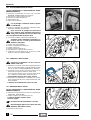 199
199
-
 200
200
-
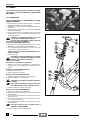 201
201
-
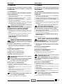 202
202
-
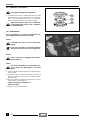 203
203
-
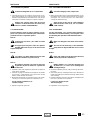 204
204
-
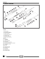 205
205
-
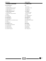 206
206
-
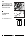 207
207
-
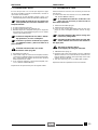 208
208
-
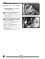 209
209
-
 210
210
-
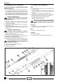 211
211
-
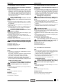 212
212
-
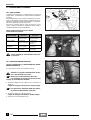 213
213
-
 214
214
-
 215
215
-
 216
216
-
 217
217
-
 218
218
-
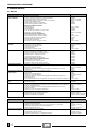 219
219
-
 220
220
-
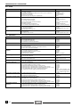 221
221
-
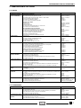 222
222
-
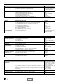 223
223
-
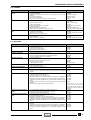 224
224
-
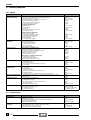 225
225
-
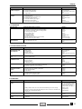 226
226
-
 227
227
-
 228
228
-
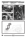 229
229
-
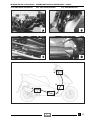 230
230
-
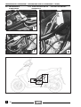 231
231
-
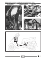 232
232
-
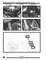 233
233
-
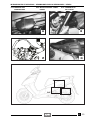 234
234
-
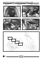 235
235
-
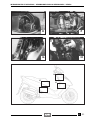 236
236
-
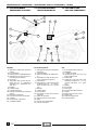 237
237
-
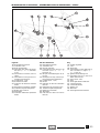 238
238
-
 239
239
-
 240
240
-
 241
241
-
 242
242
-
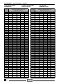 243
243
-
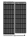 244
244
-
 245
245
-
 246
246
-
 247
247
-
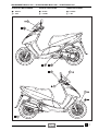 248
248
-
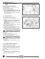 249
249
-
 250
250
-
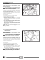 251
251
-
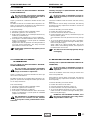 252
252
-
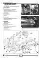 253
253
-
 254
254
-
 255
255
-
 256
256
-
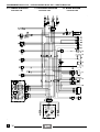 257
257
-
 258
258
-
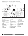 259
259
-
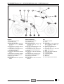 260
260
-
 261
261
-
 262
262


APRILIA 1997 Leonardo 125 Service and Repair Manual
- Categoría
- Motocicletas
- Tipo
- Service and Repair Manual
- Este manual también es adecuado para
en otros idiomas
- italiano: APRILIA 1997 Leonardo 125
- English: APRILIA 1997 Leonardo 125
Artículos relacionados
-
APRILIA Area 51 960x Service and Repair Manual
-
APRILIA SR 50 STREET 2009 Service and Repair Manual
-
-
-
-
-
APRILIA RS 50 - UPDATE 2004 El manual del propietario
Otros documentos
-
Oleo-Mac OM 98 L/14,5 K El manual del propietario
-
CAMPAGNOLA 0310.0415 ENERGY4 El manual del propietario
-
DAB AQUAPROF Instrucciones de operación
-
MV Agusta 2012 Brutale 675 Maintenance Manual
-
-
Malaguti MADISON 150cc Manual de usuario
-
 Annovi Reverberi HPV-M 90517-EX Manual de usuario
-
AGPtek MTII3 El manual del propietario
-
Shimano TL-HP51 Service Instructions
-
Ducati 96380031A Instructions Manual
