Bosch 3912 El manual del propietario
- Categoría
- Sierras de inglete
- Tipo
- El manual del propietario

iMPORTANT:
Read Before Using
IMPORTANT'.
Life avant usage
IMPORTANTE:
Leer antes de usar
Operating/Safety instructions
Consignes de fonctionnernent/s_curit_
Instrucciones de funcionarniento y seguridad
3912
Consumer Information
Renseignernent des consornrnateurs
Toll Free Number:
1=877=BOSCH99 (1=877=267=2499)
Inforrnaci6n para el consurnidor
Appel gratuit : N_rnero de tel_fono gratuito:
http://www.boschtools.corn.
For English
See page 2
Parlez=vous fran_ais?
Voir page 10
&Habla espa_ol?
Vet p_gina 18

Safety
r !_v*vl'-_z'l_ll_[e]l "READ ALL INSTRUCTIONS" -- Failure to follow the SAFETY RULES identified by BULLET (I)symbol
listed BELOW and other safety precautions, may result inserious personal injury.
General Safety Rules
For Bench Top Tools
W0rkArea
Keep work area clean and well lit. Cluttered benches
and dark areas invite accidents.
, Do not operate power tools in explosive
atmospheres, such as in the presence of flammable
liquids, gases or dust. Power tools create sparks which
may ignite the dust or fumes.
• Keep bystanders, children and visitors away while
operating a power tool. Distractions can cause you to
lose control.
Store idle tools out of reach of children and other
untrained persons. Tools are dangerous in the hands
of untrained users.
Do not leave tool running unattended, turn power off.
Do not leave tool until itcomes to a complete stop.
MAKE WORKSHOP CHILDPROOF with padlock,
master switches, or by removing starter keys.
Electrical Safety
Before plugging in the tool, be certain the outlet
voltage supplied is compatible with the voltage
marked on the nameplate within 10%. An outlet
voltage incompatible with that specified on the
nameplate can result in serious hazards and damage to
the tool.
Double insulated tools are equipped with a polarized
plug (one blade is wider than the other). This plug
will fit in a polarized outlet only one way. If the plug
does not fit fully in the outlet, reverse the plug. If it
still does not fit, contact a qualified electrician to
install a polarized outlet. Do not change the plug in
any way. Double insulation eliminates the need for the
three wire grounded power cord and grounded power
supply.
Avoid body contact with grounded surfaces such as
pipes, radiators, ranges and refrigerators. There is an
increased risk of electric shock if your body is grounded.
Do not expose power tools to rain or wet conditions.
Water entering a power tool will increase the risk of
electric shock.
Do not abuse the cord. Never use the cord to carry
the tools or pull the plug from an outlet. Keep cord
away from heat, oil, sharp edges or moving parts.
Replace damaged cords immediately. Damaged
cords increase the risk of electric shock.
When operating a power tool outside, use an outdoor
extension cord marked "W-A" or "W'. These cords are
rated for outdoor use and reduce the risk of electric
shock.
Personal Safety
Stay alert, watch what you are doing and use
common sense when operating a power tool. A
moment of inattention or use of drugs, alcohol or
medication while operating power tools can be
dangerous.
Dress properly. Do not wear loose clothing or
jewelry. Contain long hair. Keep your hair, clothing
and gloves away from moving parts. Loose clothes,
jewelry or long hair can be caught in moving parts.
Roll long sleeves above elbows. Rubber gloves and non-
skid footwear are recommended when working
outdoors.
Avoid accidental starting. Be sure switch is "OFF"
before plugging in. Carrying tools with your finger on
the switch or plugging intools that have the switch "ON"
invites accidents.
Remove adjusting keys or wrenches before turning
the tool "ON". A wrench or a key that is left attached to
a rotating part of the tool will be thrown.
Do not overreach, keep proper footing and balance
at all times. Proper footing and balance enables better
control of the tool in unexpected situations.
Do not stand on tool or its stand. Serious injurymay
occur if the tool is tipped or if the cutting tool is
accidentally contacted. Do not store materials on or
near the tool such that it is necessary to stand on the
tool or its stand to reach them.
Use safety equipment. Always wear safety goggles.
Dust mask, safety shoes, hard hat or hearing protection
must be used for appropriate conditions. Everyday
eyeglasses only have impact resistant lenses. They are
NOT safety glasses
"SAVE THESE INSTRUCTIONS"
2

Safety
r !_v*vl'-_'l_ll_[e]l "READ ALL INSTRUCTIONS" -- Failure to follow the SAFETY RULES identified by BULLET (I)symbol
listed BELOW and other safety precautions, may result inserious personal injury.
ToolUse andCare
Use clamps or other practical way to secure and
support the workpiece to a stable platform. Holding
the work by hand or against your body is unstable. It
allows for work to shift, causes binding of the tool and
loss of control.
Do not force tool. Use the correct tool for your
application. The correct tool will do the job better and
safer at the rate for which it is designed. Do not use the
tool for purpose not intended - for example; do not use
the miter saw for slicing meats.
Do not use tool if switch does not turn it "ON" or
"OFF". Any tool that cannot be controlled with the
switch isdangerous.
Disconnect the plug from the power source before
making any adjustments or changing accessories.
Such preventive safety measures reduce the risk of
starting the tool accidentally.
Keep cutting tools sharp and clean. Properly
maintained tools, with sharp cutting edges, are less likely
to bind and easier to control. When mounting saw
blades be certain that the arrow on the blade matches
the direction of the arrow marked on the tool and that the
teeth are also pointing in the same direction.
, inspect guards before using a tool. Keep guards in
place. Check moving parts for binding or any other
condition that may affect the normal operation or
safety features of the tool. if damaged, have tool
serviced before using the tool. Many accidents are
caused by poorly maintained tools.
. Do not alter or misuse tool. Any alteration or
modification is a misuse and may result in serious
personal injury.
• The use of any other accessories not specified in this
manual may create a hazard. Accessories that may be
suitable for one type of tool, may become hazardous
when used on an inappropriate tool.
Service
Tool service must be performed only by qualified
repair personnel. Service or maintenance performed by
unqualified personnel may result in misplacing internal
wires and components which could cause serious
hazard.
When servicing a tool, use only identical replacement
parts. Follow instructions in the Maintenance section
of this manual. Use of unauthorized parts or failure to
follow Maintenance Instructions may create a hazard.
Safety Rules for
Miter Saws
Use clamps to support workpiece whenever
possible, if supporting the workpiece by hand, you
must always keep hand outside of "No Hands" area
as marked with a symbol on the base. Do not use
this saw to cut pieces that are too small to be
securely clamped. Your hand if placed inside the "No
Hands" region can easily slip or be pulled intothe blade.
Do not reach in back of the saw blade behind the
fence with either hand to hold down or support the
workpiece, remove wood scraps, or for any other
reason. The proximity of the spinning saw blade to your
hand may not be obvious and you may be seriously
injured.
Never cross your hand over intended line of cutting.
Supporting the workpiece "cross handed" i.e. holding
the left side of the workpiece with your right hand isvery
dangerous.
Always disconnect the power cord from the power
source before making any adjustments or attaching
any accessories. You may unintentionally start the saw,
leading to serious personal injury.
Miter saws are intended primarily to cut wood or
woodlike products, they cannot be used with
abrasive cutoff wheels for cutting ferrous material
such as bars, rods, studs, etc. However, if cutting
materials like aluminum or other non=ferrous metals,
use only saw blades specifically recommended for
non=ferrous metal cutting. Cutting ferrous materials
causes excessive sparking and will damage the lower
guard and will overload the motor. (NOTE: S-B Power
Tool Company does not offer 12" metal cutting blades.)
inspect your workpiece before cutting. If workpiece
is bowed or warped, clamp it with the outside bowed
face toward the fence. Always make certain that
there is no gap between the workpiece, fence and
table along the line of the cut. Bent or warped
workpieces can twist or rock and may cause binding on
the spinning saw blade while cutting. Also, make sure
there are no nails or foreign objects in the workpiece.
• Do not use the saw until the table is clear of all tools,
wood scraps, etc., except the workpiece. Small
debris or loose pieces of wood or other objects that
contact the revolving blade can be thrown with high
speed at the operator.
. Do not feed workpiece into the blade or cut
"freehand" in any way. Workpiece must be
stationary and damped or braced by your hand. Saw
must be fed through the workpiece smoothly and at a
rate which will not overload the saw's motor.
"SAVE THESE INSTRUCTIONS"
3

Safety
! r!_v*vl'-1_'l_ll_[ttl "READ ALL INSTRUCTIONS" -- Failure to follow the SAFETY RULES identified by BULLET (I)symbol
listed BELOW and other safety precautions, may result inserious personal injury.
Cut only one workpiece at a time. Multiple workpieces
cannot be adequately clamped or braced and may bind
on the blade or shift during cutting.
Be certain the miter saw is mounted or placed on a
level, firm work surface before using. A level and firm
work surface reduces the risk of the miter saw becoming
unstable.
Plan your work. Provide adequate support
accessories such as tables, saw horses, table
extension, etc. for workpieces wider or longer than
the table top (see page 21). Workpieces longer or
wider than the miter saw table can tip if not securely
supported. If the cutoff piece or workpiece tips it can lift
the lower guard or be thrown by the spinning blade.
• Do not use another person as a substitute for a table
extension or as additional support. Unstable support
for the workpiece can cause the blade to bind or the
workpiece to shift during the cutting operation pulling
you and the helper into the spinning blade.
• The cutoff piece must not be jammed against or
pressured by any other means against the spinning
saw blade. If confined, i.e. using length stops, it could
get wedged against the blade and thrown violently.
• Always use a clamp or a fixture designed to properly
support round material such as dowel rods, or
tubing. Rods have a tendency to roll while being cut,
causing the blade to "bite" and pull the work with your
hand into the blade.
• When cutting irregularly shaped workpieces, plan
your work so it will not slip and pinch the blade and
be torn from your hand. A piece of molding, for
example, must lie flat or be held by afixture or jig that will
not let it twist, rock or slip while being cut.
, Let the blade reach full speed before contacting the
workpiece. This will help avoid thrown workpieces.
if the workpiece or blade becomes jammed or
bogged down, turn miter saw "OFF" by releasing
switch. Wait for all moving parts to stop and unplug
the miter saw, then work to free the jammed
material. Continued sawing with jammed workpiece
could cause loss of control or damage to compound
miter saw.
Braking action of the saw causes the saw head to
jerk downward. Be ready for this reaction when
making an incomplete cut or when releasing the switch
before the head is completely in the down position.
After finishing the cut, release the switch, hold the
saw arm down and wait for blade to stop before
removing work or cutoff piece. If blade does not stop
within five (5) seconds, unplug the saw and follow the
instructions in the Troubleshooting section.
REACHING WITH YOUR HAND UNDER A COASTING
BLADE IS DANGEROUS!
I'w,_ wl-],_=l,_r.,-_i[ ___VAV.,_..L_L,,LL_ Some dust created by power
sanding, sawing, grinding, drilling, and other
construction activities contains chemicals known to
cause cancer, birth defects or other reproductive harm.
Some examples of these chemicals are:
• Lead from lead-based paints,
Crystalline silica from bricks and cement and other
masonry products, and
Arsenic and chromium from chemically treated
lumber.
Your risk from these exposures varies, depending on how
often you do this type of work. To reduce your exposure to
these chemicals: work in a well ventilated area, and work
with approved safety equipment, such as those dust masks
that are specially designed to filter out microscopic
particles.
• There are additional safety instructions for particular
operations of the saw in the operating section. Read
the rest of the manual for safe operation.
"SAVE THESE INSTRUCTIONS"
4

Safety
IV !_Wl'-_'l_ll_[ctl "READ ALL INSTRUCTIONS"- Failure to follow the SAFETY RULES identified by BULLET (I)symbol
listed BELOW and other safety precautions, may result inserious personal injury.
• Do not aBow famBiarity gained from frequent use of your miter saw to become commonplace. Always remember that
a careless fraction of a second is sufficient to inflict severe injury.
• THINK SAFETY! SAFETY IS A COMBiNATiON OF OPERATOR'S COMMON SENSE, KNOWLEDGE OF THE SAFETY AND
OPERATING iNSTRUCTiONS AND ALERTNESS AT ALL TIMES WHEN THE MITER SAW IS BEING USED.
m'rm.l-]_ti_r,,._lr,.,=vAv.,_.,,..,,.....THE WARNINGS SHOWN BELOW CAN BE FOUND ON YOUR TOOL. THESE WARNINGS ARE
ONLY A CONDENSED FORM OF THE MORE DETAILED SAFETY RULES AND PRECAUTIONS THAT APPEAR IN YOUR
OWNER'S MANUAL. THEY SERVE AS A REMINDER OF ALL SAFETY RULES NEEDED FOR SAFE OPERATION OF THIS
MITER SAW.
DESIGNATED DANGER ZONE.
AVOID POSITIONING HANDS,
FINGERS OR ARMS IN THE
AREA DESIGNATED BY THIS
SYMBOL.
"SAVE THESE INSTRUCTIONS"
5

Safety
r !_v*vl'-_'l_ll_[ttl "READ ALL INSTRUCTIONS" -- Failure to follow the SAFETY RULES identified by BULLET (I)symbol
listed BELOW and other safety precautions, may result inserious personal injury.
DoubleInsulated Tools
Double insulation _ is a design concept used in electric
power tools which eliminates the need for the three wire
grounded power cord and grounded power supply system. It
is a recognized and approved system by Underwriter's
Laboratories, CSA and Federal OSHA authorities.
• Servicing of a tool with double insulation requires care
and knowledge of the system and should be performed
only by a qualified service technician.
• WHEN SERVICING, USE ONLY IDENTICAL
REPLACEMENT PARTS.
POLARIZED PLUGS. If your tool is equipped with a
polarized plug (one blade is wider than the other), this
plug will fit in a polarized outlet only one way. If the plug
does not fit fully in the outlet, reverse the plug. If it still
does not fit, contact a qualified electrician to install the
proper outlet. Do not change the plug in any way.
"SAVE THESE INSTRUCTIONS"
Extension Cords
Replace damaged cords immediately. Use of damaged
cords can shock, burn or electrocute.
If an extension cord is necessary, a cord with adequate
size conductors should be used to prevent excessive
voltage drop, loss of power or overheating. The table
shows the correct size to use, depending on cord length
and nameplate amperage rating of tool. If in doubt, use
the next heavier gauge. Always use U.L and CSA listed
extension cords.
Tool's
Am pere
Rating
RECOMMENDED SIZES OF EXTENSION CORDS
120 Volt A.C. Tools
Cord Length in Feet
Cord Size in A.W.G.
3-6
6-8
8-10
10-12
12-16
25 50 100 150
18 16 16 14
18 16 14 12
18 16 14 12
16 16 14 12
14 12 - -
NOTE: The smaller the gauge number, the heavier the cord.
Table of Contents
Page
Safety ......................................................................... 2-6
General Safety Rules for Benchtop Tools .............2-3
Safety Rules for Miter Saws ................................... 3-6
Table of Contents ........................................................ 6
Electrical Requirements ............................................. 7
Getting to Know your Miter Saw ............................8-9
Assembly ............................................................... 26-32
Tools needed for Assembly and Alignment ............26
Unpacking and Checking Contents ........................ 28
Installation of Miter Lock Knob ................................ 28
Installation and removal of the Blade ...................... 30
Assembling Dust Elbow and Dust Bag ................... 32
Adjustments .......................................................... 34-44
Blade square to Table (90°) .................................... 34
Blade 45° to Table ................................................... 36
Blade Square to Fence ............................................ 38
Miter Scale and Vernier Scale Usage .....................40
Miter Scale (Vernier) Indicator Adjustment .............42
Crown Molding Detent Adjustment (Bevel) .............42
Page
installation ............................................................ 44, 46
Mounting Applications ............................................. 46
Basic Saw Operations ......................................... 48-54
Body and Hand Position .......................................... 48
Workpiece Support ............................................ 50, 52
Switch Activation ..................................................... 52
Detent Override ....................................................... 54
Sliding Base/Fence Extension ................................ 54
Saw Operations .................................................... 56-72
Miter Cut .................................................................. 56
Bevel Cut ................................................................. 58
Compound Cuts ...................................................... 60
Base Molding ........................................................... 62
Cutting Crown Molding ............................................ 65
Special Cuts ............................................................. 72
Accessories ................................................................ 74
Maintenance and Lubrication ............................ 76, 78
Trouble Shooting ................................................. 80, 82
6

Electrical Requirements
1. Connect this saw to a 120V, 15-amp branch circuit with
a 15-amp time delay fuse or circuit breaker. Using the wrong
size fuse can damage the motor.
2. Fuses may "blow" or circuit breakers may trip frequently
if motor is overloaded. Overloading can occur if you feed the
blade into the workpiece too rapidly or start and stop too
often in a short time.
3. Most motor troubles may be traced to loose or incorrect
connections, overload, low voltage (such as small size wire in
the supply circuit or to overly long supply circuit wire).
Always check the connections, the load and the supply circuit
whenever motor does not work well.
Electric Brake
Your saw is equipped with an automatic electric brake which
is designed to stop the blade from spinning in about five (5)
seconds after you release the trigger switch. It is useful when
making certain cuts in wood where a coasting blade would
result in awide, imprecise cut.
r!'vAV'-_i_ll_[el When electrical power is lost due to
blown fuse or other causes, the motor will gradually slow
down and the braking action is initiated ONLY by the release
of the trigger switch.
The electric blade brake of your miter saw has been designed
for highest degree of reliability, but unexpected
circumstances such as contamination on the commutator
and brushes or failure of motor's components can cause the
brake not to activate. If this condition occurs, turn the saw
"ON" and "OFF" four to five times without contacting the
workpiece. If the tool operates but the brake does not
consistently stop the blade in about five (5)seconds, DO NOT
use saw and have it serviced immediately.
r!'vAV'-_i_ll_[el The brake action of this saw is not
intended as a safety feature. Remember to let the saw blade
come to a complete stop before removing from the
workpiece. As always the guard system is your best
protection against unintentional contact with a spinning saw
blade. NEVER wedge open or defeat the closing action of the
lower guard.
Wiring Diagram
r !_v*V'-_r`_ll_[e]l This wiring diagram can be used only with the switch (Part No. 2610910020) supplied with your miter
saw. Other switches may look the same but internal switch components can be different, thus creating electrical shock hazard if
wired according to this diagram.
Blue _ _ Black (PowerCord)
,
vv_ed_ _ _Gray
7

2
1
3
4
27
26
24
23
25
37
30
22
\
\
21
10
16 15
20 17 10 18
I To avoid injury from accidental
starting, remove plug from power source outlet before
making any adjustments.
1, Carrying Handle
This handle is built into the head assembly for transportation.
2. Arbor Lock
Allows the user to keep the blade from rotating while
tightening or loosening arbor screw during blade replacement
or removal.
3. Ambidextrous Switch
The left or right hand ambidextrous switch must be pressed
to activate the power switch.
14
13
4. Switch Handle
This handle contains the switch. The blade is lowered into
the workpiece by pushing/pulling down on the handle.
5. Power Switch
The power switch used with the ambidextrous switch
energizes the unit.
6. Lower Blade Guard/Lower Guard Lip
The lower blade guard helps protect your hands from the
spinning blade. It retracts as the blade is lowered. Lip can be
used to raise the lower guard when guard becomes jammed
on a workpiece.
8

7. Blade
Use only 12" blades with 1" arbor hole.
8. Fence
Supports the workpiece. The fence has a cast in scale to
make repetitive cuts easy. The fence also has holes which
are used to secure an auxiliary fence if desired.
9. Kerf insert
Minimizes workpiece tear-out.
10. Tool Mounting Pads
The four corners of the saw provide areas to clamp, bolt or
nail the saw to a flat work surface.
11. Detent Override
Allows detent action to be locked out allowing for micro
adjustments to any miter angle.
12. Miter Lock Knob
The miter lock knob locks the miter saw table at any desired
miter angle.
13. Miter Detent Trigger
The trigger releases the table from the detent.
14. Miter Scale
This scale is cast in on the base of the saw. Allows you to
read the miter angles easily.
15. Detents
There are nine (9) miter detents for fast and accurate miter
cuts of common miter angles.
16. Table
Sits in base, provides workpiece support, rotates for desired
miter cuts and rotates the head assembly.
17. Workpiece Clamp Positions
There are six (6) positions around the base for the workpiece
clamp.
18. Base
Provides working surface to support workpiece.
19. Accessory Extension/Stop Holes (Standard Type)
Machined holes that accept the extension/stop accessory.
20. Accessory Pipe Extension/Stop Holes
Machined holes that accept the pipe extension/stop
accessory.
21. Sliding Base
This provides extra support and clamping area for compound
miter cuts.
22. Sliding Fence
Provides maximum height support for the workpiece and
slides to left for easy compound cuts.
23. Lock Pin
The compound miter saw is equipped with a lock pin used to
lock the head assembly in the lower position.
24. Dust Chute Elbow
The dust chute elbow rotates 360° and can accommodate
the dust bag or a 1-1/4" vacuum hose hookup.
25. Chip Deflector
This protects against large chips from entering the upper
guard.
26. Lower Guard Actuation Link
Allows for smooth movement of the lower guard.
27. Upper Blade Guard
Covers upper portion of the blade.
©
30
o
36
28. Blade Wrench
Used for tightening/loosening blade and adjusting bevel
stops. Blade wrench is stored in the switch handle.
29. Bevel Detent Pin (Crown Molding Setting)
Allows you to easily move the head assembly to the bevel
angle of 33.9°.
30. Dust Collection Bag
Attaches to the dust elbow and collects dust to help keep
work area clean.
31. Bevel Lock Handle
The bevel lock handle locks the head assembly at a desired
bevel angle. Handle ratchets for use in tight spaces.
32. 45° Bevel Stop
Adjustable stop for a quick and accurate 45° bevel index.
33. 0 ° Bevel Stop
Adjustable stop for a quick and accurate 0° bevel index.
34. Bevel Scale
This scale is cast in on the saw. Allows you to read the bevel
angles easily.
35. Hex Wrench
Used to adjust sliding base. Hex wrench is stored in the left
rear base.
36. Brush Caps
These caps keep the motor brushes in position and provide
easy access for inspecting and replacing brushes.
37. Quick Action Clamp
Provides fast clamping of workpiece.
FOR CONTiNUATiON OF ENGLISH SEE PAGE 26
9

blessures.
S curit
_ LISEZ TOUTESLES INSTRUCTIONS_ -- L'utilisateur qui n6gligerait de suivre los CONSIGNESDE SECURITE
pr6c6d@sd'un point noir (I) ci-dessous et de prendred'autres pr6cautions616mentairesrisquerait de subir de graves
Consignesg6n rales des curit
pourlosoutiisd' tabli
Zonede travail
GardezJazone de travail propreet hien _clair_e. Les 6tablis
encombr6setlos endroitssombresinvitent losaccidents.
• N'utiJisez pas los outils _Jectriques en atmospheresexplo-
sives,commeen presencede poussi_te,de gazou de Jiquides
inflammables. Les outils 61ectriquescr@nt des 6tincellesqui
peuventenflammerlapoussi_reoules vapeurs.
• GatdezJesspectateuts, Jesenfants et Jesvisiteurs _ J'_cad
Jorsque vous utiJisez un outil _Jectrique. Les distractions
peuventvousfaireperdrele contr61e.
• Rangez JesoutiJs inutilis_s hers de pod_e des enfants et
autrespersonnessansformation _ cot _gard. Les outils sent
dangereuxentre losmains d'utilisateursnonform6s.
• Ne laissez pas J'outiJen marche, sans surveillance, mettez
hers tension. Ne laissez pas I'outil avant qu'il soit & I'arr_,t
complet.
• RENDEZL'ATEUER A L'rtPREUVEDES ENFANTS_,I'aide de
cadenasou d'interrupteurs principaux,ou en retirant loscl6sdu
d6marreur.
S6curit6 61ectrique
• Avant de brancher J'outil _ une prisede courant,assurez-vous
que Jatension fournie correspond, _ 10 % pros, _ ceJJe
sp_cifi_e sur la plaque signaJ_tique. Unetension de sortie
incompatibleaveccellosp6cifi(_esur laplaquesignal(_tiquerisque
de blesser s@ieusement I'utilisateur sans mentionner
I'endommagementde I'outil.
• Los outiJs_ double isolationsent pourvusd'une fiche poJa-
ris_e(une lame est pluslarge que J'autre). Cettefiche ne pout
_tre ins_r_edarts une prisepolaris_eque d'une seuJefa_on.
Si ia fiche ne s'ins_re pas _ fond darts ia prise, inversezJa
fiche. Si elle ne rentre toujours pas, contactez un _lectficien
quaJifi_ pourfaire poserune prisepoJaris_e.Ne modifiez Ja
fiche d'aucune far,;on.La double isolation (_liminela n(_cessit(_
d'un cordonmis _,laterre_,trois fiis etd'une aiimentationmise_,
laterre.
• ftvitez tout contactcorporeJavec lessurfaces raises _ la torte
teJJesquetuyaux, radiateurs, cuisini_res et r_frig_rateurs. Cos
surfacesposentunrisqueaccrudesecousses61ectriquessi votre
corpsestmis b,laterre.
• N'exposezpasJesoutiJs_lectriques _ JapJuieou_ J'humidit_.
L'eaup6n6trantdansun outil (_lectriqueaugmenteralerisque de
secousses(_lectriques.
• N'abusezpasdu cordon.N'utiJisezjamais Jecordonpourtran-
spoderJesoutilset ne tirez pas Jafiche d'une prise. TenezJe
cordon_ I'_cad de JachaJeur,de J'huiJe,des armiesviveso,
des pi_ces mobiles. RempJacez Jes cordons abim_s
imm_diatement. Les cordons ab_m(_saugmentent le risquede
secousses(_iectriques.
• LorsquevousutiJisezun outiJ_lectrique _ J'ext_rieur, utiiisez
un cordonde rallonge pourserviceext_rieur marqu_ ,, W-A ,,
o, <<W ,,. Ces cordons sent pr@us pour usage ext@ieur et
r(_duisentlerisquedesecousses(_lectfiques.
S curit personnelle
• Demeurez vigilant, surveiJJezceque vous faites et faites
preuve de discernement en utiJisantun outil _Jectfique. Un
moment d'inattention ou la prise de drogues, d'alcool ou de
m(_dicamentspeut s'av@er dangereux durant I'utilisation d'un
outil (_lectrique.
• Portez des v_tements convenabJes. Ne portez pas de
v_tementsamples ni de bijoux.Pour ies cheveux longs,nous
conseillonsie port d'un serre-t_te. Tenez ies cheveux, les
v_tements et les gants _ I'_cad des pi_ces mobiles. Los
v_tementsampJes,Jesbijouxou Jescheveux longsfisquent de
s'accrocher dans Jes pi_ces mobiles. Roulez los manches
Ionguesau-dessusdu coude.Le port de gantsen caoutchoucet
de chaussures_,semelleantid@apanteest recommand(_si vous
travaillez_,I'ext@ieur.
• ftvitez Ja raise en marche accidenteJJe.Assurez-vous que
J'interrupteur est _ J'arr_t avant de hrancher.Le transport de
I'outil avec le doigt sur I'interrupteur ou le branchementd'outils
dentI'interrupteurestb,la positiondemarcheinvitelesaccidents.
• Enlevezlos cJ_sde r_gJageet autres cl_s avant de mettre
J'outiJ en marche. Une cl(_qui est laiss(_efix(_e_,une piece
rotativedeI'outil seraprojet@.
• TravaiJJezavec aplombet _quiiibre _tout moment, cequi aide
mieux contrSJerJ'outiJdartsJescasimpr_vus.
• Ne montez pas sur J'outiJ ni sur son supped. Des bJessures
gravespeuvent#,trecaus@sencas de basculementdeI'outil ou
de contactaccidentelavec I'outilde coupe. Neconservezpas de
mat@iaux sur ou b,proximit_ de I'outil de sorte qu'il soit
n@essaire de monter sur I'outil ou son support pour les
atteindre.
UtiJisezJ'_quipementde s_curit_.Podeztoujours des Junettes
coquesJat_raJes.Un masqueanti-poussi_re,des chaussures
de s_curit_,un casquedur ou des prot_ge-oreiiiesdoivent _,tre
utiiis(_s si ia situation i'exige.Les lunettes de tous los jours
comportent uniquementdes verres r(_sistantaux chocs. Ce NE
SeNTPASdes lunettesdes@urit_.
,,CONSERVEZCESINSTRUCTIONS,,
10

blessures.
S curit
_ LISEZ TOUTESLES INSTRUCTIONS_ -- L'utilisateur qui n6gligerait de suivre los CONSIGNESDE SECURITE
pr6c6d6esd'un point noir (I) ci-dessous et de prendred'autres pr6cautions616mentairesrisquerait de subir de graves
Utilisation et entretiende I'ouiil
• Utilisezdes pincesou autrefagon pratiqued'assujettir el de
supporterrouvrage _ une plate-formestable. TenirI'ouvrageb,
la main ou centre son corps n'assure pas la stabilit6 voulue.
L'ouvragepoutainsised6placer,faire gripper I'outiletvous faire
perdrele contr61ede I'outil.
• Ne forcez pus Foutil. UtilisezI'outil convenant _ votreappli-
cation. L'outil convenabieex6cuterale travail plus efficacement
et plussQrementb,lavitesseb.laquelieil estcon(_u.N'utilisezpas
I'outilb.une fin autre que celieb,iaquelieil est pr6vu -- ainsi,
n'utiiisezpas lascieb,ongietpourtrancher losviandes.
• N utilisez pusI outil si I interrupteur ne le met pusen marche
el _ I'arr_t. Tout outil qui ne peut#,trecommand6parI'interrup-
teurestdangereux.
• D_branchezla fiche de la prise de courant avant d effectuer
tout r_glage ou de changer los accessoires. Ces mesures
pr6ventives r6duisent le risque d'une mise en marche
accidentelle.
• Gardezlos outilsde coupeaffil_s el propres.Des outils bien
entretenus,avec tranchants affil6s, sent moins susceptiblesde
gripper et plus faciles b,contr61er. Lorsque vous montez des
lamesdescie, assurez-vousquelafl_che de lalamecorrespond
au sensde lafl_chemarqu6esur I'outiletque losdents pointent
6galementdanslem_,mesens.
• Inspectezlos protecteursavant d'utiliser un outil. Gardezlos
protecteursenplace V_rifiezsi los pi_cesmobiles gfippent ou
toutautre_tat pouvantinfluersurle fonctionnement normalou
los fonctions de s_cufit_de routil, si routil est abim_, faites-
le r_parer avant de I'utiliser. Beaucoupd'accidentssent caus6s
pardesoutils malentretenus.
• Ne modifiez pusI'outil el n'enfaites pusunusageinappropfi_.
Toutealt6ration ou modificationconstitue un usage inappropri6
etpoutcauserdes biessuresgraves.
• L utilisation de tout autre accessoirenon pr_cis_ duns ce
manuel poutcrier un danger. Lesaccessoiresqui peuvent_,tre
ad6quats pour un type d'outil peuvent devenir dangereux
Iorsqu'ilssent utilis6ssur unoutil inappropri6.
R6paration
• L outil ne doit _tre r_par_ que par des techniciens de
r_parationqualifies. Les r6parationsou I'entretieneffectu6spar
des personnes non qualifi6es peuvent r6sulter en un posi-
tionnementerron6de composantset defils internes,cequi pout
provoquerdesdangerss6rieux.
• N'utiiisez que des pi_cesde rechange identiquespourr_parer
un outil Suivez los consignes contenues duns la section
Entretiendecemanuel. L'utilisation depi_cesnonautoris6esou
le non-respectdesconsignesd'entretienpout_,tredangereux.
Consignesdes6curit6
pourlosscies onglet
Utilisezdes pincespoursupporterI'ouvrage chaque lois que
possible Si voussupportez I ouvrage _ la main, vous devez
toujours garder la main _ I ext_rieur de la zone interdite aux
mains, identifi_e parun symbolesur la base N'utilisez pus
cettescie pour couperdes pi_cesqui sent trop petites pour
_tre bien assujetties.Si erieest plac6eb,I'int6rieur de la zone
interdite aux mains,votre main poutglisser facilement ou _,tre
tir6e dansla lame.
• N ins_rezpusla main_ I artiste de la lame de scie,derriere le
guide, pourtenir ousupporterrouvrage, enlever des d_bris de
bois ou route autreraison. La proximit_ de la lame de scie en
rotationb,votre main peutne pas_,tre_vidente,etvous pourriez
_,tregri_vementbiess_.
• Ne passezjamais la main_travers la ligne de coupepr_vue II
est tr_s dangereux de supporter I'ouvrage b,main crois_e, b,
savoir, en tenant le c6t_ gauche de I'ouvrage avec votre main
droite.
• D_brancheztoujours le cordonde la prise de courant avant
d'effectuer quelque r_glage quece soil ou de poserdes acce-
ssoires.Vous pouvezmettre la scieen marche parm_garde,et
6trebiess_gfi_vement.
• Losscies _ ongiet sent destinies pfincipalement_ couperle
bois ou des produits similaires ; on ne pout los utiliseravec
des meules _ tron_onner pourco.per des mat_riaux ferreux
tels que burros, tiges, poteaux,etc Cependant, pour couper
des mat_riaux tels que I aluminium ou autres m_taux non
ferreux, utilisez uniquement des lamesde scierecommand_es
sp_cifiquementpourla coupede m_taux nonferreux Lacoupe
de mat_riauxferreuxforme unequantit_ excessived'_tincelleset
abfmerale protecteur inf_rieur en plus de cr6er une surcharge
sur le moteur. (REMARQUE: S-B PowerTool Companyn'offre
pasdelamesde 12pc pour couperles m_taux.)
• Inspectez votre ouvrage avant de couper Si I ouvrage est
cintr_ ou gondola, pincezle avec la face cintr_e ext_fieure
dirig_e vers le guide. Assurez-vous toujours qu'il n'y a pas
d_cartement entre I ouvrage,le guide el la table le longde la
ligne de coupe. Les ouvrages plies ou gondolas peuvent se
tordre ou cuibuter, et peuventfaire gripper la lame de scie en
rotation durant ia coupe.Assurez-vous_galement de I'absence
declousou decorps_trangersdansFouvrage.
• N utilisez pusla scierant que la table nest puslib_r_e de tous
outiis, d_bris de bois, etc, saufi'ouvrage.Les petits d_brisou
pi_cesd_tach_esdebois ouautres objetsvenanten contactavec
la lame en rotation peuvent _,treprojet_s b,haute vitesse en
directionde I'op_rateur.
CONSERVEZCES/NSTRLICT/ONS,,
11

blessures.
S curit
_ LISEZ TOUTESLES INSTRUCTIONS_ -- L'utilisateur qui n6gligerait de suivre les CONSIGNESDE SECURITE
pr6c6d6esd'un point noir (I) ci-dessous et de prendred'autres pr6cautions616mentairesrisquerait de subir de graves
• N'introduisez pas I'ouvtage darts la lame et ne coupez d'au-
curie mani_re _ ,, main libre ,,. L'ouvrage dolt _tre fixe et
cramponn_o, serr_ par votremain. La scie dolt _,treins6r6e_,
traversi'ouvrage doucementet _,unevitessequi nesurchargera
pasle moteurde lascie.
• Coupezun soulouvrage _ Jafois. Les ouvrages multiples ne
peuvent_,trecramponn6sou serr6sad6quatement,et ilspeuvent
grippersur lalameou sed6placerdurant lacoupe.
• Assurez-vous que la scie _ onglet est monroe ou platte sur
unesurface detravail ferme et_ niveauavant de I'utiliser. Une
surfacedetravailferme et &niveaur6duit le risqued'instabilit_de
la scie_,onglet.
• PJanifiez votre travail Obtenez des accessoires de support
ad_quats tels que tables, cbevalets de scieur, rallonge de
table, etc. pourlos ouvrages pluslargos ou pluslongsque le
dessusde la table (voir page85). Les ouvragesplus longs ou
plus largesque la tablede la scie_,ongiet peuventbasculers'ils
ne sent passupport_s ad(_quatement.Si la piecetron(_onn(_eou
I'ouvrage bascuie, il pout lever le protecteur inf(_rieurou _,tre
projet_par lalameen rotation.
• N'utilisez pas une autre personneen remplacement d'une
rallongede table ou commesupport suppl_mentaire. Un sup-
port instablede rouvrage peutfaire gripper la lame ou d(_placer
I'ouvrage durant la coupe, tirant ainsi votre assistant et vous-
m#,medansla lameenrotation.
• La piecetron_onn_ene doit pas _tre bloqu_e centre la lame
de scie en rotation ni _tre press_e par aucun autre moyen
centre celle-ci. Si elle est captive, en utilisant des buttes de
Iongueur,parexemple,eliepourrait_,trecoinc6ecentre la lameet
_,treprojet_evioiemment.
• Utilisez toujours .n serre-joints ou un dispositif con_. de
mani_re _ supporterad_quatement los mat_riaux rendstels
quelos goujons ou lostubes. Lesgoujonsont tendance_,rouler
pendantqu'on ies coupe, cequi amine la lame_,<_mordre _ et
tire I'ouvrageetvotremaindans lalame.
• En coupantdes ouvrages de forme irr(_,guli_re,planifiezvotre
travail de mani_re _ ce que I'ouvrage ne glisse pas et ne
vienne pas pincer la lame, pour _tre ensuite tir_ de votre
main. Unepiece de moulure dolt ainsi _,trepos6e_,plat et _tre
tenue par un dispositif ou une monture qui I'emp_,chera de
tordre, basculerou giisserpendantlacoupe.
• Laissez la lame atteindre une vitesse maximum avant de Ja
mettre en contact avec I'ouvrage. Ceci aidera _,(_viter la
projectiond'ouvrages.
• Si rouvrage oula lame sebloque ousecoince,mettez lascie
onglet _ I'arr_t en rel_chant I'interrupteur. Attendez que
routes los pi_cesmobiles s'arr_tent et d_branchez la scie
onglet avant de lib_rer los mat_riaux ¢oinc_s. Le fait de
continuer b,scier avec I'ouvrage coinc_ pourrait entra_nerune
pertedecontr61eou desdommagesb,lascieb,ongletcompos6e.
• La t_te de scie estsecou_e versle has sous reffet de raction
de freinage de la scie. Soyezpr_t_ cette r_actionen pratiquant
unecoupeincompleteou en rel_,chantI'interrupteuravantque la
t_tenesoit compl_tementdescendue.
• Apr_savoir termin_ la coupe,reJ_chezI'interrupteur,tenez le
bras de la scie en has et attendezque la lame s'arr_te avant
de rotifer I'ouvrage ou la piece tron_onn_e. Si la lame ne
s'arr_tepasdartsund_lai de cinq (5)secondes,d_brancbezla
scieet suivez los consignesapparaissant dans la section
D_pannage. IL ESTDANGEREUXD'INSERERLA MAIN SOUS
UNELAMEENTRAINDES'IMMOBILISER.
Los travaux _ la machine tel que
pon_age, sciage, moulage, per_age et
autrestravaux du b_timent peuventcr_erdes poussi_rescontenant
des produitscbimiquesqui sentdes causesreconnues de cancer,
de malformation cong_nitaleou d'autres probl_mesreproductifs.
Cosproduitschimiquessent,parexemple :
• Le plombprovenantdespeintures& basedeplomb,
•Les cfistaux de siiices provenantdes briques et du ciment et
d'autres produitsdema(_onnerie,et
• L'arsenic et le chrome provenant des bois trait(_s
chimiquement
Le niveaude risque dQ_,cette exposition varie avecla fr(_quencede
cos types de travaux. Pour r(_duire I'exposition _,cos produits
chimiques, il faut travailier dans un lieu bien ventil(_et porter un
(_quipement de s_curit(_ appropri(_ tel que certains masques _,
poussi_re con(_us sp(_cialement pour filtrer les particules
microscopiques.
• II existedes consignesde s_curit_suppl_mentairespour los
operations particuli_resde la scie darts la sectionrelative au
fonctionnement. Lisezle reste du manuel pourune utilisation
sQrede la scie.
,,CONSERVEZCESINSTRUCTIONS,,
12

blessures.
S curit
<_LISEZ TOUTES LES INSTRUCTIONS >_-- L'utilisateur qui n6gligerait de suivre les CONSIGNES DE SECURITE
pr6c6d6es d'un point noir (I) ci-dessous et de prendre d'autres pr6cautions 616mentaires risquerait de subir de graves
• Ne laissez pas la familiatit_ tir_e d',ne utilisationfr_q,ente de votrescie _ ongletatt_nuer vetrevigilance. N'oubliezjamaisqu'une
fraction deseconded'insouciancesuffit b.causerdesbiessuresgraves.
• PENSEZEN TERMESDE SECURITE.LA SECURITEESTUNECOMBINAISONDE BONSENS,DE CONNAISSANCEDESCONSIGNESDE
SECURITEETDE FONCTIONNEMENT,ET DEVILIGANCECONSTANTEDE LA PARTDE L'OPERATEURLORSDEL'UTILISATIONDELA
SCIEAONGLET.
LESAVERTISSEMENTSCI-APRi:SSETROUVENTSURVOTREOUTIL.CESAVERTISSEMENTSNESONTQU'UNE
FORIVlECONDENSEEDESRi:GLESETPRECAUTIONSBESECURITI_PLUSBETAILLEESQUiAPPARAISSENTBANS
VOTREMANUEL,ELLESSERVENTA VOUSRAPPELERTOUTESLESRi:GLESDESECURITENECESSAIRESA UNEUTIUSATIONSOREDE
CETTESCIEAONGLET.
ZONE DI_SIGNI_EDE DANGER.
i_VITERDE PLACER LES MAINS,
LES DOIGTS OU LES BRAS
DANS LA ZONE DI_SIGNI_EPAR
CE SYMBOLE.
f ASSUREZ-VOUSDELIREETDECOMPRENDRELEMANUELD'INSTRUCTIONSAVANT
, VB TISSI I ENTD'UT,USERCETOUT,L
PORTEZTOUJOURSDESLUNETTESDESCCURITE/_COQUESLATERALES.
e POUREVITERLESCHOCSELECTRIQUES,N'EXPOSEZPASLA SCIEA LA PLUIEETNEL'UTILISEZPASA DES
ENTROITSHUMIDES.
• UTILISEZUNELAME DESCIEPREVUEPOURUTILISATION_,4 000TR/MIN OUPLUS.
• DEBRANCHEZLA SCIEAVANTDEL'ENTRETENIROU DE CHANGERLA LAME.
• N'UTILISEZQUEDESPIECESDERECHANGEIDENTIQUESSUR LA SCIE.
• GARDEZLESMAINS _,UNEDISTANCESUREDELALAMEDESCIE.
e NEMETTEZJAMAIS LESMAINS ENTRAVERSDUPARCOURSDELA LAMEDESCIE.NEPLACEZPASLESMAINS
DERRIERE,SOUSOUDEVANTLA LAME.
e SERREZL'OUVRAGECONTRELA BASEETLEGUIDE.N'EFFECTUEZJAMAIS AUCUNEOPERATIONA<<MAIN
LIBRE>>.
• TOUTESLESSCIESELECTRIQUESAREIN PEUVENTPARFOISNE PASREUSSIRA ARRETERLA LAME.
e APRESAVOIRMIS LASCIEENPOSITIOND'ARRET,MAINTENEZTOUJOURSLATETEDESCIEENBASET
ATTENDEZQUELA LAMES'ARRETEAVANTD'ENLEVERLESPIECESDECOUPEESOUDENETTOYERLATABLE.
e DEPLOYEZLA BASECOULISSANTEPOURPRATIQUERDESCOUPESENBISEAUOULORSQUELA TABLEEST
TOURNEEDUCOTEGAUCHE.
• RETIREZL'ONGLETDROITPOURLESCOUPESENBISEAUOUCOMPOSEES.
e NEPASUTILISERLASCIESANSLESPROTECTEURSENPLACE.REMETTEZLEPROTECTEURA LA POSITIONDE
SERVICEAPRESAVOIRCHANGELALAME.
e SI LE PROTECTEURNETRAVAILLEPASENDOUCEUR,CESSEZDESCIERETFAITESREPARERL'OUTILAVANTDE
PROCEDER.
e L'ACTIONDEFREINAGEDELASCIEFAITAVANCERLA TETEDELA SCIEBRUSQUEMENTVERSLE BAS.ATTENDEZ-
VOUS_,CETTEREACTIONENRELACHANTL'INTERRUPTEURAVANTQUELATETENESOITCOMPLETEMENT
DESCENDUE.
_CONSERVEZCES/NSTRUCT/ONS>>
13

blessures.
S curit
_ LISEZ TOUTESLES INSTRUCTIONS_ -- L'utilisateur qui n6gligerait de suivre les CONSIGNESDE SECURITE
pr6c6d6esd'un point noir (I) ci-dessous et de prendred'autres pr6cautions616mentairesrisquerait de subir de graves
Doubleisolation
La doubJeisolation L_ est utilis6e dans les outils 61ectriquespour
61iminerle besoin de cordon d'alimentationavec prise deterre et de
dispositif d'alimentation b,prise de terre. Elleest homologu6e par
I'Underwriter'sLaboratories,I'ACNORet I'OSHA.
• L'entretien d'un outil b.double isolation exige laconnaisancedu
syst_meet lacomp6tenced'untechnicienqualifi6.
• EN CAS D'ENTRETIEN, N'UTILISEZ QUE DES PIECES DE
RECHANGEIDENTIQUES.
• FICHES POLARISEES.Si votre outil est 6quip6 d'une fiche
poiaris6e(une lameplus largeque I'autre)eile ne s'enficheque
d'une mani_redans uneprise polaris6e.Si lafiche n'entre pasb,
fond dans ia prise, tournez-la d'un demi-tour. Si elle refuse
encored'entrer, demandezb,un 61ectricienquaiifi6 d'installerune
priseappropri6e.Nemodifiezlafiche d'aucunefa(_on.
,_CONSERVEZCES/NSTRUCT/ONS ,,
Ralionges
Remplacez imm6diatement toute rallonge endommag6e.
L'utilisationde rallongesendommag6esrisquede provoquerun
choc61ectrique,desbrQluresou 1'61ectrocution.
En cas de besoin d'une railonge, utilisez un cordon de calibre
satisfaisantpour 6viter route chute detension, perte de courant
ou surchauffe. Le tableau ci-contre indique le calibre des
rallonges recommand6es en fonction de ieur Iongueur et de
I'intensit6indiqu6esur la plaquedu constructeurdeI'outil. Encas
de doute, optez pour ie prochain calibre inf6rieur. Utilisez
toujours desrallongeshomologu6esparI'U.L. etI'ACNOR.
DiMENSiONSDERALLONGESRECOMMANDEES
Intensit_ OUTILS120VOLTSC.A.
norninale Longueuren pieds
de routil CalibreA.W.G.
3-6
6-8
8-10
10-12
12-16
25 50 100 150
18 16 16 14
18 16 14 12
18 16 14 12
16 16 14 12
14 12 -- --
REMARQUE:Plusle calibreestpetit,pluslefil estgros.
Table des rnati res
Page
Securit_........................................... 10-14
Consignesg6n6ralesdes6curit_pour les
outiis d'6tabii ..................................... 10-11
Consignesdes_curit_pour lessciesb,onglet ........... 11-14
Table des mati_res .................................... 14
Specifications _lectriques ............................... 15
FamJJiafisez-veusavecvetrescie_ engJet .............. 16-17
Assemblage ....................................... 26-32
Outilsn6cessairesb,I'assemblageetb,I'alignement .......... 26
D6bailageet v6rificationdu contenu ...................... 29
Posedu boutonde biocaged'onglet ..................... 29
Poseet d6posede la lame ............................. 31
Assemblagedu coudede poussi_reet dusac b,poussi_re .... 33
R_gJages.......................................... 35-43
Lamed'6querreparrapport b,latable(90°) ................ 35
Lameb,450parrapport b,latable ........................ 37
Lamed'6querreparrapport auguide ..................... 39
Utilisationde 1'6chellegradu6ed'ongletetde
1'6chellegradu6eVernier ............................... 40
R6giagedeI'indicateurde 1'6cheilegradu6e
d'onglet (Vernier) .................................... 43
R6glageducran d'arr_,tmouluresen couronne(biseau) ...... 43
Page
InstalJatien........................................ 44-47
Applications demontage ............................... 47
Operations de basede Jas¢ie ......................... 49-55
Positiondu corpsetdes mains ......................... 49
Support deI'ouvrage ............................... 51-53
Actionnementde I'interrupteur .......................... 53
Court-circuitagedu crand'arr_t ......................... 55
Railongede base/guideb,glissi_re ....................... 55
Operations de Jascie ................................ 57-72
Coupeb,I'onglet...................................... 57
Coupeenbiseau ..................................... 59
Coupescompos_es................................... 61
Mouluresde base .................................... 63
Coupedemoulures encouronne ..................... 65-70
Coupessp6ciales..................................... 73
Accesseires .......................................... 74
RempJacementdes baJaisde meteur ................... 77-78
D_pannage ........................................ 80-82
14

Specifications iectriques
1. Branchezcettescie surun circuit de d@ivationde 120 V, 15 A
avecdisjoncteurou fusible b,action diff6r6ede 15 A. L'utilisation
du mauvaistypedefusible peutabfmerle moteur.
2. Les fusibies peuvent sauter ou les disjoncteurs peuvent se
d6clencher souvent si le moteur est surcharg6. II peuty avoir
surcharge si vous introduisez la lame dans I'ouvrage trop
rapidementou si vous mettezen marcheetb,I'arr_,ttrop souvent
dansun p@iodebr_ve.
3. La plupart des troubles de moteur sont attribuables b,des
connexionsIb,ches ou incorrectes,b,une surcharge,b,une basse
tension (teiiequefil de petit calibredans le circuit d'alimentation
ou fil trop long de circuit d'alimentation). V@ifieztoujours les
connexions,la chargeet le circuit d'alimentationchaquefois que
le moteur nefonctionne pasbien.
Frein iectrique
Votre scie est6quip6ed'un frein 61ectriqueautomatiquequi estcongu
de mani_reb,emp_,cherla lame detourner environ cinq (5) secondes
apr_s que vous ayez relb,ch6 la gb,chette de commande. Cette
particularit6estutile pourpratiquercertainescoupesdansieboisalors
qu'une lamequi sed6placepar inertieentraYneraitunecoupe largeet
impr6cise.
Lorsqu'il y a panne de courant en raison
d'un fusible grill6 ou d'autres causes, le
moteur ralentit progressivement et Faction defreinage est amorc6e
UNIQUEMENTparle relb,chementde lagb,chettedecommande.
Le frein 61ectriquede lamede votre scie a 6t6 conqu en vue du plus
hautniveaudefiabilit6, mais ilse peutque lefrein nesoit pasactionn6
sous I'effetdecirconstancesimpr6vuestellesque la contaminationsur
le commutateur et les balais ou la d6faillance des composants du
moteur. Danscecas, mettez la scie en marcheet b,I'arr_,tquatreou
cinq fois en 6vitanttout contact entre la scie et le mat6riau.Si I'outil
fonctionne mais lefrein n'arr_,tepas uniform6mentla lame en environ
cinq (5) secondes, N'utilisez PAS la scie et faites-la r6parer
imm6diatement.
L'actionde freinagede cette scie n'est pas
destin6e b,servir de mesure de s6curit6.
N'oubiiezpasde iaisserla lame de scies'arr_,tercompl_tementavant
constitue la meilleurefagon d'6viter le contact accidentel avec une
lamede scie qui tourne. Vous ne devezJAMAIS ouvrir enforgant ni
emp_,cherFactiondefermeture du protecteurinf@ieur.
Frein /ectrique avecinterrupteurs
Lorsque les balais atteignent une Iongueur pr6alablement6tablie de
servicesousI'effet deI'usurenormale,ils interrompentlecourant61ec-
trique _.la scie. A mesure quele courant est interrompu, le moteur
vient progressivement b,I'arr_t,et il ne fonctionne pas rant que les
baiais nesont pas remplac_s.Les baiaisDOIVENT_,treremplac6sen
ensemble.N'utilisezque les baiais<<interrupteurs >>sp6ciauxcongus
pour cette scie ; d'autres peuventne pasfonctionneravec Factionde
freinage.
Schemadec blage
Ce sch6ma de c_,blagene peut _,treutilis6 qu'avec I'interrupteur (No. de piece 2610910020)fourni avec votre scie b,
onglet. D'autresinterrupteurspeuventavoir la m_,meapparencemais lescomposantsinternesde I'interrupteurpeuvent
diff@er,cr6antainsi desrisquesdesecousses61ectriquessi lecb,biageesteffectu6conform6mentb,cesch6ma.
Blea _ Noir (puissance)
Blanc
(puissance) _Jaane
Gris
Blanc
15

FarnHiarisez-vous avec votre scie onglet
2
1
3
4
27
26
24
23
25
37
30
22
\
\
21
10
20 1:
10
18
16
15
14
13
Pour @iter les blessures r6sultant d'une
raise en marcheaccidentelle,d6branchez
lafiche de laprise decourantavantd'effectuerquelquer6ghge quece
soit.
1. Poign_edetransport
Cettepoign@estincorpor@dans lat_tepour letransport.
2. BJocaged'arbre
Permetb,I'utilisateurd'emp#,cherla lamedetourner tout enserrantou
desserrantla vis de I'arbredurant le remplacementou la d@osede la
lame.
3. Interr,pteur ambidextre
Vous devezappuyer sur I'interrupteur ambidextre gauche ou droit
pouractionnerI'interrupteurg6n@al.
4. Poign_e-interrupteur
Cette poign@ contient i'interrupteur. La lame est abaiss@ dans
I'ouvrageenpoussant/tirantla poign@vers lebas.
5. Interrupteurg_n_raJ
L'interrupteur g6n@al utiiis6 avec I'interrupteur ambidextre met
I'appareilsoustension.
6, Protecteurinf_fieur de Jame/rebordde protecteurinf_rieur
Le protecteur inf@ieur de lame aide b,prot6ger vos mains contre la
lame en rotation. II se r6tracte au fur et b,mesure que la lame est
abaiss@.Le rebord peut_tre utilis6 pour lever leprotecteur inf@ieur
Iorsqueleprotecteursecoincesur unouvrage.
16

7. Lame
Utilisezuniquementdes lames de 12 po avec un trou d'arbre de 1
po.
8. Guide
Supporte I'ouvrage. Le guide poss_de une6chelle graduGeincor-
porGepour faciliter les coupes b,rGpGtition.Le guide comporte
6galementdestrous qui serventb,fixer un guideauxiliaire,si dGsir&
9. insert detrait descie
RGduitau minimum ledGchirementdu matGriau.
10. Coussinetsde montage de I'outil
Lesquatre coins de la scie comportent des surfaces permettantde
cramponner, boulonner ou clouer la scie b,une surface de travail
plate.
11. Court-circuitage du crand'arr_t
Permetd'inhiber lecrand'arr#,tet d'ainsieffectuerdes microrGglages
b,toutangled'onglet.
12. Bouton debJocaged'ongJet
Le bouton de blocaged'onglet bloque la table de la scie b,ongletb,
toutangled'ongletdGsir&
13. G_chettede crand'arr_t d'onglet
Lagb,chettefib_relatable ducrand'arr#,t.
14. [':chellegradu_e d'onglet
Cette6chelleest moulGedans labasede la scie.Vous aideb,fire les
anglesd'onglet.
15. Cransd'arr_t
IIexiste ned (9) cransd'arr#,td'onglet en vue decoupes rapideset
exactesd'anglescourantsd'onglet.
16. TuNe
Reposedans la base, supporte I'ouvrage, tourne pour coupes b,
ongletdGsirGesettourne lat#,te.
17. Positions debride d'ouvrage
Six (6) positions sont prGvues autour de la base pour la bride
d'ouvrage.
18. Base
Assureunesurfacedetravail poursupporter Fouvrage.
19. TrouspourI'accessoire raJJonge/but_e(typestandard)
TroususinGspouvant recevoirI'accessoirerallonge/butGe.
20. TrouspourI'accessoirebut_e/rallonge detuyau
TroususinGspouvant recevoirI'accessoirebut_e/rallongedetuyau.
21. Base_ glissi_re
Cette base offre un plus grand support et une aire de serrage
6tenduepour lescoupescombinGesb,onglet.
22. Guide_giissi_re
Assure un support de hauteur maximum pour I'ouvrage et glisse
vers la gaucheafindefaciliterlescoupescombinGes.
23. ChevilJedeNocage
La scieb,onglet composGeest pourvue d'une cheville de blocage
servantb,bloquerlat_te enpositionabaissGe.
24. Coudede chutede poussi_re
Lecoude de chutede poussi_retourne sur 360oet peut recevoir le
sacb,poussi_reou unraccorddeflexibled'aspirationde 1-1/4po.
25. D_flecteur de copeaux
Ce dGflecteur emp#,che les gros copeaux de pGnGtrerdans le
protecteursupGrieur.
26. Raccordd'actionnement du protecteurinf_rieur
Permetun mouvementendouceurdu protecteurinfGrieur.
27. Protecteursup_fieurde Jame
Couvrela partiesupGrieuredela lame.
30
O
36
31
28. CI__ lame
Sertb,serrer/desserrerlalameetb,rGglerles buttes de biseau.Lacl6
b,lameestrangGedansla poignGe-interrupteur.
29. CheviHed'arr_t de biseau(r_gJagemoulures en couronne)
Vous permet de dGplacerfacilement la tSte b,I'anglede biseaude
33,9°.
30. Sacde coJJectede poussi_re
Sefixe au coude de poussi_reet ramassela poussi_repour aiderb,
maintenirI'airedetravail propre.
31. Poign_e debJocagede biseau
La poignGede blocagede biseaubloque lat#,teb.I'anglede biseau
dGsir&CliquetsdepoignGepour usagedanslesespacesrestreints.
32. Butte de biseaude 45°
ButGerGglabiepour un rep_rerapideetexactde biseaude45°.
33. Butte de biseaude 0°
ButGer_ghblepour un rep_rerapideetexactde biseaude0°.
34. ['.-chelJegradu_ede biseau
Cette_chelleest moul_edans la scie.Vous aideb,firelesanglesde
biseau.
35. CI_hexagonale
Sert b,ajuster la fixation droite de guide d'onglet, la base/guideb,
gfissi_reet leguide.Lacl_ hexagonaleestrangGedans labase.
36. Capuchonsde baJai
Ces capuchons gardent les balaisde moteur en place et facilitent
I'acc_spour inspectionetremplacementdesbalais.
37. Serre-joint _action rapide
Permetun cramponnagerapidede I'ouvrage.
POUR CONTINUATION DU FRAN(_AIS, REPORTEZ=VOUS P, LA PAGE 26.
17

personalesgraves.
Seguridad
"LEATODASLASINSTRUCCIONES".Elincumplimientode las NORMASDESEGURIDADidentificadasper elsimbolo del
PUNTONEGRO(I) que se indican A CONTINUACIONy otras precaucionesde seguridad puede dar lugar a lesiones
Normasgeneralesdeseguridadpara
herramientasparatablerode banco
Area detrabajo
IVlantengalimpia y bien iluminadael dtea de trabajo. Los ban-
cosdesordenadosy las_,reasoscurasinvitanaque seproduzcan
accidentes.
• No utilice berramientasmec;_nicasen atm6sferasexplosivas,
tales come las existentes en presencia de liquidos, gases o
poJvosinflamabJes. Las herramientasmec_,nicasgeneranchis-
pasy 6staspuedendar lugara la ignici6ndelpolvo olos vapores.
• Mantenga alejadas a las personasque se encuentren pre-
sentes,a losninesy a losvisitantesmientras est_ utiJizando
una herramientamec;_nica. Las distracciones pueden hacerle
perderel control.
• GuardeJasherramientasque noest_ usandofuera deJaicance
de losnifiosy otras personasnocapacitadas.Lasherramientas
son peligrosasen lasmanesde los usuariosnocapacitados.
• No deje desatendida la herramientaen marcha. Ap_guela.No
dejela herramientahastaquese hayadetenidopercomplete.
• HAGA EL TALLER A PRUEBA DE NINES con candados,
interruptoresmaestroso quitandolasIlavesdearranque.
Seguridad el6ctrica
• Antes de enchufarla herramienta,aseg[_resedeque la tensi6n
del tomacorriente es compatible con Jatensi6n especificada
en la placa del fabficante dentro de un margen del 10%. Una
tensi6n deltomacorriente incompatiblecon la que se especifica
en la placa del fabficante puede dar come resultado peligros
gravesy da_osa laherramienta.
• LasberramientasconaisJamiento dobJeest_n equipadas con
unenchufepolarizado (un terminal es m_s ancboque el otto).
Este enchufe entrar_ en un tomacorriente polarizado
soiamente de una manera. Si el encbufe no entra per
compJetoen el tomacorriente, d_Je la vuelta. Si sigue sin
entrar, p6ngase en ¢ontacto con un electricista competente
para instalaruntomacorriente polarizado. Nohaganing_ntipo
de cambio en el encbufe. El aislamiento doble elimina la
necesidadde un cord6n de energiade tres cables conectadoa
tierray de unafuentedeenergiaconectadaa tierra.
• EviteeJcontactodeJcuerpocon Jassuperficiesconectadasa
tierra, tales come tuberias, radiadores, estufas de cocina y
refrigeradores. Hay mayor riesgo de que se produzcan
sacudidasel6ctricassisu cuerpoest,,conectadoatierra.
• No exponga Jas herramientas mec_nicas a JaJluvia ni a
situacionesb_medas. La entrada de agua en unaherramienta
mec_,nicaaumentar_,el riesgo de que se produzcansacudidas
el(_ctricas.
• No abuse del cord6n. Nunca use el cord6n para JJevarlas
herramientas ni tire de _Jpara desconectaflo del toma-
corriente.Mantengael cord6nalejadodel calor, el aceite, los
hordes afilados o Jaspiezas m6viJes. Cambie los cordones
dafiados inmediatamente. Los cordones da_adosaumentanel
riesgodequese produzcansacudidasel(_ctricas.
• Cuandoutiiice unaberramientamec_nica a la intemperie,use
un cord6n de extensi6n para intemperie marcado "W-A' o
"W". Estos cordones tienen capacidad nominal para use a la
intemperiey reducen el riesgo de que se produzcansacudidas
el(_ctricas.
Seguridad personal
• IVlant_ngaseaJerta,fijese en Joque estd haciendoy use eJ
sentido corn[in al utilizar una herramienta mec_nica. Un
memento de descuido o el consume de drogas, alcohol o
medicamentos mientras se utilizan herramientas mec_,nicas
puedeserpeligroso.
• Vistaseadecuadamente. No se pongaropa bolgadani joyas.
Suj_tese eJpoloJargo.Mantengael polo,la ropay los guantes
aJejadosde Jaspiezas m6viJes.Laropa holgada,las joyas oel
pelo largo puedenquedar atrapados en ias piezas m6viles.
S_base las mangas largas per encima de los codes. Se
recomiendanguantesde cauchoy calzadoantideslizantecuando
setrabajaa laintemperie.
• Eviteel arranqueaccidental.Aseg[_resede que el interrupter
est_ en la posici6n "OFF" (apagado) antes de enchufar Ja
herramienta. El Ilevar las herramientas con el dedo en el
interrupter o el enchufar ias herramientas que tienen el
interrupter en la posici6n "ON" (encendido) invita a que se
produzcanaccidentes.
• Quite las liaves de ajuste o Jasliaves de tuerca antes de
encenderla berramienta.UnaIlavedetuerca o deajustequese
deje puesta en una pieza giratoria de la herramienta saldr_,
despedida.
• No intenteaicanzardemasiado lejos. Mantenga un apoyo de
Jospiesy unequilibrio adecuadosenrode memento. EJapoyo
de los pies y el equilibrio adecuados permiten un mejor
controlde Jaherramientaensituacionesinesperadas.
• No se subaen Jaherramientani en su base. Se puedenpro-
ducir lesionesgraves si la herramientavuelca o si se hace con-
tacto con la herramienta de corte accidentalmente. No guarde
matefialessobre ni cercade la herramientade tal mode quesea
necesariosubirseala herramientaoa su baseparaalcanzarlos.
• Utiliceequipo de seguridad.Usesiempregafas de segufidad.
Se debe utilizar una m_,scaraantipolvo, calzadode seguridad,
casco o protecci6n en los oidos seg_n io requieran ias
condiciones. Los lentes de use diario s61o tienen lentes
resistentesa losgolpes. NOsongafasde seguridad.
"CONSERVE ESTASINSTRLICCIONES"
18

personalesgraves.
Seguridad
"LEATODASLASINSTRUCCIONES".Elincumplimientode las NORMASDESEGURIDADidentificadasper elsimbolo del
PUNTONEGRO(I) que se indican A CONTINUACIONy otras precaucionesde seguridad puede dar lugar a lesiones
Utiiizaci6ny cuidadode las herramientas
• Utilice abrazaderasu otto mode prdctico de fijar y soporiarJa
pieza de trabajo en una plataformaestabJe.La sujeci6n de la
piezade trabajocon lamane o contrael cuerporesultainestable.
Permitequela piezadetrabajo sedesplacey causeatascode la
herramientay p6rdidadecontrol.
• No fuerce la herramienta.UseJaherramientacorrectapara la
apJicaci6nque desea. La herramientacorrecta har_ el trabajo
mejor y con m_s seguridada la capacidadnominal para la que
est,,dise_ada.No utilicela herramientaparaprop6sitos paralos
que no est_ dise_ada.Per ejemplo, no use lasierra paracortar
ingletesparatrocear metales.
• No utilice la herramientasi el interruptorno la enciende o
apaga. Cualquierherramientaque no se pueda controlar con el
interrupterespeligrosa.
• DesconecteeJ enchufede la fuente de energia antes de hater
cuaJquierajuste o de cambiar accesofios. Estasmedidas de
seguridad preventivas reducen el riesgo de arrancar la
herramientaaccidentalmente.
IVlantengalas herramientas de corte afiladas y limpias. Es
menos probable que las herramientas mantenidasadecuada-
mente, con bordes de corte afilados, se atasquen, y son m_,s
f_,cilesde controlar.AI montar hojasde sierra, asegQresede que
la flechade la hoja coincidacon el sentido de laflecha marcada
en laherramientay de que losdientestambi6nest_nofientados
enel mismo sentido.
Inspeccionelos protectores antes de usar una herramienta.
IVlantengalos protectoresen su sitio.Compruebesi Jaspiezas
m6viJes se atascan o si existe cualquier otra situaci6n que
puedaafectar el funcionamiento normalo los dispositivos de
segufidadde la herramienta.Si la herramientase dana, haga
que realicen servicio de ajustes y reparaciones antes de
usafla. Muchos accidentesson causadosper herramientasmal
mantenidas.
No altere ni hagause incorrecto de Jaherramienta.Cualquier
alteraci6no modificaci6nconstituye un use incorrecto y puede
darlugaralesionespersonalesgraves.
La utiJizaci6n de cualquier otto accesofio no especificado en
este manual puedeconstituirun peligro. Los accesorios que
pueden ser adecuados para un ripe de herramienta pueden
resultar peiigrosos cuando se utilizan en una herramienta
inadecuada.
Servicio
El serviciode ajustesy reparaciones de unaherramientadebe
set realizado _nicamente per personaJde reparaciones
competente.El servicioo mantenimientorealizadoper personal
no competente puede tenor come resultado una colocaci6n
incorrecta de los canes y componentes internes que podria
causarun peligrograve.
AI realizar serviciode ajustes y reparaciones de ,ha herra-
mienta, ,tilice _nicamente piezas de repuesto id_nticas. Siga
Jasinstruccionesque figuran en Jasecci6nMantenimiento de
este manual. El use de piezas no autorizadas o el
incumplimiento de las instrucciones de Mantenimiento puede
constituir un peligro.
Normasdeseguridadparasierras
paracortaringletes
• Use abrazaderasparasoportarJapiezade trabajo siempreque
sea posible. Si soporta la pieza de trabajo con la mane,
siempredebe mantener Jamane fuera del _rea de "No recur
conla mane" seg_nse marca conunsimboloen la base. No
use esta sierra para cortar piezas que sean demasiado
pequefiasparafijaflas firmemente conabrazaderas. Si coloca
la mane dentro de la regi6n de "No tocar con la mane", 6sta
puederesbalaroexperimentartracci6n hacialahoja.
• No ponganinguna mane detr_s de Jahoja de sierra tras el
tope-guia para sujetar o soportarJa pieza de trabajo, quitar
desechosde madera ni percuaJquierotra raz6n. Puedequela
proximidadde la manea la hojadesierraquegira noseaobvia,y
sin embargoustedpuederesultarlesionadogravemente.
• Nunca atraviesela mane sobreJaJineade eerie prevista.Es
muy peligroso soportar la pieza de trabajo "con las manes
cruzadas",es decir, sujetando ei lade izquierdode la pieza de
trabajocon lamanederecha.
• Desconectesiempre eJ cord6n de energia de Jafuente de
energia antes de hater cuaJquierajuste o colocarcualquier
accesorio. Usted podia arrancar la sierra involuntariamente,
teniendocome resultadolesionespersonalesgraves.
• LassierrasparacortaringJetesest_n disefiadas pfincipaJmen-
te paracortarmadera o productosparecidosala madera y no
se pueden usar con ruedas de torte abrasivas para cortar
material ferroso taJ come barras, vafilJas, espigas, etc. Sin
embargo, si terra materiales comeaJuminiou cites materia-
los noferrosos, utilice _nicamente hojasde sierra recomen-
dadasespecificamente paraeJcortede morales noferrosos. El
cortede materialesferrososgeneraunexcesodechispas,da_ar_,
el protectorinferior y sobrecargar_,el motor. (NOTA:S-BPower
ToolCompanyno ofrecehojasde12"paracortarmetales.)
• InspeccioneJapiezade trabajo antesde cortar.Si Japiezade
trabajo est_ arqueadao combada,fijeJa conel lade arqueado
exterior ofientado hacia el tope-guia. Aseg_rese siemprede
que no haya espacio libre entre Japiezade trabajo, el tope-
guia y la mesa a Io largo de la linea de torte. Las piezasde
trabajo arqueadas o combadas pueden torcerse u oscilar y
pueden causaratasco en la hoja de sierra que gira durante el
corte. Adem_,s,asegQresede que no haya clavos ni objetos
extra_osenla piezadetrabajo.
"CONSERVEESTASINSTRUCC/OIVES"
19

personalesgraves.
Seguridad
"LEATODASLASINSTRUCCIONES".Elincumplimientode las NORMASDESEGURIDADidentificadasper elsimbolo del
PUNTONEGRO(I) que se indican A CONTINUACIONy otras precaucionesde seguridad puede dar lugar a lesiones
• No use la sierra hastaque sehayanretiradede la mesatedas
las hetramientas,desecbes de madeta, etc., excepte la pieza
de ttabajo. Los desperdiciospeque_oso las piezassueltas de
maderau otros objetos que hagancontactocon la hoja quegira
puedensalirdespedidosa altavelocidadhaciael operador.
• Ne hagaavanzar la pieza de trabaje hacia la heja ni cede a
pulsede ning[inmode. La piezade trabaje debe estar estacie-
nafia y fljada con abrazaderaso sujetada con la mane. Se
debe hacer avanzarlasierra a trav6s de la pieza de trabajo de
mode suavey a unavelocidadque nosobrecargueel motor de la
sierra.
• Cede _nicamente una pieza de trabajo per vez. No sepueden
fijar con abrazaderas ni sujetar de mode adecuado m_ltiples
piezas de trabajo y 6stas pueden atascarse en la hoja o
desplazarseduranteel corte.
• Aseg[iresede que Jasierraparacedar ingJetesest_ mentada o
celecada sebre una superficie de trabajo nivelada y firme
antes de utilizafla. Unasuperficie de trabajo niveladay firme
reduceel riesgo de que la sierra para cortar ingletesse vuelva
inestabie.
• Planifique el trabajo que va ahacer. Properciene accesofies
de soperte adecuades, tales come mesas, caballeros de
aserrar, extensienes de mesa, etc., para piezas de trabaje
m;_sanchase m;_slargas que el tablere de la mesa (yea la
p_gina53). Laspiezasde trabajom_s largaso m_s anchasque
la mesade lasierra para cortaringletesse puedeninclinar si no
se soportan adecuadamente.Si ia pieza cortada o la pieza de
trabajose inclina, puede hacersubir el protector inferior o salir
despedidaperacci6ndela hojaque gira.
• No use a otra persona come sustitute de una extensi6n de
mesa e come sepede adicienaL Un soporte inestaNe de la
piezadetrabajo puedehacerque la hojaseatasqueoquela pieza
de trabajose desplacedurante la operaci6nde corte, tirando de
ustedy delayudantehaciala hojaquegira.
• La piezacedada ne debe estar bloqueada centraning[inotto
medio ni presienadaperning_netre medic centrala heja de
sierra que gira. Si se confina, es decir, si se usan topes de
Iongitud, podfia quedaracu_adacontra lahojay salirdespedida
violentamente.
• Use siempre una abrazadera o un dispesitivo de sujeci6n
disefiado parasopodaradecuadamentematerial redende tal
comevafillas conespiga e tubes. Lasvarillastienentendenciaa
rodar mientas son cortadas, haciendoque la hoja "muerda" la
piezade trabajoy tire de 6sta,junto con la mane dei operador,
haciala hoja.
• AJcedar piezas de trabaje que tienen ferma irregular, plani-
fique sutrabaje de modeque Japiezade trabaje ne resbaley
pellizquela hejay le sea arrancadade la mane. Per ejemplo,
unapiezade moldura debeestarcolocadaen posici6nhorizontal
o estar sujeta per un dispositivo de sujeci6n o un posicionador
queno permitaque la piezasetuerza, oscileo resbalemientras
est6siendocortada.
• Deje que la hoja alcance toda su velecidad antes de hacer
centactocon la pieza de trabaje. EstoayudarD,a evitarque las
piezasdetrabajosalgandespedidas.
• Si Japiezade trabajo e Jahejase atasca e engancha, apague
la sierra paracedar ingletesseltandeel interrupter.Esperea
que todas las piezas m6viles se detengan y desenchufe la
sierraparacedaringletes.Luego,suelteel materialatascado.El
aserradocontinuede unapiezadetrabajoatascadapodfiacausar
p6rdida de control o daSos a la sierra para cortar ingletes
compuestos.
• La acci6n de frenado de la sierra hate que el cabezalde la
sierra d_ sacudidas hacia abaje. Estepreparade para esta
reacci6nal hacer un corte incomplete o al soltar el interrupter
antesdeque el cabezalest_en la posici6n completamentehacia
abajo.
• Despu_sde terminar el cede, suelte el interrupter, sujete el
brazede la sierrahaciaabajoy espere aque la heja sedeten-
ga antesde retirarla piezadetrabaje e la piezaterraria. Si la
heja nese detieneal cabe de cince(5) segundes,desenchufe
la sierra y siga las instrucciones que figuran en la secci6n
Localizaci6ny reparaci6n de averias, iESPELIGROSOPONER
LAMANe BAJOUNAHOJAQUEaunGIRAPeR INERCIA!
Cierto pelve generade per el lijade,
aserrade, amelade y taladrado
mec_nices, y pot etras actividades de censtrucci6n, centiene
agonies quimices que se sabe que causan cdncer, defectes de
nacimientou otresdahossobrela repreducci6n. Algunes ejemples
de estes agoniesquimicos son:
• Plomode pinturasa basedeplomo,
• Silice cristaiina de ladrillos y cemento y otros productos de
mampostefia,y
•Ars6nico y cremede maderatratadaquimicamente.
Su riesgoper causade estasexposicionesvafia, dependiendodecon
cuD,nta frecuencia realice este ripe de trabajo. Para reducir su
exposici6n a estos agentes quimicos: trabaje en un D,rea bien
ventilada y trabaje con equipo de seguridad aprobado, come per
ejemplo m_scarasantipolvo que est_ndise_adasespecialmentepara
impedir mediantefiltraci6n el pasodeparticulas microsc6picas.
• Hay instmccienesde seguridadadicionales para operacienes
especificas de la sierra en la secci6nde operacienes.Lea el
reste del manual para infermarse sebre la utilizaci6n con
seguridad.
"CONSERVE ESTASINSTRLICCIONES"
2O

personalesgraves.
Seguridad
"LEA TODAS LAS INSTRUCCIONES". El incumplimiento de las NORMAS DE SEGURIDAD identificadas per el simbolo del
PUNTO NEGRO (I) que se indican A CONTINUACION y otras precauciones de seguridad puede dar lugar a lesiones
• No permitaquela familiafizaci6n ehtenida perel use frecuentede Jasierrapara cottaringJetessevueJvaaJgehabitual.Recuerdesiempre
queundescuidodeunafracci6n desegundoessuficienteparacausarunalesi6ngrave.
• iPIENSEENLASEGURIDAD!LASEGURIDADESUNACOMBINACIONDESENTIDOCOMUNY CONOCIMIENTODELASINSTRUCCiONESDE
SEGURIDADYDEFUNCIONAMIENTOPeRPARTEDELOPERADORY DEQUEESTEPERMANEZCAALERTAENTODOMEMENTOMIENTRAS
SEESTAUTILIZANDOLA SIERRAPARACORTARINGLETES.
LASADVERTENCIASQUESEMUESTRANACONTINUACIONSEPUEDENENCONTRARENLAHERRAMIENTA.ESTAS
ADVERTENCIASSONSOLAIVlENTEUNAFORIVlACONDENSADADELASNORIVlASY PRECAUCIONESDESEGURIDAD
MASDETALLADASQUEAPARECENENELMANUALDELUSUARIO.SIRVENCOMORECORDATORIODETODASLASNORIViASDESEGURIDAD
NECESARIASPARALAUTILIZACIONCONSEGURIDADDEESTASIERRAPARACORTARINGLETES.
ZONA DESIGNADADE PELIGRO.
EVITESITUAR LASMANOS, LOS
DEDOS 0 LOS BRAZOS EN EL
AREA DESIGNADA POR ESTE
SliVIBOLO.
f ADVERTENCIA "
LEAYENTIENDAELMANUAL DEL USUARIOANTESDEUTILIZARESTAHERRAMIENTA.
e USESIEMPREGAFASDESEGURIDAD.
e PARAEVITARSACUDIDASELECTRICAS,NOEXPONGALA SIERRAALA LLUVIANI LA UTILICEENLUGARES
HUMEDOS.
e UTILICEUNAHOJADESIERRACONUNAVELOCIDADNOMINALDE4000 RPM 0 SUPERIOR.
e DESCONECTELASIERRADELAFUENTEDEENERGIAANTESDEREALIZARSERVICIODEAJUSTESY
REPARACIONES0 DECAMBIARLA HOJA.
e AL REALIZARSERVICIODEAJUSTESYREPARACIONES,UTILICEUNICAMENTEPIEZASDEREPUESTOIDENTICAS.
e MANTENGALASMANOSA UNADISTANCIASEGURADELA HOJADESIERRA.
e NUNCAPONGALAS MANOSENLA TRAYECTORIADELAHOJADESIERRA.NO PONGALASMANOS DETRAS,
DEBAJO0 DELANTEDELAHOJA.
e FIJECONABRAZADERASLA PIEZADETRABAJOCONTRALABASEY EL TOPE-GUIA.NUNCAREALICENINGUNA
OPERACIONA PULSO.
e ESPOSIBLEQUELASSIERRASCONFRENOELECTRICOENOCASIONESNO DETENGANLA HOJA.
e DESPUESDEAPAGARLASIERRA,MANTENGASIEMPRELA CABEZADELASIERRAENPOSICIONHACIAABAJOY
ESPEREA QUELA HOJASE DETENGAANTESDERETIRARLAS PIEZASCORTADAS0 DELIMPIAR LA MESA.
e EXTIENDALA BASEDESLIZANTEAL HACERCORTESENBISEL0 CUANDOLAMESAESTEGIRADAHACIAELLADO
IZQUlERDO.
e QUITEELACCESORIODEINGLETESRECTOPARAHACERCORTESENBISEL0 COMPUESTOS.
e NO UTILICELASIERRASIN LOSPROTECTORESCOLOCADOSENSU SITIO.DEVUELVAELPROTECTORA LA
POSICIONDEFUNCIONAMIENTODESPUESDECAMBIARLA HOJA.
e SI EL PROTECTORNOFUNCIONACONSUAVIDAD,DEJEDESERRARY REALICESERVICIODEAJUSTESY
REPARACIONESANTESDECONTINUAR.
0
LAACCIONDEFRENADODELA SIERRAHACEQUEELCABEZALDELASIERRADESACUDIDASHACIAABAJO.ESTE
PREPARADOPARAESTAREACCIONAL SOLTAREL INTERRUPTERANTESDEQUEELCABEZALESTE
COMPLETAMENTEABAJO.
J
"CONSERVEESTAS/NSTRUCCIONES"
21

personalesgraves.
Seguridad
"LEATODASLASINSTRUCCIONES".Elincumplimientode las NORMASDESEGURIDADidentificadasper elsimbolo del
PUNTONEGRO(I) que se indican A CONTINUACIONy otras precaucionesde seguridad puede dar lugar a lesiones
Herrarnientasconaislarnientodoble
El aislamiento done L_ es un conceptode dise_o utilizado en las
herramientas mec_,nicasel6ctricas que eiimina la necesidad de un
cord6ndeenergiadetres canes conectadoatierra y de unsistemade
fuente de energia conectado a tierra. Es un sistema reconocido y
aprobado per Underwriter's Laboratories, la CSAy las autoridades
federalesde laOSHA.
• El servicio de ajustes y reparaciones de una herramienta con
aislamientodone requierecuidadoy conocimientodelsistemay
deber_,set realizado _nicamente per un t6cnico de servicio
competente.
• DURANTE EL SERVICIO DEAJUSTES Y REPARAClONES,
UTILICEUNICAMENTEPIEZASDEREPUESTOIDENTICAS.
ENCHUFESPOLARIZADOS.Si su herramientaest,,equipadacon
un enchufepolarizado(un terminal es m_,sancho que ei otro),
este enchufeentrar_,en un tomacorriente polarizadosolamente
de una manera. Si ei enchufe no entra per complete en ei
tomacorriente, d6ie la vuelta. Si sigue sin entrar, p6ngase en
contacto con un electricista competente para instalar el
tomacorrienteadecuado.No haganing_n ripe de cambio en el
enchufe.
"CONSERVEESTA$INSTRUCCIOIVE$"
Cordonesde extensi6n
Sustituya los cordones da_ados inmediatamente.La utilizaci6n
de cordones da_ados puede causar sacudidas, quemar o
electrocutar.
Si senecesitaun cord6ndeextensi6n,sedebeutilizarun cord6n
con conductores de tamale adecuadopara prevenir caidas de
tensi6n excesivas,p6rdidasdepotenciao sobrecalentamiento.La
tabla muestrael tamale correcto a utilizar,seg_n la Iongituddel
cord6ny la capacidadnominal en amperiosindicadaen la placa
del fabricante de la herramienta. En case de duda, utilice la
medida m_,s gruesa siguiente. Utilice siempre cordones de
extensi6ncatalogadosper U.L y la CSA.
TAIViANOSRECOIViENDADOSDECORDONESDEEXTENSION
Capacidadnominal en
amperiosde la
herramienta
3-6
6-8
8-10
10-12
12-16
HERRAMIENTASDE120VOLTA.C.
Longituddel cordonen pies
Tamale del cordonencalibresA.W.G.
25 50 lOO 150
18 16 16 14
18 16 14 12
18 16 14 12
16 16 14 12
14 12 -- --
NOTA:Cuantom_speque_oes eln_mero de calibre,m_sgruesoes el
cord6n.
Indice
Pdgiaa
Seguridad ...................................... 18-22
Normas generalesde seguridad paraherramientas
paratablero de banco ............................ 18-19
Normas de seguridad para sierras paracortar ingletes . .19-20
Indice ............................................ 22
Req.isites el_ctrices ................................ 23
Faimiliarizaci6n conla sierra para certar ingletes ...... 24-25
Easamblaje ..................................... 27-33
Herramientas necesariasparael ensamblajey laalineaci6n .27
Desempaquetadoy comprobaci6n del contenido ......... 29
Instalaci6ndel pomo de fijaci6n de inglete .............. 29
Instalaci6ny remoci6n de lahoja ..................... 31
Ensamblajedel code para polvoy labolsa parapolvo ...... 33
Ajastes......................................... 35-45
Hojaen _,ngulorectocon la mesa(90°) ................. 35
Hojaa450 respectoa lamesa ........................ 37
Hojaen _,ngulorectocon el tope-guia .................. 39
Use dei laescala deingletes y la escalaVernier .......... 41
Ajuste del indicador (Vernier) de laescalade ingletes ...... 43
Ajuste de ret6n paramoldura detecho (bisel) ............ 43
Pdgina
Instalaci6n ...................................... 45-47
Aplicaciones de montaje ............................ 47
Operacienes b_sicas de la sierra .................... 49-55
Posici6n delcuerpo y de las manes ................... 49
Soporte de lapiezade trabajo ..................... 51-53
Activaci6n dei interrupter ........................... 53
Sobrecontrol de ret6n .............................. 55
Extensi6n de labase/tope-guiadeslizante ............... 55
Operacienes de la sierra ........................... 57-73
Cortea inglete .................................... 57
Corteen bisei ..................................... 59
Cortescompuestos ................................ 61
Moldura de base .................................. 63
Cortede moldura detecho ........................ 65-71
Cortesespeciales .................................. 73
Accesorios ........................................ 75
Mantenimientey lubricaci6r= ....................... 77-79
Localizaci6n yreparaci6n de averias ................. 81-83
22

Requisitos ei ctricos
.
Conecteesta sierra a un circuito derivadode 120V y 15 A con
cortacircuitoo un fusible de15 amperiosdeacci6n retardada.La
utilizaci6n de un fusible de tama_o incorrecto puede da_ar el
motor.
2. Los fusibles puedenfundirse o los cortacircuitos puedendispa-
rarse frecuentementesi se sobrecargael motor. La sobrecarga
puede producirse si se hace avanzar la hoja por la pieza de
trabajodemasiador_,pidoo sisearrancay sedetienedemasiado
frecuenteen unperiododetiempo corto.
3. La mayoria de los probiemas del motor se puedenatribuir a
conexiones fiojas o incorrectas, sobrecarga, tensi6n baja (tal
como un cabledetama_o peque_oenel circuito deaiimentaci6n
o un cable del circuito de alimentaci6n demasiado largo).
Compruebe siempre las conexiones, ia carga y ei circuito de
alimentaci6ncuandoel motorno funcionabien.
Frenoei6ctrico
La sierra est_ equipada con un freno elOctricoautom_,ticoque est,.
dise_adoparahacerque la hojadejede girar en unoscincosegundos
despuOsque ustedsuelteel interruptor gatillo. Es _tilal hacerciertos
cortes enmaderadonde unahojaqueaQngire por inerciapodria pro-
ducirun corteanchoeimpreciso.
Cuando se pierda laenergia elOctricade-
bido a que se hayafundido un fusible o a
otras causas,la velocidad del motor se reducir_,gradualmente y la
acci6ndefrenadose iniciar_.Unicamenteal soRarel interruptorgatiID.
El freno elOctrico de la hoja de la sierra ha sido dise_ado para
proporcionar el m_,salto grado de confiabilidad,pero circunstancias
inesperadas, tales como presencia de contaminaci6n en el
conmutador yen las escobillas o averia de los componentes del
motor, puedenhacer que el freno no seactive. Si se produce esta
situaci6n, encienda (posici6n "ON") y apague (posici6n "OFF") la
sierra cuatro o cinco veces sin entrar en contacto con la pieza de
trabajo. Si la herramienta funciona pero el freno no detiene la hoja
cadavezen unos5 segundos,NOutilice lasierray hagaquese realice
serviciodeajustesy reparacionesinmediatamente.
Laacci6n de frenadode estasierra no est,,
proyectadacomo dispositivo de seguridad.
Recuerdedejarque lahojade lasierrase detengapor completoantes
de retirarla de la pieza de trabajo. Como siempre, el sistema de
protectores constituye la mejor protecci6n para usted contra el
contacto no intencionalcon la hoja de sierraque gira. NUNCAponga
cu_asparamantenerabiertoel protectorinferior ni anulela acci6n de
cierrededicho protector.
Frenoel6ctrico coninterruptores
Cuando las escobillas alcancen una Iongitud de servicio prede-
terminadadebido al desgastenormal,actuar_,ncomo interruptoresde
corriente de la energia elOctrica suministrada a la sierra. AI
interrumpirse la corriente, el motor marchar_, por inercia hasta
detenersey no funcionar_,hasta que se cambien las escobillas. Se
DEBEcambiar eljuego completo de escobillas.Utilice _nicamentelas
escobillas "interruptoras" especiaiesdise_adaspara esta sierra; es
posibleque otrasnofuncionencon laacci6ndefrenado.
Diagramadecableado
Estediagramade cableadosepuede usarsolamentecon el interruptor (No. de pieza2610910020) suministradocon la
para cortaringletes.Esposibleque otros interruptoresparezcaniguales,perolos componentesinternosdedichos
interruptorespuedenser diferentes,por Ioque constituir_,nun peligrode queseproduzcansacudidaselOctricassi seconectandeacuerdocon este
diagrama.
NegOcord ndeener a
(cordOndeenergia) : _Amal'JJJo
23

Farniliarizaci6n
con la sierra para cortar ingletes
3
2 4
1
27
26
24
23
25
37
30
22
\
21 o
10
20 17 10 18
16
Paraevitarlesionesdebidasa un arranque
accidental, saque el enchufe del toma-
corfientedelafuente deenergiaantesdehacercualquierajuste.
1. Mangede transperte
Este mango est,, incorporadoal ensamblaje del cabezal para el
transporte.
2. Cierre del eje portaherramienta
Permiteal usuario evitarque la hoja gire mientras aprietao afioja el
tornillo delejeportaherramientaal cambiaro quitarla hoja.
3. interrupterambidextre
Se debe oprimir el interrupter ambidextro, para mane izquierda o
derecha,paraactivarel interrupterdeenergia.
15
14
13
4. Mangoconinterrupter
Estemango contiene elinterrupter. La hoja se baja haciala piezade
trabajoempujando/tirandohaciaabajosobreei mango.
5. interrupterde energia
El interrupterde energia se usa con el interrupterambidextro para
energizarla unidad.
6. Protectorinferior de laheja/reberdedel protectorinferior
El protector inferior de la hoja ayuda a proteger las manes del
operadorcontra la hojaque gira.Se retraeal bajar lahoja. El reborde
se puedeusar parasubir el protector inferior cuando6ste seatasque
enunapiezadetrabajo.
24

7. Hoja
Use solamente hojas de 12" con agujero para eje portaherramienta
de 1".
8. Tope-guia
Soporta lapiezadetrabajo. Eltope-guia tieneuna escalafundidapara
hacercortesrepetitivosfAcilmente.Eltope-guiatambi6ntieneagujeros
queseusanparafijar untope-guia auxiliarsiasi sedesea.
g. Accesofiode inserci6nparaJaseparaci6nde corte
Minimizaeldesgarredela piezadetrabajo.
10. Plataformasde montajede laherramienta
Las cuatroesquinasde la sierra proporcionanAreasparafijar con a-
brazaderas,atornillar o clavar la sierra a unasuperficie de trabajo
plan&
11. Sohrecontroldel ret_n
Permite anular la acci6n del ret6n para facilitar los microajustes a
cualquierAngulodeinglete.
12. Pomodefijaci6n de inglete
El pomo de fijaci6n de ingletefija la mesa de la sierra para cortar
ingletesencualquierAngulode ingletequesedesee.
13. Gatillodel ret_n de ingJete
Elgatillosuelta lamesadelret_n.
14. Escalade ingletes
Esta escalaestAfundida sobre la basede la sierra. Permiteleer los
AngulosdeingletefAcilmente.
15. Retenes
Hay nueve(9) retenesde ingletepara cortes a ingleterApidosy pre-
cisos delosAngulosdeingletecomunes.
16. Mesa
EstAasentadasobre labase,proporcionasoportea lapiezadetrabajo,
gira para realizarlos cortes de ingletedeseadosy gira el ensamblaje
delcabezal.
17. Posicionesde laahrazaderade la piezadetrahajo
Existen seis(6) posicionespara la abrazaderade la piezade trabajo
alrededordela base.
18. Base
Proporcionaunasuperficiedetrabajo parasoportar lapiezadetrabajo.
19. Agujerosparael accesofiode extensi6n/tope (ripeest_ndar)
Agujeros hechosa mAquinaque aceptanel accesofio de extensi6n/
tope.
20. Agujerosparael accesoriode extensi6n detuhos/'tope
AgujeroshechosamAquinaque aceptanel accesofiode extensi6nde
tubes/tope.
21. Basedeslizante
Estasuministra un soporteadicionaly un Areapara laabrazaderaen
los cortesaingletecompuestos.
22. Tope-guiadeslizante
Suministra un soporte de altura mAximo a la piezade trabajo y se
deslizahacialaizquierdaparafacilitarlos cortescompuestos.
23. Pasadorde fljaci6n
La sierraparacortar ingletescompuestosestAequipadacon un pasa-
dor de fijaci6n quese usa parafijar el ensamblajedel cabezalen la
posici6ninferior.
24. Codede conductoparapolvo
El codede conducto parapolvo gira 3600y puedeacomodar la bolsa
parapolvoo unaconexi6nparamangueradeaspiraci6nde1-1/4".
25. Deflectorde virutas
Este deflector evita que las virutas grandes entren en el protector
superior.
26. Eslah6nde accionamiento deJprotectorinferior
Permiteunmovimientosuavedelprotectorinferior.
27. Protectorsuperior de la hoja
Cubrela porci6nsuperiordela hoja
©
30
o
36
28. Llavedetuerca parala hoja
Seusa paraapretar/afiojarla hojay ajustar lostopesde bisel.La Ilave
detuercaparala hojase guardaenel mangodelgatillo.
29. Pasadorde ret_nde bisel (ajuste paramoldura de roche)
Le permitemoverfAcilmenteelensamblajedelcabezalhastael Angulo
debiselde33.9°.
30. Bolsade recogidade polvo
Seconectaal codo para polvo y recogeel polvo paraayudara man-
tener limpiael Areadetrabajo.
31. Mangodefijaci6n de bisel
El mangodefijaci6n de biselfija el ensamblajedelcabezala un Angulo
de biseldeseado.El mangoactQaen forma de mecanismode carraca
parauseenespaciosreducidos.
32. Topedehisel de45°
Topeajustableparaunindicede biselde45° rApidoy precise.
33. Topedehisel de0°
Topeajustableparaunindicede biselde0° rApidoy precise.
34. Escalade hiseles
EstaescalaestAfundida en la sierra. Le permite leer los Angulosde
biselfAcilmente.
35. Llavehexagonal
Se usa para ajustar el aditamento de tope-guia de inglete recto, la
base/tope-guiadeslizantey el tope-guia.La Ilavehexagonalseguarda
enla base.
36. Tapasdelas escohillas
Estastapasmantienenlasescobillasdelmotor en susitio y facilitan el
accesoparainspeccionary cambiarlasescobillas.
37. Ahrazaderade acci6n r_pida
Proporcionafijaci6n rApidadela piezadetrabajo.
VER CONTINUACI6N DEL ESPAI_OL EN LA PAGINA 27
25

Assembly
Tools Needed For Assembly And Alignment
Phillips Screwdriver
Hex "L" Wrench
(supplied) 6mm
Blade Wrench
(supplied)
Combination Square
Combination Square Must be True
Should be no Gap or Overlap
when Square is Flipped Over in
Dotted Position
Draw Light
Line on Board
Along this Edge
_ ?_ Perfectly
Ir ¢
Straight Edge of
Board 3/4" Thick
This Edge Must be
Straight
!rr'_'A'l'-'1_i_ll_t:_Disconnect plug from power source before performing any assembly, adjustment or repair to avoid
possible injury.
Assemblage
Outiisn_cessaires_ i'assemblageet_i'alignement
Tournevis_ empreinte
cruciforrne
CJ_hexagonaleenL
(fournie)de6 rnm
©
0
CI__ lame(fournie)
IIne doity avoir aucun _cartement
ou chevauchementIorsqueI'_querre
est renvers_e_ Japositionentirets.
L'_querre_ cornbinaisondoitetrevraie.
TracezuneJigne Borddroitdelaplanche
d_licatesurla planche 3/4pod'_paisseur
lelongdecebord. Ceborddoit_tre
_ ?,?_ parfaiternentdroit.
D6branchezla fiche de la prise de courant avant d'effectuer tout assemblage, r6glageou r6paration pour 6viter
d'6ventuellesblessures.
26

Eresamblaje
Herramientasnecesariasparael ensamblajey iaalineaci6n
DestornilladorPhillips
Llavehexagonalen "L"
de6rnm(s.rninistrada)
LJavedetuercaparalahoja
(s.rninistrada)
Esc.adradecornbinaci6n
\ _, _._ perfectarnente
J
NodebehaberespacioJibrenisuperposici6n[ _ ]
c.andosed_lavueltaa laesc.adrasobre
/
!
laposici6nrnarcadacon.na lineadepuntos
Laesc.adradecornbinaci6ndebeestaralineada
Trace.ha linealigera Borderectodelatabla
sobrelatabiaa Jo de3/4"degrosor.
Jargodeestehorde Estehordedebeset
recto
Desconecteel enchufede lafuente de energiaantesde realizarcualquierensamblaje,ajusteo reparaci6nparaevitar
posibleslesiones.
27

Assembly
Unpacking and Checking
Contents
r !_[°,]p'i_.lln/[°]_m Before moving the saw: Lock the
miter lock knob in 45° left or right position. Lock bevel lock
handle. Lock head assembly in the down position.
Never carry the tool by the cord or head assembly power
switch handle. Damage to insulation could cause an electric
shock. Damage to wire connections could cause a fire.
Model 3912 Compound Miter Saw is shipped complete in
one box.
1. Separate all parts from packing materials and check
each one with the "Table of Loose Parts" to make sure
all items are accounted for before discarding any
packing material.
2. Loose parts:
• Quick Action Clamp - Used to clamp work-pieces.
• Hex Wrench - Should be stored on the left rear base.
• Blade Wrench - Should be stored in the handle.
• Miter Lock Knob
• Dust Chute Elbow
• Dust Bag
• Operating/Safety Instructions
J
Ir!'_',v'-'1_lala:_if any parts are missing, do not plug
in power cord or turn the switch on until the missing parts are
obtained and are installed correctly.
Installation of Miter Lock Knob
1. Locate Miter Lock Knob from Loose Parts.
2. Assemble Miter Lock Knob into front of Table as shown
(Figure 1).
Do Not Over Tighten
28

Assemblage Ensarnblaje
OuverturedeI'emballageet
v6rificationducontenu
Avant de d6placer la scie : bloquez le
bouton de blocagede I'ongletb,la position
gauche ou droite 45°. Bloquez la poign6e de blocage de biseau.
Bloquezlat_,teb,la positionabaiss6e.
Netransportezjamais I'outilparle cordonou ia poign6e-interrupteurde
la t?_te.Les dommages b, I'isolation pourraient provoquer des
secousses 61ectriques. Les dommages aux connexions de ills
pourraientprovoquerun incendie.
La scie& onglet compos6emod61e3912 est exp6di6ecompl6tedans
unebo'ite.
1. S6pareztoutes les pi6ces des mat6riaux d'emballageet v6rifiez
chacuneb,I'aidede la <<Liste des pi6cesd6tach6es>ipour vous
assurer de la pr6sencede toutes les pi6ces avant de jeter tout
mat6rield'emballage.
2. Pi6cesd6tach6es:
• Serre-jointb,action rapide-- sertb,cramponnerI'ouvrage.
• 016hexagonale-- doit #,trerang6esur lapartiedroite
arri6redela base.
• CI6_ lame-- dolt _,trerang6edanslapoign6e.
• Boutondeblocaged'onglet
• Coudedechutedepoussi6re
• Sacb,poussi6re-- sert b,recevoirlebrandescie.
• Consignesdefonctionnement/s6curit6
Desempaquetadoycomprobaci6n
deicontenido
Antes de mover la sierra: Fijeel pomo de
fijaci6n de ingleteen la posici6nde45° a la
derecha o a la izquierda. Fije el mango de fijaci6n de bisel. Fije el
ensamblajedelcabezalen laposici6nhaciaabajo.
Nunca Ileve la herramienta por el cord6n ni por el mango con
interruptor de encendido del ensambhje del cabezal.Los da_os al
aislamiento podrian causar una sacudida el6ctrica. Los da_os alas
conexionesde loscablespodriancausarunincendio.
La sierra para cortar ingletes compuestos modelo 3912 se empaca
completaenuna caja.
1. Separetodas las piezasde los materialesde empaquetamientoy
compruebe cada una usando la "Tabla de piezassueltas" para
asegurarsede quenofalte ningQnarticulo antesdetirar cualquier
materialdeempaquetamiento.
2. Piezassueltas:
• Abrazaderade acci6n rApida: Se usa para fijar las piezasde
trabajo.
• Llavehexagonal:Sedebeguardaren labasetraseraderecha.
• Llavedetuerca parala hoja:Sedebeguardarenel mango.
• Pomodefijaci6n deinglete
• Cododeconductoparapolvo
• Bolsaparapolvo:Seusapararecogerserrin.
• Instruccionesdefuncionamientoy de seguridad
Si despi6cesmanquent,ne branchezpasle
cordon et ne mettez pas I'interrupteurb,la
position de marcheavantd'avoir obtenu les pi6cesmanquanteset de
lesavoirpos6escorrectement.
Posed. boutondeblocaged'onglet
1. Rep6rez, dans les pi6ces d6tach6es, le bouton de blocage
d'onglet.
2. Montez le bouton de blocaged'onglet dans la partie frontale de
latableillustr6 (Figure1).
Neserrezpasexcessivement.
Si falta alguna pieza,no enchufeel cord6n
de energiani enciendael interruptor hasta
quelaspiezasquefaltanseobtenganeinstalencorrectamente.
Instalaci6ndeipomodefijaci6n
de inglete
1. Localiceelpomo defijaci6n deingleteentrelas piezassueltas
2. Ensambleel pomo defijaci6n deingleteen lapartedelantera
dela mesamuestraen la(Figura1).
No Ioaprietedemasiado
29

Assembly
Removal and Installation
of the Blade
r !-v&vl'-_`i_ll_[ell Disconnect plug from power source
before performing any assembly, adjustment or repair to
avoid possible injury.
Note: Clean blade of any excess oil before installation.
1. Rotate the lower guard 1 by hand. Loosen, but do not
remove, the cover plate screw 2 using a Phillips or
straight screwdriver (Figure 2).
2. Rotate the cover plate 3 counterclockwise so the blade
bolt 4 is exposed (Figure 2).
3. Press and hold the arbor lock. Use the blade wrench to
remove the blade screw by turning wrench clockwise.
NOTE: The blade screw has a left hand thread.
4.
5.
Remove the blade bolt 4, outer washer 5 and the blade 6.
Inner washer 7 does not need to be removed (Figure 3).
To install the 12" blade, fit blade between the chip
deflectors 8 and onto the inner washer shoulder 9
(Figure 3 & 4). NOTE: Make sure the rotation arrow on
the blade matches the clockwise rotation arrow on the
lower guard.
[l[l-I I_1
I II'!_l'vivl'-_r'l#ll#[€'ll To avoid injury, do not use a blade
larger or smaller than 12" diameter and 1" arbor.
6. Replace the outer washer 5 in the proper orientation,
and tighten blade bolt 4 finger tight. Press the arbor lock
and tighten blade bolt 4 securely, but do not overtighten.
7. Rotate cover plate 3 clockwise to original position.
Tighten the screw 2.
I II'!_l'vivl'-_r'l#ll#[€'ll Never use saw without cover plate
securely in place. Lower guard will not function properly.
8. Be sure the arbor lock is released so the blade turns
freely.
[_[_ _!
BFv_ # l-],_tl,_r=.-!i[ ; _=VAV.=_..=.=,,==.=- After installing a new blade, lower
the blade into the table slot and check for any contact with
the base or turn table structure. If blade contacts table, seek
authorized service.
Cutting Kerr Inserts
NOTE: New inserts need to be cut initially to provide blade
clearance. This should be done by carefully making a straight
cut through the insert.
I
I
I
I
I
\
\
\
/
4
6
7
f \
I
I
I
I
/
/
I
I
I
I
\
\
\
9
5
30

Assemblage Ensarnblaje
Poseetd posedeialame
ou r@arationpour
D6branchezlafiche de la prise de courant
avant d'effectuer tout assemblage,r6glage
@iterd'@entuellesblessures.
Remarque: Enleveztout exc6dentd'huilesur lalameavantlapose.
1. Tournezle protecteur inf@ieur1 b,la main. Desserrez,sans en-
lever,la vis dela plaquederecouvrement2b,I'aided'un tournevis
b,empreintecruciforme(Figure2).
2. Tournez la plaque de recouvrement 3 en sens anti-horaire de
mani_reb,exposerlavis dela lame4 (Figure2).
3. Appuyezsur le blocagede I'arbreettenezcelui-ci. Utilisezla cl6 b,
lamepour d@oser la vis de la lame en tournant la cl6 en sens
horaire.REMARQUE: Lavis de lalamepr6senteunfiletgauche.
4. Retirezleboulon delame4, la rondelleext@ieure5 et la lame6. II
n'estpasn6cessairederetirerla rondelleint_rieure7 (Figure3).
5. Pourposer la lamede 12 po, ins@ezla lameentre les ddlecteurs
de copeaux 8 et sur I'@aulement de la rondelle int@ieure9
(Figure4). REMARQUE: Assurez-vousque la fl_che de rotation
de lalame correspondb,lafi_che de rotation en sens horairesur
le protecteurinf@ieur.
Pour @iter d'@entuelles biessures, n'uti-
lisezpas de lamede plus ou de moins que
12 podediam_treetarbrede1 po.
6. Remettezla rondelle ext@ieure5 en placedans le bon sens, et
serrezlavis delame4b,lamain.Appuyezsur leblocagede rarbre
etserrezla vis delame4fermement, sansserrerexcessivement.
7. Tournez la plaque de recouvrement 3 en sens horaire b,sa
positiond'origine.Serrezlavis 2.
N'utilisezjamaisla scie sans la plaque de
recouvrement solidement en place. Le
protecteurinf@ieurnefonctionerapasad@uatement.
8. Assurez-vousque le blocagede I'arbreest relb,ch6 de mani_reb,
ceque lalametourne librement.
Apr_s avoir pos6 une nouvelle lame,
assurez-vous que la lame ne g#,ne pas
I'insertde tableaux positionsde biseaude 0et de45 degr6s.Abaissez
la lamedans lafentede latable et v6rifiezs'il y aquelque contactque
ce soit avec la base ou la structure de la table tournante. Si la lame
vient encontactaveclatable,obtenezunserviceautoris6.
Coupedesinsertsd'encoche
REMARQUE' Les nouveauxinsertsdoivent 8,trecoup6s initiaiement
afin d'assurer une espacesuffisanteautour de la lame.Ceci doit #,tre
far enpratiquantsoigneusementunecoupedroite b,traversI'insert.
Instalaci6ny remoci6ndeia hoja
Desconecte el enchufe de la fuente de
energia antes de realizar cualquier
ensamblaje,ajusteo reparaci6nparaevitarposibleslesiones.
NOTA: Limpie todo el exceso de aceite de la hoja antes de la
instalaci6n.
1. Gireel protectorinferior 1a mano.Afloje,pero noquite,eltornillo
de la placa de cubierta 2 usando un destornillador Phillips
(Figura2).
2. Girela placade cubierta3 ensentidocontrario al delasagujasdel
reloj para que el tornillo de la hoja 4 quede al descubierto
(Figura2).
3. Oprimay mantengafijo el cierredel eje portaherramienta.Use la
Ilave de tuerca para la hoja para quitar el tornillo de la hoja
girando la Ilavede tuerca en el sentido de las agujas del reloj.
NOTA:Eltornillo dela hojaes deroscaa izquierdas.
4. Quiteel pernode lahoja4, laarandelaexterior5 y lahoja6. [/o es
necesarioquitar laarandelainterior7 (Figura3).
5. Parainstalarla hoja de12",ajustela hoja entre los defiectoresde
virutas 8 y sobre el salientede la arandelainterior g (Figura4).
NOTA:Aseg_resede quelaflechade rotaci6nqueest,, enla hoja
coincidacon la flechade rotaci6nen el sentido de lasagujasdel
reloj queest,,enel protectorinferior.
Paraevitar lesiones,no use unahoja cuyo
di_,metroseasuperior ni inferior a 12", ni
queseaparaunejeportaherramientasuperiorni inferiora 1".
6. Vuelvaacolocarla arandelaexterior5 en la orientaci6nadecuada
y aprieteeltornillo de la hoja4 con los @dos.Optimael cierredel
ejeportaherramientay aprieteel tornillo de la hoja 4firmemente,
pero noIoaprietedemasiado.
7. Gire la placa de cubierta 3 en el sentido de las agujasdel reloj
hastala posici6noriginal.Aprieteel tornillo2.
Nunca utilice la sierra sin la placa de cu-
bierta colocada en su sitio firmemente. El
protectorinferiornofuncionar_,adecuadamente.
8. Aseg_resede que el cierre del eje portaherramientaest_ suelto
paraquela hojagire libremente.
Despu6sde instahruna hoja nueva, ase-
g_resede que la hoja no interfieracon el
accesoriode inserci6nde la mesaen lasposicionesde ingletede0° y
45°. Bajela hojahastael interiorde laranurade lamesay compruebe
si hay contactocon la baseo la estructurade la mesagiratoria. Si la
hoja hacecontactocon lamesa,obtengaservicioautorizado.
Cortedeaccesoriosdeinserci6npara
iaseparaci6ndetorte
NOTA:Hayque cortar inicialmentelos accesoriosde inserci6nnuevos
paraproporcionarun espaciolibre parala hoja.Estosedebehacercon
cuidadohaciendouncorterectoa trav6sdelaccesoriode inserci6n.
31

Assembly
1.
2.
3.
4.
Assembling Dust Elbow and
Dust Bag
With the miter arm locked in the down position, push
the dust elbow 1 onto the dust nozzle over the tabs
(Figure 5).
The dust bag 2 attaches to the dust chute elbow 1 and is
used to collect sawdust. The dust elbow can also be
attached to a standard 1-1/4" vacuum tube for dust
collection.
Position dust elbow/bag so that it does not interfere with
the tool during the cutting operation for all miter/bevel
settings.
The dust bag requires emptying when full of sawdust.
Empty it frequently and after completion of sawing.
Carefully remove dust bag from dust elbow. Empty dust
bag in proper trash bin by unzipping the bag. Zip the bag
before installing on the dust elbow. Be extremely careful
of dust disposed, materials in fine particle form may be
explosive. Do not throw sawdust on an open fire.
Spontaneous combustion, may in time, result from
mixture of oil or water with dust particles.
r!_b, vAvl'_.__,1#II #[€'-! When sawing chem ically pressu re
treated lumber, paint that may be lead based, or any other
materials that may contain carcinogens, use special
precautions. A suitable respirator must be worn by all
personnel entering the work area. Work area should be
sealed by plastic sheeting and persons not protected should
be kept out until work area is thoroughly cleaned.
2
|
32

Assemblage Ensarnblaje
Assemblageducoudede
poussi reetdusac poussi re
1. Le bras d'onglet 6tantbloqu6 en position descendue,poussezle
coude de poussi_re 1 sur la buse b,poussi_re par-dessus les
languettes(Figure5).
2. Lesac b,poussi_re2 sefixe sur lecoudedechuteb,poussi_re1et
sert b,recueillir le bran de scie. Le coude b,poussi_re peut
6galement_tre fix6 b,un tube d'aspirationstandard de 1-1/4 po
pour collectede lapoussi_re.
3. Positionnez le coude/sacb.poussi_rede mani_re b,ce qu'il ne
g#,nepasI'outil durantla coupepourtous les r6ghges d'ongletet
de biseau.
4. Le sac doit _trevid6 Iorsqu'ilest plein de bran de scie.Videz-le
souventet apr_savoirfini de scier. Retirezsoigneusementle sac
b,poussi_redu coudeb,poussi_re.Videz lesac b,poussi_redans
une poubelle appropri@ en ouvrant la fermeture b,glissi_re du
sac. Remontezla fermetureb,glissi_redu sacavant de le poser
sur la coudeb,poussi_re.Faitesparticuli_rementattentionaubran
de sciemis au rebutcar lesfines particulesde mati_respeuvent
#,treexplosives.Nejetezpas de bran descie dans unfeu ouvert.
Une combustion spontan@ peut parfois r6sulter d'un m61ange
d'huileou d'eauavecdes particulesde poussi_re.
Redoublezde prudenceen sciant du bois
trait_ chimiquement sous pression, de la
peinturepouvant#,treb,basede plomb outout autre mat@iaupouvant
contenir des agents canc6rig_nes. Un respirateur ad@uat doit #,tre
port6 partousles personnesp6n6trantdansI'aire de travail.L'aire de
travaildolt #,trescell@b,I'aidede feuillesenplastique,et lespersonnes
non prot6g@s doivent#,tremaintenuesb,I'ext@ieurjusqu'b,ceque la
zonedetravailsoit nettoy@b,fond.
Ensamblajedeicodoparapoivoy
iaboisaparapoivo
1. Conel brazode ingletefijado en laposici6nhaciaabajo,empujeel
codo para polvo 1 encima de la boquilla para polvo sobre las
leng@tas(Figura5).
2. La bolsapara polvo2 seconectaal codode conductopara polvo
1 y se usa para recoger serrin. El codo para polvo tambi6n se
puede conectara un tubo deaspiraci6n est_,ndarde 1-1/4" para
recogerpolvo.
3. Posicioneel codo/la bolsa para polvode modo que no interfiera
con la herramientadurante la operaci6nde corte paratodas las
posMonesde inglete/biseL
4. Hay que vaciar la bolsa para polvo cuando est_ Ilenade serdn.
Vacielafrecuentementey despu6s de terminar de aserrar. Quite
cuidadosamentela bolsa parapolvo delcodo parapolvo.Vaciela
bolsa para polvo en un cubo de basura adecuado abriendo la
cremallerade la bolsa.Cierrela cremallerade la bolsa antes de
instalarla en el codo para polvo. Tenga mucho cuidado con el
polvo que setire, ya que los materialesen forma de particulas
finas puedenser explosivos.[/o tire el serrin a un fuego abierto.
AI cabo del tiempo se puede producir una combusti6n espon-
t_,neacomo consecuenciade la mezclade aceite o aguacon las
particulasdepolvo.
AI aserrar maderatratada quimicamentea
presi6n,pinturaque puedaestarbasadaen
plomo o cualquier otro material que pueda contener carcin6genos,
tome precaucionesespeciales.Todoel personalque entreenel Areade
trabajo debe usar un aparato de respiraci6n adecuado. El Areade
trabajo debe cerrarse con cubiertas colgantes de pl_,stico y debe
mantenersefuera a las personasno protegidas hastaque el Areade
trabajoest_bien limpia.
33

Adjustments
Disconnect plug from power source
before performing any assembly, adjustment or repair to
avoid possible injury.
NOTE: Your compound miter saw was completely adjusted
at the factory. However, during shipment, slight
misalignment may have occurred. Check the following
settings and adjust if necessary prior to using this compound
miter saw.
1.
2.
Blade Square to Table (90°)
Rotate table 1 to 0° position and lock in place.
Lower the blade 2 and engage the lock pin 3. Use a
combination square 4 to check blade squareness to
table. Place the square on the table and press it against
the blade. If the blade does not contact the full length of
the square, (Figure 6) follow the alignment procedure.
90°
a.
b.
C.
d.
e.
f.
g.
B/adeA/ignment
Move sliding fence to proper position. (See Sliding
Fence on page 54.)
Loosen bevel lock handle 8.
Lower 0° stop screw and jam nut using blade
wrench supplied in the handle.
Grasp carrying handle, move the head assembly
left or right until blade makes contact with the full
length of the square.
Tighten bevel lock handle 8.
Adjust 0° bevel stop screw 5 so that the hex screw
head hits the 0° stop 6 at the same time the blade
makes contact with the full length of the square.
Tighten jam nut 7 (Figure 7).
Adjust bevel indicator 9. Loosen screw 10 and align
indicator 11 to the 0° mark. Tighten screw 10
(Figure 8).
|
3
\
2
10
II_[€-]1_]
\
11
34

R glages Ajustes
D6branchezlafiche de la prise de courant
avantd'effectuer tout assemblage,r6glage
ou r@arationpour @iterd'@entuellesblessures.
REMARQUE: Votre scie b,ongletcompos@a 6t6 enti_rementr6gl@b,
Fusine.Cependant,un 16gerd6salignementpeuts'_treproduiten cours
d'exp6dition.V6rifiezles r6glagessuivantsetajustez,au besoin,event
d'utiliser cettescieb,ongletcompos@.
.
2.
Lamed' querreparrapport
iatable(gO°)
Tournezlatable 1 b,la position0° et bloquezenplace.
Abaissezla lame 2 et engagezla chevillede blocage3. Utilisez
une@uerreb,combinaison4 pour v6rifiersi la lameestd'@uerre
par rapport b,la table. PlacezI'@uerre sur la table et pressez-la
contre la lame.Si la lame ne vient pas en contact avectoute la
Iongueurde I'@uerre(Figure6), suivezla proc6dured'aJignement
d6criteci-apr_s.
Alignementde/e lame gO°
a. D@lacezle guideb,glissi_re b,la position appropri@. (Voir
Guideb,glissi_reb,lapage55.)
b. Desserrezlapoign@deblocagede biseau8.
c. Abaissezlavis d'arr#,t0° etle contre-6croub,I'aidede lacl6 b,
lamefournie denslapoign@.
d. Saisissezla poign@ detransport, d@lacezla t#,teb,gauche
ou b,droite jusqu'b,ce que la lame vienne en contact avec
toutela IongueurdeI'@uerre.
e. Serrezlapoign@de blocagede biseau8.
f. Ajustezla vis d'arr#,tde biseau0° 5 de mani_reb,ceque la
tSte hexagonale de vis touche la but@ 0° 6 au m#,me
moment o_ la lamevient en contactavectoute la Iongueur
de I'@uerre.Serrezle contre-6crou7 (Figure7).
g. AjustezI'indicateurde biseaug. Desserrezlavis 18 etalignez
I'indicateur11 sur la marque0°.Serrezlavis 10 (Figure8).
Desconecte el enchufe de la fuente de
gia antes de realizar cualquier en-
samblaje, ajuste o reparaci6npare evitar posibles lesiones.
NOTA:La sierra para cortar ingletes compuestos se ajust6 comple-
tamente en la f_,brica. Sin embargo, puede que durante el trans-
porte se haya producido una ligera desalineaci6n. Compruebe las
posiciones siguientes y aj_stelas si es necesarioantes de user esta
sierra parecortar ingletescompuestos.
.
2.
Hojaen ng.lo rectocon
iamesa(gO°)
Girela mesa1 hastala posici6nde0° yfijela en susitio.
Balela hoja2 y acopleel pasadorde fijaci6n3. Use unaescuadra
de combinaci6n4 paracomprobar laperpendicularidadde la hoja
respecto a la mesa. Coloque la escuadra sobre la mesa y
presi6nelacontra la hole.Si la hoja no hacecontacto contoda la
Iongitud de la escuadra (Figura 6), siga el procedimiento de
aJineaci6n.
Alineeci6ndeIsholee gO°
a. Muevael tope-guiadeslizanteala posici6n apropiada.(Ver
Topes-guiadeslizantesen lap_,gina55.)
b. Aflojeel mangodefijaci6n de bisel8.
c. Baleeltornillo detopede0° y la contratuercausandola Ilave
detuerca paralahojasuministradaen el mango.
d. Agarre el mango de transporte y mueva elensamblajedel
cabezalhacia la izquierdao hacia la derecha hasteque la
hojahagacontactocontoda laIongitud dela escuadra.
e. Aprieteel mangodefijaci6n debisel8.
f. Ajuste eltornillo detopede biselde 0° 5 paraquela cabeza
del tornillo hexagonal golpee el tope de 0° 6 al mismo
tiempo que la hojahacecontacto con toda la Iongitudde la
escuadra.Aprietelacontratuerca7 (Figure7).
g. Ajuste elindicadorde biseJg.Afioje el tornillo 10 y alineeel
indicador 11 con la marca de 0°. Apriete el tornillo 10
(Figure8).
35

Adjustments
Blade 45° To The Table
1. Rotate table 1to 0° position and lock in place.
2. Move sliding fence to its proper position. (See Sliding
Fence on page 54.)
3.
4.
5.
Lower head assembly. Lock in place.
Loosen bevel lock handle and tilt the head assembly to
45° bevel. Check the 45° bevel stop. The bevel indicator
should be on the 45° mark, the 45° bevel stop should be
in full contact with the 45° bevel stop screw, and the
blade 2 should contact the full length of the combination
square 3 (Figure 9).
If the blade is not 45° with the table, adjust 45° bevel
stop.
45°BladeAlignment
a.
b.
C.
d.
e.
Lower the 45° bevel stop screw 4 and jam nut 5
using blade wrench supplied in the handle.
Grasp carrying handle, move the head assembly left
or right until blade makes contact with the full length
of the square.
Tighten the bevel lock handle.
Adjust 45° bevel stop screw 4 so that the hex screw
head hits the 45° stop 6 at the same time the blade
makes contact with the full length of the square.
Tighten 45° jam nut 5 (Figure 10).
Check that bevel indicator is pointing to the 45°
mark on the bevel scale (see Figure 8). If bevel
indicator is not aligned with the 45 ° mark, first
recheck the blade squareness to the table and 0°
bevel indicator alignment. Then, repeat the 45°
blade alignment and make appropriate adjustments.
|
5
36

R glages Ajustes
Lame 45° parrapport
iatable
1. Tournezlatable1b,laposition0° etbloquezen place.
2. D6placezleguide_ glissi_reb,sapositionappropri6e.(Voir Guide
b,glissi_re_ lapage55.)
3. AbaissezlatSte.Bloquezen place.
4. Desserrezla poign6ede blocagede biseauet inclinezla t_,teau
biseau de 45°. V6rifiez la butte de biseau45°. L'indicateur de
biseaudoit _,tresur la marque45°, la but6e de biseau45°doit
_,treenti_rementencontactavecla vis d'arr_,tde biseau45°, et la
lame2 dolt _,treen contactavectoute la Iongueurde 1'6querreb,
combinaison3 (Figure9).
5. Si lalamen'estpasb,45° parrapportb,latable,ajustezlabutte de
biseau45°.
Alignementde la lame 45°
a. Abaissezlavis d'arrStde biseau45° 4 et lecontre-6crou5 b,
I'aidede lacl6 b,lamefourniedans lapoign6e.
b. Saisissezla poign6edetransport, d6placezla t_,teb,gauche
ou b,droite jusqu'b,ce que la lame vienne en contact avec
toutela Iongueurde1'6querre.
c. Serrezh poign6edeblocagede biseau.
d. Ajustezla vis d'arr_,tde biseau45° 4 de mani_reb.ceque la
tSte hexagonale de vis touche la but6e 45° 8 au m_,me
moment o_ la lamevient en contact avectoute la Iongueur
de 1'6querre.Serrezle contre-6crou45° 5 (Figure10).
e. Assurez-vous que I'indicateur de biseau pointe vers la
marque 45° sur 1'6chellegradu6ede biseau(voir Figure8).
Si rindicateur de biseaun'est pasaJign6sur la marque45°,
rev6rifiezd'abord si la lame est d'6querrepar rapport b,la
tableet rev6rifiez I'aJignementde I'indicateurde biseau0°.
R6p6tez ensuite I'alignement de lame 45° et faites les
r6glagesappropri6s.
Hojaa45° respectoa iamesa
1. Girela mesa1hastalaposici6n de0° y fijelaensu sitio.
2. Mueva el tope-guiadeslizantehastasu posici6napropiada.(Ver
Topes-guiadeslizantesenla p_,gina55.)
3. Bajeel ensamblajedelcabezal.Fijeloensusitio.
4. Afioje el mango de fijaci6n de bisel e incline el ensamblaje del
cabezalhastael biselde 45°. Compruebeel tope de biselde45°.
El indicadorde biseldebe estar en la marca de 45°, el tope de
bisel de 45° debe estar en contactocompleto con el tornillo de
tope de biselde45° y la hoja2 debehacercontacto con toda la
Iongituddela escuadradecombinaci6n3 (Figura9).
5. Si lahoja noest,,a 45° respectoa la mesa,ajusteel topede bisel
de45°.
Alineaci6ndela hoja a 45°
a. Bajeel tornillo detope de biselde 45° 4 y la contratuerca5
usando la Ilave de tuerca para la hoja suministrada en el
mango.
b. Agarre el mangode transporte y mueva el ensamblajedel
cabezalhacia la izquierdao hacia la derechahasta que la
hoja hagacontactocontodala Iongitudde laescuadra.
c. Aprieteel mangodefijaci6n debisel.
d. Ajusteeltornillo detope debiselde45° 4 paraquelacabeza
del tornillo hexagonal golpee el tope de 45° 6 al mismo
tiempo que la hojahacecontacto contoda la Iongitudde la
escuadra.Apriete lacontratuercade45° 5 (Figura10).
e. Compruebeque el indicadorde biselse_alehaciala marca
de 45° en la escala de biseles (yea la Figura 8). Si el
indicadordebiselno est,,aJineadocon la marcade45°, pri-
mero vuelva a comprobar la perpendicularidadde la hoja
respectoa la mesay la aJineaci6ndel indicadorde biselde
0°. Luego,repita laoperaci6n parala aJineaci6nde lahojaa
45° y hagalos ajustesadecuados.
,.'.!7

2.
Adjustments
Blade Square to Fence
Lower the head assembly and push in the lock pin to
lock in the lower position. Make sure table is in 0°
detent and tighten miter lock knob. Place a combination
square 1 against the fence 2 and next to the blade 3 as
illustrated. Locate the square properly so it does not
contact the tooth of saw blade. The saw blade should
contact the full length of the square (Figure 11).
If blade does not contact the square, follow the fence
alignment procedure.
FenceAlignment
a.
b.
C.
d.
The head assembly should remain in lowered
position.
Loosen the three (3)hex cap screws 4 behind fence
5 (Figure 12).
Adjust fence until blade and the fence has full
contact with the square.
Tighten hex cap screws.
4
38

R glages Ajustes
Lamed' querreparrapporta. guide
1. Abaissezla t#,teet enfoncezla chevillede blocage pour bloquer
en position abaiss@. Assurez-vous que la table est au cran
d'arr#,t0° et serrez le bouton de blocage d'onglet. Phcez une
@uerreb,combinaison1 contre le guide2 etb,c6t_de la lame3,
comme illustr6. PlacezI'@uerread@uatement de mani_reb,ce
qu'elleneviennepasen contactaveclesdentsdela lamede scie.
La lamede scie doit venir en contactavectoute la Iongueurde
F@uerre(Figure11).
2. Si la lame ne vient pas en contact avec I'@uerre, suivez la
proc6dured'alignementdu guide.
Hojaen nguio rectoconeltope-guia
1. Baje el ensamblajedel cabezaly empuje el pasador defijaci6n
parafijarlo en laposici6ninferior.Aseg_resedeque lamesaest6
enel ret6nde0° y aprieteel pomo defijaci6n deinglete.Coloque
unaescuadradecombinaci6n1 contrael tope-guia2 y juntoa la
hoja3 tal como seilustra.Sit@ laescuadraadecuadamentepara
queno hagacontacto con eldientede la hoja de sierra. Lahoja
desierradebehacercontactocontoda la Iongituddela escuadra
(Figura11).
2. Si la hoja no hace contacto con la escuadra, siga el proce-
dimiento deaJineaci6ndeltope-guia.
Alignementduguide
a.
b.
LatStedoitdemeurerabaiss6e.
Desserreztrois (3) vis b,t_te hexagonale4 derrierele guide
5 (Figure12).
c. Ajustez le guide jusqu'b, ce que lame et le guide soient
enti_rementencontactavecI'@uerre.
d. Serrezlesvisb,tStehexagonale.
Alineaci6nde/tope-guia
a. El ensamblajedel cabezaldebe permaneceren la posM6n
bajada.
b. Afloje los tres (3) tornillos de casquetehexagonales4 que
est_,ndetr_,sdeltope-guia5 (Figura12).
c. Ajuste el tope-guia hastaque la hoja y el tope-guia hagan
contactocompletoconla escuadra.
d. AprieteIostornillos de casquetehexagonales.
39

Miter Scale and Vernier Scale Usage
The Vernier miter scale can help you adjust the miter to any 1/4° increment (Figure 13).
_ !--I_ _ Vernier
/ _'_ _' F_I I I _, / Miter
Indicator
Z_T he centtii i_i _cii_'_sdir_ct IY_
Miter
Scale
ThZ_e 1/2° 40-1/2 °
Vernier mark is over the
42 ° scale mark
40-1/4 °
The 1/4° Vernier mark (first line to right of
center indicator) is over the 41° scale mark
40-3/4 °
The 3/4° Vernier mark is over the_
43 ° scale mark
Figure 13. Vernier and Miter Scale Usage
Utilisationde1'6chellegradu6ed'ongletet de1'6chellegradu6eVernier
L'6chellegradu6ed'ongletVernierpeutvousaiderb,ajusterI'ongletb,tout accroissementde1/4° (Figure13).
Indicateur
d'englet
Vernier
40° exactement
J L'indicateur decentre estdirectement au-
dessusde la marque d'6chelle de40°. \ ftchelle
gradu_e
d'englet
40-1/4°
LamarqueVernier1/4° (premiereligneb,droitede
I'indicateurdecentre)estau-dessusdela marque
d'6chellede41°.
40-1/2°
La marqueVernier 1/2° estau-dessus de
la marque d'6chellede42°.
40-3/4°
La marqueVernier 3/4° est au-dessus dela
marque d'6chellede 43°.
Figure13.UtilisatiendeI'_chellegradu_eVernieretd'englet
40

Usodela escaladeingletesy la escalaVernier
La escalade ingletesVernier puede ayudarleaajustar el ingleteencualquier incrementode 1/4° (Figura 13).
Indicadorde
inglete
Vernier
te
/-- El indicador central est_,directamente \ . .
o \ Lscala
sobre lamarca de laescalaa 40° \
de
ingletes
48-1/4°
LamarcaVernierde1/4° (laprimeralineaala
derechadelindicadorcentral)est,,sobrelamarcade
laescalaa41°
L
48-1/2°
LamarcaVernierde1/2° estAsobrela
marcadelaescalaa42°
48-3/4°
La marcaVernier de3/4° estAsobre la
marca de laescalaa43°
Figura13,UsedelaescalaVerniery laescaladeingletes
41

Adjustments
Miter Scale (Vernier) indicator
Adjustment
1. Raise the head assembly to the full-up position.
2. Through the slot 1 in the kerf insert, loosen the Phillips
screw 2 that holds the indicator 3 in place (Figure 14).
3.
Position the indicator 3 to align with the 0° miter mark 4.
Tighten the screw 2.
Crown Molding Detent
Adjustment (Bevel}
1. Move sliding fence to proper position. (See Sliding
Fence on page 54.)
2. Pull crown molding detent pin out and rotate pin 90° so
it stays in the out position.
r !_[e_*--_ill|[e]_m Keep pin in out position for all
operations except when cutting crown molding.
3. Loosen bevel lock handle 5. Rotate head assembly to
33.9° on the bevel scale. Insert the pin 6 into the detent,
tighten the bevel lock handle 5 (Figure 15).
4. Measure the angle between the blade and the table. If it
is not 33.9° follow the procedures for the crown molding
detent adjustment.
CrownMoldingDetentAdjustment
a. Remove plastic plug 7.
b. Loosen crown molding detent adjusting hex head
cap screw 8 using the 6mm Hex "L" Wrench.
c. Loosen bevel lock handle 5.
d. Move the head assembly, with the pin 6 still
inserted into the detent, to 33.9°.
e. Tighten bevel lock handle 5. Tighten adjusting
screws 7.
3
6
8
42

R glages Ajustes
R6glagedei'indicateurdei'6chelle
gradu6ed'onglel(Vernier)
1. LevezlatStejusqu'&sapositionenti_rementlev@.
2. Par le biaisde lafente 1 pratiqu@ dansI'insert d'encoche,des-
serrez lavis b,empreintecruciforme2 qui tient I'indicateur3 en
place(Figure14).
3. Positionnez I'indicateur 3 de mani_re b,ce qu'il s'aligne sur la
marqued'onglet0° 4.Serrezlavis 2.
R6glageducrand'arr l mouluresen
couronne(biseau)
1. D@lacezle guideb,glissi_re b,la positionappropri@.(Voir Guide
b,glissi_reb,la page55.)
2. Tirez la cheville du cran d'arr#,t moulures en couronne vers
I'ext@ieuret tournez la cheville de 90° de mani_reb,ce qu'elle
restesortie.
mouluresencouronne.
IGardez la cheville sortie pour toutes les
p@ations b,I'exception de la coupe de
3. Desserrezla poign@ de blocagede biseau5. Tournez la tSte b,
33,9° sur 1'6chellegradu@de biseau.Ins@ezlacheville6dans le
crand'arr#,t,serrezlapoign@deblocagede biseau5 (Figure15).
4. MesurezI'angle entrela lame et la table. S'il n'est pas de 33,9°,
suivez les proc6dures de r6glage du cran d'arr#,t moulures en
couronne.
R_glaqeducran d'arr_t mouluresen couronne
a. Retirezlebouchonenplastique7.
b. A I'aidede la cl6 <<L >>hexagonalede 6 mm, desserrezles
boulons b,t_te hexagonale 8 ajustant le dispositif d'arr#,t
pour mouluresencouronne.
c. Desserrezlapoign@debiocagede biseau5.
d. D@lacezla t#,te,avec la cheville6 encore ins@@ dansle
crand'arr#,t,b,33,9°.
e.
Serrezla poign@de blocagede biseau5. Serrezles vis de
r6glage7.
.
2.
.
Ajusledeiindicador(Vernier}deia
escaladeingleles
Subael ensamblajedel cabezalhastala posici6n completamente
haciaarriba.
A trav6s de la ranura 1 del accesorio de inserci6n para lasepa-
raci6nde corte,afioje eltornillo Phillips2 que sujetael indicador
3 ensusitio (Figura14).
Posicioneelindicador 3 paraalinearlocon la marcade ingletede
0° 4.Aprieteel tornillo 2.
.
2.
Ajusledeireignparamoidurade
lecho(bisei)
Mueva el tope-guia deslizante a la posici6n apropiada. (Ver
Topes-guiadeslizantesen lap_,gina55.)
Tire del pasadordel ret6n para moldura detecho haciaafueray
gireel pasador90° paraqueest_enla posici6nhaciaafuera.
Mantengael pasador en la posici6n hacia
paratodas las operaciones,excepto
al cortarmolduradetecho.
3. Afloje el mango de fijaci6n de bisel 5. Gire el ensamblaje del
cabezalhasta33.9° en la escalade biseles.Introduzcael pasador
6 enei ret_ny aprieteeimango defijaci6nde bisel5 (Figura15).
4. Midaei _.nguloentrela hoja y la mesa.Si noes de 33.9°, sigalos
procedimientosparaelajustedel ret_nparamolduradetecho.
Ajuste de/ret_n paramoldurade techo
a. Quiteeltap6n depl_,stico7.
b. Afloje los pernos de casquete de cabeza hexagonal de
ajuste del ret6n para moldura de techo 8 usando la Ilave
hexagonalen"L"de 6mm.
c. Afiojeel mangodefijaci6n de bisel5.
d. Muevael ensamblajedel cabezal,con el pasador6 to@via
introducidoenel ret6n,hasta33.9°.
e.
Apfiete el mangodefijaci6n de bisel5. Apfiete los tornillos
deajuste7.
43

To avoid injury from unexpected saw
movement observe the following:
• Unplug electric cord. Before transporting the saw, rotate
head assembly to 45° miter, lock into detent and lock the
head assembly in the lowered position.
To avoid back injury, hold the tool close to your body
when lifting. Bend your knees so you can lift with your
legs, not your back. Lift by using the cast-in carry
handles at each side of the bottom of the base or by the
carrying handle.
Never carry the miter saw by the power cord or the
operational handle. Attempting to lift or carry the tool by
the power cord will damage the insulation and the wire
connections resulting in electric shock or fire.
Observe the position of the saw. People standing behind
it could be injured by thrown debris.
Place the saw on a firm, level surface where there is
plenty of room for handling and properly supporting the
workpiece.
Bolt, nail or clamp the saw to its support.
i Be careful not to over drive nail or
over torque the bolt. This could crack foot or damage base.
les mesuressuivantes:
Pour 6viter les blessures caus6espar un
mouvement inattendu de la scie, observez
• D6branchez le cordon 61ectrique.Avant de transporter la scie,
tournez la t_te b,I'onglet 45°, bloquez dans le cran d'arr#,tet
bloquezlat_teen positionabaiss6e.
• Pour 6viter des 16sionsau dos, tenezI'outil b,proximit6 devotre
corps Iorsquevous le soulevez.Pliezvos genoux de mani_re b,
pouvoir le leveravecles jambes, etnon avecle dos. Soulevezen
utilisant les poign6esmoul6essur chaquec6t_ au basde labase
ou enutilisantla poign6edetransport.
• Netransportezjamais lascie b,onglet par lecordon 61ectriqueou
par la poign6e d'op6ration. Toute tentative de soulever ou de
transporterI'outil parlecordon 61ectriqueaNmerarisohtion et les
connexionsde fils, provoquantainsi unesecousse61ectriqueou
un incendie.
• Notezla position de la scie. Les personnessetenant derrierela
scie pourraient#,trebless6esparlaprojectionded6bris.
• Placez la scie sur une surface ferme et b,niveau comportant
amplement d'espace pour manier et supporter ad6quatement
I'ouvrage.
• Boulonnez,clouezou cramponnezlascieb,son support.
Veillez _ ne pas enfoncer excessivement
le el0. 0. _ Repassetter excessivement
le boulon. Cecipourraitcraquerle piedou abfmerlabase.
44

Instalaci6n
instruccionessiguientes:
Para evitar lesiones debidas a un movi-
inesperado de la sierra, siga las
• Desenchufeelcord6n el6ctrico.Antesdetransportarla sierra,gire
el ensamblajedelcabezalhastael ingletede 45°, fijelo enel ret_n
y fijeelensamblajedelcabezalen la posici6nbajada.
• Paraevitarlesionesen la espalda,sujetela herramientacercadel
cuerpocuandola levante.Doblelas rodillasparapoderlevantarla
herramientahaciendofuerza con las piernas,no con la espalda.
Levante la herramienta usando los mangos de transporte
fundidos que seencuentrana los ladosde la parteinferior de la
baseo usandoelmangodetransporte.
• NuncaIlevela sierraparacortar ingletespor el cord6nde energia
ni por el mango operativo. El intentar levantar o Ilevar la
herramientapor el cord6n de energiada_ar_,el aishmiento y las
conexiones de los cables, dando como resultado sacudidas
el6ctricaso incendio.
• Fijeseen laposici6n dela sierra.Laspersonasque seencuentren
detr_,sde ellapodfian resultarlesionadaspor residuosque salgan
despedidos.
• Coloque la sierra sobre una superficie firme y nivelada,donde
hayasuficienteespaciopara manejary soportaradecuadamente
la piezadetrabajo.
• Atornille,claveofije con abrazaderaslasierraasu soporte.
Tengacuidadode no ¢lavardemasiadoel
;lavo ni girar dernasiadoel perno. Esto
podfiaagrietarel pieoda_arlabase.
45

Installation
Mounting Applications
Workbench
Mount the saw using either the four bolt holes (7/16") 1 or the
four nail holes 2 to the workbench. Check for clearance to
the left and right of the saw (Figure 16).
1. Each of the four mounting holes should be bolted
securely using 7/16" flat head screws, lock washers, and
hex nuts (not included).
2. Locate and mark where the saw is to be mounted.
3. Drill four (4)7/16" diameter holes through workbench.
4. Place the compound miter saw on the workbench
aligning holes in base with holes drilled in workbench.
Install screws, lock washers and hex nuts.
Supporting surface where saw is to be mounted should be
examined carefully after mounting to insure that no movement
can occur during use. if any tipping or walking is noted,
secure the workbench or stand before operating the
compound miter saw.
I_ i|_
Portable Mounting Using Clamps
If necessary, clamp the compound miter saw to a
workbench or table top.
Place two (2) or more "C" clamps 3 on the clamping
areas and secure (Figure 17).
PortableMounting Using2x4's
[n order to avoid any twisting of the saw, the saw can be
placed over 2x4's mounted on a workbench.
The cast-in carry handle openings have ribs on the inside
that are the same size as a 2x4. Center the miter saw
openings over the 2x4 clamped or nailed 4 on a
workbench for stability (Figure 18).
NOTE: The board does not slide completely through the
opening. The saw must be placed over two (2) boards, one
on each side.
4
46

Applicationsdemontage
Etab/i
Montezla scieb_1'6tablib_I'aidedesquatretrous deboulon (7/16 pc) 1
ou des quatre trous de clou 2. Assurez-vous d'un d6gagement
suffisantb,gaucheetb,droite delascie (Figure16).
1. Chacun des quatre trous de montage doit #,tre boulonn6
solidementb,I'aide de vis b,t#,teplatede 7/16 pc, de rondelles
d'arr#,tet d'6croushexagonaux(nonfournis).
2. Rep6rezetmarquezI'emplacementdu montagede lascie.
3. Percezquatre(4)trous de7/16 pc dediam_treb,travers1'6tabli.
4. Placezlascie b,onglet compos6esur 1'6tablienalignantles trous
de la base sur ceux perc6s dans 1'6tabli.Posez des vis, des
rondellesd'arr#,tet des6croushexagonaux.
La surface d'appui o_ la scie doit #,tremont_e doit #,treexamin6e
soigneusementapr_sle montagepour s'assurerqu'il nepourra y avoir
aucun mouvementdurantI'usage.Encasdebasculementou d'avance,
fixez solidement1'6tabliou le support avant d'utiliser la scieb,onglet
compos6e.
Montageportatif /'aide de serre=joints
Si besoinest, cramponnezlascie b,ongletcompos6eb,un 6tabli
oub,unetable.
Placezau moins deux(2) serre-joints enC 3sur les surfacesde
cramponnageetfixezsoHement (Figure17).
Montageportatif /'aide de 2x4
Pour _vitertoute torsion de la scie,la scie peut #,treplac6esur
des2x4 monthssur un6tabli.
• Les ouvertures des poign6es de transport moul6es pr6sentent
des nervuresb,I'int6rieurde dimensionsidentiquesb,cellesd'un
2x4. Centrezlesouverturesde la scieb,onglet par-dessusle 2x4
cramponn6ou clou6 4sur un 6tablipour plusdestabilit_ (Figure
18).
REMARQUE: La planchene glisse pasenti_rementb,travers I'ouver-
ture. La scie doit #,treplac6epar-dessusdeux (2) planches, unede
chaquec6t6.
Aplicacionesdemontaje
Bancodetrabajo
Monte lasierraenel bancodetrabajousandolos cuatroagujerospara
pernos(7/16") 1 o los cuatroagujerosparaclavos2. Compruebeque
hayaespaciolibreala izquierday ala derechade lasierra (Figura16).
1. Cada uno de los cuatro agujeros de montaje debeatornillarse
firmemente usandotornillos decabezaplanade 7/16",arandelas
deseguridady tuercashexagonales(nose incluyen).
2. Localicey marquedonde sevaamontar lasierra.
3. Hagacuatro (4) agujerosde7/16" dedi_,metroa trav6sdelbanco
detrabajo.
4. Coloquela sierra paracortar ingletescompuestossobreel banco
de trabajo alineando los agujeros de la base con los agujeros
hechosen el bancodetrabajo. Instalelos tornillos, lasarandelas
deseguridady lastuercas.
La superficie de soporte donde se va a montar la sierra se debe
examinar cuidadosamentedespu6s de montarla para asegurarsede
queno sepuedaproducir ning_n movimientodurantela utilizaci6n.Si
se observa alguna inclinaci6n o desplazamiento, fije el banco de
trabajo o la base para la herramientaantes de utilizar la sierra para
cortaringletescompuestos.
Montaje port til usandoabmzadems
• Si esnecesario,fije con abrazaderasla sierra paracortaringletes
compuestosa unbancodetrabajooa untablero demesa.
• Coloque dos (2) o m_,sabrazaderasen "C" 3 en las Areasde
fijaci6nconabrazaderay fijelas(Figura17).
Montaje port ti/ usandotab/asde 2x4
Para evitar que la sierra se tuerza,6sta se debecolocar sobre
tablasde2x4 montadassobre unbancodetrabajo.
• Lasaberturasdelmango detransportefundido tienennervaduras
en el interior que son del mismotama_o que una tablade 2x4.
Centrelasaberturasdela sierraparacortaringletessobrelatabla
de 2x4 fijada con abrazaderaso chvada 4 sobre un banco de
trabajoparaIograrmayor estabilidad(Figura18).
NOTA:Latabla nosedeslizacompletamenteatrav6sde laabertura.La
sierrase debecolocarsobredos (2)tablas,unaacadalado.
47

Basic Saw Operations
Body and Hand Position
iVV_ ll-J_il_rPliii. v&v.,_.=.=,,==_== Position your body and hands
properly to make cutting easier and safer. Observe the
following instructions (Figure 19).
• Never place hands near cutting area. Keep hands
outside the "No Hands Zone". The "No Hands Zone" is
defined as the area between marked lines on the left and
right side of the Base, including the entire Table and
portion of the Fence within these marked lines. This zone
is labeled by "No Hands" symbols placed just inside the
marked lines on the Base.
• Hold workpiece firmly to the fence to prevent movement.
• Keep hands in position until trigger has been released
and blade has stopped completely.
• Keep feet firmly on the floor and maintain proper
balance.
• Follow the miter arm when mitering left or right. Stand
slightly to the side of the saw blade.
• Sight through the lower guard if following a pencil line.
• Before making any cut, with the power off, lower the
blade to preview the blade path.
The lower guard may not
automatically open under certain cutting conditions. If this
occurs:
Typically this may occur when trying to cut workpieces
that are near the maximum cutting height capacity.
Under these conditions, the workpiece can stop the
lower guard movement before the downward motion of
the arm could preopen the lower guard. If this occurs:
• Workpiece must be securely clamped. This frees
your left hand to raise the guard 1 by the lip 2 just
enough to clear the workpiece (Figure 20).
• Start the saw and begin your cut.
• Once you have cleared the position where the lower
guard may bind, release the guard and it will continue to
raise automatically as you cut.
\
\
\
\
\
\
\
I
I
I
I
/
48

Op ralions de base de
la scie
Operaciones basicas
de la suerra
Positionducorpsel desmains
Positionnezvotre corps et vos mains ad6-
luatement pour rendrela coupeplusfacile
etplussire. Observezlesinstructionssuivantes(Figure19).
• Ne pJacezjamais Jesmains _ proximit_de I'aite de coupe.
Gardezlos mains_ I'ext_rieur de la zone interdite auxmains.
La zone interditeaux mains se ddinit comme la zone entre les
lignes marqu@s sur les c6t6s gauche et droit de la base, y
compris toute la table et une partiedu guideD,I'int_rieurde ces
lignes marqu@s. Cette zone est identifi@ par les symboles
d'interdiction aux mains plac6s imm6diatementD,I'int_rieur des
lignesmarqu@ssur labase.
• Tenez I'ouvrage fermement sur le guide pour emp_,chertout
mouvement.
• Gardez les mains en place jusqu'D,ce que la gD.chetteait 6t6
relD,ch@etquelalamesesoitcompl_tementarr#,t@.
• Gardezlespieds fermement sur leplancheret maintenezun ben
@uilibre.
• Suivezie brasd'onglet en coupantD,gaucheou D,droite. Tenez-
vous16g_rementsur lec6t_de lalamedescie.
• RegardezD,traversleprotecteurinf@ieursi vous suivezuneligne
decrayon.
• Avant de pratiquerquelquecoupequece soit et I'outil6rant hers
tension, abaissez la lame pour visualiser pr6alablement le
parcoursdelalame.
II se peut que le protecteur inf@ieur ne
pas automatiquement dans cer-
tainesconditionsdecoupe.Danscecas :
• Ceci peut se produire g6n@alementen tentant de couper des
ouvragesqui serapprochentde lacapacit6maximumde hauteur
de coupe. Dans ces conditions, I'ouvrage peut arr#,ter le
mouvementdu protecteurinf@ieuravantque le mouvementvers
lebasdu bras nepuissepr6ouvrirleprotecteurinf@ieur.Dansce
cas:
• L'ouvragedolt _,trecramponn6solidement.Cecilib_revotre
main gauche pour souleverle protecteur1 par le rebord 2
suffisammentpourpasserD,c6t6deFouvrage(Figure20).
• Mettezlascie enmarcheetcommencezvotre coupe.
Lorsque vous _,tespass6D,c6t6 de la position o_ le protecteur
inf@ieur peut gripper, relD,chez le protecteur et il continuera D,
leverautomatiquementaufur etD,mesurequevous coupez.
Posici6ndeicuerpoy deiasmanes
Posicioneel cuerpo y las manes de mode
para hacer que las operaciones
de corte seanmD,s fD,ciles y seguras.Siga lasinstruccionessiguientes
(Figura19).
• NuncapongaJasmanes cercadel _rea de corte.Mantenga Jas
manes fuera de Ja"Zona de notocar con Jamane". La "Zona
de no tocar con la mane" sedefinecome el D,reaentre lasIJneas
marcadasen ei lade izquierdoyen el lade derechode la base,
incluyendo toda la mesay parte dei tope-guJadentro de estas
lineas marcadas.EstazonaestD,rotulada con simbolos de "No
tocar con lamane" colocadosjusto dentrode las IJneasmarcadas
en labase.
• Sujetelapiezafirmementealtope-guJaparaevitarquesemueva.
• Mantengalas manes en su sitio hastaque se haya soltado el
gatilloy la hojasehayadetenidocompletamente.
• Mantengalos piesfirmementeenel pisoy mantengaun equilibrio
adecuado.
Siga el brazede ingleteal ingleteara la izquierdao a la derecha.
Sit@seNgeramentea unlade dela hojadesierra.
Mireatrav6s del protectorinferior si estD,siguiendouna lineade
ID,piz.
Antesde hacercualquier corte,con la herramientaapagada,baje
lahoja paraver conanteiaci6nlatrayectoriadela misma.
Puedeque el protector inferior no se abra
automD,ticamenteen ciertascondicionesde
corte. Siesto sucede:
Generalmente,esto puede suceder al intentar cortar piezasde
trabajo que estD.ncerca de la capacidad de altura de corte
m_xima.Enestascondicionesla piezadetrabajo puededetenerel
movimiento del protector inferior antes de que el movimiento
haciaabajo del brazepuedapreabrirel protectorinferior. Si esto
sucede:
• La pieza de trabajo debe sujetarse firmemente con
abrazaderas.Estodeja libre la mane izquierdaparasubir ei
protector1 per el reborde2 justo Iosuficientepara queno
toque lapiezadetrabajo(Figura20).
• Arranquelasierray comienceelcorte.
Una vez que haya despejado la posici6n donde ei protector
inferior podfia atascarse,suelte el protector y (_stecontinuarD,
subiendoautomD,ticamenteamedidaqueustedcorte.
49

Basic Saw Operations
Workpiece Support
Long workpieces have a tendency to
tip over unless clamped down and properly supported from
underneath.
3
Clamps
Quick Action Clamp - This clamp easily secures a
workpiece in any of six (6) clamp holes around the saw
(Figure 21).
• Insert clamp post into clamp hole 1.
• Adjust screw rod 2 to proper height, if necessary.
• Press down on lever 3 to tighten clamp.
• Move the head assembly to check clearance with clamp.
• Pull up on lever to release clamp.
re'v1 ll-J_._re-==. ray.,_.=..,,.=_ - There may be extreme compound
cuts where clamp cannot be used. Support with hand
outside No Hands Zone. Do not try to cut short pieces that
cannot be clamped and cause your hand to be in the No
Hands Zone.
Conventional Clamps and other hold down devices can be
used to hold the workpiece firmly against the table and the
fence.
Long WorkpieceSupport
Blocks - Long pieces need extra support. The base height
(3-3/4") is designed to match the standard lumber of two
2x4's and one lx4. Boards of these thicknesses can be used
to create auxiliary support extensions for long workpieces
(Figure 22).
Extension and Stock Stop - This attachment (accessory
#80164) allows extra support for the longer workpieces.
Refer to the accessory instruction sheet for details (Figure
23). See page 74 for a complete accessory list.
(2) 2x4
(1)lx4
(#80164)
0 o o
50

Operations de base de
la scie
Operaciones basicas
de la suerra
Supportdei'ouvrage
Les ouvrages longs ont tendance b,bas-
culerb.moins qu'ils ne soientcramponn6s
etnesoient dQmentsupport_sparen-dessous.
Soportedeia piezadetrabajo
Las piezasdetrabajo largastienen tenden-
cia a inclinarsea menos queest6nsujetas
con abrazaderasy soportadasadecuadamentedesdedebajo.
Serre-joints
Serre-joint d action rapide -- Ce serre-joint permet de fixer un
ouvragesansdifficult_ dansFundeshuit (8)trous deserre-jointautour
dela scie(Figure21).
• Ins6rezle montantdeserre-jointdansletrou deserre-joint1.
• Ajustezlatige filet_e2b,la hauteurappropri6e,si besoinest.
• Appuyezsur lelevier3 pourserrer leserre-joint.
• D6placezlat_te afindev6rifier 1'6cartementavecle serre-joint.
• Tirezle levierversle hautpourreib,cherle serre-joint.
II pout y avoir des coupes compos6es
extr_,mesIorsquele serre-jointne pout pas
_,treutilis& Supportezavecla mainb,i'ext6rieurde lazoneinterditeaux
mains. N'essayezpasde couperdes pi_cescoulles qui ne peuvent
_,trecramponn6eset vous obiigeraient b,mettre la main dans la zone
interditeauxmains.
Onpeut utiliser lesserre-jointsconventionnelset autres dispositifs de
retenuepourtenir I'ouvragefermement contrelatable et leguide.
Supportd'ouvrageslongs
Blocs-- Les pi_ces Ionguesont besoind'_,tremieux soutenues. La
hauteur de base (3-3/4 po) est conque enfonction du bois d'oeuvre
standardde deux2x4 et un lx4. On poututiliser des planchesde cos
6paisseurs pour cr6er des rallonges de support auxiliaires pour los
ouvrageslongs (Figure22).
Rallonge et tale -- Cotaccessoire (No. 80164) offre un support
suppl6mentaire pour los ouvrages plus longs. Pour plus de d6taiis,
reportez-vousb,la feuilled'instructions sur los accessoires(Figure23).
Voir la listecompINedesaccessoiresb,lapage74.
Abrazaderas
Abrazaderade acci6n rdpida:Estaabrazaderafija f_,cilmenteuna pieza
de trabajo en cualquiera de los ocho (8) agujeros para abrazadera
alrededorde lasierra(Figura21).
• Introduzca el poste de la abrazadera en el agujero para
abrazadera1.
• Ajuste lavarillaroscada2 alaalturaapropiadasi esnecesario.
• Presione hacia abajo sobre la paianca 3 para apretar la
abrazadera.
• Muevael ensamblajedel cabezalparacomprobar elespaciolibre
con laabrazadera.
• Tirede lapalancahaciaarribaparasoltarlaabrazadera.
Es posible que haya cortes compuestos
extremos en que no se pueda usar una
abrazadera.Sujetela piezadetrabajo con la manofuera de la "Zonade
no tocar con la mano". No intente cortat piezas cottas que no se
puedanfijar con unaabrazaderay que puedanhacerquela mano est_
entreen la"Zonadenotocar con lamano".
Lasabrazaderasconvencionalesy otros dispositivos de sujeci6n se
puedenusar para sujetar las piezasde trabajo firmemente contra la
mesay eltope-guia.
Soportedepiezas detrabajolargas
BIoques:Las piezasde trabajo largasnecesitansoporte adicional.La
altura de la base (3-3/4") esD,dise_adapara coincidir con la madera
est_,ndarde dos bioquesde 2x4 y unode lx4. Se puedenusartablas
de estos grosores para crear extensiones de soporte auxiliar para
piezasdetrabajo largas(Figura22).
Extensi6ny tope para el material: Esteaditamento (accesorio No.
80164) ofrecesoporteadicionalparalas piezasdetrabajo m_,slargas.
Consultela hoja de instruccionesdel accesorio para obtener detalles
(Figura 23). Vea la p_,gina75 para obtener una lista completa de
accesorios.
51

Basic Saw Operations
Pipe Extension Kit with Workpiece Support/Stop - This
attachment 1 (accessory #80162) allows extra support for the
longer workpieces (Figure 24). The stops help assist in
repetitive cuts. This combines with any length 1/2" Black
Pipe 2. Refer to the accessory instruction sheet for details.
See page 74 for a complete accessory list.
Auxiliary Fence - Certain types of molding need a fence face
extension because of the size and position of the workpiece.
Holes are provided in the fence to attach an auxiliary fence.
The auxiliary fence is used with the saw in the 0° bevel
position only.
1. Place a piece of wood 3 against the miter saw fence
(Figure 25). (Wood can have a maximum height as
high as the fence on the left. For the right side,
check that head assembly does not interfere with
auxiliary fence.)
2. Mark the locations of the support holes on the wood
from the back side of the fence.
3. Drill and countersink the holes on the front of the
support board.
4.
Attach the auxiliary fence using four (4) flat head
machine screws 4. Make a full depth cut to create
the blade slot 5. Check for interference between the
auxiliary fence and the lower blade guard. Make
adjustments as necessary.
m'v_ II-],x,l,xr,.-]mir =_VAV.,_._LXL,,,L,L_ Check for interference from any
corn ponents.
1 (#80162)
/
\
\
\
I
I
4
Switch Activation
To reduce the likelihood of accidental start-up, the switch is
equipped with safety buttons 6 that must be depressed
before the trigger 7 can be activated. The safety buttons are
designed to be activated by the right or left thumb pushing in
the left to right direction. When either safety button is
depressed, the trigger is unlocked and it can be pulled to
activate the motor. Once the trigger is activated, release the
safety button so it can automatically engage and lock the
switch upon release of the trigger.
Avoid positioning the palm of your
hand over the safety button. Pressure from the palm of your
hand may unintentionally unlock the safety button or prevent
it from automatically engaging and locking the switch upon
release of the trigger.
NOTE: Switch can accommodate a padlock with a long
shackle of up to 1/4" in diameter (not provided with
compound miter saw) to prevent unauthorized use.
4
6
5
\
\
\
\
\
3
7
52

Op ralions de base de
la scie
Operaciones basicas
de la suerra
H_cessairede rallonge de tuya. avecsupporl/but_ed'ouvrage --
Getaccessoire1 (No.80162) offre unsupportsuppl6mentairepour les
ouvrages plus longs (Figure 24). Les but6esfacilitent les coupes D,
r6p6tition. Getaccessoire peut#,treajout_ D,toute Iongueurde tuyau
noir 2 de 1/2 po. Pour plusde d6tails, reportez-vousD,la feuille d'in-
structions sur lesaccessoires.Voir la listecompletedesaccessoiresD,
la page74.
G.ide auxiliaire -- Certains types de moulure n6cessitent une
rallongedefacede guideen raisondela dimensionet dela positionde
I'ouvrage.Destrous sont pratiqu6sdartsle guide pour fixer un guide
auxiliaire.Leguideauxiliaireest utilis6 avecla scieen position biseau
0° seulement.
1. Placezunepiecedebois3 contrele guidedela scieb_onglet
(Figure25). (Leboispeutavoir unehauteurmaximumaussi
grandeque le guideD,gauche.Pour le c6t_ droit, assurez-
vousquelatSteneg#,nepasleguideauxiliaire.)
2. Marquezlesemplacementsdestrous desupport sur le bois
depuisI'arri_redu guide.
3. PercezetfraisezlestrousD,I'avantde laplanchedesupport.
4. Fixezle guideauxiliaireD,I'aidedequatre(4) vis D,t61eD,t#,te
plate4. Pratiquezunecoupe de profondeur normale pour
cr6er lafenteD,lame5. V6rifiezs'il y a interf6renceentre le
guideauxiliaireet le protecteurinf6rieurde lame.Faitesdes
ajustementsaubesoin.
V6rifiezs'il y a interf6rencecaus6epar un
=posantquelconque.
Actionnementparinterrupteur
Pour r6duire la probabilit6 d'une mise en marche accidentelle,
I'interrupteur est pourvu de boutons de s6curit6 6 qui doivent #,tre
enfonc_s avant que la gD,chette 7 ne puisse #,treactionn6e. Les
boutons de s6curit_ sont conqus de mani_reD,#,treactionn6s par le
poucedroit ou gauche poussantde gauche&droite. LorsqueI'un ou
I'autrebouton de s6curit_est enfonc6,lagD,chetteestd6bloqu6eetelle
peut #,tretir6e afin d'actionner le moteur. Une fois la gD,chette
actionn6e,relD,chez le boutonde s6curit6de mani_reD,ce qu'il puisse
#,tre engag6 automatiquement, et bloquez I'interrupteur d_s
reID,chementdelagD,chette.
Evitez de placer la paume de votre main
par-dessus le bouton de s6curit6. La
pression de la paume de votre main peut d6bloquerpar m6gardele
boutondes_curit6ou I'emp#,cherde s'engagerautomatiquementet de
bloquerI'interrupteurIors durelD,chementdela gD,chette.
REMARQUE: L'interrupteur peut recevoir un cadenasavec une tige
Iongue d'un diam_tre allant jusqu'D,1/4 po (non fourni avec la scie
compos6eD,onglet)afinde pr6venirI'utilisationnon autoris6e.
Juegode extensi6n de tubos con soporte/lope para la pieza de
trabajo: Este aditamento 1 (accesorio No. 80162) ofrece soporte
adicionalparalas piezasde trabajomD,s largas(Figura 24). Lostopes
ayudanenlos cortesrepetitivos.Estosecombina contubo negro2 de
1/2" de cualquier Iongitud. Consulte la hoja de instrucciones del
accesorio para obtener detalles.Yea la pD,gina 75 para obtener una
lista completadeaccesorios.
Tope-guiaauxiliar:Ciertostipos de moldura necesitanuna extensi6n
de lacaradeltope-guia debido al tama_oy la posici6nde la piezade
trabajo. El tope-guia cuenta con agujeros para sujetar un tope-guia
auxiliar.Eltope-guiaauxiliar seusacon la sierraenla posici6ndebisel
de0° solamente.
.
3.
4.
Coloqueun pedazode madera3 contra el tope-guia de la
sierra para cortar ingletes(Figura 25). (La madera puede
tener una altura mD,xima igual a la del tope-guia a la iz-
quierda. Para el lado derecho, compruebe que el
ensamblaje del cabezal no interfiera con el tope-guia
auxiliar.)
Marque las ubicacionesde los agujeros de soporte en la
maderadesdeel ladoposteriordeltope-guia.
Taladrey avellanelos agujeros en la parte delanterade la
tabladesoporte.
Coloqueel tope-guiaauxiliarusando cuatro (4) tornillos de
cabezaplanaparametales4. Hagaun corte de profundidad
completaparacrear laranura parala hoja 5. Compruebesi
hay interferenciaentre el tope-guia auxiliar y el protector
inferiordela hoja.HagaajustessegOnseanecesafio.
Compruebesi alguno de los componentes
interfiere.
Aclivaci6ndeiinlerruplor
Parareducirlas posibilidadesde un arranqueaccidental,el interruptor
esD,equipado con botones de segufidad 6 que se deben presionar
antesde que se puedaactivarel gatillo 7. Los botonesde seguridad
estD,n dise_ados para ser activados con el dedo pulgar derecho o
izquierdoempujandohaciaadentro deizquierdaaderecha.Cuandose
presiona cualquiera de los botones de seguridad, el gatillo se
desbloqueay sepuedetirar de 61paraactivarel motor. Unavezquese
hayaactivado el gatillo, suelteel bot6n de segufidadde maneraque
pueda enganchar y fijar automD,ticamente el interruptor cuando se
suelteel gatillo.
Eviteponer la palma de su mano sobre el
bot6n desegufidad.Lapresi6nde la palma
de la mano podria involuntariamente desbloquear el bot6n de
seguridad o impedir que enganche y fije automD,ticamente el
interruptorunavezquesesueltael gatillo.
NOTA:El interruptorpuedeacomodaruncandadocon una barralarga
de hasta 1/4"de diD,metro (no suministrado con la sierra para cortar
ingletescompuestos)paraevitarel usono autorizado.
53

Basic
ToEngage:
Saw Operations
Detent Override
1. Lift the miter detent trigger 1 (Figure 27).
2. Push the detent override clip 2 forward and latch in place
over edge. Release miter detent trigger 1.
3. Move miter arm 3 to any position on the miter scale.
4. Lock the miter lock knob 4 to retain miter position.
ToDisengage:
5. Loosen miter lock knob 4 and lift the miter detent trigger
1 to release the detent override clip 2.
Sliding Base/Fence Extension
_'vl II-],,==,,r=.==ir :_VAV.,___LXL,,,L,L_ Extend and use sliding base/fence
when making severe bevel, severe miter or compound cuts
to provide sufficient (minimum 6") spacing from hand to saw
blade.
SlidingBase:
...
0
4
1.
2.
3.
4.
Remove hex wrench from storage position on left rear
leg.
Loosen two (2) socket cap screws 5 in sliding base
channel (Figure 28).
Extend sliding base/fence 6 to the desired position.
Tighten screws. Store hex wrench.
6
5
Sliding Fence:
1. Unlock the fence locking lever 7 (Figure 29).
2. Slide fence to proper position 8.
3. Relockfence in place.
rr_[#,__lJ/[,]:m During transportation, sliding base
and fence should always be secured in the full in position.
8
7
/
)
54

Operations de base de
la scie
Operaciones basicas
de la suerra
CourFcircuitaged. crand'arr t
Pourengager"
1. Soulevezla gb,chetteducrand'arr#,td'onglet1 (Figure27).
2. Poussezla pincede court-circuitagedu cran d'arr#,t2 vers I'avant
etverrouillezen placepar-dessusle bord. Relb,chezlagb,chettedu
crand'arr#,td'onglet1.
3. D@lacezle brasd'onglet 3 b,toute positionsur 1'6chellegradu@
d'onglet.
4. Bloquezle boutonde blocaged'onglet 4 pour fixer la position de
I'onglet.
Sobrecontroidei ret n
Paraacoplarlo:
1. Subael gatillodelret_nde inglete1 (Figura27).
2. Empujeel clip de sobrecontrol del ret6n 2 haciaadelantey ac6-
plelo en su sitio sobre el horde. Suelte el gatillo del ret6n de
inglete1.
3. Muevael brazode inglete3 hastacualquier posici6nen la escala
deingletes.
4. Fijeel pomo de fijaci6n de inglete4 para retenerla posici6n de
inglete.
Pour rel_cher:
5. Desserrezleboutonde blocaged'onglet4 et soulevezla gb_chette
du cran d'arr_t d'onglet 1 pour relb,cher la pince de court-
circuitageducrand'arr#,t2.
Raliongedebase/guide glissi re
Rallongez et utilisez la base/guide b,glis-
pour pratiquerdescoupescompos@s
ou des coupes difficiles au biseau ou b,I'onglet pour assurer un
@artementsuffisant (minimum de 6 po) entre la main et la lame de
scie.
1. Retirezlacl6hexagonaledesapositionderangementsurlepied
arri_redroit.
2. Desserrezdeux(2) vis &tSteb,six pans creux5 enfaisant glisser
la rainuredela base(Figure28).
3. Rallongezla base/guide6 b,glissi_reb,lapositiond6sir@.
4. Serrezlesvis. Rangezlacl6 hexagonale.
Paradesacoplarlo:
5. Aflojeel pomo defijaci6nde inglete4y subael gatillodelret_nde
inglete1 parasoltarel clip desobrecontroldelret_n2.
Extensi6nde iabase/tope-guia
deslizante
Extienday use la base/tope-guhdeslizante
al hacercortes en biselextremos,cortesde
inglete extremos o cortes compuestos extremos para proporcionar
suficiente separaci6n (minimo 6") desde la mano hasta la hoja de
sierra.
1. Quite la Ilavehexagonalde la posici6n de aJmacenamientoen la
patatraseraizquierda.
2. Afioje los dos (2) tornillos de cabezahueca5 que est_,nen el
canaldela basedeslizante(Figura28).
3. Extiendalabase/tope-guiadeslizante6 hastalaposici6n@sea@.
4. AprieteIostornillos. Guardela Ilavehexagonal.
Guide_ g/issi#re "
1. D6bloquezlelevier7 deblocagedu guide(Figure29).
2. Faitesglisser le guideb,la positionappropri@8.
3. Rebloquezleguideen place.
Durantletransport,labasecoulissantedoit
jours #,tremaintenuesolidementen
positionenti_rementrentr@.
Tope-guiades/izante:
1. Sueltela palancadefijaci6n deltope-guia7 (figura29).
2. Desliceeltope-guiaa laposici6napropiada8.
3. Vuelvaafijar eltope-guia ensu sitio.
Durante el transporte, la base deslizante
siempre debe estar fijada en la posici6n
completamentehaciaadentro.
55

o
o
Saw Operations
Miter Cut
A miter cut is made at 0° bevel and any miter angle in the
range from 52° left to 52° right.
The miter scale is cast-in on the base for easy reading.
Positive detents have been provided for fast and
accurate mitering at 0°, 15°, 22.5°, and 45° left and right.
• There is also a crown molding detent at 31.6 ° (see
Cutting Crown Molding for more information page 65).
• The sliding fence must always be in its full right position,
for maximum support, when making miter cuts (see
Sliding Fence Adjustment, if necessary, page 54).
• For precision settings, use the detent override to lock out
the detent. To adjust for 1/4 ° angles, use the vernier
scale along with the detent override (see Vernier Scale for
details).
4
Fo//owtheseinstructionsfor makingyourmiter
cut:
2
1.
2.
Loosen miter lock knob 1. Lift miter detent trigger and
move the saw to the desired angle, using either the
detents 2 or the miter scale 3. Tighten miter lock knob
(Figure 30).
Properly position workpiece 4. Make sure workpiece is
clamped 5 firmly against the table and the fence.
r !-vAvl,-_E_ll_[e-]l Use clamping position that does not
interfere with operation. Before switching on, lower head
assembly to make sure clamp clears guard and head
assembly.
3. Activate the switch. Lower the head assembly and make
your cut.
4. Wait until blade comes to a complete stop before
returning head assembly to the raised position and/or
removing workpiece.
56

Operations de la scie
Coupe i'onglet
• Une coupeb,I'ongletest pratiqu6eau biseau0° et b,tout angle
d'ongletvariantentre52° b,gaucheet52° b,droite.
• L'6chellegradu6ed'onglet estcoul6edanslatable pourfaciliter la
lecture.
• Des cransd'arr_,tpositifs ont 6t6 cr66sb,0°, 15°, 22,5° et 45° b,
gaucheet &droiteenvued'unecouperapideetexacte.
• II existe6galementun crand'arr_t mouluresen couronneb,31,6°
(voir Coupe de moulures en couronne pour de plus amples
informations,b,la page65).
• Leguideb,glissi_redoittoujours _,treen positionenti_rementvers
la droite, en vue d'un support maximal,Iors de la r6alisationde
coupesb,I'onglet(voir R6glagedu guideb,glissi_re,si n6cessaire,
b,lapage55).
• Pourdes r6glagesde pr6cision,utilisezle court-circuitagedu cran
d'arr_,tpour inhiber lecran d'arr_,t.Pour ajuster b,des anglesde
1/4°, utilisez1'6chellegradu6eVernierainsique lecourt-circuitage
du crand'arr_,t(voir Echellegradu6eVernierpour de plusamples
informations).
Suivez cesinstructionspour pratiquer votre
coupe /'onglet"
1. Desserrezle bouton de blocaged'onglet 1. Soulevezla g_,chette
du cran d'arr_,td'onglet et d6placez la scie b,I'angle d6sir6, en
utilisant soit les crans d'arr_,t2 soit 1'6chellegradu6ed'onglet 3.
Serrezleboutonde blocaged'onglet(Figure30).
2. Positionnez i'ouvrage 4 ad6quatement. Assurez-vous que
I'ouvrageestcramponn65fermement contrela tableetle guide.
Utilisez une position de cramponnage qui
ne g_ne pas le fonctionnement. Avant de
mettre en marche,abaissezla t_,tepour vous assurer d'un 6cartement
suffisant entre le serre-joint, d'une part, et le protecteur et la t_te,
d'autrepart.
3. ActionnezI'interrupteur.Abaissezlat_te et pratiquezvotre coupe.
4. Attendez que la lame s'immobilise compl_tement avant de
remettrelat_teb,laposition lev6eet/ou deretirer I'ouvrage.
Operaciones de la
suerra
Corteainglete
• Un corte a ingletese haceaun bisel de 0° y cualquier_,ngulode
ingleteenel intervalode52° alaizquierdaa52° a laderecha.
• Laescaiadeingletesest,,fundida sobre lamesaparapoderleerla
f_,cilmente.
• Se han provisto retenes positivos para un ingleteado r_,pidoy
precisoa 0°, 15°, 22.5° y 45° ala izquierday ala derecha.
• Tambi6nhay un ret6n paramoldura detecho a 31.6°(vea Corte
de moldura detecho para obtenerm&sinformaci6n en lap_,gina
65).
• Eltope-guia deslizantedebeestarsiemprecompletamenteen su
posici6na laderechaparaproporcionarm_ximo soporteal hacer
cortes a inglete (en caso necesario, ver Ajuste del tope-guia
deslizanteen lap_,gina55).
• Para Iogrargraduacionesprecisas,use el sobrecontrol del ret6n
para anular el ret_n. Para ajustar para _,ngulosde 1/4°, use la
escah Vernier junto con el sobrecontrol del ret6n (vea Escala
Vernierparaobtenerdetalles).
Sigaestas instruccionespara hater un corte a
ing/ete:
1. Aflojeel pomodefijaci6n de inglete1. Subael gatillodel ret6nde
inglete y mueva la sierra hasta el _,ngulodeseado usando los
retenes2 o la escahde ingletes3. Apriete elpomo defijaci6n de
inglete(Figura30).
2. PosMonela piezadetrabajo4 adecuadamente.AsegQresedeque
la piezadetrabajoest6fijada conabrazadera5 firmementecontra
la mesay eltope-guia.
Useunaposici6n defijaci6ncon abrazadera
queno interfieracon laoperaci6n.Antesde
encenderla sierra, bajeel ensamblajedel cabezalparaasegurarsede
quelaabrazaderanotoque niel protectorni elensamblajedelcabezal.
3. Active el interruptor. Baje el ensambhje del cabezaly haga el
corte.
4. Esperehastaque lahoja sedetengaporcompleto antesdevolver
a colocar el ensambhje del cabezalen la posici6n subida y/o
retirar lapiezadetrabajo.
57

Saw Operations
Bevel Cut
A bevel cut is made at 0° miter and any bevel angle in the
range of -3° to 50°.
• There are two (2) factory set bevel stops at 0° and 45°.
(See Adjustment section if adjustments are required.)
• The cast in bevel scale faces the operator for easy
reading.
There is a positive crown molding stop at 33.9 °.
Disengage this stop unless using. (See cutting Crown
Molding for details.)
The bevel lock handle is spring loaded and can be
repositioned by pulling handle out, rotating to desired
position and engaging by releasing for use in tight
spaces.
Use sliding base/fence as appropriate. (See Sliding
Base/Fence Extension page 54.)
5
Fo//owtheseinstructionsfor makingyourhere/
cut:
OO
1.
2.
3.
Move the sliding fence to proper position 1. (See Sliding
Fence on page 54.)
Loosen the bevel lock handle. Tilt the head assembly to
desired bevel angle 2. Tighten the bevel lock handle
(Figure 31).
Properly position workpiece 3. Make sure work piece is
clamped 4 firmly against the table and the fence 5.
r !-vAvl,-_E_ll_[e]l Use clamping position that does not
interfere with operation. Before switching on, lower head
assembly to make sure clamp clears guard and head
assembly.
4. Activate the switch. Lower the head assembly and make
your cut.
5. Wait until blade comes to a complete stop before
returning head assembly to the raised position and/or
removing workpiece.
58

Operations de la scie
Coupeenbisea.
Unecoupe en biseauest pratiqu6eb,onglet de 0° et b,tout angle
de biseauvariantentre-3 et 50°.
• II existe bonhombrede but6esde biseaur6gl6esen usineb,0° et
45°. (VoirsectionR6glagesi desajustementssont n6cessaires.)
• L'6chelle gradu6ede biseau moul6e est dirig6e vers I'op6rateur
pourfaciliter lalecture.
• II existe une but6e positive de moulures en couronne b,33,9°.
Relb,chezcette but6eb.moinsque vous ne I'utilisiez.(Voir Coupe
de mouluresencouronnepour deplusamplesinformations.)
• La poign6e de blocage de biseau est b,ressort et on peut la
repositionnerentirant la poign6evers I'ext6rieur,en tournantb,la
position d6sir6eet en engageanten relb,chant pour usagedans
desespacesrestreints.
• Utilisezla base/guideb,glissi_re,le cas6ch6ant.(Voir Rallongede
base/guideb,glissi_re,page55).
Suivezcesinstructionspour pratiquer votre
coupe en biseau"
1. D6placez le guide b,glissi_re b,la position appropri6e 1. (Voir
Guideb,glissi_reb,lapage55.)
2. Desserrez la poign6e de bJocagede biseau. Inclinezla tSte b,
I'anglede biseaud6sir62. Serrezlapoign6ede blocagedebiseau
(Figure31).
3. Positionnez I'ouvragead6quatement 3. Assurez-vous que I'ou-
vrageestcramponn64fermementcontre latable etle guide5.
Utilisez une position de cramponnage qui
ne g6ne pas le fonctionnement. Avant de
mettre en marche,abaissezlat_,tepour vous assurer d'un 6cartement
suffisant entre le serre-joint, d'une part, et le protecteur et la t_te,
d'autrepart.
4. ActionnezI'interrupteur.Abaissezlat_te et pratiquezvotre coupe.
5. Attendez que la lame s'immobilise compl_tement avant de
remettrelat_teb,laposition lev6eet/ou deretirer I'ouvrage.
Operaciones de la
suerra
Corteenbisei
Uncorte enbiselsehaceaun ingletede0° y cualquier_ngulo de
biselenel intervalode-3° a 50°.
• Haymuchostopes de biselajustadosen f_bricaa 0° y 45°. (Yea
lasecci6nAjustesi esnecesariorealizarajustes.)
• Laescalade biselesfundidaest,, orientadahaciael operadorpara
poderleerlaf_,cilmente.
• Hay un tope positivo para moldura detecho a 33.9°. Desacople
estetope amenos queIoest6 usando.(YeaCortedemoldura de
techoparaobtenerdetalles.)
• Elmangode fijaci6n de biselest_accionadopor resortey puede
reposicionarsetirando delmango haciaafuera,gir_,ndolohastala
posici6ndeseaday acopl_,ndoloaJsoltarlo parauso en espacios
reducidos.
Use la base/tope-guia deslizante segQnsea adecuado. (Yea
Extensi6nde labase/tope-guiadeslizanteen lap_,gina55.)
Sigaestas instruccionespara haceruncorte en
bise/:
1. Mueva el tope-guia deslizante a la posici6n apropiada 1. (Ver
Tope-guiadeslizanteenla p_,gina55.)
2. Afioje el mango de fijaci6n de bisel. IncJineel ensamblaje del
cabezalhastael _,ngulode bisel deseado2. Apriete el mango de
fijaci6nde bisel(Figura31).
3. PosMoneadecuadamentelapiezadetrabajo 3.AsegQresedeque
lapiezadetrabajoest6fijada con abrazadera4firmementecontra
lamesay eltope-guia5.
Useunaposici6ndefijaci6n conabrazadera
lue no interfieracon laoperaci6n.Antesde
encenderlasierra, baje el ensamblajedel cabezalparaasegurarsede
quelaabrazaderano toqueni el protectorni elensamblajedelcabezal.
4. Active el interruptor. Baje el ensamblaje del cabezaly haga el
corte.
5. Esperehastaque lahojasedetengapor completoantesdevolver
a colocar el ensambhje del cabezalen la posici6n subida y/o
retirarla piezadetrabajo.
59

Saw Operations
Compound Cuts
A compound cut is a cut requiring both a miter setting
and a bevel setting.
Because it may take several tries to obtain the desired
compound angle, perform test cuts on scrap material
before making your cut.
Followtheseinstructionsfor makingyour
compound cut:
1.
2.
Move sliding fence to proper position 1 (see Sliding
Fence on page 54).
Extend the sliding base 2 (see Sliding Base Extension on
page 54). Select the desired miter and bevel angles 3
(Figure 32). (See Miter Cut and Bevel Cut on pages 56
and 58.)
3. Properly position workpiece 4. Make sure workpiece is
clamped 5 firmly against the table and the fence.
4. Make sure all controls are locked before cutting.
_'w_ E I-],_,l,_r._=li, _lV&V.,__.L.L,,LL.j= Use clamping position that does not
interfere with operation. Before switching on, lower head
assembly to make sure clamp clears guard and head
assembly.
4. Activate the switch. Lower the head assembly and make
your cut.
5. Wait until blade comes to a complete stop before
returning head assembly to the raised position and/or
removing workpiece.
2
5
4
3
60

Operations de la scie
Coupescompos6es
• Une coupe compos@ est une coupe n6cessitant un r6glage
d'ongletaussibienqu'un r6glagede biseau.
• Etantdonn6 qu'il faudra peut-_tre plusieurs essaispour obtenir
I'anglecompos6 d6sir6, effectuez des coupes d'essai sur des
mat@iauxderebutavantde pratiquervotrecoupe.
Suivez cesinstructions pourpratiquervotre
coupe compos_e "
1. D@lacez le guide b,glissi_re b,la position appropri@ 1. (Voir
Guideb,glissi_reb,lapage55.)
2. Rallongezla baseb,glissi_re 2 (voir Rallongede base/guide b,
glissi_reb,la page55). S61ectionnezlesanglesd6sir6sd'onglet et
de biseau3 (Figure32). (Voir Coupe& I'ongletet Coupeenbiseau
b,la page57.)
3. Positionnez I'ouvrage ad6quatement 4. Assurez-vous que
I'ouvrageestcramponn65fermement contrela tableetle guide.
Utilisez une position de cramponnage qui
ne g_ne pas le fonctionnement. Avant de
mettre en mar@e,abaissezlat#,tepour vous assurer d'un 6cartement
suffisant entre le serre-joint, d'une part, et le protecteur et la t_te,
d'autrepart.
4. Actionnezrinterrupteur.Abaissezlat_teet pratiquezvotre coupe.
5. Attendez que la lame s'immobilise compl_tement avant de
remettrelat_teb,laposition lev@et/ou deretirer I'ouvrage.
Operaciones de la
suerra
Cortescompuestos
• Un corte compuestoes un corte que requieretanto una posici6n
deingletecomo unade bisel.
• Como puede que se necesiten varios intentos para Iograr el
_,ngulocompuestodeseado,realicecortesde pruebaen material
dedesechoantesdehacerel corte.
Sigaestasinstruccionesparahater un corte
compuesto:
1. Mueva el tope-guia deslizante a la posici6n apropiada 1. (Ver
Tope-guiadeslizanteen lap_,gina55.)
2. Extienda la base/tope-guia deslizante 2 (vea Extensi6n de la
base/tope-guiadeslizanteen lap_,gina55).Seleccionelos_,ngulos
de ingletey debiseldeseados3 (Figura32). (Yeacorteaingletey
Corteen biselenlas p_,ginas57 a59)
3. Posicionela piezadetrabajo 4adecuadamente.AsegQresedeque
la piezadetrabajoest6fijada conabrazadera5 firmementecontra
la mesay eltope-guia.
Useunaposici6n defijaci6ncon abrazadera
queno interfieracon laoperaci6n.Antesde
encenderla sierra, bajeel ensamblajedel cabezalparaasegurarsede
quelaabrazaderanotoque niel protectorni elensamblajedelcabezal.
4. Active el interruptor. Baje el ensambiaje del cabezaly haga el
corte.
5. Esperehastaque lahoja sedetengaporcompleto antesdevolver
a colocar el ensambJajedel cabezalen la posici6n subida y/o
retirar lapiezadetrabajo.
61

Saw Operations
Base Molding
Basemolding can be cut verticalagainst fence or flat on • Follow the table for helpful hints on cutting base
thetable, molding.
BASE MOLDING CUTTING iNSTRUCTiONS
SETTINGS Vertical Position Horizontal Position
/ Back of molding is Back of molding is flat
INSTRUCTIONS against the fence on the table
Sfiding Fence Far Right Position Move to proper position
Bevel Angle
Molding position
Inside
corner of wall
I
I
I
Outside
corner of wall
Left Side
o
Right Side
Left Side
45 °
Miter Angle Left at 45° Right at 45 °
o
Right Side
0o
Molding Bottom Bottom Top against Bottom
position against table against table fence against fence
Keep left Keep right
side of cut side of cut
Right at 45° Left at 45°
Finished
side
Keep left
side of cut
o
Miter Angle
Keep left
side of cut
o
Molding Bottom Bottom Bottom against Top against
position against table against table fence fence
Finished Keep left Keep right Keep right Keep right
side side of cut side of cut side of cut side of cut
62

Operations de la scie
IVlouluresdebase
• Les mouluresde basepeuvent#,trecoup@sb,laverticalecontre
le guideou b,platsur latable.
• Reportez-vous au tableau contenant des conseils utiles sur la
coupedemouluresdebase.
INSTRUCTIONSDECOUPEDEiVIOULURESDEBASE
REGLAGES
/
INSTRUCTIONS
Fixationduguided'onglet
Anglede biseau
Position de moulure
Coin int_rieur
d. tour
I
I
I
Coin ext_rieur
d. tour
I
Angle d'onglet
Position vertical
L'arri_re de la moulure repose
contre le guide
Position extr#,medroite
o
06t6 droit
Droit b,45°
Position horizontale
L'arri_re de la moulure repose
b,plat sur la table
D@lacezb,la position appropri@.
45°
C6t_gauche
Gaucheb,45°
06t6gauche
0o
06t6droit
0o
Position de Fond contre Fond contre Dessuscontre Fondcontre
moulure latable latable le guide le guide
Gardezle c6t6
gauche de lacoupe
Gardezle c6t6
gauche de lacoupe
oDroitb,45°
06t6
fini
Angle d'onglet
Gardezle c6t6
droit de la coupe
Gaucheb,45°
Gardezle c6t6
gauche de lacoupe
o
Position de Fond contre Fond contre Fondcontre Dessuscontre
moulure latable latable le guide le guide
06t6 Gardezlec6t6 Gardezle c6t6 Gardezle c6t6 Gardezlec6t6
fini gauche de la coupe droit de lacoupe droit de la coupe droit de lacoupe
63

Operaciones de la sierra
IVloiduradebase
• La moldurade basese puedecortarvertical contrael tope-guiau
horizontalsobre lamesa.
• Siga el cuadro para obtener consejos _tiles sobre el corte de
moldurade base.
INSTRUCCIONESPARAELCORTEDEiVIOLDURADEBASE
POSICIONES
/
INSTRUCCIONES
Aditamentodeltope-gufaparacortaringletes
Angulo de bisel
Posici6n de lamoldura
Esquinainterior Angulo deinglete
de ia pared
I
I
I Posici6n de
la moldura
Lado
acabado
Esquina exterior Angulo deinglete
de la pared
Posici6n vertical
La parteposterior de la moldura
est,,contra el tope-guia
PosM6n aextrema derecha
Lado izquierdo
Izquierdaa45°
Parte inferior
contra la mesa
Conservar ellado
izquierdodel corte
OO
Lado derecho
Derechaa45°
Parte inferior
contra la mesa
Conservarel lado
derecho dei corte
Izquierdaa45°
Posici6n horizontal
Laparte posterior de la moldura
est,, horizontal sobre lamesa
Mover a la posici6n apropiada
Ladoizquierdo
0o
Parte superior
contra eltope-guia
Conservarel lado
izquierdodel corte
45°
Derechaa45° OO
Ladoderecho
0o
Parte inferior
contra eltope-guia
Conservar eilado
derecho dei corte
OO
Posici6n de Parte inferior Parte inferior Parte inferior Parte superior
la moldura contra la mesa contra la mesa contra eltope-guia contra eltope-guia
Lado Conservar ei lado Conservarel lado Conservarel lado Conservar ei lado
acabado izquierdodei corte derecho dei corte derecho del corte derecho dei corte
64

o
o
Saw Operations
Cutting Crown Molding
Crown molding must be cut exactly to fit properly.
There are two ways to cut crown molding: flat on table or
angled to table and fence.
• Your miter saw has special miter detents of 31.6° left and
right and a bevel detent of 33.9 ° for cutting crown
molding flat on the table.
• These special detents angles have been designed into
your compound miter saw for the standard crown
molding used in the United States with the following
angles:
NOTE:
52° between the back of the molding and the top
flat surface that fits against the wall.
38 ° between the back of the molding and the
bottom flat surface that fits against the wall.
These detents cannot be used with 45 ° crown
molding.
Even though these angles are standards, most rooms do
not have angles of exactly 90°, therefore, you will need to
fine tune your settings using the detent override and the
vernier scale.
Operations de la scie
Coupe de ITlOUi[lres en couronne
• Lesmouluresencouronnedoivent#,trecoup6esexactementpour
fairead6quatement.
• II existedeuxfa(_onsdecouperles mouiuresencouronne:
b,platsur latableou b,angleparrapportb,latable etau guide.
• Votre scieb,onglet poss_dedes crans d'arr#,td'onglet sp6ciaux
de 31,6° b,gauche et b,droite, et un cran d'arr#,tde biseau de
33,9° pourcouperles mouluresen couronneb,platsur latable.
• Ces angles de crans d'arr#,tsp6ciauxont 6t6 incorpor6s dans
votre scie b,ongiet compos6e pour les moulures en couronne
standardutilis6esauxEtats-Unisaveclesanglessuivants:
52° entre I'arri_re de la moulure et la surface plate
sup6rieurequireposecontre lemur.
38° entre I'arri_rede lamoulure etla surfaceplateinf6rieure
qui reposecontrelemur.
REMARQUE: Cescrans d'arr#,tne peuventpas #,treutilis6savec les
mouluresencouronnede45°.
Bienque cesanglessoient standard,la plupart des pi_cesn'ont
pas d'angles d'exactement 90° ; vous devrezdonc ajuster vos
r6glages&I'aidedu court-circuitagede crand'arr#,tet de1'6chelle
gradu6eVernier.
Operaciones de la sierra
Corledemoiduradelecho
• La moldura de techo se debe cortar con precisi6n para que
encajeadecuadamente.
• Haydos manerasdecortar molduradetecho: horizontalsobre la
mesao en_ngulorespectoala mesay altope-guia.
• La sierra para cortar ingletestiene retenesde ingleteespeciales
de31.6° a la izquierday ala derechay unret6n debiselde33.9°
para cortar moldura de techo en posici6n horizontal sobre la
mesa.
Estos_,ngulosderet6nespecialeshan sidodise_adosenla sierra
para cortar ingletes compuestos para la moidura de techo
est_ndar quese usa en los Estados Unidos con los siguientes
_,ngulos:
NOTA:
52° entre la parte posterior de la moldura y la superficie
superiorplanaqueencajacontra lapared.
38° entre la parte posterior de la moldura y la superficie
inferiorplanaque encajacontra lapared.
Estos retenes no se pueden usar con moldura de techo
de45°.
Aunque estos _ngulos son est_ndar, la mayoriade las salasy
cuartos no tienen _,ngulos de exactamente90°. Por Io tanto,
ustedtendrAqueajustar con precisi6n las posicionesusandoel
sobrecontroldelret6ny laescalaVernier.
65

Saw Operations
CrownMolding LayingFlaton Table
Follow these instructions for cutting crown molding:
1. Move sliding fence to proper position (see Sliding Fence
on page 54).
2. Set the bevel and miter angles using Chart 1 below.
Tighten the miter lock knob and the bevel lock handle
(Figure 33).
3.
Position molding on saw table. Use the chart below for
correct position. Clamp workpiece in place using the
workpiece clamp.
IIF!'vAvl'-1E_ll_[e']l Use clamping position that does not
interfere with operation. Before switching on, lower head
assembly to make sure clamp clears guard and head
assembly.
4. Activate the switch. Lower the head assembly and make
your cut.
5. Wait until blade comes to a complete stop before
returning head assembly to the raised position and/or
removing workpiece.
6. ALWAYS TAKE A TEST CUT USING SCRAP TO
CONFIRM CORRECT ANGLES.
Workpiece Clamp
33.9 ° Bevel
Crown Molding
31.6° Miter
CROWNMOLDINGCUTS- MOLDINGPLACEDFLATONTABLE
U.S.STANDARDCROWNMOLDING
52 ° CEILING
TYPE MITER BEVEL
OF (TABLE) (TILT)
LEFTSIDE O _ RIGHT
PLACETOPEDGEOF 31.6°_ 33"9°
.oL_I.G_G_.s__.c_-SAVELErrE.DO_CUT
LEFT
RIGHTSIDEO _ 31.6° @ 33"9°
PLACEBOTTOMEDGEOF
MOLDINGAGAINST FENCE- SAVE LEFTEND OFCUT
LEFT
LEFTSiDE0 _ 31,6° @ 33"9°
PLACEBOTTOM EDGE OF
MOLDINGAGAINST FENCE- SAVE RIGHTEND OFCUT
RIGHTSIDEQ _ RIGHT
PLACETOPEDGEOF 31.6°_ 33"9°
.oLDI.QACAI.STrE.CE-SAW.IO._E.OOFCUT
Chart1: CrownMolding Flat onTable
66

Operations de la scie
Moulures en couronnereposant _plat sur la |
table
SuivezcesinstructionspourcouperJesmouJuresencouronne"
1. DGplacezle guideb,glissi_reb,la positionappropriGe(voir Guideb,
glissi_reb,lapage55.)
2. RGglezlesangles de biseauet d'onglet b,raide du Tableau1 ci-
apr_s. Serrez le bouton de blocage d'onglet et la poignGede
blocagedebiseau(Figure33).
3. Positionnezla moulure sur la table.Reportez-vousautableau ci-
apr_s pour connaftrela positioncorrecte. Cramponnezrouvrage
enplaceb,raidedu serre-jointd'ouvrage.
IUtilisez une position de cramponnage qui
g_ne pas lefonctionnement. Avant de
mettreen marche,abaissezlat_,tepour vous assurerd'un 6cartement
suffisant entre le serre-joint, d'une part, et le protecteur et la t_te,
d'autrepart.
4. Actionnezrinterrupteur.Abaissezlat_teetpratiquezvotrecoupe.
5. Attendez que la lame s'immobilise compl_tement avant de
remettrelatSteb,lapositionlevGeet/oude retirerrouvrage.
6. PROCEDEZTOUJOURSA UNE COUPED'ESSAIA L'AIDE DE
MATERIAUX DE REBUT POUR CONFIRMER LES ANGLES
CORRECTS.
Serre-jointd'ouvrage OngJetde 31,6°
COUPESDEMOULURESEHCOUROHHE-MOULURE._PLATSt,JRLATABLE
MOULUREENCOURONNESTANDARDU.S.
52° PLAFOND
TABLE
TYPE RI_GLAGE RI_GLAGE
DE D'ONGLET DEBISEAU
COUPE (TABLE) (INCLINAISON)
Ilo,[oll_iI_lil:l;tl:lll;il
_E GAUCHE 0 _ A DROITE
PLACEZLEDESSUSDELAMOULURE--31="60_ 33=90
CONTRELEGUIDE-GARDEZL'EXTRI_iVIIT[_GAUCHEDELACOUPE
COTEDROIT _) IJ_ "_GAUCHE
a .6 aa'9°
CONTRELEGUIDE-GARDEZL'EXTRI_iVIIT[_GAUCHEDELACOUPE
COTIEGAUCHE 0 _ AGAUCHE
PLACEZLEBASDELAMOULURE 31,,60m_' 33"90
CONTRELEGUIDE-GARDEZL'EXTRi_IV]IT[_DROITEDELACOUPE
COTIEDROIT _ IJ_ "_DROITE
PLACEZLEDESSUSDELAMOULURE 31=6 0 _!_ 33=90
CONTRELEGUIDE-GARDEZL'EXTRi_IV]IT[_DROITEDELACOUPE
Tableau1 : Mo.l.re encouronne_ plats.r la table
67

Operaciones
Moldurade techocolocada horizonta/mente
sobre la mesa
Sigaestasinstruccionesparacortarrnoiduradetecho:
1. Mueva el tope-guia deslizante a la posici6n apropiada 1 (Vet
Tope-guiadeslizanteen lap_,gina55.)
2. Ajuste los_,ngulosde bisel y de ingleteusando elCuadro 1 que
aparecem_,sabajo. Apfiete el pomo de fijaci6n de inglete y el
mangodefijaci6n debisel(Figura33).
3. Posicionela moldura sobre la mesade la sierra. Useel cuadro
queaparecem_,sabajo paraobtener la posici6n correcta. Fijela
pieza de trabajo en su sitio usando la abrazadera para la
piezadetrabajo.
Useunaposici6n defijaci6ncon abrazadera
lue no interfieracon la operaci6n.Antesde
encenderla sierra, baje el ensamblajedel cabezalparaasegurarsede
quelaabrazaderanotoque niel protectorni el ensamblajedelcabezal.
4. Activeel interruptor.Bajeel ensamblajedelcabezaly hagael corte.
5. Esperehastaquela hoja sedetengapor completoantesdevolver
a colocar el ensamblaje del cabezalen la posici6n subida y/o
retirar lapiezadetrabajo.
6. HAGASlEMPREUNCORTEDE PRUEBAUSANDOMADERADE
DESECHO PARA CONFIRMAR QUE LOS ANGULOS SON
CORRECTOS.
de la sierra
Abrazaderaparaia
piezadetrabajo
Biselde 33.9°
Ingietede31.6°
CORTESDEIVlOLDUBADETECHO- IVlOLDUBAHORIZONTALSOBBELAIVlESA
IVIOLDUBADETECHOESTANDABEN LOSEE.UU.
52° TECFIO
ESOU,NA:
INTEBIOB ESQUINA
EXTEBIOB
0
P
E- :6_"
G
U
I
A
I
MESA
TIPO POSICION POSICION
DE DEINGLETE DEBISEL
CORTE (MESA) (INCLINACION)
DERECHA
LADOIZQUIERDOO J_ 31 ,,6 ° JJlJ_33.9°
COLOQUELAPARTESUPERIOR
DELAMOLOURACONTRAELTOPE-GUIA-CONSERVEELEXTREiVIOIZQUIEROOOELCORTE
LADODERECHO O ll_ IZQUIERDA
COLOQUELAPARTEINFERIOR 31/'6 0 m_ll_ 33"90
DELAIVIOLDURACONTRAELTOPE-GUIA-CONSERVEELEXTREiVIOIZQUIERDODELCORTE
II _,'_*_ill_r._l=):tI =i;tlo];il
LADO IZQUIERDO 0 _ IZQUIERDA
COLOQUELAPARTEINFERIOR 31 "60 m_' 33"90
DELAIVIOLDURACONTRAELTOPE-GUIA-CONSERVEELEXTREiVIODERECHODELCORTE
LADODERECHO 0 JJ_ DERECHA
COLOQUELAPARTESUPERIOR31,60 33"9°
DELAMOLOURACONTRAELTOPE-GUIA-CONSERVEELEXTREiVIOOERECNOOELCORTE
Cnadro1:Moldnradetechohorizontalsobrelamesa
68

Saw Operations
Crown Molding Angled to Table
and Fence
The advantage to cutting in this position is that no bevel
setting is required. Cutting is done with 45° miter angle.
Crown molding of up to 6-5/8" maximum width can be
cut on your saw.
Sliding Fence
Follow theseinstructions for cutting crown
moldingangled totable and fence.
1.
2.
3.
Position the molding so the bottom (part which is
installed against the wall) is against the fence. Make sure
the sliding fence is in place to provide maximum support
(see Sliding Fence for instructions).
NOTE: Crown Molding Support (accessory #80163)
assists in holding crown molding in place during the
cutting operation. Refer to the accessory instruction
sheet for details. See page 74 for a complete accessory
list.
Set the miter angle using the chart below. Tighten the
miter lock knob (Figure 34).
Activate the switch. Lower the head assembly and make
your cut.
CrownMolding
Snpp0rt 450Miter
4.
5.
Wait until blade comes to a complete stop before
returning head assembly to the raised position and/or
removing workpiece.
ALWAYS TAKE A TEST CUT USING SCRAP TO
CONFIRM CORRECT ANGLES.
CROWNMOLDINGCUTS ANGLED TOTABLEANDFENCE
U.S.STANDARDCROWNMOLDING
52 ° CEiLiNG
MAXIMUMSIZE:6%"
TABLE
ALLCUTS= PLACEBOTTOMEDGEAGAINSTFENCE
TYPE MITER BEVEL
OF (TABLE) (TILT)
LEFTSIDE 0 _ RIGHT
SAVERIGHT END OF CUT _ o ll_
0
RIGHTSIDEO _ LEFToII_ O0
SAVELEFT END OFCUT
LEFTSIDE 0
SAVERIGHT END OFCUT
RIGHTSIDE0
SAVELEFT END OFCUT
LEFT Oo
RIGHTol _ Oo
Chart2: Crown MoldingAngledto Table andFence
69

Operations de la scie
IVioulureencouronne_angle
parrapport_ iatableetauguide
• La coupe en cette position est avantageuse parce qu'aucun
r6glagede biseau n'est n6cessaire.La coupe est pratiqu6eavec
un angled'ongletde45°.
• Une moulure en couronne d'une largeurallant jusqu'b,6-5/8 pc
peut#,trecoup6esur votrescie.
Monlnre en
conronne_ angle
contre le guide
Fixation droite
d'onglet posse
Suivezcesinstructionspourcouperlesmouluresen
couronne_angleparrapport_latableet auguide"
1. Positionnezla moulurede mani_reb,ce que le bas (partb pos6e
contre lemur) repose contre le guide. Assurez-vous que la
fixation droite d'onglet est en place pour assurer un support
maximum (voir instructions darts la section Fixation droite
d'onglet).
REMARQUE: Le support de moulures en couronne (accessoire
No.80163)aideb,tenir la moulureen couronneen placedurantla
coupe. Pour plus de d6tails, reportez-vous b. la feuille
d'instructions sur les accessoires. Voir la liste complete des
accessoiresb,lapage74.
2. R6glez I'angle d'onglet en vous reportant au tableau ci-apr_s.
Serrezleboutonde blocaged'onglet(Figure34).
Supportde monlnre Onglet de45°
en couronne
3. ActionnezI'interrupteur.AbaissezlatSteet pratiquezvotre coupe.
4. Attendez que la lame s'immobilise compl_tement avant de
remettrelat_teb,lapositionlev6eet/ouderetirerI'ouvrage.
5. PROCEDEZTOUJOURSA UNECOUPED'ESSAI A L'AIDE DE
MATERIAUX DE REBUT POUR CONFIRMER LES ANGLES
CORRECTS.
COUPESDEIV]OULURESENCOURONNE-AANGLEPARRAPPORTALATABLEETAUGUIDE
MOULUREENCOURONNESTANDARDU.S.
52° PLAFOND
INTERIEUR COIN
EXTI_RIEUR
TOUTESCOUPES- PLACEZLEBORDINFI_RIEURCONTRELEGUIDE
TYPE RI_GLAGE RI_GLAGE
DE D'ONGLET DEBISEAU
COUPE (TABLE) INCLINAISON
COTEGAUCHE_
GARDEZL'EXTRI_MITE
DROITEDELACOUPE
COXl_DROIT ._
GARDEZL'EXTRI_MITI_ --
GAUCHEDELACOUPE
._ DROITE O0
45° '4'
._ GAUCHE
45o, 0o
COTI_GAUCHE.__ AGAUCHE O0
GARDEZL'EXTRI_MITI_ -- 45 ° J_
DROITEDELACOUPE
COTI_DROIT ._ II_ A DROITE
GARDEZL'EXTRI_IVlITE 45°
GAUCHEDELACOUPE
0
Tableau2 : Monlnre enconronne_angle parrapport_ latable et anguide
70

Operaciones de la sierra
Moiduradetechoen_ngulorespecto
aiamesay altope-guia
• Laventajade cortaren estaposici6nes queno serequiereajuste
de bisel.Elcortesehaceconel _,ngulode ingletede45°.
• Con la sierra se puede cortar moldura de techo de hasta una
anchuramaximade6-5/8".
Molduradetecho
en_ngulocontrael
tope-guia
Aditamentode
ingleterecto
instalado
Sigaestas instruccionesparacortar moldumde
techoendngulorespectoa la mesaifal tope-guia.
1. Posicionelamoldura de modo que laparte inferior (la parteque
se instala contra la pared) est6 contra el tope-guia.
AsegQresedeque el aditamentode ingleterectoest6colocadoen
su sitio para proporcionar m_ximo soporte (veaAditamentode
ingleterecto paraobtenerinstrucciones).
NOTA:El soporte para moldura detecho (accesorio NO.80163)
ayuda a sujetar la moldura de techo en su sitio durante la
operaci6n de corte. Consulte la hoja de instrucciones del
accesofio para obtener detalles.Yea la p_,gina75 para obtener
unalistacompletadeaccesofios.
2. Ajuste el _,ngulode inglete usando el cuadro que aparecem_,s
abajo.Apdeteel mangodefijaci6n deinglete(Figura34).
3. Active el interruptor. Baje el ensambhje del cabezaly haga el
corte.
Soportepara moldura deroche Inglete de 45°
4. Esperehastaque la hojasedetengapor completoantesdevolver
a colocar el ensamblaje del cabezalen la posici6n subida y/o
retirar lapiezadetrabajo.
5. HAGASIEMPREUN CORTEDE PRUEBAUSANDOMADERADE
DESECHO PARA CONFIRMAR QUE LOS ANGULOS SON
CORRECTOS.
CORTESDEMOLDURADETECHO-ENANGULORESPECTOALAMESAYALTOPE-GUIA
MOLDURADETECHOESTANDARENLOSEE.UU.
52 ° TECHO
Esou,.:
INTERIOR ESQUINA
EXTERIOR
TAMIANOMAXIMO: 6_"
SOPORTE
52 ° _ PARA
IVlOLDURA
DETECHO
!
MESA
TODOCORTE- COLOOUELAPARTEINFERIORCONTRAELTOPE-GUIA
TIPO POSICION POSICION
DE DEINGLETE DEBISEL
CORTE (MESA) (INCLINACION)
LADO IZQUIERDOO I_ DERECIIAi_ 0 0
CONSERVEELEXTREIVIO 0
DERECHODELCORTE
, oo oo
CONSERVEELEXTREIMIO
IZQUIERDADELCORTE
LADOIZQUIERDO0 ll_ IZQUIERDAAj_O
CONSERVEELEXTREIVIO "r_,,P
DERECHODELCORTE
LADODERECH0011_ DERECHAA_oI_
CONSERVEELEXTREIVIO _#,;,j
IZQUIERDADELCORTE
0
0
Cuadro 2: IVioldurade teche en _ngule respectea ia mesay ai tepe-guia
71

Saw Operations
Special Cuts
Cutting bowed material and round material are only examples
of special cuts.
CuttingBowedMateria/
IV !'vAvl'-_r'_ll_[el If workpiece 1 is bowed or warped,
clamp it 2 with the outside bowed face toward the fence 3.
Always make certain that there is no gap between the
workpiece, fence and table along the line of cut 4. Bent or
warped workpieces can twist or rock and may cause binding
on the spinning saw blade while cutting (Figure 35).
CuttingRoundorIrregularlyShapedMateria/
r !-v*vg,-_r`i_ll_[_ For round material 5 such as
dowel rods or tubing, always use a clamp 6 or a fixture
designed to clamp the workpiece firmly against the fence
7 and table. Rods have a tendency to roll while being cut,
causing the blade to "bite" and pull the work with your hand
into the blade (Figure 36).
3
\
4
\
2
7
\
6
5
72

Operations de la scie
Coupessp6ciales
La coupe de mat6riaux courb_s et de mat6riaux rends ne constitue
qu'unexempledecoupessp6ciales.
Coupede mat_riauxcourb_s
Si I'ouvrage 1 est courb6 ou gondol6,
cramponnez-le 2 avec la face courb_e
ext6rieuredirig6evers le guide 3. Assurez-voustoujours de I'absence
cl'un6cartemententre I'ouvrage,le guideet la table le long de la ligne
de coupe 4. Les ouvrages pli6s ou gondol6s peuvent setordre ou
culbuter,et peuventfaire gripper la lamede scie en rotation clurantla
coupe(Figure35).
Coupede mat_riauxrendsoude forme
irr_guli#re
Pourlesmat_riauxroncls5 tels que les
goujonso. lestubes,.tilisez toujoursun
serre-joint 6 o. un clispositif con_;uclemani_re _ cramponner
I'ouvragerefinementcentrele guide7 etlatable. Lesgoujonsont
tenclanceb,roulerpendantqu'onlescoupe,cequiaminelalameb,_<
morclre_ettireI'ouvrageetvotremainclanslalame(Figure36).
Operaciones de la
suerra
Cortesespeciales
Loscortes de materialarqueadoy de materialredondo son solamente
ejemplosdecortesespeciales.
Cortede materia/arqueado
Si la )iezade trabajo 1 est,. arqueada o
fijela con abrazadera 2 con la
cara exterior arqueada orientada hacia el tope-guia 3. AsegQrese
siemprede queno hayaespaciolibre entre lapiezadetrabajo,el tope-
guia y la mesaa Io largo de la linea de corte4. Las piezasdetrabajo
dobladas o combadas pueden torcerse u oscilar y pueden causar
atascoen lahojadesierraquegira duranteel corte(Figura35).
Cortedemateria/redondoo quetenga forma
irregular
Para material reclonclo 5, tal come va-
con espiga o tubes, use siempre
una abrazaclera6 o unclispositivoclesujeci6nclisenacloparafijar la
pieza cletrabajo firmemente contrael tope-guia 7 y la mesa, Las
varillastienen tenclenciaa roclarmientrasson cortadas,haciencloque
la hoja"muerda" y tirede la piezadetrabajo con h mane deloperador
hacialahoja(Figura36).
73

Accessories A ccessoires
Pipe Extension Kit with Work Piece/Support Stop
(BB1202)
This attachment allows extra support for the longer work
pieces cut in the shop. The stops help assist in repetitive
cuts. Combines with any length 1/2" Black Pipe.
Various 12" Carbide Tipped Blades
A range of blades of various materials, tooth configurations,
rakes are offered to provide the correct blade for various
applications.
40 Tooth ATB 0° Hook -1" Arbor (95090)
60 Tooth ATB Thin Kerf 0° Hook- 1" Arbor (95080)
Table inserts (BB1201}
Additional kerf inserts.
Extension and Stock Stop (BB1204}
This attachment allows extra support for the longer work
pieces cut in the shop.
Crown Molding Support (BB1203}
Clamp that assists in holding crown molding in place during
the cutting operation.
Dust Collection Bag (BB1205)
Attaches to the dust elbow and collects dust to help keep
work area clean.
Quick Action Clamp (BB1200}
Provides fast clamping of workpiece.
N_cessaire de rallonge de tuyau avec support/butte d'ouvrage
(BB1202)
Cetaccessoireoffre unsupport suppl6mentairepour lesouvragesplus
longs coup6sb,I'atelier.Les but6esfacilitent les coupes b,r6p6tition.
Getaccessoire peut#,treajout_b,toute Iongueurde tuyau noir de 1/2
po.
Diff_rentes lames aucarburede12 po
Un assortiment de lames de diff6rents mat6fiaux, configurations de
dents, inclinaisons, sont offerts vous donnant ainsi I'assurance de
trouverla bonnelame pourdiff6rentesapplications.
LameATB(Biseausup6deuralternant)avec40 dentsb,0° -- Arbre de
1po (95090)
LameATB(Biseausup6rieuralternant),encochemince,avec60 dents
&0°-- Arbrede 1po (95080)
insertsdetable (BB1201)
Diff6rents insertsde table sont offerts de mani_re&ce que I'encoche
correctepuisse#,treutilis_eenpratiquantdes coupes.
Rallonge etcale(BB1204)
Getaccessoireoffre unsupport suppl6mentairepour lesouvragesplus
longs coup6sb,I'atelier.
Supportde rnoulureen couronne(BB1203)
Serre-jointqui aide b,tenir la moulure de couronneen place durant la
coupe.
Sacde collectede poussi_re(BB1205)
Sefixe au coude de poussi_reet ramassela poussi_repour aider b,
maintenirI'airedetravail propre.
Serre-j0int _actionrapide (BB1200)
PermetuncramponnagerapidedeI'ouvrage.
74

Accesorios
Juego de extensi6n de tubos con tope de soporte para la pieza de
trabajo (BB1202)
Esteaditamento proporciona un soporte adicionalpara las piezasde
trabajo m_,slargasque secortan enel taller. Lostopes ayudanen los
cortes repetitivos.Se combina con tubo negro de 1/2" de cualquier
Iongitud.
Variashojasdepunta decarburode 12"
Se ofrece una amplia gama de hojas de diversos materiales,
configuracionesde dientese inclinacionespara proporcionar la hoja
correctaparadiversasaplicaciones.
Hoja tipo BSA de 40 dientes con enganche a 0° -- eje porta
herramientade1" (95090)
Hojatipo BSAde 60 dientes con enganchea 0° paraseparaci6nde
corteestrecha-- ejeportaherramientade 1"(95080)
Accesoriosde inserci6nparalamesa(BB1201)
Hay una amplia gama de accesorios de inserci6n para la mesa
disponiblespara quese puedausar la separaci6nde corte correctaal
hacercortes.
Extensi6nytope parael material(BB1204)
Esteaditamento proporciona un soporte adicionalpara las piezasde
trabajo m_,slargasquesecortaneneltaller.
Soporteparamolduradetecho(BB1203)
Abrazaderaqueayudaasujetarla molduradetechoensu sitio durante
la operaci6ndecorte.
Bolsaderecogidadepolvo (BB1205)
Seconecta alcodo para polvo y recogeel polvo paraayudara man-
tener limpia elAreadetrabajo.
Abrazaderadeacci6nr_,pida(BB1200)
Proporcionafijaci6n r_,pidadela piezadetrabajo.
75

Maintenance and
Lubrication
Service
Preventive maintenance performed
by unauthorized personnel may result in misplacing of internal
wires and components which could cause serious hazard. We
recommend that all tool service be performed by a Bosch
Factory Service Center or Authorized Bosch Service Station.
Carbon Brushes
The brushes and commutator in your tool have been
engineered for many hours of dependable service. To
maintain peak efficiency of the motor, we recommend every
two to six months the brushes be examined. Only genuine
Bosch replacement brushes specially designed for your tool
should be used.
\
MotorBrushReplacement
To inspect or Replace Brushes: receive
1. Unplug the saw.
Ervwr_ 1 kii .__ *_._1./ [e] #• The brush cap isspring loaded by the
brush assembly.
2. Remove the brush cap on the motor using a wide flat
blade screwdriver.
3. Pull out the brush 1 (Figure 37). Repeat for the opposite
side.
NOTE: if installingthe existing brush or brushes, make sure
the brush goes in the same way it came out. Otherwise a
break-in period will occur that will reduce motor performance
and increase brush wear.
4. install new brush. The two (2) tabs on the brush terminal
2 go in the same hole the carbon part fits into.
5. Tighten the brush cap but do not overtighten.
76

Rernplacernent des
balais de rnoteur
Mantenirniento y
lubricaci6n
Entretien
L'entretien pr@entif effectu6 par des
personnesnonautoris@speutentra_nerun
posRionnementerron6 des composants et des ills internes,et ainsi
causer des dangers s@_rs. II est recommand6 que I'entretien et la
r@aration de nos outils soientconfi6s b,un centre de service-usine
Boschoub,uncentredeserviceapr_s-venteBoschagr66.
Balaisdecharbon
Les balaiset le collecteurde votre outil ont 6t6 conqus pour donner
plusieurs heures de fonctionnement sans al6as. Pour maintenir le
moteur enforme, nous recommandonsd'examinerles balaistousles
deuxb,six mois. Vous ne devriezutiliser que les balaisde rechange
d'origineBoschqui conviennentsp6cialementb,votreoutil.
Servicio
El mantenimiento preventivo realizadopor
personalno autorizado pudedar lugar a la
colocaci6n incorrecta de cables y componentes internos que podda
constituir un peligroserio. Recomendamosquetodo el serviciode las
herramientassearealizadopor un Centrode serviciodef_,bricaBosch
o poruna Estaci6ndeservicioBoschautorizada.
Escobiilasdecarb6n
Las escobillasy el conmutadorde la herramientahansido dise_ados
para muchas horas de servicio fiable. Paramantenerun rendimiento
6ptimo del motor, recomendamos que cada dos a seis meses se
examinen las escobillas. S61ose deben usar escobillas de repuesto
Boschgenuinasdise_adasespecificamenteparasu herramienta.
Remp/acementdesba/ais dumoteur
Pourinspecterouremplacerlesbalais'
1. D6branchezlascie.
Le capuchon de balai est charg6 par
ressortparI'ensembledebalai.
2. Retirezlecapuchonde balaisur le moteur b,I'aided'un tournevis
b,lameplatelarge.
3. Tirez le balai1 vers I'ext@ieur(Figure 37). R@6tezpour le c6t_
oppos6.
REMARQUE: Si vous posez le ou les balaisexistants,assurez-vous
que le balai est ins6r6 de la m_me faqon qu'il en est sorti. Sinon, il
s'ensuivra une p@iode de rodage qui r6duira la performance du
moteuretaccroYtraI'usuredes balais.
4. Posezle nouveaubahi. Les deux(2) languettessur la bornedu
balai2 s'in@rent dans le m#,metrou quecelui dans lequel est
ins@@la pieceen carbone.
5. Serrez le capuchon de balai sans, toutefois, serrer exces-
sivement.
Cambiode/as escobi//as de/motor
Parainspeccionaro cambiarlasescobillas:
1. Desenchufelasierra.
Latapadelas escobillasest,,accionadapor
resorteporel ensamblajedelcabezal.
2. Quite latapa de las escobillasque est,, en el motor usando un
destornilhdor dehojaplanaancha.
3. Tirede laescobilla1 parasacarla(Figura37). Repitala operaci6n
parael ladocontrario.
NOTA:Si instalala escobillao escobillasexistentes,aseg_resede que
la escobilla entre del mismo modo en que sail6. De Io contrario, se
producir_,un periodode rodajeque reducir_,el rendimientodelmotory
aumentar_,el desgastedelasescobillas.
4. Instalelaescobillanueva.Lasdos (2) leng@tasdelterminalde la
escobilla2van en el mismo agujeroen queseacoplala piezade
carb6n.
5. Aprietelatapadelas escobillasperono laaprietedemasiado.
77

Cleaning
--'------"----It"v_v&vn''-l[i_ll_iell To avoid accidents always
disconnect the tool from the power supply before cleaning or
performing any maintenance. The tool may be cleaned most
effectively with compressed dry air. Always wear safety
goggles when cleaning tools with compressed air.
Ventilation openings and switch levers must be kept clean
and free of foreign matter. Do not attempt to clean by
inserting pointed objects through openings.
Develop a regular check to make sure the lower guard is
working properly. Clean the lower guard of any sawdust build
up with a damp cloth.
Sawdust will accumulate:
• Under the work table
Under the base
In the dust chute
Between the chip deflector and the blade
In the upper blade guard
_lV'!_[e,y,_._lllllII[e] #• Certain cleaning agents and solvents
damage plastic parts. Some of these are: gasoline, carbon
tetrachloride, chlorinated cleaning solvents, ammonia and
household detergents that contain ammonia.
Care of Blades
Blades become dull even from cutting regular lumber. If you
find yourself forcing the saw forward to cut instead of just
guiding it through the cut, chances are the blade is dull or
coated with wood pitch.
When cleaning gum and wood pitch from blade, unplug the
saw and remove the blade. Remember, blades are designed
to cut, so handle carefully. Wipe the blade with kerosene or
similar solvent to remove the gum and pitch. Unless you are
experienced in sharpening blades, we recommend you do not
try.
Tool Lubrication
Your Bosch tool has been properly lubricated and is ready to
use. It is recommended that tools with gears be regreased
with a special gear lubricant at every brush change.
The Sliding Fence should slide smoothly left and right,
lubricate if needed.
Bearings
All bearings in this tool are lubricated with a sufficient amount
of high grade lubricant for the life of the unit under normal
operating conditions. No further lubrication is required.
Nettoyage
Pour 6viter le risque d'accidents, d6-
branchez toujours I'outil de la prise de
courantavant de proc6derau nettoyageou b.I'entretien.Vous pouvez
tr_sbien lenettoyerb,Fairseccomprim& Dansce cas,porteztoujours
deslunettesdes6curit&
Gardezles prises d'air et les interrupteurs propreset libres de d6bris.
N'essayezpasde lesnettoyeren introduisant desobjets pointus dans
leursouvertures.
V6rifiez r6guli_rement pour vous assurer que le protecteur inf6rieur
fonctionnead6quatement.Nettoyezle protecteurinf6rieurb,I'aided'un
chiffonhumide poury enlevertoute accumulationde brandescie.
Lebran descies'accumulera:
* sous latabledetravail
= sous labase
• dans lachuteb,poussi_re
• entrele ddlecteur decopeauxetla lame
• dans leprotecteursup6rieurdelame
Certains produits de nettoyage et dis-
solvants dont la gazoline, le t_trachlorure
de carbone, les nettoyeurs chlor6s, I'ammoniaque et les d6tergents
m6nagerscontenant de I'ammoniaque peuventabfmer les pi_ces en
plastique.
Entretiendeslames
Leslamesfinissent pars'6mousser,m#,meb,couperdespi_cesde bois
r6guli_res.Si vous constatez quevous devezforcer la scie b,avancer
plut6t que de la guider simplement vers la ligne de coupe, il est
probablequela lameest6mouss6eou souill6eder6sine.
Quandvous devez enleverla gomme et la r6sinede la lamede votre
scie, d6branchezd'abord la scie avant d'enlever la lame. Souvenez-
vous que les lamessont des objetstranchants et qu'elles doivent#,tre
manipul6es avec soin. Essuyez la lame avec du k6ros_ne ou un
dissolvant similaire pour enlever I'accumulation de gomme et de
r6sine.A moins que vous soyez parfaitementfamilier avec I'affQtage
deslames,nousvousd6conseillonsdeI'essayer.
Graissagede i'outii
Votre outil Boscha 6t_ convenablementgraiss6et estpr#,tb,utiliser.II
est recommand6 que les outils b,engrenagessoient regraiss_savec
unegraissesp6cialeb,I'occasiondetout remplacementde balais.
Le guide b,glissi_redoit glisser en douceurvers la gauche etvers la
droite, lubrifiezaubesoin.
Roulements
Tousles roulementsde cet outil sont lubrifi6s b,I'aide d'une quantit6
suffisante de lubrifiant de haute qualit6 pour toute ia dur6e de i'outil
dans des conditions normales d'utilisation. Aucune lubrification
ult_rieuren'estn6cessaire.
78

Limpieza
Para evitar accidentes desconecte siempre la
herramienta de la fuente de energiaantes de la
limpiezao de la realizaci6nde cualquier mantenimiento.La herramientase
puede limpiar m_,seficazmentecon aire comprimido seco. Use gafas de
seguridadsiemprequelimpie herramientasconairecomprimido.
Lasaberturasde ventihci6n y las palancasde interruptor debenmantenerse
limpiasy libresdemateriasextra,as. No intentelimpiar introduciendoobjetos
puntiagudosatrav6sde lasaberturas.
Realice una comprobaci6n peri6dica para asegurarse de que el protector
inferiorfuncione adecuadamente.Limpietodo el serrin queseacumuleen el
protectorinferiorusandoun pasohQmedo.
Elserrin seacumular_,:
• Debajode la mesadetrabajo
• Debajode la base
• EnelconductoparapoDo
• Entreeldeflectordevirutasy la hoja
• Enel protectorsuperiorde la hoja
Ciertosagentes de limpieza y disolventes daSan
piezas de pD,stico. AIgunos de estos son:
gasolina,tetraclorurodecarbono,disolventesde limpiezaclorados,amoniaco
y detergentesdom6sticosquecontienenamoniaco.
Cuidadodeiashojas
Las hojas se desafilanincluso al cortar maderanormal. Si ustedtiene que
forzarla sierrahaciaadelanteparaque corte,envez desimplementeguiarlaa
trav6sdel corte, Iom_,sprobablees quela hojaest_desafiladao cubierta de
resinademadera.
Cuandolimpie lahojaparaquitarlela gomay laresinade madera,desenchufe
la sierra y quitela hoja. Recuerde,las hojas est_,ndiseSadaspara cortar,asi
que manip_lelascuidadosamente.Limpie la hoja con queroseno o con un
disolventesimilar paraeliminar lagomay la resina.Amenos queustedtenga
experienciaenafilar hojas,le recomendamosqueno Iointente.
Lubricaci6ndeiasherrarnientas
Su herramientaBosch ha sido lubricadaadecuadamentey est,, lista parala
utilizaci6n.Se recomiendaquelas herramientascon engranajessevuelvana
engrasar con un lubricante especial para engranajesen cada cambio de
escobillas.
El tope-guia deslizantedebe deslizarsesuavementede izquierdaa derecha,
lubricar siesnecesario.
Cojinetes
Todos los cojinetes de esta herramientaest&nlubricados con una cantidad
suficiente de lubricante de alto grado para la vida de la unidad en
circunstancias normales de funcionamiento. No se requiere lubricaci6n
adicional.
79

Troubleshooting Guide
PROBLEM
CAUSE
SOLUTION
PROBLEM
CAUSE
SOLUTION
PROBLEM
CAUSE
Electrical
BRAKE DOES NOT STOP BLADE WiTHiN 5
SECONDS
1. Brushes not seated or lightly sticking.
2. Motor overheated from use of not
recommended accessory or rapid on/off
cycling.
3. Blade bolt loose.
4. Other
1. Inspect/clean or replace brushes (see
Maintenance Section).
2. Use a recommended blade. Let saw cool
down.
3. Tighten blade bolt.
4. Authorized service
MOTOR DOES NOT START.
1. Check that unit is plugged in.
2. Fuse.
3. Brushes worn.
4. Other.
1. Plug unit in. Use different outlet.
2.15-Amp time delay fuse or circuit breaker.
3. See Brush Replacement in the Maintenance
and Lubrication section.
4. Authorized service.
FLASH OF LIGHT FROM MOTOR ENDCAP
WHEN SWITCH iS RELEASED.
1. Normal - brake working properly.
PROBLEM
CAUSE
SOLUTION
PROBLEM
CAUSE
SOLUTION
PROBLEM
CAUSE
SOLUTION
PROBLEM
CAUSE
SOLUTION
General
BLADE HiTS TABLE.
1. Misalignment
1.Authorized service.
ANGLE OF CUT NOT ACCURATE.
1. Misalignment
1. See Adjustments section.
CANNOT MOVE MITER ADJUSTMENT.
1. Lock knob tightened/detent engaged.
2. Sawdust under table.
3. Blade interferes with fence.
1. Loosen lock knob/move out of detent.
2. Vacuum or blow out dust. Wear eye
protection.
3. Authorized service.
HEAD ASSEMBLY WOBBLES.
1. Loose pivot points.
1.See Bevel Pivot Adjustment in the
Adjustments section.
Duide de D parmage
i lectrique
PROBLJ:IViE LE FREINN'ARRETEPASLALAIViEBANSUN BELAI
DE5 SECONDES.
CAUSE 1. Les balais ne sont pas cal6s ouils adherent
I@_rement.
2. Lemoteur asurchauff6en raisonde I'utilisationd'un
accessoire non recommand6 ou de la mise en
marcheet& I'arr#,trapide.
3. Boulondelamedesserr&
4.Autre
ACTIONCORRECTRICE
1. Inspectez/nettoyez ou remplacez les balais (voir
Sectionde maintenance).
2. Utilbezune lamerecommand@.
Laissezlascie rdroidir.
3. Serrezleboulon delame.
4. Serviceagr6&
PROBLJ:IViE LEMOTEURNEDrtMARREPAS.
CAUSE 1.V6fifiez queI'outil est branch&
2. Fusible.
3. Balaisus6s.
4.Autre
ACTIONCORRECTRICE
1. BranchezI'outil. UtilJsezuneprise diff6rente.
2. Disjoncteurou fusibletemporis6 de15A.
3.Voir Remplacement des balais dans la section
Maintenanceetlubrification.
4. Serviceagr6&
PROBLJ:ME LUIVlIERE-ECLAIR DEPUIS LE CAPUCNON DU
JVIOTEUR LORSQUE L'INTERRUPTEUR EST
RELACHE.
CAUSE 1. Situation normale -- le frein fonctionne
ad6quatement.
G n ralit s
PROBLJ:IViE LALAMESENEURTECONTRELATABLE.
CAUSE 1. Ddaut d'alignement
ACTIONCORRECTRICE
1. Serviceagr6&
PROBLJ:IMIE L'ANGLEDECOUPEN'ESTPASEXACT.
CAUSE 1. Ddaut d'alignement
ACTIONCORRECTRICE
1.Voir sectionR@lages.
PROBLJ:IViE IMPOSSIBLE DE IViOBIFIER L'AJUSTEIViENT
D'ONGLET.
CAUSE 1 Le bouton de blocage est serr6/le cran d'arr#,test
engag&
2. Brandesciesous latable.
3. Lalameentraveleguide.
ACTIONCORRECTRICE
1. Desserrez le bouton de blocage/sor tez du cran
d'arr#,t.
2.Aspirez ou soufflez le bran de scie. Portez des
lunettesde protection.
3. Serviceagr6&
80

Guia de Localizaci6n y
reparaci6n de averias
Ei6ctricas
PROBLEMA EL FRENO NO DETIENE LA HOJAAL CABODE 5
SEGUNDOS.
CAUSA 1. Escobillasnoasentadaso quesepeganligeramente.
2. Motor recalentadodebidoal usode un accesoriono
recomendado o a rApidos ciclos de
encendido/apagado.
3. Pernode lahojaflojo.
4. Otra.
MEDIDADECORRECCION
1. Inspeccione/limpie las escobillas (vea la secci6n
Mantenimiento).
2. Useuna hojarecomendada.
Dejeque lasierrase enfrie.
3. Aprieteei pernode lahoja.
4. Servicioautorizado.
PROBLEIViA ELMOTORNOARRANCA,
CAUSA 1. Compruebequela unidadest_enchufada.
2. Fusible.
3. Escobillasdesgastadas.
4. Otra.
MEDIDADECORRECCION
1. Enchufelaunidad.Useottotomacorriente.
2. Fusibledeacci6nretardadaocortacircuito de15A.
3. Vea Cambio de las escobillas en la secci6n
Mantenimientoy lubricaci6n.
4. Servicioautorizado.
PROBLEIVIA SE PRODUCEUN DESTELLODE LUZPROVENIENTE
DE LATAPADE E×TREIVIODELMOTORCUANDOSE
SUELTAELiNTERRUPTOR.
CAUSA J. Normal. El freno autom_,tico funciona
adecuadamente.
Generales
PROBLEIViA LA HOJAGOLPEALAMESA,
CAUSA 1. Desalineaci6n.
MEDIDADECORRECCION
1. Servicioautorizado.
PROBLEIViA ELANGULODECORTENOESPRECISO.
CAUSA 1. Desalineaci6n.
MEDIDADECORRECCION
1. Vealasecci6nAjustes.
PROBLEMA NOSEPUEDEMOVERELAJUSTEDEINGLETES.
CAUSA 1. Pomodefijaci6napretado/ret6nacoplado
2. Serrindebajodelamesa.
3. Lahoja interfierecon eltope-guia.
MEDIDADECORRECCION
1. Afloje el pomo defijaci6n/mu6valo haciaafuera del
ret_n.
2. Limpieel polvo por aspiraci6no con chorro deaire.
Useprotecci6nparalos ojos.
3. Servicioautorizado.
81

PROBLEM
CAUSE
SOLUTION
PROBLEM
CAUSE
SOLUTION
PROBLEM
CAUSE
SOLUTION
PROBLEM
CAUSE
SOLUTION
General
HEAD ASSEMBLY WiLL NOT FULL RiSE OR
BLADE GUARD WiLL NOT FULLY CLOSE.
1. Part failure.
2. Pivot spring or guard spring not replaced
properly after service.
3. Sawdust accumulation.
1.Authorized service.
2. Authorized service.
3. Clean head assembly.
BLADE BINDS, JAMS, BURNS WOOD.
ROUGH CUTS.
1. improper operation.
2. Dull blade.
3. improper blade.
4. Bent blade.
1. See Basic Saw Operation section.
2. Replace or sharpen blade.
3. Replace with 12" diameter blade designed for
the material being cut.
4. Replace blade.
TOOL VIBRATES OR SHAKES.
1. Saw blade not round.
2. Saw blade damaged.
3. Saw blade loose.
4. Other.
1. Replace blade.
2. Replace blade.
3. Tighten arbor screw.
4. Authorized service.
HEAD ASSEMBLY DOES NOT MOVE FROM
33.9° POSiTiON.
1. Bevel detent lock pin engaged.
1. Pull lock pin out and rotate 90°.
Generalites
PROBLi:ME LATETEVACILLE.
CAUSE 1. Pointesde pivotIb,ches.
ACTIONCORRECTRICE
1.Voir RGglagedes pivots de biseaudans la section
RGghges.
PROBLi:ME LA TETE NE LEVE PAS COMPLETEMENT 0U LE
PROTECTEUR DE LAME NE SE FERME PAS
COMPLETEMENT.
CAUSE 1. Ddaillance depi_ces.
2. Le ressort de pivot ou le ressort de protecteur n'a
pas 6t6 remis en place adGquatement apr_s
I'entretien.
3.Accumulationde brandescie.
ACTIONCORRECTRICE
1. ServiceagrG&
2. ServiceagrG&
3. Nettoyezlat_te.
PROBLi:ME LA LAME GRIPPE, SE C01NCE, BRULEDU B01S.
COUPESGROSSIERES.
CAUSE 1. OpGrationinappropriGe.
2. Lame6moussGe.
3. LameinappropriGe.
4. LamepliGe.
ACTIONCORRECTRICE
1.Voir sectionOpGrationsdebasedela scie.
2. RemplacezouaffQtezla lame.
3. Remplacez par une lame de 12 pc de diamNre
conquepour lematGriaub,couper.
4. Remplacezla lame.
PROBLi:ME L'OUTILVIBREOUTREMBLE.
CAUSE 1. Lahme de scien'estpas ronde.
2. Lahme de scieestabfmGe.
3. Lahme de scieestdesserrGe.
4.Autre
ACTIONCORRECTRICE
1. Remplacezla lame.
2. Remplacezla lame.
3. Serrezlavis deI'arbre.
4. ServiceagrG&
PROBLi:ME LATETENESORTPASDESAPOSITIONA 33,9°.
CAUSE 1. La chevillede blocagedu cran d'arr#,tde biseauest
engagGe.
ACTIONCORRECTRICE
1. Tirezlachevillede blocagevers I'extGrieurettournez
de90°.
82

Guia de Localizaci6n y
reparaci6n de averias
Generales
PROBLEMA ELENSAMBLAJEDELCABEZALTAMBALEA.
CAUSA 1. Puntosdepivotesueltos.
MEDIDADECORRECCION
1. VeaAjustedeipivotedebiselenla secci6nAjustes.
PROBLEIViA EL ENSAMBLAJEDEL CABEZAL NO SUBE COIVl-
PLETAMENTE0 EL PROTECTORDE LAHOJANOSE
CIERRACOIViPLETAIViENTE.
CAUSA 1. Fallodepieza.
2. Resorte del pivote o resorte del protector no
colocado adecuadamentedespu6s del servicio de
ajustesy reparaciones.
3. Acumulaci6ndeserfin.
MEDIDADECORRECCION
1. Servicioautorizado.
2. Servicioautorizado.
3. Limpieei ensamblajedelcabezal.
PROBLEIViA LA HOJASE ENGANCHA,SE ATASCA, QUEIViALA
IViADERA.CORTESBASTOS.
CAUSA 1. Funcionamientoinadecuado.
2. Hojadesafilada.
3. Hojainadecuada.
4. Hojadobiada.
MEDIDADECORRECCION
1. Vealasecci6nOperacionesb_,sicasde lasierra.
2. Gambleo afilelahoja.
3. C_,mbielapor una hoja de 12"de di_,metrodise_ada
parael materialquese est_cortando.
4. Cambielahoja.
PROBLEIViA LAHERRAMIENTAVIBRA0 TIEIViBLA.
CAUSA 1. Hojadesierra noredonda.
2. Hojadesierra da_ada.
3. Hojadesierrafloja.
4. Otra.
MEDIDADECORRECCION
1. Cambielahoja.
2. Cambielahoja.
3. Aprieteeltornillo delejeportaherramienta.
4. Servicioautorizado.
PROBLEIViA EL ENSAMBLAJE DEL CABEZAL NO SE IVIUEVE
DESDELAPOSICIONDE33.9°,
CAUSA 1. Pasadordelcierrederet_nde biselacoplado.
MEDIDADECORRECCION
1. Tiredeipasadordefijaci6n haciaafueray gire90°.
83

LIMIITEDWARRANTYOFBOSCHPORTABLEANDBENCHTOPPOWERTOOLS
S-B Power Tool Company ("Seller") warrants to the original purchaser only, that all BOSCHportable and benchtop power tools will be free from defects in
material or workmanship for a period of one year from date of purchase. SELLER'SSOLE OBLIGATIONAND YOUR EXCLUSIVEREMEDYunder this Limited
Warranty and, to the extent permitted by law, any warranty or condition implied by law, shall be the repair or replacement of parts, without charge, which are
defective in material or workmanship and which have not been misused, carelessly handled, or misrepaired by persons other than Seller or Authorized Service
Station. To make a claim under this Limited Warranty, you must return the complete portable or benchtop power tool product, transportation prepaid, to any
BOSCHFactory ServiceCenter or Authorized Service Station. For Authorized BOSCHPower Tool ServiceStations, please refer to your phone directory.
THIS LIMITED WARRANTY DOESNOTAPPLY TO ACCESSORYITEMS SUCHAS CIRCULAR SAW BLADES, DRILL BITS, ROUTERBITS, JIGSAW BLADES,
SANDINGBELTS,GRINDINGWHEELSANDOTHERRELATEDITEMS.
ANY IMPLIEDWARRANTIESSHALL BE LIMITED IN DURATIONTOONEYEARFROMDATE OFPURCHASE.SOMESTATESIN THE U.S.,SOMECANADIANPROV-
INOESDONOTALLOW LIMITATIONSONHOWLONGAN IMPLIEDWARRANTYLASTS,SOTHEABOVELIMITATIONMAY NOTAPPLYTOYOU.
IN NO EVENTSHALL SELLERBE LIABLEFORANY INCIDENTALOR CONSEQUENTIALDAMAGES(INCLUDINGBUTNOTLIMITEDTOLIABILITY FORLOSSOF
PROFITS)ARISING FROM THE SALE OR USE OFTHIS PRODUCT.SOMESTATES IN THE U.S. AND SOMECANADIAN PROVINCESDO NOT ALLOW THE
EXCLUSIONOR LIMITATIONOFINCIDENTALORCONSEQUENTIALDAMAGES,SOTHEABOVELIMITATION OR EXCLUSIONMAY NOTAPPLYTOYOU.
THIS LIMITED WARRANTYGIVESYOUSPECIFICLEGALRIGHTS,AND YOU MAY ALSO HAVEOTHER RIGHTSWHICHVARY FROMSTATETO STATEIN THE
U.S.,PROVINCETOPROVINCEINCANADAANDFROMCOUNTRYTOCOUNTRY.
THIS LIMITED WARRANTYAPPLIES ONLYTO PORTABLEAND BENOHTOPELECTRICTOOLSSOLDWITHIN THEUNITEDSTATESOFAMERICA,CANADAAND
THECOMMONWEALTHOFPUERTORICO. FORWARRANTYCOVERAGEWITHINOTHERCOUNTRIES,CONTACTYOUR LOCALBOSCHDEALEROR IMPORTER.
GARANTIELIIVIITI:_'EDESOUTILSI:_'LECTRIQUESPORTATIFSETD'I:_'TABLiBOSCH
S-B Power Tool Company (le <<vendeur >>)garantit _ I'acheteur initial seulement que tousles outils _lectriques portatifs et d'_tabli BOSCHseront exempts de
vices de mat_riaux ou d'ex_cution pendant une p_riode d'un an depuis la date d'achat. LA SEULEOBLIGATION DU VENDEURET LE SEUL REOOURSDE
L'AOHETEURsous la pr_sente garantie limit_e, et en autant que la Ioi le permette sous toute garantie oucondition implicite qui en d_coulerait, sera I'obligation de
remplacer ou r@arer gratuitement les pi_ces d_fectueuses mat_riellement ou comme fabrication, pourvu que lesdites d_fectuosit_s ne soient pas attribuables
un usage abusif ou &quelque r@aration bricol_e par quelqu'un d'autre que le vendeur ou le personnel d'une station-service agr_e. Pour presenter une
r_clamation en vertu de cette garantie limit_e, vous devez renvoyer I'outil _lectrique portatif ou d'_tabli complet, port payS,&tout centre de service agr_ ou
centre deservice usine BOSCH. Veuillezconsulter votre annuaire t_l@honique pour lesadresses.
LAPRESENTEGARANTIENES'APPLIQUEPASAUX AOOESSOIRESTELSQUE LAMESDE SOLESOIROULAIRES,MEOHESDEPEROEUSES,FERSDETOUPIES,
LAMESDESOLESSAUTEUSES,OOURROIESDEPONOAGE,MEULESETAUTRESARTICLESDU GENRE.
TOUTEGARANTIEIMPLIOITE SERA LIMITEE COMME DUREEA UN AN A OOMPTERDE LA DATE D'AOHAT.OERTAINSETATSAMERIOAINS,OERTAINES
PROVINCESCANADIENNESN'ADMETTANT PAS LE PRINOIPE DE LA LIMITATION DE LA DUREEDES GARANTIESIMPLIOITES, IL ESTPOSSIBLEQUE LES
LIMITATIONSCI-DESSUSNES'APPLIQUENTPASAVOTREOAS.
ENAUOUN OAS LE VENDEUR NE SAURAIT ETRETENU POUR RESPONSABLE DES INCIDENTS OU DOMMAGES INDIREOTS (INOLUANT, MAIS NE SE
LIMITANT PAS AUX PERTESDE PROFITS) OONSEOUTIFS_, LA VENTE OU L'USAGE DE OE PRODUIT. CERTAINS ETATS AMERIOAINS ET OERTAINES
PROVINCESCANADIENNESN'ADMETTANT PAS LE PRINCIPEDE LA LIMITATION NI L'EXOLUSlONDES DOMMAGESINDIRECTSETCONSI_QUENTIELS,IL
ESTPOSSIBLEQUELESLIMITATIONS OUEXCLUSIONSCI-DESSUSNES'APPLIQUENTPASAVOTRECAS.
LA PRCSENTEGARANTIEVOUS AOOORDEDES DROITS BIEN DETERMINCS,Y OOMPRIS POSSIBLEMENT OERTAINS DROITS VARIABLES DANS LES
DIFFERENTSETATSAMERICAINS,PROVINCESCANADIENNES.
CETTEGARANTIELIMITEE NE S'APPLIQUEQU'AUX OUTILS ELECTRIQUESPORTATIFSET D'ETABLI VENDUSAUX ETATS-UNISD'AMERIQUE,AU CANADA
ET AU COMMONWEALTH DE PORTO RICO. POUR OOUVERTURE DE GARANTIE DANS LES AUTRES PAYS, OONTAOTEZVOTRE IMPORTATEUR OU
REVENDEURBOSCHLOCAL.
GARAHTIALllVIITADAPARAHERRAIVliENTASMIECANICASPORTATILESY PARATABLERODEBAiICOBOSCH
S-BPower Tool Company ("el Vendedor") garantiza, _nicamente al comprador original, que todas las herramientas mec_nicas port,tiles y para tablero de banco
BOSCHestar_n libres de defectos de material o de fabricaciOn durante un periodo de un afio a partir de la fecha de compra. LA UNIOAOBLIGAOIONDEL
VENDEDORY EL RECURSOEXCLUSlVOQUE USTEDTIENEbajo esta Garantia Limitada y, hasta donde la ley Io permita, bajo cualquier garantia o condiciOn
implicita por ley, consistir_ en la reparaciOn o sustituciOn sin costo de las piezas que presenten defectos de material o de fabricaciOn y que no hayan sido
utilizadas incorrectamente, manejadas descuidadamente o reparadas incorrectamente por personas que no sean el Vendedor o una EstaciOn de servicio
autorizada. Paraefectuar una reclamaciOnbajo esta Garantia Limitada, usted debe devolver el producto, queconsiste en la herramienta mec_nica port_til o para
tablero de banco completa, con el transporte pagado, a cualquier Oentro de servicio de f_brica o EstaciOn de servicio autorizada BOSCH. Para Estaciones de
servicio autorizadas deherramientas mecAnicasBOSCH,por favor, consulte el directorio telefOnico.
ESTAGARANTIA LIMITADA NO SE APLIOA A ARTIOULOS AOOESORIOSTALES OOMO HOJAS PARA SIERRAS OIROULARES,BROOASPARA TALADROS,
BROOASPARAFRESADORAS,HOJAS PARASIERRASDEVAIVEN,OORREASPARALIJAR, RUEDASDEAMOLAR Y OTROSARTIOULOSRELAOIONADOS.
TODAS LAS GARANTIASIMPLIOITAS TENDRANUNA DURAOIONLIMITADA A UN ANO A PARTIRDE LA FEOHADEOOMPRA.ALGUNOSESTADOSDE LOS
EE.UU.,ALGUNAS PROVlNCIASCANADIENSESNO PERMITENLIMITACIONESENCUANTOA LA DURACIONDEUNAGARANTIAIMPLICITA, PORLO QUE ES
POSlBLEQUELA LIMITAOIONANTERIORNOSEAAPLIOABLEENEL OASODEUSTED.
EL VENDEDOR NO SERA RESPONSABLE EN NINGUN OASO DE NINGUN DANO INCIDENTAL 0 EMERGENTE (INOLUYENDO PERO NO LIMITADO A
RESPONSABILIDAD POR PERDIDA DE BENEFIOIOS)QUE SE PRODUZOACOMO OONSEOUENOIADE LA VENTA 0 UTILIZAOION DE ESTE PRODUOTO.
ALGUNOSESTADOSDELOSEE.UU.YALGUNAS PROVINOIASOANADIENSESNO PERMITENLAEXCLUSION0 LIMITAOION DELOSDANOSINOIDENTALES0
EMERGENTES,PORLO QUEESPOSlBLE QUELA LIMITAOION0 EXCLUSIONANTERIORNOSEAAPLIOABLEENEL OASODEUSTED.
ESTAGARANTIALIMITADA LE OONFIEREA USTEDDEREOHOSLEGALESESPEOIFIOOSYES POSlBLEQUE USTEDTAMBIENTENGAOTROSDEREOHOSQUE
VARIANDEESTADOA ESTADOENLOSEE.UU.,DEPROVINOIAAPROVINOIAENCANADA.
ESTA GARANTIA LIMITADA SE APLIOA SOLAMENTE A HERRAMIENTAS ELECTRIOAS PORTATILESY PARA TABLERO DE BANO0 VENDIDAS EN LOS
ESTADOS UNIDOS DE AMERICA, CANADA Y EL ESTADOLIBRE ASOOIADO DE PUERTO RICO. PARA OOBERTURA DE GARANTIA EN OTROS PAISES,
PONGASEENOONTAOTOCON SUDISTRIBUIDOR0 IMPORTADORLOCALDEBOSCH.
© S-B POWERTOOLCOMPANY4300 W. PETERSONAVENUECHICAGO,IL60646 USA
2610993488 7/00 Printed in Taiwan
-
 1
1
-
 2
2
-
 3
3
-
 4
4
-
 5
5
-
 6
6
-
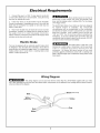 7
7
-
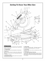 8
8
-
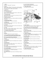 9
9
-
 10
10
-
 11
11
-
 12
12
-
 13
13
-
 14
14
-
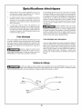 15
15
-
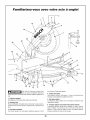 16
16
-
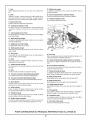 17
17
-
 18
18
-
 19
19
-
 20
20
-
 21
21
-
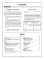 22
22
-
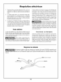 23
23
-
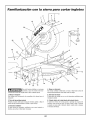 24
24
-
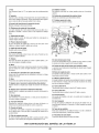 25
25
-
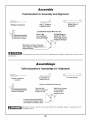 26
26
-
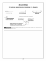 27
27
-
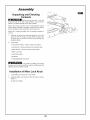 28
28
-
 29
29
-
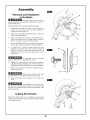 30
30
-
 31
31
-
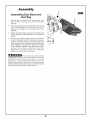 32
32
-
 33
33
-
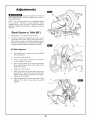 34
34
-
 35
35
-
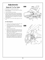 36
36
-
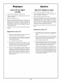 37
37
-
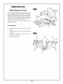 38
38
-
 39
39
-
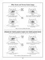 40
40
-
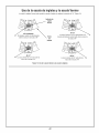 41
41
-
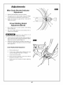 42
42
-
 43
43
-
 44
44
-
 45
45
-
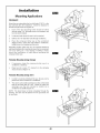 46
46
-
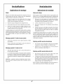 47
47
-
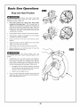 48
48
-
 49
49
-
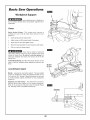 50
50
-
 51
51
-
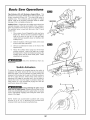 52
52
-
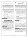 53
53
-
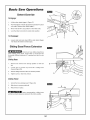 54
54
-
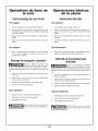 55
55
-
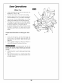 56
56
-
 57
57
-
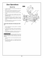 58
58
-
 59
59
-
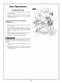 60
60
-
 61
61
-
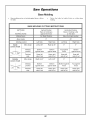 62
62
-
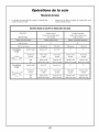 63
63
-
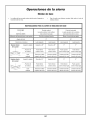 64
64
-
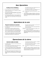 65
65
-
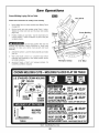 66
66
-
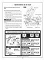 67
67
-
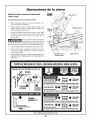 68
68
-
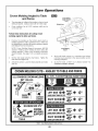 69
69
-
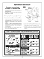 70
70
-
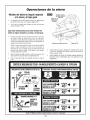 71
71
-
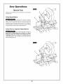 72
72
-
 73
73
-
 74
74
-
 75
75
-
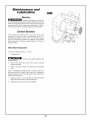 76
76
-
 77
77
-
 78
78
-
 79
79
-
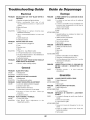 80
80
-
 81
81
-
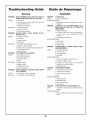 82
82
-
 83
83
-
 84
84


Bosch 3912 El manual del propietario
- Categoría
- Sierras de inglete
- Tipo
- El manual del propietario
en otros idiomas
- français: Bosch 3912 Le manuel du propriétaire
- English: Bosch 3912 Owner's manual
Artículos relacionados
-
Bosch 5412L El manual del propietario
-
-
-
-
-
-
Bosch Power Tools CM12 Manual de usuario
-
-