Cameo OTOS® SP6 Manual de usuario
- Categoría
- Focos
- Tipo
- Manual de usuario

USER´S MANUAL
BEDIENUNGSANLEITUNG
MANUEL D`UTILISATION
MANUAL DE USUARIO
INSTRUKCJA OBSŁUGI
MANUALE D‘ USO
OTOS® SP6
OUTDOOR LED MOVING HEAD
CLOTOSSP6
ANIMATION WHEEL

CONTENTS / INHALTSVERZEICHNIS / CONTENU / CONTENIDO / TREŚĆ /
CONTENUTO
ENGLISH
INFORMATION ON THIS USER MANUAL 6
INTENDED USE 6
DEFINITIONS AND SYMBOL EXPLANATIONS 6
SAFETY INSTRUCTIONS 7
NOTES ON PORTABLE OUTDOOR DEVICES 10
INCLUDED 11
INTRODUCTION 11
CONNECTIONS, OPERATING AND DISPLAY ELEMENTS 12
OPERATION 15
SETUP AND INSTALLATION 29
CARE, MAINTENANCE AND REPAIR 29
REPLACING GOBOS 30
DIMENSIONS 33
TECHNICAL DATA 34
EXPLANATION OF IP PROTECTION CLASS 36
MINIMUM DISTANCE TO ILLUMINATED SURFACE 36
MINIMUM DISTANCE TO NORMALLY FLAMMABLE MATERIALS 36
DISPOSAL 37
MANUFACTURER’S DECLARATIONS 37
DEUTSCH
INFORMATIONEN ZU DIESER BEDIENUNGSANLEITUNG 39
BESTIMMUNGSGEMÄSSER GEBRAUCH 39
BEGRIFFS- UND SYMBOLERKLÄRUNGEN 39
SICHERHEITSHINWEISE 40
HINWEISE FÜR ORTSVERÄNDERLICHE OUTDOOR-GERÄTE 44
LIEFERUMFANG 44
EINFÜHRUNG 44
ANSCHLÜSSE, BEDIEN- UND ANZEIGEELEMENTE 45
BEDIENUNG 48
AUFSTELLUNG UND MONTAGE 62
PFLEGE, WARTUNG UND REPARATUR 62
GOBOS AUSTAUSCHEN 64
ABMESSUNGEN 67
TECHNISCHE DATEN 68
ERLÄUTERUNGEN ZUR IP-SCHUTZART 70

MINDESTABSTAND ZUR BELEUCHTETEN FLÄCHE 70
MINDESTABSTAND ZU NORMAL ENTFLAMMBAREN MATERIALIEN 70
ENTSORGUNG 71
HERSTELLERERKLÄRUNGEN 71
FRANÇAIS
INFORMATIONS SUR CE MANUEL D’UTILISATION 72
UTILISATION PRÉVUE 72
DÉFINITIONS ET EXPLICATION DES PICTOGRAMMES 72
CONSIGNES DE SÉCURITÉ 73
NOTES SUR LES APPAREILS PORTABLES POUR EXTÉRIEUR 77
CONTENU DU CARTON 77
INTRODUCTION 77
BRANCHEMENTS, UTILISATION ET INDICATEURS 78
FONCTIONNEMENT 81
MONTAGE ET INSTALLATION 96
ENTRETIEN, MAINTENANCE ET RÉPARATIONS 97
REMPLACEMENT DES GOBOS 98
DIMENSIONS 101
CARACÉRISTIQUES TECHNIQUES 102
EXPLICATION DE LA CLASSE DE PROTECTION IP 104
DISTANCE MINIMALE PAR RAPPORT À LA SURFACE ÉCLAIRÉE 105
DISTANCE MINIMALE PAR RAPPORT AUX MATÉRIAUX NORMALEMENT INFLAMMABLES 105
MISE AU REBUT 105
DÉCLARATIONS DU FABRICANT 106
ESPAÑOL
INFORMACIÓN SOBRE ESTE MANUAL DEL USUARIO 107
USO PREVISTO 107
DEFINICIONES Y EXPLICACIONES DE LOS SÍMBOLOS 107
INSTRUCCIONES DE SEGURIDAD 108
NOTAS SOBRE LOS DISPOSITIVOS PORTÁTILES DE EXTERIOR 112
CONTENIDO DE LA ENTREGA 112
INTRODUCCIÓN 112
CONEXIONES, MANDOS E INDICADORES 113
FUNCIONAMIENTO 116
CONFIGURACIÓN E INSTALACIÓN 130

CUIDADO, MANTENIMIENTO Y REPARACIÓN 131
SUSTITUCIÓN DE GOBOS 132
DIMENSIONES 135
DATOS TÉCNICOS 136
EXPLICACIÓN DE LA CLASE DE PROTECCIÓN IP 138
DISTANCIA MÍNIMA A LA SUPERFICIE ILUMINADA 139
DISTANCIA MÍNIMA A MATERIALES NORMALMENTE INFLAMABLES 139
RECICLAJE 139
DECLARACIONES DEL FABRICANTE 140
POLSKI
INFORMACJE NA TEMAT NINIEJSZEJ INSTRUKCJI OBSŁUGI 141
ZAMIERZONE ZASTOSOWANIE 141
DEFINICJE I OBJAŚNIENIA SYMBOLI 141
INSTRUKCJE BEZPIECZEŃSTWA 142
UWAGI DOTYCZĄCE PRZENOŚNYCH URZĄDZEŃ ZEWNĘTRZNYCH 146
ZAKRES DOSTAWY 146
WPROWADZENIE 146
PRZYŁĄCZA, ELEMENTY OBSŁUGI I WSKAŹNIKI 147
OBSŁUGA 150
KONFIGURACJA I INSTALACJA 164
PIELĘGNACJA, KONSERWACJA I NAPRAWA 164
WYMIANA GOBOSÓW 166
WYMIARY 169
DANE TECHNICZNE 170
WYJAŚNIENIE KLASY OCHRONY IP 172
MINIMALNA ODLEGŁOŚĆ OD OŚWIETLANEJ POWIERZCHNI 172
MINIMALNA ODLEGŁOŚĆ OD MATERIAŁÓW NORMALNIE ŁATWOPALNYCH 172
UTYLIZACJA 173
DEKLARACJE PRODUCENTA 173
ITALIANO
INFORMAZIONI SU QUESTO MANUALE DI ISTRUZIONI 174
USO PREVISTO 174
DEFINIZIONI E SPIEGAZIONI DEI SIMBOLI 174
ISTRUZIONI DI SICUREZZA 175
NOTE SUI DISPOSITIVI PORTATILI PER ESTERNI 178

MATERIALE COMPRESO NELLA FORNITURA 179
INTRODUZIONE 179
CONNESSIONI, ELEMENTI DI COMANDO E DI VISUALIZZAZIONE 180
FUNZIONAMENTO 183
INSTALLAZIONE E CONFIGURAZIONE 197
CURA, MANUTENZIONE E RIPARAZIONE 198
SOSTITUZIONE DEI GOBOS 199
DIMENSIONI 202
DATI TECNICI 203
SPIEGAZIONE DELLA CLASSE DI PROTEZIONE IP 205
DISTANZA MINIMA DALLA SUPERFICIE ILLUMINATA 205
DISTANZA MINIMA DAI MATERIALI NORMALMENTE INFIAMMABILI 206
SMALTIMENTO 206
DICHIARAZIONI DEL PRODUTTORE 206
DMX
DMX CONTROL / DMX STEUERUNG / PILOTAGE DMX /
CONTROL DMX / STEROWANIE DMX / CONTROLLO DMX 208

6
DMX
ITALIANO
POLSKI
ESPAÑOL
FRANCAIS
DEUTSCHENGLISH
ENGLISH
You have made the right choice!
This device has been developed and manufactured to the highest quality standards to ensure
many years of problem-free operation. Please read this user manual carefully to be able to use
your new Cameo product quickly and optimally. Further information about Cameo Light is availab-
le on our website CAMEOLIGHT.COM.
INFORMATION ON THIS USER MANUAL
• Carefully read the safety instructions and the entire manual before operating the device.
• Observe the warnings on the device and in the user manual.
• Always keep the user manual within reach.
• If you sell or pass on the device, it is important that you also include this user manual, as it is an
integral part of the product.
INTENDED USE
The product is a device for event technology!
This product has been developed for professional use in the field of event technology and is not
suitable for use as domestic lighting!
Furthermore, this product is only intended for qualified users with specialist knowledge of event
technology!
Use of the product outside the specified technical data and operating conditions is considered
improper use!
Liability for damage and third-party damage to persons and property due to inappropriate use is
excluded!
The product is not suitable for:
• Use by persons (including children) with limited physical, sensory or mental abilities or lack of
experience and knowledge.
• Children (children must be instructed not to play with the device).
DEFINITIONS AND SYMBOL EXPLANATIONS
1. DANGER: The word DANGER, possibly in combination with a symbol, indicates immediately
dangerous situations or conditions for life and limb.
2. WARNING: The word WARNING, possibly in combination with a symbol, indicates potentially
dangerous situations or conditions for life and limb.
3. CAUTION: The word CAUTION, possibly in combination with a symbol, is used to indicate situa-
tions or conditions that may lead to injury.
4. ATTENTION: The word ATTENTION, possibly in combination with a symbol, refers to situations
or states that can lead to damage to property and/or the environment.
This symbol identifies hazards that can cause electric shock.
This symbol identifies hazardous areas or hazardous situations.

7
DMX DEUTSCHFRANCAIS
ESPAÑOL ENGLISH
ITALIANO POLSKI
This symbol indicates hazards caused by hot surfaces.
This symbol indicates hazards caused by intense light sources.
This symbol indicates a device in which there are no user-replaceable parts.
This symbol indicates additional information on the operation of the product.
SAFETY INSTRUCTIONS
HAZARD:
1. Do not open or modify the unit.
2. If your device no longer functions properly, if liquids or objects get inside it or if it
has been damaged in any other way, switch it off immediately and disconnect it
from the mains. The device may be repaired only by authorised repair technicians.
3. For devices of protection class 1, the protective conductor must be connected
correctly. Never disconnect the protective conductor. Devices of protection class 2
do not have a protective conductor.
4. Ensure that live cables are not kinked or otherwise mechanically damaged.
5. Never bypass the unit fuse.
WARNING:
1. The device may not be operated if it shows obvious signs of damage.
2. The device may only be installed in a voltage-free state.
3. If the mains cable of the device is damaged, do not operate the device.
4. Permanently connected power cables may only be replaced by a qualified person.
ATTENTION:
1. Do not operate the unit if it has been exposed to large temperature fluctuations
(for example, after transport). Moisture and condensation can damage the device.
Switch on the device only when it has reached room temperature.
2. Make sure that the voltage and frequency of the mains supply correspond to the
values indicated on the unit. If the device has a voltage selector switch, do not
connect the device until it has been set correctly. Use only suitable power cables.
3. To disconnect the unit from the mains at all poles, it is not sufficient to press the
on/off switch on the unit.
4. Make sure that the fuse used corresponds to the type printed on the unit.

8
DMX
ITALIANO
POLSKI
ESPAÑOL
FRANCAIS
DEUTSCHENGLISH
5. Make sure that appropriate measures have been taken against overvoltage (e.g.
lightning strike).
6. Observe the specified maximum output current on units with Power Out connec-
tion. Ensure that the total current consumption of all connected devices does not
exceed the specified value.
7. Replace pluggable mains cables only with original cables.
HAZARD:
1. Danger of suffocation! Plastic bags and small parts must be kept out of reach of
persons (including children) with reduced physical, sensory or mental capabilities.
2. Danger from falling down! Make sure that the device is securely installed and will
not fall down. Only use suitable stands or mounts (particularly for fixed installa-
tions). Ensure that accessories are properly installed and secured. Ensure that
applicable safety regulations are observed.
WARNING:
1. Use the device only in the manner intended.
2. Operate the device only with the accessories recommended and intended by the
manufacturer.
3. During installation, observe the safety regulations applicable in your country.
4. After connecting the unit, check all cable routes to avoid damage or accidents, e.g.
due to tripping hazards.
5. Always observe the specified minimum distance to normally flammable materials!
Unless explicitly stated, the minimum distance is 0.3 m.
6. Always observe the minimum distance to the illuminated surface that can be read
on the device!
CAUTION:
1. In the case of moving components such as mounting brackets or other moving
components, there is a possibility of jamming.
2. In the case of units with motor-driven components, there is a risk of injury from the
movement of the unit. Sudden movement of the device can cause shock reactions.
3. The housing surface of the device can become very hot during regular operation.
Ensure that accidental touching of the housing is not possible. Always allow the
lamp to cool sufficiently before removal, maintenance work and charging etc.
ATTENTION:
1. Do not install or operate the device near any radiators, heat registers, stoves or other
heat sources. Ensure that the device is always installed in such a way that it is suffi-
ciently cooled and cannot overheat.
2. Do not place ignition sources such as burning candles near the device.
3. Ventilation openings must not be covered and fans must not be blocked.

9
DMX DEUTSCHFRANCAIS
ESPAÑOL ENGLISH
ITALIANO POLSKI
4. Use the original packaging or packaging provided by the manufacturer for transport.
5. Avoid shock or impact to the unit.
6. Observe the IP protection class as well as the ambient conditions such as tempera-
ture and humidity according to the specification.
7. Devices can be constantly further developed. In the event of deviating information on
operating conditions, performance or other device properties between the user manual
and the device labelling, the information on the device always takes priority.
8. The unit is not suitable for tropical climates and for operation above 2000 m above
sea level.
9. Unless explicitly stated, the unit is not suitable for operation in marine conditions .
CAUTION! IMPORTANT INFORMATION REGARDING LIGHTING PRODUCTS!
1. Never look directly into the beam of light, not even for a short period of time.
2. Never look into the beam of light using optical devices such as a magnifying glass.
3. Stroboscopic effects may cause epileptic seizures in susceptible individuals!
SIGNAL TRANSMISSION BY RADIO (E.G. W-DMX OR AUDIO RADIO SYSTEMS):
The quality and performance of wireless signal transmissions generally depends on
the ambient conditions.
The following factors can impact range and signal stability, for example:
Shielding (e.g. masonry, metal structures, water)
High volume of radio traffic (e.g. powerful wireless LAN networks)
Interference
Electromagnetic radiation (e.g. LED video screens, dimmers)
All range specifications refer to free-field application with visual contact and without
interference!
The operation of transmission systems is subject to official regulations. These may
vary from region to region and must be checked by the operator before use (e.g. radio
frequency and transmission power).
WARNING: Devices with wireless signal transmission are not suitable for use in sen-
sitive areas in which radio operation can lead to potential detrimental effects. These
include:
• Hospitals, health centres or other healthcare facilities that provide patient treatment
with skilled personnel and equipment.
• Hazardous areas Class I, II and III
• Restricted areas
• Military facilities
• Aircraft or vehicles
• Areas where the use of mobile phones is prohibited

10
DMX
ITALIANO
POLSKI
ESPAÑOL
FRANCAIS
DEUTSCHENGLISH
TRANSMISSION VIA W-DMX
WARNING: In general, wireless DMX transmission must not be used for applications
involving safety-related factors that might result in personal injury or property dama-
ge in the event of a failure.
This applies in particular to moving scene or traverse structures, DMX-controlled mo-
tors/lifts or lifting devices for operating DMX-operated platform lifts, hydraulic systems
or comparable moving components.
Furthermore, wireless DMX transmission must not be used to trigger flame or pyro-
technic devices, explosion-driven effects, or to control gas or liquid effects. These
include CO2 cannons, confetti shooters, water effects or similar.
CAUTION! POTENTIAL DAMAGE FROM EXTERNAL LIGHT SOURCES!
Solar radiation, laser radiation and bundled light beams from other spotlights can da-
mage the housing and internal components such as filters, gobo and colour wheels,
motors, cables, belts, etc., as well as light sources!
Do not expose the unit and especially the lens opening to direct sunlight, laser radi-
ation and bundled light beams from other spotlights during unpacking, installation,
prolonged non-use and operation! Always point the lens opening towards the floor
when the unit is not in use! For this purpose, also use the Sun Protection function,
which can be activated via DMX command (see Device Settings channel in the DMX
table). An integrated gyroscope sensor detects the position of use.
Damage caused by external light sources is excluded from the manufacturer's warranty!
NOTES ON PORTABLE OUTDOOR DEVICES
1. Temporary operation! Event equipment is generally only designed for temporary
operation.
2. Continuous operation or permanent structural installation – particularly outdoors –
can impair the function, surfaces and seals and accelerate material fatigue.
3. Damage to the surface coating can impair the device's corrosion protection.
Damaged surface coating (e.g. scratches) must be promptly repaired by suitable
measures.

11
DMX DEUTSCHFRANCAIS
ESPAÑOL ENGLISH
ITALIANO POLSKI
INCLUDED
Remove the product from the packaging and remove all packaging material.
Please check the completeness and integrity of the delivery and notify your distribution partner
immediately after purchase if the delivery is not complete or if it is damaged.
The packaging includes:
X 1 x OTOS SP6 Moving Head
X 1x Power cord
X 2 x Omega bracket
X User manual
INTRODUCTION
PROFESSIONAL OUTDOOR LED MOVING HEAD
CLOTOSSP6
CONTROL FUNCTIONS:
33, 36 and 50 channel DMX control
Master/slave operation
Standalone operation
W-DMX™
FEATURES:
Protection class IP65. 600 W LED. DMX512. W-DMX™. Artnet and sACN. 5-pin DMX connections.
2x Omega mounting brackets included. Operating voltage: 100–240 V AC.
The spotlight features the RDM standard (Remote Device Management). This remote device
management enables the status query and configuration of RDM end devices via an RDM-capable
controller, such as the optionally available Cameo UNICON (item number CLIREMOTE).

12
DMX
ITALIANO
POLSKI
ESPAÑOL
FRANCAIS
DEUTSCHENGLISH
CONNECTIONS, OPERATING AND DISPLAY ELEMENTS
1 POWER IN
IP65 power input socket with rubber sealing cap. Operating voltage 100–240 V AC/50–60 Hz.
Connection via supplied power cable (when not in use, always close with rubber sealing cap).
2 POWER OUT
IP65 power output socket with rubber sealing cap. Facilitates power supply to other CAMEO
spotlights. Ensure that the total current consumption of all connected devices does not exceed
the value specified on the device in amperes (A) (when not in use, always close with the rubber
sealing cap).
3 DMX IN
Male IP65 5-pin XLR socket for connecting a DMX control device (e.g. DMX console; when not in
use, always close with the rubber sealing cap).
4 DMX OUT
Female IP65 5-pin XLR socket for sending DMX control signal (when not in use, always close with
the rubber sealing cap).
5 NET IN / OUT
RJ45 network connections for connecting to an ArtNet or sACN network and for forwarding the
control signal (always close with the rubber sealing cap when not in use). Use CAT 5e or better
cables to set up the network.
6 FUSE
IP65 fuse holder for 5 x 20mm fuses. IMPORTANT NOTE: Replace the fuse only with one of the
same type and rating. Carefully close the fuse holder again so that the IP65 tightness is still gua-
ranteed. In the event of repeated fuse failure, please contact an authorised service centre.
1 2 3 4
56

13
DMX DEUTSCHFRANCAIS
ESPAÑOL ENGLISH
ITALIANO POLSKI
7 LC DISPLAY
The illuminated display shows the currently activated mode (main display), the menu items in the
main menu and sub-menus and the numerical value or status in certain menu items. If there is no
control signal to the device, the characters in the centre of the display start flashing; the flashing
stops as soon as a control signal is available (W-DMX, DMX and slave operation).
8 TOUCH-SENSITIVE CONTROLS
MENU – Press MENU to access the main menu. Press again or repeatedly to return to the main
display.
and – Select the menu items in the main menu (DMX address, operating mode, etc.) and in
the submenus using and . Change value or status in a menu item, e.g. DMX address.
ENTER – Press ENTER to access the menu level to make value or status changes, and to access
one of the sub-menus. Confirm value or status changes by pressing ENTER.
Before navigating the unit menu, make sure that the control panels are dry and clean so that their
functionality is not impaired.
PRESSURE EQUALISATION ELEMENT
The pressure compensation element to prevent condensation inside the housing is located in the
rear part of the unit head. In order to ensure its proper function, the element must be protected
from contamination.
W-DMX™ ANTENNA
The antenna for control via W-DMX™ is located inside the unit base.
ATTENTION: To ensure IP65 splash protection for the DMX and network sockets,
the special input and output sockets must be correctly sealed with the IP65 special
plugs or the rubber sealing caps must be used for sealing. When connected correct-
ly, or when sealed correctly with the rubber sealing caps, the POWER IN and POWER
OUT sockets are protected from spraying water, as in accordance with IP65.
8
7

14
DMX
ITALIANO
POLSKI
ESPAÑOL
FRANCAIS
DEUTSCHENGLISH
The battery-powered display can be activated, even if the device is not connected to
the mains. To do this, press and hold MENU for about 10 seconds. You can now access
device information to change and save system settings without mains connection.
External control of the spotlight is not activated in this case. For this reason, the display
shows that there is no DMX signal even if a DMX signal is available at the device.
9 PAN LOCK
Mechanical locking device to prevent the head
from turning on the horizontal plane during
transport (8 possible positions). Disconnect
the unit from the mains and slide the locking
lever in the direction of the pan rotation axis,
moving the head of the unit horizontally until
one of the 8 locking positions is found and
the locking lever engages. Unlock the device
before startup (UNLOCK).
10 TILT LOCK
Mechanical locking device to prevent the
head from turning on the vertical plane during
transport (7 possible positions). Disconnect the
unit from the mains and slide the locking lever
in the direction of the tilt rotation axis, moving
the head of the unit vertically until one of the 7
locking positions is found and the locking lever
engages (LOCK). Unlock the device before
startup (UNLOCK).
10
UNLOCK
LOCK
9
UNLOCKLOCK
11 11

15
DMX DEUTSCHFRANCAIS
ESPAÑOL ENGLISH
ITALIANO POLSKI
11 RECESSED GRIPS
In addition to the two transport handles on the base of the unit, there are practical recessed grips
at the top of the inner sides of the two device arms.
OPERATION
NOTES
Once the fixture is correctly connected to the mains, the display will show "Software
Update ...please wait", the software version, "Welcome to Cameo" and "...RESET"
during the start-up procedure and motor reset. After this process, the spotlight is
ready for operation and the previously activated operating mode is launched. The
main display is activated automatically if no input is made within approximately 30
seconds.
MAIN DISPLAY
The main display shows different information relevant to the various operating modes.
DMX and W-DMX operating modes ArtNet and sACN operating modes
LED-Temperature
W-DMX Status
Error Message
DMX-Starting Address and DMX-Mode
LED-Temperature
W-DMX Status
Error Message
Mode
DMX-Mode, DMX-Address, IP-Adress, Subnet
Mask and Galaxy
Stand-alone operating modes Operating mode Slave
LED-Temperature
W-DMX Status
Error Message
Scene / Loop and Signal Output
LED-Temperature
W-DMX Status
Error Message
Mode

16
DMX
ITALIANO
POLSKI
ESPAÑOL
FRANCAIS
DEUTSCHENGLISH
NOTE REGARDING THE MAIN DISPLAY IN OPERATING MODES WITH EXTERNAL
CONTROL:
As soon as the control signal is interrupted, the characters in the centre of the display
begin to flash. The flashing stops when a control signal is present.
Error message: If the warning symbol (triangle with exclamation mark) appears in
the display, there is an error in one or more components of the unit. Which compo-
nents are affected can be seen in the System Info Menu under Error Info. If the
error cannot be rectified by a restart or reset, please contact an authorised service
centre.
W-DMX™
To pair a W-DMX receiver with a W-DMX compatible transmitter, the Reset command must be
executed in the menu item WDMX under Receiver (select and confirm Reset). The receiver is
now in pairing standby and waiting for a pairing request from a transmitter. Start the pairing
by selecting Link in the menu of the transmitter and confirming; the pairing now takes place
automatically. In the same way, several receivers can be paired simultaneously or one after the
other to a transmitter (e.g. for master/slave operation). A W-DMX connection is always maintained
until the connection is disconnected by means of the Reset command in the receiver or the Unlink
command in the transmitter, regardless of whether a device has been disconnected from the
power supply in the meantime.
W-DMX™ STATUS
?
W-DMX
deactivated
W-DMX
as receiver
activated,
not paired
W-DMX
as receiver
activated and
paired,
Transmitter
switched off
or out of
range
W-DMX
as receiver
activated and
paired,
no
DMX signal
W-DMX
as receiver
activated and
paired,
DMX signal
is present
W-DMX
as transmitter
activated,
CONTROL MENU
The control menu enables selection of the various operating modes and their setting options in
the relevant sub-menus. DMX address and DMX operating mode are set in each operating mode
across all operating modes, if relevant.
OPERATION VIA DMX CABLE
Starting from the main display, press MENU to enter the main menu. Using and , select the
Control menu and press ENTER. Now select the DMX menu item and confirm again.

17
DMX DEUTSCHFRANCAIS
ESPAÑOL ENGLISH
ITALIANO POLSKI
Information on the submenu items in the DMX menu and the corresponding setting options can be
found in the table below (select with and confirm with ENTER, change value or status with
and confirm with ENTER).
DMX
DMX Address 001 - 4xx Setting the DMX start address
Mode
33CH Basic
Selecting the DMX mode36CH Standard
50CH Extended
W-DMX Trans-
mitter
Off Deactivate sending of the DMX control signal via
W-DMX
On Activate DMX control signal forwarding via W-DMX
Force to pair Pairing with ready-to-pair W-DMX devices
Unlink All Disconnect all W-DMX connections
OPERATION VIA W-DMX
Starting from the main display, press MENU to enter the main menu. Using and , select the
Control menu and press ENTER. Now select the menu item W-DMX and confirm again.
For information on the submenu items in the W-DMX menu and the corresponding setting options,
see the table below (select with and confirm with ENTER, change value or status with
and confirm with ENTER).
W-DMX
DMX Address 001 - 4xx Setting the DMX start address
Mode
33CH Basic
Selecting the DMX mode36CH Standard
50CH Extended

18
DMX
ITALIANO
POLSKI
ESPAÑOL
FRANCAIS
DEUTSCHENGLISH
Receive
Off Deactivate W-DMX reception
On Activate W-DMX reception
Unlink Disconnect W-DMX connections and put them in coupling standby
Signal
routing
Send to XLR Forwarding the control signal to XLR (DMX OUT)
Backup by XLR Control via XLR (DMX IN) with W-DMX signal interruption
Receive only No connection between W-DMX signal and XLR connectors
OPERATION VIA ART-NET
Starting from the main display, press MENU to enter the main menu. Using and , select the
Control menu and press ENTER. Now select the menu item ArtNet and confirm again.
Information on the submenu items in the ArtNet menu and the corresponding setting options can
be found in the table below (select with and confirm with ENTER, change value or status
with and confirm with ENTER).
ArtNet
DMX Address 001 - 4xx Setting the DMX start address
DMX Mode 33CH / 36CH /
50CH Selecting the DMX mode
Universe 000–255 Setting the universe
Universe Group 000–127 Setting the Universe Group
IP Address xxx.xxx.xxx.
xxx.xxx
Setting the IP address: Set 1st block, confirm, Set 2nd block,
confirm..
Subnet Mask xxx.xxx.xxx.
xxx.xxx
Setting the subnet mask: Set 1st block, confirm, Set 2nd
block, confirm..
W-Transmitter
On Activate (On) or deactivate (Off) forwarding of the DMX signal
via W-DMX.
Off
Force to pair Establish a connection with other W-DMX units (Force to
pair) or disconnect them (Unlink all).
Unlink all
Signal Routing
Send to XLR Forwarding the control signal to XLR Out
Backup by XLR Control via XLR with ArtNet signal interruption
Receive only No connection between network signal and XLR connectors

19
DMX DEUTSCHFRANCAIS
ESPAÑOL ENGLISH
ITALIANO POLSKI
OPERATION VIA SACN
Starting from the main display, press MENU to enter the main menu. Using and , select the
Control menu and press ENTER. Now select the menu item sACN and confirm again.
Information on the submenu items in the sACN menu and the corresponding setting options can
be found in the table below (select with and confirm with ENTER, change value or status
with and confirm with ENTER).
sACN
DMX Address 001 - 4xx Setting the DMX start address
DMX Mode 33CH / 36CH /
50CH Selecting the DMX mode
Universe 000–255 Setting the universe
Universe Group 000–127 Setting the Universe Group
IP Address xxx.xxx.xxx.xxx.
xxx
Setting the IP address: Set 1st block, confirm, Set 2nd block,
confirm..
Subnet Mask xxx.xxx.xxx.xxx.
xxx
Setting the subnet mask: Set 1st block, confirm, Set 2nd
block, confirm..
W-Transmitter
On Activate (On) or deactivate (Off) forwarding of the DMX signal
via W-DMX.
Off
Force to pair Establish a connection with other W-DMX units (Force to pair)
or disconnect (Unlink all).
Unlink all
Signal Routing
Send to XLR Forwarding the control signal to XLR Out
Backup by XLR Control via XLR with ArtNet signal interruption
Receive only No connection between network signal and XLR connectors
EDIT SCENE
Eight scenes are available (Scene 1 - 8). Set pan, tilt, gobo, pan / tilt macros etc. of each scene
individually directly on the unit with values from 000 to 255. The scenes are pre-programmed ex
works.

20
DMX
ITALIANO
POLSKI
ESPAÑOL
FRANCAIS
DEUTSCHENGLISH
Starting from the main display, press MENU to enter the main menu. Using and , select the
Control menu, confirm, then select Stand Alone and confirm again. Now select Edit Scene,
confirm, select the desired scene and confirm again.
The scene is activated when confirmed and you can make the settings as desired (see table,
select with and confirm with ENTER, change value or status with and confirm with
ENTER).
Edit Scene
Pan 000 – 255 0-100
Tilt 000 – 255 0-100
Dimmer 000 – 255 Master dimmer 0% -> 100%
Strobe 000 – 255 Multi-functional strobe
Cyan 000 – 255
CMYMagenta 000 – 255
Yellow 000 – 255
CTO 000 – 255 Colour Transmission Orange
Colour wheel 000 – 255 Colour wheel
Gobo 000 – 255 Gobo wheel 1
Gobo rot. 000 – 255 Gobo wheel 1 Gobo rotation
red Fine 000 – 255 Gobo wheel 1 Gobo rotation fine
Gobo2 000 – 255 Gobo wheel 2
Zoomz 000 – 255 Zoom narrow <-> wide
Focus 000 – 255 0-100
Iris 000 – 255 0-100
Prism 000 – 255 Prism
Prism red. 000 – 255 (Prism rotation)
Frost1 000 – 255 Frost 1 0% <-> 100%
Frost2 000 – 255 Frost 2 0% <-> 100%
Animation 000 – 255 Animation wheel

21
DMX DEUTSCHFRANCAIS
ESPAÑOL ENGLISH
ITALIANO POLSKI
Ani. rot. 000 – 255 Animation Wheel Rotation
Blade 1A 000 – 255 Blade 1A 0% <-> 100%
Blade 1B 000 – 255 Blade 1B 0% <-> 100%
Blade 2A 000 – 255 Blade 2A 0% <-> 100%
Blade 2B 000 – 255 Blade 2B 0% <-> 100%
Blade 3A 000 – 255 Blade 3A 0% <-> 100%
Blade 3B 000 – 255 Blade 3B 0% <-> 100%
Blade 4A 000 – 255 Blade 4A 0% <-> 100%
Blade 4B 000 – 255 Blade 4B 0% <-> 100%
Rot. Blade 000 – 255 Blade rotation 0% <-> 100%
Pan / tilt macro 000 – 255 Pan/Tilt Macro
Pan tilt speed 000 – 255 Pan/Tilt Macro Speed
EDIT LOOP
Each of the eight available loops consists of up to eight scenes, which in turn can be edited
individually (Edit Scene 1 - 8). The number of steps, the steps themselves (Scene 1 - 8), the step
duration and the fade time can be set separately for all eight loops.
Starting from the main display, press MENU to enter the main menu. Using and , select the
Control menu item and confirm with ENTER. Select Stand Alone, confirm, select Edit Loop,
select the desired loop for editing and confirm again.
This takes you to the submenu for setting the submenu items (see table, select with and ,
confirm with ENTER, change value or status with and confirm with ENTER). The settings for
each loop are made separately and are retained even after restarting the device.
Edit Loop
Step1
User Scene 1 - User Scene 8 User scene selection
t-Step 0s - 20min Sets step time
t-Fade 0s - 20min Sets fade time

22
DMX
ITALIANO
POLSKI
ESPAÑOL
FRANCAIS
DEUTSCHENGLISH
Step 2 “ "
Step 3
User Scene 1 - User Scene 8 + Skip Step User scene selection + skip step
t-Step 0s - 20min Sets step time
t-Fade 0s - 20min Sets fade time
Step 4 " "
Step 5 " "
Step 6 “ “
Step 7 “ “
Step 8 " "
STAND-ALONE OPERATION PLAY SCENE / PLAY LOOP
Starting from the main display, press MENU to enter the main menu. Select the Control menu
using and and confirm with ENTER. Now select the menu item Stand Alone, confirm,
select Play Scene/Loop, confirm, then select the desired scene or loop and confirm again. The
selected scene or loop is activated when confirmed.
MASTER / ALONE PLAY SCENE & PLAY LOOP
In Play Scene and Play Loop stand-alone mode, the control signal of the scenes and loops can be
output to slave units via XLR (DMX OUT) and W-DMX (Control -> Stand Alone -> Master/Alone ->
Master). If the output of the control signal is not desired, the output can be deactivated (Control ->
Stand Alone -> Master/Alone -> Alone).
Starting from the main display, press MENU to enter the main menu. Select the Control menu
using and and confirm with ENTER. Now select the Stand Alone menu item, confirm,
select Master/Alone and confirm again.

23
DMX DEUTSCHFRANCAIS
ESPAÑOL ENGLISH
ITALIANO POLSKI
Make the settings as desired (see table, select with and , confirm with ENTER, change value
or status with and confirm with ENTER).
Master/Alone
Master
Send to XLR Control signal is forwarded via DMX OUT
Send to
W-DMX
Off Deactivate sending of the DMX control signal via W-DMX
On Activate DMX control signal forwarding via W-DMX
Force to pair Pairing with ready-to-pair W-DMX devices
Unlink All Disconnect all W-DMX connections
Alone Do not forward control signal
SLAVE MODE
Starting from the main display, press MENU to enter the main menu. Using and , select the
Control menu item and confirm with ENTER. Then select Slave and confirm again. Activate the
output of the control signal in the master unit (Control -> Stand Alone -> Master/Alone -> Mas-
ter). Connect the slave and master units (same model, same software version) using a DMX cable
or make the connection via W-DMX and activate the Play Scene or Play Loop stand-alone mode in
the master unit. The slave unit will now follow the master unit.
Information on the submenu items in the slave menu and the corresponding setting options can
be found in the table below (select with and , confirm with ENTER, change value or status
with and , confirm with ENTER).
Slave
XLR (permanently active)
Wireless
On Activate W-DMX module
Off Deactivate W-DMX module
Unlink Disconnect all connections and place in pairing standby mode

24
DMX
ITALIANO
POLSKI
ESPAÑOL
FRANCAIS
DEUTSCHENGLISH
SYSTEM SETTINGS
Starting from the main display, press MENU to enter the main menu. Select Settings using
and and confirm with ENTER.
Information on the submenu items in the Settings menu and the corresponding setting options
can be found in the table below (select with and confirm with ENTER, change value or
status with and confirm with ENTER).
Settings
Display
Reverse
On Rotate display by 180°
Off No display rotation
Car Automatic detection (upright / head-over-mount)
Display Off Timer
Always On Display lighting permanently on
Off after 20s Deactivation of the display illumination after ap-
prox. 20 seconds without input
Auto Lock On after 60s
Locking of the controls after approx. 2 minutes
without input. To unlock: press and hold MENU for
approx. 3 seconds
Off Lock deactivated
Dimmer Curve
Linear Light intensity increases linearly with DMX value
Exponential Light intensity can be finely adjusted at lower DMX
values and broadly adjusted at higher DMX values
Dimmer
Curve
Logarithmic
Light intensity can be broadly adjusted at lower
DMX values and finely adjusted at higher DMX
values
S-curve
Light intensity can be finely adjusted at lower and
higher DMX values and broadly adjusted at medium
DMX values
Response
LED Light responds abruptly to changes in DMX value
Halogen Light behaves like a halogen spotlight with slight
brightness changes
PWM Frequency
650 Hz,
1530 Hz,
3600 Hz, 12
kHz, 18.9
kHz, 25 kHz
Select LED PWM frequency

25
DMX DEUTSCHFRANCAIS
ESPAÑOL ENGLISH
ITALIANO POLSKI
Move-
ment
Pan Reverse On Reverses pan direction
Off Does not reverse pan direction
Tilt Reverse On Reverses tilt direction
Off Does not reverse tilt direction
Position Feed-
back
On Automatic position correction is enabled
Off Automatic position correction is disabled
Move in Black On Blackout during head movement
Off No blackout during head movement
Silent Movement On Slowed pan and tilt movement
Off Function disabled
Wheels
Gobo Wheel
Position Clockwise Clockwise rotation
Shortest way Shortest way
Movement
Snap
Gobo wheels jump directly back
to the desired gobo when the
relevant value is reached
Scroll Continuous rotation of the gobo
wheels
Color Cor-
rection
On Compensate for colour shift when
using gobos
Off No compensation for colour shift
when using gobos
Colour Wheel
Position Clockwise Clockwise rotation
Shortest way Shortest way
Movement
Snap
Colour wheel jumps directly back
to the desired colour filter when
the relevant value is reached
Scroll Continuous rotation of the colour
wheels
Wheels
Move in Black On Blackout during gobo or colour wheel rotation
Off Function disabled
Framing Control
Left & Right
Standard function: The xA channel of the blade
controls the left side of the blade x and the xB
channel controls the right side.
Position &
Angle
Alternative control of the iris sliders: The xA chan-
nel of the blade controls the insertion of the blade x
and the xB channel controls the angle of the blade
Sun Pro-
tection
On The unit head is directed downwards and the shutter is closed
Off Function disabled
Fan
Car Automatic fan speed control
Silent Low fan speed with reduced brightness, if necessary
Off Fan deactivated at strongly reduced brightness, if necessary

26
DMX
ITALIANO
POLSKI
ESPAÑOL
FRANCAIS
DEUTSCHENGLISH
Signal
Fail
Hold Last command is maintained if the control signal is interrupted
Last Stand Alone In case of control signal interruption, the last activated stand-
alone operation is started
Fade to Black
(10s)
In case of control signal interruption, fade out to blackout takes
place for 10 seconds
Blackout Instant blackout if the control signal is interrupted
Full Full On on control signal interruption
Sun Protection Function is activated in case of signal failure
Store
Default
User A Save user settings A
User B Save user settings B
User C Save user settings C
SERVICE MENU
Starting from the main display, press MENU to enter the main menu. Select Service using and
and confirm with ENTER.
Information on the submenu items in the service menu and the corresponding options can be
found in the table below (select with and confirm with ENTER, change value or status with
and confirm with ENTER).
Service
Load Default
Factory Reset to factory setting
User A Reset to User A values (save user values: Settings -> Set
Def. values)
User B Reset to User B values (save user values: Settings -> Set
Def. values)
User C Reset to User C values (save user values: Settings -> Set
Def. values)
Reset
Pan / Tilt Resets pan / tilt motors
Head Resets motors in the device head
All Resets all motors
Test
Test Sequence Pre-programmed sequence to test all components
Stress Test Pre-programmed sequence to test all components under
maximum load

27
DMX DEUTSCHFRANCAIS
ESPAÑOL ENGLISH
ITALIANO POLSKI
Test Engine Test
Pan Run the selected engine. Motor stops when selecting
another motor and when leaving the menu level.
Tilt
…
LED Calibration 0–255 Setting the maximum brightness across operating modes
Reset Service
Timer
No Cancel operation
Reset now Reset service operation time
Password For service purposes only
SYSTEM INFORMATION
Starting from the main display, press MENU to enter the main menu. Select System Info using
and and confirm with ENTER.
Information on the submenu items in the system info menu and the corresponding options can be
found in the table below (select with and confirm with ENTER, change value or status with
and confirm with ENTER)
System Info
Firmware
DISP Vx.x.x
Display of the firmware version of the
corresponding component
LED Vx.x.x
CTR1 engine Vx.x.x
… Vx.x.x
Temperature
LED xxx °C / °F Display of the temperature of the
corresponding component
Base xxx °C / °F
…
Temperature unit °C Setting the temperature unit
°F
Fan Speed xxxx RPM Display of the speed of the corresponding fan
Runtime
Total xxxx h : xx m Total operating time
Operation xxxx h : xx m Usable time
LED xxxx h : xx m Lamp operating time
Service xxxx h : xx m Operating time after resetting the
service operating time
MAC Address xxx.xxx.xxx.xxx.xxx MAC address
RDM-UID RDM Unique Identifier

28
DMX
ITALIANO
POLSKI
ESPAÑOL
FRANCAIS
DEUTSCHENGLISH
Show DMX
values Displays the applied DMX values
Error Info Error display in case of malfunction
DMX Table Display of DMX mode tables
QUICKLIGHT
Set up a scene quickly and easily using the basic Moving Head functions without an external
controller. Starting from the main display, press MENU to enter the main menu. Select Quicklight
using and and confirm with ENTER. Select the desired menu item with and , confirm
with ENTER, change the value with and and confirm the value change with ENTER.
If the Quicklight mode is activated, the display does not automatically change to the main display;
when leaving the Quicklight menu, Quicklight mode is automatically terminated. The settings in
the Quicklight menu are retained until the next restart of the spotlight; as a result, Quicklight can
be accessed repeatedly with the same settings as long as the spotlight remains switched on. After
a restart, the values in the Quicklight settings are reset.

29
DMX DEUTSCHFRANCAIS
ESPAÑOL ENGLISH
ITALIANO POLSKI
SETUP AND INSTALLATION
Overhead mounting requires extensive experience, including the calculation of the
load limit values of the installation material and regular safety inspection of all instal-
lation materials and spotlights. If you do not have these qualifications, do not attempt
to perform an installation yourself. Refer instead to a qualified professional. There is
a risk that devices that are incorrectly mounted and secured may come loose and
fall down. This can cause serious injury or death.
Thanks to its integrated rubber feet, the lamp can be positioned in a suitable location on a level
surface. Traverse installation can be achieved with the help of two Omega brackets, which are
attached to the base of the device (A). 2 x Omega brackets are included. Suitable beam clamps
are available as an option. Ensure firm connections and secure the spotlight to the securing lug
(B) with a suitable safety cable.
BA
A
CARE, MAINTENANCE AND REPAIR
In order to ensure the long-term, proper functioning of the device, it must be regularly cleaned
and, if necessary, maintained. The maintenance requirement depends on the intensity of use and
the environment in which it is used.
We generally recommend a visual inspection before each operation. Furthermore, we recommend
carrying out all the applicable maintenance measures specified below once every 500 operating
hours or, in the case of a lower intensity of use, at the latest after one year. Warranty claims may
be limited in the event of defects resulting from inadequate maintenance.
CARE (carried out by user)
WARNING! Before carrying out any care or maintenance, the power supply – and, if
possible, all device connections – must be disconnected.

30
DMX
ITALIANO
POLSKI
ESPAÑOL
FRANCAIS
DEUTSCHENGLISH
PLEASE NOTE! Improper care can lead to impairment of the device or even its
destruction.
1. Housing surfaces must be cleaned with a clean, damp cloth. Make sure that no moisture can
penetrate the device.
2. Air inlets and outlets must be regularly cleaned of dust and dirt. If compressed air is used, make
sure that damage to the device is prevented (e.g. fans must be blocked in this case, as they
could otherwise over-rev.).
3. Lines and plug contacts must be cleaned regularly and dust and dirt must be removed.
4. In general, no cleaning agents or abrasive agents may be used, otherwise the surface finish
may be damaged.
5. Devices must generally be stored dry and protected from dust and dirt.
6. To ensure correct and safe operation, all accessible or removable lenses and light-emitting
apertures must be cleaned regularly.
MAINTENANCE AND REPAIR (by qualified personnel only)
HAZARD! There are live components in the device. Even after disconnecting the
mains connection, there may still be residual voltage in the device, for example, due
to charged capacitors.
PLEASE NOTE! Maintenance and repair work may only be carried out by sufficiently
qualified specialist personnel. If in doubt, consult a specialist workshop.
PLEASE NOTE! Improperly performed maintenance work may affect the warranty
claim.
PLEASE NOTE! For conversion or retrofit sets provided by the manufacturer, it is
essential to observe the enclosed installation instructions.
REPLACING GOBOS
CAUTION: Gobo replacement must only be carried out by qualified personnel. If you
are not qualified to do this, do not try to replace gobos yourself. Refer instead to
professional companies.
CAUTION: When carrying out any work, make sure that no foreign bodies enter the
housing! When replacing the gobos, make sure that the gobos are inserted correctly
into the corresponding gobo bracket, otherwise heat damage to the gobos and gobo
brackets may occur!
ATTENTION: In order to maintain the IP65 tightness of the OTOS SP6 moving head,
a new gasket must be inserted at the appropriate location after replacing a gobo.
Carefully follow each step in the instructions below.
After mounting the cover, perform a leak test.

31
DMX DEUTSCHFRANCAIS
ESPAÑOL ENGLISH
ITALIANO POLSKI
1 Disconnect the unit from the power supply at all poles (pull out the mains plug). Lock the
headlamp head (pan and tilt lock).
2 Loosen the hexagon socket screws of the unit head cover (see markings), remove the cover
from the headlamp head, loosen the cover‘s safety rope and put it aside.
3 Disconnect the two connectors for the voltage and signal supply of the gobo module.
4 Now remove the two screws holding the module in the guide and pull the module out of the
headlamp head.
3
4 4
To avoid contaminating the gobos, please wear lint-free gloves.
5 Place the module on a clean and flat surface with the gobo wheels facing upwards. Turn the
desired gobo towards the front of the module.

32
DMX
ITALIANO
POLSKI
ESPAÑOL
FRANCAIS
DEUTSCHENGLISH
6 Gobo wheel with the rotating gobos: Lift the gobo holder on the gear wheel slightly upwards
and then pull it out of the gobo wheel.
7 Gobo wheel with the fixed gobos: Turn the gobo wheel with the rotating gobos with the „Open“
opening over the desired gobo of the gobo wheel with the fixed gobos, press the gobo holder
down slightly through the opening and then pull it out of the gobo wheel.
8 The gobo can now be removed from the bracket and replaced with another one.
9 Then place the gobo bracket back into the gobo wheel, ensuring that the gobo bracket is
correctly seated in the corresponding recess. With the rotating gobos, you can check that they are
seated correctly by turning the gobo wheel; the gobo must rotate without hooking.
10 Reinstall the module in the headlamp head, secure it with the help of the two previously loo-
sened screws and reconnect the two plugs for the voltage and signal supply to the corresponding
connections.
11 Remove the old seal from the groove in the installation bay surround.
12 Thoroughly clean the groove and the contact surface of the cover. Make sure that the contact
surfaces of the seal are free from foreign objects and dirt.
13 Remove the new seal from the packaging and remove any residues of the mould release
agent.
14 Now place the seal positively into the groove. Ensure that the seal is not twisted.

33
DMX DEUTSCHFRANCAIS
ESPAÑOL ENGLISH
ITALIANO POLSKI
15 Reattach the cover‘s safety rope to the appropriate place in the unit head and place the cover
flat on the seal in the installation shaft surround.
16 First tighten the middle and then the outer screws of the cover crosswise with gentle force.
17 Then tighten the middle screws and then the outer screws crosswise to 6 (± 0.5) kgf-cm.
After mounting the cover, perform a leak test.
DIMENSIONS (mm)
768
601
468
552
430
163
366
272
431
601
302,9 249,1

34
DMX
ITALIANO
POLSKI
ESPAÑOL
FRANCAIS
DEUTSCHENGLISH
TECHNICAL DATA
Product number: CLOTOSSP6
Product type: LED moving light
Type: IP65 Moving Head
Number of lamps: 1
Type of lamp: 600 W cool white LED
Colour temperature (lamp): Fixed CCT LED @ 7000K
Luminous flux: 18780 lm @ Zoom 205 Auto Fan / 4600 lm @ Fan Off Operation
Colour rendering index (CRI): >70
LED PWM: 650 Hz; 1530 Hz; 3600 Hz; 12 kHz; 18.9 kHz; 25 kHz
Dimmer resolution: 16 bit
Dimmer curves Linear; Exponential; Logarithmic; S-Curve
Dimmer response LED; halogen
Beam angle / field angle:
Max. Zoom focused: 46°
Min. zoom focused: 7.5°
Max. zoom frost: 38° / 49°. Zoom frost: 38° / 49°
Pan / Tilt angle: 540° / 270°
Colour blend function: Linear CMY, linear CTO, colour wheel
Number of colours: Colour
wheel: 6 + open, continuous positioning, split colours
Number of gobos: Gobo wheel 1: 7 rotatable and interchangeable gobos + open
Gobo wheel 2: 7 interchangeable gobos + open
Effects: 5-facet prism; Frost filter light; Frost filter heavy; Animation
wheel; Iris
Orifice slider: 4 shutter - 2 axis iris slider, +/-45° rotatable
Motor modes: Normal; Silent
DMX modes: 33-channel basic, 36-channel standard, 50-channel extended
DMX functions:
Pan, Pan fine, Tilt, Tilt fine, Dimmer, Dimmer fine, Multifunctional
strobe, Cyan, Cyan fine, Magenta, Magenta fine, Yellow, Yellow
fine, CTO, CTO fine, Colour wheel, Gobo wheel 1, Gobo wheel 1
Gobo rotation, Gobo wheel 1 Gobo rotation fine, Gobo wheel 2,
Zoom, Zoom fine, Focus, Focus fine, Iris, Prism, Prism rotation,
Frost heavy, Frost light, Animation wheel, Animation wheel
rotation, Aperture slider 1A, Iris slider 1A fine, Iris slider 1B, Iris
slider 1B fine, Iris slider 2A, Iris slider 2A fine, Iris slider 2B, Iris
slider 2B fine, Iris slider 3A, Iris slider 3A fine, Iris slider 3B, Iris
slider 3B fine, Iris slider 4A, Iris slider 4A fine, Iris slider 4B, Iris
slider 4B fine, Iris slider rotation, Iris slider rotation fine, System
settings
Standalone functions: Scenes, loops, master/slave operation, quicklight
System settings: Display: Reverse, Lighting On/Off, Auto Lock; Dimmer: Dimmer
curve, Dimming behaviour, LED PWM; Movement: Pan

35
DMX DEUTSCHFRANCAIS
ESPAÑOL ENGLISH
ITALIANO POLSKI
System settings:
Reverse, Tilt Reverse, Position Feedback, Move in Black, Silent
Movement; Wheels: Gobowheel Position, Gobowheel Movement,
Colorwheel Position, Colorwheel Movement, Move in Black,
Framing Control Mode; Sun Protection; Fan Settings; Signal Fail;
Defaults
Data connections: 5-pin XLR IP65 IN/OUT; Ethernet IN/OUT; Lumen Radio Timo-Two
FX
Control: DMX512; RDM enabled; Artnet; sACN; W-DMX™ (transceiver); CRMX
RDM functions: Cameo Standard
RDM UID: 0x08A40500 (0000 -> FFFF)
Operating controls: 4-button navigation (MENU/ENTER/UP/DOWN)
Display elements: Illuminated LC display
Battery for controls and
display (mains-independent
system settings):
18650 battery cell (3.7 V / 2000 mAh)
Power supply connection: TRUE1 compatible input and output
Operating voltage: 100–240 V AC/50–60 Hz
Power Link: 3 units (SP6) @230 V; 2 units (SP6) @ 110 V
Fuse: T10A / 250V
Electrical protection class: 1
Power consumption: 750 W
Maximum current: 3.4A @ 230V; 7.0A @ 110V
Inrush current: 72.1A @ 2 ms
Standby power: 103 W @ 230 V; 101 W @ 110 V
IP protection class: IP 65
Ambient operating temperature: -20°C - 45°C
Lens diameter 130 mm
Housing material: Magnesium alloy die casting
Housing colour: Black, powder coated
Housing cooling: Temperature-controlled fan
Noise level: 49.2dB @ Auto Fan; 38.0dB @ Silent Fan; Virtualy Noise Free @
Fan Off operation
Minimum distance to illumi-
nated surface: 3 m
Minimum distance to normal
flammable materials: 0,8 m
Dimensions (W x H x D): Vertical head: 431 x 768 x 366 mm
Horizontal head: 431 x 601 x 552 mm
Weight: 34 kg
Additional features: 1m mains cable with TRUE1 compatible plug and 2 Omega
mounting brackets included in delivery

36
DMX
ITALIANO
POLSKI
ESPAÑOL
FRANCAIS
DEUTSCHENGLISH
EXPLANATION OF IP PROTECTION CLASS
1. An IP rating only reflects protection from solid objects and water. It does not describe general
weather resistance, such as protection from UV radiation and temperature, etc.
2. The first identification digit indicates protection from dust, solid objects and contact:
IP2X Protected against solid foreign bodies ≥ 12.5 mm in diameter
IP3X Protected against solid foreign bodies ≥ 2.5 mm in diameter
IP4X Protected against solid foreign bodies ≥ 1.0 mm in diameter
IP5X Protected against dust in harmful quantities and completely protected against contact
IP6X Are dust-tight and completely protected against contact
3. The second identification digit indicates protection from water:
IPX0 No protection
IPX1 Protection against dripping water
IPX2 Protection against dripping water when the device is tilted up to 15°
IPX3 Protection against falling spray water up to 60° from the vertical
IPX4 Protection against splashing water on all sides
IPX5 Protection against water jets (nozzle) from any angle
IPX6 Protection against strong water jets
IPX7 Protection against temporary immersion
4. In addition, some device-specific measures such as covers and sealing caps are necessary in
order to achieve the specified protection class (e.g. protective caps on unused connections).
The IP rating of the product can be found in the technical data and is printed on the device.
MINIMUM DISTANCE TO ILLUMINATED SURFACE
3.0 m
This symbol with distance specification in metres (m) indicates the minimum
distance between the light head and the illuminated surface. In this example,
the distance is 3 m. Please refer to the technical data in this manual and the
imprint on the unit casing for the value valid for this unit!
MINIMUM DISTANCE TO NORMALLY FLAMMABLE MATERIALS
0.5 m
This symbol with distance specification in metres (m) indicates the minimum
distance between the light head and normally flammable materials. In this ex-
ample, the distance is 0.5 m. Please refer to the technical data in this manual
for the value valid for this unit!

37
DMX DEUTSCHFRANCAIS
ESPAÑOL ENGLISH
ITALIANO POLSKI
DISPOSAL
Packaging:
1. Packaging can be fed into the reusable material cycle using the usual disposal
methods.
2. Please separate the packaging in accordance with the disposal laws and recycling
regulations in your country.
Device:
1. This appliance is subject to the European Directive on Waste Electrical and
Electronic Equipment as amended. WEEE Directive Waste Electrical and Electronic
Equipment. Old appliances do not belong in household waste. The old device must
be disposed of via an approved disposal company or a municipal disposal facility.
Please observe the applicable regulations in your country!
2. Observe all disposal laws applicable in your country.
3. As a private customer, you can obtain information on environmentally-friendly dis-
posal options from the seller of the product or the appropriate regional authorities.
MANUFACTURER’S DECLARATIONS
Manufacturer‘s warranty & limitation of liability
Adam Hall GmbH, Adam-Hall-Strasse 1, D-61267 Neu Anspach
E-mail: [email protected] / +49 (0)6081 / 9419-0
Our current warranty conditions and limitation of liability can be found at:
https://cdn-shop.adamhall.com/media/pdf/Manufacturers-Declarations-CAMEO_DE_EN_ES_FR.pdf
In case of service, please contact your sales partner.
UKCA- CONFORMITY
Hereby, Adam Hall Ltd. declares that this product meets the following guidelines
(where applicable)
Electrical Equipment (Safety) Regulations 2016
Electromagnetic Compatibility Regulations 2016 (SI 2016/1091)
The Restriction of the Use of Certain Hazardous Substances in Electrical and Electronic Equipment
Regulation 2012 (SI 2012/3032)
Radio Equipment Regulations 201 7(SI 2016/2015)
UKCA- DECLARATION OF CONFORMITY
Products that are subject to Electrical Equipment(Safety)Regulation 2016, EMC Regulation 2016 or
RoHS Regulation can be requested at [email protected].
Products that are subject to the Radio Equipments Regulations 2017 (SI2017/1206) can be down-
loaded from www.adamhall.com/compliance/

38
DMX
ITALIANO
POLSKI
ESPAÑOL
FRANCAIS
DEUTSCHENGLISH
FCC STATEMENT
This equipment has been tested and found to comply with the limits for a Class B digital device,
pursuant to part 15 of the FCC Rules. These limits are designed to provide reasonable protection
against harmful interference in a residential installation. This equipment generates, uses and can
radiate radio frequency energy and, if not installed and used in accordance with the instructions,
may cause harmful interference to radio communications. However, there is no guarantee that
interference will not occur in a particular installation. If this equipment does cause harmful inter-
ference to radio or television reception, which can be determined by turning the equipment off
and on, the user is encouraged to try to correct the interference by one or more of the following
measures:
• Reorient or relocate the receiving antenna.
• Increase the separation between the equipment and receiver.
• Connect the equipment into an outlet on a circuit different from that to which the receiver is
connected.
• Consult the dealer or an experienced radio/TV technician for help.
Caution: Any changes or modifications to this device not explicitly approved by manufacturer
could void your authority to operate this equipment.
This device complies with part 15 of the FCC Rules. Operation is subject to the following two
conditions: (1) This device may not cause harmful interference, and (2) this device must accept
any interference received, including interference that may cause undesired operation.
RF EXPOSURE INFORMATION
This equipment complies with FCC radiation exposure limits set forth for an uncontrolled environ-
ment. This equipment should be installed and operated with minimum distance 20cm between
the radiator and your body.
Subject to misprints and errors, as well as technical or other modifications!

39
DMX DEUTSCHFRANCAIS
ESPAÑOL ENGLISH
ITALIANO POLSKI
DEUTSCH
Sie haben die richtige Wahl getroffen!
Dieses Gerät wurde unter hohen Qualitätsanforderungen entwickelt und gefertigt, um viele Jahre
einen reibungslosen Betrieb zu gewährleisten. Bitte lesen Sie diese Bedienungsanleitung sorgfäl-
tig, damit Sie Ihr neues Produkt von Cameo Light schnell und optimal einsetzen können. Weitere
Informationen über Cameo Light erhalten Sie auf unserer Website CAMEOLIGHT.COM.
INFORMATIONEN ZU DIESER BEDIENUNGSANLEITUNG
• Lesen Sie vor Inbetriebnahme die Sicherheitshinweise und die gesamte Anleitung
aufmerksam durch.
• Beachten Sie die Warnungen auf dem Gerät und in der Bedienungsanleitung.
• Bewahren Sie die Bedienungsanleitung immer in Reichweite auf.
• Wenn Sie das Gerät verkaufen oder weitergeben, händigen Sie unbedingt auch diese Bedie-
nungsanleitung aus, da sie ein wesentlicher Bestandteil des Produkts ist.
BESTIMMUNGSGEMÄSSER GEBRAUCH
Bei dem Produkt handelt es sich um ein Gerät für die Veranstaltungstechnik!
Das Produkt ist für den professionellen Einsatz im Bereich der Veranstaltungstechnik entwickelt
worden und ist nicht für die Verwendung in Haushalten geeignet!
Weiterhin ist dieses Produkt nur für qualifizierte Benutzer mit Fachkenntnissen im Umgang mit
Veranstaltungstechnik vorgesehen!
Die Benutzung des Produkts außerhalb der spezifizierten technischen Daten und Betriebs-
bedingungen gilt als nicht bestimmungsgemäß!
Haftung für Schäden und Drittschäden an Personen und Sachen durch nicht bestimmungs-
gemäßen Gebrauch ist ausgeschlossen!
Das Produkt ist nicht geeignet für:
• Personen (einschließlich Kinder) mit eingeschränkten körperlichen, sensorischen oder geistigen
Fähigkeiten oder mangelnder Erfahrung und Kenntnis.
• Kinder (Kinder müssen angewiesen werden, nicht mit dem Gerät zu spielen).
BEGRIFFS- UND SYMBOLERKLÄRUNGEN
1. GEFAHR: Mit dem Wort GEFAHR, evtl. in Kombination mit einem Symbol, wird auf unmittelbar
gefährliche Situationen oder Zustände für Leib und Leben hingewiesen.
2. WARNUNG: Mit dem Wort WARNUNG, evtl. in Kombination mit einem Symbol, wird auf
potentiell gefährliche Situationen oder Zustände für Leib und Leben hingewiesen.
3. VORSICHT: Mit dem Wort VORSICHT, evtl. in Kombination mit einem Symbol, wird auf Situatio-
nen oder Zustände hingewiesen, die zu Verletzungen führen können.
4. ACHTUNG: Mit dem Wort ACHTUNG, evtl. in Kombination mit einem Symbol, wird auf Situatio-
nen oder Zustände hingewiesen, die zu Sach- und/oder Umweltschäden führen können.
Dieses Symbol kennzeichnet Gefahren, die einen elektrischen Schlag verursachen
können.

40
DMX
ITALIANO
POLSKI
ESPAÑOL
FRANCAIS
DEUTSCHENGLISH
Dieses Symbol kennzeichnet Gefahrenstellen oder gefährliche Situationen.
Dieses Symbol kennzeichnet Gefahren durch heiße Oberflächen.
Dieses Symbol kennzeichnet Gefahren durch intensive Lichtquellen.
Dieses Symbol kennzeichnet ein Gerät, in dem sich keine vom Benutzer austauschba-
ren Teile befinden.
Dieses Symbol kennzeichnet ergänzende Informationen zur Bedienung des Produkts.
SICHERHEITSHINWEISE
GEFAHR:
1. Öffnen Sie das Gerät nicht und verändern Sie es nicht.
2. Wenn Ihr Gerät nicht mehr ordnungsgemäß funktioniert, Flüssigkeiten oder Gegen-
stände in das Geräteinnere gelangt sind, oder das Gerät anderweitig beschädigt
wurde, schalten Sie es sofort aus und trennen es von der Spannungsversorgung.
Dieses Gerät darf nur von autorisiertem Fachpersonal repariert werden.
3. Bei Geräten der Schutzklasse 1 muss der Schutzleiter korrekt angeschlossen wer-
den. Unterbrechen Sie niemals den Schutzleiter. Geräte der Schutzklasse 2 haben
keinen Schutzleiter.
4. Sorgen Sie dafür, dass spannungsführende Kabel nicht geknickt oder anderweitig
mechanisch beschädigt werden.
5. Überbrücken Sie niemals die Gerätesicherung.
WARNUNG:
1. Das Gerät darf nicht in Betrieb genommen werden, wenn es offensichtliche
Beschädigungen aufweist.
2. Das Gerät darf nur im spannungsfreien Zustand installiert werden.
3. Wenn das Netzkabel des Geräts beschädigt ist, darf das Gerät nicht in Betrieb
genommen werden.
4. Fest angeschlossene Netzleitungen dürfen nur von einer qualifizierten Person
ersetzt werden.
ACHTUNG:
1. Nehmen Sie das Gerät nicht in Betrieb, wenn es starken Temperaturschwankungen
ausgesetzt war (beispielsweise nach dem Transport). Feuchtigkeit und Kondensat
könnten das Gerät beschädigen. Schalten Sie das Gerät erst ein, wenn es Umge-
bungstemperatur erreicht hat.

41
DMX DEUTSCHFRANCAIS
ESPAÑOL ENGLISH
ITALIANO POLSKI
2. Stellen Sie sicher, dass die Spannung und die Frequenz des Stromnetzes mit den
auf dem Gerät angegebenen Werten übereinstimmen. Verfügt das Gerät über einen
Spannungswahlschalter, schließen Sie das Gerät erst an, wenn dieser korrekt
eingestellt ist. Nutzen sie nur geeignete Netzkabel.
3. Um das Gerät allpolig vom Netz zu trennen genügt es nicht, den Ein-/Aus-Schalter
am Gerät zu betätigen.
4. Stellen Sie sicher, dass die eingesetzte Sicherung dem auf dem Gerät abgedruck-
ten Typ entspricht.
5. Stellen Sie sicher, dass geeignete Maßnahmen gegen Überspannung (z.B. Blitz-
schlag) ergriffen wurden.
6. Beachten Sie den angegebenen maximalen Ausgangsstrom an Geräten mit Power
Out Anschluss. Beachten Sie, dass die gesamte Stromaufnahme aller angeschlos-
senen Geräte den vorgegebenen Wert nicht überschreitet.
7. Ersetzen Sie steckbare Netzleitungen nur durch Originalleitungen.
GEFAHR:
1. Erstickungsgefahr! Kunststoffbeutel und Kleinteile müssen außer Reichweite von
Personen (einschließlich Kindern) mit eingeschränkten körperlichen, sensorischen
oder geistigen Fähigkeiten aufbewahrt werden.
2. Gefahr durch Herabfallen! Stellen Sie sicher, dass das Gerät sicher installiert ist
und nicht herunterfallen kann. Verwenden Sie ausschließlich geeignete Stative
bzw. Befestigungen (im Besonderen bei Festinstallationen). Stellen Sie sicher, dass
Zubehör ordnungsgemäß installiert und gesichert ist. Achten sie dabei darauf, dass
geltende Sicherheitsbestimmungen eingehalten werden.
WARNUNG:
1. Verwenden Sie das Gerät nur in der vorgesehenen Art und Weise.
2. Betreiben Sie das Gerät nur mit dem vom Hersteller empfohlenen und vorgesehe-
nen Zubehör.
3. Beachten Sie bei der Installation die für Ihr Land geltenden Sicherheitsvorschriften.
4. Überprüfen Sie nach dem Anschluss des Geräts alle Kabelwege, um Schäden oder
Unfälle, z. B. durch Stolperfallen zu vermeiden.
5. Beachten Sie unbedingt den angegebenen Mindestabstand zu normal entflammba-
ren Materialien! Sofern dieser nicht explizit ausgewiesen ist, beträgt der Mindest-
abstand 0,3 m.
6. Beachten Sie unbedingt den auf dem Gerät abzulesenden Mindestabstand zur
beleuchteten Fläche!
VORSICHT:
1. Bei beweglichen Bauteilen wie Montagebügeln, oder sonstigen beweglichen Bau-
teilen besteht die Möglichkeit sich zu klemmen.
2. Bei Geräten mit motorisch angetriebenen Bauteilen besteht Verletzungsgefahr
durch die Bewegung des Gerätes. Plötzliche Gerätebewegungen können zu
Schreckreaktionen führen.

42
DMX
ITALIANO
POLSKI
ESPAÑOL
FRANCAIS
DEUTSCHENGLISH
3. Die Gehäuseoberfläche des Geräts kann sich im regulären Betrieb stark erwärmen.
Stellen Sie sicher, dass ein versehentliches Berühren des Gehäuses ausgeschlos-
sen ist. Lassen Sie das Gerät vor dem Abbau, vor Wartungsarbeiten und vor dem
Aufladen etc. immer ausreichend abkühlen.
ACHTUNG:
1. Installieren und betreiben Sie das Gerät nicht in der Nähe von Heizkörpern, Wärme-
speichern, Öfen oder sonstigen Wärmequellen. Sorgen Sie dafür, dass das Gerät
immer so installiert ist, dass es ausreichend gekühlt wird und nicht überhitzen kann.
2. Platzieren Sie keine Zündquellen wie z.B. brennende Kerzen in der Nähe des Geräts.
3. Lüftungsöffnungen dürfen nicht abgedeckt und Lüfter nicht blockiert werden.
4. Nutzen Sie zum Transport die Originalverpackung oder vom Hersteller dafür vorge-
sehene Verpackungen.
5. Vermeiden Sie, dass Erschütterung oder Schläge auf das Gerät einwirken.
6. Beachten sie die IP-Schutzart, sowie die Umgebungsbedingungen wie Temperatur
und Luftfeuchtigkeit entsprechend der Spezifizierung.
7. Geräte können stetig weiterentwickelt werden. Bei abweichenden Angaben zu Be-
triebsbedingungen, Leistung oder sonstigen Geräteeigenschaften zwischen Bedie-
nungsanleitung und Gerätebeschriftung, hat immer die Angabe auf dem Gerät Priorität.
8. Das Gerät ist nicht für tropische Klimazonen und für den Betrieb oberhalb 2000 m
über NN geeignet.
9. Sofern nicht explizit ausgewiesen, ist das Gerät nicht für den Betrieb unter Marine-
bedingungen geeignet.
VORSICHT! WICHTIGE HINWEISE IN BEZUG AUF LICHT-PRODUKTE!
1. Blicken Sie niemals, auch nicht kurzzeitig, direkt in die Lichtquelle.
2. Blicken Sie niemals mit optischen Geräten wie Vergrößerungsgläsern in die Lichtquelle.
3. Stroboskopeffekte können bei empfindlichen Menschen epileptische Anfälle auslösen!
SIGNALÜBERTRAGUNG PER FUNK (Z.B. W-DMX ODER AUDIO-FUNKSYSTEME):
Die Qualität und Leistungsfähigkeit kabelloser Signalübertragungen ist generell
abhängig von den Umgebungsbedingungen.
Einfluss auf die Reichweite und Signalstabilität haben z.B.:
Abschirmung (z.B. Mauerwerk, Metallbauten, Wasser)
Hohes Funkaufkommen (z.B. starke W-LAN Netze)
Interferenzen
Elektromagnetische Strahlung (z.B. LED-Videowände, Dimmer)
Alle Reichweitenangaben beziehen sich auf Freifeldanwendung mit Sichtkontakt ohne
Störeinflüsse!
Der Betrieb von Sendeanlagen unterliegt behördlichen Bestimmungen. Diese können
regional unterschiedlich ausfallen und müssen vor Inbetriebnahme vom Betreiber
überprüft werden (z.B. Funkfrequenz und Sendeleistung).

43
DMX DEUTSCHFRANCAIS
ESPAÑOL ENGLISH
ITALIANO POLSKI
WARNUNG: Geräte mit kabelloser Signalübertragung sind nicht für den Betrieb in
sensiblen Bereichen, in denen Funkbetrieb zu möglichen Wechselwirkungen führen
kann, geeignet. Dazu zählen z.B.:
• Krankenhäuser, Gesundheitszentren oder andere Einrichtungen des Gesundheitswe-
sens, die Patientenbehandlungen mit Fachpersonal und -ausrüstung durchführen.
• Ex-Bereiche der Klassen I, II und III
• Sperrbereiche
• Militärische Einrichtungen
• Flugzeuge oder Fahrzeuge
• Bereiche, in denen die Nutzung von Mobiltelefonen untersagt ist
SIGNALÜBERTRAGUNG PER W-DMX
WARNUNG: Generell darf kabellose DMX-Übertragung nicht für Anwendungen mit
sicherheitsrelevanten Faktoren genutzt werden, die im Falle eines Versagens Perso-
nen- oder Sachschäden zur Folge haben können.
Dies gilt im Speziellen für bewegte Szenen- oder Traversenstrukturen, für DMX-gesteu-
erte Motoren/Hebezeuge oder Hebevorrichtungen zum Betreiben von DMX-betriebenen
Bühnenliften, Hydrauliksystemen oder vergleichbaren beweglichen Komponenten.
Weiterhin darf kabellose DMX-Übertragung nicht zum Auslösen von Flammen- oder
pyrotechnischen Geräten, explosionsgetriebenen Effekten, sowie zur Steuerung von
Gas oder Flüssigkeitseffekten benutzt werden. Dazu zählen z.B. Co2-Kanonen, Kon-
fetti-Shooter, Wasser-Effekte oder Ähnliches.
ACHTUNG! POTENTIELLE BESCHÄDIGUNG DURCH EXTERNE LICHTQUELLEN!
Sonneneinstrahlung, Laserstrahlung und gebündelte Lichtstrahlen anderer Schein-
werfer können das Gehäuse und interne Komponenten, wie Filter, Gobo- und Farbrä-
der, Motoren, Kabel, Riemen etc., sowie Leuchtmittel beschädigen!
Setzen Sie das Gerät und vor allem die Linsenöffnung während des Auspackens, der
Installation, längerem Nichtgebrauch und im Betrieb nicht direkter Sonneneinstrah-
lung, Laserstrahlung und gebündelten Lichtstrahlen anderer Scheinwerfer aus! Rich-
ten Sie die Linsenöffnung stets Richtung Boden, wenn das Gerät nicht in Gebrauch
ist! Nutzen Sie dafür auch die Sun Protection-Funktion, die über DMX-Befehl aktiviert
werden kann (siehe Device Settings-Kanal in der DMX-Tabelle). Ein integrierter Gyros-
kop-Sensor erkennt dabei die Gebrauchslage.
Schäden, die durch externe Lichtquellen entstehen, sind von der Herstellergarantie
ausgeschlossen!

44
DMX
ITALIANO
POLSKI
ESPAÑOL
FRANCAIS
DEUTSCHENGLISH
HINWEISE FÜR ORTSVERÄNDERLICHE OUTDOOR-GERÄTE
1. Temporärer Betrieb! Veranstaltungsequipment ist grundsätzlich nur für den vorü-
bergehenden Betrieb konzipiert.
2. Dauerbetrieb oder dauerhafte bauliche Anbringung, besonders im Außenbereich,
kann zur Beeinträchtigung der Funktion, sowie der Oberflächen und Dichtungen
und zu beschleunigter Materialermüdung führen.
3. Durch Beschädigungen der Oberflächenbeschichtung kann der Korrosionsschutz
des Geräts beeinträchtigt werden. Eine beschädigte Oberflächenbeschichtung (z.B.
Kratzer) muss zeitnah durch geeignete Maßnahmen wiederhergestellt werden.
LIEFERUMFANG
Entnehmen Sie das Produkt aus der Verpackung und entfernen Sie sämtliches Verpackungsmaterial.
Bitte überprüfen Sie die Vollständigkeit und Unversehrtheit der Lieferung und benachrichtigen Sie
Ihren Vertriebspartner bitte unverzüglich nach dem Kauf, falls die Lieferung nicht komplett oder
beschädigt ist.
Im Lieferumfang des Produkts sind enthalten:
X 1 x OTOS SP6 Moving Head
X 1 x Netzkabel
X 2 x Omega-Bügel
X Bedienungsanleitung
EINFÜHRUNG
PROFESSIONELLER OUTDOOR LED MOVING HEAD
CLOTOSSP6
STEUERUNGSFUNKTIONEN:
33-, 36- und 50-Kanal DMX-Steuerung
Master / Slave Betrieb
Standalone Funktion
W-DMX™
EIGENSCHAFTEN:
Schutzart IP65. 600 W LED. DMX512. W-DMX™. Artnet und sACN. 5-Pol DMX-Anschlüsse. 2x
Omega-Montagebügel inklusive. Betriebsspannung 100 - 240 V AC.
Der Scheinwerfer verfügt über den RDM-Standard (Remote Device Management). Diese Geräte-
fernverwaltung ermöglicht die Statusabfrage und Konfiguration von RDM-Endgeräten über einen
RDM-fähigen Controller, wie den optional erhältlichen Cameo UNICON (Artikelnummer CLIREMOTE).

45
DMX DEUTSCHFRANCAIS
ESPAÑOL ENGLISH
ITALIANO POLSKI
ANSCHLÜSSE, BEDIEN- UND ANZEIGEELEMENTE
1 POWER IN
IP65 Netzeingangsbuchse mit Gummidichtkappe. Betriebsspannung 100 - 240V AC / 50 - 60Hz.
Anschluss mit Hilfe des mitgelieferten Netzkabels (bei Nichtgebrauch stets mit der Gummidicht-
kappe verschließen).
2 POWER OUT
IP65 Netzausgangsbuchse mit Gummidichtkappe. Dient der Netzversorgung weiterer CAMEO
Scheinwerfer. Achten Sie darauf, dass die gesamte Stromaufnahme aller angeschlossenen Geräte
den auf dem Gerät in Ampere (A) angegebenen Wert nicht überschreitet (bei Nichtgebrauch stets
mit der Gummidichtkappe verschließen).
3 DMX IN
Männliche IP65 5-Pol XLR-Buchse zum Anschließen eines DMX-Kontrollgeräts (z.B. DMX-Pult, bei
Nichtgebrauch stets mit der Gummidichtkappe verschließen).
4 DMX OUT
Weibliche IP65 5-Pol XLR-Buchse zum Weiterleiten des DMX-Steuersignals (bei Nichtgebrauch
stets mit der Gummidichtkappe verschließen).
5 NET IN / OUT
RJ45 Netzwerk-Anschlüsse zum Verbinden mit einem ArtNet bzw. sACN Netzwerk und zum
Weiterleiten des Steuersignals (bei Nichtgebrauch stets mit der Gummidichtkappe verschließen).
Verwenden Sie für die Einrichtung des Netzwerks IP65 Kabel der Kategorie CAT-5e oder besser.
6 FUSE
IP65 Sicherungshalter für 5 x 20mm Sicherungen. WICHTIGER HINWEIS: Ersetzen Sie die Siche-
rung ausschließlich durch eine Sicherung des gleichen Typs und mit gleichen Werten. Verschlie-
ßen Sie den Sicherungshalter wieder sorgfältig, damit die Dichtheit nach IP65 weiterhin gewähr-
leistet ist. Sollte die Sicherung wiederholt auslösen, wenden Sie sich bitte an ein autorisiertes
Servicezentrum.
56
1 2 3 4

46
DMX
ITALIANO
POLSKI
ESPAÑOL
FRANCAIS
DEUTSCHENGLISH
7 LC-DISPLAY
Das beleuchtete Display zeigt die aktuell aktivierte Betriebsart an (Hauptanzeige), die Menüpunkte
im Haupt- und den Untermenüs und den Zahlenwert bzw. Status in bestimmten Menüpunkten.
Liegt kein Steuersignal am Gerät an, fangen die Zeichen in der Mitte des Displays an zu blinken,
das Blinken stoppt, sobald ein Steuersignal anliegt (W-DMX, DMX- und Slave-Betrieb).
8 BERÜHRUNGSEMPFINDLICHE BEDIENFELDER
MENU - Durch Drücken auf MENU gelangen Sie in das Hauptmenü. Durch nochmaliges bzw.
wiederholtes Drücken gelangen Sie zurück zur Hauptanzeige.
und - Wählen Sie die Menüpunkte im Hauptmenü (DMX-Adresse, Betriebsart usw.) und in
den Untermenüs mit Hilfe von und aus. Ändern Sie Wert bzw. Status in einem Menüpunkt,
z.B. DMX-Adresse.
ENTER - Durch Drücken auf ENTER gelangen Sie auf die Menüebene um Wert- bzw. Statusände-
rungen vornehmen zu können und um eines der Untermenüs zu erreichen. Bestätigen Sie Wert-
bzw. Statusänderungen durch Drücken auf ENTER.
Vergewissern Sie sich vor dem Navigieren im Gerätemenü, dass die Bedienfelder trocken und
sauber sind, damit ihre Funktionalität nicht beeinträchtigt wird.
DRUCKAUSGLEICHSELEMENT
Das Druckausgleichselement zur Vermeidung von Kondenswasserbildung im Gehäuseinneren
befindet sich im hinteren Teil des Gerätekopfs. Um die einwandfreie Funktion zu gewährleisten, ist
das Element vor Verschmutzung zu schützen.
W-DMX™ ANTENNE
Die Antenne für die Steuerung per W-DMX™ befindet sich im Inneren der Gerätebasis.
ACHTUNG: Um den Spritzwasserschutz nach Schutzart IP65 bei den DMX- und
Netzwerkbuchsen zu gewährleisten, müssen die speziellen Eingangs- und Aus-
gangsbuchsen korrekt mit den IP65 Spezialsteckern verschlossen sein, bzw. die
Gummidichtkappen zum Verschließen verwendet werden. Die Netzbuchsen POWER
IN und POWER OUT sind in korrekt gestecktem Zustand spritzwassergeschützt nach
IP65, ebenso bei korrekter Verwendung der Gummidichtkappen.
8
7

47
DMX DEUTSCHFRANCAIS
ESPAÑOL ENGLISH
ITALIANO POLSKI
Das batteriegespeiste Display lässt sich aktivieren, selbst wenn das Gerät nicht am
Stromnetz angeschlossen ist. Drücken und halten Sie hierfür MENU für die Dauer von
circa 10 Sekunden. Sie können nun netzunabhängig Geräteinformationen auslesen
und Systemeinstellungen ändern und abspeichern. Die externe Steuerung des Schein-
werfers wird in diesem Fall nicht aktiviert. Aus diesem Grund wird, auch wenn ein
Steuersignal am Gerät anliegt, im Display angezeigt, dass kein Steuersignal anliegt.
9 PAN LOCK
Mechanische Verriegelungsvorrichtung um
beim Transport das Verdrehen des Kopfes auf
horizontaler Ebene zu verhindern (8 mögliche
Positionen). Trennen Sie das Gerät vom Netz
und schieben den Arretierhebel zum Verriegeln
in Richtung Pan-Drehachse, bewegen Sie
dabei den Kopf des Geräts auf horizontaler
Ebene, bis eine der 8 Rastpositionen gefunden
ist und der Arretierhebel einrastet (LOCK).
Entriegeln Sie die Vorrichtung vor Inbetrieb-
nahme des Geräts (UNLOCK).
10 TILT LOCK
Mechanische Verriegelungsvorrichtung um
beim Transport das Verdrehen des Kopfes auf
vertikaler Ebene zu verhindern (7 mögliche
Positionen). Trennen Sie das Gerät vom Netz
und schieben den Arretierhebel zum Verriegeln
in Richtung Tilt-Drehachse, bewegen Sie dabei
den Kopf des Geräts auf vertikaler Ebene, bis
eine der 7 Rastpositionen gefunden ist und der
Arretierhebel einrastet (LOCK). Entriegeln Sie
die Vorrichtung vor Inbetriebnahme des Geräts
(UNLOCK).
10
UNLOCK
LOCK
9
UNLOCKLOCK
11 11

48
DMX
ITALIANO
POLSKI
ESPAÑOL
FRANCAIS
DEUTSCHENGLISH
11 GRIFFMULDEN
Zusätzlich zu den beiden Transportgriffen an der Gerätebasis befinden sich praktische Griffmulden
oben an den Innenseiten der beiden Gerätearme.
BEDIENUNG
HINWEISE
Sobald der Scheinwerfer korrekt am Stromnetz angeschlossen ist, wird während
des Startvorgangs und des Motoren-Resets “Software Update ...please wait”, die
Software-Version, “Welcome to Cameo” und “...RESET” im Display angezeigt. Nach
diesem Vorgang ist der Scheinwerfer betriebsbereit und die Betriebsart, die zuvor
aktiviert war, wird gestartet. Die Hauptanzeige wird automatisch aktiviert, wenn
innerhalb von circa 30 Sekunden keine Eingabe erfolgt.
DISPLAY HAUPTANZEIGE
Die Display Hauptanzeige zeigt in den verschiedenen Betriebsarten unterschiedliche, Betriebsart
relevante Informationen an.
Betriebsarten DMX und W-DMX Betriebsarten ArtNet und sACN
LED-Temperatur
W-DMX Status
Fehlermeldung
DMX-Startadresse und DMX-Modus
LED-Temperatur
W-DMX Status
Fehlermeldung
Betriebsart
DMX-Betriebsart, DMX-Adresse, IP-Adresse,
Subnetzmaske und Universum
Stand-Alone-Betriebsarten Betriebsart Slave
LED-Temperatur
W-DMX Status
Fehlermeldung
Szene bzw. Loop und Signalausgabe
LED-Temperatur
W-DMX Status
Fehlermeldung
Betriebsart

49
DMX DEUTSCHFRANCAIS
ESPAÑOL ENGLISH
ITALIANO POLSKI
HINWEIS ZUR HAUPTANZEIGE IN DEN BETRIEBSARTEN MIT EXTERNER STEUERUNG:
Sobald das Steuer-Signal unterbrochen wird, beginnen die Zeichen in der Mitte des
Displays zu blinken, liegt das Steuer-Signal wieder an, stoppt das Blinken.
Fehlermeldung: Erscheint das Warnsymbol (Dreieck mit Ausrufezeichen) im Display,
liegt bei einer oder mehreren Komponenten des Geräts ein Fehler vor. Welche Kom-
ponenten dabei betroffen sind, kann im System Info-Menü unter Error-Info einge-
sehen werden. Falls sich der Fehler nicht durch einen Neustart bzw. Reset beheben
lässt, wenden Sie sich bitte an ein autorisiertes Service-Center.
W-DMX™
Zum Koppeln eines W-DMX Receivers (Empfänger) mit einem W-DMX kompatiblen Transmitter
(Sender) muss im Menüpunkt WDMX unter Receiver der Befehl Reset ausgeführt werden (Reset
auswählen und bestätigen). Der Receiver befindet sich nun in Koppelbereitschaft und wartet
auf die Kopplungsanfrage eines Transmitters. Starten Sie die Kopplung, indem Sie im Menü des
Transmitters Link auswählen und bestätigen, die Kopplung erfolgt nun automatisch. Es können
auf die gleiche Weise auch mehrere Receiver gleichzeitig oder nacheinander mit einem Trans-
mitter gekoppelt werden (z.B. für den Master/Slave-Betrieb). Eine W-DMX-Verbindung bleibt
grundsätzlich so lange erhalten, bis die Verbindung durch den Reset-Befehl im Receiver oder den
Unlink-Befehl im Transmitter getrennt wird, unabhängig davon, ob ein Gerät zwischenzeitlich von
der Spannungsversorgung getrennt wird.
W-DMX™ STATUS
?
W-DMX
deaktiviert
W-DMX
als Receiver
aktiviert,
nicht gekop-
pelt
W-DMX
als Receiver
aktiviert und
gekoppelt,
Transmitter
abgeschaltet
oder außer
Reichweite
W-DMX
als Receiver
aktiviert und
gekoppelt,
kein
DMX-Signal
W-DMX
als Receiver
aktiviert und
gekoppelt,
DMX-Signal
liegt an
W-DMX
als Transmit-
ter
aktiviert
KONTROLLMENÜ (Control)
Das Kontrollmenü ermöglicht die Auswahl der verschiedenen Betriebsarten und deren Einstellop-
tionen in den entsprechenden Untermenüs. DMX-Adresse und DMX-Betriebsart werden in jeder
Betriebsart betriebsartübergreifend eingestellt, sofern relevant.
BETRIEB VIA DMX-KABEL
Ausgehend von der Hauptanzeige gelangen Sie durch Drücken auf MENU in das Hauptmenü
(Main Menu). Wählen Sie mit Hilfe von und das Kontrollmenü Control aus und drücken auf
ENTER. Wählen Sie nun den Menüpunkt DMX aus und bestätigen abermals.

50
DMX
ITALIANO
POLSKI
ESPAÑOL
FRANCAIS
DEUTSCHENGLISH
Informationen zu den Untermenüpunkten im DMX-Menü und den entsprechenden Einstelloptionen
finden Sie in untenstehender Tabelle (Auswahl mit und , bestätigen mit ENTER, Wert bzw.
Status ändern mit und , bestätigen mit ENTER).
DMX
DMX Address 001 - 4xx Einstellen der DMX-Startadresse
Mode
33CH Basic
Auswählen des DMX-Modus36CH Standard
50CH Extended
W-DMX Trans-
mitter
Off Weiterleiten des DMX-Steuersignals per W-DMX
deaktivieren
On Weiterleiten des DMX-Steuersignals per W-DMX
aktivieren
Force to pair Koppeln mit koppelbereiten W-DMX-Geräten
Unlink All Alle W-DMX Verbindungen trennen
BETRIEB VIA W-DMX
Ausgehend von der Hauptanzeige gelangen Sie durch Drücken auf MENU in das Hauptmenü
(Main Menu). Wählen Sie mit Hilfe von und das Kontrollmenü Control aus und drücken auf
ENTER. Wählen Sie nun den Menüpunkt W-DMX aus und bestätigen abermals.
Informationen zu den Untermenüpunkten im W-DMX-Menü und den entsprechenden Einstellop-
tionen finden Sie in untenstehender Tabelle (Auswahl mit und , bestätigen mit ENTER, Wert
bzw. Status ändern mit und , bestätigen mit ENTER).

51
DMX DEUTSCHFRANCAIS
ESPAÑOL ENGLISH
ITALIANO POLSKI
W-DMX
DMX Address 001 - 4xx Einstellen der DMX-Startadresse
Mode
33CH Basic
Auswählen des DMX-Modus36CH Standard
50CH Extended
Receive
Off W-DMX Empfang deaktivieren
On W-DMX Empfang aktivieren
Unlink W-DMX Verbindungen trennen und in Koppelbereitschaft versetzen
Signal
Routing
Send to XLR Weiterleiten des Steuersignals an XLR (DMX OUT)
Backup by XLR Ansteuerung per XLR (DMX IN) bei W-DMX Signalunterbrechung
Receive only Keine Verbindung zwischen W-DMX Signal und XLR-Anschlüssen
BETRIEB VIA ARTNET
Ausgehend von der Hauptanzeige gelangen Sie durch Drücken auf MENU in das Hauptmenü
(Main Menu). Wählen Sie mit Hilfe von und das Kontrollmenü Control aus und drücken auf
ENTER. Wählen Sie nun den Menüpunkt ArtNet aus und bestätigen abermals.
Informationen zu den Untermenüpunkten im ArtNet-Menü und den entsprechenden Einstellopti-
onen finden Sie in untenstehender Tabelle (Auswahl mit und , bestätigen mit ENTER, Wert
bzw. Status ändern mit und , bestätigen mit ENTER).
ArtNet
DMX Address 001 - 4xx Einstellen der DMX-Startadresse
DMX Mode 33CH / 36CH /
50CH Auswählen des DMX-Modus
Universe 000 - 255 Einstellen des Universums
Universe Group 000 - 127 Einstellen der Universum-Gruppe
IP Address xxx.xxx.xxx.xxx Einstellen der IP-Adresse: 1. Block einstellen, bestätigen, 2.
Block einstellen, bestätigen…
Subnet Mask xxx.xxx.xxx.xxx Einstellen der Subnetzmaske: 1. Block einstellen, bestätigen,
2. Block einstellen, bestätigen…
W-Transmitter
On Weiterleiten des DMX-Signals via W-DMX aktivieren (On)
bzw. deaktivieren (Off).
Off
Force to pair Eine Verbindung mit weiteren W-DMX Geräten herstellen
(Force to pair) bzw. lösen (Unlink all).
Unlink all

52
DMX
ITALIANO
POLSKI
ESPAÑOL
FRANCAIS
DEUTSCHENGLISH
Signal Routing
Send to XLR Weiterleiten des Steuersignals an XLR Out
Backup by XLR Ansteuerung per XLR bei ArtNet Signalunterbrechung
Receive only Keine Verbindung zwischen Netzwerksignal und XLR-An-
schlüssen
BETRIEB VIA SACN
Ausgehend von der Hauptanzeige gelangen Sie durch Drücken auf MENU in das Hauptmenü
(Main Menu). Wählen Sie mit Hilfe von und das Kontrollmenü Control aus und drücken auf
ENTER. Wählen Sie nun den Menüpunkt sACN aus und bestätigen abermals.
Informationen zu den Untermenüpunkten im sACN-Menü und den entsprechenden Einstellopti-
onen finden Sie in untenstehender Tabelle (Auswahl mit und , bestätigen mit ENTER, Wert
bzw. Status ändern mit und , bestätigen mit ENTER).
sACN
DMX Address 001 - 4xx Einstellen der DMX-Startadresse
DMX Mode 33CH / 36CH /
50CH Auswählen des DMX-Modus
Universe 000 - 255 Einstellen des Universums
Universe Group 000 - 127 Einstellen der Universum-Gruppe
IP Address xxx.xxx.xxx.xxx Einstellen der IP-Adresse: 1. Block einstellen, bestätigen, 2.
Block einstellen, bestätigen…
Subnet Mask xxx.xxx.xxx.xxx Einstellen der Subnetzmaske: 1. Block einstellen, bestätigen,
2. Block einstellen, bestätigen…
W-Transmitter
On Weiterleiten des DMX-Signals via W-DMX aktivieren (On)
bzw. deaktivieren (Off).
Off
Force to pair Eine Verbindung mit weiteren W-DMX Geräten herstellen
(Force to pair) bzw. lösen (Unlink all).
Unlink all
Signal Routing
Send to XLR Weiterleiten des Steuersignals an XLR Out
Backup by XLR Ansteuerung per XLR bei ArtNet Signalunterbrechung
Receive only Keine Verbindung zwischen Netzwerksignal und XLR-An-
schlüssen

53
DMX DEUTSCHFRANCAIS
ESPAÑOL ENGLISH
ITALIANO POLSKI
SZENE EDITIEREN (Edit Scene)
Acht Szenen stehen zur Verfügung (Scene 1 – 8). Stellen Sie Pan, Tilt, Gobo, Pan / Tilt Makros usw.
jeder Szene individuell direkt am Gerät mit Werten von 000 bis 255 ein. Ab Werk sind die Szenen
vorprogrammiert.
Ausgehend von der Hauptanzeige gelangen Sie durch Drücken auf MENU in das Hauptmenü (Main
Menu). Wählen Sie mit Hilfe von und das Kontrollmenü Control aus, bestätigen, wählen
dann Stand Alone und bestätigen nochmals. Wählen Sie nun Edit Scene aus, bestätigen, wählen
die gewünschte Szene aus und bestätigen abermals.
Die Szene wird beim Bestätigen aktiviert und Sie können die Einstellungen nach Wunsch vorneh-
men (siehe Tabelle, Auswahl mit und , bestätigen mit ENTER, Wert bzw. Status ändern mit
und , bestätigen mit ENTER).
Edit Scene
Pan 000 - 255 0% -> 100%
Tilt 000 - 255 0% -> 100%
Dimmer 000 - 255 Master dimmer 0% -> 100%
Strobe 000 - 255 Multifunctional Strobe
Cyan 000 - 255
CMYMagenta 000 - 255
Yellow 000 - 255
CTO 000 - 255 Color Transmission Orange
Color wheel 000 - 255 Color wheel
Gobo 000 - 255 Gobo wheel 1
Gobo Rot. 000 - 255 Gobo wheel 1 Gobo rotation
Rot. Fine 000 - 255 Gobo wheel 1 Gobo rotation fine
Gobo2 000 - 255 Gobo wheel 2
Zoom 000 - 255 Zoom narrow <-> wide

54
DMX
ITALIANO
POLSKI
ESPAÑOL
FRANCAIS
DEUTSCHENGLISH
Focus 000 - 255 0% <-> 100%
Iris 000 - 255 0% <-> 100%
Prism 000 - 255 Prism
Prism rot. 000 - 255 Prism rotation
Frost1 000 - 255 Frost 1 0% <-> 100%
Frost2 000 - 255 Frost 2 0% <-> 100%
Animation 000 - 255 Animation wheel
Ani. Rot. 000 - 255 Animation wheel rotation
Blade 1A 000 - 255 Blade 1A 0% <-> 100%
Blade 1B 000 - 255 Blade 1B 0% <-> 100%
Blade 2A 000 - 255 Blade 2A 0% <-> 100%
Blade 2B 000 - 255 Blade 2B 0% <-> 100%
Blade 3A 000 - 255 Blade 3A 0% <-> 100%
Blade 3B 000 - 255 Blade 3B 0% <-> 100%
Blade 4A 000 - 255 Blade 4A 0% <-> 100%
Blade 4B 000 - 255 Blade 4B 0% <-> 100%
Rot. Blade 000 - 255 Blade rotation 0% <-> 100%
Pan Tilt Macro 000 - 255 Pan / Tilt Macro
Pan Tilt Speed 000 - 255 Pan / Tilt Macro speed
LOOP EDITIEREN (Edit Loop)
Jeder der acht verfügbaren Loops besteht aus bis zu acht Szenen, die wiederum individuell
editierbar sind (Edit Scene 1 – 8). Die Anzahl der Schritte, die Schritte selbst (Scene 1 - 8), die
Schrittdauer und die Überblendzeit sind bei allen acht Loops separat einstellbar.
Ausgehend von der Hauptanzeige gelangen Sie durch Drücken auf MENU in das Hauptmenü.
Mit Hilfe von und wählen Sie nun den Menüpunkt Control aus und bestätigen mit ENTER.
Wählen Sie Stand Alone, bestätigen, wählen Edit Loop, wählen nun den gewünschten Loop zum
Editieren aus und bestätigen abermals.

55
DMX DEUTSCHFRANCAIS
ESPAÑOL ENGLISH
ITALIANO POLSKI
Daraufhin gelangen Sie in das Untermenü zum Einstellen der Untermenüpunkte (siehe Tabelle,
Auswahl mit und , bestätigen mit ENTER, Wert bzw. Status ändern mit und , bestätigen
mit ENTER). Die Einstellungen werden für jeden Loop separat vorgenommen und bleiben auch
nach einem Neustart des Geräts erhalten.
Edit Loop
Step1
User Scene 1 - User Scene 8 Auswahl der Benutzerszene
t-Step 0s - 20min Einstellen der Schrittdauer
t-Fade 0s - 20min Einstellen der Überblendzeit
Step 2 “ “
Step 3
User Scene 1 - User Scene 8 + Skip Step Auswahl der Benutzerscene + Schritt
überspringen
t-Step 0s - 20min Einstellen der Schrittdauer
t-Fade 0s - 20min Einstellen der Überblendzeit
Step 4 “ “
Step 5 “ “
Step 6 “ “
Step 7 “ “
Step 8 “ “
STAND-ALONE-BETRIEB PLAY SCENE / PLAY LOOP
Ausgehend von der Hauptanzeige gelangen Sie durch Drücken auf MENU in das Hauptmenü
(Main Menu). Wählen Sie mit Hilfe von und das Kontrollmenü Control aus und bestätigen
mit ENTER. Wählen Sie nun den Menüpunkt Stand Alone aus, bestätigen, wählen Play Scene/
Loop aus, bestätigen, wählen dann die gewünschte Szene bzw. den gewünschten Loop aus und
bestätigen abermals. Die ausgewählte Szene bzw. der ausgewählte Loop wird beim Bestätigen
aktiviert.

56
DMX
ITALIANO
POLSKI
ESPAÑOL
FRANCAIS
DEUTSCHENGLISH
MASTER / ALONE PLAY SCENE & PLAY LOOP
Im Stand-Alone-Betrieb Play Scene und Play Loop kann das Steuersignal der Szenen und Loops
via XLR (DMX OUT) und W-DMX an Slave-Einheiten ausgegeben werden (Control -> Stand Alone
-> Master/Alone -> Master). Ist die Ausgabe des Steuersignals nicht gewünscht, kann die Ausga-
be deaktiviert werden (Control -> Stand Alone -> Master/Alone -> Alone).
Ausgehend von der Hauptanzeige gelangen Sie durch Drücken auf MENU in das Hauptmenü (Main
Menu). Wählen Sie mit Hilfe von und das Kontrollmenü Control aus und bestätigen mit
ENTER. Wählen Sie nun den Menüpunkt Stand Alone aus, bestätigen, wählen Master/Alone aus
und bestätigen abermals.
Nehmen Sie die Einstellungen wie gewünscht vor (siehe Tabelle, Auswahl mit und , bestäti-
gen mit ENTER, Wert bzw. Status ändern mit und , bestätigen mit ENTER).
Master/Alone
Master
Send to XLR Steuersignal wird via DMX OUT weitergeleitet
Send to
W-DMX
Off Weiterleiten des DMX-Steuersignals per W-DMX deaktivieren
On Weiterleiten des DMX-Steuersignals per W-DMX aktivieren
Force to pair Koppeln mit koppelbereiten W-DMX-Geräten
Unlink All Alle W-DMX Verbindungen trennen
Alone Steuersignal nicht weiterleiten
SLAVE-BETRIEB
Ausgehend von der Hauptanzeige gelangen Sie durch Drücken auf MENU in das Hauptmenü. Mit
Hilfe von und wählen Sie nun den Menüpunkt Control aus und bestätigen mit ENTER. Wäh-
len Sie dann Slave aus und bestätigen abermals. Aktivieren Sie die Ausgabe des Steuersignals in
der Master-Einheit (Control -> Stand Alone -> Master/Alone -> Master). Verbinden Sie die Slave-
und die Master-Einheit (gleiches Modell, gleicher Softwarestand) mit Hilfe eines DMX-Kabels
oder stellen die Verbindung via W-DMX her und aktivieren in der Master-Einheit die Stand-Alone
Betriebsart Play Scene oder Play Loop. Nun folgt die Slave-Einheit exakt der Master-Einheit.

57
DMX DEUTSCHFRANCAIS
ESPAÑOL ENGLISH
ITALIANO POLSKI
Informationen zu den Untermenüpunkten im Slave-Menü und den entsprechenden Einstellop-
tionen finden Sie in untenstehender Tabelle (Auswahl mit und , bestätigen mit ENTER, Wert
bzw. Status ändern mit und , bestätigen mit ENTER).
Slave
XLR (permanent aktiv)
Wireless
On W-DMX Modul aktivieren
Off W-DMX Modul deaktivieren
Unlink Alle Verbindungen trennen und in Koppelbereitschaft versetzen
SYSTEMEINSTELLUNGEN (Settings)
Ausgehend von der Hauptanzeige gelangen Sie durch Drücken auf MENU in das Hauptmenü (Main
Menu). Wählen Sie mit Hilfe von und Settings aus und bestätigen mit ENTER.
Informationen zu den Untermenüpunkten im Settings-Menü und den entsprechenden Einstellop-
tionen finden Sie in untenstehender Tabelle (Auswahl mit und , bestätigen mit ENTER, Wert
bzw. Status ändern mit und , bestätigen mit ENTER).
Settings
Display
Reverse
On Drehung der Display-Anzeige um 180°
Off Keine Drehung der Display-Anzeige
Auto Automatische Erkennung (stehend / Kopfüber-
montage)
Display Off Timer
Always On Display-Beleuchtung permanent an
Off after 20s Deaktivierung der Display-Beleuchtung nach ca. 20
Sekunden ohne Eingabe
Auto Lock On after 60s
Sperrung der Bedienelemente nach ca. 2 Minuten
ohne Eingabe. Entsperren: MENU für ca. 3 Sekund-
en gedrückt halten
Off Sperrung deaktiviert
Dimmer Curve
Linear Die Lichtintensität steigt linear mit dem DMX-Wert
an
Exponential
Die Lichtintensität lässt sich im unteren DMX-Wert-
bereich fein und im oberen DMX-Wertbereich grob
einstellen

58
DMX
ITALIANO
POLSKI
ESPAÑOL
FRANCAIS
DEUTSCHENGLISH
Dimmer
Curve
Logarithmic
Die Lichtintensität lässt sich im unteren DMX-Wert-
bereich grob und im oberen DMX-Wertbereich fein
einstellen
S-Curve
Die Lichtintensität lässt sich im unteren und oberen
DMX-Wertbereich fein und im mittleren DMX-Wert-
bereich grob einstellen
Response
LED Der Strahler reagiert abrupt auf Änderungen des
DMX-Werts
Halogen Der Strahler verhält sich ähnlich einem Halogen-
strahler mit sanften Helligkeitsänderungen
PWM Frequency
650 Hz,
1530 Hz,
3600 Hz, 12
kHz, 18.9
kHz, 25 kHz
Auswählen der LED PWM Frequenz
Move-
ment
Pan Reverse On Umkehrung der Pan Bewegungsrichtung
Off Keine Umkehrung der Pan Bewegungsrichtung
Tilt Reverse On Umkehrung der Tilt Bewegungsrichtung
Off Keine Umkehrung der Tilt Bewegungsrichtung
Position Feed-
back
On Automatische Positionskorrektur aktiviert
Off Automatische Positionskorrektur deaktiviert
Move in Black On Blackout bei Kopfbewegung
Off Kein Blackout bei Kopfbewegung
Silent Movement On Verlangsamte Pan- und Tilt-Bewegung
Off Funktion deaktiviert
Wheels
Gobo Wheel
Position Clockwise Rotation im Uhrzeigersinn
Shortest way Kürzester Weg
Movement snap
Goboräder springen bei Erreichen
des entsprechenden Werts direkt
zum gewünschten Gobo
scroll Stufenlose Drehung der Goboräder
Color Cor-
rection
On
Farbverschiebung bei der
Verwendung von Gobos kompen-
sieren
Off
Keine Kompensation der Farbver-
schiebung bei der Verwendung
von Gobos
Color Wheel
Position Clockwise Rotation im Uhrzeigersinn
Shortest way Kürzester Weg
Movement snap
Farbrad springt bei Erreichen des
entsprechenden Werts direkt zum
gewünschten Farbfilter
scroll Stufenlose Drehung der Farbräder

59
DMX DEUTSCHFRANCAIS
ESPAÑOL ENGLISH
ITALIANO POLSKI
Wheels
Move in Black On Blackout bei Gobo- bzw. Farbraddrehung
Off Funktion deaktiviert
Framing Control
Left & Right
Standardfunktion: Der xA-Kanal des Blades steuert
die linke Seite des Blades x und der xB-Kanal die
rechte Seite.
Position &
Angle
Alternative Steuerung der Blendenschieber: Der xA-
Kanal des Blades steuert das Einsetzen des Blades
x und der xB-Kanal den Winkel des Blades
Sun Pro-
tection
On Der Gerätekopf wird nach unten gerichtet und der Shutter ges-
chlossen
Off Funktion deaktiviert
Fan
Auto Automatische Regelung der Lüfterleistung
Silent Niedrige Lüfterdrehzahl bei reduzierten Helligkeit, falls notwendig
Off Lüfter deaktiviert bei stark reduzierter Helligkeit, falls notwendig
Signal
Fail
Hold Letzter Befehl wird bei Steuersignalunterbrechung gehalten
Last Stand Alone Bei Steuersignalunterbrechung wird der zuletzt aktivierte Stand-
Alone-Betrieb gestartet
Fade to Black
(10s)
Bei Steuersignalunterbrechung erfolgt Fade Out zu Blackout über
10 Sekunden
Blackout Sofortiger Blackout bei Steuersignalunterbrechung
Full Full On bei Steuersignalunterbrechung
Sun Protection Funktion wird bei Signalausfall aktiviert
Store
Default
User A Benutzereinstellungen A speichern
User B Benutzereinstellungen B speichern
User C Benutzereinstellungen C speichern
SERVICE-MENÜ (Service)
Ausgehend von der Hauptanzeige gelangen Sie durch Drücken auf MENU in das Hauptmenü (Main
Menu). Wählen Sie mit Hilfe von und Service aus und bestätigen mit ENTER.
Informationen zu den Untermenüpunkten im Service-Menü und den entsprechenden Optionen
finden Sie in untenstehender Tabelle (Auswahl mit und , bestätigen mit ENTER, Wert bzw.
Status ändern mit und , bestätigen mit ENTER).

60
DMX
ITALIANO
POLSKI
ESPAÑOL
FRANCAIS
DEUTSCHENGLISH
Service
Load Default
Factory Zurücksetzen auf Werkseinstellung
User A Zurücksetzen auf User A Werte (User Werte speichern:
Settings -> Set Def. Values)
User B Zurücksetzen auf User B Werte (User Werte speichern:
Settings -> Set Def. Values)
User C Zurücksetzen auf User C Werte (User Werte speichern:
Settings -> Set Def. Values)
Reset
Pan/Tilt Pan/Tilt Motoren zurücksetzen
Head Motoren im Gerätekopf zurücksetzen
All Alle Motoren zurücksetzen
Test
Test Sequence Vorprogrammierte Sequenz zum Testen aller Komponenten
Stress Test Vorprogrammierte Sequenz zum Testen aller Komponenten
unter Maximallast
Motor Test
Pan Ausgewählten Motor laufen lassen. Motor stoppt beim
Auswählen eines anderen Motors und beim Verlassen der
Menüebene.
Tilt
…
LED Calibration 0 - 255 Betriebsartübergreifende Einstellung der Maximalhelligkeit
Reset Service
Timer
No Vorgang abbrechen
Reset now Service-Betriebszeit zurücksetzen
Password Nur für Service-Zwecke
SYSTEMINFORMATIONEN (System Info)
Ausgehend von der Hauptanzeige gelangen Sie durch Drücken auf MENU in das Hauptmenü (Main
Menu). Wählen Sie mit Hilfe von und System Info aus und bestätigen mit ENTER.
Informationen zu den Untermenüpunkten im System-Info-Menü und den entsprechenden Opti-
onen finden Sie in untenstehender Tabelle (Auswahl mit und , bestätigen mit ENTER, Wert
bzw. Status ändern mit und , bestätigen mit ENTER)
System Info
Firmware
DISP Vx.x.x
Anzeige der Firmware-Version der
entsprechenden Komponente
LED Vx.x.x
CTR1-Motor Vx.x.x
… Vx.x.x

61
DMX DEUTSCHFRANCAIS
ESPAÑOL ENGLISH
ITALIANO POLSKI
Temperature
LED xxx °C/°F Anzeige der Temperatur der entspre-
chenden Komponente
Base xxx °C/°F
…
Temperature Unit °C Einstellen der Temperatureinheit
°F
Fan Speed xxxx RPM Anzeige der Drehzahl des entsprechenden Lüfters
Runtime
Total xxxx h : xx m Gesamtbetriebszeit
Operation xxxx h : xx m Nutzzeit
LED xxxx h : xx m Betriebszeit des Leuchtmittels
Service xxxx h : xx m Betriebszeit nach dem Zurücksetzen
der Service-Betriebszeit
MAC Address xx:xx:xx:xx:xx:xx MAC-Adresse
RDM-UID RDM Unique Identifier (eindeutige Kennung)
Show DMX
Values Anzeige der anliegenden DMX-Werte
Error-Info Fehleranzeige im Fehlerfall
DMX Table Anzeige der Tabellen der DMX-Modi
QUICKLIGHT
Stellen Sie eine Szene mit den Basisfunktionen des Moving Heads ohne externen Controller
schnell und unkompliziert ein. Ausgehend von der Hauptanzeige gelangen Sie durch Drücken auf
MENU in das Hauptmenü (Main Menu). Wählen Sie mit Hilfe von und Quicklight aus und
bestätigen mit ENTER. Die Auswahl des gewünschten Menüpunkts erfolgt mit und , die
Bestätigung mit ENTER, die Wertänderung mit und und die Bestätigung der Wertänderung
mit ENTER.
Wenn die Betriebsart Quicklight aktiviert ist, wechselt die Anzeige nicht automatisch zur Hauptan-
zeige, beim Verlassen des Quicklight-Menüs wird die Quicklight-Betriebsart automatisch beendet.
Die Einstellungen im Quicklight-Menü bleiben bis zum nächsten Neustart des Scheinwerfers
erhalten, Quicklight kann also immer wieder mit den selben Einstellungen aufgerufen werden,
so lange der Scheinwerfer eingeschaltet bleibt. Nach einem Neustart werden die Werte in den
Quicklight-Einstellungen zurückgesetzt.

62
DMX
ITALIANO
POLSKI
ESPAÑOL
FRANCAIS
DEUTSCHENGLISH
AUFSTELLUNG UND MONTAGE
GEFAHR: Überkopfmontage erfordert umfassende Erfahrung, einschließlich der
Berechnung der Grenzwerte für die Arbeitslast, des verwendeten Installationsmate-
rials und der regelmäßigen Sicherheitsüberprüfung aller Installationsmaterialien und
Scheinwerfer. Wenn Sie diese Qualifikationen nicht haben, versuchen Sie nicht, eine
Installation selbst durchzuführen, sondern nutzen Sie die Hilfe von professionellen
Unternehmen. Es besteht die Gefahr, dass sich nicht korrekt montierte und gesi-
cherte Geräte lösen und herabfallen. Dadurch können Personen schwer verletzt oder
getötet werden.
Dank der integrierten Gummifüße kann der Scheinwerfer an einer geeigneten Stelle auf eine ebe-
ne Fläche gestellt werden. Die Montage an einer Traverse erfolgt mit Hilfe zweier Omega-Bügel,
die an der Gerätebasis befestigt werden (A). Zwei Omega-Bügel sind im Lieferumfang enthalten,
geeignete Traversenklemmen sind optional erhältlich. Sorgen Sie für feste Verbindungen und
sichern Sie den Scheinwerfer mit einem geeigneten Sicherungsseil an der dafür vorgesehenen
Stelle (B).
B
PFLEGE, WARTUNG UND REPARATUR
Um die einwandfreie Funktion des Geräts auf Dauer zu gewährleisten, muss es regelmäßig ge-
pflegt und bei Bedarf gewartet werden. Der Pflege- bzw. Wartungsbedarf steht in Abhängigkeit der
Nutzungsintensität und -umgebung.
Wir empfehlen generell eine Sichtprüfung vor jeder Inbetriebnahme. Weiterhin empfehlen wir alle
500 Betriebsstunden, oder bei geringerer Nutzungsintensität spätestens nach Ablauf eines Jahres
alle unten genannten und zutreffenden Pflegemaßnahmen durchzuführen. Bei Mängeln, die auf
eine unzureichende Pflege zurückzuführen sind, kann es zu Einschränkungen der Garantieansprü-
che kommen.
A
A

63
DMX DEUTSCHFRANCAIS
ESPAÑOL ENGLISH
ITALIANO POLSKI
PFLEGE (vom Anwender durchführbar)
WARNUNG! Vor jeglichen Pflegemaßnahmen müssen die Spannungsversorgung und
sofern möglich sämtliche Geräteverbindungen getrennt werden.
HINWEIS! Unsachgemäße Pflege kann zu Beeinträchtigung des Gerätes führen bis
hin zur Zerstörung.
1. Gehäuseoberflächen müssen mit einem sauberen, feuchten Tuch gereinigt werden. Dabei ist
darauf zu achten, dass keine Feuchtigkeit in das Gerät eindringen kann.
2. Luft Ein- und Austrittsöffnungen müssen regelmäßig von Staub und Schmutz befreit werden. Im
Fall des Einsatzes von Druckluft ist darauf zu achten, dass Beschädigungen am Gerät ver-
hindert werden (z.B. müssen Lüfter für diesen Fall blockiert werden, da sie sonst überdrehen
könnten).
3. Leitungen und Steckkontakte sind regelmäßig zu reinigen und von Staub und Schmutz zu
befreien.
4. Es dürfen generell keine Reinigungsmittel oder Mittel mit schleifender Wirkung zur Pflege
verwendet werden, andernfalls ist mit Beeinträchtigung der Oberflächenbeschaffenheit zu
rechnen.
5. Geräte sind generell trocken zu lagern und vor Staub und Verschmutzung zu schützen.
6. Um den korrekten und sicheren Betrieb zu gewährleisten, müssen sämtliche zugängliche oder
herausnehmbare Linsen und Lichtaustrittsöffnungen regelmäßig gereinigt werden.
WARTUNG UND REPARATUR (nur durch Fachpersonal)
GEFAHR! Im Gerät befinden sich Spannungsführende Bauteile. Auch nach Trennung
der Netzverbindung kann noch Restspannung im Gerät vorhanden sein, z.B. durch
geladene Kondensatoren.
HINWEIS! Wartungs- und Reparaturmaßnahmen dürfen nur von ausreichend qual-
ifiziertem Fachpersonal durchgeführt werden. Im Zweifel wenden Sie sich an eine
Fachwerkstatt.
HINWEIS! Unsachgemäß ausgeführte Wartungsarbeiten können den Gewährleis-
tungsanspruch beeinträchtigen.
HINWEIS! Bei vom Hersteller vorgesehenen Um- oder Nachrüstsets beachten Sie
unbedingt die beiliegende Einbauanleitung.

64
DMX
ITALIANO
POLSKI
ESPAÑOL
FRANCAIS
DEUTSCHENGLISH
GOBOS AUSTAUSCHEN
ACHTUNG: Das Austauschen von Gobos darf nur von qualifiziertem Fachpersonal
durchgeführt werden. Wenn Sie dazu nicht qualifiziert sind, versuchen Sie nicht,
Gobos selbst auszutauschen, sondern nutzen Sie die Hilfe von professionellen
Unternehmen.
ACHTUNG: Achten Sie bei allen Arbeiten darauf, dass keine Fremdkörper in das
Gehäuse gelangen! Achten Sie beim Gobotausch darauf, dass die Gobos korrekt
ausgerichtet in den entsprechenden Gobohalter eingesetzt werden, da sonst Hitz-
eschäden an den Gobos und den Gobohaltern entstehen können!
ACHTUNG: Um die Dichtheit des OTOS SP6 Moving Heads nach Schutzart IP65 zu
erhalten, muss nach dem Austauschen eines Gobos an der entsprechenden Stelle
eine neue Dichtung eingesetzt werden. Beachten Sie dabei präzise jeden Schritt in
der nachstehenden Anleitung. Nach dem Montieren der Abdeckung ist eine Dich-
theitsprüfung durchzuführen!
1 Trennen Sie das Gerät allpolig von der Spannungsversorgung (Netzstecker ziehen). Arretieren
Sie den Scheinwerferkopf (Pan- und Tilt-Lock).
2 Lösen Sie die Innensechskantschrauben der Abdeckung des Gerätekopfs (siehe Markierun-
gen), nehmen die Abdeckung vom Scheinwerferkopf, lösen das Sicherungsseil der Abdeckung und
legen sie zur Seite.

65
DMX DEUTSCHFRANCAIS
ESPAÑOL ENGLISH
ITALIANO POLSKI
3 Lösen Sie die beiden Stecker für die Spannungs- und Signalversorgung des Gobo-Moduls.
4 Entfernen Sie nun die beiden Schrauben, die das Modul in der Führung halten und ziehen das
Modul aus dem Scheinwerferkopf.
Um die Gobos nicht zu verunreinigen, tragen Sie bitte fusselfreie Handschuhe.
5 Legen Sie das Modul mit den Goborädern nach oben gerichtet auf eine saubere und ebene
Unterlage. Drehen Sie das gewünschte Gobo zur Vorderseite des Moduls.
6 Goborad mit den rotierenden Gobos: Heben Sie die Gobohalterung am Zahnrad leicht nach
oben und ziehen es dann aus dem Goborad.
7 Goborad mit den fixen Gobos: Drehen Sie das Goborad mit den rotierenden Gobos mit der
Öffnung „Open“ über das gewünschte Gobo des Goborads mit den fixen Gobos, drücken den
Gobohalter durch die Öffnung leicht nach unten und ziehen ihn dann aus dem Goborad.
3
4 4

66
DMX
ITALIANO
POLSKI
ESPAÑOL
FRANCAIS
DEUTSCHENGLISH
8 Nun kann das Gobo aus der Halterung genommen und gegen ein anderes ausgetauscht werden.
9 Setzen Sie danach die Gobohalterung wieder in das entsprechende Goborad und achten dabei
darauf, dass die Gobohalterung korrekt in der Aussparung sitzt. Bei den rotierenden Gobos können
Sie den korrekten Sitz durch Drehen des Goborads überprüfen, dabei muss das Gobo ohne zu
haken rotieren.
10 Bauen Sie das Modul wieder in den Scheinwerferkopf ein, sichern es mit Hilfe der beiden
zuvor gelösten Schrauben und verbinden die beiden Stecker für die Spannungs- und Signalver-
sorgung wieder mit den entsprechenden Anschlüssen.
11 Nehmen Sie die alte Dichtung aus der Nut in der Einbauschachtumrandung.
12 Reinigen Sie die Nut und die Auflagefläche der Abdeckung gründlich. Stellen Sie sicher, dass
die Auflageflächen der Dichtung frei von Fremdkörpern und Verunreinigungen sind.
13 Nehmen Sie die neue Dichtung aus der Verpackung und entfernen Sie eventuelle Rückstände
des Formtrennmittels.
14 Legen Sie nun die Dichtung formschlüssig in die Nut. Achten Sie darauf, dass die Dichtung
nicht in sich verdreht ist.
15 Befestigen Sie das Sicherungsseil der Abdeckung wieder an der entsprechenden Stelle im
Gerätekopf und setzen Sie die Abdeckung plan auf die Dichtung in der Einbauschachtumrandung.
16 Ziehen Sie zuerst die mittleren und dann die äußeren Schrauben der Abdeckung über Kreuz
mit geringer Kraft an.
17 Dann sind die zunächst die mittleren und dann die äußeren Schrauben ebenfalls über Kreuz
mit 6 (± 0,5) kgf-cm festzuziehen.
Nach dem Montieren der Abdeckung ist eine Dichtheitsprüfung durchzuführen!

67
DMX DEUTSCHFRANCAIS
ESPAÑOL ENGLISH
ITALIANO POLSKI
ABMESSUNGEN (mm)
768
601
468
552
430
163
366
272
431
601
302,9 249,1

68
DMX
ITALIANO
POLSKI
ESPAÑOL
FRANCAIS
DEUTSCHENGLISH
TECHNISCHE DATEN
Artikelnummer: CLOTOSSP6
Produktart: LED Moving Light
Typ: IP65 Moving Head
Anzahl Leuchtmittel: 1
Typ Leuchtmittel: 600 W kaltweiß LED
Farbtemperatur (Leuchtmittel): Feste CCT LED @ 7000K
Lichtstrom: 18780 lm @ Zoom 205 Auto Fan / 4600 lm @ Fan Off Operation
Farbwiedergabe (CRI): >70
LED PWM: 650 Hz; 1530 Hz; 3600 Hz; 12 kHz; 18,9 kHz; 25 kHz
Dimmerauflösung: 16 Bit
Dimmerkurven: Linear; Exponential; Logarithmic; S-Curve
Dimmverhalten: LED; Halogen
Abstrahlwinkel (beam angle /
field angle):
Max. Zoom fokussiert: 46°
Min. Zoom fokussiert: 7,5°
Max. Zoom Frost: 38° / 49°
Pan / Tilt Winkel: 540° / 270°
Farbmischfunktion: Linear CMY, linear CTO, Farbrad
Farbrad Anzahl Farben: 6 + offen, kontiniuerliches Positionieren, Split-Farben
Anzahl Gobos: Goborad 1: 7 rotierbare und austauschbare Gobos + offen
Goborad 2: 7 austauschbare Gobos + offen
Effekte: 5-Facetten Prisma; Frostfilter light; Frostfilter heavy; Animation-
srad; Iris
Blendenschieber: 4 Shutter - 2 Achsen Blendenschieber, +/-45° rotierbar
Motor Modi: Normal; Silent
DMX-Modi: 33-Kanal Basic, 36-Kanal Standard, 50-Kanal Extended
DMX-Funktionen:
Pan, Pan fein, Tilt, Tilt fein, Dimmer, Dimmer fein, multifunktio-
nales Stroboskop, Cyan, Cyan fein, Magenta, Magenta fein, Yel-
low, Yellow fein, CTO, CTO fein, Farbrad, Goborad 1, Goborad 1
Gobo Rotation, Goborad 1 Gobo Rotation fein, Goborad 2, Zoom,
Zoom fein, Fokus, Fokus fein, Iris, Prisma, Prisma Rotation,
Frost heavy, Frost light, Animationsrad, Animationsrad Rotation,
Blendenschieber 1A, Blendenschieber 1A fein, Blendenschieber
1B, Blendenschieber 1B fein, Blendenschieber 2A, Blenden-
schieber 2A fein, Blendenschieber 2B, Blendenschieber 2B fein,
Blendenschieber 3A, Blendenschieber 3A fein, Blendenschieber
3B, Blendenschieber 3B fein, Blendenschieber 4A, Blenden-
schieber 4A fein, Blendenschieber 4B, Blendenschieber 4B
fein, Blendenschieber Rotation, Blendenschieber Rotation fein,
Systemeinstellungen
Standalone Funktionen: Szenen, Loops, Master/Slave-Betrieb, Quicklight
Systemeinstellungen: Display: Reverse, Beleuchtung On/Off, Auto Lock; Dimmer: Dim-
merkurve, Dimmverhalten, LED PWM; Movement: Pan

69
DMX DEUTSCHFRANCAIS
ESPAÑOL ENGLISH
ITALIANO POLSKI
Systemeinstellungen:
Reverse, Tilt Reverse, Position Feedback, Move in Black, Silent
Movement; Wheels: Gobowheel Position, Gobowheel Movement,
Colorwheel Position, Colorwheel Movement, Move in Black,
Framing Control Mode; Sun Protection; Fan Settings; Signal Fail;
Defaults
Datenanschlüsse: 5-Pol XLR IP65 IN/OUT; Ethernet IN/OUT; Lumen Radio Timo-Two FX
Steuerung: DMX512; RDM enabled; Artnet; sACN; W-DMX™ (Transceiver); CRMX
RDM Funktionen: Cameo Standard
RDM UID: 0x08A40500 (0000 -> FFFF)
Bedienelemente: 4-Tasten Navigation (MENU / ENTER / UP / DOWN)
Anzeigeelemente: Beleuchtetes LC-Display
Akku für Bedienelemente und
Display (stromnetzunabhän-
gige Systemeinstellungen):
Akkuzelle 18650 (3,7 V / 2000 mAh)
Stromversorgungsanschluss: TRUE1 kompatibler Ein- und Ausgang
Betriebsspannung: 100 - 240 V AC / 50 - 60 Hz
Power Link: 3 Geräte (SP6) @230 V; 2 Geräte (SP6) @ 110 V
Sicherung: T10A / 250V
Elektrische Schutzklasse: 1
Leistungsaufnahme: 750 W
Maximale Stromstärke: 3.4A @ 230V; 7.0A @ 110V
Einschaltstrom: 72,1A @ 2 ms
Standby Leistung: 103 W @ 230 V; 101 W @ 110 V
IP-Schutzart: IP 65
Umgebungstemperatur in
Betrieb: -20°C - 45°C
Linsendurchmesser 130 mm
Gehäusematerial: Magnesiumlegierung Druckguß
Gehäusefarbe: Schwarz, pulverbeschichtet
Gehäusekühlung: Temperaturgesteuerte Lüfter
Geräuschpegel: 49,2dB @ Auto Fan; 38,0dB @ Silent Fan; Virtualy Noise Free @
Fan Off operation
Minimaler Abstand zur be-
leuchteten Fläche: 3 m
Minimaler Abstand zu normal
entflammbaren Materialien: 0,8 m
Abmessungen (B x H x T): Kopf senkrecht: 431 x 768 x 366 mm
Kopf waagerecht: 431 x 601 x 552 mm
Gewicht: 34 kg
Weitere Eigenschaften: 1m Netzkabel mit TRUE1 kompatiblem Stecker und 2 Ome-
ga-Montagebügel im Lieferumfang enthalten

70
DMX
ITALIANO
POLSKI
ESPAÑOL
FRANCAIS
DEUTSCHENGLISH
ERLÄUTERUNGEN ZUR IP-SCHUTZART
1. Eine IP-Schutzart gibt ausschließlich den Schutz gegen feste Gegenstände, sowie Wasser wie-
der. Sie beschreibt keine allgemeine Witterungsbeständigkeit, wie beispielsweise Schutz gegen
UV-Strahlung und Temperatureinflüsse etc.
2. Die erste Kennziffer bezeichnet den Schutz gegen Staub, feste Gegenstände und Berührung:
IP2X Geschützt gegen feste Fremdkörper mit Durchmesser ≥ 12.5 mm
IP3X Geschützt gegen feste Fremdkörper mit Durchmesser ≥ 2.5 mm
IP4X Geschützt gegen feste Fremdkörper mit Durchmesser ≥ 1.0 mm
IP5X Geschützt gegen Staub in schädigender Menge und vollständig gegen Berührung geschützt
IP6X Sind Staubdicht und vollstädig gegen Berührung geschützt
3. Die zweite Kennziffer bezeichnet den Schutz gegen Wasser:
IPX0 kein Schutz
IPX1 Schutz gegen Tropfwasser
IPX2 Schutz gegen fallendes Tropfwasser, wenn das Gerät bis zu 15° geneigt ist
IPX3 Schutz gegen fallendes Sprühwasser bis 60°gegen die Senkrechte
IPX4 Schutz gegen allseitiges Spritzwasser
IPX5 Schutz gegen Strahlwasser (Düse) asu belibigem Winkel
IPX6 Schutz gegen starkes Strahlwasser
IPX7 Schutz gegen zeitweiliges Untertauchen
4. Weiterhin sind teilweise gerätespezifische Maßnahmen wie Abdeckungen und Verschluss-
kappen notwendig um die angegebene Schutzart zu erreichen (z.B. Schutzkappen an nicht
verwendeten Anschlüssen).
Die IP-Schutzart des Produkts finden Sie in den technischen Daten und als Aufdruck
auf dem Gerät.
MINDESTABSTAND ZUR BELEUCHTETEN FLÄCHE
3,0 m
Dieses Symbol mit Entfernungsangabe in Metern (m) gibt den Mindestabstand
des Leuchtkörpers zur beleuchteten Fläche an. In diesem Beispiel beträgt
der Abstand 3 m. Den für dieses Gerät gültigen Wert entnehmen Sie bitte den
technischen Daten in dieser Anleitung und dem Aufdruck auf dem Gerätege-
häuse!
MINDESTABSTAND ZU NORMAL ENTFLAMMBAREN MATERIALIEN
0,5 m
Dieses Symbol mit Entfernungsangabe in Metern (m) gibt den Mindestab-
stand des Geräts zu normal entflammbaren Materialien an. In diesem Beispiel
beträgt der Abstand 0,5 m. Den für dieses Gerät gültigen Wert entnehmen Sie
bitte den technischen Daten in dieser Anleitung!

71
DMX DEUTSCHFRANCAIS
ESPAÑOL ENGLISH
ITALIANO POLSKI
ENTSORGUNG
Verpackung:
1. Verpackungen können über die üblichen Entsorgungswege dem Wertstoffkreislauf
zugeführt werden.
2. Bitte trennen Sie die Verpackung entsprechend der Entsorgungsgesetze und Wert-
stoffverordnungen in Ihrem Land.
Gerät:
1. Dieses Gerät unterliegt der europäischen Richtlinie für Elektro- und Elektronik-Alt-
geräte in der jeweils geltenden aktuellen Fassung. WEEE-Richtlinie Waste Elec-
trical and Electronical Equipment. Altgeräte gehören nicht in den Hausmüll. Das
Altgerät muss über einen zugelassenen Entsorgungsbetrieb oder eine kommunale
Entsorgungseinrichtung entsorgt werden. Bitte beachten Sie geltende Vorschriften
in Ihrem Land!
2. Beachten Sie alle in Ihrem Land geltenden Entsorgungsgesetze.
3. Als Privatkunde erhalten Sie Informationen zu umweltfreundlichen Entsorgung-
smöglichkeiten über den Händler, bei dem das Produkt erworben wurde, oder
über die entsprechenden regionalen Behörden.
HERSTELLERERKLÄRUNGEN
Herstellergarantie & Haftungsbeschränkung
Adam Hall GmbH, Adam-Hall-Strasse 1, D-61267 Neu Anspach
E-Mail: [email protected] / +49 (0)6081 / 9419-0
Unsere aktuellen Garantiebedingungen und Haftungsbeschränkung finden Sie unter:
https://cdn-shop.adamhall.com/media/pdf/Manufacturers-Declarations-CAMEO_DE_EN_ES_FR.pdf
Im Servicefall wenden Sie sich an Ihren Vertriebspartner.
CE-Konformität
Hiermit erklärt die Adam Hall GmbH, dass dieses Produkt folgender Richtlinie entspricht (soweit
zutreffend):
Niederspannungsrichtlinie (2014/35/EU)
EMV-Richtlinie (2014/30/EU)
RoHS (2011/65/EU)
RED (2014/53/EU)
CE-Konformitätserklärung
Konformitätserklärungen für Produkte, die der LVD, EMC, RoHS-Richtlinie unterliegen, können
unter [email protected] angefragt werden.
Konformitätserklärungen für Produkte, die der RED-Richtlinie unterliegen, können unter www.
adamhall.com/compliance/ heruntergeladen werden.
Druckfehler und Irrtümer, sowie technische oder sonstige Änderungen sind vorbehalten!

72
DMX
ITALIANO
POLSKI
ESPAÑOL
FRANCAIS
DEUTSCHENGLISH
FRANÇAIS
Vous avez fait le bon choix!
Cet appareil a été conçu et produit suivant des exigences de qualité très strictes pour fonctionner
pendant de nombreuses années. Veuillez lire attentivement ce manuel d’utilisation pour pouvoir
utiliser rapidement et de manière optimale votre nouveau produit Cameo Light. Vous trouverez de
plus amples informations sur Cameo Light sur notre site Web CAMEOLIGHT.COM
INFORMATIONS SUR CE MANUEL D’UTILISATION
• Lisez attentivement les consignes de sécurité et l’ensemble du manuel avant d’utiliser l’appareil.
• Respectez les avertissements figurant sur l’appareil et dans le manuel d’utilisation.
• Gardez toujours le manuel d’utilisation à portée de main.
• Si vous vendez ou transmettez l’appareil, il est important d’inclure également ce manuel
d’utilisation, car il fait partie intégrante du produit.
UTILISATION PRÉVUE
Ce produit est un appareil pour technologie événementielle.
Ce produit a été développé pour un usage professionnel dans le domaine de la technologie événe-
mentielle et ne convient pas à un usage domestique.
En outre, ce produit est exclusivement destiné à des utilisateurs qualifiés possédant des connais-
sances spécialisées en matière de technologie événementielle,
L’utilisation du produit en dehors des données techniques et des conditions de fonctionnement
spécifiées est considérée comme une exploitation inappropriée.
La responsabilité pour les dommages et les dégâts causés par des tiers aux personnes et aux
biens suite à une utilisation inappropriée est exclue !
Le produit ne convient pas:
• À une utilisation par des personnes (y compris les enfants) ayant des capacités physiques,
sensorielles ou mentales limitées ou un manque d’expérience et de connaissances.
• Aux enfants (les enfants doivent être informés qu’ils ne doivent pas jouer avec l’appareil).
DÉFINITIONS ET EXPLICATION DES PICTOGRAMMES
1. DANGER: Le mot DANGER, éventuellement associé à un pictogramme, indique des situations
ou des conditions directement dangereuses pour la vie et l’intégrité physique.
2. AVERTISSEMENT: Le mot AVERTISSEMENT, éventuellement associé à un pictogramme, indique
des situations ou des conditions potentiellement dangereuses pour la vie et l’intégrité physique.
3. ATTENTION: Le mot ATTENTION, éventuellement associé à un pictogramme, est utilisé pour
indiquer des situations ou des conditions pouvant entraîner des blessures.
4. ATTENTION: Le mot ATTENTION, éventuellement associé à un pictogramme, fait référence à
situations ou états qui peuvent entraîner des dommages matériels et/ou environnementaux.
Ce pictogramme identifie les dangers qui peuvent causer un choc électrique.

73
DMX DEUTSCHFRANCAIS
ESPAÑOL ENGLISH
ITALIANO POLSKI
Ce pictogramme identifie les zones ou les situations dangereuses.
Ce pictogramme indique les dangers causés par les surfaces portées à haute température.
Ce symbole indique les dangers causés par des sources lumineuses intenses.
Ce symbole indique qu'il n'y a pas de pièces remplaçables par l'utilisateur sur le site
Ce pictogramme indique des informations supplémentaires concernant le fonctionne-
ment du produit.
CONSIGNES DE SÉCURITÉ
DANGER:
1. N'ouvrez pas l'appareil et ne lui apportez aucune modification.
2. Si votre appareil ne fonctionne plus correctement, si des liquides ou des objets ont
pénétré à l'intérieur ou s'il a été endommagé de toute autre manière, éteignez-le
immédiatement et débranchez-le du secteur. L'appareil ne peut être réparé que
par des techniciens de réparation agréés.
3. Pour les appareils de la classe de protection 1, le conducteur de protection (mise
à la terre) doit être connecté correctement. Ne débranchez jamais le conducteur
de protection. Les appareils de la classe de protection 2 ne disposent pas d'un
conducteur de protection.
4. Assurez-vous que les câbles sous tension ne sont pas tordus, pincés ou endomma-
gés mécaniquement.
5. Ne contournez jamais le fusible de l'appareil.
AVERTISSEMENT:
1. L'appareil ne doit pas être utilisé s'il présente des signes évidents de dommages.
2. L’appareil doit être installé uniquement alors qu'il se trouve hors tension.
3. Si le câble d'alimentation de l'appareil est endommagé, n'utilisez pas l'appareil.
4. Les câbles d'alimentation fixes ne peuvent être remplacés que par une personne
qualifiée.
AVIS:
1. Ne faites pas fonctionner l'appareil s'il a été exposé à de fortes variations de tem-
pérature (par exemple, après le transport). L'humidité et la condensation internes
peuvent endommager l'appareil. N'allumez l'appareil qu'une fois qu'il a atteint la
température ambiante.

74
DMX
ITALIANO
POLSKI
ESPAÑOL
FRANCAIS
DEUTSCHENGLISH
2. Assurez-vous que la tension et la fréquence du réseau électrique correspondent
aux valeurs indiquées sur l'appareil. Si l'appareil dispose d'un sélecteur de tension,
ne connectez pas l'appareil avant de l'avoir réglé correctement. N'utilisez que des
câbles secteur adaptés.
3. Pour déconnecter l'appareil du secteur sur tous les contacts, il ne suffit pas d'ap-
puyer sur l'interrupteur marche/arrêt de l'appareil .
4. Assurez-vous que le fusible utilisé correspond au type imprimé sur l'appareil.
5. Assurez-vous que des mesures appropriées ont été prises contre les surtensions
(par exemple, la foudre).
6. Respectez l'intensité maximale de sortie spécifiée sur les appareils possédant un
renvoi secteur (Power Out). Vérifiez que la consommation totale de courant de tous
les appareils connectés ne dépasse pas la valeur indiquée.
7. Remplacez les câbles secteur enfichables uniquement par des câbles d'origine.
DANGER:
1. Danger d'asphyxie ! Les sacs en plastique et les petites pièces doivent être tenus
hors de portée des personnes (y compris les enfants) aux capacités physiques,
sensorielles ou mentales réduites.
2. Risque de chute ! Assurez-vous que l'appareil est bien installé et qu'il ne risque
pas de tomber. N'utilisez que des supports ou montures adaptés (notamment pour
les installations fixes). Assurez-vous que les accessoires sont correctement instal-
lés et fixés. Veillez à ce que les règles de sécurité applicables soient respectées.
AVERTISSEMENT:
1. N'utilisez l'appareil que de la manière prévue.
2. N'utilisez avec l'appareil que des accessoires recommandés et prévus par le
fabricant.
3. Pendant l'installation, respectez les règles de sécurité en vigueur dans votre pays.
4. Après avoir branché l'appareil, vérifiez le cheminement de tous les câbles pour évi-
ter tout dommage ou accident, par exemple en raison de risques de trébuchement.
5. Respectez toujours la distance minimale spécifiée par rapport aux matériaux
normalement inflammables ! Sauf mention explicite, la distance minimale est de
0,3 m.
6. Respectez toujours la distance minimale de la surface éclairée lisible sur l'appareil!
ATTENTION:
1. Dans le cas de composants mobiles tels que des supports de montage ou d'autres
pièces similaires, il existe un risque de blocage.
2. Dans le cas des appareils dotés de composants motorisés, il existe un risque de
blessure dû au mouvement de l'appareil. Un mouvement soudain de l'appareil peut
provoquer des réactions de choc.

75
DMX DEUTSCHFRANCAIS
ESPAÑOL ENGLISH
ITALIANO POLSKI
3. La surface du boîtier de l'appareil peut devenir très chaude lors d'un fonctionne-
ment régulier. Veillez à ce qu'il ne soit pas possible de toucher accidentellement
le boîtier. Laissez toujours la lampe refroidir suffisamment avant de la déposer, de
l'entretenir, de la recharger, etc.
AVIS:
1. N'installez pas et ne faites pas fonctionner l'appareil à proximité de radiateurs, de
bouches de chaleur, de poêles ou d'autres sources de chaleur. Veillez toujours à
ce que l'appareil soit installé de manière à ce qu'il soit suffisamment refroidi et ne
puisse pas surchauffer.
2. Ne placez pas de sources d'inflammation telles que des bougies allumées à proximi-
té de l'appareil.
3. Les ouvertures de ventilation ne doivent pas être couvertes et les ventilateurs ne
doivent pas être bloqués.
4. Pour le transport, utilisez l’emballage d’origine ou l’emballage fourni par le fabricant.
5. Évitez tout choc ou impact sur l'appareil.
6. Respectez la classe de protection IP ainsi que les conditions ambiantes telles que
la température et l'humidité spécifiées dans les caractéristiques.
7. Les appareils sont susceptibles d'améliorations en permanence. En cas d'informa-
tions divergentes sur les conditions de fonctionnement, les performances ou d'autres
propriétés de l'appareil entre le manuel d'utilisation et l'étiquetage de l'appareil, les
informations figurant sur l'appareil sont toujours prioritaires.
8. L'appareil n'est pas adapté aux climats tropicaux ni à un fonctionnement à plus de
2000 m au-dessus du niveau de la mer.
9. Sauf indication expresse, l'appareil ne convient pas à un fonctionnement en milieu marin.
ATTENTION! INFORMATIONS IMPORTANTES CONCERNANT LES PRODUITS
D'ÉCLAIRAGE !
1. Ne regardez jamais directement le faisceau lumineux, même pendant une courte période.
2. Ne regardez jamais dans le faisceau lumineux à l'aide de dispositifs optiques tels
qu'une loupe.
3. Les effets stroboscopiques peuvent provoquer des crises d'épilepsie chez les
personnes sensibles !
TRANSMISSION DE SIGNAUX PAR RADIO (PAR EXEMPLE, W-DMX OU SYSTÈMES
DE RADIO AUDIO) :
La qualité et les performances des transmissions de signaux sans fil dépendent
généralement des conditions ambiantes.
Les facteurs suivants peuvent avoir un impact sur la portée et la stabilité du signal :
Blindage (par exemple, maçonnerie, structures métalliques, eau)
Utilisation intense du spectre HF radio (par exemple, réseaux locaux sans fil de
grande puissance)
Interférences

76
DMX
ITALIANO
POLSKI
ESPAÑOL
FRANCAIS
DEUTSCHENGLISH
Rayonnement électromagnétique (par exemple, écrans vidéo LED, gradateurs)
Toutes les valeurs de portée se réfèrent à une application en champ libre avec un
contact visuel et sans interférence !
L'exploitation des systèmes émetteurs HF est soumise à des réglementations
officielles. Celles-ci peuvent varier d'une région à l'autre et doivent être vérifiées
par l'opérateur avant l'utilisation (par exemple, la fréquence radio et la puissance de
transmission).
AVERTISSEMENT: Les appareils utilisant une transmission de signaux sans fil ne
sont pas adaptés à une utilisation dans des zones sensibles dans lesquelles le fonc-
tionnement de la radio peut entraîner des effets néfastes potentiels. Citons notam-
ment :
• Hôpitaux, centres de santé ou autres établissements de soins de santé qui four-
nissent un traitement au patient avec du personnel et des équipements qualifiés.
• Zones dangereuses Classe I, II et III
• Zones d'accès restreint
• Installations militaires
• Avions ou véhicules
• Zones où l'utilisation des téléphones portables est interdite
TRANSMISSION VIA W-DMX
AVERTISSEMENT: En général, la transmission W-DMX (Wireless DMX, sans fil) ne
doit pas être utilisée pour des applications impliquant des facteurs liés à la sécu-
rité, susceptibles d'entraîner des blessures ou des dommages matériels en cas de
défaillance.
Cela s'applique en particulier aux scènes et structures mobiles, aux moteurs/ascen-
seurs ou dispositifs de levage commandés par DMX pour contrôle de plates-formes
élévatrices, de systèmes hydrauliques ou de dispositifs mobiles similaires.
En outre, la transmission DMX sans fil ne doit pas être utilisée pour déclencher des
dispositifs générateurs de flammes ou pyrotechniques, des effets à explosion ou pour
contrôler des effets de gaz ou de liquides. Ces dispositifs peuvent être des canons à
CO2, des canons à confettis, des machines à effets d'eau ou autres.
ATTENTION! DOMMAGES POTENTIELS CAUSÉS PAR DES SOURCES LUMI-
NEUSES EXTERNES !
Le rayonnement solaire, les rayons laser et les faisceaux lumineux d’autres projec-
teurs peuvent endommager le boîtier et les composants internes tels que les filtres,
les roues de gobos et de couleurs, les moteurs, les câbles, les courroies, etc. ainsi
que les sources lumineuses. Ne pas exposer l’appareil et en particulier l’ouverture de
la lentille à la lumière directe du soleil, aux rayons laser et aux faisceaux lumineux
d’autres projecteurs lors du déballage, de l’installation, de l’inutilisation prolongée et
de l’utilisation.

77
DMX DEUTSCHFRANCAIS
ESPAÑOL ENGLISH
ITALIANO POLSKI
Lorsque l'appareil n'est pas utilisé, orientez toujours l'ouverture de la lentille vers le
sol. Pour ce faire, vous pouvez utiliser la fonction de protection solaire, activable via
une commande DMX (voir le canal Device Settings (Paramètres de l'appareil) dans le
tableau DMX). Un capteur gyroscopique intégré détecte la position d'utilisation.
Les dommages causés par des sources lumineuses externes sont exclus de la garan-
tie du fabricant.
NOTES SUR LES APPAREILS PORTABLES POUR EXTÉRIEUR
1. Utilisation temporaire ! Les équipements événementiels ne sont généralement
conçus que pour un fonctionnement temporaire.
2. Un fonctionnement continu ou une installation structurelle permanente– en par-
ticulier à l'extérieur–peut altérer le fonctionnement, détériorer les surfaces et les
joints et accélérer la fatigue des matériaux.
3. L'endommagement du revêtement de surface peut nuire à la protection anticorro-
sion de l'appareil. Les revêtements de surface endommagés (par exemple suite à
des rayures) doivent être rapidement réparés par des mesures appropriées.
CONTENU DU CARTON
Sortez le produit du carton et retirez tous les matériaux d'emballage.
Veuillez vérifier l'intégralité et l'intégrité de la livraison et informer votre partenaire de distribution
immédiatement après l'achat si la livraison n'est pas complète ou si elle est endommagée.
L'emballage comprend :
X 1 x tête mobile OTOS SP6
X 1x cordon secteur
X 2 x support oméga
X Manuel de l'utilisateur
INTRODUCTION
PROJECTEUR ASSERVI PROFESSIONNEL À LED POUR L'EXTÉRIEUR
CLOTOSSP6
FONCTIONS DE COMMANDE
Contrôle DMX à 33, 36 et 50 canaux
Fonctionnement maître/esclave
Fonctionnement autonome
W-DMX™

78
DMX
ITALIANO
POLSKI
ESPAÑOL
FRANCAIS
DEUTSCHENGLISH
POINTS FORTS:
Classe de protection IP65. LED de puissance 600 W. DMX512. W-DMX™. Compatible Art-Net et
sACN. Connecteurs DMX 5 points. Livré avec 2 supports de montage en omega. Tension secteur:
100-240 V.
Le projecteur est compatible avec le protocole RDM (Remote Device Management). Ce protocole de
gestion à distance des appareils permet d'interroger leur état et de les configurer via un contrôleur
compatible RDM, tel que le Cameo UNICON disponible en option (référence CLIREMOTE).
BRANCHEMENTS, UTILISATION ET INDICATEURS
1 POWER IN
Embase secteur IP65 avec capuchon d’étanchéité en caoutchouc. Tension secteur: 100-240
V, 50-60 Hz. Branchement via le câble secteur fourni (lorsque l’appareil n’est pas utilisé, il faut
toujours le fermer à l’aide d’un bouchon en caoutchouc).
2 POWER OUT
Renvoi secteur IP65 avec capuchon d’étanchéité en caoutchouc. Facilite l’alimentation d’autres
projecteurs CAMEO. Assurez-vous que l’intensité totale consommée par tous les projecteurs
connectés en cascade ne dépasse pas la valeur spécifiée sur l’appareil en ampères (A) (lorsque le
renvoi secteur n’est pas utilisé, fermez toujours le capuchon d’étanchéité en caoutchouc).
3 DMX IN
Connecteur XLR mâle IP65 à 5 broches pour le raccord d’un contrôleur DMX (p.ex. console DMX;
lorsqu’il n’est pas utilisé, toujours replacer le capuchon d’étanchéité en caoutchouc).
4 DMX OUT
Connecteur XLR femelle IP65 à 5 broches pour le raccord d’un contrôleur DMX (p.ex. console
DMX; lorsqu’il n’est pas utilisé, toujours replacer le capuchon d’étanchéité en caoutchouc).
5 NET IN / OUT
Connexions réseau RJ45 pour la connexion à un réseau ArtNet ou sACN et pour la transmission du
signal de commande (fermez toujours le capuchon d’étanchéité en caoutchouc en cas de non-uti-
lisation). Utilisez des câbles CAT 5e ou supérieur pour configurer le réseau.
1 2 3 4
56

79
DMX DEUTSCHFRANCAIS
ESPAÑOL ENGLISH
ITALIANO POLSKI
6 FUSIBLE
Porte-fusible IP65 pour fusible 5 x 20 mm. REMARQUE IMPORTANTE : Remplacez le fusible uni-
quement par un fusible de même type et de même valeur. Refermez soigneusement le porte-fu-
sible de manière à ce que l’étanchéité IP65 soit toujours garantie. En cas de défaillance persis-
tante des fusibles, veuillez prendre contact avec un centre de service autorisé.
7 ÉCRAN À CRISTAUX LIQUIDES
L’écran à cristaux liquides rétro-éclairé indique le mode actuellement activé (écran principal),
les éléments du menu principal et des sous-menus, ainsi que la valeur numérique ou l’état dans
certains éléments du menu. Si aucun signal de commande n’est envoyé à l’appareil, les carac-
tères au centre de l’écran commencent à clignoter ; le clignotement s’arrête dès qu’un signal de
commande est disponible (W-DMX, DMX et fonctionnement en mode esclave).
8 COMMANDES TACTILES
MENU - Appuyez sur MENU pour accéder au menu principal. Appuyez à nouveau, une ou plu-
sieurs fois, pour revenir à l’affichage principal.
et - Sélectionnez les rubriques du menu principal (adresse DMX, mode de fonctionnement,
etc.) et des sous-menus à l’aide de et . Modifiez la valeur ou l’état d’un élément de menu,
par exemple l’adresse DMX.
ENTER - Appuyez sur ENTER pour accéder au niveau du menu afin d’effectuer des modifications
de valeur ou d’état, et pour accéder à l’un des sous-menus. Pour confirmer les changements de
valeur ou d’état, appuyez sur la touche ENTER.
Avant de naviguer dans le menu de l’appareil, assurez-vous que les panneaux de commande sont
secs et propres, afin que leur fonctionnement ne soit pas altéré.
ÉLÉMENT D’ÉGALISATION DE LA PRESSION
L’élément de compensation de la pression, destiné à éviter toute condensation à l’intérieur du
boîtier, se trouve dans la partie arrière de la tête de l’unité. Pour assurer son bon fonctionnement,
cet élément doit être protégé de toute contamination.
ANTENNE W-DMX™
L’antenne pour le contrôle via W-DMX™ est située à l’intérieur de la base de l’appareil.
8
7

80
DMX
ITALIANO
POLSKI
ESPAÑOL
FRANCAIS
DEUTSCHENGLISH
ATTENTION : Pour garantir la protection IP65 contre les éclaboussures des con-
necteurs DMX et réseau, les embases d'entrée et de sortie spéciales doivent être
correctement scellées avec les connecteurs spéciaux IP65 ou par les capuchons
d'étanchéité en caoutchouc. Lorsqu'elles sont correctement connectées ou scellées
avec les capuchons d'étanchéité en caoutchouc, les embases POWER IN et POWER
OUT sont protégées contre les projections d'eau, conformément à l'indice de protec-
tion IP65.
Alimenté par batterie, l'écran peut être activé même si l'appareil n'est pas branché
sur le secteur. Pour ce faire, appuyez sur la touche MENU et maintenez-la enfoncée
pendant environ 10 secondes. Vous pouvez désormais accéder aux informations de
l'appareil pour modifier et enregistrer les paramètres du système sans connexion
au réseau. La commande externe du projecteur n'est pas activée dans ce cas. Pour
cette raison, l'écran indique qu'il n'y a pas de signal DMX, même si un signal DMX est
disponible sur l'appareil.
9 VERROUILLAGE DU PANNEAU
Dispositif de verrouillage mécanique pour
empêcher la tête de tourner sur le plan
horizontal pendant le transport (8 positions
possibles). Débranchez l'appareil et faites
glisser le levier de verrouillage dans le sens
de l'axe de rotation du plateau, en déplaçant
la tête de l'appareil horizontalement jusqu'à
ce que vous trouviez l'une des 8 positions de
verrouillage et que le levier de verrouillage
s'enclenche. Déverrouillez l'appareil avant le
démarrage (UNLOCK).
10 VERROUILLAGE DU BASCULEMENT
Dispositif de blocage mécanique pour em-
pêcher la tête de tourner sur le plan vertical
pendant le transport (7 positions possibles).
Débranchez l'appareil et faites glisser le levier
de verrouillage dans le sens de l'axe de rota-
tion de l'inclinaison, en déplaçant la tête de
l'appareil verticalement jusqu'à ce que vous
trouviez l'une des 7 positions de verrouillage
et que le levier de verrouillage s'enclenche
(LOCK). Déverrouillez l'appareil avant le dé-
marrage (UNLOCK).
10
UNLOCK
LOCK
9
UNLOCKLOCK

81
DMX DEUTSCHFRANCAIS
ESPAÑOL ENGLISH
ITALIANO POLSKI
11 POIGNÉES ENCASTRÉES
Outre les deux poignées de transport situées dans la base, les deux bras de l'appareil sont dotés
de poignées pratiques encastrées à l'intérieur de la partie supérieure.
FONCTIONNEMENT
REMARQUES:
Une fois que le projecteur est correctement connecté au réseau, l'écran affiche
"Software Update ...please wait", la version du logiciel, "Welcome to Cameo" et "...
RESET" pendant la procédure de démarrage et de réinitialisation du moteur. Après
cette opération, le projecteur est prêt à fonctionner et le mode de fonctionnement
précédemment activé est lancé. Si aucune entrée n'est effectuée dans un délai
d'environ 30 secondes, l'écran principal s'affiche automatiquement.
ÉCRAN PRINCIPAL
L’écran principal affiche différentes informations relatives aux divers modes de fonctionnement.
Modes de fonctionnement DMX et W-DMX Modes de fonctionnement ArtNet et sACN
LED-Température
W-DMX Statut
Message
d’erreur
DMX-Adresse de départ / DMX-Mode
LED-Température
W-DMX Statut
Message
d’erreur
Mode
DMX-Mode, DMX-Adresse, IP-Adresse, Subnet
Masque, Univers
11 11

82
DMX
ITALIANO
POLSKI
ESPAÑOL
FRANCAIS
DEUTSCHENGLISH
Modes de fonctionnement autonomes Mode de fonctionnement esclave
LED-Température
W-DMX Statut
Message
d’erreur
Scène / Boucle / Sortie du signal
LED-Température
W-DMX Statut
Message
d’erreur
Mode
REMARQUE CONCERNANT L'AFFICHAGE PRINCIPAL DANS LES MODES DE FONC-
TIONNEMENT AVEC COMMANDE EXTERNE :
Dès que le signal de commande est interrompu, les caractères au centre de l'écran
commencent à clignoter. Le clignotement s'arrête lorsqu'un signal de commande est
présent.
Message d'erreur : Si le symbole d'avertissement (triangle avec point d'exclama-
tion) apparaît à l'écran, cela signifie qu'un ou plusieurs composants de l'appareil
sont défectueux. Les composants concernés peuvent être consultés dans le menu
Info, élément Error Info. Si l'erreur ne peut être corrigée par un redémarrage ou une
réinitialisation, veuillez contacter un centre de service agréé.
W-DMX™
Pour appairer un récepteur W-DMX avec un émetteur compatible W-DMX, il faut utiliser la
commande Reset, qui se trouve dans l’élément de menu WDMX dans Receiver (sélectionner et
confirmer Reset). Le récepteur est maintenant en attente d’appairage, et attend une demande
d’appairage de la part d’un émetteur. Lancez l’appairage en sélectionnant Link dans le menu de
l’émetteur et en confirmant ; l’appairage s’effectue alors automatiquement. La même procédure
permet d’apparier à un même émetteur plusieurs récepteurs, simultanément ou l’un après l’autre
(par exemple pour un fonctionnement maître/esclave). La connexion W-DMX est maintenue
jusqu’à sa désactivation, que ce soit au moyen de la commande Reset dans le récepteur ou de la
commande Unlink dans l’émetteur, qu’un appareil ait été débranché ou non entre-temps.

83
DMX DEUTSCHFRANCAIS
ESPAÑOL ENGLISH
ITALIANO POLSKI
STATUT W-DMX
?
W-DMX
désactivé
W-DMX
en tant que
récepteur
activé,
non appairé
W-DMX
en tant que
récepteur
activé et
appairé,
Émetteur
désactivé
ou hors de
portée
W-DMX
en tant que
récepteur
activé et
appairé,
pas de
signal DMX
W-DMX
en tant que
récepteur
activé et
appairé,
signal DMX
présent
W-DMX
en tant
qu'émetteur
activé,
CONTRÔLE (Menu Control)
Le menu Control permet de sélectionner les différents modes de fonctionnement et leurs options
de réglage dans les sous-menus correspondants. L’adresse DMX et le mode de fonctionnement
DMX se règlent dans chaque mode de fonctionnement, successivement.
EXPLOITATION EN DMX FILAIRE
À partir de l’écran principal, appuyez sur MENU pour accéder au menu principal. En utilisant et
sélectionnez le menu Control et appuyez sur ENTER. Sélectionnez ensuite l’élément de menu
DMX et confirmez à nouveau.
Vous trouverez dans le tableau ci-dessous des informations sur les sous-menus du menu DMX
et les options de réglage correspondantes (sélectionnez avec et confirmez avec ENTER,
modifiez la valeur ou l’état avec et confirmez avec ENTER).
DMX
DMX Address 001 - 4xx Réglage de l'adresse de départ DMX
Mode
33CH Basic
Sélection du mode DMX36CH Standard
50CH Extended

84
DMX
ITALIANO
POLSKI
ESPAÑOL
FRANCAIS
DEUTSCHENGLISH
W-DMX Trans-
mitter
Off Désactive l'envoi du signal de contrôle DMX via
W-DMX
On Active la transmission du signal de contrôle DMX
via W-DMX
Force to pair Appairage avec des appareils W-DMX prêts à être
appariés
Unlink All Déconnecte toutes les connexions W-DMX
FONCTIONNEMENT VIA W-DMX
À partir de l’écran principal, appuyez sur MENU pour accéder au menu principal. En utilisant et
sélectionnez le menu Control et appuyez sur ENTER. Sélectionnez ensuite l’élément de menu
W-DMX puis confirmez à nouveau.
Pour plus d’informations sur les sous-menus du menu W-DMX et les options de réglage corres-
pondantes, voir le tableau ci-dessous (sélectionnez avec et confirmez avec ENTER, modifiez
la valeur ou l’état avec et confirmez avec ENTER).
W-DMX
DMX Address 001 - 4xx Réglage de l'adresse de départ DMX
Mode
33CH Basic
Sélection du mode DMX36CH Standard
50CH Extended
Receive
Off Désactive la réception W-DMX
On Active la réception W-DMX
Unlink Déconnecte les connexions W-DMX et active l'attente de couplage
Signal
Routing
Send to XLR Transmission du signal de contrôle vers la sortie XLR (DMX
OUT)
Backup by XLR Contrôle via XLR (DMX IN) en cas d'interruption du signal
W-DMX
Receive only Pas de connexion entre le signal W-DMX et les connecteurs XLR

85
DMX DEUTSCHFRANCAIS
ESPAÑOL ENGLISH
ITALIANO POLSKI
UTILISATION VIA ART-NET
À partir de l’écran principal, appuyez sur MENU pour accéder au menu principal. En utilisant et
, sélectionnez le menu Control et appuyez sur ENTER. Sélectionnez ensuite l’élément de menu
ArtNet et confirmez à nouveau.
Vous trouverez dans le tableau ci-dessous des informations sur les sous-menus du menu ArtNet
et les options de réglage correspondantes (sélectionnez avec et confirmez avec ENTER,
modifiez la valeur ou l’état avec et confirmez avec ENTER).
ArtNet
DMX Address 001 - 4xx Réglage de l'adresse de départ DMX
DMX Mode: 33CH / 36CH /
50CH Sélection du mode DMX
Universe 000–255 Définir l'univers
Universe Group 000–127 Définition du groupe d'univers
IP Address xxx.xxx.xxx.
xxx.xxx
Réglage de l'adresse IP : Réglez le 1er bloc, confirmer, réglez
le 2e bloc, confirmez...
Subnet Mask xxx.xxx.xxx.
xxx.xxx
Réglage du masque de sous-réseau : Réglez le 1er bloc,
confirmez, réglez le 2e bloc, confirmez...
W-Transmitter
On Active (On) ou désactive (Off) la transmission du signal DMX
via W-DMX.
Off
Force to pair Établissez une connexion avec d'autres unités W-DMX (Force
to pair) ou déconnectez-les (Unlink all).
Unlink all
Signal
Routing
Send to XLR Transmission du signal de contrôle à la sortie XLR
Backup by XLR Contrôle via XLR en cas d'interruption du signal ArtNet
Receive only Pas de connexion entre le signal réseau et les connecteurs
XLR
UTILISATION VIA SACN
À partir de l’écran principal, appuyez sur MENU pour accéder au menu principal. En utilisant et
sélectionnez le menu Control et appuyez sur ENTER. Sélectionnez ensuite l’élément de menu
sACN et confirmez à nouveau.

86
DMX
ITALIANO
POLSKI
ESPAÑOL
FRANCAIS
DEUTSCHENGLISH
Vous trouverez dans le tableau ci-dessous des informations sur les sous-menus du menu sACN
et les options de réglage correspondantes (sélectionnez avec et confirmez avec ENTER,
modifiez la valeur ou l’état avec et confirmez avec ENTER).
sACN
DMX Address 001 - 4xx Réglage de l'adresse de départ DMX
DMX Mode 33CH / 36CH /
50CH Sélection du mode DMX
Universe 000-255 Définir l'univers
Universe Group 000-127 Définition du groupe d'univers
IP Address xxx.xxx.xxx.xxx.
xxx
Réglage de l'adresse IP : Réglez le 1er bloc, confirmer, réglez
le 2e bloc, confirmez...
Subnet mask xxx.xxx.xxx.xxx.
xxx
Réglage du masque de sous-réseau : Réglez le 1er bloc,
confirmez, réglez le 2e bloc, confirmez...
W-Transmitter
On Active (On) ou désactive (Off) la transmission du signal DMX
via W-DMX.
Off
Force to pair Établissez une connexion avec d'autres unités W-DMX (Force
to pair) ou déconnectez-vous (Unlink all).
Unlink all
Signal
Routing
Send to XLR Transmission du signal de contrôle à la sortie XLR
Backup by XLR Contrôle via XLR en cas d'interruption du signal ArtNet
Receive only Pas de connexion entre le signal réseau et les connecteurs
XLR
MODIFIER LA SCÈNE (Edit Scene)
Huit scènes sont disponibles (scènes 1 à 8). Réglez le pan, le tilt, le gobo, les macros pan / tilt etc.
de chaque scène individuellement directement sur le projecteur, avec des valeurs de 000 à 255.
Les scènes sont préprogrammées ex works.
À partir de l’écran principal, appuyez sur MENU pour accéder au menu principal. En utilisant et
sélectionnez le menu Control, confirmez, puis sélectionnez Stand Alone et confirmez à nou-
veau. Sélectionnez ensuite Edit Scene, confirmez, sélectionnez la scène souhaitée et confirmez à
nouveau.

87
DMX DEUTSCHFRANCAIS
ESPAÑOL ENGLISH
ITALIANO POLSKI
La scène est activée après confirmation et vous pouvez effectuer les réglages souhaités (voir
tableau, sélectionner avec et confirmer avec ENTER, modifier la valeur ou l’état avec et
confirmer avec ENTER).
Edit Scene
Pan 000 – 255 0-100
Tilt 000 – 255 0-100
Dimmer 000 – 255 Variateur maître 0-100%
Strobe 000 – 255 Stroboscope multifonctionnel
Cyan 000 – 255
CMJMagenta 000 – 255
Yellow 000 – 255
CTO 000 – 255 Couleur Transmission Orange
Colour wheel 000 – 255 Roue chromatique
Gobo 000 – 255 Roue de gobos 1
Gobo rot. 000 – 255 Roue de gobos 1 Rotation des gobos
Red Fine 000 – 255 Roue de gobos 1 Rotation des gobos réglage fin
Gobo2 000 – 255 Roue de gobos 2
Zoom 000 – 255 Zoom étroit <-> large
Focus 000 – 255 0-100
Iris 000 – 255 0-100
Prism 000 – 255 Prisme
Prism red. 000 – 255 (Rotation du prisme)
Frost1 000 – 255 Frost 1 0% <-> 100%
Frost2 000 – 255 Frost 2 0% <-> 100%
Animation 000 – 255 Roue d'animation
Ani. rot. 000 – 255 Rotation de la roue d'animation
Blade 1A 000 – 255 Blade 1A 0% <-> 100%

88
DMX
ITALIANO
POLSKI
ESPAÑOL
FRANCAIS
DEUTSCHENGLISH
Blade 1B 000 – 255 Blade 1B 0% <-> 100%
Blade 2A 000 – 255 Blade 2A 0% <-> 100%
Blade 2B 000 – 255 Blade 2B 0% <-> 100%
Blade 3A 000 – 255 Blade 3A 0% <-> 100%
Blade 3B 000 – 255 Blade 3B 0% <-> 100%
Blade 4A 000 – 255 Blade 4A 0% <-> 100%
Blade 4B 000 – 255 Blade 4B 0% <-> 100%
Rot. Blade 000 – 255 Rotation de la lame 0% <-> 100%
Pan / tilt macro 000 – 255 Macro Pan/Tilt
Pan tilt speed 000 – 255 Vitesse Pan/Tilt Macro
BOUCLE D’ÉDITION (Edit Loop)
Chacune des huit boucles disponibles comprend jusqu’à huit scènes, qui peuvent être éditées
individuellement (Edit Scene 1 - 8). Le nombre de pas, les pas eux-mêmes (Scène 1 - 8), la durée
du pas et le temps de fondu peuvent être réglés séparément pour les huit boucles.
À partir de l’écran principal, appuyez sur MENU pour accéder au menu principal. En utilisant et
sélectionnez le menu Control et appuyez sur ENTER. Sélectionnez Stand Alone, confirmez,
sélectionnez Edit Loop, sélectionnez la boucle souhaitée pour l’édition et confirmez à nouveau.
Vous accédez ainsi au sous-menu permettant de régler les points du sous-menu (voir tableau, sé-
lectionnez avec et confirmez avec ENTER, modifiez la valeur ou l’état avec et confir-
mez avec ENTER). Les réglages de chaque boucle sont effectués séparément et sont conservés
même après le redémarrage de l’appareil.
Edit Loop
Step1
User Scene 1 - User Scene 8 Sélection de scènes par l'utilisateur
t-Step 0 s - 20 min Définit la durée du pas
t-Fade 0 s - 20 min Règle la durée de fondu

89
DMX DEUTSCHFRANCAIS
ESPAÑOL ENGLISH
ITALIANO POLSKI
Step 2 " "
Step 3
User Scene 1 - User Scene 8 + Skip Step Sélection de scènes par l'utilisateur +
saut de pas
t-Step 0 s - 20 min Définit la durée du pas
t-Fade 0 s - 20 min Règle la durée de fondu
Pas 4 " "
Pas 5 " "
Pas 6 " "
Pas 7 " "
Pas 8 " "
FONCTIONNEMENT AUTONOME LECTURE D’UNE SCÈNE / LECTURE D’UNE BOUCLE
À partir de l’écran principal, appuyez sur MENU pour accéder au menu principal. Sélectionnez
le menu Control à l’aide de et et confirmez avec ENTER. Sélectionnez ensuite le point de
menu Stand Alone, confirmez, sélectionnez Play Scene/Loop, confirmez, puis sélectionnez
la scène ou la boucle souhaitée et confirmez à nouveau. La scène ou la boucle sélectionnée est
activée lorsqu’elle est confirmée.
MASTER / ALONE PLAY SCENE & PLAY LOOP
En mode autonome Play Scene et Play Loop, le signal de contrôle des scènes et des boucles peut
être transmis aux projecteurs esclaves via XLR (DMX OUT) et W-DMX (Control -> Stand Alone ->
Master/Alone -> Master). Si la sortie du signal de commande n’est pas souhaitée, elle peut être
désactivée (Control -> Stand Alone -> Master/Alone -> Alone).
À partir de l’écran principal, appuyez sur MENU pour accéder au menu principal. Sélectionnez le
menu Control à l’aide de et et confirmez avec ENTER. Sélectionnez ensuite l’élément de
menu Stand Alone, confirmez, sélectionnez Master/Alone et confirmez à nouveau.

90
DMX
ITALIANO
POLSKI
ESPAÑOL
FRANCAIS
DEUTSCHENGLISH
Effectuez les réglages souhaités (voir tableau, sélectionnez avec et confirmez avec ENTER,
modifiez la valeur ou l’état avec et confirmez avec ENTER).
Master/Alone
Master
Send to XLR Le signal de commande est transmis via la sortie DMX
OUT
Send to
W-DMX
Off Désactive l'envoi du signal de contrôle DMX via W-DMX
On Active la transmission du signal de contrôle DMX via
W-DMX
Force to pair Appairage avec des appareils W-DMX prêts à être appa-
riés
Unlink All Déconnectez toutes les connexions W-DMX
Alone Ne pas transmettre le signal de contrôle
MODE ESCLAVE
À partir de l’écran principal, appuyez sur MENU pour accéder au menu principal. A l’aide des
et sélectionnez le point de menu Control et confirmez avec la touche ENTER. Sélectionnez
ensuite Slave et confirmez à nouveau. Activez la sortie du signal de commande dans l’appareil
maître (Control -> Stand Alone -> Master/Alone -> Master). Connectez le projecteur esclave et le
projecteur maître (même modèle, même version de logiciel) à l’aide d’un câble DMX ou établissez
la connexion via W-DMX et activez le mode autonome Play Scene ou Play Loop sur le projecteur
maître. Le projecteur esclave répond alors au projecteur maître.
Vous trouverez dans le tableau ci-dessous des informations sur les sous-menus du menu esclave
et les options de réglage correspondantes (sélectionnez et , confirmez par ENTER, modifiez
la valeur ou l’état et , confirmez par ENTER).

91
DMX DEUTSCHFRANCAIS
ESPAÑOL ENGLISH
ITALIANO POLSKI
Slave
XLR (actif en permanence)
Wireless
On Active le module W-DMX
Off Désactive le module W-DMX
Unlink Débranche toutes les connexions et met le projecteur en mode d'attente
d'appairage
PARAMÉTRES DU SYSTÉME (Settings)
À partir de l’écran principal, appuyez sur MENU pour accéder au menu principal. Sélectionnez
Settings à l’aide de et et confirmez avec ENTER.
Vous trouverez dans le tableau ci-dessous des informations sur les sous-menus du menu Para-
mètres et les options de réglage correspondantes (sélectionnez avec et confirmez avec
ENTER, modifiez la valeur ou l’état avec et confirmez avec ENTER).
Settings
Display
Reverse
On Rotation de l'affichage de 180°
Off Pas de rotation de l'affichage
Car Détection automatique (debout / tête en bas)
Display Off Timer
Always On Le rétro-éclairage de l'écran est activé en perma-
nence
Off after 20s Désactivation automatique de l'éclairage de l'écran
après environ 20 secondes sans saisie
Auto Lock On after 60s
Verrouillage des commandes après environ 2
minutes sans saisie. Pour déverrouiller : appuyez
sur MENU et maintenez enfoncé pendant environ 3
secondes
Off Verrouillage désactivé
Dimmer Curve
Linear L’intensité lumineuse augmente linéairement avec
la valeur DMX
Exponential
L’intensité lumineuse varie finement pour les val-
eurs DMX basses, et plus grossièrement pour les
valeurs DMX élevées
Logarithmic
L’intensité lumineuse varie grossièrement pour
les valeurs DMX basses et avec précision pour les
valeurs DMX élevées

92
DMX
ITALIANO
POLSKI
ESPAÑOL
FRANCAIS
DEUTSCHENGLISH
Dimmer
Curve S-curve
L’intensité lumineuse varie avec précision pour les
valeurs DMX basses et élevées, et plus grossière-
ment pour les valeurs DMX intérmédiaires
Response
LED La luminosité varie brusquement aux changements
de valeur DMX
Halogen La luminosité émule celle d'une source halogène,
avec de légères variations de brillance
PWM Frequency
650Hz/
1530Hz/
3600Hz/
12kHz/
18.9kHz/
25kHz
Sélection de la fréquence PWM (modulation de
largeur d'impulsion) de la LED
Move-
ment
Pan reverse On Inverse le sens du panoramique
Off N'inverse pas le sens du panoramique
Tilt Reverse On Inverse le sens de l'inclinaison
Off N'inverse pas le sens de l'inclinaison
Position Feed-
back
On La correction automatique de la position est activée
Off La correction automatique de la position est dés-
activée
Move in Black On Noir lorsque la tête bouge
Off Pas de noir lorsque la tête bouge
Silent Movement On Ralentissement des mouvements de panoramique
et d'inclinaison
Off Fonction désactivée
Wheels
Gobo Wheel
Position Clockwise Rotation dans le sens des aiguilles
d'une montre
Shortest way Chemin le plus court
Movement
Snap
Les roues de gobos reviennent
directement au gobo souhaité
lorsque la valeur correspondante
est atteinte
Scroll Rotation continue des roues de
gobos
Color Cor-
rection
On Compense le décalage des cou-
leurs lors de l'utilisation de gobos
Off
Pas de compensation pour le
décalage des couleurs lors de
l'utilisation de gobos
Colour wheel Position Clockwise Rotation dans le sens des aiguilles
d'une montre
Shortest way Chemin le plus court

93
DMX DEUTSCHFRANCAIS
ESPAÑOL ENGLISH
ITALIANO POLSKI
Wheels
Colour wheel Movement
Snap
La roue des couleurs revient
directement au filtre de couleur
souhaité lorsque la valeur corre-
spondante est atteinte
Scroll Rotation continue des roues
chromatiques
Move in Black On Blackout pendant la rotation des gobos ou de la
roue chromatique
Off Fonction désactivée
Framing Control
Left & Right
Fonction standard : Le canal xA de la lame contrôle
le côté gauche de la lame x et le canal xB contrôle
le côté droit.
Position &
Angle
Contrôle alternatif des curseurs de l'iris : Le canal
xA de la lame contrôle l'insertion de la lame x et le
canal xB contrôle l'angle de la lame
Sun Pro-
tection
On La tête de l'appareil est orientée vers le bas et l'obturateur est
fermé
Off Fonction désactivée
Fan
Car Contrôle automatique de la vitesse du ventilateur
Silent Faible vitesse du ventilateur et luminosité réduite, si nécessaire
Off Ventilateur désactivé et forte réduction de la luminosité, si néces-
saire
Signal
Fail
Hold La dernière commande est maintenue si le signal de commande
est interrompu
Last Stand Alone En cas d'interruption du signal de commande, la dernière opéra-
tion autonome activée est lancée
Fade to Black
(10s)
En cas d'interruption du signal de commande, un fondu au noir de
10 secondes est lancé
Blackout Noir instantané en cas d'interruption du signal de commande
Full Plein feu en cas d'interruption du signal de commande
Sun Protection La fonction de protection solaire est activée en cas de défaillance
du signal
Store
Default
User A Sauvegarder les paramètres de l'utilisateur A
User B Sauvegarder les paramètres de l'utilisateur B
User C Sauvegarder les paramètres de l'utilisateur C
MENU SERVICE (Service)
À partir de l’écran principal, appuyez sur MENU pour accéder au menu principal. Sélectionnez
Service à l’aide de et et confirmez avec ENTER.

94
DMX
ITALIANO
POLSKI
ESPAÑOL
FRANCAIS
DEUTSCHENGLISH
Vous trouverez dans le tableau ci-dessous des informations sur les sous-menus du menu de ser-
vice et les options correspondantes (sélectionnez avec et confirmez avec ENTER, modifiez
la valeur ou l’état avec et confirmez avec ENTER).
Service
Load Default
Factory Réinitialisation au réglage d'usine
User A Rétablir les valeurs de l'utilisateur A (pour sauvegarder les
valeurs de l'utilisateur : Settings -> Set Def. values)
User B Rétablir les valeurs de l'utilisateur B (pour sauvegarder les
valeurs de l'utilisateur : Settings -> Set Def. values)
User C Rétablir les valeurs de l'utilisateur C (pour sauvegarder les
valeurs de l'utilisateur : Settings -> Set Def. values)
Reset
Pan / Tilt Réinitialisation des moteurs de panoramique et d'inclinai-
son
Head Réinitialise les moteurs de la tête de l'appareil
All Réinitialise tous les moteurs
Test
Test Sequence Séquence préprogrammée pour tester tous les composants
Stress Test Séquence préprogrammée pour tester tous les com-
posants sous une charge maximale
Engine test
Pan Fait tourner le moteur sélectionné. Le moteur s'arrête lors
de la sélection d'un autre moteur et lorsque vous quittez le
niveau du menu.
Tilt
…
LED Calibration 0–255 Réglage de la luminosité maximale en fonction des modes
de fonctionnement
Reset Service
Timer
No Cancel operation
Reset now Réinitialisation de la valeur de durée d'utilisation
Password Pour technicien de service uniquement
SYSTEM INFORMATION (System Info)
À partir de l’écran principal, appuyez sur MENU pour accéder au menu principal. Sélectionnez
System Info à l’aide de et et confirmez avec ENTER.

95
DMX DEUTSCHFRANCAIS
ESPAÑOL ENGLISH
ITALIANO POLSKI
Vous trouverez dans le tableau ci-dessous des informations sur les sous-menus du menu System
Info et les options correspondantes (sélectionnez avec et confirmez avec ENTER, modifiez
la valeur ou l’état avec et confirmez avec ENTER)
System Info
Firmware
DISP Vx.x.x
Affichage de la version du micrologi-
ciel du composant correspondant
LED Vx.x.x
CTR1-Motor Vx.x.x
… Vx.x.x
Temperature
LED xxx °C / °F Affichage de la température du com-
posant correspondant
Base xxx °C / °F
…
Temperature unit °C Réglage de l'unité de température
°F
Fan Speed xxxx RPM Affichage de la vitesse du ventilateur correspondant
Runtime
Total xxxx h : xx m Durée totale de fonctionnement
Operation xxxx h : xx m Durée d'utilisation
LED xxxx h : xx m Durée de fonctionnement de la
lampe/LED
Service xxxx h : xx m
Durée de fonctionnement après
réinitialisation de la valeur de durée
de fonctionnement
MAC Address xxx.xxx.xxx.xxx.xxx Adresse MAC
RDM-UID Identifiant unique du RDM
Show DMX
values Affiche les valeurs DMX appliquées
Error Info Affichage des erreurs en cas de dysfonctionnement
DMX Table Affichage des tableaux des modes DMX
QUICKLIGHT
Créez une scène rapidement et facilement en utilisant les fonctions de base de la tête mobile
sans contrôleur externe. À partir de l’écran principal, appuyez sur MENU pour accéder au menu
principal. Sélectionnez Quicklight à l’aide de et et confirmez avec ENTER. Sélectionnez
l’élément de menu souhaité avec et confirmez avec ENTER, modifiez la valeur avec et
et confirmez la modification de la valeur avec ENTER.

96
DMX
ITALIANO
POLSKI
ESPAÑOL
FRANCAIS
DEUTSCHENGLISH
Si le mode Quicklight est activé, l’affichage ne passe pas automatiquement à l’affichage principal;
lorsque vous quittez le menu Quicklight, le mode Quicklight est automatiquement désactivé. Les
réglages du menu Quicklight sont conservés jusqu’au prochain redémarrage du projecteur ; il est
donc possible d’accéder à Quicklight à plusieurs reprises avec les mêmes réglages tant que le
projecteur reste allumé. Après un redémarrage, les valeurs des paramètres de l’éclairage rapide
sont réinitialisées.
MONTAGE ET INSTALLATION
Le montage au plafond nécessite une grande expérience, notamment pour calculer
les valeurs limites de charge du matériel d’installation et vérifier régulièrement la
sécurité de tous les matériaux d’installation et des projecteurs. Si vous ne possé-
dez pas ces qualifications, n'essayez pas d'effectuer une installation vous-même.
Adressez-vous plutôt à un professionnel qualifié. Les appareils mal montés et mal
fixés risquent de se détacher et de tomber. Cela peut entraîner des blessures graves,
voire mortelles.
Grâce à ses pieds en caoutchouc intégrés, le projecteur peut être placé à un endroit approprié sur
une surface plane. L’installation sur structure est possible, en utilisant deux supports en oméga,
qui viennent se fixer à la base de l’appareil (A). 2 supports en oméga sont livrés. Des pinces pour
poutre adaptées sont disponibles en option. Veillez à ce que les connexions soient solides et fixez
le projecteur à la languette de fixation (B) à l’aide d’un câble de sécurité approprié.
BA
A

97
DMX DEUTSCHFRANCAIS
ESPAÑOL ENGLISH
ITALIANO POLSKI
ENTRETIEN, MAINTENANCE ET RÉPARATIONS
Afin de garantir le bon fonctionnement à long terme de l’appareil, celui-ci doit être régulièrement
nettoyé et, si nécessaire, passer en maintenance . Le besoin de maintenance dépend de l’intensi-
té de l’utilisation et de l’environnement dans lequel il est utilisé.
Nous recommandons généralement une inspection visuelle avant chaque opération. En outre,
nous recommandons d’effectuer toutes les opérations de maintenance applicables spécifiées
ci-dessous une fois toutes les 500 heures de fonctionnement ou, en cas d’intensité d’utilisation
moindre, au plus tard après un an. Les demandes de garantie peuvent être limitées en cas de
défauts résultant d’une maintenance inadéquate.
ENTRETIEN (effectué par l’utilisateur)
AVERTISSEMENT! Avant d'effectuer toute opération de maintenance, il faut débranch-
er l'alimentation électrique et, si possible, toutes les connexions de l'appareil.
À NOTER: Un mauvais entretien peut entraîner une détérioration de l'appareil, voire
sa destruction.
1. Les surfaces du boîtier doivent être nettoyées avec un chiffon propre et humide. Veillez à éviter
toute infiltration d’humidité dans l’appareil.
2. Les entrées et sorties d’air doivent être régulièrement débarrassées de la poussière et des
saletés. Si vous utilisez de l’air comprimé, veillez à ne pas endommager l’appareil (dans ce cas,
il faut bloquer les ventilateurs avant d’envoyer l’air comprimé).
3. Les câbles et les contacts des connecteurs doivent être nettoyés régulièrement et la poussière
et la saleté doivent être éliminées.
4. De façon générale, n’utilisez aucun produit de nettoyage agressif ou substance abrasive, sous
peine d’endommager la finition de surface de l’appareil.
5. Les appareils doivent généralement être stockés au sec et protégés de la poussière et de la saleté.
6. Toutes les lentilles accessibles ou amovibles et les ouvertures émettant de la lumière doivent
être nettoyées régulièrement pour garantir un fonctionnement correct et sûr.
MAINTENANCE ET RÉPARATION (uniquement par du personnel qualifié)
DANGER! L'appareil contient des composants sous tension. Même après avoir
débranché la fiche de la prise secteur, il peut subsister une tension résiduelle dans
l'appareil, par exemple en raison de condensateurs chargés.
À NOTER! Les travaux d'entretien et de réparation ne peuvent être effectués que par
du personnel spécialisé suffisamment qualifié. En cas de doute, consultez un atelier
spécialisé.
À NOTER! Des travaux d'entretien/maintenance mal effectués peuvent affecter le
recours à la garantie.

98
DMX
ITALIANO
POLSKI
ESPAÑOL
FRANCAIS
DEUTSCHENGLISH
À NOTER! Pour les kits ou accessoires de conversion ou d'adaptation fournis par le
fabricant, il est essentiel de respecter les instructions incluses.
REMPLACEMENT DES GOBOS
ATTENTION: Le remplacement des gobos ne doit être effectué que par du personnel
qualifié. Si vous n'êtes pas qualifié pour le faire, n'essayez pas de remplacer les
gobos vous-même. Adressez-vous plutôt à des entreprises professionnelles.
ATTENTION: Lors de toute intervention, veillez à ce qu'aucun corps étranger ne
pénètre dans le boîtier ! Lorsque vous remplacez les gobos, assurez-vous qu'ils sont
correctement insérés dans le support de gobo correspondant, sinon les gobos et les
supports de gobos risquent d'être endommagés par la chaleur !
ATTENTION: Afin de maintenir l'étanchéité IP65 de la tête mobile OTOS SP6, un
nouveau joint doit être inséré à l'endroit approprié après le remplacement d'un gobo.
Suivez attentivement chaque étape des instructions ci-dessous.
Après avoir remis en place le couvercle, effectuez un test d'étanchéité.
1 Débranchez l’appareil de l’alimentation électrique sur tous les pôles (retirez la fiche secteur).
Verrouillez la tête du projecteur (blocage de l’orientation et de l’inclinaison).
2 Desserrez les vis à six pans creux du couvercle de la tête de l’unité (voir les marques), retirez le
couvercle de la tête du projecteur, détachez le câble de sécurité du couvercle et mettez-le de côté.

99
DMX DEUTSCHFRANCAIS
ESPAÑOL ENGLISH
ITALIANO POLSKI
3 Débranchez les connecteurs secteur et de signal du module de gobos.
4 Retirez ensuite les deux vis qui maintiennent le module dans le guide et sortez le module de la
tête du projecteur.
3
4 4
Pour éviter de contaminer les gobos, veuillez porter des gants non pelucheux.
5 Placez le module sur une surface propre et plane, les roues de gobos orientées vers le haut.
Tournez le gobo souhaité vers l’avant du module.
6 Roue de gobos avec les gobos rotatifs : Soulevez légèrement le support de gobos sur la roue
dentée, puis retirez-le de la roue de gobos.
7 Roue de gobos avec gobos fixes : Tournez la roue de gobos avec les gobos rotatifs avec l’ou-
verture «Open» sur le gobo désiré de la roue de gobos avec les gobos fixes, appuyez légèrement
sur le porte-gobos par l’ouverture et tirez-le hors de la roue de gobos.
8 Le gobo peut maintenant être retiré du support et remplacé par un autre.

100
DMX
ITALIANO
POLSKI
ESPAÑOL
FRANCAIS
DEUTSCHENGLISH
9 Replacez ensuite le support de gobo dans la roue de gobo, en veillant à ce que le support
de gobo soit correctement placé dans le logement correspondant. Avec les gobos rotatifs, vous
pouvez vérifier qu’ils sont correctement placés en tournant la roue de gobo ; le gobo doit tourner
sans accrocher.
10 Réinstallez le module dans la tête du projecteur, fixez-le à l’aide des deux vis précédem-
ment desserrées et rebranchez les deux fiches pour l’alimentation en tension et en signaux aux
connexions correspondantes.
11 Retirez l’ancien joint de la rainure de l’entourage de la baie d’installation.
12 Nettoyez soigneusement la rainure et la surface de contact du couvercle. Veillez à ce que les
surfaces de contact du joint soient exemptes de corps étrangers et de saletés.
13 Retirez le nouveau joint de son emballage et éliminez tout résidu d’agent de démoulage.
14 Placez maintenant le joint dans la rainure. Veillez à ce qu’il ne soit pas tordu.
15 Fixez à nouveau le câble de sécurité du couvercle à l’endroit approprié du projecteur et pla-
cez le couvercle à plat sur le joint dans l’entourage de l’arbre d’installation.
16 Serrez d’abord la vis centrale, puis les vis extérieures du couvercle en croix, en exerçant une
légère pression.
17 Serrez ensuite les vis centrales puis les vis extérieures en croix à 6 (± 0,5) kgf-cm.
Après avoir monté le couvercle, effectuez un test d’étanchéité.

101
DMX DEUTSCHFRANCAIS
ESPAÑOL ENGLISH
ITALIANO POLSKI
DIMENSIONS (mm)
768
601
468
552
430
163
366
272
431
601
302,9 249,1

102
DMX
ITALIANO
POLSKI
ESPAÑOL
FRANCAIS
DEUTSCHENGLISH
CARACÉRISTIQUES TECHNIQUES
Référence produit CLOTOSSP6
Type de produit: Tête mobile LED
Type: Projecteur asservi IP65
Nombre de lampes : 1
Type de lampe : 600 W LED blanc froid
Température de couleur
(lampe) : LED à TDC fixe @ 7000K
Flux lumineux 18780 lm @ Zoom 205, ventilateur automatique / 4600 lm
ventilateur désactivé
Indice de rendu des couleurs
(CRI) : >70
Fréquence de modulation de
largeur d'impulsion (PWM)
LED :
650Hz/ 1530Hz/ 3600Hz/ 12kHz/ 18.9kHz/ 25kHz
Résolution du gradateur 16 bits
Courbes de gradateur Linéaire ; Exponentiel ; Logarithmique ; Courbe en S
Réponse du gradateur LED; halogène
Angle de faisceau/angle de
champ
Max. Zoom focalisé : 46°
Zoom min. focalisé : 7.5°
Zoom maxi Frost : 38° / 49°. Zoom Frost : 38° / 49°
Angle panoramique / d'in-
clinaison : 540° / 270°
Fonction de mélange des
couleurs : CMJ linéaire, CTO linéaire, roue chromatique
Nombre de couleurs : Roue
des couleurs : 6 + ouvert, positionnement continu, couleurs fractionnées
Nombre de gobos : Roue de gobos 1 : 7 gobos rotatifs et interchangeables + ouvert
Roue de gobos 2 : 7 gobos interchangeables + ouvert
Effets : Prisme à 5 facettes ; Filtre Frost léger ; Filtre Frost lourd ; Roue
d'animation ; Iris
Curseur d'orifice : 4 volets - Curseur d'iris à 2 axes, orientable à +/-45°
Modes de fonctionnement du
moteur : Normal ; Silencieux
Modes DMX 33 canaux de base, 36 canaux standard, 50 canaux étendus
Fonctions DMX:
Pan, Pan fin, Tilt, Tilt fin, Dimmer, Dimmer fin, Stroboscope
multifonctionnel, Cyan, Cyan fin, Magenta, Magenta fin, Yellow,
Yellow fin, CTO, CTO fin, Roue des couleurs, Roue des gobos
1, Roue des gobos 1 Rotation des gobos, Roue des gobos 1
Rotation des gobos fin, Roue des gobos 2, Zoom, Zoom fin,
Focus, Focus fin, Iris, Prisme, Rotation des prismes, Frost heavy,
Frost light, Roue d’animation, Rotation de la roue d’animation,
Curseur d’ouverture 1A, Curseur d’iris 1A fin, Curseur d’iris 1B,

103
DMX DEUTSCHFRANCAIS
ESPAÑOL ENGLISH
ITALIANO POLSKI
Fonctions DMX:
Curseur d’iris 1B fin, Curseur d’iris 2A, Curseur d’iris 2A fin, Cur-
seur d'iris 2B fin, Curseur d'iris 3A, Curseur d'iris 3A fin, Curseur
d'iris 3B, Curseur d'iris 3B fin, Curseur d'iris 4A, Curseur d'iris
4A fin, Curseur d'iris 4B, Curseur d'iris 4B fin, Rotation du cur-
seur d'iris, Rotation du curseur d'iris fin, Réglages du système
Fonctions autonomes: Scènes, boucles, fonctionnement maître/esclave, éclairage
rapide
Paramètres système:
Affichage : Inversion, allumage/extinction de l'éclairage, ver-
rouillage automatique ; gradateur : Courbe de gradation, com-
portement de gradation, PWM LED ; Mouvement : Panoramique
Paramètres système:
Inversion, Inversion de l'inclinaison, Retour de position, Déplace-
ment en noir, Déplacement silencieux ; Roues : Position de la
roue de gobelet, Mouvement de la roue de gobelet, Position de
la roue de couleur, Mouvement de la roue de couleur, Déplace-
ment en noir, Mode de contrôle du cadrage ; Protection solaire ;
Réglages du ventilateur ; Défaillance du signal ; Défauts
Connexions de données : XLR 5 broches IP65 IN/OUT ; Ethernet IN/OUT ; Lumen Radio Timo-
Two FX
Contrôle : DMX512 ; RDM activé ; Artnet ; sACN ; W-DMX™ (émetteur-récep-
teur) ; CRMX
Fonctions RDM Cameo Standard
RDM UID : 0x08A40500 (0000 -> FFFF)
Commandes de fonctionne-
ment : Navigation à 4 boutons (MENU/ENTER/UP/DOWN)
Éléments d’affichage: Écran LCD rétro-éclairé
Batterie pour les commandes
et l'affichage (réglages du
système indépendants du
réseau) :
Batterie type 18650 (3,7 V / 2000 mAh)
Raccordement d’alimentation
électrique: Entrée et sortie compatibles avec TRUE1
Tension d'utilisation: 100 à 240 V50 - 60Hz
Renvoi secteur 3 projecteurs (SP6) en 230 V ; 2 projecteurs (SP6) en 110 V
Fusible: T10A / 250V
Classe de protection élec-
trique : 1
Consommation électrique: 750 W
Intensité maximale : 3,4A sous 230V; 7,0A sous 110V
Courant d’appel 72,1A pendant 2ms
Puissance consommée en
veille : 103 W sous 230 V ; 101 W sous 110 V
Classe de protection IP : IP 65

104
DMX
ITALIANO
POLSKI
ESPAÑOL
FRANCAIS
DEUTSCHENGLISH
Température ambiante de
fonctionnement : -20°C - 45°C
Diamètre de la lentille 130 mm
Matériau du boîtier: Alliage de magnésium moulé sous pression
Couleur du boîtier : Noir, finition peinture Époxy
Refroidissement du boîtier: Ventilateur à température contrôlée
Niveau sonore :
49,2dB SPL si ventilateur en mode automatique ; 38,0dB SPL
@ ventilateur en mode silencieux ; pratiquement sans bruit si
ventilateur éteint
Distance minimale par rapport
à la surface éclairée : 3 m
Distance minimale par rapport
aux matériaux inflammables
ordinaires:
0,8 m
Dimensions (L x H x P): Tête verticale : 431 x 768 x 366 mm
Tête horizontale : 431 x 601 x 552 mm
Poids: 34 kg
Caractéristiques supplémen-
taires:
Livré avec câble secteur longueur 1 m (fiche compatible TRUE1)
et 2 supports de montage en oméga
EXPLICATION DE LA CLASSE DE PROTECTION IP
1. Un indice IP décrit uniquement la protection contre les objets solides et l’eau. Il ne décrit
pas la résistance générale aux intempéries, comme la protection contre les rayons UV et les
influences thermiques, etc.
2. Le premier chiffre de l’indice correspond à indique la protection contre la poussière, les objets
solides et le contact:
IP2X Protégé contre les corps étrangers solides ≥ 12,5 mm de diamètre
IP3X Protégé contre les corps étrangers solides ≥ 2,5 mm de diamètre
IP4X Protégé contre les corps étrangers solides ≥ 1,0 mm de diamètre
IP5X Protégé contre la poussière en quantités dangereuses et complètement protégé
contre le contact
IP6X Étanche à la poussière et complètement protégé contre le contact
3. Le second chiffre de l’indice indique la protection contre l’eau:
IPX0 Pas de protection
IPX1 Protection contre les gouttes d’eau
IPX2 Protection contre les gouttes d'eau lorsque l'appareil est incliné jusqu'à 15°
IPX3 Protection contre la chute d'eau pulvérisée jusqu'à 60° par rapport à la verticale
IPX4 Protection contre les projections d’eau sur tous les côtés
IPX5 Protection contre les jets d'eau (buse) provenant de n'importe quel angle
IPX6 Protection contre les jets d'eau puissants
IPX7 Protection contre l’immersion temporaire

105
DMX DEUTSCHFRANCAIS
ESPAÑOL ENGLISH
ITALIANO POLSKI
4. En outre, certaines mesures spécifiques à l’appareil, telles que des couvercles et des capu-
chons d’étanchéité, sont nécessaires pour atteindre la classe de protection spécifiée (par
exemple, des capuchons de protection sur les connexions inutilisées).
L'indice IP du produit figure dans les données techniques et est imprimé sur l'appareil.
DISTANCE MINIMALE PAR RAPPORT À LA SURFACE ÉCLAIRÉE
3,0m
Ce symbole, accompagné d'une indication de distance en mètres (m), indique
la distance minimale entre la tête d'éclairage et la surface éclairée. Dans cet
exemple, la distance est de 3 m. Veuillez vous référer aux données techniques
de ce manuel et à l'impression sur le boîtier de l'appareil pour connaître la
valeur valable pour cet appareil !
DISTANCE MINIMALE PAR RAPPORT AUX MATÉRIAUX NORMALEMENT IN-
FLAMMABLES
0,5m
Ce symbole, accompagné d'une indication de distance en mètres (m), indique
la distance minimale entre la tête d'éclairage et les matériaux normalement
inflammables. Dans cet exemple, la distance est de 0,5 m. Veuillez vous
référer aux données techniques de ce manuel pour connaître la valeur valable
pour cet appareil.
MISE AU REBUT
Emballage :
1. Les emballages peuvent être introduits dans le cycle des matériaux réutilisables
en utilisant les méthodes d'élimination habituelles.
2. Veillez à séparer les emballages conformément aux lois sur la mise au rebut et
aux réglementations sur le recyclage en vigueur dans votre pays.
Appareil:
1. Cet appareil est soumis à la directive européenne sur les déchets d'équipements
électriques et électroniques telle qu'amendée. Directive DEEE relative aux déchets
d’équipements électriques et électroniques. Les appareils usagés ne doivent pas
être jetés dans les ordures ménagères. L'appareil usagé doit être éliminé par une
entreprise de recyclage agréée ou par un centre de recyclage municipal. Veillez à
respecter les réglementations en vigueur dans votre pays.
2. Respectez toutes les lois sur l'élimination des déchets en vigueur dans votre pays.
3. En tant que client privé, vous pouvez obtenir des informations sur les options
d'élimination respectueuses de l'environnement auprès du vendeur du produit ou
des autorités régionales compétentes.

106
DMX
ITALIANO
POLSKI
ESPAÑOL
FRANCAIS
DEUTSCHENGLISH
DÉCLARATIONS DU FABRICANT
GARANTIE DU FABRICANT ET LIMITATION DE RESPONSABILITÉ
Adam Hall GmbH, Adam-Hall-Strasse 1, D-61267 Neu Anspach /
Courriel : [email protected] / +49 (0)6081 9419-0
Nos conditions de garantie et notre limitation de responsabilité actuelles peuvent être consultées
en ligne à l’adresse suivante :
https://cdn-shop.adamhall.com/media/pdf/Manufacturers-Declarations-CAMEO_DE_EN_ES_FR.pdf
En cas de recours au service après-vente, veuillez contacter votre interlocuteur commercial.
Conformité CE
Adam Hall GmbH confirme par la présente que ce produit est conforme aux directives suivantes (le
cas échéant) :
Directive basse tension (2014/35/UE)
Directive CEM (2014/30/UE)
RoHS (2011/65/EU)
RED (2014/53/EU)
Déclaration de conformité CE
Les déclarations de conformité pour les produits soumis aux directives LVD, EMC, RoHS peuvent
être demandées à [email protected].
Les déclarations de conformité des produits soumis à la RED peuvent être téléchargées sur le site
www.adamhall.com/compliance/.
Sous réserve de fautes d´impression et d´erreurs, ainsi que de modifications tech-
niques ou autres!

107
DMX DEUTSCHFRANCAIS
ESPAÑOL ENGLISH
ITALIANO POLSKI
ESPAÑOL
Ha tomado la decisión correcta.
Este aparato ha sido desarrollado y fabricado siguiendo las normas de calidad más exigentes para
garantizarle muchos años de funcionamiento sin problemas. Lea atentamente este manual de
usuario para poder utilizar su nuevo producto Cameo de forma rápida y óptima. Encontrará más
información sobre Cameo Light en nuestra página web CAMEOLIGHT.COM.
INFORMACIÓN SOBRE ESTE MANUAL DEL USUARIO
• Lea atentamente las instrucciones de seguridad y todo el manual antes de utilizar el equipo.
• Respete los indicadores de advertencia que aparecen en el equipo y en las instrucciones de uso.
• Tenga siempre a mano el manual de usuario.
• Si vende o cede el aparato, es importante que incluya también este manual del usuario, ya que
forma parte integrante del producto.
USO PREVISTO
¡El producto es un equipo para eventos!
Este producto ha sido desarrollado para su uso profesional en el ámbito de la tecnología de even-
tos y no es apto para su uso como iluminación doméstica
Además, este producto está destinado únicamente a usuarios cualificados con conocimientos
especializados en eventos,
Cualquier uso de este producto que no tenga en cuenta los datos técnicos y las condiciones de
funcionamiento especificados se considera un uso inadecuado.
El uso inadecuado de este producto exime de toda responsabilidad por daños personales y mate-
riales, incluso de terceros.
El producto no es adecuado para:
• Personas (incluidos niños) con capacidades físicas, sensoriales o mentales reducidas o con falta
de experiencia y conocimientos.
• Niños (los niños deben recibir instrucciones de no jugar con este dispositivo).
DEFINICIONES Y EXPLICACIONES DE LOS SÍMBOLOS
1. PELIGRO: La palabra PELIGRO, posiblemente en combinación con un símbolo, indica una situ-
ación o condición inminentemente peligrosa para la vida y la integridad física.
2. ADVERTENCIA: La palabra ADVERTENCIA, posiblemente en combinación con un símbolo, indi-
ca situaciones o condiciones potencialmente peligrosas para la vida y la integridad física.
3. CAUTION: The word CAUTION, possibly in combination with a symbol, is used to indicate situa-
tions or conditions that may lead to injury.
4. ATENCIÓN: La palabra ATENCIÓN, posiblemente en combinación con un símbolo, indica situa-
ciones o condiciones que pueden provocar daños a la propiedad y/o al medioambiente.
Este símbolo indica peligro de descarga eléctrica.

108
DMX
ITALIANO
POLSKI
ESPAÑOL
FRANCAIS
DEUTSCHENGLISH
Este símbolo identifica las zonas o situaciones peligrosas.
Este símbolo indica peligro por superficie a alta temperatura.
Este símbolo indica peligros causados por fuentes de luz intensas.
Este símbolo indica que se trata de un aparato en el que no hay piezas sustituibles
por el usuario.
Este símbolo identifica información complementaria sobre el uso del producto.
INSTRUCCIONES DE SEGURIDAD
PELIGRO:
1. No abra ni modifique la unidad.
2. Si el equipo deja de funcionar correctamente, si han entrado líquidos u objetos en
el interior del equipo o si este ha sufrido algún otro desperfecto, apáguelo inme-
diatamente y desconéctelo de la corriente eléctrica. Este equipo solo puede ser
reparado por un técnico autorizado.
3. Para los equipos de la clase de protección1, el conductor de protección debe estar
conectado correctamente. No desconecte nunca el conductor de protección. Los
equipos de la clase de protección2 no tienen conductor de protección a tierra.
4. Asegúrese de que los cables con tensión no estén doblados ni dañados mecánica-
mente de alguna forma.
5. Nunca puentee el fusible de la unidad.
ADVERTENCIA:
1. El equipo no debe ponerse en funcionamiento si presenta daños evidentes.
2. El equipo solo debe instalarse cuando esté desenchufado de la corriente eléctrica.
3. Si el cable eléctrico está dañado, no ponga en funcionamiento el equipo.
4. Los cables eléctricos fijos solo deben ser sustituidos por una persona cualificada.
ADVERTENCIA:
1. Si el equipo ha estado expuesto a un cambio brusco de temperatura (por ejemplo,
después del transporte), no lo encienda inmediatamente. La condensación o la
humedad podrían dañar el equipo. No encienda el equipo hasta que haya alcanza-
do la temperatura ambiente.

109
DMX DEUTSCHFRANCAIS
ESPAÑOL ENGLISH
ITALIANO POLSKI
2. Asegúrese de que la tensión y la frecuencia de la red eléctrica coinciden con los
valores indicados en el equipo. Si el equipo dispone de un selector de tensión,
antes de enchufarlo a la red eléctrica, asegúrese de que el valor seleccionado es
correcto. Utilice solo cables eléctricos adecuados.
3. Para desconectar completamente el equipo de la red eléctrica, no es suficiente con
pulsar el interruptor de encendido/apagado del equipo.
4. Asegúrese de que el fusible utilizado corresponde al tipo impreso en el equipo.
5. Hay que asegurarse de que se hayan tomado las medidas adecuadas para evitar
cualquier sobretensión (p. ej., en caso de rayos).
6. Respete la corriente de salida máxima especificada en los equipos con salida
eléctrica en paralelo. Asegúrese de que el consumo total de corriente de todos los
equipos conectados no supera el valor especificado.
7. Sustituya los cables eléctricos solo por otros cables originales.
PELIGRO:
1. ¡Peligro de asfixia! Las bolsas de plástico y las piezas pequeñas deben mantenerse
fuera del alcance de las personas (incluidos los niños) con capacidades físicas,
sensoriales o mentales reducidas.
2. ¡Peligro de caída! Asegúrese de que el equipo está bien instalado y no se puede
caer. Utilice únicamente soportes y anclajes adecuados (especialmente en insta-
laciones fijas). Asegúrese de que los accesorios están correctamente instalados y
bien fijados. Asegúrese de que se cumplen las normas de seguridad pertinentes.
ADVERTENCIA:
1. Utilice el equipo solo de la manera prevista.
2. Utilice solo los accesorios recomendados por el fabricante para el equipo.
3. Durante la instalación, respete las normas de seguridad de su país.
4. Después de conectar el equipo, compruebe todos las tiradas de cable para evitar
daños o accidentes, por ejemplo, por riesgo de tropiezo.
5. ¡Es esencial respetar la distancia mínima especificada a los materiales normalmente
inflamables! Si no se indica explícitamente, la distancia mínima es de 0,3m.
6. Respete siempre la distancia mínima a la superficie iluminada que se puede leer
en el aparato
ADVERTENCIA:
1. En el caso de los componentes móviles, como los soportes de montaje u otros
elementos móviles, existe la posibilidad de que se atasquen.
2. En el caso de los equipos con componentes accionados por motor, existe riesgo de
lesiones por el movimiento del equipo. Un movimiento brusco del aparato puede
provocar lesiones por impacto.
3. La superficie de la carcasa del aparato puede calentarse mucho durante el
funcionamiento regular. Asegúrese de que no es posible tocar accidentalmente la
carcasa. Deje siempre que la lámpara se enfríe lo suficiente antes de desmontarla,
realizar trabajos de mantenimiento, cargarla, etc.

110
DMX
ITALIANO
POLSKI
ESPAÑOL
FRANCAIS
DEUTSCHENGLISH
ADVERTENCIA:
1. No instale ni opere el equipo cerca de radiadores, salidas de calefacción, estufas u
otras fuentes de calor. Asegúrese siempre de que el equipo está instalado de forma
que esté suficientemente refrigerado y no pueda sobrecalentarse.
2. No coloque fuentes de ignición, como velas encendidas, cerca del aparato.
3. Las rejillas de ventilación no deben estar cubiertas; los ventiladores no deben estar
bloqueados.
4. Utilice el embalaje original u otro embalaje suministrado por el fabricante para el
transporte.
5. Evite los golpes o impactos en el equipo.
6. Respete la clase de protección IP, así como las condiciones ambientales, como la
temperatura y la humedad, de acuerdo con las especificaciones.
7. Los dispositivos pueden perfeccionarse constantemente. En caso de que la infor-
mación sobre las condiciones de funcionamiento, el rendimiento u otras propiedades
del aparato especificada en el manual del usuario difiera de la información del
etiquetado del aparato, siempre tendrá prioridad la información del aparato.
8. El equipo no es adecuado para climas tropicales ni para funcionar a más de
2000m sobre el nivel del mar.
9. A menos que se indique explícitamente, el equipo no es adecuado para su uso en
entornos marinos.
¡ADVERTENCIA! INFORMACIÓN IMPORTANTE SOBRE LOS PRODUCTOS DE ILU-
MINACIÓN
1. Nunca mire directamente al haz de luz, ni siquiera durante un breve periodo de tiempo.
2. No mire nunca al haz de luz utilizando dispositivos ópticos como una lupa.
3. ¡Los efectos estroboscópicos pueden provocar ataques epilépticos en individuos
susceptibles!
TRANSMISIÓN DE SEÑALES POR RADIO (POR EJEMPLO, W-DMX O SISTEMAS
DE AUDIO POR RADIO):
La calidad y las prestaciones de las transmisiones de señales inalámbricas suelen
depender de las condiciones ambientales.
Por ejemplo, los siguientes factores pueden influir en el alcance y la estabilidad de la
señal:
Apantallamiento (como muros, estructuras metálicas, agua).
Saturación del espectro de radio (redes inalámbricas potentes).
Interferencias
Radiación electromagnética (videowalls LED, reguladores de intensidad de luces).
Todas las especificaciones sobre el alcance se refieren a la operación en campo libre
con línea directa visual y sin interferencias.
El funcionamiento de los transmisores está sujeto a la normativa oficial. Estos pueden
variar de una región a otra y deben ser comprobados por el operador antes de su uso
(por ejemplo, la frecuencia de radio y la potencia de transmisión).

111
DMX DEUTSCHFRANCAIS
ESPAÑOL ENGLISH
ITALIANO POLSKI
ADVERTENCIA: Los transmisores inalámbricos no deben utilizarse en zonas sensibles
donde la radio puede provocar posibles interferencias. Entre las zonas sensibles están:
• Hospitales, centros de salud u otros centros de atención sanitaria que prestan
atención al paciente con personal y equipos especializados.
• Zonas peligrosas de claseI, II y III.
• Zonas restringidas.
• Instalaciones militares.
• Aviones y vehículos.
• Zonas en las que está prohibido el uso de teléfonos móviles.
TRANSMISIÓN POR W-DMX
ADVERTENCIA: En general, la transmisión DMX inalámbrica no debe utilizarse para
aplicaciones que impliquen factores relacionados con la seguridad que puedan
provocar lesiones personales o daños materiales en caso de fallo.
Esto se aplica en particular a las estructuras móviles de escena o transversales,
motores/elevadores controlados por DMX o dispositivos de elevación para accionar
plataformas elevadoras controladas por DMX, sistemas hidráulicos o componentes
móviles comparables.
Además, la transmisión DMX inalámbrica no debe utilizarse para activar dispositivos
de llama o pirotécnicos, efectos accionados por explosiones o para controlar efectos
de gas o líquidos. Estos incluyen cañones de CO2, lanzadores de confeti, efectos de
agua o similares.
¡ADVERTENCIA! POSIBLES DAÑOS POR FUENTES DE LUZ EXTERNAS
La radiación solar, la radiación láser y los haces de luz agrupados de otros focos
pueden dañar la carcasa y los componentes internos, como los filtros, las ruedas
de gobos y colores, los motores, los cables, las correas, etc., ¡así como las fuentes
luminosas!
No exponga el aparato, y en especial la abertura del objetivo, a la luz solar directa,
a la radiación láser ni a los haces de luz de otros focos durante el desembalaje, la
instalación, la inactividad prolongada y el funcionamiento Cuando no utilice el equipo,
dirija siempre la abertura del objetivo hacia el suelo. Para ello, también puede utilizar
la función «Sun Protection», que puede activarse mediante un comando DMX (véase
el canal «Device Settings» en la tabla DMX). Un sensor giroscópico integrado detecta
la posición de uso.
Los daños causados por fuentes de luz externas quedan excluidos de la garantía del
fabricante

112
DMX
ITALIANO
POLSKI
ESPAÑOL
FRANCAIS
DEUTSCHENGLISH
NOTAS SOBRE LOS DISPOSITIVOS PORTÁTILES DE EXTERIOR
1. ¡Funcionamiento temporal! Por lo general, los equipos para eventos sólo están
diseñados para un funcionamiento temporal.
2. El funcionamiento continuo o la instalación estructural permanente -sobre todo
en el exterior- pueden deteriorar el funcionamiento, las superficies y las juntas y
acelerar la fatiga del material.
3. Los daños en el revestimiento de la superficie pueden mermar la protección
anticorrosión del aparato. Los revestimientos superficiales dañados (por ejemplo,
arañazos) deben repararse rápidamente con medidas adecuadas.
CONTENIDO DE LA ENTREGA
Saque el producto del envase y retire todo el material de embalaje.
Compruebe que la entrega está completa e intacta y notifique a su distribuidor inmediatamente
después de la compra si la entrega no está completa o está dañada.
En el embalaje se incluyen los siguientes componentes:
X 1 x Cabeza móvil OTOS SP6
X 1x Cable de alimentación
X 2 x Soporte Omega
X Manual de usuario
INTRODUCCIÓN
CABEZA MÓVIL LED PROFESIONAL PARA EXTERIORES
CLOTOSSP6
FUNCIONES DE CONTROL
control DMX de 33, 36 y 50 canales
Funcionamiento maestro/esclavo
Funcionamiento autónomo
W-DMX™
CARACTERÍSTICAS:
Clase de protección IP65. lED DE 600 W. DMX512. W-DMX™. Artnet y sACN. conexiones DMX de 5
patillas. soportes de montaje 2x Omega incluidos. Tensión de funcionamiento: 100-240 V CA.
El foco cuenta con el estándar RDM (gestión remota de dispositivos). Esta gestión remota de dis-
positivos permite la consulta del estado y la configuración de los dispositivos finales RDM a través
de un controlador compatible con RDM, como el Cameo UNICON disponible opcionalmente (número
de artículo CLIREMOTE).

113
DMX DEUTSCHFRANCAIS
ESPAÑOL ENGLISH
ITALIANO POLSKI
CONEXIONES, MANDOS E INDICADORES
1 POWER IN
Toma de entrada de corriente IP65 con tapa de estanqueidad de goma. Tensión de funcionamiento
100-240 V CA/50-60 Hz. Conexión a través del cable de alimentación suministrado (cuando no se
utilice, ciérrelo siempre con la tapa de cierre de goma).
2 SALIDA DE ALIMENTACIÓN
Toma de salida de corriente IP65 con tapa de estanqueidad de goma. Facilita la alimentación de
otros focos CAMEO. Asegúrese de que el consumo total de corriente de todos los aparatos conect-
ados no supere el valor especificado en el aparato en amperios (A) (cuando no lo utilice, ciérrelo
siempre con la tapa de cierre de goma).
3 ENTRADA DMX
Toma XLR macho IP65 de 5 patillas para conectar un dispositivo de control DMX (por ejemplo, una
consola DMX; cuando no se utilice, ciérrela siempre con la tapa de cierre de goma).
4 SALIDA DMX
Toma XLR hembra IP65 de 5 patillas para el envío de la señal de control DMX (cuando no se
utilice, ciérrela siempre con la tapa de cierre de goma).
5 NET IN / OUT
Conexiones de red RJ45 para la conexión a una red ArtNet o sACN y para el reenvío de la señal de
control (cierre siempre con la tapa de cierre de goma cuando no se utilice). Utilice cables CAT 5e
o superiores para configurar la red.
6 FUSIBLE
Portafusibles IP65 para fusibles de 5 x 20 mm. NOTA IMPORTANTE: Sustituya el fusible solo por
uno del mismo tipo y características. Vuelva a cerrar con cuidado el portafusibles para que la
estanqueidad IP65 siga estando garantizada. En caso de fallo repetido del fusible, póngase en
contacto con un centro de servicio autorizado.
1 2 3 4
56

114
DMX
ITALIANO
POLSKI
ESPAÑOL
FRANCAIS
DEUTSCHENGLISH
7 PANTALLA LC
La pantalla iluminada muestra el modo activado en ese momento (pantalla principal), los ele-
mentos del menú principal y de los submenús y el valor numérico o el estado en determinados
elementos del menú. Si no hay ninguna señal de control en el aparato, los caracteres del centro
de la pantalla empiezan a parpadear; el parpadeo se detiene en cuanto hay una señal de control
disponible (W-DMX, DMX y funcionamiento esclavo).
8 CONTROLES TÁCTILES
MENÚ - Pulse MENÚ para acceder al menú principal. Pulse de nuevo o repetidamente para volver
a la pantalla principal.
y - Seleccione los elementos del menú principal (dirección DMX, modo de funcionamiento,
etc.) y de los submenús mediante y Cambiar el valor o el estado de un elemento del menú,
por ejemplo, la dirección DMX.
ENTER - Pulse ENTER para acceder al nivel de menú para realizar cambios de valor o de estado, y
para acceder a uno de los submenús. Confirme los cambios de valor o de estado pulsando ENTER.
Antes de navegar por el menú de la unidad, asegúrese de que los paneles de control están secos
y limpios para que su funcionalidad no se vea afectada.
ELEMENTO DE IGUALACIÓN DE PRESIÓN
El elemento de compensación de la presión para evitar la condensación en el interior de la carca-
sa se encuentra en la parte trasera del cabezal de la unidad. Para garantizar su correcto funciona-
miento, el elemento debe protegerse de la contaminación.
W-DMX™ ANTENA
La antena para el control mediante W-DMX™ se encuentra en el interior de la base de la unidad.
ATENCIÓN: Para garantizar la protección IP65 contra salpicaduras para las tomas
DMX y de red, las tomas especiales de entrada y salida deben estar correctamente
selladas con los tapones especiales IP65 o deben utilizarse las tapas de sellado de
goma para sellarlas. Cuando se conectan correctamente, o cuando se sellan cor-
rectamente con las tapas de estanqueidad de goma, las tomas POWER IN y POWER
OUT están protegidas de las salpicaduras de agua, según la norma IP65.
8
7

115
DMX DEUTSCHFRANCAIS
ESPAÑOL ENGLISH
ITALIANO POLSKI
La pantalla a pilas puede activarse aunque el aparato no esté conectado a la red
eléctrica. Para ello, mantenga pulsado MENÚ durante unos 10 segundos. Ahora puede
acceder a la información del aparato para cambiar y guardar los ajustes del sistema
sin conexión a la red eléctrica. El control externo del foco no se activa en este caso.
Por esta razón, la pantalla muestra que no hay señal DMX aunque haya una señal
DMX disponible en el aparato.
9 CIERRE DEL PANEL
Dispositivo de bloqueo mecánico para evitar
que el cabezal gire sobre el plano horizontal
durante el transporte (8 posiciones posibles).
Desconecte la unidad de la red eléctrica y de-
slice la palanca de bloqueo en la dirección del
eje de rotación del plato, moviendo el cabezal
de la unidad horizontalmente hasta encontrar
una de las 8 posiciones de bloqueo y que
la palanca de bloqueo encaje. Desbloquee
el dispositivo antes de ponerlo en marcha
(DESBLOQUEAR).
10 BLOQUEO BASCULANTE
Dispositivo de bloqueo mecánico para evitar
que el cabezal gire sobre el plano vertical
durante el transporte (7 posiciones posibles).
Desconecte la unidad de la red eléctrica y
deslice la palanca de bloqueo en la dirección
del eje de rotación de inclinación, moviendo
el cabezal de la unidad verticalmente hasta
encontrar una de las 7 posiciones de bloqueo
y que la palanca de bloqueo encaje (LOCK).
Desbloquee el dispositivo antes de ponerlo en
marcha (DESBLOQUEAR).
10
UNLOCK
LOCK
9
UNLOCKLOCK
11 11

116
DMX
ITALIANO
POLSKI
ESPAÑOL
FRANCAIS
DEUTSCHENGLISH
11 EMPUÑADURAS EMBUTIDAS
Además de las dos asas de transporte en la base de la unidad, hay unos prácticos asideros empo-
trados en la parte superior de los lados interiores de los dos brazos del aparato.
FUNCIONAMIENTO
NOTAS
Una vez que el aparato esté correctamente conectado a la red eléctrica, la pantalla
mostrará "Actualización de software ...por favor espere", la versión del software,
"Bienvenido a Cameo" y "...RESET" durante el procedimiento de puesta en marcha
y reinicio del motor. Tras este proceso, el foco está listo para funcionar y se pone en
marcha el modo de funcionamiento previamente activado. La pantalla principal se
activa automáticamente si no se realiza ninguna entrada en aproximadamente 30
segundos.
PANTALLA PRINCIPAL
La pantalla principal muestra diferente información relevante para los distintos modos de funcio-
namiento.
Modos de funcionamiento DMX y W-DMX Modos de funcionamiento ArtNet y sACN
LED-Temperatura
W-DMX Estado
Mensaje
de error
DMX-Dirección de inicio / DMX-Modo
LED-Temperatura
W-DMX Estado
Mensaje
de error
Modo
DMX-Modo, DMX-Dirección, IP-Dirección, Subnet
Máscara / Universo
Modos de funcionamiento autónomo Modo de funcionamiento Esclavo
LED-Temperatura
W-DMX Estado
Mensaje
de error
Escena / Loop / Salida de señal
LED-Temperatura
W-DMX Estado
Mensaje
de error
Modo

117
DMX DEUTSCHFRANCAIS
ESPAÑOL ENGLISH
ITALIANO POLSKI
NOTA RELATIVA A LA PANTALLA PRINCIPAL EN LOS MODOS DE FUNCIONAMIENTO
CON CONTROL EXTERNO:
En cuanto se interrumpe la señal de control, los caracteres del centro de la pantalla
empiezan a parpadear. El parpadeo se detiene cuando hay una señal de control.
Mensaje de error: Si aparece el símbolo de advertencia (triángulo con signo de
exclamación) en la pantalla, significa que hay un error en uno o más componentes de
la unidad. Qué componentes están afectados se puede ver en el menú de información
en Información de errores. Si el error no puede subsanarse mediante un reinicio o
reajuste, póngase en contacto con un centro de servicio autorizado.
W-DMX™
Para emparejar un receptor W-DMX con un transmisor compatible con W-DMX, debe ejecutarse el
comando Reset en la opción de menú WDMX dentro de Receptor (seleccione y confirme Reset). El
receptor está ahora en espera de emparejamiento y esperando una solicitud de emparejamiento
de un transmisor. Inicie el emparejamiento seleccionando Enlace en el menú del transmisor y
confirmando; el emparejamiento se realiza ahora automáticamente. Del mismo modo, pueden
emparejarse varios receptores simultáneamente o uno tras otro a un transmisor (por ejemplo,
para un funcionamiento maestro/esclavo). Una conexión W-DMX se mantiene siempre hasta
que se desconecta la conexión mediante el comando Reset en el receptor o el comando Unlink
en el transmisor, independientemente de si entretanto se ha desconectado un aparato de la red
eléctrica.
ESTADO DE W-DMX™
?
W-DMX
desactivado
W-DMX
como receptor
activado,
no empare-
jado
W-DMX
como receptor
activado y
emparejado,
Transmisor
apagado
o fuera de
gama
W-DMX
como receptor
activado y
emparejado,
no
Señal DMX
W-DMX
como receptor
activado y
emparejado,
Señal DMX
está presente
W-DMX
como trans-
misor
activado,
MENÚ DE CONTROL (Control)
El menú de control permite seleccionar los distintos modos de funcionamiento y sus opciones de
ajuste en los submenús correspondientes. La dirección DMX y el modo de funcionamiento DMX se
ajustan en cada modo de funcionamiento en todos los modos de funcionamiento, si procede.

118
DMX
ITALIANO
POLSKI
ESPAÑOL
FRANCAIS
DEUTSCHENGLISH
FUNCIONAMIENTO MEDIANTE CABLE DMX
Desde la pantalla principal, pulse MENU para entrar en el menú principal. Con y seleccione
el menú Control y pulse ENTER. Seleccione ahora la opción de menú DMX y confirme de nuevo.
En la siguiente tabla encontrará información sobre los elementos del submenú del menú DMX y
las opciones de ajuste correspondientes (seleccione con y , confirme con ENTER, cambie el
valor o el estado con y confirme con ENTER).
DMX
DMX address 001-4xx Ajustar la dirección de inicio DMX
Mode
33CH Basic
Seleccionar el modo DMX36CH Standard
50CH Extended
W-DMX Trans-
mitter
Off Desactivar el envío de la señal de control DMX por
W-DMX
On Activar el envío de señales de control DMX por
W-DMX
Force to pair Emparejamiento con equipos W-DMX
Unlink All Cerrar todas las conexiones W-DMX
FUNCIONAMIENTO A TRAVÉS DE W-DMX
Desde la pantalla principal, pulse MENU para entrar en el menú principal. Con y seleccione
el menú Control y pulse ENTER. Seleccione ahora la opción de menú W-DMX y confirme de
nuevo.
Para obtener información sobre las opciones de submenú del menú W-DMX y las opciones de
ajuste correspondientes, consulte la tabla siguiente (seleccione con y , confirme con ENTER,
cambie el valor o el estado con y confirme con ENTER).

119
DMX DEUTSCHFRANCAIS
ESPAÑOL ENGLISH
ITALIANO POLSKI
W-DMX
DMX Address 001-4xx Ajustar la dirección de inicio DMX
Mode
33CH Basic
Seleccionar el modo DMX36CH Standard
50CH Extended
Receive
Off Desactivar la recepción W-DMX
On Activar la recepción W-DMX
Unlink Desconecte las conexiones W-DMX y póngalas en espera de
acoplamiento
Signal
Routing
Send to XLR Enviar la señal de control por el conector XLR (DMX OUT)
Backup by XLR Utilizar la señal de control del conector XLR (DMX IN) si se
interrumpe la señal W-DMX
Receive only Sin conexión entre la señal W-DMX y los conectores XLR
OPERACIÓN A TRAVÉS DE ART-NET
Desde la pantalla principal, pulse MENU para entrar en el menú principal. Con y selecci-
one el menú Control y pulse ENTER. Seleccione ahora la opción de menú ArtNet y confirme de
nuevo.
En la siguiente tabla encontrará información sobre las opciones del submenú del menú ArtNet y
las opciones de ajuste correspondientes (seleccione con y , confirme con ENTER, cambie el
valor o el estado con y confirme con ENTER).
ArtNet
DMX Address 001-4xx Ajustar la dirección de inicio DMX
DMX Mode 33CH / 36CH /
50CH Seleccionar el modo DMX
Universe 000–255 Establecer el universo
Universe Group 000–127 Ajustar el grupo universo
IP Address xxx.xxx.xxx.
xxx.xxx
Configurar la dirección IP: Establecer 1er bloque, confirmar,
Establecer 2º bloque, confirmar..
Subnet Mask xxx.xxx.xxx.
xxx.xxx
Configurar la máscara de subred: Ajustar 1er bloque, confir-
mar, Ajustar 2º bloque, confirmar..

120
DMX
ITALIANO
POLSKI
ESPAÑOL
FRANCAIS
DEUTSCHENGLISH
W-Transmitter
Off Activar (On) o desactivar (Off) el reenvío de la señal DMX a
través de W-DMX.
On
Force to pair Establezca una conexión con otras unidades W-DMX (Forzar
para emparejar) o desconéctelas (Desenlazar todas).
Unlink All
Signal Routing
Send to XLR Reenvío de la señal de control a la salida XLR
Backup by XLR Control mediante XLR con interrupción de señal ArtNet
Receive only No hay conexión entre la señal de red y los conectores XLR
OPERACIÓN VÍA SACN
Desde la pantalla principal, pulse MENU para entrar en el menú principal. Con y seleccione
el menú Control y pulse ENTER. Seleccione ahora la opción de menú sACN y confirme de nuevo.
En la siguiente tabla encontrará información sobre las opciones del submenú del menú sACN y
las opciones de ajuste correspondientes (seleccione con y , confirme con ENTER, cambie el
valor o el estado con y confirme con ENTER).
sACN
DMX Address 001-4xx Ajustar la dirección de inicio DMX
DMX Mode 33CH / 36CH /
50CH Seleccionar el modo DMX
Universe 000–255 Establecer el universo
Universe Group 000–127 Ajustar el grupo universo
IP Address xxx.xxx.xxx.xxx.
xxx
Configurar la dirección IP: Establecer 1er bloque, confirmar,
Establecer 2º bloque, confirmar..
Subnet Mask xxx.xxx.xxx.xxx.
xxx
Configurar la máscara de subred: Ajustar 1er bloque, confir-
mar, Ajustar 2º bloque, confirmar..
W-Transmitter
On Activar (On) o desactivar (Off) el reenvío de la señal DMX a
través de W-DMX.
Off
Force to pair Establezca una conexión con otras unidades W-DMX (Forzar
para emparejar) o desconéctese (Desenlazar todas).
Unlink All
Signal Routing
Send to XLR Reenvío de la señal de control a la salida XLR
Backup by XLR Control mediante XLR con interrupción de señal ArtNet
Receive only No hay conexión entre la señal de red y los conectores XLR

121
DMX DEUTSCHFRANCAIS
ESPAÑOL ENGLISH
ITALIANO POLSKI
EDITAR ESCENA (Edit Scene)
Hay ocho escenas disponibles (Scene1-8). Ajuste el giro, la inclinación, el gobo, las macros de
giro/inclinación, etc. de cada escena de forma individual directamente en la unidad con valores de
000 a 255. Las escenas están preprogramadas de fábrica.
Desde la pantalla principal, pulse MENU para entrar en el menú principal. Utilizando y
seleccione el menú Control, confirme, luego seleccione Autónomo y confirme de nuevo. Ahora
seleccione Editar escena, confirme, seleccione la escena deseada y confirme de nuevo.
La escena se activa cuando se confirma y puede realizar los ajustes que desee (consulte la tabla,
seleccione con y , confirme con ENTER, cambie el valor o el estado con y confirme
con ENTER).
Edit Scene
Pan 000 - 255 0-100
Tilt 000 - 255 0-100
Dimmer 000 - 255 Atenuador maestro 0-100%
Strobe 000 - 255 Estroboscopio multifuncional
Cyan 000 - 255
CMYMagenta 000 - 255
Yellow 000 - 255
CTO 000 - 255 Color Transmisión Naranja
Colour wheel 000 - 255 Colour wheel
Gobo 000 - 255 Rueda gobo 1
Gobo rot. 000 - 255 Rueda de gobos 1 Rotación de gobos
red Fine 000 - 255 Rueda de gobos 1 Rotación fina del gobo
Gobo2 000 - 255 Rueda gobo 2
ZOOM 000 - 255 Zoom estrecho <-> ancho
Focus 000 - 255 0-100

122
DMX
ITALIANO
POLSKI
ESPAÑOL
FRANCAIS
DEUTSCHENGLISH
Iris 000 - 255 0-100
Prism 000 - 255 Prisma
Prism red. 000 - 255 (Rotación del prisma)
Frost1 000 - 255 Escarcha 1 0% <-> 100%
Frost2 000 - 255 Escarcha 2 0% <-> 100%
Animation 000 - 255 Rueda de animación
Ani. rot. 000 - 255 Rotación de la rueda de animación
Blade 1A 000 - 255 Hoja 1A 0% <-> 100%
Blade 1B 000 - 255 Hoja 1B 0% <-> 100%
Blade 2A 000 - 255 Hoja 2A 0% <-> 100%
Blade 2B 000 - 255 Hoja 2B 0% <-> 100%
Blade 3A 000 - 255 Hoja 3A 0% <-> 100%
Blade 3B 000 - 255 Hoja 3B 0% <-> 100%
Blade 4A 000 - 255 Hoja 4A 0% <-> 100%
Blade 4B 000 - 255 Hoja 4B 0% <-> 100%
Rot. Blade 000 - 255 Rotación de la hoja 0% <-> 100%
Pan / tilt macro 000 - 255 Macro panorámica/inclinación
Pan tilt speed 000 - 255 Velocidad Macro Pan/Tilt
EDITAR BUCLE (Edit Loop)
Cada uno de los ocho bucles disponibles consta de hasta ocho escenas, que a su vez pueden ed-
itarse individualmente (Editar escena 1 - 8). El número de pasos, los propios pasos (Escena 1 - 8),
la duración del paso y el tiempo de fundido pueden ajustarse por separado para los ocho bucles.
Desde la pantalla principal, pulse MENU para entrar en el menú principal. Con y , selecci-
one la opción de menú Control y confirme con ENTER. Select Stand Alone, confirm, select Edit
Loop, select the desired loop for editing and confirm again.

123
DMX DEUTSCHFRANCAIS
ESPAÑOL ENGLISH
ITALIANO POLSKI
De este modo accederá al submenú para ajustar los elementos del submenú (consulte la tabla,
seleccione con y , confirme con ENTER, cambie el valor o el estado con y confirme
con ENTER). Los ajustes de cada bucle se realizan de forma independiente y se conservan incluso
después de reiniciar el equipo.
Edit Loop
Step1
User Scene1-User Scene8 Seleccionar la escena de usuario
t-Step 0s-20min Establecer el tiempo de paso
t-Fade 0s-20min Establecer el tiempo de fundido
Paso 2 ídem "
Paso 3
User Scene1-User Scene8 + Skip Step Seleccionar la escena de usuario + saltar
paso
t-Step 0s-20min Establecer el tiempo de paso
t-Fade 0s-20min Establecer el tiempo de fundido
Paso 4 " "
Paso 5 " "
Paso 6 " "
Paso 7 " "
Paso 8 " "
FUNCIONAMIENTO AUTÓNOMO REPRODUCIR ESCENA / REPRODUCIR BUCLE
Desde la pantalla principal, pulse MENU para entrar en el menú principal. Seleccione el menú
Control con y y confirme con ENTER. Ahora seleccione la opción de menú Autónomo,
confirme, seleccione Reproducir escena/bucle, confirme, después seleccione la escena o bucle
deseado y confirme de nuevo. La escena o bucle seleccionado se activa cuando se confirma.

124
DMX
ITALIANO
POLSKI
ESPAÑOL
FRANCAIS
DEUTSCHENGLISH
MASTER / SOLO REPRODUCIR ESCENA & REPRODUCIR BUCLE
En el modo autónomo Play Scene y Play Loop, la señal de control de las escenas y los bucles
puede emitirse a las unidades esclavas a través de XLR (DMX OUT) y W-DMX (Control -> Stand
Alone -> Master/Alone -> Master). Se puede desactivar el envío de la salida de la señal de control
(menú Control > Stand Alone > Master/Alone > Alone).
Desde la pantalla principal, pulse MENU para entrar en el menú principal. Seleccione el menú
Control con y y confirme con ENTER. Ahora seleccione la opción de menú Stand Alone,
confirme, seleccione Master/Alone y confirme de nuevo.
Realice los ajustes deseados (consulte la tabla, seleccione con y , confirme con ENTER,
cambie el valor o el estado con y confirme con ENTER).
Master/Alone
Master
Send to XLR La señal de control se envía por DMX OUT
Send to
W-DMX
Off Desactivar el envío de la señal de control DMX por W-DMX
On Activar el envío de señales de control DMX por W-DMX
Force to pair Emparejamiento con equipos W-DMX
Unlink All Cerrar todas las conexiones W-DMX
Alone No enviar la señal de control
MODO ESCLAVO
Desde la pantalla principal, pulse MENU para entrar en el menú principal. Con y seleccione
la opción de menú Control y confirme con ENTER. Then select Slave and confirm again. Active
la salida de la señal de control en el equipo maestro (Control > Stand Alone > Master/Alone >
Master). Conecte los equipos maestro y esclavo (mismo modelo y misma versión de software) con
un cable DMX o por W-DMX y active el modo autónomo Scene o Play Loop en el equipo maestro.
Ahora, la unidad esclava seguirá a la unidad maestra.

125
DMX DEUTSCHFRANCAIS
ESPAÑOL ENGLISH
ITALIANO POLSKI
En la siguiente tabla encontrará información sobre las opciones del submenú del menú esclavo
y las opciones de ajuste correspondientes (seleccione y , confirme con ENTER, cambie el
valor o el estado y , confirme con ENTER).
Slave
XLR (siempre activo)
Wireless
On Activar el módulo W-DMX
Off Desactivar el módulo W-DMX
Unlink Cerrar todas las conexiones y ponerlas en modo En espera de empare-
jamiento
AJUSTES DEL SISTEMA (Settings)
Desde la pantalla principal, pulse MENU para entrar en el menú principal. Seleccione Settings
con y y confirme con ENTER.
En la siguiente tabla encontrará información sobre las opciones de submenú del menú Ajustes y
las opciones de ajuste correspondientes (seleccione con y , confirme con ENTER, cambie el
valor o el estado con y confirme con ENTER).
Settings
Display
Reverse
On Girar la pantalla 180
Off Sin rotación de pantalla
Auto Detección automática (en posición vertical / de
cabeza)
Display Off Timer
Always On Pantalla siempre encendida
Off after 20s Desactivar la iluminación de la pantalla tras unos
20segundos sin señal de entrada
Auto Lock On after 60s
Bloqueo de los mandos tras aprox. 2 minutos sin
entrada. Para desbloquear: mantenga pulsado
MENÚ durante aprox. 3 segundos
Off Bloqueo desactivado
Dimmer Curve
Linear La intensidad de la luz aumenta de forma lineal con
el valor DMX
Exponential
La intensidad de la luz puede ajustarse con pre-
cisión en los valores DMX más bajos y de forma
más amplia en los valores DMX más altos

126
DMX
ITALIANO
POLSKI
ESPAÑOL
FRANCAIS
DEUTSCHENGLISH
Dimmer
Curve
Logarithmic
La intensidad de la luz puede ajustarse de forma
más amplia en los valores DMX más bajos y con
precisión en los valores DMX más altos
S-Curve
Ajustar la intensidad luminosa con precisión en los
valores DMX altos y bajos, y de forma más amplia
en los valores DMX intermedios
Response
LED La luz responde bruscamente a los cambios en el
valor DMX
Halogen La luz se comporta como un foco halógeno con
ligeros cambios de luminosidad
PWM Frequency
650 Hz;
1530 Hz;
3600 Hz; 12
kHz; 18,9
kHz; 25 kHz
Seleccione la frecuencia PWM del LED
Move-
ment
Pan Reverse On Invertir la dirección de giro horizontal
Off No invertir la dirección de giro horizontal
Tilt Reverse On Invertir la dirección de giro vertical
Off No invertir la dirección de giro vertical
Position Feed-
back
On Activada la corrección automática de la posición
Off Desactivada la corrección automática de la
posición
Move in Black
On Oscurecimiento durante el movimiento de la
cabeza
Off Sin oscurecimiento durante el movimiento de la
cabeza
Silent Movement On Movimiento panorámico y de inclinación ralentiza-
do
Off Función desactivada
Wheels Gobo Wheel
Position Clockwise Rotación en el sentido de las
agujas del reloj
Shortest Way Camino más corto
Movement
Snap
Las ruedas de gobos saltan direct-
amente al gobo deseado cuando
se alcanza el valor correspondi-
ente
Scroll Giro continuo de las ruedas de
gobos
Color
Correction
On Compensación del cambio de
color al utilizar gobos
Off No se compensa el cambio de
color al utilizar gobos

127
DMX DEUTSCHFRANCAIS
ESPAÑOL ENGLISH
ITALIANO POLSKI
Wheels
Colour wheel
Position Clockwise Rotación en el sentido de las
agujas del reloj
Shortest Way Camino más corto
Movement
Snap
La rueda de colores cambia
directamente al filtro de color de-
seado cuando se alcanza el valor
correspondiente
Scroll Giro continuo de las ruedas de
colores
Move in Black On Apagón durante la rotación del gobo o de la rueda
de color
Off Función desactivada
Framing Control
Left & Right
Función estándar: El canal xA de la hoja controla el
lado izquierdo de la hoja x y el canal xB controla el
lado derecho.
Position &
Angle
Control alternativo de los deslizadores del iris: El
canal xA de la hoja controla la inserción de la hoja
x y el canal xB controla el ángulo de la hoja
Sun Pro-
tection
On La cabeza del equipo apunta hacia abajo y se cierra el obturador
Off Función desactivada
Fan
Auto Control automático de la velocidad del ventilador
Silent Baja velocidad del ventilador con brillo reducido, si es necesario
Off Ventilador desactivado con luminosidad muy reducida, si es
necesario
Signal
Fail
Hold Memorizar la última orden si se interrumpe la señal de control
Last Stand Alone Si se interrumpe la señal de control, iniciar la última operación en
modo Autónomo activada
Fade to Black
(10s)
En caso de interrupción de la señal de control, se produce un
fundido a negro durante 10 segundos
Blackout Oscurecimiento inmediato si se interrumpe la señal de control
Full Encendido total al interrumpirse la señal de control
Sun Protection La función se activa en caso de fallo de la señal
Store
Default
User A Guardar los ajustes del usuarioA
User B Guardar los ajustes del usuarioB
User C Guardar los ajustes del usuarioC
MENÚ DE SERVICIO (Service)
Desde la pantalla principal, pulse MENU para entrar en el menú principal. Seleccione Service con
y y confirme con ENTER.

128
DMX
ITALIANO
POLSKI
ESPAÑOL
FRANCAIS
DEUTSCHENGLISH
En la siguiente tabla encontrará información sobre las opciones del submenú del menú de servi-
cio y las opciones correspondientes (seleccione con y , confirme con ENTER, cambie el valor
o el estado con y confirme con ENTER).
Service
Load Default
Factory Restablecer ajustes de fábrica
User A Restablecer valores del usuarioA (guardar valores de
usuario: Settings -> Set Def. values)
User B Restablecer valores del usuarioB (guardar valores de
usuario: Settings -> Set Def. values)
User C Restablecer valores del usuarioC (guardar valores de
usuario: Settings -> Set Def. values)
Reset
Pan / Tilt Reiniciar los motores de giro horizontal/vertical
Head Reiniciar los motores de la cabeza del equipo
All Reiniciar todos los motores
Test
Test Sequence Secuencia preprogramada para probar todos los compo-
nentes
Stress Test Secuencia preprogramada para probar todos los compo-
nentes con carga máxima
Motor Test
Pan Ponga en marcha el motor seleccionado. El motor se
detiene al seleccionar otro motor y al salir del nivel de
menú.
Tilt
…
LED Calibration 0–255 Ajuste del brillo máximo en todos los modos de funciona-
miento
Reset Service
Timer
No Cancelar operación
Reset Now Restablecer las horas de funcionamiento
Password Solo para fines de mantenimiento
SYSTEM INFORMATION (System Info)
Desde la pantalla principal, pulse MENU para entrar en el menú principal. Seleccione Información
del sistema con y y confirme con ENTER.

129
DMX DEUTSCHFRANCAIS
ESPAÑOL ENGLISH
ITALIANO POLSKI
En la siguiente tabla encontrará información sobre los elementos del submenú del menú de
información del sistema y las opciones correspondientes (seleccione con y , confirme con
ENTER, cambie el valor o el estado con y confirme con ENTER)
System Infomation
Firmware
DISP Vx.x.x
Mostrar la versión de firmware del
equipo
LED Vx.x.x
CTR1-Motor Vx.x.x
… Vx.x.x
Temperature
LED xxx °C/°F
Mostrar la temperatura del equipoBase xxx °C/°F
…
Temperature unit °C Establecer la unidad de temperatura
°F
Fan Speed xxxx RPM Visualización de la velocidad del ventilador correspon-
diente
Runtime
Total xxxx h : xx m Horas totales de funcionamiento
Operation xxxx h : xx m Horas efectivas
LED xxxx h : xx m Horas de funcionamiento de la
lámpara
Service xxxx h : xx m
Tiempo de funcionamiento tras resta-
blecer el tiempo de funcionamiento
de servicio
MAC Address. xxx.xxx.xxx.xxx.xxx Dirección MAC.
RDM-UID Identificador único RDM
Show DMX
values Mostrar los valores DMX aplicados
Error Info Indicar el error en caso de avería
DMX Table Mostrar las tablas de los modos DMX
QUICKLIGHT
Configure una escena de forma rápida y sencilla utilizando las funciones básicas de la cabeza
móvil sin necesidad de un controlador externo. Desde la pantalla principal, pulse MENU para
entrar en el menú principal. Seleccione Quicklight con y confirme con ENTER. Seleccione
la opción de menú deseada con y , confirme con ENTER, cambie el valor con y y
confirme el cambio de valor con ENTER.

130
DMX
ITALIANO
POLSKI
ESPAÑOL
FRANCAIS
DEUTSCHENGLISH
Con el modo Quicklight activado, la pantalla no cambia automáticamente a la pantalla principal;
al salir del menú Quicklight, el modo Quicklight finalizará automáticamente. Los ajustes del menú
Quicklight se mantienen hasta que apague el foco; por ello, puede entrar varias veces en el modo
Quicklight con los mismos ajustes con tal de que el foco permanezca encendido. Tras un reinicio,
se restablecen los valores de la configuración de Quicklight.
CONFIGURACIÓN E INSTALACIÓN
El montaje en suspensión requiere una amplia experiencia, lo que incluye el cálculo
de los valores límite de carga del material de instalación y la inspección regular de
seguridad de todos los materiales de instalación y focos. Si no dispone de estas
cualificaciones, no intente realizar la instalación usted mismo. Diríjase en su lugar
a un profesional cualificado. Existe el riesgo de que los dispositivos mal montados y
asegurados se suelten y se caigan. Esto puede causar lesiones graves o la muerte.
Gracias a sus pies de goma integrados, la lámpara puede colocarse en un lugar adecuado sobre
una superficie nivelada. La instalación transversal puede realizarse con la ayuda de dos soportes
Omega, que se fijan a la base del aparato (A). se incluyen 2 soportes Omega. Hay disponibles
opcionalmente abrazaderas de viga adecuadas. Asegúrese de que las conexiones sean firmes y
fije el foco a la orejeta de sujeción (B) con un cable de seguridad adecuado.
BA
A

131
DMX DEUTSCHFRANCAIS
ESPAÑOL ENGLISH
ITALIANO POLSKI
CUIDADO, MANTENIMIENTO Y REPARACIÓN
Para garantizar el buen funcionamiento del equipo a largo plazo, hay que limpiarlo con regularidad
y, si es necesario, hacerle las revisiones necesarias. Los requisitos de mantenimiento dependen
de la intensidad de uso y del entorno en el que se utilice.
Por lo general, recomendamos una inspección visual antes de cada puesta en marcha. Además,
recomendamos llevar a cabo todas las medidas de mantenimiento aplicables que se especifican
a continuación una vez cada 500horas de funcionamiento o, en caso de uso menos intensivo, al
cabo de un año como máximo. Las reclamaciones de garantía pueden estar limitadas en caso de
defectos debidos a un mantenimiento inadecuado.
LIMPIEZA (llevada a cabo por el usuario)
¡ADVERTENCIA! Antes de realizar cualquier operación de cuidado o mantenimiento,
debe desconectarse la fuente de alimentación y, si es posible, todas las conexiones
del aparato.
NOTA! Un cuidado inadecuado puede deteriorar el aparato o incluso destruirlo.
1. Las superficies de la carcasa deben limpiarse con un paño limpio y húmedo. Asegúrese de que
la humedad no pueda penetrar en el dispositivo.
2. Las entradas y salidas de aire deben limpiarse regularmente para eliminar el polvo y la suc-
iedad. Si se utiliza aire comprimido, asegúrese de que no se produzcan daños en el aparato
(por ejemplo, los ventiladores deben bloquearse en este caso, ya que de lo contrario podrían
sobrerrevolucionar).
3. Los cables y los contactos de los enchufes deben limpiarse regularmente para eliminar el polvo
y la suciedad.
4. En general, no deben utilizarse productos de limpieza ni agentes abrasivos, ya que de lo con-
trario podría dañarse el acabado de la superficie.
5. Por lo general, los equipos deben guardarse en un lugar seco y protegido del polvo y la sucie-
dad.
6. Para garantizar un funcionamiento correcto y seguro, todas las lentes accesibles o extraíbles y
las aberturas emisoras de luz deben limpiarse con regularidad.
MANTENIMIENTO Y REPARACIÓN (solo por personal cualificado)
¡PELIGRO! Hay componentes vivos en el dispositivo. Incluso después de desench-
ufar el equipo del suministro eléctrico, puede haber tensiones residuales dentro del
equipo, por ejemplo, en los condensadores.
NOTA! Los trabajos de mantenimiento y reparación sólo podrán ser realizados por
personal especializado suficientemente cualificado. En caso de duda, consulte a un
taller especializado.

132
DMX
ITALIANO
POLSKI
ESPAÑOL
FRANCAIS
DEUTSCHENGLISH
NOTA! Los trabajos de mantenimiento realizados de forma incorrecta pueden com-
prometer el derecho a la garantía.
NOTA! Para los conjuntos de conversión o reequipamiento proporcionados por el
fabricante, es esencial observar las instrucciones de instalación adjuntas.
SUSTITUCIÓN DE GOBOS
PRECAUCIÓN: La sustitución de los gobos sólo debe ser realizada por personal cual-
ificado. Si no está cualificado para ello, no intente sustituir los gobos usted mismo.
Diríjase en su lugar a empresas profesionales.
PRECAUCIÓN: Al realizar cualquier trabajo, ¡asegúrese de que no entren cuerpos
extraños en la carcasa! Cuando sustituya los gobos, asegúrese de que éstos se
insertan correctamente en el soporte de gobos correspondiente; de lo contrario,
¡pueden producirse daños por calor en los gobos y en los soportes de gobos!
PRECAUCIÓN: Para mantener la hermeticidad IP65 de la cabeza móvil OTOS SP6,
es necesario insertar una nueva junta en el lugar adecuado después de sustituir un
gobo. Siga atentamente cada paso de las instrucciones que figuran a continuación.
Después de montar la tapa, realice una prueba de estanqueidad.
1 Desconecte el aparato de la red eléctrica por todos los polos (saque el enchufe de la red).
Bloquee el cabezal del faro (bloqueo de giro e inclinación).
2 Afloje los tornillos Allen de la cubierta del cabezal de la unidad (consulte las marcas), retire la
cubierta del cabezal del faro, afloje la cuerda de seguridad de la cubierta y déjela a un lado.

133
DMX DEUTSCHFRANCAIS
ESPAÑOL ENGLISH
ITALIANO POLSKI
3 Desconecte los dos conectores de alimentación de tensión y señal del módulo gobo.
4 Retire ahora los dos tornillos que sujetan el módulo en la guía y saque el módulo del cabezal
del faro.
3
4 4
Para evitar contaminar los gobos, utilice guantes sin pelusa.
5 Coloque el módulo sobre una superficie limpia y plana con las ruedas de gobos hacia arriba.
Gire el gobo deseado hacia la parte frontal del módulo.
6 Rueda de gobos con los gobos giratorios: Levante ligeramente hacia arriba el soporte de
gobos de la rueda de engranajes y, a continuación, extráigalo de la rueda de gobos.
7 Rueda de gobos con los gobos fijos Gire la rueda de gobos con los gobos giratorios con la
abertura “Open” sobre el gobo deseado de la rueda de gobos con los gobos fijos, presione ligera-
mente el portagobos hacia abajo a través de la abertura y extráigalo de la rueda de gobos.
8 Ahora puede retirar el gobo del soporte y sustituirlo por otro.

134
DMX
ITALIANO
POLSKI
ESPAÑOL
FRANCAIS
DEUTSCHENGLISH
9 A continuación, vuelva a colocar el soporte de gobos en la rueda de gobos, asegurándose de
que el soporte de gobos queda correctamente asentado en el hueco correspondiente. Con los
gobos giratorios, puede comprobar que están bien asentados girando la rueda de gobos; el gobo
debe girar sin engancharse.
10 Vuelva a instalar el módulo en el cabezal del faro, fíjelo con ayuda de los dos tornillos afloja-
dos anteriormente y vuelva a conectar los dos enchufes para la alimentación de tensión y señal a
las conexiones correspondientes.
11 Retire la junta antigua de la ranura del marco del vano de instalación.
12 Limpie a fondo la ranura y la superficie de contacto de la cubierta. Asegúrese de que las
superficies de contacto de la junta estén libres de objetos extraños y suciedad.
13 Retire el nuevo precinto del envase y elimine los restos del agente desmoldeante.
14 Ahora coloque la junta positivamente en la ranura. Asegúrese de que la junta no esté retorcida.
15 Vuelva a colocar la cuerda de seguridad de la cubierta en el lugar apropiado del cabezal de la
unidad y coloque la cubierta plana sobre la junta en el contorno del eje de instalación.
16 Apriete primero los tornillos centrales y luego los exteriores de la tapa en cruz con fuerza suave.
17 A continuación, apriete los tornillos centrales y después los exteriores en cruz a 6 (± 0,5) kgf-cm.
Después de montar la tapa, realice una prueba de estanqueidad.

135
DMX DEUTSCHFRANCAIS
ESPAÑOL ENGLISH
ITALIANO POLSKI
DIMENSIONES (mm)
768
601
468
552
430
163
366
272
431
601
302,9 249,1

136
DMX
ITALIANO
POLSKI
ESPAÑOL
FRANCAIS
DEUTSCHENGLISH
DATOS TÉCNICOS
Referencia: CLOTOSSP6
Tipo de producto: Luz LED móvil
Tipo: Cabezal móvil IP65
Número de lámparas: 1
Tipo de lámpara: lED blanco frío de 600 W
Temperatura de color (lám-
para): LED de CCT fijo @ 7000K
Flujo luminoso 18780 lm @ Zoom 205 Ventilador automático / 4600 lm @
Funcionamiento sin ventilador
Índice de reproducción
cromática (IRC): >70
LED PWM: 650 Hz; 1530 Hz; 3600 Hz; 12 kHz; 18,9 kHz; 25 kHz
Resolución del atenuador 16 bits
Curvas de atenuación Lineal; Exponencial; Logarítmica; Curva en S
Respuesta del atenuador LED; Halógeno
Ángulo de haz/ángulo de
campo
Máx. Zoom enfocado: 46°
Zoom mín. enfocado: 7.5°
Zoom máx. escarchado: 38° / 49°. Escarcha zoom: 38° / 49°
Ángulo de paneo/inclinación: 540° / 270°
Mezcla de colores: CMY lineal, CTO lineal, rueda de color
Número de colores en la
rueda de colores: 6 + abierto, posicionamiento continuo, colores divididos
Número de gobos: Rueda de gobos 1:7 gobos giratorios e intercambiables + abier-
ta Rueda de gobos 2:7 gobos intercambiables + abierta
Efectos: Prisma de 5 facetas; Filtro Frost ligero; Filtro Frost pesado;
Rueda de animación; Iris
Deslizador de orificio: 4 obturadores - Deslizador de iris de 2 ejes, +/-45° giratorio
Modos de motor: Normal; Silencioso
Modos DMX 33 canales básicos, 36 canales estándar, 50 canales ampliados
Funciones DMX:
Pan, Pan fino, Inclinación, Inclinación fina, Atenuador, Atenua-
dor fino, Estroboscopio multifunción, Cian, Cian fino, Magenta,
Magenta fino, Amarillo, Amarillo fino, CTO, CTO fino, Rueda de
colores, Rueda de gobos 1, Rueda de gobos 1 rotación de go-
bos, Rueda de gobos 1 rotación de gobos fina, Rueda de gobos
2, Zoom, Zoom fino, Enfoque, Enfoque fino, Iris, Prisma, Prisma
rotación, Escarcha pesada, Escarcha ligera, Rueda de ani-
mación, Rueda de animación rotación, Deslizador de apertura
1A, Deslizador de iris 1A fino, Deslizador de iris 1B, Deslizador
de iris 1B fino, Deslizador de iris 2A, Deslizador de iris 2A fino,
Deslizador de iris 2B, Deslizador de iris 3A, Deslizador de iris 3A
fino, Deslizador de iris 3B, Deslizador de iris 3B fino, Deslizador

137
DMX DEUTSCHFRANCAIS
ESPAÑOL ENGLISH
ITALIANO POLSKI
Funciones DMX:
de iris 4A, Deslizador de iris 4A fino, Deslizador de iris 4B, De-
slizador de iris 4B fino, Rotación del deslizador de iris, Rotación
del deslizador de iris fino, Ajustes del sistema
Funciones en modo Autónomo: Escenas, bucles, funcionamiento maestro/esclavo, quicklight
Ajustes del sistema:
Indicación: Marcha atrás, Encendido/Apagado de la iluminación,
Bloqueo automático; Atenuador: Curva de atenuación, Compor-
tamiento de atenuación, LED PWM; Movimiento: Panorámica
Ajustes del sistema:
Inversa, Inclinación inversa, Retroalimentación de posición,
Movimiento en negro, Movimiento silencioso; Ruedas: Posición
de la rueda giratoria, Movimiento de la rueda giratoria, Posición
de la rueda de color, Movimiento de la rueda de color, Mov-
imiento en negro, Modo de control del encuadre; Protección
solar; Ajustes del ventilador; Fallo de señal; Valores predetermi-
nados
Conexiones de datos: eNTRADA/SALIDA XLR IP65 de 5 patillas; ENTRADA/SALIDA Ether-
net; Lumen Radio Timo-Two FX
Control: DMX512; RDM habilitado; Artnet; sACN; W-DMX™ (transceptor); CRMX
Funciones RDM Cameo estándar
RDM UID: 0x08A40500 (0000 -> FFFF)
Controles de funcionamiento: Navegación con 4botones (MENU/ENTER/UP/DOWN)
Elementos de visualización: Pantalla LC iluminada
Batería para los mandos y la
pantalla (configuración del
sistema independiente de la
red eléctrica):
Pila 18650 (3,7 V / 2000 mAh)
Conexión del alimentación
eléctrica: Entrada y salida compatibles con TRUE1
Tensión de funcionamiento: 100-240VCA, 50/60Hz
Conexión eléctrica 3 unidades (SP6) @230 V; 2 unidades (SP6) @ 110 V
Fusible: T10A / 250V
Clase de protección eléctrica: 1
Consumo energético: 750 W
Corriente máxima: 3.4A @ 230V; 7.0A @ 110V
Corriente de irrupción 72.1A a 2 ms
Energía de reserva: 103 W @ 230 V; 101 W @ 110 V
Clase de protección IP: IP 65
Temperatura ambiente operativa: -20°C - 45°C
Diámetro de la lente 130 mm
Material de la carcasa: Fundición a presión de aleación de magnesio
Color de la carcasa: Negro, recubierto de polvo
Refrigeración de la carcasa: Ventilador controlado por temperatura
Nivel de ruido: 49.2dB @ Ventilador automático; 38,0dB @ Ventilador silencio-
so; Prácticamente sin ruido @ Ventilador apagado

138
DMX
ITALIANO
POLSKI
ESPAÑOL
FRANCAIS
DEUTSCHENGLISH
Distancia mínima a la superfi-
cie iluminada: 3 m
Distancia mínima respecto
a materiales normalmente
inflamables:
0,8 m
Dimensiones (Ancho × Alto
× P):
Cabezal vertical 431 x 768 x 366 mm
Cabezal horizontal: 431 x 601 x 552 mm
Peso: 34 kg
Características adicionales: Cable de alimentación de 1 m con enchufe compatible TRUE1 y
2 soportes de montaje Omega incluidos en el suministro
EXPLICACIÓN DE LA CLASE DE PROTECCIÓN IP
1. La clasificación IP sólo refleja la protección contra objetos sólidos y el agua. No describe la resis-
tencia general a la intemperie, como la protección contra la radiación UV y la temperatura, etc.
2. El primer dígito de identificación indica la protección contra el polvo, los objetos sólidos y el
contacto:
IP2X Protegido contra cuerpos extraños sólidos ≥ 12,5 mm de diámetro
IP3X Protegido contra cuerpos extraños sólidos ≥ 2,5 mm de diámetro
IP4X Protegido contra cuerpos extraños sólidos ≥ 1,0 mm de diámetro
IP5X Protected against dust in harmful quantities and completely protected against contact
IP6X Son estancos al polvo y están completamente protegidos contra el contacto
3. La segunda cifra de identificación indica la protección contra el agua:
IPX0 Sin protección
IPX1 Protección contra goteo de agua
IPX2 Protección contra el goteo de agua cuando el aparato se inclina hasta 15°
IPX3 Protección contra la caída de agua pulverizada hasta 60° de la vertical
IPX4 Protección contra salpicaduras de agua en todos los lados
IPX5 Protección contra chorros de agua (boquilla) desde cualquier ángulo
IPX6 Protección contra fuertes chorros de agua
IPX7 Protección contra inmersión temporal
4. Además, para alcanzar la clase de protección especificada son necesarias algunas medidas es-
pecíficas del aparato, como cubiertas y tapones de sellado (por ejemplo, tapones de protección
en las conexiones no utilizadas).
El grado de protección IP del producto figura en los datos técnicos y está impreso en
el aparato.

139
DMX DEUTSCHFRANCAIS
ESPAÑOL ENGLISH
ITALIANO POLSKI
DISTANCIA MÍNIMA A LA SUPERFICIE ILUMINADA
3,0m
Este símbolo con la especificación de la distancia en metros (m) indica la distan-
cia mínima entre el cabezal de la luz y la superficie iluminada. En este ejemplo,
la distancia es de 3 m. Consulte las característica técnicas en este manual y la
serigrafía de la carcasa del equipo para conocer el valor válido de este equipo.
DISTANCIA MÍNIMA A MATERIALES NORMALMENTE INFLAMABLES
0,5m
Este símbolo con especificación de distancia en metros (m) indica la distancia
mínima entre el cabezal de la luz y los materiales normalmente inflamables.
En este ejemplo, la distancia es de 0,5 m. Consulte las característica técnicas
en este manual para conocer el valor válido de este equipo.
RECICLAJE
Embalaje:
1. El embalaje puede reciclarse a través de los métodos habituales de eliminación de
residuos.
2. Por favor, separe el embalaje de acuerdo con las normas de eliminación de resid-
uos y las normas de reciclaje de su país.
Aparato:
1. Este aparato está sujeto a la Directiva Europea aplicable a los residuos de apara-
tos eléctricos y electrónicos, en su versión modificada. (Directiva RAEE sobre
residuos de aparatos eléctricos y electrónicos). Los electrodomésticos viejos no
pertenecen a la basura doméstica. El aparato viejo debe eliminarse a través de
una empresa de eliminación de residuos autorizada o de una instalación munici-
pal de eliminación de residuos. Respete la normativa vigente en su país.
2. Respete todas las leyes de eliminación aplicables en su país.
3. Como cliente particular, puede obtener información sobre las opciones de elimi-
nación respetuosas con el medio ambiente en el establecimiento donde adquirió
el producto o de las autoridades regionales competentes.

140
DMX
ITALIANO
POLSKI
ESPAÑOL
FRANCAIS
DEUTSCHENGLISH
DECLARACIONES DEL FABRICANTE
Garantía del fabricante y limitación de responsabilidad
Adam Hall GmbH, Adam-Hall-Strasse 1, D-61267 Neu Anspach
Correo electrónico: [email protected] / +49 (0)6081 9419 0
Puede consultar nuestras condiciones de garantía y la limitación de responsabilidad vigentes en:
https://cdn-shop.adamhall.com/media/pdf/Manufacturers-Declarations-CAMEO_DE_EN_ES_FR.pdf
Para cualquier tarea de mantenimiento o reparación, póngase en contacto con su distribuidor.
Conformidad CE
Por la presente, Adam Hall Ltd. declara que este producto cumple las siguientes directrices (si
procede):
Directiva de baja tensión (2014/35/UE)
Directiva EMC (2014/30/UE)
RoHS (2011/65/UE)
RED (2014/53/UE)
Declaración de conformidad CE
Las declaraciones de conformidad de los productos sujetos a las directivas LVD, EMC y RoHS
pueden solicitarse a [email protected].
Las declaraciones de conformidad de los productos sujetos a la RED pueden descargarse de
www.adamhall.com/compliance/.
Sujeto a erratas y errores, así como a modificaciones técnicas o de otro tipo.

141
DMX DEUTSCHFRANCAIS
ESPAÑOL ENGLISH
ITALIANO POLSKI
POLSKI
Dokonali Państwo dobrego wyboru!
To urządzenie zostało opracowane i wyprodukowane zgodnie z najwyższymi standardami jakości,
aby zapewnić wiele lat bezproblemowej pracy. Proszę uważnie przeczytać niniejszą instrukcję
obsługi, aby móc szybko i optymalnie korzystać z nowego produktu Cameo. Więcej informacji o
Cameo Light znajdą Państwo na naszej stronie internetowej CAMEOLIGHT.COM.
INFORMACJE NA TEMAT NINIEJSZEJ INSTRUKCJI OBSŁUGI
• Przed przystąpieniem do obsługi urządzenia należy uważnie przeczytać wskazówki bezpieczeń-
stwa i całą instrukcję obsługi.
• Przestrzegać ostrzeżeń umieszczonych na urządzeniu i w instrukcji obsługi.
• Instrukcję obsługi należy zawsze trzymać w zasięgu ręki.
• Jeżeli sprzedają Państwo lub przekazują urządzenie, ważne jest, aby dołączyli Państwo również
niniejszą instrukcję obsługi, ponieważ stanowi ona integralną część produktu.
ZAMIERZONE ZASTOSOWANIE
Produkt jest urządzeniem do techniki eventowej!
Ten produkt został opracowany do profesjonalnego użytku w dziedzinie techniki eventowej i nie
nadaje się do stosowania jako oświetlenie domowe!
Ponadto produkt ten przeznaczony jest wyłącznie dla wykwalifikowanych użytkowników posiada-
jących specjalistyczną wiedzę z zakresu techniki eventowej,
Użytkowanie produktu poza określonymi danymi technicznymi i warunkami eksploatacji jest
uważane za niezgodne z przeznaczeniem!
Wyklucza się odpowiedzialność za szkody osobowe i rzeczowe osób trzecich spowodowane
niewłaściwym użytkowaniem!
Produkt nie jest odpowiedni dla:
• Stosowania przez osoby (w tym dzieci) o ograniczonych możliwościach fizycznych, sensorycz-
nych lub umysłowych lub z brakiem doświadczenia i wiedzy.
• Dzieci (dzieci należy pouczyć, aby nie bawiły się urządzeniem).
DEFINICJE I OBJAŚNIENIA SYMBOLI
1. NIEBEZPIECZEŃSTWO: Słowo NIEBEZPIECZEŃSTWO, ewentualnie w połączeniu z symbolem,
wskazuje na sytuacje lub warunki bezpośrednio zagrażające życiu i zdrowiu.
2. OSTRZEŻENIE: Słowo OSTRZEŻENIE, ewentualnie w połączeniu z symbolem, wskazuje na
sytuacje lub warunki potencjalnie niebezpieczne dla życia i zdrowia.
3. PRZESTROGA: Słowo PRZESTROGA, ewentualnie w połączeniu z symbolem, jest używane do
wskazania sytuacji lub warunków, które mogą prowadzić do obrażeń.
4. UWAGA: Słowo UWAGA, ewentualnie w połączeniu z symbolem, odnosi się do sytuacji lub
stanów, które mogą prowadzić do szkód materialnych i/lub środowiskowych.
Ten symbol wskazuje na zagrożenia, które mogą spowodować porażenie prądem.
Ten symbol identyfikuje obszary niebezpieczne lub niebezpieczne sytuacje.

142
DMX
ITALIANO
POLSKI
ESPAÑOL
FRANCAIS
DEUTSCHENGLISH
Ten symbol wskazuje na niebezpieczeństwo związane z gorącymi powierzchniami.
Ten symbol wskazuje na zagrożenia spowodowane przez intensywne źródła światła.
Ten symbol oznacza urządzenie, w którym nie ma części wymienianych przez
użytkownika.
Ten symbol oznacza dodatkowe informacje na temat działania produktu.
INSTRUKCJE BEZPIECZEŃSTWA
ZAGROŻENIE:
1. Nie należy otwierać ani modyfikować urządzenia.
2. Jeżeli urządzenie przestanie działać prawidłowo, jeżeli do jego wnętrza dostaną się
płyny lub przedmioty, lub jeżeli zostanie uszkodzone w jakikolwiek inny sposób,
należy je natychmiast wyłączyć i odłączyć od sieci. Urządzenie może być napra-
wiane tylko przez autoryzowane serwisy.
3. W przypadku urządzeń klasy ochrony 1, przewód ochronny musi być prawidłowo
podłączony. Nigdy nie odłączać przewodu ochronnego. Urządzenia klasy ochrony 2
nie posiadają przewodu ochronnego.
4. Upewnić się, że przewody pod napięciem nie są zagięte lub w inny sposób uszko-
dzone mechanicznie.
5. Nigdy nie wolno omijać bezpiecznika urządzenia.
OSTRZEŻENIE!
1. Urządzenie nie może być użytkowane, jeżeli wykazuje oczywiste oznaki uszkodzenia.
2. Urządzenie może być instalowane tylko w stanie beznapięciowym.
3. Jeżeli kabel sieciowy urządzenia jest uszkodzony, nie należy używać urządzenia.
4. Kable zasilające podłączone na stałe mogą być wymieniane tylko przez wykwalifi-
kowany personel.
UWAGA:
1. Nie używać urządzenia, jeżeli było narażone na duże wahania temperatury (np. po
transporcie). Wilgoć i kondensacja mogą uszkodzić urządzenie. Urządzenie należy
włączać dopiero wtedy, gdy osiągnie temperaturę pokojową.
2. Upewnić się, że napięcie i częstotliwość sieci zasilającej odpowiadają wartościom
podanym na urządzeniu. Jeżeli urządzenie posiada przełącznik wyboru napięcia,
nie należy podłączać urządzenia, dopóki nie zostanie on prawidłowo ustawiony.
Stosować tylko odpowiednie kable zasilające.
3. Aby odłączyć urządzenie od sieci na wszystkich biegunach, nie wystarczy nacisnąć
włącznik/wyłącznik na urządzeniu.

143
DMX DEUTSCHFRANCAIS
ESPAÑOL ENGLISH
ITALIANO POLSKI
4. Upewnić się, że zastosowany bezpiecznik odpowiada typowi podanemu na urządzeniu.
5. Upewnić się, że podjęto odpowiednie środki przeciwko przepięciu (np. uderzeniu pioruna).
6. W urządzeniach z przyłączem Power Out należy przestrzegać wartości podanego
maksymalnego prądu wyjściowego. Należy upewnić się, że całkowity pobór prądu
wszystkich podłączonych urządzeń nie przekracza podanej wartości.
7. Podłączane kable sieciowe należy wymieniać tylko na oryginalne.
ZAGROŻENIE:
1. Niebezpieczeństwo uduszenia! Torebki plastikowe i małe części należy przechowy-
wać w miejscu niedostępnym dla osób (w tym dzieci) o ograniczonej sprawności
fizycznej, sensorycznej lub umysłowej.
2. Niebezpieczeństwo upadku! Należy upewnić się, że urządzenie jest bezpiecznie
zamontowane i nie spadnie. Należy używać tylko odpowiednich stojaków lub
uchwytów (szczególnie w przypadku instalacji stałych). Upewnić się, że akcesoria
są prawidłowo zainstalowane i zabezpieczone. Zapewnić przestrzegania obowiązu-
jących przepisów bezpieczeństwa.
OSTRZEŻENIE!
1. Urządzenie należy używać tylko zgodnie z przeznaczeniem.
2. Urządzenie należy eksploatować wyłącznie z akcesoriami zalecanymi i przewidzia-
nymi przez producenta.
3. Podczas instalacji należy przestrzegać przepisów bezpieczeństwa obowiązujących
w Państwa kraju.
4. Po podłączeniu urządzenia należy sprawdzić wszystkie trasy kabli, aby uniknąć
uszkodzeń lub wypadków, np. z powodu niebezpieczeństwa potknięcia.
5. Należy zawsze przestrzegać podanej minimalnej odległości od normalnie palnych
materiałów! Jeśli nie jest to wyraźnie określone, minimalna odległość wynosi 0,3 m.
6. Należy zawsze przestrzegać minimalnej odległości od oświetlanej powierzchni, któ-
rą można odczytać na urządzeniu!
PRZESTROGA!
1. W przypadku ruchomych elementów, takich jak uchwyty montażowe lub inne
ruchome elementy, istnieje możliwość zakleszczenia.
2. W przypadku urządzeń z elementami napędzanymi silnikiem, istnieje ryzyko obrażeń
spowodowanych ruchem urządzenia. Nagły ruch urządzenia może wywołać reakcje
szokowe.
3. Powierzchnia obudowy urządzenia może się bardzo nagrzewać podczas regularnej
pracy. Upewnić się, że przypadkowe dotknięcie obudowy nie jest możliwe.
Przed demontażem, pracami konserwacyjnymi, ładowaniem itp. należy zawsze
odczekać, aż lampa wystarczająco ostygnie.

144
DMX
ITALIANO
POLSKI
ESPAÑOL
FRANCAIS
DEUTSCHENGLISH
UWAGA:
1. Nie należy instalować ani obsługiwać urządzenia w pobliżu grzejników, rejestrów
ciepła, pieców lub innych źródeł ciepła. Należy zadbać o to, aby urządzenie było
zawsze zainstalowane w taki sposób, aby było wystarczająco chłodzone i nie mogło
się przegrzać.
2. Nie umieszczać w pobliżu urządzenia źródeł zapłonu, takich jak płonące świece.
3. Nie wolno zakrywać otworów wentylacyjnych i blokować wentylatorów.
4. Do transportu należy używać oryginalnego opakowania lub opakowania dostarczo-
nego przez producenta.
5. Unikać wstrząsów i uderzeń w urządzenie.
6. Należy przestrzegać stopnia ochrony IP, jak również warunków otoczenia, takich
jak temperatura i wilgotność, zgodnie ze specyfikacją.
7. Urządzenia mogą być stale rozwijane. W przypadku rozbieżnych informacji dotyczących
warunków pracy, wydajności lub innych właściwości urządzenia pomiędzy instrukcją
obsługi a etykietą urządzenia, pierwszeństwo mają zawsze informacje na urządzeniu.
8. Urządzenie nie nadaje się do pracy w klimacie tropikalnym oraz do pracy na wyso-
kości powyżej 2000 m n.p.m.
9. O ile nie jest to wyraźnie określone, urządzenie nie nadaje się do pracy w warun-
kach morskich.
PRZESTROGA! WAŻNE INFORMACJE DOTYCZĄCE PRODUKTÓW
OŚWIETLENIOWYCH!
1. Nigdy nie patrzeć bezpośrednio w wiązkę światła, nawet przez krótki czas.
2. Nigdy nie należy patrzeć w wiązkę światła za pomocą urządzeń optycznych, takich
jak lupa.
3. Efekty stroboskopowe mogą powodować u osób wrażliwych napady padaczkowe!
TRANSMISJA SYGNAŁU PRZEZ RADIO (NP. W-DMX LUB SYSTEMY RADIOWE AUDIO):
Jakość i wydajność transmisji sygnału bezprzewodowego zależy na ogół od warun-
ków otoczenia.
Następujące czynniki mogą wpływać na zasięg i stabilność sygnału:
Ekranowanie (np. mur, konstrukcje metalowe, woda)
Duże natężenie ruchu radiowego (np. silne bezprzewodowe sieci LAN)
Zakłócenia
Promieniowanie elektromagnetyczne (np. ekrany wideo LED, ściemniacze)
Wszystkie dane dotyczące zasięgu odnoszą się do zastosowania w polu swobodnym
z kontaktem wzrokowym i bez zakłóceń!
Eksploatacja systemów przesyłowych podlega przepisom urzędowym. Mogą się
one różnić w zależności od regionu i muszą być sprawdzone przez operatora przed
użyciem (np. częstotliwość radiowa i moc nadawania).

145
DMX DEUTSCHFRANCAIS
ESPAÑOL ENGLISH
ITALIANO POLSKI
OSTRZEŻENIE: Urządzenia z bezprzewodową transmisją sygnału nie nadają się do
stosowania w obszarach wrażliwych, w których działanie radia może prowadzić do
potencjalnie szkodliwych skutków. Należą do nich:
• Szpitale, ośrodki zdrowia lub inne placówki opieki zdrowotnej, które zapewniają
leczenie pacjentów przy pomocy wykwalifikowanego personelu i sprzętu.
• Obszary niebezpieczne Klasa I, II i III
• Obszary ograniczonego użytkowania
• Obiekty wojskowe
• Samoloty lub pojazdy
• Obszary, w których zabronione jest używanie telefonów komórkowych
TRANSMISJA PRZEZ W-DMX
OSTRZEŻENIE: Ogólnie rzecz biorąc, bezprzewodowa transmisja DMX nie może być
wykorzystywana do zastosowań związanych z czynnikami bezpieczeństwa, które w
przypadku awarii mogłyby spowodować obrażenia ciała lub szkody materialne.
Dotyczy to w szczególności ruchomych konstrukcji scenicznych lub trawersowych,
silników/podnośników sterowanych przez DMX lub urządzeń podnoszących do obsługi
podnośników platformowych sterowanych przez DMX, systemów hydraulicznych lub
porównywalnych elementów ruchomych.
Ponadto bezprzewodowa transmisja DMX nie może być wykorzystywana do wyzwa-
lania płomieni lub urządzeń pirotechnicznych, efektów wywołanych eksplozją lub do
sterowania efektami gazowymi lub płynnymi. Należą do nich armatki CO2, strzelające
konfetti, efekty wodne lub podobne.
PRZESTROGA! MOŻLIWOŚĆ USZKODZENIA PRZEZ ZEWNĘTRZNE ŹRÓDŁA ŚWIATŁA!
Promieniowanie słoneczne, promieniowanie laserowe i wiązki światła z innych reflek-
torów mogą uszkodzić obudowę i elementy wewnętrzne, takie jak filtry, koła gobo i
kolorów, silniki, kable, paski itp. oraz źródła światła!
Podczas rozpakowywania, instalacji, dłuższego nieużywania i eksploatacji nie
należy narażać urządzenia, a w szczególności otworu w soczewce, na bezpośred-
nie działanie promieni słonecznych, promieniowania laserowego i wiązek światła z
innych reflektorów! Gdy urządzenie nie jest używane, należy zawsze kierować otwór
obiektywu w stronę podłogi! W tym celu należy również wykorzystać funkcję ochrony
przed słońcem, którą można aktywować za pomocą polecenia DMX (patrz kanał
Ustawienia urządzenia w tabeli DMX). Zintegrowany czujnik żyroskopowy wykrywa
pozycję użytkowania.
Uszkodzenia spowodowane przez zewnętrzne źródła światła są wykluczone z gwarancji producenta!

146
DMX
ITALIANO
POLSKI
ESPAÑOL
FRANCAIS
DEUTSCHENGLISH
UWAGI DOTYCZĄCE PRZENOŚNYCH URZĄDZEŃ ZEWNĘTRZNYCH
1. Działanie tymczasowe! Sprzęt eventowy jest z reguły przeznaczony tylko do pracy
tymczasowej.
2. Ciągła eksploatacja lub stały montaż konstrukcyjny - szczególnie na zewnątrz -
może pogorszyć funkcjonowanie, powierzchnie i uszczelnienia oraz przyspieszyć
zmęczenie materiału.
3. Uszkodzenie powłoki powierzchniowej może pogorszyć ochronę antykorozyjną
urządzenia. Uszkodzoną powłokę powierzchniową (np. zarysowania) należy nie-
zwłocznie naprawić odpowiednimi środkami.
ZAKRES DOSTAWY
Wyjąć produkt z opakowania i usunąć wszystkie materiały opakowaniowe.
Proszę sprawdzić kompletność i integralność dostawy i niezwłocznie po zakupie powiadomić
sprzedawcę , jeśli dostawa nie jest kompletna lub jest uszkodzona.
Opakowanie zawiera:
X 1 x Ruchoma głowica OTOS SP6
X 1x Przewód zasilający
X 2 x Wspornik Omega
X Instrukcja Użytkowania
WPROWADZENIE
PROFESJONALNA RUCHOMA GŁOWICA LED DO ZASTOSOWAŃ ZEWNĘTRZNYCH
CLOTOSSP6
FUNKCJE KONTROLNE:
33, 36 i 50 kanałowe sterowanie DMX
Praca w trybie Master/Slave
Praca samodzielna
W-DMX™
CECHY:
Stopień ochrony IP65. 600 W LED. DMX512. W-DMX™. Artnet i sACN. 5-pinowe złącza DMX. w
zestawie 2x uchwyty montażowe Omega. Napięcie robocze: 100-240 V AC.
Reflektor posiada standard RDM (Remote Device Management). To zdalne zarządzanie urządze-
niami umożliwia odczytywanie stanu i konfigurację urządzeń końcowych RDM poprzez kontroler
obsługujący RDM, jak np. dostępny opcjonalnie Cameo UNICON (numer artykułu CLIREMOTE).

147
DMX DEUTSCHFRANCAIS
ESPAÑOL ENGLISH
ITALIANO POLSKI
PRZYŁĄCZA, ELEMENTY OBSŁUGI I WSKAŹNIKI
1 POWER IN
Gniazdo wejściowe zasilania IP65 z gumowym kapturkiem uszczelniającym. Napięcie robocze
100-240 V AC/50-60 Hz. Podłączenie za pomocą dostarczonego kabla zasilającego (gdy nie jest
używany, należy je zawsze zamykać gumową zaślepką).
2 POWER OUT
Gniazdo wyjściowe mocy IP65 z gumowym kapturkiem uszczelniającym. Umożliwia zasilanie
innych reflektorów CAMEO. Upewnić się, że całkowity pobór prądu wszystkich podłączonych
urządzeń nie przekracza wartości podanej na urządzeniu w amperach (A) (gdy nie jest używane,
zawsze zamykać gumową zaślepką).
3 DMX IN
Męskie IP65 5-pinowe gniazdo XLR do podłączenia urządzenia sterującego DMX (np. konsoli DMX;
gdy nie jest używane, należy je zawsze zamykać gumową zaślepką).
4 DMX OUT
Żeńskie IP65 5-pinowe gniazdo XLR do wysyłania sygnału sterującego DMX (gdy nie jest używa-
ne, należy je zawsze zamykać gumową zaślepką).
5 NET IN / OUT
Złącza sieciowe RJ45 do podłączenia do sieci ArtNet lub sACN i do przekazywania sygnału
sterującego (zawsze zamykane gumową zaślepką, gdy nie są używane). Do skonfigurowania sieci
należy użyć kabli CAT 5e lub lepszych.
6 BEZPIECZNIK
Uchwyt na bezpieczniki IP65 do bezpieczników 5 x 20 mm. WAŻNA UWAGA: Wymieniać bez-
piecznik tylko na taki, który jest tego samego typu i o tej samej wartości znamionowej. Ostrożnie
zamknąć ponownie uchwyt bezpiecznika, aby nadal była zagwarantowana szczelność IP65.
W przypadku ponownego zadziałania bezpiecznika należy skontaktować się z autoryzowanym
centrum serwisowym.
1 2 3 4
56

148
DMX
ITALIANO
POLSKI
ESPAÑOL
FRANCAIS
DEUTSCHENGLISH
7 LC DISPLAY
Podświetlony wyświetlacz pokazuje aktualnie włączony tryb (wyświetlacz główny), pozycje menu
w menu głównym i podmenu oraz wartość numeryczną lub stan w niektórych pozycjach menu.
Jeżeli nie ma sygnału sterującego do urządzenia, znaki w środku wyświetlacza zaczynają migać;
miganie ustaje, gdy tylko pojawi się sygnał sterujący (W-DMX, DMX i praca w trybie slave).
8 STEROWANIE DOTYKOWE
MENU - Naciśnij MENU, aby wejść do menu głównego. Nacisnąć ponownie lub wielokrotnie, aby
powrócić do głównego ekranu.
i - Wybór pozycji menu w menu głównym (adres DMX, tryb pracy itd.) i w podmenu za
pomocą i . Zmiana wartości lub stanu w punkcie menu, np. adresu DMX.
ENTER - Nacisnąć ENTER, aby wejść na poziom menu w celu dokonania zmian wartości lub sta-
tusu oraz aby wejść do jednego z podmenu. Potwierdzić zmiany wartości lub statusu, naciskając
ENTER.
Przed poruszaniem się po menu urządzenia należy upewnić się, że panele sterowania są suche i
czyste, aby ich funkcjonalność nie uległa pogorszeniu.
ELEMENT WYRÓWNUJĄCY CIŚNIENIE
Element wyrównujący ciśnienie, zapobiegający kondensacji wewnątrz obudowy, znajduje się
w tylnej części głowicy urządzenia. Aby zapewnić prawidłowe działanie, element ten musi być
chroniony przed zanieczyszczeniem.
ANTENY W-DMX™
Antena do sterowania przez W-DMX™ znajduje się wewnątrz podstawy urządzenia.
UWAGA: Aby zapewnić ochronę IP65 przed bryzgami wody dla gniazd DMX i gniazd
sieciowych, należy prawidłowo uszczelnić specjalne gniazda wejściowe i wyjściowe
za pomocą specjalnych wtyczek IP65 lub zastosować gumowe zaślepki do uszczel-
niania. Po prawidłowym podłączeniu lub po prawidłowym uszczelnieniu gumowymi
zaślepkami, gniazda POWER IN i POWER OUT są chronione przed wodą rozprys-
kową, zgodnie z normą IP65.
8
7

149
DMX DEUTSCHFRANCAIS
ESPAÑOL ENGLISH
ITALIANO POLSKI
Wyświetlacz zasilany z baterii można włączyć nawet wtedy, gdy urządzenie nie jest
podłączone do sieci. W tym celu należy nacisnąć i przytrzymać MENU przez około 10
sekund. Teraz można uzyskać dostęp do informacji o urządzeniu, aby zmienić i zapisać
ustawienia systemu bez podłączenia do sieci. Zewnętrzne sterowanie reflektorem nie
jest w tym przypadku aktywowane. Z tego powodu na wyświetlaczu pojawia się infor-
macja, że nie ma sygnału DMX, nawet jeśli w urządzeniu dostępny jest sygnał DMX.
9 PAN LOCK
Mechaniczna blokada zapobiegająca obra-
caniu się głowicy na płaszczyźnie poziomej
podczas transportu (8 możliwych pozycji).
Odłączyć urządzenie od sieci i przesunąć
dźwignię blokującą w kierunku poziomej osi
obrotu, przesuwając głowicę urządzenia w
poziomie, aż do znalezienia jednej z 8 pozycji
blokujących i zatrzaśnięcia dźwigni blokującej.
Odblokować urządzenie przed uruchomieniem
(UNLOCK).
10 TILT LOCK
Mechaniczna blokada zapobiegająca obra-
caniu się głowicy na płaszczyźnie pionowej
podczas transportu (7 możliwych pozycji).
Odłączyć urządzenie od sieci i przesunąć
dźwignię blokującą w kierunku pionowej osi
obrotu, przesuwając głowicę urządzenia w
pionie, aż do znalezienia jednej z 7 pozycji
blokujących i zatrzaśnięcia dźwigni blokującej
(LOCK). Odblokować urządzenie przed urucho-
mieniem (UNLOCK).
9
UNLOCKLOCK
10
UNLOCK
LOCK
11 11

150
DMX
ITALIANO
POLSKI
ESPAÑOL
FRANCAIS
DEUTSCHENGLISH
11 UCHWYTY WPUSZCZANE
Oprócz dwóch uchwytów transportowych na podstawie urządzenia, w górnej części wewnętrz-
nych stron obu ramion urządzenia znajdują się praktyczne uchwyty wpuszczane.
OBSŁUGA
UWAGI
Po prawidłowym podłączeniu urządzenia do sieci, na wyświetlaczu pojawi się napis
"Software Update ...please wait", wersja oprogramowania, napis "Welcome to
Cameo" oraz "...RESET" podczas procedury uruchamiania i resetowania silnika. Po
tym procesie reflektor jest gotowy do pracy i uruchamiany jest wcześniej aktywo-
wany tryb pracy. Wyświetlacz główny włącza się automatycznie, jeżeli w ciągu około
30 sekund nie zostanie wprowadzony żaden sygnał.
WYŚWIETLACZ GŁÓWNY
Główny wyświetlacz pokazuje różne informacje związane z różnymi trybami pracy.
Tryby pracy DMX i W-DMX Tryby pracy ArtNet i sACN
LED-Temperatura
W-DMX Stan
Komunikat o
błędzie
DMX-Adres początkowy und DMX-Tryb
LED-Temperatura
W-DMX Stan
Komunikat o
błędzie
Tryb
DMX-Tryb, DMX-Adres, IP-Adres, Subnet maska,
Wszechświat
Tryby pracy samodzielnej Tryb pracy Slave
LED-Temperatura
W-DMX Stan
Komunikat o
błędzie
Scena / Loop / Wyjście sygnału
LED-Temperatura
W-DMX Stan
Komunikat o
błędzie
Tryb

151
DMX DEUTSCHFRANCAIS
ESPAÑOL ENGLISH
ITALIANO POLSKI
WSKAZÓWKA DOTYCZĄCA GŁÓWNEGO WYŚWIETLACZA W TRYBACH PRACY ZE
STEROWANIEM ZEWNĘTRZNYM:
Gdy tylko sygnał sterujący zostanie przerwany, znaki w środku wyświetlacza zaczy-
nają migać. Miganie ustaje po pojawieniu się sygnału sterującego.
Komunikat o błędzie: Jeżeli na wyświetlaczu pojawi się symbol ostrzegawczy (trój-
kąt z wykrzyknikiem), w jednym lub kilku komponentach urządzenia wystąpił błąd.
Których komponentów dotyczy problemem, można zobaczyć w menu Info w sekcji
Error Info. Jeżeli błąd nie może być usunięty przez ponowne uruchomienie lub reset,
należy skontaktować się z autoryzowanym serwisem.
W-DMX™
Aby sparować odbiornik W-DMX z nadajnikiem kompatybilnym z W-DMX, należy w punkcie menu
WDMX pod Odbiornik wykonać polecenie Reset (wybrać i potwierdzić Reset). Odbiornik jest
teraz w stanie gotowości do parowania i czeka na żądanie parowania od nadajnika. Uruchomić
parowanie, wybierając w menu nadajnika opcję Link i potwierdzając; parowanie odbywa się teraz
automatycznie. W ten sam sposób można sparować kilka odbiorników jednocześnie lub jeden
po drugim z nadajnikiem (np. do pracy w trybie master/slave). Połączenie W-DMX jest zawsze
utrzymywane do momentu rozłączenia połączenia za pomocą polecenia Reset w odbiorniku lub
polecenia Unlink w nadajniku, niezależnie od tego, czy w międzyczasie urządzenie zostało odłą-
czone od zasilania.
STATUS W-DMX
?
W-DMX
dezaktywowa-
ny
W-DMX
jako odbiornik
aktywowany,
nie sparowany
W-DMX
jako odbiornik
aktywowany i
sparowany,
Nadajnik
wyłączony
lub poza
zakresem
W-DMX
jako odbiornik
aktywowany i
sparowany,
brak
sygnału DMX
W-DMX
jako odbiornik
aktywowany i
sparowany,
Sygnał DMX
jest obecny
W-DMX
jako nadajnik
aktywowany,
STEROWANIE (Control Menu)
Menu sterowania umożliwia wybór różnych trybów pracy i ich opcji ustawień w odpowiednich
podmenu. Adres DMX i tryb pracy DMX są ustawiane w każdym trybie pracy we wszystkich try-
bach pracy, jeżeli ma to zastosowanie.
OBSŁUGA ZA POMOCĄ KABLA DMX
Począwszy od ekranu głównego, nacisnąć MENU, aby wejść do menu głównego. Korzystając z i
wybierz menu Control i naciśnij ENTER. Teraz wybrać punkt menu DMX i ponownie potwierdzić.

152
DMX
ITALIANO
POLSKI
ESPAÑOL
FRANCAIS
DEUTSCHENGLISH
Informacje na temat pozycji podmenu w menu DMX i odpowiadających im możliwości ustawień
znajdują się w poniższej tabeli (wybór za pomocą i potwierdzenie za pomocą ENTER, zmia-
na wartości lub stanu za pomocą i potwierdzenie za pomocą ENTER).
DMX
DMX Address 001 - 4xx Ustawianie adresu startowego DMX
Mode
33CH Basic
Wybór trybu DMX36CH Standard
50CH Extended
W-DMX Trans-
mitter
Off Dezaktywacja wysyłania sygnału sterującego DMX
przez W-DMX
On Aktywować przekazywanie sygnału sterującego
DMX przez W-DMX
Force to pair Parowanie z gotowymi urządzeniami W-DMX
Unlink All Odłączyć wszystkie połączenia W-DMX
OBSŁUGA PRZEZ W-DMX
Począwszy od ekranu głównego, nacisnąć MENU, aby wejść do menu głównego. Korzystając z
i wybierz menu Control i naciśnij ENTER. Teraz wybrać punkt menu W-DMX i ponownie
potwierdzić.
Informacje na temat pozycji podmenu w menu W-DMX i odpowiadających im możliwości ustawień
znajdują się w poniższej tabeli (wybór za pomocą i potwierdzenie za pomocą ENTER, zmia-
na wartości lub stanu za pomocą i potwierdzenie za pomocą ENTER).
W-DMX
DMX Address 001 - 4xx Ustawianie adresu startowego DMX
Mode 33CH Basic Wybór trybu DMX
36CH Standard

153
DMX DEUTSCHFRANCAIS
ESPAÑOL ENGLISH
ITALIANO POLSKI
Mode 50CH Extended Wybór trybu DMX
Receive
Off Dezaktywacja odbioru W-DMX
On Aktywacja odbioru W-DMX
Unlink Odłączyć połączenia W-DMX i umieścić je w stanie gotowości do
łączenia
Signal
Routing
Send to XLR Przekazanie sygnału sterującego do XLR (DMX OUT)
Backup by XLR Sterowanie przez XLR (DMX IN) z przerwaniem sygnału W-DMX
Receive only Brak połączenia między sygnałem W-DMX a złączami XLR
OBSŁUGA PRZEZ ART-NET
Począwszy od ekranu głównego, nacisnąć MENU, aby wejść do menu głównego. Korzystając z
i wybierz menu Control i naciśnij ENTER. Teraz należy wybrać punkt menu ArtNet i ponownie
potwierdzić.
Informacje o punktach podmenu w menu ArtNet i odpowiadających im możliwościach ustawień
można znaleźć w poniższej tabeli (wybór za pomocą i potwierdzenie za pomocą ENTER,
zmiana wartości lub stanu za pomocą i potwierdzenie za pomocą ENTER).
ArtNet
DMX Address 001 - 4xx Ustawianie adresu startowego DMX
DMX Mode 33CH / 36CH /
50CH Wybór trybu DMX
Universe 000–255 Ustawianie universe
UniverseGroup 000–127 Ustawianie grupy universe
IP Address xxx.xxx.xxx.
xxx.xxx
Ustawianie adresu IP: Ustawić pierwszy blok, potwierdzić,
Ustawić drugi blok, potwierdzić...
Subnet Mask xxx.xxx.xxx.
xxx.xxx
Ustawianie maski podsieci: Ustawić pierwszy blok, potwi-
erdzić, Ustawić drugi blok, potwierdzić...
W-Transmitter
On Aktywować (On) lub dezaktywować (Off) przekazywanie
sygnału DMX przez W-DMX.
Off
Force to pair Nawiązać połączenie z innymi jednostkami W-DMX (Force to
pair) lub rozłączyć je (Unlink all).
Unlink All
Signal Routing
Send to XLR Przekazanie sygnału sterującego do wyjścia XLR
Backup by XLR Sterowanie przez XLR z przerwaniem sygnału ArtNet
Receive only Brak połączenia między sygnałem sieciowym a złączami XLR

154
DMX
ITALIANO
POLSKI
ESPAÑOL
FRANCAIS
DEUTSCHENGLISH
OBSŁUGA PRZEZ SACN
Począwszy od ekranu głównego, nacisnąć MENU, aby wejść do menu głównego. Korzystając z
i wybierz menu Sterowanie i naciśnij ENTER. Teraz wybrać punkt menu sACN i ponownie
potwierdzić.
Informacje na temat pozycji podmenu w menu sACN i odpowiadających im możliwości ustawień
znajdują się w poniższej tabeli (wybór za pomocą i potwierdzenie za pomocą ENTER, zmia-
na wartości lub stanu za pomocą i potwierdzenie za pomocą ENTER).
sACN
DMX Address 001 - 4xx Ustawianie adresu startowego DMX
DMX Mode 33CH / 36CH /
50CH Wybór trybu DMX
Universe 000-255 Ustawianie universe
Universe Group 000-127 Ustawianie grupy universe
IP Address xxx.xxx.xxx.xxx.
xxx
Ustawianie adresu IP: Ustawić pierwszy blok, potwierdzić,
Ustawić drugi blok, potwierdzić...
Subnet Mask xxx.xxx.xxx.xxx.
xxx
Ustawianie maski podsieci: Ustawić pierwszy blok, potwi-
erdzić, Ustawić drugi blok, potwierdzić...
Universe Group
On Aktywować (On) lub dezaktywować (Off) przekazywanie
sygnału DMX przez W-DMX.
Off
Force to pair Nawiązać połączenie z innymi jednostkami W-DMX (Force to
pair) lub rozłączyć (Unlink all).
Unlink All
Signal Routing
Send to XLR Przekazanie sygnału sterującego do wyjścia XLR
Backup by XLR Sterowanie przez XLR z przerwaniem sygnału ArtNet
Receive only Brak połączenia między sygnałem sieciowym a złączami XLR
EDYCJA SCENY (Edit Scene)
Do dyspozycji jest osiem scen (Scena 1 - 8). Ustawianie obrotu, pochylenia, gobo, makra obrotu/
pochylenia itd. każdej sceny indywidualnie bezpośrednio na urządzeniu za pomocą wartości od
000 do 255. Sceny są zaprogramowane ex works.
Począwszy od ekranu głównego, nacisnąć MENU, aby wejść do menu głównego. Za pomocą i
wybrać menu Control, potwierdzić, następnie wybrać Stand Alone i ponownie potwierdzić.
Teraz wybrać Edit Scene , potwierdzić, wybrać żądaną scenę i ponownie potwierdzić.

155
DMX DEUTSCHFRANCAIS
ESPAÑOL ENGLISH
ITALIANO POLSKI
Po potwierdzeniu scena jest aktywowana i można dokonać ustawień zgodnie z życzeniem (patrz
tabela, wybrać za pomocą i potwierdzić za pomocą ENTER, zmienić wartość lub status za
pomocą i potwierdzić za pomocą ENTER).
Edit Scene
Pan 000 - 255 0-100
Tilt 000 - 255 0-100
Dimmer 000 - 255 Master dimmer 0–100%
Strobe 000 - 255 Multi-functional strobe
Cyan 000 - 255
CMYMagenta 000 - 255
Yellow 000 - 255
CTO 000 - 255 Colour Transmission Orange
Colour wheel 000 - 255 Colour wheel
Gobo 000 - 255 Gobo wheel 1
Gobo rot. 000 - 255 Gobo wheel 1 Gobo rotation
Red Fine 000 - 255 Gobo wheel 1 Gobo rotation fine
Gobo2 000 - 255 Gobo wheel 2
Zoom 000 - 255 Zoom narrow <-> wide
Focus 000 - 255 0-100
Iris 000 - 255 0-100
Prism 000 - 255 Prism
Prism red. 000 - 255 (Prism rotation)
Frost1 000 - 255 Frost 1 0% <-> 100%
Frost2 000 - 255 Frost 2 0% <-> 100%
Animation 000 - 255 Animation wheel
Ani. rot. 000 - 255 Animation Wheel Rotation
Blade 1A 000 - 255 Blade 1A 0% <-> 100%

156
DMX
ITALIANO
POLSKI
ESPAÑOL
FRANCAIS
DEUTSCHENGLISH
Blade 1B 000 - 255 Blade 1B 0% <-> 100%
Blade 2A 000 - 255 Blade 2A 0% <-> 100%
Blade 2B 000 - 255 Blade 2B 0% <-> 100%
Blade 3A 000 - 255 Blade 3A 0% <-> 100%
Blade 3B 000 - 255 Blade 3B 0% <-> 100%
Blade 4A 000 - 255 Blade 4A 0% <-> 100%
Blade 4B 000 - 255 Blade 4B 0% <-> 100%
Rot. Blade 000 - 255 Blade rotation 0% <-> 100%
Pan / tilt macro 000 - 255 Pan/Tilt Macro
Pan tilt speed 000 - 255 Pan/Tilt Macro Speed
EDYCJA PĘTLI (Edit Loop)
Każda z ośmiu dostępnych pętli składa się z maksymalnie ośmiu scen, które z kolei można
edytować indywidualnie (Edycja sceny 1 - 8). Ilość kroków, same kroki (Scena 1 - 8), czas trwania
kroku i czas zanikania można ustawić osobno dla wszystkich ośmiu pętli.
Począwszy od ekranu głównego, nacisnąć MENU, aby wejść do menu głównego. Za pomocą
i wybrać pozycję menu Control i potwierdzić przyciskiem ENTER. Wybrać Stand Alone,
potwierdzić, wybrać Edit Loop, wybrać żądaną pętlę do edycji i ponownie potwierdzić.
W ten sposób można przejść do podmenu do ustawiania pozycji podmenu (patrz tabela, wybrać
za pomocą i potwierdzić za pomocą ENTER, zmienić wartość lub stan za pomocą i
potwierdzić za pomocą ENTER). Ustawienia dla każdej pętli są dokonywane oddzielnie i są zacho-
wywane nawet po ponownym uruchomieniu urządzenia.
Edit Loop
Step 1
User Scene 1 - User Scene 8 Wybór sceny przez użytkownika
t-Step 0s - 20min Ustawia czas kroku
t-Fade 0s - 20min Ustawia czas zanikania

157
DMX DEUTSCHFRANCAIS
ESPAÑOL ENGLISH
ITALIANO POLSKI
Step 2 “ "
Step 3
User Scene 1 - User Scene 8 + Skip Step Wybór sceny przez użytkownika +
pominięcie kroku
t-Step 0s - 20min Ustawia czas kroku
t-Fade 0s - 20min Ustawia czas zanikania
Step 4 " "
Step 5 " "
Step 6 " "
Step 7 " "
Step 8 " "
ODTWARZANIE SCENY / ODTWARZANIE PĘTLI W TRYBIE STAND-ALONE
Począwszy od ekranu głównego, nacisnąć MENU, aby wejść do menu głównego. Wybrać menu
Control za pomocą i i potwierdzić przyciskiem ENTER. Teraz wybrać pozycję menu Stand
Alone, potwierdzić, wybrać Play Scene/Loop, potwierdzić, następnie wybrać żądaną scenę lub
pętlę i ponownie potwierdzić. Wybrana scena lub pętla jest aktywowana po potwierdzeniu.
ODTWARZANIE SCENY / ODTWARZANIE PĘTLI W TRYBIE MASTER / ALONE
W trybie samodzielnego odtwarzania scen i pętli sygnał sterujący scenami i pętlami może być
wyprowadzany do urządzeń podrzędnych za pośrednictwem XLR (DMX OUT) i W-DMX (Control ->
Stand Alone -> Master/Alone -> Master). Jeżeli wyjście sygnału sterującego nie jest pożądane,
można je wyłączyć (Control -> Stand Alone -> Master/Alone -> Alone).
Począwszy od ekranu głównego, nacisnąć MENU, aby wejść do menu głównego. Wybrać menu
Control za pomocą i i potwierdzić przyciskiem ENTER. Teraz należy wybrać pozycję menu
Stand Alone, potwierdzić, wybrać Master/Alone i ponownie potwierdzić.

158
DMX
ITALIANO
POLSKI
ESPAÑOL
FRANCAIS
DEUTSCHENGLISH
Dokonać ustawień zgodnie z życzeniem (patrz tabela, wybrać za pomocą i potwierdzić za
pomocą ENTER, zmienić wartość lub stan za pomocą i potwierdzić za pomocą ENTER).
Master/Alone
Master
Send to XLR Sygnał sterujący jest przekazywany przez DMX OUT
Send to
W-DMX
Off Dezaktywacja wysyłania sygnału sterującego DMX przez
W-DMX
On Aktywować przekazywanie sygnału sterującego DMX
przez W-DMX
Force to pair Parowanie z gotowymi urządzeniami W-DMX
Unlink All Odłączyć wszystkie połączenia W-DMX
Alone Nie przekazuje sygnału sterującego
TRYB SLAVE
Począwszy od ekranu głównego, nacisnąć MENU, aby wejść do menu głównego. Za pomocą
i wybrać pozycję menu Control i potwierdzić przyciskiem ENTER. Następnie wybrać Slave i
ponownie potwierdzić. Aktywacja wyjścia sygnału sterującego w urządzeniu głównym (Control ->
Stand Alone -> Master/Alone -> Master). Podłączyć urządzenie podrzędne i główne (ten sam mo-
del, ta sama wersja oprogramowania) za pomocą kabla DMX lub wykonać połączenie za pomocą
W-DMX i aktywować tryb samodzielnego odtwarzania sceny lub pętli w urządzeniu głównym.
Jednostka Slave będzie teraz podążać za jednostką Master.
Informacje o pozycjach podmenu w menu slave i odpowiadających im opcjach ustawień można
znaleźć w poniższej tabeli (wybrać i , potwierdzić przyciskiem ENTER, zmienić wartość lub
status i , potwierdzić przyciskiem ENTER).

159
DMX DEUTSCHFRANCAIS
ESPAÑOL ENGLISH
ITALIANO POLSKI
Slave
XLR (stale aktywny)
Wireless
On Aktywacja modułu W-DMX
Off Dezaktywacja modułu W-DMX
Unlink Odłączenie wszystkich połączeń i ustawienie w trybie gotowości do parowania
USTAWIENIA SYSTEMOWE (Settings)
Począwszy od ekranu głównego, nacisnąć MENU, aby wejść do menu głównego. Wybierz Settings
za pomocą i i potwierdź ENTER.
Informacje na temat pozycji podmenu w menu Ustawienia i odpowiadających im opcji ustawień
można znaleźć w poniższej tabeli (wybór za pomocą i potwierdzenie za pomocą ENTER,
zmiana wartości lub stanu za pomocą i potwierdzenie za pomocą ENTER).
Settings
Display
Reverse
On Obrót wyświetlacza o 180°
Off Brak obrotu wyświetlacza
Car Automatyczne wykrywanie (w pozycji pionowej /
nad głową)
Display Off Timer
Always On Stale włączone podświetlenie wyświetlacza
Off after 20s Wyłączenie podświetlenia wyświetlacza po ok. 20
sekundach bez wprowadzania danych
Auto Lock On after 60s
Blokada elementów sterujących po ok. 2 minutach
bez wprowadzania danych. Aby odblokować: na-
cisnąć i przytrzymać MENU przez ok. 3 sekundy
Off Blokada wyłączona
Dimmer Curve
Linear Intensywność światła rośnie liniowo wraz z war-
tością DMX
Exponential
Intensywność światła można precyzyjnie regulować
przy niższych wartościach DMX i szeroko regulow-
ać przy wyższych wartościach DMX
Logarithmic
Intensywność światła można regulować w szer-
okim zakresie przy niższych wartościach DMX i
precyzyjnie przy wyższych wartościach DMX

160
DMX
ITALIANO
POLSKI
ESPAÑOL
FRANCAIS
DEUTSCHENGLISH
Dimmer
Curve S-curve
Intensywność światła można precyzyjnie regulować
przy niższych i wyższych wartościach DMX oraz
szeroko regulować przy średnich wartościach DMX
Response
LED Światło reaguje gwałtownie na zmiany wartości
DMX
Halogen Światło zachowuje się jak reflektor halogenowy z
niewielkimi zmianami jasności
PWM Frequency
650 Hz;
1530 Hz;
3600 Hz; 12
kHz; 18,9
kHz; 25 kHz
Wybór częstotliwości PWM LED
Move-
ment
Pan reverse On Odwraca kierunek obrotów
Off Nie odwraca kierunku obrotu
Tilt Reverse On Odwraca kierunek nachylenia
Off Nie odwraca kierunku nachylenia
Position Feed-
back
On Automatyczna korekta pozycji jest włączona
Off Automatyczna korekta pozycji jest wyłączona
Move in Black On Zaciemnienie podczas ruchu głowy
Off Brak zaciemnienia podczas ruchu głowy
Silent Movement On Spowolniony ruch obrotu i pochylenia
Off Funkcja wyłączona
Wheels
Gobo Wheel
Position Clockwise Obrót zgodny z ruchem wska-
zówek zegara
Shortest Way Najkrótsza droga
Movement sSnap
Koła gobo po osiągnięciu odpow-
iedniej wartości przeskakują
bezpośrednio z powrotem do
żądanego gobo
Scroll Ciągły obrót tarcz gobo
Color Cor-
rection
On Kompensacja przesunięcia kol-
orów przy użyciu gobosów
Off Brak kompensacji przesunięcia
kolorów przy użyciu gobosów
Colour wheel
Position Clockwise Obrót zgodny z ruchem wska-
zówek zegara
Shortest Way Najkrótsza droga
Movement Snap
Tarcza kolorów przeskakuje bez-
pośrednio z powrotem do żąda-
nego filtra kolorów po osiągnięciu
odpowiedniej wartości
Scroll Ciągły obrót tarcz kolorów

161
DMX DEUTSCHFRANCAIS
ESPAÑOL ENGLISH
ITALIANO POLSKI
Wheels
Move in Black On Zaciemnienie podczas obrotu gobo lub koła barw
Off Funkcja wyłączona
Framing Control
Left & Right Funkcja standardowa: Kanał xA ostrza steruje lewą
stroną ostrza x, a kanał xB prawą stroną.
Position &
Angle
Alternatywne sterowanie suwakami przysłony:
Kanał xA ostrza steruje wprowadzeniem ostrza x, a
kanał xB steruje kątem ostrza
Sun Pro-
tection
On Głowica urządzenia jest skierowana w dół, a przesłona jest
zamknięta
Off Funkcja wyłączona
Fan
Car Automatyczna regulacja prędkości obrotowej wentylatora
Silent Niska prędkość obrotowa wentylatora z obniżoną jasnością, w
razie potrzeby
Off Wentylator wyłącza się przy mocno zredukowanej jasności, w
razie potrzeby
Signal
Fail
Holg Ostatnie polecenie zostaje zachowane, jeżeli sygnał sterujący
zostanie przerwany
Last Stand Alone W przypadku przerwania sygnału sterującego uruchamiana jest
ostatnio aktywowana operacja samodzielna
Fade to Black
(10s)
W przypadku przerwania sygnału sterującego przez 10 sekund
następuje wygaszenie do zera
Blackout Natychmiastowe zaciemnienie w przypadku przerwania sygnału
sterującego
Full Pełne włączenie przy przerwaniu sygnału sterującego
Sun Protection Funkcja jest aktywowana w przypadku braku sygnału
Store
Default
User A Zapisywanie ustawień użytkownika A
User B Zapisywanie ustawień użytkownika B
User C Zapisywanie ustawień użytkownika C
SERWIS (Service Menu)
Począwszy od ekranu głównego, nacisnąć MENU, aby wejść do menu głównego. Wybierz Service
za pomocą i i potwierdź przyciskiem ENTER.
Informacje o pozycjach podmenu w menu serwisowym i odpowiadających im opcjach można
znaleźć w poniższej tabeli (wybór za pomocą i potwierdzenie ENTER, zmiana wartości lub
stanu za pomocą i potwierdzenie ENTER).

162
DMX
ITALIANO
POLSKI
ESPAÑOL
FRANCAIS
DEUTSCHENGLISH
Service
Load Default
Factory Przywrócenie ustawień fabrycznych
User A Przywrócenie wartości użytkownika A (zapisanie wartości
użytkownika: Settings -> Set Def. )
User B Resetowanie do wartości użytkownika B (zapisywanie
wartości użytkownika: Settings -> Set Def. )
Load Default User C Przywrócenie wartości użytkownika A (zapisanie wartości
użytkownika: Settings -> Set Def. )
Reset
Pan/Tilt Resetowanie wartości Pan / Tilt
Head Resetuje silniki głowicy urządzenia
All Resetuje wszystkie silniki
Test
Test Sequence Wstępnie zaprogramowana sekwencja testowania wszyst-
kich komponentów
Stress Test Zaprogramowana sekwencja testowania wszystkich kom-
ponentów pod maksymalnym obciążeniem
Engine test
Pan Uruchomić wybrany silnik. Silnik zatrzymuje się przy wy-
borze innego silnika i przy opuszczaniu poziomu menu.
Tilt
…
LED Calibration 0–255 Ustawienie maksymalnej jasności w różnych trybach pracy
Reset Service
Timer
No Anulowanie operacji
Reset now Resetowanie czasu pracy serwisowej
Password Tylko do celów serwisowych
INFORMACJE O SYSTEMIE (System Information)
Począwszy od ekranu głównego, nacisnąć MENU, aby wejść do menu głównego. Wybierz System
Info za pomocą i i potwierdź ENTER.
Informacje o pozycjach podmenu w menu Informacje o systemie i odpowiadających im opcjach
znajdują się w poniższej tabeli (wybór za pomocą i potwierdzenie ENTER, zmiana wartości
lub stanu za pomocą i potwierdzenie ENTER)
System Info
Firmware
DISP Vx.x.x Wyświetlanie wersji oprogramowania
firmowego odpowiedniego kompo-
nentu
LED Vx.x.x
CTR1-Motor Vx.x.x
… Vx.x.x

163
DMX DEUTSCHFRANCAIS
ESPAÑOL ENGLISH
ITALIANO POLSKI
Temperature
LED xxx °C / °F Wyświetlanie temperatury odpowied-
niego komponentu
Base xxx °C / °F
…
Temperature Unit °C Ustawianie jednostki temperatury
°F
Fan Speed xxxx RPM Wyświetlanie prędkości obrotowej odpowiedniego
wentylatora
Runtime
Total xxxx h : xx m Całkowity czas pracy
Operation xxxx h : xx m Czas użytkowania
LED xxxx h : xx m Czas pracy lampy
Service xxxx h : xx m Czas pracy po zresetowaniu czasu
pracy serwisowej
MAC Address xxx.xxx.xxx.xxx.xxx Adres MAC
RDM-UID Unikalny identyfikator RDM
Show DMX
values Wyświetla zastosowane wartości DMX
Error Info Wyświetlanie błędów w przypadku zakłóceń
DMX Table Wyświetlanie tabel trybów DMX
QUICKLIGHT
Ustawienie sceny szybko i łatwo przy użyciu podstawowych funkcji urządzenia bez zewnętrzne-
go kontrolera. Począwszy od ekranu głównego, nacisnąć MENU, aby wejść do menu głównego.
Wybierz Quicklight za pomocą i i potwierdź ENTER. Wybrać żądany punkt menu za pomocą
i potwierdzić za pomocą ENTER, zmienić wartość za pomocą i i potwierdzić zmianę
wartości za pomocą ENTER.
Jeżeli tryb Quicklight jest aktywny, wyświetlacz nie zmienia się automatycznie na wyświetlacz
główny; po wyjściu z menu Quicklight tryb Quicklight zostaje automatycznie zakończony. Usta-
wienia w menu Quicklight są zachowywane do następnego ponownego uruchomienia reflektora;
dzięki temu można wielokrotnie korzystać z Quicklight z tymi samymi ustawieniami, dopóki
reflektor pozostaje włączony. Po ponownym uruchomieniu, wartości w ustawieniach Quicklight są
resetowane.

164
DMX
ITALIANO
POLSKI
ESPAÑOL
FRANCAIS
DEUTSCHENGLISH
KONFIGURACJA I INSTALACJA
Montaż podwieszany na wysokości wymaga dużego doświadczenia, w tym oblicze-
nia wartości granicznych obciążeń materiałów instalacyjnych oraz regularnej kontroli
bezpieczeństwa wszystkich materiałów instalacyjnych i reflektorów. Jeżeli nie
posiadają Państwo takich kwalifikacji, nie należy podejmować prób samodzielnego
wykonania instalacji. Należy zwrócić się do wykwalifikowanego specjalisty. Istnieje
ryzyko, że urządzenia, które są nieprawidłowo zamontowane i zabezpieczone, mogą
się poluzować i spaść. Może to spowodować poważne obrażenia lub śmierć.
Dzięki zintegrowanym gumowym nóżkom, lampę można ustawić w odpowiednim miejscu na
równej powierzchni. Montaż na kratownicy można wykonać za pomocą dwóch wsporników Ome-
ga, które są przymocowane do podstawy urządzenia (A). w zestawie znajdują się 2 x wsporniki
Omega. Odpowiednie klamry do kratownic są dostępne jako opcja. Zapewnić pewne połączenia i
zabezpieczyć reflektor na uchwycie zabezpieczającym (B) za pomocą odpowiedniej linki bezpie-
czeństwa.
BA
A
PIELĘGNACJA, KONSERWACJA I NAPRAWA
Aby zapewnić długotrwałe, prawidłowe funkcjonowanie urządzenia, należy je regularnie czyścić
i w razie potrzeby konserwować. Wymagania dotyczące konserwacji zależą od intensywności
użytkowania i środowiska, w którym jest użytkowany.
Generalnie zalecamy kontrolę wzrokową przed każdym uruchomieniem. Ponadto zalecamy prze-
prowadzanie wszystkich wymienionych poniżej czynności konserwacyjnych raz na 500 godzin
pracy lub, w przypadku mniejszej intensywności użytkowania, najpóźniej po roku. Roszczenia
gwarancyjne mogą być ograniczone w przypadku wad wynikających z niewłaściwej konserwacji.
PIELĘGNACJA (przeprowadzana przez użytkownika)
OSTRZEŻENIE! Przed przystąpieniem do jakichkolwiek czynności pielęgnacyjnych
lub konserwacyjnych należy odłączyć zasilanie oraz, jeżeli to możliwe, wszystkie
połączenia urządzeń.

165
DMX DEUTSCHFRANCAIS
ESPAÑOL ENGLISH
ITALIANO POLSKI
Uwaga: Niewłaściwa pielęgnacja może doprowadzić do pogorszenia stanu urządze-
nia lub nawet jego zniszczenia.
1. Powierzchnie obudowy należy czyścić czystą, wilgotną szmatką. Należy upewnić się, że do
urządzenia nie dostanie się wilgoć.
2. Wloty i wyloty powietrza muszą być regularnie czyszczone z kurzu i brudu. W przypadku zasto-
sowania sprężonego powietrza należy upewnić się, że nie dojdzie do uszkodzenia urządzenia
(np. wentylatory muszą być w tym przypadku zablokowane, ponieważ w przeciwnym razie
mogłyby przekroczyć obroty).
3. Należy regularnie czyścić przewody i styki wtyczek oraz usuwać kurz i brud.
4. Zasadniczo nie wolno stosować środków czyszczących ani ściernych, w przeciwnym razie
może dojść do uszkodzenia wykończenia powierzchni.
5. Urządzenia należy z reguły przechowywać w suchym miejscu i chronić przed kurzem i brudem.
6. Aby zapewnić prawidłowe i bezpieczne działanie, należy regularnie czyścić wszystkie dostępne
lub wyjmowane soczewki i otwory emitujące światło.
KONSERWACJA I NAPRAWA (tylko przez wykwalifikowany personel)
NIEBEZPIECZEŃSTWO! W urządzeniu znajdują się elementy pod napięciem. Nawet
po odłączeniu zasilania sieciowego w urządzeniu może nadal występować napięcie
szczątkowe, na przykład z powodu naładowanych kondensatorów.
UWAGA! Prace konserwacyjne i naprawcze mogą być wykonywane wyłącznie przez
odpowiednio wykwalifikowany personel specjalistyczny. W razie wątpliwości należy
zwrócić się do specjalistycznego warsztatu.
UWAGA! Nieprawidłowo wykonane prace konserwacyjne mogą wpłynąć na roszcze-
nie gwarancyjne.
UWAGA! W przypadku zestawów do przebudowy lub modernizacji dostarczonych
przez producenta należy bezwzględnie przestrzegać załączonej instrukcji montażu.

166
DMX
ITALIANO
POLSKI
ESPAÑOL
FRANCAIS
DEUTSCHENGLISH
WYMIANA GOBOSÓW
UWAGA: Wymiana gobo może być przeprowadzona wyłącznie przez wykwalifikowany
personel. Jeżeli nie posiadają Państwo odpowiednich kwalifikacji, nie należy próbować
wymieniać gobosów samodzielnie. Należy zwrócić się do profesjonalnych firm.
UWAGA: Podczas wykonywania jakichkolwiek prac należy zwrócić uwagę, aby do
obudowy nie dostały się ciała obce! Przy wymianie gobosów należy zwrócić uwagę
na to, aby gobosy były prawidłowo włożone do odpowiedniego uchwytu gobo, w
przeciwnym razie może dojść do uszkodzenia termicznego gobosów i uchwytu gobo!
UWAGA: Aby zachować szczelność IP65 ruchomej głowicy OTOS SP6, po wymianie
gobo należy włożyć w odpowiednim miejscu nową uszczelkę. Uważnie wykonać
każdy krok w poniższej instrukcji. Po zamontowaniu pokrywy należy przeprowadzić
próbę szczelności.
1 Odłączyć urządzenie od zasilania na wszystkich biegunach (wyciągnąć wtyczkę sieciową).
Zablokować głowicę reflektora (blokada obrotu i pochylenia).
2 Poluzować śruby z gniazdem sześciokątnym pokrywy głowicy urządzenia (patrz oznaczenia),
zdjąć pokrywę z głowicy reflektora, poluzować linkę zabezpieczającą pokrywę i odłożyć na bok.
3 Odłączyć dwa złącza zasilania napięciem i sygnałem modułu gobo.
4 Teraz należy odkręcić dwie śruby mocujące moduł w prowadnicy i wyciągnąć moduł z głowicy
reflektora.

167
DMX DEUTSCHFRANCAIS
ESPAÑOL ENGLISH
ITALIANO POLSKI
3
4 4
Aby uniknąć zabrudzenia gobosów, należy założyć rękawiczki nie pozostawiające włókien.
5 Umieścić moduł na czystej i płaskiej powierzchni z kołami gobo skierowanymi do góry. Obró-
cić żądane gobo w kierunku przodu modułu.
6 Koło gobo z obracającymi się gobo: Unieść lekko do góry uchwyt gobo na kole zębatym, a
następnie wyciągnąć go z koła gobo.
7 Koło gobo z nieruchomymi gobo: Obrócić koło gobo z obrotowymi gobo z otworem „Open”
nad żądanym gobo koła gobo ze stałymi gobo, lekko nacisnąć uchwyt gobo w dół przez otwór, a
następnie wyciągnąć go z koła gobo.
8 Teraz można zdjąć gobo z uchwytu i zastąpić je innym.

168
DMX
ITALIANO
POLSKI
ESPAÑOL
FRANCAIS
DEUTSCHENGLISH
9 Następnie umieścić uchwyt gobo z powrotem w kole gobo, upewniając się, że uchwyt gobo
jest prawidłowo osadzony w odpowiednim zagłębieniu. W przypadku gobosów obrotowych można
sprawdzić, czy są one prawidłowo osadzone, obracając kołem gobo; gobo musi się obracać bez
zaczepiania.
10 Ponownie zamontować moduł w głowicy reflektora, zabezpieczyć go za pomocą dwóch
wcześniej poluzowanych śrub i ponownie podłączyć dwie wtyczki zasilania napięciem i sygnałem
do odpowiednich przyłączy.
11 Wyjąć starą uszczelkę z rowka w otoku wnęki instalacyjnej.
12 Dokładnie oczyścić rowek i powierzchnię styku pokrywy. Upewnić się, że powierzchnie kon-
taktowe uszczelnienia są wolne od ciał obcych i zanieczyszczeń.
13 Wyjąć nową uszczelkę z opakowania i usunąć pozostałości środka oddzielającego formy.
14 Teraz należy umieścić uszczelkę pozytywnie w rowku. Upewnić się, że uszczelka nie jest
przekręcona.
15 Ponownie zamocować linkę zabezpieczającą pokrywy w odpowiednim miejscu w głowicy
urządzenia i umieścić pokrywę płasko na uszczelce w otoczeniu wału instalacyjnego.
16 Najpierw należy delikatnie dokręcić na krzyż środkowe, a następnie zewnętrzne śruby pokrywy.
17 Następnie dokręcić śruby środkowe, a potem zewnętrzne na krzyż do 6 (± 0,5) kgf-cm.
Po zamontowaniu pokrywy należy przeprowadzić próbę szczelności.

169
DMX DEUTSCHFRANCAIS
ESPAÑOL ENGLISH
ITALIANO POLSKI
WYMIARY (mm)
768
601
468
552
430
163
366
272
431
601
302,9 249,1

170
DMX
ITALIANO
POLSKI
ESPAÑOL
FRANCAIS
DEUTSCHENGLISH
DANE TECHNICZNE
Numer produktu: CLOTOSSP6
Typ produktu: Ruchome światło LED
Typ: Głowica ruchoma IP65
Liczba lamp: 1
Typ lampy: 600 W dioda LED cold-white
Temperatura barwowa (lampa): Stałe CCT LED @ 7000K
Strumień świetlny 18780 lm @ Zoom 205 Auto Fan / 4600 lm @ Fan Off Operation
Wskaźnik oddawania barw (CRI): >70
LED PWM: 650 Hz; 1530 Hz; 3600 Hz; 12 kHz; 18,9 kHz; 25 kHz
Rozdzielczość ściemniania 16-bitowa
Krzywe ściemniania Liniowa; wykładnicza; logarytmiczna; krzywa-S
Charakterystyka ściemniania LED; Halogen
Kąt wiązki / kąt pola
Maks. zoom zogniskowany: 46°
Min. zoom skupiony: 7.5°
Maks. zoom ustawiony: 38° / 49°. Zoom mroźny: 38° / 49°
Kąt obrotu / pochylenia: 540° / 270°
Funkcja mieszania kolorów: Linear CMY, linear CTO, koło kolorów
Liczba kolorów: Koło kolorów: 6 + otwarte, pozycjonowanie ciągłe, kolory dzielone
Liczba gobosów: Koło gobo 1: 7 obrotowych i wymiennych gobo + otwarte
Koło gobo 2: 7 wymiennych gobo + otwarte
Efekty: Pryzmat 5-płaszczyznowy; Filtr Frost light; Filtr Frost heavy; Koło
animacyjne; Iris
Suwak kryzy: 4 migawki - 2-osiowy suwak przysłony, obracany o +/-45°
Tryby pracy silnika: Normalny; Cichy
Tryby DMX 33-kanałowy podstawowy, 36-kanałowy standardowy,
50-kanałowy rozszerzony
Funkcje DMX
Pan, Pan fine, Tilt, Tilt fine, Dimmer, Dimmer fine, Stroboskop
wielofunkcyjny, Cyan, Cyan fine, Magenta, Magenta fine, Yellow,
Yellow fine, CTO, CTO fine, Koło kolorów, Koło Gobo 1, Koło Gobo
1 obrót Gobo, Koło Gobo 1 obrót Gobo fine, Koło Gobo 2, Zoom,
Zoom fine, Focus, Focus fine, Iris, Prism, Prism rotation, Frost
heavy, Frost light, Koło animacji, Animation wheel, Animation
wheel rotation, Iris slider 1A, Iris slider 1A fine, Iris slider 1B,
Iris slider 1B fine, Iris slider 2A, Iris slider 2A fine, Iris slider 2B,
Iris slider 2B fine, Iris slider 3A, Iris slider 3A fine, Iris slider 3B,
Iris slider 3B fine, Iris slider 4A, Iris slider 4A fine, Iris slider 4B,
Iris slider 4B fine, Iris slider rotation, Iris slider rotation fine,
Ustawienia systemowe
Funkcje w trybie Standalone: Sceny, pętle, praca master/slave, quicklight
Ustawienia systemu
Wyświetlacz: Rewers, Włączenie/wyłączenie oświetlenia, Auto
Lock; Ściemniacz: Krzywa ściemniania, Charakterystyka ściem-
niania, LED PWM; Ruch: Pan

171
DMX DEUTSCHFRANCAIS
ESPAÑOL ENGLISH
ITALIANO POLSKI
Ustawienia systemu
Odwrócenie, Odwrócenie pochylenia, Sprzężenie zwrotne
pozycji, Zaciemnienie, Cichy ruch; Koła: Pozycja koła gobo,
Ruch koła gobo, Pozycja koła tarczy kolorów, Ruch koła tarczy
kolorów, Zaciemnienie, Tryb kontroli kadrowania; Ochrona przed
słońcem; Ustawienia wentylatora; Awaria sygnału; Ustawienia
domyślne
Połączenia danych: 5-pin XLR IP65 IN/OUT; Ethernet IN/OUT; Lumen Radio Timo-Two FX
Kontrola: DMX512; RDM enabled; Artnet; sACN; W-DMX™ (transceiver); CRMX
Funkcje RDM Standard Cameo
RDM UID: 0x08A40500 (0000 -> FFFF)
Sterowanie pracą: nawigacja 4-przyciskowa (MENU/ENTER/UP/DOWN)
Elementy wyświetlacza Podświetlany wyświetlacz LCD
Bateria do sterowania i
wyświetlacza (ustawienia sys-
temowe niezależne od sieci):
Ogniwo 18650 (3,7 V / 2000 mAh)
Podłączenie zasilania: Wejście i wyjście zgodne z TRUE1
Napięcie robocze: 100-240 V AC/50-60 Hz
Power Link: 3 jednostki (SP6) @230 V; 2 jednostki (SP6) @ 110 V
Bezpiecznik T10A / 250V
Klasa ochrony elektrycznej: 1
Pobór mocy 750 W
Prąd maksymalny: 3.4A @ 230V; 7.0A @ 110V
Prąd rozruchowy 72.1A @ 2 ms
Moc w stanie czuwania: 103 W @ 230 V; 101 W @ 110 V
Stopień ochrony IP: IP 65
Temperatura pracy w otocze-
niu: -20°C - 45°C
Średnica soczewki 130 mm
Materiał obudowy: Odlew ciśnieniowy ze stopu magnezu
Kolor obudowy: Czarny, malowany proszkowo
Chłodzenie obudowy: Wentylator sterowany temperaturowo
Poziom hałasu: 49.2dB @ Auto Fan; 38.0dB @ Silent Fan; Virtualy Noise Free @
Praca Fan Off
Minimalna odległość od oświ-
etlanej powierzchni: 3 m
Minimalna odległość od
zwykłych materiałów palnych 0,8 m
Wymiary (szer. x wys. x dł.): Głowica pionowo: 431 x 768 x 366 mm
Głowica poziomo: 431 x 601 x 552 mm
Masa: 34 kg
Dodatkowe cechy: W zestawie kabel sieciowy 1m z wtyczką kompatybilną z TRUE1
oraz 2 uchwyty montażowe Omega

172
DMX
ITALIANO
POLSKI
ESPAÑOL
FRANCAIS
DEUTSCHENGLISH
WYJAŚNIENIE KLASY OCHRONY IP
1. Stopień IP odzwierciedla jedynie ochronę przed ciałami stałymi i wodą. Nie opisuje on ogólnej od-
porności na warunki atmosferyczne, jak np. ochrona przed promieniowaniem UV, temperaturą itp.
2. Pierwsza cyfra identyfikacyjna wskazuje na ochronę przed pyłem, ciałami stałymi i dotykiem:
IP2X Ochrona przed stałymi ciałami obcymi o średnicy ≥ 12,5 mm
IP3X Ochrona przed stałymi ciałami obcymi o średnicy ≥ 2,5 mm
IP4X Ochrona przed stałymi ciałami obcymi o średnicy ≥ 1,0 mm
IP5X Chronione przed pyłem w szkodliwych ilościach i całkowicie chronione przed kontaktem z
IP6X Są pyłoszczelne i całkowicie zabezpieczone przed dotykiem
3. Druga cyfra identyfikacyjna oznacza ochronę przed wodą:
IPX0 Brak ochrony
IPX1 Ochrona przed kapiącą wodą
IPX2 Ochrona przed kapiącą wodą przy przechyleniu urządzenia do 15°
IPX3 Ochrona przed spadającą wodą do 60° od pionu
IPX4 Ochrona przed rozpryskującą się wodą z każdej strony
IPX5 Ochrona przed strumieniem wody (dysza) pod każdym kątem
IPX6 Ochrona przed silnym strumieniem wody
IPX7 Ochrona przed czasowym zanurzeniem
4. Ponadto, aby osiągnąć określoną klasę ochrony, konieczne są pewne środki specyficzne dla
urządzenia, takie jak osłony i kapturki uszczelniające (np. kapturki ochronne na nieużywanych
przyłączach).
Stopień IP produktu można znaleźć w danych technicznych i jest on wydrukowany
na urządzeniu.
MINIMALNA ODLEGŁOŚĆ OD OŚWIETLANEJ POWIERZCHNI
3,0 m
Ten symbol z określeniem odległości w metrach (m) wskazuje minimalną
odległość między głowicą lampy a oświetlaną powierzchnią. W tym przykładzie
odległość wynosi 3 m. Wartość obowiązującą dla tego urządzenia należy
odczytać z danych technicznych zawartych w niniejszej instrukcji oraz z nad-
ruku na obudowie urządzenia!
MINIMALNA ODLEGŁOŚĆ OD MATERIAŁÓW NORMALNIE ŁATWOPALNYCH
0,5 m
Ten symbol z określeniem odległości w metrach (m) wskazuje minimalną
odległość między głowicą lampy a normalnie łatwopalnymi materiałami. W tym
przykładzie odległość wynosi 0,5 m. Wartości obowiązujące dla tego urządze-
nia można znaleźć w danych technicznych w niniejszej instrukcji!

173
DMX DEUTSCHFRANCAIS
ESPAÑOL ENGLISH
ITALIANO POLSKI
UTYLIZACJA
Opakowanie:
1. Opakowania można wprowadzić do cyklu materiałów do ponownego wykorzysta-
nia przy użyciu standardowych metod utylizacji.
2. Proszę oddzielić opakowanie zgodnie z przepisami dotyczącymi utylizacji i recyk-
lingu obowiązującymi w Państwa kraju.
Urządzenie:
1. Niniejsze urządzenie podlega europejskiej dyrektywie w sprawie zużytego sprzętu
elektrycznego i elektronicznego z późniejszymi zmianami. Dyrektywa WEEE Zużyty
sprzęt elektryczny i elektroniczny. Stare urządzenia nie należą do odpadów do-
mowych. Stare urządzenie należy oddać do utylizacji w autoryzowanym zakładzie
utylizacji lub w zakładzie komunalnym. Należy przestrzegać odpowiednich prze-
pisów obowiązujących w danym kraju!
2. Przestrzegać wszystkich przepisów dotyczących utylizacji obowiązujących w Państwa kraju.
3. Jako klient prywatny mogą Państwo uzyskać informacje o przyjaznych dla śro-
dowiska możliwościach utylizacji od sprzedawcy produktu lub od odpowiednich
władz regionalnych.
DEKLARACJE PRODUCENTA
Gwarancja producenta i ograniczenie odpowiedzialności
Adam Hall GmbH, Adam-Hall-Strasse 1, D-61267 Neu Anspach
E-mail: [email protected] / +49 (0)6081 / 9419-0
Nasze aktualne warunki gwarancji i ograniczenia odpowiedzialności można znaleźć na stronie:
https://cdn-shop.adamhall.com/media/pdf/Manufacturers-Declarations-CAMEO_DE_EN_ES_FR.pdf
W przypadku konieczności skorzystania z usług serwisowych należy skontaktować się ze swoim
partnerem handlowym.
Zgodność z CE
Adam Hall GmbH niniejszym potwierdza, że ten produkt spełnia następujące wytyczne (o ile mają
zastosowanie):
Dyrektywa niskonapięciowa (2014/35/EU)
Dyrektywa EMC (2014/30/EU)
RoHS (2011/65/EU)
RED (2014/53/EU)
Deklaracja zgodności EC
Deklaracje zgodności dla produktów podlegających dyrektywie LVD, EMC, RoHS można zamówić
pd adresem [email protected].
Deklaracje zgodności dla produktów podlegających RED można pobrać ze strony www.adamhall.
com/compliance/.
Zastrzega się możliwość wystąpienia błędów w druku i pomyłek, a także zmian technicznych i innych!

174
DMX
ITALIANO
POLSKI
ESPAÑOL
FRANCAIS
DEUTSCHENGLISH
ITALIANO
Ottima scelta!
Questo dispositivo è stato sviluppato e prodotto secondo i più alti standard di qualità, per garantire
molti anni di funzionamento senza problemi. Legga attentamente questo manuale d’uso per poter
utilizzare il suo nuovo prodotto Cameo in modo rapido e ottimale. Ulteriori informazioni su Cameo
Light sono disponibili sul nostro sito web CAMEOLIGHT.COM.
INFORMAZIONI SU QUESTO MANUALE DI ISTRUZIONI
• Prima di utilizzare il dispositivo, leggere attentamente le istruzioni di sicurezza e l’intero manuale.
• Rispettare le avvertenze riportate sul dispositivo e nel manuale d’istruzioni.
• Tenere sempre a portata di mano il manuale d’istruzioni.
• Se si vende o si cede il dispositivo, è importante accludere anche questo manuale d’istruzioni
perché è parte integrante del prodotto.
USO PREVISTO
Il prodotto è un dispositivo per eventi!
Questo prodotto è stato sviluppato per l’uso professionale nel campo della tecnologia degli eventi
e non è adatto all’illuminazione domestica!
Questo prodotto, inoltre, è destinato esclusivamente a utenti qualificati e con conoscenze speciali-
stiche in materia di tecnologia degli eventi,
Utilizzare il prodotto senza attenersi ai dati tecnici e alle condizioni di esercizio specificate è
considerato uso improprio.
È esclusa la responsabilità per i danni e i danni di terzi a persone e cose dovuti a uso improprio!
Il prodotto non è adatto a:
• Utilizzo da parte di persone (compresi i bambini) con capacità fisiche, sensoriali o mentali limi-
tate o mancanza di esperienza e conoscenza.
• Bambini (ai bambini deve essere insegnato a non giocare con il dispositivo).
DEFINIZIONI E SPIEGAZIONI DEI SIMBOLI
1. PERICOLO: la parola PERICOLO, eventualmente abbinata a un simbolo, indica situazioni o
condizioni di pericolo imminente per la vita e l’incolumità delle persone.
2. AVVERTENZA: la parola AVVERTENZA, eventualmente abbinata a un simbolo, indica situazioni o
condizioni potenzialmente pericolose per la vita e l’incolumità delle persone.
3. CAUTION: The word CAUTION, possibly in combination with a symbol, is used to indicate situa-
tions or conditions that may lead to injury.
4. ATTENZIONE: la parola ATTENZIONE, eventualmente abbinata a un simbolo, indica situazioni o
condizioni che possono provocare danni alle cose e/o all’ambiente.
Questo simbolo identifica pericoli che possono causare scosse elettriche.
Questo simbolo identifica aree o situazioni pericolose.

175
DMX DEUTSCHFRANCAIS
ESPAÑOL ENGLISH
ITALIANO POLSKI
Questo simbolo indica i pericoli causati da superfici calde.
Questo simbolo indica i pericoli causati da fonti luminose intense.
Questo simbolo indica un dispositivo in cui non ci sono parti sostituibili dall'utente.
Questo simbolo indica informazioni complementari sull’utilizzo del prodotto.
ISTRUZIONI DI SICUREZZA
PERICOLO:
1. Non apra o modifichi l'unità.
2. Se il dispositivo non funziona più correttamente, se liquidi o oggetti sono pene-
trati al suo interno o se il dispositivo è stato danneggiato in qualsiasi altro modo,
spegnerlo immediatamente e staccarlo dall’alimentazione di rete. Il dispositivo può
essere riparato unicamente da tecnici autorizzati alla riparazione.
3. Per i dispositivi di classe di protezione1, il conduttore di protezione deve essere
collegato correttamente. Non scollegare mai il conduttore di protezione. I dispositivi
della classe di protezione2 non hanno il conduttore di protezione.
4. Verificare che i cavi sotto tensione non siano piegati o riportino altri danni meccanici.
5. Non escluda mai il fusibile dell'unità.
AVVERTENZA
1. Il dispositivo non deve essere utilizzato se presenta evidenti segni di danneggia-
mento.
2. Il dispositivo può essere installato solo se a tensione zero.
3. Non mettere in funzione il dispositivo se il cavo di rete dello stesso è danneggiato.
4. I cavi di alimentazione fissi possono essere sostituiti solo da una persona qualificata.
ATTENZIONE
1. Non utilizzare il dispositivo se è stato esposto a forti oscillazioni di temperatura (ad
esempio, dopo il trasporto). L’umidità e la condensa possono danneggiare il dispo-
sitivo. Accendere il dispositivo solo quando ha raggiunto la temperatura ambiente.
2. Verificare che la tensione e la frequenza dell’alimentazione di rete corrispondano ai
valori indicati sul dispositivo. Se il dispositivo è dotato di un selettore di tensione,
non collegare il dispositivo finché non è impostato correttamente. Usare solo cavi di
alimentazione adatti.
3. Per scollegare il dispositivo dalla rete elettrica su tutti i poli, non basta premere
l’interruttore di accensione/spegnimento del dispositivo.

176
DMX
ITALIANO
POLSKI
ESPAÑOL
FRANCAIS
DEUTSCHENGLISH
4. Verificare che il fusibile utilizzato corrisponda al tipo stampato sull’unità.
5. Accertarsi che siano state adottate misure adeguate contro le sovratensioni (ad es.
fulmini).
6. Attenersi alla corrente di uscita massima specificata sui dispositivi con connessio-
ne Power Out (potenza in uscita). Assicurarsi che il consumo totale di corrente di
tutti i dispositivi collegati non superi il valore specificato.
7. Sostituire unicamente con cavi originali i cavi di rete collegabili.
PERICOLO:
1. Pericolo di soffocamento! I sacchetti di plastica e le piccole parti devono essere te-
nuti fuori dalla portata di persone (compresi i bambini) con ridotte capacità fisiche,
sensoriali o mentali.
2. Pericolo di caduta! Assicurarsi che il dispositivo sia installato in modo sicuro e non
possa cadere. Utilizzi solo stativi o supporti adatti (in particolare per le installazioni
fisse). Assicurarsi che gli accessori siano installati e fissati correttamente. Aver
cura di rispettare le norme di sicurezza applicabili.
AVVERTENZA
1. Utilizzare il dispositivo solo secondo il modo previsto.
2. Utilizzare il dispositivo solo con gli accessori raccomandati e previsti dal produttore.
3. Durante l’installazione, osservare le norme di sicurezza vigenti nel proprio Paese.
4. Dopo aver collegato l’unità, controllare tutti i percorsi dei cavi per evitare danni o
incidenti, ad esempio per il rischio di inciampare.
5. Rispettare sempre la distanza minima specificata dai materiali normalmente
infiammabili! Se non esplicitamente indicato, la distanza minima è di 0,3metri.
6. Rispetti sempre la distanza minima dalla superficie illuminata che può essere letta
sul dispositivo!
CAUTELA
1. Per i componenti mobili, come le staffe di montaggio o altri componenti amovibili,
esiste la possibilità che si inceppino.
2. Nel caso di unità con componenti azionati a motore, sussiste il rischio di lesioni
provocate dal movimento dell’unità. Il movimento improvviso del dispositivo può
provocare shock.
3. La superficie dell'alloggiamento del dispositivo può diventare molto calda durante il
funzionamento regolare. Si assicuri che non sia possibile toccare accidentalmente
l'alloggiamento. Lasci sempre raffreddare sufficientemente la lampada prima di
rimuoverla, effettuare interventi di manutenzione, caricare ecc.
ATTENZIONE
1. Non installare o far funzionare l’apparecchio vicino a radiatori, termosifoni, stufe o
altre fonti di calore. Assicurarsi sempre che il dispositivo sia installato in modo che
possa raffreddarsi a sufficienza e non si surriscaldi.
2. Non metta fonti di accensione come candele accese vicino al dispositivo.

177
DMX DEUTSCHFRANCAIS
ESPAÑOL ENGLISH
ITALIANO POLSKI
3. Le aperture di ventilazione non devono essere coperte e le ventole non devono
essere bloccate.
4. Utilizzare l’imballaggio originale o l’imballaggio fornito dal produttore per il trasporto.
5. Evitare urti o colpi al dispositivo.
6. Rispettare la classe di protezione IP e le condizioni ambientali, come temperatura e
umidità, indicate nelle specifiche.
7. I dispositivi possono essere ulteriormente perfezionati. In caso di discrepanza delle
informazioni inerenti alle condizioni di esercizio, alle prestazioni o ad altre caratteristi-
che del dispositivo, tra il manuale d’istruzioni e l’etichettatura sul dispositivo, hanno
sempre la priorità le informazioni sul dispositivo.
8. L’unità non è adatta ai climi tropicali e al funzionamento sopra i 2000metri sul
livello del mare.
9. Se non esplicitamente indicato, l’unità non è adatta a operare in ambiente marino.
ATTENZIONE! INFORMAZIONI IMPORTANTI SUI PRODOTTI DI ILLUMINAZIONE!
1. Non guardi mai direttamente nel fascio di luce, nemmeno per un breve periodo di tempo.
2. Non guardi mai nel fascio di luce utilizzando dispositivi ottici come una lente
d'ingrandimento.
3. Gli effetti stroboscopici possono provocare crisi epilettiche in soggetti predisposti!
TRASMISSIONE DEL SEGNALE VIA RADIO (AD ESEMPIO W-DMX O SISTEMI
RADIO AUDIO):
La qualità e la performance delle trasmissioni di segnali wireless generalmente
dipendono dalle condizioni ambientali.
I seguenti fattori possono influire sulla portata e sulla stabilità del segnale, ad esempio:
Schermatura (come muratura, strutture metalliche, acqua)
Volume di traffico radio elevato (come reti LAN wireless potenti)
Interferenza
Radiazioni elettromagnetiche (come schermi video a LED, dimmer)
Tutte le specifiche della portata si riferiscono ad applicazioni in campo libero con
contatto visivo e senza interferenze.
Il funzionamento dei sistemi di trasmissione è soggetto a regolamenti ufficiali. Questi
possono variare da regione a regione e devono essere verificati dall'operatore prima
dell'uso (ad esempio, la frequenza radio e la potenza di trasmissione).
AVVERTENZA: I dispositivi con trasmissione del segnale wireless non sono adatti
all’utilizzo in zone sensibili dove il funzionamento via radio può causare effetti poten-
zialmente dannosi. Queste zone includono:
• Ospedali, centri sanitari o altre strutture sanitarie che forniscono trattamenti ai
pazienti con personale e attrezzature qualificate.
• Zone pericolose di classe I, II e III
• Zone ad accesso ristretto
• Strutture militari

178
DMX
ITALIANO
POLSKI
ESPAÑOL
FRANCAIS
DEUTSCHENGLISH
• Aerei o veicoli
• Aree in cui è vietato l’uso di telefoni cellulari
TRASMISSIONE TRAMITE W-DMX
AVVERTENZA: In generale, la trasmissione DMX wireless non deve essere utilizzata
per applicazioni che comportano fattori di sicurezza che potrebbero causare lesioni
personali o danni materiali in caso di guasto.
Questo vale in particolare per le strutture di scena o di traversata in movimento, i motori/
sollevatori controllati da DMX o i dispositivi di sollevamento per l'azionamento di piatta-
forme elevatrici azionate da DMX, i sistemi idraulici o componenti mobili comparabili.
Inoltre, la trasmissione DMX wireless non deve essere utilizzata per attivare dispositi-
vi a fiamma o pirotecnici, effetti azionati da esplosioni o per controllare effetti a gas o
liquidi. Questi includono cannoni a CO2, spara coriandoli, effetti d'acqua o simili.
ATTENZIONE! POTENZIALI DANNI DA FONTI DI LUCE ESTERNE!
Le radiazioni solari, le radiazioni laser e i fasci di luce di altri proiettori possono dan-
neggiare l'alloggiamento e i componenti interni, come i filtri, le ruote gobo e cromati-
che, i motori, i cavi, le cinghie e così via, nonché le sorgenti luminose!
Non esponga l'unità e in particolare l'apertura della lente alla luce solare diretta, alle
radiazioni laser e ai fasci di luce di altri faretti durante il disimballaggio, l'installazio-
ne, il non utilizzo prolungato e il funzionamento! Rivolgere sempre l’apertura della
lente verso il pavimento quando l’unità non è in uso! A questo scopo, utilizzare anche
la funzione Sun Protection, che può essere attivata tramite comando DMX (vedi il
canale Device Settings nella tabella DMX). Un sensore giroscopico integrato rileva la
posizione di utilizzo.
I danni causati da fonti di luce esterne sono esclusi dalla garanzia del produttore!
NOTE SUI DISPOSITIVI PORTATILI PER ESTERNI
1. Funzionamento temporaneo! Le attrezzature per eventi sono generalmente proget-
tate solo per un funzionamento temporaneo.
2. Il funzionamento continuo o l'installazione strutturale permanente - in particolare
all'aperto - possono compromettere il funzionamento, le superfici e le guarnizioni e
accelerare l'affaticamento del materiale.
3. I danni al rivestimento superficiale possono compromettere la protezione anticor-
rosione del dispositivo. Il rivestimento superficiale danneggiato (ad esempio, graffi)
deve essere riparato tempestivamente con misure adeguate.

179
DMX DEUTSCHFRANCAIS
ESPAÑOL ENGLISH
ITALIANO POLSKI
MATERIALE COMPRESO NELLA FORNITURA
Estrarre il prodotto dalla confezione ed eliminare tutto il materiale di imballaggio.
Controllare che la consegna sia completa e intatta, e informare il partner di distribuzione imme-
diatamente dopo l’acquisto se non è completa o è danneggiata.
La confezione comprende:
X 1 x Testa mobile OTOS SP6
X 1 cavo di alimentazione
X 2 x staffa Omega
X Manuale di istruzioni
INTRODUZIONE
TESTA MOBILE A LED PROFESSIONALE PER ESTERNI
CLOTOSSP6
FUNZIONI DI CONTROLLO
controllo DMX a 33, 36 e 50 canali
Funzionamento master/slave
Funzionamento autonomo
W-DMX™
CARATTERISTICHE:
Classe di protezione IP65. 600 W LED. DMX512. W-DMX™. Artnet e sACN. connessioni DMX a 5
pin. 2 staffe di montaggio Omega incluse. Tensione di funzionamento: 100-240 V CA.
Il proiettore è dotato dello standard RDM (Remote Device Management). Questa gestione remota dei
dispositivi consente l'interrogazione dello stato e la configurazione dei dispositivi finali RDM tramite
un controller compatibile con RDM, come ad esempio Cameo UNICON (codice articolo CLIREMOTE),
disponibile come optional.

180
DMX
ITALIANO
POLSKI
ESPAÑOL
FRANCAIS
DEUTSCHENGLISH
CONNESSIONI, ELEMENTI DI COMANDO E DI VISUALIZZAZIONE
1 INGRESSO POTENZA
Presa di alimentazione IP65 con tappo di tenuta in gomma. Tensione di funzionamento 100-240
V AC/50-60 Hz. Collegamento tramite il cavo di alimentazione in dotazione (quando non è in uso,
chiuda sempre con il tappo di gomma).
2 USCITA DI ALIMENTAZIONE
Presa di corrente IP65 con tappo di tenuta in gomma. Facilita l’alimentazione di altri proiettori
CAMEO. Si assicuri che il consumo totale di corrente di tutti i dispositivi collegati non superi il
valore specificato sul dispositivo in ampere (A) (quando non è in uso, chiuda sempre con il tappo
di gomma).
3 INGRESSO DMX
Presa XLR maschio IP65 a 5 pin per il collegamento di un dispositivo di controllo DMX (ad esem-
pio, console DMX; quando non è in uso, chiuda sempre con il tappo di gomma).
4 USCITA DMX
Presa XLR femmina IP65 a 5 pin per l’invio del segnale di controllo DMX (quando non è in uso,
chiuda sempre con il tappo di gomma).
5 IN/USCITA NETTO
Connessioni di rete RJ45 per il collegamento a una rete ArtNet o sACN e per l’inoltro del segnale
di controllo (chiudere sempre con il tappo di gomma quando non viene utilizzato). Utilizzi cavi CAT
5e o migliori per configurare la rete.
6 FUSIBILE
Portafusibili IP65 per 5 fusibili da 20 mm. NOTA IMPORTANTE: sostituire il fusibile solo con un
fusibile dello stesso tipo e caratteristiche. Richiuda con cura il portafusibile, in modo da garantire
la tenuta IP65. In caso di guasti ripetuti ai fusibili, contattare un centro assistenza autorizzato.
1 2 3 4
56

181
DMX DEUTSCHFRANCAIS
ESPAÑOL ENGLISH
ITALIANO POLSKI
7 DISPLAY LC
Il display illuminato mostra la modalità attualmente attivata (display principale), le voci del menu
principale e dei sottomenu e il valore numerico o lo stato di alcune voci del menu. Se non c’è
un segnale di controllo al dispositivo, i caratteri al centro del display iniziano a lampeggiare; il
lampeggiamento si interrompe non appena è disponibile un segnale di controllo (funzionamento
W-DMX, DMX e slave).
8 COMANDI TOUCH-SENSITIVE
MENU - Prema MENU per accedere al menu principale. Prema di nuovo o ripetutamente per
tornare alla visualizzazione principale.
e - Seleziona le voci del menu principale (indirizzo DMX, modalità operativa, ecc.) e dei sot-
tomenu utilizzando e . Cambia il valore o lo stato di una voce di menu, ad esempio l’indirizzo
DMX.
ENTER - Prema ENTER per accedere al livello del menu per effettuare modifiche di valore o di
stato e per accedere a uno dei sottomenu. Confermi le modifiche del valore o dello stato premen-
do ENTER.
Prima di navigare nel menu dell’unità, si assicuri che i pannelli di controllo siano asciutti e puliti,
in modo da non comprometterne la funzionalità.
ELEMENTO DI EQUALIZZAZIONE DELLA PRESSIONE
L’elemento di compensazione della pressione per evitare la condensa all’interno dell’alloggiamen-
to si trova nella parte posteriore della testa dell’unità. Per garantire il suo corretto funzionamento,
l’elemento deve essere protetto dalla contaminazione.
W-DMX™ ANTENNA
L’antenna per il controllo tramite W-DMX™ si trova all’interno della base dell’unità.
ATTENZIONE: per garantire la protezione dagli spruzzi IP65 per le prese DMX e di
rete, le prese speciali di ingresso e di uscita devono essere sigillate correttamente
con i tappi speciali IP65 o devono essere utilizzati i tappi di gomma per la sigilla-
tura. Quando sono collegate correttamente, o quando sono sigillate correttamente
con i tappi di gomma, le prese POWER IN e POWER OUT sono protette dagli spruzzi
d'acqua, in conformità alla normativa IP65.
8
7

182
DMX
ITALIANO
POLSKI
ESPAÑOL
FRANCAIS
DEUTSCHENGLISH
Il display alimentato a batteria può essere attivato anche se il dispositivo non è
collegato alla rete elettrica. Per farlo, tenga premuto MENU per circa 10 secondi. Ora
può accedere alle informazioni del dispositivo per modificare e salvare le impostazioni
del sistema senza collegamento alla rete elettrica. In questo caso, il controllo esterno
del faretto non viene attivato. Per questo motivo, il display indica che non c'è alcun
segnale DMX anche se un segnale DMX è disponibile sul dispositivo.
9 BLOCCO DEL PAN
Dispositivo di bloccaggio meccanico per
evitare che la testa ruoti sul piano orizzontale
durante il trasporto (8 posizioni possibili). Scol-
legare l'unità dalla rete elettrica e far scorrere
la leva di bloccaggio in direzione dell'asse di
rotazione della pentola, spostando la testa
dell'unità in orizzontale fino a trovare una delle
8 posizioni di bloccaggio e ad agganciare la
leva di bloccaggio. Sblocca il dispositivo prima
dell'avvio (UNLOCK).
10 BLOCCO INCLINAZIONE
Dispositivo di bloccaggio meccanico per evita-
re che la testa ruoti sul piano verticale durante
il trasporto (7 posizioni possibili). Scolleghi
l'unità dalla rete elettrica e faccia scorrere
la leva di bloccaggio in direzione dell'asse di
rotazione dell'inclinazione, spostando la testa
dell'unità in verticale fino a trovare una delle 7
posizioni di bloccaggio e la leva di bloccaggio
si innesta (LOCK). Sblocca il dispositivo prima
dell'avvio (UNLOCK).
9
UNLOCKLOCK
10
UNLOCK
LOCK
11 11

183
DMX DEUTSCHFRANCAIS
ESPAÑOL ENGLISH
ITALIANO POLSKI
11 GRIGLIE INCASSATE
Oltre alle due maniglie di trasporto sulla base dell'unità, ci sono pratiche impugnature incassate
nella parte superiore dei lati interni dei due bracci del dispositivo.
FUNZIONAMENTO
NOTE
Una volta che l'apparecchio è collegato correttamente alla rete elettrica, il display
mostrerà "Aggiornamento software... attendere", la versione del software, "Ben-
venuti in Cameo" e "...RESET" durante la procedura di avvio e il reset del motore.
Dopo questo processo, il faretto è pronto per il funzionamento e viene avviata la
modalità operativa precedentemente attivata. Il display principale si attiva automati-
camente se non viene effettuato alcun input entro circa 30 secondi.
DISPLAY PRINCIPALE
Il display principale mostra diverse informazioni relative alle varie modalità operative.
Modalità operative DMX e W-DMX Modalità operative ArtNet e sACN
LED-Temperatura
W-DMX Stato
Messaggio di
avvertimento
DMX-Indirizzo di partenza / DMX-Modo
LED-Temperatura
W-DMX Stato
Messaggio di
avvertimento
Modo
DMX-Modo, DMX-Adres, IP-Adres, Subnet
Maschera, Universo
Modalità di funzionamento stand-alone Modalità di funzionamento Slave
LED-Temperatura
W-DMX Stato
Messaggio di
avvertimento
Scena, Loop, Uscita segnale
LED-Temperatura
W-DMX Stato
Messaggio di
avvertimento
Modo

184
DMX
ITALIANO
POLSKI
ESPAÑOL
FRANCAIS
DEUTSCHENGLISH
NOTA RELATIVA AL DISPLAY PRINCIPALE NELLE MODALITÀ OPERATIVE CON CON-
TROLLO ESTERNO:
Non appena il segnale di controllo viene interrotto, i caratteri al centro del display
iniziano a lampeggiare. Il lampeggiamento si interrompe quando è presente un
segnale di controllo.
Messaggio di errore: Se sul display appare il simbolo di avvertimento (triangolo
con punto esclamativo), c'è un errore in uno o più componenti dell'unità. I compo-
nenti interessati possono essere visualizzati nel menu Info, alla voce Info errori.
Se l'errore non può essere risolto con un riavvio o un reset, si rivolga a un centro di
assistenza autorizzato.
W-DMX™
Per accoppiare un ricevitore W-DMX con un trasmettitore compatibile W-DMX, il comando Reset
deve essere eseguito nella voce di menu WDMX sotto Ricevitore (selezionare e confermare Reset).
Il ricevitore è ora in standby di accoppiamento e attende una richiesta di accoppiamento da un
trasmettitore. Avvii l’accoppiamento selezionando Link nel menu del trasmettitore e conferman-
do; l’accoppiamento avviene ora automaticamente. Allo stesso modo, diversi ricevitori possono
essere accoppiati simultaneamente o uno dopo l’altro a un trasmettitore (ad esempio, per il
funzionamento master/slave). Una connessione W-DMX viene sempre mantenuta fino a quando la
connessione non viene scollegata tramite il comando Reset nel ricevitore o il comando Unlink nel
trasmettitore, indipendentemente dal fatto che un dispositivo sia stato scollegato dall’alimentazio-
ne nel frattempo.
STATO W-DMX™
?
W-DMX
disattivato
W-DMX
come ricev-
itore
attivato,
non accop-
piato
W-DMX
come ricev-
itore
attivato e
accoppiato,
Trasmettitore
spento
o fuori da
gamma
W-DMX
come ricev-
itore
attivato e
accoppiato,
No
Segnale DMX
W-DMX
come ricev-
itore
attivato e
accoppiato,
Segnale DMX
è presente
W-DMX
come tras-
mettitore
attivato,
MENU’ DI CONTROLLO (Control)
Il menu di controllo consente di selezionare le varie modalità operative e le relative opzioni di
impostazione nei relativi sottomenu. L’indirizzo DMX e la modalità operativa DMX sono impostati
in ciascuna modalità operativa in tutte le modalità operative, se pertinenti.

185
DMX DEUTSCHFRANCAIS
ESPAÑOL ENGLISH
ITALIANO POLSKI
FUNZIONAMENTO TRAMITE CAVO DMX
Iniziando dal display principale, premere MENU per accedere al menu principale. Utilizzando e
selezioni il menu Control e prema ENTER. Ora selezionare l’elemento del menu DMX e confer-
mare di nuovo.
Le informazioni sulle voci di sottomenu del menu DMX e le corrispondenti opzioni di impostazione
sono riportate nella tabella seguente (selezionare con e confermare con ENTER, modificare
il valore o lo stato con e confermare con ENTER).
DMX
DMX Address 001 - 4xx Impostazione dell’indirizzo iniziale DMX
Mode
33CH Basic
Selezione della modalità DMX36CH Standard
50CH Extended
W-DMX Trans-
mitter
Off Disattivare l’invio del segnale di controllo DMX
tramite W-DMX
On Attivare l’inoltro del segnale di controllo DMX
tramite W-DMX
Force to pair Accoppiamento con dispositivi W-DMX pronti per
l’accoppiamento
Unlink All Scollegare tutti i collegamenti W-DMX
FUNZIONAMENTO TRAMITE W-DMX
Iniziando dal display principale, premere MENU per accedere al menu principale. Utilizzando e
selezioni il menu Control e prema ENTER. Ora selezioni la voce di menu W-DMX e confermi di
nuovo.

186
DMX
ITALIANO
POLSKI
ESPAÑOL
FRANCAIS
DEUTSCHENGLISH
Per informazioni sulle voci di sottomenu del menu W-DMX e sulle corrispondenti opzioni di impo-
stazione, veda la tabella seguente (selezionare con e confermare con ENTER, modificare il
valore o lo stato con e confermare con ENTER).
W-DMX
DMX Address 001 - 4xx Impostazione dell’indirizzo iniziale DMX
Mode
33CH Basic
Selezione della modalità DMX36CH Standard
50CH Extended
Receive
Off Disattiva la ricezione W-DMX
On Attivare la ricezione W-DMX
Unlink Disconnetta i collegamenti W-DMX e li metta in standby di accop-
piamento
Signal
Routing
Send to XLR Inoltro del segnale di controllo a XLR (DMX OUT)
Backup by XLR Controllo tramite XLR (DMX IN) con interruzione del segnale
W-DMX
Receive only Nessun collegamento tra il segnale W-DMX e i connettori XLR
OPERAZIONE TRAMITE ART-NET
Iniziando dal display principale, premere MENU per accedere al menu principale. Utilizzando e
selezioni il menu Control e prema ENTER. Ora selezioni la voce di menu ArtNet e confermi di
nuovo.
Le informazioni sulle voci di sottomenu del menu ArtNet e le corrispondenti opzioni di imposta-
zione sono riportate nella tabella seguente (selezionare con e confermare con ENTER,
modificare il valore o lo stato con e confermare con ENTER).
ArtNet
DMX Address 001 - 4xx Impostazione dell’indirizzo iniziale DMX
DMX Mode 33CH / 36CH /
50CH Selezione della modalità DMX
Universe 000–255 Impostazione dell'universo
Universe Group 000–127 Impostazione del gruppo Universo
IP Address xxx.xxx.xxx.
xxx.xxx
Impostazione dell'indirizzo IP: Impostare il 1° blocco, confer-
mare, Impostare il 2° blocco, confermare.

187
DMX DEUTSCHFRANCAIS
ESPAÑOL ENGLISH
ITALIANO POLSKI
Subnet Mask xxx.xxx.xxx.
xxx.xxx
Impostazione della maschera di sottorete: Impostare il 1°
blocco, confermare, Impostare il 2° blocco, confermare.
W-Transmitter
On Attiva (On) o disattiva (Off) l'inoltro del segnale DMX tramite
W-DMX.
Off
Force to pair Stabilisca una connessione con altre unità W-DMX (Forza di
accoppiamento) o le scolleghi (Scollega tutti).
Unlink All
Signal Routing
Send to XLR Inoltro del segnale di controllo all'uscita XLR
Backup by XLR Controllo tramite XLR con interruzione del segnale ArtNet
Receive only Nessun collegamento tra il segnale di rete e i connettori XLR
OPERAZIONE TRAMITE SACN
Iniziando dal display principale, premere MENU per accedere al menu principale. Utilizzando e
selezioni il menu Control e prema ENTER. Ora selezioni la voce di menu sACN e confermi di
nuovo.
Le informazioni sulle voci di sottomenu del menu sACN e le corrispondenti opzioni di impostazione
sono riportate nella tabella seguente (selezionare con e confermare con ENTER, modificare
il valore o lo stato con e confermare con ENTER).
sACN
DMX Address 001 - 4xx Impostazione dell’indirizzo iniziale DMX
DMX Mode 33CH / 36CH /
50CH Selezione della modalità DMX
Universe 000–255 Impostazione dell'universo
Universe Group 000–127 Impostazione del gruppo Universo
IP Address xxx.xxx.xxx.xxx.
xxx
Impostazione dell'indirizzo IP: Impostare il 1° blocco, confer-
mare, Impostare il 2° blocco, confermare.
Subnet Mask xxx.xxx.xxx.xxx.
xxx
Impostazione della maschera di sottorete: Impostare il 1°
blocco, confermare, Impostare il 2° blocco, confermare.
W-Transmitter
On Attiva (On) o disattiva (Off) l'inoltro del segnale DMX tramite
W-DMX.
Off
Force to pair Stabilisca una connessione con altre unità W-DMX (Forza di
accoppiamento) o si disconnetta (Disconnetti tutti).
Unlink All

188
DMX
ITALIANO
POLSKI
ESPAÑOL
FRANCAIS
DEUTSCHENGLISH
Signal Routing
Send to XLR Inoltro del segnale di controllo all'uscita XLR
Backup by XLR Controllo tramite XLR con interruzione del segnale ArtNet
Receive only Nessun collegamento tra il segnale di rete e i connettori XLR
MODIFICA SCENA (Edit Scene)
Sono disponibili otto scene (Scena1-8). Imposta pan, tilt, gobo, macro pan / tilt ecc. di ogni scena
individualmente direttamente sull’unità con valori da 000 a 255. Le scene sono pre-programmate
ex opere.
Iniziando dal display principale, premere MENU per accedere al menu principale. Utilizzando e
selezioni il menu Control, confermi, quindi selezioni Stand Alone e confermi nuovamente. Ora
selezioni Edit Scene, confermi, selezioni la scena desiderata e confermi di nuovo.
La scena viene attivata quando viene confermata e lei può effettuare le impostazioni desiderate
(vedere la tabella, selezionare con e confermare con ENTER, modificare il valore o lo stato
con e confermare con ENTER).
Edit Scene
Pan 000 – 255 0-100
Tilt 000 – 255 0-100
Dimmer 000 – 255 Master dimmer 0% -> 100%
Strobe 000 – 255 Strobo multifunzionale
Cyan 000 – 255
CMYMagenta 000 – 255
Yellow 000 – 255
CTO 000 – 255 Colore Trasmissione Arancione
Colour wheel 000 – 255 Colour wheel
Gobo 000 – 255 Ruota gobo 1
Gobo rot. 000 – 255 Ruota gobo 1 Rotazione gobo

189
DMX DEUTSCHFRANCAIS
ESPAÑOL ENGLISH
ITALIANO POLSKI
Red Fine 000 – 255 Ruota gobo 1 Rotazione gobo fine
Gobo2 000 – 255 Ruota gobo 2
Zoom 000 – 255 Zoom stretto <-> largo
Focus 000 – 255 0-100
Iris 000 – 255 0-100
Prism 000 – 255 Prisma
Prism red. 000 – 255 (Rotazione del prisma)
Frost1 000 – 255 Gelo 1 0% <-> 100%
Frost2 000 – 255 Gelo 2 0% <-> 100%
Animation 000 – 255 Ruota di animazione
Ani. rot. 000 – 255 Rotazione della ruota di animazione
Blade 1A 000 – 255 Lama 1A 0% <-> 100%
Blade 1B 000 – 255 Lama 1B 0% <-> 100%
Blade 2A 000 – 255 Lama 2A 0% <-> 100%
Blade 2B 000 – 255 Lama 2B 0% <-> 100%
Blade 3A 000 – 255 Lama 3A 0% <-> 100%
Blade 3B 000 – 255 Lama 3B 0% <-> 100%
Blade 4A 000 – 255 Lama 4A 0% <-> 100%
Blade 4B 000 – 255 Lama 4B 0% <-> 100%
Rot. Blade 000 – 255 Rotazione della lama 0% <-> 100%
Pan / tilt macro 000 – 255 Pan/Tilt Macro
Pan tilt speed 000 – 255 Pan/Tilt Macro Velocità
MODIFICA LOOP (Edit Loop)
Ciascuno degli otto loop disponibili è composto da un massimo di otto scene, che a loro volta pos-
sono essere modificate individualmente (Modifica scena 1 - 8). Il numero di passi, i passi stessi
(Scena 1 - 8), la durata del passo e il tempo di dissolvenza possono essere impostati separata-
mente per tutti gli otto loop.
Iniziando dal display principale, premere MENU per accedere al menu principale. Utilizzando e
selezioni la voce di menu Control e confermi con INVIO. Select Stand Alone, confirm, select
Edit Loop, select the desired loop for editing and confirm again.

190
DMX
ITALIANO
POLSKI
ESPAÑOL
FRANCAIS
DEUTSCHENGLISH
Questo la porta al sottomenu per impostare le voci del sottomenu (vedere la tabella, selezionare
con e confermare con ENTER, modificare il valore o lo stato con e confermare con
ENTER). Le impostazioni per ogni loop vengono effettuate separatamente e vengono mantenute
anche dopo il riavvio del dispositivo.
Edit Loop
Step 1
User Scene 1 - User Scene 8 Selezione della scena da parte dell’utente
t-Step 0s - 20min Imposta il tempo del passo
t-Step 0s - 20min Imposta il tempo del passo
Step 2 “ "
Step 3
User Scene 1 - User Scene 8 + Skip Step Selezione della scena utente + salta
passo
t-Step 0s - 20min Imposta il tempo del passo
t-Step 0s - 20min Imposta il tempo della dissolvenza
Step 4 " "
Step 5 " "
Step 6 " "
Step 7 " "
Step 8 " "
FUNZIONAMENTO STAND-ALONE RIPRODUZIONE DELLA SCENA / RIPRODUZIONE DEL LOOP
Iniziando dal display principale, premere MENU per accedere al menu principale. Selezioni il menu
Control con e e confermi con ENTER. Ora selezioni la voce di menu Stand Alone, confer-
mi, selezioni Play Scene/Loop, confermi, quindi selezioni la scena o il loop desiderato e confermi
nuovamente. La scena o il loop selezionato viene attivato quando viene confermato.

191
DMX DEUTSCHFRANCAIS
ESPAÑOL ENGLISH
ITALIANO POLSKI
MASTER / DA SOLO RIPRODUCE LA SCENA E IL LOOP DI RIPRODUZIONE
In modalità Play Scene e Play Loop stand-alone, il segnale di controllo delle scene e dei loop può
essere emesso alle unità slave tramite XLR (DMX OUT) e W-DMX (Controllo -> Stand Alone ->
Master/Alone -> Master). Se non si desidera l’uscita del segnale di controllo, l’uscita può essere
disattivata (Control -> Stand Alone -> Master/Alone -> Alone).
Iniziando dal display principale, premere MENU per accedere al menu principale. Selezioni il menu
Control con e e confermi con ENTER. Ora selezionare l’elemento del menu Stand Alone,
confermare, selezionare Master/Alone e confermare nuovamente.
Effettui le impostazioni desiderate (vedere la tabella, selezionare con e confermare con
ENTER, modificare il valore o lo stato con e confermare con ENTER).
Master/Alone
Master
Send to XLR Il segnale di controllo viene trasmesso tramite DMX OUT
Send to
W-DMX
Off Disattivare l’invio del segnale di controllo DMX tramite
W-DMX
On Attivare l’inoltro del segnale di controllo DMX tramite
W-DMX
Force to pair Accoppiamento con dispositivi W-DMX pronti per l’accop-
piamento
Unlink All Scollegare tutti i collegamenti W-DMX
Alone Non inoltrare il segnale di controllo
MODALITÀ SLAVE
Iniziando dal display principale, premere MENU per accedere al menu principale. Utilizzando e
selezioni la voce di menu Control e confermi con INVIO. Quindi selezioni Slave e confermi di nuovo.
Attivare l’uscita del segnale di controllo nell’unità master (Control -> Stand Alone -> Master/Alone

192
DMX
ITALIANO
POLSKI
ESPAÑOL
FRANCAIS
DEUTSCHENGLISH
-> Master). Connettere le unità slave e master (stesso modello, stessa versione software) utilizzando
un cavo DMX o effettuare il collegamento tramite W-DMX e attivare la modalità stand-alone Scena
Utente o Attivazione Loop nell’unità master. L’unità slave seguirà l’unità master.
Le informazioni sulle voci di sottomenu del menu slave e le corrispondenti opzioni di impostazione
sono riportate nella tabella seguente (selezionare e , confermare con INVIO, modificare il
valore o lo stato e , confermare con INVIO).
Slave
XLR (permanentemente attivo)
Wireless
On Attivare il modulo W-DMX
Off Disattivare il modulo W-DMX
Unlink Disconnettere tutte le connessioni e mettere in modalità standby di
accoppiamento
IMPOSTAZIONI DEL SISTEMA(Settings)
Iniziando dal display principale, premere MENU per accedere al menu principale. Selezioni Settings
con e e confermi con INVIO.
Le informazioni sulle voci di sottomenu del menu Impostazioni e le relative opzioni di imposta-
zione sono riportate nella tabella seguente (selezionare con e confermare con ENTER,
modificare il valore o lo stato con e confermare con ENTER).
Settings
Display Reverse
On Ruotare il display di 180°
Off Nessuna rotazione del display
Auto Rilevamento automatico (verticale / a testa in giù)

193
DMX DEUTSCHFRANCAIS
ESPAÑOL ENGLISH
ITALIANO POLSKI
Display
Display Off Timer
Always On L’illuminazione del display è sempre accesa
Off after 20s Disattivazione dell’illuminazione del display dopo
circa 20secondi senza input
Auto Lock On after 60s
Blocco dei comandi dopo circa 2 minuti di assenza
di input. Per sbloccare: tenga premuto MENU per
circa 3 secondi
Off Blocco disattivato
Dimmer
Curva
Linear L'intensità della luce aumenta linearmente con il
valore DMX
Exponential
L'intensità della luce può essere regolata con
precisione a valori DMX più bassi e ampiamente
regolata a valori DMX più elevati
Curve
Logarithmic
L'intensità della luce può essere ampiamente
regolata a valori DMX più bassi e regolata con
precisione a valori DMX più elevati
S-Curve
L’intensità della luce può essere regolata con pre-
cisione a valori DMX più bassi e più alti e ampia-
mente regolata a valori DMX medi
Response
LED La luce risponde in modo brusco alle variazioni del
valore DMX
Halogen La luce si comporta come un faretto alogeno con
leggere variazioni di luminosità
PWM Frequency
650 Hz,
1530 Hz,
3600 Hz, 12
kHz, 18,9
kHz, 25 kHz
Seleziona la frequenza PWM del LED
Movement
Pan reverse On Inverte la direzione pan
Off Non inverte la direzione pan
Tilt Reverse On Inverte la direzione tilt
Off Non inverte la direzione tilt
Position Feed-
back
On La correzione automatica della posizione è attivata
Off La correzione automatica della posizione è disat-
tivata
Move in Black On Blackout durante il movimento della testa
Off Nessun blackout durante il movimento della testa
Silent Movement On Movimento pan e tilt rallentato
Off Funzione disattivata
Wheels Gobo Wheel
Position Clockwise Rotazione in senso orario
Shortest Way Via più breve
Movement Snap
Le ruote gobo tornano diretta-
mente al gobo desiderato quando
viene raggiunto il valore pertinente

194
DMX
ITALIANO
POLSKI
ESPAÑOL
FRANCAIS
DEUTSCHENGLISH
Wheels
Gobo Wheel Color Cor-
rection
Scroll Rotazione continua delle ruote
gobo
On Compensare il cambiamento di
colore quando si utilizzano i gobo
Off
Non c'è compensazione per lo
spostamento del colore quando si
utilizzano i gobo
Colour wheel
Position Clockwise Rotazione in senso orario
Shortest Way Via più breve
Movement
Snap
La ruota dei colori salta diretta-
mente all’indietro al filtro dei colori
desiderato quando si raggiunge il
relativo valore
Scroll Rotazione continua delle ruote dei
colori
Move in Black On Blackout durante la rotazione dei gobo o della ruota
colori
Off Funzione disattivata
Framing Control
Left & Right
Funzione standard: Il canale xA della lama controlla
il lato sinistro della lama x e il canale xB controlla il
lato destro.
Position &
Angle
Controllo alternativo dei cursori dell'iride: Il canale
xA della lama controlla l'inserimento della lama x e
il canale xB controlla l'angolo della lama
Sun Pro-
tection
On La testa dell’unità è diretta verso il basso e l’otturatore è chiuso
Off Funzione disattivata
Fan
Auto Controllo automatico della velocità della ventola
Silent Bassa velocità della ventola con luminosità ridotta, se necessario
Off Ventilatore disattivato a luminosità fortemente ridotta, se neces-
sario
Signal
Fail
Hold L’ultimo comando viene mantenuto se il segnale di controllo viene
interrotto
Last Stand Alone In caso di interruzione del segnale di controllo, viene avviata
l’ultima operazione autonoma attivata
Fade to
Black(10s)
In caso di interruzione del segnale di controllo, la dissolvenza
verso il blackout avviene per 10 secondi
Blackout Blackout istantaneo se il segnale di controllo viene interrotto
Full Full On sull'interruzione del segnale di controllo
Sun Protection La funzione si attiva in caso di guasto del segnale
Store
Default
User A Salvare le impostazioni dell'utente A
User B Salva le impostazioni utente B
User C Salva le impostazioni utente B

195
DMX DEUTSCHFRANCAIS
ESPAÑOL ENGLISH
ITALIANO POLSKI
MENU’ DI SERVIZIO (Service)
Iniziando dal display principale, premere MENU per accedere al menu principale. Selezioni Service
con e e confermi con ENTER.
Le informazioni sulle voci di sottomenu del menu di servizio e le opzioni corrispondenti sono ripor-
tate nella tabella seguente (selezionare con e confermare con ENTER, modificare il valore o
lo stato con e confermare con ENTER).
Service
Load Default
Factory Ripristino delle impostazioni di fabbrica
User A Ripristina i valori dell’Utente A (salva i valori dell’utente:
Settings -> Set Def. values)
User B Ripristina i valori dell’Utente B (salva i valori dell’utente:
Settings -> Set Def. values)
User C Ripristina i valori dell’Utente C (salva i valori dell’utente:
Settings -> Set Def. values)
Reset
Pan / Tilt Ripristina i motori di pan / tilt
Head Resetta i motori nella testa del dispositivo
All Resetta tutti i motori
Test
Test Sequence Sequenza pre-programmata per testare tutti i componenti
Stress Test Sequenza pre-programmata per testare tutti i componenti
sotto il carico massimo
Motor
test
Pan Eseguire il motore selezionato. Il motore si ferma quando
seleziona un altro motore e quando esce dal livello del
menu.
Tilt
…
LED Calibration 0–255 Impostazione della luminosità massima tra le modalità
operative
Reset Service
Timer
No Annullamento dell'operazione
Reset Now Resettare il tempo di funzionamento del servizio
Password Solo per scopi di manutenzione
SYSTEM INFORMATION (System Info)
Iniziando dal display principale, premere MENU per accedere al menu principale. Selezioni Info
sistema con e e confermi con INVIO.

196
DMX
ITALIANO
POLSKI
ESPAÑOL
FRANCAIS
DEUTSCHENGLISH
Le informazioni sulle voci di sottomenu del menu Info sistema e le opzioni corrispondenti sono
riportate nella tabella seguente (selezionare con e confermare con ENTER, modificare il
valore o lo stato con e confermare con ENTER)
System Info
Firmware
DISP Vx.x.x Visualizzazione della versione del
firmware del componente corrispon-
dente
LED Vx.x.x
CTR1-Motor Vx.x.x
… Vx.x.x
Temperature
LED xxx °C / °F Visualizzazione della temperatura del
componente corrispondente
Base xxx °C / °F
…
Temperature unit °C Impostazione dell’unità di tempera-
tura
°F
Fan Speed xxxx RPM Visualizzazione della velocità del ventilatore corrispon-
dente
Runtime
Total xxxx h : xx m Tempo totale di funzionamento
Operation xxxx h : xx m Tempo utilizzabile
LED xxxx h : xx m Tempo di funzionamento della
lampada
Service xxxx h : xx m
Tempo di funzionamento dopo
l'azzeramento del tempo di funziona-
mento di servizio
NAC Address xxx.xxx.xxx.xxx.xxx Indirizzo MAC
RDM-UID Identificatore unico RDM
Show DMX
values Visualizza i valori DMX applicati
Error Info Visualizzazione degli errori in caso di malfunzionamento
DMX Table Visualizzazione delle tabelle delle modalità DMX
LUCE RAPIDA
Configuri una scena in modo rapido e semplice utilizzando le funzioni di base della testa mobile
senza un controller esterno. Iniziando dal display principale, premere MENU per accedere al menu
principale. Selezioni Quicklight con e e confermi con INVIO. Selezioni la voce di menu de-
siderata con e confermi con ENTER, modifichi il valore con e e confermi la modifica
del valore con ENTER.

197
DMX DEUTSCHFRANCAIS
ESPAÑOL ENGLISH
ITALIANO POLSKI
Se la modalità Quicklight è attivata, il display non passa automaticamente al display principale;
quando esce dal menu Quicklight, la modalità Quicklight viene terminata automaticamente. Le
impostazioni del menu Quicklight vengono mantenute fino al successivo riavvio del proiettore; di
conseguenza, è possibile accedere a Quicklight ripetutamente con le stesse impostazioni finché
il proiettore rimane acceso. Dopo un riavvio, i valori delle impostazioni di Quicklight vengono
ripristinati.
INSTALLAZIONE E CONFIGURAZIONE
Il montaggio a soffitto richiede una vasta esperienza, incluso il calcolo dei valori
limite di carico del materiale di installazione e la regolare ispezione di sicurezza di
tutti i materiali di installazione e dei riflettori. Se non possiede queste qualifiche, non
cerchi di eseguire l'installazione da solo. Si rivolga invece a un professionista qual-
ificato. C'è il rischio che i dispositivi montati e fissati in modo non corretto possano
allentarsi e cadere. Questo può causare lesioni gravi o morte.
Grazie ai piedini in gomma integrati, la lampada può essere posizionata in un luogo adatto su una
superficie piana. L’installazione trasversale può essere realizzata con l’aiuto di due staffe Omega,
che vengono fissate alla base del dispositivo (A). sono incluse 2 staffe Omega. I morsetti per travi
adatti sono disponibili come opzione. Assicuri dei collegamenti solidi e fissi il faretto al capocorda
di sicurezza (B) con un cavo di sicurezza adeguato.
BA
A

198
DMX
ITALIANO
POLSKI
ESPAÑOL
FRANCAIS
DEUTSCHENGLISH
CURA, MANUTENZIONE E RIPARAZIONE
Per garantire il funzionamento corretto nel lungo termine del dispositivo, è necessario effettuarne
la pulizia e, se necessario, la manutenzione regolarmente. I requisiti di manutenzione dipendono
dall’intensità e dall’ambiente di utilizzo.
In generale, raccomandiamo un’ispezione visiva prima di ogni utilizzo. Consigliamo inoltre di ese-
guire tutti i pertinenti interventi di manutenzione indicati di seguito ogni 500 ore di esercizio o, in
caso di uso meno intensivo, al massimo dopo un anno. I diritti di garanzia possono essere limitati
in caso di difetti derivanti da manutenzione inadeguata.
CURA (effettuata dall’utente)
AVVERTENZA! Prima di eseguire qualsiasi intervento di cura o manutenzione, è nec-
essario scollegare l'alimentazione e, se possibile, tutti i collegamenti del dispositivo.
NOTA! Una cura inadeguata può portare al danneggiamento del dispositivo o addirit-
tura alla sua distruzione.
1. Le superfici dell’alloggiamento devono essere deterse con un panno umido pulito. Assicurarsi
che l’umidità non possa penetrare nel dispositivo.
2. Gli ingressi e le uscite dell’aria devono essere puliti regolarmente da polvere e sporcizia. Se
viene utilizzata l’aria compressa, si assicuri di evitare di danneggiare il dispositivo (ad esem-
pio, in questo caso le ventole devono essere bloccate, perché altrimenti potrebbero andare in
sovraccarico).
3. I cavi e i contatti a spina devono essere puliti regolarmente, e polvere e sporcizia devono essere
rimossi.
4. In generale non devono essere utilizzati detergenti o agenti abrasivi, altrimenti la finitura della
superficie potrebbe esserne danneggiata.
5. In generale, i dispositivi devono essere conservati in un luogo asciutto e protetto da polvere e
sporcizia.
6. Per garantire un funzionamento corretto e sicuro, tutte le lenti accessibili o rimovibili e le aper-
ture di emissione della luce devono essere pulite regolarmente.
MANUTENZIONE E RIPARAZIONE (solo da parte di personale qualificato)
PERICOLO! Nel dispositivo ci sono componenti sotto tensione. Anche dopo la dis-
connessione dalla rete elettrica, nel dispositivo potrebbe permanere della tensione
residua, ad esempio a causa di condensatori carichi.
NOTA! Gli interventi di manutenzione e riparazione devono essere eseguiti solo da
personale specializzato sufficientemente qualificato. In caso di dubbio, si rivolga a
un'officina specializzata.
NOTA! gli interventi di manutenzione eseguiti in modo improprio possono comprom-
ettere il diritto di garanzia.

199
DMX DEUTSCHFRANCAIS
ESPAÑOL ENGLISH
ITALIANO POLSKI
NOTA! Per i set di conversione o retrofit forniti dal produttore, è essenziale osservare
le istruzioni di installazione allegate.
SOSTITUZIONE DEI GOBOS
ATTENZIONE: la sostituzione dei gobo deve essere effettuata solo da personale qual-
ificato. Se non è qualificato per farlo, non cerchi di sostituire i gobo da solo. Si rivolga
invece ad aziende professionali.
ATTENZIONE: Quando esegue qualsiasi lavoro, si assicuri che nessun corpo estraneo
entri nell'alloggiamento! Quando sostituisce i gobo, si assicuri che i gobo siano inser-
iti correttamente nella staffa gobo corrispondente, altrimenti potrebbero verificarsi
danni da calore ai gobo e alle staffe gobo!
ATTENZIONE: per mantenere la tenuta IP65 della testa mobile OTOS SP6, è necessa-
rio inserire una nuova guarnizione nella posizione appropriata dopo aver sostituito un
gobo. Segua attentamente ogni fase delle istruzioni riportate di seguito.
Dopo aver montato il coperchio, esegua una prova di tenuta.
1 Scollegare l’unità dall’alimentazione elettrica su tutti i poli (estrarre la spina di rete). Bloccare
la testa del proiettore (blocco pan e tilt).
2 Allenti le viti ad esagono cavo del coperchio della testa dell’unità (vedere le marcature), rimuo-
va il coperchio dalla testa del proiettore, allenti la corda di sicurezza del coperchio e lo metta da
parte.

200
DMX
ITALIANO
POLSKI
ESPAÑOL
FRANCAIS
DEUTSCHENGLISH
3 Scolleghi i due connettori per l’alimentazione di tensione e di segnale del modulo gobo.
4 Ora rimuova le due viti che tengono il modulo nella guida ed estragga il modulo dalla testa del faro.
3
4 4
Per evitare di contaminare i gobo, indossi dei guanti che non lasciano residui.
5 Collochi il modulo su una superficie pulita e piana, con le ruote gobo rivolte verso l’alto. Giri il
gobo desiderato verso la parte anteriore del modulo.
6 Ruota gobo con i gobo rotanti: Sollevi leggermente verso l’alto il supporto gobo sulla ruota
dentata e poi lo estragga dalla ruota gobo.
7 Ruota gobo con gobo fissi: Giri la ruota gobo con i gobo rotanti con l’apertura “Open” sul
gobo desiderato della ruota gobo con i gobo fissi, prema leggermente il supporto gobo attraverso
l’apertura e poi lo estragga dalla ruota gobo.
8 Il gobo può ora essere rimosso dalla staffa e sostituito con un altro.

201
DMX DEUTSCHFRANCAIS
ESPAÑOL ENGLISH
ITALIANO POLSKI
9 Quindi, riposizioni la staffa gobo nella ruota gobo, assicurandosi che la staffa gobo sia corret-
tamente inserita nell’incavo corrispondente. Con i gobo rotanti, può verificare che siano posiziona-
ti correttamente ruotando la ruota gobo; il gobo deve ruotare senza agganciarsi.
10 Reinstalli il modulo nella testa del proiettore, lo fissi con l’aiuto delle due viti allentate in
precedenza e ricolleghi le due spine per l’alimentazione di tensione e di segnale ai collegamenti
corrispondenti.
11 Rimuova la vecchia guarnizione dalla scanalatura nella cornice del vano di installazione.
12 Pulisca accuratamente la scanalatura e la superficie di contatto del coperchio. Si assicuri che
le superfici di contatto della guarnizione siano prive di oggetti estranei e di sporcizia.
13 Rimuova la nuova guarnizione dalla confezione ed elimini eventuali residui di distaccante per
stampi.
14 Ora posiziona la guarnizione in modo positivo nella scanalatura. Si assicuri che la guarnizione
non sia attorcigliata.
15 Riattacchi la corda di sicurezza del coperchio al posto appropriato nella testa dell’unità e
posizioni il coperchio in piano sulla guarnizione nel bordo dell’albero di installazione.
16 Prima stringa le viti centrali e poi quelle esterne del coperchio in senso trasversale con una
leggera forza.
17 Quindi stringa le viti centrali e poi le viti esterne in senso trasversale a 6 (± 0,5) kgf-cm.
Dopo aver montato il coperchio, esegua una prova di tenuta.

202
DMX
ITALIANO
POLSKI
ESPAÑOL
FRANCAIS
DEUTSCHENGLISH
DIMENSIONI (mm)
768
601
468
552
430
163
366
272
431
601
302,9 249,1

203
DMX DEUTSCHFRANCAIS
ESPAÑOL ENGLISH
ITALIANO POLSKI
DATI TECNICI
Codice prodotto: CLOTOSSP6
Tipologia di prodotto: Luce mobile a LED
Tipo: Testa mobile IP65
Numero di lampade: 1
Tipo di lampada: 600 W LED bianco freddo
Temperatura di colore (lampada): CCT fisso LED @ 7000K
Flusso luminoso 18780 lm @ Zoom 205 Auto Fan / 4600 lm @ Funzionamento
Fan Off
Indice di resa cromatica (CRI): >70
LED PWM: 650 Hz; 1530 Hz; 3600 Hz; 12 kHz; 18,9 kHz; 25 kHz
Risoluzione dimmer 16 bit
Curva dimmer Lineare; esponenziale; logaritmico; curva S
Risposta dimmer LED; alogeno
Angolo di emissione luminosa/
angolo di campo
Max. Zoom focalizzato: 46°
Zoom minimo focalizzato: 7.5°
Max. zoom focalizzato: 38° / 49°. Gelo dello zoom: 38° / 49°
Angolo di panoramica/in-
clinazione: 540° / 270°
Funzione miscelazione colori: CMY lineare, CTO lineare, ruota dei colori
Numero di colori: Ruota dei
colori: 6 + aperto, posizionamento continuo, colori divisi
Numero di gobos: Ruota gobo 1: 7 gobo ruotabili e intercambiabili + aperto
Ruota gobo 2: 7 gobo intercambiabili + aperto
Effetti: Prisma a 5 sfaccettature; Filtro antigelo leggero; Filtro antigelo
pesante; Ruota di animazione; Iris
Cursore dell'orifizio: 4 otturatori - cursore dell'iride a 2 assi, ruotabile di +/-45
Modalità del motore: Normale; Silenzioso
Modalità DMX 33 canali di base, 36 canali standard, 50 canali esteso
Funzioni DMX:
Pan, Pan fine, Tilt, Tilt fine, Dimmer, Dimmer fine, Strobo mul-
tifunzionale, Ciano, Ciano fine, Magenta, Magenta fine, Giallo,
Giallo fine, CTO, CTO fine, Ruota colori, Ruota Gobo 1, Ruota
Gobo 1 rotazione Gobo, Ruota Gobo 1 rotazione Gobo fine,
Ruota Gobo 2, Zoom, Zoom fine, Focus, Focus fine, Iris, Prisma,
Rotazione Prisma, Ghiaccio pesante, Ghiaccio leggero, Ruota
animazione, Rotazione ruota animazione, Cursore apertura 1A,
Cursore Iris 1A fine, Cursore Iris 1B fine, Cursore Iris 2A, Cursore
Iris 2A fine, Cursore Iris 2B fine, Cursore Iris 3A, Cursore Iris
3A fine, Cursore Iris 3B, Cursore Iris 3B fine, Cursore Iris 4A,
Cursore Iris 4A fine, Cursore Iris 4B, Cursore Iris 4B fine, Cursore
Iris rotazione, Cursore Iris rotazione fine, Impostazioni di sistema
Funzioni indipendenti: Scene, loop, funzionamento master/slave, quicklight

204
DMX
ITALIANO
POLSKI
ESPAÑOL
FRANCAIS
DEUTSCHENGLISH
Impostazioni di sistema:
Display: Inversione, accensione/spegnimento dell'illuminazione,
blocco automatico; Dimmer: Curva dimmer, comportamento
dimmer, PWM LED; Movimento: Pan
Impostazioni di sistema:
Inversione, Inversione di inclinazione, Feedback di posizione,
Movimento in nero, Movimento silenzioso; Ruote: Posizione della
ruota panoramica, Movimento della ruota panoramica, Posizione
della ruota colorata, Movimento della ruota colorata, Spostamento
in nero, Modalità di controllo dell'inquadratura; Protezione solare;
Impostazioni della ventola; Mancanza di segnale; Default
Connessioni dati: iNGRESSO/USCITA XLR IP65 a 5 pin; INGRESSO/USCITA Ethernet;
Radio Lumen Timo-Two FX
Controllo: DMX512; RDM abilitato; Artnet; sACN; W-DMX™ (ricetrasmettitore);
CRMX
Funzioni RDM Cameo Standard
RDM UID: 0x08A40500 (0000 -> FFFF)
Controlli operativi: Navigazione a 4pulsanti (MENU/ENTER/UP/DOWN)
Elementi del display: Display LC illuminato
Batteria per i comandi e il dis-
play (impostazioni di sistema
indipendenti dalla rete):
Batteria 18650 (3,7 V / 2000 mAh)
Collegamento all'alimentazi-
one: Ingresso e uscita compatibili con TRUE1
Tensione di esercizio: 100-240V CA / 50-60Hz
Collegamento alimentazione 3 unità (SP6) @230 V; 2 unità (SP6) @ 110 V
Fusibile: T10A / 250V
Classe di protezione elettrica: 1
Consumo energetico: 750 W
Corrente massima: 3.4A @ 230V; 7.0A @ 110V
Corrente di spunto 72.1A @ 2 ms
Potenza in standby: 103 W @ 230 V; 101 W @ 110 V
Classe di protezione IP: IP 65
Temperatura ambiente di
funzionamento: -20°C - 45°C
Diametro della lente 130 mm
Materiale alloggiamento: Pressofusione di leghe di magnesio
Colore cassa: Nero, verniciato a polvere
Raffreddamento alloggiamen-
to: Ventilatore a temperatura controllata
Livello di rumore: 49.2 dB con la ventola automatica; 38,0 dB con la ventola silen-
ziosa; praticamente senza rumore con la ventola spenta
Distanza minima dalla superfi-
cie illuminata: 3 m

205
DMX DEUTSCHFRANCAIS
ESPAÑOL ENGLISH
ITALIANO POLSKI
Distanza minima da materiali
normalmente infiammabili: 0,8 m
Dimensioni (L x H x P): Testa verticale: 431 x 768 x 366 mm
Testa orizzontale: 431 x 601 x 552 mm
Peso: 34 kg
Caratteristiche aggiuntive: Cavo di alimentazione da 1 m con spina compatibile TRUE1 e 2
staffe di montaggio Omega incluse nella consegna
SPIEGAZIONE DELLA CLASSE DI PROTEZIONE IP
1. La classificazione IP riflette solo la protezione da oggetti solidi e dall’acqua. Non descrive la
resistenza generale alle intemperie, come la protezione dai raggi UV e dalla temperatura, ecc.
2. La prima cifra di identificazione indica la protezione da polvere, oggetti solidi e contatto:
IP2X Protetto contro i corpi estranei solidi ≥ 12,5 mm di diametro
IP3X Protetto contro i corpi estranei solidi di diametro ≥ 2,5 mm
IP4X Protetto contro i corpi estranei solidi di diametro ≥ 1,0 mm
IP5X Protected against dust in harmful quantities and completely protected against contact
IP6X Sono a tenuta di polvere e completamente protetti contro il contatto
3. La seconda cifra di identificazione indica la protezione dall’acqua:
IPX0 Nessuna protezione
IPX1 Protezione contro le gocce d'acqua
IPX2 Protezione contro il gocciolamento dell'acqua quando il dispositivo è inclinato fino a 15°
IPX3 Protezione contro la caduta di acqua nebulizzata fino a 60° dalla verticale
IPX4 Protezione da spruzzi d'acqua su tutti i lati
IPX5 Protezione contro i getti d'acqua (ugello) da qualsiasi angolazione
IPX6 Protezione contro i forti getti d'acqua
IPX7 Protezione contro l'immersione temporanea
4. Inoltre, per raggiungere la classe di protezione specificata, sono necessarie alcune misure spe-
cifiche del dispositivo, come coperture e cappucci di tenuta (ad esempio, cappucci di protezio-
ne sulle connessioni non utilizzate).
Il grado di protezione IP del prodotto si trova nei dati tecnici ed è stampato sul
dispositivo.
DISTANZA MINIMA DALLA SUPERFICIE ILLUMINATA
3,0m
Questo simbolo con la specifica della distanza in metri (m) indica la distanza
minima tra la testa luminosa e la superficie illuminata. In questo esempio, la
distanza è di 3 m. Per il valore valido per questa unità, prendere come rifer-
imento i dati tecnici nel presente manuale e quanto stampato sull’involucro
dell’unità!

206
DMX
ITALIANO
POLSKI
ESPAÑOL
FRANCAIS
DEUTSCHENGLISH
DISTANZA MINIMA DAI MATERIALI NORMALMENTE INFIAMMABILI
0,5m
Questo simbolo con la specifica della distanza in metri (m) indica la distanza
minima tra la testa luminosa e i materiali normalmente infiammabili. In questo
esempio, la distanza è di 0,5 m. Per il valore valido per questa unità, prendere
come riferimento i dati tecnici nel presente manuale!
SMALTIMENTO
Imballaggio
1. Gli imballaggi possono essere immessi nel ciclo dei materiali riutilizzabili attra-
verso i consueti metodi di smaltimento.
2. Separare l’imballaggio in conformità alle norme sullo smaltimento e alle dispo-
sizioni sul riciclaggio vigenti nel proprio Paese.
Dispositivo
1. Questo dispositivo è soggetto alla Direttiva europea sui rifiuti di apparecchia-
ture elettriche ed elettroniche nella versione in vigore. (Direttiva RAEE: Rifiuti di
apparecchiature elettriche ed elettroniche). I vecchi elettrodomestici non rientrano
nei rifiuti domestici. Il vecchio dispositivo deve essere smaltito tramite un'azienda
di smaltimento approvata o un impianto di smaltimento comunale. Rispettare le
normative in vigore nel proprio Paese!
2. Rispettare tutte le leggi sullo smaltimento vigenti nel proprio Paese.
3. Come cliente privato, è possibile ottenere informazioni sulle opzioni di smaltimen-
to ecologico dal venditore del prodotto o dalle autorità regionali competenti.
DICHIARAZIONI DEL PRODUTTORE
Garanzia del produttore e limitazione di responsabilità
Adam Hall GmbH, Adam-Hall-Strasse 1, D-61267 Neu Anspach
E-mail: [email protected] / +49 (0)6081 9419-0
Le nostre attuali condizioni di garanzia e la limitazione di responsabilità sono reperibili all’indirizzo:
https://cdn-shop.adamhall.com/media/pdf/Manufacturers-Declarations-CAMEO_DE_EN_ES_FR.pdf
Per interventi di manutenzione o riparazione, contattare il proprio partner commerciale.
Conformità CE
Adam Hall GmbH conferma che questo prodotto soddisfa le seguenti linee guida (ove applicabili):
Direttiva LVD (bassa tensione, 2014/35/UE)
Direttiva EMC (2014/30/UE)
RoHS (2011/65/UE)
RED (2014/53/UE)

207
DMX DEUTSCHFRANCAIS
ESPAÑOL ENGLISH
ITALIANO POLSKI
Dichiarazione di conformità CE
Le dichiarazioni di conformità per i prodotti soggetti alle direttive LVD, CEE, RoHS possono essere
richieste a [email protected]
Le dichiarazioni di conformità per i prodotti soggetti a RED possono essere scaricate da
www.adamhall.com/compliance/.
Soggetto a refusi ed errori, nonché a modifiche tecniche o di altro tipo.

208
DMX
ITALIANO
POLSKI
ESPAÑOL
FRANCAIS
DEUTSCHENGLISH
DMX CONTROL / DMX STEUERUNG / PILOTAGE DMX / CONTROL DMX /
STEROWANIE DMX / CONTROLLO DMX
33CH
Basic
36CH
Stan-
dard
50CH
Extend-
ed Function Values Sub-
group
1 1 1 Pan 000 - 255 0% to 100% Pan
2 2 2 Pan fine 000 - 255
3 3 3 Tilt 000 - 255 0% to 100% Tilt
4 4 4 Tilt fine 000 - 255
5 5 5 Dimmer 000 - 255
0% to 100% Dimmer
6 6 Dimmer
fine 000 - 255
6 7 7 Strobe
Functions
000 - 005 Open
Multi-
functional
Strobe
006 - 010 Closed
011 - 022 Ramp up/down slow to fast
023 - 033 Ramp up/down random slow
to fast
034 - 045 Ramp up slow to fast
046 - 056 Ramp up random slow to fast
057 - 068 Ramp down slow to fast
069 - 079 Ramp down random slow to
fast
080 - 102 Random Strobe effect slow
to fast
103 - 127 Strobe Break effect 5s to 1s
(short burst with break)
128 - 250 Strobe slow to fast (<1Hz to
20Hz)
251 - 255 Open
7 8 8 Cyan 000 - 255 0% to 100%
Subtrac-
tive Color
Mixing
9 Cyan fine 000 - 255
8 9 10 Magenta 000 - 255
0% to 100%
11 Magenta
fine 000 - 255
9 10 12 Yellow 000 - 255 0% to 100%
13 Yellow fine 000 - 255
10 11 14 CTO 000 - 255 0% to 100%
15 CTO fine 000 - 255
11 12 16 Color
Wheel
000 - 000 Open
Color
Wheel
001 - 026 Open -> Deep Red
027 - 027 Deep Red
028 - 053 Deep Red -> Medium Blue

209
DMX DEUTSCHFRANCAIS
ESPAÑOL ENGLISH
ITALIANO POLSKI
11 12 16 Color
Wheel
054 - 054 Medium Blue
Color
Wheel
055 - 080 Medium Blue -> Deep Green
081 - 081 Deep Green
082 - 107 Deep Green -> Lavender
108 - 108 Lavender
109 - 134 Lavender -> Deep Orange
135 - 135 Deep Orange
136 - 161 Deep Orange -> Congo Blue
162 - 162 Congo Blue
163 - 188 Congo Blue -> Open
189 - 192 Open
193 - 223 Color Wheel rotation fast ->
slow, fwd
224 - 224 Color Wheel rotation stop
225 - 255 Color Wheel rotation slow->
fast, bwd
12 13 17 Gobo
Wheel 1
000 - 005 Open
Gobo
Wheel
rotating
Gobos
006 - 021 Open -> Gobo1
022 - 022 Gobo 1
023 - 038 Gobo 1 -> Gobo 2
039 - 039 Gobo 2
040 - 055 Gobo 2 -> Gobo 3
056 - 056 Gobo 3
057 - 072 Gobo 3 -> Gobo 4
073 - 073 Gobo 4
074 - 089 Gobo 4 -> Gobo 5
090 - 090 Gobo 5
091 - 106 Gobo 5 -> Gobo 6
107 - 107 Gobo 6
108 - 123 Gobo 6 -> Gobo 7
124 - 124 Gobo 7
125 - 140 Gobo 7 -> Open
141 - 142 Open
143 - 149 Gobo 1 Shake (slow -> fast)
150 - 156 Gobo 2 Shake (slow -> fast)
157 - 163 Gobo 3 Shake (slow -> fast)
164 - 170 Gobo 4 Shake (slow -> fast)
171 - 177 Gobo 5 Shake (slow -> fast)
178 - 184 Gobo 6 Shake (slow -> fast)
185 - 191 Gobo 7 Shake (slow -> fast)
192 - 192 Open

210
DMX
ITALIANO
POLSKI
ESPAÑOL
FRANCAIS
DEUTSCHENGLISH
12 13 17 Gobo
Wheel 1
193 - 223 Gobo Wheel rotation fast to
slow
Gobo
Wheel
rotating
Gobos
224 - 224 Gobo Wheel rotation Stop
225 - 255 Gobo Wheel rotation slow to
fast (backwards)
13 14 18
Gobo
Wheel 1
Gobo
rotation
000 - 128 Gobo Position 0° ... 540°
129 - 191 Gobo Rotation fast to slow
192 - 192 Gobo Rotation Stop
193 - 255 Gobo Rotation slow to fast
(backwards)
15 19
Gobo
Wheel 1
Gobo
rotation
fine
000 - 255 Gobo Rotation fine
14 16 20 Gobo
Wheel 2
000 - 005 Open
Gobo
Wheel 2
static
Gobos
006 - 021 Open -> Gobo1
022 - 022 Gobo 1
023 - 038 Gobo 1 -> Gobo 2
039 - 039 Gobo 2
040 - 055 Gobo 2 -> Gobo 3
056 - 056 Gobo 3
057 - 072 Gobo 3 -> Gobo 4
073 - 073 Gobo 4
074 - 089 Gobo 4 -> Gobo 5
090 - 090 Gobo 5
091 - 106 Gobo 5 -> Gobo 6
107 - 107 Gobo 6
108 - 123 Gobo 6 -> Gobo 7
124 - 124 Gobo 7
125 - 140 Gobo 7 -> Open
141 - 142 Open
143 - 149 Gobo 1 Shake (slow -> fast)
150 - 156 Gobo 2 Shake (slow -> fast)
157 - 163 Gobo 3 Shake (slow -> fast)
164 - 170 Gobo 4 Shake (slow -> fast)
171 - 177 Gobo 5 Shake (slow -> fast)
178 - 184 Gobo 6 Shake (slow -> fast)
185 - 191 Gobo 7 Shake (slow -> fast)
192 - 192 Open
193 - 223 Gobo Wheel rotation fast to
slow

211
DMX DEUTSCHFRANCAIS
ESPAÑOL ENGLISH
ITALIANO POLSKI
14 16 20 Gobo
Wheel 2
224 - 224 Gobo Wheel rotation Stop
225 - 255 Gobo Wheel rotation slow to
fast (backwards)
15 17 21 Zoom 000 - 255 Narrow to Wide Zoom
22 Zoom fine 000 - 255
16 18 23 Focus 000 - 255 0% to 100% Focus
19 24 Focus fine 000 - 255
17 20 25 Iris
000 - 191 Open to Close
Iris
192 - 200 Pulse slow to fast (with Dim)
201 - 209 Pulse slow to fast (without
Dim)
210 - 218 Pulse Random slow to fast
(without Dim)
219 - 227 Ramp up slow to fast (with
Dim)
228 - 236 Ramp up slow to fast (without
Dim)
237 - 245 Ramp down slow to fast (with
Dim)
246 - 255 Ramp down slow to fast
(without Dim)
18 21 26 Prism
Selection
000 - 005 Prism Wheel 1 off (open)
Prism
006 - 255 Prism 1
19 22 27 Prism 1
000 - 128 Prism Position 0° to 540°
129 - 191 Prism Rotation fast to slow
192 - 192 Prism Rotation Stop
193 - 255 Prism Rotation slow to fast
(backwards)
20 23 28 Frost
Heavy 000 - 255 0% to 100% Frost
21 24 29 Frost Light 000 - 255 0% to 100%
22 25 30 Animation
Wheel
000 - 005 Animation Wheel In 0 - 100%
Ani-
mation
Wheel
006 - 047 Animation Wheel Bounce 1/3
In slow to fast
048 - 089 Animation Wheel Bounce 2/3
In slow to fast
090 - 255 Animation Wheel Bounce full
In slow to fast
23 26 31
Animation
Wheel
Rotation
000 - 128 Animation Wheel Position 0°
to 540°
129 - 191 Animation Wheel Rotation
fast to slow

212
DMX
ITALIANO
POLSKI
ESPAÑOL
FRANCAIS
DEUTSCHENGLISH
23 26 31
Animation
Wheel
Rotation
192 - 192 Animation Wheel Rotation
Stop Ani-
mation
Wheel
193 - 255 Animation Wheel Rotation
slow to fast (backwards)
24 27 32 Blade 1A 000 - 255
0% - 100%
Framing
Blades
33 Blade 1A
fine 000 - 255
25 28 34 Blade 1B 000 - 255
0% - 100%
35 Blade 1B
fine 000 - 255
26 29 36 Blade 2A 000 - 255
0% - 100%
37 Blade 2A
fine 000 - 255
27 30 38 Blade 2B 000 - 255
0% - 100%
39 Blade 2B
fine 000 - 255
28 31 40 Blade 3A 000 - 255
0% - 100%
41 Blade 3A
fine 000 - 255
29 32 42 Blade 3B 000 - 255
0% - 100%
43 Blade 3B
fine 000 - 255
30 33 44 Blade 4A 000 - 255
0% - 100%
45 Blade 4A
fine 000 - 255
31 34 46 Blade 4B 000 - 255
0% - 100%
47 Blade 4B
fine 000 - 255
32 35 48 Shape
Rotation 000 - 255
0% - 100% Rotation
49
Shape
Rotation
fine
000 - 255
33 36 50 Device
settings
000 - 005 No function
006 - 007 Blackout while P/T moving On
Blackout
008 - 009 Blackout while P/T moving
Off
010 - 011 Blackout while Wheels
moving On
012 - 013 Blackout while Wheels
moving Off

213
DMX DEUTSCHFRANCAIS
ESPAÑOL ENGLISH
ITALIANO POLSKI
33 36 50
Device
settings
(All
settings
executed
are after
holding
value for 3
seconds)
(please
read re-
mark 1*)
014 - 015 Sun Protection On Sun Pro-
tection
016 - 017 Sun Protection Off
018 - 019 Sleep Mode On Energy
Saving
020 - 021 Sleep Mode Off/Wake Up
022 - 024 No function
025 - 025 Record User Scene 1
User
Scenes
026 - 026 Record User Scene 2
027 - 027 Record User Scene 3
028 - 028 Record User Scene 4
029 - 029 Record User Scene 5
030 - 030 Record User Scene 6
031 - 031 Record User Scene 7
032 - 032 Record User Scene 8
033 - 041 No function
042 - 043 Invert Pan On
Move-
ment
044 - 045 Invert Pan Off
046 - 047 Invert Tilt On
048 - 049 Invert Tilt Off
050 - 073 No function
074 - 075 Dimmer Response LED Dimming
076 - 077 Dimmer Response Halogen
078 - 097 No function
098 - 099 Fan Auto Cooling
Fan
100 - 101 Fan Silent
102 - 103 Fan Off
104 - 119 No function
120 - 121 PWM 1 (650 Hz)
PWM Fre-
quency
122 - 123 PWM 2 (1530 Hz)
124 - 125 PWM 3 (3600 Hz)
126 - 127 PWM 4 (12000 Hz)
128 - 129 PWM 5 (18900 Hz)
130 - 131 PWM 6 (25000 Hz)
132 - 139 No function
140 - 141 Display Always On Display
Functions
142 - 143 Display Off after 20s
144 - 147 No function
148 - 149 Color Wheel Snap Wheel
Move-
ment
150 - 151 Color Wheel Scroll
152 - 153 Gobo Wheel Snap
154 - 155 Gobo Wheel Scroll

214
DMX
ITALIANO
POLSKI
ESPAÑOL
FRANCAIS
DEUTSCHENGLISH
33 36 50
Device
settings
(All
settings
executed
are after
holding
value for 3
seconds)
(please
read re-
mark 1*)
156 - 157 Gobo Color Correction On Gobo
Color
Correc-
tion
158 - 159 Gobo Color Correction Off
160 - 163 No function
164 - 165 Dimmer Curve Linear
Dimmer
Curve
166 - 167 Dimmer Curve Exponential
168 - 169 Dimmer Curve Logarithmic
170 - 171 Dimmer Curve S-Curve
172 - 209 No function
210 - 211 Color Wheel Shortest Way Wheel
Position-
ing
212 - 213 Color Wheel Clockwise
214 - 215 Gobo Wheel Shortest Way
216 - 217 Gobo Wheel Clockwise
218 - 219 Framing Control Left & Right Framing
Control
220 - 221 Framing Control Position &
Angle
222 - 223 Reset Pan / Tilt
Reset
224 - 225 No function
234 - 235 Reset Head complete
236 - 237 Reset All
238 - 239 No function
240 - 241 Load Factory Defaults
Load
Default
242 - 243 No function
244 - 245 Load User Default A
246 - 247 Load User Default B
248 - 249 Load User Default C
250 - 255 No function
EN: (1*) After the adjustments have been made, set the value to 000 to avoid disturbance by
endless function call.
DE: (1*) Nachdem die Einstellungen vorgenommen wurden, stellen Sie den Wert auf 000 ein, um
Störungen durch endlosen Funktionsaufruf zu vermeiden.
FR: (1*) Une fois les ajustements effectués, réglez la valeur sur 000 pour éviter les perturbations
par appel de fonction sans fin.
ES: (1*) Después de realizar los ajustes, establezca el valor en 000 para evitar perturbaciones
mediante una llamada de función sin fin.
PL: (1*) Po dokonaniu ustawień ustaw wartość na 000, aby uniknąć zakłóceń przez niekończące
się wywołanie funkcji.
IT: (1*) Dopo aver effettuato le regolazioni, impostare il valore su 000 per evitare disturbi causati
da una chiamata a funzione infinita.

215
DMX DEUTSCHFRANCAIS
ESPAÑOL ENGLISH
ITALIANO POLSKI

CAMEOLIGHT.COM
REV: 02
Adam Hall GmbH
Adam-Hall-Str. 1 | 61267 Neu-Anspach | Germany
Phone: +49 6081 9419-0 | adamhall.com
Adam Hall Ltd. | The Seedbed Business Centre | SS3 9QY Essex | United Kingdom
-
 1
1
-
 2
2
-
 3
3
-
 4
4
-
 5
5
-
 6
6
-
 7
7
-
 8
8
-
 9
9
-
 10
10
-
 11
11
-
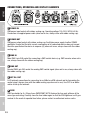 12
12
-
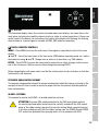 13
13
-
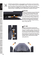 14
14
-
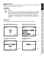 15
15
-
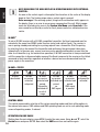 16
16
-
 17
17
-
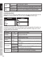 18
18
-
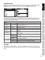 19
19
-
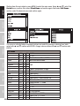 20
20
-
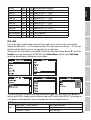 21
21
-
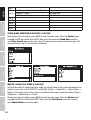 22
22
-
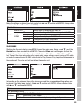 23
23
-
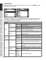 24
24
-
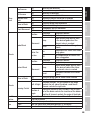 25
25
-
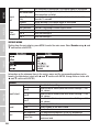 26
26
-
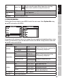 27
27
-
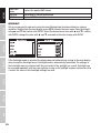 28
28
-
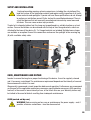 29
29
-
 30
30
-
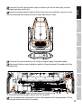 31
31
-
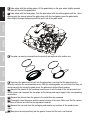 32
32
-
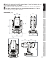 33
33
-
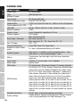 34
34
-
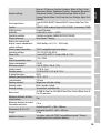 35
35
-
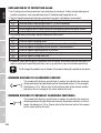 36
36
-
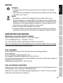 37
37
-
 38
38
-
 39
39
-
 40
40
-
 41
41
-
 42
42
-
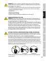 43
43
-
 44
44
-
 45
45
-
 46
46
-
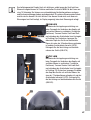 47
47
-
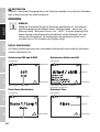 48
48
-
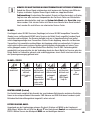 49
49
-
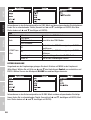 50
50
-
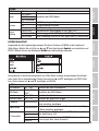 51
51
-
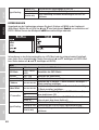 52
52
-
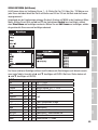 53
53
-
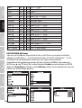 54
54
-
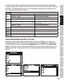 55
55
-
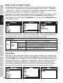 56
56
-
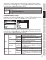 57
57
-
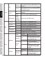 58
58
-
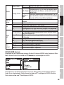 59
59
-
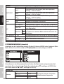 60
60
-
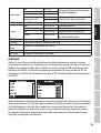 61
61
-
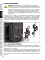 62
62
-
 63
63
-
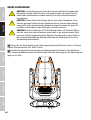 64
64
-
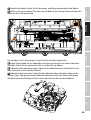 65
65
-
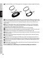 66
66
-
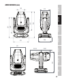 67
67
-
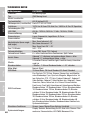 68
68
-
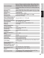 69
69
-
 70
70
-
 71
71
-
 72
72
-
 73
73
-
 74
74
-
 75
75
-
 76
76
-
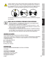 77
77
-
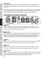 78
78
-
 79
79
-
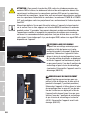 80
80
-
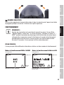 81
81
-
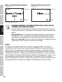 82
82
-
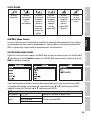 83
83
-
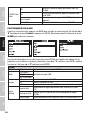 84
84
-
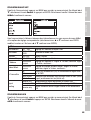 85
85
-
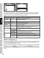 86
86
-
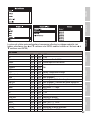 87
87
-
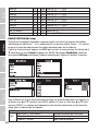 88
88
-
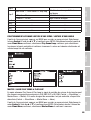 89
89
-
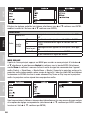 90
90
-
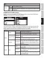 91
91
-
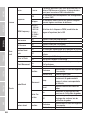 92
92
-
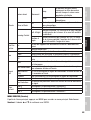 93
93
-
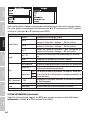 94
94
-
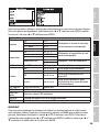 95
95
-
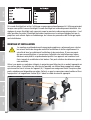 96
96
-
 97
97
-
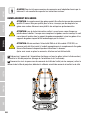 98
98
-
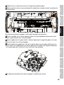 99
99
-
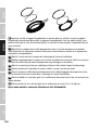 100
100
-
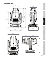 101
101
-
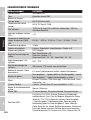 102
102
-
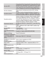 103
103
-
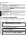 104
104
-
 105
105
-
 106
106
-
 107
107
-
 108
108
-
 109
109
-
 110
110
-
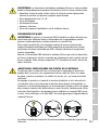 111
111
-
 112
112
-
 113
113
-
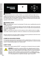 114
114
-
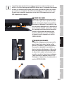 115
115
-
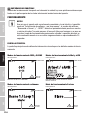 116
116
-
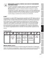 117
117
-
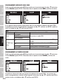 118
118
-
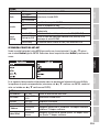 119
119
-
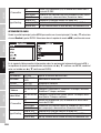 120
120
-
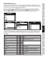 121
121
-
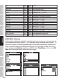 122
122
-
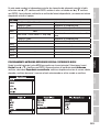 123
123
-
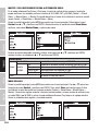 124
124
-
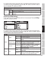 125
125
-
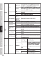 126
126
-
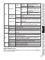 127
127
-
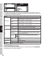 128
128
-
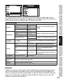 129
129
-
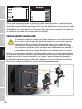 130
130
-
 131
131
-
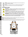 132
132
-
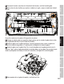 133
133
-
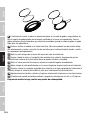 134
134
-
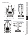 135
135
-
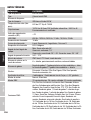 136
136
-
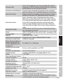 137
137
-
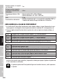 138
138
-
 139
139
-
 140
140
-
 141
141
-
 142
142
-
 143
143
-
 144
144
-
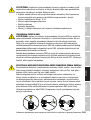 145
145
-
 146
146
-
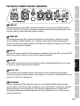 147
147
-
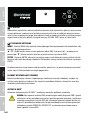 148
148
-
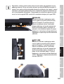 149
149
-
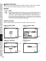 150
150
-
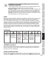 151
151
-
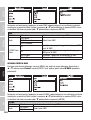 152
152
-
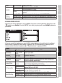 153
153
-
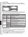 154
154
-
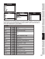 155
155
-
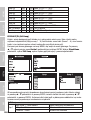 156
156
-
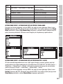 157
157
-
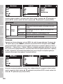 158
158
-
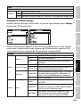 159
159
-
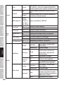 160
160
-
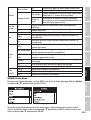 161
161
-
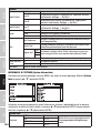 162
162
-
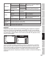 163
163
-
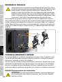 164
164
-
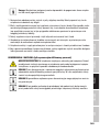 165
165
-
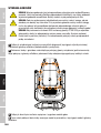 166
166
-
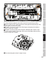 167
167
-
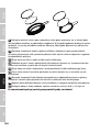 168
168
-
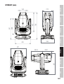 169
169
-
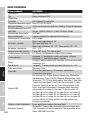 170
170
-
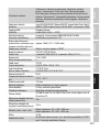 171
171
-
 172
172
-
 173
173
-
 174
174
-
 175
175
-
 176
176
-
 177
177
-
 178
178
-
 179
179
-
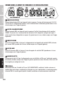 180
180
-
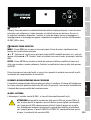 181
181
-
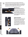 182
182
-
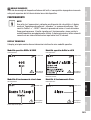 183
183
-
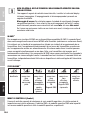 184
184
-
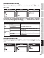 185
185
-
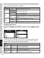 186
186
-
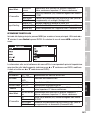 187
187
-
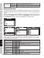 188
188
-
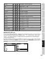 189
189
-
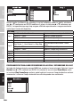 190
190
-
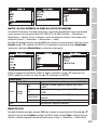 191
191
-
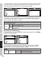 192
192
-
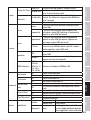 193
193
-
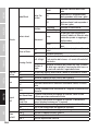 194
194
-
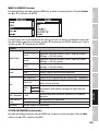 195
195
-
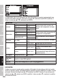 196
196
-
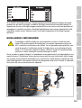 197
197
-
 198
198
-
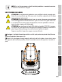 199
199
-
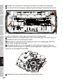 200
200
-
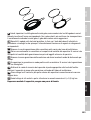 201
201
-
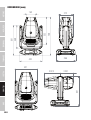 202
202
-
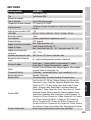 203
203
-
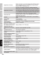 204
204
-
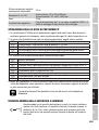 205
205
-
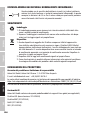 206
206
-
 207
207
-
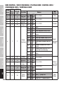 208
208
-
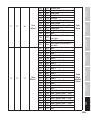 209
209
-
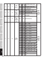 210
210
-
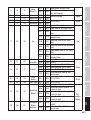 211
211
-
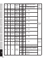 212
212
-
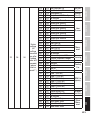 213
213
-
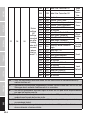 214
214
-
 215
215
-
 216
216


Cameo OTOS® SP6 Manual de usuario
- Categoría
- Focos
- Tipo
- Manual de usuario
en otros idiomas
- français: Cameo OTOS® SP6 Manuel utilisateur
- italiano: Cameo OTOS® SP6 Manuale utente
- Deutsch: Cameo OTOS® SP6 Benutzerhandbuch
- polski: Cameo OTOS® SP6 Instrukcja obsługi
Artículos relacionados
-
Cameo OTOS® H5 Manual de usuario
-
-
-
-
-
-
-
-
-
