HTW MINI VRF V10 UNIDAD EXTERIOR Guía de instalación
- Tipo
- Guía de instalación

MINI VRF V10
OUTDOOR UNIT
HTW-V200WV2RN1V10 | HTW-V224WV2RN1V10
HTW-V260WV2RN1V10 | HTW-V280WV2RN1V10
HTW-V335WV2RN1V10
ES
EN
Por favor lea atentamente antes de usar este producto.
Please, read carefully before using the product.
Manual de Instalación
Installation Manual


ESPAÑOL
Manual de Instalación
MINI VRF V10
UNIDAD EXTERIOR
HTW-V200WV2RN1V10 | HTW-V224WV2RN1V10
HTW-V260WV2RN1V10 | HTW-V280WV2RN1V10
HTW-V335WV2RN1V10

3
PRECAUCIONES
No conecte el equipo a la alimentación principal directamente.
ADVERTENCIA
CONTENIDO PÁGINA
PRECAUCIONES ........................................................................................... 3
ACCESORIOS SUMINISTRADOS ................................................................4
INSTALLATION DE LA UNIDAD EXTERIOR ................................................5
INSTALACIÓN DE LA TUBERÍA DE REFRIGERANTE ...............................6
INSTALACIÓN ELÉCTRICA ........................................................................11
TEST RUNNING ...........................................................................................14
CONFIGURATION .......................................................................................14
PRECAUCIONES PARA EVITAR FUGAS DE REFRIGERANTE ...............14
CÓDIGOS DE ERROR .................................................................................15
ENTREGA DEL MANUAL ...........................................................................15
1. PRECAUCIONES
nacionales e internacionales.
BXY!?@Z?:[+!=X#""
la instalación.
Las precauciones descritas a continuación incluyen temas de
seguridad importante. Cumplir estas regulaciones rigurosamente.
#K"J\"#"
funcionamiento para comprobar que no hay problemas.
Seguir las indicaciones del manual de usuario sobre el uso y el
mantenimiento de la unidad por el cliente.
Apague la alimentación principal (disyuntor) antes de realizar el
de mantenimiento la unidad.
YT"VJ"&
instalación.
PRECAUCIONES
Instalación del nuevo refrigerante del aire acondicionado
B""G"$""^@v]"\"
x&#"\#"x{V&"T
"$""9KQ
"$""\#"""J\
"T#V"$""""
aceite de refrigeración no entren en el circuito de refrigeración.
Y"V""""$""""\&"$""
tamaños de las secciones de conexión de los puertos de carga de
la unidad principal y las herramientas de instalación son las del
"$""V
=Q""#T#"
"$""'^@-v
Y""Gx\"GV&#
H#"^@&#"$V"T"
#V@}"Gx#"T#
Q"#"""&#"%T#"G
tener dentro.
Pida a un técnico autorizado o a un profesional de instalación
eléctricas o incendios.
Desconecte el equipo o el disyuntor antes de realizar cualquier
eléctricas.
Conecte correctamente el cable de conexión.
Si el cable de conexión está mal conectado se pueden dañar las
piezas eléctricas.
tenga cuidado de no introducir gases ni otras sustancia que no sea
e. Si
se mezcla aire u otra sustancia con el refrigerante, la presión de gas
Si la unidad queda expuesta al agua o a la humedad antes de la
eléctricos.
cuidadosamente en
busca de daños.
cuidado al manipular las piezas.
manual de instalación.
eléctricas o incendios.
Cuando el aire acondicionado se instala en una habitación pequeña,
tome las medidas necesarias para asegurar que la concentración de
Instale el aire acondicionado de manera segura en un lugar donde la
base pueda sostener el peso adecuadamente.
contra un terremoto.
Si el aire acondicionado no se instala adecuadamente, pueden
Si el gas refrigerante derramado entra en contacto con el fuego, se
refrigerante.
Si hay fugas de refrigerante dentro de la habitación y hay cerca
fuentes de calor como una cocina, se pueden generar gases
La unidad se debe instalar teniendo en cuenta las regulaciones
Si el bornero de alimentación está dañado, debe ser sustituido por
dimensiones del espacio necesario para la correcta instalación de la

4
La temperatura del circuito puede ser alta, mantenga el cableado
J"G
!#\]+]+;#""
Z#\#"##
#"V"
Z##"x\"
"!VTJ"%$"%""#"T
H@"TT#}""
@"T""K"G
gas o agua, o al cable a tierra de la luz o del teléfono.
Cumpla con las regulaciones locales de electricidad durante los
"JK"
Zx\""##"V""K"
No instale el equipo en un lugar peligroso con riesgos de posibles
$
Si hay fugas de gas alrededor del aire acondicionado, y el gas
#""##"V"
Para los aparatos destinados a ser utilizados en altitudes superiores a
"}}x
2. ACCESORIOS
?#""="""&
Tubería de refrigerante
!"G%#""$""V
no puede ser utilizado.
B""&"J"
K$""$""V=T
tuerca abocardada que se encuentra en la unidad principal del aire
&G
Preparación previa a la instalación
Tenga cuidado con los siguientes puntos antes de la instalación.
Purga de aire
Y"#""VG
No utilice el refrigerante cargado en la unidad exterior para la
purga de aire.(El refrigerante para la purga de aire no está en la
unidad exterior)
Cableado eléctrico
@"J"\&
x\""x"""%"#"T"
en contacto con la carcasa ni otros elementos.
Lugar de instalación
Z"T#"#"##""
unidad exterior. Un lugar donde el ruido del funcionamiento y el aire
"V
Z"TKx#""$"V
Un lugar donde no se bloquee el paso.
?x""#\V
"TK$""
distancia aprox.
Q"##""#"
Un lugar donde el agua drenada no cause problemas.
PRECAUCIONES
Instale la unidad exterior en un lugar donde el aire de descarga no
esté bloqueado.
Cuando una unidad exterior está instalada en un lugar siempre
x#V$"""%
alto, asegure el equipo usando un conducto o un pantalla contra
V#"""$"V"
CANTIDAD
ACCESORIOS
DE INSTALACIÓN
FORMANOMBRE
1. Manual de instalación de la
unidad exterior
2. Manual de usuario de la
unidad exterior
3.Pipeta de condensados 1
4. Resistencia fin de bus
5. Tapón drenaje
6. Accesorio de conexión de las
tuberías frigoríficas
2
1
2
1
1
7) Detector de fugas de gas
9
especiales)
requisitos especiales)
los bordes
4) Cortador de tubos
5) Cuchillo

5
3. INSTALACIÓN UNIDAD EXTERIOR
3.1 Lugar de instalación
Por favor, mantenga el equipo alejado de los siguientes lugar, de lo
contrario puede provocar un mal funcionamiento:
Hay una fuga de gas combustible.
Hay mucho aceite (incluyendo aceite del motor).
Hay aire salado circundante (cerca de la costa).
Hay gas cáustico (el sulfuro, por ejemplo) existente en el
aire (cerca de una fuente termal).
Un lugar donde el aire expulsado hacia fuera de la unidad
exterior pueda llegar a la ventana de su vecino.
Un lugar en el que el ruido no interfiere a sus vecinos en la
vida cotidiana.
Un lugar demasiado débil para soportar el peso de la unidad.
Lugar desequlibrado.
Un lugar con una ventilación insuficiente.
Cerca de una central eléctrica o de equipos de alta frecuencia.
Instale la unidad interior, la unidad exterior, el cable de
Instale la unidad en un lugar que pueda ofrecer espacio
suficiente para su instalación y mantenimiento. No lo instale en
un lugar que tenga una elevada exigencia de silencio, como
una habitación.
alimentación y el cable de comunicación al menos a 1 m de
distancia del televisor o de la radio para evitar ruidos o
interferencias en la imagen.
PRECAUCIÓN
3.2 Espacio de instalación (Unidad:mm)
evitar interferencias en la imagen y el ruido en los aparatos
eléctricos. (Se puede generar ruido en función de las
condiciones bajo las cuales se genera la onda eléctrica,
incluso si se mantiene 1 metro).
Mantenga la unidad interior, la unidad exterior, el cable de
alimentación y el de comunicación de al menos 1 m
de distancia de las televisiones y radios. Esto es para
El aislamiento de las partes metálicas del edificio y el aire
acondicionado debe cumplir con la regulación de la Norma Nacional
de Electricidad.
Cuando instale la unidad exterior en un lugar que esté constante-
-
Instale la unidad de manera que los laterales que expulsan aire
No instale la unidad exterior en la pared.
operación de la boca de descarga se establece en ángulo recto
Viento
fuerte Viento
fuerte
Fig.2-2
La instalación en los siguientes lugares puede dar lugar a algunos
problemas.
Un lugar lleno de aceite de máquina.
Un lugar donde es probable que se generen ondas de radio
de alta frecuencia a partir de equipos de audio, soldadores y
equipos médicos.
3000
Stro
wind
Strong
wind
Fig.2
Fig.3-1
668 206
440
400
528
494
1558
1120
>300
>600
>300
>
0003
Fig.3-2
Fig.3-3
Fig.3-4
>3000 >1000 >6000 >4000 >300
>600
>3000
>300
Instalación de una sola unidad
Pared o obstáculo
Mantener
distancias
Salida aire
Entrada aire
Entrada aire
Conexión paralela de dos unidades o más
Conexión paralela de los lados delantero y trasero

Fig.3-6
Fig.4-1
Fig.3-5
>600
Fix with bolt
6
3.3 Traslado y montaje
El centro de gravedad de la unidad no se encuentra en su
centro físico, así que por favor tenga cuidado al levantarla.
Nunca sujete la unidad por la entrada de aire para evitar
que se deforme.
No toque el ventilador con las manos u otros objetos.
No incline la unidad más de 45 °, y nunca tumbarla horizontal-
-mente.
Haga una base de hormigón de acuerdo con las
epecificaciones de la unidad exterior (Consulte Fig.3-5).
Fijar los pies de la unidad con pernos con firmeza para
evitar que se csuelte en caso de terremoto o de fuerte
viento. (Consulte Fig.3-5)
4. INSTALACIÓN DE LAS TUBERÍAS
FRIGORÍFICAS
Compruebe que la diferencia de altura entre la unidad interior y
la unidad exterior, la longitud total de las tuberías de refrigerante,
y el número de las curvas cumplan con los siguientes
requisitos:
4.1
Tubería de regrigerante
PRECAUCIÓN
Por favor, preste atención para evitar que se dañen los
componentes mientras se realiza la conexión de las tuberías.
Para evitar que la tubería de refrigerante se oxide en el
interior durante la soldadura, es necesario usar nitrógeno, de
lo contrario el óxido puede bloquear el sistema.
Entrada para las conexiones frigoríficas y eléctricas
Los patrones de salida de conexiones que se pueden
seleccionar, son por la parte frontal y la lateral. En las siguientes
figuras se muestran las ubicaciones:
Tabl
a
4-1
da frontal Salida lateral
4.2 Detec
ción de fugas
Utilice agua jabonosa o detector de fugas para comprobar si todas
las soldaduras presenta fugas o no (Consulte Fig.4-2). Nota:
A es la válvula de de servicio de baja presión
B
es la válvula de servicio de alta presión
C y D es la conexión de tuberías entre las unidades interiores y
exterior.
PRECAUCIÓN
1. Salida lateral: cortar el agujero de la placa lateral. Se sugiere cortar
un trozo de la placa de metal de abajo para evitar la entrada de
ratones y que destruyan el cableado de la máquina.
2. Salida frontal: cortar el agujero de la placa frontal. Se sugiere cortar
un pedazo del lado derecho placa de metal para evitar la entrada de
ratones y que destruyan el cableado de la máquina.
3. Cableados: el cable eléctrico debe salir a través de los dos agujeros
de plástico de la placa, unirlos con las tuberías de refrigerante.
PRECAUCIÓN
Durante la instalación de la unidad exterior, prestar atención al
lugar de instalación y el patrón de drenaje;
Si el equipo está instalado en una zona alpina, el agua congelada
condensada bloqueará la salida de agua, por favor saque el tapón
de goma de la salida de agua de reserva. Si aún así no logra
satisfacer el drenaje de agua, por favor abrir las otras dos salidas
de agua pre-troqueladas.
Tapón elíptico Pipeta y junta de desagüe
NOTA
3.4 Drenaje
Todas las imágenes de este manual tienen el único propósito
explicativo. Pueden ser ligeramente diferentes del equipo que ha
adquirido (depende del modelo). La forma real prevalecerá.
Cuando se desee realizar un drenaje centralizado en un punto,
instalar la pipeta con su junta y los dos tapones elípticos para el
chasis, como se muestra en la Figura 3.6. Instale el tubo de
drenaje para completar la instalación del drenaje centralizado.

7
Fig. 4-2
DC
AB
Conexiones frigoríficas interiores
Conexiones frigoríficas
Fig. 4-3
4.3
Aislamiento térmico
Cortar
Realice el aislamiento térmico de las tuberías de líquido y gas por
separado. La temperatura de las tuberías del lado de gas y lado de
líquido es totalmente diferente, para evitar la condensación por favor
realizar el aislamiento térmico total.
El tubo de gas debe utilizar material de aislamiento de espuma
de células cerradas, con el ignífugo de grado B1 y con una
resistencia al calor de más de 120 ° C.
.
Cuando el diámetro exterior del tubo de cobre sea ≤ Φ12.7mm,
el espesor de la capa aislante debe ser de más de 15 mm;
Cuando el diámetro exterior del tubo de cobre sea ≥ Φ15.9mm, el
espesor de la capa aislante debe de ser de más de 20 mm.
Por favor, use materiales de aislamiento térmico unidos para
realizar el aislamiento térmico y sin espacio para las piezas de
conexión de los tubos de la unidad interior.
Cuerpo de la unidad Cinta
Tubería
4.4 Método de conexión
Selec
ción de las tubería
Tabl
a
4-2
/
DEF
GHI
$%&
'(
DEF
H
I
G
/////
$%&'(
Fig. 4-4
Código
Tubería principal
Tuberías
principales uds. Int
Tuberías uds.
Interiores
Distribuidores
Tubería entra la unidad exterior y el
primer distribuidor.
Tuberías entre distribuidores
Tubería del distribuidor a su unidad
interior
Nombre Definición
El primer método de conexión
El primer distribuidor
Unidad Exterior
Unidades
Interiores
Distribuidores frigoríficos intermedios
y finales
/Њ/
Fig. 4-5
1
1
1
1
1
1
$%
'
(
&
D
E
F
H
I
G
/ /
/
/
/
primer distribuidor
Unidades
Interiores
Unidad Exterior (Ejemplo modelo 260)
El segundo método de conexión
NOTA
Si la distancia entre el primer distribuidor y la última unidad
interior es más de 15 metros, elija el segundo método de
conexión.
La distancia entre la unidad interior y el distribuidor más cercano
debe ser inferior a 15m.
4.4 Diámetros de tubería de las unidades
interiores
Diámetro de la tubería principal, del distribuidor intermedio y
del distribuidor final.
1) Diámetros de tubería según la capacidad (Consulte la Tabla 4-3).
2) Ejemplo: En la Fig.4-5, la capacidad total aguas abajo de la
tubería L2 es de 45×2˙90, por lo que según la Tabla 4.4, el
diámetro de gas / líquido de L2 será˖Φ15.9 (5/8") / Φ9.5 (3/8").
$ψ
ŏ$ψ
ŏ$ψ
¢ ¢
FQZHN-03D
FQZHN-02D
FQZHN-01D
FQZHN-01D
ЊЊ
Tabla 4-3 Diámetros de tubería (L2 L5) y distribuidores (B E)
Gas Líquido Distribuidor
Tubería (mm)
Capacidad total
(kW) aguas
abajo (A)
¢ (5/8")
¢9.5 (3/8")
¢ (3/4")
¢9.5 (3/8")
¢9.5 (3/8")
(1/2")
(1 1/8")
Tabla 4-4 Diámetros de tubería principal (L1) y primer distribuidor (A)
4.5 Diámetros de tubería de la unidad exterior
¢ (7/8")
ŏ$ψ
Capacidad
total de la
ud. exterior
9H"G#"#
"G
TVGT
Gas
(mm) Gas
(mm)
BGT
(mm) BGT
(mm)
Primer
Distribuidor Primer
Distribuidor
9H"G#"#
"G
TVGT
NOTA

8
las unidades interiores, no se permite la conexión de bifurcación
adicional.
total diseñada de las unidades interiores a las que se conecta.
Si esta capacidad es mayor que la de la unidad exterior,
Método de conexión
Tabla 4-5
Unidad exterior
Unidad interior
Distribuidor
Gas
Soldadura o
Abocardado
Abocardado
Soldadura o
Abocardado
Soldadura o
Abocardado
Abocardado
Soldadura o
Abocardado
T
Capacidad
rango Capacidad
(HP)
Capacidad
rango
Capacidad
(HP)
Diferencia de altura máxima
(m)
Cuando la ud.
ext. está arriba
4.6. Ilustración
Cuando la ud.
La longitud
de
El primer distribuidor
Unidad interior
T
Cuando la capacidad total de las unidades interiores sea mayor que el
Cuando la capacidad total de las unidades interiores sea mayor o igual
arrancar las unidades interiores en diferentes momentos.
NOTA
Tamaños de tubería en la tubería de derivación
Diámetro de la tubería del conector en el cuerpo de la unidad exterior
Salida de aire de
4 lados 56~80
Salida de aire de
4 lados 28~45
montado en pared
22~45
Tipo conducto delgado
71
12.7
(Tuerca abocardada)
12.7
(Tuerca abocardada)
15.9
(Tuerca abocardada)
15.9
(Tuerca abocardada)
6.4
(Tuerca abocardada)
montado en pared 56 15.9
(Tuerca abocardada)
9.5
(Tuerca abocardada)
6.4
(Tuerca abocardada)
9.5
(Tuerca abocardada)
9.5
(Tuerca abocardada)
Salida de aire
unilateral 18~45 12.7
(Tuerca abocardada)
6.4
(Tuerca abocardada)
Salida de aire
unilateral 56 15.9
(Tuerca abocardada)
9.5
(Tuerca abocardada)
Baja presión
estática 18~45 12.7
(Tuerca abocardada)
6.4
(Tuerca abocardada)
Baja presión estática 56
15.9
(Tuerca abocardada)
9.5
(Tuerca abocardada)
Tipo conducto
A5
22~45
Tipo conducto
A5
56~140
12.7
(Tuerca abocardada)
6.4
(Tuerca abocardada)
Refrigerante
R410A
A (TIPO) Lado del aire (Φ) Lado líquido (Φ)
Tabla 4-6
(A: the total capacity of indoor units)
Tipo cassette de 4 vías
15~45
12.7
(Tuerca abocardada)
6.4
(Tuerca abocardada)
Tipo cassette
bidireccional 22~45
12.7
(Tuerca abocardada)
6.4
(Tuerca abocardada)
Tipo cassette
bidireccional 56~71
15.9
(Tuerca abocardada)
9.5
(Tuerca abocardada)
Tipo consola 22~45
12.7
(Tuerca abocardada)
6.4
(Tuerca abocardada)
Tipo suelo techo
36~45
12.7
(Tuerca abocardada)
6.4
(Tuerca abocardada)
Tipo suelo techo
56~160
15.9
(Tuerca abocardada)
9.5
(Tuerca abocardada)
Tipo suelo expuesto y
oculto 22~45
Tipo suelo expuesto y
oculto 56~80
12.7
(Tuerca abocardada)
6.4
(Tuerca abocardada)
15.9
(Tuerca abocardada)
9.5
(Tuerca abocardada)
15.9
(Tuerca abocardada)
9.5
(Tuerca abocardada)
Lado de conexión
de tubería
Diámetro de la tubería del conector de la u.exterior (mm)
Φ19.1 Φ9.53
Φ22.2
Φ9.53
Modelo (kW)
20-22.4
26-28
33.5
Tabla 4-7
Lado de gas Lado líquido
Φ22.2
Φ12.7
Tabla 4-8
Unidad exterior
(kW)
Capacidad de la
u. exterior
(caballos de
fuerza)
Cantidad
máxima de
u. interior
Capacidad total de
la unidad interior
(caballos de fuerza)
50%~130%
117
20
138
22.4
159
26
1610
28
33.5
12 20
de la capacidad de la unidad exterior.
La sobrecarga reduce la capacidad correspondiente.
La cabecera de bifurcación debe conectarse directamente con

9
Diferencia
de altura
Máximo
9
Long. real
(desde una ud. int. a su distribuidor
más cercano) (m)
Diferencia de
Ud. ext. arriba
ẇ
c t
T
L2+L3+L4+L5+f (El primer método de conexión)
o L3+L5+f (El segundo método de conexión)
Primer método de conexión
Unidad exterior
El primer distribuidor
del distribuidor más cercano)
Unidad interior
Diferencia de altura
entre uds. interiores
Fig.4-7
Los distribuidores interiores son a~f, para diferentes tamaños
los distribuidores de la unidad interior

10
Segundo método de conexión
Unidad exterior
Longitud máxima de la
El primer distribuidor
Unidad interior
4.7. Sacar la suciedad o el agua de la tubería
-
-
gerante de la unidad exterior.
4.8. Prueba de estanqueidad
Cargue con nitrógeno presurizado después de conectar las
prueba de estanqueidad.
cuando se aplique nitrógeno presurizado.
5. La prueba de estanqueidad nunca se debe realizar con
más cercano)
El primer distribuidor
4.10. Carga adicional de refrigerante
T
9
Diámetro
Carga de refrigerante
NOTA
PRECAUCIONES
se debe usar en la prueba de estanqueidad.
nitrógeno presurizado.
4.9. Purga del aire con la bomba de vacío
refrigerante para sacar el aire.

11
5. CABLES ELÉCTRICOS
PRECAUCIONES
las unidades interiores conectadas a la misma unidad exterior. Utilice el mismo circuito para las fuentes de
alimentación de las unidades interiores del mismo sistema. Se deben encender y apagar al mismo tiempo.
Interruptor
Fusible
(Opcional)
Alimentación
de la unidad
exterior
Interruptor Fusible Fusible Fusible Fusible
Alimentación de la unidad exterior
Unidad interior Unidad interior Unidad interior Unidad interior
Unidad exterior
Alimentación del control central
(Opcional)
!"#$
PRECAUCIONES
% !&'"""
% ()"#"'*+#",#-.
% /"""##"#&1"##""2"+
% ","#"*##"#&1
% ","""#"*#+"""""""
La fuente de alimentación, los protectores eléctricos de fuga y los interruptores manuales de las unidades interiores
sistema.
Para reducir la interferencia, utilice como cable de comunicación un cable apantallado de tres hilos. No utilice un
cable de multi-hilos.
El cableado lo debe hacer un ingeniero eléctrico.

12
Unidad
exterior
opcionales, contacte el distribuidor local para adquirirlas
si es necesario.
!"#$
Unidad
interior Unidad
interior Unidad
interior
Unidad
interior
4
#
"
Cableado de la unidad interior y del control de la unidad exterior
PRECAUCIONES
'""&
(5)2
"
de bus
Fig. 5-2
5.1. Cableado de la Unidad exterior
Bornero de la unidad exterior Terminales
Alimentación
Fig. 5-3
PRECAUCIONES
%
Nacional de Cableado.
%
descontinuadas, los usuarios pueden seleccionar esta función
cuando sea necesario.
Cable de comunicación entre la unidad exterior / interior
Reservado Al controlador
centralizado
Al medidor
de kilovatios-
hora
20 - 28kW
33.5kW
K1 K22 2 2 2 XX X Y P Q Q
Monitor de unid.
exterior
Controlador de
unid. interior
central
Amperíme-
tro digital
A la comunicación
de las unidades
interiores bus
Comunicación de
la unidad interior y
exterior
50
380-415
342
456
21
24.3
25
/
18.4
20.5
24.3
25
/
15
19
24.3
25
/
12.4
19
24.3
25
/
12
2×0.17
2.1+2.1
Modelo Capacidad (kW)
Hz
Voltaje
Min.(V)
Max.(V)
MSC
RLA
kW
FLA
380-415V 3N~ 50Hz
Fuente
de
alimenta
ción
Compresor
OFM
Fuente de alimentación
262220 28
Amperios máx. del fusible
Amperios del circuito mín.
Amperios totales de sobrecorriente
33.5
26.4
33.2
32
/
19.6
Tabla 5-1
% Cuando el cable de alimentación esté paralelo al cable de comunicación, inserte los cables eléctricos en sus
%
%
cableado es opcional. Para adquirir un control cableado, póngase en contacto con su distribuidor local.

13
Conexión de cables
Selle la conexión de cables con material aislante o se
NOTA
Los aires acondicionados se pueden conectar a un control central
(CCM). Antes del funcionamiento, conecte los cables correctamente
5.2. Cableado de la Unidad Interior
% Alimentación
Unidad
interior
DC
"&"
#
7
Disyuntor (A)
Cable de señal unidad
2)
(señal eléctrica débil)
Alimentación
Tabla 5-2
ẇ
3x2.5
Unidad interior
Control
centralizado Comunicación
uds. interiores
Pantalla
Control
cableado
Fig. 5-4
-
do de puesta a tierra ahora es conectar a tierra el extremo más
cercano del cable apantallado y abrir en el extremo (aislado).
El cable apantallado es para conexión a tierra.
2. El control entre la unidad exterior y la unidad interior es de tipo
BUS. Las direcciones se establecen durante la instalación.
PRECAUCIONES
tubo de distribución de cables.
NOTA
Cableado de alimentación de la unidad interior
Interruptor magnetotérmico
Interruptor manual
Unidad interior
PRECAUCIONES
Fig. 5-5
% Use un cable apantallado de 3 hilos como cable de señal
entre las unidades exterior e interior.
Cable de comunicación de la unidad exterior / interior
Unidad exterior
Extremo del cable apantallado de conexión
Cable de
comunicación
e interiores
(abierto)
comprar el controlador de cable cuando sea necesario.
PRECAUCIONES
producir un error de comunicación cuando el cableado de comunicación
excede estas limitaciones.
BLANCO
AZUL
NEGRO
AMARILLO
GRIS
NEGRO
Para cablear el controlador La
función de control de cable
reservado se indica en la tabla
de líneas discontinuas, los
usuarios pueden comprar el
controlador de cable cuando
sea necesario.
de la unidad interior-unidad interior y el cable de conexión de la unidad
interior-unidad exterior deben estar en el mismo sistema.
2.. Cuando el cable de alimentación es paralelo al cable de comunicación,

14
6. PRUEBA DE FUNCIONAMIENTO
eléctrica de control.
PRECAUCIONES
% La prueba de funcionamiento no se puede realizar hasta que
% La prueba de funcionamiento no puede comenzar hasta que
% Nunca fuerce el recorrido. (O el protector se asienta hacia
atrás y es peligroso.)
7. CONFIGURACIÓN
7.1. Resumen
Información
7.2. Ajustes de los micro-interruptores
ẇ
ẇ
ẇ
3
ẇ
ẇ
ẇ
ẇ
La cantidad de unidades interiores está en el
Cuando se conectan las uds. int. DC2 (por defecto)
Cuando se conecta a uds. interiores antiguas
Direccionamiento automático (por defecto)
Borrar la dirección de las unidades interiores
Prioridad automática (por defecto)
Prioridad de refrigeración
Prioridad de primera en marcha
Solo calefacción
Otras combinaciones, prioridad de calefacción
Solo prueba de fábrica
NOTA
micro-interruptores
Tabla 7-1 Solo para
unidades de
200 a 280
Prioridad automática (predeterminado)
S2
S9-1
000
100
010
110
Prioridad de enfriamiento
Primera prioridad ON
Solo calefacción
Otras combinaciones, prioridad de calefacción
Solo enfriamiento
001
Reservado
Reservado
Borrar direcciones de unidades interiores
S1-2
S1-3
0
1
0
1
Capacidad de la unidad exterior, 12HP
0
1
Direccionamiento automático (predeterminado)
1 2 3
1 2 3
S9-2
Solo prueba de fábrica
Reservado
Reservado
0
1
1 2 3
1 2 3
1 2 3
Cuando se conecta a la unidad interior de DC de 2a generación
(predeterminado)
S1-1
0
1
1 2 3
1 2 3
ENC1
&
S9-3 0-F
El número de unidades interiores está en el rango
0-15 0-9 en ENC1 indica 0-9 unidades interiores;
A-F en ENC1 indican 10-15 unidades interiores
0-7
Configuración de la dirección de red de la unidad
exterior, solo se debe seleccionar de 0 a 7 (el
valor predeterminado es 0).
El número de unidades interiores está en el rango
16-31 0-9 en ENC1 indica 16-25 unidades
interiores;
A-F en ENC1 indican 26-31 unidades interiores
ENC3
1
1 2 3
0-F
0
Tabla7-2
Solo para la unidad 335, la
unidad 335 adopta PCB diferente
Cuando se conecta a una unidad interior de AC o DC de primera generación

8. PRECAUCIONES PARA EVITAR
FUGAS DE REFRIGERANTE
ser grande para que cualquier fuga de refrigerante no pueda
alcanzar el grosor máximo. De manera que se puedan tomar
acciones importantes a tiempo.
%
% 3
Compruebe el grosor en los siguientes pasos y tome las
acciones necesarias.
+ cargas adicionales
3.. Calcule el espesor del refrigerante
-
Unidad exterior
Unidad
interior
Fuga de refrigerante en la habitación
(todo el refrigerante circula hacia arriba)
Ud. interior
A. Ventilación
lugares donde sea fácil mantener el refrigerante)
15
A[kg]
B[m ]
3
Contramedida contra sobre espesores altos

16
8.1. Información importante para el
refrigerante usado
9
2 o más, unidades de menos de
2
un sistema de detección de fugas al menos cada 24 meses
2)
3)
)
2 o más, unidades de menos de
2
)
2 o más, comprobar al menos
cada 3 meses, o cuando se instale un sistema de detección de fugas al
5)) Solo puede realizar la instalación, la manipulación y el mantenimiento un
9. CODIGOS DE ERROR
Error
Código
Error de comunicación entre la placa principal y la placa
de accionamiento del compresor
Error del sensor alta presión
Error de secuencia de la fase
Error de comunicación entre las unidades interior y exterior
Error del sensor de temperatura T3 o T4
Tensión de alimentación anormal
Error del sensor de temp. de descarga
Fallo del sensor TL
Protección de alta presión
Protección de corriente del compresor
Protección de temperatura de descarga
Protección de alta temperatura del condensador
Protección contra tormentas
Error MEC
Protección de secuencia de fase
Protección por frecuencia actual del compresor es diferente
Error de tensión del bus de DC
Irrecuperable
Irrecuperable
Irrecuperable
Irrecuperable
10.0. ENTREGA DEL MANUAL AL USUARIO
Los manuales de uso de las unidades interiores y exteriores se deben entregar al usuario. Explique en detalles el contenido
del manual de usuario a los clientes.
Atención:
Frecuencia de comprobaciones de fugas de refrigerante
Modelo
Refrigerante / kg
toneladas de CO2 equivalente
6.5 13.57
20-28kW
Carga de fábrica
33.5kW
816.71

17
Tabla.1
UnidadValorSímbolo
metI
UnidadValorSímbolo
metI
Capacidad de
enfriamiento nominal Prated,c
Eficiencia energética estacional
de refrigeración de espacios
ηs,c
Tj=+35℃Pdc Tj=+35℃EERd
EERd
EERd
EERd
Tj=+30℃Pdc Tj=+30℃
Tj=+25℃Pdc Tj=+25℃
Tj=+20℃Pdc Tj=+20℃
Coeficiente de
degradación para aires
acondicionados(*)
Cdc
Modo off POFF PCK
Modo de apagado térmico
PTO 0 PSB
Control de capacidad
Para aire acondicionado aire-aire:
caudal de aire, medido en exteriores
m3/h
Nivel de potencia
acústica, exterior LWA
GWP del refrigerante kg CO2 eq(100años)
Detalles de contacto
Requisitos de información para acondicionadores de aire a aire
Modo de enfriamiento:
Intercambiador de calor lateral exterior del aire acondicionado: aire
Intercambiador de calor lateral interior del aire acondicionado: aire
Cuando la información se relaciona con acondicionadores de aire multi-split, el resultado de la prueba y los datos de rendimiento pueden obtenerse
sobre la base del rendimiento de la unidad exterior, con una combinación de unidades interiores recomendadas por el fabricante o importador.
Capacidad de refrigeración declarada para carga parcial a
temperaturas exteriores determinadas Tj e interior 27/19℃(bulbo
seco / húmedo)
Relación de eficiencia energética declarada o eficiencia de
utilización de gas / factor de energía auxiliar para carga parcial a
temperaturas exteriores determinadas Tj
Consumo de energía en modos distintos del "modo activo"
(*)If Cdc no se determina mediante medición, el coeficiente de degradación predeterminado de las bombas de calor será de 0,25
Tipo: accionado por compresor
Si aplica: controlador del compresor: motor eléctrico
Otros items
variable
0.25
kW
kW
kW
kW
kW
kW
kW
kW
kW
Modo calentador del cárter
Modo de espera
dB
--
--
--
--
%
20 281.4
20 3.79
14.811 4.71
9.760 9.11
6.378 12.76
0.04 0
0.04
9000
78
Modelo(s):HTW-V200WV2RN1V10
Prueba que coincida con la forma de las unidades interiores, sin conducto: 2×HTW-MI45Q4+2×HTW-MI56Q4;
2088

18
Tabla.2
Item Símbolo Valor Unidad Item Símbolo Valor Unidad
Capacidad de
calefacción nominal Prated,h kW
Eficiencia energética estacional
de calefacción de espacios
ηs,h %
Tj=-7 Pdh kW Tj=-7
Tj=+2 Pdh kW Tj=+2
Tj=+7 Pdh kW Tj=+7
Tj=+12 Pdh kW Tj=+12 --
--
--
--
--
--
Tbiv=Temperatura
bivalente Pdh kW Tbiv =Temperatura bivalente
TOL=temperatura de
operación Pdh kW TOL =temperatura de
operación
Temperatura bivalente Tbiv
Coeficiente de
degradación para
bombas de calor (**)
Cdh 0.25
Modo off POFF kW
Capacidad de calefacción de respaldo
elbu 0 kW
Modo de apagado térmico
PTO kW Tipo de entrada de energía
Modo calentador del cárter
PCK kW Modo de espera PSB kW
Control de capacidad
Para bomba de calor aire-aire: caudal
de aire, medido en exteriores
m3/h
Nivel de potencia
acústica, exterior LWA dB
GWP del refrigerante kg CO2 eq(100años)
Detalles de contacto
Requisitos de información para bombas de calor
Intercambiador de calor lateral exterior del aire acondicionado: aire
Intercambiador de calor lateral interior del aire acondicionado: aire
Otros items
(**)If Cdh no se determina mediante medición, el coeficiente de degradación predeterminado de las bombas de calor será de 0,25
Cuando la información se relaciona con bombas de calor multi-split, el resultado de la prueba y los datos de rendimiento se pueden obtener sobre
la base del rendimiento de la unidad exterior, con una combinación de unidades interiores recomendadas por el fabricante o importador.
(*)
variable
Los parámetros se declararán para la temporada de calefacción media, los parámetros para las estaciones de calefacción más cálidas y más frías son opcionales.
Indicación si el calefactor está equipado con un calefactor suplementario: no
Si aplica: controlador del compresor: motor eléctrico
Consumo de energía en modos distintos del "modo activo" Calefactor suplementario
Capacidad de calefaccióón declarada para carga parcial a
temperatura interior de 20 ℃ y temperaturas exteriores Tj
Coeficiente de rendimiento declarado o eficiencia de
utilización de gas / factor de energía auxiliar para carga
parcial a temperaturas exteriores determinadas Tj
COPd
COPd
COPd
COPd
COPd
COPd
Modo de calefacción:
20 155
10.629 3.19
6.471 3.39
6.625.763
3.652 7.57
10.629 3.19
12.310 2.44
-7
0.04
0.04
0 0.04
9000
78
2088
Modelo(s):HTW-V200WV2RN1V10
Prueba que coincida con la forma de las unidades interiores, sin conducto: 2×HTW-MI45Q4+2×HTW-MI56Q4;

19
Tabla.3
UnidadValorSímbolo
metI
UnidadValorSímbolo
metI
Capacidad de
enfriamiento nominal Prated,c
Eficiencia energética estacional de
refrigeración de espacios
ηs,c
Tj=+35℃Pdc Tj=+35℃EERd
EERd
EERd
EERd
Tj=+30℃Pdc Tj=+30℃
Tj=+25℃Pdc Tj=+25℃
Tj=+20℃Pdc Tj=+20℃
Coeficiente de
degradación para aires
acondicionados(*)
Cdc
Modo off POFF PCK
Modo de apagado térmico
PTO 0 PSB
Control de capacidad
Para aire acondicionado aire-aire:
caudal de aire, medido en exteriores
m3/h
Nivel de potencia
acústica, exterior LWA
GWP del refrigerante kg CO2 eq(100años)
Detalles de contacto
Requisitos de información para acondicionadores de aire a aire
Modo de enfriamiento:
Intercambiador de calor lateral exterior del aire acondicionado: aire
Intercambiador de calor lateral interior del aire acondicionado: aire
Cuando la información se relaciona con acondicionadores de aire multi-split, el resultado de la prueba y los datos de rendimiento pueden
obtenerse sobre la base del rendimiento de la unidad exterior, con una combinación de unidades interiores recomendadas por el fabricante o
importador.
Capacidad de refrigeración declarada para carga parcial a
temperaturas exteriores determinadas Tj e interior 27/19℃(bulbo
seco / húmedo)
Relación de eficiencia energética declarada o eficiencia de
utilización de gas / factor de energía auxiliar para carga parcial a
temperaturas exteriores determinadas Tj
Consumo de energía en modos distintos del "modo activo""
(*)If Cdc no se determina mediante medición, el coeficiente de degradación predeterminado de las bombas de calor será de 0,25
Tipo: accionado por compresor
Si aplica: controlador del compresor: motor eléctrico
Otros items
variable
0.25
kW
kW
kW
kW
kW
kW
kW
kW
kW
Modo calentador del cárter
Modo de espera
dB
--
--
--
--
%
22.4 270.2
22.4 3.31
16.645 4.57
10.990 8.61
6.399 12.8
0.04
0.04
0
9000
78
Modelo(s):HTW-V224WV2RN1V10;
Prueba que coincida con la forma de las unidades interiores, sin conducto: 4×HTW-MI56Q4;
2088

20
Tabla.4
Item Símbolo Valor Unidad Item Símbolo Valor Unidad
Capacidad de
calefacción nominal Prated,h kW
Eficiencia energética estacional
de calefacción de espacios
ηs,h %
Tj=-7 Pdh kW Tj=-7
Tj=+2 Pdh kW Tj=+2
Tj=+7 Pdh kW Tj=+7
Tj=+12 Pdh kW Tj=+12 --
--
--
--
--
--
Tbiv=Temperatura
bivalente Pdh kW Tbiv =Temperatura bivalente
TOL=temperatura de
operación Pdh kW
TOL =temperatura de operación
Temperatura bivalente Tbiv
Coeficiente de
degradación para
bombas de calor (**)
Cdh 0.25
Modo off POFF kW
Capacidad de calefacción de respaldo
elbu 0 kW
Modo de apagado térmico
PTO kW Tipo de entrada de energía
Modo calentador del cárter
PCK kW Modo de espera PSB kW
Control de capacidad
Para bomba de calor aire-aire: caudal
de aire, medido en exteriores
m3/h
Sound power
level,outdoor
LWA dB
GWP del refrigerante kg CO2 eq(100años)
Detalles de contacto
Requisitos de información para bombas de calor
Intercambiador de calor lateral exterior del aire acondicionado: aire
Intercambiador de calor lateral interior del aire acondicionado: aire
Otros items
(**)If Cdh no se determina mediante medición, el coeficiente de degradación predeterminado de las bombas de calor será de 0,25
Cuando la información se relaciona con bombas de calor multi-split, el resultado de la prueba y los datos de rendimiento se pueden obtener sobre
la base del rendimiento de la unidad exterior, con una combinación de unidades interiores recomendadas por el fabricante o importador.
(*)
variable
Los parámetros se declararán para la temporada de calefacción media, los parámetros para las estaciones de calefacción más cálidas y más frías son opcionales.
Indicación si el calefactor está equipado con un calefactor suplementario: no
Si aplica: controlador del compresor: motor eléctrico
Consumo de energía en modos distintos del "modo activo" Calefactor suplementario
Capacidad de calefacción declarada para carga parcial a
temperatura interior de 20 ℃ y temperaturas exteriores Tj
Coeficiente de rendimiento declarado o eficiencia de
utilización de gas / factor de energía auxiliar para carga
parcial a temperaturas exteriores determinadas Tj
COPd
COPd
COPd
COPd
COPd
COPd
Modo de calefacción:
22.4 167.4
12.113 3.22
7.272 3.56
5.825 6.76
3.703 7.76
12.113 3.22
13.74 2.35
-7
0.04
0.04
0 0.04
9000
78
2088
Modelo(s):HTW-V224WV2RN1V10;
Prueba que coincida con la forma de las unidades interiores, sin conducto: 4×HTW-MI56Q4;

21
Tabla.5
UnidadValorSímbolo
metI
UnidadValorSímbolo
metI
Capacidad de
enfriamiento nominal Prated,c
Eficiencia energética estacional
de refrigeración de espacios
ηs,c
Tj=+35℃Pdc Tj=+35℃EERd
EERd
EERd
EERd
Tj=+30℃Pdc Tj=+30℃
Tj=+25℃Pdc Tj=+25℃
Tj=+20℃Pdc Tj=+20℃
Coeficiente de
degradación para aires
acondicionados(*)
Cdc
Modo off POFF PCK
Modo de apagado térmico
PTO 0 PSB
Control de capacidad
Para aire acondicionado aire-aire:
caudal de aire, medido en exteriores
m3/h
Nivel de potencia
acústica, exterior LWA
GWP del refrigerante kg CO2 eq(100años)
Detalles de contacto
Requisitos de información para acondicionadores de aire a aire
Modo de enfriamiento:
Intercambiador de calor lateral exterior del aire acondicionado: aire
Intercambiador de calor lateral interior del aire acondicionado: aire
Cuando la información se relaciona con acondicionadores de aire multi-split, el resultado de la prueba y los datos de rendimiento pueden obtenerse
sobre la base del rendimiento de la unidad exterior, con una combinación de unidades interiores recomendadas por el fabricante o importador.
Capacidad de refrigeración declarada para carga parcial a
temperaturas exteriores determinadas.
Tj e interior 27/19℃(bulbo seco / húmedo)
Relación de eficiencia energética declarada o eficiencia de
utilización de gas / factor de energía auxiliar para carga parcial a
temperaturas exteriores determinadas Tj
Consumo de energía en modos distintos del "modo activo"
(*)If Cdc no se determina mediante medición, el coeficiente de degradación predeterminado de las bombas de calor será de 0,25
Tipo: accionado por compresor
Si aplica: controlador del compresor: motor eléctrico
Otros items
variable
kW
kW
kW
kW
kW
kW
kW
kW
kW
Modo calentador del cárter
Modo de espera
dB
--
--
--
--
%
26 259
26 2.59
18.843 4.53
12.745 8.35
6.330
0.25
12.66
0.04 0
0.04
10000
78
Modelo(s):HTW-V260WV2RN1V10;
Prueba que coincida con la forma de las unidades interiores, sin conducto: 2×HTW-MI45Q4+2×HTW-MI90Q4;
2088

22
Tabla.6
Item Símbolo Valor Unidad Item Símbolo Valor Unidad
Capacidad de
calefacción nominal Prated,h kW
Eficiencia energética estacional de
calefacción de espacios
ηs,h %
Tj=-7 Pdh kW Tj=-7
Tj=+2 Pdh kW Tj=+2
Tj=+7 Pdh kW Tj=+7
Tj=+12 Pdh kW Tj=+12 --
--
--
--
--
--
Tbiv=Temperatura
bivalente Pdh kW Tbiv =Temperatura bivalente
TOL=temperatura de
operación Pdh kW TOL =
temperatura de operación
Temperatura bivalente Tbiv
Coeficiente de
degradación para
bombas de calor (**)
Cdh 0.25
Modo off POFF kW
Capacidad de calefacción de respaldo
elbu 0 kW
Modo de apagado térmico
PTO kW Tipo de entrada de energía
Modo calentador del cárter
PCK kW Modo de espera PSB kW
Control de capacidad
Para bomba de calor aire-aire:
caudal de aire, medido en exteriores
m3/h
Nivel de potencia
acústica, exterior LWA dB
GWP del refrigerante kg CO2 eq(100años)
Detalles de contacto
Requisitos de información para bombas de calor
Intercambiador de calor lateral exterior del aire acondicionado: aire
Intercambiador de calor lateral interior del aire acondicionado: aire
Otros items
(**)If Cdh no se determina mediante medición, el coeficiente de degradación predeterminado de las bombas de calor será de 0,25
Cuando la información se relaciona con bombas de calor multi-split, el resultado de la prueba y los datos de rendimiento se pueden obtener sobre
la base del rendimiento de la unidad exterior, con una combinación de unidades interiores recomendadas por el fabricante o importador.
(*)
variable
Los parámetros se declararán para la temporada de calefacción media, los parámetros para las estaciones de calefacción más cálidas y más frías son opcionales.
Indicación si el calefactor está equipado con un calefactor suplementario: no
Si aplica: controlador del compresor: motor eléctrico
Consumo de energía en modos distintos del "modo activo" Calefactor suplementario
Capacidad de calefacción declarada para carga parcial a
temperatura interior de 20 ℃ y temperaturas exteriores Tj
Coeficiente de rendimiento declarado o eficiencia de
utilización de gas / factor de energía auxiliar para carga
parcial a temperaturas exteriores determinadas Tj
COPd
COPd
COPd
COPd
COPd
COPd
Modo de calefacción:
26 178.2
13.663 3.17
8.703 3.90
6.027 7.17
3.881 8.36
13.633 3.17
15.861 2.32
-7
0.04
0.04
0 0.04
10000
78
2088
Modelo(s):HTW-V260WV2RN1V10;
Prueba que coincida con la forma de las unidades interiores, sin conducto: 2×HTW-MI45Q4+2×HTW-MI90Q4;

23
Tabla.7
UnidadValorSímbolo
metI
UnidadValorSímbolo
metI
Capacidad de
enfriamiento nominal Prated,c
Eficiencia energética estacional
de refrigeración de espacios
ηs,c
Tj=+35℃Pdc Tj=+35℃EERd
EERd
EERd
EERd
Tj=+30℃Pdc Tj=+30℃
Tj=+25℃Pdc Tj=+25℃
Tj=+20℃Pdc Tj=+20℃
Coeficiente de
degradación para aires
acondicionados(*)
Cdc
Modo off POFF PCK
Modo de apagado térmico
PTO PSB
Control de capacidad
Para aire acondicionado aire-aire:
caudal de aire, medido en exteriores
m3/h
Nivel de potencia
acústica, exterior LWA
GWP del refrigerante kg CO2 eq(100años)
Detalles de contacto
Requisitos de información para acondicionadores de aire a aire
Modo de enfriamiento:
Intercambiador de calor lateral exterior del aire acondicionado: aire
Intercambiador de calor lateral interior del aire acondicionado: aire
Cuando la información se relaciona con acondicionadores de aire multi-split, el resultado de la prueba y los datos de rendimiento pueden obtenerse
sobre la base del rendimiento de la unidad exterior, con una combinación de unidades interiores recomendadas por el fabricante o importador.
Capacidad de refrigeración declarada para carga parcial a
temperaturas exteriores determinadas Tj e interior 27/19℃(bulbo
seco / húmedo)
Relación de eficiencia energética declarada o eficiencia de
utilización de gas / factor de energía auxiliar para carga parcial a
temperaturas exteriores determinadas Tj
Consumo de energía en modos distintos del "modo activo"
(*)If Cdc no se determina mediante medición, el coeficiente de degradación predeterminado de las bombas de calor será de 0,25
Tipo: accionado por compresor
Si aplica: controlador del compresor: motor eléctrico
Otros items
variable
kW
kW
kW
kW
kW
kW
kW
kW
kW
Modo calentador del cárter
Modo de espera
dB
--
--
--
--
%
28 251
28 2.33
20.662 4.31
13.537 8.16
6.328 12.66
0.04 0.04
0 0.04
11000
78
2088
Modelo(s):HTW-V280WV2RN1V10;
Prueba que coincida con la forma de las unidades interiores, sin conducto: 2×HTW-MI56Q4+2×HTW-MI90Q4;
0.25

24
Tabla.8
Item Símbolo Valor Unidad Item Símbolo Valor Unidad
Capacidad de
calefacción nominal Prated,h kW
Eficiencia energética estacional
de calefacción de espacios
ηs,h %
Tj=-7 Pdh kW Tj=-7
Tj=+2 Pdh kW Tj=+2
Tj=+7 Pdh kW Tj=+7
Tj=+12 Pdh kW Tj=+12 --
--
--
--
--
--
Tbiv=Temperatura
bivalente Pdh kW Tbiv =Temperatura bivalente
TOL=temperatura de
operación Pdh kW TOL =temperatura de
operación
Temperatura bivalente Tbiv
Coeficiente de
degradación para
bombas de calor (**)
Cdh
Modo off POFF kW
Capacidad de calefacción de respaldo
elbu kW
Modo de apagado térmico
PTO kW Tipo de entrada de energía
Modo calentador del cárter
PCK kW Modo de espera PSB kW
Control de capacidad
Para bomba de calor aire-aire:
caudal de aire, medido en exteriores
m3/h
Nivel de potencia
acústica, exterior LWA dB
GWP del refrigerante kg CO2 eq(100años)
Detalles de contacto
Requisitos de información para bombas de calor
Intercambiador de calor lateral exterior del aire acondicionado: aire
Intercambiador de calor lateral interior del aire acondicionado: aire
Otros items
(**)If Cdh no se determina mediante medición, el coeficiente de degradación predeterminado de las bombas de calor será de 0,25
Cuando la información se relaciona con bombas de calor multi-split, el resultado de la prueba y los datos de rendimiento se pueden obtener sobre
la base del rendimiento de la unidad exterior, con una combinación de unidades interiores recomendadas por el fabricante o importador.
(*)
variable
Los parámetros se declararán para la temporada de calefacción media, los parámetros para las estaciones de calefacción más cálidas y más frías son opcionales.
Indicación si el calefactor está equipado con un calefactor suplementario: no
Si aplica: controlador del compresor: motor eléctrico
Consumo de energía en modos distintos del "modo activo" Calefactor suplementario
Capacidad de calefacción declarada para carga parcial a
temperatura interior de 20 ℃ y temperaturas exteriores Tj
Coeficiente de rendimiento declarado o eficiencia de
utilización de gas / factor de energía auxiliar para carga
parcial a temperaturas exteriores determinadas Tj
COPd
COPd
COPd
COPd
COPd
COPd
Modo de calefacción:
28 179.4
15.715 2.93
9.445 3.99
6.060 7.26
3.906 8.48
15.715 2.93
17.534 2.21
-7
0.25
0.04
0.04
00.04
0
11000
78
2088
Modelo(s):HTW-V280WV2RN1V10;
Prueba que coincida con la forma de las unidades interiores, sin conducto: 2×HTW-MI56Q4+2×HTW-MI90Q4;

25
Tabla.9
UnidadValorSímbolo
metI
UnidadValorSímbolo
metI
Capacidad de
enfriamiento nominal Prated,c
Eficiencia energética estacional
de refrigeración de espacios
ηs,c
Tj=+35℃Pdc Tj=+35℃EERd
EERd
EERd
EERd
Tj=+30℃Pdc Tj=+30℃
Tj=+25℃Pdc Tj=+25℃
Tj=+20℃Pdc Tj=+20℃
Coeficiente de
degradación para aires
acondicionados(*)
Cdc
Modo off POFF PCK
Modo de apagado térmico
PTO PSB
Control de capacidad
Para aire acondicionado aire-aire:
caudal de aire, medido en exteriores
m3/h
Nivel de potencia
acústica, exterior LWA
GWP del refrigerante kg CO2 eq(100años)
Detalles de contacto
Requisitos de información para acondicionadores de aire a aire
Modo de enfriamiento:
Intercambiador de calor lateral exterior del aire acondicionado: aire
Intercambiador de calor lateral interior del aire acondicionado: aire
Cuando la información se relaciona con acondicionadores de aire multi-split, el resultado de la prueba y los datos de rendimiento pueden
obtenerse sobre la base del rendimiento de la unidad exterior, con una combinación de unidades interiores recomendadas por el fabricante o
importador.
Capacidad de refrigeración declarada para carga parcial a
temperaturas exteriores determinadas Tj e interior 27/19℃(bulbo
seco / húmedo)
Relación de eficiencia energética declarada o eficiencia de
utilización de gas / factor de energía auxiliar para carga parcial a
temperaturas exteriores determinadas Tj
Consumo de energía en modos distintos del "modo activo"
(*)If Cdc no se determina mediante medición, el coeficiente de degradación predeterminado de las bombas de calor será de 0,25
Tipo: accionado por compresor
Si aplica: controlador del compresor: motor eléctrico
Otros items
variable
kW
kW
kW
kW
kW
kW
kW
kW
kW
Modo calentador del cárter
Modo de espera
dB
%
--
--
--
--
33.5 253.8
33.500 2.19
23.814 4.21
15.216 8.36
7.644 15.29
0.03 0
0 0.03
11300
81
2088
Modelo(s):HTW-V335WV2RN1V10;
Test matching indoor units form, non-duct : 6 ×HTW-MI56Q4;
0.25

26
Tabla.10
Item Símbolo Valor Unidad Item Símbolo Valor Unidad
Capacidad de
calefacción nominal Prated,h kW
Eficiencia energética estacional
de calefacción de espacios
ηs,h %
--
--
--
--
--
--
Tj=-7 Pdh kW Tj=-7
Tj=+2 Pdh kW Tj=+2
Tj=+7 Pdh kW Tj=+7
Tj=+12 Pdh kW Tj=+12
Tbiv=Temperatura
bivalente Pdh kW Tbiv =Temperatura bivalente
TOL=temperatura de
operación Pdh kW TOL =t
emperatura de operación
Temperatura bivalente Tbiv
Coeficiente de
degradación para
bombas de calor (**)
Cdh
Modo off POFF kW
Capacidad de calefacción de respaldo
elbu kW
Modo de apagado térmico
PTO kW Tipo de entrada de energía
Modo calentador del cárter
PCK kW Modo de espera PSB kW
Control de capacidad
Para bomba de calor aire-aire:
caudal de aire, medido en exteriores
m3/h
Nivel de potencia
acústica, exterior LWA dB
GWP del refrigerante kg CO2 eq(100años)
Detalles de contacto
Requisitos de información para bombas de calor
Intercambiador de calor lateral exterior del aire acondicionado: aire
Intercambiador de calor lateral interior del aire acondicionado: aire
Otros items
(**)If Cdh no se determina mediante medición, el coeficiente de degradación predeterminado de las bombas de calor será de 0,25
Cuando la información se relaciona con bombas de calor multi-split, el resultado de la prueba y los datos de rendimiento se pueden obtener sobre
la base del rendimiento de la unidad exterior, con una combinación de unidades interiores recomendadas por el fabricante o importador.
(*)
variable
Los parámetros se declararán para la temporada de calefacción media, los parámetros para las estaciones de calefacción más cálidas y más frías son opcionales.
Indicación si el calefactor está equipado con un calefactor suplementario: no
Si aplica: controlador del compresor: motor eléctrico
Consumo de energía en modos distintos del "modo activo" Calefactor suplementario
Capacidad de calefacción declarada para carga parcial a
temperatura interior de 20 ℃ y temperaturas exteriores Tj
Coeficiente de rendimiento declarado o eficiencia de
utilización de gas / factor de energía auxiliar para carga
parcial a temperaturas exteriores determinadas Tj
COPd
COPd
COPd
COPd
COPd
COPd
Modo de calefacción:
33.5 155.4
17.114 2.3
10.512 3.54
6.894 7.00
3.214 5.48
17.114 230
19.50 2.25
-7
0.25
0.03
0.03
00.03
0.03
11300
81
2088
Modelo(s):HTW-V335WV2RN1V10;
Prueba que coincida con la forma de las unidades interiores, sin conducto: 6×HTW-MI56Q4;


ENGLISH
Installation Manual
MINI VRF V10
OUTDOOR UNIT
HTW-V200WV2RN1V10 | HTW-V224WV2RN1V10
HTW-V260WV2RN1V10 | HTW-V280WV2RN1V10
HTW-V335WV2RN1V10


1
1. PRECAUTIONS
CAUTION
CONTENTS PAGE
PRECAUTIONS........................................................................................1
ATTACHED FITTINGS..............................................................................2
OUTDOOR UNIT INSTALLATION..............................................................3
INSTALL THE CONNECTING PIPE............................................................4
ELECTRICAL WIRING..............................................................................9
TEST RUNNING.
..
......
..
..................
..
...........
...............................
.......
..
.
..
12
CONFIGURATION.......
..
..................
..
...........
...............................
.......
..
.
..
12
PRECAUTIONS ON REFRIGERANT LEAKAGE.........................................13
ERROR CODES......................................................................................14
TURN OVER TO CUSTOMER..................................................................14
Ensure that all Local, National and International regulations
are satisfied.
Read this ”PRECAUTIONS ” carefully before Installation.
The precautions described below include the important
items regarding safety. Observe them without fail.
After the installation work, perform a trial operation to check
for any problem.
Follow the Owner’s Manual to explain how to use and
maintain the unit to the customer.
Turn off the main power supply switch (or breaker) before
maintenance the unit .
Ask the customer that the Installation Manual and the Owner’s
Manual should be kept together .
New Refrigerant Air Conditioner Installation
CAUTION
Do not connect the Appliance from Main Power Supply directly.
WARNING
THIS AIR CONDITIONER ADOPTS THE NEW HFC
REFRIGERANT(R410A)WHICH DOES NOT DESTROY OZONE
LAYER.
The characteristics of R410A refrigerant are; Hydrophilic, oxid-
izing membrane or oil, and its pressure is approx.1.6 times high-
er than that of refrigerant R22.Accompanied with the new refrig-
erant, refrigerating oil has also been changed ,Therefore, during
installation work, be sure that water, dust, former refrigerant, or
refrigerating oil does not enter the refrigerating cycle.
To prevent charging an incorrect refrigerant and refrigerating oil,
the sizes of connecting sections of charging port of the main
unit and installation tools are charged from those for the
conventional refrigerant.
Accordingly the exclusive tools are required for the new
refrigerant (R410A):
For connecting pipes, use new and clean piping designed for
R410A,and please care so that water or dust does not enter.
Moreover, do not use the existing piping because there are
problems with pressure-resistance force and impurity in it.
Ask an authorized dealer or qualified installation professional to
install/maintain the air conditioner.
Inappropriate installation may result in water leakage,electric shock
or fire.
Turn off the main power supply switch or breaker before
attempting any electrical work.
Make sure all power switches are off.Failure to do so may cause
electric shock.
Connect the connecting cable correctly.
If the connecting cable is connected in a wrong way, electric parts
may be damaged.
When moving the air conditioner for the installation into another
place, be very careful not to enter any gaseous matter other
than the specified refrigerant into the refrigeration cycle.
If air or any other has is mixed in refrigerant, the gas pressure in the
refrigeration cycle becomes abnormally high and it may resultingly
causes pipe burst and injuries on persons.
Do not modify this unit by removing any of the safety guards or
by by-passing any of the safety interlock switches.
Exposure of unit to water or other moisture before installation
may cause a short-circuit of electrical parts.
Do not store it in a wet basement or expose to rain or water.
After unpacking the unit, examine it carefully if there are
possible damage.
Do not install in a place that might increase the vibration of the
unit.
To avoid personal injury (with sharp edges), be careful when
handling parts.
Perform installation work properly according to the Installation
Manual.
Inappropriate installation may result in water leakage, electric shock
or fire.
When the air conditioner is installed in a small room, provide
appropriate measures to ensure that the concentration of
refrigerant leakage occur in the room does not exceed the
critical level.
Install the air conditioner securely in a location where the base
can sustain the weight adequately.
Perform the specified installation work to guard against an
earthquake.
If the air conditioner is not installed appropriately, accidents may
occur due to the falling unit.
If refrigerant gas has leaked during the installation work,
ventilate the room immediately.
If the leaked refrigerant gas comes in contact with fire, noxious gas
may generate.
After the installation work, confirm that refrigerant gas doer not
leak.
If refeigerant gas leaks into the room and flows near a fire source,
such as a cooking range, noxious gas might generate.
Electrical work must be performed by a qualified electrician in
accordance with the Installation Manual. Make sure the air
conditioner uses an exclusive power supply.
The appliance shall be installed in accordance with national wiring
regulations.
If the supply cord is damaged, it must be replaced by the
manufacture or its service agent or a similarly qualified person
in order to avoid a hazard.
An all-pole disconnection switch having a contact separation of at
least 3mm in all poles should be connected in fixed wiring.
The dimensions of the space necessary for correct installation
of the appliance including the minimum permissible distances
in order to avoid a hazard.

2
2. ATTACHED FITTINGS
Please check whether the following fittings are of full scope. If there are some spare fittings , please restore them carefully.
QUANTITY
INSTALLATION FITTINGS
SHAPENAME
1. Outdoor unit installation manual
2. Outdoor unit owner’s manual
4.Water outlet connection pipe
--
1
5.Matched resistance
6.Waterproof chassis cover
7.Connection pipe(26/28/33.5kW)
2
1
2
3. Installation Instructions:
Indoor Unit Manifold
1
1
An insufficient power supply capacity or inappropriate installation
may cause fire.
Use the specified cables for wiring connect the terminals
securely fix. To prevent external forces applied to the terminals
from affecting the terminals.
Be sure to provide grounding.
Do not connect ground wires to gas pipes, water pipes, lightning rods
or ground wires for telephone cables.
Conform to the regulations of the local electric company when
wiring the power supply.
Inappropriate grounding may cause electric shock.
Do not install the air conditioner in a location subject to a risk
of exposure to a combustible gas.
If a combustible gas leaks, and stays around the unit, a fire may occur.
6) Reamer
7) Gas leak detector
8) Tape measure
9) Thermometer
10) Mega-tester
11) Electro circuit tester
12) Hexagonal wrench
13) Flare tool
14) Pipe bender
15) Level vial
16) Metal saw
17) Gauge manifold (Charge hose:R410A special requirement)
18) Vacuum pump (Charge hose:R410A special requirement)
19) Torque wrench
1/4(17mm)16N•m (1.6kgf•m)
3/8(22mm)42N•m (4.2kgf•m)
1/2(26mm)55N•m (5.5kgf•m)
5/8(15.9mm)120N•m (12.0kgf•m)
20) Copper pipe gauge adjusting projection margin
21) Vacuum pump adapter
Required tools for installation work
1) Philips screw driver
2) Hole core drill(65mm)
3) Spanner
4) Pipe cutter
5) Knife
Refrigerant Piping
Piping kit used for the conventional refrigerant cannot be used.
Use copper pipe with 0.8 mm or more thickness for φ9.5.
Use copper pipe with 1.0 mm or more thickness for φ15.9.
Use copper pipe with 1.0 mm or more thickness for φ19.0.
Flare nut and flare works are also different form those of the
conventional refrigerant.take out the flare nut attached to the main
unit of the air conditioner, and use it.
Before installation
Be careful to the following items before installation.
Air purge
For air purge, use a vacuum pump.
Do not use refrigerant charged in the outdoor unit for air purge.
(The refrigerant for air purge is not contained in the outdoor unit.)
Electrical cabling
Be sure to fix the power cables and indoor/outdoor connecting
cables with clamps so that they do not contact with the cabinet, etc.
Installation Place
A place which provides a specified space around the outdoor unit.
A place were the operation noise and discharged air are not given
to your neighbors.
A place that is not exposed to a strong wind.
A place that does not block a passage.
When the outdoor unit is installed in an elevated position, make
sure it's four feet securely installed.
There must be sufficient space for carrying in the unit.
A place where the drain water does not make any problem.
Install the outdoor unit at a place where discharge air is not blocked.
When an outdoor unit is installed in a place that is always exposed
to a strong wind like a coast or on a high storey of a building, secure
a normal fan operation by using a duct or a wind shield.
CAUTION
The temperature of refrigerant circuit will be high, please keep the
interconnection cable away from the copper tube.
The power cord type designation is H05RN-For above/H07RN-F.
For appliances intended for use at altitudes exceeding 2000m, the
maximum altitude of use shall be stated.

3
Keep indoor unit, outdoor unit, power supply wiring and
transmission wiring at least 1 meter away from televisions
and radios. This is to prevent image interference and
noise in those electrical appliances. (Noise may be
generated depending on the conditions under which the
electric wave is generated, even if 1 meter is kept.)
3. OUTDOOR UNIT INSTALLATION
3.1 Installation place
CAUTION
There is combustible gas leakage.
There is much oil (including engine oil) ingredient.
Please keep away from the following place, or malfunction of the
machine may be caused:
There is salty air surrounding(near the coast)
There is caustic gas (the sulfide, for example) existing in the
air (near a hotspring)
A place the heat air expelled out from the outdoor unit can
reach your neighbor’s window.
A place that the noise interferes your neighbors every day
life.
A place that is too weak to bear the weight of the unit
Uneven place.
Insufficient ventilation place.
Near a private power station or high Frequency equipment.
The insulation of the metal parts of the building and the air
conditioner should comply with the regulation of National Electric
Standard.
Install indoor unit, outdoor unit, power cord and connecting
wire at least 1m away from TV set or radio to prevent noise or
picture interference.
Strong
wind
Strong
wind
3.2 Installation space (Unit:mm)
>300
>600
>300
>0003
(Wall or obstacle)
Maintain the electric
wire and pipeline
Air outlet
Air inlet
Air inlet
Fig.2-2
Fig.2-1
Fig.3-2
Fig.3-1
Single unit installation
Fig.3-3
Fig.3-4
>3000 >1000 >6000 >4000 >300
>600
>3000
>300
Parallel connect the two units or above
Parallel connect the front with rear sides
When installing the outdoor unit in a place that is constantly
exposed to a strong wind such as the upper stairs or rooftop of a
building, apply the windproof measures referring to the following
examples.
Install the unit so that its discharge port faces to the wall of the
building. Keep a distance 3000mm or more between the unit and
the wall surface.
Do not mount the outdoor unit on a wall.
Supposing the wind direction during the operation season of the
discharge port is set at right angle to the wind direction.
Installation in the following places may result in some troubles.
Do not install the unit in such places below.
A place full of machine oil.
A place full of sulphuric gas.
A place where high-frequency radio waves are likely to be
generated as from audio quipment, welders, and medical
equipment.
3000
668 206
440
400
528
494
1558
1120

4
All the pictures in this manual are for explanation purpose only.
They may be slightly different from the air conditioner you
purchased(depend on model).The actual shape shall prevail.
NOTE
3.3 Moving and installation
Since the gravity center of the unit is not at its physical center,
so please be careful when lifting it with a sling.
Never hold the inlet of the outdoor unit to prevent it from
deforming.
Do not touch the fan with hands or other objects.
Do not lean it more than 45°, and do not lay it sidelong.
Make concrete foundation according to the sepecifications of
the outdoor units.(refer to Fig.3-5)
Fasten the feet of this unit with bolts firmly to prevent it from
collapsing in case of earthquake or strong wind.
(refer to Fig.3-5)
Fig.3-6
The indoor and outdoor connecting pipe interface and power
line outlet
3.4 Centralized Chassis Drainage
Vavious piping and viring patterns can be selected,such as out from
the front ,the back the side ,and undersurface, etc.(The follow display
the locations of several piping and wiring knock-off interfaces)
To prevent the refrigerant piping from oxidizing inside when
welding, it is necessary to charge nitrogen, or oxide will chock
the circulation system.
CAUTION
4. INSTALL THE CONNECTING PIPE
Check whether the height drop between the indoor unit and
outdoor unit, the length of refrigerant pipe, and the number of
the bends meet the following requirements:
4.1 Refrigerant piping
Fig.4-1
Please pay attention to avoid the components while connect to
the connecting pipes.
While installing the outdoor unit, pay attention to the installation
place and the drainage pattern;
if it’s installed at the alpine zone, the frozen condensed water will
block up the water outlet, please pull out the rubber stopper of the
reserve water outlet. If that still fails to satisfy for the water draining,
please knock open the other two water outlets, and keep the water
can drain in time.
Pay attention to the knock the reserve water outlet from outside to
inside, and it will be beyond repair after knocking open, please pay
attention to the installation place, lest cause the inconvenience.
Please do the moth proofing for the knocked out hole, to avoid the
pest processing into and destroy the components.
CAUTION
1. Side out pipe: cut the side hole of the pipe-outlet plate selectively.
It is suggested to cut a piece of metal plate below to avoid the mouse
come and destroy the machine wiring body.
2.Front out pipe: cut the frontal hole of the pipe-outlet plate selectively.
It is suggested to cut a piece of metal plate right side to avoid the
mouse come and destroy the machine wiring body.
3. Wiring of power cord: the strong and weak electrical wire should be
out through the two plastic holes of the pipe-outlet plate, and binded
with gas and liquid pipe together.
CAUTION
Use soap water or leak detector to check every joint whether leak or
not (Refer to Fig.4-2).Note:
A is low pressure side stop valve
B is high pressure side stop valve
C and D is connecting pipes interface of indoor and outdoor units
4.2 Leak Detection
Fig.3-5
>600
Fix with bolt
When the outdoor unit requires centralized drainage, install the
chassis and two waterproof covers for the chassis, as shown in
Figure 3-6. Install the water outlet union pipe and sealing ring on
the chassis, and then connect the drainage pipe to complete
centralized drainage installation.
Sealing ring for the
water outlet union pipe
Waterproof chassis cover
Table 4-1
Front out pipe Side out pipe

5
NOTE
Size of main pipe and corresponding branch joint and branch
header
Table 4-2
Select refrigerant pipe
Fig. 4-3
The unit body
Affiliated heat pump belt
Site pipe side
Cut from upward
4.3 Heat Insulation
Do the heat insulation to the pipes of air side and liquid side
separately. The temperature of the pipes of air side and liquid side
when cooling, for avoiding condensation please do the heat
insulation fully.
The air side pipe should use closed cell foamed insulation
material, which the fire-retardant is B1 grade and the heat
resistance over 120°C.
When the external diameter of copper pipe≤Φ12.7mm, the
thickness of the insulating layer at least more than 15mm;
When the external diameter of copper pipe≥Φ15.9mm, the
thickness of the insulating layer at least more than 20mm.
Please use attached heat-insulating materials do the heat
insulation without clearance for the connecting parts of the indoor
unit pipes.
Fig. 4-2
Check point of outdoor unit
Check point of indoor unit
pipe definition pipe connect position
The pipe between outdoor unit to the
first branch of indoor unit.
The main pipes of
indoor unit
code
Indoor unit branch
pipes components
L2~L5
L1
a,b,c,
d,e,f
A,B,C,
D,E
The first connect methond
NOTE
4.4 Confirmation for the diameters of indoor
unit connecting pipes
The straight distance between copper pipe turning and the contig-
uous branch pipe is at least 0.5m;
The straight distance between the contiguous branchpipes is at
least 0.5m;
The straight distance which the branch pipes connected to the
indoor unit is at least 0.5m;
4.4 Connecting method
main pipe
The branch pipes
of indoor unit
The pipe after the first branch do not
direct connect with the indoor unit.
The pipe after the branch connect with
the indoor unit.
The pipes connect with the main pipe、
the branch pipe and the the main pipe
of indoor unit.
The first Line Branch Pipe
Outdoor Unit
The first Line Branch Pipe
Outdoor Unit(Take Model 280 for example)
The second connect methond
intdoor Units
Fig. 4-4
Fig. 4-5
The distance between the first branch to the last indoor unit is
more than 15m,choose the second connect methond.
The pipe between the indoor unit to the closest branch must less
than 15m.
4.5 Confirmation for the diameters of outdoor
unit connecting pipes
DC
A
B
abc
e
f
d
L1 L2 L3 L4 L5
ABCDE
N1
(56)
N3
(45)
N5
(45)
N6
(56)
N2
(56)
N4
(45)
AB
D
E
C
a
b
c
e
f
d
L1 L2
L5
L3
L4
1) R410A Indoor unit connecting pipes diameters 4-3。
2) Example 1:In the Fig.4-5,The downstream inner units of the
L4,and its total capacity is 45×2=90,refers to the Table 4.4,the
air/liquid side of L4 is:Φ15.9/Φ9.5。
R410A Indoor unit connecting pipes diameters
Table 4-3
A<166
166≤A<230
Capacity of the
downstream
indoor unit
Main pipe size (mm)
Air pipe Liquid pipe
Φ15.9
Φ9.5
Φ9.5
Applicable
manifold
FQZHN-01D
FQZHN-01D
Φ19.1
230≤A<330
330≤A<470
Φ9.5 FQZHN-02DΦ22.2
Φ12.7 FQZHN-03DΦ25.4
Gas side
(mm)
Liquid si-
de
(mm)
20-28KW Φ22.2 Φ9.5 Φ25.4 Φ12.7
Main pipe size when the tot-
al equivalent piping length
of liquid + gas side is <90m
R410A outdoor unit connecting pipes diameters
Total capa-
ctiy of The
outdoor
units
Table 4-4
Main pipe size when the tot-
al equivalent piping length
of liquid + gas side is ≥90m
Gas side
(mm)
Liquid si-
de
(mm)
The first Line
Branch Pipe
The first Line
Branch Pipe
FQZHN-02D FQZHN-03D
33.5KW Φ25.4 Φ12.7
FQZHN-03D
Φ25.4 Φ12.7
FQZHN-03D

6
Branch header must be connected with indoor units directly,
the further branch connection is not allowed.
Select branch joint
Select the branch joint according to the total designed capacity
of indoor units which it connects to. If this capacity is more than
that of the outdoor unit, then select the connection according to
the outdoor unit.
The selection of branch header depends on the quantity of
branches it connects to.
0.8
1.3
1.6
2
2.8
3.5
4.5
5
22
0.618
100
4112
3.290
36
45
56
2.571
125
4.3120
140
80
Capacity
ranking
Capacity
(horsepower)
Capacity
ranking
Capacity
(horsepower)
Connection method
Table 4-9
Piping sizes at the branch pipe
128
When the outdoor unit connects one indoor unit
4.6 Illustration
Outdoor Unit((Take Model 280 for example)
Caution: Suppose in the displayed piping system, the total equi-
valent piping length of air side + liquid side is longer than 90m.
Fig.4-6
Pipe diameter of the connector in the outdoor unit's body
When capacity of indoor unit greater than the sum of 100%, capacity
of indoor unit will be attenuated.
When capacity of indoor unit greater than or equal to the sum of
120%, in order to ensure the effectiveness of machine, and then try to
open the indoor units at different time.
NOTE
The indoor unit capacity total can not exceed 130% of the outdoor
unit load.
Overloading reduces the corresponding capacity.
The first line Branch Pipe
N1
(56)
N3
(45)
N5
(45)
N6
(56)
N2
(56)
N4
(45)
Indoor unit
AB
D
E
C
a
b
c
e
f
d
L1L2
L5
L3
L4
(280)
Four-sided air outlet
56~80
Four-sided air outlet
28~45
Wall mounted 22~45
Thin duct type 71
12.7(Flaring nut)
12.7(Flaring nut)
15.9(Flaring nut)
15.9(Flaring nut)
6.4(Flaring nut)
Wall mounted 56 15.9(Flaring nut) 9.5(Flaring nut)
6.4(Flaring nut)
9.5(Flaring nut)
9.5(Flaring nut)
One-sided air outlet
18~45 12.7(Flaring nut) 6.4(Flaring nut)
One-sided air outlet
56 15.9(Flaring nut) 9.5(Flaring nut)
Low static pressure
18~45 12.7(Flaring nut) 6.4(Flaring nut)
Low static pressure 56
15.9(Flaring nut) 9.5(Flaring nut)
A5 duct type 22~45
A5 duct type 56~140
12.7(Flaring nut) 6.4(Flaring nut)
Refrigerant
R410A
A (TYPE) Air Side (Φ) Liquid Side (Φ)
Table 4-6
(A: the total capacity of indoor units)
Four-way Cassette Type
15~45
12.7(Flaring nut) 6.4(Flaring nut)
Tow-way Cassette Type
22~45
12.7(Flaring nut) 6.4(Flaring nut)
Tow-way Cassette Type
56~71
15.9(Flaring nut) 9.5(Flaring nut)
Console Type 22~45
12.7(Flaring nut) 6.4(Flaring nut)
Ceiling And Floor Type
36~45
12.7(Flaring nut) 6.4(Flaring nut)
Ceiling And Floor Type
56~160
15.9(Flaring nut) 9.5(Flaring nut)
Expose And Concealed
Floor-standing type 22~45
Expose And Concealed
Floor-standing type 56~80
12.7(Flaring nut) 6.4(Flaring nut)
15.9(Flaring nut) 9.5(Flaring nut)
15.9(Flaring nut) 9.5(Flaring nut)
Welding or Flaring
Flaring
Branch pipe
Indoor unit
Outdoor unit
Gas side Liquid side
Table 4-5
Flaring
Welding or Flaring
Welding or Flaring Welding or Flaring
Piping connection
side
Pipe diameter of outdoor unit's connector(mm)
Φ19.1 Φ9.53
Φ22.2
Φ9.53
Model(kW)
20-22.4
26-28
33.5
Table 4-7
Gas Side Liquid Side
33.5
Table 4-8
Table 4-10
When outdoor
unit is top
When outdoor
unit is bottom
less than 10
MODEL
(kW)
The max height drop(m) The length of
refrigerant
pipe(m)
The number
of bends
20-33.5 25 20 50
Φ22.2
Φ12.7
Outdoor Unit
(kW)
Capacity of
Outdoor unit
(horsepower)
Maximum
Quantity of
Indoor unit
Sum Capacity
of Indoor unit
(horsepower)
50%~130%
117
20
138
22.4
159
26
1610
28
33.5
12 20

7
Main pipe (Please refer to Fig.4-6 and Table 4-4)
In Fig.4-6, the main pipe L1, the outdoor unit capacity is
28kW, and check the Table 4-4 to get the size of gas pipe/liquid
pipe is Φ22.2/Φ9.5, and aslo the total equivalent length of liquid
side and gas side pipes is >90m,then check the Table 4-4 to get
the size of gas pipe/liquid pipe is Φ25.4/Φ12.7, and according to
the maximum value principle, it should apply the Φ25.4/Φ12.7.
Allowable length and altitude difference of refrigerant pipe
Maximum
Piping(L)
Indoor Unit to Indoor Unit Drop Heihgt(H)
Equivalent Length
Actual Length
or L1+L3+L5+f(The second connect methond)
or L3+L5+f(The second connect methond)
L1+L2+L3+L4+L5+f(The first connect methond)
L2+L3+L4+L5+f(The first connect methond)
a,b,c,d,e,f
Total Pipe Length(Actual)
Pipe Length
Pipe Length(from the first line branch
pipe to furhtest indoor unit)(m)
Indoor Unit-Outdoor
Unit Drop Height(H)
Outdoor Unit up
Outdoor Unit Down
Pimitted value
≤150m
≤100m
≤110m
≤40m
≤15m
≤15m
≤50m
Piping
L1+L2+L3+L4+L5+a+b+c+d+e+f
≤40m
Drop HEIGHT between indoor unit and uutdoor unit
The first connect method
Indoor Unit
The first line Branch Pipe
Outdoor unit
Fig.4-7
Note: When the total equivalent piping length of liquid + gas side is ≥90m, it must increase the size of air side main pipe. Besides, according
to the distance of refrigerant pipe and the over matched state of inner unit, when the capacity is decreasing it still can increase the gas side
main pipe size.
Inner branch pipes are a~f, the size selection please refers to
Table4-6. Note: The max. length of the branch pipe should not
longer than 15m.
Indoor unit branch pipe
The main pipes of indoor unit and the indoor unit branch pipe
components
The downstream inner units of the main pipe L2 are N1, N2, and
its total capacity is 56×2=112, the size of pipe L2 is Φ15.9/Φ9.5,
and the branch pipe B should be FQZHN-01D.
The downstream inner units of the main pipe L4 are N3, N4, and
its total capacity is 45×2=90, the size of pipe L4 isΦ15.9/Φ9.5,
and the branch pipe D should be FQZHN-01D.
The downstream inner units of the main pipe L5 are N5, N6, and
its total capacity is 45+56=101, the size of pipe L5 isΦ15.9/Φ9.5,
and the branch pipe E should be FQZHN-01D.
The indoor unit below to the main pipe L3 are N3~N6, and its to-
tal capacity is 45×3+56=191, the size of pipe L3 isΦ19.1/Φ9.5,
and the branch pipe C should be FQZHN-01D.
The indoor unit below to the main pipe A are N1~N6, and its to-
tal capacity is 45×5+56=281, and the branch pipe should be
FQZHN-02D, and because the total piping length of liquid + air side
is ≥90m, check Table.4-4, and the first branch pipe should apply
FQZHN-02D, and according to the principle of maximum value, it
should apply FQZHN-02D.
Drop Height
Pipe Length(from the nearest branch
pipe equivalent length(m)
Pipe Length (from the nearest branch pipe equivalent length
Maximum pipe equivalent length
(from the first line branch pipe) Maximum pipe equivalent length
Indoor Unit to Indoor
Unit Drop Heihgt
table 4-11
a
A
L2
L1
BCDE
L3 L4 L5
bcde f

Make sure there is no any dirt or water before connectiong
the piping to the outdoor units.
Wash the piping with high pressure nitrogen, never use
refrigerant of outdoor unit.
4.7 Remove Dirt or Water in the Piping
4.8 Airtight Test
Charge pressured nitrogen after connecting indoor/outdoor unit
piping to do airtight test.
CAUTION
1. Pressured nitrogen [ 4.3MPa (44kg/cm ) for R410A] should be
used in the airtight test.
2
2. Tighten high pressure/low pressure valves before
applying pressured nitrogen.
3. Apply pressure from air vent mouth on the hight pressure/
low pressure valves.
4. The high pressure/low pressure valves are closed when
applying pressured nitrogen.
5. The airtight test should never use any oxygen,
flammable gas or poisonous gas.
8
4.9 Air Purge with Vacuum Pump
4.10 Refrigerant Amount to be Added
Using vacuum pump to do the vacuum,never using refrigerant to
expel the air.
Vacuuming should be done from both liquid side and gas side
simultaneously.
Calculate the added refrigerant according to the diameter and the
length of the liquid side pipe of the outdoor unit/indoor unit
connection.
NOTE
Additional refrigerant volume of divergent pipe is 0.1kg
per item (Consider the liquid side of divergent pipe only)
Liquid Side Piping
Diameter
Refrigerant to be Added
Permeter Piping
Φ9.5
Φ12.7
Φ15.9
Φ19.1
Φ22.2
0.057kg
0.110kg
0.170kg
0.260kg
0.360kg
Φ6.4 0.022kg
Table 4-12
When the outdoor unit connects 1 indoor unit:
The second cennect methond
Indoor unit
Outdoor unit
Drop HEIGHT between indoor unit and uutdoor unit
Maximum pipe equivalent length
Pipe Length(from the nearest branch
pipe equivalent length
(from the first line branch pipe)
Maximum pipe equivalent length
Indoor Unit to Indoor Unit Drop Height
The first line Branch Pipe
Fig.4-8
a
N
1
3
N
5
N
6
N
2
N
4
N
A
B
D
E
C
b
c
ef
d
1
L
2
L
5
L
3
L
4
L

5. ELECTRICAL WIRING
9
CAUTION
●Design a dedicated power supply for the indoor unit and outdoor unit.
●If the power supply uses a branch loop, install an electricity leakage protector and a manual switch.
●The power supply, electric leakage protectors, and manual switches of the indoor units that connect to the same
outdoor unit must be universal. Use the same loop for the indoor unit power connect to the same outdoor unit
must be universal. Use the same loop for the indoor unit power supplies in the same system. Power on/off at the
same time.
●Incorporate the outdoor unit and indoor unit connection wiring system and refrigerant pipe system for the same
system.
●To reduce interference, use a three-core shielded twisted pair as the outdoor unit signal cable. Do not use a
multi-core cable.
●Complete wiring according to national electrical standards.
●Employ an electrical engineer for wiring.
280 Three-phase electrical control system connection of the outdoor unit
P Q E
L N
P Q E
L N P Q E
L N P Q E
L N
L2 L3 NL1 K2 E OK1 A E Y E PX Q E
Power supply for the outdoor unit monitor
Outdoor unit
Reserved
(Optional)
L N K1 K2 E
Digital ammeter power supply
To kilowatt-hour
meter(Optional)
L N O A E
Power supply for the central indoor
unit controller
To centralized
controller(Optional)
L N X Y E
Outdoor power supply
Outdoor power
supply
Indoor unit Indoor unit Indoor unit Indoor unit
Distribution box Distribution box Distribution box Distribution box
Switch
Switch
Fuse
Fuse Fuse Fuse Fuse
Use a shielded cable and ground
the shielding layer
CAUTION
An incorrect connection configuration may damage the compressor or other components.
PQE is a signal cable, which must be connected to a weak current. Do not connect it to strong current.
All wiring terminals must be securely fixed. The grounding wire must be grounded as required.
After connecting to the connector base, the power cable must be securely fixed.
After all wires are connected, check the correctness all components before powering on.
Fig.5-1

10
CAUTION
5.1 Outdoor Unit Wiring
Equipment complying with IEC 61000-3-12.
A disconnection device having an air gap contact separation
in all active conductors should be incorporated in the fixed
wiring according to the National Wiring Regulation.
The reserved function is indicated in broken line table,users
can select it when necessary.
CAUTION
Indoor/Outdoor Unit Signal Wire
Connect the wire according to their numbers.
Fig. 5-2
Wiring the indoor unit and outdoor unit control
P Q EP Q E P Q E P Q E
P Q E
Note: The parts in the dotted line box are optional.Contact
the local distributor to purchase them if required.
Outdoor
unit
Indoor unit Indoor unit Indoor unit Indoor unit
Wired
controller
Remote
control
Add a build-out resistor
at the P/Q end of the last
indoor unit only.
Build-out
resistor
Use a shield cable and
ground the shielding layer.
When the power cable is parallel to the signal cable, insert electric wires in their respective electric wire pipes
and reserve a proper inter-wire distance. (distance between power cables: lower than 10 A –300 mm; lower
than 50 A – 500 mm)
Use a three-core shielded cable as the indoor/outdoor unit signal cable, and ground the shielding layer as
required.
The display box, remote control, and build-out resistor are accessories for the indoor unit. The wired controller
is optional. To purchase a wired controller, contact your local distributor.
Functions of Outdoor Unit Wiring Terminals
L1 L2 N
L3
Power Supply
XT1
To indoor units com-
munication bus
Reserved To centralized
controller
To kilowatt-
hour meter
Note:Use a three-core shielded cable,
and ground the shielding layer
Fig. 5-3
The Specification of Power Table 5-1
50
380-415
342
456
21
24.3
25
/
18.4
20.5
24.3
25
/
15
19
24.3
25
/
12.4
19
24.3
25
/
12
2×0.17
2.1+2.1
Model Capicity(kW)
Hz
Voltage
Min.(V)
Max.(V)
MSC
RLA
kW
FLA
380-415V 3N~ 50 Hz
Power
Supply
Compressor
OFM
Power Source
262220 28
Max Fuse Amps.
Min Circuit Amps.
Total Over-current Amps.
20 - 28kW
33.5kW
33.5
26.4
33.2
32
/
19.6
K1 K2 E O A E X Y E P Q E
Indoor and outdoor
unit communication
Outdoor unit
monitor
Central indoor
unit controller
Digital
ammeter

11
5.2 Indoor Unit Wiring
Power Supply
The wire diameter and continuous length is under the
condition that the voltage vibration is within 2%. If the
continuous length is exceed showing value, choose the
wire diameter follow relevant regulation.
NOTE
Indoor Power Supply
Circuit Breaker
Manual swtich
Wire Distribution Box
Indoor Unit
CAUTION
1. Refrigerant piping system, indoor unit-indoor unit connection
signal wires and indoor unit-outdoor unit connection singal wire
are in the same system.
2. When power cord is parallel with signal wire, please put them
into separate wire distribution pipes, and leave a proper distance.
(Reference distance: It is 300mm when current capacity of
power cord is less than 10A, or 500mm when 50A).
Please use shield wire as indoor unit/outdoor unit signal wire.
Indoor/Outdoor unit signal wire wiring
Outdoor Unit
Close end of the connection shielded wire
Indoor/Outdoor
Unit Signal Wire
(open)
Table 5-2
Fig. 5-5
Wrong connection may cause malfunction .
Wiring Connection
Seal the wiring connection with the insulation material , or the
condensing dew will be caused.
The air-conditioners can connect with Central Control Monitor
(CCM). Before operation, please wiring correctly and set system
address and network address of indoor units
NOTE
Single phase indoor unit
Wire controller
The reserved wire control
function is indicated in broken
line table, users can purchase
the wire controller when
necessary.
in broken line table, users can purchase the wire
controller when necessary.
To wire controller
Display
board
WHITE
BLUE
BLACK
P QX Y E
YELLOW
GRAY
To Outdoor
COMM.BUS
To Central Control
Monitor (CCM)
COMM. BUS
Power Supply
Y/G
N
L
Please use three-core shielded wire, and
connect the shielded layer to Grounding
XT1
XT3
Fig. 5-4
BLACK
E
Indoor unit power supply wiring
Circuit Breaker (A) 16
3x2.5
Indoor Unit
Power
Specifications 220-240V~ 50Hz
Indoor Unit /Outdoor Unit
Signal Wire (mm2)
(Weak electric signal)
Indoor/Outdoor unit signal wire is low voltage circuit. Do not
let it touch the high voltage power wire and put it to gather
with power cord in the same wire distribution pipe.
1. Signal wire is three-core, polarized wire. Use three-core shield
wire to prevent interference. The grounding method now is
grounding the closed end of the shield wire and opening
(insulating) at the end. Shield is to be grounded.
2. The control between outdoor unit and indoor unit is BUS type.
Addresses is set on field during the installation.
CAUTION
Three-core shielded wire
3x0.75
Capicity(kW) 1.8~16
Fig. 5-6
Power Wiring
Size(mm²)
CAUTION
The length of signal wire must not exceed 1200m. A communication
error may result when the signal wiring exceeds these
limitations.

12
6. TEST RUNNING
Operate according to "gist for test running" on the electric control box
cover.
Test running can not start until the outdoor unit has been
connected to the power for 12hr.
Test running can not start until all the valves are affirmed
open.
Never make the forced running. (Or the protector sits back,
danger will occur.)
CAUTION
This chapter describes how the system configuration can be
implemented once the installation is complete, and other relevant
information.
It contains the following information:
▪ Implement field settings
▪ Energy-saving and optimized operation
The installation personnel should read this chapter.
Information
i
7. CONFIGURATION
7.1 Overview
7.2 Dial Switch Settings
Dial code definitions:
means 0 means 1
Auto priority (default)
S2
000
100
010
110
Cooling priority
First ON priority
Heating only
Other combinations,Heating priority
Cooling only
001
Clear indoor unit addresses
S1-2
S1-3
0
0
1
1
Outdoor unit capacity,260
Outdoor unit capacity,280
00
10
Auto addressing (default)
S9-1
S9-2
Factory test only
Reserved
Reserved
01
11
When connected to 2nd generation DC indoor unit(default)
S1-1
0
1
When connected to AC or 1st generation DC indoor unit
ENC1
S9-3
0-7
Outdoor unit network address setting,
Only 0 to 7 should be selected (default is 0).
ENC3
&
0-F
The number of indoor units is in the range 0-15
0-9 on ENC1 indicate 0-9 indoor units;
A-F on ENC1 indicate 10-15 indoor units
The number of indoor units is in the range 16-31
0-9 on ENC1 indicate 16-25 indoor units;
A-F on ENC1 indicate 26-31 indoor units
1
0-F
0
1 2 3
1 2 3
1 2 3
1 2 3
1 2 3
1 2 3
1 2 3
Outdoor unit capacity,224/200(customer)
Table 7-1
For 200 to 280 unit only
Table 7-1
Auto priority (default)
S2
S9-1
000
100
010
110
Cooling priority
First ON priority
Heating only
Other combinations,Heating priority
Cooling only
001
Reserved
Reserved
Clear indoor unit addresses
S1-2
S1-3
0
1
0
1
Outdoor unit capacity,12HP
0
1
Auto addressing (default)
1 2 3
1 2 3
S9-2
Factory test only
Reserved
Reserved
0
1
1 2 3
1 2 3
1 2 3
When connected to 2nd generation DC indoor unit(default)
S1-1
0
1
When connected to AC or 1st generation DC indoor unit
1 2 3
1 2 3
ENC1
&
S9-3 0-F
The number of indoor units is in the range 0-15
0-9 on ENC1 indicate 0-9 indoor units;
A-F on ENC1 indicate 10-15 indoor units
0-7
Outdoor unit network address setting,
Only 0 to 7 should be selected (default is 0).
The number of indoor units is in the range 16-31
0-9 on ENC1 indicate 16-25 indoor units;
A-F on ENC1 indicate 26-31 indoor units
ENC3
1
1 2 3
0-F
0
Table 7-2
Table 7-2
For 335 unit only,335 unit adopt different PCB
Please cut off the power supply when changing the dial switch
NOTE

12
6. TEST RUNNING
Operate according to "gist for test running" on the electric control box
cover.
Test running can not start until the outdoor unit has been
connected to the power for 12hr.
Test running can not start until all the valves are affirmed
open.
Never make the forced running. (Or the protector sits back,
danger will occur.)
CAUTION
8. PRECAUTIONS ON REFRIGERANT
LEAKAGE
This air conditioner(A/C) adopts inncouous and nonflammable
refrigerant. The locating room of the A/C should big engough
that any refrigerant leakage is unable to reach critical thickness.
So certain esssential action can be taken on time.
A[kg]
B[m ]
3
Critical thickness------the Max. thickness of Freon without any
harm to person.
Refrigerant critical thickness: 0.44[kg/m ] for R410A.
3
Confirm the critical thickness through follow steps, and take
necessary actions.
1. Calculate the sum of the charge volume (A[kg]) Total
Refrigerant volume of 10HP=factory refrigerant
volume + superaddition
2. Calculate the indoor cubage (B[m ]) (as the minimum
cubage.
3
3. Calculate the refrigerant thickness
≤critical thickness
Counter measure against over high thickness
1. Installmechanicalventilator to reduce the refrigerant thickness
under critical level. (ventilate regularly)
2. Install leak alarm facility related to mechanical ventilator if
you can not regularly ventilate.
b. Leak alarm related to mechanical ventilator
A. Ventilation
peristome
(Leak hunting siren should be installed in
places easily keep refrigerant)
Indoor unit
Outdoor unit
Indoor unit
Room full of leak refrigerant
(All refrigerant has run up)
Fig. 8-1
Please cut off the power supply when changing the dial switch
NOTE
This chapter describes how the system configuration can be
implemented once the installation is complete, and other relevant
information.
It contains the following information:
▪ Implement field settings
▪ Energy-saving and optimized operation
The installation personnel should read this chapter.
Information
i
7. CONFIGURATION
7.1 Overview
7.2 Dial Switch Settings
Dial code definitions:
means 0 means 1
Auto priority (default)
S2
000
100
010
110
Cooling priority
First ON priority
Heating only
Other combinations,Heating priority
Cooling only
001
Clear indoor unit addresses
S1-2
S1-3
0
0
1
1
Outdoor unit capacity,260
Outdoor unit capacity,280
00
10
Auto addressing (default)
S9-1
S9-2
Factory test only
Reserved
Reserved
01
11
When connected to 2nd generation DC indoor unit(default)
S1-1
0
1
When connected to AC or 1st generation DC indoor unit
ENC1
S9-3
0-7
Outdoor unit network address setting,
Only 0 to 7 should be selected (default is 0).
ENC3
&
0-F
The number of indoor units is in the range 0-15
0-9 on ENC1 indicate 0-9 indoor units;
A-F on ENC1 indicate 10-15 indoor units
The number of indoor units is in the range 16-31
0-9 on ENC1 indicate 16-25 indoor units;
A-F on ENC1 indicate 26-31 indoor units
1
0-F
0
1 2 3
1 2 3
1 2 3
1 2 3
1 2 3
1 2 3
1 2 3
Outdoor unit capacity,224/200(customer)
13
8. PRECAUTIONS ON REFRIGERANT
LEAKAGE
This air conditioner(A/C) adopts inncouous and nonflammable
refrigerant. The locating room of the A/C should big engough
that any refrigerant leakage is unable to reach critical thickness.
So certain esssential action can be taken on time.
A[kg]
B[m ]
3
Critical thickness------the Max. thickness of Freon without any
harm to person.
Refrigerant critical thickness: 0.44[kg/m ] for R410A.
3
Confirm the critical thickness through follow steps, and take
necessary actions.
1. Calculate the sum of the charge volume (A[kg]) Total
Refrigerant volume of 10HP=factory refrigerant
volume + superaddition
2. Calculate the indoor cubage (B[m ]) (as the minimum
cubage.
3
3. Calculate the refrigerant thickness
≤critical thickness
Counter measure against over high thickness
1. Installmechanicalventilator to reduce the refrigerant thickness
under critical level. (ventilate regularly)
2. Install leak alarm facility related to mechanical ventilator if
you can not regularly ventilate.
b. Leak alarm related to mechanical ventilator
A. Ventilation
peristome
(Leak hunting siren should be installed in
places easily keep refrigerant)
Indoor unit
Outdoor unit
Indoor unit
Room full of leak refrigerant
(All refrigerant has run up)
Fig. 8-1
8.1 Important information for the used
refrigerant
This product has the fluorinated gas, it is forbidden to release to air.
Refrigerant type: R410A; Volume of GWP: 2088;
GWP=Global Warming Potential
Model
Refrigerant/kg tonnes CO2 equivalent
6.5 13.57
20-28kW
Factory charge
Attention:
Frequency of Refrigerant Leak Checks
For equipment that contains fluorinated greenhouse gases
in quantities of 5 tonnes of CO
2
equivalent or more,but of
less than 50 tonnes of CO
2
equipment,at least every 12
months, or where a leakage detection system is installed, at
least every 24 months
1)
2) For equipment that contains fluorinated greenhouse gases in
quantities of 50 tonnes of CO
2
equivalent or more,but of less than
500 tonnes of CO
2
equipment,at least every six months, or where
a leakage detection system is installed, at least every 12 months.
3) For equipment that contains fluorinated greenhouse gases in
quantities of 500 tonnes of CO
2
equivalent or more,at least every
three months, or where a leakage detection system is installed,
at least every six months.
4) Non-hermetically sealed equipment charged with fluorinated
greenhouse gases shall only be sold to the end user where evidence
is provide that the installation is to be carried out by an undertaking
certified person.
5) Only certificated person is allowed to do installation, operation
and maintenance.
33.5kW
816.71

10. TURN OVER TO CUSTOMER
14
Error
code
Error description Remarks
The troubleshooting for each error code, please refer to the service manual.
Communication error between main board and
compressor drive board
Inverter-module protection
Qty. of indoor units mismatching
High pressure sensor error
M-HOME for the indoor and outdoor units does not match
Phase sequence error
Communication error between indoor and master unit
T3 or T4 temperature sensor error
Abnormal power supply voltage
DC fan motor error
E6 protection appears 6 times in 1 hour
TL sensor fault
High pressure protection
Low pressure protection
Compressor current protection
Discharge Temp. protection
High Temp. protection of condenser
Typhoon protection
Inverter module Temp. protection
Inverter compressor module error
DC bus low voltage protection
DC bus high voltage protection
MCE error
Zero speed protection
Compressor frequency variation greater than 15Hz
within one second protection
Actual compressor frequency differs from target
frequency by more than 15Hz protection
DC bus voltage error
H0
Irrecoverable
Irrecoverable
Irrecoverable
Irrecoverable
H4
H5
H8
HF
E1
E2
E4
E5
E6
Eb
E7
EH
P1
P2
P3
P4
P5
P8
PL
L0
L1
L2
L4
L5
L7
L8
L9
F1 DC bus voltage error
H7
Discharge temperature sensor error
3 times of P2 protection in 30 minutes
Phase sequence protection
bH
bL
PED protection board error
High pressure switch protection on driver board
The owner's manual of indoor unit and owner's manual of outdoor or unit must be turned over to the customer. Explain
the contents in the owner’s manual to the customers in details.
9
ERROR CODES

15
Table.1
tinUeulaVlobmySmetItinUeulaVlobmySmetI
Rated cooling capacity Prated,c Seasonal space cooling
energy efficiency ηs,c
Tj=+35℃Pdc Tj=+35℃EERd
EERd
EERd
EERd
Tj=+30℃Pdc Tj=+30℃
Tj=+25℃Pdc Tj=+25℃
Tj=+20℃Pdc Tj=+20℃
Degradation co-efficient
for air conditioners(*) Cdc
Off mode POFF PCK
Thermosat-off mode PTO 0 PSB
Capacity control For air-to-air air conditioner:air
flow rate,outdoor measured m3/h
Sound power
level,outdoor LWA
GWP of the refrigerant kg CO2 eq(100years)
Contact details
Information requirements for air-to-air conditioners
Cooling mode:
Outdoor side heat exchanger of air conditioner:air
Indoor side heat exchanger of air conditioner:air
Where information relates to multi-split air conditioners,the test result and performance data may be obtained on the basis of performance of the
outdoor unit ,with a combination of indoor unit(s) recommended by the manufacturer or importer
Declared cooling capacity for part load at given outdoor temperatures
Tj and indoor 27/19℃(dry/wet bulb)
Declared energy efficiency ratio or gas utilisation efficiency/auxiliary
energy factor for part load at given outdoor temperatures Tj
Power consumption in modes other than "active mode"
(*)If Cdc
is not determined by measurement then the default degradation coefficient of heat pumps shall be 0.25
Type:compressor driven
If applicable:driver of compressor:electric motor
Other items
variable
0.25
kW
kW
kW
kW
kW
kW
kW
kW
kW
Crankcase heater mode
Standby mode
dB
--
--
--
--
%
20 281.4
20 3.79
14.811 4.71
9.760 9.11
6.378 12.76
0.04 0
0.04
9000
78
Model(s):HTW-V200WV2RN1V10
Test matching indoor units form, non-duct : 2×HTW-MI45Q4+2×HTW-MI56Q4;
2088

16
Table.2
Item Symbol Value Unit Item Symbol Value Unit
Rated heating capacity Prated,h kW Seasonal space heating
energy efficiency ηs,h %
Tj=-7 Pdh kW Tj=-7
Tj=+2 Pdh kW Tj=+2
Tj=+7 Pdh kW Tj=+7
Tj=+12 Pdh kW Tj=+12 --
--
--
--
--
--
Tbiv=bivalent
temperature Pdh kW Tbiv =bivalent temperature
TOL=operation
temperature Pdh kW TOL =operation temperature
Bivalent temperature Tbiv
Degradation co-efficient
for heat pumps(**) Cdh 0.25
Off mode POFF kW Back-up heating capacity(*) elbu 0 kW
Thermosat-off mode PTO kW Type of energy input
Crankcase heater mode PCK kW Standby mode PSB kW
Capacity control
For air-to-air heat pump:air
flow rate,outdoor measured
m3/h
Sound power
level,outdoor
LWA dB
GWP of the refrigerant kg CO2 eq(100years)
Contact details
Information requirements for heat pumps
Outdoor side heat exchanger of air conditioner:air
Indoor side heat exchanger of air conditioner:air
Other items
(**)If Cdh is not determined by measurement then the default degradation coefficient of heat pumps shall be 0.25
Where information relates to multi-split heat pumps,the test result and performance data may be obtained on the basis of performance of the outdoor
unit ,with a combination of indoor unit(s) recommended by the manufacturer or importer
(*)
variable
Parameters shall be declared for the average heating season,parameters for the warmer and colder heating seasoms are optional
Idication if the heater is equipped with a supplementary heater:no
If applicable:driver of compressor:electric motor
Power consumption in modes other than "active mode" Supplementary heater
Declared heating capacity for part load at indoor teperature 20 and
outdoor temperatures Tj
Declared coefficient of performance or gas utilisation
efficiency/auxiliary energy factor for part load at given outdoor
temperatures Tj
COPd
COPd
COPd
COPd
COPd
COPd
Heating mode:
20 155
10.629 3.19
6.471 3.39
6.625.763
3.652 7.57
10.629 3.19
12.310 2.44
-7
0.04
0.04
0 0.04
9000
78
2088
Model(s):HTW-V200WV2RN1V10
Test matching indoor units form, non-duct : 2×HTW-MI45Q4+2×HTW-MI56Q4;

17
Table.3
tinUeulaVlobmySmetItinUeulaVlobmySmetI
Rated cooling capacity Prated,c Seasonal space cooling
energy efficiency ηs,c
Tj=+35℃Pdc Tj=+35℃EERd
EERd
EERd
EERd
Tj=+30℃Pdc Tj=+30℃
Tj=+25℃Pdc Tj=+25℃
Tj=+20℃Pdc Tj=+20℃
Degradation co-efficient
for air conditioners(*) Cdc
Off mode POFF PCK
Thermosat-off mode PTO 0 PSB
Capacity control For air-to-air air conditioner:air
flow rate,outdoor measured m3/h
Sound power
level,outdoor LWA
GWP of the refrigerant kg CO2 eq(100years)
Contact details
Information requirements for air-to-air conditioners
Cooling mode:
Outdoor side heat exchanger of air conditioner:air
Indoor side heat exchanger of air conditioner:air
Where information relates to multi-split air conditioners,the test result and performance data may be obtained on the basis of performance of the
outdoor unit ,with a combination of indoor unit(s) recommended by the manufacturer or importer
Declared cooling capacity for part load at given outdoor temperatures
Tj and indoor 27/19℃(dry/wet bulb)
Declared energy efficiency ratio or gas utilisation efficiency/auxiliary
energy factor for part load at given outdoor temperatures Tj
Power consumption in modes other than "active mode"
(*)If Cdc
is not determined by measurement then the default degradation coefficient of heat pumps shall be 0.25
Type:compressor driven
If applicable:driver of compressor:electric motor
Other items
variable
0.25
kW
kW
kW
kW
kW
kW
kW
kW
kW
Crankcase heater mode
Standby mode
dB
--
--
--
--
%
22.4 270.2
22.4 3.31
16.645 4.57
10.990 8.61
6.399 12.8
0.04
0.04
0
9000
78
Model(s):HTW-V224WV2RN1V10;
Test matching indoor units form, non-duct : 4×HTW-MI56Q4;
2088

18
Table.4
Item Symbol Value Unit Item Symbol Value Unit
Rated heating capacity Prated,h kW Seasonal space heating
energy efficiency ηs,h %
Tj=-7 Pdh kW Tj=-7
Tj=+2 Pdh kW Tj=+2
Tj=+7 Pdh kW Tj=+7
Tj=+12 Pdh kW Tj=+12 --
--
--
--
--
--
Tbiv=bivalent
temperature Pdh kW Tbiv =bivalent temperature
TOL=operation
temperature Pdh kW TOL =operation temperature
Bivalent temperature Tbiv
Degradation co-efficient
for heat pumps(**) Cdh 0.25
Off mode POFF kW Back-up heating capacity(*) elbu 0 kW
Thermosat-off mode PTO kW Type of energy input
Crankcase heater mode PCK kW Standby mode PSB kW
Capacity control
For air-to-air heat pump:air
flow rate,outdoor measured
m3/h
Sound power
level,outdoor
LWA dB
GWP of the refrigerant kg CO2 eq(100years)
Contact details
Information requirements for heat pumps
Outdoor side heat exchanger of air conditioner:air
Indoor side heat exchanger of air conditioner:air
Other items
(**)If Cdh is not determined by measurement then the default degradation coefficient of heat pumps shall be 0.25
Where information relates to multi-split heat pumps,the test result and performance data may be obtained on the basis of performance of the outdoor
unit ,with a combination of indoor unit(s) recommended by the manufacturer or importer
(*)
variable
Parameters shall be declared for the average heating season,parameters for the warmer and colder heating seasoms are optional
Idication if the heater is equipped with a supplementary heater:no
If applicable:driver of compressor:electric motor
Power consumption in modes other than "active mode" Supplementary heater
Declared heating capacity for part load at indoor teperature 20 and
outdoor temperatures Tj
Declared coefficient of performance or gas utilisation
efficiency/auxiliary energy factor for part load at given outdoor
temperatures Tj
COPd
COPd
COPd
COPd
COPd
COPd
Heating mode:
22.4 167.4
12.113 3.22
7.272 3.56
5.825 6.76
3.703 7.76
12.113 3.22
13.74 2.35
-7
0.04
0.04
0 0.04
9000
78
2088
Model(s):HTW-V224WV2RN1V10;
Test matching indoor units form, non-duct : 4×HTW-MI56Q4;

19
Table.5
tinUeulaVlobmySmetItinUeulaVlobmySmetI
Rated cooling capacity Prated,c Seasonal space cooling
energy efficiency ηs,c
Tj=+35℃Pdc Tj=+35℃EERd
EERd
EERd
EERd
Tj=+30℃Pdc Tj=+30℃
Tj=+25℃Pdc Tj=+25℃
Tj=+20℃Pdc Tj=+20℃
Degradation co-efficient
for air conditioners(*) Cdc
Off mode POFF PCK
Thermosat-off mode PTO 0 PSB
Capacity control For air-to-air air conditioner:air
flow rate,outdoor measured m3/h
Sound power
level,outdoor LWA
GWP of the refrigerant kg CO2 eq(100years)
Contact details
Information requirements for air-to-air conditioners
Cooling mode:
Outdoor side heat exchanger of air conditioner:air
Indoor side heat exchanger of air conditioner:air
Where information relates to multi-split air conditioners,the test result and performance data may be obtained on the basis of performance of the
outdoor unit ,with a combination of indoor unit(s) recommended by the manufacturer or importer
Declared cooling capacity for part load at given outdoor temperatures
Tj and indoor 27/19℃(dry/wet bulb)
Declared energy efficiency ratio or gas utilisation efficiency/auxiliary
energy factor for part load at given outdoor temperatures Tj
Power consumption in modes other than "active mode"
(*)If Cdc
is not determined by measurement then the default degradation coefficient of heat pumps shall be 0.25
Type:compressor driven
If applicable:driver of compressor:electric motor
Other items
variable
kW
kW
kW
kW
kW
kW
kW
kW
kW
Crankcase heater mode
Standby mode
dB
--
--
--
--
%
26 259
26 2.59
18.843 4.53
12.745 8.35
6.330
0.25
12.66
0.04 0
0.04
10000
78
Model(s):HTW-V260WV2RN1V10;
Test matching indoor units form, non-duct : 2×HTW-MI45Q4+2×HTW-MI90Q4;
2088

20
Table.6
Item Symbol Value Unit Item Symbol Value Unit
Rated heating capacity Prated,h kW Seasonal space heating
energy efficiency ηs,h %
Tj=-7 Pdh kW Tj=-7
Tj=+2 Pdh kW Tj=+2
Tj=+7 Pdh kW Tj=+7
Tj=+12 Pdh kW Tj=+12 --
--
--
--
--
--
Tbiv=bivalent
temperature Pdh kW Tbiv =bivalent temperature
TOL=operation
temperature Pdh kW TOL =operation temperature
Bivalent temperature Tbiv
Degradation co-efficient
for heat pumps(**) Cdh 0.25
Off mode POFF kW Back-up heating capacity(*) elbu 0 kW
Thermosat-off mode PTO kW Type of energy input
Crankcase heater mode PCK kW Standby mode PSB kW
Capacity control
For air-to-air heat pump:air
flow rate,outdoor measured
m3/h
Sound power
level,outdoor LWA dB
GWP of the refrigerant kg CO2 eq(100years)
Contact details
Information requirements for heat pumps
Outdoor side heat exchanger of air conditioner:air
Indoor side heat exchanger of air conditioner:air
Other items
(**)If Cdh is not determined by measurement then the default degradation coefficient of heat pumps shall be 0.25
Where information relates to multi-split heat pumps,the test result and performance data may be obtained on the basis of performance of the outdoor
unit ,with a combination of indoor unit(s) recommended by the manufacturer or importer
(*)
variable
Parameters shall be declared for the average heating season,parameters for the warmer and colder heating seasoms are optional
Idication if the heater is equipped with a supplementary heater:no
If applicable:driver of compressor:electric motor
Power consumption in modes other than "active mode" Supplementary heater
Declared heating capacity for part load at indoor teperature 20 and
outdoor temperatures Tj
Declared coefficient of performance or gas utilisation
efficiency/auxiliary energy factor for part load at given outdoor
temperatures Tj
COPd
COPd
COPd
COPd
COPd
COPd
Heating mode:
26 178.2
13.663 3.17
8.703 3.90
6.027 7.17
3.881 8.36
13.633 3.17
15.861 2.32
-7
0.04
0.04
0 0.04
10000
78
2088
Model(s):HTW-V260WV2RN1V10;
Test matching indoor units form, non-duct : 2×HTW-MI45Q4+2×HTW-MI90Q4;

21
Table.7
tinUeulaVlobmySmetItinUeulaVlobmySmetI
Rated cooling capacity Prated,c Seasonal space cooling
energy efficiency ηs,c
Tj=+35℃Pdc Tj=+35℃EERd
EERd
EERd
EERd
Tj=+30℃Pdc Tj=+30℃
Tj=+25℃Pdc Tj=+25℃
Tj=+20℃Pdc Tj=+20℃
Degradation co-efficient
for air conditioners(*) Cdc
Off mode POFF PCK
Thermosat-off mode PTO PSB
Capacity control For air-to-air air conditioner:air
flow rate,outdoor measured m3/h
Sound power
level,outdoor LWA
GWP of the refrigerant kg CO2 eq(100years)
Contact details
Information requirements for air-to-air conditioners
Cooling mode:
Outdoor side heat exchanger of air conditioner:air
Indoor side heat exchanger of air conditioner:air
Where information relates to multi-split air conditioners,the test result and performance data may be obtained on the basis of performance of the
outdoor unit ,with a combination of indoor unit(s) recommended by the manufacturer or importer
Declared cooling capacity for part load at given outdoor temperatures
Tj and indoor 27/19℃(dry/wet bulb)
Declared energy efficiency ratio or gas utilisation efficiency/auxiliary
energy factor for part load at given outdoor temperatures Tj
Power consumption in modes other than "active mode"
(*)If Cdc
is not determined by measurement then the default degradation coefficient of heat pumps shall be 0.25
Type:compressor driven
If applicable:driver of compressor:electric motor
Other items
variable
kW
kW
kW
kW
kW
kW
kW
kW
kW
Crankcase heater mode
Standby mode
dB
--
--
--
--
%
28 251
28 2.33
20.662 4.31
13.537 8.16
6.328 12.66
0.04 0.04
0 0.04
11000
78
2088
Model(s):HTW-V280WV2RN1V10;
Test matching indoor units form, non-duct : 2×HTW-MI56Q4+2×HTW-MI90Q4;
0.25

22
Table.8
Item Symbol Value Unit Item Symbol Value Unit
Rated heating capacity Prated,h kW Seasonal space heating
energy efficiency ηs,h %
Tj=-7 Pdh kW Tj=-7
Tj=+2 Pdh kW Tj=+2
Tj=+7 Pdh kW Tj=+7
Tj=+12 Pdh kW Tj=+12 --
--
--
--
--
--
Tbiv=bivalent
temperature Pdh kW Tbiv =bivalent temperature
TOL=operation
temperature Pdh kW TOL =operation temperature
Bivalent temperature Tbiv
Degradation co-efficient
for heat pumps(**) Cdh
Off mode POFF kW Back-up heating capacity(*) elbu kW
Thermosat-off mode PTO kW Type of energy input
Crankcase heater mode PCK kW Standby mode PSB kW
Capacity control
For air-to-air heat pump:air
flow rate,outdoor measured
m3/h
Sound power
level,outdoor
LWA dB
GWP of the refrigerant kg CO2 eq(100years)
Contact details
Information requirements for heat pumps
Outdoor side heat exchanger of air conditioner:air
Indoor side heat exchanger of air conditioner:air
Other items
(**)If Cdh is not determined by measurement then the default degradation coefficient of heat pumps shall be 0.25
Where information relates to multi-split heat pumps,the test result and performance data may be obtained on the basis of performance of the outdoor
unit ,with a combination of indoor unit(s) recommended by the manufacturer or importer
(*)
variable
Parameters shall be declared for the average heating season,parameters for the warmer and colder heating seasoms are optional
Idication if the heater is equipped with a supplementary heater:no
If applicable:driver of compressor:electric motor
Power consumption in modes other than "active mode" Supplementary heater
Declared heating capacity for part load at indoor teperature 20 and
outdoor temperatures Tj
Declared coefficient of performance or gas utilisation
efficiency/auxiliary energy factor for part load at given outdoor
temperatures Tj
COPd
COPd
COPd
COPd
COPd
COPd
Heating mode:
28 179.4
15.715 2.93
9.445 3.99
6.060 7.26
3.906 8.48
15.715 2.93
17.534 2.21
-7
0.25
0.04
0.04
00.04
0
11000
78
2088
Model(s):HTW-V280WV2RN1V10;
Test matching indoor units form, non-duct : 2×HTW-MI56Q4+2×HTW-MI90Q4;

23
Table.9
tinUeulaVlobmySmetItinUeulaVlobmySmetI
Rated cooling capacity Prated,c Seasonal space cooling
energy efficiency ηs,c
Tj=+35℃Pdc Tj=+35℃EERd
EERd
EERd
EERd
Tj=+30℃Pdc Tj=+30℃
Tj=+25℃Pdc Tj=+25℃
Tj=+20℃Pdc Tj=+20℃
Degradation co-efficient
for air conditioners(*) Cdc
Off mode POFF PCK
Thermosat-off mode PTO PSB
Capacity control For air-to-air air conditioner:air
flow rate,outdoor measured m3/h
Sound power
level,outdoor LWA
GWP of the refrigerant kg CO2 eq(100years)
Contact details
Information requirements for air-to-air conditioners
Cooling mode:
Outdoor side heat exchanger of air conditioner:air
Indoor side heat exchanger of air conditioner:air
Where information relates to multi-split air conditioners,the test result and performance data may be obtained on the basis of performance of the
outdoor unit ,with a combination of indoor unit(s) recommended by the manufacturer or importer
Declared cooling capacity for part load at given outdoor temperatures
Tj and indoor 27/19℃(dry/wet bulb)
Declared energy efficiency ratio or gas utilisation efficiency/auxiliary
energy factor for part load at given outdoor temperatures Tj
Power consumption in modes other than "active mode"
(*)If Cdc
is not determined by measurement then the default degradation coefficient of heat pumps shall be 0.25
Type:compressor driven
If applicable:driver of compressor:electric motor
Other items
variable
kW
kW
kW
kW
kW
kW
kW
kW
kW
Crankcase heater mode
Standby mode
dB
%
--
--
--
--
33.5 253.8
33.500 2.19
23.814 4.21
15.216 8.36
7.644 15.29
0.03 0
0 0.03
11300
81
2088
Model(s):HTW-V335WV2RN1V10;
Test matching indoor units form, non-duct : 6 ×HTW-MI56Q4;
0.25

24
Table.10
Item Symbol Value Unit Item Symbol Value Unit
Rated heating capacity Prated,h kW Seasonal space heating
energy efficiency ηs,h %
--
--
--
--
--
--
Tj=-7 Pdh kW Tj=-7
Tj=+2 Pdh kW Tj=+2
Tj=+7 Pdh kW Tj=+7
Tj=+12 Pdh kW Tj=+12
Tbiv=bivalent
temperature Pdh kW Tbiv =bivalent temperature
TOL=operation
temperature Pdh kW TOL =operation temperature
Bivalent temperature Tbiv
Degradation co-efficient
for heat pumps(**) Cdh
Off mode POFF kW Back-up heating capacity(*) elbu kW
Thermosat-off mode PTO kW Type of energy input
Crankcase heater mode PCK kW Standby mode PSB kW
Capacity control
For air-to-air heat pump:air
flow rate,outdoor measured
m3/h
Sound power
level,outdoor
LWA dB
GWP of the refrigerant kg CO2 eq(100years)
Contact details
Information requirements for heat pumps
Outdoor side heat exchanger of air conditioner:air
Indoor side heat exchanger of air conditioner:air
Other items
(**)If Cdh is not determined by measurement then the default degradation coefficient of heat pumps shall be 0.25
Where information relates to multi-split heat pumps,the test result and performance data may be obtained on the basis of performance of the outdoor
unit ,with a combination of indoor unit(s) recommended by the manufacturer or importer
(*)
variable
Parameters shall be declared for the average heating season,parameters for the warmer and colder heating seasoms are optional
Idication if the heater is equipped with a supplementary heater:no
If applicable:driver of compressor:electric motor
Power consumption in modes other than "active mode" Supplementary heater
Declared heating capacity for part load at indoor teperature 20 and
outdoor temperatures Tj
Declared coefficient of performance or gas utilisation
efficiency/auxiliary energy factor for part load at given outdoor
temperatures Tj
COPd
COPd
COPd
COPd
COPd
COPd
Heating mode:
33.5 155.4
17.114 2.3
10.512 3.54
6.894 7.00
3.214 5.48
17.114 230
19.50 2.25
-7
0.25
0.03
0.03
00.03
0.03
11300
81
2088
Model(s):HTW-V335WV2RN1V10;
Test matching indoor units form, non-duct : 6×HTW-MI56Q4;


ADVERTENCIAS PARA LA ELIMINACIÓN CORRECTA DEL PRODUCTO SEGÚN ESTABLECE LA DIRECTIVA EUROPEA 2002/96/EC.
Al nal de su vida útil, el producto no debe eliminarse junto a los residuos urbanos. Debe entregarse a centros especícos de
recogida selectiva establecidos por las administraciones municipales, o a los revendedores que facilitan este servicio. Eliminar
por separado un aparato eléctrico o electrónico (WEEE) signica evitar posibles consecuencias negativas para el medio ambiente
y la salud derivadas de una eliminación inadecuada y permite reciclar los materiales que lo componen, obteniendo así un ahorro
importante de energía y recursos. Para subrayar la obligación de eliminar por separado el aparato, en el producto aparece un
contenedor de basura móvil listado.
IMPORTANT INFORMATION FOR CORRECT DISPOSAL OF THE PRODUCT IN ACCORDANCE WITH EC DIRECTIVE 2002/96/EC.
At the end of its working life, the product must not be disposed of as urban waste. It must be taken to a special local authority
deifferentiated waste collection centre or to a dealer providing this service. Disposing of a household appliance separately avoids
possible negative consequences for the environment and health deriving from inappropriate disposal and enables the constituent
materials to be recovered to obtain signicant savings in energy and resources. As a reminder of the need to dispose of household
appliances separately, the product is marked with a crossed-outwheeled dustbin.
C/ Industria, 13, Polígono Industrial El Pedregar. 08160 Montmeló. Barcelona (España)
Tel (0034) 93 390 42 20 - Fax (0034) 93 390 42 05
[email protected] - www.htwspain.com
FRANCE
ITALIA
PORTUGAL
info@htw.pt
-
 1
1
-
 2
2
-
 3
3
-
 4
4
-
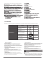 5
5
-
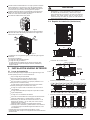 6
6
-
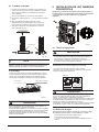 7
7
-
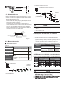 8
8
-
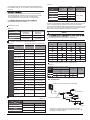 9
9
-
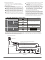 10
10
-
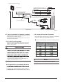 11
11
-
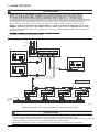 12
12
-
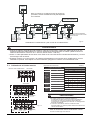 13
13
-
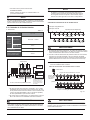 14
14
-
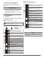 15
15
-
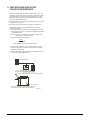 16
16
-
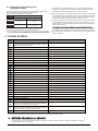 17
17
-
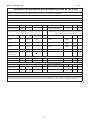 18
18
-
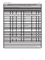 19
19
-
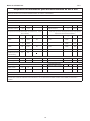 20
20
-
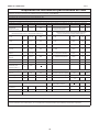 21
21
-
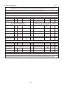 22
22
-
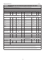 23
23
-
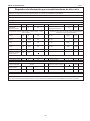 24
24
-
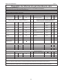 25
25
-
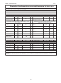 26
26
-
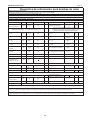 27
27
-
 28
28
-
 29
29
-
 30
30
-
 31
31
-
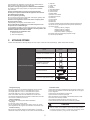 32
32
-
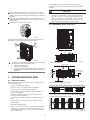 33
33
-
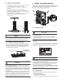 34
34
-
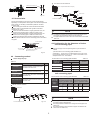 35
35
-
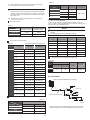 36
36
-
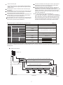 37
37
-
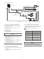 38
38
-
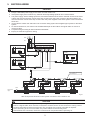 39
39
-
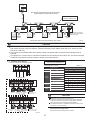 40
40
-
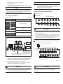 41
41
-
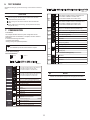 42
42
-
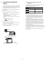 43
43
-
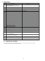 44
44
-
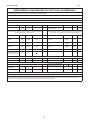 45
45
-
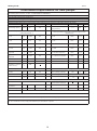 46
46
-
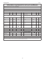 47
47
-
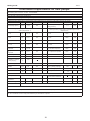 48
48
-
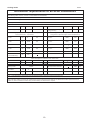 49
49
-
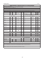 50
50
-
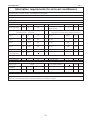 51
51
-
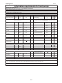 52
52
-
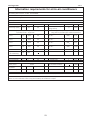 53
53
-
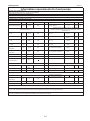 54
54
-
 55
55
-
 56
56


HTW MINI VRF V10 UNIDAD EXTERIOR Guía de instalación
- Tipo
- Guía de instalación
en otros idiomas
Artículos relacionados
-
HTW SPLIT MURAL VRF UNIDAD INTERIOR Manual de usuario
-
-
-
-
-
HTW TV-30ESSECO Electric Water Heater Manual de usuario
-
Otros documentos
-
mundoclima Series MUCHR-H6 “Duct Inverter Great Capacity” Guía de instalación
-
-
Fujitsu AJH040LELAH Guía de instalación
-
-
Fujitsu AJH040LELBH Guía de instalación
-
-
Fujitsu AJY054LBLAH Guía de instalación
-
-
Zenner PDC – Pulse Data Capture Modul Installation and Operating Instructions
-
 Macurco RD-VRF Manual de usuario
