Truper MUT-60A El manual del propietario
- Categoría
- Multimetros
- Tipo
- El manual del propietario

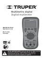
Multímetro digital
Digital multimeter
MUT-60A
100362
INSTRUCTIVO
INSTRUCTIVE
NOTA IMPORTANTE: Este producto no debe quedar
expuesto a goteo o salpicaduras por líquidos.
IMPORTANT NOTE: This product shall not be
exposed to liquids dripping or spatter.

1. INTRODUCCIÓN
Este instructivo proporciona toda la información de seguridad,
instrucciones de operación, especificaciones y mantenimiento del
Multímetro digital, el cual es compacto, manual y de mano y operado
por batería.
Este instrumento lleva a cabo mediciones de la tensión de c.a. / c.c.,
corriente c.a. / c.c. resistencia, continuidad audible, diodo, hFE,
temperatura, alerta de la tensión (NCV) y mediciones de frecuencia.
Llega a 3 3/4 dígitos, cuenta 3 999 de DMM rango automático.
Tiene las funciones de indicación de polaridad, retención de datos,
medición relativa de datos, indicación de sobre rango. Es fácil de
operar y es un instrumento ideal.
El multímetro digital ha sido diseñado de acuerdo con la norma
EN61010-1 sobre instrumentos electrónicos de medición con una
categoría de sobretensión (CAT III 600 V, CAT II 1 000 V) y un grado de
contaminación 2.

Para evitar una posible descarga eléctrica o lesiones personales, y para
evitar posible daño al Medidor o el equipo bajo prueba, siga las
siguientes reglas:
Antes de utilizar el Multímetro digital inspeccione la carcasa. No
utilice el Multímetro digital si está dañado o la carcasa (o parte de
ella) ha sido retirada. Revise que no tenga cuarteaduras o plástico
faltante. Ponga atención a el aislamiento alrededor de los
conectores.
Inspeccione que los conductores de prueba no tengan daños en el
aislamiento ni tengan metal expuesto. Revise la continuidad de los
conductores de prueba.
No aplique más que la tensión nominal, tal como se indica en el
Multímetro digital, entre las terminales o entre cualquier terminal y
tierra.
El interruptor giratorio se debe colocar en la posición correcta y no
se debe hacer ningún cambio de rango durante la medición para
prevenir daños al Multímetro digital.
Cuando el Multímetro digital esté funcionando en una tensión
efectiva sobre 60 V en c.c. o 30 V RMS en c.a., se debe tener especial
cuidado debido a que existe el peligro de descarga eléctrica.
Utilice las terminales correctas, funciones y rango para sus
mediciones.
No utilice o almacene el Multímetro digital en un ambiente de alta
temperatura, humedad, material explosivo o inflamable y fuertes
campos magnéticos. El desempeño del Multímetro digital se puede
deteriorar después de haberse mojado.
Cuando se utilicen los conductores de prueba, mantenga sus dedos
detrás de las guardas para dedos.
Desconecte la energía del circuito y descargue todos los capacitores
de alta tensión antes de comprobar resistencia, continuidad, diodos.
Reemplace la batería tan pronto como el indicador de batería
aparezca. Con la batería baja, el Multímetro digital podría producir
lecturas falsas que pueden conducir a una descarga eléctrica y
lesiones personales.
ADVERTENCIA Retire la conexión entre los conductores de prueba y el circuito que
se está comprobando, y apague la energía eléctrica antes de abrir la
carcasa del Multímetro digital.
Cuando lleve a cabo el servicio al Multímetro digital, utilice solamente
piezas de repuesto del mismo número de modelo o especificaciones
eléctricas idénticas.
El circuito interno del Multímetro digital no se debe alterar a voluntad
para evitar daños al Medidor y cualquier accidente.
Se debe utilizar una paño y detergente suave para limpiar la
superficie del Multímetro digital cuando se le de servicio. No se debe
utilizar material abrasivo ni solventes para proteger la superficie del
Medidor de corrosión, daños y accidentes.
El Multímetro digital es adecuado para uso en interiores.
Apague la corriente eléctrica del Multímetro digital cuando no esté en
uso y retire la batería cuando no se vaya a utilizar por largos periodos
de tiempo. Revise constantemente la batería ya que puede escurrir
cuando se utiliza por mucho tiempo. Cambie la batería tan pronto
como aparezca algún escurrimiento. Una batería que se escurre va a
dañar el Multímetro digital.
2. CARACTERÍSTICAS GENERALES
ESPAÑOL

Para evitar una posible descarga eléctrica o lesiones personales, y para
evitar posible daño al Medidor o el equipo bajo prueba, siga las
siguientes reglas:
Antes de utilizar el Multímetro digital inspeccione la carcasa. No
utilice el Multímetro digital si está dañado o la carcasa (o parte de
ella) ha sido retirada. Revise que no tenga cuarteaduras o plástico
faltante. Ponga atención a el aislamiento alrededor de los
conectores.
Inspeccione que los conductores de prueba no tengan daños en el
aislamiento ni tengan metal expuesto. Revise la continuidad de los
conductores de prueba.
No aplique más que la tensión nominal, tal como se indica en el
Multímetro digital, entre las terminales o entre cualquier terminal y
tierra.
El interruptor giratorio se debe colocar en la posición correcta y no
se debe hacer ningún cambio de rango durante la medición para
prevenir daños al Multímetro digital.
Cuando el Multímetro digital esté funcionando en una tensión
efectiva sobre 60 V en c.c. o 30 V RMS en c.a., se debe tener especial
cuidado debido a que existe el peligro de descarga eléctrica.
Utilice las terminales correctas, funciones y rango para sus
mediciones.
No utilice o almacene el Multímetro digital en un ambiente de alta
temperatura, humedad, material explosivo o inflamable y fuertes
campos magnéticos. El desempeño del Multímetro digital se puede
deteriorar después de haberse mojado.
Cuando se utilicen los conductores de prueba, mantenga sus dedos
detrás de las guardas para dedos.
Desconecte la energía del circuito y descargue todos los capacitores
de alta tensión antes de comprobar resistencia, continuidad, diodos.
Reemplace la batería tan pronto como el indicador de batería
aparezca. Con la batería baja, el Multímetro digital podría producir
lecturas falsas que pueden conducir a una descarga eléctrica y
lesiones personales.
Retire la conexión entre los conductores de prueba y el circuito que
se está comprobando, y apague la energía eléctrica antes de abrir la
carcasa del Multímetro digital.
Cuando lleve a cabo el servicio al Multímetro digital, utilice solamente
piezas de repuesto del mismo número de modelo o especificaciones
eléctricas idénticas.
El circuito interno del Multímetro digital no se debe alterar a voluntad
para evitar daños al Medidor y cualquier accidente.
Se debe utilizar una paño y detergente suave para limpiar la
superficie del Multímetro digital cuando se le de servicio. No se debe
utilizar material abrasivo ni solventes para proteger la superficie del
Medidor de corrosión, daños y accidentes.
El Multímetro digital es adecuado para uso en interiores.
Apague la corriente eléctrica del Multímetro digital cuando no esté en
uso y retire la batería cuando no se vaya a utilizar por largos periodos
de tiempo. Revise constantemente la batería ya que puede escurrir
cuando se utiliza por mucho tiempo. Cambie la batería tan pronto
como aparezca algún escurrimiento. Una batería que se escurre va a
dañar el Multímetro digital.
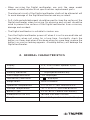
2. CARACTERÍSTICAS GENERALES
Pantalla
Medida del LCD
Indicador de polaridad
Indicador de sobre rango
Indicador de batería baja
Selector de rango
Temperatura de operación
Temp. de almacenamiento
Tipo de batería
Medidas (H x W x D)
Peso
LCD, 3 999 actualizaciones de 2 /s
63 mm x 39 mm
“-“ se muestra automáticamente
“OL” se muestra
se muestra
Auto o manual
0 ºC a 40 ºC, menos del 80% HR
-10 ºC a 50 ºC, menos del 85% HR
1 batería de Carbón-Zinc de 9 V c.c. 6F22
189 mm x 89 mm x 55 mm
Aproximadamente 365 g (incluye funda y batería)

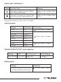
3. SÍMBOLOS ELÉCTRICOS
AUTO
APO
V—
V~
c.c. (Corriente Directa)
c.a. (Corriente alterna)
c.c. o c.a.
Información importante de seguridad
refiérase al instructivo
Puede haber tensión peligrosa
Tierra
Batería baja
Fusible
Diodo
Prueba de continuidad
Centígrados
Fahrenheit
Rango automático
Doble aislamiento
Apagado Automático
Prueba de relatividad
Retención de datos
ºC
ºF
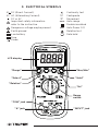
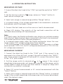
Pantalla de LCD
Botón “Select”
Botón “Relativo”
Botón “Rango”
Botón
“Hold”
Botón
“Hz”
Botón
“Max/Min”
Contacto
“INPUT”
Contacto “COM”
Contacto “A”
Interruptor
de rango

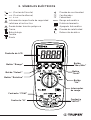
4. DESCRIPCIÓN DE LA PANTALLA
1. Pantalla LCD de 3 3/4 dígitos
2. Botón de rango
El Multímetro digital se predetermina en el modo de rango automático
cuando se mide la tensión, la corriente y la resistencia. Cuando el
Multímetro digital está en el modo de rango automático, se muestra
"AUTO".
Para entrar y salir del modo de rango manual:
a. Presione el botón "RANGE". El Multímetro digital entra en el modo
de rango manual y el símbolo "AUTO" se apaga.
b. Para salir del modo de rango manual, presione y mantenga
presionado el botón "RANGE" durante 2 segundos, el Multímetro
regresa al modo de rango automático y se muestra el símbolo "AUTO".
3. Botón “Select”
Cuando busque rango en V , mA , A , presionar este botón va a
cambiar el Multímetro digital en la función de c.c. y la función de c.a.
Cuando busque rango en el rango , al presionar este botón puede
seleccionar Ohm, capacitancia, diodo y funciones de continuidad.
Cuando busque rango en el rango de “ºC / ºF”, presione este botón
para seleccionar el modo de ºC o modo de ºF
4. Botón Relativo
El Multímetro va a mostrar medidas relativas en todas las funciones a
excepción de las funciones Frecuencia, Ohm, Diodo y Continuidad
Audible.
5. Conector “COM”
Conecte el conector en el conductor de prueba negro (negativo).
6. Conector “10” A
Conecte el conector en el conductor de prueba rojo para mediciones
de Corriente (600 mA – 10 A)
7. Botón “MAX / MIN”
Después de presionarlo, el botón va a mostrar los valores máximo y
mínimo durante la prueba. Los valore máximo y mínimo se borran
después de los cambios en la función de comprobación o se apaga el
Multímetro digital.
8. Botón “ ”
Después de presionar el botón, la lectura actual se mantiene en la
pantalla LCD, mientras tanto, se muestra “HOLD” en la pantalla LCD
como indicador. Para salir del modo Hold, presione el botón
nuevamente y el indicador “HOLD” desaparece.
Presionar el botón durante más de 2 segundos, enciende la luz de fondo.
Presionar nuevamente el botón más de dos segundos, o retrasar 15
segundos después, se apaga la luz de fondo.
9. Botón “Hz /Duty”
Cuando se mida la función Hz o Duty, presionar este botón va a cambiar el
Multímetro digital a la función Hz ó ciclo Duty (%).
Cuando mida ACV, presionar este botón cambiar el Multímetro digital y
mostrar la frecuencia de la tensión de c.a.
10. Conector “INPUT”
Enchufe el conector para el conductor de prueba rojo para todas las
mediciones excepto mediciones de corriente (> 600 mA).
11. Interruptor Función / Rango
Este interruptor se puede utilizar para seleccionar el rango y función
deseado.
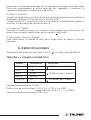
5. ESPECIFICACIONES
Se garantiza la precisión por 1 año a 23 ºC 5 ºC menos que 80% HR
TENSIÓN c.c. (RANGO AUTOMÁTICO)
Impedancia de entrada: 10 MΩ
Protección de sobre carga: 1 000 V c.c. o 750 V c.a. RMS
(rango 200 mV: 250 V c.c. / c.a. RMS)
Tensión máxima de entrada: 1 000 V c.c.
/

4. DESCRIPCIÓN DE LA PANTALLA
1. Pantalla LCD de 3 3/4 dígitos
2. Botón de rango
El Multímetro digital se predetermina en el modo de rango automático
cuando se mide la tensión, la corriente y la resistencia. Cuando el
Multímetro digital está en el modo de rango automático, se muestra
"AUTO".
Para entrar y salir del modo de rango manual:
a. Presione el botón "RANGE". El Multímetro digital entra en el modo
de rango manual y el símbolo "AUTO" se apaga.
b. Para salir del modo de rango manual, presione y mantenga
presionado el botón "RANGE" durante 2 segundos, el Multímetro
regresa al modo de rango automático y se muestra el símbolo "AUTO".
3. Botón “Select”
Cuando busque rango en V , mA , A , presionar este botón va a
cambiar el Multímetro digital en la función de c.c. y la función de c.a.
Cuando busque rango en el rango , al presionar este botón puede
seleccionar Ohm, capacitancia, diodo y funciones de continuidad.
Cuando busque rango en el rango de “ºC / ºF”, presione este botón
para seleccionar el modo de ºC o modo de ºF
4. Botón Relativo
El Multímetro va a mostrar medidas relativas en todas las funciones a
excepción de las funciones Frecuencia, Ohm, Diodo y Continuidad
Audible.
5. Conector “COM”
Conecte el conector en el conductor de prueba negro (negativo).
6. Conector “10” A
Conecte el conector en el conductor de prueba rojo para mediciones
de Corriente (600 mA – 10 A)
7. Botón “MAX / MIN”
Después de presionarlo, el botón va a mostrar los valores máximo y
mínimo durante la prueba. Los valore máximo y mínimo se borran
después de los cambios en la función de comprobación o se apaga el
Multímetro digital.
8. Botón “ ”
Después de presionar el botón, la lectura actual se mantiene en la
pantalla LCD, mientras tanto, se muestra “HOLD” en la pantalla LCD
como indicador. Para salir del modo Hold, presione el botón
nuevamente y el indicador “HOLD” desaparece.
Presionar el botón durante más de 2 segundos, enciende la luz de fondo.
Presionar nuevamente el botón más de dos segundos, o retrasar 15
segundos después, se apaga la luz de fondo.
9. Botón “Hz /Duty”
Cuando se mida la función Hz o Duty, presionar este botón va a cambiar el
Multímetro digital a la función Hz ó ciclo Duty (%).
Cuando mida ACV, presionar este botón cambiar el Multímetro digital y
mostrar la frecuencia de la tensión de c.a.
10. Conector “INPUT”
Enchufe el conector para el conductor de prueba rojo para todas las
mediciones excepto mediciones de corriente (> 600 mA).
11. Interruptor Función / Rango
Este interruptor se puede utilizar para seleccionar el rango y función
deseado.
5. ESPECIFICACIONES
Se garantiza la precisión por 1 año a 23 ºC 5 ºC menos que 80% HR
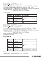
TENSIÓN c.c. (RANGO AUTOMÁTICO)
Impedancia de entrada: 10 MΩ
Protección de sobre carga: 1 000 V c.c. o 750 V c.a. RMS
(rango 200 mV: 250 V c.c. / c.a. RMS)
Tensión máxima de entrada: 1 000 V c.c.
Rango
400 mV
4 V
40 V
400 V
1 000 V
Resolución
0.1 mV
1 mV
10 mV
100 mV
1 V
Precisión
(0.8% de rdg + 5 dgts)
(0.8% de rdg + 3 dgts)
(1.0% de rdg + 5 dgts)

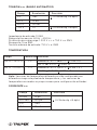
TENSIÓN c.a. (RANGO AUTOMÁTICO)
Impedancia de entrada: 10 MΩ
Rango de frecuencia: 40 Hz ˜ 400 Hz
Protección de sobrecarga: 1 000 V c.c. o 750 V c.a. RMS
Respuesta: True RMS
Tensión máxima de entrada: 750 V c.a. RMS
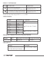
TEMPERATURA
Nota: Sensores de temperatura diferentes están configurados en
diferentes rangos de prueba de temperatura, y los sensores de
temperatura normales se proporcionan para configuración estándar.
CORRIENTE c.c.
Rango
4 V
40 V
400 V
750 V
Resolución
1 mV
10 mV
100 mV
1 V
Precisión
(1.0% de rdg + 8 dgts)
(1.2% de rdg + 8 dgts)
Rango
-40 ºC – 1 370 ºC
-40 ºF – 2 000 ºF
Resolución
1 ºC
1 ºF
Precisión
Alrededor de
-40 ºC 150 ºC: (2.5% + 4)
150 ºC 1 370 ºC (2.5% + 4)
Alrededor de
-40 ºF 302 ºF: (2.5% + 4 )
320 ºF 2 000 ºF (2.5% + 4)
Rango
40 mA
400 mA
4 A
10 A
Resolución
10 µA
100 µA
1 mA
10 mA
Precisión
(1.2% de rdg + 8 dgts)

Protección de sobrecarga:
Rangos mA : Fusible F 0.5 A / 600 V
Rangos A : Fusible F 10 A / 600 V
Corriente máxima de entrada para el conector ”INPUT” es 400 mA
Corriente máxima de entrada para el conector “10 A” es 10 A
Para mediciones > 5 A: duración < 10 segundos, intervalo > 15 minutos)
Caída de tensión: Rangos 40 mA y 4 A: 40 mV
Rangos 400 mA y 10 A: 400 mV
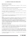
CORRIENTE c.a.
Protección de sobrecarga:
Rangos mA : Fusible F 0.5 A / 600 V
Rangos A : Fusible F 10 A / 600 V
Corriente máxima de entrada para conector “Input” es 600 mA
Corriente máxima de entrada para conector “A” es 10 A
Para mediciones > 5 A: duración < 10 segundos, intervalo > 15 minutos
Caída de tensión: Rangos 40 mA y 4 A: 40 mV
Rangos 400 mA y 10 A: 400 mV
Rango de frecuencia: 40 Hz ˜ 400 Hz
Respuesta: True-RMS
RESISTENCIA
Tensión de circuito abierto: alrededor de 1.0 V
Protección de sobre carga: 250 V c.c. / c.a. RMS
Rango
40 mA
400 mA
4 A
10 A
Resolución
10 µA
100 µA
1 mA
10 mA
Precisión
(1.5% de rdg + 10 dgts)
(2.0 % de rdg + 10 dgts)
Rango
400 Ω
4 kΩ
40 kΩ
400 kΩ
4 MΩ
40 MΩ
Resolución
0.1 Ω
1 Ω
10 Ω
100 Ω
1 kΩ
10 kΩ
Precisión
(1.2% de rdg + 5 dgts)
(1.5% de rdg + 5 dgts)

DIODO Y CONTINUIDAD
Protección de sobre carga: 250 V c.c. / c.a. RMS
CAPACITANCIA
PRUEBA DE TRANSISTOR hFE (CON ADAPTADOR)
FRECUENCIA
Rango Introducción
Se mostrará la caída de la
tensión en sentido directo aproximada
El zumbador inter construido va a sonar
si la resistencia es menor que 30 Ω aprox.
Comentario
Tensión de circuito abierto:
alrededor de 3.2 V
Tensión de circuito abierto:
alrededor de 0.5 V
Rango
PNP & NPN
hFE
0 1 000
Corriente de prueba
lb 2 µA
Tensión de prueba
Vce 1 V
Rango
4 nF
40 nF
400 nF
4 µF
40 µF
400 µF
4 mF
40 mF
Resolución
1 pF
10 pF
100 pF
1 nF
10 nF
100 nF
1 µF
10 µF
Precisión
(8 % de rdg + 10 dgts)
(5 % de rdg + 10 dgts)
(8 % de rdg + 10 dgts)
Rango
9.999/99.99/999.9/9.999K
99.99K/999.9K/9.999MHz
Precisión
(1.0 % of rdg + 3 dgts)

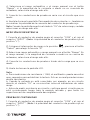
6. INSTRUCCIONES DE OPERACIÓN
MEDICIÓN DE LA TENSIÓN
1. Conecte el conductor de prueba negro al conductor “COM” y el rojo al
conductor “INPUT”.
2. Coloque el interruptor de función en el rango y presione el botón
“Select” para elegir el tipo de la tensión deseado.
3. Seleccione rango automático o manual con el botón “Range”
4. En rango manual, si la magnitud de la tensión a medir no se conoce de
antemano, seleccione el rango más alto.
5. Conecte los conductores de prueba a través de la fuente o carga a
medir.
6. Lea la pantalla LCD. La polaridad de la conexión del conductor rojo se va
a indicar cuando se haga la medición de c.c.
Nota:
a. En un rango pequeño el Multímetro digital puede mostrar una lectura
inestable cuando los conductores de prueba no se han conectado a la
carga a medir. Esto es normal y no va a afectar las mediciones.
b. En el modo de rango manual, cuando el Multímetro digital muestra el
símbolo de sobre rango “OL”, se debe seleccionar un rango mas mayor.
c. Para evitar dañar el Multímetro digital, no mida una tensión que exceda
1 000 V c.c. (para mediciones de la tensión de c.c.) o 750 V c.a. (para
medición de la tensión de c.a.)
MEDICIÓN DE CORRIENTE
1. Conecte el conductor de prueba negro al conector “COM”. Si la corriente
a medir es menor a 600 mA, conecte el conductor de prueba rojo al
conector “INPUT”. Si la corriente está entre 400 mA y 10 A, en su lugar,
conecte el conductor de prueba rojo al conector “A”.
2. Coloque el interruptor de rango en el rango mA o rango A deseado.
Si la magnitud de la corriente a medir no se conoce de antemano, coloque
el interruptor de rangos a la posición de rango más alta y entonces
reduzca rango por rango hasta que obtenga la resolución que le satisfaga.
3. Seleccione la medición de corriente c.c. o la medición de corriente c.a.
con el botón “Select”.
V~

4. Seleccione el rango automático o el rango manual con el botón
“Rango”, si la magnitud de la corriente a medir no es conocida de
antemano, seleccione el rango más alto.
5. Conecte los conductores de prueba en serie con el circuito que va a
medir.
6. Vea la lectura en la pantalla. Para medición de corriente c.c., también se
va a indicar la polaridad de la conexión del conductor de prueba rojo.
Nota: Cuando la pantalla muestra el símbolo “OL” de sobre rango, se debe
seleccionar un rango más alto.
MEDICIÓN DE RESISTENCIA
1. Conecte el conductor de prueba negro al conector “COM” y el rojo al
conector “INPUT”. (Nota: La polaridad de el conductor de prueba rojo es
positiva “+”).
2) Coloque el interruptor de rango a la posición , presione el botón
“Select” para elegir la función “Ω”
3) Seleccione rango automático o rango manual con el botón “Range”. En
el rango manual, si la magnitud de corriente a medir no se conoce de
antemano, seleccione el rango más alto.
4) Conecte los conductores de prueba a través de la carga que se va a
medir.
5) Vea la lectura en la pantalla LCD.
Nota:
a. Para mediciones de resistencia > 1 MΩ, el multímetro puede necesitar
unos segundos para estabilizar la lectura. Esto es normal para decisiones
de alta resistencia.
b. Cuando la entrada no está conectada, por ejemplo, en un circuito
abierto, el símbolo “OL” se va a mostrar como en indicadoras de sobre
rango.
c. Antes de medir resistencia en circuito, confirme que el circuito que se
está corroborando tenga toda la energía retirada y que todos los
capacitores están completamente descargados.
PRUEBA DE CONTINUIDAD
1. Conecte el conductor de prueba negro al conector “COM” y el rojo al
conector “INPUT”. (Nota: La polaridad del conductor de prueba rojo es
positiva “+”).

2. Coloque el interruptor de rango en la posición
3. Presione el botón “Select” para seleccionar el modo de comprobación
de continuidad, y el símbolo va a aparecer como indicador.
4. Conecte los conductores de prueba a través de la carga que se va a
medir.
5. Si la resistencia del circuito es menor de 30 Ω, va a sonar el zumbador
inter construido.
PRUEBA DE DIODO
1. Conecte el conductor de prueba negro al conector “COM” y el rojo al
conector “INPUT” (Nota: La polaridad del conductor de prueba rojo es
positiva “+”).
2. Coloque el interruptor de rango en la posición
3. Presione el botón “Select” para seleccionar el modo de comprobación
de diodo. El símbolo va a aparecer como indicador.
4. Conecte el conductor de prueba al ánodo del diodo que se va a
comprobar y el conector de prueba negro al cátodo.
5. El Multímetro digital va a mostrar la tensión en sentido directo del
diodo. Si las conexiones se revierten, se va a mostrar “OL” en la pantalla.
MEDICIÓN DE CAPACITANCIA
1. Conecte el conductor de prueba negro al conector “COM” y el rojo al
conector “INPUT”
2. Coloque el interruptor de rango en la posición
3. Presione el botón “Select” para seleccionar modo de medición de
capacitancia. El símbolo “nF” va a aparecer como indicador.
4. Conecte los conductores de prueba a través del capacitor que se va a
medir y confirme que se observe la polaridad de la conexión.
Nota: Cuando la capacitancia que se va a medir está sobre 100 µF, necesita
por lo menos 10 segundos para que la lectura sea estable.

MEDICIÓN DE TEMPERATURA
1. Coloque el interruptor de rango en el rango “ºC” o en “ºF”
2. Presione el botón “Select” para selección el rango “ºC” ó “ºF”
3. Inserte el conector negro (0 “-“) del termopar tipo K al conector “COM”,
y el conector rojo (ó “+”) al conector “Input”
4. Con cuidado, toque con un extremo de la sonda termopar al objeto que
va a medir.
5. Espere un momento. Lea la lectura en la pantalla LCD.
MEDICIÓN DE FRECUENCIA / CICLO DE TRABAJO
1. Conecte el conector de prueba negro al conector COM y el rojo al
conector “INPUT”.
2) Coloque el interruptor de rango en el rango “Hz/Duty”
3) Presione el botón “Hz/Duty” para elegir el modo “Hz” o el modo de
“ciclo de trabajo” (%)
4) Conecte los conductores de prueba a través de la fuente o carga que se
está midiendo.
Nota: La tensión de entrada debe estar entre 200 mV y 10 V RMS c.a. Si la
tensión es mayor que 10 V RMS, la lectura puede estar fuera del rango de
precisión.
PRUEBA NCV (CONTACTO SIN TENSIÓN)
1. “NCV” significa “detección de la tensión sin contacto” sin los
conductores de prueba.
2. Coloque el interruptor en el rango “NCV”
3. La pantalla LCD del Multímetro digital muestra el ícono “NCV” y “EF”.
4. Utilice la parte superior del Multímetro digital para detectar el objeto.
5. Si hay una tensión de 30 V de c.a. - 1 000 V de c.a., el Multímetro digital
va a emitir un sonido continuo.

MEDICIÓN DE TRANSISTOR hFE
1. Coloque el interruptor de rango en el rango “hFE”
2. Conecte el adaptador al conector “COM” y al conector “INPUT”
3. Identifique si es que el transistor es tipo NPN o PNP y localice el
conductor Emisor, Base y Colector. Inserte los conductores del transistor
que se va a comprobar en los orificios adecuados del contacto de prueba
de transistor del adaptador.
4. La pantalla LCD va a mostrar el valor hFE aproximado.
Nota: Esta medición se puede utilizar para determinar si el transistor es
bueno y se puede utilizar para comparar el hFE de un transistor con el hFE
de otro transistor. La lectura en la pantalla es solo para referencia.
7. APAGADO AUTOMÁTICO
Si no se opera el medidor por alrededor de 15 minutos, se va a apagar
automáticamente.
Para volver a encenderlo, presione cualquier botón.
En el estado de apagado, presione y sostenga presionado el botón
“Select” del interruptor del rango giratorio. Se puede cancelar la función
de apagado automático y el símbolo “APO” desaparece de la pantalla LCD.
8. CAMBIO DE BATERÍAS
En caso que el símbolo aparezca en la pantalla, indica que la batería se
debe reemplazar. Retire los tornillos y abra la parte rasera de la carcasa.
Cambie la batería gastada por una batería nueva de 9 V (IEC 6F22, NEDA
1604, JIS006P o su equivalente.
9. CAMBIO DE FUSIBLES
El fusible raramente necesita ser reemplazado y casi siempre se funde
como resultado de un error del operador. Este multímetro utiliza un
fusible F1: 500 mA / 600V y F2: 10 A / 600V de acción rápida. Para
cambiar los fusibles, abra la cubierta trasera del multímetro, Reemplace el
fusible dañado por un nuevo fusible de las especificaciones especificadas.
Vuelva a instalar la cubierta de la batería y asegure la cubierta.

NOTAS

1. INTRODUCTION
This instructive provides all safety information, operation instruction,
specifications and maintenance for the Digital multimeter, which is
compact, hand-held, and battery operated.
This instrument performs AC / DC voltage, AC / DC Current, Resistance,
Audible Continuity, Diode, hFE, Temperature,volt alert (NCV) and
Frequency measurements, it is a 3 3/4 digits, 3 999 counts auto ranging
DMM.
It has the functions of polarity indication, data hold, relative data
measurements, over range indication.
It can be operated easily and is an ideal instrument tool.
The digital multimeter has been designed according to EN61010-1
oncoming electronic measuring instruments with an over voltage
category (CAT III 600 V, CAT II 1 000 V) and Pollution degree 2.

To avoid possible electric shock or personal injury, and to avoid possible
damage to the Digital multimeter or to the equipment under test,
adhere to the following rules:
Before using the Digital multimeter inspect the case. Do not use the
Digital multimeter if it is damaged or the case (or part of the case) is
removed. Look for cracks or missing plastic. Pay attention to the
insulation around the connectors.
Inspect the test leads for damaged insulation or exposed metal.
Check the test leads for continuity.
Do not apply more than the rated voltage, as marked on the Digital
multimeter, between the terminals or between any terminal and
grounding.
The rotary switch should be placed in the right position and no any
changeover of range shall be made during measurement is
conducted to prevent damage of the Digital multimeter.
When the Digital multimeter working at an effective voltage over
60 V in DC or 30 V RMS in AC, special care should be taken for there
is danger of electric shock.
Use the proper terminals, function, and range for your
measurements.
Do not use or store the Digital multimeter in an environment of high
temperature, humidity, explosive, inflammable and strong magnetic
field. The performance of the Digital multimeter may deteriorate
after dampened.
When using the test leads, keep your fingers behind the finger
guards.
Disconnect circuit power and discharge all high-voltage capacitors
before testing resistance, continuity, diodes .
Replace the battery as soon as the battery indicator “ ” appears.
With a low battery, the Digital multimeter might produce false
readings that can lead to electric shock and personal injury.
Remove the connection between the testing leads and the circuit
being tested, and turn the Digital multimeter power off before
opening the Digital multimeter case.
WARNING When servicing the Digital multimeter, use only the same model
number or identical electrical specifications replacement parts.
The internal circuit of the Digital multimeter shall not be altered at will
to avoid damage of the Digital multimeter and any accident.
Soft cloth and mild detergent should be used to clean the surface of the
Digital multimeter when servicing. No abrasive and solvent should be
used to prevent the surface of the Digital multimeter from corrosion,
damage and accident.
The Digital multimeter is suitable for indoor use.
Turn the Digital multimeter power off when it is not in use and take out
the battery when not using for a long time. Constantly check the
battery as it may leak when it has been using for some time, replace the
battery as soon as leaking appears. A leaking battery will damage the
Digital multimeter.
2. GENERAL CHARACTERISTICS
ENGLISH

To avoid possible electric shock or personal injury, and to avoid possible
damage to the Digital multimeter or to the equipment under test,
adhere to the following rules:
Before using the Digital multimeter inspect the case. Do not use the
Digital multimeter if it is damaged or the case (or part of the case) is
removed. Look for cracks or missing plastic. Pay attention to the
insulation around the connectors.
Inspect the test leads for damaged insulation or exposed metal.
Check the test leads for continuity.
Do not apply more than the rated voltage, as marked on the Digital
multimeter, between the terminals or between any terminal and
grounding.
The rotary switch should be placed in the right position and no any
changeover of range shall be made during measurement is
conducted to prevent damage of the Digital multimeter.
When the Digital multimeter working at an effective voltage over
60 V in DC or 30 V RMS in AC, special care should be taken for there
is danger of electric shock.
Use the proper terminals, function, and range for your
measurements.
Do not use or store the Digital multimeter in an environment of high
temperature, humidity, explosive, inflammable and strong magnetic
field. The performance of the Digital multimeter may deteriorate
after dampened.
When using the test leads, keep your fingers behind the finger
guards.
Disconnect circuit power and discharge all high-voltage capacitors
before testing resistance, continuity, diodes .
Replace the battery as soon as the battery indicator “ ” appears.
With a low battery, the Digital multimeter might produce false
readings that can lead to electric shock and personal injury.
Remove the connection between the testing leads and the circuit
being tested, and turn the Digital multimeter power off before
opening the Digital multimeter case.
When servicing the Digital multimeter, use only the same model
number or identical electrical specifications replacement parts.
The internal circuit of the Digital multimeter shall not be altered at will
to avoid damage of the Digital multimeter and any accident.
Soft cloth and mild detergent should be used to clean the surface of the
Digital multimeter when servicing. No abrasive and solvent should be
used to prevent the surface of the Digital multimeter from corrosion,
damage and accident.
The Digital multimeter is suitable for indoor use.
Turn the Digital multimeter power off when it is not in use and take out
the battery when not using for a long time. Constantly check the
battery as it may leak when it has been using for some time, replace the
battery as soon as leaking appears. A leaking battery will damage the
Digital multimeter.
2. GENERAL CHARACTERISTICS
Display
LCD Size
Polarity Indication
Over-range Indication
Low Battery Indication
Range select
Operation Temperature
Storage Temperature
Battery Type
Dimension (H x W x D)
Weight
LCD, 3 999 counts updates 2/sec
63 mm x 39 mm
“-” displayed automatically
“OL” displayed
“ ” displayed
Auto or manual
0 °C to 40 °C, less than 80% RH
-10 °C to 50 °C, less than 85% RH
9 V DC 6F22, Carbon-Zinc battery
189 mm x 89 mm x 55 mm
About 365 g (with holster & battery)

3. ELECTRICAL SYMBOLS
AUTO
APO
V—
V~
DC (Direct Current)
AC (Alternating Current)
DC or AC
Important safety information
refer to the instructive
Dangerous voltage maybe present
Earth ground
Low battery
Fuse
Diode
Continuity test
Centigrade
Fahrenheit
Auto range
Double insulated
Auto Power Off
Relative test
Data hold
ºC
ºF
LCD display
“Select”
“Relative”
“Range”
“Hold”
“Hz”
“Max/Min”
“INPUT” jack
“COM” jack
“A” jack
Range
switch

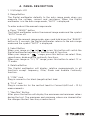
4. PANEL DESCRIPTION
1. 3 3/4 digits LCD
2. Range Button
The Digital multimeter defaults to the auto range mode when you
measure the voltage, current and resistance. When the Digital
multimeter is in the auto range mode, “AUTO” is displayed.
To enter and exit the manual range mode:
a. Press “ RANGE” button
The Digital multimeter enters the manual range mode and the symbol
“AUTO” turns off.
b. To exit the manual range mode, press and hold down the “RANGE”
button for 2 seconds, the Digital multimeter returns to the auto range
mode and the symbol “AUTO” is displayed.
3. Select Button
When your range on V , mA , A , press this button will switch the
Digital multimeter between DC function and AC function.
When your range on “ ” range, press this button can select Ohm,
capacitance, diode and the continuity functions.
When your range on “°C / °F” range, press this button to select °C or
°F mode.
4. Relative Button
This Digital multimeter will display relative measurements in all
functions except frequency, Ohm, Diode and Audible Continuity
function.
5. “COM” Jack
Plug-in connector for black (negative) test lead.
6. “10 A” Jack
Plug-in connector for the red test lead for Current (600 mA ~ 10 A)
measurements.
7. “Max/Min” Button
After press the button will display the maximum and minimum values
during the test. The maximum and minimum values are cleared after
the changes the test function,or meter be off.
8. “ ” Button
After press the button, the present reading is held on the LCD, meanwhile
“HOLD” is displayed on the LCD as an indicator. To exit the Hold mode,
press the button again and the indicator “HOLD” will disappear.
Pressing the button more than 2 seconds back-light turned on pressing
the button more than 2 seconds again or delay 15 seconds later back-light
will turned off.
9. “Hz/Duty” button
When you measure the Hz or Duty function, pressing this button will
switch the meter to Hz or Duty cycle (%) function.
When you measure the ACV, pressing this button will switch the meter will
show the frequency of the AC voltage.
10. “INPUT” Jack
Plug-in connector for the red test lead for all measurements except
current (>600 mA) measurements.
11. Function/Range Switch
This switch can be used to select desired function and range.
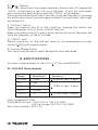
5. SPECIFICATIONS
Accuracy is guarantied for 1 year 23 °C 5 °C less than 80% RH
DC VOLTAGE (Auto ranging)
Input Impedance: 10 MΩ
Overload Protection: 1 000 V DC or 750 V AC RMS
(200 mV range: 250 V DC / AC RMS)
Max. Input voltage: 1 000 V DC

4. PANEL DESCRIPTION
1. 3 3/4 digits LCD
2. Range Button
The Digital multimeter defaults to the auto range mode when you
measure the voltage, current and resistance. When the Digital
multimeter is in the auto range mode, “AUTO” is displayed.
To enter and exit the manual range mode:
a. Press “ RANGE” button
The Digital multimeter enters the manual range mode and the symbol
“AUTO” turns off.
b. To exit the manual range mode, press and hold down the “RANGE”
button for 2 seconds, the Digital multimeter returns to the auto range
mode and the symbol “AUTO” is displayed.
3. Select Button
When your range on V , mA , A , press this button will switch the
Digital multimeter between DC function and AC function.
When your range on “ ” range, press this button can select Ohm,
capacitance, diode and the continuity functions.
When your range on “°C / °F” range, press this button to select °C or
°F mode.
4. Relative Button
This Digital multimeter will display relative measurements in all
functions except frequency, Ohm, Diode and Audible Continuity
function.
5. “COM” Jack
Plug-in connector for black (negative) test lead.
6. “10 A” Jack
Plug-in connector for the red test lead for Current (600 mA ~ 10 A)
measurements.
7. “Max/Min” Button
After press the button will display the maximum and minimum values
during the test. The maximum and minimum values are cleared after
the changes the test function,or meter be off.
8. “ ” Button
After press the button, the present reading is held on the LCD, meanwhile
“HOLD” is displayed on the LCD as an indicator. To exit the Hold mode,
press the button again and the indicator “HOLD” will disappear.
Pressing the button more than 2 seconds back-light turned on pressing
the button more than 2 seconds again or delay 15 seconds later back-light
will turned off.
9. “Hz/Duty” button
When you measure the Hz or Duty function, pressing this button will
switch the meter to Hz or Duty cycle (%) function.
When you measure the ACV, pressing this button will switch the meter will
show the frequency of the AC voltage.
10. “INPUT” Jack
Plug-in connector for the red test lead for all measurements except
current (>600 mA) measurements.
11. Function/Range Switch
This switch can be used to select desired function and range.
5. SPECIFICATIONS
Accuracy is guarantied for 1 year 23 °C 5 °C less than 80% RH
DC VOLTAGE (Auto ranging)
Input Impedance: 10 MΩ
Overload Protection: 1 000 V DC or 750 V AC RMS
(200 mV range: 250 V DC / AC RMS)
Max. Input voltage: 1 000 V DC
Range
400 mV
4 V
40 V
400 V
1 000 V
Resolution
0.1 mV
1 mV
10 mV
100 mV
1 V
Accuracy
(0.8% of rdg + 5 dgts)
(0.8% of rdg + 3 dgts)
(1.0% of rdg + 5 dgts)
/

AC VOLTAGE (Auto ranging)
Input Impedance: 10 MΩ
Frequency Range: 40 Hz ~ 400 Hz
Overload Protection: 1 000 V DC or 750 V AC RMS
Response: True RMS
Max. Input voltage: 750 V AC RMS
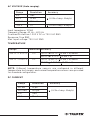
TEMPERATURE
NOTE: Different temperature sensors are configured in different
temperature test ranges, and normal temperature sensors are provided
for standard configuration.
DC CURRENT
Range
4 V
40 V
400 V
750 V
Resolution
1 mV
10 mV
100 mV
1 V
Accuracy
(1.0% of rdg + 8 dgts)
(1.2% of rdg + 8 dgts)
Range
-40 ºC – 1 370 ºC
-40 ºF – 2 000 ºF
Resolution
1 ºC
1 ºF
Accuracy
-40 ºC 150 ºC: (2.5% + 4) about
150 ºC 1 370 ºC (2.5% + 4)
-40 ºF 302 ºF: (2.5% + 4) about
320 ºF 2 000 ºF (2.5% + 4)
Range
40 mA
400 mA
4 A
10 A
Resolution
10 µA
100 µA
1 mA
10 mA
Accuracy
(1.2% of rdg + 8 dgts)

Overload Protection:
mA ranges: F 0.5 A / 600 V fuse
A ranges: F 10 A / 600 V fuse
Max. Input Current for “INPUT” jack is 400 mA.
Max. Input Current for “10 A” jack is 10 A.
For measurements > 5 A: duration < 10 seconds, interval > 15 minutes
Voltage Drop: 40 mA and 4 A ranges: 40 mV
400 mA and 10 A ranges: 400 mV
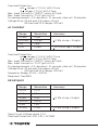
AC CURRENT
Overload Protection:
mA ranges: F 0.5 A / 600 V fuse
A ranges: F 10 A / 600 V fuse
Max. Input Current for “INPUT” jack is 600 mA
Max. Input Current for “10 A” jack is 10 A
For measurements > 5 A: duration < 10 seconds, interval > 15 minutes
Voltage Drop: 40 mA and 4 A ranges: 40 mV
400 mA and 10 A ranges: 400 mV
Frequency Range: 40 Hz ~ 400 Hz
Response: True RMS
RESISTANCE
Open Circuit Voltage: about 1.0 V
Overload Protection: 250 V DC / AC RMS
Range
40 mA
400 mA
4 A
10 A
Resolution
10 µA
100 µA
1 mA
10 mA
Accuracy
(1.5% of rdg + 10 dgts)
(2.0 % of rdg + 10 dgts)
Range
400 Ω
4 kΩ
40 kΩ
400 kΩ
4 MΩ
40 MΩ
Resolution
0.1 Ω
1 Ω
10 Ω
100 Ω
1 kΩ
10 kΩ
Accuracy
(1.2% of rdg + 5 dgts)
(1.5% of rdg + 5 dgts)

DIODE AND CONTINUITY
Overload Protection: 250 V DC / AC RMS
CAPACITANCE
TRANSISTOR hFE TEST (with Adapter)
FREQUENCE
Range Introduction
The approximate forward voltage
drop will be displayed
The built-in buzzer will sound if the
resistance is less than about 30 Ω
Remark
Open circuit voltage: about
3.2 V
Open circuit voltage: about
0.5 V
Range
4 nF
40 nF
400 nF
4 µF
40 µF
400 µF
4 mF
40 mF
Resolution
1 pF
10 pF
100 pF
1 nF
10 nF
100 nF
1 µF
10 µF
Accuracy
(8 % of rdg + 10 dgts)
(5 % of rdg + 10 dgts)
(8 % of rdg + 10 dgts)
Range
PNP & NPN
hFE
0 1 000
Test Current
lb 2 µA
Test Voltage
Vce 1 V
Range
9.999/99.99/999.9/9.999K
99.99K/999.9K/9.999 MHz
Accuracy
(1.0 % of rdg + 3 dgts)

6. OPERATION INSTRUCTION
MEASURING VOLTAGE
1. Connect the black test lead to the “COM” jack and the red to the “INPUT”
jack.
2. Set the function switch to range, and press “Select” button to
select desire voltage type.
3. Select auto range or manual range withthe “Range” button.
4. In manual range, if the voltage magnitude to be measured is unknown
beforehand, select the highest range.
5. Connect the test leads across the source or load to be measured.
6. Read LCD display. The polarity of the red lead connection will be
indicated when making a DC measurement.
Note:
a. In small range, the Digital multimeter may display an unstable reading
when the test leads have not been connected to the load to be measured.
It is normal and will not affect the measurements.
b. In manual range mode, when the Digital multimeter shows the over
range symbol “OL”, a higher range must to be selected.
c. To avoid damage to the Digital multimeter, don’t measure a voltage
which exceeds 1 000 V DC (for DC voltage measurement) or 750 V AC (for
AC voltage measurement).
MEASURING CURRENT
1. Connect the black test lead to the “COM” jack. If the current to be
measured is less than 600 mA, connect the red test lead to the “INPUT”
jack. If the current is between 400 mA and 10 A, connect the red test lead
to the “10 A” jack instead.
2. Set the range switch to desired mA or A range. If the current
magnitude to be measured is not known beforehand, set the ranges switch
to the highest range position and then reduce it range by range until
satisfactory resolution is obtained.
3. Select DC current measurement or AC current measurement with the
“Select” Button.
4. Select auto range or manual range with the “Range” button. In manual
range, if the current magnitude to be measured is not known beforehand,
select the highest range.
V~

5. Connect test leads in series with the circuit to be measured.
6. Read the reading on the display. For DC current measurement, the
polarity of the red test lead connection will be indicated as well.
Note: When the display shows the over range symbol “OL”, a higher range
must be selected.
MEASURE RESISTANCE
1. Connect the black test lead to the “COM” jack and the red to the “INPUT”
jack (Note: The polarity of the red test lead is positive “+”).
2. Set the range switch to “ ” position, press “Select” button to select
“Ω” function.
3. Select auto range or manual range with the “Range” button. In manual
range, if the current magnitude to be measured is not known beforehand,
select the highest range.
4. Connect the test leads across the load to be measured.
5. Read the reading on the LCD.
Note:
a. For resistance measurements > 1 MΩ, the Digital multimeter may take a
few seconds to stabilize reading. This is normal for high-resistance
measurement.
b. When the input is not connected, i.e. at open circuit, the symbol “OL” will
be displayed as an over range indicator.
c. Before measuring in-circuit resistance, be sure that the circuit under
test has all power removed and all capacitors are fully discharged.
CONTINUITY TEST
1. Connect the black test lead to the “COM” jack and the red to the “INPUT”
jack (Note: The polarity of the red test lead is positive “+”).
2. Set the range switch to “ ” position.
3. Press the “Select” Button to select continuity measurement mode, and
the symbol “ ” will appear as an indicator.
4. Connect the test leads across the load to be measured.
5. When the circuit resistance is lower than about 30 Ω, the built-in
buzzer will sound.

DIODE TEST
1. Connect the black test lead to the “COM” jack and the red to the “INPUT”
jack (Note: The polarity of the red test lead is positive “+”).
2. Set the range switch to “ ” position.
3. Press the “Select” Button to select diode test mode, and the symbol
“ ” will appear as an indicator.
4. Connect the red test lead to the anode of the diode to be tested and the
black test lead to the cathode.
5. The Digital multimeter will show the approximate forward voltage of the
diode. If the connections are reversed, “OL” will be shown on the display.
MEASURING CAPACITANCE
1. Connect the black test lead to the COM jack and the red to the “INPUT”
jack.
2. Set the range switch to “ ” position
3. Press the “Select” Button to select capacitance measurement mode,
and the symbol “nF” will appear as an indicator.
4. Connect test leads across the capacitor under measure and be sure
the polarity of connection is observed.
Note: When the capacitance under measure is above 100 uF, it needs at
least 10 seconds to make readings stable.
MEASURING TEMPERATURE
1. Set the range switch to “ºC” / “ºF” range.
2. Press the “Select” Button to select “°C” or “°F” mode.
3. Insert the black (or “-“) plug of the K-type thermocouple to the “COM”
jack, and the red( or “+”) plug to the “INPUT” jack.
4. Carefully touch the end of the thermocouple to the object to be
measured.
5. Wait a moment, read the reading on the display.

MEASURING FREQUENCY OR DUTY CYCLE
1. Connect the black test lead to the COM jack and the red to the“INPUT”
jack.
2. Set the range switch to “Hz/Duty” range.
3. Press the “Hz/Duty” Button to select “Hz” or “duty cycle” (%) mode.
4. Connect test leads across the source or load under measurement.
Note: The input voltage should be between 200 mV and 10 V rms AC. If the
voltage is more than 10 V RMS, reading may be out of the accuracy range.
NCV TEST (NON-CONTACT VOLTAGE)
1. "NCV" means "Non-Contact Voltage detection" without the test
leads.
2 Set the range switch to “NCV” range.
3 The Digital multimeter LCD screen show “NCV” icon and “EF”.
4 Use the topside of the Digital multimeter to detect the object.
5 If there is 30 V AC ~ 1 000 V AC voltage, the Digital multimeter will make
a continuous sound.
TRANSISTOR HFE TEST
1 Set the range switch to "hFE" range.
2 Connect the adapter to the "COM" jack and the "INPUT" jack.
3 Identify whether the transistor is NPN or PNP type and locate Emitter,
Base and Collector lead. Insert leads of the transistor to be tested into
proper holes of the transistor test socket of the adapter.
4 LCD display will show the approximate hFE value.
Note: This measurement can be used to determine whether the transistor
is good, and be used to compare the hFE of one transistor with the hFE of
another transistor; the reading on the display is only for reference.

7. AUTO POWER OFF
If you don’t operate the meter for about 15 minutes, it will turn off
automatically. To turn on it again, just press any button.
In the power off state, press and hold “Select” button to Rotary range
switch, you can cancel the auto power off function, “APO” symbol
disappear from the LCD.
8. BATTERY REPLACEMENT
If the sign “ ” appear on the display, it indicates battery should be
replaced. Remove screws and open the back case, replace the exhausted
battery with a new 9V battery (IEC 6F22, NEDA 1604, JIS006P or
equivalent).
9. FUSE REPLACEMENT
Fuse rarely needs replacement and is blown almost always as a result of
operator’s error. This Digital multimeter uses a fuse: F1: 500 mA / 600 V
and F2: 10 A / 600 V fast action. To replace the fuses, open the meter back
cover, replace the damaged fuse with a new fuse of the specified ratings.
Re-install the battery cover and lock this cover.

NOTES

Póliza de garantía
Warranty Policy
Garantía. Duración: 1 año. Cobertura: piezas, componentes y mano de obra
contra defectos de fabricación o funcionamiento, excepto si se usó en
condiciones distintas a las normales; cuando no fue operado conforme
instructivo; fue alterado o reparado por personal no autorizado por Truper®.
Para hacer efectiva la garantía presente el producto, póliza sellada o factura
o recibo o comprobante, en el establecimiento donde lo compró o en
Corregidora 35, Centro, Cuauhtémoc, CDMX, 06060, donde también podrá
adquirir partes, componentes, consumibles y accesorios. Incluye los gastos
de transportación del producto que deriven de su cumplimiento de su red
de servicio. Tel. 800-018-7873. Made in/Hecho en China. Importador Truper,
S.A. de C.V. Parque Industrial 1, Parque Industrial Jilotepec, Jilotepec,
Edo. de Méx. C.P. 54257, Tel. 761 782 9100.
Warranty. Duration: 1 year. Coverage: parts, components and workmanship
against manufacturing or operating defects, except if used under conditions
other than normal; when it was not operated in accordance with the
instructive; was altered or repaired by personnel not authorized by Truper®.
To make the warranty valid, present the product, stamped policy or invoice
or receipt or voucher, in the establishment where you bought it or in
Corregidora 35, Centro, Cuauhtémoc, CDMX, 06060, where you can also
purchase parts, components, consumables and accessories. It includes the
costs of transportation of the product that derive from its fulfillment of
its service network. . Phone number 800-018-7873. Made in China. Imported
by Truper, S.A. de C.V. Parque Industrial 1, Parque Industrial Jilotepec,
Jilotepec, Edo. de Méx. C.P. 54257, Phone number 761 782 9100.
Sello del establecimiento comercial / Stamp of the business
Fecha de entrega / Delivery date
MUT-60A 100362
03-2023
Truper, S.A. de C.V.
www.truper.com
-
 1
1
-
 2
2
-
 3
3
-
 4
4
-
 5
5
-
 6
6
-
 7
7
-
 8
8
-
 9
9
-
 10
10
-
 11
11
-
 12
12
-
 13
13
-
 14
14
-
 15
15
-
 16
16
-
 17
17
-
 18
18
-
 19
19
-
 20
20
-
 21
21
-
 22
22
-
 23
23
-
 24
24
-
 25
25
-
 26
26
-
 27
27
-
 28
28
-
 29
29
-
 30
30
-
 31
31
-
 32
32


Truper MUT-60A El manual del propietario
- Categoría
- Multimetros
- Tipo
- El manual del propietario
En otros idiomas
- English: Truper MUT-60A Owner's manual
Documentos relacionados
Otros documentos
-
Amprobe 38XR-A Manual de usuario
-
Ega Master 58515 El manual del propietario
-
-
B&K 2704C Instrucciones de operación
-
Wavetek 235 El manual del propietario
-
-
KNOVA KN 8058 El manual del propietario
-
-
-