
• En un ejemplo de rango pequeño mV, el multímetro puede mostrar una
lectura inestable cuando las puntas de prueba no han sido conectadas
a la carga a ser medida. Esto es normal y no afectará la medición.
• Para evitar daño al multímetro, no mida una tensión que exceda 600 V
(para mediciones de tensión c.c.) ó 600 V (para medición de tensión
c.a. bajo condiciones CAT III y 1 000 V (para tensión de c.c.) 750 V (para
tensión c.a.) bajo condiciones de CAT II.
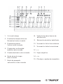
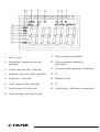
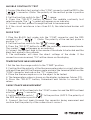
MEDICIÓN DE CORRIENTE
1. Coloque el interruptor Función / Rango, en el rango 60 A / 600 A /
1 000 A
2. Presione el gatillo para abrir las pinzas de transformación y sujetar
solamente un conductor ya que no es posible hacer mediciones cuando
dos o tres conductores estén sujetos a la vez.
3. La lectura en la pantalla muestra la corriente del conductor de c.a.
MEDICIÓN DE RESISTENCIA
1. Conecte la punta de prueba NEGRA al conector “COM” y la ROJA al
conector “ ” (Nota: La polaridad de la punta de prueba roja es
positiva “+”).
2. Coloque el interruptor de funciones en el rango
3. Presione el botón “RANGO” y se puede seleccionar la medición
manualmente.
4. Presione el botón “SELECT” para seleccionar la medición del modo de
resistencia, el símbolo “MΩ” aparece como indicador.
5. Conecte las puntas de prueba a través de la carga que se va a medir.
6. Lea la lectura en la pantalla.
• Para mediciones de resistencia >1 MΩ, le toma al multímetro unos
segundos para estabilizar la lectura. Esto es normal en mediciones de
alta resistencia.
• Cuando la entrada de energía no está conectada, por ejemplo, en
circuito abierto, se mostrará el símbolo “OL” como indicador de sobre
rango.
• Antes de medir la resistencia en circuito, confirme que el circuito que
se está probando tiene todo el suministro eléctrico retirado y que todos
los capacitores estén descargados por completo.
PRUEBA DE CONTINUIDAD AUDIBLE
1. Conecte la punta de prueba negra al conector “COM” y la ROJA al
conector “ ”. (Nota: La polaridad de la punta de prueba roja es
positiva “+”).
2. Coloque el interruptor de función en el rango “ ”.
3. Presione el botón “SELECT” para seleccionar el modo de selección de
prueba de continuidad audible. El símbolo “ ” aparecerá como indicador.
4. Conecte las puntas de prueba a través de la carga que se va a medir.
5. Si la resistencia del circuito es menor a 30 Ω, el zumbador
inter-construido va a zumbar.
PRUEBA DE DIODO
1. Conecte la punta de prueba NEGRA en el conector “COM” y el conector
ROJO en “ ”. (Nota: La polaridad dela punta de prueba roja es
positiva “+”).
2. Coloque el interruptor de funciones en el rango “ ”
3. Presione el botón “SELECT” para elegir el modo de medición de
continuidad. El símbolo “ ” va a aparecer como indicador.
4. Conecte la punta de prueba roja al ánodo del diodo a set probado y la
punta de prueba negra al cátodo.
5. El multímetro va a mostrar la tensión directa del diodo. Si se revierten
las conexiones, se muestra “OL” en la pantalla.
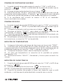
MEDICIÓN DE TEMPERATURA
1. Coloque el interruptor del rango de funciones en la posición “TEMP”.
2. Confirme que la polaridad de la sonda termopar sea la correcta;
coloque el extremo frío (extremo libre) del sensor de la sonda termopar en
la terminal (negra en el conector “COM” y roja en el conector “°C”).
3. Coloque el termopar sobre o dentro del objeto a probar.
4. El valor de temperatura se muestra en la pantalla en grados
centígrados (°C).
5. Presione el botón “SELECT”, Fahrenheit y Celsius para convertir los
valores.
MEDICIÓN DE CAPACITANCIA
1. Conecte la punta de prueba NEGRA en el conector “COM” y la ROJA en
el conector “ ”.
2. Coloque el interruptor de funciones “ ” en la posición.
(NOTA: La polaridad de la punta de prueba ROJA es positiva “+”).
3. Conecte las puntas de prueba a través del capacitor que se está
midiendo y confirme que la polaridad de la conexión sea correcta.
Cuando la capacitancia que se está midiendo esté sobre 100 µF, necesita por
lo menos 5 segundos para estabilizar la lectura.
MEDICIÓN DE FRECUENCIA (Rango Automático)
1. Coloque el interruptor de funciones de rango en la posición “Hz / DUTY”
requerida.
2. Conecte la punta de prueba NEGRA en el conector “COM” y la ROJA en
el conector “ ”. (Nota: La polaridad de la punta de prueba es positiva
(“+”).
3. Conecte las puntas de prueba a través de la carga que se va a medir.
No aplique más de 250 V RMS en la entrada. Es posible que indique las
tensiones mayores a 100 V RMS, pero la lectura puede estar fuera de
especificación.
Al mismo tiempo que usa la pinza para probar corriente c.a., presione el
botón y abra la pinza, el multímetro muestra la frecuencia de la corriente
medida.
• Se despliega la temperatura de prueba cuando la sonda termopar se
coloca en los orificios de prueba.
• Se muestra la temperatura circundante cuando se corta el circuito del
sensor.
• El límite de temperatura medido por la sonda termopar junto con el
multímetro es de 400 ºC máximo en periodos cortos, en caso de necesitar
medir temperaturas más altas debe adquirir una sonda termopar de mayor
capacidad.
7. APAGADO AUTOMÁTICO
Si no se opera el multímetro cerca de 15 minutos, se apaga de manera
automática. Para volver a encenderlo solo gire el interruptor de rango.
8. CAMBIO DE PILA
Si aparece el símbolo “ ” en la pantalla, indica que se debe cambiar la pila.
Retire los tornillos y abra la parte trasera de la carcasa. Cambie la pila
gastada por la pila nueva.
Emplea 1 pila 6F22 de Carbón-Zinc de 9 V c.c. (incluida).
NOTA
NOTA
NOTA
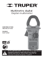
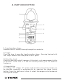
1. INTRODUCTION
This manual provides all safety information, operation instructions,
specifications and maintenance for the multimeter, which is compact,
hand-held and battery operated.
This instrument performs AC / DC voltage measurements, AC current,
resistance, audible continuity, diode, frequency, capacitance and
temperature.
It has 3-5/6 digits, is clamp digital multimeter and counts to 6 000
automatic range.
The design of the digital multimeter is in accordance with the
electronic measuring instruments, with over voltage category (CAT III
600 V, CAT II 1 000 V) and pollution degree 2.
To avoid possible electric shock or personal injury, and possible damage
to the Digital multimeter or the equipment under test, follow the
following rules:
Before using the Digital multimeter inspect the case. Do not use the
multimeter if damaged or part of the case has been removed. Look for
cracks or missing plastic Double check insulation around the
connectors.
Inspect the test probes for damaged insulation or exposed metal.
Check the test probes have continuity.
Do not apply more than the rated voltage as marked on the
multimeter, between the terminals or between any terminal and
grounding.
To prevent damage, the rotary switch must be placed in the correct
position and there must be no changes while the measurement is
being carried out.
Special care should be taken when the multimeter is working at an
effective voltage higher than 60 V in DC or 30 V RMS AC, as there is a
danger of electric shock.
Use the appropriate terminals, functions and range for the
measurements.
Do not use or store the multimeter in high temperature, humid
environments, near explosive and flammable products and strong
magnetic fields are present.
The performance of the multimeter may deteriorate after it gets wet.
When using test probes keep fingers behind the fingers guard.
Disconnect the feeding circuit and discharge all the high voltage
capacitors before testing resistance, continuity and diodes.
Replace the battery as soon as the battery indicator “ ” appears. With
a low battery, the multimeter might produce false readings that can lead
to electric shock and personal injury.
Remove the connection between the test probes and the circuit being
tested. Turn off the power to the multimeter before opening its housing.
When servicing the multimeter use only replacement parts of the same
model number or electrical specifications.
The internal circuit of the multimeter must not be altered at will to avoid
damaging it or having an accident.
Soft cloth and mild detergent should be used to clean the surface or the
multimeter when servicing. No abrasive and solvent should be used to
prevent the surface of the Digital multimeter from corrosion, damage
and accident.
The multimeter is suitable for indoor use.
Turn the multimeter power off when it is not in use and take out the
battery when not using for a long time. Constantly check the battery as
it may leak when it has been used for a long time. Replace the battery
immediately if leaking appears. A leaking battery will damage the
multimeter.
3. ELECTRICAL SYMBOLS


 1
1
 2
2
 3
3
 4
4
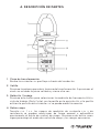 5
5
 6
6
 7
7
 8
8
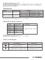 9
9
 10
10
 11
11
 12
12
 13
13
 14
14
 15
15
 16
16
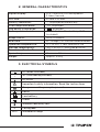 17
17
 18
18
 19
19
 20
20
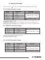 21
21
 22
22
 23
23
 24
24
 25
25
 26
26
 27
27
 28
28


Amprobe AU92 Automotive Multimeter Manual de usuario
Promax CT-347 Manual de usuario