
LEVL30SS400
LEVL36SS400
Installation Instructions
Use and Care Information
Instructions d'installation
Utilisez et d'entretien
Instrucciones de instalación
Información de uso y cuidado

2
READ AND SAVE THESE INSTRUCTIONS BEFORE YOU START
INSTALLING THIS RANGEHOOD
WARNING: - TO REDUCE THE RISK OF A RANGE TOP GREASE FIRE:
a) Never leave surface units unattended at high settings. Boilovers cause smoking and greasy
spillovers that may ignite. Heat oils slowly on low or medium setting.
A KV@XRSTQMGNNC.-VGDMBNNJHMF@SGHFGGD@SNQVGDMl@LADHMFENNCHD"QDODR2T-
zette, Cherries Jubilee, Peppercorn Beef Flambé).
c) Clean ventilating fans frequently. Grease should not be allowed to accumulate on fan or
kKSDQ
d) Use proper pan size. Always use cookware appropriate for the size of the surface element.
WARNING: - TO REDUCE THE RISK OF INJURY TO PERSONS IN THE EVENT OF A RANGE
TOP GREASE FIRE, OBSERVE THE FOLLOWING*:
@2,.3'$1%+ ,$2VHSG@BKNRDkSSHMFKHCBNNJHDRGDDSNQLDS@KSQ@XSGDMSTQMNEESGDATQMDQ
!$" 1$%4+3./1$5$-3!41-2(ESGDl@LDRCNMNSFNNTSHLLDCH@SDKX$5 "4 3$ -#
CALL THE FIRE DEPARTMENT.
b) NEVER PICK UP A FLAMING PAN - You may be burned.
c) DO NOT USE WATER, including wet dishcloths or towels - a violent steam explosion will result.
d) Use an extinguisher ONLY if:
1. You know you have a Class ABC extinguisher, and you already know how to operate it.
3GDkQDHRRL@KK@MCBNMS@HMDCHMSGD@QD@VGDQDHSRS@QSDC
3GDkQDCDO@QSLDMSHRADHMFB@KKDC
8NTB@MkFGSSGDkQDVHSGXNTQA@BJSN@MDWHS
* Based on "Kitchen Firesafety Tips" published by NFPA
WARNING - TO REDUCE THE RISK OF FIRE OR ELECTRIC SHOCK, do not use this fan
with any solid-state speed control device.
WARNING - TO REDUCE THE RISK OF FIRE, ELECTRICAL SHOCK, OR INJURY TO PER-
SONS, OBSERVE THE FOLLOWING:
1. Use this unit only in the manner intended by the manufacturer. If you have any ques-
tions, contact the manufacturer.
2. Before servicing or cleaning unit, switch power off at service panel and lock the
service disconnecting means to prevent power from being switched on accidentally.
When the service disconnecting means cannot be locked, securely fasten a prominent
warning device, such as a tag, to the service panel.
CAUTION: For General Ventilating Use Only. Do Not Use To Exhaust Hazardous or Ex-
plosive Materials and Vapors.
WARNING - TO REDUCE THE RISK OF FIRE, ELECTRICAL SHOCK, OR INJURY TO PER-
SONS, OBSERVE THE FOLLOWING:
1. (MRS@KK@SHNM6NQJ MC$KDBSQHB@K6HQHMF,TRS!D#NMD!X0T@KHkDC/DQRNMR(M BBNQ-
dance With All Applicable Codes And Standards, Including Fire-Rated Construction.
2. 2TEkBHDMS@HQHRMDDCDCENQOQNODQBNLATRSHNM@MCDWG@TRSHMFNEF@RDRSGQNTFGSGD
lTDBGHLMDXNEETDKATQMHMFDPTHOLDMSSNOQDUDMSA@BJCQ@ESHMF%NKKNVSGDGD@SHMF
equipment manufacturer's guideline and safety standards such as those published by
SGD-@SHNM@K%HQD/QNSDBSHNM RRNBH@SHNM-%/ @MCSGD LDQHB@M2NBHDSXENQ'D@SHMF
1DEQHFDQ@SHNM@MC HQ"NMCHSHNMHMF$MFHMDDQR 2'1 $@MCSGDKNB@KBNCD@TSGNQHSHDR
3. When cutting or drilling into wall or ceiling, do not damage electrical wiring and other
hidden utilities.
4. Ducted fans must always be vented to the outdoors.

3
ALL WALL AND FLOOR OPENINGS WHERE THE RANGEHOOD IS INSTALLED MUST
BE SEALED.
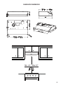
This rangehood requires at least 24" of clearance between the bottom of the rangehood and the
cooking surface or countertop. This hood has been approved by UL at this distance from the cooktop.
This minimum clearance may be higher depending on local building codes. For gas cooktops and
combination ranges, a minimum of 30" is recommended and may be required.
The maximum depth of overhead cabinets is 13". Overhead cabinets on both sides of this unit
must be a minimum of 18" above the cooking surface or countertop. Consult the cooktop or range
installation instructions given by the manufacturer before making any cutouts.
MOBILE HOME INSTALLATION The installation of this rangehood must conform to the Manufactured
Home Construction and Safety Standards, Title 24 CFR, Part 3280 (formerly Federal Standard
for Mobile Home Construction and Safety, Title 24, HUD, Part 280). See Electrical Requirements"
• Venting system MUST terminate outside the home.
• DO NOT terminate the ductwork in an attic or other enclosed space.
• DO NOT use 4" laundry-type wall caps.
• Flexible-type ductwork is not recommended.
• DO NOTNARSQTBSSGDkNVNEBNLATRSHNM@MCUDMSHK@SHNM@HQ
q%@HKTQDSNENKKNVUDMSHMFQDPTHQDLDMSRL@XQDRTKSHM@jQD
WARNING
!
Cold Weather installations
M@CCHSHNM@KA@BJCQ@ESC@LODQRGNTKCADHMRS@KKDCSNLHMHLHYDA@BJV@QCBNKC@HQkNV@MC@MNM-
metallic thermal break should be installed to minimize conduction of outside temperatures as part of
the vent system. The damper should be on the cold air side of the thermal break. The break should
be as close as possible to where the vent system enters the heated portion of the house.
VENTING REQUIREMENTS
Determine which venting method is best for your application. Ductwork can extend either through the
wall or the roof.
3GDKDMFSGNESGDCTBSVNQJ@MCSGDMTLADQNEDKANVRRGNTKCADJDOSSN@LHMHLTLSNOQNUHCDDEjBHDMS
performance. The size of the ductwork should be uniform. Do not install two elbows together. Use duct
S@ODSNRD@K@KKINHMSRHMSGDCTBSVNQJRXRSDL4RDB@TKJHMFSNRD@KDWSDQHNQV@KKNQkNNQNODMHMF@QNTMC
the cap.
Flexible ductwork is not recommended. Flexible ductwork creates back pressure and air turbulence that
greatly reduces performance.
,@JDRTQDSGDQDHROQNODQBKD@Q@MBDVHSGHMSGDV@KKNQkNNQENQDWG@TRSCTBSADENQDL@JHMFBTSNTSR#N
not cut a joist or stud unless absolutely necessary. If a joist or stud must be cut, then a supporting frame
must be constructed.
WARNING - To Reduce The Risk Of Fire, Use Only Metal Ductwork.
" 43(.-3NQDCTBDQHRJNEkQD@MCSNOQNODQKXDWG@TRS@HQADRTQDSNCTBS@HQNTSRHCDm#N
not vent exhaust air into spaces within walls or ceilings or into attics, crawl spaces, or garages.

4
ELECTRICAL REQUIREMENTS
A 120 volt, 60 Hz AC-only electrical supply is required on a separate 15 amp fused circuit. A time-delay
fuse or circuit breaker is recommended. The fuse must be sized per local codes in accordance with
SGDDKDBSQHB@KQ@SHMFNESGHRTMHS@RRODBHjDCNMSGDRDQH@KQ@SHMFOK@SDKNB@SDCHMRHCDSGDTMHSMD@QSGDjDKC
wiring compartment.
ELECTRICAL INSTALLATION WITH WIRING BOX
THIS UNIT MUST BE CONNECTED WITH COPPER WIRE ONLY. Wire sizes must conform to the
QDPTHQDLDMSRNESGD-@SHNM@K$KDBSQHB@K"NCD -2(-%/ K@SDRSDCHSHNM@MC@KKKNB@KBNCDR@MC
ordinances. Wire size and connections must conform with the rating of the appliance. Copies of the
standard listed above may be obtained from:
National Fire Protection Association
Batterymarch Park
Quincy, Massachusetts 02269
This appliance should be connected directly to the fused disconnect (or circuit breaker) through
kDWHAKD@QLNQDCNQMNMLDS@KKHBRGD@SGDCBNOODQB@AKD KKNVRNLDRK@BJHMSGDB@AKDRNSGD
@OOKH@MBDB@MADLNUDCHERDQUHBHMFHRDUDQMDBDRR@QX 4++HRSDCŭBNMCTHSBNMMDBSNQLTRS
be provided at each end of the power supply cable (at the appliance and at the junction box).
6GDML@JHMFSGDDKDBSQHB@KBNMMDBSHNMBTS@ŭGNKDHMSGDV@KK GNKDBTSSGQNTFGVNNC
must be sanded until smooth. A hole through metal must have a grommet.
• Electrical ground is required on this rangehood.
• If cold water pipe is interrupted by plastic, nonmetallic gaskets or other materials, DO
NOT use for grounding.
• DO NOT ground to a gas pipe.
• DO NOT have a fuse in the neutral or grounding circuit. A fuse in the neutral or
grounding circuit could result in electrical shock.
q"GDBJVHSG@PT@KHjDCDKDBSQHBH@MHEXNT@QDHMCNTAS@RSNVGDSGDQSGDQ@MFDGNNCHR
properly grounded.
q%@HKTQDSNENKKNVDKDBSQHB@KQDPTHQDLDMSRL@XQDRTKSHM@jQD
WARNING

5
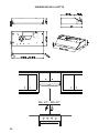
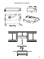
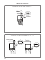
RANGEHOOD DIMENSIONS
Min. 24" - Max.30"

6
Available Accessories
Wireless Remote Control-REMCTRL
Parts needed
5RXQG GDPSHU LI XVLQJ URXQG ÀDQJH
- Drywall plugs or other suitable wall fasteners based on your installation.
- Wire connectors.
- Power Supply Cable.
For installation that is attached to bottom of wood cabinets with a recessed bottom; 1" x 2" by 12"(approximate
length) wood strips will need to be purchased locally. 12C Wall Mount Screws may work as fasteners for this
W\SH RI LQVWDOO LI QRW WKHQ IRXU ÀDW KHDG ZRRG VFUHZV ZLOO DOVR QHHG WR EH SXUFKDVHG ORFDOO\ WR FRPSOHWH WKLV
type of install.
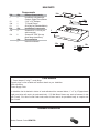
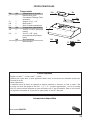
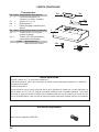
MAIN PARTS
Components
Ref. Qty. Product Components
1 1 Hood Body, complete with:
Controls, Lights, Filters, Blower.
10 1 3 1/4" x 10" Damper
10a 1 7" Round Flange
13 1 Grid (Only for Canadian Market)
Ref. Qty. Installation Components
12a 4 Screws 3/16" x 1 15/16" (for
wall mounting)
12c 6 Screws 1/8" x 3/8" (for sup
SOLHGÀDQJHWUDQVLWLRQV
Qty. Documentation
1 Instruction Manual
1
12a
10
12c
12c
13
10a
12c

7
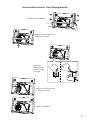
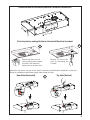
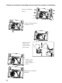
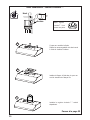
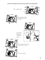
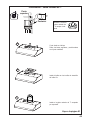
Before Installation Remove These Shipping Materials
Remove the side packaging.
Remove the wood shipping by
unscrew the 4 screws.
Ready for Installation.
Remove the
internal block as
VKRZQ LQ D ¿JXUH
to the right.
Remove the block as shown
LQ D ¿JXUH WR WKH OHIW

8
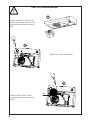
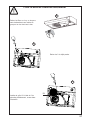
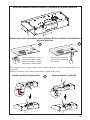
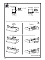
ONLY FOR CANADIAN MARKET
5HPRYH WKH ¿OWHUV RQH DW D WLPH E\
pushing them towards the back of the
group and pulling down at the same
time.
Install the Grid 13 with 2 screws
removed previously as shown in the
picture.
13
5HPRYH WKH VFUHZ DOUHDG\ ¿[HG
a
b
c

9
a
b
c
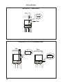
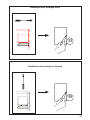
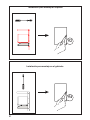
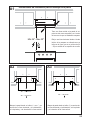
Choose Vertical or Horizontal Electrical Connection Knockout's
5HPRYH WKH ¿OWHUV RQH DW D
time by pushing them towards
the back of the board and
pulling down at the same time.
Remove the wiring box
cover by unscrewing the
2 screws.
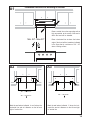
Choose the rear hole or top hole for the electric connection and break with a screwdriver or other tool.
During the installation thread Power Supply Cable through this hole.
1D@Q'NKD'NQHYNMS@K 3NO'NKD5DQSHB@K
First step before making Vertical or Horizontal Electrical knockout
7" 1/2
13/16"
13/16"

10
7"
10"
3 1/4"
10"
3 1/4"
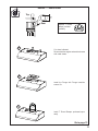
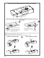
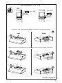
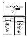
Ducting Methods
Ducted with 7" Round Outlet
Ducted with 3 1/4" x 10" Rectangular Outlet
Rear
Top
Rear
Top

11
a
b
c
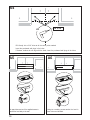
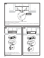
Ducted - 7" Round Outlet
Cut where indicated.
Remove both the angular and semicircle areas
with metal shears.
Install the Flange with Flange transition
screws 12c
Install 7" Round Damper purchased sepa-
rately.
Rear
Top
7"
Required; 7" Round
Damper purchase
separately.
Go to page 13

12
a
b
c
a
b
c
Ducted - 3 1/4" x 10"
Choose the rectangular upper air outlet or rectangular rear air outlet and cut where indicated.
,QVWDOO WKH LQFOXGHG UHFWDQJXODU DLU RXWOHW ZLWK WZR ÀDQJH WUDQVLWLRQ VFUHZV
Rear
Rear
Top
RearTop
3
1/4" x 10"
3
1/4" x 10"
Go to page 13

13
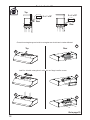
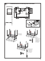
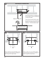
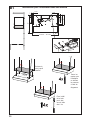
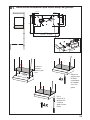
Installation for Mounting on the Wall
Installation for Mounting to the cabinet
14
16

14
A1
==
Min. 24" - Max.30"
Installation Instruction for mounting on the Wall
Draw a vertical line on the supporting wall as
high as practical, at the center of the area in
which the hood will be installed.
Draw a horizontal line at where the bottom
edge of the hood will be located as indicated
LQ WKH ¿JXUH WKDW LV D PLQLPXP RI
above cooking surface
4 15/16”
4 15/16”
24” - - > A= 21 3/8”
30” - - > A= 27
3/8”
36” - - > A= 33
3/8”
A
1”
1”
24” - - > A= 21 3/8”
30” - - > A= 27
3/8”
36” - - > A= 33
3/8”
A
A2 A3
Mark the wall where indicated, 4 15/16" above the
horizontal line and at A distance on the left and
right of vertical line.
Mark the wall where indicated, 1" above the hori-
zontal line and at A distance on the left and right
of vertical line.

15
A4
´
;
Drill directly into ø 3/16" holes at all the center points marked.
Insert the purchased wall plugs in the holes.
If fastener locations do not align with the studs, insert the purchased wall plugs in the holes.
A5 A6
In upper holes use two of the supplied screws to
secure the hood body to the wall.
Using two remaining screws anchor the hood in
lower holes as indicated.

16
B1
Installation Instruction for Mounting Under to the Cabinet
Mark the
KROHV IRU ¿[LQJ
verifying the
measures with
the diagram.
Lift the hood
to the cabinet.
Fix the Hood
Body with 4
screws from
the bottom.
20"
24"-30"-36"
12"
7"
2" 13/16
10" 1/2
1" 5/16
1" 5/16
7" 11/16 2"
7" 1/2
13/16"
13/16"
29 15/16" - 35 15/16"

17
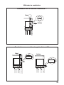
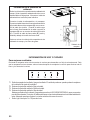
Installation of wiring connection
5HPRYHWKHFRYHUIURPWKH¿HOGZLULQJFRPSDUWPHQW
5HPRYHWKHZLULQJHOHFWULFDONQRFNRXWXVLQJDÀDW
blade screwdriver. Feed the Power Supply Cable
through the electrical knockout.
Connect the Power Supply Cable to the rangehood.
Attach the White lead of the power supply (A) to the
White lead of the rangehood (D) with a twist-on type
wire connector. Attach the Black lead of the power
supply to the Black lead of the rangehood (B) with
a twist-on type wire connector (C). Connect the
Green (E) (Green and Yellow) ground wire under
the Green grounding screw.
5HSODFH WKH ¿HOG ZLULQJ FRPSDUWPHQW FRYHU DQG
WKHJUHDVH¿OWHUV
Hood wiring
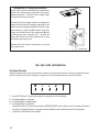
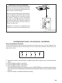
USE AND CARE INFORMATION
T1. Hood ON/OFF button. The hood can be turned on by pressing any of the fan settings.
T2. Fan Settings Buttons: Low Speed.
T3. Fan Settings Buttons: Medium Speed.
T4. Fan Settings Buttons: High Speed.
Hold down the button for 2 seconds to activate the INTENSIVE SPEED, which is timed to run for 10 minutes. At the end of
this time it will automatically return to the speed set before.Suitable to deal with maximum levels of cooking fumes.
L. Light Button: On/Off switch for the Led lights.
LT1 T2 T3 T4
For Best Results
6WDUWWKHUDQJHKRRGVHYHUDOPLQXWHVEHIRUHFRRNLQJWRGHYHORSSURSHUDLUÀRZ$OORZWKHUDQJHKRRGWRRSHU-
ate for several minutes after cooking is complete to clear all smoke and odors from the kitchen.

18
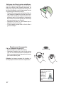
"KD@MHMFLDS@KFQD@RDkKSDQR
7KHPHWDOJUHDVH¿OWHUVFDQEHFOHDQHGLQKRWGHWHUJHQW
solution or washed in the dishwasher. They should be
cleaned every 2 months use, or more frequently if use
is particularly heavy.
• 5HPRYHWKH¿OWHUSXVKLQJWKHOHYHUWRZDUGVWKHEDFN
of the unit and at the same time pulling downward.
• :DVK WKH ¿OWHUZLWKRXW EHQGLQJ LW OHDYHLWWR GU\
WKRURXJKO\EHIRUHUHSODFLQJLIWKHVXUIDFHRIWKH¿OWHU
changes color over time, this will have absolutely no
HIIHFWRQLWVHI¿FLHQF\
• Replace, taking care to ensure that the handle
faces forward.
• &OHDQLQJLQGLVKZDVKHUPD\GXOOWKH¿QLVKRI
WKHPHWDOJUHDVH¿OWHU
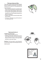
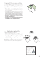
Replacing the light unit
5 W LED Type GU10 lamp
• Remove the bulb (See the picture).
• Replace the bulb with a new one of the same
type, making sure that you insert the two pins
properly into the housings on the lamp holder
and twist to lock back in place.
Attention: If the hood was in use wait several
minutes after turning the hood and lights off before
replacing lights.
• Screw the Frame into place
Gu10 self-ballasted led
lamps – listed in ac-
cordance with
ul 1993/nmx-
j-578/1-ance/
csa c22.2 No.
1993

19
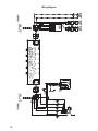
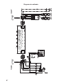
Wiring Diagram
+U
+U

20
January 4, 2016
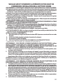
FABER CONSUMER WARRANTY & SERVICE
All Faber products are warranted against any defect in materials or workmanship for the original purchaser
for a period of 1 year from the date of original purchase (requires proof of purchase). This warranty covers
labor and replacement parts. Faber, at its option, may repair or replace the product or components
necessary to restore the product to good working condition. To obtain warranty service, contact the dealer
from whom you purchased the range hood, or the local Faber distributor. If you cannot identify a local Faber
distributor, contact us at (508) 358-5353 for the name of a distributor in your area.
The following is not covered by Faber's warranty:
1. Service calls to correct the installation of your range hood, to instruct you how to use your range hood, to
replace or repair house fuses or to correct house wiring or plumbing.
2. Service calls to repair or replace range hood light bulbs, fuses or filters. Those consumable parts are
excluded from warranty coverage.
3. Repairs when your range hood is used for other than normal, single-family household use.
4. Damage resulting from accident, alteration, misuse, abuse, fire, flood, acts of God, improper installation,
installation not in accordance with electrical or plumbing codes or Faber documentation, or use of products
not approved by Faber.
5. Replacement parts or repair labor costs for units operated outside the United States or Canada, including
any non-UL or C-UL approved Faber range hoods.
6. Repairs to the hood resulting from unauthorized modifications made to the range hood.
7. Expenses for travel and transportation for product service in remote locations and pickup and delivery
charges. Faber range hoods should be serviced in the home.
THIS WARRANTY DOES NOT ALLOW RECOVERY OF INCIDENTAL OR CONSEQUENTIAL DAMAGES, INCLUDING, WITHOUT
LIMITATION, DIRECT, INDIRECT, INCIDENTAL, SPECIAL OR CONSEQUENTIAL DAMAGES, PERSONAL INJURY/WRONGFUL
DEATH OR LOST PROFITS FABER WARRANTY IS LIMITED TO THE ABOVE CONDITIONS AND TO THE WARRANTY PERIOD
SPECIFIED HEREIN AND IS EXCLUSIVE. EXCEPT AS EXPRESSLY SPECIFIED IN THIS AGREEMENT, FABER DISCLAIMS ALL
EXPRESS OR IMPLIED CONDITIONS, REPRESENTATIONS, AND WARRANTIES INCLUDING, WITHOUT LIMITATION, ANY
IMPLIED WARRANTIES OF MERCHANTABILITY OR FITNESS FOR A PARTICULAR PURPOSE
.
This warranty gives you specific legal rights that may vary from state to state.
Model#: ______________________________ Serial #: _____________________________
This warranty applies for USA and Canada

21
VEUILLEZ LIRE ET CONSERVER LA PRÉSENTE NOTICE AVANT DE
COMMENCER L'INSTALLATION DE LA HOTTE DE CUISINE
5$13(22$,$-3/.411Í#4(1$+$1(204$#f4-%$4#$&1 (22$241+ 3 !+$#$"4(22.-Ů
a) Ne laissez jamais sans surveillance les éléments de la surface de cuisson à température élevée. Les
bouillonnements excessifs peuvent provoquer de la fumée et les débordements de graisse peuvent
RfDMl@LLDQ+fGTHKDCNHSģSQDBG@TEEĢDKDMSDLDMSĒTMDSDLOĢQ@STQDA@RRDNTLNXDMMD
b) Assurez-vous de toujours mettre en marche le ventilateur de la hotte lorsque vous cuisinez à tempéra-
STQDĢKDUĢDNTOQĢO@QDYTMLDSRl@LAĢODWBQģODR2TYDSSDBDQHRDRITAHKĢATEl@LAĢ
c) Nettoyez régulièrement les ventilateurs d'aspiration. Assurez-vous de ne pas laisser de la graisse
Rf@BBTLTKDQRTQKDUDMSHK@SDTQNTKDkKSQD
C4SHKHRDYSNTINTQRCDRONģKDRDSB@RRDQNKDRCDK@S@HKKD@OOQNOQHĢD4SHKHRDYSNTINTQRCDRTRSDMRHKDRCD
cuisine de la taille adaptée à celle de l'élément chauffant.
5$13(22$,$-3Ů/.41/1Í5$-(1+$2!+$2241$2$-" 2#$%$4#$&1 (22$241+ 3 !+$
#$"4(22.-24(5$9+$21$".,, -# 3(.-224(5 -3$2Ů
a) ÉTOUFFEZ LES FLAMMES à l'aide d'un couvercle hermétique, d'une plaque à biscuits ou d'un plateau
métallique, puis éteignez le brûleur. FAITES ATTENTION AUX BRÛLURES. Si le feu ne s'éteint pas
immédiatement, QUITTEZ LES LIEUX ET APPELEZ LES POMPIERS.
b) NE PRENEZ JAMAIS UNE CASSEROLE EN FLAMME - Vous pourriez vous brûler.
c) N'UTILISEZ JAMAIS DE L'EAU, ni un linge à vaisselle ou un torchon mouillé, pour éteindre le feu. Cela
pourrait provoquer une violente explosion de vapeur.
C4SHKHRDYTMDWSHMBSDTQ4-(04$,$-3RHŮ
5NTRģSDRBDQS@HMPTfHKRf@FHSCfTMDWSHMBSDTQCDBK@RRD !"DSPTDUNTRBNMM@HRRDYAHDMRNMLNCD
d'emploi.
2. Le feu est de faible intensité et se limite à l'endroit où il a démarré.
3. Les pompiers ont déjà été appelés.
4MDUNHDCDRNQSHDRDSQNTUDCDQQHġQDUNTRODMC@MSPTDUNTRĢSDHFMDYKDRl@LLDR
#e@OQĠRKDFTHCDgŰ*HSBGDM%HQDR@EDSX3HORŰuOTAKHġO@QK@-%/ @TWÍS@SR4MHR
AVERTISSEMENT - POUR RÉDUIRE LE RISQUE D'INCENDIE OU DE CHOC ÉLECTRIQUE, n'utilisez
jamais ce ventilateur en association avec un dispositif de réglage de vitesse à semi-conducteurs.
AVERTISSEMENT - POUR RÉDUIRE LES RISQUES D'INCENDIE, DE CHOC ÉLECTRIQUE OU DE
!+$2241$".1/.1$++$1$2/$"3$9+$2(-2314"3(.-224(5 -3$2Ů
1. Utilisez cet appareil uniquement de la façon prévue par le fabricant. Pour toute question, com-
muniquez avec le fabricant.
2. Avant de procéder à l'entretien ou au nettoyage de l'appareil, coupez l'alimentation au niveau du
panneau électrique et verrouillez-le pour vous assurer que l'électricité n'est pas rétablie accidentel-
KDLDMS2fHKMfDRSO@RONRRHAKDCDUDQQNTHKKDQKDCHRONRHSHECfHMSDQQTOSHNMCDKf@KHLDMS@SHNM@EkBGDYCD
façon ferme et bien visible un avis de danger, par exemple à l'aide d'une étiquette sur le panneau.
33$-3(.-Ů#DRSHMĢĒTMTR@FDCDUDMSHK@SHNMFĢMĢQ@KDTMHPTDLDMS-fTSHKHRDYO@RBDCHRONRHSHEONTQ
l'aspiration de vapeurs ou de matériaux dangereux ou explosifs.
AVERTISSEMENT - POUR RÉDUIRE LES RISQUES D'INCENDIE, DE CHOC ÉLECTRIQUE OU DE
!+$2241$".1/.1$++$1$2/$"3$9+$2(-2314"3(.-224(5 -3$2Ů
1. +fHMRS@KK@SHNMDSKDAQ@MBGDLDMSĢKDBSQHPTDCNHUDMSģSQDQĢ@KHRĢRO@QTMSDBGMHBHDMPT@KHkĢDSBNMENQLĢ-
ment à tous les codes et normes en vigueur, incluant ceux concernant la construction à l'épreuve du feu.
2. kMCDF@Q@MSHQTMDBNLATRSHNMDSTMDĢU@BT@SHNM@CĢPT@SDRCDRF@YO@QKDRBNMCTHSDRCDK@
cheminée des appareils à combustion, une bonne aération est nécessaire pour éviter le refoulement.
Respectez les lignes directrices fournies par le fabricant du matériel chauffant, ainsi que les normes
CDRĢBTQHSĢBNLLDBDKKDROTAKHĢDRO@QK@-@SHNM@K%HQD/QNSDBSHNM RRNBH@SHNM-%/ DSK@ LDQHB@M
2NBHDSXENQ'D@SHMF1DEQHFDQ@SHNM@MC HQ"NMCHSHNMHMF$MFHMDDQR 2'1 $@TWÍS@SR4MHR@HMRH
que les codes en vigueur dans votre région.
3. Lorsque vous faites une ouverture ou percez dans un mur ou le plafond, veillez à ne pas endom-
L@FDQKDRkKRĢKDBSQHPTDRNTCf@TSQDRCHRONRHSHERB@BGĢR
4. +DRUDMSHK@SDTQRB@M@KHRĢRCNHUDMSSNTINTQRģSQDQ@BBNQCĢRĒKfDWSĢQHDTQ

22
T
.43$.45$1341$# -2+$,41.4+$/+ -"'$1½/1.7(,(3Í#$+ '.33$#.(3Î31$
2"$++Í$
Un espace libre d'au moins 24" est requis entre le bas de la hotte et la surface de cuisson ou le comptoir. Cette
GNSSD@ġSġGNLNKNFTġDO@QKe4+ĐBDSSDCHRS@MBDCDK@RTQE@BDCDBTHRRNM
+DRO@BD KHAQD LHMHL@K QDPTHR ODTS ĢSQD OKTR FQ@MC RDKNM KDR BNCDR DS QġFKDLDMS@SHNMR DM L@SHĠQD CD
BNMRSQTBSHNMCDUNSQDQġFHNM/NTQKDRBTHRHMHĠQDRĐF@YDSKDRBTHRHMHĠQDRBNLAHMġDRTMDRO@BDLHMHL@KCD
ŭDRSQDBNLL@MCġDSONTQQ@HSĢSQDDWHFġ+@OQNENMCDTQL@WHL@KDCDR@QLNHQDRRTRODMCTDRDRSCDŭ
+DR@QLNHQDRRTRODMCTDRCDBG@PTDBŃSġCDKe@OO@QDHKCNHUDMSRDSQNTUDQĐ@TLNHMRŭCDK@RTQE@BDCD
cuisson ou du comptoir. Consultez la notice d'installation de la surface de cuisson ou de la cuisinière fournie
par le fabricant avant de pratiquer des ouvertures.
INSTALLATION DANS UNE MAISON MOBILE L’installation de cette hotte doit être conforme aux exigences
CDK@MNQLD,@MTE@BSTQDC'NLD"NMRSQTBSHNM@MC2@EDSX2S@MC@QCRSDKPTDCġBQHS@T3HSQD"%1O@QSHD
3280 (anciennement Federal Standard for Mobile Home Construction and Safety, titre 24, HUD, partie 280).
"NMRTKSDYK@jBGDSDBGMHPTDġKDBSQHPTD
Installation dans les climats froids
+DRXRSĠLDCDUDMSHK@SHNMCNHSOQġUNHQTMQDFHRSQD@MSHQDENTKDLDMSRTOOKġLDMS@HQDONTQQġCTHQDKDkTWCe@HQEQNHC
HMUDQRD@HMRHPTeTMDA@QQHĠQDSGDQLHPTDONTQQġCTHQDK@BNMCTBSHNMCDRSDLOġQ@STQDRDWSġQHDTQDR+DQDFHRSQD
CNHSĢSQDHMRS@KKġCTBŃSġ@HQEQNHCO@QQ@OONQSĐK@A@QQHĠQDSGDQLHPTD+@A@QQHĠQDSGDQLHPTDCNHSĢSQDONRHSHNMMġD
KDOKTROQĠRPTDONRRHAKDCDKeDMCQNHSNŔKDRXRSĠLDCDUDMSHK@SHNMOġMĠSQDC@MRK@O@QSHDBG@TEEġDCDK@L@HRNM
CRITÈRES DE VENTILATION
#ġSDQLHMDYPTDKKDLġSGNCDCDUDMSHK@SHNMDRSLHDTW@C@OSġDĐUNSQD@OOKHB@SHNM+DRBNMCTHSRODTUDMS
passer par le mur ou le toit.
/NTQF@Q@MSHQTMDLDHKKDTQDDEjB@BHSġK@KNMFTDTQCDRBNMCTHSRDSKDMNLAQDCDBNTCDRCNHUDMSĢSQDKDOKTR
KHLHSġRPTDONRRHAKD+DCH@LĠSQDCDRBNMCTHSRCDUQ@HSĢSQDTMHENQLD-eHMRS@KKDYO@RCDTWBNTCDRDMRDLAKD
4SHKHRDYTMQTA@MONTQB@M@KHR@SHNMR@jMCDRBDKKDQSNTRKDRINHMSRCTRXRSĠLDCDBNMCTHSR4SHKHRDYTMB@KEDT-
SQ@FDONTQRBDKKDQKDRNTUDQSTQDRC@MRKDLTQDWSġQHDTQNTKDOK@MBGDQ@TSNTQCTBK@ODS
,OQHVWSDVUHFRPPDQGpGXWLOLVHUGHVFRQGXLWVÀH[LEOHV/HVFRQGXLWVÀH[LEOHVSURYRTXHQWXQHFRQWUHSUHVVLRQ
HWGHODWXUEXOHQFHTXLGLPLQXHQWJUDQGHPHQWOHI¿FDFLWpGHODSSDUHLO
RRTQDYUNTRPTDKeDRO@BDKHAQDC@MRKDLTQNTKDOK@MBGDQDRSRTEjR@MSONTQKDBNMCTHSCeġU@BT@SHNM@U@MSCD
OQ@SHPTDQKDRNTUDQSTQDR-DBNTODYI@L@HRTMDONTSQDNTTMBGDUQNMR@TERHBeDRS@ARNKTLDMSMġBDRR@HQD
2eHKRe@UĠQDMġBDRR@HQDCDBNTODQTMDONTSQDNTTMBGDUQNMK@BNMRSQTBSHNMCeTMQDMENQBDLDMSDRSQDPTHRD
$9(57,66(0(173RXUUpGXLUHOHULVTXHGLQFHQGLHXWLOLVH]XQLTXHPHQWGHVFRQGXLWVPpWDOOLTXHV
ATTENTION - Pour réduire le risque d'incendie et pour évacuer adéquatement l'air, assurez-vous
CDQ@BBNQCDQKDRBNMCTHSRĒKfDWSĢQHDTQm-DCHEETRDYO@RKf@HQCfĢU@BT@SHNMC@MRCDRDRO@BDRĒ
l'intérieur des murs ou du plafond, ou encore à l'intérieur d'un grenier, d'une galerie technique
ou d'un garage.
q+DRXRSĠLDCDUDMSHK@SHNM#.(3CġANTBGDQĐKeDWSġQHDTQ
• NE FAITES PASCġANTBGDQKDRBNMCTHSRC@MRTMFQDMHDQNTTM@TSQDDMCQNHSEDQLġ
• N'UTILISEZ PASTMBK@ODSCDRġBGDTRDLTQ@KCDŰŭ
q(KMeDRSO@RQDBNLL@MCġCeTSHKHRDQCDRBNMCTHSRkDWHAKDR
• N'ENTRAVEZ PASKDkTWCDKe@HQCDBNLATRSHNMDSCDUDMSHK@SHNM
• Le non-respect des exigences en matière de ventilation pourrait entraîner un incendie.
AVERTISSEMENT
!

23
FICHE TECHNIQUE ÉLECTRIQUE
4MD@KHLDMS@SHNMCDBNTQ@MS@KSDQM@SHECDUNKSĐ'YDRSQDPTHRDRTQTMBHQBTHSĐETRHAKDCHRSHMBS
CD@LOĠQDR(KDRSQDBNLL@MCġCeHMRS@KKDQTMETRHAKDSDLONQHRġNTTMCHRINMBSDTQ+DETRHAKDCNHS
ĢSQDB@KHAQġBNMENQLġLDMS@TWBNCDRDMUHFTDTQONTQKDRB@Q@BSġQHRSHPTDRMNLHM@KDRġKDBSQHPTDRCD
Ke@OO@QDHKHMCHPTġDRRTQK@OK@PTDRHFM@KġSHPTDRHSTġDĐKeHMSġQHDTQCDKe@OO@QDHKĐOQNWHLHSġCTBNLO@QSH-
ment des câblages externes.
INSTALLATION ÉLECTRIQUE AVEC BOÎTIER DE CÂBLAGES
"$3 // 1$(+#.(3Î31$4-(04$,$-3!1 -"'ͽ+e (#$#$%(+2#$"4(51$+DB@KHAQDCDR
jKRCNHSĢSQDBNMENQLD@TWBQHSĠQDRCDK@CDQMHĠQDġCHSHNMCT-@SHNM@K$KDBSQHB@K"NCDCDKe -2(-%/
DSCDKeDMRDLAKDCDRBNCDRDSQġFKDLDMS@SHNMRDMUHFTDTQ+DB@KHAQDCDRjKRDSKDRBNMMDWHNMR
CNHUDMSĢSQD@C@OSġR@TWB@Q@BSġQHRSHPTDRMNLHM@KDRCDKe@OO@QDHK(KDRSONRRHAKDCDRDOQNBTQDQTM
DWDLOK@HQDCDRMNQLDRHMCHPTġDRBHCDRRTRDMBNLLTMHPT@MS@UDBŰ
National Fire Protection Association
Batterymarch Park
0THMBX,@RR@BGTRDSSRÍS@SR4MHR
"DS@OO@QDHKCDUQ@HSĢSQDAQ@MBGġCHQDBSDLDMS@TRDBSHNMMDTQĐETRHAKDNT@TCHRINMBSDTQO@QTMBĒAKD
kDWHAKDCDBTHUQD@UDBAKHMC@FDNTF@HMDMNMLġS@KKHPTD+@HRRDYTMODTCDIDTC@MRKDBĒAKDONTQ
ODQLDSSQDKDCġOK@BDLDMSCDKe@OO@QDHKRHCDRSQ@U@TWCeDMSQDSHDMRe@UġQ@HDMSMġBDRR@HQDR4MQ@BBNQC
CDBNMCTHSGNLNKNFTġO@QKe4+CDŰŭCNHSĢSQDHMRS@KKġ@TWCDTWDWSQġLHSġRCTBĒAKDCe@KHLDMS@SHNM
(au niveau de l'appareil et de la boîte de liaison).
+NQRCDK@Qġ@KHR@SHNMCTAQ@MBGDLDMSġKDBSQHPTDQġ@KHRDYTMSQNTCDŰŰŭC@MRKDLTQ2eHKRe@FHS
CeTMSQNTC@MRKDANHRHKCNHSĢSQDONMBġONTQKDQDMCQDKHRRD2eHKRe@FHSCeTMSQNTC@MRKDLġS@KTM
O@RRDjKRDRSQDPTHR
q4MDLHRDĐK@SDQQDġKDBSQHPTDDRSQDPTHRDONTQBDSSDGNSSD
q-e43(+(2$9/ 2TMSTX@TCeD@TEQNHCDONTQK@LHRDĐK@SDQQDRHBDKTHBHDRSAQ@MBGġO@QCDR
INHMSRDMOK@RSHPTDO@QCDRQNMCDKKDRMNMLġS@KKHPTDRNTCe@TSQDRL@SġQH@TW
q-e43(+(2$9/ 2TMDBNMCTHSDCDF@YONTQK@LHRDĐK@SDQQD
q-e(-23 ++$9/ 2TMETRHAKDRTQKDBHQBTHSMDTSQDNTKDBHQBTHSCDLHRDĐK@SDQQD+@OQġRDMBD
CeTMETRHAKDC@MRKDBHQBTHSMDTSQDNTCDLHRDĐK@SDQQDODTSDMSQ@ıMDQTMBGNBġKDBSQHPTD
q"NMRTKSDYTMġKDBSQHBHDMPT@KHjġRHUNTRMeĢSDRO@RBDQS@HMCDK@LHRDĐK@SDQQDCDK@GNSSD
q+DMNMQDRODBSCDRDWHFDMBDRCDK@jBGDSDBGMHPTDġKDBSQHPTDONTQQ@HSDMSQ@ıMDQTMHMBDMCHD
AVERTISSEMENT
!

24
DIMENSIONS DE LA HOTTE
Min. 24" - MAx.30"

25
Accessoires disponibles
Télécommande-REMCTRL
Pièces requises
- Registre circulaire 7 " si bride ronde 7 " utilisée.
&KHYLOOHVSRXUFORLVRQVqFKHRXDXWUHV\VWqPHGH¿[DWLRQPXUDOHQIRQFWLRQGHYRWUHLQVWDOODWLRQDFKDWORFDO
&RQQHFWHXUV GH ¿OV
- Câble d'alimentation.
6L OLQVWDOODWLRQ SUpYRLW OD ¿[DWLRQ GH ODSSDUHLO DX GHVVRXV GDUPRLUHV HQ ERLV DYHF XQ IRQG HQ UHWUDLW LO IDXW
se procurer sur place des bandes de bois de 1 " x 2 " x 12 " (longueur approximative). Les vis de montage
PXUDO & SHXYHQW VDYpUHU DGpTXDWHV HQ JXLVH GH ¿[DWLRQ SRXU FH W\SH GLQVWDOODWLRQ 'DQV OH FDV FRQWUDLUH
il est également nécessaire de se procurer sur place quatre vis à bois à tête plate.
PIÈCES PRINCIPALES
Composants
Réf. Qté Composants du produit
1 1 Bâti de la hotte, avec :
Commandes, Éclairage, Filtres,
Ventilateur.
10 1 Registre 3 1/4 " x 10 "
10a 1 Bride ronde 7 "
13 1 Grille (Canada uniquement)
Réf. Qté Composants d'installation
12a 4 Vis 3/16 " x 1 15/16 " (pour pose
murale)
12c 6 Vis 1/8 " x 3/8 " (pour
UDFFRUGGHWUDQVLWLRQÀDVTXH
fourni)
Qté Documentation
1 Mode d'emploi
1
12a
10
12c
12c
13
10a
12c

26
Retirez les matériaux d'emballage suivants avant de procéder à l'installation
Enlevez les emballages
latéraux.
Enlevez le cadre de bois en
dévissant les 4 vis.
Vous êtes prêt à procéder à
l'installation.
Déplacez le bloc
interne comme
indiqué dans une
¿JXUH j GURLWH
Déplacez le bloc
comme indiqué
GDQV XQH ¿JXUH j
gauche.

27
13
POUR LE MARCHÉ CANADIEN UNIQUEMENT
5HWLUH] OHV ¿OWUHV XQ j XQ HQ OHV SRXV-
sant simultanément vers l'arrière du
groupe et en les tirant vers le bas.
Retirez les 2 vis déjà posées.
Installez la grille 13 à l'aide de 2 vis
enlevées précédemment, comme dans
l'illustration.
a
b
c

28
a
b
c
Choisir l'entrée électrique défonçable verticale ou horizontale
Avant de procéder au défoncement de l'entrée électrique verticale ou
horizontale
5HWLUH] OHV ¿OWUHV XQ j XQ HQ
les poussant simultanément
vers l'arrière du groupe et en
les tirant vers le bas.
Dévissez les 2 vis pour re-
tirer le couvercle du boîtier
de câblage.
&KRLVLVVH] VL YRXV XWLOLVHUH] ORUL¿FH DUULqUH RX ORUL¿FH VXSpULHXU SRXU OH EUDQFKHPHQW pOHFWULTXH HW EULVH]
ORUL¿FH FKRLVL j ODLGH GXQ WRXUQHYLV RX GXQ DXWUH RXWLO
'XUDQW OLQVWDOODWLRQ IDLWHV SDVVHU OH FkEOH GDOLPHQWDWLRQ pOHFWULTXH GDQV FHW RUL¿FH
.QHkBD@QQHġQDGNQHYNMS@K .QHkBDRTOĢQHDTQUDQSHB@K
7" 1/2
13/16"
13/16"

29
7"
10"
3 1/4"
10"
3 1/4"
"@M@KHR@SHNM@UDBTMBNMCTHSBHQBTK@HQDCDŮŪ
Canalisation avec conduit rectangulaire 3 ŮŪWŮŪ
Arrière
Haut
Méthodes de canalisation
Arrière
Haut

30
a
b
c
7"
Arrière
Haut
UDBB@M@KHR@SHNMBNMCTHSBHQBTK@HQDŮŪ
Requis : registre
circulaire 7 " à se
procurer sur place.
Coupez aux endroits indiqués.
Retirez les zones angulaires et le demi-cercle
à l'aide de cisailles à métaux.
,QVWDOOH]OHÀDVTXH jODLGHGHV YLVSRXUUDF-
FRUG GH WUDQVLWLRQ GX ÀDVTXH F
Installez le registre circulaire 7 " acheté
séparément.
Passez à la page 32

31
a
b
c
a
b
c
3 1/4" x 10"
3
1/4" x 10"
Avec canalisation - 3 1/4ŮŪWŮŪ
Arrière
Haut
Arrière
Choisissez la sortie d'air rectangulaire supérieur ou arrière et coupez à l'endroit indiqué.
ArrièreHaut
,QVWDOOH]OD VRUWLHGDLUUHFWDQJXODLUHIRXUQLHjODLGHGHGHX[YLV SRXUUDFFRUG GHWUDQVLWLRQ GXÀDVTXH
Passez à la page 32

32
33
35
Installation pour montage mural
Installation pour montage à l'armoire

33
A1
==
Min.24" - Max.30"
4 15/16”
4 15/16”
24” - - > A= 21 3/8”
30” - - > A= 27
3/8”
36” - - > A= 33
3/8”
A
1”
1”
24” - - > A= 21 3/8”
30” - - > A= 27
3/8”
36” - - > A= 33
3/8”
A
A2
A3
Instructions pour l'installation mural
Tracez une ligne verticale sur le mur d'appui le plus
haut que possible, au centre de l'emplacement
où la hotte sera installée.
Tracez une ligne horizontale à l'endroit correspon-
dant au bas de la hotte comme représenté dans
l'illustration. Cet emplacement doit se trouver à
au moins 24 " - 30" de la surface de cuisson.
Tracez un repère sur le mur à l'endroit indiqué, 4
15/16 "
au-dessus de la ligne horizontale et à la distance A à
droite et à gauche de la ligne verticale.
Tracez un repère sur le mur à l'endroit indiqué, 1 "
au-dessus de la ligne horizontale et à la distance A à
droite et à gauche de la ligne verticale.

34
A4
´
;
A5 A6
Percez des trous de ø 3/16 " directement au centre des repères.
Insérez les chevilles achetées dans les trous.
6LOHPSODFHPHQWGHV¿[DWLRQVQHVWSDVDOLJQpDYHFOHVFKHYURQVLQVpUH]OHVFKHYLOOHVDFKHWpHVGDQVOHVWURXV
Dans les trous supérieurs, utilisez deux des vis
IRXUQLHVSRXU¿[HU OH EkWLGHODKRWWHDXPXU
Utilisez les deux vis restantes dans les trous infé-
rieurs pour ancrer la hotte au mur.

35
B1
Instructions pour l'installation sous une armoire
Tracez les
repères pour
l'installation
HQ YpUL¿DQW
les mesures
à l'aide du
diagramme.
Soulevez la
hotte jusqu'à
l'armoire.
Fixez le bâti
de la hotte
par le des-
sous à l'aide
des 4 vis.
20"
24"-30"-36"
12"
7"
2" 13/16
10" 1/2
1" 5/16
1" 5/16
7" 11/16 2"
7" 1/2
13/16"
13/16"
29 15/16" - 35 15/16"

36
LT1 T2 T3 T4
Câblage de la hotte
Réalisation des branchements
Retirez le couvercle du compartiment des câblages
externes. Défoncez l'entrée électrique à l'aide d'un
tournevis plat. Faites passer le câble d'alimentation
dans l'entrée électrique défoncée.
Branchez le câble d'alimentation à la hotte. Bran-
FKH]OH¿OEODQFGHODOLPHQWDWLRQADX¿OEODQF
de la hotte (D) à l'aide d'un connecteur verrouillé
SDU URWDWLRQ %UDQFKH] OH ¿O QRLU ODOLPHQWDWLRQ
DX¿OQRLUGHODKRWWHB) à l'aide d'un connecteur
verrouillé par rotation (C). Branchez le câble vert
(E) (vert et jaune) de mise à la terre sous la vis
de mise à la terre verte.
Remettez le couvercle du compartiment des
FkEODJHVH[WHUQHVHWOHV¿OWUHVjJUDLVVHHQSODFH
INFORMATIONS POUR L'UTILISATION ET L'ENTRETIEN
Pour de meilleurs résultats
$FWLYH]ODKRWWHTXHOTXHVPLQXWHVDYDQWGHFRPPHQFHUjFXLVLQHUSRXUFUpHUXQÀX[GDLUDGpTXDW/DLV-
VH]ODKRWWHIRQFWLRQQHUTXHOTXHVPLQXWHVDSUqVDYRLU¿QLGHFXLVLQHUSRXUDEVRUEHUWRXWHODIXPpHHWOHV
odeurs de la cuisine.
T1. Désactivation du ventilateur : éteint le ventilateur. Le ventilateur peut être allumé en appuyant sur l'un ou l'autre des boutons de
réglage.
T2. Boutons de réglage du ventilateur : vitesse réduite.
T3. Boutons de réglage du ventilateur : vitesse moyenne.
T4. Boutons de réglage du ventilateur : vitesse élevée.
Tenez le bouton enfoncé pendant environ 2 secondes pour activer la VITESSE INTENSIVE, pour une durée de 10 minutes. Après ce
délai, la vitesse retournera automatiquement à la vitesse sélectionnée précédemment. Utile pour contrer les émanations maximales
de cuisson.
L. Bouton pour l'éclairage : Commutateur Marche/Arrêt pour l'éclairag.

37
• Screw the Frame into place
-DSSNX@FDCDRkKSQDRĒFQ@HRRDLĢS@KKHPTDR
/HV¿OWUHVjJUDLVVHPpWDOOLTXHVSHXYHQWrWUHODYpV
dans une solution d'eau chaude savonneuse ou
dans le lave-vaisselle. Ils devraient être nettoyés tous
les 2 mois d'utilisation, ou plus fréquemment en cas
d'utilisation particulièrement intensive.
• 5HWLUH]OH¿OWUHHQSRXVVDQWVLPXOWDQpPHQWOHOHYLHU
vers l'arrière de l'appareil et en le tirant vers le bas.
• /DYH]OH¿OWUHVDQVOHSOLHU/DLVVH]OHVpFKHUFRP-
plètement avant de le réinstaller (un changement
GHODFRXOHXUjODVXUIDFHGX¿OWUHDX¿OGXWHPSV
QDDXFXQLPSDFWVXUVRQHI¿FDFLWp
• Remettez-le en place, en vous assurant que la
poignée se trouve vers l'avant.
• /H ODYHYDLVVHOOH SRXUUDLW WHUQLU OH ¿QL GX ¿OWUH j
graisse métallique.
Remplacement des ampoules
5 W Led - Ampoules de type GU10
• Retirez l'ampoule (consultez l'illustration).
• Remplacez l'ampoule avec une autre du même
type, en vous assurant d'insérer correctement les
deux connecteurs dans leur logement, puis tournez
pour la verrouiller en place.
Attention: les lampes pourraient être chaudes; at-
tendre quelques minutes avant leur remplacement.
Lampes DEL à ballast
intégré de type Gu10 –
répondant à
la norme UL
1993/nmx-j-
578/1-ance/
csa c22.2 No
1993

38
Schéma de câblage
+U
+U

39
4 janvier 2016
GARANTIE LIMITÉE ET SERVICE FABER
Tous les produits Faber font l'objet d'une garantie contre les défauts de matériel et de main-
d'œuvre,accordée à l'acheteur original pour une période d'un (1) an à compter de la date d'achat initiale
(preuve d'achat requise). Cette garantie couvre les frais de main-d'œuvre et les pièces de rechange. À sa
discrétion, Faber peut réparer ou remplacer le produit ou les composants nécessaires à remettre le produit
en bon état de marche. Pour bénéficier de services prévus par la garantie, veuillez communiquer avec le
détaillant auprès duquel vous avez acheté la hotte de cuisine, ou encore avec le distributeur Faber de votre
région. Si vous n'êtes pas en mesure de localiser un distributeur Faber dans votre région, veuillez
communiquer avec nous au 508-358-5353 pour connaître le nom d'un distributeur à proximité.
Les éléments suivants ne sont pas visés par la garantie Faber :
1. Les appels au service de réparation visant à corriger l'installation de la hotte de cuisine, à recevoir des
instructions sur l'utilisation de la hotte de cuisine, le remplacement ou la réparation des fusibles du domicile
ou la correction des câblages ou de la plomberie du domicile.
2. Les appels au service de réparation visant à réparer ou remplacer les ampoules électriques de hotte, les
fusibles ou les filtres. Ces pièces consommables ne sont pas couvertes par la garantie.
3. Les réparations si votre hotte de cuisine est employée à des fins autres que celles prévues, soit l'utilisation
résidentielle normale pour une famille.
4. Les dommages découlant d'un accident, d'une modification, de l'utilisation incorrecte ou abusive, d'un
incendie, d'une inondation, d'un cas de force majeure, d'une installation inadéquate, d'une installation non
conforme aux codes en matière d'électricité ou de plomberie ou à la documentation fournie par Faber, ou
encore d'une utilisation du produit non approuvée par Faber.
5. Les frais de main-d'œuvre ou de remplacement des pièces pour les appareils utilisés à l'extérieur des
États-Unis ou du Canada, y compris toutes les hottes de cuisine Faber non-UL ou C-UL homologuées.
6. Les réparations à la hotte découlant de modifications non autorisées apportées à la hotte de cuisine.
7. Les frais encourus pour les déplacements et le transport de produits en région éloignée et les frais de
cueillette et livraison. La réparation des hottes de cuisine Faber doit être réalisée à domicile.
LA PRÉSENTE GARANTIE NE PRÉVOIT AUCUNE FORME DE DÉDOMMAGEMENT EN CAS DE DOMMAGES ACCESSOIRES OU
CONSÉCUTIFS, Y COMPRIS, SANS TOUTEFOIS S'Y LIMITER, LES DOMMAGES DIRECTS, INDIRECTS, ACCESSOIRES,
PARTICULIERS OU CONSÉCUTIFS, LES LÉSIONS CORPORELLES/MORTELLES OU LA PERTE DE PROFITS. LA GARANTIE
OFFERTE PAR FABER EST LIMITÉE AUX CONDITIONS ÉNONCÉES CI-DESSUS ET À LA PÉRIODE DE GARANTIE INDIQUÉE
DANS LES PRÉSENTES ET EST EXCLUSIVE. SAUF DISPOSITIONS EXPRESSES CONTRAIRES DANS LE PRÉSENT ACCORD,
FABER DÉCLINE TOUTE CONDITION, REPRÉSENTATION OU GARANTIE EXPLICITE OU IMPLICITE, Y COMPRIS, SANS
TOUTEFOIS S'Y LIMITER, TOUTE GARANTIE IMPLICITE DE QUALITÉ MARCHANDE OU D'ADAPTATION À UN USAGE
PARTICULIER
.
Les droits qui vous sont conférés en vertu de la présente garantie peuvent varier d'une province ou d'un État
à l'autre.
N
o
de modèle : ______________________________ N
o
de série : _____________________________
Cette garantie s'applique aux États-Unis et au Canada

40
LEA Y GUARDE ESTAS INSTRUCCIONES ANTES DE EMPEZAR
LA INSTALACIÓN DE ESTA CAMPANA
ADVERTENCIA: - PARA REDUCIR EL RIESGO DE INCENDIO DE GRASA:
-TMB@CDIDK@RTMHC@CDRCDRTODQkBHDCDR@SDMCHC@RDMKNR@ITRSDR@KSNR+NRCDQQ@LDR
por ebullición pueden causar humos y derrames de grasa que pueden encenderse.
Caliente los aceites lentamente en un ajuste bajo o medio.
! 2HDLOQDDMBHDMC@K@B@LO@M@BT@MCNBNBHMD@ETDFN@KSNN@Kl@LAD@Q@KHLDMSNR
ONQDIDLOKN"QDODR2TYDSSD"GDQQHDR)TAHKDD/DOODQBNQM!DDE%K@LAĢ
C) Limpie los ventiladores frecuentemente. No se debe permitir que la grasa se acumule
DMDKUDMSHK@CNQNDMDKkKSQN
D) Utilice una cacerola de tamaño adecuado. Utilice siempre utensilios de cocina apro-
OH@CNRO@Q@DKS@L@ĿNCDKDKDLDMSNCDRTODQkBHD
ADVERTENCIA: - PARA REDUCIR EL RIESGO DE LESIONES A PERSONAS EN CASO
DE INCENDIO DE GRASA EN LA CAMPANA, TENGA EN CUENTA LO SIGUIENTE*:
A) APAGUE LAS LLAMAS con una tapa bien cerrada, una bandeja para galletas o una
bandeja metálica, luego apague el quemador. TENGA CUIDADO PARA EVITAR
QUEMADURAS. Si las llamas no salen inmediatamente EVACUE Y LLAME A LOS
BOMBEROS.
B) NUNCA RECOGER UNA CACEROLA EN LLAMAS - Usted puede ser quemado.
C) NO USE AGUA, incluyendo toallas húmedas o toallas - se pudiera producir una vio-
lenta explosión de vapor.
D) Use un extintor SOLAMENTE si:
1. Usted sabe que usted tiene un extintor de la clase ABC, y sabe ya utilizarlo.
2. El incendio es pequeño y está contenido en el área donde comenzó.
3. Se está llamando a los bomberos.
4. Usted puede luchar el fuego con la espalda dirigida hacia una salida.
* Basado en "Consejos para luchas contra los incendios en las cocinas" publicado por NFPA
ADVERTENCIA - PARA REDUCIR EL RIESGO DE DESCARGAS ELÉCTRICAS O INCEN-
DIOS, no use este ventilador con ningún dispositivo de control de velocidad de estado.
ADVERTENCIA - PARA REDUCIR EL RIESGO DE INCENDIOS, DESCARGAS ELÉCTRICAS
O LESIONES PERSONALES, OBSERVE LO SIGUIENTE:
1. Utilice esta unidad sólo en la forma prevista por el fabricante. Si tiene alguna pregunta,
póngase en contacto con el fabricante.
2. Antes de dar servicio o limpiar la unidad, desconecte la alimentación del panel de
servicio y bloquee los medios de desconexión del servicio para evitar que la alimen-
tación se conecte accidentalmente. Cuando los medios de desconexión del servicio
MNOTDC@MRDQAKNPTD@CNRkIDkQLDLDMSDTMCHRONRHSHUNCD@UHRNOQNLHMDMSDS@K
como una etiqueta, al panel de servicio.
PRECAUCIÓN: Para uso general de ventilación solamente. No utilizar para el escape de
materiales peligrosos o explosivos y vapores.
ADVERTENCIA - PARA REDUCIR EL RIESGO DE INCENDIOS, DESCARGAS ELÉCTRICAS
O LESIONES PERSONALES, OBSERVE LO SIGUIENTE:
1. +@HMRS@K@BHŃMXDKB@AKD@CNDKĢBSQHBNCDADMRDQGDBGNRONQODQRNM@KB@KHkB@CNCD
acuerdo con todos los códigos y estándares aplicables, incluyendo la construcción
según normas anti-incendio.
2. 2DMDBDRHS@RTkBHDMSD@HQDO@Q@K@BNLATRSHŃMXDK@FNS@LHDMSN@CDBT@CNRCDKNR
gases a través de la chimenea del equipo de combustión de combustible para evitar el
BNMSQ@lTIN2HF@K@RCHQDBSQHBDRCDKE@AQHB@MSDCDKDPTHONCDB@KDE@BBHŃMXK@RMNQL@R
de seguridad tales como los publicados por la National Fire Protection Association
-%/ K@ LDQHB@M2NBHDSXENQ'D@SHMF1DEQHFDQ@SHNM@MC HQ"NMCHSHNMHMF$MFHMDDQR
2'1 $XK@R@TSNQHC@CDRCDKNRBŃCHFNRKNB@KDR

41
TODAS LAS ABERTURAS DE LA PARED Y EL PISO DONDE ESTÁ INSTALADA LA
CAMPANA SE DEBEN SELLAR.
Esta campana requiere por lo menos 24 "de espacio libre entre el fondo de la campana y la
RTODQjBHDCDBNBBHłMNDMBHLDQ@$RS@B@LO@M@G@RHCN@OQNA@C@ONQ4+@DRS@CHRS@MBH@CDK
plano de cocción.
Esta distancia mínima puede ser mayor dependiendo de los códigos de construcción locales. Para
los planos de cocción de gas y las cocinas combinadas, se recomienda y puede ser necesario
un mínimo de 30".
La profundidad máxima de los gabinetes de arriba es de 13". Los gabinetes de arriba a ambos
K@CNRCDDRS@TMHC@CCDADMDRS@Q@TMLİMHLNCDŭONQDMBHL@CDK@RTODQjBHDCDBNBBHłMN
encimera. Consulte las instrucciones de instalación del plano de cocción o de la cocina dadas por
el fabricante antes de realizar cualquier recorte. INSTALACIÓN EN CASA MÓVIL La instalación
de esta campana debe cumplir con las Normas de Construcción y Seguridad de Viviendas
Manufacturadas, Título 24 CFR, Parte 3280 (anteriormente Normal Federal para la Construcción
XRDFTQHC@CCDK@R5HUHDMC@R,łUHKDR3İSTKN'4#O@QSD5D@1DPTHRHSNRDKġBSQHBNR
• El sistema de ventilación DEBE terminar fuera del hogar.
• NO termine el conducto en un ático u otro espacio cerrado.
• -.TSHKHBDS@O@RCDO@QDCSHONK@U@CDQNCDŪ
r-NRDQDBNLHDMC@DKTRNCDBNMCTBSNRlDWHAKDR
• NONARSQTX@DKkTINCD@HQDCDBNLATRSHłMXUDMSHK@BHłM
• El incumplimiento de los requisitos de ventilación puede provocar un incendio.
ADVERTENCIA
!
Instalaciones en clima frío
2DCDADHMRS@K@QTMQDFHRSQNCDSHQN@CHBHNM@KO@Q@LHMHLHY@QDKkTINCD@HQDEQİNG@BH@@SQđR
XRDCDADHMRS@K@QTMCHRXTMSNQSġQLHBNMNLDSđKHB@O@Q@LHMHLHY@QK@BNMCTBBHłMCDK@R
temperaturas exteriores como parte del sistema de ventilación. El registro debe estar en
DKK@CNCD@HQDEQİNCDKCHRXTMSNQSġQLHBN$KCHRXTMSNQCDADDRS@QKNLđRBDQB@ONRHAKDCD
donde el sistema de ventilación entra en la parte calentada de la casa.
REQUISITOS DE VENTILACIÓN
#DSDQLHMDPTġLġSNCNCDUDMSHK@BHłMDRLDINQO@Q@RT@OKHB@BHłM$KBNMCTBSNOTDCDDWSDMCDQRD
@SQ@UġRCDK@O@QDCNDKSDBGN
La longitud del conducto y el número de codos deben mantenerse al mínimo para proporcionar
TMQDMCHLHDMSNDjBHDMSD$KS@L@ľNCDKBNMCTBSNCDADRDQTMHENQLD-NHMRS@KDCNRBNCNRITMSNR
Use cinta adhesiva para sellar todas las juntas en el sistema de conductos. Utilice calafateo para
sellar la pared exterior o la abertura del piso alrededor de la tapa.
1RVHUHFRPLHQGDHOXVRGHFRQGXFWRVÀH[LEOHV(OFRQGXFWRÀH[LEOHFUHDXQDFRQWUDSUHVLyQ\XQD
WXUEXOHQFLDGHODLUHTXHUHGXFHFRQVLGHUDEOHPHQWHHOUHQGLPLHQWR
RDFŕQDRDCDPTDG@X@RTjBHDMSDDRO@BHNKHAQDCDMSQNCDK@O@QDCNDKOHRNO@Q@DKBNMCTBSNCD
escape antes de hacer recortes. No corte una viga o un poste a menos que sea absolutamente
necesario. Si se debe cortar una viga o un poste, se debe construir una estructura de soporte.
ADVERTENCIA - Para reducir el riesgo de incendio, use solamente conductos de metal.
PRECAUCIÓN - Para reducir el riesgo de incendio y para descargar adecuadamente el
aire, asegúrese de sacar el aire - No expulse los humos en espacios dentro de paredes
o techos, áticos, espacios angostos o garajes.
3. Al cortar o perforar la pared o el techo, no dañe el cableado eléctrico ni otros servi-
cios ocultos.
4. Los ventiladores con conductos siempre deben tener salida al exterior.

42
REQUISITOS ELÉCTRICOS
$MTMBHQBTHSNRDO@Q@CNCDETRHAKDCD@LODQHNRRDQDPTHDQDTMRTLHMHRSQNDKġBSQHBN
de solo 120 voltios, 60 Hz CA. Se recomienda un fusible o disyuntor de retardo. El
ETRHAKDCDADCHLDMRHNM@QRDRDFŕMKNRBłCHFNRKNB@KDRCD@BTDQCNBNMK@BK@RHjB@BHłM
DKġBSQHB@CDDRS@TMHC@CS@KBNLNRDDRODBHjB@DMK@OK@B@CDRDQHDCDB@Q@BSDQİRSHB@R
situada en el interior de la unidad cerca del compartimiento de cableado de campo.
INSTALACIÓN ELÉCTRICA CON CAJA DE CABLEADO
ESTA UNIDAD DEBE CONECTARSE SOLAMENTE CON ALAMBRE DE COBRE. Los
S@L@ľNRCDKNRB@AKDRCDADMBTLOKHQBNMKNRQDPTHRHSNRCDK"łCHFN$KġBSQHBN-@BHNM@K
-2(-%/ ŕKSHL@DCHBHłMXSNCNRKNRBłCHFNRXNQCDM@MY@RKNB@KDR$KS@L@ľN
CDKB@AKDXK@RBNMDWHNMDRCDADM@ITRS@QRD@K@RDRODBHjB@BHNMDRCDK@O@Q@SN2D
pueden obtener copias de la norma antes mencionada en:
National Fire Protection Association
Batterymarch Park
Quincy, Massachusetts 02269
Este aparato debe conectarse directamente a la desconexión de fusible (o disyuntor) a
SQ@UġRCDTMB@AKDCDBNAQDkDWHAKDAKHMC@CNNMNLDSđKHBN#DIDTMONBNCDGNKFTQ@
en el cable para que el aparato pueda moverse si es necesario realizar algún tipo de
mantenimiento. En cada extremo del cable de alimentación (en el aparato y en la caja
CDDLO@KLDRCDADDMBNMSQ@QRDTMBNMDBSNQCDBNMCTBSNCDŭBDQSHjB@CN4+
KG@BDQK@BNMDWHłMDKġBSQHB@QD@KHBDTM@FTIDQNCDŭDMK@O@QDC4M@FTIDQN
BNQS@CN@SQ@UġRCDK@L@CDQ@CDADRDQKHI@CNG@RS@PTDDRSġKHRN4M@FTIDQN@SQ@UġR
del metal debe tener un ojal.
q$RS@B@LO@M@QDPTHDQDBNMDWHłMDKġBSQHB@CDSHDQQ@
• Si la tubería de agua fría está interrumpida por juntas de plástico, de materiales no
metálicos u otros materiales, NO la utilice para conexión a tierra.
• NO conecte a tierra una tubería de gas.
• NO coloque un fusible en el circuito de neutro o tierra. Un fusible en el neutro o circuito
CDOTDRS@@SHDQQ@ONCQİ@C@QKTF@Q@TM@CDRB@QF@DKġBSQHB@
q"NMRTKSDBNMTMDKDBSQHBHRS@B@KHjB@CNRHSHDMDCTC@R@BDQB@CDRHK@B@LO@M@DRSđ
correctamente conectada a tierra.
q$KHMBTLOKHLHDMSNCDKNRQDPTHRHSNRDKġBSQHBNROTDCDOQNUNB@QTMHMBDMCHN
ADVERTENCIA
!

43
DIMENSIONES DE LA CAMPANA
Min.24" - Max.30"

44
Accesorios disponibles
Control Remoto Inalámbrico-REMCTRL
Piezas necesarias
- Registro redondo de 7" si utiliza brida redonda de 7".
7DSRQHV GH SDUHG GH \HVR X RWURV HOHPHQWRV GH ¿MDFLyQ GH SDUHG DGHFXDGRV EDVDGRV HQ VX LQVWDODFLyQ
- Conectores de alambre.
&DEOH GH DOLPHQWDFLyQ
3DUDODLQVWDODFLyQTXHVHFRQHFWDDODSDUWHLQIHULRUGHORVJDELQHWHVGHPDGHUDFRQXQIRQGRHPSRWUDGRODV
tiras de madera de 1"x 2" por 12" (longitud aproximada) tendrán que ser compradas localmente. Los tornillos
GHPRQWDMHHQSDUHG&SXHGHQIXQFLRQDUFRPRVXMHWDGRUHVSDUDHVWHWLSRGHLQVWDODFLyQGHQRVHUDVtWDP-
ELpQVHQHFHVLWDUiDGTXLULUFXDWURWRUQLOORVGHPDGHUDGHFDEH]DSODQDSDUDFRPSOHWDUHVWHWLSRGHLQVWDODFLyQ
PARTES PRINCIPALES
Componentes
Ref. Cdad. Componentes del producto
1 1 Cuerpo de la campana, con:
&RQWUROHVOX]¿OWURVYHQWLODGRU
10 1 Registro 3 1/4 "x 10"
10a 1 Brida redonda 7"
5HMLOOD6yORSDUDHOPHUFDGRFDQD
diense)
Ref. Cdad. Componentes para la instalación
12a 4 Tornillos 3/16" x 1 15/16" (para
montaje en pared)
12c 6 Tornillos 1/8" x 3/8" (para transicio
nesde brida suministradas)
Cdad. Documentación
1 Manual de instrucciones
1
12a
10
12c
12c
13
10a
12c

45
Antes de la instalación retire estos materiales de transportación
Retire el embalaje lateral.
Retire el transporte de mad-
era, para esto desenrosque
los 4 tornillos.
/LVWR SDUD OD LQVWDODFLyQ
Retire el bloque
interno como
se muestra en
XQD ¿JXUD D OD
derecha.
Retire el bloque como se muestra
HQ XQD ¿JXUD D OD L]TXLHUGD

46
SOLO PARA EL MERCADO CANADIENSE
5HWLUH ORV ¿OWURV XQR D OD YH] HPSXMiQ-
dolos hacia la parte posterior del grupo
y tirando hacia abajo al mismo tiempo.
Instale la rejilla 13 con los 2 tornillos
H[WUDtGRV DQWHULRUPHQWH FRPR VH PXHV-
tra en la imagen.
13
5HWLUH ORV WRUQLOORV \D ¿MDGRV
a
b
c

47
a
b
c
Elija una conexión eléctrica vertical u horizontal en el panel eléctrico
5HWLUH ORV ¿OWURV XQR D OD YH]
empujándolos hacia la parte
posterior del tablero y tirando
hacia abajo al mismo tiempo.
Retire la cubierta de la caja
de cableado desenroscando
los 2 tornillos.
(OLMD HO DJXMHUR WUDVHUR R DJXMHUR VXSHULRU SDUD OD FRQH[LyQ HOpFWULFD \ URPSD FRQ XQ GHVWRUQLOODGRU X RWUD
herramienta.
'XUDQWH OD LQVWDODFLyQ SDVH HO FDEOH GH DOLPHQWDFLyQ D WUDYpV GH HVWH RUL¿FLR
FTIDQNONRSDQHNQGNQHYNMS@K FTIDQNRTODQHNQUDQSHB@K
Primer paso antes de realizar una conexión eléctrica vertical u horizontal en
el panel eléctrico
7" 1/2
13/16"
13/16"

48
7"
10"
3 1/4"
10"
3 1/4"
Métodos de canalización
Canalización con una salida redonda de 7"
Canalización con salida rectangular de 3 1/4" x 10"
Posterior
Parte
superior
Posterior
Parte superior

49
a
b
c
Canalización - salida redonda de 7"
Corte donde se indique.
Retire las áreas angulares y semicirculares
con tijeras metálicas.
,QVWDOHODEULGDFRQORVWRUQLOORVGHWUDQVLFLyQ
de brida 12c
Instale el registro redondo de 7" comprado
por separado.
Posterior
Parte
superior
7"
Necesario; accesorio
registro redondo de
7" a comprar local-
mente.
Vaya a la página 51

50
a
b
c
a
b
c
Canalización - 3 1/4" x 10"
Elija la salida de aire superior rectangular o la salida de aire posterior rectangular y corte donde se indique.
,QVWDOHODVDOLGDGHDLUHUHFWDQJXODULQFOXLGDFRQGRVWRUQLOORVGHWUDQVLFLyQGHEULGD
Posterior
Posterior
Parte superior
Posterior
Parte
superior
3 1/4" x 10"
3 1/4" x 10"
Vaya a la página 51

51
Instalación para montaje en la pared
Instalación para montaje en el gabinete
52
54

52
A1
==
0tQ0D[
Instrucciones de instalación para el montaje en la pared
7UDFH XQD OtQHD YHUWLFDO HQ OD SDUHG GH VR-
porte tan alto como sea posible, en el centro
de la zona en la que se instalará la campana.
'LEXMH XQD OtQHD KRUL]RQWDO GRQGH HO ERUGH
inferior de la campana se ubicará como se
LQGLFDHQOD¿JXUDTXHHVXQPtQLPRGH
SRU HQFLPD GH ODVXSHU¿FLH GH FRFFLyQ
4 15/16”
4 15/16”
24” - - > A= 21 3/8”
30” - - > A= 27
3/8”
36” - - > A= 33
3/8”
A
1”
1”
24” - - > A= 21 3/8”
30” - - > A= 27
3/8”
36” - - > A= 33
3/8”
A
A2 A3
Marque la pared donde se indica, 4 15/16 " por
HQFLPD GH OD OtQHD KRUL]RQWDO \ D OD GLVWDQFLD $
D OD L]TXLHUGD\ D OD GHUHFKD GH OD OtQHD YHUWLFDO
Marque la pared donde se indica, 1" por encima de
ODOtQHDKRUL]RQWDO\DODGLVWDQFLD$DODL]TXLHUGD
\ D OD GHUHFKD GH OD OtQHD YHUWLFDO

53
A4
´
;
Perfore agujeros de ø 3/16” en todos los puntos centrales marcados.
Inserte los tacos comprados en los agujeros.
Si las ubicaciones de los sujetadores no se alinean con los pernos, inserte los tapones de pared adquiridos
HQ ORV RUL¿FLRV
A5 A6
(Q ORV RUL¿FLRV VXSHULRUHV XWLOLFH GRV GH ORV
WRUQLOORV VXPLQLVWUDGRV SDUD ¿MDU HO FXHUSR GH OD
campana a la pared.
Utilizando los dos tornillos restantes, ancle la cam-
SDQD HQ ORV RUL¿FLRV LQIHULRUHV FRPR VH LQGLFD

54
B1
Instrucciones de instalación para montar debajo del gabinete
Marque los
agujeros para
OD ¿MDFLyQ
comprobando
las medidas
con el dia-
grama.
Levante la
campana
hasta el gabi-
nete.
Fije el
cuerpo de la
campana con
4 tornillos
desde la parte
inferior.
20"
24"-30"-36"
12"
7"
2" 13/16
10" 1/2
1" 5/16
1" 5/16
7" 11/16 2"
7" 1/2
13/16"
13/16"
29 15/16" - 35 15/16"

55
Instalación de la conexión de
cableado
Retire la cubierta del compartimento de cableado del
campo. Quite el panel de cableado eléctrico con un
destornillador de hoja plana. Alimentar el cable de
DOLPHQWDFLyQDWUDYpVGHOSDQHOHOpFWULFR
&RQHFWH HO FDEOH GH DOLPHQWDFLyQ D OD FDPSDQD
&RQHFWHHOFDEOHEODQFRGHODIXHQWHGHDOLPHQWDFLyQ
(A) al cable blanco de la campana (D) con un conec-
WRUGHFDEOHWLSRWRUVLyQ&RQHFWHHOFDEOHQHJUR
GHODIXHQWHGHDOLPHQWDFLyQDOFDEOHQHJURGHOD
campana (BFRQXQFRQHFWRUGHFDEOHWLSRWRUVLyQ
(C). Conecte el cable de tierra verde (E) (verde y
amarillo) debajo del tornillo de tierra verde.
Vuelva a colocar la cubierta del compartimento de
FDEOHDGRGHFDPSR\ORV¿OWURVGHJUDVD
Cableado de la
campana
INFORMACIÓN DE USO Y CUIDADO
T1. Botón de apagado del ventilador: Apaga el ventilador. El ventilador puede ser operado pulsando cualquiera
de los botones de ajuste del ventilador.
T2. Botones de ajuste del ventilador: Baja velocidad.
T3. Botones de ajuste del ventilador: Media velocidad.
T4. Botones de ajuste del ventilador: Alta velocidad.
Mantenga pulsado el botón durante 2 segundos para activar la VELOCIDAD INTENSIVA, que se cronometra
SDUDIXQFLRQDUGXUDQWHPLQXWRV$O¿QDOGHHVWHWLHPSRYROYHUiDXWRPiWLFDPHQWHDODYHORFLGDGHVWDEOHFLGD
DQWHV$GHFXDGRSDUDKDFHUIUHQWHDORVQLYHOHVPi[LPRVGHKXPRVGHFRFFLyQ
L. Botón Light: Interruptor On / Off para las luces.
LT1 T2 T3 T4
Para mejores resultados
(QFLHQGDODFDPSDQDYDULRVPLQXWRVDQWHVGHFRFLQDUSDUDGHVDUUROODUXQÀXMRGHDLUHDGHFXDGR'HMH
TXHODFDPSDQDIXQFLRQHGXUDQWHYDULRVPLQXWRVGHVSXpVGHFRPSOHWDUODFRFFLyQSDUDHOLPLQDUWRGRHO
humo y los olores de la cocina.

56
+HLOHDY@CDkKSQNRCDFQ@R@LDSēKHBNR
/RV¿OWURVGHJUDVDPHWiOLFRVVHSXHGHQOLPSLDU
HQVROXFLyQGHGHWHUJHQWHFDOLHQWHRODYDUVHHQ
el lavavajillas. Se deben limpiar cada 2 meses de
uso, o más frecuentemente si el uso es particu-
larmente pesado.
• 5HWLUHHO¿OWURHPSXMDQGRODSDODQFDKDFLDOD
parte posterior de la unidad y al mismo tiempo
tirando hacia abajo.
• /DYHHO¿OWURVLQGREODUORGHMHTXHVHVHTXH
completamente antes de reemplazarlo (si la
VXSHU¿FLHGHO¿OWURFDPELDGHFRORUFRQHOWLHPSR
HVWRQRWHQGUiQLQJ~QHIHFWRVREUHVXH¿FLHQFLD
• Reemplace, asegurándose de que el asa esté
orientada hacia adelante.
• La limpieza en el lavavajillas puede estropear
HODFDEDGRGHO¿OWURGHJUDVDPHWiOLFR
Sustitución de las bombillas
5 W Led - Bombilla tipo GU10
• Retire la bombilla (consulte la imagen).
• Vuelva a colocar la bombilla con una nueva del
mismo tipo, asegurándose de que inserta los
dos pines correctamente en las carcasas del
VRSRUWH GH OD OiPSDUD \ JtUHOD SDUD YROYHU D
encajar en su lugar.
Atención: las bombillas pueden estar calientes,
espere unos minutos antes de reemplazarlas.
• Screw the Frame into place
Lámparas integradas del
LED del lastre de Gu10-
tipo, conforme
a UL 1993 /
nmx-j-578/1-
ance / csa
c22.2 No 1993

57
Diagrama de cableado
+U
+U

58
Esta garantia Aplica para USA y Canada
GARANTÍA Y SERVICIO AL CONSUMIDOR FABER
Todos los productos Faber están garantizados contra cualquier defecto de materiales o mano de obra para el
FRPSUDGRURULJLQDOSRUXQSHUtRGRGHDxRDSDUWLUGHODIHFKDGHFRPSUDRULJLQDOUHTXLHUHSUXHEDGHFRPSUD
(VWDJDUDQWtDFXEUHPDQRGHREUD\SLH]DVGHUHSXHVWR)DEHUDVXHOHFFLyQSXHGHUHSDUDURUHHPSOD]DUHO
producto o componentes necesarios para restaurar el producto en buenas condiciones de trabajo. Para obtener
HOVHUYLFLRGHJDUDQWtDSyQJDVHHQFRQWDFWRFRQHOGLVWULEXLGRUGHTXLHQDGTXLULyODFDPSDQDH[WUDFWRUDRFRQHO
GLVWULEXLGRUORFDOGH)DEHU6LQRSXHGHLGHQWL¿FDUDXQGLVWULEXLGRUORFDOGH)DEHUFRPXQtTXHVHFRQQRVRWURVDO
(508) 358-5353 para obtener el nombre de un distribuidor en su área.
Lo siguiente no está cubierto por la garantía de Faber:
/ODPDGDVGHVHUYLFLRSDUDFRUUHJLUODLQVWDODFLyQGHVXFDPSDQDH[WUDFWRUDSDUDLQVWUXLUOHVREUHFyPRXVDUVX
campana extractora, para reemplazar o reparar fusibles de la casa o para corregir el cableado de la casa o la
SORPHUtD
/ODPDGDVGHVHUYLFLRSDUDUHSDUDURUHHPSOD]DUODVERPELOODVIXVLEOHVR¿OWURVGHODFDPSDQDH[WUDFWRUD(VWDV
SDUWHVGHFRQVXPLEOHVHVWiQH[FOXLGDVGHODFREHUWXUDGHODJDUDQWtD
3. Reparaciones, cuando su campana extractora se utiliza para uso doméstico distinto al normal.
'DxRVUHVXOWDQWHVGHDFFLGHQWHDOWHUDFLyQPDOXVRDEXVRLQFHQGLRLQXQGDFLyQHYHQWRVQDWXUDOHVLQVWDOD-
FLyQLQFRUUHFWDLQVWDODFLyQQRFRQIRUPHDORVFyGLJRVHOpFWULFRVRGHSORPHUtDRODGRFXPHQWDFLyQGH)DEHUR
uso de productos no aprobados por Faber.
3LH]DVGHUHSXHVWRRFRVWRVGHPDQRGHREUDGHUHSDUDFLyQSDUDXQLGDGHVRSHUDGDVIXHUDGHORV(VWDGRV
Unidos o Canadá, incluyendo cualquier campana de cocina Faber no aprobada por UL o C-UL.
5HSDUDFLRQHVDODFDPSDQDUHVXOWDQWHVGHPRGL¿FDFLRQHVQRDXWRUL]DGDVDODPLVPD
7. Gastos de viaje y transporte para el servicio del producto en lugares remotos, y gastos de recogida y entrega.
Las campanas de cocina Faber deben ser reparadas en el hogar.
ESTA GARANTÍA NO PERMITE LA RECUPERACIÓN DE DAÑOS INCIDENTALES O CONSECUENTES, IN-
CLUYENDO, SIN LIMITACIÓN, DAÑOS DIRECTOS, INDIRECTOS, INCIDENTALES, ESPECIALES O CONSE-
CUENTES, LESIONES PERSONALES O MUERTE INCORRECTA O BENEFICIOS PERDIDOS. LA GARANTÍA
DE FABER SE LIMITA A LAS CONDICIONES ANTERIORES Y AL PERÍODO DE GARANTÍA ESPECIFICADO
AQUÍ Y ES EXCLUSIVA. EXCEPTO DADO LO EXPRESAMENTE ESPECIFICADO EN ESTE ACUERDO, FABER
RENUNCIA A TODAS LAS CONDICIONES, REPRESENTACIONES Y GARANTÍAS EXPRESAS O IMPLÍCITAS
INCLUYENDO, SIN LIMITACIÓN, CUALQUIER GARANTÍA IMPLÍCITA DE COMERCIABILIDAD O ADECUACIÓN
PARA UN PROPÓSITO PARTICULAR.
(VWDJDUDQWtDOHRWRUJDGHUHFKRVOHJDOHVHVSHFt¿FRVTXHSXHGHQYDULDUGHHVWDGRDHVWDGR
Modelo: ____________________________ Número de serie ____________________________
4 de enero de 2016

59
CampanaGH&RFLQD
Marca: FABER
Modelo: CAMPANA /(9$17(,/(9$17(,,
Especificaciones eléctricas:
110V ~ 60Hz
Consumo de energìa en modo de espera: 1$
Consumo de energìa en modo de operaciòn: Wh
ANTES DE USAR EL PRODUCTO LEA EL INSTRUCTIVO Y CONSERVELO PARA
FUTURAS REFERENCIAS FIJACIÓN "Y", SI EL CORDÓN DE ALIMENTACIÓN ES
DAÑADO, ÉSTE DEBE SER REEMPLAZADO POR EL FABRICANTE, SU AGENTE DE
SERVICIO O POR PERSONAL CALIFICADO PARA EVITAR UN RIESGO.
Este aparato no se destina para utilizarse por personas (incluyendo niños) cuyas capacidades
físicas, sensoriales o mentales sean diferentes o estén reducidas o carezcan de experiencia o
conocimiento a menos que dichas personas reciban una supervisión o capacitación para el
funcionamiento del aparato por una persona responsable de su seguridad.
Los niños deben de supervisarse para asegurar que ellos no empleen los aparatos como
juguete.
Ͳ Debe haber una ventilación adecuada en el cuarto, cuando la campana de cocina se
utiliza al mismo tiempo que los aparatos que consumen gas u otros combustibles.
Ͳ Detallar acerca del método y frecuencia de limpieza.
Ͳ Existe el riesgo de fuego, si la limpieza no se realiza de acuerdo con las instrucciones.
Ͳ No flamear alimentos bajo la campana de cocina.
&RPHUFLDOL]DGRSRU)UDQNH0H[LFR6$GH&9
&LUFXLWR0H[LFR7UHV1DFLRQHV,GXVWULDO3DUN
6DQ/XLV3RWRVL6/3&30H[LFR
7HO&RPHUFLDOL]DGRU
- Que el aire de descarga no debe enviarse a través de un conducto que se utilice
para evacuar los humos de los aparatos que consumen gas u otros combustibles
- La distancia mínima entre la superficie de soporte para los recipientes de cocción
en la parrilla y la parte inferior de la campana de cocina. Cuando la campana de
cocina se encuentra sobre un aparato de gas, esta distancia no debe se menor
que 65 cm. Sí las instrucciones de instalación para la parrilla de gas especifican
una distancia mayor, ésta debe tomarse en consideración.
- Deben cumplirse las regulaciones que se relacionen con la evaluación de la
descarga del aire.
GH&RFLQD
/(9$17(,/(9$17(,,
1$
Ͳ
Ͳ
Ͳ
Ͳ
&RPHUFLDOL]DGRSRU)UDQNH0H[LFR6$GH&9
&LUFXLWR0H[LFR7UHV1DFLRQHV,GXVWULDO3DUN
6DQ/XLV3RWRVL6/3&30H[LFR
7HO&RPHUFLDOL]DGRU

60
Póliza de garantía. Información aplica a México exclusivamente
Producto:_________________ Número de serie: ____________________
Marca:___________________ Distribuidor: ______________________
Modelo:__________________ Firma o sello del establecimiento
Fecha en la que el consumidor recibe el producto:___________
% !$1%1 -*$,$7(".F@Q@MSHY@DRSDOQNCTBSNDMSNC@RRTROHDY@RBNLONMDMSDRXL@MN
CDNAQ@ONQDKSHDLONCD@ľNDMRTOQNCTBSNjM@KBNMS@CN@O@QSHQCDK@EDBG@CDQDBDOBHłMCD
BNMENQLHC@CCDKBNMRTLHCNQjM@KBNMSQ@BT@KPTHDQCDEDBSNCDE@AQHB@BHłMXETMBHNM@LHDMSNCTQ@MSD
DKTRNMNQL@KXCNLġRSHBNCDDRSDOQNCTBSN(MBKTXDKNRF@RSNRCDSQ@MRONQS@BHłMCDKOQNCTBSN
que se deriven del cumplimiento de esta póliza dentro de su red de servicio.
$RS@F@Q@MSİ@@LO@Q@ŕMHB@LDMSDDKLNCDKNL@QB@XRDQHDQDEDQHCNRDMKNRŭC@SNRCDHCDMSHjB@BHłM
del producto", ubicado en la parte superior del presente documento.
Conceptos cubiertos por la garantía
Defectos de fabricación que impidan total o parcialmente el correcto funcionamiento del aparato
PTDRDOQDRDMSDCDMSQNCDKNRSġQLHMNRCDUHFDMBH@CDDRS@F@Q@MSİ@
Esta garantía ampara todas las piezas y componentes del producto e incluye la mano de obra,
así como el reemplazo de cualquier pieza o componente defectuoso sin costo adicional para el
consumidor.
2DHMBKTXDMS@LAHġMKNRF@RSNRCDSQ@MRONQS@BHłMCDKOQNCTBSNPTDCDQHUDMCDKBTLOKHLHDMSNCD
la presente, dentro de cualquiera de nuestros centros de servicio indicados en el listado que se
HMBKTXDDMġRS@OłKHY@
La garantía no podrá hacerse efectiva en los siguientes casos:
a) Cuando el producto se hubiese utilizado en condiciones distintas a las normales.
b) Cuando el producto no hubiese sido operado de acuerdo con el instructivo de uso que se le
@BNLO@ľ@
B"T@MCNDKOQNCTBSNGTAHDRDRHCN@KSDQ@CNNQDO@Q@CNONQODQRNM@RXNS@KKDQDRRDRDQUHBHNMN
@TSNQHY@CNONQ% !$1%1 -*$,$7(".
Procedimiento para hacer efectiva la garantía
Para hacer efectiva la presente garantía, el consumidor deberá presentar esta póliza debidamente
sellada por el establecimiento que vendió el producto, o la factura o recibo o comprobante con los
C@SNRCDHCDMSHjB@BHłMCDOQNCTBSNPTDRDCDRBQHADMDMġRS@OłKHY@DMBT@KPTHDQ@CDMTDRSQNR
"DMSQNRCD2DQUHBHN3ġBMHBNQDEDQHCNRDMK@OQDRDMSDOłKHY@NKK@L@MCN@KNRSDKġENMNRCDKCHQDBSN-
QHNHMBKTHCNDMDRSDCNBTLDMSNDMCNMCDS@LAHġMKNRBNMRTLHCNQDRONCQđMNASDMDQK@RO@QSDR
consumibles y accesorios correspondientes.

61

62

63

991.0524.145_01 - 171012
D0004047_00
-
 1
1
-
 2
2
-
 3
3
-
 4
4
-
 5
5
-
 6
6
-
 7
7
-
 8
8
-
 9
9
-
 10
10
-
 11
11
-
 12
12
-
 13
13
-
 14
14
-
 15
15
-
 16
16
-
 17
17
-
 18
18
-
 19
19
-
 20
20
-
 21
21
-
 22
22
-
 23
23
-
 24
24
-
 25
25
-
 26
26
-
 27
27
-
 28
28
-
 29
29
-
 30
30
-
 31
31
-
 32
32
-
 33
33
-
 34
34
-
 35
35
-
 36
36
-
 37
37
-
 38
38
-
 39
39
-
 40
40
-
 41
41
-
 42
42
-
 43
43
-
 44
44
-
 45
45
-
 46
46
-
 47
47
-
 48
48
-
 49
49
-
 50
50
-
 51
51
-
 52
52
-
 53
53
-
 54
54
-
 55
55
-
 56
56
-
 57
57
-
 58
58
-
 59
59
-
 60
60
-
 61
61
-
 62
62
-
 63
63
-
 64
64


Faber Levante II + 30 SS 400 cfm El manual del propietario
- Tipo
- El manual del propietario
- Este manual también es adecuado para
en otros idiomas
Artículos relacionados
-
Faber CHLO28BK600 Guía del usuario
-
-
-
-
-
Faber Levante I 36 WH 300 cfm Guía de instalación
-
-
-