La página se está cargando...

IS88 Rev.12 14/12/2018
CTRL
centrale di comando per barriere elettromeccaniche
Istruzioni originali
IT - Istruzioni ed avvertenze per l’installatore
EN - Instructions and warnings for the installer
DE - Anweisungen und Hinweise für den Installateur
FR - Instructions et consignes pour l’installateur
ES -
Instrucciones y advertencias para el instalador
PT - Instruções e advertências para o instalador
NLD - Aanwijzingen en waarschuwingen voor de installateur
PL - 0UZ[Y\RJQHPVZ[YaLǏLUPHKSHPUZ[HSH[VYH

2

3
IT DE
EN
FR
1 Avvertenze generali 25
Dichiarazione CE di Conformità 27
2 Simbologia 28
3 Descrizione prodotto 28
4 Aggiornamenti versione r3.50 29
5 Caratteristiche tecniche prodotto 29
6 Descrizione dei collegamenti 30
6.1 Installazione tipo 30
6.2 Collegamenti elettrici 31
7 Comandi e accessori 32
8 Tasti funzione e display 35
9 Accensione o messa in servizio 35
10 Modalità funzionamento display 35
10.1 Modalità visualizzazione dei parametri 35
10.2 Modalità visualizzazione di stato comandi e
sicurezze 36
10.3 Modalità TEST 36
10.4 Modalità Stand By 36
11 Apprendimento della corsa 37
11.1 Prima di procedere: 37
11.2 Procedura di apprendimento: 39
12 Indice dei parametri 40
13 Menù parametri 42
14 Esempi di applicazioni per il funzionamento in modalità
accesso parcheggi 50
15 Segnalazione degli ingressi di sicurezza e dei comandi
(modalità TEST) 51
16 Segnalazione allarmi e anomalie 52
17 Diagnostica - Modalità INFO 55
18 Sblocco meccanico 56
19 Collaudo 56
20 Messa in funzione 57
21 Manutenzione 57
22 Smaltimento 57
23 Informazioni aggiuntive e contatti 57
1 General safety precautions 58
Declaration CE of Conformity 60
2 Symbols 61
3 Product description 61
4 Updates of version r3.50 62
5 Technical characteristics of product 62
6 Description of connections 63
6.1 Typical installation 63
6.2 Electrical connections 64
7 Commands and Accessories 65
8 Function buttons and display 68
9 Switching on or commissioning 68
10 Display function modes 68
10.1 Parameter display mode 68
10.2 Command and safety device status display mode 69
10.3 TEST mode 69
10.4 Standby mode 69
11 Travel acquisition 70
11.1 Before starting: 70
11.2 Acquisition procedure: 72
12 Index of parameters 73
13 Parameters menu 75
14 Examples of applications in parking access mode. 83
15 Safety input and command status (TEST mode) 84
16 Alarms and faults 85
17 Procedural verifications - INFO Mode 88
18 Mechanical release 89
19 Initial testing 89
20 Start-up 90
21 Maintenance 90
22 Disposal 90
23 Additional information and contact details 90
1 Allgemeine Sicherheitshinweise 91
Konformitätserklärung 93
2 Symbole 94
3 Produktbeschreibung 94
4 Aktualisierungen Version r3.50 95
5 Technische Daten des Produkts 95
6 Beschreibung der Anschlüsse 96
6.1 Art der Installation 96
6.2 Elektrische Anschlüsse 97
7 Befehle und Zubehör 98
8 Funktionstasten und Display 101
9 Einschalten oder Inbetriebnahme 101
10 Funktion Display 101
10.1 Parameter-Anzeigemodus 101
10.2 Anzeige des Status von Befehlen und
Sicherheitseinrichtungen 102
10.3 TEST-Modus 102
10.4 Standby-Modus 102
11 Lernlauf 103
11.1 Zunächst: 103
11.2 Lernlauf: 105
12 Verzeichnis der Parameter 106
13 Menü Parameter 108
14 Anwendungsbeispiele für Zugangsarten zu den
Parkplätzen. 116
15 Meldung von Sicherheitseingängen und Befehlen (TEST-
Modus) 117
16 Meldung von Alarmen und Störungen 118
17 Diagnostik - Betriebsart Info 121
18 Mechanische Entriegelung 122
19 Abnahmeprüfung 122
20 Inbetriebnahme 123
21 Wartungsarbeiten 123
22 Entsorgung 123
23 Zusätzliche Informationen und Kontakte 123
1 Consignes générales de sécurité 124
Déclaration de conformité CE 126
2 Symboles 127
3 Description produit 127
4 Mises à jour version r3.50 128
5 Caractéristiques techniques produit 128
6 Description des raccordements 129
6.1 Installation type 129
6.2 Raccordements électriques 130
7 Commandes et accessoires 131
8 Touches fonction et écran 134
9 Allumage ou mise en service 134
10 Modalités fonctionnement écran 134
10.1 Modalités affichage des paramètres 134
10.2 Modalité d'affichage d'état commandes et sécurités
135
10.3 Modalité TEST 135
10.4 Modalité Stand By 135
11 Apprentissage de la course 136
11.1 Avant de procéder: 136
11.2 Procédure d'apprentissage : 138
12 Index des paramètres 139
13 Menu paramètres 141
14 Exemples d'applications pour le fonctionnement en
modalité accès parkings. 149
15 Signalisation des entrées de sécurité et des commandes
(modalités TEST) 150
16 Signalisations alarmes et anomalies 151
17 Diagnostic - Modalité info 154
18 Déblocage mécanique 155
19 Test 155
20 Mise en marche 156
21 Entretien 156
22 Élimination 156
23 Informations complémentaires et contacts 156

4
ES NL
PT
PL
1 Advertencias generales 157
Declaración CE de Conformidad 159
2 Símbolos 160
3 Descripción del producto 160
4 Actualización de la versión r3.50 161
5 Características técnicas del producto 161
6 Descripción de las conexiones 162
6.1 Instalación básica 162
6.2 Conexiones eléctricas 163
7 Comandos y accesorios 164
8 Teclas de función y pantalla 167
9 Encendido o puesta en servicio 167
10 Modo de funcionamiento de la pantalla 167
10.1 Modos de visualización de los parámetros 167
10.2 Modos de visualización de indicaciones de seguridad
y comandos 168
10.3 Modo de TEST 168
10.4 Modo Stand By 168
11 Aprendizaje del recorrido 169
11.1 Antes de actuar: 169
11.2 Procedimiento de aprendizaje: 171
12 Índice de los parámetros 172
13 Menú de parámetros 174
14 Ejemplos de aplicaciones para funcionamiento en modo
de acceso a los aparcamientos. 182
15 Señalización de las entradas de seguridad y de los
comandos (Modo TEST) 183
16 Señalización de alarmas y anomalías 184
17 Diagnostica - Modo Info 187
18 Desbloqueo mecánico 188
19 Ensayo 188
20 Puesta en funcionamiento 189
21 Mantenimiento 189
22 Eliminación 189
23 Información adicional y contactos 189
1 Advertências gerais 190
Declaração CE de conformidade 192
2 Simbologia 193
3 Descrição do produto 193
4 Atualizações da versão r3.50 194
5 Caraterísticas técnicas do produto 194
6 Descrição das ligações 195
6.1 Instalação tipo 195
6.2 Ligações eléctricas 196
7 Comandos e acessórios 197
8 Teclas de função e display 200
9 Ignição ou comissionamento 200
10 Modalidade de funcionamento do display 200
10.1 Modalidade de visualização dos parâmetros 200
10.2 Modalidade de visualização de estado dos comandos
e dispositivos de segurança 201
10.3 Modalidade TESTE 201
10.4 Modalidade Stand By 201
11 Aprendizagem do curso 202
11.1 Antes de proceder: 202
11.2 Procedimento de aprendizado: 204
12 Índice dos parâmetros 205
13 Menu dos parâmetros 207
14 Exemplos de aplicações para o funcionamento em modo
de acesso aos estacionamentos. 215
15 Sinalização das entradas de segurança e dos comandos
(modalidade TEST) 216
16 Sinalização de alarmes e anomalias 217
17 Diagnosticar - Modo INFO 220
18 Desbloqueio mecânico 221
19 Teste 221
20 Entrada em funcionamento 222
21 Manutenção 222
22 Descarte 222
23 Informações adicionais e contatos 222
1 Algemene waarschuwingen 223
EG-verklaring van overeenstemming 225
2 Symbolen 226
3 Beschrijving product 226
4 Update versie r3.50 227
5 Technische kenmerken product 227
6 Beschrijving aansluitingen 228
6.1 Type installatie 228
6.2 Elektrische aansluitingen 229
7 Bedieningen en accessoires 230
8 Functietoetsen en display 233
9 Inschakeling en inbedrijfsstelling 233
10 Bedrijfsmodus display 233
10.1 Modus van weergave parameters 233
10.2 Modus van weergave van de status bedieningen en
veiligheden 234
10.3 TEST modus 234
10.4 Stand By modus 234
11 Lering van de slag 235
11.1 Voordat de handelingen worden uitgevoerd: 235
11.2 Procedure van lering: 237
12 Inhoudsopgave van de parameters 238
13 Menu parameters 240
14 Voorbeelden van toepassingen voor de werking in de
toegangsmodaliteit parkings 248
15 Signalering van de veiligheidsingangen en van de
bedieningen (modus TEST) 249
16 Signalering alarmen en storingen 250
17 Modus INFO 253
18 Mechanische deblokkering 254
19 Test 254
20 Inbedrijfstelling 255
21 Onderhoud 255
22 Inzameling 255
23 Bijkomende informatie en contact 255
6Z[YaLǏLUPHVN}SUL
+LRSHYHJQHaNVKUVNjJP>,
:`TIVSL
6WPZ\YaǃKaLUPH
(R[\HSPaHJQH^LYZQPY
*OHYHR[LY`Z[`RH[LJOUPJaUH\YaǃKaLUPH
6WPZWVéǃJaLlj
9VKaHQPUZ[HSHJQP
7VéǃJaLUPHLSLR[Y`JaUL
,SLTLU[`Z[LYV^UPJaLPHRJLZVYPH
7Ya`JPZRPM\URJ`QULP^`Nj^PL[SHJa
>éǃJaHUPLS\I\Y\JOHTPHUPL
;Y`I`KaPHéHUPH^`Nj^PL[SHJaH
>`Nj^PL[SHUPLWHYHTL[Y}^
>`Nj^PL[SHUPL Z[H[\Z\ Z`NUHé}^ Z[LYV^UPJa`JO P
aHILaWPLJaLlj
;Y`I;,:;
;Y`I:[HUK)`
7YVNYHTV^HUPLY\JO\
>JaLNjUPLQ!
7YVJLK\YHWYVNYHTV^HUPHY\JO\!
:WPZWHYHTL[Y}^
7Ya`RéHK` aHZ[VZV^Hlj KSH KaPHéHUPH ^ [Y`IPL ^QHaK\ UH
WHYRPUNP
:`NUHSPaHJQH ^LQNjDž ILaWPLJaLljZ[^H P Z`NUHé}^
Z[LYV^UPJa`JO[Y`I;,:;
:`NUHSPaHJQLHSHYTV^LPIéLJK`
;Y`I05-6
6KISVRV^HUPLTLJOHUPJaUL
;LZ[`VKIPVYJaL
<Y\JOVTPLUPL
2VUZLY^HJQH
<[`SPaHJQH
0UMVYTHJQLKVKH[RV^LPKHULRVU[HR[V^L

5
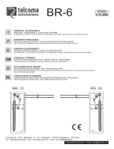
Fusibile 3A
Fuse 3A
Fusibile 20A
Fuse 20A
Fusibile 4A
Fuse 4A
Display a 4 cifre e 6 tasti di
programmazione
4 digit display and 6
programming buttons
Ingresso alimentazione
(secondario trasformatore)
Power supply unit
(transformer's secondary)
Morsettiere di
collegamento
periferiche
Device power
supply terminal
block
Microprocessore
CPU
Connettore scheda carica
batterie
Plug for battery charger
Collegamento batterie
Batteries connection
Collegamento
seriale RS485
RS485 serial
connection
Inverter a mosfet con
controllo sinusoidale
Mosfet inverter with
sinusoidal control
Collegamento
MOTORE
(cavo 3 fili)
MOTOR connection
(3 wiring cable)
Morsettiere dei
comandi
Commands terminal
blocks
Morsettiere delle
sicurezze
Safeties terminal
blocks
Connettori di collegamento
encoder, contatto di sblocco
e kit luci.
Plug for encoder, unlock
microswitch and lights kit
connection
Connettore ad innesto
per radio ricevente
Plug-in connector for
radio receiver
FW
r3.50

6
TRASFORMATORE
PRIMARIO
MONOFASE
SECONDARIO
CEI 61558-2-6
0 19 0 26
F1
F2
F3
PROG TEST
+
-
BATTERY (+)
RECEIVER CARD
BATTERY CHARGER
SEC2
ENC2
ENC1
LOCKS
LED LIGHT
SEC1
BATTERY (-)
123456
Y
X
M
Z
78
COM
COM
+24V
+ES
+LAM
COM
COM
LNA
LNB
+SC
10 11 12 13 14 15 16 17 18 19 20
+LUCI
ST
COM
COS
FT
COM
ANT
21 22 23 24 25
COM
PED
PP
CH
AP
28 29 30 31 32
ORO
33
COM
3426 27
9
F4
H93/RX22A/I
RICEVITORE RADIO
RADIO RECEIVER
F4
FUSIBILE
FUSE
T1A
F1
FUSIBILE
FUSE 10
A
F2
FUSIBILE
FUSE 4A
F3
FUSIBILE
FUSE 3A
N
L
230 Vac
OR
115 Vac
(CTRL/115)
1
N
L
AGILIK • KB

7
N
L
PROG TEST
N L
F4
F1
F3
+
-
F2
BATTERY
BATTERY
CHARGER
MOTOR
BI/BLED
XYZ
SEC1
230 Vac
OR
115 Vac
(CTRL/115)
F1
FUSIBILE
FUSE
10A
F2
FUSIBILE
FUSE
4A
F3
FUSIBILE
FUSE
3A
SEC2
F4
FUSIBILE
FUSE
T1A
H93/RX22A/I
RICEVITORE RADIO
RADIO RECEIVER
rosso/red
ne
ro/black
blu/blue
nero/black
+
2
0
19
0
26
Blu/Blue
Nero/Black
BIONIK

8
F2
PROG TEST
+
-
RECEIVER CARD
G
ER
ENC2
ENC1
LOCKS
LED LIGHT
COM
COM
+24V
+ES
+LAM
COM
COM
LNA
LNB
+SC
10 11 12 13 14 15 16 17 18 19 20
+LUCI
ST
COM
COS
FT
COM
ANT
21 22 23 24 25
COM
PED
PP
CH
AP
28 29 30 31 32
ORO
33
COM
3426 27
Bordo sensibile / Safety edge
STOP
Antenna
RG58 max 10 m
rosso/red
brown/red
marrone/rosso
blue/black
nero/black
blue/black
Apertura parziale / Partial opening
Passo passo / Step by step
Chiusura / Closing
Apertura / Opening
Orologio / Timer
Lampeggiante / Flashing light
24Vdc 5W
Luci asta / Boom arm lights
24Vdc 12W
Spia stato barriera / Position barrier light
24Vdc 3W
Elettroblocco / Electric lock
12Vdc 10W
Collegamento seriale RS485
RS485 serial connection
-
+
-
-
+
+
+
3

9
F2
RECEIVER CARD
ENC2
ENC1
LOCKS
LED LIGHT
COM
COM
+24V
+ES
+LAM
COM
COM
LNA
LNB
+SC
10 11 12 15 16 17 18 19 20
+LUCI
ST
COM
COS
FT
COM
ANT
21 22 23
24
25
COM
PED
PP
CH
AP
28 29 30 31 32
ORO
33
COM
3426 27
13 14
RXTX
1 2 3
1 2 345
MASTER
-COM
SYNC
+24
-COM
+24
FT(N.C)
4
F2
PROG TEST
+
-
RECEIVER CARD
ENC2
ENC1
LOCKS
LED LIGHT
COM
+24V
+ES
+LAM
COM
COM
LNA
LNB
12
13 14
15 16 17 18 19 20
+LUCI
ST
COM
COS
FT
COM
ANT
21 22 23
24
25
COM
PED
PP
CH
AP
28 29 30 31 32
ORO
33
COM
3426 27
RXTX
1 2 3
1 2
RXTX
FT1 FT2
MASTER SLAVE1
345
12 3
12345
-COM
+24
-COM
SYNC
SYNC
SYNC
SYNC
+24
FT(N.C)
-COM
+24
-COM
+24
FT(N.C)
COLLEGAMENTO CON 1 COPPIA FOTOCELLULE SINCRONIZZABILI
CONNECTION WITH 1 PAIR OF SYNCHRONOUS PHOCELLS
COLLEGAMENTO CON 2 COPPIE FOTOCELLULE SINCRONIZZABILI
CONNECTION WITH 2 PAIRS OF SYNCHRONOUS PHOCELLS
USO RACCOMANDATO per
fotocellule Serie F4ES - F4S
RECOMMENDED USE for
Series F4ES - F4S photocells
*
*
*
*
Per le impostazioni delle fotocellule, consultare il relativo manuale di installazione.
For photocell settings, refer to the relevant installation manual.

10
RECEIVER CARD
ENC2
ENC1
LOCKS
LED LIGHT
COM
COM
+24V
+ES
+LAM
COM
COM
LNA
LNB
+SC
10 11 12 13 14 15 16 17 18 19 20
+LUCI
ST
COM
COS
FT
COM
ANT
21 22 23
24
25
COM
PED
PP
CH
AP
28 29 30 31 32
ORO
33
COM
3426 27
RX
TX
1 2 3
1 2 345
MASTER
-COM
+24
-COM
SYNC
SYNC
+SC
FT(N.C)
COLLEGAMENTO CON 1 COPPIA FOTOCELLULE SINCRONIZZABILI
CONNECTION WITH 1 PAIR OF SYNCHRONOUS PHOCELLS
COLLEGAMENTO CON 2 COPPIE FOTOCELLULE SINCRONIZZABILI
CONNECTION WITH 2 PAIRS OF SYNCHRONOUS PHOCELLS
F2
PROG TEST
+
-
RECEIVER CARD
R
ENC2
ENC1
LOCKS
LED LIGHT
COM
COM
+24V
+ES
+LAM
COM
COM
LNA
LNB
+SC
10
11
12
13 14
15 16 17 18 19 20
+LUCI
ST
COM
COS
FT
COM
ANT
21 22 23
24
25
COM
PED
PP
CH
AP
28 29 30 31 32
ORO
33
COM
3426 27
RXTX
1 2 3
1 2
RXTX
FT1 FT2
MASTER SLAVE1
345
12 3
12345
-COM
+24
-COM
SYNC
SYNC
+SC
FT(N.C)
-COM
+24
-COM
+SC
FT(N.C)
SYNC
SYNC
USO RACCOMANDATO per
fotocellule Serie F4ES - F4S
RECOMMENDED USE for
Series F4ES - F4S photocells
*
Per le impostazioni delle fotocellule, consultare il relativo manuale di installazione.
For photocell settings, refer to the relevant installation manual.
* *
*
5
TEST FOTOCELLULE · PHOTOCELLS TEST ($ )

11
6
RECEIVER CARD
ENC2
ENC1
LOCKS
LED LIGHT
COM
COM
+24V
+ES
+LAM
COM
COM
LNA
LNB
+SC
10
11
12
13
14 15 16 17 18 19 20
+LUCI
ST
COM
COS
FT
COM
ANT
21 22 23
24
25
COM
PED
PP
CH
AP
28 29 30 31 32
ORO
33
COM
3426 27
RX
TX
1 2 3
1 2 345
MASTER
-COM
SYNC
SYNC
+SC
-COM
+SC
FT(N.C)
COLLEGAMENTO CON 1 COPPIA FOTOCELLULE SINCRONIZZABILI
CONNECTION WITH 1 PAIR OF SYNCHRONOUS PHOCELLS
COLLEGAMENTO CON 2 COPPIE FOTOCELLULE SINCRONIZZABILI
CONNECTION WITH 2 PAIRS OF SYNCHRONOUS PHOCELLS
F2
PROG TEST
+
-
RECEIVER CARD
ENC2
ENC1
LOCKS
LED LIGHT
COM
COM
+24V
+ES
+LAM
COM
COM
LNA
LNB
+SC
10
11
12
13
14 15 16 17 18 19 20
+LUCI
ST
COM
COS
FT
COM
ANT
21 22 23
24
25
COM
PED
PP
CH
AP
28 29 30 31 32
ORO
33
COM
3426 27
RXTX
1 2 3
1 2
RXTX
FT1 FT2
MASTER SLAVE1
345
12 3
12345
-COM
+SC
-COM
SYNC
SYNC
+SC
FT(N.C)
-COM
+SC
-COM
+SC
FT(N.C)
SYNC
SYNC
USO RACCOMANDATO per
fotocellule Serie F4ES - F4S
RECOMMENDED USE for
Series F4ES - F4S photocells
*
Per le impostazioni delle fotocellule, consultare il relativo manuale di installazione.
For photocell settings, refer to the relevant installation manual.
* *
*
BATTERY SAVING ($ )
BATTERY SAVING + TEST FOTOCELLULE · PHOTOCELLS TEST ($ )

12
7
G90/F4ES
T90/F4S
*
*
L'immagine della barriera ha scopo puramente indicativo.
The image of the barrier is for reference only.
TX
TX
RX
RX
T90/F4S
T90/F4S
TRIX100
G90/F4ES
G90/F4ES
G90/F4ES

13
8
F1
RECEIVER CARD
ENC2
ENC1
LOCKS
LED LIGHT
COM
COM
+24V
+ES
+LAM
COM
COM
LNA
LNB
+SC
10 11 12 13 14 15 16 17
18 19 20
+LUCI
ST
COM
COS
FT
COM
ANT
21 22 23 24 25
COM
PED
PP
CH
AP
28 29 30 31 32
ORO
33
COM
3426 27
COM
PED
PP
CH
AP
28 29 30 31 32
ORO
33
COM
34
verde
green
CO
COM
+24V
+LAM
COM
+SC
10 11 12 13 14 15 16 17
+LUCI
marrone
brown
bianco
white
verde
green
ENC2
LED LI
G
COM
COM
+24V
+ES
+LAM
COM
COM
LNA
LNB
+SC
10 11 12 13 14 15 16 17
18 19 20
+LUCI
ACCESA
ON
SPENTA
OFF
ALLARME
ALARM
OK
...
...
ENC2
ENC1
LOCKS
LED LIGHT
COM
COM
+24V
+ES
+LAM
COM
COM
LNA
LNB
+SC
10 11 12 13 14 15 16 17
18 19 20
+LUCI
21
CHIUSO
CLOSED
APERTO
OPENED
Relay 24V
9

14
ENC1
LOCKS
LIGHT
ST
COM
21 22
Microinterruttore
sblocco
Unlock
microswitch
AGILIK • KB • BIONIK4HP • BIONIK6 • BIONIK8
10
Microinterruttore
sblocco
Unlock
microswitch
LOCKS
11
BIONIK4

15
ENC2
ENC1
LOCKS
LED LIGHT
ST
21
ENC2
ENC1
6 FILI
6 WIRES
7 FILI
7 WIRES
ENC2
ENC1
AGILIK • KB • BIONIK4HP • BIONIK6 • BIONIK8
12

16
13
ENC2
ENC1
LOCKS
LED LIGHT
ST
COM
21 22
ENC2
ENC2
6 FILI
6 WIRES
ENC1
7 FILI
7 WIRES
ENC1
BIONIK4

17
14
AG/BLED B73/EXP
Bi-adesivo
Double-sided
adhesive
B73/EXP
ENC2
ENC1
LOCKS
LED LIGHT
ST
COM
21 22
TO TC
100 mm
AG/BLED
B73/EXP
AGILIK • KB

18
15
B73/EXP
ENC2
ENC1
LOCKS
LED LIGHT
ST
COM
21 22
TO TC
100 mm
B73/EXP
Bi-adesivo
Double-sided
adhesive
B73/EXP
BIONIK4 • BIONIK4HP • BIONIK6 • BIONIK8
BI/BLED
BI/BLED6
BI/BLED8
LED LIGHT
BI/BLED

19
AGILIK • KB
MESSA A TERRA
GROUNDING SCHEME
16

20
17
MESSA A TERRA
GROUNDING SCHEME
BIONIK4 • BIONIK4HP • BIONIK6 • BIONIK8

21
18
1 19 0
TRASFORMATORE
PRIMARIO
MONOFASE
SECONDARIO
CEI 61558-2-6
0 19 0 26
F1
F2
F3
PROG TEST
+
-
BATTERY (+)
RECEIVER CARD
BATTERY CHARGER
SEC2
ENC2
ENC1
LOCKS
LED LIGHT
SEC1
BATTERY (-)
123456
Y
X
M
Z
78
COM
COM
+24V
+ES
+LAM
COM
COM
LNA
LNB
+SC
10 11 12 13 14 15 16 17 18 19 20
+LUCI
ST
COM
COS
FT
COM
ANT
21 22 23 24 25
COM
PED
PP
CH
AP
28 29 30 31 32
ORO
33
COM
3426 27
9
F4
RED
BLACK
2 x 12V 4,5Ah
F3
FUSE
T10A
5x20
A
BLACK
RED
BATTERY (+)
BATTERY C
SEC2
BATTERY (-)
12345
BATTERY
CHARGER
CTRL
BI/BA
T/KIT
AG/BAT/KIT
AGM Battery ONLY
8 07 0
AGILIK • KB

22
19
Rosso
Red
Nero
Black
Blu
Blue
BI/BCHP
BI/BAT/KIT
BLACK
RED
BATTERY (+)
BATTERY C
SEC2
BATTERY (-)
12345
1
2
3
2 x 12V 4500 mAh
AGM Battery ONLY
BIONIK4 • BIONIK4HP • BIONIK6 • BIONIK8

23
20
RECEIVER CARD
ENC2
ENC1
LOCKS
LED LIGHT
COM
COM
+24V
+ES
+LAM
COM
COM
LNA
LNB
+SC
10 11 12 13 14 15 16 17 18 19 20
+LUCI
ST
COM
COS
FT
COM
ANT
21 22 23 24 25
COM
PED
PP
CH
AP
28 29 30 31 32
ORO
33
COM
3426 27
Costa di sicurezza MASTER / MASTER Safety edge
STOP (MASTER+SLAVE)
Antenna
RG58 max 10 m
Apertura parziale / Partial opening
Passo passo / Step by step
Chiusura / Closing
Apertura / Opening
Orologio / Timer
RX
TX
1 2 3
1 2 345
+- + -
RECEIVER CARD
ENC2
ENC1
LOCKS
LED LIGHT
COM
COM
+24V
+ES
+LAM
COM
COM
LNA
LNB
+SC
10 11 12 13 14 15 16 17 18 19 20
+LUCI
ST
COM
COS
FT
COM
ANT
21 22 23 24 25
COM
PED
PP
CH
AP
28 29 30 31 32
ORO
33
COM
3426 27
Costa di sicurezza SLAVE / SLAVE Safety ed
g
STOP (SLAVE)
MASTER
SLAVE

24
21
7100
7101
IMPOSTAZIONE DI FABBRICA
FACTORY SETTING
(VANO PASSAGGIO A DESTRA)
(GATEWAY ON THE RIGHT)
(VANO PASSAGGIO A SINISTRA)
(GATEWAY ON THE LEFT)
INSTALLAZIONE CORPO BARRIERA A SINISTRA
CABINET BARRIER INSTALLED ON THE LEFT
INSTALLAZIONE CORPO BARRIERA A DESTRA
CABINET BARRIER INSTALLED ON THE LEFT
*
* *
L'immagine della barriera ha scopo puramente indicativo.
The image of the barrier is for reference only.
SELEZIONE POSIZIONE DI INSTALLAZIONE BARRIERA - PAR.
SELECTION OF THE BARRIER INSTALLATION POSITION - PAR.

25
IT
1 Avvertenze generali
ATTENZIONE
IMPORTANTI ISTRUZIONI DI SICUREZZA
È IMPORTANTE PER LA SICUREZZA DELLE PERSONE
OSSERVARE QUESTE ISTRUZIONI
CONSERVARE QUESTE ISTRUZIONI
Il presente manuale di installazione è rivolto esclusivamente a personale qualificato.
La mancata osservanza delle informazioni contenute nel presente manuale
può dare luogo a infortuni personali o danni all’apparecchio.
ROGER TECHNOLOGY declina qualsiasi responsabilità derivante da un uso
improprio o diverso da quello per cui è destinato ed indicato nel presente manuale.
L’installazione, i collegamenti elettrici e le regolazioni devono essere effettuati da
personale qualificato nell’osservanza della Buona Tecnica e in ottemperanza alle
norme vigenti.
Leggere attentamente le istruzioni prima di iniziare l’installazione del prodotto.
Una errata installazione può essere fonte di pericolo.
Prima di iniziare l’installazione verificare l’integrità del prodotto: in caso di dubbi
non utilizzare il prodotto e rivolgersi esclusivamente a personale professionalmente
qualificato.
Non installare il prodotto in ambiente e atmosfera esplosivi: presenza di gas o fumi
infiammabili costituiscono un grave pericolo per la sicurezza.
Prima di installare la motorizzazione, apportare tutte le modifiche strutturali relative
alla realizzazione dei franchi di sicurezza ed alla protezione o segregazione di tutte
le zone di schiacciamento, cesoiamento, convogliamento e di pericolo in genere.
ATTENZIONE: verificare che la struttura esistente abbia i necessari requisiti di
robustezza e stabilità.
ROGER TECHNOLOGY non è responsabile dell’inosservanza della Buona Tecnica
nella costruzione degli infissi da motorizzare, nonché delle deformazioni che
dovessero intervenire nell’utilizzo.
I dispositivi di sicurezza (fotocellule, coste sensibili, stop di emergenza, ecc.) devono
essere installati tenendo in considerazione: le normative e le direttive in vigore, i
criteri della Buona Tecnica, l’ambiente di installazione, la logica di funzionamento
del sistema e le forze sviluppate dalla porta o cancello motorizzati.
I dispositivi di sicurezza devono proteggere eventuali zone di schiacciamento,
cesoiamento, convogliamento e di pericolo in genere, della porta o cancello
motorizzati; si consiglia all’installatore di verificare che le ante movimentate non
presentino bordi spigolosi o tali da poter causare il rischio di cesoiamento e/o
convogliamento.
Se richiesto in base all'analisi dei rischi, installare bordi sensibili deformabili sulla
parte mobile.
Si fa presente che, come specificato nella norma UNI EN 12635, tutti i requisiti delle

26
IT
norme EN 12604 e EN 12453 devono essere soddisfatti e, se necessario, anche
verificati.
Le norme Europee EN 12453 e EN 12445 stabiliscono i requisiti minimi relativi
alla sicurezza d’uso di porte e cancelli automatici. In particolare prevedono l’utilizzo
della limitazione delle forze e di dispositivi di sicurezza (pedane sensibili, barriere
immateriali, funzionamento a uomo presente, etc) atti a rilevare la presenza di
persone o cose che ne impediscano l’urto in qualsiasi circostanza.
L’installatore è tenuto ad eseguire la misurazione delle forze di impatto ed a
selezionare sulla centrale di comando i valori della velocità e della coppia che
permettano alla porta o cancello motorizzati di rientrare nei limiti stabiliti dalle
norme EN 12453 e EN 12445.
ROGER TECHNOLOGY declina ogni responsabilità qualora vengano installati
componenti incompatibili ai fini della sicurezza e del buon funzionamento.
In caso sia attiva la funzione uomo presente dovrà essere cura dell’installatore
verificare la distanza d’arresto massima o l’alternativo uso di un bordo deformabile
in gomma, la velocità di chiusura del varco ed in generale tutti gli accorgimenti
definiti dalle norme applicabili. Inoltre si informa che se il mezzo di comando è fisso,
deve essere posto in una posizione che garantisca il controllo e il funzionamento
dell’automazione e che il tipo di comando ed il tipo di utilizzo soddisfino la norma
UNI EN 12453 prospetto 1 (con le seguenti restrizioni: comando di tipo A o B e tipo
di utilizzo 1 o 2).
Nel caso di utilizzo della funzione a uomo presente, allontanare dall'automazione
le persone che dovessero trovarsi nel raggio di azione delle parti in movimento; i
comandi diretti devono essere installati ad una altezza minima di 1,5 m e non devono
essere accessibili al pubblico, inoltre, a meno che il dispositivo non sia operativo
con chiave, devono essere posizionati in vista diretta della parte motorizzata e
lontano da parti in movimento.
Applicare le segnalazioni previste dalle norme vigenti per individuare le zone
pericolose.
Ogni installazione deve avere visibile l’indicazione dei dati identificativi della porta
o cancello motorizzati in accordo con la norma EN 13241-1:2001 o successive
revisioni
Prevedere sulla rete di alimentazione un interruttore o un sezionatore
onnipolare con distanza di apertura dei contatti uguale o superiore a 3 mm ;
posizionare il sezionatore in posizione OFF, e scollegare le eventuali batterie
tampone, prima di eseguire qualsiasi operazione di pulizia o manutenzione.
Verificare che a monte dell’impianto elettrico vi sia un interruttore differenziale con
soglia di 0,03 A ed una protezione di sovracorrente adeguati nell’osservanza della
Buona Tecnica ed in ottemperanza alle norme vigenti.
Quando richiesto, collegare l’automazione ad un efficace impianto di messa a terra
eseguito come indicato dalle vigenti norme di sicurezza.
La manipolazione delle parti elettroniche deve essere effettuata munendosi di
bracciali conduttivi antistatici collegati a terra.
Per l’eventuale riparazione o sostituzione dei prodotti dovranno essere utilizzati
esclusivamente ricambi originali.

27
IT
L’installatore deve fornire tutte le informazioni relative al funzionamento automatico,
manuale e di emergenza della porta o cancello motorizzati, e consegnare
all’utilizzatore dell’impianto le istruzioni d’uso.
Evitare di operare in prossimità delle cerniere o organi meccanici in movimento.
Non entrare nel raggio di azione della porta o cancello motorizzati mentre sono in
movimento.
Non opporsi al moto della porta o cancello motorizzati poiché possono causare
situazioni di pericolo.
La porta o cancello motorizzati possono essere utilizzati da bambini di età non
inferiore a 8 anni e da persone con ridotte capacità fisiche, sensoriali o mentali,
o prive di esperienza o della necessaria conoscenza, purché sotto sorveglianza
oppure dopo che le stesse abbiano ricevuto istruzioni relative all’uso sicuro
dell’apparecchio e alla comprensione dei pericoli ad esso inerenti.
I bambini devono essere sorvegliati per evitare che giochino o sostino nel raggio di
azione della porta o cancello motorizzati.
Tenere fuori dalla portata dei bambini i radiocomandi e/o qualsiasi altro dispositivo
di comando, per evitare che la porta o cancello motorizzati possano essere azionati
involontariamente.
Il mancato rispetto di quanto sopra può creare situazioni di pericolo.
Qualsiasi riparazione o intervento tecnico deve essere eseguito da personale
qualificato.
La pulizia e la manutenzione devono essere effettuate solamente da personale
qualificato.
In caso di guasto o di cattivo funzionamento del prodotto, disinserire l’interruttore
di alimentazione, astenendosi da qualsiasi tentativo di riparazione o di intervento
diretto e rivolgersi solo a personale qualificato.
I materiali dell’imballaggio (plastica, polistirolo, ecc.) non vanno dispersi nell’ambiente
e non devono essere lasciati alla portata dei bambini in quanto potenziali fonti di
pericolo.
Smaltire e riciclare gli elementi dell’imballo secondo le disposizioni delle norme
vigenti.
È necessario conservare queste istruzioni e trasmetterle ad eventuali subentranti
nell’uso dell’impianto.
Dichiarazione CE di Conformità
Il sottoscritto Dino Florian, legale rappresentante di Roger Technology - Via Botticelli 8, 31021 Mogliano V.to (TV) DICHIARA
che la centrale di comando CTRL è conforme ai requisiti essenziali e alle altre disposizioni pertinenti, stabilite dalle seguenti
direttive CE:
– 2014/35/EU Direttiva LVD
– 2014/30/EU Direttiva EMC
– 2011/65/CE Direttiva RoHS
Luogo: Mogliano V.to
Data: 14/01/2014 Firma

28
IT
2 Simbologia
Qui di seguito indichiamo i simboli e il loro significato presenti sul manuale o sulle
etichette prodotto.
Pericolo generico.
Importante informazione di sicurezza. Segnala operazioni o situazioni
in cui il personale addetto deve prestare molta attenzione.
Pericolo tensione pericolosa.
Segnala operazioni o situazioni in cui il personale addetto deve
prestare molta attenzione a tensioni pericolose.
Pericolo superfici calde.
Segnala il pericolo per la presenza di zone riscaldate o comunque che
presentano parti con alte temperature (pericolo di ustioni)
Informazioni utili
Segnala informazione utili all'installazione.
Consultazione Istruzioni di installazione e d'uso.
Segnala l'obbligo di consultazione del manuale o documento in
originale, che deve essere reperibile per futuri utilizzi e non deve in
alcun modo essere deteriorato.
Punto di collegamento della messa a terra di protezione.
Indica il range di temperature ammesso.
Corrente alternata (AC)
Corrente continua (DC)
Simbolo per lo smaltimento del prodotto secondo la direttiva RAEE,
vedere capitolo 22.
3 Descrizione prodotto
La centrale CTRL controlla in modalità sensored, il motore ROGER brushless per barriere elettromeccaniche.
La centrale CTRL si avvale di due encoder magnetici, uno controlla il motore l'altro controlla la posizione dell'asta, anche
quando viene movimentata a mano.
Attenzione all’impostazione del parametro A1. Una errata impostazione può causare
anomalie nel funzionamento dell’automazione.
ROGER TECHNOLOGY declina qualsiasi responsabilità derivante da un uso improprio o diverso da
quello per cui è destinato ed indicato nel presente manuale.
E' possibile collegare due barriere contrapposte mediante cavo di comunicazione seriale RS485 solo per versione firmware
1.3 (Q) o successive.
Si consiglia l’uso di accessori, dispositivi di comando e di sicurezza ROGER TECHNOLOGY. In particolare, si raccomanda di
installare fotocellule serie F4ES e F4S.
Per ulteriori informazioni consultare il manuale della barriera BIONIK4, BIONIK4HP,
BIONIK6, BIONIK8.

29
IT
4 Aggiornamenti versione r3.50
1. Cambiato nome prodotto (AG/CTRL -> CTRL).
2. Aggiunta gestione barriera BIONIK8 (parametro $).
3. Aggiunta gestione sistema antisfondamento (BreakAway) ACS/BA/SA (parametro )
4. Migliorata gestione batteria ai sensi delle normative vigenti (Parametri --).
5. Aggiunta gestione di segnalazione anomalia sistema antisfondamento e/o batteria (parametro ).
6. Aggiunta abilitazione gestione apertura con esclusione della richiusura automatica (parametro );
7. Aggiunta segnalazione sistema antisfondamento in allarme - EU($.
8. Aggiunta gestione del comando AP: l'attivazione persistente del comando di apertura inibisce la richiusura automatica.
5 Caratteristiche tecniche prodotto
AG/004
AG/006
KB/004
KB/006
BI/004HP
BI/006
BI/008
BI/004
AG/004/115
AG/006/115
KB/004/115
KB/006/115
BI/004HP/115
BI/006/115
BI/008/115
BI/004/115
TENSIONE DI ALIMENTAZIONE 230 V
±10% 50Hz 115 V ±10% 60Hz
POTENZA MASSIMA
ASSORBITA DA RETE
240 W
FUSIBILI
F1 = 10A (ATO257) protezione circuito di potenza
F2 = 4A (ATO257) protezione elettroserratura
F3 = 3A (ATO257) protezione alimentazione accessori
F4 = T1A (5x20 mm)
protezione primario trasformatore
F4 = T2A (5x20 mm)
protezione primario trasformatore
NUMERO MOTORI COLLEGABILI 1
ALIMENTAZIONE MOTORE 36 V
TIPOLOGIA MOTORE brushless sinusoidale (ROGER BRUSHLESS)
TIPOLOGIA CONTROLLO MOTORE “sensored” ad orientamento di campo (FOC)
POTENZA MASSIMA MOTORE 220 W
POTENZA MASSIMA LAMPEGGIANTE
ESTERNO
5 W 24 V
POTENZA MASSIMA LUCI ASTA 12 W 24 V
POTENZA MASSIMA
ELETTROSERRATURA
10W 12V (attivazione impulsiva, 1.5 secondi)
5W 12V (elettroblocco normalmente alimentato)
POTENZA MASSIMA SPIA DI
SEGNALAZIONE
3 W 24 V
POTENZA USCITA ACCESSORI 10 W 24 V
TEMPERATURA DI FUNZIONAMENTO
-20°C +55°C
PRESSIONE SONORA DURANTE L'USO <70 dB (A)
DIMENSIONI PRODOTTO Dimensioni in mm. 166x150x48 Peso: 0,254Kg
B73/EXP
CONTATTO RELE' N.C. 2x 30 V
1A (contatto puro, carico resistivo)

30
IT
6 Descrizione dei collegamenti
Per accedere alla centrale di comando, rimuovere la testata della barriera.
Effettuare i collegamenti come indicato in fig. 1-2-3.
6.1 Installazione tipo
2
2
3
3
4
1
5
Cavo consigliato
1 Alimentazione di rete.
Cavo a doppio isolamento tipo H07RN-F 3x1,5 mm
2
2 Fotocellula - Ricevitore F4ES/F4S Cavo 4x0,5 mm
2
(massimo 20 m)
3 Fotocellula - Trasmettitore F4ES/F4S Cavo 2x0,5 mm
2
(massimo 20 m)
4
Selettore a chiave R85/60 Cavo 3x0,5 mm
2
(massimo 20 m)
Tastierino H85/TTD - H85/TDS (collegamento da centrale a DECODER
H85/DEC - H85/DEC2)
Cavo 3x0,5 mm
2
(massimo 20 m)
5
Spia barriera aperta
Alimentazione 24V DC 3W max
Cavo 2x0,5 mm
2
(massimo 20 m)
SUGGERIMENTI: nel caso di installazioni esistenti suggeriamo di controllare la sezione e le condizioni (buono stato) dei cavi.

31
IT
6.2 Collegamenti elettrici
Prevedere sulla rete di alimentazione un interruttore o un sezionatore onnipolare con distanza di
apertura dei contatti uguale o superiore a 3 mm; posizionare il sezionatore in posizione OFF, e
scollegare le eventuali batterie tampone, prima di eseguire l’installazione e le periodiche operazioni
di manutenzione.
Verificare che a monte dell’impianto elettrico vi sia un interruttore differenziale con soglia di 0,03 A
ed una protezione di sovracorrente adeguati nell’osservanza della Buona Tecnica ed in ottemperanza
alle norme vigenti.
Per l’alimentazione, utilizzare un cavo elettrico tipo H07RN-F 3G1,5 e collegarlo ai morsetti L
(marrone), N (blu),
(giallo/verde), presenti all’interno del contenitore della centrale di comando.
Sguainare il cavo di alimentazione solamente in corrispondenza del morsetto (vedi fig. 1-2) e
bloccarlo mediante l’apposito fermacavi.
Verificare con un tester la tensione in Volt sul collegamento dell'alimentazione primaria.
A
V
V
A
+-COM
220÷230
N L
FUSE
TRANSFORMER
Per il perfetto funzionamento delle automazioni Brushless la tensione di
alimentazione di rete primaria deve essere di:
- 230Vac ±10% per centrale CTRL.
- 115Vac ±10% per centrale CTRL/115.
Se la tensione rilevata non soddisfa i dati sopra indicati o non è stabile,
l'automazione potrebbe lavorare in modo NON efficiente.
I collegamenti alla rete di distribuzione elettrica e ad eventuali altri conduttori a bassa tensione,
nel tratto esterno al quadro elettrico, devono avvenire su percorso indipendente e separata dai
collegamenti ai dispositivi di comando e sicurezza (SELV = Safety Extra Low Voltage).
Accertarsi che i conduttori dell’alimentazione di rete e i conduttori degli accessori (24 V) siano
separati.
I cavi devono essere in doppio isolamento, sguainarli in prossimità dei relativi morsetti di collegamento
e bloccarli mediante fascette non di nostra fornitura.
DESCRIZIONE
FUSE
N L
Collegamento all'alimentazione di rete:
- 230Vac ±10% per centrale CTRL.
- 115Vac ±10% per centrale CTRL/115.
Fusibile 5x20 T1A.
Fusibile 5x20 T2A (alimentazione di rete 115 Vac).
SEC2
SEC1
3456
Ingresso secondario 26 Vac del trasformatore per alimentazione motore (SEC1) e per
alimentazione logica e periferiche 19 Vac (SEC2).
NOTA: Il cablaggio è realizzato di fabbrica da ROGER TECHNOLOGY.
X-Y-Z
Y
X
M
Z
789
Collegamento al motore ROGER brushless.
NOTA: Il cablaggio è realizzato di fabbrica da ROGER TECHNOLOGY.
Attenzione! Se i fili del motore si scollegano dalla morsettiera, dopo averli ricollegati
effettuare un apprendimento della corsa, vedi capitolo 11.
BATTERY (+)
BA
TTERY (-)
12
Collegamento al kit batterie BI/BAT/KIT (vedi fig. 18-19)
Per ulteriori informazioni fare riferimento alle istruzioni B71/BCHP oppure
BI/BCHP.

32
IT
7 Comandi e accessori
Le sicurezze con contatto N.C. se non installate devono essere ponticellate ai morsetti COM,
oppure disabilitate modificando i parametri , , .
In installazioni di due barriere contrapposte i collegamenti ai comandi e agli accessori devono essere
effettuati sulla centrale di comando MASTER. Sulla centrale SLAVE collegare il bordo sensibile e
l'eventuale comando di STOP.
LEGENDA:
N.A. (Normalmente Aperto).
N.C. (Normalmente Chiuso).
CONTATTO DESCRIZIONE
11(+SC) 10(COM)
Spia barriera aperta/chiusa 24 Vdc 3 W.
Il funzionamento della spia è regolato dal parametro $.
11(+SC) 13(COM)
Collegamento test fotocellule e/o battery saving (fig. 5-6).
E’ possibile collegare l’alimentazione dei trasmettitori (TX) delle fotocellule al morsetto 11(SC).
Impostare il parametro $ per abilitare la funzione di test.
La centralina ad ogni comando ricevuto spegne e accende le fotocellule, per verificare il corretto cambio
di stato del contatto.
E’ possibile collegare inoltre, l’alimentazione di tutti i dispositivi esterni (escluso ricevitore radio esterno)
per ridurre il consumo delle batterie (se presenti). Impostare $ o $ . Queste funzioni non sono
disponibili nella barriera SLAVE nel caso di installazioni con due barriere contrapposte.
ATTENZIONE! Se si utilizza il contatto 11(SC) per il test fotocellule o il funzionamento battery saving,
NON è più possibile collegare una spia barriera aperta.
11(+SC) 13(COM)
Collegamento lampada spia per segnalazione anomalia del sensore del sistema per asta sganciabile
ACS/BA/60 o segnalazione anomalia nell'alimentazione da batteria (batteria in esaurimento. (Fig. 9)
Il livello di tensione della batteria è impostabile al parametro .
Collegando un RELAY all'uscita SC è possibile avere un contatto puro di segnalazione a un sistema di
controllo esterno (fig. 9).
NOTA: in installazioni MASTER - SLAVE collegare il sistema di controllo esterno all'uscita SC della cen-
trale di comando MASTER.
12(+LUCI) 13(COM)
Ingresso per collegamento luci di segnalazione sull'asta serie ALED (opzionale). 24 Vdc 12W max (fig. 3).
14(+24V) 13(COM)
Alimentazione per dispositivi esterni max 10W. Vedi caratteristiche tecniche.
15(+ES) 17(COM)
Ingresso per collegamento elettroblocco. Vedi caratteristiche tecniche.
16(+LAM) 17(COM)
Collegamento lampeggiante (24 Vdc - 5 W max).
E’ possibile selezionare le impostazioni di prelampeggio dal parametro $ e le modalità di intermittenza
dal parametro.
18(COM)-19(LNA)-20(LNB)
COM
LNA
LNB
18 19 20
Collegamento cavo (3x0,5 mm
2
- lunghezza massima 30 m) di comunicazione seriale RS485 per in-
stallazione di due barriere contrapposte MASTER e SLAVE (dalla versione firmware Q o successive).
Collegamenti.
• Collegare i morsetti COM-LNA-LNB della barriera MASTER ai relativi morsetti della barriera SLAVE.
• La barriera MASTER è la barriera che apre (completamente) al comando di apertura parziale (PED).
• Impostare il parametro $ per la barriera MASTER e $ per la barriera SLAVE.
• Dopo aver modificato le impostazioni del parametro $ togliere e dare nuovamente alimentazione.
• Tutti i comandi, le fotocellule e il comando di STOP generale devono essere collegati alla barriera
MASTER. I bordi sensibili e i dispositivi BreakAway ACS/BA/60 devono essere collegati alle rispettive
barriere.
• E' possibile collegare un eventuale comando di STOP ausiliario sulla barriera SLAVE. Se non utilizzato
ponticellare i morsetti 21(ST)-22(COM) sulla centrale di comando SLAVE.
• Tutti i parametri, tranne $ , e , devono essere impostati sulla centrale MASTER.
• L'apprendimento della corsa deve essere effettuato su entrambe le barriere, dopo aver impostato i
parametri come desiderato e come da tipologia di installazione.
• Le segnalazioni di allarme sono visibili nei display delle rispettive centrali.

33
IT
CONTATTO DESCRIZIONE
18(COM)-19(LNA)-20(LNB)
COM
LNA
LNB
18 19 20
Funzionamento.
La comunicazione seriale permette la sincronizzazione tra le barriere.
L'intervento di un ostacolo provoca l'inversione immediata del movimento dell'asta che l'ha rilevato,
l'altra asta invertirà il movimento con un ritardo fisso.
Se la barriera MASTER è completamente aperta o completamente chiusa e la barriera SLAVE si trova in
posizione intermedia, la barriera MASTER invia un comando di riallineamento alla barriera SLAVE con un
prelampeggio fisso di 5 s.
Se viceversa è la barriera MASTER a trovarsi in posizione intermedia, dopo 5 s di prelampeggio si riallinea
con la barriera SLAVE.
L'allineamento non è possibile se è abilitata la funzione a uomo presente $.
21(ST) 22(COM)
Ingresso comando di STOP (N.C.). L’apertura del contatto di sicurezza provoca l’arresto del movimento.
NOTA: il contatto è ponticellato di fabbrica da ROGER TECHNOLOGY.
In installazioni con due barriere contrapposte, se il comando di STOP è dato sulla barriera MASTER
entrambe le barriere si fermano. Se il comando di STOP è dato sulla barriera SLAVE, solo la barriera
SLAVE si ferma.
23(COS) 22(COM)
Ingresso (N.C. oppure 8.2 kOhm) per collegamento bordo sensibile COS.
L'intervento del bordo sensibile in chiusura provoca l'inversione della manovra (riapertura).
Se il bordo sensibile non è installato, ponticellare i morsetti 23(COS)-22(COM) oppure impostare il
parametro .
In installazioni con due barriere contrapposte, il bordo sensibile (se presente) deve essere collegato e
configurato sia sulla barriera MASTER sia sulla barriera SLAVE.
24(FT) 13(COM)
Ingresso (N.C.) per collegamento fotocellula FT (fig. 4-5-6).
Le fotocellule sono configurate di fabbrica con le seguenti impostazioni:
– . La fotocellula interviene solo in chiusura. In apertura è ignorata.
– . Durante la chiusura l’intervento della fotocellula provoca l’inversione del movimento.
– . Se la fotocellula FT è oscurata, la barriera apre al ricevimento di un comando di apertura.
Se le fotocellule non sono installate, ponticellare i morsetti 24(FT) - 13(COM) oppure impostare i
parametri e .
ATTENZIONE! Si raccomanda l’uso di fotocellule serie G90/F4ES oppure T90/F4S.
In installazioni con due barriere contrapposte le fotocellule devono essere collegate e configurate solo
sulla barriera MASTER.
In installazioni con modalità parcheggio l'ingresso FT può essere utilizzato come comando di chiusura
dato da una spira magnetica (N.C.) (vedi capitolo 14).
27 26(ANT)
Collegamento antenna per ricevitore radio ad innesto.
Se si utilizza l’antenna esterna, utilizzare cavo RG58, lunghezza massima consigliata: 10 m.
NOTA: evitare di fare giunture sul cavo.
29(PED) 28(COM)
Ingresso comando di apertura parziale (N.A.).
La chiusura del contatto provoca sempre l'apertura totale della barriera.
Nel caso di installazioni con due barriere contrapposte, il comando PED apre la barriera MASTER solo
quando entrambe le barriere sono completamente chiuse
In installazioni con modalità parcheggio "Direzionale" (parametro oppure ) l'ingresso PED
può essere utilizzato come comando di apertura dato da spira magnetica (vedi capitolo 14).
29(PED) 28(COM)
Ingresso di comando (N.C.) disponibile per il collegamento del sensore del sistema attacco asta barriere
sganciabile ACS/BA/60 (fig. 8)
Quando interviene il sistema di sicurezza attacco anta sganciabile ACS/BA/60 il contatto passa da N.C.
a N.O..
Abilitare l'ingresso con parametro .
30(PP) 28(COM)
Ingresso comando passo-passo (N.A.).
Il funzionamento del comando è regolato dal parametro $.
30(PP) 28(COM)
Ingresso di comando (N.C.) disponibile per il collegamento del sensore del sistema attacco asta barriere
sganciabile ACS/BA/60 (fig. 8).
Quando interviene il sistema di sicurezza attacco anta sganciabile ACS/BA/60 il contatto passa da N.C.
a N.O..
Abilitare l'ingresso con parametro .
31(CH) 28(COM)
Ingresso comando di chiusura (N.A.).

34
IT
CONTATTO DESCRIZIONE
31(CH) 28(COM)
Ingresso di comando (N.C.) disponibile per il collegamento del sensore del sistema attacco asta barriere
sganciabile ACS/BA/60 (fig. 8).
Quando interviene il sistema di sicurezza attacco anta sganciabile ACS/BA/60 il contatto passa da N.C.
a N.O..
Abilitare l'ingresso con parametro .
32(AP) 28(COM)
Ingresso comando di apertura (N.A.).
32(AP) 28(COM)
Ingresso di comando (N.C.) disponibile per il collegamento del sensore del sistema attacco asta barriere
sganciabile ACS/BA/60 (fig. 8).
Quando interviene il sistema di sicurezza attacco anta sganciabile ACS/BA/60 il contatto passa da N.C.
a N.O..
Abilitare l'ingresso con parametro .
33(ORO) 34(COM)
Ingresso contatto temporizzato orologio (N.A.).
Quando si attiva la funzione orologio la barriera apre e rimane aperta per il tempo programmato dall'o-
rologio.
Allo scadere del tempo programmato dal dispositivo esterno (orologio) la barriera chiude.
Il funzionamento del comando è regolato dal parametro .
33(ORO) 34(COM)
Ingresso di comando (N.C.) disponibile per il collegamento del sensore del sistema attacco asta barriere
sganciabile ACS/BA/60.
Quando interviene il sistema di sicurezza attacco anta sganciabile ACS/BA/60 il contatto passa da N.C.
a N.O..
Abilitare l'ingresso con parametro .
In installazioni di due barriere contrapposte MASTER e SLAVE collegare il sensore del sistema attacco
anta sganciabile della barriera SLAVE, OBBLIGATORIAMENTE all'ingresso ORO della centrale di comando
SLAVE.
ENC1
Connettore a 7 fili per collegamento all’encoder installato sul motore (vedi fig. 12-13).
ATTENZIONE! Scollegare e collegare il cavo dell’encoder solo in assenza di alimentazione.
ENC2
Connettore a 6 fili per collegamento all’encoder installato su un lato del motore (vedi fig. 12-13).
ATTENZIONE! Scollegare e collegare il cavo dell’encoder solo in assenza di alimentazione.
LED LIGHT
Connettore per il collegamento (OPZIONALE) del dispositivo di segnalazione B73/EXP e delle luci lam-
peggianti installate sulla calotta superiore (vedi fig. 14-15).
LOCKS
(Fig. 8) Connettori per il collegamento del microinterruttore del dispositivo di sblocco e del microinterruttore
di arresto di sicurezza sullo sportello di ispezione barriera (collegamento non fornito di fabbrica da ROGER
TECHNOLOGY).
Se è collegato un solo connettore, ponticellare l'altro.
RECEIVER CARD
Connettore per ricevitore radio ad innesto.
La centrale ha impostate di fabbrica due funzioni di comando a distanza via radio:
– PR1 - comando di passo-passo (modificabile dal parametro ).
– PR2 - comando di chiusura (modificabile dal parametro ).
CARICABATTERIE
B71/BCHP
BI/BCHP
KIT BATTERIE
AG/BAT/KIT
BI/BAT/KIT
2x12 Vdc 4,5 Ah
(SOLO tipo AGM)
Connettore per scheda carica batteria ad innesto.
In assenza di tensione di rete la centrale viene alimentata dalle batterie, il display visualizza E$WW e
il lampeggiante si attiva saltuariamente, fino al ripristino della linea o fino a quando la tensione delle
batterie scende sotto la soglia di sicurezza. Il display visualizza EW/2 (Battery Low) e la centrale non
accetta nessun comando.
Se la tensione di rete viene sospesa quando l'asta è in movimento, questa si ferma e dopo 2 s riprende
in automatico la manovra interrotta.
Impostando il parametro diverso da si abilita la gestione della batteria.
Con il parametro si imposta il tipo di limitazione di funzionamento della batteria, quando la tensione
scende sotto una determinata soglia.
In installazioni con due barriere contrapposte il caricabatterie deve essere collegato su entrambe le
barriere.
Il parametro non è disponibile nelle automazioni SLAVE.
ATTENZIONE! Per consentire la ricarica, le batterie devono essere sempre collegate alla centrale
elettronica . Verificare periodicamente, almeno ogni 6 mesi, l’efficienza delle batterie.
Per ulteriori informazioni fare riferimento al manuale di installazione del caricabatterie B71/BCHP
oppure BI/BCHP.

35
IT
8 Tasti funzione e display
PROG
UP
DOWN
TEST
TASTO DESCRIZIONE
UP
a
Parametro successivo
DOWN b
Parametro precedente
+ Incremento di 1 del valore del
parametro
- Decremento di 1 del valore del
parametro
PROG Apprendimento della corsa
TEST Attivazione modalità TEST
• Premere i tasti UP c e/o DOWN b per visualizzare il parametro da modificare.
• Con i tasti + e - modificare il valore del parametro. Il valore inizia a lampeggiare.
• Tenendo premuto il tasto + o il tasto -, si attiva lo scorrimento veloce dei valori, permettendo una variazione più rapida.
• Per salvare il valore impostato, attendere qualche secondo, oppure spostarsi su un altro parametro con i tasti UP a o DOWN
b. Il display lampeggia velocemente ad indicare il salvataggio della nuova impostazione.
• La modifica dei valori è possibile solo a motore fermo. La consultazione dei parametri è sempre possibile.
9 Accensione o messa in servizio
Alimentare la centralina di comando.
Sul display appare per un tempo limitato la versione del firmware della centralina.
Versione installata r3.50.
Subito dopo, il display visualizza la modalità di stato comandi e sicurezze. Vedi capitolo 10.
Procedere alla regolazione dell'installazione mediante la modifica dei parametri.
In installazioni di due barriere contrapposte, le regolazioni devono essere effettuate sulla centrale MASTER. Sulla centrale
SLAVE è possibile modificare solo i parametri $ e .
10 Modalità funzionamento display
10.1 Modalità visualizzazione dei parametri
PARAMETRO
VALORE DEL
PARAMETRO
Per le descrizioni dettagliate dei parametri fare riferimento al capitolo 12.

36
IT
10.2 Modalità visualizzazione di stato comandi e sicurezze
STATO DEI COMANDI STATO DELLE SICUREZZE
AP PED
ORO
FT
COS BREAK
PP
CH
POWER C485 STOP/RELEASE
STATO DEI COMANDI:
Le indicazioni dei comandi (segmenti AP=apre, PP=passo-
passo, CH=chiude, PED=apertura parziale, ORO=orologio) sono
normalmente spente. Si accendono alla ricezione di un comando
(esempio: quando viene dato un comando di passo-passo si
accende il segmento PP).
STATO DELLE SICUREZZE:
Le indicazioni delle sicurezze (segmenti FT=fotocellule, COS=bordo
sensibile, BREAK= sensore magnetico sistema BreakAway ACS/
BA/60, o il punto di STOP/RELEASE) sono normalmente accese.
Se sono spente significa che sono in allarme o non collegate. Se lampeggiano significa che sono disabilitate da apposito
parametro.
10.3 Modalità TEST
La modalità di TEST permette di verificare visivamente l’attivazione dei comandi e delle sicurezze.
La modalità si attiva premendo il tasto TEST ad automazione ferma. Se la barriera è in movimento, il tasto TEST provoca uno
STOP. La successiva pressione abilita la modalità di TEST.
Il lampeggiante e la spia barriera aperta si accendono per un secondo.
NOTA: in installazioni con due barriere contrapposte se si preme il tasto TEST sulla barriera SLAVE, la barriera MASTER
funziona normalmente.
Il display visualizza a sinistra lo stato dei comandi SOLO se attivi, per 5 s (AP,
CH, PP, PE, OR).
Esempio se si attiva il comando di apertura, sul display appare AP:
Il display visualizza a destra lo stato delle sicurezze/ingressi. Il numero del morsetto della sicurezza in allarme lampeggia.
Esempio: contatto di STOP in allarme.
Nessuna sicurezza in allarme o barriera in attesa di comando.
Il contatto di STOP (N.C.) è aperto.
Ponticellare il contatto di STOP.
Maniglia di sblocco o serratura aperta.
Sportello di ispezione barriera aperto.
Il contatto COS (N.C.) del bordo sensibile è aperto. Verificare il
collegamento.
Se il bordo sensibile non è presente disabilitarlo .
Il contatto FT (N.C.) della fotocellula è aperto (segnalazione visibile
sul display della centrale MASTER). Verificare il collegamento. Se
la fotocellula non è presente disabilitarla .
EU
Sistema antisfondamento attivato, oppure non collegato o colle-
gamento errato.
5 (rS)
STOP attivo sulla barriera MASTER (segnalazione visibile sul
display della centrale SLAVE).
NOTA: Se uno o piu contatti sono aperti, la barriera non apre e/o non chiude.
Se c’è più di una sicurezza in allarme, risolto il problema della prima, appare l’allarme della seconda, e così via.
Per interrompere la modalità di test, premere nuovamente il tasto TEST.
Dopo 10 s di inattività, il display ritorna alla visualizzazione di stato comandi e sicurezze.
10.4 Modalità Stand By
POWER
La modalità si attiva dopo 30 min di inattività. Il LED POWER lampeggia
lentamente.
Per riattivare la centralina premere uno dei tasti UP a, DOWN b, +, -.

37
IT
11 Apprendimento della corsa
Per un corretto funzionamento, è necessario eseguire l’apprendimento della corsa.
11.1 Prima di procedere:
IMPORTANTE: Selezionare la lunghezza dell'asta installata con il parametro $.
Fare la massima attenzione nella selezione del parametro. Una errata impostazione può causare gravi danni.
SELEZIONE MODELLO Asta
D
AG/004
KB/004
BI/004HP
fino a 3 m
D
AG/004
KB/004
BI/004HP
da 3 m a 4,5 m
D
AG/006
KB/006
BI/006
da 4,5 a 6 m
D
BI/004 fino a 3 m
D
BI/004 da 3 m a 4 m
$,
BI/008 asta da 8 m

38
IT
1. Selezionare la posizione della barriera rispetto al varco con il parametro. Di fabbrica il parametro è impostato con
corpo barriera installata a destra () con varco di apertura e chiusura asta a sinistra, vista lato sportello di ispezione.
IMPOSTAZIONE DI FABBRICA
FACTORY SETTING
Nel caso di cambio posizione di installazione da destra a sinistra, è necessario cambiare anche la
posizione di installazione della/e molla/e.
Per la corretta installazione fare riferimento al manuale di installazione della barriera.
IMPORTANTE! Ingrassare gli snodi con grasso al LITIO (EP LITIO)
2. Verificare di non aver abilitato la funzione a uomo presente ($).
OPEN CLOSE
3. Verificare il bilanciamento della molla e la regolazione delle battute meccaniche.
Fare riferimento al manuale di installazione della barriera.
45°
>45°
<45°
IMPORTANTE! Ingrassare gli snodi con grasso al LITIO (EP LITIO)
4. Nelle installazioni con barriere contrapposte, effettuare i collegamenti dei comandi e delle sicurezze sulla centrale
MASTER. Per ulteriori informazioni relative all'installazione fare riferimento al capitolo 7 (vedi fig. 20).
5. Se non è installato il sistema di attacco anta sganciabile ACS/BA/60 il parametro deve essere impostato a .
6. Portare l'asta della barriera in posizione di completa CHIUSURA.
7. Premere il tasto TEST (vedi modalità TEST al paragrafo 10.3) e verificare lo stato dei comandi e delle sicurezze. Se le
sicurezze non sono installate, ponticellare il contatto o disabilitarle dal relativo parametro (,, e ).

39
IT
TEST
CHIUSA
VEDI CAPITOLO 15 e 16
TEST
TEST
Sì
No
WDGD
No
VEDI PROCEDURA DI
APPRENDIMENTO
CAP. 11.2
VEDI PROCEDURA DI
APPRENDIMENTO
CAP. 11.2
Tener premuto
TEST
PROG
$3 3
finchè ...
1 click
1 click
1 click
1 click
11.2 Procedura di apprendimento:
AP P- PH A5
AU to
PROG
x4 s
APERTURA APERTA
CHIUSURA
CHIUSA
Sì
SBLOCCARE
BLOCCARE
2x360°
2x360°
45°
PH A5
AU to
• Premere il tasto PROG per 4 s, sul display appare $3 3.
• Sbloccare la barriera.
AGILIK - KB - BIONIK4HP - BIONIK6 - BIONIK8. Fare due giri completi della chiave in senso anti orario.
BIONIK4. Aprire lo sportellino di sblocco.
• La barriera si posiziona a 45°.
• Dopo qualche secondo sul display appare 3+ $6. La centrale avvia una procedura di taratura. In questa fase vengono calcolati i
parametri di funzionamento del motore.
• Se la taratura del motore ha avuto esito positivo il display lampeggia 3+ $.
• Ribloccare la barriera.
AGILIK - KB - BIONIK4HP - BIONIK6 - BIONIK8. Fare due giri completi della chiave in senso orario.
BIONIK4. Chiudere lo sportellino di sblocco e girare la chiave.
• A questo punto inizia la procedura di apprendimento. Sul display appare $XWR e la barriera avvia una manovra in apertura
a bassa velocità.
• Raggiunta la battuta meccanica di apertura, la barriera si ferma brevemente. Sul display lampeggia $XWR.
• La barriera richiude fino al raggiungimento della battuta meccanica di chiusura.
Se la procedura di apprendimento è terminata correttamente, il display entra in modalità di visualizzazione comandi e
sicurezze.
Se sul display appaiono i seguenti messaggi di errore, ripetere la procedura di apprendimento:
• QR 3+: procedura di taratura fallita.
• $3 3.(: errore di apprendimento.
Per ulteriori informazioni vedere capitolo 16 “Segnalazione allarmi e anomalie”.

40
IT
12 Indice dei parametri
PARAM.
VALORE DI
FABBRICA
DESCRIZIONE PAGINA
$
Abilitazione comunicazione seriale RS485 (MASTER-SLAVE) 42
$
Selezione del modello di barriera e della lunghezza dell'asta 42
$
Richiusura automatica dopo il tempo di pausa (da barriera completamente aperta) 42
$
Richiusura automatica dopo interruzione di alimentazione di rete (black-out) 42
$
Selezione funzionamento comando passo-passo (PP) 43
$
Prelampeggio 43
$
Funzione condominiale sul comando di apertura parziale (PED) 43
$
Abilitazione funzione a uomo presente 43
$
Spia barriera aperta/funzione test fotocellule e "battery saving" 43
Abilitazione dispositivo di segnalazione B73/EXP per segnalazione barriera com-
pletamente aperta/chiusa
43
Regolazione del rallentamento in apertura 44
Regolazione del rallentamento in chiusura 44
Abilitazione del sistema per attacco anta sganciabile "BreakAway" ACS/BA/60 44
Modalità di funzionamento uscita SC 44
Regolazione tempo di chiusura automatica 44
Abilitazione gestione apertura con esclusione della richiusura automatica 44
Abilitazione elettroserratura 44
Regolazione del tempo di rilevamento ostacoli (anti-schiacciamento) 45
Regolazione accelerazione alla partenza della manovra di apertura 45
Regolazione accelerazione alla partenza della manovra di chiusura 45
Regolazione velocità in apertura 45
Regolazione velocità in chiusura 45
Regolazione velocità di accostamento 45
Regolazione dello spazio di accostamento in apertura 45
Regolazione dello spazio di accostamento in chiusura 45
Impostazione numero di tentativi di richiusura automatica dopo intervento del
bordo sensibile o del rilevamento ostacoli (anti-schiacciamento)
45
Impostazione modalità di funzionamento della fotocellula in apertura (FT) 45
Impostazione modalità di funzionamento della fotocellula in chiusura (FT) 45
Modalità di funzionamento della fotocellula (FT) con barriera chiusa 46
Abilitazione comando di chiusura 6 s dopo l'intervento della fotocellula (FT) 46
Regolazione dello spazio di arresto del motore 46
Selezione della posizione di installazione della barriera rispetto al varco, vista lato
sportello di ispezione.
46
Configurazione bordo sensibile COS 46
Configurazione 1° canale radio (PR1) 46
Configurazione 2° canale radio (PR2) 46
Configurazione intermittenza lampeggiante / luci calotta superiore 46

41
IT
PARAM.
VALORE DI
FABBRICA
DESCRIZIONE PAGINA
Selezione modalità di funzionamento luci di segnalazione sull'asta 47
Configurazione contatto orologio 47
Abilitazione della chiusura garantita 47
Regolazione tempo di attivazione della chiusura garantita 47
Selezione modalità di accesso ai parcheggi 47
Abilitazione comando di chiusura dopo l'intervento delle fotocellule (FT) 48
Selezione gestione funzionamento a batteria 48
Selezione delle limitazioni nel funzionamento a batteria 48
Selezione del tipo di batteria e riduzione dei consumi 48
Ripristino ai valori standard di fabbrica 48
Q
Versione HW 49
Q
Anno di produzione 49
Q
Settimana di produzione 49
Q
Numero seriale
49
Q
49
Q
49
Q
Versione FW 49
Q
Versione della comunicazione seriale RS485 49
R
Manovre eseguite
49
R
49
R
49
K
Ore manovra
49
K
49
G
Giorni di accensione
49
G
49
3
Password
49
3
49
3
49
3
49
&3
Protezione cambio password 49

42
IT
13 Menù parametri
PARAMETRO
VALORE DEL
PARAMETRO
$
Abilitazione comunicazione seriale RS485 (MASTER-SLAVE)
L'abilitazione della comunicazione seriale permette la gestione sincronizzata di due automazioni contrapposte.
Esempio: un comando di apertura dato all'automazione MASTER attiva l'apertura dell'automazione SLAVE.
Disabilitata.
Automazione SLAVE.
Automazione MASTER.
C485
Quando si abilita l'automazione MASTER appare per pochi secondi sul display
6U&+. Se viene rilevata correttamente l'automazione SLAVE si accende il punto
C485.
$
Selezione del modello di barriera e della lunghezza dell'asta
ATTENZIONE! Una errata impostazione può causare gravi danni.
In relazione alla lunghezza dell'asta selezionata, i valori standard dei parametri da prendere a riferimento sono
quelli indicati in tabella.
Parametro
AG/004
asta fino a 3 m
VALORE
STANDARD
KB/004
BI/004HP
AG/004
asta da 3 m a 4,5 m
KB/004
BI/004HP
AG/006
asta da 4,5 m a 6 m
KB/006
BI/006
BI/004
asta fino a 3 m
BI/004
asta da 3 m a 4 m
B/008
asta da 8 m
$
Richiusura automatica dopo il tempo di pausa (da barriera completamente
aperta). NOTA: Il parametro non è visibile nella barriera SLAVE e se il parametro = , , .
Disabilitata.
Da 1 a 15 tentativi di richiusura dopo l’intervento delle fotocellule.
Scaduto il numero di tentativi impostato, la barriera rimane aperta.
La barriera prova a chiudere illimitatamente.
$
Richiusura automatica dopo interruzione di alimentazione di rete (black-out)
NOTA: Il parametro non è visibile nella barriera SLAVE.
Disabilitata. Al ritorno dell’alimentazione di rete, la barriera NON chiude.
Abilitata. Se la barriera NON è completamente aperta, al ritorno dell’alimentazione di rete, chiude, dopo un
prelampeggio di 5 s (indipendentemente dal valore impostato al parametro $).

43
IT
$
Selezione funzionamento comando passo-passo (PP)
Apre-stop-chiude-stop-apre-stop-chiude...
Condominiale: la barriera apre e richiude dopo il tempo impostato di chiusura automatica.
Il tempo di chiusura automatica si rinnova se, da asta completamente aperta, viene dato un nuovo comando di
passo-passo. Durante l’apertura il comando passo-passo viene ignorato. Questo permette all'asta di aprirsi
completamente, evitando la chiusura indesiderata.
Se è disabilitata la richiusura automatica ($ ), la funzione condominiale attiva in automatico un tentativo
di richiusura
$ .
Condominiale: la barriera apre e richiude dopo il tempo impostato di chiusura automatica.
Il tempo di chiusura automatica NON si rinnova se viene dato un nuovo comando di passo-passo.
Durante l’apertura il comando passo-passo viene ignorato. Questo permette all'asta di aprirsi completamen-
te, evitando la chiusura indesiderata.
Se è disabilitata la richiusura automatica ($ ), la funzione condominiale attiva in automatico un tentativo
di richiusura $ .
Apre-chiude-apre-chiude.
Apre-chiude-stop-apre.
D
Prelampeggio
Disabilitato. Il lampeggiante si attiva durante la manovra di apertura e chiusura.
Da 1 a 10 s di prelampeggio prima di ogni manovra.
5 s di prelampeggio prima della manovra in chiusura.
D
Funzione condominiale sul comando di apertura parziale (PED)
Disabilitato. La barriera si apre parzialmente in modalità passo-passo: apre-stop-chiude-stop-apre...
Abilitato. Durante l’apertura il comando di apertura parziale (PED) viene ignorato.
D
Abilitazione funzione a uomo presente.
NOTA: Il parametro non è visibile se il parametro = , , .
Disabilitato.
Abilitato. La barriera funziona tenendo premuti i comandi apre (AP) o chiude (CH). Al rilascio del comando
l'asta si ferma.
D
Spia barriera aperta / Funzione test fotocellule e “battery saving”
NOTA: Il parametro non è visibile nella barriera SLAVE (e l'impostazione è fissa a ) oppure se parametro
diverso da .
La spia è spenta con barriera chiusa. Accesa fissa durante le manovre e quando la barriera è aperta.
La spia lampeggia lentamente durante la manovra di apertura. Si accende fissa quando la barriera è comple-
tamente aperta. Lampeggia velocemente durante la manovra di chiusura.
Se la barriera è ferma in posizione intermedia, la spia si spegne due volte ogni 15 s.
Impostare a se l’uscita SC viene utilizzata come test fotocellule. Vedi fig. 5.
Impostare a se l’uscita SC viene utilizzata come “battery saving”. Vedi fig. 6.
Quando la barriera è completamente aperta o completamente chiusa, la centralina disattiva gli accessori
collegati al morsetto SC per ridurre il consumo di batteria.
NOTA: impostazione non disponibile nel caso di installazioni di due barriere contrapposte. Il valore non è
visibile se il parametro = , , o $=, .
Impostare a se l’uscita SC viene utilizzata come “battery saving” e test fotocellule. Vedi fig. 6.
NOTA: impostazione non disponibile nel caso di installazioni di due barriere contrapposte. Il valore non è
visibile se il parametro = , , o $=, .
Abilitazione dispositivo di segnalazione B73/EXP per segnalazione barriera
completamente aperta/chiusa (contatto puro N.C.)
Disabilitato.
Abilitato.
Con asta completamente aperta, si apre il contatto TO (N.C.) e si accende il LED verde sulla scheda B73/EXP.
Con asta completamente chiusa si apre il contatto TC (N.C.) e si accende il LED rosso sulla scheda B73/EXP.

44
IT
Regolazione del rallentamento in apertura
Regolazione del rallentamento in chiusura
= la barriera rallenta in prossimità della battuta di arresto ... = la barriera rallenta con molto anticipo
rispetto alla battuta di arresto.
NOTA: I valori disponibili potrebbero essere limitati dall'impostazione del parametro $.
Abilitazione sistema antisfondamento “BreakAway” ACS/BA/60 (fig. 8)
Collegare il sensore del sistema antisfondamento ad uno degli ingressi di comando sulla centrale.
Quando interviene il sistema antisfondamento, il segnale passa da N.C. a N.O.
In installazioni di barriere contrapposte MASTER e SLAVE, nella barriera SLAVE collegare il sensore
OBBLIGATORIAMENTE sull’ingresso ORO della centrale di comando SLAVE e impostare parametro .
NON collegato, gli ingressi di comando hanno tutti la funzione standard.
Collegato su ingresso AP
Collegato su ingresso CH
Collegato su ingresso PP
Collegato su ingresso PED
Collegato su ingresso ORO. (Per barriera SLAVE: utilizzare SOLO questa impostazione).
Modalità di funzionamento uscita SC (fig. 9)
Collegando un relay all’uscita SC, è possibile avere un contatto puro di segnalazione a sistema di controllo esterno.
In installazioni di barriere contrapposte MASTER e SLAVE, effettuare i collegamenti sulla centrale di comando
MASTER. L'uscita SC sulla centrale di comando SLAVE ha funzione standard impostata da parametro $ : la spia
è spenta con barriera chiusa. Accesa fissa durante le manovre e quando la barriera è aperta.
Funzionamento STANDARD gestito da parametro $
Con lampada spia collegata all’uscita SC, quando accesa indica che il sensore del sistema antisfondamento ACS/
BA/60 è a riposo.
Lampada spia spenta per anomalia: il sensore è in allarme.
Con lampada spia collegata all’uscita SC, quando accesa indica che la barriera è alimentata da rete o da batteria carica.
Lampada spia spenta per anomalia: la batteria è in esaurimento (livello di tensione impostato da parametro ).
Con lampada spia collegata all’uscita SC, quando accesa indica che nessuna delle situazioni anomale 1 e 2 si verifica.
Con lampada spia spenta indica che almeno una delle situazioni anomale 1 e 2 si verifica.
Regolazione tempo di chiusura automatica
Il conteggio inizia a barriera aperta e dura per il tempo impostato. Scaduto il tempo, la barriera chiude
automaticamente. L’intervento delle fotocellule rinnova il tempo.
da 00 a 90 s di pausa.
da 2 a 9 min di pausa.
Abilitazione gestione apertura con esclusione della richiusura automatica.
Se abilitata, l'esclusione della richiusura automatica vale solo per il comando selezionato dal parametro. Esempio:
se si imposta
, dopo un comando AP la richiusura automatica è esclusa, mentre dopo i comandi PP e PED la
richiusura automatica si attiva.
NOTA: Il comando ha funzione di attivazione in sequenza apre-stop-chiude oppure chiude-stop-apre.
NOTA: Il parametro non è visibile se par. $ oppure diverso da
Disabilitata.
Un comando AP (apertura) attiva la manovra di apertura. Con barriera completamente aperta la richiusura automa-
tica è esclusa. Un successivo comando AP (apre) attiva la manovra di chiusura.
Un comando PP (passo-passo) attiva la manovra di apertura. Con barriera completamente aperta la richiusura
automatica è esclusa. Un successivo comando PP (passo-passo) attiva la manovra di chiusura.
Un comando PED (apertura parziale) attiva la manovra di apertura parziale. La richiusura automatica è esclusa. Un
successivo comando PED (apertura parziale) attiva la manovra di chiusura.
Selezione tipo elettroblocco
Disabilitato.
Normalmente non alimentato. L'elettroblocco si alimenta per 1,5 s all'inizio della manovra di apertura per
permettere alla barriera di aprire.
Elettroblocco magnetico tipo "ventouse" normalmente alimentato quando la barriera è completamente chiu-
sa. Non alimentato con barriera in movimento o completamente aperta

45
IT
Regolazione del rilevamento ostacoli (anti-schiacciamento)
L'intervento del rilevamento ostacoli durante la manovra di chiusura provoca la riapertura.
Durante la manovra di apertura l'intervento del rilevamento ostacoli provoca l'inversione soltanto se l'osta-
colo viene rilevato nei primi 60° di manovra.
I tentativi di richiusura automatica sono determinati dall'impostazione del parametro .
NOTA: I valori disponibili potrebbero essere limitati dall'impostazione del parametro $.
= tempo di intervento minimo (sensibilità massima)... = tempo di intervento massimo (sensibilità minima).
La barriera rimane ferma sull'ostacolo per un tempo massimo di 5 s prima di invertire.
Regolazione accelerazione alla partenza della manovra di apertura
Regolazione accelerazione alla partenza della manovra di chiusura
= la barriera accelera rapidamente in partenza ... = la barriera accelera lentamente e gradualmente
in partenza.
NOTA: I valori disponibili potrebbero essere limitati dall'impostazione del parametro $.
Regolazione velocità in apertura (%)
Regolazione velocità in chiusura (%)
= 10% velocità minima ... = 100% velocità massima.
NOTA: I valori disponibili potrebbero essere limitati dall'impostazione del parametro $.
Regolazione velocità di accostamento
Il parametro regola la velocità del motore in fase di accostamento alla battuta di apertura/chiusura.
= 10 giri motore al minuto (RPM) ... = 100 giri motore al minuto (RPM).
Regolazione dello spazio di accostamento in apertura
Regolazione dello spazio di accostamento in chiusura
da 0,5 a 3 giri che il motore compie alla velocità impostata dal parametro .
NOTA: I valori disponibili potrebbero essere limitati dall'impostazione del parametro $.
Impostazione numero tentativi di richiusura automatica dopo intervento del
bordo sensibile o del rilevamento ostacolo (anti-schiacciamento)
Nessun tentativo di richiusura automatica.
Da 1 a 3 tentativi di richiusura automatica.
La richiusura automatica avviene solo se la barriera è completamente aperta.
Impostare un valore minore o uguale al parametro $.
Impostazione modalità di funzionamento della fotocellula in apertura (FT)
NOTA: Il parametro non è visibile se il parametro = , , .
DISABILITATA. La fotocellula non è attiva o non è installata.
STOP. La barriera si ferma e resta ferma fino al successivo comando.
INVERSIONE IMMEDIATA. Se si attiva la fotocellula durante la manovra di apertura, la barriera inverte immediatamente.
STOP TEMPORANEO. La barriera si ferma finché la fotocellula è oscurata. Liberata la fotocellula, la barriera
continua ad aprire.
INVERSIONE RITARDATA. Con fotocellula oscurata la barriera si ferma. Liberata la fotocellula la barriera chiude.
Impostazione modalità di funzionamento della fotocellula in chiusura (FT)
NOTA: Il parametro non è visibile se il parametro = , ,
DISABILITATA. La fotocellula non è attiva o non è installata.
STOP. La barriera si ferma e resta ferma fino al successivo comando.
INVERSIONE IMMEDIATA. Se si attiva la fotocellula durante la manovra di chiusura, la barriera inverte imme-
diatamente.
STOP TEMPORANEO. La barriera si ferma finché la fotocellula è oscurata. Liberata la fotocellula, la barriera
continua a chiudere.
INVERSIONE RITARDATA. Con fotocellula oscurata la barriera si ferma. Liberata la fotocellula la barriera apre.

46
IT
Modalità di funzionamento della fotocellula (FT) con barriera chiusa
NOTA: Il parametro non è visibile se il parametro = , , oppure se D = , , .
Se la fotocellula è oscurata la barriera non può aprire.
La barriera si apre al ricevimento di un comando di apertura anche se la fotocellula è oscurata.
La fotocellula oscurata invia il comando di apertura della barriera.
Abilitazione comando di chiusura 6 s dopo l’intervento della fotocellula (FT)
NOTA: Il parametro non è visibile se si imposta $ o $ e se il parametro = , , .
Disabilitata.
Abilitata. L’attraversamento delle fotocellule FT attiva, dopo 6 secondi, un comando di chiusura.
Regolazione dello spazio di arresto del motore.
La frenata interviene ad ogni arresto della manovra, causata da un comando dell'utente o dall'intervento
delle fotocellule.
Impostare un valore che eviti urti a cose e/o persone causati dalla forza di inerzia dell'asta.
= frenata rapida/minor spazio di arresto ...
= frenata dolce (soft-stop)/maggior spazio di arresto (NOTA:
selezione consigliata per aste lunghe più di 4 m).
NOTA: I valori disponibili potrebbero essere limitati dall'impostazione del parametro $.
Selezione della posizione di installazione della barriera rispetto al varco, vista
lato sportello di ispezione
Nel caso di installazioni con due barriere contrapposte, il parametro deve essere impostato sulla barriera
MASTER. La barriera SLAVE riconosce automaticamente la sua posizione.
NOTA: Ad ogni cambio della posizione di installazione e quindi di variazione del parametro , il display visualizza il
messaggio di richiesta dati di posizione GDWD. Premere il tasto PROG finché sul display appare $33e ripetere la
procedura di apprendimento (vedi fig. 21 e capitolo 11.2).
Barriera installata a sinistra, vista lato sportello di ispezione. Con vano passaggio a destra.
Barriera installata a destra vista lato sportello di ispezione. Con vano passaggio a sinistra.
Configurazione bordo sensibile COS
Bordo sensibile NON INSTALLATO.
Contatto N.C. (Normalmente Chiuso). La barriera inverte solo in chiusura.
Contatto con resistenza da 8k2. La barriera inverte solo in chiusura.
Configurazione 1° canale radio (PR1)
Configurazione 2° canale radio (PR2)
PASSO PASSO.
APERTURA PARZIALE.
APERTURA.
CHIUSURA.
STOP.
PASSO PASSO con conferma di sicurezza
(1)
.
APERTURA PARZIALE con conferma di sicurezza
(1)
.
APERTURA con conferma di sicurezza
(1)
.
CHIUSURA con conferma di sicurezza
(1)
.
(1)
Per evitare che la pressione involontaria di un tasto del radiocomando attivi erroneamente la barriera, viene richiesta una conferma di
sicurezza per abilitare il comando. Esempio: parametri e impostati:
• Premendo il tasto CHA del comando radio si seleziona la funzione passo passo, che deve essere confermata entro 2 s dalla pressione del
tasto CHB del comando radio. Premendo il tasto CHB si attiva l’apertura parziale.
Configurazione intermittenza lampeggiante / luci calotta superiore
L’intermittenza è regolata elettronicamente dal lampeggiante.
Intermittenza lenta. Quando l'asta si trova in prossimità delle battute meccaniche si riduce la frequenza del
lampeggio.
Intermittenza lenta in apertura, rapida in chiusura. Quando l'asta si trova in prossimità delle battute meccani-
che si riduce la frequenza del lampeggio.

47
IT
Selezione modalità di funzionamento luci di segnalazione sull'asta
NOTA: nel funzionamento a batteria, per ridurre il consumo, la centrale imposta automaticamente al valore .
Disabilitata. Luci sempre spente.
Luci sempre accese.
Luci accese con asta ferma, lampeggianti con asta in movimento.
Luci con breve intermittenza con asta ferma, lampeggianti con asta in movimento.
Luci con breve intermittenza con asta chiusa, lampeggianti con asta in movimento, spente con asta aperta.
Configurazione contatto orologio.
Quando si attiva la funzione orologio la barriera apre e rimane aperta per il tempo programmato dall'orologio. Allo
scadere del tempo programmato dal dispositivo esterno (orologio) la barriera chiude.
Quando si attiva la funzione orologio, la barriera apre e rimane aperta. Qualsiasi comando dato viene ignorato.
Quando si attiva la funzione orologio, la barriera apre e rimane aperta. Qualsiasi comando dato viene accetta-
to. Quando la barriera torna ad essere completamente aperta si riattiva la funzione orologio.
Abilitazione della chiusura garantita
L’abilitazione di questo parametro garantisce che la barriera non rimanga aperta a causa di comandi erronei.
La funzione NON si abilita se:
• la barriera riceve un comando di STOP.
• interviene il bordo sensibile.
• sono terminati i tentativi di richiusura impostati dal parametro $.
Disabilitata. Il parametro non è visibile.
Abilitata chiusura garantita.
Se la barriera si ferma a seguito di un comando passo-passo, dopo un tempo impostato dal parametro , la
centralina attiva un prelampeggio di 5 s (indipendentemente dal parametro $) e la barriera chiude.
Regolazione tempo di attivazione della chiusura
NOTA: Il parametro non è visibile se il parametro = .
Da 2 a 90 s di attesa.
Da 2 a 9 min di attesa.
Selezione modalità di accesso ai parcheggi
NOTA: Se abilitata dai valori , o , durante la manovra di chiusura la fotocellula provoca sempre la
riapertura, tranne se . I parametri $, $, , , , non sono visibili.
Con = , , la barriera richiude dopo il tempo di pausa impostato al parametro (se
impostato ad un valore diverso da ).
Per ulteriori informazioni vedere capitolo 14 “Esempi di applicazioni in modalità di accesso
parcheggi”.
Disabilitata. Il parametro non è visibile.
Modalità bidirezionale con richiusura immediata.
In ingresso e in uscita dal parcheggio la barriera apre con comando AP.
Quando il veicolo ha attraversato e liberato il contatto FT (N.C.) (esempio spira magnetica) la barriera richiude
immediatamente.
Con parametro =, la barriera apre e rimane aperta finché il veicolo non ha completato il transito. Se il
veicolo retrocede la barriera rimane aperta.
NOTA: è possibile avere ulteriori 5 s di ritardo prima della chiusura impostando $.
Modalità direzionale 1. In ingresso la barriera apre con un comando di apertura AP. Quando il veicolo ha
attraversato e liberato i contatti FT (N.C.) e PED (N.A.), la barriera richiude. In uscita dal parcheggio la barriera
apre con un comando PED dato da spira magnetica. Quando il veicolo ha attraversato e liberato il contatto FT
(N.C.) la barriera richiude.
Con parametro =, la barriera apre e rimane aperta finché il veicolo non ha completato il transito. Se il
veicolo retrocede la barriera rimane aperta.
NOTA: è possibile avere ulteriori 5 s di ritardo della chiusura impostando $.
Modalità direzionale 2. In ingresso la barriera apre con un comando di apertura AP o da radiocomando,
richiude dopo il tempo di chiusura automatica impostato al parametro .
NOTA: Per ottenere la chiusura automatica, impostare il parametro ad un valore diverso da ).
In uscita dal parcheggio la barriera apre con un comando PED dato da spira magnetica. Quando il veicolo ha
attraversato e liberato il contatto FT (N.C.) la barriera richiude.
NOTA: è possibile avere ulteriori 5 s di ritardo della chiusura impostando $.

48
IT
Abilitazione comando di chiusura dopo l’intervento della fotocellula (FT)
NOTA: il parametro non è visibile se .
Disabilitata.
Abilitata. Se durante la manovra di chiusura interviene la fotocellula, la barriera si ferma. Al rilascio della
fotocellula, la barriera continua a chiudere.
Selezione gestione funzionamento a batteria
Impostando un valore diverso da si abilita un controllo sul livello di tensione della batteria. È possibile
selezionare il tipo di funzionalità desiderata al parametro e abilitare una segnalazione mediante l’uscita
SC al parametro .
La centrale accetta sempre i comandi fino ad esaurimento completo della carica della batteria.
Il controllo si attiva quando la tensione di batteria scende alla soglia minima (22Vdc per batteria 2x12Vdc)
Il controllo si attiva quando la tensione di batteria scende alla soglia intermedia (23Vdc per batteria 2x12Vdc)
Il controllo si attiva quando la tensione di batteria scende alla soglia massima (24Vdc per batteria 2x12Vdc)
Selezione delle limitazioni nel funzionamento a batteria.
NOTA: il parametro è visibile solo se par. diverso da
Nessuna limitazione ai comandi, quando la tensione di batteria scende alla soglia selezionata. È possibile attivare una
segnalazione mediante uscita SC (se parametri e opportunamente impostati).
Quando la tensione di batteria scende alla soglia selezionata con par. , la centrale accetta solo comandi di apertura
e non richiude mai.
Quando la tensione di batteria scende alla soglia selezionata con par. , la centrale, dopo un prelampeggio di 5 s,
apre automaticamente l’asta della barriera e accetta solo un comando di chiusura.
Accetta solo comandi di chiusura, anche se ingresso ORO attivo e se parametro .
Selezione del tipo di batteria e riduzione dei consumi
NOTA: Una NON ADEGUATA impostazione di questo parametro, in assenza di tensione di rete, causa il blocco
delle funzioni e sul display appare il messaggio EW/2 (se impostato o e batteria 2x12Vdc) oppure
una segnalazione E RG.
Batteria 24Vdc (2x12V). Riduzione delle accelerazioni/decelerazioni/velocità abilitata, per aumentare la durata della batteria.
Batteria 36Vdc (3x12V). Riduzione delle accelerazioni/decelerazioni/velocità abilitata, per aumentare la durata della
batteria. - NON SELEZIONARE. USO FUTURO -
Batteria 36Vdc (3x12V). Nessuna riduzione delle prestazioni, massimo consumo della batteria. - NON SELEZIONARE.
USO FUTURO -
Ripristino ai valori standard di fabbrica
NOTA. Questa procedura è possibile solo se NON è impostata una password a protezione dei dati.
NOTA: Il parametro non è visibile nella barriera SLAVE.
P1
P2
x4 s
+
-
Attenzione! Il ripristino cancella ogni selezione fatta in precedenza tranne i parametri $ , $e : verifi-
care che tutti i parametri siano adeguati all’installazione.
E’ possibile ripristinare i valori standard di fabbrica anche intervenendo sui tasti + (PIÙ) e - (MENO), come
indicato di seguito:
• Togliere alimentazione.
• Premere i tasti + (PIÙ) e - (MENO) e mantenendoli premuti dare alimentazione.
• Dopo 4 s il display lampeggia U(V.
• I valori standard di fabbrica sono stati ripristinati.

49
IT
Numero identificativo
Il numero identificativo è composto dai valori dei parametri da Q a Q.
NOTA: i valori indicati in tabella sono valori puramente indicativi.
Q
Versione HW
Esempio:
Q
Anno di produzione
Q
Settimana di produzione
Q
Numero seriale
Q
Q
Q
Versione FW
Q
Versione della comunicazione seriale RS485
Visualizzazione contatore manovre
Il numero è composto dai valori dei parametri da R a R moltiplicato per 100.
NOTA: i valori indicati in tabella sono valori puramente indicativi.
R
Manovre eseguite
Esempio: x100 = 1.234.500 manovre
R
R
Visualizzazione contatore ore manovra
Il numero è composto dai valori dei parametri da K a K.
NOTA: i valori indicati in tabella sono valori puramente indicativi.
K
Ore manovra
Esempio: = 123 ore
K
Visualizzazione contatore giorni di accensione della centralina
Il numero è composto dai valori dei parametri da G a G.
NOTA: i valori indicati in tabella sono valori puramente indicativi.
G
Giorni di accensione
Esempio: = 123 giorni
G
Password
L’impostazione della password impedisce l’accesso alle regolazioni a personale non autorizzato.
Con password attiva (&3=) è possibile visualizzare i parametri, ma NON è possibile modificarne i valori.
La password è univoca, cioè una sola password può gestire l’automazione.
ATTENZIONE: Se si smarrisce la password contattare il Servizio Assistenza.
NOTA: Il parametro non è visibile nella barriera SLAVE.
3
3
3
3
Procedura di attivazione password:
• Inserire i valori desiderati nei parametri 3, 3, 3 e 3.
• Con i tasti UP
a
e/o DOWN
b visualizzare il parametro &3.
• Premere per 4 s i tasti + e -.
• Quando il display lampeggia, la password è stata memorizzata.
• Spegnere e riaccendere la centralina. Verificare l’attivazione della password (&3=).
Procedura sblocco temporaneo:
• Inserire la password.
• Verificare che &3= .
Procedura di cancellazione password:
• Inserire la password (&3=).
• Memorizzare i valori di 3, 3, 3, 3 =
• Con i tasti UP
a
e/o DOWN
b visualizzare il parametro &3.
• Premere per 4 s i tasti + e -.
• Quando il display lampeggia, la password è stata cancellata (i valori 3 ,3,3 e 3 corrispondono a
“password assente”).
• Spegnere e riaccendere la centralina (&3=).
&3
Protezione cambio password
Protezione disattivata.
Protezione attivata.

50
IT
14 Esempi di applicazioni per il funzionamento in modalità
accesso parcheggi
La centrale di comando CTRL gestisce il funzionamento in modalità accesso parcheggio.
La funzione è abilitata dal parametro e si devono utilizzare ESCLUSIVAMENTE gli ingressi di comando AP e/o PED a morsettiera.
NOTA: nei seguenti esempi di funzionamento non è possibile disabilitare l'ingresso FT. Se il contatto (N.C.) viene aperto durante la manovra
chiusura, la barriera riapre e rimane ferma aperta fino alla richiusura del contatto.
• Modalità bidirezionale con richiusura immediata ()
In ingresso e in uscita dal parcheggio la barriera apre con comando AP (da morsettiera o radiocomando).
Quando il veicolo ha attraversato e liberato il contatto FT (N.C.) (esempio spira magnetica) la barriera richiude immediatamente.
Con parametro =, la barriera apre e rimane aperta finché il veicolo non ha completato il transito.
Se il veicolo retrocede la barriera rimane aperta.
Se parametro ha un valore diverso da , la barriera richiude dopo il tempo di richiusura automatica impostato
NOTA: è possibile avere ulteriori 5 s di ritardo prima della chiusura, impostando $.
FT
AP
FT
AP
FT
FT
• Modalità direzionale 1 ()
In ingresso la barriera apre con un comando di apertura AP (da morsettiera). Quando il veicolo ha attraversato e liberato i contatti FT (N.C.) e PED
(N.A.), la barriera richiude.
In uscita dal parcheggio la barriera apre con un comando PED (N.A.) dato da spira magnetica.
Quando il veicolo ha attraversato e liberato il contatto FT (N.C.) la barriera richiude.
Con parametro =, la barriera apre e rimane aperta finché il veicolo non ha completato il transito. Se il veicolo retrocede la barriera
rimane aperta.
Se parametro ha un valore diverso da , la barriera richiude dopo il tempo di richiusura automatica impostato
NOTA: è possibile avere ulteriori 5 s di ritardo prima della chiusura, impostando $.
FT
PED
FT
PED
AP
FT
PED
FT
PED
• Modalità direzionale 2 ()
In ingresso la barriera apre con un comando di apertura AP (da morsettiera), richiude dopo il tempo di chiusura automatica impostato al
parametro .
NOTA: per ottenere la chiusura automatica, impostare il parametro ad un valore diverso da .
In uscita dal parcheggio la barriera apre con un comando PED (N.A.) dato da spira magnetica.
Quando il veicolo ha attraversato e liberato il contatto FT (N.C.) la barriera richiude.
NOTA: è possibile avere ulteriori 5 s di ritardo prima della chiusura, impostando $.
FT
PED
Tempo di chiusura
automaca
Automac closing
me
FT
PED
AP
FT
PED
FT
PED

51
IT
15 Segnalazione degli ingressi di sicurezza e dei comandi
(modalità TEST)
In assenza di comandi volontari attivati, premere il tasto TEST e verificare quanto segue:
DISPLAY POSSIBILE CAUSA
INTERVENTO
DA SOFTWARE
INTERVENTO TRADIZIONALE
U(rS)
La barriera MASTER è bloccata. Con-
tatto di STOP della barriera MASTER
aperto.
(La segnalazione è visibile sulla barriera
SLAVE).
-
Verificare il pulsante/contatto di STOP della
centrale MASTER.
Installare un pulsante di STOP (N.C.) oppu-
re ponticellare il contatto ST con il contatto
COM della centrale MASTER.
EU
Sistema supporto asta sganciabile
attivato, oppure non collegato o colle-
gamento errato.
Verificare le impostazioni del
parametro .
Verificare il corretto collegamento del
sistema alla centrale
Contatto STOP di sicurezza aperto.
-
Verificare il pulsante/contatto di STOP.
Installare un pulsante di STOP (N.C.) oppu-
re ponticellare il contatto ST con il contatto
COM.
Dispositivo di sblocco aperto.
-
AGILIK-KB-BI/004HP-BI/006-BI/008
Chiudere con la chiave effettuando due giri
completi in senso orario.
Verificare il collegamento al microinterruttore
di sblocco.
BIONIK4
Chiudere lo sportellino di sblocco e girare la
chiave.
Verificare il collegamento al microinterruttore
di sblocco.
Sportello di ispezione barriera aperto.
-
Chiudere lo sportello di ispezione barriera.
Verificare il collegamento al microinterruttore.
Bordo sensibile COS non collegato o
collegamento errato.
Se non utilizzato o se si vuole
escludere, impostare il parametro
.
Se non utilizzato, ponticellare il contatto COS
con il contatto COM.
Fotocellula FT non collegata o collega-
mento errato.
Se non utilizzata o se si vuole
escludere, impostare il parametro
e
Se non utilizzato, ponticellare il contatto FT
con il contatto COM.
Controllare la connessione e i riferimenti al
relativo schema di collegamento.
SS
In assenza di comando volontario il
contatto potrebbe essere difettoso o il
collegamento ad un pulsante potrebbe
essere errato.
-
Verificare i contatti PP - COM e i collega-
menti al pulsante.
&+
-
Verificare i contatti CH - COM ed i collega-
menti al pulsante.
DS
-
Verificare i contatti AP - COM e i collegamenti
al pulsante.
SH
-
Verificare i contatti PED - COM e i collega-
menti al pulsante.
2U
In assenza di comando volontario il
contatto potrebbe essere difettoso o il
collegamento al timer potrebbe essere
errato
-
Verificare i contatti ORO - COM.
Il contatto non deve essere ponticellato se
non usato.
NOTA: Premere il tasto TEST per uscire dalla modalità TEST.
Si consiglia di procedere alla risoluzione delle segnalazioni dello stato delle sicurezze e degli ingressi sempre in modalità
“intervento da software”.

52
IT
16 Segnalazione allarmi e anomalie
PROBLEMA
SEGNALAZIONE
ALLARME
POSSIBILE CAUSA INTERVENTO
La barriera non apre
o non chiude.
LED POWER spento Manca alimentazione. Verificare il cavo di alimentazione.
LED POWER spento Fusibili bruciati. Sostituire il fusibile.
Si raccomanda di estrarre e reinserire i fusibili sola-
mente in assenza di tensione di rete.
)86(
Fusibile F1 bruciato o danneggiato (se
la centrale è in modalità batteria la se-
gnalazione non è visibile)
Sostituire il fusibile.
Si raccomanda di estrarre e reinserire il fusibile so-
lamente in assenza di tensione di rete.
2) 6W
Anomalia nella tensione di alimenta-
zione di ingresso.
Inizializzazione della centrale fallita.
Togliere alimentazione, attendere 10 s e ridare ali-
mentazione.
Se il problema persiste si consiglia di sostituire la
centralina di comando.
3U 2W
Rilevata sovracorrente nell’inverter. Premere due volte il tasto TEST oppure dare 3 co-
mandi in successione.
6(&2
Errato collegamento a SEC1-SEC2
del trasformatore.
Scambiare la connessione tra SEC1 e SEC2.
G$ W$
Errore acquisizione dati corsa. Verificare il corretto bilanciamento della molla con
barriera sbloccata.
Premere TEST e verificare eventuali sicurezze in allarme.
Ripetere la procedura di apprendimento.
Procedura di taratura (3+$6)fallita.
Rispettare i tempi di taratura richiesti in fase di pro-
cedura di apprendimento.
Prima di richiudere lo sportellino di sblocco assicu-
rarsi che sul display lampeggi 3+$6.
Ripetere la procedura di apprendimento.
Messaggio di modifica selezione di
posizione dell’automazione con il
parametro .
DX
SX
Di fabbrica le barriere sono fornite con apertura a
destra (posizione della barriera rispetto al
varco guardando lo sportello di ispezione). Se la po-
sizione viene modificata, appare messaggio 'DWD:
• Portare l’asta a 45°.
• Spostare la posizione della molla in base al senso
di apertura scelto.
• Premere PROG finché scompare il messaggio
'$7$ e appare sul display $33.
Ripetere la procedura di apprendimento.
Motore non collegato. Verificare il cavo motore.
EU($
Sistema BreakAway in allarme.
• Verificare l’impostazione di par. .
• Verificare il corretto collegamento del sistema
ACS/BA/60 alla centrale.
• Riagganciare l’asta.
• Valutare la sostituzione dell’asta se danneggiata.
esempio:
HH/ HH
Errore nei parametri di configura-
zione.
Impostare correttamente il valore di configurazione
e salvarlo.
...Segue

53
IT
PROBLEMA
SEGNALAZIONE
ALLARME
POSSIBILE CAUSA INTERVENTO
La barriera non apre
o non chiude.
VWR3
lampeggiante
Dispositivo di sblocco aperto.
AGILIK-KB-BI/004HP-BI/006-BIONIK8: Chiu-
dere con la chiave effettuando due giri completi in
senso orario.
BIONIK: Chiudere lo sportellino di sblocco e girare
la chiave.
Sportello di ispezione barriera aperto
(se installato il microinterruttore di
arresto di sicurezza).
Chiudere lo sportello di ispezione correttamente e verifi-
care il collegamento del micro interruttore.
Connettori LOCKS non correttamente
collegati.
Verificare i collegamenti ai connettori.
Ponticellare uno dei due connettori LOCKS.
Pulsante/contatto di STOP attivo da
più di 5 s.
Verificare i collegamenti al pulsante di STOP.
In installazioni MASTER-SLAVE è
attivo il sistema ACS/BA/60 Brea-
kAway sulla barriera MASTER.
Verificare il sistema BreakAway e se la situazione di
allarme è terminata, riagganciare il sistema ACS/
BA/60.
(QH
Encoder 1 non collegato. Verificare il collegamento all’encoder. Se il problema
persiste si consiglia di sostituire l’encoder.
(QH
Encoder 2 non collegato. Verificare il collegamento all’encoder. Se il problema
persiste si consiglia di sostituire l’encoder.
HQ(
Malfunzionamento grave dell’en-
coder 1.
Premere il tasto TEST, se la segnalazione di errore si
ripresenta, spegnere la centralina per 5 s e riaccenderla.
Se il problema persiste, sostituire l’encoder.
HQ(
Malfunzionamento grave dell’en-
coder 2.
Premere il tasto TEST, se la segnalazione di errore
si ripresenta, spegnere la centralina per 5 s e riac-
cenderla. Se il problema persiste, sostituire l’encoder.
(QH
(EnE5)
Malfunzionamento dell’encoder 1. Premere il tasto TEST oppure dare 3 comandi in
successione, se la segnalazione di errore persiste,
sostituire l’encoder.
Funzionamento in modalità batterie.
Batterie quasi scariche.
(QH
Malfunzionamento dell’encoder 2. Premere il tasto TEST oppure dare 3 comandi in
successione, se la segnalazione di errore persiste,
sostituire l’encoder.
Funzionamento in modalità batterie.
Batterie quasi scariche.
(Q(
Errore di calcolo dell’encoder 1. Ripetere la procedura di apprendimento.
(Q(
Errore di calcolo dell’encoder 2. Ripetere la procedura di apprendimento.
Protezione termica dell’inverter atti-
vata.
Il funzionamento si ripristina automaticamente entro
2 minuti.
EW/2
(btLO)
Batterie scariche. Attendere il ripristino della tensione di rete.
Comunicazione seriale RS485 tra
barriera MASTER e barriera SLAVE
assente.
Verificare il collegamento ai morsetti COM-LNA-LNB.
Verificare le impostazioni del parametro
$
.
Verificare la presenza del kit batterie sia sulla bar-
riera MASTER sia sulla SLAVE.
Interferenza nella comunicazione
seriale: rilevate due centrali MASTER.
Verificare le impostazioni del parametro
$
.
Errore di trasferimento configurazione
parametri tra MASTER e SLAVE.
Verificare il collegamento ai morsetti COM-LNA-LNB.
I modelli delle centrali di comando
non sono compatibili.
Verificare l'installazione e sostituire una o entrambe
le centrali di comando.
(COM5)
Rilevata incompatibilità tra le versioni
Firmware delle centrali di comando.
Verificare il parametro
Q
. Le centrali collegate
devono avere la stessa versione di Firmware. Con-
tattare l'assistenza tecnica.
...Segue

54
IT
PROBLEMA
SEGNALAZIONE
ALLARME
POSSIBILE CAUSA INTERVENTO
La procedura di ap-
prendimento non si
conclude.
QR 3+
Taratura del motore fallita. Ripetere la procedura di apprendimento.
Se il problema persiste verificare il cavo di connes-
sione dell’encoder 1 al motore.
Verificare la fluidità di rotazione del motore. In caso
di problemi contattare l’assistenza tecnica.
$3 3(
E’ stato erroneamente premuto il
tasto TEST.
Ripetere la procedura di apprendimento.
Le sicurezze sono in allarme. Verificare i collegamenti delle sicurezze.
Eccessivo calo di tensione. Ripetere la procedura di apprendimento; verificare
la tensione di rete.
La barriera non
esegue la manovra
desiderata.
Impostazione errata del parametro
.
Selezionare la corretta posizione di installazione con il
parametro
. Ripetere la procedura di apprendimento.
La barriera apre/
chiude per un breve
tratto poi si ferma.
Impostazione errata del parametro
$
.
Verificare la tipologia dell'asta e impostare corretta-
mente il parametro
$
.
Ripetere la procedura di apprendimento.
Valori inadeguati al tipo di installa-
zione.
Adeguare i valori dei parametri
,
,
,
al
tipo di installazione.
Errata regolazione della molla. Vedere le istruzione della barriera per il bilancia-
mento della molla.
E RG
Gestione del funzionamento batteria
(par. diverso da ) non rilevato.
Modificare il valore del parametro .
Il radiocomando ha
poca portata e non
funziona con automa-
zione in movimento.
La trasmissione radio è ostacolata da strut-
ture metalliche o muri in cemento armato.
Installare l’antenna.
Batterie scariche. Sostituire le batterie dei radiocomandi.
Il lampeggiante non
funziona.
Lampadina / LED bruciati oppure fili
lampeggiante staccati.
Verificare il circuito a LED e/o i fili.
La spia barriera
aperta non funziona.
Lampadina bruciata oppure fili stac-
cati.
Verificare la lampadina e/o i fili.
NOTA: Premendo il tasto TEST, si cancella momentaneamente la segnalazione di allarme.
Al ricevimento di un comando, se il problema non è stato risolto, sul display riappare la segnalazione di allarme.

55
IT
17 Diagnostica - Modalità INFO
TEST
x5 s
TEST
1 click
...
PER USCIRE
DALLA MODALITA’
La Modalità INFO permette di visualizzare alcuni valori misurati dalla centrale CTRL.
Dalla modalità “Visualizzazione comandi e sicurezze” e con motore fermo, premere per 5 s il tasto TEST.
La centrale visualizza in sequenza i seguenti valori:
Parametro Funzione
U.
Visualizza per 3 s la versione firmware della centrale.
&QW
Visualizza la posizione in cui si trova la sbarra (dati ENCODER) al momento della verifica, espressa in giri.
(esempio:
. = barriera installata a destra; . = barriera installata a sinistra).
/ Q
Visualizza la lunghezza totale della corsa programmata, espressa in giri (esempio:. = 37,8 giri motore).
U3
Visualizza la velocità del motore espressa in giri al minuto (rPM).
$ 3
Visualizza la corrente assorbita dal motore, espressa in Ampère (esempio: . = 16.5 A).
Se il motore è fermo la corrente assorbita è uguale a 0.
E86
Indicatore di buono stato dell'impianto. A motore fermo è possibile verificare un eventuale sovraccarico o una tensione di
rete troppo bassa. Fare riferimento ai seguenti valori:
tensione di rete = 230 Vac (nominale), bUS=37.6
tensione di rete = 207 Vac (-10%), bUS=33.6
tensione di rete = 253 Vac (+10%), bUS=41.6
7,Q
Indica il tempo che impiega il motore a rilevare un ostacolo come da impostazioni del parametro , espresso in secondi .
Esempio . = 1 s / . = 0.12 s (120 ms). Assicurarsi che il tempo di intervento sia superiore a 0,3 s.
6W$
Visualizza un numero che indica lo stato della centrale (USO INTERNO - ASSISTENZA TECNICA ROGER)
U6W$
Visualizza un numero che indica lo stato della centrale SLAVE (USO INTERNO - ASSISTENZA TECNICA ROGER) e visibile
solo sulla centrale MASTER; sulla centrale SLAVE visualizza sempre .
(UU/
Numero di errori di comunicazione RS485 (si azzera premendo “freccia giù”
b
): può evidenziare problemi a livello
circuitale della scheda.
(UU&
Numero di errori del protocollo di comunicazione (si azzera premendo “freccia giù”
b
).
Può evidenziare:
• problemi a livello di cavo di collegamento LNA/LNB/COM (sezione ridotta, eccessiva lunghezza, passaggio in vicinanza
a cavi con carichi in commutazione)
• difficoltà a comunicare con la centrale SLAVE.
2&
Indica lo stato dell’automazione (Aperta/Chiusa).
2&23automazione in fase di apertura (motore attivo).
23&/automazione in fase di chiusura (motore attivo).
2S2automazione completamente aperta (motore fermo).
2S&automazione completamente chiusa (motore fermo).
2W
Indica l'attivazione del rilevamento ostacolo.
2W
B rilevamento ostacolo attivato.
8)
8)8B rilevata una tensione di rete troppo bassa oppure un sovraccarico.
8)
B+ rilevata una sovracorrente sul motore.
8)
B6 rilevata anomalia di funzionamento, ridurre accelerazioni e velocità, verificare regolazione della molla.
• Per scorrere i parametri utilizzare i tasti + / - . Raggiunto l’ultimo parametro si deve tornare indietro.
• Nella Modalità INFO è possibile attivare l'automazione per verificarne in tempo reale il funzionamento.
• Per uscire dalla Modalità INFO premere per qualche secondo il tasto TEST.

56
IT
18 Sblocco meccanico
In caso di guasto o in mancanza di tensione, è possibile sbloccare la barriera e movimentarla a mano.
Per ulteriori informazioni consultare l'operazione di blocco/sblocco sul manuale d'uso
dell'automazione BIONIK4, BIONIK4HP, BIONIK6, BIONIK8.
Se si sblocca la barriera con la centralina alimentata, sul display appare 6WRS lampeggiante finché la barriera viene ribloccata.
La movimentazione manuale dell'asta è segnalata dal lampeggiante e dalle luci di segnalazione (se installate).
Nel caso di elettroblocco tipo "ventouse" installato, lo sblocco della barriera toglie alimentazione, rendendo possibile la
movimentazione manuale dell'asta.
Quando si ripristina il sistema di sblocco la barriera riprende a funzionare normalmente.
19 Collaudo
Il collaudo deve essere effettuato da personale tecnico qualificato.
L’installatore è tenuto ad eseguire la misurazione delle forze di impatto e a selezionare sulla centrale
di comando i valori della velocità e della coppia che permettano alla porta o cancello motorizzati di
rientrare nei limiti stabiliti dalle norme EN 12453 e EN 12445.
Accertarsi che siano rispettate le indicazioni del Capitolo 1 "AVVERTENZE GENERALI".
• Dare alimentazione.
• Eseguire l'apprendimento della corsa.
• Impostare le accelerazioni, le velocità e i rallentamenti. Verificare che i valori siano adeguati
e conformi al tipo di installazione. L'asta deve accostarsi al fermo battuta meccanico a bassa
velocità, appoggiandosi e premendo leggermente per bloccarne il movimento. Un valore del
parametro compreso tra e garantisce all'asta di accostarsi alle battute lentamente e
senza vibrazioni. Per aste fino a 4 m si consiglia di impostare un valore dei parametri e
compreso tra e . Per aste più lunghe impostare un valore maggiore.
NOTA: nelle barriere BIONIK8 fare particolare attenzione alle impostazioni del parametro .
Evitare eccessive oscillazioni all'arrivo in battuta in chiusura.
• Verificare il corretto funzionamento di tutti i comandi collegati.
• Verificare il corretto funzionamento del dispositivo di sblocco. Sul display deve apparire 6W23
lampeggiante.
• Verificare il rispetto delle forze di impatto ai sensi delle normative EN 12453 e EN 12445.
• Verificare il corretto intervento delle sicurezze.
• Nel caso sia installato, verificare il corretto funzionamento del sistema di attacco anta sganciabile
BreakAway ACS/BA/60.
• Nel caso sia installato il kit batterie, togliere alimentazione di rete e verificarne il funzionamento.
• Togliere alimentazione di rete e batterie (se presenti) e ridarla. Verificare, con barriera ferma in
posizione intermedia che la manovra sia eseguita correttamente.
• Verificare la regolazione delle battute meccaniche. Ripetere la procedura di apprendimento ad
ogni modifica di regolazione.
• In installazioni con due barriere contrapposte, dare un comando e verificare il funzionamento di
entrambe.
• Nel caso di utilizzo di elettroblocco di tipo "ventouse" , verificare che con asta completamente
chiusa si attivi il blocco e che l'asta non possa essere sollevata dall'appoggio fisso con magnete
integrato.
IT

57
IT
20 Messa in funzione
L'installatore è tenuto a redigere e conservare per almeno 10 anni il fascicolo tecnico dell'impianto, che dovrà contenere lo
schema elettrico, il disegno e foto dell'impianto, l'analisi dei rischi e le soluzioni adottate, la dichiarazione di conformità del
fabbricante di tutti i dispositivi collegati, il manuale di istruzioni di ogni dispositivo e/o accessorio e il piano di manutenzione
dell'impianto.
Fissare sul cancello o porta motorizzata una targa indicante i dati dell'automazione, il nome del responsabile della messa in
servizio, il numero seriale e l'anno di costruzione, nonché il marchio CE.
Fissare una targa e/o etichetta con le indicazioni delle operazioni per sbloccare manualmente l'impianto.
Realizzare e consegnare all'utilizzatore finale la dichiarazione di conformità, le istruzioni e avvertenze d'uso e il piano di
manutenzione.
Accertarsi che l'utilizzatore finale abbia compreso il corretto funzionamento dell'impianto, automatico, manuale e di
emergenza.
Informare l'utilizzatore finale circa i pericoli e rischi eventualmente presenti.
21 Manutenzione
Effettuare una manutenzione programmata ogni 6 mesi.
Verificare lo stato di pulizia ed il funzionamento.
Nel caso ci sia presenza di sporco, umidità, insetti o altro, togliere l’alimentazione e pulire la scheda ed il contenitore.
Eseguire nuovamente la procedura di collaudo.
Nel caso si noti dell’ossido sul circuito stampato valutare la sostituzione.
Verificare l’efficienza delle batterie (se installate).
22 Smaltimento
Il prodotto deve essere disinstallato sempre da personale tecnico qualificato utilizzando le
procedure idonee alla corretta rimozione del prodotto.
Questo prodotto è costituito da vari tipi di materiali, alcuni possono essere riciclati
altri devono essere smaltiti attraverso sistemi di riciclaggio o smaltimento previsti dai
regolamenti locali per questa categoria di prodotto.
E’ vietato gettare questo prodotto nei rifiuti domestici.
Eseguire la “raccolta separata” per lo smaltimento secondo i metodi previsti dai regolamenti locali;
oppure riconsegnare il prodotto al venditore nel momento dell’acquisto di un nuovo prodotto
equivalente.
Regolamenti locali possono prevedere pesanti sanzioni in caso di smaltimento abusivo di questo prodotto.
Attenzione! Alcune parti del prodotto possono contenere sostanze inquinanti o pericolose, se
disperse potrebbero provocare effetti dannosi sull’ambiente e sulla salute umana.
23 Informazioni aggiuntive e contatti
Tutti i diritti relativi alla presente pubblicazione sono di proprietà esclusiva di ROGER TECHNOLOGY.
ROGER TECHNOLOGY si riserva il diritto di apportare eventuali modifiche senza preavviso. Copie, scansioni, ritocchi o
modifiche sono espressamente vietate senza un preventivo consenso scritto di ROGER TECHNOLOGY.
Il presente manuale d’istruzioni e le avvertenze d’uso per l’installatore sono forniti in formato cartaceo ed inseriti all’interno
della relativa scatola prodotto.
Il formato digitale (PDF) e tutti gli eventuali aggiornamenti futuri, sono disponibili nell’area riservata del nostro sito internet
www.rogertechnology.com/B2B nella sezione Self Service.
SERVIZIO CLIENTI ROGER TECHNOLOGY:
attivo: dal lunedì al venerdì
dalle 8:00 alle 12:00 - dalle 13:30 alle 17:30
Telefono: +39 041 5937023
E-mail: service@rogertechnology.it
Skype: service_rogertechnology
IT

EN
58
1 General safety precautions
WARNING: IMPORTANT SAFETY INSTRUCTIONS
THESE INSTRUCTIONS MUST BE FOLLOWED TO GUARANTEE THE SAFETY
OF THE PERSONS
PRESERVE THESE INSTRUCTIONS
This installation manual is intended for qualified personnel only.
Failure to observe the information included in this manual may result in
personal injury or damage to the equipment.
ROGER TECHNOLOGY cannot be held responsible for any damage or injury due to
improper use or any use other than the intended usage indicated in this manual.
The installation, electrical connections and adjustments must be performed by
qualified personnel, in accordance with best practices and in compliance with
applicable regulations.
Read the instructions carefully before installing the product.
Incorrect installation may pose risks.
Before installing the product, make sure it is in perfect condition: In case of doubts,
do not use the product and refer exclusively to professionally qualified personnel.
Do not install the product in explosive environment and atmosphere: inflammable
gas or vapours constitute serious danger for safety.
Before installing the motor, make all structural modifications related to the safety
precautions and to the protection or segregation of areas involving crushing,
shearing, dragging risks or any other risks.
WARNING: check that the existing structure fulfils the required resistance and
stability specifications.
ROGER TECHNOLOGY is not liable for failure to observe the good practices in the
construction of fixtures to be motorised or for deformations that may occur during
use.
The safety devices (photocells, sensing edges, emergency stops, etc.) must be
installed taking into consideration the following: the regulations and directives in
force, the good practices criteria, the installation environment, the operating logic
of the system and the forces generated by the motorised door or gate.
The safety devices must protect any areas where there is crushing, shearing,
dragging or any other danger in general generated by the motorised door or gate;
the installer is advised to check that the moving wings do not have sharp edges or
anything that may pose shearing and/or dragging risks.
If it is deemed necessary based on the risk analysis, install sensing edges on the
mobile part.
It should be noted that, as provided by the UNI EN 12635 standard, all requirements
of the EN 12604 and EN 12453 standards must be fulfilled and, if necessary, also
checked.
The European standards EN 12453 and EN 12445 define the minimum safety

EN
59
requirements for the operation of automatic doors and gates. In particular, these
standards require the use of force limiting and safety devices (sensing ground
plates, photocell barriers, hold-to-run operation, etc.) intended to detect persons or
objects in the operating area and prevent collisions in all circumstances.
The installer is required to measure impact forces and select on the control unit the
appropriate speed and torque values to ensure that the door or gate remains within
the limits defined by the standards EN 12453 and EN 12445.
ROGER TECHNOLOGY cannot be held responsible for any damage or injury caused
by the installation of incompatible components which compromise the safety and
correct operation of the device.
If the hold-to-run function is active, the installer will have the obligation to check
the maximum stop distance or the alternative use of the rubber deformable edge,
the closing speed or the gate and in general all aspects indicated by the applicable
regulations. Moreover, please not that if the command means is fixed, it must be
located in a position guaranteeing the automation system control and operation and
the command type and the use type must comply with the UNI EN 12453 standard,
prospectus 1 (with the following restrictions: type A or B command or type 1 or 2
use).
In case of hold-to-run operation, remove any potential persons away from the range
of action of the automation system's moving parts; the direct commands must be
installed at a minimum height of 1.5 m and must not be accessible to the public;
moreover, unless the device is key operated, they must be located with a direct view
to the motorised part and far from the moving parts.
Apply the signs indicated by the regulations in force for the identification of the
dangerous areas.
Each installed device must have a visible indication of the motorised door or
gate identification data, in accordance with the EN 13241-1:2001 standard or
subsequent revisions
A switch or an omnipolar cut-off switch with a contact opening of at least 3
mm must be installed on the mains power line; put the cut-off switch in OFF
position and disconnect any buffer batteries before performing any cleaning or
maintenance operations.
Ensure that an adequate residual current circuit breaker with a 0.03 A threshold
and a suitable overcurrent cut-out are installed upstream the electrical installation
in accordance with best practices and in compliance with applicable legislation.
When requested, connect the automation to an effective earthing system that
complies with current safety standards.
The electronic parts must be handled using anti-static conductive wrist straps with
grounding wire.
Only use original spare parts when repairing or replacing products.
The installer must provide the user with complete instruction for using the motorised
door or gate in automatic, manual and emergency modes, and must hand the
operating instructions to the user of the installation upon completion.
Keep away from hinges and moving parts.
Keep out of the area of action of the motorised door or gate while it is moving.

EN
60
Never try to stop the motorised door or gate while it is moving as this may be
dangerous.
The motorised door or gate may be used by children aged 8 and above, by persons
with diminished physical, sensory or mental capacity and by persons without the
necessary experience and knowledge provided that they are supervised or have
received adequate instruction on using the device safely and to ensure that they
understand the dangers involved in its operation.
Children must be supervised at all times to ensure that they do not play with the
device and that they keep out of the area of action of the motorised door or gate.
Keep remote controls and any other control devices out of the reach of children to
prevent the risk of the motorised door or gate being operated unintentionally.
Failure to observe these instructions may lead to danger.
Any repair or technical interventions must be performed by qualified personnel.
The cleaning and maintenance operations must be performed exclusively by
qualified personnel.
In the event of a fault or malfunction of the product, turn the main power switch off
and have the installation serviced by qualified personnel and refrain from attempting
to repair or perform any direct intervention yourself.
The packaging materials (plastic, polystyrene, etc.) should not be discarded in the
environment or left within reach of children, as they are a potential source of danger.
Dispose of and recycle the packaging items according to the provisions of the laws
in force.
These instructions must be kept and must be made available to any other persons
authorised to use the installation.
Declaration CE of Conformity
The undersigned Dino Florian, legal representative of Roger Technology - Via Botticelli 8, 31021 Mogliano V.to (TV)
DECLARES that the CTRL digital control unit is compliant with the provisions established by Community directives:
– 2014/35/EU LVD Standard
– 2014/30/EU EMC Standard
– 2014/53/EU RED Standard
– 2011/65/CE RoHS Standard
Place: Mogliano V.to
Date: 14/01/2014 Signature

EN
61
2 Symbols
The symbols and their meaning in the manual or on the product label are indicated
below.
Generic danger.
Important safety information. Indicates operations and situations in
which the personnel involved must pay close attention.
Dangerous voltage risk.
Indicates operations and situations in which the personnel involved
must pay close attention to dangerous voltages.
Hot surfaces risk.
Indicates danger due to hot surfaces or which anyway have high
temperatures (risk of burns)
Useful information
Indicates useful information for the installation.
Refer to the Installation and use instructions.
Indicates the obligation to refer to the manual or original document,
which must be available for future use and must not be damaged in
any way.
Protective earth connection point.
Indicates the admissible temperature range.
Alternating current (AC)
Direct current (DC)
Symbol for the product disposal according to the WEEE directive, see
chapter 22.
3 Product description
The CTRL controller is a unit for the sensored control of the ROGER brushless motor powering an electromechanical barrier.
The CTRL uses two magnetic encoders, with one monitoring the motor and another monitoring the position of the boom,
even when it is moved manually.
Ensure that the parameter A1 is set correctly. If this parameter is not set correctly,
the automation system may not function properly.
Two opposing barriers may be connected with a RS485 serial communication cable. This capability is only available with
firmware version 1.3 (Q) or later.
We recommend using only ROGER TECHNOLOGY accessories and control and safety devices. Specifically, we recommend
installing F4ES or F4S series photocells.
ROGER TECHNOLOGY cannot be held responsible for any damage or injury due to improper use or
any use other than the intended usage indicated in this manual.
For further information, refer to the installation manual of the BIONIK4, BIONIK4HP, BIONIK6,
BIONIK8 automation system

EN
62
4 Updates of version r3.50
1. The product name was changed (AG/CTRL -> CTRL).
2. The BIONIK8 barrier management was added (parameter $ ).
3. Shatter-proof (BreakAway) system management ACS/BA/SA was added (parameter )
4. The battery management was improved, according to the legislation in force (Parameters --).
5. The shatter-proof system and/or battery anomaly signalling was added (parameter ).
6. The opening management enabling with automatic re-closure exclusion was added (parameter );
7. The shatter-proof system alarm signalling was added - EU($.
8. The AP command management was added: persistent activation of the opening command prevents automatic re-closure.
5 Technical characteristics of product
AG/004
AG/006
KB/004
KB/006
BI/004HP
BI/006
BI/008
BI/004
AG/004/115
AG/006/115
KB/004/115
KB/006/115
BI/004HP/115
BI/006/115
BI/008/115
BI/004/115
MAINS POWER VOLTAGE 230 V
± 10% 50Hz 115V ± 10% 60Hz
MAXIMUM MAINS POWER ABSORPTION 240 W
FUSES
F1 = 10A (ATO257) motor power circuit protection
F2 = 4A (ATO257) electric lock protection
F3 = 3A (ATO257) accessories power supply protection
F4 = T1A (5x20 mm)
primary transformer coil
protection
F4 = T2A (5x20 mm)
primary transformer coil
protection
NUMBER OF CONNECTABLE MOTORS 1
MOTOR POWER SUPPLY 36 V
MOTOR TYPE sinusoidal drive brushless (ROGER BRUSHLESS)
MOTOR CONTROL TYPE "sensored", with field oriented control (FOC)
MAXIMUM MOTOR POWER
220 W
MAXIMUM POWER, EXTERNAL FLASHING LIGHT 5 W 24 V
MAXIMUM POWER, BARRIER LIGHTS 12 W 24 V
MAXIMUM POWER, ELECTRIC LOCK
10W 12V (impulse activation, 1.5 seconds)
5W 12V (normally powered electric lock)
MAXIMUM POWER, INDICATOR LAMP 3 W 24 V
ACCESSORY OUTPUT POWER 10 W 24 V
OPERATING TEMPERATURE
-20°C +55°C
SOUND PRESSURE DURING USE <70 dB(A)
PRODUCT DIMENSIONS Dimensions in mm.: 166x150x48 Weight: 0.254 Kg
B73/EXP
RELAY CONTACT NC 2x 30 V
1A (potential free contact, resistive load)

EN
63
6 Description of connections
To access the control unit. remove the barrier head.
Figure 1-2-3 shows connection diagrams.
6.1 Typical installation
2
2
3
3
4
1
5
Recommended cable
1 Power supply H07RN-F 3x1,5 mm2 double insulated cable
2 Photocell - Receiver F4ES/F4S Cable 4x0,5 mm
2
(max 20 m)
3 Photocell - Transmitter F4ES/F4S Cable 2x0,5 mm
2
(max 20 m)
4
Key selector R85/60 Cable 3x0,5 mm
2
(max 20 m)
Keypad H85/TTD - H85/TDS (connecting to control panel to decoder
board H85/DEC - H85/DEC2)
Cable 3x0,5 mm
2
(max 20 m)
5
Barrier open indicator
Power supply 24V DC 3W max
Cable 2x0,5 mm
2
(max 20 m)
SUGGESTIONS: with existing installations, we recommend checking the cross section of the cables and that the
cables themselves are in good condition.

EN
64
6.2 Electrical connections
A switch or an omnipolar cut-off switch with a contact opening of at least 3 mm must be installed
on the mains power line; put the cut-off switch in OFF position and disconnect any buffer batteries
before performing any cleaning or maintenance operations.
Ensure that an adequate residual current circuit breaker with a 0.03 A threshold and a suitable
overcurrent cut-out are installed upstream the electrical installation in accordance with best
practices and in compliance with applicable legislation.
For power supply, use a H07RN-F 3G1.5 type electric cable and connect it to the terminals L
(brown), N (blue),
(yellow/green), located inside the control panel box.
Strip the insulation from the ends of the power cable wires which will be connected to the terminal
(see ref. D, fig. 3-4), and secure the cable with the cable retainer.
Measure the voltage on the primary mains power connection with a tester.
A
V
V
A
+-COM
220÷230
N L
FUSE
TRANSFORMER
For the Brushless automation system to function correctly, the mains power
voltage must be:
- 230Vac ±10% for the CTRL control unit.
- 115Vac ±10% for the CTRL/115 control unit.
If the detected value does not comply with the above specified values or is not
stable, the automation system may NOT operate efficiently.
Connections to the electrical distribution network and to any other low-voltage conductors in
the external section to the electrical panel must be on an independent path and separate from
the connections to the command and safety devices (SELV = Safety Extra Low Voltage).
Make sure that the mains power conductors and the accessory wires (24 V) are separated.
The cables must be double insulated, strip them near the relevant connection terminals and lock
them with clamps [B] (not supplied).
DESCRIPTION
FUSE
N L
Connection to mains power, 230 Vac ±10% (115 Vac ±10% 60 Hz).
- 230 Vac ± 10% for CTRL control panel.
- 115 Vac ± 10% for CTRL/115 control panel.
Fuse 5x20 T1A.
Fuse 5x20 T2A (mains power 115 Vac).
SEC2
SEC1
3456
Secondary transformer input for 26 V AC motor power (SEC1) and for 19 V power to logical
control and peripheral devices (SEC2).
N.B.: Ready wired in factory by ROGER TECHNOLOGY.
X-Y-Z
Y
X
M
Z
789
Connection to ROGER brushless motor.
N.B.: Ready wired in factory by ROGER TECHNOLOGY.
Warning! If the motor wires become disconnected from the terminal board, after reconnecting
correctly, the travel must be acquired again as described in chapter 11.
BATTERY (+)
BATTERY (-)
12
Connection to the battery BI/BAT/KIT (see fig. 18-19).
See instructions for B71/BCHP or BI/BCHP for further information.

EN
65
7 Commands and Accessories
If not installed, safety devices with NC contacts must be jumpered at the COM terminals, or
disabled by modifying the parameters , and .
For installations with two opposed barriers, connections for command signals and accessories must
be made on the MASTER controller. The sensing edge and, if used, the STOP command signal must
be connected to the SLAVE controller.
KEY:
N.A. (Normally Open) .
N.C. (Normally Closed).
CONTACT DESCRIPTION
11(+SC) 10(COM)
Barrier open/closed indicator lamp, 24 V DC 3 W.
The function of the indicator lamp is determined by parameter $.
11(+SC) 13(COM)
Photocell test function and/r battery saving mode connection (fig. 5-6).
The power feed for the photocell transmitters (TX) may be connected to terminal 11(SC).
Set the parameter $ to enable the test function.
Each time a command is received, the controller unit switches the photocells off and on to check that the
contact changes state correctly.
Power feeds for all external devices (excluding the external radio receiver) may be connected to reduce
battery consumption (if batteries are used). Set $ or $ . In the case of installations with two op-
posed barriers, the functions are not available for the SLAVE barrier.
WARNING! If contact 11(SC) is used for the photocell test function or battery saving function, a barrier
open indicator lamp CANNOT BE connected.
11(+SC) 13(COM)
Indicator lamp connection for signalling the ACS/BA/60 detachable boom system sensor anomaly or for
signalling battery supply anomaly (battery exhausted. (Fig. 9)
The voltage level of the battery can be set via parameter .
By connecting a RELAY to the SC output, an error alert signal contact can be achieved at an external
control system (fig. 9).
NOTE: in MASTER - SLAVE systems, connect the external control system to the SC output of the MASTER
control unit.
12(+LIGHTS) 13(COM)
Input for connecting ALED series signal lights on boom (optional). 24 V DC 12W max (fig. 3).
14(+24V) 13(COM)
Power feed for external devices, max. 10W. See technical specifications.
15(+ES) 17(COM)
Input for connecting electric block. See technical specifications.
16(+LAM) 17(COM)
Connection for flashing light (24 V DC - max. 5 W).
The settings for the pre-manoeuvre flashing warning signal may be selected with parameter $ , while
the flashing mode is set with parameter.
18(COM)-19(LNA)-20(LNB)
COM
LNA
LNB
18 19 20
RS485 serial communication cable connection (3x0.5 mm
2
- max. length 30 m) for installation of two
MASTER / SLAVE opposing barriers (from firmware version Q or later).
Connections.
• Connect the COM-LNA-LNB terminals of the MASTER barrier to the relative terminals of the SLAVE barrier.
• The MASTER barrier is the barrier which opens (completely) when the partial open command (PED)
is received.
• Set parameter $ for the MASTER barrier and parameter $ for the SLAVE barrier.
• After having modified the settings of parameter $ shut off power and power up again.
• All command signals, the photocells and the main STOP command must be connected to the MA-
STER barrier. The sensing edges and the ACS/BA/60 BreakAway devices must be connected to the
corresponding barriers.
• An auxiliary STOP command signal may also be connected to the SLAVE barrier. If not used, jumper
terminals 21(ST)-22(COM) on the SLAVE controller.
• All parameters except for $, and must be set on the MASTER controller.
• The travel acquisition procedure must be performed for both barriers, after setting the parameters as
required and in accordance with the type of installation.
• Alarm messages are viewable on the displays of the respective controllers.

EN
66
CONTACT DESCRIPTION
18(COM)-19(LNA)-20(LNB)
COM
LNA
LNB
18 19 20
Function.
Serial communication enables synchronised operation of the two barriers.
The obstacle detection system immediately reverses the direction of the boom which detected the obsta-
cle, while the other boom reverses after a fixed delay.
If the MASTER barrier is completely open or completely closed and the SLAVE barrier is in an intermediate
position, the MASTER barrier sends a re-alignment command to the SLAVE barrier, with a 5 second pre-
manoeuvre flashing warning signal.
Conversely, if the MASTER barrier is in an intermediate position, after 5 seconds of pre-flashing it re-aligns
with the SLAVE barrier.
The alignment function is disabled if the "operator present" function $ is enabled.
21(ST) 22(COM)
STOP command input (NC).
The current manoeuvre is arrested if the safety contact opens.
N.B.: the controller is supplied with this contact already jumpered by ROGER TECHNOLOGY.
In the case of installations with two opposed barriers, if the STOP command signal is given for the
MASTER barrier, both barriers stop. If the STOP command signal is given for the SLAVE barrier, only the
SLAVE barrier stops.
23(COS) 22(COM)
Input (NC or 8.2 kOhm) for connecting sensing edge COS.
Movement is reversed (open) if the sensing edge is activated during closure.
If the sensing edge is not installed, jumper the terminals 23(COS)-22(COM) or set parameter .
In the case of installations with two opposed barriers, the sensing edge (if installed) must be connected
to and configured for both the MASTER barrier and the SLAVE barrier.
24(FT) 13(COM)
Input (NC) for connecting photocell FT (fig. 4-5-6).
The photocells are configured by default with the following settings:
– . Photocell triggers only during barrier closure. Photocell is ignored during barrier opening
manoeuvre.
– . Movement is reversed if the photocell is triggered during barrier closure.
– . The barrier opens when an open command is received if the photocell FT is obstructed.
If the photocells are not installed, jumper the terminals 24(FT) - 25(COM) or set the parameters
and .
WARNING! Use G90/F4ES or T90/F4S photocells.
In the case of installations with two opposed barriers, the photocells must be connected to and configured
for the MASTER barrier only.
In the case of installations with parking mode, the input FT may be used to receive a closing command
from a magnetic loop (NC) (see chapter 14).
27 26(ANT)
Antenna connector for slot-in radio receiver board.
Use RG58 if an external antenna is used - maximum recommended length: 10 m.
N.B.: do not make joints in cable.
29(PED) 28(COM)
Partial open command input (NO).
The barrier is always opened completely when the contact is closed.
In the case of installations with two opposed barriers, the command PED only opens the MASTER barrier
when both barriers are completely closed.
In the case of installations with "Directional" parking mode (parameter or ), the input PED
may be used to receive a closing command from a magnetic loop (NC) (see chapter 14).
29(PED) 28(COM)
The command input (N.C.) available for the connection of the sensor of the ACS/BA/60 detachable
barrier boom coupling system (fig. 8)
When the ACS/BA/60 detachable boom safety system intervenes, the contact switches from N.C. to N.O.
Enable the contact via parameter .
30(PP) 28(COM)
Step mode command input (NO).
The function of this command is determined by parameter $.
30(PP) 28(COM)
The command input (N.C.) available for the connection of the sensor of the ACS/BA/60 detachable
barrier boom coupling system (fig. 8)
When the ACS/BA/60 detachable boom safety system intervenes, the contact switches from N.C. to N.O.
Enable the contact via parameter .
31(CH) 28(COM)
Close command input (NO).
31(CH) 28(COM)
The command input (N.C.) available for the connection of the sensor of the ACS/BA/60 detachable
barrier boom coupling system (fig. 8)
When the ACS/BA/60 detachable boom safety system intervenes, the contact switches from N.C. to N.O.
Enable the contact via parameter .
32(AP) 28(COM)
Open command input (NO).

EN
67
CONTACT DESCRIPTION
32(AP) 28(COM)
The command input (N.C.) available for the connection of the sensor of the ACS/BA/60 detachable
barrier boom coupling system (fig. 8)
When the ACS/BA/60 detachable boom safety system intervenes, the contact switches from N.C. to N.O.
Enable the contact via parameter .
33(ORO) 34(COM)
Clock timer contact input (N.O.).
When the clock function is active, the barrier opens and remains open.
At the end of the programmed time set with the external device (clock) the barrier closes.
The function of this command is determined by parameter .
33(ORO) 34(COM)
The command input (N.C.) available for the connection of the sensor of the ACS/BA/60 detachable
barrier boom coupling system (fig. 8)
When the ACS/BA/60 detachable boom safety system intervenes, the contact switches from N.C. to N.O.
Enable the contact via parameter .
For systems composed of two MASTER and SLAVE opposing barriers, connect the detachable boom
coupling system sensor of the SLAVE barrier STRICTLY to the ORO input of the SLAVE control unit.
ENC1
7-way connector for connecting to encoder installed on motor (see fig. 12-13).
WARNING! Always disconnect from electrical power before disconnecting or connecting the encoder cable.
ENC2
6-way connector for connecting to encoder installed on one side of motor (see fig. 12-13).
WARNING! Always disconnect from electrical power before disconnecting or connecting the encoder cable.
LED LIGHT
Connector for the (OPTIONAL) B73/EXP signal device connection and flashing lights installed on the top
cover (see fig. 14-15).
LOCKS
Connectors for connecting lock device microswitch and safety stop microswitch on barrier inspection hatch
(connection not supplied by ROGER TECHNOLOGY) (see fig. 10-11).
Jumper the other connector if only one connector is connected.
RECEIVER CARD
Connector for slot-in radio receiver board.
The controller has two radio remote control functions by default:
– PR1 - step mode command (modifiable with parameter ).
– PR2 - close command (modifiable with parameter ).
B71/BCHP
BI/BCHP
BATTERY CHARGER
BI/BAT/KIT
BATTERY KIT
2x12 Vdc 4.5 Ah
(AGM type ONLY)
Connector for slot-in battery charger board.
In the event of a mains power loss, the controller unit is powered by the batteries. When battery power is
used, the message E$WW is shown on the display and the flashing light flashes briefly at intervals until
mains power is restored or until the battery voltage drops below the minimum permissible limit. In this
case, EW/2 (Battery Low) is shown on the display and the controller unit accepts no commands.
If mains power is lost while the boom is moving, the boom stops and then automatically resumes the
interrupted manoeuvre after 2 seconds.
By setting parameter to a value different than , the battery management is enabled. With parameter
the battery operation limitation type is enabled when the voltage drops under a certain threshold.
Parameter is not available for SLAVE automation systems.
WARNING! the batteries must always be connected to the electronic controller unit in order to charge.
Periodically (at least every 6 months), check that the batteries are in good working order.
For more information, refer to the installation manual for the B71/BCHP or BI/BCHP battery charger.

EN
68
8 Function buttons and display
PROG
UP
DOWN
TEST
BUTTON DESCRIPTION
UP
a
Next parameter
DOWN b
Previous parameter
+ Increase value of parameter by 1
- Decrease value of parameter by 1
PROG Travel acquisition
TEST Activate TEST mode
• Press the UP c and/or DOWN b buttons to view the parameter you intend to modify.
• Use the + and - buttons to modify the value of the parameter. The value starts to flash.
• Press and hold the + or - button to scroll quickly through values, to modify the parameter more quickly.
• To save the new value, wait a few seconds or move onto another parameter with the UP a or DOWN b button. The display
flashes rapidly to indicate that the new value has been saved.
• Parameters can only be modified while the motor is not running. Parameters can be viewed at any time.
9 Switching on or commissioning
Power the control unit.
The firmware version of the control unit is displayed briefly.
Version installed r3.50.
Immediately afterwards, the displays enters the commands and safety device status mode. See chapter 10.
Now set up the installation by configuring the parameters as needed.
For installations with two opposing barriers, settings must be made from the MASTER controller. Only the parameters $ and
may be modified from the SLAVE controller.
10 Display function modes
10.1 Parameter display mode
PARAMETER
PARAMETER
VALUE
See chapter 12 for detailed descriptions of parameters.

EN
69
10.2 Command and safety device status display mode
COMMAND STATUS SAFETY DEVICE STATUS
AP PED
ORO
FT
COS BREAK
PP
CH
POWER C485 STOP/RELEASE
COMMAND STATUS:
The command status indicators on the display (segments AP = open,
PP = step mode, CH = close, PED = partial opening, ORO=clock) are
normally off. They illuminate when a command is received (e.g.: when a
step mode command is received, the segment PP illuminates).
SAFETY DEVICE STATUS:
The safety device status indicators on the display (segments FT =
photocells, COS = sensing edge, BREAK= BreakAway system ACS/
BA/60 magnetic sensor or STOP/RELEASE position) are normally on. If
an indicator is off, the relative device is in alarm state or is not connected. The an indicator is flashing, the relative device has
been disabled with a specific parameter.
10.3 TEST mode
The TEST mode is used to test activation of the commands and safety devices with visual confirmation.
To activate the mode, press the TEST button with the automatic barrier system at rest. If the barrier is moving, pressing TEST
stops the barrier. Pressing the button again enables TEST mode.
The flashing light and the barrier open indicator lamp illuminate for one second.
N.B.: For installations with two opposing barriers, if the TEST button is pressed for the SLAVE barrier, the MASTER barrier
continues to function normally.
The command signal status is shown on the left hand side of the display for
5 seconds, ONLY when the respective command signal is active (AP, CH, PP,
PE, OR).
For example, if the open command is activated, the letters AP appear on
the display.
The status of the safety devices/inputs is shown on the right hand side of the display. The number of the terminal relative to
the safety device in alarm state flashes.
Example: STOP contact in alarm state.
No safety device in alarm state or barrier waiting for command.
STOP contact (N.C.) open.
Jumper the STOP contact.
Release handle or lock open.
Barrier inspection hatch open.
Sensing edge contact COS (N.C.) is open. Check connection. If
sensing edge is not installed, disable with .
Photocell contact FT (N.C.) is open (message shown on MASTER
controller displayed). Check connection. If photocell is not installed,
disable with .
EU
Shatter-proof system enabled, or not connected or incorrectly con-
nected.
5 (rS)
STOP contact active for MASTER barrier (message shown on
SLAVE controller displayed).
N.B.: If one or more contacts are open, the barrier will neither open nor close.
If more than one safety device is in alarm state, once the problem relative to the first device is resolved, the alarm for the next
device is displayed. Any further alarm states are also displayed with the same logic.
Press the TEST button again to exit test mode.
After 10 seconds with no user input, the display returns to command and safety device state display mode.
10.4 Standby mode
POWER
This mode is activated after 30 minutes with no user input. The POWER LED
flashes slowly.
Press UP a, DOWN b, + or - to reactivate the control unit.

EN
70
11 Travel acquisition
For the system to function correctly, the barrier travel must be acquired by the controller.
11.1 Before starting:
IMPORTANT: Select the length of the boom with the parameter $.
It is very important that this parameter is selected correctly. An incorrect setting may cause severe
damage or injury.
SELECTION MODEL BOOM
D
AG/004
KB/004
BI/004HP
up to 3 m
D
AG/004
KB/004
BI/004HP
from 3 m
to 4,5 m
D
AG/006
KB/006
BI/006
from 4,5
to 6 m
D
BI/004 up to 3 m
D
BI/004
from 3 m to
4 m
$
BI/008 up to 8 m

EN
71
1. Select the position of the barrier in relation to the gate, using parameter . The factory setting of the parameter is with
the barrier installed on the right () and the boom opening/closure gate on the left (seen from the inspection hatch
side).
IMPOSTAZIONE DI FABBRICA
FACTORY SETTING
If the installation position is changed from the right to the left, the position of the spring(s) must also
be changed.
For the correct installation, refer to the barrier installation manual.
IMPORTANT! Lubricate the pivot points with lithium based grease (EP LITIO)
2. Check that the "operator present" function is not enabled ($).
OPEN CLOSE
3. Check the spring balance setting and the mechanical stop settings.
For further information, refer to the installation manual of the barrier.
45°
>45°
<45°
IMPORTANT! Lubricate the pivot points with lithium based grease (EP LITIO)
4. For installations with opposed barriers, connect the command signals and safety devices to the MASTER controller. See
chapter 7 for further information on installation (see fig. 20).
5. If the ACS/BA/60 detachable boom coupling system is not installed, the parameter must be set to .
6. Move the barrier boom into the completely CLOSED position.
7. Press TEST (see TEST mode in paragraph 10.3) and check the command signal and safety device states. If the safety
devices are not installed, jumper the contact or disable safety device function from the relative parameter (, and
).

EN
72
TEST
CLOSED
See chapters 15 and 16
TEST
TEST
Yes
No
WDGD
No
ACQUISITION
PROCEDURE
Ch. 11.2
ACQUISITION
PROCEDURE
Ch. 11.2
Press and hold...
TEST
PROG
$3 3
Until ...
1 click
1 click
1 click
1 click
11.2 Acquisition procedure:
AP P- PH A5
AU to
PROG
x4 s
OPENING OPEN
CLOSING
CLOSED
Yes
UNLOCK
LOCK
2x360°
2x360°
45°
PH A5
AU to
• Press and hold PROG for 4 seconds. $3 3 is shown on the display.
• Unlock the barrier.
AGILIK-KB-BIONIK4HP-BIONIK6-BIONIK8. Turn the key anticlockwise by two full turns.
BIONIK4. Open the release cover.
• The barrier goes to 45° degree.
• After a few seconds, the message 3+ $6 is shown on the display. The controller unit launches a calibration procedure. The
operating parameters of the motor are determined during calibration.
• If the motor calibration procedure is successful, the message 3+ $ flashes on the display.
• To lock the barrier again
AGILIK-KB-BIONIK4HP-BIONIK6-BIONIK8. Turn the key clockwise by two full turns.
BIONIK4. Close the release cover and turn the key.
• The acquisition procedure now starts. The message $XWR is shown on the display and the barrier starts opening at low
speed.
• Once the barrier open mechanical stop is reached, the barrier stops briefly. The message $XWR flashes on the display.
• The barrier closes until it reaches the barrier closed mechanical stop.
If the acquisition procedure is completed successfully, the display enters the command and safety device state display mode.
If the following error messages are shown on the display, repeat the acquisition procedure:
• QR 3+: calibration procedure failed.
• $3 3.(: acquisition error.
For more information, see chapter 16 “Alarms and faults”.

EN
73
12 Index of parameters
PARAM.
FACTORY
DEFAULT
DESCRIPTION PAGE
$
Enable RS485 serial communication (MASTER-SLAVE) 75
$
Barrier model and the length of the boom selection 75
$
Automatic closing after time pause (from barrier completely open position) 75
$
Automatic closing after mains power outage 75
$
Step mode control function selection (PP) 76
$
Pre-manoeuvre flashing warning 76
$
Condominium function for partial open command (PED) 76
$
Enable "operator present" function 76
$
Barrier open/photocell test function and battery saving mode indicator lamp 76
Enable the B73/EXP signal device to indicate barrier completely open/closed
positions
76
Setting deceleration during opening 77
Setting deceleration during closure 77
"BreakAway" ACS/BA/60 detachable boom coupling system enabling 77
SC output operating mode 77
Setting automatic closing time 77
Enabling of management for opening with automatic re-closure exclusion 77
Enable electric lock 77
Obstacle detection time setting (crush prevention) 78
Setting opening start acceleration 78
Setting closure start acceleration 78
Opening speed setting 78
Closure speed setting 78
Approach speed setting 78
Opening approach distance setting 78
Closing approach distance setting 78
Number of automatic closure attempts after activation of sensing edge or
obstacle detection (crush protection)
78
Photocell mode for barrier opening (FT) 78
Photocell mode for barrier closure (FT) 78
Photocell (FT) mode with barrier closed 79
Enable close command 6 s after activation of photocell (FT) 79
Motor stop distance setting 79
Installation position of barrier relative to gateway (seen from the inspection hatch
side).
79
Sensing edge COS configuration 79
Radio channel 1 configuration (PR1) 79
Radio channel 2 configuration (PR2) 79
Flashing light / upper cover lights frequency configuration 79

EN
74
PARAM.
FACTORY
DEFAULT
DESCRIPTION PAGE
Operating mode of signal lights on boom 80
Clock contact configuration 80
Enable safeguarded barrier closure 80
Safeguarded closure activation time setting 80
Parking access mode selection 80
Enable close command after photocell activation (FT) 81
Selection of the battery operation management 81
Selection of the battery operation limitations 81
Selection of the battery type and consumption reduction 81
Restoring factory default values 81
Q
HW version 82
Q
Year of manufacture 82
Q
Week of manufacture 82
Q
Serial number
82
Q
82
Q
82
Q
FW version 82
Q
RS485 serial communication version 82
R
Manoeuvres performed
82
R
82
R
82
K
Manoeuvre hours
82
K
82
G
Days with unit switched on
82
G
82
3
Password
82
3
82
3
82
3
82
&3
Password change protection 82

EN
75
13 Parameters menu
PARAMETER
PARAMETER
VALUE
$
Enable RS485 serial communication (MASTER-SLAVE)
Enabling serial communication permits the synchronised control of two opposing automation systems. Example: a
command signal received by MASTER automation system also opens the SLAVE automation system.
Disabled.
SLAVE automation system.
MASTER automation system. When the MASTER automation is enabled, the message 6U&+
C485
illuminates on the display for a few seconds. If the SLAVE automation system is
detected correctly, C485 illuminates.
$
Barrier model and the length of the boom selection
WARNING! An incorrect setting may cause severe damage or injury.
Use the standard parameter values indicated in the table in relation to the boom length selected.
Parameter
AG/004
boom up to 3 m
STANDARD VALUE
KB/004
BI/004HP
AG/004
boom from 3 m to 4.5 m
KB/004
BI/004HP
AG/006
boom from 4.5 m to 6 m
KB/006
BI/006
BI/004
boom up to 3 m
BI/004
boom from 3 m or 4 m
BI/008
boom up to 8 m
$
Automatic closing after time pause (from barrier completely open position).
N.B.: This parameter is not visible for the SLAVE barrier, and if the value of parameter = , or .
Disabled.
From 1 a 15 automatic closure attempts after activation of photocells.
Once the number of attempts set is reached, the barrier remains open.
The barrier tries to close indefinitely.
$
Automatic closing after mains power outage
N.B.: This parameter is not visible for the SLAVE barrier.
Disabled. The barrier does NOT close automatically when mains power is restored.
Enabled. If the barrier is NOT completely open, when mains power is restored, the barrier closes after a 5
second pre-manoeuvre warning signalled with the flashing light (independently of the value set with param-
eter $).

EN
76
$
Step mode control function selection (PP)
Open-stop-close-stop-open-stop-close...
Condominium function: the barrier opens and closes after the set automatic closing time.
The automatic closing timer restarts if a new step mode command is received with the boom in the com-
pletely open position. Step mode commands are ignored while the barrier is opening. This allows the boom to
open completely and prevents unintentional closing.
If automatic closing is disabled ($ ), the condominium function automatically attempts a closing ma-
noeuvre
$
Condominium function: the barrier opens and closes after the set automatic closing time.
The automatic closing timer does NOT restart if a new step mode command is received.
Step mode commands are ignored while the barrier is opening. This allows the boom to open completely and
prevents unintentional closing.
If automatic closing is disabled ($ ), the condominium function automatically attempts a closing ma-
noeuvre $
Open-close-open-close.
Open-close-stop-open.
D
Pre-manoeuvre flashing warning
Disabled. The flashing light is activated during opening and closing manoeuvres.
Flashing warning signal for 1 to 10 seconds prior to every manoeuvre.
5 second flashing warning signal prior to closing manoeuvre.
D
Condominium function for partial open command (PED)
Disabled. The barrier opens partially in step mode: open-stop-close-stop-open...
Enabled. Partial open commands (PED) are ignored during barrier opening.
D
Enable "operator present" function.
N.B.: this parameter is not visible if the value of parameter = , or .
Disabled.
Enabled. The open (AP) or close (CH) button must be pressed continuously to operate the barrier. The boom
stops when the button is released.
D
Barrier open/photocell test function and battery saving mode indicator lamp
N.B.: This parameter is not visible for the SLAVE barrier, (which has a non-modifiable setting of ) or if the
parameter is other than .
The indicator is off when the barrier is closed, and steadily lit during manoeuvres and when the barrier is open.
The indicator flashes slowly during opening manoeuvres, and is lit steadily when the barrier is completely
open. Flashing rapidly during closing manoeuvres.
If the barrier is stopped in an intermediate position, the lamp extinguishes twice every 15 s.
Set to if the output SC is used for the photocell test. See fig. 5.
Set to if the output SC is used for the “battery saving” function. See fig. 6.
When the barrier is completely open or closed, the controller unit deactivates any accessories connected to
terminal SC to reduce battery consumption.
N.B.: setting not available for installations with two opposing barriers. This value is not visible if the value of
parameter = , , or $=, .
Set to if the output SC is used for the “battery saving” function and photocell test function. See fig. 6.
N.B.: setting not available for installations with two opposing barriers. This value is not visible if the value of
parameter = , or or $=, .
Enable the B73/EXP signal device to indicate barrier completely open/closed
positions (NC potential free contact)
Disabled.
Enabled.
When the boom is completely open, contact TO (NC) opens and the green LED illuminates on the B73/EXP board.
When the boom is completely closed, contact TC (NC) opens and the red LED illuminates on the B73/EXP board.

EN
77
Setting deceleration during opening
Setting deceleration during closure
01= barrier decelerates near stop ...
10= barrier decelerates long before reaching the stop.
N.B.: Available values may be limited by the setting for parameter $.
"BreakAway" ACS/BA/60 shatter-proof system enabling (fig. 8)
Connect the shatter-proof system sensor to one of the control inputs on the control unit.
When the shatter-proof system is triggered, the signal switches from N.C. to N.O.
For systems composed of opposing MASTER and SLAVE barriers, disconnect the sensor in the SLAVE barrier
STRICTLY on the ORO input of the SLAVE control unit and set the parameter .
If NOT connected, all control inputs will have standard function.
Connected on AP input
Connected on CH input
Connected on PP input
Connected on PED input
Connected on ORO input. (For SLAVE barrier: use ONLY for this setting).
SC output operating mode (fig. 9)
By connecting a Relay to the SC output, an error alert contact can be achieved at an external control system.
For systems composed of opposing MASTER and SLAVE barriers, perform the connections on the MASTER
control unit. The SC output on the SLAVE control unit has standard function set via parameter $: the
indicator is off when the barrier is closed. and steadily lit during manoeuvres and when the barrier is open.
STANDARD operation managed by parameter $
With the indicator lamp connected to the SC output and if lit, it indicates that the shatter-proof system sensor ACS/
BA/60 is in stand-by.
Indicator light off due to an anomaly: sensor alarm.
With the indicator lamp connected to the SC output and if lit, it indicates that the barrier is powered by the mains
source or by a charged battery.
Indicator light off due to an anomaly: the battery is exhausted (voltage level set via parameter ).
With the indicator lamp connected to the SC output and if lit, it indicates that none of the abnormal situations 1 or
2 occurred.
With the indicator lamp off it indicates that at least one of the abnormal situations 1 or 2 has occurred.
Setting automatic closing time
The timer starts from the barrier open state and continues for the set time. Once the set time is reached, the
barrier closes automatically. The timer count restarts if a photocell is triggered.
pause time settable from 00 to 90 s.
pause time settable from 2 to 9 min.
Enabling of management for opening with automatic re-closure exclusion.
If enabled, the exclusion of automatic re-closure only applies for the command selected via the parameter.
For example: if you set , automatic re-closure is excluded following an AP command, but it is activated
following a PP or PED command.
NOTE: The command has open-stop-close or close-stop-open sequence activation function.
NOTE: The parameter is not visible if par. $ or is different than
Disabled.
An AP (open) command activates the opening manoeuvre. With the barrier fully open, automatic re-closure is
excluded. Another AP (open) command activates the closure manoeuvre.
A PP (step mode) command activates the opening manoeuvre. With the barrier fully open, automatic re-closure is
excluded. Another PP (step mode) command activates the closure manoeuvre.
A PED (partial opening) command activates the partial opening manoeuvre. Automatic re-closure is excluded. Ano-
ther PED (partial opening) command activates the closure manoeuvre.
Enable electric block
Disabled.
Normally not powered. The electric lock is powered for 1,5 s at the start of the opening manoeuvre to allow
the barrier to open.
Magnetic "ventouse" electric lock normally powered when the barrier is completely closed. Not powered
when the barrier is moving or completely open

EN
78
Obstacle detection function setting (crush prevention)
The barrier reopens if the obstacle detection system is activated during a closing manoeuvre.
During opening manoeuvres, the barrier is reversed by the obstacle detection system only if the obstacle is
detected within the first 60° of the manoeuvre.
The maximum number of automatic closing attempts is set by parameter .
N.B.: Available values may be limited by the setting for parameter $.
= minimum activation time (maximum sensitivity)... = maximum activation time (minimum sensitivity).
The barrier remains stationary against the obstacle for a maximum time of 5 s before reversing.
Setting opening start acceleration
Setting closure start acceleration
= the barrier accelerates rapidly at start of manoeuvre ... = the barrier accelerates slowly and progres-
sively at start of manoeuvre.
N.B.: Available values may be limited by the setting for parameter $.
Setting opening speed (%)
Setting closure speed (%)
= 10% minimum speed ... = 100% maximum speed.
N.B.: Available values may be limited by the setting for parameter $.
Approach speed setting
This parameter sets the motor speed when approaching the barrier open/closed stop.
= 10 motor revolutions per minute (RPM) ... = 100 motor revolutions per minute (RPM).
Opening approach distance setting
Closing approach distance setting
from 0,5 to 3 of turns performed by the motor at speed set with parameter .
N.B.: Available values may be limited by the setting for parameter $.
Number of automatic closure attempts after activation of sensing edge or
obstacle detection (crush protection)
No automatic closure attempts.
From 1 to 3 automatic closure attempts.
Automatic closure is only performed if the barrier is completely open.
Set a value equal to or lower than the value set for parameter $.
Photocell mode for barrier opening (FT)
N.B.: this parameter is not visible if the value of parameter = , or .
DISABLED. Photocell is not active or not installed.
STOP. The barrier stops and remains stationary until the next command is received.
IMMEDIATE REVERSE. The barrier reverses immediately if the photocell is activated during opening manoeuvre.
TEMPORARY STOP. The barrier stops and remains stationary as long as the photocell is obstructed. The bar-
rier resumes opening when the photocell is cleared.
DELAYED REVERSE. The barrier stops if the photocell is obstructed. The barrier closes when the photocell is cleared.
Photocell mode for barrier closure (FT)
N.B.: this parameter is not visible if the value of parameter = , or .
DISABLED. Photocell is not active or not installed.
STOP. The barrier stops and remains stationary until the next command is received.
IMMEDIATE REVERSE. The barrier reverses immediately if the photocell is activated during closing manoeuvre.
TEMPORARY STOP. The barrier stops and remains stationary as long as the photocell is obstructed. The bar-
rier resumes closing when the photocell is cleared.
DELAYED REVERSE. The barrier stops if the photocell is obstructed. The barrier opens when the photocell is
cleared.

EN
79
Photocell (FT) mode with barrier closed
N.B.: this parameter is not visible if the value of parameter = , or or if $ = , or
If the photocell is obstructed, the barrier cannot open.
The barrier opens when an open command is received, even if the photocell is obstructed.
The photocell sends the barrier open command when obstructed.
Enable close command 6 s after activation of photocell (FT)
N.B.: This parameter is not visible if $ or $ is set, and if value of parameter = , or .
Disabled.
Enabled. When the photocell barrier FT is crossed, a close command is sent 6 seconds later.
Motor stop distance setting.
The motor brake function is activated each time a stop is requested by a user command or by activation of
the photocells.
Set a value that will prevent collision with objects or persons due to the inertia of the boom.
01= rapid braking/smaller stopping distance ...
10= gentle braking (soft-stop)/greater stopping distance (NOTE: recommended setting for bars longer than 4 m).
N.B.: Available values may be limited by the setting for parameter $.
Installation position of barrier relative to gateway (seen from interior side)
For installations with two opposed barriers, this setting must be made for the MASTER barrier. The SLAVE
barrier recognises its position automatically.
N.B.: every time the installation position is changed by altering parameter , the display shows a position
data request message GDWD. Press the PROG key until $33 appears on the display, then repeat the
acquisition procedure (see fig. 21 and chapter 11.2).
Barrier installed on the left, viewed from the inspection cover side. With passage opening on the right.
Barrier installed on the right, viewed from the inspection cover side. With passage opening on the left.
Sensing edge COS configuration
Sensing edge NOT INSTALLED.
NC contact (normally closed). The barrier reverses only when closing.
Contact with 8k2 resistor. The barrier reverses only when closing.
Radio channel 1 configuration (PR1)
Radio channel 2 configuration (PR2)
STEP MODE.
PARTIAL OPENING.
OPENING.
CLOSING.
STOP.
STEP MODE with confirmation for safety
(1)
.
PARTIAL OPENING with confirmation for safety
(1)
.
OPEN with confirmation for safety
(1)
.
CLOSE with confirmation for safety
(1)
.
(1)
To prevent barrier manoeuvres caused by accidentally pressing a remote control button, confirmation is required to enable the command.
Example: parameters e set:
• Pressing the CHA button on the remote control selects the step mode function, which must be confirmed within 2 seconds by pressing CHB
on the remote control. Press CHB to activate partial opening.
Flashing light / upper cover lights frequency configuration
The frequency is set electronically from the flashing light unit.
Slow flash. The light flashes at a lower frequency when the boom is near the mechanical stops.
Light flashes slowly when barrier opens, rapidly when barrier closes. The light flashes at a lower frequency
when the boom is near the mechanical stops.

EN
80
Operating mode of signal lights on boom
N.B.: to reduce power consumption, the controller automatically sets this par. to during battery powered operation.
Disabled. Lights always off.
Lights always on.
Lights on with boom stationary, flashing when boom is moving.
Short flash with boom stationary, flashing normally when boom is moving.
Short flash with boom closed, flashing normally when boom is moving, off when boom is open.
Clock contact configuration.
When the clock function is active, the barrier opens and remains open.
At the end of the programmed time set with the external device (clock), the barrier closes.
When the clock function is active, the barrier opens and remains open. Any command signal received is ignored.
When the clock function is active, the barrier opens and remains open. Any command signal received is accepted.
When the barrier returns to the completely open position, the clock function is reactivated.
Enable safeguarded barrier closure
Enabling this parameter ensures that the barrier is not left open due to incorrect and/or accidental commands.
This function is NOT enabled if:
• the barrier receives a STOP command;
• the sensing edge is activated;
• the number of closure attempts set by parameter $ has been reached.
Disabled. Parameter is not visible.
Enabled.
If the barrier is closed as a result of a step mode command, after a period of time set with parameter ,
the control unit signals a 5 second warning with the flashing light (regardless of the parameter $), and then
the barrier closes.
Safeguarded closure activation time setting
N.B.: this parameter is not visible if the value of parameter = .
Wait time settable from 2 to 90 s.
Wait time settable from 2 to 9 min.
Parking access mode selection
N.B.: If enabled with values , or , photocell activation during a closing manoeuvre will always trigger a
reopening manoeuvre unless parameter is set. Parameters $, $, , , and are not visible.
With = , , the barrier re-closes after a pause time set at parameter (if is set to a value
different from ).
For more information, see chapter 14 “Examples of applications in parking access mode”.
Disabled. Parameter is not visible.
Bi-directional mode with immediate closure.
When entering and leaving the parking area, the barrier is opened with an AP open command. Once the vehicle
has crossed the barrier and released contact FT (NC) (e.g. from magnetic loop), the barrier closes immediately.
When parameter =, the barrier open and remains open until the vehicle has completed the passage. If
the vehicle moves back, the barrier remains open.
NOTE: it is possible to add further 5 s delay before closing, setting $.
Directional mode 1.
When entering the parking area, the barrier is opened with an AP open command. Once the vehicle has crossed
the barrier and released contacts FT (NC) and PED (NO), the barrier closes. When leaving the parking area, the
barrier is opened by a PED command received from the magnetic loop. Once the vehicle has crossed the barrier
and released contact FT (NC), the barrier closes.
When parameter =, the barrier open and remains open until the vehicle has completed the passage. If
the vehicle moves back, the barrier remains open.
NOTE: it is possible to add further 5 s delay before closing, setting $.
Directional mode 2.
When entering, the barrier is opened with an AP open command, and closes after the automatic closing time
set with parameter .
NOTE: in order to have the automatic closing set parameter different to .
When leaving the parking area, the barrier is opened by a PED command received from the magnetic loop.
Once the vehicle has crossed the barrier and released contact FT (NC), the barrier closes.
NOTE: it is possible to add further 5 s delay before closing, setting $.

EN
81
Enable close command after activation of photocell (FT)
N.B.: this parameter is not visible if .
Disabled.
Enabled. The barrier stops if the photocell is activated during closing manoeuvre. The barrier resumes clos-
ing when the photocell is cleared.
Selection of the battery operation management
Setting a value different than a battery voltage level check is activated. The desired operation type can
be selected via parameter and an error alert can be activated through the SC output via parameter .
The control unit always accepts commands until the battery is completely exhausted.
The command becomes active when the battery voltage drops to the minimum threshold (22Vdc for battery
2x12Vdc)
The command becomes active when the battery voltage drops to the medium threshold (23Vdc for battery 2x12Vdc)
The command becomes active when the battery voltage drops to the maximum threshold (24Vdc for battery
2x12Vdc)
Selecting the battery operation limitations.
N.B.: the parameter is visible only if par. is different than
There is no limitation for the commands when the battery voltage drops under the selected threshold. An error alert
may be activated via the SC output (if parameters and are adequately set).
When the battery voltage drops under the threshold selected with par. , the control unit accepts only opening
commands and does not perform closing.
When the battery voltage drops under the threshold selected with par. , after a 5 s pre-flashing, the control unit
automatically opens the barrier's boom and accepts only a closing command.
It accepts only closing commands even if the ORO input is active and if the parameter is .
Selection of the battery type and consumption reduction
NOTE: An INCORRECT setting of this parameter, when there is no mains voltage, blocks the functions and the display
shows the message EW/2 (if set to or and the battery is 2x12Vdc) or an error alert E RG.
Battery 24Vdc (2x12V). Acceleration/deceleration/speed reduction enabled, to increase the battery life.
Battery 36Vdc (3x12V). Acceleration/deceleration/speed reduction enabled, to increase the battery life. - DO NOT
SELECT. FUTURE USE -
Battery 36Vdc (3x12V). No performance reduction, maximum battery consumption. - DO NOT SELECT. FUTURE
USE -
Restoring factory default values
NOTE This procedure is only possible is NO data protection password is set.
N.B.: This parameter is not visible for the SLAVE barrier.
P1
P2
x4 s
+
-
Warning! Restoring default settings cancels all settings made previously except for parameters $ , $and
: after restore, check that all parameters are suitable for the installation.
The default factory settings may also be restored using the + (PLUS) and/or - (MINUS) buttons as follows:
• Turn off the power.
• Press and hold the + (PLUS) and - (MINUS) buttons until the unit switches on.
• The message U(V flashes on the display after 4 s.
• The default factory settings have now been restored.

EN
82
Identification number
The identification number consists of the values of the parameters from Q to Q.
N.B.: The values shown in the table are indicative only.
Q
HW version
Example:
Q
Year of manufacture
Q
Week of manufacture
Q
Serial number
Q
Q
Q
FW version
Q
RS485 serial communication version
View manoeuvre counter
The number consists of the values of the parameters from R to R multiplied by 100.
N.B.: The values shown in the table are indicative only.
R
Manoeuvres performed
Example: x100 = 1,234,500 manoeuvres
R
R
View manoeuvre hour counter
The number consists of the values of the parameters from K to K.
N.B.: The values shown in the table are indicative only.
K
Manoeuvre hours
Example: = 123 hours
K
View control unit days on counter
The number consists of the values of the parameters from G to G.
N.B.: The values shown in the table are indicative only.
G
Days with unit switched on
Example: = 123 days
G
Password
Setting a password prevents unauthorised persons from accessing the settings.
With password protection active (&3=), parameters may be viewed but the values CANNOT be modified.
Only a single password is used to control access to the barrier automation system.
WARNING: Contact the Technical Support Service if you lose your password.
N.B.: This parameter is not visible for the SLAVE barrier.
3
3
3
3
Password activation procedure:
• Enter the desired values for parameters 3, 3, 3 and 3.
• Use the UP
a
and/or DOWN
b buttons to view parameter &3.
• Press and hold the + and - buttons for 4 seconds.
• The display flashes to confirm that the password has been saved.
• Switch the control unit off and on again. Check that password protection is activated (&3=).
Temporary unlock procedure:
• Enter the password.
• Check that &3= .
Password cancellation procedure:
• Enter the password (&3=).
• Save the values 3, 3, 3, 3 =
• Use the UP
a
and/or DOWN
b buttons to view parameter &3.
• Press and hold the + and - buttons for 4 seconds.
• The display flashes to confirm that the password has been cancelled (the values 3 ,3 ,3 and 3 and
indicate that no password is set).
• Switch the control unit off and on again (&3=).
&3
Password change protection
Protection deactivated.
Protection activated.

EN
83
14 Examples of applications in parking access mode.
The CTRL controller manages the system in parking access mode.
The function is enabled through the parameter and ONLY the AP and/or PED command inputs at the terminal board must be used.
N.B.: the input FT cannot be disabled in the following operating situations. If the contact (NC) is opened during a closing manoeuvre, the barrier
reopens and remains open until the contact is closed again.
• Bi-directional mode with immediate closure ()
When entering and leaving the parking area, the barrier is opened with an AP open command (terminal block or radio command).
Once the vehicle has crossed the barrier and released contact FT (NC) (e.g. from magnetic loop), the barrier closes immediately.
When parameter =, the barrier open and remains open until the vehicle has completed the passage. If the vehicle moves back, the
barrier remains open.
If parameter has a value different from , the barrier re-closes after an automatic re-closure set time.
NOTE: it is possible to add further 5 s delay before closing, setting $.
FT
AP
FT
AP
FT
FT
• Directional mode 1 ()
When entering the parking area, the barrier is opened with an AP open command (terminal block).
Once the vehicle has crossed the barrier and released contacts FT (NC) and PED (NO), the barrier closes.
When leaving the parking area, the barrier is opened by a PED command received from the magnetic loop.
Once the vehicle has crossed the barrier and released contact FT (NC), the barrier closes.
When parameter =, the barrier open and remains open until the vehicle has completed the passage. If the vehicle moves back, the
barrier remains open.
If parameter has a value different from , the barrier re-closes after an automatic re-closure set time.
NOTE: it is possible to add further 5 s delay before closing, setting $.
FT
PED
FT
PED
AP
FT
PED
FT
PED
• Directional mode 2 ()
When entering, the barrier is opened with an AP open command (terminal block), and closes after the automatic closing time set with pa-
rameter .
NOTE: in order to have the automatic closing set parameter different to .
When leaving the parking area, the barrier is opened by a PED (NO) command received from the magnetic loop.
Once the vehicle has crossed the barrier and released contact FT (NC), the barrier closes.
NOTE: it is possible to add further 5 s delay before closing, setting $.
FT
PED
Tempo di chiusura
automaca
Automac closing
me
FT
PED
AP
FT
PED
FT
PED

EN
84
15 Safety input and command status (TEST mode)
With no currently active intentional commands, press the TEST button and check the following:
DISPLAY POSSIBLE CAUSE ACTION BY SOFTWARE PHYSICAL CORRECTIVE ACTION
U(rS)
MASTER barrier not moving. STOP con-
tact of MASTER barrier open
(message visible for SLAVE barrier). -
Check STOP button/contact on MASTER
controller.
Install a STOP button (NC) or jumper the
ST contact with the COM contact of the
MASTER controller.
EU
Detachable boom support system
enabled or not connected or incorrect
connection.
Check the settings of parameter .
Check the correct system connection to
the control unit.
Safety STOP contact open.
-
Check the STOP button/contact.
Install a STOP button (NC) or jumper the
ST contact with the COM contact.
Release device open.
-
AGILIK-KB-BI/004HP-BI/006-BI/008
Lock by turning the key two complete
turns clockwise.
Check that the microswitch contact is
connected correctly.
BIONIK4
Close the release lock cover and turn
the key.
Check that the microswitch contact is
connected correctly.
Barrier inspection hatch open.
-
Close the barrier inspection hatch.
Check connection to microswitch.
Sensing edge COS not connected or in-
correctly connected.
Set the parameter if not used or
to disable.
If not used jumper contact COS with
contact COM.
Photocell FT not connected or incorrectly
connected.
Set parameters and if not
used or to disable.
If not used jumper contact FT with con-
tact COM.
Check connection referring to relative
connection diagram (figures 4-5).
SS
If occurs with no voluntary command, the
contact may be faulty or one of the but-
tons may be incorrectly connected.
-
Check PP - COM contacts and connec-
tions to button.
&+
-
Check CH - COM contacts and connec-
tions to buttons.
DS
-
Check AP - COM contacts and connec-
tions to button.
SH
-
Check PED - COM contacts and connec-
tions to button.
2U
If occurs with no command, the contact
may be faulty or the timer may be incor-
rectly connected.
-
Check contacts ORO - COM.
Do not jumper this contact if not used.
N.B: press TEST to exit TEST mode.
We recommend troubleshooting safety device and input status errors with “corrective action by software” only.

EN
85
16 Alarms and faults
PROBLEM ALARM SIGNAL POSSIBLE CAUSE CORRECTIVE ACTION
The barrier does
not open or close.
POWER LED off
No power. Check power cable.
POWER LED off
Fuses blown. Replace fuse.
Always disconnect from mains power before removing
and refitting fuses.
)86(
Fuse F1 blown or damaged.
This message is not visible if con-
troller is in battery power mode.
Replace fuse.
Always disconnect from mains power before removing
and refitting fuses.
2) 6W
Input mains power voltage fault.
Controller initialisation failed.
Disconnect from mains power, wait 10 seconds then
reconnect to the mains and switch on.
We recommend replacing the control unit if the prob-
lem persists.
3U 2W
Overcurrent detected in inverter. Press the TEST button twice or perform 3 command
requests in succession.
6(&2
Incorrect connection between
SEC1 and SEC2 of the transformer.
Swap the connection between SEC1 and SEC2.
G$ W$
Travel data acquisition error. Check that the spring is balanced correctly with the
barrier unlocked.
Press TEST and check if any safety devices are in
alarm state.
Repeat acquisition procedure.
Calibration procedure failed
(3+$6).
Allow the indicated calibration times to elapse during
self-acquisition.
Before re-closing the release lock cover, ensure that
on the display will flash 3+$6. Repeat acquisition
procedure.
Automation system position
selection modification message
with parameter .
DX
SX
Motors for barriers are factory configured for right
hand opening barriers (position of barrier rela-
tive to passage seen from inspection hatch side). If the
position is changed and message 'DWD is displayed:
• Move the boom 45° degree.
• Adjust the spring position correctly for the required
opening direction.
• Press and hold PROG until '$7$ disappears and
$33 appears on the display.
Repeat acquisition procedure.
Motor not connected. Check the motor cable.
EU($
BreakAway system alarm.
• Check the setting of par. .
• Check the correct ACS/BA/60 system connection
to the control unit.
• Re-engage the boom.
• Consider replacing the boom if it is damaged.
Example:
HH
HH
Configuration parameter
error.
Set configuration value correctly and save.
...Continued

EN
86
PROBLEM ALARM SIGNAL POSSIBLE CAUSE CORRECTIVE ACTION
The barrier does
not open or close.
6WRS
flashing
Release device open.
AGILIK-KB-BI/004HP-BI/006-BI/008: Lock by
turning the key two complete turns clockwise.
BIONIK4: Close the release lock cover and turn the key.
Open barrier inspection hatch (if
the emergency stop micro-switch
is installed).
Close the inspection hatch correctly and check the
micro-switch connection.
LOCKS connectors incorrectly
connected.
Check the connector connections.
Jumper one of the two LOCKS connectors.
STOP button/contact active for
more than 5 s.
Check connections to STOP button.
For MASTER-SLAVE systems, the
ACS/BA/60 BreakAway system is
active on the MASTER barrier.
Check the BreakAway system and if the alarm event is
solved, re-engage the ACS/BA/60 system.
(QH
Encoder 1 not connected. Check connection to encoder.
Replacing the encoder is recommended if the problem
persists.
(QH
Encoder 2 not connected. Check connection to encoder.
Replacing the encoder is recommended if the problem
persists.
HQ(
Severe encoder 1 malfunction. Press TEST button. If the error code is displayed again,
switch off the controller unit, wait 5 seconds and switch
on again. Replace the encoder if the problem persists.
HQ(
Severe encoder 2 malfunction. Press TEST button. If the error code is displayed again,
switch off the controller unit, wait 5 seconds and switch
on again. Replace the encoder if the problem persists.
(QH
(EnE5)
Encoder 1 malfunction. Press TEST button or perform 3 command requests
in succession. Replace the encoder if the problem
persists.
Operation in battery mode. Batteries almost flat.
(QH
Encoder 2 malfunction. Press TEST button or perform 3 command requests
in succession. Replace the encoder if the problem
persists.
Operation in battery mode. Batteries almost flat.
(Q(
Encoder 1 calculation error. Repeat acquisition procedure.
(Q(
Encoder 2 calculation error. Repeat acquisition procedure.
Inverter overheat protection trig-
gered.
Function is restored automatically within 2 minutes.
EW/2
(btLO)
Flat batteries. Wait for mains power to be restored.
No RS485 serial communication
between MASTER barrier and
SLAVE barrier.
Check connection to terminals COM-LNA-LNB.
Check settings of parameter
$
.
Check that battery kit is installed on both MASTER and
SLAVE barriers.
Serial communication interfer-
ence: two MASTER controllers
detected.
Check settings of parameter
$
.
Parameter configuration trans-
fer error between MASTER and
SLAVE.
Check connection to terminals COM-LNA-LNB.
Controller unit models not com-
patible.
Check installation and replace one or both controller
units.
(COM5)
Incompatibility between firmware
versions of controller units.
Check parameter
Q
. Both controllers must have the
same firmware version.
Contact the technical assistance.
...Continued

EN
87
PROBLEM ALARM SIGNAL POSSIBLE CAUSE CORRECTIVE ACTION
Acquisition proce-
dure does not com-
plete correctly.
QR 3+
Motor calibration failed. Repeat acquisition procedure.
If the problem persists, check the cable connecting
encoder 1 to the motor.
Check that the motor turns without impediment. Contact
technical support in case of any problems.
$3 3(
TEST button pressed accidentally. Repeat acquisition procedure.
Safety devices in alarm state. Check connections of safety devices.
Excessive voltage drop. Repeat acquisition procedure; check mains voltage.
Barrier does not
perform desired
manoeuvre.
Incorrect setting of parameter
.
Select the correct installation position with parameter
. Repeat acquisition procedure.
The barrier opens/
closes for a short
distance and then
stops.
Incorrect setting of parameter
$
. Check type of boom and set parameter
$
correctly.
Repeat acquisition procedure.
Incorrect values for installation
type.
Set values of parameters
,
,
and
correctly
for installation type.
Incorrect spring setting. See the barrier instructions for spring balancing.
E RG
Battery operation management
(par. different than ) not
detected.
Change the value of the parameter .
The remote control
has limited range
and does not work
with the automation
moving.
Radio signals are impeded by
metal structures and reinforced
concrete walls.
Install the antenna.
Flat batteries. Replace the radio control batteries.
The flashing light is
not working.
Bulb / LED blown or flashing light
wires disconnected.
Check LED circuit and/or connector wires.
Barrier open indi-
cator lamp does
not work.
Bulb blown or wires disconnected. Check the bulb and/or wires.
N.B.: Press the TEST button to temporarily cancel the alarm.
The next time a command is received, the alarm reappears on the display if the problem has not been resolved.

EN
88
17 Procedural verifications - INFO Mode
TEST
x5 s
TEST
1 click
...
TO QUIT THE
INFO MODE
INFO mode may be used to view certain parameters measured by the CTRL controller.
Press and hold the TEST button for 5 seconds from the “View command signals and safety devices” mode with the motor
stationary. The controller displays the following parameters in sequence:
Parameter Function
U.
View for 3 s the firmware version of the control unit.
&QW
View barrier position (ENCODER data) at time of test, in motor revolutions.
(example:
. = barrier installed on the right; . = barrier installed on the left).
/ Q
View total length of programmed travel, in motor revolutions (e.g.:. = 37.8 motor revolutions).
U3
View motor speed, in revolutions per minute (rPM).
$ 3
View current absorption of motor, in Amperes (e.g.: . = 16.5 A).
If the motor is stationary, the current absorption value is 0.
E86
System OK indicator. To check for overloading (e.g.: too many utilities connected to 24 V output) or if the mains voltage is
too low, compare the parameters read with values indicated as follows with the motor stationary:
mains voltage = 230 V AC (nominal), bUS= .
mains voltage = 207 V AC (-10%), bUS= .
mains voltage = 253 V AC (+10%), bUS= .
7,Q
Indicates time taken by motor to detect an obstacle, as set with parameter , in seconds.
E.g. . = 1 s / . = 0.12 s (120 ms). Ensure that the manoeuvre time is more than 0.3 s.
6W$
Displays a number which indicates the status of the control unit (INTERNAL USE - ROGER TECHNICAL ASSISTANCE)
U6W$
Displays a number which indicates the status of the SLAVE control unit (INTERNAL USE - ROGER TECHNICAL ASSISTANCE)
and visible only on the MASTER control unit; on the SLAVE control unit, is always displayed.
(UU/
Number of RS485 communication errors (it gets reset by pressing “arrow down”
b
): this could highlight problems at
board circuit level.
(UU&
Number of communication protocol errors (it gets reset by pressing “arrow down“
b
).
It can highlight:
• problems at connection cable level LNA/LNB/COM (reduced section, excessive length, closeness to cables with
switching loads)
• difficulties in communicating with the SLAVE control unit.
2&
Indicates the state of the automation system (open/closed).
2&23automation system opening (motor active).
23&/automation system closing (motor active).
2S2automation system completely open (motor not actives).
2S&automation system completely closed (motor not actives).
2W
Indicates activation of the obstacle detection system.
2W
B obstacle detection activated.
8)
8)8B mains voltage too low or overload.
8)
B+ motors overcurrent.
8)
B6 malfunction detected, reduce acceleration and speed settings, and check spring setting.
• Use the + / - buttons to scroll through the parameters. When the last parameter in the sequence is reached, press the -
button to return through the previous parameters.
• In INFO mode, the automation system may be activated to test operation in real time.
• Press and hold the TEST button for a few seconds to exit INFO mode.

EN
89
18 Mechanical release
In the event of a fault or mains power loss, the barrier may be released and opened manually.
For further information, refer to the locking/release operation in the manual of the
BIONIK4, BIONIK4HP, BIONIK6, BIONIK8 automation system.
If the barrier is unlocked while the controller is powered, the message 6WRS flashes on the display until the barrier is locked again.
The flashing light and the signal lights (if installed) illuminate if the boom is moved manually.
If a "ventouse" electric lock is installed, unlocking the barrier cuts off the power supply, making it possible to move the boom
manually.
The barrier resumes normal operation once the release system is locked again.
19 Initial testing
The testing must be performed by qualified technical personnel.
The installer is required to measure impact forces and select on the control unit the appropriate
speed and torque values to ensure that the motorised door or gate remains within the limits defined
by the standards EN 12453 and EN 12445.
Make sure that the provisions in Chapter 1 "GENERIC WARNINGS are observed.
• Turn on the power supply.
• Perform travel acquisition.
• Set acceleration, speed and deceleration values. Check that the values are correct for the
installation type. The boom must approach the mechanical stop at low speed, and then press
gently against the stop to hold the boom in the closed position. Setting a value between and
for parameter ensures that the boom approaches and arrests against the stops slowly
without vibration. For booms up to 4 m in length, values between and are recommended
for parameters and . For longer booms, set a higher value.
NOTE: for BIONIK8 barriers, pay special attention when setting parameter . Avoid excessive
oscillation upon reaching the end stop when closing.ì
• Check that all connected controls are working correctly.
• Check that the release device functions correctly. The message 6W23 must flash on the display.
• Check if the impact forces are compliant with the EN 12453 and EN 12445 standards.
• Check that the safety devices are activated correctly.
• If installed, check the correct operation of the BreakAway ACS/BA/60 detachable boom coupling
system.
• If the battery kit is installed, disconnect from mains and check that the batteries are working.
• Disconnect from mains power and disconnect the batteries (if used), then reconnect. With the
barrier stopped in an intermediate position, check that the manoeuvre is performed correctly.
• Check that the mechanical stops are set correctly. Repeat the travel acquisition procedure after
each adjustment.
• In the case of installations with two opposed barriers, request a manoeuvre and check that both
barriers function correctly.
• If a "ventouse" electric lock is used, check that when the boom is completely closed the lock
activates and the boom cannot be lifted from the fixed end rest with integrated magnet.

EN
90
20 Start-up
The installer is required to draw up and preserve the technical file of the system for at least 10 years, which must contain
the wiring diagram, the drawing and the photo of the system, the risk analysis and the solutions adopted, the manufacturer's
declaration of conformity for all connected devices, the instructions manual of each device and / or accessory and the
system's maintenance plan.
Apply a plate indicating the automation system data on the motorised door or gate, the name of the person in charge of the
start-up, the serial number and the year of construction, as well as the CE mark.
Apply a plate and / or label with the indications for the operations required to manually unlock the system.
Draw up and provide the end user with the declaration of conformity, instructions and warnings for use and the maintenance
plan.
Make sure that the end user has understood the correct automatic, manual or emergency operation of the system.
Inform the end user about the dangers and risks that may be present.
21 Maintenance
Perform scheduled maintenance every 6 months.
Check cleanliness and function.
If the unit contains dirt, moisture, insects or other foreign matter, disconnect from mains power and clean the board and the
housing.
Repeat the initial installation test procedure after cleaning.
If any corrosion is found on the printed circuit board, evaluate if it is necessary to replace the board itself.
Make sure the batteries are in good working order (if installed).
22 Disposal
This product may only be uninstalled by qualified technical personnel, following suitable
procedures for removing the product correctly and safely.
This product consists of numerous different materials.
Some of these materials may be recycled, while others must be disposed of correctly
at the specific recycling or waste management facilities indicated by local legislation
applicable for this category of product.
Do not dispose of this product as domestic refuse.
Observe local legislation for differentiated refuse collection, or hand the product over to the vendor
when purchasing an equivalent new product.
Local legislation may envisage severe fines for the incorrect disposal of this product.
Warning! some parts of this product may contain substances that are harmful to the environment
or dangerous and which may cause damage to the environment or health risks if disposed of
incorrectly.
23 Additional information and contact details
ROGER TECHNOLOGY is the exclusive proprietor holder of all rights regarding this publication.
ROGER TECHNOLOGY reserves the right to implement any modifications without prior notification. Copying, scanning or any
alterations to this document are prohibited without express prior authorised from by ROGER TECHNOLOGY.
This instruction manual and the warnings for the installer are given in printed form and included in the box containing the
product.
The digital version of this documentation (in PDF format) and all future revisions are available from the reserved area of our
website www.rogertechnology.com/B2B, in the section 'Self Service'.
ROGER TECHNOLOGY CUSTOMER SERVICE:
business hours: Monday to Friday
08:00 to 12:00 - 13:30 to 17:30
Telephone no: +39 041 5937023
E-mail: service@rogertechnology.it
Skype: service_rogertechnology

DE
91
1 Allgemeine Sicherheitshinweise
ACHTUNG: WICHTIGE SICHERHEITSANWEISUNGEN
FÜR DIE SICHERHEIT VON PERSONEN IST ES WICHTIG DIESE
ANWEISUNGEN ZU BEACHTEN
DIESE ANWEISUNGEN AUFBEWAHREN
Das vorliegende Installationshandbuch ist ausschließlich für Fachpersonal bestimmt.
Die Nichtbeachtung der in diesem Handbuch enthaltenen Informationen kann
Verletzungen oder Schäden am Gerät zur Folge haben.
ROGER TECHNOLOGY lehnt jede Haftung für Schäden, die durch unsachgemäßen
oder nicht bestimmungsgemäßen, den Angaben dieses Handbuchs nicht
entsprechenden Gebrauch verursacht werden, ab.
Die Montage, die elektrischen Anschlüsse und die Einstellung müssen fachgerecht
und in Übereinstimmung der geltenden Richtlinien ausgeführt werden.
Lesen Sie die Anleitungen vor der Montage des Produktes aufmerksam durch.
Eine unsachgemäße Montage kann eine Gefahrenquelle darstellen.
Vor dem Beginn der Montage ist die Unversehrtheit des Geräts zu überprüfen: Im
Zweifelsfall das Produkt nicht verwenden und sich nur an fachlich qualifiziertes
Personal wenden.
Das Gerät nicht in Umgebungen montieren, deren Atmosphäre explosionsgefährdet
ist: das Vorhandensein von Gas oder brennbaren Dämpfen ist ein schweres
Sicherheitsrisiko.
Vor der Montage der Motorisierung sind alle strukturellen Veränderungen
vorzunehmen, um Sicherheits- und Schutzzonen zu schaffen bzw. alle
quetschgefährdeten, abschergefährdeten, leitenden sowie alle anderen allgemein
gefährlichen Bereiche zu sichern.
ACHTUNG: Überprüfen, dass die existierende Struktur festigkeits- und
stabilitätstechnisch ausreicht.
ROGER TECHNOLOGY ist weder für die Einhaltung der fachgerechten Konstruktion
der zu motorisierenden
Tür- und Fensterflügel noch für deren Verformungen verantwortlich, sollten diese
beim Betrieb auftreten.
Die Sicherheitseinrichtungen (Fotozellen, Sicherheitsleisten, Notstopps usw.)
müssen unter Berücksichtigung von Folgendem installiert werden: den geltenden
Vorschriften und Richtlinien, den fachgerechten Kriterien, der Installationsumgebung,
der Betriebslogik des Systems und den Kräften, die von der motorisierten Tür oder
dem Tor ausgehen.
Die Sicherheitseinrichtungen müssen alle quetschgefährdeten, abschergefährdeten,
leitenden sowie alle anderen allgemein gefährlichen Bereiche der motorisierten
Tür oder des motorisierten Tores sichern Dem Installateur wird empfohlen, zu
überprüfen, dass die bewegten Tür- und Fensterflügel keine scharfen Kanten haben
oder abschergefährdete, leitende Gefahren verursachen.
Wenn es aufgrund der Risikoanalyse erforderlich ist, verformbare Sicherheitsleisten
am beweglichen Teil installieren.

DE
92
Es ist zu beachten, dass gemäß der Norm UNI EN 12635 alle Anforderungen
der Normen EN 12604 und EN 12453 erfüllt und gegebenenfalls auch überprüft
werden müssen.
Die Europäischen Richtlinien EN 12453 und EN 12445 legen die
Mindestanforderungen an die Nutzungssicherheit von automatischen Türen und
Toren fest. Insbesondere sehen sie die Nutzung der Begrenzung der Kräfte und der
Sicherheitsvorrichtungen vor (Trittmatten, Lichtschranken, Totmann-Funktion usw.),
welche die Anwesenheit von Personen oder Sachen erfassen, und das Anstoßen
unter allen Bedingungen vermeiden.
Der Installateur muss die Aufprallkräfte messen und auf dem Steuergerät die
Geschwindigkeits- und Drehmomentwerte wählen, mit denen die Tür bzw. das
motorisierte Tor die von den Richtlinien EN 12453 und EN 12445 festgesetzten
Vorschriften einhält.
Bei der Installation von nicht kompatiblen Komponenten übernimmt ROGER
TECHNOLOGY keine Haftung in Bezug auf Sicherheit und ordnungsgemäße
Funktion.
Wenn die Totmann-Funktion aktiv ist, muss der Installateur den maximalen
Bremsweg oder die alternative Verwendung einer verformbaren Gummileiste, die
Schließgeschwindigkeit des Durchgangs und alle durch die anwendbaren Normen
festgelegten Maßnahmen prüfen. Außerdem wird darauf hingewiesen, dass die
Steuereinrichtung bei einer festen Anordnung in einer Position aufgestellt werden
muss, die die Kontrolle und den Betrieb der Automatisierung gewährleistet und
dass die Art der Steuerung und die Art der Verwendung der UNI EN 12453 Prospekt
1 entsprechen (mit dem folgende Einschränkungen: Steuerung vom Typ A oder B
und Verwendungsart 1 oder 2).
Bei Verwendung der Bedienung vom "Steuerpult", müssen sich die Personen,
die sich möglicherweise im Bereich der beweglichen Teile befinden, von der
Automatisierung entfernen Die Direktsteuerungen müssen in einer Mindesthöhe
von 1,5 m installiert werden und dürfen nicht für die Öffentlichkeit zugänglich sein,
und außer wenn das Gerät mit einem Schlüssel betätigt wird, müssen sie in direkter
Sicht auf das motorisierte Teil und entfernt von beweglichen Teilen sein.
Die Anzeigen, die nach den geltenden Vorschriften für die Kennzeichnung
gefährlicher Bereiche erforderlich sind, anbringen.
Jede Installation muss die Kenndaten der motorisierten Tür oder des Tores gemäß
EN 13241-1:2001 oder nachfolgenden Überarbeitungen sichtbar anzeigen
Am Versorgungsnetz einen allpoligen Schalter oder Trennschalter mit
Öffnungsabstand der Kontakte von mindestens 3 mm einbauen; Den
Trennschalter auf OFF stellen und alle Pufferbatterien trennen, bevor Reinigungs-
oder Wartungsarbeiten durchgeführt werden.
Prüfen, ob sich vor der Elektroanlage ein geeigneter Fehlerstromschutzschalter
mit Schwellenwert 0,03 A und Überstromschutz befinden, unter Beachtung der
technischen Regeln und der geltenden Normen.
Falls vorgeschrieben, den Antrieb an eine wirksame und den Sicherheitsnormen
entsprechende Erdungsanlage anschließen.
Eingriffe an den elektronischen Geräten dürfen nur mit antistatischem geerdeten
Armschutz vorgenommen werden.
Bei Reparaturen oder Austausch der Produkte dürfen ausschließlich
Originalersatzteile verwendet werden.
Der Installateur muss alle Informationen zum automatischen, manuellen und

DE
93
Not-Betrieb des Tors liefern und dem Benutzer der Anlage die Gebrauchsanleitung
übergeben.
Vermeiden Sie Arbeiten in der Nähe der Scharniere oder der beweglichen Bauteile.
Halten Sie sich während der Bewegung aus dem Aktionsradius der Tür oder des
motorisierten Tors fern.
Stellen Sie sich nicht gegen die Bewegung der Tür oder des motorisierten Tors, da
dadurch Gefahrensituationen entstehen könnten.
Der Torantrieb darf von Kindern ab 8 Jahren und von Personen mit physisch,
sensoriell oder geistig eingeschränkten Fähigkeiten verwendet werden bzw. von
Personen ohne ausreichende Erfahrung oder Kenntnis, sofern sie von einer für ihre
Sicherheit verantwortlichen Person überwacht oder in den sicheren Gebrauch des
Geräts eingewiesen und über alle damit zusammenhängenden Gefahren informiert
wurden.
Kinder müssen überwacht werden, um sicherzustellen, dass sie nicht mit dem Gerät
spielen oder sich im Aktionsradius der motorisierten Tür oder des Tors aufhalten.
Halten Sie die Fernbedienungen und/oder alle Steuervorrichtungen von Kindern
fern, um unbeabsichtigte Betätigungen der Tür oder des motorisierten Tors zu
vermeiden.
Die Nichtbeachtung der obigen Vorschriften kann zu Gefahrensituationen führen.
Reparaturen oder technische Eingriffe müssen von qualifiziertem Fachpersonal
durchgeführt werden.
Die Reinigung und Wartung darf nur von qualifiziertem Fachpersonal durchgeführt
werden.
Schalten Sie im Falle einer Betriebsstörung des Produkts den Hauptschalter aus.
Versuchen Sie nicht, den Torantrieb selbst zu reparieren, sondern wenden Sie sich
an qualifiziertes Fachpersonal.
Die Verpackungsmaterialien (Kunststoff, Polystyrol usw.) müssen sachgemäß
entsorgt werden und dürfen nicht in Kinderhände gelangen, da sie eine
Gefahrenquelle darstellen können.
Die Verpackungselemente gemäß den geltenden Bestimmungen entsorgen und
recyceln.
Diese Anleitung muss aufbewahrt und eventuellen neuen Benutzern der Anlage
übergeben werden.
Konformitätserklärung
Der Unterzeichnende Dino Florian, gesetzlicher Vertreter von Roger Technology - Via Botticelli 8, 31021 Mogliano V.to
(TV) ERKLÄRT, dass die Steuerung CTRL mit den von den folgenden Gemeinschaftsrichtlinien vorgegebenen Bestimmungen
übereinstimmt:
– 2014/35/EU LVD Richtlinie
– 2014/30/EU EMC Richtlinie
– 2011/65/CE RoHS Richtlinie
Ort: Mogliano V.to
Datum: 14/01/2018 Unterschrift

DE
94
2 Symbole
Im Folgenden zeigen wir die Symbole und ihre Bedeutung, die im Handbuch oder
auf den Produktetiketten verwendet werden.
Allgemeine Gefahr.
Wichtige Sicherheitsinformationen. Weist auf Vorgänge oder
Situationen hin, bei denen das Personal sehr genau aufpassen muss.
Gefahr gefährlicher Spannung.
Weist auf Vorgänge oder Situationen hin, bei denen das Personal sehr
genau auf gefährliche Spannungen achten muss.
Gefahr heißer Oberflächen.
Weist auf die Gefahr durch das Vorhandensein heißer Bereiche oder
Bereiche mit Teilen mit hoher Temperatur hin (Verbrennungsgefahr)
Nützliche Informationen
Weist auf nützliche Informationen für die Installation hin.
Konsultieren der Installations- und Bedienungsanweisungen.
Weist auf die Verpflichtung hin, das Handbuch oder das
Originaldokument zu konsultieren, das für die zukünftige Verwendung
verfügbar sein muss und in keiner Weise beschädigt werden darf.
Verbindungsstelle der Erdung.
Gibt den zulässigen Temperaturbereich an.
Wechselstrom (AC)
Gleichstrom (DC)
Symbol für die Entsorgung des Produkts gemäß der WEEE-Richtlinie,
siehe Kapitel 22.
3 Produktbeschreibung
Das Steuergerät CTRL sorgt für die sensorgesteuerte Überwachung des bürstenlosen ROGER Motors für elektromechanische
Schranken.
Dazu verwendet das Steuergerät CTRL zwei Magnet-Encoder: einer steuert den Motor, der zweite steuert die Schrankenposition
– auch bei manueller Betätigung.
Es muss auf die Einstellung des Parameters A1 geachtet werden. Eine falsche
Einstellung kann Funktionsstörungen des Antriebs verursachen.
Die Verbindung zweier gegenüberliegender Schranken mittels eines seriellen Kabels RS485 ist nur bei Verwendung der
Firmware 1.3 (Q) oder höher möglich.
Wir empfehlen die Verwendung von Zubehör, Steuer- und Sicherheitsvorrichtungen von ROGER TECHNOLOGY. Insbesondere
empfehlen wir, Lichtschranken der Baureihe F4ES und F4S zu verwenden.
ROGER TECHNOLOGY lehnt jede Haftung für Schäden, die durch unsachgemäßen oder nicht bestimmungsgemäßen,
den Angaben dieses Handbuchs nicht entsprechenden Gebrauch verursacht werden, ab.
Für weitere Informationen, siehe die Installationsanleitung der Automatisierung
BIONIK4, BIONIK4HP, BIONIK6, BIONIK8.

DE
95
4 Aktualisierungen Version r3.50
1. Produktname geändert (AG/CTRL -> CTRL).
2. Verwaltung der Schranke BIONIK8 zugefügt (Parameter $ ).
3. Verwaltung des Trennschutzsystems (BreakAway) ACS/BA/SA zugefügt (Parameter )
4. Verwaltung der Batterie in Übereinstimmung mit den geltenden Vorschriften verbessert (Parameter --).
5. Verwaltung der Anzeige bei Störung des Trennschutzsystems und/oder der Batterie hinzugefügt (Parameter ).
6. Aktivierung der Öffnungsverwaltung mit Deaktivierung der automatischen erneuten Schließung hinzugefügt (Parameter );
7. Anzeige des Trennschutzsystems in Alarmzustand hinzugefügt - EU($.
8. Verwaltung der AP-Steuerung hinzugefügt: Bei dauerhafter Aktivierung des Öffnungsbefehls ist die automatische erneute Schließung
verhindert.
5 Technische Daten des Produkts
AG/004
AG/006
KB/004
KB/006
BI/004HP
BI/006
BI/008
BI/004
AG/004/115
AG/006/115
KB/004/115
KB/006/115
BI/004HP/115
BI/006/115
BI/008/115
BI/004/115
VERSORGUNGSSPANNUNG
230 V
±10% 50 Hz 115 V ±10% 60 Hz
MAXIMAL VOM STROMNETZ AUFGENOMMENE LEISTUNG 240 W
SICHERUNGEN
F1 = 10 A Schutz des Kraft-Motor Stromkreis
F2 = 4 A Schutz des Elektrosperre
F3 = 3 A Schutz der Zubehör Stromversorgung
F4 = T1 A (5x20 mm)
Primärer Schutz
Transformator
F4 = T2 A (5x20 mm)
Primärer Schutz Transformator
ANSCHLIESSBARE MOTOREN
1
STROMVERSORGUNG DES MOTORS
36 V
MOTORTYP
Bürstenloser Sinusmotor (ROGER BRUSHLESS)
MOTORSTEUERUNG
Sensorüberwacht und feldorientiert (FOC)
HÖCHSTLEISTUNG MOTOR
220 W
MAXIMALE LEISTUNG BLINKLEUCHTE AUSSEN
5 W 24 V
MAXIMALE LEISTUNG SCHRANKENBELEUCHTUNG
12 W 24 V
MAXIMALE LEISTUNG ELEKTROSCHLOSS
10W 12V (Impulsaktivierung, 1,5 Sekunden)
5W 12V (Elektrosperre normalerweise gespeist)
MAXIMALE LEISTUNG WARNLEUCHTE
3 W 24V
AUSGANGSLEISTUNG FÜR ZUBEHÖR
10 W 24V
BETRIEBSTEMPERATUR
-20 °C +55 °C
SCHALLDRUCK WÄHREND DES GEBRAUCHS <70 dB(A)
PRODUKTABMESSUNGEN Abmessungen in mm 166 x 150 x 48 Gewicht: 0,254 kg
B73/EXP
RELAIS-ÖFFNERKONTAKT 2x 30 V
1A (reiner Kontakt, ohmsche Last)

DE
96
6 Beschreibung der Anschlüsse
Um auf das Steuergerät zuzugreifen, den Kopfteil der Schranke entfernen.
In Abbildung 1-2-3 ist das Anschlussschema dargestellt.
6.1 Art der Installation
2
2
3
3
4
1
5
Empfohlene Kabel
1 Stromversorgung Kabel mit mit doppelt isolierten Typ H07RN-F 3x1,5 mm
2
2 Lichtschranken - Empfänger F4ES/F4S Kabel 4x0,5 mm
2
(Kabellänge Max 20 m)
3 Lichtschranken - Sender F4ES/F4S Kabel 2x0,5 mm
2
(Kabellänge Max 20 m)
4
Schlüssel-Wählschalter R85/60 Kabel 3x0,5 mm
2
(Kabellänge Max 20 m)
Numerische Tastatur H85/TTD - H85/TDS (Anschluß Steuergerät and die
H85/DEC - H85/DEC2 Steuerung)
Kabel 3x0,5 mm
2
(Kabellänge Max 20 m)
5
Kontrollleuchte Schranken Offen
Stromversorgung 24V DC 3W max
Kabel 2x0,5 mm
2
(Kabellänge Max 20 m)
EMPFEHLUNGEN: Im Falle schon vorhandener Installationen empfehlen wir, den Querschnitt und den (guten)
Zustand der Kabel zu überprüfen.

DE
97
6.2 Elektrische Anschlüsse
Am Versorgungsnetz einen allpoligen Schalter oder Trennschalter mit Öffnungsabstand der Kontakte
von mindestens 3 mm einbauen; Den Trennschalter auf OFF stellen und alle Pufferbatterien trennen,
bevor Reinigungs- oder Wartungsarbeiten durchgeführt werden.
Prüfen, ob sich vor der Elektroanlage ein geeigneter Fehlerstromschutzschalter mit Schwellenwert
0,03 A und Überstromschutz befinden, unter Beachtung der technischen Regeln und der geltenden
Normen.
Für die Stromversorgung ein elektrisches Kabel vom Typ H07RN-F 3G1.5 verwenden, und mit den
Klemmen L (braun), N (blau),
(gelb/grün), die sich im Inneren der Automation befinden, verbinden.
Die Umhüllung des Versorgungskabels nur auf Klemmenhöhe (siehe Bez. D Abb. 3-4) abziehen und
mit dem speziellen Kabelbinder befestigen.
Mit einem Tester die Spannung in Volt des primären Netzanschlusses prüfen.
A
V
V
A
+-COM
220÷230
N L
FUSE
TRANSFORMER
Um die ordnungsgemäße Funktion der Brushless-Antriebe sicherzustellen,
muss die primäre Netzstromversorgungsspannung wie folgt sein:
- 230Vac ±10% für das Steuergerät CTRL.
- 115Vac ±10% für das Steuergerät CTRL/115.
Wenn die erfasste Spannung die oben genannten Daten nicht erfüllt oder nicht
stabil ist, könnte die Automatisierung auf NICHT effiziente Weise funktionieren.
Die Verbindungen zum Stromnetz und zu möglichen Niederspannungsleitungen im
Außenbereich der Schalttafel, müssen auf einem unabhängigen Pfad und getrennt von den
Anschlüssen zu den Steuer- und Sicherheitseinrichtungen (SELV = Safety Extra Low Voltage)
erfolgen.
Stellen Sie sicher, dass die Leitungen der Netzstromversorgung und die Leitungen des Zubehörs
(24 V) getrennt sind.
BESCHREIBUNG
FUSE
N L
Spannung Netzanschluss 230 Vac ±10% (115 Vac ±10% 60 Hz).
- 230 Vac ± 10% für CTRL Steurung.
- 115 Vac ± 10% für CTRL/115 Steurung.
Sicherung 5x20 T1A.
Sicherung 5x20 T2A (Netzanschluss 115 Vac).
SEC2
SEC1
3456
Sekundäreingang des Transformators für die Stromversorgung des Motors mit 26 V AC (SEC1)
und für die Versorgung der Logikkomponenten und der Peripheriegeräte mit 19 V AC (SEC2).
ANMERKUNG: Die Verkabelung erfolgt werkseitig von ROGER TECHNOLOGY.
X–Y–Z
Y
X
M
Z
789
Anschluss an den bürstenlosen Motor ROGER.
ANMERKUNG: Die Verkabelung erfolgt werkseitig von ROGER TECHNOLOGY.
Achtung! Wenn die Drähte des Motors von der Klemmleiste abgetrennt werden, muss nach
ihrem erneuten Anschluss ein Lernlauf durchgeführt werden (siehe Kapitel 11).
BATTERY (+)
BA
TTERY (-)
12
Anschluss an den Akkusatz BI/BAT/KIT (siehe Abb. 18-19)
Für weitere Informationen wird auf die Betriebsanleitung B71/BCHP or BI/
BCHP verwiesen.

DE
98
7 Befehle und Zubehör
Wenn die Sicherheitseinrichtungen des Öffnerkontakts nicht installiert sind, so sind sie an den COM-
Klemmen zu überbrücken oder durch die Einstellung der Parameter , , zu deaktivieren.
Bei Anlagen mit zwei gegenüberliegenden Schranken sind die Befehle und Geräte am MASTER-
Steuergerät anzuschließen. Am SLAVE-Steuergerät ist die Sicherheitsleiste und der eventuell
vorhandene STOPP-Befehl anzuschließen.
LEGENDE:
Schließerkontakt (NO – Normally Open).
Öffnerkontakt (NC – Normally Closed).
KONTAKT BESCHREIBUNG
11(+SC) 10(COM)
Kontrollleuchte Schranke offen/geschlossen 24 V DC 3 W.
Die Funktion der Kontrollleuchte wird vom Parameter $ geregelt.
11(+SC) 13(COM)
Anschluss Lichtschrankentest und/oder Batteriesparbetrieb (Abb. 5-6).
Die Stromversorgung der Sender (TX) der Lichtschranken kann an die Klemme 11(SC) angeschlossen
werden.
Den Parameter $ einstellen, um die Testfunktion zu aktivieren.
Bei jedem erhaltenen Befehl schaltet das Steuergerät die Lichtschranke aus und ein, um den korrekten
Zustandswechsel des Kontakts zu prüfen.
Es ist außerdem möglich, die Stromversorgung aller externen Vorrichtungen (den aüßeren Radioempfän-
ger ist auszuschließt) anzuschließen, um den Verbrauch der Akkus (falls vorhanden) zu reduzieren. Fol-
gende Einstellung vornehmen: $ oder $ . Bei Anlagen mit zwei gegenüberliegenden Schranken
sind diese Funktionen an der SLAVE-Schranke nicht verfügbar.
ACHTUNG! Wenn man den Kontakt 11(SC) für den Lichtschrankentest oder den Batteriesparbetrieb ver-
wendet, ist es nicht mehr möglich, eine Kontrollleuchte Schranke offen anzuschließen.
11(+SC) 13(COM)
Anschluss der Kontrolllampe zur Anzeige von Störungen des Systemsensors für den abnehmbaren
Schlagbaum ACS/BA/60 oder Anzeige von Störungen der Batterieversorgung (Batterie fast leer) (Abb. 9)
Der Spannungspegel der Batterie kann in Parameter eingestellt werden.
Durch Anschließen eines RELAY am SC-Ausgang kann ein reiner Signalkontakt zu einem externen Steue-
rungssystem erfolgen (Abb. 9).
HINWEIS: Bei MASTER - SLAVE Installationen, das externe Steuerungssystem am SC-Ausgang des
MASTER-Steuergerätes anschließen.
12(+LUCI) 13(COM)
Eingang für den Anschluss der Warnblinkleuchten an der Schranke der Baureihe ALED (optional). max.
24 V DC 12 W
14(+24V) 13(COM)
Stromversorgung für externe Geräte max. 10 W. Siehe technische Daten.
15(+ES) 17(COM)
Eingang für den Anschluss der Elektrosperre max. Siehe technische Daten.
16(+LAM) 17(COM)
Anschluss Blinkleuchte (max. 24 V DC – 5 W).
Die Einstellungen des Vorblinkens über den Parameter $ und des Blinkmodus über den Parameter
vornehmen.
18(COM)–19(LNA)–20(LNB)
COM
LNA
LNB
18 19 20
Kabelanschluss (3 x 0,5 mm
2
– maximale Länge 30 m) für die serielle Verbindung RS485 bei Anlagen
mit zwei gegenüberliegenden Schranken vom Typ MASTER und SLAVE (ab Firmware-Version Q oder
höher).
Anschlüsse
• Die Klemmen COM–LNA–LNB der MASTER-Schranke an die entsprechenden Klemmen der SLAVE-
Schranke anschließen.
• Die MASTER-Schranke ist diejenige Schranke, die sich beim Befehl Teilöffnung (PED) vollständig
öffnet.
• Den Parameter $ für die MASTER-Schranke und $ für die SLAVE-Schranke eingeben.
• Nach Ändern der Einstellung des Parameters $ die Stromversorgung trennen und wieder verbinden.
• Alle Befehl, die Lichtschranke und der allgemeine STOPP-Befehl müssen an die MASTER-Schranke
angeschlossen werden. Die Sicherheitsleisten und BreakAway-Vorrichtungen ACS/BA/60 müssen an
die entsprechenden Schranken angeschlossen werden.
• Ein zusätzlicher STOPP-Befehl kann darüber hinaus an die SLAVE-Schranke angeschlossen werden.
Wird er nicht benutzt, dann sind die Klemmen 21(ST)–22(COM) am SLAVE-Steuergerät zu über-
brücken.
• Mit Ausnahme von $, und sind alle Parameter am MASTER-Steuergerät einzugeben.
• Nach Einstellung der je nach Installationsart erforderlichen Parameter ist an beiden Schranken ein
Lernlauf durchzuführen.
• Mögliche Alarmmeldungen werden auf den Displays der jeweiligen Steuergeräte angezeigt.

DE
99
KONTAKT BESCHREIBUNG
18(COM)–19(LNA)–20(LNB)
COM
LNA
LNB
18 19 20
Betriebsweise.
Dank serieller Verbindung sind die Schranken untereinander synchronisiert.
Das Erkennen eines Hindernisses führt zur sofortigen Bewegungsumkehr der betreffenden Schranke,
während die gegenüberliegende Schranke ihre Bewegungsrichtung nach einer voreingestellten Zeit än-
dert.
Wenn die MASTER-Schranke vollständig geöffnet oder geschlossen ist und die SLAVE-Schranke ihre
Endposition noch nicht erreicht, dann sendet die MASTER-Schranke nach einem Dauerleuchten von 5
Sekunden einen Befehl zur Ausrichtung an die SLAVE-Schranke.
Wenn sich dagegen die MASTER-Schranke in einer Zwischenstellung befindet, dann richtet sie sich nach
5 s des Vorblinkens selbstständig zur SLAVE-Schranke aus.
Diese Ausrichtung ist nicht möglich, wenn die Totmann-Funktion $ aktiviert ist.
21(ST) 22(COM)
Eingang STOPP-Befehl (Öffner). Die Öffnung des Sicherheitskontaktes verursacht das Anhalten der
Bewegung.
HINWEIS: Der Kontakt wird werkseitig von ROGER TECHNOLOGY überbrückt.
Wenn in Anlagen mit zwei gegenüberliegenden Schranken ein STOPP-Befehl von der MASTER-Schranke
ausgegeben wird, so halten beide Schranken an. Wenn der STOPP-Befehl von der SLAVE-Schranke
ausgegeben wird, dann hält nur die SLAVE-Schranke an.
23(COS) 22(COM)
Eingang (Öffner oder 8,2 kOhm) für den Anschluss der Sicherheitsleiste COS.
Während des Schließens bewirkt das Ansprechen der Sicherheitsleiste die Umkehr der Bewegung (er-
neutes Öffnen).
Wenn die Sicherheitsleiste nicht installiert ist, die Klemmen 23(COS)–22(COM) überbrücken oder den
Parameter eingeben.
Bei Anlagen mit zwei gegenüberliegenden Schranken muss die Sicherheitsleiste (falls vorhanden) sowohl
an der MASTER- als auch an der SLAVE-Schranke angeschlossen und konfiguriert werden.
24(FT) 13(COM)
Eingang (Öffnerkontakt) für Anschluss Lichtschranke FT (Abb. 4-5).
Die Lichtschranken sind werkseitig mit folgenden Einstellungen konfiguriert:
– . Die Lichtschranke spricht nur beim Schließen an. Beim Öffnen wird sie ignoriert.
– . Während des Schließens bewirkt das Ansprechen der Lichtschranke die Umkehr der Bewegung.
– . Wenn die Lichtschranke FT verdunkelt ist, öffnet sich die Schranke bei Erhalt eines
Öffnungsbefehls.
Wenn die Lichtschranken nicht installiert sind, die Klemmen 24(FT) – 13(COM) überbrücken oder die
Parameter und eingeben.
ACHTUNG! Wir empfehlen, Lichtschranken der Baureihe G90/F4ES oder T90/F4S zu verwenden.
Bei Anlagen mit zwei gegenüberliegenden Schranken muss die Lichtschranke nur an der MASTER-
Schranke angeschlossen und konfiguriert werden.
Bei Anlagen mit Parkplatzzugang kann der Eingang FT für den Schließbefehl über einen Schleifenauswerter
(Öffner) verwendet werden (siehe Kapitel 14).
27 26(ANT)
Anschluss Antenne für steckbaren Funkempfänger.
Bei Verwendung einer externen Antenne, ein RG58-Kabel der maximal zulässigen Länge verwenden:
10 m.
ANMERKUNG: Ein durchgehendes Kabel ohne Verbindungsstellen verwenden.
29(PED) 28(COM)
Eingang Befehl Teilöffnung (Schließer).
Die Schließung des Kontakts bewirkt immer die vollständige Öffnung der Schranke.
Bei Anlagen mit zwei gegenüberliegenden Schranken öffnet der PED-Befehl die MASTER-Schranke nur,
wenn beide Schranken vollständig geschlossen sind.
Bei Anlagen mit Parkplatzzugang und Richtungserkennung (Parameter oder ) kann der
Eingang PED als Öffnungsbefehl seitens Schleifenauswerter verwendet werden (siehe Kapitel 14).
29(PED) 28(COM)
Steuereingang (N.C.) verfügbar für den Anschluss des Sensors für den abnehmbaren Schranken-
Schlagbaumanschluss ACS/BA/60 (Abb. 8)
Wenn das Sicherheitssystem des abnehmbaren Torflügelanschluss ACS/BA/60 eingreift, wechselt der
Kontakt von N.C. zu N.O..
Den Eingang mit Parameter aktivieren.
30(PP) 28(COM)
Eingang Befehl Schrittbetrieb (Schließer).
Die Funktion des Befehls wird vom Parameter $ geregelt.
30(PP) 28(COM)
Steuereingang (N.C.) verfügbar für den Anschluss des Sensors für den abnehmbaren Schranken-
Schlagbaumanschluss ACS/BA/60 (Abb. 8)
Wenn das Sicherheitssystem des abnehmbaren Torflügelanschluss ACS/BA/60 eingreift, wechselt der
Kontakt von N.C. zu N.O..
Den Eingang mit Parameter aktivieren.
31(CH) 28(COM)
Eingang Schließbefehl (Schließer).

DE
100
KONTAKT BESCHREIBUNG
31(CH) 28(COM)
Steuereingang (N.C.) verfügbar für den Anschluss des Sensors für den abnehmbaren Schranken-
Schlagbaumanschluss ACS/BA/60 (Abb. 8)
Wenn das Sicherheitssystem des abnehmbaren Torflügelanschluss ACS/BA/60 eingreift, wechselt der
Kontakt von N.C. zu N.O..
Den Eingang mit Parameter aktivieren.
32(AP) 28(COM)
Eingang Öffnungsbefehl (Schließer).
32(AP) 28(COM)
Steuereingang (N.C.) verfügbar für den Anschluss des Sensors für den abnehmbaren Schranken-
Schlagbaumanschluss ACS/BA/60 (Abb. 8)
Wenn das Sicherheitssystem des abnehmbaren Torflügelanschluss ACS/BA/60 eingreift, wechselt der
Kontakt von N.C. zu N.O..
Den Eingang mit Parameter aktivieren.
33(ORO) 34(COM)
Eingang Zeitgebung Uhr (Schließer).
Wenn man die Funktion Uhr aktiviert, öffnet sich die Schranke und bleibt geöffnet.
Nach Ablauf der vom externen Gerät (Uhr) programmierten Zeit, die Schranke schließt sich.
Die Funktion des Befehls wird vom Parameter geregelt.
33(ORO) 34(COM)
Steuereingang (N.C.) verfügbar für den Anschluss des Sensors für den abnehmbaren Schranken-
Schlagbaumanschluss ACS/BA/60 (Abb. 8)
Wenn das Sicherheitssystem des abnehmbaren Torflügelanschluss ACS/BA/60 eingreift, wechselt der
Kontakt von N.C. zu N.O..
Den Eingang mit Parameter aktivieren.
Bei Installationen mit zwei gegenüberliegenden MASTER- und SLAVE-Schranken, MUSS der Sensor des
abnehmbaren Torflügelanschluss der SLAVE-Schranke am ORO-Eingang des SLAVE-Steuergerätes an-
geschlossen werden.
ENC1
7-poliger Steckverbinder für den Anschluss des Encoders, der am Motor installiert ist (siehe Abb. 12-13).
ACHTUNG! Das Kabel des Encoders nur nach Unterbrechung der Netzspannung lösen und anschließen.
ENC2
6-poliger Steckverbinder für den Anschluss des Encoders, der auf einer Seite des Motors installiert ist (siehe
Abb. 12-13).
ACHTUNG! Das Kabel des Encoders nur nach Unterbrechung der Netzspannung lösen und anschließen.
LED LIGHT
Steckverbinder für den Anschluss (OPTIONAL) der Signalvorrichtung B73/EXP und der Blinklichter, die
auf der oberen Abdeckhaube installiert sind (siehe Abb. 14-15).
LOCKS
(Abb. 8) Steckverbinder für den Anschluss des Mikroschalters der Entriegelungsvorrichtung und des Mikro-
schalters für die Sicherheitsabschaltung an der Inspektionsluke der Schranke (anschluss nicht werksseitig
von ROGER TECHNOLOGY geliefert).
Wenn nur ein Steckverbinder angeschlossen ist, dann den anderen überbrücken.
RECEIVER CARD
Steckverbinder für steckbaren Funkempfänger.
Das Steuergerät hat werkseitig zwei Fernsteuerfunktionen über Funk eingestellt:
– PR1 – Befehl Schrittbetrieb (einstellbar über den Parameter ).
– PR2 – Schließbefehl (einstellbar über den Parameter ).
AKKULADEGERÄT
B71/BCHP
BI/BCHP
AKKUSATZ
AG/BAT/KIT
BI/BAT/KIT
2 x 12 V DC 4,5 Ah
(nur AGM Typ)
Steckverbinder für steckbare Akkuladekarte.
Bei Ausfall der Netzspannung wird die Steuereinheit von den Akkus gespeist. Das Display zeigt E$WW
an und die Blinkleuchte wird vorübergehend aktiviert, bis die Leitung wieder hergestellt ist oder bis die
Spannung der Akkus unter die Sicherheitsschwelle absinkt. Das Display zeigt EW/2 (Akku schwach) an
und die Steuereinheit nimmt keine Befehle an.
Wenn die Netzspannung während der Bewegung der Schranke ausfällt, so bleibt die Schranke stehen
und führt die unterbrochene Bewegung nach 2 Sekunden automatisch fort.
Durch Einstellen von Parameter abweichend von , wird die Verwaltung der Batterie aktiviert.
Mit Parameter wird die Art der Betriebseinschränkung der Batterie eingestellt, wenn die Spannung
einen festgelegten Schwellenwert unterschreitet.
Bei Anlagen mit zwei gegenüberliegenden Schranken muss das Akkuladegerät an beiden Schranken
angeschlossen sein.
Bei SLAVE-Antrieben ist der Parameter nicht verfügbar.
ACHTUNG! Damit sie wieder aufgeladen werden können, müssen die Akkus immer an die elektronische
Steuereinheit angeschlossen sein. Prüfen Sie die Leistungsfähigkeit des Akkus regelmäßig, mindestens
aber alle 6 Monate.
Für weitere Informationen wird auf das Installationshandbuch des Akkuladegeräts B71/BCHP oder BI/
BCHP verwiesen.

DE
101
8 Funktionstasten und Display
PROG
UP
DOWN
TEST
TASTE BESCHREIBUNG
UP
a
Nächster Parameter
DOWN b
Vorhergehender Parameter
+ Erhöhung des Parameterwerts um 1
– Verringerung des Parameterwerts um 1
PROG Lernlauf
TEST Aktivierung TEST-Modus
• Die Tasten UP c und/oder DOWN b drücken, um den zu bearbeitenden Parameter anzuzeigen.
• Die Tasten + und – drücken, um den Wert des Parameters zu ändern. Der Wert beginnt zu blinken.
• Wenn man die Taste + oder die Taste – gedrückt hält, erfolgt ein Schnelldurchlauf der Werte, womit man die Änderung
schneller durchführen kann.
• Um den eingestellten Wert zu speichern, einige Sekunden warten oder mit den Tasten UP a oder DOWN bauf einen anderen
Parameter wechseln. Das Display blinkt schnell und zeigt damit die Speicherung der neuen Einstellung an.
• Die Änderung der Werte ist nur bei stehendem Motor möglich. Die Parameter können immer durchsucht werden.
9 Einschalten oder Inbetriebnahme
Das Steuergerät mit Strom versorgen.
Auf dem Display erscheint für kurze Zeit die Firmware-Version des Steuergeräts.
Installierte Version r3.50.
Gleich darauf zeigt das Display den Status der Befehle und Sicherheitseinrichtungen an. Siehe Kapitel 10.
Die Einstellung der Anlage erfolgt über die Änderung der Parameter.
Bei Anlagen mit zwei gegenüberliegenden Schranken sind die Einstellungen am MASTER-Steuergerät durchzuführen. Am
SLAVE-Steuergerät können nur die Parameter $ und geändert werden.
10 Funktion Display
10.1 Parameter-Anzeigemodus
PARAMETER
WERT DES PARA-
METERS
Eine genaue Beschreibung der Parameter befindet sich in Kapitel 12.

DE
102
10.2 Anzeige des Status von Befehlen und Sicherheitseinrichtungen
STATUS DER BEFEHLE
STATUS DER SICHERHEITS-
EINRICHTUNGEN
AP PED
ORO
FT
COS BREAK
PP
CH
POWER C485 STOP/RELEASE
STATUS DER BEFEHLE:
Die Anzeigen der Befehle (Segmente AP = Öffnen, PP = Schrittbetrieb,
CH = Schließen, PED = Teilöffnung, ORO = Uhr) sind normalerweise
ausgeschaltet. Sie schalten sich bei Erhalt eines Befehls ein (Beispiel:
Wenn ein Befehl zum Schrittbetrieb gegeben wird, schaltet sich das
Segment PP ein).
STATUS DER SICHERHEITSEINRICHTUNGEN:
Die Anzeigen der Sicherheitsvorrichtungen (Segmente FT =
Lichtschranke, COS = Sicherheitsleiste, BREAK= Magnetsensor des
BreakAway ACS/BA/60-Systems., oder der Punkt STOP/RELEASE)
sind normalerweise eingeschaltet. Sollten sie ausgeschaltet sein bedeutet dies, dass sie im Alarmzustand oder nicht
angeschlossen sind. Wenn sie blinken bedeutet das, dass sie durch einen speziellen Parameter deaktiviert wurden.
10.3 TEST-Modus
Der TEST-Modus ermöglicht die Sichtprüfung der Aktivierung der Befehle und Sicherheitseinrichtungen.
Der Modus wird aktiviert, indem man bei abgeschaltetem Antrieb die Taste TEST drückt. Wenn sich die Schranke bewegt,
bewirkt die Taste TEST einen STOPP. Der darauffolgende Druck aktiviert den TEST-Modus.
Die Blinkleuchte und die Kontrollleuchte Schranke geöffnet schalten sich eine Sekunde lang ein.
HINWEIS: Wenn man bei Anlagen mit zwei gegenüberliegenden Schranken die Taste TEST an der SLAVE-Schranke betätigt,
funktioniert die MASTER-Schranke normal.
Das Display zeigt auf der linken Seite 5 s lang den Status der Befehle an (AP, CH, PP,
PE, OR), allerdings NUR, wenn sie aktiv sind.
Wenn man beispielsweise den Befehl Öffnen aktiviert, erscheint am Display AP:
Das Display zeigt auf der rechten Seite den Status der Sicherheitseinrichtungen/Eingänge an. Die Zahl der Klemme der
Sicherheitseinrichtung in Alarm blinkt.
Beispiel: STOPP-Kontakt in Alarm.
Keine Sicherheitseinrichtung in Alarm oder Schranke wartet auf
Befehl.
Stoppkontakt (N.C.) ist aktiv.
Überbrückung des Stoppkontakts
Entriegelungsvorrichtung geöffnet.
Inspektionsklappe an Schranke geöffnet.
COS Kontakt des Sicherheitsleiste ist geöffnet.
Überprüfen Sie die Verbindung.
Wenn das Sicherheitsleiste ist nicht anwesend, deaktivieren Sie
.
Lichtschranke FT (wird nur an der MASTER-Schranke angezeigt)
nicht angeschlossen or nicht funktionieren. Wenn das Lichtschranke
ist nicht anwesend, deaktivieren Sie .
EU
Trennschutzsystem aktiviert oder nicht angeschlossen oder falsch
angeschlossen.
5 (rS)
STOPP an der MASTER-Schranke aktiv (Anzeige auch auf dem
Display des SLAVE-Steuergeräts sichtbar).
ANMERKUNG: Wenn einer oder mehrere Kontakte geöffnet sind, öffnet und/oder schließt sich die Schranke nicht.
Wenn mehr als eine Sicherheitseinrichtung in Alarm ist, erscheint nach Beheben des Problems der ersten der Alarm der
zweiten und so weiter. Um den Test-Modus zu unterbrechen, erneut die Taste TEST drücken.
Nach 10 s Inaktivität kehrt das Display zur Anzeige des Status von Befehlen und Sicherheitseinrichtungen zurück.
10.4 Standby-Modus
POWER
Der Modus wird nach 30 Minuten Inaktivität aktiviert. Die POWER-LED blinkt
langsam.
Um das Steuergerät wieder zu aktivieren, eine der Tasten UPa, DOWNb, +, –
drücken.

DE
103
11 Lernlauf
Für einen korrekten Betrieb muss erneut ein Lernlauf durchgeführt werden.
11.1 Zunächst:
WICHTIG: Die Länge der eingebauten Schranke über den Parameter A1 anwählen.
Dieser Parameter ist mit großem Bedacht zu wählen. Eine falsche Einstellung kann schwere Schäden
zur Folge haben.
AUSWAHL MODELL Schrankenlänge
D
AG/004
KB/004
BI/004HP
bis zu 3 m
D
AG/004
KB/004
BI/004HP
zwischen 3 m und
4,5 m
D
AG/006
KB/006
BI/006
zwischen 4,5 und
6 m
D
BI/004 bis zu 3 m
D
BI/004
zwischen 3 m und
4 m
$
BI/008 bis zu 8 m

DE
104
1. Die Position der Schranke zum Durchgang mit dem Parameter wählen. Ab Werk wird der Parameter mit rechts
installiertem Schrankengehäuse () mit Öffnungs- und Schließraum des Schlagbaums links, Ansicht Seite
Inspektionsklappe eingestellt.
IMPOSTAZIONE DI FABBRICA
FACTORY SETTING
Im Falle eines Wechsels der Installationsposition von rechts nach links, muss auch die
Installationsposition der Feder/n geändert werden.
Für die korrekte Installation wird auf das Installationshandbuch der Schranke verwiesen.
WICHTIG! Die Gelenke mit LITHIUM-Fett (EP LITHIUM) schmieren.
2. Sicherstellen, dass die Totmann-Funktion ($) nicht aktiviert ist.
OPEN CLOSE
3. Die korrekte Einstellung der Feder und der mechanischen Anschläge überprüfen.
Siehe dazu auch das Installationshandbuch der Schranke.
45°
>45°
<45°
WICHTIG! Die Gelenke mit LITHIUM-Fett (EP LITHIUM) schmieren.
4. Bei Anlagen mit zwei gegenüberliegenden Schranken sind die Befehle und Sicherheitseinrichtungen am MASTER-
Steuergerät anzuschließen. Für weitere Informationen zur Installation wird auf Kapitel 7 (siehe Abb. 20) verwiesen.
5. Wenn das System des abnehmbaren Torflügelanschluss ACS/BA/60 nicht installiert ist, muss der Parameter auf
eingestellt werden.
6. Den Schlagbaum komplett schließen.
7. Die Taste TEST drücken (siehe TEST-Modus im Absatz 10.3) und den Status der Befehle und der Sicherheitseinrichtungen
überprüfen. Wenn keine Sicherheitseinrichtungen installiert sind, den Kontakt überbrücken oder den entsprechenden
Parameter deaktivieren (, und ).

DE
105
TEST
GESCHLOSSEN
Siehe Kapitel 15 und 16
TEST
TEST
00
21
Ja
Nein
WDGD
Nein
EINLERNVERFAHREN
Kap. 11.2
EINLERNVERFAHREN
Kap. 11.2
Drücken
TEST
PROG
$3 3
Bis ...
1 Klick
1 Klick
1 Klick
1 Klick
11.2 Lernlauf:
AP P- PH A5
AU to
PROG
x4 s
ÖFFNUNG GEÖFFNET
SCHLIESSUNG
GESCHLOSSEN
Ja
ENTRIEGELN
VERRIEGELN
2x360°
2x360°
45°
PH A5
AU to
• Die Taste PROG 4 Sekunden lang drücken; am Display erscheint $3 3.
• Die Schranke entriegeln
AGILIK-KB-BI/004HP-BI/006-BI/008. Den Schlüssel zweimal im gegen Uhrzeigersinn drehen.
BIONIK. Die Entriegelungsklappe öffnet.
• Die Schranke 45° öffnet.
• Nach einigen Sekunden erscheint auf dem Display 3+ $6. Das Steuergerät beginnt ein Kalibrierungsverfahren. In dieser Phase
werden die Funktionsparameter des Motors berechnet.
• Wenn die Motorkalibrierung erfolgreich war, blinkt auf dem Display die Meldung 3+ $.
• Um die Schranke erneut zu sperren.
AGILIK-KB-BI/004HP-BI/006-BI/008. Den Schlüssel zweimal im Uhrzeigersinn drehen.
BIONIK. Die Entriegelungsklappe wieder schließen und den Schlüssel drehen.
• Nun beginnt der Lernlauf. Auf dem Display erscheint $XWR und die Schranke beginnt sich langsam zu öffnen.
• Bei Erreichen des mechanischen Öffnungsanschlags hält die Schranke kurz an. Auf dem Display blinkt $XWR.
• Die Schranke schließt sich wieder bis zum Erreichen des mechanischen Schließanschlags.
Wenn der Lernlauf korrekt abgeschlossen wurde, geht das Display in den Anzeigemodus Befehle und Sicherheitseinrichtungen über.
Wenn am Display die folgenden Fehlermeldungen erscheinen, muss der Lernlauf wiederholt werden:
• QR 3+: Kalibrierungsverfahren fehlgeschlagen.
• $3 3.(: Fehler beim Lernlauf.
Für weitere Informationen, siehe Kapitel 16 "Meldung von Alarmen und Störungen".

DE
106
12 Verzeichnis der Parameter
PARAM. WERKSEINSTELLUNG BESCHREIBUNG SEITE
$
Aktivierung serielle Verbindung RS485 (MASTER-SLAVE) 108
$
Auswahl des Schrankenmodells und der Länge des Schlagbaums 108
$
Automatisches Schließen nach Ablauf der Pausenzeit (bei ganz geöffneter
Schranke)
108
$
Automatische Schließung nach einem Stromausfall (Blackout) 108
$
Funktionsauswahl Steuerbefehl Schrittbetrieb (PP) 109
$
Vorblinken 109
$
Wohnanlagebetrieb auf Befehl zur Teilöffnung (PED) 109
$
Aktivieren des Totmannbetriebs 109
$
Kontrollleuchte Schranke offen / Funktionstest Lichtschranke und
Batteriesparbetrieb
109
Signalvorrichtung B73/EXP aktivieren, um anzuzeigen, ob die Schranke
vollständig geöffnet/geschlossen ist
109
Einstellung der Verlangsamung beim Öffnen 110
Einstellung der Verlangsamung beim Schließen 110
Aktivierung des Systems des abnehmbaren Torflügelanschluss "BreakAway"
ACS/BA/60
110
Betriebsart SC-Ausgang 110
Einstellung der automatischen Schließzeit 110
Aktivierung der Öffnungsverwaltung mit Deaktivierung der automatischen
erneuten Schließung
110
Aktivierung Elektroschloss 110
Zeiteinstellung für die Erkennung von Hindernissen (Quetschschutz) 111
Einstellung Beschleunigung zu Beginn der Öffnungsbewegung 111
Einstellung Beschleunigung zu Beginn der Schließbewegung 111
Einstellung Geschwindigkeit beim Öffnen 111
Einstellung Geschwindigkeit beim Schließen 111
Einstellung der Annäherungsgeschwindigkeit 111
Einstellung des Annäherungswegs beim Öffnen 111
Einstellung des Annäherungswegs beim Schließen 111
Einstellung der Anzahl der Versuche des automatischen Wiederschließens
nach Ansprechen der Sicherheitsleiste oder Erkennung eines Hindernisses
(Quetschschutz)
111
Einstellung Funktionsweise der Lichtschranke beim Öffnen (FT) 111
Einstellung Funktionsweise der Lichtschranke beim Schließen (FT) 111
Funktionsweise der Lichtschranke (FT) bei geschlossener Schranke 112
Aktivierung Schließbefehl 6 s nach Ansprechen der Lichtschranke (FT) 112
Einstellung des Anhaltewegs des Motors 112
Auswahl des Installationsorts der Schranke in Bezug zum Durchgang (Ansicht
Seite Inspektionsklappe eingestellt)
112
Konfiguration Sicherheitsleiste COS 112
Konfiguration 1. Funkkanal (PR1) 112

DE
107
PARAM. WERKSEINSTELLUNG BESCHREIBUNG SEITE
Konfiguration 2. Funkkanal (PR2) 112
Konfiguration Einschaltdauer Blinklicht / Leuchten obere Abdeckung 112
Auswahl der Funktionsweise der Warnleuchten am Schlagbaum 113
Konfiguration Kontakt Uhr 113
Aktivierung der garantierten Schließung 113
Einstellung Aktivierungszeit der garantierten Schließung 113
Auswahl der Zugangsart zu den Parkplätzen 113
Aktivierung Schließbefehl nach Ansprechen der Lichtschranke (FT) 114
Auswahl der Verwaltung im Batteriebetrieb 114
Auswahl der Einschränkungen im Batteriebetrieb 114
Auswahl der Batterieart und Reduzierung des Verbrauchs 114
Wiederherstellung der Werkseinstellungen 114
Q
HW-Version 115
Q
Herstellungsjahr 115
Q
Herstellungswoche 115
Q
Seriennummer
115
Q
115
Q
115
Q
FW-Version 115
Q
Version der seriellen Verbindung RS485 115
R
Durchgeführte Bewegungen
115
R
115
R
115
K
Stunden Bewegung
115
K
115
G
Einschalttage
115
G
115
3
Passwort
115
3
115
3
115
3
115
&3
Passwort schutz 115

DE
108
13 Menü Parameter
PARAMETER
WERT DES
PARAMETERS
$
Aktivierung serielle Verbindung RS485 (MASTER-SLAVE)
Die Aktivierung der seriellen Verbindung ermöglicht die synchronisierte Steuerung zweier gegenüberliegender
Antriebe. Beispiel: Ein vom MASTER-Antrieb erteilter Öffnungsbefehl aktiviert die Öffnung des SLAVE-Antriebs.
Deaktiviert.
SLAVE-Antrieb.
MASTER-Antrieb.
C485
Nach Aktivierung des MASTER-Antriebs erscheint auf dem Display für einige Sekunden
die Meldung 6U&+. Wenn der SLAVE-Antrieb richtig erkannt wurde, leuchtet der Punkt
C485.
$
Auswahl des Schrankenmodells und der Länge des Schlagbaums
ACHTUNG! Eine falsche Einstellung kann schwere Schäden zur Folge haben.
Je nach gewählter Schrankenlänge gelten die in der nachstehenden Tabelle genannten Standardwerte als
Richtwerte für die Parameter.
Parameter
AG/004
Schrankenlänge bis zu
3 m
STANDARDWERT
KB/004
BI/004HP
AG/004
Schrankenlänge zwi-
schen 3 m und 4,5 m
KB/004
BI/004HP
AG/006
Schrankenlänge zwi-
schen 4,5 m und 6 m
KB/006
BI/006
BI/004
Schrankenlänge bis zu 3 m
BI/004
Schrankenlänge
zwischen 3 m oder 4 m
BI/008
Schrankenlänge bis zu 8 m
$
Automatisches Schließen nach Ablauf der Pausenzeit (bei ganz geöffneter
Schranke)
HINWEIS: Der Parameter wird an der SLAVE-Schranke nicht angezeigt und wenn der Parameter
= , , ist.
Deaktiviert.
1 bis 15 Versuche des Wiederschließens nach Ansprechen der Lichtschranke.
Nach Ablauf der eingestellten Versuche bleibt die Schranke offen.
Die Schranke versucht unbegrenzt zu schließen.
$
Automatische Schließung nach einem Stromausfall (Blackout)
HINWEIS: Der Parameter wird an der SLAVE-Schranke nicht angezeigt.
Deaktiviert. Bei Rückkehr der Stromversorgung schließt die Schranke NICHT.
Aktiviert. Wenn die Schranke NICHT vollständig geöffnet ist, schließt sie bei Rückkehr der Stromversorgung nach einer
Vorblinkzeit von 5 Sekunden (unabhängig von dem im Parameter $ eingestellten Wert).

DE
109
$
Funktionsauswahl Steuerbefehl Schrittbetrieb (PP)
Öffnen – Stopp – Schließen – Stopp – Öffnen – Stopp – Schließen...
Wohnanlagebetrieb: Die Schranke öffnet und schließt nach der eingestellten Zeit für die automatische Schließung.
Die Zeit der automatischen Schließung beginnt von vorne, wenn bei komplett geöffneter Schranke ein neuer
Befehl für den Schrittbetrieb erteilt wird.
Während der Öffnung wird der Befehl Schrittbetrieb ignoriert. Dies ermöglicht es der Schranke, sich ganz zu
öffnen und die unerwünschte Schließung zu vermeiden.
Wenn die automatische Schließung deaktiviert ist ($ ), aktiviert die Wohnanlagefunktion automatisch
einen Schließversuch
$
Wohnanlagebetrieb: Die Schranke öffnet und schließt nach der eingestellten Zeit für die automatische Schließung.
Die Zeit der automatischen Schließung beginnt NICHT von vorne, wenn ein neuer Steuerbefehl zum Schrittbetrieb
gegeben wird. Während der Öffnung wird der Befehl Schrittbetrieb ignoriert. Dies ermöglicht es der Schranke, sich
ganz zu öffnen und die unerwünschte Schließung zu vermeiden.
Wenn die automatische Schließung deaktiviert ist ($ ), aktiviert die Wohnanlagefunktion automatisch
einen Schließversuch $
Öffnen – Schließen – Öffnen – Schließen.
Öffnen – Schließen – Stopp – Öffnen.
D
Vorblinken
Deaktiviert. Die Blinkleuchte schaltet sich während der Öffnungs- und Schließbewegung ein.
Von 1 bis 10 s Vorblinkzeit vor jeder Bewegung.
5 s Vorblinkzeit vor der Schließbewegung.
D
Wohnanlagebetrieb auf Befehl zur Teilöffnung (PED)
Deaktiviert. Die Schranke öffnet sich teilweise im Schrittbetrieb: Öffnen – Stopp – Schließen – Stopp – Öffnen...
Aktiviert. Während der Öffnung wird der Befehl Teilöffnung (PED) ignoriert.
D
Aktivieren des Totmannbetriebs.
HINWEIS: Der Parameter wird nicht angezeigt, wenn der Parameter = , , ist.
Deaktiviert.
Aktiviert. Die Schranke funktioniert, wenn man die Bedienelemente "Öffnen" (AP) oder "Schließen" (CH) ge-
drückt hält. Bei Loslassen des Bedienelements bleibt die Schranke stehen.
D
Kontrollleuchte Schranke offen / Funktionstest Lichtschranke und "Batteriesparbetrieb"
HINWEIS: Der Parameter ist in der SLAVE-Schranke nicht sichtbar (und die Einstellung ist auf festgelegt)
oder wenn der Parameter von abweicht.
Die Kontrollleuchte ist bei geschlossener Schranke ausgeschaltet. Dauerhaft eingeschaltet während der Bewe-
gungen und wenn die Schranke geöffnet ist.
Die Kontrollleuchte blinkt langsam während der Öffnungsbewegung. Sie schaltet sich dauerhaft ein, wenn die
Schranke ganz geöffnet ist. Die Kontrollleuchte blinkt schnell während der Schließbewegung.
Wenn die Schranke in einer Zwischenposition stillsteht, schaltet sich die Kontrollleuchte zweimal alle 15 s aus.
Auf einstellen, wenn der Ausgang SC als Lichtschrankentest verwendet wird. Siehe Abb. 5.
Auf einstellen, wenn der Ausgang SC als Batteriesparbetrieb verwendet wird. Siehe Abb. 6.
Wenn die Schranke ganz geöffnet oder ganz geschlossen ist, deaktiviert das Steuergerät die an die Klemme
SC angeschlossenen Geräte, um den Batterieverbrauch zu reduzieren.
HINWEIS: Bei Anlagen mit zwei gegenüberliegenden Schranken ist diese Einstellung nicht verfügbar. Das
Wert wird nicht angezeigt, wenn der Parameter = , , oder $=, ist.
Auf einstellen, wenn der Ausgang SC als Batteriesparbetrieb und Lichtschrankentest verwendet wird. Siehe
Abb. 6. HINWEIS: Bei Anlagen mit zwei gegenüberliegenden Schranken ist diese Einstellung nicht verfüg-
bar. Das Wert wird nicht angezeigt, wenn der Parameter = , , oder $=, ist.
Signalvorrichtung B73/EXP aktivieren, um anzuzeigen, ob die Schranke voll-
ständig geöffnet/geschlossen ist (reiner Öffner-Kontakt)
Deaktiviert.
Aktiviert.
Bei vollständig geöffneter Schranke öffnet sich der Kontakt TO (Öffner) und die grüne LED auf der B73/EXP-Karte leuchtet.
Bei vollständig geschlossener Schranke öffnet sich der Kontakt TC (Öffner) und die rote LED auf der B73/EXP-Karte leuchtet.

DE
110
Einstellung der Verlangsamung beim Öffnen
Einstellung der Verlangsamung beim Schließen
= Die Schranke bremst bei Annäherung an den Endanschlag ab. ... = Die Schranke bremst lange vor
dem Endanschlag ab.
HINWEIS: Die verfügbaren Werte können durch die Einstellung des Parameters $ begrenzt sein.
Aktivierung des Trennschutzsystems “BreakAway” ACS/BA/60 (Abb. 8)
Den Sensor des Trennschutzsystems an einen der Steuereingänge am Steuergerät anschließen.
Wenn das Trennschutzsystem eingreift, wechselt das Signal von N.C. auf N.O.
Bei Installationen mit gegenüberliegenden MASTER- und SLAVE-Schranken, MUSS in der SLAVE-Schranke der
Sensor am ORO-Eingang des SLAVE-Steuergerätes angeschlossen und der Parameter eingestellt werden.
Wenn er NICHT angeschlossen ist, verfügen die Steuereingänge über alle Standard-Funktionen.
Angeschlossen an AP-Eingang
Angeschlossen an CH-Eingang
Angeschlossen an PP-Eingang
Angeschlossen an PED-Eingang
Angeschlossen an ORO-Eingang . (Für SLAVE-Schranken: NUR diese Einstellung verwenden).
Betriebsart SC-Ausgang (Abb. 9)
Durch Anschließen eines RELAY am SC-Ausgang kann ein reiner Signalkontakt zu einem externen Steuerungssystem erfolgen.
Bei Installationen mit gegenüberliegenden MASTER- und SLAVE-Schranken, die Anschlüsse am MASTER-
Steuergerät durchführen. Der SC-Ausgang am SLAVE-Steuergerät verfügt über die durch Parameter $
eingestellte Standard-Funktion: Die Kontrollleuchte ist bei geschlossener Schranke ausgeschaltet. Dauerhaft
eingeschaltet während der Bewegungen und wenn die Schranke geöffnet ist.
STANDARD-Betrieb, verwaltet durch Parameter $
Die am SC-Ausgang angeschlossene und eingeschaltete Kontrolllampe gibt an, dass der Sensor der
Trennschutzsystems ACS/BA/60 sich in Ruhestellung befindet.
Kontrolllampe ausgeschaltet aufgrund einer Störung: Der Sensor ist im Alarmzustand.
Die am SC-Ausgang angeschlossene und eingeschaltete Kontrolllampe gibt an, dass die Schranke durch ein Netzwerk
oder durch eine Batterie versorgt wird. Kontrolllampe ausgeschaltet aufgrund einer Störung: Die Batterie ist fast leer
(Spannungspegel eingestellt durch Parameter ).
Die am SC-Ausgang angeschlossene und eingeschaltete Kontrolllampe gibt an, dass keine der Störungen 1 und 2
aufgetreten ist. Die ausgeschaltete Kontrolllampe gibt an, dass mindestens eine der Störungen 1 und 2 aufgetreten ist.
Einstellung der automatischen Schließzeit
Die Zählung beginnt bei offener Schranke und dauert die eingestellte Zeit. Nach Ablauf dieser Zeit schließt die
Schranke automatisch. Nach Ansprechen der Lichtschranke beginnt die Zeit von vorne zu zählen.
von 00 bis 90 s Pause.
von 2 bis 9 Min. Pause.
Aktivierung der Öffnungsverwaltung mit Deaktivierung der automatischen er-
neuten Schließung
Die aktivierte Deaktivierung der automatischen erneuten Schließung gilt nur für den über den Parameter ausgewähl-
ten Befehl. Beispiel: Bei Einstellung ist nach einem AP-Befehl die automatische erneute Schließung deakti-
viert, nach den Befehlen PP und PED wird die automatische erneute Schließung hingegen aktiviert.
HINWEIS: Die Steuerung dient zur aufeinanderfolgenden Aktivierung öffnen-stoppen-schließen oder schließen-
stoppen-öffnen. HINWEIS: Der Parameter ist nicht sichtbar, wenn Par. $ oder von abweicht.
Deaktiviert.
Ein AP-Befehl (Öffnung) aktiviert das Öffnungsmanöver. Bei komplett offener Schranke ist die automatische erneute
Schließung deaktiviert. Ein nachfolgender AP-Befehl (Öffnen) aktiviert das Schließmanöver.
Ein Schrittbetrieb-Befehl (PP) aktiviert das Öffnungsmanöver. Bei komplett offener Schranke ist die automatische
erneute Schließung deaktiviert. Ein nachfolgender Schrittbetrieb-Befehl (PP) aktiviert das Schließmanöver.
Ein PED-Befehl (teilweise Öffnung) aktiviert das teilweise Öffnungsmanöver. Die erneute automatische Schließung
ist deaktiviert. Ein nachfolgender PED-Befehl (teilweise Öffnung) aktiviert das Schließmanöver.
Aktivierung Elektrosperre
Deaktiviert.
Normalerweise nicht mit Strom beaufschlagt. Die Elektrosperre wird am Anfang der Öffnungsbewegung 1,5 s
lang mit Strom beaufschlagt, damit die Schranke sich öffnet.
Magnetische Elektrosperre vom Typ "Saugknopf" normalerweise gespeist wenn die Schranke ganz geschlos-
sen ist. Nicht gespeist bei sich bewegender oder ganz offener Schranke.

DE
111
Einstellung für die Erkennung von Hindernissen (Quetschschutz)
Das Ansprechen der Hinderniserkennung während der Schließbewegung verursacht das erneute Öffnen.
Das Ansprechen der Hinderniserkennung während der Öffnungsbewegung verursacht die Umkehr der Bewe-
gung nur dann, wenn das Hindernis in den ersten 60° des Bewegungsradius erkannt wird.
Die Versuche zum erneuten automatischen Schließen der Schranke werden durch den Parameter festgelegt.
HINWEIS: Die verfügbaren Werte können durch die Einstellung des Parameters $ begrenzt sein.
= Minimale Zeit bis zum Ansprechen (maximale Sensibilität) ... = Maximale Zeit bis zum Ansprechen
(minimale Sensibilität).
Die Schranke bleibt für maximal 5 Sekunden am Hindernis stehen, bevor sich die Bewegungsrichtung ändert.
Einstellung Beschleunigung zu Beginn der Öffnungsbewegung
Einstellung Beschleunigung zu Beginn der Schließbewegung
= Die Schranke beschleunigt schnell zu Beginn der Bewegung ... = Die Schranke beschleunigt lang-
sam und allmählich zu Beginn der Bewegung.
HINWEIS: Die verfügbaren Werte können durch die Einstellung des Parameters $ begrenzt sein.
Einstellung Geschwindigkeit beim Öffnen (%)
Einstellung Geschwindigkeit beim Schließen (%)
= 10% Minimale Geschwindigkeit ... = 100% Maximale Geschwindigkeit.
HINWEIS: Die verfügbaren Werte können durch die Einstellung des Parameters $ begrenzt sein.
Einstellung der Annäherungsgeschwindigkeit
Der Parameter regelt die Geschwindigkeit des Motors während der Annäherung an den Öffnungs-/Schließanschlag.
= 10 Motorumdrehungen pro Minute (U/min) ... = 100 Motorumdrehungen pro Minute (U/min).
Einstellung des Annäherungswegs beim Öffnen
Einstellung des Annäherungswegs beim Schließen
0,5 bis 3 Umdrehungen der Motors mit der unter Parameter eingestellten Geschwindigkeit.
HINWEIS: Die verfügbaren Werte können durch die Einstellung des Parameters $ begrenzt sein.
Einstellung der Anzahl der Versuche des automatischen Wiederschließens nach An-
sprechen der Sicherheitsleiste oder Erkennen eines Hindernisses (Quetschschutz)
Kein Versuch des automatischen Wiederschließens.
1 bis 3 Versuche des automatischen Wiederschließens.
Das automatische Wiederschließen erfolgt nur, wenn die Schranke vollständig geöffnet ist.
Stellen einen geringeren oder gleichen Wert wie Parameter $ ein.
Einstellung Funktionsweise der Lichtschranke beim Öffnen (FT)
HINWEIS: Der Parameter wird nicht angezeigt, wenn der Parameter = , , ist.
DEAKTIVIERT. Die Lichtschranke ist nicht aktiv oder nicht installiert.
STOP. Die Schranke hält an und bleibt bis zum nächsten Befehl stehen.
SOFORTIGE UMKEHR. Wenn die Lichtschranke während der Öffnungsbewegung aktiviert wird, kehrt die
Schranke sofort um.
VORÜBERGEHENDER STOPP. Die Schranke hält so lange an, wie die Lichtschranke verdunkelt ist. Bei Freigabe
der Lichtschranke öffnet sich die Schranke weiter.
VERZÖGERTE UMKEHR. Bei verdunkelter Lichtschranke hält die Schranke an. Bei Freigabe der Lichtschranke
schließt sich die Schranke.
Einstellung Funktionsweise der Lichtschranke beim Schließen (FT)
HINWEIS: Der Parameter wird nicht angezeigt, wenn der Parameter = , , ist.
DEAKTIVIERT. Die Lichtschranke ist nicht aktiv oder nicht installiert.
STOPP. Die Schranke hält an und bleibt bis zum nächsten Befehl stehen.
SOFORTIGE UMKEHR. Wenn die Lichtschranke während der Schließbewegung aktiviert wird, kehrt die Schran-
ke sofort um.
VORÜBERGEHENDER STOPP. Die Schranke hält so lange an, wie die Lichtschranke verdunkelt ist. Bei Freigabe
der Lichtschranke schließt sich die Schranke weiter.
VERZÖGERTE UMKEHR. Bei verdunkelter Lichtschranke hält die Schranke an. Bei Freigabe der Lichtschranke
öffnet sich die Schranke.

DE
112
Funktionsweise der Lichtschranke (FT) bei geschlossener Schranke
HINWEIS: Der Parameter wird nicht angezeigt, wenn der Parameter = , , ist oder wenn D = , ,
Wenn die Lichtschranke verdunkelt ist, kann sich die Schranke nicht öffnen.
Die Schranke öffnet sich bei Erhalt eines Öffnungsbefehls, auch wenn die Lichtschranke verdunkelt ist.
Die verdunkelte Lichtschranke sendet den Öffnungsbefehl der Schranke.
Aktivierung Schließbefehl 6 s nach Ansprechen der Lichtschranke (FT)
HINWEIS: Der Parameter wird nicht angezeigt, wenn $ oder $ ist und wenn der Parameter = , , ist.
Deaktiviert.
Aktiviert. Der Durchgang durch die Lichtschranke FT aktiviert nach 6 Sekunden einen Schließbefehl.
Einstellung des Anhaltewegs des Motors
Die Abbremsung erfolgt bei jeder Unterbrechung der Bewegung, die entweder durch einen Befehl des Anwen-
ders oder durch das Auslösen der Lichtschranke verursacht wird.
Es ist ein Wert einzugeben, bei dem weder Personen noch Gegenstände durch die Trägheitskraft der Schranke
verletzt oder beschädigt werden können.
= Schnelles Abbremsen/kurzer Anhalteweg ...
= Langsames Abbremsen (Soft-Stop)/langer Anhalteweg (ANMERKUNG: Empfohlene Einstellung für
Schrankenlängen über 4 m).
HINWEIS: Die verfügbaren Werte können durch die Einstellung des Parameters $ begrenzt sein.
Auswahl des Installationsorts der Schranke in Bezug zum Durchgang (An-
sicht von der Innenseite)
Bei Anlagen mit zwei gegenüberliegenden Schranken muss der Parameter an der MASTER-Schranke
eingestellt werden. Die SLAVE-Schranke erkennt ihre Position automatisch.
HINWEIS: Bei jedem Wechsel der Installationsposition und somit Änderung des Parameters zeigt das Display die
Meldung für die Anforderung der Positionsdaten an GDWD. Die Taste PROG drücken, bis am Display $33 erscheint
und den Lernlauf wiederholen (siehe Abb. 21 und Kapitel 11.2).
Schranke links installiert, Ansicht von Seite der Inspektionstür. Mit Durchgang rechts.
Schranke rechts installiert, Ansicht von Seite der Inspektionstür. Mit Durchgang links.
Konfiguration Sicherheitsleiste COS
Sicherheitsleiste NICHT INSTALLIERT.
Öffnerkontakt (NC – Normally Closed). Die Schranke kehrt nur beim Schließen um.
Kontakt mit Widerstand von 8k2. Die Schranke kehrt nur beim Schließen um.
Konfiguration 1. Funkkanal (PR1)
Konfiguration 2. Funkkanal (PR2)
SCHRITTBETRIEB.
TEILWEISE ÖFFNUNG.
ÖFFNUNG.
SCHLIESSUNG.
STOPP.
SCHRITTBETRIEB mit Sicherheitsbestätigung
(1)
.
TEILÖFFNUNG mit Sicherheitsbestätigung
(1)
.
ÖFFNUNG mit Sicherheitsbestätigung
(1)
.
SCHLIESSUNG mit Sicherheitsbestätigung
(1)
.
(1)
Um den ungewollten Druck einer Taste der Fernbedienung und damit die Aktivierung der Schranke zu vermeiden, wird eine Sicherheitsbe-
stätigung verlangt, um den Befehl zu aktivieren. Beispiel: Eingegebene Parameter und :
• Durch Betätigen der Taste CHA der Fernbedienung wählt man den Schrittbetrieb, der innerhalb von 2 s nach Drücken der Taste CHB auf der
Fernbedienung bestätigt werden muss. Durch Drücken der Taste CHB wird die Teilöffnung aktiviert.
Konfiguration Einschaltdauer Blinklicht / Leuchten obere Abdeckung
Die Einschaltdauer wird elektronisch von der Blinkleuchte geregelt.
Langsames Blinken. Wenn sich die Schranke den mechanischen Anschlägen nähert, blinkt die Leuchte langsamer.
Langsames Blinken beim Öffnen, schnelles Blinken beim Schließen. Wenn sich die Schranke den mechani-
schen Anschlägen nähert, blinkt die Leuchte langsamer.

DE
113
Auswahl der Funktionsweise der Warnleuchten am Schlagbaum
HINWEIS: Um den Stromverbrauch im Akkubetrieb zu senken, stellt das Steuergerät automatisch den Wert ein.
Deaktiviert. Leuchten immer aus.
Leuchten immer an.
Leuchten an, wenn die Schranke still steht, Leuchten blinken, wenn sich die Schranke bewegt.
Leuchten kurz eingeschaltet, wenn die Schranke stillsteht, Leuchten blinken, wenn sich die Schranke bewegt.
Leuchten kurz eingeschaltet, wenn die Schranke geschlossen ist, Leuchten blinken, wenn sich die Schranke
bewegt und sind aus, wenn die Schranke geöffnet ist.
Konfiguration Kontakt Uhr.
Wenn man die Funktion Uhr aktiviert, öffnet sich die Schranke und bleibt geöffnet.
Nach Ablauf der vom externen Gerät (Uhr) programmierten Zeit die Schranke schließt sich.
Wenn man die Funktion Uhr aktiviert, öffnet sich die Schranke und bleibt geöffnet. Alle Befehle werden ignoriert.
Wenn man die Funktion Uhr aktiviert, öffnet sich die Schranke und bleibt geöffnet. Alle Befehle werden ange-
nommen. Wenn die Schranke wieder ganz geöffnet ist, wird die Funktion Uhr wieder aktiviert.
Aktivierung der garantierten Schließung
Die Aktivierung dieses Parameters stellt sicher, dass die Schranke nicht offen bleibt aufgrund fehlerhafte Befehle.
Die Funktion wird NICHT aktiviert wenn:
• die Schranke einen STOPP-Befehl erhält,
• die Sicherheitsleiste anspricht,
• die vom Parameter $ eingestellten Versuche beendet sind.
Deaktiviert. Der Parameter wird nicht angezeigt.
Aktiviert.
Wenn die Schranke infolge eines Befehls für den Schrittbetrieb stehen bleibt, aktiviert das Steuergerät nach einer vom
Parameter eingestellten Zeit ein Vorblinken von 5 s (unabhängig vom Parameter $) und die Schranke schließt sich.
Einstellung Aktivierungszeit der garantierten Schließung
HINWEIS: Der Parameter wird nicht angezeigt, wenn der Parameter = ist.
von 2 bis 90 s Wartezeit
von 2 bis 9 Min. Wartezeit
Auswahl der Zugangsart zu den Parkplätzen
HINWEIS: Wenn die Lichtschranke durch die Werte , oder aktiviert wird, verursacht sie während
der Schließbewegung immer das erneute Öffnen, es sei denn der Parameter steht auf . Die Parame-
ter $, $, , , , werden nicht angezeigt.
Bei = , , schließt die Schranke nach der in Parameter eingestellten Pausenzeit (wenn
auf einen anderen Wert eingestellt ist als ).
Für weitere Informationen wird auf Kapitel 14 "Anwendungsbeispiele für Zugangsarten zu den
Parkplätzen" verwiesen.
Deaktiviert. Der Parameter wird nicht angezeigt.
Betrieb in beide Richtungen mit sofortiger Wiederschließung.
Bei der Einfahrt in und der Ausfahrt aus dem Parkplatz öffnet die Schranke durch den Befehl AP.
Wenn das Fahrzeug den Kontakt FT (Öffner) überquert und wieder freigegeben hat (zum Beispiel mit Hilfe
eines Schleifenauswerters), schließt sich die Schranke sofort wieder.
Mit Parameter = öffnet die Schranke und bleibt geöffnet, bis das Fahrzeug durchgefahren ist.Wenn das
Fahrzeug zurückfährt bleibt die Schranke geöffnet.
HINWEIS: Es ist möglich, weitere 5 Sekunden vor der Schließung zu hinzuzufügen. Regulieren Sie $.
Betriebsart Richtung 1. Bei der Einfahrt öffnet die Schranke durch den Öffnungsbefehl AP. Wenn das Fahrzeug
die Kontakte FT (Öffner) und PED (Schließer) überquert und wieder freigegeben hat, schließt sich die Schranke
wieder. Bei der Ausfahrt aus dem Parkplatz öffnet die Schranke durch den Befehl PED, der vom Schleifenaus-
werter erteilt wird. Wenn das Fahrzeug den Kontakt FT (Öffner) überquert und wieder freigegeben hat, schließt
sich die Schranke wieder.
Mit Parameter = öffnet die Schranke und bleibt geöffnet, bis das Fahrzeug durchgefahren ist.Wenn das
Fahrzeug zurückfährt bleibt die Schranke geöffnet.
HINWEIS: Es ist möglich, weitere 5 Sekunden vor der Schließung zu hinzuzufügen. Regulieren Sie $.
Betriebsart Richtung 2. Bei der Einfahrt öffnet die Schranke durch den Öffnungsbefehl AP, nach der über den
Parameter eingestellten Zeit für die automatische Schließung schließt sich die Schranke wieder.
HINWEIS: Um die automatische Schließung zu erhalten, den Parameter auf einen anderen Wert als einzustellen.
Bei der Ausfahrt aus dem Parkplatz öffnet die Schranke durch den Befehl PED, der vom Schleifenauswerter erteilt wird.
Wenn das Fahrzeug den Kontakt FT (Öffner) überquert und wieder freigegeben hat, schließt sich die Schranke wieder.
HINWEIS: Es ist möglich, weitere 5 Sekunden vor der Schließung zu hinzuzufügen. Regulieren Sie $.

DE
114
Aktivierung Schließbefehl nach Ansprechen der Lichtschranke (FT)
HINWEIS: Der Parameter wird nicht angezeigt, wenn ist.
Deaktiviert.
Aktiviert. Wenn die Lichtschranke während der Schließbewegung aktiviert wird, bleibt die Schranke stehen.
Bei Freigabe der Lichtschranke schließt sich die Schranke weiter.
Auswahl der Verwaltung im Batteriebetrieb
Wenn ein anderer Wert als eingegeben wird, aktiviert sich eine Kontrolle am Spannungspegel der Batterie.
Die gewünschte Betriebsart kann am Parameter ausgewählt und eine Anzeige durch den SC-Ausgang an
Parameter aktiviert werden.
Das Steuergerät übernimmt stets die Befehle, bis zum kompletten Entladen der Batterie.
Die Steuerung wird aktiviert, wenn die Batteriespannung den minimalen Schwellenwert unterschreitet (22Vdc für
2x12Vdc Batterie)
Die Steuerung wird aktiviert, wenn die Batteriespannung den mittleren Schwellenwert unterschreitet (23Vdc für
2x12Vdc Batterie)
Die Steuerung wird aktiviert, wenn die Batteriespannung den maximalen Schwellenwert unterschreitet (24Vdc für
2x12Vdc Batterie)
Auswahl der Einschränkungen im Batteriebetrieb.
ANMERKUNG: Der Parameter ist nur sichtbar, wenn der Parameter nicht ist.
Keine Einschränkungen der Befehle, wenn die Batteriespannung auf den ausgewählten Schwellenwert fällt. Es ist
möglich, eine Anzeige über den SC-Ausgang zu aktivieren (wenn die Parameter und entsprechend eingestellt
sind).
Wenn die Batteriespannung auf den mit Parameter eingestellten Schwellenwert fällt, akzeptiert das Steuergerät nur
Öffnungsbefehle und schließt sich nicht wieder.
Wenn die Batteriespannung auf den mit Parameter eingestellten Schwellenwert fällt, öffnet das Steuergerät,
nach 5 Sekunden Vorblinken, automatisch den Schlagbaum der Schranke und akzeptiert nur einen Schließbefehl.
Es werden nur Schließbefehle akzeptiert, auch wenn der ORO-Eingang aktiv und wenn der Parameter ist.
Auswahl der Batterieart und Reduzierung des Verbrauchs
HINWEIS: Eine NICHT ORDNUNGSGEMÄSSE Einstellung dieses Parameters führt, wenn keine Netzspannung
vorhanden ist, zur Blockierung der Funktionen und auf dem Display erscheint die Meldung EW/2 (wenn
oder eingestellt und 2x12Vdc Batterie) oder eine Anzeige E RG.
24Vdc (2x12V) Batterie. Reduzierung der Beschleunigung/Verlangsamung/Geschwindigkeit aktiviert, um die
Batteriedauer zu verlängern.
36Vdc (3x12V) Batterie. Reduzierung der Beschleunigung/Verlangsamung/Geschwindigkeit aktiviert, um die
Batteriedauer zu verlängern. - NICHT AUSWÄHLEN. SPÄTERE VERWENDUNG -
36Vdc (3x12V) Batterie. Keine Reduzierung der Leistungen, maximaler Batterieverbrauch. - NICHT AUSWÄHLEN.
SPÄTERE VERWENDUNG -
Wiederherstellung der Werkseinstellungen
ANMERKUNG. Dieses Verfahren ist nur möglich, wenn KEIN Passwort zum Schutz der Daten eingestellt ist.
HINWEIS: Der Parameter wird an der SLAVE-Schranke nicht angezeigt.
P1
P2
x4 s
+
-
Achtung! Das Zurücksetzen auf die Werkseinstellungen löscht alle zuvor durchgeführten Einstellungen mit
Ausnahme der Parameter $ , $ und : Sicherstellen, dass alle Parameter für die Installation geeignet
sind.
Die werkseitigen Standardwerte können auch über die Tasten + (PLUS) und/oder - (MINUS) wiederhergestellt
werden, wie nachfolgend angegeben:
• Den Strom abschalten.
• Die Tasten + (PLUS) und - (MINUS) gedrückt halten, um die Stromversorgung zu gewährleisten.
• Nach 4 s blinkt am Display U(V.
• Die werkseitigen Standardwerte wurden wiederhergestellt.

DE
115
Kennnummer
Die Kennnummer besteht aus den Werten der Parameter von Q bis Q.
ANMERKUNG: Die in der Tabelle angegebenen Werte dienen nur zur Veranschaulichung.
Q
HW-Version
Beispiel:
Q
Herstellungsjahr
Q
Herstellungswoche
Q
Seriennummer
Q
Q
Q
FW-Version
Q
Version der seriellen Verbindung RS485
Anzeige Bewegungszähler
Die Zahl besteht aus den Werten der Parameter von R bis R, multipliziert mit 100.
ANMERKUNG: Die in der Tabelle angegebenen Werte dienen nur zur Veranschaulichung.
R
Durchgeführte Bewegungen
Beispiel: x 100 = 1.234.500 Bewegungen
R
R
Anzeige Stundenzähler Bewegung
Die Zahl besteht aus den Werten der Parameter von K bis K.
ANMERKUNG: Die in der Tabelle angegebenen Werte dienen nur zur Veranschaulichung.
K
Stunden Bewegung
Beispiel: = 123 Stunden
K
Anzeige Zähler Einschalttage des Steuergeräts
Die Zahl besteht aus den Werten der Parameter von G a G.
ANMERKUNG: Die in der Tabelle angegebenen Werte dienen nur zur Veranschaulichung.
G
Einschalttage
Beispiel: = 123 Tage
G
Passwort
Die Festlegung eines Passworts verhindert Unbefugten den Zugriff auf die Einstellungen.
Bei aktiviertem Passwort (&3 = ) können die Parameter zwar angezeigt, aber NICHT geändert werden.
Das Passwort ist eindeutig, d. h. nur ein Passwort kann den Antrieb verwalten.
ACHTUNG: Wenden Sie sich bei Verlust des Passworts an den Kundendienst.
HINWEIS: Der Parameter wird an der SLAVE-Schranke nicht angezeigt.
3
3
3
3
Verfahren zur Aktivierung des Passworts:
• Die gewünschten Werte für die Parameter 3, 3, 3 und 3 eingeben.
• Mit den Tasten UP
a
und/oder DOWN
b den Parameter &3 anzeigen.
• Die Tasten + und – 4 Sekunden lang drücken.
• Wenn das Display blinkt, wurde das Passwort gespeichert.
• Das Steuergerät aus- und wieder einschalten. Die Aktivierung des Passworts prüfen (&3 = ).
Verfahren zur vorübergehenden Entriegelung:
• Das Passwort eingeben.
• Prüfen, dass &3 = ist.
Verfahren zum Löschen des Passworts:
• Das Passwort eingeben (&3 = ).
• Die Werte 3, 3, 3, 3 = speichern.
• Mit den Tasten UP
a
und/oder DOWN
b den Parameter &3 anzeigen.
• Die Tasten + und – 4 Sekunden lang drücken.
• Wenn das Display blinkt, wurde das Passwort gelöscht (die Werte 3 ,3,3 und 3
bedeuten "Kein Passwort vorhanden").
• Das Steuergerät aus- und wieder einschalten (&3 = ).
&3
Passwort schutz
Schutz deaktiviert.
Schutz aktiviert.

DE
116
14 Anwendungsbeispiele für Zugangsarten zu den
Parkplätzen.
Das Steuergerät CTRL steuert die Funktion für den Zugang zum Parkplatz.
Die Funktion wird von Parameter freigegeben und es dürfen AUSSCHLIESSLICH die AP- und/oder PED-Befehlseingänge mit Klemmenbrett
verwendet werden.
HINWEIS: In den folgenden Beispielen kann der Eingang FT nicht deaktiviert werden. Wenn der Kontakt (Öffner) während der Schließbewegung
geöffnet wird, dann öffnet sich die Schranke und bleibt bis zur erneuten Schließung des Kontakt geöffnet.
• Betrieb in beide Richtungen mit sofortiger Wiederschließung ()
Bei der Einfahrt in und der Ausfahrt aus dem Parkplatz öffnet die Schranke durch den Befehl AP (über Klemmenbrett oder Funksender).
Wenn das Fahrzeug den Kontakt FT (Öffner) überquert und wieder freigegeben hat, schließt sich die Schranke sofort wieder. Mit Parameter
= öffnet die Schranke und bleibt geöffnet, bis das Fahrzeug durchgefahren ist.Wenn das Fahrzeug zurückfährt bleibt die Schranke
geöffnet.
Wenn der Parameter einen anderen Wert als , hat, schließt die Schranke wieder nach der eingestellten automatischen Schließzeit.
HINWEIS: Es ist möglich, weitere 5 Sekunden vor der Schließung zu hinzuzufügen. Regulieren Sie $.
FT
AP
FT
AP
FT
FT
• Betriebsart in Richtung 1 ()
Bei der Einfahrt öffnet die Schranke durch den Öffnungsbefehl AP (über Klemmenbrett). Wenn das Fahrzeug die Kontakte FT (Öffner) und PED (Schlie-
ßer) überquert und wieder freigegeben hat, schließt sich die Schranke wieder.
Bei der Ausfahrt aus dem Parkplatz öffnet die Schranke durch den Befehl PED, der vom Schleifenauswerter erteilt wird.
Wenn das Fahrzeug den Kontakt FT (Öffner) überquert und wieder freigegeben hat, schließt sich die Schranke wieder.
Mit Parameter = öffnet die Schranke und bleibt geöffnet, bis das Fahrzeug durchgefahren ist.Wenn das Fahrzeug zurückfährt bleibt die
Schranke geöffnet.
Wenn der Parameter einen anderen Wert als , hat, schließt die Schranke wieder nach der eingestellten automatischen Schließzeit.
HINWEIS: Es ist möglich, weitere 5 Sekunden vor der Schließung zu hinzuzufügen. Regulieren Sie $.
FT
PED
FT
PED
AP
FT
PED
FT
PED
• Betriebsart in Richtung 2 ()
Bei der Einfahrt öffnet die Schranke durch den Öffnungsbefehl AP (über Klemmenbrett); nach der über den Parameter eingestellten Zeit für
die automatische Schließung schließt sich die Schranke wieder.
HINWEIS: Die automatische Schließzeit ist eingeschaltet wenn der Parameter auf einen anderen Wert als eingestellt ist.
Bei der Ausfahrt aus dem Parkplatz öffnet die Schranke durch den Befehl PED (Schließer), der vom Schleifenauswerter erteilt wird. Wenn das
Fahrzeug den Kontakt FT (Öffner) überquert und wieder freigegeben hat, schließt sich die Schranke wieder.
HINWEIS: Es ist möglich, weitere 5 Sekunden vor der Schließung zu hinzuzufügen. Regulieren Sie $.
FT
PED
Tempo di chiusura
automaca
Automac closing
me
FT
PED
AP
FT
PED
FT
PED

DE
117
15 Meldung von Sicherheitseingängen und Befehlen (TEST-
Modus)
Falls keine Befehle aktiviert sind, die Taste TEST drücken, um folgendes zu überprüfen:
DISPLAY MÖGLICHE URSACHE
MASSNAHME ÜBER
SOFTWARE
HERKÖMMLICHE MASSNAHME
U(rS)
Die MASTER-Schranke ist blockiert.
STOPP-Kontakt der MASTER-Schranke
ist geöffnet.
(Die Meldung wird an der SLAVE-
Schranke angezeigt).
–
Taste/Kontakt der STOPP-Funktion am MAS-
TER-Steuergerät prüfen.
Eine STOPP-Taste (Öffner) einbauen oder die
Kontakte ST und COM am MASTER-Steuer-
gerät überbrücken.
EU
Abnehmbare Schlagbaumhalterung
aktiviert, oder nicht angeschlossen
oder falsch angeschlossen.
Die Einstellungen von Parameter
prüfen.
Den richtigen Anschluss des Systems an das
Steuergerät prüfen.
STOPP-Sicherheitskontakt geöffnet.
–
Taste/Kontakt der STOPP-Funktion prüfen.
Eine STOPP-Taste (Öffner) installieren oder
den Kontakt ST mit dem Kontakt COM über-
brücken.
Entriegelungsvorrichtung geöffnet.
–
AGILIK-KB-BIONIK4HP-BIONIK6-BIO-
NIK8
Mit dem Schlüssel schließen. Dazu zwei
vollständige Umdrehungen im Uhrzeigersinn
durchführen.
Den Anschluss des Mikroschalters für die
Entriegelung überprüfen.
BIONIK4
Die Freigabetür schließen und den Schlüssel
drehen.
Den Anschluss des Mikroschalters für die
Entriegelung überprüfen.
Inspektionsklappe an Schranke geöffnet.
–
Inspektionsklappe an Schranke schließen.
Den Anschluss der Mikroschalters überprüfen.
Sicherheitsleiste COS nicht oder falsch
angeschlossen.
Falls nicht benutzt oder man sie
überbrücken möchte, den Parameter
eingeben.
Falls nicht benutzt, den Kontakt COS mit dem
Kontakt COM überbrücken.
Lichtschranke FT nicht oder falsch an-
geschlossen.
Falls nicht benutzt oder man sie
überbrücken möchte, die Parameter
und eingeben.
Falls nicht benutzt, den Kontakt FT mit dem
Kontakt COM überbrücken.
Den Anschluss und die Referenzen zum ent-
sprechenden Schaltplan kontrollieren.
SS
Wenn kein manueller Befehl vorliegt,
könnte der Kontakt defekt oder der An-
schluss an eine Taste falsch sein.
–
Die Kontakte PP–COM und die Anschlüsse
an die Taste überprüfen.
&+
–
Die Kontakte CH–COM und die Anschlüsse
an die Taste überprüfen.
DS
–
Die Kontakte AP–COM und die Anschlüsse
an die Taste überprüfen.
SH
–
Die Kontakte PED–COM und die Anschlüsse
an die Taste überprüfen.
2U
Wenn kein manueller Befehl vorliegt,
könnte der Kontakt defekt oder der An-
schluss an den Timer falsch sein.
–
Die Kontakte ORO–COM überprüfen.
Falls der Kontakt nicht verwendet wird, darf
er NICHT überbrückt werden.
ANMERKUNG: Die Taste TEST drücken um den TEST-Modus zu verlassen.
Es wird empfohlen, die Abhilfen für die Meldungen zum Status der Sicherheitseinrichtungen und der Eingänge immer im
Modus “Maßnahme über Software” durchzuführen.

DE
118
16 Meldung von Alarmen und Störungen
PROBLEM
WARNMELDUNG
MÖGLICHE URSACHE MASSNAHME
Die Schranke öffnet
oder schließt sich nicht.
POWER-LED
ausgeschaltet
Keine Stromversorgung. Das Netzkabel überprüfen.
POWER-LED
ausgeschaltet
Sicherungen durchgebrannt. Sicherung ersetzen.
Die Sicherung nur bei ausgeschalteter Netzspannung
herausziehen und wieder einsetzen.
)86(
Sicherung F1 durchgebrannt oder
defekt.
Wenn das Steuergerät im Akkubetrieb
läuft, wird die Meldung nicht angezeigt.
Sicherung ersetzen.
Die Sicherung nur bei ausgeschalteter Netzspannung
herausziehen und wieder einsetzen.
2) 6W
Störung der Eingangsspannung.
Initialisierung des Steuergeräts fehl-
geschlagen.
Die Netzspannung ausschalten, 10 s warten und die
Stromversorgung wieder herstellen.
Wenn das Problem weiter besteht wird empfohlen, das
Steuergerät auszutauschen.
3U 2W
Erfasster Überstrom im Wechselrich-
ter.
Zweimal die Taste TEST drücken oder 3 aufeinander-
folgende Befehle geben.
6(&2
Falscher Anschluss SEC1-SEC2 des
Transformators
Den Anschluss zwischen SEC1 und SEC2 austauschen.
G$ W$
Fehler bei Erfassen der Hubdaten. Die Ausgewogenheit der Feder bei entriegeltem
Schranken prüfen.
TEST drücken und prüfen, ob Sicherheitseinrichtungen
Alarm ausgelöst haben.
Den Lernlauf wiederholen.
Kalibrierungsverfahren fehlgeschla-
gen (3+$6)
Die in der Lernlaufphase verlangten Kalibrierungszeiten
beachten.
Vor dem erneuten Schließen der Freigabetür sicher-
stellen, dass am Display 3+$6 blinkt.
Den Lernlauf wiederholen.
Meldung über die Auswahländerung
der Position des Antriebs mit dem
Parameter .
DX
SX
Werkseitig werden die Schranken mit Rechtsöffnung
geliefert (Position des Schrankens hinsichtlich
des Durchgangs von der Inspektionstür aus gesehen).
Wird die Position geändert, erscheint die Meldung
'DWD:
• Die Schranke 45° bringen.
• Die Position der Feder entsprechend der gewählten
Öffnungsrichtung verschieben.
• PROG drücken, bis am Display '$7$verschwindet
und $3S erscheint.
Den Lernlauf wiederholen.
Motor nicht angeschlossen. Das Motorkabel überprüfen.
EU($
BreakAway-System in Alarmzustand.
• Die Einstellung von Abs. prüfen.
• Den richtigen Anschluss des ACS/BA/60-Systems
an das Steuergerät prüfen.
• Den Schlagbaum wieder anbringen.
• Den Austausch des Schlagbaums in Betracht ziehen,
wenn er beschädigt ist.
Beispiel:
HH
HH
Fehler in den Konfigurationsparame-
tern.
Den Konfigurationswert korrekt einstellen und spei-
chern.
...Fortsetzung

DE
119
PROBLEM
WARNMELDUNG
MÖGLICHE URSACHE MASSNAHME
Die Schranke öffnet
oder schließt sich nicht.
6WRS
Blinkt
Entriegelungsvorrichtung geöffnet.
AGILIK-KB-BIONIK4HP-BIONIK6-BIONIK8: Mit dem
Schlüssel schließen. Dazu zwei vollständige Umdre-
hungen im Uhrzeigersinn durchführen.
BIONIK4: Die Freigabetür schließen und den Schlüssel
drehen.
Inspektionsklappe an Schranke offen
(wenn der Mikroschalter für die Si-
cherheitsabschaltung installiert ist).
Die Inspektionsklappe an Schranke richtig schließen
und den Anschluss des Mikroschalters prüfen.
LOCKS-Steckverbinder nicht richtig
angeschlossen.
Die Anschlüsse an die Steckverbinder prüfen.
Einen der beiden LOCKS-Steckverbinder überbrücken.
STOP Taste/Kontakt seit über 5 Se-
kunden aktiviert.
Die Anschlüsse der STOPP-Taste überprüfen.
Bei MASTER-SLAVE-Installationen ist
das ACS/BA/60 BreakAway-System
an der MASTER-Schranke aktiv.
Das BreakAway-System prüfen, sowie ob der Alarm-
zustand beendet ist, das ACS/BA/60 System wieder
anbringen.
(QH
Encoder 1 nicht angeschlossen. Den Anschluss an den Encoder überprüfen.
Wenn das Problem weiter besteht, wird empfohlen, den
Encoder auszutauschen.
(QH
Encoder 2 nicht angeschlossen. Den Anschluss an den Encoder überprüfen.
Wenn das Problem weiter besteht, wird empfohlen, den
Encoder auszutauschen.
HQ(
Schwere Betriebsstörungen des
Encoders 1.
Die Taste TEST drücken, wenn die Fehlermeldung erneut
auftritt, das Steuergerät 5 s lang aus- und dann wieder
einschalten. Wenn das Problem weiter besteht, den En-
coder austauschen.
HQ(
Schwere Betriebsstörungen des
Encoders 2.
Die Taste TEST drücken, wenn die Fehlermeldung erneut
auftritt, das Steuergerät 5 s lang aus- und dann wieder
einschalten. Wenn das Problem weiter besteht, den En-
coder austauschen.
(QH
(EnE5)
Betriebsstörungen des Encoders 1. Die Taste TEST drücken oder 3 aufeinanderfolgende Be-
fehle geben, wenn die Fehlermeldung bestehen bleibt,
den Encoder austauschen.
Funktion im Akkubetrieb. Akku fast leer.
(QH
Betriebsstörungen des Encoders 2. Die Taste TEST drücken oder 3 aufeinanderfolgende Be-
fehle geben, wenn die Fehlermeldung bestehen bleibt,
den Encoder austauschen.
Funktion im Akkubetrieb. Akku fast leer.
(Q(
Rechenfehler des Encoders 1. Den Lernlauf wiederholen.
(Q(
Rechenfehler des Encoders 2. Den Lernlauf wiederholen.
Wärmeschutz des Wechselrichters
aktiviert.
Der Betrieb wird innerhalb von 2 Minuten automatisch
wiederhergestellt.
EW/2
(btLO)
Akku leer.
Die Wiederherstellung der Netzspannung abwarten.
Keine serielle Verbindung RS485
zwischen MASTER- und SLAVE-
Schranke.
Den Anschluss der Klemmen COM–LNA–LNB überprüfen.
Die Einstellung des Parameters
$
überprüfen.
Prüfen, ob sowohl die MASTER- als auch die SLAVE-
Schranke mit einem Akkusatz ausgestattet sind.
Interferenz bei der seriellen Verbin-
dung: Es wurden zwei MASTER-Steu-
ergeräte erkannt.
Die Einstellung des Parameters
$
überprüfen.
Fehler bei der Übertragung der Kon-
figurationsparameter zwischen MAS-
TER und SLAVE.
Den Anschluss der Klemmen COM–LNA–LNB über-
prüfen.
Die Steuergerätemodelle sind nicht un-
tereinander kompatibel.
Die Installation überprüfen und eines oder beide Steu-
ergeräte austauschen.
(COM5)
Die Firmware-Versionen der Steuer-
geräte stimmen nicht überein.
Den Parameter
Q
überprüfen. Die angeschlossenen
Steuergeräte müssen dieselbe Firmware-Version auf-
weisen. Den technischen Kundendienst kontaktieren.
...Fortsetzung

DE
120
PROBLEM
WARNMELDUNG
MÖGLICHE URSACHE MASSNAHME
Der Lernlauf wird nicht
abgeschlossen.
QR 3+
Kalibrierung des Motors fehlgeschla-
gen.
Den Lernlauf wiederholen.
Wenn das Problem weiter besteht, das Verbindungskabel
des Encoders 1 zum Motor überprüfen.
Die freie Drehung des Motors überprüfen. Im Fall von
Problemen, wenden Sie sich an den technischen Kun-
dendienst.
$3 3(
Es wurde fälschlicherweise die Taste
TEST gedrückt.
Den Lernlauf wiederholen.
Die Sicherheitseinrichtungen sind in
Alarm.
Die Anschlüsse der Sicherheitseinrichtungen überprü-
fen.
Übermäßiger Spannungsabfall. Den Lernlauf wiederholen. Die Netzspannung über-
prüfen.
Die Schranke führt
nicht die gewünschte
Bewegung aus.
Falsche Einstellung des Parameters
.
Den korrekten Installationsort mit dem Parameter
auswählen. Den Lernlauf wiederholen.
Die Schranke öffnet/
schließt für ein kurzes
Stück und hält dann
an.
Falsche Einstellung des Parameters
$
.
Die Art der eingebauten Schranke prüfen und über den
Parameter
$
richtig einstellen.
Den Lernlauf wiederholen.
Werte entsprechen nicht der Installa-
tionsart.
Die Parameterwerte
,
,
,
an die Installati-
onsart anpassen.
Feder falsch eingestellt. Siehe Anleitungen der Schranke den Ausgleich der
Feder.
E RG
Verwaltung des Batteriebetriebs (Abs.
abweichend von ) nicht erfasst.
Den Wert des Parameters ändern.
Die Funksteuerung hat
wenig Reichweite und
funktioniert bei laufen-
dem Antrieb nicht.
Die Funkübertragung wird durch Me-
tallkonstruktionen oder Wände aus
Stahlbeton behindert.
Antenne einbauen.
Akku leer. Die Akkus der Fernbedienung austauschen.
Die Blinkleuchte funk-
tioniert nicht.
Lampe / LED durchgebrannt oder Drähte
der Blinkleuchte abgetrennt.
Die LED-Platine und/oder die Drähte überprüfen.
Die Kontrollleuchte
Schranke offen funkti-
oniert nicht.
Lampe durchgebrannt oder Drähte
abgetrennt.
Die Lampe und/oder die Drähte prüfen.
ANMERKUNG: Durch Drücken der Taste TEST wird die Alarmmeldung vorübergehend gelöscht.
Wenn das Problem nicht behoben wurde, erscheint bei Erhalt eines Befehls die Alarmmeldung erneut auf dem Display.

DE
121
17 Diagnostik - Betriebsart Info
TEST
x5 s
TEST
1 Klick
...
AUS DER
BESTRIEBSART
ZU GEHEN
In der Betriebsart INFO werden einige Messwerte der Steuerung CTRL angezeigt.
In der Betriebsart „Bedienelemente und Sicherheitsvorrichtungen anzeigen“ und bei ausgeschaltetem Motor, die Taste TEST
5 Sekunden lang gedrückt halten. Auf dem Steuergerät werden nacheinander folgende Werte angezeigt:
Parameter Funktion
U.
Anzeige für 3 Sekunden die Firmware-Version des Steuergeräts.
&QW
Anzeige der Schrankenposition (ENCODER-Daten) zum Zeitpunkt der Abfrage in Umdrehungen:
(Beispiel:. = Schranke rechts eingebaut; . = Schranke links eingebaut).
/ Q
Anzeige der Gesamtlänge des programmierten Hubs in Umdrehungen (Beispiel:. = 37,8 Motorumdrehungen).
U3
Anzeige der Motorgeschwindigkeit in Umdrehungen pro Minute (rPM).
$ 3
Anzeige der Motorstromaufnahme in Ampere (Beispiel: . = 16.5 A).
Bei stillstehendem Motor ist die Stromaufnahme gleich 0.
E86
Anzeige des ordnungsgemäßen Anlagenzustands. Bei stillstehendem Motor kann eine mögliche Überlastung (Beispiel: zu
viele Lasten am Ausgang 24 V) oder eine zu niedrige Netzspannung festgestellt werden. Achten Sie auf folgende Werte:
Netzspannung = 230 V AC (Nennspannung), bUS = ,
Netzspannung = 207 V AC (-10%), bUS = ,
Netzspannung = 253 V AC (+10%), bUS = ,
7,Q
Anzeige des Zeitraums in Sekunden, den der Motor je nach Einstellung des Parameters benötigt, um ein Hindernis zu
erkennen .
Beispiel . = 1 s / . = 0,12 s (120 ms). Sicherstellen, dass die Motorlaufzeit über 0,3 s beträgt.
6W$
Zeigt eine Zahl, die den Status der Steuereinheit angibt (INTERNE VERWENDUNG - TECHNISCHER KUNDENDIENST VON
ROGER)
U6W$
Zeigt eine Zahl, die den Status der SLAVE-Steuereinheit angibt (INTERNE VERWENDUNG - TECHNISCHER KUNDENDIENST
VON ROGER) und nur auf der MASTER-Steuereinheit sichtbar ist; an der SLAVE-Steuereinheit wird immer angezeigt.
(UU/
Anzahl der Kommunikationsfehler RS485 (durch Drücken von “Pfeil runter”
b
zurücksetzen : kann auf Probleme auf
Schaltungsebene der Karte hinweisen.
(UU&
Anzahl der Kommunikationsprotokollfehler (durch Drücken von “Pfeil runter”
b
zurücksetzen.
Kann hinweisen auf:
• Probleme der Verbindungskabel LNA/LNB/COM (reduzierter Abschnitt, übermäßige Länge, Durchgang in der Nähe von
Kabeln mit Schaltlasten)
• Schwierigkeiten bei der Kommunikation mit der SLAVE-Steuereinheit.
2&
Zustandsanzeige des Antriebs (offen/geschlossen).
2&23Antrieb in der Öffnungsphase (Motor aktiv).
23&/Antrieb in Schließungsphase (Motor aktiv).
2S2Antrieb vollständig geöffnet (Motor nicht aktiv).
2S&Antrieb vollständig geschlossen (Motor nicht aktiv).
2W
Zeigt die Aktivierung der Hinderniserkennung an.
2W
B Hinderniserkennung aktiviert.
8)
8)8B Netzspannung zu niedrig oder überlastet.
8)B+ Überstrom am Wechselrichter.
8)B6 Funktionsstörung erkannt, Beschleunigung und Geschwindigkeit verringern, Federeinstellung überprüfen.
• Um zwischen den einzelnen Parametern zu wechseln, die Tasten + / - verwenden. Beim Erreichen des letzten Parameters
die Taste - betätigen, um wieder zurückzukehren.
• In der Betriebsart INFO kann der Antrieb betätigt werden, um seine Funktion in Echtzeit zu prüfen.
• Um die Betriebsart INFO zu verlassen, die Taste TEST einige Sekunden gedrückt halten.

DE
122
18 Mechanische Entriegelung
Im Falle einer Störung oder bei Spannungsausfall kann man die Schranke entriegeln und von Hand bewegen
Für weitere Informationen, siehe die Verriegelungs-/Entriegelungsvorgänge im
Gebrauchshandbuch der Automatisierung BIONIK4, BIONIK4HP, BIONIK6, BIONIK8
Wenn die Schranke bei stromversorgtem Steuergerät entriegelt wird, blinkt am Display 6WRS, bis die Schranke erneut
verriegelt wird.
Die manuelle Bewegung der Schranke wird durch das Blinklicht und die Warnleuchten (falls vorhanden) angezeigt.
Falls eine Elektrosperre vom Typ "Saugknopf" installiert ist, unterbricht die Entriegelung der Schranke die Stromversorgung
und ermöglicht damit die manuelle Bewegung des Schlagbaums.
Wenn das Entriegelungssystem wiederhergestellt ist, funktioniert die Schranke wieder normal.
19 Abnahmeprüfung
Die Prüfung muss von qualifiziertem technischem Personal durchgeführt werden.
Der Installateur muss die Aufprallkräfte messen und auf dem Steuergerät die Geschwindigkeits- und
Drehmomentwerte wählen, mit denen die Tür bzw. das motorisierte Tor die von den Richtlinien EN
12453 und EN 12445 festgesetzten Vorschriften einhält.
Sicherstellen, dass die Anweisungen in Kapitel 1 "ALLGEMEINE HINWEISE" beachtet werden.
• Strom einschalten.
• Einen Lernlauf durchführen.
• Beschleunigungen, Geschwindigkeiten und Verlangsamungen eingeben. Sicherstellen, dass die
Werte für die Installationsart geeignet sind. Die Schranke muss sich langsam an den mechanischen
Endanschlag annähern und leicht anliegen, um die Bewegung zu sperren. Ein Parameterwert
zwischen und sorgt dafür, dass die Schranke sich langsam und vibrationsfrei den
Anschlägen nähert.
Für Schranken bis zu einer Länge von 4 m wird für die Parameter und ein Wert zwischen
und empfohlen. Bei längeren Schlagbäumen einen höheren Wert eingeben.
HINWEIS: bei BIONIK8 Schranken, besonders auf die Einstellungen von Parameter achten.
Übermäßige Schwingungen bei Erreichen des Anschlags bei der Schließung vermeiden.
• Die korrekte Funktion aller angeschlossenen Befehle überprüfen.
• Die korrekte Funktion der Entriegelungsvorrichtung überprüfen. Auf dem Display muss 6W23
blinken.
• Die Einhaltung der Aufprallkräfte in Übereinstimmung mit den Richtlinien EN 12453 und EN
12445 überprüfen.
• Das korrekte Ansprechen der Sicherheitseinrichtungen überprüfen.
• Wenn installiert, den ordnungsgemäßen Betrieb des abnehmbaren Torflügelanschluss BreakAway
ACS/BA/60 sicherstellen.
• Falls der Akkusatz eingebaut ist, die Netzversorgung unterbrechen und seine Funktion überprüfen.
• Netzversorgung und Akkus (falls vorhanden) trennen und wieder anschließen. Während die
Schranke in der Zwischenstellung feststeht, prüfen, ob die Bewegung richtig ausgeführt wird.
• Die Einstellung der mechanischen Anschläge überprüfen. Den Lernlauf nach jeder Änderung der
Einstellung wiederholen.
• Bei Installationen mit zwei gegenüberliegenden Schranken, einen Befehl geben und die
ordnungsgemäße Funktion beider Schranken prüfen.
• Wenn eine Elektrosperre vom Typ "Saugknopf" verwendet wird sicherstellen, dass bei ganz
geschlossenem Schlagbaum die Sperre aktiviert wird und dass der Schlagbaum nicht von der
festen Auflage mit integriertem Magnet angehoben werden kann.

DE
123
20 Inbetriebnahme
Der Installateur muss das technische Dokument der Anlage verfassen und mindestens 10 Jahre lang aufbewahren. Es
muss den Schaltplan, die Zeichnung und das Foto der Anlage, die Risikoanalyse und die angewandten Lösungen sowie
die Konformitätserklärung des Herstellers aller angeschlossenen Geräte, die Bedienungsanleitung aller Geräte und/oder
Zubehörteile und den Wartungsplan der Anlage enthalten.
Ein Kennschild mit den Daten der Automatisierung, dem Namen der für die Inbetriebnahme verantwortlichen Person, der
Seriennummer und dem Baujahr sowie dem CE-Zeichen am motorisierten Tor oder der Tür befestigen.
Ein Schild und/oder ein Etikett mit den Angaben der Vorgänge zum manuellen Entriegeln der Anlage befestigen.
Die Konformitätserklärung, Anweisungen und Warnungen für den Gebrauch und den Wartungsplan erstellen und dem
Endbenutzer zur Verfügung stellen.
Sicherstellen, dass der Endbenutzer den ordnungsgemäßen Betrieb der Anlage, automatisch, manuell und die Notfallfunktion
verstanden hat.
Den Endbenutzer über die möglichen Gefahren und Risiken informieren.
21 Wartungsarbeiten
Alle 6 Monate eine planmäßige Wartung durchführen.
Den Reinigungszustand und die Funktion überprüfen.
Bei Vorhandensein von Schmutz, Feuchtigkeit, Insekten oder Sonstigem, die Stromversorgung trennen und die Karte sowie
das Gehäuse reinigen.
Das Prüfverfahren erneut durchführen.
Wenn die Schaltplatine oxidiert ist, diese ggf. austauschen.
Die Effizienz der Akkus prüfen (falls installiert).
22 Entsorgung
Das Produkt muss immer von technisch qualifiziertem Personal mit den geeigneten Verfahren ausgebaut werden.
Dieses Produkt besteht aus verschiedenen Stoffen, von denen einige recycelt werden können.
Informieren Sie sich über die Recycling- oder Entsorgungssysteme, die für diese Produktkategorie von den
örtlich gültigen Vorschriften vorgesehen sind.
Dieses Produkt darf nicht zusammen mit dem Haushaltsmüll entsorgt werden.
Für die Entsorgung gelten die gesetzlich vorgesehenen Methoden der Mülltrennung.
Alternativ können Sie das Produkt Ihrem Händler beim Kauf eines neuen, gleichwertigen Produktes zurückgeben.
Die nicht ordnungsgemäße Entsorgung dieses Produkts kann schwere Strafen nach sich ziehen.
Achtung! Bestimmte Teile des Produktes können Schadstoffe oder gefährliche Substanzen enthalten, die sich, falls sie in die
Umwelt gelangen, schädlich auf die Umwelt und die Gesundheit der Menschen auswirken können.
23 Zusätzliche Informationen und Kontakte
Alle Rechte bezüglich dieser Veröffentlichung sind ausschließliches Eigentum von ROGER TECHNOLOGY.
ROGER TECHNOLOGY behält sich das Recht vor, eventuelle Änderungen ohne Vorankündigung anzubringen. Kopien, Scannen,
Überarbeitungen oder Änderungen sind ohne vorherige schriftliche Zustimmung durch ROGER TECHNOLOGY ausdrücklich
verboten.
Diese Bedienungsanleitung und die Gebrauchsanweisungen für den Installateur werden auf Papier geliefert und sind in der
Produktverpackung enthalten.
Die digitale Fassung (PDF) und alle eventuellen zukünftigen Aktualisierungen stehen im geschützten Bereich unserer Website
www.rogertechnology.com/B2B auf der Seite Self Service zur Verfügung.
KUNDENDIENST ROGER TECHNOLOGY:
Aktiv: Montag bis Freitag
Von 8:00 bis 12:00 Uhr und von 13:30 bis 17:30 Uhr
Telefon: +39 041 5937023
E-Mail: service@rogertechnology.it
Skype: service_rogertechnology

FR
124
1 Consignes générales de sécurité
ATTENTION : INSTRUCTIONS DE SÉCURITÉ IMPORTANTES
IL EST IMPORTANT POUR LA SÉCURITÉ DES PERSONNES D’OBSERVER CES
INSTRUCTIONS.
CONSERVER CES INSTRUCTIONS
Le présent manuel d'installation s'adresse uniquement à un personnel qualifié.
La non observation des informations contenues dans ce manuel peut causer
des accidents à des personnes ou des dommages à l'appareil.
ROGER TECHNOLOGY décline toute responsabilité dérivant d'une utilisation
impropre ou différente de celle pour laquelle l'installation est destinée et indiquée
dans le présent manuel.
L’installation, les raccordements électriques et les réglages doivent être effectués
par un personnel qualifié selon les règles de la bonne technique et conformément
aux normes en vigueur.
Lire les instructions avec beaucoup d'attention avant d'installer le produit.
Une installation erronée peut être une source de danger.
Avant de commencer l'installation, contrôler l'état du produit : En cas de doutes,
ne pas utiliser le produit et s'adresser exclusivement à du personnel professionnel
qualifié.
Ne pas installer le produit dans un local ou une atmosphère explosifs : la présence
de gaz ou de fumées inflammables constituent un grave danger pour la sécurité.
Avant d'installer la motorisation, apporter toutes les modifications structurelles
correspondant à la réalisation de revanches de sécurité et à la protection ou
séparation de toutes les zones d'écrasement, de cisaillement, de convoyage et de
danger en général.
ATTENTION : vérifier si la structure existante a les conditions nécessaires de
robustesse et de stabilité.
ROGER TECHNOLOGY n'est pas responsable du non-respect de la bonne technique
de fabrication des châssis à motoriser, de même que des déformations qui
pourraient se produire dans l’utilisation.
Les dispositifs de sécurité (photocellules, côtes sensibles, bouton d'arrêt d'urgence,
etc.) doivent être installés en tenant compte : des normes et des directives en
vigueur, des critères de la bonne technique, du local d'installation, de la logique
de fonctionnement du système et des forces produites par la porte ou le portail
motorisés.
Les dispositifs de sécurité sont utilisés pour protéger d'éventuelles zones
d'écrasement, de cisaillement, de convoyage et de danger en général de la porte
motorisée ou du portail motorisé ; il est recommandé à l’installateur de vérifier si
les vantaux déplacés n'ont pas des arêtes vives ou pouvant entraîner le risque de
cisaillement et/ou de convoyage.
S'il est nécessaire sur la base de l'analyse des risques, installer des bords sensibles

FR
125
déformables sur la partie mobile.
Il faut remarquer que, comme précisé dans la norme UNI EN 12635, toutes les
exigences des normes EN 12604 et EN 12453 doivent être satisfaites et, si
nécessaire, même vérifiées.
Les normes européennes EN 12453 et EN 12445 définissent les exigences
minimales concernant la sécurité à l'utilisation de portes motorisées. Elles prévoient
notamment l'utilisation de la limitation des forces et de dispositifs de sécurité (bords
sensibles, barrières immatérielles, fonctionnement à homme mort, etc.) visant à
relever la présence de personnes ou objets, de manière à prévenir la collision en
toute circonstance.
L’installateur est tenu d'exécuter la mesure des forces d'impact et de sélectionner
sur la centrale de commande les valeurs de la vitesse et du couple qui permettent
à la porte motorisée de rentrer dans les limites établies par les normes EN 12453
et EN 12445.
ROGER TECHNOLOGY décline toute responsabilité au cas où seraient installés des
composants incompatibles pour la sécurité et le bon fonctionnement.
Si la fonction « homme présent » est activée, l'installateur devra se charger de
vérifier la distance d’arrêt maximale ou l’utilisation alternative d'un bord déformable
en caoutchouc, la vitesse de fermeture de l'embrasure et en général toutes les
mesures définies par les normes applicables. En outre, on informe que si le moyen
de commande est fixe, il doit être situé dans une position garantissant le contrôle
et le fonctionnement de l’automatisme et que le type de commande et d'utilisation
satisfont la norme UNI EN 12453, tableau 1 (avec les restrictions suivantes :
commande du type A ou B et type d'utilisation 1 ou 2).
En cas d'utiliser la fonction « homme présent », écarter de l'automatisme les
personnes qui se trouvent dans le rayon d'action des parties en mouvement ; les
commandes directes doivent être installées à une hauteur minimale de 1,5 m et
elles ne doivent pas être accessibles au public, en plus, à moins que le dispositif
fonctionne avec clé, elles doivent être placées en vue directe de la partie motorisée
et éloignées de parties en mouvement.
Appliquer les signalisations prévues par les normes en vigueur pour identifier les
zones dangereuses.
Toute installation doit avoir visible l’indication des données d'identification de la
porte ou du portail motorisés conformément à la norme EN 13241-1:2001 ou
révisions successives.
Prévoir sur le réseau d'alimentation un interrupteur ou un dispositif de coupure
omnipolaire avec distance d'ouverture des contacts égale ou supérieure à 3
mm ; placer le sectionneur sur OFF et débrancher les éventuelles batteries tampon
avant de réaliser toute opération de nettoyage ou d'entretien.
Vérifier qu'un disjoncteur différentiel avec un seuil de 0,03 A et une protection
contre la surintensité adéquats sont installés en amont de l'installation électrique,
selon les règles de la bonne technique et conformément aux normes en vigueur.
Si nécessaire, raccorder l'automatisme à une installation efficace de mise à la terre,
exécutée conformément aux normes de sécurité en vigueur.
La manipulation des parties électroniques doit être effectuée en se servant de

FR
126
bracelets conducteurs antistatiques branchés à l'installation de mise à la terre.
Pour l’éventuelle réparation ou remplacement des produits, seules des pièces de
rechange originales devront être utilisées.
L’installateur doit fournir les informations relatives au fonctionnement automatique,
manuel et d'urgence de la porte ou du portail motorisé, et remettre à l'utilisateur de
l’installation les consignes d'utilisation.
Éviter de travailler à proximité des charnières ou des organes mécaniques en
mouvement.
Ne pas entrer dans le rayon d'action de la porte ou du portail motorisés pendant
qu'ils sont en mouvement.
Ne pas s'opposer au mouvement de la porte ou du portail motorisés car cela peut
créer des situations de danger.
La porte ou le portail motorisés peuvent être utilisés par des enfants de plus de 8
ans et par des personnes ayant des capacités physiques, sensorielles ou mentales
réduites ou sans l'expérience ou les connaissances nécessaires, à condition qu'ils
soient sous surveillance ou qu'ils aient reçu les instructions concernant l'utilisation
en sécurité de l'appareil et la compréhension des dangers inhérents.
Les enfants doivent être surveillés pour éviter qu'il jouent ou restent dans le rayon
d'action de la porte ou du portail motorisés.
Tenir hors de la portée des enfants les radiocommandes et/ou tout autre dispositif
de commande pour éviter que la porte ou le portail motorisés puissent être actionnés
involontairement.
Le non respect de ce qui est susmentionné peut créer des situations de danger.
Toute réparation ou intervention technique doit être réalisée par du personnel qualifié.
Le nettoyage et l'entretien doivent être effectués uniquement par du personnel qualifié.
En cas de panne ou de dysfonctionnement du produit, désactiver l'interrupteur
d'alimentation en s'abstenant de toute tentative de réparation ou d'intervention
directe et contacter uniquement des personnes qualifiées.
Les matériaux qui composent l'emballage (plastique, polystyrène, etc.) ne doivent
pas être abandonnés dans la nature ni laissés à la portée des enfants car ils
représentent des risques de danger.
Éliminer et recycler les éléments de l’emballage conformément aux dispositions
des normes en vigueur.
Conserver ces instructions et les transmettre aux éventuels nouveaux utilisateurs
de l'installation.
Déclaration de conformité CE
Le soussigné M. Dino Florian, représentant légal de Roger Technology - Via Botticelli 8, 31021 Mogliano V.to (TV) DÉCLARE
que la centrale de commande CTRL est conforme aux dispositions établies par les directives communautaires suivantes:
– 2014/35/EU Directive LVD
– 2014/30/EU Directive EMC
– 2011/65/CE Directive RoHS
Lieu
: Mogliano V.to
Date: 14/01/2014 Signature

FR
127
2 Symboles
Les symboles et leur signification, présents dans le manuel et sur les étiquettes du
produit, sont indiqués ci-dessous.
Danger général.
Information importante de sécurité. Il signale des opérations ou des
situations où le personnel chargé doit faire beaucoup d'attention.
Danger par tension dangereuse.
Il signale des opérations ou des situations où le personnel chargé doit
faire beaucoup d'attention à des tensions dangereuses.
Danger par surfaces chaudes.
Il signale le danger à cause de la présence de zones chauffées ou,
en tout cas, qui présentent des parties avec températures élevées
(danger de brûlure).
Informations utiles
Il signale des informations utiles pour l'installation.
Consultation des instructions d'installation et d'utilisation
Il signale l'obligation de consulter le manuel ou le document d'origine,
qui doit être accessible pour des utilisations futures et qui ne doit pas
être détérioré.
Point de branchement de la mise à la terre de protection.
Il indique la plage de températures admissible.
Courant alternatif (AC)
Courant continu (DC)
Symbole pour l'élimination du produit conformément à la directive
RAEE, voir le chapitre 22.
3 Description produit
La centrale CTRL contrôle en modalité sensored le moteur ROGER brushless pour barrières électromécaniques.
La centrale CTRL utilise deux encodeurs magnétiques, l'un contrôle le moteur, l'autre contrôle la position de la barrière
même quand elle est manutentionnée à la main.
Attention à la configuration du paramètre A1. Une mauvaise configuration peut
provoquer des erreurs de fonctionnement de l’automatisme.
Il est possible de raccorder deux barrières opposées par un câble de communication de série RS485 uniquement pour
version firmware 1.3 (Q) ou suivantes.
Il est conseillé d'utiliser les accessoires, les dispositifs de commande et de sécurité ROGER TECHNOLOGY. En particulier, il
est recommandé d'installer des photocellules de série F4ES et F4S.
ROGER TECHNOLOGY décline toute responsabilité dérivant d'une utilisation impropre ou différente
de celle pour laquelle l'installation est destinée et indiquée dans le présent manuel.
Pour plus d'informations, consulter le manuel d'installation de l'automatisme BIONIK4,
BIONIK4HP, BIONIK6, BIONIK8.

FR
128
4 Mises à jour version r3.50
1. Changement du nom du produit (AG/CTRL -> CTRL).
2. Ajout de la gestion de la barrière BIONIK8 (paramètre $ ).
3. Ajout de la gestion du système incassable (BreakAway) ACS/BA/SA (paramètre )
4. Gestion améliorée de la batterie aux termes des réglementations en vigueur (Paramètres --).
5. Ajout de la gestion de signalisation d'une anomalie du système incassable et/ou de la batterie (paramètre ).
6. Ajout de l'activation de la gestion d'ouverture avec exclusion de la fermeture automatique (paramètre ).
7. Ajout de la signalisation du système incassable en état d'alarme - EU($.
8. Ajout de la gestion de la commande AP : l'activation persistante de la commande d'ouverture empêche la fermeture automatique.
5 Caractéristiques techniques produit
AG/004
AG/006
KB/004
KB/006
BI/004HP
BI/006
BI/008
BI/004
AG/004/115
AG/006/115
KB/004/115
KB/006/115
BI/004HP/115
BI/006
BI/008/115
BI/004/115
TENSION D'ALIMENTATION 230 V
± 10% 50Hz 115 V ± 10% 60Hz
PUISSANCE MAXIMALE ABSORBÉE PAR LE
SECTEUR
240 W
FUSIBLES
F1 = 10A (ATO257) Protection de le circuit de puissance des moteur
F2 = 4A ATO257) Protection électroserrure
F3 = 3A (ATO257) Protection d'alimentation des accessoires
F4 = T1A (5x20 mm)
Protection transformateur
principal
F4 = T2A (5x20 mm)
Protection transformateur principal
NOMBRE DE MOTEURS RACCORDABLES 1
ALIMENTATION DU MOTEUR 36 V
TYPOLOGIE MOTEUR brushless sinusoïdal (ROGER BRUSHLESS)
TYPOLOGIE CONTRÔLE MOTEUR “sensored” à orientation de champ (FOC)
PUISSANCE MAXIMALE MOTEUR
220 W
PUISSANCE MAXIMALE CLIGNOTANT EXTÉRIEUR 5 W 24 V
PUISSANCE MAXIMALE LUMIÈRES BARRIÈRE 12 W 24 V
PUISSANCE MAXIMALE ÉLECTROSERRURE
10W 12V (activation impulsive, 1,5 seconde)
5W 12V (verrouillage électrique normalement alimenté)
PUISSANCE MAXIMALE VOYANT DE SIGNALISATION 3 W 24 V
PUISSANCE SORTIE ACCESSOIRES 10 W 24 V
TEMPÉRATURE DE FONCTIONNEMENT
-20°C +55°C
PRESSION SONORE PENDANT L'UTILISATION <70 dB(A)
DIMENSIONS PRODUIT Dimensions en mm 166x150x48 Poids : 0,254 kg
B73/EXP
CONTACT RELAIS N.F. 2x 30 V
1A (contact pur, charge résistive)

FR
129
6 Description des raccordements
Pour accéder à la centrale de commande, déposer la tête de la barrière.
Dans la figure 1-2-3 figure le schéma de raccordement.
6.1 Installation type
2
2
3
3
4
1
5
Câble conseillé
1 Alimentation
Câble à double isolation type H07RN-F 3x1,5 mm
2
2 Cellules photo-électriques - Récepteurs F4ES/F4S Câble 4x0,5 mm
2
(maximum 20 m)
3 Cellules photo-électriques - Émetteurs F4ES/F4S Câble 2x0,5 mm
2
(maximum 20 m)
4
Selecteur a cle R85/60 Câble 3x0,5 mm
2
(maximum 20 m)
Clavier à code numérique H85/TTD - H85/TDS (branchement centrale
- interface DECODER H85/DEC - H85/DEC2)
Câble 3x0,5 mm
2
(maximum 20 m)
5
Lumière barrièr ouverte
Alimentation 24V DC 3W max
Câble 2x0,5 mm
2
(maximum 20 m)
CONSEILS: En cas d'installations existantes, nous conseillions de contrôler la section et les conditions (bon état) des
câbles.

FR
130
6.2 Raccordements électriques
Prévoir sur le réseau d'alimentation un interrupteur ou un dispositif de coupure omnipolaire avec
distance d'ouverture des contacts égale ou supérieure à 3 mm ; placer le sectionneur sur OFF et
débrancher les éventuelles batteries tampon avant de réaliser toute opération de nettoyage ou
d'entretien.
Vérifier qu'un disjoncteur différentiel avec un seuil de 0,03 A et une protection contre la surintensité
adéquats sont installés en amont de l'installation électrique, selon les règles de la bonne technique
et conformément aux normes en vigueur.
Pour l’alimentation, utiliser un câble électrique du type H07RN-F 3G1,5 et le brancher aux bornes L
(marron), N (bleu),
(jaune/vert), présentes à l'intérieur de l’automatisme.
Dégainer le câble d'alimentation uniquement au niveau de la borne (voir réf. D fig. 1-2) et le bloquer
à l'aide du serre-câble.
Vérifier à l'aide d'un voltmètre la tension en volt sur le branchement de l’alimentation primaire.
A
V
V
A
+-COM
220÷230
N L
FUSE
TRANSFORMER
Pour le bon fonctionnement des automatisations brushless, la tension
l'alimentation de réseau primaire doit être de :
- 230 Vac ±10 % pour centrale CTRL.
- 115 Vac ±10 % pour centrale CTRL/115.
Si la tension relevée ne satisfait pas aux données indiquées ci-dessus ou n'est
pas stable, l'automatisme NE PEUT PAS fonctionner de manière efficace.
Les branchements au réseau de distribution électrique et à d'éventuels conducteurs
supplémentaires à basse tension, dans le tronçon extérieur au tableau électrique, doivent
avoir lieu sur un parcours indépendant e séparés des branchements aux dispositifs de
commande et de sécurité (SELV = Safety Extra Low Voltage).
Vérifier si les conducteurs de l’alimentation de réseau et les conducteurs des accessoires (24 V)
sont séparés.
Les câbles doivent être à double isolement, les dégainer à proximité des bornes de raccordement
correspondantes et les bloquer à l'aide de colliers non fournis par ROGER TECHNOLOGY.
DESCRIPTION
FUSE
N L
Branchement à l'alimentation de réseau 230 Vca ±10% (115 Vac ± 10% 60Hz).
- 230 Vac ± 10% pour centrale CTRL.
- 115 Vac ± 10% pour centrale CTRL/115.
Fusible 5x20 T1A.
Fusible 5x20 T2A (l'alimentation de réseau 115 Vca).
SEC2
SEC1
3456
Entrée secondaire du transformateur pour alimentation moteur 26 Vac (SEC1) et pour alimen-
tation logique et périphériques 19 Vac (SEC2).
REMARQUE: Le câblage est réalisé en usine par ROGER TECHNOLOGY.
X-Y-Z
Y
X
M
Z
789
Raccordement au moteur ROGER brushless.
REMARQUE: Le câblage est réalisé en usine par ROGER TECHNOLOGY.
Attention ! Si les fils du moteur se débranchent du bornier, après les avoir rebranchés, effec-
tuer un apprentissage de la course, voir chapitre 11.
BATTERY (+)
BATTERY (-)
12
Branchement au kit batteries BI/BAT/KIT (voir fig. 18-19)
Pour des informations supplémentaires, voir les instructions B71/BCHP ou BI/
BCHP.

FR
131
7 Commandes et accessoires
Les sécurités avec contact N.F. si elles ne sont pas installées doivent être shuntées aux bornes
COM, ou désactivées en modifiant les paramètres , , .
Dans les installations de deux barrières opposées, les raccordements aux commandes et aux
accessoires doivent être effectués sur la centrale de commande MASTER. Sur la centrale SLAVE, on
doit raccorder le bord sensible et l'éventuelle commande d'arrêt.
LÉGENDE:
N.O. (Normalement ouvert).
N.F. (Normalement fermé).
CONTACT DESCRIPTION
11(+SC) 10(COM)
Voyant barrière ouverte/fermée 24 Vdc 3 W.
Le fonctionnement du voyant est réglé par le paramètre $.
11(+SC) 13(COM)
Raccordement test photocellules et/ou battery saving (fig. 5-6).
Il est possible de raccorder l'alimentation des émetteurs (TX) des photocellules à la borne 11(SC).
Régler le paramètre $ pour activer la fonction de test.
La centrale à chaque commande reçue éteint et allume les photocellules pour vérifier que le changement
d'état du contact a bien eu lieu.
Il est en outre possible de brancher l'alimentation de tous les dispositifs extérieurs (exclu récepteur extérieur
radio) pour réduire la consommation des batteries (le cas échéant). Paramétrer $ ou $ . Ces fonc-
tions ne sont pas disponibles dans la barrière SLAVE en cas d'installations avec deux barrières opposées.
ATTENTION ! En cas d'utilisation du contact 11(SC) pour l'essai photocellules ou le fonctionnement
économie batterie, il n'est plus possible de relier un voyant barrière ouverte.
11(+SC) 13(COM)
Branchement du voyant pour signalisation d'anomalie du capteur du système pour barre largable ACS/
BA/60 ou signalisation d'anomalie dans l'alimentation par batterie (batterie faible. (Fig. 9)).
Le niveau de tension de la batterie peut être réglé au paramètre .
En branchant un RELAIS à la sortie SC il est possible d'avoir un contact pur de signalisation à un système
de commande extérieur (fig. 9).
REMARQUE : dans des installations MASTER - SLAVE brancher le système de commande extérieur à la
sortie SC de la centrale de commande MASTER.
12(+LUMIÈRES) 13(COM)
Entrée pour raccordement lumières de signalisation sur la barrière série ALED (option). 24 Vdc 12W max.
14(+24V) 13(COM)
Alimentation pour dispositifs extérieurs max 10 W. Voir caractéristiques techniques.
15(+ES) 17(COM)
Entrée pour raccordement électroverrouillage. Voir caractéristiques techniques.
16(+LAM) 17(COM)
Raccordement clignotant (24 Vdc - 5 W max).
Il est possible de sélectionner les paramétrages de préclignotement depuis le paramètre $ et les
modalités d'intermittence du paramètre .
18(COM)-19(LNA)-20(LNB)
COM
LN
A
LNB
18 19 20
Raccordement câble (3x0,5 mm
2
- longueur maximale 30 m) de communication série RS485 pour ins-
tallation de deux barrières opposées MASTER et SLAVE (de la version firmware Q ou suivantes).
Raccordements.
• Raccorder les bornes COM-LNA-LNB de la barrière MASTER aux bornes correspondantes de la
barrière SLAVE.
• La barrière MASTER est la barrière qui s'ouvre (complètement) à la commande d'ouverture partielle
(PED).
• Paramétrer le paramètre$ pour la barrière MASTER et $ pour la barrière SLAVE.
• Après avoir modifié les réglages du paramètre $, couper et restaurer l’alimentation.
• Toutes les commandes, les photocellules et la commande de STOP général doivent être raccordées
à la barrière MASTER. Les bords sensibles et les dispositifs BreakAway ACS/BA/60 doivent être
branchés aux barrières correspondantes.
• On peut relier une éventuelle commande de STOP auxiliaire sur la barrière SLAVE. S'ils ne sont pas
utilisés, shunter les bornes 21(ST)-22(COM) sur la centrale de commande SLAVE.
• Tous les paramètres, sauf $, et , doivent être paramétrés sur la centrale MASTER.
• L'apprentissage de la course doit être effectué sur les deux barrières après avoir paramétré les
paramètres comme souhaité et comme typologie d'installation.
• Les signalisations d'alarme sont visibles dans les écrans des centrales correspondantes.

FR
132
CONTACT DESCRIPTION
18(COM)-19(LNA)-20(LNB)
COM
LN
A
LNB
18 19 20
Fonctionnement.
La communication en série permet la synchronisation entre les barrières.
L'intervention d'un obstacle provoque l'inversion immédiate du mouvement de la barrière qui l'a détecté,
l'autre barrière inversera le mouvement avec un retard fixe.
Si la barrière MASTER est complètement ouverte ou complètement fermée et la barrière SLAVE se trouve en
position intermédiaire, la barrière MASTER envoie une commande de réalignement à la barrière SLAVE avec
un préclignotement fixe de 5 s.
Par contre, si la barrière MASTER se trouve en position intermédiaire, après 5 s de préclignotement, elle
se réaligne avec la barrière SLAVE.
L'alignement n'est pas possible si la fonction homme présent est activée $.
21(ST) 22(COM)
Entrée commande d'arrêt (N.F.).
L’ouverture du contact de sécurité provoque l’arrêt du mouvement.
REMARQUE : Le contact est shunté en usine par ROGER TECHNOLOGY.
Dans les installations avec deux barrières opposées, si la commande de STOP est donnée sur la barrière
MASTER les deux barrières s'arrêtent. Si la commande de STOP est donnée sur la barrière SLAVE, la
barrière SLAVE seule s'arrête.
23(COS) 22(COM)
Entrée (N.F. ou 8.2 kOhm) pour raccordement bord sensible COS.
L'intervention du bord sensible en fermeture provoque l'inversion de la manoeuvre (réouverture).
Si le bord sensible n'est pas installé, shunter les bornes 23(COS) -22(COM) ou configurer le paramètre
.
Dans les installations avec les deux barrières opposées, le bord sensible (si présent) doit être relié et
configuré aussi bien sur la barrière MASTER que sur la barrière SLAVE.
24(FT) 13(COM)
Entrée (N.F.) pour branchement photocellule FT (fig. 4-5).
Les photocellules sont configurées en usine avec les paramétrages suivants :
– . La photocellule intervient uniquement en fermeture. En ouverture elle est ignorée.
– . Pendant la fermeture l'intervention de la photocellule provoque l'inversion du mouvement.
– . Si la photocellule FT est obturée, la barrière s'ouvre à la réception d'une commande
d'ouverture.
Si les photocellules ne sont pas installées, shunter les bornes 24(FT) - 13(COM) ou configurer les
paramètres et .
ATTENTION ! Il est recommandé d'utiliser les photocellules série G90/F4ES ou T90/F4S.
Dans des installations avec deux barrières opposées, les photocellules doivent être reliées et configurées
uniquement sur la barrière MASTER.
Dans des installations avec modalité parking, l'entrée FT peut être utilisée comme commande de fermeture
donnée par une boucle magnétique (N.F.) (voir chapitre 14).
27 26(ANT)
Branchement antenne pour récepteur radio à prise.
En cas d'antenne extérieure, utiliser un câble RG58 , longueur maximale conseillée : 10 m.
REMARQUE: éviter de faire des jonctions sur le câble.
29(PED) 28(COM)
Entrée commande d'ouverture partielle (N.A.).
La fermeture du contact provoque toujours l'ouverture totale de la barrière.
En cas d'installations avec deux barrières opposées, la commande PED ouvre la barrière MASTER uniquement
quand les deux barrières sont complètement fermées
Dans des installations avec modalité parking "directionnel" (paramètre ou ) l'entrée PED
peut être utilisée comme commande d'ouverture donnée par une boucle magnétique (voir chapitre 14).
29(PED) 28(COM)
Entrée de commande (N.C.) disponible pour le branchement du capteur du système de fixation de la barre
largable des barrières ACS/BA/60 (fig. 8)
Lorsque le système de sécurité de la fixation du vantail largable ACS/BA/60 intervient le contact passe
de N.C. à N.O..
Activer l'entrée avec le paramètre .
30(PP) 28(COM)
Entrée commande pas-à-pas (N.O.).
Le fonctionnement de la commande est réglé par le paramètre $.
30(PP) 28(COM)
Entrée de commande (N.C.) disponible pour le branchement du capteur du système de fixation de la barre
largable des barrières ACS/BA/60 (fig. 8)
Lorsque le système de sécurité de la fixation du vantail largable ACS/BA/60 intervient le contact passe
de N.C. à N.O..
Activer l'entrée avec le paramètre .
31(CH) 28(COM)
Entrée commande de fermeture (N.O.).
31(CH) 28(COM)
Entrée de commande (N.C.) disponible pour le branchement du capteur du système de fixation de la barre
largable des barrières ACS/BA/60 (fig. 8)
Lorsque le système de sécurité de la fixation du vantail largable ACS/BA/60 intervient le contact passe
de N.C. à N.O..
Activer l'entrée avec le paramètre .

FR
133
CONTACT DESCRIPTION
32(AP) 28(COM)
Entrée commande d'ouverture (N.A.).
32(AP) 28(COM)
Ingresso di comando (N.C.) disponibile per il collegamento del sensore del sistema attacco asta barriere
sganciabile ACS/BA/60 (fig. 8)
Quando interviene il sistema di sicurezza attacco anta sganciabile ACS/BA/60 il contatto passa da N.C.
a N.O..
Abilitare l'ingresso con parametro .
33(ORO) 34(COM)
Entrée contact temporisé horloge (N.A.).
Quand la fonction horloge s'active, la barrière s'ouvre et reste ouverte.
Au terme du temps programmé par le dispositif externe (horloge), la barrière se ferme.
33(ORO) 34(COM)
Ingresso di comando (N.C.) disponibile per il collegamento del sensore del sistema attacco asta barriere
sganciabile ACS/BA/60 (fig. 8)
Quando interviene il sistema di sicurezza attacco anta sganciabile ACS/BA/60 il contatto passa da N.C.
a N.O..
Abilitare l'ingresso con parametro
Dans des installations à deux barrières opposées MASTER et SLAVE brancher le capteur du système de
fixation du vantail largable de la barrière SLAVE, OBLIGATOIREMENT à l'entrée ORO de la centrale de
commande SLAVE.
ENC1
Connecteur à 7 fils pour le branchement à l'encodeur installé sur le moteur (voir fig. 12-13).
ATTENTION ! Débrancher et brancher le câble de l'encodeur uniquement en absence d'alimentation.
ENC2
Connecteur à 6 fils pour le branchement à l'encodeur installé sur un côté du moteur (voir fig. 12-13).
ATTENTION ! Débrancher et brancher le câble de l'encodeur uniquement en absence d'alimentation.
LED LIGHT
Connecteur pour le branchement (EN OPTION) du dispositif de signalisation B73/EXP et des lumières
installées sur la calotte supérieure (voir fig. 14-15).
LOCKS
(Fig. 8) Connecteurs pour le branchement du microinterrupteur du dispositif de déblocage et du microinter-
rupteir d'arrêt de sécurité sur le portillon d'inspection barrière (branchement non fourni d'usine par ROGER
TECHNOLOGY).
Si un seul connecteur est branché, shunter l'autre.
CARTE RÉCEPTEUR
Connecteur pour récepteur radio à prise.
La centrale a deux fonctions de commande à distance paramétrées en usine via radio :
– PR1 - commande de pas-à-pas (modifiable par le paramètre ).
– PR2 - commande de fermeture (modifiable par le paramètre ).
CHARGEUR BATTERIE
B71/BCHP
BI/BCHP
KIT BATTERIES
AG/BAT/KIT
BI/BAT/KIT
2x12 Vdc 4,5 Ah
(seulement type AGM)
Connecteur pour carte recharge batterie à raccordement.
À défaut d'alimentation de secteur, la centrale est alimentée par les batteries, l'écran affiche E$WW
et le flash clignotant s'active par intermittence, jusqu'au rétablissement de la ligne ou jusqu'à ce que
l'alimentation des batteries descende sous le seuil de sécurité. L'écran affiche EW/2 (Batterie faible) et
la centrale n'accepte aucune commande.
Si l'alimentation de secteur est interrompue quand la barrière est en mouvement, celle-ci s'arrête et
après 2 s reprend en automatique la manoeuvre interrompue.
En réglant le paramètre différent de , la gestion de la batterie est activée.
Le paramètre permet de régler le type de limitation de fonctionnement de la batterie, lorsque la
tension descend au-dessous d'un seuil déterminé.
Dans des installations avec deux barrières opposées, le chargeur de batterie doit être relié sur les deux
batteries.
Le paramètre n'est pas disponible dans les automatismes SLAVE.
ATTENTION ! pour garantir la recharge, les batteries doivent toujours être branchées à la centrale
électronique. Contrôler périodiquement, au moins tous les 6 mois, l'efficacité des batteries.
Pour plus d'informations, consulter le manuel d'installation du chargeur de batteries B71/BCHP ou BI/
BCHP.

FR
134
8 Touches fonction et écran
PROG
UP
DOWN
TEST
TOUCHE DESCRIPTION
UP
a
Paramètre suivant
DOWN b
Paramètre précédent
+ Augmentation de 1 de la valeur du para-
mètre
- Diminution de 1 de la valeur du para-
mètre
PROG Apprentissage de la course
TEST Activation modalité TEST
• Appuyer sur les touches UP c et/ou DOWN b pour afficher le paramètre à modifier.
• Avec les touches + et - modifier la valeur du paramètre. La valeur commence à clignoter.
• Maintenir la touche + ou la touche - enfoncées pour activer le défilement rapide des valeurs, en permettant une variation
plus rapide.
• Pour sauvegarder la valeur paramétrée, attendre quelques secondes ou se déplacer sur un autre paramètre avec les touches
UP a ou DOWN b. L'écran clignote rapidement pour indiquer la sauvegarde du nouveau paramètre.
• La modification de valeurs n'est possible que lorsque le moteur est à l'arrêt. La consultation des paramètres est toujours
possible.
9 Allumage ou mise en service
Alimenter la centrale de commande.
Sur l'écran s'affiche pour un temps limité la version du firmware de la centrale.
Version installée r3.50.
L'écran affiche peu après la modalité d'état commandes et sécurités. Voir chapitre 10.
Procéder au réglage de l'installation à travers la modification des paramètres.
Sur les installations de deux barrières opposées, les réglages doivent être effectués sur la centrale MASTER. Sur la centrale
SLAVE, il est possible de modifier uniquement les paramètres $ et .
10 Modalités fonctionnement écran
10.1 Modalités affichage des paramètres
PARAMÈTRE
VALEUR DU
PARAMÈTRE
Pour les descriptions détaillées des paramètres, consulter le chapitre 12.

FR
135
10.2 Modalité d'affichage d'état commandes et sécurités
ÉTAT DES COMMANDES ÉTAT DES SÉCURITÉS
AP PED
ORO
FT
COS BREAK
PP
CH
POWER C485 STOP/RELEASE
ÉTAT DES COMMANDES :
Les indications des commandes (segments AP=ouvre, PP=pas-à-pas,
CH=ferme, PED=ouverture partielle, ORO = horloge) sont normalement
éteintes. Elles s'allument à la réception d'une commande (exemple
: quand est donnée une commande de pas-à-pas le segment PP
s'allume).
ÉTAT DES SÉCURITÉS :
Les indications des sécurités (segments FT=photocellules, COS=bord
sensible, BREAK= capteur magnétique du système BreakAway ACS/
BA/60, ou le point de STOP/RELEASE) sont normalement allumées. Si elles sont éteintes, cela signifie qu'elles sont en alarme
ou non raccordées. Si elles clignotent, cela signifie qu'elles sont désactivées par leur paramètre.
10.3 Modalité TEST
La modalité de TEST permet de vérifier visuellement l'activation des commandes et des sécurités.
La modalité s'active avec la touche TEST lorsque l'automatisme est à l'arrêt. Si la barrière est en mouvement, la touche TEST
provoque un ARRÊT. La pression successive active la modalité de TEST.
Le clignotant et le voyant barrière ouverte s'allument pendant une seconde.
REMARQUE : dans les installations avec deux barrières opposées, si on appuie sur la touche TEST sur la barrière SLAVE, la
barrière MASTER fonctionne normalement.
L'écran affiche à gauche l'état des commandes UNIQUEMENT si elles sont
actives, pendant 5 s (AP, CH, PP, PE, OR).
Par exemple, si l'ouverture est activée, l'écran affiche AP :
L'écran affiche à droite l'état des sécurités/entrées. Le numéro de la borne de la sécurité en alarme clignote.
Exemple : contact d'ARRÊT en alarme.
Aucune sécurité en alarme ou barrière en attente de commande.
Le contact d’ARRÊT (N.F.) est ouvert.
Shunter le contact d’ARRÊT.
Dispositif de déblocage ouvert.
Porte d’inspection barrière ouverte.
Le contact COS (N.F.) du bord sensible est ouvert. Vérifier le
branchement.
À défaut de bord sensible, le désactiver .
Le contact FT (N.C.) de la photocellule est ouvert
(visible
uniquement sur la barrière MASTER)
Vérifier le branchement. À
défaut de photocellule, la désactiver .
%5
Système incassable activé, non branché ou branchement incorrect.
5 (rS)
ARRÊT actif sur la barrière MASTER (signalisation visible sur
l'écran de la centrale SLAVE).
REMARQUE: Si l'un ou plusieurs contacts sont ouverts, la barrière ne s'ouvre pas et/ou ne se ferme pas.
S'il y a plusieurs sécurités en alarme, une fois résolu le problème de la première, l'alarme de la deuxième apparaît et ainsi
de suite. Pour interrompre la modalité de test, appuyer de nouveau sur la touche TEST.
Après 10 s d'inactivité, l'écran affiche de nouveau l'état des commandes et sécurités.
10.4 Modalité Stand By
POWER
La modalité s'active après 30 min d'inactivité. La led POWER clignote lentement.
Pour réactiver la centrale appuyer sur l'une des touches UP a, DOWN b, +, -.

FR
136
11 Apprentissage de la course
Pour un bon fonctionnement, exécuter l'apprentissage de la course.
11.1 Avant de procéder:
IMPORTANT: Sélectionner la longueur de la barrière installée avec le paramètre $.
Faire très attention pour la sélection du paramètre. Une mauvaise installation peut causer de graves dommages.
SÉLECTION
MODÈLE Barre
D
AG/004
KB/004
BI/004HP
jusqu'à 3 m
D
AG/004
KB/004
BI/004HP
de 3 m a 4,5 m
D
AG/006
KB/006
BI/006
de 4,5 a 6 m
D
BI/004 jusqu'à 3 m
D
BI/004 de 3 m a 4 m
$,
BI/008 jusqu'à 8 m

FR
137
1. Sélectionner la position de la barrière par rapport à l'embrasure avec le paramètre . Le paramètre est réglé par défaut
avec le corps barrière installé à droite () avec l'embrasure d'ouverture et de fermeture de la barre à gauche, vue
côté trappe d'inspection.
IMPOSTAZIONE DI FABBRICA
FACTORY SETTING
Si la position d'installation est modifiée de droite à gauche, la position d'installation du ou des
ressorts doit également être modifiée.
Pour l'installation correcte, consulter le manuel d'installation de la barrière.
IMPORTANT! Graisser les articulations à la graisse au LITHIUM (EP LITHIUM).
2. Vérifier que la fonction homme présent n'a pas été activée ($).
OPEN CLOSE
3. Vérifier l'équilibrage du ressort et le réglage des butées mécaniques.
Consulter le manuel d'installation de la barrière.
45°
>45°
<45°
IMPORTANT! Graisser les articulations à la graisse au LITHIUM (EP LITHIUM).
4. Dans les installations avec barrières opposées, effectuer les branchements des commandes et des sécurités sur la
centrale MASTER. Pour de plus amples informations concernant l'installation, consulter le chapitre 7 (voir fig. 20).
5. Si le système de fixation du vantail largable ACS/BA/60 n'est pas installé, le paramètre doit être réglé à .
6. Porter la barrière en position de fermeture complète.
7. Appuyer sur la touche TEST (voir modalité TEST au paragraphe 10.3) et vérifier l'état des commandes et des sécurités.
Si les sécurités ne sont pas installées, shunter le contact ou les désactiver depuis le paramètre correspondant (,,
et ).

FR
138
TEST
FERMÉE
Voir chapitres 15 et 16.
TEST
TEST
Oui
Non
WDGD
Non
APPRENDISAGE
DE LA COURSE
Ch. 11.2
APPRENDISAGE
DE LA COURSE
Ch. 11.2
Appuyer
TEST
PROG
$3 3
jusqu'à...
1 clic
1 clic
1 clic
1 clic
11.2 Procédure d'apprentissage :
AP P- PH A5
AU to
PROG
x4 s
OUVERTURE OUVERTE
FERMETURE
FERMÉE
Oui
DÉBLOQUER
BLOQUER
2x360°
2x360°
45°
PH A5
AU to
• Appuyer sur la touche PROG pendant 4 s, sur l'écran s'affiche $3 3-.
• Débloquer la barrière.
AGILIK-KB-BIONIK4HP-BIONIK6-BIONIK8. Faire deux tours complets de clé en sens anti-horaire.
BIONIK4. Ouvrir la trappe de déverrouillage.
• La barrière s'ouvrir à 45°.
• Après quelques secondes sur l'écran apparaît 3+ $6. La centrale lance une procédure de réglage. Au cours de cette phase, les
paramètres de fonctionnement du moteur sont calculés.
• Si le réglage du moteur est allé à bon port, 3+ $ clignote à l'écran.
• Pour rebloquer à nouveau.
AGILIK-KB-BIONIK4HP-BIONIK6-BIONIK8. Faire deux tours complets de clé en sens horaire.
BIONIK4. Fermer la trappe de déverrouillage, et tourner la clé.
• À ce stade, la procédure d'apprentissage commence. Sur l'écran apparaît $XWR et la barrière démarre une manoeuvre
en ouverture à faible vitesse.
• Une fois atteinte la butée mécanique d'ouverture, la barrière s'arrête brièvement. Sur l'écran clignote $XWR.
• La barrière se referme jusqu'à atteindre la butée mécanique de fermeture.
Si la procédure d'apprentissage est terminée correctement, l'écran entre en modalité d'affichage commandes et sécurités.
Si l'écran affiche les messages suivants d'erreur, répéter la procédure d'apprentissage :
• QR 3+: procédure d'étalonnage échouée.
• $3 3.(: erreur d'apprentissage.
Pour des informations complémentaires, voir le chapitre 16 « Signalisation des alarmes et des anomalies ”.

FR
139
12 Index des paramètres
PARAM. VALEUR D'USINE DESCRIPTION PAGE
$
Activation communication série RS485 (MASTER-SLAVE) 141
$
Sélection du modèle de barrière et de la longueur de la barre 141
$
Refermeture automatique après le temps de pause (de barrière complètement
ouverte)
141
$
Refermeture automatique après interruption d'alimentation de secteur
(black-out)
141
$
Sélection fonctionnement commande pas-à-pas (PP) 142
$
Préclignotement 142
$
Fonction copropriété sur la commande d'ouverture partielle (PED) 142
$
Activation fonction homme présent 142
$
Voyant barrière ouverture/fonction test photocellules et "battery saving" 142
Activation du dispositif de signalisation B73/EXP pour signalisation barrière
entièrement ouverte/fermée
142
Réglage du ralentissement en ouverture 143
Réglage du ralentissement en fermeture 143
Activation du système pour fixation du vantail largable «BreakAway» ACS/BA/60
143
Mode de fonctionnement sortie SC 143
Réglage du temps de fermeture automatique 143
Activation gestion ouverture avec exclusion de la fermeture automatique 143
Activation électroserrure 144
Réglage du temps de détection obstacles (anti-écrasement) 144
Réglage accélération au départ de la manoeuvre d'ouverture 144
Réglage accélération au départ de la manoeuvre de fermeture 144
Réglage vitesse en ouverture 144
Réglage vitesse en fermeture 144
Réglage de la vitesse de rapprochement 144
Réglage de l'espace de rapprochement en ouverture 144
Réglage de l'espace de rapprochement en fermeture 144
Paramétrage nombre d'essais de refermeture automatique après intervention
du bord sensible ou de la détection obstacles (anti-écrasement)
144
Paramétrage modalité de fonctionnement de la photocellule en ouverture (FT)
144
Paramétrage modalité de fonctionnement de la photocellule en fermeture (FT)
144
Modalités de fonctionnement de la photocellule (FT) avec barrière fermée 145
Activation commande de fermeture 6 s après l'intervention de la photocellule (FT)
145
Réglage de l'espace d'arrêt du moteur 145
Sélection de la position d'installation de la barrière par rapport à l'embrasure, vue
côté trappe d'inspection.
145
Configuration bord sensible COS 145
Configuration 1er canal radio (PR1) 145
Configuration 2° canal radio (PR2) 145
Configuration intermittence clignotant / calotte supérieure 145

FR
140
PARAM. VALEUR D'USINE DESCRIPTION PAGE
Sélection modalités de fonctionnement lumières de signalisation sur la
barrière
146
Configuration contact horloge 146
Activation de la fermeture garantie 146
Réglage temps d'activation de la fermeture garantie 146
Sélection modalité d'accès aux parkings 146
Activation commande de fermeture après l'intervention des photocellules (FT)
147
Sélection de la gestion du fonctionnement par batterie 147
Sélection des limitations dans le fonctionnement par batterie 147
Sélection du type de batterie et réduction des consommations 147
Restauration valeurs standard d'usine 147
Q
Version HW 148
Q
Année de production 148
Q
Semaine de production 148
Q
Numéro de série
148
Q
148
Q
148
Q
Version FW 148
Q
Version de la communication de série RS485 148
R
Manœuvres effectuées
148
R
148
R
148
K
Heures manoeuvre
148
K
148
G
Jours d'allumage
148
G
148
3
Mot de passe
148
3
148
3
148
3
148
&3
Protection changement mot de passe 148

FR
141
13 Menu paramètres
PARAMÈTRE
VALEUR DU
PARAMÈTRE
$
Activation communication de série RS485 (MASTER-SLAVE)
L'activation de la communication en série permet la gestion synchronisée de deux automatismes opposés.
Exemple : une commande d'ouverture donnée à l'automatisme MASTER active l'ouverture de l'automatisme SLAVE.
Désactivée.
Automatisme SLAVE.
C485
Automatisme MASTER. Quand on active l'automatisme MASTER, l'écran affiche
6U&+ pendant quelques secondes. Si l'automatisme SLAVE est détecté correcte-
ment, le point C485 s'allume.
$
Sélection du modèle de barrière et de la longueur de la barre
ATTENTION ! une mauvaise installation peut causer de graves dommages.
Par rapport à la longueur de la barrière sélectionnée, les valeurs standard des paramètres à prendre comme
référence sont celles indiquées dans le tableau.
Paramètre
AG/004
barrière jusqu’à 3 m
VALEUR STANDARD
KB/004
BI/004HP
AG/004
barrière de 3 m à 4,5 m
KB/004
BI/004HP
AG/006
barrière de 4,5 m à 6 m
KB/006
BI/006
BI/004
barrière jusqu’à 3 m
BI/004
barrière de 3 m à 4 m
BI/008
barrière jusqu’à 8 m
$
Refermeture automatique après le temps de pause (de barrière complète-
ment ouverte). REMARQUE: Le paramètre n'est pas visible dans la barrière SLAVE et si le paramètre
= , , .
Désactivée.
De 1 à 15 essais de refermeture après l'intervention des photocellules.
Quand le nombre d'essais paramétré est expiré, la barrière reste ouverte.
La barrière essaie de se fermer de façon illimitée.
$
Refermeture automatique après interruption d'alimentation de secteur
(black-out)
REMARQUE: Le paramètre n'est pas visible dans la barrière SLAVE.
Désactivée. Au retour de l'alimentation de secteur, la barrière ne se ferme pas.
Activée. Si la barrière N'EST PAS complètement ouverte, au retour de l'alimentation de secteur, elle se ferme après
un préclignotement de 5 s (indépendamment de la valeur paramétrée au paramètre $).

FR
142
$
Sélection fonctionnement commande pas-à-pas (PP)
Ouvre-stop-ferme-stop-ouvre-stop-ferme...
Copropriété : la barrière s'ouvre et se referme après le temps paramétré de fermeture automatique.
Le temps de fermeture automatique se renouvelle si, de la barrière complètement ouverte, on donne une
nouvelle commande de pas-pas. Pendant l'ouverture la commande pas-à-pas est ignorée. Ceci permet à la
barrière de s'ouvrir complètement en évitant la fermeture non souhaitée.
Si la refermeture automatique est désactivée ($ ), la fonction copropriété active en automatique un essai
de refermeture
$
Copropriété : la barrière s'ouvre et se referme après le temps paramétré de fermeture automatique.
Le temps de fermeture automatique NE se renouvelle PAS si une nouvelle commande pas-à-pas est donnée.
Pendant l'ouverture la commande pas-à-pas est ignorée. Ceci permet à la barrière de s'ouvrir complètement
en évitant la fermeture non souhaitée.
Si la refermeture automatique est désactivée ($ ), la fonction copropriété active en automatique un essai
de refermeture $
Ouvre-ferme-ouvre-ferme.
Ouvre-ferme-stop-ouvre.
D
Préclignotement
Désactivé. Le clignotant s'active pendant la manoeuvre d'ouverture et fermeture.
De 1 à 10 s de préclignotement avant chaque manoeuvre.
5 s de préclignotement avant la manoeuvre de fermeture.
D
Fonction copropriété sur la commande d'ouverture partielle (PED)
Désactivé. La barrière s'ouvre partiellement en modalité pas-à-pas : Ouvre-stop-ferme-stop-ouvre...
Habilité. Pendant l'ouverture, la commande d'ouverture partielle (PED) est ignorée.
D
Activation fonction homme présent.
REMARQUE: Le paramètre n'est pas visible si le paramètre = , , .
Désactivé.
Habilité. La barrière fonctionne quand on maintien enfoncées les commandes d'ouverture (AP) ou de ferme-
ture (CH). Au relâchement de la commande, la barrière s'arrête.
D
Voyant barrière ouverture/fonction test photocellules et "battery saving”
REMARQUE : Le paramètre n'est pas visible dans la barrière SLAVE (et le réglage est fixe à ) ou si le para-
mètre est différent de .
Le voyant est éteint avec barrière fermée. Allumé fixe pendant les manœuvres et quand la barrière est ouverte.
Le voyant clignote lentement pendant la manoeuvre d'ouverture. Il s'allume fixe quand la barrière est com-
plètement ouverte. Il clignote rapidement pendant la manoeuvre de fermeture.
Si la barrière est arrêtée en position intermédiaire, le voyant s'éteint deux fois toutes les 15 s.
Paramétrer à si la sortie SC est utilisée comme test photocellules. Voir fig. 5.
Configurer à si la sortie SC est utilisée comme « économie batterie ”. Voir fig. 6.
Quand la barrière est complètement ouverte ou complètement fermée, la centrale désactive les accessoires
reliés à la borne SC pour réduire la consommation de la batterie.
REMARQUE: paramétrage non disponible dans les installations de deux barrières opposées. Le valeur n'est
pas visible si le paramètre = , , ou $=, .
Configurer sur si la sortie SC est utilisée comme « économie batterie » et test photocellules. Voir fig. 6.
REMARQUE: paramétrage non disponible dans les installations de deux barrières opposées. Le valeur n'est
pas visible si le paramètre = , , ou $=, .
Activation du dispositif de signalisation B73/EXP pour signalisation barrière
entièrement ouverte/fermée (en contact pur N.F.)
Désactivé.
Habilité.
Avec la tige complètement ouverte, on peut ouvrir le contact TO (N.F.) et allumer la LED verte sur la carte
B73/EXP.
Avec la tige complètement fermée, on peut ouvrir le contact TC (N.F.) et allumer la LED rouge sur la carte
B73/EXP.

FR
143
Réglage du ralentissement en ouverture
Réglage du ralentissement en fermeture
01= la barrière ralentit à proximité de la butée d'arrêt ...
10= la barrière ralentit très en avance par rapport à la butée d'arrêt.
REMARQUE: Les valeurs disponibles pourraient être limitées par le paramétrage du paramètre $.
Activation du système incassable « BreakAway » ACS/BA/60 (fig. 8)
Brancher le capteur du système incassable à une des entrées de commande sur la centrale.
Lorsque le système incassable intervient, le signal passe de N.C. à N.O.
Dans des installation à barrières opposées MASTER et SLAVE, brancher dans la barrière SLAVE le capteur
OBLIGATOIREMENT sur l’entrée ORO de la centrale de commande SLAVE et régler le paramètre .
Il N'est PAS branché, les entrées de commande ont toutes la fonction standard.
Branché sur entrée AP
Branché sur entrée CH
Branché sur entrée PP
Branché sur entrée PED
Branché sur entrée ORO. (Pour la barrière SLAVE : utiliser UNIQUEMENT ce réglage).
Mode de fonctionnement sortie SC (fig. 9)
En branchant un relais à la sortie SC il est possible d'avoir un contact pur de signalisation à un système de
commande extérieur.
Dans les installations avec barrières opposées MASTER et SLAVE, effectuer les branchements sur la centrale de
commande MASTER. La sortie SC sur la centrale de commande SLAVE a une fonction standard réglé par le paramètre
$ : Le voyant est éteint avec barrière fermée. Allumé fixe pendant les manœuvres et quand la barrière est ouverte.
Fonctionnement STANDARD géré par le paramètre $
Lorsque le voyant branché à la sortie SC est allumé il indique que le capteur du système incassable ACS/BA/60
est au repos.
Voyant éteint par anomalie : le capteur est en état d'alarme.
Lorsque le voyant branché à la sortie SC est allumé il indique que la barrière est alimentée par réseau ou par batterie chargée.
Voyant éteint par anomalie : la batterie est faible (niveau de tension réglé par le paramètre ).
Lorsque le voyant branché à la sortie SC est allumé il indique qu'aucune des situations anormales 1 et 2 n'est vérifiée.
Le voyant éteint indique qu'au moins une des situations anormales 1 et 2 est vérifiée.
Réglage du temps de fermeture automatique
Le comptage commence lorsque la barrière est ouverte et dure pendant le temps paramétré. Le temps
expiré, la barrière se ferme automatiquement. L’intervention des photocellules renouvelle le temps.
de 00 à 90 s de pause.
de 2 à 9 min de pause.
Activation gestion ouverture avec exclusion de la fermeture automatique.
Si activée, l'exclusion de la fermeture automatique vaut uniquement pour la commande sélectionnée par
le paramètre. Exemple : si on règle , après une commande AP la fermeture automatique est exclue,
tandis qu'après les commandes PP et PED la fermeture automatique s'active.
REMARQUE : La commande a la fonction d'activation en séquence ouverture-arrêt-fermeture ou fermeture-
arrêt-ouverture. REMARQUE : Le paramètre n'est pas visible si le par. $ ou est différent de
Désactivée.
Une commande AP (ouverture) active la manœuvre d'ouverture. À barrière entièrement ouverte la fermeture auto-
matique est exclue. Une commande ultérieure AP (ouverture) active la manœuvre de fermeture.
Une commande PP (pas-à-pas) active la manœuvre d'ouverture. À barrière entièrement ouverte la fermeture auto-
matique est exclue. Une commande ultérieure PP (pas-à-pas) active la manœuvre de fermeture.
Une commande PED (ouverture partielle) active la manœuvre d'ouverture partielle. La fermeture automatique est
exclue. Une commande ultérieure PED (ouverture partielle) active la manœuvre de fermeture.
Activation électroverrouillage
Désactivé.
Normalement non alimenté. L'électro-bloc est alimenté pour 1,5 sau début de la manœuvre d'ouverture pour
permettre à la barrière de s'ouvrir.
Verrouillage électrique magnétique de type « ventouse » normalement alimenté quand la barrière est entière-
ment fermée. Non alimenté avec barrière en mouvement ou entièrement ouverte

FR
144
Réglage de la détection obstacles (anti-écrasement)
L'intervention de la détection obstacles pendant la manoeuvre de fermeture provoque la réouverture.
Pendant la manoeuvre d'ouverture, l'intervention de la détection obstacles provoque l'inversion uniquement
si l'obstacle est détecté dans les 60 premiers degrés de manoeuvre.
Les essais de refermeture automatique sont déterminés par le paramétrage du paramètre .
REMARQUE: Les valeurs disponibles pourraient être limitées par le paramétrage du paramètre $.
01= temps d'intervention minimal (sensibilité maximale)... 09= temps d'intervention maximal (sensibilité minimale).
La barrière reste arrêtée sur l'obstacle pendant un temps maximal de 5 s avant d'inverser.
Réglage accélération au départ de la manoeuvre d'ouverture
Réglage accélération au départ de la manoeuvre de fermeture
= la barrière accélère rapidement au démarrage ... = la barrière accélère lentement et graduellement au démarrage.
REMARQUE: Les valeurs disponibles pourraient être limitées par le paramétrage du paramètre $.
Réglage vitesse en ouverture (%)
Réglage vitesse en fermeture (%)
= 10% vitesse minimale ... = 100% vitesse maximale.
REMARQUE: Les valeurs disponibles pourraient être limitées par le paramétrage du paramètre $.
Réglage de la vitesse de rapprochement
Le paramètre règle la vitesse du moteur en phase de rapprochement à la butée d'ouverture/fermeture.
= 10 tours moteur à la minute (RPM) ... = 100 tours moteur à la minute (RPM).
Réglage de l'espace de rapprochement en ouverture
Réglage de l'espace de rapprochement en fermeture
de 0,5 à 3 de tour que le moteur accomplit à la vitesse paramétrée par le paramètre .
REMARQUE: Les valeurs disponibles pourraient être limitées par le paramétrage du paramètre $.
Paramétrage nombre d'essais de refermeture automatique après intervention
du bord sensible ou de la détection obstacle (anti-écrasement)
Aucun essai de refermeture automatique.
De 1 à 3 essais de refermeture automatique.
La refermeture automatique est effectuée uniquement si la barrière est complètement ouverte.
Paramétrer une valeur inférieure ou égale au paramètre $.
Paramétrage modalité de fonctionnement de la photocellule en ouverture (FT)
REMARQUE: Le paramètre n'est pas visible si le paramètre = , , .
DÉSACTIVÉE. La photocellule n'est pas active ou n'est pas installée.
ARRÊT. La barrière s'arrête et reste à l'arrêt jusqu'à la commande suivante.
INVERSION IMMÉDIATE. Si la photocellule s'active pendant la manoeuvre d'ouverture, la barrière s'inverse
immédiatement.
STOP TEMPORAIRE. La barrière s'arrête tant que la photocellule est occultée. Une fois la photocellule libérée
la barrière continue à s'ouvrir.
INVERSION RETARDÉE. Avec la photocellule occultée la barrière s'arrête. Une fois la photocellule libérée la barrière se ferme.
Paramétrage modalité de fonctionnement de la photocellule en fermeture (FT)
REMARQUE: Le paramètre n'est pas visible si le paramètre = , , .
DÉSACTIVÉE. La photocellule n'est pas active ou elle n'est pas installée.
ARRÊT. La barrière s'arrête et reste à l'arrêt jusqu'à la commande suivante.
INVERSION IMMÉDIATE. Si la photocellule s'active pendant la manoeuvre de fermeture, la barrière s'inverse
immédiatement.
STOP TEMPORAIRE. La barrière s'arrête tant que la photocellule est occultée. Une fois la photocellule libérée
la barrière continue à se fermer.
INVERSION RETARDÉE. Avec la photocellule occultée la barrière s'arrête. Une fois la photocellule libérée la
barrière s'ouvre.

FR
145
Modalités de fonctionnement de la photocellule (FT) avec barrière fermée
REMARQUE: Le paramètre n'est pas visible si le paramètre = , , ou si D = , ,
Si la photocellule est occultée la barrière ne peut pas s'ouvrir.
La barrière s'ouvre à la réception d'une commande d'ouverture même si la photocellule est occultée.
La photocellule occultée envoie la commande d'ouverture de la barrière.
Activation commande de fermeture 6 s après l'intervention de la photocellule (FT)
REMARQUE: Le paramètre n'est pas visible si on paramètre $ ou $ et si le paramètre = , , .
Désactivée.
Activée. Le franchissement des photocellules FT active, après 6 secondes, une commande de fermeture.
Réglage de l'espace d'arrêt du moteur.
Le freinage intervient à chaque arrêt de la manoeuvre, causée par une commande de l'utilisateur ou l'inter-
vention des photocellules. Paramétrer une valeur qui évite des chocs à des choses et/ou des personnes
causés par la force d'inertie de la tige.
= freinage rapide/moindre espace d'arrêt ...
= freinage doux (soft-stop)/plus grand espace d'arrêt (REMARQUE : sélection conseillée pour des barrière
de plus de 4 m de longueur).
REMARQUE: Les valeurs disponibles pourraient être limitées par le paramétrage du paramètre $.
Sélection de la position d'installation de la barrière par rapport à l'embrasure,
vue côté intérieur
Dans le cas d'installations avec deux barrières opposées, le paramètre doit être paramétré sur la barrière
MASTER. La barrière SLAVE reconnaît automatiquement sa position.
REMARQUE : À chaque modification de la position d'installation et donc du paramètre , l'écran affiche le
message de demande de données de position GDWD. Appuyer sur la touche PROG jusqu'à ce que $33 s'affiche
à l'écran et répéter la procédure d'apprentissage (voir fig. 21 et chapitre 11.2).
Barrière installée à gauche, vue du côté de la trappe d’inspection. Avec le compartiment de passage à droite.
Barrière installée à droite, vue du côté de la trappe d’inspection. Avec le compartiment de passage à gauche.
Configuration bord sensible COS
Bord sensible NON INSTALLÉ.
Contact N.F. (Normalement fermé). La barrière inverse uniquement en fermeture.
Contact avec résistance de 8k2. La barrière inverse uniquement en fermeture.
Configuration 1er canal radio (PR1)
Configuration 2° canal radio (PR2)
PAS.
OUVERTURE PARTIELLE.
OUVERTURE.
FERMETURE.
ARRÊT.
PAS avec confirmation de sécurité
(1)
.
OUVERTURE PARTIELLE avec confirmation de sécurité
(1)
.
OUVERTURE avec confirmation de sécurité
(1)
.
FERMETURE avec confirmation de sécurité
(1)
.
(1)
Pour éviter que la pression involontaire d'une touche de la radiocommande active la barrière par erreur, une confirmation de sécurité est
demandée pour activer la commande. Exemple : paramètres et paramétrés :
• Appuyer sur la touche CHA de la radiocommande pour sélectionner la fonction pas qui doit être confirmée au plus tard 2 s après la pression
de la touche CHB de la radiocommande. Appuyer sur la touche CHB pour activer l'ouverture partielle.
Configuration intermittence clignotant / lumières calotte supérieure
L’intermittence est réglée électroniquement par le clignotant.
Intermittence lente. Quand la barrière se trouve à proximité des butées mécaniques, la fréquence de cligno-
tement se réduit.
Intermittence lente en ouverture, rapide en fermeture. Quand la barrière se trouve à proximité des butées
mécaniques, la fréquence de clignotement se réduit.

FR
146
Sélection modalités de fonctionnement lumières de signalisation sur la barrière
REMARQUE : dans le fonctionnement à batterie, pour réduire la consommation, la centrale paramètre automati-
quement la valeur .
Désactivée. Lumières toujours éteintes.
Lumières toujours allumées.
Lumières allumées avec barrière arrêtée, clignotantes avec barrière en mouvement.
Lumières avec brève intermittence avec barrière arrêtée, clignotantes avec barrière en mouvement.
Lumières avec brève intermittence avec barrière fermée, clignotantes avec barrière en mouvement, éteintes
avec barrière ouverte.
Configuration contact horloge.
Quand la fonction horloge s'active, la barrière s'ouvre et reste ouverte.
Au terme du temps programmé par le dispositif externe (horloge), la barrière se ferme.
Quand la fonction horloge s'active, la barrière s'ouvre et reste ouverte. Toute commande donnée est ignorée.
Quand la fonction horloge s'active, la barrière s'ouvre et reste ouverte. Toute commande donnée est accep-
tée. Quand la barrière est de nouveau entièrement ouverte, la fonction horloge est réactivée.
Activation de la fermeture garantie
L’activation de ce paramètre garantit que la barrière ne reste pas ouverte à cause de commandes involontaires.
La fonction NE s'active PAS si :
• la barrière reçoit une commande d'arrêt .
• le bord sensible intervient.
• les tentatives de refermeture configurées par le paramètre $ sont terminées.
Désactivée. Le paramètre n'est pas visible.
Activée.
Si la barrière s'arrête après une commande pas-à-pas, après un temps réglé par le paramètre , la centrale
active un préclignotement de 5 s (indépendamment du paramètre $) et la barrière se ferme.
Réglage temps d'activation de la fermeture garanti
REMARQUE: Le paramètre n'est pas visible si le paramètre = .
de 2 à 90 s de pause.
de 2 à 9 min de pause.
Sélection modalité d'accès aux parkings
REMARQUE : Si elle est activée par les valeurs , ou , pendant la manoeuvre de fermeture, la photocellule
provoque toujours la réouverture, hormis si . Les paramètres $, $, , , , ne sont pas visibles.
Avec = , , , la barrière se ferme après le temps de pause défini au paramètre (si est réglé à
une valeur différente de ).
Pour de plus amples informations, voir chapitre 14 “Exemples d'applications en modalité d'ac-
cès parkings”.
Désactivée. Le paramètre n'est pas visible.
Modalité bidirectionnelle avec refermeture immédiate.
en entrée et en sortie du parking la barrière s'ouvre avec commande AP ou radiocommande.
Quand le véhicule a traversé et libéré le contact FT (N.F.) (exemple boucle magnétique) la barrière se referme
immédiatement.
Avec le paramètre = la barrière s'ouvre et reste ouverte jusqu'à ce que le véhicule n'a pas complété
son parcours. Si le véhicule recule, la barrière reste ouverte.
REMARQUE: il est possible ajouter autres 5 s de retard premier de la fermeture. Régler $.
Modalité directionnelle 1. En entrée la barrière s'ouvre avec une commande d'ouverture AP ou radiocom-
mande. Quand le véhicule a traversé et libéré les contacts FT (N.F.) et PED (N.A.), la barrière se referme.
En sortie du parking la barrière s'ouvre avec une commande PED donnée par une boucle magnétique.
Quand le véhicule a traversé et libéré le contact FT (N.F.) la barrière se referme.
Avec le paramètre = la barrière s'ouvre et reste ouverte jusqu'à ce que le véhicule n'a pas complété
son parcours. Si le véhicule recule, la barrière reste ouverte.
REMARQUE: il est possible ajouter autres 5 s de retard premier de la fermeture. Régler $.
Modalité directionnelle 2. En entrée la barrière s'ouvre avec une commande d'ouverture AP ou radiocommande,
se referme après le temps de fermeture automatique paramétré au paramètre.
REMARQUE : pour obtenir la fermeture automatique, paramétrer le paramètre à une valeur différente de .
En sortie du parking la barrière s'ouvre avec une commande PED donnée par une boucle magnétique. Quand
le véhicule a traversé et libéré le contact FT (N.F.) la barrière se referme.
REMARQUE: il est possible ajouter autres 5 s de retard premier de la fermeture. Régler $.

FR
147
Activation commande de fermeture s après l'intervention de la photocellule (FT)
REMARQUE : Le paramètre n'est pas visible si .
Désactivée.
Activée. Si la photocellule s'active pendant la manoeuvre de fermeture, la barrière s'arrête. Une fois la
photocellule libérée la barrière continue à se fermer.
Sélection de la gestion du fonctionnement par batterie
Lorsqu'une valeur différente de est réglée, une commande s'active sur le niveau de tension de la batterie.
Il est possible de sélectionner le type de fonction souhaitée au paramètre et d'activer une signalisation au
moyen de la sortie SC au paramètre .
La centrale accepte toujours les commandes jusqu'à l'épuisement complet de la charge de la batterie.
La commande s'active lorsque la tension de batterie descend au seuil minimum (22 Vcc pour batterie 2x12 Vcc).
La commande s'active lorsque la tension de batterie descend au seuil intermédiaire (23 Vcc pour batterie 2x12 Vcc).
La commande s'active lorsque la tension de batterie descend au seuil maximum (24 Vcc pour batterie 2x12 Vcc).
Sélection des limitations dans le fonctionnement par batterie.
REMARQUE : le paramètre est visible uniquement si le par. est différent de
Aucune limitation aux commandes, lorsque la tension de batterie descend au seuil sélectionné. Il est possible
d'activer une signalisation au moyen de la sortie SC (si les paramètres et sont convenablement définis).
Lorsque la tension de batterie descend au seuil sélectionné avec le par. , la centrale accepte uniquement des
commandes d'ouverture et elle ne referme jamais.
Lorsque la tension de batterie descend au seuil sélectionné avec le par. , la centrale, après un préclignotement de
5 s, ouvre automatiquement la barre de la barrière et elle n'accepte qu'une commande de fermeture.
Elle n'accepte que des commandes de fermeture, même si l'entrée ORO est activée et si le paramètre .
Sélection du type de batterie et réduction des consommations
REMARQUE : Un réglage INAPPROPRIÉ de ce paramètre, en l'absence de tension secteur, provoque le
blocage des fonctions et le message EW/2 (si réglé à ou et batterie 2x12 Vcc) ou une signalisation
E
RG s'affiche à l'écran.
Batterie 24 Vcc (2x12 V). Réduction des accélérations/décélérations/vitesse activée, pour augmenter la durée de
la batterie.
Batterie 36 Vcc (3x12V V). Réduction des accélérations/décélérations/vitesse activée, pour augmenter la durée de
la batterie. - NE PAS SÉLECTIONNER. UTILISATION FUTURE -
Batterie 36 Vcc (3x12V V). Aucune réduction des performances, consommation maximale de la batterie. - NE PAS
SÉLECTIONNER. UTILISATION FUTURE -
Restauration valeurs standard d'usine
REMARQUE. Cette procédure est possible uniquement si un mot de passe N'EST PAS paramétré pour
protéger les données.
REMARQUE: Le paramètre n'est pas visible dans la barrière SLAVE.
P1
P2
x4 s
+
-
Attention ! La réinitialisation élimine chaque sélection faite précédemment hormis les paramètres $, $et
: vérifier que tous les paramètres sont adaptés à l'installation.
Il est possible de restaurer les valeurs standard d'usine également en appuyant sur les touches + (PLUS) et/
ou - (MOINS), comme indiqué ci-après :
• Couper la tension.
• Appuyer sur les touches + (PLUS) et - (MOINS) et en les maintenant enfoncées mettre sous tension.
• Après 4 s, l'écran clignoteU(V.
• Les valeurs standard d'usine ont été restaurées.

FR
148
Numéro d'identification
Le numéro d'identification composé des valeurs des paramètres de Q a Q.
REMARQUE: les valeurs indiquées dans le tableau sont des valeurs purement indicatives.
Q
Version HW
Exemple :
Q
Année de production
Q
Semaine de production
Q
Numéro de série
Q
Q
Q
Version FW
Q
Version de la communication de série RS485
Affichage compteur manœuvres
Le numéro est composé des valeurs des paramètres de R à multiplié par 100.
REMARQUE: les valeurs indiquées dans le tableau sont des valeurs purement indicatives.
R
Manœuvres effectuées
Exemple : x100 = 1 234 500 manœuvres
R
R
Affichage compteur heures manoeuvre
Le numéro est composé des valeurs des paramètres de K à K .
REMARQUE: les valeurs indiquées dans le tableau sont des valeurs purement indicatives.
K
Heures manoeuvre
Exemple : = 123 heures
K
Affichage compteur jours d'allumage de la centrale
Le numéro est composé des valeurs des paramètres de G à G.
REMARQUE: les valeurs indiquées dans le tableau sont des valeurs purement indicatives.
G
Jours d'allumage
Exemple : = 123 jours
G
Mot de passe
La saisie du mot de passe empêche l'accès aux réglages au personnel non autorisé.
Avec mot de passe actif (&3=) on peut afficher les paramètres, mais on ne peut pas en modifier les valeurs.
Le mot de passe est univoque, c'est-à-dire un seul mot de passe peut gérer l'automatisme.
ATTENTION : En cas de perte du mot de passe, contacter le service assistance.
REMARQUE: Le paramètre n'est pas visible dans la barrière SLAVE.
3
3
3
3
Procédure d'activation mot de passe :
• Saisir les valeurs souhaitées dans les paramètres 3, 3, 3 et 3.
• Avec les touches UP
a
et/ou DOWN
b afficher le paramètre &3.
• Appuyer pendant 4 s sur les touches + et -.
• Quand l'écran clignote, le mot de passe a été mémorisé.
• Éteindre et rallumer la centrale. Vérifier l'activation du mot de passe (&3=).
Procédure de déblocage temporaire :
• Saisir le mot de passe.
• Vérifier que &3= .
Procédure d'élimination mot de passe :
• Saisir le mot de passe (&3=).
• Mémoriser les valeurs de 3, 3, 3, 3 =
• Avec les touches UP
a
et/ou DOWN
b afficher le paramètre &3.
• Appuyer pendant 4 s sur les touches + et -.
• Quand l'écran clignote, le mot de passe a été supprimé (les valeurs 3 3 3 et 3 correspondent à “mot
de passe absent”).
• Éteindre et rallumer la centrale (&3=).
&3
Protection changement mot de passe
Protection désactivée.
Protection activée.

FR
149
14 Exemples d'applications pour le fonctionnement en
modalité accès parkings.
La centrale de commande CTRL gère le fonctionnement en modalité accès parking.
La fonction est activée par le paramètre et il faut utiliser EXCLUSIVEMENT les entrées de commande AP et/ou PED du bornier.
ATTENTION ! Seulement avec , , , l’activation persistante de la commande d’ouverture AP permet de garder la barre de barrière
ouverte, empêchant le déclenchement de la refermeture automatique (exemple : un véhicule arrêté au-dessus d’une boucle magnétique avec
une fonction de commande d’ouverture de la barrière).
REMARQUE : dans les exemples de fonctionnement suivants, il n'est pas possible de désactiver l'entrée FT. Si le contact (N.F.) est ouvert
pendant la manoeuvre fermeture, la barrière s'ouvre de nouveau et reste à l'arrêt ouverte jusqu'à la refermeture du contact.
• Modalités bidirectionnelle avec refermeture immédiate ()
En entrée et en sortie du parking la barrière s'ouvre avec commande AP (depuis le bornier ou radiocommande).
Quand le véhicule a traversé et libéré le contact FT (N.F.) (exemple boucle magnétique) la barrière se referme immédiatement.
Avec le paramètre = la barrière s'ouvre et reste ouverte jusqu'à ce que le véhicule n'a pas complété son parcours. Si le véhicule recule,
la barrière reste ouverte.
Si le paramètre a une valeur différente de , la barrière se ferme après le temps de refermeture automatique défini
REMARQUE: il est possible ajouter autres 5 s de retard premier de la fermeture. Régler $.
FT
AP
FT
AP
FT
FT
• Modalité directionnelle 1 ()
En entrée la barrière s' ouvre avec une commande d'ouverture AP (depuis le bornier).
Quand le véhicule a traversé et libéré les contacts FT (N.F.) et PED (N.A.), la barrière se referme.
En sortie du parking la barrière ouvre avec une commande PED donnée par une boucle magnétique.
Quand le véhicule a traversé et libéré le contact FT (N.F.) la barrière se referme.
Avec le paramètre = la barrière s'ouvre et reste ouverte jusqu'à ce que le véhicule n'a pas complété son parcours. Si le véhicule recule,
la barrière reste ouverte.
Si le paramètre a une valeur différente de , la barrière se ferme après le temps de refermeture automatique défini
REMARQUE: il est possible ajouter autres 5 s de retard premier de la fermeture. Régler $.
FT
PED
FT
PED
AP
FT
PED
FT
PED
• Modalité directionnelle 2 ()
En entrée la barrière s'ouvre avec une commande d'ouverture AP (depuis le bornier), se referme après le temps de ferme-
ture automatique paramétré au paramètre .
REMARQUE : pour obtenir la fermeture automatique, paramétrer le paramètre à une valeur différente de .
En sortie du parking la barrière s'ouvre avec une commande PED (N.A.) donnée par une boucle magnétique.
Quand le véhicule a traversé et libéré le contact FT (N.F.) la barrière se referme.
REMARQUE: il est possible ajouter autres 5 s de retard premier de la fermeture. Régler $.
FT
PED
Tempo di chiusura
automaca
Automac closing
me
FT
PED
AP
FT
PED
FT
PED

FR
150
15 Signalisation des entrées de sécurité et des commandes
(modalités TEST)
En l'absence de commandes activées, appuyer sur la touche TEST et vérifier ce qui suit :
ÉCRAN CAUSE PROBABLE
INTERVENTION DE
LOGICIEL
INTERVENTION
TRADITIONNELLE
U(rS)
La barrière MASTER est bloquée. Contact
de STOP de la barrière MASTER ouverte.
(La signalisation est visible sur la barrière
SLAVE).
-
Vérifier le bouton/contact de STOP de la
centrale MASTER.
Installer un bouton de STOP (N.F.) ou shun-
ter le contact ST avec le contact COM de la
centrale MASTER.
EU
Système de support de la barre largable
activé, non branché ou branchement
incorrect.
Vérifier les réglages du para-
mètre .
Vérifier le bon branchement du système à
la centrale.
Contact STOP de sécurité ouvert.
-
Vérifier la commande/contact d'ARRÊT.
Installer un bouton de STOP (N.F.) ou shun-
ter le contact ST avec le contact COM.
Dispositif de déblocage ouvert.
-
AGILIK-KB-BI/004HP-BI/006-BI/008
Fermer avec la clef en effectuant deux
tours complets en sens horaire.
Vérifier le raccordement au microinterrup-
teur de déverrouillage.
BIONIK4
Fermer la trappe de déverrouillage et tour-
ner la clé.
Vérifier le raccordement au microinterrup-
teur de déverrouillage.
Porte d'inspection barrière ouverte.
-
Fermer le portillon d'inspection barrière.
Vérifier le branchement au microinterrupteur.
Bord sensible COS non raccordé ou mau-
vais raccordement.
S'il n'est pas utilisé ou si on veut
l'exclure, régler le paramètre
.
S'il n'est pas utilisé, shunter le contact COS
avec le contact COM.
Photocellule FT non raccordée ou mau-
vais raccordement.
S'il n'est pas utilisé ou si on veut
l'exclure, régler le paramètre
et
S'il n'est pas utilisé, shunter le contact FT
avec le contact COM.
Vérifier la connexion et les références au
schéma correspondant de raccordement
SS
En absence de commande volontaire, le
contact pourrait être défectueux ou le
raccordement à un bouton pourrait être
incorrect.
-
Vérifier les contacts PP - COM et les rac-
cordements au bouton.
&+
-
Vérifier les contacts CH - COM et les rac-
cordements au bouton.
DS
-
Vérifier les contacts AP - COM et les rac-
cordements au bouton.
SH
-
Vérifier les contacts PED - COM et les rac-
cordements au bouton.
2U
En absence de commande, le contact
pourrait être défectueux ou le raccorde-
ment au timer pourrait être incorrect
-
Vérifier les contacts ORO - COM.
Le contact ne doit pas être shunté s'il n'est
pas utilisé.
REMARQUE : appuyer sur la touche TEST pour sortir de la modalité TEST.
Il est conseillé de procéder à la résolution des signalisations de l’état des sécurités et des entrées toujours en modalité
“intervention de logiciel».

FR
151
16 Signalisations alarmes et anomalies
DÉFAUTS
SIGNALISATION
ALARME
CAUSE PROBABLE ACTION CORRECTIVE
La barrière ne
s'ouvre pas ou ne se
ferme pas.
LED POWER éteinte
Absence de l'alimentation.
Vérifier le câble d'alimentation.
LED POWER
éteinte
Fusibles grillés. Remplacer le fusible.
Il est recommandé d'extraire et de réinsérer le fusible uni-
quement en l'absence d'alimentation de secteur.
)86(
Fusible F1 grillé.
Si la centrale est en modalité
batterie la signalisation n'est
pas visible.
Remplacer le fusible.
Il est recommandé d'extraire et de réinsérer le fusible uni-
quement en l'absence d'alimentation de secteur.
2) 6W
Anomalie dans la tension
d'alimentation d'entrée.
Initialisation de la centrale
échouée.
Couper l'alimentation, attendre 10 s et remettre l'alimen-
tation.
Si le problème persiste, il est conseillé de remplacer la
centrale de commande.
3U 2W
Détection surintensité dans
l'onduleur.
Appuyer deux fois sur la touche TEST ou donner 3 com-
mandes en succession.
VH&2
Mauvais raccordement à SEC1-
SEC2 du transformateur
Échanger la connexion entre SEC1 et SEC2.
G$ W$
Erreur de saisie de données
de course
Vérifier l’équilibrage correct du ressort avec la barrière
débloquée. Appuyer sur TEST et vérifier les éventuelles
sécurités en alarme.
Répéter la procédure d’apprentissage.
Procédure d’étalonnage
échouée (3+$6)
Respecter les temps d’étalonnage requis en phase de
procédure d’apprentissage.
Avant de refermer le portillon de déverrouillage, s’assurer
que sur l’écran le signal 3+$6 clignote.
Répéter la procédure d’apprentissage.
Message de modification de
sélection de position de l’au-
tomatisme avec le paramètre
.
DX
SX
D’usine, les barrières sont fournies avec une ouverture à
droite (position de la barrière par rapport à l’embrasu-
re en regardant vers la trappe d’inspection). Si la position est
modifiée et que le message 'DWD apparaît :
• Mettre la tige en position 45°.
• Déplacer la position du ressort sur la base du sens d’ou-
verture choisi.
• Appuyer sur PROG jusqu’à ce que le message '$7$
disparaît et $3S apparaisse sur l’écran.
Répéter la procédure d’apprentissage.
Moteur non raccordé. Vérifier le câble moteur.
EU($
Système BreakAway en état
d'alarme.
• Vérifier le réglage du par. .
• Vérifier le bon branchement du système ACS/BA/60 à
la centrale.
• Raccrocher la barre.
• Évaluer le remplacement de la barre si elle est endom-
magée.
Exemple :
HH
HH
Erreur dans les paramètres
de configuration.
Paramétrer correctement la valeur de configuration et la
sauvegarder.
...Suite

FR
152
DÉFAUTS
SIGNALISATION
ALARME
CAUSE PROBABLE ACTION CORRECTIVE
La barrière ne
s'ouvre pas ou ne se
ferme pas.
6WRS
Flash clignotant
Dispositif de déblocage
ouvert.
AGILIK-KB-BIONIK4HP-BIONIK6-BIONIK8: Fermer avec
la clef en effectuant deux tours complets en sens horaire.
BIONIK4: Fermer la trappe de déverrouillage et tourner la clé.
Trappe d'inspection de la bar-
rière ouverte (si le micro-inter-
rupteur d'arrêt de sécurité est
installé).
Fermer la trappe d'inspection correctement et vérifier le
branchement du micro-interrupteur.
Connecteurs LOCKS bran-
chés de manière incorrecte.
Vérifier les branchements aux connecteurs.
Ponter un des deux connecteurs LOCKS
Bouton/contact d'arrêt actif
depuis plus de 5 s.
Vérifier les branchements au bouton de STOP.
Dans des installations MAS-
TER-SLAVE le système ACS/
BA/60 BreakAway est activé
sur la barrière MASTER.
Vérifier le système BreakAway et si la situation d'alarme est
finie, rebrancher le système ACS/BA/60.
(QH
Encodeur 1 non branché. Vérifier le raccordement à l'encodeur. Si le problème per-
siste, il est conseillé de remplacer l'encodeur.
(QH
Encodeur 2 non branché. Vérifier le raccordement à l'encodeur. Si le problème per-
siste, il est conseillé de remplacer l'encodeur.
HQ(
Grave dysfonctionnement de
l'encodeur 1.
Appuyer sur la touche TEST, si la signalisation d'erreur se repré-
sente, éteindre la centrale pendant 5 s puis la rallumer. Si le
problème persiste, remplacer l'encodeur.
HQ(
Grave dysfonctionnement de
l'encodeur 2.
Appuyer sur la touche TEST, si la signalisation d'erreur se repré-
sente, éteindre la centrale pendant 5 s puis la rallumer. Si le
problème persiste, remplacer l'encodeur.
(QH
(EnE5)
Dysfonctionnement de
l'encodeur 1.
Appuyer sur la touche TEST ou donner 3 commandes suc-
cessivement, si la signalisation d'erreur persiste, remplacer
l’encodeur
Fonctionnement en modalité
batterie.
Batteries quasiment déchargées.
(QH
Dysfonctionnement de
l'encodeur 2.
Appuyer sur la touche TEST ou donner 3 commandes suc-
cessivement, si la signalisation d'erreur persiste, remplacer
l’encodeur
Fonctionnement en modalité
batterie.
Batteries quasiment déchargées.
(Q(
Erreur de calcul de l'encodeur 1.
Répéter la procédure d'apprentissage.
(Q(
Erreur de calcul de l'encodeur 2.
Répéter la procédure d'apprentissage.
Protection thermique de l'on-
duleur activée.
Le fonctionnement se rétablit automatiquement dans les
2 min.
EW/2
(btLO)
Batteries déchargées. Attendre le retour de la tension de réseau.
Communication en série
RS485 entre barrière MAS-
TER et barrière SLAVE
absente.
Vérifier le branchement aux bornes COM-LNA-LNB.
Vérifier les paramétrages du paramètre
$
.
Vérifier la présence du kit batteries aussi bien sur la bar-
rière MASTER que sur la SLAVE.
Interférence dans la communi-
cation en série: deux centrales
MASTER sont détectées.
Vérifier les paramétrages du paramètre
$
.
Erreur de transfert configura-
tion paramètres entre MAS-
TER et SLAVE.
Vérifier le branchement aux bornes COM-LNA-LNB.
Les modèles des centrales
de commande ne sont pas
compatibles.
Vérifier l'installation et remplacer une ou les deux centrales
de commande.
(COM5)
Détection incompatibilité entre
les versions Firmware des cen-
trales de commande.
Vérifier le paramètre
Q
. Les centrales branchées doivent
avoir la même version de Firmware.
Contacter l’assistance technique.
...Suite

FR
153
DÉFAUTS
SIGNALISATION
ALARME
CAUSE PROBABLE ACTION CORRECTIVE
La procédure d'ap-
prentissage n'est pas
terminée.
QR 3+
Réglage du moteur échoué. Répéter la procédure d'apprentissage.
Si le problème persiste, vérifier le câble de connexion de
l'encodeur 1 au moteur.
Vérifier la fluidité de rotation du moteur. En cas de pro-
blèmes, contacter l'assistance.
$3 3(
Activation involontaire de la
touche TEST.
Répéter la procédure d'apprentissage.
Les sécurités sont en alarme.
Vérifier les raccordements des sécurités.
Chute de tension excessive. Répéter la procédure d'apprentissage.; Vérifier l'alimenta-
tion de secteur.
La barrière n'effectue
pas la manoeuvre
souhaitée.
Configuration incorrecte du
paramètre
.
Sélectionner la bonne position correcte avec le paramètre
. Répéter la procédure d'apprentissage.
La barrière s'ouvre et se
referme sur une courte
distance, puis s'arrête.
Configuration incorrecte du
paramètre
$
.
Vérifier la typologie de la barrière et configurer correcte-
ment le paramètre
$
.
Répéter la procédure d'apprentissage.
Valeurs inadaptées au type
d'installation.
Adapter les valeurs des paramètres
,
,
,
au
type d'installation.
Mauvais réglage du ressort. Voir les consignes de la barrière pour l'équilibrage du res-
sort.
E RG
Gestion du fonctionnement
par batterie (par. différent
de ) non détectée.
Modifier la valeur du paramètre .
La radiocommande a
peu de portée et elle
ne marche pas avec
l'automatisme en mou-
vement.
L'émission radio est empê-
chée par les structures
métalliques ou les murs en
béton armé.
Installer l'antenne.
Batteries déchargées. Remplacer les batteries des radiocommandes.
Le flash clignotant ne
fonctionne pas.
Ampoule / LED grillées ou fils
clignotant débranchés.
Vérifier le circuit à LED et/ou les fils.
Le voyant barrière ou-
verte ne marche pas.
Ampoule grillée ou fils dé-
branchés.
Vérifier l'ampoule et/ou les fils.
REMARQUE: Appuyer sur la touche TEST pour supprimer momentanément la signalisation d'alarme.
À la réception d'une commande, si le problème n'a pas été résolu, sur l'écran réapparaît la signalisation d'alarme.

FR
154
17 Diagnostic - Modalité info
TEST
x5 s
TEST
1 clic
...
POUR SORTIR DE
LA MODALITÉ
La modalité INFO permet d'afficher certaines valeurs mesurées par la centrale CTRL.
À partir de la modalité « Affichage commandes et sécurités » et à moteur coupé, appuyer pendant 5 s sur la touche TEST.
La centrale affiche en séquence les valeurs suivantes :
Paramètre Fonction
U.
Afficher pour 3 s la version du firmware de la centrale.
&QW
Afficher la position où se trouve la barrière (données ENCODEUR) au moment de la vérification, exprimée en tours. (exem-
ple :
. = 21,6 = barrière installée à droite ; . = 21,6 barrière installée à gauche).
/ Q
Affiche la longueur totale de la course programmée, exprimée en tours (exemple :. = 37,8 tours moteur).
U3
Affiche la vitesse du moteur exprimée en tours minute (rPM).
$ 3
Affiche le courant absorbé par le moteur, exprimé en ampères (exemple: . = 16.5 A).
Si le moteur est arrêté, le courant absorbé est égal à 0.
E86
Indicateur du bon état de l'installation. Avec le moteur arrêté, il est possible de vérifier s'il y a une éventuelle surcharge ou
tension de secteur trop basse. Faire référence aux valeurs suivantes :
tension de secteur = 230 Vac (nominal), bUS=.
tension de secteur = 207 Vac (-10%), bUS=.
tension de secteur = 253 Vac (+10%), bUS=.
7,Q
Indique le temps qu'emploie le moteur pour détecter un obstacle suivant les configurations du paramètre , exprimé en
secondes . Exemple . = 1 s / . = 0,12 s (120 ms). S'assurer que le temps d'intervention soit supérieur à 0,3 s.
6W$
Affiche un numéro indiquant l’état de la centrale (À USAGE INTERNE - ASSISTANCE TECHNIQUE ROGER)
U6W$
Affiche un numéro indiquant l’état de la centrale SLAVE (À USAGE INTERNE - ASSISTANCE TECHNIQUE ROGER), visible
seulement sur la centrale MASTER. Sur la centrale SLAVE, est toujours affiché.
(UU/
Nombre d’erreurs de communication RS485 (il est remis à zéro en appuyant sur « flèche vers le bas »
b
) : cela peut
indiquer des problèmes au niveau des circuits de la carte.
(UU&
Nombre d’erreurs du protocole de communication (il est remis à zéro en appuyant sur « flèche vers le bas »
b
).
Cela peut indiquer :
• Des problèmes avec le câble de connexion LNA/LNB/COM (section réduite, longueur excessive, passage à proximité
de câbles avec des charges de commutation).
• Des difficultés à communiquer avec la centrale SLAVE.
2&
Indique l'état de l'automatisme (ouvert/fermé).
2&23automatisme en phase d'ouverture (moteur activé).
23&/automatisme en phase de fermeture (moteur activé).
2S2automatisme entièrement ouvert (moteur arrêté).
2S&automatisme entièrement fermé (moteur arrêté).
2W
Indique l'activation de la détection obstacle.
2W
B détection obstacle activée.
8)
8)8B tension de réseau relevée trop basse ou surcharge.
8)
B+ surintensité relevée sur l'onduleur.
8)
B6 dysfonctionnement détecté, réduire les accélérations et la vitesse, vérifier le réglage du ressort.
• Pour faire défiler les paramètres, utiliser les touches + / - . Une fois atteint le dernier paramètre, revenir en arrière.
• En modalité INFO, il est possible d'activer l'automatisme pour en vérifier en temps réel le fonctionnement.
• Pour quitter la modalité INFO, appuyer quelques secondes sur la touche TEST.

FR
155
18 Déblocage mécanique
En cas de panne ou d'absence d'alimentation, il est possible de débloquer la barrière et de la déplacer manuellement.
Pour plus d'informations, consulter l'opération de blocage/déblocage dans le manuel
d'utilisation de l'automatisme BIONIK4, BIONIK4HP, BIONIK6, BIONIK8.
Si la barrière est débloquée avec la centrale alimentée, sur l'écran apparaît le 6WRS clignotant jusqu'à ce que la barrière
soit rebloquée.
La manutention manuelle de la barrière est signalée par le flash clignotant et les lumières de signalisation (si elles sont
installées).
En cas de verrouillage électrique de type « ventouse » installé, le déverrouillage de la barrière coupe l'alimentation, permettant
l'activation manuelle de la barre.
Quand est réinitialisé le système de déblocage, la barrière reprend à fonctionner normalement.
19 Test
L'essai doit être effectue par des techniciens qualifiés.
L’installateur est tenu d'exécuter la mesure des forces d'impact et de sélectionner sur la centrale
de commande les valeurs de la vitesse et du couple qui permettent à la porte motorisée de rentrer
dans les limites établies par les normes EN 12453 et EN 12445.
Vérifier si les indications du chapitre 1 « AVERTISSEMENTS GÉNÉRAUX » sont respectées.
• Fournir l'alimentation.
• Effectuer l'apprentissage de la course.
• Configurer les accélérations, les vitesses et les ralentissements. Vérifier que les valeurs sont
adaptées et conformes au type d'installation. La barrière doit s'approcher à l'arrêt butée mécanique
à faible vitesse, en se posant et en appuyant légèrement pour en bloquer le mouvement. Une
valeur du paramètre comprise entre et garantit à la barrière de s'approcher des butées
lentement et sans vibrations.
Pour des barrière jusqu'à 4 m, il est conseillé de paramétrer une valeur des paramètres et
comprise entre et . Pour les barres plus longues, régler une valeur supérieure.
REMARQUE : dans les barrières BIONIK8 faire très attention aux réglages du paramètre .
Éviter des oscillations excessives à l'arrivée en butée à la fermeture.
• Vérifier le bon fonctionnement de toutes les commandes raccordées.
• Vérifier le fonctionnement du dispositif de déverrouillage. Le message 6723 clignotant doit
s'afficher à l'écran.
• Vérifier le respect des forces d'impact aux termes des normes EN 12453 et EN 12445.
• Vérifier la bonne intervention des sécurités.
• S'il est installé, vérifier le bon fonctionnement du système de fixation du vantail largable BreakAway
ACS/BA/60.
• Si le kit batteries est installé, couper l'alimentation de réseau et en vérifier le fonctionnement.
• Couper l'alimentation de réseau et des batteries (le cas échéant) puis la rétablir. Vérifier, avec la
barrière arrêtée en position intermédiaire, que la manoeuvre est effectuée correctement.
• Vérifier le réglage des butées mécaniques. Répéter la procédure d'apprentissage à chaque
modification de réglage.
• Sur les installations avec deux barrières opposées, donner une commande et vérifier le
fonctionnement de chacune.
• En cas d'utilisation de verrouillage électrique de type « ventouse », vérifier qu'à barre entièrement
fermée s'active le verrouillage et que la barre ne puisse être levée par l'appui fixe avec aimant
intégré.

FR
156
20 Mise en marche
L'installateur doit rédiger et conserver pendant au moins 10 ans le pour de l'installation, qui devra contenir le schéma
électrique, le dessin et la photo de l'installation, l'analyse des risques et les solutions adoptées, la déclaration de conformité
du fabricant de tous les dispositif branchés, le manuel d'instructions de chaque dispositif et/ou accessoire et le plan
d'entretien de l'installation.
Fixer sur le portail ou la porte motorisée une plaque indiquant les données de l'automatisme,le nom du responsable de la
mise en service, le numéro de série et l'année de construction, de même que le marquage CE.
Fixer une plaque et/ou une étiquette avec les indications des opérations pour débloquer manuellement l'installation.
Réaliser et livrer à l'utilisateur final la déclaration de conformité, les instructions et les avertissements d'utilisation et le plan
d'entretien.
Vérifier si l'utilisateur final a compris le bon fonctionnement de l'installation, en mode automatique, manuel et d'urgence.
Informer l'utilisateur final sur les dangers et les risques éventuellement présents.
21 Entretien
Effectuer un entretien programmé tous les 6 mois.
Vérifier l'état de propreté et le fonctionnement.
En cas de saleté, humidité, insectes ou autre, couper la tension et nettoyer la carte et le conteneur.
Effectuer de nouveau la procédure de test.
Si le circuit moulé est oxydé, le remplacer si nécessaire.
Vérifier l'efficacité des batteries (si installées).
22 Élimination
Le produit doit toujours être désinstallé par des techniciens qualifiés selon les procédures adaptées.
Ce produit est constitué de différents types de matériaux, certains peuvent être recyclés, d'autres doivent être
triés à travers des systèmes de recyclage ou d'élimination prévus par les législations locales pour cette catégorie
de produit.
Il est interdit de jeter ce produit dans les déchets ménagers.
Effectuer le “tri” pour l'élimination suivant les méthodes prévues par les législations locales ; ou ramener le
produit au vendeur au moment de l'achat d'un nouveau produit équivalent.
Des législations locales peuvent prévoir de lourdes sanctions en cas d'élimination abusive de ce produit.
Attention ! certaines parties du produit peuvent contenir des substances polluantes ou dangereuses, si elles sont dispersées
elles peuvent avoir des effets toxiques sur l'environnement et la santé.
23 Informations complémentaires et contacts
Tous les droits relatifs à la présente publication appartiennent exclusivement à ROGER TECHNOLOGY.
ROGER TECHNOLOGY se réserve le droit d'apporter des modifications sans préavis. Toute copie, reproduction, retouche ou
modification est expressément interdite sans l'autorisation écrite préalable de ROGER TECHNOLOGY.
Le présent manuel d'instructions et les consignes d'utilisation pour l'installateur sont fournies en format papier dans
l'emballage du produit.
Le format numérique (PDF) et toutes les éventuelles mises à jours futures sont disponibles dans l'espace réservé de notre
site internet www.rogertechnology.com/B2B dans la section Self Service.
SERVICE CLIENTS ROGER TECHNOLOGY:
ouvert : du lundi au vendredi
de 8h à 12h - de 13h30 à 17h30
Téléphone : +39 041 5937023
E-mail : service@rogertechnology.it
Skype : service_rogertechnology

ES
157
1 Advertencias generales
¡ATENCIÓN! INSTRUCCIONES DE SEGURIDAD IMPORTANTES
ES IMPORTANTE PARA LA SEGURIDAD DE LAS PERSONAS RESPETAR
ESTAS INSTRUCCIONES
CONSERVAR ESTAS INSTRUCCIONES
Este manual de instalación está dirigido exclusivamente a personal cualificado.
El incumplimiento de las indicaciones contenidas en este manual puede
ocasionar lesiones personales o daños al equipo.
ROGER TECHNOLOGY declina cualquier responsabilidad que deriva de un uso
inoportuno o distinto al que se ha destinado e indicado en el presente manual.
La instalación, las conexiones eléctricas y las regulaciones deben ser efectuadas
por personal cualificado aplicando las buenas prácticas y respetando la normativa
vigente.
Leer detenidamente las instrucciones antes de comenzar la instalación del producto.
Una instalación errónea puede ser fuente de peligro.
Antes de empezar la instalación, comprobar si el producto se encuentra en
perfectas condiciones: en caso de dudas, no utilizar el producto y dirigirse al
personal profesionalmente cualificado.
No instalar el producto en ambientes y atmósferas explosivos: la presencia de
gases o de humos inflamables constituyen un grave peligro para la seguridad.
Antes de instalar la motorización, realizar todas las modificaciones estructurales
relativas a los laterales de seguridad y a la protección o delimitación de todas
las zonas sujetas a aplastamientos, cizallamientos, arrastre o cualquier peligro en
general.
¡ATENCIÓN!: asegurarse de que la estructura existente sea lo suficientemente
robusta y estable.
ROGER TECHNOLOGY no asume ninguna responsabilidad por el incumplimiento
de las buenas prácticas en la construcción de dispositivos a motorizar, ni por las
deformaciones producidas por el uso.
Los dispositivos de seguridad (fotocélulas, laterales sensibles, paradas de
emergencia, etc.) se deben instalar teniendo presente: las normativas y las
directivas vigentes, los criterios de buenas prácticas, el ambiente de instalación, la
lógica de funcionamiento del sistema y las fuerzas que ejercen la puerta o cancela
motorizadas.
Los dispositivos de seguridad deben proteger las posibles zonas de aplastamiento,
cizallamiento, arrastre y peligros en general, de la puerta o cancela motorizadas; el
instalador debe controlar y asegurarse que las hojas que se desplazan no tengan
aristas filosas o puedan provocar cizallamientos y/o arrastre.
Si del análisis de los riesgos surge la necesidad, instalar bordes sensibles
deformables en la parte móvil.
Tener presente que, tal como se ha especificado en la norma UNI EN 12635, se

ES
158
deben respetar y controlar si es necesario todos los requisitos de las normas EN
12604 y EN 12453.
Las normas europeas EN 12453 y EN 12445 establecen los requisitos mínimos
concernientes a la seguridad en el uso de puertas y cancelas automáticas. En
especial, establecen el uso de la limitación de las fuerzas y de los dispositivos
de seguridad (plataformas sensibles, barreras inmateriales, funcionamiento con
hombre presente, etc.) para detectar la presencia de personas o cosas que impidan
su impacto en cualquier circunstancia.
El instalador debe medir las fuerzas de impacto y seleccionar en la central de
mando los valores de velocidad y par para que la puerta o cancela monitorizadas
respeten los límites establecidos por las normas EN 12453 y EN 12445.
ROGER TECHNOLOGY no asume ninguna responsabilizad en caso de instalar
componentes incompatibles que afecten la seguridad y el buen funcionamiento de
la máquina.
Si está activa la función de hombre presente, el instalador deberá establecer la
distancia máxima de parada o el uso alternativo de un borde deformable de goma,
la velocidad de cierre de la barrera y en general, todas las medidas definidas por
las normas de aplicación. Se informa además, que si se utiliza un medio de mando
fijo, se lo debe colocar en una posición que garantice el control y el funcionamiento
del automatismo y que tanto el tipo de mando como el tipo de uso, deben respetar
la norma UNI EN 12453 parte 1 (con las siguientes restricciones: mando de tipo A
o B y tipo de uso 1 o 2).
Si se utiliza la función de hombre presente, alejar del automatismo las personas
que se encuentren en el radio de acción de las partes en movimiento; instalar los
mandos directos a una altura mínima de 1,5 m en una zona no accesible al público,
además, excepto si el dispositivo está bajo llave, su colocación debe permitir la
vista directa de la parte motorizada y estar alejada de las partes en movimiento.
Aplicar las señalizaciones previstas por las normas vigentes para identificar las
zonas peligrosas.
Cada instalación debe tener a la vista las características de la puerta o cancela
motorizadas, conforme a la norma EN 13241-1:2001 y siguientes modificaciones.
Montar un interruptor o seccionador omnipolar en la red de alimentación
eléctrica con distancia de apertura de los contactos igual o superior a 3 mm;
colocar el seccionador en la posición de OFF y desconectar las eventuales baterías
tampón, antes de iniciar cualquier operación de limpieza o mantenimiento.
Comprobar que línea arriba de la instalación eléctrica haya un interruptor
diferencial con un umbral de 0,03 y una protección de sobrecorriente adecuados,
de conformidad con las prácticas de la buena técnica y las normativas vigentes.
Cuando sea necesario, conectar el automatismo a una instalación de puesta a
tierra eficiente, realizada según las normativas vigentes en materia de seguridad.
Manipular las partes electrónicas con brazaletes conductivos antiestáticos
conectados a tierra.
Utilizar solo recambios originales para la reparación o la sustitución de los productos.
El instalador debe facilitar toda la información relacionada con el funcionamiento
automático, manual y de emergencia, puerta o cancela motorizadas, y entregar al

ES
159
usuario las instrucciones de uso.
No intervenir cerca de las bisagras u órganos mecánicos en movimiento.
No permanecer en el radio de acción de la puerta o cancela motorizadas mientras
están en marcha.
No oponerse al movimiento de la puerta o cancela motorizadas ya que se podrían
provocar situaciones de peligro.
La puerta o cancela motorizadas pueden ser utilizadas por niños mayores de 8
años y por personas con una reducida capacidad física, sensorial o mental, o sin
experiencia o el conocimiento necesarios, siempre que estén vigilados o que hayan
recibido instrucciones sobre el uso seguro del aparato y hayan comprendido los
posibles peligros.
Los niños tienen que estar vigilados para cerciorarse de que no jueguen con el
aparato ni se detengan en el radio de acción de la puerta o cancela motorizadas.
Mantener fuera del alcance de los niños los radiocontroles y/o cualquier otro
dispositivo de mando, para impedir que la puerta o cancela puedan accionarse
involuntariamente.
En caso contrario podrían provocarse situaciones de peligro.
Cualquier reparación o intervención técnica debe ser realizada por personal
cualificado.
Solo el personal cualificado puede realizar las tareas de limpieza y mantenimiento.
En caso de fallo o funcionamiento incorrecto del producto, apagar el interruptor
de alimentación, evitando cualquier intento de reparación o actuación directa y
dirigirse exclusivamente a personal cualificado.
El material del embalaje (plástico, poliestireno, etc.) no se debe desechar en el
medio ambiente y debe mantenerse fuera del alcance de los niños porque es una
fuente de peligro potencial.
Eliminar y reciclar los elementos del embalaje conforme a las disposiciones vigentes.
Es preciso conservar estas instrucciones y transmitirlas a quien pudiera utilizar la
instalación más adelante.
Declaración CE de Conformidad
Quien suscribe, Sr Dino Florian, representante legal de Roger Technology - Via Botticelli 8, 31021 Mogliano V.to (TV)
DECLARA que la central de mando CTRL cumple con las disposiciones de las siguientes directivas comunitarias:
– 2014/35/EU Directiva LVD
– 2014/30/EU Directiva EMC
– 2011/65/CE Directiva RoHS
Lugar: Mogliano V.to
Fecha: 14/01/2014 Firma

ES
160
2 Símbolos
A continuación se indican los símbolos utilizados en el manual o en las etiquetas
del producto y sus significados.
Peligro genérico
Importante información de seguridad. Señala operaciones o situaciones
donde el personal encargado debe prestar mucha atención.
Peligro tensión peligrosa.
Señala operaciones o situaciones donde el personal encargado debe
prestar mucha atención a las tensiones peligrosas.
Peligro superficies calientes.
Señala el peligro por la existencia de zona calientes o con altas
temperaturas (peligro de quemaduras).
Información útil.
Señala la presencia de información útil para la instalación.
Consulta instrucciones de instalación y de uso.
Señala que se debe consultar obligatoriamente el manual o el
documento original, el cual debe estar al alcance de todos y ser
conservado en perfectas condiciones.
Puntos de conexión de la puesta a tierra de protección.
Indica el rango de temperatura admitido.
Corriente alterna (CA)
Corriente continua (CC)
Símbolo que indica que el producto se debe eliminar según la directiva
RAEE, ver capítulo 22.
3 Descripción del producto
La central CTRL controla en modo "sensored" el motor ROGER brushless para barreras electromecánicas.
La central CTRL emplea dos codificadores magnéticos, uno controla el motor y el otro controla la posición del asta, aunque
se mueva a mano.
Atención a la configuración del parámetro A1. Una configuración incorrecta puede
provocar anomalías en el funcionamiento del automatismo.
Pueden conectarse dos baterías contrapuestas con un cable de comunicación serial RS485 solo para versión de firmware
1.1 (Q) o siguientes.
Es aconsejable utilizar accesorios, dispositivos de mando y de seguridad ROGER TECHNOLOGY. En especial, se recomienda
instalar fotocélulas de la serie F4ES y F4S.
ROGER TECHNOLOGY declina cualquier responsabilidad que deriva de un uso inoportuno o distinto
al que se ha destinado e indicado en el presente manual.
Para más información consultar el Manual de instalación del automatismo BIONIK4,
BIONIK4HP, BIONIK6, BIONIK8.

ES
161
4 Actualización de la versión r3.50
1. Se ha modificado el nombre del producto (AG/CTRL -> CTRL).
2. Se ha agregado el control de barrera BIONIK8 (parámetro $ ).
3. Se ha agregado el control del sistema de contención (BreakAway) ACS/BA/SA (parámetro )
4. Se ha mejorado el control de batería conforme a las normativas vigentes (Parámetros --).
5. Se ha agregado el control de señalización de anomalía del sistema de contención y/o batería (parámetro ).
6. Se ha agregado la habilitación del control de apertura con exclusión del cierre automático (parámetro );
7. Se ha agregado la indicación de sistema de contención en alarma - EU($.
8. Se ha agregado el control del mando AP: la activación persistente del mando de apertura inhibe el cierre automático
5 Características técnicas del producto
AG/004
AG/006
KB/004
KB/006
BI/004HP
BI/006
BI/008
BI/004
AG/004/115
AG/006/115
KB/004/115
KB/006/115
BI/004HP/115
BI/006
BI/008/115
BI/004/115
TENSIÓN DE ALIMENTACIÓN 230 V
± 10% 50 Hz 115 V ± 10% 60 Hz
POTENCIA MÁXIMA ABSORBIDA POR LA RED 240 W
FUSIBLES
F1 = 10A (ATO257) Protección del circuito de potencia motor
F2 = 4A (ATO257) Protección dell'electrocerradura
F3 = 3A (ATO257) Protección de alimentación accesorios
F4 = T1A (5x20 mm)
Protección del primario del
transformador
F4 = T2A (5x20 mm)
Protección del primario del
transformador
MOTORES QUE PUEDEN CONECTARSE 1
ALIMENTACIÓN MOTOR 36 V
TIPO DE MOTOR brushless sinusoidal (ROGER BRUSHLESS)
TIPO DE CONTROL DEL MOTOR "sensored" por campo orientado (FOC), sin sensor
POTENCIA MÁXIMA MOTOR
220 W
POTENCIA MÁXIMA INTERMITENTE EXTERIOR 5 W 24 V
POTENCIA MÁXIMA DE LAS LUCES DE LA BARRA 12 W 24 V
POTENCIA MÁXIMA ELECTROCERRADURA
10W 12V (activación impulsiva, 1,5 segundos)
5W 12V (electrobloqueo normalmente alimentado)
POTENZA MÁXIMA LUZ DE SEÑALIZACIÓN 3 W 24 V
POTENCIA SALIDA ACCESORIOS 10 W 24 V
TEMPERATURA DE FUNCIONAMIENTO
-20° C +55° C
PRESIÓN ACÚSTICA DURANTE EL USO <70 dB(A)
DIMENSIONES PRODUCTO Dimensiones en mm. 166x150x48 Peso: 0,254Kg
B73/EXP
CONTACTO RELÉ N.C. 2x 30 V
1A (contacto puro, carga resistiva)

ES
162
6 Descripción de las conexiones
Para acceder a la central de mando, retirar el cabezal de la barrera.
En la figura 1-2-3 aparece el esquema de conexión.
6.1 Instalación básica
2
2
3
3
4
1
5
Cable aconsejado
1 Alimentación
Cable aislamiento doble tipo H07RN-F 3x1,5 mm
2
2 Fotocélulas - Receptor F4ES/F4S Cable 4x0,5 mm
2
(max 20 m)
3 Fotocélulas - Transmisor F4ES/F4S Cable 2x0,5 mm
2
(max 20 m)
4
Selector de llave R85/60 Cable 3x0,5 mm
2
(max 20 m)
Teclado de código numérico H85/TTD - H85/TDS (conexión de central
- interfaz de control DECODER H85/DEC - H85/DEC2)
Cable 3x0,5 mm
2
(max 20 m)
5
Luz barrera abierta
Alimentación 24V DC 3W max
Cable 2x0,5 mm
2
(max 20 m)
SUGERENCIAS: Para las instalaciones existentes es recomendable controlar la sección y las condiciones (buen
estado) de los cables.

ES
163
6.2 Conexiones eléctricas
Montar un interruptor o seccionador omnipolar en la red de alimentación eléctrica con distancia de
apertura de los contactos igual o superior a 3 mm; colocar el seccionador en la posición de OFF
y desconectar las eventuales baterías tampón, antes de iniciar cualquier operación de limpieza o
mantenimiento.
Comprobar que línea arriba de la instalación eléctrica haya un interruptor diferencial con un umbral
de 0,03 y una protección de sobrecorriente adecuados, de conformidad con las prácticas de la
buena técnica y las normativas vigentes.
Utilizar un cable eléctrico tipo H07RN-F 3G1,5 para la alimentación y conectarlo a los bornes L
(marrón), N (azul),
(amarillo/verde) situados dentro del contenedor de la unidad de control.
Pelar el cable de alimentación solamente a la altura del borne (véase fig. 1-2) y fijarlo con el
sujetacables.
Comprobar con un tester la tensión en voltios en la conexión de la alimentación primaria.
A
V
V
A
+-COM
220÷230
N L
FUSE
TRANSFORMER
Para que los automatismos Brushless funcionen perfectamente, la tensión de
alimentación de red primaria debe ser como mínimo de:
- 230 Vca ±10% para central CTRL.
- 115 Vca ±10% para central CTRL/115.
Si la tensión medida no responde a los datos indicados anteriormente o es
inestable, es posible que el automatismo NO trabaje eficientemente.
Efectuar las conexiones a la red de distribución eléctrica y a eventuales otros conductores de
baja tensión, en la parte extrema del cuadro eléctrico, de forma independiente y separada de
las conexiones a los dispositivos de mando y seguridad (SELV = Safety Extra Low Voltage).
Asegurarse de que los conductores de la alimentación eléctrica de red y los conductores de los
accesorios (24 V) estén separados.
Los cables deben estar doblemente aislados, pelarlos cerca de los bornes de conexión y bloquearlos
con abrazaderas [B] no suministradas por la empresa.
DESCRIPCIÓN
FUSE
N L
Conexión a la red de alimentación 230 Vca ±10% (115 Vca ± 10% 60 Hz).
- 230Vac ± 10% para central CTRL.
- 115Vac ± 10% para central CTRL/115.
Fusible 5x20 T1A.
Fusible 5x20 T2A (red de alimentación 115 Vca).
SEC2
SEC1
3456
Entrada secundaria del transformador para alimentación del motor 26 Vca (SEC1) y para
alimentación de lógica y periféricas 19 Vca (SEC2).
NOTA: El cableado llega realizado de fábrica por ROGER TECHNOLOGY.
X-Y-Z
Y
X
M
Z
789
Conexión al motor ROGER brushless.
NOTA: El cableado llega realizado de fábrica por ROGER TECHNOLOGY.
¡Atención! Si los cables se desconectan del terminal de bornes, después de volverlos a
conectar efectúe un aprendizaje de la carrera, véase capítulo 11.
BATTERY (+)
BA
TTERY (-)
12
Conexión al kit de baterías BI/BAT/KIT (véase fig. 18-19)
Para mayor información consulte las instrucciones B71/BCHP ó BI/BCHP .

ES
164
7 Comandos y accesorios
Si no están instaladas las funciones de contraseña con contacto N.C. se han de conectar con
puente a los bornes COM, o desactivarlas modificando los parámetros , , .
En instalaciones de dos barreras contrapuestas las conexiones a los mandos y a los accesorios han
de efectuarse en la central de mando MASTER. En la central SLAVE se han de conectar el borde
sensible y el comando de STOP, si lo hubiera.
LEYENDA:
N.A. (Normalmente Abierto) .
N.C. (Normalmente Cerrado).
CONTACTO DESCRIPCIÓN
11(+SC) 10(COM)
Testigo de barrera abierta/cerrada 24 Vcc 3 W.
El funcionamiento del testigo está regulado por el parámetro $.
11(+SC) 13(COM)
Conexión para test de fotocélulas y/o economizador de baterías (fig. 5-6).
La alimentación de los transmisores (TX) de las fotocélulas puede conectarse al borne 11(SC).
Seleccione el parámetro $ para activar la función de test.
Cada vez que recibe un comando la centralita apaga y enciende las fotocélulas para comprobar el cambio
correcto de estado del contacto.
Además puede conectarse la alimentación de todos los dispositivos exteriores (excluido receptor radio
exterior) para reducir el consumo de las baterías (si las hubiera). Seleccione $ o $ . Estas fun-
ciones no están disponibles en la barrera SLAVE en caso de instalaciones de dos barreras contrapuestas.
¡ATENCIÓN! Si se utiliza el contacto 11(SC) para el test de fotocélulas o el funcionamiento de economi-
zador de baterías, ya no se podrá conectar un testigo de barrera abierta.
11(+SC) 13(COM)
Conexión de la bombilla del testigo de indicación de anomalía del sensor del sistema para asta con des-
enganche ACS/BA/60 o indicación de anomalía en la alimentación desde batería (batería por agotarse.
(Fig. 9). El nivel de tensión de la batería puede configurarse en el parámetro .
Conectando un RELÉ en la salida SC puede obtenerse un contacto puro de indicación a un sistema de
control externo (fig. 9).
NOTA: en instalaciones MASTER - SLAVE, conectar el sistema de control externo en la salida SC de la
central de mando MASTER.
12(+LUCI) 13(COM)
Entrada para conexión luces de señalización en el asta serie ALED (opcional). 24 Vcc 12W máx (fig. 3).
14(+24V) 13(COM)
Alimentación para dispositivos exteriores máx 10W. Véase características técnicas.
15(+ES) 17(COM)
Entrada para conexión de electrobloqueo. Véase características técnicas.
16(+LAM) 17(COM)
Conexión intermitente (24 Vcc - 5 W máx).
Se pueden seleccionar la configuración de predestello con el parámetro $ y los modos de intermitencia
con el parámetro .
18(COM)-19(LNA)-20(LNB)
COM
LNA
LNB
18 19 20
Conexión del cable (3x0,5 mm
2
- longitud máxima 30 m) de comunicación serial RS485 para instalación
de dos barreras contrapuestas MASTER y SLAVE (a partir de la versión de firmware Q o siguientes).
Conexiones.
• Conectar los bornes COM-LNA-LNB de la barrera MASTER a los bornes correspondientes de
la barrera SLAVE.
• La barrera MASTER es la barrera que se abre (completamente) al recibir la orden de apertura
parcial (PED).
• Seleccione el parámetro $ para la barrera MASTER y $ para la barrera SLAVE.
• Tras haber modificado las configuraciones del parámetro $ cortar y volver a conectar la ali-
mentación.
• Todos los mandos, las fotocélulas y la orden de STOP general han de conectarse a la barrera
MASTER. Los bordes sensibles y los dispositivos BreakAway ACS/BA/60 deben conectarse a las
respectivas barreras.
• Puede conectarse una posible orden de STOP auxiliar en la barrera SLAVE. Si no se utiliza, conec-
tar con puente los bornes 21(ST)-22(COM) en la central de mando SLAVE.
• Todos los parámetros, excepto $, y , han de seleccionarse en la central MASTER.
• El aprendizaje de la carrera ha de efectuarse en ambas barreras, tras seleccionar los parámetros
según se desee y en función del tipo de instalación.
• Las señales de alarma pueden verse en la pantalla de las centrales correspondientes.

ES
165
CONTACTO DESCRIPCIÓN
18(COM)-19(LNA)-20(LNB)
COM
LN
A
LNB
18 19 20
Funcionamiento.
La comunicación serial permite efectuar la sincronización entre las barreras.
Si interviene un obstáculo se invierte inmediatamente el movimiento del asta que lo ha detectado, la otra
invertirá el movimiento con un retraso fijo.
Si la barrera MASTER está completamente abierta o completamente cerrada y la barrera SLAVE se
encuentra en una posición intermedia, la barrera MASTER envía una orden de realineación de la barrera
SLAVE con un predestello fijo de 5 s.
Si por el contrario la barrera MASTER se encuentra en la posición intermedia, después de los 5 s de pre-
destello se realinea con la barrera SLAVE.
La alineación no es viable si está activada la función de hombre presente $.
21(ST) 22(COM)
Entrada de comando de STOP (N.C.).
La apertura del contacto de seguridad provoca la parada del movimiento.
NOTA: el contacto llega conectado con puente de fábrica por ROGER TECHNOLOGY. En instalaciones con
dos barreras contrapuestas, si la orden de STOP se da a la barrera MASTER se pararán ambas barreras.
Si se da la orden de STOP a la barrera SLAVE, solo la barrera SLAVE se detendrá.
23(COS) 22(COM)
Entrada (N.C. o 8.2 kOhm) para conexión del borde sensible COS.
La actuación del borde sensible durante el cierre provoca la inversión de la maniobra (reapertura).
Si el borde sensible no está instalado, conecte con puente los bornes 23(COS)-22(COM) o seleccione
el parámetro .
En instalaciones con dos barreras contrapuestas, el borde sensible (si lo lleva) ha de conectarse y
configurarse tanto en la barrera MASTER como en la barrera SLAVE.
24(FT) 13(COM)
Entrada (N.C.) para conexión de la fotocélula FT (fig. 4-5).
Le fotocélulas llegan configuradas de fábrica de la manera siguiente::
– . La fotocélula actúa solo durante la fase de cierre. Se ignorará en la fase de apertura.
– . Durante el cierre la actuación de la fotocélula provoca la inversión del movimiento.
– . La barrera se abre al recibir un comando de apertura aunque la luz de la fotocélula FT
quede interrumpida.
Si las fotocélulas no están instaladas, conecte con puente los bornes 24(FT) - 13(COM) o seleccione
los parámetros y .
¡ATENCIÓN! Se aconseja instalar fotocélulas de la serie G90/F4ES o T90/F4S.
En instalaciones con dos barreras contrapuestas las fotocélulas han de conectarse y configurarse solo
en la barrera MASTER.
En instalaciones con modo de aparcamiento, la entrada FT puede utilizarse como orden de cierre dada
por una espira magnética (N.C.) (véase capítulo 14).
27 26(ANT)
Conexión enchufable de la antena para receptor de radio.
Si se utiliza la antena exterior, utilice cable RG58, longitud máxima aconsejada: 10 m.
NOTA: no efectúe empalmes en el cable.
29(PED) 28(COM)
Entrada del comando de apertura parcial (N.A.).
El cierre del contacto causa siempre la apertura total de la barrera.
En caso de dos barreras contrapuestas, la orden PED abre la barrera MASTER solo cuando las dos
barreras están completamente cerradas
En instalaciones con modo de aparcamiento "Direccional" (parámetro o ) la entrada PED
puede utilizarse como orden de apertura dada por la espira magnética (véase capítulo 14).
29(PED) 28(COM)
Entrada de mando (N.C.) disponible para la conexión del sensor del sistema de conexión del asta de las
barreras con desenganche ACS/BA/60 (fig. 8)
Cuando interviene el sistema de seguridad de conexión de la hoja con desenganche ACS/BA/60, el
contacto pasa de N.C. a N.O.
Habilitar la entrada con el parámetro .
30(PP) 28(COM)
Entrada del comando paso a paso (N.A.).
El funcionamiento del comando está regulado por el parámetro $.
30(PED) 28(COM)
Entrada de mando (N.C.) disponible para la conexión del sensor del sistema de conexión del asta de las
barreras con desenganche ACS/BA/60 (fig. 8)
Cuando interviene el sistema de seguridad de conexión de la hoja con desenganche ACS/BA/60, el
contacto pasa de N.C. a N.O.
Habilitar la entrada con el parámetro .
31(CH) 28(COM)
Entrada del comando de cierre (N.A.).
31(CH) 28(COM)
Ingresso di comando (N.C.) disponibile per il collegamento del sensore del sistema attacco asta barriere
sganciabile ACS/BA/60 (fig. 8)
Quando interviene il sistema di sicurezza attacco anta sganciabile ACS/BA/60 il contatto passa da N.C.
a N.O..
Abilitare l'ingresso con parametro .

ES
166
CONTACTO DESCRIPCIÓN
32(AP) 28(COM)
Entrada del comando de apertura (N.A.).
32(AP) 28(COM)
Entrada de mando (N.C.) disponible para la conexión del sensor del sistema de conexión del asta de las
barreras con desenganche ACS/BA/60 (fig. 8)
Cuando interviene el sistema de seguridad de conexión de la hoja con desenganche ACS/BA/60, el
contacto pasa de N.C. a N.O.
Habilitar la entrada con el parámetro .
33(ORO) 34(COM)
Entrada de contacto temporizado reloj (N.A.).
Cuando se activa la función de reloj, la barrera se abre y permanece abierta.
Cuando termina el tiempo programado desde el dispositivo exterior (reloj) la barrera se cierra.
33(ORO) 34(COM)
Entrada de mando (N.C.) disponible para la conexión del sensor del sistema de conexión del asta de las
barreras con desenganche ACS/BA/60 (fig. 8)
Cuando interviene el sistema de seguridad de conexión de la hoja con desenganche ACS/BA/60, el
contacto pasa de N.C. a N.O.
Habilitar la entrada con el parámetro .
En instalaciones de dos barreras contrapuestas MASTER y SLAVE, conectar el sensor del sistema de
conexión con hoja con desenganche de la barrera SLAVE, OBLIGATORIAMENTE en la entrada ORO de la
central de mando SLAVE.
ENC1
Conector de 7 polos para conexión al codificador instalado en el motor (véase fig. 12-13).
¡ATENCIÓN! Desconecte y conecte el cable del codificador solo cuando no haya alimentación.
ENC2
Conector de 6 polos para conexión al codificador instalado en un lado del motor (véase fig. 12-13).
¡ATENCIÓN! Desconecte y conecte el cable del codificador solo cuando no haya alimentación.
LED LIGHT
Conector para conectar (OPCIONAL) el dispositivo de señalización B73/EXP y las luces intermitentes
instaladas en la carcasa superior (véase fig. 14-15).
LOCKS
(Fig. 8) Conectores para la conexión del microinterruptor del dispositivo de desbloqueo y del microinterruptor
de parada de seguridad en la puertecilla de inspección de la barrera (conexión no suministrada de fábrica
por ROGER TECHNOLOGY).
Si está conectado un solo conector, conectar con puente el otro.
RECEIVER CARD
Conector enchufable para receptor de radio.
La central lleva configuradas de fábrica dos funciones de mando a distancia por radio:
– PR1 - orden de paso-paso (modificable desde el parámetro ).
– PR2 - orden de cierre (modificable desde el parámetro ).
CARGADOR DE
BATERÍAS
B71/BCHP
BI/BCHP
KIT DE BATERÍAS
AG/BAT/KIT
BI/BAT/KIT
2x12 Vcc 4,5 Ah
(sólo tipo AGM)
Conector de acoplamiento para tarjeta del cargador de baterías.
Cuando no hay alimentación eléctrica de la red, la centralita se alimenta con las baterías, la pantalla
visualiza E$WW y el intermitente se enciende de vez en cuando, hasta que la línea eléctrica queda
restablecida o cuando la tensión de las baterías desciende por debajo del umbral de seguridad. En la
pantalla aparece EW/2 (Batería baja) y la central no acepta ningún comando.
Si la alimentación eléctrica de la red se interrumpe cuando el asta está moviéndose, ésta se para y a los
2 s reanuda automáticamente la maniobra interrumpida.
Configurando el parámetro diferente de , se habilita el control de la batería. Con el parámetro
se configura el tipo de limitación en el funcionamiento de la batería, cuando la tensión desciende por
debajo de un determinado umbral
En instalaciones con dos barreras contrapuestas el cargador de baterías ha de conectarse a las dos
barreras.
El parámetro no está disponible en los automatismos SLAVE.
¡ATENCIÓN! para la recarga, las baterías deben estar siempre conectadas al central electrónica. Controle
periódicamente, como mínimo cada 6 meses, la eficacia de las baterías.
Para mayor información consulte el manual de instalación del cargador de baterías B71/BCHP o BI/BCHP

ES
167
8 Teclas de función y pantalla
PROG
UP
DOWN
TEST
TECLA DESCRIPCIÓN
UP
a
Parámetro siguiente
DOWN b
Parámetro anterior
+ Incremento de 1 del valor del parámetro
- Decremento de 1 del valor del parámetro
PROG Aprendizaje del recorrido
TEST Activación en modo TEST
• Pulsar las teclas UP c y/o DOWN b para ver el parámetro que se ha de modificar.
• Con las teclas + y - modifique el valor del parámetro. El valor empieza a parpadear.
• Manteniendo pulsada la tecla + o la tecla-, se activa el desplazamiento rápido de los valores, consiguiendo una variación
más rápida.
• Para guardar el valor seleccionado, esperar unos segundos, o desplazarse sobre otro parámetro con las teclas UP a o DOWN
b. La pantalla parpadea rápidamente indicando que se ha guardado la nueva configuración.
• La modificación de los valores puede realizarse solo con el motor parado. Los parámetros podrán consultarse en cualquier
momento.
9 Encendido o puesta en servicio
Alimentar la centralita de mando.
En la pantalla aparece durante unos momentos la versión del firmware de la centralita.
Versión instalada r3.50.
Inmediatamente después, en la pantalla aparece el modo de estado de comandos e indicaciones de seguridad. Véase
capítulo 10.
Ajuste la instalación modificando los parámetros.
En instalaciones de dos barreras contrapuestas, las regulaciones han de efectuarse en la central MASTER. En la central
SLAVE solo pueden modificarse los parámetros $ y .
10 Modo de funcionamiento de la pantalla
10.1 Modos de visualización de los parámetros
PARÁMETRO
VALOR DEL
PARÁMETRO
Las descripciones detalladas de los parámetros pueden consultarse en el capítulo 12.

ES
168
10.2 Modos de visualización de indicaciones de seguridad y comandos
ESTADOS DE LOS
COMANDOS
ESTADO DE LAS INDICACIO-
NES DE SEGURIDAD
AP PED
ORO
FT
COS BREAK
PP
CH
POWER C485 STOP/RELEASE
ESTADOS DE LOS COMANDOS:
Las indicaciones de los comandos (segmentos AP=abre, PP=paso-
paso, CH=cierra, PED=apertura parcial, ORO=reloj) normalmente están
apagadas. Se encienden al recibir un comando (ejemplo: cuando se
ejecuta un comando de paso a paso se enciende el segmento PP).
ESTADO DE LAS INDICACIONES DE SEGURIDAD:
Las indicaciones de las funciones de seguridad (segmentos
FT=fotocélulas, COS=borde sensible, BREAK= sensor magnético sistema
BreakAway ACS/BA/60 o el punto de STOP/RELEASE) normalmente están
encendidas. Si están apagadas significa que están en estado de alarma o
que no están conectadas. Si parpadean significa que han sido deshabilitadas por un parámetro específico.
10.3 Modo de TEST
El modo de TEST permite comprobar a simple vista la activación de los comandos y de las indicaciones de seguridad.
El modo se activa pulsando la tecla TEST con el automatismo parado. Si la barrera está moviéndose, la tecla TEST provoca
una PARADA. Al volver a pulsar la tecla se habilita el modo de TEST.
El intermitente y el testigo de barrera abierta se encienden durante un segundo.
NOTA: En instalaciones con dos barreras contrapuestas si se presiona la tecla TEST en la barrera SLAVE, la barrera MASTER
funciona normalmente.
A la izquierda de la pantalla aparece el estado de los comandos SOLO si están
activos, durante 5 s (AP, CH, PP, PE, OR).
Por ejemplo si se activa la apertura, en la pantalla aparecerá AP:
A la derecha de la pantalla aparece el estado de las indicaciones de seguridad/entradas. El número del borne de la indicación
de seguridad en estado de alarma parpadeará.
Ejemplo: contacto de STOP en condición de alarma.
Ninguna función de seguridad en condición de alarma o barrera a
la espera de comando.
Contacto STOP (N.C.) de seguridad abierto.
Conecte en puente el contacto ST con el contacto COM.
Dispositivo de desbloqueo abierto.
Puertecilla de inspección de la barrera abierta.
Contacto COS (N.C.) del borde sensible abierto. Verifica la
conexión. Si no se utiliza o se desea deshabilitar, seleccione el
parámetro .
Contacto FT (N.C.) de la fotocélula abierto (solo puede verse en la
barrera MASTER). Verifica la conexión. Si no se utiliza o se desea
deshabilitar, seleccione el parámetro .
EU
Sistema de contención activado, no conectado o conexión
incorrecta.
5 (rS)
PARADA activa en la barrera MASTER (la indicación puede verse
en la pantalla de la central SLAVE).
NOTA: Si uno o varios contactos están abiertos, la barrera no se abre ni se cierra.
Si hay más de una función de seguridad en estado de alarma, tras solucionar el problema de la primera, aparece la alarma
de la segunda y así sucesivamente.
Para interrumpir el modo de test, vuelva a pulsar la tecla de TEST.
A los 10 s de inactividad, en la pantalla vuelve a aparecer el estado de los comandos y de las indicaciones de seguridad.
10.4 Modo Stand By
POWER
El modo se activa a los 30 m de inactividad. El LED POWER parpadea lentamente.
Para reactivar la centralita pulse una de las teclas UP a, DOWN b, +, -.

ES
169
11 Aprendizaje del recorrido
Para conseguir un funcionamiento correcto es necesario efectuar el aprendizaje del recorrido.
11.1 Antes de actuar:
IMPORTANTE: Seleccione la longitud del asta instalada con el parámetro $.
Preste la máxima atención al seleccionar el parámetro. Una configuración incorrecta puede ocasionar
daños graves.
SELECCIÓN
MODELO Asta
D
AG/004
KB/004
BI/004HP
Asta hasta 3 m
D
AG/004
KB/004
BI/004HP
Asta de 3 m a
4,5 m
D
AG/006
KB/006
BI/006
Asta de 4,5 a
6 m
D
BI/004 Asta hasta 3 m
D
BI/004
Asta de 3 m a
4 m
D
BI/008 Asta hasta 8 m

ES
170
1. Seleccione la posición de la barrera respecto a la abertura con el parámetro . El parámetro se ajusta de fábrica con el cuerpo
de la barrera montada a la derecha () con apertura de paso y cierre del asta a la izquierda, vista lateral de la puertecillla
de inspección.
IMPOSTAZIONE DI FABBRICA
FACTORY SETTING
En caso de cambiar la posición de montaje de derecha a izquierda, también es necesario cambiar la
posición de montaje del(los) muelle(s).
Consulte el manual de montaje de la barrera.
IMPORTANTE! Lubrique las rótulas con grasa de LITIO (EP LITIO)
2. Compruebe que no se ha activado la función hombre presente ($)
OPEN CLOSE
3. Compruebe que el resorte está equilibrado y los topes mecánicos ajustados.
Consulte el manual de instalación de la barrera.
45°
>45°
<45°
IMPORTANTE! Lubrique las rótulas con grasa de LITIO (EP LITIO)
4. En instalaciones con barreras contrapuestas, conecte los mandos y las funciones de seguridad en la central MASTER.
Para mayor información sobre la instalación consulte el capítulo 7 (véase fig. 20).
5. Si no se ha instalado el sistema de conexión de hoja con desenganche ACS/BA/60, el parámetro debe configurarse
en .
6. Coloque el asta de la barrera en posición de cierre total.
7. Pulse la tecla TEST (véase modo TEST en la sección 10.3) y compruebe el estado de los comandos y de las indicaciones
de seguridad. Si no van instaladas funciones de seguridad, conecte con puente el contacto o desactive el parámetro
correspondiente (, y ).

ES
171
TEST
CERRADA
Véase capítulos 15 y 16
TEST
TEST
Sí
No
WDGD
No
APRENDIZAJE
DE LA CARRERA
Cap. 11.2
APRENDIZAJE
DE LA CARRERA
Cap. 11.2
Pulse
TEST
PROG
$3 3
hasta que...
1 clic
1 clic
1 clic
1 clic
11.2 Procedimiento de aprendizaje:
AP P- PH A5
AU to
PROG
x4 s
APERTURA ABIERTA
CIERRE
CERRADA
Sí
DESBLOQUEAR
BLOQUEAR
2x360°
2x360°
45°
PH A5
AU to
• Pulse la tecla PROG durante 4 s, en la pantalla aparecerá $3 3.
• Desbloquee la barrera.
AGILIK-KB-BIONIK4HP-BIONIK6-BIONIK8. Girar la llave a la izquierda dándole dos vueltas completas.
BIONIK4. Abrir la tapa de desbloqueo.
• La barrera se sitúa a 45°.
• A los pocos segundos aparecerá en la pantalla 3+ $6. La centralita pone en marcha el procedimiento de tarado. En esta fase se
calculan los parámetros de funcionamiento del motor.
• Si el tarado del motor ha dado un resultado positivo, la pantalla parpadeará 3+ $.
• Para bloquear otra vez.
AGILIK-KB-BIONIK4HP-BIONIK6-BIONIK8. Girar la llave dé dos vueltas completas hacia la derecha.
BIONIK4. Cierre la tapa de desbloqueo girando la llave.
• Entonces empezará el procedimiento de aprendizaje. En la pantalla aparecerá $XWR y la barrera comienza una maniobra
de apertura a baja velocidad.
• Al llegar al tope mecánico de apertura, la barrera se para momentáneamente. En la pantalla parpadea $XWR.
• La barrera se cierra hasta llegar al tope mecánico de cierre.
Si el procedimiento de aprendizaje ha terminado correctamente, la pantalla pasa al modo de visualización de los comandos
y de las indicaciones de seguridad.
Si en la pantalla aparecen los mensajes de error siguientes, repita procedimiento de aprendizaje:
• QR 3+: procedimiento de tarado fallido.
• $3 3.(: error de aprendizaje.
Para más información véase el capítulo 16 “Señalización de alarmas y anomalías”.

ES
172
12 Índice de los parámetros
PARAM.
VALOR DE
FÁBRICA
DESCRIPCIÓN PÁGINA
$
Activación de la comunicación serial RS485 (MASTER-SLAVE) 174
$
Selección del modelo de barrera y de la longitud de el asta 174
$
Cierre automático después del tiempo de pausa (desde barrera completamente
abierta)
174
$
Cierre automático tras una interrupción de alimentación eléctrica (black-out) 174
$
Selección del funcionamiento de mando paso-paso (PP) 175
$
Preintermitencia 175
$
Función de comunidad en el mando de apertura parcial (PED) 175
$
Activación de la función hombre presente 175
$
Testigo de barrera abierta/función test fotocélulas y "economizador de batería" 175
Habilitación del dispositivo de señalización B73/EXP para señalizar barrera
completamente abierta/cerrada
175
Regulación de la deceleración de apertura 176
Regulación de la deceleración de cierre 176
Habilitación del sistema para conexión de hoja con desenganche "BreakAway"
ACS/BA/60
176
Modalidad de funcionamiento de salida SC 176
Regulación del tiempo de cierre automático 176
Habilitación gestión apertura con exclusión del cierre automática 176
Habilitación de la electrocerradura 176
Regulación del tiempo de detección de obstáculos (antiaplastamiento) 177
Regulación de la aceleración al empezar la maniobra de apertura 177
Regulación de la aceleración al empezar la maniobra de cierre 177
Regulación de la velocidad de apertura 177
Regulación de la velocidad de cierre 177
Regulación de la velocidad de acercamiento 177
Regulación del espacio de acercamiento durante la apertura 177
Regulación del espacio de acercamiento durante el cierre 177
Configuración del número de intentos de cierre automático después de la
actuación del borde sensible o de la detección de obstáculos (antiaplastamiento)
177
Configuración del modo de funcionamiento de la fotocélula de apertura (FT) 177
Configuración del modo de funcionamiento de la fotocélula de cierre (FT) 177
Modo de funcionamiento de la fotocélula (FT) con barrera cerrada 178
Activación del comando de cierre a los 6 s de la actuación de la fotocélula (FT) 178
Regulación del espacio de parada del motor 178
Selección de la posición de instalación de la barrera respecto a la apertura de la
barrera, vista lateral de la puertecillla de inspección.
178
Configuración del borde sensible COS 178
Configuración 1° canal de radio (PR1) 178
Configuración 2° canal de radio (PR2) 178

ES
173
PARAM.
VALOR DE
FÁBRICA
DESCRIPCIÓN PÁGINA
Configuración intermitencia del intermitente / luces del cárter superior 178
Selección del modo de funcionamiento luces de señalización en el asta 179
Configuración del contacto de reloj 179
Activación del cierre garantizado 179
Regulación del tiempo de activación del cierre garantizado 179
Selección del modo de acceso a los aparcamientos 179
Orden de cierre tras la actuación de las fotocélulas (FT) efectuado 180
Selección de control de funcionamiento con batería 180
Selección de las limitaciones en el funcionamiento con batería 180
Selección del tipo de batería y reducción de los consumos 180
Restablecimiento de valores estándar de fábrica 180
Q
Versión de HW 181
Q
Año de fabricación 181
Q
Semana de fabricación 181
Q
Número de serie
181
Q
181
Q
181
Q
Versión de FW 181
Q
Versión de la comunicación serial RS485 181
R
Maniobras efectuadas
181
R
181
R
181
K
Horas de maniobra
181
K
181
G
Días de encendido
181
G
181
3
Contraseña
181
3
181
3
181
3
181
&3
Protección cambio de contraseña 181

ES
174
13 Menú de parámetros
PARÁMETRO
VALOR DEL
PARÁMETRO
$
Activación de la comunicación serial RS485 (MASTER-SLAVE)
La activación de la comunicación serial permite la gestión sincronizada de dos automatismos contrapuestos.
Ejemplo: una orden de apertura dada por el automatismo MASTER activa la apertura del automatismo SLAVE.
Desactivada.
Automatismo SLAVE.
C485
Automatismo MASTER. Cuando se activa el automatismo MASTER en la pantalla
aparece durante pocos segundos 6U&+. Si se detecta correctamente el automa-
tismo SLAVE se enciende el punto C485.
$
Selección del modelo de barrera y de la longitud de el asta
¡ATENCION! Una configuración incorrecta puede ocasionar daños graves.
En relación a la longitud del asta seleccionada, los valores estándar de los parámetros de referencia figuran
en la tabla.
Parámetro
AG/004
Asta hasta 3 m
VALOR ESTÁNDAR
KB/004
BI/004HP
AG/004
Asta de 3 a 4,5 m
KB/004
BI/004HP
AG/006
Asta de 4,5 a 6 m
KB/006
BI/006
BI/004
Asta hasta 3 m
BI/004
Asta de 3 a 4 m
BI/008
Asta hasta 8 m
$
Cierre automático después del tiempo de pausa (desde barrera completamente
abierta). NOTA: El parámetro no puede verse en la barrera SLAVE y si el parámetro = , , .
Desactivada.
De 1 a 15 intentos de cierre después de la actuación de las fotocélulas.
Al terminar el número de intentos que se ha seleccionado, la barrera permanecerá abierta.
La barrera intenta cerrarse incesantemente.
$
Cierre automático tras una interrupción de alimentación eléctrica (black-out)
NOTA: El parámetro no puede verse en la barrera SLAVE.
Deshabilitada. Cuando vuelve la alimentación eléctrica, la barrera no se cierra.
Habilitada. Si la barrera NO está completamente abierta, cuando vuelve la alimentación eléctrica, se cierra, tras
un predestello de 5 s (independientemente del valor elegido para el parámetro $).

ES
175
$
Selección del funcionamiento de mando paso a paso (PP)
Abre-stop-cierra-stop-abre-stop-cierra...
Función de comunidad: después del tiempo configurado de cierre automático, la barrera se abre y se cierra.
El tiempo de cierre automático se renueva si, desde asta completamente abierta, se da una nueva orden de
paso-paso. Durante la apertura se ignorará el comando paso a paso. Así el asta se abrirá completamente,
evitando el cierre indeseado de la misma.
Si el cierre automático ($ ) está desactivado, la función de comunidad activa automáticamente un intento
de cierre
$
Función de comunidad: después del tiempo configurado de cierre automático, la barrera se abre y se cierra.
El tiempo de cierre automático NO se renueva, si llega un nuevo comando paso-paso.
Durante la apertura se ignorará el comando paso a paso. Así el asta se abrirá completamente, evitando el
cierre indeseado de la misma.
Si el cierre automático ($ ) está desactivado, la función de comunidad activa automáticamente un intento
de cierre $
Abre-cierra-abre-cierra.
Abre-cierra-stop-cierra.
D
Preintermitencia
Deshabilitado. El intermitente se activa durante la maniobra de apertura y cierre.
Da 1 a 10 s de preintermitencia antes de cada maniobra.
5 s de preintermitencia antes de la maniobra de cierre.
D
Función de comunidad en el mando de apertura parcial (PED)
Deshabilitada. La barrera se abre parcialmente en modo paso-paso: abre-stop-cierra-stop-abre...
Habilitada. Durante la apertura se ignorará el comando de apertura parcial (PED).
D
Habilitación de la función con hombre presente.
NOTA: El parámetro no puede verse si el parámetro = , , .
Deshabilitado.
Habilitada. La barrera funciona manteniendo presionados los mandos abre (AP) o cierra (CH). Al soltar el
mando, el asta se para.
D
Testigo de barrera abierta/Función de test de fotocélulas y "economizador
de batería"
NOTA: El parámetro no está visible en la barrera SLAVE (y la configuración se encuentra fija en ), o bien, si
el parámetro es diferente de .
El testigo se apaga con la barrera cerrada. Se enciende fijo durante las maniobras y cuando la barrera está abierta.
El testigo parpadea lentamente durante la maniobra de apertura. Se enciende fijo cuando la barrera está
completamente abierta. Parpadea rápidamente durante la maniobra de cierre.
Si la barrera está parada en una posición intermedia, el testigo se apaga dos veces cada 15 s.
Seleccione si la salida SC se utiliza como test de fotocélulas. Véase fig. 5.
Seleccione si la salida SC se utiliza como “economizador de batería”. Véase fig. 6.
Cuando la barrera está completamente abierta o completamente cerrada, la centralita desactiva los acceso-
rios conectados al borne SC para reducir el consumo de la batería.
NOTA: selección no disponible en caso de instalación de dos barreras contrapuestas. El valor no puede verse
si el parámetro = , , o $=, .
Seleccione si la salida SC se utiliza como “economizador de batería” y test de fotocélulas. Véase fig. 6.
NOTA: selección no disponible en caso de instalación de dos barreras contrapuestas. El valor no puede verse
si el parámetro = , , o $=, .
Habilitación del dispositivo de señalización B73/EXP para señalizar barrera
completamente abierta/cerrada
Deshabilitado.
Habilitado.
Con el asta completamente abierta se abre el contacto TO (N.C.) y se enciende el LED verde en la tarjeta B73/EXP.
Con el asta completamente cerrada se abre el contacto TC (N.C.) y se enciende el LED rojo en la tarjeta B73/EXP.

ES
176
Regulación de la deceleración de apertura
Regulación de la deceleración de cierre
01= la barrera desacelera cuando llega cerca del tope ... 10= la barrera desacelera muy por adelantado
respecto al tope. NOTA: Los valores disponibles podrían ser limitados por la configuración del parámetro $.
Habilitación del sistema de contención “BreakAway” ACS/BA/60 (fig. 8)
Conectar el sensor del sistema de contención a una de las entradas de mando en la central.
Cuando interviene el sistema de contención, la señal pasa de N.C. a N.O.
En instalaciones de barreras contrapuestas MASTER y SLAVE, en la barrera SLAVE, conectar el sensor
OBLIGATORIAMENTE en la entrada ORO de la central de mando SLAVE y configurar el parámetro .
NO conectado, las entradas de mando tienen todas la función estándar.
Conectado en entrada AP
Conectado en entrada CH
Conectado en entrada PP
Conectado en entrada PED
Conectado en entrada ORO. (Para barrera SLAVE: utilizar SOLO esta configuración).
Modalidad de funcionamiento de salida SC (fig. 9)
Conectando un Relé en la salida SC, puede obtenerse un contacto puro de indicación a un sistema de control externo.
En instalaciones de barreras contrapuestas MASTER y SLAVE, realizar las conexiones en la central de mando
MASTER. La salida SC en la central de mando SLAVE tiene función estándar configurada desde el parámetro $:
el testigo se apaga con la barrera cerrada. Se enciende fijo durante las maniobras y cuando la barrera está abierta.
Funcionamiento ESTÁNDAR controlado desde parámetro $
Con la bombilla del testigo conectada a la salida SC, cuando está encendida, indica que el sensor del sistema de
contención ACS/BA/60 se encuentra en reposo.
Bombilla del testigo apagado por anomalía: el sensor se encuentra en alarma.
Con la bombilla del testigo conectada a la salida SC, cuando está encendida, indica que la barrera se encuentra
alimentada desde la red o desde batería cargada.
Bombilla del testigo apagado por anomalía: la batería se está agotando (nivel de tensión configurado desde el parámetro ).
Con la bombilla del testigo conectada a la salida SC, cuando está encendida, indica que no se presenta ninguna de
las situaciones anómalas 1 y 2.
La bombilla del testigo apagada indica que se presenta al menos una de las situaciones anómalas 1 y 2.
Regulación del tiempo de cierre automático
El recuento comienza con la barrera abierta y dura el tiempo seleccionado. Una vez transcurrido el tiempo,
la barrera se cierra automáticamente. Cuando intervienen las fotocélulas el tiempo cuenta a partir de cero.
de 00 a 90 s de descanso.
de 2 a 9 m de descanso.
Habilitación gestión apertura con exclusión del cierre automático.
Si está habilitada, la exclusión del cierre automático vale solo para el mando seleccionado por el parámetro. Ejem-
plo: si se configura , después de un mando AP el cierre automático está excluido, mientras que después de
los mandos PP y PED el cierre automático se activa.
NOTA: El mando tiene función de activación en secuencia abrir-stop-cerrar o cerrar-stop-abrir.
NOTA: El parámetro no se encuentra visible en caso de par. $ o diferente de
Deshabilitado.
Un mando AP (apertura) activa la maniobra de apertura. Con la barrera completamente abierta, el cierre automático
está excluido. Un sucesivo mando AP (abre) activa la maniobra de cierre.
Un mando PP (paso-paso) activa la maniobra de apertura. Con la barrera completamente abierta, el cierre automáti-
co está excluido. Un sucesivo mando PP (paso-paso) activa la maniobra de cierre.
Un mando PED (apertura parcial) activa la maniobra de apertura parcial. El cierre automático está excluido. Un
sucesivo mando PED (apertura parcial) activa la maniobra de cierre.
Activación del electrobloqueo
Deshabilitado.
Normalmente no alimentado. El electrobloqueo se alimenta para 1,5 s al principio de la maniobra de apertura
dejando que se abra la barrera.
Electro bloqueo magnético tipo "ventouse" normalmente alimentado cuando la barrera está completamente
cerrada. Sin alimentar cuando se mueve la barrera o con la barrera completamente abierta

ES
177
Regulación del tiempo de detección de obstáculos (antiaplastamiento)
La actuación de la detección de obstáculos durante la maniobra de cierre provoca la reapertura.
Durante la maniobra de apertura la actuación de la detección de obstáculos provoca la inversión del movi-
miento solo si el obstáculo se detecta en los primeros 60° de maniobra.
Los intentos de cierre automático están determinados por la configuración del parámetro .
NOTA: Los valores disponibles podrían ser limitados por la configuración del parámetro $.
= tiempo de intervención mínimo (sensibilidad máxima)... = tiempo de intervención máxima (sensibi-
lidad mínima).
La barrera permanece parada sobre el obstáculo durante 5 s como máximo antes de invertir su movimiento.
Regulación de la aceleración al empezar la maniobra de apertura
Regulación de la aceleración al empezar la maniobra de cierre
= la barrera acelera rápidamente al empezar a cerrarse... = la barrera acelera lenta y gradualmente
al empezar a cerrarse.
NOTA: Los valores disponibles podrían ser limitados por la configuración del parámetro $.
Regulación de la velocidad de apertura (%)
Regulación de la velocidad de cierre (%)
=10% velocidad mínima ... =100% velocidad máxima.
NOTA: Los valores disponibles podrían ser limitados por la configuración del parámetro $.
Regulación de la velocidad de acercamiento
El parámetro ajusta la velocidad del motor durante la fase de acercamiento al tope de apertura/cierre.
01= 10 vueltas por minuto (RPM) ... 10= 100 vueltas del motor por minuto (RPM).
Regulación del espacio de acercamiento durante la apertura
Regulación del espacio de acercamiento durante el cierre
de 0,5 a 3 de vuelta que el motor efectúa a la velocidad configurada desde el parámetro .
NOTA: Los valores disponibles podrían ser limitados por la configuración del parámetro $.
Configuración del número de intentos de cierre automático después de la actua-
ción del borde sensible o de la detección de obstáculos (antiaplastamiento)
Ningún intento de cierre automático.
Da 1 a 3 intentos di cierre automático.
La barrera se cierra automáticamente solo si está completamente abierta.
Seleccionar un valor inferior o igual al parámetro $.
Configuración del modo de funcionamiento de la fotocélula durante apertura (FT)
NOTA: El parámetro no puede verse si el parámetro = , , .
DESHABILITADA. La fotocélula no está activa o la fotocélula no está instalada.
STOP. La barrera se para y permanece parada hasta que recibe el comando siguiente.
INVERSIÓN INMEDIATA. Si se activa la fotocélula durante la maniobra de apertura, la barrera invierte inme-
diatamente su movimiento.
STOP TEMPORAL. La barrera se para mientras la luz de la fotocélula queda interrumpida. Cuando la luz de la
fotocélula queda libre la barrera reanuda la apertura.
INVERSIÓN RETRASADA. Con la luz de la fotocélula interrumpida la barrera se para. Cuando la luz de la fotocélula
queda libre la barrera se cierra.
Configuración del modo de funcionamiento de la fotocélula durante cierre (FT)
NOTA: El parámetro no puede verse si el parámetro = , , .
DESHABILITADA. La fotocélula no está activa o la fotocélula no está instalada.
STOP. La barrera se para y permanece parada hasta que recibe el comando siguiente.
INVERSIÓN INMEDIATA. Si se activa la fotocélula durante la maniobra de apertura, la barrera invierte inme-
diatamente su movimiento.
STOP TEMPORAL. La barrera se para mientras la luz de la fotocélula queda interrumpida. Cuando la luz de la
fotocélula queda libre la barrera sigue cerrándose.
INVERSIÓN RETRASADA. Con la luz de la fotocélula interrumpida la barrera se para. Cuando la luz de la fotocélula
queda libre la barrera se abre.

ES
178
Modo de funcionamiento de la fotocélula (FT) con barrera cerrada
NOTA: El parámetro no puede verse si el parámetro = , , o D = , ,
La barrera no puede abrirse si la luz de la fotocélula queda interrumpida.
La barrera se abre al recibir un comando de apertura aunque la luz de la fotocélula quede interrumpida.
La luz de la fotocélula interrumpida envía un comando de apertura de la barrera.
Activación del comando de cierre a los 6 s de la actuación de la fotocélula(FT)
NOTA: El parámetro no puede verse si se selecciona $ o $ y si el parámetro = , , .
Desactivada.
Habilitada. Al pasar por delante de las fotocélulas FT, al cabo de 6 segundos, se activa un comando de cierre.
Regulación del espacio de parada del motor.
El frenado actúa cada vez que se detiene la maniobra, debido a una orden del usuario o a la actuación de
las fotocélulas.
Seleccione un valor que evite golpes a cosas y/o a personas a causa de la fuerza de inercia del asta.
= frenado rápido/menor espacio de parada ...
= frenado suave (soft-stop)/mayor espacio de parada (NOTA: selección aconsejada para astas con más
de 4 m de largo).
NOTA: Los valores disponibles podrían ser limitados por la configuración del parámetro $.
Selección de la posición de instalación de la barrera respecto a la apertura
de la barrera, vista lado interior
En caso de instalaciones con dos barreras contrapuestas, el parámetro se ha de configurar en la barrera
MASTER. La barrera SLAVE reconoce automáticamente su posición.
NOTA: Cada vez que se cambia la posición de montaje y por tanto de variación del parámetro , en la pantalla
aparece el mensaje solicitando los datos de posición GDWD. Pulse la tecla PROG hasta que en la pantalla aparezca
$33 y repita el procedimiento de aprendizaje (véase fig. 21 y capítulo 11.2).
Barrera instalada a la izquierda, vista lado tapa de inspección. Con compartimento de paso a la derecha.
Barrera instalada a la derecha, vista lado tapa de inspección. Con compartimento de paso a la izquierda.
Configuración del borde sensible COS
Borde sensible NO INSTALADO.
Contacto N.C. (Normalmente Cerrado). La barrera invierte el movimiento solo en la fase de cierre.
Contacto con resistencia de 8k2. La barrera invierte el movimiento solo en la fase de cierre.
Configuración 1° canal de radio (PR1)
Configuración 2° canal de radio (PR2)
PASO A PASO.
APERTURA PARCIAL.
APERTURA.
CIERRE.
STOP.
PASO-PASO con confirmación de indicación de seguridad
(1)
.
APERTURA PARCIAL con confirmación de indicación de seguridad
(1)
.
APERTURA con confirmación de indicación de seguridad
(1)
.
CIERRE con confirmación de indicación de seguridad
(1)
.
(1)
Para evitar que al presionar involuntariamente una tecla del radiocontrol, se active la barrera por error, se solicita una confirmación de
seguridad para activar el comando. Ejemplo: parámetros y seleccionados:
• Pulsando la tecla CHA del mando por telecontrol se selecciona la función paso a paso, que deberá confirmarse a los 2 s de pulsar la tecla
CHB del mando por telecontrol. Pulsando la tecla CHB se activa la apertura parcial.
Configuración intermitencia del intermitente / luces del cárter superior
El testigo se ocupa de regular electrónica mente la intermitencia.
Intermitencia lenta. Cuando el asta se encuentra cerca de los topes mecánicos se reduce la frecuencia de
la intermitencia.
Intermitencia lenta durante la fase de apertura y rápida durante la de cierre. Cuando el asta se encuentra
cerca de los topes mecánicos se reduce la frecuencia de la intermitencia.

ES
179
Selección del modo de funcionamiento de las luces de señalización en el asta
NOTA: en el funcionamiento con batería, para reducir el consumo, la central selecciona automáticamente el valor .
Deshabilitada. luces siempre apagadas.
Luces siempre encendidas.
Luces encendidas con asta parada, intermitentes con asta en marcha.
Luces con breve intermitencia con asta parada, intermitentes con asta en marcha.
Luces con breve intermitencia con asta cerrada, intermitentes con asta en marcha, apagadas con asta abierta.
Configuración del contacto de reloj.
Cuando se activa la función de reloj, la barrera se abre y permanece abierta.
Cuando termina el tiempo programado desde el dispositivo exterior (reloj), la barrera se cierra.
Cuando se activa la función de reloj, la barrera se abre y permanece abierta. Se ignorarán todos los comandos.
Cuando se activa la función de reloj, la barrera se abre y permanece abierta. Se ignorarán todos los comandos.
Cuando la barrera vuelve a estar completamente abierta se reactiva la función de reloj.
Activación del cierre garantizado
La habilitación de este parámetro garantiza que la barrera no permanezca abierta a causa de mandos erróneos.
La función NO se habilita si:
• la barrera recibe un comando de STOP.
• interviene el borde sensible.
• han terminado los intentos de cierre que se han configurado con el parámetro $.
Deshabilitada. El parámetro no puede verse.
Habilitada.
Si la barrera se para a raíz de un comando paso a paso, al cabo de un plazo seleccionado por el parámetro
, la centralita activa una preintermitencia de 5 s (independientemente del parámetro $) y luego cierra la
barrera. Si durante la maniobra de cierre, la barrera se para a raíz de la actuación de la detección de obstá-
culos, al cabo de un plazo seleccionado por el parámetro , se cierra la barrera.
Regulación del tiempo de activación del cierre garantizado
NOTA: El parámetro no puede verse si el parámetro = .
De 2 a 90 s de descanso.
De 2 a 9 m de descanso.
Selección del modo de acceso a los aparcamientos
NOTA: Si está activada por los valores , o , durante la maniobra de cierre la fotocélula siempre
provoca la reapertura, excepto si . Los parámetros $, $, , , , no pueden verse.
Con = , , la barrera se cierra tras el tiempo de pausa establecido en el parámetro (si
está configurado a un valor diferente de ).
Para mayor información consulte el capítulo 14 “Ejemplos de aplicaciones en modo de acceso
a los aparcamientos".
Desactivada. El parámetro no puede verse.
Modo bidireccional con cierre inmediato.
A la entrada y a la salida del aparcamiento la barrera se abre con una orden AP o por radiocontrol.
Cuando el vehículo ha cruzado y dejado libre el contacto FT (N.C.) (ejemplo de espira magnética) la barrera
se cierra inmediatamente.
Con el parámetro = la barrera se abre y permanece abierta hasta que el vehículo termine de pasar a
través de la misma. Si el vehículo retrocede la barrera permanecerá abierta.
NOTA: es posible tener ulteriores 5 s de retraso antes del cierre. Regular$.
Modo direccional 1. A la entrada la barrera se abre con una orden de apertura AP o por radiocontrol. Cuando el
vehículo ha cruzado y dejado libre los contactos FT (N.C.) y PED (N.A.), se cierra la barrera. A la salida del apar-
camiento la barrera se abre con una orden PED dada por la espira magnética. Cuando el vehículo ha cruzado y
dejado libre el contacto FT (N.C.), se cierra la barrera.
Con el parámetro = la barrera se abre y permanece abierta hasta que el vehículo termine de pasar a
través de la misma. Si el vehículo retrocede la barrera permanecerá abierta.
NOTA: es posible tener ulteriores 5 s de retraso antes del cierre. Regular$.
Modo direccional 2. A la entrada la barrera se abre con una orden de apertura AP o por radiocontrol, se
cierra al pasar el tiempo de cierre automático configurado con el parámetro .
NOTA: Para obtener el cierre automático configurar el parámetro con un valor que no sea .
A la salida del aparcamiento la barrera se abre con una orden PED dada por la espira magnética. Cuando el
vehículo ha cruzado y dejado libre el contacto FT (N.C.) la barrera se cierra.
NOTA: es posible tener ulteriores 5 s de retraso antes del cierre. Regular$.

ES
180
Activación de la orden de cierre después de la actuación de la fotocélula (FT)
NOTA: el parámetro no puede verse si .
Desactivada.
Habilitada. Si se activa la fotocélula durante la maniobra de cierre, la barrera se para. Cuando la luz de la
fotocélula queda libre la barrera sigue cerrándose.
Selección de control de funcionamiento con batería
Configurando un valor diferente de , se habilita un control en el nivel de tensión de la batería. Se puede
seleccionar el tipo de funcionamiento deseado en el parámetro y habilitar una indicación mediante la
salida SC en el parámetro .
La central acepta siempre los mandos hasta que se agota por completo la carga de la batería.
El control se activa cuando la tensión de batería desciende al umbral mínimo (22Vcc para batería 2x12Vcc)
El control se activa cuando la tensión de batería desciende al umbral intermedio (23Vcc para batería 2x12Vdc)
El control se activa cuando la tensión de batería desciende al umbral máximo (24Vcc para batería 2x12Vdc)
Limitaciones en el funcionamiento con batería.
NOTA: El parámetro se visualiza solo si par. es distinto que
Cuando la tensión de la batería alcanza el umbral seleccionado no hay ninguna restricción respecto de los mandos.
Se puede activar una señalización a través de la salida SC (si están configurados correctamente los parámetros
y ).
Cuando la tensión de la batería alcanza al umbral seleccionado con par. , la central acepta solo mandos de apertura
y nunca de cierre.
Cuando la tensión de la batería alcanza el umbral seleccionado con par. , la central emite un destello durante 5
segundos, abre automáticamente el asta de la barrera y acepta solo mandos de cierre.
Acepta solo mandos de cierre aunque la entrada ORO esté activa y el parámetro configurado en .
Selección del tipo de batería y reducción de los consumos
NOTA: Una configuración NO ADECUADA de este parámetro, en ausencia de tensión de red, determina el
bloqueo de las funciones y, en la pantalla, aparece el mensaje EW/2 (si está configurado o y batería
2x12Vcc) o una indicación E RG.
Batería 24Vcc (2x12V). Reducción de las aceleraciones/desaceleraciones/velocidad habilitada, para aumentar la
duración de la batería.
Batería 36Vcc (3x12V). Reducción de las aceleraciones/desaceleraciones/velocidad habilitada, para aumentar la
duración de la batería. - NO SELECCIONAR. USO FUTURO -
Batería 36Vcc (3x12V). Ninguna reducción de las prestaciones, máximo consumo de la batería. - NO SELECCIONAR.
USO FUTURO -
Restablecimiento de valores estándar de fábrica
NOTA: Puede efectuarse este procedimiento solo si NO se ha configurado una contraseña de protección de
los datos.
NOTA: El parámetro no puede verse en la barrera SLAVE.
P1
P2
x4 s
+
-
¡Atención! El reajuste borra todas las selecciones realizadas previamente excepto los parámetros $ , $
y : compruebe que todos parámetros son adecuados para la instalación.
Se podrán restablecer los valores estándar de fábrica también pulsando las teclas + (MÁS) y/o - (MENOS),
como se indica a continuación:
• Quite la alimentación.
• Pulse las teclas + (MÁS) y/o - (MENOS) y manteniéndolas pulsadas dé alimentación.
• Al cabo de 4 s la pantalla parpadea U(V.
• Quedarán restablecidos los valores estándar de fábrica.

ES
181
Número identificativo
El número identificativo está compuesto por los valores de los parámetros de Q a Q.
NOTA: los valores indicados en la tabla son meramente orientativos.
Q
Versión de HW
Ejemplo:
Q
Año de fabricación
Q
Semana de fabricación
Q
Número de serie
Q
Q
Q
Versión de FW
Q
Versión de la comunicación serial RS485
Visualización del contador de maniobras
El número está compuesto por los valores de los parámetros de R a R multiplicado por 100.
NOTA: los valores indicados en la tabla son meramente orientativos.
R
Maniobras efectuadas
Ejemplo: x100 = 1.234.500 maniobras
R
R
Visualización del contador de horas de maniobra
El número está compuesto por los valores de los parámetros de K a K.
NOTA: los valores indicados en la tabla son meramente orientativos.
K
Horas de maniobra
Ejemplo: = 123 horas
K
Visualización del contador de días de encendido de la centralita
El número está compuesto por los valores de los parámetros de G a G.
NOTA: los valores indicados en la tabla son meramente orientativos.
G
Días de encendido
Ejemplo: = 123 días
G
Contraseña
La configuración de la contraseña impide el acceso a las regulaciones a personal no autorizado.
Con la contraseña activa (&3=) se podrán ver los parámetros, pero NO será posible modificar su valor.
La contraseña es unívoca, es decir una sola contraseña puede gobernar la el automatismo.
¡ATENCIÓN!: Si se extravía la contraseña, diríjase al Servicio de Asistencia.
NOTA: El parámetro no puede verse en la barrera SLAVE.
3
3
3
3
Procedimiento de activación de la contraseña:
• Seleccione los valores deseados en los parámetros 3, 3, 3 y 3.
• Con las teclas UP
a
y/o DOWN
b visualice el parámetro &3 .
• Pulse durante 4 s las teclas + y -.
• Cuando la pantalla parpadea, la contraseña quedará memorizada.
• Apague y vuelva a encender la centralita. Compruebe la activación de la contraseña (&3=).
Procedimiento de desbloqueo temporal:
• Introduzca la contraseña.
• Compruebe que &3= .
Procedimiento de desactivación de la contraseña:
• Introduzca la contraseña (&3=).
• Memorice los valores de 3, 3, 3, 3 =
• Con las teclas UP
a
y/o DOWN
b visualice el parámetro &3 .
• pulse durante 4 s las teclas + y -.
• Cuando la pantalla parpadea, se ha borrado la contraseña (los valores 3 ,3,3 y 3
corresponden a “contraseña inexistente”).
• Apague y vuelva a encender la centralita (&3=).
&3
Protección cambio de contraseña
Protección desactivada.
Protección activada.

ES
182
14 Ejemplos de aplicaciones para funcionamiento en modo
de acceso a los aparcamientos.
La central de mando CTRL gobierna el funcionamiento en modo de acceso al aparcamiento.
El parámetro habilita la función y se deben utilizar EXCLUSIVAMENTE las entradas de mando AP y/o PED de la bornera.
NOTA: en los ejemplos de funcionamiento siguientes no se puede desactivar la entrada FT. Si se abre el contacto (N.C.) durante la maniobra
de cierre, la barrera se vuelve a abrir y permanece parada abierta hasta que se cierra el contacto.
• Modo bidireccional con cierre inmediato ()
A la entrada y a la salida del aparcamiento la barrera se abre con una orden AP o por radiocontrol.
Cuando el vehículo ha cruzado y dejado libre el contacto FT (N.C.) (ejemplo de espira magnética) la barrera se cierra inmediatamente.
Con el parámetro = la barrera se abre y permanece abierta hasta que el vehículo termine de pasar a través de la misma. Si el vehículo
retrocede la barrera permanecerá abierta.
Si el parámetro tiene un valor diferente de , la barrera se cierra luego del tiempo de cierre automático configurado
NOTA: es posible tener ulteriores 5 s de retraso antes del cierre. Regular$.
FT
AP
FT
AP
FT
FT
• Modo direccional 1 ()
A la entrada la barrera se abre con una orden de apertura AP. Cuando el vehículo ha cruzado y dejado libre los contactos FT (N.C.) y PED (N.A.),
la barrera se cierra.
A la salida del aparcamiento la barrera se abre con una orden PED dada por la espira magnética.
Cuando el vehículo ha cruzado y dejado libre el contacto FT (N.C.) la barrera se cierra.
Con el parámetro = la barrera se abre y permanece abierta hasta que el vehículo termine de pasar a través de la misma. Si el vehículo
retrocede la barrera permanecerá abierta.
Si el parámetro tiene un valor diferente de , la barrera se cierra luego del tiempo de cierre automático configurado
NOTA: es posible tener ulteriores 5 s de retraso antes del cierre. Regular$.
FT
PED
FT
PED
AP
FT
PED
FT
PED
• Modo direccional 2 ()
A la entrada la barrera se abre con una orden de apertura AP, se cierra al pasar el tiempo de cierre automático configurado con el parámetro
.
NOTA: Para obtener el cierre automático configurar el parámetro con un valor que no sea .
A la salida del aparcamiento la barrera se abre con una orden PED (N.A.) dada por la espira magnética.
Cuando el vehículo ha cruzado y dejado libre el contacto FT (N.C.) la barrera se cierra.
NOTA: es posible tener ulteriores 5 s de retraso antes del cierre. Regular$.
FT
PED
Tempo di chiusura
automaca
Automac closing
me
FT
PED
AP
FT
PED
FT
PED

ES
183
15 Señalización de las entradas de seguridad y de los
comandos (Modo TEST)
Si no se ha activado ningún comando de forma voluntaria, pulse la tecla TEST y compruebe lo siguiente:
PANTALLA CAUSA POSIBLE
INTERVENCIÓN DESDE
SOFTWARE
INTERVENCIÓN TRADICIONAL
U(rS)
La barrera MASTER está bloqueada.
Contacto de PARADA de la barrera
MASTER abierto.
(La señal puede verse en la barrera
SLAVE).
-
Compruebe el pulsador/contacto de STOP
de la central MASTER.
Instale un pulsador de STOP (N.C.) o co-
necte con puente el contacto ST con el
contacto COM de la central MASTER.
EU
Sistema de soporte de asta con des-
enganche activado, no conectado o
conexión incorrecta.
Controlar las configuraciones del
parámetro .
Controlar que la conexión del sistema a la
central sea correcta
Contacto STOP de seguridad abierto.
-
Compruebe el pulsador/contacto de STOP.
Instale un pulsador de STOP (N.C.) o co-
necte en puente el contacto ST con el
contacto COM.
Dispositivo de desbloqueo abierto.
-
AGILIK-KB-BI/004HP-BI/006-BI/008
Cierre con la llave dando dos vueltas com-
pletas hacia la derecha.
Compruebe la conexión al microinterruptor
de desbloqueo.
BIONIK4
Cerrar la tapa de desbloqueo y girar la
llave.
Compruebe la conexión al microinterruptor
de desbloqueo.
Puertecilla de inspección de la barrera
abierta.
-
Cierre la puertecilla de inspección de la
barrera.
Compruebe la conexión al microinterruptor.
Borde sensible COS no conectado o
conexión incorrecta.
Si no se utiliza o se desea deshabili-
tar, seleccione el parámetro .
Si no se utiliza, conecte con puente el con-
tacto COS con el contacto COM.
Fotocélula FT no conectada o conexión
incorrecta.
Si no se utiliza o se desea desha-
bilitar, seleccione el parámetro
y
Si no se utiliza, conecte con puente el con-
tacto FT con el contacto COM.
Controle la conexión y las referencias al
esquema de conexión.
SS
Si no se produce un comando volunta-
rio, podría ser defectuoso el contacto
o incorrecta la conexión a un pulsador.
-
Compruebe los contactos PP - COM y las
conexiones al pulsador.
&+
-
Compruebe los contactos CH - COM y las
conexiones al pulsador.
DS
-
Compruebe los contactos AP - COM y las
conexiones al pulsador.
SH
-
Compruebe los contactos PED - COM y las
conexiones al pulsador.
2U
Si no se produce un comando volunta-
rio, podría ser defectuoso el contacto o
incorrecta la conexión al temporizador
-
Compruebe los contactos ORO - COM.
El contacto no ha de conectarse con puente
si no se utiliza.
NOTA: pulse la tecla TEST para salir del modo TEST.
Es aconsejable solucionar las señalizaciones del estado de las indicaciones de seguridad y de las entradas siempre en modo
“intervención desde software”.

ES
184
16 Señalización de alarmas y anomalías
PROBLEMA
SEÑALIZACIÓN
ALARMA
CAUSA POSIBLE INTERVENCIÓN
La barrera no
se abre o no se
cierra.
LED POWER apagado No hay alimentación. Compruebe el cable de alimentación.
LED POWER apagado Fusibles quemados. Sustituya el fusible.
Es aconsejable extraer el fusible solamente cuando
el sistema está desconectado de la red eléctrica.
)86(
Fusible F1 quemado.
Si la central está en modo batería no
podrá verse la señalización.
Sustituya el fusible.
Es aconsejable extraer el fusible solamente cuando
el sistema está desconectado de la red eléctrica.
2) 6W
Anomalía en la tensión de alimentación
de entrada.
Inicialización de la central fallida.
Desconecte la alimentación, espere 10 s y vuelva a dar
la alimentación. Si el problema persiste es aconsejable
sustituir la centralita de mando.
3U 2W
Se ha detectado sobrecorriente en el
inverter.
Pulse dos veces la tecla TEST o dé 3 comandos
consecutivos.
6(&2
Conexión errónea a SEC1-SEC2 del
transformador
Intercambie la conexión entre SEC1 y SEC2.
G$ W$
Error de adquisición de los datos de
la carrera.
Compruebe que el muelle esté bien equilibrado con
la barrera desbloqueada.
Pulse TEST y compruebe los dispositivos de seguri-
dad, si los hubiera.
Repita el procedimiento de aprendizaje.
Procedimiento de tarado fallido (3+$6)
Respete el tiempo de tarado solicitado en función
del procedimiento de aprendizaje.
Antes de cerrar la tapa de desbloqueo compruebe
que en la pantalla parpadee 3+$6.
Repita el procedimiento de aprendizaje.
Mensaje de modificación de selección
de posición del automatismo con el
parámetro .
DX
SX
Las barreras se suministran de fábrica con aper-
tura a la derecha (posición de la barrera
con respecto a la barrera mirando la puertecilla de
inspección). Si se modifica la posición y aparece el
mensaje 'DWD:
• Ponga la asta a 45°.
• Desplace la posición del muelle en función del
sentido de apertura que se prefiera.
• Pulsar PROG hasta que en la pantalla desapa-
rezca '$7$ y aparezca $33.
Repita el procedimiento de aprendizaje.
Motor no conectado. Compruebe el cable motor.
EU($
Sistema BreakAway en alarma.
• Controlar la configuración de par. .
• Controlar que la conexión del sistema ACS/
BA/60 a la central sea correcta.
• Volver a enganchar el asta.
• Evaluar sustituir el asta si se encuentra dañada.
Ejemplo:
HH
HH
Error en los parámetros de configura-
ción.
Seleccione correctamente el valor de configuración
y guárdelo.
...Sigue

ES
185
PROBLEMA
SEÑALIZACIÓN
ALARMA
CAUSA POSIBLE INTERVENCIÓN
La barrera no
se abre o no se
cierra.
6WRS
intermitente
Dispositivo de desbloqueo abierto. AGILIK-KB-BI/004HP-BI/006-BI/008: Cierre
con la llave dando dos vueltas completas hacia la
derecha.
BIONIK4: Cerrar la tapa de desbloqueo y girar la
llave.
Tapa de inspección de barrera abierta
(si está instalado el microinterruptor de
parada de seguridad).
Cerrar la tapa de inspección correctamente y con-
trolar que el microinterruptor esté conectado.
Conectores LOCKS incorrectamente
conectados.
Controlar las conexiones a los conectores.
Realizar un puente en uno de los dos conectores
LOCKS.
Pulsador/contacto de STOP activo des-
de hace más de 5 s.
Compruebe las conexiones al pulsador de STOP.
En instalaciones MASTER-SLAVE se
encuentra activo el sistema ACS/
BA/60 BreakAway en la barrera MAS-
TER.
Controlar el sistema BreakAway y si la situación de
alarma finaliza, volver a enganchar el sistema ACS/
BA/60.
(QH
Codificador 1 no está conectado. Compruebe la conexión al codificador.
Si el problema continúa, es aconsejable sustituir el
codificador.
(QH
Codificador 2 no está conectado. Compruebe la conexión al codificador.
Si el problema continúa, es aconsejable sustituir el
codificador.
HQ(
Grave funcionamiento incorrecto del
codificador 1.
Presione la tecla TEST, si se presenta la indicación
de error, apague la centralita durante 5 segundos y
vuelva a encenderla. Si el problema continúa, susti-
tuya el codificador.
HQ(
Grave funcionamiento incorrecto del
codificador 2.
Presione la tecla TEST, si se presenta la indicación
de error, apague la centralita durante 5 segundos y
vuelva a encenderla. Si el problema continúa, susti-
tuya el codificador.
(QH
(EnE5)
Funcionamiento incorrecto del codifi-
cador 1.
Pulse la tecla TEST o dé 3 mandos consecutiva-
mente, si la indicación de error sigue manifestándo-
se, sustituya el codificador.
Funcionamiento en modo baterías. Baterías casi descargadas.
(QH
Funcionamiento incorrecto del
codificador 2.
Pulse la tecla TEST o dé 3 mandos consecutiva-
mente, si la indicación de error sigue manifestándo-
se, sustituya el codificador.
Funcionamiento en modo baterías. Baterías casi descargadas.
(Q(
Error de cálculo del codificador 1. Repita el procedimiento de aprendizaje.
(Q(
Error de cálculo del codificador 2. Repita el procedimiento de aprendizaje.
Protección térmica del inverter activada. El funcionamiento se restablece automáticamente
al cabo de 2 minutos.
EW/2
(btLO)
Baterías descargadas. Espere a que se restablezca la tensión de la red.
No hay comunicación serial RS485 en-
tre barrera MASTER y barrera SLAVE.
Compruebe la conexión a los bornes COM-LNA-LNB.
Compruebe las configuraciones del parámetro
$
.
Compruebe la presencia del kit de baterías tanto en
la barrera MASTER como en la SLAVE.
Interferencia en la comunicación se-
rial: se han detectado dos centrales
MASTER.
Compruebe las configuraciones del parámetro
$
.
Error de transferencia de la configura-
ción de los parámetros entre MASTER
y SLAVE.
Compruebe la conexión a los bornes COM-LNA-LNB.
Compruebe las conexiones de los mandos y de los
accesorios.
Los modelos de las centrales de mando
no son compatibles.
Compruebe la instalación y sustituya una o las dos
centrales de mando.
(COM5)
Se ha detectado incompatibilidad entre
las versiones de Firmware de las cen-
trales de mando.
Compruebe el parámetro
Q
. Las centrales conec-
tadas han de tener la misma versión de Firmware.
Contactar con la asistencia técnica.
...Sigue

ES
186
PROBLEMA
SEÑALIZACIÓN
ALARMA
CAUSA POSIBLE INTERVENCIÓN
El procedimiento
de aprendizaje
no llega a termi-
narse.
QR 3+
Tarado del motor fallida. Repita el procedimiento de aprendizaje.
Si el problema continúa, compruebe el cable de
conexión del codificador 1 al motor.
Compruebe la fluidez de rotación del motor. En caso
de problemas, póngase en contacto con la asisten-
cia técnica.
$3 3(
Se ha pulsado por error la tecla de TEST. Repita el procedimiento de aprendizaje.
Las indicaciones de seguridad están en
estado de alarma.
Compruebe las conexiones de las indicaciones de
seguridad.
Caída de tensión excesiva. Repita el procedimiento de aprendizaje.
Compruebe la tensión eléctrica.
La barrera no
ejecuta la manio-
bra deseada.
Configuración incorrecta del parámetro
.
Seleccione la posición correcta de instalación con el
parámetro .
Repita el procedimiento de aprendizaje.
La barrera se
abre/cierra duran-
te un breve tramo
y se detiene.
Configuración incorrecta del parámetro
$
.
Compruebe el tipo del asta y seleccione correcta-
mente el parámetro
$
. Repita el procedimiento de
aprendizaje.
Valores no idóneos para el tipo de ins-
talación.
Adapte los valores de los parámetros
,
,
,
al tipo de instalación.
Regulación incorrecta del resorte. Véanse las instrucciones de la barrera para equilibrar el
resorte.
E RG
Control del funcionamiento de la
batería (par. diferente de ) no
medido.
Modificar el valor del parámetro .
El radiocontrol
tiene poco alcan-
ce y no funciona
con el automa-
tismo en movi-
miento.
La transmisión radio está obstaculizada
por estructuras metálicas y paredes de
hormigón armado.
Instale la antena.
Baterías descargadas. Sustituya las baterías de los radiocontroles.
El intermitente no
funciona.
Bombilla o LED quemados o cables del
intermitente sueltos.
Compruebe el circuito de LED y los cables.
El testigo de ba-
rrera abierta no
funciona.
Bombilla quemada o cables sueltos. Compruebe la bombilla y/o los cables.
NOTA: Pulsando la tecla TEST, se borra momentáneamente la señalización de alarma.
Al recibir un comando, si el problema aun no se ha solucionado, en la pantalla vuelve a aparecer la señalización de alarma.

ES
187
17 Diagnostica - Modo Info
TEST
x5 s
TEST
1 clic
...
PARA SALIR DEL
MODO INFO
El Modo INFO permite visualizar algunos valores medidos por la central CTRL.
En el modo “Visualización de mando y dispositivos de seguridad” y con el motor parado, presionar durante 5 s la tecla TEST.
En la central aparece la secuencia de los valores siguientes:
Parámetro Función
U.
Muestra durante 3 s durante la versión del firmware de la centralita.
&QW
Muestra la posición en que se encuentra la barrera (datos ENCODER) durante la comprobación, expresada en revolucio-
nes. (ejemplo:
. = 21,6 = barrera instalada a la derecha; . = 21,6 barrera instalada a la izquierda).
/ Q
Muestra la longitud total de la carrera programada, expresada en revoluciones (ejemplo:. = 37,8 revoluciones
del motor).
U3
Indica la velocidad de rotación del motor expresada en revoluciones por minuto (rPM).
$ 3
Muestra la corriente absorbida por el motor, expresada en amperios (ejemplo: . = 16,5 A).
Si el motor está parado la corriente absorbida es 0.
E86
Indicador del buen estado de la instalación. Con el motor parado se puede producir una posible sobrecarga o una tensión
de red demasiado baja. Tomar como referencia los valores siguientes:
tensión de red = 230 Vca (nominal), bUS=,
tensión de red = 207 -10Vca (nominal), bUS=,
tensión de red = 253 +10Vca (nominal), bUS=,
7,Q
Indica el tiempo que tarda el motor en detectar un obstáculo según la configuración del parámetro , expresado en
segundos.
Ejemplo . = 1 s / . = 0,12 s (120 ms). Cerciorarse de que el tiempo de actuación sea superior a 0,3 s.
6W$
Muestra un número que indica el estado de la central (USO INTERNO - ASISTENCIA TÉCNICA ROGER)
U6W$
Muestra un número que indica el estado de la central SLAVE (USO INTERNO - ASISTENCIA TÉCNICA ROGER) y visible solo
en la central MASTER; en la central SLAVE muestra siempre .
(UU/
Número de errores de comunicación RS485 (se pone a cero presionando “flecha abajo”
b
): puede destacar problemas
a nivel de circuito de la tarjeta.
(UU&
Número de errores del protocolo de comunicación (se pone a cero presionando “flecha abajo”
b
).
Puede remarcar:
• problemas a nivel de cable de conexión LNA/LNB/COM (sección reducida, excesiva longitud, paso cerca de cables
con cargas de conmutación)
• dificultad para comunicar con la central SLAVE.
2&
Indica el estado del automatismo (Abierto/Cerrado).
2&23automatismo en fase de apertura (motor activo).
23&/automatismo en fase de cierre (motor activo).
2S2automatismo completamente abierto (motor parado).
2S&automatismo completamente cerrado (motor parado).
2W
Indica la activación de la detección del obstáculo.
2W
B detección del obstáculo activada.
8)
8) 8B se ha detectado una tensión eléctrica demasiado baja o una sobrecarga.
8) B+ se ha detectado una sobretensión en el inversor.
8)
B6 se ha detectado una anomalía de funcionamiento, reduzca las aceleraciones y la velocidad y compruebe el
ajuste del resorte.
• Para desplazarse por los parámetros utilizar las teclas + / - . Al llegar al último parámetro se ha de volver atrás.
• En el Modo INFO se puede activar el automatismo para comprobar su funcionamiento en tiempo real.
• Para salir del Modo INFO presionar durante algunos segundos la tecla TEST.

ES
188
18 Desbloqueo mecánico
En caso de avería o si no hay corriente, puede desbloquearse la barrera y moverse a mano.
Para más información consultar la operación de bloqueo y desbloqueo en el Manual de
uso del automatismo BIONIK4, BIONIK4HP, BIONIK6 o BIONIK8
Si se desbloquea la barrera con la centralita alimentada, en la pantalla aparece 6WRSÊ intermitente hasta que se vuelve a
bloquear la barrera.
El movimiento manual del asta queda señalado por el intermitente y por las luces de señalización (si están instaladas).
En caso de utilizar el tipo de electro bloqueo "ventouse", el desbloqueo de la barrera interrumpe la alimentación pudiendo
mover el asta en modo manual.
Cuando se restablece el sistema de desbloqueo la barrera reanuda su funcionamiento normal.
19 Ensayo
El ensayo debe ser efectuado por personal técnico cualificado.
El instalador debe medir las fuerzas de impacto y seleccionar en la central de mando los valores de
velocidad y par para que la puerta o cancela monitorizadas respeten los límites establecidos por las
normas EN 12453 y EN 12445.
Asegurarse de que se respeten las indicaciones del capítulo 1 "ADVERTENCIAS GENERALES.
• Conecte la alimentación.
• Efectúe el aprendizaje de la carrera.
• Seleccione los valores de aceleración, de velocidad y de ralentización. Compruebe que los valores
son adecuados y conformes para el tipo de instalación. El asta ha de acercarse al tope mecánico
a baja velocidad, apoyándose en éste y presionando ligeramente para bloquear su movimiento.
Un valor del parámetro comprendido entre y garantiza que el asta puede acercarse a
los topes lentamente y sin sufrir vibraciones.
Para astas de hasta 4 m es aconsejable seleccionar un valor de los parámetros y
comprendido entre y . Para astas más largas, configurar un valor mayor.
NOTA: en las barreras BIONIK8, prestar especial atención a las configuraciones del parámetro
. Evitar oscilaciones excesivas al llegar al tope de cierre.
• Compruebe el funcionalmente correcto de todos los comandos conectados.
• Compruebe el funcionamiento del dispositivo de desbloqueo. En la pantalla tendrá que aparecer
6W2S intermitente.
• Controlar si se respetan las fuerzas de impacto, conforme a lo indicado en las normas EN 12453
y EN 12445.
• Compruebe que las indicaciones de seguridad intervienen correctamente.
• En caso de que se encuentre instalado, controlar que el sistema de conexión de la hoja con
desenganche BreakAway ACS/BA/60 funcione correctamente.
• Si se hubiera instalado el kit de baterías, desconecte la alimentación eléctrica y compruebe su
funcionamiento.
• Desconecte la alimentación eléctrica y de las baterías (si las hubiera) y vuelva a conectarla. Con la
barrera parada en una posición intermedia compruebe que la maniobra se ejecuta correctamente.
• Compruebe la regulación de los topes mecánicos. Repita el procedimiento de aprendizaje cada
vez que se modifique la regulación.
• En instalaciones con dos barreras contrapuestas, dé un comando y compruebe que ambas
funcionen.
• En caso de utilizar el tipo de electro bloqueo magnético "ventouse", compruebe que con el asta
completamente cerrada se activa el bloqueo y que el apoyo fijo con imán integrado no pueda levantar
el asta.

ES
189
20 Puesta en funcionamiento
El instalador debe redactar y conservar durante al menos de 10 años, el manual técnico de la instalación que debe contener
el esquema eléctrico, el diseño y fotografías de la instalación, el análisis de los riesgos y las soluciones adoptadas, la
declaración de conformidad del fabricante para todos los dispositivos conectados, el manual de instrucciones de cada
dispositivo y/o accesorio y el plan de mantenimiento de la instalación.
Fijar en la cancela o en la puerta motorizada una placa con los datos del automatismo, el nombre del responsable de la
puesta en funcionamiento, el número de serie, el año de fabricación y el marcado CE.
Fijar una placa o etiqueta con las indicaciones de las operaciones necesarias para desbloquear manualmente el sistema.
Realizar y entregar al usuario final la declaración de conformidad, las instrucciones, las advertencias de uso y el plan de
mantenimiento.
Asegurarse de que el usuario final haya entendido el funcionamiento correcto del sistema, tanto automático como manual
y de emergencia.
Informar al usuario final los peligros y eventuales riesgos presentes.
21 Mantenimiento
Efectúe un mantenimiento programado cada 6 meses.
Compruebe el estado de limpieza y el funcionamiento.
En caso de suciedad, humedad, insectos, etc. desconecte el sistema de la alimentación eléctrica y limpie la tarjeta y su
recipiente.
Vuelva a efectuar el procedimiento de ensayo.
En caso de observar oxido en el circuito impreso considere su sustitución.
Compruebe si las baterías funcionan correctamente (si están instaladas).
22 Eliminación
El producto siempre ha de ser desinstalado por parte de personal técnico cualificado
adoptando los procedimientos oportunos para desinstalar correctamente el producto.
Este producto consta de varios tipos de materiales, algunos pueden reciclarse y otros
han de eliminarse a través de los sistemas de reciclaje o eliminación contemplados por
los reglamentos locales para esta categoría de producto. Queda prohibido echar este
producto en los residuos domésticos.
Efectúe la "recogida separada” para eliminarlo según los métodos contemplados por los reglamentos
locales; o entregue el producto al establecimiento de venta cuando se compre un nuevo producto
equivalente.
Los reglamentos locales pueden contemplar sanciones importantes en caso de eliminar incorrectamente
este producto.
¡Atención! algunas piezas del producto pueden contener sustancias contaminantes o peligrosas,
si se dispersan podrían provocar efectos perjudiciales para el medio ambiente y la salud de las
personas.
23 Información adicional y contactos
Todos los derechos de la presente publicación son de propiedad exclusiva de ROGER TECHNOLOGY.
ROGER TECHNOLOGY se reserva el derecho a aportar posibles modificaciones sin previo aviso. Las copias, los escaneos,
retoques o modificaciones están expresamente prohibidos sin la autorización previa por escrito de ROGER TECHNOLOGY.
El presente manual de instrucciones y las advertencias de uso para el instalador se suministran en versión impresa o dentro
de la caja del producto.
El formato digital (PDF) y cualquier actualización futura podrá consultarse en el área reservada de nuestra página internet
www.rogertechnology.com/B2B en la sección Self Service.
SERVICIO AL CLIENTE ROGER TECHNOLOGY:
activo: de lunes a viernes
de las 8:00 a las 12:00 - de las 13:30 a las 17:30
Teléfono: +39 041 5937023
Email: service@rogertechnology.it
Skype: service_rogertechnology

PT
190
1 Advertências gerais
ATENÇÃO: INSTRUÇÕES IMPORTANTES DE SEGURANÇA
É IMPORTANTE PARA A SEGURANÇA DAS PESSOAS SEGUIR ESTAS
INSTRUÇÕES
CONSERVAR ESSAS INSTRUÇÕES
O presente manual de instalação é dirigido exclusivamente a pessoal especializado.
O não cumprimento das informações contidas neste manual pode resultar em
ferimentos pessoais ou danos ao equipamento.
ROGER TECHNOLOGY declina qualquer responsabilidade derivada de um uso
impróprio ou diferente daquele para o qual é destinado e indicado neste manual.
A instalação, as ligações elétricas e as regulações devem ser efetuadas por pessoal
qualificado na observância da Boa Técnica e em respeito das normas vigentes.
Ler atentamente as instruções antes de iniciar a instalação do produto.
Uma instalação inadequada pode ser fonte de perigo.
Antes de iniciar a instalação, verifique a integridade do produto: em caso de dúvida,
não utilize o produto e entre em contacto unicamente com pessoal profissionalmente
qualificado.
Não instale o produto em ambiente e atmosfera explosivos: presença de gases ou
vapores inflamáveis constituem um grave perigo para a segurança.
Antes de instalar a motorização, realize todas as alterações estruturais relacionadas
à construção dos flancos de segurança e à proteção ou segregação de todas as
zonas de esmagamento, cisalhamento, arrastamento e de perigo em geral.
ATENÇÃO: verifique se a estrutura existente conta com os requisitos necessários
de resistência e estabilidade.
A ROGER TECHNOLOGY não é responsável pela inobservância da Boa Técnica na
construção das fixações a motorizar, bem como pelas deformações que possam
ocorrer no uso.
Os dispositivos de segurança (fotocélulas, bordas sensíveis, paragem de
emergência, etc.) devem ser instalados levando em consideração: as normativas
e as diretivas em vigor, os critérios da Boa Técnica, o ambiente de instalação, a
lógica de funcionamento do sistema e as forças desenvolvidas pela porta ou portão
motorizados.
Os dispositivos de segurança devem proteger quaisquer zonas de esmagamento,
cisalhamento, arrastamento e de perigo em geral da porta ou portão motorizados;
o instalador é aconselhado a verificar se as folhas movimentadas não apresentam
arestas afiadas ou tais a causar o risco de cisalhamento e/ou arrastamento.
Se necessário, com base na análise de risco, instale bordas sensíveis deformáveis
na parte móvel.
É de sublinhar que, conforme especificado na norma UNI EN 12635, todos os
requisitos das normas EN 12604 e EN 12453 devem ser atendidos e, se necessário,
também verificados.

PT
191
As normas europeias EN 12453 e EN 12445 estabelecem os requisitos mínimos
relativos à utilização segura de portas e portões automáticos. Em particular, preveem
a utilização da limitação das forças e dos dispositivos de segurança (plataformas
sensíveis, barreiras intangíveis, funcionamento com homem presente, etc.) para
detetar a presença de pessoas ou coisas que impeçam a colisão em qualquer
circunstância.
O instalador deve realizar a medição das forças de impacto e selecionar na unidade
de controlo os valores da velocidade e do binário que permitam à porta ou portão
motorizados ficar dentro dos limites estabelecidos pela normas EN 12453 e EN
12445.
ROGER TECHNOLOGY declina qualquer responsabilidade caso sejam instalados
componentes incompatíveis com uma operação segura e adequada.
Se a função homem presente estiver ativa, o instalador deverá verificar a distância
máxima de paragem ou o uso alternativo de uma borda de borracha deformável, a
velocidade de fechamento da abertura e, em geral, todas as precauções definidas
pelas normas aplicáveis. Além disso, informa-se que, se o meio de comando for
fixo, deve ser colocado numa posição que garanta o controlo e o funcionamento do
automatismo e que o tipo de comando e o tipo de utilização atendam à norma UNI
EN 12453 tabela 1 (com as seguintes restrições: comando de tipo A ou B e tipo de
utilização 1 ou 2).
No caso de utilização da função com homem presente, afaste do automatismo as
pessoas que possam estar dentro do raio de ação das partes em movimento; os
comandos diretos devem ser instalados a uma altura mínima de 1,5 m e não devem
ser acessíveis ao público, além disso, a menos que o dispositivo seja operado por
chave, devem ser posicionados em vista direta da parte motorizada e distante das
partes em movimento.
Aplique as sinalizações previstas pelas normas em vigor para identificar as áreas
perigosas.
Cada instalação deve ter uma indicação visível dos dados de identificação da porta
ou portão motorizados de acordo com a norma EN 13241-1:2001 ou revisões
posteriores
Preveja na rede de alimentação um interruptor ou um seccionador unipolar
com distância de abertura dos contactos igual ou superior a 3 mm; coloque o
seccionador na posição OFF, e desconecte as eventuais baterias tampão, antes de
realizar qualquer operação de limpeza ou manutenção.
Verifique se, a montante da instalação elétrica, há um interruptor diferencial com
limiar de 0,03 A e uma proteção de sobrecarga de acordo com critérios da Boa
Técnica e em conformidade com as normas em vigor.
Quando requerido, ligar o automatismo a um apropriado sistema de colocação a
terra realizado em conformidade com as normas de segurança vigentes.
A manipulação das partes eletrónicas deve ser realizada usando pulseiras
condutivas antiestáticas ligadas à terra.
Para a eventual reparação ou a substituição dos produtos deverão ser utilizadas
exclusivamente peças de reposição originais.
O instalador deve fornecer todas as informações relativas ao funcionamento

PT
192
automático, manual e de emergência da porta ou do portão motorizados, e fornecer
ao utilizador do sistema as instruções de operação.
Evite operar em proximidade das dobradiças ou dos órgãos mecânicos em
movimento.
Não entre no raio de ação da porta ou portão motorizados enquanto estão em
movimento.
Não obstrua o movimento da porta ou do portão motorizados, pois isso pode causar
situações de perigo.
A porta ou o portão motorizados podem ser utilizados por crianças com uma idade
não inferior a 8 anos e por pessoas com capacidades físicas, sensoriais ou mentais
reduzidas ou com falta de experiência ou sem o conhecimento necessário, desde
que sob supervisão ou depois que as mesmas tenham recebido instruções relativas
ao uso seguro do aparelho e à compreensão dos perigos inerentes a ele.
As crianças devem ser vigiadas para garantir que não brinquem ou fiquem dentro
do alcance da porta ou do portão motorizados.
Manter fora do alcance das crianças os controlos remotos e/ou qualquer outro
dispositivo de controlo, para evitar que a porta ou do portão motorizados possam
ser operados de forma não intencional.
O não cumprimento do acima pode levar a situações perigosas.
Qualquer reparação ou intervenção técnica deve ser realizada por pessoal
qualificado.
A limpeza e a manutenção devem ser realizadas apenas por pessoal qualificado.
Em caso de avaria ou mau funcionamento do produto, desligue o interruptor de
alimentação, não tente reparar nem realizar nenhuma intervenção direta e dirija-se
apenas a pessoal qualificado.
Os materiais da embalagem (plástico, poliestireno, etc.) não devem ser abandonados
no ambiente e não devem ser deixados ao alcance de crianças porque são fontes
potenciais de perigo.
Descarte e recicle os elementos de embalagem de acordo com as disposições das
normas em vigor.
É necessário conservar essas instruções e transmiti-las a qualquer eventual
utilizador do sistema.
Declaração CE de conformidade
O abaixo-assinado Dino Florian, representante legal da Roger Technology - Via Botticelli 8, 31021 Mogliano V.to (TV)
DECLARA que unidade de comando CTRL atende as exigências impostas pelas seguintes diretivas comunitárias:
– 2014/35/EU Diretiva LVD
– 2014/30/EU Diretiva EMC
– 2011/65/CE Diretiva RoHS
Local: Mogliano V.to
Data: 14/01/2014 Assinatura

PT
193
2 Simbologia
Abaixo indicamos os símbolos e o seu significado no manual ou nas etiquetas do
produto.
Perigo genérico.
Importante informação de segurança. Indica operações ou situações
em que o pessoal responsável deve prestar muita atenção.
Perigo de tensão perigosa.
Indica operações ou situações em que o pessoal responsável deve
prestar muita atenção a tensões perigosas.
Perigo de superfícies quentes.
Indica o perigo devido à presença de áreas aquecidas ou, de outra
forma, apresentando partes com altas temperaturas (perigo de
queimaduras)
Informações úteis
Indica informações úteis para a instalação.
Consulta Instruções de instalação e uso.
Indica a obrigação de consultar o manual ou o documento original,
que deve estar disponível para uso futuro e não deve, em caso algum,
estar deteriorado.
Ponto de ligação à terra de proteção.
Indica o intervalo de temperatura admissível.
Corrente alternada (AC)
Corrente contínua (DC)
Símbolo para o descarte do produto de acordo com a diretiva RAEE,
consulte o capítulo 22.
3 Descrição do produto
A central CTRL controla no modo sensored, o motor ROGER brushless para barreiras eletromecânicas.
A unidade de controlo CTRL é equipada com dois encoders magnéticos: um controla o motor, o outro controla a posição da
haste, mesmo quando é movimentada manualmente.
Atenção à configuração do parâmetro A1. Uma configuração errada pode causar
anomalias no funcionamento do automatismo.
É possível conectar duas barreiras opostas através de cabo de comunicação de série RS485 apenas para versão firmware
1.3 (Q) ou seguintes.
Recomenda-se o uso de acessórios, dispositivos de comando e de segurança ROGER TECHNOLOGY. Em particular,
aconselha-se instalar fotocélulas de série F4ES e F4S.
ROGER TECHNOLOGY declina qualquer responsabilidade derivada de um uso impróprio ou diferente
daquele para o qual é destinado e indicado neste manual.
Para mais informações, consulte o manual de instalação do automatismo BIONIK4,
BIONIK4HP, BIONIK6, BIONIK8.

PT
194
4 Atualizações da versão r3.50
1. Nome do produto alterado (AG/CTRL -> CTRL).
2. Inclusão da gestão da barreira BIONIK8 (parâmetro $ ).
3. Inclusão da gestão do sistema antiarrombamento (BreakAway) ACS/BA/SA (parâmetro )
4. Melhor gestão da bateria de acordo com as normativas em vigor (Parâmetros --).
5. Inclusão da gestão de sinalização de anomalia do sistema antiarrombamento e/ou bateria (parâmetro ).
6. Inclusão da ativação da gestão de abertura com exclusão do fecho automático (parâmetro );
7. Inclusão da sinalização do sistema antiarrombamento em alarme - EU($.
8. Inclusão da gestão do comando AP: a ativação persistente do comando de abertura não inibe o fecho automático.
5 Caraterísticas técnicas do produto
AG/004
AG/006
KB/004
KB/006
BI/004HP
BI/006
BI/008
BI/004
AG/004/115
AG/006/115
KB/004/115
KB/006/115
BI/004HP/115
BI/006/115
BI/008/115
BI/004/115
TENSÃO DE ALIMENTAÇÃO 230 V
± 10% 50Hz 115 V ± 10% 60Hz
POTÊNCIA MÁXIMA ABSORVIDA PELA REDE 240 W
FUSÍVEIS
F1 = 10A (ATO257) Proteção do circuito de potência motor
F2 = 4A (ATO257) Proteção do fechadura elétrica
F3 = 3A (ATO257) Protección do alimentação acessórios
F4 = T1A (5x20 mm)
Proteção do primário do
transformador
F4 = T2A (5x20 mm)
Proteção do primário do
transformador
NÚMERO DE MOTORES CONECTÁVEIS 1
ALIMENTAÇÃO DO MOTOR 36 V
TIPO DE MOTOR brushless sinusoidal (ROGER BRUSHLESS)
TIPO DE CONTROLO DO MOTOR "sensored" de orientação de campo (FOC)
POTÊNCIA MÁXIMA DO MOTOR
220 W
POTÊNCIA MÁXIMA LAMPEJANTE EXTERNO 5 W 24 V
POTÊNCIA MÁXIMA LUZES DA BARRA 12 W 24 V
POTÊNCIA MÁXIMA DA FECHADURA ELÉTRICA
10W 12V (ativação por impulsos, 1,5 segundos)
5W 12V (fechadura elétrica normalmente alimentada)
POTÊNCIA MÁXIMA DA LUZ INDICADORA DE
SINALIZAÇÃO
3 W 24 V
POTÊNCIA DA SAÍDA DOS ACESSÓRIOS 10 W 24 V
TEMPERATURA DE FUNCIONAMENTO
-20 °C +55 °C
PRESSÃO SONORA DURANTE O USO <70 dB(A)
DIMENSÕES DO PRODUTO Dimensões em mm. 166x150x48 Peso: 0,254Kg
B73/EXP
CONTATO RELÉ N.F. 2x 30 V
1A (contacto puro, carga resistiva)

PT
195
6 Descrição das ligações
Para ter acesso à unidade de controlo, remova o cabeçote da barreira.
Na figura 1-2-3 são mostrados o esquema de ligação.
6.1 Instalação tipo
2
2
3
3
4
1
5
Cabo recomendado
1 Alimentação Cabo a doppio isolamento tipo H07RN-F 3x1,5 mm
2
2 Fotocélulas - Receptores F4ES/F4S Cabo 4x0,5 mm
2
(max 20 m)
3 Fotocélulas - Transmissores F4ES/F4S Cabo 2x0,5 mm
2
(max 20 m)
4
Selector de chave R85/60 Cabo 3x0,5 mm
2
(max 20 m)
Teclado H85/TTD - H85/TDS ((ligação da central à interface de
controlo H85/DEC - H85/DEC2)
Cabo 3x0,5 mm
2
(max 20 m)
5
Luz da barreira aberta
Alimentação 24V DC 3W max
Cabo 2x0,5 mm
2
(max 20 m)
DICAS: No caso das instalações existentes recomendamos verificar a seção e as condições (boas condições) dos
cabos.

PT
196
6.2 Ligações eléctricas
Preveja na rede de alimentação um interruptor ou um seccionador unipolar com distância de abertura
dos contactos igual ou superior a 3 mm; coloque o seccionador na posição OFF, e desconecte as
eventuais baterias tampão, antes de realizar qualquer operação de limpeza ou manutenção.
Verifique se, a montante da instalação elétrica, há um interruptor diferencial com limiar de 0,03 A
e uma proteção de sobrecarga de acordo com critérios da Boa Técnica e em conformidade com as
normas em vigor.
Quando requerido, ligar o automatismo a um apropriado sistema de colocação a terra realizado em
conformidade com as normas de segurança vigentes.
Para a alimentação, utilize um cabo elétrico tipo H07RN-F 3G1,5 e conecte-o aos terminais L
(castanho), N (azul),
(amarelo/verde), presentes dentro do recipiente da unidade de controle.
Desencape o cabo de alimentação somente em correspondência do terminal (consulte fig. 1-2) e
bloqueie-o com a abraçadeira de cabo adequada.
Controle com um testador a tensão em Volts na ligação da alimentação primária.
A
V
V
A
+-COM
220÷230
N L
FUSE
TRANSFORMER
Para o funcionamento perfeito dos automatismos Brushless, a tensão de
alimentação de rede primária deve ser de:
- 230Vac ±10% para central CTRL.
- 115Vac ±10% para central CTRL/115.
Se a tensão detetada não satisfaz os dados acima ou não é estável, o
automatismo pode funcionar de modo NÃO eficiente.
As conexões à rede de distribuição elétrica e a quaisquer outros condutores de baixa tensão,
na seção externa ao painel elétrico, devem ocorrer num percurso independente e separado
das conexões aos dispositivos de comando e segurança (SELV = Safety Extra Low Voltage).
Certifique-se de que os condutores da alimentação de rede e os condutores dos acessórios (24 V)
estão separados.
Os cabos devem ser de isolamento duplo, desencape-os perto dos terminais de conexão
correspondentes e bloqueie-os com abraçadeiras [B] não fornecidas por nós.
DESCRIÇÃO
FUSE
N L
Ligação à alimentação de rede:
- 230 Vac ± 10% para a central CTRL.
- 115 Vac ± 10% para a central CTRL/115.
Fusível 5x20 T1A.
Fusível 5x20 T2A (alimentação de rede 115 Vac).
SEC2
SEC1
3456
Entrada secundário do transformador para a alimentação do motor 26 Vac (SEC1) e
+para a alimentação da lógica e periféricos 19 Vac (SEC2).
NOTA: A cablagem é realizada de fábrica pela ROGER TECHNOLOGY.
X-Y-Z
Y
X
M
Z
789
Conexão ao motor ROGER brushless.
NOTA: A cablagem é realizada de fábrica pela ROGER TECHNOLOGY.
Atenção! Se os fios do motor desligarem-se da bateria de bornes, depois de tê-los
ligados novamente efetue uma aprendizagem do curso, veja capítulo 11.
BATTERY (+)
BATTERY (-)
12
Ligação ao kit de baterias BI/BAT/KIT (veja figs. 18-19)
Para mais informações, consulte as instruções B71/BCHP ou BI/BCHP.

PT
197
7 Comandos e acessórios
Os dispositivos de segurança com contato N.F., se não forem instalados, devem ser ligados
com ponte aos terminais COM ou desativados, alterando os parâmetros , , .
Em instalações de duas barreiras opostas, as ligações aos comandos e aos acessórios devem ser
realizados na unidade de controlo MASTER. Na unidade de controlo SLAVE devem ser ligados a
borda sensível e o eventual comando de STOP.
LEGENDA:
N.A. (Normalmente Aberto) .
N.F. (Normalmente Fechado).
CONTACTO DESCRIÇÃO
11(+SC) 10(COM)
Ligação do indicador luminoso de barreira aberta/fechada 24 Vdc 3 W.
O funcionamento da luz indicadora é regulado pelo parâmetro $.
11(+SC) 13(COM)
Ligação do teste de fotocélulas e/ou battery saving (fig. 5-6).
É possível ligar a alimentação dos transmissores (TX) das fotocélulas ao borne 11(SC).
Definir o parâmetro $ para habilitar a função de teste.
A unidade de controlo, a cada comando recebido, apaga e acende as fotocélulas para verificar a correta
mudança de estado do contato.
É possível ligar também, a alimentação de todos os dispositivos externos (receptor rádio externo excluído)
para reduzir o consumo das baterias (se presentes). Configurar $ o $ . Estas funções não estão
disponíveis na barreira SLAVE no caso de instalações com duas barreiras opostas.
ATENÇÃO! Se utilizar o contato 11(SC) para o teste das fotocélulas ou o funcionamento do poupar
bateria não é mais possível ligar uma luz indicadora luminosa de barreira aberta.
11(+SC) 13(COM)
Conexão da lâmpada para sinalização de anomalia do sensor do sistema para haste desconectável ACS/
BA/60 ou sinalização de anomalia na alimentação por bateria (bateria fraca. (Fig. 9)
O nível de tensão da bateria pode ser configurado no parâmetro .
Ao conectar um RELÉ à saída SC, é possível ter um contacto de sinalização puro para um sistema de
controlo externo (fig. 9).
NOTA: em instalações MASTER - SLAVE conecte o sistema de controlo externo à saída SC da unidade
de controlo MASTER.
12(+LUCI) 13(COM)
Entrada para a ligação das luzes de sinalização na haste de série ALED (opcional). 24 Vdc 12W máx.
14(+24V) 13(COM)
Alimentação para dispositivos externos máx 10W. Veja Características Técnicas.
15(+ES) 17(COM)
Entrada para ligação do bloqueio elétrico. Veja Características Técnicas.
16(+LAM) 17(COM)
Ligação lampejante (24 Vdc - 5 W max).
É possível selecionar as programações de pré-lampejo pelo parâmetro $ e as modalidades de intermi-
tência pelo parâmetro.
18(COM)-19(LNA)-20(LNB)
COM
LNA
LNB
18 19 20
Ligação do cabo (3x0,5 mm
2
- comprimento máximo 30 m) de comunicação serial RS485 para a instala-
ção de duas barreiras opostas MASTER e SLAVE (da versão firmware Q ou seguintes).
Conexões.
• Ligar os bornes COM-LNA-LNB da barreira MASTER aos relativos bornes da barreira SLAVE.
• A barreira MASTER é a barreira que abre (completamente) ao comando de abertura parcial (PED).
• Configurar o parâmetro $ para a barreira MASTER e $ para a barreira SLAVE.
• Após ter modificado as definições do parâmetro $ retire e forneça novamente a alimentação.
• Todos os comandos, as fotocélulas e o comando de STOP geral devem ser ligados à barreira MASTER.
As arestas sensíveis e os dispositivos BreakAway ACS/BA/60 devem ser conectados às barreiras
correspondentes.
• É possível ligar um eventual comando de STOP auxiliar na barreira SLAVE. Se não utilizado, ligar com ponte
os bornes 21(ST)-22(COM) na unidade de controlo SLAVE.
• Todos os parâmetros, menos $, e , devem ser configurados na unidade de controlo MASTER.
• A aprendizagem do curso que deve ser feita em ambas as barreiras, depois de definir os parâmetros
conforme necessário e de acordo com o tipo de instalação.
• As sinalizações de alarme são visíveis nos visores das relativas unidades de controlo.

PT
198
CONTACTO DESCRIÇÃO
18(COM)-19(LNA)-20(LNB)
COM
LN
A
LNB
18 19 20
Funcionamento.
A comunicação serial permite a sincronização entre as barreiras.
A intervenção de um obstáculo provoca a reversão imediata da haste que o detetou, a outra haste irá
inverter o movimento com um atraso fixo.
Se a barreira MASTER estiver completamente aberta ou completamente fechada e a barreira SLAVE se
encontra em posição intermediária, a barreira MASTER envia um comando de realinhamento à barreira
SLAVE com um prelampejo fixo de 5 s.
Se vice versa for a barreira MASTER a se encontrar em posição intermediária, depois de 5 s de prelam-
pejo, realinha-se com a barreira SLAVE.
O alinhamento não é possível se for ativada a função com operador presente $.
21(ST) 22(COM)
Entrada de comando de STOP (N.F.). A abertura do contacto de segurança provoca a paragem do mo-
vimento.
NOTA: o contato é ligado com ponte de fábrica pela ROGER TECHNOLOGY.
Em instalações com duas barreiras opostas, se o comando de STOP for dado na barreira MASTER, ambas
as barreiras param. Se o comando de STOP for dado na barreira SLAVE, apenas a barreira SLAVE para.
23(COS) 22(COM)
Entrada (N.F. ou 8,2 kOhm) para ligação da borda sensível COS.
A intervenção da borda sensível em fecho provoca a inversão da manobra (reabertura).
Se a borda sensível não estiver instalada, ligar com ponte os bornes 23(COS)-22(COM) ou configurar
o parâmetro .
Em instalações com duas barreiras opostas, a borda sensível (se presente) deve ser ligada e configurada
tanto na barreira MASTER como na barreira SLAVE.
24(FT) 13(COM)
Entrada (N.F.) para a ligação da fotocélula FT (fig. 4-5).
As fotocélulas são configuradas de fábrica com as seguintes programações:
– 50 00. A fotocélula intervém somente no fecho. Na abertura, é ignorada.
– 51 02 . Durante o fecho, a intervenção da fotocélula provoca a inversão do movimento.
– 52 01 . Se a fotocélula FT está obscurecida, a barreira abre quando recebe um comando de
abertura.
Se as fotocélulas não estão instaladas, ligar com ponte os bornes 24(FT) - 13(COM) ou configurar os
parâmetros e .
ATENÇÃO! Recomenda-se o uso de fotocélulas série G90/F4ES ou T90/F4S.
Em instalações com duas barreiras opostas as fotocélulas devem ser ligadas e configuradas apenas na
barreira MASTER.
Em instalações com modo de estacionamento a entrada FT pode ser utilizada como comando de fecho dado
por um espiral magnético (N.F.) (veja o capítulo 14).
27 26(ANT)
Ligação da antena para receptor rádio com conexão.
Se utilizar a antena externa, utilizar o cabo RG58, comprimento máximo aconselhado: 10 m.
NOTA: evitar fazer uniões no cabo.
29(PED) 28(COM)
Entrada do comando de abertura parcial (N.A.).
O fechamento do contacto provoca sempre a abertura da barreira.
No caso de instalações com duas barreiras opostas, o comando PED abre a barreira MASTER apenas
quando ambas as barreiras estão completamente fechadas.
Em instalações com modo de estacionamento "Direcional" (parâmetro ou ) a entrada
PED pode ser usada como comando de abertura dado por um espiral magnético (veja o capítulo 14).
29(PED) 28(COM)
Entrada de comando (N.C.) disponível para a conexão do sensor do sistema de engate da haste desco-
nectável das barreiras ACS/BA/60 (fig. 8)
Quando o sistema de segurança de engate da haste desconectável ACS/BA/60 intervém, o contacto
passa de N.C. a N.O..
Ative a entrada com o parâmetro .
30(PP) 28(COM)
Entrada do comando passo-a-passo (N.A.).
O funcionamento do comando é regulado pelo parâmetro $.
30(PP) 28(COM)
Entrada de comando (N.C.) disponível para a conexão do sensor do sistema de engate da haste desco-
nectável das barreiras ACS/BA/60 (fig. 8)
Quando o sistema de segurança de engate da haste desconectável ACS/BA/60 intervém, o contacto
passa de N.C. a N.O..
Ative a entrada com o parâmetro .
31(CH) 28(COM)
Entrada do comando de fecho (N.A.).
31(CH) 28(COM)
Entrada de comando (N.C.) disponível para a conexão do sensor do sistema de engate da haste desco-
nectável das barreiras ACS/BA/60 (fig. 8)
Quando o sistema de segurança de engate da haste desconectável ACS/BA/60 intervém, o contacto
passa de N.C. a N.O..
Ative a entrada com o parâmetro .

PT
199
CONTACTO DESCRIÇÃO
32(AP) 28(COM)
Entrada do comando de abertura (N.A.).
32(AP) 28(COM)
Entrada de comando (N.C.) disponível para a conexão do sensor do sistema de engate da haste desco-
nectável das barreiras ACS/BA/60 (fig. 8)
Quando o sistema de segurança de engate da haste desconectável ACS/BA/60 intervém, o contacto
passa de N.C. a N.O..
Ative a entrada com o parâmetro .
33(ORO) 34(COM)
Entrada do contacto cronometrado pelo relógio (N.A.).
Quando se ativa a função relógio, a barreira abre e permanece aberta.
Quando o tempo programado pelo dispositivo externo (relógio) expirar, a barreira fecha.
33(ORO) 34(COM)
Entrada de comando (N.C.) disponível para a conexão do sensor do sistema de engate da haste desco-
nectável das barreiras ACS/BA/60 (fig. 8)
Quando o sistema de segurança de engate da haste desconectável ACS/BA/60 intervém, o contacto
passa de N.C. a N.O..
Ative a entrada com o parâmetro .
Em instalações de duas barreiras opostas MASTER e SLAVE, conecte o sensor do sistema de engate
da haste desconectável da barreira SLAVE OBRIGATORIAMENTE à entrada ORO da unidade de controlo
SLAVE.
ENC1
Conector com 7 fios para a ligação ao encoder instalado no motor (veja a fig. 12-13).
ATENÇÃO! Desligue e ligue o cabo do encoder somente em ausência de alimentação.
ENC2
Conector com 6 fios para a ligação ao encoder instalado em um lado do motor (veja a fig. 12-13).
ATENÇÃO! Desligue e ligue o cabo do encoder somente em ausência de alimentação.
LED LIGHT
Conector para a ligação (OPCIONAL) do dispositivo de sinalização B73/EXP e das luzes intermitentes
instaladas na calota superior (veja a fig. 14-15).
LOCKS
(Fig. 8) Conectores para a ligação do microinterruptor do dispositivo de desbloqueio e do microinterruptor
de paragem de segurança na escotilha de inspeção da barreira (conexão não fornecida de fábrica por
ROGER TECHNOLOGY).
Se estiver ligado apenas um conector, ligar com ponte também o outro.
RECEIVER CARD
Conector para receptor rádio com conexão.
A central tem, programadas de fábrica, duas funções de comando a distância via rádio:
– PR1 - comando de passo-a-passo (modificável pelo parâmetro ).
– PR2 - comando de fecho (modificável pelo parâmetro ).
CARREGADOR DE
BATERIAS
B71/BCHP
BI/BCHP
KIT DE BATERIAS
AG/BAT/KIT
BI/BAT/KIT
2x12 Vdc 4,5 Ah
(somente tipo AGM)
Conector para placa de carregamento da bateria de carregamento de bateria de plugue.
Na ausência de tensão de rede a central é alimentada pelas baterias, o visor exibe E$WW e o lampejante
ativa-se ocasionalmente, até o restabelecimento da linha ou até quando a tensão das baterias descer
abaixo do nível de segurança. O display visualiza EW/2(Bateria com pouca carga) e a central não aceita
nenhum comando.
Se a alimentação for suspensa quando a haste está em movimento, esta para e depois de 2 s e retoma
a manobra interrompida automaticamente.
Ao configurar o parâmetro diferente de ativa-se a gestão da bateria. Ao configurar com o
parâmetro configura-se o tipo de limitação de funcionamento da bateria, quando a tensão cai abaixo
de um determinado limite.
Em instalações com duas barreiras opostas o carregador deve ser ligado em ambas as barreiras.
O parâmetro não está disponível nas automações SLAVE.
ATENÇÃO! para consentir a recarga, as baterias devem sempre estar ligadas à central eletrónica.
Verifique periodicamente, ao menos a cada 6 meses, a eficiência de baterias.
Para obter mais informações, consulte o manual de instalação do carregador de baterias B71/BCHP
o BI/BCHP

PT
200
8 Teclas de função e display
PROG
UP
DOWN
TEST
TECLA DESCRIÇÃO
UP
a
Parâmetro seguinte
DOWN b
Parâmetro anterior
+ Aumento de 1 do valor do parâmetro
- Diminuição de 1 do valor do parâmetro
PROG Aprendizagem do curso
TEST Ativação da modalidade TESTE
• Premir as teclas UP c e/ou DOWN b para visualizar o parâmetro a modificar.
• Com as teclas + e - alterar o valor do parâmetro. O valor começa a piscar.
• Mantendo premida a tecla + ou a tecla -, ativa-se o deslizamento rápido dos valores, permitindo uma variação mais
rápida.
• Para guardar o valor programado, aguardar alguns segundos, ou deslocar-se para um outro parâmetro com as teclas UP a
ou DOWN b. O display pisca rapidamente para indicar a gravação da nova programação.
• A modificação dos valores somente é possível com o motor parado. A consulta aos parâmetros é sempre possível.
9 Ignição ou comissionamento
Alimentar a unidade de controlo.
No display aparece, por um tempo limitado, a versão do firmware da unidade de controlo.
Versão instalada r3.50.
Logo depois, o display exibe a modalidade de estado dos comandos e dispositivos de segurança. Ver capítulo 10.
Realize a regulação da instalação através da alteração dos parâmetros.
Em instalações de duas barreiras opostas, as regulações devem ser realizadas na unidade de controlo MASTER. Na unidade
de controlo SLAVE é possível alterar apenas os parâmetros $ e .
10 Modalidade de funcionamento do display
10.1 Modalidade de visualização dos parâmetros
PARÂMETRO
VALOR DO PARÂ-
METRO
Para as descrições detalhadas dos parâmetros, consulte o capítulo 12.

PT
201
10.2 Modalidade de visualização de estado dos comandos e dispositivos
de segurança
ESTADO DOS COMANDOS
ESTADO DOS DISPOSITIVOS DE
SEGURANÇA
AP PED
ORO
FT
COS BREAK
PP
CH
POWER C485 STOP/RELEASE
ESTADO DOS COMANDOS:
As indicações dos comandos (segmentos AP=abre, PP=passo-
a-passo, CH=fecha, PED=abertura parcial, ORO=relógio) estão
normalmente apagadas. Acendem-se quando recebem um
comando (exemplo: quando é dado um comando de passo-a-passo,
acende-se o segmento PP).
ESTADO DOS DISPOSITIVOS DE SEGURANÇA:
As indicações dos dispositivos de segurança (segmentos
FT=fotocélulas, COS=borda sensível, BREAK= sensor magnético
sistema BreakAway ACS/BA/60 ou o ponto de STOP/RELEASE)
estão normalmente acesas. Se estiverem apagadas, isso significa
que estão em alarme ou não conectadas. Se estão a piscar, significa que estão desabilitadas pelo parâmetro correspondente.
10.3 Modalidade TESTE
A modalidade de TESTE permite verificar visualmente a ativação dos comandos e dos dispositivos de segurança.
A modalidade é ativada pressionando-se a tecla TEST com automatismo parado. Se a barreira estiver em movimento, a tecla
TEST provoca um STOP. A pressão seguinte habilita a modalidade de TESTE.
O lampejante e o indicador luminoso de barreira aberta se acendem por um segundo.
NOTA: em instalações com duas barreiras opostas, ao premir a tecla TEST na barreira SLAVE, a barreira MASTER funciona
normalmente.
O display exibe, à esquerda, o estado dos comandos, SOMENTE se ativos, por 5
s (AP, CH, PP, PE, OR).
Por exemplo, se o comando de abertura for ativado, aparece AP no display:
O display exibe, à direita, o estado dos dispositivos de segurança/ingressos. O número do prensador do dispositivo de
segurança em alarme pisca.
Exemplo: contacto de STOP em alarme.
Nenhum dispositivo de segurança em alarme ou barreira à espera
de comando.
O contacto STOP está aberto.
Ligar com ponte o contacto ST com o contacto COM.
Dispositivo de desbloqueio aberto.
Escotilha de inspeção de barreira aberta.
O contacto del borde sensível COS está aberto. Verificar as
ligações. Se não utilizada, programar o parâmetro .
Fotocélula FT (visível apenas na barreira MASTER) não ligada ou
não funciona. Verificar as ligações. Se não utilizada, programar o
parâmetro .
EU
Sistema antiarrombamento ativado ou não conectado, ou conexão
incorreta.
5 (rS)
STOP ativo na barreira MASTER (sinalização visível no visor da
unidade de controlo SLAVE).
NOTA: Se um ou mais contatos estiverem abertos, a barreira não abre e/ou não fecha. Se houver mais de um dispositivo
de segurança em alarme, após resolver o problema do primeiro, aparece o alarme do segundo, e assim por diante. Para
interromper a modalidade de teste, premir novamente a tecla TEST. Após 10 s de inatividade, o display retorna à exibição do
estado de comandos e dispositivos de segurança.
10.4 Modalidade Stand By
POWER
A modalidade é ativada após 30 min de inatividade. O LED POWER pisca
lentamente.
Para reativar a unidade de controlo, premir uma das teclas UP a, DOWN b,
+, -.

PT
202
11 Aprendizagem do curso
Para um correto funcionamento, é necessário realizar a aprendizagem do curso.
11.1 Antes de proceder:
IMPORTANTE: Selecionar o comprimento da haste instalado com o parâmetro $.
É preciso ter muito cuidado na seleção do parâmetro. Uma instalação errada pode causar danos
graves.
SELEÇÃO MODELO HASTE
D
AG/004
KB/004
BI/004HP
Haste até 3 m
D
AG/004
KB/004
BI/004HP
Haste entre 3 m e
4,5 m
D
AG/006
KB/006
BI/006
Haste entre 4,5
e 6 m
D
BI/004 Haste até 3 m
D
BI/004
Haste entre 3 m
e 4 m
$,
BI/008 Haste até 8 m

PT
203
1. Selecione a localização da barreira em relação à abertura com o parâmetro . De fábrica, o parâmetro é configurado
com o corpo da barreira instalado à direita () com abertura e fecho da haste à esquerda, vista lado portinhola de
inspeção.
IMPOSTAZIONE DI FABBRICA
FACTORY SETTING
No caso da mudança de posição de instalação da direita para a esquerda, é também preciso alterar
a posição de instalação da(s) mola(s).
Para a correta instalação, consulte o manual de instalação da barreira.
IMPORTANTE! Lubrifique as articulações com graxa de LÍTIO (EP LÍTIO).
2. Verifique não ter habilitado a função com operador presente ($).
OPEN CLOSE
3. Verifique o equilíbrio da mola e a regulação dos batentes mecânicos.
Para a correta instalação, consulte o manual de instalação da barreira.
45°
>45°
<45°
IMPORTANTE! Lubrifique as articulações com graxa de LÍTIO (EP LÍTIO).
4. Nas instalações com barreiras opostas, realizar as ligações dos comandos e dos dispositivos de segurança na unidade de
controlo MASTER. Para mais informações sobre a instalação, consulte o capítulo 7 (veja a fig. 20).
5. Se o sistema de engate da haste desconectável ACS/BA/60 não estiver instalado, o parâmetro deve ser configurado
a .
6. Mover a haste da barreira na posição totalmente fechada.
7. Premir a tecla TEST (ver modalidade TESTE no secção 10.3) e verificar o estado dos comandos e dos dispositivos de
segurança. Se os dispositivos de segurança não estiverem instalados, ligar com ponte o contato ou desativá-los a partir
do relativo parâmetro (, e ).

PT
204
TEST
FECHADA
CONSULTAR OS CAPITULOS 15 e 16
TEST
TEST
Sì
Não
WDGD
Não
APRENDIZAGEM
DO CURSO Cap.11.2
APRENDIZAGEM
DO CURSO Cap.11.2
Premir
TEST
PROG
$3 3
Até ...
1 clique
1 clique
1 clique
1 clique
11.2 Procedimento de aprendizado:
$3 3 3+ $
$8 WR
PROG
x4 s
ABERTURA ABERTA
FECHO
FECHADA
Sim
DESBLOQUEAR
BLOQUEAR
2x360°
2x360°
45°
PH A5
$8 WR
• Premir a tecla PROG por 4 s, no visor aparece $3 3.
• Desbloqueie a barreira.
AGILIK-KB-BI/004HP-BI/006-BI/008. Fazer duas voltas completas da chave em sentido anti-horário.
BIONIK4. Abrir a portinhola de desbloqueio.
• A barreira abre 45°.
• Após alguns segundos, no visor é exibido 3+ $6. A central inicia um procedimento de calibragem. Nesta fase são calculados os
parâmetros de funcionamento do motor.
• Se a calibragem do motor teve um êxito positivo no visor pisca 3+ $.
• Para bloquear novamente a barreira.
AGILIK-KB-BI/004HP-BI/006-BI/008. Fazer duas voltas completas da chave em sentido horário.
BIONIK4. Feche a portinhola de desbloqueio fazendo da chave.
• A este ponto inicia o procedimento de aprendizagem. No visor é exibido $XWR e a barreira inicia uma manobra em
abertura a baixa velocidade.
• Após alcançar a batida mecânica de abertura, a barreira para brevemente. No visor pisca $XWR.
• A barreira fecha novamente até alcançar o batente mecânico de fecho.
Se o procedimento de aprendizagem terminou corretamente, o display entra na modalidade de visualização de comandos e
dispositivos de segurança.
Se no display aparecerem as seguintes mensagens de erro, repetir o procedimento de aprendizagem:
• QR 3+: procedimento de calibragem falido.
• $3 3.(: erro de aprendizagem.
Para mais informações veja o capítulo 16 “Sinalizações de alarmes e anomalias”.

PT
205
12 Índice dos parâmetros
PARÂM.
VALOR DE
FÁBRICA
DESCRIÇÃO PÁGINA
$
Habilitação à comunicação serial RS485 (MASTER-SLAVE) 207
$
Seleção do modelo de barreira e do comprimento da haste 207
$
Fecho automático depois do tempo de pausa (pela barreira completamente
aberta)
207
$
Novo fecho automático após interrupção de alimentação de rede (black-out) 207
$
Seleção de funcionamento do comando passo-a-passo (PP) 208
$
Prelampejo 208
$
Função condominial no comando de abertura parcial (PED) 208
$
Habilitação da função com operador presente 208
$
Luz indicadora de barreira aberta/função do teste das fotocélulas e "battery
saving"
208
Ativação do dispositivo de sinalização B73/EXP para sinalização da barreira
completamente aberta/fechada
208
Regulação da desaceleração na abertura 209
Regulação da desaceleração no fecho 209
Ativação do sistema para engate da haste desconectável "BreakAway" ACS/BA/60
209
Modo de funcionamento saída SC 209
Regulação do tempo de fecho automático 209
Ativação da gestão de abertura com exclusão do fecho automático 209
Habilitação da fechadura elétrica 209
Regulação do tempo de deteção de obstáculos (antiesmagamento) 210
Regulação da aceleração na partida da manobra de abertura 210
Regulação da aceleração na partida da manobra de fecho 210
Regulação da velocidade em abertura 210
Regulação da velocidade em fecho 210
Regulação da velocidade de acostagem 210
Regulação do espaço de acostagem em abertura 210
Regulação do espaço de acostagem em fecho 210
Programação do número de tentativas de novo fecho automático após
intervenção da borda sensível ou de deteção de obstáculo (antiesmagamento)
210
Programação da modalidade de funcionamento da fotocélula em abertura (FT) 210
Programação da modalidade de funcionamento da fotocélula em fecho (FT) 210
Modalidade de funcionamento da fotocélula (FT) com a barreira fechada 211
Habilitação do comando de fecho 6 s após a intervenção da fotocélula (FT) 211
Regulação do espaço de paragem do motor 211
Seleção da posição de instalação da barreira em relação à abertura, vista lado
portinhola de inspeção.
211
Configuração da borda sensível COS 211
Configuração 1° canal de rádio (PR1) 211
Configuração 2° canal de rádio (PR2) 211

PT
206
PARÂM.
VALOR DE
FÁBRICA
DESCRIÇÃO PÁGINA
Configuração da intermitência lampejante / luzes da calota superior 211
Seleção do modo de funcionamento das luzes indicadoras na haste 212
Configuração do contacto do relógio 212
Habilitação do fecho garantido 212
Regulação do tempo de ativação do fecho garantido 212
Seleção do modo de acesso aos estacionamentos 212
Habilitação do comando de fecho depois da intervenção das fotocélulas (FT) 213
Seleção da gestão de funcionamento com bateria 213
Seleção das limitações no funcionamento com bateria 213
Seleção do tipo de bateria e redução do consumo 213
Restabelecimento aos valores-padrão de fábrica 213
Q
Versão HW 214
Q
Ano de produção 214
Q
Semana de produção 214
Q
Número de série
214
Q
214
Q
214
Q
Versão FW 214
Q
Versão da comunicação serial RS485 214
R
Manobras realizadas
214
R
214
R
214
K
Horas de manobra
214
K
214
G
Dias de ignição
214
G
214
3
Palavra passe
214
3
214
3
214
3
214
&3
Proteção da alteração da palavra passe 214

PT
207
13 Menu dos parâmetros
PARÂMETRO
VALOR DO PARÂ-
METRO
$
Habilitação à comunicação serial RS485 (MASTER-SLAVE)
A ativação da comunicação de série permite a operação sincronizada de dois automatismos opostos.
Exemplo: um comando de abertura dado ao automatismo MASTER ativa a abertura do automatismo SLAVE.
Desabilitada.
Automatismo SLAVE.
C485
Automatismo MASTER. Quando ativa-se o automatismo MASTER é exibido por
alguns segundos no visor 6U&+. Se o automatismo SLAVE for devidamente dete-
tado, o ponto C485 acende-se.
$
Seleção do modelo de barreira e do comprimento da haste
ATENÇÃO! Uma instalação errada pode causar danos graves.
Em relação ao comprimento da haste selecionada, osvalores padrão dos parâmetros a serem tomados como
referência são os indicados na tabela.
Parâmetro
AG/004
Haste até 3 m
VALOR PADRÃO
KB/004
BI/004HP
AG/004
Haste entre 3 m e 4,5 m
KB/004
BI/004HP
AG/006
Haste entre 4,5 m e 6 m
KB/006
BI/006
BI/004
Haste até 3 m
BI/004
Haste entre 3 m e 4 m
BI/008
Haste até 8 m
$
Fecho automático depois da intervenção das fotocélulas (pela barreira com-
pletamente aberta).
NOTA: O parâmetro não está visível na barreira SLAVE e se o parâmetro = , , .
Desabilitada.
De 1 a 15 tentativas de fecho, depois da intervenção das fotocélulas.
Terminado o número de tentativas programados, a barreira permanece aberta.
A barreira tenta fechar ilimitadamente.
$
Novo fecho automático após interrupção de alimentação de rede (black-out)
NOTA: O parâmetro não é visível na barreira SLAVE.
Desabilitada. No retorno da alimentação de rede, a barreira NÃO fecha.
Habilitada. Se a barreira NÃO estiver completamente aberta, ao retorno da alimentação de rede, fecha, depois de
um prelampejo de 5 s (independentemente do valor configurado no parâmetro $).

PT
208
$
Seleção de funcionamento do comando passo-a-passo (PP)
Abre-stop-fecha-stop-abre-stop-fecha...
Condominial: a barreira abre e fecha de novo depois do tempo configurado de fecho automático.
O tempo de fecho automático renova-se, com a haste completamente aberta, é dado um novo comando de
passo-a-passo. Durante a abertura, o comando passo-a-passo é ignorado. Isso permite que a barreira se
abra completamente, evitando o fecho indesejado.
Se o fecho automático for desabilitado ($ ), a função condominial ativa em modo automático uma ten-
tativa de fecho
$
Condominial: a barreira abre e fecha de novo depois do tempo configurado de fecho automático.
O tempo de fecho automático NÃO se renova se for dado um novo comando passo-a-passo.
Durante a abertura, o comando passo-a-passo é ignorado. Isso permite que a barreira se abra completamen-
te, evitando o fecho indesejado.
Se o fecho automático for desabilitado ($ ), a função condominial ativa em modo automático uma ten-
tativa de fecho $
Abre-fecha-abre-fecha.
Abre-fecha-stop-abre.
D
Prelampejo
Desactivado. O lampejante ativa-se durante as manobras de abertura e de fecho.
De 1 a 10 s de pré-lampejo antes de cada manobra.
5 s de pré-lampejo antes da manobra no fecho.
D
Função condominial no comando de abertura parcial (PED)
Desactivado. A barreira se abre parcialmente na modalidade passo-a-passo: abre-stop-fecha-stop-abre...
Ativado. Durante a abertura, o comando de abertura parcial (PED) é ignorado.
D
Habilitação da função com operador presente.
NOTA: O parâmetro não está visível se o parâmetro = , , .
Desactivado.
Ativado. A barreira funciona ao manter premidos os comandos abre (AP) ou fecha (FH). Ao liberar o comando
a haste para.
D
Luz indicadora de barreira aberta / Função do teste das fotocélulas e "battery saving"
NOTA: O parâmetro não está visível na barreira SLAVE (e a configuração está fixa para ) ou se o parâmetro
é diferente de .
O indicador luminoso fica apagado com a barreira fechada. Aceso fixo durante as manobras e quando a barreira
está aberta.
O indicador luminoso pisca lentamente durante a manobra de abertura. Acende-se fixo quando a barreira
está completamente aberta. Pisca rapidamente durante a manobra de fecho.
Se a barreira estiver parada em uma posição intermediária, o indicador luminoso apaga-se duas vezes a
cada 15 s.
Configurar a se a saída SC for utilizada como teste de fotocélulas. Veja fig. 5.
Programar em se a saída SC for utilizada como “battery saving”. Ver fig. 6.
Quando a barreira estiver completamente aberta ou completamente fechada, a central desativa os acessórios
ligados ao borne SC para reduzir o consumo da bateria.
NOTA: Configuração não disponível no caso de instalações de duas barreiras opostas. O valor não está visível
se o parâmetro = , , o $=, .
Programar em se a saída SC for utilizada como “battery saving” e teste das fotocélulas. Ver fig. 6.
NOTA: Configuração não disponível no caso de instalações de duas barreiras opostas. O valor não está visível
se o parâmetro = , , o $=, .
Ativação do dispositivo de sinalização B73/EXP para sinalização da barreira
completamente aberta/fechada (contato N.F.)
Desactivado.
Ativado.
Com haste completamente aberta, abre-se o contato TO (N.F.) e acende-se o LED verde na placa B73/EXP.
Com haste completamente fechada, abre-se o contato TC (N.F.) e acende-se o LED vermelho na placa B73/EXP.

PT
209
Regulação da desaceleração na abertura
Regulação da desaceleração no fecho
= a barreira desacelera na proximidade da batida de paragem
...
= a barreira desacelera muito tempo antes em relação à batida de paragem.
NOTA: Os valores disponíveis poderiam ser limitados pela configuração do parâmetro $.
Ativação do sistema antiarrombamento “BreakAway” ACS/BA/60 (fig. 8)
Conecte o sensor do sistema antiarrombamento a uma das entradas de comando na unidade de controlo.
Quando o sistema antiarrombamento intervém, o sinal passa de N.C. a N.O.
Em instalações de barreiras opostas MASTER e SLAVE, na barreira SLAVE conecte OBRIGATORIAMENTE o sensor
na entrada ORO da unidade de controlo SLAVE e configure o parâmetro .
NÃO conectado, todas as entradas de comando têm a função padrão.
Conectado na entrada AP
Conectado na entrada CH
Conectado na entrada PP
Conectado na entrada PED
Conectado na entrada ORO. (Para barreira SLAVE: utilize APENAS esta configuração).
Modo de funcionamento saída SC (fig. 9)
Ao conectar um Relé à saída SC é possível ter um contacto de sinalização puro para o sistema de controlo externo.
Em instalações de barreiras opostas MASTER e SLAVE, realize as conexões na unidade de controlo MASTER. A saída
SC na unidade de controlo SLAVE tem função padrão configurada pelo parâmetro $: o indicador luminoso fica
apagado com a barreira fechada. Aceso fixo durante as manobras e quando a barreira está aberta.
Funcionamento PADRÃO gerido pelo parâmetro $
Com lâmpada de sinalização conectada à saída SC, quando acesa, indica que o sensor do sistema antiarrombamento
ACS/BA/60 está em repouso.
Lâmpada de sinalização apagada por anomalia: o sensor está em alarme.
Com lâmpada de sinalização conectada à saída SC, quando acesa, indica que a barreira é alimentada pela rede elétrica
ou por uma bateria carregada.
Lâmpada de sinalização apagada por anomalia: a bateria está fraca (nível de tensão configurado pelo parâmetro ).
Com lâmpada de sinalização conectada à saída SC, quando acesa, indica que nenhuma das situações anormais 1 e 2 ocorre.
Com lâmpada de sinalização apagada, indica que, pelo menos, uma das situações anormais 1 e 2 ocorre.
Regulação do tempo de fecho automático
A contagem começa com a barreira aberta e dura pelo tempo programado. Terminado o tempo, a barreira
fecha automaticamente. A intervenção das fotocélulas renova o tempo.
de 00 a 90 s de pausa.
de 2 a 9 min de pausa.
Ativação da gestão de abertura com exclusão do fecho automático
Se ativada, a exclusão do fecho automático vale apenas para o comando selecionado pelo parâmetro. Exemplo: ao
configurar , depois de um comando AP o fecho automático é excluído, enquanto depois dos comandos PP e
PED o fecho automático ativa-se.
NOTA: O comando tem a função de ativação em sequência abre-stop-fecha ou fecha-stop-abre.
NOTA: O parâmetro não está visível se par. $ ou diferente de
Desabilitada.
Um comando AP (abertura) ativa a manobra de abertura. Com barreira completamente aberta o fecho automático é
excluído. Um comando AP subsequente (abre) ativa a manobra de fecho.
Um comando PP (passo-a-passo) ativa a manobra de abertura. Com barreira completamente aberta o fecho au-
tomático é excluído. Um comando PP subsequente (passo-a-passo) ativa a manobra de fecho.
Um comando PED (abertura parcial) ativa a manobra de abertura parcial. O fecho automático é excluído. Um coman-
do PED subsequente (abertura parcial) ativa a manobra de fecho.
Habilitação do bloqueio elétrico
Desactivado.
Normalmente não alimentado. O bloqueio elétrico alimenta-se durante 5 segundos no início da manobra de
abertura para permitir à barreira de se abrir.
Fechadura elétrica do tipo "ventosa" normalmente alimentada quando a barreira está completamente
fechada. Não alimentado com barreira em movimento ou completamente aberta.

PT
210
Regulação do tempo de deteção de obstáculos (antiesmagamento)
A intervenção da deteção de obstáculos durante a operação de fecho provoca a reabertura.
Durante a operação de abertura, a intervenção da deteção de obstáculos provoca uma inversão apenas se
o obstáculo for detetado nos primeiros 60° da manobra.
As tentativas de fecho automático são determinadas pela configuração do parâmetro .
NOTA: Os valores disponíveis poderiam ser limitados pela configuração do parâmetro $.
= tempo mínimo de funcionamento (máxima sensibilidade)... = tempo máximo de funcionamento
(sensibilidade mínima).
A barreira fica parada no obstáculo por um tempo máximo de 5 s antes de inverter.
Regulação da aceleração na partida da manobra de abertura
Regulação da aceleração na partida da manobra de fecho
01= a barreira acelera rapidamente na partida ... 10= a barreira acelera lentamente e gradualmente na partida.
NOTA: Os valores disponíveis poderiam ser limitados pela configuração do parâmetro $.
Regulação da velocidade na abertura (%)
Regulação da velocidade no fecho (%)
01=10% velocidade mínima ... 10=100% velocidade máxima.
NOTA: Os valores disponíveis poderiam ser limitados pela configuração do parâmetro $.
Regulação da velocidade de acostagem
O parâmetro ajusta a velocidade do motor em fase de acostagem à batida de abertura/fecho.
01= 10 rotações do motor por minuto (RPM) ... 10= 100 rotações do motor por minuto (RPM).
Regulação do espaço de acostagem em abertura
Regulação do espaço de acostagem em fecho
de 0,5 a 3 de rotação que o motor realiza à velocidade configurada pelo parâmetro .
NOTA: Os valores disponíveis poderiam ser limitados pela configuração do parâmetro $.
Programação do número de tentativas de novo fecho automático após interven-
ção da borda sensível ou de deteção de obstáculo (antiesmagamento)
Nenhuma tentativa de novo fecho automático.
De 1 a 3 tentativas de novo fecho automático.
O novo fecho automático ocorre somente se a barreira estiver completamente aberta.
Programar um valor menor ou igual ao parâmetro $.
Programação da modalidade de funcionamento da fotocélula em abertura (FT)
NOTA: O parâmetro não está visível se o parâmetro = , , .
DESABILITADA. A fotocélula não está ativa ou não está instalada.
STOP. A barreira para e permanece parada até o comando seguinte.
INVERSÃO IMEDIATA. Se for ativada a fotocélula durante a manobra de abertura, a barreira inverte imediatamente.
STOP TEMPORÁRIO. A barreira para até que a fotocélula seja obscurecida. Liberada a fotocélula, a barreira
continua abrir.
INVERSÃO ATRASADA. Com a fotocélula obscurecida, a barreira para. Liberada a fotocélula, a barreira fecha.
Programação da modalidade de funcionamento da fotocélula em fecho (FT)
NOTA: O parâmetro não está visível se o parâmetro = , , .
DESABILITADA. A fotocélula não está ativa ou não está instalada.
STOP. A barreira para e permanece parada até o comando seguinte.
INVERSÃO IMEDIATA. Se for ativada a fotocélula durante a manobra de abertura, a barreira inverte imedia-
tamente.
STOP TEMPORÁRIO. A barreira para até que a fotocélula seja obscurecida. Liberada a fotocélula, a barreira
continua a fechar.
INVERSÃO ATRASADA. Com a fotocélula obscurecida, a barreira para. Liberada a fotocélula, a barreira abre.

PT
211
Modalidade de funcionamento da fotocélula (FT) com a barreira fechada
NOTA: O parâmetro não está visível se o parâmetro = , , o $ = , ,
Se a fotocélula estiver obscurecida, a barreira não pode abrir.
A barreira se abre quando recebe um comando de abertura mesmo se a fotocélula estiver obscurecida.
A fotocélula obscurecida envia o comando de abertura da barreira.
Habilitação do comando de fecho 6 s após a intervenção da fotocélula (FT)
NOTA: O parâmetro não está visível ao configurar $ o $ e se o parâmetro = , , .
Desabilitada.
Habilitada. O cruzamento das fotocélulas FT ativa, após 6 segundos, um comando de fecho.
Regulação do espaço de paragem do motor.
A travagem intervém por cada paragem da manobra, causada por um comando do utilizador ou da inter-
venção das fotocélulas. Configurar um valor que evite impactos com objetos e/ou pessoas, provocados pela
força de inércia da haste.
01= travagem rápida/menor espaço de travagem ...
10= travagem suave (soft-stop)/maior espaço de paragem (NOTA: seleção aconselhada para hastes com um
comprimento superior a 4 m).
NOTA: Os valores disponíveis poderiam ser limitados pela configuração do parâmetro $.
Seleção da posição de instalação da barreira em relação à abertura, vista do
lado interno
No caso de instalações com duas barreiras opostas, o parâmetros deve ser configurado na barreira MASTER.
A barreira SLAVE reconhece automaticamente a sua posição.
NOTA: A cada alteração da posição de montagem, e então de alteração do parâmetro , o visor exibe a
mensagem de solicitação de dados de posição GDWD. Pressione a tecla PROG até quando no visor é exibido
$33 e repita o procedimento de aprendizagem (veja a fig. 21 e o capítulo 11.2).
Barreira instalada à esquerda, vista do lado da portinhola de inspeção. Com vão de passagem à direita.
Barreira instalada à direita, vista do lado da portinhola de inspeção. Com vão de passagem à esquerda.
Configuração da borda sensível COS
Borda sensível NÃO INSTALADA.
Contato N.F. (Normalmente Fechado). A barreira inverte somente no fecho.
Contato com resistência de 8k2. A barreira inverte somente no fecho.
Configuração 1° canal de rádio (PR1)
Configuração 2° canal de rádio (PR2)
PASSO A PASSO.
ABERTURA PARCIAL.
ABERTURA.
FECHO.
STOP.
PASSO A PASSO com confirmação de segurança
(1)
.
ABERTURA PARCIAL com confirmação de segurança
(1)
.
ABERTURA PARCIAL com confirmação de segurança
(1)
.
FECHO com confirmação de segurança
(1)
.
(1)
Pa a evitar que a pressão involuntária de uma tecla do rádio controlo ative equivocadamente a barreira, é solicitada uma confirmação de
segurança para ativar o comando. Exemplo: parâmetros e configurados:
• Premindo a tecla CHA do comando de rádio se seleciona a função passo a passo, que deve ser confirmada até 2 s após a pressão da tecla
CHB do comando de rádio. A pressão da tecla CHB ativa a abertura parcial.
Configuração da intermitência lampejante / luzes da calota superior
A intermitência é regulada eletronicamente pelo lampejante.
Intermitência lenta. Quando a haste está na proximidade das batidas mecânicas, a frequência do lampejo diminui.
Intermitência lenta na abertura, rápida no fecho. Quando a haste está na proximidade das batidas mecânicas,
a frequência do lampejo diminui.

PT
212
Seleção do modo de funcionamento luzes de sinalização na haste
NOTA: no funcionamento por bateria, para reduzir o consumo, a unidade de controlo configura automaticamente
para o valor .
Desabilitada. Luzes sempre desligadas.
Luzes sempre acesas.
Luzes acesas com haste parada, lampejantes com haste em movimento.
Luzes acesas com intermitência curta com haste parada, lampejantes com haste em movimento.
Luzes acesas com intermitência curta com haste fechada, lampejantes com haste em movimento, desligadas
com haste aberta.
Configuração do contacto do relógio.
Quando se ativa a função relógio, a barreira abre e permanece aberta.
Quando o tempo programado pelo dispositivo externo (relógio) expirar, a barreira fecha.
Quando se ativa a função relógio, a barreira abre e permanece aberta. Qualquer comando dado é ignorado.
Quando se ativa a função relógio, a barreira abre e permanece aberta. Qualquer comando dado é ignorado.
Quando a barreira volta a estar completamente aberta, reativa-se a função relógio.
Habilitação do fecho garantido
A habilitação deste parâmetro garante que a barreira não permaneça aberta por causa de comandos errados.
A função NÃO se habilita se:
• a barreira recebe um comando de STOP.
• a borda sensível intervém.
• são terminadas as tentativas de fechos programados pelo parâmetro $.
Desabilitada. O parâmetro não está visível.
Habilitada.
Se a barreira para após um comando passo-a-passo, depois de um tempo, programado pelo parâmetro , a
unidade de controlo ativa um pré-lampejo de 5 s (independentemente do parâmetro $) e a barreira se fecha.
Regulação do tempo de ativação do fecho garantido
NOTA: O parâmetro não está visível se o parâmetro = .
De 2 a 90 s de espera.
De 2 a 9 min de espera.
Seleção do modo de acesso aos estacionamentos
NOTA: Se habilitada pelos valores , ou , durante a manobra de fecho, a fotocélula provoca sempre a
reabertura, exceto . Os parâmetros $, $, , , , não estão visíveis.
Com = , , a barreira volta a fechar depois do tempo de pausa definido no parâmetro (se
definido com um valor diferente de ).
Para mais informações veja o capítulo 14 “Exemplos de aplicações em modos de acesso a
estacionamentos”.
Desabilitada. O parâmetro não está visível.
Modo bidireccional com fecho imediato.
Na entrada e na saída do estacionamento, a barreira abre com comando AP ou com rádio controlo.
Quando o veículo tem atravessado e libertado o contato FT (N.F.) (por exemplo, o espiral magnético), a barreira
fecha de novo imediatamente.
Com o parâmetro = a barreira abre e permanece aberta até que o veículo não tenha concluído o
trânsito. Se o veículo recuar a barreira permanece aberta.
NOTA: é possível um atraso suplementar de 5 s antes do fecho. Regular $.
Modo direcional 1. Na entrada, a barreira abre com um comando de abertura AP ou com rádio controlo.
Quando o veículo tem atravessado e liberado os contatos FT (N.F.) e PED (N.A.), a barreira volta a fechar. Na
saída do estacionamento, a barreira abre com um comando PED dado pelo espiral magnético. Quando o veículo
tem atravessado e libertado o contato FT (N.F.), a barreira volta a fechar.
Com o parâmetro = a barreira abre e permanece aberta até que o veículo não tenha concluído o
trânsito. Se o veículo recuar a barreira permanece aberta.
NOTA: é possível um atraso suplementar de 5 s antes do fecho. Regular $.
Modo direcional 2. Na entrada a barreira abre com um comando de abertura AP ou com rádio controlo,
fecha de novo depois do tempo de fecho automático configurado no parâmetro .
NOTA: Para obter o fecho automático definir o parâmetro para um valor diferente de .
Na saída do estacionamento, a barreira abre com um comando PED dado pelo espiral magnético. Quando o
veículo tem atravessado e libertado o contato FT (N.F.), a barreira volta a fechar.
NOTA: é possível um atraso suplementar de 5 s antes do fecho. Regular $.

PT
213
Habilitação do comando de fecho após a intervenção da fotocélula (FT)
NOTA: o parâmetro não é visível se .
Desabilitada.
Habilitada. Se for ativada a fotocélula durante a manobra de fecho, a barreira para. Ao libertar a fotocélula,
a barreira continua a fechar.
Seleção da gestão de funcionamento com bateria
Ao configurar um valor diferente de se ativa um controlo sobre o nível de tensão da bateria . É possível
selecionar o tipo de funcionalidade desejada ao parâmetro e habilitar uma sinalização com a saída SC
para o parâmetro .
A unidade de controlo sempre aceita os comandos até que a bateria esteja totalmente esgotada.
O controlo é ativado quando a tensão da bateria cai para o limite mínimo (22Vdc para bateria 2x12Vdc)
O controlo é ativado quando a tensão da bateria cai para o limite intermediário (23Vdc para bateria 2x12Vdc)
O controlo é ativado quando a tensão da bateria cai para o limite máximo (24Vdc para bateria 2x12Vdc)
Seleção das limitações no funcionamento com bateria.
NOTA: o parâmetro é visível somente se o par. for diferente de
Não há qualquer limitação aos comandos quando a tensão da bateria cai para o limite selecionado. É possível ativar
uma sinalização com a saída SC (com os parâmetros e adequadamente configurados).
Quando a tensão da bateria cai para o limite selecionado com o par. , a central aceita apenas comandos de abertura
e nunca fecha novamente.
Quando a tensão da bateria cai para o limite selecionado com o par. , a central, após uma pré-intermitência de 5
segundos, abre automaticamente a haste da barreira e aceita apenas um comando de fecho.
Aceita apenas comandos de fecho, mesmo se entrada ORO ativa e se parâmetro .
Seleção do tipo de bateria e redução do consumo
NOTA: Uma configuração NÃO ADEQUADA deste parâmetro, na ausência de tensão de rede, causa o bloqueio
das funções e no ecrã aparece a mensagem EW/2 (se configurado ou e bateria 2x12Vdc) ou uma
sinalização E RG.
Bateria 24Vdc (2x12V). Redução das acelerações/desacelerações/velocidade ativada, para aumentar a duração
da bateria.
Bateria 36Vdc (3x12V). Redução das acelerações/desacelerações/velocidade ativada, para aumentar a duração da
bateria. - NÃO SELECIONAR. USO FUTURO -
Bateria 36Vdc (3x12V). Nenhuma redução no desempenho, consumo máximo da bateria. - NÃO SELECIONAR.
USO FUTURO -
Restabelecimento aos valores-padrão de fábrica
NOTA. Este procedimento somente é possível se NÃO estiver programada uma palavra passe de proteção
dos dados.
NOTA: O parâmetro não está visível na barreira SLAVE.
P1
P2
x4 s
+
-
Atenção! A restauração elimina qualquer seleção feita anteriormente, menos os parâmetros $, $e :
certifique-se de que todos os parâmetros estejam adequados na instalação.
É possível restaurar os valores-padrão de fábrica também intervindo nas teclas teclas + (MAIS) e/ou -
(MENOS), como indicado a seguir:
• Cortar a alimentação.
• Premir as teclas + (MAIS) e - (MENOS) e, mantendo-as premidas, dar alimentação.
• Após 4 s, o display pisca U(V.
• Os valores-padrão de fábrica foram restabelecidos.

PT
214
Número de identificação
O número de identificação é composto dos valores dos parâmetros de Q a Q.
NOTA: os valores indicados na tabela são puramente indicativos.
Q
Versão HW
Exemplo:
Q
Ano de produção
Q
Semana de produção
Q
Número de série
Q
Q
Q
Versão FW
Q
Versão da comunicação serial RS485
Visualização do contador de manobras
O número é composto pelos valores dos parâmetros de R a R multiplicado por 100.
NOTA: os valores indicados na tabela são puramente indicativos.
R
Manobras realizadas
Exemplo: x100 = 1.234.500 manobras
R
R
Visualização do contador de horas de manobra
O número é composto pelos valores dos parâmetros de K a K.
NOTA: os valores indicados na tabela são puramente indicativos.
K
Horas de manobra
Exemplo: = 123 horas
K
Visualização do contador de dias de ignição da unidade de controlo
O número é composto pelos valores dos parâmetros de G a G.
NOTA: os valores indicados na tabela são puramente indicativos.
G
Dias de ignição
Exemplo: = 123 dias
G
Palavra passe
A configuração da palavra passe impede o acesso às regulações a pessoal não autorizado.
Com a palavra passe ativa (&3=) é possível visualizar os parâmetros, mas NÃO é possível alterar os valores.
A palavra passe é unívoca, isto é, uma única palavra passe pode gerenciar o automatismo.
ATENÇÃO: Se a palavra passe for extraviada, entrar em contato com o Serviço de Assistência.
NOTA: O parâmetro não está visível na barreira SLAVE.
3
3
3
3
Procedimento de ativação da palavra passe:
• Introduzir os valores desejados nos parâmetros 3, 3, 3 e 3.
• Com as teclas UP
a
e/ou DOWN
b visualizar o parâmetro &3.
• Premir por 4 s as teclas + e -.
• Quando o display piscar, a palavra passe terá sido memorizada.
• Desligar e religar a unidade de controlo. Verificar a ativação da palavra passe (&3=).
Procedimento de desbloqueio temporário:
• Inserir a palavra passe.
• Verificar se &3= .
Procedimento de apagamento da palavra passe:
• Introduzir a palavra passe (&3=).
• Memorizar os valores de 3, 3, 3, 3 =
• Com as teclas UP
a
e/ou DOWN
b visualizar o parâmetro &3.
• Premir por 4 s as teclas + e -.
• Quando o display piscar, a palavra passe terá sido apagada (os valores 3 ,3,3 e 3
correspondem a “palavra passe ausente”).
• Desligar e religar a unidade de controlo (&3=).
&3
Proteção contra a alteração da palavra passe
Proteção desativada.
Proteção ativada.

PT
215
14 Exemplos de aplicações para o funcionamento em modo
de acesso aos estacionamentos.
A unidade de controlo CTRL gere o funcionamento no modo de acesso ao estacionamento.
A função é habilitada pelo parâmetro e as entradas de comando AP e/ou PED devem ser utilizadas EXCLUSIVAMENTE com caixa de
conexões.
NOTA: nos seguintes exemplos de funcionamento não é possível desativar a entrada FT. Se o contato (N.F.) for aberto durante a manobra de
fecho, a barreira abre de novo e fica aberta até o contato fechar de novo.
• Modo bidireccional com fecho imediato ()
Na entrada e na saída do estacionamento, a barreira abre com comando AP (a partir da bateria de bornes ou com rádio controlo).
Quando o veículo tem atravessado e libertado o contato FT (N.F.), (por exemplo, o espiral magnético) a barreira volta a fechar imediatamente.
Com o parâmetro = a barreira abre e permanece aberta até que o veículo não tenha concluído o trânsito. Se o veículo recuar a barreira
permanece aberta.
Se o parâmetro tem um valor diferente de , a barreira volta a fechar depois de um tempo de fecho automático definido.
NOTA: é possível um atraso suplementar de 5 s antes do fecho. Regular $.
FT
AP
FT
AP
FT
FT
• Modo direcional 1 ()
Na entrada, a barreira abre com um comando de abertura AP (a partir da bateria de bornes).
Quando o veículo tem atravessado e liberado os contatos FT (N.F.) e PED (N.A.), a barreira volta a fechar. Na saída do estacionamento, a barreira
abre com um comando PED dado pelo espiral magnético.
Quando o veículo tem atravessado e libertado o contato FT (N.F.), a barreira volta a fechar.
Com o parâmetro = a barreira abre e permanece aberta até que o veículo não tenha concluído o trânsito. Se o veículo recuar a barreira
permanece aberta.
Se o parâmetro tem um valor diferente de , a barreira volta a fechar depois de um tempo de fecho automático definido.
NOTA: é possível um atraso suplementar de 5 s antes do fecho. Regular $.
FT
PED
FT
PED
AP
FT
PED
FT
PED
• Modo direcional 2 ()
Na entrada a barreira abre com um comando de abertura AP (a partir da bateria de bornes), fecha de novo depois do tempo de fecho auto-
mático configurado no parâmetro .
NOTA: Para obter o fecho automático definir o parâmetro para um valor diferente de .
Na saída do estacionamento, a barreira abre com um comando PED (N.A.) dado pelo espiral magnético. Quando o veículo tem atravessado e
libertado o contato FT (N.F.), a barreira fecha de novo.
NOTA: é possível um atraso suplementar de 5 s antes do fecho. Regular $.
FT
PED
Tempo di chiusura
automaca
Automac closing
me
FT
PED
AP
FT
PED
FT
PED

PT
216
15 Sinalização das entradas de segurança e dos comandos
(modalidade TEST)
Na ausência de comandos voluntários ativados, premir a tecla TEST e verificar o que segue:
VISOR CAUSA POSSÍVEL
INTERVENÇÃO POR
SOFTWARE
INTERVENÇÃO TRADICIONAL
U(rS)
A barreira MASTER é bloqueada.
Contacto de STOP da barreira MAS-
TER aberto.
(A sinalização é visível na barreira
SLAVE).
-
Verificar o botão de contacto de STOP da
unidade de controlo MASTER.
Instalar um botão de STOP (N.F.) ou ligar
com ponte o contacto ST com o contacto
COM da unidade de controlo MASTER.
EU
Sistema de suporte da haste desco-
nectável ativado ou não conectado,
ou conexão incorreta.
Verificar as configurações do parâ-
metro .
Verificar a conexão correta do sistema à uni-
dade de controlo.
Contacto STOP de segurança aberto.
-
Verificar o botão/contacto de STOP.
Instalar um botão de STOP (N.F.) ou ligar
com ponte o contacto ST com o contacto
COM.
Dispositivo de desbloqueio aberto.
-
AGILIK-KB-BI/004HP-BI/006-BI/008
Fechar com a chave fazendo duas rotações
completas em sentido horário.
Verifique a ligação com o microinterruptor
de desbloqueio.
BIONIK4
Feche a portinhola de desbloqueio e gire a
chave.
Escotilha de inspeção de barreira
aberta.
-
Fechar a escotilha de inspeção da barreira.
Verificar a ligação ao microinterruptor.
Borda sensível COS não ligada ou
ligação errada.
Se não utilizada ou se desejar ex-
cluir, programar o parâmetro
.
Se não utilizado, ligar com ponte o contacto
COS com o contacto COM.
Fotocélula FT não ligada ou ligação
errada.
Se não utilizada ou se desejar ex-
cluir, programar o parâmetro
e
Se não utilizado, ligar com ponte o contacto
FT com o contacto COM.
Verificar a conexão e as referências ao siste-
ma de ligação correspondente.
SS
Na ausência de comando voluntário
o contacto poderia estar com defeito
ou a ligação com um botão poderia
estar errado.
-
Verifique os contactos PP - COM e as liga-
ções ao botão.
&+
-
Verifique os contactos CH - COM e as liga-
ções ao botão.
DS
-
Verifique os contactos AP - COM e as liga-
ções ao botão.
SH
-
Verifique os contactos PED - COM e as liga-
ções ao botão.
2U
Na ausência de comando voluntário
o contacto poderia estar com defei-
to ou a ligação com o timer poderia
estar errado
-
Verificar os contactos ORO - COM.
O contacto não deve ser ligado com ponte
se não é usado.
NOTA: premir a tecla TEST para sair dela modalidade TEST.
Recomenda-se realizar a resolução das sinalizações do estado dos dispositivos de segurança e das entradas sempre na
modalidade “intervenção por software”.

PT
217
16 Sinalização de alarmes e anomalias
PROBLEMA SINALIZAÇÃO ALARME CAUSA POSSÍVEL INTERVENÇÃO
A barreira não abre
ou não fecha.
LED POWER apagado Ausência de alimentação. Verificar o cabo de alimentação.
LED POWER apagado Fusíveis queimados. Substituir o fusível.
Recomenda-se remover e reinserir o fusível so-
mente na ausência de tensão de rede.
)86(
Fusível F1 queimado.
Se a unidade de controlo estiver
no modo bateria, a sinalização
não é visível.
Substituir o fusível.
Recomenda-se remover o fusível somente na au-
sência de tensão de rede.
2) 6W
Anomalia na tensão de alimen-
tação de entrada.
Inicialização da central falhada.
Remover a alimentação, aguardar 10 s e religar a
alimentação.
Se o problema persistir, recomenda-se substituir a
unidade de controlo.
3U 2W
Detetada sobrecarga no inver-
ter.
Premir duas vezes a tecla TEST ou dar 3 comandos
em sucessão.
6(&2
Ligação errada a SEC1-SEC2 do
transformador.
Troque a conexão entre SEC1 e SEC2.
G$ W$
Erro de aquisição dos dados
de curso.
Verifique o equilíbrio correto da mola com a barreira
desbloqueada.
Pressione TEST e verifique eventuais seguranças
em alarme.
Repita o procedimento de aprendizagem.
Procedimento de calibragem
falido. (3+$6)
Observe o tempo de calibragem necessário em
fase de procedimento de aprendizagem.
Antes de voltar a fechar a portinhola de desbloque-
io, certifique-se de que no visor está a piscar 3+$6.
Mensagem de alteração de
seleção de posição do automa-
tismo com o parâmetro .
DX
SX
De fábrica as barreiras são equipadas com abertura
à direita (posição da barreira em relação à
passagem olhando para a portinhola de inspeção).
Se a posição for alterada e for exibida a mensagem
'DWD:
• Leve a haste a 45°.
• Desloque a posição da mola em base ao sentido
de abertura escolhido.
• Pressione PROG até o visor desaparece '$7$
e exibir $3S.
Repita o procedimento de aprendizagem.
Motor não conectado. Verificar o cabo do motor.
%5($
Sistema BreakAway em alarme.
• Verificar a configuração do par. .
• Verificar a conexão correta do sistema ACS/
BA/60 à unidade de controlo.
• Reconectar a haste.
• Avaliar a substituição da haste se estiver dani-
ficada.
Exemplo:
HH
HH
Erro nos parâmetros de confi-
guração.
Programar corretamente o valor de configuração e
guardá-lo.
...Seguinte

PT
218
PROBLEMA SINALIZAÇÃO ALARME CAUSA POSSÍVEL INTERVENÇÃO
A barreira não abre
ou não fecha.
6WRS
Lampejante
Dispositivo de desbloqueio
aberto.
AGILIK-KB-BI/004HP-BI/006-BI/008: Fechar
com a chave fazendo duas rotações completas em
sentido horário.
BIONIK4: Feche a portinhola de desbloqueio e gire
a chave.
Portinhola de inspeção barreira
aberta (se o microinterruptor de
paragem de segurança estiver
instalado).
Fechar a portinhola de inspeção corretamente e
verificar a conexão do microinterruptor.
Conectores LOCKS não conec-
tados corretamente.
Verificar as conexões aos conectores.
Unir em ponte um dos dois conectores LOCKS.
Botão/contato de STOP ativo há
mais de 5 s.
Verificar as ligações ao botão de STOP.
Em instalações MASTER-SLAVE o
sistema ACS/BA/60 BreakAway
está ativo na barreira MASTER.
Verificar o sistema BreakAway e, se a situação de
alarme terminar, reconectar o sistema ACS/BA/60.
(QH
Encoder 1 não ligado. Verifique a ligação com o encoder.
Se o problema persistir aconselha-se substituir o
encoder.
(QH
Encoder 2 não ligado. Verifique a ligação com o encoder.
Se o problema persistir aconselha-se substituir o
encoder.
HQ(
Mau funcionamento grave do
encoder 1.
Prema a tecla TEST, se a sinalização de erro reaparecer,
desligue a central por 5 s e volte a ligá-la. Se o problema
persistir, substitua o encoder.
HQ(
Mau funcionamento grave do
encoder 2.
Prema a tecla TEST, se a sinalização de erro reapa-
recer, desligue a central por 5 s e volte a ligá-la. Se o
problema persistir, substitua o encoder.
(QH
(EnE5)
Mau funcionamento do encoder 1. Prema a tecla TEST, se a sinalização de erro per-
sistir, substitua o encoder, se a sinalização de erro
persistir, substitua o encoder.
Funcionamento no modo baterias.
Baterias quase descarregadas.
(QH
Mau funcionamento do encoder 2. Prema a tecla TEST, se a sinalização de erro per-
sistir, substitua o encoder, se a sinalização de erro
persistir, substitua o encoder.
Funcionamento no modo bate-
rias.
Baterias quase descarregadas.
(Q(
Erro de cálculo do encoder 1. Repita o procedimento de aprendizagem.
(Q(
Erro de cálculo do encoder 2. Repita o procedimento de aprendizagem.
Proteção térmica do inverter
ativada.
O funcionamento restabelece-se automaticamente
dentro de 2 min.
EW/2
(btLO)
Baterias descarregadas. Espere o restabelecimento da tensão da rede.
Comunicação de série RS485
entre barreira MASTER e barrei-
ra SLAVE ausente.
Verificar a ligação aos bornes COM-LNA-LNB.
Verificar as configurações do parâmetro
$
.
Verificar a presença do kit de baterias tanto na bar-
reira MASTER como na SLAVE.
Interferência na comunicação
serial: foram detetadas duas
unidades de controlo MASTER.
Verificar as configurações do parâmetro
$
.
Erro de transferência da confi-
guração dos parâmetros entre
MASTER e SLAVE.
Verificar a ligação aos bornes COM-LNA-LNB.
Os modelos das unidades de con-
trolo não são compatíveis.
Verificar a instalação e substituir uma ou ambas as
unidades de controlo.
(COM5)
Detetada incompatibilidade
entre as versões Firmware das
unidades de controlo.
Verificar o parâmetro
Q
. As unidades de controlo
ligadas devem ter a mesma versão de Firmware.
Contacte a assistência técnica.
...Seguinte

PT
219
PROBLEMA SINALIZAÇÃO ALARME CAUSA POSSÍVEL INTERVENÇÃO
O procedimento de
aprendizagem não se
conclui.
QR 3+
Falha da calibragem do motor. Repita o procedimento de aprendizagem.
Se o problema persistir verifique o cabo de conexão
do encoder 1 ao motor.
Verifique a fluidez de rotação do motor. Em caso de
problema contacte a assistência técnica.
$3 3(
A tecla TEST foi premida erro-
neamente.
Repita o procedimento de aprendizagem.
Os dispositivos de segurança
estão em alarme.
Verificar as ligações dos dispositivos de segurança.
Excessiva queda de tensão. Repita o procedimento de aprendizagem; verificar
a tensão de rede.
A barreira não realiza a
manobra desejada.
Configuração errada do parâ-
metro
.
Selecione a posição de instalação correta com os
parâmetro .
A barreira abre/fecha
por um breve período
e depois para.
Configuração errada do parâ-
metro
$
.
Verificar o tipo de haste e configurar corretamente
o parâmetro
$
.
Repita o procedimento de aprendizagem.
Valores inadequados com o tipo
de instalação.
Adequar os valores dos parâmetros
,
,
,
ao tipo de instalação.
Regulagem errada da mola. Consultar as instruções da barreira para o balan-
ceamento da mola.
E RG
Gestão do funcionamento da
bateria (par. diferente de )
não detetado.
Alterar o valor do parâmetro .
O rádio controlo tem
pouco caudal e não
funciona com automa-
tismo em movimento.
A transmissão rádio está impe-
dida por estruturas metálicas e
paredes em concreto.
Instalar a antena.
Baterias descarregadas. Substituir as baterias dos rádio comandos.
O lampejante não
funciona.
Lâmpada / LED queimados ou
fios do lampejante desligados.
Verificar o circuito de LED e/ou os fios.
O indicador luminoso
de barreira aberta não
funciona.
Lâmpada queimada ou fios
desligados.
Verificar a lâmpada e/ou os fios.
NOTA: Premindo a tecla TEST apaga-se momentaneamente a sinalização de alarme.
Ao receber um comando, se o problema não foi resolvido, aparece novamente no display a sinalização de alarme.

PT
220
17 Diagnosticar - Modo INFO
TEST
x5 s
TEST
1 clique
...
PARA SAIR DO
MODO INFO
O Modo INFO permite visualizar alguns valores medidos pela unidade de controlo CTRL.
A partir do modo “Visualização de comandos e dispositivos de segurança” e com o motor parado, pressione por 5 s a tecla
TEST. A unidade de controlo exibe em sequência os seguintes valores:
Parâmetro Função
U.
Veja por 3 s a versão do firmware da unidade de controlo.
&QW
Veja a posição em que a barreira (dados do CODIFICADOR) se encontra no momento da verificação, expressa em rotações.
(exemplo:
. = 21,6 barreira instalada à direita; . = 21,6 barreira instalada à esquerda).
/ Q
Exibe o comprimento total do curso programado, expresso em rotações (exemplo:. = 37,8 rotações do motor).
U3
Indica a velocidade de rotação do motor expressa em rotações por minuto (rPM).
$ 3
Exibe a corrente absorvida pelo motor, expressa em Ampères (exemplo: . = 16.5 A).
Se o motor estiver parado a corrente absorvida é igual a 0.
E86
Indicador de status bom do sistema. Com o motor parado é possível observar uma eventual sobrecarga ou uma tensão
de rede demasiado baixa. Basear-se nos seguintes valores:
tensão de rede = 230 Vac (nominal), bUS= .
tensão de rede = 207 Vac (-10%), bUS= .
tensão de rede = 253 Vac (+10%), bUS= .
7,Q
Indica o tempo necessário para o motor detetar um obstáculo conforme as configurações do parâmetro , expresso
em segundos.
Por exemplo: . = 1 s / . = 0.12 s (120 ms). Certifique-se de que o tempo de intervenção seja superior a 0,3 s.
6W$
Visualiza um número que indica o estado da central (USO INTERNO - ASSISTÊNCIA TÉCNICA ROGER)
U6W$
Visualiza um número que indica o estado da central SLAVE (USO INTERNO - ASSISTÊNCIA TÉCNICA ROGER) é visível
apenas na central MASTER; na central SLAVE visualiza sempre .
(UU/
Número de erros de comunicação RS485 (ajusta-se em zero premindo “seta para baixo”
b
): pode destacar problemas
nos circuitos da placa.
(UU&
Número de erros do protocolo de comunicação (ajusta-se em zero premindo “seta para baixo”
b
):
Pode destacar:
• problemas com o cabo de ligação LNA/LNB/COM (secção reduzida, comprimento excessivo, passagem em proximi-
dade de cabos com cargas em comutação)
• dificuldade de comunicar com a central SLAVE.
2&
Indica o estado do automatismo (Aberto/Fechado).
2&23automatismo em fase de abertura (motor ativo).
23&/automatismo em fase de fecho (motor ativo).
2S2automatismo completamente aberto (motor não ativo).
2S&automatismo completamente fechado (motor não ativo).
2W
Indica a ativação da deteção de obstáculo.
2W
B deteção de obstáculo ativada.
8)
8)8B foi detetada uma tensão de rede demasiado baixa ou uma sobrecarga.
8)
B+ foi detetada uma sobrecarga no inversor.
8)
B6 foi detetada uma anomalia de funcionamento, reduza as acelerações e a velocidade, verifique a regulação da
mola
• Para se deslocar entre os parâmetros use as teclas + / - . Após alcançar o último parâmetro deve-se voltar para trás.
• No Modo INFO é possível ativar o automatismo para verificar em tempo real o seu funcionamento.
• Para sair do Modo INFO pressione durante alguns segundos a tecla TEST.

PT
221
18 Desbloqueio mecânico
Em caso de avaria ou falta de tensão, é possível desbloquear a barreira e movimentá-la manualmente.
Para mais informações, consulte a operação de bloqueio/desbloqueio no manual de uso
do automatismo BIONIK4, BIONIK4HP, BIONIK6, BIONIK8.
Ao desbloquear a barreira com a unidade de controlo alimentada, no visor é exibido 6WRS lampejante até a barreira ser de
novo bloqueada.
A movimentação manual da haste é indicada pelo lampejante e pelas luzes de sinalização (se instaladas).
No caso de fechadura elétrica do tipo "ventosa" instalada, o desbloqueio da barreira corta a alimentação de energia, tornando
possível a movimentação manual da haste.
Ao restaurar o sistema de desbloqueio a barreira continua a trabalhar normalmente.
19 Teste
A inspeção deve ser realiza por pessoal técnico qualificado.
O instalador deve realizar a medição das forças de impacto e selecionar na unidade de controlo os
valores da velocidade e do binário que permitam à porta ou portão motorizados ficar dentro dos
limites estabelecidos pelas normas EN 12453 e EN 12445.
Certifique-se de que as indicações do Capítulo 1 "ADVERTÊNCIAS GERAIS sejam respeitadas.
• Ligue a alimentação.
• Executar a aprendizagem do curso.
• Configurar as acelerações, as velocidades e as desacelerações. Certifique-se de que os valores
são apropriados e de acordo com o tipo de instalação. A haste deve aproximar-se do bloqueador
de batida mecânico em baixa velocidade, encostando-se e pressionando ligeiramente para
bloquear o seu movimento. Um valor do parâmetro incluído entre e garante à haste
uma acostagem às batidas lenta e sem vibrações.
Para hastes até 4 m aconselha-se configurar um valor dos parâmetros e incluído entre
e . Configurar um valor maior para hastes mais longas.
NOTA: nas barreiras BIONIK8 prestar a máxima atenção às configurações do parâmetro .
Evitar flutuações excessivas na chegada em batente no fecho.
• Verificar o correto funcionamento de todos os comandos ligados.
• Verificar o correto funcionamento do dispositivo de desbloqueio. No display deve aparecer 6W23
lampejante.
• Verifique a conformidade com as forças de impacto nos termos das normativas EN 12453 e EN
12445.
• Verificar a correta intervenção dos dispositivos de segurança.
• Se estiver instalado, verificar o funcionamento correto do sistema de engate da haste
desconectável BreakAway ACS/BA/60.
• Caso esteja instalado o kit baterias, retire a alimentação de rede e verifique o seu funcionamento.
• Retire a alimentação de rede e as baterias (se presentes) e volte a alimentar. Verificar, com a
barreira parada em posição intermediária, que a manobra seja realizada corretamente.
• Verificar a regulação das batidas mecânicas. Repetir o procedimento de aprendizagem por cada
modificação de regulação.
• Em instalações com duas barreiras opostas, dê um comando e verifique o funcionamento de
ambas.
• No caso de utilização de fechadura elétrica do tipo "ventosa", verifique se com a haste
completamente fechada o bloqueio é ativado e se a haste não pode ser levantada a partir do
suporte fixo com íman integrado.

PT
222
20 Entrada em funcionamento
O instalador deve preparar e manter o dossiê técnico do sistema por pelo menos 10 anos, que deve conter o esquema
elétrico, o desenho e foto do sistema, a análise de risco e as soluções adotadas, a declaração de conformidade do fabricante
de todos os dispositivos conectados, o manual de instruções de cada dispositivo e/ou acessório e o plano de manutenção
do sistema.
Fixe no portão ou porta motorizada uma placa indicando os dados do automatismo, o nome do responsável pela colocação
em funcionamento, o número de série e o ano de fabricação, bem como a marca CE.
Fixe uma placa e/ou etiqueta com as indicações das operações para desbloquear o sistema manualmente.
Realize e entregue ao utilizador final a declaração de conformidade, as instruções e advertências para o uso e o plano de
manutenção.
Certifique-se de que o utilizador final entendeu o funcionamento correto do sistema automático, manual e de emergência.
Informe o utilizador final sobre os perigos e riscos que podem estar presentes.
21 Manutenção
Realize uma manutenção programada a cada 6 meses.
Verificar o estado de limpeza e o funcionamento.
Se houver sujidade, umidade, insetos ou outros, remover a alimentação e limpar a placa e o contentor.
Realizar novamente o procedimento de teste.
Se for percebida oxidação no circuito impresso, avaliar a substituição.
Verifique a eficiência das baterias (se instaladas).
22 Descarte
O produto deve ser desinstalado sempre por pessoal técnico qualificado, utilizando os
procedimentos adequados para a correta remoção do produto.
Este produto é constituído de diversos tipos de materiais; alguns podem ser reciclados, e
outros devem ser descartados por meio de sistemas de reciclagem ou descarte previstos
pelos regulamentos locais para esta categoria de produto. É proibido jogar este produto
nos rejeitos domésticos.
Realize a “recolha separada” para o descarte, de acordo com os métodos previstos pelos
regulamentos locais; ou retorne o produto ao vendedor no momento da aquisição de um novo
produto equivalente.
Regulamentos locais podem prever pesadas sanções em caso de descarte abusivo deste produto.
Atenção! algumas partes do produto podem conter substâncias poluentes ou perigosas; se
dispersas, podem causar efeitos danosos ao ambiente e à saúde humana.
23 Informações adicionais e contatos
Todos os direitos relativos a esta publicação são de propriedade exclusiva de ROGER TECHNOLOGY.
ROGER TECHNOLOGY se reserva o direito de fazer alterações sem aviso prévio. Cópias, digitalizações, alterações ou
modificações são expressamente proibidas sem o consentimento prévio por escrito da ROGER TECHNOLOGY.
Este manual de instruções e as advertências de uso para o instalador são fornecidos em formato de papel e inseridos na
caixa do produto correspondente.
O formato digital (PDF) e todas as eventuais atualizações futuras estão disponíveis na área reservada do nosso sítio internet
www.rogertechnology.com/B2B na seção Self Service.
SERVIÇO AOS CLIENTES ROGER TECHNOLOGY:
ativo: de segunda-feira a sexta-feira
das 8:00 às 12:00 - das 13:30 às 17:30
Telefone: +39 041 5937023
E-mail: service@rogertechnology.it
Skype: service_rogertechnology

223
NL
1 Algemene waarschuwingen
OPGELET: BELANGRIJKE VEILIGHEIDSINSTRUCTIES
HET IS BELANGRIJK VOOR DE VEILIGHEID VAN DE PERSONEN OM DEZE
INSTRUCTIES TE RESPECTEREN
BEWAAR DEZE INSTRUCTIES
Deze handleiding voor de installatie is uitsluitend bestemd voor gekwalificeerd
personeel.
Als de informatie in deze handleiding niet wordt gerespecteerd, kan dit leiden
tot persoonlijke letsels of schade aan het apparaat.
ROGER TECHNOLOGY kan niet aansprakelijk gesteld worden voor de gevolgen van
oneigenlijk gebruik, of ander gebruik dan hetgene waarvoor het product is bestemd
en wordt aangeduid in deze handleiding.
De installatie, de elektrische aansluitingen en de afstellingen moeten uitgevoerd
worden door gekwalificeerd personeel door de regels van de kunst en de geldende
normenstelsels te respecteren.
Lees de aanwijzingen aandachtig door voordat het product wordt geïnstalleerd.
Een verkeerde installatie kan een bron van gevaar zijn.
Voordat de installatie wordt uitgevoerd, moet gecontroleerd worden dat het product
intact is: in geval van twijfels mag u het product niet gebruiken en mag u zich
uitsluitend wenden tot gekwalificeerd personeel.
Installeer het product niet in een explosieve atmosfeer of omgeving: de aanwezigheid
van ontvlambare gassen of dampen vormt een ernstig veiligheidsrisico.
Alvorens de motorisering te installeren, moeten alle structurele veranderingen
aangebracht worden voor de realisatie van de veiligheidsmarges en met de
bescherming of segregatie van alle zones waar gevaar aanwezig is voor verplettering,
kapwonden, meesleping en algemeen gevaar.
OPGELET: controleer dat de bestaande structuur voldoet aan de nodige eisen van
kracht en stabiliteit.
ROGER TECHNOLOGY kan niet aansprakelijk gesteld worden voor het niet naleven
van de regels van de kunst bij de constructie van de te motoriseren inrichtingen, en
voor de vervormingen die kunnen optreden bij het gebruik.
De veiligheidsinrichtingen (fotocellen, contactlijsten, noodstoppen, enz.) moeten
geïnstalleerd worden door rekening te houden met: de geldende voorschriften
en richtlijnen, de criteria van de regels van de kunst, het installatiegebied, de
bedieningslogica van het systeem en de krachten die worden ontwikkeld door de
gemotoriseerde deur of poort.
De veiligheidsinrichtingen moeten beschermen in zones waar gevaar aanwezig is
voor verplettering, kapwonden, meesleping en algemeen gevaar, afkomstig van de
gemotoriseerde deur of poort; de installateur wordt geadviseerd om te controleren
of de bewogen poortvleugels geen scherpe randen hebben of zodanig zijn dat ze
risico's voor kapwonden en/of meesleping veroorzaken.

224
NL
Plaats, indien noodzakelijk, op basis van de risicoanalyse, vervormbare contactlijsten
op het bewegende onderdeel.
Houd er rekening mee dat, zoals is gespecificeerd in de norm UNI EN 12635, moet
worden voldaan aan alle vereisten van de normen EN 12604 en EN 12453 en,
indien nodig, ze ook moeten gecontroleerd worden.
De Europese normen EN 12453 en EN 12445 bepalen de minimum vereisten voor de
gebruiksveiligheid van automatische deuren en poorten. Ze voorzien meer bepaald
het gebruik van krachtbegrenzingen en van veiligheidsinrichtingen (gevoelige
platforms, immateriële barrières, dodemanswerking, enz) om de aanwezigheid
van personen of voorwerpen te detecteren die in eender welke omstandigheid
botsingen beletten.
De installateur moet de impactkrachten meten en moet op de bedieningsregeleenheid
de waarden van de snelheid en het koppel selecteren die aan de gemotoriseerde
deur of poort toestaan dat de beperkingen worden gerespecteerd die zijn aangeduid
in de normen EN 12453 en EN 12445.
ROGER TECHNOLOGY wijst alle verantwoordelijkheid af indien componenten zijn
geïnstalleerd die incompatibel zijn voor de veiligheid en de correcte werking.
Als de dodemansfunctie actief is, moet de installateur de maximale stopafstand of
het alternatieve gebruik van een vervormbare rubberen rand, de sluitsnelheid van
de opening en in het algemeen alle voorzorgsmaatregelen controleren die worden
bepaald door de toepasselijke regels. Als het bedieningsmiddel vast is, moet het in
een positie worden geplaatst die de besturing en de werking van de automatisering
garandeert en dat het type van bediening en het type van gebruik voldoen aan de
norm UNI EN 12453 overzicht 1 (met de volgende beperkingen: bediening type A of
B en gebruikstype 1 of 2).
In het geval van gebruik van de dodemansfunctie moeten alle personen verwijderd
worden die zich binnen het bereik van bewegende delen bevinden; de directe
bedieningen moeten worden geïnstalleerd op een minimum hoogte van 1,5 m,
en mogen niet toegankelijk zijn voor het publiek; bovendien moeten ze, tenzij de
inrichting met de sleutel wordt bediend, direct zichtbaar op het gemotoriseerde deel
gepositioneerd zijn, uit de buurt van bewegende delen.
Breng de signaleringen aan die door de huidige voorschriften worden vereist om de
gevaarlijke zones te identificeren.
Elke installatie moet een zichtbare indicatie hebben van de identificatiegegevens
van de gemotoriseerde deur of poort, in overeenstemming met de norm EN 13241-
1: 2001 of latere herzieningen.
Voorzie op het stroomtoevoernet een scheidingsschakelaar met openingsafstand
tussen de contacten van minstens 3 mm; plaats de scheidingsschakelaar op
OFF, en koppel eventuele bufferbatterijen los voordat eender welke reiniging of
onderhoudshandeling wordt uitgevoerd.
Controleer dat vóór de elektrische installatie een aardlekschakelaar met drempel
van 0,03 A en een geschikte beveiliging tegen overbelasting aanwezig is met
inachtneming van de regels van de kunst en de geldende normenstelsels.
Sluit, indien gevraagd, de automatisering aan op een doeltreffend aardingssysteem
zoals wordt aangegeven door de geldende veiligheidsnormen.

225
NL
De hantering van de elektronische onderdelen moet worden uitgevoerd door zich te
voorzien van antistatische geleidende armbanden die op de aarding zijn aangesloten.
Voor de eventuele herstelling of vervanging van de producten mogen uitsluitend
originele reserveonderdelen gebruikt worden.
De installateur moet alle informatie verstrekken met betrekking tot de automatische
en de handmatige werking en de noodbediening van de gemotoriseerde deur of poort,
en moet de gebruiksaanwijzing van het systeem overhandigen aan de gebruiker.
Werk niet in de buurt van scharnieren of bewegende mechanische onderdelen.
Blijft buiten de actieradius van de gemotoriseerde deur of poort terwijl ze in beweging is.
Bied geen weerstand aan de beweging van de gemotoriseerde deur of poort omdat
gevaarlijke situaties kunnen veroorzaakt worden.
De gemotoriseerde deur of poort kan worden gebruikt door kinderen van minstens
8 jaar en door personen met verminderde fysieke, sensorische of mentale
capaciteiten, of zonder ervaring of noodzakelijke kennis, mits ze onder toezicht
staan of nadat ze instructies hebben ontvangen betreffende het veilige gebruik van
de inrichting en de gevaren begrijpen die ermee verbonden zijn.
Kinderen moeten bewaakt worden om te voorkomen dat ze binnen het bereik van
de gemotoriseerde deur of poort staan of ermee spelen.
Houd afstandsbedieningen en/of elke andere bedieningsapparatuur buiten
het bereik van kinderen om te voorkomen dat de gemotoriseerde deur of poort
onvrijwillig wordt geactiveerd.
Het niet respecteren van deze aanwijzingen kan gevaarlijke situaties veroorzaken.
Elke herstelling of technische ingreep moet worden uitgevoerd door gekwalificeerd personeel.
De reiniging- en onderhoudshandelingen mogen alleen door gekwalificeerd
personeel worden uitgevoerd.
In geval van storingen of een slechte werking van het product moet de
stroomschakelaar uitgeschakeld worden, en mag niet geprobeerd worden om
herstellingen uit te voeren of rechtsreeks in te grijpen: contacteer uitsluitend
gekwalificeerd personeel.
De verpakkingsmaterialen (plastic, polystyreen, enz.) mogen niet verspreid worden
in het milieu en moeten uit de buurt van kinderen gehouden worden omdat ze een
gevarenbron zijn.
Voer de inzameling en de recyclage van de verpakkingselementen uit in
overeenstemming met de bepalingen van de geldende voorschriften.
Deze instructies moeten bewaard worden, en ze moeten doorgegeven worden aan
eventuele volgende gebruikers van de installatie.
EG-verklaring van overeenstemming
Ondergetekende Dino Florian, wettelijke vertegenwoordiger van Roger Technology - Via Botticelli 8, 31021 Mogliano V.to
(TV) VERKLAART dat het commandocentrum CTRL voldoet aan de essentiële eisen en andere relevante bepalingen die zijn
vastgelegd in de volgende EG-richtlijnen:
– 2014/35/EU LVD-richtlijnen
– 2014/30/EU EMC-richtlijnen
– 2011/65/CE RoHS-richtlijnen
Plaats: Mogliano V.to
Datum: 14/01/2014 Handtekening

226
NL
2 Symbolen
Hieronder worden de symbolen en hun betekenis aangeduid die aanwezig zijn in de
handleiding of op de productlabels.
Algemeen gevaar.
Belangrijke informatie over de veiligheid. Signaleert handelingen of
situaties waar het personeel goed moet opletten.
Gevaar voor gevaarlijke spanningen.
Signaleert handelingen of situaties waar het personeel goed moet
opletten voor gevaarlijke spanningen.
Gevaar voor hete oppervlakken.
Signaleert gevaar door de aanwezigheid van verwarmde zones of zones
waar delen met hoge temperaturen aanwezig zijn (gevaar voor verbranding)
Nuttige informatie
Signaleert nuttige informatie over de installatie.
Raadpleging Instructies voor de installatie en het gebruik.
Signaleert de verplichting om de handleiding of het originele document
te raadplegen, die/dat beschikbaar moet zijn voor toekomstig gebruik
en op geen enkele manier mag worden beschadigd.
Aansluitpunten van de aarding.
Toegestaan temperatuurbereik.
Wisselstroom (AC)
Gelijkstroom (DC)
Symbool voor de inzameling van het product volgens de AEEA-richtlijn,
zie hoofdstuk 22.
3 Beschrijving product
De regeleenheid CTRL bestuurt, in de sensored modus, de brushless motor ROGER voor elektromechanische slagbooms.
De regeleenheid CTRL heeft twee magnetische encoders: de ene bestuurt de motor en de andere bestuurt de positie van de
stang, ook wanneer deze handmatig wordt bewogen.
Let op voor de instelling van de parameter A1. Een verkeerde instelling kan
storingen van de werking van de automatisering veroorzaken.
Het is mogelijk om twee tegengestelde slagbooms te verbinden met behulp van de seriële verbindingskabel RS485, enkel
voor firmwareversie 1.3 (Q) of volgende.
Er wordt aanbevolen om accessoires en bedienings- en veiligheidsinrichtingen van ROGER TECHNOLOGY te gebruiken. Er
wordt vooral aanbevolen om de fotocellen van de serie F4ES en F4S te installeren.
ROGER TECHNOLOGY kan niet aansprakelijk gesteld worden voor de gevolgen van oneigenlijk
gebruik, of ander gebruik dan hetgene waarvoor het product is bestemd en wordt aangeduid in
deze handleiding.
Voor meer informatie wordt verwezen naar de handleiding van de installatie van de
automatisering BIONIK4, BIONIK4HP, BIONIK6, BIONIK8.

227
NL
4 Update versie r3.50
1. Wijziging productnaam (AG/CTRL -> CTRL).
2. Toevoeging beheer barrière BIONIK8 (parameter $ ).
3. Toevoeging beheer veiligheidssysteem (BreakAway) ACS/BA/SA (parameter )
4. Verbetering beheer batterij aldus de geldende normenstelsels (Parameters --).
5. Toevoeging beheer signalering storing veiligheidssysteem en/of batterij (parameter ).
6. Toevoeging activering beheer opening met uitsluiting van de automatische hersluiting (parameter );
7. Toevoeging signalering veiligheidssysteem in alarm - EU($.
8. Toevoeging beheer bediening AP: de persistente activering van de bediening van de opening blokkeert de automatisch hersluiting;
5 Technische kenmerken product
AG/004
AG/006
KB/004
KB/006
BI/004HP
BI/006
BI/008
BI/004
AG/004/115
AG/006/115
KB/004/115
KB/006/115
BI/004HP/115
BI/006/115
BI/008/115
BI/004/115
VOEDINGSSPANNING
230 V
±10% 50Hz
115 V
±10% 60Hz
MAXIMUM VERMOGENSVERBRUIK
240 W
ZEKERINGEN
F1 = 10A (ATO257) bescherming vermogenscircuit motoren
F2 = 4A (ATO257) bescherming elektrosloten
F3 = 3A (ATO257) bescherming voedingen accessoires
F4 = T1A (5x20 mm)
bescherming primair circuit
transformator
F4 = T2A (5x20 mm)
bescherming primair circuit
transformator
AANSLUITBARE MOTOREN
1
VOEDING MOTOR
36 V
SOORT MOTOR
sinusoïdaal brushless (ROGER BRUSHLESS)
SOORT MOTORBESTURING
veldgericht (FOC), “sensored”
NOMINAAL VERMOGEN MOTOR
220 W
MAXIMUM VERMOGEN EXTERN KNIP-
PERLICHT
5 W 24 V
MAXIMUM VERMOGEN LICHTEN STANG
12 W 24 V
MAXIMUM VERMOGEN
ELEKTROSLOT
10W 12V (impulsieve activering, 1.5 seconden)
5W 12V (gewoon gevoed elektroslot)
MAXIMUM VERMOGEN CONTROLELAMP
SIGNALERING
3 W 24 V
VERMOGEN UITGANG ACCESSOIRES
10 W 24 V
BEDRIJFSTEMPERATUUR
-20°C +55°C
GELUIDSDRUK TIJDENS GEBRUIK
<70 dB(A)
AFMETINGEN PRODUCT
Afmetingen in mm. 166x150x48 Gewicht: 0,254Kg
B73/EXP
CONTACT RELAIS N.C.
2x 30 V
1A (zuiver contact, resistieve lading)

228
NL
6 Beschrijving aansluitingen
Om de regeleenheid van de bediening te bereiken, moet de kop van de barrière verwijderd worden.
Voer de aansluitingen uit zoals is aangeduid in afb. 1-2-3.
6.1 Type installatie
2
2
3
3
4
1
5
Aanbevolen kabel
1 Voeding
Dubbel isolatiekabel type H07RN-F 3x1,5 mm
2
2 Fotocellen - Ontvanger F4ES/F4S Kabel 4x0,5 mm
2
(maximaal 20 m)
3 Fotocellen - Zender F4ES/F4S Kabel 2x0,5 mm
2
(maximaal 20 m)
4
Sleutelschakelaar R85/60
Kabel 3x0,5 mm
2
(maximaal 20 m)
Toetsenbord H85/TTD - H85/TDS (aansluiting van regeleenheid naar
kaart DECODER H85/DEC - H85/DEC2)
Kabel 3x0,5 mm
2
(maximaal 20 m)
5
Controlelamp slagboom open
Voeding 24V DC 3W max
Kabel 2x0,5 mm
2
(maximaal 20 m)
SUGGESTIE: In geval van bestaande installaties moeten de diameter en de condities van de kabels gecontroleerd
worden.

229
NL
6.2 Elektrische aansluitingen
Voorzie op het stroomtoevoernet een scheidingsschakelaar met openingsafstand tussen de contacten
van minstens 3 mm; plaats de scheidingsschakelaar op OFF, en koppel eventuele bufferbatterijen
los voordat eender welke reiniging of onderhoudshandeling wordt uitgevoerd.
Controleer dat vóór de elektrische installatie een aardlekschakelaar met drempel van 0,03 A en een
geschikte beveiliging tegen overbelasting aanwezig is met inachtneming van de regels van de kunst
en de geldende normenstelsels.
Sluit, indien gevraagd, de automatisering aan op een doeltreffend aardingssysteem zoals wordt
aangegeven door de geldende veiligheidsnormen.
Voor de voeding moet een stroomkabel type H07RN-F 3G1,5 gebruikt worden, en moet deze aangesloten
worden op de klemmen L (bruin), N (blauw),
(geel/groen) in de container van de regeleenheid.
Haal de stroomkabel enkel uit de hoes ter hoogte van de klem (zie fig. 1-2) en blokkeer hem via de
specifieke kabelband.
Controleer, met behulp van een tester, de spanning in Volt op de aansluiting van de primaire voeding.
A
V
V
A
+-COM
220÷230
N L
FUSE
TRANSFORMER
Voor een perfecte werking van de Brushless automatiseringen moet de
spanning van de primaire netvoeding als volgt zijn:
- 230Vac ±10% voor de regeleenheid CTRL.
- 115Vac ±10% voor de regeleenheid CTRL/115.
Als de gemeten spanning niet overeenstemt met de bovenvermelde gegevens,
of niet stabiel is, kan het zijn dat de automatisering NIET doeltreffend werkt.
De aansluitingen op het elektrische distributienetwerk en andere laagspanningsgeleiders, in
het deel buiten het schakelpaneel, moeten een onafhankelijk traject hebben en moeten
gescheiden zijn van de aansluitingen op de bedienings- en veiligheidsvoorzieningen (SELV =
Safety Extra Low Voltage).
Controleer dat de netvoedingsgeleiders en de geleiders van de accessoires (24 V) gescheiden zijn.
De kabels moeten dubbel geïsoleerd zijn, haal ze nabij de relatieve aansluitklemmen uit de hoes en
blokkeer ze met de klemmen [B] (niet bijgeleverd).
BESCHRIJVING
FUSE
N L
Aansluiting op netvoeding:
- 230 Vac ±10% 50 Hz voor CTRL
- 115 Vac ± 10% 60Hz voor CTRL/115.
Zekering 5x20 T1A.
Zekering 5x20 T2A (Aansluiting op netvoeding 115 Vac).
SEC2
SEC1
3456
Secundaire ingang transformator voor voeding motor 26 Vac (SEC1) en voor voeding
logica en randapparatuur 19 Vac (SEC2).
OPMERKING: De bedrading wordt gerealiseerd in de fabriek door ROGER TECHNOLOGY.
X-Y-Z
Y
X
M
Z
789
Aansluiting op brushless motor ROGER.
OPMERKING: De bedrading wordt gerealiseerd in de fabriek door ROGER TECHNOLOGY.
Opgelet! Als de draden van de motor loskomen uit het klemmenbord, moet nadat ze
opnieuw zijn vastgemaakt een zelflering van de slag uitgevoerd worden, zie hoofdstuk 11.
BATTERY (+)
BA
TTERY (-)
12
Aansluiting op de kit batterijen BI/BAT/KIT (zie afb 18-19)
Voor meer informatie wordt verwezen naar de aanwijzingen B71/BCHP of
BI/BCHP.

230
NL
7 Bedieningen en accessoires
De veiligheden met contact N.C. moeten, indien niet geïnstalleerd, overbrugd worden op de
klemmen COM, of moeten gedeactiveerd worden door de parameters , , .
Bij installaties van twee tegengestelde slagbooms moeten de aansluitingen van de bedieningen en
de accessoires uitgevoerd worden op de MASTER regeleenheid. Op de SLAVE regeleenheid moeten
de contactlijst en de eventuele bediening van STOP aangesloten worden.
LEGENDA:
N.A. (Normally Opened).
N.C. (Normally Closed).
CONTACT BESCHRIJVING
11(+SC) 10(COM)
Controlelamp slagboom geopend/gesloten 24 Vdc 3 W.
De werking van de controlelamp wordt geregeld door de parameter $.
11(+SC) 13(COM)
Aansluiting test fotocellen en/of battery saving (fig. 5-6).
Het is mogelijk om de voeding van de zenders (TX) van de fotocellen aan te sluiten op de klem 11(SC).
Stel de parameter $ in om de functie van test te activeren.
De regeleenheid schakelt de fotocellen uit en in bij elke ontvangen bediening, om de correcte wissel van
de status van het contact te controleren.
Het is bovendien mogelijk om de voeding van alle externe inrichtingen aan te sluiten (behalve de externe
ontvanger) om het verbruik van de batterijen te beperken (indien aanwezig). Stel $ of $ in. Deze
functies zijn niet beschikbaar in de SLAVE slagboom in geval van installaties met twee tegengestelde
slagbooms.
OPGELET! Als het contact 11(SC) wordt gebruikt voor de test van de fotocellen of de werking battery saving,
is het niet meer mogelijk om een controlelamp 'slagboom geopend' aan te sluiten.
11(+SC) 13(COM)
Aansluiting van de controlelamp voor de signalering van storing van de sensor van het systeem voor de
loskoppelbare stang ACS/BA/60 of signalering van storing in de voeding van de batterij (batterij leeg). (Afb. 9)
Het spanningsniveau van de batterij is instelbaar op parameter .
Wanneer een RELAY wordt aangesloten op de uitgang SC is het mogelijk om een zuiver signaleringscon-
tact met een extern controlesysteem te hebben (afb. 9).
OPMERKING: in installaties MASTER - SLAVE moet het externe controlesysteem aangesloten worden op
de uitgang SC van de regeleenheid MASTER.
12(+LUCI) 13(COM)
Ingang voor aansluiting signaallichten op stang serie ALED (optie). 24 Vdc 12W max (fig. 3).
14(+24V) 13(COM)
Voeding voor externe inrichtingen max 10 W. Zie de technische kenmerken.
15(+ES) 17(COM)
Uitgang voor voeding elektroslot. Zie de technische kenmerken.
16(+LAM) 17(COM)
Aansluiting knipperlicht (24 Vdc - 5 W max).
Het is mogelijk om de instellingen van het voorknipperen te selecteren via de parameter $, en de modus
van intermittentie via de parameter .
18(COM)-19(LNA)-20(LNB)
COM
LNA
LNB
18 19 20
Aansluiting kabel (3x0,5 mm2 - max. lengte 30 m) voor seriële verbinding RS485 voor de installatie van twee
tegengestelde slagbooms MASTER en SLAVE (vanaf firmwareversie Q of volgende).
Aansluitingen.
• Sluit de klemmen COM-LNA-LNB van de MASTER slagboom aan op de relatieve klemmen van de
SLAVE slagboom.
• De MASTER slagboom is de slagboom die (helemaal) wordt geopend bij de bediening van de gede-
eltelijke opening (PED).
• Stel de parameter $ in voor de MASTER slagboom en $ voor de SLAVE slagboom.
• Nadat de instellingen van de parameter $ zijn gewijzigd, moet de spanning uitgeschakeld en op-
nieuw ingeschakeld worden.
• Alle bedieningen, de fotocellen en de bediening van algemene STOP moeten aangesloten worden op
de MASTER barrière. De contactlijsten en de inrichtingen BreakAway ACS/BA/60 moeten aangesloten
worden op de respectievelijke barrières.
• Het is mogelijk om een eventuele extra bediening van STOP aan te sluiten op de SLAVE slagboom.
Indien niet gebruikt, moeten de klemmen 21(ST)-22(COM) overbrugd worden op de SLAVE rege-
leenheid.
• Alle parameters behalve $, en moeten ingesteld worden op de MASTER regeleenheid.
• De lering van de slag moet uitgevoerd worden op beide slagbooms, nadat de parameters volgens het
type van installatie en naar wens zijn ingesteld.
• De alarmsignaleringen zijn zichtbaar op de displays van de respectievelijke regeleenheden.

231
NL
CONTACT BESCHRIJVING
18(COM)-19(LNA)-20(LNB)
COM
LNA
LNB
18 19 20
Werking.
Dankzij de seriële verbinding is de synchronisatie tussen de slagbooms mogelijk.
De ingreep van een obstakel veroorzaakt de onmiddellijke omkering van de beweging van de stang die ze
heeft gedetecteerd, en de andere stang zal de beweging omkeren met een vaste vertraging.
Als de MASTER slagboom helemaal is geopend of helemaal is gesloten en de SLAVE slagboom zich in
een tussenpositie bevindt, zendt de MASTER slagboom een bediening van heruitlijning naar de SLAVE
slagboom met een voorknippering van 5 s.
Als de MASTER zich in een tussenpositie bevindt, zal ze na 5 s van voorknipperen opnieuw uitgelijnd
worden met de SLAVE slagboom.
De uitlijning is niet mogelijk als de dodemansfunctie $ is geactiveerd.
21(ST) 22(COM)
Ingang bediening STOP (N.C.). De opening van het veiligheidscontact veroorzaakt de stop van de bewe-
ging. OPMERKING: het contact wordt overbrugd in de fabriek door ROGER TECHNOLOGY.
In installaties met twee tegengestelde slagbooms, worden beide slagbooms gestopt als de bediening van
STOP op de MASTER slagboom wordt gegeven. Als de bediening van STOP op de SLAVE wordt gegeven,
zal enkel de SLAVE slagboom gestopt worden.
23(COS) 22(COM)
Ingang (N.C. of 8.2 kOhm) voor aansluiting contactlijst COS.
De ingreep van de contactlijst tijdens de sluiting veroorzaakt de omkering van het manoeuvre (heropening).
Als de contactlijst niet is geïnstalleerd, moeten de klemmen 23(COS)-22(COM) overbrugd worden of
moet de parameter ingesteld worden.
In installaties met twee tegengestelde slagbooms moet de contactlijst (indien aanwezig) aangesloten en
geconfigureerd worden op zowel de MASTER als de SLAVE slagboom.
24(FT) 13(COM)
Ingang (N.C.) voor aansluiting fotocel FT (afb. 4-5-6).
De fotocellen zijn in de fabriek geconfigureerd met de volgende instellingen:
. De fotocel grijpt enkel in bij de sluiting. Bij de opening wordt ze verwaarloosd.
. Tijdens de sluiting wordt de omkering van de beweging geactiveerd wanneer de fotocel wordt
verduisterd.
. Wanneer de fotocel FT is verduisterd, wordt de slagboom geopend wanneer een bediening van
opening wordt ontvangen.
Als de fotocellen niet zijn geïnstalleerd, moeten de klemmen 24(FT) - 13(COM) overbrugd worden of
moeten de parameters en ingesteld worden.
OPGELET! Er wordt aanbevolen om fotocellen van de serie G90/F4ES of T90/F4S te gebruiken.
In installaties met twee tegengestelde slagbooms moeten de fotocellen enkel op de MASTER slagboom
aangesloten en geconfigureerd worden.
In installaties met parkeermodus kan de ingang FT gebruikt worden als bediening van sluiting die worden
gegeven door een magnetische winding (N.C.) (zie hoofdstuk 14).
27 26(ANT)
Aansluiting poortvleugelsnne voor ontvanger met koppeling.
Als de externe poortvleugelsnne wordt gebruikt, moet de kabel RG58 gebruikt worden. Aanbevolen ma-
ximum lengte: 10 m.
OPMERKING: maak geen verbindingen op de kabel.
29(PED) 28(COM)
De sluiting van het contact veroorzaakt altijd de totale opening van de slagboom.
In geval van installaties met twee tegengestelde slagbooms opent de bediening PED enkel de MASTER
slagbooms wanneer beide slagbooms helemaal zijn gesloten
In installaties met "Directionele" parkeermodus (parameter of ) kan de ingang PED gebru-
ikt worden als bediening van opening die wordt gegeven door de magnetische winding (zie hoofdstuk 14).
29(PED) 28(COM)
Bedieningsingang (N.C.) beschikbaar voor de aansluiting van de sensor van het koppelingssysteem van
de loskoppelbare stang van de barrières ACS/BA/60 (afb. 8)
Wanneer het veiligheidssysteem van de koppeling van de loskoppelbare poortvleugel ACS/BA/60 wordt
geactiveerd, wordt het N.C. contact een N.O. contact.
Activeer de ingang met de parameter .
30(PP) 28(COM)
Ingang bediening stap-stap (N.O.).
De werking van de bediening wordt afgesteld door de parameter $.
30(PP) 28(COM)
Bedieningsingang (N.C.) beschikbaar voor de aansluiting van de sensor van het koppelingssysteem van
de loskoppelbare stang van de barrières ACS/BA/60 (afb. 8)
Wanneer het veiligheidssysteem van de koppeling van de loskoppelbare poortvleugel ACS/BA/60 wordt
geactiveerd, wordt het N.C. contact een N.O. contact.
Activeer de ingang met de parameter .
31(CH) 28(COM)
Ingang bediening sluiting (N.O.).
31(CH) 28(COM)
Bedieningsingang (N.C.) beschikbaar voor de aansluiting van de sensor van het koppelingssysteem van
de loskoppelbare stang van de barrières ACS/BA/60 (afb. 8)
Wanneer het veiligheidssysteem van de koppeling van de loskoppelbare poortvleugel ACS/BA/60 wordt
geactiveerd, wordt het N.C. contact een N.O. contact.
Activeer de ingang met de parameter .

232
NL
CONTACT BESCHRIJVING
32(AP) 28(COM)
Ingang bediening opening (N.O.).
32(AP) 28(COM)
Bedieningsingang (N.C.) beschikbaar voor de aansluiting van de sensor van het koppelingssysteem van
de loskoppelbare stang van de barrières ACS/BA/60 (afb. 8)
Wanneer het veiligheidssysteem van de koppeling van de loskoppelbare poortvleugel ACS/BA/60 wordt
geactiveerd, wordt het N.C. contact een N.O. contact.
Activeer de ingang met de parameter .
33(ORO) 34(COM)
Ingang contact schakelklok (N.O.).
Wanneer de functie van de klok wordt geactiveerd, wordt de slagboom geopend en blijft ze open voor de
tijd die is geprogrammeerd door de klok.
Wanneer de geprogrammeerde tijd is verstreken, geprogrammeerd door de externe inrichting (klok),
wordt de slagboom gesloten.
33(ORO) 34(COM)
Bedieningsingang (N.C.) beschikbaar voor de aansluiting van de sensor van het koppelingssysteem van
de loskoppelbare stang van de barrières ACS/BA/60 (afb. 8)
Wanneer het veiligheidssysteem van de koppeling van de loskoppelbare poortvleugel ACS/BA/60 wordt
geactiveerd, wordt het N.C. contact een N.O. contact.
Activeer de ingang met de parameter
Sluit, in installaties met twee tegengestelde barrières MASTER en SLAVE, de sensor van het koppe-
lingssysteem van de loskoppelbare poortvleugel van de barrière SLAVE VERPLICHT aan op de ingang
ORO van de regeleenheid SLAVE.
ENC1
Connector met 7 draden voor de aansluiting op de encoder die op de motor is gemonteerd (zie afb.
12-13).
OPGELET! De kabel van de encoder mag enkel los- en vastgekoppeld worden wanneer de voeding
afwezig is.
ENC2
Connector met 6 draden voor de aansluiting op de encoder die op een zijde van de motor is gemonteerd
(zie afb. 12-13).
OPGELET! De kabel van de encoder mag enkel los- en vastgekoppeld worden wanneer de voeding
afwezig is.
LED LIGHT
Connector voor de aansluiting (OPTIE) van de signaleerinrichting B73/EXP en van de knipperlichten op de
bovenkap (zie afb. 14-15).
LOCKS
(Afb. 8) Stekkers voor de aansluiting van de microschakelaar van de deblokkeerinrichting en van de micro-
schakelaar van de veiligheidsstop op het inspectiedeurtje van de slagboom (aansluiting niet bijgeleverd door
ROGER TECHNOLOGY).
Als slechts één connector is aangesloten, moet de andere overbrugd worden.
RECEIVER CARD
Stekker voor ontvanger met koppeling.
De regeleenheid heeft als fabrieksinstelling twee functies van de afstandsbediening:
– PR1 - bediening stap-stap (wijzigbaar door de parameter ).
– PR2 - bediening van sluiting (wijzigbaar door de parameter ).
OPLADEN BATTERIJ
B71/BCHP
BI/BCHP
KIT BATTERIJEN
AG/BAT/KIT
BI/BAT/KIT
2x12 Vdc 4,5 Ah
Gebruik enkel batterijen
type AGM.
Connector voor kaart opladen batterij met koppeling.
Wanneer de netspanning ontbreekt, wordt de regeleenheid gevoed door de batterijen, geeft de display
E$WW weer en wordt het knipperlicht af en toe geactiveerd, tot de voedingslijn wordt hersteld of de
spanning van de batterijen onder de veiligheidslimiet daalt. De display geeft EW/2 (Battery Low) weer en
de regeleenheid aanvaardt geen enkele bediening.
Als de netspanning wordt onderbroken wanneer de stang in beweging is, wordt de beweging gestopt en
wordt het onderbroken manoeuvre automatisch hervat na 2 s.
Als de parameter anders dan wordt ingesteld, wordt het beheer van de batterij geactiveerd. Met
de parameter wordt het type van begrenzing van de werking van de batterij ingesteld wanneer de
spanning onder een bepaalde limiet daalt.
In installaties met twee tegengestelde slagbooms moet de batterijlader aangesloten worden op beide
slagbooms.
De parameter is niet beschikbaar in de SLAVE automatiseringen.
OPGELET! om het opladen toe te staan, moeten de batterijen altijd aangesloten worden op de
elektronische regeleenheid. Controleer regelmatig, minstens elke 6 maanden, de doeltreffendheid van
de batterijen.
Voor meer informatie wordt verwezen naar de handleiding van de installatie van de batterijlader B71/
BCHP of BI/BCHP.

233
NL
8 Functietoetsen en display
PROG
UP
DOWN
TEST
TOETS BESCHRIJVING
UP
a
Volgende parameter
DOWN b
Vorige parameter
+ Toename met 1 van de waarde van
de parameter
- Afname met 1 van de waarde van de
parameter
PROG Lering van de slag
TEST Activering van de TEST modus
• Druk op de toetsen UP c en/of DOWN b om de te wijzigen parameter weer te geven.
• Gebruik de toetsen + en - om de waarde van de parameter te wijzigen. De waarde begint te knipperen.
• Houd de toets + of de toets - ingedrukt zodat de waarde snel overlopen worden, en de wijziging sneller kan uitgevoerd
worden.
• Om de ingestelde waarde te bewaren, moet enkele seconden gewacht worden of moet een andere parameter bereikt worden
met de toetsen UP a of DOWN b. De display knippert snel, wat aanduidt dat de nieuwe instelling wordt opgeslagen.
• De waarden kunnen enkel gewijzigd worden wanneer de motor niet draait. De raadpleging van de parameters is altijd
mogelijk.
9 Inschakeling en inbedrijfsstelling
Schakel de stroomtoevoer naar de regeleenheid in.
Op de display verschijnt eventjes de firmwareversie van de regeleenheid.
Geïnstalleerde versie: r3.50.
Onmiddellijk daarna geeft de display de modus van de status van de bedieningen en de veiligheden weer. Zie hoofdstuk 10.
Voer de afstelling van de installatie uit met behulp van de wijziging van de parameters.
In installaties met twee tegengestelde slagbooms moeten de afstellingen uitgevoerd worden op de MASTER regeleenheid. Op
de SLAVE regeleenheid kunnen enkel de parameters $ en gewijzigd worden.
10 Bedrijfsmodus display
10.1 Modus van weergave parameters
PARAMETER
WAARDE
PARAMETER
Voor de gedetailleerde beschrijving van de parameters wordt verwezen naar hoofdstuk 12.

234
NL
10.2 Modus van weergave van de status bedieningen en veiligheden
STATUS BEDIENINGEN STATUS VEILIGHEDEN
AP PED
ORO
FT
COS BREAK
PP
CH
POWER C485 STOP/RELEASE
STATUS VAN DE BEDIENINGEN:
De aanduidingen van de bedieningen (segmenten AP=opening,
PP=stap-stap, CH=sluiting, PED=gedeeltelijke opening, ORO=klok)
zijn gewoonlijk uitgeschakeld. Ze lichten op wanneer een bediening
wordt ontvangen (bijvoorbeeld: wanneer een bediening stap-stap
wordt gegeven, licht het segment PP op).
De aanduidingen van de beveiligingen (segmenten FT=fotocellen,
COS=contactlijst, BREAK= magnetische sensor systeem BreakAway
ACS/BA/60 of het punt van STOP/RELEASE) zijn gewoonlijk
ingeschakeld. Als ze niet zichtbaar zijn, is een alarm aanwezig of zijn ze niet aangesloten. Als ze knipperen, zijn ze
gedeactiveerd via de specifieke parameter.
10.3 TEST modus
Met de TEST modus kan de activering van de bedieningen en de veiligheden visueel gecontroleerd worden.
De modus kan geactiveerd worden door op de toets TEST te drukken wanneer de automatisering niet in beweging is. Als de
slagboom in beweging is, zal een STOP geproduceerd worden wanneer op de toets TEST gedrukt wordt. De volgende druk
activeert de TEST modus.
Het knipperlicht en de controlelamp 'slagboom open' lichten één seconde op.
OPMERKING: in installaties met twee tegengestelde slagbooms zal, wanneer op de toets TEST op de SLAVE slagboom wordt
gedrukt, de MASTER slagboom gewoon functioneren.
De display geeft links de status van de bedieningen 5 s lang weer (AP, CH, PP,
PE, OR), ENKEL indien actief.
Voorbeeld: als de bediening van de opening wordt geactiveerd, verschijnt op
de display AP:
De display geeft rechts de status van de veiligheden weer. Het nummer van de veiligheidsklem in alarm knippert. Voorbeeld:
contact van STOP in alarm.
Geen veiligheid in alarm of slagboom in afwachting van een
bediening.
STOP-contact is geopend. Verbind het STOP-contact
Deblokkeerinrichting open
Inspectiedeurtje barrière open.
Contactlijst COS is geopend. Controleer de verbinding. Indien deze
niet wordt gebruikt of moet uitgesloten worden, moet de parameter
ingesteld worden.
FT-contact Fotocel (enkel zichtbaar op MASTER slagboom) is geopend.
Controleer de verbinding. Indien deze niet wordt gebruikt of moet
uitgesloten worden, moet de parameter ingesteld worden.
EU
Veiligheidssysteem geactiveerd, of niet aangesloten of verkeerd
aangesloten.
5 (rS)
STOP actief op MASTER slagboom (signalering zichtbaar op
display regeleenheid SLAVE).
OPMERKING: Als een of meerdere contacten open staan, opent en/of sluit de slagboom niet.
Als meer dan één veiligheid in alarm is gesteld, zal nadat het eerste probleem is opgelost het alarm van het tweede
verschijnen, enzovoort.
Om de testmodus te onderbreken, moet opnieuw op de toets TEST gedrukt worden.
Na 10 s van inactiviteit geeft de display opnieuw de status van de bedieningen en de veiligheden weer.
10.4 Stand By modus
POWER
De modus wordt geactiveerd na 30 min van inactiviteit. De LED POWER knippert
langzaam.
Om de regeleenheid opnieuw te activeren, moet op een van de toetsen UP a,
DOWN b, +, - gedrukt worden.

235
NL
11 Lering van de slag
Voor een correcte functionering is het noodzakelijk om de lering van de slag uit te voeren.
11.1 Voordat de handelingen worden uitgevoerd:
Selecteer de lengte van de stang die is gemonteerd met de parameter $.
Let zeer goed op bij de selectie van de parameter. Een verkeerde instelling kan ernstige schade veroorzaken.
SELECTIE MODEL Asta
D
AG/004
KB/004
BI/004HP
tot 3 m
D
AG/004
KB/004
BI/004HP
van 3 m tot 4,5 m
D
AG/006
KB/006
BI/006
van 4,5 tot 6 m
D
BI/004 tot 3 m
D
BI/004 van 3 m tot 4 m
D
BI/008 tot 8 m

236
NL
1. Selecteer de positie van de slagboom ten opzichte van de opening met de parameter . De parameter is standaard
ingesteld met de slagboom rechts gemonteerd ten opzichte van de opening, aanzicht zijde inspectiedeurtje.
IMPOSTAZIONE DI FABBRICA
FACTORY SETTING
In het geval van het veranderen van de installatiepositie, van rechts naar links, is het ook nodig om
de installatiepositie van de veer te wijzigen.
Voor correcte installatie, raadpleeg de handleiding van de slagboominstallatie
BELANGRIJK! Smeert dus de scharnieren met vet LITIO (EP LITIO).
2. Contacteer dat de dodemansfunctie ($) niet is geactiveerd.
OPEN CLOSE
3. Controleer de balancering van de veer en de afstelling van de mechanische aanslagen.
Zie de handleiding van de installatie van de slagboom.
45°
>45°
<45°
BELANGRIJK! Smeert dus de scharnieren met vet LITIO (EP LITIO).
4. Bij de installaties met tegengestelde slagbooms moet de aansluiting van de bedieningen en de veiligheden uitgevoerd
worden op de MASTER regeleenheid. Voor meer informatie over de installatie wordt verwezen naar hoofdstuk 7 (zie afb.
20).
5. Als het koppelingssysteem van de loskoppelbare stang ACS/BA/60 niet is geïnstalleerd, moet de parameter ingesteld
worden op .
6. Plaats de stang van de slagboom in de positie van helemaal GESLOTEN.
7. Druk op de toets TEST (zie TEST modus in sectie 10.3) en controleer de status van de bedieningen en van de veiligheden.
Als de veiligheden niet zijn geïnstalleerd, moet het contact overbrugd worden of moet de relatieve parameter (,, e
) ervan gedeactiveerd worden.

237
NL
TEST
GESLOTEN
Zie hoofdstukken 15 en 16
TEST
TEST
Ja
No
WDGD
No
PROCEDURE
VAN LERING
hoofdstukk 11.2
PROCEDURE
VAN LERING
hoofdstukk 11.2
Druck
TEST
PROG
$3 3
tot ...
1 klick
1 klick
1 klick
1 klick
11.2 Procedure van lering:
AP P- PH A5
AU to
PROG
x4 s
OPENING GEOPEND
SLUITING
GESLOTEN
Ja
DEBLOKKEREN
BLOKKEREN
2x360°
2x360°
45°
PH A5
AU to
• Druk 4 s lang op de toets PROG, op de display verschijnt $33.
• Deblokkeer de slagboom.
AGILIK-KB-BIONIK4HP-BIONIK6-BIONIK8. Moet de sleutel twee complete draaien linksom te draaien.
BIONIK4. Ook het deblokkeerklepje te openen.
• De slagboom open 45°.
• Na enkele seconden verschijnt op de display 3+$6. De regeleenheid start de procedure van de ijking. Tijdens deze fase
worden de bedrijfsparameters van de motor berekend.
• Als de ijking van de motor succesvol is uitgevoerd, knippert 3+$ op de display.
• Op opnieuw te blokkeren.
AGILIK-KB-BIONIK4HP-BIONIK6-BIONIK8. Moet de sleutel twee complete draaien rechtsom gedraaid worden.
BIONIK4. Moet het deblokkeerklepje gesloten worden.
• Nu begint de procedure van de lering. Op de display verschijnt $XWR en de slagboom start een manoeuvre van opening
aan lage snelheid.
• Wanneer de mechanische aanslag van de opening is bereikt, zal de slagboom eventjes stoppen. Op de display knippert
$XWR.
• De slagboom wordt opnieuw gesloten tot de mechanische aanslag van de sluiting wordt bereikt.
Als de procedure van de lering correct is voltooid, zal de display de bedieningen en de veiligheden weergeven.
Als op de display de volgende foutberichten verschijnen, moet de procedure van de lering herhaald worden:
• QR3+: procedure ijking mislukt.
• $33.(: leerfout.
Zie voor meer informatie hoofdstuk 16 “Signalering alarmen en storingen”.

238
NL
12 Inhoudsopgave van de parameters
PARAM.
FABRIEKSWAARDE
BESCHRIJVING PAGINA
$
Activering seriële verbinding RS485 (MASTER-SLAVE) 240
$
Selectie van het model van de slagboom en van de lengte van de stang 240
$
Automatische hersluiting na pauzetijd (vanaf slagboom helemaal geopend) 240
$
Automatische hersluiting na onderbreking netvoeding (black-out) 240
$
Selectie functionering bediening stap-stap (PP) 241
$
Voorknipperen 241
$
Servicefunctie op bediening van gedeeltelijke opening (PED) 241
$
Activering dodemansfunctie 241
$
Controlelamp slagboom geopend / testfunctie fotocellen en "battery saving" 241
Activering signaleerinrichting B73/EXP voor signalering slagboom helemaal
geopend/gesloten
241
Afstelling van vertraging tijdens opening 242
Afstelling van vertraging tijdens sluiting 242
Activering van het systeem voor de koppeling van de loskoppelbare poortvleu-
gel "BreakAway" ACS/BA/60
242
Bedrijfsmodus uitgang SC 242
Afstelling automatische sluitingstijd 242
Activering beheer opening met uitsluiting van de automatische hersluiting 242
Activering elektroslot 242
Afstelling van de detectietijd van obstakels (antiverplettering) 243
Afstelling acceleratie bij start van het openingsmanoeuvre 243
Afstelling acceleratie bij start van het sluitmanoeuvre 243
Afstelling openingssnelheid 243
Afstelling sluitingssnelheid 243
Afstelling van de naderingssnelheid 243
Afstelling van de aandrukruimte bij de opening 243
Afstelling van de aandrukruimte bij de sluiting 243
Instelling van het aantal pogingen van automatische hersluiting na ingreep van
contactlijst of detectie obstakels (antiverplettering)
243
Instelling bedrijfsmodus fotocel bij opening (FT) 243
Instelling bedrijfsmodus fotocel bij sluiting (FT) 243
Bedrijfsmodaliteit van de fotocel (FT) bij gesloten slagboom 244
Activering van bediening van sluiting 6 s na de ingreep van de fotocel (FT) 244
Afstelling van de stopruimte van de motor 244
Selectie van de installatiepositie van de slagboom ten opzichte van de opening,
aanzicht zijde inspectieklep.
244
Configuratie contactlijst COS 244
Configuratie 1° radiokanaal (PR1) 244
Configuratie 2° radiokanaal (PR2) 244
Configuratie intermittentie knipperlicht / lichten bovenkap 244
Selectie bedrijfsmodus signaallichten op stang 245

239
NL
PARAM.
FABRIEKSWAARDE
BESCHRIJVING PAGINA
Configuratie contact klok (ORO) 245
Activering van gegarandeerde sluiting 245
Afstelling tijdsduur activering gegarandeerde sluiting 245
Selectie toegangswijze tot parkings 245
Activering bediening van de sluiting na ingreep van de fotocellen (FT) 246
Selectie beheer werking op batterij 246
Selectie van de begrenzingen in de werking met batterij 246
Selectie van het type van batterij en beperking van het verbruik 246
Reset van de standaard fabriekswaarde 246
Q
Versie HW 247
Q
Productiejaar 247
Q
Productieweek 247
Q
Serienummer
247
Q
247
Q
247
Q
Versie FW 247
Q
Versie van de seriële verbinding RS485 247
R
Weergave teller uitgevoerde manoeuvres
247
R
247
R
247
K
Weergave urenteller manooeuvres
247
K
247
G
Weergave teller dagen inschakeling
247
G
247
3
Wachtwoord
247
3
247
3
247
3
247
&3
Bescherming wijziging wachtwoord 247

240
NL
13 Menu parameters
PARAMETER
WAARDE
PARAMETER
$
Activering seriële verbinding RS485 (MASTER-SLAVE)
Dankzij de activering van de seriële verbinding is de gesynchroniseerde besturing van twee tegengestelde
automatiseringen mogelijk. Voorbeeld: een bediening van opening gegeven door de MASTER automatisering
activeert de opening van de SLAVE automatisering.
Gedeactiveerd.
SLAVE autmatisering.
MASTER automatisering.
C485
Wanneer de MASTER automatisering wordt geactiveerd, verschijnt 6U&+ enkele
seconden op de display. Als de SLAVE automatisering correct wordt gedetecteerd
licht het punt C485 op.
$
Selectie van het model van de slagboom en van de lengte van de stang
OPGELET! Een verkeerde instelling kan ernstige schade veroorzaken.
De standaard waarden van de parameters die als referentie moeten genomen worden, met betrekking tot de
geselecteerde lengte van de stang, zijn diegenen die zijn aangeduid in de tabel.
Parameter
AG/004
stang tot 3 m
WAARDE
KB/004
BI/004HP
AG/004
stang van 3 m tot 4,5 m
KB/004
BI/004HP
AG/006
stang van 4,5 m tot
6 m
KB/006
BI/006
BI/004
stang tot 3 m
BI/004
stang van 3 m tot 4 m
BI/008
stang tot 8 m
$
Automatische hersluiting na pauzetijd (vanaf slagboom helemaal geopend).
OPMERKING: De parameter is niet zichtbaar in de SLAVE slagboom en als de parameter = , , .
Gedeactiveerd.
Van 1 tot 15 pogingen van hersluiting (na ingreep van de fotocellen).
Wanneer het ingestelde aantal pogingen is vervallen, blijft de slagboom open staan.
De slagboom zal een oneindig aantal keren proberen te sluiten.
$
Automatische hersluiting na onderbreking netvoeding (black-out)
OPMERKING: De parameter is niet zichtbaar in de SLAVE slagboom.
Gedeactiveerd. Wanneer de netvoeding opnieuw wordt geactiveerd, zal de slagboom NIET sluiten.
Geactiveerd. Als de slagboom NIET helemaal is geopend, zal ze, wanneer de netvoeding opnieuw wordt geactiveerd, sluiten na
een voorknippertijd van 5 s (onafhankelijk van de waarde die is ingesteld in de parameter $).

241
NL
$
Selectie functionering bediening stap-stap (PP)
Opening-stop-sluiting-stop-opening-stop-sluiting...
Servicefunctie: de slagboom opent en sluit na de ingestelde tijd van de automatische sluiting.
De tijd van de automatische sluiting, vanaf de stang helemaal geopend, wordt hernieuwd als een nieuwe
bediening van stap-stap wordt gegeven. Tijdens de opening wordt de bediening van stap-stap verwaarloosd.
Op deze manier kan de slagboom helemaal geopend worden, en wordt de ongewenste sluiting vermeden.
Als de automatische hersluiting ($) is gedeactiveerd, activeert de servicefunctie automatisch een poging
van hersluiting $.
Servicefunctie: de slagboom opent en sluit na de ingestelde tijd van de automatische sluiting.
De automatische sluitingstijd wordt NIET hernieuwd wanneer een nieuwe bediening van stap-stap wordt
gegeven.
Tijdens de opening wordt de bediening van stap-stap verwaarloosd. Op deze manier kan de slagboom hele-
maal geopend worden, en wordt de ongewenste sluiting vermeden.
Als de automatische hersluiting ($) is gedeactiveerd, activeert de servicefunctie automatisch een poging
van hersluiting $.
Opening-sluiting-opening-sluiting.
Opening-sluiting-stop-opening.
D
Voorknipperen
Gedeactiveerd. Het knipperlicht wordt geactiveerd tijdens het manoeuvre van de opening en de sluiting.
Van 1 tot 10 s voorknipperen vóór elk manoeuvre.
5 s voorknipperen vóór het manoeuvre van de sluiting.
D
Servicefuntie op bediening van gedeeltelijke opening (PED)
Gedeactiveerd. De slagboom wordt gedeeltelijk geopend in de modus stap-stap: opening-stop-sluiting-stop-
opening...
Geactiveerd. Tijdens de opening wordt de bediening van gedeeltelijke opening (PED) verwaarloosd.
D
Activering dodemansfunctie.
OPMERKING: De parameter is niet zichtbaar als de parameter = , , .
Gedeactiveerd.
Geactiveerd. De slagboom
functioneert wanneer de bedieningen opening (AP) of sluiting (CH) ingedrukt worden gehou-
den.
Wanneer de bediening wordt losgelaten, wordt de beweging van de
slagboom
gestopt.
D
Controlelamp slagboom geopend / testfunctie fotocellen en "battery saving"
OPMERKING: De parameter is niet zichtbaar in de barrière SLAVE (en de instelling is vast ) of indien de
parameter anders is dan .
De controlelamp is uit wanneer de slagboom is gesloten. De controlelamp licht vast op tijdens de manoeuvres en
wanneer de slagboom is geopend.
De controlelamp knippert langzaam tijdens het manoeuvre van de opening. Ze licht vast op wanneer de
slagboom helemaal is geopend. De controlelamp knippert snel tijdens het manoeuvre van de sluiting.
De slagboom is gestopt in een tussenpositie, de controlelamp gaat twee maal uit elke 15 s.
Stel in op als de uitgang SC wordt gebruikt als test fotocellen. Zie afb. 5.
Stel in op als de uitgang SC wordt gebruikt als “battery saving”. Zie afb. 6.
Wanneer de slagboom helemaal is geopend of gesloten, deactiveert de regeleenheid de accessoires die zijn
aangesloten op de klem SC om het verbruik van de batterij te beperken.
OPMERKING: instelling niet beschikbaar in geval van installaties met twee tegengestelde slagbooms. De
waarde is niet zichtbaar als de parameter = , , of $=, .
Stel in op als de uitgang SC wordt gebruikt als “battery saving” en test fotocellen. Zie afb. 6.
OPMERKING: instelling niet beschikbaar in geval van installaties met twee tegengestelde slagbooms. De waarde
is niet zichtbaar als de parameter = , , of $=, .
Activering isignaleerinrichting B73/EXP voor signalering slagboom helemaal
geopend/gesloten (zuiver contact N.C.)
Gedeactiveerd.
Geactiveerd.
Bij compleet geopende stang wordt het contact TO (N.C.) geopend en licht de groene LED op de kaart B73/EXP op.
Bij compleet geopende stang wordt het contact TO (N.C.) gesloten en licht de rode LED op de kaart B73/EXP op.

242
NL
Afstelling van vertraging tijdens opening
Afstelling van vertraging tijdens sluiting
01= de slagboom vertraagt nabij de stopaanslagen ... 10= de slagboom vertraagt ruim tevoren ten opzichte
van de stopaanslag.
OPMERKING: De beschikbare waarden kunnen beperkt zijn door de instelling van de parameter $.
Activering veiligheidssysteem “BreakAway” ACS/BA/60 (fig. 8)
Sluit de sensor van het veiligheidssysteem aan op een van de ingangen van de bediening op de regeleenheid.
Wanneer het veiligheidssysteem ingrijpt, wordt het N.C. contact een N.O. contact
In installaties van tegengestelde barrières MASTER en SLAVE is het VERPLICHT om in de barrière SLAVE de sensor
aan te sluiten op de ingang ORO van de regeleenheid SLAVE, en moet de parameter ingesteld worden op .
NIET aangesloten, de ingangen van de bediening hebben allen de standaard functie.
Aangesloten op ingang AP
Aangesloten op ingang CH
Aangesloten op ingang PP
Aangesloten op ingang PED
Aangesloten op ingang ORO. (Voor barrière SLAVE: ALLEEN deze instelling gebruiken).
Bedrijfsmodus uitgang SC (afb. 9)
Wanneer een RELAY wordt aangesloten op de uitgang SC is het mogelijk om een zuiver signaleringscontact met een
extern controlesysteem te hebben.
In installaties van tegengestelde barrières MASTER en SLAVE moeten de aansluitingen uitgevoerd worden op de
regeleenheid MASTER. De uitgang SC op de regeleenheid SLAVE heeft de standaard functie die is ingesteld door
de parameter $: de controlelamp is uit wanneer de barrière is gesloten. De controlelamp licht vast op tijdens de
manoeuvres en wanneer de barrière is geopend.
STANDAARD werking beheerd door de parameter $
Met de controlelamp aangesloten op de uitgang SC, en indien aan, is de sensor van het veiligheidssysteem ACS/
BA/60 in rust.
Controlelamp uit door storing: de sensor is in alarm.
Met de controlelamp aangesloten op de uitgang SC, wanneer aan, wordt de barrière gevoed door het net of door
opgeladen batterij.
Controlelamp uit door storing: de batterij is (bijna) leeg (spanningsniveau ingesteld door parameter ).
Met de controlelamp aangesloten op de uitgang SC, wanneer aan, wordt aangeduid dat geen enkele van de abnormale
situaties 1 en 2 gebeurt.
Met de controlelamp uit wordt aangeduid dat minstens een van de abnormale situaties 1 en 2 gebeurt.
Afstelling automatische sluitingstijd
Het tellen begint wanneer de slagboom is geopend, en duurt zolang de ingestelde tijd. Nadat de tijd is verstreken,
wordt de slagboom automatisch gesloten. Wanneer de fotocellen ingrijpen, begint het tellen van de tijd opnieuw.
van 00 tot 90 s pauze.
van 2 tot 9 min pauze.
Activering beheer opening met uitsluiting van de automatische hersluiting.
Indien geactiveerd, geldt de uitsluiting van de automatische hersluiting enkel voor de bediening die is geselecteerd
door de parameter. Voorbeeld: als is ingesteld, wordt de automatische hersluiting uitgesloten na een bedie-
ning AP terwijl de automatische hersluiting wordt geactiveerd na de bedieningen PP en PED.
OPMERKING: De bediening dient voor de activering van de sequentie opening-stop-sluiting of sluiting-stop-opening.
OPMERKING: De parameter is niet zichtbaar als par. $ of anders is dan
Gedeactiveerd
Een bediening AP (opening) activeert het manoeuvre van de opening. Wanneer de barrière helemaal is geopend, is de
automatische hersluiting uitgesloten. Een volgende bediening AP (opening) activeert het manoeuvre van de sluiting.
Een bediening PP (stap-stap) activeert het manoeuvre van de opening. Wanneer de barrière helemaal is geopend, is de
automatische hersluiting uitgesloten. Een volgende bediening PP (stap-stap) activeert het manoeuvre van de sluiting.
Een bediening PED (gedeeltelijke opening) activeert het manoeuvre van de gedeeltelijke opening. De automatische
hersluiting is uitgesloten. Een volgende bediening PED (gedeeltelijke opening) activeert het manoeuvre van de sluiting.
Selectie type elektroslot
Gedeactiveerd.
Gewoonlijk niet gevoed. Het elektroslot wordt 1,5 s lang gevoed vanaf het begin van het manoeuvre van de
opening zodat de slagboom kan geopend worden.
Magnetisch elektroslot type "ventouse" gewoonlijk gevoed wanneer de slagboom helemaal is gesloten. Niet
gevoed wanneer de slagboom in beweging is of helemaal is geopend.

243
NL
Afstelling van de detectie van obstakels (antiverplettering)
De ingreep van de detectie van obstakels tijdens het manoeuvre van de sluiting veroorzaakt de heropening.
Tijdens het manoeuvre van de opening veroorzaakt de ingreep van de detectie van obstakels de omkering enkel
als het obstakel wordt gedetecteerd gedurende de eerste 60° van het manoeuvre.
De pogingen van de automatische hersluiting worden bepaald door de instelling van de parameter .
OPMERKING: De beschikbare waarden kunnen beperkt zijn door de instelling van de parameter $.
01= minimum tijd van ingreep (maximum gevoeligheid)... 09= maximum tijd van ingreep (minimum gevoeligheid).
De slagboom wordt maximaal 5 s gestopt op het obstakel voordat de omkering wordt geactiveerd.
Afstelling acceleratie bij start van het openingsmanoeuvre
Afstelling acceleratie bij start van het sluitmanoeuvre
01= de slagboom accelereert snel gedurende de start ... 10= de slagboom accelereert langzaam en gelei-
delijk aan tijdens de start.
OPMERKING: De beschikbare waarden kunnen beperkt zijn door de instelling van de parameter $.
Afstelling openingssnelheid (%)
Afstelling sluitingssnelheid (%)
01= 10% minimum snelheid ... 10= 100% maximum snelheid.
OPMERKING: De beschikbare waarden kunnen beperkt zijn door de instelling van de parameter $.
Afstelling van de naderingssnelheid
De parameter regelt de snelheid van de motor tijdens de fase van de aandrukking tegen de aanslag van opening/sluiting.
01= 10 t/min motor (RPM) ... 10= 100 t/min motor (RPM).
Afstelling van de aandrukruimte bij de opening
Afstelling van de aandrukruimte bij de sluiting
van 0,5 tot 3 toeren van de motor aan de snelheid die is ingesteld in de parameter .
OPMERKING: De beschikbare waarden kunnen beperkt zijn door de instelling van de parameter $.
Instelling van het aantal pogingen van automatische hersluiting na ingreep
van contactlijst of detectie obstakels (antiverplettering)
Geen poging van automatische hersluiting.
Van 1 tot 3 pogingen van automatische hersluiting.
De automatische hersluiting gebeurt enkel als de slagboom helemaal is gesloten.
Er wordt aanbevolen om een waarde in te stellen die kleiner of gelijk aan de parameter $ is.
Instelling bedrijfsmodus fotocel FT bij opening
OPMERKING: De parameter is niet zichtbaar als de parameter = , , .
GEDEACTIVEERD. De fotocel is niet actief of is niet geïnstalleerd.
STOP. De slagboom stopt de beweging en blijft gestopt tot de volgende bediening wordt gegeven.
ONMIDDELLIJKE OMKERING. Als de fotocel wordt geactiveerd gedurende het manoeuvre van de opening
wordt de bewegingsrichting van de slagboom onmiddellijk omgekeerd.
TIJDELIJKE STOP. De slagboom stopt de beweging zolang de fotocel is verduisterd. Wanneer de fotocel wordt
bevrijd, zal de slagboom blijven open gaan.
UITGESTELDE OMKERING. Wanneer de fotocel wordt verduisterd, wordt de beweging van de slagboom gestopt.
Wanneer de fotocel wordt bevrijd, wordt de slagboom gesloten.
Instelling bedrijfsmodus fotocel FT bij sluiting
OPMERKING: De parameter is niet zichtbaar als de parameter = , , .
GEDEACTIVEERD. De fotocel is niet actief of is niet geïnstalleerd.
STOP. De slagboom stopt de beweging en blijft gestopt tot de volgende bediening wordt gegeven.
ONMIDDELLIJKE OMKERING. Als de fotocel wordt geactiveerd gedurende het manoeuvre van de sluiting wordt
de bewegingsrichting van de slagboom onmiddellijk omgekeerd.
TIJDELIJKE STOP. De slagboom stopt de beweging zolang de fotocel is verduisterd. Wanneer de fotocel wordt
bevrijd, zal de slagboom blijven sluiten.
UITGESTELDE OMKERING. Wanneer de fotocel wordt verduisterd, wordt de beweging van de slagboom gestopt.
Wanneer de fotocel wordt bevrijd, wordt de slagboom geopend.

244
NL
Bedrijfsmodaliteit van de fotocel (FT) bij gesloten slagboom
OPMERKING: De parameter is niet zichtbaar als de parameter = , , of als D = , , .
Wanneer de fotocel is verduisterd, kan de slagboom niet geopend worden.
De slagboom wordt geopend wanneer een bediening van opening wordt ontvangen ook al is de fotocel verduisterd.
De verduisterde fotocel zendt de bediening van opening van de slagboom.
Activering van bediening van sluiting 6 s na de ingreep van de fotocel (FT)
OPMERKING: De parameter is niet zichtbaar als de parameter $ , $ of als = , , .
Gedeactiveerd
Geactiveerd. Wanneer de fotocellen FT worden verduisterd, wordt na 6 seconden een bediening van sluiting geactiveerd.
Afstelling van de stopruimte van de motor.
Het remmen wordt geactiveerd bij elke stop van het manoeuvre die wordt veroorzaakt door een bediening van de
gebruiker of door een ingreep van de fotocellen. Stel een waarde in die botsingen vermijdt met voorwerpen en/
of personen, veroorzaakt door de inertiekracht van de stang.
01= snel afremmen/kleine stopruimte ...
10= zacht afremmen (soft-stop)/grote stopruimte (OPMERKING: deze selectie wordt aanbevolen voor stan-
gen die langer zijn dan 4 m).
OPMERKING: De beschikbare waarden kunnen beperkt zijn door de instelling van de parameter $.
Selectie van de installatiepositie van de slagboom ten opzichte van de opening, aan-
zicht binnenzijde
In geval van installaties met twee tegengestelde slagbooms moet de parameter ingesteld worden op de
MASTER slagboom. De SLAVE slagboom herkent automatisch zijn positie.
OPMERKING: Bij elke wijziging van de installatiepositie en dus de wijziging van de parameter geeft de
display het bericht van de vraag om positiegegevens GDWD weer. Druk op de toets PROG tot op de display
$33 verschijnt, en herhaal de procedure van de lering (zie afb. 21 en hoofdstuk 11.2).
Slagboom links geïnstalleerd, aanzicht zijde inspectieklep. Met doorgang rechts.
Slagboom rechts geïnstalleerd, aanzicht zijde inspectieklep. Met doorgang links.
Configuratie contactlijst COS
Contactlijst NIET GEÏNSTALLEERD.
Contact N.C. (Normally Closed). De slagboom keert enkel de beweging om tijdens de sluiting.
Contact met weerstand van 8k2. De slagboom keert de beweging enkel om tijdens de sluiting.
Configuratie 1° radiokanaal (PR1)
Configuratie 2° radiokanaal (PR2)
STAP STAP.
GEDEELTELIJKE OPENING.
OPENING.
SLUITING.
STOP.
STAP STAP met veiligheidsbevestiging
(1)
.
GEDEELTELIJKE OPENING met veiligheidsbevestiging
(1)
.
OPENING met veiligheidsbevestiging
(1)
.
SLUITING met veiligheidsbevestiging
(1)
.
(1)
Om te vermijden dat een onvrijwillige druk op een toets van de afstandsbediening onterecht de slagboom activeert, wordt een
veiligheidsbevestiging gevraagd om de bediening te activeren. Voorbeeld: parameters en ingesteld:
• Wanneer op de toets CHA van de afstandsbediening wordt gedrukt, wordt de functie stap-stap geselecteerd die binnen 2 s na de druk op de toets
CHB van de afstandsbediening moet bevestigd worden. Wanneer op de toets CHB wordt gedrukt, wordt de gedeeltelijke opening geactiveerd.
Configuratie intermittentie knipperlicht / lichten bovenkap
De intermittentie wordt elektronisch bestuurd door het knipperlicht.
Langzame intermittentie. Wanneer de stang zich nabij de mechanische aanslagen bevindt, wordt de frequen-
tie van het knipperen verminderd.
Langzame intermittentie bij de opening, snel bij de sluiting. Wanneer de stang zich nabij de mechanische
aanslagen bevindt, wordt de frequentie van het knipperen verminderd.

245
NL
Selectie bedrijfsmodus lichten signaallichten op stang
OPMERKING: bij de werking met batterij stelt de regeleenheid automatisch de waarde in om het verbruik te beperken
Gedeactiveerd. Lichten altijd uit.
Lichten altijd aan.
Lichten aan bij stilstaande stang, knipperen bij bewegende stang.
Lichten met korte intermittentie bij stilstaande stang, knipperen bij bewegende stang.
Lichten met korte intermittentie bij gesloten stang, knipperen bij bewegende stang uit bij geopende stang.
Configuratie contact klok
.
Wanneer de functie van de klok wordt geactiveerd, wordt de slagboom geopend en blijft ze open voor de tijd
die is geprogrammeerd door de klok. Wanneer de geprogrammeerde tijd is verstreken, geprogrammeerd door
de externe inrichting (klok), wordt de slagboom gesloten.
Wanneer de functie van de klok wordt geactiveerd, wordt de slagboom geopend en blijft ze open. Elke bedie-
ning wordt verwaarloosd.
Wanneer de functie van de klok wordt geactiveerd, wordt de slagboom geopend en blijft ze open. Elke bediening wordt
aanvaard. Wanneer de slagboom opnieuw helemaal is geopend, wordt de functie van de klok opnieuw geactiveerd.
Activering van gegarandeerde sluiting
De activering van deze parameter garandeert dat de slagboom niet geopend blijft als gevolg van foute bedieningen.
De functie wordt NIET geactiveerd wanneer:
• de slagboom een bediening van STOP ontvangt.
• de contactlijst ingrijpt.
• de pogingen van hersluiting ingesteld door de parameter $ zijn op.
Gedeactiveerd. De parameter is niet zichtbaar.
Geactiveerd.
Als de slagboom wordt gestopt na een bediening van stap-stap, activeert de regeleenheid, na een tijd die is
ingesteld door de parameter , het voorknipperen gedurende 5 s (onafhankelijk van de parameter $), en
wordt de slagboom gesloten.
Afstelling tijdsduur activering gegarandeerde sluiting
OPMERKING: De parameter is niet zichtbaar als de parameter = .
Van 2 tot 90 s wachttijd.
Van 2 tot 9 min wachttijd.
Selectie toegangswijze tot parkings
OPMERKING: Indien geactiveerd door de waarden , of , veroorzaakt de fotocel altijd de heropening gedu-
rende het manoeuvre van de sluiting, behalve als . De parameters $, $, , , , zijn niet zichtbaar.
Met = , , sluit de slagboom opnieuw na een pauzetijd die is ingesteld in de parameter (als
is ingesteld op een waarde anders dan ).
Voor meer informatie wordt verwezen naar hoofdstuk 14 “Voorbeelden van toepassingen in de
toegangsmodaliteit parkings”.
Gedeactiveerd. De parameter is niet zichtbaar.
Bidirectionele modus met onmiddellijke hersluiting. Bij ingang een uitgang in/uit de parking wordt de
slagboom geopend met de bediening AP.
Wanneer het voertuig is gepasseerd en het contact FT (N.C.) heeft bevrijd (bijvoorbeeld magnetische winding),
wordt de slagboom onmiddellijk opnieuw gesloten.
Met parameter = wordt de slagboom geopend en blijft ze geopend tot het voertuig is gepasseerd. Als
het voertuig achteruit rijdt, blijft de slagboom geopend.
OPMERKING: het is mogelijk om nog 5 s vertraging te hebben voordat de sluiting wordt geactiveerd, door
$ in te stellen.
Directionele modus 1. Tijdens de ingang wordt de slagboom geopend met een bediening van opening AP.
Wanneer het voertuig is gepasseerd en de contacten FT (N.C.) en PED (N.O.) heeft bevrijd, wordt de slagboom
gesloten. Tijdens de uitgang uit de parking wordt de slagboom geopend met een bediening PED die wordt
gegeven door de magnetische winding. Wanneer het voertuig is gepasseerd en het contact FT (N.C.) heeft
bevrijd, wordt de slagboom gesloten.
Met parameter = wordt de slagboom geopend en blijft ze geopend tot het voertuig is gepasseerd. Als
het voertuig achteruit rijdt, blijft de slagboom geopend.
OPMERKING: het is mogelijk om nog 5 s vertraging van de sluiting te hebben, door $ in te stellen.
Directionele modus 2. Tijdens de ingang wordt de slagboom geopend met een bediening van opening AP of vanaf de
afstandsbediening, en wordt opnieuw gesloten na de tijd van automatische sluiting die is ingesteld door de parameter .
OPMERKING: Om de automatische sluiting te verkrijgen, wordt aanbevolen om de parameter in te stellen
op een andere waarde dan .
Tijdens de uitgang uit de parking wordt de slagboom geopend met een bediening PED gegeven door de magnetische
winding. Wanneer het voertuig is gepasseerd en het contact FT (N.C.) heeft bevrijd, wordt de slagboom gesloten.
OPMERKING: het is mogelijk om nog 5 s vertraging van de sluiting te hebben, door $ in te stellen.

246
NL
Activering bediening van de sluiting na ingreep van de fotocel (FT)
OPMERKING: de parameter is niet zichtbaar als .
Gedeactiveerd.
Geactiveerd. Als de fotocel ingrijpt gedurende het manoeuvre van de sluiting wordt de beweging van de
slagboom gestopt. Wanneer de fotocel wordt bevrijd, zal de slagboom blijven sluiten.
Selectie beheer werking op batterij
Als een andere waarde dan wordt ingesteld, wordt een controle geactiveerd op het spanningsniveau van
de batterij. Het is mogelijk om het gewenste type van functionaliteit te selecteren voor de parameter en
een signalering te activeren via de uitgang SC naar de parameter .
De regeleenheid aanvaardt altijd de bedieningen tot de batterij helemaal leeg is.
De controle wordt geactiveerd als de batterijspanning onder de minimum limiet daalt (22Vdc voor batterij 2x12Vdc)
De controle wordt geactiveerd als de batterijspanning onder de tussenlimiet daalt (23Vdc voor batterij 2x12Vdc)
De controle wordt geactiveerd als de batterijspanning onder de maximum limiet daalt (24Vdc voor batterij 2x12Vdc)
Selectie van de begrenzingen bij de werking op batterij.
OPMERKING: de parameter is enkel zichtbaar als par. anders is dan
Geen begrenzing van de bedieningen, wanneer de batterijspanning onder de geselecteerde limiet daalt. Het is
mogelijk om een signalering te activeren via de uitgang SC (als de parameters en correct zijn ingesteld).
Wanneer de batterijspanning de met par. geselecteerde limiet bereikt, aanvaardt de regeleenheid enkel bedieningen
van de opening en nooit de bediening van hersluiting.
Wanneer de batterijspanning de met par. geselecteerde limiet bereikt, opent de regeleenheid na 5 s voorknipperen
automatisch de stang van de barrière en aanvaardt ze enkel de bediening van de sluiting.
Ze aanvaardt enkel de bedieningen van de sluiting, ook al is de ingang ORO actief en is de parameter .
Selectie van het type van batterij en begrenzing van het verbruik
OPMERKING: Een ONGESCHIKTE instelling van deze parameter veroorzaakt, wanneer de netspanning
ontbreekt, de blokkering van de functies, en op de display verschijnt het bericht EW/2 (indien of
ingesteld en batterij 2x12Vdc) of een signalering E RG.
Batterij 24Vdc (2x12V). Afname van de acceleraties/deceleraties/snelheid geactiveerd, voor de toename van de
duur van de batterij.
Batterij 36Vdc (3x12V). Afname van de acceleraties/deceleraties/snelheid geactiveerd, voor de toename van de
duur van de batterij. - NIET SELECTEREN. TOEKOMSTIG GEBRUIK -
Batterij 36Vdc (3x12V). Geen begrenzing van de prestaties, maximum verbruik van de batterij. - NIET SELECTEREN.
TOEKOMSTIG GEBRUIK -
Reset van de standaard fabriekswaarde
OPMERKING: Deze procedure is enkel mogelijk als GEEN wachtwoord ter bescherming van de gegevens is
ingesteld.
OPMERKING: De parameter is niet zichtbaar in de SLAVE slagboom.
P1
P2
x4 s
+
-
Opgelet! De reset elimineert elke selectie die eerder is uitgevoerd, behalve de parameters $, $en :
controleer of alle parameters geschikt zijn voor de installatie.
De standaard fabriekswaarden kunnen ook gereset worden door de toetsen + (plus) en/of - (min) te gebruiken
zoals vervolgens wordt aangeduid:
• Schakel de voeding uit.
• Druk op de toetsen + (plus) en - (min), en houd ze ingedrukt om de voeding in te schakelen.
• Na 4 s knippert U(V op de display.
• De standaard fabriekswaarden zijn gereset.

247
NL
Identificatienummer
Het identificatienummer bestaat uit de waarden van de parameters van Q tot Q.
OPMERKING: de waarden die zijn aangeduid in de tabel zijn puur indicatief
Q
Versie HW
Voorbeeld:
Q
Productiejaar
Q
Productieweek
Q
Serienummer
Q
Q
Q
Versie FW
Q
Versie van de seriële verbinding RS485
Weergave teller manoeuvres
Het nummer bestaat uit de waarden van de parameters van R tot R vermenigvuldigd met 100.
OPMERKING: de waarden die zijn aangeduid in de tabel zijn puur indicatief
R
Uitgevoerde manoeuvres
Voorbeeld: x100 = 1.234.500 manoeuvres
R
R
Weergave urenteller manooeuvres
Het nummer bestaat uit de waarden van de parameters van K tot K.
OPMERKING: de waarden die zijn aangeduid in de tabel zijn puur indicatief
K
Uren manoeuvres
Voorbeeld: = 123 uur
K
Weergave teller dagen inschakeling regeleenheid
Het nummer bestaat uit de waarden van de parameters van G tot G.
OPMERKING: de waarden die zijn aangeduid in de tabel zijn puur indicatief
G
Dagen inschakeling
Voorbeeld: = 123 dagen
G
Wachtwoord
De instelling van het wachtwoord belet de toegang tot de afstellingen aan onbevoegd personeel.
Wanneer het wachtwoord is geactiveerd (&3=) kunnen de parameters weergegeven worden maar kunnen
de waarden NIET gewijzigd worden.
Het wachtwoord is eenduidig: één wachtwoord kan dus de automatisering besturen.
OPGELET: Als het wachtwoord wordt verloren, moet de assistentidienst gecontacteerd worden.
OPMERKING: De parameter is niet zichtbaar in de SLAVE slagboom.
3
3
3
3
Procedure activering wachtwoord:
• Voer de gewenste gegevens in de parameters 3, 3, 3 en 3.
• Met de toetsen UP
a
en/of DOWN
b wordt de parameter &3 weergegeven.
• Druk 4 s lang op de toetsen + en -.
• Wanneer de display knippert, is het wachtwoord gememoriseerd.
• Schakel de regeleenheid uit en opnieuw in. Controleer of het wachtwoord is geactiveerd (&3=).
Procedure tijdelijke deblokkering:
• Voer het wachtwoord in.
• Controleer dat &3= .
Procedure wachtwoord wissen:
• Voer het wachtwoord in (&3=).
• Memoriseer de waarden van 3, 3, 3, 3 =
• Met de toetsen UP
a
en/of DOWN
b wordt de parameter &3 weergegeven.
• Druk 4 s lang op de toetsen + en -.
• Wanneer de display knippert, is het wachtwoord gewist (de waarden 3 ,3,3 en 3
betekenen “wachtwoord afwezig”).
• Schakel de regeleenheid uit en opnieuw in (&3=).
&3
Wijziging wachtwoord
Bescherming gedeactiveerd.
Bescherming geactiveerd.

248
NL
14 Voorbeelden van toepassingen voor de werking in de
toegangsmodaliteit parkings
De regeleenheid CTRL bestuurt de werking in de toegangsmodaliteit parkings.
De functie wordt geactiveerd door de parameter , en UITSLUITEND de ingangen van de bediening AP en/of PED klemmenbord mogen
gebruikt worden.
OPMERKING: in de volgende voorbeelden van werking is het niet mogelijk om de ingang FT te deactiveren. Als het contact (N.C.) wordt
geopend gedurende het manoeuvre van de sluiting wordt de slagboom opnieuw geopend en blijft ze open tot de hersluiting van het contact.
• Bidirectionele modus met onmiddellijke hersluiting ()
Bij ingang een uitgang in/uit de parking wordt de slagboom geopend met de bediening AP (vanaf klemmenbord of afstandsbediening).
Wanneer het voertuig is gepasseerd en het contact FT (N.C.) heeft bevrijd (bijvoorbeeld magnetische winding) wordt de slagboom onmiddellijk
opnieuw gesloten.
Met parameter = wordt de slagboom geopend en blijft ze geopend tot het voertuig is gepasseerd. Als het voertuig achteruit rijdt, blijft
de slagboom geopend.
Als de parameter een andere waarde heeft dan , sluit de slagboom na een ingestelde tijd van automatische hersluiting.
OPMERKING: het is mogelijk om nog 5 s vertraging te hebben voordat de sluiting wordt geactiveerd, door $ in te stellen.
FT
AP
FT
AP
FT
FT
• Directionele modus 1 ()
Tijdens de ingang wordt de slagboom geopend met een bediening van opening AP (vanaf klemmenbord of afstandsbediening). Wanneer het
voertuig is gepasseerd en de contacten FT (N.C.) en PED (N.O.) heeft bevrijd, wordt de slagboom gesloten.
Tijdens de uitgang uit de parking wordt de slagboom geopend met een bediening PED (N.O.) gegeven door de magnetische winding.
Wanneer het voertuig is gepasseerd en het contact FT (N.C.) heeft bevrijd, wordt de slagboom gesloten.
Met parameter = wordt de slagboom geopend en blijft ze geopend tot het voertuig is gepasseerd. Als het voertuig achteruit rijdt, blijft de
slagboom geopend.
Als de parameter een andere waarde heeft dan , sluit de slagboom na een ingestelde tijd van automatische hersluiting.
OPMERKING: het is mogelijk om nog 5 s vertraging te hebben voordat de sluiting wordt geactiveerd, door $ in te stellen.
FT
PED
FT
PED
AP
FT
PED
FT
PED
Directionele modus 2 ()
Tijdens de ingang wordt de slagboom geopend met een bediening van opening AP (vanaf klemmenbord) en wordt opnieuw gesloten na de tijd
van automatische sluiting die is ingesteld door de parameter .
OPMERKING: om de automatische sluiting te verkrijgen, wordt aanbevolen om de parameter in te stellen op een andere waarde dan ).
Tijdens de uitgang uit de parking wordt de slagboom geopend met een bediening PED (N.O.) gegeven door de magnetische winding.
Wanneer het voertuig is gepasseerd en het contact FT (N.C.) heeft bevrijd, wordt de slagboom gesloten.
OPMERKING: het is mogelijk om nog 5 s vertraging te hebben voordat de sluiting wordt geactiveerd, door $ in te stellen.
FT
PED
Tempo di chiusura
automaca
Automac closing
me
FT
PED
AP
FT
PED
FT
PED

249
NL
15 Signalering van de veiligheidsingangen en van de
bedieningen (modus TEST)
Als geen vrijwillige bedieningen zijn geactiveerd, moet op de toets TEST gedrukt worden en moet het volgende gecontroleerd
worden:
DISPLAY MOGELIJKE OORZAAK INGREEP VANAF SOFTWARE TRADITIONELE INGREEP
U(rS)
De MASTER slagboom is geblokkeerd.
Contact van STOP van de MASTER
slagboom geopend.
(De signalering is zichtbaar op de SLA-
VE slagboom).
-
Controleer de knop/contact van STOP
van de MASTER regeleenheid.
Installeer een STOP knop (N.C.) of
overbrug het contact ST met het con-
tact COM van de MASTER regeleenheid.
EU
Hulpsysteem loskoppelbare stang ge-
activeerd, of niet aangesloten of verke-
erd aangesloten.
Controleer de instellingen van de para-
meter .
Controleer de correcte aansluiting van
het systeem op de regeleenheid
Veiligheidscontact STOP geopend.
-
Installeer een STOP knop (N.C.) of
overbrug het contact ST met het con-
tact COM.
Veiligheidscontact STOP geopend.
-
AGILIK-KB-BI/004HP-BI/006-BI/008
Sluiten met de sleutel door twee draa-
ien volledig rechtsom te draaien.
Controleer de aansluiting op de micro-
schakelaar van deblokkering.
BIONIK4
Sluit het deblokkeerklepje en draai de
sleutel.
Controleer de aansluiting op de micro-
schakelaar van deblokkering.
Deblokkeerinrichting open.
-
Sluit het inspectiedeurtje van de slagbo-
om.
Controleer de aansluiting op de micro-
schakelaar.
Contactlijst COS niet of verkeerd aan-
gesloten.
Indien deze niet wordt gebruikt of moet
uitgesloten worden, moet de parameter
ingesteld worden.
Indien deze niet wordt gebruikt, moet
het contact COS overbrugd worden met
het contact COM.
Fotocel FT niet of verkeerd aangesloten. Indien deze niet wordt gebruikt of moet
uitgesloten worden, moet de parameter
en ingesteld worden.
Indien deze niet wordt gebruikt, moet
het contact FT1 overbrugd worden met
het contact COM.
Controleer de aansluiting en de referen-
ties van het aansluitschema (afb. 4-5).
SS
In afwezigheid van de vrijwillige bedie-
ning kan het zijn dat het contact (N.O.)
defect is of dat de aansluiting op een
knop fout is.
-
Controleer de contacten PP - COM en
de aansluitingen van de knop.
&+
-
Controleer de contacten CH - COM en
de aansluitingen van de knop.
DS
-
Controleer de contacten AP - COM en
de aansluitingen van de knop.
SH
-
Controleer de contacten PED - COM en
de aansluitingen op de knop.
2U
In afwezigheid van de bediening kan het
zijn dat het contact (N.O.) defect is of
dat de aansluiting op de timer fout is.
-
Controleer de contacten ORO - COM.
Het contact mag niet overbrugd worden
als het niet wordt gebruikt.
OPMERKING: Druk op de toets TEST om de modus TEST te verlaten.
Er wordt aanbevolen om de signaleringen van de status van de veiligheden en van de ingangen altijd op te lossen in de modus
“ingreep vanaf software”.

250
NL
16 Signalering alarmen en storingen
PROBLEEM
ALARMSIGNALERING
MOGELIJKE OORZAAK INGREEP
De slagboom
wordt niet geopend
of niet gesloten.
LED POWER UIT Geen stroomtoevoer. Controleer de stroomkabel.
LED POWER UIT Verbrande zekeringen.
Vervang de zekering. Er wordt aanbevolen om de zekerin-
gen enkel te verwijderen en opnieuw te plaatsen wanneer
de netspanning is uitgeschakeld.
)86(
Zekering F1 verbrand of beschadigd.
Als de regeleenheid in de modus batterij
is gesteld, is de signalering niet zichtbaar.
Vervang de zekering.
Er wordt aanbevolen om de zekeringen enkel te verwijde-
ren en opnieuw te plaatsen wanneer de netspanning is
uitgeschakeld.
2) 6W
Storing in de ingaande voe-
dingsspanning.
Initialisatie van de regeleenheid mi-
slukt.
Schakel de stroiomtoevoer uit, wacht 10 s, en schakel de
stroomtoevoer opnieuw in.
Als het probleem aanhoudt, wordt aanbevolen om de re-
geleenheid te vervangen.
3U 2W
Overstroom gedetecteerd in de in-
verter.
Druk twee maal op de toets TEST of geef 3 bedieningen
achtereenvolgens.
6(&2
Foute aansluiting met SEC1-SEC2
van de transformator.
Verwissel de aansluiting tussen SEC1 en SEC2.
G$ W$
Foute tijdens verwerving gegevens
slag.
Controleer of de veer correct is gebalanceerd bij
gedeblokkeerde slagboom.
Druk op TEST en controleer eventuele veiligheden
in alarm.
Herhaal de procedure van de lering.
Procedure ijking mislukt (3+$6) .
Respecteer de noodzakelijke tijden voor de ijking
tijdens de fase van de procedure van lering. Voordat
de deblokkeerklep wordt gesloten, moet gecontroleerd
worden dat 3+$6 knippert op de display. Herhaal de
procedure van de lering.
Bericht van wijziging selectie
positie van automatisering met de
parameter .
DX
SX
De slagbooms zijn standaard ingesteld met de
opening rechts (positie van de slagboom ten
opzichte van de ruimte terwijl het inspectiedeurtje
wordt bekeken). Als de positie wordt gewijzigd, ver-
schijnt het bericht 'DWD:
• Stel de stang op 45°.
• Schakel de netvoeding opnieuw in of plaats de
zekering.
• Druk op PROG zodat het bericht '$7$ verdwijnt
en op de display $33 verschijnt. Herhaal de
procedure van de lering.
Motor niet aangesloten. Controleer de motorkabel.
EUHD
Systeem BreakAway in alarm.
• Controleer de instelling van par. .
• Controleer de correcte aansluiting van het syste-
em ACS/BA/60 op de regeleenheid
• Koppel de stang opnieuw aan.
• Beoordeel de vervanging van de stang indien
beschadigd.
Voorbeeld:
HH
HH
Fout in de configuratieparameters. Stel de configuratiewaarde correct in, en bewaar ze.
Volgt ...

251
NL
PROBLEEM
ALARMSIGNALERING
MOGELIJKE OORZAAK INGREEP
De slagboom
wordt niet geopend
of niet gesloten.
VWR3
Knipperlicht
Deblokkeerinrichting open.
AGILIK-KB-BI/004HP-BI/006-BI/008: Sluiten
met de sleutel door twee draaien volledig rechtsom
te draaien.
BIONIK4: Sluit het deblokkeerklepje en draai de
sleutel.
Inspectieklep barrière geopend (in-
dien de veiligheidsmicroschakelaar
van de stop is gemonteerd).
Sluit de inspectieklep correct, en controleer de aan-
sluiting van de microschakelaar.
Connectoren LOCKS niet correct
aangesloten.
Controleer de aansluitingen op de connectoren.
Overbrug een van de twee connectoren LOCKS.
Knop/contact van STOP langer dan
5 s actief.
Controleer de aansluitingen met de STOP knop.
In installaties MASTER-SLAVE is het
systeem ACS/BA/60 BreakAway ac-
tief op de barrière MASTER.
Controleer het systeem BreakAway, en koppel het
systeem ACS/BA/60 opnieuw aan als de alarmsi-
tuatie is opgelost.
(QH
Encoder 1 niet aangesloten. Controleer de aansluiting op de encoder. Als het
probleem aanhoudt, wordt aanbevolen om de en-
coder te vervangen.
(QH
Encoder 2 niet aangesloten. Controleer de aansluiting op de encoder. Als het
probleem aanhoudt, wordt aanbevolen om de en-
coder te vervangen.
HQ(
Ernstige storing van encoder 1. Druk op de toets TEST, als de foutsignalering nog ver-
schijnt, moet de regeleenheid 5 s lang uitgeschakeld
worden en moet ze daarna opnieuw ingeschakeld
worden. Als het probleem aanhoudt, moet de encoder
vervangen worden.
HQ(
Ernstige storing van encoder 2.
Druk op de toets TEST, als de foutsignalering nog ver-
schijnt, moet de regeleenheid 5 s lang uitgeschakeld
worden en moet ze daarna opnieuw ingeschakeld
worden. Als het probleem aanhoudt, moet de encoder
vervangen worden.
(QH
(EnE5)
Storing van encoder 1.
Druk op de toets TEST of geef achtereenvolgens 3
bedieningen; als de foutsignalering aanhoudt, moet de
encoder vervangen worden.
Werking in modus batterijen. Batterijen bijna leeg.
(QH
Storing van encoder 2.
Druk op de toets TEST of geef achtereenvolgens 3
bedieningen; als de foutsignalering aanhoudt, moet de
encoder vervangen worden.
Werking in modus batterijen. Batterijen bijna leeg.
(Q(
Berekeningsfout van encoder 1. Herhaal de procedure van de lering.
(Q(
Berekeningsfout van encoder 2. Herhaal de procedure van de lering.
Thermische beveiliging van de inver-
ter geactiveerd.
De werking wordt binnen 2 minuten automatisch
hersteld.
EW/2
(btLO)
Batterijen leeg. Wacht tot de netspanning wordt hersteld.
Seriële verbinding RS485 tussen
MASTER en SLAVE slagboom afwe-
zig.
Controleer de aansluiting op de klemmen COM-
LNA-LNB.
Controleer de instellingen van de parameter $.
Controleer de aanwezigheid van de kit batterijen op
zowel de MASTER als de SLAVE slagboom.
Interferentie in de seriële verbinding:
twee MASTER regeleenheden gede-
tecteerd.
Controleer de instellingen van de parameter $.
Fout transfer configuratie parameters
tussen MASTER en SLAVE.
Controleer de aansluiting op de klemmen COM-
LNA-LNB.
De modellen van de regeleenheden
zijn niet compatibel.
Controleer de installatie en vervang één of beide
regeleenheden.
(COM5)
Incompatibiliteit gedetecteerd tussen
de Firmwareversies van de regeleen-
heden.
Controleer de parameter Q. De aangesloten rege-
leenheden moeten dezelfde Firmwareversie heb-
ben. Contacteer de technische assistentiedienst.
...Volgt

252
NL
PROBLEEM
ALARMSIGNALERING
MOGELIJKE OORZAAK INGREEP
De procedure van
de lering wordt niet
voltooid.
QR 3+
IJking van de motor mislukt. Herhaal de procedure van de lering.
Als het probleem aanhoudt, moet de aansluiting van enco-
der 1 op de motor gecontroleerd worden.
Controleer of de motor vloeiend draait. Anders moet
de technische assistentiedienst gecontacteerd
worden.
$3 3(
De toets TEST werd onterecht ingedrukt.
Herhaal de procedure van de lering.
De veiligheden zijn in alarm gesteld.
Druk op de toets TEST en controleer de veiligheid/
en die in alarm is/zijn en de respectievelijke aanslu-
itingen van de veiligheden.
Excessieve spanningsval. Herhaal de procedure van de lering; controleer de
netspanning
De slagboom voert
het gewenste mano-
euvre niet uit.
Foute instelling van de parameter .
Selecteer de correcte positie van de installatie met
de parameter . Herhaal de procedure van de
lering.
De slagboom open/
sluit voor een kort
deel, en stopt daarna.
Foute instelling van de parameter
$
.
Controleer het type van de stang en stel de para-
meter $ correct is.
Herhaal de procedure van de lering.
Ongepaste waarden voor het type
van installatie.
Pas de waarden van de parameters , , ,
aan het type van installatie aan.
Foute afstelling van de veer. Zie de instructies van de barrière voor de balance-
ring van de veer.
E RG
Beheer van de werking van de bat-
terij (par. anders dan ) niet
gedetecteerd.
Wijzig de waarde van de parameter .
De radiobediening heeft
weinig bereik en werkt niet
wanneer de automatisering
in beweging is.
De radiotransmissie wordt belemmerd
door metalen structuren of muren van
gewapend beton.
Installeer de poortvleugelsnne.
Batterijen leeg. Vervang de batterijen van de radiobediening.
Het knipperlicht werkt
niet.
Lampje / LED verbrand of draden knip-
perlicht losgekoppeld.
Controleer het LED circuit en/of de draden.
De controlelamp van 'slagbo-
om geopend' werkt niet.
Lampje verbrand of draden
losgekoppeld.
Controleer het lampje en/of de draden.
OPMERKING: Druk op de toets TEST; de alarmsignalering wordt tijdelijk gewist.
Wanneer een bediening wordt ontvangen, als het probleem niet is opgelost, verschijnt de alarm signalering op de display.

253
NL
17 Modus INFO
TEST
x5 s
TEST
1 Klik
...
OM DE MODUS
TE VERLATEN
Via de modus INFO kunnen bepaalde waarden weergegeven worden die worden gemeten door de regeleenheid CTRL.
Vanaf de modus “Weergave bedieningen en veiligheden” en met motoren niet in werking moet de toets TEST 5 s lang
ingedrukt worden.
De regeleenheid geeft in sequentie de volgende parameters en de relatieve gemeten waarde weer:
Parameter Functie
U.
Weergave voor 3s van de firmwareversie van de regeleenheid.
&QW
Geeft de positie weer waar zich de stang bevindt (gegevens ENCODER) op het ogenblik van de controle, uitgedrukt in toeren.
(voorbeeld:. = slagboom rechts gemonteerd; . = slagboom links gemonteerd).
/ Q
Geeft de totale lengte weer van de geprogrammeerde slag, uitgedrukt in toeren :. = 37,8 toeren van de motor).
U3
Geeft de snelheid weer van de motor, uitgedrukt in toeren per minuut (rPM).
$ 3
Geeft de verbruikte stroom weer van de motor, uitgedrukt in Ampère (voorbeeld: . = 16.5 A).
Als de motor niet draait, is het stroomverbruik gelijk aan 0.
E86
Indicator goede conditie installatie. Als de motor niet draait, is het mogelijk om een eventuele overbelasting of een te lage
netspanning te controleren. Controleer de volgende waarde:
netspanning = 230 Vac (nominaal), bUS=37.6
netspanning = 207 Vac (-10%), bUS=33.6
netspanning = 253 Vac (+10%), bUS=41.6
7,Q
Duidt de tijd aan die de motor nodig heeft om een obstakel te detecteren volgens de instellingen van de parameter ,
uitgedrukt in seconden.
Voorbeeld . = 1 s / . = 0.12 s (120 ms). Controleer dat de tijdsduur van de ingreep groter is dan 0,3 s.
6W$
Geeft een nummer weer dat de status van de centrale aanduidt (INTERN GEBRUIK - TECHNISCHE ASSISTENTIEDIENST
ROGER)
U6W$
Geeft een nummer weer dat de status van de SLAVE centrale aanduidt (INTERN GEBRUIK - TECHNISCHE ASSISTENTIE-
DIENST ROGER) dat enkel zichtbaar is op de MASTER centrale op de SLAVE centrale wordt altijd weergegeven.
(UU/
Aantal communicatiefouten RS485 (wordt gereset met de “pijl omlaag”
b
): kan problemen aanduiden met het circuit
van de kaart.
(UU&
Aantal fouten van het communicatieprotocol (wordt gereset met de “pijl omlaag”
b
).
Kan het volgende aanduiden:
• problemen met de verbindingskabel LNA/LNB/COM (kleine doorsnede, te lang, doorgang nabij kabels met ladingen
in omschakeling)
• moeilijkheden bij de communicatie met de SLAVE centrale.
2&
Duidt de status van de poort aan (Geopend/Gesloten).
2&23automatisering in fase van opening (motoren actief).
23&/automatisering in fase van sluiting (motoren actief).
2S2automatisering helemaal geopend (motoren niet actief).
2S&automatisering helemaal gesloten (motoren niet actief).
2W
Duidt de activering van de detectie van het obstakel aan.
2W B detectie obstakel geactiveerd.
8)
8)8B te lage netspanning of overbelasting gedetecteerd.
8)B+ overstroom op de motor gedetecteerd.
8)B6 storing van de werking gedetecteerd, acceleraties en snelheid beperken, de afstelling van de veer controleren.
• Om de parameters te overlopen, moeten de toetsen + / - gebruikt worden. Wanneer de laatste parameter wordt bereikt,
moet teruggekeerd worden.
• In de modus INFO is het mogelijk om de motoren te bedienen om de werking ervan in real time te controleren.
• Druk op de toets TEST om de modus INFO te verlaten.

254
NL
18 Mechanische deblokkering
In geval van een storing of gebrek aan spanning kan de slagboom geblokkeerd worden en handmatig bewogen worden.
Raadpleeg voor meer informatie de handeling van de vergrendeling/ontgrendeling in de
handleiding van de automatisering BIONIK4, BIONIK4HP, BIONIK6, BIONIK8.
Als de slagboom wordt gedeblokkeerd wanneer de regeleenheid is gevoed, verschijnt knipperend 6WRS op de display tot de
slagboom opnieuw wordt geblokkeerd.
De handmatige beweging van de stang wordt gesignaleerd door het knipperlicht en door de signaallichten (indien gemonteerd).
In geval van een elektroslot type "ventouse" schakelt de deblokkering van de slagboom de voeding uit zodat de handmatige
beweging van de stang mogelijk is.
Wanneer het deblokkeersysteem wordt gereset, zal de slagboom opnieuw gewoon beginnen te functioneren.
19 Test
De test moet worden uitgevoerd door gekwalificeerd technisch personeel.
De installateur moet de impactkrachten meten en moet op de bedieningsregeleenheid de waarden
van de snelheid en het koppel selecteren die aan de gemotoriseerde deur of poort toestaan dat de
beperkingen worden gerespecteerd die zijn aangeduid in de normen EN 12453 en EN 12445.
Controleer dat de aanwijzingen worden gerespecteerd die zijn aangeduid in Hoofdstuk 1 "ALGEMENE
WAARSCHUWINGEN.
• Schakel de voeding in.
• Voer de lering van de slag uit.
• Stel de acceleraties, de snelheid en de vertragingen in. Controleer of de waarden geschikt zijn
voor en in overeenstemming zijn met het type van installatie. De stang moet aan lage snelheid
tegen de mechanische aanslag aandrukken, en moet er lichtjes op duwen zodat de beweging
wordt geblokkeerd. Een waarde van de parameter tussen en garandeert dat de
stang langzaam en zonder trillingen aandrukt tegen de aanslagen. Voor stangen tot 4 m wordt
aanbevolen om een waarde van de parameters en te hebben tussen en . Voor
langere stangen moet een grotere waarde ingevuld worden.
OPMERKING: in de barrières BIONIK8 moet vooral opgelet worden voor de instellingen van de
parameter . Vermijd overmatige schommelingen op de aanslag bij de sluiting.
• Controleer dat alle aangesloten bedieningen correct werken.
• Controleer of de deblokkeerinrichting correct werkt. Op de display moet knipperend 6W23
verschijnen.
• Controleer of de impactkrachten worden gerespecteerd aldus de normenstelsels EN 12453 en
EN 12445.
• Controleer dat de veiligheden correct ingrijpen.
• Als het koppelingssysteem van de loskoppelbare stang BreakAway ACS/BA/60 is geïnstalleerd,
moet de correcte werking ervan gecontroleerd worden.
• Indien de kit batterijen is geïnstalleerd, moet de netvoeding uitgeschakeld worden en moet de
werking ervan gecontroleerd worden.
• Schakel de netvoeding en de batterijen (indien aanwezig) uit, en opnieuw in. Controleer, bij
stilstaande slagboom in de tussenpositie, dat het manoeuvre correct is uitgevoerd.
• Controleer de afstelling van de mechanische aanslagen. Herhaal de procedure van de lering bij
elke wijziging van de afstelling.
• Bij installaties met twee tegengestelde slagbooms moet een bediening gegeven worden, en moet
de werking van beide gecontroleerd worden.
• In geval van een elektroslot type "ventouse" moet gecontroleerd worden, bij compleet gesloten
stang, dat de blokkering wordt geactiveerd en dat de stang niet kan uit de vaste houder met
geïntegreerde magneet kan getild worden.

255
NL
20 Inbedrijfstelling
De installateur is verplicht om het technische dossier van de installatie op te stellen en het minstens 10 jaar te bewaren,
dat het bedradingsschema, de tekening en de foto's van de installatie, de risicoanalyse en de aangenomen oplossingen,
de verklaring van overeenstemming van de fabrikant van alle aangesloten apparaten, de handleiding van elk apparaat en/of
accessoire en het onderhoudsplan van de installatie bevat.
Bevestig een plaat op de gemotoriseerde poort of deur die de gegevens van de automatisering, de naam van de persoon die
verantwoordelijk is voor de inbedrijfstelling, het serienummer, het bouwjaar en de CE-markering bevat.
Bevestig een plaat en/of label met de aanduidingen van de bewerkingen om het systeem handmatig te ontgrendelen.
Realiseer en overhandig aan de eindgebruiker de verklaring van overeenstemming, de instructies en de waarschuwingen
voor het gebruik en het onderhoud.
Controleer dat de eindgebruiker de correcte automatische, handmatige en noodwerking van de installatie heeft begrepen.
Informeer de eindgebruiker over de gevaren en risico's die aanwezig kunnen zijn.
21 Onderhoud
Voer het geprogrammeerde onderhoud elke zes maanden uit.
Controleer de status van reiniging en de werking.
Indien vuil, vochtigheid, insecten of ander aanwezig is, moet de voeding uitgeschakeld worden en moeten de kaart en de
box gereinigd worden.
Voer opnieuw de testprocedure uit.
Indien de printplaat sporen roest bevat, moet de vervanging ervan beoordeeld worden.
Controleer de doeltreffendheid van de batterijen.
22 Inzameling
Het product moet altijd gedemonteerd worden door gekwalificeerd technisch personeel dat
de geschikte procedures voor de correcte verwijdering van het product volgt. Dit product
bestaat uit verschillende materiaalsoorten, waarvan bepaalde kunnen gerecycled worden
en andere moeten ingezameld worden via de recycle- en inzamelsystemen die worden
voorzien door de plaatselijke reglementeringen voor deze productcategorie.
Het is verboden om dit product weg te gooien bij het huishoudafval. Voer de “gescheiden
inzameling” in volgens de methodes die worden voorzien door de plaatselijke reglementeringen; of
overhandig het product opnieuw aan de verkoper wanneer een nieuw gelijkwaardig product wordt
aangeschaft.
De plaatselijke reglementeringen kunnen zware straffen voorzien indien dit product illegaal wordt gedumpt.
Opgelet! Sommige delen van dit product kunnen vervuilende of gevaarlijke stoffen bevatten, die
schadelijke effecten voor het milieu en de menselijke gezondheid kunnen hebben indien niet correct
ingezameld.
23 Bijkomende informatie en contact
Alle rechten van deze uitgave zijn exclusieve eigendom van ROGER TECHNOLOGY.
ROGER TECHNOLOGY behoudt zich het recht voor om eventuele wijzigingen aan te brengen, zonder voorafgaande
waarschuwing. Kopieën, scans, wijzigingen of aanpassingen zijn uitdrukkelijk verboden zonder voorafgaande schriftelijke
toestemming van ROGER TECHNOLOGY.
Deze handleiding met instructies en de waarschuwingen voor het gebruik voor de installateur worden afgedrukt geleverd, in
de relatieve doos van het product.
Het digitale formaat (PDF) en alle eventuele toekomstige updates zijn beschikbaar in de voorbehouden zone van onze website
www.rogertechnology.com/B2B in het deel Self Service.
KLANTENDIENST ROGER TECHNOLOGY:
actief: van maandag tot vrijdag
van 8:00 tot 12:00 - van 13:30 tot 17:30
Telefoon: +39 041 5937023
E-mail: service@rogertechnology.it
Skype: service_rogertechnology

256
PL
1 6Z[YaLǏLUPHVN}SUL
6:;96ǎ50,!>(ǎ5,05:;9<2*1,),A70,*A,Lj:;>(
79A,:;9A,.(50,;@*/05:;9<2*101,:;>(ǎ5,+3(A(7,>50,50(
),A70,*A,Lj:;>(6:Ô)
A(*/6>(DŽ5050,1:Aǂ05:;9<2*1dž
;HPUZ[Y\RJQHTVU[HǏV^HQLZ[WYaLaUHJaVUH^`éǃJaULKSHZWLJQHSPZ[}^
5PLWYaLZ[YaLNHUPL^ZRHaHljaH^HY[`JO^UPUPLQZaLQPUZ[Y\RJQPTVǏLZWV^VKV^HDž
VIYHǏLUPHJPHéHS\I\ZaRVKaLUPL\YaǃKaLUPH
96.,9;,*/5636.@\JO`SHZPLJVK^ZaLSRPLQVKWV^PLKaPHSUVNjJPaHUPLWYH^PKéV^ǃ
LRZWSVH[HJQLJS\I^`RVYa`Z[HUPLPUULUPǏaHTPLYaVULPWVKHUL^[LQPUZ[Y\RJQP
0UZ[HSHJQHWVéǃJaLUPHLSLR[Y`JaUL VYHaYLN\SHJQLTVNǃI`Dž^`RVU`^HUL^`éǃJaUPL
WYaLa ZWLJQHSPZ[}^ KaPHéHQǃJ`JO aNVKUPL a aHZHKHTP [LJOUPRP VYHa aNVKUPL a
VIV^Pǃa\QǃJ`TPWYaLWPZHTP
<^HǏUPLWYaLJa`[HDžPUZ[Y\RJQLJWYaLKYVaWVJaLJJPLTPUZ[HSHJQP\YaǃKaLUPH
5PLWYH^PKéV^HPUZ[HSHJQHTVǏLZ[HUV^PDžǍY}KéVaHNYVǏLUPH
7YaLK YVaWVJaLJJPLT PUZ[HSHJQP ZWYH^KaPDž Z[HU WYVK\R[\! ^ WYa`WHKR\ ^ǃ[WSP^VNjJP
UPL\Ǐ`^HDžWYVK\R[\Pa^YHJHDžZPLJ^`éǃJaUPLKVWYVMLZQVUHSUPL^`R^HSPÄRV^HULNV
WLYZVULS\
5PL PUZ[HSV^HDž WYVK\R[\ ^ NjYVKV^PZR\ S\I H[TVZMLYaL WVKH[U`JO UH ^`Z[ǃWPLUPL
^`I\JO\! ^`Z[LJWV^HUPL éH[^VWHSU`JO NHa}^ S\I VWHY}^ Z[HUV^P WV^HǏUL
aHNYVǏLUPLKSHILaWPLJaLljZ[^H
7YaLK aHPUZ[HSV^HUPLT ZPSUPRH UHSLǏ` WYaLWYV^HKaPDž ^Za`Z[RPL aTPHU` Z[Y\R[\YHSUL
a^PǃaHUL a RVUZ[Y\RJQǃ LSLTLU[}^ aHILaWPLJaHQǃJ`JO VJOYVUǃ S\I VKKaPLSLUPLT
^Za`Z[RPJO VIZaHY}^ aNUPH[HUPH WYaLJPUHUPH WYaLUVZaLUPH P UPLILaWPLJaLljZ[^H
VN}SULNV
6:;96ǎ50,!ZWYH^KaPDžJa`PZ[UPLQǃJHRVUZ[Y\RJQHWVZPHKHUPLaILJKUL^`THNHUPH
KV[`JaǃJL^`[Ya`THéVNjJPPZ[HIPSUVNjJP
-PYTH 96.,9 ;,*/5636.@ UPL WVUVZP VKWV^PLKaPHSUVNjJP aH UPLWYaLZ[YaLNHUPL
aHZHKKVIYLQ[LJOUPRP^aHRYLZPLRVUZ[Y\RJQPM\[Y`UR[}YLTHQǃaVZ[HDž^`WVZHǏVUL^
UHWLJKHUP[LǏaH^ZaLSRPLVKRZa[HéJLUPHR[}YLTVNǃ^`Z[ǃWPDžWVKJaHZ\Ǐ`[RV^HUPH
<YaǃKaLUPH aHILaWPLJaHQǃJL MV[VRVT}YRP Ja\éL IYaLNP ^`éǃJaUPRP H^HY`QUL P[W
T\Zaǃ I`Dž PUZ[HSV^HUL a \^aNSLJKUPLUPLT! VIV^Pǃa\QǃJ`JO WYaLWPZ}^ P K`YLR[`^
RY`[LYP}^ KVIYLQ [LJOUPRP NjYVKV^PZRH PUZ[HSHJQP SVNPRP KaPHéHUPH Z`Z[LT\ P ZPé
^`^Vé`^HU`JOWYaLaUHWLJKaHULKYa^PS\IIYHT`
<YaǃKaLUPH aHILaWPLJaHQǃJL T\Zaǃ JOYVUPDž L^LU[\HSUL VIZaHY` aNUPLJLUPH
WYaLJPLJJPHWYaLUVZaLUPHPUPLILaWPLJaLljZ[^HVN}SULNV^`^Vé`^HULWYaLaKYa^PS\I
IYHT`aUHWLJKLT"PUZ[HSH[VYV^PaHSLJHZPLJZWYH^KaLUPLJa`Y\JOVTLZRYa`KéHUPL
THQǃVZ[Y`JORYH^LJKaPS\I[HRPJOR[}YLTVNé`I`ZWV^VKV^HDžY`a`RVWYaLJPLJJPHPS\I
WYaLUPLZPLUPH
1LNjSP QLZ[ [V ^`THNHUL aNVKUPL a HUHSPaǃ Y`a`RH UHSLǏ` aHPUZ[HSV^HDž Ja\éL
VKRZa[HéJHSULRYH^LJKaPLUHY\JOVTLQJaLJNjJP

257
PL
5HSLǏ`aH\^HǏ`DžǏLaNVKUPLaUVYTǃ<50,5^Za`Z[RPL^`TVNPUVYT,5
P,5T\ZaǃaVZ[HDžZWLéUPVULHQLNjSP[VRVUPLJaUL[HRǏLa^LY`ÄRV^HUL
5VYT`L\YVWLQZRPL,5P,5VRYLNjSHQǃTPUPTHSUL^`THNHUPHKV[`JaǃJL
ILaWPLJaLljZ[^H^aHRYLZPL\Ǐ`[RV^HUPHKYa^PPIYHTaUHWLJKLT>ZaJaLN}SUVNjJP
WYaL^PK\Qǃ VUL Z[VZV^HUPL VNYHUPJaLUPH ZPé` P \YaǃKaLlj ILaWPLJaLljZ[^H WVKLZ[`
Ja\éL UH UHJPZR IHYPLY` UPLTH[LYPHSUL KaPHéHUPL WYa` VILJUVNjJP JaéV^PLRH P[W
^`RY`^HQǃJ`JOVILJUVNjDžVZ}IS\IWYaLKTPV[}^P\UPLTVǏSP^PHQǃJ`JO\KLYaLUPL^
KV^VSU`JOVRVSPJaUVNjJPHJO
0UZ[HSH[VYQLZ[aVIV^PǃaHU`KV^`RVUHUPHWVTPHY\ZPé`\KLYaLUPHP^`IYHUPHUHJLU[YHSP
Z[LY\QǃJLQ^HY[VNjJPWYLJKRVNjJPPTVTLU[\R[}YLaHWL^UPǃaNVKUVNjDžKYa^PS\IIYHT`a
UHWLJKLTaSPTP[HTPVRYLNjSVU`TP^UVYTHJO,5P,5
-PYTH 96.,9 ;,*/5636.@ ^ JLS\ aHWL^UPLUPH ILaWPLJaLljZ[^H P KVIYLNV
M\URJQVUV^HUPHaYaLRHZPLJ^ZaLSRPLQVKWV^PLKaPHSUVNjJP^WYa`WHKR\aHPUZ[HSV^HUPH
UPLRVTWH[`IPSU`JOWVKaLZWVé}^
> WYa`WHKR\ HR[`^ULQ M\URJQP VILJUVNjJP JaéV^PLRH VIV^PǃaRPLT PUZ[HSH[VYH QLZ[
ZWYH^KaLUPL THRZ`THSULQ VKSLNéVNjJP aH[Ya`THUPH S\I HS[LYUH[`^ULNV \Ǐ`JPH
VKRZa[HéJHSULQN\TV^LQRYH^LJKaPWYLJKRVNjJPaHT`RHUPHWYaLQNjJPHPVN}SUPL^ZaLSRPJO
NjYVKR}^ VRYLNjSVU`JO WYaLa VIV^Pǃa\QǃJL UVYT` 7VUHK[V PUMVYT\QLT` ǏL QLNjSP
NjYVKLRZ[LYV^HUPHQLZ[Z[Hé`T\ZPI`Dž\Z[H^PVU`^WVa`JQPR[}YHaHWL^UPHRVU[YVSLJ
PKaPHéHUPLH\[VTH[`RPH[`WZ[LYV^HUPHPYVKaHQaHZ[VZV^HUPHZWLéUPH^`TVNPUVYT`
<50,5[HILSHaUHZ[LJW\QǃJ`TPVNYHUPJaLUPHTP!Z[LYV^HUPL[`W\(S\I)P
YVKaHQaHZ[VZV^HUPHS\I
>WYa`WHKR\RVYa`Z[HUPHaM\URJQPVILJUVNjJPJaéV^PLRHUHSLǏ`WVWYVZPDžVVKKHSLUPL
ZPLJ VK H\[VTH[`RP VZVI` aUHQK\QǃJL ZPLJ ^ aHZPLJN\ KaPHéHUPH Y\JOVT`JO JaLJNjJP"
ILaWVNjYLKUPLLSLTLU[`Z[LY\QǃJLT\ZaǃI`DžaHPUZ[HSV^HULUH^`ZVRVNjJPJVUHQTUPLQ
TPUPLWV^PUU`I`DžKVZ[LJWULKSH^Za`Z[RPJO"WVUHK[VVPSL\YaǃKaLUPLUPLQLZ[
VIZé\NP^HUL aH WVTVJǃ RS\JaH WV^PUU` I`Dž VUL \TPLZaJaVUL ^ ILaWVNjYLKUPT
^PKVR\UHJaLJNjDžUHWLJKV^ǃPaKHSHVKJaLJNjJPY\JOVT`JO
AHZ[VZV^HDžVaUHJaLUPHWYaL^PKaPHULWYaLaVIV^Pǃa\QǃJLWYaLWPZ`^JLS\^ZRHaHUPH
UPLILaWPLJaU`JOVIZaHY}^
2HǏKH PUZ[HSHJQH T\ZP TPLDž ^PKVJaUL VaUHJaLUPL KHU`JO PKLU[`ÄRHJ`QU`JO
UHWLJKaHU`JOKYa^PS\I IYHT`aNVKUPLa UVYTǃ,5!S\Ia RVSLQU`TP
aTPHUHTP
AHPUZ[HSV^HDž ^`éǃJaUPR S\I ^PLSVIPLN\UV^` YVaéǃJaUPR ZLRJ`QU` V YVa^HYJP\
Z[`R}^^`UVZaǃJ`TWVUHKTT"\TPLNjJPDžYVaéǃJaUPR^WVa`JQP6--PVKéǃJa`Dž
L^LU[\HSULIH[LYPLWHZ[`SRV^LWYaLKWYa`Z[ǃWPLUPLTKVJa`ZaJaLUPHS\IRVUZLY^HJQP
:WYH^KaPDž Ja` WYaLK PUZ[HSHJQǃ LSLR[Y`JaUǃ aHPUZ[HSV^HUV ^`éǃJaUPR Y}ǏUPJV^` a
WYVNPLT^`UVZaǃJ`T(VYHaaHILaWPLJaLUPLWYaLKWYaL[LJǏLUPLTZWLéUPHQǃJL
aHZHK`KVIYLQ[LJOUPRPVYHa^`TVNPVIV^Pǃa\QǃJ`JOWYaLWPZ}^
1LǏLSP QLZ[ [HRH WV[YaLIH WVKéǃJa`Dž ZPéV^UPR KV ZWYH^ULQ PUZ[HSHJQP \aPLTPHQǃJLQ
^`RVUHULQ^ZWVZ}IaNVKU`aVIV^Pǃa\QǃJ`TPWYaLWPZHTPILaWPLJaLljZ[^H
6IZé\NH JaLJNjJP LSLR[YVUPJaU`JO T\ZP VKI`^HDž ZPLJ aH WVTVJǃ HU[`Z[H[`JaU`JO
WYaL^VKaǃJ`JOIYHUZVSL[LRWVéǃJaVU`JOaTHZǃ
+V L^LU[\HSU`JO UHWYH^ S\I ^`TPHU` \YaǃKaLlj Z[VZV^HDž ^`éǃJaUPL VY`NPUHSUL

258
PL
JaLJNjJPaHTPLUUL
0UZ[HSH[VYT\ZPKVZ[HYJa`Dž^Za`Z[RPLPUMVYTHJQLKV[`JaǃJLH\[VTH[`JaULNVYLJJaULNV
PH^HY`QULNVKaPHéHUPHUHWLJKaHU`JOKYa^PS\IIYHTVYHaWYaLRHaHDž\Ǐ`[RV^UPRV^P
Z`Z[LT\PUZ[Y\RJQLVIZé\NP
5HSLǏ`\UPRHDžWYHJ^WVISPǏ\aH^PHZ}^S\IY\JOVT`JOJaLJNjJPTLJOHUPJaU`JO
5PL^JOVKaPDž^VIZaHYaHZPLJN\UHWLJKaHU`JOKYa^PS\IIYHTNK`ZǃVUL^Y\JO\
5PLVWPLYHDžZPLJY\JOV^PUHWLJKaHU`JOKYa^PS\IIYHTWVUPL^HǏTVǏL[VZWV^VKV^HDž
UPLILaWPLJaULZ`[\HJQL
5HWLJKaHULKYa^PS\IIYHT`TVNǃI`Dž\Ǐ`^HULWYaLaKaPLJP^^PLR\JVUHQTUPLQ
SH[VYHaWYaLaVZVI`VVNYHUPJaVU`JOTVǏSP^VNjJPHJOÄa`JaU`JOZLUZVY`JaU`JOS\I
\T`ZéV^`JOS\IVZVI`ILaKVNj^PHKJaLUPHS\IUPLaILJKULQ^PLKa`WVK^HY\URPLT
ǏL aUHQK\Qǃ ZPLJ VUL WVK UHKaVYLT S\I WV V[Ya`THUP\ PUZ[Y\RJQP KV[`JaǃJ`JO
ILaWPLJaULNV\Ǐ`[RV^HUPH\YaǃKaLUPHPaYVa\TPLUPHa^PǃaHU`JOaUPTaHNYVǏLlj
+aPLJPT\ZaǃaUHQKV^HDžZPLJWVKVWPLRǃHI`\UPLTVǏSP^PDžPTaHIH^LJS\IWYaLI`^HUPL
^aHZPLJN\KaPHéHUPHUHWLJKaHU`JOKYa^PS\IIYHT
7PSV[`PS\IPUUL\YaǃKaLUPHZ[LY\QǃJLUHSLǏ`[Ya`THDžaKHSHVKKaPLJPHI`aHWVIPLJ
UPLaHTPLYaVULT\\Y\JOVTPLUP\UHWLJKaHU`JOKYa^PS\IIYHT`
5PLWYaLZ[YaLNHUPLWV^`ǏZa`JOaHSLJLljTVǏLWYV^HKaPDžKVUPLILaWPLJaU`JOZ`[\HJQP
>ZaLSRPL UHWYH^` S\I PU[LY^LUJQL [LJOUPJaUL T\Zaǃ I`Dž WYaLWYV^HKaHUL WYaLa
^`R^HSPÄRV^HU`WLYZVULS
*a`ZaJaLUPLPRVUZLY^HJQHTVNǃI`Dž^`RVU`^HUL^`éǃJaUPLWYaLa^`R^HSPÄRV^HU`
WLYZVULS
>WYa`WHKR\\ZaRVKaLUPHS\IUPLWYH^PKéV^LNVKaPHéHUPHWYVK\R[\UHSLǏ`^`éǃJa`Dž
WYaLéǃJaUPRaHZPSHUPHWV^Z[Ya`THDžZPLJVK^ZaLSRPJOWY}IUHWYH^S\IILaWVNjYLKUPLQ
PU[LY^LUJQPPZRVU[HR[V^HDžZPLJ^`éǃJaUPLa^`R^HSPÄRV^HU`TWLYZVULSLT
5PLaHNjTPLJHDžV[VJaLUPHTH[LYPHéHTPVWHRV^HUPV^`TPWSHZ[PRZ[`YVWPHUP[WHUPUPL
WVaVZ[H^PHDžPJO^aHZPLJN\KaPLJPNK`ǏZ[HUV^PǃWV[LUJQHSULǍY}KéHaHNYVǏLUPH
A\[`SPaV^HDžPWVKKHDžYLJ`RSPUNV^PLSLTLU[`VWHRV^HUPHaNVKUPLaVIV^Pǃa\QǃJ`TP
WYaLWPZHTP
5HSLǏ` aHJOV^HDž UPUPLQZaL PUZ[Y\RJQL P WYaLRHaHDž QL PUU`T VZVIVT TVNǃJ`T
RVYa`Z[HDžaZ`Z[LT\
+LRSHYHJQHaNVKUVNjJP>,
5PǏLQWVKWPZHU`+PUV-SVYPHU WYaLKZ[H^PJPLS WYH^U` WYaLKZPLJIPVYZ[^H 9VNLY ;LJOUVSVN` =PH
)V[[PJLSSP4VNSPHUV =[V;=+,23(9<1,ǏLJLU[Y\T KV^VKaLUPH *;93ZWLéUPHaH
ZHKUPJaL^`THNHUPHPPUULVKWV^PLKUPLWYaLWPZ`\Z[HUV^PVULWYaLaUHZ[LJW\QǃJLK`YLR[`^`>,!
¶,<K`YLR[`^`3=+
¶,<K`YLR[`^`,4*
¶*,K`YLR[`^`9V/:
4PLQZJL
!4VNSPHUV=[V
+H[H!7VKWPZ

259
PL
2 :`TIVSL
7VUPǏLQ^ZRHaHULZǃZ`TIVSLaUHQK\QǃJLZPLJ^PUZ[Y\RJQPS\IUHL[`RPL[HJOWYVK\R[}^
VYHaVWPZPJOaUHJaLUPH
6N}SULUPLILaWPLJaLljZ[^V
>HǏUHPUMVYTHJQHKV[`JaǃJHILaWPLJaLljZ[^H>ZRHa\QLJa`UUVNjJPS\I
Z`[\HJQLWYa`R[}Y`JOWLYZVULST\ZP\^HǏHDž^ZaJaLN}SU`ZWVZ}I
5PLILaWPLJaULUHWPLJJPL
>ZRHa\QLJa`UUVNjJPS\IZ`[\HJQLWYa`R[}Y`JOWLYZVULST\ZP\^HǏHDž
^ZaJaLN}SU`ZWVZ}IUHUPLILaWPLJaULUHWPLJJPL
5PLILaWPLJaLljZ[^VNVYǃJ`JOWV^PLYaJOUP
>ZRHa\QLUPLILaWPLJaLljZ[^VaWV^VK\^`Z[LJWV^HUPHVNYaL^HU`JOVIZaHY}^
S\IJaLJNjJPV^`ZVRPJO[LTWLYH[\YHJOUPLILaWPLJaLljZ[^VWVWHYaLUPH
7Ya`KH[ULPUMVYTHJQL
>ZRHa\QLPUMVYTHJQLWYa`KH[ULWYa`PUZ[HSHJQP
7H[Ya!0UZ[Y\RJQHPUZ[HSHJQPPVIZé\NP
>ZRHa\QLUHVIV^PǃaLRaHWVaUHUPHZPLJaPUZ[Y\RJQǃS\IVY`NPUHSU`T
KVR\TLU[LTR[}Y`T\ZPI`DžKVZ[LJWU`KVWYa`Zaé`JOaHZ[VZV^HljP
^ǏHKLUZWVZ}IUPLTVǏL\SLJWVNVYZaLUP\
7\UR[WVKéǃJaLUPH\aPLTPLUPHVJOYVUULNV
>ZRHa\QLKVW\ZaJaHSU`aHRYLZ[LTWLYH[\Y
7YǃKaTPLUU`(*
7YǃKZ[Hé`+*
:`TIVS KSH \[`SPaHJQP WYVK\R[\ aNVKUPL a K`YLR[`^ǃ >,,, WH[Ya
YVaKaPHé
3 6WPZ\YaǃKaLUPH
*LU[YHSH*;93Z[LY\QL^[Y`IPLZLUZVYLKZPSUPRPLTILaZaJaV[RV^`T96.,9KVZaSHIHU}^LSLR[YVTLJOHUPJaU`JO
*LU[YHSH*;93^`RVYa`Z[\QLK^HLURVKLY`THNUL[`JaUL!QLKLUaUPJOZ[LY\QLZPSUPRPLTHKY\NPWVa`JQǃYHTPLUPHY}^UPLǏ^[LK`
NK`QLZ[VUVWVY\ZaHULYLJJaUPL
<^HNH UH \Z[H^PLUPH WHYHTL[Y\ ( 5PLWYH^PKéV^L \Z[H^PLUPL TVǏL ZWV^VKV^HDž
IéLJK`^KaPHéHUP\ZPéV^UPRH
0Z[UPLQLTVǏSP^VNjDžWVéǃJaLUPHK^}JOWYaLJP^SLNé`JOZaSHIHU}^aHWVTVJǃRHISHRVT\UPRHJQPZaLYLNV^LQ9:[`SRVKSH^LYZQP
ÄYT^HYLQS\IRVSLQU`JO
AHSLJHZPLJZ[VZV^HUPLHRJLZVYP}^LSLTLU[}^Z[LYV^UPJa`JOPaHILaWPLJaLljÄYT`96.,9;,*/5636.@>ZaJaLN}SUVNjJP
aHSLJHULQLZ[aHPUZ[HSV^HUPLMV[VRVT}YLRZLYPP-,:P-:
96.,9;,*/5636.@\JO`SHZPLJVK^ZaLSRPLQVKWV^PLKaPHSUVNjJPaHUPLWYH^PKéV^ǃLRZWSVH[HJQLJS\I
^`RVYa`Z[HUPLPUULUPǏaHTPLYaVULPWVKHUL^[LQPUZ[Y\RJQP
>PLJJLQPUMVYTHJQPTVǏUHaUHSLǍDž^WVKYLJJaUPR\PUZ[HSHJQPH\[VTH[`RP)06502)06502/7
)06502)06502

260
PL
4 (R[\HSPaHJQH^LYZQPY
1. ATPLUPVUVUHa^LJWYVK\R[\(.*;93%*;93
+VKHUVZ[LYV^HUPLZaSHIHULT)06502WHYHTL[Y$
3. +VKHUVZ[LYV^HUPLZ`Z[LTLTaHWVIPLNHQǃJ`T^`éHTHUP\)YLHR(^H`(*:)(:(WHYHTL[Y
4. 7VWYH^PVUVaHYaǃKaHUPLHR\T\SH[VYLTaNVKUPLaVIV^Pǃa\QǃJ`TPWYaLWPZHTPWYH^H7HYHTL[Y`
+VKHUVVIZé\NLJZ`NUHé\UPLWYH^PKéV^VNjJPZ`Z[LT\aHWVIPLNHQǃJLNV^`éHTHUP\PS\IHR\T\SH[VYHWHYHTL[Y
+VKHUVHR[`^HJQLJZ[LYV^HUPHV[^PLYHUPLTa^`éǃJaLUPLTWVUV^ULNVaHT`RHUPHH\[VTH[`JaULNVWHYHTL[Y"
7. +VKHUVZ`NUHéÉZ`Z[LTaHWVIPLNHQǃJ`^`éHTHUP\^Z[HUPLHSHYT\¹EU($.
+VKHUVVIZé\NLJWVSLJLUPH(7!Z[HéHHR[`^HJQHWVSLJLUPHV[^PLYHUPH\UPLTVǏSP^PHWVUV^ULaHTRUPLJJPLH\[VTH[`JaUL
5 *OHYHR[LY`Z[`RH[LJOUPJaUH\YaǃKaLUPH
(.
(.
2)
2)
)0/7
)0
)0
)0
(.
(.
2)
2)
)0/7
)0
)0
)0
5(70dž*0,A(:03(50(
=
/a = /a
46*4(2:@4(35(76)0,9(5(A
:0,*0
>
),A70,*A5020 -$((;6aHILaWPLJaLUPLVI^VK\aHZPSHUPHZPSUPR}^
F2$((;6aHILaWPLJaLUPLLSLR[YVaHTRH
F3$((;6aHILaWPLJaLUPLaHZPSHUPHHRJLZVYP}^
-$;(_TT
aHILaWPLJaLUPLWPLY^V[UL
[YHUZMVYTH[VYH
-$;(_TT
aHILaWPLJaLUPLWPLY^V[UL
[YHUZMVYTH[VYH
76+èǂ*A65,:035020
1
A(:03(50,:03502(
=
;@7:03502(
ILaZaJaV[RV^`ZPU\ZVPKHSU`96.,9)9<:/3,::
;@7:;,96>(50(:035020,4
¸ZLUZVYLK¹Z[LYV^HUPLaVYPLU[V^HULWVSV^V-6*
46*A5(40656>(:03502(
>
46*4(2:@4(35(A,>5dž;9A5,1
3(47@)è@:26>,1
>=
46*4(2:@4(35(NJ>0(;,è)(90,9@
>=
46*4(2:@4(35(
,3,2;96A(4,2
>=
aHéǃJaHUPLPTW\SZV^LZLR\UK`
>= LSLR[YVISVRHKHUVYTHSUPLaHZPSHUH
46*4(2:@4(35(265;96320
:@.5(30A(*@15,1
>=
46*>@1NJ*0((2*,:690Ô>
>=
:;670,Lj6*/965@
* *
*0NJ50,50,(2<:;@*A5,76+*A(:
<ǎ@;26>(50(
#K)(
>@40(9@<9Aǂ+A,50(
^`TPHY`^TT__>HNH!2N
),?7
:;@279A,2(nj502(5A
_= (Z[`RILaWV[LUJQHéV^`VIJPǃǏLUPLYLa`Z[HUJ`QUL

261
PL
6 6WPZWVéǃJaLlj
(I`\a`ZRHDžKVZ[LJWKVJLU[YHSPZ[LY\QǃJLQUHSLǏ`aKQǃDžNéV^PJLJZaSHIHU\
>`RVUHDžWVKéǃJaLUPH^ZWVZ}IWVRHaHU`UHY`Z
6.1 Rodzaj instalacji
2
2
3
3
4
1
5
AHSLJHU`RHILS
AHZPSHUPL
7VK^}QU`RHILSPaVSHJ`QU`[PW\/95-_TT
2
-V[VRVT}YRP6KIPVYUPR-,:-:
2HILS_TT
THRZ`THSU`T
3
-V[VRVT}YRP5HKHQUPR-,:-:
2HILS_TT
THRZ`THSU`T
7YaLéǃJaUPRaRS\JaLT9 2HILS_TT
THRZ`THSU`T
2SH^PH[\YH/;;+/;+:WVéǃJaLUPLaJLU[YHSP
KVWé`[`KLRVKLYH/+,*/+,*
2HILS_TT
THRZ`THSU`T
2VU[YVSRHV[^HYJPHZaSHIHU\
AHZPSHUPL=+*>TH_
2HILS_TT
THRZ`THSU`T
769(+@: >WYa`WHKR\PUZ[HSHJQPQ\ǏPZ[UPLQǃJ`JOZWYH^KaPDžWYaLRY}QPZ[HU\ZaRVKaLUPH
RHISP

262
PL
6.2 7VéǃJaLUPHLSLR[Y`JaUL
AHPUZ[HSV^HDž ^`éǃJaUPR S\I ^PLSVIPLN\UV^` YVaéǃJaUPR ZLRJ`QU` V YVa^HYJP\ Z[`R}^ ^`UVZaǃJ`T
WVUHK TT" \TPLNjJPDž YVaéǃJaUPR ^ WVa`JQP 6-- P VKéǃJa`Dž L^LU[\HSUL IH[LYPL WHZ[`SRV^L WYaLK
WYa`Z[ǃWPLUPLTKVJa`ZaJaLUPHS\IRVUZLY^HJQP
:WYH^KaPDžJa`WYaLKPUZ[HSHJQǃLSLR[Y`JaUǃaHPUZ[HSV^HUV^`éǃJaUPRY}ǏUPJV^`aWYVNPLT^`UVZaǃJ`T
( VYHa aHILaWPLJaLUPL WYaLK WYaL[LJǏLUPLT ZWLéUPHQǃJL aHZHK` KVIYLQ [LJOUPRP VYHa ^`TVNP
VIV^Pǃa\QǃJ`JOWYaLWPZ}^
1LǏLSPQLZ[[HRHWV[YaLIHWVKéǃJa`DžZPéV^UPRKVZWYH^ULQPUZ[HSHJQP\aPLTPHQǃJLQ^`RVUHULQ^ZWVZ}I
aNVKU`aVIV^Pǃa\QǃJ`TPWYaLWPZHTPILaWPLJaLljZ[^H
+SHaHZPSHUPHUHSLǏ`\Ǐ`DžWYaL^VK\LSLR[Y`JaULNV[`W\/95-.PWVKéǃJa`DžNVKVaHJPZR}^3
IYǃaV^`5UPLIPLZRP
Ǐ}é[`aPLSVU`VILJU`^RVU[LULYaLQLKUVZ[RPRVU[YVSULQP
AKQǃDž VZéVULJ a RHISH aHZPSHUPH [`SRV ^ TPLQZJ\ aHJPZR\ aVI Y`Z P aHISVRV^HDž NV aHWVTVJǃ
VKWV^PLKUPLNVTVJV^HUPH
:WYH^KaPDž^VS[VTPLYaLTUHWPLJJPLUHWYa`éǃJa\aHZPSHUPHWPLY^V[ULNV
A
V
V
A
+-COM
220÷230
N L
FUSE
TRANSFORMER
(I`aHWL^UPDžKVZRVUHéLM\URJQVUV^HUPLH\[VTH[`RPILaZaJaV[RV^LQUHWPLJJPL
WPLY^V[ULNVaHZPSHUPHZPLJPV^LNVT\ZP^`UVZPDž!
=HJKSHJLU[YHSP*;93
=HJKSHJLU[YHSP*;93
1LNjSPaTPLYaVUL UHWPLJJPL UPL TPLNjJP ZPLJ ^ WVKHU`T WV^`ǏLQ aHRYLZPLS\IQLZ[
UPLZ[HIPSULUHWLJKTVǏLKaPHéHDž50,79(>0+è6>6
7VKéǃJaLUPHKVZPLJPYVaKaPLSJaLQP^ZaLSRPJOPUU`JOWYaL^VK}^UPZRPLNVUHWPLJJPHUHVKJPUR\
aL^ULJ[YaU`TWHULS\LSLR[Y`JaULNVT\ZaǃI`Dž^`RVU`^HULUHNjJPLǏJLUPLaHSLǏULQPVKKaPLSVULQ
VKWYa`éǃJa`KV\YaǃKaLljZ[LY\QǃJ`JOPaHILaWPLJaHQǃJ`JO:,3=$:HML[`,_[YH3V^=VS[HNL
<WL^UPDžZPLJǏLWYaL^VK`aHZPSHQǃJLZPLJPPWYaL^VK`HRJLZVYP}^=ZǃVKKaPLSVUL
7YaL^VK`T\ZaǃI`DžWVK^}QUPLPaVSV^HULUPLVNYaL^HUL^WVISPǏ\VKWV^PLKUPJOaHJPZR}^éǃJaǃJ`JO
PaHILaWPLJaVULKVZ[HYJaHU`TPVWHZRHTPB)DR[}YLUPLZǃWYaLaUHZKVZ[HYJaHUL
670:
FUSE
N L
7VKéǃJaLUPLKVaHZPSHUPHZPLJPV^LNV!
=HJUHJLU[YHSH*;93
=HJ/aUHJLU[YHSH*;93
)LaWPLJaUPR_;(
)LaWPLJaUPR_;(aHZPSHUPHZPLJPV^LNV=HJ
SEC2
SEC1
3456
>LQNjJPL^[}YUL[YHUZMVYTH[VYHKSHaHZPSHUPHZPSUPRH=HJ:,*PaHZPSHUPHSVNPRP
P\YaǃKaLljWLY`MLY`QU`JO =HJ:,*
<>(.(!6RHISV^HUPL^`RVUHUL^aHRéHKaPL96.,9;,*/5636.@
X-Y-Z
Y
X
M
Z
789
7VKéǃJaLUPLKVZPSUPRHILaZaJaV[RV^LNV96.,9
<>(.(!6RHISV^HUPL^`RVUHUL^aHRéHKaPL96.,9;,*/5636.@
6Z[YVǏUPL1LǏLSPWYaL^VK`ZPSUPRHVKéǃJaǃZPLJVKZRYa`URPaHJPZRV^LQWVPJOWV
UV^U`TWVKéǃJaLUP\UHSLǏ`^`RVUHDžWYVNYHTV^HUPLY\JO\aVIYVaKaPHé
BATTERY (+)
BATTERY (-)
12
7VKéǃJaLUPLKVaLZ[H^\HR\T\SH[VY}^(.)(;20;S\I)0)(;20;WH[YaY`Z
+VKH[RV^LPUMVYTHJQLaHTPLZaJaVUV^PUZ[Y\RJQHJO))*/7S\I
)0)*/7

263
PL
7 ,SLTLU[`Z[LYV^UPJaLPHRJLZVYPH
1LǏLSPaHILaWPLJaLUPHaLZ[`RPLT5*UPLZǃaHPUZ[HSV^HUL[YaLIHQLWVéǃJa`DžTVZ[RPLTa
aHJPZRHTP*64S\IKLaHR[`^V^HDžTVK`MPR\QǃJWHYHTL[Y` .
>PUZ[HSHJQHJOaK^VTHWYaLJP^SLNé`TPZaSHIHUHTPWVKéǃJaLUPHKVWYa`JPZR}^Z[LYV^HUPHPKV
HRJLZVYP}^UHSLǏ`^`RVUHDžUHJLU[YHSPZ[LY\QǃJLQ4(:;,95HJLU[YHSP:3(=,WVKéǃJa`DžSPZ[^LJ
RYH^LJKaPV^ǃPL^LU[\HSUPLWYa`JPZR:;67
3,.,5+(!
56UVYTHSUPLV[^HY[`
5AUVYTHSUPLaHTRUPLJ[`
:;@2 670:
:**64
2VU[YVSRHV[^HYJPHaHTRUPLJJPHZaSHIHU\=KJ>
+aPHéHUPLRVU[YVSRPYLN\S\QLWHYHTL[Y$.
:**64
7VKéǃJaLUPL[LZ[V^LMV[VRVT}YLRPS\IVZaJaLJKaHUPHIH[LYPPWH[YaY`Z
+VaHJPZR\:*TVǏUHWVKéǃJa`DžaHZPSHUPLUHKHQUPR}^;?MV[VRVT}YLR
(I`HR[`^V^HDžM\URJQLJ[LZ[\\Z[H^PDžWHYHTL[Y$.
7VRHǏK`TV[Ya`THU`TWVSLJLUP\JLU[YHSH^`éǃJaHP^éǃJaHMV[VRVT}YRP^JLS\ZWYH^KaLUPHJa`Z[`R
WYaLéǃJaHZPLJWYH^PKéV^V
4VǏUH[LǏWVKéǃJa`DžaHZPSHUPL^Za`Z[RPJO\YaǃKaLljaL^ULJ[YaU`JOa^`Qǃ[RPLTaL^ULJ[YaULNVVKIPVYUP
RHYHKPV^LNVHI`VNYHUPJa`Dža\Ǐ`JPLHR\T\SH[VY}^QLǏLSPZǃ<Z[H^PDž$S\I$-\URJQL[LUPLZǃ
KVZ[LJWULUHZaSHIHUPL:3(=,^WYa`WHKR\PUZ[HSHJQPaK^VTHWYaLJP^SLNé`TPZaSHIHUHTP
6:;96ǎ50, 1LǏLSP Z[`R :* QLZ[ \Ǐ`^HU` KV [LZ[\ MV[VRVT}YLR S\I KV KaPHéHUPH ^ [Y`IPL
VZaJaLJKaHUPHHR\T\SH[VY}^UPLTVǏUHQ\ǏWVKéǃJa`DžRVU[YVSRPV[^HYJPHZaSHIHU\
7VKéǃJaLUPL RVU[YVSRP Nj^PL[SULQ Z`NUHSPa\QǃJLQ UPLWYH^PKéV^L KaPHéHUPL Ja\QUPRH Z`Z[LT\ KV YHTPL
UPH VKéǃJaHULNV (*:)( S\I Z`NUHSPa\QǃJLQ UPLWYH^PKéV^VNjDž aHZPSHUPH HR\T\SH[VYH UPZRP Z[HU
UHéHKV^HUPH9`Z
7VaPVTUHWPLJJPHHR\T\SH[VYHTVǏUH\Z[H^PDž^WHYHTL[YaL.
7VKéǃJaLUPL79A,2(nj502(KV^`QNjJPH:*WVa^HSH\a`ZRHDžILaWV[LUJQHéV^`Z[`RZ`NUHSPaHJ`QU`KV
aL^ULJ[YaULNV\RéHK\Z[LYV^HUPHY`Z
<>(.(!^WYa`WHKR\PUZ[HSHJQP4(:;,9:3(=,aL^ULJ[YaU`\RéHKZ[LYV^HUPHUHSLǏ`WVKéǃJa`DžKV
^`QNjJPH:*JLU[YHSPZ[LY\QǃJLQ4(:;,9
3<*0*64
>LQNjJPLKVWVKéǃJaLUPHVNj^PL[SLUPHZ`NUHSPaHJ`QULNVUHYHTPLUP\ZaSHIHU\ZLYPH(3,+VWJQH=KJ
>THRZ
=*64
AHZPSHUPL\YaǃKaLljaL^ULJ[YaU`JOTH_>7H[YaJOHYHR[LY`Z[`RH[LJOUPJaUH
,:*64
>`QNjJPLaHZPSHUPHLSLR[YVaHTRH 7H[YaJOHYHR[LY`Z[`RH[LJOUPJaUH
3(4*64
7VKéǃJaLUPLSHTW`Ié`ZRV^LQ=KJ>TH_
> WHYHTL[YaL $ TVǏUH \Z[H^PDž TPNHUPL VZ[YaLNH^JaL UH[VTPHZ[ ^ WHYHTL[YaL JaLJZ[V[SP^VNjDž
TPNHUPH
*64 35(35)
COM
LNA
LNB
18 19 20
7VKéǃJaLUPLRHISH_TTTHRZ`THSUHKé\NVNjDžTRVT\UPRHJQPZaLYLNV^LQ9:KVaHPU
Z[HSV^HUPHK^}JOWYaLJP^SLNé`JOZaSHIHU}^4(:;,9P:3(=,^LYZQHÄYT^HYL\QS\I^`ǏZaL
7VKéǃJaLUPH
• 7VKéǃJa`DžaHJPZRP*6435(35)ZaSHIHU\4(:;,9KVVKWV^PLKUPJOaHJPZR}^ZaSHIHU\:3(=,
• :aSHIHU4(:;,9QLZ[ZaSHIHULTR[}Y`V[^PLYHZPLJJHéRV^PJPLUHWVSLJLUPLV[^HYJPHJaLJNjJPV^LNV
7,+
• <Z[H^PDžWHYHTL[Y$KSHZaSHIHU\4(:;,9P$KSHZaSHIHU\:3(=,
• 7VaTPHUPL\Z[H^PLljWHYHTL[Y\$^`éǃJa`DžaHZPSHUPLPWVUV^UPL^éǃJa`Dž
• >Za`Z[RPLWYa`JPZRPZ[LYV^HUPHMV[VRVT}YRPVYHaWYa`JPZRaH[Ya`THUPHVN}SULNV:;67T\ZaǃI`Dž
WVKéǃJaVUL KV ZaSHIHU\ 4(:;,9 6IYaLǏHJa\éLUHUHJPZRP\YaǃKaLUPH )YLHR(^H` (*:)(
UHSLǏ`WVKéǃJa`DžKVVKWV^PLKUPJOZaSHIHU}^
• 0Z[UPLQLTVǏSP^VNjDžWVKéǃJaLUPHL^LU[\HSULNVKVKH[RV^LNVWYa`JPZR\:;67UHZaSHIHUPL :3(=,
1LNjSPUPLQLZ[VU^`RVYa`Z[`^HU`aHéVǏ`DžTVZ[LRUHaHJPZRP:;*64UHJLU[YHSPZ[LY\QǃJLQ
:3(=,
• >Za`Z[RPLWHYHTL[Y`a^`Qǃ[RPLT$PT\ZaǃI`Dž\Z[H^PVULUHJLU[YHSP4(:;,9
• 7YVNYHTV^HUPLY\JO\UHSLǏ`^`RVUHDžUHVI\SPZ[^HJOWV\Z[H^PLUP\WHYHTL[Y}^aNVKUPLa^`TH
NHUPHTPPaNVKUPLa[`WLTPUZ[HSHJQP
• 2VT\UPRH[`HSHYTV^LWVQH^PHQǃZPLJUH^`Nj^PL[SHJaHJOVKWV^PLKUPJOJLU[YHSP

264
PL
:;@2 670:
*64 35(35)
COM
LNA
LNB
18 19 20
+aPHéHUPL.
2VT\UPRHJQHZaLYLNV^H\TVǏSP^PHZ`UJOYVUPaHJQLJZaSHIHU}^
>`Z[ǃWPLUPL WYaLZaRVK` WV^VK\QL UH[`JOTPHZ[V^L VK^Y}JLUPL RPLY\UR\ Y\JO\ YHTPLUPH
R[}YL^`RY`éV[LJWYaLZaRVKLJKY\NPLYHTPLJVK^YHJHRPLY\ULRY\JO\aLZ[Hé`TVW}ǍUPLUPLT
1LNjSPZaSHIHU4(:;,9QLZ[JHéRV^PJPLV[^HY[`S\IJHéRV^PJPLaHTRUPLJ[`HZaSHIHU:3(=,
aUHQK\QLZPLJ^WVéVǏLUP\WVNjYLKUPTZaSHIHU4(:;,9WYaLZ`éHKVZaSHIHU\:3(=,WVSLJL
UPL^`Y}^UHUPHWVWYaLKaVULTPNHUPLTVZ[YaLNH^Ja`T[Y^HQǃJ`TZ
1LNjSP^`Z[ǃWPZ`[\HJQHVK^YV[UH[aUZaSHIHU4(:;,9aUHQKaPLZPLJ^WVéVǏLUP\WVNjYLKUPT
WVZTPNHUPH^Z[LJWULNV^`Y}^U\QLZPLJaLZaSHIHULT:3(=,
>`Y}^UHUPL UPL QLZ[ TVǏSP^L QLNjSP ^éǃJaVU` QLZ[ [Y`I Ja\^HRV^` a WYa`[Ya`THUPLT
WYa`JPZR\$
:;*64
>LQNjJPLWYa`JPZR\:;675AS\IR6OT
6[^HYJPLZ[`R\ILaWPLJaLljZ[^HWV^VK\QLaH[Ya`THUPLY\JO\
<>(.(!Z[`RTHMHIY`JaUPLaHéVǏVU`TVZ[LR^aHRéHKaPL96.,9;,*/5636.@
>PUZ[HSHJQHJOaK^VTHWYaLJP^SLNé`TPZaSHIHUHTPQLǏLSPWYa`JPZR:;67aVZ[HUPL^éǃJaVU`
UHZaSHIHUPL4(:;,9aH[Ya`T\QǃZPLJVIHZaSHIHU`1LǏLSPWYa`JPZR:;67aVZ[HUPL^éǃJaVU`
UHZaSHIHUPL:3(=,aH[Ya`T\QLZPLJ[`SRVZaSHIHU:3(=,
*6:*64
>LQNjJPL5AS\IR6OTKVWVKéǃJaLUPHSPZ[^`RYH^LJKaPV^LQ*6:.
AHKaPHéHUPL SPZ[^` RYH^LJKaPV^LQ WYa` aHT`RHUP\ WV^VK\QL aTPHULJ RPLY\UR\ THUL^Y\
WVUV^ULV[^HYJPL
1LǏLSP SPZ[^H RYH^LJKaPV^H UPL QLZ[ aHPUZ[HSV^HUH aHéVǏ`Dž TVZ[LR UH aHJPZRP *6:
*64S\I\Z[H^PDžWHYHTL[Y.
> PUZ[HSHJQHJO a K^VTH WYaLJP^SLNé`TP ZaSHIHUHTP SPZ[^H RYH^LJKaPV^H QLNjSP QLZ[
aHPUZ[HSV^HUHT\ZPI`DžWVKéǃJaVUHPZRVUÄN\YV^HUHaHY}^UVUHZaSHIHUPL4(:;,9QHR
PUHZaSHIHUPL:3(=,
-;*64
>LQNjJPL5AKVWVKéǃJaLUPHMV[VRVT}YRP-;Y`Z
-V[VRVT}YRPTHQǃUHZ[LJW\QǃJL\Z[H^PLUPHMHIY`JaUL!
-V[VRVT}YRHKaPHéH[`SRVWVKJaHZaHT`RHUPH7VKJaHZV[^PLYHUPHQLZ[PNUVYV^HUH
AHKaPHéHUPLMV[VRVT}YRPWVKJaHZaHT`RHUPHWV^VK\QLaTPHULJRPLY\UR\Y\JO\
1LNjSPMV[VRVT}YRHFTQLZ[aHZéVUPLJ[H ZaSHIHUV[^PLYHZPLJWVV[Ya`THUP\WVSLJLUPH
V[^HYJPH
1LǏLSPMV[VRVT}YRPUPLZǃaHPUZ[HSV^HULaHéVǏ`DžTVZ[LRUHaHJPZRP-;*64S\I
\Z[H^PDžWHYHTL[Y`P.
6:;96ǎ50,AHSLJHZPLJ\Ǐ`^HUPLMV[VRVT}YLRZLYPP-,:S\I-:.
>PUZ[HSHJQHJO aK^VTH WYaLJP^SLNé`TPZaSHIHUHTP MV[VRVT}YRPT\Zaǃ I`DžWVKéǃJaVUL P
ZRVUÄN\YV^HUL[`SRVUHZaSHIHUPL4(:;,9
>PUZ[HSHJQHJOa[Y`ILTWHYRV^HUPH^LQNjJPLFTTVǏLI`Dž^`RVYa`Z[`^HULQHRVWVSLJLUPL
aHTRUPLJJPH^`KH^HULWYaLaa^}QTHNUL[`JaU`5AaVIYVaKaPHé
(5;
7VKéǃJaLUPLHU[LU`KVVKIPVYUPRHYHKPV^LNVaZa`IRVaéǃJaLT
1LǏLSP\Ǐ`^HUHQLZ[HU[LUHaL^ULJ[YaUHaHZ[VZV^HDžRHILS9.THRZ`THSUHaHSLJHUHKé\
NVNjDž!T
<>(.(!Z[HYHDžZPLJUPLéǃJa`DžRHISH
7,+*64
>LQNjJPLZ`NUHé\V[^HYJPHJaLJNjJPV^LNV5(
AHTRUPLJJPLZ[`R\aH^ZaLWV^VK\QLJHéRV^P[LV[^HYJPLZaSHIHU\
>WYa`WHKR\PUZ[HSHJQPaK^VTHWYaLJP^SLNé`TPZaSHIHUHTPWVSLJLUPL7,+V[^PLYHZaSHIHU
4(:;,9[`SRVQLǏLSPVIHZaSHIHU`ZǃJHéRV^PJPLaHTRUPLJ[L
> PUZ[HSHJQHJO a [Y`ILT WHYRV^HUPH RPLY\URV^LNV WHYHTL[Y S\I ^LQNjJPL
7,+TVǏLI`Dž^`RVYa`Z[`^HULQHRVWVSLJLUPLV[^HYJPH^`KH^HULWYaLaa^}QTHNUL[`JaU`
aVIYVaKaPHé
7,+*64
>LQNjJPLZ[LYV^HUPH5*KVZ[LJWULKVWVKéǃJaLUPHJa\QUPRHZ`Z[LT\TVJV^HUPHYHTPLUPH
ZaSHIHU}^VKéǃJaHU`JO(*:)(Y`Z
> TVTLUJPL aHKaPHéHUPH Z`Z[LT\ aHILaWPLJaHQǃJLNV TVJV^HUPL ZRYa`KéH VKéǃJaHULNV
(*:)(Z[`RWYaLJOVKaPaLZ[HU\5*KVZ[HU\56
(R[`^V^HDž^LQNjJPLWHYHTL[YLT .
77*64
>LQNjJPLZ`NUHé\[Y`I\RYVRV^LNV5(
+aPHéHUPLZ`NUHé\QLZ[YLN\SV^HULWHYHTL[YLT$.
77*64
>LQNjJPLZ[LYV^HUPH5*KVZ[LJWULKVWVKéǃJaLUPHJa\QUPRHZ`Z[LT\TVJV^HUPHYHTPLUPH
ZaSHIHU}^VKéǃJaHU`JO(*:)(Y`Z
> TVTLUJPL aHKaPHéHUPH Z`Z[LT\ aHILaWPLJaHQǃJLNV TVJV^HUPL ZRYa`KéH VKéǃJaHULNV
(*:)(Z[`RWYaLJOVKaPaLZ[HU\5*KVZ[HU\56
(R[`^V^HDž^LQNjJPLWHYHTL[YLT .

265
PL
:;@2 670:
*/ *64
>LQNjJPLZ`NUHé\aHT`RHUPH5(
*/*64
>LQNjJPLZ[LYV^HUPH5*KVZ[LJWULKVWVKéǃJaLUPHJa\QUPRHZ`Z[LT\TVJV^HUPHYHTPLUPH
ZaSHIHU}^VKéǃJaHU`JO(*:)(Y`Z
> TVTLUJPL aHKaPHéHUPH Z`Z[LT\ aHILaWPLJaHQǃJLNV TVJV^HUPL ZRYa`KéH VKéǃJaHULNV
(*:)(Z[`RWYaLJOVKaPaLZ[HU\5*KVZ[HU\56
(R[`^V^HDž^LQNjJPLWHYHTL[YLT .
(7*64
>LQNjJPLZ`NUHé\V[^PLYHUPH5(
(7*64
>LQNjJPLZ[LYV^HUPH5*KVZ[LJWULKVWVKéǃJaLUPHJa\QUPRHZ`Z[LT\TVJV^HUPHYHTPLUPH
ZaSHIHU}^VKéǃJaHU`JO(*:)(Y`Z
> TVTLUJPL aHKaPHéHUPH Z`Z[LT\ aHILaWPLJaHQǃJLNV TVJV^HUPL ZRYa`KéH VKéǃJaHULNV
(*:)(Z[`RWYaLJOVKaPaLZ[HU\5*KVZ[HU\56
(R[`^V^HDž^LQNjJPLWHYHTL[YLT .
696*64
>LQNjJPLZ[`R\YLN\SH[VYHaLNHYV^LNV56
7VHR[`^HJQPM\URJQPaLNHYHZaSHIHUV[^PLYHZPLJPWVaVZ[HQLV[^HY[`WYaLaJaHZaHWYVNYHTV
^HU`^aLNHYaL
7V\Wé`^PLJaHZ\ aHWYVNYHTV^HULNV^\YaǃKaLUP\aL^ULJ[YaU`TaLNHYZaSHIHUaHT`RH
ZPLJ
696*64
>LQNjJPLZ[LYV^HUPH5*KVZ[LJWULKVWVKéǃJaLUPHJa\QUPRHZ`Z[LT\TVJV^HUPHYHTPLUPH
ZaSHIHU}^VKéǃJaHU`JO(*:)(Y`Z
> TVTLUJPL aHKaPHéHUPH Z`Z[LT\ aHILaWPLJaHQǃJLNV TVJV^HUPL ZRYa`KéH VKéǃJaHULNV
(*:)(Z[`RWYaLJOVKaPaLZ[HU\5*KVZ[HU\56
(R[`^V^HDž^LQNjJPLWHYHTL[YLT .
> WYa`WHKR\ PUZ[HSHJQP K^}JO WYaLJP^SLNé`JO ZaSHIHU}^ 4(:;,9 P :3(=, UHSLǏ`
6)6>0ǂA26>6WVKéǃJa`Dž Ja\QUPRZ`Z[LT\TVJV^HUPHZRYa`KéHVKéǃJaHULNV ZaSHIHU\
:3(=,KV^LQNjJPH696JLU[YHSPZ[LY\QǃJLQ:3(=,
,5*
>[`RWYaL^VKV^`KVWVKéǃJaLUPHKVLURVKLYHaHPUZ[HSV^HULNVUHZPSUPR\aVIY`Z
6:;96ǎ50,6KéǃJaHDžPWVKéǃJaHDžRHILSLURVKLYH^`éǃJaUPLWYa`VKéǃJaVU`TaHZPSHUP\
,5*
>[`RWYaL^VKV^`KV WVKéǃJaLUPHKVLURVKLYHaHPUZ[HSV^HULNVWVQLKULQZ[YVUPLZPSUPRH
aVIY`Z
6:;96ǎ50,6KéǃJaHDžPWVKéǃJaHDžRHILSLURVKLYH^`éǃJaUPLWYa`VKéǃJaVU`TaHZPSHUP\
3,+30./;
>[`RKVWVKéǃJaLUPH67*1(Z`NUHSPaH[VYH),?7PTPNHQǃJ`JONj^PH[LéaHPUZ[HSV^HU`JOUH
N}YULQWVRY`^PLaVIY`Z
36*2:
aVI Y`Z >[`RP KV WVKéǃJaLUPH TPRYV^`éǃJaUPRH TLJOHUPaT\ VKISVRV^\QǃJLNV P
TPRYV^`éǃJaUPRH aH[Ya`THUPH ILaWPLJaLljZ[^H UH KYa^PJaRHJO YL^Pa`QU`JO ZaSHIHU\
WVéǃJaLUPL[VUPLQLZ[^`RVU`^HULMHIY`JaUPLWYaLa96.,9;,*/5636.@
1LǏLSP[`SRVQLKLU^[`RQLZ[WVKéǃJaVU`aHéVǏ`DžTVZ[LRUHKY\NPT
9,*,0=,9*(9+
>[`JaRHKVVKIPVYUPRHYHKPV^LNVaZa`IRVaéǃJaLT
*LU[YHSHTHMHIY`JaUPL\Z[H^PVULK^PLM\URJQLaKHSULNVZ[LYV^HUPHYHKPV^LNV!
– 79Z[LYV^HUPLRYVRV^LTVK`ÄRHJQH^WHYHTL[YaL
– 79WVSLJLUPLaHTRUPLJJPHTVK`ÄRHJQH^WHYHTL[YaL
è(+6>(92(
)(;,900
))*/7
)0)*/7
A,:;(>
)(;,900
(.)(;20;
)0)(;20;
_=KJ(O
<Ǐ`^HDž^`éǃJaUPL
IH[LYPP[`W\(.4
>[`RKVRHY[`^[`RV^LQéHKV^HYRP
> WYa`WHKR\ IYHR\ UHWPLJJPH ZPLJPV^LNV JLU[YHSH QLZ[ aHZPSHUH a HR\T\SH[VY}^ UH
LRYHUPL ^`Nj^PL[SH ZPLJ E$WW H SHTWH Ié`ZRV^H ^éǃJaH ZPLJ ZWVYHK`JaUPL KV TVTLU[\
WYa`^Y}JLUPH aHZPSHUPH S\I KV TVTLU[\ NK` UHWPLJJPL HR\T\SH[VY}^ ZWHKUPL WVUPǏLQ
WYVN\ILaWPLJaLljZ[^H5HLRYHUPL^`Nj^PL[SHZPLJEW/2)H[[LY`3V^PJLU[YHSHUPLHRJLW[\QL
ǏHKU`JOWVSLJLljZ[LYV^HUPH
1LǏLSPaHIYHRUPLUHWPLJJPHZPLJPV^LNVWVKJaHZY\JO\YHTPLUPHZaSHIHU\aH[Ya`T\QLZPLJVUP
WVZH\[VTH[`JaUPLWVKLQT\QLWYaLY^HU`THUL^Y
<Z[H^PHQǃJ WHYHTL[Y UH ^HY[VNjDž PUUǃ UPǏ HR[`^\QL ZPLJ aHYaǃKaHUPL HR\T\SH[VYLT
\Z[H^PHQǃJ^WHYHTL[YaL [`W VNYHUPJaLUPH KaPHéHUPH^ WYa`WHKR\NK`UHWPLJJPL ZWHKH
WVUPǏLQVRYLNjSVULQ^HY[VNjJPWYVNV^LQ
>PUZ[HSHJQHJOaK^VTHWYaLJP^SLNé`TPZaSHIHUHTPéHKV^HYRHT\ZPI`DžWVKéǃJaVUHKVVI\
ZaSHIHU}^
7HYHTL[YUPLQLZ[KVZ[LJWU`^UHWLJKHJO:3(=,
6:;96ǎ50,(I`TVǏUHI`éVUHéHKV^HDžHR\T\SH[VY`T\ZaǃI`DžVULaH^ZaLWVKéǃJaVUL
KVJLU[YHSPLSLR[YVUPJaULQ6RYLZV^VJVUHQTUPLQYHaUHTPLZPLJJ`ZWYH^KaHDžZWYH^UVNjDž
HR\T\SH[VY}^
>PLJJLQPUMVYTHJQPTVǏUHaUHSLǍDž^PUZ[Y\RJQPPUZ[HSHJQPéHKV^HYRP))*/7S\I)0)*/7

266
PL
8 7Ya`JPZRPM\URJ`QULP^`Nj^PL[SHJa
PROG
UP
DOWN
TEST
79A@*0:2 670:
<7
a
5HZ[LJWU`WHYHTL[Y
+6>5b
7VWYaLKUPWHYHTL[Y
A^PLJRZaHUPL^HY[VNjJPWHYHTL[Y\
V
ATUPLQZaHUPL^HY[VNjJPWHYHTL[Y\
V
796.
7YVNYHTV^HUPLY\JO\
;,:;
(R[`^HJQH[Y`I\;,:;
• (I`^`Nj^PL[SPDžWHYHTL[YR[}Y`JOJLT`aTPLUPDžUHJPZUǃDžWYa`JPZRP<7cPS\I+6>5b .
• 7Ya`JPZRHTPPaTPLUPDž^HY[VNjDžWHYHTL[Y\>HY[VNjDžaHJa`UHTPNHDž
• 7Ya`[Ya`THUPLUHJPNjUPLJ[LNVWYa`JPZR\S\IWYa`JPZR\HR[`^\QLZa`IRPLWYaL^PQHUPL^HY[VNjJP
\TVǏSP^PHQǃJ[`TZHT`TZa`IZaǃaTPHULJ
• (I` aHWPZHDž\Z[H^PVUǃ ^HY[VNjDž WVJaLRHDž RPSRH ZLR\UK S\I WYaLQNjDžKV UHZ[LJWULNV WHYHTL[Y\
WYa`JPZRHTP <7 c S\I +6>5 b >`Nj^PL[SHJa Za`IRV TPNH PUMVYT\QǃJ V aHWPZHUP\ UV^LNV
\Z[H^PLUPH
• >HY[VNjJPTVǏUHTVK`ÄRV^HDž[`SRV^[LK`NK`ZPSUPRQLZ[^`éǃJaVU`2VU[YVSHWHYHTL[Y}^QLZ[
aH^ZaLTVǏSP^H
9 >éǃJaHUPLS\I\Y\JOHTPHUPL
>éǃJa`DžaHZPSHUPLJLU[YHSPZ[LYV^UPJaLQ
5HLRYHUPL^`Nj^PL[SHUHQLZ[WYaLaJO^PSLJ^LYZQHVWYVNYHTV^HUPHJLU[YHSP
AHPUZ[HSV^HUH^LYZQH!Y
AHYHaWV[LTUHLRYHUPL^`Nj^PL[SHU`QLZ[[Y`IZ[H[\Z\Z`NUHé}^Z[LYV^UPJa`JOPaHILaWPLJaLlj7H[Ya
YVaKaPHé
7YaLWYV^HKaPDžYLN\SHJQLJPUZ[HSHJQPWVWYaLaaTPHULJWHYHTL[Y}^
>PUZ[HSHJQHJOaK^VTHWYaLJP^SLNé`TPZaSHIHUHTPYLN\SHJQLUHSLǏ`^`RVUHDžUHJLU[YHSP4(:;,9
5HJLU[YHSP:3(=,TVǏUHaTPLUPHDž[`SRVWHYHTL[Y`$P.
10 ;Y`I`KaPHéHUPH^`Nj^PL[SHJaH
10.1 >`Nj^PL[SHUPLWHYHTL[Y}^
7(9(4,;9
>(9;6NJDŽ
7(9(4,;9<
:aJaLN}éV^`VWPZWHYHTL[Y}^aUHQK\QLZPLJ^YVaKaPHSL

267
PL
10.2 >`Nj^PL[SHUPLZ[H[\Z\Z`NUHé}^Z[LYV^UPJa`JOPaHILaWPLJaLlj
:;(;<::@.5(èÔ>
:;,96>50*A@*/
:;(;<:
A(),A70,*A,Lj
AP PED
ORO
FT
COS BREAK
PP
CH
POWER C485 STOP/RELEASE
:;(;<::@.5(èÔ>:;,96>50*A@*/!
:`TIVSL Z[LYV^HUPH ZLNTLU[` (7$V[^PLYH 77$RYVRV^V
*/$aHT`RH 7,+$V[^HYJPLJaLJNjJPV^L 696$aLNHY a^`RSL UPL
Nj^PLJǃ 7VKNj^PL[SHQǃ ZPLJ ^ JO^PSP V[Ya`THUPH Z`NUHé\ UW! WV
aHKHUP\RVTLUK`Y\JO\RYVRV^LNVWVKNj^PL[SHZPLJZLNTLU[77
:;(;<:A(),A70,*A,Lj!
:`TIVSL aHILaWPLJaLlj ZLNTLU[` -;$MV[VRVT}YRP *6:$SPZ[^H
RYH^LJKaPV^H)9,(2$Ja\QUPRTHNUL[`JaU`Z`Z[LT\)YLHR(^H`
(*:)(S\IW\UR[:;679,3,(:,WV^PUU`Nj^PLJPDž1LǏLSP
UPL Nj^PLJǃ VaUHJaH [V PJO HSHYT S\I IYHR WVKéǃJaLUPH 1LǏLSP
TPNHQǃVaUHJaH[VǏLZǃ^`éǃJaVULVKWV^PLKUPTWHYHTL[YLT
10.3 Tryb TEST
;Y`I;,:;\TVǏSP^PH^aYVRV^LZWYH^KaLUPLJa`Z`NUHé`Z[LYV^HUPHPaHILaWPLJaLUPHZǃHR[`^V^HUL
;Y`I ^éǃJaH ZPLJ WYa`JPZRPLT ;,:; WV aH[Ya`THUP\ UHWLJK\ 1LǏLSP ZaSHIHU QLZ[ ^ Y\JO\ WYa`JPZR ;,:; aH[Ya`T\QL NV
:;672VSLQULUHJPNjUPLJJPLHR[`^\QL[Y`I;,:;
3HTWHIé`ZRV^HPRVU[YVSRHV[^HYJPHZaSHIHU\aHNj^PLJHQǃZPLJUHQLKUǃZLR\UKLJ
<>(.(!>PUZ[HSHJQHJOaK^VTHWYaLJP^SLNé`TPZaSHIHUHTPWVUHJPNjUPLJJP\WYa`JPZR\;,:;UHZaSHIHUPL:3(=,ZaSHIHU
4(:;,9KaPHéHUVYTHSUPL
7V SL^LQ Z[YVUPL LRYHU\ WYaLa Z ^`Nj^PL[SHU` QLZ[ Z[H[\Z Z`NUHé}^
Z[LYV^UPJa`JO(7*/777,69;@326QLǏLSPZǃVULHR[`^UL
5WQLǏLSPaVZ[HUPLWVKHU`Z`NUHéV[^HYJPHUH^`Nj^PL[SHJa\^PKHDž(7!
7VWYH^LQZ[YVUPLLRYHU\^`Nj^PL[SHU`QLZ[Z[H[\ZaHILaWPLJaLlj5\TLYaHJPZR\aHILaWPLJaLUPHR[}YL^éǃJa`éVHSHYTTPNH
5HWYa`RéHK!HSHYTZ[`R\:;67
)YHRaHILaWPLJaLlj^Z[HUPLHSHYT\S\IZaSHIHU\VJaLR\QǃJLNVUHWVSLJLUPL
:[`R:;675*QLZ[V[^HY[`
ATVZ[RV^HDžZ[`R:;67
<YaǃKaLUPLVKISVRV^\QǃJLV[^HY[L
+Ya^PJaRPYL^Pa`QULZaSHIHU\V[^HY[L
:[`R*6:5*Ja\éLQRYH^LJKaPQLZ[V[^HY[`:WYH^KaPDžWVKéǃJaLUPL
1LNjSPJa\éHRYH^LJKǍUPL^`Z[LJW\QLKLaHR[`^V^HDžQǃ.
:[`R FT ^PKVJaUH [`SRV UH ZaSHIHUPL 4(:;,9 MV[VRVT}YRP QLZ[
V[^HY[` :WYH^KaPDž WVKéǃJaLUPL 1LNjSP MV[VRVT}YRH UPL ^`Z[LJW\QL
KLaHR[`^V^HDžQǃ.
EU
:`Z[LT aHWVIPLNHQǃJ` ^`éHTHUP\ HR[`^U` S\I UPLWVKéǃJaVU` S\I
IéLJKUPLWVKéǃJaVU`
5 (rS)
AH[Ya`THUPL :;67 HR[`^UL UH ZaSHIHUPL 4(:;,9 Z`NUHSPaHJQH
^PKVJaUHUH^`Nj^PL[SHJa\JLU[YHSP:3(=,
<>(.(!1LNjSPQLKLUS\I^PLJJLQZ[`R}^QLZ[V[^HY[`JOZaSHIHUUPLV[^VYa`ZPLJPS\IUPLaHTRUPL
1LǏLSP^éǃJa`éZPLJHSHYTRPSR\aHILaWPLJaLljWVYVa^PǃaHUP\WYVISLT\a^PǃaHU`TaWPLY^Za`T^`Nj^PL[SHZPLJHSHYTKY\NPLNV
P[HRKHSLQ
(I`WYaLY^HDž[Y`I[LZ[V^`UHJPZUǃDžWVUV^UPLWYa`JPZR;,:;
7VZILaJa`UUVNjJPLRYHUWVUV^UPL^`Nj^PL[SHZ[H[\ZZ`NUHé}^Z[LYV^UPJa`JOPaHILaWPLJaLlj
10.4 Tryb Stand By
POWER
;LU[Y`I^éǃJaHZPLJWV TPU ILaJa`UUVNjJP 265;9632(A(:03(50(TPNH
WV^VSP
(I`WVUV^UPLHR[`^V^HDžJLU[YHSLJUHJPZUǃDžQLKLUaWYa`JPZR}^!<7a+6>5
b .

268
PL
11 Programowanie ruchu
(I`\YaǃKaLUPLKaPHéHéVWYH^PKéV^V[YaLIHaHWYVNYHTV^HDžY\JO
11.1 >JaLNjUPLQ!
>`IYHDžKé\NVNjDžaHPUZ[HSV^HULNVYHTPLUPHaHWVTVJǃWHYHTL[Y\$.
7VKJaHZ KVRVU`^HUPH ^`IVY\ WHYHTL[Y\ UHSLǏ` aHJOV^HDž UHQ^`ǏZaǃ VZ[YVǏUVNjDž
5PLWYH^PKéV^L\Z[H^PLUPLTVǏLZWV^VKV^HDžWV^HǏULZaRVK`
>@)Ô9 46+,3 9HTPLJ
D
(.
2)
)0/7
KVTL[Y}^
D
(.
2)
)0/7
VKTKVT
D
(.
2)
)0
VKKVT
D
)0
KVTTL[Y}^
D
)0
VKTKVT
D
)0
KVTTL[Y}^

269
PL
1. >`IYHDžWVa`JQLJZaSHIHU\^aNSLJKLTWYaLQHaK\aHWVTVJǃWHYHTL[Y\-HIY`JaULWHYHTL[Y
QLZ[\Z[H^PVU`KSHZaSHIHU\aHPUZ[HSV^HULNVWVWYH^LQZ[YVUPLaYHTPLUPLTWVKUVZaVU`T
PaHT`RHU`TWVZ[YVUPLSL^LQWH[YaǃJVKZ[YVU`KYa^PJaLRYL^Pa`QU`JO
IMPOSTAZIONE DI FABBRICA
FACTORY SETTING
>WYa`WHKR\aTPHU` TVU[HǏ\aWYH^VZ[YVUULNVUHSL^VZ[YVUU` [YaLIHaTPLUPDž
Y}^UPLǏTPLQZJLTVU[HǏ\ZWYLJǏ`U`
0UMVYTHJQLU[WYH^PKéV^LQPUZ[HSHJQPaUHQK\QǃZPLJ^PUZ[Y\RJQPPUZ[HSHJQPZaSHIHU\
>(ǎ5,:TLLYKLaéǃJaHZTHYSP[V^`,730;06
:WYH^KaPDžJa`UPLHR[`^V^HUVM\URJQPZ[LYV^HUPHaWYa`[Ya`THUPLTWYa`JPZR\$
3. :WYH^KaPDž^`^HǏLUPLZWYLJǏ`U`PYLN\SHJQLJVNYHUPJaUPR}^TLJOHUPJaU`JO
2VYa`Z[HDžaPUZ[Y\RJQPPUZ[HSHJQPZaSHIHU\
45°
>45°
<45°
>(ǎ5,:TLLYKLaéǃJaHZTHYSP[V^`,730;06
4. > PUZ[HSHJQHJO a WYaLJP^SLNé`TP ZaSHIHUHTP ^`RVUHDž WVKéǃJaLUPH WYa`JPZR}^ Z[LYV^HUPH P
aHILaWPLJaLljUHJLU[YHSP4(:;,9+VKH[RV^LPUMVYTHJQLKV[`JaǃJLPUZ[HSHJQPaUHQK\QǃZPLJ^
YVaKaPHSLaVIY`Z
1LǏLSPZ`Z[LTTVJV^HUPHZRYa`KéHVKéǃJaHULNV(*:)(UPLaVZ[HéaHPUZ[HSV^HU`WHYHTL[Y
UHSLǏ`\Z[H^PDžUH^HY[VNjDž.
<Z[H^PDžYHTPLJZaSHIHU\^WVa`JQPJHéRV^P[LNVA(4250dž*0(
7. 5HJPZUǃDž WYa`JPZR ;,:; WH[Ya [Y`I ;,:; ^ ZLRJQH P ZWYH^KaPDž Z[H[\Z Z`NUHé}^
Z[LYV^UPJa`JOPaHILaWPLJaLlj1LǏLSPUPLaHPUZ[HSV^HUVaHILaWPLJaLljaHéVǏ`DžTVZ[LRUHZ[`R
S\IKLaHR[`^V^HDžQL^L^éHNjJP^`TWHYHTL[YaLP
OPEN CLOSE

270
PL
TEST
D<E/%dz
WĂƚƌnjƌŽnjĚnjŝĂųLJŽƐLJŐŶĂůŝnjŽǁĂŶŝƵϭϯŝϭϰ
TEST
TEST
Tak
Nie
WDGD
Nie
PROCEDURA
PROGRAMOWANIA
Zh,hƌŽnjĚnjŝĂųϵ͘Ϯ
PROCEDURA
PROGRAMOWANIA
RUCHU ƌŽnjĚnjŝĂųϵ͘Ϯ
EĂĐŝƐŶČđ
TEST
PROG
$3 3
ĚŽƉſŬŝ͘͘͘
ϭŬůŝŬŶŝħĐŝĞ
ϭŬůŝŬŶŝħĐŝĞ
ϭŬůŝŬŶŝħĐŝĞ
ϭŬůŝŬŶŝħĐŝĞ
11.2 Procedura programowania ruchu:
AP P- PH A5
AU to
PROG
x4 s
OTWARCIE OTWARTY
ZAMKNIĘCIE
ZAMKNIĘTY
Tak
ODBLOKOWAĆ
AGILIK
AGILIK BIONIK
BIONIK
ZABLOKOWAĆ
2x360°
2x360°
45°
PH A5
AU to
• 5HJPZUǃDžWYa`JPZR796.UHZ5H^`Nj^PL[SHJa\WVQH^PZPLJ$33.
• 6KISVRV^HDžZaSHIHU
(.03022))0/7)0)0>`RVU\QǃJK^\RYV[UPLWLéU`VIY}[RS\Ja`RH^RPLY\UR\
WYaLJP^U`TKVY\JO\^ZRHa}^LR
aLNHYH
)065026[^PLYHQǃJKYa^PJaRPVKISVRV^\QǃJL
• :aSHIHUV[^PLYHZPLJ
• 7VRPSR\ZLR\UKHJOUH^`Nj^PL[SHJa\WVQH^PZPLJ3+$6*LU[YHSH\Y\JOHTPHWYVJLK\YLJRHSPIYHJQP
>[LQMHaPLVISPJaHULZǃWHYHTL[Y`KaPHéHUPHZPSUPRH
• 1LǏLSPRHSPIYHJQHZPSUPRHWV^PLKaPLZPLJ^`Nj^PL[SHJaTPNH3+$.
• >JLS\WVUV^ULNVaHISVRV^HUPH
(.03022))0/7)0)0 >`RVUHDž K^\RYV[UPL WLéU` VIY}[ RS\Ja`RH ^
RPLY\UR\aNVKU`TaY\JOLT^ZRHa}^LRaLNHYH
)06502AHTRUǃDžKYa^PJaRPVKISVRV^\QǃJL
• >[`TTVTLUJPLYVaWVJa`UHZPLJWYVJLK\YHWYVNYHTV^HUPHY\JO\5H^`Nj^PL[SHJa\WVQH^PHZPLJ
$XWRPZaSHIHUYVaWVJa`UHTHUL^YV[^PLYHUPHaUPZRǃWYLJKRVNjJPǃ
• 7VVZPǃNUPLJJP\VNYHUPJaUPRHTLJOHUPJaULNV V[^PLYHUPH ZaSHIHUaH[Ya`T\QLZPLJUHRY}[RV 5H
^`Nj^PL[SHJa\TPNH$XWR.
• :aSHIHUaHT`RHZPLJWVUV^UPLHǏKVVZPǃNUPLJJPHVNYHUPJaUPRHTLJOHUPJaULNVaHT`RHUPH
1LǏLSPWYVJLK\YHWYVNYHTV^HUPHaHRVljJa`ZPLJWYH^PKéV^VUH^`Nj^PL[SHJa\WVQH^PHQǃZPLJWYa`JPZRP
Z[LYV^HUPHPaHILaWPLJaLUPH
1LǏLSP UH ^`Nj^PL[SHJa\ WVQH^Pǃ ZPLJ WVUPǏZaL RVT\UPRH[` IéLJK\ WV^[}Ya`Dž WYVJLK\YLJ
WYVNYHTV^HUPHY\JO\!
• QR 3+!UPLWV^VKaLUPLWYVJLK\Y`RHSPIYHJQP
• $3 3(!IéǃKWYVNYHTV^HUPH
>JLS\\a`ZRHUPHZaJaLN}éV^`JOPUMVYTHJQPWH[YaYVaKaPHéÉ:`NUHSPaHJQLHSHYTV^LP
IéLJK`¹

271
PL
12 Spis parametrów
7(9(4
<:;(>0,50,
-()9@*A5,
670: :;965(
$
(R[`^HJQHRVT\UPRHJQPZaLYLNV^LQ9:4(:;,9:3(=,
$
>`I}YTVKLS\ZaSHIHU\PKé\NVNjJPYHTPLUPH
$
(\[VTH[`JaUL aHTRUPLJJPL WV \Wé`^PL JaHZ\ WH\a` VK ZaSHIHU\
JHéRV^PJPLV[^HY[LNV
$
(\[VTH[`JaULaHTRUPLJJPLWVWYaLY^HUP\aHZPSHUPHISHJRV\[
$
>`I}YKaPHéHUPHWYa`JPZR\^[Y`IPLRYVRV^`T77
$
4PNHUPLVZ[YaLNH^JaL
$
-\URJQHTPLZaRHSUHKSHZ`NUHé\V[^PLYHUPHJaLJNjJPV^LNV7,+
$
(R[`^HJQHZ[LYV^HUPHM\URJQǃaWYa`[Ya`THUPLTWYa`JPZR\
$
2VU[YVSRH V[^HYJPH ZaSHIHU\M\URJQH [LZ[V^HUPH MV[VRVT}YLR VYHa
IH[[LY`ZH]PUN
(R[`^HJQHZ`NUHSPaH[VYH),?7KVZ`NUHSPaHJQPJHéRV^P[LNVV[^HY
JPHaHTRUPLJJPHZaSHIHU\
9LN\SHJQHa^HSUPHUPHWYa`V[^PLYHUP\
9LN\SHJQHa^HSUPHUPHWYa`aHT`RHUP\
(R[`^HJQHZ`Z[LT\KVTVJV^HUPHZRYa`KéHVKéǃJaHULNVÉ)YLHR(
^H`¹(*:)(
;Y`IKaPHéHUPH^`QNjJPH:*
9LN\SHJQHJaHZ\H\[VTH[`JaULNVaHTRUPLJJPH
(R[`^HJQH aHYaǃKaHUPH V[^PLYHUPLT a ^`éǃJaHUPLT WVUV^ULNV
aHT`RHUPHH\[VTH[`JaULNV
(R[`^HJQHLSLR[YVaHTRH
9LN\SHJQH JaHZ\ ^`RY`^HUPH WYaLZaR}K aHILaWPLJaLUPL WYaLK
aNUPLJLUPLT
9LN\SHJQHWYa`ZWPLZaLUPHWYa`YVaWVJaLJJP\THUL^Y\V[^PLYHUPH
9LN\SHJQHWYa`ZWPLZaLUPHWYa`YVaWVJaLJJP\THUL^Y\aHT`RHUPH
9LN\SHJQHWYLJKRVNjJPWVKJaHZV[^PLYHUPH
9LN\SHJQHWYLJKRVNjJPWVKJaHZaHT`RHUPH
9LN\SHJQHWYLJKRVNjJPWYa`ISPǏHUPH
9LN\SHJQHWYaLZ[YaLUPWYa`ISPǏHUPHWYa`V[^PLYHUP\
9LN\SHJQHWYaLZ[YaLUPWYa`ISPǏHUPHWYa`aHT`RHUP\
<Z[H^PHUPL SPJaI` WY}I H\[VTH[`JaULNV aHTRUPLJJPH WV aHKaPHéHUP\
SPZ[^`RYH^LJKaPV^LQS\IWV^`RY`JP\WYaLZaR}KaHILaWPLJaLUPLWYaLK
aNUPLJLUPLT
<Z[H^PHUPL[Y`I\KaPHéHUPHMV[VRVT}YRPWVKJaHZV[^PLYHUPH-;
<Z[H^PHUPL[Y`I\KaPHéHUPHMV[VRVT}YRPWVKJaHZaHT`RHUPH-;
;Y`IKaPHéHUPHMV[VRVT}YRP-;WYa`aHTRUPLJ[`TZaSHIHUPL
(R[`^HJQH Z`NUHé\ aHTRUPLJJPH WV \Wé`^PL Z VK aHKaPHéHUPH
MV[VRVT}YRP-;
9LN\SHJQHVKJPURHaH[Ya`THUPHZPSUPRH
>`I}YWVa`JQPPUZ[HSHJQPZaSHIHU\^aNSLJKLTWYaLQHaK\WH[YaǃJVKZ[YVU`
KYa^PJaLRYL^Pa`QU`JO

272
PL
7(9(4
<:;(>0,50,
-()9@*A5,
670: :;965(
2VUÄN\YHJQHSPZ[^`RYH^LJKaPV^LQ*6:
2VUÄN\YHJQHRHUHé\YHKPV^LNV79
2VUÄN\YHJQHRHUHé\YHKPV^LNV79
2VUÄN\YHJQHTPNHUPHSHTWHIé`ZRV^HNj^PH[éHN}YULQWVRY`^`
>`I}Y [Y`I\ KaPHéHUPH VNj^PL[SLUPH Z`NUHSPaHJ`QULNV UH YHTPLUP\
ZaSHIHU\
2VUÄN\YHJQHZ[`R\aLNHYH
(R[`^HJQHN^HYHUJQPaHTRUPLJJPH
9LN\SHJQHJaHZ\HR[`^HJQPN^HYHUJQPaHTRUPLJJPH
>`I}Y[Y`I\^QHaK\UHWHYRPUNP
(R[`^HJQHWVSLJLUPHaHTRUPLJJPHWVaHKaPHéHUP\MV[VRVT}YLR-;
>`I}YaHYaǃKaHUPHWVKJaHZWYHJ`aHR\T\SH[VYLT
>`I}YVNYHUPJaLljWVKJaHZWYHJ`aHR\T\SH[VYLT
>`I}YYVKaHQ\HR\T\SH[VYHPVNYHUPJaLUPLWVIVY}^
7Ya`^YHJHUPLZ[HUKHYKV^`JO\Z[H^PLljMHIY`JaU`JO
Q
>LYZQH/>
Q
9VRWYVK\RJQP
Q
;`KaPLljWYVK\RJQP
Q
5\TLYZLY`QU`
Q
Q
Q
>LYZQH->
Q
>LYZQHRVT\UPRHJQPZaLYLNV^LQ9:
R
>`Nj^PL[SHUPLSPJaUPRH^`RVUHU`JOTHUL^Y}^
R
R
K
>`Nj^PL[SHUPLSPJaUPRHJaHZ\THUL^Y}^NVKaPU`
K
G
>`Nj^PL[SHUPLSPJaUPRHJaHZ\^éǃJaLUPHKUP
G
3
/HZéV
3
3
3
&3
AHILaWPLJaLUPLaTPHU`OHZéH

273
PL
13 4LU\WHYHTL[Y}^
7(9(4,;9
>(9;6NJDŽ
7(9(4,;9<
$
(R[`^HJQHRVT\UPRHJQPZaLYLNV^LQ9:4(:;,9:3(=,
(R[`^HJQH RVT\UPRHJQP ZaLYLNV^LQ \TVǏSP^PH aZ`UJOYVUPaV^HUL aHYaǃKaHUPL K^VTH
aSVRHSPaV^HU`TPWYaLJP^SLNSLUHWLJKHTP
5HWYa`RéHK!WVSLJLUPLV[^HYJPH^`KHULKSHUHWLJK\4(:;,9^éǃJaHV[^HYJPLUHWLJK\:3(=,
+LaHR[`^V^HU`
5HWLJK:3(=,
5HWLJK4(:;,9
C485
7VHR[`^HJQPUHWLJK\4(:;,9UH^`Nj^PL[SHJa\WVQH^PHZPLJUH
RPSRHZLR\UK6U&+1LNjSPaVZ[HUPLWYH^PKéV^V^`RY`[`UHWLJK:3(
=,aHNj^PLJHZPLJW\UR[*
$
>`I}YTVKLS\ZaSHIHU\PKé\NVNjJPYHTPLUPH
>(ǎ5,5PLWYH^PKéV^L\Z[H^PLUPLTVǏLZWV^VKV^HDžWV^HǏULZaRVK`
>aHSLǏUVNjJPVK^`IYHULQKé\NVNjJPYHTPLUPHZ[HUKHYKV^L^HY[VNjJPWHYHTL[Y}^R[}YL
UHSLǏ`[YHR[V^HDžQHRV^HY[VNjJPVKUPLZPLUPHaVZ[Hé`^ZRHaHUL^[HILSP
<>(.(!KSHZaSHIHU}^)06502\Z[H^PDžVIV^PǃaRV^VWHYHTL[Y$ .
7HYHTL[Y
(.
YHTPLJKVT
:;(5+(9+
2)
)0/7
(.
YHTPLJVKTKVT
2)
)0/7
(.
YHTPLJVKTKVT
2)
)0
)0
YHTPLJKVT
)0
YHTPLJVKTKVT
$
(\[VTH[`JaULaHTRUPLJJPLWV\Wé`^PLJaHZ\WH\a`VKZaSHIHU\JHéRV^PJPLV[^HY
[LNV
<>(.(!7HYHTL[YUPLQLZ[^PKVJaU`UHZaSHIHUPL:3(=,PQLNjSPWHYHTL[Y = .
+LaHR[`^V^HUL
6KKVWY}IaHTRUPLJJPHWVaHKaPHéHUP\MV[VRVT}YLR
7V^`RVUHUP\aHWYVNYHTV^HULQSPJa`WY}IZaSHIHUWVaVZ[HQLV[^HY[`
:aSHIHU^`RVU\QLWY}ILJaHTRUPLJJPHUPLVNYHUPJaVUǃSPJaILJYHa`
$
(\[VTH[`JaULaHTRUPLJJPLWVWYaLY^HUP\aHZPSHUPHISHJRV\[
<>(.(!7HYHTL[YUPLQLZ[^PKVJaU`UHZaSHIHUPL:3(=,
+LaHR[`^V^HU`7VWYa`^Y}JLUP\aHZPSHUPHZPLJPV^LNVZaSHIHU50,aHT`RHZPLJ
(R[`^V^HU`1LǏLSPZaSHIHU50,QLZ[JHéRV^PJPLV[^HY[`WVWYa`^Y}JLUP\aHZPSHUPHZPLJPV^LNVaHT`RHZPLJWV
VZ[YaLNH^Ja`TTPNHUP\SHTW`WYaLaZUPLaHSLǏUPLVK^HY[VNjJP\Z[H^PVULQ^WHYHTL[YaL$

274
PL
$
>`I}YKaPHéHUPHWYa`JPZR\^[Y`IPLRYVRV^`T77
6[^PLYHZ[VWaHT`RHZ[VWV[^PLYHZ[VWaHT`RH
;Y`ITPLZaRHSU`!ZaSHIHUV[^PLYHZPLJPaHT`RHWV\Wé`^PL\Z[H^PVULNVJaHZ\aHTRUPLJJPHH\[VTH[`JaULNV
*aHZaHTRUPLJJPHH\[VTH[`JaULNVQLZ[VKSPJaHU`VKUV^HQLNjSPWYa`JHéRV^PJPLV[^HY[`TYHTPLUP\aVZ[HUPL^`KH
ULRVSLQULWVSLJLUPL[Y`I\RYVRV^LNV7VKJaHZV[^PLYHUPHWVSLJLUPL[Y`I\RYVRV^LNVQLZ[PNUVYV^HUL+aPLJRP
[LT\YHTPLJZaSHIHU\V[^PLYHZPLJJHéRV^PJPLPUPLTHaHNYVǏLUPHǏLaHTRUPLZPLJ^UPL^éHNjJP^`TTVTLUJPL
1LǏLSPH\[VTH[`JaUL aHTRUPLJJPL QLZ[ KLaHR[`^V^HUL $M\URJQH TPLZaRHSUH H\[VTH[`JaUPL HR[`^\QL
WY}ILJWVUV^ULNVaHTRUPLJJPH$.
;Y`ITPLZaRHSU`!ZaSHIHUV[^PLYHZPLJPaHT`RHWV\Wé`^PL\Z[H^PVULNVJaHZ\aHTRUPLJJPHH\[VTH[`JaULNV
*aHZaHTRUPLJJPHH\[VTH[`JaULNV50,QLZ[VKSPJaHU`VKUV^HWVRVSLQU`TWVSLJLUP\[Y`I\RYVRV^LNV
7VKJaHZV[^PLYHUPHWVSLJLUPL[Y`I\RYVRV^LNVQLZ[ PNUVYV^HUL+aPLJRP[LT\YHTPLJZaSHIHU\V[^PLYHZPLJ
JHéRV^PJPLPUPLTHaHNYVǏLUPHǏLaHTRUPLZPLJ^UPL^éHNjJP^`TTVTLUJPL1LǏLSPH\[VTH[`JaULaHTRUPLJJPL
QLZ[KLaHR[`^V^HUL$M\URJQHTPLZaRHSUHH\[VTH[`JaUPLHR[`^\QLWY}ILJWVUV^ULNVaHTRUPLJJPH$.
6[^PLYHaHT`RHV[^PLYHaHT`RH
6[^PLYHaHT`RHZ[VWV[^PLYH
D
4PNHUPLVZ[YaLNH^JaL
+LaHR[`^V^HUL3HTWHIé`ZRV^H^éǃJaHZPLJWVKJaHZTHUL^Y\V[^PLYHUPHPaHT`RHUPH
6KKVZTPNHUPHVZ[YaLNH^JaLNVWYaLKRHǏK`TTHUL^YLT
ZTPNHUPHVZ[YaLNH^JaLNVWYaLKTHUL^YLTaHT`RHUPH
D
-\URJQHTPLZaRHSUHKSHZ`NUHé\V[^PLYHUPHJaLJNjJPV^LNV7,+
+LaHR[`^V^HU`:aSHIHUV[^PLYHZPLJJaLJNjJPV^V^[Y`IPLRYVRV^`T!V[^PLYHZ[VWaHT`RHZ[VWV[^PLYH
(R[`^V^HU`7VKJaHZV[^PLYHUPHWVSLJLUPLV[^HYJPHJaLJNjJPV^LNV7,+QLZ[PNUVYV^HUL
D
(R[`^HJQHZ[LYV^HUPHM\URJQǃaWYa`[Ya`THUPLTWYa`JPZR\
<>(.(!7HYHTL[YUPLQLZ[^PKVJaU`QLNjSPWHYHTL[Y = .
+LaHR[`^V^HUL.
(R[`^V^HUL)YHTHKaPHéHWVWYa`[Ya`THUP\WYa`JPZR\V[^PLYHUPH(7S\IaHT`RHUPH
*/7Va^VSUPLUP\WYa`JPZR\IYHTHZPLJaH[Ya`T\QL
D
2VU[YVSRHV[^HYJPHZaSHIHU\-\URJQH[LZ[V^HUPHMV[VRVT}YLR
VYHaIH[[LY`ZH]PUN
<>(.(!7HYHTL[YUPLQLZ[^PKVJaU`^ZaSHIHUPL:3(=,PUHZ[H^HQLZ[Z[HéHV^HY[VNjJPS\IQLǏLSPWHYHTL[Y
QLZ[PUU`UPǏ.
1LǏLSPZaSHIHUQLZ[aHTRUPLJ[`RVU[YVSRHUPLNj^PLJPNJ^PLJPNj^PH[éLTZ[Hé`TWVKJaHZTHUL^Y}^PRPLK`ZaSHIHU
QLZ[V[^HY[`
2VU[YVSRHTPNHWV^VSPWVKJaHZTHUL^Y\V[^PLYHUPH>éǃJaHZPLJPNj^PLJPNj^PH[éLTZ[Hé`TRPLK`ZaSHIHUQLZ[
JHéRV^PJPLV[^HY[`7VKJaHZTHUL^Y\aHT`RHUPHZa`IRVTPNH
1LǏLSPZaSHIHUaH[Ya`THZPLJ^WVa`JQPWVNjYLKUPLQRVU[YVSRHNHNjUPLK^HYHa`JVZ
<Z[H^PDžUHQLǏLSP^`QNjJPL:*QLZ[\Ǐ`^HULQHRV[LZ[MV[VRVT}YLRAVIY`Z
<Z[H^PDžUHQLǏLSP^`QNjJPL:*QLZ[\Ǐ`^HULQHRV¸IH[[LY`ZH]PUN¹7H[YaY`Z
2PLK`ZaSHIHUQLZ[JHéRV^PJPLV[^HY[`S\IJHéRV^PJPLaHTRUPLJ[`JLU[YHSHKLaHR[`^\QLHRJLZVYPHWVKéǃJaVUL
KVaHJPZR\:*HI`VNYHUPJa`Dža\Ǐ`JPLHR\T\SH[VYH
<>(.(!<Z[H^PLUPLQLZ[UPLKVZ[LJWUL^WYa`WHKR\PUZ[HSHJQPaK^VTHWYaLJP^SLNé`TPZaSHIHUHTP>HY[VNjDž
UPLQLZ[^PKVJaUHQLNjSPWHYHTL[Y = S\I$=.
<Z[H^PDžUHQLǏLSP^`QNjJPL:*QLZ[\Ǐ`^HULQHRV¸IH[[LY`ZH]PUN¹P[LZ[MV[VRVT}YLR7H[YaY`Z
<>(.(!<Z[H^PLUPLQLZ[UPLKVZ[LJWUL^WYa`WHKR\PUZ[HSHJQPaK^VTHWYaLJP^SLNé`TPZaSHIHUHTP>HY[VNjDžUPL
QLZ[^PKVJaUHQLNjSPWHYHTL[Y = V$=.
(R[`^HJQH Z`NUHSPaH[VYH ),?7 KV Z`NUHSPaHJQP JHéRV^P[LNV
V[^HYJPHaHTRUPLJJPHZaSHIHU\Z[`RILaWV[LUJQHéV^`5A
+LaHR[`^V^HUL
(R[`^V^HUL1LǏLSPYHTPLJQLZ[JHéRV^PJPLaHTRUPLJ[LV[^PLYHZPLJZ[`R;*5APaHNj^PLJHZPLJaPLSVUHRVU[YVS
RH3,+UHRHYJPL),?7.
1LǏLSPYHTPLJQLZ[JHéRV^PJPLaHTRUPLJ[LV[^PLYHZPLJZ[`R;*5APaHNj^PLJHZPLJJaLY^VUHRVU[YVSRHUHRHYJPL),?7.

275
PL
9LN\SHJQHa^HSUPHUPHWYa`V[^PLYHUP\
9LN\SHJQHa^HSUPHUPHWYa`aHT`RHUP\
$ZaSHIHUa^HSUPH^WVISPǏ\VNYHUPJaUPRH$ZaSHIHUa^HSUPHK\ǏV^JaLNjUPLQWYaLKVNYHUPJaUPRPLT
<>(.(!+VZ[LJWUL^HY[VNjJPTVNǃI`DžVNYHUPJaVULWYaLa\Z[H^PLUPLWHYHTL[Y\$
(R[`^HJQHZ`Z[LT\aHWVIPLNHQǃJLNV^`éHTHUP\É)YLHR(^H`¹(*:)(Y`Z
7VKéǃJa`DžJa\QUPRZ`Z[LT\aHWVIPLNHQǃJLNV^`éHTHUP\KVQLKULNVa^LQNjDžZ[LYV^UPJa`JO^JLU[YHSP
>TVTLUJPLaHKaPHéHUPHZ`Z[LT\aHWVIPLNHQǃJLNV^`éHTHUP\Z`NUHéWYaLJOVKaPaLZ[HU\5*KVZ[HU\56
>WYa`WHKR\PUZ[HSHJQPZaSHIHU}^WYaLJP^SLNé`JO4(:;,9P:3(=,UHZaSHIHUPL:3(=,UHSLǏ`6)6>0ǂA26>6
WVKéǃJa`DžJa\QUPRUH^LQNjJP\696JLU[YHSPZ[LY\QǃJLQ:3(=,P\Z[H^PDžWHYHTL[Y .
50,WVKéǃJaVU`^Za`Z[RPL^LQNjJPHZ[LYV^UPJaLTHQǃM\URJQLJZ[HUKHYKV^ǃ
7VKéǃJaVU`UH^LQNjJP\(7
7VKéǃJaVU`UH^LQNjJP\*/
7VKéǃJaVU`UH^LQNjJP\77
7VKéǃJaVU`UH^LQNjJP\7,+
7VKéǃJaVU`UH^LQNjJP\696+SHZaSHIHU\:3(=,!Z[VZV^HDž;@326[V\Z[H^PLUPL
;Y`IKaPHéHUPH^`QNjJPH:*Y`Z
7VKéǃJaLUPL7YaLRHǍUPRHKV^`QNjJPH:*WVa^HSH\a`ZRHDžILaWV[LUJQHéV^`Z[`RZ`NUHSPaHJ`QU`KVaL^ULJ[YaULNV
\RéHK\Z[LYV^HUPH
> WYa`WHKR\ PUZ[HSHJQP ZaSHIHU}^ WYaLJP^SLNé`JO 4(:;,9 P :3(=, UHSLǏ` ^`RVUHDž WVKéǃJaLUPH ^ JLU[YHSP
Z[LY\QǃJLQ 4(:;,9 >`QNjJPL :*^ JLU[YHSP Z[LY\QǃJLQ :3(=, TH M\URJQLJZ[HUKHYKV^ǃaHKHUǃWYaLa WHYHTL[Y
$!RVU[YVSRHQLZ[^`éǃJaVUHNK`ZaSHIHUQLZ[aHTRUPLJ[`NJ^PLJPNj^PH[éLTZ[Hé`TWVKJaHZTHUL^Y}^PRPLK`
ZaSHIHUQLZ[V[^HY[`
+aPHéHUPL:;(5+(9+6>,Z[LYV^HULWYaLaWHYHTL[Y$
1LǏLSP RVU[YVSRH WVKéǃJaVUH KV ^`QNjJPH :* QLZ[ aHéǃJaVUH VaUHJaH ǏL Ja\QUPR Z`Z[LT\ aHWVIPLNHQǃJLNV
^`éHTHUP\(*:)(QLZ[^Z[HUPLZWVJa`UR\
2VU[YVSRH^`éǃJaVUHaWV^VK\UPLWYH^PKéV^VNjJP!Ja\QUPRQLZ[^Z[HUPLHSHYT\
1LǏLSPRVU[YVSRHWVKéǃJaVUHKV^`QNjJPH:*QLZ[aHéǃJaVUHVaUHJaH[VǏLZaSHIHUQLZ[aHZPSHU`aZPLJPS\Ia
UHéHKV^HULNVHR\T\SH[VYH
2VU[YVSRH^`éǃJaVUHaWV^VK\UPLWYH^PKéV^VNjJP!UPZRPWVaPVTUHéHKV^HUPHHR\T\SH[VYHWVaPVTUHWPLJJPH
\Z[H^PVU`^WHYHTL[YaL
1LǏLSPRVU[YVSRHWVKéǃJaVUHKV^`QNjJPH:*QLZ[aHéǃJaVUHVaUHJaH[VǏLUPL^`Z[LJW\QLǏHKUHaUPLWYH^PKéV^VNjJP
S\I>`éǃJaVUHRVU[YVSRHVaUHJaHǏL^`Z[LJW\QLWYa`UHQTUPLQQLKUHaUPLWYH^PKéV^VNjJPS\I
9LN\SHJQHJaHZ\H\[VTH[`JaULNVaHTRUPLJJPH
6KSPJaHUPLYVaWVJa`UHZPLJRPLK`ZaSHIHUQLZ[V[^HY[`P[Y^HWYaLaaHWYVNYHTV^HU`JaHZ
7V\Wé`^PLJaHZ\ZaSHIHUaHT`RHZPLJH\[VTH[`JaUPLAHKaPHéHUPLMV[VRVT}YLRWV^VK\QL
WVUV^ULYVaWVJaLJJPLVKSPJaHUPHJaHZ\
VKKV ZWH\a`
VKKV TPUWH\a`
(R[`^HJQHaHYaǃKaHUPHV[^PLYHUPLTa^`éǃJaHUPLTWVUV^ULNVaHT`RHUPH
H\[VTH[`JaULNV
1LNjSPHR[`^UL^`éǃJaHUPLWVUV^ULNVaHT`RHUPHH\[VTH[`JaULNVKV[`Ja`[`SRVWVSLJLUPH^`IYHULNV
^WHYHTL[YaL5HWYa`RéHK!QLNjSP\Z[H^PVUVWVWVSLJLUP\(7WVUV^ULaHT`RHUPLH\[VTH[`JaUL
QLZ[^`éǃJaHULUH[VTPHZ[WVWVSLJLUPHJO77P7,+WVUV^ULaHT`RHUPLH\[VTH[`JaUL^éǃJaHZPLJ
<>(.(! 7VSLJLUPL TH M\URJQLJ HR[`^HJQP ^ ZLR^LUJQP V[^PLYHUPLaH[Ya`THUPLaHT`RHUPL S\I
aHT`RHUPLaH[Ya`THUPLV[^PLYHUPL
<>(.(!7HYHTL[YUPLQLZ[^PKVJaU`QLǏLSPWHY$S\IQLZ[PUU`UPǏ
+LaHR[`^V^HU`
7VSLJLUPL(7V[^PLYHUPLHR[`^\QLTHUL^YV[^PLYHUPH7Ya`JHéRV^PJPLV[^HY[`TZaSHIHUPLWVUV^ULaHT`RHUPLH\
[VTH[`JaULQLZ[^`éǃJaVUL2VSLQULWVSLJLUPL(7V[^PLYHUPLHR[`^\QLTHUL^YaHT`RHUPH
7VSLJLUPL77Y\JORYVRV^`HR[`^\QLTHUL^YaHT`RHUPH7Ya`JHéRV^PJPLV[^HY[`TZaSHIHUPLWVUV^ULaHT`RHUPL
H\[VTH[`JaULQLZ[^`éǃJaVUL2VSLQULWVSLJLUPL77Y\JORYVRV^`HR[`^\QLTHUL^YaHT`RHUPH
7VSLJLUPL7,+V[^PLYHUPLJaLJNjJPV^LHR[`^\QLTHUL^YJaLJNjJPV^LNVV[^PLYHUPH7VUV^ULaHT`RHUPLH\[VTH[`JaUL
QLZ[^`éǃJaVUL2VSLQULWVSLJLUPL7,+V[^PLYHUPLJaLJNjJPV^LHR[`^\QLTHUL^YaHT`RHUPH

276
PL
>`I}Y[`W\LSLR[YVISVRHK`
+LaHR[`^V^HUL
5VYTHSUPLUPLQLZ[aHZPSHUH,SLR[YVISVRHKHQLZ[aHZPSHUHWYaLaZUHWVJaǃ[R\THUL^Y\
V[^PLYHUPHHI`\TVǏSP^PDžV[^HYJPLZaSHIHU\
,SLR[Y`JaUH ISVRHKH THNUL[`JaUH [`W\ ÉWYa`ZZH^RH¹ UVYTHSUPL aHZPSHUH RPLK` ZaSHIHU QLZ[
JHéRV^PJPLaHTRUPLJ[`5PLaHZPSHUHRPLK`ZaSHIHUaUHQK\QLZPLJ^Y\JO\S\IQLZ[JHéRV^PJPLV[^HY[`
9LN\SHJQHZ`Z[LT\^`RY`^HUPHWYaLZaR}KaHILaWPLJaLUPLWYaLKaNUPLJLUPLT
AHKaPHéHUPLZ`Z[LT\^`RY`^HUPHWYaLZaR}KWVKJaHZTHUL^Y\aHT`RHUPHWV^VK\QLWVUV^ULV[^HYJPL
1LǏLSP WVKJaHZ THUL^Y\ V[^PLYHUPH aHKaPHéH Z`Z[LT ^`RY`^HQǃJ` WYaLZaRVK` ZaSHIHU aTPLUPH RPLY\ULR
Y\JO\[`SRVQLNjSPWYaLZaRVKHaVZ[HUPL^`RY`[HUHWPLY^Za`JOTHUL^Y\
7Y}I`aHTRUPLJJPHH\[VTH[`JaULNVZǃVRYLNjSVULWYaLa\Z[H^PLUPLWHYHTL[Y\.
<>(.(!+VZ[LJWUL^HY[VNjJPTVNǃI`DžVNYHUPJaVULWYaLa\Z[H^PLUPLWHYHTL[Y\$.
$TPUPTHSU`JaHZaHKaPHéHUPHTPUPTHSUHJa\éVNjDž $THRZ`THSU`JaHZaHKaPHéHUPHTPUPTHSUHJa\éVNjDž
7YaLKaTPHUǃRPLY\UR\Y\JO\ZaSHIHUWVaVZ[HQLaH[Ya`THU`UHWYaLZaRVKaPLWYaLaJaHZY}^U`THRZ`THSUPLZ
9LN\SHJQHWYa`ZWPLZaLUPHWYa`YVaWVJaLJJP\THUL^Y\V[^PLYHUPH
9LN\SHJQHWYa`ZWPLZaLUPHWYa`YVaWVJaLJJP\THUL^Y\aHT`RHUPH
$ZaSHIHUWYa`ZWPLZaHZa`IRVWV\Y\JOVTPLUP\$ZaSHIHUWYa`ZWPLZaHWV^VSPPZ[VWUPV^VWV\Y\JOVTPLUP\
<>(.(!+VZ[LJWUL^HY[VNjJPTVNǃI`DžVNYHUPJaVULWYaLa\Z[H^PLUPLWHYHTL[Y\$
9LN\SHJQHWYLJKRVNjJPWVKJaHZV[^PLYHUPH
9LN\SHJQHWYLJKRVNjJPWVKJaHZaHT`RHUPH
$WYLJKRVNjJPTPUPTHSULQ$WYLJKRVNjJPTHRZ`THSULQ
<>(.(!+VZ[LJWUL^HY[VNjJPTVNǃI`DžVNYHUPJaVULWYaLa\Z[H^PLUPLWHYHTL[Y\$
9LN\SHJQHWYLJKRVNjJPWYa`ISPǏHUPH
7HYHTL[YYLN\S\QLWYLJKRVNjDžZPSUPRH^MHaPLWYa`ISPǏHUPHKVVNYHUPJaUPRHV[^PLYHUPHaHT`RHUPH
$VIYV[}^ZPSUPRHUHTPU\[LJ974$VIYV[}^ZPSUPRHUHTPU\[LJ974
9LN\SHJQHWYaLZ[YaLUPWYa`ISPǏHUPHWYa`V[^PLYHUP\
9LN\SHJQHWYaLZ[YaLUPWYa`ISPǏHUPHWYa`aHT`RHUP\
VKKVVIYV[}^R[}YLZPSUPR^`RVU\QLaWYLJKRVNjJPǃ\Z[H^PVUǃWYaLaWHYHTL[Y
<>(.(!+VZ[LJWUL^HY[VNjJPTVNǃI`DžVNYHUPJaVULWYaLa\Z[H^PLUPLWHYHTL[Y\$
<Z[H^PHUPLSPJaI`WY}IH\[VTH[`JaULNVaHTRUPLJJPHWVaHKaPHéHUP\SPZ[^`RYH^LJ
KaPV^LQS\IWV^`RY`JP\WYaLZaRVK`aHILaWPLJaLUPLWYaLKaNUPLJLUPLT
)YHRWY}IH\[VTH[`JaULNVaHTRUPLJJPH
6KKVWY}IH\[VTH[`JaULNVaHTRUPLJJPH
:aSHIHUaHT`RHZPLJH\[VTH[`JaUPL[`SRVQLǏLSPQLZ[JHéRV^PJPLV[^HY[`
AHSLJHZPLJ\Z[H^PLUPL^HY[VNjJPTUPLQZaLQS\IY}^ULQWHYHTL[YV^P$
<Z[H^PHUPL[Y`I\KaPHéHUPHMV[VRVT}YRP-;WVKJaHZV[^PLYHUPH
<>(.(!7HYHTL[YUPLQLZ[^PKVJaU`QLNjSPWHYHTL[Y$
+,A(2;@>6>(5,-V[VRVT}YRHUPLQLZ[HR[`^V^HUHS\IUPLQLZ[aHPUZ[HSV^HUH
:;67:aSHIHUaH[Ya`T\QLZPLJPWVaVZ[HQLaH[Ya`THU`HǏKVUHJPNjUPLJJPHRVSLQULNVWYa`JPZR\
5(;@*/40(:;6>(A40(5(20,9<52<1LǏLSPWVKJaHZTHUL^Y\V[^PLYHUPHMV[VRVT}YRHaVZ[HUPLHR[`^V
^HUHZaSHIHUUH[`JOTPHZ[aTPLUPHRPLY\ULRY\JO\
A(;9A@4(50,*/>036>,:aSHIHUWVaVZ[HQLaH[Ya`THU`[HRKé\NVQHRKé\NVMV[VRVT}YRHQLZ[aHZéVUPLJ[H7V
VKZéVUPLJJP\MV[VRVT}YRPZaSHIHURVU[`U\\QLTHUL^YV[^PLYHUPH
A40(5(20,9<52<9<*/<A67Ônj50,50,47VaHZéVUPLJJP\MV[VRVT}YRPZaSHIHUaH[Ya`T\QLZPLJ7VVKZéVUPLJJP\
MV[VRVT}YRPZaSHIHUaHT`RHZPLJ

277
PL
<Z[H^PHUPL[Y`I\KaPHéHUPHMV[VRVT}YRP-;WVKJaHZaHT`RHUPH
<>(.(!7HYHTL[YUPLQLZ[^PKVJaU`QLNjSPWHYHTL[Y$
+,A(2;@>6>(5,-V[VRVT}YRHUPLQLZ[HR[`^V^HUHS\IUPLQLZ[aHPUZ[HSV^HUH
:;67:aSHIHUaH[Ya`T\QLZPLJPWVaVZ[HQLaH[Ya`THU`HǏKVUHJPNjUPLJJPHRVSLQULNVWYa`JPZR\
5(;@*/40(:;6>(A40(5(20,9<52<1LǏLSPWVKJaHZTHUL^Y\aHT`RHUPHMV[VRVT}YRHaVZ[HUPLHR[`^V
^HUHZaSHIHUUH[`JOTPHZ[aTPLUPHRPLY\ULRY\JO\
A(;9A@4(50,*/>036>,:aSHIHUWVaVZ[HQLaH[Ya`THU`[HRKé\NVQHRKé\NVMV[VRVT}YRHQLZ[aHZéVUPLJ[H7V
VKZéVUPLJJP\MV[VRVT}YRPZaSHIHURVU[`U\\QLTHUL^YaHT`RHUPH
A40(5(20,9<52<9<*/<A67Ônj50,50,47VaHZéVUPLJJP\MV[VRVT}YRPZaSHIHUaH[Ya`T\QLZPLJ7VVKZéVUPLJJP\
MV[VRVT}YRPZaSHIHUV[^PLYHZPLJ
;Y`IKaPHéHUPHMV[VRVT}YRP-;WYa`aHTRUPLJ[`TZaSHIHUPL
<>(.(!7HYHTL[YUPLQLZ[^PKVJaU`QLNjSPWHYHTL[Y$S\IQLNjSPD$
1LǏLSPMV[VRVT}YRHQLZ[aHZéVUPLJ[HUPLTVǏUHV[^VYa`DžZaSHIHU\
:aSHIHUV[^PLYHZPLJWVV[Ya`THUP\WVSLJLUPHV[^HYJPHUH^L[QLǏLSPMV[VRVT}YRHQLZ[aHZéVUPLJ[H
AHZéVUPLJ[HMV[VRVT}YRHWYaLZ`éHWVSLJLUPLV[^HYJPHZaSHIHU\
(R[`^HJQHZ`NUHé\aHTRUPLJJPHWV\Wé`^PLZVKaHKaPHéHUPHMV[VRVT}YRP-;
7HYHTL[YQLZ[UPL^PKVJaU`QLǏLSP^WPZaLZPLJ$ S\I$ ZPLJ $
+LaHR[`^V^HUL
(R[`^V^HULAHZéVUPLJJPLMV[VRVT}YLR-;HR[`^\QLWVZLR\UKHJOWVSLJLUPLaHTRUPLJJPH
9LN\SHJQHVKJPURHaH[Ya`THUPHZPSUPRH
/HTV^HUPLUHZ[LJW\QLWYa`RHǏK`TaH[Ya`THUP\THUL^Y\ZWV^VKV^HU`TWYaLaWVSLJLUPL\Ǐ`[RV^UPRH
S\IWYaLaaHKaPHéHUPLMV[VRVT}YLR<Z[H^PDž^HY[VNjDžR[}YHaHWVIPLNUPL\KLYaLUPVT^WYaLKTPV[`PS\IVZV
I`ZWV^VKV^HU`TZPéǃILa^éHKUVNjJPYHTPLUPH
.
$Za`IRPLOHTV^HUPLRY}[Za`VKJPULRaH[Ya`THUPH
$ éHNVKUL OHTV^HUPL ZVM[Z[VWKé\ǏZa` VKJPULR aH[Ya`THUPH <>(.(! ^`I}Y aHSLJHU` KSH YHTPVU V
Ké\NVNjJPWV^`ǏLQT
<>(.(!+VZ[LJWUL^HY[VNjJPTVNǃI`DžVNYHUPJaVULWYaLa\Z[H^PLUPLWHYHTL[Y\$
>`I}YWVa`JQPPUZ[HSHJQPZaSHIHU\ ^aNSLJKLT WYaLQHaK\ WH[YaǃJ VK
Z[YVU`^L^ULJ[YaULQ
>WYa`WHKR\PUZ[HSHJQPaK^VTHWYaLJP^SLNé`TPZaSHIHUHTPWHYHTL[YT\ZPI`Dž\Z[H^PVU`UHZaSHIHUPL4(:;,9
:aSHIHU:3(=,YVaWVaUHQLH\[VTH[`JaUPLZ^VQǃWVa`JQLJ
<>(.(! 7V RHǏKLQ aTPHUPL WVa`JQP TVU[HǏ\ H aH[LT WV aTPHUPL WHYHTL[Y\ UH ^`Nj^PL[SHJa\ WVRHa\QL ZPLJ
RVT\UPRH[aWYVNjIǃV^WPZHUPLKHU`JOWVa`JQPGDWD5HJPZRHDžWYa`JPZR796.KVW}RPUH^`Nj^PL[SHJa\UPLWVQH^PZPLJ
$33WV^[}Ya`DžWYVJLK\YLJWYVNYHTV^HUPHWH[YaY`ZPYVaKaPHé
:aSHIHUaHPUZ[HSV^HU`WVSL^LQZ[YVUPL^PKVRWVZ[YVUPLKYa^PPUZWLRJ`QU`JOAWYaLQNjJPLTWVWYH^LQZ[YVUPL
:aSHIHUaHPUZ[HSV^HU`WVWYH^LQZ[YVUPL^PKVRWVZ[YVUPLKYa^PPUZWLRJ`QU`JOAWYaLQNjJPLTWVSL^LQZ[YVUPL
2VUÄN\YHJQHSPZ[^`RYH^LJKaPV^LQ*6:
3PZ[^HRYH^LJKaPV^H50,1,:;A(05:;(36>(5(
:[`R5AUVYTHSUPLaHTRUPLJ[`:aSHIHUaTPLUPHRPLY\ULRY\JO\[`SRVWYa`aHT`RHUP\
:[`RaVWVYUPRPLTR:aSHIHUaTPLUPHRPLY\ULRY\JO\[`SRVWYa`aHT`RHUP\

278
PL
2VUÄN\YHJQHRHUHé\YHKPV^LNV79
2VUÄN\YHJQHRHUHé\YHKPV^LNV79
;9@)29626>@
6;>(9*0,*AdžNJ*06>,
6;>(9*0,
A(4250dž*0,
:;67
;9@)29626>@aWV[^PLYKaLUPLTILaWPLJaLljZ[^H
6;>(9*0,*AdžNJ*06>,aWV[^PLYKaLUPLTILaWPLJaLljZ[^H
6;>(9*0,aWV[^PLYKaLUPLTILaWPLJaLljZ[^H
A(4250dž*0,aWV[^PLYKaLUPLTILaWPLJaLljZ[^H
(I` UPL KVW\NjJPDž KV UPLWVǏǃKHULNV \Y\JOVTPLUPH ZaSHIHU\ WYa`WHKRV^`T UHJPNjUPLJJPLT WYa`JPZR\ WPSV[H HR[`^HJQH WVSLJLUPH ^`THNH
WV[^PLYKaLUPHILaWPLJaLljZ[^H5HWYa`RéHK!WHYHTL[Y` i \Z[H^PVUL!
• 5HJPNjUPLJJPLWYa`JPZR\*/(WPSV[H^`IPLYHKaPHéHUPL^[Y`IPLRYVRV^`TR[}YL[YaLIHWV[^PLYKaPDž^JPǃN\ZLR\UKUHJPZRHQǃJWYa`JPZR*/)
WPSV[H5HJPNjUPLJJPLWYa`JPZR\*/)HR[`^\QLV[^HYJPLJaLJNjJPV^L
2VUÄN\YHJQHTPNHUPHSHTWHIé`ZRV^HNj^PH[éHN}YULQWVRY`^`
*aLJZ[V[SP^VNjDžQLZ[YLN\SV^HUHLSLR[YVUPJaULWYaLaSHTWLJIé`ZRV^ǃ
5PZRH JaLJZ[V[SP^VNjDž 2PLK` YHTPLJ aUHQKaPL ZPLJ ^ WVISPǏ\ VNYHUPJaUPR}^ TLJOHUPJaU`JO aTUPLQZaH ZPLJ
JaLJZ[V[SP^VNjDžTPNHUPH
5PZRHJaLJZ[V[SP^VNjDžWVKJaHZV[^PLYHUPH^`ZVRHWVKJaHZaHT`RHUPH2PLK`YHTPLJaUHQKaPLZPLJ^WVISPǏ\VNYH
UPJaUPR}^TLJOHUPJaU`JOaTUPLQZaHZPLJJaLJZ[V[SP^VNjDžTPNHUPH
>`I}Y[Y`I\KaPHéHUPHVNj^PL[SLUPHZ`NUHSPaHJ`QULNVUHYHTPLUP\ZaSHIHU\
<>(.(!WVKJaHZKaPHéHUPHUHHR\T\SH[VYaL^JLS\aTUPLQZaLUPHa\Ǐ`JPHLULYNPPJLU[YHSH\Z[H^PHH\[VTH[`JaUPL^HY[VNjDž
+LaHR[`^V^HULNJ^PH[éHaH^ZaL^`éǃJaVUL
NJ^PH[éHaH^ZaL^éǃJaVUL
NJ^PH[éH^éǃJaVULQLNjSPYHTPLJQLZ[aH[Ya`THULTPNHQǃJLQLNjSPYHTPLJaUHQK\QLZPLJ^Y\JO\
NJ^PH[éHRY}[RVTPNHQǃJLQLNjSPYHTPLJQLZ[aH[Ya`THULTPNHQǃJLQLNjSPYHTPLJaUHQK\QLZPLJ^Y\JO\
NJ^PH[éHRY}[RVTPNHQǃJLQLNjSPYHTPLJQLZ[aHTRUPLJ[LTPNHQǃJLQLNjSPYHTPLJaUHQK\QLZPLJ^Y\JO\^`éǃJaVULQLNjSPYHTPLJQLZ[V[^HY[L
2VUÄN\YHJQHZ[`R\aLNHYH
7V HR[`^HJQP M\URJQPaLNHYH ZaSHIHU V[^PLYH ZPLJ PWVaVZ[HQL V[^HY[` WYaLa JaHZ aHWYVNYHTV^HU`^aLNHYaL 7V
\Wé`^PLJaHZ\aHWYVNYHTV^HULNV^\YaǃKaLUP\aL^ULJ[YaU`TaLNHYZaSHIHUaHT`RHZPLJ
7VHR[`^HJQPM\URJQPaLNHYHZaSHIHUV[^PLYHZPLJPWVaVZ[HQLV[^HY[`>Za`Z[RPLWVSLJLUPHZ[LYV^HUPHZǃPNUVYV^HUL
7VHR[`^HJQPM\URJQPaLNHYHZaSHIHUV[^PLYHZPLJPWVaVZ[HQLV[^HY[`>Za`Z[RPLWVSLJLUPHZ[LYV^HUPHZǃHRJLW[V
^HUL7VWVUV^U`TJHéRV^P[`TV[^HYJP\ZaSHIHU\M\URJQHaLNHYHaVZ[HQLWVUV^UPLHR[`^V^HUH
(R[`^HJQHN^HYHUJQPaHTRUPLJJPH
(R[`^HJQH[LNVWHYHTL[Y\N^HYHU[\QLǏLZaSHIHUUPLWVaVZ[HUPLV[^HY[`aWV^VK\WVT`éLR^Z[LYV^HUP\
Funkcja NIEHR[`^\QLZPLJQLǏLSP!
• ZaSHIHUaVZ[HUPLaH[Ya`THU`WYa`JPZRPLT:;67
• aHKaPHéHSPZ[^HRYH^LJKaPV^H
• aVZ[HUǃ^`RVUHUL^Za`Z[RPLWY}I`aHTRUPLJJPHaHWYVNYHTV^HUL^WHYHTL[YaL$
+LaHR[`^V^HUL7HYHTL[YUPLQLZ[^PKVJaU`
(R[`^V^HUL
1LNjSPZaSHIHUaHT`RHZPLJ^^`UPR\^éǃJaLUPHWVSLJLUPH[Y`I\RYVRV^LNVWV\Wé`^PLJaHZ\aHWYVNYHTV^HULNV^
WHYHTL[YaLJLU[YHSH^éǃJaHTPNHUPLVZ[YaLNH^JaL[Y^HQǃJLZUPLaHSLǏUPLVKWHYHTL[Y\$PZaSHIHUaHT`RHZPLJ
9LN\SHJQHJaHZ\HR[`^HJQPN^HYHUJQPaHTRUPLJJPH
<>(.(!7HYHTL[YUPLQLZ[^PKVJaU`QLǏLSPWHYHTL[Y$
6KKV ZVJaLRP^HUPH
6KKV TPUVJaLRP^HUPH

279
PL
>`I}Y[Y`I\^QHaK\UHWHYRPUNP
<>(.(!>WYa`WHKR\HR[`^HJQPWYaLa^HY[VNjJPS\IWVKJaHZTHUL^Y\aHT`RHUPHMV[VRVT}YRHaH^ZaL
WV^VK\QLWVUV^ULV[^HYJPLa^`Qǃ[RPLTWYa`WHKR\NK`7HYHTL[Y`$$UPLZǃ^PKVJaUL
<Z[H^PLUPL$WV^VK\QLǏLZaSHIHUaHT`RHZPLJWV\Wé`^PLJaHZ\WH\a`\Z[H^PVULNV^WHYHTL[YaL
QLǏLSPTH^HY[VNjDžPUUǃUPǏ
+VKH[RV^LPUMVYTHJQLaUHQK\QǃZPLJ^YVaKaPHSL¸7Ya`RéHK`aHZ[VZV^Hlj^[Y`IPL^QHaK\UHWHY
RPUNP¹
+LaHR[`^V^HUL7HYHTL[YUPLQLZ[^PKVJaU`
;Y`IK^\RPLY\URV^`aUH[`JOTPHZ[V^`TaHTRUPLJJPLT
7Ya` ^QLǍKaPL UH WHYRPUN P WYa` ^`QLǍKaPL ZaSHIHU V[^PLYH ZPLJ aH WVTVJǃ WVSLJLUPH V[^HYJPH (7 2PLK` WVQHaK
WYaLQLKaPLPa^VSUPZ[`RFT5AUWa^}QTHNUL[`JaU`ZaSHIHUUH[`JOTPHZ[ZPLJaHT`RH
1LǏLSP WHYHTL[Y $ ZaSHIHU V[^PLYH ZPLJ P WVaVZ[HQL V[^HY[` KVW}RP WVQHaK UPL aHRVljJa` WYaLQHaK\ 1LNjSP
WVQHaKJVMHZaSHIHUWVaVZ[HQLV[^HY[`
<>(.(!TVǏUHaHWL^UPDžKVKH[RV^LZVW}ǍUPLUPHWYaLKaHTRUPLJJPLT\Z[H^PHQǃJ$
;Y`IRPLY\URV^`7Ya`^QLǍKaPLZaSHIHUV[^PLYHZPLJaHWVTVJǃWVSLJLUPHV[^HYJPH(72PLK`WVQHaKWYaLQLKaPL
Pa^VSUPZ[`RPFT5AP7,+56ZaSHIHUaHT`RHZPLJ7Ya`^`QLǍKaPLaWHYRPUN\ZaSHIHUV[^PLYHZPLJaHWVTVJǃ
WVSLJLUPH 7,+ ^`KH^HULNV WYaLa a^}Q THNUL[`JaU` 2PLK` WVQHaK WYaLQLKaPL P a^VSUP Z[`R FT 5A ZaSHIHU
aHT`RHZPLJ
1LǏLSPWHYHTL[Y$ZaSHIHUV[^PLYHZPLJPWVaVZ[HQLV[^HY[`KVW}RPWVQHaKUPLaHRVljJa`WYaLQHaK\1LNjSPWVQHaK
JVMHZaSHIHUWVaVZ[HQLV[^HY[`
<>(.(!TVǏUHaHWL^UPDžKVKH[RV^LZVW}ǍUPLUPHaHTRUPLJJPH\Z[H^PHQǃJ$
;Y`IRPLY\URV^`7Ya`^QLǍKaPLZaSHIHUV[^PLYHZPLJaHWVTVJǃWVSLJLUPHV[^HYJPH(7S\IaHWVTVJǃWPSV[H
aHT`RHZPLJWV\Wé`^PLJaHZ\aHTRUPLJJPHH\[VTH[`JaULNV\Z[H^PVULNV^WHYHTL[YaL
<>(.(!(I`\TVǏSP^PDžH\[VTH[`JaULaHTRUPLJJPLaHSLJHZPLJ\Z[H^PDžWHYHTL[YUH^HY[VNjDžY}ǏUǃVK
7Ya`^`QLǍKaPLaWHYRPUN\ZaSHIHUV[^PLYHZPLJaHWVTVJǃWVSLJLUPH7,+^`KH^HULNVWYaLaa^}QTHNUL[`JaU`
2PLK`WVQHaKWYaLQLKaPLPa^VSUPZ[`R-;5AZaSHIHUaHT`RHZPLJ
<>(.(!TVǏUHaHWL^UPDžKVKH[RV^LZVW}ǍUPLUPHaHTRUPLJJPH\Z[H^PHQǃJ$
(R[`^HJQHWVSLJLUPHaHTRUPLJJPHWVaHKaPHéHUP\MV[VRVT}YRP-;
<>(.(!WHYHTL[YUPLQLZ[^PKVJaU`QLǏLSP
+LaHR[`^V^HUL
(R[`^V^HUL1LǏLSPWVKJaHZTHUL^Y\aHT`RHUPHaHKaPHéHMV[VRVT}YRHZaSHIHUaH[Ya`
THZPLJ7Va^VSUPLUP\MV[VRVT}YRPZaSHIHURVU[`U\\QLaHT`RHUPL
>`I}YaHYaǃKaHUPHWVKJaHZWYHJ`aHR\T\SH[VYLT
<Z[H^PLUPL^HY[VNjJPPUULQUPǏWV^VK\QLHR[`^HJQLJRVU[YVSPWVaPVT\UHWPLJJPHHR\T\SH[VYHǎǃKHU`[`WKaPHéHUPH
TVǏUH^`IYHDž^WHYHTL[YaLPHR[`^V^HDžZ`NUHSPaHJQLJWVWYaLa^`QNjJPL:*^WHYHTL[YaL
*LU[YHSHaH^ZaLHRJLW[\QLWVSLJLUPHKVTVTLU[\JHéRV^P[LNV^`JaLYWHUPHHR\T\SH[VYH
2VU[YVSH^éǃJaHZPLJNK`UHWPLJJPLHR\T\SH[VYHZWHKHWVUPǏLQTPUPTHSULQ^HY[VNjJPWYVNV^LQ=+*KSH
HR\T\SH[VYH_=+*
2VU[YVSH^éǃJaHZPLJNK`UHWPLJJPLHR\T\SH[VYHZWHKHWVUPǏLQWVNjYLKUPLQ^HY[VNjJPWYVNV^LQ=+*KSH
HR\T\SH[VYH_=+*
2VU[YVSH^éǃJaHZPLJNK`UHWPLJJPLHR\T\SH[VYHZWHKHWVUPǏLQTHRZ`THSULQ^HY[VNjJPWYVNV^LQ=+*KSH
HR\T\SH[VYH_=+*
>`I}YVNYHUPJaLlj^M\URJQVUV^HUP\^VWHYJP\VHR\T\SH[VY
<>(.(!WHYHTL[YQLZ[^PKVJaU`^`éǃJaUPLQLNjSPWHYQLZ[PUU`UPǏ
)YHRVNYHUPJaLlj^Z[LYV^HUP\NK`UHWPLJJPLHR\T\SH[VYHZWHKHKV^`IYHULNVWYVN\4VǏSP^HQLZ[HR[`^HJQH
Z`NUHSPaHJQPWVWYaLa^`QNjJPL:*QLNjSPWHYHTL[Y`PZǃVKWV^PLKUPV\Z[H^PVUL
.K` UHWPLJJPL HR\T\SH[VYH ZWHKH WVUPǏLQ ^`IYHULNV WYVN\ WYa` WHY JLU[YHSH WYa`QT\QL [`SRV WVSLJLUPH
V[^HYJPHPUPNK`UPLaHT`RHZPLJWVUV^UPL
.K` UHWPLJJPL HR\T\SH[VYH ZWHKH WVUPǏLQ ^`IYHULNV WYVN\ WYa` WHY JLU[YHSH WV ^Z[LJWU`T TPNHUP\
[Y^HQǃJ`TZH\[VTH[`JaUPLV[^PLYHZaSHIHUPWYa`QT\QL[`SRVWVSLJLUPLaHTRUPLJJPH
7Ya`QT\QL[`SRVWVSLJLUPHaHTRUPLJJPHUH^L[QLNjSP^LQNjJPLÉ696¹QLZ[HR[`^ULPQLNjSPWHYHTL[Y .

280
PL
>`I}YYVKaHQ\HR\T\SH[VYHPVNYHUPJaLUPLWVIVY}^
<>(.(! 50,6+76>0,+50, \Z[H^PLUPL [LNV WHYHTL[Y\ ^ WYa`WHKR\ IYHR\ UHWPLJJPH ZPLJPV^LNV WV^VK\QL
aHISVRV^HUPLM\URJQPP^`Nj^PL[SLUPLUH^`Nj^PL[SHJa\WV^PHKVTPLUPHEW/2QLǏLSP\Z[H^PVUVS\IWYa`HR\T\SH[VYaL
_=+*S\IZ`NUHSPaHJQPE RG
(R\T\SH[VY=+*_=(R[`^ULVNYHUPJaLUPLWYa`ZWPLZaHUPHa^HSUPHUPHWYLJKRVNjJP^JLS\^`Ké\ǏLUPHVRYLZ\
WYHJ`HR\T\SH[VYH
(R\T\SH[VY=+*_=(R[`^ULVNYHUPJaLUPLWYa`ZWPLZaHUPHa^HSUPHUPHWYLJKRVNjJP^JLS\^`Ké\ǏLUPHVRYLZ\
WYHJ`HR\T\SH[VYH50,>@)0,9(DŽ+6A(:;6:6>(50(>79A@:Aè6NJ*0
(R\T\SH[VY=+*_=)YHRVNYHUPJaLUPHVZPǃN}^THRZ`THSULWVIVY`HR\T\SH[VYH50,>@)0,9(DŽ+6
A(:;6:6>(50(>79A@:Aè6NJ*0
7Ya`^YHJHUPLZ[HUKHYKV^`JO\Z[H^PLljMHIY`JaU`JO
<>(.(!;HWYVJLK\YHQLZ[TVǏSP^H[`SRVQLǏLSP50,\Z[H^PVUVOHZéHJOYVUPǃJLNVKHUL
<>(.(!7HYHTL[YUPLQLZ[^PKVJaU`UHZaSHIHUPL:3(=,
P1
P2
x4 s
+
-
6Z[YVǏUPL7Ya`^Y}JLUPL\Z[H^PLljMHIY`JaU`JORHZ\QL^Za`Z[RPL^JaLNjUPLQZaL\Z[H^PLUPHVWY}JaWHYHTL[Y}^
$$P!ZWYH^KaPDžJa`^Za`Z[RPLWHYHTL[Y`ZǃKVZ[VZV^HULKVPUZ[HSHJQP
:[HUKHYKV^L\Z[H^PLUPHMHIY`JaULTVǏUHWYa`^Y}JPDžY}^UPLǏWYa`JPZRHTP73<:PS\I405<:QHRVWPZHUV
WVUPǏLQ!
• >`éǃJa`DžaHZPSHUPL
• 5HJPZUǃDžWYa`JPZRP73<:P405<:PWYa`[Ya`T\QǃJQLUHJPNjUPLJ[L^éǃJa`DžaHZPSHUPL
• 7VZ^`Nj^PL[SHJaTPNHU(V
• :[HUKHYKV^L\Z[H^PLUPHMHIY`JaULaVZ[Hé`WYa`^Y}JVUL
5\TLYPKLU[`ÄRHJ`QU`
5\TLYPKLU[`ÄRHJ`QU`ZRéHKHZPLJa^HY[VNjJPWHYHTL[Y}^VKKHQKVQ.
<>(.(!^HY[VNjJPWVKHUL^[HILSPTHQǃJOHYHR[LYWYa`RéHKV^`
Q
>LYZQH/>
5HWYa`RéHK!
Q
9VRWYVK\RJQP
Q
;`KaPLljWYVK\RJQP
Q
5\TLYZLY`QU`
Q
Q
Q
>LYZQH->
Q
>LYZQHRVT\UPRHJQPZaLYLNV^LQ9:
>`Nj^PL[SHUPLSPJaUPRHTHUL^Y}^
3PJaIH[V^HY[VNjJPWHYHTL[Y}^VK R KVR WVTUVǏVULWYaLa
<>(.(!^HY[VNjJPWVKHUL^[HILSPTHQǃJOHYHR[LYWYa`RéHKV^`
R
>`RVUHULTHUL^Y`
5HWYa`RéHK!_$THUL^Y}^
R
R

281
PL
>`Nj^PL[SHUPLSPJaUPRHJaHZ\THUL^Y}^NVKaPU`
3PJaIH[V^HY[VNjJPWHYHTL[Y}^VK KKVK
<>(.(!^HY[VNjJPWVKHUL^[HILSPTHQǃJOHYHR[LYWYa`RéHKV^`
K
*aHZTHUL^Y}^^NVKaPUHJO
5HWYa`RéHK!$NVKaPU`
K
>`Nj^PL[SHUPLSPJaUPRHJaHZ\KUP^éǃJaLUPHJLU[YHSP
3PJaIH[V^HY[VNjJPWHYHTL[Y}^VK GKVG
<>(.(!^HY[VNjJPWVKHUL^[HILSPTHQǃJOHYHR[LYWYa`RéHKV^`
G
+UP^éǃJaLUPH
5HWYa`RéHK: $KUP
G
/HZéV
<Z[H^PLUPLOHZéH\UPLTVǏSP^PHKVZ[LJWKVYLN\SHJQPVZVIVTUPL\WYH^UPVU`T
2PLK`OHZéVQLZ[HR[`^V^HUL&3$TVǏUH^`Nj^PL[SHDžWHYHTL[Y`HSL50,TVǏUHPJOTVK`ÄRV^HDž
/HZéVQLZ[QLKUVaUHJaULJa`SPKVZPéV^UPRHWYa`WVYaǃKRV^HULQLZ[[`SRVQLKUVOHZéV
6:;96ǎ50,!>WYa`WHKR\aN\IPLUPHOHZéHZRVU[HR[V^HDžZPLJa:LY^PZLT;LJOUPJaU`T
<>(.(!7HYHTL[YUPLQLZ[^PKVJaU`UHZaSHIHUPL:3(=,
3
3
3
3
7YVJLK\YHHR[`^HJQPOHZéH!
• >WPZHDž^`THNHUL^HY[VNjJPHWHYHTL[YHJO333P3.
• 7Ya`JPZRHTP<7
a
PS\I+6>5
b ^`Nj^PL[SPDžWHYHTL[Y&3.
• 5HJPZUǃDžWYa`JPZRPPUHZ
• 4PNHUPL^`Nj^PL[SHJaHPUMVYT\QLǏLOHZéVaVZ[HéVaHWHTPLJ[HUL
• >`éǃJa`DžJLU[YHSLJPWVUV^UPL^éǃJa`Dž:WYH^KaPDžJa`OHZéVQLZ[HR[`^V^HUL&3=
7YVJLK\YHVKISVRV^HUPHJaHZV^LNV!
• >WPZHDžOHZéV
• :WYH^KaPDžJa`&3= .
7YVJLK\YHRHZV^HUPHOHZéH!
• >WPZHDžOHZéV&3=
• AHWPZHDž^HY[VNjJP3333 =
• 7Ya`JPZRHTP<7
a
PS\I+6>5
b ^`Nj^PL[SPDžWHYHTL[Y&3.
• 5HJPZUǃDžWYa`JPZRPPUHZ
• 4PNHUPL ^`Nj^PL[SHJaH PUMVYT\QL ǏL OHZéV aVZ[HéV ^`RHZV^HUL ^HY[VNjJP 3 3 3 P3
VaUHJaHQǃIYHROHZéH
• >`éǃJa`DžJLU[YHSLJPWVUV^UPL^éǃJa`Dž&3=
&3
ATPHUHOHZéH
AHILaWPLJaLUPLKLaHR[`^V^HUL
AHILaWPLJaLUPLHR[`^V^HUL

282
PL
14 7Ya`RéHK` aHZ[VZV^Hlj KSH KaPHéHUPH ^ [Y`IPL
^QHaK\UHWHYRPUNP
*LU[YHSHZ[LY\QǃJH*;93aHYaǃKaHKaPHéHUPLT^[Y`IPL^QHaK\UHWHYRPUN
3HM\UaPVULuHIPSP[H[HKHSWHYHTL[YVLZPKL]VUV\[PSPaaHYL,:*3<:0=(4,5;,NSPPUNYLZZPKPJVTHUKV(7LV7,+
HTVYZL[[PLYH
<>(.(!^UPǏLQ^ZRHaHU`JOWYa`RéHKHJOKaPHéHUPHUPLTVǏUHKLaHR[`^V^HDž^LQNjJPH-;1LNjSPZ[`R5AaVZ[HUPL
V[^HY[`WVKJaHZTHUL^Y\aHT`RHUPHZaSHIHUV[^PLYHZPLJPWVaVZ[HQLV[^HY[`HǏKVTVTLU[\WVUV^ULNVaHTRUPLJJPH
Z[`R\
• ;Y`IK^\RPLY\URV^`aUH[`JOTPHZ[V^`TaHTRUPLJJPLT
7Ya`^QLǍKaPLUHWHYRPUNPWYa`^`QLǍKaPLZaSHIHUV[^PLYHZPLJaHWVTVJǃWVSLJLUPH(7aLZRYa`URPaHJPZRV^LQS\I
aHWVTVJǃWPSV[H
2PLK`WVQHaKWYaLQLKaPLPa^VSUPZ[`RFT5AUWa^}QTHNUL[`JaU`ZaSHIHUUH[`JOTPHZ[ZPLJaHT`RH
1LǏLSPWHYHTL[Y$ZaSHIHUV[^PLYHZPLJPWVaVZ[HQLV[^HY[`KVW}RPWVQHaKUPLaHRVljJa`WYaLQHaK\1LNjSPWVQHaK
JVMHZaSHIHUWVaVZ[HQLV[^HY[`
1LǏLSP WHYHTL[Y TH ^HY[VNjDž PUUǃ UPǏ ZaSHIHU aHT`RH ZPLJ WV \Wé`^PL \Z[H^PVULNV JaHZ\ H\[VTH[`JaULNV
aHTRUPLJJPH
<>(.(!TVǏUHaHWL^UPDžKVKH[RV^LZVW}ǍUPLUPHWYaLKaHTRUPLJJPLT\Z[H^PHQǃJ$
FT
AP
FT
AP
FT
FT
• ;Y`IRPLY\URV^`
7Ya`^QLǍKaPLZaSHIHUV[^PLYHZPLJaHWVTVJǃWVSLJLUPHV[^HYJPH(7aLZRYa`URPaHJPZRV^LQ2PLK`WVQHaKWYaLQLKaPLP
a^VSUPZ[`RPFT5AP7,+56ZaSHIHUaHT`RHZPLJ
7Ya`^`QLǍKaPLaWHYRPUN\ZaSHIHUV[^PLYHZPLJaHWVTVJǃWVSLJLUPH7,+56^`KH^HULNVWYaLaa^}QTHNUL[`JaU`
2PLK`WVQHaKWYaLQLKaPLPa^VSUPZ[`RFT5AZaSHIHUaHT`RHZPLJ
1LǏLSPWHYHTL[Y$ZaSHIHUV[^PLYHZPLJPWVaVZ[HQLV[^HY[`KVW}RPWVQHaKUPLaHRVljJa`WYaLQHaK\1LNjSPWVQHaKJVMH
ZaSHIHUWVaVZ[HQLV[^HY[`
1LǏLSP WHYHTL[Y TH ^HY[VNjDž PUUǃ UPǏ ZaSHIHU aHT`RH ZPLJ WV \Wé`^PL \Z[H^PVULNV JaHZ\ H\[VTH[`JaULNV
aHTRUPLJJPH
<>(.(!TVǏUHaHWL^UPDžKVKH[RV^LZVW}ǍUPLUPHWYaLKaHTRUPLJJPLT\Z[H^PHQǃJ$
FT
PED
FT
PED
AP
FT
PED
FT
PED
• ;Y`IRPLY\URV^`
7Ya`^QLǍKaPLZaSHIHUV[^PLYHZPLJaHWVTVJǃWVSLJLUPHV[^HYJPH(7aLZRYa`URPaHJPZRV^LQaHT`RHZPLJWV\Wé`^PL
JaHZ\aHTRUPLJJPHH\[VTH[`JaULNV\Z[H^PVULNV^WHYHTL[YaL
<>(.(!HI`\TVǏSP^PDžH\[VTH[`JaULaHTRUPLJJPLaHSLJHZPLJ\Z[H^PDžWHYHTL[YUH^HY[VNjDžY}ǏUǃVK
7Ya`^`QLǍKaPLaWHYRPUN\ZaSHIHUV[^PLYHZPLJaHWVTVJǃWVSLJLUPH7,+56^`KH^HULNVWYaLaa^}QTHNUL[`JaU`
2PLK`WVQHaKWYaLQLKaPLPa^VSUPZ[`RFT5AZaSHIHUaHT`RHZPLJ
<>(.(!TVǏUHaHWL^UPDžKVKH[RV^LZVW}ǍUPLUPHWYaLKaHTRUPLJJPLT\Z[H^PHQǃJ$
FT
PED
Tempo di chiusura
automaca
Automac closing
me
FT
PED
AP
FT
PED
FT
PED

283
PL
15 :`NUHSPaHJQH ^LQNjDž ILaWPLJaLljZ[^HPZ`NUHé}^
Z[LYV^UPJa`JO[Y`I;,:;
1LǏLSPUPLUHJPNjUPLJ[VJLSV^VǏHKU`JOWYa`JPZR}^Z[LYV^UPJa`JOUHJPZUǃDžWYa`JPZR;,:;PZWYH^KaPDžWVUPǏZaL!
>@NJ>0,;3(*A
46ǎ30>(79A@*A@5(
+A0(è(50(5(
6796.9(46>(50<
+A0(è(50(;9(+@*@15,
U(rS)
:aSHIHU4(:;,9QLZ[aHISVRV^HU`:[`R
:;67ZaSHIHU\4(:;,9V[^HY[`
:`NUHSPaHJQHQLZ[^PKVJaUHUHZaSHIHUPL
:3(=,
:WYH^KaPDž WYa`JPZRZ[`R :;67 JLU[YHSP
4(:;,9
AHPUZ[HSV^HDž WYa`JPZR :;67 5A S\I
aHéVǏ`DžTVZ[LRUH Z[`R :;P Z[`R *64
JLU[YHSP4(:;,9
EU
:`Z[LT ^ZWVYJa` YHTPL
UPH VKéǃJaHULNV HR[`^U` S\I
UPLWVKéǃJaVU` S\I IéLJKUPL
WVKéǃJaVU`
:WYH^KaPDž\Z[H^PLUPHWHYHTL[Y\ :WYH^KaPDž WYH^PKéV^L WVKéǃJaLUPL
Z`Z[LT\KVJLU[YHSP
:[`RILaWPLJaLljZ[^H:;67QLZ[V[^HY[`
:WYH^KaPDžWYa`JPZRZ[`R:;67
AHPUZ[HSV^HDž WYa`JPZR :;67 5A S\I
aHéVǏ`Dž TVZ[LR UH Z[`R :; P UH Z[`R
*64
<YaǃKaLUPLVKISVRV^\QǃJLV[^HY[L
(.03022))0/7)0)0!
AHTRUǃDž^`RVU\QǃJK^HWLéUL VIYV[`
RS\Ja`RH^RPLY\UR\aNVKU`TaY\JOLT
^ZRHa}^LRaLNHYH
:WYH^KaPDž WVKéǃJaLUPL KV
TPRYV^`éǃJaUPRHVKISVRV^\QǃJLNV
)06502!
AHTRUǃDž KYa^PJaRP TLJOHUPaT\
VKISVRV^\QǃJLNVPVIY}JPDžRS\Ja
:WYH^KaPDž WVKéǃJaLUPL KV
TPRYV^`éǃJaUPRHVKISVRV^\QǃJLNV
+Ya^PJaRPYL^Pa`QULZaSHIHU\V[^HY[L
AHTRUǃDžKYa^PJaRPYL^Pa`QULZaSHIHU\
:WYH^KaPDž WVKéǃJaLUPL KV
TPRYV^`éǃJaUPRH
3PZ[^HRYH^LJKaPV^H*6: UPL QLZ[WVK
éǃJaVUH S\I QLZ[ WVKéǃJaVUH UPLWYH^P
KéV^V
1LǏLSPUPLQLZ[\Ǐ`^HUHS\IJOJLT`Qǃ^`
RS\Ja`Dž\Z[H^PDžWHYHTL[Y
1LǏLSPUPLQLZ[\Ǐ`^HUHaHéVǏ`DžTVZ[LR
UHZ[`R*6:PUHZ[`R*64
-V[VRVT}YRHFTUPLQLZ[WVKéǃJaVUHS\I
QLZ[WVKéǃJaVUHUPLWYH^PKéV^V
1LǏLSPUPLQLZ[\Ǐ`^HUHS\IJOJLT`Qǃ^`
RS\Ja`Dž\Z[H^PDžWHYHTL[Y i
1LǏLSPUPLQLZ[\Ǐ`^HUHaHéVǏ`DžTVZ[LR
UHZ[`RFTPUHZ[`R*64
:WYH^KaPDž WVéǃJaLUPL P KHUL UH VKWV
^PLKUPTZJOLTHJPLWVéǃJaLUPV^`T
SS
1LǏLSPǏHKLUWYa`JPZRZ[LYV^HUPHUPLQLZ[
JLSV^VUHJPNjUPLJ[`Z[`R5(TVǏLI`Dž
^HKSP^` S\I WVéǃJaLUPL a WYa`JPZRPLT
TVǏLI`Dž^`RVUHULUPLWYH^PKéV^V
:WYH^KaPDžZ[`RP77*64VYHaWVéǃJaL
UPHaWYa`JPZRPLT
&+
:WYH^KaPDžZ[`RP*/*64VYHaWVéǃJaL
UPHaWYa`JPZRPLT
DS
:WYH^KaPDžZ[`RP(7*64VYHaWVéǃJaL
UPHaWYa`JPZRPLT
SH
:WYH^KaPDžZ[`RP7,+*64 VYHaWVéǃ
JaLUPHaWYa`JPZRPLT
2U
1LǏLSPǏHKLUWYa`JPZRZ[LYV^HUPHUPLQLZ[
UHJPNjUPLJ[`Z[`R5(TVǏLI`Dž^HKSP^`
S\IWVéǃJaLUPLaaLNHYLTTVǏLI`Dž^`
RVUHULUPLWYH^PKéV^V
:WYH^KaPDžZ[`RP696*64
5PL aHRéHKHDž TVZ[RH UH Z[`R QLǏLSP UPL
QLZ[\Ǐ`^HU`
<>(.(!(I`^`QNjDža[Y`I\;,:;UHJPZUǃDžWYa`JPZR;,:;
AHSLJHZPLJaH^ZaLYVa^Pǃa`^HDžWYVISLT`aLZ[H[\ZHTPaHILaWPLJaLljP^LQNjDž^[Y`IPL¸KaPHéHUPL
UHVWYVNYHTV^HUP\¹

284
PL
16 :`NUHSPaHJQLHSHYTV^LPIéLJK`
796)3,4
:@.5(30A(*1(
(3(946>(
46ǎ30>(79A@*A@5( +A0(è(50,
:aSHIHU UPL V[^PLYH ZPLJ
S\IUPLaHT`RH
2VU[YVSRH 76>,9
UPLNj^PLJP
)YHRaHZPSHUPH :WYH^KaPDžRHILSaHZPSHUPH
2VU[YVSRH76>,9UPL
Nj^PLJP
:WHSVULILaWPLJaUPRP >`TPLUPDžILaWPLJaUPR
AHSLJHZPLJ^`QTV^HUPLP^RéHKHUPLILaWPLJaUPRH^`
éǃJaUPLWV^`éǃJaLUP\aHZPSHUPH
)86(
)LaWPLJaUPR - ZWHSVU` S\I \ZaRVKaVU`
1LNjSPJLU[YHSHQLZ[^[Y`IPLKaPHéHUPHaHR\
T\SH[VYLTZ`NUHSPaHJQHUPLQLZ[^PKVJaUH
>`TPLUPDžILaWPLJaUPR
AHSLJHZPLJ^`QTV^HUPLP^RéHKHUPLILaWPLJaUPRH^`
éǃJaUPLWV^`éǃJaLUP\aHZPSHUPH
2) 6W
)éǃKUHWPLJJPHaHZPSHUPH^LQNjJPV^LNV
)éǃKPUPJQHSPaHJQPJLU[YHSP
>`éǃJa`DžaHZPSHUPLWVJaLRHDžZ PWVUV^UPL^éǃ
Ja`Dž aHZPSHUPL 1LǏLSP WYVISLT ZPLJ WV^[HYaH aHSLJH
ZPLJ^`TPHULJJLU[YHSPZ[LYV^UPJaLQ
3U 2W
7YǃKWYaL[LJǏLUPV^`^MHSV^UPR\ 5HJPZUǃDžK^HYHa`WYa`JPZR;,:;S\IaHKHDžRVSLQU`
RVTLUK`
6(&2
)éLJKUL WVKéǃJaLUPL KV :,*:,*
[YHUZMVYTH[VYH
AHTPLUPDžWVéǃJaLUPLTPLJKa`:,*P:,*
G$ W$
)éǃKaHWHTPLJ[`^HUPHKHU`JOV
Y\JO\
:WYH^KaPDž WYH^PKéV^VNjDž ^`^HǏLUPH ZWYLJǏ`U` WYa`
VKISVRV^HU`TZaSHIHUPL
5HJPZUǃDž;,:;PZWYH^KaPDžJa`QHRPLNjaHILaWPLJaLUPH
UPLaUHQK\QǃZPLJ^Z[HUPLHSHYT\
7V^[}Ya`DžWYVJLK\YLJWYVNYHTV^HUPHY\JO\
5PLWV^VKaLUPLWYVJLK\Y`3+$6
RHSPIYHJQP
7YaLZ[YaLNHDžJaHZ}^RHSPIYHJQP^`THNHU`JO^MHaPL
WYVJLK\Y`WYVNYHTV^HUPHY\JO\
7YaLKWVUV^U`TaHTRUPLJJPLTKYa^PJaLRVKISVRV
^HUPH\WL^UPDžZPLJǏLUH^`Nj^PL[SHJa\TPNH3+$6
7V^[}Ya`DžWYVJLK\YLJWYVNYHTV^HUPHY\JO\
2VT\UPRH[aTPHU`^`IVY\WVa`JQP
UHWLJK\aWHYHTL[YLT
DX
SX
• -HIY`JaUPLZaSHIHU`ZǃKVZ[HYJaHULaV[^PLYHUPLT
aWYH^LQZ[YVU`WVa`JQHZaSHIHU\^aNSLJKLT
WYaLQHaK\WH[YaǃJVKZ[YVU`KYa^PJaLRYL^Pa`QU`
JO1LǏLSPWVa`JQH[HaVZ[HUPLaTPLUPVUHWVQH^PH
ZPLJRVT\UPRH['DWD!
• <Z[H^PDžYHTPLJWVKRǃ[LT
• 7VUV^UPLWVKéǃJa`DžaHZPSHUPLS\IILaWPLJaUPR
• 5HJPZRHDž 796. KV TVTLU[\ HǏ aUPRUPL RVT\UPRH[
'$7$PUH^`Nj^PL[SHJa\WVQH^PZPLJ$33
7V^[}Ya`DžWYVJLK\YLJWYVNYHTV^HUPHY\JO\
:PSUPRUPLQLZ[WVKéǃJaVU` :WYH^KaPDžRHILSZPSUPRH
EU($
:`Z[LT)YLHR(^H`^Z[HUPLHSHYT\ • :WYH^KaPDž\Z[H^PLUPHWHY.
• :WYH^KaPDž WYH^PKéV^L WVKéǃJaLUPL Z`Z[LT\
(*:)(KVJLU[YHSP
• 7VUV^UPLKVéǃJa`DžYHTPLJ
• 9Va^HǏ`Dž ^`TPHULJ YHTPLUPH QLǏLSP QLZ[
\ZaRVKaVUL
5HWYa`RéHK!
HH
HH
)éǃKWHYHTL[Y}^RVUÄN\YHJQP <Z[H^PDž WYH^PKéV^V ^HY[VNjDž RVUÄN\YHJ`QUǃ P aHWP
ZHDžQǃ
*PǃNKHSZa`

285
PL
*PǃNKHSZa`
796)3,4
:@.5(30A(*1(
(3(946>(
46ǎ30>(79A@*A@5( +A0(è(50,
:aSHIHU UPL V[^PLYH ZPLJ
S\IUPLaHT`RH
VWR3
Nj^PH[éVTPNHQǃJL
<YaǃKaLUPLVKISVRV^\QǃJLV[^HY[L
(.03022))0/7)0)0!AHTRUǃDž
^`RVU\QǃJ K^H WLéUL VIYV[` RS\Ja`RH ^ RPLY\UR\
aNVKU`TaY\JOLT^ZRHa}^LRaLNHYH
)06502! AHTRUǃDž KYa^PJaRP TLJOHUPaT\
VKISVRV^\QǃJLNVPVIY}JPDžRS\Ja
+Ya^PJaRP PUZWLRJ`QUL ZaSHIHU\ V[^HY[L
QLǏLSPaVZ[HéaHTVU[V^HU`TPRYV^`éǃJaUPR
aH[Ya`THUPHILaWPLJaLljZ[^H
AHTRUǃDž WYH^PKéV^V KYa^PJaRP PUZWLRJ`QUL P ZWYH^KaPDž
WVKéǃJaLUPLTPRYV^`éǃJaUPRH
5PLWYH^PKéV^V WVKéǃJaVUL aéǃJaH
36*2:
:WYH^KaPDžWVKéǃJaLUPHKVaéǃJa
ATVZ[RV^HDžQLKUVaK^}JOaéǃJa`36*2:
7Ya`JPZRZ[`R :;67 HR[`^U` WYaLa
WVUHKZ
:WYH^KaPDžWVKéǃJaLUPHKVWYa`JPZR\:;67
W przypadku instalacji MASTER-
SLAVE jest aktywny system ACS/
BA/60 BreakAway na szlabanie
MASTER.
:WYH^KaPDžZ`Z[LT)YLHR(^H`P^WYa`WHKR\\Z[HUPH
HSHYT\WVUV^UPLWVKéǃJa`DžZ`Z[LT(*:)(
(QH
,URVKLYUPLWVKéǃJaVU` :WYH^KaPDžWVKéǃJaLUPL KVLURVKLYH 1LNjSPWYVISLTUHKHS
^`Z[LJW\QLaHSLJHZPLJ^`TPLUPDžLURVKLY
(QH
,URVKLYUPLWVKéǃJaVU` :WYH^KaPDž WVKéǃJaLUPL KV LURVKLYH 1LNjSP WYVISLT UHKHS
^`Z[LJW\QLaHSLJHZPLJ^`TPLUPDžLURVKLY
HQ(
7V^HǏUH\Z[LYRHKaPHéHUPHLURVKLYH
5HJPZUǃDž WYa`JPZR ;,:; QLNjSP RVT\UPRH[ IéLJK\ WVQH
^P ZPLJ WVUV^UPL ^`éǃJa`Dž JLU[YHSLJ UH Z P WVUV^UPL
Qǃ ^éǃJa`Dž 1LNjSP WYVISLT UHKHS ^`Z[LJW\QL ^`TPLUPDž
LURVKLY
HQ(
7V^HǏUH\Z[LYRHKaPHéHUPHLURVKLYH
5HJPZUǃDž WYa`JPZR;,:; QLNjSP RVT\UPRH[IéLJK\WVQH
^PZPLJWVUV^UPL^`éǃJa`DžJLU[YHSLJUHZPWVUV^UPL
Qǃ^éǃJa`Dž 1LNjSPWYVISLTUHKHS^`Z[LJW\QL ^`TPLUPDž
LURVKLY
(QH
(EnE5)
<Z[LYRHKaPHéHUPHLURVKLYH 5HJPZUǃDž WYa`JPZR ;,:; S\I^`KHDžRVSLQUV WVSL
JLUPH QLǏLSP RVT\UPRH[ IéLJK\ UPL aUPRUPL ^`TPLUPDž
LURVKLY
+aPHéHUPL^[Y`IPLHR\T\SH[VY}^ (R\T\SH[VY`WYH^PLYVaéHKV^HUL
(QH
<Z[LYRHKaPHéHUPHLURVKLYH 5HJPZUǃDž WYa`JPZR ;,:; S\I^`KHDžRVSLQUV WVSL
JLUPH QLǏLSP RVT\UPRH[ IéLJK\ UPL aUPRUPL ^`TPLUPDž
LURVKLY
+aPHéHUPL^[Y`IPLHR\T\SH[VY}^ (R\T\SH[VY`WYH^PLYVaéHKV^HUL
(Q(
)éǃKVISPJaLUPV^`LURVKLYH 7V^[}Ya`DžWYVJLK\YLJWYVNYHTV^HUPHY\JO\
(Q(
)éǃKVISPJaLUPV^`LURVKLYH 7V^[}Ya`DžWYVJLK\YLJWYVNYHTV^HUPHY\JO\
6JOYVUH[LYTPJaUH PU^LY[LYH HR[`^V
^HUH
+aPHéHUPL QLZ[ WYa`^YHJHUL H\[VTH[`JaUPL ^ JPǃN\
TPU\[
EW/2
(btLO)
9VaéHKV^HULIH[LYPL 7VJaLRHDžHǏ^Y}JPaHZPSHUPL
)YHR RVT\UPRHJQP ZaLYLNV^LQ 9:
TPLJKa`ZaSHIHULT4(:;,9HZaSHIH
ULT:3(=,
:WYH^KaPDž WVKéǃJaLUPL KV aHJPZR}^ *6435(
35)
:WYH^KaPDž\Z[H^PLUPHWHYHTL[Y\$
:WYH^KaPDž VILJUVNjDž aLZ[H^\ HR\T\SH[VY}^
aHY}^UV UH ZaSHIHUPL 4(:;,9 QHR P UH ZaSHIHUPL
:3(=,
AHRé}JLUPL ^ RVT\UPRHJQP ZaLYLNV^LQ!
^`RY`[VK^PLJLU[YHSL4(:;,9
:WYH^KaPDž\Z[H^PLUPHWHYHTL[Y\$
)éǃK WYaLRHa`^HUPH RVUÄN\YHJQP WHYHTL
[Y}^TPLJKa`4(:;,9H:3(=,
:WYH^KaPDž WVKéǃJaLUPL KV aHJPZR}^ *6435(
35)
4VKLSL JLU[YHSP Z[LY\QǃJ`JO UPL Zǃ
RVTWH[`IPSUL
:WYH^KaPDžPUZ[HSHJQLP^`TPLUPDžQLKUǃS\IVIPLJLU
[YHSLZ[LY\QǃJL
(COM5)
>`RY`[VUPLaNVKUVNjDžTPLJKa`^LYZQHTP
ÄYT^HYL\JLU[YHSPZ[LY\QǃJ`JO
:WYH^KaPDž WHYHTL[Y Q 7VéǃJaVUL JLU[YHSL T\Zaǃ
TPLDž[HRǃZHTǃ^LYZQLJÄYT^HYL\:RVU[HR[V^HDžZPLJ
aZLY^PZLT[LJOUPJaU`T

286
PL
796)3,4
:@.5(30A(*1(
(3(946>(
46ǎ30>(79A@*A@5( +A0(è(50,
7YVJLK\YH WYVNYHTV
^HUPHY\JO\UPLRVljJa`
ZPLJ
QR 3+
5PLWV^VKaLUPLRHSPIYHJQPZPSUPRH 7V^[}Ya`DžWYVJLK\YLJWYVNYHTV^HUPHY\JO\
1LNjSP WYVISLT UPL \Z[LJW\QL ZWYH^KaPDž RHILS
WVKéǃJaLUPHLURVKLYHKVZPSUPRH
:WYH^KaPDž Wé`UUVNjDž VIYV[}^ ZPSUPRH > YHaPL WYV
ISLT}^ZRVU[HR[V^HDžZPLJaZLY^PZLT[LJOUPJaU`T
$3 3(
7Ya`WHKRV^V UHJPNjUPLJ[V WYa`JPZR
;,:;
7V^[}Ya`DžWYVJLK\YLJWYVNYHTV^HUPHY\JO\
>éǃJa`éZPLJHSHYTaHILaWPLJaLlj :WYH^KaPDžWVKéǃJaLUPHaHILaWPLJaLlj
AI`[K\Ǐ`ZWHKLRUHWPLJJPH 7V^[}Ya`Dž WYVJLK\YLJ WYVNYHTV^HUPH Y\JO\"
ZWYH^KaPDžUHWPLJJPLZPLJPV^L
:aSHIHUUPL^`RVU\QL
ǏǃKHULNVTHUL^Y\
)éLJKUL\Z[H^PLUPLWHYHTL[Y\ >`IYHDž WYH^PKéV^ǃ WVa`JQLJ PUZ[HSHJQP aH WVTVJǃ
WHYHTL[Y\ 7V^[}Ya`DžWYVJLK\YLJ WYVNYHTV^H
UPHY\JO\
:aSHIHU V[^PLYH ZPLJ
aHT`RH WYaLa RY}[RP
JaHZ H UHZ[LJWUPL aH
[Ya`T\QLZPLJ
)éLJKUL\Z[H^PLUPLWHYHTL[Y\$ :WYH^KaPDž [`W YHTPLUPH P WYH^PKéV^V \Z[H^PDž WH
YHTL[Y $ 7V^[}Ya`Dž WYVJLK\YLJ WYVNYHTV^HUPH
Y\JO\
>HY[VNjJP UPLVKWV^PLKUPL KSH [`W\
PUZ[HSHJQP
+VZ[VZV^HDž^HY[VNjJPWHYHTL[Y}^KV
[`W\PUZ[HSHJQP
)éLJKUHYLN\SHJQHZWYLJǏ`U` (I` ^`^HǏ`Dž ZWYLJǏ`ULJ UHSLǏ` aHWVaUHDž ZPLJ a
PUZ[Y\RJQǃZaSHIHU\
E RG
5PL ^`RY`[V aHYaǃKaHUPH KaPHéHUPLT
HR\T\SH[VYHWHYPUU`UPǏ
ATPLUPDž^HY[VNjDžWHYHTL[Y\
7PSV[ YHKPV^` TH THé`
aHZPLJNP UPLKaPHéHWVK
JaHZY\JO\ZPéV^UPRH
;YHUZTPZQH YHKPV^H QLZ[ \[Y\KUPVUH
WYaLaTL[HSV^LRVUZ[Y\RJQLS\INjJPH
U`aLaIYVQVULNVJLTLU[\
AHPUZ[HSV^HDžHU[LULJ
9VaéHKV^HULIH[LYPL >`TPLUPDžIH[LYPL^WPSV[HJOYHKPV^`JO
3HTWH Ié`ZRV^H UPL
KaPHéH
:WHSVUHǏHY}^RH RVU[YVSRHS\I VK
WPLJ[LWYaL^VK`SHTW`Ié`ZRV^LQ
:WYH^KaPDžVI^}KRVU[YVSRPPS\IWYaL^VK`
2VU[YVSRHV[^HYJPHZaSH
IHU\UPLKaPHéH
:WHSVUH ǏHY}^RH S\I VKWPLJ[L WY
aL^VK`
:WYH^KaPDžǏHY}^RLJPS\IWYaL^VK`
<>(.(!5HJPNjUPLJJPLWYa`JPZR\;,:;UH[`JOTPHZ[RHZ\QLZ`NUHSPaHJQLJHSHYTV^ǃ
1LǏLSP WYVISLT UPL aVZ[Hé YVa^PǃaHU` WV UHJPNjUPLJJP\ WYa`JPZR\ Z[LYV^HUPH UH ^`Nj^PL[SHJa\ WVRHa\QL ZPLJ
Z`NUHSPaHJQHHSHYTV^H

287
PL
17 ;Y`I05-6
TEST
x5 s
TEST
1 kliknięcie
...
ABY WYJŚĆ Z TRYBU
;Y`I05-6\TVǏSP^PH^`Nj^PL[SHUPLUPLR[}Y`JO^HY[VNjJPaTPLYaVU`JOWYaLaJLU[YHSLJ*;93.
> [Y`IPL ¸>`Nj^PL[SHUPL WYa`JPZR}^ Z[LYV^UPJa`JO P aHILaWPLJaLlj¹ WV aH[Ya`THUP\ ZPSUPR}^
UHJPZUǃDžUHZWYa`JPZR;,:;.
*LU[YHSH^`Nj^PL[SHRVSLQUVWVUPǏZaLWHYHTL[Y`VYHaVKWV^PLKUPǃaTPLYaVUǃ^HY[VNjDž!
7HYHTL[Y Funkcja
U.
7YaLaZ^`Nj^PL[SH^LYZQLJÄYT^HYLJLU[YHSP
&QW
>`Nj^PL[SH WVa`JQLJ ^ QHRPLQ aUHQK\QL ZPLJ IHYPLYH KHUL ,526+,9( ^ TVTLUJPL RVU[YVSP
^`YHǏVUǃ ^ VIYV[HJO WYa`RéHK!. $ ZaSHIHU aHPUZ[HSV^HU` WV WYH^LQ Z[YVUPL". =
ZaSHIHUaHPUZ[HSV^HU`WVSL^LQZ[YVUPL
/ Q
>`Nj^PL[SHJHéRV^P[ǃKé\NVNjDžaHWYVNYHTV^HULNVY\JO\^`YHǏVUǃ^VIYV[HJOWYa`RéHK!.
$VIYV[}^ZPSUPRH
U3
>`Nj^PL[SHWYLJKRVNjDžZPSUPRH^`YHǏVUǃ^VIYV[HJOUHTPU\[LJY74
$ 3
>`Nj^PL[SHWVI}YWYǃK\WYaLaZPSUPR^`YHǏVU`^HTWLYHJOWYa`RéHK!.$(
7Ya`aH[Ya`THU`TZPSUPR\WVI}YWYǃK\^`UVZP
E86
:`NUHSPaH[VYKVIYLNVZ[HU\PUZ[HSHJQP7Ya`^`éǃJaVU`TZPSUPR\TVǏUHZWYH^KaPDžL^LU[\HSUL
WYaLJPǃǏLUPLS\IaI`[UPZRPLUHWPLJJPLZPLJPV^L7H[YaUHZ[LJW\QǃJL^HY[VNjJP!
UHWPLJJPLZPLJPV^L$=HJaUHTPVUV^LI<:$
UHWPLJJPLZPLJPV^L$=HJI<:$
UHWPLJJPLZPLJPV^L$=HJI<:$
7,Q
>ZRHa\QLJaHZQHRPLNVWV[YaLI\QLZPSUPRUH^`RY`JPLWYaLZaRVK`aNVKUPLa\Z[H^PLUPHTPWHYH
TL[Y\^`YHǏVU`TP^ZLR\UKHJO
7Ya`RéHK.$Z.$ZTZ<WL^UPDžZPLJǏLJaHZaHKaPHéHUPHUPLWYaLRYHJaH
Z
6W$
>`Nj^PL[SH U\TLY PUMVYT\QǃJ` V Z[H[\ZPL JLU[YHSP +6 <ǎ@;2< >,>5dž;9A5,.6 :,9>0:
;,*/50*A5@96.,9
U6W$
>`Nj^PL[SHU\TLYPUMVYT\QǃJ`VZ[H[\ZPLJLU[YHSP:3(=,+6<ǎ@;2<>,>5dž;9A5,.6:,9
>0:;,*/50*A5@96.,9^PKVJaU`[`SRVUHJLU[YHSP4(:;,9UHJLU[YHSP:3(=,^`Nj^PL[SH
aH^ZaL.
(UU/
3PJaIH IéLJK}^ RVT\UPRHJQP 9: aLYV^HUPL WV UHJPNjUPLJJP\ ¸Z[YaHéRP ^ K}é¹
b
! TVǏL
^ZRHa`^HDžUHWYVISLT`aVI^VKLTWé`[`
(UU&
3PJaIHIéLJK}^WYV[VRVé\RVT\UPRHJQPaLYV^HUPLWVUHJPNjUPLJJP\¸Z[YaHéRP^K}é¹
b
4VǏL^ZRHa`^HDžUH!
• WYVISLT`aRHISLTéǃJaLUPV^`T35(35)*64aHTHé`WYaLRY}QaI`[Ké\NPRHILSWYaLIPLN
^WVISPǏ\RHISPVUHWYaLTPLUU`TVIJPǃǏLUP\
• [Y\KUVNjJP^RVT\UPRHJQPaJLU[YHSǃ:3(=,
2&
>ZRHa\QLZ[HUUHWLJK\V[^HY[`aHTRUPLJ[`
2& 23 UHWLJK^MHaPLV[^PLYHUPHZPSUPR^éǃJaVU`
2& 23 UHWLJK^MHaPLaHT`RHUPHZPSUPR^éǃJaVU`
2S 2 UHWLJKJHéRV^PJPLV[^HY[`ZPSUPRaH[Ya`THU`
2S & UHWLJKJHéRV^PJPLaH[Ya`THU`ZPSUPRaH[Ya`THU`
2W
>ZRHa\QLHR[`^HJQLJ^`RY`^HUPHWYaLZaRVK`
2W B ^`RY`^HUPLWYaLZaRVK`HR[`^UL
8)
8)8B^`RY`[VaI`[UPZRPLUHWPLJJPLZPLJPV^LS\IWYaLJPǃǏLUPL
8)B+^`RY`[VWYaL[LJǏLUPLZPSUPRH
8)B6^`RY`[VUPLWYH^PKéV^VNjDžKaPHéHUPHaTUPLQZa`Dž^HY[VNjJPWYa`ZWPLZaLUPHPWYLJKRVNjJP
ZWYH^KaPDžYLN\SHJQLJZWYLJǏ`U`
• +V WYaL^PQHUPH WHYHTL[Y}^ Zé\Ǐǃ WYa`JPZRP 7V KVQNjJP\ KV VZ[H[UPLNV WHYHTL[Y\ [YaLIH
^Y}JPDž
• >[Y`IPL05-6TVǏUHZ[LYV^HDžZPUPRHTP^JLS\ZWYH^KaLUPHPJOKaPHéHUPH^JaHZPLYaLJa`^PZ[`T
• (I`^`QNjDža[Y`I\05-6UHJPZUǃDžWYa`JPZR;,:;.

288
PL
18 6KISVRV^HUPLTLJOHUPJaUL
>WYa`WHKR\\Z[LYRPS\IIYHR\UHWPLJJPHTVǏUHVKISVRV^HDžZaSHIHUPWVY\ZaHDžUPTYLJJaUPL
>PLJJLQPUMVYTHJQPUH[LU[LTH[TVǏUHaUHSLǍDž^VWPZPLJa`UUVNjJPISVRV^HUPHVKISVRV^HUPH
^PUZ[Y\RJQPVIZé\NPH\[VTH[`RP)06502)06502/7)06502)06502
1LǏLSPZaSHIHUaVZ[HUPLVKISVRV^HU`WYa`aHZPSHULQJLU[YHSJLUH^`Nj^PL[SHJa\WVQH^PZPLJZ`TIVS
6WRSTPNHQǃJ`HǏKVTVTLU[\WVUV^ULNVaHISVRV^HUPH
9LJJaUL Y\JO` YHTPLUPH ZaSHIHU\ Zǃ Z`NUHSPaV^HUL WYaLa SHTWLJ Ié`ZRV^ǃ P WYaLa Nj^PH[éH
Z`NUHSPaHJ`QULQLNjSPZǃVULaHPUZ[HSV^HUL
> WYa`WHKR\ aHPUZ[HSV^HULQ LSLR[YVISVRHK` [`W\ WYa`ZZH^RH VKISVRV^HUPL ZaSHIHU\ VKJPUH
aHZPSHUPL\TVǏSP^PHQǃJYLJJaULWVY\ZaHUPLYHTPLUPLT
7VWYa`^Y}JLUP\Z`Z[LT\VKISVRV^HUPHZaSHIHUWV^YHJHKVUVYTHSULNVKaPHéHUPH
19 ;LZ[`VKIPVYJaL
;LZ[`T\ZaǃI`DžWYaLWYV^HKaHULWYaLa^`R^HSPÄRV^HU`WLYZVULS[LJOUPJaU`
0UZ[HSH[VYQLZ[aVIV^PǃaHU`KV^`RVUHUPHWVTPHY\ZPé`\KLYaLUPHP^`IYHUPHUHJLU[YHSPZ[LY\QǃJLQ
^HY[VNjJPWYLJKRVNjJPPTVTLU[\R[}YLaHWL^UPǃaNVKUVNjDžKYa^PS\IIYHT`aUHWLJKLTaSPTP[HTP
VRYLNjSVU`TP^UVYTHJO,5P,5
<WL^UPDžZPLJǏLWYaLZ[YaLNHULZǃ^ZRHaHUPHaH^HY[L^9VaKaPHSLÉ6:;9A,ǎ,50(6.Ô35,
• >éǃJa`DžaHZPSHUPL
• >`RVUHDžWYVNYHTV^HUPLY\JO\
• <Z[H^PDž WYa`ZWPLZaLUPH WYLJKRVNjJP P OHTV^HUPH :WYH^KaPDž Ja` ^HY[VNjJP Zǃ VKWV^PLKUPL
P aNVKUL a [`WLT PUZ[HSHJQP 9HTPLJ T\ZP ZPLJ aISPǏHDž KV VNYHUPJaUPRH TLJOHUPJaULNV a THéǃ
WYLJKRVNjJPǃVWPLYHQǃJZPLJUHUPTPSLRRVKVJPZRHQǃJHI`aHISVRV^HDžY\JO>HY[VNjDžWHYHTL[Y\
aH^HY[HTPLJKa`HKHQLN^HYHUJQLJǏLYHTPLJILJKaPLZPLJaISPǏHDžKVVNYHUPJaUPR}^WV^VSPP
ILaKYNHlj+SHYHTPVUVKé\NVNjJPKVTaHSLJHZPLJ\Z[H^PDž^HY[VNjDžWHYHTL[Y}^PaH^HY[ǃ
TPLJKa`P+SHKé\ǏZa`JOYHTPVUUHSLǏ`\Z[H^PDž^PLJRZaǃ^HY[VNjDž
<>(.(!^WYa`WHKR\ZaSHIHU}^)06502UHSLǏ`a^Y}JPDžZaJaLN}SUǃ\^HNLJUHWHYHTL[Y.
<UPRHDžUHKTPLYU`JOVZJ`SHJQP^TVTLUJPLVZPǃNUPLJJPHVKIVQUPRHaHT`RHUPH
• :WYH^KaPDžJa`^Za`Z[RPLWYa`JPZRPZ[LYV^UPJaLKaPHéHQǃWYH^PKéV^V
• :WYH^KaPDžWYH^PKéV^VNjDžKaPHéHUPH\YaǃKaLUPHVKISVRV^\QǃJLNV5H^`Nj^PL[SHJa\WV^PUPLUZPLJ
WVQH^PDžTPNHQǃJ`Z`TIVS6W23.
• :WYH^KaPDžaNVKUVNjDžZPé\KLYaLUPHaUVYTHTP,5P,5
• :WYH^KaPDžJa`aHILaWPLJaLUPHKaPHéHQǃWYH^PKéV^V
• :WYH^KaPDžWYH^PKéV^LKaPHéHUPLZ`Z[LT\TVJV^HUPHZRYa`KéHVKéǃJaHULNV)YLHR(^H`(*:
)(QLǏLSPaVZ[HéaHPUZ[HSV^HU`
• 1LǏLSPaHPUZ[HSV^HUVaLZ[H^HR\T\SH[VY}^^`éǃJa`DžaHZPSHUPLPZWYH^KaPDžJa`KaPHéHQǃ
• >`éǃJa`DžaHZPSHUPLZPLJPV^LPaHR\T\SH[VY}^QLǏLSPZǃPWVUV^UPLQL^éǃJa`Dž7Ya`IHYPLYaL
aH[Ya`THULQ^WVa`JQPWVNjYLKUPLQZWYH^KaPDžJa`THUL^YaVZ[Hé^`RVUHU`WYH^PKéV^V
• :WYH^KaPDž YLN\SHJQLJ VNYHUPJaUPR}^ TLJOHUPJaU`JO 7V^[}Ya`Dž WYVJLK\YLJ WYVNYHTV^HUPH
Y\JO\WVRHǏKLQaTPHUPLYLN\SHJQP
• > PUZ[HSHJQHJO a K^VTH WYaLJP^SLNé`TP ZaSHIHUHTP ^éǃJa`Dž WVSLJLUPL Z[LYV^HUPH UH VI\
ZaSHIHUHJOPZWYH^KaPDžPJOKaPHéHUPL
• >WYa`WHKR\RVYa`Z[HUPHaLSLR[YVISVRHK`[`W\WYa`ZZH^RHZWYH^KaPDžJa`WYa`JHéRV^PJPL
aHTRUPLJ[`T YHTPLUP\ ^éǃJa` ZPLJ ISVRHKH P Ja` YHTPLJ UPL TVǏL I`Dž WVKUPLZPVUL WYaLa Z[Hé`
^ZWVYUPRa^I\KV^HU`TTHNULZLT

289
PL
20 <Y\JOVTPLUPL
0UZ[HSH[VYQLZ[aVIV^PǃaHU` KV ZWVYaǃKaLUPH P WYaLJOV^`^HUPH WYaLaJVUHQTUPLQSH[ KVR\TLU[HJQP [LJOUPJaULQ Z`Z[LT\
R[}YHT\ZPaH^PLYHDžZJOLTH[LSLR[Y`JaU`Y`Z\ULRPaKQLJJPHZ`Z[LT\HUHSPaLJY`a`RHPWYa`QLJ[LYVa^PǃaHUPHKLRSHYHJQLJaNVKUVNjJP
WYVK\JLU[H^Za`Z[RPJOWVKéǃJaVU`JO\YaǃKaLljPUZ[Y\RJQLJVIZé\NPRHǏKLNV\YaǃKaLUPHPS\IHRJLZVYP}^VYHaWSHURVUZLY^HJQP
Z`Z[LT\
5HUHWLJKaHU`JOKYa^PHJOS\IIYHTHJO\TPLNjJPDž[HISPJaRLJ^ZRHa\QǃJǃUHKHULH\[VTH[`RPUHa^PZRVVZVI`VKWV^PLKaPHSULQaH
\Y\JOVTPLUPLU\TLYZLY`QU`PYVRWYVK\RJQPVYHaVaUHJaLUPL*,
<TPLNjJPDž[HISPJaRLJPS\IL[`RPL[LJaPUZ[Y\RJQǃVIZé\NPHI`YLJJaUPLVKISVRV^HDžZ`Z[LT
7Ya`NV[V^HDžPKVZ[HYJa`Dž\Ǐ`[RV^UPRV^P RVljJV^LT\ KLRSHYHJQLJ aNVKUVNjJP PUZ[Y\RJQL P VZ[YaLǏLUPH KV[`JaǃJL VIZé\NP VYHa
WSHURVUZLY^HJQP
<WL^UPDž ZPLJ ǏL \Ǐ`[RV^UPR RVljJV^` aYVa\TPHé aHZHK` WYH^PKéV^LNV KaPHéHUPH H\[VTH[`JaULNV YLJJaULNV P H^HY`QULNV
Z`Z[LT\
7VPUMVYTV^HDž\Ǐ`[RV^UPRHRVljJV^LNVVL^LU[\HSU`JOaHNYVǏLUPHJOPY`a`R\R[}YLTVNǃZPLJWVQH^PDž
21 2VUZLY^HJQH
2VUZLY^HJQLJWYVNYHTV^ǃ^`RVU`^HDžJVTPLZPLJJ`
:WYH^KaPDžJa`Z[VNjDžPKaPHéHUPL
>WYa`WHKR\aHIY\KaLljaH^PSNVJLUPHV^HK}^S\IPUU`JOaHUPLJa`ZaJaLlj^`éǃJa`DžaHZPSHUPLP^`Ja`NjJPDžRHY[LJVYHaVI\KV^LJ
7V^[}Ya`Dž[LZ[`VKIPVYJaL
>WYa`WHKR\aH\^HǏLUPH\[SLUPVU`JOTPLQZJUHVI^VKaPLKY\RV^HU`TYVa^HǏ`Dž^`TPHULJ
:WYH^KaPDžJa`IH[LYPLZǃZWYH^UL
22 <[`SPaHJQH
<YaǃKaLUPL TVNǃ aKLQTV^HDž ^`éǃJaUPL ^`R^HSPÄRV^HUP [LJOUPJ` Z[VZ\QǃJ` WYVJLK\Y`
WYH^PKéV^LNVaKLQTV^HUPH\YaǃKaLUPH;V\YaǃKaLUPLQLZ[^`RVUHULaY}ǏU`JOTH[LYPHé}^
a JaLNV UPLR[}YL TVǏUH VKa`ZRHDž H PUUL [YaLIH \Z\UǃDž ^ VKWV^PLKUP ZWVZ}I S\I
a\[`SPaV^HDž^ZWVZ}IaNVKU`aWYaLWPZHTPTPLQZJV^`TPVIV^Pǃa\QǃJ`TPKSH[LQRH[LNVYPP
^`YVI}^
AHIYHUPHZPLJ^`Ya\JHUPH[LNV\YaǃKaLUPHKVVKWHK}^RVT\UHSU`JO4H[LYPHé`ZLNYLNV^HDž
KV\Z\UPLJJPH^ZWVZ}IWYaL^PKaPHU`TPLQZJV^`TPWYaLWPZHTP4VǏUH[LǏWYaLRHaHDž\YaǃKaLUPLKV
ZWYaLKH^J`^TVTLUJPLaHR\W\UV^LNV\YaǃKaLUPHY}^UV^HǏULNV
4PLQZJV^L WYaLWPZ` TVNǃ WYaL^PK`^HDž Z\YV^L ZHURJQL ^ WYa`WHKR\ UPL^éHNjJP^LQ \[`SPaHJQP [LNV
\YaǃKaLUPH6Z[YVǏUPL5PLR[}YLJaLJNjJP\YaǃKaLUPH TVNǃaH^PLYHDžZ\IZ[HUJQL aHUPLJa`ZaJaHQǃJLS\I
UPLILaWPLJaULR[}YL^WYa`WHKR\YVaWYaLZ[YaLUPLUPHTVNǃTPLDžZaRVKSP^`^Wé`^UHNjYVKV^PZRVPUH
S\KaRPLaKYV^PL
23 0UMVYTHJQLKVKH[RV^LPKHULRVU[HR[V^L
>Za`Z[RPLWYH^HKV[`JaǃJL[LQW\ISPRHJQPZ[HUV^Pǃ^`éǃJaUǃ^éHZUVNjDžÄYT`96.,9;,*/5636.@
96.,9 ;,*/5636.@ aHZ[YaLNH ZVIPL WYH^ KV ^WYV^HKaHUPH L^LU[\HSU`JO TVK`ÄRHJQP Y}^UPLǏ ILa ^JaLNjUPLQZaLNV
PUMVYTV^HUPHV[`T>`YHǍUPLaHIYHUPHZPLJ^`RVU`^HUPHRVWPPZRHU}^RVYLR[PTVK`ÄRHJQPILaWPZLTULQaNVK`ÄYT`96.,9
;,*/5636.@
;HPUZ[Y\RJQH^YHaaVZ[YaLǏLUPHTPKSHPUZ[HSH[VYHQLZ[KVZ[HYJaHUH^WVZ[HJPWHWPLYV^LQP\TPLZaJaVUH^VI\KV^PL\YaǃKaLUPH
-VYTH[ J`MYV^` 7+- VYHa ^Za`Z[RPL L^LU[\HSUL WYa`ZaéL HR[\HSPaHJQL Zǃ KVZ[LJWUL ^ aHZ[YaLǏVULQ Z[YLÄL UHZaLQ Z[YVU`
PU[LYUL[V^LQ^^^YVNLY[LJOUVSVN`JVT))^ZLRJQP:LSM:LY]PJL
:,9>0:230,5;(96.,9;,*/5636.@!
V[^HY[L! VKWVUPLKaPHéR\KVWPǃ[R\
VK!KV!VK!KV!
;LSLMVU!
,THPS! ZLY]PJL'YVNLY[LJOUVSVN`P[
:R`WL! ZLY]PJLFYVNLY[LJOUVSVN`

290

291

www.wearebrushless.com
ROGER TECHNOLOGY
Via S. Botticelli 8 • 31021 Bonisiolo di Mogliano Veneto (TV) • ITALIA
P.IVA 01612340263 • Tel. +39 041.5937023 • Fax. +39 041.5937024
info@rogertechnology.com • www.rogertechnology.com
/