Mitsubishi PUY-A24NHA Guía de instalación
- Tipo
- Guía de instalación

,_ MITSUBISHI
ELECTRIC
I =r.SlLIII
Air-Co
PUZ-A.
PUY-A.
d
e
P Z-A.
PUY-A.
m
A-
iNSTALLATiON MANUAL
For safe and correct use, read this manual and the indoor unit installation manual thoroughly before installing
the air-conditioner unit.
MANUAL DE INSTALACI6N
Para un uso correcto y seguro, lea detalladamente este manual y el manual de instalaci6n de la unidad interior
antes de instalar la unidad de aire acondicionado.

Contents
1. Safety precautions ................................................................................... 2
2. Installation location .................................................................................. 3
3. Installing the outdoor unit ......................................................................... 4
4. Installing the refrigerant piping ................................................................. 5
5. Drainage piping work ............................................................................... 7
6. Electrical work .......................................................................................... 7
7. Test run .................................................................................................... 9
8. Special Functions .................................................................................. 10
9. System control (Fig. 9-1) ........................................................................ 10
1. Safety precautions
II_ Before installing the unit, make sure you read all the "Safety precau-
tions".
I_ Please report to or take consent by the supply authority before connec-
tion to the system.
/_ Warning:
Describes precautions that must be observed to prevent danger of injury or
death to the user.
z_ Caution:
Describes precautions that must be observed to prevent damage to the unit.
_:_ Warning:
, The unit must not be installed by the user. Ask a dealer or an authorized
technician to install the unit. If the unit is installed incorrectly, water leakage,
electric shock, or fire may result.
, For installation work, follow the instructions in the Installation Manual and use
tools and pipe components specifically made for use with R410A refrigerant.
The R410A refrigerant in the BFC system is pressurized 1.6 times the pressure
of usual refrigerants. If pipe components not designed for R410A refrigerant
are used and the unit is not installed correctly, the pipes may burst and cause
damage or injuries, in addition, water leakage, electric shock, or fire may result.
, The unit must be installed according to the instructions in order to minimize
the risk of damage from earthquakes, typhoons, or strong winds. An incor-
rectly installed unit may fall down and cause damage or injuries.
, The unit must be securely installed on a structure that can sustain its weight.
if the unit is mounted on an unstable structure, it may fall down and cause
damage or injuries.
, if the air conditioner is installed in a small room, measures must be taken to
prevent the refrigerant concentration in the room from exceeding the safety
limit in the event of refrigerant leakage. Consult a dealer regarding the appro-
priate measures to prevent the allowable concentration from being exceeded.
Should the refrigerant leak and cause the concentration limit to be exceeded,
hazards due to lack of oxygen in the room may result.
, Ventilate the room if refrigerant leaks during operation. If refrigerant comes
into contact with a flame, poisonous gases will be released.
, All electric work must be performed by a qualified technician according to
local regulations and the instructions given in this manual.The units must be
powered by dedicated power lines and the correct voltage and circuit break-
ers must be used. Power lines with insufficient capacity or incorrect electri-
cal work may resumt in electric shock or fire.
After installation work has been completed, explain the "Safety Precautions," use,
and maintenance of the unit to the customer according to the information in the Op-
eration Manual and perform the test run to ensure normal operation. Both the Instal-
lation Manual and Operation Manual must be given to the user for keeping. These
manuals must be passed on to subsequent users.
_: Indicates a part which must be grounded.
Z_, Warning:
Carefully read the labels affixed to the main unit.
, Use C1220 copper phosphorus, for copper and copper alloy seamless pipes,
to connect the refrigerant pipes. If the pipes are not connected correctly, the
unit will not be properly grounded and electric shock may result.
o Use only specified cables for wiring.The connections must be made securely
without tension on the terminals, if the cables are connected or installed in-
correctly, overheating or fire may resumt.
, The terminam block cover panemof the outdoor unit must be firmly attached. If
the cover panel is mounted incorrectly and dust and moisture enter the unit,
electric shock or fire may result.
o When installing or moving the air conditioner, use only the specified refriger-
ant (R410A) to charge the refrigerant lines. Do not mix it with any other refrig-
erant and do not allow air to remain in the lines. Air enclosed in the lines can
cause pressure peaks resulting in a rupture and other hazards.
, Use only accessories authorized by Mitsubishi Electric and ask a dealer or
an authorized technician to install them. if accessories are incorrectly in-
stalled, water leakage, electric shock, or fire may result.
, Do not alter the unit. Consult a dealer for repairs, if alterations or repairs are
not performed correctly, water leakage, electric shock, or fire may result.
o The user should never attempt to repair the unit or transfer it to another loca-
tion. If the unit is installed incorrectly, water leakage, electric shock, or fire
may result. If the air conditioner must be repaired or moved, ask a dealer or
an authorized technician.
o After installation has been completed, check for refrigerant leaks, if refriger-
ant meaks into the room and comes into contact with the flame of a heater or
portabme cooking range, poisonous gases will be released.
1.1. Before installation
Caution:
, Do not use the unit in an unusual environment, if the air conditioner is in-
stalled in areas exposed to steam, volatile oil (including machine oil), or sulfuric
gas, areas exposed to high salt content such as the seaside, or areas where
the unit will be covered by snow, the performance can be significantly re-
duced and the internal parts can be damaged.
, Do not install the unit where combustible gases may leak, be produced, flow,
or accumulate. If combustible gas accumulates around the unit, fire or explo-
sion may resumt.
, The outdoor unit produces condensation during the heating operation. Make
sure to provide drainage around the outdoor unit if such condensation is
mikely to cause damage.
o When installing the unit in a hospital or communications office, be prepared
for noise and electronic interference. Inverters, home appliances, high-fre-
quency medical equipment, and radio communications equipment can cause
the air conditioner to malfunction or breakdown.The air conditioner may also
affect medical equipment, disturbing medical care, and communications equip-
ment, harming the screen display quality.
1.2. Before installation (relocation)
/_ Caution:
, Be extremely careful when transporting the units.Two or more persons are
needed to handle the unit, as it weighs 20 kg, 44 Ibs or more. Do not grasp
the packaging bands. Wear protective grooves to remove the unit from the
packaging and to move it, as you can injure your hands on the fins or other
parts.
, Be sure to safely dispose of the packaging materials. Packaging materials, such
as nails and other metai or wooden parts may cause stabs or other injuries.
o The base and attachments of the outdoor unit must be periodically checked
for looseness, cracks or other damage. If such defects are left uncorrected,
the unit may fall down and cause damage or injuries.
, Do not clean the air conditioner unit with water. Electric shock may result.
, Tighten all flare nuts to specification using a torque wrench. If tightened too
much, the flare nut can break after an extended period and refrigerant can
leak out.
2

1. Safety precautions
1.3. Before electric work
Caution:
, Be sure to install circuit breakers, if not installed, electric shock may result.
, For the power lines, use standard cables of sufficient capacity. Otherwise, a
short circuit, overheating, or fire may resumt.
, When installing the power mines, do not apply tension to the cabmes. If the
connections are loosened, the cables can snap or break and overheating or
fire may resumt.
, Be sure to ground the unit. Do not connect the ground wire to gas or water
pipes, lighting rods, or teiephone grounding mines, if the unit is not properly
grounded, electric shock may result.
, Use circuit breakers (ground fault interrupter, isolating switch (+B fuse), and
molded case circuit breaker) with the specified capacity, if the circuit breaker
capacity is margerthan the specified capacity, breakdown or fire may resumt.
1.4. Before starting the test run
Z_ Caution:
, Turn on the main power switch more than 12 hours before starting operation.
Starting operation just after turning on the power switch can severely dam-
age the internal parts. Keep the main power switch turned on during the op-
eration season.
, Before starting operation, check that all paneNs, guards and other protective
parts are correctly installed. Rotating, hot, or high voltage parts can cause
injuries.
, Do not touch any switch with wet hands. Electric shock may result.
, Do not touch the refrigerant pipes with bare hands during operation. The
refrigerant pipes are hot or cold depending on the condition of the flowing
refrigerant, if you touch the pipes, burns or frostbite may result.
, After stopping operation, be sure to wait at least five minutes before turning
off the main power switch. Otherwise, water leakage or breakdown may re-
suit.
1.5. Using R410A refrigerant air conditioners
Z_ Caution:
, Use Cl 220 copper phosphorus, for copper and copper alloy seamless pipes,
to connect the refrigerant pipes. Make sure the insides of the pipes are cmean
and do not contain any harmful contaminants such as sulfuric compounds,
oxidants, debris, or dust. Use pipes with the specified thickness. (Refer to
page 5) Note the following if reusing existing pipes that carried R22 refriger-
ant.
- Replace the existing flare nuts and flare the flared sections again.
- Do not use thin pipes. (Refer to page 5)
, Store the pipes to be used during installation indoors and keep both ends of
the pipes sealed until just before brazing. (Leave elbow joints, etc. in their
packaging.) If dust, debris, or moisture enters the refrigerant lines, oil dete-
rioration or compressor breakdown may result.
, Use ester oil, ether oil, alkylbenzene oil (small amount) as the refrigeration oil
applied to the flared sections, if mineral oil is mixed in the refrigeration oil, oil
deterioration may result.
o DO not use refrigerant other than R410A refrigerant, if another refrigerant is
used, the chlorine will cause the oil to deteriorate.
, Use the folmowing tools specificammy designed for use with R410A refrigerant.
The folmowing tools are necessary to use R410A refrigerant. Contact your
nearest dealer for any questions.
Tools (for R410A)
Gauge manifold Flare tool
Charge hose Size adjustment gauge
Gas leak detector Vacuum pump adapter
Torque wrench Electronic refrigerant charging scale
,, Be sure to use the correct tools, if dust, debris, or moisture enters the refrig-
erant lines, refrigeration oil deterioration may result.
, Do not use a charging cylinder. If a charging cylinder is used, the composi-
tion of the refrigerant will change and the efficiency will be lowered.
2. Installation location
©
©
Fig. 2-1
2.1. Refrigerant pipe (Fig. 2-1)
II_ Check that the difference between the heights of the indoor and outdoor
units, the length of refrigerant pipe, and the number of bends in the pipe are
within the mimits shown below.
Models (_) Pipe length
(one way)
A12, A18 Max. 30 m, 100 ft
A24, A30, A36, A42 Max. 50 m, 165 ft
_) Height (_) Number of
difference bends (one way)
Max. 30 m, 100 ft Max. 15
Max. 30 m, 100 ft Max. 15
. Height difference limitations are binding regardless of which unit, indoor or outdoor,
is positioned higher.
@ Indoor unit
_ Outdoorunit
[] A12, A18 (inch) [] A24, A30, A36, A42
\5
Fig. 2=2
(inch)
2.2. Choosing the outdoor unit installation location
Avoid locations exposed to direct sunlight or other sources of heat.
Select a location from which noise emitted by the unit will not inconvenience
neighbors.
Select a location permitting easy wiring and pipe access to the power source and
indoor unit.
Avoid locations where combustible gases may leak, be produced, flow, or accumulate.
Note that water may drain from the unit during operation.
Select a level location that can bear the weight and vibration of the unit.
Avoid locations where the unit can be covered by snow. In areas where heavy snow
fall is anticipated, special precautions such as raising the installation location or
installing a hood on the air intake must be taken to prevent the snow from blocking
the air intake or blowing directly against it. This can reduce the airflow and a mal-
function may result.
Avoid locations exposed to oil, steam, or sulfuric gas.
Use the transportation handles of the outdoor unit to transport the unit. If the unit is
carried from the bottom, hands or fingers may be pinched.
2.3. Outline dimensions (Outdoor unit) (Fig. 2-2)
The figure in parenthesis is for A42 model.
3

2. Installation location
Fig. 2=4
®
Fig. 2=3
Fig. 2=5
2.4. Ventilation and service space
2.4.1. Windy location installation
When installing the outdoor unit on a rooftop or other location unprotected from the
wind, situate the air outlet of the unit so that it is not directly exposed to strong winds.
Strong wind entering the air outlet may impede the normal airflow and a malfunction
may result.
The following shows three examples o1 precautions against strong winds.
Face the air outlet towards the nearest available wall about 50 cm, 19-11/16 inch
away from the wall. (Fig. 2-3)
Install an optional air outlet guide and air guide if the unit is installed in a location
where strong winds from a typhoon, etc. may directly enter the air outlet. (Fig. 2-4)
(_)Air outletguide
_) Position the unit so that the air outlet blows perpendicularly to the seasonal wind
direction, if possible. (Fig. 2-5)
(_)Winddirection
2.4.2. When installing a single outdoor unit (Refer to the last page)
Minimum dimensions are as follows, except for Max., meaning Maximum dimensions,
indicated.
The figures in parentheses are for A42 models.
Refer to the figures for each case.
_'_ Obstacles at rear only (Fig. 2-6)
@} Obstacles at rear and above only (Fig. 2-7)
(_) Obstacles at rear and sides only (Fig. 2-8)
,2 350ram,13-25/32 inchfor At2,A18
_} Obstacles at front only (Fig. 2-9)
,2 When using an optional air outlet guide, the clearance for A42 models is 500 ram,
19-11/16 inch or more.
(_) Obstacles at front and rear only (Fig. 2-10)
,2 When using an optional air outlet guide, the clearance for A42 models is 500 ram,
19-11/16 inch or more.
(_ Obstacles at rear, sides, and above only (Fig. 2-11)
,2 350for A12, A18
• Donot install the optional airoutlet guides forupwardairflow.
2.4.3. When installing multiple outdoor units (Refer to the last page)
Leave 350 ram, 13-25/32 inch for A18 and 10 ram, 13/32 inch for A24-A42 space or
more between the units.
(_) Obstacles at rear only (Fig. 2-12)
(_) Obstacles at rear and above only (Fig. 2-13)
• Nomore than three unitsmust be installed side byside. In addition, leave space asshown.
• Donot install the optional airoutlet guides forupwardairflow.
(_) Obstacles at front only (Fig. 2-14)
,2 When using an optional air outlet guide, the clearance for A42 models is 1000 ram,
39-3/8 inchor more.
_} Obstacles at front and rear only (Fig. 2-15)
,2 When using an optional air outlet guide, the clearance for A42 models is 1000 ram,
39-3/8 inchor more.
(_) Single parallel unit arrangement (Fig. 2-16)
,2 When using an optional air outlet guide installed for upward airflow,the clearance is 500
(1000) ram, 19-11/16(39-3/8)inch or more.
(_ Multiple parallel unit arrangement (Fig. 2-17)
,2 When using an optional air outlet guide installed for upwardairflow,the clearance is 1000
(1500) ram,39-3/8 (59-1/16) inchor more.
(_ Stacked unit arrangement (Fig. 2-18)
• The unitscan be stacked up to two units high.
• No more thantwo stacked units must be installed side by side. In addition, leave space as
shown.
3. Installing the outdoor unit
= Be sure to install the unit in a sturdy, level surface to prevent rattling noises during
@ M1O (3/8") bolt
_) Base
© As long as possible.
@ Vent
[] A12, A18 [] A24-A42
(inch)
[] A12, A18 [] A24-A42
(inch)
operation. (Fig. 3-1)
<Foundation specifications>
Foundation bolt
Thickness o1 concrete
Length of bolt
Weight-bearing capacity
M10 (3/8")
120 mm, 4-23/32 inch
70 mm, 2-3/4 ing
320 kg, 264 Ibs
Make sure that the length of the foundation bolt is within 30 mm, 1-3/16 inch of the
bottom surface of the base.
Secure the base of the unit firmly with four-M 10 foundation bolts in sturdy locations.
Installing the outdoor unit
= Do not block the vent. If the vent is blocked, operation will be hindered and break-
down may result.
In addition to the unit base, use the installation holes on the back o1 the unit to attach
wires, etc., if necessary to install the unit. Use self-tapping screws (e5 x 15 mm,
e13/16 x 19/32 inch or more) and install on site.
Z_ Warning:
,, The unit must be securely installed on a structure that can sustain its weight.
If the unit is mounted on an unstable structure, it may fall down and cause
damage or injuries.
,, The unit must be installed according to the instructions in order to minimize
the risk of damage from earthquakes, typhoons, or strong winds. An incor-
rectly installed unit may fall down and cause damage or injuries.
19-11/16 Min.25-19/32 19-11/16 23-5/8
.-
Min.14-3/16 23-5/8
Fig. 3=1
4

4. Installing the refrigerant piping
4.1. Precautions for devices that use R410A refrigerant
, Refer to page 3 for precautions not included below on using air conditioners
with R410A refrigerant.
. Use ester oil, ether oil, alkylbenzene oil (small amount) as the refrigeration oil
applied to the flared sections.
. Use C1220 copper phosphorus, for copper and copper alloy seamless pipes,
to connect the refrigerant pipes. Use refrigerant pipes with the thicknesses
specified in the tabme to the bemow. Make sure the insides of the pipes are
clean and do not contain any harmful contaminants such as sulfuric com-
pounds, oxidants, debris, or dust.
/'_ Warning:
When installing or moving the air conditioner, use only the specified refriger-
ant (R410A) to charge the refrigerant lines. Do not mix it with any other refriger-
ant and do not allow air to remain in the mines. Air encmosed in the mines can
cause pressure peaks resulting in a rupture and other hazards.
®
c5
+l
03
45o±2°
(inch)
®
(_) Flare cutting dimensions
(_) Flare nut tightening torque
@ (Fig. 4-1)
Copper pipe O.D.
(mm) (inch)
o6.35 1/4"
o9.52 3/8"
o12.7 1/2"
o 15.88 5/8"
(_) (Fig. 4-1)
Copper pipe O.D.
(mm) (inch)
o6.35 1/4"
o9.52 3/8"
o12.7 1/2"
o 15.88 5/8"
Fig. 4=1
Flare dimensions
oA dimensions
(mm) (inch)
8.7 - 9.1 11/32 - 23/64
12.8 - 13.2 1/2 - 33/64
16.2- 16.6 41/64-21/32
19.3- 19.7 49/64-25/32
Flare nut O.D. Tightening torque
(ram) (inch) (N,m) (ft.lbs)
17 43/64 14 - 18 10 - 13
22 7/8 34 - 42 25 - 30
26 1 - 3/64 49 - 61 35 - 44
29 1 - 9/64 68 - 82 49 - 59
m A12, A18 [] A24-A42
@ Front piping cover
© Piping cover
© Stop valve
© Service panel
_ Band radius : 100 mm, 3-15/16 inch-150 mm, 5-27/32 inch
©
Fig. 4=3
A12, A18 A24-A42
o6.35 mm, 1/4inch e9.52 mm, 3/8 inch
Liquid pipe thickness 0.8 mm, 1/32 inch thickness 0.8 mm, 1/32 inch
Gas pipe e12.7 mm, 1/2 inch e15.88 mm, 5/8 inch
thickness 0.8 mm, 1/32 inch thickness 1.0 mm, 3/64 inch
. Do not use pipes thinner than those specified above.
4.2. Connecting pipes (Fig. 4=1)
o When commercially available copper pipes are used, wrap liquid and gas pipes
with commercially available insulation materials (heat-resistant to 100 °C, 212 °F or
more, thickness of 12 mm, 1/2 inch or more).
The indoor parts of the drain pipe should be wrapped with polyethylene foam insu-
lation materials (specific gravity of 0.03, thickness of 9 mm, 23/64 inch or more).
Apply thin layer of refrigerant oil to pipe and joint seating surface before tightening
flare nut. @
Use two wrenches to tighten piping connections. (_
Use leak detector or soapy water to check for gas leaks after connections are com-
pleted.
Apply refrigerating machine oil over the entire flare seat surface. @
Use the flare nuts for the following pipe size. (_
A12, A18 A24, A42
Gas side Pipe size (mm, inch) e12.7, 1/2" e15.88, 5/8"
Liquid side Pipe size (mm, inch) e6.35, 1/4" e9.52, 3/8"
"1: The flare nut is attached to its pipe.
*2: The flare nut is in the outdoor unit accessory.
Do not use the flare nut attached. If it is used, a gas leakage or even a pipe
extraction may occur.
When bending the pipes, be careful not to break them. Bend radii of 100 mm,
3-15/16 inch to 150 mm, 5-27/32 inch are sufficient.
Make sure the pipes do not contact the compressor. Abnormal noise or vibration
may result.
L_ Pipes must be connected starting from the indoor unit.
Flare nuts must be tightened with a torque wrench.
Flare the liquid pipes and gas pipes and apply a thin layer of refrigeration oil
(Applied on site).
4.3. Refrigerant piping (Fig. 4=3)
[] For A12, A18
Remove the service panel (_ (one screw).
[] For A24-A42
Remove the service panel @ (three screws) and the front piping cover @ (two screws)
and rear piping cover (_) (two screws).
L_ Perform refrigerant piping connections for the indoor/outdoor unit when the out-
door unit's stop valve is completely closed.
Vacuum-purge air from the indoor unit and the connection piping.
(_ After connecting the refrigerant pipes, check the connected pipes and the indoor
unit for gas leaks. (Refer to 4.4 Refrigerant pipe airtight testing method)
_') Vacuumize the refrigerant lines through the service port of the liquid stop valve
and then open the stop valves completely (for both the liquid and gas stop valves).
This will completely connect the refrigerant lines of the indoor and outdoor units.
If the stop valves are left closed and the unit is operated, the compressor and
control valves will be damaged.
Use a leak detector or soapy water to check for gas leaks at the pipe connec-
tion sections of the outdoor unit.
Do not use the refrigerant from the unit to purge air from the refrigerant lines.
After the valve work is completed, tighten the valve caps to the correct torque:
20 to 25 N.m, 14 to 18 ft.lbs (200 to 250 kgf.cm).
Failure to replace and tighten the caps may result in refrigerant leakage. In
addition, do not damage the insides of the valve caps as they act as a seal to
prevent refrigerant leakage.
(_) Use sealant to seal the ends of the thermal insulation around the pipe connection
sections to prevent water from entering the thermal insulation.
5

4. Installing the refrigerant piping
(_) Stop valve <Liquid side>
(_) Stop valve <Gas side>
C-C)Service port
(_) Open/Close section
®
®
Local pipe
_F_Sealed, same way for gas side
_) Pipe cover
CH_Do not use a wrench here.
Refrigerant leakage may result.
Ci_Use two wrenches here.
4.4. Refrigerant pipe airtight testing method
(1) Connect the testing tools.
. Make sure the stop valves @ _) are closed and do not open them.
. Add pressure to the refrigerant lines through the service port © of the liquid
stop valve (_.
(2) Do not add pressure to the specified pressure all at once; add pressure little by little.
Pressurize to 0.5 MPa (5 kgf/cm2G), wait five minutes, and make sure the
pressure does not decrease.
Pressurize to 1.5 MPa (15 kgf/cm2G), wait five minutes, and make sure the
pressure does not decrease.
(_ Pressurize to 4.15 MPa (41.5 kgf/cm2G) and measure the surrounding tem-
perature and refrigerant pressure.
(3) If the specified pressure holds for about one day and does not decrease, the pipes
have passed the test and there are no leaks.
. If the surrounding temperature changes by 1 °C, the pressure will change by
about 0.03 MPa (0.3 kgf/cm2G). Make the necessary corrections.
(4) If the pressure decreases in steps (2) or (3), there is a gas leak. Look for the
source of the gas leak.
(1)
(2)
Fig. 4=4
® ®
® ®
Type A Type B
Fig. 4-5
®
4.5. Stop valve opening method
(1) Gas side of A24-A42 (Fig. 4-5)
Type A
Remove the cap, then turn one-quarter rotation counter-clockwise with a flat-bladed
screwdriver to complete open.
Check that the valves are fully open, then return the cap to its original state and
tighten it down.
Type B
Remove the cap, pull the handle toward you and rotate 1/4 turn in a counterclock-
wise direction to open.
Make sure that the stop valve is open completely, push in the handle and rotate
the cap back to its original position.
(2) Liquid side of A24-A42 and Gas/Liquid side of A12, A18 (Fig. 4-6)
Remove the cap and turn the valve rod counterclockwise as far as it will go with
the use of a 4 mm hexagonal wrench. Stop turning when it hits the stopper.
(06.35, 1/4 inch: Approximately 4.5 revolutions) (e9.52, 3/8 inch: Approximately
10 revolutions)
Make sure that the stop valve is open completely, push in the handle and rotate
the cap back to its original position.
(_)Valve
(_) Unit side
CO)Operation section
(_ Cap
Local pipe side
(_ Pipe cover
(G'_Service port
(_ Wrench hole
Ci_Double spanner section
(Do not apply a spanner other than to this sec-
tion. Doing so would cause coolant leaks.)
_3_Seal section
(Seal the end of the heat insulation material at
the pipe connection section with whatever seal
material you have on hand so that water does
not infiltrate the heat insulation material.)
(K_Handle
Refrigerant pipes are protectively wrapped for A24-A42
. The pipes can be protectively wrapped up to a diameter of e90 mm, 3-35/64 inch
before or after connecting the pipes. Cut out the knockout in the pipe cover follow-
ing the groove and wrap the pipes.
Pipe inlet gap for A24-A42
. Use putty or sealant to seal the pipe inlet around the pipes so that no gaps remain.
(If the gaps are not closed, noise may be emitted or water and dust will enter the
unit and breakdown may result.)
4.6. Addition of refrigerant
. Additional charging is not necessary if the pipe length does not exceed 20 m, 70 ft
for A12-A36, 30 m 100 ft for A42.
. If the pipe length exceeds the specified length above, charge the unit with addi-
tional R410A refrigerant according to the permitted pipe lengths in the chart below.
* When the unit is stopped, charge the unit with the additional refrigerant through
the liquid stop valve after the pipe extensions and indoor unit have been
vacuumized.
When the unit is operating, add refrigerant to the gas check valve using a
safety charger. Do not add liquid refrigerant directly to the check valve.
* After charging the unit with refrigerant, note the added refrigerant amount on
the service label (attached to the unit).
Refer to the "1.5. Using R410A refrigerant air conditioners" for more informa-
tion.
Be careful when installing multiple units. Connecting to an incorrect indoor unit can
lead to abnormally high pressure and have a serious effect on operation perform-
ance.
Additional refrigerant charging amount (kg/oz)
Model Max pipe Max height 20 m 25 m 27 m 30 m 33.5 m 36.6 m 40 m 43 m 45.5 m 48.8 m 50 m
length difference
70 ft 80 ft 90 ft 100 ft 110 ft 120 ft 130 ft 140 ft 150 ft 160 ft 165 ft
O.06kg 0.11kg 0.17kg
A12, A18 30m, lOOft 30m, lO0ft 0 2oz 4oz 6oz ....
0.17 kg 0.34 kg 0.51 kg 0.68 kg 0.85 kg 1.02 kg 1.19 kg 1.36 kg 1.53 kg 1.70 kg
A24, A30, A36 50 m, 165 ft 30 m, 100 ft 0
6 oz 12 oz 18 oz 24 oz 30 oz 36 oz 42 oz 48 oz 54 oz 60 oz
0.17 kg 0.34 kg 0.51 kg 0.68 kg 0.85 kg 1.02 kg 1.19 kg
A42 50 m, 165 ft 30 m, 100 ft 0 0 0 0
6 oz 12 oz 18 oz 24 oz 30 oz 36 oz 42 oz
6

4. Installing the refrigerant piping
@
A24, A36 : A+B+C < 50 m, 165ft
A
S
IB-CI< 8 m, 26 ft
4.7. For twin combination (For A24, A36 only)
Refrigerant piping limitation of length, height difference are shown in the figure. (Fig.
4-7)
@ Indoor unit
© Outdoor unit
© Multi distribution pipe (option)
@ Height difference (Indoor unit-Outdoor unit) Max. 30 m, 100 ft
_ Height difference (Indoor unit-Indoor unit) Max. 1 m, 3 ft
Fig. 4-7
5. Drainage piping work
Outdoor unit drainage pipe connection
When drain piping is necessary, use the drain socket or the drain pan (option).
A12, A18 [ A24-A42 i
Drain socket PAC-SG61 DS-E
/Drain pan PAC-SG63DP-E ! PAC-SGS4DP-E
6. Electrical work
6.1. Outdoor unit (Fig. 6-1, Fig. 6-2)
_) Remove the service panel.
(2_Wire the cables referring to the Fig. 6-1 and the Fig. 6-2.
For Power
®
Fig. 6-1
@ Indoor unit
© Outdoor unit
© Remote controller
© Main switch (Breaker)
¢_ Earth
[]
[]
A12, A18
A24-A42 _
(_) Earth terminal
© Terminal block
© Clamp
© Service panel
© Wire the cables so that they do not
contact the center of the service
panel or the gas valve.
Fig. 6-2
7

m A12, A18
D * /CORD COVER
TER_,NAL_ED_ _
o
SERVICE PANEL
m A24.--42
CONDUIT PLATE : accessory
?
8

6. Electrical work
6.2. Field electrical wiring
Outdoor unit model A12 A18 A24 A30 A36
Outdoor unit powersupply Single,208/230V,60 Hz Single,208/230V,60 Hz Single,208/230V,60 Hz Single,208/230V,80Hz Single,208/230V, 60Hz
Breakersize 15A 18A 25A 30A 30A
Minimum circuit ampacity 13A 13A 18A 25A 28A
Maximum ratingof overcurrent protectivedevice 15A 20A 30A 40A 40A
Outdoor unit power supply
×
d Outdoor unit power supply earth
c z
.,_ ._ Indoor unit-Outdoor unit
_: Indoor unit earth
Remote controller-Indoor unit
Outdoor unit L1-L2
_ _ Indoor unit-Outdoor unit S1-S2
_ Indoor unit-Outdoor unit $2-$3
Remote controller-Indoor unit
2xMin. AWG14
1 x Min. AWG 14
41 3 x AWG 16 (polar)
41 1 x Min. AWG 16
*2 2 xAWG 22 (Non-polar)
43 AC 208/230 V
*3 AC 208/230 V
*3 DC 24 V
*3 DC 12V
2 x Min. AWG 14
1 x Min. AWG 14
3 x AWG 18 (polar)
1 x Min. AWG 18
2 x AWG 22 (Non-polar)
AC 208/230 V
AC 208/230 V
DC 24 V
DC 12V
2 x Min. AWG 12
1 x Min. AWG 12
3 x AWG 16 (polar)
1 x Min. AWG 16
2 x AWG 22 (Non-polar)
AC 208/230 V
AC 208/230 V
DC 24 V
DC 12V
2 x Min. AWG 10
1 x Min. AWG 10
3 x AWG 16 (polar)
1 x Min. AWG 16
2 x AWG 22 (Non-polar)
AC 208/230 V
AC 208/230 V
DC 24 V
DC 12 V
2xMin. AWG10
1 x Min. AWG 10
3 x AWG 18 (polar)
1 x Min. AWG 18
2 x AWG 22 (Non-polar)
AC 208/230 V
AC 208/230 V
DC 24 V
DC 12V
"1. Max. 50 m, 185 ft
"2. The 10 m, 30 ft wire is attached in the remote controller accessory. Max 1500 ft
"3. The figures are NOT always against the ground.
$3 terminal has DC 24 V against $2 terminal. However between $3 and $1, these terminals are NOT electrically insulataed by the transformer or other device.
A42
Single, 208/230 V, 60 H2
30A
28A
40A
2xMin. AWG10
1 x Min. AWG 10
3 x AWG 16 (polar)
1 x Min. AWG 16
2 x AWG 22 (Non-polar)
AC 208/230 V
AC 208/230 V
DC 24 V
DC 12V
Notes:
1. Wiring size must comply with the applicable local and national code.
2. Use copper supply wires.
3. Use wires rated 300V ro more for the power supply cables and the indoor/outdoor unit connecting cables.
4. Install an earth longer than other cables.
208/230V
Single phase
Isolator
Sl
A-Control S2
Outdoor Unit
S3
_:_ Warning:
3 poles isolator
,Y
Sl
S2 A-Control
Indoor Unit
S3
in case of A-control wiring, there is high voltage potential on the $3 terminal caused by electrical circuit design that has no electrical insulation between power line
and communication signal line.Therefore, please turn off the main power supply when servicing. And do not touch the $1, S2, $3 terminals when the power is
energized, if isolator should be used between indoor unit and outdoor unit, please use 3-poise type.
7. Test run
7.1. Before test run
I_ After completing installation and the wiring and piping of the indoor and outdoor
units, check for refrigerant leakage, Ioosenese in the power supply or control
wiring, wrong polarity, and no disconnection of one phase in the supply.
II_ Use a 500-volt megohmmeter to check that the resistance between the power
supply terminals and ground is at least 1.01VI_.
I_ Do not carry out this test on the control wiring (low voltage circuit) terminals.
Z_ Warning:
Do not use the air conditioner if the insulation resistance is less than 1.0M_.
Insulation resistance
After installation or after the power source to the unit has been cut for an extended
period, the insulation resistance will drop below 1 M_-_due to refrigerant accumulat-
ing in the compressor.This is not a malfunction. Perform the following procedures.
1. Remove the wires from the compressor and measure the insulation resistance of
the compressor.
2. If the insulation resistance is below 1 M£_, the compressor is faulty or the resist-
ance dropped due the accumulation of refrigerant in the compressor.
3. After connecting the wires to the compressor, the compressor will start to warm
up after power is supplied. After supplying power for the times indicated below,
measure the insulation resistance again.
The insulation resistance drops due to accumulation of refrigerant in the com-
pressor. The resistance will rise above 1 M£_ after the compressor is warmed
up for two to three hours.
(The time necessary to warm up the compressor varies according to atmos-
pheric conditions and refrigerant accumulation.)
To operate the compressor with refrigerant accumulated in the compressor,
the compressor must be warmed up at least 12 hours to prevent breakdown.
4. If the insulation resistance rises above 1 M_-_,the compressor is not faulty.
/_ Caution:
= The compressor will not operate unlses the power supply phase connection
is correct.
, Turn on the power at least 12 hours before starting operation.
- Starting operation immediately after turning on the main power switch can result in
severe damage to internal parts. Keep the power switch turned on during the op-
erational season.
The followings must be checked as well.
o The outdoor unit is not faulty. LED1 and LED2 on the control board of the outdoor
unit flash when the outdoor unit is faulty.
Both the gas and liquid stop valves are completely open.
A protective sheet covers the surface of the DIP switch panel on the control board of
the outdoor unit. Remove the protective sheet to operate the DiP switches easily.
Make sure that the all of the SW5 DIP switches for function changes on the control
board of the outdoor unit are set to OFR If all of the SW5 switches are not set to
OFF, record the settings and then set all of the switches to OFR Begin recovering
the refrigerant. After moving the unit to a new location and completing the test run,
set the SW5 switches to the previously recorded settings.
9

7. Test run
7.2. Test run
7.2.1. Using SW4 in outdoor unit
1) PUHType, PUZType
SW4-1 ON
SW4-2 OFF Cooling operation
SW4-1 ON
SW4-2 ON Heating operation
2) PUY Type
SW4-1 ON OFF
SW4-2 ON or Cooling operation
* After performing the test run, set SW4-1 to OFR
* After power is supplied, a small clicking noise may be heard from the inside of the outdoor
unit.The electronic expansion valve is opening and closing.The unit is not faulty.
A few seconds after the compressor starts, a clanging noise may be heard from the
inside of the outdoor unit.The noise is coming from the check valve due to the small
difference in pressure in the pipes. The unit is not faulty.
The test run operation mode cannot be changed by DiP switch SW4-2 during
the test run. (To change the test run operation mode during the test run, stop
the test run by DIP switch SW4-1. After changing the test run operation mode,
resume the test run by switch SW4-1 .)
7.2.2. Using remote controller
Refer totheindoorunit installationmanual.
8. Special Functions
®
® © ©
i i Red i
,
i i Brown
I ' "
,
L
®
Fig. 8-1
@ Circuit diagram example (low noise mode) @ Outdoor unit control board
_p On-site arrangement _ Max. 10 m, 33 ft
© External input adapter (PAC-SC36NA)
8.1. Low noise mode (on-site modification) (Fig. 8-1)
By performing the following modification, operation noise of the outdoor unit can be
reduced by about 3-4 dB.
The low noise mode will be activated when a commercially available timer or the
contact input of an ON/OFF switch is added to the CNDM connector (option) on the
control board of the outdoor unit.
The capacity may be insufficient according to the outdoor temperature and condi-
tions, etc.
(_) Complete the circuit as shown when using the external input adapter (PAC-
SC36NA). (Option)
® SWl ON: Low noise mode
SWl OFF: Normal operation
8.2. Refrigerant collecting (pump down)
Perform the following procedures to collect the refrigerant when moving the indoor
unit or the outdoor unit.
L_ Before collecting the refrigerant, first make sure that the all of the SW5 DIP switches
for function changes on the control board ofthe outdoor unit are set to OFE If all of the
SW5 switches are not set to OFF, record the settings and then set all of the switches
to OFE Start collecting the refrigerant. After moving the unit to a new location and
completing the test run, set the SW5 switches to the previously recorded settings.
Supply power (circuit breaker).
* When power is supplied, make sure that "CENTRALLY CONTROLLED" is not
displayed on the remote controller. If "CENTRALLY CONTROLLED" is dis-
played, the refrigerant collecting (pump down) cannot be completed normally.
(_ After the gas stop valve is closed, set the SWP switch on the control board of the
outdoor unit to ON. The compressor (outdoor unit) and ventilators (indoor and
outdoor units) start operating and refrigerant collecting operation begins. LED1
and LED2 on the control board of the outdoor unit are lit.
* Only set the SWP switch (push-button type) to ON if the unit is stopped. How-
ever, even if the unit is stopped and the SWP switch is set to ON less than
three minutes after the compressor stops, the refrigerant collecting operation
cannot be performed. Wait until compressor has been stopped for three min-
utes and then set the SWP switch to ON again.
Because the unit automatically stops inabout two to three minutes after the refrig-
erant collecting operation (LED1 and LED2 are lit), be sure to quickly close the
gas stop valve. When LED1 and LED2 are lit and the outdoor unit is stopped, open
the liquid stop valve completely, and then repeat step (_) after three minutes have
passed.
* If the refrigerant collecting operation has been completed normally (LED1 and
LED2 are lit), the unit will remain stopped until the power supply is turned off.
® Turn off the power supply (circuit breaker).
9. System control (Fig. 9-1)
{E_SW1 -3-6
3456
_SWl-3-6ONoFF
3456
@swt-3-6 ON
OFF
E,
TB1
zq
(_) Outdoor unit
(_ Indoor unit
{-C}Master remote controller
(_ Subordinate remote controller
Standard 1:1 (Refrigerant address = 00)
(_ Simultaneous twin (Refrigerant address = 01)
(G'_Simultaneous twin (Refrigerant address = 02)
* Set the refrigerant address using the DIP switch of the outdoor unit.
(_) Wiring from the Remote Control
This wire is connected toTB5 (terminal board for remote controller) of the indoor unit
(non-polar).
@} When a Different Refrigerant System Grouping is Used.
Up to 16 refrigerant systems can be controlled as one group using the slim MA re-
mote controller.
3456
___ TB1 I
Note:
In single refrigerant system (twin/triple), there is no need of wiring (_).
SW1 _ Function
Function table
1 Compulsory de-
<SW1 > frosting
SWl 2 Error history clear
ON_ function 3 Refrigerant sys-
OFF_ settings 4 tern address set-
5 ting
6
Operationaccordingtoswitchsetting
ON OFF
Start Normal
Clear Normal
Settings for outdoor unit ad-
dresses 0 to 15
Fig. 9-1
10

Fig. 2-6 Fig. 2-7 "_\_
inch
Fig. 2=8 Fig. 2-9 Fig. 2-10
• ,k/'kr°
39-3/8 (59-1/16)
i ....
i17[
-->.
_ F'9"_"_ _ 11-13/16 (19-11/18)
Fig. 2-11
Fig. 2-12 Fig. 2-13 Fig. 2-14
Fig. 2-15
Fig. 2-16
Fig. 2-17 Fig. 2-18
11

Contenido
1. Medidas de Seguridad ........................................................................... 12
2. Lugaren que se instalardt ...................................................................... 13
3. Instalaci6n de la unidad exterior ............................................................ 14
4. Instalaci6n de los tubos del refrigerante ................................................ 15
5. Tuberfa de drenaje ................................................................................. 17
6. Trabajo electrico ..................................................................................... 17
7. Prueba de funcionamiento ..................................................................... 19
8. Funciones especiales ............................................................................ 20
9. Sistema de control (Fig. 9-1) .................................................................. 20
1. (Vledidas de Seguridad
Antes de instaiar (a unidad, asegt_rese de haber (eido e( capituio de"Me-
didas de seguridad'.
I_ Antes de conectar el sistema, informe amservicio de suministro o p(daie
permiso para efectuar la conexi6n.
Despues de terminar la instalaci6n, explique las "Medidas de Seguridad", funciona-
miento y mantenimiento de la unidad al cliente segun el Manual de instrucciones y
realice una prueba para asegurarse de que funciona correctamente. Entregue una
copia del Manual de instalaci6n y del Manual de instrucciones al usuario. Estos ma-
nuales deben pasar a usuarios posteriores del equipo.
/_ Atenci6n:
Describe las precauciones que deben tenerse en cuenta para evitar e( riesgo
de lesiones o muerte del usuario.
Z_ Cuidado:
Describe las precauciones que deben tenerse en cuenta para evitar dahos en
la unidad.
Q: Indica una debe estar conectada a tierra.
pieza
que
z_ Atenci6n:
Lea atentamente las etiquetas adheridas a la unidad principal
z_ Atenci6n:
, El usuario no debe instalar la unidad. La instalaci6n del aire acondicionado
debe cotter a cargo del distribuidor o tecnico autorizado. La instaiaci6n inco-
rrecta de la unidad puede provocar escapes de agua, descargas electricas o
incendios.
, Para la instalaci6n, siga las instrucciones del Manual de instalaci6n y utilice
las herramientas y piezas de fontaneria especificamente disehados para uti-
lizar con el refrigerante R410A. El refrigerante R410A en el sistema de HFC
puede asimiiar una presion 1,6 veces superior a la de los refrigerantes con-
vencionales. Si los accesorios de fontaneria que se instalan no est&n fabri-
cados para el refrigerante R410A, los tubes se pueden quemar y causar da-
iios o lesiones. Adem&s, pueden producirse escapes de agua, descargas elec-
tricas o incendios.
,, La unidad debe instalarse segt_n masinstrucciones para reducir posibmes da-
(ios en caso de terremoto, hurac&n o vientos fuertes. Si no se instaia correc-
tamente, la unidad podr(a caerse y provocar dahos o lesiones.
,, La unidad debe instaiarse firmemente sobre una estructura capaz de sopor-
tar su peso. Si la unidad se instala sobre una estructura inestabie, podr(a
caerse y provocar da_os o lesiones.
,, Si el equipo de aire acondicionado se instala en una sala peque5a deberan
tomarse medidas para prevenir que la concentraci6n de refrigerante exceda
los limites de seguridad en caso de fugas. Pregunte a un distribuidor per las
medidas adecuadas para evitar que maconcentraci6n exceda moslimites. Si
se produce una fuga de refrigerante que sobrepase los limites de concentra-
ci6n, la estancia en la saia puede ser pemigrosa per faita de oxigeno.
,, Si se produce una fuga de refrigerante durante el funcionamiento, ventiie la
saia. Si el refrigerante entra en contacto con una llama, se desprenderan
gases nooivos.
,, Todas las conexiones ei_ctricas deberzin ser reaiizadas per un t_cnico cuami-
ficado segt_n la normativa local y las instrucciones de este manual. Cada
unidad debe tener su linea electrica y se deben usar disyuntores y un voltaje
correcto. El use de lineas electricas con una capacidad insuficiente o una
conexi6n ei_ctrica incorrecta puede provocar descargas ei_ctricas o incen-
dios.
o Utilice tubes de cobre fosforoso del tipo C1220 y tubes de aleacion de cobre
sin costuras para conectar los tubos de( refrigerante.Si los tubos no se co-
nectan correctamente, la unidad no estarzi bien puesta a tierra y puede pro-
voear descargas electricas.
o Utilice solo cables especificados para el cableado. Las conexiones se deben
realizar con seguridad sin corriente en los terminales. Si los cables no est&n
bien conectados o no se hart instalado correctamente, puede producirse
sobrecalentamiento o un incendio.
o La cubierta del bloque de terminales de la unidad exterior tiene que estar
bien sujeta.
Si la cubierta no se instala correctamente y el polvo y la humedad entran en
la unidad, se pueden producir una descarga electrica o un incendio.
o Cuando instale o mueva el equipo de aire acondicionado, utilice solo el refri-
gerante indicado (R410A) para cargar los tubes de refrigerante. No Io mezc(e
con otto tipo de refrigerante y vac(e completamente de aire los tubos. Ei aire
que quede en los tubos puede provocar picos de presi6n que causarian su
rotura y otros da5os.
o Utilice s61o accesorios autorizados pot Mitsubishi Electric y pida a su distri-
buidor o a un t_cnico autorizado que se los instale. Si los accesorios no se
instalan correctamente, pueden producirse escapes de agua, descargas elec-
tricas o incendios.
o No modifique la unidad. Para las reparaciones, acuda a su distribuidor. Si las
modificaciones o las reparaciones no se realizan correctamente, pueden pro-
ducirse escapes de agua, deseargas ei_ctricas o incendios.
o El usuario nunca debe intentar reparar la unidad o moverla de sitio. Si la
unidad no se instala correctamente, pueden producirse escapes de agua,
deseargas el_ctricas o incendios. Si debe reparar o mover el equipo de aire
acondicionado, acuda a su distribuidor o t_cnico autorizado.
o Tras haber realizado la instalaci6n, compruebe si hay fugas de refrigerante.
Si en case de fuga el refrigerante entra en contacto con las llamas de un
calentador o de un equipo de cocina port&til, se desprenderan gases noci-
VOS.
1.1. Cuestiones previas a la insta(aci6n
Z_ Cuidado:
, No utilice la unidad en un ambiente enrarecido. Este aire acondicionado no
se puede instaiar en &teas expuestas a vapor, aceite esencial (inciuyendo el
aceite para maquinas) o al humo sulfurico, ni en &teas con alto contenido en
sal, come playas, o en zonas donde la nieve pueda cubrir la unidad, ya que
pueden reducir significativamente su rendimiento y dahar las piezas inter-
has.
,, No instaie la unidad donde se puedan verter, producir, circular o acumuiar
gases inflamabies. Si se acumu(a gas inflamabie en zonas pr6ximas a la uni-
dad, se podria producir un incendio o una expiosi6n.
o La unidad exterior produce condensaci6n cuando funciona como caiefac-
ci6n. Asegurese de habilitar drenaje alrededor de la unidad exterior si la con-
densaci6n puede provocar dahos.
o Si instala la unidad en un hospital o en un centro de comunicaciones, recuer-
de que la unidad produce ruidos e interferencias electr6nicas. Los conmuta-
dotes, aparatos domesticos, equipos m_dicos de alta frecuencia y las comu-
nicaciones de radio pueden provoear un real funcionamiento o la averia del
equipo de aire acondicionado. El equipo de aire acondicionado tambien puede
afectar los equipos m_dicos e interrumpir los cuidados m_dicos, asi come
los equipos de comunicaci6n y da5ar la caiidad de la pantaiia.
1.2. Cuestiones previas a la insta(aci6n (reubicaci6n)
Z_ Cuidado:
,' Tenga touche cuidado cuando mueva las unidades. Se necesitan dos o m_s
personas para lievar la unidad porque pesa 20 kg, 44 Ibs o mas. No la sujete
por las bandas de embalaje. Utiiice guantes protectores para sacar la unidad
de la caja y para moveria, ya que se podr(a lesionar con las aietas u otras
partes.
,, Guarde los embalajes en un lugar seguro. Los materiales de embalaje, eomo
clavos y otras piezas de metal o de madera pueden producir pinchazos y
otras lesiones.
o La base y los aditamentos de fijaci6n de la unidad exterior deben comprobar-
se peri6dicamente para detectar posibies roturas, tuercas flojas o cualquier
otto da_o que hayan podido sufrir. Si no se solucionan esos probiemas, la
unidad podr(a caerse y causar da5os o lesiones.
o No limpie con agua el equipo de aire acondicionado. Puede sufrir una des-
carga el_ctrica.
o Apriete las tuercas de abocardado a los niveles recomendados mediante una
Have dinamom_trica. Si las aprieta demasiado, se pueden romper al cabo de
un tiempo y producirse fugas de refrigerante.
12

1. Medidas de Seguridad
1.3. Antes de la instalaci6n el_ctrica
Cuidado:
, Aeegurese de instalar disyunteres. Si no se instaian, se pedrian producir
descargas el_ctricas.
, Use cables est&ndar de suficiente capacidad para las lineas electricas. Si no
Io hace asi, se pedria producir un cortecircuite, un sobrecalentamiente o un
incendio.
, Cuando instale las lineas el_ctricas, los cables no deben tenor cerriente. Si
las cenexiones se aflojan, los cables se pedrian cruzar e romper y se podria
preducir un incendie e un sebrecaNentamiento.
, Asegurese de instalar una toma de tierra. No cenecte eNcabNe de tierra alas
temas de tierra de las tuberias de gas e de agua, de pestes de iluminaci6n e
de teNefone. Si la unidad no est& bien conectada a la linea de tierra, se puede
preducir una descarga eN_ctrica.
, Utilice disyunteres (interrupter de falta de tierra, interrupter aisNante (+fusi-
ble B) e interrupteres en caja meldeada) con la petencia especificada. Si la
potencia del interrupter es mayor que la especificada, puede ocurrir un in-
cendio o una averia.
1.4. Antes de realizar las pruebas de funcionamiento
Cuidade:
, Conecte la cerriente al menos 12 heras antes de que empiece a funcionar eN
equipo. Si se acciena inmediatamente despu_s de haberlo conectado a la
corriente, pueden producirse daiios graves en las piezas internas. Mantenga
la unidad conectada a la corriente durante la temporada de funcionamiente.
, Antes de que comience a funcionar ei equipo, cempruebe que todos los pa-
neles y protectores est&n instalades correctamente. Las piezas giratorias,
caiientes o de ante voltaje pueden prevocar lesiones.
, No toque ningun interrupter con las manes mejadas. Puede sufrir una des-
carga eNectrica.
, No toque la tuberia den refrigerante sin guantes mientras durante eNfuncio-
namiento. La tuberia del refrigerante est& caiiente e frie segun las condicio-
nes de la corriente de refrigerante. Si toca matuberia puede sufrir quemadu-
ras per eNcaner o per eNfrio.
, Una vez deje de funcionar eNaparato, espere cinco minutes antes de apagar
eNinterrupter principal De mecentrario, se puede preducir un geteo de agua
o una averia.
1.5. Utilizaci6n del refrigerante R410A para equipos de
aire acondicionado
Cuidado:
, Utilice tubes de cobre fosferoso den tipo C1220 y tubes de aleaci6n de cobre
sin costuras para conectar los tubes del refrigerante. Asegurese de que el
interior de las tuberias est& limpie y que no contienen ningun contaminante
dahino come compuestos sulfuricos, oxidantes, impurezas o poivo. Utilice
tuberias con el grosor especificado. (Consulte la p_gina 15)Tonga en cuenta
Io siguiente si reutiliza tuberias que contenian refrigerante R22.
- Sustituya las tuercas de abocardado existentes y vuelva a abocardar las seccio-
nes abocardadas.
- No use tuberfas de poco grosor. (Consulte la p_.gina 15)
Almacene mastuberias que se deban instaiar en el interior y mantenga rues
orificios tapados hasta eNmemento de instalarlas. (Deje las juntas articula-
das y otras piezas en sue embamajes.) Si el pomvo, ruestestes o mahumedad
entran en las tuberias de refrigeraci6n, se puede producir eN deterioro den
aceite o una averia en el aparato.
, Utilice aceite de ester, de _ter o alquilobenceno (en pequei_as cantidades)
para recubrir las secciones abocardadas. Si se mezcia aceite mineral con
aceite de refrigeraci6n se puede deteriorar el aceite.
, No utilice otto refrigerante que no sea R410A. Si utiliza otro refrigerante, el
cloro provocarzi el deterioro del aceite.
, Utilice las siguientes herramientas especialmente dise_adas para usar con
eNrefrigerante R410A. Se necesitan las siguientes herramientas para utilizar
el refrigerante R410A. Si tiene aiguna duda, consulte con su distribuidor mrs
cercano.
Herramientas (para R410A)
ManOmetro Abocardador
Manguera de carga Ajustador del tama5o
Detector de fugas de gas Adaptador de la bomba de vacfo
Llave dinamometrica BasculaelectrOnicade carga delrefrigerante
,, Asegurese de utilizar las herramientas adecuadas. Si eNpolvo, los testes o la
humedad entran en las tuberias de refrigeraci6n, se puede producir el dete-
rioro den aceite de refrigeraci6n.
, No utilice un cilindro de carga. Si utiliza un cilindro de carga, variara la com-
posici6n den refrigerante y no set& tan eficaz.
2. Lugar en que se instalara
©
Fig. 2=1
2.1. Tuberia de refrigerante (Fig. 2=1)
II_ Compruebe que la diferencia de aitura entre las unidades interior y exterior,
la Iongitud den tube de refrigerante y la cantidad de codes en la tuberia se
encuentren dentro de los limites que se indican a continuaci6n.
Modelos
A12, A18
A24, A30, A36, A42
(_) Longitud de las
tuberfas (un sentido)
Max. 30 m, 100 ft
Max. 50 m, 165 ft
(_) Diferencia (_) Numero de
de altura codes (un sentido)
Max. 30 m, 100 ft Max. 15
Max. 30 m, 100 ft Max. 15
o Las limitaciones de diferencia de altura son obligatorias sin importar que unidad, la
interior o la exterior, est,. colocada mas alta.
(_)Unidad interior
(E_Unidadexterior
[] A12, A18
(inch)
[] A24, A30, A36, A42
Fig. 2=2
(inch)
2.2. Elecci6n del lugar de instalaci6n de la unidad exte=
tier
No instale la unidad en lugares expuestos directamente al sol o aotras fuentes de
calor.
Escoja un lugar donde el ruido de la unidad no moleste a los vecinos.
Escoja un lugar donde sea f_.cil instalar el cableado y las tuberfas y acceder a la
fuente de alimentaci6n y a la unidad exterior.
No instale la unidad donde se puedan verter, producir, circular o acumular gases
infiamables.
Durante el funcionamiento, la unidad puede perder agua.
Escoja un lugar nivelado que pueda soportar el peso y la vibraci6n de la unidad.
No instale la unidad en lugares donde la pueda cubrir la nieve. En zonas propen-
sas alas nevadas intensas, se deben tomar medidas de precauci6n, come per
ejemplo, situar la unidad elevada o instalar una protecci6n en la entrada de aire
para evitar que la nieve la obstruya o fluya directamente contra esta. Esto reduce la
corriente de aire e impide que la unidad funcione correctamente.
No instale la unidad en lugares expuestos a aceite, vapor o hums sulfurico.
Utilice las asas de transporte de la unidad exterior parar transportarla. Si transpor-
ta la unidad tomandola per la parte inferior se podria lesionar las manes o los
dodos.
2.3. Dimensiones exteriores (Unidad exterior) (Fig. 2-2)
La cifra que aparece en parentesis es para los modelos A42.
13

2. Lugar en que se instalara
Fig. 2=3
Fig. 2=5
2.4. Ventilaci6n y espacio de servicio
2.4.1. Instalaci6n en lugares expuestos al viento
Cuando instale una unidad en el tejado o en otros lugares desprotegidos del viento,
la salida de aire de la unidad no debe quedar expuesta directamente al viento fuerte.
Si el viento fuerte entra en la salida de aire puede impedir la circulaci6n normal del
aire y causar un real funcionamiento.
A continuaci6n se muestran tres ejemplos de precauciones a tomar contra el viento
fuerte.
L_ Coloque la salida de aire de frente a la pared m_.s pr6xima a una distancia de
unos 50 cm, 19-11/16 inch de ella. (Fig. 2-3)
Si la unidad est,. situada en un lugar expuesto a vientos fuertes come huracanes
que puedan entrar en la salida de aire coloque una guia para la salida de aire o
una gufa de aire. (Fig. 2-4)
(_)Guia para la salidadeaire
(_ Coloque la unidad de manera que la salida de aire sople en direcci6n perpendicu-
lar a la direcci6n estacional del viento, si la conoce. (Fig. 2-5)
(_)Direccion delviento
3. Instalaci6n de la unidad exterior
2.4.2. Cuando se instala una unidad exterior simple (Consulte la p_-
gina anterior)
Las dimensiones m[nimas son las siguientes, excepto para mdtx. (dimensiones maxi-
mas), las cuales tambien est_n indicadas.
Las cifras que aparecen en parentesis son para los modelos A42.
Consulte los nLimeros correspondientes para cada caso.
_'_ Obstaculos s61o en la parte trasera (Fig. 2-6)
@_Obstaculos s61o en la parte trasera y superior (Fig. 2-7)
(_) Obstaculos s61o en la parte trasera y los laterales (Fig. 2-8)
,2 350ram,13-25/32 inchparaA12, A18
@ Obstaculos s61o en la parte delantera (Fig. 2-9)
,2 Si utiliza unaguia parasalida de aire opcional,el espacio libre paralos modelos A42debe
ser de 500 ram, 19-11/18 incho m_ts.
(_) Obstaculos s61o en la parte delantera y trasera (Fig. 2-10)
,2 Si utiliza unaguia parasalida de aire opcional,el espacio libre paralos modelos A42debe
ser de 500 ram, 19-11/18 incho m_ts.
(_ Obstaculos s61o en la parte trasera, los laterales y superior (Fig. 2-11)
,2 350 paraA12, A18
• Noutilice las guias parasalida de aire opcionales para corriente de aire hacia arriba.
2.4.3. Cuando instale varias unidades exteriores (Consulte la p_gina
anterior)
Deje 350 mm, 13-25/32 inch para A18 y 10 mm, 13/32 inch para A24-A42 de holgura
o m_ts entre las unidades.
_'_ Obstaculos sTIo en la parte trasera (Fig. 2-12)
(_) Obstaculos sTIo en la parte trasera y superior (Fig. 2-13)
• Nose deben instalar m_.sde tres unidades correlativas.Adem_.s,se debe dejar el espacio
indicado.
• Noutilice las guias parasalida de aire opcionales para corriente de aire hacia arriba.
(_) Obstaculos sTIo en la parte delantera (Fig. 2-14)
,2 Si utiliza unaguia parasalida de aire opcional,el espacio libre paralos modelos A42debe
ser de 1000mm, 39-3/8 inch o m_.s.
Obstaculos sTIo en la parte delantera y trasera (Fig. 2-15)
,2 Si utiliza unaguia parasalida de aire opcional,el espacio libre paralos modelos A42debe
ser de 1000mm, 39-3/8 inch o m_.s.
(_) DisposiciTn en paralelo de unidades simples (Fig. 2-16)
,2 Si utilizaun guia parasalida deaire opcional instaladaparaqueel airesalga haciaarriba, el
espacio libre debe set de 500(1000) mm, 19-11/18 (39-3/8) incho m_.s.
(_ DisposiciTn en paralelo de varias unidades (Fig. 2-17)
,2 Si utilizaun guia parasalida deaire opcional instaladaparaqueel airesalga haciaarriba, el
espacio libre debe ser de 1000 (1500) mm, 39-3/8 (59-1/18) incho m_.s.
(_ Disposici6n de unidad apilada (Fig. 2-18)
• Se pueden apilar hastados unidadesde altura.
• Nose deben instalar mas de dos unidadescorrelativas. Ademas,se debe dejar el espacio
indicado.
Cerci6rese de instalar la unidad en una superficie robusta y nivelada para evitar los
(inch) ruidos de traqueteo durante la operaciTn. (Fig. 3-1)
<Especificaciones de la cimentaciTn>
Perno de cimentaciTn M10 (3/8")
Grosor del hormigOn 120 mm, 4-23/32 inch
Longitud del perno 70 mm, 2-3/4 ing
Capacidad de soporte de peso 320 kg, 264 Ibs
@ Perno MIO (3/8")
@ Base
© Lo mas largo posible.
@ Salida de aire
[] A12, A18
[] A12, A18
[] A24-A42
[] A24-A42 (inch)
23=5/8 IViin.14-11/64 23-5/8
CerciTrese de que la Iongitud del perno de cimentaci6n este dentro de 30 mm,
1-3/16 inch de la superficie inferior de la base.
Asegure firmemente la base de la unidad con cuatro pernos de cimentaci6n M10
en lugares robustos.
Instalaci6n de la unidad exterior
= No obstruya la salida de aire. Si se obstruye la salida de aire, se puede dificultar el
funcionamiento del aparato y puede causar una averia.
Ademas de la base de la unidad, utilice los orificios de instalaciOn situados en la
parte trasera de la unidad para aSadirle cables u otros elementos necesarios para
instalar la unidad. Utilice tirafondos (05 x 15 mm, o 13/16 x 19/32 inch o mas) para
instalar el equipo.
Z_ Atenci6n:
o La unidad debe instalarse firmemente sobre una estructura capaz de sopor-
tar su peso. Si la unidad se instala sobre una estructura inestable, podria
caerse y provocar daSos o lesiones.
o La unidad debe instalarse segt_n las instrucciones para reducir posibles da-
_os en caso de terremoto, huracan o vientos fuertes. Si no se instala correc-
tamente, la unidad podria caerse y provocar dahos o lesiones.
/
14
Fig. 3=1

4. Instalacion de los tubes del refrigerante
4.1. Precauciones a tomar en equipos que utilicen el
refrigerante R410
, Consulte la p_gina 13 para las precaucienes a temar en equipoe que utilicen
el refrigerante R410A y que no se encuentren a eentinuaci6n.
, Utilice aceite de ester, de _ter o alquilobenceno (en pequehas cantidades)
para recubrir las secciones abocardadas.
, Utilice tubes de cobre fosferoso del tipo C1220 y tubes de aleaci6n de cobre
sin costuras para conectar los tubes del refrigerante. Utilice tuberias para
refrigerante del gresor especificade en la tabla siguiente. Asegurese de que
el interior de las tuberias est_ limpio y que no contienen ningun centaminan-
te nocive come cernpuestos sulfuricee, exidantes, testes o polvo.
,/_ Atencion:
Cuando instale e rnueva el equipo de aire acondicienado, utnice solo el refrigeran-
te indicado (R410A) para cargar lee tubes de refrigerante. No le rnezele con otto
tipo de refrigerante y vacie completamente de aire lee tubes. El aire que quede en
lee tubes puede provecar pices de presi6n que causarfan su rotura y otros dahos.
@ Dimensiones del corte abocinado
(_) TorsiOn de apriete de la tuerca abocardada
Fig. 4=1
@ (Fig. 4-1)
Tube de cobre O.D.
(mm) (inch)
06,35 1/4"
09,52 3/8"
o12,7 1/2"
o 15,88 5/8"
(_) (Fig. 4-1)
Dimensiones de abocinado
dimensiones eA
(mm) (inch)
8,7-9,1 11/32-23/64
12,8 - 13,2 1/2 - 33/64
16,2 - 16,6 41/64 - 21/32
19,3 - 19,7 49/64 - 25/32
(inch)
®
Tuerca de abocardado
Tube de cobre O.D. O.D. Torsi6n de apriete
(mm) (inch) (ram) (inch) (N+m) (ft.lbs)
06,35 1/4" 17 43/64 14 - 18 10 - 13
09,52 3/8" 22 7/8 34 - 42 25 - 30
o12,7 1/2" 26 1 - 3/64 49 - 61 35 - 44
o 15,88 5/8" 29 1 - 9/64 68 - 82 49 - 59
[] A12, A18
[] A24-A42
@ Cubierta de la tuberfa frontal
_p Cubierta de la tuberfa
© Vailvula de parada
@ Panel de servicio
_ Radio del code: 100 mm, 3-15/16 inch-150 mm, 5-27/32 inch
Fig. 4=3
©
®
A12, A18 A24-A42
06,35 mm, 1/4inch 09,52 mm, 3/8 inch
Tube de liquido grosor 0,8 mm, 1/32 inch grosor 0,8 mm, 1/32 inch
o12,7 mm, 1/2 inch o15,88 mm, 5/8 inch
Tube de gas grosor 0,8 mm, 1/32 inch grosor 1,0 mm, 3/64 inch
No utilice tubes con un grosor menor del especificado a continuaci6n.
4.2. Tubes de cone×i6n (Fig. 4-1)
= Si se utilizan tubes de cobre convencionales, envuelva los tubes de gas y Ifquido
con materiales aislantes (resistente al calor hasta 100 °C, 212 °F o mas, espesor
de 12 mm 1/2 inch o mas).
= Las piezas interiores del tube de drenaje tienen que estar envueltas en materiales
aislantes de espuma de polietileno (gravedad especffica de 0,03 y espesor de
9 ram, 23/64 inch o m_.s).
= Aplique una capa delgada de aceite refrigerante a la superficie tube y de la junta
de asiento antes de apretar la tuerca de abocardado. (_)
= Utilice dos Ilaves de apriete para apretar las conexiones de los tubes. (_)
= Utilice un detector de fugas o agua jabonosa para comprobar posibles fugas de
gas una vez realizadas las conexiones.
o Aplique aceite refrigerante para ma.quinas en toda la superficie abocinada. (_
Utilice las tuercas abocardadas para el siguiente tamaSo de tuberia. (_
(ram,inch) A12, A18 A24, A42
Gasseite TamaSode latubeda o12,7, 1/2" o15,88, 5/8"
Fll3ssigkeitsseite TamaSode atuber a ram, nch 06,35, 1/4" 09,52, 3/8"
"1: La tuerca abocardada esta acoplada a su tuberfa.
*2: La tuerca abocardada esta en el accesorio de la unidad exterior.
No use la tuerca abocardada adjunta. Si se usa, podria ocurrir una fuga de gas o
incluso la extracci6n de una tuberia.
Cuando doble los tubes, tenga cuidado de no romperlos. Un radio de curvatura de
100 mm, 3-15/16 inch a 150 mm, 5-27/32 inch es suficiente.
Asegurese de que las tuberias no tocan el compresor. Podrfa producir ruidos o
vibraciones extra5as.
Las tuberfas se deben conectar empezando per la unidad interior.
Las tuercas abocardadas se deben apretar con una Ilave dinamometrica.
Caliente el tube de Ifquido y el tube de gas y aplique una fina capa de aceite de
refrigeraci6n (aplicado directamente).
4.3. Tubes de refrigerante (Fig. 4=3)
[] Para A12, A18
Elimine el panel de servicio (_ (un tornillo).
[] Para A24-A42
Quite el panel de servicio (_ (tres tornillos) y la cubierta de la tuberfa frontal (_) (dos
tornillos) y cubierta de la tuberfa posterior (_) (dos tornillos).
Realice las conexiones de los tubes de refrigerante de la unidad interior/exterior
con la v_.lvula de parada de la unidad exterior completamente cerrada.
Purgue el aire del sistema per succi6n en la unidad interior y tubes de conexi6n.
(_ Tras conectar las tuberfas de refrigerante con la unidad interior, compruebe que
no haya fugas de gas. (Consulte apartado 4.4. Prueba de fuga de gas del tube de
refrigerante.)
(_) Aspire las Ifneas de refrigerante a traves del punto de reparaciones de la va.lvula
de parada de Ifquido y a continuaci6n, abra completamente las v_.lvulas de para-
da (tanto las de Ifquido come las de gas). Esta operaci6n le permitir_, conectar
completamente las Ifneas refrigerantes de las unidades interiores y exteriores.
= Si deja cerradas las valvulas de parada y pone en marcha la unidad, el com-
presor y la valvula de control sufrir_.n daSos.
= Utilice un detector de fugas o jab6n y agua para detectar las fugas de gas en
las juntas de las conexiones de los tubes de la unidad exterior.
o No utilice el refrigerante desde la unidad para purgar el aire de las lineas de
refrigerante.
= Tras haber realizado los trabajos en las valvulas, ajuste las tuercas de las
va.lvulas a la presi6n adecuada: 20 a 25 N+m, 14 a 18 ft.lbs (200 a 250 kgf.cm).
Si no sustituye o aprieta bien las tuercas puede provocar una fuga de refrige-
rante. Adema.s, evite daSar el interior de las v_.lvulas ya que funcionan come
selladoras para evitar fugas de refrigerante.
(_) Utilice un sellador para proteger las conexiones de los tubes y los extremes del
material aislante no se impregnen de agua.
15

4. Instalacion de los tubos del refrigerante
®
®
Tubo local
CF_Sellado, igual para lade de gas
(_)V_tlvulade retencion <Lade deliquido> _) Cubierta del tube
(_)V_tlvulade retencion <Lade degas> CH_No utilice una Ilave aqui.
C-C)Puerto de servicio Podria producirse una perdida de refrige-
(_)Seccion Abierto/Cerrado rante.
Utilice dos Ilaves aqui.
Fig. 4-4
(1)
(2)
®
F_ .....
®
Type A
Fig. 4-5
®
®
Type B
®
Fig. 4-6
4.4. Prueba de fuga de gas del tube de refrigerante
(1) Conecte las herramientas para pruebas.
• Asegtirese de que las valvulas de parada @ (_) estan cerradas y no las abra.
• A_ada presidn alas I[neas de refrigerante a traves del punto (_) para repara-
ciones de v_.lvula de parada de I[quido @.
(2) No ahada presidn al nivel especificado de golpe; h_.galo poco a poco.
(_) Presurice a 0,5 MPa (5 kgf/cm2G), espere cinco minutes y compruebe que la
presiOn no se ha reducido.
(_) Presurice a 1,5 MPa (15 kgf/cm2G), espere cinco minutes y compruebe que la
presiOn no se ha reducido.
(_) Presurice a 4,15 MPa (41,5 kgf/cm2G) y tome la temperatura ambiental y la
presiOn del refrigerante.
(3) Si la presidn especificada se mantiene estable durante un dia y no se reduce, las
tuberias han pasado la prueba y no existe riesgo de fugas.
• Si la temperatura ambiental cambia 1 °C, la presidn variardt unos 0,03 MPa
(0,3 kgf/cm2G). Haga las correcciones necesarias.
(4) Si la presiOn se reduce en los pasos (2) o (3), hay una fuga de gas. Busque el
punto de fuga del gas.
4.5. M_todo de abertura de la v£1vula de retenci6n
(1) Lade del gas de A24-A42 (Fig. 4-5)
Tipo A
(_) Quite la tapa, gire la valvula un cuarto de vuelta hacia la izquierda con un destor-
nillador plane para abrirla completamente.
(_) CerciOrese de que las v_.lvulas est_.n completamente abiertas, coloque la tapa en
su posicidn original y aprietela.
Tipo B
(_) Quite la tapa, tire de la manivela hacia usted y gire 1/4 de vuelta hacia la izquier-
da para abrir.
(_) Cercidrese de que la valvula de parada este completamente abierta, empuje la
manivela y enrosque la tapa en su posicidn original.
(2) Lade del Ifquido de A24-A42 y lade del gas/Ifquido de A12, A18 (Fig. 4-6)
(_) Abra la tapa y gire la varilla de va.lvula hacia la izquierda hasta su tope, utilizando
una Ilave hexagonal de 4 mm. Deje de girar cuando Ilega al tope.
(e6,35, 1/4 inch: Aproximadamente 4,5 revoluciones) (e9,52, 3/8 inch: Aproxima-
damente 10 revoluciones)
(_) Cercidrese de que la valvula de parada este completamente abierta, empuje la
manivela y enrosque la tapa en su posicidn original.
(_)V_Jvula
(_) Lade de la unidad
C-C)Seccidn de operacion
(_)Tapa
Lade del tube local
(_)Cubierta del tube
(G}Puerto de servicio
(_ Oriflcio de Ilave
Ci_Seccion de Ilave doble
(No utilice una Ilave en ninguna otra seccion.
De hacerlo podria provocar fugas de refrige-
rante).
_3_Seccidn de sellado (Selle el extreme del mate-
rial termoaislante en la seccion de conexion
del tube con cualquier material sellante dispo-
nible, de mode que el agua no se filtre a traves
del material termoaislante).
_. Manivela
Las tuberfas de refrigerante estan envueltas con una proteccidn para A24-A42
Los tubes se pueden envolver para su protecciOn hasta un diametro de e90 mm,
3-35/64 inch antes de conectar los tubes. Corte la tapa del tube siguiendo la guia y
envuelva los tubes.
Hueco de entrada de la tuberia para A24-A42
Utilice masilla de minio o un sellador para sellar el extreme del tuvo alrededor del
tube para que no queden espacios vacios.
(Si no se tapan los vacfos, se puede producir ruido o puede entrar agua o polvo y
la unidad se podrfa averiar.)
4.6. A_adido de refrigerante
o No es necesario realizar una carga adicional si la Iongitud de la tuberia no supera
los 20 m (70 ft) para A12-A36, o los 30 m (100 ft) para A42.
Si la Iongitud de la tuberia es superior a la especificada, cargue la unidad con
refrigerante R410A adicional de acuerdo con las longitudes de tuber[a permitidas
mostradas en la tabla siguiente.
* Con la unidad parada, carguela con el refrigerante adicional a traves de la v_.lvula
de parada de liquido despues de haber aspirado los tubes y la unidad interior.
Si la unidad esta en marcha, ahada refrigerante a la valvula de retencidn de
gas con un cargador seguro. No ahada refrigerante liquido directamente a la
v_.lvula de retencidn.
* Despues de haber cargado la unidad con refrigerante, apunte la cantidad de
refrigerante a_adida en la etiqueta de mantenimiento (adjunta a la unidad).
Para mas informaciOn, consulte la secciOn "1.5. Utilizacidn del refrigerante
R410A para equipos de aire acondicionado".
Tenga cuidado cuando instale varias unidades. Si conecta los tubes a una unidad
interior incorrecta puede provocar una presidn elevada anormal y ocasionar gra-
ves problemas al funcionamiento.
Diferencia Cantidad de carga de refrigerante adicional (kg/oz)
Modelo Longitud m_.xima
maxima de 20 m 25 m 27 m 30 m 33,5 m 36,6 m 40 m 43 m 45,5 m 48,8 m 50 m
de la tuberfa
altu ra 70 ft 80 ft 90 ft 100 ft 110 ft 120 ft 130 ft 140 ft 150 ft 160 ft 165 ft
0,06kg 0,11kg 0,17kg
A12, A18 30 ft, 100 ft 30 m, 100 ft 0 2 oz 4 oz 6 oz ....
0,17 kg 0,34 kg 0,51 kg 0,68 kg 0,85 kg 1,02 kg 1,19 kg 1,36 kg 1,53 kg 1,70 kg
A24, A30, A36 50 m, 165 ft 30 m, 100 ft 0
6 oz 12 oz 18 oz 24 oz 30 oz 36 oz 42 oz 48 oz 54 oz 60 oz
0,17 kg 0,34 kg 0,51 kg 0,68 kg 0,85 kg 1,02 kg 1,19 kg
A42 50 m, 165 ft 30 m, 100 ft 0 0 0 0
6 oz 12 oz 18 oz 24 oz 30 oz 36 oz 42 oz
16

4. Instalaci6n de los tubos del refrigerante
@
A24, A36 : A+B+C < 60 m, 165 ft
CB7
C
A
IB-CI--< 8 m, 26 ft
4.7. Para combinaci6n doble (s61o para A24 y A36)
La limitaci6n de diferencia de Iongitud y altura del tube refrigerante aparece en la
figura. (Fig. 4-7)
(_) Unidad interior
© Unidad exterior
© Tubo de distribuci6n multiple (opci6n)
(_) Diferencia de altura (Unidad interior-Unidad exterior) Max. 30 m, 1O0 ft
_E_Diferencia de altura (Unidad interior-Unidad interior) Max. 1 m, 3 ft
Fig. 4=7
5. Tuberfa de drenaje
Conexi6n de la tuberfa de drenaje con la unidad exterior
Cuando sea necesario drenar la tuberfa, use la toma de drenaje o la baterfa de drenaje (opcional).
Toma de drenaje A12, A18 PAC-SG611DS-E A24-A42
Bater a de drena e PAC-SG63DP-E I PAC-SG64DP-E
6. Trabajo electrico
6.1. Unidad exterior (Fig. 6=1, Fig. 6=2)
_} Extraiga el panel de servicio.
@} Tienda los cables de acuerdo con la Fig. 6-1 y Fig. 6-2.
Para la Alimentacion
®
Para [a
Alimentacion
Fig. 6=1
@ Unidad interior
© Unidad exterior
© Controlador remoto
© Interruptor/fusible principal
(Diferencial)
_} Conexion a tierra
m 4_
A12, A18
(_ Tierra del terminal
© Bloque de terminales
© Grapa
(_) Panel de servicio
_E_Enrute los cables de modo que
no entren en contacto con el
centro del panel de servicio o
la valvula de gas.
Fig. 6=2
17

6. Trabajo electrico
m A12, A18
BA.CODE, ,_°_'_'_'_ , , .
/111/111/// 1111111111111111111
B_,DADE_lIll I _-_4_1 I
o _
/ CUBIERTA DE CABLES
/ CUBIERTA DEL CONDUCTO
II
", t I
()
PANEL DE SERVICIO
m A24-A42
PLACA DEL CONDUCTO: accesorio
18

6. Trabajo electrico
6.2. Cone×iTn el_ctrica de campo
Modelo de la unidad exterior A12 A18 A24 A30 A36 A42
Monofase, Monofase, Monofase, Monofase, Monofase, Monofase,
Unidad exterioralimentacion
208/230 V, 60 Hz 208/230 V,60 Hz 208/230 V,60 Hz 208/230 V,60 Hz 208/230 V,60 Hz 208/230 V, 60Hz
Tamahodel disyuntor 15A 15A 25A 30A 30A 30A
Amperaje mfnimo delcircuito 13A 13A 18A 25A 25A 28A
Capacidad maximadel dispositivode
15A 20A 30A 40A 40A 40A
protecciTncontra sobrecorriente
Unidadexterior alimentacion 2 x Mfn.AWG 14 2 x Mfn. AWG 14 2 x Mfn.AWG 12 2 x Mfn.AWG 10 2 x Mfn. AWG 10 2 x Mfn.AWG 10
Cable atierra de lafuente de
1xMfn. AWG14 1xMfn. AWG14 1xMfn. AWG12 lxMfn. AWG10 lxMfn. AWG10 lxMfn. AWG10
o ×
o o alimentaci6n de launidad exterior
_e • _ Unidadinterior-unidadexterior 41 3xAWG16(Polar) 3xAWG18(Polar) 3xAWG16(Polar) 3xAWG16(Polar) 3×AWG18(Polar) 3xAWG16(Polar)
Cable atierra de la unidadinterior
oo 41 1x Mfn.AWG 18 1x Mfn. AWG 16 1x Mfn.AWG 18 1x Mfn.AWG 18 1 x Mfn. AWG 16 1 x Mfn. AWG 18
Control remoto -unidad interior 42 2 x AWG22 (Non-polar) 2 x AWG22 (Non-polar) 2 x AWG22(Non-polar) 2 xAWG22 (Non-polar) 2 xAWG22 (Non-polar) 2 xAWG 22(Non-polar)
Unidadexterior L1-L2 43 AC 208/230V AC 208/230 V AC 208/230 V AC 208/230 V AC 208/230 V AC 208/230 V
Unidadinterior-unidad exterior
o _o $1 -$2 43 AC 208/230 V AC 208/230 V AC 208/230 V AC 208/230 V AC 208/230 V AC 208/230 V
u_ o Unidadinterior-unidad exterior
_6 DC 24 V DC 24 V DC 24 V DC 24 V DC 24V DC 24 V
$2-$3 43
Control remoto- unidad interior 43 DC12V DC 12V DC 12V DC 12V DC 12V DC 12V
"1. Max. 50m, 185ft
"2. Se coloca un cable de 10 m,30 ft al accesorio del controlador remote, max.1500 ft
"3. Los valores NO siempre se aplican a la toma a tierra.
El terminal $3 dispone de DC24V frente al terminal $2. Entre $3 y $1, estos terminales no estDm aislados electricamente por el transformador u otro dispositivo.
Notas:
1. El diametro de los cables debe cumplir la normativa local y nacional.
2. Utilice cables de cobre.
3. Utilice cables con un regimen nominal de 300 V o superior para los cables de la fuente de alimentaci6n y los cables de conexi6n de las unidades
interior/exterior.
4. Instale un cable de toma de tierra mas largo que el resto de los cables.
208/230 V
Monofasicos
I I Aislante Aislante de 3 polos
Sl
Unidad
Externa de S2
"Control A"
S3
Y
Sl
Unidad
S2
Internade
"ControlA"
S3
z_ Atenci6n:
Si hay un cableado de control A habr& un alto voltaje potencial en el terminal $3 causado por un disefio de circuito electrico que no incluye aislamiento entre la
linea de alimentaci6n y la linea de serial de comunicaci6n. Por ello es necesario que desconecte la alimentaci6n principal antes de reparar la unidad. No toque
nunca los terminales el, $2 y S3 mientras est_ conectada la alimentaci6n electrica. Si debe utilizar el aislante entre la unidad interior y la unidad exterior, utilice
el tipo de aislante de 3 polos.
7. Prueba de funcionamiento
7.1. Antes de realizar las pruebas
Despu_s de la instalaci6n de tubos y cables en las unidadee interior y exte-
rior, compruebe que no haya escapes de refrigerante, que no se haya afloja-
do ni la fuente de aHmentaci6n ni el cableado de control, que la polaridad no
sea err6nea y que no se haya desconectado ninguna fase de la alimenta-
cion.
I_ Utilice un megaohmfmetro de 500 V para comprobar que la resistencia entre
los bornes de alimentaciTn y la tierra es como minimo de 1,0 M_.
I1_No efectue eeta prueba en los bornes de los cables de control (circuito de
bajo voltaje).
Z_ Atencion:
No utilice el aire acondicionado si la resistencia de aislamiento es inferior a 1,0
Resistencia del aislamiento
Despues de la instalaci6n, o despues de un prolongado perfods de desconexi6n del
aparato, la resistencia del aislamiento ser_. inferior a 1 M_-_debido a la acumulaciTn
de refrigerante en el compresor. Esto no es una averfa. Siga los siguientes pasos:
1. Retire los cables del compresor y mida la resistencia del aislamiento del compre-
SOL
2. Si la resistencia del aislamiento es menor de 1 M£_, el compresor esta daSado o
la resistencia ha descendido por la acumulaciOn de refrigerante en el compresor.
3. Despues de conectar los cables al compresor, este empezara a calentarse des-
pues de volver a restablecerse el suministro de corriente. Despues de restablecer
la corriente segQn los intervalos que se detallan a continuaci6n, vuelva a medir la
resistencia del aislamiento.
La resistencia del aislamiento se reduce debido a la acumulaciOn de refrige-
rante en el compresor. La resistencia volvera a subir por encima de 1 M_-_
despues de que el compresor haya funcionado durante dos o tres horas.
(El tiempo requerido para calentar el compresor varfa segun las condiciones
atmosfericas y la acumulaciTn de refrigerante.)
Para hacer funcionar un compresor con refrigerante acumulado, se debe ca-
lentar durante al menos 12 horas para evitar que se averie.
4. Si la resistencia del aislamiento es superior a 1 M_-_,el compresor no esD. averia-
do.
Z_ Precauci6n:
= El compreeor no funcionar& a menos que la conexi6n de fase de la fuente de
alimentaci6n sea correcta.
= Conecte la corriente al menos 12 horas antes de que empiece a funcionar el
equipo.
- Si se acciona inmediatamente despues de haberlo conectado a la corriente, pue-
den producirse daSos graves en las piezas internas. Mantenga la unidad conecta-
da a la corriente durante la temporada de funcionamiento.
I_ Tambien debe comprobar Io siguiente.
La unidad exterior no est,. averiada. Los indicadores LED1 y LED2 del cuadro de
control parpadean cuando la unidad exterior esD. averiada.
Tanto las valvulas de gas como las de liquids estdm completamente abiertas.
La superficie del panel de los conmutadores DIP del cuadro de control de la unidad
exterior estdt protegida por una tapa. Quite la tapa protectora para manejar los
conmutadores DiP facilmente.
Asegurese de que todos los conmutadores DIP SW5 para controlar el funciona-
miento situados en el cuadro de control esD.n en posici6n OFF [DESACTIVADOS].
Si todos los interruptores SW5 no esta.n en posici6n OFF [DESACTIVADOS], apunte
la configuraci6n y cambie todos los interruptores a la posici6n OFR Empiece a
retirar el refrigerante. Despues de cambiar la unidad de lugar y haber realizado la
prueba de funcionamiento, vuelva los interruptores SW5 a la posici6n que se habfa
anotado previamente.
19

7. Prueba de funcionamiento
7.2. Prueba de funcionamiento
7.2.1. AI usar SW4 en la unidad exterior
1) Tipe PUH,Tipo PUZ
SW4-1 ON
SW4-2 OFF
SW4-1 ON
SW4-2 ON
Funcionamiento del enfriamiento
Funcionamiento del de la calefacciOn
2) Tipe PUY
SW4-1 ON
SW4-2 ON o OFF Funcionamiento del del enfriaminto
* Despues de la realizaciOn de las pruebas, ponga SW4-1 en OFR
Despues de conectar la corriente, se puede err un pequeNo "clic" del interior de la
unidad exterior. La valvula electrOnica de expansion se ira abriendo y cerrando. La
unidad no esta averiada.
A los pocos segundos de funcionar el compresor, se puede err un pequeOo sonido
metalico del interior de la unidad exterior. El sonido Io produce la valvula de reten-
ciOn per la pequeOa diferencia de presiOn de las tuberias. La unidad no esta averia-
da.
Ei mode de prueba de funcionamiento no se puede cambiar per el conmutador
DiP SW4-2 durante la prueba. (Para cambiar el mode de prueba de funciona-
miento durante la prueba, pare la prueba con el eonmutador DiP SW4-1. Des-
pu_s de eambiar el mode de prueba de funcionamiento, reanude la prueba con
el conmutador SW4-1 .)
7.2.2. Use del control remote
Consulteel manual deinstalaci6nde la unidad interior.
8. Funciones especiales
® ©
® ©
r ......... I r
i i Red
' i Brown
®
@ Ejemplo de diagrama de circuito (mode de
reduccion del ruido)
_} Arreglo in situ
Fig. 8-1
© Adaptador de contacto externo (PAC-
SC36NA)
@ Cuadro de control de la unidad exterior
_ Max. 10 m, 33 ft
8.1. Mode de reducci6n del ruido (modificaci6n in situ)
(Fig. 8-1)
Si Ileva a cabo las siguientes modificaciones, puede reducir el ruido de la unidad
exterior en 3 o 4 dB.
El mode de reducciOn del ruido se activara cuando aNada un programador (disponi-
ble en los comercios) o sial conector CNDM (que se vende per separado) del cuadro
de control de la unidad exterior se le a_ade una entrada per contacto de un interrup-
ter de Endendido/Apagado.
La capacidad puede ser insuficiente dependiendo de la temperatura exterior y las con-
diciones, etc.
(_) Complete el circuito come se muestra utilizando el adaptador de contacto externo
(PAC-SC36NA). (Se vende per separado)
® SW1 en posiciOn ON: Mode de reducciOn del ruido
SW1 en posiciOn OFF: Funcionamiento normal
8.2. Recuperaci6n del refrigerante (vaciado)
Para recuperar el refrigerante cuando mueva la unidad interior o exterior siga los
siguientes pasos.
L_ Antes de recuperar el refrigerante, asegerese primero que redes los conmutado-
res de cambios de funciOn DIP SW5 del cuadro de control de la unidad exterior
estan en posiciOn OFR Si todos los conmutadores DIP SW5 no estan en posiciOn
OFF, anote la configuraciOn y pOngalos en posiciOn OFR Empiece a recuperar el
refrigerante. Despues de cambiar la unidad de sitio y haber realizado la prueba
de funcionamiento, vuelva los interruptores SW5 a la posiciOn que se habfa ano-
tado previamente.
Fuente de alimentaciOn (disyuntor).
* Cuando haya restablecido la corriente, asegurese de queen la pantalla del
controlador remote no aparece "CENTRALLY CONTROLLED". Si aparece
"CENTRALLY CONTROLLED" no se puede recuperar el refrigerante (vacia-
do) de manera normal.
(_ Despues de cerrar la valvula de gas, sittie el interrupter SWP del cuadro de con-
trol de la unidad exterior en posiciOn ON. El compresor (unidad exterior) y los
ventiladores (unidad interior y exterior) se ponen en marcha y empieza el proceso
de recuperaciOn del refrigerante. Los indicadores LED1 y LED2 del cuadro de
control de la unidad exterior estan encendidos.
* S01o coloque el interrupter SWP (botOn ripe pulsador) en la posiciOn ON si la
unidad esta parada. Aun y asi, incluso si la unidad esta parada y el interrupter
SWP esta en posiciOn ON menos de tres minutes despues de que el compre-
sor se haya parade, la operaciOn de recuperaciOn del refrigerante no se puede
realizar. Espere tres minutes despues que el compresor se haya parade y
vuelva a poner el interrupter SWP en posiciOn ON.
Dado que la unidad se para automaticamente al cabo de dos o tres minutes des-
pues de terminar el proceso de recuperaci6n del refrigerante (LED1 y LED2 es-
tan encendidos), asegOrese de cerrar rapidamente la valvula de parada de gas.
Cuando los indicadores LED1 y LED2 esten encendidos y la unidad exterior este
parada, abra completamente la valvula de parada de Ifquido y repita el paso tres
al cabo de (_) minutes.
* Si la operaci6n de recuperaci6n del refrigerante se ha completado con exito
(los indicadores LED1 y LED2 estan encendidos), la unidad continuara para-
da hasta que se corte la corriente.
(_) Corte la corriente (disyuntor).
9. Sistema de control (Fig. 9-1)
{E_SW1 -3-6
(_) SW 1 -3-6
3456
ON
OFF
3456
(G'}SW 1 -3-6
TB]
TBB
(_) Unidad exterior
(_) Unidad interior
C-C}Control remote principal
(_ Control remote secundario
_E_Estandar 1:1 (Direccion de refrigerante = 00)
(_ Doble sirnult4neo (DirecciOn de refrigerante = 01 )
(G'_Sistema doble simultaneo (direcciOn de refrige-
rante = 02)
ON
OFF
3456
___ TB1 I
Fig. 9-1
* Ajuste la direcciOn de refrigerante utilizando el interrupter DIP de la unidad exte-
rior.
_} Cableado desde el control remote
Este cable se conecta a TB5 (bloque de terminales del control remote) de la unidad
interior (sin polaridad).
@} Cuando este utilizando un agrupamiento de sistemas de refrigerante diferente
Utilizando un control remote fine MA podran controlarse come un grupo hasta 16
sistemas de refrigerante.
Nota:
Si se utiliza un unite sistema refrigerante (doble/triple) no es necesario Ilevar
cable a @.
SW1
Tabla de
funciones
<SWI>
O°=F
FunciOn
1 Desescarchado
obligatorio
2 Borrado del registro
SWl
hist6rico de errores
Ajustesde
funci6n 3 Ajuste de la
4 direcciOn del
5 sistema
6 refrigerante
Funci0narnient0segSnelajustedelinterrupt0r
Activado Desactivado
Iniciar Normal
Borrar Normal
Ajustes de las direcciones 0
a 1,5 de la unidad exterior
20

_llj_ _ '_1_'i___>'''__
Fig. 2-6 Fig. 2-7 "_'_\_
inch
Fig. 2-8 Fig. 2-9 Fig. 2-10
_c,) "x/'xr°
_39-3/8 (59-1/16)
1-13/16 (19-11/16)
Fig. 2-11
Fig. 2-12 Fig. 2-13 Fig. 2-14
Fig. 2-15
Fig. 2-16
Fig. 2-17 Fig. 2-18
21

This product is designed and intended for use in the residential,
commercial and light-industrial environment.
Please be sure to put the contact address/telephone number on
this manual before handing it to the customer.
MITSUBISHI ELECTRIC CORPORATION
HEAD OFFICE: TOKYO BLDG., 2-7-3, MARUNOUCHI, CHIYODA-KU, TOKYO 100-8310, JAPAN
BG79U896H02 Printed in Japan
-
 1
1
-
 2
2
-
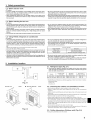 3
3
-
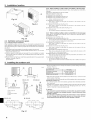 4
4
-
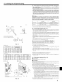 5
5
-
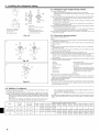 6
6
-
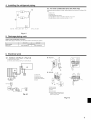 7
7
-
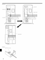 8
8
-
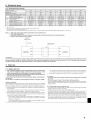 9
9
-
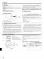 10
10
-
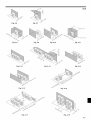 11
11
-
 12
12
-
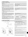 13
13
-
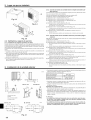 14
14
-
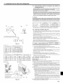 15
15
-
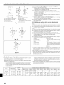 16
16
-
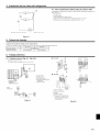 17
17
-
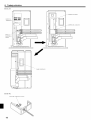 18
18
-
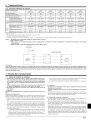 19
19
-
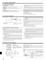 20
20
-
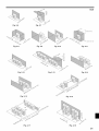 21
21
-
 22
22


Mitsubishi PUY-A24NHA Guía de instalación
- Tipo
- Guía de instalación
en otros idiomas
Artículos relacionados
Otros documentos
-
Mitsubishi Electric PUZ-A18NKA7 Manual de usuario
-
Mitsubishi Electric PUZ-A·NHA7-KA7 Wall Mounted Heat Pump Air Conditioners Manual de usuario
-
-
-
-
 Mitsubishi Electronics USA MXZ-8C60NA2-U1 Guía de instalación
-
-
-
Daikin 4MXS36NMVJU Guía de instalación
-
