
,_ MITSUBISHI
ELECTRIC
$LIII
Air-Co "
PKA-A.GA
PKA-A.GAL
e
iNSTALLATiON MANUAL
For safe and correct use, read this manual and the outdoor unit installation manual thoroughly before installing
the air-conditioner unit.
MANUAL DE INSTALACION
Para un uso correcto y seguro, lea detalladamente este manual y el manual de instalaci6n de la unidad exterior
antes de instalar la unidad de aire acondicionado.

Contents
1. Safety precautions ................................................................................... 2 5. Drainage piping work ............................................................................... 6
2. Installation location .................................................................................. 3 6. Electrical work .......................................................................................... 7
3. Installing the indoor unit ........................................................................... 3 7. Test run .................................................................................................. 12
4. Installing the refrigerant piping ................................................................. 5 8. Easy maintenance function (Option) ...................................................... 15
1. Safety precautions
Before installing the unit, make sure you read all the "Safety precau-
tions".
Please report to your supply authority or obtain their consent before
connecting this equipment to the power suppmysystem.
Warning:
Describes precautions that must be observed to prevent danger of injury or
death to the user.
Z_ Caution:
Describes precautions that must be observed to prevent damage to the unit.
After installation work has been completed, explain the "Safety precautions;' use, and
maintenance of the unit to the customer according to the information in the Operation
Manual and perform the test run to ensure normal operation. Both the Installation
Manual and Operation Manual must be given to the user for keeping. These manuals
must be passed on to subsequent users.
(_: Indicates which must be
a
part grounded.
Warning:
Carefully read the labels affixed to the main unit.
Warning:
,, Ask a dealer or an authorized technician to install the unit.
,, For installation work, follow the instructions in the Installation Manual and use
tools and pipe components specifically made for use with refrigerant specified
in the outdoor unit installation manual
, The unit must be installed according to the instructions in order to minimize
the risk of damage from earthquakes, typhoons, or strong winds. An incor-
rectly installed unit may fall down and cause damage or injuries.
,, The unit must be securely installed on a structure that can sustain its weight.
,, if the air conditioner is installed in a small room, measures must be taken to
prevent the refrigerant concentration in the room from exceeding the safety
limit in the event of refrigerant leakage. Should the refrigerant leak and cause
the concentration limit to be exceeded, hazards due to lack of oxygen in the
room may result.
o Ventilate the room if refrigerant leaks during operation, if refrigerant comes
into contact with a flame, poisonous gases will be released.
, All electric work must be performed by a qualified technician according to
local regulations and the instructions given in this manual.
, Use only specified cables for wiring.
, The terminal block cover panel of the unit must be firmly attached.
o Use only accessories authorized by Mitsubishi Electric and ask a dealer or
an authorized technician to instammthem.
, The user shoumd never attempt to repair the unit or transfer it to another moca-
tion.
o After installation has been completed, check for refrigerant leaks, if refriger-
ant leaks into the room and comes into contact with the flame of a heater or
portabme cooking range, poisonous gases will be released.
1.1. Before installation (Environment)
Caution:
,, Do not use the unit in an unusuam environment, if the air conditioner is in-
stalmedin areas exposed to steam, vomatimeoim(incmuding machine oim),or sulfuric
gas, areas exposed to high salt content such as the seaside, the performance
can be significantmy reduced and the internam parts can be damaged.
,, Do not install the unit where combustible gases may leak, be produced, flow,
or accumulate. If combustible gas accumulates around the unit, fire or explo-
sion may resumt.
,, Do not keep food, plants, caged pets, artwork, or precision instruments in the
direct airflow of the indoor unit or too close to the unit as these items can be
damaged by temperature changes or dripping water.
o When the room humidity exceeds 80% or when the drainpipe is cmogged, wa-
ter may drip from the indoor unit. Do not install the indoor unit where such
dripping can cause damage.
, When installing the unit in a hospital or communications office, be prepared
for noise and electronic interference. Inverters, home appliances, high-fre-
quency medical equipment, and radio communications equipment can cause
the air conditioner to malfunction or breakdown.The air conditioner may also
affect medical equipment, disturbing medical care, and communications equip-
ment, harming the screen display quality.
1.2. Before installation or relocation
Caution:
,, Be extremely carefum when transporting the units.Two or mote persons are
needed to handle the unit as it weighs 20 kg, 44 Ibe or more. Do not grasp the
packaging bands. Wear protective gloves as you can injure your hands on
the fins or other parts.
,, Be sure to safely dispose of the packaging materials. Packaging materiame,
such as naimsand other metam or wooden parts may cause stabs or other
injuries.
o Thermal insulation of the refrigerant pipe is necessary to prevent condensa-
tion. if the refrigerant pipe isnot properly insulated, condensation will beformed.
o Place thermal insulation on the pipes to prevent condensation, if the drain-
pipe is installed incorrectly, water leakage and damage to the ceiling, floor,
furniture, or other possessions may result.
, Do not clean the air conditioner unit with water. Electric shock may result.
, Tighten all flare nuts to specification using a torque wrench. If tightened too
much, the flare nut can break after an extended period.
1.3. Before electric work
Caution:
,, Be sure to install circuit breakers, if not installed, electric shock may result.
,, For the power lines, use standard cables of sufficient capacity. Otherwise, a
short circuit, overheating, or fire may result.
,, When installing the power lines, do not apply tension to the cables.
o Be sure to ground the unit. if the unit is not properly grounded, electric shock
may result.
, Use circuit breakers (ground fault interrupter, isolating switch (+B fuse), and
molded case circuit breaker) with the specified capacity. If the circuit breaker
capacity is larger than the specified capacity, breakdown or fire may result.
1.4. Before starting the test run
/_ Caution:
,, Turn on the main power switch more than 12 hours before starting operation.
Starting operation just after turning on the power switch can severely dam-
age the internal parts.
, Before starting operation, check that all panels, guards and other protective
parts are correctly installed. Rotating, hot, or high voltage parts can cause
injuries.
o Do not operate the air conditioner without the air filter set in place, if the air
filter is not installed, dust may accumulate and breakdown may result.
, Do not touch any switch with wet hands. Electric shock may result.
, Do not touch the refrigerant pipes with bare hands during operation.
, After stopping operation, be sure to wait at least five minutes before turning off
the main power switch. Otherwise, water meakage or breakdown may resumt.
2

2. Installation location
®T
©
®
2.1. Outline dimensions (indoor unit) (Fig. 2-1)
Select a proper position allowing the following clearances for installation and mainte-
nance. (mm)
(inch)
Models W B H (_) _ _F_ _G_ (_
990 235 340 Mn 30 Max 130 Mn 180 Mn 50 Mn 160
A12, A18 39 9-1/4 13-3/8 Min.l-13/16 Max.5 Max.7-3/32Min.l-31/32Min.5-29/32
_ Ceiling
© Wall
@ Furnishing, etc
Warning:
Mount the indoor unit on a ceiling strong enough to withstand the weight of the
unit.
2.2. Outline dimensions (Outdoor unit)
Refer to the outdoor unit installation manual.
Fig. 2-1
3. Installing the indoor unit
@
®
®
®
®
®
®
®
Fig. 3-1
3.1. Check the indoor unit accessories (Fig. 3-1)
The indoor unit should be supplied with the following accessories.
PARTNUMBER
d_
®
®
®
®
®
®
®
®
®
ACCESSORY
Mount board
Tapping screw 4 × 35
Pipe cover
Band
Felt tape
Wireless remote controller
Remocon holder
Alkali batteries (size AAA)
Mount piece (Package)
Wired remote controller
Drain adaptor
QUANTITY
1
12
1
5
3
1
1
2
1
1
1
LOCATIONOFSETTING
Fixatthe backofthe unit
Set inside the unit
for PKA-A,GAL
for PKA-A,GA
(_) - ® are stored in a cut-out section of the packing material (styrofoam).
(inch)
©
3.2. installing the wall mounting fixture (Fig. 3-2)
3.2.1. Setting the wall mounting fixture and piping positions
Using the wall mounting fixture, determine the unit's installation position
and the locations of the piping holes to be drilled.
z_ Warning:
Before drilling a hole in the wall, you must consult the building contractor.
Supporting piece
_ Mount board
© Main body
@ Slot (6-11 x 20,
8P-7/16 x 25/32 inch)
Unit center
CF}Bolt hole (14-o14 ram,
14P-9/16 inch)
_) Tapping hole (49-o5 ram,
49P-3/16 inch)
CH}Bottom left pipe slot
(o90 mm, 3-9/18 inch)
Bottom left pipe slot knockout hole
(_) Bottom right pipe slot (o90 ram, 3-9/16 inch)
Bottom right pipe slot knockout hole
_L_Liquid pipe flare connection position
@ Gas pipe flare connection position
(_) Level setting standard
_) Insert scale.
Hole centre
(_) Align the scale with the line.
©
@
®®
Fig. 3-2
®
Fig. 3-3
Sleeve
_ Hole
© (Indoors)
@ Wall
_} (Outdoors)
3.2.2. Drilling the piping hole (Fig. 3-3)
Use a core drill to make a hole of 90-100 ram, 3-9/16 to 4 inch diameter in the
wail in the piping direction, at the position shown in the diagram to the left.
The hole should incline so that the outside opening is lower than the inside
opening.
I_ Insert a sleeve (with a 90 ram, 3-9/16 inch diameter and purchased locally)
through the hole.
Note:
The purpose of the hole's inclination is to promote drain flow.
3

3. Installing the indoor unit
Fig. 3-4
®
®
Fig. 3-5
Fig. 3-6
®
Fig. 3-7
_o_)
_ _....
@ Min. 140 ram,
5-1/2 inch
_) Min. 300 ram,
11-13/16 inch
© Min. 55 mm,
2-3/16 inch
@ Mount board
©
3.2.3. Installing the wall mounting fixture
II_ Since the indoor unit weighs near 30 kg, 66 Ibs selection of the mounting
location requires thorough consideration. If the wall does not seem to be
strong enough, reinforce it with boards or beams before installation.
II_ The mounting fixture must be secured at both ends and at the centre, if
possible. Never fix it at a single spot or in any nonsymetrical way.
(If possible, secure the fixture at all the positions marked with a bold arrow.)
(Fig. 3-4)
z_ Warning:
If possible, secure the fixture at all positions indicated with a bold arrow.
z_ Caution:
o The unit body must be mounted horizontally.
o Fasten at the holes marked with A as shown by the arrows.
_) Fasten athread to the hole.
_ The levelcan be easily obtained byhanging a weight fromthe string andaligning the string
with the mark.
3.3. When embedding pipes into the wall (Fig. 3-5)
• The pipes are on the bottom left.
• When the cooling pipe, drain pipes internal/external connection lines etc are to be
embedded into the wall in advance, the extruding pipes etc, may have to be bent
and have their length modified to suit the unit.
• Use marking on the mount board as a reference when adjusting the length of the
embedded cooling pipe.
• During construction, give the length of the extruding pipes etc some leeway.
(_)Mountboard
(_)Referencemarking forflare connection
C-C)Through hole
(_)On-site piping
3.4. Preparing the indoor unit
Rear, right and lower piping (Fig. 3-6)
1. Bind the cooling pipe and drain pipe together.
• Bind the pipes together with vinyl tape at three or more points. This will facilitate
passing the pipes through the wall.
2. Remove the corner box and knock out the knockout holes as necessary.
• Remove the corner box by pushing in a downward direction (_), while at the same
time, pressing in the upper side part of the corner box (_.
(_)Corner box
(_)Under cover
Left and left rear piping (Fig. 3-7)
1. Remove the under cover.
• Remove the under cover by sliding it towards the rear of the unit @, while at the
same time, pressing the two points marked by arrow heads (_.
2. Remove the corner box and knock out the knockout holes as necessary.
3.5. Mounting the indoor unit
1. Affix the mounting plate to the wall.
2. Hang the indoor unit on the two hooks positioned on the upper part of the mount-
ing plate.
Rear, right and lower piping (Fig. 3-8)
3. Affix the indoor unit.
4. After connecting the pipes, put the corner box back to where it was (follow the
removal steps backwards).
(_)Square hole
(_)Hooks
®
/
Fig. 3-8
Fig. 3-9
(inch)
Left and left rear piping (Fig. 3-9)
3. Cut out a mounting piece from the packaging material.
4. Pull the indoor unit up towards yourself as shown in the figure below and slide the
mounting piece in to the mounting plate using the mounting piece setting marks
as reference.
5. After connecting the pipes and wiring, put the under cover back to where it was,
and remove the mounting piece and affix the indoor unit as shown in the left
figure.
6. Put the corner box back to where it was.
(_)Mountingpiece
(_)Ceiling
© Rib
4

4. Installing the refrigerant piping
4.1. Precautions
4.1.1. For devices that use R410A refrigerant
. Use ester oil, ether oil, a(kyibenzene oil (small amount) as the refrigeration oil
applied to the flared sections.
. Use Cl 220 copper phosphorus, for copper and copper alloy seamless pipes,
to connect the refrigerant pipes. Use refrigerant pipes with the thicknesses
specified in the tab(e to the be(ow. Make sure the insides of the pipes are
clean and do not contain any harmful contaminants such as sulfuric com-
pounds, oxidants, debris, or dust.
®
45o_+2°
®
Fig. 44
@ Flare cutting dimensions
Copper pipe O.D. Flare dimensions
(mm, inch) sA dimensions (mm, inch)
06.35, 1/4" 8.7 - 9.1,11/32-23/64
09.52, 3/8" 12.8- 13.2, 1/2-33/64
o12.7, 1/2" 16.2 - 16.6, 41/64-21/32
el 5.88, 5/8" 19.3 - 19.7, 49/64-25/32
Z_ Warning:
When installing or moving the air conditioner, use only the specified refriger-
ant (R410A) to charge the refrigerant lines. Do not mix it with any other refriger-
ant and do not a((ow air to remain in the (ines. Air enclosed in the (ines can
cause pressure peaks resulting in a rupture and other hazards.
I A12, A18
Liquid pipe e6.35mm, 1/4 inch thickness 0.8 mm, 1/32 inch
Gas pipe e12.7mm, 1/2 inch thickness 0.8 mm, 1/32 inch
Do not use pipes thinner than those specified above.
(inch)
4.2. Connecting pipes (Fig. 4-1)
= When commercially available copper pipes are used, wrap liquid and gas pipes
with commercially available insulation materials (heat-resistant to 100 °C, 212 °F or
more, thickness of 12 ram, 1/2 inch or more).
= The indoor parts of the drain pipe should be wrapped with polyethylene foam insu-
lation materials (specific gravity of 0.03, thickness of 9 ram, 23/64 inch or more).
= Apply thin layer of refrigerant oil to pipe and joint seating surface before tightening
flare nut.
= Use two wrenches to tighten piping connections.
= Use refrigerant piping insulation provided to insulate indoor unit connections. Insu-
late carefully.
(_) Flare nut tightening torque
Copper pipe O.D.
(mm, inch)
06.35, 1/4"
e9.52, 3/8"
o12.7, 1/2"
o15.88, 5/8"
Flare nut O.D. Tightening torque
(mm, inch) (N.m, ft4bs!
17, 43/64 14 - 18, 10-13
22, 7/8 34 - 42, 25-30
26, 1-3/64 49 - 61, 35-44
29, 1-9/64 68 - 82, 49-59
© Apply refrigerating machine oil over the entire flare seat surface.
@ Use correct flare nuts meeting the pipe size of the outdoor unit.
Avaimabmepipe size
Liquid side
Gas side
A12, A18
06.35
o12.7
O : Factory flare nut attachment to the heat-exchanger.
5

4. Installing the refrigerant piping
_'_ #............................................................................................................................................................................1_ (inch)
..................................................................................................;;
U_ ........ _ '_)
@2......@
4.3. Positioning refrigerant and drain piping
(_) Position of refrigerant and drain piping (Fig. 4-2)
• The drain pipe can be cut midway to meet the on-site conditions.
(_)(Totallength offlexible hose) @ Drain hose
(_)Liquid pipe _E}Left-side piping
© Gas pipe _} Right-side piping
® Determine the position o1 the knockout holes on the unit body. (Fig. 4-8)
Fig. 4=2
II_ Cut the knockout holes using a saw blade or an adequate knife.
Take care not to damage other parts of the unit.
® ® ® Remove the corner box and drill a knockout hole. If a hole is made without remov-
ing the box, the drain hose could be damaged.
(_) Left-side piping _D}Remote controller cable through hole
(_) Lower piping (E} Corner box
_C)Right-side piping
Fig. 4=3
Fig. 4=4
\
4.4. Refrigerant piping (Fig. 4=4)
1. Remove the flare nut and cap of the indoor unit.
2. Make a flare for the liquid pipe and gas pipe and apply refrigerating machine oil
(available from your local supplier) to the flare sheet surface.
3. Quickly connect the on site cooling pipes to the unit.
4. Wrap the pipe cover ® that is attached to the gas pipe and make sure that the
connection join is not visible.
5. Wrap the pipe cover of the unit's liquid pipe and make sure that it covers the
insulation material of the on site liquid pipe.
6. Use the bands that are provided _') to tighten both ends (15-20mm, 19/32 to
25/32 inch) o1 each pipe cover ®.
(_)Cooling pipe and insulation (availablefrom local supplier)
(_)Unit'sgas pipe _} Bands(_0
_c)Unit'sliquid pipe (_F_Onsite gas pipe
(_)Pipecover _ _) Onsite liquidpipe
4.5. For twin combination
Refer to the outdoor unit unstallation manual.
5. Drainage piping work
@
®
@ ®
\
©
Fig. 5=1
®
5.1. Drainage piping work (Fig. 5-1)
• Use a PVC pipe (I.D. o20mm, 13/16 inch) for drain piping and provide 1/100 or
more downward slope.
• Other PVC pipe sizes are available with the drain adaptor supplied.
• Make sure that there is no water leakage from the connections.
• If the drain pipe passes indoors it must be covered with insulating material (foamed
polyethylene: specific gravity: 0.03, thickness: 9 mm, 23/64 inch or more) available on the
market.
• Do not put the drain piping directly in a drainage ditch where sulphuric gas may be
generated.
• When piping has been completed, check that water flows from the end of the drain
pipe.
(_)Drain connectionsocket © Indoor unit's drain hose
(_)Field drainpipe
Caution:
The drain pipe should be installed according to this Installation Manual to en-
sure correct drainage. Thermal insulation of the drain pipes is necessary to
prevent condensation. If the drain pipes are not properly installed and insu-
lated, condensation may drip on the ceiling, floor or other possessions.
@
/
Preparing left and left rear piping (Fig. 5-2)
(_) Remove the drain cap.
• Remove the drain cap by holding the bit that sticks out at the end of the pipe and
pulling.
(_)Drain cap
® Remove the drain hose.
• Remove the drain hose by holding on to the base of the hose (_ (shown by arrow)
and pulling towards yourself (_).
® Insert the drain cap.
• Insert a screwdriver etc into the hole at the end of the pipe and be sure to push to
the base of the drain cap.
_) Insert the drain hose.
• Push the drain hose until it is at the base of the drain box connection outlet.
• Please make sure the drain hose hook is fastened properly over the extruding drain
box connection outlet.
(_)Hooks
Remove the side panel of the indoor unit on the drain side. Pour water in the drain
pan and check that it comes out the drain pipe end. After confirmation, reinstall the
side panel.
,',._:3_#ia ,;J,
@bx:_.... .....................,
Fig. 5=2
6

6. Electrical work
\
Fig. 6-1
®
6.1. Indoor unit (Fig. 6-1)
1. Remove the corner box.
2. install each wire into the unit.
3. Open the front grill, remove 1 tapping screw and remove the terminal block cover.
@ Terminal block cover
4. Connect each wire properly to the terminal block.
o In consideration of future servicing, please leave some leeway for the wiring length.
5. Put all the parts back the way they were.
6. Use a clamp from the bottom of the electric parts box to fasten each wire.
I_ Fix power source wiring to control box using buffer bushing for tensile force.
(PG connection or the like.)
A means for the disconnection of the supply with an isolation switch, or similar de-
vice, in all active conductors shall be incorporated in the fixed wiring.
_p Terminal block for Indoor/outdoor connecting
© Terminal block for power supply (separate indoor/outdoor unit power supplies, K-control ap-
plication)
@ Earth point
Clamp
CF_Terminal block for remote controller (Only for PKA-A.GA)
_) Conduit plate
CH_Bush (Purchased locally)
Ci_Lock nut (Purchased locally)
_3_Connector (Purchased locally)
(K_Conduit (Purchased locally)
6.1.1. indoor unit power supplied from outdoor unit (A-control application)
The following connection patterns are available.
The outdoor unit power supply patterns vary on models.
®
@ Outdoor unit power supply
(_ (_ _ Wiring circuit breaker or isolating switch
[-ql © Outdoor unit
i I _D)Indoor unit/outdoor unit connecting cords
(_ IIi _ Remote controller (Only for PKA-A.GA)
i_! CF)Indoor unit
_! _) Indoor unit earth
LCJ _/-_/
@
* Affix a label A that is included with the manuals near each wiring diagram for the indoor and outdoor units.
®
@ Outdoor unit power supply
(_ (_ (_ _ Wiring circuit breaker or isolating switch
[-ql [-ql © Outdoor unit
i I i @ Indoor unit/outdoor unit connecting cords
@ I , I I ®Remotecontroller(Only for PKA-A.GA)
H! CF_Indoor unit
L¢i _O_, I _) Indoor unit earth
* Affix a label A that is included with the manuals near each wiring diagram for the indoor and outdoor units.
Indoor unit model
Indoor unit power supply
Minimum circuit ampacity
Maximum rating of overcurrent protective device
Indoor unit power supply
u_ _ Indoor unit power supply earth
•__o
•- z Indoor unit-Outdoor unit 41
_ Indoor unit earth
_: Remote controller-Indoor unit 42
Indoor unit L1-L2 43
,_, ._ Indoor unit-Outdoor unit $1-$2 43
"_ Indoor unit-Outdoor unit $2-S3 43
Remote controller-Indoor unit 43
PKA
1A
15A
3 x AWGf6 (polar)
t x Min. AWG16
2 x AWG22 (Non-polar)
AC 208/230 V
DC24 V
DCf2V
"1. Max. 50 m, 168ft
*2. The 10 m, 30 ft wire is attached in the remote controller accessory. Max. 800 m, 1800 ft <Only for PKA-A.GA>
*3. The figures are NOT always against the ground.
$3 terminal has DC 24 V against $2 terminal. However between $3 and $1, these terminals are not electrically insulataed by the transformer or other device.
Notes:
1. Wiring size must comply with the applicable local and national code.
2. Use copper supply wires.
3. Use wires rated 300V or more for the power supply cables and the indoor unit/outdoor unit connecting cables.
4. Install an earth longer than other cables.
7

6. Electrical work
6.1.2. Separate indoor unit/outdoor unit power suppJies (A-controJ appJication)
The following connection patterns are available.
The outdoor unit power supply patterns vary on models.
© ®
®
(_) Outdoor unit power supply
© Wiring circuit breaker or isolating switch
© Outdoor unit
© Indoor unit/outdoor unit connecting cords
© Remote controller (Only for PKA-A.GA)
(_ Indoor unit
(G'_Indoor unit power supply
@
* Affix a label B that is included with the manuals near each wiring diagram for the indoor and outdoor units.
©
._._ ® ®
I '
@ I
(_) Outdoor unit power supply
© Wiring circuit breaker or isolating switch
© Outdoor unit
© Indoor unit/outdoor unit connecting cords
© Remote controller (Only for PKA-A.GA)
(_ Indoor unit
(G'_Indoor unit power supply
* Affix a label B that is included with the manuals near each wiring diagram for the indoor and outdoor units.
If the indoor and outdoor units have separate power supplies, refer to the table at the
below. Change the indoor unit electrical box wiring refering to the figure in the right
and the DIP switch settings of the outdoor unit control board.
Indoor unit specifications
Indoor unit electrical box connector con-
nection change Required
Label affixed near each wiring diagram Required
for the indoor and outdoor units
Outdoor unit DIP switch settings (when
Ao, _
using separate indoor unit/outdoor unit L£3__
power supplies only) _ (SW8)
There are three types of labels (labels A, B, and C). Affix the appropriate labels to
the units according to the wiring method.
Connectors (connections when shipped
from the factory are for indoor unit power
supplied from outdoor unit)
Indoor unit power supplied from outdoor unit
(when shipped from factory)
If the indoor and
outdoor units have
separate power
supplies, change the
connections of the
connectors as shown
in the following
figure.
Connectors
Separate indoor unit/outdoor unit power
supplies
Indoor unit model
Indoor unit power supply
Minimum circuit ampacity
Maximum rating of overcurrent protective device
,_ Indoor unit power supply
Indoor unit power supply earth
×
;_ Indoor unit-Outdoor unit "1
'_ Indoor unit earth
_: Remote controller-Indoor unit *2
Indoor unit L1-L2 *3
R ._ Indoor unit-Outdoor unit $1-$2 *3
_- _ Indoor unit-Outdoor unit $2-$3 *3
Remote controller-Indoor unit *3
41. Max. 80m, 165ft
42. The 10 m, 30 ft wire is attached in the remote controller accessory. Max. 800 m, 1800 ft
43. The figures are NOT always against the ground.
PKA
Single 208/230 V, 60 Hz
1A
18A
2x Min. AWG16
1 x Min. AWG16
2 x AWG22 (polar)
2 x AWG22 (Non-polar)
AC 208/230 V
DC24 V
DC12 V
Notes:
1. Wiring size must comply with the applicable local and national code.
2. Use copper supply wires.
3. Use wires rated 300V or more for the power supply cables.
4. mnstaNman earth monger than other cabmes.
8

6. Electrical work
6.1.3. K-control application
The following connection patterns are available.
The outdoor unit power supply patterns vary on models.
<For cooming onmy modems><For heat pump modems>
© ® © @
® ®
@
@
(_) Outdoor unit power supply
(_) Wiring circuit breaker or isolating switch
C-C}Outdoor unit
(_) Indoor unit/outdoor unit connecting cords
Remote controller (Only for PKA-A.GA)
(_ Indoor unit <For heat pump models>
(G'_Indoor unit <For cooling only models>
(_ Indoor unit power supply
Set the DIP switch of the indoor
unit control board.
SW5 1 2 3
SW5-1 :ON SW5-2, 3 : OFF
Set the DIP switch of the indoor
unit control board.
SW5 1 2 3
SW5-1,2 :ON SW5-3 : OFF
* Affix a label B that is included with the manuals near each wiring diagram for the indoor and outdoor units.
<For heat pump models> <For cooling only models> _) Outdoor unitpower supply
.
© @ @ © @ @
@
Set the DIP switchof the indoor
unit control board.
© Main indoor (_) Sub indoor
123 1123 I
SW5
SW5-1 : ON SW5-1 :ON
SW5-2 : OFF SW5-2 :OFF
SW5-3 : OFF SW5-3 :ON
@
Set the DIPswitch of the indoor
unit control board.
(_ Main indoor (_ Sub indoor
1 23 1 23 I
SW5
SW5-1 : ON SW5-1 : ON
SW5-2 : ON SW5-2 : ON
SW5-3 : OFF SW5-3 : ON
(_) Wiring circuit breaker or isolating switch
C-C}Outdoor unit
(_) Indoor unit/outdoor unit connecting cords
_E_Remote controller (Only for PKA-A.GA)
(_ Main indoor unit <For heat pump models>
(G'_Sub indoor unit <For heat pump models>
(_ Indoor unit power supply
(_) Main indoor unit <For cooling only models>
Sub indoor unit <For cooling only models>
* Affix a label B that is included with the manuals near each wiring diagram for the indoor and outdoor units.
To change to K-control, set the DIP switch (SW5) of the indoor unit control board as
shown in the above figure and change the electric wiring of the indoor unit as shown
in the right figure.
Set up Dip switch after turning off Power supply switch.
Be careful that setting the DIP switch (SW5) of the indoor unit control board varies
between the heat pump models and cooling models of the outdoor unit.
DIP switch (SW5)
OFF ON
SW5-1 A_CONTROL K-CONTROL
SW5-2 heat pump models cooling only models _ Dip switch SW5-2 and SW5-3 is effective only
sw5-3 MAIN SUB _Jwhen Dip switch SW5-1 (K-CONTROL) is ON.
* There are three types of labels (labels A, B, and C). Affix the appropriate labels to
the units according to the wiring method.
Indoor unit model PKA
Indoor unit power supply Single 208/230 V, 60 Hz
Minimum circuit ampacity 1 A
Maximum rating of overcurrent protective device 15A
Indoor unit power supply 2 x Min. AWG16
-_ Indoor unit power supply earth 1 x Min. AWG16
× H/P: 3 x AWG22 (polar)
_;_ C/O: 2 x AWG22 (polar)
Indoor unit-Outdoor unit "1
Indoor unit earth
Remote controller-Indoor unit *2 2 x AWG22 (Non-polar)
Indoor unit L1-L2 *3 AC 208/230 V
# _ Indoor unit-Outdoor unit $1-$2 *3 DC12 V
E "_ Indoor unit-Outdoor unit $1 -$3 *3 D012 V
_5
Remote controller-Indoor unit *3 DC12 V
41. Max. 50 m, 185 ft
42. The 10 m, 30 ft wire is attached in the remote controller accessory. Max. 500 m, 1500 ft
43. The figures are NOT always against the ground.
Notes:
1. Wiring size must comply with the applicable local and national code.
2. Use copper supply wires.
3. Use wires rated 300V or more for the power supply cables.
4. mnstamman earth monger than other cabmes.
Connectors
INDOOR UNIT
CONTROL BOARD
To change to the K-control,
make sure to change the
INDOOR UNIT
CONTROL BOARD
9

6. Electrical work
®
B-2.
Fig. 6=3
TB6
®
Fig. 6=4
®
®
Fig. 6=2
B-I.
®
®
6.2. Remote controller
6.2.1. For wired remote controJJer
(inch) 1) installing procedures
(1) Select an installing position for the remote controller. (Fig. 6-2)
The temperature sensors are located on both remote controller and indoor unit.
I_ Procure the following parts locally:
Two piece switch box
Thin copper conduit tube
Lock nuts and bushings
(_)Remotecontroller profile
(_)Required clearancessurrounding the remotecontroller
_-C_Installation pitch
(2) Seal the service entrance for the remote controller cord with putty to prevent pos-
sible invasion of dew drops, water, cockroaches or worms. (Fig. 6-3)
® For installation in the switch box:
® For direct installation on the wall select one of the following:
Prepare a hole through the wall to pass the remote controller cord (in order to run
the remote controller cord from the back), then seal the hole with putty.
Run the remote controller cord through the cut-out upper case, then seal the cut-
out notch with putty similarly as above.
B-1. To meadthe remote controller cord from the back of the controller:
B-2. To run the remote controller cord through the upper portion:
(3) For direct installation on the wall
_c)Wall
(_)Conduit
Lock nut
(_ Bushing
(G'_Switch box
(_ Remotecontroller cord
Sealwith putty
(J_Wood screw
2) Connecting procedures (Fig. 6-4)
(_) Connect the remote controller cord to the terminal block.
(_)ToTB5 on the indoor unit
(_)TB6 (No polarity)
3) Two remote controllers setting
If two remote controllers are connected, set one to "Main" and the other to "Sub". For
setting procedures, refer to "Function selection of remote controller" in the operation
manual for the indoor unit.
[
/
/
ON STAND COOL HEAT
Fig. 6=5
Fig. 6=6
6.2.2. For wireless remote controJJer
1) mnstammationarea
• Area in which the remote controller is not exposed to direct sunshine.
• Area in which there is no nearby heating source.
• Area in which the remote controller is not exposed to cold (or hot) winds.
• Area in which the remote controller can be operated easily.
• Area in which the remote controller is beyond the reach of children.
2) installation method (Fig. 6-5)
_'_ Attach the remote controller holder to the desired location using two tapping screws.
® Place the lower end of the controller into the holder.
(_)Remotecontroller
(_)Wall
_C)Displaypanel
(_)Receiver
• The signal can travel up to approximately 7 meters, 23 ft (in a straight line) within 45
degrees to both right and left of the center line of the receiver.
3) Setting (Fig. 6-6)
(_) Insert batteries.
® Press the SET button with something sharp at the end.
blinks and Model No. is lighted.
® Press the temp _v_ 0'_ button to set the Model No.
® Press the SET button with something sharp at the end.
and Model No. are lighted for three seconds, then turned off.
Indoor Outdoor ® Model No.
PLA, PCA, PKA (A12, A18) heat pump models 001
icooling only models 033
PKA (A24, A30, A36) i heat pump models 003
3ooling only models 035
10

6. Electrical work
Fig. 6=7
4) Assigning a remote controller to each unit (Fig. 6-7)
Each unit can be operated only by the assigned remote controller.
Make sure each pair of an indoor unit PC board and a remote controller is assigned
to the same pair No.
5) Wireless remote controller pair number setting operation
Press the SET button with something sharp at the end.
Start this operation from the status of remote controller display turned off.
blinks and Model No. is lighted.
Press the _ button twice continuously.
Pair No. "0" blinks.
®
Press the temp _ _'_,_button to set the pair number you want to set.
_') Press the SET button with something sharp at the end.
Set pair number is lighted for three seconds then turned off.
@ Pair No. of wireless remote controller Indoor PC board
0 Factory setting
1 Cut J41
2 Cut J42
3-9 Cut J41, J42
-@
<_ Mode number
(I[) Setting number
_ Refrigerant address
@) Unit number
© ©
\
u u _ _
/
_ _ LU _ __
C!:-I .]--
,q,q'7-I12_-
I
L_I_ II_ I
uu LI_ i __
6.3. Function settings
6.3.1 Function setting on the unit (Selecting the unit functions)
1) For wired remote controller (Fig. 6-8)
Changing the power voltage setting
= Be sure to change the power voltage setting depending on the voltage used.
Go to the function setting mode.
Switch OFF the remote controller.
Press the @ and (_) buttons simultaneously and hold them for at least 2
seconds. FUNCTION will start to flash.
Use the © button to set the refrigerant address (]][) to 00.
® Press @ and [--] will start to flash in the unit number (_) display.
(_ Use the © button to set the unit number (IV) to 00.
(_) Press the (_ MODE button to designate the refrigerant address/unit number. [--]
will flash in the mode number ( I ) display momentarily.
® Press the (_ buttons to set the mode number ( t ) to 04.
(_ Press the (_) button and the current set setting number ( _ ) will flash.
Use the (_ button to switch the setting number in response to the power supply
voltage to be used.
Power supply voltage
230V : setting number = 1
208V : setting number- 2
® Press the MODE button (_) and mode and the setting number ( I ) and ( _ ) will
change to being on constantly and the contents of the setting can be confirmed.
_) Press the FILTER @ and TEST RUN _) buttons simultaneously for at least two
seconds. The function selection screen will disappear momentarily and the air
conditioner OFF display will appear.
,@ ®
\ _1_/-
4,-,,1
®
\ _I_Z
\4 I /
Ji,-,,1
ll
Fig. 6=9
2) For wireless remote controller (Fig. 6-9)
Changing the power voltage setting
o Be sure to change the power voltage setting depending on the voltage used.
Go to the function select mode
Press the _ button (_ twice
continuously.
(Start this operation from the status of remote controller display turned off.)
is lighted and_"00" blinks.
Press the temp f,,v_button @ once to set "50". Direct the wireless remote controller
h
toward the receiver of the indoor unit and press the _ button (_).
Setting the unit number
Press the temp (\v)) ((A_button © and (_ to set the unit number"00". Direct the wireless
_J
min
remote controller toward the receiver of the indoor unit and press the _ button (_).
® Selecting a mode
Enter 04 to change the power voltage setting using the _vj_© and _ @ buttons.
Direct the wireless remote controller toward the receiver of the indoor unit and press
the _ button @.
Current setting number: 1 = 1 beep (one second)
2 = 2 beeps (one second each)
3 = 3 beeps (one second each)
(_ Selecting the setting number
© and _ @ buttons to change the power voltage setting to 01 (240 V).
Use the
Direct the wireless remote controller toward the sensor of the indoor unit and press
the _ button @.
i
(_ To select multiple functions continuously
Repeat steps ® and @ to change multiple function settings continuously.
(_ Complete function selection
Direct the wireless remote controller toward the sensor of the indoor unit and press
the _$_ button ®.
Note:
Whenever changes are made to the function settings after installation or main-
tenance, be sure to record the changes with a mark in the "Setting" column of
the Function table.
6.3.2 Function setting on the remote controller
Referto the indoor unit operation manual.
11

6. Electrical work
Function table
Select unit number 00
Mode
Power failure automatic recovery
Indoor temperature detecting
Settings Mode no.
Not available 01
Available "1
Indoor unit operating average
Set by indoor unit's remote controller 02
Remote controller's internal sensor
Not Supported
Supported (indoor unit is not equipped with outdoor-air intake) 03
Supported (indoor unit is equipped with outdoor-air intake)
230 V 04
208 V
Energy saving cycle automatically enabled 05
Energy saving cycle automatically disabled
Mode no.
O7
LOSSNAY connectivity
Power voltage
Auto mode (only for PUHZ)
Select unit numbers 01 to 03 or all units (AL [wired remote controller]/07 [wireless remote controller])
Mode Settings
Filter sign 100Hr
2500Hr
No filter sign indicator
Standard (PLA)/Silent (PCA)
High ceiling _ (PLA)/Standard (PCA)
High ceiling (_) (PLA)/High ceiling (PCA)
4 directions
3 directions
2 directions
Not supported
Supported
No vanes
Equipped with vanes (vanes angle setup _'})
Equipped with vanes (vanes angle setup @})
Disabled
Enabled
Fan speed
No. of air outlets
Installed options (high-performance filter)
Up/down vane setting
Energy saving air flow
(Heating mode)
O8
O9
10
11
12
Setting no. Initial setting
1
2 O
1 O
2
3
1 O
2
3
1 O
2
1 O
2
Setting no. Initial setting
1 O
2
3
1
2
3
1
2
3
1
2
1
2
3
1
2
setting
setting
"1 When the power supply returns, the air conditioner will start 3 minutes later.
7. Test run
7.1. Before test run
I_ After completing installation and thewiring and piping of the indoor and outdoor _ Do not carry out this test on the control wiring (low voltage circuit) termi-
units, check for refrigerant leakage, looseness in the power supply or control hale.
wiring, wrong polarity, and no disconnection of one phase in the supply. Z_ Warning:
I_ Use a 500-volt megohmmeter to check that the resistance between the power Do not use the air conditioner if the insulation resistance is less than 1.0 M_.
supply terminals and ground is at least 1.0 M_. Insulation resistance
®@ (D @
Fig. 74
@ ON/OFF button
_p Test run display
© Indoor temperature liquid line
temperature display
@ ON/OFF lamp
Power display
CF_Error code display
Test run remaining time dis-
play
Set temperature button
CH)Mode selection button
Ci_Fan speed button
@ TEST button
7.2. Test run
The following 3 methods are available.
7.2.1. Using wired remote controller (Fig. 7-1)
(_) Turn on the power at least 12 hours before the test run.
@_ Press the [TEST] button twice. =, "TEST RUN" liquid crystal display
(_) Press the [Mode selection] button. = Make sure that wind is blown out.
@ Press the [Mode selection] button and switch to the cooling (or heating) mode.
=, Make sure that cold (or warm) wind is blown out.
(_ Press the [Fan speed] button. = Make sure that the wind speed is switched.
(_ Check operation of the outdoor unit fan.
_'} Release test run by pressing the [ON/OFF] button. _, Stop
(_ Register a telephone number.
The telephone number of the repair shop, sales office, etc., to contact if an error
occurs can be registered in the remote controller. The telephone number will be
displayed when an error occurs. For registration procedures, refer to the operation
manual for the indoor unit.
7.2.2. Using wireless remote controller (Fig. 7-2)
_} Turn on the power to the unit at least 12 hours before the test run.
@Press the _ button twice continuously.
(Start this operation from the status of remote controller display turned off.)
(_)_ and current operationmode are displayed.
(_) Press the [L_ (O O"_, D I;3) button to activate COOLOmode, then check whether
cool air is blown out from the unit.
_} Press the _ (O O'_ _ t_3.)button to activate HEATamode, then check whether
warm air is blown out from the unit.
FAN
(_) Press the _ button and check whether fan speed changes.
VANE
(_ Press the _ button and check whether the auto vane operates properly.
(_ Press the ON/OFF button to stop the test run.
12
Fig. 7-2
Note:
o Point the remote controller towards the indoor unit receiver while following
steps (_) to (_).
, It is not possible to run the in FAN, DRY or AUTO mode.

7. Test run
7.2.3. Using SW4 in outdoor unit
Refer to the outdoor unit installation manual.
@-
®
® ®
®
Fig. 7-3
Fig. 7=4
7.3. Self=check
7.3.1. Wired remote controller (Fig. 7=3)
(_ Turn on the power.
® Press the [CHECK] button twice.
(_ Set refrigerant address with [TEMP] button if system control is used.
® Press the [ON/OFF] button to stop the self-check.
@ CHECKbutton
_p Refrigerant address
© TEMRbutton
@ IC: Indoor unit
OC: Outdoor unit
Checkcode
CF_Unit address
7.3.2. Wireless remote controller (Fig. 7=4)
L_ Turn on the power.
CHECK
® Press the _ button twice.
(Start this operation from the status of remote controller display turned off.)
@ _ begins to light.
_p "00"begins to blink.
(_ While pointing the remote controller toward the unit's receiver, press the [_B
button. The check code will be indicated by the number of times that the buzzer
sounds from the receiver section and the number of blinks of the operation lamp.
® Press the ON/OFF button to stop the self-check.
o Refer to the following tables for details on the check codes. (Wireless remote controller)
[Output pattern A]
Beeper sounds Beep Beep Beep Beep Beep
OPERATION
INDICATOR
lamp flash
_attern
Beep Beep
J-hr[ ..... _ _ ... Repeated
4 < i,
._.._. off on on on on off on on
Self-check Approx. 2.Ssec. 0.Ssec. 0.Ssec. 0.5sec. 0.Ssec. Approx.2.Ssec. 0.Ssec. 0.Ssec.
starts \ J
(Start signal _'f _-----mf--
received) Number of flashes/beeps in pattern indicates the check Number of flashes/beeps in pattern indicates
code in the following table (i.e., n=5 for "PS") the check code in the following table
[Output pattern B]
Beeper sounds Beep
OPERATION j-[j-[ [
INDICATOR
lamp flash Off
_attern
Self-check Approx.2.5 sec.
starts
(Start signal
received)
Beep Beep Beep Beep
_ t
On On On On On Off
Approx.3sec. 0.5sec. 0.5sec. 0.5sec. 0.5sec. Approx.2.5sec.
\ )
"V-
Number of flashes/beeps in pattern indicates the check
code in the following table (i.e. n=B for "U2")
[
)
On
Approx.3 sec,
Beep Beep
• .. Repeated
On On
0.5 sec. 0.Ssec.
\
Y
Number of flashes/beeps in pattern indicates
the check code in the following table
[Output pattern A]
Wireless remote controller
Errors detected by indoor unit
Wired remote
controller
Beeper sounds/OPERATION
INDICATOR lamp flashes
(Number of times)
1
2
3
4
5
6
7
8
9
10
11
12
No sound
Check code
Symptom
P1 Intake sensor error
P2, P9 Pipe (Liquid or 2-phase pipe) sensor error
E6, E7 Indoor/outdoor unit communication error
P4 Drain sensor error
P5 Drain pump error
P6 Freezing/Overheating safeguard operation
EE Communication error between indoor and outdoor units
P8 Pipe temperature error
E4 Remote controller signal receiving error
Fb
Indoor unit control system error (memory error, etc.)
No corresponding
Remark
13

7. Test run
[Output pattern B]
Wireless remote controller
Beeper sounds/OPERATION
INDICATOR lamp flashes
(Number of times)
Errors detected by unit other than indoor unit (outdoor unit, etc.)
Wired remote
controller
Check code
Symptom
Remark
1 E9 Indoor/outdoor unit communication error (Transmitting error) (Outdoor unit)
2 UP Compressor overcurrent interruption
3 U3, U4 Open/short of outdoor unit thermistors
4 UF Compressor overcurrent interruption (When compressor locked)
5 i U2 Abnormal high discharging temperature/49C worked/insufficient refrigerant
6 i U1, Ud Abnormal high pressure (63H worked)/Overheating safeguard operation
7 i U5 Abnormal temperature of heat sink
For details, check the LED display
8 i U8 Outdoor unit fan safeguard stop of the outdoor controller board.
9 i U6 Compressor overcurrent interruption/Abnormal of power module
10 i U7 Abnormality of super heat due to low discharge temperature
11 i U9, UH Abnormality such as overvoltage or voltage shortage and abnormal synchronous
signal to main circuit/Current sensor error
12 ,- -
13 ,- -
14 Others Other errors (Refer to the technical manual for the outdoor unit.)
"1 If the beeper does not sound again after the initial two beeps to confirm the self-check start signal was received and the OPERATION INDICATOR lamp does not come on,
there are no error records.
*2 If the beeper sounds three times continuously "beep, beep, beep (0.4 4-0.4 4-0.4 sec.)" after the initial two beeps to confirm the self-check start signal was received, the
specified refrigerant address is incorrect.
o On wireless remote controller
The continuous buzzer sounds from receiving section of indoor unit.
Blink of operation lamp
On wired remote controller
Check code displayed in the LCD.
If the unit cannot be operated properly after the above test run has been performed, refer to the following table to remove the cause.
Symptom
Wired remote controller
For about 2
minutes following
power-on
PLEASE WAIT
PLEASE WAIT -_ Error code
After about 2
minutes has
expired following
power-on
Display messages do not appear even
when operation switch is turned ON
i (operation lamp does not light up).
LED 1,2 (PCB in outdoor unit)
After LED 1,2 are lighted, LED 2 is turned off,
i then only LED 1 is lighted. (Correct operation)
Only LED 1 is lighted. -_ LED 1,2 blink.
i Only LED 1 is lighted. -_ LED 1 blinks twice,
i LED 2 blinks once.
phenomena takes place.
Cause
For about 2 minutes following power-on, operation of the
remote controller is not possible due to system start-up. (Cor-
rect operation)
Connector for the outdoor unit's protection device is not con-
nected.
Reverse or open phase wiring for the outdoor unit's power
terminal block (L1, L2, GR)
Incorrect wiring between indoor and outdoor units (incorrect
polarity of Sl, S2, $3)
Remote controller wire short
On the wireless remote controller with condition above, followin
No signals from the remote controller are accepted.
OPE lamp is blinking.
The buzzer makes a short pipng sound.
Note:
Operation is not possible for about 30 seconds after cancellation of function selection. (Correct operation)
For description of each LED (LED 1,2, 3) provided on the indoor controller, refer to the following table.
LED 1 (power for microcomputer) Indicates whether control power is supplied. Make sure that this LED is always lit.
LED 2 (power for remote controller) Indicates whether power is supplied to the remote controller. This LED lights only in the case of the
indoor unit which is connected to the outdoor unit refrigerant address "0".
LED 3 (communication between indoor and outdoor units only A-control) Indicates state of communication between the indoor and outdoor units. Make sure that this LED is
always blinking.
14

8. Easy maintenance function [This function only for A-control]
Dispmay exampme (Comp discharge temperature 147°F) By using the maintenance mode, you can display many types of maintenance data
on the remote controller such as the heat exchanger temperature and compressor
current consumption for the indoor and outdoor units.
This function can be used whether the air conditioner is operating or not.
During air conditioner operation, data can be checked during either normal operation
or maintenance mode stable operation.
* This function cannot be used during the test run.
* The availability of this function depends on the connecting outdoor unit. Refer to the
brochures.
1) Press the button for three seconds to jNAi EN N |
Display
activate the maintenance mode.
J
4,
(2) Press the TEMP. buttons to set the refrigerant address. ]
/
Display@ r* ...... 7 j
4,
(3) Select the data you want to display.
Compressor Cumulative _ ON/OFF _ Operation
information number current
Heat exchanger Cornp discharge Outdoor ambient
Outdoor unit [------_temperatuEe _ temperature J
information DisplayO _ :;o DOe'U IT
I Display0 £X f_
Indoor room
Indoor unit [-------_ tempe[a!u[e
information mDisplayO
* The filter operation time displayed is the number of hours the filter has been
used since the filter reset was performed.
4,
I(4) Press the button. 1
4,
(5) The data is displayed in O. (Airflowtemperature display example) ]
Flashing I//
Display e _ /
Wai;ingfor A_PsreCX' 147°F I/
response ' I /
* Repeat steps (2) to (5) to check another date. J
4,
I(6) Press the button for three seconds or press the button to1deactivate the maintenance mode.
4=
Stable operation
Using the maintenance mode, the operation frequency can be fixed and the op-
eration can be stabilized. If the air conditioner is stopped, use the following proce-
dure to start this operation.
Press the button to select the operation mode.
Stablecooling Stableheating Stableoperation
operation _ cancellation
STABPE _1 _
Press the button.
Stable
Waiting forstable operation
operatJoo
Display _ 10-20 rain.
* You can check the data using steps (3) to (5) of the maintenance mode opera-
tion procedures while waiting for the stable operation.
15

Contenido
1. Medidas de Seguridad ........................................................................... 16
2. Lugaren que se instalar_. ...................................................................... 17
3. InstalaciOn de la unidad interior ............................................................. 17
4. Instalaci6n de los tubos del refrigerante ................................................ 19
5. Tuberfa de drenaje ................................................................................. 20
6. Trabajo electrico ..................................................................................... 21
7. Prueba de funcionamiento ..................................................................... 26
8. Funci6n de mantenimiento f_.cil (opcional) ............................................ 29
1. Medidas de Seguridad
Antes de instalar la unidad, asegurese de haber leido el capitulo de "Me-
didas de seguridad'.
Jl_Informe al encargado del suministro u obtenga su consentimiento antes
de conectar este equipo al sistema de suministro de alimentaci6n.
z_ Atencion:
Describe las precauciones que deben tenerse en cuenta para evitar el riesgo
de lesiones o muerte del usuario.
Z_ Cuidado:
Describe las precauciones que deben tenerse en cuenta para evitar dahos en
la unidad.
Despues de terminar la instalaciOn, explique las "Medidas de Seguridad", funciona-
miento y mantenimiento de la unidad al cliente segQn el Manual de instrucciones y
realice una prueba para asegurarse de que funciona correctamente. Entregue una
copia del Manual de instalaci6n y del Manual de instrucciones al usuario. Estos ma-
nuales deben pasar a usuarios posteriores del equipo.
(_: Indica una debe estar conectada a tierra.
pieza que
z_ Atenci6n:
Lea atentamente las etiquetas adheridas a la unidad principal.
z_ Atenci6n:
, La instalaci6n del aire acondicionado debe correr a cargo del distribuidor o
t_cnico autodzado.
, Para mainstalaci6n, siga masinstrucciones del Manual de instamacion y utimice mas
herramientas y piezae de fontaneria especfficamente dise_adas para utilizar con
el refrigerante especificado en el manual de instalaci6n de la unidad exterior.
, La unidad debe instalarse segt_n las instrucciones para reducir poeibles da-
i_os en cseo de terremoto, hurac&n o vientos fuertes. Si no se instala correc-
tamente, la unidad podda caerse y provocar daSos o mesiones.
, La unidad debe instalarse firmemente sobre una estructura capaz de sopor-
tar su peso.
, Si el equipo de aire acondicionado se instala en una sala pequet_a deberan
tomaree medidas para prevenir que la concentraci6n de refrigerante exceda
los limites de seguridad en caso de fugas. Si se produce una fuga de refrige-
rante que sobrepase mosmimites de concentraci6n, maestancia en masamapuede
ser pemigrosa pot famtade oxigeno.
o Si se produce una fuga de refrigerante durante el funcionamiento, ventile la
sala. Si el refrigerante entra en contacto con una llama, se desprenderan
gases nocJvoe.
o Todas las conexiones el_ctricas deber&n set realizadas pot un t_cnico cuali-
ficado segt_n manormativa mocal y masinstrucciones de este manual.
o Utimice s61o cabmes especificados para el cabmeado.
o Empanem de la cubierta del bmoque de terminales de maunidad debe comocarse
firmemente.
o Utilice s61o accesorios autorizados pot Mitsubishi Electric y pida a su distri-
buidor o a un tecnico autorizado que se los instale.
o El usuario nunca debe intentar reparar la unidad o moverla de sitio.
o Tras haber realizado la instalaci6n, compruebe si hay fugas de refrigerante. Si
en caso de fuga el refrigerante entra en contacto con las llamas de un calen-
tador o de un equipo de cocina port&til, se desprenderan gases nocivos.
1.1. Cuestiones previas a la instalaci6n (Ambiente)
z_ Cuidado:
, No utilice maunidad en un ambiente enrareeido. Si instamael aire acondiciona-
do en zireas expuestas amvapor, aceite esenciam (incmuyendo el aceite para
maquinas), o humo suffurico, areas con alto contenido en samcomo pmayas,el
rendimiento puede verse reducido significativamente y maspiezas internas
pueden daiiarse.
, No instame la unidad donde se puedan verter, producir, circular o acumumar
gases inflamabmes. Sise acumula gas inflamabme en zonas pr6ximas ama uni-
dad, se podria producir un incendio o una expmosi6n.
, No comoque amimentos, pmantas,animames, obras de arte o instrumentos de pre-
cisi6n en masamida de aire directa de maunidad exterior o demasiado cerca de
ella, ya que moscambios de temperatura o el agua que gotea podrian da_arlos.
o Cuando la humedad de la habitacion supera el 80%, o cuando el tubo de
drenaje este obstruido, puede gotear agua de la unidad interior. No instale la
unidad interior en lugares donde el goteo pueda causar dahos.
o Si instala la unidad en un hospital o en un centro de comunicaciones, recuer-
de que la unidad produce ruidos e interferencias eleetronicas. Los conmuta-
dotes, aparatos dom_sticos, equipos m_dicos de alta frecuencia y las comu-
nicaciones de radio pueden provocar un real funcionamiento o la averia del
equipo de aire acondicionado. El equipo de aire aeondicionado tambien puede
afectar los equipos m_dicos e interrumpir los cuidados m_dicos, asi como
los equipos de comunicaci6n y da_ar la calidad de la pantalla.
1.2. Antes de la instalaci6n o reubicaci6n
/_ Cuidado:
, Tenga mucho cuidado cuando mueva las unidades. Se neeesitan dos o m&s
personas para Hevar la unidad ya que pesa 20 kg, 44 robso mas. No masujete
por mas bandas de embamaje. Utimice guantes protectores ya que se podria
mesionar con las ametas u otras partes.
, Guarde mosembalajes en un lugar seguro. Los materiales de embalaje, eomo
clavos y otras piezas de metal o de madera pueden producir pinchazos y
otras lesiones.
, El tubo de refrigerante debe estar aislado termicamente para evitar la con-
densacion. Si el tubo de refrigerante no se aisla correctamente, se formarzi
condensaci6n.
o Sitt_e material aislante termico en las tuberias para evitar la condensaci6n. Si
el tubo de drenaje no se instala correctamente, se puede producir un escape
de agua o daSos en el techo, suelo, muebles u otros objetos.
o No limpie con agua el equipo de aire acondicionado. Puede sufrir una des-
carga el_ctrica.
o Apriete las tuercas de aboeardado a los niveles especificados mediante una
llave dinamom_trica. Si las aprieta demasiado, se pueden romper al cabo de
un tiempo.
1.3. Antes de la instalaci6n el_ctrica
/_ Cuidado:
, Asegt_rese de instalar disyuntores. Si no se instalan, se podrian producir
descargas eieetricas.
, Use cables est&ndar de suficiente eapacidad para las lineas electricas. Si no
Io hace asi, se podria producir un cortocircuito, un sobrecalentamiento o un
incendio.
o Cuando instale las lineas el_ctricas, los cables no deben tenet corriente.
o Asegurese de instalar una toma de tierra. Si la unidad no est& bien conectada
a la linea de tierra, se puede producir una descarga el_etrica.
o Utilice disyuntores (interruptor de falta de tierra, interrupter aislante (+fusi-
ble B) e interruptores en caja moldeada) con la potencia especificada. Si la
potencia del interruptor es mayor que la especificada, puede ocurrir un in-
cendio o una averia.
1.4. Antes de realizar las pruebas de funcionamiento
,/fk Cuidado:
, Coneete la corriente al menos 12 horas antes de que empieee a funcionar el
equipo. Si se acciona inmediatamente despues de habedo coneetado a la
corriente, pueden producirse da5os graves en las piezas internas.
, Antes de que comience a funcionar el equipo, compruebe que todos los pa-
neles y proteetores estan instalados correctamente. Las piezas giratorias,
calientes o de alto voltaje pueden provocar lesiones.
, No haga funcionar el equipo de aire acondicionado sin el filtro de aire insta-
lado. Si el filtro de aire no esta colocado, se puede acumular el polvo y se
puede averiar el equipo.
o No toque ningun interruptor con las manos mojadas. Puede sufrir una des-
carga el_ctrica.
o No toque la tuberia del refrigerante sin guantes mientras durante el funcio-
namiento.
o Una vez deje de funcionar el aparato, espere cinco minutos antes de apagar
el interrupter principal. De Io contrario, se puede producir un goteo de agua
o una averia.
16

2. Lugar en que se instalara
®7
©
®
.@
Fig. 2-1
2.1. Dimensiones exteriores (Unidad interior) (Fig. 2-1)
Seleccisne una pssici6n adecuada, de fsrma que queden las siguientss distancias
para prscsder a la instalaci6n y al mantsnimients.
(mm)
(inch)
Modelos W U m (_) _ CF_ (G_
990 235 340 Mn 30 Max 130 Mn 180 Mn 50 Mn 160
A12, A18 39 9-1/4 13-3/8 Min.l-13/16 Max.5 Max.7-3/32Min.l-31/32Min.5-29/32
(_)Techo
_C}Pared
(_)Muebles, etc.
Z_ Atenci6n:
Instale la unidad interior snun techo suficisntemente fusrte para soportar el
peso de la unidad.
2.2. Dimensiones exteriores (Unidad exterior)
Csnsulte el manual de instalaci6n de la unidad exterior.
3. Instalaci6n de la unidad interior
@
®
®
®
@
®
®
®
Fig. 3-1
(inch)
3.1. Comprobaci6n de los accesorios de la unidad
interior (Fig. 3-1)
La unidad interior debe ir acsmpa_ada de los siguientss accessrios.
NOMERO
@
®
@
@
@
@
@
@
@
@
@
ACCESORIO
i Panel de montaje
Tornills rsscado 4 x 35
Tapa del tubs
Brida
Cinta de fieltrs
Controlador remots inal_.mbrico
Soporte del controlador remoto
Pilas alcalinas (tama_s AAA)
i Pieza sopsrte (Paquete)
i Csntrolador remsts cableads
Adaptador de desagL_e
CANTIDAD
1
12
1
5
3
1
1
2
1
1
1
(_) - _) se uardan en una secci6n recortada
(poliestireno).
UBICACION
Fiiad0alapartetraseradelaunidad
Dentro de la unidad
para PKA-A,GAL
para PKA-A,GA
del material de embalaje
3.2. Instalaci6n del soporte de montaje en la pared
(Fig. 3-2)
3.2.1. Determine las posiciones del soporte de montaje y de las tu-
berias
I_ Con la ayuda dsl soporte de montajs determine d6nds se colocara la uni-
dad y los lugares en que se har& un agujero para las tuberias.
©
©
Fig. 3-2
@
®
Fig. 3-3
@ Manguito
_p Agujero
© (lado interior)
@ Pared
_ (lado exterior)
Z_ Atenci6n:
Antes de hacer los agujeros de la pared, consulte al contratista.
(_) Pieza soporte
(_) Panel de montaje
{C)Estructura principal
(_) Ranura (6-11 x 20,
8P-7/18 x 25/32 inch)
Centro de la unidad
(_) Orificio troquelado (14-o14 mm,
14P-9/16 inch)
(G')Orificio roscador (49-05 mm,
49P-3/16 inch)
Ci} Orifbio ciegode la ranurade Bs tuberlas inferioresdel ladoizqubrdo
_3} Ranura de las tuberias inferiores del lado derecho (_90
mm, o3-9/16 inch)
_. Orifbio ciegode la ranurade lastuberias inferioresdel ladoderecho.
_ PosiciOn de la conexiOn abocinada de la tuberla de liquido
_) Posicion de la conexion abocinada de la tuberia de gas
(N) Nivel ajustado al estandar
_ Introducir la escala
(_ Centro del agujero
(2pAlinear la escala con la linea
(_ Ranura de las tuber/as inferiores del lado izquierdo
(o90 ram,3-9/16 inch)
3.2.2. Hacer el agujero para las tuberias (Fig. 3-3)
II_ Utilice una broca hueca para hacer en la pared una perforaci6n de 90-100
ram, 3-9/16 a 4 inch de diametro en la direcci6n de las tuberias, en la posi-
ci6n indicada en el diagrama de la izquierda.
La perforacion de la pared debe inclinarse, de manera que el orificio exte-
rior este m_is bajo qus el orificio interior.
I_ Introduzca un manguito pot el agujero (de 90 ram, 3-9/16 inch de diametro y
comprado sn su Iocalidad).
Nota:
El objetivo de la inclinaci6n del agujero perforado es facilitar el drenaje.
17

3. Instalacion de la unidad interior
®
®
Fig. 3=4
Fig. 3=5
Fig. 3-6
@ Min. 140 mm,
5-1/2 inch
_ Min. 300 mm,
11-13/16 inch
© Min. 66 mm,
2-3/16 inch
@ Placa de montaje
©
3.2.3. Instalaci6n deJ soporte de montaje en la pared
I_ Come maunidad interior pesa casi 30 kg, 66 robstendrzi que tenet en cuenta em
mugarde montaje. Si la pared no parece mosuficientemente fuerte, refuercema
con tablas y vigas antes de instalar la unidad.
I_ El soporte de montaje se fijarzi por ambos extremes y por el centro, si es
posible. No Io fije nunca por un solo punto o de manera asim_trica.
(Si es posible, sujete el soporte pot todos los lados marcados con una fie-
cha gruesa.) (Fig. 3-4)
Z_ Atenci6n:
Si es posible, fije el soporte en todas las posiciones marcadas con una flecha.
Z_, Cuidado:
o La unidad se tiene que montar hodzontalmente.
o Apdete en mosagujeros marcados con A.
_ Introduzcaun hilo en el orificio y atelo.
_ El nivel se puedecomprobar facilmente si se cuelga unaplemada de la cuerda y se alinea
esta a la marca.
3.3. Cuando coloque los tubos en la pared (Fig. 3=5)
• Los tubos estan en el lado inferior izquierdo.
• Cuando las Ifneas de conexi6n interna/externa del tubo de refrigerante y de los
tubos de drenaje tienen que empotrarse en la pared con anterioridad, es probable
que haya que doblar los tubos troquelados y tener que modificar su Iongitud para
adaptarlos a la unidad.
• Haga una marca en la placa de montaje para que sirva de referencia cuando vaya
a ajustar la Iongitud del tubo de refrigerante empotrado.
• Durante la construcci6n, deje algLin margen en la Iongitud de los tubos troquelados.
(_)Placade montaje
(_)Marcade referencia de laconexion abocinada
© Orificio pasante
(_)Tuberia local
3.4. Preparacion de la unidad interior
Tuberias trasera, derecha e inferior (Fig. 3-6)
1. Junte el tubo de refrigerants con el tubo de drenaje.
• Junte los tubos con cinta de vinilo en tres puntos o mas. Esto facilitara el paso de
los tubos por la pared.
2. Saque la caja lateral y destape los orificios ciegos si fuera necesario.
• Saque la caja lateral empujandola hacia abajo @ y al mismo tiempo, apriete la
parte superior de la misma (_.
(_)Caja lateral
(_)Tapainferior
Tuberias izquierda y posterior izquierda (Fig. 3-7)
1. Saque la tapa inferior.
Saque la tapa inferior desliz_.ndola hacia la parts posterior de la unidad @ y, al
mismo tiempo, apriete las dos posiciones marcadas con flechas m_.s gruesas (_).
2. Saque la caja lateral y destape los orificios ciegos si fuera necesario.
3.5. Montaje de la unidad interior
1. Sujete la placa de montaje a la pared.
2. Cuelgue la unidad inferior en los dos ganchos que estan colocados en la parts
superior de la place de montaje.
®
Tuberia izquierda y posterior izquierda (Fig. 3-8)
3. Sujste la unidad interior.
4. Despues de conectar los tubes, coloqus la caja lateral sn el sitio en donde sstaba
(siga los pasos de la extracci6n indicados anteriormsnte a la invsrsa).
(_)Orificiocuadrado
(_)Ganchos
®
/
Fig. 3=8
< (inch)
t_
Fig. 3-9
Tuberia izquierda y posterior izquierda (Fig. 3-9)
3. Corte una pieza soporte del material de embalaje.
4. Tire de la unidad interior hacia usted tal ycomo se muestra en la figura de abajo
y deslice la pieza soporte en la placa de montaje, utilizando la pieza soporte
come marca de referencia.
5. Despues de conectar las tuberfas y los cables, coloque la tapa inferior en el sitio
en donde estaba, saque la pieza soporte y sujete la unidad interior tal y como se
muestra en la figura de la izquierda.
6. Coloque la caja lateral en el sitio en donde estaba.
(_)Piezasoporte
Techo
© Reborde
18

4. Instalaci6n de los tubes del refrigerante
4.1. Precauciones
4.1.1. Para aparatos con refrigerante R410A
, Utilice aceite de _ster, de _ter o alquilobenceno (en pequehas cantidades)
para recubrir las secciones abocardadas.
, Utilice tubes de cobre fosforoso del ripe C1220 y tubes de aleaci6n de cobre
sin costuras para cenectar los tubes del refrigerante. Utilice tuberias para
refrigerante del grosor especificado en la tabla siguiente. Asegurese de que
el interior de las tuberias est_ limpio y que no contienen ningun contaminan-
te nocivo come compuestos sulfuricos, oxidantes, restos o polvo.
Z_ Atenci6n:
Cuando instale o mueva el equipe de aire acondicionado, utilice s61o el refrigeran-
te indicado (R410A) para cargar los tubes de refrigerante. No Io mezcle con otto
tipo de refrigerante y vacie cornpletarnente de aire los tubes. Ei aire que quede en
los tubes puede provocar picos de presi6n que causarian su rotura y otros dahos.
®
o
b
o)
45o_+2°
®
Fig. 4-1
(inch)
®
l A12, A18
Tube de liquido 06,35 mm, 1/4 inch grosor 0,8 mm, 1/32 inch
Tube de gas o12,7 mm, 1/2 inch grosor 0,8 mm, 1/32 inch
No utilice tubes con un grosor rnenor del especificado a continuaci6n.
4.2. Tubes de conexi6n (Fig. 44)
o Si se utilizan tubes de cobre convencionales, envuelva los tubes de gas y Ifquido
con materiales aislantes (resistente al calor hasta 100 °C, 212°F o mdts, espesor
de 12 mm, 1/2 inch o mas).
Las piezas interiores del tube de drenaje tienen que estar envueltas en materiales
aislantes de espuma de polietileno (gravedad especifica de 0,03 y espesor de
9 mm, 23/64 inch o m_ts).
Aplique una capa delgada de aceite refrigerante a la superficie tube y de la junta
de asiento antes de apretar la tuerca de abocardado.
Utilice dos Ilaves de apriete para apretar las conexiones de los tubes.
Utilice el aislante de tuberia de refrigerante suministrado para aislar las conexio-
nes de la unidad interior. Realice los aislamientos con cuidado.
@ Dimensiones del corte abocinado
Tube de cobre O.D. Dimensiones de abocinado
(mm, inch) dimensiones eA (ram, inch)
e6,35, 1/4" 8,7 - 9,1,11/32-23/64
e9,52, 3/8" 12,8- 13,2, 1/2-33/64
e12,7, 1/2" 16,2 - 16,6, 41/64-21/32
el 5,88, 5/8" 19,3 - 19,7, 49/64-25/32
(_) TorsiOn de apriete de la tuerca abocardada
Tube de cobre O.D. Tuerca de abocardado
(mm, inch) O.D. (ram, inch)
e6,35, 1/4" 17, 43/64
e9,52, 3/8" 22, 7/8
e12,7, 1/2" 26, 1-3/64
e15,88, 5/8" 29, 1-9/64
TorsiOn de apriete
(N.m, ft.lbs)
14- 18, 10-13
34 - 42, 25-30
49- 61, 35-44
68 - 82, 49-59
C-C)Aplique aceite refrigerante para m_.quinas en toda la superficie abocinada.
(_) Utilice tuercas abocardadas que coincidan con el tamai_o de la tuberia de la unidad exterior.
Tamahos de tuberia disponibles
A12, A18
e6,35
Lade del Ifquido
e12,7
Lade del gas
O : Accesorio de fabrica para acoplar la tuerca abocardada al intercambiador de
calor.
lg

4. InstaIaci6n de los tubes del refrigerante
Fig. 4-2
®
©
@
Q (inch)
®
4.3. ColocaciOn de los tubes del refrigerante y de drenaje
(_) PosiciOn de los tubes del refrigerante y de drenaje (Fig. 4-2)
• La tuberia de drenaje se puede cortar per la mitad para adaptarse a las condicio-
nes del lugar.
(_)(Longitudtotal de la rnangueraflexible) _D)Manguerade drenaje
(_)Tuberia deliquido _ Tuberiadel lade izquierdo
© Tuberia de gas CF_Tuberiadel lade derecho
® Determine la posiciOn de los agujeros ciegos en la unidad. (Fig. 4-3)
(inch)
II_ Abra los agujeros ciegos con un serrucho o un cuchillo adecuado.
Tenga cuidado de no daffar otras piezas de la unidad.
• Quite la caja de la esquina y haga un agujero ciego. Si hace un agujero sin retirar
la caja, puede daffar el tube de drenaje.
(_) Tuberias del lade izquierdo @ Orificio pasante para el cable del controlador remote
(_) Tuberias inferiores ¢_ Caja lateral
CO)Tuberias del lade derecho
Fig. 4=3
Fig. 4-4
\
4.4. Trabajo de instalaciOn de la tubeffa del refrigeran=
te (Fig. 4-4)
1. Saque la tuerca de mariposa y la tapa de la unidad interior.
2. Efectue un ensanchamiento para la tuberia de Ifquido y la tuberfa de gas y apli-
que aceite refrigerante (que puede obtener a traves de su proveedor local) en la
superficie de la lamina de mariposa.
3. Conecte r_,pidamente los tubes de refrigerante existentes en la unidad.
4. Envuelva la tapa (_) que est,. colocada en el tube de gas y asegLirese de que la
union de la conexiOn no quede visible.
5. Envuelva la tapa del tube de liquido de la unidad y asegurese de que cubra el
material aisiante del tube de liquido existente.
6. Utilice las cintas que se proporcionan @ para apretar ambos extremes (15-20
mm, 19/32 a 25/32 inch) de cada tapa de tube (_).
(_)Tubede refrigerante y aislante (disponibles atrav0s desu proveedorlocal)
(_)Tubede gas de la unidad _ Cintas@
© Tubede liquido de launidad (-F_Tubede gas del ernplazamiento
(_)Tapadel tubeC3) _) Tubede liquido del ernplazamiento
4.5. Para combinaciOn doble
Consulte el manual de instalaciOn de la unidad exterior.
5. Tubeda de drenaje
Q
®
®
®
\
©
Fig. 5=1
/
Fig. 5-2
5.1. Tuberfa de drenaje (Fig. 5-1)
• Utilice una tuberfa de PVC (I.D. e20 mm, 13/16 inch) para la tuberfa de desagOe y
prevea una pendiente de descenso de 1/100 o ma.s.
• Con el adaptador de desagt3e suministrado se pueden utilizar tuberias de PVC de
otros tama5os.
• Si la tuberia de drenaje pasa per dentro del edificio debera estar recubierta de
material aislante (polietileno espumado, gravedad especffica: 0,03, grosor: un mi-
nimo de 9 mm, 23/64 inch) disponible en tiendas especializadas.
• No ponga la tuberia de drenaje directamente en una zanja de desagOe donde se
pueda generar gas suif0rico.
• Cuando haya terminado de trabajar en las tuberias, asegurese de que el agua
circula desde el final de la tuberfa de drenaje.
(_)Tomade conexion de drenaje © Manguerade drenajede launidad interior
(_)Tuberia dedesag0esuministrada per el instalador
Z_ Cuidado:
El tube de drenaje se instalarzi de acuerdo con el Manual de InstalaciOn para
garantizar el drenaje correcto. El aislamiento t_rmico de los tubes de drenaje
es necesario para evitar la condensaci6n. Si los tubes de drenaje no se insta-
lan y se aislan correctamente, la condensaciOn puede gotear per el techo, el
suelo u otras propiedades.
Preparacion de la tuberia izquierda y posterior izquierda (Fig. 5-2)
(_) Saque la tapa de drenaje.
• Saque la tapa de drenaje sujetando la parte que sobresale del extreme del tube y
tirando.
(_)Tapade drenaje
® Saque la manguera de drenaje.
• Saque la manguera de drenaje sujetando la base de la manguera (_) (indicada con
una flecha) y tire hacia usted (_.
(_) Introduzca la tapa de drenaje.
• Introduzca un destornillador u objeto similar en el orificio del extreme del tube y
asegurese de que empuja la base de la tapa de drenaje.
@ Introduzca la manguera de drenaje.
• Empuje la manguera de drenaje hasta que se encuentre en la base de la salida de
la conexi6n de la caja de drenaje.
• Asegurese de que el gancho de la manguera de drenaje este debidamente ajusta-
do sobre la salida de conexiOn de la caja de drenaje troquelada.
Ganchos
Retire el panel lateral de la unidad interior per la parte del drenaje. Ponga agua en
la cubeta de drenaje y compruebe si Ilega hasta el final del tube de drenaje. Des-
pues de comprobarlo vuelva a colocar el panel lateral.
20

6. Trabajo elOctrico
®
Fig. 6=1
6.1. Unidad interior (Fig. 6=1)
1. Saque la caja lateral.
2. Instale Iss cables en la unidad.
3. Abra la parrilla frontal, saque un tornillo de fijaciOn y saque la tapa del bloque de
terminales.
(_) Tapa del bloque de terminales
4. Conscte cada uno de los cables csrrectamsnte en el bisque de terminalss.
o Psr razones de servicio futuro, Is sugerimos que deje clefts margen de Iongitud de
los cables.
5. Coloqus todas las piszas en los sitios en dsnde estaban anterisrmsnte.
6. Utilice una presilla de sujeciOn de la parts inferior de la caja de piezas slectricas
para ajustar Iss cables.
II_ Fije el cabmeado de mafuente de aHmentaci6n ama caja de control mediante
un casquillo de tope para aplicar una fuerza de tracci6n.
(Conexi6n PG o similar.)
En el cableads fijs se debe incorporar un medic que permita la descsnexiOn de la
fuente csn un interruptor de aislamiento, s un dispositivo similar, en todos los csn-
ductsrss activss.
(_) Bloque de terminales para la conexiOn de las unidades interior y exterior
_c)Bloque de terminales de la fuente de alimentacion (fuentes de alimentacion independientes
para las unidades interiores/exteriores, aplicacion K-control)
(_) ConexiOn a tierra
Grapa
(_ Bloque de terminales para el controlador remoto (s01o para PKA-A-GA)
(G'_Placa de conduccion
(_ Casquillo (adquirido Iocalmente)
Contratuerca (adquirida Iocalmente)
(_) Conector (adquirido Iocalmente)
Conducto (adquirido Iocalmente)
6.1.1. AlimentaciOn de la unidad interior suministrada por la unidad exterior (aplicaci6n A-control)
Est_n disponibles los siguientes patrones de conexiOn.
Los patrones de la fuente de alimentaciOn de la unidad exterior var[an en funciOn del modelo.
®
(_) Alimentacion de la unidad exterior
(_) Disyuntor de cableado o interruptor aislante
_c)Unidad exterior
(_) Cables de conexion de la unidad interior/
unidad exterior
Controlador remoto (S01o para PKA-A-GA)
(_ Unidad interior
(G'_Cable a tierra de la unidad interior
* Coloque una de las stiquetas A incluidas con los manualss cerca de cada ssqusma de cablsado de las unidades intsriores y exterior.
®
(_) Alimentacion de la unidad exterior
(_) Disyuntor de cableado o interruptor aislante
_c)Unidad exterior
(_) Cables de conexion de la unidad interior/
unidad exterior
Controlador remoto (S01o para PKA-A-GA)
(_ Unidad interior
(G'_Cable a tierra de la unidad interior
* Coloque una de las stiquetas A incluidas con los manualss cerca de cada ssquema de cablsado de las unidades interiores y exterior.
o
c,c
@o>c_
_ E Unidad interior-unidad exterior
o _ _ Cable a tierra de la unidad interior
Control rernoto - unidad interior
o Unidad interior L1-L2
o -'_ Unidad interior-unidad exterior $1 -$2
•_ Unidad interior-unidad exterior $2-$3
Control remoto - unidad interior
41. Max. 50 m, 185ft
Modelo de la unidad interior
AlimentaciOn de la unidad interior
Amperaje mfnimo del circuito
Capacidad maxima del dispositivo de proteccion contra sobrecorriente
AlimentaciOn de la unidad interior
Cable a tierra de la fuente de alimentacion de la unidad interior
*2
*3
*3
*3
*3
PKA
1A
15A
3 x AWG16 (polar)
1 x Min. AWG16
2 x AWG22 (No-polar)
AC 208/230 V
DC24 V
DC12V
42. Se coloca un cable de 10 m, 30ft al accesorio del controlador remoto. Max. 500 m, 1500ft S01o para PKA-A.GA
43. Los valores NO siempre se aplican a la toma a tierra.
El terminal $3 dispone de DC24V frente al terminal $2. Entre $3 y $1, estos terminales no est_.n aislados electricamente por el transformador u otro dispositivo.
Notas:
1. El diametro de los cables debe cumplir la normativa local y nacional.
2. Utilice cables de cobre.
3. Utilice cables con un rOgimen nominal de 300 V o superior para los cables de la fuente de alimentaciOn y los cables de conexiOn de las unidades
interior/exterior.
4. Instals un cable de toma de tierra mas largo que el resto de los cables.
21

6. Trabajo electrico
6.1.2. Separe las fuentes de alimentaciOn de la unidad interior y la unidad exterior (apJicaciOn A-controJ)
Esta.n disponibles los siguientes patrones de conexiOn.
Los patrones de la fuente de alimentaciOn de la unidad exterior varfan en funciOn del modelo.
© ®
,
(_) Alimentacion de la unidad exterior
(_) Disyuntor de cableado o interrupter aislante
C-C}Unidad exterior
(_) Cables de conexion de la unidad interior/unidad exterior
Controlador remoto (S01o para PKA-A-GA)
(_ Unidad interior
(G'_Alimentacion de la unidad interior
@
* Coloque una de las etiquetas B incluidas con los manuales cerca de cada esquema de cableado de las unidades interiores y exterior.
© ® ®
®
(_) Alimentacion de la unidad exterior
(_) Disyuntor de cableado o interrupter aislante
C-C}Unidad exterior
(_) Cables de conexion de la unidad interior/unidad exterior
Controlador remoto (S01o para PKA-A-GA)
(_ Unidad interior
(G'_Alimentacion de la unidad interior
@
* Coloque una de las etiquetas B incluidas con los manuales cerca de cada esquema de cableado de las unidades interiores y exterior.
Si las unidades interior y exterior reciben alimentaci0n independiente, consulte la
tabla que aparece mas abajo. Cambie el cableado de la caja de conexiones de la
unidad interior siguiendo la figura de la derecha y los ajustes del conmutador DiP del
panel de control de la unidad exterior.
Especificaciones de las unidades interiores
Cambio de conexiones de la caja de co- Necesario
i nexiones de la unidad interior
Etiqueta colocada cerca de cada esque-
ma de cableado de las unidades interio- Necesario
res y exterior
Ajustes del conmutador DIP de la uni-
dad exterior (s01o si se utilizan fuentes
i de alimentaciOn independientes para las
unidades interiores y exterior) _ (SW8)
Conectores (cuando la unidad se suministra
de f_.brica, las conexiones estdtn realizadas
para alimentaciOn de la unidad interior sumi-
nistrada desde la unidad exterior)
Alimentacion de la unidad interior suministrada
desde la unidad exterior (cuando se surninistra
de fabrica)
Si las unidades
interior y exterior
)resentan fuentes de
alimentaciOn
independientes,
cambie las
conexienes tal y
come se muestra en
la siguiente figura.
Conectores
Hay tres tipos de etiquetas (etiquetas A, B y C). Coloque las etiquetas adecuadas
en las unidades segt]n el metodo de cableado.
Fuentes de alimentacion para unidades interior
y exterior independientes
Modelo de la unidad interior
AlimentaciOn de la unidad interior
Amperaje mfnimo del circuito
Capacidad maxima del dispositivo de proteccion contra sobrecorriente
Alimentacion de la unidad interior
2o
c Cable a tierra de la fuente de alimentacion de la unidad interior
E Unidad interior-unidad exterior "1
_ _6 Cable a tierra de la unidad interior
o
Control rernoto - unidad interior *2
Unidad interior L1-L2 *3
o
o :"# Unidad interior-unidad exterior $1-$2 *3
._ Unidad interior-unidad exterior $2-$3 *3
LE
Control rernoto - unidad interior *3
41. Max. 80 m, 168ft
42. Se coloca un cable de 10 m, 30ft al accesorio del controlador remoto. Max. 500 m, 1500ft
43. Los valores NO siempre se aplican a la toma a tierra.
PKA
Monofase 208/230 V, 60 Hz
1A
15A
2 x Min. AWG16
1 x Min. AWG16
2 x AWG22 (polar)
2 x AWG22 (No-polar)
AC 208/230 V
DC24 V
DC12 V
Notas:
1. El all&metro de los cables debe cumplir la normativa local y nacional.
2. Utilice cables de cobre.
3. Utimice cabmes con un regimen nominam de 300 V o superior para racecabmes de mafuente de alimentaciOn.
4. mnstale un cabmede toma de tierra m&s margo que el resto de racecabmes.
22

6. Trabajo electrico
6.1.3. aplicaciOn K-control
Est_.n disponibles los siguientes patrones de conexiOn.
Los patrones de la fuente de alimentaciOn de la unidad exterior varfan en funciOn del modelo.
<Para modeNos con bomba de camor> <Para modeNos solo con refrigeraciOn>
© ® © @
® ®
@
@
(_) AlimentaciOn de la unidad exterior
(_) Disyuntor de cableado o interrupter aislante
C-C}Unidad exterior
(_) Cables de conexiOn de la unidad interior/unidad exterior
Controlador remoto (S01o para PKA-A-GA)
(_ Unidad interior <Para modelos con bomba de calor>
(G'_Unidad interior <Para modelos sOlo con refrigeracion>
(_ Alimentacion de la unidad interior
Ajuste el conmutador DIP del panel Ajuste el conmutador DIP del panel
de control de la unidad interior, de control de la unidad interior.
SW5 1 2 3 SW5 1 2 3
SW5-1 : ON SW5-2, 3 :OFF SW5-1,2 : ON SW5-3 : OFF
* Coloque una de las etiquetas B incluidas con los manuales cerca de cada esquema de cableado de las unidades interiores y exterior.
<Para modeNos con bomba de camor> <Para modeNos solo con refrigeraciOn> @ AlimentaciOnde launidad exterior
© ® @ © ® ®
@
Ajuste el conmutador DIP del panel
de control de la unidadinterior.
© Unidadinterior principal (_) Unidadinteriorsecundaria
123 1123 I
SW5
SW5-1 : ON SW5-1 :ON
SW5-2 : OFF SW5-2 :OFF
SW5-3 : OFF SW5-3 :ON
@
_ Disyuntor de cableado o interrupter aislante
© Unidad exterior
@ Cables de conexion de la unidad interior/unidad exterior
Controlador remoto (S01o para PKA-A-GA)
CF_Unidad interior principal <Para modelos con bomba de calor>
_) Unidad interior secundaria <Para modelos con bomba de calor>
CH_Alimentacion de la unidad interior
Unidad interior principal <Para modelos s01o con retrigeracion>
(K_Unidad interior secundaria <Para modelos s01o con refri-
geracion>
Ajuste el conmutador DIP del panel
decontrol de la unidadinterior.
® Unidadinterior principal (_ Unidadinteriorsecundaria
1 23 1 23 I
SW5
SW5-1 : ON SW5-1 : ON
SW5-2 : ON SW5-2 : ON
SW5-3 : OFF SW5-3 : ON
* Coloque una de las etiquetas B incluidas con los manuales cerca de cada esquema de cableado de las unidades interiores y exterior.
Para cambiar a K-control, ajuste el conmutador DIP (SW5) del panel de control de la unidad interior
de la rnanera mostrada en la figura anterior, y cambie el cableado electrico de la unidad interior de
la manera indicada en la figura de la derecha.
Ajuste el conmutador DIP despues de colocar el interruptor de la fuente de alimentacion en la
posicion de apagado.
Tenga en cuenta que el ajuste del conmutador DIP (SW5) del panel de control de la unidad interior
varfa dependiendo del modelo (modelos con bomba de calory modelos con refrigeracion).
Conmutador DIP (SW5)
OFF (DESACTIVADO) ON (ACTIVADO)
SWO-1 A-CONTROL K-CONTROL Los conmutadores DIP SW 5-2 y SW 5-3 solo sur-
sw5-2 modelosconbombade calor modeloss01ocon refrigeraci0n _,,ten efecto cuando el conmutador DIP 5-1 (K-CON-
sw5-3 PRINCIPAL SECUNDARIA J TROL) esta activado (ON).
* Hay tres tipos de etiquetas (etiquetas A, B y C). Coloque las etiquetas adecuadas
en las unidades segOn el metodo de cableado.
Modelo de la unidad interior
Alimentacion de la unidad interior
Amperaje mfnimo del circuito
Capacidad m_.xima del dispositivo de proteccion contra sobrecorriente
AlimentaciOn de la unidad interior
o oX o Cable a tierra de la fuente de alimentaci0n de la unidad interior
c,c
__ _E Unidad interior-unidad exterior 41
o (_ Cable a tierra de la unidad interior
Control remoto - unidad interior 42
Unidad interior L1-L2 43
o
o -'_ Unidad interior-unidad exterior $1 -$2 43
•_ Unidad interior-unidad exterior $1 -$3 43
_: Control remoto - unidad interior 43
"1. MAx. 50 m, 16Oft
•2. Se coloca un cable de 10 m, 30ft al accesorio del controlador remoto. M_.x. 800 m, 1800ft
•3. Los valores NO siernpre se aplican a la toma a tierra.
PKA
Monofase 208/230 V. 60 Hz
1A
18A
2x Min. AWG16
1 x Min. AWG16
H/P: 3 x AWG22 (polar)
C/O: 2 x AWG22 (polar)
2 x AWG22 (No-polar)
AC 208/230 V
DC12V
DC12V
DC12V
,Conectores
PANEL DE
CONTROL DE LA
UNIDAD INTERIOR
Para cambiar a K-control,
asegt_rese de cambiar los
mostrada en la figura.
PANEL DE
CONTROL DE LA
UNIDAD INTERIOR
Notas:
1. El diametro de ruescabmes debe cumpmir manormativa mocaNy nacionaL
2. Utilice cables de cobre.
3. Utilice cables con un r_gimen nominal de 300V o superior para los cables de la fuente de aiimentaciOn.
4. Instale un cable de toma de tierra mas largo que el resto de los cables.
23

6. Trabajo electrico
®
® (inch)
B-2,
®
Fig. 6-3
/
/
/
//
®
TB6
®
Fig. 6-4
Fig. 6-2
B-1.
4_
6.2. Control remoto
6.2.1. Para el controlador remoto cableado
1) Procedimientos de instamaci6n
(1) Seleccione una posici6n adecuada para el control remoto. (Fig. 6-2)
Hay sensores de temperatura tanto en el control remora coma en la unidad interior.
I_ Tendr& que adquirir massiguientes piezas no suministradas con maunidad:
Caja de interruptores para dos piezas
Tube conductor de cobre fine
Tuercas y casquillos de seguridad
(_)Perfildelcontrol remote
(_)Espacios necesarios alrededor delcontrol remoto
© Paso de instalaci6n
(2) Selle la entrada del cable del control remoto con masilla para evitar que puedan
entrar gotas de rode, agua, cucarachas o gusanos. (Fig. 6-3)
® Para instalarlo en la caja de interruptores:
® Para instalarlo directamente en la pared, elija uno de los siguientes metodos:
• Haga un agujero en la pared para pasar el cable de control remoto (de forma que
pase par detrdts) y despues selle el agujero con masilla.
• Pase el cable del control remoto a traves de la muesca de la caja superior y selle
despues la muesca con masilla, igual queen el caso anterior.
B-1. Para pasar emcabme del control remoto par detr_s demcontrol:
B-2. Para pasar emcabme del controm remoto par maparte de arriba:
(3) Para instalarla en la pared
© Pared
(_ Conducto
_E_Tuercade seguridad
(_)Casquillo
(G')Caja de interruptores
Cable del controlremoto
Sellar con masilla.
@ Tornillo paramadera
2) Procedimientos de conexi6n (Fig. 6-4)
(_) Conecte el cable del control remora en el bloque de terminales.
(_)AIterminalTB5 de launidad interior
(_)TB6 (Sin polaridad)
3) Ajuste de dos controladores remotos
Si hay dos controladores remotos conectados, ajuste uno coma "principal" y el otro
coma "subordinado". Para conocer los procedimientos de ajuste, consulte "Selecci6n
de funci6n" en el manual de instrucciones de la unidad interior.
[
/
/
/
/
/
/
®
/
/
/
/
/
/
ON STAND COOL HEAT
Fig. 6-5
Fig. 6-6
6.2.2. Para controlador remoto inal_mbrico
1) Zona de instamaci6n
• El mando a distancia no debe estar expuesto a luz solar directa.
• No debe estar cerca de fuentes de calor.
• No debe exponerse a corrientes de aire frfo (o caliente).
• Debe poder manejarse con facilidad.
• Debe estar fuera del alcance de los ni5os.
2) M_todo de instalaci6n (Fig. 6-5)
(_) Fije el soporte del mando a distancia en el lugar deseado atornilldtndolo con ta-
cos.
® Inserte la parte inferior del mando en el soporte.
(_)Mando a distancia
(_)Pared
© Pantalla del mando
_D_Receptor
• La serial alcanza aproximadamente hasta 7 metros, 23ft (en Ifnea recta), con un
dtngulo de desviaci6n de hasta 45 ° a la izquierda y la derecha de la Ifnea central del
receptor.
3) Preparaci6n inicial (Fig. 6-6)
_') Introduzca las pilas.
® Pulse el bot6n SET con algt]n objeto puntiagudo.
El mensaje IMODEESEI:Eot'parpadea y se resalta el nQmero de modelo (Model No.).
® Pulse el bot6n _f_ _,_ para seleccionar el nt3mero de modelo.
® Pulse el bot6n SET con algt3n objeto puntiagudo.
Los datos _ y el nQmero de modelo se iluminan durante tres segundos y a
continuaci6n desaparecen.
Interior
PLA, PCA, PKA (A12, A18)
PKA (A24, A30, A36)
Exterior ® Numerode modelo
modelos con bomba de calor 001
modelos s61ocon refrigeraci6n 033
madelos con bomba de calor 003
modelos s61ocon refrigeraci6n 035
24

6. Trabajo electrico
4) AsignaciOn de un mande a distancia para cada unidad (Fig. 6-7)
Cada unidad responder_, s01o a las se_ales del mando a distancia asignado.
Cerci0rese de que cada mando a distancia tenga el mismo cOdigo que la unidad
interior que debe gobernar.
5) Procedimiento para establecer el numero del par en el mando a distancia
Pulse el bot0n SET con algun objeto puntiagudo.
Inicie el procedimiento con la pantalla de estado del controlador remote detenida.
El mensaje _ parpadeara y se iluminara el numero de modelo (Model No.)
Pulse el bot0n _ dos veces seguidas.
m
El nOmero "0" parpadear&
® Pulse el bot0n temp _ _(A_para seleccionar el nLimero del par deseado.
® Pulse el bot0n SET con algt3n objeto puntiagudo.
El nt3mero del parseleccionado se enciende durante tres segundos y luego se apaga.
® Numero de par enel mando a distancia Tarjeta PC interior
0 Ajuste de f_.brica
1 Cut J41
2 Cut J42
3-9 Cut J41, J42Fig. 6=7
®
®
Numero de mode
(_ Numero de ajuste
(_) Direccion de refrigerante
_/_Numero de unidad
© @
@ \
LILt _ = __
--- I J:l'--
mm
LtU UU --
I --
(
NCVION mF_
L/LIu u
iL_l -
i'
NCTI_ i N F/FI
uu __uu
III'_ I--
171_: I
Fig. 6=8
6.3. Ajuste de funciones
6.3.1. Ajuste de funciones en Ja unidad (seJecciOn de funciones de Ja
unidad)
1) Para emcontrolador remote cableado (Fig. 6-8)
Cambio del ajuste de voltaje de alimentaciOn
= Asegt_rese de cambiar el ajuste de voltaje de alimentaciOn dependiendo del voltaje
utilizado.
L_ Paso al mode de ediciOn de funciones.
Apague el controlador remote.
Pulse simult_.neamente los botones ® y _) y mantengalos pulsados du-
rante al menos dos segundos. "FUNCTION" empezara, a parpadear.
Utilice el botOn © para ajustar la direcciOn de refrigerante (][1) a 00.
® Presione (_ y [--] comenzardt a parpadear en la visualizaciOn del nt3mero de uni-
dad (IV).
® Utilice el botOn (_ para cambiar el numero de unidad (IV) a 00.
(_ Presione el botOn (]_ MODE para designar la direcciOn de refrigerante/numero de
unidad. [--] parpadeara momentaneamente en lavisualizaciOn del nOmero de modo
(i).
(_ Presione los botones (_ para ajustar el numero de mode ( i ) a 04.
(_ Pulse el bot0n _); el nQmero de configuraciOn de la unidad en use (LI) empezara
a parpadear.
Utilice el botOn (_ para modificar el nOmero de configuraciOn de acuerdo con la
tension electrica que vaya a emplear.
TensiOn electrica
230V : nQmero de configuraciOn = 1
208 V : nQmero de configuraciOn = 2
® Pulse el botOn MODE (_ para que el mode y el nQmero de configuraci0n ( i ) y
(Ll ) esten continuamente activados y se pueda confirmar el contenido de la con-
figuraciOn.
(_) Mantenga simultaneamente presionados los FILTER @ y TEST RUN _) durante
dos segundos per Io menos. La pantalla de selecciOn de funciones desaparecera
moment_.neamente y aparecera la visualizaciOn de desconexiOn (OFF) del acon-
dicionador de aire.
d_
®
\ _I_Z
L
®
Fig. 6=9
2) Para contromador remote inal&mbrico (Fig. 6-9)
Cambio del ajuste de voltaje de alimentaciOn
= Asegt3rese de cambiar el ajuste de voltaje de alimentaciOn de acuerdo al voltage
que utilice.
L_ Vaya al mode de selecciOn de funci0n
CHECK
Pulse el botOn _ (_ dos veces seguidas.
(Inicie el procedimiento con la pantalla de estado del controlador remote detenida.)
se enciende y "0_' parpadea.
Pulse el bot0n TEMP _ © una vez para seleccionar "50". Apunte el mando a dis-
tancia hacia el receptor de la unidad interior y pulse el botOn _ @.
ConfiguraciOn del nQmero de unidad
Pulse el botOn TEMP _ @ y _ (_ para seleccionar el numero de unidad "00:'. Apunte
mm
el mando a distancia hacia el receptor de la unidad interior y pulse el botOn _ (_).
® COmo seleccionar un mode
Introduzca 04para cambiar la tension de alimentaciOn mediante los botones _v_ © y ,._ @.
Apunte el mando a distancia hacia el receptor de la unidad interior y pulse el bot0n _ @.
H
NQmero de configuraciOn en use:
1 = 1 pitido (un segundo)
2 = 2 pitidos (de un segundo cada uno)
3 = 3 pitidos (de un segundo cada uno)
® SelecciOn del numero de ajuste
Cambie la tension de alimentaci0n a 01 (240V) mediante los botones _ (_)y (_A_@.
nte el mando a distancia hacia el sensor de la unidad interior y pulse el botOn F-b-q
m
Apu ®.
(_) Para seleccionar mQItiples funciones sucesivamente
Repita los pasos ® y ® para cambiar de manera sucesiva la configuraciOn de fun-
clones multiples.
(_ Para seleccionar la funci0n completa
Apunte el mando a distancia hacia el sensor de la unidad interior y pulse el bot0n
Nora:
Carla vez que se realicen cambios en los ajustes de funciOn despues de la
instalacion o mantenimiento, asegurese de anotar los cambios con un cruz en
la columna "Ajuste" de la tabla de funciones.
6.3.2. Ajuste de funciones en el controlador remote
Consulteel manual deinstrucciones de la unidad interior.
25

6. Trabajo electrico
Tabla de funciones
Seleccione el nOmero de unidad 00
Modo
Recuperaci6n automdttica de fallo de alimentaci6n
Detecci6n de la temperatura de la sala
Conectividad LOSSNAY
Voltaje de alimentaci6n
i Ajustes
i No disponible
Disponible "1
Media de funcionamiento de la unidad interior
i Ajustada per el control remote de la unidad interior
Sensor interno del control remoto
i No soportada
Soportada(launidadinteriornoestAequipadacon entradadeairedelexterior)
i Soportada(la unidadinteriorestaequipadaconentradade airedelexterior)
230 V
208 V
Ciclo de ahorro de energfa activado automaticamente
Ciclo de ahorro de energfa desactivado automaticamente
Modo autom_.tico (s61o para PUHZ)
NL_m.de mode
01
O2
O3
O4
O5
Nt_m.de ajuste C0nfiguraci6n#cial
1
2 O
1 O
2
3
1 O
2
3
1 O
2
1 O
2
Seleccione los nt]meros de unidad 01 a 03 o todas las unidades (AL [controlador remoto al_.mbrico] /07 [controlador remoto inal_.mbrico])
Modo Ajustes NL_m.de modo
Se5alizaci6n de filtro
Velocidad del ventilador
NQm. de salidas de aire
100 horas
2500 horas
Sin indicador de seSalizaci6n del filtro
i Estandar (PLA)/Silencioso (PCA)
i Techo alto L_ (PLA)/Normal (PCA)
Techo alto (_) (PLA)/Techo alto (PCA)
4 direcciones
3 direcciones
2 direcciones
O7
i No soportado
Soportado
Sin aletas
Equipado con aletas (Configuraci6n del angulo de las paletas _'))
Equipado con aletas (Configuraci6n del angulo de las paletas @))
Desactivado
Activado
O8
O9
10
11
12
Opciones instaladas (Filtro de alto rendimiento)
Ajuste de las aletas de movimiento vertical
Ahorro de energia de la corriente de aire
(modo calefacci6n)
N0m.deajuste C0nfiguraci6ninicial
1 O
2
3
1
2
3
1
2
3
1
2
1
2
3
1
2
41 Cuando la corriente ebctrica vuelva a estar disponible, el aire acondicionado tardara. 3 minutes en encenderse.
Ajuste
Ajuste
7. Prueba de funcionamiento
7.1. Antes de realizar las pruebas
Despues de la instalaci6n de tubos y cables en las unidades interior y exte-
rior, compruebe que no haya escapes de refrigerante, que no se haya aflojado
ni la fuente de alirnentaci6n ni el cableado de control, que la polaridad no sea
err6nea y que no se haya deseoneetado ninguna fase de la alimentaci6n.
I_ Utilice un megaohmimetro de 500 V para eomprobar que la resistencia entre
los bornes de alimentaci6n y la tierra es como minimo de 1,0 M_.
II_ No efectt_e esta prueba en los bornes de los cables de control (circuito de
bajo voltaje).
Z_, Atenci6n:
No utilice el abe acondicionado si la resistencia de aislamiento es inferior a
1,0 M_.
Resistencia del aislamiento
®@ d> @
Fig. 7=1
Fig. 7=2
@ Bot6n ON/OFF
_p Indicacion de la prueba de
funcionamiento
© Indicacion de la temperatura
de la linea de liquido y de la
temperatura interior
Luz ON/OFF
Indicacion de la potencia
CF_Indicacion de c6digo de error
Indicacion de tiempo restan-
te de la prueba de funciona-
miento
_) Bot6n de seleccion de tem-
peratura
_H_Bot6n de seleccion de mode
Ci_Bot6n de selecci6n de la
velocidad del ventilador
@ Boton TEST (prueba)
7.2. Prueba de funcionamiento
Estan disponibles los siguientes 3 metodos.
7.2.1. AI usar el controlador remoto cableado (Fig. 7-1)
(_) Encienda el aparato por Io menos 12 horas antes de Ilevar a cabo la prueba de
funcionamiento
(_) Pulse el bot6n de prueba de funcionamiento [TEST] (PRUEBA) dos veces.
Indicador del cristal liquido de prueba en funcionamiento "TEST RUN" (EJECU-
CION DE PRUEBA)
(_) Pulse el bot6n de selecci6n de mode [Mode selection] (Modo). =, Compruebe que
sale aire.
Pulse el bot6n de selecci6n de mode [Mode selection] (Mode) y cambie al modo
de refrigeraci6n (o calefacci6n). = Compruebe que sale aire frb (o caliente).
(_) Pulse el botOn de velocidad del aire [Fan speed] (Velocidad del aire). =, Comprue-
be que cambia la velocidad del aire.
(_) Compruebe el funcionamiento del ventilador de la unidad exterior.
(_ Desactive la prueba de funcionamiento pulsando el bot6n de activaci6n/
desactivaci6n [ON/OFF] (ACTIVAR/DESACTIVAR). =, Parar
(_ Registre un nt]mero de telefono.
El controlador remoto permite registrar el nt]mero de telefono de la tienda de
electrodomesticos, distribuidor, etc. con quien se deba contactar en caso de error.
El nL_meroaparecer_, si se produce algt]n error. Para conocer el procedimiento de
registro, consulte el manual de instrucciones de la unidad interior.
7.2.2. AI usar el controlador remoto inal_mbrico (Fig. 7-2)
_) Encienda la unidad al menos 12 horas antes de la prueba de funcionamiento.
TESTRUN
(_) Pulse el bot6n _ dos veces seguidas.
(Inicie el procedimiento con la pantalla de estado del controlador remoto apagada.)
(_)Seven en pantalla _ y el modo actual de funcionamiento.
MODE
(_) Presione el botOn _ (O 0"2- E_'_3-)para activar el modo de refrigeraci6n OOOLO
y compruebe si sale aire frio de la unidad.
MODE
Presione el botOn _ (O 6"_, D I3.) para activar el modo de calefacci6n HEATi3 y
compruebe si sale aire caliente de la unidad.
FAN
Pulse le bot6n _ y compruebe si cambia la velocidad del ventilador.
VANE
(_ Presione el bot6n _ y compruebe que el sistema automatico de desviaci6n
del aire funciona correctamente.
(_ Presione el bot6n ON/OFF para finalizar el funcionamiento de prueba.
Nota:
o Cuando siga los pasos (_) a (_, oriente el mando a distancia hacia el receptor
de la unidad interior.
o No es posible activar el modo FAN, DRY o AUTO.
26

7. Prueba de funcionamiento
7.2.3. AI usar SW4 en la unidad exterior
Consulte el manual de instalaci6n de la unidad exterior.
_TEMP _0N_O_ri
®
® ®
®
Fig. 7-3
Fig. 7-4
7.3. Autotest
7.3.1. Para el controlador remoto cableado (Fig. 7=3)
(_) Encienda el aparato.
Pulse el bot6n [CHECK] dos veces.
® Ajuste la direcci6n del refrigerante mediante el bot6n [TEMP] si utiliza un control
de sistema.
® Pulse el bot6n [ON/OFF] para terminar el autotest.
(_ Botch CHECK
(_ Direcci6n delrefrigerante
C-C)Botch TEMR
(_)IC: Unidadinterior
OC: Unidadexterior
C6digo de comprobacion
(_)Direccionde unidad
7.3.2. Para controlador remoto inal_mbrico (Fig. 7=4)
L3_Encienda el aparato.
Pulse el bot6n _ dos veces.
(Inicie el procedimiento con la pantalla de estado del controlador remoto apaga-
da.)
(_)Se encenderan _.
"00"empiezaa parpadear.
® Apunte con el mando a distancia hacia el receptor de la unidad y pulse el botOn
[_]. El nt]mero de veces que suene el zumbador del receptor y el nt:lmero de
parpadeos del piloto de funcionamiento indican el c6digo de comprobaci6n.
® Pulse el botOn ON/OFF para terminar el autotest.
Para m_.s informaci6n sobre los cOdigos de comprobaci6n, consulte las siguientes tablas. (Controlador remoto inalambrico)
Ciclo de emisi6n A]
Sonidos Pitido Pitido Pitido Pitido Pitido Pitido Pitido
.rhr]. _ _ ... Repetido
ii
Desactivado ActivadoActivadoActivado Activado Desactivado Activado Activado
Comienza Aprox.2,5s. O,Ss. 0,Ss. O,Ss. O,Ss. Aprox.2,5s. O,Ss. 0,Ss.
el autotest k. ) L_ ___
(seflal de Y
V
inicio El numero depitidos e iluminaciones en un cicloindica El nt_merode pitidos e iluminaciones en un
recibida) el c6digo en la siguientetabla (donde n=5 para"PS") ciclo indica el cOdigoen la siguientetabla
Ciclo de
iluminacidn de
la luz
INDICADORA
DE
FUNCIONA-
MIENTO
Ciclo de emisidn B]
Sonidos Pitido Pitido Pitido Pitido Pitido
Ocod M r f
iluminaci6nde _ t _,_ _ t J,
la luz Desactivado Activado ActivadoActivadoActivado Activado Desactivado Activado
INDICADORA '--'--'
DE Comienza Aprox.2,5s. Aprox.3s. 0,5s. 0,5s. 0,5s. 0,5 s. Aprox.2,5s. Aprox.3s.
FUNCIONA- el autotest _ /
MIENTO (serial de Y
inicio El numero de pitidos e iluminaciones en unciclo indica
recibida) el c6digo en la siguientetabla (donde n=5para "U2")
Pitido Pitido
_ ... Repetido
Activado Activado
O,5s. O,5s.
\
%f
El nt_mero de pitidos e iluminaciones en un
ciclo indica el cOdigo en la siguiente tabla
Ciclo de emisi6n A] Errores detectados por la unidad interior
Controlador remoto
inalambrico
Pitido/seiluminalaluz
INDICADORADEFUNCIONAMIENTO
(nt]mero de veces)
1
2
3
4
5
6
7
8
9
10
11
12
Sin sonido
Controlador
remoto cableado
Cddigo de
comprobacidn
iP1
P2, P9
E6, E7
i P4
i P5
i P6
IEE
i P8
i E4
I Fb
Sfntoma
Error del sensor de admisi6n
Error del sensor del tubo (liquido o tubo de 2 fases)
Error de comunicaciOn con unidad interior/exterior
Error del sensor de drenaje
Error de la bomba de drenaje
Funcionamiento de seguridad por helada/sobrecalentamiento
Error de comunicaci6n entre unidades interior y exterior
Error de temperatura del tubo
Error de recepci6n de serial del controlador remoto
Error del sistema de control de la unidad interior (error de memoria, etc.)
No corresponde
Observaciones
27

7. Prueba de funcionamiento
Ciclo de emisiOn B] Errores detectados per una unidad distinta de la unidad interior (unidad exterior, etc.)
Controlador remoto
inalambrico
Pitido/seiluminalaluz
i INDICADORADEFUNCIONAMIENTO
(numero de veces)
1
2
3
4
5
6
7
8
9
10
11
Controlador
remoto cableado
Sfntoma
C0digo de
comprobaciOn
E9
UP
U3, U4
UF
i U2
i U1, Ud
iU5
I U8
iU6
iU7
i U9, UH
Observaciones
Error de comunicaciOn de la unidad interior/exterior (error de transmisiOn) (unidad exterior)
Interrupci0n del compresor por sobrecorriente
Apertura/corte de termistores de la unidad exterior
Interrupci0n por sobrecorriente del compresor (si el compresor est,. bloqueado)
Temperatura de descarga anormalmente alta/49C funcionO/refrigerante insuficiente
Presi0n anormalmente alta (63HfuncionO)/Funcionamientode seguridad por sobrecalentamiento
Temperatura anormal del cuerpo de refrigeraciOn Para informaciOn detallada, com-
Parada de seguridad del ventilador de la unidad exterior pruebe la pantalla de LEDs del
Interrupci0n del compresor por sobrecorriente/Anomalfa en el modulo de alimentaciOn cuadro del controlador exterior.
Anomalia de sobrecalentamiento debido a una baja temperatura de descarga
Anomalia (tensiOn demasiado alta o baja, sepal asfncrona anormal al circuito
principal)/Error del sensor de corriente
12 .- -
13 .- -
14 Otros Otros errores (consulte el manual tecnico de la unidad exterior).
"1 Si tras los dos pitidos iniciales que confirman la recepciOn de la se_al de inicio del autotest no hay mas pitidos y la luz INDICADORA DE FUNCIONAMIENTO no se
enciende, no habra errores registrados.
*2 Si suenan tres pitidos consecutivos "piip, piip, piip (0,4 + 0,4 4-0,4 segundos)" tras los dos pitidos iniciales que confirman la recepciOn de la se_al de inicio del autotest, la
direcciOn de refrigerante especificada no es correcta.
. Controlador remoto inal_.mbrico
Se eye un pitido continuo desde la secciOn receptora de la unidad interior.
La luz de funcionamiento parpadea
. Controlador remote cableado
Compruebe el c0digo que aparece en la LCD.
. Si no se puede activar la unidad adecuadamente despues de haberse Ilevado a cabo la ejecuciOn de prueba, consulte la tabla siguiente para suprimir la causa.
Controlador remoto cableado
PLEASE WAIT
PLEASE WAIT -_ C0digo de error
NO aparecen mensajes en pantalla
aunque se active el interrupter de fun-
cionamiento (la luz de funcionamiento
no se enciende).
Sfntoma
Durante aproxima-
damente 2 minutos
despues del
encendido.
Aproximadamente
2 minutos despues
de haber finalizado
el encendido.
i LED 1,2 (tarjetadecircuitoimpresoenunidadexterior)
i Se iluminan los LED 1 y 2 y, a continuaciOn,
el LED 2 se apaga y s01o queda encendido el
I LED 1. (Funcionamiento correcto)
S01ose ilumina el LED 1. -_ Los LED 1y 2
iparpadean.
S01o se ilumina LED 1. -_ El LED 1 parpadea
i dos veces y el LED 2 una.
Causa
. Durante aproximadamente 2 minutes despues del encendi-
do, no se puede utilizar el control remote debido al proceso
de calentamiento del equipo. (Funcionamiento correcto)
. El conector del dispositivo de protecciOn de la unidad exte-
rior no est,. conectado.
• Cableado de fase abierta o invertida del bloque de termina-
les de alimentaci0n de la unidad exterior (L1, L2, GR).
. Cableado incorrecto entre las unidades interior y exterior
(polaridad incorrecta de $1, S2, $3).
, El cable del controlador remote es corto
Si sucede Io que se ha indicado anteriormente:
No se acepta ninguna sepal procedente del controlador remoto.
La luz OPE parpadea.
Se emite un pitido breve.
Nota:
No se puede utilizar durante aproximadamente 30 segundos despu_s de cancelar la selecciOn de funciones. (Funcionamiento correcto)
Para la descripci0n de cada uno de los LED (LED 1,2, 3) de los controladores interiores, consulte la tabla siguiente.
LED1 (alimentaci0n para microordenador) _ Indica si se suministra alimentaciOn de control. Asegt_rese de que este LED este siempre encendido.
LED2 (alimentaci0n para controlador remote) / Indica si se suministra alimentaci0n al controlador remoto. Este LED se enciende t]nicamente en
/
caso de una unidad interior conectada a la direcci0n de refrigerante "0" de la unidad exterior.
LED 3 (comunicaci0nentre unidades interiores y exterioressolo con A-control)_ Indica el estado de comunicaciOn entre las unidades interior y exterior. AsegQrese de que este LED
!
este siempre parpadeando.
28

8. Funcion de mantenimiento facil [Esta funcion solo esta disponible para A-control]
Ejempme de vieuamizaci6n (temperatura de descarga del compreser 147°F) AI utilizar el modo de mantenimiento, puede visualizar distintos tipos de dates de
mantenimiento en el controlador remoto, come la temperatura del intercambiador de
calory el consumo de corriente del compresor para las unidades interiores y exterior.
Esta funci6n se puede utilizar independientemente de si el aire acondicionado este
funcionando o no.
Durante el funcionamiento del aire acondicionado, los datos se pueden comprobar
durante el funcionamiento normal o durante el funcionamiento estable del modo de
mantenimiento.
* Esta funciOn no se puede utilizar durante la prueba de funcionamiento.
* La disponibilidad de esta funci6n dependera de si la unidad exterior est,. conecta-
da. Consulte los folletos.
I(1) Pulse el botOn durante 3 segundos para !MAi EN N |
PantallaO
activar el modo de mantenimiento.
J
4,
(2) Pulse los botones TEMR (temperatura) Pa[a ajustar la direcei6n ]
del refrigerante, i
Pantalla@ ......_ _"l J
4,
(3) Seleccione los datos que desee visualizar.
Dates del Tiempodefunciona- N0mero Corriente de
oompresor F -----_ m!ent0acumu!ado---_ON/OFF _ fUlqConamient_
Pantalla@ _o_ _ON :: CdM_:oN |
......................................................................._B_ _A) [
Temperatura
del
descargadelcompresor ambmntee×tenor"_Datosde la r-----_ ine[cambado cabr-T-'_ Temperaturade Temperatura
PantallaO _ _ RBNI_unidad exterior IPantalla @ _6UT_PrU_iti
/
I
UT ET _M |
Datosde la
unidadinterior
* Eltiempo de funcionamientodelfiltroque se muestra es elnumero de horas
que se ha utilizadoelfiltrodesde que se restableci6por ultimavez.
4,
I(4) Pulse el bot6n . 1
4,
[ -
(5) Los datos aparecen en 0. (Ejemplo de visualization de temperatura del fluio de aire)
Intermitente
Pantalla 0
Aprox.
respuestaESperand°10seg. 147°F
* Repita del paso (2) al (5) para comprobar otra fecha.
4,
I(6) Pulse el bot6n durante 3 segundos o pulse el bot6n para 1desactivar el modo de mantenimiento.
4=
Funcionamiento estable
El mode de mantenimiento permite fijar la frecuencia de funcionamiento y esta-
bilizar asi el funcionamiento. Si se detiene el aire acondicionado, siga este pro-
cedimiento para que comience a funcionar.
Pulse el bot6n para elegir el modo de funcionamiento.
Funcionamientode Funclonamientode Cancelaci6n de
Pulse el bot6n
Esperando Funcionamien-
funcionamiento to estable
e_t_b,e [-"--,--,--, q
Pantalla_ 10-20 rain.
* Puede comprobar los datos siguiendo del paso (3) al (5) de los procedimientos
de manejo del modo de mantenimiento para el funcionamiento estable.
29

This product is designed and intended for use in the residential,
commercial and light-industrial environment.
Please be sure to put the contact address/telephone number on
this manual before handing it to the customer.
MITSUBISHI ELECTRIC CORPORATION
HEAD OFFICE: TOKYO BLDG., 2-7-3, MARUNOUCHI, CHIYODA-KU, TOKYO 100-8310, JAPAN
BG79U874H02 Printed in Japan
-
 1
1
-
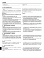 2
2
-
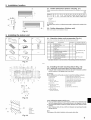 3
3
-
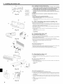 4
4
-
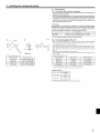 5
5
-
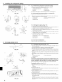 6
6
-
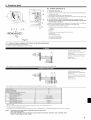 7
7
-
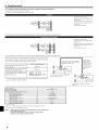 8
8
-
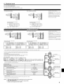 9
9
-
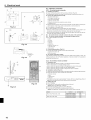 10
10
-
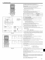 11
11
-
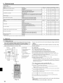 12
12
-
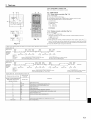 13
13
-
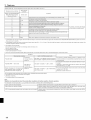 14
14
-
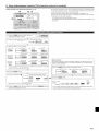 15
15
-
 16
16
-
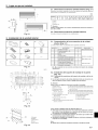 17
17
-
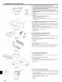 18
18
-
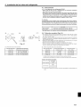 19
19
-
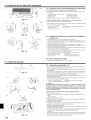 20
20
-
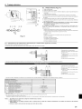 21
21
-
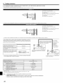 22
22
-
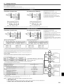 23
23
-
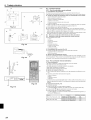 24
24
-
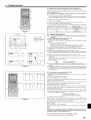 25
25
-
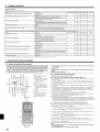 26
26
-
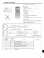 27
27
-
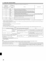 28
28
-
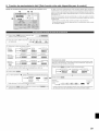 29
29
-
 30
30


Mitsubishi PKA-A18GA Guía de instalación
- Tipo
- Guía de instalación
- Este manual también es adecuado para
en otros idiomas
Artículos relacionados
Otros documentos
-
Mitsubishi Electric PUZ-HA24NHA1 Air Conditioners Manual de usuario
-
-
-
-
Mitsubishi Electric PUZ-A18NKA7 Manual de usuario
-
-
-
LG A3UW36GFAB.AWGTLAR Manual de usuario
-
Hitachi RAC-D10EX5 Manual de usuario
-