Craftsman 77236100N - 5.0 Ft-Lbs Gross Torque Edger Manual de usuario
- Categoría
- Herramientas de jardín
- Tipo
- Manual de usuario
Este manual también es adecuado para

Operator's Manual
Edger
500 Series Engine
9 Inch Blade
Model 536.772360
CAUTION: Before using this
product, read this manual and
follow all of its Safety Rules and
Operating Instructions.
-IcR"FTS"""°l-
Manual del usario
(pagina 43)
Orilladora
500 Series Engine
de 9 pulgada lamina
Modelo 536.772360
PRECAUCION: Antes de usar este
producto, lea este manual y siga todas
las reglas de seguridad e instrucciones
de operaci6n.
Sears, Roebuck and Co., Hoffman Estates, IL 60179 U.S.A.
1740549 www, sears,com/craftsman TP899-4502-01- EG-C

Craftsman Edger Warranty ......... 2
Operator Safety ................... 3
Symbols And Warnings ............ 3
Operator Safety Rules ................... 6
Assembly ......................... 8
Parts Packed Separately In Carton ........ 8
Removal From The Carton ............... 8
How To Raise The Handle ................ 9
Features .......................... 10
Operation ......................... 11
Before Starting The Engine ............... 11
HowTo Start The Engine ................. 13
How To Stop ........................... 14
How To Use The Depth Control Lever ...... 14
Edging Tips ............................ 18
Maintenance ...................... 19
Maintenance Chart ..................... 19
Recommended Maintenance ............. 19
How To Remove The Belt ................ 20
How To Replace The Blade ............... 21
Engine Maintenance ..................... 22
Storage ................................ 25
Troubleshooting .................. 26
Product Specifications ............ 27
Power Ratings .......................... 27
Illustrated Parts List ............... 30
Edger ................................. 30
Engine ................................ 34
TWO YEAR FULL WARRANTY ON CRAFTSMAN EDGER
When assembled, operated and maintained according to all supplied instructions, if this
Craftsman Edger fails due to a defect in material or workmanship within two years from the
date of purchase, return it to any Sears store, Sears Parts & Repair Center, or other
Craftsman outlet in the United States for free repair (or replacement if repair proves
impossible). This warranty does not include Edger spark plugs, blades or belts, which are
expendable parts that can wear out from normal use in less than two years.
This warranty applies for only 90 days if this Edger is ever used for commercial or rental
purposes.
This warranty gives you specific rights, and you may also have other rights which vary from
state to state.
Sears, Roebuck and Co., Dept. 817WA, Hoffman Estates, tL 60179

[[_ This manual contains safety
information to make you aware of the hazards and
risks associated with edgers, and how to avoid them.
The edger is designed and intended only for lawn
care edging and trimming, and should not be used for
any other purpose. It is important that you read and
understand these instructions, and that anyone who
operates this equipment also read and understand
these instructions.
A
The safety alert symbol _ is used to identify safety
information about hazards that can result in personal
injury. A signal word (DANGER, WARNING, or
CAUTION) is used with the alert symbol to indicate the
likelihood and the potential severity of injury. In addition,
a hazard symbol may be used to represent the type of
hazard.
DANGER indicates a hazard which, if not
avoided, will result in death or serious
injury.
WARNING indicates a hazard which, if not
avoided, could result in death or serious
injury.
WITH THIS PRODUCT:
Fire
[[_ Read
Manual
Explosion _ Oil
_. Kickback ._ Fuel
,,_,l_II_l,_,,,Hot Surface ]_ Fuel Shutoff
Toxic Fumes Fi _ On Off
Movin0Parts I'1
Choke
A
AI_ CAUTION indicates a hazard which, if not
avoided, might result in minor or moderate
injury.
Shock Stop
CAUTION, when used without the alert
symbol, indicates a situation that could result
in damage to the product.
A
Wear Eye _ Slow
Protection
_1_ WARNING
The engine exhaust from this product contains
chemicals known to the State of California to cause
cancer, birth defects, or other reproductive harm.
O_ Thrown
Objects
Fast

WARNING
When Adding Fuel
• Stop the engine. Let engine cool at least 2
minutes before removing the gas cap.
• Fill fuel tank outdoors or in well-ventilated
area.
• Do not overfill fuel tank. Fill tank to
approximately 1-1/2 inches below top of neck
to allow for fuel expansion.
• Keep gasoline away from sparks, open
flames, pilot lights, heat, and other ignition
sources.
• Check fuel lines, tank, cap, and fittings
frequently for cracks or leaks. Replace if
necessary.
• If fuel spills, wait until it evaporates before
starting engine.
When Starting Engine
• Make sure spark plug, muffler, fuel cap and air
cleaner are in place.
• Do not crank engine with spark plug removed.
• If engine floods, set choke to OPEN/RUN
position, place throttle in FAST and crank until
engine starts.
When Operating Equipment
• Do not tip engine or equipment at angle which
causes gasoline to spill.
• Do not choke carburetor to stop the engine.
Move the throttle control to the stop position to
stop the engine.
When Transporting Equipment
• Transport with fuel tank EMPTY or with fuel
shut-off valve OFF.
When Storing Gasoline Or Equipment With
Fuel In Tank
Store away from furnaces, stoves, water
heaters or other appliances that have pilot
light or other ignition source because they can
ignite gasoline vapors.
WARNING
• If there is natural or LP gas leakage in area, do
not start engine.
• Do not use pressurized starting fluids because
vapors are flammable.
WARNING
• Start and run engine outdoors.
• Do not start or run engine in enclosed area,
even if doors or windows are open.
WARNING
• Before starting the engine, make sure to raise
the blade.
• When starting engine, pull the starter cord
slowly until resistance is felt, then pull rapidly.
• Remove all external equipment/engine loads
before starting engine.
• Direct-coupled equipment components such as,
but not limited to, blades, impellers, pulleys,
sprockets, etc., must be securely attached.

WARNING
• Operate equipment with guards in place.
• Keep hands and feet away from rotating parts.
• Tie up long hair and remove jewelry.
• Do not wear loose-fitting clothing, dangling
drawstrings or items that could become
caught.
• Before unclogging the blade or making
repairs, stop the engine by moving the throttle
control to the stop position. Disconnect the
wire from the spark plug.
• Before you adjust the wheels or change the
position of the blade, stop the engine by
moving the throttle control to the stop position.
• Never leave the unit unattended while the
engine is running.
• Keep bystanders away from machine.
WARNING
°Bl
) . = • = . _ =
It"i'T_'T'_ I_ [.I,.I..l!li.]h!
_ I_ I--'-}-_o]dI _--,]i PlK_I (_!K_I-: l i l_,:-:- | _'_] I1 III ill
Allow muffler, engine cylinder and fins to cool
before touching.
Remove accumulated debris from muffler area
and cylinder area.
Install and maintain in working order a spark
arrester before using equipment on
forest-covered, grass-covered, brush-covered
unimproved land. The state of California
requires this (Section 4442 of the California
Public Resources Code). Other states may
have similar laws. Federal laws apply on
federal land.
,WARNING
Before performing adjustments or repairs:
• Disconnect the spark plug wire and keep it
away from the spark plug.
• Use only correct tools.
• Do not tamper with governor spring, links or
other parts to increase engine speed.
When testing for spark:
• Use approved spark plug tester.
• Do not check for spark with spark plug
removed.
WARNING
• Always wear safety glasses or eye shields while
you assemble, operate or perform maintenance
to the unit.
, WARNING
• Never sharpen the blade, always replace.
Sharpening the blade will cause the blade
to shatter.
• Before doing an adjustment, maintenance
or repair, disconnect the spark plug wire
and keep it away from the spark plug.

Operator Safety Rules
Before Use
• READ AND FOLLOW ALL INSTRUCTIONS -
Read the instruction manual carefully. Be
thoroughly familiar with the controls and the proper
use of the Edger. Know how to stop the Edger and
disengage the controls quickly.
• DRESS PROPERLY - Wear safety glasses or eye
shields to protect your eyes from thrown objects.
Do not wear loose clothing or jewelry. They can be
caught in moving parts. Use of sturdy gloves and
safety footwear is recommended. Wear footwear
that will improve footing on slippery surfaces. Do
not operate product when barefoot or wearing open
sandals. Always wear safety footwear, and pants or
slacks that cover your legs.
• STAY ALERT - Watch what you are doing - use
common sense. Do not operate product when
fatigued or under the influence of alcohol or drugs.
• KEEP OPERATING AREA CLEAR - Keep the
area of operation clear of all persons, particularly
small children and pets.
• INSPECT AREA - Thoroughly inspect the area
where the Edger is to be used and remove all
foreign objects. Objects struck by the cutting
member can cause severe injuries to persons.
Fuel Safety
• Allow muffler and engine areas to cool before
touching.
• Handle fuel with care; it is highly flammable.
• Use an approved container.
• Turn engine OFF and let engine cool at least 2
minutes before removing the gas cap.
• Check fuel supply before each use. Do not overfill
fuel tank. To allow for fuel expansion, fill fuel tank
to approximately 1-1/2 inches below top of fuel
tank neck. Replace gasoline cap securely.
• Fill fuel tank outdoors with extreme care. Never fill
fuel tank indoors or near appliances with pilot
lights, heaters, or other ignition sources. Replace
fuel tank cap securely and wipe up spilled fuel.
• Never remove the fuel tank cap or add fuel to a
running or hot engine.
• Never store fuel or Edger with fuel in the tank
inside a building where fumes may reach an open
flame or other ignition source.
Operating Safety
• Read and follow all instructions in this manual
carefully.
6
• Never operate the product without guards, plates
or other protective devices in place. Operate
product from position where guards block the line
of sight to the cutting member.
• Never allow children to operate the Edger. Keep
them away while it is operating. Never allow adults
to operate the Edger without proper instruction.
• Do not operate this machine if you are taking drugs
or other medication which can cause drowsiness or
affect your ability to operate this machine.
• Do not use this machine if you are mentally or
physically unable to operate it safely.
• To protect your eyes from foreign object that may
be thrown from the Edger, always wear safety
glasses or eye shields during operation or while
performing an adjustment or repair.
• Do not put hands or feet near or under rotating
parts including cutting area. Keep both hands on
handles when blade is rotating. Cutting member
coasts after turn off.
• Do not attempt to remove cut material nor hold
material to be cut when engine is running or when
cutting member is moving.
• Exercise extreme caution when operating on or
crossing drives, walks, or roads. Stay alert for
hidden hazards or traffic.
• Exercise caution to avoid slipping or falling. Don't
overreach or stand on unstable support. Keep good
footing and balance at all times.
• Use only for edging or trimming the type of growth
as described in the operating instructions. Do not
abuse the product. Do not use the product on
graveled surfaces.
• Never operate the Edger at high transport speeds
on slippery surfaces. Do not use product in rain or
wet locations. Look behind and use care when
backing.
• Stay alert for uneven sidewalks, holes in terrain or
other similar conditions when using product.
Always push slowly over rough ground.
• Never direct discharge of material toward
bystanders nor allow anyone near the area of
operation. Use care in directing discharge to avoid
glass enclosures, automobiles, and similar objects.
• Keep children and pets away while operating.
• Never operate the Edger without good visibility or
light.
• Do not run the engine indoors. The exhaust fumes
are dangerous, containing CARBON MONOXIDE,
an ODORLESS and DEADLY gas.
• Make sure that spark plug, muffler, fuel cap and air
cleaner are in place when operating.
• Make sure spark plug is disconnected when
clearing jammed material from cutting member. Do
not crank engine with spark plug remove.

• Iffuelspills,waituntilitevaporatesbeforestarting
engine.
• Takeallpossibleprecautionswhenleavingthe
Edgerunattendedorduringtransport.Stopthe
engine.
• DonotoverloadtheEdgercapacitybyattempting
totilltoodeepattoofastarate.
Maintenance / Repair / Adjustments
Safety / Storage
• Follow maintenance instructions given in Manual.
• Do not change the engine governor settings or
overspeed the engine.
• To reduce the risk of fire, do not allow excessive
grass, leaves, or grease to accumulate on the
product.
• After striking a foreign object, stop the engine.
Remove the wire from the spark plug, and keep the
wire away from the plug to prevent accidental
starting. Thoroughly inspect the Edger for any
damage. Repair the damage before restarting and
operating.
• Do not operate product with a damaged or
excessively worn cutting member.
• Have repairs made by a qualified dealer or
repairman. See that only identical replacement
parts are used.
• If Edger should start to vibrate abnormally, stop
engine and check immediately for the cause.
Vibration is generally a warning of trouble.
• Stop the engine whenever you leave the operating
position. Also, disconnect the spark plug wire
before unclogging the blade and when making any
repairs, adjustments, or inspections.
• When cleaning, repairing, or inspecting, shut off the
engine and make certain all moving parts have
stopped. Remove the wire from the spark plug, and
keep the wire away from the plug to prevent
accidental starting.
• Never attempt to make any adjustments while the
engine is running.
• When not in use, disconnect spark plug lead and
store product indoors in a dry place locked or
otherwise inaccessible to children.
• SAVE THESE INSTRUCTIONS

Parts Packed Separately In Carton
1 - Owner's Manual (not shown)
1 - Container Of Oil
2 - Hair Pin
1 - Control Rod
1 - Control Rod
_--- /u I!
L i
1 - Container of Oil
2 - Hair Pin
....:;:i,ii_il;;i;:i,ii_il;;i;:i,ii_il;;i;:i,ii_il;;i;:i,ii_il;;i;:i,ii_il;;i;:i,ii_il;;i;:i,ii_il;;i;:i,ii_il;;i;:i,ii_il;;i;:i,ii_il;;i;:i,ii_il;;i;:i,ii_il;;i;:i,ii_il;;i;:i,ii_il;;i;:i,ii_il;;i;:i,ii_il;;i;:i,ii_il;;i;:i,ii_il;;i;:i,ii_il;;i;:i,ii_il;;i;:i,ii_il;;i;:i,ii_il;;i;:i,ii_il;;i;:i,ii_il;;i;:i,ii_il;;i;:i,ii_il;;i;:i,ii_il;;i;:i,ii_il;;i;:i,ii_il;;i;:i,ii_il;;i;:i,ii_il;;i;:i,ii_il;;i;:i,ii_il;;i;:i,ii_il;;i;:i,ii_il;;i;:i,ii_il;;i;:i,ii_il;;i;:i,ii_il;;i;:i,ii_il;;i;:i,ii_il;;i;:i,ii_il;;i;:i,ii_il;;i;:i,ii_il;;i;:i,ii_il;;i;:i,ii_il;;i;:i,ii_il;;i;:i,ii_il;;i;:i,ii_il;;i;:i,ii_il;;i;:i,ii_il;;i;:i,ii_il;;i;:i,ii_il;;i;:i,ii_il;;i;:i,ii_il;;i;:i,ii_il;;i;:i,ii_il;;i;:i,ii_il;;i;:i,ii_il;;i;:i,ii_il;;i;:i,ii_il;;i;:i,ii_il;;i;:i,ii_il;;i;:i,ii_il;;i;:i,ii_il;;i;:i,ii_il;;i;:i,ii_il;;i;:i,ii_il;;i;:i,ii_il;;i;:i,ii_il;;i;:i,ii_il;;i;:i,ii_il;;i;:i,ii_il;;i;:i,ii_il;;i;:i,ii_il;;i;:i,ii_il;;i;:i,ii_il;;i;:i,ii_il;;i;:i,ii_il;;i;:i,ii_il;;i;:i,ii_il;;i;:i,ii_il;;i;:i,ii_il;;i;:i,ii_il;;i;:i,ii_il;;i;:i,ii_il;;i;:i,ii_il;;i;:i,ii_il;;i;:i,ii_il;;i;:i,ii_il;;i;:i,ii_il;;i;:i,ii_il;;i;:i,ii_il;;i;:i,ii_il;;i;:i,ii_il;;i;:i,ii_il;;i;:i,ii_il;;i;:i,ii_il;;i;:i,ii_il;;i;:i,ii_il;;i;:i,ii_il;;i;:i,ii_il;;i;:i,ii_il;;i;:i,ii_il;;i;:i,ii_il;;i;:i,ii_il;;i;:i,ii_il;;i;:i,ii_il;;i;:i,ii_il;;i;:i,ii_i_
_1_ WARNING
Always wear safety glasses or eye shields while
you assemble, operate or do maintenance to
the unit,
Figure 1 shows the product completely assembled.
References to the right or left side are from the
viewpoint of the operator's position behind the unit.
Removal From The Carton
1
2
3
Remove the bottle of oil and parts bag from the
carton.
Cut down all four corners of the carton.
Remove the packing material positioned around
the front and rear of the unit. Leave the packing
material on the bottom of the unit until the control
rod is assembled. This will keep the front wheel in
a stable position.
Lift the machine out of the carton and place on a
hard level surface,
Figure 1: Product Completely Assembled

How To Raise The Handle
1 Loosen the knobs (A) and raise the upper handle
(B) to the upright position. See Figure 2.
2 Tighten the knobs. Make sure the knobs are to the
outside of the handles as shown in Figure 2.
Figure 2: Handle Assembly
Insert the end of the control rod (C), from RIGHT
to LEFT, through the hole in the front wheel arm
(D). Attach with the hair pin (E) found in the parts
bag. See Figure 3.
Figure 3: Lower Control Rod Assembly
4
5
Push down on the handle to tilt the unit back.
Insert the other end of the control rod, from RIGHT
to LEFT, through the hole in the depth control lever
(F) and fasten with the hair pin. See Figure 4.
Figure 4: Upper Control Rod Assembly
6
7
8
Move the depth control lever forward to the
STARTING and TRANSPORT position.
Remove any packing material from the bottom of
the unit.
Twist the starter rope (G) through the rope guide
(H). See Figure 5,
Figure 5: Starter Rope
_- Assembly Checklist _"
For the best performance and satisfaction from this
quality product, please review the following checklist _'
before you operate the product: _,
_' All assembly instructions have been completed.
Check carton. Make sure no loose parts remain
in the carton.
All fasteners have been properly tightened.
Add engine oil to the engine. See "Before
Starting The Engine" in the Operation Section.
9

A EngineStopLever- Mustbeengagedto
allowtheenginetostartandrun,Release
tostoptheengine,
B StarterRopeHandle- Theengineis
equippedwithaneasypullrecoilstarter.
C BladeDepthLever- Controlsdepthofcut,
D ControlRod
E AirFilter
F FuelTank
G PrimerButton- Injectsfueldirectlyintothe
carburetorforcoldstarts,
H Dipstick
I BladeGuard- Usetopreventstonesand
debrisfrombeingthrownattheoperator,
J Blade
K BladeGuide
L QuillAssembly
IV1OilDrainPlug(locatedonbottomof
engine)
N EngineModelNumber
O ProductModelNumber
P AdjustableFrontWheel- Frontwheelcan
beloweredforedgingalongcurbs.
Q AdjustableRearWheel- Rightrearwheel
isadjustabletoleveltheEdgerwhen
edgingalongcurbs.
R IndexLever- Usetosettheangleofthe
blade,
A
\
R
Bottom View
Side View
10

Eye Protection
Read "Operator Safety Rules" section prior to using
this product.
Before Starting The Engine
CAUTION
This engine was shipped from the factory without
oil. If you start the engine without oil, the engine
will be damaged beyond repair and will not be
covered under warranty.
Always wear safety glasses. If you wear eye glasses,
put a Wide Vision Safety Mask over your eye glasses.
WARNING
• Always wear safety glasses or eye shields while
you assemble, operate or do maintenance to
the unit.
Oil Capacity
The engine holds approximately 20 ounces (0.6 liter)
of oil.
Oil Recommendation
Choose a viscosity from the following chart.
SAE 30 40°F and higher (5°0 and higher)
is good for all purpose use above 40°F, use below
40°F will cause hard starting.
10W-30 0 to IO0_F (- 18 to 38c'C)
is better for varying temperature conditions. This
grade of oil improves cold weather starting, but may
increase oil consumption at 80°F (27°C) or higher.
Check oil level frequently at higher temperatures.
Synthetic 5W-30 -20 to 120_'F(-30 to 40_C)
provides the best protection at all temperatures as
well as improved starting with less oil consumption.
5W-30 40_F and below (5°C and below)
is recommended for winter use, and works best in
cold conditions.
14
4
_,22
40 C
3O
20
I0
0
10
_20
-30
Check Oil Level
• Before you start the engine, check the oil level.
• Make sure the engine is level. Remove the dipstick
(A) from the engine oil fill (B).
• Make sure that the oil level is at the FULL mark
shown on the dipstick (see Figure 6).
F] Check oil level daily, or after every eight (8) hours.
Add Oil
1 Make sure the engine is level.
2 Clean the engine oil fill area of debris.
3 Remove the dipstick from the engine oil fill. Wipe
the dipstick with a clean cloth.
4 Install and tighten the dipstick. Remove and check
the oil level.
5 To add oil, pour the oil slowly into the engine oil fill.
6 Fill to the FULL mark shown on the dipstick (see
Figure 6). Pour slowly. Do not overfill.
Figure 6: Oil Fill
11

Gasoline Requirements
All gasoline is not the same. If a starting or
performance problem is encountered after new
gasoline has been used, try another service station or
change brands.
This engine is designed to operate on gasoline. The
emission control system for this engine is EM (Engine
Modifications).
Type of gasoline to use
Always use gasoline that meets these requirements:
• Clean, fresh, unleaded gasoline.
• A minimum of 87 octane/87 AKI (91 RON). At
altitudes over 5,000 feet, see "High-altitude use".
• Gasoline with up to 10% ethanol (gasohol) or up
to 15% MTBE (methyl tertiary butyl ether), is
acceptable.
• Use of any gasoline other than those approved
above will void the engine warranty. Some
areas require that fuel pumps be marked if the
gasoline contains alcohols or ethers. If you are not
sure if your gasoline contains alcohol or ethers that
are different than those approved above, then
check with the service station operator.
• Do not modify the engine fuel system or
carburetor to run on alternative fuels.
• Never mix oil with gasoline.
Gasoline Storage
Follow these guidelines when storing gasoline for
longer than 30 days:
• If fuel stabilizer is used, you do not need to drain
gasoline prior to storage.
• If no fuel stabilizer is used, then always remove
gasoline from engine during storage.
Fuel stabilizer
• If you do not want to remove the gasoline, add a
fuel stabilizer to any gasoline left in the fuel tank. A
fuel stabilizer will minimize gum deposits and acids.
If the fuel tank is almost empty, mix the fuel
stabilizer with fresh gasoline in a separate
container and add the mixture to the fuel tank.
Always follow the instructions on the stabilizer
container. Start the engine. Let the engine run for 3
minutes to allow the mixture to reach the
carburetor.
High-altitude use
At higher altitudes (over 5,000 feet), 85 octane / 85
AKI (89 RON) gasoline can be used. Operation at
high altitude may require a high-altitude carburetor jet
kit to improve performance and decrease fuel
consumption.
Adding Fuel
1 Stop the engine. Before you remove gas cap (A),
let the engine cool at least 2 minutes.
2 Remove the gas cap. Fill the fuel tank (B) to
approximately 1-1/2 inches below top of neck to
allow for fuel expansion. Be careful, do not overfill.
3 Before starting the engine, replace the gas cap.
Figure 7: Gas Cap
WARNING
When Adding Fuel
• Stop the engine. Let engine cool at least 2
minutes before removing the gas cap.
• Fill fuel tank outdoors or in well-ventilated
area.
• Do not overfill fuel tank. Fill tank to
approximately 1-1/2 inches below top of neck
to allow for fuel expansion.
• Keep gasoline away from sparks, open
flames, pilot lights, heat, and other ignition
sources.
• Check fuel lines, tank, cap, and fittings
frequently for cracks or leaks. Replace if
necessary.
12

How To Start The Engine
WARNING
• Start and run engine outdoors.
• Do not start or run engine in enclosed area,
even if doors or windows are open.
CAUTION
This engine was shipped from the factory without
oil. If you start the engine without oil, the engine
will be damaged beyond repair and will not be
covered under warranty.
Before starting the engine, make sure to raise the
blade. To raise the blade, move the depth control
lever (D) forward until the blade will not contact the
ground. See Figure 8.
WARNING
• Keep hands and feet away from rotating parts.
• Before starting the engine, raise the blade so
that it will not contact the ground.
Push the primer button (A) three times. Wait
approximately two seconds between each push,
See Figure 9,
IMPORTANT: Do not use the primer button to
start a warm engine.
A
Figure 9: Primer Button
3 With your left hand, pull back and hold the engine
stop lever (B) in the operating position. See
Figure 8.
4 To start the engine, hold the starter rope handle
(C) firmly with your right hand.
5 Slowly pull the starter rope handle until resistance
is felt, then pull quickly. DO NOT allow the starter
rope to snap back. Let the rope slowly rewind. If
the engine fails to start after three pulls, push the
primer button two times and again pull the starter
rope handle.
6 If assistance is needed, see the "Troubleshooting"
Chart.
o
D
Figure 8: Operating Controls
WARNING
• Before starting the engine, make sure to raise
the blade.
• When starting engine, pull the starter rope
handle slowly until resistance is felt, then pull
rapidly.
• Remove all external equipment/engine loads
before starting engine.
• Direct-coupled equipment components such
as, but not limited to, blades, impellers, pulleys,
sprockets, etc., must be securely attached.
13

How To Stop
Emergency Stopping
Release the engine stop lever (A). See Figure 10.
Normal Stopping
Move the depth control lever (B) forward to raise the
blade. Then, release the engine stop lever (A) (see
Figure 10).
Figure 10: Operating Controls
How To Use The Depth Control Lever
_,WARNING
• Keep a safe distance from rotating blade
during operation.
1 Start the engine.
2 To lower the cutting blade (C), pull the depth
control lever (B) back. To raise the cutting blade,
push the depth control lever forward (see
Figure 11).
3 Select the edging depth that you need.
NOTE: For deep edging, first cut at shallow
depths. Then, cut at greater depths until the
desired depth is obtained.
WARNING
• Operate equipment with guards in place.
• Keep hands and feet away from rotating parts.
• Tie up long hair and remove jewelry.
• Do not wear loose-fitting clothing, dangling
drawstrings or items that could become
caught.
• Never leave the unit unattended while the
engine is running.
• Keep bystanders away from machine.
B
c
Figure 11:Depth Control
14

How To Use The Index Lever
The cutting angle of the blade is controlled by the
index lever (A). The index lever has four cutting
positions, one vertical cut and three bevel cut position.
WARNING
1 Stop the engine. Do not change the position of the
index lever while the engine is running.
2 Raise the blade. See "How To Use The Depth
Control Lever" in the Operation Section.
3 For a vertical cut (C), set the index lever in position
(0 °) See Figure 12.
4 For a bevel cut (B), set the index lever in one of
the three bevel positions (15 °, 15 °, 30°). See
Figure 12.
5 Start the engine.
6 Move the depth control lever to the desired height.
See "How To Use The Depth Control Lever" in the
Operation Section.
The three bevel cutting positions cut a trench at an
angle and reduce the need to edge as often.
NOTE: For deep edging, first cut at shallow
depths. Then, cut at greater depths until the
desired depth is obtained.
WARNING
• Before you adjust the wheels or change the
position of the blade, release the engine stop
lever to stop the engine.
• Do not change the position of the index lever
while the engine is running.
• Change the cutting angle of the blade only
when the engine is not running.
0 o
0 o
15 °
B
30 °
Figure 12: Index Lever
15

How To Operate The Edger
The edger is designed to cut a small trench along
sidewalks and driveways or to trim close to trees,
flower beds, lampposts, etc. The main reason for
edging is to enhance the overall appeal of the yard. A
cleanly-edged yard gives a nice, overall finished look.
Always dress properly to protect against flying debris.
Wear substantial shoes, long pants and close-fitting
clothes that are not likely to get caught in the
machinery. Also, make sure to wear safety glasses or
goggles.
WARNING
3
4
Start the engine. See "How To Start The Engine".
Move the depth control lever back to lower the
blade. Do not try to edge too deep. It may take
several passes to obtain a nice clean edge.
5 Stand behind the edger and firmly hold the handle
(D). See Figure 13. As the blade begins to cut,
slowly move forward.
6 Proceed at a moderate pace until you are
comfortable with the handling of the edger.
NOTE: To operate on a curb, see the "Curb-hop
feature" section.
• Always wear safety glasses or eye shields while
you assemble, operate or do maintenance to
the unit.
To reduce the risk of flying debris, inspect the area
and remove any stones, sticks or other objects that
could be thrown by the edger.
If the lawn has not been edged in a while, it may take
several passes to obtain a nice, clean edge.
Because the front wheel and the right rear wheel are
adjustable, the edger can be used on uneven
surfaces, such as the curb shown in Figure 14.
NOTE: References to the right or left side of the
edger are from the viewpoint of the operator's
position behind the unit.
1 Before you start the engine, move the depth
control lever (D) forward until the blade (A) will not
contact the ground.
When edging along a concrete driveway or
sidewalk, set the wheels on the concrete and
position the blade along the left side of the
driveway. To position the edger on a curb, see the
"Curb-hop feature" section. To keep the blade from
hitting the driveway, make sure to keep the blade
guide (B) aligned with the side of the driveway
(see Figure 13).
Figure 13: Operation Of Edger
16

Curb-hopfeature
1 Stoptheengine.Neveradjustthewheelswhilethe
engineisrunning.
2 Settheindexleveratverticalcutpositionto
preventbladecontactwiththecurb.Themaximum
heightofacurbshouldnotexceed8inches.
3 Settheentireedgeronthecurb.
4 Inthecorrectposition,boththerightrearwheel(A)
andthefrontwheel(B)areofftothesideofthe
curbandtheleftrearwheelisonthecurbas
showninFigure14.Positiontheedgertoallowthe
wheelstobelowered.
5 Loosentherearwheelknob(C)tolowertheright
rearwheeltothepavement.Makesuretheedger
islevelfromsidetosideandtightentherearwheel
knob.
6 Usethedepthcontrollever(D)tolowerthefront
wheeltothesettingwherethefrontwheeltouches
thepavementandtheedgerislevel.
WARNING
• Never adjust the wheels or the blade while the
engine is running.
• While the engine is running, never leave the
unit unattended.
• Keep bystanders away from machine.
A
C
B
Figure 14: Curb-Hopping Feature
17

Edging Tips
• Edging is best performed when conditions are dry.
If the soil is too wet, dirt becomes packed around
the blade causing premature belt wear and
decreased performance.
If dirt does become packed around the blade, stop
the engine and remove the wire from the spark
plug. Remove the packed dirt and debris from the
blade,
• For deep edging, first cut at shallow depths. Then,
cut at greater depths until the desired depth is
obtained.
• For uniform edging, make sure the blade guide
rides on the surface.
• Before you begin mowing, try first edging around
the lawn. Use the edger along hard edges such as
sidewalks and driveways.
WARNING
• Operate equipment with guards in place.
• Keep hands and feet away from rotating parts.
• Tie up long hair and remove jewelry.
• Do not wear loose-fitting clothing, dangling
drawstrings or items that could become
caught.
• Before unclogging the blade or making
repairs, stop the engine by releasing the
engine stop lever. Disconnect the wire from
the spark plug.
• Never leave the unit unattended while the
engine is running.
• Keep bystanders away from machine.
18

* In dusty conditions, clean every 25 hours.
** In dusty conditions or when airborne debris is present, clean more often. Replace air cleaner if it is very dirty.
*** Change oil after first 5 to 8 hours of use, then every 50 hours. Change oi! every 25 hours when operating the engine
under heavy load or in high temperatures.
Recommended Maintenance
Regular maintenance will improve the performance
and extend the life of the equipment. See any Sears
or other qualified service dealer for service. Use only
original equipment replacement parts, Other parts
may not perform as well, may damage the unit,
and may result in injury, In addition, use of other
parts may void your warranty.
• Check the fasteners. Make sure all fasteners are
tight.
• Follow the information in the Maintenance section
to keep the unit in good operating condition,
WARNING
• Always wear safety glasses or eye shields while
you assemble, operate or perform maintenance
to the unit.
WARNING
Before performing adjustments or repairs:
• Disconnect the spark plug wire and keep it
away from the spark plug.
• Use only correct tools.
• Do not tamper with governor spring, links or
other parts to increase engine speed.
When testing for spark:
• Use approved spark plug tester.
• Do not check for spark with spark plug
removed.
19

How To Remove The Belt
The belt is made of a special compound. If the belt
becomes worn or breaks, replace the belt with an
original equipment belt.
1 Disconnect the spark plug wire from the spark
plug.
2 Tilt the machine backwards on the handle. Secure
the top of the handle under a bench or against a
wall,
3 Remove the screws (A) from the belt guard (B)
(see Figure 15).
4 Carefully note the twist of the belt (G) around the
engine pulley (F) (see Figure 16 and Figure 17).
Release tension on the belt by pushing the blade
bearing housing (E) back toward the engine to
compress the spring (D) (see Figure 16). Remove
the old belt. Replace with an original equipment
belt.
6 To install a new belt, reverse the above steps.
Make sure to twist the new belt as shown in
Figure 17.
NOTE: If the belt is not installed properly, the
blade will not turn in the proper direction and can
damage the blade or the belt.
o
A
B A
Figure 15: Belt Guard
F E
C
D
Figure 16: Belt Removal
Figure 17: Belt Twist
2O

How To Replace The Blade
The blade is subject to wear and damage, such as
nicks and dents, This is normal and does not affect its
function.
The blade does not require sharpening, Do not
sharpen the blade.
If both sides of the blade (A) are severely worn or
damaged, replace as follows.
1 Disconnect the spark plug wire from the spark
plug.
2 Remove the blade Iocknut (B) that holds the blade
to the drive shaft.
c
B
A
Figure 18: Blade Removal
3
4
NOTE: To remove or tighten the blade Iocknut,
always use the method shown in NO TAG.
First, secure wrench (C) onto the nut located
behind the blade. Then, to remove or tighten
the blade Iocknut, turn the wrench (D).
Remove the blade.
Install a new blade and secure with the blade
Iocknut. Tighten the blade Iocknut to a torque of
40-45 foot pounds.
Connect the spark plug wire to the spark plug.
IbWARNING
• Never sharpen the blade, always replace.
Sharpening the blade will cause the blade to
shatter,
• Keep a safe distance from rotating blade
during operation,
21

Engine Maintenance
CAUTION
All the components used to build this engine must
remain in place for the proper operation of this
engine.
Emission Control
Maintenance, replacement or repair of the emission
control devices and systems may be performed by
any non-road engine repair establishment or
individual. However, to obtain no charge repairs under
the terms and provisions of the Sears warranty
statement, any service or emission control part repair
or replacement must be performed by a factory
authorized dealer. See the Emission Warranty.
Carburetor Adjustment
Never make unnecessary adjustments to the
carburetor. The carburetor was set at the factory to
operate efficiently under most applications. However,
if adjustments are required, see any Sears or other
qualified service dealer for service.
CAUTION
The manufacturer of the equipment on which this
engine is installed specifies top speed at which the
engine will be operated. DO NOT EXCEED this
speed.
Spark Plug
Check the spark plug every 100 hours. Replace the
spark plug if, upon inspection, the electrode (A) is
burned or worn. Make sure that the spark plug is
clean. Check the gap with a wire gauge (B). If
necessary, reset to 0.030" (0.76 mm). See
(Figure 19).
NOTE: In some areas, local law requires using a
resistor spark plug to suppress ignition signals. If
this engine was originally equipped with a
resistor spark plug, use same type for
replacement.
A
B
Figure 19: Check Spark Plug
22

How To Change The Oil
Change oil after first 5 to 8 hours of use, then
every 50 hours. Change oil every 25 hours when
operating the engine under heavy load or in high
temperatures.
1 Make sure the engine is level.
2 Disconnect the spark plug wire and keep it away
from the spark plug.
3 With engine off but still warm, remove the oil drain
plug (A) as shown in Figure 20. Drain the oil into
an appropriate receptacle.
8 To add oil, pour the oil slowly into the engine oil fill.
The engine holds approximately 20 ounces (0.6
liter) of oil. For the type of oil to use, see "Oil
Recommendation" in the Operation Section.
9 Before checking the oil level, wait 2 minutes for the
oil to drain out of the oil fill. Then, install the
dipstick and check the oil level. Make sure the oil
is at the FULL mark shown on the dipstick (see
Figure 21). Do not overfill.
10 Connect the spark plug wire to the spark plug.
Figure 20: Oil Drain Plug
4 After draining all the oil, install and tighten the oil
drain plug.
5 Make sure the engine is level.
6 Clean the engine oil fill area of debris.
7 Remove the dipstick (B) from the engine oil fill (C).
Wipe the dipstick with a clean cloth.
Figure 21: Oil Fill
23

How To Service The Air Filter
Replace the air filter every 50 hours; more often in
dusty or dirty conditions,
CAUTION
Do not use pressurized air or solvents to clean the
filter. Pressurized air can damage the filter and
solvents will dissolve the filter.
1 Disconnect the spark plug wire from the spark
plug.
2 Remove screw (A) as illustrated in Figure 22.
3 Carefully remove the air cleaner to prevent dirt
from falling into carburetor.
4 Take the air cleaner apart and clean all parts. If the
filter (B) is very dirty or damaged, replace it with a
new filter.
NOTE: Wash the filter in liquid detergent and
water, Squeeze dry in a clean cloth, Saturate
the filter in clean engine oil and squeeze in a
clean cloth to remove ALL excess oil,
5 Install the filter and cup in the air cleaner body (C).
6 Install the air cleaner onto the carburetor. Tighten
the screw.
7 Connect the spark plug wire to the spark plug.
A
C
B
\
WARNING
Never start or run the engine with the air
cleaner or the filter removed as a fire or
explosion could result. A defective air filter will
cause a loss of engine power. If dirt or dust
enters the engine through the carburetor, the
result will be excessive wear or damage to the
engine. Replace a damaged or clogged air
cleaner immediately.
)
Figure 22: Change Air Filter
24

Storage
Follow these guidelines when storing the edger for
longer than 30 days.
Edger
• Completely clean the edger.
• Check the edger for worn or damaged parts.
Tighten all loose hardware.
• Apply a small amount of engine oil to all moving
parts, particularly the wheels.
• Put the edger in a building that has good
ventilation.
• Never store the edger with fuel in the fuel tank
inside a building where fumes may reach an open
flame or spark, or in a confined space such as a
car trunk.
• Store the Edger in the operating position with the
wheels down. If the Edger is stored in any other
position, oil from the crankcase will enter the
cylinder and cause a service problem.
• Cover the edger with a suitable protective cover
that does not retain moisture. Do not use plastic.
Never cover the edger while the engine and
exhaust areas are still warm as this can cause a
fire.
Engine
• If no fuel stabilizer is used, then either drain the
gasoline from the engine or let the engine run until
it is out of gasoline.
• If fuel stabilizer is used, you do not need to drain
gasoline prior to storage. See "Fuel Stabilizer"
section.
• While the engine is still warm, change the engine
oil. See "How To Change The Oil" in the
Maintenance section.
• Lubricate the piston / cylinder area. This can be
done by first removing the spark plug and pouring
1/2 ounce (15 ml.) of clean engine oil into the spark
plug hole. Then, install the spark plug.
• Slowly pull the starter rope. This will turn the
engine's crankshaft and distribute oil slowly through
the engine.
Fuel stabilizer
• If you do not want to remove the gasoline, add a
fuel stabilizer to any gasoline left in the fuel tank. A
fuel stabilizer will minimize gum deposits and acids.
If the fuel tank is almost empty, mix the fuel
stabilizer with fresh gasoline in a separate
container and add the mixture to the fuel tank.
Always follow the instructions on the stabilizer
container. Start the engine. Let the engine run for 3
minutes to allow the mixture to reach the
carburetor.
WARNING
When Storing Gasoline Or Equipment With
Fuel In Tank
• Store away from furnaces, stoves, water
heaters or other appliances that have pilot
light or other ignition source because they can
ignite gasoline vapors.
• Do not remove gasoline while inside a
building, near a fire, or while you smoke.
Gasoline fumes can cause an explosion or a
fire.
• Never cover the edger while the engine and
exhaust areas are still warm as this may
cause a fire.
25

PROBLEM
Engine difficult to start
or
Engine runs erratically
or
Engine will not run at full
speed
Engine smokes excessively
CAUSE
Stale fueJ
Dirt in fuel tank or out of fue
i i uel.
Carburetor out of adjustment
Fouled spark plug
Dirty air filter
Dirty air filter
CORRECTION
Drain fuel tank. Fill with fresh fuel.
Drain and clean fuel tank. Fill with fresh
Contact a Sears or other qualified
service dealer.
Clean and set spark plug gap.
Clean or replace air filter.
Clean or replace air filter.
Cutting blade will not rotate
Debris interferes with blade
Loose blade
Damaged V-belt
Clean debris from blade.
Tighten blade nut.
Replace V-belt,
Blade will not cut properly
Excessive vibration
Damaged quill bearings
Damage or worn blade
Loose parts
Replace the quill assembly. Contact a
Sears or other qualified service dealer.
Replace the blade.
Stop engine immediately. Tighte nal
fasteners. If vibration continues, take
the unit to a Sears or other qualified
service dealer.
Need Assistance?
Call 1-800-4-MY-HOME_ (1-800-469-4663)
26

Product Model No.: 536.772360
Gross Torque: 5:00 ft Ibsl
Displacement: 9.67 cu. in. (158.6 cc)
i quart
Oil Capacity: 20 oz. SAE-30W
i
spark Plug Gap: 0.030 inch (&76 mm)
Bore
2-9/16 in. (65.09 mm)
Stroke !-7/8 in; (47;63 mm)
Engine Power Rating Information
The gross power rating for individual gas engine
models is labeled in accordance with SAE (Society of
Automotive Engineers) code J1940 (Small Engine
Power & Torque Rating Procedure), and rating
performance has been obtained and corrected in
accordance with SAE J1995 (Revision 2002-05).
Torque values are derived at 3060 RPM; horsepower
values are derived at 3600 RPM. Actual gross engine
power will be lower and is affected by, among other
things, ambient operating conditions and
engine-to-engine variability. Given both the wide
array of products on which engines are placed and
the variety of environmental issues applicable to
operating the equipment, the gas engine will not
develop the rated gross power when used in a given
piece of power equipment (actual "on-site" or net
horsepower). This difference is due to a variety of
factors including, but not limited to, accessories (air
cleaner, exhaust, charging, cooling, carburetor, fuel
pump, etc.), application limitations, ambient operating
conditions (temperature, humidity, altitude), and
engine-to-engine variability. Due to manufacturing
and capacity limitations, Briggs & Stratton may
substitute an engine of higher rated power for this
Series engine.
27

The California Air Resources Board (CARB), U.S. EPA and
Sears are pleased to explain the Emissions Control System
Warranty on your small off-road engine (SORE). In California,
new small off-road engines model year 2007 and later must be
designed, built and equipped to meet the State's stringent anti-
smog standards.
Elsewhere in the United States, new non-road, spark-ignition
engines certified for model year 1997 and later must meet simi-
lar standards set forth by the U.S. EPA. Sears must warrant the
emissions control system on your engine for the periods of time
listed below, provided there has been no abuse, neglect or im-
proper maintenance of your small off-road engine.
Your emissions control system includes parts such as the carbu-
retor, air cleaner, ignition system, fuel line, muffler and catalytic
converter. Also included may be connectors and other emissions
related assemblies.
Where a warrantable condition exists, Sears will repair your
small off-road engine at no cost to you including diagnosis, parts
and labor.
Small off-road engines are warranted relative to emissions control parts defects for a period of two years, subject to provisions set
forth below. If any covered part on your engine is defective, the part will be repaired or replaced by Sears.
As the small off-road engine owner, you are responsible for the
performance of the required maintenance listed in your Operatin-
g and Maintenance Instructions. Sears recommends that you
retain all your receipts covering maintenance on your small off-
road engine, but Sears cannot deny warranty solely for the lack
of receipts or for your failure to ensure the performance of all
scheduled maintenance.
As the small off-road engine owner, you should however be
aware that Sears may deny you warranty coverage if your small
off-road engine or a part has failed due to abuse, neglect, im-
proper maintenance or unapproved modifications.
You are responsible for presenting your small off-road engine to
an Authorized Sears Service Dealer as soon as a problem ex-
ists.
The undisputed warranty repairs should be completed in a rea-
sonable amount of time, not to exceed 30 days.
If you have any questions regarding your warranty rights and
responsibilities, you should contact a Sears Service Representa-
tive at 1-800-469-4863.
The emissions warranty is a defects warranty. Defects are
judged on normal engine performance. The warranty is not re-
lated to an in-use emissions test.
The following are specific provisions relative to your Emissions Control Defects Warranty Coverage. It is in addition to the Sears
engine warranty for non-regulated engines found in the Operating and Maintenance Instructions.
1. Warranted Parts
Coverage under this warranty extends only to the parts
listed below (the emission control systems parts) to the ex-
tent these parts were present on the engine purchased.
a. Fuel Metering System
N Cold start enrichment system
F_ Carburetor and internal parts
R Fuel Pump
b. Air Induction System
R Air cleaner
N Intake manifold
c. Ignition System
N Spark plug(s)
F_ Magneto ignition system
d. Catalyst System
F_ Catalytic converter
N Exhaust manifold
N Air injection system, Pulse valve
e. Miscellaneous Items
N Vacuum, temperature, position, time sensitive valves
and switches
F_ Connectors and assemblies
2. Length of Coverage
Sears warrants to the initial owner and each subsequent
purchaser that the Warranted Parts shall be free from de-
fects in materials and workmanship which caused the failure
of the Warranted Parts for a period of two years from the
date the engine is delivered to a retail purchaser.
3. No Charge
Repair or replacement of any Warranted Part will be per-
formed at no charge to the owner, including diagnostic labor
which leads to the determination that a Warranted Part is
defective, if the diagnostic work is performed at an Autho-
rized Sears Service Dealer. For emissions warranty service
contact your nearest Authorized Sears Service Dealer as
listed in the "Yellow Pages" under "Engines, Gasoline,"
"Gasoline Engines," "Lawn Mowers," or similar category.
4. Claims and Coverage Exclusions
Warranty claims shall be filed in accordance with the provi-
sions of the Sears Engine Warranty Policy. Warranty cover-
age shall be excluded for failures of Warranted Parts which
are not original Sears parts or because of abuse, neglect or
improper maintenance as set forth in the Sears Engine War-
ranty Policy. Sears is not liable to cover failures of Warranted
Parts caused by the use of add-on, non-original, or modified
parts, by the use of add-on, non-original, or modified parts.
5. Maintenance
Any Warranted Part which is not scheduled for replacement
as required maintenance or which is scheduled only for reg-
ular inspection to the effect of "repair or replace as neces-
sary" shall be warranted as to defects for the warranty peri-
od. Any Warranted Part which is scheduled for replacement
as required maintenance shall be warranted as to defects
only for the period of time up to the first scheduled replace-
ment for that part. Any replacement part that is equivalent in
performance and durability may be used in the performance
of any maintenance or repairs. The owner is responsible for
the performance of all required maintenance, as defined in
the Sears Operating and Maintenance Instructions.
6. Consequential Coverage
Coverage hereunder shall extend to the failure of any en-
gine components caused by the failure of any Warranted
Part still under warranty.
28

Look For Relevant Emission Durability Period and
Air Index Information On¥our Engine Emission Label
Engines that are certified to meet the California Air Resources
Board (CARB) Tier 2 Emission Standards must display informa-
tion regarding the Emissions Durability Period and the Air Index.
Briggs & Stratton makes this information available to the con-
sumer on our emission labels. The engine emission label will in-
dicate certification information.
The Emissions Durability Period describes the number of
hours of actual running time for which the engine is certified to
be emissions compliant, assuming proper maintenance in ac-
cordance with the Operating & Maintenance Instructions. The
following categories are used:
Moderate:
Engine is certified to be emission compliant for 125 hours of ac-
tual engine running time.
Intermediate:
Engine is certified to be emission compliant for 250 hours of ac-
tual engine running time.
Extended:
Engine is certified to be emission compliant for 500 hours of ac-
tual engine running time. For example, a typical walk-behind
lawn mower is used 20 to 25 hours per year. Therefore, the
Emissions Durability Period of an engine with an intermedi-
ate rating would equate to 10 to 12 years.
Certain Briggs & Stratton engines will be certified to meet the
United States Environmental Protection Agency (USEPA)
Phase 2 emission standards. For Phase 2 certified engines, the
Emissions Compliance Period referred to on the Emissions
Compliance label indicates the number of operating hours for
which the engine has been shown to meet Federal emission re-
quirements.
For engines less than 225 cc displacement.
Category C = 125 hours
Category B = 250 hours
Category A = 500 hours
For engines of 225 cc or more displacement.
Category C = 250 hours
Category B = 500 hours
Category A = 1000 hours
29

CRAFTSMAN 536.772360
REPAIR PARTS
EDGER BLADE ASSEMBLY
25
26
17
18
11
12
14
16
15
Key
No. Part No. Description
1 Engine 500 Series
10T5020121 E1
2 0025x6MA Screw
3 52052MA Pulley, V3L
4 338490MA Key, Hi Pro #505
5 120580MA Screw, Set
6 1701067E701MA Frame, Edger
7 740096E701MA Quill Assembly
8 51603MA Spring
9 032x72MA Spring Pin
10 32668MA Belt, V4L
11 331076E701MA Blade Guard
12 002x53MA Bolt, Carriage
13 015x88MA Nut, 5/16-18
14 22265MA Flat washer
30
20
Key
No, Part No, Description
15 740296MA Blade, Edger
16 46023MA Nut, 1/2-20
17 338682MA Deflector, Rubber
18 337792E701MA Plate, Rubber Flap
19 336631MA Belt Guard
20 26x245MA Screw, 10-16x.50
21 1701069MA Lever, Blade
22 783641MA Washer
23 36368MA Pin, Hair
24 166x49MA Spring, Torsion
25 1701066MA Bracket, Index
26 26x263MA Screw, 1/4-20x0.50
-- 333874MA Decal, Caution Rotating Blade
-- 1740549MA Manual, Owner's

CRAFTSMAN 536.772360 REPAIR PARTS
WHEEL ASSEMBLY
6
20
19
22
21 _..
26
18
10
8
9
11
12
>
Key
No. Part No. Description
1 071294MA Knob, Wing
2 015x68MA Locknut, Flange
3 45222MA Spacer, Sleeve
4 845MA Washer
6 336545MA Tire & Rim
7 0009x6MA Bolt, Shoulder
8 011X16MA Ring, Ret E.
9 417098MA Flat washer
10 1701050E701 MA Arm, Front Wheel
11 015x88MA Nut, 5/16-18
12 336546MA Tire & Rim
13 1701052MA Spacer, Sleeve
14 1701054MA Washer, Nylon
Key
No.
15
16
17
18
19
20
21
22
23
24
25
26
Part No.
120393MA
180091 MA
0020x3MA
740091 MA
030x20MA
017x91MA
310896MA
180077MA
1498MA
126380MA
8082MA
6842MA
Description
Flat washer
Screw
Spring Washer
Rod, Axle Front
Pin, Cotter
Washer
Rod, Wheel Support
Screw, 5/16-18x0.75
Nut, 5/16-18
Bolt, 5/16-18x2.00
Clevis
Bracket, Curb-Hop
31

CRAFTSMAN 536.772360
23
26
\
11
25
23
4
7 9
\
10
16
16
20
20
/
19 r_ 17
\\ /@
\ \
\\\
12 \
27
REPAIR PARTS
HANDLE ASSEMBLY
18
15
19
/
\
Key
No,
1
2
3
4
5
6
7
8
9
10
11
12
13
14
32
Part No.
740142E701 MA
782585MA
339489MA
314276MA
337744MA
337775MA
340162MA
57796MA
339229MA
071372MA
1701062E701MA
36368MA
015x43MA
25644MA
Description
Upper Handle
Nut, 1/4-20
Cap, Operator Control
Nut, Push On
Bail, Operator Control
Torsion Spring
Clip, Grounding
Screw, #6x.50
Insulator, Oper Control
Cable Tie
Handle, Depth
Hair Pin
Nut, 5/16-18
Spring, Compression
Key
No, Part No. Description
15 138485MA Washer
16 315288MA Bolt, 5/16-18x.75
17 1498MA Nut, 5/16-18
18 1701051E701MA Lower Handle
19 711558MA Bolt, 5/16-18x.75
20 015x79MA Nut, 5/16-18
21 1701064E701MA Rod, Control
22 071495MA Wing Knob 5/16-18
23 672510MA Rope Guide
24 180081MA Screw
25 180024MA Screw, 1/4-20xl .25
26 1701063E701MA Bracket, Adj. Quadrant
27 126380MA Bolt, 5/16-18x2.00

33

BRIGGS & STRATTON ENGINE
MODEL 10T502-0121-E1
358 ENGINE GASKET SET
3@ 12 _ 163 _)
20 @
51 @
524 0
200_
REPAIR PARTS
1058 OWNER'S MANUAL]
[ 1330 REPAIR MANUAL ]
1095 VALVE GASKET SET
307
306
11
668 @ 745
718[_
_71I
O 524 O
524
51
523
13J
o35__
383
lO
34

BRIGGS & STRATTON ENGINE
MODEL 10T502-0121-E1
REPAIR PARTS
RER PART RER PART
NO. NO. DESCRIPTION NO. NO. DESCRIPTION DESCRIPTION
54 691111699653
399269
299819
5 690386
7 698717
8 791781
9 695890
10 691666
11
12
13
20
50
51
691245
692218
691640
391483S
699644
699649
Cylinder Asembly
Kit- Bushing/Seal
(Magneto Side)
Seal-Oil
(Magneto Side)
Head-Cylinder
Gasket-Cylinder Head
Breather Assembly
Gasket- Breather
Screw
(Breather Assembly)
163 271139s
200 691912
306 690400
307 690345
337 802592s
358 699933
383 89838s
426 691107
Screw
(Intake Manifold)
Gasket-Air Cleaner
Blade-Governor
Shield-Cylinder
Screw
(Cylinder Shield)
Plug-Spark
Gasket Set- Engine
Wrench-Spark Plug
Screw
RER
NO.
718
745
842
869
870
871
PART
NO.
690959 Pin-Locating
691146 Screw
(Brake)
691870 SeaI-O Ring
(Dipstick Tube)
699641 Seat-Valve
(Intake)
699642 Seat-Valve
(Exhaust)
699643 Bushing-Valve Guide
(Exhaust Valve)
Tube-Breather
Gasket-Crankcase
Screw
(Cylinder Head)
Seal-Oil
PTO Side)
Manifold-intake
Gasket-Intake
523 692040
523A 691913
524 691876
525 691320
635 665388
668 692889
(Governor Blade)
Dipstick
Dipstick
Seal-Dipstick Tube
Tube-Dipstick
Boot-Spark Plug
Spacer
1058
1095
1330
Note .....
63709 Bushing-Valve
Guide
(Intake Valve)
275508 Operator's Manual
498526 Gasket Set-Valve
270962 Repair Manual
35

BRIGGS & STRATTON ENGINE
MODEL 10T502-0121-E1
REPAIR PARTS
868 4_
87_
@
741 _/_
71%
24[_
12
o_
15 @ 22_
36

BRIGGS & STRATTON ENGINE
MODEL 10T502-0121-E1
REPAIR PARTS
RER PART RER PART RER PART
NO. NO. DESCRIPTION NO. NO. DESCRIPTION NO. NO. DESCRIPTION
4 698691 Sump-Engine
12 692218 Gasket-Crankcase
15 691680 Plug-Oil Drain
16 692989 Crankshaft
20 3914838 Seal-Oil
22 692551 Screw
(Crankcase Cover/
Sump)
24 2226988 Key-Flywheel
25 790908 Piston Assembly
(Standard)
Note .....
26
792532 Piston Assembly
(,020" Oversize)
790909 Ring Set
(Standard)
Note .....
792533 Ring Set
(,020" Oversize)
27 691588 Lock-Piston Pin
28 699659 Pin-Piston
(Standard)
29 699654 Rod-Connecting
32 691664 Screw
(Connecting Rod)
33 296676 Valve-Exhaust
34 296677 Valve-intake
35 690520 Spring-Valve
(Intake)
36 690520 Spring-Valve
(Exhaust)
40 692194 Retainer-Valve
43 698690 Slinger-Governor/Oil
45 691762 Tappet-Valve
46 691998 Camshaft
718A 499047 Pin-Locating
(Crankshaft)
741 691805 Gear-Timing
868 697338 Seal-Valve
37

BRIGGS & STRATTON ENGINE
MODEL 10T502-0121-E1
REPAIR PARTS
366'_
}17
393
612 390 _ 724
529
190A _
957
222
670 (_
188
534
U
535
42o_
678_
38

BRIGGS & STRATTON ENGINE
MODEL 10T502-0121-E1
REPAIR PARTS
RER PART RER PART RER PART
NO. NO. DESCRIPTION NO. NO. DESCRIPTION NO. NO. DESCRIPTION
24 222698s Key-Flywheel
90 699660 Carburetor
97 691931 Shaft-Throttle
106 691901 Seat-Inlet
130 691190 Valve-Throttle
163 2711398 Gasket-Air Cleaner
180 494406 Tank-Fuel
188 692198 Screw
(Control Bracket)
190 691697 Screw
(Fue! Tank to Cylinder)
190A 692198 Screw
(Fuel Tank)
201 690347 Link-Air Vane
209 690250 Spring-Governor
(Light Green)
211 691859 Spring-Governed Idle
222 691446 Bracket-Control
333 496914 Armature-Magneto
334 691061 Screw
(Magneto Armature)
365 790029 Screw
(Carburetor)
390 691839 Spring-Choke Dia-
phragm
393 691837 Screen-Carburetor
394 495770 Diaphragm-Carburetor
426 691107 Screw
(Governor Blade)
529 692189 Grommet
534 691417 Screw
(Air Cleaner)
535 698369 Filter-Air Cleaner Foam
536 698472 Cleaner-Air
576 697582 Wire Assembly
612 496046s Tube-Pick Up
617 2703448 SeaI-O Ring
(Intake Manifold)
633 691321 Seal-Choke/Throttle
Shaft
(Throttle)
670 691633 Spacer-Fuel Tank
724 697478 Retainer-Seal
851 493880s Terminal-Spark Plug
913 494409 Seat-Check Valve
957 791129 Cap-Fuel Tank
976 694394 Primer-Carburetor
39

BRIGGS & STRATTON ENGINE
MODEL 10T502-0121-E1
REPAIR PARTS
363
78
37
3O4
305
23
332
455
78
55
1036 EMISSIONS LABEL ]
[ 1329 REPLACEMENT ENGINE ]
I 48 SHORT BLOCK I
1211
1210
459
689 O
456 _
697
613_
Sl
4O

BRIGGS & STRATTON ENGINE
MODEL 10T502-0121-E1
REPAIR PARTS
RER PART RER PART RER PART
NO. NO. DESCRIPTION NO. NO. DESCRIPTION NO. NO. DESCRIPTION
23 690843
37 690482
37A 691209
48 398213
55 692144
58 697316
60 691915
65 690837
73 699850
78 692198
81 691179
300 692307
304 694051
305 692198
Flywheel
Guard-Flywheel
Guard-Flywheel
Short Block
Housing-Rewind Starter
(Blower Housing)
332 690662 Nut
(Flywheel)
363 19069 Puller-Flywheel
455 691236 Cup-Flywheel
1210 499901 Pulley/Spring Assembly
(Pulley)
1211 499901 Pulley/Spring Asembly
(Spring)
132910M9020018Replacement Engine
Rope-Starter
Grip-Starter Rope
Screw
(Rewind Starter)
Screen-Rotating
Screw
(Flywheel Guard)
Lock-Muffler Screw
Muffler
Housing-Blower
Screw
456 692299 PawI-Friction Plate
459 2815058 PawI-Ratchet
592 690800 Nut
(Rewind Starter)
597 691698 Screw
(Pawl Friction Plate)
608 499708 Starter-Rewind
613 691413 Screw
(Muffler)
1038 791938 Label-Emissions
(Transfer the Blower
Housing, Rewind
Assembly and related
parts from the original
engine to the replace-
ment engine. Transfer
Flywheel Assembly to
the replacement
engine) (Remove 698719
and add 790220).
41


Orilladora Modelo 536.772360
PRECAUCION: Antes de usar este producto, lea este manual y
siga todas las reglas de seguridad e instrucciones de operaci6n.
Garantia de la bordeadora Craftsman 43
Seguridad del operario ............ 44
Simbolos y advertencias ........... 44
Normas de seguridad para el operario ..... 47
Ensamble ......................... 49
Las piezas est_.n embaladas en cart6n
pot separado ......................... 49
Instrucciones para desembalar ........... 49
C6mo levantar la manija ................. 50
Caracteristicas .................... 51
Funcionamiento ................... 52
Antes de arrancar el motor ............... 52
C6mo arrancar el motor .................. 54
C6mo apagar el motor ................... 55
C6mo utilizar la palanca de control de
profundidad .......................... 55
C6mo manejar la bordeadora ............. 57
Consejos de corte ....................... 59
Mantenimiento .................... 60
Cronograma de mantenimiento ........... 60
Mantenimiento recomendado ............. 60
C6mo retirar la correa ................... 61
C6mo reemplazar la cuchilla .............. 62
Mantenimiento del motor ................. 63
Almacenamiento ........................ 66
Deteccion de fallas ................ 67
68
Especificaciones del producto .....
Informaci6n de potencia nominal
del motor ............................. 68
DOS ANOS DE GARANTJA TOTAL
DE LA BORDEADORA CRAFTSMAN
Si la bordeadora Craftsman se ensambla, maneja y mantiene de acuerdo con todas las
instrucciones suministradas, y esta falla a causa de un defecto en el material o en la
mano de obra dentro para dos afios de la fecha de compra, Ilevela a cualquier tienda de
Sears, Centro de partes y reparaciones de Sears o cualquier punto de venta de
Craftsman en los Estados Unidos para su reparaci6n (o reemplazo si es imposible
repararla) sin costo. Esta garantia no incluye las bujias, las cuchillas o las correas de la
bordeadora, que son partes fungibles que pueden desgastarse con el uso normal en
menos de dos afios.
Esta garantia se aplicar_. 0nicamente por 90 dias si la bordeadora se utiliza para fines
comerciales o de alquiler.
Esta garantia le da derechos especificos, y es posible que tenga otros derechos que
varian de un estado a otro.
Sears, Roebuck and Co., Dept. 817WA, Hoffman Estates, IL 60179
43

_k, [[_ Este manual contiene informaci6n de
seguridad para alertarlo sobre los peligros y riesgos
asociados con las bordeadoras, y para indicarle c6mo
evitarlos. La bordeadora esta diser_ada L_nicamente para
recortar y rebordear el c6sped, y no debe ser utilizada para
ningLin otro prop6sito. Es importante que lea y comprenda
estas instrucciones, y que cualquier persona que opere este
equipo tambien Io haga.
El simbolo de aviso de seguridad _ se utiliza para
identificar la informaci6n de seguridad relacionada con los
peligros que pueden ocasionar lesiones personales. Se
ser_aliza con una palabra (PELIGRO, ADVERTENCIA o
PRECAUCION) con el simbolo de aviso para indicar la
probabilidad de una lesi6n y su gravedad potencial. AdemAs,
un simbolo de peligro puede ser utilizado para representar el
tipo de peligro.
PELIGRO indica un peligro que, si no es
evitado, ocasionara la muerte o lesiones
graves.
ADVERTENClA indica un peligro que, si no
es evitado, podria ocasionar la muerte o
lesiones graves.
PRECAUCION indica un peligro que, si no es
evitado, podria ocasionar lesiones menores o
moderadas.
i
PRECAUCION, cuando aparece sin el
simbolo de aviso, indica una situaci6n que podria
ocasionar dar_os en el producto.
_IILADVERTENCIA
La descarga de escape que expele este motor per este
producto contiene sustancias quimicas que estAn
identificadas per el Estado de California como
causantes de cancer, defectos de nacimiento u otros
da_os que pueden ser perjudiciales para la
reproducci6n.
SiMBOLOS ASOCIADOS
CON ESTE PRODUCTO:
[[_ Leer el
Fuego manual
Explosi6n _ Aceite
_l_. Contragolpe __ Combustible
,,_,tlll_t,l_,,, Superficie .[_ Cierre de
i caliente combustible
Gases t6xicos
'_On (Encendido)
Off (Apagado)
Partes m6viles I"ql_l Estrangulador
_(_/_ Descarga @ Parar
el6ctrica
_4_ Use protecci6npara los ojos
Slow (Lento)
O_L Objetos _ Fast (Rapido)arrojados
44

,ADVERTENCIA
Cuando cargue combustible
• Detenga el motor. Deje que el motor se enfrie al
menos durante 2 minutos antes de quitar la tapa de
la gasolina.
• Llene el dep6sito de combustible en exteriores en
un 6rea bien ventilada.
• No Ilene el dep6sito de combustible en exceso.
Llene el dep6sito de combustible aproximadamente
hasta 3,8 cm (1-1/2 pulg.) debajo de la parte
superior del cuello para permitir la expansi6n del
combustible.
• Mantenga la gasolina lejos de chispas, llamas
expuestas o de encendido, calory otras fuentes de
encendido.
• Revise frecuentemente las tuberias, el dep6sito, la
tapa y los accesorios de combustible para saber si
existen grietas o filtraciones. Reemp!6celos si
iuese necesario.
• Si se derrama combustible, espere hasta que se
evapore antes de arrancar e! motor.
Cuando arranque el motor
• AsegQrese de que la bujia, el silenciador, la tapa
para el combustible y el depurador de aire se
encuentren en su lugar.
• No encienda el motor si se retir6 la bujfa.
• Si se ahoga el motor, coloque el estrangulador en
la posici6n OPEN/RUN (Abierto/Marcha), ponga la
mariposa en FAST (Rapido) y encienda hasta que
arranque el motor.
Cuando opere el equipo
• No incline el motor o equipo en un 6ngulo que
provoque el derrame de la gasolina.
• No estrangule el carburador para detener el motor.
Mueva el control de la mariposa a la posici6n de
detenci6n para detener el motor.
Cuando transporte el equipo
• Transp6rte!o con el dep6sito de combustible
VAdO.
Cuando almacene gasolina o el equipo con
combustible en el deposito
• AImacene lejos de hornos, estufas, calentadores
de agua u otros aparatos que tengan una llama u
otra fuente de encendido, ya que 6stos pueden
encender los vapores de la gasolina.
ADVERTENCIA
• Si existe una fuga de gas natural o gas licuado de
petr61eo en el Area, no arranque el motor.
• No use fluidos de arranque presurizados, ya que los
vapores son inflamables.
Arranque el motor y hagalo funcionar en exteriores.
No arranque ni haga funcionar el motor en un 6rea
cerrada, aOn cuando las puertas y ventanas esten
abiertas.
ADVERTENCIA
• AsegL_rese de subir la cuchilla antes de arrancar el
motor.
• Cuando arranque el motor, tire lentamente de la
cuerda del arrancador hasta que sienta una
resistencia, luego tire rapidamente.
• Retire todas las cargas extemas del equipo/motor
antes de arrancar el motor.
• Los componentes del equipo acoplados
directamente tales como, entre otros, cuchillas,
rotores, poleas, ruedas dentadas, etc. deben estar
bien ajustados.
45

ADVERTENCIA
• Opere el equipo con las protecciones en su lugar.
• Mantenga las manos y los pies alejados de las
partes giratorias.
• AmArrese el cabello, si Io tiene largo y quitese las
joyas.
• No use ropa suelta, tiras colgantes o articulos que
podrian engancharse.
• Antes de desatascar la cuchiila o realizar
reparaciones, detenga el motor moviendo el control
de la mariposa a la posici6n de parada.
Desconecte el cable de la bujia.
• Antes de ajustar las ruedas o cambiar la posici6n
de la cuchilla, detenga el motor moviendo el control
de la mariposa a la posicion de parada.
• Nunca deje la unidad sin supervisi6n mientras el
motor est6 en funcionamiento.
• Mantenga a los transeQntes alejados de la
mAquina.
ADVERTENCIA
m
Deje que el silenciador, el motor y las aletas se
enfrien antes de tocarlas.
Retire los desechos acumulados del Area de!
silenciador y del Area del cilindro.
Instale y mantenga en correcto funcionamiento un
amortiguador de chispas antes de usar el equipo
en terrenos arbolados, con matorrales o cesped sin
urbanizar. El estado de California Io exige (secci6n
4442 de California Public Resources Code). Otros
estados pueden tener leyes similares. Las leyes
federales se aplican en territorio federal.
ADVERTENCIA
Antes de realizar ajustes o reparaciones:
• Desconecte el cable de la bujia y mant6ngalo
lejos de ella.
• Use solamente las herramientas correctas.
• No altere el resorte, las conexiones u otras
piezas del regulador para aumentar la velocidad
del motor.
Cuando pruebe la chispa:
• Use un probador de bujias aprobado,
• No verifique la chispa si se retir6 la bujia,
kADVERTENCIA
• Use siempre anteojos de seguridad o viseras del
ocular mientras arme, opere o realice e!
mantenimiento de la unidad.
ADVERTENCIA
Nunca afile la cuchilla, siempre reemplacela.
Afilar la cuchilla harA que 6sta se quiebre.
Antes de realizar un ajuste, mantenimiento o
reparaci6n, desconecte e! cable de la bujia y
mant6ngalo lejos de ella.
46

Normas de seguridad para el operador
Antes de usar
• LEA Y SIGA TODAS LAS INSTRUCCIONES: Lea
detenidamente el manual de instrucciones. Familiaricese
completamente con los controles y el uso correcto de la
orilladora. Sepa c6mo detener la orilladora y desactivar
r@,pidamente los controles.
• ViSTASE ADECUADAMENTE: Use anteojos de
seguridad o viseras del ocular para proteger sus ojos de
los objetos que se lancen. No use ropa suelta o joyas.
Pueden quedar atrapadas en las piezas m6viles. Se
recomienda el uso de guantes resistentes y calzado de
seguridad. Use calzado que mejore el apoyo en
superficies resbaladizas. No opere el producto cuando
est@ descalzo ni use sandalias abiertas. Use siempre
calzado de seguridad y pantalones largos o deportivos
que cubran sus piernas.
• MANTENGANSE ALERTA: Fijese en Io que hace, use el
sentido com0n. No opere el producto cuando se sienta
cansado o est@ bajo la influencia de alcohol o
medicamentos.
• MANTENGA EL AREA DE OPERACION DESPEJADA:
Mantenga el @,rea de operaci6n libre de personas, en
especial de ni6os pequenos y mascotas.
• INSPECCIONE EL._.REA: Inspeccione meticulosamente
el _trea donde se utilizar@, la orilladora y retire todos los
objetos extrahos. Los objetos golpeados por la pieza
cortadora pueden provocar lesiones graves alas
personas.
Seguridad del combustible
• Deje que las _treas del silenciador y del motor se enfrien
antes de tocarlas.
• Manipule el combustible con cuidado, es altamente
inflamable.
• Use un recipiente aprobado.
• Apague el motor y deje que se enfrie al menos durante
2 minutos antes de quitar la tapa de la gasolina.
• Revise el suministro de combustible antes de cada uso.
No Ilene el dep6sito de combustible en exceso. Para
permitir la expansi6n del combustible, Ilene el dep6sito
de combustible aproximadamente hasta 3,8 cm (1-1/2
pulg.) debajo de la parte superior del cuello del dep6sito
de combustible. Vuelva a colocar la tapa de la gasolina
bien tapada.
• Llene el dep6sito de combustible en exteriores con
maximo cuidado. Nunca Ilene el dep6sito de combustible
en el interior o cerca de aparatos con llamas de
encendido, calefactores u otras fuentes de encendido.
Vuelva a colocar la tapa del dep6sito de combustible
bien tapada y limpie el combustible derramado.
• Nunca retire la tapa del dep6sito de combustible ni
cargue combustible con el motor funcionando o caliente.
• Nunca guarde combustible o la orilladora con
combustible en el dep6sito dentro de un inmueble donde
los gases puedan alcanzar una llama expuesta u otra
fuente de encendido.
Seguridad operativa
• Lea y siga cuidadosamente todas las instrucciones de
este manual.
• Nunca opere el producto sin las protecciones, placas ni
otros dispositivos de seguridad en su lugar. Opere el
producto desde una posici6n donde las protecciones
bloqueen la linea visual de la pieza cortadora.
• Nunca permita que los ni6os operen la orilladora.
Mant@ngalos lejos mientras est@ en funcionamiento.
Nunca permita que adultos sin la capacitaci6n adecuada
operen la orilladora.
• No opere esta maquina siesta tomando medicamentos
que puedan ocasionar somnolencia o afectar su
capacidad para operarla.
• No use esta m6,quina si est@, incapacitado mental o
fisicamente para operarla en forma segura.
• Para proteger sus ojos de objetos extra6os que pueda
lanzar la orilladora, use siempre anteojos o viseras de
seguridad durante la operaci6n o mientras realice un
ajuste ouna reparaci6n.
• No coloque las manos ni los pies cerca de piezas
giratorias, Io que incluye el @,reade corte. Mantenga
ambas manos en los mangos cuando la cuchilla est@
girando. La pieza cortadora se sigue moviendo despu@s
del corte.
• No intente retirar el material cortado ni sostener el
material que va a cortar cuando el motor est@
funcionando o cuando la pieza cortadora est@ en
movimiento.
• Tenga sumo cuidado al operar en cruces de caminos,
pasillos o carreteras. Mant@ngase alerta a los peligros
ocultos o al transito.
• Tenga cuidado para evitar resbalar o caerse. No intente
estirarse demasiado ni pararse sobre una superficie
inestable. Mantenga un buen apoyo y equilibrio en todo
momento.
• 0sela solamente para orillar o cortar el tipo de
crecimiento que se describe en las instrucciones de
funcionamiento. No abuse del producto. No use el
producto en superficies de grava.
• Nunca opere la orilladora a alta velocidad sobre
superficies resbalosas. No debe usar el producto bajo la
Iluvia ni en lugares mojados. Mire hacia atras y tenga
cuidado al retroceder.
• Mant@ngase alerta alas aceras irregulares, los hoyos en
el terreno u otras condiciones similares cuando use el
producto. Siempre empuje lentamente sobre terreno
Ileno de baches.
• Nunca oriente la descarga de material hacia los
transe0ntes ni permita que nadie se acerque al b,rea de
operaci6n. Tenga cuidado al dirigir la descarga para
evitar recintos de vidrio, autom6viles y objetos similares.
• Mantenga a ni_os y mascotas alejados mientras la est@
operando.
• Nunca opere la orilladora sin tener buena visibilidad o
luz.
• Nunca haga funcionar el motor en interiores. Los vapores
del escape son peligrosos y contienen MONOXIDO DE
CARBONO, un gas INODORO y MORTAL.
• AsegOrese de que la bujia, el silenciador, la tapa para el
combustible y el depurador de aire se encuentren en su
lugar cuando est@ en funcionamiento.
47

• AsegOresedequelabujiaest@desconectadacuando
retireelmaterialatascadodelapiezacortadora.No
enciendaelmotorsiseretir6labujia.
• Sisederramacombustible,esperehastaqueseevapore
antesdearrancarelmotor.
• Tometodaslasprecaucionesposiblescuandodejela
orilladorasinsupervisi6noduranteeltransporte.
Detengaelmotor.
• Nosobrecarguelacapacidaddelaorilladoraintentando
labrardemasiadoprofundoaunavelocidaddemasiado
r&pida.
Mantenimiento/Reparacion/Seguridad de
ajustes/Almacenamiento
• Siga las instrucciones de mantenimiento que se incluyen
en este manual.
• No cambie la configuraci6n del regulador de motor ni
acelere en exceso el motor.
• Para reducir el riesgo de incendio, no permita que se
acumule en exceso pasto, hojas o grasa en el producto.
• Despu@s de golpear algOn objeto extraSo, detenga el
motor. Desconecte el cable de la bujia y mant@ngalo
lejos de la bujia para evitar el arranque accidental.
Inspeccione meticulosamente la orilladora para saber si
tiene da6os. Repare los dahos antes de volver a
arrancar y operar.
No opere el producto con una pieza cortadora da_ada o
excesivamente gastada.
Solicite a un concesionario o t@cnico calificado que
realice las reparaciones. AsegOrese de que s61o se usen
repuestos id@nticos.
Si la orilladora comienza a vibrar de modo anormal,
detenga el motor y revisela inmediatamente para saber
cual es el motivo. Generalmente, la vibraci6n es una
advertencia de problemas.
Detenga el motor siempre que deje la posici6n de
operaci6n. Adem6,s, desconecte el cable de la bujia
antes de desatascar la cuchilla y cuando realice
cualquier reparaci6n, ajuste o inspecci6n.
Cuando realice reparaciones, limpiezas o inspecclones,
apague el motor y compruebe que todas las piezas
m6viles se hayan detenido por completo. Desconecte el
cable de la bujia y mant@ngalo lejos de la bujia para
evitar el arranque accidental.
Nunca intente realizar algOn ajuste mientras el motor
est@ en funcionamiento.
Cuando no la use, desconecte el cable de la bujia y
almacene el producto en interiores en un lugar cerrado y
seco, o que de alguna manera sea inaccesible para los
ni6os.
GUARDE ESTAS INSTRUCClONES.
48

Las piezas estan embaladas en carton
por separado
1 - Manual del propietario (no se muestra)
1 - Recipiente de aceite
2 - Pin de retenci6n
1 - Varilla de control
1 - Varilla de control
1 - Recipiente de aceite
2 - Pin de retencion
ADVERTENCIA
• Siempre use gafas de protecci6n o protectores
oculares cuando ensamble, maneje o realice el
mantenimiento de la unidad.
Figura 1 muestra el producto completamente ensamblado.
Las referencias a derecha o izquierda son desde el punto
de vista del operador, que ester pot detr_,s de la unidad.
Instrucciones para desembalar
1 Retire la botella de aceite y la bolsa de piezas de la caja.
2 Corte las cuatro esquinas del cart6n.
3 Retire el material de embalaje en torno a la parte
delantera y trasera de la unidad. Deje el embalaje en la
parte inferior de la unidad hasta que la varilla de control
est_ colocada. Esto mantendrb, a la rueda delantera en
una posici6n estable.
4 Levante la m_,quina para sacarla del cart6n y col6quela
en una superficie dura y nivelada.
Figura 1: Producto completamente armado
49

C6mo levantar la manija
1 Afloje las perillas (A) y levante la manija superior (B) a
su posici6n vertical. Ver Figura 2.
2 Ajuste las perillas. Aseg0rese de que las perillas est_n
colocadas por afuera de la manija come se muestra en
Figura 2.
4
5
Empuje la manija hacia abajo para inclinar la unidad
hacia atr_,s.
Introduzca el otro extremo de la varilla de control, de
DERECHA a IZQUIERDA, a trav_s del orificio de
palanca de control de profundidad (F) y ajuste la varilla
con el pin de retenci6n. Ver Figura 4.
E
F
C
Figura 4: Ensamble de la varilla de control superior
Figura 2: Ensamble de la manija
3 Introduzca el extremo de la varilla de control (C), de
DERECHA a IZQUIERDA, a trav_s del orificio en el eje
de la rueda delantera (D). Fije la varilla utilizando el pin
de retenci6n (E) que se encuentra en la bolsa de piezas.
Ver Figura 3.
D E
Figura 3: Ensamble de la varilla de control inferior
6 Mueva la palanca de control de profundidad hacia
adelante a la posici6n de STARTING y TRANSPORT
(ARRANQUE y DESPLAZAMIENTO).
7 Retire todo el material de empaque que se encuentre
debajo de la unidad.
8 Gire la cuerda de arranque (G) a trav_s de la guia de
cuerda (H). Ver Figura 5.
G
Figura 5: Cuerda de arranque
....:;:i,ii_il;;i;:i,ii_il;;i;:i,ii_il;;i;:i,ii_il;;i;:i,ii_il;;i;:i,ii_il;;i;:i,ii_il;;i;:i,ii_il;;i;:i,ii_il;;i;:i,ii_il;;i;:i,ii_il;;i;:i,ii_il;;i;:i,ii_il;;i;:i,ii_il;;i;:i,ii_il;;i;:i,ii_il;;i;:i,ii_il;;i;:i,ii_il;;i;:i,ii_il;;i;:i,ii_il;;i;:i,ii_il;;i;:i,ii_il;;i;:i,ii_il;;i;:i,ii_il;;i;:i,ii_il;;i;:i,ii_il;;i;:i,ii_il;;i;:i,ii_il;;i;:i,ii_il;;i;:i,ii_il;;i;:i,ii_il;;i;:i,ii_il;;i;:i,ii_il;;i;:i,ii_il;;i;:i,ii_il;;i;:i,ii_il;;i;:i,ii_il;;i;:i,ii_il;;i;:i,ii_il;;i;:i,ii_il;;i;:i,ii_il;;i;:i,ii_il;;i;:i,ii_il;;i;:i,ii_il;;i;:i,ii_il;;i;:i,ii_il;;i;:i,ii_il;;i;:i,ii_il;;i;:i,ii_il;;i;:i,ii_il;;i;:i,ii_il;;i;:i,ii_il;;i;:i,ii_il;;i;:i,ii_il;;i;:i,ii_il;;i;:i,ii_il;;i;:i,ii_il;;i;:i,ii_il;;i;:i,ii_il;;i;:i,ii_il;;i;:i,ii_il;;i;:i,ii_il;;i;:i,ii_il;;i;:i,ii_il;;i;:i,ii_il;;i;:i,ii_il;;i;:i,ii_il;;i;:i,ii_il;;i;:i,ii_il;;i;:i,ii_il;;i;:i,ii_il;;i;:i,ii_il;;i;:i,ii_il;;i;:i,ii_il;;i;:i,ii_il;;i;:i,ii_il;;i;:i,ii_il;;i;:i,ii_il;;i;:i,ii_il;;i;:i,ii_il;;i;:i,ii_il;;i;:i,ii_il;;i;:i,ii_il;;i;:i,ii_il;;i;:i,ii_il;;i;:i,ii_il;;i;:i,ii_il;;i;:i,ii_il;;i;:i,ii_il;;i;:i,ii_il;;i;:i,ii_il;;i;:i,ii_il;;i;:i,ii_il;;i;:i,ii_il;;i;:i,ii_il;;i;:i,ii_il;;i;:i,ii_il;;i;:i,ii_il;;i;:i,ii_il;;i;:i,ii_il;;i;:i,ii_il;;i;:i,ii_il;;i;:i,ii_il;;i;:i,ii_il;;i;:i,ii_il;;i;:i,ii_il;;i;:i,ii_il;;i;:i,ii_il;;i;:i,ii_il;;i;:i,ii_i_
_-Lista de verificaci6n de ensamble
Para obtener un rendimiento 6ptimo y mayor satisfacci6n de
este producto de calidad, revise esta lista de verificaci6n
antes de hacer funcionar el producto:
_" Todas las instrucciones de ensamble ban sido
completadas.
5O
_" Revise la caja. AsegOrese de que no quede ninguna
pieza suelta dentro de la caja.
_' Todos los sujetadores han sido ajustados
correctamente.
_' Agr_guele aceite al motor. Consulte "Antes de
arrancar el motor" en la secci6n Funcionamiento.

A Palancadeparadadelmotor:Debeestar
enganchadaparapermitirqueelmotorarranquey
semantengaenfuncionamiento.Su61telapara
apagarelmotor.
B Manijadelacuerdadearranque:Elmotorest&
equipadoconunarranquederetrocesof&cilde
jalar.
C Palancadecontroldeprofundidad:Controlala
profundidaddelcorte.
D Varilladecontrol
E Filtrodeaire
F Tanquedecombustible
G Bot6ncebador:Inyectacombustibledirectamenteal
carburadorparaarranqueenfrio.
H Varillaindicadoradeniveldeaceite
I Protectordelacuchilla:Evitaquelaspiedrasylos
desechosseanarrojadoshaciae!operario.
R
J Cuchilla
K Guia de la cuchilla
L Conjunto de eje hueco
M Tap6n de drenaje de aceite (ubicado en la parte
inferior del motor)
N NOmero de modelo del motor
O NOmero de modelo del producto
P Rueda delantera ajustable: La rueda delantera se
puede bajar para bordear en aceras.
Q Rueda trasera ajustable: La rueda trasera derecha
es ajustable para nivelar la bordeadora cuando se
trabaja en aceras.
R Palanca guia: 0sela para determinar el &ngulo de la
cuchilla.
E
F
O
Q
Vista desde abajo
L K
J
51

Lea la secci6n "Normas de seguridad de operaci6n" antes
de usar este producto.
Antes de arrancar el motor
PRECAUCleN
Este motor se despacha de f@,brica sin aceite. Si usted
arranoa el motor sin aceite, ocasionara da_os
irreparables en el motor y no estar@,n oubiertos por la
garantia.
Protecci6n para los ojos
Siempre use gafas de protecci6n. Si usted usa anteojos,
p6ngase una m_tscara de protecci6n encima de @stos.
ADVERTENCIA
• Siempre use gafas de protecci6n o protectores
oculares cuando ensamble, maneje o realice el
mantenimiento de la unidad.
Capacidad de aceite
El motor tiene capacidad para aproximadamente 0,6 litre
(20 onzas) de aceite.
Recomendacione8 de aceite
Seleccione un grado de viscosidad del siguiente cuadro.
SAE 30 5 °C y superior (40 °F y superior)
es bueno para todo prop6sito. Uselo a m_ts de 5 °C. El
uso a menos de 5 °C dificultar_t el arranque.
10W-30-18a38°C(Oa IO0°F)
es mejor para condiciones de cambio de temperatura.
Este grado de aceite mejora el arranque en climas frios,
pero puede incrementar el consumo de aceite a 27 °C
(80 °F) o m&s. -k Verifique con frecuencia el nivel de
aceite a temperaturas mas altas.
Sintetico 5W-30 -30 a 40 °C (-20 a 120 °F)
brinda la mejor protecci6n a toda temperatura asi como
tambi@n mejora el arranque con menor consumo de
aceite.
5W-30 5 °C e inferior (40 °F e inferior)
se recomienda para uso en el invierno y funciona mejor
en el frio.
4
.22
40 C
30
20
10
0
10
_.20
_30
Verifique el nivel de aceite
• Antes de arrancar el motor, verifique el nivel de aceite.
• AsegQrese de que el motor est@ nivelado. Retire la varilla
indicadora de nivel de aceite (A) de la boca de Ilenado
del motor (B).
• AsegQrese de que el nivel de aceite est@ en la marca
FULL (LLENO) que figura en la varilla indicadora (ver
Figura 6).
• Verifique el nivel de aceite diariamente o despu@s de
cada ocho (8) horas de operaci6n.
Armada aceite
1 Aseg_rese de que el motor est@ nivelado.
2 Limpie los desechos del _trea de Ilenado de aceite del
motor.
3 Retire la varilla indicadora de nivel de aceite de la boca
de Ilenado del motor. Limpie la varilla indicadora con un
trapo limpio.
4 Coloque y ajuste la varilla indicadora. Retirela y verifique
el nivel de aceite.
5 Para agregar aceite, vierta lentamente el aceite en el
Ilenado de aceite del motor.
6 Llene de aceite hasta la marca FULL (LLENO) que
figura en la varilla indicadora (ver Figura 6). Vierta el
aceite lentamente. No Io Ilene en exceso.
Figura 6: Llenado de aceite
52

Requisitos de gasolina
No cualquier gasolina es igual. Si detecta un problema de
arranque o de rendimiento luego de usar una gasolina
nueva, pruebe con otra estaci6n de servicio o cambie de
marca.
Este motor est@, disefiado para operar con gasolina. El
sistema de control de emisiones para este motor es EM
(Modificaciones del Motor).
Tipo de gasolina a utilizar
Siempre use gasolina que cumpla con estos requisitos:
• Gasolina limpia, fresca, y sin plomo.
Un minimo de 87 octanos / 87 AKI (91 RON). Para
altitudes superiores a 1.524 m (5.000 pies), consulte a
continuaci6n la secci6n "Uso para altitudes altas".
• La gasolina con hasta un 10% de etanol (gasohol) o
hasta un 15% de MTBE (@ter butilico terciario metilico)
es aceptable.
• El uso de otras gasolinas que no sean aquellas
aprobadas anteriormente invalidara la garantia del
motor. Algunas @,reas requieren que se marquen las
bombas de combustible si la gasolina contiene alcoholes
o @teres. Si no est@, seguro de si su gasolina contiene
alcohol o @teres que sean diferentes a los aprobados
anteriormente, consOltelo con el operario de su estaci6n
de servicio.
• No modifique el sistema de combustible o el
carburador del motor para utilizar combustibles
alternativos.
• Nunca mezcle aceite con gasolina.
Almacenamiento de gasolina
Siga estas pautas para almacenar gasolina durante un
periodo mayor a 30 dias:
• Si utiliza un estabilizador de combustible, no necesita
drenar la gasolina para su almacenamiento.
• Si no utiliza un estabilizador de combustible, siempre
extraiga la gasolina del motor para su almacenamiento.
Estabilizador de combustible
• Si no desea extraer la gasolina, agregue un estabilizador
de combustible a la gasolina que quede en el tanque. El
estabilizador de combustible minimizar@, los dep6sitos de
resina y los _tcidos. Si el tanque esta casi vacio, mezcle
el estabilizador de combustible con gasolina fresca en
otro recipiente y agregue la mezcla al tanque de
combustible. Siga siempre las instrucciones que
aparecen en el envase del estabilizador. Arranque el
motor. Deje el motor en marcha durante 3 minutos para
permitir que la mezcla Ilegue al carburador.
U8o para altitudes alta8
Se puede utilizar gasolina de 85 octanos / 85 AKI (89 RON)
en altitudes superiores (m_ts de 1.524 m [5.000 pies]). El
funcionamiento en altitud alta puede requerir un kit de
boquerel de carburador para altitudes altas para mejorar el
rendimiento y reducir el consumo de combustible.
Aprovisionamiento de combustible
1 Apague el motor. Antes de retirar la tapa de gasolina (A),
deje que el motor se enfrie por Io menos 2 minutos.
2 Retire la tapa de gasolina. Llene el tanque de
combustible (B) hasta aproximadamente 3,8 cm (1-1/2
pulgadas) por debajo de la parte superior del cuello para
permitir la expansi6n del combustible. Tenga cuidado de
no Ilenar excesivamente.
3 Antes de arrancar el motor, vuelva a colocar la tapa del
tanque de gasolina.
Figura 7: Tapa del tanque de gasolina
ADVERTENCIA
Cuando ahada combustible
• Apague el motor. Deje que se enfrie por Io menos
2 minutos antes de retirar la tapa deltanque de
gasolina.
• Llene eltanque de combustible en exteriores o
en un area bien ventilada.
• No Ilene demasiado el tanque de combustible.
Llene el tanque aproximadamente 3,8 cm (1-1/2
pulgadas) por debajo de la parte superior del cuello
para permitir la expansi6n del combustible.
• Mantenga la gasolina a distancia de chispas,
llamas abiertas, llamas piloto, calory otras
fuentes de ignici6n.
• Compruebe con frecuencia si existen grietas o
fugas en las mangueras de combustible, el
tanque, la tapa yen los accesorios. C@,mbielos si
es necesario.
53

Como arrancar el motor
ADVERTENCIA
Arranque el motor y op6relo en exteriores,
No arranque el motor ni Io opere en un _trea
cerrada, aun si las puertas o las ventanas se
encuentran abiertas.
PRECAUCION
Este motor se despacha de f_,brica sin aceite. Si usted
arranca el motor sin aceite, ocasionar_t da6os
irreparables en el motor y no estar_,n cubiertos por la
garantia.
Antes de arrancar el motor, asegOrese de levantar la
cuchilla. Para levantar la cuchilla, mueva la palanca de
control de profundidad (D) hacia adelante hasta que la
cuchilla no toque el suelo. Ver Figura 8.
ADVERTENCIA
• Aleje las manos y los pies de las partes giratorias.
• Antes de arrancar el motor, levante la cuchilla para
que no toque el suelo.
c
Figura 8: Controles de funcionamiento
Presione el bot6n cebador (A) tres veces. Espere
aproximadamente dos segundos cada vez que presione
el bot6n. Ver Figura 9.
IMPORTANTE: No use el boton cebador para
arrancar un motor caliente.
A
Figura 9: Botdn cebador
3 Con la mano izquierda, jale hacia atr_ts la palanca de
parada del motor (B) y sostengala en la posici6n de
funcionamiento. Ver Figura 8.
4 Para arrancar el motor, sostenga la manija de la cuerda
de arranque (C) firmemente con su mano derecha.
5 Jale lentamente la manija de la cuerda de arranque
hasta que se sienta resistencia, despu6s j_,lela
r_tpidamente. NO deje que la cuerda de arranque
retroceda bruscamente. Deje que la misma retroceda
lentamente. Si el motor no Iogra arrancar luego de jalar
tres veces, presione el bot6n cebador dos veces y jale
nuevamente la manija de la cuerda de arranque.
6 Si necesita asistencia, consulte el cuadro "Detecci6n de
fallas".
ADVERTENCIA
• Antes de arrancar el motor, asegQrese de levantar la
cuchilla.
• Cuando arranque el motor, jale lentamente la manija
de la cuerda de arranque hasta que se sienta
resistencia, despu6s j_tlela r_tpidamente.
• Retire todas las cargas externas del equipo/motor
antes de arrancar el motor.
• Los componentes de acople directo del equipo tales
como, pero no s61o, cuchillas, impulsores, poleas,
dientes de pi6ones, etc. se deben sujetar
firmemente.
54

Como apagar el motor
Parada de emergencia
Suelte la palanca de parada del motor (A). Ver Figura 10.
Parada normal
Mueva la palanca de control de profundidad (B) hacia
adelante para levantar la cuchila. Luego, suelte la palanca
de parada del motor (A) (ver Figura 10).
Figura 10. Controles de funcionamiento
Como utilizar la palanca de control de
profundidad
NOTA: Para un corte profundo, primero corte la
superficie. Luego, corte a mayor profundidad hasta
obtener Is profundidad deseada.
ADVERTENCIA
• Mantenga una distancia segura cuando la cuchilla
gire durante el funcionamiento de la unidad.
1 Arranque el motor.
2 Para bajar la cuchilla de corte (C), jale la palanca de
control de profundidad (B) hacia atr_ts. Para levantar la
cuchila de corte, empuje la palanca de control de
profundidad hacia adelante (ver Figura 11).
3 Seleccione la profundidad de corte que necesite.
ADVERTENCIA
• Opere el equipo con los protectores en su lugar.
• Aleje las manos y los pies de las partes giratorias.
• Rec6jase el cabello y quitese las joyas.
• No use ropa floja, tiras que cuelguen o articulos
que puedan ser enganchados.
• Nunca deje la unidad sin vigilancia mientras el
motor se encuentre en funcionamiento.
• Mantenga a otras personas a distancia.
B
C
Figura 11. Control de profundidad
55

C6mo utilizar la palanca guia
El angulo de corte de la cuchilla se controla per medio de la
palanca guia (A). La palanca guia tiene cuatro posiciones
de corte, un corte vertical y tres posiciones de angulo de
corte. Las tres posiciones de __ngulo de corte hacen el corte
en determinado Angulo y reducen la necesidad de bordear
con frecuencia.
,ADVERTENCIA
1 Detenga el motor. No cambie la posici6n de la palanca
guia con el motor en funcionamiento.
2 Levante la cuchilla. Consulte "C6mo utilizar la palanca
de control de profundidad" en la secci6n Operaci6n.
3 Para efectuar un corte vertical (C), coloque la palanca
guia en la posici6n (0 °) Ver Figura 12.
4 Para efectuar un corte en angulo (B), coloque la palanca
guia en una de las posiciones de corte en angulo (! 5 o,
30 °, 45°). Ver Figura 12.
5 Arranque el motor.
6 Ponga la palanca de control de profundidad en la altura
deseada. Consulte "C6mo utilizar la palanca de control
de profundidad" en la secci6n Operaci6n.
NOTA" Para un corte profundo, primero corte la
superficie. Luego, corte a mayor profundidad hasta
obtener la profundidad deseada.
,ADVERTENCIA
• Antes de ajustar las ruedas o cambiar la posici6n
de la cuchilla, suelte la palanca de parada de!
motor para apagar el motor.
• No cambie la posici6n de la palanca guia con el
motor en funcionamiento.
• Cambie el angulo de corte de la cuchilla
L_nicamente cuando el motor est6 apagado.
0 o
15 °
30 °
0 o
15°
B
30°
Figura 12: Palanca gu[a
56

Como manejar la bordeadora
La bordeadora esta dise_ada para cortar pequehas zanjas
a Io largo de las aceras y los caminos para ingreso de
vehiculos o para recortar alrededor de _,rboles, macizo de
flores, postes de luz, etc. La raz6n principal del uso de la
bordeadora es mejorar la apariencia general del jardin. Un
jardin cortado de un modo prolijo da un aspecto agradable y
terminado.
Siempre utilice ropa apropiada para protegerse de los
desechos que puedan salir arrojados. Use zapatos s61idos,
pantalones largos y ropa cenida que no pueda engancharse
con el equipo. Adem_ts, asegQrese de usar gafas o anteojos
de protecci6n.
ADVERTENCIA
3 Arranque el motor. Consulte "C6mo arrancar el motor".
4 Mueva la palanca de control de profundidad hacia atr_ts
para bajar la cuchilla. No intente cortar muy profundo.
Puede Ilevarle varias pasadas obtener un corte prolijo.
5 P_trese detr_ts de la bordeadora y sostenga la manija
firmemente (D). Ver Figura 13. Cuando la cuchilla
comience a cortar, mu_vase lentamente hacia adelante.
6 Contin[_e a un ritmo moderado hasta que adquiera
seguridad en el manejo de la bordeadora.
NOTA: Para utilizar en bordillos de aceras, consulte la
seccion "Bordeado de aceras".
• Siempre use gafas de protecci6n o protectores
oculares cuando ensamble, maneje o realice el
mantenimiento de la unidad.
Para reducir el riesgo de que haya desechos que puedan
salir disparados, inspeccione el _trea y retire cualquier
piedra, palo u otro objeto que pueda ser arrojado por la
bordeadora.
Si el cesped no ha sido cortado por bastante tiempo, puede
Ilevarle varias pasadas dejar el c_sped bonito y prolijo.
Dado que la rueda delantera y la rueda trasera derecha son
ajustables, la bordeadora se puede utilizar en superficies
con desnivel, como la acera que se muestra en la Figura 14.
NOTA: Las referencias a la derecha o a la izquierda de la
bordeadora son desde el punto de vista de la posicion
del operario detr',s de la unidad.
1 Antes de arrancar el motor, mueva la palanca de control
de profundidad (D) hacia adelante hasta que la cuchilla
(A) no toque el suelo.
Cuando corte a Io largo de aceras o caminos para
ingreso de vehiculos pavimentados, fije las ruedas en el
pavimento y coloque la cuchilla al lado izquierdo del
camino. Para colocar la bordeadora en posici6n en una
acera, consulte la secci6n "Bordeado de aceras". Para
evitar que la cuchilla golpee el camino, asegOrese de
mantener la guia de la cuchilla (B) alineada con el borde
del camino. Ver Figura 13.
c
D
Figura 13: Funcionamiento de la bordeadora
57

Bordeado de aceras
1 Detenga el motor. Nunca ajuste las ruedas con el motor
en funcionamiento.
2 Coloque la palanca guia en la posici6n de corte vertical
para que la cuchilla no toque la acera. La altura maxima
de la acera no deber_, superar las 20,3 cm (8 pulgadas).
3 Coloque toda la bordeadora en la acera.
4 En la posici6n correcta, tanto la rueda trasera derecha
(A) como la rueda delantera (B) est6,n debajo del
bordillo, al costado de la acera y la rueda trasera
izquierda est,, sobre la acera como se muestra en la
Figura 14. Coloque la bordeadora en posici6n para
permitir el descenso de las ruedas.
5 Afloje la perilla de la rueda trasera (C) para bajar la
rueda trasera derecha hasta la calzada. AsegOrese de
que la bordeadora quede nivelada a los lados y ajuste la
perilla de la rueda trasera.
Utilice la palanca de control de profundidad (D) para
bajar la rueda delantera hasta que haga contacto con la
calzada y la bordeadora quede nivelada.
ADVERTENCIA
• Nunca ajuste las ruedas ni la cuchilla mientras con
el motor en funcionamiento.
• Nunca deje la unidad sin vigilancia mientras el
motor se encuentre en funcionamiento.
• Mantenga a otras personas a distancia.
A
C
B
Figura 14: Bordeado de aceras
58

Consejos de corte
• El corte se realiza mejor cuando la superficie se
encuentra seca. Si la tierra est,, demasiado hOmeda, la
cuchilla se Ilena de suciedad provocando un desgaste
premature de la correa y una reducci6n en el
rendimiento.
• Si la cuchilla se Ilena de suciedad, apague el motor y
retire el cable de la bujia. Retire la suciedad y los
desechos de la cuchilla.
• Para un corte profundo, primero corte la superficie.
Luego, corte a mayor profundidad hasta obtener la
profundidad deseada.
• Para Iograr un corte uniforme, asegOrese de que la guia
de la cuchilla pase per la superficie.
Antes de comenzar a cortar el cesped, intente primero
bordear con la bordeadora. 0sela en bordes dificiles de
alcanzar como aceras y caminos para ingreso de
vehiculos.
ADVERTENCIA
• Opere el equipo con los protectores en su lugar.
• Aleje las manes y los pies de las partes giratorias.
• Rec6jase el cabello y quitese las joyas.
• No use ropa floja, tiras que cuelguen o articulos
que puedan ser enganchados.
• Antes de desobstruir o reparar la cuchilla, apague
el motor soltando la palanca de parada del motor.
Desconecte el cable de la bujia.
• Nunca deje la unidad sin vigilancia mientras el
motor se encuentre en funcionamiento.
• Mantenga a otras personas a distancia.
59

Antes
de cada
U80
PROCEDIMIENTO
a Lubrique t0d0s !0S punt0s de! eje Central
O
R Lubrique los ejes de las ruedas
D
E
A
Controle la co[rea de transmisi6n
D
O Ajuste todos los sujetadores
A Revise ta cuchilla para comprobar si ester
desgastada o dar_ada
Controle el aceite _/
M Cambie el aceite*#
O Limpie el sistema de enfriamiento *
T **
_ Limpie / Reemplace e! fi!tro de aire
O
A las
primeras Cada
5a8 25
horas horas
,/
Cada
50
horas
I
,/
Cada Antes del
,00 o,moseno-
horas miento
i iiilii
-7
R Revise el mofle _/
Limpie i ReemplaCe la bui[a I I I I' _'
* En condiciones de mucho polvo, limpie cada 25 horas.
** Limpie con mayor frecuencia en condiciones de mucho polvo o cuando e! aire contenga muchas particulas. Reemplace e!
filtro de aire siesta muy sucio.
*** Cambie el aceite deepues de las primerae 5 a 8 horae de uso, y luego cada 50 horas. Cambie el aceite cada 25 horas
cuando opere el motor bajo carga pesada o en altas temperaturas ambiente.
Mantenimiento recomendado
El mantenimiento de rutina mejorara el rendimiento y
aumentar_ la vida L_tildel equipo. Para servicio consulte a
un agente autorizado de Sears. Utilice 861o repueetoe
originales para los equipoe. Ee poeible que otros
repuestoe no funcionen tan bien, dahen la unidad y
hasta pueden ocaeionar lesionee. Ademas, el use de
otros repuestos puede anular la validez de su garantia.
• Inspeccione los sujetadores. AsegQrese de que todos
est6n bien ajustados.
• Siga las instrucciones de la secci6n Mantenimiento para
mantener la unidad en buenas condiciones.
ADVERTENCIA
• Siempre use gafas de protecci6n o protectores
oculares cuando ensamble, maneje o realice e!
mantenimiento de la unidad.
ADVERTENCIA
Antes de hacer ajustes o reparaciones:
• Desconecte el cable de la bujia y al_jelo de ella.
• Use Onicamente las herramientas adecuadas.
• No manipule los resortes del regulador, las
varillas u otras partes para incrementar la
ve!ocidad del motor.
Cuando compruebe la existencia de
chispa:
• Utilice un probador de bujias aprobado,
• No compruebe la existencia chispa si retir6 la
bujia.
60

Como retirar la correa
La correa ester hecha de un material especial. Si la correa
se desgasta o se rompe, reempl&cela con un repuesto
original.
1 Desconecte el cable de la bujia.
2 Incline la maquina hacia atr&s utilizando la manija.
Sujete la parte superior de la manija contra la pared o
debajo de un banco.
3 Retire los tornillos (A) del protector de la correa (B) (ver
Figura 15).
4 Con cuidado, fijese en la vuelta de la correa (G)
alrededor de la polea motriz (F) (ver Figura 16 y
Figura 17).
Afloje la tensi6n de la correa empujando la cubierta del
buje de la cuchilla (E) hacia el motor para comprimir el
resorte (D) (ver Figura 16). Retire la correa vieja.
Reempl&cela con un repuesto original.
6 Para instalar una nueva correa, siga los pasos
anteriores en orden inverso. AsegQrese de girar la
nueva correa come se muestra en Figura 17.
NOTA: Si la correa no esta colocada correctamente, la
cuchilla no girara en la direcci6n correcta y se puede
da_ar la cuchilla o la correa.
C
A
B A
Figura 15: Protector de la correa
F E
C
D
Figura 16: Extraccidn de la correa
[
Figura 17: Giro de la correa
61

Como reemplazar la cuchilla
La cuchilla sufre desgastes y dar_os, come hendeduras y
abolladuras. Generalmente 6stas no afectan su
funcionamiento.
La cuchilla no necesita afilarse. No intente afilarla.
Si ambos lados de la cuchilla (A) estan muy desgastados o
da_ados, reemplacela como se indica a continuaci6n.
1 Desconecte el cable de la bujia.
2 Retire la contratuerca de la cuchilla (B) que sujeta la
cuchilla al eje de transmisi6n.
D
C
B
A
Figura 18: Extraccidn de la cuchilla
3
4
5
ADVERTENCIA
NOTA: Para retirar o ajustar la contratuerca de la
cuchilla, use siempre el metodo que se muestra en
Figura 16. Primero, coloque la Ilave (C) para sujetar
la tuerca ubicada detras de la cuchilla. Luego, gire la
Ilave (D) para retirar o ajustar la contratuerca de la
cuchilla.
Retire la cuchilia.
Co!oque una nueva cuchilla y suj6tela con la
contratuerca. Ajuste la contratuerca de la cuchilla a un
torque de 54,2 a 61,0 Nm (40 a 45 pies-libras).
Oonecte el cable de la bujia a la bujia.
• Nunca afile la cuchilla, reemplacela. Si afila la
cuchilla, se quebrar__.
• Mantenga una distancia segura cuando la cuchilla
gire durante el funcionamiento de la unidad.
62

Mantenimiento del motor
PRECAUCION
Todos los componentes utilizados para construir este
motor deben mantenerse en su lugar para el
funcionamiento correcto de este motor.
Control de emisiones
El manteoimiento, cambio o reparaci6n de los dispositivos y
sistemas de control de emisiones pueden ser realizados por
cualquier establecimiento o persona que repare motores
todo terreno. Sin embargo, para obtener reparaciones sin
costo bajo los t@rminos y provisiones de la garantia de
Sears, todo servicio, cambio o reparaci6n de una parte del
sistema de control de emisiones debe ser realizado por un
distribuidor autorizado por la f_tbrica. Ver la Garantia de
emisiones.
Ajuste del carburador
Nunca realice ajustes innecesarios en el carburador. El
carburador ha sido calibrado en la f@,brica para funcionar de
manera 6ptima en la mayoria de las condiciones de uso. Sin
embargo, si es necesario ajustarlo, para servicio consulte a
un agente autorizado de Sears.
PRECAUCION
El fabricante del equipo en el cual se instala el motor
especifica la velocidad m@,ximaen la cual sera operado
el motor. NO EXCEDA esta velooidad.
Bujia
Revise la bujia cada 100 horas de operaci6n de la unidad.
Reemplace la bujia si al realizar una inspecci6n encueotra
que el electrodo (A) est@,quemado o gastado. AsegOrese de
que la bujia est@ limpia. Controle el entrehierro de la bujia
usando un calibrador (B). Si es necesario, vuelva a
establecerlo en 0,76 mm (0,030"). Ver Figura 19.
NOTA: En algunas _,reas, las leyes locales requieren el
uso de una bujla con resistencia para suprimir las
sehales de encendido. Si este motor vino originalmente
equipado con una bujla con resistencia, utilice el mismo
tipo de bujia cuando la reemplace.
A
Figura 19: Revise la bujfa
63

Como cambiar el aceite
Cambie aceite despues de las primeras 5 a 8 horas de
uso, y luego cada 50 horas. Cambie aceite cada 25 horas
cuando opere el motor bajo carga pesada o en altas
temperaturas ambiente.
1 AsegOrese de que el motor este nivelado.
2 Desconecte el cable de la bujia y mantengalo alejado de
la misma.
3 Con el motor apagado pero aOn caliente, retire el tap6n
de drenaje de aceite (A) como se muestra en Figura 20.
Drene el aceite en el recipiente apropiado.
Figura 20: Tapdn de drenaje de aceite
8 Vierta lentamente el aceite en la boca de Ilenado de
aceite del motor. El motor tiene capacidad para
aproximadamente 0,6 litre (20 onzas) de aceite. Para
obtener informaci6n sobre el tipo de aceite que se debe
utilizar, consulte "Recomendaciones de aceite" en la
secci6n Funcionamiento.
9 Antes de verificar el nivel de aceite, espere 2 minutos
para que el aceite drene de la boca de Ilenado de aceite.
Luego, coloque la varilla indicadora y verifique el nivel
del aceite. AsegQrese de que aceite este en la marca
FULL (LLENO) que aparece en la varilla indicadora (ver
Figura 21). No sobrepase este nivel.
10 Conecte el cable de la bujia a la bujia.
4 Luego de drenar todo el aceite, coloque y ajuste el tap6n
de drenaje de aceite.
5 AsegQrese de que el motor este nivelado.
6 Limpie los desechos del _trea de Ilenado de aceite del
motor.
7 Retire la varilla indicadora de nivel de aceite (B) de la
boca de Ilenado de aceite del motor (C). Limpie la varilla
indicadora con un trapo limpio.
Figura 21: Llenado de aceite
64

C6mo mantener el filtro de aire
Cambie el filtro de aire cada 50 horas de operaci6n; con
mayor frecuencia en condiciones de mucho polvo o
suciedad.
PRECAUCION
No use aire a presi6n ni solventes para limpiar el filtro. El
aire a presi6n puede dahar el filtro y los solventes
pueden disolverlo.
1 Desconecte el cable de la bujia.
2 Retire el tomillo (A) seg0n se ilustra en Figura 22.
3 Retire cuidadosamente el filtro de aire para impedir que
entre suciedad en el carburador.
4 Desarme el filtro de aire y limpie todas las partes. Si el
filtro (B) est@, muy sucio o da_ado, reempl6,celo por un
nuevo filtro.
NOTA: Lave el filtro con detergente llquido y agua.
Eacurra haata aecarlo con un trapo limpio. Embeba
el filtro en aceite limpio para motor y esct_rralo en un
trapo limpio para extraer TODO el exceao de aceite.
5 Coloque el filtro y la taza en el cuerpo del filtro de aire
(C).
6 Coloque el filtro de aire en el carburador. Ajuste el
tornillo.
7 Conecte el cable a la bujia.
A
C
ADVERTENCIA
Nunca arranque o ponga en marcha el motor sin el
filtro de aire ya que puede provocarse un incendio
o una explosi6n. Un filtro de aire defectuoso
reducir@, la potencia del motor. Si entra polvo o
suciedad en el motor a trav@s del carburador, el
motor se desgastar@, excesivamente o se da_ar_t.
Reemplace el filtro de aire da_ado u obstruido de
inmediato.
Figura 22: Cambie el filtro de aire
65

Almacenamiento
Siga estas pautas para almacenar la bordeadora durante un
periodo mayor a 30 dias.
Bordeadora
• Limpie completamente la bordeadora.
• Verifique que la bordeadora no contenga piezas
gastadas o dafiadas. Ajuste todos los tornillos o piezas
que est@n sueltos.
• Aplique una pequefia cantidad de aceite para motor a
todas las partes m6viles, en especial alas ruedas.
• Guarde la bordeadora en un recinto que tenga buena
ventilaci6n.
• Nunca almacene la bordeadora con combustible en su
dep6sito dentro de un inmueble donde los gases puedan
alcanzar una llama o chispa expuesta, o en un espacio
cerrado como el portaequipajes del autom6vil.
• Guarde la bordeadora en posici6n de funcionamiento
con las ruedas apoyadas en el suelo. Si la misma se
almacena en cualquier otra posici6n, el aceite del carter
entrara en el cilindro Io cual causaria un problema de
servicio.
• Cubra la bordeadora con una cubierta apropiada que no
retenga humedad. No use pl6,stico. Nunca cubra la
bordeadora mientras el motor y las @,reas de escape
est@n todavfa calientes dado que podria provocarse un
incendio.
Motor
• Si no utiliza un estabilizador de combustible, entonces
drene la gasolina del motor o deje el motor en marcha
hasta que se consuma toda la gasolina.
• Si utiliza un estabilizador de combustible, no necesita
drenar la gasolina antes de almacenar la bordeadora.
Consulte la secci6n "Estabilizador de combustible".
• Mientras el motor se encuentre aOn caliente, cambie el
aceite del motor. Consulte "C6mo cambiar el aceite" en la
secci6n Mantenimiento.
• Lubrique el _trea del pist6n / cilindro. Esto se puede
hacer retirando primero la bujia y vertiendo 15 ml
(1/2 onza) de aceite limpio para motor en el orificio de la
bujia. Luego, vuelva a colocar la bujia.
• Jale lentamente la cuerda de arranque. Esto girar@, el
cigOe_al del motor y distribuir@, lentamente aceite a todo
el motor.
Estabilizador de combustible
• Si no desea extraer la gasolina, agregue un estabilizador
de combustible a la gasolina que quede en el tanque. El
estabilizador de combustible minimizar_t los dep6sitos de
resina y los @,cidos. Si el tanque est@, casi vacio, mezcle
el estabilizador de combustible con gasolina fresca en
otro recipiente y agregue la mezcla al tanque de
combustible. Siga siempre las instrucciones que
aparecen en el envase del estabilizador. Arranque el
motor. Deje el motor en marcha durante 3 minutos para
permitir que la mezcla Ilegue al carburador.
ADVERTENCIA
Cuando almacene gasolina o el equipo con
combustible en el tanque
• Almacene a distancia de hornos, estufas,
calentadores de agua u otros aparatos que utilicen
llama piloto u otras fuentes de ignici6n ya que estos
pueden encender los vapores de la gasolina.
• No extraiga la gasolina cuando la unidad se
encuentre dentro de espacios cerrados, cerca del
fuego, o mientras fuma. Los vapores de la gasolina
pueden causar una explosi6n o un incendio.
• Nunca cubra la bordeadora mientras el motor y las
@,reas de escape est@n todavia calientes dado que
podria provocarse un incendio.
66

PROBLEMA
El motor arranca con dificultad
o
El motor marcha de forma
irregular
o
El motor no corre a toda marcha
La cuchilla de corte no gira
iiiiiiiiiiiii
La cuchilla no corta de manera
correcta
CAUSA
SOLUCION
Combustible viejo
_uciedad en el tanque de
_ombustible o falta de combustible
Carburador desajustado
Bujia sucia
El filtro de alre esta suclo.
El filtro de aire est._ sucio.
Drene el tanQue de combustible: I]enelo con
combustible fresco.
Drene y limpie el tanque de combustible.
Lt6nelo con combustible fresco.
Para servicio consulte a un agente
autorizado de Sears.
Limpie y calibre el entrehierro de la bujJa.
L.]mple o cambie el fi]tro de aire.
Limpie o cambie el filtro de aire.
Hay desechos que traban la cuchiila
Cuchilta suelta
Correa en "V" da_ada
L.impJe los desechos de la cuchi!la.
Ajuste la tuerca de la cuchilla.
Reemplace la correa en "V".
Bujes da_ados en el eje hueco
Cuchilla daSada o gastada
Reemplace el conjunto de eje hueco. Para
servicio consulte a un agente autorizado de
Sears.
I Reempace a cuch a.
&Necesita asistencia?
Llame al 1-800-4-MY-HOME ®(1-800-469-4663)
67

Desplazamiento: 158,6cc(9,67pulgadascQbicas)
Capacidaddel tanque de aceite: 20,6 litre (20 onzas) SAE-30W
"ntrehierro de la bujia: 0,76 mm (0,030 pulgadas)
Diametro interno:
65,09 mm (2-9/16 pulgadas)
Entrehierro del inducido: 0,15-0,25 mm (0,006-0,010 pulgadas)
Cuchilla: 2219 cm(9 puigadas)
Informacion de potencia nominal del
motor
La potencia nominal bruta para los modelos de
motores individuales a gas se etiqueta de acuerdo
con el c6digo J1940 (Procedimiento de potencia
nominal y par motor de motores pequeffos) de la SAE
(Society of Automotive Engineers) y se ha obtenido y
corregido el rendimiento nominal de acuerdo con SAE
J1995 (Modificaci6n 2002-05). Los valores de par
motor se obtuvieron a 3060 RPM; los valores de
caballos de fuerza se obtuvieron a 3600 RPM La
potencia real bruta del motor puede ser menor y
verse afectada por, entre otras cosas, las condiciones
ambientales de funcionamiento y la variabilidad de los
motores. Dada la gran variedad de productos en los
cuales se ubican los motores y la variedad de
problemas ambientales relacionados con el
funcionamiento de los equipos, el motor a gas no
desarrollar& la potencia nominal bruta cuando se use
en una pieza determinada de equipo de potencia ("en
el lugar" real o potencia neta en caballos de fuerza).
Esta diferencia se debe a una variedad de factores
que incluyen, entre otros, accesorios (depurador de
aire, escape, carga, enfriamiento, carburador, bomba
de combustible, etc.), limitaciones de aplicaci6n,
condiciones ambientales de funcionamiento
(temperatura, humedad, altitud) y variabilidad de los
motores. Debido alas limitaciones de fabricaci6n y
capacidad, Briggs & Stratton puede sustituir un motor
de potencia nominal mayor pot un motor de esta
serie.
68

La Junta de Recursos Ambientales (CARB), la Agencia de Protecci6n
Ambiental de los Estados Unidos (U.S. EPA) y Sears se comptacen en
explicartes la Garant[a det Sistema de Control de Emisiones de su mo-
tor peque_hopara todo terreno (SORE). En California, los nuevos mo-
tores pequeBos para todo terreno, modelo 2007 en adetante, deben ser
disefiados, fabricados y equipados para cumplir los rigurosos
estAndares anti-contaminaci6n del Estado.
En cualquier otra parte de los Estados Unidos, tos nuevos motores de
encendido pot chispa para uso fuera de carretera modeto t997 en ade-
lante deben cumplir est&ndares similares a los establecidos por la
Agencia de Protecci6n Ambiental de los Estados Unidos (U.S. EPA).
Sears debe garantizar el sistema de control de emisiones en su motor
por los perlodos de tiempo listados abajo, teniendo en cuenta que no
haya habido abuso, negtigencia o mantenimiento no apropiado de su
motor pequeBo para todo terreno.
Su sistema de control de emisiones inctuye partes tales como: et carbu-
rador, et filtro de aire, et sistema de encendido, et tubo de combustible,
el mofle y et conver_idor catalitico. Tambi6n puede incluir los conectores
y otros conjuntos relacionados con el sistema de control de emisiones.
Siempre que exista una condici6n cubierta por la garant[a, Sears repa-
rata su motor pequeBo para todo terreno sin ningUn costo inctuyendo et
diagn6stico, las piezas de repuesto y la mano de obra.
Los motores peque_hospara todo terreno estan cubiertos pot ta garantla respecto a los defectos de tas partes del sistema de control de emisiones
durante un periodo de dos aBos, segUn las provisiones establecidas abajo. Si alguna de las partes bajo cobertura de su motor se encuentra defec-
tuosa, sergtreparada o reemplazada por Sears.
Como propietario de un motor pequeBo para todo terreno, usted es
responsable de que se tteve a cabo el mantenimiento requerido tal
como se indica en las Instrucciones de Mantenimiento y Funcionamien-
to. Sears le recomienda guardar todos tos recibos que cubran et man-
tenimiento de su motor peque_hopara todo terreno, pero Sears no
puede negar ta garantla Unicamente pot falta de recibos o por no haber
realizado todo el mantenimiento programado.
No obstante, como propietario de un motor pequeBo para todo terreno,
usted debe tener en cuenta que Sears puede negade la cobertura de ta
garantla si su motor peque_ho para todo terreno o una de sus parses ha
fallado debido a abuso, negligencia, mantenimiento incorrecto o modifi-
caciones no aprobadas.
Usted es responsable de presentar su motor pequeBo para todo terreno
a un Agente de Servicio Autorizado de Sears tan pronto se presente el
probtema.
Las reparaciones bajo garantla indisputables deben completarse en un
periodo de tiempo razonable que no exceda tos 30 dias.
Si usted tiene atguna pregunta retacionada con sus derechos y respon-
sabilidades respecto de ta garantla, deber_t comunicarse con un Agente
de Servicio de Sears aI nUmero: 1-800-469-4663.
La garantla de emisiones es una garantla de defectos. Los defectos
son juzgados en et desempeBo normal de un motor. La garantla no
esta relacionada con una prueba de emisiones en uso.
Las siguientes son provisiones especfficas relativas a la Cobertura de Garantia de Defectos del Sistema de Controt de Emisiones. Es una adici6n a
la garantla det motor Sears para tos motores no-regulados encontrada en Ias Instrucciones de Mantenimiento y Funcionamiento.
2.
3.
Partes cubiertas por la garantla
La cobertura de esta garantla se extiende Unicamente alas partes
enumeradas abajo (partes de tos sistemas de control de emi-
siones) en ta medida que estas partes hayan sido presentadas en
el motor comprado.
a. Sistema de medici6n de combustible
• Sistema de enriquecimiento de arranque en frio
Carburador y partes internas
Bomba de combustible
b. Sistema de inducci6n de aire
FiItro de aire
MUltiple de admisi6n
c. Sistema de encendido
Buj_a(s)
• Sistema de encendido con magneto
d. Sistema cataIizador
• Oonvertidor catalltico
MUltiple de escape
• Sistema de inyecci6n de aire, Valvuta de pulsaci6n
e. Art_culos varios
• Vacio, temperatura, posici6n, v_tlvulas sensibles altiempo y
suiches
• Oonectores y conjuntos
Duraci6n de la cobertura
Sears garantiza al propietario iniciaI y a cada comprador subsi-
guiente que tas Partes cubiertas pot ta garantla estar_tn Iibres de
defectos en materiales y mano de obra que puedan ocasionar
fallas de tas Partes cubiertas por un perlodo de dos aBos a partir
de la fecha en que se entrega el motor a un comprador minorista.
Sin costo
La reparaci6n o cambio de cualquier Parte cubierta se tlevar_t a
cabo sin costo alguno para et propietario, incluyendo la labor de
diagn6stico para Ia determinaci6n de que esa Parte cubierta por Ia
garantla es defectuosa, si el trabajo de diagn6stico es realizado
por un Agente de Servicio Autorizado de Sears. Para servicio de
garantla de emisiones contacte a su Agente de Servicio Autorizado
de Sears mas cercano tistado en las "Paginas Amarillas" bajo "Mo-
tores, Gasolina", "Motores a Gasotina", "M_tquinas Co4ac6sped" o
en una categoria similar.
4. Rectamos y exctusiones de la cobertura
Los reclamos de ta garantla se completar_tn de acuerdo con las
provisiones de la P61iza de Garantia det Motor Sears. La cobertura
de la garantia excluir_t las fallas de tas PaRes cubiertas por la ga-
rant[a que no sean pares originales Sears o pot abuso, negtigen-
cia o mantenimiento incorrecto segUn se establece en ta P61iza de
Garantfa del Motor Sears. Sears no se hace responsable de cubrir
fallas de PaRes cubiertas ocasionadas por el uso de adici6n de
pares, partes no originales o pares modificadas.
5. Mantenimiento
Toda Parte cubierta por la garant[a que no est6 programada para
reemplazo al realizar el mantenimiento requerido o que est6 pro-
gramada Unicamente para una inspecci6n de rutina al efecto de
"reparaci6n o cambio si fuese necesario" esta cubierta por la ga-
rantla pot defectos en toda su duraci6n. Toda Parte cubierta que
est6 programada para cambio por el mantenimiento requerido
quedar_t bajo garantla por defectos Unicamente durante el perlodo
de tiempo hasta el primer cambio programado para esa parte. Se
puede utilizar cualquier repuesto que sea equivalente en de-
sempefio y durabilidad al Ilevar a cabo las tareas de mantenimien-
to o reparaci6n. Et propietario es responsable de Ia realizaci6n de
todo el mantenimiento requerido, segUn se define en las Instruc-
clones de Mantenimiento y Funcionamiento de Sears.
6. Cobertura consecuente
La cobertura aqu_ estabtecida se extender_t a ta falla de cualquiera
de los componentes del motor ocasionada por Ia fatla de cuatquier
Parte cubierta que aUn se encuentre bajo garantia.
69

Busque el Periodo de Durabilidad de Emisiones y la Informacion
F
del Indice de Aire Pertinentes en su Etiqueta de Emisiones del Motor
Los motores que son certificados porque cumplen con las
Normas de Emisiones Etapa 2 de la Junta de Recursos
Ambientales de California (CARB) deben mostrar la
informaci6n referente al Periodo de Durabilidad de Emisiones
y al indice de Aire. Briggs & Stratton hace que esta informaci6n
este disponible para el consumidor en nuestras etiquetas de
emisiones. La etiqueta de emisiones del motor indicarA la
informaci6n de certificaci6n.
El Periodo de Durabilidad de Emisione8 describe el nL_mero
de horas del tiempo real de operaci6n para el cuAI el motor tiene
certificaci6n de conformidad de emisiones, asumiendo un
mantenimiento apropiado de acuerdo con las Instrucciones de
Mantenimiento y Operaci6n. Se utilizan las siguientes
categorias:
Moderado:
El motor tiene certificaci6n de conformidad de emisiones pot
125 horas de! tiempo real de operaci6n de! motor.
Intermedio:
El motor tiene certificaci6n de conformidad de emisiones pot
250 horas del tiempo real de operaci6n de! motor.
Extenei6n:
El motor tiene certificaci6n de conformidad de emisiones pot
500 horas del tiempo real de operaci6n. Por ejemplo, una
m&quina cortac6sped tipica de arrastrar es usada de 20 a 25
horas pot argo. Por Io tanto, el Periodo de Durabilidad de
Emisiones de un motor con una claeificaci6n intermedia
deberia igualarse de 10 a 12 argos.
Ciertos motores Briggs & Stratton estaran certificados pot
cumplir con las normas de emisiones Fase 2 de la Agencia de
Protecci6n Ambiental de los Estados Unidos (USEPA). Para los
motores certificados Fase 2, el Periodo de Conformidad de
Emisiones al cual se refiere la Etiqueta de Conformidad de
Emisiones indica el nL_mero de horas de operaci6n para las
cuales el motor ha demostrado que cumple con los
requerimientos Federales de emisiones,
Para motores con un desplazamiento inferior a 225 cc
Categoria C = 125 horas
Categoria B = 250 horas
Categoria A = 500 horas
Para motores con un desplazamiento de 225 cco superior
Categoria C = 250 horas
Categoria B = 500 horas
Categoria A = 1000 horas
70

71

Your Home
.................................. j ppli
..................................For repair-in your home-of all ma or brand a ances,
ip..................................lawn and garden equ ment, or heating and cooling systems,
..................................no matter who made it, no matter who sold it!
.................................. pl
.................................. For the re acement parts, a_ssories and
..................................owner's manuals that you need to do-it-yourself ......
.................................. pli .............
..................................For Sears professional installation of home ap ances
..................................and items like garage door openers and water heaters.
.................................. Call anytime, day or night(USA and Canada) .........
................................. www.sears.com www.sears,ca
Our Home
For repairofcarry-in items like vacuums, lawn equipment,
and electronics, call or go on-line for the location of your nearest
:::::::::::::::::::::::::::::::::: Sears Pa_s & Repair Center.
1-800-488-1222
Call anytime, dayornight(USA only)
www.sears.com
TO purchase a protection agreement(UoSA)
ormaintenanceagreement(Canada) onaproductservicedbySears: .............................
1-800-827-6655 (USA) 1-800-361-6665(Canada)
Para pedir servicio de reparaci6n Au Canada pour service en frangais:
a domicilio, y para ordenar piezas: 1-800-LE-FOYER Mc
1-888-SU-HOGAR_; (1-800-533-6937) .....
:::::
(1_888W84-6427) wrap, sears,ca
_M M
® Regiate[ed T_ademark/ Trademark I s Ser'ai_ Mark o_ Sears Brands, LLC
¢_;, Ma_ca Registrada / _' Maroa de F_br_ca _,t_ Marca de Seraicio de Geals Brands, LLC
" Marque de commerce / ' Marque d6pes_a de Sears BraRds LLC @Seas Brands, LLC
-
 1
1
-
 2
2
-
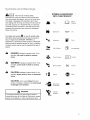 3
3
-
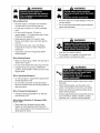 4
4
-
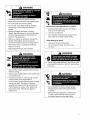 5
5
-
 6
6
-
 7
7
-
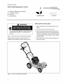 8
8
-
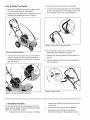 9
9
-
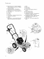 10
10
-
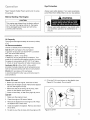 11
11
-
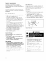 12
12
-
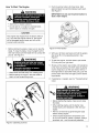 13
13
-
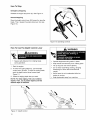 14
14
-
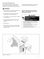 15
15
-
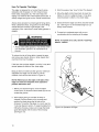 16
16
-
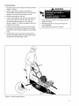 17
17
-
 18
18
-
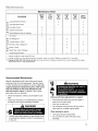 19
19
-
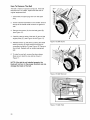 20
20
-
 21
21
-
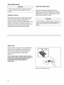 22
22
-
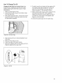 23
23
-
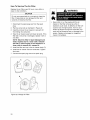 24
24
-
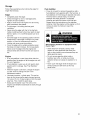 25
25
-
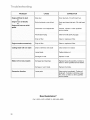 26
26
-
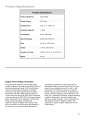 27
27
-
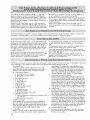 28
28
-
 29
29
-
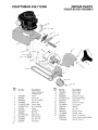 30
30
-
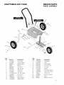 31
31
-
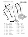 32
32
-
 33
33
-
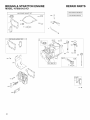 34
34
-
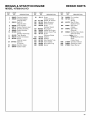 35
35
-
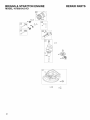 36
36
-
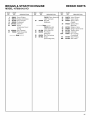 37
37
-
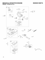 38
38
-
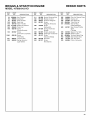 39
39
-
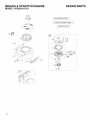 40
40
-
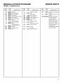 41
41
-
 42
42
-
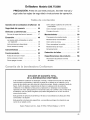 43
43
-
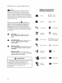 44
44
-
 45
45
-
 46
46
-
 47
47
-
 48
48
-
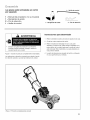 49
49
-
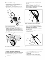 50
50
-
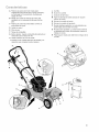 51
51
-
 52
52
-
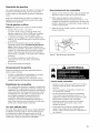 53
53
-
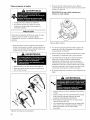 54
54
-
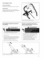 55
55
-
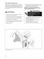 56
56
-
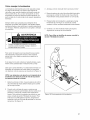 57
57
-
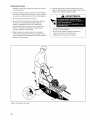 58
58
-
 59
59
-
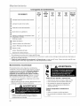 60
60
-
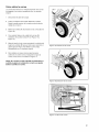 61
61
-
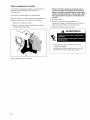 62
62
-
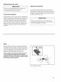 63
63
-
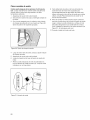 64
64
-
 65
65
-
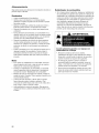 66
66
-
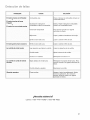 67
67
-
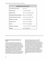 68
68
-
 69
69
-
 70
70
-
 71
71
-
 72
72


Craftsman 77236100N - 5.0 Ft-Lbs Gross Torque Edger Manual de usuario
- Categoría
- Herramientas de jardín
- Tipo
- Manual de usuario
- Este manual también es adecuado para
en otros idiomas
Artículos relacionados
-
Craftsman 536.772330 El manual del propietario
-
Craftsman 536772350 El manual del propietario
-
-
-
-
-
-
-
Otros documentos
-
Simplicity CRAFTSMAN EDGER Manual de usuario
-
Kenmore 721.64663 El manual del propietario
-
-
Maytag MDE17MN Installation Instructions Manual
-
Jenn-Air JGS9900BDF El manual del propietario
-
 Kenmore Elite 66561684102 El manual del propietario
-
Kenmore Elite 66561689101 El manual del propietario
-
Thermador T36IT71FN/26 Guía de instalación
-
GE DPSF505EW1WW El manual del propietario
