Simplicity 7800311 Manual de usuario
- Categoría
- Cortadoras de césped
- Tipo
- Manual de usuario
Este manual también es adecuado para

This Instruction Book contains information for several models.
Read and keep this book for future reference.
This book contains important information on SAFETY, ASSEMBLY,
OPERATION, AND MAINTENANCE.
PRODUCT INFORMATION
The owner must be certain that all the product information is
included with the unit. This information includes the INSTRUCTION
BOOKS, the REPLACEMENT PARTS and the WARRANTIES. This
information must be included to make sure state laws and other
laws are followed.
Models
LT20460 (7800192)
CLT20460 (7800311)
7102273 (Rev. B, 4/28/2008) TP 100-5346-B-TC-R
Not for
Reproduction

Thank you for purchasing this quality-built MURRAY mower. We are pleased that you’ve placed your confidence
in the MURRAY brand. When operated and maintained according to the instructions in this manual, your
MURRAY mower will provide many years of dependable service.
This manual contains safety information to make you aware of the hazards and risks associated with mowers
and how to avoid them. Because Briggs & Stratton Power Products Group, LLC does not necessarily know all
the applications this mower could be used for, it is important that you read and understand these instructions.
Keep this manual near the mower for convenient reference.
This mower requires final assembly before use. Refer to the
Assembly
section of this manual for instructions
on final assembly procedures. Follow the instructions completely.
Where to Find Us
You never have to look far to find Briggs & Stratton support and service for your mower. Consult your Yellow
Pages. There are over 30,000 Briggs & Stratton authorized service dealers worldwide who provide quality
service. You can also contact Briggs & Stratton Customer Service by phone at (800) 528-5087, or on the Internet
at www.murray.com.
Mower
Model Number _____________________________________
Serial Number _____________________________________
Engine
Model Number _____________________________________
Serial Number _____________________________________
Date Purchased
MURRAY is a trademark of Briggs & Stratton Power Products Group, LLC.
Briggs & Stratton Power Products Group, LLC
900 N. Parkway
Jefferson, WI 53549
Copyright © 2008 Briggs & Stratton Corporation. All rights
reserved. No part of this material may be reproduced or
transmitted in any form by any means without the express
written permission of Briggs & Stratton Power Products
Group, LLC.
Not for
Reproduction

1
EnglishEnglish
Table of Contents
Operator Safety. . . . . . . . . . . . . . . . . . . . . . . . . . . . . . . . . . 2
Important Operator Safety Instructions . . . . . . . . . . . . . . . . . . . . . . . 2
International Pictorials. . . . . . . . . . . . . . . . . . . . . . . . . . . . . . . . . . . . 5
Assembly. . . . . . . . . . . . . . . . . . . . . . . . . . . . . . . . . . . . . . . 6
Parts Bag - Contents. . . . . . . . . . . . . . . . . . . . . . . . . . . . . . . . . . . . . 6
Installing the Seat . . . . . . . . . . . . . . . . . . . . . . . . . . . . . . . . . . . . . . . 7
Assembling the Steering Wheel . . . . . . . . . . . . . . . . . . . . . . . . . . . . 7
Maintenance Free Battery. . . . . . . . . . . . . . . . . . . . . . . . . . . . . . . . . 8
IMPORTANT! Before You Start Mowing. . . . . . . . . . . . . . . . . . . . . . 9
Features and Controls . . . . . . . . . . . . . . . . . . . . . . . . . . . . 12
Operation. . . . . . . . . . . . . . . . . . . . . . . . . . . . . . . . . . . . . . . 13
Attachments . . . . . . . . . . . . . . . . . . . . . . . . . . . . . . . . . . . . . . . . . . . 13
Electrical Safety System . . . . . . . . . . . . . . . . . . . . . . . . . . . . . . . . . . 13
Using Controls. . . . . . . . . . . . . . . . . . . . . . . . . . . . . . . . . . . . . . . . . . 14
Mowing . . . . . . . . . . . . . . . . . . . . . . . . . . . . . . . . . . . . . . . . . . . . . . . 17
Engine Operation . . . . . . . . . . . . . . . . . . . . . . . . . . . . . . . . . . . . . . . 19
Tips . . . . . . . . . . . . . . . . . . . . . . . . . . . . . . . . . . . . . . . . . . . . . . . . . . 20
Maintenance . . . . . . . . . . . . . . . . . . . . . . . . . . . . . . . . . . . . 21
Maintenance Schedule . . . . . . . . . . . . . . . . . . . . . . . . . . . . . . . . . . . 21
General Recommendations. . . . . . . . . . . . . . . . . . . . . . . . . . . . . . . . 22
Inspection . . . . . . . . . . . . . . . . . . . . . . . . . . . . . . . . . . . . . . . . . . . . . 22
Adjustments. . . . . . . . . . . . . . . . . . . . . . . . . . . . . . . . . . . . . . . . . . . . 23
Maintenance Free Battery. . . . . . . . . . . . . . . . . . . . . . . . . . . . . . . . . 26
Lubrication. . . . . . . . . . . . . . . . . . . . . . . . . . . . . . . . . . . . . . . . . . . . . 27
Mower Housing Maintenance . . . . . . . . . . . . . . . . . . . . . . . . . . . . . . 28
Misc . . . . . . . . . . . . . . . . . . . . . . . . . . . . . . . . . . . . . . . . . . . . . . . . . . 36
Storage . . . . . . . . . . . . . . . . . . . . . . . . . . . . . . . . . . . . . . . . . . . . . . . 37
Troubleshooting . . . . . . . . . . . . . . . . . . . . . . . . . . . . . . . . . 38
Specifications . . . . . . . . . . . . . . . . . . . . . . . . . . . . . . . . . . . 40
Slope Guide. . . . . . . . . . . . . . . . . . . . . . . . . . . . . . . . . . . . . 41
Warranties . . . . . . . . . . . . . . . . . . . . . . . . . . . . . . . . . . . . . . 45
General Warranty . . . . . . . . . . . . . . . . . . . . . . . . . . . . . . . . . . . . . . . 45
WARNING
Battery posts, terminals and related accessories contain
lead and lead compounds, chemicals known to the State of
California to cause cancer and birth defects or other
reproductive harm. Wash hands after handling.
!
!
WARNING
Engine exhaust, some of its constituents, and certain
vehicle components contain or emit chemicals known to
the State of California to cause cancer or other reproductive
harm.
!
!
Not for
Reproduction

English
2 murray.com
! !
WARNING: This powerful cutting machine is capable of amputating hands and feet and can throw objects
that can cause injury and damage! Failure to comply with the following SAFETY instructions could result in
serious injury or death to the operator or other persons. The owner of the machine must understand these
instructions and must allow only persons who understand these instructions to operate machine. Each
person operating the machine must be of sound mind and body and must not be under the influence of any
substance, which might impair vision, dexterity or judgment. If you have any questions pertaining to your
machine which your dealer cannot answer to your satisfaction, call Customer Service Department.
Phone: (1-800-528-5087).
Protection for Children
Tragic accidents can occur if the operator is not alert to the
presence of children. Children are often attracted to the
machine and the mowing activity. Children who have been
given rides in the past may suddenly appear in the mowing
area for another ride and be run over or backed over by the
machine. Never assume that children will remain where you
last saw them.
1. KEEP children out of the mowing area and under the
watchful care of a responsible adult other than the operator.
2. DO NOT allow children in yard when machine is operated
(even with the blade OFF).
3. DO NOT allow children or others to ride on machine,
attachments or towed equipment (even with the blades
OFF). They may fall and be seriously injured.
4. DO NOT allow pre-teenage children to operate machine.
5. ALLOW only responsible adults & teenagers with mature
judgment under close adult supervision to operate machine.
6. DO NOT operate blades in reverse. STOP BLADES. LOOK
and SEE behind and down for children, pets and hazards
before and while backing.
7. USE EXTRA CARE when approaching blind corners,
shrubs, trees, or other objects that may obscure vision.
Protection against Tipovers
Slopes are a major factor related to loss-of-control and tip-
over accidents, which can result in severe injury or death.
All slopes require extra CAUTION. If you cannot back up the
slope or if you feel uneasy on the slope, DO NOT mow it.
Use extra care with grass catchers or other attachments;
these affect the handling and the stability of the machine.
Refer to the Slope Guide at the end of this manual.
1. DO NOT operate machine on slopes exceeding 15
degrees (27% grade).
2. Exercise EXTREME CAUTION on slopes above 10
degrees (18% grade). Turn blades OFF when traveling
uphill. Use a slow speed and avoid sudden or sharp turns.
3. DO NOT operate machine back and forth across face of
slopes. Operate up and down. Practice on slopes with
blades off.
4. AVOID starting, stopping or turning on slopes. If
machine stops going uphill or tires lose traction, turn
blades OFF and back slowly straight down the slope.
5. STAY ALERT for holes and other hidden hazards. Tall
grass can hide obstacles. Keep away from ditches,
washouts, culverts, fences and protruding objects.
Protection against Tipovers
(Continued From Previous Column)
6. KEEP A SAFE DISTANCE (at least 3 feet) away from edge
of ditches and other drop offs. The machine could turn over
if an edge caves in.
7. Always begin forward motion slowly and with caution.
8. Use weights or a weighted load carrier in accordance
with instructions supplied with a grass catcher. DO NOT
operate machine on slopes exceeding 10 degrees (18%
grade) when equipped with grass catcher.
9. DO NOT put your foot on the ground to try to stabilize
the machine.
10. DO NOT operate machine on wet grass. Reduced
traction could cause sliding.
11. Choose a low enough speed setting so that you will not
have to stop or shift on a slope. Tires may lose traction on
slopes even though the brakes are functioning properly.
12. DO NOT operate machine under any condition where
traction, steering or stability is doubtful.
13. Always keep the machine in gear when going down
slopes. DO NOT shift to neutral (or actuate hydro roll
release) and coast downhill.
Preparation
1. Read, understand, and follow instructions and warnings
in this manual and on the machine, engine and
attachments. Know the controls and the proper use of the
machine before starting.
2. Only mature, responsible persons shall operate the
machine and only after proper instruction.
3. Data indicates that operators age 60 and above, are
involved in a large percentage of mower-related injuries.
These operators should evaluate their ability to operate the
mower safely enough to protect themselves and others
from serious injury.
4. Handle fuel with extra care. Fuels are flammable and
vapors are explosive. Use only an approved fuel container.
DO NOT remove fuel cap or add fuel with engine running.
Add fuel outdoors only with engine stopped and cool. Clean
spilled fuel from machine. DO NOT smoke.
5. Practice operation of machine with BLADES OFF to learn
controls and develop skills.
6. Check the area to be mowed and remove all objects such
as toys, wire, rocks, limbs and other objects that could
cause injury if thrown by blade or interfere with mowing.
Important Operator Safety Instructions
Not for
Reproduction

English
3
! !
Protection against Tipovers
(Continued From Previous Column)
7. Keep people and pets out of mowing area. Immediately
STOP blades, STOP engine, and STOP machine if anyone
enters the area.
8. Check shields, deflectors, switches, blade controls and
other safety devices frequently for proper operation and
location.
9. Make sure all safety decals are clearly legible. Replace if
damaged.
10. Protect yourself when mowing and wear safety glasses,
a dust mask, long pants and substantial footwear.
11. Know how to STOP blades and engine quickly in
preparation for emergencies.
12. Use extra care when loading or unloading the machine
into a trailer or truck.
13. Check grass catcher components frequently for signs of
wear or deterioration and replace as needed to prevent
injury from thrown objects going through weak or worn
spots.
Safe Handling of Gasoline
To avoid personal injury or property damage, use extreme
care in handling gasoline. Gasoline is extremely flammable
and the vapors are explosive.
1. Extinguish all cigarettes, cigars, pipes and other sources
of ignition.
2. Use only an approved fuel container.
3. DO NOT remove fuel cap or add fuel with the engine
running. Allow the engine to cool before refueling.
4. DO NOT refuel the machine indoors.
5. DO NOT store the machine or fuel container inside where
there is an open flame, spark or pilot light such as on a
water heater or other appliances.
6. DO NOT fill fuel containers inside a vehicle or on a truck
or trailer bed with a plastic liner. Always place the
containers on the ground away from the vehicle before
filling.
7. Remove gas-powered equipment from the vehicle or
trailer and refuel it on the ground. If this is not possible,
then refuel equipment using a portable container, rather
than a gasoline dispenser nozzle.
8. DO NOT start gas powered equipment in enclosed
vehicles or trailers.
9. Keep the nozzle in contact with the rim of the fuel tank or
container opening at all times until fueling is complete. DO
NOT use a nozzle lock-open device
10. If fuel is spilled on clothing, change clothing
immediately.
11. Never overfill a fuel tank. Replace fuel cap and tighten
securely.
Operation
1. Mount and dismount machine from left side. Keep clear
of discharge opening at all times.
2. Start engine from operator’s seat, if possible. Make sure
blades are OFF and parking brake is set.
3. DO NOT leave machine with engine running. STOP
engine, STOP blades, SET brake, and Remove key before
leaving operators position of any reason.
4. DO NOT operate machine unless properly seated with
feet on feet rests or pedal(s).
5. STOP BLADES and ENGINE and make sure blades have
stopped before removing grass catcher or unclogging
mower to prevent loss of fingers or hand.
6. Blades must be OFF except when cutting grass. Set
blades in highest position when mowing over rough
ground.
7. Keep hands and feet away from rotating blades
underneath deck. DO NOT place foot on ground while
BLADES are ON or machine is in motion.
8. DO NOT operate machine without entire grass catcher or
guards in place and working. DO NOT point discharge at
people, passing cars, windows or doors.
9. Slow down before turning.
10. Watch out for traffic when near or crossing roadways.
11. STOP engine immediately after striking an obstruction.
Inspect machine and repair damage before resuming
operation.
12. Operate machine only in daylight or with good artificial
light.
13. Exercise CAUTION when pulling loads. Limit loads to
those you can safely control and attach loads to hitch plate
as specified with MURRAY attachment instructions.
14. On slopes, the weight of the towed equipment may
cause loss of traction and loss of control. When towing,
travel slowly and allow extra distance to stop.
15. DO NOT operate engine in enclosed areas. Engine
exhaust gases contain carbon monoxide, a deadly poison.
16. DO NOT discharge material against a wall or
obstruction. Material may ricochet back towards the
operator.
17. Only use accessories approved by the manufacturer.
See manufacturer’s instructions for proper operation and
installation of accessories.
Important Operator Safety Instructions (Continued)
Not for
Reproduction

English
4 murray.com
! !
Towing
1. Tow only with a machine that has a hitch designed for
towing. DO NOT attach towed equipment except at the hitch
point.
2. Follow the manufacturer’s recommendation for weight
limits for towed equipment and towing on slopes.
3. DO NOT allow children or others on towed equipment.
4. On slopes, the weight of the towed equipment may cause
loss of traction and loss of control.
5. Travel slowly and allow extra distance to stop.
Maintenance
1. DO NOT store machine or fuel container inside where
fumes may reach an open flame, spark or pilot light such as
in a water heater, furnace, clothes dryer or other gas
appliance. Allow engine to cool before storing machine in
an enclosure. Store fuel container out of the reach of
children in a well ventilated, unoccupied building.
2. Keep engine free of grass, leaves or excess grease to
reduce fire hazard and engine overheating.
3. When draining fuel tank, drain fuel into an approved
container outdoors and away from open flame.
4. Check brakes frequently; adjust, repair or replace as
needed.
5. Keep all bolts, nuts and screws properly tight. Check that
all cotter pins are in proper position.
Maintenance
(Continued From Previous Column)
6. Always provide adequate ventilation when running
engine. Exhaust gases contain carbon monoxide, an
odorless and deadly poison.
7. Disconnect negative (black) cable from battery before
performing maintenance or service. Cranking engine could
cause injury.
8. DO NOT work under machine without safety blocks.
9. Service engine and make adjustments only when engine
is stopped. Remove spark plug wire(s) from spark plug(s)
and secure wire(s) away from spark plug(s).
10. DO NOT change engine governor speed settings or
overspeed engine.
11. Lubricate machine at intervals specified in manual to
prevent controls from binding.
12. Mower blades are sharp and can cut. Wrap the blades
or wear heavy leather gloves and use CAUTION when
handling them.
13. DO NOT test for spark by grounding spark plug next to
spark plug hole; spark plug could ignite gas exiting engine.
14. Have machine serviced by an authorized MURRAY
dealer at least once a year and have the dealer install any
new safety devices.
15. Maintain or replace safety and instruction labels as
necessary.
16. Use only genuine MURRAY replacement parts to assure
that original standards are maintained.
Important Operator Safety Instructions (Continued)
Not for
Reproduction

English
5
International Pictorials
IMPORTANT: Some of the following pictorials are located on your unit or on literature supplied with the product.
Before you operate the unit, learn and understand the purpose for each pictorial.
Figure 1: Safety warning pictorials
A
B
C
D
E
G
H
F
I
J
K
L
M
N
P
max 15°
A - Warning
B - Shield Eyes. Explosive Gases
Can Cause Blindness Or Injury.
C - No Sparks, Flames or Smoking.
D - Sulphuric Acid Can Cause
Blindness Or Severe Burns
E - Flush Eyes Immediately With
Water. Get Medical Help Fast.
F - IMPORTANT: Read Owner’s
Manual Before Operating This
Machine.
G - WARNING: Thrown Objects.
Keep Bystanders Away. Read
User Instructions Before
Operating This Machine.
H - WARNING: Do Not Use This
Machine On Slopes Greater
Than 15 Degrees.
I - DANGER: Keep People,
Especially Children, Away From
Unit.
J - DANGER: No Step.
K - DANGER: Keep Feet And
Hands Away From Rotating
Blade.
L- DANGER: Keep Hands Away
From Rotating Blade.
M - DANGER: Disconnect Spark
Plug Wire Before Servicing
Unit.
N - WARNING: Hot Surface.
O - WARNING: Use Caution When
Connecting Or Disconnecting
Accessories.
P - WARNING: Crushed Fingers.
A - Engine start
B - Lights
C - Engine off
D - Engine on
E - Brake
F - Parking brake
G - Clutch
H - Slow
I - Fast
J - Choke
K - Oil
L - Blade rotation control
M - Raise
N - Fuel
A
B
C
D
E
G
H
F
I
J
K
L
M
N
max± 90N max± 150N
O
Figure 2: Control and operating pictorials
Not for
Reproduction

English
6 murray.com
Parts Bag - Contents
The fasteners and other loose parts are shown below. The
fasteners are shown full size. The quantity is shown in
brackets ( ).
Figure 3: Parts bag components
Assembly
Read and follow the assembly and
adjustment instructions for your mower.
All fasteners are in the parts bag. Do not
discard any parts or material until the unit
is assembled.
NOTE: In this instruction book, left and right describe
the location of a part with the operator on the seat.
WARNING: Before doing any assembly or
maintenance to the mower, remove the wire
from the spark plug.
A - (2) Carriage bolt
B - (2) Wing nut
C - (1) Bolt
D - (1) Washer
E - (2) Knob
F - (2) Washer
G - (1) Keys & ring
H - (1) Terminal cover
A
B
C
D
E
G
H
F
Not for
Reproduction

English
7
Installing the Seat
How to Install the Seat
1. Carefully remove the plastic bag from the seat.
Use the fasteners shown below to install the
seat. The fasteners are shown at full size.
Figure 4: Seat parts
A - Wing bolt (Also see ‘E’ in Figure 3)
B - Washer (Also see ‘F’ in Figure 3)
NOTE: Fasteners may be attached to seat for
shipping purposes, if so remove fasteners before
proceeding.
2. Align the holes in the seat hinge to the holes in
the seat (Figure 5). Fasten the seat to the seat
hinge with the fasteners as shown.
3. Check the operating position of the seat. If the
seat needs to be adjusted, loosen the two wing
bolts. Slide the seat forward or backward along
the seat adjusting holes as shown. Tighten the
wing bolts (A).
Figure 5: Seat
A - Wing bolt
B - Washer
C - Seat adjusting hole
D - Seat hinge
E - Seat
Assembling the Steering Wheel
How to Assemble the Steering Wheel
Tools Required: 3/8" Socket Wrench
Attach the steering wheel as follows:
Figure 6: Steering wheel parts
A - Screw (Also see ‘C’ in Figure 3)
B - Washer (Also see ‘D’ in Figure 3)
1. Make sure the front wheels point forward.
2. Slide the bellows over the steering post
(Figure 7).
NOTE: Before attachment of the steering wheel,
make sure that the front wheels point forward and
are straight. For proper alignment of the steering
wheel, see Figure 7.
3. Slide the steering wheel onto the steering post.
4. Use the fasteners shown above to secure the
steering wheel. The fasteners are shown at full
size. Tighten the screw until snug and then add
1/4 turn. DO NOT over tighten.
5. Attach the cover to the steering wheel.
6. Some models have an
optional
decal in the parts
bag. Attach the decal to the center of the
steering wheel as shown.
A B
A
B
B
C
D
E
A
Not for
Reproduction

Figure 7: Steering post
A - Screw
B - Washer
C - Cover
D - Decal (Optional)
E - Steering wheel
F - Bellows
G - Steering post
H - Straight
Maintenance Free Battery
IMPORTANT: Before you attach the battery cables to
the battery, check the battery date. The battery date
tells if the battery must be charged.
1. Check the top and the side of the battery for the
location of the battery date (Figure 9).
2. If the battery is put into service before the
battery date, the battery cables can be attached
without charging the battery. See “How To Install
The Battery Cables”.
3. If the battery is put into service
after
the battery
date, the battery must be charged. See “How To
Charge The Maintenance Free Battery”.
How to Charge the Maintenance Free Battery
WARNING: When you charge the battery, do
not smoke. Keep the battery away from any
sparks. The fumes from the battery acid can
cause an explosion.
1. Remove the battery and battery tray.
2. Remove the protective cap from the battery
terminal.
3. Use a 12 volt battery charger to charge the
battery. Charge at a rate of 6 amperes for one
hour. If you do not have a battery charger, have
an authorized service center charge the battery.
4. Install the battery and battery tray. Make sure
the positive (+) terminal is on the left side.
How to Install the Battery Cables
WARNING: To prevent sparks, fasten the
red cable to the positive (+) terminal before
you connect the black cable.
Use the fasteners shown below to install the battery
cables. The fasteners are shown at full size.
Figure 8: Battery cable parts
A - Carriage bolt (Also see ‘A’ in Figure 3)
B - Wing nut (Also see ‘B’ in Figure 3)
8 murray.com
English
D
A
B
E
C
H
G
F
A
B
Not for
Reproduction

1. Remove the protective cap from the battery
terminal.
2. Fasten the red cable and terminal cover (if
equipped) to the positive (+) terminal with the
fasteners as shown (Figure 9).
3. Fasten the black cable to the negative (-) terminal
with the fasteners as shown.
Figure 9: Battery
A - Carriage bolt
B - Wing nut
C - Black cable
D - Positive (+) terminal
E - Red cable
F - Battery
G - Battery tray
H - Terminal cover (Also see ‘H’ in Figure 3)
IMPORTANT! Before You Start Mowing
• Check the engine oil.
• Fill the fuel tank with gasoline.
• Check the air pressure of the tires.
• Check the level of the mower housing.
• Make sure the battery cables are attached.
• Make sure the wire is attached to the spark plug.
WARNING: Before doing any assembly or
maintenance to the mower, remove the wire
from the spark plug.
NOTE: In this instruction book, left and right describe
the location of a part with the operator on the seat.
9
English
H
A
E
A
B
D
C
G
F
Not for
Reproduction

How to Prepare the Engine
NOTE: The engine was shipped from the factory filled
with oil. Check the level of the oil. Add oil as needed.
NOTE: The operation of a new engine will sometimes
result in a slight amount of smoke. This smoke is
caused by paint or oil on or around the muffler. This is
normal and only expected during initial operation.
A separate engine manual is also included with the
unit. See this engine manual for the manufacturer’s
instructions for the type of gasoline and oil to use.
Before you use the unit, read the information on
safety, operation, maintenance, and storage.
WARNING: Follow the engine
manufacturer’s instructions for the type of
gasoline and oil to use. Always use a safety
gasoline container. Do not smoke when
adding gasoline to the engine. When inside
an enclosure, do not fill with gasoline.
Before you add gasoline, stop the engine.
Let the engine cool for several minutes.
IMPORTANT: This unit is equipped with an internal
combustion engine and must not be used on or near
any unimproved forest-covered, brush-covered or
grass-covered land unless the engine’s exhaust
system is equipped with a spark arrester meeting
applicable local or state laws (if any). If a spark
arrester is used, it must be maintained in effective
working order by the operator.
In the State of California the above is required by law
(Section 4442 of the California Public Resources
Code). Other states may have similar laws. Federal
laws apply on federal lands. See an Authorized
Service Center for a spark arrester for the muffler.
In some areas, local law requires the use of a resistor
spark plug to control the ignition signals. See an
Authorized Service Center for a resistor spark plug for
the engine.
NOTE: Actual sustained horsepower will likely be
lower due to operating limitations and environmental
factors.
10 murray.com
English
Not for
Reproduction

Check the Tires
NOTE: The tires may be over inflated for shipment.
Check the air pressure in the tires. Tires with too
much air pressure will cause the unit to ride rough.
Also, the wrong air pressure will keep the mower
housing from cutting level. Recommended air
pressure is 14 PSI (1 BAR).
Check the Level of the Mower Deck
Make sure the level of cut is still correct. After you
mow a short distance, look at the area that was cut. If
the mower deck does not cut level, see the
instructions on “How To Level The Mower Housing” in
the Maintenance section of this instruction book.
11
English
Not for
Reproduction

English
12 murray.com
Features and Controls
A - Throttle Control / Choke Control Lever — Throttle
control increases or decreases the speed of the
engine. Choke control engages the choke to start a
cold engine. (Note: The choke control is incorporated
into the throttle control lever.)
B - Brake Pedal — Use the brake pedal to quickly
stop the forward or reverse motion of the unit.
C - Lift Lever — Use the lift lever to change the height
of cut.
D - Ignition Key Switch — Use the ignition key switch
to start and stop the engine. (Note: The headlight
switch is incorporated into the ignition switch.
E - Blade Rotation Control — Use the blade rotation
control to start and stop the rotation of the blade.
F - Parking Brake Lever — Use the parking brake
lever to engage the brake when you leave the unit.
G - Speed Control Pedal — Use the speed control
pedal to change the speed and direction of the unit.
H - Reverse Mowing Option (RMO) — Use the
reverse mowing option to allow engaging of mower
housing while traveling in reverse.
I - Automatic Drive Disconnect (not shown, located
behind the unit) — Use the automatic drive disconnect
to disengage the transmission.
C
D
F
E
A
H
G
B
Not for
Reproduction

Operation
Attachments
This unit can use many different attachments.
For all pull-behind attachments or trailers, the
maximum gross weight is 250 pounds. Gross weight
is the weight of the attachment or trailer and any load
that might be on or in it.
Do not operate on a slope that is greater than 10
degrees when using a pull-behind attachment or
trailer. We have included a slope guide in this book to
help you determine the slope on which you will be
operating your unit. Never allow someone to stand or
ride on or in an attachment or trailer.
Electrical Safety System
Operator Presence System (Seat)
The seat has an Operator Presence System to shut
off the engine when the operator leaves the seat. This
system is not intended for regular use in stopping the
engine or the blade(s). Before leaving the seat, move
the blade rotation control to the DISENGAGE position,
shift to neutral, set the parking brake, and stop the
engine.
How To Check The Safety Interlock Switches
To check the function of the safety interlock switches,
follow the steps below.
1. Check the blade rotation control switch. Sit in
the seat. Depress the clutch/brake pedal. Move
the blade rotation control to the ENGAGE
position. Turn the ignition switch to the START
position. The engine should not start. If the
engine starts, the switch is defective and must be
replaced.
2. Check the clutch/brake switch. Sit in the seat.
Move the blade rotation control to the
DISENGAGE position. DO NOT depress the
clutch/brake pedal. Turn the ignition switch to the
START position. The engine should not start. If
the engine starts, the switch is defective and
must be replaced.
3. Check the Operator Presence System switch.
DO NOT sit in the seat. Depress the clutch/brake
pedal. Move the blade rotation control to the
DISENGAGE position. Turn the ignition switch to
the START position. The engine should not start.
If the engine starts, the switch is defective and
must be replaced.
4. Check the Reverse Mowing Option (RMO)
switch. Sit in the seat. Depress the clutch/brake
pedal. Move the blade rotation control to the
DISENGAGE position. Start the engine and move
the speed control pedal to the reverse (R)
position. With the engine running, move the blade
rotation control to the ENGAGE position. The
engine should stop running. If the engine
continues to run, the RMO switch is defective
and must be replaced.
13
English
Not for
Reproduction

Using Controls
How to Use the Throttle Control
Use the throttle control to increase or decrease the
speed of the engine.
CAUTION: Always operate the engine with the
throttle control in the FAST position. If the engine
runs for several minutes at slower than the FAST
position, the engine and transmission will
overheat and can be damaged.
1. The FAST position is marked with a detent. For
normal operation and when using a grass
bagger, move the throttle control to the FAST
position. For maximum charging of the battery
and for a cooler running engine and transmission,
operate the engine in the FAST position.
2. For transport and to tow pull behind attachments,
control the ground speed with the speed control
pedal.
3. The engine governor is set at the factory for
maximum performance. Do not adjust the
governor to increase the speed of the engine.
How to Use the Blade Rotation Control
The blade rotation control is next to the steering
wheel (Figure 10). Use the blade rotation control to
engage the blade(s) or to operate a snow thrower
attachment.
Figure 10: Blade rotation controls
A - DISENGAGE position
B - Blade rotation control ENGAGE position
1. Before you start the engine, make sure the blade
rotation control is in the DISENGAGE position.
2. Move the blade rotation control to the ENGAGE
position to rotate the blade(s).
NOTE: If the engine stops when you engage the
blade(s), the seat switch is not activated. Make
sure you sit in the middle of the seat. Also, make
sure the wire is connected to the seat switch.
3. Move the blade rotation control to the
DISENGAGE position to stop the blade(s).
Before you leave the operator’s position, make
sure the blade(s) has stopped rotating.
4. Before you ride the unit across a sidewalk or a
road, move the blade rotation control to the
DISENGAGE position.
WARNING: Always keep your hands and
feet away from the blade, deflector opening,
and the mower housing when the engine
runs.
14 murray.com
English
A
B
Not for
Reproduction

How to Use the Speed Control Pedal
The drive system uses a Hydrostatic Automatic Drive
transmission. The Hydrostatic transmission is very
easy to operate. This type of drive system does not
require a shift lever or a clutch pedal.
The speed and direction of travel is controlled by a
single speed control pedal operated with your right
foot. Do not use the left brake pedal in normal
operation. Only use the left brake pedal to quickly
stop in an emergency.
Driving and Stopping the Unit
How to Drive Forward
1. The automatic drive disconnect must be in the
DRIVE position (Figure 12).
2. Slowly release your left foot from the brake pedal.
3. Move the throttle control to the FAST position.
4. Slowly push the speed control pedal forward to
the desired speed (Figure 11).
5. To increase forward speed, slowly move the
speed control pedal forward. To reduce forward
speed, slowly release the speed control pedal
until the unit slows to the desired speed.
Figure 11: Speed control operation
A - Reverse
B - Neutral
C - Forward
D - Forward movement
E - Reverse movement
F - Speed control pedal
How to Drive in Reverse
1. Look to the rear.
2. Slowly push the speed control pedal to the
REVERSE position.
How to Change Direction
CAUTION: To change directions, do not use the
left brake pedal. Use only the speed control pedal.
1. Slowly remove your foot from the speed control
pedal. The speed control pedal will
automatically return to the NEUTRAL position.
2. When the unit stops, slowly move the speed
control pedal to the desired direction.
Speed Control Pedal Positions
The forward speed is controlled by the position of the
speed control pedal. The following chart provides
functions along with the pedal positions. Always
operate the engine with the throttle control in the
FAST position.
How to Disconnect the Transmission
To push the unit, use the automatic drive
disconnect to release the transmission. The
automatic drive disconnect is under the seat.
1. The engine must be off.
2. Raise the seat. The automatic drive disconnect
is under the seat.
3. Move and latch the automatic drive disconnect
in the PUSH position (Figure 12). The
transmission is now released and the unit can be
pushed.
NOTE: In cold weather, the heavy viscosity oil in
the transmission will make the unit difficult to
push.
4. To engage the transmission, unlatch the
automatic drive disconnect. The transmission
is now connected and ready to operate.
Function Pedal Positon Throttle Position
Trimming
Snow Thrower
1/3
Fast Throttle
Bagging Grass 1/3 to 1/2
Normal Mowing 1/2 to 2/3
Easy Mowing
Snow Blade
1/2 to 3/4
Transport FULL
Pull Behind
Attachments
1/3 to 1/2
15
English
E
D
F
7101936
A B
C
Not for
Reproduction

Figure 12: Automatic drive disconnect
A - Automatic drive disconnect DRIVE position
B - Automatic drive disconnect PUSH position
C - Automatic drive disconnect
How to Set the Parking Brake
1. Completely push the brake pedal forward.
2. Lift the parking brake lever (Figure 13).
3. Remove your foot from the brake pedal and then
release the parking brake lever. Make sure the
parking brake will hold the unit.
4. To release the parking brake, completely push
the brake pedal forward. The parking brake will
automatically release.
WARNING: Before you leave the operator’s
position, move the shift lever to the neutral
(N) position. Set the parking brake. Move the
blade rotation control to the DISENGAGE
position. Stop the engine and remove the
ignition key.
Figure 13: Parking brake
A - Parking brake
How to Change the Cutting Height
To change the cutting height, raise or lower the lift
lever as follows.
1. Move the lift lever forward to lower the mower
housing and back to raise the mower housing
(Figure 14).
2. When you ride on a sidewalk or road, move the
lift lever to the highest position and move the
blade rotation control to the DISENGAGE
position (Figure 10).
Figure 14: Lift control
A - Lift lever
16 murray.com
English
C
A
A
7101935
A
B
Not for
Reproduction

How to Stop the Unit
1. Slowly remove your foot from the speed control
pedal. The speed control pedal will automatically
return to the NEUTRAL position and the unit will
stop.
2. Move the blade rotation control to the
DISENGAGE position.
3. Set the parking brake.
WARNING: Make sure the parking brake will
hold the unit.
4. Move the throttle control to the SLOW position.
5. To stop the engine, turn the ignition key to the
OFF position. Remove the key.
How to Transport the Unit
To transport the unit, follow the steps below.
1. Move the blade rotation control to the
DISENGAGE position.
2. Raise the lift lever to the highest position.
3. Move the throttle control to the FAST position.
4. Slowly push the speed control pedal forward to
the desired speed.
Mowing
How to Operate with the Mower Housing
WARNING: The deflector is a safety device.
Do not remove the deflector. The deflector
forces the discharged material toward the
ground. Always keep the deflector in the
down position. If the deflector is damaged,
replace the deflector with an original
equipment part from an authorized service
center.
1. Start the engine.
2. Release the parking brake.
3. Move the lift lever to a height of cut position. In
high or thick grass, cut the grass in the highest
position first and then lower the mower housing
to a lower position.
CAUTION: Do not operate with the mower housing
in the LEVEL ADJUSTMENT position. If you
operate in the LEVEL ADJUSTMENT position, the
mower housing and blades can be damaged.
4. Move the throttle control to the SLOW position.
5. Move the blade rotation control to the ENGAGE
position.
6. Move the throttle control to the FAST position.
7. Slowly push the speed control pedal to the
desired speed.
NOTE: When you mow in heavy grass or mow
with a grass bagger, use a slow forward speed.
8. Make sure the level of cut set at the factory is still
correct. After you mow a short distance, look at
the area that was cut. If the mower housing does
not cut level, see the instructions on “How To
Level The Mower Housing” in the Maintenance
section.
WARNING: For better control of the unit,
always select a safe speed.
Reverse Mowing Option (RMO)
WARNING: Mowing in reverse can be
hazardous to bystanders. Tragic accidents
can occur if the operator is not alert to the
presence of children. Never activate RMO if
children are present. Children are often
attracted to the unit and the mowing
activity.
1. Engage the blades.
2. Insert the supplied key into the RMO switch,
located to the right of the steering wheel bellows
(Figure 15).
3. Turn the key. The L.E.D. light will illuminate,
indicating thet the RMO feature has been
activated. The mower deck can now be operated
while the unit is traveling in reverse.
4. The reverse mowing option is deactivated when
the blades are disengaged, and must be
reactivated each time the blades are engaged, if
desired.
5. Remove the key to restrict access to the RMO
feature.
WARNING: The engine will shut off if the
speed control pedal is moved into reverse
while the blades are engaged and the RMO
is not activated.
17
English
Not for
Reproduction

Figure 15: Reverse Mowing Option (RMO)
A - Key
B - RMO switch
C - L.E.D. light
How to Operate the Unit on Hills
WARNING: Do not ride up or down slopes
that are too steep to back straight up. Never
ride the unit across a slope. See the “Slope
Guide” in the back of this book for
information on how to check slopes.
1. Control the speed only with the speed control
pedal. Do not use the brake pedal on a hill.
2. To help prevent an accident, slowly move the
speed control pedal. Avoid sudden turns or
changes in speed.
3. To reduce forward speed when going down a hill,
slowly release the speed control pedal until the
unit slows to the desired speed.
How to Stop on a Hill
1. Avoid stopping on a hill. If you must quickly stop
in an emergency, remove your right foot from the
speed control pedal and quickly depress the left
brake pedal.
2. Set the parking brake.
3. Before you dismount from the seat, move the
throttle control to SLOW position, move the blade
rotation control to the DISENGAGED position,
turn off the engine and set the parking brake.
How to Start Operation on a Hill
1. Start the engine.
2. Move the blade rotation control to the ENGAGED
position.
3. Move the throttle control to the FAST position.
4. Depress the brake pedal and release the parking
brake. As you release the parking brake, push
the speed control pedal to the desired speed.
WARNING: Slowly push the speed control
pedal as you release the parking brake. The
parking brake must be disengaged before
the speed control pedal is able to engage
the transmission.
18 murray.com
English
A
C
B
Not for
Reproduction

Engine Operation
Before Starting the Engine
Check the Oil
NOTE: The engine was shipped from the factory filled
with oil. Check the level of the oil. Add oil as needed.
See the engine manufacturer’s instructions for the
type of gasoline and oil to use.
1. Make sure the unit is level.
NOTE: Do not check the level of the oil while the
engine runs.
2. Check the oil. Follow the procedure in the engine
manufacturer’s instructions.
3. If necessary, add oil until the oil reaches the
FULL mark on the dipstick. The quantity of oil
needed from ADD to FULL is shown on the
dipstick. Do not add too much oil.
Add Gasoline
WARNING: Always use a safety gasoline
container. Do not smoke when adding
gasoline to the fuel tank. Do not add
gasoline when you are inside an enclosure.
Before you add gasoline, stop the engine
and let the engine cool for several minutes.
Fill the fuel tank with regular unleaded gasoline. Do
not use premium unleaded gasoline. Make sure the
gasoline is fresh and clean. Leaded gasoline will
increase deposits and shorten the life of the valves.
Figure 16: Gas tank
A - Fuel tank
B - Full line
CAUTION: A mixture of alcohol (ethanol or
methanol) and gasoline (called gasohol), will
attract moisture and cause acid deposits during
storage. While the unit is in storage, the acids in
the fuel can damage the fuel system.
To prevent engine problems with the fuel system,
empty the fuel system before storage of 30 days or
longer as follows.
1. Drain the fuel tank.
2. Start the engine. Let the engine run until the fuel
lines and the carburetor are empty.
3. After storage, make sure you use fresh fuel. See
the storage instructions for additional information.
4. Never use engine cleaner or carburetor cleaner in
the fuel tank or permanent damage can occur.
Carburetor
Do not attempt to adjust the carburetor. Engine
adjustments and repairs should be performed only by
an authorized dealer.
How to Start the Engine
WARNING: The electrical system has an
operator presence system that includes a
sensor switch for the seat. These
components tell the electrical system if the
operator is sitting on the seat. This system
will stop the engine when the operator
leaves the seat. For your protection, always
make sure this system operates correctly.
NOTE: The engine will not start unless you depress
the brake pedal or engage the parking brake and
move the blade rotation control to the DISENGAGE
position.
1. Push the brake pedal completely forward. Keep
your foot on the pedal.
2. Make sure the blade rotation control is in the
DISENGAGE position.
3. Move the throttle control completely forward to
the CHOKE or FAST position. Some models
have a separate choke knob. Pull the choke knob
to the full CHOKE position.
4. Turn the ignition key to the START position.
Release the key when the engine starts.
NOTE: If the engine does not start after four or
five tries, see the TROUBLESHOOTING CHART.
5. Slowly move the throttle control to the SLOW
position.
6. Let a cold engine run for several minutes. Begin
work when the engine is warm. To start a hot
engine, move the throttle control to a position
between FAST and SLOW.
19
English
B
A
Not for
Reproduction

Tips
Operating Tips
1. Check the blade rotation control for correct
adjustment. For the blade(s) to disengage
correctly, the adjustment must be correct.
2. Before you use the unit, check the oil in the
engine and add oil if necessary.
3. If the engine will not start, first make sure the
wire is attached to the spark plug.
4. Make sure all the belts are inside all the belt
guides. See the instructions on how to remove
and install the motion drive and mower drive
belts.
5. Before you make an inspection, adjustment
(except for the carburetor), or repair, make sure
the wire from the spark plug is disconnected.
6. For longer life of the battery on electric start
models, charge the battery every three months.
7. Use the speed control pedal to change the
ground speed, not the throttle control.
8. Belt noise can occur when the blade is engaged.
This noise is normal and does not affect the
operation of the unit.
Moving and Bagging Tips
1. For a lawn to look better, check the cutting level
of the mower housing. See “How To Level The
Mower Housing” in the Maintenance section.
2. For the mower housing to cut level, make sure
the tires have the correct amount of air pressure.
3. Every time you use the unit, check the blade. If
the blade is bent or damaged, immediately
replace the blade. Also, make sure the nut for the
blade is tight.
4. Keep the blade(s) sharpened. Worn blades will
cause the ends of the grass to turn brown.
5. Do not cut or bag grass that is wet. Wet grass will
not discharge correctly. Let the grass dry before
cutting.
6. Use the left side of the mower housing to trim
near an object.
7. Discharge the cut grass onto the mowed area.
The result is a more even discharge of cut grass.
8. When you mow large areas, start by turning to
the right so that the cut grass will discharge away
from shrubs, fences, driveways, etc. After one or
two rounds, mow in the opposite direction making
left turns until finished (Figure 17).
Figure 17: Mowing tips
9. If the grass is very high, cut two times to
decrease the load on the engine. First cut with
the mower housing in the highest position and
then lower the mower housing for the second cut.
10. For better engine performance and an even
discharge of the cut grass, always operate the
engine with the throttle in FAST position.
11. When you use a bagger, operate the engine with
the throttle in FAST position and the speed
control pedal pushed 1/3 forward.
12. For better cutting performance and a quality cut,
mow with the speed control pedal pushed 1/3 to
1/2 forward.
13. After each use, clean the bottom and top of the
mower housing for better performance. Also, a
clean mower housing will help prevent a fire.
20 murray.com
English
Not for
Reproduction

21
English
Maintenance
Maintenance Schedule
Frequency Maintenance Required Comments
Daily or before each
use
Maintenance engine. Refer to the Engine Owner’s Manual.
Examine blade(s). Check for cracks, wear, and excessive
damage.
Remove debris from unit and mowing
area.
Examine all rotating and sliding parts.
Check tire inflation. Refer to the Maintenance section.
Verify that the mower housing is level. Refer to the Maintenance section.
Examine V-belts. Check for cracks, wear, and excessive
damage.
Check brake operation. Refer to the Operation and Maintenance
sections.
After completion of
first 5 hours
Change oil. Refer to the Engine Owner’s Manual.
After 25 hours Maintenance engine. Refer to the Engine Owner’s Manual.
Remove, examine, sharpen, and balance
blade(s).
Refer to Maintenance section.
Check adjustments:
a. Blade Rotation Control
b. Brake
c. Clutch
d. Steering
Refer to Maintenance section.
Lubricate chassis and mower housing. Refer to Where to Lubricate instructions.
Check the muffler:
a. Torque
b. For wear or burn out
c. Condition of spark arrestor
(if applicable).
Refer to Maintenance section.
Before storage of 30
days or more
Prepare engine for storage. Refer to the Engine Owner’s Manual.
Drain fuel system. Refer to warnings in the Owner’s Manual.
Add fuel stabilizer. Refer to the Engine Owner’s Manual.
Prepare battery for storage:
a. Remove from unit.
b. Fully charge.
c. Move to cool dry place.
Not for
Reproduction

General Recommendations
1. The owner’s responsibility is to maintain this
product. This will extend the life of the product and
is also necessary to maintain warranty coverage.
2. Check the spark plug, drive brake, lubricate the
unit, and clean the air filter once a year.
3. Check the fasteners. Make sure all fasteners are
tight.
4. Follow the Maintenance section to keep the unit
in good operating condition.
WARNING: Before you make an inspection,
adjustment, or repair to the unit, disconnect
the wire to the spark plug. Remove the wire
from the spark plug to prevent the engine
from starting by accident.
NOTE: Torque is measured in foot pounds (metric
Nm). This measurement describes how tight a nut or
bolt must be. The torque is measured with a torque
wrench.
Inspection
How to Check the Muffler
Check the muffler every 50 hours. Make sure the
muffler is correctly mounted and is not loose. If the
muffler is worn or burnt, replace with a new muffler. A
worn muffler is a fire hazard and can also damage the
engine.
If you mount a spark arrester to the muffler, also
check the spark arrester when you check the muffler.
If the spark arrester is worn or damaged, replace it
with a new spark arrester. See your nearest
authorized service center for a spark arrester.
Inspect Blade
WARNING: Before you inspect or remove the
blade, disconnect the wire to the spark plug. If
the blade hits an object, stop the engine.
Check the unit for damage. The blade has
sharp edges. When you hold the blade, use
gloves or cloth material to protect your hands.
If you keep the blade sharp and inspect the blade for
damage, the blade will cut better and be more safe to
operate. Frequently check the blade for excessive
wear, cracks, or other damage. Frequently check the
nut that holds the blade. Keep the nut tight. If the
blade hits an object, stop the engine. Disconnect the
wire to the spark plug. See if the blade is bent or
damaged. Check the blade adapter for damage.
Before you operate the unit, replace damaged parts
with original equipment parts. See the authorized
service center in your area. Every three years, have
an authorized service person inspect the blade or
replace the old blade with an original equipment part.
How to Remove and Install the Blade
1. Remove the mower housing. See the instructions
on “How To Remove The Mower Housing”.
2. Use a piece of wood to keep the blade from
rotating.
3. Remove the nut that holds the blade (Figure 18).
Figure 18: Removing the blades
A - Hi-lift edge up
B - Blade
C - Belleville washer
D - Nut
E - Washer
F - Blade adapter
G - Mandrel
4. Check the blade and the blade adapter
according to the instructions for “Inspect Blade”.
Replace a badly worn or damaged blade with an
original equipment blade. See an authorized
service center in your area.
5. Clean the top and bottom of the mower housing.
Remove all the grass and debris.
6. Mount the blade and blade adapter on the
mandrel (Figure 18).
7. Mount the blade so that the hi-lift edges are up.
If the blade is upside down, the blade will not cut
correctly and can cause an accident.
8. Fasten the blade with the original washers and
nut. Make sure the outside rim of the Belleville
washer is against the blade (Figure 19).
WARNING: Always keep the nut tight that
holds the blade. A loose nut or blade can
cause an accident.
22 murray.com
English
B
C
E
D
A
F
G
Not for
Reproduction

9. Tighten the nut that holds the blade to a torque of
35 foot pounds (47,5 N-m).
10. Install the mower housing. See “How To Install
The Mower Housing”.
Figure 19: Blade assembly
A - Blade adapter
B - Belleville washer (Outside rim must be against the
blade.)
C - Nut
D - Washer
E - Blade
How to Sharpen the Blade
WARNING: Vibration can be caused if the
blade is not correctly balanced or if the
blade is damaged. A blade that is damaged
with cracks can break and cause an
accident.
Keep a sharp edge on the blade. A blade that is not
sharp will cause the tips of the grass to become
brown.
1. Sharpen the blade two times a year or every 25
hours.
2. Remove the blade according to the instructions
in “How To Remove And Install The Blade”.
3. Clean the blade with a brush, soap and water.
Check the blade. Look for cracks, nicks, or other
damage. Replace a badly worn or damaged
blade with an original equipment blade. See an
authorized service center in your area.
4. Sharpen the blade with a file (Figure 20). Make
sure you keep the original bevel angle.
5. Make sure the blade is balanced. Use a
screwdriver and hold the blade parallel to the
ground (Figure 20). A blade that is balanced will
stay parallel to the ground. If the blade is not
balanced, the heavy end will rotate toward the
ground. Sharpen the heavy end until the blade
is balanced.
6. A new blade will cut better than a badly worn
blade. Every three years, have an authorized
service person inspect the blade or replace the
old blade with an original equipment blade.
7. Assemble the blade according to the instructions
“How To Remove And Install The Blade”.
Figure 20: Sharpening the blades
A - Screwdriver
B - Blade
C - File
D - Ground
E - Blade is balanced when parallel to the ground
Adjustments
How to Adjust the Blade Rotation Control
WARNING: To prevent an injury, the blade
rotation control must operate correctly.
In normal usage, the blade rotation control will not
require an adjustment. However, if the cutting
performance decreases or the quality of cut is poor,
make the following changes.
1. When you mow, make sure the throttle control in
in the FAST position.
2. Move the blade rotation control to the
DISENGAGE position (Figure 21).
3. Stop the engine. Disconnect the wire from the
spark plug.
23
English
E
C
D
A
B
B
E
C
D
A
Not for
Reproduction

Figure 21: Blade adjustments
A - DISENGAGE Position
B - Blade Rotation Control ENGAGE Position
4. Check the blade(s). Keep a sharp edge on the
blade(s). A blade that is not sharp will cause the
tips of the grass to become brown.
5. Disconnect the blade drive spring from the
blade control rod. Move the blade drive spring
to the middle hole (Figure 22). This will increase
the tension on the mower drive belt.
Figure 22: DISENGAGE position
A - Blade control rod
B - Blade drive spring
C - Bottom hole
D - Middle hole
E - Top hole (New Belt)
6. Attach the wire to the spark plug. Mow for a short
distance and again check the quality of cut. If
necessary, move the blade drive spring to the
bottom hole.
7. Again check the quality of cut. If the quality of cut
has not improved, replace the mower drive belt.
See “How To Replace The Mower Drive Belt”. If
replacing the belt does not correct the problem,
take the unit to an authorized service center.
8. Move the blade rotation control to the
DISENGAGE position. Stop the engine.
Disconnect the wire from the spark plug. Check
the operation of the blade brake. Rotate the
pulleys with your hand. Make sure the brake
pads are pressed tightly against the pulleys
(Figure 23).
WARNING: If the brake pads do not press
tightly against the pulleys, take the unit to
an authorized service center.
Figure 23: Blade brake
A - Brake pad against pulley
9. Move the blade rotation control to the
ENGAGE position. Check the pads for the blade
brake. If the pads are excessively worn or
damaged, replace the brake pad assemblies.
Correct replacement parts and assistance are
available from an authorized service center.
10. Attach the wire to the spark plug. Mow for a short
distance and again check the operation of the
blade rotation control.
11. When you move the blade rotation control to
the DISENGAGE position, all movement will
stop within five seconds. If there is movement of
the belt or the blades continue to rotate, engage
and disengage the blade rotation control five
times to remove any excess rubber from a new
mower drive belt. If you need assistance, take
the unit to an authorized service center.
12. If you replace the mower drive belt, move the
blade drive spring to the top hole (Figure 22).
24 murray.com
English
B
A
B
C
D
E
A
A
Not for
Reproduction

25
English
How to Check and Adjust the Motion Drive Belt
If the motion drive belt is loose, the belt will slip when;
(1) going up a hill, (2) pulling a heavy load, or (3) the
unit will not move forward. Adjust the belt as follows.
WARNING: Before you make an inspection,
adjustment, or repair to the unit, disconnect
the wire to the spark plug. Remove the wire
from the spark plug to prevent the engine
from starting by accident.
1. Check the routing of the motion drive belt. Make
sure the belt is installed correctly and is inside all
the belt guides.
2. Disconnect the clutch link from the idler arm
(Figure 24).
3. Align the hole in the brake lever with the hole in
the frame. Hold the brake lever in place with a
1/4 inch (6 mm) pin or bolt (Figure 25).
4. Rotate the clutch link until the mounting hole in
the clutch link is aligned with the hole in the
idler arm as shown in Figure 24.
5. Connect the clutch link to the idler arm
(Figure 24).
6. Remove the 1/4 inch (6 mm) pin or bolt
(Figure 25).
Figure 24: Aligning clutch link
A - Mounting holes
B - Idler arm
C - Clutch link
D - Clutch rod
7. If the belt still slips after the belt has been
adjusted, then the motion drive belt is worn or
damaged and must be replaced. See “How To
Replace The Motion Drive Belt”.
D
C
B
A
Figure 25: Adjusting motion drive belt
A - 1/4" (6mm) Pin or bolt
B - Clutch link
C - Idler arm
D - Idler spring
E - Motion drive belt
F - Belt guide
G - Brake lever
A
B
D
E
F
G
C
Not for
Reproduction

Maintenance Free Battery
How to Remove the Battery
To charge or clean the battery, remove the battery
from the unit as follows.
WARNING: To prevent sparks, disconnect
the black battery cable from the negative (-)
terminal before you disconnect the red
cable.
WARNING: The battery contains sulfuric
acid which is harmful to the skin, eyes, and
clothing. If the acid gets on the body or
clothing, wash with water.
1. Disconnect the black cable from the negative (-)
terminal (Figure 26).
2. Disconnect the red cable from the positive (+)
terminal.
3. Lift the battery tray and the battery out of the
unit.
How to Clean the Battery
1. Remove the battery.
2. Wash the battery with a solution of one gallon of
water and four tablespoons of baking soda
(sodium bicarbonate). Make sure the solution
does not get into the battery cells.
3. Clean the terminals and the ends of the cables
with a wire brush.
4. Install the battery.
5. To prevent corrosion, apply grease to the battery
terminals.
How to Charge the Battery
WARNING: When you charge the battery, do
not smoke. Keep the battery away from any
sparks. The fumes from the battery acid can
cause an explosion.
1. Before you charge the battery, remove the
battery.
2. To charge the battery, use a 12 volt battery
charger. Charge at a rate of 6 amperes for 1
hour.
3. Install the battery.
WARNING: To prevent sparks, fasten the
red cable to the positive (+) terminal before
you connect the black cable.
4. Fasten the red cable and terminal cover (if
equipped) to the positive (+) terminal with the
fasteners as shown.
5. Fasten the black cable to the negative (-)
terminal with the fasteners as shown (Figure 26).
Figure 26: Battery
A - Carriage bolt
B - Wing nut
C - Black cable
D - Positive (+) terminal
E - Red cable
F - Battery
G - Battery tray
H - Terminal cover
26 murray.com
English
H
A
E
A
B
D
C
G
F
Not for
Reproduction

Lubrication
Where to Lubricate
Models with grease fittings: Lubricate with
grease gun.
Apply grease with a brush to the areas shown.
Lubricate the areas shown with engine oil.
NOTE: Apply grease to the steering gear assembly.
CAUTION: If the unit is operated in dry areas that
have sand, use a dry graphite spray to lubricate
the unit.
Figure 27: Lubrication areas
27
English
Not for
Reproduction

How to Check the Fuel Filter
NOTE: Before you replace the fuel filter or the fuel
line, the fuel tank must be empty.
If the fuel filter is dirty, the engine will run rough and
have less performance. Remove the old filter (Figure
28). Replace the old filter with a new filter. Use an
original equipment part. See an authorized service
dealer in your area.
Figure 28: Fuel filter
A - Fuel line
B - Clips
C - Fuel filter
Check the Tires
Check the air pressure in the tires. Tires with too
much air pressure will cause the unit to ride rough.
Also, the wrong air pressure will keep the mower
housing from cutting level. The correct air pressure is
shown on the side of the tire.
Mower Housing Maintenance
How to Remove the Mower Housing
1. Move the blade rotation control to the
DISENGAGE position.
2. If equipped, remove the gauge wheels.
3. Move the lift lever to the level adjustment
position (Figure 29).
WARNING: The lift lever is spring loaded.
Make sure the lift lever is locked in the
LEVEL ADJUSTMENT position.
4. Remove the hair pins and the washers from the
adjuster arms (Figure 30). See illustrations “C”
and “D”.
5. Remove the hair pins and washers from the
suspension links. See illustrations “A” and “B”.
6. Disconnect the extension spring from the blade
control rod. See illustration “E”.
7. Disconnect the front hanger from the axle
support. See illustration “F”.
Figure 29: Lift lever
A - Level adjustment position
8. Remove the mower drive belt from the stack
pulley.
9. Pull the mower housing away from the right side
of the unit.
10. To operate without the mower housing, move the
lift lever to the TOP position.
How to Install the Mower Housing
1. Push the mower housing under the right side of
the unit.
2. Put the mower drive belt around the stack
pulley. Make sure the “V” side of the mower
drive belt is against the stack pulley. Also,
make sure the mower drive belt is not twisted.
3. Attach the front hanger to the axle support with
the hanger rod. Fasten with the fasteners as
shown. See illustration “F”.
4. Make sure the mower drive belt is between the
stack pulley and the two belt guides. See
illustration “G”.
5. Attach the suspension links to the lifter
assembly. Fasten with the washers and hair
pins. See illustrations “A” and “B”.
6. Attach the right and the left adjuster arms to the
suspension brackets. Fasten with the washers
and hair pins. See illustrations “C” and “D”.
7. Attach the extension spring to the blade
control rod. See illustration “E”.
8. Move the blade rotation control to the ENGAGE
position. Make sure the mower drive belt is
inside all the belt guides.
9. Make sure the mower housing is level. See the
instructions on “How To Level The Mower
Housing”.
10. If equipped, install the gauge wheels.
11. Check the operation of the blade rotation
control. See the instructions on “How To Adjust
The Blade Rotation Control”.
28 murray.com
English
C
B
A
A
Not for
Reproduction

Figure 30: Mower housing assembly
A - View A
B - View B
C - View C
D - View D
E - View E
F - View F
G - View G
H - Suspension link
I - Adjuster arm
J - Lift lever
K - Lifter assembly
L - Gauge wheel
M - Blade rotation control
N - Mower drive belt
O - Front hanger
P - Extension spring
Q - Hanger rod
R - Blade control rod
S - Adjuster arm
T - Belt guide
U - Mower driver belt
V - Belt guide
W - Stack pulley
29
English
I
J
M
L
N
O
P
T
U
S
Q
R
A
H
A
A
H
B
B
B
G
D
E
F
C
B
A
A
C
B
E
D
F
F
K
W
V
Not for
Reproduction

How to Adjust the Gauge Wheels
The axle bolts for the gauge wheels were mounted in
the LOW cut position. To change the position of the
gauge wheels, move the axle bolts as follows.
IMPORTANT: Before you adjust the gauge wheels,
you must do the following. Make sure the mower
housing is level. Make sure the height of cut is set at
the height you want for your lawn. Mow a short
distance on a flat level area and look at the area that
was cut. If the mower housing does not cut level, see
the instructions “How To Level The Mower Housing.”
WARNING: Before you make an inspection,
adjustment, or repair to the unit, disconnect
the wire to the spark plug. Remove the
spark plug wire to prevent the engine from
starting by accident.
1. Remove the gauge wheels (Figure 31).
2. Mow a short distance on a flat level area to check
the level of cut and the height of cut. Look at the
height of cut position number on the lift lever
(Figure 32).
3. Look at each gauge wheel bracket. There are 3
holes in each bracket and a number next to each
hole. The number for the height of cut position on
the lift lever indicates the correct hole to use on
each gauge wheel bracket (Figure 33).
4. Assemble the axle bolts to the gauge wheel
brackets using the correct hole in the bracket as
indicated (Figure 33).
NOTE: If the height of cut position is changed by the
lift lever, you must move the gauge wheels to the
correct hole (Figure 33) to keep a level height of cut.
Figure 31: Gauge wheel assembly
A - Locking ring
B - Washer
C - Axle bolt
D - Gauge wheel
Figure 32: Lift lever
A - Lift lever
B - Cutting height positions
Figure 33: Gauge wheel bracket positions
A - Gauge wheel bracket
B - Wheel bracket hole no.
C - Lift lever position no.
How to Level the Mower Housing
If the mower housing is level, the blade will cut easier
and the lawn will look better.
WARNING: Before you make an inspection,
adjustment, or repair to the unit, disconnect
the wire to the spark plug. Remove the
spark plug wire to prevent the engine from
starting by accident.
1. Make sure the unit is on a hard flat surface.
2. Check the air pressure in the tires. If the air
pressure is incorrect, the mower housing will not
cut level. Make sure the tires are inflated to
14 PSI (1 BAR).
IMPORTANT: On models equipped with gauge
wheels, the gauge wheels must be removed to
correctly adjust the level of the mower housing.
30 murray.com
English
B
C
D
A
11
22
3 3,4,5,6
A
B
A
C
B
Not for
Reproduction

31
English
3. Some models have gauge wheels on the mower
housing. If equipped, remove the gauge wheels.
4. Move the lift lever to the LEVEL ADJUSTMENT
position (Figure 34).
WARNING: The lift lever is spring loaded.
Make sure the lift lever is locked in the
LEVEL ADJUSTMENT position.
5. Loosen the left and right adjuster knobs (Figure
35). Push down on each side of the mower
housing. Make sure both sides of the mower
housing are setting on a flat surface. Also, make
sure the lift links are loose and can easily move
up or down.
6. Push down on the lift links and tighten the left
and right adjuster knobs (Figure 35). Make sure
the adjuster knobs are tight. If necessary, use a
wrench to tighten the adjuster knobs. For plastic
adjuster knobs, tighten to a torque of 7 foot
pounds (9,5 Nm). For metal adjuster knobs,
tighten to a torque of 10 foot pounds (13,5 Nm).
7. Raise the lift lever from the LEVEL
ADJUSTMENT position to a CUTTING HEIGHT
position (Figure 36).
8. If equipped, install the gauge wheels.
9. Mow for a short distance. If the height of cut is
not level, repeat the above steps.
CAUTION: Do not operate with the mower housing
in the LEVEL ADJUSTMENT position. If you
operate in the LEVEL ADJUSTMENT position, the
mower housing and blades can be damaged.
Figure 34: Lever adjustment
A - Lift lever
B - LEVEL ADJUSTMENT positon
C - CUTTING HEIGHT positions
Figure 35: Loosening adjuster knobs
A - Lift link
B - Adjuster knobs
Figure 36: Cutting position
A - Lift lever
B - CUTTING HEIGHT positions
How to Replace the Motion Drive Belt
Removal:
1. Remove the mower housing. See the instructions
on “How To Remove The Mower Housing”.
2. Remove the mid-idler pulley.
3. Disconnect the idler spring (Figure 39).
4. Remove the idler pulley and spacer (Figure 39).
5. Remove the V-idler pulley and spacer.
A
B
C
A
B
A
B
Not for
Reproduction

6. Remove the motion drive belt from the drive
pulley (Figure 39).
7. To remove the motion drive belt from the stack
pulley, pull the front end of the belt under the
stack pulley and then back between the stack
pulley and the steering plate (Figure 37).
8. Remove the access panel (Figure 38).
9. Remove the two screws that attach the steering
shaft assembly (Figure 38). Raise the steering
wheel and steering shaft assembly. Pull the
motion drive belt under the steering shaft
assembly.
10. Remove the motion drive belt. A correct
replacement part or assistance is available from
an Authorized Service Center in your area.
Installation:
1. Slide the motion drive belt between the stack
pulley and the belt guides (Figure 37). Install
the motion drive belt on the top pulley of the
stack pulley. Make sure the “V” side of the belt
is against the pulley.
2. Push the motion drive belt through the opening
between the steering plate and the engine plate.
3. Install the end of the motion drive belt around
the drive pulley (Figure 39).
4. Put the motion drive belt around the V-idler
pulley. Install the motion drive belt, V-idler
pulley and spacer.
5. Put the belt around the idler pulley. Fasten the
idler pulley and spacer with the hex nut. Make
sure the flat side of the belt is against the idler
pulley. Also, make sure the belt is not twisted.
6. Connect the idler spring (Figure 39).
7. Install the mid-idler pulley.
8. Check the routing of the motion drive belt
(Figure 39). Make sure the motion drive belt is
installed correctly on the idler pulleys and inside
all belt guides.
9. Attach the steering shaft assembly to the
steering plate with two screws (Figure 38).
10. Attach the access
panel (Figure 38).
11. Before you use the unit, check the adjustment of
the clutch. See the instructions “How To Check
And Adjust The Clutch”.
12. Install the mower housing. See the instructions
“How To Install The Mower Housing”.
Figure 37: Removing belt
A - Stack pulley
B - Motion drive belt
C - Belt guides
D - Steering plate
Figure 38: Detaching the steering shaft
A - Screw
B - Steering shaft assembly
C - Motion drive belt
D - Access panel
32 murray.com
English
A
A
B
B
C
D
C
D
Not for
Reproduction

33
English
Figure 39: Motion drive belt assembly
A - Idler pulley
B - Spacer
C - V-Idler pullery
D - Spacer
E - Idler spring
F - Drive pulley
G - Idler spring
H - V-Idler pulley
I - Stack pulley
J - Belt guide
K - Belt guide
L - Motion drive belt
M - Mid-Idler pulley
A
M
L
K
B
F
C
D
J
G
H
I
E
Not for
Reproduction

34 murray.com
English
How to Replace the Primary Mower Drive Belt
1. Remove the mower housing. See the instructions
on “How To Remove The Mower Housing”.
2. Remove the three screws from the left pulley
cover. Remove the pulley cover (Figure 40).
3. To remove the primary mower drive belt from
the left mandrel pulley, slide the primary
mower drive belt between the left mandrel
pulley and the belt guides.
4. Pull the belt retainer away from the idler pulley.
Remove the primary mower drive belt from the
idler pulley.
5. Move the brake pad assembly away from the
stack pulley. Remove the primary mower drive
belt from the stack pulley.
NOTE: Replace the primary mower drive belt with
an original equipment belt from an authorized
service center.
6. Install a new primary mower drive belt. Pull the
brake pad assembly away from the stack
pulley. Put the belt around the stack pulley.
Make sure the primary mower drive belt is
inside of the belt guide.
7. Pull the belt retainer away from the idler pulley.
Put the flat side of the primary mower drive belt
around the idler pulley.
8. Make sure the “V” side of the primary mower
drive belt is against the mandrel pulleys as
shown.
9. Make sure the primary mower drive belt is
inside all the belt guides.
10. Assemble the left pulley cover.
11. Install the mower housing. See the instructions
on “How To Install The Mower Housing”.
12. Before you mow, check the blade rotation control.
See the instructions on “How To Adjust The
Blade Rotation Control”.
How to Replace the Secondary Mower Drive Belt
1. Remove the mower housing. See the instructions
on “How To Remove The Mower Housing”.
2. Remove the primary mower drive belt from the
stack pulley (Figure 40).
3.
Remove the two screws from the right pulley
cover. Remove the right pulley cover.
4. Pull the idler pulley away from the secondary
mower drive belt. Remove the belt from the
idler pulley.
5. Remove the secondary mower drive belt from
the right mandrel pulley.
6. Remove the secondary mower drive belt from
the stack pulley.
NOTE: Replace the secondary mower drive belt
with an original equipment belt from an
authorized service center.
7. Install a new secondary mower drive belt. Put
the belt around the bottom of the stack pulley.
Make sure the secondary mower drive belt is
inside the belt guide next to the stack pulley.
8. Put the secondary mower drive belt around the
right mandrel pulley.
9. Pull the idler pulley toward the front. Install the
flat side of the secondary mower drive belt
against the idler pulley.
10. Make sure the “V” side of the secondary mower
drive belt is around the right mandrel pulley.
11. Assemble the right pulley cover.
12. Put the primary mower drive belt around the
stack pulley.
13. Install the mower housing. See the instructions
on “How To Install The Mower Housing”.
14. Before you mow, check the blade rotation control.
See the instructions on “How To Adjust The
Blade Rotation Control”.
Not for
Reproduction

Figure 40: Mower drive belt assembly
A - Screw
B - Left pulley cover
C - Primary mower drive belt
D - Left mandrel pulley
E - Belt guides
F - Stack pulley
G - Idler pulleys
H - Right pulley cover
I - Secondary mower drive belt
J - Right mandrel pulley
K - Belt Retainer
L - Brake Pad Assemblies
I
D
C
G
F
E
A
35
English
A
B
E
E
G
H
J
K
L
L
Not for
Reproduction

How to Install the Wheels
If the wheels must be removed for service, make sure
they are installed as follows.
Front Wheel:
1. Make sure the valve stem is to the outside of the
tractor. Slide the front wheel on the spindle
(See Figure 41).
2. Fasten the front wheel with washer and cotter
pin. Bend the ends of the cotter pin apart to
keep the front wheel on the spindle.
3. If your model has hub caps, install the hub
caps. Make sure the washers hold the hub caps
in place.
Figure 41: Front wheel assembly
A - Cotter pin
B - Hub cap
C - Valve stem
D - Front wheel
E - Spindle
F - Washers
Rear Wheel:
1. Install the washers and spacer onto the axle as
shown in Figure 42.
2. Mount the square key in the key slot (See
Figure 42).
3. Make sure the valve stem is to the outside of the
tractor. Align the slot in the rear wheel with the
square key. Slide the rear wheel on the axle.
4. Fasten the rear wheel with washer and e-ring.
5. If your model has hub caps, install the hub
caps. Make sure the washers hold the hub caps
in place.
Figure 42: Rear wheel assembly
A - Rear wheel
B - Hub cap
C - E-ring
D - Washer
E - Valve stem
F - Spacer
G - Washer
H - Square key
I - Key slot
J - Axle
How to Replace the Fuse
If the fuse is blown, the engine will not start. The
location of the fuse is behind the panel between the
engine and the control console. Remove the fuse and
replace with a automotive fuse (Figure 43).
Figure 43: Fuse location
A - Automotive fuse
36 murray.com
English
A
B
C
D
E
F
A
A
H
I
G
B
D
C
E
F
J
Not for
Reproduction

How to Replace the Light Bulb
1. Raise the tractor hood.
2. Turn the light socket until the tabs on the socket
align with the notches in the bezel (Figure 44).
Remove the light socket. Turn the light bulb
and remove the bulb.
3. Install a new light bulb. Align the light socket
with the notches in the bezel and turn the light
socket to lock in position.
Figure 44: Light bulb replacement
A - Bezel
B - Light bulb
C - Light socket
How to Clean the Mower Housing
WARNING: Before you clean the mower
housing, stop the engine and disconnect
the wire to the spark plug.
Grass and other debris on top of the mower housing
can keep the belt from working correctly. For safety
and correct operation, frequently clean the top of the
mower housing. Remove grass and debris from
around the pulleys and other moving parts.
1. Move the lever for the blade rotation control to
the ENGAGE position.
2. Clean the top of the mower housing.
3. Move the lever for the blade rotation control to
the DISENGAGE position.
4. Again clean the top of the mower housing.
5. After you cut the grass, clean the bottom of the
mower housing.
Storage (over 30 days)
At the end of each year, prepare the unit for storage
as follows.
The Engine
For storage information, see the the engine
manufacturer’s instructions.
The Battery
1. Remove the battery.
2. Clean the battery terminals of any deposits.
3. Charge the battery. See the instructions on “How
To Prepare And Charge The Battery”.
4. Store the battery in a cool, dry place.
NOTE: After a long time in storage, charge the
battery.
The Fuel System
WARNING: Do not drain the gasoline inside
a building or near a fire. Do not smoke
because the fumes from the fuel can cause
an explosion.
1. Start the engine.
2. Run the engine until the fuel tank and the
carburetor are out of fuel and the engine stops.
3. After storage, make sure you use fresh fuel.
Clean the Unit
1. Clean the dirt and grass from the engine.
2. Clean the mower housing.
Lubricate the Unit
See the “Lubrication” instructions in this book.
37
English
C
A
B
Not for
Reproduction

Troubleshooting
38 murray.com
English
Troubleshooting Chart
Problem Correction
The engine will not start.
1. Follow the steps, “How To Start The Engine” in this book.
2. Electric-Start Models: Clean the battery terminals. Tighten the cables.
3. Drain the fuel tank. Clean the fuel line. Replace the fuel filter.
4. Remove the spark plug(s). Move the throttle to the SLOW position. Turn the ignition key
to the ON position. Try to start the engine several times. Install the spark plug.
5. Replace the spark plug.
The engine will not turn
over.
1. Follow the steps, “How To Start The Engine” in this book.
2. Electric-Start Models: Check the level of the acid in the battery. If needed, add water.
Charge the battery.
3. Replace the fuse.
4. Check the wiring harness for damage or a loose connection. Repair the damaged wire.
5. Electric-Start Models: Replace the solenoid. Recoil-Start Models: Replace the module.
The engine is difficult to
start.
1. Replace the spark plug.
2. Replace the fuel filter.
The engine does not run
smooth or has a loss of
power.
1. Check the oil.
2. Clean the air filter.
3. Clean the air screen.
4. Replace the spark plug.
5. The engine is working too hard. Use a lower gear.
6. Replace the fuel filter.
The engine does not run
smooth at fast speed.
1. Replace the spark plug.
2. Adjust the throttle control.
3. Clean the air filter.
4. Replace the fuel filter.
The engine stops when
the blades are engaged.
1. To activate the seat sensor, always sit in the middle of the seat.
2. Check the wiring harness for damage or a loose connection. Repair the damaged wire.
On slopes, the engine
stops.
1. Mow up and down slopes. Never mow across a slope.
2. To activate the seat sensor, always sit in the middle of the seat.
The engine will not idle.
1. Replace the spark plug.
2. Clean the air filter.
3. Adjust the throttle control.
4. Drain the fuel tank. Clean the fuel line. Replace the fuel filter.
A hot engine causes a
decrease in power.
1. Clean the air screen.
2. Check the oil.
3. Replace the fuel filter.
Excessive vibration.
1. Replace the blade.
2. Check for loose engine bolts.
3. Decrease the air pressure in the tires.
4. Check for a damaged belt or damaged pulley. Replace the damaged parts.
Not for
Reproduction

39
English
Troubleshooting Chart Continued
Problem Correction
The grass does not
discharge correctly.
1. Stop the engine. Clean the mower housing.
2. Raise the height of cut.
3. Replace or sharpen the blade(s).
4 Move the shift lever to a slower speed.
5. Move the throttle control to the FAST position.
6. Replace the spring for the blade idler.
The mower housing does
not cut level.
1. Check the air pressure in the tires.
2. Adjust the level of the mower housing.
3. Check the front axle. If the front axle does not freely pivot, loosen the axle bolt(s).
The mower blades will
not rotate.
1. Check the mower drive belt. Make sure the belt is installed correctly.
2. Replace the mower drive belt.
The unit will not move
when the brake is
released and the speed
control pedal is
depressed.
1. Check the motion drive belt. Make sure the belt is installed correctly.
2. Adjust the clutch.
3. Replace the motion drive belt.
4. Release the automatic drive disconnect under the seat.
The unit moves slower or
stops when the speed
control pedal is
depressed.
1. Adjust the clutch.
2. Replace the motion drive belt.
When the brake pedal is
released, belt noise can
be heard.
1. Temporary belt noise does not change the operation of the unit. If belt noise is
continuous, check the routing of the belt. Make sure the belt is inside all belt guides.
2. If the noise is continuous, adjust the clutch.
The rear wheels spin over
uneven terrain.
1. Check the front axle. If the front axle does not freely pivot, loosen the axle bolt(s).
Not for
Reproduction

Specifications
40 murray.com
English
Product Specifications LT20460 / CLT20460
Deck Size (inches) 46
Height of Cut (inches) 1.5 - 4.0
Transmission Type Hydro Drive
Ground Speed - Fwd/Rev (mph) 0 - 5.6 / 0 - 3.5
Engine Power (hp) 20
Engine Displacement (cc) 502
Fuel Tank Capacity (gal) 2.8
Not for
Reproduction

41
English
Not for
Reproduction

42 murray.com
English
Notes
Not for
Reproduction

43
English
Notes
Not for
Reproduction

44 murray.com
English
Notes
Not for
Reproduction

45
English
Warranty
Murray Two Year Limited Warranty
Murray warrants to the original purchaser that this unit shall be free from defects in material and workmanship
under normal use and service for a period of Two (2) Years from the date of purchase; however, this warranty
does not cover engines, accessories (such as snow blowers, snow blades, grass baggers and plows),
transmissions, batteries and Normal Wear Parts (except as noted below) or transaxles as the companies that
manufacture these items furnish their own warranties and provide service through their authorized field service
facilities. For additional information, see the warranties covering these particular parts. If you are uncertain
whether your unit contains or is equipped with one or more of these parts, consult your dealer prior to purchase.
Subject to the terms and conditions noted in this Limited Warranty, we shall, at our option, repair or replace at no
cost to the original purchaser any part covered by this Limited Warranty during the applicable warranty period.
In the event the battery proves defective within ninety (90) days from the date of purchase, we will replace it
without charge. If the battery proves defective after (90) days but within one hundred twenty (120) days from the
date of purchase, we will replace it for a charge of one half (1/2) of the retail price of the battery in effect at the
time of return.
Normal Wear Parts are defined as belts, blades, blade adapters, pneumatic tires, headlights, and seat covers.
These parts are warranted to be free from defects in material and workmanship as delivered with the product.
Any claim for repair or replacement of Normal Wear Parts must be made within thirty (30) days of the date of
purchase. No claims involving damage caused from material use, abuse, or misuse will be honored.
This Murray Two (2) Year Limited Warranty is your exclusive remedy; however, this warranty is void or does
not apply to any unit that has been tampered with, altered, misused, abused or used for rental or other
commercial and/or professional (non-homeowner) uses. Your warranty does not cover minor mechanical
adjustments which are not due to any defect in material or workmanship. For assistance in making such
adjustments, consult your Instruction Book.
To make a claim under this Murray Two (2) Year Limited Warranty, return the unit (or if authorized in advance,
the defective part) along with your proof of purchase to an Authorized Service Center near you. To locate the
nearest Authorized Service Center, check the Yellow Page listings in your local telephone directory. If you return
the entire unit, we will repair the unit. If we authorize the return of the defective part only, we will either replace or
repair the part. In the case of a defect in a transmission or differential (as distinguished from a transaxle), the
entire transmission or differential must be returned since they do not include user serviceable parts.
This Murray Two (2) Year Limited Warranty gives you specific legal rights, and you may also have other rights
which vary from state to state. This Limited Warranty is given in lieu of all other expressed and implied
warranties including the implied warranty of merchantability and warranty of fitness for a particular
purpose. If you need additional information on this written warranty or assistance in obtaining service, write or
call:
MURRAY
Briggs & Stratton Power Products Group, LLC
900 N. Parkway
Jefferson, WI 53549
1-800-528-5087
www.murray.com
Not for
Reproduction

Engine Power Rating Information: The gross power rating for individual gas engine models is labeled in accordance with
SAE (Society of Automotive Engineers) code J1940 (Small Engine Power & Torque Rating Procedure), and rating
performance has been obtained and corrected in accordance with SAE J1995 (Revision 2002-05). Torque values are derived
at 3060 RPM; horsepower values are derived at 3600 RPM. Actual gross engine power will be lower and is affected by,
among other things, ambient operating conditions and engine-to-engine variability. Given both the wide array of products on
which engines are placed and the variety of environmental issues applicable to operating the equipment, the gas engine will
not develop the rated gross power when used in a given piece of power equipment (actual "on-site" or net power). This
difference is due to a variety of factors including, but not limited to, accessories (air cleaner, exhaust, charging, cooling,
carburetor, fuel pump, etc.), application limitations, ambient operating conditions (temperature, humidity, altitude), and
engine-to-engine variability. Due to manufacturing and capacity limitations, Briggs & Stratton may substitute an engine of
higher rated power for this Series engine.
Not for
Reproduction

CORTACÉSPED
LIBRO DE INSTRUCCIONES
Este Libro de instrucciones contiene información para varios modelos.
Lea este manual y consérvelo para consultas futuras.
Este manual contiene información importante sobre SEGURIDAD,
MONTAJE, FUNCIONAMIENTO Y MANTENIMIENTO.
INFORMACIÓN SOBRE EL PRODUCTO
El propietario debe asegurarse de que se incluye con la unidad toda la
información sobre el producto. Esta información incluye los MANUALES
DE INSTRUCCIONES, las PIEZAS DE REPUESTO y las GARANTÍAS. Esta
información debe incluirse con la unidad para asegurar el cumplimiento
de las leyes locales y otras leyes.
Modelos
LT20460 (7800192)
CLT20460 (7800311)
7102273 (Rev. B, 4/28/2008) TP 125-5346-B-TC-R
Not for
Reproduction

Gracias por haber adquirido este cortacésped MURRAY de alta calidad. Le agradecemos la confianza que ha
depositado en la marca MURRAY. Si se maneja y se realiza el mantenimiento adecuado, tal y como se indica
en este manual; su cortacésped MURRAY le proporcionará años de funcionamiento fiable.
Este manual contiene información de seguridad para advertirle sobre los peligros y riesgos asociados con el
cortacésped y cómo evitarlos. Debido a que Briggs & Stratton Power Products Group, LLC no conoce todas las
aplicaciones para las cuales se puede utilizar este cortacésped, es importante que usted lea y comprenda estas
instrucciones. Mantenga este manual cerca del cortacésped para poder consultarlo con facilidad.
Debe montar este cortacésped antes de utilizarlo. Consulte la sección de
Montaje
de este manual para
obtener instrucciones sobre el procedimiento de montaje final. Siga las instrucciones al pie de la letra.
Dónde encontrarnos
No tendrá que buscar mucho para encontrar el servicio y mantenimiento de Briggs & Stratton para su
cortacésped. Consulte sus Páginas amarillas. Existen mas de 30,000 distribuidores autorizados de Briggs &
Stratton en todo el mundo, proporcionándole un servicio de alta calidad. También puede ponerse en contacto
con el Servicio al cliente de Briggs & Stratton llamando por teléfono al (800) 528-5087, o mediante Internet en
www.briggsandstratton.com.
Cortacésped
Número de modelo _____________________________________
Número de serie _______________________________________
Motor
Número de modelo _____________________________________
Número de serie _______________________________________
Fecha de adquisición
MURRAY es una marca comercial de Briggs & Stratton Power Products
Group, LLC.
Briggs & Stratton Power Products Group, LLC
900 N. Parkway
Jefferson, WI 53549
Copyright © 2008, Briggs & Stratton Corporation. Reservados
todos los derechos. Ninguna parte de este material podrá ser
reproducida o transmitida en modo alguno y por ningún
medio sin el consentimiento explícito por escrito de Briggs &
Stratton Power Products Group, LLC.
Not for
Reproduction

Índice de contenidos
Seguridad del operador . . . . . . . . . . . . . . . . . . . . . . . . . . . 2
Instrucciones importantes para la seguridad del operador. . . . . . . . 2
Gráficos internacionales . . . . . . . . . . . . . . . . . . . . . . . . . . . . . . . . . . 5
Montaje . . . . . . . . . . . . . . . . . . . . . . . . . . . . . . . . . . . . . . . . 6
Bolsa de piezas - Contenidos . . . . . . . . . . . . . . . . . . . . . . . . . . . . . . 6
Instalar el asiento . . . . . . . . . . . . . . . . . . . . . . . . . . . . . . . . . . . . . . . 7
Montar el volante. . . . . . . . . . . . . . . . . . . . . . . . . . . . . . . . . . . . . . . . 7
Batería sin mantenimiento . . . . . . . . . . . . . . . . . . . . . . . . . . . . . . . . 8
¡IMPORTANTE! Antes de comenzar a cortar el césped . . . . . . . . . 9
Características y controles . . . . . . . . . . . . . . . . . . . . . . . . 12
Funcionamiento . . . . . . . . . . . . . . . . . . . . . . . . . . . . . . . . . 13
Accesorios. . . . . . . . . . . . . . . . . . . . . . . . . . . . . . . . . . . . . . . . . . . . . 13
Sistema de seguridad eléctrico . . . . . . . . . . . . . . . . . . . . . . . . . . . . . 13
Utilización de los controles . . . . . . . . . . . . . . . . . . . . . . . . . . . . . . . . 14
Cortado de césped . . . . . . . . . . . . . . . . . . . . . . . . . . . . . . . . . . . . . . 17
Funcionamiento del motor. . . . . . . . . . . . . . . . . . . . . . . . . . . . . . . . . 19
Información de ayuda . . . . . . . . . . . . . . . . . . . . . . . . . . . . . . . . . . . . 20
Mantenimiento . . . . . . . . . . . . . . . . . . . . . . . . . . . . . . . . . . 21
Planificación del mantenimiento . . . . . . . . . . . . . . . . . . . . . . . . . . . . 21
Recomendaciones generales . . . . . . . . . . . . . . . . . . . . . . . . . . . . . . 22
Inspección . . . . . . . . . . . . . . . . . . . . . . . . . . . . . . . . . . . . . . . . . . . . . 22
Ajustes. . . . . . . . . . . . . . . . . . . . . . . . . . . . . . . . . . . . . . . . . . . . . . . . 23
Batería sin mantenimiento . . . . . . . . . . . . . . . . . . . . . . . . . . . . . . . . 26
Engrase . . . . . . . . . . . . . . . . . . . . . . . . . . . . . . . . . . . . . . . . . . . . . . . 27
Mantenimiento de la plataforma del cortacésped . . . . . . . . . . . . . . . 28
Varios . . . . . . . . . . . . . . . . . . . . . . . . . . . . . . . . . . . . . . . . . . . . . . . . 36
Almacenaje . . . . . . . . . . . . . . . . . . . . . . . . . . . . . . . . . . . . . . . . . . . . 37
Resolución de problemas . . . . . . . . . . . . . . . . . . . . . . . . . 38
Especificaciones. . . . . . . . . . . . . . . . . . . . . . . . . . . . . . . . . 40
Guía de inclinaciones. . . . . . . . . . . . . . . . . . . . . . . . . . . . . 41
Garantías . . . . . . . . . . . . . . . . . . . . . . . . . . . . . . . . . . . . . . . 45
Garantía general . . . . . . . . . . . . . . . . . . . . . . . . . . . . . . . . . . . . . . . . 45
1
Español
ADVERTENCIA
Los bornes y terminales de baterías y los accesorios conexos
contienen plomo y compuestos de plomo, productos químicos
que en el conocimiento del Estado de California causan cáncer y
defectos de nacimiento y otras lesiones reproductivas. Lévese las
manos despues del uso.
!
!
ADVERTENCIA
El tubo de escape del motor, algunos de sus componentes y
ciertos componentes del vehículo contienen o emiten productos
químicos que en el conocimiento del Estado de California causan
cáncer u otras lesiones reproductivas.
!
!
Not for
Reproduction

2 murray.com
Español
! !
ADVERTENCIA: Esta potente máquina cortacésped puede llegar a amputar manos y pies y puede lanzar objetos que
pueden causar lesiones y daños. El no cumplimiento de las siguientes instrucciones de SEGURIDAD puede resultar en
lesiones graves o muerte del operador u otras personas. El propietario de la máquina deberá comprender estas
instrucciones y permitirá utilizar la máquina únicamente a personas que comprendan estas instrucciones. Todas las
personas que hagan funcionar la máquina deberán ser dueñas de sí mental y físicamente y no deberán hallarse bajo la
influencia de ningún tipo de sustancias que puedan deteriorar sus capacidades visuales, su destreza o capacidad de juicio.
Si tiene alguna pregunta relativa a su máquina que su distribuidor no pueda responder a su satisfacción, llame al
Departamento de atención al cliente. Teléfono: (1-800-528-5087).
Protección a la infancia
Pueden ocurrir accidentes trágicos si el operador no estáatento a
la presencia de niños. Los niños suelen sentirse atraídos por la
unidad y por la actividad del cortacésped. Los niños que han
montado en un cortacésped en el pasado pueden aparecer
repentinamente en la zona en la que está cortando el césped para
que los lleve y pueden caerse o ser atropellados por la máquina.
Nunca presuponga que los niños permanecerán donde los vio por
última vez.
1. MANTENGA a los niños fuera de la zona de segado y bajo la
atenta vigilancia de un adulto que se responsabilice de ellos,
aparte del operador de la máquina.
2. NO PERMITA que los niños estén en el jardín mientras utiliza la
máquina (incluso cuando la cuchilla esté DESCONECTADA).
3. NO PERMITA que niños u otros se monten sobre la máquina,
en sus accesorios o en el equipo de remolque (ni con las cuchillas
DESCONECTADAS). Podrían caerse y resultar gravemente heridos.
4. NO PERMITA que menores preadolescente utilicen la máquina.
5. PERMITA ÚNICAMENTE que adultos responsables y
adolescentes con madura capacidad de juicio y bajo la cercana
supervisión de un adulto utilicen la máquina.
6. NO maneje las cuchillas marcha atrás. DETENGA LAS
CUCHILLAS. MIRE detrás y debajo de Vd. antes de retroceder y
antes de retroceder y mientras lo haga por si hay niños, animales
domésticos u otros peligros.
7. PONGA UN CUIDADO ESPECIAL al acercarse a esquinas ciegas,
arbustos, árboles u otros objetos que puedan obstaculizar la
visión.
Cómo evitar que vuelque
Las inclinaciones son un factor de gran importancia en la pérdida
de control y en los accidentes en los que vuelca el cortacésped, y
podrían causar lesiones graves o incluso la muerte. Todas las
inclinaciones requieren mayor PRECAUCIÓN. Si no puede ir hacia
atrás sobre una inclinación con el cortacésped, o no se siente
seguro sobre la inclinación, NO corte el césped en la misma.
Ponga el mayor cuidado con los recogedores de hierba y otros
elementos anexos; afectan al manejo y a la estabilidad de la
máquina. Remí tase a la Guía de inclinaciones que encontrará al
final de este manual.
1. NO MANEJE la máquina en inclinaciones de excedan los 15
grados (27% nivel).
2. Tenga ESPECIAL CUIDADO en las inclinaciones mayores a los
10 grados (18% nivel). DESCONECTE las cuchillas cuando suba
una inclinación. Utilice una velocidad lenta evitando giros bruscos.
3. NO MANEJE la máquina hacia adelante y hacia atrás en medio
de las inclinaciones. Manéjela hacia arriba y hacia abajo. Practique
sobre las inclinaciones con las cuchillas desconectadas.
4. EVITE arrancar, detenerse, o girar sobre las inclinaciones. Si la
máquina se detiene mientras sube o los neumáticos pierden
tracción, DESCONECTE las cuchillas y retroceda lentamente en
línea recta hacia abajo.
Cómo evitar que vuelque
(Continuación de la columna previa)
5. ESTÉ alerta ante la presencia de hoyos y otros peligros ocultos.
La hierba alta puede ocultar obstáculos. Manténgase lejos de
cunetas, deslaves, alcantarillas, cercas y objetos que puedan salir
proyectados.
6. MANTENGA UNA DISTANCIA DE SEGURIDAD (mínima de 91,5
cm) de separación con cunetas y otros desniveles. La máquina
podría volcar si se mete una parte en un desnivel.
7. Comienze siempre a moverse hacia adelante lentamente y con
precaución.
8. Utilice pesos o un transportador de carga con peso de acuerdo
con las instrucciones proporcionadas junto con el recolector de
hierba. NO DEBE manejar la máquina sobre inclinaciones que
superen los 10 grados (18% nivel) cuando se remolca un
recolector de hierba.
9. NO coloque su pie en el suelo para intentar estabilizar la
máquina.
10. NO utilice el cortacésped sobre hierba húmeda. La reducción
de tracción puede causar deslizamiento.
11. Escoja una velocidad lo suficientemente baja de tal manera
que no tenga que parar o cambiar en una inclinación. Los
neumáticos puden perder tracción en las inclinaciones incluso
cuando los frenos funcionen debidamente.
12. NO maneje la máquina bajo ninguna circunstancia donde la
tracción, la dirección o la estabilidad sean dudosas.
13. Mantenga la máquina con una marcha al bajar las
inclinaciones. NO utilice el punto muerto (ni libere el hidro-
rodamiento) para bajar una inclinación.
Preparación
1. Lea, comprenda, y siga las instrucciones y advertencias en este
manual y las indicadas sobre la máquina, el motor y sus
accesorios. Conozca los controles y el uso apropiado de la
máquina antes de comenzar.
2. Únicamente deberá hacer funcionar la máquina personas
maduras y responsables, y únicamente tras la adecuada instrucción.
3. Los datos indican que operadores de 60 o más años están
implicados en un amplio porcentaje de lesiones relacionadas con
el uso de cortacéspedes. Estos operadores deberán evaluar su
capacidad de utilizar la unidad de manera lo suficientemente
segura como para protegerse a sí mismos y a los demás frente a
graves lesiones.
4. Manipule el combustible con especial precaución. Los
combustibles son inflamables y sus vapores, explosivos. Utilice un
recipiente de combustible homologado. NO retire la tapa del
combustible ni añada combustible con el motor en marcha. Añada
combustible únicamente en exteriores y con el motor parado y
frío. Limpie el carburante derramado sobre la máquina. NO fume.
5. Cuando haga prácticas para manejar la máquina, hágalo con
LAS CUCHALLAS DESCONECTADAS para hacerse con los
controles y mejorar su habilidad.
Instrucciones importantes para la seguridad del operador
Not for
Reproduction

Preparación
(Continuación de la columna previa)
6. Compruebe la zona cuyo césped haya de ser cortado y retire
objetos como son juguetes, cables, piedras, ramas y otros
elementos que puedan causar lesiones si son lanzados por la
cuchilla o interfieren con el funcionamiento del cortacésped.
7. Mantenga a las personas y los animales domésticos lejos de la
zona en la que va a cortar el césped. DETENGA inmediatamente
las cuchillas, DETENGA el motor y DETENGA el cortacésped en
caso de que alguna persona entre en la zona.
8. Compruebe con frecuencia el adecuado funcionamiento y
ubicación de broqueles, deflectores, conmutadores, controles de
la cuchilla y otros dispositivos de seguridad.
9. Asegúrese de que todas las calcomanías de seguridad se leen
con claridad. Reemplácelas si están dañadas.
10. Protéjase cuando corte el césped y use gafas protectoras,
máscarilla anti-polvo, pantalones largos y calzados sólidos.
11. Debe saber cómo DETENER la cuchilla y el motor con rapidez
ante cualquier emergencia.
12. Extreme la precaución cuando cargue o descargue la máquina
de camiones o furgonetas.
13. Compruebe con frecuencia los componentes del recogedor de
hierba en busca de signos de desgaste o deterioro y repóngalos
según sea necesario para evitar las lesiones producidas por el
lanzamiento de objetos a través de puntos débiles o desgarrados.
Manipulación segura de la gasolina
Para evitar lesiones personales o daños en los bienes, extreme la
precaución cuando manipule gasolina. La gasolina es
extremadamente inflamable y sus vapores son explosivos.
1. Apague cigarrillos, puros, pipas y cualquier otra fuente de
fuego.
2. Utilice un recipiente de combustible homologado.
3. NO retire la tapa del combustible ni añada combustible con el
motor en marcha. Dé tiempo al motor para que se enfríe antes de
reponer el combustible.
4. NO ponga combustible en la máquina en espacios interiores.
5. NO almacene la máquina ni el contenedor de combustible en
interiores en que haya llamas expuestas, chispas o luces pilotos
como las de los calentadores de agua u otros dispositivos.
6. NO llene recipientes de combustible en el interior de vehículos o
sobre el lecho de un camión o remolque con revestimientos de
plástico. Sitúe los recipientes sobre el suelo, lejos del vehículo,
antes de llenarlos.
7. Retire del vehículo o camión el equipamiento que se alimente
de gasolina y reponga el combustible sobre su suelo. Si ello no es
posible, reponga el combustible del equipo utilizando un
contenedor portátil y no con boqillas dosificadoras de gasolina.
8. NO arranque equipos alimentados por gasolina en vehículos o
camiones cerrados.
9. Mantenga la boquilla en contacto con el borde de la boca del
tanque o recipiente de combustible en todo momento y hasta
haber completado el llenado. NO use un dispositivo para trabar y
abrir boquillas.
10. Si se derrama combustible sobre su ropa, cámbiese de
inmediato.
11. Nunca llene en exceso el depósito. Vuelva a situar la tapa del
combustible y ajústela firmemente.
Funcionamiento
1. Monte y desmonte la máquina desde el lado izquierdo.
Manténgase alejado del agujero de descarga en todo momento.
2. Si es posible, encienda el motor desde el asiento del usuario.
Asegúrese de que las cuchillas están DESACTIVADAS y de que
está activado el freno de mano.
3. NO abandone la máquina con el motor en funcionamiento.
DETENGA el motor, DETENGA las cuchillas, ACTIVE el freno y
quite la llave antes de abandonar el puesto del conductor.
4. NO maneje la máquina a no ser que esté correctamente sentado
con los pies sobre los apoyos para los pies o los pedales.
5. DETENGA LAS CUCHILLAS y EL MOTOR y asegúrese que las
cuchillas hayan parado antes de quitar el recolector de césped o
antes de desatascar el cortacésped para evitar cortarse los dedos
o la mano.
6. Las cuchillas deberán estar DESCONECTADAS (OFF)
siempreque no se esté cortando el césped. Coloque las cuchillas
en la posición mas alta cuando esté cortando sobre una superficie
desigual.
7. Mantenga las manos y los pies lejos de las cuchillas en rotación
que estan debajo de la plataforma. NO ponga el pie en el suelo
mientras las CUCHILLAS estén ACTIVADAS (ON) o la mientras la
máquina esté en movimiento.
8. NO maneje la máquina sin que el recolector de césped o los
protectores estén correctamente colocados y en funcionamiento.
NO apunte la descarga hacia personas, coches en tránsito,
ventanas o puertas.
9. Reduzca la velocidad antes de realizar giros.
10. Tenga precaución con el tráfico cuando se halle cerca de vías
de comunicación o cruce por ellas.
11. DETENGA la máquina inmediatamente al encontrarse con un
obstáculo. Inspeccione el cortacésped y repare los daños antes de
volver a manejarlo.
12. Maneje la máquina sólo durante el día o con luz artificial
potente.
13. Tenga PRECAUIÓN cuando arrastre cargas. No lleve más
carga de la que pueda controlar con seguridad y sujete las cargas
al amarre tal y como se indica en las instrucciones de los
accesorios de MURRAY.
14. Sobre las inclinaciones, el peso del equipo remolcado puede
causar pérdida de tracción y pérdida de control. Cuando esté
remolcando, vaya despacio y deje distancia extra para detenerse.
15. NO haga funcionar el motor en zonas cerradas. Los gases del
tubo de escape del motor contiene monóxido de carbono, un
veneno letal.
16. NO descargue materiales contra paredes u obstáculos. Los
materiales puede rebotar hacia el operador.
17. Utilice únicamente accesorios aprobados por el fabricante.
Consulte las instrucciones del fabricante para obtener información
sobre el funcionamiento y la instalación de accesorios.
3
Español
! !
Instrucciones importantes para la seguridad del operador (continuación)
Not for
Reproduction

4 murray.com
Español
! !
Remolcar
1. Remolque solamente con una máquina que tenga un enganche
diseñado para remolque. NO sujete el equipo remolcado a un lugar
que no sea el punto de enganche.
2. Siga las recomendaciones del fabricante en cuanto a los límites
de peso para equipos remolcados y remolque en inclinaciones.
3. NO deje que se suban al remolque niños u otras personas.
4. Sobre las inclinaciones, el peso del equipo remolcado puede
causar pérdida de tracción y pérdida de control.
5. Vaya despacio y deje una distancia extra para poder parar.
Mantenimiento
1. NO guarde el cortacésped ni el recipiente para el carburante en
lugares donde los humos puedan alcanzar una llama, chispa o luz
piloto tal como la de los calentadores, hornos, secadoras u otros
dispositivos que utilicen gas. Permita que el motor se enfríe antes
de almacenar la máquina en un lugar cerrado. Guarde el
contenedor o recipiente para el carburante fuera del alcance de los
niños en un lugar deshabitado.
2. Mantenga la máquina libre de césped, hojas o exceso de grasa
para reducir el riesgo de incendio y sobrecalientamiento del
motor.
3. Cuando drene el tanque de combustible, drene el combustible
hasta un contenedor homologado y hágalo en espacios exteriores
y lejos de llamas expuestas.
4. Compruebe frecuentemente los frenos; ajústelos, arréglelos
ocámbielos si es necesario.
5. Mantenga todos los pernos, tuercas y tornillos debidamente
apretados. Compruebe que todos los contrapinos se hallan en la
posición adecuada.
Mantenimiento
(Continuación de la columna previa)
6. Procure que haya siempre una ventilación adecuada antes de
poner el motor en funcionamiento. Los gases del tubo de escape
del motor contienen monóxido de carbono, un veneno inoloro
letal.
7. Desconecte el cable negativo (negro) de la batería antes de
efectuar el mantenimiento o realizar cualquier reparación en la
máquina. El motor de arranque puede causar lesiones.
8. NO trabaje debajo de la máquina sin bloques de seguridad.
9. Únicamente realice reparaciones y ajustes en el motor cuando
éste se halle parado. Retire el (los) cable (s) de bujía del enchufe
de la bujía y fije el (los) cable (s) lejos del (los) enchufe (s) de la
bujía.
10. NO cambie los ajustes de velocidad del regulador del motor o
el motor de sobrevelocidad.
11. Lubrique la máquina en los intérvalos de tiempo específicados
en el manual para prevenir que se peguen los controles.
12. Las cuchillas del cortacéspes son afilandas y pueden producir
cortes. Envuelva las cuchillas o utilice gruesos guantes de cuero y
extreme la PRECAUCIÓN cuando las manipule.
13. NO compruebe la existencia de chispas basando la bujía junto
al orificio de la bujía; la chispa podrá prender la gasolina que salga
del motor.
14. Realice el mantenimiento de la máquina a través de un
distribuidor de MURRAY al menos una vez al año y haga que el
distribuidor le instale todos los dispositivos de seguridad nuevos.
15. Mantenga o rcambie las etiquetas de instrucciones y de
seguridad cuando sea necesario.
16. Utilice únicamente piezas de repuesto auténticas de MURRAY
para garantizar que se mantienen los estándares originales.
Instrucciones importantes para la seguridad del operador (continuación)
Not for
Reproduction

5
Español
Gráficos internacionales
IMPORTANTE: Algunos de los siguientes gráficos están colocados sobre su unidad o en el manual proporcionado
con el producto. Antes de manejar la unidad, conozca y comprenda el propósito de cada gráfico ilustrativo.
Figura 1: Gráficos de advertencia de seguridad
A
B
C
D
E
G
H
F
I
J
K
L
M
N
P
máx 15°
A - Advertencia
B - Proteja sus ojos. Los gases
explosivos pueden causar
ceguera o lesiones.
C - No fume, encienda llamas o
chispas.
D - El acido sulfúrico puede causar
ceguera o quemaduras graves.
E - Enjuaguese Inmediatamente los
ojos con agua. Busque
rápidamente ayuda médica.
F - IMPORTANTE: Lea el Manual
del propietario antes de manejar
esta máquina.
G - ADVERTENCIA: Puede lanzar
objetos. Mantenga apartadas a
las personas que le observan.
Lea las Instrucciones del
usuario antes de manejar esta
máquina.
H - ADVERTENCIA: No utilice esta
máquina sobre inclinaciones
superiores a 15 grados.
I - PELIGRO: Mantenga a las
personas, especialmente a los
niños, lejos de la unidad.
J - PELIGRO: No pisar.
K - PELIGRO: Mantenga los pies y
las manos lejos de las cuchillas
rotatorias.
L- PELIGRO: Mantenga las manos
alejadas de la cuchilla giratoria.
M - PELIGRO: Desconecte el cable
de la bujía antes de realizar
alguna reparación a la unidad.
N - ADVERTENCIA: Superficie
caliente.
O - ADVERTENCIA: Tenga
cuidado cuando conecte o
desconecte accesorios.
P - ADVERTENCIA: Dedos
aplastados.
A - Arrancar el motor
B - Luces
C - Motor apagado
D - Motor encendido
E - Frenos
F - Freno de mano
G - Embrague
H - Despacio
I - Rápido
J - Estrangulador
K - Aceite
L - Control de rotación de la
cuchilla
M - Levantar
N - Combustible
A
B
C
D
E
G
H
F
I
J
K
L
M
N
máx± 90N máx± 150N
O
Figura 2: Gráficos de control y funcionamiento
Not for
Reproduction

6 murray.com
Español
Bolsa de piezas - Contenidos
A continuación se muestran los sujetadores y otras
piezas sueltas. Los sujetadores se muestran en
tamaño real. La cantidad se muestra entre
paréntesis ( ).
Figura 3: Bolsa de piezas
Montaje
Lea y siga las instrucciones de montaje y
ajuste para su cortacésped. Todos los
sujetadores se encuentran en la bolsa de
las piezas. No se deshaga de ninguna pieza
o material hasta haber montado la unidad.
NOTA: En este manual de instrucciones, izquierda y
derecha describen la ubicación de una pieza con el
operario en el asiento.
ADVERTENCIA: Antes de realizar cualquier
montaje o mantenimiento al cortacésped,
quite el cable de la bujía.
A - (2) Perno de carrocería
B - (2) Tuercas de mariposa
C - (1) Perno
D - (1) Arandela
E - (2) Tiradores
F - (2) Arandelas
G - (1) Llaves y anilla
H - (1) Tapa de la unidad
A
B
C
D
E
G
H
F
Not for
Reproduction

Instalar el asiento
Cómo instalar el asiento
1. Retire cuidadosamente la protección plástica del
asiento. Utilice los sujetadores que se muestran
debajo para instalar el asiento. Los sujetadores
se muestran en tamaño real.
Figura 4: Componentes del asiento
A - Perno de mariposa (Ver también “E” en la Figura 3)
B - Arandela (Ver también “F” en la Figura 3)
NOTA: Los sujetadores pueden sujetarse al asiento
para el transporte, si es así, quite los sujetadores
antes de continuar.
2. Alinee los agujeros en la visagra del asiento
con los agujeros en el asiento (Figura 5). Ajuste
el asiento a la visagra del asiento con los
sujetadores tal y como se muestra.
3. Revise la posición de funcionamiento del
asiento. Si necesita ajustar el asiento, afloje los
dos pernos de mariposa. Mueva el asiento
hacia adelante o hacia atrás a lo largo de los
huecos de ajuste del asiento como se indica.
Apriete los pernos de mariposa (A).
Figura 5: Asiento
A - Perno de mariposa
B - Arandela
C - Agujero de ajuste del asiento
D - Bisagra del asiento
E - Asiento
Montar el volante
Cómo montar el volante
Herramientas necesarias: Llave de tubo de 3/8"
Coloque el volante tal y como se indica:
Figura 6: Piezas del volante
A - Tornillo (Ver también “C” en la Figura 3)
B - Arandela (Ver también “D” en la Figura 3)
1. Asegúrese que las ruedas delanteras están hacia
adelante.
2. Deslice los fueles sobre el poste del volante
(Figura 7).
NOTA: Antes de sujetar el volante, asegúrse que
las ruedas delanteras apuntan hacia adelante y
están derechas. Para una correcta alineación del
volante, ver Figura 7.
3. Deslice el volante sobre el tubo de la dirección.
4. Utilice los sujetadores tal como se muestra arriba
para fijar el volante. Los sujetadores se muestran
en tamaño real. Aprieteel tornillo hasta que se
ajuste y luego de 1/4 de vuelta más. NO lo
apriete demasiado.
5. Sujete la tapa sobre el volante.
6. Algunos modelos tienen una calcomanía
opcional
en la bolsa de piezas. Pegue la
calcomanía en el centro del volante tal y como
se muestra.
7
Español
A
B
A
B
B
C
D
E
A
Not for
Reproduction

Figura 7: Tubo de la dirección
A - Tornillo
B - Arandela
C - Tapa
D - Calcomanía (Opcional)
E - Volante
F - Fuelles
G - Tubo de dirección
H - Recto
Batería sin mantenimiento
IMPORTANTE: Antes de sujetar los cables de la
batería a la batería, revise la fecha en la batería. La
fecha en la batería indica si hay que cargar la batería.
1. Compruebe la parte superior y el lateral de la
batería para ver la ubicación de la fecha de la
batería (Figura 9).
2. Si pone a funcionar la batería antes de la fecha
de la batería, puede conectar los cables de la
batería sin cargar la batería. Ver “Cómo instalar
los cables de la batería”.
3. Si la batería se pone en funcionamiento
después
de la fecha de la batería tiene que cargarla. Ver
“Cómo cargar la batería sin mantenimiento”.
Cómo cargar la batería sin mantenimiento
ADVERTENCIA: Cuando cargue la batería,
no fume. Mantenga la batería alejada de
cualquier chispa. Los vapores del ácido de
la batería pueden causar una explosión.
1. Quite la batería y su bandeja.
2. Quite la tapa protectora de la terminal de la
batería.
3. Utilice un cargador de 12 voltios para cargar la
batería. Cargue a un índice de 6 amperes
durante una hora. Si no tiene cargador de
batería, llévela a cargar a un servicio técnico
autorizado.
4. Instale la batería y su bandeja. Asegúrese de
que la terminal positiva (+) se encuentre a la
izquierda.
Cómo instalar los cables de la batería
ADVERTENCIA: Para prevenir chispas,
sujete el cable rojo de la batería a la
terminal positiva (+) antes de conectar el
cable negro.
Utilice los sujetadores que se muestran debajo para
instalar los cables de la batería. Los sujetadores se
muestran en tamaño real.
8 murray.com
Español
D
A
B
E
C
H
G
F
Not for
Reproduction

Figura 8: Partes del cable de la batería
A - Perno de carrocería (Ver también “A” en la
Figura 3)
B - Tuerca de palomilla (Ver también “B” en la
Figura 3)
1. Quite la tapa protectora de la terminal de la
batería.
2. Ajuste el cable rojo y la tapa de la terminal (si
la hubiese) a la terminal positiva (+) con los
sujetadores según se muestra en la Figura 9.
3. Ajuste el cable negro a la terminal negativa (-)
con los sujetadores tal y como se muestra.
Figura 9: Batería
A - Perno de carrocería
B - Tuerca de palomilla
C - Cable negro
D - Terminal (+) positiva
E - Cable rojo
F - Batería
G - Bandeja de la batería
H - Tapa de la terminal (Ver también “H” en la Figura 3)
¡IMPORTANTE! Antes de comenzar a
cortar el césped
• Compruebe el aceite en el motor.
• Llene el depósito de combustible con gasolina.
• Compruebe la presión de aire de los neumáticos.
• Compruebe el nivel de la carcasa del
cortacésped.
• Asegúrese de que están colocados los cables de
la batería.
• Asegúrese de que el cable está conectado a la
bujía.
ADVERTENCIA: Antes de realizar cualquier
montaje o mantenimiento al cortacésped,
quite el cable de la bujía.
NOTA: En este manual de instrucciones, izquierda y
derecha describen la ubicación de una pieza con el
operario en el asiento.
9
Español
H
A
E
A
B
D
C
G
F
A
B
Not for
Reproduction

Cómo preparar el motor
NOTA: El motor se envía de fábrica lleno de aceite.
Compruebe el nivel de aceite. Agregue aceite si es
necesario.
NOTA: El funcionamiento de un motor nuevo
producirá en ocasiones una pequeña cantidad de
humo. Este humo está causado por la pintura o el
aceite que se halla en el silenciador a alrededor de
éste. Ello es normal y únicamente es esperable
durante el funcionamiento inicial.
Se incluye también con la unidad un manual del
motor por separado. Consulte las instrucciones del
fabricante del motor para conocer el tipo de gasolina
y aceite que debe usarse. Antes de utilizar la unidad,
lea la información sobre seguridad, funcionamiento,
mantenimiento y almacenaje.
ADVERTENCIA: Siga las instrucciones del
fabricante del motor sobre el tipo de
gasolina y aceite que debe usarse. Utilice
siempre un recipiente de gasolina de
seguridad. No fume mientras añade
gasolina al motor. Mientras se halle en un
lugar cerrado, no eche gasolina al motor.
Antes de añadir gasolina, pare el motor.
Deje enfríar el motor durante varios
minutos.
IMPORTANTE: Esta unidad está equipada con un
motor de combustión interna y no debe ser utilizada
sobre o cerca de terrenos arbolados, rastrojos o
terrenos cubiertos de césped a menos que el sistema
de escape del motor esté equipado con pantallas
antichispas que cumplan con las normas locales o
estatales (si las hubiere). Si se utiliza una pantalla
antichipas, el operador deberá mantenerla en correcto
orden de marcha.
En el Estado de California el elemento anterior es
obligatorio en virtud de la ley (artículo 4442 del
California Public Resources Code). Otros estados
pueden tener leyes similares. Las leyes federales son
de aplicación en tierras de titularidad federal.
Consulte con un Centro de mantenimiento autorizado
la cuestión de las pantallas antichispas para el
silenciador.
En ciertas áreas, las leyes locales requieren que se
utilice una pantalla antichispas para controlar las
señales de ignición Consulte con un Centro de
mantenimiento autorizado la cuestión de las pantallas
antichispas para el motor.
NOTA: La potencia del motor será probablemente
menor debido a limitaciones de funcionamiento y
factores medioambientales.
10 murray.com
Español
Not for
Reproduction

Compruebe los neumáticos
NOTA: Los neumáticos pueden estar inflados en
exceso para el envío.
Compruebe la presión de aire en los neumáticos. Los
neumáticos con mucha presión de aire harán que la
conducción sea brusca. Además, la presión de aire
indebida hará que la plataforma no esté a nivel de
corte. Presión de aire recomendada para los
neumáticos 1 BAR (14 PSI).
Compruebe el nivel de la cubierta de la cortadora
de césped
Asegúrese de que el nivel de corte siga siendo el
correcto. Después de cortar el césped en una
distancia corta, observe el área cortada. Si la cubierta
del cortacéspedes no corta a nivel, consulte las
instrucciones acerca de “Cómo nivelar la cubierta del
cortacéspedes” en la sección de Mantenimiento de
este manual de instrucciones.
11
Español
Not for
Reproduction

Características y controles
A - Control de aceleración/Palanca de control del
estrangulador — El control de aceleración aumenta o
disminuye la velocidad del motor. El control del
estrangulador lo acopla para poder para iniciar el
motor en frío. (Nota: El control del estrangulador está
incoprporado en la palanca de control de
aceleración).
B - Pedal de freno —Utilice el freno de mano para
detener rápidamente el movimiento hacia delante o
marcha atrás de la unidad.
C - Palanca elevadora — Utilice la palanca elevadora
para cambiar la altura de cortado.
D - Llave de contacto — Utilice la llave de contacto
para encender y apagar el motor. (Nota: El interruptor
del faro se incorpora al interruptor de encendido).
E - Control de rotación de la cuchilla — Utilice el
control de rotación de la cuchilla para activar y
desactivar la rotación de la cuchilla.
F - Palanca del freno de estacionamiento — Utilice la
palanca del freno de estacionamiento para pisar el
freno cuando abandone la unidad.
G - Pedal de control de la velocidad— Utilice el pedal
de control para cambiar la velocidad y dirección de la
unidad.
H - Opción de corte en marcha atrás (RMO) —
Permite acoplar la cubierta de corte mientras se
circula en marcha atrás.
I - Desconector de motor automático (no se visualiza,
se ubica detrás de la unidad) —Utilice el desconector
automático para desacoplar la transmisión.
12 murray.com
Español
C
D
F
E
A
H
G
B
Not for
Reproduction

Funcionamiento
Accesorios
Esta unidad puede utilizar muchos accesorios
diferentes.
Para aquellos accesorios de arrastre o remolques, el
peso bruto máximo es de 113,4 kg. El peso bruto es
el peso del acople o remolque y de cualquier carga
que pueda encontrarse en o sobre él.
No maneje la unidad en una inclinación mayor a los
10 grados cuando utilice un accesorio de arrastre o
remolque. Hemos incluido una guía de inclinaciones
en este manual para ayudarle a determinar la
inclinación en lcual estará operando su unidad. Nunca
permita que alguien vaya de pié o circule sobre o
dentro de un acople o remolque.
Sistema de seguridad eléctrico
Sistema de presencia del operario (Asiento)
El asiento tiene un Sistema de presencia del operario
para apagar el motor cuando el operario abandona el
asiento. El sistema no está diseñado para utilizarlo
regularmente como método de detención del motor o
la cuchilla(s). Antes de abandonar el aiento, mueva el
control de rotación de la cuchilla a pa posición
DESACOPLADA, el cambio a punto muerto, ponga el
freno de mano, y detenga el motor.
Cómo comprobar los interruptores de
interbloqueo de seguridad
Para comprobar que los interruptores de interbloqueo
de seguridad funcionan, siga los siguientes pasos.
1. Compruebe el interruptor de control de
rotación de las cuchillas. Siéntese en el
asiento. Suelte el pedal del freno/embrague.
Mueva el control de rotación de la cuchilla a la
posición de ACOPLADO. Gire la llave de
encendido a la posición de ARRANQUE. El
motor no debería arrancar. Si el motor arranca, el
interruptor está defectuoso y deberá ser
reemplazado.
2. Compruebe el interruptor del embrague/freno.
Siéntese en el asiento. Mueva el control de
rotación de las cuchillas a la posición
DESACOPLAR. NO suelte el pedal del
freno/embrague. Gire la llave de encendido a la
posición de ARRANQUE. El motor no debería
arrancar. Si el motor arranca, el interruptor está
defectuoso y deberá ser reemplazado.
3. Compruebe el interruptor del Sistema de
presencia del operario. NO se siente en el
asiento. Suelte el pedal del freno/embrague.
Mueva el control de rotación de la cuchilla a la
posición de DESACOPLADO. Gire la llave de
encendido a la posición de ARRANQUE. El
motor no debería arrancar. Si el motor arranca, el
interruptor está defectuoso y deberá ser
reemplazado.
4. Compruebe el Interruptor opción de cortar el
césped marcha atrás (RMO). Siéntese en el
asiento. Suelte el pedal del freno/embrague.
Mueva el control de rotación de las cuchillas a la
posición DESACOPLAR. Arranque el motor y
mueva el control de conducción a la posición de
marcha atrás (R). Con el motor en marcha, ueva
el control de rotación de la cuchilla a la posición
de ACOPLADO. El motor debería dejar de
funcionar. Si el motor continua en marcha, el
interruptor de selección de marcha atrás está
defectuoso y debe ser reemplazado.
13
Español
Not for
Reproduction

Utilización de los controles
Cómo utilizar el control de aceleración
Utilice el control de aceleración para aumentar o
disminuir la velocidad del motor.
PRECAUCIÓN: Maneje siempre el motor con el
control de aceleración en la posición de RÁPIDO.
Si el motor funciona durante varios minutos a una
velocidad más baja que la de RÁPIDO, el motor y
la transmisión se recalentarán y pueden dañarse.
1. La posición de RÁPIDO se encuentra marcada
con una muesca. En funcionamiento normal y
cuando utilice un recolector de hierba, mueva el
control de aceleración a la posición RÁPIDO.
Para cargar por completo la batería y para un
funcionamiento más fresco del motor y la
transmisión, ponga en funcionamiento el motor
en la posición de RÁPIDO.
2. Para transportar y para remolcar accesorios,
controle la velocidad con el pedal de control de
velocidades.
3. El regulador del motor viene configurado de
fábrica para sacarle un mayor rendimiento. No
configure el regulador para aumentar la velocidad
del motor.
Cómo utilizar el control de rotación de la cuchilla
El control de rotación de la cuchilla está ubicado
cerca del volante (Figura 10). Utilice el control de
rotación de la cuchilla para acoplar la cuchilla/s o
para manejar un accesorio para nieve.
Figura 10: Controles de rotación de la cuchilla
A -Posición de DESENGRANAJE
B - Posición de ACOPLADO en el control de rotación
de la cuchilla
1. Antes de encender el motor, asegúrese de que el
control de rotación de la cuchilla esté en la
posición DESACOPLADO.
2. Cambie el control de rotación de la cuchilla a la
posición ACOPLADO para que gire la cuchilla/s.
NOTA: Si el motor se detiene cuando acopla las
cuchillas, no se activará el interruptor del asiento.
Asegúrese de sentarse en el centro del asiento.
Asegúrese también de que el cable esté
conectado al interruptor del asiento.
3. Cambie el control de rotación de la cuchilla a
la posición DESACOPLADO para parar la
cuchilla/s. Antes de abandonar el puesto del
operario, asegúrese de que la cuchilla/s han
dejado de rotar.
4. Antes de conducir la unidad por una acera o
carretera, cambie el control de rotación de la
cuchilla a la posición DESACOPLADO.
ADVERTENCIA: Mantenga siempre las manos
y los pies alejados de la cuchilla, la abertura
del deflector y la carcasa de la cuchilla
cuando el motor esté en funcionamiento.
14 murray.com
Español
A
B
Not for
Reproduction

Cómo utilizar el pedal de control de velocidad
El sistema de conducción utiliza una transmisión
Automática hidrostática. La transmisión hidrostática
es muy fácil de manejar. Este sistema de dirección no
necesita una palanca de cambios ni embrague.
La velocidad y dirección del viaje son controladas por
un único pedal de control de velocidad que
funciona cuando presiona su pie derecho. No utilice el
pedal de freno izquierdo durante el funcionamiento
normal. Sólo utilice el pedal de freno izquierdo para
frenar rápidamente en una emergencia.
Conducción y frenado de la unidad
Cómo avanzar
1. La desconexión de accionamiento automático
debe encontrarse en la posición
ACCIONAMIENTO (Figura 12).
2. Lentamente, libere el pie izquierdo del embrague.
3. Mueva el control de aceleración a la posición
RÁPIDO.
4. Lentamente presione el pedal de control de
velocidad hacia adelante, hasta la velocidad
deseada (Figura 11).
5. Para aumentar la velocidad de marcha, mueva
lentamente el pedal de control de velocidad hacia
adelante. Para reducir la velocidad de marcha,
libere lentamente el pedal de control de
velocidad hasta que la unidad disminuya la
marcha hasta la velocidad deseada.
Figura 11: Funcionamiento del control de velocidad
A - Marcha atrás
B - Punto muerto
C - Marcha alante
D - Movimiento hacia atrás
E - Movimiento marcha atrás
F - Pedal de control de la velocidad
Cómo conducir en marcha atrás
1. Mire hacia atrás.
2. Empuje lentamente el pedal de control de
velocidad a la posición MARCHA ATRÁS.
Cómo cambiar de dirección
PRECAUCIÓN: Para cambiar de dirección, no use
el pedal de freno izquierdo. Use sólo el pedal de
control de velocidad.
1. Quite lentamente el pie del pedal de control de
velocidad. El pedal de control de velocidad
regresará automáticamente a la posición
NEUTRAL.
2. Cuando se detenga la unidad, mueva lentamente
el pedal de control de velocidad hacia la
dirección deseada.
Posiciones del pedal de control de velocidad
La velocidad hacia adelante está controlada por la
posición del pedal de control de velocidad. El
siguiente gráfico le proporciona las funciones junto
con las posiciones del pedal. Maneje siempre el
motor con el control de aceleración en la posición
RÁPIDO.
15
Español
E
D
F
7101936
A B
C
Not for
Reproduction

Cómo desconectar la transmisión
Para empujar la unidad, use el interruptor
automático de desconexión para liberar la
transmisión. El interruptor de desconexión
automática está debajo del asiento.
1. El motor debe estar apagado.
2. Levante el asiento. El interruptor de
desconexión automática está debajo del asiento.
3. Tire y trabe el interruptor automático de
desconexión en la posición EMPUJE (Figura
12). La transmisión se encuentra libera ahora y la
unidad se puede empujar.
NOTA: En climas fríos, la alta viscosidad del
aceite en la transmisión dificultará el empuje de
la unidad.
4. Para acoplar la transmisión, destrabe y empuje el
interruptor automático de desconexión. La
transmisión se encuentra conectada ahora y lista
para operar.
Figura 12: Interruptor automático de desconexión
A - Posición de DESCONEXIÓN automática
B - Posición de EMPUJE del interruptor automático de
desconexión
C - Interruptor automático de desconexión
Cómo accionar el freno de mano
1. Empuje el pedal de freno hacia adelante por
completo.
2. Levante la palanca del freno de mano (Figura
13).
3. Quite el pie del pedal de freno y luego libere la
palanca del freno de mano. Asegúrese de que
el freno de mano sostenga a la unidad.
4. Para soltar el freno de mano, empuje el pedal de
freno hacia adelante por completo. El freno de
mano se soltará automáticamente.
ADVERTENCIA: Antes de dejar el puesto del
operario, mueva la palanca de cambios a
punto muerto (N). Accione el freno de mano.
Mueva el control de rotación de las cuchillas
a la posición DESACOPLAR. Pare el motor y
quite la llave de contacto.
Figura 13: Freno de mano
A - Freno de mano
Cómo cambiar la altura de corte
Para cambiar la altura de corte, suba o baje la
palanca de elevación de la siguiente manera:
1. Mueva la palanca de elevación hacia adelante
para bajar la carcasa del cortacésped y hacia
atrás para subir la carcasa del mismo (Figura
14).
2. Cuando circule por una acera o carretera, mueva
la palanca de elevación a la posición más alta y
mueva el control de rotación de la cuchilla a la
posición DESACOPLADO (Figura 10).
16 murray.com
Español
C
A
7101935
A
B
Función
Posición del
pedal
Posición del
acelerador
Recorte
Equipo quitanieve
1/3
Acelerador rápido
Recoger hierba 1/3 a 1/2
Cortado de césped
normal
1/2 a 2/3
Corte de césped fácil
Cuchilla para nieve
1/2 a 3/4
Transportar LLENO
Accesorios de arrastre 1/3 a 1/2
Not for
Reproduction

Figura 14: Control de elevación
A - Palanca de elevación
Cómo detener la unidad
1. Quite lentamente el pie delpedal de control de
velocidad. El pedal de control de velocidad
regresará automáticamente a la posición
NEUTRAL y se parará la unidad.
2. Mueva el control de rotación de las cuchillas a la
posición DESACOPLAR.
3. Accione el freno de mano.
ADVERTENCIA: Asegúrese de que el freno
de mano sostenga a la unidad.
4. Mueva el control de aceleración a la posición
LENTO.
5. Para parar el motor, gire la llave de encendido a
la posición APAGADO. Quite la llave.
Cómo transportar la unidad
Para transportar la unidad, siga los siguientes pasos.
1. Mueva el control de rotación de las cuchillas a la
posición DESACOPLAR.
2. Suba la palanca de elevación a la posición más
alta.
3. Mueva el control de aceleración a la posición
RÁPIDO.
4. Empuje lentamente el pedal de control de
velocidad a la posición deseada.
Cortado de césped
Cómo conducir con la plataforma del cortacésped
ADVERTENCIA: El deflector es un
dispositivo de seguridad. No quite el
deflector. El deflector hace que el material
de descarga se dirija hacia el suelo.
Mantenga siempre el deflector en posición
baja. Si el deflector se daña, cámbielo por
una pieza de repuesto original adquirido en
un centro de servicio autorizado.
1. Arranque el motor
2. Suelte el freno de mano.
3. Mueva la palanca de elevación a la altura de la
posición de corte. En casos de hierbas altas o
gruesas, corte el césped primero en la posición
más alta y luego baje la plataforma cortacésped
a la posición más baja.
PRECAUCIÓN: No conduzca con la plataforma del
cortacésped en la posición AJUSTE DE NIVEL. Si
conduce en la posición AJUSTE DE NIVEL, se
pueden dañar la plataforma del cortacésped y las
cuchillas.
4. Mueva el control de aceleración a la posición
LENTO.
5. Mueva el control de rotación de la cuchilla a la
posición de ACOPLADO.
6. Mueva el control de aceleración a la posición
RÁPIDO.
7. Empuje lentamente el pedal de control de
velocidad a la posición deseada.
NOTA: Cuando corta el césped habiendo césped
muy tupido o con un recogedor, use una
velocidad lenta.
8. Asegúrese que el nivel de corte fijado en fábrica
sigue siendo el correcto. Después de cortar el
césped en una distancia corta, observe el área
cortada. Si la plataforma del cortacésped no
corta a nivel, vea las instrucciones acerca de
“Cómo nivelar la plataforma del cortacésped” en
la sección de Mantenimiento.
ADVERTENCIA: Para un mejor control de la
unidad, seleccione siempre una velocidad
segura.
17
Español
A
Not for
Reproduction

Opción de corte en marcha atrás
(RMO, por sus siglas en inglés)
ADVERTENCIA: El corte en rmarcha atrás
puede ser peligroso para los transeúntes.
Pueden ocurrir accidentes trágicos si el
operador no estáatento a la presencia de
niños. Nunca active la RMO en presencia de
niños. Los niños suelen sentirse atraídos
por la unidad y por la actividad del
cortacésped.
1. Cambie las cuchillas.
2. Inserte la llave suministrada en el interruptor
RMO, ubicado a la derecha de los acoplamientos
del volante (Figura 15).
3. Gire la llave. Se encenderá la luz del LED,
indicando que la función del RMO se ha
activado. Ahora se puede manejar la plataforma
del cortacésped mientras la unidad se desplaza
en marcha atrás.
4. La opción de marcha atrás del cortacésped se
desactiva cuando las cuchillas se desacoplan y
se deben volver a activar cada vez que se
acoplan las cuchillas, si se desea.
5. Quite la llave para restringir el acceso a la
función RMO.
ADVERTENCIA: El motor se apagará si el
pedal de control de velocidad se mueve en
marcha atrás mientras las cuchillas están
acopladas y la RMO no está activada.
Figura 15: Opción de corte en marcha atrás
(RMO, por sus siglas en inglés)
A - Llave
B - Interruptor (RMO)
C - Luz LED
Cómo manejar la unidad sobre colinas
ADVERTENCIA: No suba ni baje
inclinaciones que sean muy empinadas.
Nunca conduzca la unidad a través de una
inclinación. Vea la “Guía de inclinaciones”
en el reverso de este manual para obtener
información sobre como verificar
inclinaciones.
1. Controle la velocidad únicamente con el pedal de
control de velocidad. No utilice el pedal de freno
en una colina.
2. Para ayudar a prevenir un accidente, mueva
lentamente el pedal de control de velocidad.
Evite giros o cambios de velocidad repentinos.
3. Para reducir la velocidad directa cuando esté
bajando una colina, lentamente libere el pedal de
control de velocidad hasta que la unidad baje a
la velocidad deseada.
Como detenerse en una colina
1. Evite detenerse en una colina Si en una
emergencia debe detenerse rápidamente, quite
el pie derecho del pedal de control de velocidad
y rápidamente rebaje el pedal de freno izquierdo.
2. Accione el freno de mano.
3. Antes de desmontarse del asiento, mueva el
control de aceleración a la posición LENTO,
mueva el control de rotación de la pala a la
posición de DESACOPLAR, apague el motor y
coloque el freno de mano.
Como iniciar la operación en una colina
1. Arranque el motor
2. Mueva el control de rotación de la cuchilla a la
posición de ACOPLADO.
3. Mueva el control de aceleración a la posición
RÁPIDO.
4. Quite el pie del pedal del freno y suelte el freno
de mano. A medida que suelta el freno de mano,
presione el pedal de control de velocidad a la
velocidad deseada.
ADVERTENCIA: Presione lentamente el
pedal de control de la velocidad a medida
que suelta el freno de mano. El freno de
manodebe estar desactivado antes de que
el pedal de control de la velocidad pueda
activar la transmisión.
18 murray.com
Español
A
C
B
Not for
Reproduction

Funcionamiento del motor
Antes de arrancar el motor
Verifique el aceite
NOTA: El motor se envía de fábrica lleno de aceite.
Compruebe el nivel de aceite. Agregue aceite si es
necesario. Remítase a las instrucciones del fabricante
del motor para conocer el tipo de gasolina y aceite
que debe usarse.
1. Asegúrse de que la unidad esté nivelada.
NOTA: No verifique el nivel del aceite mientras el
motor esté funcionando.
2. Compruebe el aceite. Siga el procedimiento de
las instrucciones del fabricante del motor.
3. Si es necesario, agregue aceite hasta que el
aceite alcance la marca de FULL (LLENO) en la
varilla de nivel de aceite. La cantidad de aceite
necesaria se muestra en la varilla de nivel de
aceite con las marcas ADD (AÑADIR) o FULL
(LLENO). No añada demasiado aceite.
Añada gasolina
ADVERTENCIA: Utilice siempre un
recipiente de gasolina de seguridad. No
fume mientras añade gasolina en el
depósito. No añada gasolina cuando esté
dentro de un lugar cerrado. Antes de añadir
gasolina, detenga el motor y deje que éste
se enfríe durante varios minutos.
Llene el depósito con gasolina normal sin plomo. No
utilice gasolina sin plomo súper. Cerciórese de que la
gasolina está limpia y fresca. La gasolina con plomo
incrementará los posos y acortará la vida de las
válvulas.
Figura 16: Depósito
A - Depósito de combustible
B - Línea lleno
PRECAUCIÓN: El mezclar alcohol (etanol o
metanol) y gasolina (llamada gasohol), atraerán la
humedad y causarán depositos ácidos cuando la
unidad esté guardada. Mientras la unidad está
guardada, los ácidos en el combustible pueden
dañar el sistema de combustible.
Para prevenir problemas del motor con el sistema de
combustible, vacíe el sistema de combustible antes
de guardar la unidad durante 30 días o más como se
indica a continuación.
1. Drene el depósito.
2. Arranque el motor. Deje funcionar el motor hasta
que las tuberías de combustible y el carburador
estén vacíos.
3. Después de guardarlo, asegúrese de utilizar
combustible fresco. Consulte las instrucciones de
almacenaje para obtener información adicional.
4. Nunca utilice limpia motores o limpia
carburadores en el depósito ya que puede
causar un daño permanente.
Carburador
No intente ajustar el carburador. Los ajustes y
reparaciones del motor deben ser llevadas a cabo
solamente por un distribuidor autorizado.
Cómo arrancar el motor
ADVERTENCIA: El sistema eléctrico tiene
un sistema de presencia del operador que
incluye un interruptor de sensor para el
asiento. Estos componentes dicen al
sistema eléctrico si el operador está
sentado en el asiento. Este sistema
detendrá el motor cuando el operador
abandone el asiento. Para su protección,
siempre asegúrese de que este sistema
opere correctamente.
NOTA: El motor no se encenderá a no ser que usted
suelte el pedal de freno/embrague o active el freno de
mano y mueva el control de rotación de la cuchilla a
la posición DESACOPLADO.
1. Presione el pedal de freno completamente hacia
delante. Deje su pie en el pedal.
2. Asegúrse de que el control de rotación de la
cuchilla está en posición DESACOPLADO.
3. Mueva el control de aceleración completamente
hacia delante a la posición de RÁPIDO o
ESTRANGULADOR. Algunos modelos tienen un
botón independiente para el estrangulador. Gire
el botón del estrangulador hasta la posición de
ESTRANGULADOR.
4. Gire la llave de encendido a la posición de
ARRANQUE. Suelte la llave cuando el motor
esté en funcionamiento.
NOTA: Si el motor no enciende después de
cuatro o cinco intentos, vea el CUADRO DE
SOLUCIÓN DE PROBLEMAS.
5. Mueva el control de aceleración a la posición
LENTO.
6. Si el motor está frío, déjelo funcionar durante
varios minutos. Comience a trabajar cuando el
motor esté caliente. Para encender un motor
caliente, mueva el control de aceleración una
posición entre RÁPIDO y LENTO.
19
Español
B
A
Not for
Reproduction

Información de ayuda
Consejos
1. Compruebe si está bien ajustado el control de
rotación de la cuchilla. El ajuste debe ser
correcto para que la cuchilla/s se desactiven
correctamente.
2. Antes de utilizar la unidad, compruebe el aceite
en el motor y añada aceite si es necesario.
3. Si el motor no enciende, primero asegúrese de
que el cable esté conectado a la bujía.
4. Asegúrese de que todas las correas estén dentro
de sus guías. Consulte las instrucciones sobre
cómo quitar e instalar la transmisión y las correas
de transmisión del cortacésped.
5. Antes de realizar una revisión, ajustes (excepto
para el carburador) o reparaciones, asegúrese de
que el cable de la bujía esté desconectado.
6. Para una mayor duración de la batería los
modelos de encendido eléctrico, cargue la
batería cada tres meses.
7. Utilice el pedal de control de velocidad para
cambiar la velocidad de tierrra, no el control de
aceleración.
8. Cuando se activa la pala puede escucharse un
ruido de la banda. Este ruido es normal y no
afecta al funcionamiento de la unidad.
Consejos de cortado y aspiración
1. Para que el césped tenga un mejor aspecto,
verifique el nivel de corte de la plataforma del
cortacésped. Consulte “Cómo nivelar la
plataforma del cortacésped” en la sección de
Mantenimiento.
2. Para que el puente del cortacésped corte de
modo uniforme, asegúrese de que los
neumáticos tengan la presión de aire adecuada.
3. Cada vez que utilice la unidad, verifique la
cuchilla. Si la cuchilla está doblada o dañada,
reemplácela inmediatamente. Además,
asegúrese de que la cuchilla esté ajustada.
4. Mantenga la cuchilla/s afilada. Las cuchillas
desgastadas harán que las puntas del césped se
vuelvan de color café.
5. No corte o aspire el césped cuando esté mojado.
El césped no se descargará correctamente. El
césped deberá estar seco antes de cortarse.
6. Utilice el lado izquierdo de la plataforma del
cortacésped para cortar alrededor de un objeto.
7. Descargue el césped cortado sobre una zona
que ya esté cortada. El resultado es una
descarga más uniforme del césped cortado.
8. Cuando corte el césped en zonas grandes,
comience girando hacia la derecha de manera
que el césped cortado se descargue lejos de las
vallas, caminos, arbustos. Después de una o dos
rondas, corte en dirección opuesta, girando a la
izquierda hasta que haya terminado (Figura 17).
Figura 17: Consejos de cortado
9. Si el césped está muy alto, córtelo dos veces
para disminuir la carga sobre el motor. Primero
corte con la plataforma del cortacésped en la
posición más alta y depués baje la plataforma
para un segundo corte.
10. Para un mejor rendimiento del motor y una
descarga uniforme del césped cortado, haga
funcionar el motor con la aceleración en posición
de RÁPIDO.
11. Cuando utilice una tolva, maneje el motor con la
aceleración en posición de RÁPIDO y el pedal
del control de velocidad presionado un 1/3 hacia
delante.
12. Para un mejor rendimiento en el corte y un corte
de calidad, segue con el pedal de control de
velocidad presionado un 1/3 o un 1/2 hacia
delante.
13. Después de cada uso, limpie el fondo y la parte
superior de la plataforma del cortacésped para
un mejor rendimiento. Además, mantener la
plataforma limpia ayudará a prevenir un incendio.
20 murray.com
Español
Not for
Reproduction

Mantenimiento
Planificación del mantenimiento
21
Español
Frecuencia Mantenimiento necesario Comentarios
Diariamente o antes
de cada utilización
Mantenimiento del motor. Consulte el Manual del motor.
Examine la cuchilla/s. Compruebe si hay grietas, o si están
excesivamente dañadas o gastadas.
Quite los residuos de la unidad y fuera de
la zona de corte.
Examine todas las piezas giratorias y
deslizantes.
Compruebe el inflado de los neumáticos. Consulte la sección de Mantenimiento.
Compruebe que la plataforma del
cortacésped está nivelada.
Consulte la sección de Mantenimiento.
Examine las correas en V. Compruebe si hay grietas, o si están
excesivamente dañadas o gastadas.
Compruebe el funcionamiento de los
frenos.
Consulte las secciones de Fucionamiento
y Mantenimiento.
Después de concluidas
las primeras 5 horas
Cambie el aceite. Consulte el Manual del motor.
Después de 25 horas Mantenimiento del motor. Consulte el Manual del motor.
Quite, examine, afile y equilibre las
cuchillas.
Consulte la sección de Mantenimiento.
Compruebe los ajustes:
a. Control de rotación de la cuchilla
b. Freno
c. Embrague
d. Dirección
Consulte la sección de Mantenimiento.
Engrase el chasis y la plataforma del
cortacésped.
Consulte las instrucciones sobre “Dónde
engrasar”.
Compruebe el silenciador:
a. Fuerza de torsión
b. Por desgaste o quemado
c. Estado del parachispas
(si corresponde).
Consulte la sección de Mantenimiento.
Antes de almacenar
durante 30 días o más
Prepare el motor para almacenaje. Consulte el Manual del motor.
Drene el sistema de combustible. Consulte las advertencias del Manual del
propietario.
Añada estabilizador de combustible. Consulte el Manual del motor.
Prepare la batería para guardarla:
a. Quítela de la unidad.
b. Cárguela por completo.
c. Llévela a un lugar fresco y seco.
Not for
Reproduction

Recomendaciones generales
1. Es responsabilidad del propietario el mantener
este producto. Así conseguirá una mayor
durabilidad del producto, también necesitará
mantener la cobertura de la garantía.
2. Verifique la bujía de encendido, freno de
transmisión, lubrique la unidad y limpie el filtro de
aire una vez al año.
3. Verifique los sujetadores. Asegúrse de que todos
los sujetadores estén ajustados.
4. Siga las intrucciones de Mantenimiento para
mantener su unidad en buenas condiciones de
funcionamiento.
ADVERTENCIA: Antes de realizar una
inspección, ajuste, o reparación a la unidad,
desconecte el cable de la bujía. Desconecte
el cable de la bujía para impedir que el
motor arranque por accidente.
NOTA: La fuerza de torsión se mide en Nm métrico
(pies-libras). Esta medida describe lo apretados que
deben estar un tornillo o un perno. El torque se mide
con una llave de torque.
Inspección
Cómo verificar el silenciador
Verifique el silenciador cada 50 horas. Asegúrse de
que el silenciador esté montado correctamente y no
esté suelto. Si el silenciador está desgastado o
quemado, reemplácelo con uno nuevo. Un silenciador
desgastado es un peligro de incendio y también
puede dañar el motor.
Si usted monta un dispositivo antichispas para el
silenciador, compruebe también el dispositivo
antichispas cuando verifique el silenciador. Si el
dispositivo antichispas está desgastado o dañado,
reemplácelo con un nuevo dispositivo antichispas.
Acuda a su centro de mantenimiento autorizado más
cercano para un nuevo dispositivo antichispas.
Verifique la cuchilla
ADVERTENCIA: Antes de inspeccionar o
quitar la cuchilla, desconecte el cable de la
bujía. Si la cuchilla golpea algún objeto, pare
el motor. Compruebe si se han producido
daños en la unidad. La cuchilla tiene bordes
afilados. Cuando coja la cuchilla, utilice
guantes o un paño para proteger sus manos.
Si mantiene la cuchilla afilada y comprueba que no
tiene daños, cortará mejor y será más segura.
Compruebe con frecuencia la cuchilla en busca de
señales de desgaste, grietas u otros daños. Compruebe
con frecuencia el perno que mantiene fija la cuchilla.
Mantega ajustado el perno. Si la cuchilla golpea algún
objeto, pare el motor. Desconecte el cable de la bujía.
Compruebe si la cuchilla está torcida o dañada.
Compruebe si el adaptador de la cuchilla tiene daños.
Antes de utilizar la unidad deben sustituirse los
componentes dañados con piezas del equipo original.
Acuda al centro local de mantenimiento autorizado.
Cada tres años, lleve la cuchilla a revisar o reemplace
la cuchilla vieja por una pieza de equipo original.
Cómo quitar e instalar la cuchilla
1. Quite la plataforma del cortacésped. Vea las
instrucciones sobre “Cómo quitar la plataforma
del cortacésped”.
2. Utilice una pieza de madera para evitar que la
cuchilla gire.
3. Quite el perno que sujeta la cuchilla (Figura 18).
Figura 18: Quitar la cuchilla
A - Levantar el borde
B - Cuchilla
C - Arandela de Belleville
D - Tuerca
E - Arandela
F - Adaptador de la cuchilla
G - Abrazadera
4. Verifique la cuchilla y el adaptador de la
cuchilla de acuerdo con las instrucciones para
“Inspeccionar la cuchilla”. Reemplace una
cuchilla mal desgastada o dañada con una
cuchilla de equipo original. Acuda al centro local
de mantenimiento autorizado.
5. Limpie el fondo y la parte superior de la
plataforma del cortacésped. Quite todo el césped
y desperdicios.
6. Monte la cuchilla y el adaptador de la cuchilla
sobre la abrazadera (Figura 18).
22 murray.com
Español
B
C
E
D
A
F
G
Not for
Reproduction

7. Monte la cuchilla de modo que bordes
superiores estén hacia arriba. Si la cuchilla está
al revés, la cuchilla no cortará de modo correcto
y puede causar un accidente.
8. Apriete la cuchilla con las arandelas y tuercas
originales. Asegúrese de que el borde exterior de
la arandela de Belleville esté contra la cuchilla
(Figura 19).
ADVERTENCIA: Mantenga siempre apretado
el perno que sostiene la cuchilla. Un perno
o cuchilla sueltos pueden causar un
accidente.
9. Ajuste el perno que sostiene la cuchilla hasta una
fuerza de torsión de 47,5 N-m (35 pies-libras).
10. Instalar la carcasa del cortacésped. Consulte
“Cómo instalar la plataforma del cortacésped”.
Figura 19: Montaje de la cuchilla
A - Adaptador de la cuchilla
B - Arandela de Belleville (El borde exterior debe
estar contra la cuchilla).
C - Tuerca
D - Arandela
E - Cuchilla
Cómo afilar la cuchilla
ADVERTENCIA: Puede haber vibración si la
cuchilla no está correctamente equilibrada o si
está dañada. Una cuchilla dañada y con grietas
puede romperse y producir un accidente.
Mantenga afilado el filo de la cuchilla. Una cuchilla
que no esté bien afilada hará que las puntas del
césped se vuelvan color café.
1. Afile la cuchilla dos veces al año o cada 25
horas de funcionamiento.
2. Quite la cuchilla según las instrucciones en
“Cómo quitar e instalar la cuchilla”.
3. Limpie la cuchilla con un cepillo, jabón y agua.
Verifique la cuchilla. Busque grietas, mellas u
otro tipo de daños. Reemplace una cuchilla que
se haya gastado mal o que presente daños por
una cuchilla del equipo original. Acuda al centro
local de mantenimiento autorizado.
4. Afile la cuchilla con un afilador (Figura 20).
Asegúrese de mantener el ángulo de biselado
original.
5. Asegúrese de que la cuchilla esté equilibrada.
Utilice un destornillador y mantenga la cuchilla
paralela al suelo (Figura 20). Una cuchilla bien
colocada permanecerá paralela al suelo. Si la
cuchilla no está bien colocada, el extremo
pesado girará hacia el suelo. Afile el extremo
pesado hasta que la cuchilla esté bien.
6. Una cuchilla nueva cortará mejor que una
cuchilla mal utilizada. Cada tres años, lleve a
inspeccionar la cuchilla o reemplace la cuchilla
vieja por una pieza del equipo original.
7. Monte la cuchilla según las instrucciones en
“Cómo quitar e instalar la cuchilla”.
Figura 20: Afilar las cuchillas
A - Destornillador
B - Cuchilla
C - Afilador
D - Suelo
E - La cuchilla está equilibrada cuando está paralela
al suelo
Ajustes
Cómo ajustar el control de rotación de la cuchilla
ADVERTENCIA: Para evitar daños, el
control de rotación de la cuchilla debe
funcionar correctamente.
En condiciones normales, el control de rotación de
la cuchilla no necesitará ajustes. Sin embargo, si el
rendimiento de corte disminuye o la calidad de corte
es mala, realice los siguientes cambios.
1. Cuando esté cortando, asegúrese de que el control
de aceleración esté en la posición de RÁPIDO.
2. Mueva el control de rotación de la cuchilla a la
posición de DESACOPLADO (Figura 21).
3. Pare del motor. Desconecte el cable de la bujía.
23
Español
E
C
D
A
B
B
E
C
D
A
Not for
Reproduction

24 murray.com
Español
Figura 21: Ajustes de la cuchilla
A - Posición de DESENGRANAJE
B - Posición de ACOPLADO en el control de rotación
de la cuchilla
4. Compruebe la cuchilla/s. Mantenga afilado el filo
de la cuchilla/s. Una cuchilla no afilada hará que
las puntas de la hierba se vuelvan marrones.
5. Desconecte la ballesta de la cuchilla de la
barra de control de la cuchilla. Mueva la
ballesta de la cuchilla hacia el agujero en el
medio (Figura 22). Esto aumentará la tensión
sobre la correa del cortacésped.
Figura 22: Posición de DESACOPLADO
A - Varilla de control de la cuchilla
B - Ballesta de dirección de la cuchilla
C - Agujero inferior
D - Agujero medio
E - Agujero superior (Nueva correa)
6. Fije el cable a la bujía. Corte una poca cantidad
de césped y compruebe la calidad del corte. Si
es necesario, mueva la ballesta de la cuchilla al
agujero inferior.
7. Compruebe de nuevo la calidad de corte. Si la
calidad del corte no ha mejorado, cambie la
correa de tracción del cortacésped. Consulte
la sección “Como reemplazar la correa de
tracción del corta césped”. Si al cambiar la correa
no se soluciona el problema, lleve la unida a un
centro de mantenimiento autorizado.
8. Mueva el control de rotación de la cuchilla a la
posición de DESACOPLADO. Pare del motor.
Desconecte el cable de la bujía. Compruebe el
funcionamiento del freno de la cuchilla. Rote las
poleas con su mano. Asegúrese de que las
pastillas de freno estén firmemente presionadas
contra las poleas (Figura 23).
ADVERTENCIA: Si las pastillas de freno no
hacen presión contra las poleas, lleve la
unidad a un centro de mantenimiento
autorizado.
Figura 23: Freno de la cuchilla
A - Pastilla del freno contra la polea
9. Mueva el control de rotación de la cuchilla a la
posición de ACOPLADO. Compruebe el
funcionamiento del freno de la cuchilla. Si las
pastillas están dañadas o gastadas, cambie el
montaje de las pastillas de freno. Dispone de un
servicio de mantenimiento y substitución correcta
de las piezas en el servicio técnico autorizado.
10. Fije el cable a la bujía. Corte el césped en un lugar
pequeño y compruebe de nuevo el funcionamiento
del control de giro de las cuchillas.
11. Cunado mueva el control de rotación de las
cuchillas a la posición de DESACOPLADO,
todo movimeinto se detendrá en los próximos
cinco segundos. Si hay movimiento de la correa o
las cuchillas continuan girando, active y desactive
el control de rotación de la cuchilla cinco veces
para eliminar cualquier exceso de caucho de una
nueva correa de transmisión del cortacésped.
Si necesita asistencia, lleve el cortacésped a un
centro de mantenimiento autorizado.
12. Si le cambia la correa de transmisión, mueva la
ballesta de la cuchilla al agujero superior
(Figura 22).
B
A
B
C
D
E
A
A
Not for
Reproduction

25
Español
Cómo verificar y ajustar la correa de transmisión
de movimiento
Si la correa de transmisión de movimiento está suelta, la
correa se deslizará cuando; (1) se sube una colina, (2)
se hala una carga pesada o (3) la unidad no se moverá
hacia delante. Ajuste la correa de la forma siguiente.
ADVERTENCIA: Antes de realizar una
inspección, ajuste, o reparación a la unidad,
desconecte el cable de la bujía. Desconecte
el cable de la bujía para impedir que el
motor arranque por accidente.
1. Compruebe la dirección de la correa de transmisión
de movimiento. Asegúrese de que la correa está
instalada correctamente y que está dentro de sus
guías.
2. Desconecte el enlace del embrague desde el
brazo libre (Figura 24).
3. Alinear el agujero en la palanca de freno con el
agujero en el armazón. Sujete la palanca de
freno en su sitio con una clavija o perno de 1/4
de pulgada (6 mm) (Figura 25).
4. Rote el enlace del embrague hasta que el
agujero de montaje en el enlace del embrague
esté alineado con el agujero en el brazo libre
como se muestra en la Figura 24.
5. Conecte el enlace del embrague desde el brazo
libre (Figura 24).
6. Quite la perno o tornillo de 1/4 de pulgada
(6 mm) (Figura 25).
Figura 24: Alineando el enlace del embrague
A - Agujeros de montaje
B - Brazo libre
C - Enlace del embrague
D - Barra del embrague
7. Si la correa aún se desliza luego de que se ha
ajustado, entonces la correa de transmisión de
movimiento está desgastada o dañada y debe
ser reemplazada. Ver “Cómo cambiar la correa
de transmisión de movimiento”.
D
C
B
A
Figura 25: Ajustando la correa de transmisión de movimiento
A - Clavija o perno de 1/4 de pulgada (6 mm) E - Correa de transmisión de movimiento
B - Enlace del embrague F - Guía de la correa
C - Brazo libre G - Palanca de freno
D - Resorte de tensión
A
B
D
E
F
G
C
Not for
Reproduction

Batería sin mantenimiento
Cómo quitar la batería
Para cargar o limpiar la batería, quite la batería de la
unidad como se indica a continuación.
ADVERTENCIA: Para prevenir chispas,
desconecte el cable negro de la batería de
la terminal negativa (-) antes de desconectar
el cable rojo.
ADVERTENCIA: La batería contiene ácido
sulfúrico el cual es dañino para la piel, ojos
y vestimenta. Si cae ácido en su cuerpo o
en su ropa, lávese o lave la ropa con agua.
1. Desconecte el cable negro de la terminal
negativa (-) (Figura 26).
2. Desconecte el cable rojo de la terminal positiva
(+).
3. Levante la bandeja de la batería y la saque la
batería de la unidad.
Cómo limpiar la batería
1. Quite la batería.
2. Lave la batería con una solución de cuatro litros
de agua y cuatro cucharadas de levadura
química (bicarbonato de sodio). Asegúrese de
que la solución no entre en las células de la
batería.
3. Limpie las terminales y los extremos de los
cables con un cepillo de alambre.
4. Instale la batería.
5. Para prevenir la corrosión, aplique grasa en las
terminales de la batería.
Cómo cargar la batería
ADVERTENCIA: Cuando cargue la batería,
no fume. Mantenga la batería alejada de
cualquier chispa. Los vapores del ácido de
la batería pueden causar una explosión.
1. Antes de cargar la batería, quite la batería.
2. Para cargar la batería, utilice un cargador de
baterías de 12 voltios. Cargar a una tasa de 6
amperios durante 1 hora.
3. Instale la batería.
ADVERTENCIA: Para prevenir chispas,
sujete el cable rojo de la batería a la
terminal positiva (+) antes de conectar el
cable negro.
4. Ajuste el cable rojo y la cubierta de la terminal
(si tiene una) al terminal positivo (+) con los
sujetadores como se muestran.
5. Sujete el cable negro a la terminal negativa (-)
con los sujetadores como se muestra (Figura 26).
Figura 26: Batería
A - Perno de carrocería
B - Tuerca de palomilla
C - Cable negro
D - Terminal (+) positiva
E - Cable rojo
F - Batería
G - Bandeja de la batería
H - Tapa de la terminal
26 murray.com
Español
H
A
E
A
B
D
C
G
F
Not for
Reproduction

Engrase
Dónde engrasar
Modelos con ajustes de grasa: Engrase
con una pistola de grasa.
Aplique la grasa con un cepillo sobre las áreas
mostradas.
Engrase las zonas que se muestran con aceite
de motor.
NOTA: Aplique grasa al ensamblaje del mecanismo
de la dirección.
PRECAUCIÓN: Si maneja la unidad en zonas
secas que tengabn arena, utilice un atomizador de
grafito seco para engrasar la unidad.
Figura 27: Zonas de engrase
27
Español
Not for
Reproduction

Cómo verificar el filtro de combustible
NOTA: Antes de cambiar el filtro de combustible o la
tubería de combustible, debe vaciar el depósito.
Si el filtro de combustible está sucio, el motor
funcionará bruscamente y tendrá un menor
rendimiento. Quite el filtro viejo (Figura 28).
Substituya el filtro viejo por uno nuevo. Utilice una
pieza del equipo original. Acuda al centro de
distribuidor local autorizado.
Figura 28: Filtro de combustible
A - Línea lleno
B - Clips
C - Filtro del combustible
Compruebe los neumáticos
Compruebe la presión de aire en los neumáticos. Los
neumáticos con mucha presión de aire harán que la
conducción sea brusca. Además, la presión de aire
indebida hará que la plataforma no esté a nivel de
corte. En el lateral del neumático se muestra la
presión de aire adecuada.
Mantenimiento de la plataforma del
cortacésped
Cómo quitar la plataforma del cortacésped
1. Mueva el control de rotación de las cuchillas a
la posición DESACOPLAR.
2. Si posee ruedas de medición, quítelas.
3. Mueva la palanca de elevación a la posición de
ajuste de nivel (Figura 29).
ADVERTENCIA: La palanca de elevación se
encuentra controlada por resortes.
Compruebe que la palanca esté bloqueada
en la posición de AJUSTE DE NIVEL.
4. Retire las clavijas y arandelas de los brazos de
ajuste (Figura 30). Ver ilustraciones “C” y “D”.
5. Retire las clavijas y arandelas de los engranajes
de suspensión. Ver ilustraciones “A” y “B”.
6. Desconecte la ballesta de extensión de la barra
de control de la cuchilla. Ver ilustración “E”.
7. Desconecte la barra de suspensión delantera
del soporte del eje. Ver ilustración “F”.
Figura 29: Palanca de elevación
B - Posición de ajuste de nivel
8. Retire la correa de tracción del cortacésped de
la polea doble.
9. Retire la plataforma del cortacésped del lado
derecho de la unidad.
10. Para conducir sin la plataforma del cortacésped,
mueva la palanca para levantar la plataforma a la
posición ARRIBA.
Cómo instalar la plataforma del cortacésped
1. Empuje la plataforma del cortacésped por debajo
del lado derecho de la unidad.
2. Coloque la correa de tracción del cortacésped
alrededor de la polea doble. Asegúrese de que
el lado en “V” de la correa de tracción del
cortacésped se encuentre contra la polea
doble. Además, compruebe que la correa de
tracción del cortacésped no esté enroscada.
3. Adjunte la barra de suspensión delantera al
soporte del eje con la varilla de la barra de
suspensión. Ajuste con los pasadores tal y
como se indica. Ver ilustración “F”.
4. Verifique que la correa del tracción del
cortacésped se encuentra entre la polea del
embrague y las dos guías de la correa. Ver
ilustración “G”.
5. Coencte los engranajes de suspensión a la
estructura del elevador. Ajuste con las
arandelas y clavijas. Ver ilustraciones “A” y “B”.
6. Ajuste los brazos de ajuste derecho e izquierdo
a los soportes de suspensión. Ajuste con las
arandelas y clavijas. Ver ilustraciones “C” y “D”.
7. Sujete la ballesta de extensión a la barra de
control de la cuchilla. Ver ilustración “E”.
8. Mueva el control de rotación de la cuchilla a la
posición de ACOPLADO. Asegúrese de que la
correa de tracción del cortacésped está dentro
de las guías de la correa.
9. Compruebe que la plataforma del cortacésped se
encuentra en su nivel. Consulte las instrucciones
sobre “Cómo nivelar la plataforma del cortacésped”.
10. Si posee ruedas de medición, quítelas.
11. Compruebe el funcionamiento del control de
rotación de cuchillas. Consulte las
instrucciones sobre “Cómo ajustar el control de
rotación de la cuchilla”.
28 murray.com
Español
C
B
A
A
Not for
Reproduction

29
Español
Figura 30: Montaje de la plataforma del cortacésped
A - Ver A
B - Ver B
C - Ver C
D - Ver D
E - Ver E
F - Ver F
G - Ver G
H - Engranaje de suspensión
I - Brazo ajustador
J - Palanca de cambios
K - Montaje del cambio
L - Calibrador
M - Control de rotación de la cuchilla
N - Correa de tracción del cortacésped
O - Barra de suspensión delantera
P - Ballesta de extensión
Q - Varilla de la barra de suspensión
R - Barra de control de la cuchilla
S - Brazo de ajuste
T - Guía de la correa
U - Correa de tracción del cortacésped
V - Guía de la correa
W - Polea doble
I
J
M
L
N
O
P
T
U
S
Q
R
A
H
A
A
H
B
B
B
G
D
E
F
C
B
A
A
C
B
E
D
F
F
K
W
V
Not for
Reproduction

Cómo ajustar las ruedas de medición
Los pernos del eje para las ruedas del medidor están
montados en la posición del corte BAJO. Para
cambiar la posición de las ruedas del medidor, mueva
los pernos del eje de la siguiente forma.
IMPORTANTE: Antes de ajustar las ruedas del
medidor, debe realizar lo siguiente. Compruebe que la
plataforma del cortacésped se encuentra en su nivel.
Compruebe que la altura de corte esté configurada a
la altura de corte que desea. Corte el césped una
pequeña distancia en una zona plana y observe la
zona cortada. Si la plataforma del cortacésped no
corta uniformemente, consulte las instrucciones sobre
“Cómo nivelar la plataforma del cortacésped”.
ADVERTENCIA: Antes de realizar una
inspección, ajuste, o reparación a la unidad,
desconecte el cable de la bujía. Retire el
cable de la bujía para impedir que el motor
arranque por accidente.
1. Retire las ruedas de medición (Figura 31).
2. Corte el césped una distancia corta en una zona
plana para verificar el nivel de corte y la altura
del corte. Observe la altura del número de
posición de corte sobre la palanca de
elevación (Figura 32).
3. Observe cada soporte de la rueda de
medición. Hay 3 agujeros en cada soporte y un
número próximo a cada agujero. El número de la
altura de la posición de corte sobre la palanca
de elevación indica el agujero correcto que debe
utilizar en cada soporte de la rueda de
medición (Figura 33).
4. Fije los pernos del eje a los soportes de la
rueda de medición utilizando el agujero correcto
en el soportetal y como se indica (Figura 33).
NOTA: Si la altura de la posición de corte se modifica
mediante la palanca de elevación, debe mover las
ruedas de medición al agujero correcto (Figura 33)
para mantener un nivel de corte regular.
Figura 31: Montaje de la rueda de medición
A - Anilla de bloqueo
B - Arandela
C - Perno del eje
D - Rueda de medición
Figura 32: Palanca de elevación
A - Palanca de cambios
B - Posiciones de altura de corte
Figura 33: Posiciones del soporte de la rueda de
medición
A - Soporte de la rueda de medición
B - Número de agujero del soporte de la rueda
C - Número de posición de la palanca de cambios
30 murray.com
Español
B
C
D
A
11
22
3 3,4,5,6
A
B
A
C
B
Not for
Reproduction

31
Español
Cómo nivelar la plataforma del cortacésped
Si la plataforma del cortacésped se encuentra
nivelada, la cuchilla cortará más fácilmente y el
cesped tendrá mejor aspecto.
ADVERTENCIA: Antes de realizar una
inspección, ajuste, o reparación a la unidad,
desconecte el cable de la bujía. Retire el
cable de la bujía para impedir que el motor
arranque por accidente.
1. Asegúrese de que la unidad se encuentre sobre
una superficie plana y rígida.
2. Compruebe la presión de aire en los neumáticos
Si la presión no es la correcta, la plataforma de
la cortadora no cortará uniformemente.
Asegúrese de que los neumáticos se encuentren
inflados a 1 BAR (14 PSI).
IMPORTANTE: En aquellos modelos equipados con
ruedas de medición, hay que quitarlas para ajustar
correctamente el nivel de la plataforma del
cortacésped.
3. Algunos modelos tienen ruedas de medición en
la cubierta de la cortadora de césped. Si posee
ruedas de medición, quítelas.
4. Mueva la palanca de elevación a la posición de
AJUSTE DE NIVEL (Figura 34).
ADVERTENCIA: La palanca de elevación se
encuentra controlada por resortes.
Compruebe que la palanca esté bloqueada
en la posición de AJUSTE DE NIVEL.
5. Afloje los pernos de ajuste derechos e
izquierdos (Figura 35). Empuje hacia abajo sobre
cada lateral de la plataforma. Asegúrese que que
ambos lados de la plataforma se encuentren
apoyados sobre una superficie plana. Además,
asegúrese de que los enlaces de elevación se
encuentren flojos y de que se puedan mover
hacia arriba o hacia abajo con facilidad.
6. Empuje hacia abajo los enlaces de elevación y
ajuste los pernos de ajuste derechos e izquierdos
(Figura 35). Asegúrese de que los pernos de
ajuste se encuentren ajustados. De ser necesario,
utilice una llave inglesa para ajustar los pernos de
ajuste. Para pernos de ajuste de plástico, ajuste
a una torsión de 9,5 Nm (7 libras pié). Para
pernos de ajuste de metal, ajuste a una torsión
de 13,5 Nm (10 pies-libras).
7. Levante la palanca de elevación desde la
posición de AJUSTE DE NIVEL a una posición
de ALTURA DE CORTE (Figura 36).
8. Si posee ruedas de medición, quítelas.
9. Corte el césped una distancia corta. Si la altura
de corte no es uniforme, repita los pasos
anteriores.
PRECAUCIÓN: No conduzca con la plataforma del
cortacésped en la posición AJUSTE DE NIVEL. Si
conduce en la posición AJUSTE DE NIVEL, se
pueden dañar la plataforma del cortacésped y las
cuchillas.
Figura 34: Ajuste de la palanca
A - Palanca de cambios
B - Posición de AJUSTE DEL NIVEL
C - Posiciones de ALTURA DE CORTE
Figura 35: Aflojar los pernos de ajuste
A - Enlace de elevación
B - Pernos de ajuste
A
B
C
A
B
Not for
Reproduction

Figura 36: Posición de corte
A - Palanca de cambios
B - Posiciones de ALTURA DE CORTE
Cómo cambiar la correa de transmisión de
movimiento
Quitarla:
1. Quite la plataforma del cortacésped. Vea las
instrucciones sobre “Cómo quitar la plataforma
del cortacésped”.
2. Quite el rodillo tensor intermedio.
3. Desconecte el resorte de tensión (Figura 39).
4. Quite el rodillo tensor y el espaciador (Figura 39).
5. Quite el rodillo tensor en V y el espaciador.
6. Quite la correa de transmisión de movimiento
desde la polea (Figura 39).
7. Para quitar la correa de transmisión de
movimiento de la polea doble, empuje el
extremo frontal de la correa bajo la polea doble y
otra vez entre la correa doble y la placa de
dirección (Figura 37).
8. Quite el panel de acceso (Figura 38).
9. Quite los dos tornillos que unen la estructura
del árbol de dirección (Figura 38). Levante el
volante y la estructura del árbol de dirección.
Empuje la correa de transmisión bajo la
estructura del árbol de dirección.
10. Quite la correa de transmisión de movimiento.
Dispone de un servicio de reparación o substitución
de piezas en el servicio técnico local autorizado.
Instalación:
1. Deslice la correa de transmisión de
movimiento entre la polea doble y las guías de
la correa (Figura 37). Instale la correa de
transmisión de movimiento en la polea
superior de la polea doble. Asegúrse de que el
lado en “V” de la correa está contra la polea.
2. Empuje la correa de transmisión de
movimiento a través de la apertura entre la
placa de dirección y la placa del motor.
3. Instale el extremo de la correa de transmisión de
movimiento alrededor de la polea de la
transmisión (Figura 39).
4. Coloque la correa de transmisión de
movimiento alrededor de la rodillo tensor en V.
Instale el correa de transmisión de
movimiento, la rodillo tensor en V y el
espaciador.
5. Coloque la correa alrededor de la polea doble.
Apriete el rodillo tensor y el espaciador con la
tuerca hexagonal. Asegúrse de que el lado plano
de la correa está contra el rodillo tensor.
Además, compruebe que la correa de tracción
del cortacésped no esté enroscada.
6.
Conecte el resorte de tensión (Figura 39).
7. Coloque el rodillo tensor intermedio.
8. Compruebe la dirección de la correa de
transmisión de movimiento (Figura 39).
Asegúrese de que la correa de transmisión de
movimiento está correctamente instalada sobre
los rodillos tensores y dentro de las guías de la
correa.
9. Sujete la estructura del árbol de dirección a la
placa de dirección con dos tornillos (Figura 38).
10. Coloque el panel de acceso (Figura 38).
11. Antes de utilizar la unidad, compruebe el ajuste
del embrague. Consulte las instrucciones sobre
“Cómo comprobar y ajustar el embrague”.
12. Instalar la plataforma del cortacésped. Consulte
las instrucciones sobre “Cómo instalar la
plataforma del cortacésped”.
Figura 37: Quitar la correa
A - Polea doble
B - Correa de transmisión de movimiento
C - Guías de la correa
D - Placa de dirección
32 murray.com
Español
A
B
C
D
A
B
Not for
Reproduction

33
Español
Figura 38: Quitar el árbol de dirección
A - Tornillo
B - Montaje del eje de dirección
C - Correa de transmisión de movimiento
D - Panel de acceso
A
M
L
K
B
F
C
D
J
G
H
I
E
A
B
C
D
A - Rodillo tensor
B - Espaciador
C - Rodillo tensor en V
D - Espaciador
E - Resorte de tensión
F - Polea de la transmisión
G - Resorte de tensión
H - Rodillo tensor en V
I - Polea doble
J - Guía de la correa
K - Guía de la correa
L - Correa de transmisión de movimiento
M - Rodillo tensor intermedio
Figura 39: Montaje de la correa de transmisión de movimiento
Not for
Reproduction

34 murray.com
Español
Cómo cambiar la correa de tracción primaria del
cortacésped
1. Quite la plataforma del cortacésped. Vea las
instrucciones sobre “Cómo quitar la tracción
secundaria del cortacésped”.
2. Retire los tres tornillos de la cubierta de la
polea izquierda. Retire la tapa de la polea
(Figura 40).
3. Para retirar la correa de tracción primaria del
cortacésped desde la polea izquierda de la
prensa de sujeción, deslice la correa de
tracción primaria del cortacésped entre la
polea izquierda de la prensa de sujeción y las
guías de la correa.
4. Quite el retenedor de la correa alejándolo del
rodillo tensor. Retire la correa de tracción
primaria del cortacésped desde la polea
tensora.
5. Saque el montaje del pedal de freno de la
polea doble. Retire la correa de tracción
primaria del cortacésped desde la polea doble.
NOTA: Reemplace la correa de tracción primaria
del cortacésped con una correa original para el
equipo proveniente de un centro de
mantenimiento autorizado.
6. Instale la nueva correa de tracción primaria
para el cortacésped. Saque el montaje del
pedal de freno de la polea doble. Coloque la
correa alrededor de la polea doble. Cerciórese
de que la correa de tracción primaria del
cortacésped este dentro de la guía de la
correa.
7. Quite el retenedor de la correa alejándolo del
rodillo tensor. Coloque el lado plano de la
correa de tracción primaria del cortacésped
alrededor de la polea tensora.
8. Cerciorecé que el lado con la “V” dentro de la
correa de tracción primaria del cortacésped
esté contra las poleas de la prensa de sujeción
tal como se muestra.
9. Cerciórese de que la correa de tracción
primaria del cortacésped este dentro de las
guías de la correa.
10. Ensamble la tapa de la polea izquierda.
11. Instalar la plataforma del cortacésped. Consulte
las instrucciones sobre “Cómo instalar la
plataforma del cortacésped”.
12. Antes de cortar el césped, compruebe el control
de rotación de la cuchilla. Remítase a las
instrucciones sobre “Como ajustar el control de
rotación de la cuchilla”.
Cómo cambiar la correa de tracción secundaria
del cortacésped
1. Quite la plataforma del cortacésped. Vea las
instrucciones sobre “Cómo quitar la plataforma
del cortacésped”.
2. Retire la correa de tracción primaria del
cortacésped desde la polea doble (Figura 40).
3.
Retire los dos tornillos de la cubierta de la
polea derecha. Retire la cubiera de la polea
derecha.
4. Retire la polea tensora alejándola desde la
correa de tracción secundaria del
cortacésped. Retire la correa desde la polea
tensora.
5. Retire la correa de tracción secundaria del
cortacésped desde la polea de sujeción de la
prensa derecha.
6. Retire la correa de tracción secundaria del
cortacésped desde la polea doble.
NOTA: Reemplace la correa de tracción
secundaria del cortacésped con una correa
original para el equipo proveniente de un centro
de mantenimiento autorizado.
7. Instale la nueva correa de tracción secundaria
para el cortacésped. Coloque la correa
alrededor de la parte inferior de la polea doble.
Cerciórese de que la correa de tracción
secundaria del cortacésped este dentro de la
guía de la correa que esta próxima a la polea
doble.
8. Ponga la correa de tracción secundaria del
cortacésped alrededor de la polea de sujeción
de la prensa derecha.
9. Jale la polea tensora apuntando hacia la parte
frontal. Installe el lado plano de la correa de
tracción secundaría del cortacésped contra la
polea tensora.
10. Cerciorecé que el lado con la “V” dentro de la
correa de tracción secundaria del
cortacésped esté alrededor de la polea de la
prensa de sujeción derecha
11. Ensamble la tapa de la polea derecha.
12. Ponga la correa de tracción primaria del
cortacésped alrededor de la polea doble.
13. Instalar la carcasa del cortacésped. Consulte las
instrucciones sobre “Cómo instalar la carcasa del
cortacésped”.
14. Antes de cortar el césped, compruebe el control
de rotación de la cuchilla. Consulte las
instrucciones sobre “Cómo ajustar el control de
rotación de la cuchilla”.
Not for
Reproduction

35
Español
Figura 40: Montaje de la correa de tracción del cortacésped
A - Tornillo
B - Tapa de la polea izquierda
C - Correa de tracción primaria
D - Polea izquierda de la prensa de sujeción
E - Guías de la correa
F - Polea doble
G - Poleas tensoras
H - Tapa polea derecha
I - Correa de tracción secundaria
J - Polea derecha de la prensa de sujeción
K - Retenedor de la correa
L - Montaje del pedal de freno
I
D
C
G
F
E
A
A
B
E
E
G
H
J
K
L
L
Not for
Reproduction

Cómo instalar las ruedas
Si tiene que quitar las ruedas para llevar a cabo el
mantenimiento, asegúrese de que las instala del
siguiente modo:
Rueda delantera:
1. Asegúrese de que el vástago de la válvula está
hacia parte exterior del tractor. Deslice la rueda
delantera sobre el eje (consulte la Figura 41).
2. Apriete la rueda delantera con la arandela y el
pasador de horquilla. Doble los extremos del
pasador de horquilla alejándolos uno del otro
para mantener la rueda delantera en el eje.
3. Si el modelo tiene tapacubos, instale los
tapacubos. Asegúrese de que las arandelas
mantienen los tapacubos en su ubicación.
Figura 41: Montaje de la rueda delantera
A - Pasador de la horquilla
B - Tapacubos
C - Vástago de la válvula
D - Rueda delantera
E - Eje
F - Arandelas
Rueda trasera:
1. Coloque las arandelas y el espaciador sobre el
eje tal y como se muestra en la Figura 42.
2. Monte la llave cuadrada en la ranura para llave
(ver Figura 42).
3. Asegúrese de que el vástago de la válvua está
hacia parte exterior del tractor. Alinee la ranura
en la rueda trasera con la llave cuadrada.
Deslice la rueda trasera en el eje.
4. Apriete la rueda trasera con la arandela y el
anillo de ajuste.
5. Si el modelo tiene tapacubos, instale los
tapacubos. Asegúrese de que las arandelas
mantienen los tapacubos en su ubicación.
Figura 42: Montaje de la rueda trasera
A - Rueda trasera
B - Tapacubos
C - Anillo de ajuste
D - Arandela
E - Vástago de la válvula
F - Espaciador
G - Arandela
H - Llave cuadrada
I - Ranura para llave
J - Eje
Cómo cambiar el fusible
Si el fusible está quemado,el motor no arrancará. El
fusible esta ubicado en la parte de atras del panel
entre el motor y la consola de control. Quite el fusible
y cámbielo por un fusible automotriz (Figura 43).
Figura 43: Ubicación del fusible
A - Fusible automotríz
36 murray.com
Español
A
B
C
D
E
F
A
A
H
I
G
B
D
C
E
F
J
Not for
Reproduction

Cómo cambiar la bombilla de luz
1. Levante el capote del tractor.
2. Gire la toma de la luz hasta que las lengüetas
en la toma estén alineadas con los puntos
sobresalientes en el bisel (Figura 44). Retire la
toma de luz. Gire la bombilla de luz y retire la
bombilla.
3. Instale la nueva bombilla de luz. Alinee la toma
de luz con los puntos sobresalientes en el bisel
y gire la toma de luz hasta que se bloquee en su
posición.
Figura 44: Cambiar la bombilla de luz
A - Bisel
B - Bombilla de luz
C - Toma de luz
Cómo limpiar la plataforma del cortacésped
ADVERTENCIA: Antes de limpiar la plataforma del
cortacésped, detenga el motor y desconecte el
cable de la bujía.
La hierba y otros desechos que estén encima de la
plataforma del cortacésped pueden impedir que la
correa funcione correctamente. Por seguridad y para
un funcionamiento adecuado limpie con frecuencia la
parte superior de la plataforma del cortacésped. Quite
la hierbay los residuos de alrededor de las poleas y
piezas móviles.
1. Mueva el control de rotación de la cuchilla a la
posición de ACOPLADO.
2. Limpie la parte superior de la plataforma del
cortacésped.
3. Mueva el control de rotación de la cuchilla a la
posición de DESACOPLADO.
4. Limpie de nuevo la parte superior de la
plataforma del cortacésped.
5. Después de cortar la hierba, limpie el fondo del
cortacésped.
Almacenaje (más de 30 días)
Al final de cada año, prepare la unidad para guardarla
de la siguiente manera.
El motor
Para información sobre el almacenaje, consulte las
instrucciones del fabricante.
La batería
1. Quite la batería.
2. Limpie cualquier depósito que haya sobre los
terminales de la batería.
3. Cargue la batería. Consulte las instrucciones
sobre “Cómo preparar y cargar la batería”.
4. Guarde la batería in un lugar fresco y seco.
NOTA: Tras un largo periodo de almacenamiento,
cargue la batería.
El sistema de combustible
ADVERTENCIA: No llene el depósito dentro
de un edificio o cerca del fuego. No fume
porque los humos de la gasolina pueden
provocar una explosión.
1. Arranque el motor.
2. Deje funcionar el motor hasta que el depósito y el
carburador se vacíen y el motor se pare.
3. Después de guardarlo, asegúrese de utilizar
combustible fresco.
Limpiar la unidad
1. Limpie la suciedad y la grasa del motor.
2. Limpie la plataforma del cortacésped.
Engrase la unidad
Ver las instrucciones para la “Lubricación” en este
manual.
37
Español
C
A
B
Not for
Reproduction

Resolución de problemas
38 murray.com
Español
Tabla de resolución de problemas
Problema Solución del problema
El motor no arranca.
1. Siga los pasos en “Cómo encender el motor” en este libro.
2. Modelos con encendido eléctrico: Limpie los terminales de la batería. Ajuste los cables.
3. Drene el depósito. Limpie la línea de combustible. Cambie el filtro de combustible.
4. Quite la/s bujía/s. Mueva el control de aceleración a la posición LENTO. Gire la llave de
encendido hasta la posición ENCENDIDO. Intente encender el motor varias veces. Instale
la bujía.
5. Cambie la/s bujía/s.
El motor no gira.
1. Siga los pasos en “Cómo encender el motor” en este libro.
2. Modelos con encendido eléctrico: Compruebe el nivel de ácido en la batería. Si es
necesario, añada agua. Cargue la batería.
3. Cambie los fusibles.
4. Verifique el cableado para detectar daños o conexiones flojas. Repare los cables
dañados.
5. Modelos con encendido eléctrico: Cambie la solenoide. Modelos con encendido manual:
Cambie el módulo.
El motor tiene
dificultades en el
encendido.
1. Cambie la/s bujía/s.
2. Cambie el filtro de combustible.
El motor no funciona con
suavidad o presenta una
pérdida de potencia.
1. Compruebe el aceite.
2. Limpie el filtro de aire.
3. Limpie la rejilla de aire.
4. Cambie la/s bujía/s.
5. El motor funciona demasiado fuerte. Utilice una marcha más lenta.
6. Cambie el filtro de combustible.
El motor no funciona con
suavidad en velocidad
rápida.
1. Cambie la/s bujía/s.
2. Ajuste el control de aceleración.
3. Limpie el filtro de aire.
4. Cambie el filtro de combustible.
El motor se detiene
cuando se acoplan las
cuchillas.
1. Para activar el sensor del asiento, siéntese siempre en el medio del asiento.
2. Verifique el cableado para detectar daños o conexiones flojas. Repare los conductores
dañados.
E motor se para en
inclinaciones.
1. Accione el cortacésped en inclinaciones, en subida y bajada. Nunca corte el césped a
través de una inclinación.
2. Para activar el sensor del asiento, siéntese siempre en el medio del asiento.
El motor no se acciona
en ralentí.
1. Cambie la/s bujía/s.
2. Limpie el filtro de aire.
3. Ajuste el control de aceleración.
4. Drene el depósito. Limpie la línea de combustible. Cambie el filtro de combustible.
Un motor caliente
produce una disminución
en la potencia.
1. Limpie la rejilla de aire.
2. Compruebe el aceite.
3. Cambie el filtro de combustible.
Excesiva vibración.
1. Cambie las cuchillas.
2. Compruebe pos si hay pernos del motor flojos.
3. Disminuya la presión de aire en los neumáticos.
4. Compruebe si hay correas o poleas dañadas. Cambie las piezas dañadas.
Not for
Reproduction

39
Español
Tabla de resolución de problemas (continuación)
Problema Solución del problema
La hierba no se descarga
correctamente.
1. Pare del motor. Limpie la plataforma del cortacésped.
2. Suba la altura de corte.
3. Cambie o afile la/s cuchilla/s.
4 Mueva la palanca de cambios a una velocidad más lenta.
5. Mueva el control de aceleración a la posición RÁPIDO.
6. Cambie el resorte del engranaje intermedio de la cuchilla.
El cortacésped no corta a
nivel.
1. Compruebe la presión de aire en los neumáticos
2. Ajuste el nivel de la plataforma del cortacésped.
3. Verifique el eje delantero. Si el eje delantero no pivotea libremente, afloje el/los perno/s
del eje.
Las cuchillas del
cortacésped no giran.
1. Compruebe la correa de transmisión. Asegúrese de que la correa está instalada en
forma correcta.
2. Cambie la correa de transmisión.
La unidad no se mueve
cuando se libera el freno
y se presiona el pedal de
control del freno.
1. Compruebe la correa de transmisión. Asegúrese de que la correa está instalada en
forma correcta.
2. Ajuste el embrague.
3. Cambie la correa de impulsión de movimiento.
4. Suelte el interruptor automático de desconexión bajo el asiento.
La unidad disminuye de
velocidad o se detiene al
soltar el pedal de control
de la velocidad.
1. Ajustar el embrague
2. Cambie la correa de impulsión de movimiento.
Cuando se libera el pedal
de freno, se escucha un
ruido del freno.
1. El ruido temporal del freno no afecta al funcionamiento de la unidad. Si el ruido del
freno continúa, cambie la trayectoria de la correa. Asegúrese de que la correa esté
dentro de las guías.
2. Si el ruido continua, ajuste el embrague.
Las ruedas traseras
patinan sobre terreno no
liso.
1. Compruebe el eje delantero. Si el eje delantero no pivotea libremente, afloje el/los
perno/s del eje.
Not for
Reproduction

Especificaciones
40 murray.com
Español
Especificaciones del producto LT20460 / CLT20460
Dimensiones de la cubierta (cm / pulgadas) 116,8 / 46
Altura de corte (cm / pulgadas) 3,8 - 10,2 / 1,5 - 4,0
Tipo de transmisión Dirección hidráulica
Velocidad de suelo - Hacia Avance/Retroceso kph (millas por hora) 0 - 9,0 / 0 - 5,6 (0 - 5,6 / 0 - 3,5)
Potencia el motor (hp) 20
Desplazamiento del motor (cc) 502
Capacidad del depósito de combustible (litros / cuartos de galones) 10,6 / 2,8
Not for
Reproduction

41
Español
GUÍA DE INCLINACIONES
15 GRADOS
MANTENGA A LA VISTA Y SOSTENGA ESTE NIVEL DE GUÍA CON UN
ARBOL ERECTO, LA ARISTA DE UNA ESTRUCTURA, UN POSTE DE
LÍNEA ELÉCTRICA O UNA VALLA.
DOBLE SIGUIENDO LA LÍNEA DE PUNTOS
Utilice el cortacésped del tipo
“walk behind” a lo ancho de la
cara de las pendientes, nunca de
arriba a abajo.
Utilice el cortacésped de
monta de arriba a abajo de las
pendientes, nunca a lo ancho
de la cara de las pendientes.
15 GRADOS10 GRADOS
En un cortacésped de monta, para determinar si una pendiente puede ser cortada con seguridad: (1) desacople la(s) cuchilla(s), (2) ponga la
unidad en sentido contrario, y (3) intente retroceder pendiente arriba. Si Vd. puede remontar la pendiente, será por lo general seguro cortar la
hierba. Sin embargo, si no se siente completamente seguro, siga esta guía y no corte la hierba en pendientes cuya inclinación sea mayor de
15 grados. Si el cortacésped de monta se utiliza con un accesorio montado “pull-behind” o posterior, no utilice la unidad en pendientes cuya
inclinación sea superior a 10 grados.
Una pendiente de 15% grados es la propia de una colina que incrementa su altura en aproximadamente 0,6 m cada 3,05 m.
Una pendiente de 10% grados es la propia de una colina que incrementa su altura en aproximadamente 0,5 m cada 3,05 m.
Emplee la mayor precaución en todo momento y evite giros y maniobras bruscas. Siga el resto de instrucciones de este manual en
pro de la seguridad cuando corte la hierba en pendientes. Utilice el cortacésped de monta de arriba a abajo de la pendiente y nunca a
lo ancho de su cara. Utilice el cortacésped del tipo “walk-behind” a lo ancho de la cara de las pendientes, nunca de arriba a abajo de
ésta. Emplee una precaución especial cuando trabaje en pendientes u obturaciones, o cerca de ellas.
CORTE AQUÍ PARA UTILIZAR LA GUÍA DE PENDIENTE.
Not for
Reproduction

42 murray.com
Español
Notas
Not for
Reproduction

43
Español
Notas
Not for
Reproduction

44 murray.com
Español
Notas
Not for
Reproduction

45
Español
Garantía
Garantía limitada por dos años de Murray
Murray le garantiza al comprador original que esta unidad estará libre de defectos de material y de fabricación
en condiciones normales de utilización durante un periodo de dos (2) años desde la fecha de adquisición; sin
embargo, esta garantía no cubre motores, accesorios (como son fuelles, cuchillas para la nieve, bolsas para el
cesped y arados), transmisiones, baterías y componentes de desgaste normal (excepto en lo que se establece
más abajo) o transejes, ya que las empresas que fabrican estos elementos establecen sus propias garantías y
ofrecen servicios de mantenimiento a través de sus centros de mantenimiento de campo autorizados. Para
mayor información, consulte las garantías que cubren estos componentes. Si no sabe si su unidad contiene o
está equipada con uno o más de estos componentes, consulte a su distribuidor antes de realizar la compra. Con
sujeción a las condiciones que se hacen constar en esta Garantía limitada, debemos, a su elección, reparar o
substituir sin cargo alguno para el comprador original cualesquiera componentes cubiertos por esta Garantía
limitada durante el periodo de garantía aplicable.
En el caso de que la batería resulte defectuosa en un plazo de 90 (noventa) días a contar desde la fecha de
compra, procederemos a sustituirla sin cargo alguno. Si la batería resulta defectuosa después de 90 (noventa)
días pero antes de 120 (ciento veinte) días desde la fecha de compra, procederemos a reponerla con un cargo
equivalente al 50% (cincuenta por ciento) del precio de venta al por menor que esté en vigor en el momento de
la devolución.
Los componentes de desgaste normal se definen como correas adaptadores de cuchillas, neumá¡ticos, faros y
fundas de asientos. Esto componentes están garantizados como libres de defectos de material y de fabricación
en el estado en que fuesen entregados con el producto. Toda reclamación de reparación o sustitución de
componentes de desgaste normal deberá hacerse dentro del término de 30 (treinta) días a contar desde la
fecha de compra. No se atenderán reclamaciones relativas a daños causados por el uso, abuso o uso
improcedente de los materiales.
Esta Garantía limitada de 2 (dos) años de Murray constituye el único derecho jurídico que le corresponde a
Vd.; sin embargo, esta garantía será nula y no válida para cualquier unidad que haya sido forzadas o alterada, o
que haya sido objeto de utilización inadecuada o que haya sido utilizada para alquiler o para otros usos
comerciales y/o profesionales (que no sean la utilización propia de los propietarios particulares). Su garantía no
cubre ajustes mecánicos menores que no sean debidos a defectos de material o de fabricación. Para obtener
asistencia en la realización de tales ajustes, consulte su Manual de instrucciones.
Para realizar una reclamación amparada en esta Garantía limitada de 2 (dos) años de Murray, remita la
unidad (o, si se autoriza tal cosa de forma anticipada, el componente defectuoso), junto con su prueba de
compra a un Centro de mantenimiento autorizado. Para localizar al servicio técnico autorizado más cercano,
consulte las Páginas amarillas de su localidad. Si remite la unidad completa, procederemos a reparar la unidad.
Si autorizamosla devolución de únicamente un componente defectuoso,procederemos a reparar o sustituir el
componente de que se trate. En el caso de defectos en la transmisión o diferencial (como elemento diferente del
transeje), deberá remitirse el conjunto de la transmisión o del diferencial ya que estos elementos no incluyen
partes utilizables por parte del usuario.
Esta Garantía limitada de 2 (dos ) años de Murray, le otorga derechos legales específicos, y puede que usted
tenga otros derechos, que pueden variar de estado en estado. Esta Garantía limitada se establece en lugar
de todas las demás garantías expresas e implícitas, incluida la garantía implícita de comerciabilidad y la
garantíaa de adecuación para un propósito determinado. Si necesita información adicional sobre esta
garantía o ayuda en la obtención de asistencia, escribe o llame a:
MURRAY
Briggs & Stratton Power Products Group, LLC
900 N. Parkway
Jefferson, WI 53549
1-800-528-5087
www.murray.com
Not for
Reproduction

Información de clasificación de potencia del motor: La clasificación de potencia bruta para modelo de motor de gasolina individual está
etiquetada de acuerdo con el código J1940 (Small Engine Power & Torque Rating Procedure) de la SAE (Society of Automotive Engineers),
y la clasificación de rendimiento ha sido obtenida y corregida de conformada con SAE J1995 (Revisión 2002-05) Los valores de fuerzas de
torsión han sido derivados a 3060 rpm; los valores de caballos de fuerza han sido derivados a 3600 rpm. La potencia bruta efectiva del
motor resultará dismunuida y se verá afectada por, entre otros elementos, las condiciones ambientales de funcionamiento y variabilidad
entre motores. Dado el amplio conjunto de productos en que son colocados los motores y la variedad de cuestiones ambientales relevantes
para el funcionamiento del equipo, el motor de gasolina no desarrollará la potencia bruta clasificada cuando sea utilizado en un componente
dado de equipamiento de motor (caballos de fueza efectivos in situ o netos). Estas diferencias son debidas a una amplia variedad de
factores, incluidos, sin exclusión de otros, accesorios (limpiadores de aire, tubos de escape, carga, refrigeración, carburador, bomba de
combustible), limitaciones de aplicación, condiciones ambientales de funcionamiento (temperatura, humedad, altitud), y la variabilidad
entre motores. A causa de las limitaciones de fabricación y de capacidad, Briggs & Stratton podrá substituir un mayor potencia
clasificación para esta de motor de series.
Not for
Reproduction
-
 1
1
-
 2
2
-
 3
3
-
 4
4
-
 5
5
-
 6
6
-
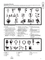 7
7
-
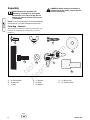 8
8
-
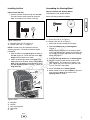 9
9
-
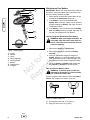 10
10
-
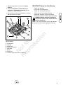 11
11
-
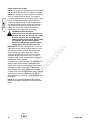 12
12
-
 13
13
-
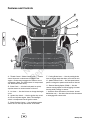 14
14
-
 15
15
-
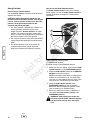 16
16
-
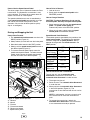 17
17
-
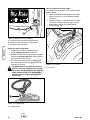 18
18
-
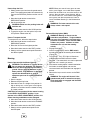 19
19
-
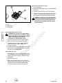 20
20
-
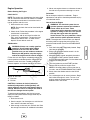 21
21
-
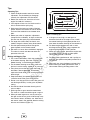 22
22
-
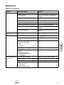 23
23
-
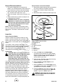 24
24
-
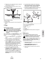 25
25
-
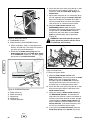 26
26
-
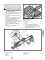 27
27
-
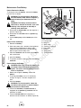 28
28
-
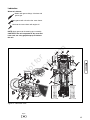 29
29
-
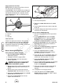 30
30
-
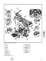 31
31
-
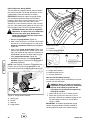 32
32
-
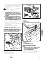 33
33
-
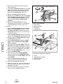 34
34
-
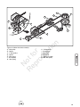 35
35
-
 36
36
-
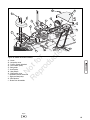 37
37
-
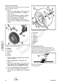 38
38
-
 39
39
-
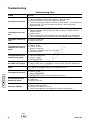 40
40
-
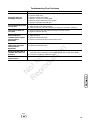 41
41
-
 42
42
-
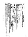 43
43
-
 44
44
-
 45
45
-
 46
46
-
 47
47
-
 48
48
-
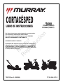 49
49
-
 50
50
-
 51
51
-
 52
52
-
 53
53
-
 54
54
-
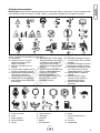 55
55
-
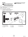 56
56
-
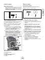 57
57
-
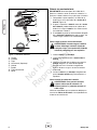 58
58
-
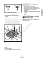 59
59
-
 60
60
-
 61
61
-
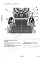 62
62
-
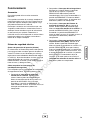 63
63
-
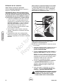 64
64
-
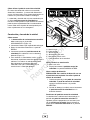 65
65
-
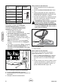 66
66
-
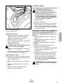 67
67
-
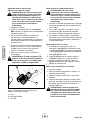 68
68
-
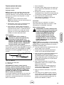 69
69
-
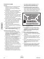 70
70
-
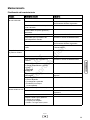 71
71
-
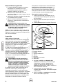 72
72
-
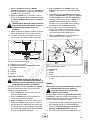 73
73
-
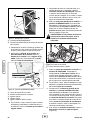 74
74
-
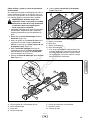 75
75
-
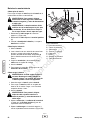 76
76
-
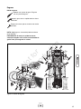 77
77
-
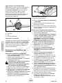 78
78
-
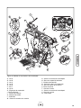 79
79
-
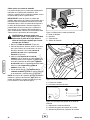 80
80
-
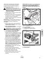 81
81
-
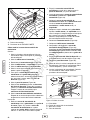 82
82
-
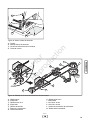 83
83
-
 84
84
-
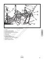 85
85
-
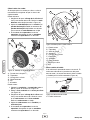 86
86
-
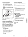 87
87
-
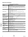 88
88
-
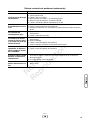 89
89
-
 90
90
-
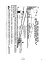 91
91
-
 92
92
-
 93
93
-
 94
94
-
 95
95
-
 96
96


Simplicity 7800311 Manual de usuario
- Categoría
- Cortadoras de césped
- Tipo
- Manual de usuario
- Este manual también es adecuado para
en otros idiomas
- English: Simplicity 7800311 User manual
Artículos relacionados
-
Simplicity 7800352 Manual de usuario
-
-
-
-
-
-
-
Briggs & Stratton 2691098-00 Manual de usuario
-
-
Murray 24744D Manual de usuario
Otros documentos
-
-
-
-
Anova TC98LH El manual del propietario
-
 EMAK RIDING MOWER El manual del propietario
-
Craftsman 536.270321 Manual de usuario
-
-
-
Snapper 24520 Manual de usuario
-
