Simplicity 21.0HP GARDEN TRACTOR Manual de usuario
- Categoría
- Cortadoras de césped
- Tipo
- Manual de usuario

F–030701L
Instruction Book Riding Mower
Model 461008x692A
Manual de instrucciones Cortacésped autoportado
Modelo 461008x692A
Read and keep this book for future reference. This book contains important information on SAFETY,
ASSEMBLY, OPERATION, AND MAINTENANCE.
PRODUCT INFORMATION
The owner must be certain that all the product information is included with the unit. This information
includes the INSTRUCTION BOOKS, the REPLACEMENT PARTS and the WARRANTIES.This information
must be included to make sure state laws and other laws are followed.
Este Manual de Instrucciones contiene información para varios modelos. Lea y conserve este manual
para referencias futuras. Este manual contiene información importante sobre SEGURIDAD, ENSAMBĆ
LAJE, FUNCIONAMIENTO Y MANTENIMIENTO.
INFORMACION DEL PRODUCTO
El propietario debe averiguar que toda la información del producto esté incluida con la unidad. Esta inĆ
formación incluye los MANUALES DE INSTRUCCION, las PIEZAS DE REPUESTO y las GARANTIAS. Esta
información debe ser incluida para asegurar que se sigan las leyes estatales y otras.

2
F–030701L
NOTE: This unit is equipped with an internal combustion engine
and must not be used on or near any unimproved
forest–covered, brush–covered or grass–covered land unless
the engine’s exhaust system is equipped with a spark arrester
meeting applicable local or state laws (if any). If a spark arrester
is used, it must be maintained in effective working order by the
operator.
In the State of California, the above is required by law (Section
4442 of the California Public Resources Code). Other states
may have similar laws. Federal laws apply on federal lands. See
an Authorized Service Center for a spark arrester for the
muffler.
NOTA: Esta unidad está equipada con un motor de combustión
interna, por lo que no debe usarse sobre o cerca de terreno
baldío, arbolado, herboso o de matorral a menos que el sistema
de escape del motor dispone de un parachispas que cumpla
con las leyes locales o estatales pertinentes (si las hay). Si hay
un parachispas instalado en el motor, el usuario debe
mantenerlo en buenas condiciones de operación.
Éste es un requisito legal para el estado de California (Sección
4442 del Código de Recursos Públicos de California). Puede
que otros estados tengan leyes similares. En los terrenos
federales se aplican las leyes Federales. Visite un Centro de
servicio autorizado si desea instalar un parachispas para el
sistema de escape.
Engine Exhaust, some of its constituents, and
certain vehicle components contain or emit
chemicals known to the State of California to
cause cancer and birth defects or other repro-
ductive harm.
Battery posts, terminals and related accesso-
ries contain lead and lead compounds, chemi-
cals known to the State of California to cause
cancer and birth defects or other reproductive
harm. WASH HANDS AFTER HANDLING.
Las emanaciones de escape producidas por
este motor contienen químicos reconocidos
por el Estado de California como carcinógenos,
también pueden producir defectos en los recién
nacidos o causar otros daños al sistema
reproductivo.
Los bornes, terminales y accesorios relaciona-
dos con la batería contienen plomo y compues-
tos del plomo, además de sustancias químicas
que el Estado de California reconoce como car-
cinógenas, además estas sustancias pueden
producir daños congénitos a los bebés y daños
al sistema reproductor humano. DEBE LAVAR-
SE MUY BIEN LAS MANOS DESPUÉS DE MANI-
PULAR ESTOS COMPONENTES.

3
F–030701L
1
23
7
4
1
2
3
4 (17x47)
5 (1001054)
12
5
1
3
4
2
6
8
6 (2x82)
7 (14x79) 3
4
7
6
1
2
5
4
3
1
5
2
1
2
6

4
F–030701L
1
2
3
4
5
6
7
7
1
2
3
4
5
8
7
9
7
3
4
10 11
12
11 13

5
F–030701L
1
2
34
5
6
12
2
3
1
13
7
3 mm
1
2
3
14
1
15
16

6
F–030701L
17
12
18
4
1
3
1
19
12
3
3
2
1
20
1
2
3
4
21
13
2
22

7
F–030701L
6
6
7
3
8
7
1
10
9
1
11
14
13
12
23
4
5
8
4
(17x91)
(31x4)
4
(17x91)
(31x4)
(17x91)
(31x4)
3
2
1
(17x91)
(31x4)
3
56
7
9
10
10
7
24
13
11
(17x91)
(31x11)
12

8
F–030701L
1001054
(2)
2x82
(2)
14x79
(2)
17x47
(2)
20729
(1)
25
31x4
(4)
31x11
(4)
17x91
(8)

GB
9
F–030701L
CONTENTS
OWNER’S INFORMATION 9
INTERNATIONAL PICTORIALS 10
SAFE MOWING GUIDE 12
STEPS TO FOLLOW 14
ASSEMBLY 15
OPERATION 16
MAINTENANCE CHART 18
MAINTENANCE 18
TROUBLE SHOOTING CHART 22
HOW TO ORDER REPAIR PARTS 23
STANLEY CENTRAL PARTS DISTRIBUTORS 23
SLOPE GUIDE 24
STANLEY OUTDOOR POWER
EQUIPMENT WARRANTY
Stanley Outdoor Power Equipment warrants to
the original purchaser that this unit shall be free
from defects in material and workmanship under
normal use and service for a period of Two (2)
Years from the date of purchase. Engines,
transmissions, and transaxles have an additional
warranty that is included in the literature kit.
Accessories (such as snow blowers, snow
blades, grass baggers, mulch kits, and
gardening attachments) are covered by a
separate warranty.
Normal wear parts and batteries are not covered
by this warranty except as noted below.
In the event the battery proves defective within
ninety (90) days from the date of purchase, we
will replace it without charge.
Normal Wear Parts are defined as belts, blades,
blade adapters, bushings, bearings, pneumatic
tires, headlights and seat covers. These parts
are warranted to be free from defects in material
and workmanship as delivered with the product.
Any claim for repair or replacement of normal
wear parts must be made within thirty (30) days
of the date of purchase. No claims involving
damage caused from material use, abuse, or
misuse will be honored.
Subject to the terms and conditions noted in this
Limited Warranty, we shall, at our option, repair
or replace at no cost to the original purchaser
any part covered by this Limited Warranty during
the applicable warranty period.
This Stanley Outdoor Power Equipment Two (2)
Year Limited Warranty is your exclusive remedy;
however this warranty is void or does not apply
to any unit that has been tampered with, altered,
abused, misused, or used for rental, commercial
and/or professional (non–homeowner) uses.
Your warranty does not cover minor mechanical
adjustments that are not due to any defect in
material or workmanship. For assistance in
making such adjustments, consult your
Instruction Book.
To make a claim under this Stanley Outdoor
Power Equipment Two (2) Year Limited
Warranty, take the unit (or if authorized in
advance, the defective part) along with your
proof of purchase to an Authorized Stanley
Power Equipment Service Center. To locate
your nearest Service Center, contact the retailer
where purchased, call either the Central Parts
Distributor for your area shown in the Instruction
book, or Stanley Outdoor Power Equipment
Customer Service at the number below, or
search our web site at
www.stanleylawnmower.com.
This Stanley Outdoor Power Equipment Two (2)
year Limited Warranty gives you specific legal
rights, and you may also have other rights which
vary from state to state. This Limited Warranty
is given in lieu of all other expressed and implied
warranties including the implied warranty of
merchantability and warranty of fitness for a
particular purpose. If you need additional
information on this written warranty or
assistance in obtaining service, call, write, or
e–mail at:
Stanley Outdoor Power Equipment
Customer Service Department
PO Box 268
Brentwood, TN 37024–0268
1–800–788–7766
www.stanleylawnmowers.com
OWNER’S INFORMATION
This instruction book is written for a person with
some mechanical ability. Like most service
books, not all the steps are described. Steps on
how to loosen or tighten fasteners are steps
anyone can follow with some mechanical ability.
Read and follow these instructions before you
use the unit.
Know your product: If you understand the unit
and how the unit operates, you will get the best
performance. As you read this manual, compare
the illustrations to the unit. Learn the location
and the function of the controls. To help prevent
an accident, follow the operating instructions
and the safety rules. Keep this manual for future
reference.
IMPORTANT: Many units are not assembled
and are sold in cartons. It is the responsibility of
the owner to make sure the assembly instruc-
tions in this manual are exactly followed. Other
units are purchased in an assembled condition.
On assembled units, it is the responsibility of the
owner to make sure the unit is correctly as-
sembled. The owner must carefully check the
unit according to the instructions in this manual
before it is first used.
WARNING: Look for this symbol to indicate
important safety precautions. This symbol
indicates: “Attention! Become Alert! Your
Safety Is At Risk.”
Responsibility Of The Owner
The responsibility of the owner is to
follow the instructions below.
1. Carefully read and follow the rules for safe
operation.
2. Follow all the assembly and preparation
instructions.
3. Inspect the unit.
4. Make sure that the operator of the unit
knows how to correctly use all standard
and accessory equipment.
5. Operate the unit only with guards, shields,
and other safety items in place and working
correctly.
6. Correctly adjust the unit.
7. Service the unit only with authorized or ap-
proved replacement parts.
8. Complete all maintenance on the unit.

GB
10
F–030701L
INTERNATIONAL PICTORIALS
IMPORTANT: The following pictorials are lo-
cated on your unit or on literature supplied
with the product. Before you operate the
unit, learn and understand the purpose for
each pictorial.
Safety Warning Pictorials (Figure 26)
1Warning
2Shield Eyes. Explosive Gases Can Cause
Blindness Or Injury.
3No Sparks, Flames or Smoking.
4Sulphuric Acid Can Cause Blindness Or
Severe Burns
5Flush Eyes Immediately With Water. Get
Medical Help Fast.
6IMPORTANT: Read Owner’s Manual
Before Operating This Machine.
7WARNING: Thrown Objects. Keep
Bystanders Away. Read User Instructions
Before Operating This Machine.
8WARNING: Do Not Use This Machine On
Slopes Greater Than 15 Degrees.
9DANGER: Keep People, Especially
Children, Away From Unit.
10 DANGER: No Step.
11 DANGER: Keep Feet And Hands Away
From Rotating Blade.
12 DANGER: Keep Hands Away From
Rotating Blade.
13 DANGER: Disconnect Spark Plug Wire
Before Servicing Unit.
14 WARNING: Hot Surface.
15 WARNING: Use Caution When Connecting
Or Disconnecting Accessories.
16 WARNING: Crushed Fingers.
17 IMPORTANT: Follow Instructions In
Owner’s Manual To Level The Deck.
12 3546
78910
12
11
13 14 16
26
15
MAX 130N
+MAX 230N
+
17
Control And Operating Pictorials
(Figure 27)
1Engine Start
2Lights
3Engine Stop
4Engine Stop
5Engine Run
6Brake
7Parking Brake
8Clutch
9Slow
10 Fast
11 Choke
12 Oil
13 Blade Rotation Control
14 Raise
15 Fuel
1234567
89
10 11 12 13 14 15
27

GB
11
F–030701L
Safe Operation Practices for Ride–On Mowers.
This cutting machine is capable of amputating hands and feet and throwing objects. Failure to observe the following safety instructions could
result in serious injury or death.
I. General Operation
1. Read, understand and follow all instructions
in the Instruction Book, on the machine, the
engine and with any attachments before
starting.
2. Only allow responsible adults, who are famil-
iar with the instructions, to operate the ma-
chine.
3. Clear the area of objects such as rocks, toys,
wire, etc., which could be picked up and
thrown by the blade.
4. Be sure the area is clear of other people be-
fore mowing. Stop the machine if anyone en-
ters the area.
5. Never carry passengers.
6. Turn off power to the blades or any attach-
ments before backing up. Do not mow in re-
verse unless absolutely necessary. Always
look down and behind before and while back-
ing.
7. Be aware of the mower discharge direction
and do not point it at anyone. Do not operate
the mower without either the entire grass
bagger or the mower guard in place.
8. Slow down before turning.
9. Never leave a machine unattended with the
engine running. Always turn off the blade(s),
set the parking brake, stop the engine and
remove the key before dismounting.
10. Turn off power to attachment(s) when trans-
porting or not in use. Turn off the blade(s)
when not mowing.
11. Stop the engine before removing the grass
bagger or unclogging the chute.
12. Mow only in daylight or good artificial light.
13. Do not operate the machine while under the
influence of alcohol or drugs or when very
tired.
14. Watch for traffic when operating near or
crossing roadways.
15. Use extra caution when loading or unloading
the machine into a trailer or truck.
16. Disengage all attachment clutches and shift
into Neutral before attempting to start the en-
gine.
17. Always wear goggles, safety glasses, or an
eye shield when you operate the unit to pro-
tect your eyes from foreign objects that can
be thrown from the unit. Always wear eye
protection when you make an adjustment or
repair to the machine.
18. Use care when pulling loads or using heavy
equipment.
a. Use only approved drawbar hitch points.
b. Limit loads to those you can safely con-
trol.
c. Do not turn sharply. Use care when back-
ing.
d. Use counterweights or wheel weights
when suggested in the Instruction Book.
19. Do not operate this machine if you are taking
drugs or other medication which can cause
drowsiness or affect your ability to operate
this machine.
20. Do not use this machine if you are mentally
or physically unable to operate this machine
safely.
21. Data indicates that operators, age 60 years
and above, are involved in a large percent-
age of riding mower related injuries. These
operators should evaluate their ability to op-
erate a riding mower safely enough to protect
themselves and others from serious injury.
II. Slope operation
Slopes and rough terrain are major factors
related to loss–of–control and tip–over acci-
dents, which can result in severe injury or
death. ALL slopes require extra caution. If
you cannot back up the slope or if you feel
uneasy on the slope, do not mow it. See the
“Slope Guide” in the back of this book to
check for safe operation.
DO
1. Mow up and down slopes, not across.
2. Remove obstacles such as rocks, limbs,
etc...
3. Watch for holes, ruts or bumps. Uneven ter-
rain could overturn the machine. Tall grass
can hide obstacles.
4. Use slow speed. Choose a low enough gear
so that you will not have to stop or shift while
on the slope.
5. Use slow speed on slopes. Do not make
sudden speed changes.
6. Follow the manufacturer’s recommendations
for wheel weights or counterweights to im-
prove stability.
7. Use extra care with grass baggers or other
attachments, they can change the stability of
the machine.
8. Keep all movement on the slopes slow and
gradual. Do not make sudden changes in
speed or direction.
9. Avoid starting or stopping on a slope. If tires
lose traction, turn off the blades and proceed
slowly straight down the slope.
DO NOT
1. Do not turn on slopes unless absolutely nec-
essary, then only turn slowly and gradually
downhill, if possible.
2. Do not mow drop–offs, ditches or embank-
ments. A wheel over the edge or an edge
caving in could cause a sudden overturn and
an injury or death.
3. Do not mow on wet grass. Reduced traction
could cause sliding.
4. Do not try to stabilize the machine by putting
your foot on the ground.
5. Do not use a grass bagger or other rear
mounted accessories on steep slopes (great-
er than 10 degrees).
III. Children
Tragic accidents can occur if the operator is
not alert to the presence of children. Chil-
dren are often attracted to the machine and
the mowing activity. NEVER assume that
children will remain where you last saw
them.
1. Keep children out of the mowing area and in
the watchful care of another responsible
adult.
2. Be alert and turn the engine off if children
enter the area.
3. Before and when backing, look behind and
down for small children.
4. Never carry children or any passengers,
even with the blades off. They may fall off
and be seriously injured or interfere with the
safe operation of the machine.
5. Never allow children to operate the machine.
Instruct children in the potential dangers of
the machine.
6. Use extra care when approaching blind cor-
ners, shrubs, trees or other objects that may
obscure vision.
IV. Service
1. Use extra care when handling gasoline and
other fuels. Fuels are flammable and the va-
pors are explosive.
a. Use only an approved container.
b. Never remove the gas cap or add fuel
with the engine running. Allow the engine to
cool for several minutes before refueling. Do-
not smoke.
c. Never refuel the machine indoors.
d. Never store the machine with fuel in the
tank or fuel container inside where there is
an open flame, such as a water heater.
2. Never start or run the engine inside a closed
area.
3. Keep all nuts and bolts, especially the blade
attachment nuts tight. Frequently check the
blade(s) for wear or damage such as cracks
and nicks. A blade that is bent or damaged
must be immediately replaced with an origi-
nal equipment blade from an authorized ser-
vice dealer. For safety, replace the blade
every two years. Keep the equipment in good
condition.
4. Never tamper with the safety devices. Check
their proper operation regularly.
5. To reduce fire hazards, keep the machine
free of grass, leaves or other debris build–up.
Clean up oil or fuel spills. Allow the machine
to cool before storing.
6. Stop and inspect the equipment if you strike
an object. Repair, if necessary, before re-
starting.
7. Never make adjustments or repairs with the
engine running. The carburetor can be ad-
justed with the engine running. Do not
change the engine governor settings or
over–speed the engine.
8. Grass bagger components are subject to
wear, damage and deterioration, which could
expose moving parts or allow objects to be
thrown. For storage, always make sure the
grass bag is empty. Frequently check com-
ponents and replace with manufacturer’s rec-
ommended parts when necessary.
9. Mower blade(s) are sharp and can cut. Wrap
the blade(s) or wear gloves and use extra
caution when servicing them or the blade
housing area.
10. Check the brake operation frequently. Adjust
and service as required.
11. Wait for all movement to stop before servic-
ing any part of the unit.

GB
12
F–030701L
SAFE MOWING GUIDE
Each person that operates power equipment
must learn to use correct and safe mowing pro-
cedures. To help you learn, carefully read the
following pages. Most of the time the operator
was not correctly shown or did not read the in-
structions on the unit or in the Instruction Book
before using the unit. Also, some operators do
not have enough experience. The result is un-
safe use, endangering the operator, bystanders
and the equipment. Another result can be a poor
appearance of the area mowed.
Read this book. Read the instructions on the
unit. Operate the mower according to the Safe
Mowing Guide. Follow all safety rules, cautions
or warnings in this book and on the unit. Make
sure anyone that uses the unit reads the instruc-
tions and is told how to safely operate the mow-
er.
The mower will give you good service and dura-
bility, if operated in normal conditions. If the
mower is not correctly serviced or is used where
the terrain is rough or unsuitable, product per-
formance and safety will be decreased.
Correct clothing is an important part of safe
mowing. Safety glasses will protect the eyes
from objects discharged by the mower. Safety
shoes with steel plates can protect a foot from
injury by the blade. For protection from objects
discharged from the mower, wear clothing that
will cover the arms and legs.
Before you start cutting the grass, practice using
the mower in a large open and level area. Learn
the location of the controls on the mower. Know
the purpose of the controls and how they work.
In an emergency, how fast you can stop the
blade is important. Learn how to control the
mower at all times.
Many engines are started by hand. When you
use a pull start or rope start, place your feet
apart and away from the blade(s). Hold the rope
handle tight. Never wrap the rope around your
arm or fingers for a “better grip”. To start the en-
gine, follow the instructions on the mower, in this
book and in the engine operating instructions.
For electric start engines, sit in the seat to start
the engine. The battery can be dangerous. Fol-
low the instructions on the battery, the acid con-
tainer, and in this book when working with the
battery. Even small batteries have enough volt-
age to cause an injury. Always be careful.
The mower is designed to be operated by one
person. Never let another person ride with you
on the unit or on any accessories. A passenger
will make the unit harder to control, block the
visibility or distract the operator and is danger-
ous to the operator, the passenger and the
equipment. Without a passenger seat, the pas-
senger can fall from the mower or contact dan-
gerous parts. A mower is not a toy for showing
off or for giving rides.
Never cut a wet lawn. Wet grass can cause an
accident, affect mower performance and can
cause problems with future lawn growth and ap-
pearance. Wet grass is slippery and can cause
the mower to slip. Someone can get injured by
touching the blade(s). Wet grass tends to clog
the mower, causing poor discharge. Cut wet
grass will collect on the lawn, retarding the
growth of the grass. Also, getting the mower wet
will cause parts to rust and decrease the life of
the unit.
When you look over the lawn, remember ob-
stacles that cannot be removed, like pipes,
stumps or rocks. Keep away from these ob-
stacles that can cause damage to the mower or
injury to the operator or a person near the mow-
er. Clear the area of rocks, toys, wire or other
loose objects. These items can damage the
mower or can be discharged by the mower
blade. The blade of a power mower rotates very
fast. It can discharge rocks and other objects
over a long distance which can be dangerous.
The force of the objects can break windows,
cause injuries or even put an eye out. Most of
the time the injury is to a person, like a child.
Keep every person completely away from the
area to be mowed. Make sure the grass is not
discharged toward anyone. Planning your mow-
ing pattern has a double advantage. It can de-
crease the possibility of an injury and make the
clean up after mowing easier.
Check the terrain of the area to be mowed. Mow
in a pattern that will keep you away from danger-
ous areas. Check the distance you need to stop
and the distance available to turn. Slopes and
rough terrain must be mowed carefully and
some areas must not be mowed at all. With rid-
ing mowers, mow up and down the hill. When
you must mow rough terrain or on slopes, never
change directions or change gears and stop in
these areas only in an emergency. Before you
ride up or down a slope, try to back straight up
the slope. Do not ride up or down a slope that is
too steep to back straight up. See the “Guide” in
the back of this Instruction Book to check any
slopes.
Before you start cutting, make sure the mower
was completely assembled according to the In-
struction Book. If the mower was completely as-
sembled at the store, you must still check the
mower according to the assembly instructions.
Make sure the mower is correctly assembled
and that all fasteners are tight. Make sure the
engine has the correct amount of oil. Check
these items often during the life of the mower.
Your mower has a gasoline engine. Gasoline is
a dangerous fuel. Keep gasoline only in an ap-
proved safety gasoline container. Do not keep
large amounts of gasoline. When you add gaso-
line to the fuel tank, do not smoke. Store the
gasoline container and the mower in an area
that has good ventilation. Also, keep the gaso-
line away from any flames like the pilot light of a
furnace or any other source of ignition. If the
mower is to be stored for more than a few
weeks, remove the gasoline from the fuel tank.
When inside an enclosure, do not add gasoline
to the fuel tank. Before you add gasoline, move
the mower outside and add gasoline carefully.
Before you start the engine, remove any gaso-
line from the outside of the fuel tank or from the
mower. Warm gasoline will expand. Leave some
space in the fuel tank for the gasoline to expand.
Also, the fuel cap has a vent hole for fuel va-
pors. Always use the correct fuel cap. Failure to
follow safety rules about gasoline will cause fires
and explosions, injury to you and damage to the

GB
13
F–030701L
equipment and other property.
If you add gasoline to an engine that is running
or hot, the result can be an explosion. Before
you add gasoline, stop the engine and let the
engine cool for several seconds. Remove dry
grass and other debris from the mower. Keep
the mower clean to improve the performance,
help the engine and transmission run cooler,
extend the life of moving parts, and decrease
the danger of a fire.
Fires and explosions are not the only dangers
when working around a mower. The engine,
transmission, and the muffler will get hot in sev-
eral minutes when the engine is running. Do not
touch these parts of the mower. Stop the engine.
Let the engine and transmission cool before
servicing the mower. Remember, exhaust fumes
are dangerous. Never operate the engine inside
a building.
When you get a new mower, it can be a new
experience for the family. Tell each person how a
mower can be dangerous. Remember, a mower
is not a toy. A mower is not to be used by chil-
dren or anyone not old enough, strong enough
or that does not have experience.
If the mower is not correctly assembled, not op-
erated correctly, or not regularly serviced, the
mower can be dangerous. The most important
rule to follow is always use good judgement and
common sense. Mow safely and carefully.
Your mower will easily cut thick grass. Fingers,
feet and other parts can also be cut by the
blade. Injuries occur when the operator does not
think and reaches into the chute opening. Al-
ways operate the mower as if the blade is rotat-
ing. Do not service or make an adjustment,
except to the carburetor, while the engine is run-
ning.
Use only accessories that are factory approved
for your mower. The wrong accessory can de-
crease the safety of the mower and can even
damage the unit. Read and follow the instruc-
tions included with the accessory and the mow-
er.
Use only original equipment or replacement
parts that are factory approved for service. If you
need service, select an Authorized Service Cen-
ter for your mower. If you do the work on the
unit, follow the instructions in the Instruction
Book.
When you mow, remember that children are at-
tracted to the mower. Always use caution when
mowing around obstacles like trees or shrubs or
when moving backward. Only mow in a forward
direction if possible. Your visibility is decreased
when you mow backward. Also, the blades are
made to cut while the unit is moving forward. If
you mow backward, the cutting performance
decreases.
Before you leave the mower, stop the engine.
Remove the key. Disengage and lower any at-
tachment. Set the parking brake. Never mount
or dismount from the seat while the engine is
running. An accident can occur if you touch the
brake, shift lever, throttle, clutch or blade control
while the engine is running. Mount and dis-
mount from the seat on the side of the unit that
is marked ENTER–EXIT.
Make sure you are in good condition when you
mow. When you mow for several hours your re-
flexes will decrease and your mind will not be as
alert. Take a short break or an accident can oc-
cur. If the temperature is hot, use caution to pre-
vent dehydration. If you are tired, angry or not
completely alert, do not operate the mower. If
you use alcohol, medication or drugs, do not use
the mower or any type of power equipment.
Engine speed is a key to safe mowing and to a
good looking lawn. The maximum speed of the
engine was set at the factory. Do not change the
setting of the engine governor.
Select the maximum engine and ground speed
that is right for the terrain and the height of the
grass. The blade cuts best when the engine is
operating at maximum speed. The engine and
transmission will also run cooler at maximum
engine speed. Also, the grass bagger will func-
tion better when the engine is operating at maxi-
mum speed. On slopes, decrease the ground
speed and use care making sure the mower
feels safe to operate.
If the weather conditions are bad, do not mow. If
weather conditions become bad, stop cutting
and finish later. It is dangerous to cut grass in
the rain. Always find protection in an electrical
storm. If the weather conditions are extra dry,
protect your eyes with safety glasses from the
dust and from the objects discharged by the
mower. Also, a dust or a pollen mask can help.
Your mower is equipped with a number of safety
devices which are important to the safety of the
operator and bystanders and must never be
changed or removed from the mower. If a safety
device is lost, damaged or no longer functions,
repair or replace the device before you operate
the mower.
It is best to mow during the day. If you must
mow at night, make sure there is enough light
for safe operation.
Your mower will require regular maintenance
and service. The maintenance schedule de-
pends on the hours of use. Also, mowing condi-
tions can change the schedule. Check the
Instruction Book for more information. Correct
maintenance will help the mower function safely.
Do not service the mower
(except for the carburetor
adjustment) while the en-
gine is running. Before you
service the unit, even with
the engine stopped, always
disconnect the wire from the
spark plug to prevent the
engine from starting.
If you hit a large object during operation, stop
the engine. Remove the wire from the spark
plug. Carefully inspect the mower for damage.
Before you start the engine again, make the
necessary repairs. If you feel new or excessive
vibration, immediately stop the engine and
check for the problem. Vibration can be a warn-
ing of a problem. Keep all nuts, bolts and screws
tight.
The blade is the most dangerous part of the
mower. Frequently check the blade and the
blade mounting fasteners. Keep the fasteners
tight. If the blade hits a solid object, stop the en-
gine. Remove the wire from the spark plug.
Check for a blade that is bent, cracked or for
other damages. Before you start the engine, re-
place a damaged blade(s). For safety, replace

GB
14
F–030701L
the blade every two years.
A sharp blade decreases the workload on the
engine and more evenly cuts grass. Frequently
sharpen the blade for a better looking cut. Use
the left side of the mower housing to trim near
an object.
A grass bagger is a good accessory for your
mower. For best performance and safety, make
sure the grass bagger is approved for use with
your mower. Follow the assembly and operation
instructions included with the grass bagger.
Some grass baggers require a special blade for
best performance. Before you attach, check, or
empty the grass bagger, always stop the engine.
Before each use of the grass bagger, check for
cracks, wear or deterioration. Before you use the
grass bagger, replace a damaged part with a
replacement part approved by the factory.
For you to have a good green lawn, follow the
mowing procedures below. Do not cut the grass
too short. If you cut the grass too short you can
cause the grass to become yellow or make the
lawn look brown. Use a lower height of cut in
cool months when the grass is thicker. Raise the
height of cut in hot dry periods. If you cut the
grass with a blade that is not sharp or at a slow
engine speed you can damage the grass. Move
the throttle control to the FAST position when
mowing and using the grass bagger. Also, use a
slower ground speed when using the grass bag-
ger.
If you change the direction or pattern of cut
slightly every time you mow will make the grass
grow stronger and thicker. Do not add oil or gas-
oline to the mower while on the lawn. Spilled oil
or gasoline can kill the grass. In high or thick
grass, do not try to cut all the grass the first time.
Raise the height of cut on the first cutting and
lower the height for the next cutting. Another
way is to cut only part of the width of the mower
and decrease your ground speed (not the en-
gine) to move more slowly so that the mower
can discharge the grass as it moves forward.
Understand the controls and how they work.
Learn the ground speed(s) of your mower.
Check the stopping distance required at different
travel speeds. Check the turning radius of the
mower. The controls on your riding mower are
different from an automobile. The throttle is op-
erated by hand and holds the engine speed con-
stant until it is changed. The location of the shift
lever and the shift pattern is different from that of
an automobile. Also, the brake and clutch sys-
tems are different. Remember the procedures to
follow in an emergency. Remember, turning off
the engine ignition switch will stop the blade and
the drive mechanism. If the traction of the
wheels is lost or does not feel safe, disengage
all systems and stop the engine. Dismount from
the mower. Push the unit to a safe place before
you begin mowing again.
Your unit has an electrical system that includes
an operator presence switch in the seat. The
operator presence switch detects if the operator
is sitting on the seat. The engine will stop if the
operator leaves the seat when the blade en-
gagement control is engaged. This operator
presence switch is a safety device only. It must
not regularly be used to stop the engine or the
blade. There are other control systems on the
mower for this purpose. Always keep the opera-
tor presence switch and other safety devices
and controls in place and operating for your pro-
tection.
Remember, your mower is a tool that can be
dangerous if it is not correctly used. Follow the
instructions in this Instruction Book. Safe and
careful use of the mower will give you many safe
hours of problem free use.
STEPS TO FOLLOW
Before Mowing
DBe sure to dress correctly. Wear hard shoes,
not sandals or tennis shoes.
DExamine the blade. A blade that is bent,
cracked, or damaged must be replaced with
a factory replacement blade.
DFill the fuel tank outside. Clean off spilled
fuel.
DRead and follow the Owner’s Manual, the
instructions with the engine, and the instruc-
tions with any attachments. Owner’s Manual
instructions are for your safety and the safety
of others.
DExhaust fumes are dangerous. Start the en-
gine outside.
DMake sure all safety devices are in place and
working correctly.
DOperation of the mower is only for a person
that has experience.
DWet grass can be dangerous. Let the grass
dry.
DInstruct children and others to keep away
from the work area.
DNever cut the grass without good light.
DPick up loose objects. Remove them from
the mowing area.
While Mowing
DWatch for fixed objects and avoid them. They
can damage the mower or cause injury.
DA hot engine, muffler and transmission will
cause a burn. Do not touch.
DInclines and slopes must be carefully
mowed. See the “Guide” in the back of this
book to check a slope.
DLack of daylight or good artificial light is
cause to stop mowing.
DExamine the mower, the blade, and other
parts for damage after hitting a foreign object
or if the unit vibrates excessively.
DDo not make adjustments or repairs without
stopping the engine (except for carburetor).
Disconnect the spark plug wire.
DOn or near roads, watch out for traffic. Direct
discharge away from roads.
DWhen mowing, avoid areas where traction is
unsure. Before and while moving back-
wards, look behind and down for small chil-
dren.
DIn heavy grass, raise the cutting height. Cut
slower. Stop the engine to remove clogged
grass from the mower.
DNever remove any safety related parts.
DDo not pour gasoline into a engine that is hot
or running.
After Mowing
DAlways let the mower cool before storing in
an enclosed area.
DForeign material on the mower is dangerous.
Clean off grass, leaves, grease and oil be-
fore storing.
DTighten all loose nuts, bolts and screws be-
fore you use the unit.
DEmpty and clean any grass catcher or other
accessory.
DRemove the key or disconnect the spark plug
wire to prevent unauthorized use.
DMake sure the mower is not kept near a
source of ignition. Gas fumes can cause an
explosion.
DOnly original parts or factory approved sub-
stitutes can be used to service the mower.
DWhen storing the mower for an extended pe-
riod, remove the fuel from the fuel tank.
DInstruct children to leave the mower alone. It
is not a toy.
DNever keep gasoline near a source of igni-
tion. Always use an approved container.
Keep gasoline away from children.
DLubricate according to the Instruction Book.
See “Lubrication”.
IMPORTANT––Read the Instruction
Book. Keep this book for future use and
reference.

GB
15
F–030701L
ASSEMBLY
All fasteners are in the parts bag. Do not discard
any parts or material until the unit is assembled.
WARNING: Before doing any as-
sembly or maintenance to the
mower, remove the wire from the
spark plug.
NOTE: In this instruction book, left and right
describe the location of a part with the oper-
ator on the seat.
NOTE: Illustrations and pictorials begin on
page 2.
NOTE: To assemble the following loose
parts, use the fasteners shown at full size in
Figure 25.
How To Assemble The Mower Housing
(Figure 24)
1. Move the blade rotation control (1) to the
DISENGAGE position.
2. Move the lift lever (2) to the level adjust-
ment position.
WARNING: The lift lever is spring
loaded. Make sure the lift lever is
locked in the LEVEL ADJUSTMENT
position.
3. Push the mower housing under the right side
of the unit.
4. For shipping purposes, the back of the front
hanger (9) is secured with a plastic tie. Cut
the plastic tie.
5. Attach the front hanger (9) to the mower
housing with the hanger rod (13). Fasten
with the fasteners as shown. See illustration
“F”.
6. Put the mower drive belt (7) around the
stack pulley (8). See illustration “G”.
Make sure the “V” side of the mower drive
belt is against the stack pulley. Also, make
sure the mower drive belt is not twisted.
7. Make sure the mower drive belt (7) is be-
tween the stack pulley (8) and the two belt
guides (10). See illustration “G”.
8. Attach the suspension links (4) to the lifter
assembly. Fasten with the hair pins and
washers. See illustrations “A” and “B”.
9. Attach the right and left adjuster arms (3) to
the suspension brackets. Fasten with the
hair pins and the washers. See illustrations
“C” and “D”.
10.Attach the extension spring (5) to the
blade control rod (6). See illustration “E”.
11. Move the blade rotation control (1) to the
ENGAGE position. Make sure the mower
drive belt (7) is inside all the belt guides
(10).
12.Make sure the mower housing is level. See
the instructions on “How To Level The Mower
Housing”.
13.Attach the gauge wheels (12) to the axle
bolts (11) with the fasteners.
NOTE: The axle bolt is mounted in the
LOW position. To change the position to a
higher cutting position, see “How To Ad-
just The Gauge Wheels” in the Mainten-
ance section.
14.Check the operation of the blade rotation
control. See the instructions on “How To Ad-
just The Blade Rotation Control”.
Check The Tires
Check the air pressure in the tires. Tires with too
much air pressure will cause the unit to ride
rough. Also, the wrong air pressure will keep the
mower housing from cutting level. The correct
air pressure is: Front Tires 0,97 BAR (14 PSI),
Rear Tires 0,69 BAR (10 PSI). The tires were
over inflated for shipment.
Check The Level Of The Mower
Housing
Make sure the level of cut is still correct. After
you mow a short distance, look at the area that
was cut. If the mower housing does not cut level,
see the instructions on “How To Level The
Mower Housing” in the Maintenance section of
this instruction book.
How To Install The Seat (Figure 1)
1. Carefully remove the plastic bag from the
seat (1).
2. Align the holes in the seat hinge (2) to the
holes in the seat (1). Fasten the seat (1) to
the seat hinge (2) with the fasteners (4) and
(5).
3. Check the operating position of the seat (1).
If the seat (1) needs to be adjusted, loosen
the two wing bolts (5). Slide the seat (1) for-
ward or backward along the seat adjusting
holes (3). Tighten the wing bolts (5).
How To Assemble The Steering Wheel
(Figure 2)
1. Make sure the front wheels point forward.
2. Look at the hub (4) of the steering wheel
(1). Make sure the locking clip is in place in-
side the hub (4).
3. Slide the cover (3) over the steering post
(2). Make sure the collar of the cover (3) is
on top.
4. Slide the steering wheel (1) onto the steer-
ing post (2). Push on the steering wheel
(1). The steering wheel (1) will lock onto the
steering post (2). Pull on the steering
wheel (1). Make sure the steering wheel (1)
is locked in place.
5. Some models have an optional decal (7) in
the parts bag. Attach the decal (7) to the
center of the steering wheel (1).
Maintenance Free Battery (Figure 3)
IMPORTANT: Before you attach the battery
cables to the battery, check the battery date.
The battery date tells if the battery must be
charged.
1. Check the top of the battery (1) for the loca-
tion of the battery date.
2. If the battery (1) is put into service before
the battery date , the battery cables can be
attached without charging the battery (1).
See “How To Install The Battery Cables”.
3. If the battery (1) is put into service after the
battery date , the battery (1) must be
charged. See “How To Charge The Mainten-
ance Free Battery”.
How To Charge The Battery (Figure 3)
WARNING: When you charge the
battery, do not smoke. Keep the bat-
tery away from any sparks. The
fumes from the battery acid can cause an
explosion.
1. Remove the battery (1) and battery tray (3).
2. Remove the protective caps from the battery
terminals.
3. Use a 12 volt battery charger to charge the
battery (1). Charge at a rate of 6 amperes
for one hour. If you do not have a battery
charger, have an authorized service center
charge the battery.
4. Install the battery (1) and battery tray (3).
Make sure the positive (+) terminal (4) is on
the left side.
How To Install The Battery Cables
(Figure 3)
WARNING: To prevent sparks, faste
n
the red cable to the positive (+) ter-
minal before you connect the black
cable.
1. Remove the protective caps from the battery
terminals.
2. Slide the terminal cover (2) onto the red
cable (5). Fasten the red cable (5) to the
positive (+) terminal (4) with the fasteners
(6) and (7).
3. Fasten the black cable 8 to the negative (–)
terminal with the fasteners (6) and (7).
How To Prepare The Engine
NOTE: The engine was shipped from the fac-
tory filled with oil. Check the level of the oil.
Add oil as needed.
See the engine manufacturer’s instructions for
the type of gasoline and oil to use. Before you
use the unit, read the information on safety,
operation, maintenance, and storage.
WARNING: Follow the engine manu-
facturer’s instructions for the type o
f
gasoline and oil to use. Always use
a
safety gasoline container. Do not smoke
when adding gasoline to the engine. When
inside an enclosure, do not fill with gasoline
Before you add gasoline, stop the engine.
Let the engine cool for several minutes.
Important! Before You Start Mowing
rCheck the engine oil.
rFill the fuel tank with gasoline.
rCheck the level of the mower hous-
ing.
rCheck the air pressure of the tires.
rAttach the battery cables.

GB
16
F–030701L
OPERATION
NOTE: Illustrations and pictorials begin on
page 2.
Location Of Controls (Figure 4)
Blade Rotation Control (1): Use the blade rota-
tion control to start and stop the rotation of the
blade.
Clutch / Brake Pedal (2): The pedal has two
functions. The first function is a clutch. The sec-
ond function is a brake.
Headlight Switch (3): The headlight switch is
the first part of the ignition switch. To use the
lights with the engine running, turn the key to the
position for the lights.
Ignition Switch (3): Use the ignition switch to
start and stop the engine.
Shift Lever (4): Use the shift lever to change
the speed of the unit.
Lift Lever (5): Use the lift lever to change the
height of cut.
Parking Brake Lever (6): Use the parking brake
lever to engage the brake when you leave the
unit.
Throttle Control Lever (7): Use the throttle
control lever to increase or decrease the speed
of the engine.
Attachments
This unit can use many different attachments.
This unit can pull attachments like a lawn
sweeper, a lawn aerator, or a hopper spreader.
This unit can also use attachments that engage
the ground like a plough, a disk harrow, or a
cultivator.
For trailer and pull–behind attachments, the
maximum weight is 113 kg (250 lbs.).
How To Use The Throttle Control
(Figure 4)
Use the throttle control (7) to increase or de-
crease the speed of the engine.
1. The FAST position is marked with a detent.
For normal operation and when using a
grass bagger, move the throttle control to the
FAST position. For maximum charging of the
battery and for a cooler running engine, oper-
ate the engine in the FAST position.
2. The engine governor is set at the factory for
maximum performance. Do not adjust the
governor to increase the speed of the en-
gine.
How To Use The Blade Rotation Control
(Figure 4)
Use the blade rotation control (1) to engage
the blade(s).
1. Before you start the engine, make sure the
blade rotation control (1) is in the DISEN-
GAGE position.
2. Move the blade rotation control (1) to the
ENGAGE position to rotate the blade(s).
NOTE: If the engine stops when you en-
gage the blade(s), the seat switch is not
activated. Make sure you sit in the middle
of the seat.
3. Move the blade rotation control (1) to the
DISENGAGE position to stop the blade(s).
Before you leave the operator’s position,
make sure the blade(s) has stopped rotating.
4. Before you ride the unit across a sidewalk or
a road, move the blade rotation control (1)
to the DISENGAGE position.
WARNING: Always keep your
hands and feet away from the
blade, deflector opening, and the
mower housing when the engine runs.
How To Use The Shift Lever (Figure 4)
To change the forward speed or the direction of
the unit, follow the steps below.
CAUTION: Before you move the shift lever,
completely push the clutch/brake pedal for-
ward to stop the unit. If the unit is not
stopped, the gearbox can be damaged.
1. Completely push the clutch/brake pedal (2)
forward to stop the unit. Keep your foot on
the pedal.
2. Move the throttle control lever (7) to the
SLOW position.
3. To go forward, move the shift lever (4) to a
forward speed setting. To go backward,
move the shift lever (4) to reverse.
4. Slowly release the clutch/brake pedal (2).
Do not keep your foot on the pedal.
5. Move the throttle control (7) to the FAST
position.
How To Use The Parking Brake
(Figure 4)
1. Completely push the clutch/brake pedal (2)
forward.
2. Lift the parking brake lever (6).
3. Remove your foot from the clutch/brake
pedal (2) and then release the parking
brake lever (6). Make sure the parking brake
will hold the unit.
4. To release the parking brake (6), completely
push the clutch/brake pedal (2) forward.
The parking brake will automatically release.
WARNING: Before you leave the
operator’s position, move the shift
lever to the neutral (N) position. Set
the parking brake. Move the blade rotation
control to the DISENGAGE position. Stop
the engine and remove the ignition key.
How To Change The Cutting Height
(Figure 4)
To change the cutting height, raise or lower the
lift lever (5) as follows.
1. Move the lift lever (5) forward to lower the
mower housing and back to raise the mower
housing.
2. When you ride on a sidewalk or road, move
the lift lever (5) to the highest position and
move the blade rotation control to the DIS-
ENGAGE position.
How To Stop The Unit (Figure 4)
1. Completely push the clutch/brake pedal (2)
forward to stop the unit. Keep your foot on
the pedal.
2. Move the blade rotation control (1) to the
DISENGAGE position.
3. Move the shift lever (4) to the NEUTRAL
position.
4. Set the parking brake (6).
WARNING: Make sure the parking
brake will hold the unit.
5. Move the throttle control (7) to the SLOW
position.
6. To stop the engine, turn the ignition key (3)
to the OFF position. Remove the key.
How To Transport The Unit
To transport the unit, follow the steps below.
1. Move the blade rotation control to the DIS-
ENGAGE position.
2. Raise the lift lever to the highest position.
3. Move the throttle control to a position be-
tween SLOW and FAST.
4. To go faster, move the shift lever to a faster
speed.
How To Operate With The Mower
Housing
IMPORTANT: When you operate with the
mower housing, always operate with the
throttle control in the FAST position.
1. Start the engine.
2. Move the lift lever to a height of cut position.
In high or thick grass, cut the grass in the
highest position first and then lower the mow-
er housing to a lower position.
3. Move the throttle control to the SLOW posi-
tion.
4. Slowly move the blade rotation control to the
ENGAGE position.
5. Push the clutch/brake pedal completely for-
ward.
6. Move the shift lever to one of the speed set-
tings.
NOTE: When you mow in heavy grass or
mow with a bagger, put the shift lever in
the slowest speed.
7. Slowly release the clutch/brake pedal.
8. Move the throttle control to the FAST posi-
tion. If you need to go faster or slower, stop
the unit and move the shift lever to another
speed setting.
9. Make sure the level of cut is still correct. Af-
ter you mow a short distance, look at the
area that was cut. If the mower housing does
not cut level, see the instructions on “How To
Level The Mower Housing” in the Mainte-
nance section.

GB
17
F–030701L
WARNING: For better control of the
unit, select a safe speed.
How To Operate On Hills
WARNING: Do not ride up or down
slopes that are too steep to back
straight up. Never ride the unit
across a slope.
1. Before you ride up or down a hill, move the
shift lever to the slowest speed.
2. Do not stop or change speed settings on a
hill. If you must stop, quickly push the clutch/
brake pedal forward and set the parking
brake.
3. To start again, make sure the shift lever is in
the slowest speed. Move the throttle control
to the SLOW position. Slowly release the
pedal.
4. If you must stop or start on a hill, always
have enough space for the unit to roll when
you release the brake and engage the clutch.
5. Be very careful when you change directions
on a hill. When on a slope or in a turn on a
hill, move the throttle control to the SLOW
position to help prevent an accident.
Before Starting The Engine
Check the oil
NOTE: The engine was shipped from the fac-
tory filled with oil. Check the level of the oil.
Add oil as needed. See the engine manufac-
turer’s instructions for the type of gasoline
and oil to use.
1. Make sure the unit is level.
NOTE: Do not check the level of the oil
while the engine runs.
2. Check the oil. Follow the procedure in the
engine manufacturer’s instructions.
3. If necessary, add oil until the oil reaches the
FULL mark on the dipstick. The quantity of oil
needed from ADD to FULL is shown on the
dipstick. Do not add too much oil.
Add Gasoline
WARNING: Always use a safety
gasoline container. Do not smoke
when adding gasoline to the fuel
tank. Do not add gasoline when you are
inside an enclosure. Before you add
gasoline, stop the engine and let the
engine cool for several minutes.
(Figure 6) Fill the fuel tank (1) to the FULL (2)
position with regular unleaded gasoline. Do not
use premium unleaded gasoline. Make sure the
gasoline is fresh and clean. Leaded gasoline will
increase deposits and shorten the life of the
valves.
How To Start The Engine
WARNING: The electrical system
has an operator presence system
that includes a sensor switch for
the seat. These components tell the
electrical system if the operator is sitting
on the seat. This system will stop the
engine when the operator leaves the seat if
the blade rotation control is engaged or if
the transmission is engaged. For your
protection, always make sure this system
operates correctly.
NOTE: The engine will not start unless you
depress the clutch/brake pedal or engage the
parking brake and move the blade rotation
control to the DISENGAGE position.
1. Push the clutch/brake pedal completely for-
ward. Keep your foot on the pedal.
2. Move the shift lever to the neutral (N) posi-
tion.
3. Make sure the blade rotation control is in the
DISENGAGE position.
4. Move the throttle control completely forward
to the CHOKE or FAST position. Some mod-
els have a separate choke knob. Pull the
choke knob to the full CHOKE position.
5. Turn the ignition key to the START position.
NOTE: If the engine does not start after
four or five tries, move the throttle control
to the FAST position. Again try to start the
engine. If the engine will not start, see the
TROUBLE SHOOTING CHART.
6. Slowly move the throttle control to the SLOW
position.
7. To start a hot engine, move the throttle con-
trol to a position between FAST and SLOW.
Mowing And Bagging Tips
1. For a lawn to look better, check the cutting
level of the mower housing. See “How To
Level The Mower Housing” in the Mainte-
nance section.
2. For the mower housing to cut level, make
sure the tires have the correct amount of air
pressure.
3. Every time you use the unit, check the blade.
If the blade is bent or damaged, immediately
replace the blade. Also, make sure the nut
for the blade is tight.
4. Keep the blade(s) sharpened. Worn blades
will cause the ends of the grass to turn
brown.
5. Do not cut or bag grass that is wet. Wet
grass will not discharge correctly. Let the
grass dry before cutting.
6. Use the left side of the mower housing to trim
near an object.
7. Discharge the cut grass onto the mowed
area. The result is a more even discharge of
cut grass.
8. When you mow large areas, start by turning
to the right so that the cut grass will dis-
charge away from shrubs, fences, driveways,
etc. After one or two rounds, mow in the op-
posite direction making left turns until fin-
ished.
9. If the grass is very high, cut two times to de-
crease the load on the engine. First cut with
the mower housing in the highest position
and then lower the mower housing for the
second cut.
10.For better engine performance and an even
discharge of the cut grass, always operate
the engine with the throttle in FAST position.
11. When you use a bagger, operate the engine
with the throttle in FAST position and the shift
lever in first or second gear.
12.For better cutting performance and a quality
cut, mow with the shift lever in one of the
slower speeds.
13.After each use, clean the bottom and top of
the mower housing for better performance.
Also, a clean mower housing will help pre-
vent a fire.

GB
18
F–030701L
MAINTENANCE CHART
FREQUENCY MAINTENANCE REQUIRED COMMENTS
Daily or before each use Maintenance engine. Refer to the Engine Owner’s Manual.
Examine blade(s). Check for cracks, wear, and excessive damage.
Remove debris from unit and mowing area.
Examine all rotating and sliding parts.
Check tire inflation. Refer to the Maintenance section.
Verify that the mower housing is level. Refer to the Maintenance section.
Examine V–belts. Check for cracks, wear, and excessive damage.
Check brake operation. Refer to the Operation and Maintenance
sections.
After completion of first 5 hours Change oil. Refer to the Engine Owner’s Manual.
After 25 hours Maintenance engine. Refer to the Engine Owner’s Manual.
Remove, examine, sharpen, and balance
blade(s). Refer to Maintenance section.
Check adjustments:
a. Blade Rotation Control
b. Brake
c. Clutch
d. Steering
Refer to Maintenance section.
Lubricate chassis and mower housing. Refer to Where to Lubricate instructions.
Check the muffler:
a. Torque
b. For wear or burn out
c. Condition of spark arrestor, (if applicable).
Refer to Maintenance section.
Before storage of 30 days or more Prepare engine for storage. Refer to the Engine Owner’s Manual.
Drain fuel system. Refer to warnings in the Owner’s Manual.
Add fuel stabilizer. Refer to the Engine Owner’s Manual.
Prepare battery for storage:
a. Remove from unit.
b. Fully charge.
c. Move to cool dry place.
MAINTENANCE
NOTE: Illustrations and pictorials begin on
page 2.
General Recommendations
1. The owner’s responsibility is to maintain this
product. This will extend the life of the prod-
uct and is also necessary to maintain warran-
ty coverage.
2. Check the spark plug, drive brake, lubricate
the unit, and clean the air filter once a year.
3. Check the fasteners. Make sure all fasteners
are tight.
4. Follow the Maintenance section to keep the
unit in good operating condition.
WARNING: Before you make an in-
spection, adjustment, or repair to
the unit, disconnect the wire to the
spark plug. Remove the wire from the
spark plug to prevent the engine from
starting by accident.
NOTE: Torque is measured in foot pounds
(metric Nm). This measurement describes
how tight a nut or bolt must be. The torque is
measured with a torque wrench.
Inspect Blade (Figure 7)
WARNING: Before you inspect or
remove the blade, disconnect the
wire to the spark plug. If the blade
hits an object, stop the engine. Check the
unit for damage. The blade has sharp
edges. When you hold the blade, use
gloves or cloth material to protect your
hands.
If you keep the blade (1) sharp and inspect the
blade for damage, the blade will cut better and
be more safe to operate. Frequently check the
blade for excessive wear, cracks, or other dam-
age. Frequently check the nut (3) that holds the
blade (1). Keep the nut (3) tight. If the blade hits
an object, stop the engine. Disconnect the wire
to the spark plug. See if the blade is bent or
damaged. Check the blade adapter (5) for dam-
age. Before you operate the unit, replace dam-
aged parts with original equipment parts. See
the authorized service center in your area. Every
three years, have an authorized service person
inspect the blade or replace the old blade with
an original equipment part.
How To Remove And Install The Blade
(Figure 7)
1. Remove the mower housing. See the instruc-
tions on “How To Remove The Mower Hous-
ing”.
2. Use a piece of wood to keep the blade from
rotating.
3. Remove the nut (3) that holds the blade (1).
4. Check the blade (1) and the blade adapter
(5) according to the instructions for “Inspect
Blade”. Replace a badly worn or damaged
blade with an original equipment blade. See
an authorized service center in your area.
5. Clean the top and bottom of the mower hous-
ing. Remove all the grass and debris.
6. Mount the blade (1) and blade adapter (5)
on the mandrel (6).
7. Mount the blade (1) so that the hi–lift edges
(7) are up. If the blade is upside down, the
blade will not cut correctly and can cause an
accident.
8. Fasten the blade (1) with the original wash-
ers and nut (3). Make sure the outside rim of
the Belleville washer (2) is against the
blade (1).
WARNING: Always keep the nut (3)
tight that holds the blade (1). A
loose nut or blade can cause an
accident.
9. Tighten the nut (3) that holds the blade (1) to
a torque of 30 foot pounds (41,5 Nm).
10.Install the mower housing. See “How To Re-
move The Mower Housing”.

GB
19
F–030701L
How To Adjust The Blade Rotation
Control
WARNING: To prevent an injury, the
blade rotation control must operate
correctly.
In normal usage, the blade rotation control will
not require an adjustment. However, if the cut-
ting performance decreases or the quality of cut
is poor, make the following changes.
1. When you mow, make sure the throttle con-
trol in in the FAST position.
2. (Figure 5) Move the blade rotation control to
the DISENGAGE position (1).
3. Stop the engine. Disconnect the wire from
the spark plug.
4. Check the blade(s). Keep a sharp edge on
the blade(s). A blade that is not sharp will
cause the tips of the grass to become brown.
5. (Figure 8) Disconnect the blade drive
spring (2) from the blade control rod (1).
Move the blade drive spring (2) to the
middle hole (4). This will increase the tension
on the mower drive belt.
6. Attach the wire to the spark plug. Mow for a
short distance and again check the quality of
cut. If necessary, move the blade drive
spring (2) to the bottom hole (5)
7. Again check the quality of cut. If the quality of
cut has not improved, replace the mower
drive belt. See “How To Replace The Mower
Drive Belt”. If the replacing the belt does not
correct the problem, take the unit to an au-
thorized service center.
8. Move the blade rotation control to the DIS-
ENGAGE position. Stop the engine.
9. (Figure 9) Check the operation of the blade
brake. Rotate the pulleys with your hand.
Make sure the brake pads (7) are pressed
tightly against the pulleys
WARNING: If the brake pads (7) do
not press tightly against the
pulleys, take the unit to an author-
ized service center.
10.(Figure 5) Move the blade rotation control to
the ENGAGE position (2).
11. (Figure 9) Check the pads for the blade
brake (7). If the pads are excessively worn
or damaged, replace the brake pad assem-
blies. Correct replacement parts and assis-
tance are available from an authorized
service center.
12.Attach the wire to the spark plug. Mow for a
short distance and again check the operation
of the blade rotation control.
13.When you move the blade rotation control to
the DISENGAGE position, all movement will
stop within five seconds. If there is move-
ment of the belt or the blades continue to ro-
tate, engage and disengage the blade
rotation control five times to remove any ex-
cess rubber from a new mower drive belt. If
you need assistance, take the unit to an au-
thorized service center.
14.(Figure 8) If you replace the mower drive
belt, move the blade drive spring (2) to the
top hole (3).
How To Adjust The Shift Lever
If the NEUTRAL position on the shift lever does
not match neutral on the gearbox, adjust the
shift lever as follows.
1. Stop the engine.
2. (Figure 14) Move the lift lever (1) to the
DECK LEVEL position (2).
The lift lever is spring loaded. Make
sure the lift lever is locked in the
DECK LEVEL position.
3. (Figure 10) Loosen the nut (3) on the ad-
juster plate (4). The adjuster plate (4) is
located under the left rear fender.
4. Make sure the shift lever is in the NEUTRAL
position.
5. Push the unit forward. Make sure the gear-
box is in neutral.
6. Tighten the nut (3) on the adjuster plate (4).
7. Make sure the NEUTRAL position on the
shift lever matches neutral on the gearbox.
8. (Figure 14) Raise the lift lever (1) from the
DECK LEVEL position (2) to a CUTTING
HEIGHT position.
How To Check And Adjust The Clutch
(Figure 12 and Figure 10)
If the motion drive belt is loose, the clutch will
slip when; going up a hill, pulling a heavy load,
or the unit will not move forward. Adjust the
clutch as follows.
WARNING: Before you make an in-
spection, adjustment, or repair to
the unit, disconnect the wire to the
spark plug. Remove the wire from the
spark plug to prevent the engine from
starting by accident.
1. Check the routing of the motion drive belt.
Make sure the belt is installed correctly and
is inside all the belt guides.
2. (Figure 12)Remove the cotter pin (1),
washer (2), and brake spring (3) from the
adjustable nut (4).
3. Disconnect the adjustable nut (4) from the
brake lever assembly (5) and the parking
brake latch (6).
4. Use the cotter pin (1) removed in step 2.
Hold the cotter pin(1) at the back of the slot
and move the brake lever assembly (5)
rearward against the cotter pin (1). This will
set a 3 mm (1/8 inch) gap between the
brake lever assembly (5) and the back of
the slot.
5. Turn the adjustable nut (4) until the nut will
fit through the hole in the brake lever (5).
6. Assemble the adjustable nut (4) to the
parking brake latch (6), brake lever (5) and
brake spring (3). Fasten with the washer (2)
and cotter pin (1).
7. If the belt still slips after the clutch has been
adjusted, then the motion drive belt is worn
or damaged and must be replaced. See
“How To Replace The Motion Drive Belt”.
How To Check And Adjust The Drive
Brake (Figure 13)
Completely push the clutch/brake pedal forward.
Set the parking brake. Move the shift lever to the
neutral (N) position. Push the unit. If the rear
wheels rotate, adjust or replace the brake pads.
Adjust the drive brake (1) as follows.
1. The location of the drive brake (1) is on the
right side of the gearbox (3).
2. Make sure the parking brake is set and the
shift lever is in neutral (N). Turn the hex nut
(2) in a clockwise direction until the rear
wheels do not turn when the unit is pushed
forward.
3. Release the parking brake and push the unit.
If the unit does not roll, turn the hex nut (2)
in a counter–clockwise direction until the unit
rolls.
4. Set the parking brake. Push the unit. If the
rear wheels do not turn, the drive brake (1)
is correctly adjusted. Release the parking
brake.
WARNING: If you cannot correctly
adjust the drive brake, replace the
brake pads. Correct replacement
parts and assistance are available from an
authorized service center.
How To Remove The Battery (Figure 3)
To charge or clean the battery (1), remove the
battery (1) from the unit as follows.
WARNING: To prevent sparks, dis-
connect the black battery cable (8)
from the negative (–) terminal be-
fore you disconnect the red cable (5).
WARNING: The battery contains
sulphuric acid which is harmful to
the skin, eyes and clothing. If the
acid gets on the body or clothing, wash
with water.
1. Disconnect the black cable (8) from the neg-
ative (–) terminal.
2. Disconnect the red cable (5) from the posi-
tive (+) terminal (4).
3. Lift the battery tray (3) and the battery (1)
out of the unit.
How To Charge The Battery (Figure 3)
WARNING: When you charge the
battery, do not smoke. Keep the
battery away from any sparks. The
fumes from the battery acid can cause an
explosion.
1. Before you charge the battery (1), remove
the battery (1).
2. To charge the battery (1), use a 12 volt bat-
tery charger. Charge at a rate of 6 amperes
for 1 hour.
3. Install the battery (1).
WARNING: To prevent sparks,
fasten the red cable to the positive
(+) terminal before you connect the
black cable.
4. Fasten the red cable (5) to the positive (+)
terminal (4) with the fasteners as shown.
5. Fasten the black cable (8) to the negative
(–) terminal with the fasteners as shown.
How To Adjust The Gauge Wheels
The axle bolts for the gauge wheels were
mounted in the LOW cut position. To change the
position of the gauge wheels, move the axle
bolts as follows.

GB
20
F–030701L
IMPORTANT: Before you adjust the gauge
wheels, you must do the following. Make
sure the mower housing is level. Make sure
the height of cut is set at the height you want
for your lawn. Mow a short distance on a flat
level area and look at the area that was cut. If
the mower housing does not cut level, see
the instructions “How To Level The Mower
Housing.”
WARNING: Before you make an
inspection, adjustment, or re-
pair to the unit, disconnect the
wire to the spark plug. Remove the
spark plug wire to prevent the engine
from starting by accident.
1. (Figure 11) Remove the gauge wheels (12)
and axle bolts (11).
2. (Figure 14) Mow a short distance on a flat
level area to check the level of cut and the
height of cut. Look at the height of cut posi-
tion number (3) on the lift lever (1).
3. (Figure 11) Look at each gauge wheel
bracket (13). There are 3 holes in each
bracket and a number next to each hole. The
number for the height of cut position on the
lift lever indicates the correct hole to use on
each gauge wheel bracket (13).
NOTE: Wheel bracket hole number 1 is
equal to lift lever position number 1.
Wheel bracket hole number 2 is equal to
lift lever position number 2. Wheel
bracket hole number 3 is equal to lift lever
position numbers 3,4,5, and 6.
4. Assemble the axle bolts (11) to the gauge
wheel brackets (13) using the correct hole
in the bracket as indicated.
NOTE: If the height of cut position is
changed by the lift lever, you must move the
gauge wheels to the correct hole to keep a
level height of cut.
How To Level The Mower Housing
(Figure 14 and Figure 15)
If the mower housing is level, the blade will cut
easier and the lawn will look better.
WARNING: Before you make an in-
spection, adjustment, or repair to
the unit, disconnect the wire to the
spark plug. Remove the spark plug wire to
prevent the engine from starting by acci-
dent
1. Make sure the unit is on a hard flat surface.
2. Check the air pressure in the tires. If the air
pressure is incorrect, the mower housing will
not cut level. Make sure the tires are inflated
to: Front Tires 0,97 BAR (14 PSI), Rear
Tires 0,69 BAR (10 PSI).
3. If equipped, remove the gauge wheels.
4. (Figure 14) Open the cover (3).
5. (Figure 14) Move the lift lever (1) to the
lowest position (2).
WARNING: The lifter lever (3) is
spring loaded. Make sure the lift
lever (3) is locked in the lowest cut
position (2).
6. (Figure 15) Loosen the left and right adjust-
er knobs (1). Push down on each side of the
mower housing. Make sure both sides of the
mower housing are setting on a flat surface.
7. Push down on the lift links (2) and tighten
the left and right adjuster knobs (1). Make
sure the adjuster knobs (1) are tight. If
necessary, use a wrench to tighten the ad-
juster knobs (1).
8. (Figure 14) Raise the lift lever (1).
9. Close the cover (3).
10.If equipped, attach the gauge wheels.
11. Mow for a short distance. If the height of cut
is not level, repeat the above steps.
Where To Lubricate (Figure 16)
Lubricate the areas shown
with engine oil.
Apply grease with a brush to
the areas shown.
Models with grease fittings:
Lubricate with grease gun.
NOTE: Apply grease to the steering gear as-
sembly.
CAUTION: If the unit is operated in dry areas
that have sand, use a dry graphite spray to
lubricate the unit.
Check The Tires
Check the air pressure in the tires. Tires with too
much air pressure will cause the unit to ride
rough. Also, the wrong air pressure will keep the
mower housing from cutting level. The correct
air pressure is: Front Tires 0,97 BAR (14 PSI),
Rear Tires 0,69 BAR (10 PSI).
How To Replace The Motion Drive Belt
1. Remove the mower housing. See the instruc-
tions on “How To Remove The Mower Hous-
ing”.
2. Completely push the pedal forward and en-
gage the parking brake.
3. (Figure 17) Remove the idler pulleys (1).
4. (Figure 18) To access the belt guides (1),
remove the battery and battery tray. See
“How To Remove The Battery”.
5. Loosen the belt guides (1) at the drive
pulley (2).
6. (Figure 17) Remove the motion drive belt
(3) from the drive pulley (4).
7. (Figure 19) Remove the hair pin (1) from
the shift link (2). Pull the motion drive belt
over the shifter bracket (3).
8. (Figure 20) To remove the motion drive belt
(1) from the stack pulley (2), pull the front
end of the belt under the stack pulley (2)
and then back between the stack pulley and
the steering plate (3).
9. (Figure 21) Remove the access panel (1).
10.Remove the two screws (4) that attach the
steering shaft assembly (2). Raise the
steering wheel and steering shaft assembly
(2). Pull the motion drive belt (3) under the
steering shaft assembly (2).
11. Remove the motion drive belt. A correct re-
placement part or assistance is available
from an Authorized Service Center in your
area.
12.To install the motion drive belt, reverse the
above steps.
13.(Figure 22) Check the routing of the motion
drive belt (1). Make sure the motion drive
belt is installed correctly on the idler pulleys
(2). Make sure the steering shaft assembly
(3) is inside the motion drive belt (1).
14.Before you use the unit, check the adjust-
ment of the clutch. See the instructions “How
To Check And Adjust The Clutch”.
How To Replace The Primary Mower
Drive Belt (Figure 9)
1. Remove the mower housing. See the instruc-
tions on “How To Remove The Mower Hous-
ing”.
2. Remove the three screws (1) from the left
pulley cover (2). Remove the left pulley
cover (2).
3. To remove the primary mower drive belt (3)
from the left mandrel pulley (4), slide the
primary mower drive belt (3) between the
left mandrel pulley (4) and the belt guides
(5).
4. Pull the belt retainer (6) away from the idler
pulley (7). Remove the primary mower
drive belt (3) from the idler pulley (7).
5. Move the brake pad assembly (8) away
from the stack pulley (9). Remove the pri-
mary mower drive belt (3) from the stack
pulley (9).
NOTE: Replace the primary mower drive
belt (3) with an original equipment belt.
See an authorized service center in your
area.
6. Install a new primary mower drive belt (3).
Pull the brake pad assembly (8) away from
the stack pulley (9). Put the belt around the
stack pulley (9). Make sure the primary
mower drive belt (3) is inside of the belt
guide (10).
7. Pull the belt retainer (6) away from the idler
pulley (7). Put the flat side of the primary
mower drive belt (3) around the idler pulley
(7).
8. Make sure the “V” side of the primary mow-
er drive belt (3) is against the left mandrel
pulley (4) as shown.
9. Make sure the primary mower drive belt (3)
is inside of belt guide (5) and belt guide
(10).
10.Assemble the left pulley cover (2).
11. Install the mower housing. See the instruc-
tions on “How To Install The Mower Hous-
ing”.
12.Before you mow, check the blade rotation
control. See the instructions on “How To Ad-
just The Blade Rotation Control”.
How To Replace
The Secondary Mower Drive Belt
1. Remove the mower housing. See the instruc-
tions on “How To Remove The Mower Hous-
ing”.
2. Remove the primary mower drive belt (3)
from the stack pulley (9).
3. Remove the two screws (1) from the right
pulley cover (11). Remove the right pulley
cover (11).
4. Pull the idler pulley (12) away from the sec-
ondary mower drive belt (13). Remove the
belt from the idler pulley (12).
5. Remove the secondary mower drive belt
(13) from the right mandrel pulley (11).

GB
21
F–030701L
6. Remove the secondary mower drive belt
(13) from the stack pulley (9).
NOTE: Replace the secondary mower
drive belt (13) with an original equipment
belt. See an authorized service center in
your area.
7. Install a new secondary mower drive belt
(13). Put the belt around the bottom of the
stack pulley (9). Make sure the secondary
mower drive belt (13) is inside the belt
guide (10).
8. Put the secondary mower drive belt (13)
around the right drive pulley (14).
9. Pull the idler pulley (12) toward the front.
Install the flat side of the secondary mower
drive belt (13) against the idler pulley (12).
10.Make sure the “V” side of the secondary
mower drive belt (13) is around the right
mandrel pulley (14).
11. Assemble the right pulley cover (11).
12.Put the primary mower drive belt (3)
around the stack pulley (9).
13.Install the mower housing. See the instruc-
tions on “How To Install The Mower Hous-
ing”.
14.Before you mow, check the blade rotation
control. See the instructions on “How To Ad-
just The Blade Rotation Control”.
How To Remove The Mower Housing
(Figure 24)
1. Move the blade rotation control (1) to the
DISENGAGE position.
2. Move the lift lever (2) to the level adjust-
ment position.
The lift lever is spring loaded. Make
sure the lift lever is locked in the
LEVEL ADJUSTMENT position.
3. Remove the hair pins and the washers from
the suspension arms (3). See illustrations
“C” and “D”.
4. Remove the hair pins and washers from the
lift links (4). See illustrations “A” and “B”.
5. Disconnect the extension spring (5) from
the blade control rod (6). See illustration
“E”.
6. Disconnect the front hanger (9) from the
axle support. See illustration “F”.
7. Remove the mower drive belt (7) from the
stack pulley (8).
8. Pull the mower housing away from the right
side of the unit.
9. To install the mower housing, reverse the
above steps.
How To Replace The Fuse
If the fuse is blown, the engine will not start.
Remove the fuse and replace with a 15 amp.
automotive fuse.
Storage (over 30 days)
At the end of each year, prepare the unit for stor-
age as follows.
1. Drain the fuel from the carburettor and the
fuel tank. Change the engine oil. See the en-
gine manufacturer’s instructions.
2. Clean the unit.
3. Charge the battery.
How To Order Replacement Parts
The replacement parts are shown either on the
back pages of this Instruction Book or in a sep-
arate Parts List Book.
Use only manufacturer’s authorized or approved
replacement parts. The letter placed on the end
of the part number denotes the type of finish for
the part, C for chrome, Z for zinc, a PA for pur-
chased assembly. It is important that you include
this when ordering a part. Do not use attach-
ments or accessories not specifically recom-
mended for this unit. In order to obtain proper
replacement parts you must supply the model
number of your mower (see nameplate).
Replacement parts, except for the engine, trans-
mission, transaxle or differential, are available
from the store where the mower was purchased
or a service shop recommended by the store.
If you are unable to obtain parts or service in the
manner outlined above, then contact:
Stanley Outdoor Power Equipment
Customer Service Department
PO Box 268
Brentwood, TN 37024–0268
1–800–788–7766
www.stanleylawnmowers.com
Collect telephone calls will not be accepted.
Replacement parts for the engine, transaxle, or
transmission, are available from the manufac-
turer’s authorized service center found in the
commercial pages of the telephone directory.
Also, see the individual engine or transmission
warranties to order replacement parts.
When ordering the following information is re-
quired:
(1) The Model Number
(2) Serial Number
(3) Part Number
(4) Quantity

GB
22
F–030701L
TROUBLE SHOOTING CHART
PROBLEM: The engine will not start.
1. Follow the steps, “How To Start The Engine”
in this book.
2. Electric–Start Models: Clean the battery ter-
minals. Tighten the cables.
3. Check for a loose wire. Tighten the limit
switches. (See the wiring diagram.)
4. Drain the fuel tank. Clean the fuel line. Re-
place the fuel filter.
5. Remove the spark plug(s). Move the throttle
to the SLOW position. Turn the ignition key to
the ON position. Try to start the engine sev-
eral times. Install the spark plug.
6. Replace the spark plug.
7. Adjust the carburettor.
PROBLEM: The engine will not turn
over.
1. Follow the steps, “How To Start The Engine”
in this book.
2. Electric–Start Models: Charge the battery.
3. Replace the fuse.
4. Check the wiring harness for damage or a
loose connection. Repair the damaged wire.
5. Electric–Start Models: replace the solenoid.
Recoil–Start Models: replace the module.
PROBLEM: The engine is difficult to
start.
1. Adjust the carburettor.
2. Replace the spark plug.
3. Replace the fuel filter.
PROBLEM: The engine does not run
smooth or has a loss of power.
1. Check the oil.
2. Clean the air filter.
3. Clean the air screen.
4. Replace the spark plug.
5. The engine is working too hard. Use a lower
gear.
6. Adjust the carburettor.
7. Replace the fuel filter.
PROBLEM: The engine does not run
smooth at fast speed.
1. Replace the spark plug.
2. Adjust the throttle control.
3. Clean the air filter.
4. Replace the fuel filter.
PROBLEM: The engine stops when the
blades are engaged.
1. Check the wiring harness for damage or a
loose connection. Repair the damaged wire.
2. Grass bag must be installed (applies only to
model with rear discharge grass bag).
PROBLEM: On slopes, the engine
stops.
1. Mow up and down slopes. Never mow
across a slope.
PROBLEM: The engine will not idle.
1. Replace the spark plug.
2. Clean the air filter.
3. Adjust the carburettor.
4. Adjust the throttle control.
5. Drain the fuel tank. Clean the fuel line. Re-
place the fuel filter.
PROBLEM: A hot engine causes a de-
crease in power.
1. Clean the air screen.
2. Check the oil.
3. Adjust the carburettor.
4. Replace the fuel filter.
PROBLEM: Excessive vibration.
1. Replace the blade.
2. Check for loose engine bolts.
3. Decrease the air pressure in the tyres.
4. Adjust the carburettor.
5. Check for a damaged belt or damaged
pulley. Replace the damaged parts.
PROBLEM: The grass does not dis-
charge correctly.
1. Stop the engine. Clean the mower housing.
2. Raise the height of cut.
3. Replace or sharpen the blade(s).
4. Move the shift lever to a slower speed.
5. Move the throttle control to the FAST posi-
tion.
6. Replace the spring for the blade idler.
7. Clean the extension tube and the connector
tube (applies only to model with rear dis-
charge grass bag).
PROBLEM: The mower housing does
not cut level.
1. Check the air pressure in the tyres.
2. Adjust the level of the mower housing.
3. Check the front axle. If the front axle does
not freely pivot, loosen the axle bolt(s).
PROBLEM: The mower blades will not
rotate.
1. Check the mower drive belt. Make sure the
belt is installed correctly.
2. Replace the mower drive belt.
PROBLEM: The unit will not move when
the clutch is engaged.
1. Check the motion drive belt. Make sure the
belt is installed correctly.
2. Adjust the clutch.
3. Replace the motion drive belt.
PROBLEM: The unit moves slower or
stops when the clutch is engaged.
1. Adjust the clutch.
2. Replace the motion drive belt.
PROBLEM: When the clutch/brake
pedal is released, belt noise can be
heard.
1. Temporary belt noise does not change the
operation of the unit. If belt noise is continu-
ous, check the routing of the belt. Make sure
the belt is inside all belt guides.
2. If the noise is continuous, adjust the clutch.
PROBLEM: The rear wheels spin over
uneven terrain.
1. Check the front axle. If the front axle does
not freely pivot, loosen the axle bolt(s).
PROBLEM: The transaxle is difficult to
shift between gears with the engine run-
ning and the clutch depressed.
1. Check the clutch adjustment to make sure
the belt stops when the clutch pedal is de-
pressed with the transaxle in (N) neutral.
2. Check the belt guides around the transaxle
drive pulley. Make sure the belt guides do not
touch the pulley.

GB
23
F–030701L
HOW TO ORDER REPAIR PARTS
Only use a factory repair part. Repair parts, except for the engine or the transmission, are available from the store where the unit was
purchased, a service shop recommended by the store, or an authorized service shop found in the yellow pages of the telephone directory.
If you cannot get a repair part or service as described above, call or write to the Central Parts Distributor shown below. When you order,
include the following information: (1) Complete Model Number (see nameplate), (2) Date of Manufacture, (3) Complete Part Number, (4)
Description, (5) Quantity. Repair parts for the engine or the transmission are available from the manufacturer’s authorized service center
found in the yellow pages of the telephone directory. See the individual engine or transmission warranties.
If you are unable to obtain parts or service in the manner outlined above, then contact:
Stanley Outdoor Power Equipment
Customer Service Department
PO Box 268
Brentwood, TN 37024–0268
1–800–788–7766
www.stanleylawnmowers.com
STANLEY LAWN MOWER CENTRAL PARTS DISTRIBUTORS
BEBCO, INC.
2221 2nd. Ave. South
Birmingham, AL. 35233
(205) 251-4600 1-800-828-8094
FAX 1-800-738-3352
Alabama, Florida, Georgia, Puerto Rico
BILLIOU'S, INC.
1343 South Main St.
Porterville, CA. 93257
(559) 784-4102 1-877-245-5468
FAX 1-800-226-7337
Arizona, California, Hawaii, Nevada
BROWN & WISER, INC.
9991 S.W. Avery Street
Tualatin, OR. 97062
FAX 1-503-691-2041
(503) 692-0330 1-800-882-4782
Alaska, Idaho (counties Ada, Adams,
Benewah, Boise, Bonner, Boundry, Canyon,
Clearwater, Elmore, Gem, Idaho, Kooten,
Latah, Lewis, Nez Perce, Owyee, Payette,
Ravalli, Shoshone, Valley, Washington),
Montana (counties Flathead, Lake, Lincoln,
Mineral, Missoulo, Ravalli, Sanders), Oregon,
Washington
ENGINES SOUTHWEST
1255 North Hearne
Shreveport, LA. 71107
1-800-388-6995
FAX 1-318-425-4638
Arkansas (except these counties: Clay,
Craighead, Crittendan, Cross, Greene,
Hempstead, Howard, Jackson, Lafayette,
Lawrence, Lee, Little River, Miller, Mississippi,
Monroe, Nevada, Phillips, Pike, Poinsett,
Randolph, Sevier, St. Francis, Woodruff)
Louisiana, Mississippi (except these
counties: Desota, Panola, Quitman Tate,
Tunica,)
FRANK EDWARDS CO.
3626 Parkway Blvd.
West Valley, UT 84120
1-800-318-0201
FAX 1-801-736-8067
Colorado, Idaho (counties Bannock Bearlake,
Bingham, Blaine, Booneville, Butte, Camas,
Caribou, Cassia, Custer, Franklin, Fremont,
Gooding, Jefferson, Jerome, Lemhi, Lincoln,
Madison, Minidoka, Oneida, Power, Teton,
Twin Falls) Montana (all counties except
Flathead, Lake, Lincoln, Mineral, Missoulo,
Ravalli, and Sanders), Utah, Wyoming
GARDNER, INC.
1150 Chesapeake Ave.
Columbus, OH. 43212
1-800-848-8946
FAX 1-614-486-7122
Arkansas (counties Clay, Craighead,
Crittendan, Cross, Greene, Jackson,
Lawrence, Lee, Mississippi, Monroe, Phillips,
Poinsett, Randolph, St. Francis, Woodruff),
Indiana, Kentucky, Michigan (except upper
Peninsula), Mississippi (counties Desota,
Panola, Quitman, Tate, Tunica), Ohio,
Western Pennsylvania with zip codes up to
and including 16999, Tennessee, West
Virginia
GULF COAST ENGINE, INC.
4202 Russell Dr.
Corpus Christi, TX. 78408
1-800-825-6999
FAX 1-888-888-7036
Arkansas (counties Hempstead, Howard,
Lafayette, Little River, Miller, Nevada, Pike,
Sevier) New Mexico, Oklahoma, Texas,
Mexico
OSCAR WILSON
ENGINE & PARTS, INC.
826 Lone Star Dr.
O'Fallon, MO. 63366
(636) 978-1313 1-800-873-6722
FAX 1-800-873-6720
Illinois (S. of Hwy. 80), Iowa, Kansas,
Missouri, Nebraska
R.B.I. CORPORATION
10201 Cedar Ridge Dr.
Ashland, VA. 23005-9416
(804) 550-2210 1-800-888-7149
FAX 1-800-947-1335
Connecticut, Delaware, District of
Columbia, Maine, Maryland, Massachusetts,
New Hampshire, New Jersey, New York, N.
& S. Carolina, Pennsylvania zips 17000 & up,
Rhode Island, Vermont, Virginia
WISCONSIN MAGNETO, INC.
4727 N. Teutonia Ave.
Milwaukee, WI. 53209
1-800-733-7388
FAX 1-800-733-0127
Illinois (N. of Hwy. 80), Michigan (upper
Peninsula), Minnesota, North & South
Dakota, Wisconsin

24
F–030701L

E
25
F–030701L
CONTENIDO
INFORMACION PARA EL PROPIETARIO 25
SIMBOLOS INTERNACIONALES 26
GUÍA DE SEGURIDAD PARA EL CORTE
DE CÉSPED 29
PASOS A SEGUIR 32
MONTAJE 33
OPERACION 35
TABLA DE MANTENIMIENTO 37
MANTENIMIENTO 37
LOCALIZACION DE AVERIAS 42
CÓMO HACER UN PEDIDO DE PIEZAS
DE REPUESTO 43
STANLEY DISTRIBUIDORES CENTRALES
DE PIEZAS DE REPUESTO 43
GUIA DE INCLINACION 44
GARANTÍA PARA EQUIPO MOTRIZ
DE TRABAJOS AL EXTERIOR DE
STANLEY
La compañía Stanley de Equipo motriz para
trabajos al exterior, garantiza al comprador
original que esta unidad estará libre de defectos
en material y mano de obra bajo condiciones de
uso y servicio normales durante un período de
Dos (2) años a partir de la fecha de compra. La
documentación del producto incluye otra
garantía que corresponde a motores,
transmisiones y ejes transversales.
Los accesorios (tales como sopladores de
nieve, palas de nieve, recolectores de hierba,
juego de trituradora y aditamentos para la
jardinería) están cubiertos bajo una garantía que
se ofrece por separado.
Las partes y piezas de desgaste normal y las
baterías no están cubiertas bajo esta garantía,
excepto en los casos que se indican a
continuación.
En el caso de que la batería resulte defectuosa
dentro de noventa (90) desde la fecha de
compra, nosotros la reemplazaremos sin cargo
alguno para usted.
Las partes y piezas de desgaste normal son las
correas, cuchillas, adaptadores de cuchilla,
manguitos, cojinetes, neumáticos (llantas), focos
y cubiertas protectoras para el asiento. Se
garantiza que estas partes estarán libres de
defectos en material y mano de obra cuando al
ser entregadas con el producto. Cualquier
reclamo con respecto a la reparación o
reemplazo de partes de desgaste normal debe
ser hecho dentro de treinta (30) días a partir de
la fecha de compra. No se aceptarán reclamos
debidos a daños causados por el uso, abuso o
mal uso del material.
Sujetos a los términos y condiciones indicados
en esta Garantía limitada, nosotros repararemos
o reemplazaremos, a nuestra discreción y sin
costo adicional para el comprador original,
cualquier parte o pieza que esté cubierta por
esta Garantía limitada, durante el período
aplicable de la garantía.
Esta Garantía limitada de Dos (2) años de
Stanley Outdoor Power Equipment, es su
remedio exclusivo; sin embargo esta garantía
quedará nula o no será aplicable si se
determina que la unidad ha sido estropeada,
modificada, abusada o maltratada; que ha sido
alquilada con fines comerciales y/o
profesionales (no para el hogar). Esta garantía
no cubre ajustes mecánicos secundarios que no
sean el resultado de defectos en el material o en
la mano de obra. Para obtener información
acerca de cómo realizar estos ajustes, consulte
su manual de instrucciones.
Para hacer un reclamo bajo esta Garantía
limitada de Dos (2) años ofrecida por Stanley
Outdoor Power Equipment, lleve la unidad (o la
parte o pieza defectuosa, si su devolución ha
sido autorizada con anticipación) junto con su
recibo de compra a un Centro de servicio
autorizado para equipo motriz Stanley. Para
localizar el Centro de servicio más cercano a
usted, comuníquese con la tienda donde
compró la unidad, llame al Distribuidor central
de piezas de repuesto de su área cuyo nombre
aparece en el Manual de instrucciones, o llame
al Departamento de servicio al cliente de
Stanley Outdoor Power Equipment al número de
teléfono indicado más abajo, o vaya a nuestro
sitio web en la dirección electrónica:
www.stanleylawnmower.com.
Esta Garantía limitada de Dos (2) años de
Stanley Outdoor Power Equipment, le otorga
derechos legales específicos, también es
posible que usted tenga otros derechos los
cuales pueden variar de un estado a otro. Esta
Garantía limitada es la única que se otorga al
comprador en lugar de cualquier otra garantía
expresa o implícita, incluyendo la garantía
implícita de comercialización y la de adecuación
a un propósito determinado. Si usted desea
obtener información adicional sobre el contenido
de esta garantía, o si requiere asistencia para
obtener servicio técnico, llame, escriba o envía
un correo electrónico a:
Stanley Outdoor Power Equipment
Customer Service Department
PO Box 268
Brentwood, TN 37024–0268
1–800–788–7766
www.stanleylawnmowers.com
INFORMACION PARA EL PROPIETARIO
Este manual de instrucciones está destinado
para persona con habilidad mecánica. Como en
la mayoría de los libros de servicio, no se
describen todos los pasos. Pasos sobre cómo
aflojar o apretar los ajustadores son pasos que
la persona con un poco de habilidad mecánica
puede seguir. Lea y siga estas instrucciones
antes de usar la unidad.
Conozca su producto: Si usted entiende el
funcionamiento de la unidad, obtendrá de ésta el
mejor rendimiento. A medida que vaya leyendo
este manual, compare las ilustraciones con la
unidad. Aprenda la ubicación y la función de los
controles. Para prevenir accidentes, siga las
instrucciones de operación y las reglas de segu-
ridad. Guarde este manual para referencias fu-
turas.
IMPORTANTE: Muchas unidades no son
ensambladas y se venden en cajas de
cartón. Es la responsabilidad del propietario
asegurarse que las instrucciones de
ensamblaje son seguidas exactamente.
Otras unidades se compran ya ensambladas.
En las unidades ensambladas, es la
responsabilidad del propietario asegurar que
la unidad esté ensamblada correctamente.
Antes de usar la unidad por primera vez, el
propietario debe examinarla cuidadosamente
según las instrucciones en este manual.
ADVERTENCIA: Preste atención a este
símbolo, le indica precauciones de seguri-
dad. Este símbolo indica: “¡Atención! ¡Esté
alerta! Su seguridad está en peligro.”
RESPONSABILIDAD DEL PROPIETARIO
El propietario tiene la responsabilidad
de seguir las instrucciones a
continuación.
1. Para una operación segura, lea y siga las
reglas cuidadosamente.
2. Siga todas las instrucciones de emsambla-
je.
3. Inspeccione la unidad.
4. Asegúrese que el operador de la unidad
sepa usar correctamente todos los equipos
estándares y todos los accesorios.
5. Opere la unidad solamente con protectores
y otros dispositivos de seguridad instalados
en su lugar y funcionando correctamente.
6. Ajuste la unidad correctamente.
7. Repare la unidad sólo con piezas de re-
puesto autorizadas o aprobadas.
8. Finalice todo mantenimiento en la unidad.

E
26
F–030701L
SIMBOLOS INTERNACIONALES
IMPORTANTE: Los siguientes símbolos
están ubicados en su unidad o indica-
dos en la información impresa que está
incluida con el producto. Antes de usar
la unidad, debe familiarizarse con el
significado y propósito de cada símbo-
lo.
Símbolos de seguridad (Figura 28)
1Advertencia
2Proteja los ojos. Gases potencialmente ex-
plosivos le pueden enceguecer o lesionar.
3Evite chispas y llamas. No fume.
4El ácido sulfúrico puede causar ceguera o
quemaduras graves.
5Limpie los ojos inmediatamente con agua.
Consiga asistencia médica inmediatamente.
6IMPORTANTE: Lea el Manual del Usuario
antes de operar esta máquina.
7ADVERTENCIA: Objetos pueden ser lanza-
dos de la máquina. Opere a una distancia
segura de otras personas. Lea el Manual
del Usuario antes de operar esta máquina.
8ADVERTENCIA: No use esta máquina en
cuestas de más de 15 grados.
9PELIGRO: Mantenga a otras personas,
particularmente niños, a una distancia se-
gura de esta máquina.
10 PELIGRO: No pisar.
11 PELIGRO: Mantenga los pies y las manos
a una distancia segura de la cuchilla en
movimiento.
12 PELIGRO: Mantenga las manos a una dis-
tancia segura de la cuchilla en movimiento.
13 PELIGRO: Desconecte el cable de la bujía
antes de realizar cualquier reparación en la
máquina.
14 ADVERTENCIA: Superficie caliente.
15 ADVERTENCIA: Tenga cuidado al conectar
o desconectar los accesorios.
16 ADVERTENCIA: Puede lesionar grave-
mente la mano.
17 IMPORTANTE: Para nivelar la plataforma,
siga las instrucciones en el Manual del
Usuario
12 3546
78910
12
11
13 14 16
28
15
MAX 130N
+MAX 230N
+
17
Símbolos de control y funcionamiento
(Figura 29)
1Arranque del motor
2Faros
3Parada del motor
4Parada del motor
5Motor en marcha
6Freno
7Freno de mano
8Embrague
9Marcha lenta
10 Marcha rápida
11 Cebador
12 Aceite
13 Dirección de rotación de la cuchilla
14 Levantar
15 Combustible
1234567
89
10 11 12 13 14 15
29

E
27
F–030701L
Prácticas de Operación segura para el tractor cortacésped
Esta máquina cortadora puede amputar manos y pies, además de lanzar objetos con gran fuerza. El no seguir las instrucciones de seguridad a
continuación puede resultar en lesiones graves o muerte.
I. Operación general
1. Antes de empezar, lea, asegúrese de com-
prender y siga todas las instrucciones que se
encuentran en el Manual, en la máquina y en
todos los aditamentos de la misma.
2. Permita el uso de la cortadora solamente a
personas que estén familiarizadas con las
instrucciones para su manejo.
3. Limpie el área de objetos tales como pie-
dras, juguetes, alambres, etc., los que po-
drían ser levantados y arrojados por la
cuchilla.
4. Antes de empezar a cortar el césped, asegú-
rese de que no haya otras personas alrede-
dor. Detenga la cortadora si alguien entra en
el área.
5. Nunca lleve pasajeros.
6. Apague el alimentador de corriente hacia las
cuchillas y hacia cualquier aditamento antes
de retroceder. No corte el césped en reversa
a menos que sea absolutamente necesario.
Siempre mire hacia abajo y hacia atrás mien-
tras retrocede.
7. Fíjese en la dirección hacia donde descarga
la cortadora y asegúrese de que éste no esté
dirigida hacia ninguna persona. No maneje la
cortadora sin la bolsa recogedora de hierba
completa o sin el protector del cortador en su
lugar.
8. Disminuya la velocidad antes de dar la vuel-
ta.
9. Nunca deje la máquina funcionando sin su-
pervisión. Antes de desmontar, siempre apa-
gue las cuchillas, enganche el freno, apague
el motor y quite la llave.
10. Para transportar o guardar la cortadora, apa-
gue el alimentador de corriente a los adita-
mentos
11. Apague el motor antes de quitar la bolsa re-
cogedora de hierba o limpiar el conducto de
descarga.
12. Únicamente corte el césped con la luz del
día o con buena luz artificial.
13. No opera la cortadora si está bajo los efectos
del alcohol o drogas o si está muy cansado.
14. Fíjese en el tráfico cuando opere la máquina
cerca de la calle o al cruzarla.
15. Use extra precaución cuando cargue o des-
cargue la máquina de un trailer o camión.
16. Desembrague todos los aditamentos de con-
trol de rotación de cuchilla y pase el cambio
a neutro antes de intentar arrancar el motor.
17. Siempre use gafas o cubierta de protección
para los ojos cuando maneje la máquina,
esto lo protegerá de cualquier objeto que sea
lanzado por la unidad. Siempre use protec-
ción para los ojos cuando haga ajustes o
cualquier reparación a la máquina.
18. Use mucha precaución al jalar cargas o usar
equipo pesado.
a. Use únicamente puntos de enganche de
barra de tracción aprobados.
b. Limítese a las cargas que pueda controlar
sin ningún riesgo.
c. No de las vueltas muy cerradas. Tenga
mucha precaución cuando retroceda.
d. Use contrapesos o pesos de rueda cuan-
do así lo indique el Manual de instrucciones.
19. No opere la cortadora si está tomando dro-
gas o medicinas que puedan provocar sueño
o que puedan afectar su habilidad para ope-
rar esta máquina con seguridad.
20. No use la cortadora si está mental o física-
mente incapacitado para manejarla con se-
guridad.
21. Existen datos estadísticos que indican que
un gran porcentaje de lesiones, relacionadas
con el manejo de la cortadora de césped,
ocurre a operadores de 60 años o más. Se-
ría prudente que estos operadores obtuvie-
ran una evaluación de su habilidad para
conducir un tractor cortacésped, con seguri-
dad suficiente, para proteger a otros y a sí
mismos de sufrir lesiones graves.
II. Operación en cuestas
Las cuestas y terrenos irregulares son uno
de los factores mayores relacionados con
los accidentes de resbalones y caídas, debi-
do a la falta de control, y pueden resultar en
lesiones graves o la muerte. TODAS las
cuestas requieren de un cuidado muy espe-
cial, si no puede dar marcha atrás o se siente
inseguro en la cuesta, no use la máquina pa-
ra cortar el césped en este lugar. Para eva-
luar la cuesta, refiérase a la “Guía de
cuestas” que se encuentra en la parte de
atrás de este Manual.
LO QUE DEBE HACER
1. Corte el césped hacia arriba y hacia abajo,
no en sentido diagonal a través de la cuesta.
2. Retire los objetos tales como rocas, ramas,
etc...
3. Revise el área para localizar agujeros, raíces
o salientes. Un área que no esté nivelada
puede ocasionar que la máquina se voltee.
La hierba alta puede esconder los obstácu-
los.
4. Maneje a baja velocidad. Escoja una veloci-
dad lo suficientemente baja para que no ten-
ga que parar o cambiar de velocidad
mientras está en la cuesta.
5. Siempre use baja velocidad en las cuestas.
No haga cambios bruscos de velocidad.
6. Siga las recomendaciones del fabricante pa-
ra pesos de rueda o contrapesos para au-
mentar la estabilidad.
7. Use extrema precaución con la bolsa reco-
gedora de hierba o cualquier otro aditamen-
to, ya que estos pueden cambiar la
estabilidad de la máquina.
8. Mantenga un movimiento lento y gradual en
las cuestas. No haga cambios repentinos de
dirección o velocidad.
9. Evite parar o arrancar la máquina en una
cuesta. Si las ruedas pierden tracción, deten-
ga el movimiento de las cuchillas y proceda
hacia abajo de la cuesta lentamente.
LO QUE NO DEBE HACER
1. No de la vuelta en una cuesta, a menos que
sea absolutamente necesario, si así fuera,
entonces de la vuelta despacio y gradual-
mente hacia abajo.
2. No corte el césped cerca de bajadas, zanjas
o terraplenes. Una rueda en un borde o el
derrumbe de un borde puede resultar en una
volcadura repentina causando lesiones gra-
ves o la muerte.
3. No corte la hierba mojada, la falta de trac-
ción puede resultar en resbalones.
4. No trate de estabilizar la cortadora poniendo
su pie en el suelo.
5. En cuestas demasiado empinadas (mayores
que 10 grados), No use la bolsa recogedora
de hierba ni algún otro accesorio que vaya
montado en la parte de atrás de la máquina .
III. Niños
Pueden ocurrir accidentes trágicos si el ope-
rador no está alerta a la presencia de niños.
Los niños a menudo se sienten atraídos por
la cortadora y el corte de césped. NUNCA
suponga que los niños se quedarán en el
lugar donde los vio la última vez.
1. Mantenga a los niños fuera del área donde
está cortando el césped, bajo la vigilancia y
cuidado de un adulto responsable.
2. Esté alerta y apague la cortadora si los niños
entran en el área.
3. Si retrocede, mire hacia atrás y hacia abajo
por si hubiera algún niño detrás de usted.
4. Nunca lleve niños o pasajeros aún cuando
las cuchillas no estén en movimiento. Los
pasajeros se podrían caer y lesionarse gra-
vemente, o podrían interferir con la opera-
ción segura de la cortadora.
5. Nunca permita que un niño use la cortadora,
explíqueles los peligros potenciales de la
máquina.
6. Tenga mucho cuidado al acercarse a esqui-
nas ciegas, arbustos, árboles u otros objetos
que le obstruyan la visión.
IV. Servicio
1. Tenga mucho cuidado con la gasolina y otros
combustibles. Estos son inflamables y sus
gases son explosivos.
a. Use solamente un recipiente aprobado.
b. Nunca retire la tapa del tanque de gasoli-
na ni añada combustible mientras el motor
está funcionando. Permita que el motor se
enfríe antes de reabastecer. No fume.
c. Nunca reabastezca la máquina en un re-
cinto cerrado.
d. Nunca guarde la máquina ni el recipiente
de combustible dentro de un recinto donde

E
28
F–030701L
haya una llama abierta, como la del piloto del
calentador de agua.
2. Nunca haga funcionar el motor bajo techo o
dentro de un área cerrada.
3. Mantenga apretadas todas las tuercas y los
pernos, especialmente los pernos de suje-
ción de la cuchilla. Revise frecuentemente
las cuchillas por su hubiera desgaste o daño,
tal como grietas o muescas. Una cuchilla tor-
cida o dañada debe ser reemplazada inme-
diatamente con cuchillas originales de un
distribuidor autorizado. Para mayor seguri-
dad, reemplace las cuchillas cada dos años.
Mantenga el equipo en buenas condiciones.
4. Nunca estropee los dispositivos de seguri-
dad. Revíselos regularmente para asegurar
que están trabajando correctamente.
5. Para reducir el peligro de incendio, manten-
ga la cortadora sin acumulaciones de hierba,
hojas o alguna otra basura. Limpie inmedia-
tamente cualquier derrame de aceite o com-
bustible. Permita que la cortadora se enfríe
antes de guardarla.
6. Si golpea algún objeto, pare el motor e ins-
peccione el equipo. Haga cualquier repara-
ción necesaria antes de volver a arrancar el
motor.
7. Nunca haga ajustes o reparaciones mientras
el motor está funcionando. El carburador, sí
puede ser ajustado con el motor funcionan-
do. No cambie los ajustes del regulador del
motor ni acelere demasiado el motor.
8. Los componentes de la bolsa recogedora de
hierba están sujetos a desgaste, daño y de-
terioro, lo cual puede exponer las partes mó-
viles o dejar que sean lanzados objetos
alcanzados por la cuchilla. Revise los com-
ponentes con frecuencia, y cuando sea ne-
cesario, reemplácelos con partes
recomendadas por el fabricante. Para guar-
darla, siempre asegúrese de que la bolsa
recogedora de hierba esté vacía.
9. Las cuchillas de la recortadora están afiladas
y le pueden cortar. Envuelva las cuchillas o
póngase guantes gruesos y tenga mucho
cuidado cuando les de mantenimiento.
10. Verifique frecuentemente que los frenos es-
tén funcionando correctamente. Ajústelos y
deles servicio según sea necesario.
11. Siempre espere a que se detengan todas las
partes móviles de la cortadora antes de darle
servicio de mantenimiento a cualquiera de
sus partes.

E
29
F–030701L
GUÍA DE SEGURIDAD PARA EL
CORTE DE CÉSPED
Cada persona que utiliza equipo de fuerza motriz
debe aprender a utilizar procedimientos seguros
y correctos para la operación de la cortadora.
Para ayudarle a aprender, lea las siguientes
páginas con cuidado. Con demasiada
frecuencia el operador no ha sido instruido
correctamente o no ha leído las instrucciones
ubicadas en la unidad o en el Manual de
Instrucciones antes de usar la unidad.
Adicionalmente, algunos operadores no tienen
suficiente experiencia. Esto puede resultar en
uso peligroso y daño al operador, a otras
personas y al equipo. Otro resultado puede ser
una apariencia poco atractiva del área cortada.
Lea este Manual de Instrucciones. Lea las
instrucciones para la unidad. Opere la cortadora
según la Guía para la Operación Segura de la
Cortadora. Siga todas las reglas de seguridad,
precauciones o advertencias en este manual y
en la unidad. Asegúrese que la persona que
utiliza la unidad haya leído las instrucciones y
que dicha persona haya sido instruida acerca de
cómo operar la cortadora de una manera segura.
Su cortadora está diseñada para brindarle
servicio confiable y durabilidad, si se opera bajo
condiciones normales. Si la cortadora no es
revisada y mantenida correctamente o es
utilizada en áreas donde el terreno es desigual o
inapropiado, se disminuye el nivel de rendimiento
y la seguridad del producto.
El uso de ropa apropiada es una parte
importante para lograr un cortado seguro. Las
gafas de protección protegen los ojos contra
objetos arrojados por la cortadora. Los zapatos
de protección con punta de acero evitan que los
pies sufran heridas de la cuchilla. Para
protegerse de objetos arrojados por la cortadora,
trate de vestirse con ropa que cubre los brazos y
las piernas.
NO
NO
NO
SI
Antes de comenzar a cortar el césped, debe
practicar usar la cortadora en un área grande,
abierta y nivelada. Familiarícese con la ubicación
de los controles en la cortadora. Conozca el
propósito de los controles y cómo funcionan. En
caso de una emergencia, es importante saber
cuán rápido usted puede parar la cuchilla.
Aprenda cómo controlar la cortadora en todo
momento.
Muchos motores se arrancan manualmente.
Cuando usted utiliza un arranque por tirada o
tirada de cuerda, mantenga sus pies separados y
lejos de las cuchillas. Sostenga la manija de la
cuerda firmemente. Nunca enrolle la cuerda
alrededor de su brazo o sus dedos para
conseguir un mejor asimiento. Para arrancar el
motor, siga las instrucciones en la cortadora, en
este manual y en las instrucciones de operación
del motor.
Para motores de arranque eléctrico, siéntese en
el asiento para arrancar el motor. La batería
puede ser peligrosa. Siga las instrucciones en la
batería, en el recipiente de ácido, y en este
manual siempre que trabaje con la batería.
Incluso baterías pequeñas tienen suficiente
voltaje para causar una herida. Siempre tenga
cuidado.
La cortadora está diseñada para ser operada por
una persona. Nunca permita que otra persona
maneje con usted en la unidad o en cualquiera
de los accesorios. Un pasajero hará que la
unidad sea más difícil de controlar, bloqueará la
visibilidad o distraerá el operador y es peligroso
para el operador, el pasajero y el equipo. Sin un
asiento para pasajeros, el pasajero puede caerse
de la cortadora o hacer contacto con partes
peligrosas. Una cortadora no es un juguete para
entretenimiento ni para llevar personas a pasear.
NO
Nunca corte un césped mojado. Esto puede
causar un accidente, puede afectar el
rendimiento de la cortadora y puede causar
problemas con la apariencia y el crecimiento
futuro del césped. Un césped mojado es
resbaladizo y puede causar que el operador
pierda control de la cortadora. Alguien puede
hacerse daño si toca la cuchilla. La hierba
mojada tiende a obstruir la cortadora y así causa
una descarga pobre de hierba. La hierba mojada
que ha sido cortada se acumula en el césped, lo
cual dificulta el crecimiento de la hierba.
También, una cortadora mojada puede causar
que se oxiden las piezas, lo cual puede reducir la
vida útil de la unidad.
Al cortar el césped, evite los obstáculos duros e
inmóviles, tales como cañerías, tocones, o
piedras. Manténgase alejado de estos
obstáculos que pueden causar daño a la
cortadora o un accidente para el operador u otra
persona cerca de la cortadora. Despeje el área
de piedras, juguetes, cables u otros objetos
sueltos. Estos elementos pueden causar daño a
la cortadora o pueden ser arrojados por la
cuchilla de la cortadora. La cuchilla de una
cortadora de fuerza motriz gira a una velocidad
muy rápida. Esta puede arrojar piedras u otros
objetos a larga distancia, lo cual puede ser
peligroso. La fuerza de los objetos puede romper
ventanas, causar contusiones o puede dañar
seriamente un ojo. En general, el daño es hacia
una persona, como un niño. Mantenga a cada
persona completamente alejada del área a ser
cortada. Asegúrese que la hierba no sea
descargada hacia ninguna persona. La
planificación de un patrón de cortado tiene una
ventaja doble. Puede reducir la posibilidad de
una herida y puede facilitar la limpieza después
de cortar.
Examine el terreno del área a ser cortada. Corte
el césped de manera que usted esté alejado de
las áreas peligrosas. Verifique la distancia que
necesita para parar y la distancia disponible para
girar. Las cuestas y los terrenos desiguales
deben ser cortados cuidadosamente y algunas
áreas simplemente no deben ser cortadas. Con
cortadoras autoportadas, corte cuesta arriba y
cuesta abajo. Cuando es necesario cortar el
césped en terrenos desiguales o en cuestas,
nunca cambie de dirección ni de velocidad y sólo
pare en estas áreas en caso de una emergencia.
Antes de subir o bajar una cuesta, intente
retroceder directamente hacia el pie de la cuesta.
No suba ni baje una cuesta que es demasiado
empinada para retroceder en línea directa.
Consulte la "Guía" al final de este Manual de
Instrucciones para verificar cualquier inclinación.

E
30
F–030701L
Antes de comenzar a cortar, asegúrese que la
cortadora haya sido ensamblada completamente
según indicado en el Manual de Instrucciones.
En caso que la cortadora haya sido ensamblada
completamente en la tienda de acuerdo con las
instrucciones de ensamblaje, usted aún tiene que
revisarla. Asegúrese que la cortadora esté
ensamblada correctamente y que todos los
sujetadores estén apretados. Asegúrese que el
motor tenga la cantidad correcta de aceite.
Examine estos elementos a menudo durante la
vida de la cortadora.
Su cortadora tiene un motor de gasolina. La
gasolina es un combustible peligroso. Almacene
la gasolina solamente en un recipiente aprobado
para gasolina. No almacene grandes cantidades
de gasolina. Cuando añade gasolina al tanque
de combustible, no fume. Almacene el recipiente
de gasolina y la cortadora en un área con buena
ventilación. También, mantenga la gasolina lejos
de llamas, tal como el piloto de un horno o
cualquier otra fuente de ignición. Si la cortadora
va a ser guardada por un período largo de
tiempo, quite la gasolina del tanque de
combustible. Cuando se encuentre en un lugar
cerrado, no añada gasolina al tanque. Antes de
añadir gasolina, lleve la cortadora afuera y añada
gasolina cuidadosamente. Antes de arrancar el
motor, limpie la gasolina derramada en la parte
externa del tanque o de la cortadora. La gasolina
tibia se expande. Deje espacio en el tanque para
que la gasolina pueda expandirse. También, la
tapa del tanque tiene ventilación para los
vapores del combustible. Siempre use la tapa
apropiada. El incumplimiento de las reglas de
seguridad relacionadas con el uso de la gasolina
causará incendios y explosiones, accidentes y
daño al equipo y a otras propiedades.
Si usted añade gasolina a un motor que está
encendido o caliente por uso reciente, el
resultado puede ser una explosión. Antes de
añadir gasolina, pare el motor y permita que el
motor se enfríe durante varios segundos. Saque
la hierba seca y otros escombros de la cortadora.
Mantenga limpia a la cortadora para mejorar su
rendimiento, para evitar que el motor o la
transmisión se recaliente, para extender la vida
de las partes móviles y para minimizar el riesgo
de un incendio.
Incendios y explosiones no son los únicos
peligros cuando se trabaja cerca de una
cortadora. Se requieren solamente unos pocos
segundos de operación para que se calienten el
motor, la transmisión y el silenciador. No toque
estas partes cuando la cortadora está encendida.
Apague el motor y permita que el motor y la
transmisión se enfríen antes de inspeccionar la
cortadora. Recuerde, los vapores de combustión
pueden ser peligrosos. Nunca opere el motor
dentro de un edificio o lugar cerrado.
La compra de una nueva cortadora puede ser un
gran evento para una familia. Explíquele a cada
persona cómo una cortadora de césped puede
ser peligrosa. Recuerde, una cortadora no es un
juguete. Una cortadora no es para el uso de
niños o de otros que no tienen la edad, la fuerza
o la experiencia necesaria.
Una cortadora puede ser peligrosa si no está
armada correctamente, si está maltratada, o si
no está mantenida apropiadamente. La regla
más importante a seguir es usar siempre buen
juicio y sentido común. Corte el césped de
manera segura y con cuidado.
Su cortadora cortará hierba densa con facilidad.
La cuchilla también puede cortar dedos, pies y
otras partes. Muchas heridas ocurren porque el
operador no piensa y mete los dedos dentro del
conducto de descarga. Siempre trate su
cortadora de césped como si la cuchilla estuviera
girando. Nunca realice ninguna reparación ni
intente hacer un ajuste, excepto al carburador,
mientras que el motor esté encendido.
Use solamente accesorios con aprobación de
fábrica para su cortadora. El uso de accesorios
inapropiados puede reducir la seguridad de la
cortadora e incluso puede dañar la unidad. Lea y
siga las instrucciones incluidas con el accesorio y
la cortadora.
Use solamente equipo original o partes de
repuesto aprobadas de fábrica para su
mantenimiento. Si se requiere servicio
profesional, seleccione un Centro de Servicio
Autorizado para la marca de su cortadora. Si
usted mismo va a reparar la unidad, siga las
instrucciones en el Manual de Instrucciones.
Cuando corta el césped, recuerde que los niños
se sienten atraídos a la cortadora. Siempre tenga
cuidado cuando corta alrededor de obstáculos
tales como árboles o arbustos o cuando
retrocede. Sólo corte en dirección hacia adelante
siempre que sea posible. Su visibilidad
disminuye cuando corta el césped hacia atrás.
También, las cuchillas están diseñadas para
cortar mientras que la unidad se mueve hacia
adelante. Si corta marcha atrás, el rendimiento
del cortado se reduce.
Antes de bajarse de la cortadora, apague el
motor. Retire la llave. Desconecte y baje
cualquier aditamento. Ponga el freno de
estacionamiento. No trate de montar ni
desmontarse del asiento mientras el motor corre.
Nunca se suba o baje del asiento mientras el
motor está encendido ya que podría ocurrir un
accidente si toca el freno, la palanca de cambios,
el acelerador, el embrague, o el control de la
cuchilla. Suba y baje del asiento en el lado de la
unidad que está marcado ENTER-EXIT
(ENTRADA-SALIDA).
Asegúrese de estar en buena condición física
cuando corta el césped. Si corta el césped
durante varias horas, sus reflejos se reducirán y
su mente no estará completamente alerta.
Descanse por un rato ya que de lo contrario
podría ocurrir un accidente. Si hace calor, tome
precauciones para evitar la deshidratación. Si
está cansado, enojado, o no puede prestar toda
su atención a cortar el césped, no opere la
cortadora. Si ingiere alcohol, medicamentos o
drogas, no use la cortadora ni cualquier otro tipo
de equipo de fuerza motriz.
La velocidad de motor es la clave para un
cortado y un césped atractivo. La velocidad
máxima del motor de su cortadora ha sido
establecida por la fábrica. No cambie el ajuste
del regulador del motor.
Seleccione la velocidad de motor y de vehículo
que es apropiada para el terreno y la altura de la
hierba. La cuchilla corta mejor cuando el motor
está funcionando a la velocidad máxima.
También, la bolsa recogedora de césped
funcionará mejor cuando el motor está operando
a su velocidad máxima. En las cuestas,
disminuya la velocidad de vehículo y tenga
cuidado para asegurarse que la cortadora
funcione en forma segura.
Si las condiciones climáticas no son favorables,
no corte el césped. Si las condiciones climáticas
se ponen malas, pare de cortar y termine más
tarde. Es peligroso cortar el césped bajo la lluvia.
Siempre busque refugio durante una tormenta
eléctrica. Cuando corta el césped en condiciones
muy secas, use gafas de protección para
proteger sus ojos contra polvo y objetos

E
31
F–030701L
arrojados por la cortadora. Una mascarilla contra
polvo y polen también puede ser útil.
Su cortadora está equipada con varios
dispositivos de seguridad que son importantes
para la seguridad del operador y de otros. No
deben ser quitados de la cortadora ni alterados
por ningún motivo. Si un dispositivo de seguridad
se pierde, se estropea, o se daña, usted debe
repararlo o reemplazarlo antes de operar la
cortadora.
Es mejor cortar el césped durante el día. Si debe
cortar el césped en la noche, asegúrese que
haya suficiente luz artificial para obtener una
operación segura.
Su cortadora requerirá mantenimiento y servicio
en forma regular. La frecuencia del mantenimienĆ
to depende de las horas de uso. Sin embargo, la
frecuencia puede variar debido a las condiciones
de cortado. Consulte el Manual de Instrucciones
para más información. El mantenimiento apropiaĆ
do asegurará la seguridad y confiabilidad de la
cortadora.
Nunca repare la cortadora
(salvo ajustes del carburaĆ
dor) mientras que el motor
esté encendido. Antes de reĆ
parar la unidad, incluso con
el motor apagado, siempre
desconecte el cable de la
bujía para evitar un arranĆ
que accidental del motor.
Si choca contra un objeto grande mientras está
cortando el césped, pare el motor. Quite el cable
de la bujía. Inspeccione cuidadosamente si la
cortadora exhibe daños. Haga las reparaciones
necesarias antes de arrancar el motor de nuevo.
Si la unidad empieza a vibrar anormalmente,
pare el motor inmediatamente y busque la causa
de esta condición. Una vibración puede ser una
advertencia de un problema. Mantenga todas las
tuercas, pernos y tornillos apretados.
La cuchilla es la parte más peligrosa de la cortaĆ
dora. Revise con frecuencia la cuchilla y los sujeĆ
tadores para el montaje de la cuchilla. Mantenga
los sujetadores apretados. Si la cuchilla choca
contra un objeto sólido, pare el motor. Quite el
cable de la bujía. Revise si la cuchilla está deforĆ
mada, rota o si tiene otros daños. Antes de enĆ
cender el motor, reemplace una cuchilla dañada.
Para más seguridad, reemplace la cuchilla una
vez cada dos años.
Una cuchilla afilada reduce el esfuerzo del motor
y produce un corte más parejo. Para lograr un
mejor corte, afile la cuchilla con frecuencia. Use
el lado izquierdo del cárter de la cortadora para
recortar cerca de un objeto.
Un accesorio útil para su cortadora es una bolsa
recogedora de hierba. Para mayor rendimiento y
seguridad, asegúrese que la bolsa recogedora
esté aprobada para uso con su cortadora. Siga
las instrucciones de ensamblaje y operación
incluidas con la bolsa recogedora de hierba.
Algunas bolsas recogedoras de hierba requieren
una cuchilla especial para mayor rendimiento.
Antes de ensamblar, revisar, o vaciar la bolsa
recogedora, siempre apague el motor. Recuerde
de revisar la bolsa antes de cada uso para ver si
hay roturas, desgastes o deterioro. Reemplace
cualquier parte dañada con la pieza de repuesto
recomendada por el fabricante antes de usar la
bolsa recogedora de césped
La técnica correcta del cortado es importante si
usted quiere un césped atractivo. Evite la
tentación de cortar la hierba muy corta. Si corta
la hierba demasiado corta puede causar que la
hierba se ponga amarilla o hacer que el césped
parezca marrón o seco. Use las alturas más
bajas en los meses frescos cuando la hierba es
más densa. Use las alturas más altas en los
períodos más calurosos y secos. El cortar con
una cuchilla embotada o con una velocidad baja
puede dañar la hierba. Siempre ponga el
acelerador en la posición FAST (rápido) cuando
se corta el césped o se recoge la hierba.
Cuando se recoge la hierba, la velocidad lenta de
vehículo proporcionará los mejores resultados.
Si cambia la dirección o el patrón de corte
levemente cada vez que corta el césped, esto
ayudará a que la hierba crezca de forma más
densa y resistente. No añada aceite o gasolina a
la cortadora mientras que esté sobre el césped.
El aceite y la gasolina derramados pueden matar
la hierba. En áreas de hierba alta o densa, no
intente cortar toda la hierba de una vez. Levante
la altura de corte la primera vez que corta y
reduzca la altura para el próximo corte. Otra
manera es cortar sólo parte de la anchura de la
cortadora y reducir la velocidad de vehículo (no
la velocidad de motor) para moverse más
lentamente de manera que la cortadora pueda
descargar la hierba a medida que se mueve
hacia adelante.
Conozca los controles y cómo funcionan.
Aprenda las velocidades de vehículo de su
cortadora. Verifique la distancia requerida para
parar según posiciones diferentes del acelerador
y de los cambios. Verifique el radio de giro de la
cortadora. Los controles en su cortadora de
césped autoportada son diferentes a los de un
automóvil. El acelerador es operado a mano y
mantiene la velocidad del motor constante hasta
que sea cambiada. La ubicación de la palanca de
cambios y el patrón de cambios son diferentes a
los del automóvil. Los sistemas de freno y de
embrague también son diferentes. Recuerde los
procedimientos a seguir en caso de emergencia.
Recuerde, al apagar el interruptor del encendido
del motor la cuchilla y el mecanismo motriz se
pararán. Si la tracción de las ruedas se pierde o
no es segura para continuar, ponga todos los
sistemas en posición de desembrague y pare el
motor. Bájese de la cortadora de césped. Empuje
la unidad hacia un lugar seguro antes de
comenzar a cortar el césped nuevamente.
Su unidad está equipada con un sistema
eléctrico que incluye un sistema sensor de
presencia de operador en el asiento. El sistema
sensor de presencia de operador detecta si el
operador está sentado en el asiento. Este se
parará si el operador se levanta de su asiento
cuando el control para el funcionamiento de la
cuchilla está funcionando. Este sistema sensor
de presencia de operador es sólo un dispositivo
de seguridad. No debe ser utilizado
frecuentemente para parar el motor o la cuchilla.
Existen otros sistemas de control en la cortadora
de césped para este propósito. Siempre
mantenga el sistema sensor de presencia de
operador y otros dispositivos de seguridad y
controles en su lugar y en funcionamiento para
asegurar su protección.
Recuerde, su cortadora de césped es una
herramienta útil que puede ser peligrosa si no es
usada correctamente. Siga las instrucciones en
el Manual de Instrucciones. Use la cortadora
correctamente y con cuidado, y le dará a usted
muchas horas de operación sin problemas y
accidentes.

E
32
F–030701L
PASOS A SEGUIR
Antes de cortar
DVístase adecuadamente. Colóquese zapatos
fuertes de protección, no se ponga sandalias
ni zapatos tenis.
DExamine la cuchilla. Una cuchilla doblada,
partida o dañada debe ser reemplazada con
una cuchilla de reemplazo de fábrica.
DLlene al tanque de combustible a la intempe-
rie. Limpie cualquier derrame de combusti-
ble.
DLea y siga las instrucciones del Manual del
propietario, las instrucciones que vienen con
el motor y las instrucciones que vienen con
cualquier aditamento. Las instrucciones del
Manual del propietario son para su seguridad
y la de los demás.
DLos gases de escape son peligrosos. Haga
arrancar el motor al aire libre.
DAsegúrese que todos los dispositivos de se-
guridad estén en su lugar y trabajando co-
rrectamente.
DLa operación de la cortadora es solamente
para una persona que tenga experiencia en
esto.
DLa hierba mojada puede ser peligrosa. Deje
que ésta se seque.
DDiga a los niños y otros adultos que se man-
tengan alejados del área donde usted está
trabajando.
DNunca corte el césped si no tiene bastante
luz para ver el área.
DRecoja los objetos tirados por el césped, Sá-
quelos del área a ser cortada.
Mientras corta el césped
DEsté pendiente de los objetos inmóviles para
que pueda evitarlos. Estos podrían dañar la
cortadora o causar lesiones.
DEl motor y el silenciador calientes causan
quemaduras. No los toque.
DLas cuestas y pendientes se deben cortar
con mucho cuidado. Para evaluar la inclina-
ción de una cuesta o pendiente, consulte la
“Guía” en la parte final de este Manual.
DLa falta de luz natural o de una buena ilumi-
nación artificial son un buen motivo para de-
jar de cortar el césped.
DExamine la cortadora, la cuchilla, y otras par-
tes para detectar si se han dañado o no des-
pués de golpear algún objeto o si la unidad
comienza a vibrar excesivamente.
DNo haga ningún ajuste ni reparación sin pa-
rar el motor (excepto en el carburador). Des-
conecte el cable de la bujía.
DCuando esté cortando cerca de la calle/cami-
no, esté pendiente del tráfico. No dirija la
descarga hacia la calle/camino.
DCiendo esté cortando evite áreas de terreno
que tengan poca tracción. Antes y mientras
corta en reversa, mire detrás de usted y ha-
cia abajo por si hubieran niños cerca.
DEn hierba densa, levante la altura de corte,
Mueva la cortadora un poco más lento. Pare
el motor para sacar hierba acumulada de la
cortadora.
DNunca quite de la unidad ninguna parte que
tenga que ver con la seguridad.
DNo añada gasolina en un motor que está ca-
liente o en marcha.
Después de cortar el césped
DSiempre permita que la cortadora se enfríe
antes de guardarla en un recinto cerrado.
DCualquier material extraño en la cortadora es
peligroso. Limpie la unidad de hierba, hojas y
aceite antes de guardarla.
DAntes de usar la unidad, apriete todas las
tuercas, los pernos y los tornillos flojos,
DVacíe y limpie el recogedor de hierba u otros
accesorios.
DQuite la llave o desconecte el cable de la bu-
jía para prevenir el uso no autorizado de la
unidad.
DAsegúrese de no mantener la cortadora cer-
ca de una fuente de ignición. Los gases de
escape pueden causar una explosión.
DAl darle servicio a la cortadora, sólo se pue-
den usar partes originales o piezas de re-
puesto aprobadas por la fábrica.
DCuando deba guardar la cortadora por largo
tiempo, saque todo el combustible del tan-
que.
DDígale a los niños que no pueden jugar con
la cortadora. La cortadora no es un juguete.
DNunca coloque el contenedor de gasolina
cerca de una fuente de ignición. Use siempre
un recipiente aprobado. Mantenga la gasoli-
na fuera del alcance de los niños.
DLubrique la unidad de la manera que se indi-
ca en el Manual de instrucciones. Consulte
la sección “Lubricación”.
IMPORTANTE––Lea el Manual de ins-
trucciones. Guarde el manual para refe-
rencias futuras.

E
33
F–030701L
MONTAJE
Todos los sujetadores se encuentran en la bolsa
de piezas. No descarte ninguna pieza ni material
hasta que la unidad esté montada por completo.
ADVERTENCIA: Antes de realizar
cualquier montaje o mantenimien-
to al cortacésped, desconecte el
cable de la bujía.
NOTA: Cuando se refiere a la ubicación de
ciertas partes en este Manual, será en rela-
ción al lado izquierdo o derecho del opera-
dor si éste estuviera sentado en la máquina.
NOTA: Las ilustraciones y símbolos
comienzan en la página 2.
NOTA: Para ensamblar las siguientes partes
que vienen sueltas, use los sujetadores que
se muestran en su tamaño real en la figura
25.
Montaje del cárter del cortacésped
(Figura 24)
1. Mueva la palanca de rotación de la cuchi-
lla (1) a la posición DISENGAGE.
2. Mueva la palanca de elevación (2) a la po-
sición de ajuste de nivel.
ADVERTENCIA: La palanca de ele-
vación es accionada por resorte
Procure fijar la palanca de eleva-
ción en la posición LEVEL ADJUSTMENT
(ajuste de nivel).
3. Empuje el cárter del cortacésped por debajo
del lado derecho de la unidad.
4. Para propósitos de envío, se ha asegurado
con un sujetador de plástico la parte trasera
del suspensión delantera (9). Corte el suje-
tador de plástico.
5. Monte la suspensión delantera (9) al cárter
del cortacésped con la varilla de suspen-
sión (13). Afirme con los sujetadores como
se muestra. Refiérase al dibujo “F”.
6. Coloque la correa de transmisión de la cu-
chilla (7) en la polea doble (8). Refiérase
al dibujo “G”. Asegúrese de que el lado
en “V” de la correa de transmisión de la
cuchilla quede contra la polea doble.
También verifique que la correa no esté
torcida.
7. Compruebe que la correa de transmisión
de la cuchilla (7) se encuentre entre la po-
lea doble (8) y las dos guías de correa (10).
Refiérase al dibujo “G”.
8. Conecte los brazos de suspensión (4) al
conjunto de elevación y sujételos con los re-
tenedores de horquilla y las arandelas. Re-
fiérase a los dibujos “A” y “B”.
9. Conecte los dos brazos de ajuste (3) a los
soportes de suspensión. Sujételos con los
retenedores de horquilla y las arandelas.
Refiérase a los dibujos “C” y “D”.
10.Conecte el resorte de extensión (5) a la
varilla de control de cuchilla (6). Refiérase
al dibujo “E”.
11. Mueva la palanca de rotación de la cuchi-
lla (1) a la posición ENGAGE. Asegúrese de
que la correa de transmisión de la cuchilla
(7) quede ubicada dentro de las guías de
correa (10).
12.Procure nivelar el cárter del cortacésped.
Consulte las instrucciones en “Nivelación del
cárter del cortacésped”.
13.Conecte las ruedas de apoyo (12) a los
pernos axiales (11) usando los sujetadores.
NOTA: El perno axial se monta en la posi-
ción LOW (BAJA). Para cambiar la posi-
ción a una posición de corte más alta,
consulte “Ajuste de las ruedas calibrado-
ras” en la sección de mantenimiento.
14.Compruebe el funcionamiento del control de
rotación de la cuchilla. Consulte las instruc-
ciones en “Ajuste del control de rotación de
la cuchilla”.
Verificación de la presión de aire de los
neumáticos
Compruebe la presión de aire de los neumáti-
cos. Si la presión de aire es muy alta, el tractor
no marchará de modo uniforme. Además, una
presión de aire inapropiada hará que el nivel de
corte no sea parejo. La presión de aire correcta
es: Ruedas delanteras 0,97 BAR (14 PSI); rue-
das traseras 0,69 BAR (10 PSI). Los neumáti-
cos fueron sobreinflados en la fábrica para el
envío.
Comprobación del nivel del cárter del
cortacésped
Compruebe que el nivel de corte todavía está
correcto. Después de segar una pequeña sec-
ción del césped, examine el área cortada. Si el
corte no es parejo, consulte las instrucciones
sobre “Nivelación del cárter del cortacésped” en
la sección de Mantenimiento de este manual.
Instalación del asiento (Figura 1)
1. Retire cuidadosamente el asiento (1) de la
bolsa plástica.
2. Alinee los agujeros de la bisagra del asien-
to (2) con los agujeros en el asiento (1). Use
los sujetadores (4) y (5) para fijar el asiento
(1) a la bisagra de asiento (2).
3. Compruebe la posición de operación del
asiento (1). Si es necesario ajustar el asien-
to (1), suelte los dos pernos de mariposa
(5). Para ajustar el asiento (1), deslícelo ha-
cia adelante o hacia atrás por las ranuras de
ajuste del asiento (3). Luego apriete los
pernos de mariposa (5).
Montaje del volante (Figura 2)
1. Asegúrese de que las ruedas estén orienta-
das hacia adelante.
2. Examine el cubo (4) del volante (1).
Asegúrese de que el clip de retención se
encuentre en su posición dentro del cubo
(4).
3. Deslice la cubierta (3) sobre la columna de
dirección (2). Asegúrese de que el aro de la
cubierta (3) quede arriba.
4. Deslice el volante (1) sobre la columna de
dirección (2). Empuje el volante (1) hasta
que se enganche en la columna de
dirección (2). Para verificar el acoplamiento
del volante a la columna, tire del volante.
5. En algunos modelos, se incluye una calco-
manía (7) opcional en la bolsa de piezas.
Coloque la calcomanía (7) en el centro del
volante (1).
Batería que no requiere mantenimiento
(Figura 3)
IMPORTANTE: Antes de conectar los cables
a la batería, verifique la fecha de la batería.
Esta fecha le indicará si es necesario cargar
la batería.
1. Revise la parte superior de la batería (1)
para la ubicación de la fecha de la batería.
2. Si la batería (1) fue puesta en servicio antes
de la fecha, pueden conectarse los cables
sin tener que cargar la batería (1). Vea “Co-
nexión de los cables de la batería”.
3. Si la batería (1) fue puesta en servicio des-
pués de la fecha, será necesario cargar la
batería (1). Vea “Carga de la batería”.
Carga de la batería (Figura 3)
ADVERTENCIA: No fume durante el
proceso de carga. La batería no de-
be ser expuesta a chispas. Los ga-
ses emitidos del ácido de la batería son po-
tencialmente explosivos.
1. Desmonte la batería (1) y la bandeja de ba-
tería (3).
2. Quite las tapas protectoras de los terminales
de la batería.
3. Use un cargador de baterías de 12 voltios
para cargar la batería (1). Cargue a una in-
tensidad de carga de 6 amperios por una
hora. Si usted no dispone de un cargador de
baterías, deje que un centro de servicio auto-
rizado cargue la batería.
4. Vuelva a montar la batería (1) y la bandeja
de batería (3). Verifique que el terminal posi-
tivo (+) (4) se encuentre en el lado izquierdo.
Conexión de los cables de la batería
(Figura 3)
ADVERTENCIA: Para evitar la gener
a
ción de chispas, conecte primero el
cable rojo al terminal positivo (+) an
-
tes de conectar el cable negro.
1. Quite las tapas protectoras de los terminales
de la batería.
2. Deslice la cubierta de terminal (2) sobre el
cable rojo (5). Conecte el cable rojo (5) al
terminal positivo (+) (4) usando los sujeta-
dores (6) y (7).
3. Conecte el cable negro (8) al terminal ne-
gativo (–) usando los sujetadores (6) y (7).

E
34
F–030701L
Preparación del motor
NOTA: El motor fue enviado de la fábrica lle-
no de aceite. Verifique el nivel de aceite y
rellene el depósito según sea necesario.
Consulte las instrucciones del fabricante del mo-
tor para determinar qué tipo de gasolina y aceite
debe usar. Antes de utilizar la unidad, lea toda la
información sobre seguridad, operación, mante-
nimiento y almacenamiento.
ADVERTENCIA: Siga las instruccio-
nes del fabricante para verificar el
tipo de gasolina y aceite que debe
usar. Siempre use un bidón seguro de gaso
-
lina. No fume mientras reabastece. No llene
el tanque dentro de un local cerrado. Antes
de reabastecer, apague el motor. Deje que
éste se enfríe por unos cuantos minutos.
¡Importante! Antes de usar el tractor
cortacésped:
rCompruebe el nivel de aceite.
rLlene el tanque con gasolina.
rCompruebe el nivel del cárter del
cortacésped.
rCompruebe la presión de aire de
los neumáticos.
rConecte los cables de la batería.

E
35
F–030701L
OPERACION
NOTA: Las ilustraciones y símbolos comien-
zan en la página 2.
Ubicación de los controles (Figura 4)
Palanca de rotación de la cuchilla (1): Use
esta palanca para accionar o detener la rotación
de la cuchilla.
Pedal de embrague/freno (2): Este pedal tiene
dos funciones. La primera función es la de em-
brague y la segunda es la de freno.
Interruptor de los faros (3): La posición de es-
te interruptor se encuentra a mitad de vuelta del
interruptor de encendido. Para usar los faros
cuando el motor está encendido, ponga la llave
en la posición de contacto de los faros.
Interruptor de encendido (3): Use el interruptor
de encendido para arrancar y apagar el motor.
Palanca de cambios (4): La palanca de cam-
bios sirve para cambiar la velocidad del tractor.
Palanca de elevación (5): Use la palanca de
elevación para variar la altura de corte.
Freno de mano (6): Use esta palanca para en-
ganchar el freno al estacionar el tractor.
Palanca de control de aceleración (7): Use
esta palanca para aumentar o reducir la veloci-
dad del motor.
Aditamentos
Se puede adaptar una gran variedad de adita-
mentos a esta unidad. Esta máquina tiene la
capacidad para arrastrar varios aditamentos ta-
les como bandejas tipo rastrillo, aireador o es-
parcidoras de tolva. Esta unidad también tiene
la capacidad para arrastrar arados, gradas de
disco o cultivadoras.
El peso máximo de tracción para los remolques
y otros aditamentos de arrastre es 113 kg.
Uso del control de aceleración
(Figura 4)
Use el control de aceleración (7) para aumen-
tar o reducir la velocidad del motor.
1. La posición FAST (velocidad alta) está marca-
da con un detenedor. Durante el uso normal y
cuando se usa una bolsa recogedora de hier-
ba, ponga la palanca del control de acelera-
ción en la posición FAST. Operando el motor
en esta posición (FAST) asegurará una carga
óptima de la batería y evitará el recalenta-
miento del motor.
2. El regulador de velocidad del motor se ajusta
en la fábrica para asegurar un rendimiento
óptimo. No ajuste el regulador para aumentar
la velocidad del motor.
Uso de la palanca de rotación de la
cuchilla (Figura 4)
Use la palanca de rotación de la cuchilla (1)
para accionar la cuchilla o cuchillas.
1. Antes de arrancar el motor, asegúrese de
que la palanca de rotación de la cuchilla
(1) esté en la posición DISENGAGE (desen-
ganchada).
2. Para accionar la cuchilla, mueva la palanca
de rotación de la cuchilla (1) a la posición
ENGAGE (enganchada).
NOTA: Si se apaga el motor al enganchar
la cuchilla, significa que el interruptor
(sensor detector) del asiento está desacti-
vado. Procure sentarse en el medio del
asiento.
3. Para detener el movimiento de la cuchilla,
mueva la palanca de rotación de la cuchi-
lla (1) a la posición DISENGAGE. Manténga-
se sentado en la posición de operación hasta
que se pare la cuchilla.
4. Antes de cruzar la acera o la calle con el
tractor, ponga la palanca de rotación de la
cuchilla (1) en la posición DISENGAGE.
ADVERTENCIA: Cuando el motor
esté funcionando, mantenga las
manos y los pies alejados de la cu-
chilla, la abertura del deflector y el cárter
del cortacésped.
Uso de la palanca de cambios (Figura 4)
Para cambiar la velocidad o dirección de la uni-
dad, siga los pasos indicados a continuación.
ADVERTENCIA: Antes de accionar la palanca
de cambios, presione a fondo el pedal de
embrague/freno para detener la unidad. Si el
tractor cortacésped no está parado puede
dañarse la caja de cambios.
1. Presione a fondo el pedal de embrague/fre-
no (2) para detener la unidad. Mantenga el
pedal presionado.
2. Mueva la palanca del acelerador (7) a la
posición SLOW (marcha lenta).
3. Para mover hacia adelante, mueva la palan-
ca de cambios (4) a la posición de marcha
adelante. Para mover hacia atrás, mueva la
palanca de cambios (4) a la posición Re-
verse (marcha atrás).
4. Suelte lentamente el pedal de embrague/
freno (2). No presione el pedal.
5. Mueva la palanca del acelerador (7) a la
posición FAST (marcha rápida).
Uso del freno de mano (Figura 4)
1. Presione a fondo el pedal de embrague/fre-
no (2).
2. Levante (enganche) el freno de mano (6).
3. Quite su pie del pedal de embrague/freno
(2) y suelte el freno de mano (6). Verifique
que el tractor esté detenido.
4. Para desenganchar el freno de mano (6),
presione a fondo el pedal de embrague/fre-
no (2). El freno se soltará automáticamente.
ADVERTENCIA: Antes de dejar la
posición de operación, mueva la
palanca de cambios a la posición
Neutro (N). Enganche el freno de mano.
Mueva la palanca de rotación de la cuchilla
a la posición DISENGAGE. Apague el mo-
tor y saque la llave de encendido.
Ajuste de la altura de corte (Figura 4)
Para ajustar la altura de corte, suba o baje la
palanca de elevación (5) como se describe a
continuación.
1. Mueva la palanca de elevación (5) hacia
adelante para bajar el cárter del cortacésped
y hacia atrás para subirlo.
2. Antes de conducir la máquina por la acera o
la calle, mueva la palanca de elevación (5)
hacia atrás a la posición más alta y mueva la
palanca de rotación de la cuchilla a la po-
sición DISENGAGE.
Parada de la unidad (Figura 4)
1. Para detener la unidad, presione a fondo el
pedal de embrague/freno (2). Mantenga el
el pedal presionado.
2. Mueva la palanca de rotación de la cuchi-
lla (1) a la posición DISENGAGE.
3. Mueva la palanca de cambios (4) a la posi-
ción NEUTRO.
4. Enganche el freno de mano (6).
ADVERTENCIA: Verifique que el
tractor esté inmovilizado.
5. Mueva la palanca del control de acelera-
ción (7) a la posición SLOW.
6. Para apagar el motor, ponga la llave de en-
cendido (3) en la posición OFF. Saque la
llave.
Manejo de la unidad sin segar
Para conducir el tractor sin utilizar la función de
segar, siga los pasos a continuación.
1. Mueva la palanca de rotación de la cuchilla a
la posición DISENGAGE.
2. Mueva la palanca de elevación a la posición
más alta.
3. Mueva la palanca de control de aceleración
a una posición entre SLOW y FAST.
4. Para incrementar la velocidad, mueva la pa-
lanca de cambios a una velocidad más alta.
Operación del cárter del cortacésped
IMPORTANTE: Cuando use el cárter del cor-
tacésped, coloque siempre la palanca del
control de aceleración en la posición FAST.
1. Arranque el motor.
2. Mueva la palanca de elevación a la altura de
corte deseada. Si la hierba está alta o muy
gruesa, córtela primero con el cárter en su
altura máxima y luego con el cárter en una
posición más baja.
3. Mueva la palanca de control de aceleración
a la posición SLOW.
4. Mueva lentamente la palanca de rotación de
la cuchilla a la posición ENGAGE.

E
36
F–030701L
5. Presione a fondo el pedal de embrague/freno.
6. Mueva la palanca de cambios a uno de los
ajustes de velocidad.
NOTA: Si la hierba está alta o si está
usando un recogedor de hierba, mueva la
palanca de cambios a la velocidad más
baja.
7. Suelte lentamente el pedal de embrague/freno.
8. Mueva la palanca de control de aceleración
a la posición FAST. Si necesita ir más rápido
o más lento, detenga la unidad y mueva la
palanca de cambios a otra velocidad.
9. Compruebe que el nivel de corte todavía es-
tá correcto. Después de segar una pequeña
sección del césped, examine el área cortada.
Si el corte no es parejo, consulte las instruc-
ciones sobre “Nivelación del cárter del corta-
césped” en la sección de Mantenimiento de
este manual.
ADVERTENCIA: Para mayor con-
trol de la unidad, seleccione una
velocidad prudente.
Operación en las cuestas
ADVERTENCIA: No utilice el tractor
en una cuesta tan escarpada que
resulte imposible subirla en rever-
sa. Nunca se debe conducir el tractor a lo
largo de una cuesta.
1. Antes de usar el tractor en una cuesta, mue-
va la palanca de cambios a la velocidad más
baja.
2. No debe parar el tractor ni cambiar de veloci-
dad en una cuesta. Si es necesario parar,
aplique el pedal de embrague/freno y engan-
che el freno de mano.
3. Antes de arrancar nuevamente, asegúrese
de que la palanca de cambios se encuentre
en la velocidad más baja. Mueva la palanca
de control de aceleración a la posición
SLOW. Suelte lentamente el pedal.
4. Si es necesario detener o arrancar el tractor
en una cuesta, procure tener siempre sufi-
ciente espacio para que el tractor se mueva
al soltar el freno y enganchar el embrague.
5. Debe tener mucho cuidado al cambiar de
dirección en una cuesta. Siempre que esté
en una cuesta o cuando cambie de dirección
en ésta, debe mover la palanca de control de
aceleración a la posición SLOW. Esto ayuda-
rá a evitar un posible accidente.
Antes de arrancar el motor
Compruebe el nivel de aceite
NOTE: El motor fue enviado de la fábrica lle-
no de aceite. Compruebe el nivel de aceite.
Rellene el depósito según sea necesario.
Consulte las instrucciones del fabricante del
motor para determinar qué tipo de gasolina y
aceite debe usar.
1. Asegúrese de que la unidad esté situada so-
bre una superficie nivelada.
NOTA: No revise el nivel de aceite cuando
el motor está encendido.
2. Compruebe el nivel de aceite. Siga las ins-
trucciones del fabricante del motor.
3. Añada aceite según sea necesario hasta que
el nivel de aceite en la varilla indicadora lle-
gue a la marca FULL (lleno). En la varilla es-
tá indicada la cantidad que debe añadir
(ADD) para llegar a la marca FULL. No lo
llene demasiado.
Reabastecimiento de gasolina
ADVERTENCIA: Use siempre un
bidón seguro de gasolina. No fume
mientras reabastece. No llene el
tanque dentro de un local cerrado. Antes
de reabastecer, apague el motor y deje que
éste se enfríe por unos cuantos minutos.
(Figura 6) Llene el tanque de combustible (1)
hasta la marca FULL (2) con gasolina regular
sin plomo. No use gasolina súper sin plomo.
Asegúrese de que la gasolina sea de buena ca-
lidad y que esté limpia. La gasolina con plomo
aumentará la acumulación de depósitos y redu-
cirá la vida útil de las válvulas del motor.
Arranque del motor
ADVERTENCIA: El sistema eléctri-
co cuenta con un sistema de detec-
ción del operador que incluye un
sensor en el asiento. Los componentes del
equipo de detección indican al sistema
eléctrico si el operador está sentado. El
sistema apagará el motor si el operador se
levanta del asiento y: la palanca de rota-
ción de la cuchilla o la palanca de cambios
está enganchada. Para su propia protec-
ción, asegúrese en todo momento del fun-
cionamiento correcto de este sistema.
NOTA: El motor no arrancará hasta que apli-
que el pedal de embrague/freno o enganche
el freno de mano y mueva la palanca de rota-
ción de la cuchilla a la posición DISENGAGE.
1. Presione a fondo el pedal de embrague/freno
. Mantenga el pedal presionado.
2. Mueva la palanca de cambios a la posición
Neutro (N).
3. Asegúrese de que la palanca de rotación de
la cuchilla esté en la posición DISENGAGE.
4. Mueva la palanca de control de aceleración
a la posición CHOKE (cebador) o FAST
(marcha rápida). Algunos modelos cuentan
con una perilla de cebador. Si el suyo está
provisto de una, tírela completamente hasta
la posición CHOKE.
5. Ponga la llave de encendido en la posición
START (arranque).
NOTA: Si el motor no arranca después de
cuatro o cinco intentos, mueva la palanca
de control de aceleración a la posición
FAST. Intente arrancar el motor nueva-
mente. Si aún no arranca, consulte la sec-
ción de SOLUCION DE AVERIAS.
6. Mueva lentamente la palanca de control de
aceleración a la posición SLOW (marcha len-
ta).
7. Para arrancar un motor caliente, mueva la
palanca de control de aceleración a una po-
sición entre FAST y SLOW.
Consejos para el corte y la recolección
1. Para mejorar la presentación del césped, veri-
fique el nivel de corte del cárter del cortacés-
ped. Consulte “Nivelación del cárter del
cortacésped” en la sección de Mantenimiento.
2. Para asegurar el nivel correcto de corte,
compruebe que los neumáticos tengan una
presión de aire adecuada.
3. Antes de cada uso, examine la cuchilla. Si
ésta está doblada o dañada, cámbiela inme-
diatamente. Asegúrese también de que la
tuerca que sujeta la cuchilla esté apretada.
4. Mantenga la cuchilla afilada. Cortar con una
cuchilla gastada hará que los extremos de
las briznas de hierba se tornen marrón.
5. No corte ni recoja hierba mojada. La hierba
mojada no se descargará correctamente.
Deje secar el césped antes de cortarlo.
6. Use el lado izquierdo del cárter del cortacés-
ped para recortar áreas cerca de objetos.
7. Haga que la hierba se descargue al área cor-
tada. Esto resultará en una descarga más
uniforme de la hierba cortada.
8. Si el área de corte es amplia, comience el
proceso cortando en vueltas hacia la dere-
cha para evitar la descarga de hierba en di-
rección de arbustos, cercas, caminos de
entrada, etc. Al completar varias vueltas, co-
mience a cortar en dirección opuesta (dando
vueltas hacia la izquierda) hasta que haya
terminado el trabajo.
9. Si la hierba está muy alta, haga dos pasos
de corte para minimizar el esfuerzo del mo-
tor. Haga el primer corte con el cárter en su
posición más alta y el segundo corte usando
una posición más baja.
10.Para asegurar el rendimiento óptimo de su
motor y la descarga uniforme de hierba cor-
tada, siempre opere el motor con la palanca
de control de aceleración en la posición
FAST.
11. Si está usando una bolsa recogedora de
hierba, opere el motor con la palanca de
control de aceleración en la posición FAST y
la palanca de cambios en primera o en se-
gunda.
12.Para mejorar el rendimiento y la calidad del
corte, mantenga la palanca de cambios a
una velocidad baja.
13.Para un mejor desempeño, después de cada
uso, limpie bien la parte superior y la parte
inferior del cárter del cortacésped. Un cárter
limpio ayudará a evitar incendios.

E
37
F–030701L
TABLA DE MANTENIMIENTO
FRECUENCIA MANTENIMIENTO REQUERIDO OBSERVACIONES
Diariamente o antes de cada uso Dar mantenimiento al motor. Consultar el Manual sobre el motor.
Examinar la cuchilla(s) Revisar por si estuviera agrietada, desgastada
o muy dañada.
Limpiar toda basura de la unidad y del área de
corte.
Examinar todas las partes giratorias y
deslizantes.
Revisar la presión de aire de las llantas. Consultar la sección de Mantenimiento.
Comprobar que el cárter del cortacésped esté
nivelado. Consultar la sección de Mantenimiento.
Examinar las correas en V. Revisar por si estuvieran agrietadas,
desgastadas o muy dañadas.
Revisar el funcionamiento de los frenos. Consultar las secciones de Operación y
Mantenimiento.
Después de completar las primeras 5 horas
de uso Cambiar el aceite. Consultar el Manual sobre el motor.
Después de 25 horas de uso Dar mantenimiento al motor. Consultar el Manual sobre el motor.
Sacar, examinar, afilar y balancear la
cuchilla(s). Consultar la sección de Mantenimiento.
Revisar los ajustes del/la:
a. Control de rotación de la cuchilla
b. Freno
c. Embrague
d. Dirección
Consultar la sección de Mantenimiento.
Lubricar el chasis y el cárter del cortacésped. Consultar las instrucciones acerca de Dónde
aplicar lubricante.
Revisar el silenciador de escape:
a. Par de apriete
b. Áreas desgastadas o fundidas
c. Condición del parachispas, (si corresponde).
Consultar la sección de Mantenimiento.
Antes de guardar por 30 días o más Preparar el motor para el almacenamiento de la
unidad. Consultar el Manual sobre el motor.
Drenar el sistema de combustible. Consultar las advertencias en el Manual del
propietario.
Agregar el estabilizador de combustible. Consultar el Manual sobre el motor.
Preparar la batería para el almacenamiento de
la unidad:
a. Sacar la batería de la unidad.
b. Cargar la batería completamente.
c. Guardarla en un lugar fresco y seco.
MANTENIMIENTO
NOTA: Las ilustraciones y símbolos comien-
zan en la página 2.
Recomendaciones generales
1. Es la responsabilidad del propietario mante-
ner este producto en buen estado de funcio-
namiento. No sólo ayudará a extender la
vida útil del mismo, sino que también es ne-
cesario para asegurar la validez de la garan-
tía.
2. Examine la bujía y el freno de rueda. Engra-
se la unidad y limpie el filtro de aire una vez
al año.
3. Examine los sujetadores. Asegúrese de que
todos estén apretados.
4. Siga las instrucciones en la sección de Man-
tenimiento para asegurar una condición de
operación óptima.
ADVERTENCIA: Antes de realizar
cualquier inspección, ajuste o re-
paración a la unidad, desconecte el
cable de la bujía. Esto se hace para evitar
un arranque accidental del motor.
NOTA: El par de apriete se mide en libras–pie
(sistema métrico en Nm). Esta medida indica
cuán apretada debe estar una tuerca o un
perno. El par de apriete se mide con una lla-
ve dinamométrica.
Inspección de la cuchilla (Figura 7)
ADVERTENCIA: Antes de inspec-
cionar o desmontar la cuchilla,
desconecte el cable de la bujía. Si
usted piensa que la cuchilla ha golpeado
contra algún objeto, apague el motor. Exa-
mine la unidad por si hay algún daño. La
hoja de la cuchilla está afilada. Para prote-
ger sus manos, procure usar guantes u
otro material protector cuando deba suje-
tar la cuchilla.
Para una operación más segura y eficiente,
mantenga la cuchilla (1) afilada e inspecciónela
a menudo por si existe algún daño. Examine la
cuchilla para detectar desgaste excesivo, grietas
u otro tipo de daño. Examine a menudo la tuer-
ca (3) que sujeta la cuchilla (1). Procure mante-
ner la tuerca (3) bien apretada. Si la cuchilla
golpea algún objeto, apague el motor. Desco-
necte el cable de la bujía. Verifique que la cuchi-
lla no se haya doblado y que no haya ningún
otro daño. Examine el adaptador de cuchilla
(5) por si hay daño. Antes de operar la unidad,
reemplace cualquier pieza dañada con repues-
tos originales. Comuníquese con el centro de
servicio autorizado cerca de usted. Cada tres
años, haga que alguien capacitado inspeccione
la cuchilla o reemplace una cuchilla gastada con
una de repuesto original.
Desmontaje y montaje de la cuchilla
(Figura 7)
1. Desmonte el cárter del cortacésped. Refiéra-
se a las instrucciones en la sección “Des-
montaje del cárter del cortacésped”.
2. Inmovilice la cuchilla con un pedazo de ma-
dera.

E
38
F–030701L
3. Quite la tuerca (3) que sujeta la cuchilla (1).
4. Examine la cuchilla (1) y el adaptador de
cuchilla (5) según especifican las instruccio-
nes en “Inspección de la cuchilla”. Reempla-
ce una cuchilla excesivamente gastada o
dañada con otra de repuesto original. Comu-
níquese con el centro de servicio autorizado
en su área.
5. Limpie la parte superior y la parte inferior del
cárter del cortacésped. Quite cualquier basu-
ra del mismo.
6. Monte la cuchilla (1) y el adaptador de cu-
chilla (5) al mandril (6).
7. Se debe montar la cuchilla (1) de tal manera
que los bordes levantados (hi–lift) (7) que-
den hacia arriba. Si la cuchilla se monta al
revés, ésta no cortará correctamente y pue-
de causar un accidente.
8. Monte la cuchilla (1) usando las arandelas y
la tuerca (3) originales. Asegúrese de que el
borde exterior de la arandela Belleville
(cóncava) (2) quede contra la cuchilla (1).
ADVERTENCIA: Asegúrese siem-
pre de que la tuerca (3) que sujeta
la cuchilla (1) esté apretada. Una
tuerca o cuchilla suelta puede causar un
accidente.
9. Apriete la tuerca (3) que sujeta la cuchilla
(1) a un par de apriete de 30 libras–pie (41,5
Nm).
10.Instale el cárter del cortacésped. Vea “Des-
montaje del cárter del cortacésped”.
Ajuste de la palanca de rotación de la
cuchilla
ADVERTENCIA: Para evitar un ac-
cidente, la palanca de rotación de
la cuchilla debe funcionar correcta-
mente.
Normalmente, no se requiere ningún ajuste a la
palanca de rotación de la cuchilla. Sin embargo,
si disminuyen el rendimiento y la calidad del cor-
te, haga los siguientes ajustes.
1. Al usar el cortacésped, asegúrese de que la
palanca de control del aceleración esté en la
posición FAST.
2. (Figura 5) Mueva la palanca de rotación de
la cuchilla a la posición DISENGAGE (1).
3. Apague el motor. Desconecte el cable de la
bujía.
4. Examine la cuchilla. Esta debe mantenerse
bien afilada. Cortar con una cuchilla gastada
hará que los extremos de las briznas de hier-
ba se tornen marrón.
5. (Figura 8) Desconecte el resorte de trans-
misión de cuchilla (2) de la varilla de con-
trol de cuchilla (1). Coloque el resorte de
transmisión de cuchilla (2) en el agujero
central (4). Esto aumentará la tensión en la
correa de transmisión de la cuchilla.
6. Reconecte el cable a la bujía. Haga funcio-
nar el cortacésped una distancia corta y ree-
xamine la calidad del corte. Si es necesario
reajustar el resorte de transmisión de cu-
chilla (2), muévalo al agujero inferior (5).
7. Compruebe nuevamente la calidad del corte.
Si no ha mejorado, cambie la correa de
transmisión de la cuchilla. Vea “Cambio de la
correa de transmisión de la cuchilla”. Si toda-
vía existe el problema, lleve la unidad a un
centro de servicio autorizado.
8. Mueva la palanca de rotación de la cuchilla a
la posición DISENGAGE. Apague el motor.
9. (Figura 9) Compruebe el funcionamiento del
freno de la cuchilla. Haga girar las poleas
con la mano. Las zapatas de freno (1) de-
ben presionar firmemente contra las poleas.
ADVERTENCIA: Si las zapatas de
freno (1) no presionan firmemente
contra las poleas, lleve la unidad a
un centro de servicio autorizado.
10.(Figura 5) Mueva la palanca de rotación de
la cuchilla a la posición ENGAGE (2).
11. (Figura 9) Examine las zapatas para el fre-
no de cuchilla (7). Si las zapatas están ex-
cesivamente gastadas o dañadas, cambie
los conjuntos de las zapatas de freno. En un
centro de servicio autorizado usted puede
obtener asistencia y repuestos originales.
12.Conecte el cable de la bujía. Corte una pe-
queña sección del césped y verifique nueva-
mente el funcionamiento correcto de la
palanca de rotación de la cuchilla.
13.Dentro de cinco segundos después de colo-
car la palanca de rotación de la cuchilla en la
posición DISENGAGE, todo movimiento se
detendrá. Si nota algún movimiento de la co-
rrea o si las cuchillas continúan girando, en-
ganche y desenganche la palanca de rotación
de la cuchilla unas cinco veces. Esto sirve
para ”acondicionar” una correa nueva de
transmisión de la cuchilla (es decir, quitar el
exceso de goma). Si necesita ayuda, lleve la
unidad a un centro de servicio autorizado.
14.(Figura 8) Si usted cambia la correa de
transmisión de la cuchilla, coloque el resorte
de transmisión de cuchilla (2) en el aguje-
ro superior (3).
Ajuste de la palanca de cambios
Si la posición NEUTRO de la palanca de cam-
bios no corresponde a la posición neutro de la
caja de cambios, ajuste la palanca de cambios
como se indica a continuación.
1. Apague el motor.
2. (Figura 14) Mueva la palanca de elevación
(1) a la posición de NIVEL DE PLATAFOR-
MA (2).
La palanca de elevación es accio-
nada por resorte. Asegúrese que la
palanca de elevación esté fija en la
posición de NIVEL DE PLATAFORMA.
3. (Figura 10) Afloje la tuerca (3) en la placa
de ajuste (4). La placa de ajuste (4) se en-
cuentra ubicada debajo del parachoques tra-
sero.
4. Asegúrese de que la palanca de cambios se
encuentre en la posición NEUTRO.
5. Empuje la unidad hacia adelante. Asegúrese
de que la caja de cambios esté en la posi-
ción Neutro.
6. Apriete la tuerca (3) en la placa de ajuste
(4).
7. Verifique que la posición NEUTRO en la pa-
lanca de cambios corresponda a la posición
Neutro en la caja de cambios.
8. (Figura 14) Levante la palanca de eleva-
ción (1) de la posición de NIVEL DE PLA-
TAFORMA (2) a una posición de ALTURA
DE CORTE.
Comprobación y ajuste del embrague
(Figura 12 y Figura 10)
Si la correa de transmisión del tractor está suel-
ta, el embrague se resbalará al subir una cuesta
o al arrastrar una carga pesada. También es
posible que la unidad no se mueva hacia ade-
lante. Ajuste el embrague como se describe a
continuación.
ADVERTENCIA: Antes de realizar
cualquier inspección, ajuste o re-
paración a la unidad, desconecte el
cable de la bujía. Esto se hace para evitar
un arranque accidental del motor.
1. Examine bien la colocación de la correa de
transmisión del tractor. Asegúrese de que la
correa esté bien instalada y que quede den-
tro de todas las guías.
2. (Figura 12) Desmonte el pasador (1), la
arandela (2) y el resorte de freno (3) de la
tuerca de ajuste (4).
3. Desmonte la tuerca de ajuste (4) del con-
junto de la palanca de freno (5) y el sopor-
te del freno de mano (6).
4. Use el pasador abierto (1) que se quitó en
el paso 2. Sujete el pasador abierto (1) en
la parte de atrás de la ranura y mueva la uni-
dad de la palanca de frenos (5) hacia atrás
contra el pasador abierto (1). Esto dejará
una abertura de 3 mm (1/8 pulgada) entre la
unidad de la palanca de freno (5) y la parte
de atrás de la ranura.
5. Tire de la varilla de embrague hasta que esté
apretada. Gire la tuerca de ajuste (4) hasta
que quepa por el agujero de la palanca de
freno (5).
6. Monte la tuerca de ajuste (4) al soporte del
freno de mano (6), a la palanca de freno (5)
y al resorte de freno (3). Sujete la tuerca de
ajuste con la arandela (2) y el pasador (1).
7. Si la correa todavía se desliza, aún después
de ajustar el embrague, la correa de transmi-
sión del tractor está gastada o dañada y ten-
drá que ser reemplazada. Vea “Cambio de la
correa de transmisión del tractor”.
Comprobación y ajuste del freno de
rueda (Figura 13)
Pise a fondo el pedal de embrague/freno. En-
ganche el freno de mano. Mueva la palanca de
cambios a la posición Neutro (N). Empuje la uni-
dad. Si las ruedas traseras giran, ajuste o reem-
place las zapatas de freno. Realice el ajuste al
freno de rueda (1) como se describe a conti-
nuación.
1. El freno de rueda (1) se encuentra a la de-
recha de la caja de cambios (3).
2. Asegúrese de que el freno de mano esté en-
ganchado y que la palanca de cambios se
encuentre en la posición Neutro (N). Gire la
tuerca hexagonal (2) hacia la derecha hasta
que no se observe ninguna rotación de las
ruedas traseras al empujar la unidad.

E
39
F–030701L
3. Desenganche el freno de mano y empuje la
unidad. Si el tractor no rueda, gire la tuerca
hexagonal (2) hacia la izquierda hasta que
la unidad ruede.
4. Enganche el freno de mano. Empuje la uni-
dad. Si las ruedas traseras no giran, el freno
de rueda (1) ha sido ajustado correctamen-
te. Desenganche el freno de mano.
ADVERTENCIA: Si no puede ajus-
tar correctamente el freno de rue-
da, cambie las zapatas de freno.
Puede obtener repuestos y asistencia de
un centro de servicio autorizado.
Desmontaje de la batería (Figura 3)
Para cargar o limpiar la batería (1), desmonte
primero la batería (1) de la unidad como se des-
cribe a continuación.
ADVERTENCIA: Para evitar la ge-
neración de chispas, desconecte
primero el cable de batería negro
(8) del terminal negativo (–) antes de des-
conectar el cable rojo (5).
ADVERTENCIA: La batería contie-
ne ácido sulfúrico, una sustancia
muy peligrosa para la piel, los ojos
y la ropa. Si se derrama ácido sobre la piel
o sobre la ropa, lave inmediatamente el
área afectada con mucha agua.
1. Desconecte el cable negro (8) del terminal
negativo (–).
2. Desconecte el cable rojo (5) del terminal
positivo (+) (4).
3. Retire la bandeja de batería (3) y la batería
(1) de la unidad.
Carga de la batería (Figura 3)
ADVERTENCIA: No fume durante el
proceso de carga. La batería no
debe ser expuesta a chispas. Los
gases emitidos del ácido de batería son
potencialmente explosivos.
1. Desmonte la batería (1) antes de cargarla.
2. Para cargar la batería (1), use un cargador
de baterías de 12 voltios. Cargue la batería a
una intensidad de carga de 6 amperios por
una hora.
3. Instale la batería (1).
ADVERTENCIA: Para evitar la ge-
neración de chispas, conecte pri-
mero el cable rojo al terminal posi-
tivo (+) antes de conectar el cable negro.
4. Conecte el cable rojo (5) al terminal positi-
vo (+) (4) con los sujetadores, como se
muestra en el diagrama.
5. Conecte el cable negro (8) al terminal nega-
tivo (–) con los sujetadores, como se mues-
tra en el diagrama.
Ajuste de las ruedas de apoyo
Los pernos axiales de las ruedas de apoyo fue-
ron montados en la posición de corte LOW (ba-
jo). Para cambiar la posición de las ruedas de
apoyo, mueva los pernos axiales de la manera
siguiente.
IMPORTANTE: Antes de ajustar las ruedas
de apoyo, debe hacer lo siguiente. Asegúre-
se de que el cárter del cortacésped esté nive-
lado. Procure ajustar el nivel de corte a la
altura deseada para su césped. Después de
segar una pequeña sección plana de césped,
examine el área cortada. Si el corte no es pa-
rejo, consulte las instrucciones sobre “Nive-
lación del cárter del cortacésped.”
ADVERTENCIA: Antes de realizar
cualquier inspección, ajuste o re-
paración a la unidad, desconecte el
cable de la bujía. Esto se hace para evitar
un arranque accidental del motor.
1. (Figura 11) Desmonte las ruedas de apoyo
(12) y los pernos axiales (11).
2. (Figura 14) Después de segar una pequeña
sección plana de césped, examine el área
cortada para comprobar el nivel y la altura de
corte. Compruebe el número de posición
de altura de corte (3) indicado en la palan-
ca de elevación (1).
3. (Figura 11) Examine los soportes de rueda
de apoyo (13). Cada uno tiene tres (3) agu-
jeros y un número junto al agujero. El núme-
ro de posición de la altura de corte en la
palanca de elevación indica el agujero co-
rrecto que se debe usar en cada soporte de
rueda de apoyo (13).
NOTA: El agujero número 1 del soporte
de rueda corresponde a la posición nú-
mero 1 de la palanca de elevación, el agu-
jero número 2 del soporte de rueda
corresponde a la posición número 2 de la
palanca de elevación, y el agujero número
3 del soporte de rueda corresponde a los
números de posición 3,4,5 y 6 de la palan-
ca de elevación.
4. Monte los pernos axiales (11) a los sopor-
tes de rueda de apoyo (13) usando el agu-
jero correcto en el soporte como se muestra.
Nivelación del cárter del cortacésped
(Figura 14 y Figura 15)
Si el piso del cárter del cortacésped está nivela-
do, la calidad de corte y la apariencia del cés-
ped mejorarán.
ADVERTENCIA: Antes de realizar
cualquier inspección, ajuste o re-
paración a la unidad, desconecte el
cable de la bujía. Esto se hace para evitar
un arranque accidental del motor.
1. Al nivelar la unidad, procure que ésta esté
sobre una superficie plana y sólida.
2. Compruebe la presión de aire de los neumá-
ticos. Si ésta no es correcta, hará que el ni-
vel de corte del cárter del cortacésped no
sea parejo. La presión de aire correcta es:
Ruedas delanteras 0,97 BAR (14 PSI); rue-
das traseras 0,69 BAR (10 PSI).
3. Si están incluidas, desmonte las ruedas de
apoyo.
4. (Figura 14) Abra la cubierta (4).
5. (Figura 14) Mueva la palanca de elevación
(1) a la posición más baja (2).
ADVERTENCIA: La palanca de ele-
vación (3) es accionada por un re-
sorte. Por lo tanto, asegúrese de
que la palanca de elevación (3) esté engan-
chada en la posición de corte más baja (2).
6. (Figura 15) Suelte ambas perillas de ajuste
(1) (izquierda y derecha). Empuje hacia aba-
jo contra ambos lados del cárter del corta-
césped. Asegúrese de que ambos lados del
cárter estén apoyados sobre una superficie
plana. Además, que los eslabones de eleva-
ción estén flojos y puedan moverse fácilmen-
te hacia arriba y hacia abajo.
7. Empuje hacia abajo sobre los eslabones de
elevación (2) y apriete las perillas de ajus-
te (1) izquierda y derecha. Compruebe que
las perillas de ajuste (1) estén apretadas. Si
el necesario, use una llave ajustable para
apretar las perillas de ajuste (1).
8. (Figura 14) Suba la palanca de elevación
(1).
9. Cierre la cubierta (4).
10.Si están incluidas, monte las ruedas de apo-
yo.
11. Corte una pequeña área del césped. Si la
altura de corte no es pareja, repita los pasos
anteriores.
Puntos de lubricación (Figura 16)
Aplique aceite de motor en las áreas
indicadas.
Aplique lubricante con una brocha
en las áreas indicadas.
Para modelos con conexiones de
engrase: Aplique lubricante con una
pistola de engrase.
NOTA: Aplique lubricante al conjunto de la
caja de dirección.
PRECAUCION: Si se opera la unidad en cli-
mas áridos con césped arenoso, use grafito
seco para lubricar la unidad.
Verificación de la presión de aire de los
neumáticos
Compruebe la presión de aire de los neumáti-
cos. Si la presión de aire es muy alta, el tractor
no marchará de modo uniforme. Además, una
presión de aire incorrecta hará que el nivel de
corte del cárter del cortacésped no sea parejo.
La presión de aire correcta es: Ruedas delante-
ras 0,97 BAR (14 PSI); ruedas traseras 0,69
BAR (10 PSI).
Cambio de la correa de transmisión del
tractor
1. Desmonte el cárter del cortacésped. Consul-
te las instrucciones en la sección “Desmon-
taje del cárter del cortacésped”.
2. Presione a fondo el pedal y enganche el fre-
no de mano.
3. (Figura 17) Desmonte las poleas tensoras
(1).
4. (Figura 18) Para obtener acceso a las guías
de correa (1), desmonte la batería y la bande-
ja de batería. Vea “Desmontaje de la batería”.
5. Afloje las guías de correa (1) ubicadas cer-
ca de la polea motriz (2).

E
40
F–030701L
6. (Figura 17) Quite la correa de transmisión
del tractor (3) de la polea motriz (4).
7. (Figura 19) Retire el pasador (1) del esla-
bón de cambio (2). Pase la correa de trans-
misión sobre el soporte de cambio (3).
8. (Figura 20) Para desmontar la correa de
transmisión del tractor (1) de la polea do-
ble (2), agarre el extremo de la correa y tíre-
lo por debajo de la polea doble (2), luego
guíe la correa entre la polea doble y la placa
de dirección (3).
9. (Figura 21) Quite el panel de acceso (1).
10.Saque los dos tornillos (4) que sujetan el
conjunto de la columna de dirección (2).
Levante el volante y el conjunto de la co-
lumna de dirección (2). Guíe la correa de
transmisión del tractor (3) por debajo del
conjunto de la columna de dirección (2).
11. Retire la correa de transmisión. Puede obte-
ner repuestos y asistencia de un centro de
servicio autorizado cerca de usted.
12.Para montar la correa de transmisión del
tractor, realice los pasos anteriores en orden
inverso.
13.(Figura 22) Verifique el montaje correcto de
la correa de transmisión del tractor (1).
Asegúrese de que la correa esté bien monta-
da en las poleas tensoras (2). Verifique que
el conjunto de la columna de dirección (3)
quede entre la correa de transmisión del
tractor (1).
14.Antes de usar la unidad, revise el ajuste del
embrague. Ver las instrucciones sobre “Com-
probación y ajuste del embrague”.
Cambio de la correa de transmisión de
la cuchilla principal (Figura 9)
1. Desmonte el cárter del cortacésped. Consul-
te las instrucciones en “Desmontaje del cár-
ter del cortacésped”.
2. Quite los tres tornillos (1) de la cubierta de
polea izquierda (2). Retire la cubierta de
polea izquierda (2).
3. Para sacar correa principal de transmisión
del tractor cortacésped (3) de la polea de
mandril izquierda (4), deslice la correa
principal de transmisión del tractor corta-
césped (3) entre la polea de mandril iz-
quierda (4) y las guías de correa (5).
4. Tire del retenedor de correa (6) para sepa-
rarlo de la polea tensadora (7). Retire la
correa de transmisión principal del tractor
cortacésped (3) de la polea tensadora (7).
5. Mueva la unidad de zapata de freno (8) pa-
ra separarla de la polea doble (9). Retire la
correa de transmisión principal del tractor
cortacésped (3) de la polea doble (9).
NOTA: Reemplace la correa de transmi-
sión principal del tractor cortacésped (3)
con una pieza de repuesto original. Vaya
al un centro de servicio autorizado en su
área.
6. Instale una nueva correa de transmisión
principal el tractor cortacésped (3). Mueva
la unidad de zapata de freno (8) para sepa-
rarla de la polea doble (9). Coloque la co-
rrea alrededor de la polea doble (9).
Asegúrese de que la correa de transmisión
principal del tractor cortacésped (3) quede
dentro de la guía de correa (10).
7. Mueva el retenedor de correa (6) para se-
pararlo de la polea tensadora (7). Coloque
el lado plano de la correa de transmisión
principal del tractor cortacésped (3) alre-
dedor de la polea tensadora (7).
8. Asegúrese de que el lado en “V” de la co-
rrea de transmisión principal del tractor
cortacésped (3) quede contra la polea de
mandril izquierda (4) como se muestra en
el dibujo.
9. Asegúrese de que la correa de transmisión
principal del tractor cortacésped (3) quede
dentro de la guía de correa (5) y la guía de
correa (10).
10.Coloque la cubierta de la polea izquierda
(2).
11. Instale el cárter del cortacésped. Refiérase a
las instrucciones sobre “Montaje del cárter
del cortacésped”.
12.Antes de empezar a cortar el césped, revise
el control de rotación de la cuchilla. Refiéra-
se a las instrucciones sobre “Ajuste del Con-
trol de rotación de la cuchilla”.
Cambio de la correa de transmisión
secundaria del tractor cortacésped
1. Retire el cárter del cortacésped. Refiérase a
las instrucciones sobre “Desmontaje del cár-
ter del cortacésped”.
2. Retire la correa de transmisión principal
del tractor cortacésped (3) de la polea do-
ble (9).
3. Quite los dos tornillos (1) de la cubierta de
la polea derecha (11). Retire la cubierta de
la polea derecha (11).
4. Mueva la polea tensadora (12) para sepa-
rarla de la correa de transmisión secunda-
ria del cortacésped (13). Saque la correa
de la polea tensadora (12).
5. Retire la correa de transmisión secundaria
del cortacésped (13) de la polea de man-
dril derecha (11).
6. Retire la correa de transmisión secundaria
del cortacésped (13) de la polea doble (9).
NOTA: Reemplace la correa de transmi-
sión secundaria del cortacésped (13) con
una pieza de repuesto original. Vaya a un
centro de servicio autorizado en su área.
7. Instale una nueva correa de transmisión
secundaria del cortacésped (13). Coloque
la correa alrededor de la parte inferior de la
polea doble (9). Asegúrese de que la co-
rrea de transmisión secundaria del corta-
césped (13) quede dentro de la guía de
correa (10).
8. Coloque la correa de transmisión secun-
daria del cortacésped (13) alrededor de la
polea de mandril derecha (14).
9. Empuje la polea tensadora (12) hacia el
frente. Instale el lado plano de la correa de
transmisión secundaria del cortacésped
(13) contra la polea tensadora (12).
10.Asegúrese de que el lado en “V” de la correa
de transmisión secundaria del cortacésped
(13) quede alrededor de la polea de mandril
derecha (14).
11. Monte la cubierta de la polea derecha (11).
12.Coloque la correa de transmisión principal
del tractor cortacésped (3) alrededor de la
polea doble (9).
13.Instale el cárter del cortacésped. Refiérase a
las instrucciones sobre “Montaje del cárter
del cortacésped”.
14.Antes de empezar a cortar el césped, revise
el control de rotación de la cuchilla. Refiéra-
se a las instrucciones sobre “Ajuste del Con-
trol de rotación de la cuchilla”.
Desmontaje del cárter del cortacésped
(Figura 24)
1. Mueva la palanca de rotación de la cuchi-
lla (1) a la posición DISENGAGE.
2. Mueva la palanca de elevación (2) a la po-
sición de ajuste de nivel.
La palanca de elevación es accio-
nada por resorte. Asegúrese que la
palanca de elevación esté fija en la
posición de AJUSTE DE NIVEL.
3. Desmonte los retenedores de horquilla y las
arandelas de los brazos de suspensión (3).
Refiérase a los dibujos “C” y “D”.
4. Desmonte los retenedores de horquilla y las
arandelas de los eslabones de elevación
(4). Refiérase a los dibujos “A” y “B”.
5. Desconecte el resorte de extensión (5) de
la varilla de control de cuchilla (6). Refié-
rase al dibujo “E”.
6. Desconecte la suspensión delantera (9) del
soporte de eje. Refiérase al dibujo “F”.
7. Separe la correa de transmisión de la cu-
chilla (7) de la polea doble (8).
8. Retire el cárter del cortacésped por el lado
derecho de la unidad.
9. Para instalar el cárter del cortacésped, reali-
ce los pasos anteriores en orden inverso.
Cambio del fusible
Si el fusible está fundido, el motor no arrancará.
Retire el fusible fundido y cámbielo con un fusi-
ble para automóviles de 15 amperios.
Almacenamiento (por más de 30 días)
A fines de cada año, prepare la unidad para su
almacenamiento de acuerdo a las siguientes
instrucciones.
1. Vacíe el combustible del carburador y del
tanque de combustible. Cambie el aceite de
motor. Consulte las instrucciones suministra-
das por el fabricante del motor.
2. Limpie toda la unidad.
3. Cargue la batería.

E
41
F–030701L
Cómo hacer un pedido de piezas de
repuesto
Las piezas de repuesto se muestran en las últi-
mas páginas de este manual o en un libro de
piezas de repuesto separado.
Use sólo las piezas de repuesto autorizadas o
aprobadas por el fabricante. La letra que apare-
ce al final del número de la pieza indica el tipo
de acabado de ésta. C para cromado, Z para
zinc, PA para conjunto comprado (Purchased
Assembly). Es importante que incluya esta infor-
mación cuando pida una pieza de repuesto. No
use aditamentos ni accesorios que no sean es-
pecíficamente recomendados para esta unidad.
Para obtener las piezas de repuesto apropiadas,
debe proporcionar el número del modelo de su
cortadora de césped (vea la placa de datos).
Las piezas de repuesto, con la excepción del
motor, la transmisión, el eje transversal o el dife-
rencial, están disponibles en la tienda donde se
compró la cortadora de césped o en un centro
de servicio recomendado por la tienda.
Si no puede conseguir piezas de repuesto o ser-
vicio de la manera indicada arriba, entonces co-
muníquese con:
Stanley Outdoor Power Equipment
Customer Service Department
PO Box 268
Brentwood, TN 37024–0268
1–800–788–7766
www.stanleylawnmowers.com
No se aceptarán llamadas con cobro revertido.
Las piezas de repuesto para el motor, el eje
transversal o la transmisión, están disponibles
en uno de los centros de servicio autorizados
por el fabricante, los que encontrará en las pági-
nas comerciales de su guía de teléfonos. Ade-
más, consulte las garantías individuales del
motor o de la transmisión para pedir las piezas
de repuesto.
Cuando haga un pedido por favor envíe la si-
guiente información:
(1) Número de modelo
(2) Número de serie
(3) Número de pieza
(4) Cantidad.

E
42
F–030701L
LOCALIZACION DE AVERIAS
PROBLEMA: El motor no arranca.
1. Siga los pasos en la sección “Arranque del
motor” en este manual.
2. En modelos con arranque eléctrico: Limpie los
terminales de la batería. Apriete los cables.
3. Revise por si hay un cable suelto. Apriete los
interruptores de seguridad. (Vea el diagrama
de cableado.)
4. Vacíe el tanque de combustible. Limpie la
línea de gasolina. Reemplace el filtro del
combustible.
5. Quite la bujía. Mueva la palanca del acelera-
dor a la posición SLOW (marcha lenta). Gire
la llave de encendido a la posición ON (en-
cendido). Trate de hacer arrancar el motor
varias veces. Instale la bujía.
6. Reemplace la bujía.
7. Ajuste el carburador.
PROBLEMA: El motor no enciende.
1. Siga los pasos en la sección “Arranque del
motor” en este manual.
2. En modelos con arranque eléctrico: Com-
pruebe el nivel de ácido en la batería. Si es
necesario, añada agua. Cargue la batería.
3. Reemplace el fusible.
4. Examine el arnés de cableado por si hay al-
gún daño o una conexión suelta. Repare
cualquier cable dañado.
5. En modelos de arranque eléctrico: reempla-
ce el solenoide. En modelos de arranque
manual: reemplace el módulo.
PROBLEMA: El motor no arranca fácil-
mente.
1. Ajuste el carburador.
2. Reemplace la bujía.
3. Cambie el filtro del combustible.
PROBLEMA: El motor marcha irregular-
mente o ha perdido fuerza.
1. Compruebe el nivel del aceite.
2. Limpie el filtro de aire.
3. Limpie la rejilla de aire.
4. Reemplace la bujía.
5. Si el motor trabaja con mucho esfuerzo, use
un cambio más bajo.
6. Ajuste el carburador.
7. Reemplace el filtro del combustible.
PROBLEMA: El motor marcha irregular-
mente a alta velocidad.
1. Reemplace la bujía.
2. Ajuste el acelerador.
3. Limpie el filtro de aire.
4. Reemplace el filtro del combustible.
PROBLEMA: El motor se para cuando
se enganchan las cuchillas.
1. Para activar el sensor del asiento, siéntese
en el medio del asiento.
2. Inspeccione el arnés de cableado por si hay
algún daño o una conexión suelta. Repare
cualquier cable dañado.
3. La bolsa recogedora de hierba no está cerra-
da correctamente, (esto aplica solamente a
las bolsas recogedoras traseras).
PROBLEMA: El motor se para en las
cuestas.
1. Corte hacia arriba y hacia abajo en las cues-
tas. Nunca a lo largo de éstas.
2. Para activar el sensor del asiento, siéntese
en el medio del asiento.
PROBLEMA: El motor no funciona en
vacío.
1. Reemplace la bujía.
2. Limpie el filtro de aire.
3. Ajuste el carburador.
4. Ajuste el acelerador.
5. Vacíe el tanque de combustible. Limpie la
línea de gasolina. Reemplace el filtro del
combustible.
PROBLEMA: El motor pierde fuerza
cuando se calienta.
1. Limpie el filtro de aire.
2. Compruebe el nivel de aceite.
3. Ajuste el carburador.
4. Reemplace el filtro del combustible.
PROBLEMA: Vibración excesiva.
1. Reemplace la cuchilla.
2. Revise por si hay pernos sueltos del motor.
3. Disminuya la presión de aire en los neumáti-
cos.
4. Ajuste el carburador.
5. Inspeccione por si hay una correa o una po-
lea dañada. Reemplace las piezas dañadas.
PROBLEMA: La hierba cortada no es
descargada correctamente.
1. Apague el motor. Limpie el cárter del tractor
cortacésped.
2. Aumente el alto de corte.
3. Reemplace o afile la cuchilla o cuchillas.
4. Mueva la palanca de cambios a una veloci-
dad más baja.
5. Mueva la palanca del acelerador a la posi-
ción FAST (rápido).
6. Reemplace el resorte de marcha en vacío de
la cuchilla.
PROBLEMA: El cárter del tractor corta-
césped no corta parejo.
1. Revise la presión del aire de los neumáticos.
2. Ajuste el nivel del cárter del cortacésped.
3. Examine el eje delantero. Si el eje delantero
no gira libremente, afloje el perno o los per-
nos del eje.
PROBLEMA: Las cuchillas del tractor
cortacésped no giran.
1. Inspeccione la correa de transmisión de la
cuchilla. Asegúrese de que la correa esté
instalada correctamente.
2. Reemplace la correa de transmisión de la
cuchilla.
PROBLEMA: La unidad no se mueve al
embragar.
1. Revise la correa de transmisión del tractor.
Asegúrese de que la correa esté instalada
correctamente.
2. Ajuste el embrague.
3. Reemplace la correa de transmisión del trac-
tor.
PROBLEMA: La unidad se mueve más
lento o se para al embragar.
1. Ajuste el embrague.
2. Reemplace la correa de transmisión del trac-
tor.
PROBLEMA: Cuando se suelta el pedal
de embrague/freno, se oye un ruido
proveniente de la correa.
1. El ruido ocasional de la correa no cambia la
operación de la unidad. Si el ruido es conti-
nuo, revise el recorrido de la correa. Asegú-
rese de que la correa esté dentro de las
guías.
2. Si el ruido es continuo, ajuste el embrague.
PROBLEMA: Las ruedas traseras pati-
nan sobre terreno disparejo.
1. Examine el eje delantero. Si el eje delantero
no gira libremente, afloje el perno o pernos
del eje.
PROBLEMA: Es difícil que el eje trans-
versal se mueva entre cambios cuando
el motor está en marcha y se aplica el
embrague.
1. Compruebe el ajuste del embrague para
asegurarse de que la correa se pare cuando
se oprime el pedal con el eje transversal en
(N) neutro.
2. Revise las guías de correa alrededor de la
polea motriz del eje transversal. Asegúrese
de que las guías de la correa no toquen la
polea.

E
43
F–030701L
CÓMO HACER UN PEDIDO DE PIEZAS DE REPUESTO
Use solamente piezas de repuesto del fabricante original. Las piezas de repuesto/reparación, con excepción del motor o de la transmisión,
se encuentran disponibles en la tienda donde compró la unidad, en un centro de servicio recomendado por la tienda distribuidora o en un
taller de servicio técnico que puede encontrar en las páginas amarillas de su directorio telefónico.
Si no puede conseguir las piezas de repuesto de la manera indicada anteriormente, llame o escriba al Central Parts Distributor (Distribuidor
central de piezas de repuesto) listado a continuación. Cuando haga su pedido, incluya la siguiente información: (1) Número completo del
modelo (lo encontrará en la placa de identificación de la unidad), (2) Fecha de fabricación, (3) Número completo de la pieza o parte, (4)
Descripción, (5) Cantidad. Las piezas o partes de repuesto para el motor o para la transmisión están disponibles en un centro de servicio
autorizado por el fabricante, el cual podrá encontrar en las páginas amarillas de su directorio telefónico. Consulte las garantías individuales
del motor y la transmisión.
Si no puede conseguir las piezas o el servicio que necesita de la manera indicada anteriormente, comuníquese con:
Stanley Outdoor Power Equipment
Customer Service Department
PO Box 268
Brentwood, TN 37024–0268
1–800–788–7766
www.stanleylawnmowers.com
STANLEY – DISTRIBUIDORES CENTRALES DE PIEZAS DE REPUESTO PARA CORTACÉSPED
BEBCO, INC.
2221 2nd. Ave. South
Birmingham, AL. 35233
(205) 251-4600 1-800-828-8094
FAX 1-800-738-3352
Alabama, Florida, Georgia, Puerto Rico
BILLIOU'S, INC.
1343 South Main St.
Porterville, CA. 93257
(559) 784-4102 1-877-245-5468
FAX 1-800-226-7337
Arizona, California, Hawaii, Nevada
BROWN & WISER, INC.
9991 S.W. Avery Street
Tualatin, OR. 97062
FAX 1-503-691-2041
(503) 692-0330 1-800-882-4782
Alaska, Idaho (en los condados: Ada, Adams,
Benewah, Boise, Bonner, Boundry, Canyon,
Clearwater, Elmore, Gem, Idaho, Kooten,
Latah, Lewis, Nez Perce, Owyee, Payette,
Ravalli, Shoshone, Valley, Washington),
Montana (en los condados: Flathead, Lake,
Lincoln, Mineral, Missoulo, Ravalli, Sanders),
Oregon, Washington
ENGINES SOUTHWEST
1255 North Hearne
Shreveport, LA. 71107
1-800-388-6995
FAX 1-318-425-4638
Arkansas (excepto en estos condados: Clay,
Craighead, Crittendan, Cross, Greene,
Hempstead, Howard, Jackson, Lafayette,
Lawrence, Lee, Little River, Miller, Mississippi,
Monroe, Nevada, Phillips, Pike, Poinsett,
Randolph, Sevier, St. Francis, Woodruff)
Louisiana, Mississippi (excepto en estos
condados: Desota, Panola, Quitman Tate,
Tunica,)
FRANK EDWARDS CO.
3626 Parkway Blvd.
West Valley, UT 84120
1-800-318-0201
FAX 1-801-736-8067
Colorado, Idaho (en los condados Bannock
Bearlake, Bingham, Blaine, Booneville, Butte,
Camas, Caribou, Cassia, Custer, Franklin,
Fremont, Gooding, Jefferson, Jerome, Lemhi,
Lincoln, Madison, Minidoka, Oneida, Power,
Teton, Twin Falls) Montana (en todos los
condados excepto: Flathead, Lake, Lincoln,
Mineral, Missoulo, Ravalli y Sanders), Utah,
Wyoming
GARDNER, INC.
1150 Chesapeake Ave.
Columbus, OH. 43212
1-800-848-8946
FAX 1-614-486-7122
Arkansas (en los condados: Clay, Craighead,
Crittendan, Cross, Greene, Jackson,
Lawrence, Lee, Mississippi, Monroe, Phillips,
Poinsett, Randolph, St. Francis, Woodruff),
Indiana, Kentucky, Michigan (excepto en la
alta Península), Mississippi (en los condados:
Desota, Panola, Quitman, Tate, Tunica), Ohio,
Western Pennsylvania con los códigos de
área hasta e incluyendo 16999, Tennessee,
West Virginia
GULF COAST ENGINE, INC.
4202 Russell Dr.
Corpus Christi, TX. 78408
1-800-825-6999
FAX 1-888-888-7036
Arkansas (en los condados: Hempstead,
Howard, Lafayette, Little River, Miller, Nevada,
Pike, Sevier) New Mexico, Oklahoma, Texas,
Mexico
OSCAR WILSON
ENGINE & PARTS, INC.
826 Lone Star Dr.
O'Fallon, MO. 63366
(636) 978-1313 1-800-873-6722
FAX 1-800-873-6720
Illinois (al Sur de la carretera 80), Iowa,
Kansas, Missouri, Nebraska
R.B.I. CORPORATION
10201 Cedar Ridge Dr.
Ashland, VA. 23005-9416
(804) 550-2210 1-800-888-7149
FAX 1-800-947-1335
Connecticut, Delaware, Distrito de
Columbia, Maine, Maryland, Massachusetts,
New Hampshire, New Jersey, New York,
Carolina del Norte y del Sur, Pennsylvania,
códigos de área desde 17000 para adelante,
Rhode Island, Vermont, Virginia
WISCONSIN MAGNETO, INC.
4727 N. Teutonia Ave.
Milwaukee, WI. 53209
1-800-733-7388
FAX 1-800-733-0127
Illinois (al Norte de la carretera 80), Michigan
(alta Península), Minnesota, Dakota Norte y
Sur, Wisconsin

44
F–030701L
CORTE AQUI PAPA UTILIZAR LA GUIA DE INCLINACION

45
F–030701L
Parts List
Model 461008x692A
Lista de partes
Modelo 461008x692A
GB
E

REPAIR PARTSMODEL 461008x692A
46
F–030701L
SEAT DECK
1
2
3
4
5
6
7
8
6
9
10
11
12
13
14
3
5
4
15
16
17
18 17
19
20
18
21 22
23
24
19
25
26
27
28
29
19
30
31
32
33 34
35
36
37
38
39
40
41
42
43
46
47
47
44
45
70

REPAIR PARTSMODEL 461008x692A
47
F–030701L
SEAT DECK
Key
No. Description Part No. Key
No. Description Part No.
1 Seat 1001028
2 Support, Seat 094154E701
3 Push–On Cap 028x23
4 Washer 017x47
5 Bolt, Wing 1001054
6 Bolt 001x45
7 Bracket, Pivot 094153E700
8 Nut 15X123
9 Screw 26x229
10 Spring, Leaf 094057
11 Spring 164x31
12 Washer, Cup 094155 Z
13 Bolt 009x55
14 Rod, Pivot 094156 Z
15 Bolt, Shoulder 009x56
16 Deck, Seat 1001555E700
17 Screw 26x263
18 Spring 164x30
19 Screw 26x249
20 Grip 092698
21 Handle, PTO 094217 Z
22 Screw 0025x3
23 Paddle, Switch 094022 Z
24 Lever, PTO 094017 Z
25 Nut 015x84
26 Link, PTO 094004Z
27 Shoulder, Bolt 009x39
28 Washer 017x57
29 Pin, Cotter 030x20
30 Spring 166x39
31 Bracket, PTO 094018E701
32 Spring 166x40
33 Washer 17x103
34 Handle, Lift 690533
35 Grip 092697
36 Wheel, Steering 094591
37 Grip 091079
38 Bellows 092059
39 Rod, Parking Brake 1001271 Z
40 Screw 26x267
41 Bearing, Lower 094124
42 Gear, Pinion 690183
43 Retainer 011x25
44 Shaft, Steering 690338
45 Clip, Retainer * 094131
46 Pin, Cotter 0031x4
47 Nut 15x123
70 Holder, Beverage 1001542
–– Manual and Parts List F–030701L
* NOTE: This part included with key 36.

REPAIR PARTSMODEL 461008x692A
48
F–030701L
HOOD AND DASH
23
1
2
3
4
2
2
2
5
6
4
8
8
4
9
2
10
13
12 13
4
14
15
16
17
18
19
20 21 13
22
24
25
26
26
27
28
29
70

REPAIR PARTSMODEL 461008x692A
49
F–030701L
HOOD AND DASH
Key
No. Description Part No. Key
No. Description Part No.
1 Dash 776190
2 Screw 26x270
3 Bearing, Upper Steering 094219
4 Screw 26x239
5 Panel, Side Access 093007E701
6 Channel, Support 095081E701
8 Screw 26x249
9 Support, Dash 095082E701
10 Plate, Dash 094221E700
12 Hood 093215E010
13 Bolt, Shoulder 009x47
14 Grille (Includes Lens) and
Brace 092542
15 Lens, Right 092539
16 Lens, Left 092540
17 Brace, Grille 092541
18 Rod, Pivot 093137 Z
19 Pin, Hair 0031x4
20 Container, Battery 094069
21 Plate, Lift Detent 094194E701
22 Cover 094680
23 Nut 015x81
24 Mat, Left 094383
25 Support, Left Grille 690547E700
26 Screw 26x277
27 Support, Right Grille 690546E700
28 Mat, Right 094382
29 Deck, Seat 1001555E700
70 Holder, Beverage 1001542

REPAIR PARTSMODEL 461008x692A
50
F–030701L
MOTION DRIVE
1
2
3
10
56
8
910
11 12
13
14
15 16
17
18 19
20
19
21
22
23
24
25
26 27 28
29
30
55
910
32
33
34
35
36
37
38
39 40
57
41
42
43
44
45
46
47
24
48
49
50
24
22
51
24
52
42
54
53
4
4
53
31
56

REPAIR PARTSMODEL 461008x692A
51
F–030701L
MOTION DRIVE
Key
No. Description Part No. Key
No. Description Part No.
1 Lever, Shift 690366 Z
2 Grip 092697
3 Plate, Adjusting 690131 Z
4 Nut 015x88
5 Washer 17x103
6 Link, Shift 690130 Z
8 Spring, Extension 165x116
9 Stud, Spring 094042 Z
10 Nut 015x79
11 Bolt, Shoulder 009x39
12 Nut 015x89
13 Rod, Clutch 094041 Z
14 Arm Assembly, Idler 690364 Z
15 Bolt, Shoulder 009x54
16 Nut, Adjusting 094815
17 Screw 26x249
18 Bracket, Spring Mount 690070E700
19 Bolt 01x155
20 Bolt, Carriage 002x78
21 Bolt, Carriage 002x53
22 Bolt 26x216
23 Bracket, Left Torque 690081E700
24 Nut 015x84
25 Pin, Hair 0031x4
26 Cap, Hub 094618
27 E–Ring 011x23
28 Washer 17x193
29 Stem, Valve 024373
30 Wheel and Tire 093263–010
31 Tire * 091923
–– Tube 407049
32 Latch, Parking Brake 094045 Z
33 Pedal 021544
34 Belt, Drive 037x68
35 Yoke, Shift 690129 Z
36 Washer, Square 17x148
37 Pilot, Support 091889
38 Washer 017x38
39 Capscrew 06x105
40 Pin, Hair 0031x6
41 Spacer, Left 690213 Z
42 Washer 17x118 Z
43 Pin, Cotter 030x20
44 Pulley, V Idler 690410
45 Pulley, Backside Idler 023339
46 Washer 17x169
47 Spring, Brake 165x115
48 Ring, Retainer 0011x7
49 Pulley, Drive 690181
50 Bracket, Right Torque 690080E700
51 Spring, Extension 165x92
52 Transmission † –––––
53 Key, Square 024039
54 Spacer, Right 690214 Z
55 Spring, Extension 165x133
56 Spacer 690369
57 Nut 015x98
* When you order a tire, make sure to give the brand name of the tire so that the tread pattern on the tire will match.
† For information on Replacement Parts see the Central Parts Distributor in your area.

REPAIR PARTSMODEL 461008x692A
52
F–030701L
SECTOR GEAR
1
2
3
4
5
6
7
8
9
10
11
7
6
12
13
Key
No. Description Part
No.
1 Bolt, Shoulder 009x62
2 Nut, Lock 15x111
3 Nut, Flange 015x79
4 Guide, Screw 094384
5 Link, Left Drag 690146E700
6 Washer 17x168
7 Nut, Flange 015x84
8 Link, Right Drag 690145E700
9 Bolt 001x84
10 Bearing, Sector Gear 690180
11 Fitting, Lub 092530
12 Gear, Sector 690147
13 Plate, Steering 1001121E700

REPAIR PARTSMODEL 461008x692A
53
F–030701L
FRONT AXLE
1
23
4
5
678
9
6
5
10
9
11
10
9
12
13
9
14
5
6
7
6
5
4
Key
No. Description Part No. Key
No. Description Part No.
1 Bracket, Rear Hanger 690067E700
2 Nut, Flange 15x118
3 Axle Assembly (with Fitting) 1001460E700
4 Pin, Hair 030x49
5 Washer 017x75
6 Bearing, Spindle 093058
7 Fitting, Lub 092530
8 Hanger, Left Deck 690198E700
9 Screw 26x249
10 Bolt 01x146
11 Spindle Assembly, Left 690179E701
12 Hanger, Axle 094007E701
13 Hanger, Right Deck 690199E701
14 Spindle Assembly, Right 690178E701

REPAIR PARTSMODEL 461008x692A
54
F–030701L
FRONT FRAME ASSEMBLY
1
2
3
4
5
56
7
87
7
7
11
11
7
7
12
13
77
10 9
14
7
7
16
15
17
18
16
15
18
17
19
20
21
22
23
24
25
26
Key
No. Description Part No. Key
No. Description Part No.
1 Frame, Right 1001268E701
2 Frame, Left 1001269E701
3 Nut, Flange 015x84
4 Stud, Swivel 690182
5 Bracket Assembly, Suspension 690406E700
6 Pin, Cotter 030x20
7 Screw 26x249
8 Plate, Engine 094006E700
9 Nut 015x88
10 Bracket, PTO Crank 094005E700
11 Bolt, Carriage 002x87
12 Washer 017x57
13 Crank, PTO 690394E701
14 Lever, Brake/Clutch 094038E700
15 Washer 17x152
16 Nut 015x41
17 Screw 025x15
18 Guide, Belt 690192E701
19 Assembly, Steering * †
20 Wheel & Tire Assembly 092644–010
21 Tire * 024393
–– Tube 407049
–– Bearing, Wheel 093604
22 Stem, Valve 024373
23 Washer 17x194
24 Washer 17x114
25 Pin, Cotter 030x49
26 Cap, Hub 094618
* When you order a tire, make sure to give the brand name of the tire so that the tread pattern on the tire will match.
† See the Sector Gear Repair Parts page.

REPAIR PARTSMODEL 461008x692A
55
F–030701L
REAR FRAME ASSEMBLY
1
2
3
3
3
2
3
3
4
5
6
7
8
4
5
93
3
10
11
3
3
13
14
15
4
16
17
18
3
3
19 13
14
20
21
22
23
Key
No. Description Part No. Key
No. Description Part No.
1 Frame, Rear Hitch 690094E701
2 Bracket, Seat Deck 690077E700
3 Screw 26x249
4 Nut, Flange 015x84
5 Washer 17x168
6 Link, Lift Handle 690122E700
7 Pin, Hair 0031x4
8 Assembly, Lifter 1001111E701
9 Bracket, Left Transaxle 690065E700
10 Bracket, Lift Pivot 094015E700
11 Bolt, Shoulder 009x53
13 Spacer, Lifter 690151
14 Bolt, Carriage 002x85
15 Nut, Flange 015x79
16 Bracket, Right Shift 1001302E701
17 Screw, Guide 094384
18 Support, Battery 690482E701
19 Bracket, Right Transaxle 690064E700
20 Frame, Right 1001268E701
21 Frame, Left 1001269E701
22 Bracket, Idler 690365 Z
23 Plate, Stiffening 1001098E701

REPAIR PARTSMODEL 461008x692A
56
F–030701L
ENGINE MOUNT ASSEMBLY
1
2
6
7
89
6
6
10
11
12
13
11
6
14
15
16
16
18
19
20 21 20
22
23
24
25
26
28
28
28
29
30
31
6
32
33
27
34
35
36
37
27
6

REPAIR PARTSMODEL 461008x692A
57
F–030701L
ENGINE MOUNT ASSEMBLY
Key
No. Description Part No. Key
No. Description Part No.
1 Cap, Fuel with Gauge 1001279
2 Tank, Fuel 690333
6 Screw 26x263
7 Assembly, Right Grille Support 690546E700
8 Shield, Heat 690535
9 Assembly, Left Grille Support 690547E700
10 Shield, Heat 690545
11 Screw 26x290
12 Guard 690540
13 Shield, Lower 094958
14 Engine * *
15 Line, Fuel (18 inches long) + 7601033
16 Clamp + 095197
18 Pipe, Oil Drain 092279
19 Cap, Oil Drain 021651
20 Bolt 0025x7
21 Spacer 093077
22 Pulley, Stack 690225
23 Washer 17x170
24 Lockwasher 019x35
25 Bolt 01x140
26 Gasket 711851
27 Screw 26x229
28 Bolt 06x103
29 Tube, Right Exhaust 690541
30 Tube, Left Exhaust 690542
31 Bracket, Muffler Mounting 690537E701
32 Muffler 093259E700
33 Bracket, Muffler 690538
34 Choke 690401
35 Nut 015x68
36 Screw 26x201
37 Control, Throttle 093165
* Parts are available from an Engine Authorized Service Center. See “Engines, Gasoline” or “Gasoline Engines” in the yellow
pages of the telephone directory.
+ Part is included with Key 2.

REPAIR PARTSMODEL 461008x692A
58
F–030701L
ELECTRICAL SYSTEM
RED RED
GREEN GREEN
YELLOW
YELLOW
ORANGE
VIOLET
BLACK
ORANGE
DC
RED
RED
BLACK
BLACK
YELLOW
YELLOW
ORANGE
WHITE
STARTER
START
SWITCH
STATOR
DIODE
RED DC
OUTPUT
BLACK AC
OUTPUT
HEADLIGHT HARNESS
SPARK
PLUG
ARMATURE
SOLENOID
ORANGE
YELLOW
YELLOW
YELLOW
NO
NC
SEAT SWITCH HARNESS
NC
PTO SWITCH
CLUTCH
BRAKE
SWITCH
SEAT SWITCH
RED
RED
15 AMP
FUSE
AMMETER
YELLOW
YELLOW
1
34
5
6
8
9
2
4
10
7
AFTERFIRE
SOLENOID
UNOCCUPIED
DISENGAGED
( PEDAL UP )
NO
NC 11
RED
AC
GRAY
12
YELLOW
GRAY

REPAIR PARTSMODEL 461008x692A
59
F–030701L
ELECTRICAL SYSTEM
Key
No. Description Part
No.
1 Harness, Light Wire 250x92
Socket, Light 092372
Bulb, Light 090084
2 Harness, Chassis Wire 250x117
3 Switch, Ignition 092556
Key, Ignition 020729
Nut, Hex 091489
Cap, Ignition 091488
4 Switch, Limit 094136
5 Fuse 302031
Holder, Fuse 407078
6 Solenoid 094613
Screw, Mounting 26x229
Locknut 15x116
7 Cable, Battery Ground 024x32
Screw, Ground Cable 26x201
8 Battery 021075
Bolt, Carriage 002x82
Wingnut 014x79
9 Harness, Seat Switch Wire 250x67
10 Switch, Seat Sensor 094159
11 Cable 024x31
12 Ammeter 093156

REPAIR PARTSMODEL 461008x692A
60
F–030701L
MOWER HOUSING SUSPENSION
1
235
67
6
3
1
28
9
7
5
7
9
8
17
7
10
11 12
13
20
12
13
11
10
7
14
15 16
17
18
25 14
24
22
23
14
21
22
21
26
27
28
20

REPAIR PARTSMODEL 461008x692A
61
F–030701L
MOWER HOUSING SUSPENSION
Key
No. Description Part No.
1 Knob 094068
2 Washer 017x45
3 Pad, Friction 094137
5 Pin, Hanger 095194
6 Link, Lift 690550E701
7 Nut, Flange 015x84
8 Bolt, Shoulder 009x52
9 Bracket, Rear Suspension 690578E701
10 Bolt, Gauge Wheel 094025
11 Wheel 092683
12 Pin, Hair 031x11
13 Washer 017x91
14 Washer 17x103
15 Pin, Cotter 030x49
16 Rod, Deflector 092159 Z
17 Push–On Cap 028x23
18 Roller 1001252
20 Rod, Deck Suspension 094996
21 Pin, Hair 0031x4
22 Screw 26x249
23 Bracket, Front Suspension 094765E700
24 Rod, Hanger 094158 Z
25 Stiffener 094604E700
26 Spring 166x34
27 Deflector, Inside 092103E701
28 Deflector, Chute 092100

REPAIR PARTSMODEL 461008x692A
62
F–030701L
BLADE DRIVE
1
11
1
2
2
2
43
4
53
6
8
18 15
9
10
11
8
12
14
30
13
15
16
28
15
23
21
22
24
19
8
11
20
15
26
25 22
27
34
29
22
322
33
22
29
15
22
22 32
3
22
22
31
35
36
37
38
39
40 41
36
37
38
39
40 41
37
38
39
40
41
42
3
36
3
43
44
44

REPAIR PARTSMODEL 461008x692A
63
F–030701L
BLADE DRIVE
Key
No. Description Part No. Key
No. Description Part No.
1 Pulley 094592
2 Nut 15x121
3 Nut 015x98
4 Belt, Secondary 037x66
5 Belt, Primary 037x96
6 Pulley, Idler 690387
8 Spacer, Pulley * 1001197
9 Pulley, Idler 690549
10 Link, Bell Crank 094606 Z
11 Spring 166x41
12 Spring 165x138
13 Screw 26x270
14 Cover, Right Pulley 094607E701
15 Bolt, Shoulder 009x39
16 Arm Assembly, Idler 094639E701
18 Washer 017x47
19 Screw 26x277
20 Cover, Left Pulley 094645E701
21 Arm Assembly, Idler 690579E701
22 Bolt 0025x7
23 Pin, Cotter 030x20
24 Bracket, Brake Plate 094602E701
25 Screw 26x249
26 Brake Assembly, Left 094640E701
27 Plate, Brake Arm 094596E701
28 Brake Assembly, Center 094641E701
29 Nut, Flange 015x79
30 Spring 165x79
31 Bracket, Cover 092140E701
32 Bell Crank 094603E701
33 Guide, Belt 092116 Z
34 Bracket, Pulley Cover 690221E701
35 Guide, Belt 091754
36 Assembly, Jackshaft Housing 1001200
37 Washer 17x166
38 Washer 17x165
39 Nut, Blade 15x100
40 Blade 056631E701
41 Adapter, Blade 690411
42 Bolt, Carriage 002x53
43 Spacer 690369
44 Washer 017x87
* Included with Key 36.

REPAIR PARTSMODEL 461008x692A
64
F–030701L
MOWER HOUSING
1
2
3
4
18
6
7
8
6
9
10 6
5
21
11
9
12
13
14
6
12
1212
9
15
9
12
17
16
12
12
12
6
Key
No. Description Part No. Key
No. Description Part No.
1 Bolt, Shoulder 009x51
2 Plate, Suspension 690128E701
3 Bracket, Right Rear 094598E700
4 Bracket, Hinge 092014E700
5 Spring, Left 166x43
6 Nut, Flange 015x79
7 Nut, Flange 015x84
8 Bracket, Bell Crank 094601E701
9 Nut, Flange 015x88
10 Bracket, Left Lifter 094600E700
11 Bracket, Left Gauge Wheel 094919E701
12 Bolt, Carriage 002x53
13 Housing, Blade 690204E701
14 Bracket, Front Deck 094997SE
15 Bracket, Right Gauge Wheel 094918E700
16 Retainer 028x64
17 Bolt, Carriage 002x74
18 Spring, Right 166x42
–– Complete Mower Housing 776111
-
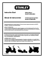 1
1
-
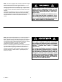 2
2
-
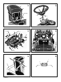 3
3
-
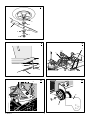 4
4
-
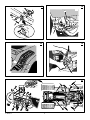 5
5
-
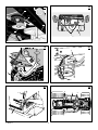 6
6
-
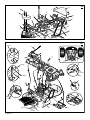 7
7
-
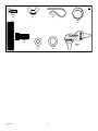 8
8
-
 9
9
-
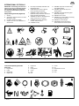 10
10
-
 11
11
-
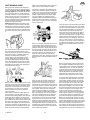 12
12
-
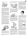 13
13
-
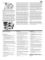 14
14
-
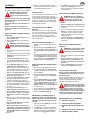 15
15
-
 16
16
-
 17
17
-
 18
18
-
 19
19
-
 20
20
-
 21
21
-
 22
22
-
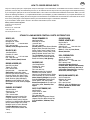 23
23
-
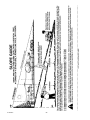 24
24
-
 25
25
-
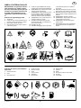 26
26
-
 27
27
-
 28
28
-
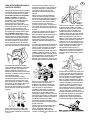 29
29
-
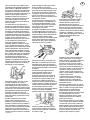 30
30
-
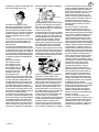 31
31
-
 32
32
-
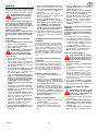 33
33
-
 34
34
-
 35
35
-
 36
36
-
 37
37
-
 38
38
-
 39
39
-
 40
40
-
 41
41
-
 42
42
-
 43
43
-
 44
44
-
 45
45
-
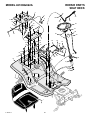 46
46
-
 47
47
-
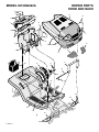 48
48
-
 49
49
-
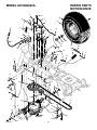 50
50
-
 51
51
-
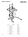 52
52
-
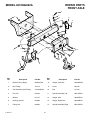 53
53
-
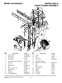 54
54
-
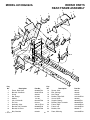 55
55
-
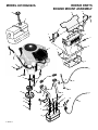 56
56
-
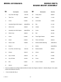 57
57
-
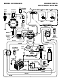 58
58
-
 59
59
-
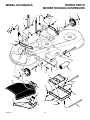 60
60
-
 61
61
-
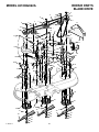 62
62
-
 63
63
-
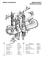 64
64


Simplicity 21.0HP GARDEN TRACTOR Manual de usuario
- Categoría
- Cortadoras de césped
- Tipo
- Manual de usuario
En otros idiomas
Documentos relacionados
Otros documentos
-
Craftsman 536.270321 Manual de usuario
-
-
-
Craftsman 536.270290 El manual del propietario
-
-