Campbell Hausfeld VT470200KB Instrucciones de operación
- Categoría
- Compresores de aire
- Tipo
- Instrucciones de operación

IN227010AV 12/02
Contractor Air Compressors
Compresseurs d’Air pour Entrepreneurs
Compresores de Aire para Contratistas
1
2
3
4
5
6
7
8
14
18
19
21
20
22
23
24
29
28
30
16
30
31
31
33
38
15
16
16
17
24
25
35
34
56
55
58
59
54
57A
25
32
15
16
17
9
10
11
12
41
26
27
27
27
39
42
9
53
60
61
60
40
VT617205, VT615208,
VT613106, VT617206,
EX800300
Para ordenar repuestos, sírvase llamar al distribuidor más cercano a su domicilio
Sírvase darnos la siguiente información: Puede escribirnos a:
-Número del modelo The Campbell Group /Attn: Parts Dept.
-Número de Serie (de haberlo) 100 Production Drive
-Descripción y número del repuesto según la lista de repuestos Harrison, OH 45030 U.S.A.
EX800300, VT613106, VT615208, VT617205, VT617206 & VT630900
32 Tuerca de seguridad de
7,9 mm (5/16”) - 18 -- ST140300AV -- -- -- 2
33 Tornillo autorroscante de
7,9 mm (5/16”) - 12 x
19 mm (3/4") ST016500AV ST016500AV ST016500AV ST016500AV ST016500AV 3
34 Tornillo autorroscante de
10-24 x 15,9 mm (5/8”) ST046500AV ST046500AV ST046500AV ST046500AV ST046500AV 1
35 Arandela elástica #10 ST109003AV ST109003AV ST109003AV ST109003AV ST109003AV 1
36 Tuerca de compresión ST033001AV -- -- -- -- 1
37 Tapa de compresión ST067300AV -- -- -- -- 1
38 ● Tubo de desfogue VT043000AP VT045400AP VT045400AP VT045400AP VT045400AP 1
39 Conector de 90°
9,5 mm (3/8”) NPT -- ST071212AV ST071212AV ST071212AV ST071212AV 1
40 Válvula de globo RE206203AV RE206203AV RE206203AV RE206202AV RE206203AV 1
41 Reductor ST071407AV ST071407AV ST071407AV ST071407AV ST071407AV 1
42 Reductor ST006400AV ST006400AV ST006400AV ST006400AV ST006400AV 1
43 Tapón ST072920AV -- -- -- -- 1
44 Presostato CW209000AJ -- -- -- -- 1
45 Válvula de desfogue CW210000AV -- -- -- -- 1
46 Tubo de desfogue ST117804AV -- -- -- -- 1
47 Ajuste de empuje ST081301AV -- -- -- -- 1
48 Válvula de chequeo CV221502AJ -- -- -- -- 1
49 Relevo de tensión CW209500AV -- -- -- -- 1
50 Cordón eléctrico con enchufe EC012601AV -- -- -- -- 1
51 Tornillo del relevo de tensión ST209800AV -- -- -- -- 1
52 Cordón del motor EC012801AV -- -- -- -- 1
53 Manómetro GA016300AV -- -- -- -- 2
Manómetro -- GA016302AV GA016302AV GA016303AV GA016300AV 1
54 Tornillo autorroscante de-
7,9 mm (5/16”) 12 x
31,8 mm (1
1
⁄4”) ST073276AV ST073249AV ST073249AV ST073249AV ST073249AV 4
55 Elemento del filtro ST073916AV ST073916AV ST073916AV ST073916AV ST073916AV 1
56 Filtro ST073915AV ST073915AV ST073915AV ST073915AV ST073915AV 1
57A● Conexión de tubo -- CV222101AV CV222101AV CV222101AV CV222101AV 1
57B Ensamblaje de compresión ST018300AV -- -- -- -- 1
58 Cabezal VT470200KB VT470000KB VT470000KB VT470000KB VT470000KB 1
59 Tapón de 3,2 mm (1/8”) -
27 para el drenaj de aceite ST022300AV ST022300AV ST022300AV ST022300AV ST022300AV 1
60 Acoplador -- -- -- MP333610 -- 2
61 Conector en T -- -- -- PA104000AV -- 1
JUEGOS DE REPUESTOS
● Kit de tubo de escape -- VT273300AJ VT273300AJ VT273300AJ VT273300AJ 1
EX800300,
VT617205,
VT617206
VT615208
Repuestos para los modelos:
No. de EX800300
Ref. Descripción VT613106 VT615208 VT617205 VT617206 VT630900 Ctd.
© 2002 Campbell Hausfeld/Scott Fetzer
For parts, product & service information
visit www.chpower.com
Replacement Parts List
Liste de Pièces de Rechange
Lista de Repuestos
EX800300, VT615208, VT617205,
VT617206, VT630900, VT613106

7
Para ordenar repuestos, sírvase llamar al distribuidor más cercano a su domicilio
Sírvase darnos la siguiente información: Puede escribirnos a:
-Número del modelo The Campbell Group /Attn: Parts Dept.
-Número de Serie (de haberlo) 100 Production Drive
-Descripción y número del repuesto según la lista de repuestos Harrison, OH 45030 U.S.A.
EX800300, VT613106, VT615208, VT617205, VT617206 & VT630900
1 Tanque AR027200CG AR027200CG AR027200CG AR027200CG AR027200CG 1
2 Mango ST160000AV ST160000AV ST160000AV ST160000AV ST160000AV 2
3 Llave de salida D-1403 D-1403 D-1403 D-1403 D-1403 2
4 Pata de goma ST158300AV ST158300AV ST158300AV ST158300AV ST158300AV 4
5 Tornillo de 10-24 x
19 mm (3/4”) ST116400AV ST116400AV ST116400AV ST116400AV ST116400AV 4
6 Rueda de 25,4 cm (10" ) PM041000AV PM041000AV PM041000AV PM041000AV PM041000AV 1
7 Eje AA021400AV AA021400AV AA021400AV AA021400AV AA021400AV 1
8 Pasador ST118300AV ST118300AV ST118300AV ST118300AV ST118300AV 4
9 Niple de 6,3mm (1/4”) HF002401AV HF002401AV HF002401AV HF002401AV HF002401AV 2
10 Válvula de seguridad ASME V-215100AV V-215100AV V-215100AV V-215100AV V-215100AV 1
11 Conector en T de
6,3 mm (1/4”) NPT -- ST049900AV ST049900AV ST049900AV ST049900AV 1
12 Manómetro -- GA015505AV GA015505AV GA015505AV GA016101AV 1
13 Motor eléctrico MC018000IP -- -- -- -- 1
14 Chaveta de 4,8 mm (3/16”)
x 31,8 mm (1
1
⁄4") KE000903AV KE000903AV KE000903AV KE000903AV KE000903AV 1
15 Tornillo Hex. de
7,9 mm (5/16”) - 18 ST016000AV ST070625AV ST070625AV ST070625AV ST070625AV 4
16 Arandela de 7,9 mm (5/16” ) ST011200AV -- -- -- -- 7
Arandela de 7,9 mm (5/16” ) -- ST011200AV ST011200AV ST011200AV ST011200AV 11
17 Tuerca de seguridad
de 7,9 mm (5/16”) - 18 ST146000AV AL014000AV AL014000AV AL014000AV AL014000AV 4
18 Polea PU015300AG PU015400AG PU015400AG PU015400AG PU016600AG 1
19 Tornillo de 6,3 mm (1/4”) -
20 x 12,7 mm (1/2") ST012200AV ST012200AV ST012200AV ST012200AV ST012200AV 1
20 Volante PU015900AG PU015900AG PU015900AG PU015900AG PU015900AG 1
21 Chaveta de 4,8 mm (3/16" ) KE000900AV KE000900AV KE000900AV KE000900AV KE000900AV 1
22 Tornillo de 9,5 mm (3/8”) -
16 x 19 mm (3/4”) ST026200AV ST026200AV ST026200AV ST026200AV ST026200AV 1
23 Banda BT023300AV BT023300AV BT023300AV BT023300AV BT023300AV 1
24 Motor de gasolina -- NG004700AV NG002502AV NG002502AV NG004500AV 1
25 Abrazadera -- BG208802AJ BG208802AJ BG208802AJ BG208802AJ 1
26 ● Descarregador -- ST128413AV ST128413AV ST128413AV ST128413AV 1
27 Regulador -- CV006409AV CV006402AV CV006402AV CV006402AV 1
28 Tapa protectora de
bandas (frontal) BG218200AV BG218200AV BG218200AV BG218200AV BG218200AV 1
29 Tapa protectora de
bandas (posterior) BG218300AV BG218300AV BG218300AV BG218300AV BG218300AV 1
30 Arandela plana #10 ST070906AV ST070906AV ST070906AV ST070906AV ST070906AV 4
31 Tuerca de seguridad #10-24 ST163200AV ST163200AV ST163200AV ST163200AV ST163200AV 4
Repuestos para los modelos:
No. de EX800300
Ref. Descripción VT613106 VT615208 VT617205 VT617206 VT630900 Ctd.
2
1
2
3
4
5
6
7
8
13
14
15
16
17
18
19
21
20
22
23
29
28
30
16
30
31
31
33
42
35
34
56
55
58
59
54
57B
46
47
36
48
43
37
38
10
40
9
53
9
52
41
53
50
51
49
44
45
O
O
T
T
U
U
A
A
F
F
F
F
O
O
Replacement Parts List
EX800300, VT615208, VT617205,
Liste de Pièces de Rechange
Lista de Repuestos
VT617206, VT630900, VT613106
Para ordenar las piezas del motor de gasolina debe comunicarse con el fabricante.
www.chpower.com
VT613106
La página se está cargando...
La página se está cargando...
La página se está cargando...
La página se está cargando...
La página se está cargando...
La página se está cargando...
La página se está cargando...
La página se está cargando...
La página se está cargando...
La página se está cargando...

Contractor Air
Compressors
Please read and save these instructions. Read carefully before attempting to assemble, install, operate or maintain the product described.
Protect yourself and others by observing all safety information. Failure to comply with instructions could result in personal injury and/or prop-
erty damage! Retain instructions for future reference.
Operating Instructions
IN227906AV 12/02
Air compressor units are intended to
provide compressed air to power pneu-
matic tools and operate spray guns. The
pumps supplied are oil lubricated. A
small amount of oil carryover is present
in the compressed air stream.
Applications requiring air free of oil or
water should have the appropriate coa-
lescing filter installed. The air compres-
sor unit must be placed on a solid floor
or solid ground. Any other use of these
units will void the warranty and the
manufacturer will not be responsible for
problems or damages resulting from
such misuse.
All models are equipped with cast-iron
pumps. Gas engine models are equipped
with an air governor for automatic idle
down when the tanks reach a preset
pressure. Model VT6131 is driven by a
dual capacitor, 3450 RPM, 60 Hz,
120/240 dual-voltage motor with manu-
al reset thermal protection. Honda
engine models have a low-oil level shut-
down.
Compressors include factory-mounted
belt guards, ductile iron crankshafts, fly-
wheels and ball bearings on crankshaft.
Safety Guidelines
This manual contains information that is
very important to know and understand.
This information is provided for SAFETY
and to PREVENT EQUIPMENT PROB-
LEMS. To help recognize this informa-
tion, observe the following symbols.
Danger indicates
an imminently haz-
ardous situation which, if not avoided,
will result in death or serious injury.
Warning indicates
a potentially haz-
ardous situation which, if not avoided,
could result in death or serious injury.
Caution indicates a
potentially haz-
ardous situation which, if not avoided,
may result in minor or moderate injury.
!
CAUTION
!
WARNING
!
DANGER
Notice indicates
important informa-
tion, that if not followed, may cause
damage to equipment.
Unpacking
After unpacking the unit, inspect care-
fully for any damage that may have
occurred during transit. Make sure to
tighten fittings, bolts, etc., before
putting unit into service.
Do not operate
unit if damaged
during shipping, handling or use.
Damage may result in bursting and cause
injury or property damage.
Since the air compressor and other com-
ponents (pump, spray guns, filters, lubri-
cators, hoses, etc.) used make up a high
pressure pumping system, the following
safety precautions must be observed at
all times:
1. Read all manuals includ-
ed with this product care-
fully. Be thoroughly
familiar with the controls
and the proper use of the
equipment.
2. Follow all local safety codes as well
as the United States Occupational
Safety and Health Act (OSHA).
3. Only persons well acquainted with
these rules of safe operation should
be allowed to use the compressor.
4. Keep visitors away and NEVER allow
children in the work area.
5. Wear safety glasses and
use hearing protection
when operating the
pump or unit.
6. Do not stand on or use
the pump or unit as a handhold.
7. Before each use, inspect compressed
air system, fuel system and electrical
components for signs of damage,
deterioration, weakness or leakage.
!
WARNING
NOTICE
Breathable Air Warning
This compressor/pump is NOT
equipped and should NOT be used
“as is” to supply breathing quality
air. For any application of air for
human consumption, you must fit
the air compressor/pump with suit-
able in-line safety and alarm equip-
ment. This additional equipment is
necessary to properly filter and
purify the air to meet minimal spec-
ifications for Grade D breathing as
described in Compressed Gas
Association Commodity
Specification G 7.1 - 1966, OSHA 29
CFR 1910. 134, and/or Canadian
Standards Associations (CSA).
DISCLAIMER OF WARRANTIES
IN THE EVENT THE COMPRESSOR IS
USED FOR THE PURPOSE OF BREATH-
ING AIR APPLICATION AND PROPER
IN-LINE SAFETY AND ALARM EQUIP-
MENT IS NOT SIMULTANEOUSLY
USED, EXISTING WARRANTIES ARE
VOID, AND CAMPBELL HAUSFELD
DISCLAIMS ANY LIABILITY WHATSO-
EVER FOR ANY LOSS, PERSONAL
INJURY OR DAMAGE.
!
DANGER
Repair or replace defective items
before using.
8. Check all fasteners at frequent inter-
vals for proper tightness.
Motors, electrical equip-
ment and controls can
cause electrical arcs that
will ignite a flammable gas
or vapor. Never operate or repair in or
near a flammable gas or vapor. Never
store flammable liquids or gases in the
vicinity of the compressor.
!
WARNING
MANUAL
Description
General Safety
© 2002 Campbell Hausfeld
Compresores de Aire para Contratistas
For parts, product & service information
visit www.chpower.com
Garantía Limitada
1. DURACION: A partir de la fecha de compra por el comprador original tal como se especifica a continuación: Productos
Estándard (Standard Duty) - Un año; Productos Resistentes (Serious Duty) -Dos años; Productos Robustos (Extreme Duty) -
Tres años; Serie Modelo Maxus - Cinco años.
2. QUIEN OTORGA ESTA GARANTIA (EL GARANTE: Campbell Hausfeld / The Scott Fetzer Company 100 Production Drive,
Harrison, Ohio 45030 Teléfono: (800) 543-6400
3. QUIEN RECIBE ESTA GARANTIA (EL COMPRADOR): El comprador original (que no sea un revendedor) del producto
Campbell Hausfeld.
4. PRODUCTOS CUBIERTOS POR ESTA GARANTIA: Cualquier compresor de aire Campbell Hausfeld.
5. COBERTURA DE LA GARANTIA: Los defectos substanciales de material y fabricación que ocurran dentro del período de
validez de la garantía.
6. LO QUE NO ESTA CUBIERTO POR ESTA GARANTIA:
A. Las garantías implícitas, incluyendo aquellas de comercialidad E IDONEIDAD PARA FINES PARTICULARES, ESTAN LIMITA-
DOS A LO ESPECIFICADO EN EL PARRAFO DE DURACION. Si el compresor de aire es empleado para uso comercial, indus-
trial o para renta, la garantía será aplicable por noventa (90) días a partir de la fecha de compra. La garantía de los
Compresores para Contratistas - Productos Robustos (Extreme Duty) no queda limitada a los noventa (90) días cuando
se los usa en aplicaciones de contratistas. La garantía de los compresores de cuatro cilindros de una y dos etapas, no
está limitada a noventa (90) días si éstos se utilizan para trabajos comerciales o industriales. En algunos estados no se
permiten limitaciones a la duración de las garantías implícitas, por lo tanto, en tales casos esta limitación no es aplica-
ble.
B. CUALQUIER PERDIDA DAÑO INCIDENTAL, INDIRECTO O CONSECUENTE QUE PUEDA RESULTAR DE UN DEFECTO, FALLA
O MALFUNCIONAMIENTO DEL PRODUCTO CAMPBELL HAUSFELD. En algunos estados no se permite la exclusión o lim-
itación de daños incidentales o consecuentes, por lo tanto, en tales casos esta limitación o exclusión no es aplicable
C. Cualquier falla que resulte de un accidente, abuso, negligencia o incumplimiento de las instrucciones de funcionamien-
to y uso indicadas en el (los) manual(es) que se adjunta(n) al compresor.
D. Los servicios requeridos antes de la entrega tales como: ensamblaje, aceite o lubricantes y ajustes.
E. Artículos o servicios normalmente requeridos para el mantenimiento del producto, tales como:lubricantes, filtros,
empaques, etc.
F. Los motores de gasolina están específicamante excluidos de la cobertura de esta garantía limitada. El comprador debe
seguir las clausulas de la garantía otorgada por el fabricante del motor de gasolina que se suministra con el producto.
G. Artículos adicionales no cubiertos bajo esta garantía:
1. Todos los Compresores
a. Cualquier componente dañado durante el envío o cualquier daño ocasionado por haber instalado u operado la
unidad bajo condiciones contrarias a lo indicado en las instrucciones para instalar u operar la unidad o daños oca-
sionados por el contacto con herramientas o los alrrededores.
b. Daños del cabezal o las válvulas ocasionados por la lluvia, humedad excesiva, agentes corrosivos u otros contami-
nantes.
c. Daños de apariencia que no afecten el funcionamiento del compresor.
d. Tanques oxidados, incluyendo pero no limitado al óxido debido al drenaje inadecuado u agentes corrosivos en el
ambiente.
e. Motores eléctricos, válvulas de chequeo y presostatos después del primer año a partir de la fecha de compra.
f. Llaves de drenaje
g. Daños debidos al alambrado incorrecto o conexión a cicuitos con voltaje inadecuados para la unidad.
h. Otros artículos no enumerados pero considerados de desgaste general.
i. Presostatos, controles de flujo de aire y válvulas de seguridad cuyos parametros fijados de fábrica se modifiquen.
2. Compresores lubricados
a. Daños del cabezal o las válvulas debidos al uso de aceites no especificados.
b. Daños del cabezal o las válvulas debidos a cualquier contaminación del aceite o por no haber seguido las instruc-
ciones de lubricación.
3. Compresores con bandas/ de accionamiento directo/ motores de gasolina
a. Bandas
b. Daños de los anillos debido al mantenimiento inadecuado del filtro.
c. Ajustes manuales de los instrumentos de carga/descarga y válvula de estrangulación.
7. RESPONSABILIDADES DEL GARANTE BAJO ESTA GARANTIA: Reparar o reemplazar, como lo decida el Garante, el compre-
sor o componentes que estén defectuosos, se hayan dañado o hayan dejado de funcionar adecuadamente, durante el
período de validez de la garantía
8. RESPONSABILIDADES DEL COMPRADOR BAJO ESTA GARANTIA:
A. Suministrar prueba fechada de compra y la historia de mantenimiento del producto.
B. Entregar o enviar los compresores de aire portátiles o componentes lal Centro de Servicio autorizado Campbell
Hausfeld más cercano. Los gastos de flete, de haberlos, deben ser pagados por el comprador.
C. Tener cuidado al utilizar el producto, tal como se indica(n) en el (los) manual(es) del propietario.
9. CUANDO EFECTUARA EL GARANTE LA REPARACION O REEMPLAZO CUBIERTO BAJO ESTA GARANTIA: La reparación o
reemplazo dependerá del flujo normal de trabajo del centro de servicio y de la disponibilidad de repuestos.
Esta garantía limitada es válida sólo en los EE.UU., Canadá y México y otorga derechos legales específicos. Usted también
puede tener otros derechos que varían de un Estado a otro. o de un país a otro.

23 Sp
Compresores de Aire para Contratistas
Guía de Diagnóstico de Averías (Continuación)
Problema Posible(s) Causa(s) Acción a Tomar
Desgasto excesivo de las ban-
das
La unidad falla
NOTA: Los modelos eléctricos
tienen un presostato que
automáticamente apaga el
motor cuando la presión del
tanque alcanza una presión
fijada. Igualmente, cuandio la
presión del tanque disminuye
a un nivel fijado, el presosta-
to enciende el motor
automáticamente
Ruido excesivo
Presencia de aceite en el aire
expulsado
Hay una fuga de aire en la
salida del presostato
1. Polea desalineada
2. Bandas muy flojas o muy apre-
tadas
3. Bandas se deslizan
4. Polea oscila
1. El motor está sobrecargado
2. Lubricación inadecuada
3. Bajo nivel de aceite
4. Válvula de chequeo defectuosa
1. Las poleas del motor o el com-
presor están flojas
2. La caja del cigüeñal necesita
aceite
3. La biela está desgastada
4. El buje del pasador del pistón
está desgastado
5. Los cojinetes están desgastados
6. El pistón está golpeando la
placa de la válvula
7. La válvula de chequeo hace
ruido
1. Los anillos del pistón están des-
gastados
2. La entrada de aire del compre-
sor está restringida
3. El respiradero está restringido
4. Exceso de aceite en el compre-
sor
5. Usó aceite de viscosidad incor-
recta
6. La biela está desalineada
La válvula de chequeo está atas-
cada en la posición abierta
1. Realinée las poleas del motor y el compresor
2. Ajuste la tensión (Vea la sección Bandas)
3. Ajuste la tensión o reemplace la banda (Vea la sección Bandas)
4. Chequée si el cigüeñal, la chavetera o el diámetro interno de las
poleas se han desgastado debido al uso con las poleas flojas. Chequée
las poleas y el cigüeñal a ver si están doblados
1. Haga que un electricista calificado chequee el motor y el alambrado y
siga sus recomendaciones. Chequée el voltaje de las conexiones del
motor
2. Vea la sección de LUBRICACION, en Ensamblaje
3. Mídale el aceite. Añádale aceite si es necesario
4. Reemplácela
1. Es muy común que el compresor haga mucho ruido debido a que las
poleas estén flojas. Apriételes todos los pernos y tornillos
2. Mídale el aceite; si le falta aceite, chequée a ver si los cojintes se
dañaron. El aceite contaminado puede ocasionar el desgasto excesivo
3. Reemplace la biela
4. Desmonte los pistones del compresor y revíselos a ver si están muy
desgastados. Reemplace los pistones o los pasadores si están muy des-
gastados
5. Reemplace los cojinetes desgastados y cámbiele el aceite
6. Desmonte la culata del compresor y la placa de la válvula y revíselas a
ver si hay depósitos de carbón u otros desperdicios en el pistón.
Coloque la culata y la placa de la válvula y use un empaque nuevo
7. Reemplácela
1. Reemplace los anillos
2. Limpie el filtro. Chequée a ver si hay otras restricciones en la entrada
de aire
3. Limpie el respiradero y chequéelo a ver si está funcionando adecuadamente
4. Drene el aceite hasta alcanzar el nivel marcado “full” (lleno)
5. Use aceite sin-detergente SAE 30 (ISO 100)
6. Reemplace la biela
Desconecte y reemplace la válvula de chequeo
No desmantele la válvula de
chequeo con aire en el tanque
!
PELIGRO
2
Contractor Air Compressors
Carbon
monoxide can cause severe
nausea, fainting or death.
Do not operate unit inside
a closed building or a poor-
ly ventilated area.
Never operate compressor
without a beltguard.
Compressors can start auto-
matically without warning.
Personal injury or property damage
could occur from contact with moving
parts.
9. Do not wear loose clothing or jewel-
ry that will get caught in the moving
parts of the unit.
Compressor parts may be
hot even if the unit is
stopped.
10. Keep fingers away from a running
compressor; fast moving and hot
parts will cause injury and/or burns.
11. If the equipment should start to
vibrate abnormally, STOP the
engine/motor and check immediately
for the cause. Vibration is generally a
warning of trouble.
NEVER refuel a running or
hot engine. Explosive fuel
can cause fires and severe
burns. Avoid overfilling fuel tank.
12. Check fuel level before starting the
engine. Do not fill the gas tank
indoors. Wipe off any spilled gas
before starting the engine.
Gasoline vapor is
highly flammable.
Refill outdoors or only in well ventilated
areas. Do not store, spill or use gasoline
near an open flame or heat devices such
as a stove, furnace, or water heater,
which utilize a pilot light, or any device
that can create a spark. If gasoline is
accidentally spilled, move unit away
from the spill area and avoid creating
any source of ignition until gasoline
vapors have dissipated.
13. To reduce fire hazard, keep
engine/motor exterior free of oil, sol-
vent, or excessive grease.
!
DANGER
!
WARNING
!
CAUTION
!
WARNING
!
WARNING
Never remove or
attempt to adjust
safety valve. Keep safety valve free from
paint and other accumulations.
14. Do not tamper with governor setting
on engine. Overspeeding the unit
severely shortens engine life and
may also be very hazardous.
Never attempt to repair or
modify a tank! Welding,
drilling or any other modi-
fication will weaken the tank resulting
in damage from rupture or explosion.
Always replace worn or damaged tanks.
15.
Tanks rust from moisture build-up,
which weakens the tank. Make sure
to drain tank regularly and inspect
periodically for unsafe conditions such
as rust formation and corrosion
.
16. Fast moving air will stir up dust and
debris which may be harmful.
Release air slowly when draining
moisture or depressurizing the com-
pressor system.
17.
STOP the engine whenever leaving the
work area, before cleaning, making
repairs or inspections. When cleaning,
repairing or inspecting, make certain
all moving parts have stopped.
Disconnect the spark plug wire and
keep the wire away from the plug to
prevent accidental starting.
18. Allow engine to cool before storing.
SPRAYING PRECAUTIONS
Do not spray flammable
materials in vicinity of
open flame or near ignition
sources including the compressor unit.
19. Do not smoke when spraying paint,
insecticides, or other flammable sub-
stances.
20. Use a face mask/respirator when
spraying and spray in a well ventilat-
ed area to prevent health and fire
hazards.
21. Do not direct paint or other sprayed
material at the compressor. Locate
compressor as far away from the
spraying area as possible to minimize
overspray accumulation on the com-
pressor.
22. When spraying or
cleaning with solvents
or toxic chemicals, fol-
low the instructions
provided by the chemi-
cal manufacturer.
!
WARNING
!
DANGER
!
WARNING
HOSE AND REGULATOR
Some units do not include a regulator.
Purchase a 3/8” hose (1/4” min.) and a
regulator that have a minimum rating
that exceeds the maximum working
pressure of the compressor.
RUBBER FEET
Attach the four rubber feet (using
screws supplied) to the cross members
under the tanks.
OIL DRAIN EXTENSION
Some models include an oil drain exten-
sion and cap (found with the owner’s
manual). Install the oil drain extension and
cap before adding oil to the pump. To
avoid oil leaks, it is highly recommended
to apply teflon tape or plumber’s putty to
the threads on each end of the oil drain
extension. Screw the cap onto one end of
the extension. Remove the oil drain plug
from the base of the pump and install the
oil drain extension (See Figure 1).
LUBRICATION
THIS UNIT
CONTAINS NO OIL!
Follow lubrication instructions before
operating compressor.
Ensure oil drain extension has been
installed (if included) then remove the
dipstick/ breather and fill pump with oil
as indicated in the chart. Use single vis-
cosity, ISO 100 (SAE 30), non-detergent
compressor oil; Campbell Hausfeld P/N
ST125300AV. Do not use a multi-viscosity
oil such as 10W-30. Proper oil fill is illus-
trated in Figure 1.
!
CAUTION
Model Oil Capacity (oz.)
VT6131 11.5
All others 12
Figure 1
General Safety (Con’t)
Assembly
www.chpower.com
Dipstick
Breather
Oil Drain
Extension
Cap
Add Oil
Fill
Line
Max
Low

3
Contractor Air Compressors
WIRING - MODEL VT6131 ONLY
Local electrical wiring codes differ from
area to area. Source wiring, plug and
protector must be rated for at least the
amperage and voltage indicated on your
motor nameplate, and meet all electrical
codes for this minimum. Use a slow blow
fuse type T or a circuit breaker.
Overheating, short
circuiting and fire
damage will result from inadequate
wiring.
NOTE: 120 volt, 15 amp units can be
operated on a 120 volt 15 amp circuit
under the following conditions:
1. No other electrical appliances or lights
are connected to the same branch cir-
cuit.
2. Voltage supply is normal.
3. Circuit is equipped with a 15 amp cir-
cuit breaker or a 15 amp slow blow
fuse type T.
If these conditions cannot be met or if
nuisance tripping of the current protec-
tion device occurs, it may be necessary to
operate the compressor from a 120 volt
20 amp circuit. To convert to 240 volt
operation, see DUAL VOLTAGE MOTOR
(Model VT6131 only).
GROUNDING INSTRUCTIONS
1. This product is for use on a nominal
120 volt circuit and has a grounding
plug that looks like the plug illustrat-
ed in Fig. 2. Make sure the product is
connected to an outlet having the
same configuration as the plug. This
product must be grounded. In the
event of an electric short circuit,
grounding reduces the risk of electri-
cal shock by providing an escape
wire for the electric current. This
product is equipped with a cord hav-
ing a grounding wire with an appro-
!
CAUTION
priate grounding plug (See Fig. 2).
The plug must be plugged into an
outlet that is properly installed and
grounded in accordance with all
local codes and ordinances.
Improper use of grounding
plug can result in a risk of
electrical shock.
NOTE: Do not use ground-
ing adapter.
2. If repair or replacement of the cord
or plug is necessary, do not connect
the grounding wire to either flat
blade terminal. The wire with insula-
tion having an outer surface that is
green with or without yellow stripes
is the grounding wire.
3. Check with a qualified electrician or
serviceman if grounding instructions
are not completely understood, or if
in doubt as to whether the product is
properly grounded. Do not modify
plug provided; if it will not fit the
outlet, have the proper outlet
installed by a qualified electrician.
!
DANGER
PLUGS AND RECEPTACLES
1. If the plug on the electrical cord of
the unit is unfamiliar to you or will
not fit your particular receptacle, the
illustrations in figure 2 will help you
understand why by illustrating the dif-
ferent plugs and the voltages they are
to be used with.
2. Make sure that the product is con-
nected to an outlet having the same
configuration as the plug.
3. The receptacles must be connected to
circuits rated to carry at least the volt-
age and amperages shown.
4. NEVER have a receptacle replaced
with one of a higher amperage
before determining the change can
be made according to all electrical
codes affecting your particular area.
The installation should be made by a
qualified electrician. If the products
must be reconnected for use on differ-
ent types of circuits, the re-connection
should be made by qualified
personnel.
DUAL VOLTAGE MOTORS (MODEL
VT6131 ONLY)
Dual voltage motors may be connected
for either 120 volts or 240 volts. By com-
paring the plug on the cord with the
receptacles shown below, you can deter-
mine for which voltage your compressor
is factory wired.
Assembly (Con’t)
Ground Pin
Grounded Outlet
Grounded Outlet
Ground Pin
120V
20A
120V
15A
240
V
20A
240V
15A
Figure 2
Safety
Valve
Belt guard
Discharge Tube
Pressure Switch
Check Valve
Handle
Drain Petcock
Figure 3
5.5
Belt guard
Discharge Tube
Handle
Unloader
Pressure
Regulator
Amps Cord Nema Plug
Not more than 15 3 wire 14 Gauge 125V, 15 Amp
Over 15 - 18 3 wire 14 Gauge 125V, 20 Amp
Over 18 - 20 3 wire 12 Gauge 125V, 20 Amp
Over 20 - 25 3 wire 12 Gauge 125V, 30 Amp
PLUG AND CORD GAUGES FOR 120 VOLT OPERATION
22 Sp
Compresores de Aire para Contratistas
Guía de Diagnóstico de Averías
(EL MANUAL DEL MOTOR DE GASOLINA LE OFRECE INSTRUCCIONES ADICIONALES)
Problema Posible(s) Causa(s) Acción a Tomar
Baja presión de salida
El compresor se sobrecalienta
1. Fugas de aire
2. Fugas en las válvulas
3. Entrada de aire restringida
4. Bandas desajustadas
5. Empaques dañados
6. Baja compresión
1. Ventilación inadecuada
2. Las superficies de enfriamiento
están sucias
1. Escuche a ver si hay fugas de aire. Aplíquele agua enjabonada a
todas las conexiones. Verá burbujas si hay fugas. Apriete o reemplace
las conexiones donde haya fugas
2. Desmonte la culata e inspeccione a ver si las válvulas están rotas o
defectuosas, si el asiento de las válvulas están dañadas etc.
Reemplace las piezas defectuosas y ensámblelas
Cerciórese de reemplazar el
empaque de la culata por uno
nuevo cada vez que la desmonte
3. Limpie el elemento del filtro
4. Afloje los pernos del motor y mueva el motor en dirección opuesta al
compresor, cerciórese de que la polea del motor esté perfectamente
alineada con el volante. Apriete los pernos del motor. La banda debe
tener una deflexión de una 12,7 mm al aplicarsele 2,3 kg de fuerza.
No force las bandas para colocarlas en las poleas
5. Reemplace cualquier empaque que encuentre dañado
6. La baja presión podría ser debido a que los anillos o las paredes del
cilindro estén desgastados. Para solucionar el problema reemplace
los anillos, cilindros y pistones cuando sea necesario
1. Reubique el compresor de modo que se le pueda suministrar sufi-
ciente aire frío, limpio, con buena circulación y seco
2. Limpie las partes del sistema de enfriamiento del cabezal y el motor
!
PRECAUCION
Deflección de 1,7 mm (1/2”)
Figura 9
Mantenimiento (Con’t)
Mídale el aceite ●
Drene el tanque ●
Chequée el filtro de aire ●
Chequée la válvula de seguridad ●
Limpie el interior del motor con aire ●
Chequée la tensión de las bandas ●
Cámbiele el aceite ●
MATENIMIENTO
Servicio necesario
Diaria- Semanal- Mensual- Anual-
mente mente mente mente
Toque el Borde
en dos Sitios
Línea recta
Paralela a la
Banda
Figura 10
Para ajustar la tensión de las bandas:
1. Quítele la tapa protectora de bandas y
afloje la abrazadera del motor.
2. Afloje los 4 pernos que sostienen el
motor a la base.
3. Mueva el motor en la dirección ade-
cuada. La banda debe estar alineada
después de ajustar el motor.
4. Para alinear la banda, coloque un
objeto recto que toque dos puntos del
volante (Vea la Figura 10).
5. Ajuste la polea del motor o el volante
de modo que la banda esté paralela al
borde recto.
6. Use un sacaengranaje para mover la
polea en el eje y apriete los tornillos.
7. Ajuste la abrazadera e instálela.
ALMACENAMIENTO
1. Cuando no los esté usando, almacene la
manguera y el compresor en un sitio
frío y seco.
2. Drene los tanques, desconecte las
mangueras y cuelguelas con los
extremos hacia abajo para que se ter-
minen de drenar.
www.chpower.com

unos 30 minutos sin carga para que las
piezas del cabezal se fijen.
9. Después de aproximadamente 30 mi-
nutos, baje la palanca del descargador
hasta la posición loaded (cargado) y
gire la perilla del regulador en el
mismo sentido de las agujas del reloj
(Vea la Figura 7). El compresor comen-
zará a suministrarle aire al tanque.
Cuando el tanque alcanza su presión máxi-
ma, el compresor automáticamente se
descarga y el motor deja de trabajar. El
motor continua funcionando al vacío hasta
que la presión del tanque baje a un nivel
fijado. Entonces el motor se acelera y el
compresor le suminestra aire adicional al
tanque.
Desconecte la unidad y libere
toda la presión del sistema
antes de tratar de instalar el
compresor, darle servicio, moverlo de
sitio o darle cualquier tipo de manten-
imiento.
Para mantener el funcionamiento eficiente
del compresor debe chequearle el filtro de
aire, medirle el aceite y cerciorarse de que
tenga suficiente gasolina antes de cada
uso. Igualmente, debe chequearle la válvu-
la de seguridad ASME diariamente. Para
hacerlo, hále el anillo y déjelo que calce de
nuevo en su posición normal. Esta válvula
automáticamente libera el aire si la pre-
sión del tanque excede el nivel máximo
fijado. Si hay fugas de aire después de
haber soltado el anillo, o si la válvula está
atascada y no se puede activar con el anil-
lo, deberá reemplazarla.
!
ADVERTENCIA
sentido de las agujas del reloj para cer-
rar el flujo de aire y coloque el presosta-
to o perilla en OFF. El compresor estará
listo para funcionar.
NOTA: Los modelos eléctricos tienen un
presostato que automáticamente apaga el
motor cuando la presión del tanque alcan-
za una presión fijada. Igualmente, cuandio
la presión del tanque disminuye a un nivel
fijado, el presostato enciende el motor
automáticamente.
PREPARACION PARA EL USO MODE-
LOS DE GASOLINA
El motor
de gasoli-
na no tiene aceite. Añádale aceite según
las instrucciones del manual del motor
antes de operarlo.
1. Llene la motor de aceite y gasolina
según las instrucciones del motor.
2. Sáquele la varilla del respiradero y llene
el cabezal de aceite hasta alcanzar el
nivel adecuado. Vea la sección
Lubricación.
3. Gire la válvula de salida o la perilla del
regulador en sentido contrario al de las
agujas del reloj para abrir el flujo de
aire.
4. Mueva la palanca del descargador man-
ual hacia arriba, a la posición vertical,
para que el cabezal funcione sin com-
primir aire (Vea la Figura 6).
PARA ENCENDER EL MOTOR DE
GASOLINA
5. Coloque la palanca del ahogador en
CHOKE y coloque la palanca de
accionamiento en ON.
6. Hále la cuerda para encender el motor
hasta que sienta resistencia, después
hálela con fuerza.
7. A medida que el motor se caliente,
mueva gradualmente la palanca del
ahogador hasta abrirlo. El manual del
motor de gasolina le ofrece más
detalles al respecto.
8. Deje que el compresor funcione por
!
PRECAUCION
21 Sp
Compresores de Aire para Contratistas
Functionamiento
(Continuación)
HUMEDAD EN EL AIRE COMPRIMIDO
La humedad que se acumula en el aire
comprimido se convierte en gotas a medi-
da que sale del cabezal del compresor de
aire. Cuando el nivel de humedad es muy
alto o cuando el compresor ha estado en
uso continuo por mucho tiempo, ésta se
acumulará en el tanque. Al usar una pisto-
la pulverizadora de pintura o una rociado-
ra de arena, la misma saldrá a través de la
manguera mezclada con el material que
esté rociando.
IMPORTANTE: Esta condensacion ocasion-
ará manchas en la superficie pintada,
especialmente cuando esté pulverizando
pinturas que no sean a base de agua. Al
rociar arena esta ocasionará que la arena
se aglutine y obstruya la pistola, reducien-
do su eficacia.
Para eliminar este problema, coloque un
filtro en la línea de aire, lo más cerca posi-
ble de la pistola.
Figura 6 - Descargado
Figura 7
AbroCierro
Cargada
Válvula de Bola
Válvula de Globo
Dirección del
Flujo de Aire
No trate
de modi-
ficar la válvula de seguridad ASME.
APAGUE el motor y limpie el motor, el
volante, el tanque, las líneas de aire y las ale-
tas del sistema de enfriamiento del cabezal.
TANQUE
¡Nunca trate de reparar o
modificar el tanque! Si lo
suelda, taladra o modifica de
cualquier otra manera, el tanque se
debilitará y podría romperse o
explotar. Siempre reemplace los tan-
ques desgastados o dañados.
Drene el
líquido
del tanque diariamente.
El tanque se debe inspeccionar por lo
menos una vez al año. Chequée a ver si
hay grietas en las soldaduras. De haberlas,
libere la presión del tanque inmediata-
mente y reemplácelo.
BANDAS
Las bandas se estiran debido al uso nor-
mal. Cuando están bien ajustadas, al apli-
carle una presión de 2,26 kg entre la
poleas del motor y el cabezal, la banda
debe tener una deflexión de más o menos
1/2”(Vea la Figura 9).
AVISO
!
PELIGRO
!
PELIGRO
Mantenimiento
Figura 8
4
Contractor Air Compressors
All wiring must be complet-
ed by a qualified electri-
cian.
To change connections for alternate
voltage (Model VT6131 only):
1. Disconnect cord from power source.
2. Remove motor terminal cover.
3. Find connection diagram on back
side of the cover or on motor name-
plate and reconnect to desired volt-
age as indicated on diagram.
4. Change plug to match voltage and
current requirements.
When converting to
an alternate voltage,
be sure the green ground wire of the
cord connects to the ground pin of the
plug and to the metal body of the pres-
sure switch.
Pressure switch (Electric Models
only) - Auto/Off Switch - In the "auto"
position, the compressor shuts off auto-
matically when tank pressure reaches
the maximum preset pressure. In the
"off" position, the compressor will not
operate. This switch should be in the
"off" position when connecting or dis-
connecting the power cord from the
electrical outlet or when changing air
tools.
Regulator - A regulator controls the
amount of air pressure released at the
hose outlet.
ASME Safety Valve - This valve auto-
matically releases air if the tank pressure
exceeds the preset maximum.
Discharge tube - This tube carries com-
pressed air from the pump to the check
valve. This tube becomes very hot during
use. To avoid the risk of severe burns,
never touch the discharge tube.
Check valve - One-way valve that
allows air to enter the tank, but pre-
vents air in the tank from flowing back
into the compressor pump.
Handle - Designed to move the com-
pressor.
Never use the
handle to lift the
unit completely off the ground.
Belt Guard - Covers the belt, motor pul-
ley and flywheel.
Drain Petcock - This valve is located on
the bottom of the tank. Use this valve to
!
WARNING
!
WARNING
!
WARNING
drain moisture from the tank daily to
reduce the risk of corrosion.
Reduce tank pressure below 10 PSI, then
drain moisture from tank daily to avoid
tank corrosion. Drain moisture from
tank(s) by opening the drain petcocks
located underneath each tank section.
Before starting the
compressor, thor-
oughly read all component instruction
manuals, especially the engine manual.
All lubricated compressor pumps dis-
charge some condensed water and oil
with the compressed air. Install appro-
priate water/oil removal equipment and
controls as necessary for the intended
application.
Failure to install
appropriate
water/oil removal equipment may result
in damage to machinery or workpiece.
Drain liquid from
tank daily.
Do not attach air
tools to open end of
the hose until start-up is completed and
unit checks OK.
START-UP – ELECTRIC MODEL VT6131
Do not attach air
tools to open end of
the hose until start-up is completed and
the unit checks OK.
1. Remove the breather and fill pump
with approximately 11.5 oz. of SAE
30 industrial grade air compressor oil
(P/N
ST125300AV).
2. Turn outlet valve
counterclockwise
to open air flow.
3. Move pressure
switch lever or
knob to the OFF position and plug in
power cord. Move pressure switch to
the AUTO position to run the unit.
4. Run the unit for 30 minutes, under
no load, to break in pump parts.
5. Turn globe valve clockwise to shut
off air flow and move the pressure
switch lever or knob to OFF. The
compressor is now ready for use.
NOTE: Electric models are equipped
with a pressure switch that automatical-
!
CAUTION
!
CAUTION
NOTICE
NOTICE
NOTICE
ly turns the motor OFF when the tank
pressure reaches a preset level. After air
is used from the tank and drops to a pre-
set low level, the pressure switch auto-
matically turns the motor back on.
START-UP GASOLINE MODELS
The gas engine
does not contain
oil. Add oil per the engine owner’s man-
ual before operating.
1. Fill engine with oil and gasoline per
instructions furnished with engine.
2. Remove the compressor dipstick
breather and fill pump to the proper
oil level. See Lubrication section.
3. Turn outlet valve or regulator knob
counterclockwise to open air flow.
4. Turn manual unloader lever up to a
vertical position to allow the compres-
sor pump to run without compressing
air. (See Figure 6.)
TO START GASOLINE ENGINE
5. Move the choke lever to the CHOKE
position and turn the stop lever to the
ON position.
!
CAUTION
MOISTURE IN COMPRESSED AIR
Moisture in compressed air will form
into droplets as it comes from an air
compressor pump. When humidity is
high or when a compressor is in con-
tinuous use for an extended period of
time, this moisture will collect in the
tank. When using a paint spray or
sandblast gun, this water will be car-
ried from the tank through the hose,
and out of the gun as droplets mixed
with the spray material.
IMPORTANT: This condensation will
cause water spots in a paint job, espe-
cially when spraying other than water
based paints. If sandblasting, it will
cause the sand to cake and clog the
gun, rendering it ineffective.
A filter or air dryer in the air line,
located as near to the gun as possible,
will help eliminate moisture.
A
U
T
O
/
O
F
F
Figure 5
OFF
AUTO
Figure 6 -
Unloaded
Position
Figure 4
Operation
Assembly (Con’t)
www.chpower.com

Release all pressure from
the system before attempt-
ing to install, service, relo-
cate or perform any main-
tenance.
In order to maintain efficient operation
of the compressor system, check the air
filter, oil level and gasoline level before
each use. The ASME safety valve should
also be checked daily. Pull ring on safety
valve and allow the ring to snap back to
normal position. This valve automatical-
ly releases air if the tank pressure
exceeds the preset maximum. If air leaks
after the ring has been released, or the
valve is stuck and cannot be actuated by
!
WARNING
5
Contractor Air Compressors
6. Pull start grip lightly until resistance is
felt, and then pull briskly.
7. As the engine warms up, gradually
move the choke lever to the open
position. See gas engine manual for
more details.
8. Run the compressor unloaded for
approximately 30 minutes to break in
the pump.
9. After approximately 30 minutes, move
the unloader lever down to the
loaded position and turn the regula-
tor knob clockwise (See Figure 7). The
compressor will begin to pump air
into the tank.
When maximum tank pressure is
reached, the compressor automatically
unloads, bringing the engine to idle. The
engine remains at idle until tank pres-
sure falls to a preset level. The engine
then accelerates and the compressor
pumps additional air into the tank.
the ring, the ASME safety valve must be
replaced.
Do not attempt to
tamper with the
ASME safety valve.
With engine OFF, clean debris from
engine, flywheel, tank, air lines and
pump cooling fins.
TANK
Never attempt to repair or
modify a tank! Welding,
drilling or any other modi-
fication will weaken the tank resulting
in damage from rupture or explosion.
Always replace worn, cracked or dam-
aged tanks.
Drain liquid from
tank daily.
The tank should be carefully inspected
at a minimum of once a year. Look for
cracks forming near the welds. If a crack
is detected, remove pressure from tank
immediately and replace.
DRIVE BELT
Belts stretch is a result of normal use.
When properly adjusted, the belt
deflects about 1/2” with five pounds of
pressure applied midway between the
engine pulley and pump (See Figure 9).
NOTICE
!
DANGER
!
DANGER
To adjust drive belt tension:
1. Remove belt guard and loosen
engine brace.
2. Loosen the four fasteners holding
the engine to the baseplate.
3. Shift the motor in the proper direc-
tion. The belt must be properly
aligned when adjustment is made.
4. To align belt, lay a straight edge
against the face of the flywheel,
touching the rim at two places (See
Figure 10).
5. Adjust flywheel or motor pulley so
that the belt runs parallel to the
straight edge.
6. Use a gear puller to move the pulley
on the shaft and tighten fasteners.
7. Adjust brace and reinstall.
STORAGE
1. When not in use, hose and compres-
sor should be stored in a cool, dry
place.
2.
Tanks should be drained of moisture.
Hose should be disconnected and
hung with open ends down to allow
any moisture to drain.
Operation (Con’t)
Figure 7
Loaded Position
Globe Valve
Air Flow Direction
Ball Valve
CloseOpen
Figure 8
Maintenance
1/2” Deflection
Figure 9
Operation Daily Weekly Monthly 3 Months
Check Oil Level ●
Drain Tank ●
Check Air Filter ●
Check Safety Valve ●
Blow Dirt From Inside Motor ●
Check Belt Tightness ●
Change Oil ●
MAINTENANCE SCHEDULE
Touch Rim in
Two Places
Straight Edge
Parallel With Belt
Figure 10
PREPARACION PARA EL USO –
MODELO ELECTRICO VT6131
No conec-
te las her-
ramientas neumáticas al extremo de la
manguera hasta que haya terminado el
proceso de preparación para el uso y
haya verificado que la unidad esté lista
para funcionar.
1. Sáquele el respiradero y llene el cabezal
con aproximadamente 0,34 L de aceite
tipo industrial SAE 30 para compresores
de aire (P/N ST125300AV).
2. Gire la válvula de salida en sentido con-
trario al de las agujas del reloj, para
abrir el flujo de
aire.
3. Coloque la palan-
ca del presostato
o perilla en OFF
(APAGADO) y
conecte el cordón
eléctrico. Coloque el presostato en
AUTO para encender la unidad.
4. Déjela funcionar por 30 minutos, sin
carga, para que las piezas del cabezal se
fijen.
5. Gire la válvula de globo en el mismo
!
PRECAUCION
conexión a tierra al terminal de cone-
xión a tierra del enchufe y a la parte
metálica del presostato.
Presostato (Sólo Para los Modelos
Eléctricos) - Interruptor En la posición
AUTO el compresor se apaga automática-
mente al alcanzar una presión máxima
fijada en la fábrica. En la posición OFF el
presostato no puede funcionar y por lo
tanto el compresor no funciona. Este
debe estar en OFF cuando vaya a conectar
(o desconectar) el cordón al tomacorri-
entes o para cambiar de herramientas
neumáticas.
Regulador - El regulador controla el flujo
de aire por la salida de la manguera (Se
vende por separado).
Válvula de seguridad ASME - Esta
válvula libera automáticamente el exceso
de aire cuando la presión ha alcanzado la
presión máxima fijada.
Tubo de salida - Este tubo permite el
flujo de aire comprimido del cabezal a la
válvula de chequeo. Este tubo se calienta
bastante durante el uso. Nunca lo toque
ya que le podría ocasionar quemaduras
graves.
Válvula de chequeo - Válvula de un sen-
tido que permite la entrada del aire al
tanque pero evita que se regrese al
cabezal.
Mango - Diseñado para mover el compre-
sor.
Nunca lo
use para
levantar el compresor.
!
ADVERTENCIA
20 Sp
Compresores de Aire para Contratistas
A
U
T
O
/
O
F
F
Figura 5
Figura 4
Éteins
Automatique
Ensamblaje (Continuación)
Funcionamiento
Figura 3
Válvula De
Chequeo
Presostato
Tubo De Salida
Tapa de protección
de la bandas
Mango
Llave De Salida
Válvula De
Seguridad
5.5
Tapa de
protección
de la bandas
Tubo De
Salida
Mango
Descarregador
Regulador
Tapa de protección de la bandas -
Cubre la banda, polea del motor y volante.
Llave de salida - Esta válvula se encuen-
tra en el fondo del tanque. Usela para
drenar el tanque diariamente para evitar
que se oxide.
Diariamente reduzca la presión del
tanque a unas 0,69 bar, después drene el
agua del tanque para evitar que el
tanque se oxide. Para drenar el agua del
tanque, abra la llave de salida ubicada
debajo del tanque.
Antes de
encender
el compresor, lea cuidadosamente
todos los manuales de instrucción,
especialemente el manual del motor.
Todos los cabezales de compresores de aire
lubricados expulsan cierta cantidad de
agua condensada y aceite mezclados con el
aire comprimido. Por lo tanto, debe insta-
larle un equipo para eliminar el
agua/aceite y controles adecuados para el
tipo de trabajo a realizar.
Si no le
instala el
equipo adecuado para eliminar el
agua/aceite podría ocasionarle daños a la
maquinaria o pieza de trabajo.
Drene el
líquido
del tanque diariamente.
No conec-
te las
herramientas neumáticas al extremo de
la manguera hasta que haya terminado
el proceso de preparación para el uso y
haya verificado que la unidad esté lista
para funcionar.
!
PRECAUCION
AVISO
AVISO
AVISO
Amperios Cordón Enchufe Nema
No más de 15 Calibre 14, 3 alambres 125V, 15 Amp
Más de 15 - 18 Calibre 14, 3 alambres 125V, 20 Amp
Más de 18 - 20 Calibre 12, 3 alambres 125V, 20 Amp
Más de 20 - 25 Calibre 12, 3 alambres 125V, 30 Amp
CALIBRES DE LOS ENCHUFES Y CORDONES PARA 120 VOLTIOS
www.chpower.com

Si no puede satisfacer las condiciones arri-
ba enumeradas o si el cortacircuito se acti-
va frecuentemente, quizas tenga que uti-
lizar un circuito de 120 voltios y 20 ampe-
rios. Para utilizarlo con 240 voltios, vea la
sección MOTOR DE DOBLE VOLTAJE
(Modelo VT6131 sólamente).
PARA CONECTAR A TIERRA
1. Este producto está diseñado para cir-
cuitos de 120 voltios y tiene un
enchufe para conectarlo a tierra similar
al de la Figura 2. Cerciórese de conec-
tarlo a un tomacorrientes adecuado
para el enchufe suministrado. Este pro-
ducto se debe conectar a tierra. Al
conectarlo a tierra reduce el riesgo de
choque eléctrico ya que, si ocurre un
cortocircuito, la conexión a tierra le
ofrece un desvío a la corriente eléctri-
ca. Este producto tiene un cordón eléc-
trico con un cable y terminal para
conexión a tierra. se debe utilizar con
un cordón eléctrico o cable que tenga
conexión a tierra (Vea la Fig. 2).
Conéctelo a un tomacorrientes que
esté instalado adecuadamente y conec-
tado a tierra según los códigos y orde-
nanzas locales.
¡Conectarlo a tierra incorrec-
tamente podría constituir un
riesgo de electrocutamiento!
NOTA: No use un adaptador para conec-
tarlo a tierra.
2. Si necesita reparar o reemplazar el
cordón o el enchufe, no conecte el
alambre de conexión a tierra a
ninguno de los terminales planos. El
alambre de conexión a tierra es el que
tiene un forro verde con o sin rayas
amarillas.
3. Consúltele a un electricista calificado o
técnico especializado si no compende
bien las instrucciones para conexión a
tierra, o si tiene dudas de que el pro-
ducto esté conectado a tierra ade-
cuadamente. No modifique el enchufe
!
PELIGRO
Cerciórese de que ha conectado la exten-
sión para drenar el aceite (si se incluye) y
saque la varilla/respiradero para llenar el
cabezal de aceite según lo indicado en la
tabla. Use aceite para compresores de vis-
cosidad sencilla, sin-detergente ISO100
(SAE 30); Campbell Hausfeld P/N
ST125300AV. No use aceite de viscosidad
múltiple tales como 10W-30. La Figura 1 le
indica los pasos a seguir para lubricar la
unidad.
ALAMBRADO - MODELO VT6131
SOLAMENTE
Los códigos eléctricos varían de un área a
otra. Sin embargo el alambrado, enchufe y
protectores se deben seleccionar según las
especificaciones de amperaje y voltaje indi-
cados en la placa del motor, y cumplir con
las especificaciones mínimas. Use fusibles
de acción retardada tipo T o un cortacir-
cuito.
Si no
conecta
los cables adecuadamente podría haber
cortacircuitos, incendios, sobrecalen-
tamiento etc.
NOTA: Las unidades de 120 voltios se
pueden utilizar en circuitos de 120 voltios,
15 amp. bajo las siguientes condiciones:
1. Ningún otro artefacto eléctrico o luces
están conectados al mismo circuito.
2. El suministro de voltaje es normal.
3. El circuito tiene un cortacircuito de de
15 amperios o un fusible de acción
retardada de 15 amperios tipo T.
!
PRECAUCION
19 Sp
Modelo Cap. De Aceite (L)
VT6131 0,34
Todos los otros 0,35
Figura 1
Ensamblaje (Continuación)
Extensión del drenaje
Tapa
Vierta el
aceite aquí
Varilla/
respiradero
Línea
indica-
dora
120V
20A
120V
15A
240V
20A
240V
15A
Figura 2
Terminal para
conexión a tierra
Tomacorrientes
conectado a tierra
Terminal para
conexión a tierra
Tomacorrientes
conectado a tierra
Bajo
Max
Línea
indica-
dora
Compresores de Aire para Contratistas
suministrado si no lo puede conectar al
tomacorrientes, en este caso, un elec-
tricista calificado debe cambiar el
tomacorrientes.
ENCHUFES Y TOMACORRIENTES
1. Si no está familiarizado con los tipos de
cordón eléctrico o enchufe de la
unidad o si éste no es el adecuado para
el tomacorrientes disponible, las ilustra-
ciones en la página 3 le ayudarán a
determinar los diferentes tipos de
enchufes y voltajes necesarios para
usarlos.
2. Cerciórese de que el producto esté
conectado a un tomacorrientes que sea
adecuado para el enchufe sumi-
nistrado.
3. Los tomacorrientes deben estar conec-
tados a circuitos diseñados para por lo
menos los voltajes y amperajes aquí
indicados.
4. NUNCA reemplace el tomacorrientes
por uno de mayor amperaje sin antes
determinar si el cambio cumple con
todos los códigos eléctricos locales. La
instalación la debe hacer un electricista
calificado. Si necesita reconectar el pro-
ducto para usarlo con circuitos difer-
entes, la reconexión la debe hacer un
técnico especializado.
MOTORES DE VOLTAJE DOBLE
(MODELO VT6131 SOLAMENTE)
Dichos motores se pueden usar con 120 ó 240
voltios. Sólo compare el enchufe del cordón
con los tomacorrientes mostrados aquí para
determinar para que tipo de voltaje fue
conectado el compresor en la fábrica.
Todos los trabajos de alam-
brado los debe hacer un elec-
tricista calificado.
Para cambiar las conexiones para usarlo con
otro voltaje (Modelo VT6131 sólamente):
1. Desconecte el cordón del tomacorri-
entes.
2. Destape el terminal del motor.
3. Busque el diagrama de conexiones en
la parte posterior de la tapa o en la
placa del motor y haga las cone-
xiones para el voltaje deseado, según
este diagrama.
4. Cámbiele el enchufe usando uno que
sea adecuado para el voltaje y corri-
ente eléctrica.
Al reco-
nectar el
alambrado para otro tipo de voltaje,
cerciórese de conectar el cable verde de
!
ADVERTENCIA
!
ADVERTENCIA
Troubleshooting Chart
(SEE GAS ENGINE MANUAL FOR ADDITIONAL INSTRUCTIONS)
Symptom Possible Cause(s) Corrective Action
Low discharge pressure
Overheating
Excessive belt wear
Unit stalls
NOTE: Electric models are
equipped with a pressure
switch that automatically
turns the motor OFF when
the tank pressure reaches a
preset level. After air is used
from the tank and drops to a
preset low level, the pressure
switch automatically turn the
motor back on
Excessive noise (knocking)
Oil in the discharge air
Air leaking from unloader on
pressure switch
1. Air leaks
2. Leaking valves
3. Restricted air intake
4. Slipping belts
5. Blown gaskets
6. Low compression
1. Poor ventilation
2. Dirty cooling surfaces
1. Pulley out of alignment
2. Belt too loose or too tight
3. Belt slipping
4. Pulley wobbles
1. Overloaded motor
2. Improper lubrication
3. Low oil level
4. Defective check valve
1. Loose motor or compressor
pulley
2. Lack of oil in crankcase
3. Worn connecting rod
4. Worn piston pin bushing
5. Worn bearings
6. Piston hitting the valve plate
7. Noisy check valve
1. Worn piston rings
2. Compressor air intake restricted
3. Restricted breather
4. Excessive oil in compressor
5. Wrong oil viscosity
6. Connecting rod out of align-
ment
Check valve stuck
in open position
1. Listen for escaping air. Apply soap solution to all fittings
and connections. Bubbles will appear at points of leakage. Tighten or
replace leaking fittings or connections
2. Remove head and inspect for valve breakage, weak valves, scored
valve seats, etc. Replace defective parts and reassemble
Be sure that the old head gasket is
replaced with a new one each time the
head is removed
3. Clean the air filter element
4. Loosen motor clamping bolts and move the motor in a direction
away from the compressor, being sure that the motor pulley is per-
fectly aligned with the flywheel. Tighten motor clamping bolts. The
belt should deflect about 1/2” under 5-lbs of force. Do not “roll”
belts over pulleys
5. Replace any gaskets proven faulty on inspection
6. Low pressure can be due to worn rings and cylinder walls. Correction
is made by replacing the rings, cylinders, and pistons as required
1. Relocate the compressor to an area where an ample supply of cool,
clean, dry and well-circulated air is available
2. Clean the cooling surfaces of pump and motor/engine
1. Realign motor pulley with compressor pulley
2. Adjust tension (See Drive Belt Section)
3. Adjust tension or replace belt (See Drive Belt Section)
4. Check for worn crankshaft, keyway or pulley bore resulting from run-
ning the compressor or motor with loose pulleys. Check for bent pul-
leys or bent crankshaft
1. Have certified electrician check the motor and wiring, then proceed
with his/her recommendations. Check motor voltage connection
2. See LUBRICATION, under Assembly
3. Check oil level. Fill if necessary
4. Replace
1. Loose motor or compressor pulleys are a very common cause of com-
pressors knocking. Tighten pulley clamp bolts and set-screws
2. Check for proper oil level; if low, check for possible damage to bear-
ings. Dirty oil can cause excessive wear
3. Replace connecting rod
4. Remove piston assemblies from the compressor and inspect for excess
wear. Replace excessively worn piston pin or pistons, as required
5. Replace worn bearings and change oil
6. Remove the compressor head and valve plate and inspect for carbon
deposits or other foreign matter on top of piston. Replace head and
valve plate using new gasket
7. Replace
1. Replace with new rings
2. Clean filter. Check for other restrictions in the intake system
3. Clean and check breather for free operation
4. Drain down to full level
5. Use SAE 30 (ISO 100) non-detergent compressor oil
6. Replace rod
Remove and replace check valve
Do not disassemble check valve with air in
tank
!
DANGER
!
CAUTION
6
Contractor Air Compressors
www.chpower.com

7
Contractor Air Compressors
PRECAUCIONES PARA ROCIAR
Nunca rocíe materiales
inflamables cerca de llamas al
descubierto o fuentes de igni-
ción, incluyendo el compresor.
19. No fume mientras esté rociando pintu-
ra, insecticidas u otras substancias
inflamables.
20. Use una máscara/respi-
rador cuando vaya a rociar
y siempre rocíe en un área
bien ventilada, para evitar
peligros de salud e incendios.
21. Nunca rocíe la pintura y otros materi-
ales, directamente hacia el compresor.
Coloque el compresor lo más lejos
posible del área de trabajo, para mini-
mizar la acumulación de residuos en el
compresor.
22. Al rociar o limpiar con solventes o
químicos tóxicos, siga las instrucciones
del fabricante de dichos químicos.
MANGUERA Y REGULADOR
Algunas unidades no incluyen un regu-
lador. Compre una manguera de 9,5 mm
(3/8”) (6,4 mm (1/4”) mín.) y un regulador
diseñado para presiones mínimas que
excedan la presión máxima de trabajo del
compresor.
PATAS DE GOMA
Coloque las cuatro patas de goma (use los
tornillos suministrados) en la cruz debajo
del tanque.
EXTENSION PARA DRENAR EL ACEITE
Algunos modelos incluyen una extensión
para drenar el aceite con una tapa (anex-
os al manual de instrucciones). Conecte
esta extensión y tapa antes de añadirle
aceite al cabezal. Para evitar fugas de
aceite, le recomendamos que le aplique
cinta de teflón o mástique a las roscas en
ambos extremos de la extensión. Coloque
la tapa en uno de los extremos de la
extensión. Quítele el tapón al orificio de
drenaje en la base del cabezal y conecte
la extensión (Vea la Figura 1).
LUBRICACION
¡ESTA
UNIDAD
NO TIENE ACEITE! Antes de utilizar el
compresor, llénelo de aceite según las
instrucciones de lubricación.
!
PRECAUCION
!
ADVERTENCIA
El vapor
emitido
por la gasolina es muy inflamable. Sólo
debe ponerle gasolina al aire libre o en
áreas bien ventiladas. No almacene, de-
rrame o use gasolina cerca de llamas al
descubierto o artefactos que tengan un
piloto como cocinas, calefacciones,
calentadores de agua, o ninguna otra
fuente de chispas. Si derrama gasolina
accidentalmente, mueva la unidad fuera
del área y evite que se creen fuentes de
ignicción hasta que los vapores de la
gasolina se hayan disipado.
13. Para reducir el peligro de incendio,
mantenga el exterior del motor libre
de aceite, solventes o exceso de grasa.
Nunca
desco-
necte ni trate de ajustar la válvula de
seguridad. Evite que se le acumule pin-
tura u otro residuos.
14. No modifique los controles del motor.
Al acelerar la unidad excesivamente,
reducirá drásticamente la duración del
motor y podría ser peligroso.
¡Nunca trate de reparar o
modificar el tanque! Si lo
suelda, taladra o modifica de
cualquier otra manera, el tanque se
debilitará y podría romperse o
explotar. Siempre reemplace los tan-
ques desgastados o dañados.
15. Los tanques se oxidan debido a la acu-
mulación de humedad y ésto debilita
el tanque. Cerciórese de drenar el
tanque con regularidad e inspec-
cionarlo periódicamente, para ver si
está en malas condiciones, por ejemp-
lo, si está oxidado.
16. La circulación rápida de aire podría
levantar polvo y desperdicios dañinos.
Siempre libere el aire lentamente para
drenar el tanque o liberar la presión
del sistema.
17. APAGUE el motor cada vez que se
vaya a alejar del área de trabajo, antes
de limpiar, reparar o inspeccionar la
unidad. Antes de limpiarla, repararla o
inspeccionarla cerciórse de que todas
las piezas de la unidad se hayan para-
do. Desconecte el cable de la bujía y
mántengalo alejado de la bujía para
evitar que se encienda accidental-
mente.
18. Espere a que el motor se enfríe antes
de almacenarlo.
!
PELIGRO
!
ADVERTENCIA
!
PELIGRO
8. Chequée todas las conexiones fre-
cuentemente para cerciorarse de que
estén bien apretadas.
Los motores, equipos eléctri-
cos y controles, pueden oca-
sionar arcos eléctricos que se
encenderían con gases o vapores
inflamables. Nunca utilice o repare el
compresor cerca de gases o vapores
inflamables. Nunca almacene líquidos o
gases inflamables cerca del compresor.
El monóxido de carbono le
puede ocasionar náuseas se-
veras, desmayos o la muerte.
No utilice el compresor dentro de un edi-
ficio encerrado o con poca ventilación.
Nunca utilice el compresor
sin la tapa de las bandas. Los
compresores se pueden
encender automáticamente sin previo
aviso. Las piezas en movimiento
podrían ocasionarle heridas o daños a
su propiedad.
9. No se ponga ropa muy holgada o
joyas, ya que éstas se le podrían
enredar en las piezas en movimiento.
Las piezas del compresor
podrían estar calientes inclu-
sive cuando la unidad esté
apagada.
10. Mantenga los dedos alejados del com-
presor cuando éste esté funcionando;
las piezas en movimiento o calientes le
ocasionarían heridas y/o quemaduras.
11. Si el equipo comienza a vibrar excesi-
vamente, APAGUE el motor y
chequéelo inmediatamente para
determinar la razón. Generalmente, la
vibración excesiva se debe a una falla.
NUNCA le ponga combustible
al motor mientras esté encen-
dido o caliente. El com-
bustible podría ocasionar incendios y
quemaduras graves. Evite rebosar el
tanque de combustible.
12. Chequée el nivel del combustible antes
de encender el motor. No le ponga
combustible al motor dentro de un área
encerrada. Limpie cualquier derrame de
gasolina antes de encender el motor.
!
ADVERTENCIA
!
PRECAUCION
!
ADVERTENCIA
!
ADVERTENCIA
!
ADVERTENCIA
18 Sp
Informaciones Generales
de Seguridad (Continuación)
Ensamblaje
Compresores de Aire para Contratistas
www.chpower.com
Limited Warranty
1. DURATION: From the date of purchase by the original purchaser as follows: Standard Duty - One Year; Serious Duty - Two
Years; Extreme Duty - Three Years; Maxus Model Series - Five Years.
2. WHO GIVES THIS WARRANTY (WARRANTOR):
Campbell Hausfeld / Scott Fetzer Company, 100 Production Drive, Harrison, Ohio, 45030, Telephone: (800) 543-6400
3. WHO RECEIVES THIS WARRANTY (PURCHASER): The original purchaser (other than for purposes of resale) of the Campbell
Hausfeld compressor.
4. WHAT PRODUCTS ARE COVERED BY THIS WARRANTY: Any Campbell Hausfeld air compressor.
5. WHAT IS COVERED UNDER THIS WARRANTY: Substantial defects due to material and workmanship with the exceptions
noted below.
6. WHAT IS NOT COVERED UNDER THIS WARRANTY:
A. Implied warranties, including those of merchantability and FITNESS FOR A PARTICULAR PURPOSE ARE LIMITED FROM
THE DATE OF ORIGINAL PURCHASE AS STATED IN THE DURATION. If this compressor is used for commercial, industrial
or rental purposes, the warranty will apply for ninety (90) days from the date of purchase. Extreme Duty Contractor
Compressors are not limited to a ninety (90) day warranty when used in contractor applications. Four cylinder single-
stage and two-stage compressors are not limited to a ninety (90) day warranty when used in commercial or industrial
applications. Some States do not allow limitations on how long an implied warranty lasts, so the above limitations may
not apply to you.
B. ANY INCIDENTAL, INDIRECT, OR CONSEQUENTIAL LOSS, DAMAGE, OR EXPENSE THAT MAY RESULT FROM ANY
DEFECT, FAILURE, OR MALFUNCTION OF THE CAMPBELL HAUSFELD PRODUCT. Some States do not allow the exclusion
or limitations of incidental or consequential damages, so the above limitation or exclusion may not apply to you.
C. Any failure that results from an accident, purchaser’s abuse, neglect or failure to operate products in accordance with
instructions provided in the owner’s manual(s) supplied with compressor.
D. Pre-delivery service, i.e. assembly, oil or lubricants, and adjustment.
E. Items or service that are normally required to maintain the product, i.e. lubricants, filters and gaskets, etc.
F. Gasoline engines and components are expressly excluded from coverage under this limited warranty. The Purchaser
must comply with the warranty given by the engine manufacturer which is supplied with the product.
G. Additional items not covered under this warranty:
1. All Compressors
a. Any component damaged in shipment or any failure caused by installing or operating unit under conditions not
in accordance with installation and operation guidelines or damaged by contact with tools or surroundings.
b. Pump or valve failure caused by rain, excessive humidity, corrosive environments or other contaminants.
c. Cosmetic defects that do not interfere with compressor functionality.
d. Rusted tanks, including but not limited to rust due to improper drainage or corrosive environments.
e. Electric motors, check valves and pressure switches after the first year of ownership.
f. Drain cocks.
g. Damage due to incorrect voltage or improper wiring.
h. Other items not listed but considered general wear parts.
i. Pressure switches, air governors and safety valves modified from factory settings.
2. Lubricated Compressors
a. Pump wear or valve damage caused by using oil not specified.
b. Pump wear or valve damage caused by any oil contamination or by failure to follow proper oil maintenance
guidelines.
3. Belt Drive / Direct Drive / Gas Driven Compressors
a. Belts.
b. Ring wear or valve damage from inadequate filter maintenance.
c. Manually adjusted load/unload and throttle control devices.
7. RESPONSIBILITIES OF WARRANTOR UNDER THIS WARRANTY: Repair or replace, at Warrantor’s option, compressor or com-
ponent which is defective, has malfunctioned and/or failed to conform within duration of the warranty period.
8. RESPONSIBILITIES OF PURCHASER UNDER THIS WARRANTY:
A. Provide dated proof of purchase and maintenance records.
B. Portable compressors or components must be delivered or shipped to the nearest Campbell Hausfeld Authorized
Service Center. Freight costs, if any, must be borne by the purchaser.
C. Use reasonable care in the operation and maintenance of the products as described in the owner’s manual(s).
9. WHEN WARRANTOR WILL PERFORM REPAIR OR REPLACEMENT UNDER THIS WARRANTY: Repair or replacement will be
scheduled and serviced according to the normal work flow at the servicing location, and depending on the availability of
replacement parts.
This Limited Warranty applies in the U.S., Canada and Mexico only and gives you specific legal rights. You may also have
other rights which vary from State to State or country to country.
La página se está cargando...
La página se está cargando...
La página se está cargando...
La página se está cargando...
La página se está cargando...
La página se está cargando...
La página se está cargando...
La página se está cargando...

Please read and save these instructions. Read carefully before attempting to assemble, install, operate or maintain the product described.
Protect yourself and others by observing all safety information. Failure to comply with instructions could result in personal injury and/or prop-
erty damage! Retain instructions for future reference.
17
Manual de Instrucciones
IN227906AV 12/02
Estos compresores de aire están diseñados
para suministrarles aire comprimido a her-
ramientas neumáticas, y operar pistolas
pulverizadoras. Los cabezales suministra-
dos con estos compresores están lubrica-
dos con aceite. El aire comprimido sumin-
istrado contiene una pequeña cantidad
de residuos de aceite. Para utilizarlos en
aplicaciones donde se requiera el sumin-
istro de aire libre de aceite o agua le debe
instalar los filtros adecuados. Estos com-
presores de aire se deben instalar sobre
un piso sólido. Cualquier otro uso de estas
unidades cancelaría la garantía y el fabri-
cante no será responsable de los proble-
mas o daños debidos al uso inadecuado.
Todos los modelos incluyen un cabezal de
hierro colado. Los modelos con motor de
gasolina incluyen un presostato que
automáticamente apaga el compresor al
alcanzar una presión fijada en la fábrica.
El modelo VT6131 tiene un motor de
voltaje doble 120/240, con dos capacita-
dores, 3450 RPM, 60 Hz y un control tér-
mico manual para protección. Los mode-
los con motores Honda tiene un sistema
automático que no permite que funcione
cuando el nivel de aceite es muy bajo. El
ciclo de trabajo de estos modelos es 65/35.
Los compresores también incluyen las
tapas protectoras de bandas, cigüeñal de
hierro dúctil, volante y cojinetes de bolas
(baleros) en el cigüeñal.
Medidas de Seguridad
Este manual contiene información que es
muy importante que sepa y comprenda.
Esta información se la suministramos
como medida de SEGURIDAD y para EVI-
TAR PROBLEMAS CON EL EQUIPO. Debe
reconocer los siguientes símbolos.
Esto le
indica que
hay una situación inmediata que LE
OCASIONARIA la muerte o heridas de
gravedad.
!
PELIGRO
Esto le
indica
que hay una situación que PODRIA oca-
sionarle la muerte o heridas de
gravedad.
Esto le
indica
que hay una situación que PODRIA oca-
sionarle heridas no muy graves.
Ésto le
indica
una información importante, que de no
seguirla, le podría ocasionar daños al
equipo.
Para desempacar
Al desempacar este producto, revíselo con
cuidado para cerciorarse de que esté en
perfecto estado. Igualmente, cerciórese
de apretar todos los pernos, tuercas y
conexiones antes de usarlo.
No debe
utilizar la
unidad si se ha dañado durante el
envío, manejo o uso. Los daños podrían
ocasionar una explosión y ocasionarle
heridas o daños a su propiedad.
Como el compresor de aire y otros compo-
nentes usados (cabezales, pistolas pulver-
izadoras, filtros, lubricadores, mangueras,
etc.), forman parte de un sistema de
bombeo de alta presión, deberá seguir las
siguientes medidas de seguiridad todo el
tiempo:
1. Lea con cuidado todos los
manuales incluídos con
este producto.
Familiarícese con los con-
troles y el uso adecuado
del equipo.
2. Siga todos los códigos de seguridad
laboral establecidos en su país, por
ejemplo, los de la OSHA en EE.UU.
3. Este compresor sólo debe ser usado
por personas que estén bien fami-
liarizadas con las reglas de seguridad
de manejo.
!
ADVERTENCIA
AVISO
!
PRECAUCION
!
ADVERTENCIA
Advertencia sobre
el aire respirable
Este compresor/cabezal NO VIENE
listo de fábrica para suministrarle
aire respirable y NO SE DEBE usar
con este fin. Antes de utilizarlos con
este fin, deberá instalarle un sis-
tema de seguridad y alarma incorpo-
rado a la línea. Este sistema adi-
cional es necesario para filtrar y
purificar el aire adecuadamente,
para cumplir con las especifica-
ciones mínimas sobre aire respirable
de Grado D descritas en la
Especificación de Productos
G.7.1.1966 de la Asociación de Gases
Comprimidos. Igualmente, deberá
cumplir los requisitos establecidos
por el Artículo 29 CFR 1910.134 de la
Organización norteamericana OSHA
y/o la Canadian Standards
Associations (CSA).
RENUNCIA A LAS GARANTIAS
SI EL COMPRESOR SE UTILIZA PARA
PRODUCIR AIRE RESPIRABLE SIN
HABERLE INSTALADO EL SISTEMA DE
SEGURIDAD Y ALARMA, TODAS LA
GARANTÍAS SE ANULARÁN Y LA
COMPAÑIA CAMPBELL HAUSFELD NO
ASUMIRÁ NINGUNA RESPONSABILI-
DAD POR PÉRDIDAS, HERIDAS PER-
SONALES O DAÑOS.
!
PELIGRO
4. Mantenga a los visitantes alejados y
NUNCA permita la presencia de niños
en el área de trabajo.
5. Siempre use anteojos de
seguridad y protéjase los
oídos para operar el
cabezal o el compresor.
6. No se encarame sobre el
cabezal ni lo use para sostenerse.
7. Antes de cada uso, inspeccione el sis-
tema de aire comprimido, sistema de
combustible y los componentes eléctri-
cos para ver si están dañados, deterio-
rados, desgastados o tienen fugas.
Repare o reemplace las piezas
dañadas antes de usar el equipo.
MANUAL
Descripción
Informaciones Generales
de Seguridad
© 2002 Campbell Hausfeld
17 Sp
Compresores de
Aire para
Contratistas
Notes
8
Contractor Air Compressors
www.chpower.com

7
Contractor Air Compressors
PRECAUCIONES PARA ROCIAR
Nunca rocíe materiales
inflamables cerca de llamas al
descubierto o fuentes de igni-
ción, incluyendo el compresor.
19. No fume mientras esté rociando pintu-
ra, insecticidas u otras substancias
inflamables.
20. Use una máscara/respi-
rador cuando vaya a rociar
y siempre rocíe en un área
bien ventilada, para evitar
peligros de salud e incendios.
21. Nunca rocíe la pintura y otros materi-
ales, directamente hacia el compresor.
Coloque el compresor lo más lejos
posible del área de trabajo, para mini-
mizar la acumulación de residuos en el
compresor.
22. Al rociar o limpiar con solventes o
químicos tóxicos, siga las instrucciones
del fabricante de dichos químicos.
MANGUERA Y REGULADOR
Algunas unidades no incluyen un regu-
lador. Compre una manguera de 9,5 mm
(3/8”) (6,4 mm (1/4”) mín.) y un regulador
diseñado para presiones mínimas que
excedan la presión máxima de trabajo del
compresor.
PATAS DE GOMA
Coloque las cuatro patas de goma (use los
tornillos suministrados) en la cruz debajo
del tanque.
EXTENSION PARA DRENAR EL ACEITE
Algunos modelos incluyen una extensión
para drenar el aceite con una tapa (anex-
os al manual de instrucciones). Conecte
esta extensión y tapa antes de añadirle
aceite al cabezal. Para evitar fugas de
aceite, le recomendamos que le aplique
cinta de teflón o mástique a las roscas en
ambos extremos de la extensión. Coloque
la tapa en uno de los extremos de la
extensión. Quítele el tapón al orificio de
drenaje en la base del cabezal y conecte
la extensión (Vea la Figura 1).
LUBRICACION
¡ESTA
UNIDAD
NO TIENE ACEITE! Antes de utilizar el
compresor, llénelo de aceite según las
instrucciones de lubricación.
!
PRECAUCION
!
ADVERTENCIA
El vapor
emitido
por la gasolina es muy inflamable. Sólo
debe ponerle gasolina al aire libre o en
áreas bien ventiladas. No almacene, de-
rrame o use gasolina cerca de llamas al
descubierto o artefactos que tengan un
piloto como cocinas, calefacciones,
calentadores de agua, o ninguna otra
fuente de chispas. Si derrama gasolina
accidentalmente, mueva la unidad fuera
del área y evite que se creen fuentes de
ignicción hasta que los vapores de la
gasolina se hayan disipado.
13. Para reducir el peligro de incendio,
mantenga el exterior del motor libre
de aceite, solventes o exceso de grasa.
Nunca
desco-
necte ni trate de ajustar la válvula de
seguridad. Evite que se le acumule pin-
tura u otro residuos.
14. No modifique los controles del motor.
Al acelerar la unidad excesivamente,
reducirá drásticamente la duración del
motor y podría ser peligroso.
¡Nunca trate de reparar o
modificar el tanque! Si lo
suelda, taladra o modifica de
cualquier otra manera, el tanque se
debilitará y podría romperse o
explotar. Siempre reemplace los tan-
ques desgastados o dañados.
15. Los tanques se oxidan debido a la acu-
mulación de humedad y ésto debilita
el tanque. Cerciórese de drenar el
tanque con regularidad e inspec-
cionarlo periódicamente, para ver si
está en malas condiciones, por ejemp-
lo, si está oxidado.
16. La circulación rápida de aire podría
levantar polvo y desperdicios dañinos.
Siempre libere el aire lentamente para
drenar el tanque o liberar la presión
del sistema.
17. APAGUE el motor cada vez que se
vaya a alejar del área de trabajo, antes
de limpiar, reparar o inspeccionar la
unidad. Antes de limpiarla, repararla o
inspeccionarla cerciórse de que todas
las piezas de la unidad se hayan para-
do. Desconecte el cable de la bujía y
mántengalo alejado de la bujía para
evitar que se encienda accidental-
mente.
18. Espere a que el motor se enfríe antes
de almacenarlo.
!
PELIGRO
!
ADVERTENCIA
!
PELIGRO
8. Chequée todas las conexiones fre-
cuentemente para cerciorarse de que
estén bien apretadas.
Los motores, equipos eléctri-
cos y controles, pueden oca-
sionar arcos eléctricos que se
encenderían con gases o vapores
inflamables. Nunca utilice o repare el
compresor cerca de gases o vapores
inflamables. Nunca almacene líquidos o
gases inflamables cerca del compresor.
El monóxido de carbono le
puede ocasionar náuseas se-
veras, desmayos o la muerte.
No utilice el compresor dentro de un edi-
ficio encerrado o con poca ventilación.
Nunca utilice el compresor
sin la tapa de las bandas. Los
compresores se pueden
encender automáticamente sin previo
aviso. Las piezas en movimiento
podrían ocasionarle heridas o daños a
su propiedad.
9. No se ponga ropa muy holgada o
joyas, ya que éstas se le podrían
enredar en las piezas en movimiento.
Las piezas del compresor
podrían estar calientes inclu-
sive cuando la unidad esté
apagada.
10. Mantenga los dedos alejados del com-
presor cuando éste esté funcionando;
las piezas en movimiento o calientes le
ocasionarían heridas y/o quemaduras.
11. Si el equipo comienza a vibrar excesi-
vamente, APAGUE el motor y
chequéelo inmediatamente para
determinar la razón. Generalmente, la
vibración excesiva se debe a una falla.
NUNCA le ponga combustible
al motor mientras esté encen-
dido o caliente. El com-
bustible podría ocasionar incendios y
quemaduras graves. Evite rebosar el
tanque de combustible.
12. Chequée el nivel del combustible antes
de encender el motor. No le ponga
combustible al motor dentro de un área
encerrada. Limpie cualquier derrame de
gasolina antes de encender el motor.
!
ADVERTENCIA
!
PRECAUCION
!
ADVERTENCIA
!
ADVERTENCIA
!
ADVERTENCIA
18 Sp
Informaciones Generales
de Seguridad (Continuación)
Ensamblaje
Compresores de Aire para Contratistas
www.chpower.com
Limited Warranty
1. DURATION: From the date of purchase by the original purchaser as follows: Standard Duty - One Year; Serious Duty - Two
Years; Extreme Duty - Three Years; Maxus Model Series - Five Years.
2. WHO GIVES THIS WARRANTY (WARRANTOR):
Campbell Hausfeld / Scott Fetzer Company, 100 Production Drive, Harrison, Ohio, 45030, Telephone: (800) 543-6400
3. WHO RECEIVES THIS WARRANTY (PURCHASER): The original purchaser (other than for purposes of resale) of the Campbell
Hausfeld compressor.
4. WHAT PRODUCTS ARE COVERED BY THIS WARRANTY: Any Campbell Hausfeld air compressor.
5. WHAT IS COVERED UNDER THIS WARRANTY: Substantial defects due to material and workmanship with the exceptions
noted below.
6. WHAT IS NOT COVERED UNDER THIS WARRANTY:
A. Implied warranties, including those of merchantability and FITNESS FOR A PARTICULAR PURPOSE ARE LIMITED FROM
THE DATE OF ORIGINAL PURCHASE AS STATED IN THE DURATION. If this compressor is used for commercial, industrial
or rental purposes, the warranty will apply for ninety (90) days from the date of purchase. Extreme Duty Contractor
Compressors are not limited to a ninety (90) day warranty when used in contractor applications. Four cylinder single-
stage and two-stage compressors are not limited to a ninety (90) day warranty when used in commercial or industrial
applications. Some States do not allow limitations on how long an implied warranty lasts, so the above limitations may
not apply to you.
B. ANY INCIDENTAL, INDIRECT, OR CONSEQUENTIAL LOSS, DAMAGE, OR EXPENSE THAT MAY RESULT FROM ANY
DEFECT, FAILURE, OR MALFUNCTION OF THE CAMPBELL HAUSFELD PRODUCT. Some States do not allow the exclusion
or limitations of incidental or consequential damages, so the above limitation or exclusion may not apply to you.
C. Any failure that results from an accident, purchaser’s abuse, neglect or failure to operate products in accordance with
instructions provided in the owner’s manual(s) supplied with compressor.
D. Pre-delivery service, i.e. assembly, oil or lubricants, and adjustment.
E. Items or service that are normally required to maintain the product, i.e. lubricants, filters and gaskets, etc.
F. Gasoline engines and components are expressly excluded from coverage under this limited warranty. The Purchaser
must comply with the warranty given by the engine manufacturer which is supplied with the product.
G. Additional items not covered under this warranty:
1. All Compressors
a. Any component damaged in shipment or any failure caused by installing or operating unit under conditions not
in accordance with installation and operation guidelines or damaged by contact with tools or surroundings.
b. Pump or valve failure caused by rain, excessive humidity, corrosive environments or other contaminants.
c. Cosmetic defects that do not interfere with compressor functionality.
d. Rusted tanks, including but not limited to rust due to improper drainage or corrosive environments.
e. Electric motors, check valves and pressure switches after the first year of ownership.
f. Drain cocks.
g. Damage due to incorrect voltage or improper wiring.
h. Other items not listed but considered general wear parts.
i. Pressure switches, air governors and safety valves modified from factory settings.
2. Lubricated Compressors
a. Pump wear or valve damage caused by using oil not specified.
b. Pump wear or valve damage caused by any oil contamination or by failure to follow proper oil maintenance
guidelines.
3. Belt Drive / Direct Drive / Gas Driven Compressors
a. Belts.
b. Ring wear or valve damage from inadequate filter maintenance.
c. Manually adjusted load/unload and throttle control devices.
7. RESPONSIBILITIES OF WARRANTOR UNDER THIS WARRANTY: Repair or replace, at Warrantor’s option, compressor or com-
ponent which is defective, has malfunctioned and/or failed to conform within duration of the warranty period.
8. RESPONSIBILITIES OF PURCHASER UNDER THIS WARRANTY:
A. Provide dated proof of purchase and maintenance records.
B. Portable compressors or components must be delivered or shipped to the nearest Campbell Hausfeld Authorized
Service Center. Freight costs, if any, must be borne by the purchaser.
C. Use reasonable care in the operation and maintenance of the products as described in the owner’s manual(s).
9. WHEN WARRANTOR WILL PERFORM REPAIR OR REPLACEMENT UNDER THIS WARRANTY: Repair or replacement will be
scheduled and serviced according to the normal work flow at the servicing location, and depending on the availability of
replacement parts.
This Limited Warranty applies in the U.S., Canada and Mexico only and gives you specific legal rights. You may also have
other rights which vary from State to State or country to country.

Si no puede satisfacer las condiciones arri-
ba enumeradas o si el cortacircuito se acti-
va frecuentemente, quizas tenga que uti-
lizar un circuito de 120 voltios y 20 ampe-
rios. Para utilizarlo con 240 voltios, vea la
sección MOTOR DE DOBLE VOLTAJE
(Modelo VT6131 sólamente).
PARA CONECTAR A TIERRA
1. Este producto está diseñado para cir-
cuitos de 120 voltios y tiene un
enchufe para conectarlo a tierra similar
al de la Figura 2. Cerciórese de conec-
tarlo a un tomacorrientes adecuado
para el enchufe suministrado. Este pro-
ducto se debe conectar a tierra. Al
conectarlo a tierra reduce el riesgo de
choque eléctrico ya que, si ocurre un
cortocircuito, la conexión a tierra le
ofrece un desvío a la corriente eléctri-
ca. Este producto tiene un cordón eléc-
trico con un cable y terminal para
conexión a tierra. se debe utilizar con
un cordón eléctrico o cable que tenga
conexión a tierra (Vea la Fig. 2).
Conéctelo a un tomacorrientes que
esté instalado adecuadamente y conec-
tado a tierra según los códigos y orde-
nanzas locales.
¡Conectarlo a tierra incorrec-
tamente podría constituir un
riesgo de electrocutamiento!
NOTA: No use un adaptador para conec-
tarlo a tierra.
2. Si necesita reparar o reemplazar el
cordón o el enchufe, no conecte el
alambre de conexión a tierra a
ninguno de los terminales planos. El
alambre de conexión a tierra es el que
tiene un forro verde con o sin rayas
amarillas.
3. Consúltele a un electricista calificado o
técnico especializado si no compende
bien las instrucciones para conexión a
tierra, o si tiene dudas de que el pro-
ducto esté conectado a tierra ade-
cuadamente. No modifique el enchufe
!
PELIGRO
Cerciórese de que ha conectado la exten-
sión para drenar el aceite (si se incluye) y
saque la varilla/respiradero para llenar el
cabezal de aceite según lo indicado en la
tabla. Use aceite para compresores de vis-
cosidad sencilla, sin-detergente ISO100
(SAE 30); Campbell Hausfeld P/N
ST125300AV. No use aceite de viscosidad
múltiple tales como 10W-30. La Figura 1 le
indica los pasos a seguir para lubricar la
unidad.
ALAMBRADO - MODELO VT6131
SOLAMENTE
Los códigos eléctricos varían de un área a
otra. Sin embargo el alambrado, enchufe y
protectores se deben seleccionar según las
especificaciones de amperaje y voltaje indi-
cados en la placa del motor, y cumplir con
las especificaciones mínimas. Use fusibles
de acción retardada tipo T o un cortacir-
cuito.
Si no
conecta
los cables adecuadamente podría haber
cortacircuitos, incendios, sobrecalen-
tamiento etc.
NOTA: Las unidades de 120 voltios se
pueden utilizar en circuitos de 120 voltios,
15 amp. bajo las siguientes condiciones:
1. Ningún otro artefacto eléctrico o luces
están conectados al mismo circuito.
2. El suministro de voltaje es normal.
3. El circuito tiene un cortacircuito de de
15 amperios o un fusible de acción
retardada de 15 amperios tipo T.
!
PRECAUCION
19 Sp
Modelo Cap. De Aceite (L)
VT6131 0,34
Todos los otros 0,35
Figura 1
Ensamblaje (Continuación)
Extensión del drenaje
Tapa
Vierta el
aceite aquí
Varilla/
respiradero
Línea
indica-
dora
120V
20A
120V
15A
240V
20A
240V
15A
Figura 2
Terminal para
conexión a tierra
Tomacorrientes
conectado a tierra
Terminal para
conexión a tierra
Tomacorrientes
conectado a tierra
Bajo
Max
Línea
indica-
dora
Compresores de Aire para Contratistas
suministrado si no lo puede conectar al
tomacorrientes, en este caso, un elec-
tricista calificado debe cambiar el
tomacorrientes.
ENCHUFES Y TOMACORRIENTES
1. Si no está familiarizado con los tipos de
cordón eléctrico o enchufe de la
unidad o si éste no es el adecuado para
el tomacorrientes disponible, las ilustra-
ciones en la página 3 le ayudarán a
determinar los diferentes tipos de
enchufes y voltajes necesarios para
usarlos.
2. Cerciórese de que el producto esté
conectado a un tomacorrientes que sea
adecuado para el enchufe sumi-
nistrado.
3. Los tomacorrientes deben estar conec-
tados a circuitos diseñados para por lo
menos los voltajes y amperajes aquí
indicados.
4. NUNCA reemplace el tomacorrientes
por uno de mayor amperaje sin antes
determinar si el cambio cumple con
todos los códigos eléctricos locales. La
instalación la debe hacer un electricista
calificado. Si necesita reconectar el pro-
ducto para usarlo con circuitos difer-
entes, la reconexión la debe hacer un
técnico especializado.
MOTORES DE VOLTAJE DOBLE
(MODELO VT6131 SOLAMENTE)
Dichos motores se pueden usar con 120 ó 240
voltios. Sólo compare el enchufe del cordón
con los tomacorrientes mostrados aquí para
determinar para que tipo de voltaje fue
conectado el compresor en la fábrica.
Todos los trabajos de alam-
brado los debe hacer un elec-
tricista calificado.
Para cambiar las conexiones para usarlo con
otro voltaje (Modelo VT6131 sólamente):
1. Desconecte el cordón del tomacorri-
entes.
2. Destape el terminal del motor.
3. Busque el diagrama de conexiones en
la parte posterior de la tapa o en la
placa del motor y haga las cone-
xiones para el voltaje deseado, según
este diagrama.
4. Cámbiele el enchufe usando uno que
sea adecuado para el voltaje y corri-
ente eléctrica.
Al reco-
nectar el
alambrado para otro tipo de voltaje,
cerciórese de conectar el cable verde de
!
ADVERTENCIA
!
ADVERTENCIA
Troubleshooting Chart
(SEE GAS ENGINE MANUAL FOR ADDITIONAL INSTRUCTIONS)
Symptom Possible Cause(s) Corrective Action
Low discharge pressure
Overheating
Excessive belt wear
Unit stalls
NOTE: Electric models are
equipped with a pressure
switch that automatically
turns the motor OFF when
the tank pressure reaches a
preset level. After air is used
from the tank and drops to a
preset low level, the pressure
switch automatically turn the
motor back on
Excessive noise (knocking)
Oil in the discharge air
Air leaking from unloader on
pressure switch
1. Air leaks
2. Leaking valves
3. Restricted air intake
4. Slipping belts
5. Blown gaskets
6. Low compression
1. Poor ventilation
2. Dirty cooling surfaces
1. Pulley out of alignment
2. Belt too loose or too tight
3. Belt slipping
4. Pulley wobbles
1. Overloaded motor
2. Improper lubrication
3. Low oil level
4. Defective check valve
1. Loose motor or compressor
pulley
2. Lack of oil in crankcase
3. Worn connecting rod
4. Worn piston pin bushing
5. Worn bearings
6. Piston hitting the valve plate
7. Noisy check valve
1. Worn piston rings
2. Compressor air intake restricted
3. Restricted breather
4. Excessive oil in compressor
5. Wrong oil viscosity
6. Connecting rod out of align-
ment
Check valve stuck
in open position
1. Listen for escaping air. Apply soap solution to all fittings
and connections. Bubbles will appear at points of leakage. Tighten or
replace leaking fittings or connections
2. Remove head and inspect for valve breakage, weak valves, scored
valve seats, etc. Replace defective parts and reassemble
Be sure that the old head gasket is
replaced with a new one each time the
head is removed
3. Clean the air filter element
4. Loosen motor clamping bolts and move the motor in a direction
away from the compressor, being sure that the motor pulley is per-
fectly aligned with the flywheel. Tighten motor clamping bolts. The
belt should deflect about 1/2” under 5-lbs of force. Do not “roll”
belts over pulleys
5. Replace any gaskets proven faulty on inspection
6. Low pressure can be due to worn rings and cylinder walls. Correction
is made by replacing the rings, cylinders, and pistons as required
1. Relocate the compressor to an area where an ample supply of cool,
clean, dry and well-circulated air is available
2. Clean the cooling surfaces of pump and motor/engine
1. Realign motor pulley with compressor pulley
2. Adjust tension (See Drive Belt Section)
3. Adjust tension or replace belt (See Drive Belt Section)
4. Check for worn crankshaft, keyway or pulley bore resulting from run-
ning the compressor or motor with loose pulleys. Check for bent pul-
leys or bent crankshaft
1. Have certified electrician check the motor and wiring, then proceed
with his/her recommendations. Check motor voltage connection
2. See LUBRICATION, under Assembly
3. Check oil level. Fill if necessary
4. Replace
1. Loose motor or compressor pulleys are a very common cause of com-
pressors knocking. Tighten pulley clamp bolts and set-screws
2. Check for proper oil level; if low, check for possible damage to bear-
ings. Dirty oil can cause excessive wear
3. Replace connecting rod
4. Remove piston assemblies from the compressor and inspect for excess
wear. Replace excessively worn piston pin or pistons, as required
5. Replace worn bearings and change oil
6. Remove the compressor head and valve plate and inspect for carbon
deposits or other foreign matter on top of piston. Replace head and
valve plate using new gasket
7. Replace
1. Replace with new rings
2. Clean filter. Check for other restrictions in the intake system
3. Clean and check breather for free operation
4. Drain down to full level
5. Use SAE 30 (ISO 100) non-detergent compressor oil
6. Replace rod
Remove and replace check valve
Do not disassemble check valve with air in
tank
!
DANGER
!
CAUTION
6
Contractor Air Compressors
www.chpower.com

Release all pressure from
the system before attempt-
ing to install, service, relo-
cate or perform any main-
tenance.
In order to maintain efficient operation
of the compressor system, check the air
filter, oil level and gasoline level before
each use. The ASME safety valve should
also be checked daily. Pull ring on safety
valve and allow the ring to snap back to
normal position. This valve automatical-
ly releases air if the tank pressure
exceeds the preset maximum. If air leaks
after the ring has been released, or the
valve is stuck and cannot be actuated by
!
WARNING
5
Contractor Air Compressors
6. Pull start grip lightly until resistance is
felt, and then pull briskly.
7. As the engine warms up, gradually
move the choke lever to the open
position. See gas engine manual for
more details.
8. Run the compressor unloaded for
approximately 30 minutes to break in
the pump.
9. After approximately 30 minutes, move
the unloader lever down to the
loaded position and turn the regula-
tor knob clockwise (See Figure 7). The
compressor will begin to pump air
into the tank.
When maximum tank pressure is
reached, the compressor automatically
unloads, bringing the engine to idle. The
engine remains at idle until tank pres-
sure falls to a preset level. The engine
then accelerates and the compressor
pumps additional air into the tank.
the ring, the ASME safety valve must be
replaced.
Do not attempt to
tamper with the
ASME safety valve.
With engine OFF, clean debris from
engine, flywheel, tank, air lines and
pump cooling fins.
TANK
Never attempt to repair or
modify a tank! Welding,
drilling or any other modi-
fication will weaken the tank resulting
in damage from rupture or explosion.
Always replace worn, cracked or dam-
aged tanks.
Drain liquid from
tank daily.
The tank should be carefully inspected
at a minimum of once a year. Look for
cracks forming near the welds. If a crack
is detected, remove pressure from tank
immediately and replace.
DRIVE BELT
Belts stretch is a result of normal use.
When properly adjusted, the belt
deflects about 1/2” with five pounds of
pressure applied midway between the
engine pulley and pump (See Figure 9).
NOTICE
!
DANGER
!
DANGER
To adjust drive belt tension:
1. Remove belt guard and loosen
engine brace.
2. Loosen the four fasteners holding
the engine to the baseplate.
3. Shift the motor in the proper direc-
tion. The belt must be properly
aligned when adjustment is made.
4. To align belt, lay a straight edge
against the face of the flywheel,
touching the rim at two places (See
Figure 10).
5. Adjust flywheel or motor pulley so
that the belt runs parallel to the
straight edge.
6. Use a gear puller to move the pulley
on the shaft and tighten fasteners.
7. Adjust brace and reinstall.
STORAGE
1. When not in use, hose and compres-
sor should be stored in a cool, dry
place.
2.
Tanks should be drained of moisture.
Hose should be disconnected and
hung with open ends down to allow
any moisture to drain.
Operation (Con’t)
Figure 7
Loaded Position
Globe Valve
Air Flow Direction
Ball Valve
CloseOpen
Figure 8
Maintenance
1/2” Deflection
Figure 9
Operation Daily Weekly Monthly 3 Months
Check Oil Level ●
Drain Tank ●
Check Air Filter ●
Check Safety Valve ●
Blow Dirt From Inside Motor ●
Check Belt Tightness ●
Change Oil ●
MAINTENANCE SCHEDULE
Touch Rim in
Two Places
Straight Edge
Parallel With Belt
Figure 10
PREPARACION PARA EL USO –
MODELO ELECTRICO VT6131
No conec-
te las her-
ramientas neumáticas al extremo de la
manguera hasta que haya terminado el
proceso de preparación para el uso y
haya verificado que la unidad esté lista
para funcionar.
1. Sáquele el respiradero y llene el cabezal
con aproximadamente 0,34 L de aceite
tipo industrial SAE 30 para compresores
de aire (P/N ST125300AV).
2. Gire la válvula de salida en sentido con-
trario al de las agujas del reloj, para
abrir el flujo de
aire.
3. Coloque la palan-
ca del presostato
o perilla en OFF
(APAGADO) y
conecte el cordón
eléctrico. Coloque el presostato en
AUTO para encender la unidad.
4. Déjela funcionar por 30 minutos, sin
carga, para que las piezas del cabezal se
fijen.
5. Gire la válvula de globo en el mismo
!
PRECAUCION
conexión a tierra al terminal de cone-
xión a tierra del enchufe y a la parte
metálica del presostato.
Presostato (Sólo Para los Modelos
Eléctricos) - Interruptor En la posición
AUTO el compresor se apaga automática-
mente al alcanzar una presión máxima
fijada en la fábrica. En la posición OFF el
presostato no puede funcionar y por lo
tanto el compresor no funciona. Este
debe estar en OFF cuando vaya a conectar
(o desconectar) el cordón al tomacorri-
entes o para cambiar de herramientas
neumáticas.
Regulador - El regulador controla el flujo
de aire por la salida de la manguera (Se
vende por separado).
Válvula de seguridad ASME - Esta
válvula libera automáticamente el exceso
de aire cuando la presión ha alcanzado la
presión máxima fijada.
Tubo de salida - Este tubo permite el
flujo de aire comprimido del cabezal a la
válvula de chequeo. Este tubo se calienta
bastante durante el uso. Nunca lo toque
ya que le podría ocasionar quemaduras
graves.
Válvula de chequeo - Válvula de un sen-
tido que permite la entrada del aire al
tanque pero evita que se regrese al
cabezal.
Mango - Diseñado para mover el compre-
sor.
Nunca lo
use para
levantar el compresor.
!
ADVERTENCIA
20 Sp
Compresores de Aire para Contratistas
A
U
T
O
/
O
F
F
Figura 5
Figura 4
Éteins
Automatique
Ensamblaje (Continuación)
Funcionamiento
Figura 3
Válvula De
Chequeo
Presostato
Tubo De Salida
Tapa de protección
de la bandas
Mango
Llave De Salida
Válvula De
Seguridad
5.5
Tapa de
protección
de la bandas
Tubo De
Salida
Mango
Descarregador
Regulador
Tapa de protección de la bandas -
Cubre la banda, polea del motor y volante.
Llave de salida - Esta válvula se encuen-
tra en el fondo del tanque. Usela para
drenar el tanque diariamente para evitar
que se oxide.
Diariamente reduzca la presión del
tanque a unas 0,69 bar, después drene el
agua del tanque para evitar que el
tanque se oxide. Para drenar el agua del
tanque, abra la llave de salida ubicada
debajo del tanque.
Antes de
encender
el compresor, lea cuidadosamente
todos los manuales de instrucción,
especialemente el manual del motor.
Todos los cabezales de compresores de aire
lubricados expulsan cierta cantidad de
agua condensada y aceite mezclados con el
aire comprimido. Por lo tanto, debe insta-
larle un equipo para eliminar el
agua/aceite y controles adecuados para el
tipo de trabajo a realizar.
Si no le
instala el
equipo adecuado para eliminar el
agua/aceite podría ocasionarle daños a la
maquinaria o pieza de trabajo.
Drene el
líquido
del tanque diariamente.
No conec-
te las
herramientas neumáticas al extremo de
la manguera hasta que haya terminado
el proceso de preparación para el uso y
haya verificado que la unidad esté lista
para funcionar.
!
PRECAUCION
AVISO
AVISO
AVISO
Amperios Cordón Enchufe Nema
No más de 15 Calibre 14, 3 alambres 125V, 15 Amp
Más de 15 - 18 Calibre 14, 3 alambres 125V, 20 Amp
Más de 18 - 20 Calibre 12, 3 alambres 125V, 20 Amp
Más de 20 - 25 Calibre 12, 3 alambres 125V, 30 Amp
CALIBRES DE LOS ENCHUFES Y CORDONES PARA 120 VOLTIOS
www.chpower.com

unos 30 minutos sin carga para que las
piezas del cabezal se fijen.
9. Después de aproximadamente 30 mi-
nutos, baje la palanca del descargador
hasta la posición loaded (cargado) y
gire la perilla del regulador en el
mismo sentido de las agujas del reloj
(Vea la Figura 7). El compresor comen-
zará a suministrarle aire al tanque.
Cuando el tanque alcanza su presión máxi-
ma, el compresor automáticamente se
descarga y el motor deja de trabajar. El
motor continua funcionando al vacío hasta
que la presión del tanque baje a un nivel
fijado. Entonces el motor se acelera y el
compresor le suminestra aire adicional al
tanque.
Desconecte la unidad y libere
toda la presión del sistema
antes de tratar de instalar el
compresor, darle servicio, moverlo de
sitio o darle cualquier tipo de manten-
imiento.
Para mantener el funcionamiento eficiente
del compresor debe chequearle el filtro de
aire, medirle el aceite y cerciorarse de que
tenga suficiente gasolina antes de cada
uso. Igualmente, debe chequearle la válvu-
la de seguridad ASME diariamente. Para
hacerlo, hále el anillo y déjelo que calce de
nuevo en su posición normal. Esta válvula
automáticamente libera el aire si la pre-
sión del tanque excede el nivel máximo
fijado. Si hay fugas de aire después de
haber soltado el anillo, o si la válvula está
atascada y no se puede activar con el anil-
lo, deberá reemplazarla.
!
ADVERTENCIA
sentido de las agujas del reloj para cer-
rar el flujo de aire y coloque el presosta-
to o perilla en OFF. El compresor estará
listo para funcionar.
NOTA: Los modelos eléctricos tienen un
presostato que automáticamente apaga el
motor cuando la presión del tanque alcan-
za una presión fijada. Igualmente, cuandio
la presión del tanque disminuye a un nivel
fijado, el presostato enciende el motor
automáticamente.
PREPARACION PARA EL USO MODE-
LOS DE GASOLINA
El motor
de gasoli-
na no tiene aceite. Añádale aceite según
las instrucciones del manual del motor
antes de operarlo.
1. Llene la motor de aceite y gasolina
según las instrucciones del motor.
2. Sáquele la varilla del respiradero y llene
el cabezal de aceite hasta alcanzar el
nivel adecuado. Vea la sección
Lubricación.
3. Gire la válvula de salida o la perilla del
regulador en sentido contrario al de las
agujas del reloj para abrir el flujo de
aire.
4. Mueva la palanca del descargador man-
ual hacia arriba, a la posición vertical,
para que el cabezal funcione sin com-
primir aire (Vea la Figura 6).
PARA ENCENDER EL MOTOR DE
GASOLINA
5. Coloque la palanca del ahogador en
CHOKE y coloque la palanca de
accionamiento en ON.
6. Hále la cuerda para encender el motor
hasta que sienta resistencia, después
hálela con fuerza.
7. A medida que el motor se caliente,
mueva gradualmente la palanca del
ahogador hasta abrirlo. El manual del
motor de gasolina le ofrece más
detalles al respecto.
8. Deje que el compresor funcione por
!
PRECAUCION
21 Sp
Compresores de Aire para Contratistas
Functionamiento
(Continuación)
HUMEDAD EN EL AIRE COMPRIMIDO
La humedad que se acumula en el aire
comprimido se convierte en gotas a medi-
da que sale del cabezal del compresor de
aire. Cuando el nivel de humedad es muy
alto o cuando el compresor ha estado en
uso continuo por mucho tiempo, ésta se
acumulará en el tanque. Al usar una pisto-
la pulverizadora de pintura o una rociado-
ra de arena, la misma saldrá a través de la
manguera mezclada con el material que
esté rociando.
IMPORTANTE: Esta condensacion ocasion-
ará manchas en la superficie pintada,
especialmente cuando esté pulverizando
pinturas que no sean a base de agua. Al
rociar arena esta ocasionará que la arena
se aglutine y obstruya la pistola, reducien-
do su eficacia.
Para eliminar este problema, coloque un
filtro en la línea de aire, lo más cerca posi-
ble de la pistola.
Figura 6 - Descargado
Figura 7
AbroCierro
Cargada
Válvula de Bola
Válvula de Globo
Dirección del
Flujo de Aire
No trate
de modi-
ficar la válvula de seguridad ASME.
APAGUE el motor y limpie el motor, el
volante, el tanque, las líneas de aire y las ale-
tas del sistema de enfriamiento del cabezal.
TANQUE
¡Nunca trate de reparar o
modificar el tanque! Si lo
suelda, taladra o modifica de
cualquier otra manera, el tanque se
debilitará y podría romperse o
explotar. Siempre reemplace los tan-
ques desgastados o dañados.
Drene el
líquido
del tanque diariamente.
El tanque se debe inspeccionar por lo
menos una vez al año. Chequée a ver si
hay grietas en las soldaduras. De haberlas,
libere la presión del tanque inmediata-
mente y reemplácelo.
BANDAS
Las bandas se estiran debido al uso nor-
mal. Cuando están bien ajustadas, al apli-
carle una presión de 2,26 kg entre la
poleas del motor y el cabezal, la banda
debe tener una deflexión de más o menos
1/2”(Vea la Figura 9).
AVISO
!
PELIGRO
!
PELIGRO
Mantenimiento
Figura 8
4
Contractor Air Compressors
All wiring must be complet-
ed by a qualified electri-
cian.
To change connections for alternate
voltage (Model VT6131 only):
1. Disconnect cord from power source.
2. Remove motor terminal cover.
3. Find connection diagram on back
side of the cover or on motor name-
plate and reconnect to desired volt-
age as indicated on diagram.
4. Change plug to match voltage and
current requirements.
When converting to
an alternate voltage,
be sure the green ground wire of the
cord connects to the ground pin of the
plug and to the metal body of the pres-
sure switch.
Pressure switch (Electric Models
only) - Auto/Off Switch - In the "auto"
position, the compressor shuts off auto-
matically when tank pressure reaches
the maximum preset pressure. In the
"off" position, the compressor will not
operate. This switch should be in the
"off" position when connecting or dis-
connecting the power cord from the
electrical outlet or when changing air
tools.
Regulator - A regulator controls the
amount of air pressure released at the
hose outlet.
ASME Safety Valve - This valve auto-
matically releases air if the tank pressure
exceeds the preset maximum.
Discharge tube - This tube carries com-
pressed air from the pump to the check
valve. This tube becomes very hot during
use. To avoid the risk of severe burns,
never touch the discharge tube.
Check valve - One-way valve that
allows air to enter the tank, but pre-
vents air in the tank from flowing back
into the compressor pump.
Handle - Designed to move the com-
pressor.
Never use the
handle to lift the
unit completely off the ground.
Belt Guard - Covers the belt, motor pul-
ley and flywheel.
Drain Petcock - This valve is located on
the bottom of the tank. Use this valve to
!
WARNING
!
WARNING
!
WARNING
drain moisture from the tank daily to
reduce the risk of corrosion.
Reduce tank pressure below 10 PSI, then
drain moisture from tank daily to avoid
tank corrosion. Drain moisture from
tank(s) by opening the drain petcocks
located underneath each tank section.
Before starting the
compressor, thor-
oughly read all component instruction
manuals, especially the engine manual.
All lubricated compressor pumps dis-
charge some condensed water and oil
with the compressed air. Install appro-
priate water/oil removal equipment and
controls as necessary for the intended
application.
Failure to install
appropriate
water/oil removal equipment may result
in damage to machinery or workpiece.
Drain liquid from
tank daily.
Do not attach air
tools to open end of
the hose until start-up is completed and
unit checks OK.
START-UP – ELECTRIC MODEL VT6131
Do not attach air
tools to open end of
the hose until start-up is completed and
the unit checks OK.
1. Remove the breather and fill pump
with approximately 11.5 oz. of SAE
30 industrial grade air compressor oil
(P/N
ST125300AV).
2. Turn outlet valve
counterclockwise
to open air flow.
3. Move pressure
switch lever or
knob to the OFF position and plug in
power cord. Move pressure switch to
the AUTO position to run the unit.
4. Run the unit for 30 minutes, under
no load, to break in pump parts.
5. Turn globe valve clockwise to shut
off air flow and move the pressure
switch lever or knob to OFF. The
compressor is now ready for use.
NOTE: Electric models are equipped
with a pressure switch that automatical-
!
CAUTION
!
CAUTION
NOTICE
NOTICE
NOTICE
ly turns the motor OFF when the tank
pressure reaches a preset level. After air
is used from the tank and drops to a pre-
set low level, the pressure switch auto-
matically turns the motor back on.
START-UP GASOLINE MODELS
The gas engine
does not contain
oil. Add oil per the engine owner’s man-
ual before operating.
1. Fill engine with oil and gasoline per
instructions furnished with engine.
2. Remove the compressor dipstick
breather and fill pump to the proper
oil level. See Lubrication section.
3. Turn outlet valve or regulator knob
counterclockwise to open air flow.
4. Turn manual unloader lever up to a
vertical position to allow the compres-
sor pump to run without compressing
air. (See Figure 6.)
TO START GASOLINE ENGINE
5. Move the choke lever to the CHOKE
position and turn the stop lever to the
ON position.
!
CAUTION
MOISTURE IN COMPRESSED AIR
Moisture in compressed air will form
into droplets as it comes from an air
compressor pump. When humidity is
high or when a compressor is in con-
tinuous use for an extended period of
time, this moisture will collect in the
tank. When using a paint spray or
sandblast gun, this water will be car-
ried from the tank through the hose,
and out of the gun as droplets mixed
with the spray material.
IMPORTANT: This condensation will
cause water spots in a paint job, espe-
cially when spraying other than water
based paints. If sandblasting, it will
cause the sand to cake and clog the
gun, rendering it ineffective.
A filter or air dryer in the air line,
located as near to the gun as possible,
will help eliminate moisture.
A
U
T
O
/
O
F
F
Figure 5
OFF
AUTO
Figure 6 -
Unloaded
Position
Figure 4
Operation
Assembly (Con’t)
www.chpower.com

3
Contractor Air Compressors
WIRING - MODEL VT6131 ONLY
Local electrical wiring codes differ from
area to area. Source wiring, plug and
protector must be rated for at least the
amperage and voltage indicated on your
motor nameplate, and meet all electrical
codes for this minimum. Use a slow blow
fuse type T or a circuit breaker.
Overheating, short
circuiting and fire
damage will result from inadequate
wiring.
NOTE: 120 volt, 15 amp units can be
operated on a 120 volt 15 amp circuit
under the following conditions:
1. No other electrical appliances or lights
are connected to the same branch cir-
cuit.
2. Voltage supply is normal.
3. Circuit is equipped with a 15 amp cir-
cuit breaker or a 15 amp slow blow
fuse type T.
If these conditions cannot be met or if
nuisance tripping of the current protec-
tion device occurs, it may be necessary to
operate the compressor from a 120 volt
20 amp circuit. To convert to 240 volt
operation, see DUAL VOLTAGE MOTOR
(Model VT6131 only).
GROUNDING INSTRUCTIONS
1. This product is for use on a nominal
120 volt circuit and has a grounding
plug that looks like the plug illustrat-
ed in Fig. 2. Make sure the product is
connected to an outlet having the
same configuration as the plug. This
product must be grounded. In the
event of an electric short circuit,
grounding reduces the risk of electri-
cal shock by providing an escape
wire for the electric current. This
product is equipped with a cord hav-
ing a grounding wire with an appro-
!
CAUTION
priate grounding plug (See Fig. 2).
The plug must be plugged into an
outlet that is properly installed and
grounded in accordance with all
local codes and ordinances.
Improper use of grounding
plug can result in a risk of
electrical shock.
NOTE: Do not use ground-
ing adapter.
2. If repair or replacement of the cord
or plug is necessary, do not connect
the grounding wire to either flat
blade terminal. The wire with insula-
tion having an outer surface that is
green with or without yellow stripes
is the grounding wire.
3. Check with a qualified electrician or
serviceman if grounding instructions
are not completely understood, or if
in doubt as to whether the product is
properly grounded. Do not modify
plug provided; if it will not fit the
outlet, have the proper outlet
installed by a qualified electrician.
!
DANGER
PLUGS AND RECEPTACLES
1. If the plug on the electrical cord of
the unit is unfamiliar to you or will
not fit your particular receptacle, the
illustrations in figure 2 will help you
understand why by illustrating the dif-
ferent plugs and the voltages they are
to be used with.
2. Make sure that the product is con-
nected to an outlet having the same
configuration as the plug.
3. The receptacles must be connected to
circuits rated to carry at least the volt-
age and amperages shown.
4. NEVER have a receptacle replaced
with one of a higher amperage
before determining the change can
be made according to all electrical
codes affecting your particular area.
The installation should be made by a
qualified electrician. If the products
must be reconnected for use on differ-
ent types of circuits, the re-connection
should be made by qualified
personnel.
DUAL VOLTAGE MOTORS (MODEL
VT6131 ONLY)
Dual voltage motors may be connected
for either 120 volts or 240 volts. By com-
paring the plug on the cord with the
receptacles shown below, you can deter-
mine for which voltage your compressor
is factory wired.
Assembly (Con’t)
Ground Pin
Grounded Outlet
Grounded Outlet
Ground Pin
120V
20A
120V
15A
240
V
20A
240V
15A
Figure 2
Safety
Valve
Belt guard
Discharge Tube
Pressure Switch
Check Valve
Handle
Drain Petcock
Figure 3
5.5
Belt guard
Discharge Tube
Handle
Unloader
Pressure
Regulator
Amps Cord Nema Plug
Not more than 15 3 wire 14 Gauge 125V, 15 Amp
Over 15 - 18 3 wire 14 Gauge 125V, 20 Amp
Over 18 - 20 3 wire 12 Gauge 125V, 20 Amp
Over 20 - 25 3 wire 12 Gauge 125V, 30 Amp
PLUG AND CORD GAUGES FOR 120 VOLT OPERATION
22 Sp
Compresores de Aire para Contratistas
Guía de Diagnóstico de Averías
(EL MANUAL DEL MOTOR DE GASOLINA LE OFRECE INSTRUCCIONES ADICIONALES)
Problema Posible(s) Causa(s) Acción a Tomar
Baja presión de salida
El compresor se sobrecalienta
1. Fugas de aire
2. Fugas en las válvulas
3. Entrada de aire restringida
4. Bandas desajustadas
5. Empaques dañados
6. Baja compresión
1. Ventilación inadecuada
2. Las superficies de enfriamiento
están sucias
1. Escuche a ver si hay fugas de aire. Aplíquele agua enjabonada a
todas las conexiones. Verá burbujas si hay fugas. Apriete o reemplace
las conexiones donde haya fugas
2. Desmonte la culata e inspeccione a ver si las válvulas están rotas o
defectuosas, si el asiento de las válvulas están dañadas etc.
Reemplace las piezas defectuosas y ensámblelas
Cerciórese de reemplazar el
empaque de la culata por uno
nuevo cada vez que la desmonte
3. Limpie el elemento del filtro
4. Afloje los pernos del motor y mueva el motor en dirección opuesta al
compresor, cerciórese de que la polea del motor esté perfectamente
alineada con el volante. Apriete los pernos del motor. La banda debe
tener una deflexión de una 12,7 mm al aplicarsele 2,3 kg de fuerza.
No force las bandas para colocarlas en las poleas
5. Reemplace cualquier empaque que encuentre dañado
6. La baja presión podría ser debido a que los anillos o las paredes del
cilindro estén desgastados. Para solucionar el problema reemplace
los anillos, cilindros y pistones cuando sea necesario
1. Reubique el compresor de modo que se le pueda suministrar sufi-
ciente aire frío, limpio, con buena circulación y seco
2. Limpie las partes del sistema de enfriamiento del cabezal y el motor
!
PRECAUCION
Deflección de 1,7 mm (1/2”)
Figura 9
Mantenimiento (Con’t)
Mídale el aceite ●
Drene el tanque ●
Chequée el filtro de aire ●
Chequée la válvula de seguridad ●
Limpie el interior del motor con aire ●
Chequée la tensión de las bandas ●
Cámbiele el aceite ●
MATENIMIENTO
Servicio necesario
Diaria- Semanal- Mensual- Anual-
mente mente mente mente
Toque el Borde
en dos Sitios
Línea recta
Paralela a la
Banda
Figura 10
Para ajustar la tensión de las bandas:
1. Quítele la tapa protectora de bandas y
afloje la abrazadera del motor.
2. Afloje los 4 pernos que sostienen el
motor a la base.
3. Mueva el motor en la dirección ade-
cuada. La banda debe estar alineada
después de ajustar el motor.
4. Para alinear la banda, coloque un
objeto recto que toque dos puntos del
volante (Vea la Figura 10).
5. Ajuste la polea del motor o el volante
de modo que la banda esté paralela al
borde recto.
6. Use un sacaengranaje para mover la
polea en el eje y apriete los tornillos.
7. Ajuste la abrazadera e instálela.
ALMACENAMIENTO
1. Cuando no los esté usando, almacene la
manguera y el compresor en un sitio
frío y seco.
2. Drene los tanques, desconecte las
mangueras y cuelguelas con los
extremos hacia abajo para que se ter-
minen de drenar.
www.chpower.com

23 Sp
Compresores de Aire para Contratistas
Guía de Diagnóstico de Averías (Continuación)
Problema Posible(s) Causa(s) Acción a Tomar
Desgasto excesivo de las ban-
das
La unidad falla
NOTA: Los modelos eléctricos
tienen un presostato que
automáticamente apaga el
motor cuando la presión del
tanque alcanza una presión
fijada. Igualmente, cuandio la
presión del tanque disminuye
a un nivel fijado, el presosta-
to enciende el motor
automáticamente
Ruido excesivo
Presencia de aceite en el aire
expulsado
Hay una fuga de aire en la
salida del presostato
1. Polea desalineada
2. Bandas muy flojas o muy apre-
tadas
3. Bandas se deslizan
4. Polea oscila
1. El motor está sobrecargado
2. Lubricación inadecuada
3. Bajo nivel de aceite
4. Válvula de chequeo defectuosa
1. Las poleas del motor o el com-
presor están flojas
2. La caja del cigüeñal necesita
aceite
3. La biela está desgastada
4. El buje del pasador del pistón
está desgastado
5. Los cojinetes están desgastados
6. El pistón está golpeando la
placa de la válvula
7. La válvula de chequeo hace
ruido
1. Los anillos del pistón están des-
gastados
2. La entrada de aire del compre-
sor está restringida
3. El respiradero está restringido
4. Exceso de aceite en el compre-
sor
5. Usó aceite de viscosidad incor-
recta
6. La biela está desalineada
La válvula de chequeo está atas-
cada en la posición abierta
1. Realinée las poleas del motor y el compresor
2. Ajuste la tensión (Vea la sección Bandas)
3. Ajuste la tensión o reemplace la banda (Vea la sección Bandas)
4. Chequée si el cigüeñal, la chavetera o el diámetro interno de las
poleas se han desgastado debido al uso con las poleas flojas. Chequée
las poleas y el cigüeñal a ver si están doblados
1. Haga que un electricista calificado chequee el motor y el alambrado y
siga sus recomendaciones. Chequée el voltaje de las conexiones del
motor
2. Vea la sección de LUBRICACION, en Ensamblaje
3. Mídale el aceite. Añádale aceite si es necesario
4. Reemplácela
1. Es muy común que el compresor haga mucho ruido debido a que las
poleas estén flojas. Apriételes todos los pernos y tornillos
2. Mídale el aceite; si le falta aceite, chequée a ver si los cojintes se
dañaron. El aceite contaminado puede ocasionar el desgasto excesivo
3. Reemplace la biela
4. Desmonte los pistones del compresor y revíselos a ver si están muy
desgastados. Reemplace los pistones o los pasadores si están muy des-
gastados
5. Reemplace los cojinetes desgastados y cámbiele el aceite
6. Desmonte la culata del compresor y la placa de la válvula y revíselas a
ver si hay depósitos de carbón u otros desperdicios en el pistón.
Coloque la culata y la placa de la válvula y use un empaque nuevo
7. Reemplácela
1. Reemplace los anillos
2. Limpie el filtro. Chequée a ver si hay otras restricciones en la entrada
de aire
3. Limpie el respiradero y chequéelo a ver si está funcionando adecuadamente
4. Drene el aceite hasta alcanzar el nivel marcado “full” (lleno)
5. Use aceite sin-detergente SAE 30 (ISO 100)
6. Reemplace la biela
Desconecte y reemplace la válvula de chequeo
No desmantele la válvula de
chequeo con aire en el tanque
!
PELIGRO
2
Contractor Air Compressors
Carbon
monoxide can cause severe
nausea, fainting or death.
Do not operate unit inside
a closed building or a poor-
ly ventilated area.
Never operate compressor
without a beltguard.
Compressors can start auto-
matically without warning.
Personal injury or property damage
could occur from contact with moving
parts.
9. Do not wear loose clothing or jewel-
ry that will get caught in the moving
parts of the unit.
Compressor parts may be
hot even if the unit is
stopped.
10. Keep fingers away from a running
compressor; fast moving and hot
parts will cause injury and/or burns.
11. If the equipment should start to
vibrate abnormally, STOP the
engine/motor and check immediately
for the cause. Vibration is generally a
warning of trouble.
NEVER refuel a running or
hot engine. Explosive fuel
can cause fires and severe
burns. Avoid overfilling fuel tank.
12. Check fuel level before starting the
engine. Do not fill the gas tank
indoors. Wipe off any spilled gas
before starting the engine.
Gasoline vapor is
highly flammable.
Refill outdoors or only in well ventilated
areas. Do not store, spill or use gasoline
near an open flame or heat devices such
as a stove, furnace, or water heater,
which utilize a pilot light, or any device
that can create a spark. If gasoline is
accidentally spilled, move unit away
from the spill area and avoid creating
any source of ignition until gasoline
vapors have dissipated.
13. To reduce fire hazard, keep
engine/motor exterior free of oil, sol-
vent, or excessive grease.
!
DANGER
!
WARNING
!
CAUTION
!
WARNING
!
WARNING
Never remove or
attempt to adjust
safety valve. Keep safety valve free from
paint and other accumulations.
14. Do not tamper with governor setting
on engine. Overspeeding the unit
severely shortens engine life and
may also be very hazardous.
Never attempt to repair or
modify a tank! Welding,
drilling or any other modi-
fication will weaken the tank resulting
in damage from rupture or explosion.
Always replace worn or damaged tanks.
15.
Tanks rust from moisture build-up,
which weakens the tank. Make sure
to drain tank regularly and inspect
periodically for unsafe conditions such
as rust formation and corrosion
.
16. Fast moving air will stir up dust and
debris which may be harmful.
Release air slowly when draining
moisture or depressurizing the com-
pressor system.
17.
STOP the engine whenever leaving the
work area, before cleaning, making
repairs or inspections. When cleaning,
repairing or inspecting, make certain
all moving parts have stopped.
Disconnect the spark plug wire and
keep the wire away from the plug to
prevent accidental starting.
18. Allow engine to cool before storing.
SPRAYING PRECAUTIONS
Do not spray flammable
materials in vicinity of
open flame or near ignition
sources including the compressor unit.
19. Do not smoke when spraying paint,
insecticides, or other flammable sub-
stances.
20. Use a face mask/respirator when
spraying and spray in a well ventilat-
ed area to prevent health and fire
hazards.
21. Do not direct paint or other sprayed
material at the compressor. Locate
compressor as far away from the
spraying area as possible to minimize
overspray accumulation on the com-
pressor.
22. When spraying or
cleaning with solvents
or toxic chemicals, fol-
low the instructions
provided by the chemi-
cal manufacturer.
!
WARNING
!
DANGER
!
WARNING
HOSE AND REGULATOR
Some units do not include a regulator.
Purchase a 3/8” hose (1/4” min.) and a
regulator that have a minimum rating
that exceeds the maximum working
pressure of the compressor.
RUBBER FEET
Attach the four rubber feet (using
screws supplied) to the cross members
under the tanks.
OIL DRAIN EXTENSION
Some models include an oil drain exten-
sion and cap (found with the owner’s
manual). Install the oil drain extension and
cap before adding oil to the pump. To
avoid oil leaks, it is highly recommended
to apply teflon tape or plumber’s putty to
the threads on each end of the oil drain
extension. Screw the cap onto one end of
the extension. Remove the oil drain plug
from the base of the pump and install the
oil drain extension (See Figure 1).
LUBRICATION
THIS UNIT
CONTAINS NO OIL!
Follow lubrication instructions before
operating compressor.
Ensure oil drain extension has been
installed (if included) then remove the
dipstick/ breather and fill pump with oil
as indicated in the chart. Use single vis-
cosity, ISO 100 (SAE 30), non-detergent
compressor oil; Campbell Hausfeld P/N
ST125300AV. Do not use a multi-viscosity
oil such as 10W-30. Proper oil fill is illus-
trated in Figure 1.
!
CAUTION
Model Oil Capacity (oz.)
VT6131 11.5
All others 12
Figure 1
General Safety (Con’t)
Assembly
www.chpower.com
Dipstick
Breather
Oil Drain
Extension
Cap
Add Oil
Fill
Line
Max
Low

Contractor Air
Compressors
Please read and save these instructions. Read carefully before attempting to assemble, install, operate or maintain the product described.
Protect yourself and others by observing all safety information. Failure to comply with instructions could result in personal injury and/or prop-
erty damage! Retain instructions for future reference.
Operating Instructions
IN227906AV 12/02
Air compressor units are intended to
provide compressed air to power pneu-
matic tools and operate spray guns. The
pumps supplied are oil lubricated. A
small amount of oil carryover is present
in the compressed air stream.
Applications requiring air free of oil or
water should have the appropriate coa-
lescing filter installed. The air compres-
sor unit must be placed on a solid floor
or solid ground. Any other use of these
units will void the warranty and the
manufacturer will not be responsible for
problems or damages resulting from
such misuse.
All models are equipped with cast-iron
pumps. Gas engine models are equipped
with an air governor for automatic idle
down when the tanks reach a preset
pressure. Model VT6131 is driven by a
dual capacitor, 3450 RPM, 60 Hz,
120/240 dual-voltage motor with manu-
al reset thermal protection. Honda
engine models have a low-oil level shut-
down.
Compressors include factory-mounted
belt guards, ductile iron crankshafts, fly-
wheels and ball bearings on crankshaft.
Safety Guidelines
This manual contains information that is
very important to know and understand.
This information is provided for SAFETY
and to PREVENT EQUIPMENT PROB-
LEMS. To help recognize this informa-
tion, observe the following symbols.
Danger indicates
an imminently haz-
ardous situation which, if not avoided,
will result in death or serious injury.
Warning indicates
a potentially haz-
ardous situation which, if not avoided,
could result in death or serious injury.
Caution indicates a
potentially haz-
ardous situation which, if not avoided,
may result in minor or moderate injury.
!
CAUTION
!
WARNING
!
DANGER
Notice indicates
important informa-
tion, that if not followed, may cause
damage to equipment.
Unpacking
After unpacking the unit, inspect care-
fully for any damage that may have
occurred during transit. Make sure to
tighten fittings, bolts, etc., before
putting unit into service.
Do not operate
unit if damaged
during shipping, handling or use.
Damage may result in bursting and cause
injury or property damage.
Since the air compressor and other com-
ponents (pump, spray guns, filters, lubri-
cators, hoses, etc.) used make up a high
pressure pumping system, the following
safety precautions must be observed at
all times:
1. Read all manuals includ-
ed with this product care-
fully. Be thoroughly
familiar with the controls
and the proper use of the
equipment.
2. Follow all local safety codes as well
as the United States Occupational
Safety and Health Act (OSHA).
3. Only persons well acquainted with
these rules of safe operation should
be allowed to use the compressor.
4. Keep visitors away and NEVER allow
children in the work area.
5. Wear safety glasses and
use hearing protection
when operating the
pump or unit.
6. Do not stand on or use
the pump or unit as a handhold.
7. Before each use, inspect compressed
air system, fuel system and electrical
components for signs of damage,
deterioration, weakness or leakage.
!
WARNING
NOTICE
Breathable Air Warning
This compressor/pump is NOT
equipped and should NOT be used
“as is” to supply breathing quality
air. For any application of air for
human consumption, you must fit
the air compressor/pump with suit-
able in-line safety and alarm equip-
ment. This additional equipment is
necessary to properly filter and
purify the air to meet minimal spec-
ifications for Grade D breathing as
described in Compressed Gas
Association Commodity
Specification G 7.1 - 1966, OSHA 29
CFR 1910. 134, and/or Canadian
Standards Associations (CSA).
DISCLAIMER OF WARRANTIES
IN THE EVENT THE COMPRESSOR IS
USED FOR THE PURPOSE OF BREATH-
ING AIR APPLICATION AND PROPER
IN-LINE SAFETY AND ALARM EQUIP-
MENT IS NOT SIMULTANEOUSLY
USED, EXISTING WARRANTIES ARE
VOID, AND CAMPBELL HAUSFELD
DISCLAIMS ANY LIABILITY WHATSO-
EVER FOR ANY LOSS, PERSONAL
INJURY OR DAMAGE.
!
DANGER
Repair or replace defective items
before using.
8. Check all fasteners at frequent inter-
vals for proper tightness.
Motors, electrical equip-
ment and controls can
cause electrical arcs that
will ignite a flammable gas
or vapor. Never operate or repair in or
near a flammable gas or vapor. Never
store flammable liquids or gases in the
vicinity of the compressor.
!
WARNING
MANUAL
Description
General Safety
© 2002 Campbell Hausfeld
Compresores de Aire para Contratistas
For parts, product & service information
visit www.chpower.com
Garantía Limitada
1. DURACION: A partir de la fecha de compra por el comprador original tal como se especifica a continuación: Productos
Estándard (Standard Duty) - Un año; Productos Resistentes (Serious Duty) -Dos años; Productos Robustos (Extreme Duty) -
Tres años; Serie Modelo Maxus - Cinco años.
2. QUIEN OTORGA ESTA GARANTIA (EL GARANTE: Campbell Hausfeld / The Scott Fetzer Company 100 Production Drive,
Harrison, Ohio 45030 Teléfono: (800) 543-6400
3. QUIEN RECIBE ESTA GARANTIA (EL COMPRADOR): El comprador original (que no sea un revendedor) del producto
Campbell Hausfeld.
4. PRODUCTOS CUBIERTOS POR ESTA GARANTIA: Cualquier compresor de aire Campbell Hausfeld.
5. COBERTURA DE LA GARANTIA: Los defectos substanciales de material y fabricación que ocurran dentro del período de
validez de la garantía.
6. LO QUE NO ESTA CUBIERTO POR ESTA GARANTIA:
A. Las garantías implícitas, incluyendo aquellas de comercialidad E IDONEIDAD PARA FINES PARTICULARES, ESTAN LIMITA-
DOS A LO ESPECIFICADO EN EL PARRAFO DE DURACION. Si el compresor de aire es empleado para uso comercial, indus-
trial o para renta, la garantía será aplicable por noventa (90) días a partir de la fecha de compra. La garantía de los
Compresores para Contratistas - Productos Robustos (Extreme Duty) no queda limitada a los noventa (90) días cuando
se los usa en aplicaciones de contratistas. La garantía de los compresores de cuatro cilindros de una y dos etapas, no
está limitada a noventa (90) días si éstos se utilizan para trabajos comerciales o industriales. En algunos estados no se
permiten limitaciones a la duración de las garantías implícitas, por lo tanto, en tales casos esta limitación no es aplica-
ble.
B. CUALQUIER PERDIDA DAÑO INCIDENTAL, INDIRECTO O CONSECUENTE QUE PUEDA RESULTAR DE UN DEFECTO, FALLA
O MALFUNCIONAMIENTO DEL PRODUCTO CAMPBELL HAUSFELD. En algunos estados no se permite la exclusión o lim-
itación de daños incidentales o consecuentes, por lo tanto, en tales casos esta limitación o exclusión no es aplicable
C. Cualquier falla que resulte de un accidente, abuso, negligencia o incumplimiento de las instrucciones de funcionamien-
to y uso indicadas en el (los) manual(es) que se adjunta(n) al compresor.
D. Los servicios requeridos antes de la entrega tales como: ensamblaje, aceite o lubricantes y ajustes.
E. Artículos o servicios normalmente requeridos para el mantenimiento del producto, tales como:lubricantes, filtros,
empaques, etc.
F. Los motores de gasolina están específicamante excluidos de la cobertura de esta garantía limitada. El comprador debe
seguir las clausulas de la garantía otorgada por el fabricante del motor de gasolina que se suministra con el producto.
G. Artículos adicionales no cubiertos bajo esta garantía:
1. Todos los Compresores
a. Cualquier componente dañado durante el envío o cualquier daño ocasionado por haber instalado u operado la
unidad bajo condiciones contrarias a lo indicado en las instrucciones para instalar u operar la unidad o daños oca-
sionados por el contacto con herramientas o los alrrededores.
b. Daños del cabezal o las válvulas ocasionados por la lluvia, humedad excesiva, agentes corrosivos u otros contami-
nantes.
c. Daños de apariencia que no afecten el funcionamiento del compresor.
d. Tanques oxidados, incluyendo pero no limitado al óxido debido al drenaje inadecuado u agentes corrosivos en el
ambiente.
e. Motores eléctricos, válvulas de chequeo y presostatos después del primer año a partir de la fecha de compra.
f. Llaves de drenaje
g. Daños debidos al alambrado incorrecto o conexión a cicuitos con voltaje inadecuados para la unidad.
h. Otros artículos no enumerados pero considerados de desgaste general.
i. Presostatos, controles de flujo de aire y válvulas de seguridad cuyos parametros fijados de fábrica se modifiquen.
2. Compresores lubricados
a. Daños del cabezal o las válvulas debidos al uso de aceites no especificados.
b. Daños del cabezal o las válvulas debidos a cualquier contaminación del aceite o por no haber seguido las instruc-
ciones de lubricación.
3. Compresores con bandas/ de accionamiento directo/ motores de gasolina
a. Bandas
b. Daños de los anillos debido al mantenimiento inadecuado del filtro.
c. Ajustes manuales de los instrumentos de carga/descarga y válvula de estrangulación.
7. RESPONSABILIDADES DEL GARANTE BAJO ESTA GARANTIA: Reparar o reemplazar, como lo decida el Garante, el compre-
sor o componentes que estén defectuosos, se hayan dañado o hayan dejado de funcionar adecuadamente, durante el
período de validez de la garantía
8. RESPONSABILIDADES DEL COMPRADOR BAJO ESTA GARANTIA:
A. Suministrar prueba fechada de compra y la historia de mantenimiento del producto.
B. Entregar o enviar los compresores de aire portátiles o componentes lal Centro de Servicio autorizado Campbell
Hausfeld más cercano. Los gastos de flete, de haberlos, deben ser pagados por el comprador.
C. Tener cuidado al utilizar el producto, tal como se indica(n) en el (los) manual(es) del propietario.
9. CUANDO EFECTUARA EL GARANTE LA REPARACION O REEMPLAZO CUBIERTO BAJO ESTA GARANTIA: La reparación o
reemplazo dependerá del flujo normal de trabajo del centro de servicio y de la disponibilidad de repuestos.
Esta garantía limitada es válida sólo en los EE.UU., Canadá y México y otorga derechos legales específicos. Usted también
puede tener otros derechos que varían de un Estado a otro. o de un país a otro.
Transcripción de documentos
EX800300, VT613106, VT615208, VT617205, VT617206 & VT630900 Para ordenar repuestos, sírvase llamar al distribuidor más cercano a su domicilio Sírvase darnos la siguiente información: -Número del modelo -Número de Serie (de haberlo) -Descripción y número del repuesto según la lista de repuestos No. de Ref. Descripción 32 Tuerca de seguridad de 7,9 mm (5/16”) - 18 VT613106 Puede escribirnos a: The Campbell Group /Attn: Parts Dept. 100 Production Drive Harrison, OH 45030 U.S.A. VT615208 Repuestos para los modelos: EX800300 VT617205 VT617206 Replacement Parts List Liste de Pièces de Rechange Lista de Repuestos VT630900 ST140300AV -- -- -- 2 ST016500AV ST016500AV ST016500AV ST016500AV ST016500AV 3 34 Tornillo autorroscante de 10-24 x 15,9 mm (5/8”) ST046500AV ST046500AV ST046500AV ST046500AV ST046500AV 1 35 Arandela elástica #10 ST109003AV ST109003AV ST109003AV ST109003AV ST109003AV 1 36 Tuerca de compresión ST033001AV -- -- -- -- 1 37 Tapa de compresión ST067300AV -- -- -- -- 1 Conector de 90° 9,5 mm (3/8”) NPT VT043000AP VT045400AP VT045400AP VT045400AP VT045400AP 1 -- ST071212AV ST071212AV ST071212AV ST071212AV 1 RE206202AV RE206203AV 1 ST071407AV 1 ST006400AV 1 40 Válvula de globo RE206203AV RE206203AV RE206203AV 41 Reductor ST071407AV ST071407AV ST071407AV 42 Reductor ST006400AV ST006400AV ST006400AV 43 Tapón ST072920AV -- -- ST071407AV ST006400AV -- -- 1 1 44 Presostato CW209000AJ -- -- -- -- 45 Válvula de desfogue CW210000AV -- -- -- -- 1 46 Tubo de desfogue ST117804AV -- -- -- -- 1 47 Ajuste de empuje ST081301AV -- -- -- -- 1 48 Válvula de chequeo CV221502AJ -- -- -- -- 1 49 Relevo de tensión CW209500AV -- -- -- -- 1 50 Cordón eléctrico con enchufe EC012601AV -- -- -- -- 1 51 Tornillo del relevo de tensión ST209800AV -- -- -- -- 1 52 Cordón del motor EC012801AV -- -- -- -- 1 53 Manómetro Manómetro GA016300AV -- -GA016302AV -GA016302AV -GA016303AV -GA016300AV 2 1 54 Tornillo autorroscante de7,9 mm (5/16”) 12 x 31,8 mm (11⁄4”) 32 ST073276AV ST073249AV ST073249AV ST073249AV ST073249AV 25 14 27 24 30 31 16 Elemento del filtro ST073916AV ST073916AV ST073916AV ST073916AV ST073916AV 1 Filtro ST073915AV ST073915AV ST073915AV ST073915AV ST073915AV 1 CV222101AV CV222101AV 1 -- 1 -- CV222101AV CV222101AV 57B Ensamblaje de compresión ST018300AV -- -- 58 Cabezal VT470200KB VT470000KB VT470000KB VT470000KB VT470000KB 1 59 Tapón de 3,2 mm (1/8”) 27 para el drenaj de aceite ST022300AV ST022300AV ST022300AV ST022300AV ST022300AV 1 -- Acoplador -- -- -- MP333610 -- 2 61 Conector en T -- -- -- PA104000AV -- 1 21 18 20 16 33 23 27 EX800300, VT617205, VT617206 25 56 57A 24 12 55 59 38 27 54 16 41 10 58 15 16 26 17 11 42 53 9 39 60 40 VT617205, VT615208, VT613106, VT617206, EX800300 61 60 8 2 JUEGOS DE REPUESTOS Kit de tubo de escape 22 17 VT615208 6 60 ● 19 15 4 56 28 30 31 9 55 57A● Conexión de tubo 34 35 29 -- Tornillo autorroscante de 7,9 mm (5/16”) - 12 x 19 mm (3/4") 39 EX800300, VT615208, VT617205, VT617206, VT630900, VT613106 Ctd. 33 38 ● Tubo de desfogue Contractor Air Compressors Compresseurs d’Air pour Entrepreneurs Compresores de Aire para Contratistas 4 -- VT273300AJ VT273300AJ VT273300AJ VT273300AJ 1 7 3 1 5 © 2002 Campbell Hausfeld/Scott Fetzer For parts, product & service information visit www.chpower.com IN227010AV 12/02 EX800300, VT613106, VT615208, VT617205, VT617206 & VT630900 Replacement Parts List Liste de Pièces de Rechange Lista de Repuestos EX800300, VT615208, VT617205, VT617206, VT630900, VT613106 34 35 29 28 30 31 22 21 18 20 16 33 23 14 15 56 57B 13 Sírvase darnos la siguiente información: -Número del modelo -Número de Serie (de haberlo) -Descripción y número del repuesto según la lista de repuestos No. de Ref. Descripción 30 31 19 Para ordenar repuestos, sírvase llamar al distribuidor más cercano a su domicilio 55 58 36 38 10 54 59 44 49 45 AU T O 50 OF F 37 9 46 48 53 53 52 42 41 9 6 8 4 3 VT613106 7 AR027200CG AR027200CG 2 Mango ST160000AV ST160000AV ST160000AV ST160000AV ST160000AV 2 3 Llave de salida D-1403 D-1403 D-1403 D-1403 D-1403 2 4 Pata de goma ST158300AV ST158300AV ST158300AV ST158300AV ST158300AV 4 5 Tornillo de 10-24 x 19 mm (3/4”) ST116400AV ST116400AV ST116400AV ST116400AV ST116400AV 4 6 Rueda de 25,4 cm (10" ) PM041000AV PM041000AV PM041000AV PM041000AV PM041000AV 1 1 7 Eje AA021400AV AA021400AV AA021400AV AA021400AV AA021400AV 1 8 Pasador ST118300AV ST118300AV ST118300AV ST118300AV ST118300AV 4 9 Niple de 6,3mm (1/4”) HF002401AV HF002401AV HF002401AV HF002401AV HF002401AV 2 10 Válvula de seguridad ASME V-215100AV V-215100AV V-215100AV V-215100AV V-215100AV 1 11 Conector en T de 6,3 mm (1/4”) NPT -- ST049900AV ST049900AV ST049900AV ST049900AV 1 12 Manómetro -- GA015505AV GA015505AV GA015505AV GA016101AV 1 -- -- 1 1 13 Motor eléctrico MC018000IP -- -- 14 Chaveta de 4,8 mm (3/16”) x 31,8 mm (11⁄4") KE000903AV KE000903AV KE000903AV KE000903AV KE000903AV 15 Tornillo Hex. de 7,9 mm (5/16”) - 18 ST016000AV ST070625AV ST070625AV ST070625AV ST070625AV 16 Arandela de 7,9 mm (5/16” ) ST011200AV -- -- Arandela de 7,9 mm (5/16” ) -- ST011200AV ST011200AV -ST011200AV -ST011200AV 4 7 11 17 Tuerca de seguridad de 7,9 mm (5/16”) - 18 ST146000AV AL014000AV AL014000AV AL014000AV AL014000AV 4 18 Polea PU015300AG PU015400AG PU015400AG PU015400AG PU016600AG 1 19 Tornillo de 6,3 mm (1/4”) 20 x 12,7 mm (1/2") ST012200AV ST012200AV ST012200AV ST012200AV ST012200AV 1 20 Volante PU015900AG PU015900AG PU015900AG PU015900AG PU015900AG 1 21 Chaveta de 4,8 mm (3/16" ) KE000900AV KE000900AV KE000900AV KE000900AV KE000900AV 1 22 Tornillo de 9,5 mm (3/8”) 16 x 19 mm (3/4”) ST026200AV ST026200AV ST026200AV ST026200AV ST026200AV 1 23 Banda BT023300AV BT023300AV BT023300AV BT023300AV BT023300AV 1 24 Motor de gasolina -- NG004700AV NG002502AV NG002502AV NG004500AV 1 25 Abrazadera -- BG208802AJ BG208802AJ BG208802AJ BG208802AJ 1 26 ● Descarregador -- ST128413AV ST128413AV ST128413AV ST128413AV 1 27 Regulador -- CV006409AV CV006402AV CV006402AV CV006402AV 1 28 Tapa protectora de bandas (frontal) Tapa protectora de bandas (posterior) BG218200AV BG218200AV BG218200AV BG218200AV BG218200AV 1 BG218300AV BG218300AV BG218300AV BG218300AV BG218300AV 1 30 Arandela plana #10 ST070906AV ST070906AV ST070906AV ST070906AV ST070906AV 4 31 Tuerca de seguridad #10-24 ST163200AV ST163200AV ST163200AV ST163200AV ST163200AV 4 Para ordenar las piezas del motor de gasolina debe comunicarse con el fabricante. www.chpower.com Ctd. AR027200CG 29 5 VT630900 AR027200CG 1 2 VT617205 AR027200CG 40 43 VT615208 Tanque 51 47 Repuestos para los modelos: EX800300 VT617206 VT613106 1 16 17 Puede escribirnos a: The Campbell Group /Attn: Parts Dept. 100 Production Drive Harrison, OH 45030 U.S.A. 2 7 Compresores de Aire para Contratistas Operating Instructions Garantía Limitada 1. DURACION: A partir de la fecha de compra por el comprador original tal como se especifica a continuación: Productos Estándard (Standard Duty) - Un año; Productos Resistentes (Serious Duty) -Dos años; Productos Robustos (Extreme Duty) Tres años; Serie Modelo Maxus - Cinco años. 2. QUIEN OTORGA ESTA GARANTIA (EL GARANTE: Campbell Hausfeld / The Scott Fetzer Company 100 Production Drive, Harrison, Ohio 45030 Teléfono: (800) 543-6400 3. QUIEN RECIBE ESTA GARANTIA (EL COMPRADOR): El comprador original (que no sea un revendedor) del producto Campbell Hausfeld. 4. PRODUCTOS CUBIERTOS POR ESTA GARANTIA: Cualquier compresor de aire Campbell Hausfeld. 5. COBERTURA DE LA GARANTIA: Los defectos substanciales de material y fabricación que ocurran dentro del período de validez de la garantía. 6. LO QUE NO ESTA CUBIERTO POR ESTA GARANTIA: A. Las garantías implícitas, incluyendo aquellas de comercialidad E IDONEIDAD PARA FINES PARTICULARES, ESTAN LIMITADOS A LO ESPECIFICADO EN EL PARRAFO DE DURACION. Si el compresor de aire es empleado para uso comercial, industrial o para renta, la garantía será aplicable por noventa (90) días a partir de la fecha de compra. La garantía de los Compresores para Contratistas - Productos Robustos (Extreme Duty) no queda limitada a los noventa (90) días cuando se los usa en aplicaciones de contratistas. La garantía de los compresores de cuatro cilindros de una y dos etapas, no está limitada a noventa (90) días si éstos se utilizan para trabajos comerciales o industriales. En algunos estados no se permiten limitaciones a la duración de las garantías implícitas, por lo tanto, en tales casos esta limitación no es aplicable. B. CUALQUIER PERDIDA DAÑO INCIDENTAL, INDIRECTO O CONSECUENTE QUE PUEDA RESULTAR DE UN DEFECTO, FALLA O MALFUNCIONAMIENTO DEL PRODUCTO CAMPBELL HAUSFELD. En algunos estados no se permite la exclusión o limitación de daños incidentales o consecuentes, por lo tanto, en tales casos esta limitación o exclusión no es aplicable C. Cualquier falla que resulte de un accidente, abuso, negligencia o incumplimiento de las instrucciones de funcionamiento y uso indicadas en el (los) manual(es) que se adjunta(n) al compresor. D. Los servicios requeridos antes de la entrega tales como: ensamblaje, aceite o lubricantes y ajustes. E. Artículos o servicios normalmente requeridos para el mantenimiento del producto, tales como:lubricantes, filtros, empaques, etc. F. Los motores de gasolina están específicamante excluidos de la cobertura de esta garantía limitada. El comprador debe seguir las clausulas de la garantía otorgada por el fabricante del motor de gasolina que se suministra con el producto. G. Artículos adicionales no cubiertos bajo esta garantía: 1. Todos los Compresores a. Cualquier componente dañado durante el envío o cualquier daño ocasionado por haber instalado u operado la unidad bajo condiciones contrarias a lo indicado en las instrucciones para instalar u operar la unidad o daños ocasionados por el contacto con herramientas o los alrrededores. b. Daños del cabezal o las válvulas ocasionados por la lluvia, humedad excesiva, agentes corrosivos u otros contaminantes. c. Daños de apariencia que no afecten el funcionamiento del compresor. d. Tanques oxidados, incluyendo pero no limitado al óxido debido al drenaje inadecuado u agentes corrosivos en el ambiente. e. Motores eléctricos, válvulas de chequeo y presostatos después del primer año a partir de la fecha de compra. f. Llaves de drenaje g. Daños debidos al alambrado incorrecto o conexión a cicuitos con voltaje inadecuados para la unidad. h. Otros artículos no enumerados pero considerados de desgaste general. i. Presostatos, controles de flujo de aire y válvulas de seguridad cuyos parametros fijados de fábrica se modifiquen. 2. Compresores lubricados a. Daños del cabezal o las válvulas debidos al uso de aceites no especificados. b. Daños del cabezal o las válvulas debidos a cualquier contaminación del aceite o por no haber seguido las instrucciones de lubricación. 3. Compresores con bandas/ de accionamiento directo/ motores de gasolina a. Bandas b. Daños de los anillos debido al mantenimiento inadecuado del filtro. c. Ajustes manuales de los instrumentos de carga/descarga y válvula de estrangulación. 7. RESPONSABILIDADES DEL GARANTE BAJO ESTA GARANTIA: Reparar o reemplazar, como lo decida el Garante, el compresor o componentes que estén defectuosos, se hayan dañado o hayan dejado de funcionar adecuadamente, durante el período de validez de la garantía 8. RESPONSABILIDADES DEL COMPRADOR BAJO ESTA GARANTIA: A. Suministrar prueba fechada de compra y la historia de mantenimiento del producto. B. Entregar o enviar los compresores de aire portátiles o componentes lal Centro de Servicio autorizado Campbell Hausfeld más cercano. Los gastos de flete, de haberlos, deben ser pagados por el comprador. C. Tener cuidado al utilizar el producto, tal como se indica(n) en el (los) manual(es) del propietario. 9. CUANDO EFECTUARA EL GARANTE LA REPARACION O REEMPLAZO CUBIERTO BAJO ESTA GARANTIA: La reparación o reemplazo dependerá del flujo normal de trabajo del centro de servicio y de la disponibilidad de repuestos. Esta garantía limitada es válida sólo en los EE.UU., Canadá y México y otorga derechos legales específicos. Usted también puede tener otros derechos que varían de un Estado a otro. o de un país a otro. Please read and save these instructions. Read carefully before attempting to assemble, install, operate or maintain the product described. Protect yourself and others by observing all safety information. Failure to comply with instructions could result in personal injury and/or property damage! Retain instructions for future reference. Contractor Air Compressors Description Air compressor units are intended to provide compressed air to power pneumatic tools and operate spray guns. The pumps supplied are oil lubricated. A small amount of oil carryover is present in the compressed air stream. Applications requiring air free of oil or water should have the appropriate coalescing filter installed. The air compressor unit must be placed on a solid floor or solid ground. Any other use of these units will void the warranty and the manufacturer will not be responsible for problems or damages resulting from such misuse. All models are equipped with cast-iron pumps. Gas engine models are equipped with an air governor for automatic idle down when the tanks reach a preset pressure. Model VT6131 is driven by a dual capacitor, 3450 RPM, 60 Hz, 120/240 dual-voltage motor with manual reset thermal protection. Honda engine models have a low-oil level shutdown. Compressors include factory-mounted belt guards, ductile iron crankshafts, flywheels and ball bearings on crankshaft. Safety Guidelines This manual contains information that is very important to know and understand. This information is provided for SAFETY and to PREVENT EQUIPMENT PROBLEMS. To help recognize this information, observe the following symbols. Danger indicates an imminently hazardous situation which, if not avoided, will result in death or serious injury. ! DANGER Warning indicates a potentially hazardous situation which, if not avoided, could result in death or serious injury. ! WARNING Caution indicates a potentially hazardous situation which, if not avoided, may result in minor or moderate injury. ! CAUTION © 2002 Campbell Hausfeld Notice indicates important information, that if not followed, may cause damage to equipment. NOTICE Unpacking After unpacking the unit, inspect carefully for any damage that may have occurred during transit. Make sure to tighten fittings, bolts, etc., before putting unit into service. Do not operate unit if damaged during shipping, handling or use. Damage may result in bursting and cause injury or property damage. ! WARNING General Safety Since the air compressor and other components (pump, spray guns, filters, lubricators, hoses, etc.) used make up a high pressure pumping system, the following safety precautions must be observed at all times: 1. Read all manuals included with this product carefully. Be thoroughly familiar with the controls and the proper use of the equipment. 2. Follow all local safety codes as well as the United States Occupational Safety and Health Act (OSHA). 3. Only persons well acquainted with these rules of safe operation should be allowed to use the compressor. 4. Keep visitors away and NEVER allow children in the work area. 5. Wear safety glasses and use hearing protection when operating the pump or unit. 6. Do not stand on or use the pump or unit as a handhold. 7. Before each use, inspect compressed air system, fuel system and electrical components for signs of damage, deterioration, weakness or leakage. MANUAL For parts, product & service information visit www.chpower.com ! DANGER Breathable Air Warning This compressor/pump is NOT equipped and should NOT be used “as is” to supply breathing quality air. For any application of air for human consumption, you must fit the air compressor/pump with suitable in-line safety and alarm equipment. This additional equipment is necessary to properly filter and purify the air to meet minimal specifications for Grade D breathing as described in Compressed Gas Association Commodity Specification G 7.1 - 1966, OSHA 29 CFR 1910. 134, and/or Canadian Standards Associations (CSA). DISCLAIMER OF WARRANTIES IN THE EVENT THE COMPRESSOR IS USED FOR THE PURPOSE OF BREATHING AIR APPLICATION AND PROPER IN-LINE SAFETY AND ALARM EQUIPMENT IS NOT SIMULTANEOUSLY USED, EXISTING WARRANTIES ARE VOID, AND CAMPBELL HAUSFELD DISCLAIMS ANY LIABILITY WHATSOEVER FOR ANY LOSS, PERSONAL INJURY OR DAMAGE. Repair or replace defective items before using. 8. Check all fasteners at frequent intervals for proper tightness. ! WARNING Motors, electrical equipment and controls can cause electrical arcs that will ignite a flammable gas or vapor. Never operate or repair in or near a flammable gas or vapor. Never store flammable liquids or gases in the vicinity of the compressor. IN227906AV 12/02 Compresores de Aire para Contratistas Contractor Air Compressors General Safety (Con’t) ! WARNING Carbon monoxide can cause severe nausea, fainting or death. Do not operate unit inside a closed building or a poorly ventilated area. ! WARNING Never operate compressor without a beltguard. Compressors can start automatically without warning. Personal injury or property damage could occur from contact with moving parts. 9. Do not wear loose clothing or jewelry that will get caught in the moving parts of the unit. ! CAUTION Compressor parts may be hot even if the unit is stopped. 10. Keep fingers away from a running compressor; fast moving and hot parts will cause injury and/or burns. 11. If the equipment should start to vibrate abnormally, STOP the engine/motor and check immediately for the cause. Vibration is generally a warning of trouble. ! WARNING NEVER refuel a running or hot engine. Explosive fuel can cause fires and severe burns. Avoid overfilling fuel tank. 12. Check fuel level before starting the engine. Do not fill the gas tank indoors. Wipe off any spilled gas before starting the engine. Gasoline vapor is highly flammable. Refill outdoors or only in well ventilated areas. Do not store, spill or use gasoline near an open flame or heat devices such as a stove, furnace, or water heater, which utilize a pilot light, or any device that can create a spark. If gasoline is accidentally spilled, move unit away from the spill area and avoid creating any source of ignition until gasoline vapors have dissipated. ! DANGER 13. To reduce fire hazard, keep engine/motor exterior free of oil, solvent, or excessive grease. Never remove or ! attempt to adjust safety valve. Keep safety valve free from paint and other accumulations. WARNING 14. Do not tamper with governor setting on engine. Overspeeding the unit severely shortens engine life and may also be very hazardous. ! DANGER Never attempt to repair or modify a tank! Welding, drilling or any other modification will weaken the tank resulting in damage from rupture or explosion. Always replace worn or damaged tanks. 15. Tanks rust from moisture build-up, which weakens the tank. Make sure to drain tank regularly and inspect periodically for unsafe conditions such as rust formation and corrosion. 16. Fast moving air will stir up dust and debris which may be harmful. Release air slowly when draining moisture or depressurizing the compressor system. 17. STOP the engine whenever leaving the work area, before cleaning, making repairs or inspections. When cleaning, repairing or inspecting, make certain all moving parts have stopped. Disconnect the spark plug wire and keep the wire away from the plug to prevent accidental starting. 18. Allow engine to cool before storing. SPRAYING PRECAUTIONS ! WARNING Do not spray flammable materials in vicinity of open flame or near ignition sources including the compressor unit. 19. Do not smoke when spraying paint, insecticides, or other flammable substances. 20. Use a face mask/respirator when spraying and spray in a well ventilated area to prevent health and fire hazards. 21. Do not direct paint or other sprayed material at the compressor. Locate compressor as far away from the spraying area as possible to minimize overspray accumulation on the compressor. 22. When spraying or cleaning with solvents or toxic chemicals, follow the instructions provided by the chemical manufacturer. Guía de Diagnóstico de Averías (Continuación) Assembly HOSE AND REGULATOR Some units do not include a regulator. Purchase a 3/8” hose (1/4” min.) and a regulator that have a minimum rating that exceeds the maximum working pressure of the compressor. RUBBER FEET Attach the four rubber feet (using screws supplied) to the cross members under the tanks. Problema Posible(s) Causa(s) Acción a Tomar Desgasto excesivo de las bandas 1. Polea desalineada 2. Bandas muy flojas o muy apretadas 3. Bandas se deslizan 1. Realinée las poleas del motor y el compresor 2. Ajuste la tensión (Vea la sección Bandas) 4. Polea oscila La unidad falla OIL DRAIN EXTENSION Some models include an oil drain extension and cap (found with the owner’s manual). Install the oil drain extension and cap before adding oil to the pump. To avoid oil leaks, it is highly recommended to apply teflon tape or plumber’s putty to the threads on each end of the oil drain extension. Screw the cap onto one end of the extension. Remove the oil drain plug from the base of the pump and install the oil drain extension (See Figure 1). NOTA: Los modelos eléctricos tienen un presostato que automáticamente apaga el motor cuando la presión del tanque alcanza una presión fijada. Igualmente, cuandio la presión del tanque disminuye a un nivel fijado, el presostato enciende el motor automáticamente LUBRICATION Ruido excesivo THIS UNIT CONTAINS NO OIL! Follow lubrication instructions before operating compressor. ! CAUTION Model Oil Capacity (oz.) VT6131 11.5 All others 12 Ensure oil drain extension has been installed (if included) then remove the dipstick/ breather and fill pump with oil as indicated in the chart. Use single viscosity, ISO 100 (SAE 30), non-detergent compressor oil; Campbell Hausfeld P/N ST125300AV. Do not use a multi-viscosity oil such as 10W-30. Proper oil fill is illustrated in Figure 1. Presencia de aceite en el aire expulsado Fill Line Hay una fuga de aire en la salida del presostato Cap 1. Las poleas del motor o el compresor están flojas 2. La caja del cigüeñal necesita aceite 3. La biela está desgastada 4. El buje del pasador del pistón está desgastado 7. La válvula de chequeo hace ruido Max Low 2. Lubricación inadecuada 3. Bajo nivel de aceite 4. Válvula de chequeo defectuosa 5. Los cojinetes están desgastados 6. El pistón está golpeando la placa de la válvula Dipstick Breather Add Oil 1. El motor está sobrecargado 3. Ajuste la tensión o reemplace la banda (Vea la sección Bandas) 4. Chequée si el cigüeñal, la chavetera o el diámetro interno de las poleas se han desgastado debido al uso con las poleas flojas. Chequée las poleas y el cigüeñal a ver si están doblados 1. Haga que un electricista calificado chequee el motor y el alambrado y siga sus recomendaciones. Chequée el voltaje de las conexiones del motor 2. Vea la sección de LUBRICACION, en Ensamblaje 3. Mídale el aceite. Añádale aceite si es necesario 4. Reemplácela 1. Es muy común que el compresor haga mucho ruido debido a que las poleas estén flojas. Apriételes todos los pernos y tornillos 2. Mídale el aceite; si le falta aceite, chequée a ver si los cojintes se dañaron. El aceite contaminado puede ocasionar el desgasto excesivo 3. Reemplace la biela 4. Desmonte los pistones del compresor y revíselos a ver si están muy desgastados. Reemplace los pistones o los pasadores si están muy desgastados 5. Reemplace los cojinetes desgastados y cámbiele el aceite 6. Desmonte la culata del compresor y la placa de la válvula y revíselas a ver si hay depósitos de carbón u otros desperdicios en el pistón. Coloque la culata y la placa de la válvula y use un empaque nuevo 7. Reemplácela 1. Los anillos del pistón están desgastados 2. La entrada de aire del compresor está restringida 3. El respiradero está restringido 4. Exceso de aceite en el compresor 5. Usó aceite de viscosidad incorrecta 6. La biela está desalineada 1. Reemplace los anillos La válvula de chequeo está atascada en la posición abierta Desconecte y reemplace la válvula de chequeo No desmantele la válvula de ! chequeo con aire en el tanque 2. Limpie el filtro. Chequée a ver si hay otras restricciones en la entrada de aire 3. Limpie el respiradero y chequéelo a ver si está funcionando adecuadamente 4. Drene el aceite hasta alcanzar el nivel marcado “full” (lleno) 5. Use aceite sin-detergente SAE 30 (ISO 100) 6. Reemplace la biela PELIGRO Oil Drain Extension Figure 1 www.chpower.com 2 23 Sp Contractor Air Compressors Compresores de Aire para Contratistas MATENIMIENTO Diaria- Semanalmente mente Mantenimiento (Con’t) Servicio necesario Deflección de 1,7 mm (1/2”) Figura 9 Para ajustar la tensión de las bandas: 1. Quítele la tapa protectora de bandas y afloje la abrazadera del motor. 2. Afloje los 4 pernos que sostienen el motor a la base. 3. Mueva el motor en la dirección adecuada. La banda debe estar alineada después de ajustar el motor. 4. Para alinear la banda, coloque un objeto recto que toque dos puntos del volante (Vea la Figura 10). Mídale el aceite ● Drene el tanque ● Chequée el filtro de aire Chequée la válvula de seguridad Limpie el interior del motor con aire Chequée la tensión de las bandas Cámbiele el aceite Toque el Borde en dos Sitios Línea recta Paralela a la Banda Figura 10 Mensualmente Anualmente ● ● ● ● ● 5. Ajuste la polea del motor o el volante de modo que la banda esté paralela al borde recto. 6. Use un sacaengranaje para mover la polea en el eje y apriete los tornillos. 7. Ajuste la abrazadera e instálela. ALMACENAMIENTO 1. Cuando no los esté usando, almacene la manguera y el compresor en un sitio frío y seco. 2. Drene los tanques, desconecte las mangueras y cuelguelas con los extremos hacia abajo para que se terminen de drenar. Guía de Diagnóstico de Averías (EL MANUAL DEL MOTOR DE GASOLINA LE OFRECE INSTRUCCIONES ADICIONALES) Problema Posible(s) Causa(s) Baja presión de salida 1. Fugas de aire 2. Fugas en las válvulas Acción a Tomar 1. Escuche a ver si hay fugas de aire. Aplíquele agua enjabonada a todas las conexiones. Verá burbujas si hay fugas. Apriete o reemplace las conexiones donde haya fugas 2. Desmonte la culata e inspeccione a ver si las válvulas están rotas o defectuosas, si el asiento de las válvulas están dañadas etc. Reemplace las piezas defectuosas y ensámblelas Cerciórese de reemplazar el ! empaque de la culata por uno nuevo cada vez que la desmonte 3. Limpie el elemento del filtro 4. Afloje los pernos del motor y mueva el motor en dirección opuesta al compresor, cerciórese de que la polea del motor esté perfectamente alineada con el volante. Apriete los pernos del motor. La banda debe tener una deflexión de una 12,7 mm al aplicarsele 2,3 kg de fuerza. No force las bandas para colocarlas en las poleas 5. Reemplace cualquier empaque que encuentre dañado 6. La baja presión podría ser debido a que los anillos o las paredes del cilindro estén desgastados. Para solucionar el problema reemplace los anillos, cilindros y pistones cuando sea necesario PRECAUCION 3. Entrada de aire restringida 4. Bandas desajustadas 5. Empaques dañados 6. Baja compresión El compresor se sobrecalienta 1. Ventilación inadecuada 2. Las superficies de enfriamiento están sucias PLUG AND CORD GAUGES FOR 120 VOLT OPERATION Assembly (Con’t) Amps WIRING - MODEL VT6131 ONLY Local electrical wiring codes differ from area to area. Source wiring, plug and protector must be rated for at least the amperage and voltage indicated on your motor nameplate, and meet all electrical codes for this minimum. Use a slow blow fuse type T or a circuit breaker. CAUTION GROUNDING INSTRUCTIONS 1. This product is for use on a nominal 120 volt circuit and has a grounding plug that looks like the plug illustrated in Fig. 2. Make sure the product is connected to an outlet having the same configuration as the plug. This product must be grounded. In the event of an electric short circuit, grounding reduces the risk of electrical shock by providing an escape wire for the electric current. This product is equipped with a cord having a grounding wire with an appro- Ground Pin Ground Pin 120V 15A 240V 15A 120V 20A Grounded Outlet ! 240V 20A Grounded Outlet Figure 2 DANGER Improper use of grounding plug can result in a risk of electrical shock. NOTE: Do not use grounding adapter. 2. If repair or replacement of the cord or plug is necessary, do not connect the grounding wire to either flat blade terminal. The wire with insulation having an outer surface that is green with or without yellow stripes is the grounding wire. 3. Check with a qualified electrician or serviceman if grounding instructions are not completely understood, or if in doubt as to whether the product is properly grounded. Do not modify plug provided; if it will not fit the outlet, have the proper outlet installed by a qualified electrician. 125V, 15 Amp 125V, 20 Amp 125V, 20 Amp 125V, 30 Amp PLUGS AND RECEPTACLES 1. If the plug on the electrical cord of the unit is unfamiliar to you or will not fit your particular receptacle, the illustrations in figure 2 will help you understand why by illustrating the different plugs and the voltages they are to be used with. 2. Make sure that the product is connected to an outlet having the same configuration as the plug. 3. The receptacles must be connected to circuits rated to carry at least the voltage and amperages shown. 4. NEVER have a receptacle replaced with one of a higher amperage before determining the change can be made according to all electrical codes affecting your particular area. The installation should be made by a qualified electrician. If the products must be reconnected for use on different types of circuits, the re-connection should be made by qualified personnel. DUAL VOLTAGE MOTORS (MODEL VT6131 ONLY) Dual voltage motors may be connected for either 120 volts or 240 volts. By comparing the plug on the cord with the receptacles shown below, you can determine for which voltage your compressor is factory wired. Unloader Belt guard Belt guard Safety Valve Nema Plug 3 wire 14 Gauge 3 wire 14 Gauge 3 wire 12 Gauge 3 wire 12 Gauge priate grounding plug (See Fig. 2). The plug must be plugged into an outlet that is properly installed and grounded in accordance with all local codes and ordinances. Overheating, short ! circuiting and fire damage will result from inadequate wiring. NOTE: 120 volt, 15 amp units can be operated on a 120 volt 15 amp circuit under the following conditions: 1. No other electrical appliances or lights are connected to the same branch circuit. 2. Voltage supply is normal. 3. Circuit is equipped with a 15 amp circuit breaker or a 15 amp slow blow fuse type T. If these conditions cannot be met or if nuisance tripping of the current protection device occurs, it may be necessary to operate the compressor from a 120 volt 20 amp circuit. To convert to 240 volt operation, see DUAL VOLTAGE MOTOR (Model VT6131 only). Cord Not more than 15 Over 15 - 18 Over 18 - 20 Over 20 - 25 Discharge Tube Discharge Tube Pressure Switch 5.5 Check Valve 1. Reubique el compresor de modo que se le pueda suministrar suficiente aire frío, limpio, con buena circulación y seco 2. Limpie las partes del sistema de enfriamiento del cabezal y el motor Handle Pressure Regulator Figure 3 Drain Petcock Handle www.chpower.com 22 Sp 3 Compresores de Aire para Contratistas Contractor Air Compressors Assembly (Con’t) ! WARNING All wiring must be completed by a qualified electrician. To change connections for alternate voltage (Model VT6131 only): 1. Disconnect cord from power source. 2. Remove motor terminal cover. 3. Find connection diagram on back side of the cover or on motor nameplate and reconnect to desired voltage as indicated on diagram. 4. Change plug to match voltage and current requirements. When converting to ! an alternate voltage, be sure the green ground wire of the cord connects to the ground pin of the plug and to the metal body of the pressure switch. WARNING Operation Never use the handle to lift the unit completely off the ground. ! WARNING Belt Guard - Covers the belt, motor pulley and flywheel. Drain Petcock - This valve is located on the bottom of the tank. Use this valve to Before starting the compressor, thoroughly read all component instruction manuals, especially the engine manual. NOTICE All lubricated compressor pumps discharge some condensed water and oil with the compressed air. Install appropriate water/oil removal equipment and controls as necessary for the intended application. Failure to install appropriate water/oil removal equipment may result in damage to machinery or workpiece. NOTICE NOTICE Drain liquid from tank daily. Do not attach air ! tools to open end of the hose until start-up is completed and unit checks OK. MOISTURE IN COMPRESSED AIR Moisture in compressed air will form into droplets as it comes from an air compressor pump. When humidity is high or when a compressor is in continuous use for an extended period of time, this moisture will collect in the tank. When using a paint spray or sandblast gun, this water will be carried from the tank through the hose, and out of the gun as droplets mixed with the spray material. IMPORTANT: This condensation will cause water spots in a paint job, especially when spraying other than water based paints. If sandblasting, it will cause the sand to cake and clog the gun, rendering it ineffective. A filter or air dryer in the air line, located as near to the gun as possible, will help eliminate moisture. CAUTION START-UP – ELECTRIC MODEL VT6131 Do not attach air ! tools to open end of the hose until start-up is completed and the unit checks OK. CAUTION 1. Remove the breather and fill pump with approximately 11.5 oz. of SAE 30 industrial grade air compressor oil (P/N ST125300AV). 2. Turn outlet valve counterclockwise to open air flow. Figure 4 3. Move pressure switch lever or knob to the OFF position and plug in power cord. Move pressure switch to the AUTO position to run the unit. OFF UT A Pressure switch (Electric Models only) - Auto/Off Switch - In the "auto" position, the compressor shuts off automatically when tank pressure reaches the maximum preset pressure. In the "off" position, the compressor will not operate. This switch should be in the "off" position when connecting or disconnecting the power cord from the electrical outlet or when changing air tools. Regulator - A regulator controls the amount of air pressure released at the hose outlet. ASME Safety Valve - This valve automatically releases air if the tank pressure exceeds the preset maximum. Discharge tube - This tube carries compressed air from the pump to the check valve. This tube becomes very hot during use. To avoid the risk of severe burns, never touch the discharge tube. Check valve - One-way valve that allows air to enter the tank, but prevents air in the tank from flowing back into the compressor pump. Handle - Designed to move the compressor. drain moisture from the tank daily to reduce the risk of corrosion. Reduce tank pressure below 10 PSI, then drain moisture from tank daily to avoid tank corrosion. Drain moisture from tank(s) by opening the drain petcocks located underneath each tank section. O / OF F ly turns the motor OFF when the tank pressure reaches a preset level. After air is used from the tank and drops to a preset low level, the pressure switch automatically turns the motor back on. START-UP GASOLINE MODELS The gas engine ! does not contain oil. Add oil per the engine owner’s manual before operating. CAUTION 1. Fill engine with oil and gasoline per instructions furnished with engine. 2. Remove the compressor dipstick breather and fill pump to the proper oil level. See Lubrication section. 3. Turn outlet valve or regulator knob counterclockwise to open air flow. 4. Turn manual unloader lever up to a vertical position to allow the compressor pump to run without compressing air. (See Figure 6.) AUTO Figure 5 4. Run the unit for 30 minutes, under no load, to break in pump parts. 5. Turn globe valve clockwise to shut off air flow and move the pressure switch lever or knob to OFF. The compressor is now ready for use. NOTE: Electric models are equipped with a pressure switch that automatical- Figure 6 Unloaded Position TO START GASOLINE ENGINE 5. Move the choke lever to the CHOKE position and turn the stop lever to the ON position. Functionamiento (Continuación) sentido de las agujas del reloj para cerrar el flujo de aire y coloque el presostato o perilla en OFF. El compresor estará listo para funcionar. NOTA: Los modelos eléctricos tienen un presostato que automáticamente apaga el motor cuando la presión del tanque alcanza una presión fijada. Igualmente, cuandio la presión del tanque disminuye a un nivel fijado, el presostato enciende el motor automáticamente. PREPARACION PARA EL USO MODELOS DE GASOLINA El motor de gasolina no tiene aceite. Añádale aceite según las instrucciones del manual del motor antes de operarlo. ! PRECAUCION 1. Llene la motor de aceite y gasolina según las instrucciones del motor. 2. Sáquele la varilla del respiradero y llene el cabezal de aceite hasta alcanzar el nivel adecuado. Vea la sección Lubricación. 3. Gire la válvula de salida o la perilla del regulador en sentido contrario al de las agujas del reloj para abrir el flujo de aire. 4. Mueva la palanca del descargador manual hacia arriba, a la posición vertical, para que el cabezal funcione sin comprimir aire (Vea la Figura 6). PARA ENCENDER EL MOTOR DE Válvula de Bola Válvula de Globo Cierro GASOLINA 5. Coloque la palanca del ahogador en CHOKE y coloque la palanca de accionamiento en ON. 6. Hále la cuerda para encender el motor hasta que sienta resistencia, después hálela con fuerza. 7. A medida que el motor se caliente, mueva gradualmente la palanca del ahogador hasta abrirlo. El manual del motor de gasolina le ofrece más detalles al respecto. 8. Deje que el compresor funcione por Figura 7 unos 30 minutos sin carga para que las piezas del cabezal se fijen. 9. Después de aproximadamente 30 minutos, baje la palanca del descargador hasta la posición loaded (cargado) y gire la perilla del regulador en el mismo sentido de las agujas del reloj (Vea la Figura 7). El compresor comenzará a suministrarle aire al tanque. Cuando el tanque alcanza su presión máxima, el compresor automáticamente se descarga y el motor deja de trabajar. El motor continua funcionando al vacío hasta que la presión del tanque baje a un nivel fijado. Entonces el motor se acelera y el compresor le suminestra aire adicional al tanque. Mantenimiento ADVERTENCIA Desconecte la unidad y libere toda la presión del sistema antes de tratar de instalar el compresor, darle servicio, moverlo de sitio o darle cualquier tipo de mantenimiento. Para mantener el funcionamiento eficiente del compresor debe chequearle el filtro de aire, medirle el aceite y cerciorarse de que tenga suficiente gasolina antes de cada uso. Igualmente, debe chequearle la válvula de seguridad ASME diariamente. Para hacerlo, hále el anillo y déjelo que calce de nuevo en su posición normal. Esta válvula automáticamente libera el aire si la presión del tanque excede el nivel máximo fijado. Si hay fugas de aire después de haber soltado el anillo, o si la válvula está atascada y no se puede activar con el anillo, deberá reemplazarla. www.chpower.com 4 Abro Dirección del Flujo de Aire ! Figura 6 - Descargado Cargada 21 Sp HUMEDAD EN EL AIRE COMPRIMIDO La humedad que se acumula en el aire comprimido se convierte en gotas a medida que sale del cabezal del compresor de aire. Cuando el nivel de humedad es muy alto o cuando el compresor ha estado en uso continuo por mucho tiempo, ésta se acumulará en el tanque. Al usar una pistola pulverizadora de pintura o una rociadora de arena, la misma saldrá a través de la manguera mezclada con el material que esté rociando. IMPORTANTE: Esta condensacion ocasionará manchas en la superficie pintada, especialmente cuando esté pulverizando pinturas que no sean a base de agua. Al rociar arena esta ocasionará que la arena se aglutine y obstruya la pistola, reduciendo su eficacia. Para eliminar este problema, coloque un filtro en la línea de aire, lo más cerca posible de la pistola. Figura 8 No trate ! de modificar la válvula de seguridad ASME. PELIGRO APAGUE el motor y limpie el motor, el volante, el tanque, las líneas de aire y las aletas del sistema de enfriamiento del cabezal. TANQUE ! PELIGRO ¡Nunca trate de reparar o modificar el tanque! Si lo suelda, taladra o modifica de cualquier otra manera, el tanque se debilitará y podría romperse o explotar. Siempre reemplace los tanques desgastados o dañados. AVISO Drene el líquido del tanque diariamente. El tanque se debe inspeccionar por lo menos una vez al año. Chequée a ver si hay grietas en las soldaduras. De haberlas, libere la presión del tanque inmediatamente y reemplácelo. BANDAS Las bandas se estiran debido al uso normal. Cuando están bien ajustadas, al aplicarle una presión de 2,26 kg entre la poleas del motor y el cabezal, la banda debe tener una deflexión de más o menos 1/2”(Vea la Figura 9). Compresores de Aire para Contratistas Ensamblaje (Continuación) conexión a tierra al terminal de conexión a tierra del enchufe y a la parte metálica del presostato. Funcionamiento Presostato (Sólo Para los Modelos Eléctricos) - Interruptor En la posición AUTO el compresor se apaga automáticamente al alcanzar una presión máxima fijada en la fábrica. En la posición OFF el presostato no puede funcionar y por lo tanto el compresor no funciona. Este debe estar en OFF cuando vaya a conectar (o desconectar) el cordón al tomacorrientes o para cambiar de herramientas neumáticas. Regulador - El regulador controla el flujo de aire por la salida de la manguera (Se vende por separado). Válvula de seguridad ASME - Esta válvula libera automáticamente el exceso de aire cuando la presión ha alcanzado la presión máxima fijada. Tubo de salida - Este tubo permite el flujo de aire comprimido del cabezal a la válvula de chequeo. Este tubo se calienta bastante durante el uso. Nunca lo toque ya que le podría ocasionar quemaduras graves. Válvula de chequeo - Válvula de un sentido que permite la entrada del aire al tanque pero evita que se regrese al cabezal. ! ADVERTENCIA levantar el compresor. Válvula De Seguridad Nunca lo use para CALIBRES DE LOS ENCHUFES Y CORDONES PARA 120 VOLTIOS Amperios Cordón No más de 15 Más de 15 - 18 Más de 18 - 20 Más de 20 - 25 Enchufe Nema Calibre 14, 3 alambres Calibre 14, 3 alambres Calibre 12, 3 alambres Calibre 12, 3 alambres 125V, 15 Amp 125V, 20 Amp 125V, 20 Amp 125V, 30 Amp Tapa de protección de la bandas Cubre la banda, polea del motor y volante. PREPARACION PARA EL USO – MODELO ELECTRICO VT6131 Llave de salida - Esta válvula se encuentra en el fondo del tanque. Usela para drenar el tanque diariamente para evitar que se oxide. No conec! te las herramientas neumáticas al extremo de la manguera hasta que haya terminado el proceso de preparación para el uso y haya verificado que la unidad esté lista para funcionar. Diariamente reduzca la presión del tanque a unas 0,69 bar, después drene el agua del tanque para evitar que el tanque se oxide. Para drenar el agua del tanque, abra la llave de salida ubicada debajo del tanque. AVISO Antes de encender el compresor, lea cuidadosamente todos los manuales de instrucción, especialemente el manual del motor. Todos los cabezales de compresores de aire lubricados expulsan cierta cantidad de agua condensada y aceite mezclados con el aire comprimido. Por lo tanto, debe instalarle un equipo para eliminar el agua/aceite y controles adecuados para el tipo de trabajo a realizar. PRECAUCION 1. Sáquele el respiradero y llene el cabezal con aproximadamente 0,34 L de aceite tipo industrial SAE 30 para compresores de aire (P/N ST125300AV). 2. Gire la válvula de salida en sentido contrario al de las agujas del reloj, para abrir el flujo de aire. 3. Coloque la palanca del presostato o perilla en OFF Figura 4 (APAGADO) y conecte el cordón eléctrico. Coloque el presostato en AUTO para encender la unidad. 4. Déjela funcionar por 30 minutos, sin AVISO Si no le instala el equipo adecuado para eliminar el agua/aceite podría ocasionarle daños a la maquinaria o pieza de trabajo. AVISO Éteins Drene el líquido UT A Mango - Diseñado para mover el compresor. Contractor Air Compressors O / OF F del tanque diariamente. Automatique No conec! te las herramientas neumáticas al extremo de la manguera hasta que haya terminado el proceso de preparación para el uso y haya verificado que la unidad esté lista para funcionar. PRECAUCION Figura 5 carga, para que las piezas del cabezal se fijen. 5. Gire la válvula de globo en el mismo Descarregador Tapa de protección de la bandas Tubo De Salida Tubo De Salida Presostato Válvula De Chequeo 5.5 Mango Mango Regulador Llave De Salida Figura 3 Tapa de protección de la bandas Operation (Con’t) 6. Pull start grip lightly until resistance is felt, and then pull briskly. 7. As the engine warms up, gradually move the choke lever to the open position. See gas engine manual for more details. 8. Run the compressor unloaded for approximately 30 minutes to break in the pump. 9. After approximately 30 minutes, move the unloader lever down to the loaded position and turn the regulator knob clockwise (See Figure 7). The compressor will begin to pump air into the tank. Loaded Position Ball Valve Open Close Globe Valve Figure 7 Air Flow Direction When maximum tank pressure is reached, the compressor automatically unloads, bringing the engine to idle. The engine remains at idle until tank pressure falls to a preset level. The engine then accelerates and the compressor pumps additional air into the tank. the ring, the ASME safety valve must be replaced. Figure 8 ! DANGER Do not attempt to tamper with the ASME safety valve. To adjust drive belt tension: 1. Remove belt guard and loosen engine brace. 2. Loosen the four fasteners holding the engine to the baseplate. 3. Shift the motor in the proper direction. The belt must be properly aligned when adjustment is made. 4. To align belt, lay a straight edge against the face of the flywheel, touching the rim at two places (See Figure 10). With engine OFF, clean debris from engine, flywheel, tank, air lines and pump cooling fins. TANK ! DANGER Never attempt to repair or modify a tank! Welding, drilling or any other modification will weaken the tank resulting in damage from rupture or explosion. Always replace worn, cracked or damaged tanks. NOTICE Drain liquid from tank daily. The tank should be carefully inspected at a minimum of once a year. Look for cracks forming near the welds. If a crack is detected, remove pressure from tank immediately and replace. DRIVE BELT Belts stretch is a result of normal use. When properly adjusted, the belt deflects about 1/2” with five pounds of pressure applied midway between the engine pulley and pump (See Figure 9). Straight Edge Parallel With Belt Touch Rim in Two Places Figure 10 5. Adjust flywheel or motor pulley so that the belt runs parallel to the straight edge. 6. Use a gear puller to move the pulley on the shaft and tighten fasteners. 7. Adjust brace and reinstall. STORAGE 1. When not in use, hose and compressor should be stored in a cool, dry place. 2. Tanks should be drained of moisture. Hose should be disconnected and hung with open ends down to allow any moisture to drain. 1/2” Deflection Maintenance ! WARNING Figure 9 Release all pressure from the system before attempting to install, service, relocate or perform any maintenance. In order to maintain efficient operation of the compressor system, check the air filter, oil level and gasoline level before each use. The ASME safety valve should also be checked daily. Pull ring on safety valve and allow the ring to snap back to normal position. This valve automatically releases air if the tank pressure exceeds the preset maximum. If air leaks after the ring has been released, or the valve is stuck and cannot be actuated by MAINTENANCE SCHEDULE Operation Daily Check Oil Level Drain Tank Check Air Filter Check Safety Valve Blow Dirt From Inside Motor Check Belt Tightness Change Oil Weekly Monthly 3 Months ● ● ● ● ● ● ● www.chpower.com 20 Sp 5 Compresores de Aire para Contratistas Contractor Air Compressors Troubleshooting Chart Ensamblaje (Continuación) (SEE GAS ENGINE MANUAL FOR ADDITIONAL INSTRUCTIONS) Symptom Low discharge pressure Possible Cause(s) 1. Air leaks 2. Leaking valves 1. Listen for escaping air. Apply soap solution to all fittings and connections. Bubbles will appear at points of leakage. Tighten or replace leaking fittings or connections 2. Remove head and inspect for valve breakage, weak valves, scored valve seats, etc. Replace defective parts and reassemble ! 3. Restricted air intake 4. Slipping belts 5. Blown gaskets 6. Low compression Overheating Excessive belt wear 1. Poor ventilation Be sure that the old head gasket is replaced with a new one each time the head is removed 3. Clean the air filter element 4. Loosen motor clamping bolts and move the motor in a direction away from the compressor, being sure that the motor pulley is perfectly aligned with the flywheel. Tighten motor clamping bolts. The belt should deflect about 1/2” under 5-lbs of force. Do not “roll” belts over pulleys 5. Replace any gaskets proven faulty on inspection 6. Low pressure can be due to worn rings and cylinder walls. Correction is made by replacing the rings, cylinders, and pistons as required 1. Relocate the compressor to an area where an ample supply of cool, clean, dry and well-circulated air is available 2. Clean the cooling surfaces of pump and motor/engine 1. 2. 3. 4. 1. 2. 3. 4. Pulley out of alignment Belt too loose or too tight Belt slipping Pulley wobbles 1. Overloaded motor NOTE: Electric models are equipped with a pressure switch that automatically turns the motor OFF when the tank pressure reaches a preset level. After air is used from the tank and drops to a preset low level, the pressure switch automatically turn the motor back on 2. Improper lubrication 3. Low oil level 4. Defective check valve Excessive noise (knocking) 1. Loose motor or compressor pulley 2. Lack of oil in crankcase Cap. De Aceite (L) VT6131 0,34 Todos los otros 0,35 Cerciórese de que ha conectado la extensión para drenar el aceite (si se incluye) y saque la varilla/respiradero para llenar el cabezal de aceite según lo indicado en la tabla. Use aceite para compresores de viscosidad sencilla, sin-detergente ISO100 (SAE 30); Campbell Hausfeld P/N ST125300AV. No use aceite de viscosidad múltiple tales como 10W-30. La Figura 1 le indica los pasos a seguir para lubricar la unidad. Varilla/ respiradero Vierta el aceite aquí Realign motor pulley with compressor pulley Adjust tension (See Drive Belt Section) Adjust tension or replace belt (See Drive Belt Section) Check for worn crankshaft, keyway or pulley bore resulting from running the compressor or motor with loose pulleys. Check for bent pulleys or bent crankshaft Max Bajo Línea indicadora Línea indicadora 1. Have certified electrician check the motor and wiring, then proceed with his/her recommendations. Check motor voltage connection 2. See LUBRICATION, under Assembly 3. Check oil level. Fill if necessary 4. Replace PARA CONECTAR A TIERRA 1. Este producto está diseñado para circuitos de 120 voltios y tiene un enchufe para conectarlo a tierra similar al de la Figura 2. Cerciórese de conectarlo a un tomacorrientes adecuado para el enchufe suministrado. Este producto se debe conectar a tierra. Al conectarlo a tierra reduce el riesgo de choque eléctrico ya que, si ocurre un cortocircuito, la conexión a tierra le ofrece un desvío a la corriente eléctrica. Este producto tiene un cordón eléctrico con un cable y terminal para conexión a tierra. se debe utilizar con un cordón eléctrico o cable que tenga conexión a tierra (Vea la Fig. 2). Conéctelo a un tomacorrientes que esté instalado adecuadamente y conectado a tierra según los códigos y ordenanzas locales. Terminal para conexión a tierra 7. Noisy check valve 1. Loose motor or compressor pulleys are a very common cause of compressors knocking. Tighten pulley clamp bolts and set-screws 2. Check for proper oil level; if low, check for possible damage to bearings. Dirty oil can cause excessive wear 3. Replace connecting rod 4. Remove piston assemblies from the compressor and inspect for excess wear. Replace excessively worn piston pin or pistons, as required 5. Replace worn bearings and change oil 6. Remove the compressor head and valve plate and inspect for carbon deposits or other foreign matter on top of piston. Replace head and valve plate using new gasket 7. Replace 1. 2. 3. 4. 5. 6. 1. 2. 3. 4. 5. 6. 5. Worn bearings 6. Piston hitting the valve plate Worn piston rings Compressor air intake restricted Restricted breather Excessive oil in compressor Wrong oil viscosity Connecting rod out of alignment Check valve stuck in open position Replace with new rings Clean filter. Check for other restrictions in the intake system Clean and check breather for free operation Drain down to full level Use SAE 30 (ISO 100) non-detergent compressor oil Replace rod Remove and replace check valve ! DANGER Do not disassemble check valve with air in tank 120V 15A Tapa ALAMBRADO - MODELO VT6131 SOLAMENTE Tomacorrientes conectado a tierra Los códigos eléctricos varían de un área a otra. Sin embargo el alambrado, enchufe y protectores se deben seleccionar según las especificaciones de amperaje y voltaje indicados en la placa del motor, y cumplir con las especificaciones mínimas. Use fusibles de acción retardada tipo T o un cortacircuito. Figura 2 Si no conecta los cables adecuadamente podría haber cortacircuitos, incendios, sobrecalentamiento etc. ! PRECAUCION NOTA: Las unidades de 120 voltios se pueden utilizar en circuitos de 120 voltios, 15 amp. bajo las siguientes condiciones: 1. Ningún otro artefacto eléctrico o luces están conectados al mismo circuito. 2. El suministro de voltaje es normal. 3. El circuito tiene un cortacircuito de de 15 amperios o un fusible de acción retardada de 15 amperios tipo T. 240V 15A 120V 20A ! 240V 20A Tomacorrientes conectado a tierra suministrado si no lo puede conectar al tomacorrientes, en este caso, un electricista calificado debe cambiar el tomacorrientes. ENCHUFES Y TOMACORRIENTES 1. Si no está familiarizado con los tipos de cordón eléctrico o enchufe de la unidad o si éste no es el adecuado para el tomacorrientes disponible, las ilustraciones en la página 3 le ayudarán a determinar los diferentes tipos de enchufes y voltajes necesarios para usarlos. 2. Cerciórese de que el producto esté conectado a un tomacorrientes que sea adecuado para el enchufe suministrado. 3. Los tomacorrientes deben estar conectados a circuitos diseñados para por lo menos los voltajes y amperajes aquí indicados. 4. NUNCA reemplace el tomacorrientes por uno de mayor amperaje sin antes determinar si el cambio cumple con todos los códigos eléctricos locales. La instalación la debe hacer un electricista calificado. Si necesita reconectar el producto para usarlo con circuitos diferentes, la reconexión la debe hacer un técnico especializado. MOTORES DE VOLTAJE DOBLE (MODELO VT6131 SOLAMENTE) Dichos motores se pueden usar con 120 ó 240 voltios. Sólo compare el enchufe del cordón con los tomacorrientes mostrados aquí para determinar para que tipo de voltaje fue conectado el compresor en la fábrica. ! PELIGRO ¡Conectarlo a tierra incorrectamente podría constituir un riesgo de electrocutamiento! NOTA: No use un adaptador para conectarlo a tierra. 2. Si necesita reparar o reemplazar el cordón o el enchufe, no conecte el alambre de conexión a tierra a ninguno de los terminales planos. El alambre de conexión a tierra es el que tiene un forro verde con o sin rayas amarillas. 3. Consúltele a un electricista calificado o técnico especializado si no compende bien las instrucciones para conexión a tierra, o si tiene dudas de que el producto esté conectado a tierra adecuadamente. No modifique el enchufe www.chpower.com 6 Terminal para conexión a tierra Extensión del drenaje Figura 1 3. Worn connecting rod 4. Worn piston pin bushing Air leaking from unloader on pressure switch CAUTION 2. Dirty cooling surfaces Unit stalls Oil in the discharge air Modelo Corrective Action Si no puede satisfacer las condiciones arriba enumeradas o si el cortacircuito se activa frecuentemente, quizas tenga que utilizar un circuito de 120 voltios y 20 amperios. Para utilizarlo con 240 voltios, vea la sección MOTOR DE DOBLE VOLTAJE (Modelo VT6131 sólamente). 19 Sp ADVERTENCIA Todos los trabajos de alambrado los debe hacer un electricista calificado. Para cambiar las conexiones para usarlo con otro voltaje (Modelo VT6131 sólamente): 1. Desconecte el cordón del tomacorrientes. 2. Destape el terminal del motor. 3. Busque el diagrama de conexiones en la parte posterior de la tapa o en la placa del motor y haga las conexiones para el voltaje deseado, según este diagrama. 4. Cámbiele el enchufe usando uno que sea adecuado para el voltaje y corriente eléctrica. Al reco! nectar el alambrado para otro tipo de voltaje, cerciórese de conectar el cable verde de ADVERTENCIA Compresores de Aire para Contratistas Informaciones Generales de Seguridad (Continuación) 8. Chequée todas las conexiones frecuentemente para cerciorarse de que estén bien apretadas. ! ADVERTENCIA Los motores, equipos eléctricos y controles, pueden ocasionar arcos eléctricos que se encenderían con gases o vapores inflamables. Nunca utilice o repare el compresor cerca de gases o vapores inflamables. Nunca almacene líquidos o gases inflamables cerca del compresor. ! ADVERTENCIA El monóxido de carbono le puede ocasionar náuseas severas, desmayos o la muerte. No utilice el compresor dentro de un edificio encerrado o con poca ventilación. ! ADVERTENCIA Nunca utilice el compresor sin la tapa de las bandas. Los compresores se pueden encender automáticamente sin previo aviso. Las piezas en movimiento podrían ocasionarle heridas o daños a su propiedad. 9. No se ponga ropa muy holgada o joyas, ya que éstas se le podrían enredar en las piezas en movimiento. ! PRECAUCION Las piezas del compresor podrían estar calientes inclusive cuando la unidad esté apagada. 10. Mantenga los dedos alejados del compresor cuando éste esté funcionando; las piezas en movimiento o calientes le ocasionarían heridas y/o quemaduras. 11. Si el equipo comienza a vibrar excesivamente, APAGUE el motor y chequéelo inmediatamente para determinar la razón. Generalmente, la vibración excesiva se debe a una falla. ! ADVERTENCIA NUNCA le ponga combustible al motor mientras esté encendido o caliente. El combustible podría ocasionar incendios y quemaduras graves. Evite rebosar el tanque de combustible. 12. Chequée el nivel del combustible antes de encender el motor. No le ponga combustible al motor dentro de un área encerrada. Limpie cualquier derrame de gasolina antes de encender el motor. Contractor Air Compressors El vapor ! emitido por la gasolina es muy inflamable. Sólo debe ponerle gasolina al aire libre o en áreas bien ventiladas. No almacene, derrame o use gasolina cerca de llamas al descubierto o artefactos que tengan un piloto como cocinas, calefacciones, calentadores de agua, o ninguna otra fuente de chispas. Si derrama gasolina accidentalmente, mueva la unidad fuera del área y evite que se creen fuentes de ignicción hasta que los vapores de la gasolina se hayan disipado. PELIGRO 13. Para reducir el peligro de incendio, mantenga el exterior del motor libre de aceite, solventes o exceso de grasa. Nunca ! desconecte ni trate de ajustar la válvula de seguridad. Evite que se le acumule pintura u otro residuos. ADVERTENCIA 14. No modifique los controles del motor. Al acelerar la unidad excesivamente, reducirá drásticamente la duración del motor y podría ser peligroso. ! PELIGRO ¡Nunca trate de reparar o modificar el tanque! Si lo suelda, taladra o modifica de cualquier otra manera, el tanque se debilitará y podría romperse o explotar. Siempre reemplace los tanques desgastados o dañados. 15. Los tanques se oxidan debido a la acumulación de humedad y ésto debilita el tanque. Cerciórese de drenar el tanque con regularidad e inspeccionarlo periódicamente, para ver si está en malas condiciones, por ejemplo, si está oxidado. 16. La circulación rápida de aire podría levantar polvo y desperdicios dañinos. Siempre libere el aire lentamente para drenar el tanque o liberar la presión del sistema. 17. APAGUE el motor cada vez que se vaya a alejar del área de trabajo, antes de limpiar, reparar o inspeccionar la unidad. Antes de limpiarla, repararla o inspeccionarla cerciórse de que todas las piezas de la unidad se hayan parado. Desconecte el cable de la bujía y mántengalo alejado de la bujía para evitar que se encienda accidentalmente. 18. Espere a que el motor se enfríe antes de almacenarlo. PRECAUCIONES PARA ROCIAR ! ADVERTENCIA Nunca rocíe materiales inflamables cerca de llamas al descubierto o fuentes de ignición, incluyendo el compresor. 19. No fume mientras esté rociando pintura, insecticidas u otras substancias inflamables. 20. Use una máscara/respirador cuando vaya a rociar y siempre rocíe en un área bien ventilada, para evitar peligros de salud e incendios. 21. Nunca rocíe la pintura y otros materiales, directamente hacia el compresor. Coloque el compresor lo más lejos posible del área de trabajo, para minimizar la acumulación de residuos en el compresor. 22. Al rociar o limpiar con solventes o químicos tóxicos, siga las instrucciones del fabricante de dichos químicos. Ensamblaje MANGUERA Y REGULADOR Algunas unidades no incluyen un regulador. Compre una manguera de 9,5 mm (3/8”) (6,4 mm (1/4”) mín.) y un regulador diseñado para presiones mínimas que excedan la presión máxima de trabajo del compresor. PATAS DE GOMA Coloque las cuatro patas de goma (use los tornillos suministrados) en la cruz debajo del tanque. EXTENSION PARA DRENAR EL ACEITE Algunos modelos incluyen una extensión para drenar el aceite con una tapa (anexos al manual de instrucciones). Conecte esta extensión y tapa antes de añadirle aceite al cabezal. Para evitar fugas de aceite, le recomendamos que le aplique cinta de teflón o mástique a las roscas en ambos extremos de la extensión. Coloque la tapa en uno de los extremos de la extensión. Quítele el tapón al orificio de drenaje en la base del cabezal y conecte la extensión (Vea la Figura 1). LUBRICACION ¡ESTA ! UNIDAD NO TIENE ACEITE! Antes de utilizar el compresor, llénelo de aceite según las instrucciones de lubricación. PRECAUCION Limited Warranty 1. DURATION: From the date of purchase by the original purchaser as follows: Standard Duty - One Year; Serious Duty - Two Years; Extreme Duty - Three Years; Maxus Model Series - Five Years. 2. WHO GIVES THIS WARRANTY (WARRANTOR): Campbell Hausfeld / Scott Fetzer Company, 100 Production Drive, Harrison, Ohio, 45030, Telephone: (800) 543-6400 3. WHO RECEIVES THIS WARRANTY (PURCHASER): The original purchaser (other than for purposes of resale) of the Campbell Hausfeld compressor. 4. WHAT PRODUCTS ARE COVERED BY THIS WARRANTY: Any Campbell Hausfeld air compressor. 5. WHAT IS COVERED UNDER THIS WARRANTY: Substantial defects due to material and workmanship with the exceptions noted below. 6. WHAT IS NOT COVERED UNDER THIS WARRANTY: A. Implied warranties, including those of merchantability and FITNESS FOR A PARTICULAR PURPOSE ARE LIMITED FROM THE DATE OF ORIGINAL PURCHASE AS STATED IN THE DURATION. If this compressor is used for commercial, industrial or rental purposes, the warranty will apply for ninety (90) days from the date of purchase. Extreme Duty Contractor Compressors are not limited to a ninety (90) day warranty when used in contractor applications. Four cylinder singlestage and two-stage compressors are not limited to a ninety (90) day warranty when used in commercial or industrial applications. Some States do not allow limitations on how long an implied warranty lasts, so the above limitations may not apply to you. B. ANY INCIDENTAL, INDIRECT, OR CONSEQUENTIAL LOSS, DAMAGE, OR EXPENSE THAT MAY RESULT FROM ANY DEFECT, FAILURE, OR MALFUNCTION OF THE CAMPBELL HAUSFELD PRODUCT. Some States do not allow the exclusion or limitations of incidental or consequential damages, so the above limitation or exclusion may not apply to you. C. Any failure that results from an accident, purchaser’s abuse, neglect or failure to operate products in accordance with instructions provided in the owner’s manual(s) supplied with compressor. D. Pre-delivery service, i.e. assembly, oil or lubricants, and adjustment. E. Items or service that are normally required to maintain the product, i.e. lubricants, filters and gaskets, etc. F. Gasoline engines and components are expressly excluded from coverage under this limited warranty. The Purchaser must comply with the warranty given by the engine manufacturer which is supplied with the product. G. Additional items not covered under this warranty: 1. All Compressors a. Any component damaged in shipment or any failure caused by installing or operating unit under conditions not in accordance with installation and operation guidelines or damaged by contact with tools or surroundings. b. Pump or valve failure caused by rain, excessive humidity, corrosive environments or other contaminants. c. Cosmetic defects that do not interfere with compressor functionality. d. Rusted tanks, including but not limited to rust due to improper drainage or corrosive environments. e. Electric motors, check valves and pressure switches after the first year of ownership. f. Drain cocks. g. Damage due to incorrect voltage or improper wiring. h. Other items not listed but considered general wear parts. i. Pressure switches, air governors and safety valves modified from factory settings. 2. Lubricated Compressors a. Pump wear or valve damage caused by using oil not specified. b. Pump wear or valve damage caused by any oil contamination or by failure to follow proper oil maintenance guidelines. 3. Belt Drive / Direct Drive / Gas Driven Compressors a. Belts. b. Ring wear or valve damage from inadequate filter maintenance. c. Manually adjusted load/unload and throttle control devices. 7. RESPONSIBILITIES OF WARRANTOR UNDER THIS WARRANTY: Repair or replace, at Warrantor’s option, compressor or component which is defective, has malfunctioned and/or failed to conform within duration of the warranty period. 8. RESPONSIBILITIES OF PURCHASER UNDER THIS WARRANTY: A. Provide dated proof of purchase and maintenance records. B. Portable compressors or components must be delivered or shipped to the nearest Campbell Hausfeld Authorized Service Center. Freight costs, if any, must be borne by the purchaser. C. Use reasonable care in the operation and maintenance of the products as described in the owner’s manual(s). 9. WHEN WARRANTOR WILL PERFORM REPAIR OR REPLACEMENT UNDER THIS WARRANTY: Repair or replacement will be scheduled and serviced according to the normal work flow at the servicing location, and depending on the availability of replacement parts. This Limited Warranty applies in the U.S., Canada and Mexico only and gives you specific legal rights. You may also have other rights which vary from State to State or country to country. www.chpower.com 18 Sp 7 Contractor Air Compressors Manual de Instrucciones Notes Please read and save these instructions. Read carefully before attempting to assemble, install, operate or maintain the product described. Protect yourself and others by observing all safety information. Failure to comply with instructions could result in personal injury and/or property damage! Retain instructions for future reference. Compresores de Aire para Contratistas Descripción Estos compresores de aire están diseñados para suministrarles aire comprimido a herramientas neumáticas, y operar pistolas pulverizadoras. Los cabezales suministrados con estos compresores están lubricados con aceite. El aire comprimido suministrado contiene una pequeña cantidad de residuos de aceite. Para utilizarlos en aplicaciones donde se requiera el suministro de aire libre de aceite o agua le debe instalar los filtros adecuados. Estos compresores de aire se deben instalar sobre un piso sólido. Cualquier otro uso de estas unidades cancelaría la garantía y el fabricante no será responsable de los problemas o daños debidos al uso inadecuado. Todos los modelos incluyen un cabezal de hierro colado. Los modelos con motor de gasolina incluyen un presostato que automáticamente apaga el compresor al alcanzar una presión fijada en la fábrica. El modelo VT6131 tiene un motor de voltaje doble 120/240, con dos capacitadores, 3450 RPM, 60 Hz y un control térmico manual para protección. Los modelos con motores Honda tiene un sistema automático que no permite que funcione cuando el nivel de aceite es muy bajo. El ciclo de trabajo de estos modelos es 65/35. Los compresores también incluyen las tapas protectoras de bandas, cigüeñal de hierro dúctil, volante y cojinetes de bolas (baleros) en el cigüeñal. Medidas de Seguridad Este manual contiene información que es muy importante que sepa y comprenda. Esta información se la suministramos como medida de SEGURIDAD y para EVITAR PROBLEMAS CON EL EQUIPO. Debe reconocer los siguientes símbolos. Esto le ! indica que hay una situación inmediata que LE OCASIONARIA la muerte o heridas de gravedad. PELIGRO www.chpower.com Esto le indica que hay una situación que PODRIA ocasionarle la muerte o heridas de gravedad. ! ADVERTENCIA Esto le ! indica que hay una situación que PODRIA ocasionarle heridas no muy graves. PRECAUCION AVISO Ésto le indica una información importante, que de no seguirla, le podría ocasionar daños al equipo. Para desempacar Al desempacar este producto, revíselo con cuidado para cerciorarse de que esté en perfecto estado. Igualmente, cerciórese de apretar todos los pernos, tuercas y conexiones antes de usarlo. No debe ! utilizar la unidad si se ha dañado durante el envío, manejo o uso. Los daños podrían ocasionar una explosión y ocasionarle heridas o daños a su propiedad. ADVERTENCIA Informaciones Generales de Seguridad Como el compresor de aire y otros componentes usados (cabezales, pistolas pulverizadoras, filtros, lubricadores, mangueras, etc.), forman parte de un sistema de bombeo de alta presión, deberá seguir las siguientes medidas de seguiridad todo el tiempo: 1. Lea con cuidado todos los manuales incluídos con este producto. Familiarícese con los controles y el uso adecuado del equipo. 2. Siga todos los códigos de seguridad laboral establecidos en su país, por ejemplo, los de la OSHA en EE.UU. 3. Este compresor sólo debe ser usado por personas que estén bien familiarizadas con las reglas de seguridad de manejo. MANUAL PELIGRO Este compresor/cabezal NO VIENE listo de fábrica para suministrarle aire respirable y NO SE DEBE usar con este fin. Antes de utilizarlos con este fin, deberá instalarle un sistema de seguridad y alarma incorporado a la línea. Este sistema adicional es necesario para filtrar y purificar el aire adecuadamente, para cumplir con las especificaciones mínimas sobre aire respirable de Grado D descritas en la Especificación de Productos G.7.1.1966 de la Asociación de Gases Comprimidos. Igualmente, deberá cumplir los requisitos establecidos por el Artículo 29 CFR 1910.134 de la Organización norteamericana OSHA y/o la Canadian Standards Associations (CSA). RENUNCIA A LAS GARANTIAS SI EL COMPRESOR SE UTILIZA PARA PRODUCIR AIRE RESPIRABLE SIN HABERLE INSTALADO EL SISTEMA DE SEGURIDAD Y ALARMA, TODAS LA GARANTÍAS SE ANULARÁN Y LA COMPAÑIA CAMPBELL HAUSFELD NO ASUMIRÁ NINGUNA RESPONSABILIDAD POR PÉRDIDAS, HERIDAS PERSONALES O DAÑOS. 4. Mantenga a los visitantes alejados y NUNCA permita la presencia de niños en el área de trabajo. 5. Siempre use anteojos de seguridad y protéjase los oídos para operar el cabezal o el compresor. 6. No se encarame sobre el cabezal ni lo use para sostenerse. 7. Antes de cada uso, inspeccione el sistema de aire comprimido, sistema de combustible y los componentes eléctricos para ver si están dañados, deteriorados, desgastados o tienen fugas. Repare o reemplace las piezas dañadas antes de usar el equipo. IN227906AV 12/02 © 2002 Campbell Hausfeld 8 ! Advertencia sobre el aire respirable 1717 Sp Compresores de Aire para Contratistas Informaciones Generales de Seguridad (Continuación) 8. Chequée todas las conexiones frecuentemente para cerciorarse de que estén bien apretadas. ! ADVERTENCIA Los motores, equipos eléctricos y controles, pueden ocasionar arcos eléctricos que se encenderían con gases o vapores inflamables. Nunca utilice o repare el compresor cerca de gases o vapores inflamables. Nunca almacene líquidos o gases inflamables cerca del compresor. ! ADVERTENCIA El monóxido de carbono le puede ocasionar náuseas severas, desmayos o la muerte. No utilice el compresor dentro de un edificio encerrado o con poca ventilación. ! ADVERTENCIA Nunca utilice el compresor sin la tapa de las bandas. Los compresores se pueden encender automáticamente sin previo aviso. Las piezas en movimiento podrían ocasionarle heridas o daños a su propiedad. 9. No se ponga ropa muy holgada o joyas, ya que éstas se le podrían enredar en las piezas en movimiento. ! PRECAUCION Las piezas del compresor podrían estar calientes inclusive cuando la unidad esté apagada. 10. Mantenga los dedos alejados del compresor cuando éste esté funcionando; las piezas en movimiento o calientes le ocasionarían heridas y/o quemaduras. 11. Si el equipo comienza a vibrar excesivamente, APAGUE el motor y chequéelo inmediatamente para determinar la razón. Generalmente, la vibración excesiva se debe a una falla. ! ADVERTENCIA NUNCA le ponga combustible al motor mientras esté encendido o caliente. El combustible podría ocasionar incendios y quemaduras graves. Evite rebosar el tanque de combustible. 12. Chequée el nivel del combustible antes de encender el motor. No le ponga combustible al motor dentro de un área encerrada. Limpie cualquier derrame de gasolina antes de encender el motor. Contractor Air Compressors El vapor ! emitido por la gasolina es muy inflamable. Sólo debe ponerle gasolina al aire libre o en áreas bien ventiladas. No almacene, derrame o use gasolina cerca de llamas al descubierto o artefactos que tengan un piloto como cocinas, calefacciones, calentadores de agua, o ninguna otra fuente de chispas. Si derrama gasolina accidentalmente, mueva la unidad fuera del área y evite que se creen fuentes de ignicción hasta que los vapores de la gasolina se hayan disipado. PELIGRO 13. Para reducir el peligro de incendio, mantenga el exterior del motor libre de aceite, solventes o exceso de grasa. Nunca ! desconecte ni trate de ajustar la válvula de seguridad. Evite que se le acumule pintura u otro residuos. ADVERTENCIA 14. No modifique los controles del motor. Al acelerar la unidad excesivamente, reducirá drásticamente la duración del motor y podría ser peligroso. ! PELIGRO ¡Nunca trate de reparar o modificar el tanque! Si lo suelda, taladra o modifica de cualquier otra manera, el tanque se debilitará y podría romperse o explotar. Siempre reemplace los tanques desgastados o dañados. 15. Los tanques se oxidan debido a la acumulación de humedad y ésto debilita el tanque. Cerciórese de drenar el tanque con regularidad e inspeccionarlo periódicamente, para ver si está en malas condiciones, por ejemplo, si está oxidado. 16. La circulación rápida de aire podría levantar polvo y desperdicios dañinos. Siempre libere el aire lentamente para drenar el tanque o liberar la presión del sistema. 17. APAGUE el motor cada vez que se vaya a alejar del área de trabajo, antes de limpiar, reparar o inspeccionar la unidad. Antes de limpiarla, repararla o inspeccionarla cerciórse de que todas las piezas de la unidad se hayan parado. Desconecte el cable de la bujía y mántengalo alejado de la bujía para evitar que se encienda accidentalmente. 18. Espere a que el motor se enfríe antes de almacenarlo. PRECAUCIONES PARA ROCIAR ! ADVERTENCIA Nunca rocíe materiales inflamables cerca de llamas al descubierto o fuentes de ignición, incluyendo el compresor. 19. No fume mientras esté rociando pintura, insecticidas u otras substancias inflamables. 20. Use una máscara/respirador cuando vaya a rociar y siempre rocíe en un área bien ventilada, para evitar peligros de salud e incendios. 21. Nunca rocíe la pintura y otros materiales, directamente hacia el compresor. Coloque el compresor lo más lejos posible del área de trabajo, para minimizar la acumulación de residuos en el compresor. 22. Al rociar o limpiar con solventes o químicos tóxicos, siga las instrucciones del fabricante de dichos químicos. Ensamblaje MANGUERA Y REGULADOR Algunas unidades no incluyen un regulador. Compre una manguera de 9,5 mm (3/8”) (6,4 mm (1/4”) mín.) y un regulador diseñado para presiones mínimas que excedan la presión máxima de trabajo del compresor. PATAS DE GOMA Coloque las cuatro patas de goma (use los tornillos suministrados) en la cruz debajo del tanque. EXTENSION PARA DRENAR EL ACEITE Algunos modelos incluyen una extensión para drenar el aceite con una tapa (anexos al manual de instrucciones). Conecte esta extensión y tapa antes de añadirle aceite al cabezal. Para evitar fugas de aceite, le recomendamos que le aplique cinta de teflón o mástique a las roscas en ambos extremos de la extensión. Coloque la tapa en uno de los extremos de la extensión. Quítele el tapón al orificio de drenaje en la base del cabezal y conecte la extensión (Vea la Figura 1). LUBRICACION ¡ESTA ! UNIDAD NO TIENE ACEITE! Antes de utilizar el compresor, llénelo de aceite según las instrucciones de lubricación. PRECAUCION Limited Warranty 1. DURATION: From the date of purchase by the original purchaser as follows: Standard Duty - One Year; Serious Duty - Two Years; Extreme Duty - Three Years; Maxus Model Series - Five Years. 2. WHO GIVES THIS WARRANTY (WARRANTOR): Campbell Hausfeld / Scott Fetzer Company, 100 Production Drive, Harrison, Ohio, 45030, Telephone: (800) 543-6400 3. WHO RECEIVES THIS WARRANTY (PURCHASER): The original purchaser (other than for purposes of resale) of the Campbell Hausfeld compressor. 4. WHAT PRODUCTS ARE COVERED BY THIS WARRANTY: Any Campbell Hausfeld air compressor. 5. WHAT IS COVERED UNDER THIS WARRANTY: Substantial defects due to material and workmanship with the exceptions noted below. 6. WHAT IS NOT COVERED UNDER THIS WARRANTY: A. Implied warranties, including those of merchantability and FITNESS FOR A PARTICULAR PURPOSE ARE LIMITED FROM THE DATE OF ORIGINAL PURCHASE AS STATED IN THE DURATION. If this compressor is used for commercial, industrial or rental purposes, the warranty will apply for ninety (90) days from the date of purchase. Extreme Duty Contractor Compressors are not limited to a ninety (90) day warranty when used in contractor applications. Four cylinder singlestage and two-stage compressors are not limited to a ninety (90) day warranty when used in commercial or industrial applications. Some States do not allow limitations on how long an implied warranty lasts, so the above limitations may not apply to you. B. ANY INCIDENTAL, INDIRECT, OR CONSEQUENTIAL LOSS, DAMAGE, OR EXPENSE THAT MAY RESULT FROM ANY DEFECT, FAILURE, OR MALFUNCTION OF THE CAMPBELL HAUSFELD PRODUCT. Some States do not allow the exclusion or limitations of incidental or consequential damages, so the above limitation or exclusion may not apply to you. C. Any failure that results from an accident, purchaser’s abuse, neglect or failure to operate products in accordance with instructions provided in the owner’s manual(s) supplied with compressor. D. Pre-delivery service, i.e. assembly, oil or lubricants, and adjustment. E. Items or service that are normally required to maintain the product, i.e. lubricants, filters and gaskets, etc. F. Gasoline engines and components are expressly excluded from coverage under this limited warranty. The Purchaser must comply with the warranty given by the engine manufacturer which is supplied with the product. G. Additional items not covered under this warranty: 1. All Compressors a. Any component damaged in shipment or any failure caused by installing or operating unit under conditions not in accordance with installation and operation guidelines or damaged by contact with tools or surroundings. b. Pump or valve failure caused by rain, excessive humidity, corrosive environments or other contaminants. c. Cosmetic defects that do not interfere with compressor functionality. d. Rusted tanks, including but not limited to rust due to improper drainage or corrosive environments. e. Electric motors, check valves and pressure switches after the first year of ownership. f. Drain cocks. g. Damage due to incorrect voltage or improper wiring. h. Other items not listed but considered general wear parts. i. Pressure switches, air governors and safety valves modified from factory settings. 2. Lubricated Compressors a. Pump wear or valve damage caused by using oil not specified. b. Pump wear or valve damage caused by any oil contamination or by failure to follow proper oil maintenance guidelines. 3. Belt Drive / Direct Drive / Gas Driven Compressors a. Belts. b. Ring wear or valve damage from inadequate filter maintenance. c. Manually adjusted load/unload and throttle control devices. 7. RESPONSIBILITIES OF WARRANTOR UNDER THIS WARRANTY: Repair or replace, at Warrantor’s option, compressor or component which is defective, has malfunctioned and/or failed to conform within duration of the warranty period. 8. RESPONSIBILITIES OF PURCHASER UNDER THIS WARRANTY: A. Provide dated proof of purchase and maintenance records. B. Portable compressors or components must be delivered or shipped to the nearest Campbell Hausfeld Authorized Service Center. Freight costs, if any, must be borne by the purchaser. C. Use reasonable care in the operation and maintenance of the products as described in the owner’s manual(s). 9. WHEN WARRANTOR WILL PERFORM REPAIR OR REPLACEMENT UNDER THIS WARRANTY: Repair or replacement will be scheduled and serviced according to the normal work flow at the servicing location, and depending on the availability of replacement parts. This Limited Warranty applies in the U.S., Canada and Mexico only and gives you specific legal rights. You may also have other rights which vary from State to State or country to country. www.chpower.com 18 Sp 7 Compresores de Aire para Contratistas Contractor Air Compressors Troubleshooting Chart Ensamblaje (Continuación) (SEE GAS ENGINE MANUAL FOR ADDITIONAL INSTRUCTIONS) Symptom Low discharge pressure Possible Cause(s) 1. Air leaks 2. Leaking valves 1. Listen for escaping air. Apply soap solution to all fittings and connections. Bubbles will appear at points of leakage. Tighten or replace leaking fittings or connections 2. Remove head and inspect for valve breakage, weak valves, scored valve seats, etc. Replace defective parts and reassemble ! 3. Restricted air intake 4. Slipping belts 5. Blown gaskets 6. Low compression Overheating Excessive belt wear 1. Poor ventilation Be sure that the old head gasket is replaced with a new one each time the head is removed 3. Clean the air filter element 4. Loosen motor clamping bolts and move the motor in a direction away from the compressor, being sure that the motor pulley is perfectly aligned with the flywheel. Tighten motor clamping bolts. The belt should deflect about 1/2” under 5-lbs of force. Do not “roll” belts over pulleys 5. Replace any gaskets proven faulty on inspection 6. Low pressure can be due to worn rings and cylinder walls. Correction is made by replacing the rings, cylinders, and pistons as required 1. Relocate the compressor to an area where an ample supply of cool, clean, dry and well-circulated air is available 2. Clean the cooling surfaces of pump and motor/engine 1. 2. 3. 4. 1. 2. 3. 4. Pulley out of alignment Belt too loose or too tight Belt slipping Pulley wobbles 1. Overloaded motor NOTE: Electric models are equipped with a pressure switch that automatically turns the motor OFF when the tank pressure reaches a preset level. After air is used from the tank and drops to a preset low level, the pressure switch automatically turn the motor back on 2. Improper lubrication 3. Low oil level 4. Defective check valve Excessive noise (knocking) 1. Loose motor or compressor pulley 2. Lack of oil in crankcase Cap. De Aceite (L) VT6131 0,34 Todos los otros 0,35 Cerciórese de que ha conectado la extensión para drenar el aceite (si se incluye) y saque la varilla/respiradero para llenar el cabezal de aceite según lo indicado en la tabla. Use aceite para compresores de viscosidad sencilla, sin-detergente ISO100 (SAE 30); Campbell Hausfeld P/N ST125300AV. No use aceite de viscosidad múltiple tales como 10W-30. La Figura 1 le indica los pasos a seguir para lubricar la unidad. Varilla/ respiradero Vierta el aceite aquí Realign motor pulley with compressor pulley Adjust tension (See Drive Belt Section) Adjust tension or replace belt (See Drive Belt Section) Check for worn crankshaft, keyway or pulley bore resulting from running the compressor or motor with loose pulleys. Check for bent pulleys or bent crankshaft Max Bajo Línea indicadora Línea indicadora 1. Have certified electrician check the motor and wiring, then proceed with his/her recommendations. Check motor voltage connection 2. See LUBRICATION, under Assembly 3. Check oil level. Fill if necessary 4. Replace PARA CONECTAR A TIERRA 1. Este producto está diseñado para circuitos de 120 voltios y tiene un enchufe para conectarlo a tierra similar al de la Figura 2. Cerciórese de conectarlo a un tomacorrientes adecuado para el enchufe suministrado. Este producto se debe conectar a tierra. Al conectarlo a tierra reduce el riesgo de choque eléctrico ya que, si ocurre un cortocircuito, la conexión a tierra le ofrece un desvío a la corriente eléctrica. Este producto tiene un cordón eléctrico con un cable y terminal para conexión a tierra. se debe utilizar con un cordón eléctrico o cable que tenga conexión a tierra (Vea la Fig. 2). Conéctelo a un tomacorrientes que esté instalado adecuadamente y conectado a tierra según los códigos y ordenanzas locales. Terminal para conexión a tierra 7. Noisy check valve 1. Loose motor or compressor pulleys are a very common cause of compressors knocking. Tighten pulley clamp bolts and set-screws 2. Check for proper oil level; if low, check for possible damage to bearings. Dirty oil can cause excessive wear 3. Replace connecting rod 4. Remove piston assemblies from the compressor and inspect for excess wear. Replace excessively worn piston pin or pistons, as required 5. Replace worn bearings and change oil 6. Remove the compressor head and valve plate and inspect for carbon deposits or other foreign matter on top of piston. Replace head and valve plate using new gasket 7. Replace 1. 2. 3. 4. 5. 6. 1. 2. 3. 4. 5. 6. 5. Worn bearings 6. Piston hitting the valve plate Worn piston rings Compressor air intake restricted Restricted breather Excessive oil in compressor Wrong oil viscosity Connecting rod out of alignment Check valve stuck in open position Replace with new rings Clean filter. Check for other restrictions in the intake system Clean and check breather for free operation Drain down to full level Use SAE 30 (ISO 100) non-detergent compressor oil Replace rod Remove and replace check valve ! DANGER Do not disassemble check valve with air in tank 120V 15A Tapa ALAMBRADO - MODELO VT6131 SOLAMENTE Tomacorrientes conectado a tierra Los códigos eléctricos varían de un área a otra. Sin embargo el alambrado, enchufe y protectores se deben seleccionar según las especificaciones de amperaje y voltaje indicados en la placa del motor, y cumplir con las especificaciones mínimas. Use fusibles de acción retardada tipo T o un cortacircuito. Figura 2 Si no conecta los cables adecuadamente podría haber cortacircuitos, incendios, sobrecalentamiento etc. ! PRECAUCION NOTA: Las unidades de 120 voltios se pueden utilizar en circuitos de 120 voltios, 15 amp. bajo las siguientes condiciones: 1. Ningún otro artefacto eléctrico o luces están conectados al mismo circuito. 2. El suministro de voltaje es normal. 3. El circuito tiene un cortacircuito de de 15 amperios o un fusible de acción retardada de 15 amperios tipo T. 240V 15A 120V 20A ! 240V 20A Tomacorrientes conectado a tierra suministrado si no lo puede conectar al tomacorrientes, en este caso, un electricista calificado debe cambiar el tomacorrientes. ENCHUFES Y TOMACORRIENTES 1. Si no está familiarizado con los tipos de cordón eléctrico o enchufe de la unidad o si éste no es el adecuado para el tomacorrientes disponible, las ilustraciones en la página 3 le ayudarán a determinar los diferentes tipos de enchufes y voltajes necesarios para usarlos. 2. Cerciórese de que el producto esté conectado a un tomacorrientes que sea adecuado para el enchufe suministrado. 3. Los tomacorrientes deben estar conectados a circuitos diseñados para por lo menos los voltajes y amperajes aquí indicados. 4. NUNCA reemplace el tomacorrientes por uno de mayor amperaje sin antes determinar si el cambio cumple con todos los códigos eléctricos locales. La instalación la debe hacer un electricista calificado. Si necesita reconectar el producto para usarlo con circuitos diferentes, la reconexión la debe hacer un técnico especializado. MOTORES DE VOLTAJE DOBLE (MODELO VT6131 SOLAMENTE) Dichos motores se pueden usar con 120 ó 240 voltios. Sólo compare el enchufe del cordón con los tomacorrientes mostrados aquí para determinar para que tipo de voltaje fue conectado el compresor en la fábrica. ! PELIGRO ¡Conectarlo a tierra incorrectamente podría constituir un riesgo de electrocutamiento! NOTA: No use un adaptador para conectarlo a tierra. 2. Si necesita reparar o reemplazar el cordón o el enchufe, no conecte el alambre de conexión a tierra a ninguno de los terminales planos. El alambre de conexión a tierra es el que tiene un forro verde con o sin rayas amarillas. 3. Consúltele a un electricista calificado o técnico especializado si no compende bien las instrucciones para conexión a tierra, o si tiene dudas de que el producto esté conectado a tierra adecuadamente. No modifique el enchufe www.chpower.com 6 Terminal para conexión a tierra Extensión del drenaje Figura 1 3. Worn connecting rod 4. Worn piston pin bushing Air leaking from unloader on pressure switch CAUTION 2. Dirty cooling surfaces Unit stalls Oil in the discharge air Modelo Corrective Action Si no puede satisfacer las condiciones arriba enumeradas o si el cortacircuito se activa frecuentemente, quizas tenga que utilizar un circuito de 120 voltios y 20 amperios. Para utilizarlo con 240 voltios, vea la sección MOTOR DE DOBLE VOLTAJE (Modelo VT6131 sólamente). 19 Sp ADVERTENCIA Todos los trabajos de alambrado los debe hacer un electricista calificado. Para cambiar las conexiones para usarlo con otro voltaje (Modelo VT6131 sólamente): 1. Desconecte el cordón del tomacorrientes. 2. Destape el terminal del motor. 3. Busque el diagrama de conexiones en la parte posterior de la tapa o en la placa del motor y haga las conexiones para el voltaje deseado, según este diagrama. 4. Cámbiele el enchufe usando uno que sea adecuado para el voltaje y corriente eléctrica. Al reco! nectar el alambrado para otro tipo de voltaje, cerciórese de conectar el cable verde de ADVERTENCIA Compresores de Aire para Contratistas Ensamblaje (Continuación) conexión a tierra al terminal de conexión a tierra del enchufe y a la parte metálica del presostato. Funcionamiento Presostato (Sólo Para los Modelos Eléctricos) - Interruptor En la posición AUTO el compresor se apaga automáticamente al alcanzar una presión máxima fijada en la fábrica. En la posición OFF el presostato no puede funcionar y por lo tanto el compresor no funciona. Este debe estar en OFF cuando vaya a conectar (o desconectar) el cordón al tomacorrientes o para cambiar de herramientas neumáticas. Regulador - El regulador controla el flujo de aire por la salida de la manguera (Se vende por separado). Válvula de seguridad ASME - Esta válvula libera automáticamente el exceso de aire cuando la presión ha alcanzado la presión máxima fijada. Tubo de salida - Este tubo permite el flujo de aire comprimido del cabezal a la válvula de chequeo. Este tubo se calienta bastante durante el uso. Nunca lo toque ya que le podría ocasionar quemaduras graves. Válvula de chequeo - Válvula de un sentido que permite la entrada del aire al tanque pero evita que se regrese al cabezal. ! ADVERTENCIA levantar el compresor. Válvula De Seguridad Nunca lo use para CALIBRES DE LOS ENCHUFES Y CORDONES PARA 120 VOLTIOS Amperios Cordón No más de 15 Más de 15 - 18 Más de 18 - 20 Más de 20 - 25 Enchufe Nema Calibre 14, 3 alambres Calibre 14, 3 alambres Calibre 12, 3 alambres Calibre 12, 3 alambres 125V, 15 Amp 125V, 20 Amp 125V, 20 Amp 125V, 30 Amp Tapa de protección de la bandas Cubre la banda, polea del motor y volante. PREPARACION PARA EL USO – MODELO ELECTRICO VT6131 Llave de salida - Esta válvula se encuentra en el fondo del tanque. Usela para drenar el tanque diariamente para evitar que se oxide. No conec! te las herramientas neumáticas al extremo de la manguera hasta que haya terminado el proceso de preparación para el uso y haya verificado que la unidad esté lista para funcionar. Diariamente reduzca la presión del tanque a unas 0,69 bar, después drene el agua del tanque para evitar que el tanque se oxide. Para drenar el agua del tanque, abra la llave de salida ubicada debajo del tanque. AVISO Antes de encender el compresor, lea cuidadosamente todos los manuales de instrucción, especialemente el manual del motor. Todos los cabezales de compresores de aire lubricados expulsan cierta cantidad de agua condensada y aceite mezclados con el aire comprimido. Por lo tanto, debe instalarle un equipo para eliminar el agua/aceite y controles adecuados para el tipo de trabajo a realizar. PRECAUCION 1. Sáquele el respiradero y llene el cabezal con aproximadamente 0,34 L de aceite tipo industrial SAE 30 para compresores de aire (P/N ST125300AV). 2. Gire la válvula de salida en sentido contrario al de las agujas del reloj, para abrir el flujo de aire. 3. Coloque la palanca del presostato o perilla en OFF Figura 4 (APAGADO) y conecte el cordón eléctrico. Coloque el presostato en AUTO para encender la unidad. 4. Déjela funcionar por 30 minutos, sin AVISO Si no le instala el equipo adecuado para eliminar el agua/aceite podría ocasionarle daños a la maquinaria o pieza de trabajo. AVISO Éteins Drene el líquido UT A Mango - Diseñado para mover el compresor. Contractor Air Compressors O / OF F del tanque diariamente. Automatique No conec! te las herramientas neumáticas al extremo de la manguera hasta que haya terminado el proceso de preparación para el uso y haya verificado que la unidad esté lista para funcionar. PRECAUCION Figura 5 carga, para que las piezas del cabezal se fijen. 5. Gire la válvula de globo en el mismo Descarregador Tapa de protección de la bandas Tubo De Salida Tubo De Salida Presostato Válvula De Chequeo 5.5 Mango Mango Regulador Llave De Salida Figura 3 Tapa de protección de la bandas Operation (Con’t) 6. Pull start grip lightly until resistance is felt, and then pull briskly. 7. As the engine warms up, gradually move the choke lever to the open position. See gas engine manual for more details. 8. Run the compressor unloaded for approximately 30 minutes to break in the pump. 9. After approximately 30 minutes, move the unloader lever down to the loaded position and turn the regulator knob clockwise (See Figure 7). The compressor will begin to pump air into the tank. Loaded Position Ball Valve Open Close Globe Valve Figure 7 Air Flow Direction When maximum tank pressure is reached, the compressor automatically unloads, bringing the engine to idle. The engine remains at idle until tank pressure falls to a preset level. The engine then accelerates and the compressor pumps additional air into the tank. the ring, the ASME safety valve must be replaced. Figure 8 ! DANGER Do not attempt to tamper with the ASME safety valve. To adjust drive belt tension: 1. Remove belt guard and loosen engine brace. 2. Loosen the four fasteners holding the engine to the baseplate. 3. Shift the motor in the proper direction. The belt must be properly aligned when adjustment is made. 4. To align belt, lay a straight edge against the face of the flywheel, touching the rim at two places (See Figure 10). With engine OFF, clean debris from engine, flywheel, tank, air lines and pump cooling fins. TANK ! DANGER Never attempt to repair or modify a tank! Welding, drilling or any other modification will weaken the tank resulting in damage from rupture or explosion. Always replace worn, cracked or damaged tanks. NOTICE Drain liquid from tank daily. The tank should be carefully inspected at a minimum of once a year. Look for cracks forming near the welds. If a crack is detected, remove pressure from tank immediately and replace. DRIVE BELT Belts stretch is a result of normal use. When properly adjusted, the belt deflects about 1/2” with five pounds of pressure applied midway between the engine pulley and pump (See Figure 9). Straight Edge Parallel With Belt Touch Rim in Two Places Figure 10 5. Adjust flywheel or motor pulley so that the belt runs parallel to the straight edge. 6. Use a gear puller to move the pulley on the shaft and tighten fasteners. 7. Adjust brace and reinstall. STORAGE 1. When not in use, hose and compressor should be stored in a cool, dry place. 2. Tanks should be drained of moisture. Hose should be disconnected and hung with open ends down to allow any moisture to drain. 1/2” Deflection Maintenance ! WARNING Figure 9 Release all pressure from the system before attempting to install, service, relocate or perform any maintenance. In order to maintain efficient operation of the compressor system, check the air filter, oil level and gasoline level before each use. The ASME safety valve should also be checked daily. Pull ring on safety valve and allow the ring to snap back to normal position. This valve automatically releases air if the tank pressure exceeds the preset maximum. If air leaks after the ring has been released, or the valve is stuck and cannot be actuated by MAINTENANCE SCHEDULE Operation Daily Check Oil Level Drain Tank Check Air Filter Check Safety Valve Blow Dirt From Inside Motor Check Belt Tightness Change Oil Weekly Monthly 3 Months ● ● ● ● ● ● ● www.chpower.com 20 Sp 5 Compresores de Aire para Contratistas Contractor Air Compressors Assembly (Con’t) ! WARNING All wiring must be completed by a qualified electrician. To change connections for alternate voltage (Model VT6131 only): 1. Disconnect cord from power source. 2. Remove motor terminal cover. 3. Find connection diagram on back side of the cover or on motor nameplate and reconnect to desired voltage as indicated on diagram. 4. Change plug to match voltage and current requirements. When converting to ! an alternate voltage, be sure the green ground wire of the cord connects to the ground pin of the plug and to the metal body of the pressure switch. WARNING Operation Never use the handle to lift the unit completely off the ground. ! WARNING Belt Guard - Covers the belt, motor pulley and flywheel. Drain Petcock - This valve is located on the bottom of the tank. Use this valve to Before starting the compressor, thoroughly read all component instruction manuals, especially the engine manual. NOTICE All lubricated compressor pumps discharge some condensed water and oil with the compressed air. Install appropriate water/oil removal equipment and controls as necessary for the intended application. Failure to install appropriate water/oil removal equipment may result in damage to machinery or workpiece. NOTICE NOTICE Drain liquid from tank daily. Do not attach air ! tools to open end of the hose until start-up is completed and unit checks OK. MOISTURE IN COMPRESSED AIR Moisture in compressed air will form into droplets as it comes from an air compressor pump. When humidity is high or when a compressor is in continuous use for an extended period of time, this moisture will collect in the tank. When using a paint spray or sandblast gun, this water will be carried from the tank through the hose, and out of the gun as droplets mixed with the spray material. IMPORTANT: This condensation will cause water spots in a paint job, especially when spraying other than water based paints. If sandblasting, it will cause the sand to cake and clog the gun, rendering it ineffective. A filter or air dryer in the air line, located as near to the gun as possible, will help eliminate moisture. CAUTION START-UP – ELECTRIC MODEL VT6131 Do not attach air ! tools to open end of the hose until start-up is completed and the unit checks OK. CAUTION 1. Remove the breather and fill pump with approximately 11.5 oz. of SAE 30 industrial grade air compressor oil (P/N ST125300AV). 2. Turn outlet valve counterclockwise to open air flow. Figure 4 3. Move pressure switch lever or knob to the OFF position and plug in power cord. Move pressure switch to the AUTO position to run the unit. OFF UT A Pressure switch (Electric Models only) - Auto/Off Switch - In the "auto" position, the compressor shuts off automatically when tank pressure reaches the maximum preset pressure. In the "off" position, the compressor will not operate. This switch should be in the "off" position when connecting or disconnecting the power cord from the electrical outlet or when changing air tools. Regulator - A regulator controls the amount of air pressure released at the hose outlet. ASME Safety Valve - This valve automatically releases air if the tank pressure exceeds the preset maximum. Discharge tube - This tube carries compressed air from the pump to the check valve. This tube becomes very hot during use. To avoid the risk of severe burns, never touch the discharge tube. Check valve - One-way valve that allows air to enter the tank, but prevents air in the tank from flowing back into the compressor pump. Handle - Designed to move the compressor. drain moisture from the tank daily to reduce the risk of corrosion. Reduce tank pressure below 10 PSI, then drain moisture from tank daily to avoid tank corrosion. Drain moisture from tank(s) by opening the drain petcocks located underneath each tank section. O / OF F ly turns the motor OFF when the tank pressure reaches a preset level. After air is used from the tank and drops to a preset low level, the pressure switch automatically turns the motor back on. START-UP GASOLINE MODELS The gas engine ! does not contain oil. Add oil per the engine owner’s manual before operating. CAUTION 1. Fill engine with oil and gasoline per instructions furnished with engine. 2. Remove the compressor dipstick breather and fill pump to the proper oil level. See Lubrication section. 3. Turn outlet valve or regulator knob counterclockwise to open air flow. 4. Turn manual unloader lever up to a vertical position to allow the compressor pump to run without compressing air. (See Figure 6.) AUTO Figure 5 4. Run the unit for 30 minutes, under no load, to break in pump parts. 5. Turn globe valve clockwise to shut off air flow and move the pressure switch lever or knob to OFF. The compressor is now ready for use. NOTE: Electric models are equipped with a pressure switch that automatical- Figure 6 Unloaded Position TO START GASOLINE ENGINE 5. Move the choke lever to the CHOKE position and turn the stop lever to the ON position. Functionamiento (Continuación) sentido de las agujas del reloj para cerrar el flujo de aire y coloque el presostato o perilla en OFF. El compresor estará listo para funcionar. NOTA: Los modelos eléctricos tienen un presostato que automáticamente apaga el motor cuando la presión del tanque alcanza una presión fijada. Igualmente, cuandio la presión del tanque disminuye a un nivel fijado, el presostato enciende el motor automáticamente. PREPARACION PARA EL USO MODELOS DE GASOLINA El motor de gasolina no tiene aceite. Añádale aceite según las instrucciones del manual del motor antes de operarlo. ! PRECAUCION 1. Llene la motor de aceite y gasolina según las instrucciones del motor. 2. Sáquele la varilla del respiradero y llene el cabezal de aceite hasta alcanzar el nivel adecuado. Vea la sección Lubricación. 3. Gire la válvula de salida o la perilla del regulador en sentido contrario al de las agujas del reloj para abrir el flujo de aire. 4. Mueva la palanca del descargador manual hacia arriba, a la posición vertical, para que el cabezal funcione sin comprimir aire (Vea la Figura 6). PARA ENCENDER EL MOTOR DE Válvula de Bola Válvula de Globo Cierro GASOLINA 5. Coloque la palanca del ahogador en CHOKE y coloque la palanca de accionamiento en ON. 6. Hále la cuerda para encender el motor hasta que sienta resistencia, después hálela con fuerza. 7. A medida que el motor se caliente, mueva gradualmente la palanca del ahogador hasta abrirlo. El manual del motor de gasolina le ofrece más detalles al respecto. 8. Deje que el compresor funcione por Figura 7 unos 30 minutos sin carga para que las piezas del cabezal se fijen. 9. Después de aproximadamente 30 minutos, baje la palanca del descargador hasta la posición loaded (cargado) y gire la perilla del regulador en el mismo sentido de las agujas del reloj (Vea la Figura 7). El compresor comenzará a suministrarle aire al tanque. Cuando el tanque alcanza su presión máxima, el compresor automáticamente se descarga y el motor deja de trabajar. El motor continua funcionando al vacío hasta que la presión del tanque baje a un nivel fijado. Entonces el motor se acelera y el compresor le suminestra aire adicional al tanque. Mantenimiento ADVERTENCIA Desconecte la unidad y libere toda la presión del sistema antes de tratar de instalar el compresor, darle servicio, moverlo de sitio o darle cualquier tipo de mantenimiento. Para mantener el funcionamiento eficiente del compresor debe chequearle el filtro de aire, medirle el aceite y cerciorarse de que tenga suficiente gasolina antes de cada uso. Igualmente, debe chequearle la válvula de seguridad ASME diariamente. Para hacerlo, hále el anillo y déjelo que calce de nuevo en su posición normal. Esta válvula automáticamente libera el aire si la presión del tanque excede el nivel máximo fijado. Si hay fugas de aire después de haber soltado el anillo, o si la válvula está atascada y no se puede activar con el anillo, deberá reemplazarla. www.chpower.com 4 Abro Dirección del Flujo de Aire ! Figura 6 - Descargado Cargada 21 Sp HUMEDAD EN EL AIRE COMPRIMIDO La humedad que se acumula en el aire comprimido se convierte en gotas a medida que sale del cabezal del compresor de aire. Cuando el nivel de humedad es muy alto o cuando el compresor ha estado en uso continuo por mucho tiempo, ésta se acumulará en el tanque. Al usar una pistola pulverizadora de pintura o una rociadora de arena, la misma saldrá a través de la manguera mezclada con el material que esté rociando. IMPORTANTE: Esta condensacion ocasionará manchas en la superficie pintada, especialmente cuando esté pulverizando pinturas que no sean a base de agua. Al rociar arena esta ocasionará que la arena se aglutine y obstruya la pistola, reduciendo su eficacia. Para eliminar este problema, coloque un filtro en la línea de aire, lo más cerca posible de la pistola. Figura 8 No trate ! de modificar la válvula de seguridad ASME. PELIGRO APAGUE el motor y limpie el motor, el volante, el tanque, las líneas de aire y las aletas del sistema de enfriamiento del cabezal. TANQUE ! PELIGRO ¡Nunca trate de reparar o modificar el tanque! Si lo suelda, taladra o modifica de cualquier otra manera, el tanque se debilitará y podría romperse o explotar. Siempre reemplace los tanques desgastados o dañados. AVISO Drene el líquido del tanque diariamente. El tanque se debe inspeccionar por lo menos una vez al año. Chequée a ver si hay grietas en las soldaduras. De haberlas, libere la presión del tanque inmediatamente y reemplácelo. BANDAS Las bandas se estiran debido al uso normal. Cuando están bien ajustadas, al aplicarle una presión de 2,26 kg entre la poleas del motor y el cabezal, la banda debe tener una deflexión de más o menos 1/2”(Vea la Figura 9). Contractor Air Compressors Compresores de Aire para Contratistas MATENIMIENTO Diaria- Semanalmente mente Mantenimiento (Con’t) Servicio necesario Deflección de 1,7 mm (1/2”) Figura 9 Para ajustar la tensión de las bandas: 1. Quítele la tapa protectora de bandas y afloje la abrazadera del motor. 2. Afloje los 4 pernos que sostienen el motor a la base. 3. Mueva el motor en la dirección adecuada. La banda debe estar alineada después de ajustar el motor. 4. Para alinear la banda, coloque un objeto recto que toque dos puntos del volante (Vea la Figura 10). Mídale el aceite ● Drene el tanque ● Chequée el filtro de aire Chequée la válvula de seguridad Limpie el interior del motor con aire Chequée la tensión de las bandas Cámbiele el aceite Toque el Borde en dos Sitios Línea recta Paralela a la Banda Figura 10 Mensualmente Anualmente ● ● ● ● ● 5. Ajuste la polea del motor o el volante de modo que la banda esté paralela al borde recto. 6. Use un sacaengranaje para mover la polea en el eje y apriete los tornillos. 7. Ajuste la abrazadera e instálela. ALMACENAMIENTO 1. Cuando no los esté usando, almacene la manguera y el compresor en un sitio frío y seco. 2. Drene los tanques, desconecte las mangueras y cuelguelas con los extremos hacia abajo para que se terminen de drenar. Guía de Diagnóstico de Averías (EL MANUAL DEL MOTOR DE GASOLINA LE OFRECE INSTRUCCIONES ADICIONALES) Problema Posible(s) Causa(s) Baja presión de salida 1. Fugas de aire 2. Fugas en las válvulas Acción a Tomar 1. Escuche a ver si hay fugas de aire. Aplíquele agua enjabonada a todas las conexiones. Verá burbujas si hay fugas. Apriete o reemplace las conexiones donde haya fugas 2. Desmonte la culata e inspeccione a ver si las válvulas están rotas o defectuosas, si el asiento de las válvulas están dañadas etc. Reemplace las piezas defectuosas y ensámblelas Cerciórese de reemplazar el ! empaque de la culata por uno nuevo cada vez que la desmonte 3. Limpie el elemento del filtro 4. Afloje los pernos del motor y mueva el motor en dirección opuesta al compresor, cerciórese de que la polea del motor esté perfectamente alineada con el volante. Apriete los pernos del motor. La banda debe tener una deflexión de una 12,7 mm al aplicarsele 2,3 kg de fuerza. No force las bandas para colocarlas en las poleas 5. Reemplace cualquier empaque que encuentre dañado 6. La baja presión podría ser debido a que los anillos o las paredes del cilindro estén desgastados. Para solucionar el problema reemplace los anillos, cilindros y pistones cuando sea necesario PRECAUCION 3. Entrada de aire restringida 4. Bandas desajustadas 5. Empaques dañados 6. Baja compresión El compresor se sobrecalienta 1. Ventilación inadecuada 2. Las superficies de enfriamiento están sucias PLUG AND CORD GAUGES FOR 120 VOLT OPERATION Assembly (Con’t) Amps WIRING - MODEL VT6131 ONLY Local electrical wiring codes differ from area to area. Source wiring, plug and protector must be rated for at least the amperage and voltage indicated on your motor nameplate, and meet all electrical codes for this minimum. Use a slow blow fuse type T or a circuit breaker. CAUTION GROUNDING INSTRUCTIONS 1. This product is for use on a nominal 120 volt circuit and has a grounding plug that looks like the plug illustrated in Fig. 2. Make sure the product is connected to an outlet having the same configuration as the plug. This product must be grounded. In the event of an electric short circuit, grounding reduces the risk of electrical shock by providing an escape wire for the electric current. This product is equipped with a cord having a grounding wire with an appro- Ground Pin Ground Pin 120V 15A 240V 15A 120V 20A Grounded Outlet ! 240V 20A Grounded Outlet Figure 2 DANGER Improper use of grounding plug can result in a risk of electrical shock. NOTE: Do not use grounding adapter. 2. If repair or replacement of the cord or plug is necessary, do not connect the grounding wire to either flat blade terminal. The wire with insulation having an outer surface that is green with or without yellow stripes is the grounding wire. 3. Check with a qualified electrician or serviceman if grounding instructions are not completely understood, or if in doubt as to whether the product is properly grounded. Do not modify plug provided; if it will not fit the outlet, have the proper outlet installed by a qualified electrician. 125V, 15 Amp 125V, 20 Amp 125V, 20 Amp 125V, 30 Amp PLUGS AND RECEPTACLES 1. If the plug on the electrical cord of the unit is unfamiliar to you or will not fit your particular receptacle, the illustrations in figure 2 will help you understand why by illustrating the different plugs and the voltages they are to be used with. 2. Make sure that the product is connected to an outlet having the same configuration as the plug. 3. The receptacles must be connected to circuits rated to carry at least the voltage and amperages shown. 4. NEVER have a receptacle replaced with one of a higher amperage before determining the change can be made according to all electrical codes affecting your particular area. The installation should be made by a qualified electrician. If the products must be reconnected for use on different types of circuits, the re-connection should be made by qualified personnel. DUAL VOLTAGE MOTORS (MODEL VT6131 ONLY) Dual voltage motors may be connected for either 120 volts or 240 volts. By comparing the plug on the cord with the receptacles shown below, you can determine for which voltage your compressor is factory wired. Unloader Belt guard Belt guard Safety Valve Nema Plug 3 wire 14 Gauge 3 wire 14 Gauge 3 wire 12 Gauge 3 wire 12 Gauge priate grounding plug (See Fig. 2). The plug must be plugged into an outlet that is properly installed and grounded in accordance with all local codes and ordinances. Overheating, short ! circuiting and fire damage will result from inadequate wiring. NOTE: 120 volt, 15 amp units can be operated on a 120 volt 15 amp circuit under the following conditions: 1. No other electrical appliances or lights are connected to the same branch circuit. 2. Voltage supply is normal. 3. Circuit is equipped with a 15 amp circuit breaker or a 15 amp slow blow fuse type T. If these conditions cannot be met or if nuisance tripping of the current protection device occurs, it may be necessary to operate the compressor from a 120 volt 20 amp circuit. To convert to 240 volt operation, see DUAL VOLTAGE MOTOR (Model VT6131 only). Cord Not more than 15 Over 15 - 18 Over 18 - 20 Over 20 - 25 Discharge Tube Discharge Tube Pressure Switch 5.5 Check Valve 1. Reubique el compresor de modo que se le pueda suministrar suficiente aire frío, limpio, con buena circulación y seco 2. Limpie las partes del sistema de enfriamiento del cabezal y el motor Handle Pressure Regulator Figure 3 Drain Petcock Handle www.chpower.com 22 Sp 3 Compresores de Aire para Contratistas Contractor Air Compressors General Safety (Con’t) ! WARNING Carbon monoxide can cause severe nausea, fainting or death. Do not operate unit inside a closed building or a poorly ventilated area. ! WARNING Never operate compressor without a beltguard. Compressors can start automatically without warning. Personal injury or property damage could occur from contact with moving parts. 9. Do not wear loose clothing or jewelry that will get caught in the moving parts of the unit. ! CAUTION Compressor parts may be hot even if the unit is stopped. 10. Keep fingers away from a running compressor; fast moving and hot parts will cause injury and/or burns. 11. If the equipment should start to vibrate abnormally, STOP the engine/motor and check immediately for the cause. Vibration is generally a warning of trouble. ! WARNING NEVER refuel a running or hot engine. Explosive fuel can cause fires and severe burns. Avoid overfilling fuel tank. 12. Check fuel level before starting the engine. Do not fill the gas tank indoors. Wipe off any spilled gas before starting the engine. Gasoline vapor is highly flammable. Refill outdoors or only in well ventilated areas. Do not store, spill or use gasoline near an open flame or heat devices such as a stove, furnace, or water heater, which utilize a pilot light, or any device that can create a spark. If gasoline is accidentally spilled, move unit away from the spill area and avoid creating any source of ignition until gasoline vapors have dissipated. ! DANGER 13. To reduce fire hazard, keep engine/motor exterior free of oil, solvent, or excessive grease. Never remove or ! attempt to adjust safety valve. Keep safety valve free from paint and other accumulations. WARNING 14. Do not tamper with governor setting on engine. Overspeeding the unit severely shortens engine life and may also be very hazardous. ! DANGER Never attempt to repair or modify a tank! Welding, drilling or any other modification will weaken the tank resulting in damage from rupture or explosion. Always replace worn or damaged tanks. 15. Tanks rust from moisture build-up, which weakens the tank. Make sure to drain tank regularly and inspect periodically for unsafe conditions such as rust formation and corrosion. 16. Fast moving air will stir up dust and debris which may be harmful. Release air slowly when draining moisture or depressurizing the compressor system. 17. STOP the engine whenever leaving the work area, before cleaning, making repairs or inspections. When cleaning, repairing or inspecting, make certain all moving parts have stopped. Disconnect the spark plug wire and keep the wire away from the plug to prevent accidental starting. 18. Allow engine to cool before storing. SPRAYING PRECAUTIONS ! WARNING Do not spray flammable materials in vicinity of open flame or near ignition sources including the compressor unit. 19. Do not smoke when spraying paint, insecticides, or other flammable substances. 20. Use a face mask/respirator when spraying and spray in a well ventilated area to prevent health and fire hazards. 21. Do not direct paint or other sprayed material at the compressor. Locate compressor as far away from the spraying area as possible to minimize overspray accumulation on the compressor. 22. When spraying or cleaning with solvents or toxic chemicals, follow the instructions provided by the chemical manufacturer. Guía de Diagnóstico de Averías (Continuación) Assembly HOSE AND REGULATOR Some units do not include a regulator. Purchase a 3/8” hose (1/4” min.) and a regulator that have a minimum rating that exceeds the maximum working pressure of the compressor. RUBBER FEET Attach the four rubber feet (using screws supplied) to the cross members under the tanks. Problema Posible(s) Causa(s) Acción a Tomar Desgasto excesivo de las bandas 1. Polea desalineada 2. Bandas muy flojas o muy apretadas 3. Bandas se deslizan 1. Realinée las poleas del motor y el compresor 2. Ajuste la tensión (Vea la sección Bandas) 4. Polea oscila La unidad falla OIL DRAIN EXTENSION Some models include an oil drain extension and cap (found with the owner’s manual). Install the oil drain extension and cap before adding oil to the pump. To avoid oil leaks, it is highly recommended to apply teflon tape or plumber’s putty to the threads on each end of the oil drain extension. Screw the cap onto one end of the extension. Remove the oil drain plug from the base of the pump and install the oil drain extension (See Figure 1). NOTA: Los modelos eléctricos tienen un presostato que automáticamente apaga el motor cuando la presión del tanque alcanza una presión fijada. Igualmente, cuandio la presión del tanque disminuye a un nivel fijado, el presostato enciende el motor automáticamente LUBRICATION Ruido excesivo THIS UNIT CONTAINS NO OIL! Follow lubrication instructions before operating compressor. ! CAUTION Model Oil Capacity (oz.) VT6131 11.5 All others 12 Ensure oil drain extension has been installed (if included) then remove the dipstick/ breather and fill pump with oil as indicated in the chart. Use single viscosity, ISO 100 (SAE 30), non-detergent compressor oil; Campbell Hausfeld P/N ST125300AV. Do not use a multi-viscosity oil such as 10W-30. Proper oil fill is illustrated in Figure 1. Presencia de aceite en el aire expulsado Fill Line Hay una fuga de aire en la salida del presostato Cap 1. Las poleas del motor o el compresor están flojas 2. La caja del cigüeñal necesita aceite 3. La biela está desgastada 4. El buje del pasador del pistón está desgastado 7. La válvula de chequeo hace ruido Max Low 2. Lubricación inadecuada 3. Bajo nivel de aceite 4. Válvula de chequeo defectuosa 5. Los cojinetes están desgastados 6. El pistón está golpeando la placa de la válvula Dipstick Breather Add Oil 1. El motor está sobrecargado 3. Ajuste la tensión o reemplace la banda (Vea la sección Bandas) 4. Chequée si el cigüeñal, la chavetera o el diámetro interno de las poleas se han desgastado debido al uso con las poleas flojas. Chequée las poleas y el cigüeñal a ver si están doblados 1. Haga que un electricista calificado chequee el motor y el alambrado y siga sus recomendaciones. Chequée el voltaje de las conexiones del motor 2. Vea la sección de LUBRICACION, en Ensamblaje 3. Mídale el aceite. Añádale aceite si es necesario 4. Reemplácela 1. Es muy común que el compresor haga mucho ruido debido a que las poleas estén flojas. Apriételes todos los pernos y tornillos 2. Mídale el aceite; si le falta aceite, chequée a ver si los cojintes se dañaron. El aceite contaminado puede ocasionar el desgasto excesivo 3. Reemplace la biela 4. Desmonte los pistones del compresor y revíselos a ver si están muy desgastados. Reemplace los pistones o los pasadores si están muy desgastados 5. Reemplace los cojinetes desgastados y cámbiele el aceite 6. Desmonte la culata del compresor y la placa de la válvula y revíselas a ver si hay depósitos de carbón u otros desperdicios en el pistón. Coloque la culata y la placa de la válvula y use un empaque nuevo 7. Reemplácela 1. Los anillos del pistón están desgastados 2. La entrada de aire del compresor está restringida 3. El respiradero está restringido 4. Exceso de aceite en el compresor 5. Usó aceite de viscosidad incorrecta 6. La biela está desalineada 1. Reemplace los anillos La válvula de chequeo está atascada en la posición abierta Desconecte y reemplace la válvula de chequeo No desmantele la válvula de ! chequeo con aire en el tanque 2. Limpie el filtro. Chequée a ver si hay otras restricciones en la entrada de aire 3. Limpie el respiradero y chequéelo a ver si está funcionando adecuadamente 4. Drene el aceite hasta alcanzar el nivel marcado “full” (lleno) 5. Use aceite sin-detergente SAE 30 (ISO 100) 6. Reemplace la biela PELIGRO Oil Drain Extension Figure 1 www.chpower.com 2 23 Sp Compresores de Aire para Contratistas Operating Instructions Garantía Limitada 1. DURACION: A partir de la fecha de compra por el comprador original tal como se especifica a continuación: Productos Estándard (Standard Duty) - Un año; Productos Resistentes (Serious Duty) -Dos años; Productos Robustos (Extreme Duty) Tres años; Serie Modelo Maxus - Cinco años. 2. QUIEN OTORGA ESTA GARANTIA (EL GARANTE: Campbell Hausfeld / The Scott Fetzer Company 100 Production Drive, Harrison, Ohio 45030 Teléfono: (800) 543-6400 3. QUIEN RECIBE ESTA GARANTIA (EL COMPRADOR): El comprador original (que no sea un revendedor) del producto Campbell Hausfeld. 4. PRODUCTOS CUBIERTOS POR ESTA GARANTIA: Cualquier compresor de aire Campbell Hausfeld. 5. COBERTURA DE LA GARANTIA: Los defectos substanciales de material y fabricación que ocurran dentro del período de validez de la garantía. 6. LO QUE NO ESTA CUBIERTO POR ESTA GARANTIA: A. Las garantías implícitas, incluyendo aquellas de comercialidad E IDONEIDAD PARA FINES PARTICULARES, ESTAN LIMITADOS A LO ESPECIFICADO EN EL PARRAFO DE DURACION. Si el compresor de aire es empleado para uso comercial, industrial o para renta, la garantía será aplicable por noventa (90) días a partir de la fecha de compra. La garantía de los Compresores para Contratistas - Productos Robustos (Extreme Duty) no queda limitada a los noventa (90) días cuando se los usa en aplicaciones de contratistas. La garantía de los compresores de cuatro cilindros de una y dos etapas, no está limitada a noventa (90) días si éstos se utilizan para trabajos comerciales o industriales. En algunos estados no se permiten limitaciones a la duración de las garantías implícitas, por lo tanto, en tales casos esta limitación no es aplicable. B. CUALQUIER PERDIDA DAÑO INCIDENTAL, INDIRECTO O CONSECUENTE QUE PUEDA RESULTAR DE UN DEFECTO, FALLA O MALFUNCIONAMIENTO DEL PRODUCTO CAMPBELL HAUSFELD. En algunos estados no se permite la exclusión o limitación de daños incidentales o consecuentes, por lo tanto, en tales casos esta limitación o exclusión no es aplicable C. Cualquier falla que resulte de un accidente, abuso, negligencia o incumplimiento de las instrucciones de funcionamiento y uso indicadas en el (los) manual(es) que se adjunta(n) al compresor. D. Los servicios requeridos antes de la entrega tales como: ensamblaje, aceite o lubricantes y ajustes. E. Artículos o servicios normalmente requeridos para el mantenimiento del producto, tales como:lubricantes, filtros, empaques, etc. F. Los motores de gasolina están específicamante excluidos de la cobertura de esta garantía limitada. El comprador debe seguir las clausulas de la garantía otorgada por el fabricante del motor de gasolina que se suministra con el producto. G. Artículos adicionales no cubiertos bajo esta garantía: 1. Todos los Compresores a. Cualquier componente dañado durante el envío o cualquier daño ocasionado por haber instalado u operado la unidad bajo condiciones contrarias a lo indicado en las instrucciones para instalar u operar la unidad o daños ocasionados por el contacto con herramientas o los alrrededores. b. Daños del cabezal o las válvulas ocasionados por la lluvia, humedad excesiva, agentes corrosivos u otros contaminantes. c. Daños de apariencia que no afecten el funcionamiento del compresor. d. Tanques oxidados, incluyendo pero no limitado al óxido debido al drenaje inadecuado u agentes corrosivos en el ambiente. e. Motores eléctricos, válvulas de chequeo y presostatos después del primer año a partir de la fecha de compra. f. Llaves de drenaje g. Daños debidos al alambrado incorrecto o conexión a cicuitos con voltaje inadecuados para la unidad. h. Otros artículos no enumerados pero considerados de desgaste general. i. Presostatos, controles de flujo de aire y válvulas de seguridad cuyos parametros fijados de fábrica se modifiquen. 2. Compresores lubricados a. Daños del cabezal o las válvulas debidos al uso de aceites no especificados. b. Daños del cabezal o las válvulas debidos a cualquier contaminación del aceite o por no haber seguido las instrucciones de lubricación. 3. Compresores con bandas/ de accionamiento directo/ motores de gasolina a. Bandas b. Daños de los anillos debido al mantenimiento inadecuado del filtro. c. Ajustes manuales de los instrumentos de carga/descarga y válvula de estrangulación. 7. RESPONSABILIDADES DEL GARANTE BAJO ESTA GARANTIA: Reparar o reemplazar, como lo decida el Garante, el compresor o componentes que estén defectuosos, se hayan dañado o hayan dejado de funcionar adecuadamente, durante el período de validez de la garantía 8. RESPONSABILIDADES DEL COMPRADOR BAJO ESTA GARANTIA: A. Suministrar prueba fechada de compra y la historia de mantenimiento del producto. B. Entregar o enviar los compresores de aire portátiles o componentes lal Centro de Servicio autorizado Campbell Hausfeld más cercano. Los gastos de flete, de haberlos, deben ser pagados por el comprador. C. Tener cuidado al utilizar el producto, tal como se indica(n) en el (los) manual(es) del propietario. 9. CUANDO EFECTUARA EL GARANTE LA REPARACION O REEMPLAZO CUBIERTO BAJO ESTA GARANTIA: La reparación o reemplazo dependerá del flujo normal de trabajo del centro de servicio y de la disponibilidad de repuestos. Esta garantía limitada es válida sólo en los EE.UU., Canadá y México y otorga derechos legales específicos. Usted también puede tener otros derechos que varían de un Estado a otro. o de un país a otro. Please read and save these instructions. Read carefully before attempting to assemble, install, operate or maintain the product described. Protect yourself and others by observing all safety information. Failure to comply with instructions could result in personal injury and/or property damage! Retain instructions for future reference. Contractor Air Compressors Description Air compressor units are intended to provide compressed air to power pneumatic tools and operate spray guns. The pumps supplied are oil lubricated. A small amount of oil carryover is present in the compressed air stream. Applications requiring air free of oil or water should have the appropriate coalescing filter installed. The air compressor unit must be placed on a solid floor or solid ground. Any other use of these units will void the warranty and the manufacturer will not be responsible for problems or damages resulting from such misuse. All models are equipped with cast-iron pumps. Gas engine models are equipped with an air governor for automatic idle down when the tanks reach a preset pressure. Model VT6131 is driven by a dual capacitor, 3450 RPM, 60 Hz, 120/240 dual-voltage motor with manual reset thermal protection. Honda engine models have a low-oil level shutdown. Compressors include factory-mounted belt guards, ductile iron crankshafts, flywheels and ball bearings on crankshaft. Safety Guidelines This manual contains information that is very important to know and understand. This information is provided for SAFETY and to PREVENT EQUIPMENT PROBLEMS. To help recognize this information, observe the following symbols. Danger indicates an imminently hazardous situation which, if not avoided, will result in death or serious injury. ! DANGER Warning indicates a potentially hazardous situation which, if not avoided, could result in death or serious injury. ! WARNING Caution indicates a potentially hazardous situation which, if not avoided, may result in minor or moderate injury. ! CAUTION © 2002 Campbell Hausfeld Notice indicates important information, that if not followed, may cause damage to equipment. NOTICE Unpacking After unpacking the unit, inspect carefully for any damage that may have occurred during transit. Make sure to tighten fittings, bolts, etc., before putting unit into service. Do not operate unit if damaged during shipping, handling or use. Damage may result in bursting and cause injury or property damage. ! WARNING General Safety Since the air compressor and other components (pump, spray guns, filters, lubricators, hoses, etc.) used make up a high pressure pumping system, the following safety precautions must be observed at all times: 1. Read all manuals included with this product carefully. Be thoroughly familiar with the controls and the proper use of the equipment. 2. Follow all local safety codes as well as the United States Occupational Safety and Health Act (OSHA). 3. Only persons well acquainted with these rules of safe operation should be allowed to use the compressor. 4. Keep visitors away and NEVER allow children in the work area. 5. Wear safety glasses and use hearing protection when operating the pump or unit. 6. Do not stand on or use the pump or unit as a handhold. 7. Before each use, inspect compressed air system, fuel system and electrical components for signs of damage, deterioration, weakness or leakage. MANUAL For parts, product & service information visit www.chpower.com ! DANGER Breathable Air Warning This compressor/pump is NOT equipped and should NOT be used “as is” to supply breathing quality air. For any application of air for human consumption, you must fit the air compressor/pump with suitable in-line safety and alarm equipment. This additional equipment is necessary to properly filter and purify the air to meet minimal specifications for Grade D breathing as described in Compressed Gas Association Commodity Specification G 7.1 - 1966, OSHA 29 CFR 1910. 134, and/or Canadian Standards Associations (CSA). DISCLAIMER OF WARRANTIES IN THE EVENT THE COMPRESSOR IS USED FOR THE PURPOSE OF BREATHING AIR APPLICATION AND PROPER IN-LINE SAFETY AND ALARM EQUIPMENT IS NOT SIMULTANEOUSLY USED, EXISTING WARRANTIES ARE VOID, AND CAMPBELL HAUSFELD DISCLAIMS ANY LIABILITY WHATSOEVER FOR ANY LOSS, PERSONAL INJURY OR DAMAGE. Repair or replace defective items before using. 8. Check all fasteners at frequent intervals for proper tightness. ! WARNING Motors, electrical equipment and controls can cause electrical arcs that will ignite a flammable gas or vapor. Never operate or repair in or near a flammable gas or vapor. Never store flammable liquids or gases in the vicinity of the compressor. IN227906AV 12/02-
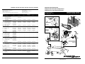 1
1
-
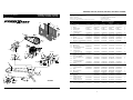 2
2
-
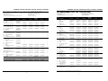 3
3
-
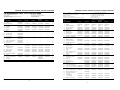 4
4
-
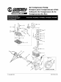 5
5
-
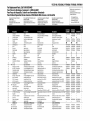 6
6
-
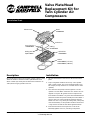 7
7
-
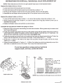 8
8
-
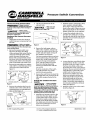 9
9
-
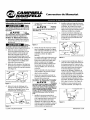 10
10
-
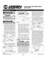 11
11
-
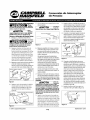 12
12
-
 13
13
-
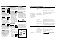 14
14
-
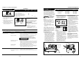 15
15
-
 16
16
-
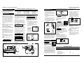 17
17
-
 18
18
-
 19
19
-
 20
20
-
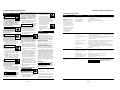 21
21
-
 22
22
-
 23
23
-
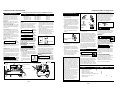 24
24
-
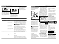 25
25
-
 26
26
-
 27
27
-
 28
28
-
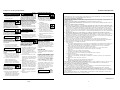 29
29
-
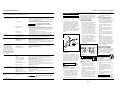 30
30
-
 31
31
-
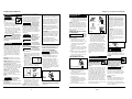 32
32
-
 33
33
-
 34
34
-
 35
35


Campbell Hausfeld VT470200KB Instrucciones de operación
- Categoría
- Compresores de aire
- Tipo
- Instrucciones de operación
en otros idiomas
Artículos relacionados
-
Campbell Hausfeld Vertical Guía del usuario
-
-
-
-
-
-
-
Campbell Hausfeld FP2052 Manual de usuario
-
-
Otros documentos
-
Husky VT631402 Operating Instructions Manual
-
RIDGID GP90150RB Manual de usuario
-
Makita MAC5501G Guía del usuario
-
-
-
-
-
Kobalt VT6389 Manual de usuario
-
-