
sauder.comsauder.com
Storage Cabinet
Model 421191
NOTE: THIS INSTRUCTION
BOOKLET CONTAINS IMPORTANT
SAFETY INFORMATION.
PLEASE READ AND KEEP FOR
FUTURE REFERENCE.
English pg 1-28
Français pg 29-32
Español pg 33-36
Lot # 530096 05/28/19
Purchased: __________________
sauder.com
CONTACT US FIRST
BEFORE MAKING ANY RETURNS TO THE STORE.
Share your journey!
sauder.com
CONTACT US FIRST
BEFORE MAKING ANY RETURNS TO THE STORE.
Visit sauder.com/service to order replacement parts, view video assembly tips, or chat with a live rep.
Prefer the phone? Give us a ring at
1-800-523-3987.
Customer Service is available Monday-Friday - 9 a.m. to 5:30 p.m. EST (except holidays)
You'll love what we
have in storage.

A RIGHT END (1)
B LEFT END (1)
C UPRIGHT (1)
D BOTTOM (1)
E ADJUSTABLE SHELF (5)
F VALANCE (1)
G SKIRT (1)
H FRONT LEG (2)
I SHELF MOLDING (6)
J LOWER DOOR MOLDING (1)
K UPPER DOOR MOLDING (1)
L FIXED SHELF (1)
M2 BACK (1)
N TOP (1)
O SLIDING DOOR (1)
P REAR LEG (2)
Table of Contents Assembly Tools Required
2-3
4-5
6-28
29-32
33-36
37-38
39
Part Identifi cation
Hardware Identifi cation
Assembly Steps
Français
Español
Safety
Warranty
Hammer
Not actual size
No. 2 Phillips Screwdriver
Tip Shown Actual Size
Skip the power trip.
This time.
Part Identifi cation
å While not all parts are labeled, some of the parts will have a label or an inked letter on the edge
to help distinguish similar parts from each other. Use this part identifi cation to help identify similar parts.
421191 www.sauder.com/servicePage 2
Straight Edge Screwdriver

Part Identifi cation
Now you know
our ABCs.
A
B
C
D
E
F
G
H
I
J
K
L
M2
N
O
P
H
P
E
E
E
E
I
I
I
I
I
421191www.sauder.com/service
Page 3

155M
RETAINING
BAR - 2
Hardware Identifi cation
å Screws are shown actual size. You may receive extra hardware with your unit.
PLASTIC
WASHER - 6
9I
METAL
PIN - 20
1R
29M
BUMPER CARD - 2
CAM SCREW - 16
8F
NAIL - 60
1N
HIDDEN CAM - 30
1F
CAM DOWEL - 14
2F
RUBBER
SLEEVE - 20
2R
DOOR WHEEL - 2
98M
DOOR
STOP - 2
106M
WHEEL SUPPORT - 2
104M
111M
DOOR TRACK
TUBE - 1
PULL - 1
149K
110M
DOOR TRACK - 1
TAPE CARD - 2
4M
421191 www.sauder.com/servicePage 4
ADJUSTABLE
GLIDE - 4
18E
PROPEL NUT - 4
14M
METAL
BRACKET - 7
4G
APPLIQUE CARD - 5
79P
109M
BARREL
NUT - 4
152M
LONG BARREL
NUT - 2
105M
DOOR TRACK
SUPPORT - 3
FURNITURE TIPPING RESTRAINT KIT - 1
97

Hardware Identifi cation
å Screws are shown actual size. You may receive extra hardware with your unit.
BLACK 9/16" LARGE HEAD SCREW - 18
1S
BLACK 1-15/16" FLAT HEAD SCREW - 2
113S
BLACK 5/8" FLAT HEAD SCREW - 2
123S
BROWN 1/2" PAN HEAD SCREW - 4
125S
126S
BROWN 5/8" FLAT HEAD SCREW - 3
BLACK 3/8" MACHINE SCREW - 4
127S
421191www.sauder.com/service
Page 5
15S
SILVER 5/8" MACHINE SCREW - 2
BLACK 3/4" PAN HEAD SCREW - 6
85S
BLACK 5/8" LARGE HEAD SCREW - 4
140S

Step 1
Look for this icon. It means a
video assembly tip is available at
www.sauder.com/service/tips
å
Assemble your unit on a carpeted fl oor or on the empty
carton to avoid scratching your unit or the fl oor.
å
Push fourteen HIDDEN CAMS (1F) into the ENDS (A and B),
UPRIGHT (C), BOTTOM (D), and FIXED SHELF (L). Then,
insert the metal end of a CAM DOWEL (2F) into each
HIDDEN CAM.
Insert the metal end of the CAM
DOWEL into the HIDDEN CAM.
Arrow
Arrow
1F
2F
(14 used)
Do not tighten the HIDDEN CAMS in this step.
A
B
C
D
L
421191 www.sauder.com/servicePage 6

å
Push sixteen HIDDEN CAMS (1F) into the long edges
of the ENDS (A and B).
Step 2
1F
Arrow
(16 used)
Arrow
1F
Arrow
The arrow in the HIDDEN
CAM must point toward the
hole in the edge of the board.
Hole
A
B
421191www.sauder.com/service
Page 7

Step 3
8F
å
Turn sixteen CAM SCREWS (8F) into the LEGS (H and P).
(16 used)
Remember:
Righty tighty.
Lefty loosey.
421191 www.sauder.com/servicePage 8
P
P
H
H

å
Fasten one of each LEG (H and P) to the RIGHT END (A).
Tighten eight HIDDEN CAMS.
Step 4
A
H
P
1
2
Surface with
HIDDEN CAMS
Edge with
CAM DOWELS
These surfaces
should be even.
The LEGS will
overhang this edge.
421191www.sauder.com/service
Page 9
These surfaces
should be even.

Step 5
å
Fasten the remaining two LEGS (H and P) to the LEFT
END (B). Tighten eight HIDDEN CAMS.
B
H
P
Surface with
HIDDEN CAMS
Edge with
CAM DOWELS
The LEGS will
overhang this edge.
421191 www.sauder.com/servicePage 10
These surfaces
should be even.
These surfaces
should be even.

å
Fasten the UPRIGHT (C) to the BOTTOM (D). Use two
BLACK 1-15/16" FLAT HEAD SCREWS (113S).
Step 6
Surface without
HIDDEN CAMS
Surface with
HIDDEN CAMS
D
C
Notch
BLACK 1-15/16" FLAT HEAD SCREW
(2 used in this step)
113S
These holes must be here.
Finished edge
421191www.sauder.com/service
Page 11
Do not stand the unit upright without the
BACK fastened. The unit may collapse.
Caution

Step 7
å
Fasten the FIXED SHELF (L) to the UPRIGHT (C). Tighten
two HIDDEN CAMS.
å
Slide one of the SHELF MOLDINGS* (I) onto the notched
edge of the FIXED SHELF (L).
å
*U.S. Patent No. 5,499,886
Start Tighten
Arrow
Minimum
190 degrees
Caution
Risk of damage or
injury. HIDDEN CAMS
must be completely
tightened. HIDDEN
CAMS that are not
completely tightened
may loosen, and parts
may separate. To
completely tighten:
Arrow
Maximum
210 degrees
Surface with
HIDDEN CAMS
C
L
Slide the SHELF MOLDING (I)
onto the notched edge.
Notched edge
The groove is
closer to this edge.
Some assembly
(and snacks) required.
I
421191 www.sauder.com/servicePage 12

Step Step 8
å
Fasten the RIGHT END (A) to the BOTTOM (D). Tighten
two HIDDEN CAMS.
å
Fasten the LEFT END (B) to the BOTTOM (D) and FIXED
SHELF (L). Tighten four HIDDEN CAMS.
Arrow
Minimum
190 degrees
Maximum
210 degrees
B
Surface without
HIDDEN CAMS
A
Surface with
HIDDEN CAMS
Edge with
CAM DOWELS
Edge with
CAM DOWELS
D
L
421191www.sauder.com/service
Page 13

Step
å
Open the FURNITURE TIPPING RESTRAINT KIT (97)
and fasten the SAFETY STRAP to the TOP (N). Use the
provided BLACK 9/16" LARGE HEAD SCREW.
å
NOTE: Position the SAFETY STRAP exactly as shown.
å
Fasten the TOP (N) to the ENDS (A and B) and
UPRIGHT (C). Tighten six HIDDEN CAMS.
Step 9
Arrow
Minimum
190 degrees
Maximum
210 degrees
B
A
C
N
N
Surface with holes
These holes must be here.
421191 www.sauder.com/servicePage 14
Meet Part (N). This component has been
engineered to be lighter, stronger, faster…
well ok. Not technically faster. But
defi nitely makes for a sturdier Storage
Cabinet that’s easier to assemble and
friendlier to the environment.
BLACK 9/16" LARGE HEAD SCREW
(1 used in this step)
Safety strap
97

Step
421191www.sauder.com/service
Page 15
Step 10
å
Fasten seven METAL BRACKETS (4G) to the ENDS (A and B),
BOTTOM (D), and TOP (N). Use seven BLACK 9/16" LARGE
HEAD SCREWS (1S).
å
Fasten the SKIRT (G) to the BOTTOM (D). Use three BLACK
9/16" LARGE HEAD SCREWS (1S) through the METAL
BRACKETS and into the SKIRT.
å
NOTE: There are no pre-drilled holes in the SKIRT. The
SCREWS will tighten into the groove.
å
Fasten the VALANCE (F) to the ENDS (A and B) and TOP (N).
Use four BLACK 9/16" LARGE HEAD SCREWS (1S) through
the METAL BRACKETS and into the VALANCE.
å
NOTE: The SCREWS will tighten into the groove.
BLACK 9/16" LARGE HEAD SCREW
(14 used in this step)
1S
The groove is
closer to this edge.
The holes are
closer to this edge.
D
B
A
N
G
F
Surface with holes
4G
4G

Step Step 11
NAIL
(60 used in this step)
1N
å
Carefully turn your unit over onto its front edges.
å
Unfold the BACK (M2) and lay it over your unit.
å
A perforation in the BACK (M2) has been provided for access
to the SAFETY STRAP. Punch out the perforation and push the
SAFETY STRAP through the hole.
å
Fasten the BACK (M2) to the REAR LEGS (P). Use four BLACK
9/16" LARGE HEAD SCREWS (1S).
å
Finish fastening the BACK (M2) to your unit using the NAILS (1N).
å
NOTE: Be sure to tap NAILS into the holes
that line up over the UPRIGHT (C).
Unfi nished
surface
M2
421191 www.sauder.com/servicePage 16
BLACK 9/16" LARGE HEAD SCREW
(4 used in this step)
1S
Do not stand the unit upright without the
BACK fastened. The unit may collapse.
Caution
Before fastening the BACK,
punch out the perforation
and push the SAFETY
STRAP through the hole.
A
C
NOTE: Fasten the BACK with
four BLACK 9/16" LARGE
HEAD SCREWS (1S) before
using the NAILS (1N).
P
P

å
Use a hammer to drive a PROPEL NUT (14M) into the
holes in the LEGS (H and P). Now, turn an ADJUSTABLE
GLIDE (18E) completely into each PROPEL NUT.
Step 12
421191www.sauder.com/service
Page 17
18E
14M
H
H
P
P

Step 13
å
Carefully stand your unit upright.
å
Insert the DOOR TRACK (110M) into the groove in
the BOTTOM (D).
å
NOTE: You may need to gently tap the DOOR TRACK
into the groove in the BOTTOM using your hammer.
D
Groove
Pro Tip: Lift with your
legs. And, you know,
your arms.
421191 www.sauder.com/servicePage 18
110M
The groove in the
DOOR TRACK
should be facing up.

Step 14
421191www.sauder.com/service
Page 19
å
Position your unit in its fi nal location. We recommend using the SAFETY STRAP for added stability.
å
NOTE: Do not turn the SAFETY DRYWALL ANCHOR into a wall stud. If you prefer to fasten the SAFETY STRAP to a wall
stud, go to your local hardware store for proper hardware.
å
INSTALLATION INSTRUCTIONS:
1. Insert the SAFETY DRYWALL ANCHOR through the WASHER and one end of the SAFETY STRAP.
2. Using a Phillips screwdriver or a hand drill, press the screw slightly onto the drywall just below the top surface of your
unit so the SAFETY STRAP will not be visible.
3. Apply pressure; turn the screw until a pilot hole is made and the nylon sheath slips through.
4. Turn the screw until it is fl ush against the wall and you feel a fi rm resistance.
5. Continue to turn until the screw starts spinning freely.
å
NOTE: Before moving your unit to a di erent location, unscrew the SAFETY DRYWALL ANCHOR from your wall. The
nylon sheath will remain behind your wall.
Safety
drywall
anchor
Safety strap
Washer
97

Step 15
å
Fasten three DOOR TRACK SUPPORTS (105M) to the
VALANCE (F). Use three BROWN 5/8" FLAT
HEAD SCREWS (126S).
å
NOTE: Be sure to position the DOOR TRACK SUPPORTS
exactly as shown.
Large hole
BROWN 5/8" FLAT HEAD SCREW
(3 used in this step)
126S
421191 www.sauder.com/servicePage 20
F
105M

Step 16
å
Apply TAPE from the TAPE CARDS (4M) to the DOOR
MOLDINGS (J and K) exactly as shown. Then, peel o the
backing from the TAPE on the DOOR MOLDINGS.
å
Fasten the DOOR MOLDINGS (J and K) to the DOOR (O).
Use six PLASTIC WASHERS (9I) and six BLACK 3/4" PAN
HEAD SCREWS (85S).
O
K
J
4M
K
J
9I
(6 used)
421191www.sauder.com/service
Page 21
These surfaces of the
DOOR MOLDINGS and
DOOR should be even.
These
smaller holes
must be here.
BLACK 3/4" PAN HEAD SCREW
(6 used in this step)
85S

Step 17
å
Fasten the DOOR WHEELS (98M) to the WHEEL SUPPORTS (104M).
Use two LONG BARREL NUTS (152M) and two BLACK 5/8" FLAT
HEAD SCREWS (123S).
å
Fasten the WHEEL SUPPORTS (104M) to the DOOR (O). Use four
BARREL NUTS (109M) and four BLACK 3/8" MACHINE SCREWS (127S).
å
NOTE: Be sure to position the WHEEL SUPPORTS exactly as shown.
O
BLACK 3/8" MACHINE SCREW
(4 used in this step)
127S
BLACK 5/8" FLAT HEAD SCREW
(2 used for the DOOR WHEELS)
123S
109M
421191 www.sauder.com/servicePage 22
104M
Surface without
DOOR MOLDINGS
Before tightening the SCREWS,
slide the WHEEL SUPPORTS down
as far as they will go on the DOOR.
104M
123S
152M
98M
104M
123S
152M
98M
109M

å
Fasten two RETAINING BARS (155M) to the DOOR (O). Tighten
the RETAINING BARS to the DOOR using four BLACK 5/8"
LARGE HEAD SCREWS (140S).
å
NOTE: Be sure to position the RETAINING BARS exactly as shown.
å
NOTE: The RETAINING BARS should move up and down easily.
å
Fasten the PULL (149K) to the DOOR (O). Use two SILVER 5/8"
MACHINE SCREWS (15S).
Step 18
149K
O
421191www.sauder.com/service
Page 23
SILVER 5/8" MACHINE SCREW
(2 used for the PULL)
15S
Surface without
DOOR MOLDINGS
155M
The RETAINING BARS should
move up and down easily.
The RETAINING
BARS should
overhang the
bottom edge of
the DOOR.
BLACK 5/8" LARGE HEAD SCREW
(4 used in this step)
140S

Step 19
å
Fasten two DOOR STOPS (106M) to the DOOR
TRACK TUBE (111M). Use two BROWN 1/2" PAN
HEAD SCREWS (125S).
å
NOTE: The SCREWS may turn in hard. Use a little
extra force while turning these SCREWS.
å
Then, hang the DOOR (O) onto the center of the
DOOR TRACK TUBE (111M) as shown.
BROWN 1/2" PAN HEAD SCREW
(2 used in this step)
125S
106M
O
111M
111M
111M
421191 www.sauder.com/servicePage 24

Step 20
å
NOTE: You will lift the DOOR by holding onto the ends of the DOOR TRACK
TUBE while the DOOR hangs from the TUBE.
å
NOTE: A corner of the unit is cut out to show part of the assembly.
å
Place the DOOR TRACK TUBE (111M) with the DOOR (O) onto the DOOR
TRACK SUPPORTS (105M).
å
Now, fasten the DOOR TRACK TUBE (111M) to the two outer DOOR TRACK
SUPPORTS (105M). Use two BROWN 1/2" PAN HEAD SCREWS (125S).
å
Carefully pull the bottom of the DOOR (O) out at an angle. Then, push up
on the RETAINING BARS (155M) on the bottom edge of the DOOR and
insert the RETAINING BARS into the DOOR TRACK (110M). Then, press
down on the RETAINING BARS.
å
See the next step for DOOR adjustments.
111M
BROWN 1/2" PAN HEAD SCREW
(2 used in this step)
125S
105M
110M
421191www.sauder.com/service
Page 25
O
125S
125S
155M

Step 21
421191 www.sauder.com/servicePage 26
å
If your unit teeters and one of the LEVELERS is not touching the fl oor, turn the LEVELER out of the LEG until it touches the
fl oor. Slide the DOOR over to the left side of your unit.
å
Diagram #1 : The gap between the DOOR and the side of your unit should be constant from top to bottom. If it is not, then
make adjustments below.
å
Diagram #2: If your door has a larger gap near the bottom, then turn the left front LEVELER out of the LEG a couple of
turns. You may need to turn the LEVELER a couple of turns again to get your DOOR adjusted as shown in diagram #1.
å
Diagram #3: If your door has a larger gap near the bottom, then turn the right front LEVELER out of the LEG a couple of
turns. You may need to turn the LEVELER a couple of turns again to get your DOOR adjusted as shown in diagram #1.
å
If further door adjustments are needed, loosen the SCREWS in the WHEEL SUPPORTS a 1/4 of a turn, make any needed
adjustments, and tighten the SCREWS as shown in the enlarge view.
Loosen these SCREWS
a 1/4 of a turn, make
adjustments, and tighten.
Diagram #1
Diagram #2 Diagram #3
To eliminate this large
gap, turn the front left
LEVELER out.
To eliminate this large
gap, turn the front
right LEVELER out.
The gap
between
the DOOR
and the unit
should be
constant from
top to bottom.

å
Slide a SHELF MOLDING* (I) onto the notched edge of one of the SHELVES (E).
å
Repeat this step for the remaining SHELVES (E) and SHELF MOLDINGS (I).
å
Push the RUBBER SLEEVES (2R) over the METAL PINS (1R). Insert the METAL PINS into the hole locations of your choice
in the ENDS (A and B) and UPRIGHT (C). Set the ADJUSTABLE SHELVES (E) onto the METAL PINS.
å
*U.S. Patent No. 5,499,886
Step 22
421191www.sauder.com/service
Page 27
(20 used)
2R
1R
E
E
E
E
E
A
C
B
Slide the SHELF MOLDING (I)
onto the notched edge.
These surfaces should be even.
I
E
Notched edge
The groove is
closer to this edge.

Step 23
421191 www.sauder.com/servicePage 28
å
IMPORTANT: The BUMPERS are used to reduce the risk of fi ngers being pinched when sliding the DOOR.
å
Peel the BUMPERS from the BUMPER CARDS (29M) and stick the BUMPERS on the upper and lower corners of both
sides of the DOOR (O).
å
Peel APPLIQUES from the APPLIQUE CARD (79P) and stick them onto each visible HIDDEN CAM.
å
NOTE: Please read the back pages of the instruction booklet for important safety information.
å
This completes assembly. Clean with a damp cloth. Wipe dry.
To reduce the risk of pinching
fi ngers, use the provided Bumpers.
Caution
(26 used)
To cover HIDDEN CAMS
29M
29M
O
No load
50 lbs.
total
20 lbs.
20 lbs.
20 lbs.
20
lbs.
20
lbs.
20
lbs.
(4 used)
A
C
B
L
79P
And to celebrate, why not share your success story at Walmart.com or

A l’usage exclusif du
Canada Noter la date
d’achat de cet élément
et conserver le livret
pour future référence.
Pour contacter Sauder
en ce qui concerne cet
élément, faire référence
au numéro de lot et
numéro de modèle en
appelant notre numéro
sans frais.
Lot nº : ____________
Date de
l’achat: ____________
LISTE DE PIÈCES
REFERENCE DESCRIPTION QUANTITÉ
LISTE DE PIÈCES
REFERENCE DESCRIPTION QUANTITÉ
NOUS SOMMES LA POUR VOUS AIDER!
Nous faisons de notre mieux pour nous assurer que votre meuble
arrive dans d’excellentes conditions. Nos représentants du service
Clientèle sont aimables et prêts à vous aider au cas où une pièce
aurait été endommagée ou manquerait (ou si vous aviez besoin
d’aide pour l’assemblage). NE RAMENEZ PAS LE MEUBLE AU
MAGASIN. Au Canada, composez ce numéro d’appel gratuit:
1-800-523-3987
Du lundi au vendredi, de 9 heures du matin à
5:30 heures du soir (horaire Côte Est)
(sauf jours fériés)
Si une pièce a besoin d’être remplacée, la pièce de remplacement
sera envoyée dans les 48 heures. (Sauf week-ends et jours fériés)
Utilisez les instructions d’assemblage en français avec les
schémas étape par étape du manuel d’instruction en anglais.
Chaque étape en français correspond à la même étape
en anglais. La pièce devant être attachée à l’élément est
représentée en gris sur les schémas de chaque étape pour plus
de précision. Comparer la “Liste de pièces” ci-dessous avec
la “PART IDENTIFICATION” du manuel en anglais pour vous
familiariser avec les pièces avant l’assemblage.
REMARQUE : CE MANUEL D’INSTRUCTIONS CONTIENT
D’IMPORTANTES INFORMATIONS RELATIVES À LA SÉCURITÉ.
À LIRE ET CONSERVER POUR TOUTE RÉFÉRENCE FUTURE.
Meuble de rangementModèle 421191
421191www.sauder.com/service
Page 29
4M CARTE DE RUBAN ADHÉSIF .............................2
14M ÉCROU À AILETTE ....................................................4
29M FICHE AVEC TAMPONS ........................................2
98M ROULETTE DE PORTE ............................................2
104M
SUPPORT DE ROULETTE ....................................2
105M
SUPPORT DE RAIL DE PORTE .........................3
106M
ARRÊT DE PORTE ......................................................2
109M
ÉCROU À MANCHON .............................................4
110M
RAIL DE PORTE .............................................................1
111M TUBE DE RAIL DE PORTE .....................................1
152M LONG ÉCROU À MANCHON ............................2
155M LANGUETTE DE RETENUE .................................2
1N CLOU ................................................................................60
79P FICHE D'APPLIQUÉS ...............................................5
1R GOUPILLE EN MÉTAL .........................................20
2R MANCHON EN CAOUTCHOUC .................20
97 KIT DE RETENUE ANTI-BASCULEMENT
POUR MOBILIER...........................................................1
1S VIS TÊTE LARGE 14 mm NOIRE ..................18
15S VIS À MÉTAUX 16 mm ARGENTÉE ..............2
85S VIS TÊTE GOUTTE DE
SUIF 19 mm NOIRE ...................................................6
113S VIS TÊTE PLATE 49 mm NOIRE .....................2
123S VIS TÊTE PLATE 16 mm NOIRE ......................2
125S VIS TÊTE GOUTTE DE
SUIF 13 mm MARRON............................................4
126S VIS TÊTE PLATE 16 mm MARRON ..............3
127S VIS À MÉTAUX 9,5 mm NOIRE ........................4
140S VIS TÊTE LARGE 16 mm NOIRE ....................4
A EXTRÉMITÉ DROITE ..................................................1
B EXTRÉMITÉ GAUCHE ...............................................1
C MONTANT..........................................................................1
D DESSOUS ...........................................................................1
E TABLETTE RÉGLABLE ............................................5
F LAMBREQUIN .................................................................1
G PLINTHE ..............................................................................1
H PIED ........................................................................................4
I MOULURE DE TABLETTE ....................................6
J MOULURE DE PORTE INFÉRIEURE ..............1
K MOULURE DE PORTE SUPÉRIEURE ............1
L TABLETTE FIXE ..............................................................1
M2 ARRIÈRE ..............................................................................1
N DESSUS ...............................................................................1
O PORTE COULISSANTE ...........................................1
18E PATIN RÉGLABLE ........................................................4
1F EXCENTRIQUE ESCAMOTABLE .................30
2F CHEVILLE D'EXCENTRIQUE ............................14
8F VIS D'EXCENTRIQUE ............................................16
4G CONSOLE EN MÉTAL .............................................7
9I RONDELLE EN PLASTIQUE ...............................6
149K POIGNÉE .............................................................................1

ÉTAPE 1
Ne pas serrer les EXCENTRIQUES ESCAMOTABLES dans
cette étape.
Assembler l'élément sur un sol à moquette ou sur le carton vide
pour éviter d'endommager l'élément ou le sol.
Enfoncer quatorze EXCENTRIQUES ESCAMOTABLES (1F) dans
les EXTRÉMITÉS (A et B), le MONTANT (C), le DESSOUS (D)
et la TABLETTE FIXE (L). Ensuite, insérer l'extrémité en métal
de la CHEVILLE D'EXCENTRIQUE (2F) dans chaque
EXCENTRIQUE ESCAMOTABLE.
ÉTAPE 2
Enfoncer seize EXCENTRIQUES ESCAMOTABLES (1F) dans les
chants longs des EXTRÉMITÉS (A et B).
ÉTAPE 8
Fixer l'EXTRÉMITÉ DROITE (A) au DESSOUS (D). Serrer deux
EXCENTRIQUES ESCAMOTABLES.
Fixer l'EXTRÉMITÉ GAUCHE (B) au DESSOUS (D) et à
la TABLETTE FIXE (L). Serrer quatre EXCENTRIQUES
ESCAMOTABLES.
ÉTAPE 3
Faire tourner seize VIS D'EXCENTRIQUE (8F) dans les PIEDS (H et P).
ÉTAPE 4
Fixer deux PIEDS (H et P) à l'EXTRÉMITÉ DROITE (A). Serrer huit
EXCENTRIQUES ESCAMOTABLES.
ÉTAPE 9
Ouvrir le KIT DE RETENUE ANTI-BASCULEMENT POUR
MOBILIER (97) et fi xer la SANGLE DE SÉCURITÉ au DESSUS (N).
Utiliser la VIS TÊTE LARGE 14 mm fourni.
REMARQUE : Placer la SANGLE DE SÉCURITÉ exactement comme
l'indique le schéma.
Fixer le DESSUS (N) aux EXTRÉMITÉS (A et B) et au
MONTANT (C). Serrer six EXCENTRIQUES ESCAMOTABLES.
421191 www.sauder.com/servicePage 30
ÉTAPE 5
Fixer les autres deux PIEDS (H et P) à l'EXTRÉMITÉ GAUCHE (B).
Serrer huit EXCENTRIQUES ESCAMOTABLES.
ÉTAPE 6
Attention: Ne pas relever l'élément dans sa position verticale
avant d'avoir fi xé l’ARRIÈRE. L'élément risque de s'e ondrer.
Fixer le MONTANT (C) sur le DESSOUS (D). Utiliser deux VIS
TÊTE PLATE 49 mm NOIRES (113S).
ÉTAPE 10
Fixer sept CONSOLES EN MÉTAL (4G) aux EXTRÉMITÉS (A et B),
au DESSOUS (D) et au DESSUS (N). Utiliser sept VIS TÊTE
LARGE 14 mm NOIRES (1S).
Fixer la PLINTHE (G) au DESSOUS (D). Utiliser trois VIS TÊTE
LARGE 14 mm NOIRES (1S) à travers les CONSOLES EN MÉTAL
et dans la PLINTHE.
REMARQUE : La PLINTHE ne comporte pas de trous pré-percés.
Serrer les VIS dans la rainure.
Fixer le LAMBREQUIN (F) aux EXTRÉMITÉS (A et B) et au
DESSUS (N). Utiliser quatre VIS TÊTE LARGE 14 mm NOIRES (1S)
à travers les CONSOLES EN MÉTAL et dans le LAMBREQUIN.
REMARQUE : Serrer les VIS dans la rainure.
ÉTAPE 7
Fixer la TABLETTE FIXE (L) au MONTANT (C). Serrer deux
EXCENTRIQUES ESCAMOTABLES.
Attention: Risque des dégâts ou blessures. Les Excentriques
Escamotables doivent être serrés à bloc. Les Excentriques
Escamotables que ne sont pas serrées à bloc peuvent desserrer
et les pièces peuvent séparer. Pour serrer à bloc, faire tourner
l'excentrique escamotable de 210 degrés.
Enfi ler l’une des MOULURES DE TABLETTE* (I) sur le chant cranté
de la TABLETTE FIXE (L).
* Brevet État Unis n° 5,499,886
ÉTAPE 11
Attention: Ne pas relever l'élément dans sa position verticale
avant d'avoir fi xé l’ARRIÈRE. L'élément risque de s'e ondrer.
Avec précaution, retourner l'élément sur ses chants avant.
Déplier l'ARRIÈRE (M2) et le placer sur l'élément.
Un perforation ont été prévue pour accès à travers l’ARRIÈRE (M2)
pour la SANGLE DE SÉCURITÉ. Découper soigneusement la
perforation et enfoncer la SANGLE DE SÉCURITÉ à travers le trou.
Fixer l'ARRIÈRE (M2) aux PIEDS ARRIÈRE (P). Utiliser quatre VIS
TÊTE LARGE 14 mm NOIRES (1S).
Finir de fi xer l'ARRIÈRE (M2) à l'élément à l'aide des CLOUS (1N).
REMARQUE : S'assurer de bien enfoncer les CLOUS dans les
trous qui sont alignés au-dessus le MONTANT (C).

ÉTAPE 12
À l'aide d'un marteau, enfoncer un TOURILLON (14M) à travers les
trous dans les PIEDS (H et P). Maintenant, faire tourner un PATIN
RÉGLABLE (18E) dans chaque TOURILLON.
ÉTAPE 15
Fixer trois SUPPORTS DE RAIL DE PORTE (105M) au LAMBREQUIN (F).
Utiliser trois VIS TÊTE PLATE 16 mm MARRON (126S).
REMARQUE : S’assurer de positionner les SUPPORTS DE RAIL DE
PORTE comme l'indique le schéma.
ÉTAPE 16
Appliquer le RUBAN ADHÉSIF de la CARTE DE RUBAN
ADHÉSIF (4M) sur les MOULURES DE PORTE (J et K) comme
l’indique le schéma. Décoller ensuite le papier du RUBAN
ADHÉSIF sur les MOULURES DE PORTE.
Fixer les MOULURES DE PORTE (J et K) à la PORTE (O). Utiliser
six RONDELLES EN PLASTIQUE (9I) et six VIS TÊTE GOUTTE DE
SUIF 19 mm NOIRES (85S).
ÉTAPE 13
Relever, avec précaution, l'élément dans sa position verticale.
Enfoncer un RAIL DE PORTE (110M) dans la rainure du DESSOUS (D).
REMARQUE : Il est peut-être nécessaire d’enfoncer le RAIL DE PORTE
délicatement à l'aide d'un marteau dans la rainure du DESSOUS.
ÉTAPE 17
Fixer les ROULETTES DE PORTE (98M) aux SUPPORTS DE
ROULETTE (104M). Utiliser deux LONGS ÉCROUS À MANCHON (152M)
et deux VIS TÊTE PLATE 16 mm NOIRES (123S).
Fixer les SUPPORTS DE ROULETTE (104M) sur la PORTE (O).
Utiliser quatre ÉCROUS À MANCHON (109M) et quatre VIS À
MÉTAUX 9,5 mm NOIRES (127S).
REMARQUE : S’assurer de positionner les SUPPORTS DE
ROULETTE exactement comme il l’est indiqué.
ÉTAPE 14
Placer l'élément dans son emplacement fi nal. Il est recommandé
d'utiliser la SANGLE DE SÉCURITÉ pour renforcer la stabilité.
REMARQUE : Ne pas tourner le DISPOSITIF DE SÉCURITÉ POUR
PLACOPLÂTRE dans un montant mural. Si on préfère fi xer la
SANGLE DE SÉCURITÉ à un montant mural, obtenir la visserie
appropriée auprès d’une quincaillerie locale.
INSTRUCTIONS D’INSTALLATION :
1.
Insérer le DISPOSITIF DE SÉCURITÉ POUR PLACOPLÂTRE à
travers la RONDELLE et une extrémité de la SANGLE DE SÉCURITÉ.
2. À l’aide d’un tournevis cruciforme ou d’une perceuse à main,
enfoncer la vis légèrement dans le Placoplatre juste en-dessous
de la surface supérieure de l’unité de sorte que la SANGLE DE
SÉCURITÉ ne soit pas visible.
3. Appliquer une certaine pression ; faire tourner la vis jusqu’à la
gaine en nylon glisse à travers.
4. Faire tourner la vis jusqu’à ce qu’elle soit à fl eur du mur et
qu'une résistance ferme se fasse sentir.
5. Continuer de tourner jusqu’à ce que la vis commence à
pivoter librement.
REMARQUE : Avant de déplacer l’unité vers un emplacement
di érent, dévisser le DISPOSITIF DE SÉCURITÉ POUR
PLACOPLÂTRE du mur. La gaine en nylon restera derrière le mur.
ÉTAPE 18
Fixer deux LANGUETTES DE RETENUE (155M) sur la PORTE (O).
Serrer les LANGUETTES DE RETENUE à la PORTE en utilisant
quatre VIS TÊTE LARGE 16 mm NOIRES (140S).
REMARQUE : S’assurer de positionner les LANGUETTES DE
RETENUE exactement comme il l’est indiqué.
REMARQUE : Les LANGUETTES DE RETENUE doivent pouvoir
remonter et redescendre sans encombre.
Fixer la POIGNÉE (149K) à la PORTE (O). Utiliser deux VIS À
MÉTAUX 16 mm ARGENTÉES (15S).
421191www.sauder.com/service
Page 31

ÉTAPE 19
Fixer deux ARRÊTS DE PORTE (106M) sur le TUBE DE RAIL
DE PORTE (111M). Utiliser deux VIS TÊTE GOUTTE DE
SUIF 13 mm MARRON (125S).
REMARQUE : Il est possible que les VIS soient di ciles à tourner.
Il faudra forcer un peu pour serrer ces VIS.
Installer ensuite la PORTE (O) sur le centre du TUBE DE RAIL DE
PORTE (111M), comme il l’est indiqué.
ÉTAPE 20
REMARQUE : Il faudra ensuite lever la PORTE en tenant
les extrémités du TUBE DE RAIL DE PORTE. La PORTE est
suspendue au TUBE.
REMARQUE : Un coin de l’unité a été découpé pour montrer une
partie de l’assemblage.
Placer le TUBE DE RAIL DE PORTE (111M) avec la PORTE (O) sur
les SUPPORTS DE RAIL DE PORTE (105M).
Maintenant, fi xer le TUBE DE RAIL DE PORTE (111M) aux les deux
SUPPORTS DE RAIL DE PORTE extérieurs (105M). Utiliser deux
VIS TÊTE GOUTTE DE SUIF 13 mm MARRON (125S).
Tirer avec précaution sur le bas de la PORTE (O) pour les incliner.
Pousser ensuite sur les LANGUETTES DE RETENUE (155M)
du bord inférieur de la PORTE et insérer les LANGUETTES DE
RETENUE dans le RAIL DE PORTE (110M). Ensuite, appuyer sur
les LANGUETTES DE RETENUE.
Voir l'étape suivante pour réglages des PORTES.
ÉTAPE 22
Enfi ler la MOULURE DE TABLETTE* (I) sur le chant cranté d'une
des TABLETTES (E).
Répéter cette étape pour les autres TABLETTES (E) et les
MOULURES DE TABLETTE (I).
Enfoncer les MANCHONS EN CAOUTCHOUC (2R) sur les
GOUPILLES EN MÉTAL (1R). Insérer les GOUPILLES EN MÉTAL
dans les trous choisis dans les EXTRÉMITÉS (A et B) et le
MONTANT (C). Poser les TABLETTES RÉGLABLES (E) sur les
GOUPILLES EN MÉTAL.
* Brevet État Unis n° 5,499,886
ÉTAPE 23
IMPORTANT : Ces BUTÉES servent à éviter que l’on se pince les
doigts en faisant coulisser la PORTE.
Décoller les TAMPONS de leur FICHE AVEC TAMPONS (29M) et
les coller sur les coins inférieurs et supérieurs, des deux côtés de
la PORTE (O).
Décoller les AUTO-COLLANTS de la FICHE D'APPLIQUÉS (79P)
et coller
sur chaque EXCENTRIQUE ESCAMOTABLE visible.
REMARQUE : Prière de lire les informations importantes sur la
sécurité fi gurant sur les pages arrière du manuel d’instructions.
Ceci complète l'assemblage.
Nettoyer avec un tissu humide. Essuyer.
421191 www.sauder.com/servicePage 32
ÉTAPE 21
Schéma n° 1 : L'écart entre la PORTE et le côté de l'unité doit être
constant de haut en bas. Si ce n'est pas le cas, ajuster comme suit.
Schéma n° 2 : Si la porte a un écart plus large près du bas, tourner
alors le VÉRIN avant gauche hors du PIED de deux tours. Il faut
peut-être faire tourner le VÉRIN de deux tours pour ajuster la
PORTE comme l'indique le schéma n° 1.
Schéma n° 3 : Si la porte a un écart plus large près du bas, tourner
alors le VÉRIN avant droit hors du PIED de deux tours. Il faut peut-
être faire tourner le VÉRIN de deux tours pour ajuster la PORTE
comme l'indique le schéma n° 1.
Si d'autres réglages sont nécessaires, desserrer les VIS dans les
SUPPORTS DE ROULETTE d'1/4 de tour, e ectuer les réglages
nécessaires et serrer les VIS comme l'indique le schéma agrandi.

LISTA DE PARTES
ITEM DESCRIPCIÓN CANTIDAD
ESTAMOS AQUI PARA AYUDAR!
Tratamos de asegurar que su mueble llega en condición excelente.
Nuestros representantes de Servicio al Cliente son amables y
listos para ayudarle con servicio rápido y efi ciente si una parte
está defectuosa o ausente (o si necesita ayuda con el ensamblaje).
NO DEVUELVA LA UNIDAD A LA TIENDA. Llame este número sin
cargo:
1-800-523-3987
Lunes a viernes, 9:00 a.m. - 5:30 p.m.
Hora ofi cial del Este
(excepto días festivos)
Si requiere un repuesto de una parte, será enviado dentro de
48 horas (excepto los fi nes de semana y días festivos)
Use estas instrucciones de ensamblaje en español junto con las
fi guras paso-a-paso provistas en el folleto inglés. Cada paso
en español corresponde al mismo paso en inglés. Se destacan
las fi guras de cada paso con una tonalidad oscura para mostrar
precisamente cual parte se debe montar a la unidad. Compare
la “Lista de Part” abajo con la “Part Identifi cation” en el folleto en
inglés para familiarizarse con Las partes de ensamblaje.
NOTA: ESTE FOLLETO DE INSTRUCCIONES CONTIENE
INFORMACIÓN IMPORTANTE SOBRE LA SEGURIDAD. POR
FAVOR LEA Y GUÁRDELO PARA REFERENCIA EN EL FUTURO.
LISTA DE PARTES
ITEM DESCRIPCIÓN CANTIDAD
Gabinete para almacenajeModelo 421191
421191www.sauder.com/service
Page 33
98M RUEDA DE LA PUERTA ...........................................2
104M
SOPORTE DE LA RUEDA .....................................2
105M
SOPORTE DE CARRIL DE LA PUERTA ......3
106M
TOPE DE LA PUERTA ..............................................2
109M
TUERCA CILÍNDRICA ..............................................4
110M
CARRIL DE LA PUERTA ...........................................1
111M TUBO DE CARRIL DE LA PUERTA .................1
152M
TUERCA CILÍNDRICA LARGA...........................2
155M
BARRA DE RETENCIÓN .........................................2
1N CLAVO .............................................................................60
79P TARJETA CON APLICACIONES ......................5
1R ESPIGA DE METAL ................................................20
2R MANGUITO DE GOMA .......................................20
97 KIT DE CONTROL ANTI-INCLINACIÓN
PARA MOBILIARIO .....................................................1
1S TORNILLO NEGRO DE CABEZA
GRANDE de 14 mm ................................................18
15S TORNILLO PLATEADO PARA
METAL de 16 mm........................................................2
85S TORNILLO NEGRO DE CABEZA
REDONDA de 19 mm ...............................................6
113S TORNILLO NEGRO DE CABEZA
PERDIDA de 49 mm .................................................2
123S TORNILLO NEGRO DE CABEZA
PERDIDA de 16 mm ..................................................2
125S TORNILLO MARRÓN DE CABEZA
REDONDA de 13 mm ...............................................4
126S TORNILLO MARRÓN DE CABEZA
PERDIDA de 16 mm ..................................................3
127S TORNILLO NEGRO PARA
METAL de 9,5 mm ......................................................4
140S TORNILLO NEGRO DE CABEZA
GRANDE de 16 mm ...................................................4
A EXTREMO DERECHO ...............................................1
B EXTREMO IZQUIERDO ............................................1
C PARAL ...................................................................................1
D FONDO .................................................................................1
E ESTANTE AJUSTABLE ............................................5
F CORNISA ............................................................................1
G FALDÓN ...............................................................................1
H PATA .......................................................................................4
I MOLDURA DE ESTANTE .......................................6
J MOLDURA DE PUERTA INFERIOR .................1
K MOLDURA DE PUERTA SUPERIOR ...............1
L ESTANTE INMÓVIL .....................................................1
M2 DORSO .................................................................................1
N PANEL SUPERIOR .......................................................1
O PUERTA CORREDIZA ................................................1
18E DESLIZAMIENTO AJUSTABLE .........................4
1F EXCÉNTRICO ESCONDIDO ...........................30
2F PASADOR DE EXCÉNTRICO ............................14
8F BIELA DE EXCÉNTRICO .....................................16
4G SOPORTE DE METAL .............................................. 7
9I ARANDELA DE PLÁSTICO ..................................6
149K TIRADOR .............................................................................1
4M TARJETA CON CINTA ADHESIVA ..................2
14M TUERCA DE HÉLICE .................................................4
29M CARTA DE LOS PROTECTORES ....................2
Para uso exclusivo de
Canadá Anote la fecha
de comprar esta unidad
y guarde el folleto para
su referencia futura. Si
necesita ponerse en
contacto con Sauder en
cuanto a esta unidad,
refi érase al número
de lote y al número de
modelo cuando llame a
nuestro número gratis.
No. lote: ____________
Fecha de
compra: ____________

PASO 1
No apriete los EXCÉNTRICOS ESCONDIDOS en este paso.
Ensamble la unidad sobre un piso alfombrado o sobre el cartón
vacío para evitar rayar la unidad o el piso.
Empuje catorce EXCÉNTRICOS ESCONDIDOS (1F) dentro de
los EXTREMOS (A y B), del PARAL (C), del FONDO (D) y del
ESTANTE INMÓVIL (L). A continuación, inserte el extremo de
metal de un PASADOR DE EXCÉNTRICO (2F) dentro de cada
EXCÉNTRICO ESCONDIDO.
PASO 2
Empuje dieciséis EXCÉNTRICOS ESCONDIDOS (1F) dentro de los
bordes largos de los EXTREMOS (A y B).
PASO 8
Fije el EXTREMO DERECHO (A) al FONDO (D). Apriete dos
EXCÉNTRICOS ESCONDIDOS.
Fije el EXTREMO IZQUIERDO (B) al FONDO (D) y al ESTANTE
INMÓVIL (L). Apriete cuatro EXCÉNTRICOS ESCONDIDOS.
PASO 3
Atornille dieciséis BIELAS DE EXCÉNTRICO (8F) en las PATAS (H y P).
PASO 9
Abrir el KIT DE CONTROL ANTI-INCLINACIÓN PARA MOBILIARIO (97)
y fi jar la CORREA DE SEGURIDAD al PANEL SUPERIOR (N). Utilice el
TORNILLO DE CABEZA GRANDE de 14 mm provisto.
NOTA: Coloque la CORREA DE SEGURIDAD exactamente como
se muestra.
Fije el PANEL SUPERIOR (N) a los EXTREMOS (A y B) y al
PARAL (C). Apriete seis EXCÉNTRICOS ESCONDIDOS.
PASO 4
Fije dos de las PATAS (H y P) al EXTREMO DERECHO (A). Apriete
ocho EXCÉNTRICOS ESCONDIDOS.
PASO 10
Fije siete SOPORTES DE METAL (4G) a los EXTREMOS (A y B), al
FONDO (D) y al PANEL SUPERIOR (N). Utilice siete TORNILLOS
NEGROS DE CABEZA GRANDE de 14 mm (1S).
Fije el FALDÓN (G) al FONDO (D). Pase tres TORNILLOS
NEGROS DE CABEZA GRANDE de 14 mm (1S) a través de los
SOPORTES DE METAL y en el FALDÓN.
NOTA: No hay agujeros perforados en el FALDÓN. Los
TORNILLOS apretarán dentro de la ranura.
Fije la CORNISA (F) a los EXTREMOS (A y B) y al PANEL
SUPERIOR (N). Pase cuatro TORNILLOS NEGROS DE CABEZA
GRANDE de 14 mm (1S) a través de los SOPORTES DE METAL y
dentro de la CORNISA.
NOTA: Los TORNILLOS apretarán dentro de la ranura.
421191 www.sauder.com/servicePage 34
PASO 5
Fije las otras dos PATAS (H y P) al EXTREMO IZQUIERDO (B).
Apriete ocho EXCÉNTRICOS ESCONDIDOS.
PASO 6
Precaución: No coloque la unidad en posición vertical hasta que se
fi je el DORSO. La unidad podría caerse.
Fije el PARAL (C) al FONDO (D). Utilice dos TORNILLOS NEGROS
DE CABEZA PERDIDA de 49 mm (113S).
PASO 7
Fije el ESTANTE INMÓVIL (L) al PARAL (C). Apriete dos
EXCÉNTRICOS ESCONDIDOS.
Precaución: Riesgo de daños o heridas. Los Excéntricos Escondidos
deben apretarse completamente. Los Excéntricos Escondidos que
no se aprieten completamente se afl ojarán y las partes pueden
separarse. Para apretar completamente, atornille el excéntrico
escondido 210 grados.
Deslice una de las MOLDURAS DE ESTANTE* (I) sobre el borde
con muesca del ESTANTE INMÓVIL (L).
*Patente EE. UU. No. 5,499,886
PASO 11
Precaución: No coloque la unidad en posición vertical hasta que se
fi je el DORSO. La unidad podría caerse.
Cuidadosamente voltee la unidad para que repose sobre los
bordes delanteros.
Desdoble el DORSO (M2) y colóquelo sobre la unidad.
Se ha provisto una perforación para acceso a través del
DORSO (M2) para la CORREA DE SEGURIDAD. Perforar la
perforación y empuje a través de la CORREA DE SEGURIDAD a
través el agujero.
Fije el DORSO (M2) a las PATAS POSTERIORES (P). Utilice cuatro
TORNILLOS NEGROS DE CABEZA GRANDE de 14 mm (1S).
Acabe de clavar el DORSO (M2) a la unidad utilizando
los CLAVOS (1N).
NOTA: Asegúrese de clavar ligeramente los CLAVOS dentro de
los agujeros que se alinean sobre el PARAL (C).

PASO 12
Utilice un martillo para golpear una TUERCA (14M) a través de los
agujeros de las PATAS (H y P). Ahora, gire un DESLIZAMIENTO
AJUSTABLE (18E) dentro de cada TUERCA DE HÉLICE.
PASO 15
Fije tres SOPORTES DE CARRIL DE LA PUERTA (105M) a la
CORNISA (F). Utilice tres TORNILLOS MARRONES DE CABEZA
PERDIDA de 16 mm (126S).
NOTA: Asegúrese de colocar los SOPORTES DE CARRIL DE LA
PUERTA exactamente como se muestra.
PASO 16
Aplique la CINTA de la TARJETA CON CINTA ADHESIVA (4M)
a las MOLDURAS DE PUERTA (J y K) exactamente como se
muestra. Luego, retire la capa al respaldo de la CINTA en las
MOLDURAS DE PUERTA.
Fije las MOLDURAS DE PUERTA (J y K) a la PUERTA (O). Utilice
seis ARANDELAS DE PLÁSTICO (9I) y seis TORNILLOS NEGROS
DE CABEZA REDONDA de 19 mm (85S).
PASO 13
Cuidadosamente ponga la unidad en posición vertical.
Empuje el CARRIL DE LA PUERTA (110M) en la ranura del FONDO (D).
NOTA: Puede ser necesario que ligeramente clave el CARRIL DE
LA PUERTA en el FONDO utilizando un martillo.
PASO 17
Fije las RUEDAS DE LA PUERTA (98M) a los SOPORTES DE LA
RUEDA (104M). Utilice dos TUERCAS CILÍNDRICAS LARGAS (152M)
y dos TORNILLOS NEGROS DE CABEZA PERDIDA de 16 mm (123S).
Fije los SOPORTES DE LA RUEDA (104M) a la PUERTA (O). Utilice
cuatro TUERCAS CILÍNDRICAS (109M) y cuatro TORNILLOS
NEGROS PARA METAL de 9,5 mm (127S).
NOTA: Asegúrese de que posicionar los SOPORTES DE LA
RUEDA exactamente como se muestra.
PASO 14
Coloque su unidad en su posición fi nal. Se recomienda que utilice
la CORREA DE SEGURIDAD para aumentar la estabilidad.
NOTA: No gire el ANCLAJE DE SEGURIDAD PARA EL DRYWALL
en un montante de la pared. Si prefi ere ajustar la CORREA DE
SEGURIDAD a un montante de la pared, vaya a su ferretería local
para obtener las herramientas adecuadas.
INSTRUCCIONES DE INSTALACIÓN:
1.
Inserte el ANCLAJE DE SEGURIDAD PARA EL DRYWALL a través
la ARANDELA y de un extremo de la CORREA DE SEGURIDAD.
2. Utilizando un destornillador Phillips o un taladro de mano,
presione ligeramente el tornillo a la pared de yeso justo debajo
de la superfi cie superior de su unidad para que la CORREA DE
SEGURIDAD no sea visible.
3. Presione; gire el tornillo hasta que se haga un agujero piloto y
se cuele la cubierta de nailon.
4. Gire el tornillo hasta que quede al ras contra la pared y usted
sienta una resistencia fi rme.
5. Continúe girando hasta que el tornillo comience a
rotar libremente.
NOTA: Antes de trasladar la unidad a otra ubicación, desatornille
el ANCLAJE DE SEGURIDAD PARA EL DRYWALL de su pared. La
cubierta de nailon permanecerá detrás de su pared.
PASO 18
Fije dos BARRAS DE RETENCIÓN (155M) a la PUERTA (O). Apriete
las BARRAS DE RETENCIÓN a la PUERTA utilizando cuatro
TORNILLOS NEGROS DE CABEZA GRANDE DE 16 mm (140S).
NOTA: Asegúrese de que posicionar las BARRAS DE RETENCIÓN
exactamente como se muestra.
NOTA: Las BARRAS DE RETENCIÓN deben moverse fácilmente
hacia arriba y hacia abajo.
Fije el TIRADOR (149K) a la PUERTA (O). Utilice dos TORNILLOS
PLATEADOS PARA METAL de 16 mm (15S).
421191www.sauder.com/service
Page 35

PASO 19
Fije dos TOPES DE PUERTA (106M) al TUBO DE CARRIL DE LA
PUERTA (111M). Utilice dos TORNILLOS MARRONES DE CABEZA
REDONDA de 13 mm (125S).
NOTA: Los TORNILLOS pueden girar duro. Aplique un poco más
fuerza cuando gire estos TORNILLOS.
Luego, cuelgue la PUERTA (O) al centro del TUBO DE CARRIL DE
LA PUERTA (111M) como se indica.
PASO 20
NOTA: Levantará la PUERTA sosteniéndola en los extremos del
TUBO DE CARRIL DE LA PUERTA mientras que la PUERTA cuelga
del TUBO.
NOTA: Una esquina de la unidad es cortada para mostrar parte
del montaje.
Coloque el TUBO DE CARRIL DE LA PUERTA (111M) con la
PUERTA (O) en los SOPORTES DE CARRIL DE LA PUERTA (105M).
Ahora, fi je el TUBO DE CARRIL DE LA PUERTA (111M) a los dos
SOPORTES DE CARRIL DE LA PUERTA exteriores (105M). Utilice dos
TORNILLOS MARRONES DE CABEZA REDONDA de 13 mm (125S).
Hale con cuidado la parte inferior de la PUERTA (O) hacia
fuera en un ángulo. Luego, empuje hacia arriba las BARRAS DE
RETENCIÓN (155M) en el borde inferior de la PUERTA e inserte
las BARRAS DE RETENCIÓN en el CARRIL DE LA PUERTA (110M).
A continuación, presione hacia abajo sobre las BARRAS
DE RETENCIÓN.
Consulte el próximo paso para ajustar la PUERTA.
PASO 22
Deslice la MOLDURA DE ESTANTE* (I) sobre el borde con
muesca de uno de los ESTANTES (E).
Repita este paso para el otro ESTANTE (E) y las MOLDURAS
DE ESTANTE (I).
Empuje los MANGUITOS DE GOMA (2R) sobre las ESPIGAS DE
METAL (1R). Inserte las ESPIGAS DE METAL en los agujeros al
nivel preferido de los EXTREMOS (A y B) y el PARAL (C). Coloque
los ESTANTES AJUSTABLES (E) sobre las ESPIGAS DE METAL.
*Patente EE. UU. No. 5,499,886
PASO 21
Si su unidad tambalea y uno de los NIVELADORES no toca el
piso, gire el NIVELADOR fuera de la PATA hasta que toque el piso.
Deslice la PUERTA hacia el lado izquierdo de su unidad.
Diagrama 1: El espacio entre la PUERTA y el lado de su unidad debe ser
constante de arriba a abajo. Si no lo es, haz los ajustes a continuación.
Diagrama 2: Si su puerta tiene un espacio más grande cerca
de la parte inferior, gire el NIVELADOR frontal izquierdo fuera
de la PATA un par de vueltas. Es posible que tenga que girar el
NIVELADOR varias veces para que su PUERTA se ajuste como se
indica en el diagrama 1.
Diagrama 3: Si su puerta tiene un espacio más grande cerca de la
parte inferior, gire el NIVELADOR frontal derecho fuera de la PATA un
par de vueltas. Es posible que tenga que girar el NIVELADOR varias
veces para que su PUERTA se ajuste como se indica en el diagrama 1.
Si es necesario realizar ajustes adicionales en la puerta, afl oje los
TORNILLOS en los SOPORTES DE LA RUEDA 1/4 de una vuelta,
realice los ajustes necesarios y apriete los TORNILLOS como se
muestra en el diagrama grande.
PASO 23
IMPORTANTE: Los PROTECTORES se utilizan para reducir el
riesgo de pellizcarse los dedos al deslizar la PUERTA.
Pele los PROTECTORES de las CARTAS DE LOS
PROTECTORES (29M) y pegue los PROTECTORES en las
esquinas superiores e inferiores de ambos lados de la PUERTA (O).
Separe las APLICACIONES de la TARJETA CON APLICACIONES (79P)
y aplique las sobre cada EXCÉNTRICO ESCONDIDO visible.
NOTA: Por favor, lea las páginas de atrás del folleto de
instrucciones en cuanto a importante información de seguridad.
Esto completa el ensamblaje. Limpiar con un trapo húmedo.
Seque con un paño.
421191 www.sauder.com/servicePage 36

421191www.sauder.com/service
Page 37
WARNING
Please use your furniture correctly and safely. Improper use can cause safety hazards,
or damage to your furniture or household items. Carefully read the following safety information.
Death or serious injury may occur when children climb on furniture. A remote control, toys or other items placed on
the furniture may encourage a child to climb on the furniture which could cause it to tip-over and result in serious injury
or death.
NEVER allow children to climb on furniture.
NEVER place toys, food, remote, etc. on top of furniture.
ALWAYS use either the safety hardware as instructed or other wall anchoring device.
Placing audio and/or video equipment onto furniture not specifi cally designed to support audio and/or video equipment
may result in death or serious injury due to furniture collapse or tip over.
NEVER place a TV on furniture that is not intended to support a TV.
This product is not designed to support a television unless a TV warning label is included and the instructions
specifi cally state the size and weight of the television.
Overloading drawers and shelves may result in furniture that can break or sag, or tip-over which may result in injury.
NEVER exceed the weight limits shown in the instructions.
Place the heavier items on lower shelves as far back from the front as possible.
Load the bottom surfaces fi rst to avoid top-heavy furniture.
Moving furniture that is not designed to be moved or equipped with casters may result in injury or damage to furnishings
or personal property.
ALWAYS unload shelves and drawers, starting with the top surfaces, before moving.
NEVER push or pull furniture on carpet. Have a friend help lift properly to move and/or reposition it.
AVERTISSEMENT
Prière d'utiliser le mobilier à bon escient et avec prudence. Une mauvaise utilisation
peut être à l'origine de risques d'accident ou peut endommager le mobilier et les articles ménagers.
Lire attentivement l'information suivante sur la sécurité.
La mort voire de graves blessures peuvent se produire lorsque des enfants grimpent sur les meubles. Une télécommande,
des jouets ou d’autres articles placés sur un meuble peuvent encourager un enfant à grimper sur le meuble qui pourrait le
renverser et résulter en graves blessures voire la mort.
NE JAMAIS laisser les enfants grimper sur les meubles.
NE JAMAIS placer de jouets, d'aliments, de télécommande, etc. sur les meubles.
TOUJOURS utiliser soit la visserie de sécurité comme il l’est indiqué soit un autre dispositif d’ancrage mural.
Placer du matériel audio et/ou vidéo sur un meuble non spécifi quement conçu pour supporter du matériel audio et/ou
vidéo peut entraîner la mort voire de graves blessures en raison de l’e ondrement du meuble ou de son renversement sur
un enfant.
NE JAMAIS placer de téléviseur sur un meuble non conçu pour supporter un téléviseur.
Ce produit n’est pas conçu pour supporter un téléviseur à moins qu’une étiquette d’avertissement de téléviseur ne soit
incluse et que les instructions indiquent spécifi quement la taille et le poids du téléviseur.
Surcharger les tiroirs et tablettes peut provoquer la casse, l’a aissement ou encore le renversement du meuble entraînant
ainsi des blessures.
NE JAMAIS excéder les limites de poids indiquées sur les instructions.
Placer les articles plus lourds sur les tablettes inférieures aussi loin que possible de l'avant.
Charger les surfaces inférieures en premier pour éviter un meuble trop lourd en haut.
Déplacer un meuble qui n’est pas conçu pour être déplacé ou qui est équipé de roulettes peut entraîner des blessures voire
des dommages de meuble ou de matériel personnel.
TOUJOURS décharger les tablettes et les tiroirs, en commençant par les surface supérieures, avant de déplacer
le meuble.
NE JAMAIS pousser ou tirer un meuble sur de la moquette. Demander à une autre personne de le soulever correctement
pour le déplacer et/ou le repositionner.

421191 www.sauder.com/servicePage 38
ADVERTENCIA
Por favor use el mobiliario correcta y seguramente. El mal uso puede causar riesgos de seguridad o daño a las
unidades o artículos domésticos. Lea cuidadosamente la siguiente información de seguridad.
Pueden suceder lesiones graves o la muerte cuando los niños se suben en los muebles. Un control remoto, juguetes u otros
artículos colocados en los muebles pueden alentar a un niño a subirse en el mueble, lo cual podría causar que se derribe y
resultaría en lesiones graves o la muerte.
NUNCA permita que los niños se suban en los muebles.
NUNCA coloque juguetes, comida, control remoto, etc. encima de los muebles.
SIEMPRE utilice el soporte físico de seguridad según las instrucciones u otro dispositivo de anclaje en la pared.
La colocación de equipos de audio y/o video en muebles que no estén específi camente diseñados para soportar equipos de
audio y/o video puede resultar en muerte o lesiones graves debido al colapso de los muebles o al derribarse.
NUNCA coloque un televisor en muebles que no estén diseñados para soportar un televisor.
Este producto no está diseñado para soportar un televisor a menos que se incluya una etiqueta de advertencia de
televisor y las instrucciones específi camente indiquen el tamaño y peso del televisor.
El sobrecargar los cajones y estantes puede resultar en muebles que se puedan romper o colapsar o derribar, lo que puede
resultar en lesiones.
NUNCA exceda los límites de peso indicados en las instrucciones.
Coloque los artículos más pesados en los estantes inferiores cuanto lejos de la parte delantera sea posible.
Cargue las superfi cies inferiores primero para evitar muebles con la parte superior pesada.
El mover muebles que no estén diseñados para ser movidos o equipados con ruedas puede resultar en lesiones o daños al
mueble o a los bienes personales.
SIEMPRE descargue los estantes y cajones, empezando con las superfi cies superiores, antes de moverlo.
NUNCA empuje ni tire de los muebles sobre una alfombra. Obtenga que un amigo le ayude a levantarlo correctamente
para moverlo y/o reposicionarlo.

1. Sauder Woodworking Co. (Sauder®) provee cobertura de garantía limitada al
comprador original de este producto por un período de un año, a partir de la fecha de
compra, contra defectos en los materiales o de mano de obra en los componentes de
muebles Sauder. Como es utilizado en esta Garantía, “defecto” signifi ca imperfecciones
en los componentes que de manera fundamental afecta la utilidad del producto. Esta
Garantía le permite a usted ciertos derechos legales, y usted también podría poseer
otros derechos adicionales, los cuales varían de estado a estado.
2. No hay cobertura de garantía para defectos o estados que resulten del
incumplimiento en seguir las instrucciones, la información o las advertencias sobre el
ensamblaje del producto; del uso incorrecto o maltrato, del daño intencional, incendio,
inundación, cambio o modifi cación del producto; o de la utilización del producto de
manera contradictoria con el uso para el cual fue fabricado, ni por ningún estado que
resulte del mantenimiento, limpieza o cuidado incorrecto o inadecuado. Tampoco no
hay cobertura de garantía para los productos rentados o para cualesquiera productos
comprados “de uso” o “como está”, en una venta de bienes embargados o en una
venta por salirse del negocio, o comprados a un liquidador.
3. Como un recurso exclusivo bajo esta Garantía, Sauder (sólo a su opción) reparará,
reemplazará o reembolsará el valor de cualquier componente defectuoso de mueble.
Sauder puede requerir una confi rmación independiente de un defecto reclamado y una
prueba de compra. Las piezas de repuesto serán garantizadas solamente por el período
de tiempo que queda de la Garantía original. SAUDER NO TENDRÁ RESPONSABILIDAD
por NINGÚN DAÑO INCIDENTAL O CONSECUENTE DE NINGÚN TIPO y todos dichos
daños SE EXCLUYEN DE ESTA GARANTÍA, tales como pérdida de uso, desensamblaje,
transportación, trabajo o daño a la propiedad en o cerca del producto. Algunos estados
no permiten la exclusión o limitación de daños incidentales o consecuentes, en tales
instancias la limitación o exclusión antes mencionada podría no ser aplicable a usted.
4. Esta Garantía sólo es aplicable a defectos garantizados que primeramente surjan
y se informen a Sauder dentro del período de cobertura de garantía. La Garantía
no puede ser transferida a propietarios o usuarios subsiguientes del producto, y
ésta será inmediatamente invalidada en el caso que el producto sea revendido,
transferido, arrendado o rentado a cualquier tercero u otra persona que no sea el
comprador original.
5. NO HAY OTRA GARANTÍA APLICABLE A ESTE PRODUCTO. Bajo las leyes
de ciertos estados, pueden no haber garantías implícitas de Sauder y se hace
renuncia de responsabilidad de todas las garantías implícitas donde lo permita la
ley, INCLUYENDO CUALQUIER GARANTÍA IMPLÍCITA DE MERCANTIBILIDAD O
DE APTITUD PARA UN PROPÓSITO EN PARTICULAR. EN LA MEDIDA CUALQUIER
GARANTÍA IMPLÍCITA ES APLICABLE, CUALESQUIERA GARANTÍAS IMPLÍCITAS,
INCLUYENDO AQUELLA DE MERCANTIBILIDAD O DE APTITUD PARA UN
PROPÓSITO EN PARTICULAR, SE LIMITAN EN DURACIÓN HASTA LA DURACIÓN
DE ESTA GARANTÍA IMPLÍCITA o hasta el periodo mínimo permitido por la ley,
la que sea más corta. Algunos estados no permiten limitaciones en cuanto a la
duración de una garantía implícita, por eso la limitación arriba citada pueda no ser
aplicable a usted.
6. Para solicitud de información o reclamación de Garantía, por favor, visite nuestro
sitio Web www.sauder.com. Usted también puede contactar a Sauder llamando al
1.800.523.3987. Sauder puede solicitar que las reclamaciones sean presentadas por
escrito a: Sauder Woodworking Co., 502 Middle Street, Archbold, OH 43502 USA.
Por favor incluya su recibo de venta u otra prueba de compra y una descripción
detallada del defecto del producto.
GARANTÍA LIMITADA DE 1 AÑO
1. Sauder Woodworking Co. (Sauder®) o re une couverture de garantie limitée à l'acheteur
initial du présent produit pendant une période de un an à compter de la date d'achat
contre tout défaut de matériaux ou de fabrication des composantes de mobilier Sauder.
Le mot « défaut », tel qu’il est utilisé sous les termes de la présente garantie, comprend
les imperfections des pièces qui empêchent substantiellement l’utilisation du produit. La
présente garantie vous donne des droits légaux spécifi ques et il est possible que vous
ayez des droits supplémentaires variant d’État en État ou de province en province.
2. La présente garantie ne saurait couvrir les défauts ou conditions qui surviendraient
à la suite du non respect des instructions, informations ou mises en garde de
montage, d’une mauvaise utilisation ou d’un abus, d’un dommage intentionnel, d’un
incendie, d’une inondation, d’une altération ou modifi cation du produit, d’une utilisation
du produit allant à l’encontre de son usage prévu, ni aucune condition résultant d'une
maintenance, d'un nettoyage ou d'un entretien inappropriés ou inadéquats. De plus,
il n'existe aucune garantie pour les produits loués ou tous les produits achetés «
d'occasion » ou « en l'état », dans le cadre d'une vente aux enchères ou de solde
pour cessation de commerce, ou auprès d'un liquidateur.
3. En tant que recours exclusif en vertu de la présente garantie, Sauder réparera,
remplacera ou rembourser (sur sa seule décision) la valeur de toute composante de
mobilier défectueuse. Sauder peut exiger une confi rmation indépendante du défaut
revendiqué ainsi qu'une preuve d'achat. Les pièces de rechange seront garanties
uniquement pendant la période restante de la garantie originale. SAUDER NE SERA EN
AUCUN CAS RESPONSABLE de TOUT DOMMAGE ACCESSOIRE OU CONSÉCUTIF
DE TOUTE SORTE et lesdits dommages sont EXCLUS DE LA PRÉSENTE GARANTIE,
à savoir perte d'utilisation, démontage, transport, main d'œuvre ou dommages
matériels sur ou à proximité du produit. Certains États ou provinces ne permettant pas
l’exclusion ou la limite aux responsabilités pour dommages accidentels ou consécutifs,
la limite ou l’exclusion ci -dessus peut ne pas être applicable.
4. La présente garantie ne s'applique qu'aux défauts garantis qui se produisent pour
la première fois et qui sont signalés à Sauder dans les limites de couverture de la
garantie. La garantie ne peut pas être transférée à des propriétaires ou utilisateurs
subséquents du produit, et sera immédiatement invalidée dans le cas où le produit
est revendu, transféré, loué sous bail ou loué à une tierce partie ou personne autre
que l’acheteur original.
5. IL N'EXISTE AUCUNE AUTRE GARANTIE EN VIGUEUR POUR LE PRÉSENT
PRODUIT. En vertu des lois de certains États ou provinces, il ne peut y avoir
de garanties implicites de la part de Sauder et toutes les garanties implicites,
Y COMPRIS TOUTE GARANTIE IMPLICITE DE COMMERCIABILITÉ OU
D'ADAPTATION À UN USAGE PARTICULIER sont déclinées partout où la
loi l'autorise. DANS LA MESURE OÙ TOUTE GARANTIE IMPLICITE EST
APPLICABLE, TOUTE GARANTIE IMPLICITE, Y COMPRIS TOUTE GARANTIE
DE COMMERCIABILITÉ OU D'ADAPTATION À UN USAGE PARTICULIER, EST
LIMITÉE À LA DURÉE DE LA PRÉSENTE GARANTIE EXPRESSE ou à la période
minimum autorisée par la loi, la période la plus courte étant retenue. Certains États
ne permettant pas que des limites soient imposées quant à la durée d’une garantie
implicite, la limite ci-dessus peut donc ne pas être applicable.
6. Pour toute question concernant la garantie ou toute demande de réclamation,
consulter le site Web www.sauder.com. Il est également possible de contacter Sauder
en composant le 1.800.523.3987. Sauder peut exiger de soumettre les demandes de
réclamation sous garantie par écrit à : Sauder Woodworking Co., 502 Middle Street,
Archbold, OH 43502 USA. Veuillez joindre votre ticket de caisse ou toute autre
preuve d’achat ainsi qu’une description spécifi que du défaut de produit.
GARANTIE LIMITÉE DE 1 AN
1. Sauder Woodworking Co. (Sauder®) provides limited warranty coverage to the
original purchaser of this product for a period of one year from the date of purchase
against defects in materials or workmanship of Sauder furniture components.
As used in this Warranty, “defect” means imperfections in components which
substantially impair the utility of the product. This Warranty gives you specifi c legal
rights, and you may also have other rights which vary from state to state.
2. There is no warranty coverage for defects or conditions that result from the failure
to follow product assembly instructions, information or warnings, misuse or abuse,
intentional damage, fi re, fl ood, alteration or modifi cation of the product, or use of the
product in a manner inconsistent with its intended use, nor any condition resulting
from incorrect or inadequate maintenance, cleaning, or care. There is also no
warranty coverage for rented products or any products purchased “used” or “as is”, at
a distress or going-out-of business sale, or from a liquidator.
3. As the exclusive remedy under this Warranty, Sauder will (at its sole option) repair,
replace or refund the value of any defective furniture component. Sauder may require
independent confi rmation of the claimed defect and proof of purchase. Replacement
parts will be warranted for only the remaining period of the original Warranty. SAUDER
SHALL HAVE NO LIABILITY for ANY INCIDENTAL OR CONSEQUENTIAL DAMAGES
OF ANY KIND and all such damages are EXCLUDED FROM THIS WARRANTY, such
as loss of use, disassembly, transportation, labor or damage to property on or near
the product. Some states do not allow the exclusion or limitation of incidental or
consequential damages, so the above limitation or exclusion may not apply to you.
4. This Warranty applies only to warranted defects that fi rst arise and are reported to
Sauder within the warranty coverage period. The Warranty cannot be transferred to
subsequent owners or users of the product, and it shall be immediately void in the
event the product is resold, transferred, leased or rented to any third party or person
other than the original purchaser.
5. THERE ARE NO OTHER WARRANTIES APPLICABLE TO THIS PRODUCT. Under
the laws of certain states, there may be no implied warranties from Sauder and all
implied warranties, INCLUDING ANY IMPLIED WARRANTY OF MERCHANTABILITY
OR FITNESS FOR A PARTICULAR PURPOSE are disclaimed where allowed by law.
TO THE EXTENT ANY IMPLIED WARRANTIES ARE APPLICABLE, ANY IMPLIED
WARRANTIES, INCLUDING ANY IMPLIED WARRANTY OF MERCHANTABILITY OR
FITNESS FOR A PARTICULAR PURPOSE, ARE LIMITED IN DURATION TO THE
DURATION OF THIS EXPRESS WARRANTY or the minimum period allowed by law,
whichever is shorter. Some states do not allow limitations on how long an implied
Warranty lasts, so the above limitation may not apply to you.
6. For Warranty inquiries or claims, please visit our website www.sauder.com. You
can also contact Sauder at 1.800.523.3987. Sauder may require Warranty claims to
be submitted in writing to: Sauder Woodworking Co., 502 Middle Street, Archbold,
OH 43502 USA. Please include your sales receipt or other proof of purchase and a
specifi c description of the product defect.
1-YEAR LIMITED WARRANTY
421191www.sauder.com/service
Page 39

General Conformity Certifi cate
1. This certifi cate applies to the Sauder Woodworking
Product identifi ed by this Instruction Book.
2. This certifi cate applies to compliance of this
product with the CPSC Ban on Lead-Containing
Paint (16 CFR 1303).
3. This product is manufactured by:
Sauder Woodworking Company
502 Middle St.
Archbold, OH 43502
419-446-2711
4. Date of Manufacture: __________________________
So, how did it go?
Set a world record for speed?
Feeling good about yourself?
Nice. Get social with it on any of these
quality share sites.
And don’t forget to rate
and review your piece at Walmart.com
in the product detail page.
If you need assistance please contact customer service at 800-523-3987 Monday-Friday - 9 a.m. to
5:30 p.m. EST (except holidays) or at
sauder.com/service.
Register your new
product online
For immediate service, 24 hours per day, 7 days per
week, to order replacement parts, access assembly tips
and register your product, visit www.sauder.com/service
Transcripción de documentos
CONTACT US FIRST sauder.com BEFORE MAKING ANY RETURNS TO THE STORE. Visit sauder.com/service to order replacement parts, view video assembly tips, or chat with a live rep. Prefer the phone? Give us a ring at 1-800-523-3987. Customer Service is available Monday-Friday - 9 a.m. to 5:30 p.m. EST (except holidays) You'll love what we have in storage. Storage Cabinet Model 421191 NOTE: THIS INSTRUCTION BOOKLET CONTAINS IMPORTANT SAFETY INFORMATION. PLEASE READ AND KEEP FOR FUTURE REFERENCE. English pg 1-28 Français pg 29-32 Español pg 33-36 Share your journey! Lot # 530096 05/28/19 Purchased: __________________ Table of Contents Part Identification Hardware Identification Assembly Steps Assembly Tools Required 2-3 No. 2 Phillips Screwdriver Tip Shown Actual Size 4-5 6-28 Straight Edge Screwdriver Français 29-32 Español 33-36 Hammer Not actual size Safety 37-38 Warranty 39 Skip the power trip. This time. Part Identification å While not all parts are labeled, some of the parts will have a label or an inked letter on the edge to help distinguish similar parts from each other. Use this part identification to help identify similar parts. A RIGHT END (1) G SKIRT (1) B LEFT END (1) H FRONT LEG (2) N TOP (1) C UPRIGHT (1) I SHELF MOLDING (6) O SLIDING DOOR (1) D BOTTOM (1) J LOWER DOOR MOLDING (1) P REAR LEG (2) E ADJUSTABLE SHELF (5) K UPPER DOOR MOLDING (1) F VALANCE (1) L FIXED SHELF (1) Page 2 M2 BACK (1) 421191 www.sauder.com/service Now you know our ABCs. Part Identification N F P M2 A C E I E E I I P E L B H I I E I H D G O K J www.sauder.com/service 421191 Page 3 Hardware Identification å Screws are shown actual size. You may receive extra hardware with your unit. 18E ADJUSTABLE GLIDE - 4 1F 9I PLASTIC WASHER - 6 149K 98M DOOR WHEEL - 2 110M DOOR TRACK - 1 79P APPLIQUE CARD - 5 Page 4 2F HIDDEN CAM - 30 PULL - 1 4M TAPE CARD - 2 104M WHEEL SUPPORT - 2 111M DOOR TRACK TUBE - 1 1R CAM DOWEL - 14 METAL PIN - 20 152M 105M DOOR TRACK SUPPORT - 3 RUBBER SLEEVE - 20 421191 CAM SCREW - 16 14M PROPEL NUT - 4 LONG BARREL NUT - 2 2R 8F 106M 155M 97 METAL BRACKET - 7 29M BUMPER CARD - 2 DOOR STOP - 2 RETAINING BAR - 2 4G 1N 109M BARREL NUT - 4 NAIL - 60 FURNITURE TIPPING RESTRAINT KIT - 1 www.sauder.com/service Hardware Identification å Screws are shown actual size. You may receive extra hardware with your unit. 1S BLACK 9/16" LARGE HEAD SCREW - 18 15S SILVER 5/8" MACHINE SCREW - 2 85S BLACK 3/4" PAN HEAD SCREW - 6 113S BLACK 1-15/16" FLAT HEAD SCREW - 2 123S BLACK 5/8" FLAT HEAD SCREW - 2 125S BROWN 1/2" PAN HEAD SCREW - 4 126S BROWN 5/8" FLAT HEAD SCREW - 3 127S BLACK 3/8" MACHINE SCREW - 4 140S BLACK 5/8" LARGE HEAD SCREW - 4 www.sauder.com/service 421191 Page 5 Look for this icon. It means a video assembly tip is available at www.sauder.com/service/tips Step 1 å Assemble your unit on a carpeted floor or on the empty carton to avoid scratching your unit or the floor. å Push fourteen HIDDEN CAMS (1F) into the ENDS (A and B), UPRIGHT (C), BOTTOM (D), and FIXED SHELF (L). Then, insert the metal end of a CAM DOWEL (2F) into each HIDDEN CAM. Do not tighten the HIDDEN CAMS in this step. 2F Arrow (14 used) 1F D L C B A Arrow Insert the metal end of the CAM DOWEL into the HIDDEN CAM. Page 6 421191 www.sauder.com/service Step 2 å Push sixteen HIDDEN CAMS (1F) into the long edges of the ENDS (A and B). Arrow 1F (16 used) B A Arrow 1F Arrow Hole The arrow in the HIDDEN CAM must point toward the hole in the edge of the board. www.sauder.com/service 421191 Page 7 Step 3 å Turn sixteen CAM SCREWS (8F) into the LEGS (H and P). Remember: Righty tighty. Lefty loosey. (16 used) 8F P P H H Page 8 421191 www.sauder.com/service Step 4 å Fasten one of each LEG (H and P) to the RIGHT END (A). Tighten eight HIDDEN CAMS. 1 2 These surfaces should be even. H Edge with CAM DOWELS These surfaces should be even. Sur HIDface w DEN ith CA MS A P The LEGS will overhang this edge. www.sauder.com/service 421191 Page 9 Step 5 å Fasten the remaining two LEGS (H and P) to the LEFT END (B). Tighten eight HIDDEN CAMS. These surfaces should be even. Edge with CAM DOWELS H ith e w AMS c a f Sur DEN C D HI B These surfaces should be even. P The LEGS will overhang this edge. Page 10 421191 www.sauder.com/service Step 6 å Fasten the UPRIGHT (C) to the BOTTOM (D). Use two BLACK 1-15/16" FLAT HEAD SCREWS (113S). Caution Do not stand the unit upright without the BACK fastened. The unit may collapse. Notch Finished edge Sur HIDface w DEN itho CA ut MS C These holes must be here. D ith e w AMS c a f Sur DEN C D HI 113S BLACK 1-15/16" FLAT HEAD SCREW (2 used in this step) www.sauder.com/service 421191 Page 11 Step 7 å Fasten the FIXED SHELF (L) to the UPRIGHT (C). Tighten two HIDDEN CAMS. å Slide one of the SHELF MOLDINGS* (I) onto the notched edge of the FIXED SHELF (L). å *U.S. Patent No. 5,499,886 Some assembly (and snacks) required. Notched edge Slide the SHELF MOLDING (I) onto the notched edge. I C ith e w AMS c a f Sur DEN C D HI L The groove is closer to this edge. Caution Risk of damage or injury. HIDDEN CAMS must be completely tightened. HIDDEN CAMS that are not completely tightened may loosen, and parts may separate. To completely tighten: Page 12 Start Tighten Arrow Maximum 210 degrees Arrow Minimum 190 degrees 421191 www.sauder.com/service Step 8 å Fasten the RIGHT END (A) to the BOTTOM (D). Tighten two HIDDEN CAMS. å Fasten the LEFT END (B) to the BOTTOM (D) and FIXED SHELF (L). Tighten four HIDDEN CAMS. Maximum 210 degrees Arrow Minimum 190 degrees Edge with CAM DOWELS A Edge with CAM DOWELS Sur HIDface w DEN ith CA MS L B D Sur HIDface w DEN itho CA ut MS www.sauder.com/service 421191 Page 13 Step 9 å Open the FURNITURE TIPPING RESTRAINT KIT (97) and fasten the SAFETY STRAP to the TOP (N). Use the provided BLACK 9/16" LARGE HEAD SCREW. å å NOTE: Position the SAFETY STRAP exactly as shown. Maximum 210 degrees Minimum 190 degrees Fasten the TOP (N) to the ENDS (A and B) and UPRIGHT (C). Tighten six HIDDEN CAMS. Meet Part (N). This component has been engineered to be lighter, stronger, faster… well ok. Not technically faster. But definitely makes for a sturdier Storage Cabinet that’s easier to assemble and friendlier to the environment. Arrow s ole h h wit Safety strap e fac Sur N BLACK 9/16" LARGE HEAD SCREW (1 used in this step) These holes must be here. 97 N A C B Page 14 421191 www.sauder.com/service Step 10 å Fasten seven METAL BRACKETS (4G) to the ENDS (A and B), BOTTOM (D), and TOP (N). Use seven BLACK 9/16" LARGE HEAD SCREWS (1S). å Fasten the SKIRT (G) to the BOTTOM (D). Use three BLACK 9/16" LARGE HEAD SCREWS (1S) through the METAL BRACKETS and into the SKIRT. å NOTE: There are no pre-drilled holes in the SKIRT. The SCREWS will tighten into the groove. å Fasten the VALANCE (F) to the ENDS (A and B) and TOP (N). Use four BLACK 9/16" LARGE HEAD SCREWS (1S) through the METAL BRACKETS and into the VALANCE. å NOTE: The SCREWS will tighten into the groove. 1S BLACK 9/16" LARGE HEAD SCREW (14 used in this step) 4G Surface with holes F N The holes are closer to this edge. A G B D 4G The groove is closer to this edge. www.sauder.com/service 421191 Page 15 Step 11 å å å Carefully turn your unit over onto its front edges. å Fasten the BACK (M2) to the REAR LEGS (P). Use four BLACK 9/16" LARGE HEAD SCREWS (1S). å å Finish fastening the BACK (M2) to your unit using the NAILS (1N). Caution Unfold the BACK (M2) and lay it over your unit. Do not stand the unit upright without the BACK fastened. The unit may collapse. A perforation in the BACK (M2) has been provided for access to the SAFETY STRAP. Punch out the perforation and push the SAFETY STRAP through the hole. NOTE: Be sure to tap NAILS into the holes that line up over the UPRIGHT (C). Before fastening the BACK, punch out the perforation and push the SAFETY STRAP through the hole. 1S BLACK 9/16" LARGE HEAD SCREW (4 used in this step) shed Unfinsui rface M2 P C P A 1N NAIL (60 used in this step) Page 16 NOTE: Fasten the BACK with four BLACK 9/16" LARGE HEAD SCREWS (1S) before using the NAILS (1N). 421191 www.sauder.com/service Step 12 å Use a hammer to drive a PROPEL NUT (14M) into the holes in the LEGS (H and P). Now, turn an ADJUSTABLE GLIDE (18E) completely into each PROPEL NUT. P P H H 14M 18E www.sauder.com/service 421191 Page 17 Step 13 å å Carefully stand your unit upright. å NOTE: You may need to gently tap the DOOR TRACK into the groove in the BOTTOM using your hammer. Pro Tip: Lift with your legs. And, you know, your arms. Insert the DOOR TRACK (110M) into the groove in the BOTTOM (D). The groove in the DOOR TRACK should be facing up. 110M D Groove Page 18 421191 www.sauder.com/service Step 14 å å Position your unit in its final location. We recommend using the SAFETY STRAP for added stability. å INSTALLATION INSTRUCTIONS: 1. Insert the SAFETY DRYWALL ANCHOR through the WASHER and one end of the SAFETY STRAP. 2. Using a Phillips screwdriver or a hand drill, press the screw slightly onto the drywall just below the top surface of your unit so the SAFETY STRAP will not be visible. 3. Apply pressure; turn the screw until a pilot hole is made and the nylon sheath slips through. 4. Turn the screw until it is flush against the wall and you feel a firm resistance. 5. Continue to turn until the screw starts spinning freely. å NOTE: Before moving your unit to a different location, unscrew the SAFETY DRYWALL ANCHOR from your wall. The nylon sheath will remain behind your wall. NOTE: Do not turn the SAFETY DRYWALL ANCHOR into a wall stud. If you prefer to fasten the SAFETY STRAP to a wall stud, go to your local hardware store for proper hardware. Washer Safety drywall anchor Safety strap 97 www.sauder.com/service 421191 Page 19 Step 15 å Fasten three DOOR TRACK SUPPORTS (105M) to the VALANCE (F). Use three BROWN 5/8" FLAT HEAD SCREWS (126S). å NOTE: Be sure to position the DOOR TRACK SUPPORTS exactly as shown. 126S F BROWN 5/8" FLAT HEAD SCREW (3 used in this step) Large hole 105M Page 20 421191 www.sauder.com/service Step 16 å Apply TAPE from the TAPE CARDS (4M) to the DOOR MOLDINGS (J and K) exactly as shown. Then, peel off the backing from the TAPE on the DOOR MOLDINGS. å Fasten the DOOR MOLDINGS (J and K) to the DOOR (O). Use six PLASTIC WASHERS (9I) and six BLACK 3/4" PAN HEAD SCREWS (85S). 4M J K These surfaces of the DOOR MOLDINGS and DOOR should be even. These smaller holes must be here. J K O 85S (6 used) 9I www.sauder.com/service 421191 BLACK 3/4" PAN HEAD SCREW (6 used in this step) Page 21 Step 17 å Fasten the DOOR WHEELS (98M) to the WHEEL SUPPORTS (104M). Use two LONG BARREL NUTS (152M) and two BLACK 5/8" FLAT HEAD SCREWS (123S). å Fasten the WHEEL SUPPORTS (104M) to the DOOR (O). Use four BARREL NUTS (109M) and four BLACK 3/8" MACHINE SCREWS (127S). å NOTE: Be sure to position the WHEEL SUPPORTS exactly as shown. 123S 123S 152M BLACK 5/8" FLAT HEAD SCREW (2 used for the DOOR WHEELS) 123S 104M 98M 152M 104M 98M O ut S itho LDING w e fac MO Sur OOR D 127S 109M BLACK 3/8" MACHINE SCREW (4 used in this step) Before tightening the SCREWS, slide the WHEEL SUPPORTS down as far as they will go on the DOOR. 104M 109M Page 22 421191 www.sauder.com/service Step 18 å Fasten two RETAINING BARS (155M) to the DOOR (O). Tighten the RETAINING BARS to the DOOR using four BLACK 5/8" LARGE HEAD SCREWS (140S). å å å NOTE: Be sure to position the RETAINING BARS exactly as shown. NOTE: The RETAINING BARS should move up and down easily. Fasten the PULL (149K) to the DOOR (O). Use two SILVER 5/8" MACHINE SCREWS (15S). The RETAINING BARS should move up and down easily. 140S BLACK 5/8" LARGE HEAD SCREW (4 used in this step) 155M The RETAINING BARS should overhang the bottom edge of the DOOR. O ut S itho LDING w e fac R MO r u O S O D 15S SILVER 5/8" MACHINE SCREW (2 used for the PULL) www.sauder.com/service 149K 421191 Page 23 Step 19 å Fasten two DOOR STOPS (106M) to the DOOR TRACK TUBE (111M). Use two BROWN 1/2" PAN HEAD SCREWS (125S). å NOTE: The SCREWS may turn in hard. Use a little extra force while turning these SCREWS. å Then, hang the DOOR (O) onto the center of the DOOR TRACK TUBE (111M) as shown. 111M 106M 111M 125S BROWN 1/2" PAN HEAD SCREW (2 used in this step) O 111M Page 24 421191 www.sauder.com/service Step 20 å NOTE: You will lift the DOOR by holding onto the ends of the DOOR TRACK TUBE while the DOOR hangs from the TUBE. å å NOTE: A corner of the unit is cut out to show part of the assembly. å Now, fasten the DOOR TRACK TUBE (111M) to the two outer DOOR TRACK SUPPORTS (105M). Use two BROWN 1/2" PAN HEAD SCREWS (125S). å Carefully pull the bottom of the DOOR (O) out at an angle. Then, push up on the RETAINING BARS (155M) on the bottom edge of the DOOR and insert the RETAINING BARS into the DOOR TRACK (110M). Then, press down on the RETAINING BARS. å See the next step for DOOR adjustments. 105M Place the DOOR TRACK TUBE (111M) with the DOOR (O) onto the DOOR TRACK SUPPORTS (105M). 111M 125S 125S 125S BROWN 1/2" PAN HEAD SCREW (2 used in this step) O 155M 110M www.sauder.com/service 421191 Page 25 Step 21 å If your unit teeters and one of the LEVELERS is not touching the floor, turn the LEVELER out of the LEG until it touches the floor. Slide the DOOR over to the left side of your unit. å Diagram #1 : The gap between the DOOR and the side of your unit should be constant from top to bottom. If it is not, then make adjustments below. å Diagram #2: If your door has a larger gap near the bottom, then turn the left front LEVELER out of the LEG a couple of turns. You may need to turn the LEVELER a couple of turns again to get your DOOR adjusted as shown in diagram #1. å Diagram #3: If your door has a larger gap near the bottom, then turn the right front LEVELER out of the LEG a couple of turns. You may need to turn the LEVELER a couple of turns again to get your DOOR adjusted as shown in diagram #1. å If further door adjustments are needed, loosen the SCREWS in the WHEEL SUPPORTS a 1/4 of a turn, make any needed adjustments, and tighten the SCREWS as shown in the enlarge view. Loosen these SCREWS a 1/4 of a turn, make adjustments, and tighten. The gap between the DOOR and the unit should be constant from top to bottom. To eliminate this large gap, turn the front left LEVELER out. Diagram #1 Page 26 Diagram #2 421191 To eliminate this large gap, turn the front right LEVELER out. Diagram #3 www.sauder.com/service Step 22 å å å Slide a SHELF MOLDING* (I) onto the notched edge of one of the SHELVES (E). å *U.S. Patent No. 5,499,886 Repeat this step for the remaining SHELVES (E) and SHELF MOLDINGS (I). Push the RUBBER SLEEVES (2R) over the METAL PINS (1R). Insert the METAL PINS into the hole locations of your choice in the ENDS (A and B) and UPRIGHT (C). Set the ADJUSTABLE SHELVES (E) onto the METAL PINS. These surfaces should be even. E Notched edge I E Slide the SHELF MOLDING (I) onto the notched edge. E B C E The groove is closer to this edge. A E E 1R (20 used) www.sauder.com/service 2R 421191 Page 27 Step 23 å å IMPORTANT: The BUMPERS are used to reduce the risk of fingers being pinched when sliding the DOOR. å å å Peel APPLIQUES from the APPLIQUE CARD (79P) and stick them onto each visible HIDDEN CAM. Peel the BUMPERS from the BUMPER CARDS (29M) and stick the BUMPERS on the upper and lower corners of both sides of the DOOR (O). NOTE: Please read the back pages of the instruction booklet for important safety information. This completes assembly. Clean with a damp cloth. Wipe dry. And to celebrate, why not share your success story at Walmart.com or (4 used) 29M No load Caution To reduce the risk of pinching fingers, use the provided Bumpers. 20 lbs. B 20 lbs. L 20 lbs. O C 20 lbs. 29M A 20 lbs. 20 lbs. 50 lbs. total 79P (26 used) To cover HIDDEN CAMS Page 28 421191 www.sauder.com/service Modèle 421191 Meuble de rangement Utilisez les instructions d’assemblage en français avec les schémas étape par étape du manuel d’instruction en anglais. Chaque étape en français correspond à la même étape en anglais. La pièce devant être attachée à l’élément est représentée en gris sur les schémas de chaque étape pour plus de précision. Comparer la “Liste de pièces” ci-dessous avec la “PART IDENTIFICATION” du manuel en anglais pour vous familiariser avec les pièces avant l’assemblage. REMARQUE : CE MANUEL D’INSTRUCTIONS CONTIENT D’IMPORTANTES INFORMATIONS RELATIVES À LA SÉCURITÉ. À LIRE ET CONSERVER POUR TOUTE RÉFÉRENCE FUTURE. A l’usage exclusif du Canada Noter la date d’achat de cet élément et conserver le livret pour future référence. Pour contacter Sauder en ce qui concerne cet élément, faire référence au numéro de lot et numéro de modèle en appelant notre numéro sans frais. Lot nº : ____________ Date de l’achat: ____________ 1-800-523-3987 Du lundi au vendredi, de 9 heures du matin à 5:30 heures du soir (horaire Côte Est) (sauf jours fériés) Si une pièce a besoin d’être remplacée, la pièce de remplacement sera envoyée dans les 48 heures. (Sauf week-ends et jours fériés) LISTE DE PIÈCES REFERENCE A B C D E F G H I J K L M2 N O 18E 1F 2F 8F 4G 9I 149K www.sauder.com/service NOUS SOMMES LA POUR VOUS AIDER! Nous faisons de notre mieux pour nous assurer que votre meuble arrive dans d’excellentes conditions. Nos représentants du service Clientèle sont aimables et prêts à vous aider au cas où une pièce aurait été endommagée ou manquerait (ou si vous aviez besoin d’aide pour l’assemblage). NE RAMENEZ PAS LE MEUBLE AU MAGASIN. Au Canada, composez ce numéro d’appel gratuit: DESCRIPTION QUANTITÉ EXTRÉMITÉ DROITE ..................................................1 EXTRÉMITÉ GAUCHE ...............................................1 MONTANT..........................................................................1 DESSOUS...........................................................................1 TABLETTE RÉGLABLE ............................................5 LAMBREQUIN .................................................................1 PLINTHE ..............................................................................1 PIED........................................................................................4 MOULURE DE TABLETTE ....................................6 MOULURE DE PORTE INFÉRIEURE ..............1 MOULURE DE PORTE SUPÉRIEURE ............1 TABLETTE FIXE..............................................................1 ARRIÈRE ..............................................................................1 DESSUS ...............................................................................1 PORTE COULISSANTE ...........................................1 PATIN RÉGLABLE........................................................4 EXCENTRIQUE ESCAMOTABLE .................30 CHEVILLE D'EXCENTRIQUE ............................14 VIS D'EXCENTRIQUE ............................................ 16 CONSOLE EN MÉTAL ............................................. 7 RONDELLE EN PLASTIQUE ...............................6 POIGNÉE.............................................................................1 421191 LISTE DE PIÈCES REFERENCE DESCRIPTION QUANTITÉ 4M CARTE DE RUBAN ADHÉSIF .............................2 14M ÉCROU À AILETTE ....................................................4 29M FICHE AVEC TAMPONS ........................................2 98M ROULETTE DE PORTE............................................2 104M SUPPORT DE ROULETTE ....................................2 105M SUPPORT DE RAIL DE PORTE.........................3 106M ARRÊT DE PORTE ......................................................2 109M ÉCROU À MANCHON .............................................4 110M RAIL DE PORTE .............................................................1 111M TUBE DE RAIL DE PORTE .....................................1 152M LONG ÉCROU À MANCHON ............................2 155M LANGUETTE DE RETENUE .................................2 1N CLOU ................................................................................60 79P FICHE D'APPLIQUÉS ...............................................5 1R GOUPILLE EN MÉTAL .........................................20 2R MANCHON EN CAOUTCHOUC .................20 97 KIT DE RETENUE ANTI-BASCULEMENT POUR MOBILIER...........................................................1 1S VIS TÊTE LARGE 14 mm NOIRE.................. 18 15S VIS À MÉTAUX 16 mm ARGENTÉE ..............2 85S VIS TÊTE GOUTTE DE SUIF 19 mm NOIRE...................................................6 113S VIS TÊTE PLATE 49 mm NOIRE.....................2 123S VIS TÊTE PLATE 16 mm NOIRE ......................2 125S VIS TÊTE GOUTTE DE SUIF 13 mm MARRON............................................4 126S VIS TÊTE PLATE 16 mm MARRON ..............3 127S VIS À MÉTAUX 9,5 mm NOIRE ........................4 140S VIS TÊTE LARGE 16 mm NOIRE ....................4 Page 29 ÉTAPE 1 ÉTAPE 8 Ne pas serrer les EXCENTRIQUES ESCAMOTABLES dans cette étape. Fixer l'EXTRÉMITÉ DROITE (A) au DESSOUS (D). Serrer deux EXCENTRIQUES ESCAMOTABLES. Assembler l'élément sur un sol à moquette ou sur le carton vide pour éviter d'endommager l'élément ou le sol. Fixer l'EXTRÉMITÉ GAUCHE (B) au DESSOUS (D) et à la TABLETTE FIXE (L). Serrer quatre EXCENTRIQUES ESCAMOTABLES. Enfoncer quatorze EXCENTRIQUES ESCAMOTABLES (1F) dans les EXTRÉMITÉS (A et B), le MONTANT (C), le DESSOUS (D) et la TABLETTE FIXE (L). Ensuite, insérer l'extrémité en métal de la CHEVILLE D'EXCENTRIQUE (2F) dans chaque EXCENTRIQUE ESCAMOTABLE. ÉTAPE 2 Enfoncer seize EXCENTRIQUES ESCAMOTABLES (1F) dans les chants longs des EXTRÉMITÉS (A et B). ÉTAPE 3 ÉTAPE 9 Ouvrir le KIT DE RETENUE ANTI-BASCULEMENT POUR MOBILIER (97) et fixer la SANGLE DE SÉCURITÉ au DESSUS (N). Utiliser la VIS TÊTE LARGE 14 mm fourni. REMARQUE : Placer la SANGLE DE SÉCURITÉ exactement comme l'indique le schéma. Fixer le DESSUS (N) aux EXTRÉMITÉS (A et B) et au MONTANT (C). Serrer six EXCENTRIQUES ESCAMOTABLES. Faire tourner seize VIS D'EXCENTRIQUE (8F) dans les PIEDS (H et P). ÉTAPE 10 ÉTAPE 4 Fixer sept CONSOLES EN MÉTAL (4G) aux EXTRÉMITÉS (A et B), au DESSOUS (D) et au DESSUS (N). Utiliser sept VIS TÊTE LARGE 14 mm NOIRES (1S). Fixer deux PIEDS (H et P) à l'EXTRÉMITÉ DROITE (A). Serrer huit EXCENTRIQUES ESCAMOTABLES. Fixer la PLINTHE (G) au DESSOUS (D). Utiliser trois VIS TÊTE LARGE 14 mm NOIRES (1S) à travers les CONSOLES EN MÉTAL et dans la PLINTHE. ÉTAPE 5 REMARQUE : La PLINTHE ne comporte pas de trous pré-percés. Serrer les VIS dans la rainure. Fixer les autres deux PIEDS (H et P) à l'EXTRÉMITÉ GAUCHE (B). Serrer huit EXCENTRIQUES ESCAMOTABLES. ÉTAPE 6 Attention: Ne pas relever l'élément dans sa position verticale avant d'avoir fixé l’ARRIÈRE. L'élément risque de s'effondrer. Fixer le MONTANT (C) sur le DESSOUS (D). Utiliser deux VIS TÊTE PLATE 49 mm NOIRES (113S). ÉTAPE 7 Fixer la TABLETTE FIXE (L) au MONTANT (C). Serrer deux EXCENTRIQUES ESCAMOTABLES. Attention: Risque des dégâts ou blessures. Les Excentriques Escamotables doivent être serrés à bloc. Les Excentriques Escamotables que ne sont pas serrées à bloc peuvent desserrer et les pièces peuvent séparer. Pour serrer à bloc, faire tourner l'excentrique escamotable de 210 degrés. Enfiler l’une des MOULURES DE TABLETTE* (I) sur le chant cranté de la TABLETTE FIXE (L). * Brevet État Unis n° 5,499,886 Page 30 Fixer le LAMBREQUIN (F) aux EXTRÉMITÉS (A et B) et au DESSUS (N). Utiliser quatre VIS TÊTE LARGE 14 mm NOIRES (1S) à travers les CONSOLES EN MÉTAL et dans le LAMBREQUIN. REMARQUE : Serrer les VIS dans la rainure. ÉTAPE 11 Attention: Ne pas relever l'élément dans sa position verticale avant d'avoir fixé l’ARRIÈRE. L'élément risque de s'effondrer. Avec précaution, retourner l'élément sur ses chants avant. Déplier l'ARRIÈRE (M2) et le placer sur l'élément. Un perforation ont été prévue pour accès à travers l’ARRIÈRE (M2) pour la SANGLE DE SÉCURITÉ. Découper soigneusement la perforation et enfoncer la SANGLE DE SÉCURITÉ à travers le trou. Fixer l'ARRIÈRE (M2) aux PIEDS ARRIÈRE (P). Utiliser quatre VIS TÊTE LARGE 14 mm NOIRES (1S). Finir de fixer l'ARRIÈRE (M2) à l'élément à l'aide des CLOUS (1N). REMARQUE : S'assurer de bien enfoncer les CLOUS dans les trous qui sont alignés au-dessus le MONTANT (C). 421191 www.sauder.com/service ÉTAPE 12 ÉTAPE 15 À l'aide d'un marteau, enfoncer un TOURILLON (14M) à travers les trous dans les PIEDS (H et P). Maintenant, faire tourner un PATIN RÉGLABLE (18E) dans chaque TOURILLON. Fixer trois SUPPORTS DE RAIL DE PORTE (105M) au LAMBREQUIN (F). Utiliser trois VIS TÊTE PLATE 16 mm MARRON (126S). ÉTAPE 13 Relever, avec précaution, l'élément dans sa position verticale. Enfoncer un RAIL DE PORTE (110M) dans la rainure du DESSOUS (D). REMARQUE : S’assurer de positionner les SUPPORTS DE RAIL DE PORTE comme l'indique le schéma. ÉTAPE 16 REMARQUE : Il est peut-être nécessaire d’enfoncer le RAIL DE PORTE délicatement à l'aide d'un marteau dans la rainure du DESSOUS. Appliquer le RUBAN ADHÉSIF de la CARTE DE RUBAN ADHÉSIF (4M) sur les MOULURES DE PORTE (J et K) comme l’indique le schéma. Décoller ensuite le papier du RUBAN ADHÉSIF sur les MOULURES DE PORTE. ÉTAPE 14 Fixer les MOULURES DE PORTE (J et K) à la PORTE (O). Utiliser six RONDELLES EN PLASTIQUE (9I) et six VIS TÊTE GOUTTE DE SUIF 19 mm NOIRES (85S). Placer l'élément dans son emplacement final. Il est recommandé d'utiliser la SANGLE DE SÉCURITÉ pour renforcer la stabilité. REMARQUE : Ne pas tourner le DISPOSITIF DE SÉCURITÉ POUR PLACOPLÂTRE dans un montant mural. Si on préfère fixer la SANGLE DE SÉCURITÉ à un montant mural, obtenir la visserie appropriée auprès d’une quincaillerie locale. INSTRUCTIONS D’INSTALLATION : 1. Insérer le DISPOSITIF DE SÉCURITÉ POUR PLACOPLÂTRE à travers la RONDELLE et une extrémité de la SANGLE DE SÉCURITÉ. 2. À l’aide d’un tournevis cruciforme ou d’une perceuse à main, enfoncer la vis légèrement dans le Placoplatre juste en-dessous de la surface supérieure de l’unité de sorte que la SANGLE DE SÉCURITÉ ne soit pas visible. 3. Appliquer une certaine pression ; faire tourner la vis jusqu’à la gaine en nylon glisse à travers. ÉTAPE 17 Fixer les ROULETTES DE PORTE (98M) aux SUPPORTS DE ROULETTE (104M). Utiliser deux LONGS ÉCROUS À MANCHON (152M) et deux VIS TÊTE PLATE 16 mm NOIRES (123S). Fixer les SUPPORTS DE ROULETTE (104M) sur la PORTE (O). Utiliser quatre ÉCROUS À MANCHON (109M) et quatre VIS À MÉTAUX 9,5 mm NOIRES (127S). REMARQUE : S’assurer de positionner les SUPPORTS DE ROULETTE exactement comme il l’est indiqué. ÉTAPE 18 4. Faire tourner la vis jusqu’à ce qu’elle soit à fleur du mur et qu'une résistance ferme se fasse sentir. Fixer deux LANGUETTES DE RETENUE (155M) sur la PORTE (O). Serrer les LANGUETTES DE RETENUE à la PORTE en utilisant quatre VIS TÊTE LARGE 16 mm NOIRES (140S). 5. Continuer de tourner jusqu’à ce que la vis commence à pivoter librement. REMARQUE : S’assurer de positionner les LANGUETTES DE RETENUE exactement comme il l’est indiqué. REMARQUE : Avant de déplacer l’unité vers un emplacement différent, dévisser le DISPOSITIF DE SÉCURITÉ POUR PLACOPLÂTRE du mur. La gaine en nylon restera derrière le mur. REMARQUE : Les LANGUETTES DE RETENUE doivent pouvoir remonter et redescendre sans encombre. www.sauder.com/service Fixer la POIGNÉE (149K) à la PORTE (O). Utiliser deux VIS À MÉTAUX 16 mm ARGENTÉES (15S). 421191 Page 31 ÉTAPE 19 ÉTAPE 22 Fixer deux ARRÊTS DE PORTE (106M) sur le TUBE DE RAIL DE PORTE (111M). Utiliser deux VIS TÊTE GOUTTE DE SUIF 13 mm MARRON (125S). Enfiler la MOULURE DE TABLETTE* (I) sur le chant cranté d'une des TABLETTES (E). REMARQUE : Il est possible que les VIS soient difficiles à tourner. Il faudra forcer un peu pour serrer ces VIS. Installer ensuite la PORTE (O) sur le centre du TUBE DE RAIL DE PORTE (111M), comme il l’est indiqué. ÉTAPE 20 Répéter cette étape pour les autres TABLETTES (E) et les MOULURES DE TABLETTE (I). Enfoncer les MANCHONS EN CAOUTCHOUC (2R) sur les GOUPILLES EN MÉTAL (1R). Insérer les GOUPILLES EN MÉTAL dans les trous choisis dans les EXTRÉMITÉS (A et B) et le MONTANT (C). Poser les TABLETTES RÉGLABLES (E) sur les GOUPILLES EN MÉTAL. * Brevet État Unis n° 5,499,886 REMARQUE : Il faudra ensuite lever la PORTE en tenant les extrémités du TUBE DE RAIL DE PORTE. La PORTE est suspendue au TUBE. ÉTAPE 23 REMARQUE : Un coin de l’unité a été découpé pour montrer une partie de l’assemblage. IMPORTANT : Ces BUTÉES servent à éviter que l’on se pince les doigts en faisant coulisser la PORTE. Placer le TUBE DE RAIL DE PORTE (111M) avec la PORTE (O) sur les SUPPORTS DE RAIL DE PORTE (105M). Décoller les TAMPONS de leur FICHE AVEC TAMPONS (29M) et les coller sur les coins inférieurs et supérieurs, des deux côtés de la PORTE (O). Maintenant, fixer le TUBE DE RAIL DE PORTE (111M) aux les deux SUPPORTS DE RAIL DE PORTE extérieurs (105M). Utiliser deux VIS TÊTE GOUTTE DE SUIF 13 mm MARRON (125S). Tirer avec précaution sur le bas de la PORTE (O) pour les incliner. Pousser ensuite sur les LANGUETTES DE RETENUE (155M) du bord inférieur de la PORTE et insérer les LANGUETTES DE RETENUE dans le RAIL DE PORTE (110M). Ensuite, appuyer sur les LANGUETTES DE RETENUE. Décoller les AUTO-COLLANTS de la FICHE D'APPLIQUÉS (79P) et coller sur chaque EXCENTRIQUE ESCAMOTABLE visible. REMARQUE : Prière de lire les informations importantes sur la sécurité figurant sur les pages arrière du manuel d’instructions. Ceci complète l'assemblage. Nettoyer avec un tissu humide. Essuyer. Voir l'étape suivante pour réglages des PORTES. ÉTAPE 21 Schéma n° 1 : L'écart entre la PORTE et le côté de l'unité doit être constant de haut en bas. Si ce n'est pas le cas, ajuster comme suit. Schéma n° 2 : Si la porte a un écart plus large près du bas, tourner alors le VÉRIN avant gauche hors du PIED de deux tours. Il faut peut-être faire tourner le VÉRIN de deux tours pour ajuster la PORTE comme l'indique le schéma n° 1. Schéma n° 3 : Si la porte a un écart plus large près du bas, tourner alors le VÉRIN avant droit hors du PIED de deux tours. Il faut peutêtre faire tourner le VÉRIN de deux tours pour ajuster la PORTE comme l'indique le schéma n° 1. Si d'autres réglages sont nécessaires, desserrer les VIS dans les SUPPORTS DE ROULETTE d'1/4 de tour, effectuer les réglages nécessaires et serrer les VIS comme l'indique le schéma agrandi. Page 32 421191 www.sauder.com/service Modelo 421191 Use estas instrucciones de ensamblaje en español junto con las figuras paso-a-paso provistas en el folleto inglés. Cada paso en español corresponde al mismo paso en inglés. Se destacan las figuras de cada paso con una tonalidad oscura para mostrar precisamente cual parte se debe montar a la unidad. Compare la “Lista de Part” abajo con la “Part Identification” en el folleto en inglés para familiarizarse con Las partes de ensamblaje. Gabinete para almacenaje ESTAMOS AQUI PARA AYUDAR! Tratamos de asegurar que su mueble llega en condición excelente. Nuestros representantes de Servicio al Cliente son amables y listos para ayudarle con servicio rápido y eficiente si una parte está defectuosa o ausente (o si necesita ayuda con el ensamblaje). NO DEVUELVA LA UNIDAD A LA TIENDA. Llame este número sin cargo: 1-800-523-3987 NOTA: ESTE FOLLETO DE INSTRUCCIONES CONTIENE INFORMACIÓN IMPORTANTE SOBRE LA SEGURIDAD. POR FAVOR LEA Y GUÁRDELO PARA REFERENCIA EN EL FUTURO. Lunes a viernes, 9:00 a.m. - 5:30 p.m. Hora oficial del Este (excepto días festivos) Si requiere un repuesto de una parte, será enviado dentro de 48 horas (excepto los fines de semana y días festivos) Para uso exclusivo de Canadá Anote la fecha de comprar esta unidad y guarde el folleto para su referencia futura. Si necesita ponerse en contacto con Sauder en cuanto a esta unidad, refiérase al número de lote y al número de modelo cuando llame a nuestro número gratis. No. lote: ____________ Fecha de compra: ____________ ITEM A B C D E F G H I J K L M2 N O LISTA DE PARTES DESCRIPCIÓN CANTIDAD EXTREMO DERECHO ...............................................1 EXTREMO IZQUIERDO ............................................1 PARAL ...................................................................................1 FONDO.................................................................................1 ESTANTE AJUSTABLE ............................................5 CORNISA ............................................................................1 FALDÓN ...............................................................................1 PATA.......................................................................................4 MOLDURA DE ESTANTE.......................................6 MOLDURA DE PUERTA INFERIOR .................1 MOLDURA DE PUERTA SUPERIOR...............1 ESTANTE INMÓVIL .....................................................1 DORSO .................................................................................1 PANEL SUPERIOR .......................................................1 PUERTA CORREDIZA ................................................1 ITEM www.sauder.com/service DESLIZAMIENTO AJUSTABLE .........................4 EXCÉNTRICO ESCONDIDO ...........................30 PASADOR DE EXCÉNTRICO............................14 BIELA DE EXCÉNTRICO ..................................... 16 SOPORTE DE METAL .............................................. 7 ARANDELA DE PLÁSTICO ..................................6 TIRADOR.............................................................................1 TARJETA CON CINTA ADHESIVA ..................2 TUERCA DE HÉLICE .................................................4 CARTA DE LOS PROTECTORES ....................2 421191 DESCRIPCIÓN CANTIDAD 98M 104M 105M 106M 109M 110M 111M 152M 155M 1N 79P 1R 2R 97 RUEDA DE LA PUERTA...........................................2 SOPORTE DE LA RUEDA .....................................2 SOPORTE DE CARRIL DE LA PUERTA ......3 TOPE DE LA PUERTA ..............................................2 TUERCA CILÍNDRICA ..............................................4 CARRIL DE LA PUERTA...........................................1 TUBO DE CARRIL DE LA PUERTA .................1 TUERCA CILÍNDRICA LARGA...........................2 BARRA DE RETENCIÓN.........................................2 CLAVO .............................................................................60 TARJETA CON APLICACIONES ......................5 ESPIGA DE METAL ................................................20 MANGUITO DE GOMA.......................................20 KIT DE CONTROL ANTI-INCLINACIÓN PARA MOBILIARIO .....................................................1 1S TORNILLO NEGRO DE CABEZA GRANDE de 14 mm ................................................ 18 TORNILLO PLATEADO PARA METAL de 16 mm........................................................2 TORNILLO NEGRO DE CABEZA REDONDA de 19 mm ...............................................6 TORNILLO NEGRO DE CABEZA PERDIDA de 49 mm .................................................2 TORNILLO NEGRO DE CABEZA PERDIDA de 16 mm ..................................................2 TORNILLO MARRÓN DE CABEZA REDONDA de 13 mm ...............................................4 TORNILLO MARRÓN DE CABEZA PERDIDA de 16 mm ..................................................3 TORNILLO NEGRO PARA METAL de 9,5 mm......................................................4 TORNILLO NEGRO DE CABEZA GRANDE de 16 mm ...................................................4 15S 18E 1F 2F 8F 4G 9I 149K 4M 14M 29M LISTA DE PARTES 85S 113S 123S 125S 126S 127S 140S Page 33 PASO 1 PASO 8 No apriete los EXCÉNTRICOS ESCONDIDOS en este paso. Fije el EXTREMO DERECHO (A) al FONDO (D). Apriete dos EXCÉNTRICOS ESCONDIDOS. Ensamble la unidad sobre un piso alfombrado o sobre el cartón vacío para evitar rayar la unidad o el piso. Empuje catorce EXCÉNTRICOS ESCONDIDOS (1F) dentro de los EXTREMOS (A y B), del PARAL (C), del FONDO (D) y del ESTANTE INMÓVIL (L). A continuación, inserte el extremo de metal de un PASADOR DE EXCÉNTRICO (2F) dentro de cada EXCÉNTRICO ESCONDIDO. PASO 2 Empuje dieciséis EXCÉNTRICOS ESCONDIDOS (1F) dentro de los bordes largos de los EXTREMOS (A y B). PASO 3 Atornille dieciséis BIELAS DE EXCÉNTRICO (8F) en las PATAS (H y P). PASO 4 Fije dos de las PATAS (H y P) al EXTREMO DERECHO (A). Apriete ocho EXCÉNTRICOS ESCONDIDOS. PASO 5 Fije el EXTREMO IZQUIERDO (B) al FONDO (D) y al ESTANTE INMÓVIL (L). Apriete cuatro EXCÉNTRICOS ESCONDIDOS. PASO 9 Abrir el KIT DE CONTROL ANTI-INCLINACIÓN PARA MOBILIARIO (97) y fijar la CORREA DE SEGURIDAD al PANEL SUPERIOR (N). Utilice el TORNILLO DE CABEZA GRANDE de 14 mm provisto. NOTA: Coloque la CORREA DE SEGURIDAD exactamente como se muestra. Fije el PANEL SUPERIOR (N) a los EXTREMOS (A y B) y al PARAL (C). Apriete seis EXCÉNTRICOS ESCONDIDOS. PASO 10 Fije siete SOPORTES DE METAL (4G) a los EXTREMOS (A y B), al FONDO (D) y al PANEL SUPERIOR (N). Utilice siete TORNILLOS NEGROS DE CABEZA GRANDE de 14 mm (1S). Fije el FALDÓN (G) al FONDO (D). Pase tres TORNILLOS NEGROS DE CABEZA GRANDE de 14 mm (1S) a través de los SOPORTES DE METAL y en el FALDÓN. NOTA: No hay agujeros perforados en el FALDÓN. Los TORNILLOS apretarán dentro de la ranura. Fije las otras dos PATAS (H y P) al EXTREMO IZQUIERDO (B). Apriete ocho EXCÉNTRICOS ESCONDIDOS. Fije la CORNISA (F) a los EXTREMOS (A y B) y al PANEL SUPERIOR (N). Pase cuatro TORNILLOS NEGROS DE CABEZA GRANDE de 14 mm (1S) a través de los SOPORTES DE METAL y dentro de la CORNISA. PASO 6 NOTA: Los TORNILLOS apretarán dentro de la ranura. Precaución: No coloque la unidad en posición vertical hasta que se fije el DORSO. La unidad podría caerse. Fije el PARAL (C) al FONDO (D). Utilice dos TORNILLOS NEGROS DE CABEZA PERDIDA de 49 mm (113S). PASO 7 Fije el ESTANTE INMÓVIL (L) al PARAL (C). Apriete dos EXCÉNTRICOS ESCONDIDOS. PASO 11 Precaución: No coloque la unidad en posición vertical hasta que se fije el DORSO. La unidad podría caerse. Cuidadosamente voltee la unidad para que repose sobre los bordes delanteros. Desdoble el DORSO (M2) y colóquelo sobre la unidad. Se ha provisto una perforación para acceso a través del DORSO (M2) para la CORREA DE SEGURIDAD. Perforar la Precaución: Riesgo de daños o heridas. Los Excéntricos Escondidos perforación y empuje a través de la CORREA DE SEGURIDAD a través el agujero. deben apretarse completamente. Los Excéntricos Escondidos que no se aprieten completamente se aflojarán y las partes pueden Fije el DORSO (M2) a las PATAS POSTERIORES (P). Utilice cuatro separarse. Para apretar completamente, atornille el excéntrico TORNILLOS NEGROS DE CABEZA GRANDE de 14 mm (1S). escondido 210 grados. Acabe de clavar el DORSO (M2) a la unidad utilizando los CLAVOS (1N). Deslice una de las MOLDURAS DE ESTANTE* (I) sobre el borde con muesca del ESTANTE INMÓVIL (L). NOTA: Asegúrese de clavar ligeramente los CLAVOS dentro de los agujeros que se alinean sobre el PARAL (C). *Patente EE. UU. No. 5,499,886 Page 34 421191 www.sauder.com/service PASO 12 PASO 15 Utilice un martillo para golpear una TUERCA (14M) a través de los agujeros de las PATAS (H y P). Ahora, gire un DESLIZAMIENTO AJUSTABLE (18E) dentro de cada TUERCA DE HÉLICE. Fije tres SOPORTES DE CARRIL DE LA PUERTA (105M) a la CORNISA (F). Utilice tres TORNILLOS MARRONES DE CABEZA PERDIDA de 16 mm (126S). PASO 13 Cuidadosamente ponga la unidad en posición vertical. Empuje el CARRIL DE LA PUERTA (110M) en la ranura del FONDO (D). NOTA: Puede ser necesario que ligeramente clave el CARRIL DE LA PUERTA en el FONDO utilizando un martillo. PASO 14 Coloque su unidad en su posición final. Se recomienda que utilice la CORREA DE SEGURIDAD para aumentar la estabilidad. NOTA: No gire el ANCLAJE DE SEGURIDAD PARA EL DRYWALL en un montante de la pared. Si prefiere ajustar la CORREA DE SEGURIDAD a un montante de la pared, vaya a su ferretería local para obtener las herramientas adecuadas. INSTRUCCIONES DE INSTALACIÓN: 1. Inserte el ANCLAJE DE SEGURIDAD PARA EL DRYWALL a través la ARANDELA y de un extremo de la CORREA DE SEGURIDAD. 2. Utilizando un destornillador Phillips o un taladro de mano, presione ligeramente el tornillo a la pared de yeso justo debajo de la superficie superior de su unidad para que la CORREA DE SEGURIDAD no sea visible. NOTA: Asegúrese de colocar los SOPORTES DE CARRIL DE LA PUERTA exactamente como se muestra. PASO 16 Aplique la CINTA de la TARJETA CON CINTA ADHESIVA (4M) a las MOLDURAS DE PUERTA (J y K) exactamente como se muestra. Luego, retire la capa al respaldo de la CINTA en las MOLDURAS DE PUERTA. Fije las MOLDURAS DE PUERTA (J y K) a la PUERTA (O). Utilice seis ARANDELAS DE PLÁSTICO (9I) y seis TORNILLOS NEGROS DE CABEZA REDONDA de 19 mm (85S). PASO 17 Fije las RUEDAS DE LA PUERTA (98M) a los SOPORTES DE LA RUEDA (104M). Utilice dos TUERCAS CILÍNDRICAS LARGAS (152M) y dos TORNILLOS NEGROS DE CABEZA PERDIDA de 16 mm (123S). Fije los SOPORTES DE LA RUEDA (104M) a la PUERTA (O). Utilice cuatro TUERCAS CILÍNDRICAS (109M) y cuatro TORNILLOS NEGROS PARA METAL de 9,5 mm (127S). NOTA: Asegúrese de que posicionar los SOPORTES DE LA RUEDA exactamente como se muestra. 3. Presione; gire el tornillo hasta que se haga un agujero piloto y se cuele la cubierta de nailon. PASO 18 4. Gire el tornillo hasta que quede al ras contra la pared y usted sienta una resistencia firme. Fije dos BARRAS DE RETENCIÓN (155M) a la PUERTA (O). Apriete las BARRAS DE RETENCIÓN a la PUERTA utilizando cuatro TORNILLOS NEGROS DE CABEZA GRANDE DE 16 mm (140S). 5. Continúe girando hasta que el tornillo comience a rotar libremente. NOTA: Antes de trasladar la unidad a otra ubicación, desatornille el ANCLAJE DE SEGURIDAD PARA EL DRYWALL de su pared. La cubierta de nailon permanecerá detrás de su pared. NOTA: Asegúrese de que posicionar las BARRAS DE RETENCIÓN exactamente como se muestra. NOTA: Las BARRAS DE RETENCIÓN deben moverse fácilmente hacia arriba y hacia abajo. Fije el TIRADOR (149K) a la PUERTA (O). Utilice dos TORNILLOS PLATEADOS PARA METAL de 16 mm (15S). www.sauder.com/service 421191 Page 35 PASO 19 PASO 22 Fije dos TOPES DE PUERTA (106M) al TUBO DE CARRIL DE LA PUERTA (111M). Utilice dos TORNILLOS MARRONES DE CABEZA REDONDA de 13 mm (125S). Deslice la MOLDURA DE ESTANTE* (I) sobre el borde con muesca de uno de los ESTANTES (E). NOTA: Los TORNILLOS pueden girar duro. Aplique un poco más fuerza cuando gire estos TORNILLOS. Luego, cuelgue la PUERTA (O) al centro del TUBO DE CARRIL DE LA PUERTA (111M) como se indica. PASO 20 NOTA: Levantará la PUERTA sosteniéndola en los extremos del TUBO DE CARRIL DE LA PUERTA mientras que la PUERTA cuelga del TUBO. NOTA: Una esquina de la unidad es cortada para mostrar parte del montaje. Coloque el TUBO DE CARRIL DE LA PUERTA (111M) con la PUERTA (O) en los SOPORTES DE CARRIL DE LA PUERTA (105M). Ahora, fije el TUBO DE CARRIL DE LA PUERTA (111M) a los dos SOPORTES DE CARRIL DE LA PUERTA exteriores (105M). Utilice dos TORNILLOS MARRONES DE CABEZA REDONDA de 13 mm (125S). Hale con cuidado la parte inferior de la PUERTA (O) hacia fuera en un ángulo. Luego, empuje hacia arriba las BARRAS DE RETENCIÓN (155M) en el borde inferior de la PUERTA e inserte las BARRAS DE RETENCIÓN en el CARRIL DE LA PUERTA (110M). A continuación, presione hacia abajo sobre las BARRAS DE RETENCIÓN. Repita este paso para el otro ESTANTE (E) y las MOLDURAS DE ESTANTE (I). Empuje los MANGUITOS DE GOMA (2R) sobre las ESPIGAS DE METAL (1R). Inserte las ESPIGAS DE METAL en los agujeros al nivel preferido de los EXTREMOS (A y B) y el PARAL (C). Coloque los ESTANTES AJUSTABLES (E) sobre las ESPIGAS DE METAL. *Patente EE. UU. No. 5,499,886 PASO 23 IMPORTANTE: Los PROTECTORES se utilizan para reducir el riesgo de pellizcarse los dedos al deslizar la PUERTA. Pele los PROTECTORES de las CARTAS DE LOS PROTECTORES (29M) y pegue los PROTECTORES en las esquinas superiores e inferiores de ambos lados de la PUERTA (O). Separe las APLICACIONES de la TARJETA CON APLICACIONES (79P) y aplique las sobre cada EXCÉNTRICO ESCONDIDO visible. NOTA: Por favor, lea las páginas de atrás del folleto de instrucciones en cuanto a importante información de seguridad. Esto completa el ensamblaje. Limpiar con un trapo húmedo. Seque con un paño. Consulte el próximo paso para ajustar la PUERTA. PASO 21 Si su unidad tambalea y uno de los NIVELADORES no toca el piso, gire el NIVELADOR fuera de la PATA hasta que toque el piso. Deslice la PUERTA hacia el lado izquierdo de su unidad. Diagrama 1: El espacio entre la PUERTA y el lado de su unidad debe ser constante de arriba a abajo. Si no lo es, haz los ajustes a continuación. Diagrama 2: Si su puerta tiene un espacio más grande cerca de la parte inferior, gire el NIVELADOR frontal izquierdo fuera de la PATA un par de vueltas. Es posible que tenga que girar el NIVELADOR varias veces para que su PUERTA se ajuste como se indica en el diagrama 1. Diagrama 3: Si su puerta tiene un espacio más grande cerca de la parte inferior, gire el NIVELADOR frontal derecho fuera de la PATA un par de vueltas. Es posible que tenga que girar el NIVELADOR varias veces para que su PUERTA se ajuste como se indica en el diagrama 1. Si es necesario realizar ajustes adicionales en la puerta, afloje los TORNILLOS en los SOPORTES DE LA RUEDA 1/4 de una vuelta, realice los ajustes necesarios y apriete los TORNILLOS como se muestra en el diagrama grande. Page 36 421191 www.sauder.com/service WARNING Please use your furniture correctly and safely. Improper use can cause safety hazards, or damage to your furniture or household items. Carefully read the following safety information. Death or serious injury may occur when children climb on furniture. A remote control, toys or other items placed on the furniture may encourage a child to climb on the furniture which could cause it to tip-over and result in serious injury or death. NEVER allow children to climb on furniture. NEVER place toys, food, remote, etc. on top of furniture. ALWAYS use either the safety hardware as instructed or other wall anchoring device. Placing audio and/or video equipment onto furniture not specifically designed to support audio and/or video equipment may result in death or serious injury due to furniture collapse or tip over. NEVER place a TV on furniture that is not intended to support a TV. This product is not designed to support a television unless a TV warning label is included and the instructions specifically state the size and weight of the television. Overloading drawers and shelves may result in furniture that can break or sag, or tip-over which may result in injury. NEVER exceed the weight limits shown in the instructions. Place the heavier items on lower shelves as far back from the front as possible. Load the bottom surfaces first to avoid top-heavy furniture. Moving furniture that is not designed to be moved or equipped with casters may result in injury or damage to furnishings or personal property. ALWAYS unload shelves and drawers, starting with the top surfaces, before moving. NEVER push or pull furniture on carpet. Have a friend help lift properly to move and/or reposition it. AVERTISSEMENT Prière d'utiliser le mobilier à bon escient et avec prudence. Une mauvaise utilisation peut être à l'origine de risques d'accident ou peut endommager le mobilier et les articles ménagers. Lire attentivement l'information suivante sur la sécurité. La mort voire de graves blessures peuvent se produire lorsque des enfants grimpent sur les meubles. Une télécommande, des jouets ou d’autres articles placés sur un meuble peuvent encourager un enfant à grimper sur le meuble qui pourrait le renverser et résulter en graves blessures voire la mort. NE JAMAIS laisser les enfants grimper sur les meubles. NE JAMAIS placer de jouets, d'aliments, de télécommande, etc. sur les meubles. TOUJOURS utiliser soit la visserie de sécurité comme il l’est indiqué soit un autre dispositif d’ancrage mural. Placer du matériel audio et/ou vidéo sur un meuble non spécifiquement conçu pour supporter du matériel audio et/ou vidéo peut entraîner la mort voire de graves blessures en raison de l’effondrement du meuble ou de son renversement sur un enfant. NE JAMAIS placer de téléviseur sur un meuble non conçu pour supporter un téléviseur. Ce produit n’est pas conçu pour supporter un téléviseur à moins qu’une étiquette d’avertissement de téléviseur ne soit incluse et que les instructions indiquent spécifiquement la taille et le poids du téléviseur. Surcharger les tiroirs et tablettes peut provoquer la casse, l’affaissement ou encore le renversement du meuble entraînant ainsi des blessures. NE JAMAIS excéder les limites de poids indiquées sur les instructions. Placer les articles plus lourds sur les tablettes inférieures aussi loin que possible de l'avant. Charger les surfaces inférieures en premier pour éviter un meuble trop lourd en haut. Déplacer un meuble qui n’est pas conçu pour être déplacé ou qui est équipé de roulettes peut entraîner des blessures voire des dommages de meuble ou de matériel personnel. TOUJOURS décharger les tablettes et les tiroirs, en commençant par les surface supérieures, avant de déplacer le meuble. NE JAMAIS pousser ou tirer un meuble sur de la moquette. Demander à une autre personne de le soulever correctement pour le déplacer et/ou le repositionner. www.sauder.com/service 421191 Page 37 ADVERTENCIA Por favor use el mobiliario correcta y seguramente. El mal uso puede causar riesgos de seguridad o daño a las unidades o artículos domésticos. Lea cuidadosamente la siguiente información de seguridad. Pueden suceder lesiones graves o la muerte cuando los niños se suben en los muebles. Un control remoto, juguetes u otros artículos colocados en los muebles pueden alentar a un niño a subirse en el mueble, lo cual podría causar que se derribe y resultaría en lesiones graves o la muerte. NUNCA permita que los niños se suban en los muebles. NUNCA coloque juguetes, comida, control remoto, etc. encima de los muebles. SIEMPRE utilice el soporte físico de seguridad según las instrucciones u otro dispositivo de anclaje en la pared. La colocación de equipos de audio y/o video en muebles que no estén específicamente diseñados para soportar equipos de audio y/o video puede resultar en muerte o lesiones graves debido al colapso de los muebles o al derribarse. NUNCA coloque un televisor en muebles que no estén diseñados para soportar un televisor. Este producto no está diseñado para soportar un televisor a menos que se incluya una etiqueta de advertencia de televisor y las instrucciones específicamente indiquen el tamaño y peso del televisor. El sobrecargar los cajones y estantes puede resultar en muebles que se puedan romper o colapsar o derribar, lo que puede resultar en lesiones. NUNCA exceda los límites de peso indicados en las instrucciones. Coloque los artículos más pesados en los estantes inferiores cuanto lejos de la parte delantera sea posible. Cargue las superficies inferiores primero para evitar muebles con la parte superior pesada. El mover muebles que no estén diseñados para ser movidos o equipados con ruedas puede resultar en lesiones o daños al mueble o a los bienes personales. SIEMPRE descargue los estantes y cajones, empezando con las superficies superiores, antes de moverlo. NUNCA empuje ni tire de los muebles sobre una alfombra. Obtenga que un amigo le ayude a levantarlo correctamente para moverlo y/o reposicionarlo. Page 38 421191 www.sauder.com/service 1-YEAR LIMITED WARRANTY 1. Sauder Woodworking Co. (Sauder®) provides limited warranty coverage to the original purchaser of this product for a period of one year from the date of purchase against defects in materials or workmanship of Sauder furniture components. As used in this Warranty, “defect” means imperfections in components which substantially impair the utility of the product. This Warranty gives you specific legal rights, and you may also have other rights which vary from state to state. 2. There is no warranty coverage for defects or conditions that result from the failure to follow product assembly instructions, information or warnings, misuse or abuse, intentional damage, fire, flood, alteration or modification of the product, or use of the product in a manner inconsistent with its intended use, nor any condition resulting from incorrect or inadequate maintenance, cleaning, or care. There is also no warranty coverage for rented products or any products purchased “used” or “as is”, at a distress or going-out-of business sale, or from a liquidator. 3. As the exclusive remedy under this Warranty, Sauder will (at its sole option) repair, replace or refund the value of any defective furniture component. Sauder may require independent confirmation of the claimed defect and proof of purchase. Replacement parts will be warranted for only the remaining period of the original Warranty. SAUDER SHALL HAVE NO LIABILITY for ANY INCIDENTAL OR CONSEQUENTIAL DAMAGES OF ANY KIND and all such damages are EXCLUDED FROM THIS WARRANTY, such as loss of use, disassembly, transportation, labor or damage to property on or near the product. Some states do not allow the exclusion or limitation of incidental or consequential damages, so the above limitation or exclusion may not apply to you. GARANTIE LIMITÉE DE 1 AN 1. Sauder Woodworking Co. (Sauder®) offre une couverture de garantie limitée à l'acheteur initial du présent produit pendant une période de un an à compter de la date d'achat contre tout défaut de matériaux ou de fabrication des composantes de mobilier Sauder. Le mot « défaut », tel qu’il est utilisé sous les termes de la présente garantie, comprend les imperfections des pièces qui empêchent substantiellement l’utilisation du produit. La présente garantie vous donne des droits légaux spécifiques et il est possible que vous ayez des droits supplémentaires variant d’État en État ou de province en province. 2. La présente garantie ne saurait couvrir les défauts ou conditions qui surviendraient à la suite du non respect des instructions, informations ou mises en garde de montage, d’une mauvaise utilisation ou d’un abus, d’un dommage intentionnel, d’un incendie, d’une inondation, d’une altération ou modification du produit, d’une utilisation du produit allant à l’encontre de son usage prévu, ni aucune condition résultant d'une maintenance, d'un nettoyage ou d'un entretien inappropriés ou inadéquats. De plus, il n'existe aucune garantie pour les produits loués ou tous les produits achetés « d'occasion » ou « en l'état », dans le cadre d'une vente aux enchères ou de solde pour cessation de commerce, ou auprès d'un liquidateur. 3. En tant que recours exclusif en vertu de la présente garantie, Sauder réparera, remplacera ou rembourser (sur sa seule décision) la valeur de toute composante de mobilier défectueuse. Sauder peut exiger une confirmation indépendante du défaut revendiqué ainsi qu'une preuve d'achat. Les pièces de rechange seront garanties uniquement pendant la période restante de la garantie originale. SAUDER NE SERA EN AUCUN CAS RESPONSABLE de TOUT DOMMAGE ACCESSOIRE OU CONSÉCUTIF DE TOUTE SORTE et lesdits dommages sont EXCLUS DE LA PRÉSENTE GARANTIE, à savoir perte d'utilisation, démontage, transport, main d'œuvre ou dommages matériels sur ou à proximité du produit. Certains États ou provinces ne permettant pas l’exclusion ou la limite aux responsabilités pour dommages accidentels ou consécutifs, la limite ou l’exclusion ci -dessus peut ne pas être applicable. GARANTÍA LIMITADA DE 1 AÑO 1. Sauder Woodworking Co. (Sauder®) provee cobertura de garantía limitada al comprador original de este producto por un período de un año, a partir de la fecha de compra, contra defectos en los materiales o de mano de obra en los componentes de muebles Sauder. Como es utilizado en esta Garantía, “defecto” significa imperfecciones en los componentes que de manera fundamental afecta la utilidad del producto. Esta Garantía le permite a usted ciertos derechos legales, y usted también podría poseer otros derechos adicionales, los cuales varían de estado a estado. 2. No hay cobertura de garantía para defectos o estados que resulten del incumplimiento en seguir las instrucciones, la información o las advertencias sobre el ensamblaje del producto; del uso incorrecto o maltrato, del daño intencional, incendio, inundación, cambio o modificación del producto; o de la utilización del producto de manera contradictoria con el uso para el cual fue fabricado, ni por ningún estado que resulte del mantenimiento, limpieza o cuidado incorrecto o inadecuado. Tampoco no hay cobertura de garantía para los productos rentados o para cualesquiera productos comprados “de uso” o “como está”, en una venta de bienes embargados o en una venta por salirse del negocio, o comprados a un liquidador. 3. Como un recurso exclusivo bajo esta Garantía, Sauder (sólo a su opción) reparará, reemplazará o reembolsará el valor de cualquier componente defectuoso de mueble. Sauder puede requerir una confirmación independiente de un defecto reclamado y una prueba de compra. Las piezas de repuesto serán garantizadas solamente por el período de tiempo que queda de la Garantía original. SAUDER NO TENDRÁ RESPONSABILIDAD por NINGÚN DAÑO INCIDENTAL O CONSECUENTE DE NINGÚN TIPO y todos dichos daños SE EXCLUYEN DE ESTA GARANTÍA, tales como pérdida de uso, desensamblaje, transportación, trabajo o daño a la propiedad en o cerca del producto. Algunos estados no permiten la exclusión o limitación de daños incidentales o consecuentes, en tales instancias la limitación o exclusión antes mencionada podría no ser aplicable a usted. www.sauder.com/service 4. This Warranty applies only to warranted defects that first arise and are reported to Sauder within the warranty coverage period. The Warranty cannot be transferred to subsequent owners or users of the product, and it shall be immediately void in the event the product is resold, transferred, leased or rented to any third party or person other than the original purchaser. 5. THERE ARE NO OTHER WARRANTIES APPLICABLE TO THIS PRODUCT. Under the laws of certain states, there may be no implied warranties from Sauder and all implied warranties, INCLUDING ANY IMPLIED WARRANTY OF MERCHANTABILITY OR FITNESS FOR A PARTICULAR PURPOSE are disclaimed where allowed by law. TO THE EXTENT ANY IMPLIED WARRANTIES ARE APPLICABLE, ANY IMPLIED WARRANTIES, INCLUDING ANY IMPLIED WARRANTY OF MERCHANTABILITY OR FITNESS FOR A PARTICULAR PURPOSE, ARE LIMITED IN DURATION TO THE DURATION OF THIS EXPRESS WARRANTY or the minimum period allowed by law, whichever is shorter. Some states do not allow limitations on how long an implied Warranty lasts, so the above limitation may not apply to you. 6. For Warranty inquiries or claims, please visit our website www.sauder.com. You can also contact Sauder at 1.800.523.3987. Sauder may require Warranty claims to be submitted in writing to: Sauder Woodworking Co., 502 Middle Street, Archbold, OH 43502 USA. Please include your sales receipt or other proof of purchase and a specific description of the product defect. 4. La présente garantie ne s'applique qu'aux défauts garantis qui se produisent pour la première fois et qui sont signalés à Sauder dans les limites de couverture de la garantie. La garantie ne peut pas être transférée à des propriétaires ou utilisateurs subséquents du produit, et sera immédiatement invalidée dans le cas où le produit est revendu, transféré, loué sous bail ou loué à une tierce partie ou personne autre que l’acheteur original. 5. IL N'EXISTE AUCUNE AUTRE GARANTIE EN VIGUEUR POUR LE PRÉSENT PRODUIT. En vertu des lois de certains États ou provinces, il ne peut y avoir de garanties implicites de la part de Sauder et toutes les garanties implicites, Y COMPRIS TOUTE GARANTIE IMPLICITE DE COMMERCIABILITÉ OU D'ADAPTATION À UN USAGE PARTICULIER sont déclinées partout où la loi l'autorise. DANS LA MESURE OÙ TOUTE GARANTIE IMPLICITE EST APPLICABLE, TOUTE GARANTIE IMPLICITE, Y COMPRIS TOUTE GARANTIE DE COMMERCIABILITÉ OU D'ADAPTATION À UN USAGE PARTICULIER, EST LIMITÉE À LA DURÉE DE LA PRÉSENTE GARANTIE EXPRESSE ou à la période minimum autorisée par la loi, la période la plus courte étant retenue. Certains États ne permettant pas que des limites soient imposées quant à la durée d’une garantie implicite, la limite ci-dessus peut donc ne pas être applicable. 6. Pour toute question concernant la garantie ou toute demande de réclamation, consulter le site Web www.sauder.com. Il est également possible de contacter Sauder en composant le 1.800.523.3987. Sauder peut exiger de soumettre les demandes de réclamation sous garantie par écrit à : Sauder Woodworking Co., 502 Middle Street, Archbold, OH 43502 USA. Veuillez joindre votre ticket de caisse ou toute autre preuve d’achat ainsi qu’une description spécifique du défaut de produit. 4. Esta Garantía sólo es aplicable a defectos garantizados que primeramente surjan y se informen a Sauder dentro del período de cobertura de garantía. La Garantía no puede ser transferida a propietarios o usuarios subsiguientes del producto, y ésta será inmediatamente invalidada en el caso que el producto sea revendido, transferido, arrendado o rentado a cualquier tercero u otra persona que no sea el comprador original. 5. NO HAY OTRA GARANTÍA APLICABLE A ESTE PRODUCTO. Bajo las leyes de ciertos estados, pueden no haber garantías implícitas de Sauder y se hace renuncia de responsabilidad de todas las garantías implícitas donde lo permita la ley, INCLUYENDO CUALQUIER GARANTÍA IMPLÍCITA DE MERCANTIBILIDAD O DE APTITUD PARA UN PROPÓSITO EN PARTICULAR. EN LA MEDIDA CUALQUIER GARANTÍA IMPLÍCITA ES APLICABLE, CUALESQUIERA GARANTÍAS IMPLÍCITAS, INCLUYENDO AQUELLA DE MERCANTIBILIDAD O DE APTITUD PARA UN PROPÓSITO EN PARTICULAR, SE LIMITAN EN DURACIÓN HASTA LA DURACIÓN DE ESTA GARANTÍA IMPLÍCITA o hasta el periodo mínimo permitido por la ley, la que sea más corta. Algunos estados no permiten limitaciones en cuanto a la duración de una garantía implícita, por eso la limitación arriba citada pueda no ser aplicable a usted. 6. Para solicitud de información o reclamación de Garantía, por favor, visite nuestro sitio Web www.sauder.com. Usted también puede contactar a Sauder llamando al 1.800.523.3987. Sauder puede solicitar que las reclamaciones sean presentadas por escrito a: Sauder Woodworking Co., 502 Middle Street, Archbold, OH 43502 USA. Por favor incluya su recibo de venta u otra prueba de compra y una descripción detallada del defecto del producto. 421191 Page 39 If you need assistance please contact customer service at 800-523-3987 Monday-Friday - 9 a.m. to 5:30 p.m. EST (except holidays) or at sauder.com/service. Register your new product online For immediate service, 24 hours per day, 7 days per week, to order replacement parts, access assembly tips and register your product, visit www.sauder.com/service So, how did it go? Set a world record for speed? Feeling good about yourself? Nice. Get social with it on any of these quality share sites. And don’t forget to rate and review your piece at Walmart.com in the product detail page. General Conformity Certificate 1. This certificate applies to the Sauder Woodworking Product identified by this Instruction Book. 2. This certificate applies to compliance of this product with the CPSC Ban on Lead-Containing Paint (16 CFR 1303). 3. This product is manufactured by: Sauder Woodworking Company 502 Middle St. Archbold, OH 43502 419-446-2711 4. Date of Manufacture: __________________________-
 1
1
-
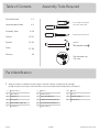 2
2
-
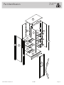 3
3
-
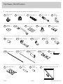 4
4
-
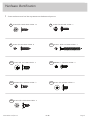 5
5
-
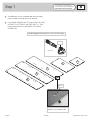 6
6
-
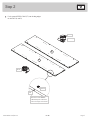 7
7
-
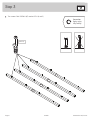 8
8
-
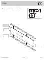 9
9
-
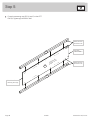 10
10
-
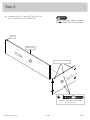 11
11
-
 12
12
-
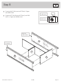 13
13
-
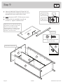 14
14
-
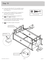 15
15
-
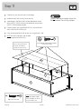 16
16
-
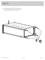 17
17
-
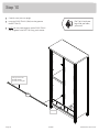 18
18
-
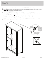 19
19
-
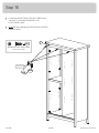 20
20
-
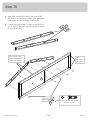 21
21
-
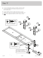 22
22
-
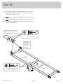 23
23
-
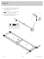 24
24
-
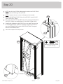 25
25
-
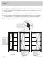 26
26
-
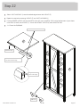 27
27
-
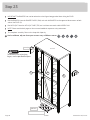 28
28
-
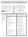 29
29
-
 30
30
-
 31
31
-
 32
32
-
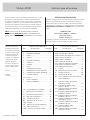 33
33
-
 34
34
-
 35
35
-
 36
36
-
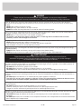 37
37
-
 38
38
-
 39
39
-
 40
40


Sauder 421191 Instrucciones de operación
- Tipo
- Instrucciones de operación
- Este manual también es adecuado para
en otros idiomas
- français: Sauder 421191 Mode d'emploi
- English: Sauder 421191 Operating instructions
Artículos relacionados
-
Sauder Storage Organizer 422647 Instrucciones de operación
-
-
-
-
-
-
-
-
-