
sauder.com
Lift-Top Co ee Table
Model 421952
NOTE: THIS INSTRUCTION
BOOKLET CONTAINS IMPORTANT
SAFETY INFORMATION.
PLEASE READ AND KEEP FOR
FUTURE REFERENCE.
English pg 1-23
Français pg 24-26
Español pg 27-29
Lot # 531007 06/25/19
Purchased: __________________
sauder.com
CONTACT US FIRST
BEFORE MAKING ANY RETURNS TO THE STORE.
Share your journey!
sauder.com
CONTACT US FIRST
BEFORE MAKING ANY RETURNS TO THE STORE.
Visit sauder.com/service to order replacement parts, view video assembly tips, or chat with a live rep.
Prefer the phone? Give us a ring at
1-800-523-3987.
Customer Service is available Monday-Friday - 9 a.m. to 5:30 p.m. EST (except holidays)
Guaranteed to hold
other beverages, too.

Table of Contents Assembly Tools Required
3
4
5-23
24-26
27-29
30
31
Part Identifi cation
Hardware Identifi cation
Assembly Steps
Français
Español
Safety
Warranty
Hammer
Not actual size
No. 2 Phillips Screwdriver
Tip Shown Actual Size
Skip the power trip.
This time.
421952 www.sauder.com/servicePage 2
Short Screwdriver
Adjustable Wrench

Part Identifi cation
å While not all parts are labeled, some of the parts will have a label or an inked letter on the edge
to help distinguish similar parts from each other. Use this part identifi cation to help identify similar parts.
A RIGHT END (1)
B LEFT END (1)
C BACK PANEL (1)
D SHELF (1)
E BOTTOM (1)
F RIGHT FRONT/LEFT REAR LEG (2)
G LEFT FRONT/RIGHT REAR LEG (2)
H LONG SKIRT (2)
I SHORT SKIRT (2)
J STRETCHER (1)
K FRONT PANEL (1)
L TOP (1)
Now you know
our ABCs.
421952www.sauder.com/service
Page 3
A
B
C
D
E
F
G
H
I
J
K
L
G
F
I
H

Hardware Identifi cation
å Screws are shown actual size. You may receive extra hardware with your unit.
421952 www.sauder.com/servicePage 4
23M
LIFT TABLE
MECHANISM SET - 1
SUPPORT
BRACKET - 2
37G
PULL - 2
149K
HIDDEN
CAM - 24
1F
CAM DOWEL - 4
2F
7F
TWIST-LOCK
®
FASTENER - 4
CAM SCREW - 20
8F
METAL
BRACKET - 12
4G
BUMPER - 6
2M
WASHER - 10
13M
NUT - 8
24M
BUSHING - 2
91M
BLACK 9/16" LARGE HEAD SCREW - 40
1S
SILVER 1/2" MACHINE SCREW - 4
38S
BLACK 3/4" PAN HEAD SCREW - 2
85S
BLACK 3/4" MACHINE SCREW - 4
92S
BLACK 1-1/4" MACHINE SCREW - 4
93S
APPLIQUE CARD - 4
79P
TACK GLIDE - 4
13E

Step 1
Look for this icon. It means a
video assembly tip is available at
www.sauder.com/service/tips
å
Assemble your unit on a carpeted fl oor or on the
empty carton to avoid scratching your unit or the fl oor.
å
To begin assembly, push a SAUDER TWIST-LOCK®
FASTENER (7F) into the large holes in the BACK
PANEL (C) and FRONT PANEL (K).
421952www.sauder.com/service
Page 5
Do not tighten the TWIST-LOCK® FASTENERS in this step.
7F
7F
C
K

Step 2
å
Push four HIDDEN CAMS (1F) into the SHELF (D). Then,
insert the metal end of a CAM DOWEL (2F) into each
HIDDEN CAM.
421952 www.sauder.com/servicePage 6
Insert the metal end of the CAM
DOWEL into the HIDDEN CAM.
Arrow
Arrow
1F
2F
(4 used)
Do not tighten the HIDDEN CAMS in this step.
D
Surface with holes
on the short edges

å
Push twenty HIDDEN CAMS (1F) into the ENDS (A and B),
BOTTOM (E), and PANELS (C and K).
Step 3
421952www.sauder.com/service
Page 7
A
B
C
E
K
Arrow
The arrow in the HIDDEN
CAM must point toward the
hole in the edge of the board.
Hole
1F
Arrow
(20 used)
Arrow
1F
Just think. The sooner
you do this, the sooner
you do something else.

Step 4
å
Turn twenty CAM SCREWS (8F) into the LEGS (F and G).
421952 www.sauder.com/servicePage 8
F
G
F
G
8F
8F
(20 used)

å
Fasten the RIGHT END (A) to the LEGS (F and G). Tighten
four HIDDEN CAMS.
å
NOTE: Be sure to position the LEGS exactly as shown.
Step 5
421952www.sauder.com/service
Page 9
1
2
A
F
G
These holes must be here.
These small holes should
be closer to this edge.

Step 6
å
Fasten the LEFT END (B) to the LEGS (F and G). Tighten
four HIDDEN CAMS.
å
NOTE: Be sure to position the LEGS exactly as shown.
421952 www.sauder.com/servicePage 10
F
G
B
These holes must be here.
These small holes should
be closer to this edge.

å
Fasten the PANELS (C and K) to the SHELF (D). Tighten
four TWIST-LOCK® FASTENERS.
Step 7
421952www.sauder.com/service
Page 11
How to use the SAUDER TWIST-LOCK® FASTENER
1. Insert the dowel end of the FASTENER into the
hole of the adjoining part.
NOTE: The dowel end of the FASTENER must
remain fully inserted in the hole of the adjoining
part while locking the FASTENER.
2. Tighten the FASTENER with a Phillips
screwdriver as tight as possible.
Dowel end
Surface with
TWIST-LOCK®
FASTENERS
D
C
Surface without
HIDDEN CAMS
Surface with groove
K

Step 8
å
Fasten the SHELF (D) and PANELS (C and K) to the
RIGHT END (A) and LEGS (F and G). Tighten six
HIDDEN CAMS.
421952 www.sauder.com/servicePage 12
Start Tighten
Arrow
Minimum
190 degrees
Caution
Risk of damage or
injury. HIDDEN CAMS
must be completely
tightened. HIDDEN
CAMS that are not
completely tightened
may loosen, and parts
may separate. To
completely tighten:
Arrow
Maximum
210 degrees
F
G
A
D
C
K
These holes are closer to this leg.
This PANEL has a groove.
Surface with
HIDDEN CAMS

å
Fasten the BOTTOM (E) to the LEGS (F and G). Tighten
two HIDDEN CAMS.
Step 9
421952www.sauder.com/service
Page 13
F
G
E
Surface with
HIDDEN CAMS

Step 10
å
Fasten the LEFT END (B) and LEGS (F and G) to the
SHELF (D), BOTTOM (E), and PANELS (C and K). Tighten
eight HIDDEN CAMS.
å
NOTE: Use the Short Screwdriver to tighten the HIDDEN
CAMS in the SHELF.
421952 www.sauder.com/servicePage 14
D
C
K
F
G
B
E
Now might be a
good time to refresh
your drink.

å
Fasten twelve METAL BRACKETS (4G) to the BOTTOM (E).
Use twelve BLACK 9/16" LARGE HEAD SCREWS (1S).
å
NOTE: Be sure four of the BRACKETS are even with the
SHORT edges of the BOTTOM.
å
Fasten the SKIRTS (H and I) to the BOTTOM (E). Use twelve
BLACK 9/16" LARGE HEAD SCREWS (1S) through the
BRACKETS and into the SKIRTS.
å
NOTE: There are no pre-drilled holes in the SKIRTS. The
SCREWS will tighten into the grooves.
Step 11
421952www.sauder.com/service
Page 15
BLACK 9/16" LARGE HEAD SCREW
(24 used in this step)
1S
4G
4G
4G
4G
E
I
H
H
I
The groove
is closer to
this edge.
The groove
is closer to
this edge.
(12 used)

Step 12
å
Using your hammer, gently tap four TACK GLIDES (13E)
into the bottoms of the LEGS (F and G).
421952 www.sauder.com/servicePage 16
F
G
F
G
13E

å
Carefully stand your unit upright.
å
Push six BUMPERS (2M) into the PANELS (C and K)
and LEGS (F and G).
å
Fasten the PULLS (149K) to the FRONT PANEL (K). Use
four SILVER 1/2" MACHINE SCREWS (38S).
Step 13
421952www.sauder.com/service
Page 17
F
G
F
G
C
K
2M
149K
SILVER 1/2" MACHINE SCREW
(4 used for the PULLS)
38S

Step 14
å
Fasten the LIFT TABLE MECHANISMS (23M) to the TOP (L).
Use six BLACK 9/16" LARGE HEAD SCREWS (1S).
å
NOTE: Be sure to position the LIFT TABLE MECHANISMS on
the TOP exactly as shown.
421952 www.sauder.com/servicePage 18
L
Surface with holes
23M
23M
BLACK 9/16" LARGE HEAD SCREW
(6 used in this step)
1S
This hole
must be here.
Meet Part (L). This component has
been engineered to be lighter, stronger,
faster… well ok. Not technically faster. But
defi nitely makes for a sturdier Lift-Top
Co ee Table that’s easier to assemble
and friendlier to the environment.

å
Fasten the SUPPORT BRACKETS (37G) to the LIFT
TABLE MECHANISMS (23M). Use four WASHERS (13M),
NUTS (24M), and BLACK 3/4" MACHINE SCREWS (92S).
å
NOTE: Use the adjustable wrench in this step.
Step 15
421952www.sauder.com/service
Page 19
37G
37G
23M
23M
BLACK 3/4" MACHINE SCREW
(4 used in this step)
92S
13M
24M
13M
24M
92S
92S

Step 16
421952 www.sauder.com/servicePage 20
å
IMPORTANT: You will need someone's help in this step.
å
Fasten the TOP (L) to the ENDS (A and B). Use ten BLACK 9/16" LARGE HEAD SCREWS (1S) through the LIFT TABLE
MECHANISMS (23M) and into the holes in the ENDS.
å
NOTE: Be careful when lining up the holes in the MECHANISMS with the holes in the ENDS as to not damage any parts.
You should start each SCREW a few turns before completely tightening any of them.
23M
23M
B
A
BLACK 9/16" LARGE HEAD SCREW
(10 used in this step)
1S
These four holes
must be here.
L
This hole will be used
in the next step.
This hole will be used
in the next step.

å
Finish, fastening the TOP (L) to the ENDS (A and B). Use
two BUSHINGS (91M), WASHERS (13M), and BLACK
3/4" PAN HEAD SCREWS (85S) through the exact holes
shown in the LIFT TABLE MECHANISMS (23M) and into
the holes in the ENDS.
å
NOTE: Do not overtighten the SCREWS (85S).
Step 17
421952www.sauder.com/service
Page 21
If you're doing this to
help a friend, don't
leave without a bite.
23M
23M
L
Do not overtighten
the SCREWS (85S).
A
B
91M
91M
13M
13M
BLACK 3/4" PAN HEAD SCREW
(2 used for the BUSHINGS)
85S

Step 18
421952 www.sauder.com/servicePage 22
å
Fasten the STRETCHER (J) to the SUPPORT BRACKETS (37G) on
the LIFT TABLE MECHANISMS (23M). Use four WASHERS (13M),
NUTS (24M), and BLACK 1-1/4" MACHINE SCREWS (93S).
å
NOTE: Use the adjustable wrench in this step.
23M
23M
J
13M
37G
37G
BLACK 1-1/4" MACHINE SCREW
(4 used in this step)
93S
24M
13M
24M
93S

Step 19
421952www.sauder.com/service
Page 23
å
IMPORTANT: Do not place valuables in the storage space.
å
Peel APPLIQUES from the APPLIQUE CARD (79P) and stick them onto each visible HIDDEN CAM.
å
NOTE: Please read the back pages of the instruction booklet for important safety information.
å
This completes assembly. Clean with a damp cloth. Wipe dry.
To cover HIDDEN CAMS
(20 used)
40 lbs.
25 lbs.
40 lbs.
79P
And to celebrate, why not share your success story at Walmart.com or

A l’usage exclusif du
Canada Noter la date
d’achat de cet élément
et conserver le livret
pour future référence.
Pour contacter Sauder
en ce qui concerne cet
élément, faire référence
au numéro de lot et
numéro de modèle en
appelant notre numéro
sans frais.
Lot nº : ____________
Date de
l’achat: ____________
LISTE DE PIÈCES
REFERENCE DESCRIPTION QUANTITÉ
LISTE DE PIÈCES
REFERENCE DESCRIPTION QUANTITÉ
NOUS SOMMES LA POUR VOUS AIDER!
Nous faisons de notre mieux pour nous assurer que votre meuble
arrive dans d’excellentes conditions. Nos représentants du service
Clientèle sont aimables et prêts à vous aider au cas où une pièce
aurait été endommagée ou manquerait (ou si vous aviez besoin
d’aide pour l’assemblage). NE RAMENEZ PAS LE MEUBLE AU
MAGASIN. Au Canada, composez ce numéro d’appel gratuit:
1-800-523-3987
Du lundi au vendredi, de 9 heures du matin à
5:30 heures du soir (horaire Côte Est)
(sauf jours fériés)
Si une pièce a besoin d’être remplacée, la pièce de remplacement
sera envoyée dans les 48 heures. (Sauf week-ends et jours fériés)
Utilisez les instructions d’assemblage en français avec les
schémas étape par étape du manuel d’instruction en anglais.
Chaque étape en français correspond à la même étape
en anglais. La pièce devant être attachée à l’élément est
représentée en gris sur les schémas de chaque étape pour plus
de précision. Comparer la “Liste de pièces” ci-dessous avec
la “PART IDENTIFICATION” du manuel en anglais pour vous
familiariser avec les pièces avant l’assemblage.
REMARQUE : CE MANUEL D’INSTRUCTIONS CONTIENT
D’IMPORTANTES INFORMATIONS RELATIVES À LA SÉCURITÉ.
À LIRE ET CONSERVER POUR TOUTE RÉFÉRENCE FUTURE.
Table basse à dessus relevableModèle 421952
13E PATIN .....................................................................................4
1F EXCENTRIQUE ESCAMOTABLE ..................24
2F CHEVILLE D'EXCENTRIQUE ..............................4
7F FIXATION TWIST-LOCK® .......................................4
8F VIS D'EXCENTRIQUE ...........................................20
4G CONSOLE EN MÉTAL ...........................................12
37G CONSOLE DE SUPPORT ......................................2
149K POIGNÉE ............................................................................2
2M TAMPON ............................................................................6
13M RONDELLE ....................................................................10
23M ENSEMBLE DE MÉCANISMES DE
LEVAGE DE TABLE ......................................................1
24M ÉCROU ................................................................................8
91M MANCHON .......................................................................2
79P FICHE D'APPLIQUÉS ...............................................4
1S VIS TÊTE LARGE 14 mm NOIRE .................40
38S VIS À MÉTAUX 13 mm ARGENTÉE ..............4
85S VIS TÊTE GOUTTE DE
SUIF 19 mm NOIRE ...................................................2
92S VIS À MÉTAUX 19 mm NOIRE ..........................4
93S VIS À MÉTAUX 32 mm NOIRE .........................4
A EXTRÉMITÉ DROITE ..................................................1
B EXTRÉMITÉ GAUCHE ...............................................1
C PANNEAU ARRIÈRE ....................................................1
D TABLETTE ..........................................................................1
E DESSOUS ...........................................................................1
F PIED AVANT DROIT/ARRIÈRE GAUCHE ..2
G PIED AVANT GAUCHE/ARRIÈRE DROIT ..2
H PLINTHE LONGUE .....................................................2
I PLINTHE COURTE .....................................................2
J BARRE ...................................................................................1
K PANNEAU AVANT ........................................................1
L DESSUS ...............................................................................1
421952 www.sauder.com/servicePage 24

ÉTAPE 1
Ne pas serrer les FIXATIONS TWIST-LOCK® à cette étape.
Assembler l'élément sur un sol à moquette ou sur le carton vide
pour éviter d'endommager l'élément ou le sol.
Pour commencer l'assemblage, enfoncer une FIXATION
TWIST-LOCK® SAUDER (7F) dans les gros trous dans le
PANNEAU ARRIÈRE (C) et le PANNEAU AVANT (K).
ÉTAPE 2
Ne pas serrer les EXCENTRIQUES ESCAMOTABLES dans
cette étape.
Enfoncer quatre EXCENTRIQUES ESCAMOTABLES (1F)
dans la TABLETTE (D). Ensuite, insérer l'extrémité en métal
de la CHEVILLE D'EXCENTRIQUE (2F) dans chaque
EXCENTRIQUE ESCAMOTABLE.
ÉTAPE 7
Fixer les PANNEAUX (C et K) à la TABLETTE (D). Serrer quatre
FIXATIONS TWIST-LOCK®.
Utilisation de la FIXATION TWIST-LOCK® SAUDER
1. Insérer l'extrémité fi letée de la FIXATION dans le trou de la
pièce attenante.
REMARQUE : L'extrémité fi letée de la FIXATION doit rester
complètement insérée dans le trou de la pièce attenante lorsque
l'on bloque la FIXATION.
2. Bien serrer la FIXATION à l'aide d'un tournevis Phillips.
ÉTAPE 3
Enfoncer vingt EXCENTRIQUES ESCAMOTABLES (1F) dans les
EXTRÉMITÉS (A et B), le DESSOUS (E) et les PANNEAUX (C et K).
ÉTAPE 8
Fixer la TABLETTE (D) et les PANNEAUX (C et K) à
l'EXTRÉMITÉ DROITE (A) et aux PIEDS (F et G). Serrer six
EXCENTRIQUES ESCAMOTABLES.
Attention: Risque des dégâts ou blessures. Les Excentriques
Escamotables doivent être serrés à bloc. Les Excentriques
Escamotables que ne sont pas serrées à bloc peuvent desserrer
et les pièces peuvent séparer. Pour serrer à bloc, faire tourner
l'excentrique escamotable de 210 degrés.
ÉTAPE 4
Faire tourner vingt VIS D'EXCENTRIQUE (8F) dans
les PIEDS (F et G).
ÉTAPE 9
Fixer le DESSOUS (E) aux PIEDS (F et G). Serrer deux
EXCENTRIQUES ESCAMOTABLES.
421952www.sauder.com/service
Page 25
ÉTAPE 5
Fixer l'EXTRÉMITÉ DROITE (A) aux PIEDS (F et G). Serrer quatre
EXCENTRIQUES ESCAMOTABLES.
REMARQUE : S’assurer que les PIEDS sont positionnées
exactement comme il l’est indiqué.
ÉTAPE 10
Fixer l'EXTRÉMITÉ GAUCHE (B) et les PIEDS (F et G) à la
TABLETTE (D), au DESSOUS (E) et aux PANNEAUX (C et K).
Serrer huit EXCENTRIQUES ESCAMOTABLES.
REMARQUE : Utiliser le tournevis court pour serrer les
EXCENTRIQUES ESCAMOTABLES dans la TABLETTE.
ÉTAPE 6
Fixer l'EXTRÉMITÉ GAUCHE (B) aux PIEDS (F et G). Serrer quatre
EXCENTRIQUES ESCAMOTABLES.
REMARQUE : S’assurer que les PIEDS sont positionnées
exactement comme il l’est indiqué.

ÉTAPE 11
Fixer douze CONSOLES EN MÉTAL (4G) au DESSOUS (E). Utiliser
douze VIS TÊTE LARGE 14 mm NOIRES (1S).
REMARQUE : S'assurer que quatre des CONSOLES sont à fl eur
des chants COURTS du DESSOUS.
Fixer les PLINTHES (H et I) au DESSOUS (E). Utiliser douze VIS
TÊTE LARGE 14 mm NOIRES (1S) à travers les CONSOLES et
dans les PLINTHES.
REMARQUE : Les PLINTHES ne comportent pas de trous pré-
percés. Serrer les VIS dans les rainures.
ÉTAPE 12
À l'aide d'un marteau, légèrement enfoncer quatre PATINS (13E)
dans les dessous des PIEDS (F et G).
ÉTAPE 16
IMPORTANT : Faire appel à une autre personne pour cette étape.
Fixer le DESSUS (L) aux EXTRÉMITÉS (A et B). Utiliser dix VIS
TÊTE LARGE 14 mm NOIRES (1S) à travers les MÉCANISMES DE
LEVAGE DE TABLE (23M) et dans les trous des EXTRÉMITÉS.
REMARQUE : Faire attention en alignant les trous dans les
MÉCANISMES sur les trous des EXTRÉMITÉS de manière à ne
pas endommager les pièces. Il est préférable de donner quelques
tours de tournevis à chaque VIS avant de les serrer toutes à bloc.
ÉTAPE 17
Finir de fi xer le DESSUS (L) aux EXTRÉMITÉS (A et B). Utiliser
deux MANCHONS (91M), RONDELLES (13M) et deux VIS TÊTE
GOUTTE DE SUIF 19 mm NOIRES (85S) à travers les trous
exacts illustrés des MÉCANISMES DE LEVAGE DE TABLE (23M)
et dans les trous des EXTRÉMITÉS.
REMARQUE : Ne pas trop serrer les VIS (85S).
ÉTAPE 13
Relever, avec précaution, l'élément dans sa position verticale.
Enfoncer six TAMPONS (2M) dans les PANNEAUX (C et K) et
les PIEDS (F et G).
Fixer les POIGNÉES (149K) au PANNEAU AVANT (K). Utiliser
quatre VIS À MÉTAUX 13 mm ARGENTÉES (38S).
ÉTAPE 18
Fixer la BARRE (J) sur les CONSOLES DE SUPPORT (37G)
sur les MÉCANISMES DE LEVAGE DE TABLE (23M). Utiliser
quatre RONDELLES (13M), ÉCROUS (24M) et VIS À
MÉTAUX 32 mm NOIRES (92S).
REMARQUE : Utiliser la clé réglable dans cette étape.
ÉTAPE 14
Fixer les MÉCANISMES DE LEVAGE DE TABLE (23M) sur le
DESSUS (L). Utiliser six VIS TÊTE LARGE 14 mm NOIRES (1S).
REMARQUE : S’assurer de positionner les MÉCANISMES DE
LEVAGE DE TABLE sur le DESSUS exactement comme il
l’est indiqué.
ÉTAPE 19
IMPORTANT : Ne pas placer d’objet de valeur dans l’espace rangement.
Décoller les AUTO-COLLANTS de la FICHE D'APPLIQUÉS (79P)
et coller
sur chaque EXCENTRIQUE ESCAMOTABLE visible.
REMARQUE : Prière de lire les informations importantes sur la
sécurité fi gurant sur les pages arrière du manuel d’instructions.
Ceci complète l'assemblage.
Nettoyer avec un tissu humide. Essuyer.
421952 www.sauder.com/servicePage 26
ÉTAPE 15
Fixer les CONSOLES DE SUPPORT (37G) sur les MÉCANISMES
DE LEVAGE DE TABLE (23M). Utiliser quatre RONDELLES (13M),
ÉCROUS (24M) et VIS À MÉTAUX 19 mm NOIRES (92S).
REMARQUE : Utiliser la clé réglable dans cette étape.

Para uso exclusivo de
Canadá Anote la fecha
de comprar esta unidad
y guarde el folleto para
su referencia futura. Si
necesita ponerse en
contacto con Sauder en
cuanto a esta unidad,
refi érase al número
de lote y al número de
modelo cuando llame a
nuestro número gratis.
No. lote: ____________
Fecha de
compra: ____________
13E TACHUELA DESLIZANTE .....................................4
1F EXCÉNTRICO ESCONDIDO ............................24
2F PASADOR DE EXCÉNTRICO ..............................4
7F SUJETADOR TWIST-LOCK®. ...............................4
8F BIELA DE EXCÉNTRICO ....................................20
4G SOPORTE DE METAL ............................................12
37G SOPORTE ..........................................................................2
149K TIRADOR ............................................................................2
2M TOPE .....................................................................................6
13M ARANDELA ....................................................................10
23M JUEGO DE MECANISMO DE
ELEVACIÓN DE MESA .............................................1
24M TUERCA ..............................................................................8
91M FORRO.................................................................................2
79P TARJETA CON APLICACIONES ......................4
1S TORNILLO NEGRO DE CABEZA
GRANDE de 14 mm ...............................................40
38S TORNILLO PLATEADO PARA
METAL de 13 mm ........................................................4
85S TORNILLO NEGRO DE CABEZA
REDONDA de 19 mm ...............................................2
92S TORNILLO NEGRO PARA METAL
de 19 mm ...........................................................................4
93S TORNILLO NEGRO PARA METAL
de 32 mm ..........................................................................4
A EXTREMO DERECHO ...............................................1
B EXTREMO IZQUIERDO ............................................1
C PANEL POSTERIOR ....................................................1
D ESTANTE .............................................................................1
E FONDO .................................................................................1
F PATA DERECHA DELANTERA/PATA
IZQUIERDA POSTERIOR .......................................2
G PATA IZQUIERDA DELANTERA/PATA
DERECHA POSTERIOR ..........................................2
H FALDÓN LARGO .........................................................2
I FALDÓN CORTO .........................................................2
J BASTIDOR .........................................................................1
K PANEL DELANTERO ..................................................1
L PANEL SUPERIOR .......................................................1
LISTA DE PARTES
ITEM DESCRIPCIÓN CANTIDAD
ESTAMOS AQUI PARA AYUDAR!
Tratamos de asegurar que su mueble llega en condición excelente.
Nuestros representantes de Servicio al Cliente son amables y
listos para ayudarle con servicio rápido y efi ciente si una parte
está defectuosa o ausente (o si necesita ayuda con el ensamblaje).
NO DEVUELVA LA UNIDAD A LA TIENDA. Llame este número sin
cargo:
1-800-523-3987
Lunes a viernes, 9:00 a.m. - 5:30 p.m.
Hora ofi cial del Este
(excepto días festivos)
Si requiere un repuesto de una parte, será enviado dentro de
48 horas (excepto los fi nes de semana y días festivos)
Use estas instrucciones de ensamblaje en español junto con las
fi guras paso-a-paso provistas en el folleto inglés. Cada paso
en español corresponde al mismo paso en inglés. Se destacan
las fi guras de cada paso con una tonalidad oscura para mostrar
precisamente cual parte se debe montar a la unidad. Compare
la “Lista de Part” abajo con la “Part Identifi cation” en el folleto en
inglés para familiarizarse con Las partes de ensamblaje.
NOTA: ESTE FOLLETO DE INSTRUCCIONES CONTIENE
INFORMACIÓN IMPORTANTE SOBRE LA SEGURIDAD. POR
FAVOR LEA Y GUÁRDELO PARA REFERENCIA EN EL FUTURO.
LISTA DE PARTES
ITEM DESCRIPCIÓN CANTIDAD
Mesita para café con tapa superiorModelo 421952
421952www.sauder.com/service
Page 27

421952 www.sauder.com/servicePage 28
PASO 1
No apriete los SUJETADORES TWIST-LOCK® en este paso.
Ensamble la unidad sobre un piso alfombrado o sobre el cartón
vacío para evitar rayar la unidad o el piso.
Para comenzar el ensamblaje, empuje un SUJETADOR
TWIST-LOCK® SAUDER (7F) dentro de los agujeros grandes
del PANEL POSTERIOR (C) y el PANEL DELANTERO (K).
PASO 2
No apriete los EXCÉNTRICOS ESCONDIDOS en este paso.
Empuje cuatro EXCÉNTRICOS ESCONDIDOS (1F) en el
ESTANTE (D). A continuación, inserte el extremo de metal
de un PASADOR DE EXCÉNTRICO (2F) dentro de cada
EXCÉNTRICO ESCONDIDO.
PASO 7
Fije los PANELES (C y K) al ESTANTE (D). Apriete cuatro
SUJETADORES TWIST-LOCK®.
Cómo utilizar el SUJETADOR TWIST-LOCK® SAUDER
1. Inserte el extremo con cabilla del SUJETADOR en el agujero de
la parte adjunta.
NOTA: El extremo con cabilla del SUJETADOR debe quedarse
completamente insertado en el agujero de la parte adjunta
cuando se enclava el SUJETADOR.
2. Apriete el SUJETADOR lo más apretado posible con un
destornillador Phillips (cruz).
PASO 3
Empuje veinte EXCÉNTRICOS ESCONDIDOS (1F) dentro de los
EXTREMOS (A y B), del FONDO (E) y de los PANELES (C y K).
PASO 8
Fije el ESTANTE (D) y los PANELES (C y K) al EXTREMO
DERECHO (A) y a las PATAS (F y G). Apriete seis
EXCÉNTRICOS ESCONDIDOS.
Precaución: Riesgo de daños o heridas. Los Excéntricos
Escondidos deben apretarse completamente. Los Excéntricos
Escondidos que no se aprieten completamente se afl ojarán y las
partes pueden separarse. Para apretar completamente, atornille el
excéntrico escondido 210 grados.
PASO 4
Atornille veinte BIELAS DE EXCÉNTRICO (8F) dentro de
las PATAS (F y G).
PASO 9
Fije el FONDO (E) a las PATAS (F y G). Apriete dos
EXCÉNTRICOS ESCONDIDOS.
PASO 5
Fije el EXTREMO DERECHO (A) a las PATAS (F y G). Apriete
cuatro EXCÉNTRICOS ESCONDIDOS.
NOTA: Asegúrese de que las PATAS están dispuestas
exactamente como se muestra.
PASO 10
Fije el EXTREMO IZQUIERDO (B) y las PATAS (F y G) al
ESTANTE (D), FONDO (E) y a los PANELES (C y K). Apriete ocho
EXCÉNTRICOS ESCONDIDOS.
NOTA: Utilice el destornillador corto para apretar los
EXCÉNTRICOS ESCONDIDOS en el ESTANTE.
PASO 6
Fije el EXTREMO IZQUIERDO (B) a las PATAS (F y G). Apriete
cuatro EXCÉNTRICOS ESCONDIDOS.
NOTA: Asegúrese de que las PATAS están dispuestas
exactamente como se muestra.

421952www.sauder.com/service
Page 29
PASO 11
Fije doce SOPORTES DE METAL (4G) al FONDO (E). Utilice doce
TORNILLOS NEGROS DE CABEZA GRANDE de 14 mm (1S).
NOTA: Asegúrese que cuatro de los SOPORTES estén nivelados
con los bordes CORTOS del FONDO.
Fije los FALDONES (H e I) al FONDO (E). Pase doce TORNILLOS
NEGROS DE CABEZA GRANDE de 14 mm (1S) a través de los
SOPORTES y en los FALDONES.
NOTA: No hay agujeros perforados en los FALDONES. Los
TORNILLOS apretarán dentro de las ranuras.
PASO 12
Con un martillo, suavemente introduzca golpeando cuatro
TACHUELAS DESLIZANTES (13E) en las partes inferiores de
las PATAS (F y G).
PASO 16
IMPORTANTE: Necesitar la ayuda de otra persona para este paso.
Fije el PANEL SUPERIOR (L) a los EXTREMOS (A y B). Utilice diez
TORNILLOS NEGROS DE CABEZA GRANDE de 14 mm (1S) a
través de los MECANISMOS DE ELEVACIÓN DE LA MESA (23M)
y en los agujeros de los EXTREMOS.
NOTA: Tenga cuidado al alinear los agujeros de los MECANISMOS
con los agujeros en los EXTREMOS para no dañar ninguna pieza.
Debe apretar cada TORNILLO unas vueltas antes de apretar
cualquier tornillo fi rmemente.
PASO 17
Termine de fi jar el PANEL SUPERIOR (L) a los EXTREMOS (A y B).
Utilice dos FORROS (91M), ARANDELAS (13M) y dos TORNILLOS
NEGROS DE CABEZA REDONDA de 19 mm (85S) a través de los
agujeros correspondientes indicados de los MECANISMOS DE
ELEVACIÓN DE LA MESA (23M) y en los agujeros de los EXTREMOS.
NOTA: No apriete los TORNILLOS (85S) en exceso.
PASO 13
Cuidadosamente ponga la unidad en posición vertical.
Empuje seis TOPES (2M) en los PANELES (C y K) y en
las PATAS (F y G).
Fije los TIRADORES (149K) al PANEL DELANTERO (K). Utilice
cuatro TORNILLOS PLATEADOS DE METAL de 13 mm (38S).
PASO 18
Fije el BASTIDOR (J) a los SOPORTES DE APOYO (37G) sobre
los MECANISMOS DE ELEVACIÓN DE LA MESA (23M). Utilice
cuatro ARANDELAS (13M), PERNOS (24M) y TORNILLOS
NEGROS PARA METAL de 32 mm (93S).
NOTA : Utilice la llave ajustable en este paso.
PASO 14
Fije los MECANISMOS DE ELEVACIÓN DE LA MESA (23M)
al PANEL SUPERIOR (L). Utilice seis TORNILLOS NEGROS DE
CABEZA GRANDE de 14 mm (1S).
NOTA: Asegúrese de colocar los MECANISMOS DE
ELEVACIÓN DE LA MESA al PANEL SUPERIOR exactamente
como se muestra.
PASO 19
IMPORTANTE: No coloque objetos de valor en el espacio
de almacenamiento.
Separe las APLICACIONES de la TARJETA CON APLICACIONES (79P)
y aplique las sobre cada EXCÉNTRICO ESCONDIDO visible.
NOTA: Por favor, lea las páginas de atrás del folleto de
instrucciones en cuanto a importante información de seguridad.
Esto completa el ensamblaje. Limpiar con un trapo húmedo.
Seque con un paño.
PASO 15
Fije los SOPORTES DE APOYO (37G) a los MECANISMOS
DE ELEVACIÓN DE LA MESA (23M). Utilice cuatro
ARANDELAS (13M), PERNOS (24M) y TORNILLOS
NEGROS PARA METAL de 19 mm (92S).
NOTA : Utilice la llave ajustable en este paso.

421952 www.sauder.com/servicePage 30
WARNING
Please use your furniture correctly and safely. Improper use can cause safety hazards,
or damage to your furniture or household items. Carefully read the following chart.
Look out for: What can happen: How to avoid the problem:
• Overloaded drawers and shelves. • Risk of injury.
• Top-heavy furniture can tip over.
• Overloaded drawers or shelves can break.
• Never exceed the weight limits shown in
the instructions.
• Work from bottom to top when loading
shelves and drawers. Place the heavier
items on the lower shelves or in lower
drawers.
• Placing TVs on furniture items that are not
designed to support a television is
hazardous.
• Risk of injury or death. TVs can be very
heavy. Plus the weight and location of the
picture tube tends to make TVs unbalanced
and prone to tipping forward.
• This product is not designed to support a
television.
AVERTISSEMENT
Prière d’utiliser le mobilier à bon escient et avec prudence. Une mauvaise utilisation peut être à l’origine de risques
d’accident ou peut endommager le mobilier et les articles ménagers. Lire attentivement le tableau suivant.
À surveiller : Danger éventuel : Solution :
• Tiroirs et tablettes surchargées. • Risque de blessure.
• Du mobilier mal équilibré risque de se
renverser.
• Des tiroirs surchargés peuvent casser.
• Ne jamais excéder les limites de poids
indiquées dans les instructions.
• Commencer a charger les tablettes et
tiroirs à partir du bas et fi nir au haut. Placer
les objets les plus lourds sur les
tablettes inférieures ou dans les tiroirs
inférieurs.
• Il est dangereux de placer des téléviseurs
sur des meubles que ne sont pas prévus à
cet e et.
• Risque de blessures graves, voire
mortelles. Les téléviseurs peuvent être
particulièrement lourds. De plus, le poids et
l’emplacement du tube image ont tendance
à rendre les téléviseurs
instables et enclins à tomber vers l’avant.
• Ce produit n’est pas destiné à supporter
un téléviseur.
ADVERTENCIA
Por favor use el mobiliario correcta y seguramente. El mal uso puede causar riesgos de seguridad
o daño a las unidades o artículos domésticos. Cuidadosamente lea la tabla a continuación.
Esté alerto de: Puede ocurrir: Evitar el problema:
• Cajones y estantes sobrecargados. • Un riesgo de lesiones.
• El mobiliario inestable puede volcarse.
• Los cajones o estantes sobrecargados
pueden romperse.
• Nunca exceda los límites de peso
indicados en las instrucciones.
• Para cargar los estantes y cajones,
comience al fondo y termine en la parte
superior. Coloque los artículos más pesados
sobre los estantes inferiores o en los
cajones inferiores.
• Es peligroso colocar los televisores sobre
muebles que no están diseñados para
soportar un televisor.
• Un riesgo de lesiones o la muerte. Los
televisores pueden ser muy pesados.
Además, el peso y la ubicación del tubo de
imagen tienden a causar la inestabilidad
de televisores y son propensos a inclinarse
hacia adelante.
• Este producto no está diseñado para
soportar un televisor.

421952www.sauder.com/service
Page 31
1. Sauder Woodworking Co. (Sauder®) provee cobertura de garantía limitada al
comprador original de este producto por un período de un año, a partir de la fecha de
compra, contra defectos en los materiales o de mano de obra en los componentes de
muebles Sauder. Como es utilizado en esta Garantía, “defecto” signifi ca imperfecciones
en los componentes que de manera fundamental afecta la utilidad del producto. Esta
Garantía le permite a usted ciertos derechos legales, y usted también podría poseer
otros derechos adicionales, los cuales varían de estado a estado.
2. No hay cobertura de garantía para defectos o estados que resulten del
incumplimiento en seguir las instrucciones, la información o las advertencias sobre el
ensamblaje del producto; del uso incorrecto o maltrato, del daño intencional, incendio,
inundación, cambio o modifi cación del producto; o de la utilización del producto de
manera contradictoria con el uso para el cual fue fabricado, ni por ningún estado que
resulte del mantenimiento, limpieza o cuidado incorrecto o inadecuado. Tampoco no
hay cobertura de garantía para los productos rentados o para cualesquiera productos
comprados “de uso” o “como está”, en una venta de bienes embargados o en una
venta por salirse del negocio, o comprados a un liquidador.
3. Como un recurso exclusivo bajo esta Garantía, Sauder (sólo a su opción) reparará,
reemplazará o reembolsará el valor de cualquier componente defectuoso de mueble.
Sauder puede requerir una confi rmación independiente de un defecto reclamado y una
prueba de compra. Las piezas de repuesto serán garantizadas solamente por el período
de tiempo que queda de la Garantía original. SAUDER NO TENDRÁ RESPONSABILIDAD
por NINGÚN DAÑO INCIDENTAL O CONSECUENTE DE NINGÚN TIPO y todos dichos
daños SE EXCLUYEN DE ESTA GARANTÍA, tales como pérdida de uso, desensamblaje,
transportación, trabajo o daño a la propiedad en o cerca del producto. Algunos estados
no permiten la exclusión o limitación de daños incidentales o consecuentes, en tales
instancias la limitación o exclusión antes mencionada podría no ser aplicable a usted.
4. Esta Garantía sólo es aplicable a defectos garantizados que primeramente surjan
y se informen a Sauder dentro del período de cobertura de garantía. La Garantía
no puede ser transferida a propietarios o usuarios subsiguientes del producto, y
ésta será inmediatamente invalidada en el caso que el producto sea revendido,
transferido, arrendado o rentado a cualquier tercero u otra persona que no sea el
comprador original.
5. NO HAY OTRA GARANTÍA APLICABLE A ESTE PRODUCTO. Bajo las leyes
de ciertos estados, pueden no haber garantías implícitas de Sauder y se hace
renuncia de responsabilidad de todas las garantías implícitas donde lo permita la
ley, INCLUYENDO CUALQUIER GARANTÍA IMPLÍCITA DE MERCANTIBILIDAD O
DE APTITUD PARA UN PROPÓSITO EN PARTICULAR. EN LA MEDIDA CUALQUIER
GARANTÍA IMPLÍCITA ES APLICABLE, CUALESQUIERA GARANTÍAS IMPLÍCITAS,
INCLUYENDO AQUELLA DE MERCANTIBILIDAD O DE APTITUD PARA UN
PROPÓSITO EN PARTICULAR, SE LIMITAN EN DURACIÓN HASTA LA DURACIÓN
DE ESTA GARANTÍA IMPLÍCITA o hasta el periodo mínimo permitido por la ley,
la que sea más corta. Algunos estados no permiten limitaciones en cuanto a la
duración de una garantía implícita, por eso la limitación arriba citada pueda no ser
aplicable a usted.
6. Para solicitud de información o reclamación de Garantía, por favor, visite nuestro
sitio Web www.sauder.com. Usted también puede contactar a Sauder llamando al
1.800.523.3987. Sauder puede solicitar que las reclamaciones sean presentadas por
escrito a: Sauder Woodworking Co., 502 Middle Street, Archbold, OH 43502 USA.
Por favor incluya su recibo de venta u otra prueba de compra y una descripción
detallada del defecto del producto.
GARANTÍA LIMITADA DE 1 AÑO
1. Sauder Woodworking Co. (Sauder®) o re une couverture de garantie limitée à l'acheteur
initial du présent produit pendant une période de un an à compter de la date d'achat
contre tout défaut de matériaux ou de fabrication des composantes de mobilier Sauder.
Le mot « défaut », tel qu’il est utilisé sous les termes de la présente garantie, comprend
les imperfections des pièces qui empêchent substantiellement l’utilisation du produit. La
présente garantie vous donne des droits légaux spécifi ques et il est possible que vous
ayez des droits supplémentaires variant d’État en État ou de province en province.
2. La présente garantie ne saurait couvrir les défauts ou conditions qui surviendraient
à la suite du non respect des instructions, informations ou mises en garde de
montage, d’une mauvaise utilisation ou d’un abus, d’un dommage intentionnel, d’un
incendie, d’une inondation, d’une altération ou modifi cation du produit, d’une utilisation
du produit allant à l’encontre de son usage prévu, ni aucune condition résultant d'une
maintenance, d'un nettoyage ou d'un entretien inappropriés ou inadéquats. De plus,
il n'existe aucune garantie pour les produits loués ou tous les produits achetés «
d'occasion » ou « en l'état », dans le cadre d'une vente aux enchères ou de solde
pour cessation de commerce, ou auprès d'un liquidateur.
3. En tant que recours exclusif en vertu de la présente garantie, Sauder réparera,
remplacera ou rembourser (sur sa seule décision) la valeur de toute composante de
mobilier défectueuse. Sauder peut exiger une confi rmation indépendante du défaut
revendiqué ainsi qu'une preuve d'achat. Les pièces de rechange seront garanties
uniquement pendant la période restante de la garantie originale. SAUDER NE SERA EN
AUCUN CAS RESPONSABLE de TOUT DOMMAGE ACCESSOIRE OU CONSÉCUTIF
DE TOUTE SORTE et lesdits dommages sont EXCLUS DE LA PRÉSENTE GARANTIE,
à savoir perte d'utilisation, démontage, transport, main d'œuvre ou dommages
matériels sur ou à proximité du produit. Certains États ou provinces ne permettant pas
l’exclusion ou la limite aux responsabilités pour dommages accidentels ou consécutifs,
la limite ou l’exclusion ci -dessus peut ne pas être applicable.
4. La présente garantie ne s'applique qu'aux défauts garantis qui se produisent pour
la première fois et qui sont signalés à Sauder dans les limites de couverture de la
garantie. La garantie ne peut pas être transférée à des propriétaires ou utilisateurs
subséquents du produit, et sera immédiatement invalidée dans le cas où le produit
est revendu, transféré, loué sous bail ou loué à une tierce partie ou personne autre
que l’acheteur original.
5. IL N'EXISTE AUCUNE AUTRE GARANTIE EN VIGUEUR POUR LE PRÉSENT
PRODUIT. En vertu des lois de certains États ou provinces, il ne peut y avoir
de garanties implicites de la part de Sauder et toutes les garanties implicites,
Y COMPRIS TOUTE GARANTIE IMPLICITE DE COMMERCIABILITÉ OU
D'ADAPTATION À UN USAGE PARTICULIER sont déclinées partout où la
loi l'autorise. DANS LA MESURE OÙ TOUTE GARANTIE IMPLICITE EST
APPLICABLE, TOUTE GARANTIE IMPLICITE, Y COMPRIS TOUTE GARANTIE
DE COMMERCIABILITÉ OU D'ADAPTATION À UN USAGE PARTICULIER, EST
LIMITÉE À LA DURÉE DE LA PRÉSENTE GARANTIE EXPRESSE ou à la période
minimum autorisée par la loi, la période la plus courte étant retenue. Certains États
ne permettant pas que des limites soient imposées quant à la durée d’une garantie
implicite, la limite ci-dessus peut donc ne pas être applicable.
6. Pour toute question concernant la garantie ou toute demande de réclamation,
consulter le site Web www.sauder.com. Il est également possible de contacter Sauder
en composant le 1.800.523.3987. Sauder peut exiger de soumettre les demandes de
réclamation sous garantie par écrit à : Sauder Woodworking Co., 502 Middle Street,
Archbold, OH 43502 USA. Veuillez joindre votre ticket de caisse ou toute autre
preuve d’achat ainsi qu’une description spécifi que du défaut de produit.
GARANTIE LIMITÉE DE 1 AN
1. Sauder Woodworking Co. (Sauder®) provides limited warranty coverage to the
original purchaser of this product for a period of one year from the date of purchase
against defects in materials or workmanship of Sauder furniture components.
As used in this Warranty, “defect” means imperfections in components which
substantially impair the utility of the product. This Warranty gives you specifi c legal
rights, and you may also have other rights which vary from state to state.
2. There is no warranty coverage for defects or conditions that result from the failure
to follow product assembly instructions, information or warnings, misuse or abuse,
intentional damage, fi re, fl ood, alteration or modifi cation of the product, or use of the
product in a manner inconsistent with its intended use, nor any condition resulting
from incorrect or inadequate maintenance, cleaning, or care. There is also no
warranty coverage for rented products or any products purchased “used” or “as is”, at
a distress or going-out-of business sale, or from a liquidator.
3. As the exclusive remedy under this Warranty, Sauder will (at its sole option) repair,
replace or refund the value of any defective furniture component. Sauder may require
independent confi rmation of the claimed defect and proof of purchase. Replacement
parts will be warranted for only the remaining period of the original Warranty. SAUDER
SHALL HAVE NO LIABILITY for ANY INCIDENTAL OR CONSEQUENTIAL DAMAGES
OF ANY KIND and all such damages are EXCLUDED FROM THIS WARRANTY, such
as loss of use, disassembly, transportation, labor or damage to property on or near
the product. Some states do not allow the exclusion or limitation of incidental or
consequential damages, so the above limitation or exclusion may not apply to you.
4. This Warranty applies only to warranted defects that fi rst arise and are reported to
Sauder within the warranty coverage period. The Warranty cannot be transferred to
subsequent owners or users of the product, and it shall be immediately void in the
event the product is resold, transferred, leased or rented to any third party or person
other than the original purchaser.
5. THERE ARE NO OTHER WARRANTIES APPLICABLE TO THIS PRODUCT. Under
the laws of certain states, there may be no implied warranties from Sauder and all
implied warranties, INCLUDING ANY IMPLIED WARRANTY OF MERCHANTABILITY
OR FITNESS FOR A PARTICULAR PURPOSE are disclaimed where allowed by law.
TO THE EXTENT ANY IMPLIED WARRANTIES ARE APPLICABLE, ANY IMPLIED
WARRANTIES, INCLUDING ANY IMPLIED WARRANTY OF MERCHANTABILITY OR
FITNESS FOR A PARTICULAR PURPOSE, ARE LIMITED IN DURATION TO THE
DURATION OF THIS EXPRESS WARRANTY or the minimum period allowed by law,
whichever is shorter. Some states do not allow limitations on how long an implied
Warranty lasts, so the above limitation may not apply to you.
6. For Warranty inquiries or claims, please visit our website www.sauder.com. You
can also contact Sauder at 1.800.523.3987. Sauder may require Warranty claims to
be submitted in writing to: Sauder Woodworking Co., 502 Middle Street, Archbold,
OH 43502 USA. Please include your sales receipt or other proof of purchase and a
specifi c description of the product defect.
1-YEAR LIMITED WARRANTY

General Conformity Certifi cate
1. This certifi cate applies to the Sauder Woodworking
Product identifi ed by this Instruction Book.
2. This certifi cate applies to compliance of this
product with the CPSC Ban on Lead-Containing
Paint (16 CFR 1303).
3. This product is manufactured by:
Sauder Woodworking Company
502 Middle St.
Archbold, OH 43502
419-446-2711
4. Date of Manufacture: __________________________
So, how did it go?
Set a world record for speed?
Feeling good about yourself?
Nice. Get social with it on any of these
quality share sites.
And don’t forget to rate
and review your piece at Walmart.com
in the product detail page.
If you need assistance please contact customer service at 800-523-3987 Monday-Friday - 9 a.m. to
5:30 p.m. EST (except holidays) or at
sauder.com/service.
Register your new
product online
For immediate service, 24 hours per day, 7 days per
week, to order replacement parts, access assembly tips
and register your product, visit www.sauder.com/service
Transcripción de documentos
CONTACT US FIRST sauder.com BEFORE MAKING ANY RETURNS TO THE STORE. Visit sauder.com/service to order replacement parts, view video assembly tips, or chat with a live rep. Prefer the phone? Give us a ring at 1-800-523-3987. Customer Service is available Monday-Friday - 9 a.m. to 5:30 p.m. EST (except holidays) Guaranteed to hold other beverages, too. Lift-Top Coffee Table Model 421952 NOTE: THIS INSTRUCTION BOOKLET CONTAINS IMPORTANT SAFETY INFORMATION. PLEASE READ AND KEEP FOR FUTURE REFERENCE. English pg 1-23 Français pg 24-26 Español pg 27-29 Share your journey! Lot # 531007 06/25/19 Purchased: __________________ Table of Contents Part Identification Hardware Identification Assembly Steps Assembly Tools Required 3 No. 2 Phillips Screwdriver Tip Shown Actual Size 4 Hammer 5-23 Français 24-26 Español 27-29 Not actual size Short Screwdriver Safety 30 Warranty 31 Adjustable Wrench Skip the power trip. This time. Page 2 421952 www.sauder.com/service Now you know our ABCs. Part Identification å While not all parts are labeled, some of the parts will have a label or an inked letter on the edge to help distinguish similar parts from each other. Use this part identification to help identify similar parts. A RIGHT END (1) B LEFT END (1) C BACK PANEL (1) D SHELF (1) E BOTTOM (1) F RIGHT FRONT/LEFT REAR LEG (2) G LEFT FRONT/RIGHT REAR LEG (2) H LONG SKIRT (2) I SHORT SKIRT (2) J STRETCHER (1) K FRONT PANEL (1) L TOP (1) L J G A C I K D F E H H F B I www.sauder.com/service G 421952 Page 3 Hardware Identification å Screws are shown actual size. You may receive extra hardware with your unit. 13E TACK GLIDE - 4 4G METAL BRACKET - 12 23M LIFT TABLE MECHANISM SET - 1 1S 1F HIDDEN CAM - 24 37G SUPPORT BRACKET - 2 2F CAM DOWEL - 4 149K PULL - 2 24M NUT - 8 7F TWIST-LOCK® FASTENER - 4 8F 2M BUMPER - 6 91M BUSHING - 2 CAM SCREW - 20 13M WASHER - 10 79P APPLIQUE CARD - 4 38S SILVER 1/2" MACHINE SCREW - 4 BLACK 9/16" LARGE HEAD SCREW - 40 85S BLACK 3/4" PAN HEAD SCREW - 2 92S BLACK 3/4" MACHINE SCREW - 4 93S BLACK 1-1/4" MACHINE SCREW - 4 Page 4 421952 www.sauder.com/service Look for this icon. It means a video assembly tip is available at www.sauder.com/service/tips Step 1 å Assemble your unit on a carpeted floor or on the empty carton to avoid scratching your unit or the floor. å To begin assembly, push a SAUDER TWIST-LOCK® FASTENER (7F) into the large holes in the BACK PANEL (C) and FRONT PANEL (K). Do not tighten the TWIST-LOCK® FASTENERS in this step. 7F C K 7F www.sauder.com/service 421952 Page 5 Step 2 å Push four HIDDEN CAMS (1F) into the SHELF (D). Then, insert the metal end of a CAM DOWEL (2F) into each HIDDEN CAM. Do not tighten the HIDDEN CAMS in this step. 2F (4 used) Arrow 1F s le ho es th dg wi rt e ce ho rfa e s Su th on D Arrow Insert the metal end of the CAM DOWEL into the HIDDEN CAM. Page 6 421952 www.sauder.com/service Step 3 å Push twenty HIDDEN CAMS (1F) into the ENDS (A and B), BOTTOM (E), and PANELS (C and K). Just think. The sooner you do this, the sooner you do something else. Arrow 1F (20 used) E C K Arrow B 1F A Arrow Hole The arrow in the HIDDEN CAM must point toward the hole in the edge of the board. www.sauder.com/service 421952 Page 7 Step 4 å Turn twenty CAM SCREWS (8F) into the LEGS (F and G). (20 used) 8F F F G G 8F Page 8 421952 www.sauder.com/service Step 5 å Fasten the RIGHT END (A) to the LEGS (F and G). Tighten four HIDDEN CAMS. å NOTE: Be sure to position the LEGS exactly as shown. 1 2 G These small holes should be closer to this edge. These holes must be here. A F www.sauder.com/service 421952 Page 9 Step 6 å Fasten the LEFT END (B) to the LEGS (F and G). Tighten four HIDDEN CAMS. å NOTE: Be sure to position the LEGS exactly as shown. F These small holes should be closer to this edge. These holes must be here. B G Page 10 421952 www.sauder.com/service Step 7 å Fasten the PANELS (C and K) to the SHELF (D). Tighten four TWIST-LOCK® FASTENERS. How to use the SAUDER TWIST-LOCK® FASTENER 1. Insert the dowel end of the FASTENER into the hole of the adjoining part. NOTE: The dowel end of the FASTENER must remain fully inserted in the hole of the adjoining part while locking the FASTENER. 2. Tighten the FASTENER with a Phillips screwdriver as tight as possible. Dowel end C S HI urfa DD ce EN wi CA tho M ut S with ® e c CK fa Sur T-LO S IS TW TENER FAS D Sur www.sauder.com/service e fac gro with K ove 421952 Page 11 Step 8 å Fasten the SHELF (D) and PANELS (C and K) to the RIGHT END (A) and LEGS (F and G). Tighten six HIDDEN CAMS. C Surf HID ace with DEN CAM S K D This PANEL has a groove. These holes are closer to this leg. G A F Caution Risk of damage or injury. HIDDEN CAMS must be completely tightened. HIDDEN CAMS that are not completely tightened may loosen, and parts may separate. To completely tighten: Page 12 Start Tighten Arrow Maximum 210 degrees Arrow Minimum 190 degrees 421952 www.sauder.com/service Step 9 å Fasten the BOTTOM (E) to the LEGS (F and G). Tighten two HIDDEN CAMS. Sur HIDface w DEN ith CA MS E G F www.sauder.com/service 421952 Page 13 Step 10 å Fasten the LEFT END (B) and LEGS (F and G) to the SHELF (D), BOTTOM (E), and PANELS (C and K). Tighten eight HIDDEN CAMS. å NOTE: Use the Short Screwdriver to tighten the HIDDEN CAMS in the SHELF. Now might be a good time to refresh your drink. F B C G K D E Page 14 421952 www.sauder.com/service Step 11 å Fasten twelve METAL BRACKETS (4G) to the BOTTOM (E). Use twelve BLACK 9/16" LARGE HEAD SCREWS (1S). å NOTE: Be sure four of the BRACKETS are even with the SHORT edges of the BOTTOM. å Fasten the SKIRTS (H and I) to the BOTTOM (E). Use twelve BLACK 9/16" LARGE HEAD SCREWS (1S) through the BRACKETS and into the SKIRTS. å NOTE: There are no pre-drilled holes in the SKIRTS. The SCREWS will tighten into the grooves. 1S BLACK 9/16" LARGE HEAD SCREW (24 used in this step) (12 used) 4G 4G The groove is closer to this edge. The groove is closer to this edge. I H E I H 4G 4G www.sauder.com/service 421952 Page 15 Step 12 å Using your hammer, gently tap four TACK GLIDES (13E) into the bottoms of the LEGS (F and G). 13E F G G F Page 16 421952 www.sauder.com/service Step 13 å å Carefully stand your unit upright. å Fasten the PULLS (149K) to the FRONT PANEL (K). Use four SILVER 1/2" MACHINE SCREWS (38S). Push six BUMPERS (2M) into the PANELS (C and K) and LEGS (F and G). 2M G C F K F 149K G 38S SILVER 1/2" MACHINE SCREW (4 used for the PULLS) www.sauder.com/service 421952 Page 17 Step 14 å Fasten the LIFT TABLE MECHANISMS (23M) to the TOP (L). Use six BLACK 9/16" LARGE HEAD SCREWS (1S). å NOTE: Be sure to position the LIFT TABLE MECHANISMS on the TOP exactly as shown. 1S BLACK 9/16" LARGE HEAD SCREW (6 used in this step) Meet Part (L). This component has been engineered to be lighter, stronger, faster… well ok. Not technically faster. But definitely makes for a sturdier Lift-Top Coffee Table that’s easier to assemble and friendlier to the environment. 23M This hole must be here. L ce rfa Su th wi 23M s le ho Page 18 421952 www.sauder.com/service Step 15 å å Fasten the SUPPORT BRACKETS (37G) to the LIFT TABLE MECHANISMS (23M). Use four WASHERS (13M), NUTS (24M), and BLACK 3/4" MACHINE SCREWS (92S). 92S NOTE: Use the adjustable wrench in this step. BLACK 3/4" MACHINE SCREW (4 used in this step) 13M 37G 92S 24M 23M 24M 23M 92S 37G 13M www.sauder.com/service 421952 Page 19 Step 16 å å IMPORTANT: You will need someone's help in this step. å NOTE: Be careful when lining up the holes in the MECHANISMS with the holes in the ENDS as to not damage any parts. You should start each SCREW a few turns before completely tightening any of them. Fasten the TOP (L) to the ENDS (A and B). Use ten BLACK 9/16" LARGE HEAD SCREWS (1S) through the LIFT TABLE MECHANISMS (23M) and into the holes in the ENDS. 1S BLACK 9/16" LARGE HEAD SCREW (10 used in this step) These four holes must be here. L 23M This hole will be used in the next step. 23M A This hole will be used in the next step. B Page 20 421952 www.sauder.com/service Step 17 å Finish, fastening the TOP (L) to the ENDS (A and B). Use two BUSHINGS (91M), WASHERS (13M), and BLACK 3/4" PAN HEAD SCREWS (85S) through the exact holes shown in the LIFT TABLE MECHANISMS (23M) and into the holes in the ENDS. å NOTE: Do not overtighten the SCREWS (85S). If you're doing this to help a friend, don't leave without a bite. Do not overtighten the SCREWS (85S). L 23M A 23M B 13M 91M 85S 91M BLACK 3/4" PAN HEAD SCREW (2 used for the BUSHINGS) 13M www.sauder.com/service 421952 Page 21 Step 18 å Fasten the STRETCHER (J) to the SUPPORT BRACKETS (37G) on the LIFT TABLE MECHANISMS (23M). Use four WASHERS (13M), NUTS (24M), and BLACK 1-1/4" MACHINE SCREWS (93S). å NOTE: Use the adjustable wrench in this step. 93S BLACK 1-1/4" MACHINE SCREW (4 used in this step) 24M 24M 37G J 23M 23M 13M 37G 13M 93S Page 22 421952 www.sauder.com/service Step 19 å å å å IMPORTANT: Do not place valuables in the storage space. Peel APPLIQUES from the APPLIQUE CARD (79P) and stick them onto each visible HIDDEN CAM. NOTE: Please read the back pages of the instruction booklet for important safety information. This completes assembly. Clean with a damp cloth. Wipe dry. And to celebrate, why not share your success story at Walmart.com or 40 lbs. 25 lbs. 40 lbs. 79P (20 used) To cover HIDDEN CAMS www.sauder.com/service 421952 Page 23 Modèle 421952 Table basse à dessus relevable Utilisez les instructions d’assemblage en français avec les schémas étape par étape du manuel d’instruction en anglais. Chaque étape en français correspond à la même étape en anglais. La pièce devant être attachée à l’élément est représentée en gris sur les schémas de chaque étape pour plus de précision. Comparer la “Liste de pièces” ci-dessous avec la “PART IDENTIFICATION” du manuel en anglais pour vous familiariser avec les pièces avant l’assemblage. REMARQUE : CE MANUEL D’INSTRUCTIONS CONTIENT D’IMPORTANTES INFORMATIONS RELATIVES À LA SÉCURITÉ. À LIRE ET CONSERVER POUR TOUTE RÉFÉRENCE FUTURE. A l’usage exclusif du Canada Noter la date d’achat de cet élément et conserver le livret pour future référence. Pour contacter Sauder en ce qui concerne cet élément, faire référence au numéro de lot et numéro de modèle en appelant notre numéro sans frais. Lot nº : ____________ Date de l’achat: ____________ NOUS SOMMES LA POUR VOUS AIDER! Nous faisons de notre mieux pour nous assurer que votre meuble arrive dans d’excellentes conditions. Nos représentants du service Clientèle sont aimables et prêts à vous aider au cas où une pièce aurait été endommagée ou manquerait (ou si vous aviez besoin d’aide pour l’assemblage). NE RAMENEZ PAS LE MEUBLE AU MAGASIN. Au Canada, composez ce numéro d’appel gratuit: 1-800-523-3987 Du lundi au vendredi, de 9 heures du matin à 5:30 heures du soir (horaire Côte Est) (sauf jours fériés) Si une pièce a besoin d’être remplacée, la pièce de remplacement sera envoyée dans les 48 heures. (Sauf week-ends et jours fériés) LISTE DE PIÈCES REFERENCE DESCRIPTION QUANTITÉ LISTE DE PIÈCES REFERENCE DESCRIPTION QUANTITÉ A EXTRÉMITÉ DROITE ..................................................1 13E PATIN.....................................................................................4 B EXTRÉMITÉ GAUCHE ...............................................1 1F EXCENTRIQUE ESCAMOTABLE ..................24 C PANNEAU ARRIÈRE....................................................1 2F CHEVILLE D'EXCENTRIQUE ..............................4 D TABLETTE ..........................................................................1 7F FIXATION TWIST-LOCK® .......................................4 E DESSOUS...........................................................................1 8F VIS D'EXCENTRIQUE ...........................................20 F PIED AVANT DROIT/ARRIÈRE GAUCHE..2 4G CONSOLE EN MÉTAL ...........................................12 G PIED AVANT GAUCHE/ARRIÈRE DROIT..2 37G CONSOLE DE SUPPORT......................................2 H PLINTHE LONGUE .....................................................2 149K POIGNÉE............................................................................2 I PLINTHE COURTE .....................................................2 2M J BARRE ...................................................................................1 13M RONDELLE ....................................................................10 K PANNEAU AVANT ........................................................1 L DESSUS ...............................................................................1 23M ENSEMBLE DE MÉCANISMES DE LEVAGE DE TABLE......................................................1 TAMPON ............................................................................6 24M ÉCROU ................................................................................8 91M MANCHON.......................................................................2 79P FICHE D'APPLIQUÉS ...............................................4 1S VIS TÊTE LARGE 14 mm NOIRE.................40 38S VIS À MÉTAUX 13 mm ARGENTÉE ..............4 85S VIS TÊTE GOUTTE DE SUIF 19 mm NOIRE...................................................2 92S VIS À MÉTAUX 19 mm NOIRE ..........................4 93S VIS À MÉTAUX 32 mm NOIRE .........................4 Page 24 421952 www.sauder.com/service ÉTAPE 1 ÉTAPE 7 Ne pas serrer les FIXATIONS TWIST-LOCK® à cette étape. Fixer les PANNEAUX (C et K) à la TABLETTE (D). Serrer quatre FIXATIONS TWIST-LOCK®. Assembler l'élément sur un sol à moquette ou sur le carton vide pour éviter d'endommager l'élément ou le sol. Pour commencer l'assemblage, enfoncer une FIXATION TWIST-LOCK® SAUDER (7F) dans les gros trous dans le PANNEAU ARRIÈRE (C) et le PANNEAU AVANT (K). ÉTAPE 2 Ne pas serrer les EXCENTRIQUES ESCAMOTABLES dans cette étape. Enfoncer quatre EXCENTRIQUES ESCAMOTABLES (1F) dans la TABLETTE (D). Ensuite, insérer l'extrémité en métal de la CHEVILLE D'EXCENTRIQUE (2F) dans chaque EXCENTRIQUE ESCAMOTABLE. Utilisation de la FIXATION TWIST-LOCK® SAUDER 1. Insérer l'extrémité filetée de la FIXATION dans le trou de la pièce attenante. REMARQUE : L'extrémité filetée de la FIXATION doit rester complètement insérée dans le trou de la pièce attenante lorsque l'on bloque la FIXATION. 2. Bien serrer la FIXATION à l'aide d'un tournevis Phillips. ÉTAPE 8 Fixer la TABLETTE (D) et les PANNEAUX (C et K) à l'EXTRÉMITÉ DROITE (A) et aux PIEDS (F et G). Serrer six EXCENTRIQUES ESCAMOTABLES. Enfoncer vingt EXCENTRIQUES ESCAMOTABLES (1F) dans les EXTRÉMITÉS (A et B), le DESSOUS (E) et les PANNEAUX (C et K). Attention: Risque des dégâts ou blessures. Les Excentriques Escamotables doivent être serrés à bloc. Les Excentriques Escamotables que ne sont pas serrées à bloc peuvent desserrer et les pièces peuvent séparer. Pour serrer à bloc, faire tourner l'excentrique escamotable de 210 degrés. ÉTAPE 4 ÉTAPE 9 ÉTAPE 3 Faire tourner vingt VIS D'EXCENTRIQUE (8F) dans les PIEDS (F et G). ÉTAPE 5 Fixer l'EXTRÉMITÉ DROITE (A) aux PIEDS (F et G). Serrer quatre EXCENTRIQUES ESCAMOTABLES. REMARQUE : S’assurer que les PIEDS sont positionnées exactement comme il l’est indiqué. Fixer le DESSOUS (E) aux PIEDS (F et G). Serrer deux EXCENTRIQUES ESCAMOTABLES. ÉTAPE 10 Fixer l'EXTRÉMITÉ GAUCHE (B) et les PIEDS (F et G) à la TABLETTE (D), au DESSOUS (E) et aux PANNEAUX (C et K). Serrer huit EXCENTRIQUES ESCAMOTABLES. REMARQUE : Utiliser le tournevis court pour serrer les EXCENTRIQUES ESCAMOTABLES dans la TABLETTE. ÉTAPE 6 Fixer l'EXTRÉMITÉ GAUCHE (B) aux PIEDS (F et G). Serrer quatre EXCENTRIQUES ESCAMOTABLES. REMARQUE : S’assurer que les PIEDS sont positionnées exactement comme il l’est indiqué. www.sauder.com/service 421952 Page 25 ÉTAPE 11 ÉTAPE 16 Fixer douze CONSOLES EN MÉTAL (4G) au DESSOUS (E). Utiliser douze VIS TÊTE LARGE 14 mm NOIRES (1S). IMPORTANT : Faire appel à une autre personne pour cette étape. REMARQUE : S'assurer que quatre des CONSOLES sont à fleur des chants COURTS du DESSOUS. Fixer les PLINTHES (H et I) au DESSOUS (E). Utiliser douze VIS TÊTE LARGE 14 mm NOIRES (1S) à travers les CONSOLES et dans les PLINTHES. REMARQUE : Les PLINTHES ne comportent pas de trous prépercés. Serrer les VIS dans les rainures. ÉTAPE 12 Fixer le DESSUS (L) aux EXTRÉMITÉS (A et B). Utiliser dix VIS TÊTE LARGE 14 mm NOIRES (1S) à travers les MÉCANISMES DE LEVAGE DE TABLE (23M) et dans les trous des EXTRÉMITÉS. REMARQUE : Faire attention en alignant les trous dans les MÉCANISMES sur les trous des EXTRÉMITÉS de manière à ne pas endommager les pièces. Il est préférable de donner quelques tours de tournevis à chaque VIS avant de les serrer toutes à bloc. ÉTAPE 17 À l'aide d'un marteau, légèrement enfoncer quatre PATINS (13E) dans les dessous des PIEDS (F et G). Finir de fixer le DESSUS (L) aux EXTRÉMITÉS (A et B). Utiliser deux MANCHONS (91M), RONDELLES (13M) et deux VIS TÊTE GOUTTE DE SUIF 19 mm NOIRES (85S) à travers les trous exacts illustrés des MÉCANISMES DE LEVAGE DE TABLE (23M) et dans les trous des EXTRÉMITÉS. ÉTAPE 13 REMARQUE : Ne pas trop serrer les VIS (85S). Relever, avec précaution, l'élément dans sa position verticale. Enfoncer six TAMPONS (2M) dans les PANNEAUX (C et K) et les PIEDS (F et G). ÉTAPE 18 Fixer les POIGNÉES (149K) au PANNEAU AVANT (K). Utiliser quatre VIS À MÉTAUX 13 mm ARGENTÉES (38S). Fixer la BARRE (J) sur les CONSOLES DE SUPPORT (37G) sur les MÉCANISMES DE LEVAGE DE TABLE (23M). Utiliser quatre RONDELLES (13M), ÉCROUS (24M) et VIS À MÉTAUX 32 mm NOIRES (92S). ÉTAPE 14 REMARQUE : Utiliser la clé réglable dans cette étape. Fixer les MÉCANISMES DE LEVAGE DE TABLE (23M) sur le DESSUS (L). Utiliser six VIS TÊTE LARGE 14 mm NOIRES (1S). REMARQUE : S’assurer de positionner les MÉCANISMES DE LEVAGE DE TABLE sur le DESSUS exactement comme il l’est indiqué. ÉTAPE 15 Fixer les CONSOLES DE SUPPORT (37G) sur les MÉCANISMES DE LEVAGE DE TABLE (23M). Utiliser quatre RONDELLES (13M), ÉCROUS (24M) et VIS À MÉTAUX 19 mm NOIRES (92S). ÉTAPE 19 IMPORTANT : Ne pas placer d’objet de valeur dans l’espace rangement. Décoller les AUTO-COLLANTS de la FICHE D'APPLIQUÉS (79P) et coller sur chaque EXCENTRIQUE ESCAMOTABLE visible. REMARQUE : Prière de lire les informations importantes sur la sécurité figurant sur les pages arrière du manuel d’instructions. Ceci complète l'assemblage. Nettoyer avec un tissu humide. Essuyer. REMARQUE : Utiliser la clé réglable dans cette étape. Page 26 421952 www.sauder.com/service Modelo 421952 Use estas instrucciones de ensamblaje en español junto con las figuras paso-a-paso provistas en el folleto inglés. Cada paso en español corresponde al mismo paso en inglés. Se destacan las figuras de cada paso con una tonalidad oscura para mostrar precisamente cual parte se debe montar a la unidad. Compare la “Lista de Part” abajo con la “Part Identification” en el folleto en inglés para familiarizarse con Las partes de ensamblaje. Mesita para café con tapa superior ESTAMOS AQUI PARA AYUDAR! Tratamos de asegurar que su mueble llega en condición excelente. Nuestros representantes de Servicio al Cliente son amables y listos para ayudarle con servicio rápido y eficiente si una parte está defectuosa o ausente (o si necesita ayuda con el ensamblaje). NO DEVUELVA LA UNIDAD A LA TIENDA. Llame este número sin cargo: 1-800-523-3987 NOTA: ESTE FOLLETO DE INSTRUCCIONES CONTIENE INFORMACIÓN IMPORTANTE SOBRE LA SEGURIDAD. POR FAVOR LEA Y GUÁRDELO PARA REFERENCIA EN EL FUTURO. Lunes a viernes, 9:00 a.m. - 5:30 p.m. Hora oficial del Este (excepto días festivos) Si requiere un repuesto de una parte, será enviado dentro de 48 horas (excepto los fines de semana y días festivos) Para uso exclusivo de Canadá Anote la fecha de comprar esta unidad y guarde el folleto para su referencia futura. Si necesita ponerse en contacto con Sauder en cuanto a esta unidad, refiérase al número de lote y al número de modelo cuando llame a nuestro número gratis. ITEM DESCRIPCIÓN CANTIDAD ITEM LISTA DE PARTES DESCRIPCIÓN CANTIDAD A EXTREMO DERECHO ...............................................1 13E TACHUELA DESLIZANTE .....................................4 B EXTREMO IZQUIERDO ............................................1 1F EXCÉNTRICO ESCONDIDO ............................24 C PANEL POSTERIOR....................................................1 2F PASADOR DE EXCÉNTRICO..............................4 D ESTANTE .............................................................................1 7F SUJETADOR TWIST-LOCK®................................4 E FONDO.................................................................................1 8F BIELA DE EXCÉNTRICO ....................................20 F PATA DERECHA DELANTERA/PATA IZQUIERDA POSTERIOR .......................................2 4G SOPORTE DE METAL ............................................12 G PATA IZQUIERDA DELANTERA/PATA DERECHA POSTERIOR ..........................................2 149K TIRADOR............................................................................2 H FALDÓN LARGO .........................................................2 I FALDÓN CORTO .........................................................2 J BASTIDOR .........................................................................1 23M JUEGO DE MECANISMO DE ELEVACIÓN DE MESA .............................................1 K PANEL DELANTERO ..................................................1 24M TUERCA ..............................................................................8 L PANEL SUPERIOR .......................................................1 91M FORRO.................................................................................2 No. lote: ____________ Fecha de compra: ____________ LISTA DE PARTES 37G SOPORTE..........................................................................2 2M TOPE .....................................................................................6 13M ARANDELA....................................................................10 79P TARJETA CON APLICACIONES ......................4 1S TORNILLO NEGRO DE CABEZA GRANDE de 14 mm ...............................................40 38S TORNILLO PLATEADO PARA METAL de 13 mm........................................................4 85S TORNILLO NEGRO DE CABEZA REDONDA de 19 mm ...............................................2 92S TORNILLO NEGRO PARA METAL de 19 mm...........................................................................4 93S TORNILLO NEGRO PARA METAL de 32 mm..........................................................................4 www.sauder.com/service 421952 Page 27 PASO 1 PASO 7 No apriete los SUJETADORES TWIST-LOCK® en este paso. Fije los PANELES (C y K) al ESTANTE (D). Apriete cuatro SUJETADORES TWIST-LOCK®. Ensamble la unidad sobre un piso alfombrado o sobre el cartón vacío para evitar rayar la unidad o el piso. Para comenzar el ensamblaje, empuje un SUJETADOR TWIST-LOCK® SAUDER (7F) dentro de los agujeros grandes del PANEL POSTERIOR (C) y el PANEL DELANTERO (K). PASO 2 Cómo utilizar el SUJETADOR TWIST-LOCK® SAUDER 1. Inserte el extremo con cabilla del SUJETADOR en el agujero de la parte adjunta. NOTA: El extremo con cabilla del SUJETADOR debe quedarse completamente insertado en el agujero de la parte adjunta cuando se enclava el SUJETADOR. No apriete los EXCÉNTRICOS ESCONDIDOS en este paso. 2. Apriete el SUJETADOR lo más apretado posible con un destornillador Phillips (cruz). Empuje cuatro EXCÉNTRICOS ESCONDIDOS (1F) en el ESTANTE (D). A continuación, inserte el extremo de metal de un PASADOR DE EXCÉNTRICO (2F) dentro de cada EXCÉNTRICO ESCONDIDO. PASO 8 PASO 3 Empuje veinte EXCÉNTRICOS ESCONDIDOS (1F) dentro de los EXTREMOS (A y B), del FONDO (E) y de los PANELES (C y K). PASO 4 Atornille veinte BIELAS DE EXCÉNTRICO (8F) dentro de las PATAS (F y G). PASO 5 Fije el EXTREMO DERECHO (A) a las PATAS (F y G). Apriete cuatro EXCÉNTRICOS ESCONDIDOS. Fije el ESTANTE (D) y los PANELES (C y K) al EXTREMO DERECHO (A) y a las PATAS (F y G). Apriete seis EXCÉNTRICOS ESCONDIDOS. Precaución: Riesgo de daños o heridas. Los Excéntricos Escondidos deben apretarse completamente. Los Excéntricos Escondidos que no se aprieten completamente se aflojarán y las partes pueden separarse. Para apretar completamente, atornille el excéntrico escondido 210 grados. PASO 9 Fije el FONDO (E) a las PATAS (F y G). Apriete dos EXCÉNTRICOS ESCONDIDOS. PASO 10 NOTA: Asegúrese de que las PATAS están dispuestas exactamente como se muestra. Fije el EXTREMO IZQUIERDO (B) y las PATAS (F y G) al ESTANTE (D), FONDO (E) y a los PANELES (C y K). Apriete ocho EXCÉNTRICOS ESCONDIDOS. PASO 6 NOTA: Utilice el destornillador corto para apretar los EXCÉNTRICOS ESCONDIDOS en el ESTANTE. Fije el EXTREMO IZQUIERDO (B) a las PATAS (F y G). Apriete cuatro EXCÉNTRICOS ESCONDIDOS. NOTA: Asegúrese de que las PATAS están dispuestas exactamente como se muestra. Page 28 421952 www.sauder.com/service PASO 11 PASO 16 Fije doce SOPORTES DE METAL (4G) al FONDO (E). Utilice doce TORNILLOS NEGROS DE CABEZA GRANDE de 14 mm (1S). IMPORTANTE: Necesitar la ayuda de otra persona para este paso. NOTA: Asegúrese que cuatro de los SOPORTES estén nivelados con los bordes CORTOS del FONDO. Fije los FALDONES (H e I) al FONDO (E). Pase doce TORNILLOS NEGROS DE CABEZA GRANDE de 14 mm (1S) a través de los SOPORTES y en los FALDONES. Fije el PANEL SUPERIOR (L) a los EXTREMOS (A y B). Utilice diez TORNILLOS NEGROS DE CABEZA GRANDE de 14 mm (1S) a través de los MECANISMOS DE ELEVACIÓN DE LA MESA (23M) y en los agujeros de los EXTREMOS. NOTA: No hay agujeros perforados en los FALDONES. Los TORNILLOS apretarán dentro de las ranuras. NOTA: Tenga cuidado al alinear los agujeros de los MECANISMOS con los agujeros en los EXTREMOS para no dañar ninguna pieza. Debe apretar cada TORNILLO unas vueltas antes de apretar cualquier tornillo firmemente. PASO 12 PASO 17 Con un martillo, suavemente introduzca golpeando cuatro TACHUELAS DESLIZANTES (13E) en las partes inferiores de las PATAS (F y G). PASO 13 Termine de fijar el PANEL SUPERIOR (L) a los EXTREMOS (A y B). Utilice dos FORROS (91M), ARANDELAS (13M) y dos TORNILLOS NEGROS DE CABEZA REDONDA de 19 mm (85S) a través de los agujeros correspondientes indicados de los MECANISMOS DE ELEVACIÓN DE LA MESA (23M) y en los agujeros de los EXTREMOS. NOTA: No apriete los TORNILLOS (85S) en exceso. Cuidadosamente ponga la unidad en posición vertical. Empuje seis TOPES (2M) en los PANELES (C y K) y en las PATAS (F y G). PASO 18 Fije los TIRADORES (149K) al PANEL DELANTERO (K). Utilice cuatro TORNILLOS PLATEADOS DE METAL de 13 mm (38S). Fije el BASTIDOR (J) a los SOPORTES DE APOYO (37G) sobre los MECANISMOS DE ELEVACIÓN DE LA MESA (23M). Utilice cuatro ARANDELAS (13M), PERNOS (24M) y TORNILLOS NEGROS PARA METAL de 32 mm (93S). PASO 14 NOTA : Utilice la llave ajustable en este paso. Fije los MECANISMOS DE ELEVACIÓN DE LA MESA (23M) al PANEL SUPERIOR (L). Utilice seis TORNILLOS NEGROS DE CABEZA GRANDE de 14 mm (1S). PASO 19 NOTA: Asegúrese de colocar los MECANISMOS DE ELEVACIÓN DE LA MESA al PANEL SUPERIOR exactamente como se muestra. PASO 15 Fije los SOPORTES DE APOYO (37G) a los MECANISMOS DE ELEVACIÓN DE LA MESA (23M). Utilice cuatro ARANDELAS (13M), PERNOS (24M) y TORNILLOS NEGROS PARA METAL de 19 mm (92S). IMPORTANTE: No coloque objetos de valor en el espacio de almacenamiento. Separe las APLICACIONES de la TARJETA CON APLICACIONES (79P) y aplique las sobre cada EXCÉNTRICO ESCONDIDO visible. NOTA: Por favor, lea las páginas de atrás del folleto de instrucciones en cuanto a importante información de seguridad. Esto completa el ensamblaje. Limpiar con un trapo húmedo. Seque con un paño. NOTA : Utilice la llave ajustable en este paso. www.sauder.com/service 421952 Page 29 WARNING Please use your furniture correctly and safely. Improper use can cause safety hazards, or damage to your furniture or household items. Carefully read the following chart. Look out for: What can happen: How to avoid the problem: • Overloaded drawers and shelves. • Risk of injury. • Never exceed the weight limits shown in • Top-heavy furniture can tip over. the instructions. • Overloaded drawers or shelves can break. • Work from bottom to top when loading shelves and drawers. Place the heavier items on the lower shelves or in lower drawers. • Placing TVs on furniture items that are not • Risk of injury or death. TVs can be very • This product is not designed to support a designed to support a television is heavy. Plus the weight and location of the television. hazardous. picture tube tends to make TVs unbalanced and prone to tipping forward. AVERTISSEMENT Prière d’utiliser le mobilier à bon escient et avec prudence. Une mauvaise utilisation peut être à l’origine de risques d’accident ou peut endommager le mobilier et les articles ménagers. Lire attentivement le tableau suivant. À surveiller : Danger éventuel : Solution : • Tiroirs et tablettes surchargées. • Risque de blessure. • Du mobilier mal équilibré risque de se renverser. • Des tiroirs surchargés peuvent casser. • Ne jamais excéder les limites de poids indiquées dans les instructions. • Commencer a charger les tablettes et tiroirs à partir du bas et finir au haut. Placer les objets les plus lourds sur les tablettes inférieures ou dans les tiroirs inférieurs. • Il est dangereux de placer des téléviseurs sur des meubles que ne sont pas prévus à cet effet. • Risque de blessures graves, voire • Ce produit n’est pas destiné à supporter mortelles. Les téléviseurs peuvent être un téléviseur. particulièrement lourds. De plus, le poids et l’emplacement du tube image ont tendance à rendre les téléviseurs instables et enclins à tomber vers l’avant. ADVERTENCIA Por favor use el mobiliario correcta y seguramente. El mal uso puede causar riesgos de seguridad o daño a las unidades o artículos domésticos. Cuidadosamente lea la tabla a continuación. Esté alerto de: Puede ocurrir: Evitar el problema: • Cajones y estantes sobrecargados. • Un riesgo de lesiones. • El mobiliario inestable puede volcarse. • Los cajones o estantes sobrecargados pueden romperse. • Nunca exceda los límites de peso indicados en las instrucciones. • Para cargar los estantes y cajones, comience al fondo y termine en la parte superior. Coloque los artículos más pesados sobre los estantes inferiores o en los cajones inferiores. • Es peligroso colocar los televisores sobre muebles que no están diseñados para soportar un televisor. • Un riesgo de lesiones o la muerte. Los televisores pueden ser muy pesados. Además, el peso y la ubicación del tubo de imagen tienden a causar la inestabilidad de televisores y son propensos a inclinarse hacia adelante. • Este producto no está diseñado para soportar un televisor. Page 30 421952 www.sauder.com/service 1-YEAR LIMITED WARRANTY 1. Sauder Woodworking Co. (Sauder®) provides limited warranty coverage to the original purchaser of this product for a period of one year from the date of purchase against defects in materials or workmanship of Sauder furniture components. As used in this Warranty, “defect” means imperfections in components which substantially impair the utility of the product. This Warranty gives you specific legal rights, and you may also have other rights which vary from state to state. 2. There is no warranty coverage for defects or conditions that result from the failure to follow product assembly instructions, information or warnings, misuse or abuse, intentional damage, fire, flood, alteration or modification of the product, or use of the product in a manner inconsistent with its intended use, nor any condition resulting from incorrect or inadequate maintenance, cleaning, or care. There is also no warranty coverage for rented products or any products purchased “used” or “as is”, at a distress or going-out-of business sale, or from a liquidator. 3. As the exclusive remedy under this Warranty, Sauder will (at its sole option) repair, replace or refund the value of any defective furniture component. Sauder may require independent confirmation of the claimed defect and proof of purchase. Replacement parts will be warranted for only the remaining period of the original Warranty. SAUDER SHALL HAVE NO LIABILITY for ANY INCIDENTAL OR CONSEQUENTIAL DAMAGES OF ANY KIND and all such damages are EXCLUDED FROM THIS WARRANTY, such as loss of use, disassembly, transportation, labor or damage to property on or near the product. Some states do not allow the exclusion or limitation of incidental or consequential damages, so the above limitation or exclusion may not apply to you. GARANTIE LIMITÉE DE 1 AN 1. Sauder Woodworking Co. (Sauder®) offre une couverture de garantie limitée à l'acheteur initial du présent produit pendant une période de un an à compter de la date d'achat contre tout défaut de matériaux ou de fabrication des composantes de mobilier Sauder. Le mot « défaut », tel qu’il est utilisé sous les termes de la présente garantie, comprend les imperfections des pièces qui empêchent substantiellement l’utilisation du produit. La présente garantie vous donne des droits légaux spécifiques et il est possible que vous ayez des droits supplémentaires variant d’État en État ou de province en province. 2. La présente garantie ne saurait couvrir les défauts ou conditions qui surviendraient à la suite du non respect des instructions, informations ou mises en garde de montage, d’une mauvaise utilisation ou d’un abus, d’un dommage intentionnel, d’un incendie, d’une inondation, d’une altération ou modification du produit, d’une utilisation du produit allant à l’encontre de son usage prévu, ni aucune condition résultant d'une maintenance, d'un nettoyage ou d'un entretien inappropriés ou inadéquats. De plus, il n'existe aucune garantie pour les produits loués ou tous les produits achetés « d'occasion » ou « en l'état », dans le cadre d'une vente aux enchères ou de solde pour cessation de commerce, ou auprès d'un liquidateur. 3. En tant que recours exclusif en vertu de la présente garantie, Sauder réparera, remplacera ou rembourser (sur sa seule décision) la valeur de toute composante de mobilier défectueuse. Sauder peut exiger une confirmation indépendante du défaut revendiqué ainsi qu'une preuve d'achat. Les pièces de rechange seront garanties uniquement pendant la période restante de la garantie originale. SAUDER NE SERA EN AUCUN CAS RESPONSABLE de TOUT DOMMAGE ACCESSOIRE OU CONSÉCUTIF DE TOUTE SORTE et lesdits dommages sont EXCLUS DE LA PRÉSENTE GARANTIE, à savoir perte d'utilisation, démontage, transport, main d'œuvre ou dommages matériels sur ou à proximité du produit. Certains États ou provinces ne permettant pas l’exclusion ou la limite aux responsabilités pour dommages accidentels ou consécutifs, la limite ou l’exclusion ci -dessus peut ne pas être applicable. GARANTÍA LIMITADA DE 1 AÑO 1. Sauder Woodworking Co. (Sauder®) provee cobertura de garantía limitada al comprador original de este producto por un período de un año, a partir de la fecha de compra, contra defectos en los materiales o de mano de obra en los componentes de muebles Sauder. Como es utilizado en esta Garantía, “defecto” significa imperfecciones en los componentes que de manera fundamental afecta la utilidad del producto. Esta Garantía le permite a usted ciertos derechos legales, y usted también podría poseer otros derechos adicionales, los cuales varían de estado a estado. 2. No hay cobertura de garantía para defectos o estados que resulten del incumplimiento en seguir las instrucciones, la información o las advertencias sobre el ensamblaje del producto; del uso incorrecto o maltrato, del daño intencional, incendio, inundación, cambio o modificación del producto; o de la utilización del producto de manera contradictoria con el uso para el cual fue fabricado, ni por ningún estado que resulte del mantenimiento, limpieza o cuidado incorrecto o inadecuado. Tampoco no hay cobertura de garantía para los productos rentados o para cualesquiera productos comprados “de uso” o “como está”, en una venta de bienes embargados o en una venta por salirse del negocio, o comprados a un liquidador. 3. Como un recurso exclusivo bajo esta Garantía, Sauder (sólo a su opción) reparará, reemplazará o reembolsará el valor de cualquier componente defectuoso de mueble. Sauder puede requerir una confirmación independiente de un defecto reclamado y una prueba de compra. Las piezas de repuesto serán garantizadas solamente por el período de tiempo que queda de la Garantía original. SAUDER NO TENDRÁ RESPONSABILIDAD por NINGÚN DAÑO INCIDENTAL O CONSECUENTE DE NINGÚN TIPO y todos dichos daños SE EXCLUYEN DE ESTA GARANTÍA, tales como pérdida de uso, desensamblaje, transportación, trabajo o daño a la propiedad en o cerca del producto. Algunos estados no permiten la exclusión o limitación de daños incidentales o consecuentes, en tales instancias la limitación o exclusión antes mencionada podría no ser aplicable a usted. www.sauder.com/service 4. This Warranty applies only to warranted defects that first arise and are reported to Sauder within the warranty coverage period. The Warranty cannot be transferred to subsequent owners or users of the product, and it shall be immediately void in the event the product is resold, transferred, leased or rented to any third party or person other than the original purchaser. 5. THERE ARE NO OTHER WARRANTIES APPLICABLE TO THIS PRODUCT. Under the laws of certain states, there may be no implied warranties from Sauder and all implied warranties, INCLUDING ANY IMPLIED WARRANTY OF MERCHANTABILITY OR FITNESS FOR A PARTICULAR PURPOSE are disclaimed where allowed by law. TO THE EXTENT ANY IMPLIED WARRANTIES ARE APPLICABLE, ANY IMPLIED WARRANTIES, INCLUDING ANY IMPLIED WARRANTY OF MERCHANTABILITY OR FITNESS FOR A PARTICULAR PURPOSE, ARE LIMITED IN DURATION TO THE DURATION OF THIS EXPRESS WARRANTY or the minimum period allowed by law, whichever is shorter. Some states do not allow limitations on how long an implied Warranty lasts, so the above limitation may not apply to you. 6. For Warranty inquiries or claims, please visit our website www.sauder.com. You can also contact Sauder at 1.800.523.3987. Sauder may require Warranty claims to be submitted in writing to: Sauder Woodworking Co., 502 Middle Street, Archbold, OH 43502 USA. Please include your sales receipt or other proof of purchase and a specific description of the product defect. 4. La présente garantie ne s'applique qu'aux défauts garantis qui se produisent pour la première fois et qui sont signalés à Sauder dans les limites de couverture de la garantie. La garantie ne peut pas être transférée à des propriétaires ou utilisateurs subséquents du produit, et sera immédiatement invalidée dans le cas où le produit est revendu, transféré, loué sous bail ou loué à une tierce partie ou personne autre que l’acheteur original. 5. IL N'EXISTE AUCUNE AUTRE GARANTIE EN VIGUEUR POUR LE PRÉSENT PRODUIT. En vertu des lois de certains États ou provinces, il ne peut y avoir de garanties implicites de la part de Sauder et toutes les garanties implicites, Y COMPRIS TOUTE GARANTIE IMPLICITE DE COMMERCIABILITÉ OU D'ADAPTATION À UN USAGE PARTICULIER sont déclinées partout où la loi l'autorise. DANS LA MESURE OÙ TOUTE GARANTIE IMPLICITE EST APPLICABLE, TOUTE GARANTIE IMPLICITE, Y COMPRIS TOUTE GARANTIE DE COMMERCIABILITÉ OU D'ADAPTATION À UN USAGE PARTICULIER, EST LIMITÉE À LA DURÉE DE LA PRÉSENTE GARANTIE EXPRESSE ou à la période minimum autorisée par la loi, la période la plus courte étant retenue. Certains États ne permettant pas que des limites soient imposées quant à la durée d’une garantie implicite, la limite ci-dessus peut donc ne pas être applicable. 6. Pour toute question concernant la garantie ou toute demande de réclamation, consulter le site Web www.sauder.com. Il est également possible de contacter Sauder en composant le 1.800.523.3987. Sauder peut exiger de soumettre les demandes de réclamation sous garantie par écrit à : Sauder Woodworking Co., 502 Middle Street, Archbold, OH 43502 USA. Veuillez joindre votre ticket de caisse ou toute autre preuve d’achat ainsi qu’une description spécifique du défaut de produit. 4. Esta Garantía sólo es aplicable a defectos garantizados que primeramente surjan y se informen a Sauder dentro del período de cobertura de garantía. La Garantía no puede ser transferida a propietarios o usuarios subsiguientes del producto, y ésta será inmediatamente invalidada en el caso que el producto sea revendido, transferido, arrendado o rentado a cualquier tercero u otra persona que no sea el comprador original. 5. NO HAY OTRA GARANTÍA APLICABLE A ESTE PRODUCTO. Bajo las leyes de ciertos estados, pueden no haber garantías implícitas de Sauder y se hace renuncia de responsabilidad de todas las garantías implícitas donde lo permita la ley, INCLUYENDO CUALQUIER GARANTÍA IMPLÍCITA DE MERCANTIBILIDAD O DE APTITUD PARA UN PROPÓSITO EN PARTICULAR. EN LA MEDIDA CUALQUIER GARANTÍA IMPLÍCITA ES APLICABLE, CUALESQUIERA GARANTÍAS IMPLÍCITAS, INCLUYENDO AQUELLA DE MERCANTIBILIDAD O DE APTITUD PARA UN PROPÓSITO EN PARTICULAR, SE LIMITAN EN DURACIÓN HASTA LA DURACIÓN DE ESTA GARANTÍA IMPLÍCITA o hasta el periodo mínimo permitido por la ley, la que sea más corta. Algunos estados no permiten limitaciones en cuanto a la duración de una garantía implícita, por eso la limitación arriba citada pueda no ser aplicable a usted. 6. Para solicitud de información o reclamación de Garantía, por favor, visite nuestro sitio Web www.sauder.com. Usted también puede contactar a Sauder llamando al 1.800.523.3987. Sauder puede solicitar que las reclamaciones sean presentadas por escrito a: Sauder Woodworking Co., 502 Middle Street, Archbold, OH 43502 USA. Por favor incluya su recibo de venta u otra prueba de compra y una descripción detallada del defecto del producto. 421952 Page 31 If you need assistance please contact customer service at 800-523-3987 Monday-Friday - 9 a.m. to 5:30 p.m. EST (except holidays) or at sauder.com/service. Register your new product online For immediate service, 24 hours per day, 7 days per week, to order replacement parts, access assembly tips and register your product, visit www.sauder.com/service So, how did it go? Set a world record for speed? Feeling good about yourself? Nice. Get social with it on any of these quality share sites. And don’t forget to rate and review your piece at Walmart.com in the product detail page. General Conformity Certificate 1. This certificate applies to the Sauder Woodworking Product identified by this Instruction Book. 2. This certificate applies to compliance of this product with the CPSC Ban on Lead-Containing Paint (16 CFR 1303). 3. This product is manufactured by: Sauder Woodworking Company 502 Middle St. Archbold, OH 43502 419-446-2711 4. Date of Manufacture: __________________________-
 1
1
-
 2
2
-
 3
3
-
 4
4
-
 5
5
-
 6
6
-
 7
7
-
 8
8
-
 9
9
-
 10
10
-
 11
11
-
 12
12
-
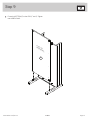 13
13
-
 14
14
-
 15
15
-
 16
16
-
 17
17
-
 18
18
-
 19
19
-
 20
20
-
 21
21
-
 22
22
-
 23
23
-
 24
24
-
 25
25
-
 26
26
-
 27
27
-
 28
28
-
 29
29
-
 30
30
-
 31
31
-
 32
32


En otros idiomas
- français: Sauder 421952 Mode d'emploi
- English: Sauder 421952 Operating instructions
Documentos relacionados
-
Sauder Carson Forge 414444 Instrucciones de operación
-
-
-
-
-
-
-
-
-