MOTO GUZZI Stelvio 1200 NTX Manual de usuario
- Categoría
- Carros
- Tipo
- Manual de usuario
Este manual también es adecuado para

MOTO GUZZI DESEA AGRADECERLE
por haber elegido uno de sus productos. Hemos preparado este manual para permitirle apreciar todas sus cualidades. Le aconsejamos que lea todo
su contenido antes de conducir por primera vez. Contiene información, consejos y advertencias para el uso de su vehículo; asimismo, descubrirá
características, detalles y soluciones que lo convencerán de lo acertado de su elección. Estamos seguros de que teniendo todo esto en cuenta, le
resultará fácil conocer su nuevo vehículo, el cual podrá disfrutar por mucho tiempo con total satisfacción. La presente publicación es parte integrante
del vehículo y en caso de venderlo debe ser entregada al nuevo propietario.
MOTO GUZZI WOULD LIKE TO THANK YOU
for choosing one of its products. We have drawn up this booklet to provide a comprehensive overview of your vehicle's quality features. Please read it
carefully before riding the vehicle for the first time. It contains information, tips and precautions for using your vehicle. It also describes features, details
and devices to assure you that you have made the right choice. We believe that if you follow our suggestions, you will soon get to know your new vehicle
well and will use it for a long time at full satisfaction. This booklet is an integral part of the vehicle, and should the vehicle be sold, it must be transferred
to the new owner.
Stelvio 1200 8V - Stelvio 1200 NTX
Ed. 11 2011

Las instrucciones de este manual han sido preparadas principalmente para suministrar una guía simple y clara de uso; se indican también las
operaciones de mantenimiento básico y los controles periódicos que se deberán realizar en los CONCESIONARIOS o Talleres autorizados Moto
Guzzi. Además, el manual contiene las instrucciones para que pueda realizar algunas reparaciones simples. Las operaciones que no se describen
explícitamente en esta publicación requieren la disponibilidad de herramientas especiales y/o de conocimientos técnicos específicos. para su ejecución
recomendamos dirigirse a los CONCESIONARIOS o Talleres autorizados Moto Guzzi.
The instructions in this manual have been prepared to offer mainly a simple and clear guide to its use; it also describes routine maintenance procedures
and regular checks that should be carried out on the vehicle at an authorised Moto Guzzi Dealer or Workshop, The booklet also contains instructions
for simple repairs. Any operations not specifically described in this booklet require the use of special tools and/or particular technical knowledge; for
these operations, please take your vehicle to an authorised Moto Guzzi Dealer or Workshop.
2

Seguridad de las personas
El no-cumplimiento total o parcial de estas prescrip-
ciones puede comportar peligro grave para la incolu-
midad de las personas.
Personal safety
Failure to completely observe these instructions will
result in serious risk of personal injury.
Salvaguardia del ambiente
Indica el comportamiento correcto para que el uso del
vehículo no cause ningún daño a la naturaleza.
Safeguarding the environment
Sections marked with this symbol indicate the correct
use of the vehicle to prevent damaging the environ-
ment.
Integridad del vehículo
El no-cumplimiento total o parcial de estas prescrip-
ciones comporta el peligro de serios daños al vehículo
e incluso la caducidad de la garantía.
Vehicle intactness
The incomplete or non-observance of these regula-
tions leads to the risk of serious damage to the vehicle
and sometimes even the invalidity of the guarantee.
Las señales indicadas previamente son de gran im-
portancia. Sirven para evidenciar las partes del ma-
nual que requieren de más atención. Como se puede
observar, cada señal está compuesta por un símbolo
gráfico diferente, para facilitar y agilizar la búsqueda
de los temas en las diversas áreas. Antes de poner
en marcha el motor, leer atentamente este manual,
especialmente el apartado "CONDUCCIÓN SEGU-
RA". Su seguridad y la de los demás no depende
solamente de la rapidez de sus reflejos y agilidad, si-
no también del conocimiento del vehículo, de su efi-
ciencia y del conocimiento de las reglas fundamenta-
les para la CONDUCCIÓN SEGURA. Por lo tanto, le
recomendamos familiarizarse con el vehículo lo sufi-
ciente como para circular por la carretera con total
control y seguridad. IMPORTANTE Este manual se
debe considerar como parte integrante del vehículo y
debe acompañarlo en caso de venta.
The symbols illustrated above are very important.
They are used to highlight parts of the booklet that
should be read with particular care. The different sym-
bols are used to make each topic in the manual simple
and quick to locate. Before starting the engine, read
this booklet thoroughly and the "SAFE RIDING" sec-
tion in particular. Your safety as well as other's does
not only depend on the quickness of your reflexes and
agility, but also on how well you know your vehicle,
the state of maintenance of the vehicle itself and your
knowledge of the rules for SAFE RIDING. For your
safety, get to know your vehicle well so as to safely
ride and master it in road traffic IMPORTANT This
booklet is an integral part of the vehicle, and must be
handed to the new owner in the event of sale.
3
La página se está cargando...

INDICE
INDEX
NORMAS GENERALES................................................................. 9
Introducción.............................................................................. 10
Monóxido de carbono............................................................... 10
Combustible............................................................................. 11
Componentes calientes............................................................ 12
Puesta en marcha y Conducción............................................. 12
La frenada................................................................................ 13
Testigos.................................................................................... 13
Aceite motor y aceite cambio usados...................................... 14
Líquido frenos y embrague...................................................... 15
Electrolito y gas hidrógeno de la batería.................................. 16
Soporte..................................................................................... 18
Comunicación de los defectos que influyen en la seguridad
................................................................................................. 18
VEHÌCULO...................................................................................... 19
Ubicación componentes principales............................................ 21
Tablero de instrumentos.............................................................. 26
Conjunto de instrumentos............................................................ 27
Grupo testigos............................................................................. 28
Representacion visual digital por cristales liquidos..................... 29
Teclas de mando...................................................................... 30
Funciones avanzadas.............................................................. 36
Conmutador de encendido....................................................... 45
Bloqueo del volante.................................................................. 46
Luces de aparcamiento............................................................ 47
Pulsante claxon........................................................................... 47
Conmutador intermitentes........................................................... 48
Commutador luces....................................................................... 49
Pulsador ráfaga luz de carretera................................................. 50
Mando de puños calefactados..................................................... 50
Boton accionamiento intermitentes de emergencia..................... 51
GENERAL RULES............................................................................ 9
Foreword.................................................................................... 10
Carbon monoxide....................................................................... 10
Fuel............................................................................................ 11
Hot components......................................................................... 12
Start off and Riding..................................................................... 12
The braking................................................................................ 13
Warning lights............................................................................. 13
Used engine oil and gearbox oil................................................. 14
Brake and clutch fluid................................................................. 15
Battery hydrogen gas and electrolyte......................................... 16
Stand.......................................................................................... 18
Reporting of defects that affect safety........................................ 18
VEHICLE........................................................................................... 19
Arrangement of the main components........................................... 21
Dashboard..................................................................................... 26
Instrument panel............................................................................ 27
Light unit........................................................................................ 28
Digital lcd display........................................................................... 29
Control buttons........................................................................... 30
Advanced functions.................................................................... 36
Ignition switch............................................................................. 45
Locking the steering wheel......................................................... 46
Parking lights.............................................................................. 47
Horn button.................................................................................... 47
Switch direction indicators............................................................. 48
High/low beam selector.................................................................. 49
Passing button............................................................................... 50
Heated handgrip control................................................................. 50
Flasher button................................................................................ 51
Start-up button............................................................................... 52
5

Pulsante arranque....................................................................... 52
Interruptor parada motor.............................................................. 52
Sistema ABS................................................................................ 52
Sistema ATC (Antiskid system)................................................... 58
Toma de corriente........................................................................ 61
El sillin.......................................................................................... 62
Abertura sillín........................................................................... 63
Compartimiento porta-doc./kit herramientas............................ 64
La identificación........................................................................... 65
Regulación parabrisas................................................................. 66
Preinstalación para accesorios.................................................... 66
EL USO........................................................................................... 69
Controles..................................................................................... 70
Abastecimiento............................................................................ 73
Regulación amortiguadores traseros........................................... 75
Regulación horquilla delantera.................................................... 78
Regulación leva freno delantero.................................................. 81
Regulación leva embrague.......................................................... 82
Rodaje......................................................................................... 82
Arranque dificultoso..................................................................... 84
Aparcamiento............................................................................... 85
Escape catalítico.......................................................................... 86
Soporte........................................................................................ 88
Sugerencias contra los robos...................................................... 90
Normas basicás de seguridad..................................................... 92
EL MANTENIMIENTO.................................................................... 99
Premisa........................................................................................ 100
Control del nivel de aceite motor.............................................. 101
Llenado de aceite motor........................................................... 102
Sustitución aceite motor........................................................... 104
Nivel aceite cardán...................................................................... 108
Nivel aceite cambio...................................................................... 108
Neumáticos.................................................................................. 109
Desmontaje bujía......................................................................... 113
Desmontaje filtro aire................................................................... 114
Control nivel aceite frenos........................................................... 114
Llenado liquido circuito de frenos............................................. 115
Control líquido embrague............................................................ 116
Reposición líquido embrague................................................... 116
Engine stop switch......................................................................... 52
System ABS................................................................................... 52
System ATC (Antiskid system)...................................................... 58
Power supply socket...................................................................... 61
The saddle..................................................................................... 62
Opening the saddle.................................................................... 63
Glove/tool kit compartment......................................................... 64
Identification................................................................................... 65
Adjusting the windscreen............................................................... 66
Provision for the installation of accessories................................... 66
USE................................................................................................... 69
Checks........................................................................................... 70
Refuelling....................................................................................... 73
Rear shock absorbers adjustment................................................. 75
Front fork adjustment..................................................................... 78
Justering af greb til forbremse....................................................... 81
Clutch lever adjustment................................................................. 82
Running in...................................................................................... 82
Difficult start up.............................................................................. 84
Parking........................................................................................... 85
Catalytic silencer............................................................................ 86
Stand.............................................................................................. 88
Suggestion to prevent theft............................................................ 90
Basic safety rules........................................................................... 92
MAINTENANCE................................................................................ 99
Foreword........................................................................................ 100
Engine oil level check................................................................. 101
Engine oil top-up........................................................................ 102
Engine oil change....................................................................... 104
Universal joint oil level................................................................... 108
Gearbox oil level............................................................................ 108
Tyres.............................................................................................. 109
Spark plug dismantlement............................................................. 113
Removing the air filter.................................................................... 114
Checking the brake oil level........................................................... 114
Braking system fluid top up........................................................ 115
Checking clutch fluid...................................................................... 116
Topping up clutch fluid............................................................... 116
Use of a new battery.................................................................. 117
6

Puesta en servicio de una batería nueva................................. 117
Comprobacion del nivel del electrolito..................................... 118
Recarga batería....................................................................... 118
Larga inactividad.......................................................................... 119
Fusibles....................................................................................... 121
Bombillas..................................................................................... 124
Regulación proyector............................................................... 127
Indicadores de dirección delanteros............................................ 130
Faros adicionales......................................................................... 132
Activación de faros adicionales................................................ 132
Sustitución de bombillas.......................................................... 132
Grupo óptico trasero.................................................................... 133
Indicadores de dirección traseros................................................ 134
Luz placa..................................................................................... 136
Espejos retrovisores.................................................................... 137
Freno de disco delantero y trasero.............................................. 138
Inactividad del vehiculo................................................................ 140
Limpieza del vehiculo.................................................................. 142
Transporte................................................................................... 148
DATOS TÉCNICOS........................................................................ 151
Datos........................................................................................... 158
Herramientas en dotación............................................................ 160
EL MANTENIMIENTO PROGRAMADO......................................... 161
Tabla manutención programada.................................................. 162
Checking the electrolyte level..................................................... 118
Charging the battery................................................................... 118
Long periods of inactivity............................................................... 119
Fuses............................................................................................. 121
Lamps............................................................................................ 124
Headlight adjustment.................................................................. 127
Front direction indicators................................................................ 130
Additional light................................................................................ 132
Additional light activation............................................................ 132
Bulb replacement....................................................................... 132
Rear optical unit............................................................................. 133
Rear turn indicators........................................................................ 134
Number plate light.......................................................................... 136
Rear-view mirrors........................................................................... 137
Front and rear disc brake............................................................... 138
Periods of inactivity........................................................................ 140
Cleaning the vehicle....................................................................... 142
Transport........................................................................................ 148
TECHNICAL DATA........................................................................... 151
Data............................................................................................... 158
Kit equipment................................................................................. 160
PROGRAMMED MAINTENANCE.................................................... 161
Scheduled maintenance table........................................................ 162
7
La página se está cargando...
La página se está cargando...

Introducción
NOTA
EL TIEMPO PREVISTO PARA REALI-
ZAR LAS OPERACIONES DE MANTE-
NIMIENTO, DEBE SER REDUCIDO A
LA MITAD SI EL VEHÍCULO SE UTILI-
ZA EN ZONAS LLUVIOSAS, POLVO-
RIENTAS, EN RECORRIDOS ACCI-
DENTADOS O EN CASO DE CONDUC-
CIÓN DEPORTIVA.
Foreword
NOTE
CARRY OUT MAINTENANCE OPERA-
TIONS AT HALF THE INTERVALS
SPECIFIED IF THE VEHICLE IS USED
IN PARTICULAR RAINY OR DUSTY
CONDITIONS, OFF ROAD OR FOR
TRACK USE.
Monóxido de carbono
Si es necesario hacer funcionar el motor
para poder efectuar alguna operación,
asegurarse de que esto ocurra en un es-
pacio abierto o en un ambiente ventilado
de manera adecuada. Nunca hacer fun-
cionar el motor en espacios cerrados. Si
se trabaja en un espacio cerrado, utilizar
un sistema de evacuación de los humos
de escape.
ATENCIÓN
LOS HUMOS DE ESCAPE CONTIENEN
MONÓXIDO DE CARBONO, UN GAS
VENENOSO QUE PUEDE PROVOCAR
LA PÉRDIDA DE CONOCIMIENTO E
INCLUSO LA MUERTE.
Carbon monoxide
If you need to keep the engine running in
order to perform a procedure, please en-
sure that you do so in an open or very well
ventilated area. Never let the engine run
in an enclosed area. If you do work in an
enclosed area, make sure to use a
smoke-extraction system.
CAUTION
EXHAUST EMISSIONS CONTAIN
CARBON MONOXIDE, A POISONOUS
GAS WHICH CAN CAUSE LOSS OF
CONSCIOUSNESS AND EVEN
DEATH.
10
1 Normas generales / 1 General rules
La página se está cargando...

LA CAÍDA O LA EXCESIVA INCLINA-
CIÓN DEL VEHÍCULO PUEDEN PRO-
DUCIR DERRAMES DE COMBUSTI-
BLE.
IF THE VEHICLE FALLS OR IS ON A
STEEP INCLINE FUEL CAN LEAK.
Componentes calientes
El motor y los componentes de la insta-
lación de escape alcanzan altas tempe-
raturas y permanecen calientes durante
un cierto período, incluso después de
apagar el motor. Para manipular estos
componentes, utilizar guantes aislantes
o esperar hasta que el motor y la insta-
lación de escape se hayan enfriado.
Hot components
The engine and the exhaust system com-
ponents get very hot and remain in this
condition for a certain time interval after
the engine has been switched off. Before
handling these components, make sure
that you are wearing insulating gloves or
wait until the engine and the exhaust sys-
tem have cooled down.
Puesta en marcha y
Conducción
ATENCIÓN
SI DURANTE LA CONDUCCIÓN, EN EL
TABLERO SE ENCIENDE EL TESTIGO
DE RESERVA DE COMBUSTIBLE,
SIGNIFICA QUE COMIENZA A UTILI-
ZARSE LA RESERVA.
REPONER COMBUSTIBLE LO ANTES
POSIBLE.
Start off and Riding
CAUTION
IF THE LOW FUEL WARNING LIGHT
ON THE INSTRUMENT PANEL TURNS
ON WHILE RIDING, THIS MEANS THE
RESERVE IS BEING USED.
REFUEL AS SOON AS POSSIBLE.
12
1 Normas generales / 1 General rules
La página se está cargando...
La página se está cargando...
La página se está cargando...
La página se está cargando...
La página se está cargando...
La página se está cargando...
La página se está cargando...
La página se está cargando...

02_02
Ubicación componentes
principales (02_02)
Leyenda (versión NTX):
1. Faro delantero
2. Toma 12V
3. Tablero de instrumentos
4. Espejo retrovisor izquierdo
5. Tapón del depósito de combus-
tible
6. Depósito combustible
7. Batería
8. Portafusibles principales
9. Asiento conductor
Arrangement of the main
components (02_02)
Key (NTX version):
1. Headlamp
2. 12 V socket
3. Instrument panel
4. Left rear-view mirror
5. Fuel tank cap
6. Fuel tank
7. Battery
8. Main fuse box
9. Rider saddle
10. Tool compartment
21
2 Vehìculo / 2 Vehicle

10. Compartimiento portaherra-
mientas
11. Asa de agarre pasajero
12. Maletero lateral izquierdo
13. Estribo izquierdo pasajero
14. Estribo izquierdo del conductor
15. Caballete lateral
16. Caballete central
17. Leva de mando del cambio
18. Cubrecárter
19. Varilla nivel de aceite del motor
20. Protector de piernas
21. Faro adicional izquierdo
22. Filtro del aceite motor
23. Leva de mando del freno trasero
24. Estribo derecho conductor
25. Transmisión por árbol cardánico
26. Basculante monobrazo
27. Estribo derecho pasajero
28. Maletero lateral derecho
29. Faro trasero
30. Portafusibles ABS (donde esté
previsto)
31. Depósito de líquido del freno
trasero
32. Centralita ABS (donde esté pre-
vista)
33. Protector de manos
34. Espejo retrovisor derecho
35. Depósito líquido freno delantero
36. Portafusibles secundarios
37. Faro adicional derecho
11. Passenger grab handle
12. Left side top box
13. Passenger left footrest
14. Left rider footrest
15. Side stand
16. Centre stand
17. Gear shift lever
18. Oil sump guard
19. Engine oil level dipstick
20. Leg guard
21. Additional left headlamp
22. Engine oil filter
23. Rear brake lever
24. Right rider footrest
25. Cardan shaft transmission
26. Single arm swingarm
27. Right passenger footrest
28. Right side top box
29. Taillight
30. ABS fuse holder (if fitted)
31. Rear brake fluid reservoir
32. ABS control unit (if fitted)
33. Hand guards
34. Right rear-view mirror
35. Front brake fluid reservoir
36. Secondary fuse holder
37. Additional right headlamp
22
2 Vehìculo / 2 Vehicle
La página se está cargando...

02_04
Leyenda (versión estándar):
1. Faro delantero
2. Toma 12V
3. Tablero de instrumentos
4. Espejo retrovisor izquierdo
5. Tapón del depósito de combus-
tible
6. Depósito combustible
7. Batería
8. Portafusibles principales
9. Asiento conductor
10. Asiento pasajero
11. Asa de agarre pasajero
Key (standard version):
1. Headlamp
2. 12 V socket
3. Instrument panel
4. Left rear-view mirror
5. Fuel tank cap
6. Fuel tank
7. Battery
8. Main fuse box
9. Rider saddle
10. Passenger seat
11. Passenger grab handle
12. Tool compartment
13. Passenger left footrest
24
2 Vehìculo / 2 Vehicle

12. Compartimiento portaherra-
mientas
13. Estribo izquierdo pasajero
14. Estribo izquierdo del conductor
15. Caballete lateral
16. Leva de mando del cambio
17. Varilla nivel de aceite del motor
18. Punta carenado
19. Filtro del aceite motor
20. Leva de mando del freno trasero
21. Caballete central
22. Estribo derecho conductor
23. Transmisión por árbol cardánico
24. Estribo derecho pasajero
25. Basculante monobrazo
26. Faro trasero
27. Toma 12V
28. Portafusibles ABS (donde esté
previsto)
29. Depósito de líquido del freno
trasero
30. Centralita ABS (donde esté pre-
vista)
31. Espejo retrovisor derecho
32. Depósito líquido freno delantero
33. Portafusibles secundarios
14. Left rider footrest
15. Side stand
16. Gear shift lever
17. Engine oil level dipstick
18. Fairing lug
19. Engine oil filter
20. Rear brake lever
21. Centre stand
22. Right rider footrest
23. Cardan shaft transmission
24. Right passenger footrest
25. Single arm swingarm
26. Taillight
27. 12 V socket
28. ABS fuse holder (if fitted)
29. Rear brake fluid reservoir
30. ABS control unit (if fitted)
31. Right rear-view mirror
32. Front brake fluid reservoir
33. Secondary fuse holder
25
2 Vehìculo / 2 Vehicle

02_05
Tablero de instrumentos
(02_05)
Leyenda ubicación mandos / instru-
mentos:
1. Leva de mando embrague
2. Instrumentos e indicadores
3. Interruptor de arranque / blo-
queo de la dirección
4. Leva del freno delantero
5. Puño del acelerador
6. Pulsador indicador de emergen-
cia
7. Interruptor de arranque y de pa-
rada del motor
Dashboard (02_05)
Instrument panel / controls location
key:
1. Clutch control lever
2. Instruments and gauges
3. Ignition switch /steering lock
4. Front brake lever
5. Throttle grip
6. Emergency telltale light button
7. Starter button and engine stop
switch
8. Light switch
9. Heated handgrips bush-button
(optional)
26
2 Vehìculo / 2 Vehicle

8. Conmutador de luces
9. Pulsador puños calefactados
(opcionales)
10. Pulsador claxon
11. Interruptor intermitentes
12. Interruptor MODE
13. Interruptor faros adicionales (a
activar con la instalación del dis-
positivo)
14. Pulsador desactivación ABS
(donde esté previsto)
10. Horn button
11. Turn indicator switch
12. MODE switch
13. Additional lights switch (to acti-
vate with device installation)
14. ABS deactivation button (if fit-
ted)
02_06
Conjunto de instrumentos
(02_06)
Leyenda:
1. Pantalla digital multifunción
2. Cuentarrevoluciones
Instrument panel (02_06)
key:
1. Multifunctional digital display
2. Rpm indicator
El tablero esta equipado con un immobi-
lizer que impide el arranque en caso de
que el sistema no identifique una llave
memorizada anteriormente.
El vehículo se entrega con dos llaves me-
morizadas. El tablero acepta simultánea-
mente cuatro llaves como máximo: para
su activación o para desactivar una llave
extraviada dirigirse a un concesionario
oficial Moto Guzzi. En el momento de la
The instrument panel has an immobilizer
which prevents start-up in case the sys-
tem does not identify a key which has
been programmed before.
The vehicle is supplied with two keys al-
ready programmed. The instrument pan-
el accepts a maximum of four keys at the
same time: contact an Official Moto Guzzi
dealer to enable these keys or to disable
a key that has been lost. When the vehi-
27
2 Vehìculo / 2 Vehicle

entrega del vehículo, luego de girar la lla-
ve a la posición ON y durante diez se-
gundos aproximadamente, el tablero so-
licita el ingreso de un código personal de
cinco cifras. Una vez ingresado este có-
digo personal no será solicitado nueva-
mente. Para conocer el procedimiento de
ingreso del código ver el apartado MO-
DIFICACIÓN DEL CÓDIGO
Es importante recordar el código perso-
nal ya que permite:
•
encender el vehículo si el siste-
ma immobilizer no funciona co-
rrectamente
•
evitar la sustitución del tablero
en el caso de tener que sustituir
el conmutador de arranque
•
memorizar nuevas llaves
cle is delivered and approximately ten
seconds after the key is set to ON, the
instrument panel requests a personal
five-digit code to be entered. This request
is no longer displayed once the personal
code is entered. For code entering pro-
cedure, see the CODE MODIFICATION
section
It is important to remember the personal
code because:
•
the vehicle can be started if the
immobilizer system is faulty
•
the instrument panel need not
be replaced should the ignition
switch be changed
•
new keys can be programmed
02_07
Grupo testigos (02_07)
Leyenda:
1. Testigo caballete lateral (color
amarillo)
2. Testigo ABS (Anti-lock Braking
System) (color amarillo) (donde
esté previsto)
3. Testigo reserva del combustible
(color anaranjado)
4. Testigo cambio en punto muerto
(color verde)
5. Testigo antirrobo
6. Testigo intermitentes (color ver-
de)
Light unit (02_07)
key:
1. Side stand warning light (yellow)
2. ABS warning light (Anti-lock
Braking system) (yellow) (if fit-
ted)
3. Low fuel warning light (orange)
4. Gear in neutral warning light
(green)
5. Antitheft device warning light
6. Turn indicator warning light
(green)
7. High beam warning light (blue)
8. General warning light (red)
28
2 Vehìculo / 2 Vehicle

7. Testigo luz de carretera (color
azul)
8. Testigo Warning general (color
rojo)
02_08
02_09
Representacion visual digital
por cristales liquidos (02_08,
02_09)
Girando la llave de contacto a la posición
ON, en la pantalla se encienden durante
dos segundos:
- el logotipo
- Todos los testigos
- la retroiluminación
La aguja del cuentarrevoluciones se des-
plaza hacia el valor máximo, programado
por el usuario.
Luego de dos segundos, todos los ins-
trumentos indicarán instantáneamente el
valor actual de las magnitudes medidas.
Las programaciones estándar que se vi-
sualizan en la pantalla son:
- ODÓMETRO (zona A)
- PUÑOS CALEFACTADOS (donde es-
tén previstos) (zona B)
- FAROS ANTINIEBLA (donde estén pre-
vistos) (zona C)
Digital lcd display (02_08,
02_09)
The following indicators will light up for a
couple of seconds on the instrument pan-
el when the ignition key is set to "ON":
- the logo
- All warning lights
- the instrument panel backlighting
The rpm indicator pointer moves to the
maximum value, set by the user
After two seconds, all instruments imme-
diately show the current value of the
measurements read.
The standard indications displayed are:
- ODOMETER (zone A)
- HEATED GRIPS (if applicable) (zone B)
- FOG LIGHTS (if applicable) (zone C)
- FUEL LEVEL (zone D)
- CLOCK (zone E)
- AMBIENT TEMPERATURE (zone F)
- SPEED (zone G)
29
2 Vehìculo / 2 Vehicle

- NIVEL COMBUSTIBLE (zona D)
- RELOJ (zona E)
- TEMPERATURA AMBIENTE (zona F)
- VELOCIDAD (zona G)
- EVENTUAL LLAVE CONTROL PERIÓ-
DICO (zona H)
- ATC (Antiskid system) (zona I)
- ORDENADOR DE VIAJE Y FUNCIO-
NES COMPLEMENTARIAS (zona L)
- POSSIBLE SERVICING KEY (zone H)
- ATC (Antiskid system) (zone I)
- TRIP COMPUTER AND ADDITIONAL
FUNCTIONS (zone L)
02_10
Teclas de mando (02_10,
02_11, 02_12, 02_13, 02_14,
02_15, 02_16, 02_17, 02_18)
•
Desplazar el selector hacia la
derecha (DCH.) o hacia la iz-
quierda (IZQ.) para recorrer las
selecciones dentro de los ME-
NÚS.
•
Presionar el selector para con-
firmar el dato seleccionado.
Control buttons (02_10, 02_11,
02_12, 02_13, 02_14, 02_15,
02_16, 02_17, 02_18)
•
Turn the selector to the right
(RH) or left (LH) to scroll the op-
tions within the MENU.
•
Press the selector to confirm the
selected data.
30
2 Vehìculo / 2 Vehicle

02_11
NOTA
CON CADA PRESIÓN PROLONGADA
DEL SELECTOR A LA DERECHA O A
LA IZQUIERDA SE PUEDE PASAR DE
UNA CONFIGURACIÓN A OTRA. (*)
NOTE
EVERY TIME THE SELECTOR IS HELD
DOWN TO THE RIGHT OR LEFT, YOU
CAN GO FROM ONE CONFIGURA-
TION TO ANOTHER. (*)
TRIP 1, TRIP 2, TRIP (ATC/Menú/Cro-
nómetro/consumo instantáneo/ ten-
sión de batería)
En las funciones TRIP1 y TRIP2 se
muestran los datos correspondientes a
los parciales de viaje 1 y 2.
NOTA
LOS DATOS DENTRO DE LAS SELEC-
CIONES TRIP1 Y TRIP2 SE VISUALI-
ZAN EN SECUENCIA PRESIONANDO
BREVEMENTE (MENOS DE UN SE-
GUNDO) EL SELECTOR EN LA POSI-
CIÓN DCH. O IZQ. (**)
TRIP 1, TRIP 2, TRIP (ATC/Menu/Chro-
nometer/current consumption/battery
voltage)
Data related to trip distances 1 and 2 are
displayed at the TRIP1 and TRIP2 func-
tions.
NOTE
DATA IN FUNCTIONS TRIP1 AND
TRIP2 ARE DISPLAYED IN SE-
QUENCE BY BRIEFLY PRESSING THE
SELECTOR IN POSITION RH OR LH.
(**) (LESS THAN A SECOND)
31
2 Vehìculo / 2 Vehicle

02_12
02_13
La indicación del parcial visualizado se
indica en la zona inferior de la pantalla (E)
y puede ser:
- ODÓMETRO PARCIAL (1)
- TIEMPO DE RECORRIDO (2)
- CONSUMO EN EL RECORRIDO (3)
- VELOCIDAD MÁXIMA (4)
- VELOCIDAD MEDIA (5)
Para poner a cero todas las medidas par-
ciales del TRIP1 o del TRIP2 selecciona-
do:
•
presionar el selector de manera
prolongada.
The trip odometer is displayed at the low-
er part of the display (E) and can be:
- TRIP ODOMETER (1)
- TRAVELLING TIME (2)
- CONSUMPTION WHEN RIDING (3)
- MAXIMUM SPEED (4)
- MEAN SPEED (5)
To zero set all the partial distances of the
selected TRIP1 or TRIP2:
•
hold down the selector for a few
seconds.
02_14
En la función TRIP se encuentran las fun-
ciones que permiten al usuario interac-
tuar con el sistema.
Para ingresar a la función TRIP:
•
Desplazar el selector a la IZQ.
(si se encuentra en TRIP1) o a
la DCH. (si se encuentra en
TRIP2), hasta llegar a la función
TRIP.
Desplazando brevemente el selector a la
posición IZQ. o DCH. se pueden visuali-
The TRIP function includes the functions
that allow the user to interact with the
system.
To enter the TRIP function:
•
Move the selector to LH (if you
are in TRIP1) or to RH (if you are
in TRIP2), up to reach TRIP
function.
By briefly pressing the selector in the LH
or RH position, the following functions
can be displayed cyclically: (***)
32
2 Vehìculo / 2 Vehicle

zar cíclicamente las siguientes funcio-
nes: (***)
- ATC (Antiskid system) (6);
- MENÚ (función excluida con el vehículo
en movimiento) (7);
- CRONÓMETRO (8);
- CONSUMO INSTANTÁNEO (9);
- TENSIÓN DE BATERÍA (10).
Las funciones TENSIÓN DE BATERÍA y
CONSUMO INSTANTÁNEO no permiten
la interacción con el usuario.
- ATC (Antiskid system) (6);
- MENU (function disabled when riding)
(7);
- CHRONOMETER (8);
- CURRENT CONSUMPTION (9);
- BATTERY VOLTAGE (10).
The BATTERY VOLTAGE and CUR-
RENT CONSUMPTION functions do not
admit interaction with the user.
02_15
ATC (Antiskid system)
Deslizando el diario de viaje TRIP pre-
sionando brevemente el mando MODE
hacia la izquierda o derecha, se puede
visualizar la opción ATC.
Presionando prolongadamente el mando
MODE en la posición central se puede
acceder a la función ATC.
ATC (Antiskid system)
Push the MODE control briefly to the left
or right to scroll through the TRIP trip
journal and display the ATC option.
Hold the centre of the MODE control to
access the ATC function.
33
2 Vehìculo / 2 Vehicle

02_16
Desplazando el selector hacia la dere-
cha, con un breve presión, se activa el
sistema.
Moving the selector to the right, press
briefly to turn the system on.
02_17
Para desactivar el sistema, desplazar el
selector hacia la izquierda con una breve
presión, hasta visualizar la leyenda OFF
El icono ATC se encenderá con luz fija.
Para salir de la función ATC presionar
prolongadamente el selector o poner en
movimiento la motocicleta.
NOTA
EN LA PRIMERA CONEXIÓN DE LA
BATERÍA, EL SISTEMA NO ESTÁ AC-
TIVO.
NOTA
UNA VEZ APAGADO EL TABLERO DE
LA MOTOCICLETA, CUANDO SE EN-
CIENDE NUEVAMENTE, EL SISTEMA
ATC MANTIENE LAS CONFIGURA-
CIONES SELECCIONADAS ANTE-
RIORMENTE.
To turn off the system, move the switch
to the left by briefly pressing it, until the
text OFF is highlighted
The ATC icon will remain on with a steady
light.
To exit the ATC function, press and hold
the selector briefly or turn on the vehicle.
NOTE
AT THE FIRST CONNECTION OF THE
BATTERY, THE SYSTEM IS NOT AC-
TIVE.
NOTE
WHEN THE VEHICLE PANEL IS OFF
AND WHEN TURNING IT ON THE
NEXT TIME, THE ATC SYSTEM KEEPS
THE SETTINGS PREVIOUSLY SELEC-
TED.
34
2 Vehìculo / 2 Vehicle

02_18
CRONÓMETRO
Para acceder a la función CRONÓME-
TRO:
•
De la configuración TRIP, selec-
cionar CRONÓMETRO presio-
nando el selector de forma pro-
longada.
En la zona inferior de la pantalla se vi-
sualiza el mensaje CHRONO y al lado el
número de la última medición realizada y
el dato medido.
Para iniciar el cronometraje:
•
Presionar brevemente el selec-
tor, el cronómetro comienza a
registrar una sesión nueva.
Si se presiona el selector dentro de los
primeros diez segundos desde el co-
mienzo del cronometraje, esto hace que
el cronómetro parta de cero.
Transcurrido dicho período, al presionar
nuevamente se memoriza el dato y se
lanza la próxima medición.
La serie de mediciones se interrumpe
presionando prolongadamente el selec-
tor.
Luego de haber realizado cuarenta re-
cuentos, no se pueden realizar más me-
diciones y se visualiza el mensaje
"FULL". Para leer las mediciones crono-
métricas adquiridas, es necesario parar
la motocicleta y entrar en la función VI-
CHRONOMETER
To enter the CHRONOMETER function:
•
In the TRIP function, select
CHRONOMETER by holding
down the selector.
The bottom zone of the display shows the
word CHRONO next to the number of the
last measurement and the value regis-
tered.
To start timekeeping:
•
Briefly press the selector, the
chronometer starts to time
again.
If the button is pressed again within the
first ten seconds after starting timekeep-
ing, the chronometer is reset.
If after said period the button is pressed
again, the data is stored and the time-
keeping starts once again.
The series of measurements is interrup-
ted by pressing and holding down the
selector.
The word "FULL" is displayed after forty
times are stored. No more times can be
stored. In order to read the chronometer
times it is necessary to stop the vehicle
and display the VIEW MEASUREMENTS
function of the CHRONOMETER menu.
35
2 Vehìculo / 2 Vehicle

SUALIZAR MEDIDAS del menú CRO-
NÓMETRO.
02_19
02_20
Funciones avanzadas (02_19,
02_20, 02_21, 02_22, 02_23,
02_24, 02_25)
MENÚ
La función puede ser seleccionada sólo
con el vehículo parado y permite progra-
mar la visualización de los parámetros
presentes en las distintas configuracio-
nes.
Para ingresar a la función MENÚ:
visualizada la función MENÚ, presionar
de forma prolongada el selector en ME-
NÚ.
Las opciones del menú de configuración
son las siguientes:
- SALIR
- CONFIGURACIONES
- CRONÓMETRO
- DIAGNÓSTICO
- IDIOMAS
Advanced functions (02_19,
02_20, 02_21, 02_22, 02_23,
02_24, 02_25)
MENU
The function can be selected only with
the vehicle at a standstill. It sets the pa-
rameter display mode in the different con-
figurations.
To access the MENU function:
with the MENU function displayed, hold
down the selector on MENU.
The configuration menu options are:
- EXIT
- SETTINGS
- CHRONOMETER
- DIAGNOSIS
- LANGUAGES
CONFIGURACIONES
Cuando se confirma la selección (presio-
nando prolongadamente el selector) en
SETTINGS
36
2 Vehìculo / 2 Vehicle

CONFIGURACIONES, aparece una
pantalla con las siguientes opciones:
- SALIR
- AJUSTE HORA
- CAMBIO MARCHA
- RETROILUMINACIÓN
- °C/°F
- 12H/24H
- LED INMOVILIZADOR
- MODIFICACIÓN CÓDIGO
- RESTABLECIMIENTO CÓDIGO
Las opciones pueden seleccionarse en
secuencia presionando el selector bre-
vemente.
When the selection is confirmed on SET-
TINGS (selector held down), a screen
displays the following options:
- EXIT
- TIME ADJUSTMENT
- GEAR SHIFT
- BACKLIGHTING
- °C / °F
- 12H / 24H
- IMMOBILIZER LED
- CODE CHANGE
- CODE RESET
These options can be selected in se-
quence by pressing the selector briefly.
- AJUSTE HORA
En esta modalidad se programa el valor
del reloj. Dentro de la función, cada vez
que se presiona el selector aumenta de
a uno el valor de la hora; al alcanzar el
valor 12 ó 24, si se presiona nuevamente
el selector se vuelve a 1.
El paso entre AM y PM o viceversa se
produce al pasar de horas 11:59 a horas
12:00. Presionando prolongadamente el
selector, se memoriza el valor y se pasa
a la modalidad de regulación de los mi-
nutos.
TIME ADJUSTMENT
The clock can be programmed with this
option. Once you have entered this func-
tion and each time the selector is press-
ed, the hour value increases by one;
when the value reaches 12 or 24, it goes
back to 1 the next time the selector is
pressed.
Shifting from AM to PM or vice versa oc-
curs when going from 11:59 to 12:00.
Hold down the selector to store the value
and shift to the minute adjustment mode.
Each time the selector is pressed increa-
ses the minute value by one; when the
37
2 Vehìculo / 2 Vehicle

Cada vez que se presiona el selector se
aumenta de uno el valor de los minutos;
al alcanzar el valor 59, si se presiona
nuevamente el selector, se vuelve a 0.
El procedimiento termina presionando
prolongadamente el selector, el tablero
vuelve al menú CONFIGURACIONES.
value reaches 59, it returns to 0 the next
time the selector is pressed.
The procedure ends when the selector is
held down; the instrument panel goes
back to the SETTINGS menu.
02_21
CAMBIO MARCHA
En esta modalidad se configura el valor
del umbral de cambio marcha. Una vez
que se active la función, en la pantalla
aparece el mensaje "CAMBIO MAR-
CHA", en el idioma programado, y en el
índice del cuentarrevoluciones se indica
el valor del umbral.
El valor del umbral se incrementa 100
rpm con cada presión breve del selector.
Alcanzado el valor superior, al presionar
nuevamente el mismo selector el valor se
resta.
El procedimiento termina presionando
prolongadamente el selector; la pantalla
vuelve al menú CONFIGURACIONES.
La primera vez que se conecta la batería,
el tablero se ajusta en el valor de REVO-
LUCIONES RODAJE, en los sucesivos
se ajusta en el último valor programado.
- REVOLUCIONES RODAJE 6500
- REVOLUCIONES MÍNIMAS PROGRA-
MABLES 6000
GEAR SHIFT
The gear shift threshold can be set in this
mode. Once within this option, the display
shows "GEARSHIFT", in the set lan-
guage, and the rpm indicator shows the
threshold value.
Every time the selector is briefly pressed,
the threshold value increases by 100
rpm. Once the maximum value is
reached, the next time the selector is
pressed, the value decreases.
The procedure ends when the selector is
held down; the display goes back to the
SETTINGS menu. When the battery is
first activated, the instrument panel is set
to the RUN-IN REVOLUTIONS value.
The subsequent times it is operated, the
last set value is displayed.
- RUN-IN REVOLUTIONS 6500
- MINIMUM PROGRAMABLE REVOLU-
TIONS 6000
- MAXIMUM PROGRAMMABLE REVO-
LUTIONS 8500
38
2 Vehìculo / 2 Vehicle

- REVOLUCIONES MÁXIMAS PRO-
GRAMABLES 8500
Al superar el umbral fijado, el testigo de
alarma del tablero parpadea hasta que
se retorna por debajo de dicho umbral.
If the set threshold value is exceeded, the
warning light on the instrument panel
starts to flash. It turns off when the value
goes back below the threshold limit.
02_22
RETROILUMINACIÓN
Esta función permite regular la intensi-
dad de la retroiluminación en tres niveles.
Dentro de la función, presionando breve-
mente el selector, aparecen cíclicamente
los siguientes iconos:
- LOW
- MEAN
- HIGH
Al finalizar la operación, presionando
prolongadamente el selector, el tablero
vuelve al menú CONFIGURACIONES.
BACKLIGHTING
This function adjusts backlighting to three
brightness levels.
Once you have entered this function and
each time the selector is pressed, the fol-
lowing icons are cyclically displayed:
- LOW
- MEAN
- HIGH
Once the procedure has ended, hold
down the selector; the instrument panel
goes back to the SETTINGS menu.
°C/°F
Esta función selecciona la unidad de me-
dida de las temperaturas ambiente. Den-
tro de la función, presionando brevemen-
te el selector, aparecen cíclicamente las
dos unidades de medida:
- °C
- °F
°C/°F
This function selects the ambient temper-
ature unit of measurement. Once you
have entered this function and each time
the selector is pressed, the two units of
measurement are cyclically displayed:
- °C
- °F
39
2 Vehìculo / 2 Vehicle

Presionando prolongadamente el selec-
tor, se memoriza el dato y el tablero vuel-
ve al menú CONFIGURACIONES.
Hold down the selector to store the data;
the instrument panel goes back to the
SETTINGS menu.
02_23
12H / 24H
Esta función selecciona la modalidad de
visualización de la hora. Dentro de la fun-
ción, presionando brevemente el selec-
tor, aparecen cíclicamente los dos for-
matos:
- 12H
- 24H
Presionando prolongadamente el selec-
tor, se memoriza el dato y el tablero vuel-
ve al menú CONFIGURACIONES.
12H / 24H
This function selects the time display
mode. Once you have entered this func-
tion and each time the selector is press-
ed, the two formats are cyclically dis-
played:
- 12H
- 24H
Hold down the selector to store the data;
the instrument panel goes back to the
SETTINGS menu.
- MODIFICACIÓN CÓDIGO
Esta función se usa cuando se dispone
del viejo código y se desea modificarlo.
Dentro de la función aparece el mensaje:
"INGRESAR EL CÓDIGO VIEJO"
Luego de reconocer el código viejo, se
solicita ingresar el nuevo código, la pan-
talla visualiza el siguiente mensaje:
"INGRESAR EL CÓDIGO NUEVO"
Al finalizar la operación la pantalla vuelve
al menú DIAGNÓSTICO. Si se ha entra-
do con el código, esta operación no está
admitida.
CODE CHANGE
This function is used to modify an old
code. Once you have entered this func-
tion, the following message is displayed:
"ENTER OLD CODE"
After recognising the old code, the new
code is requested and the display shows
the following message:
"ENTER NEW CODE"
Once the operation is finished, the dis-
play shows the DIAGNOSIS menu. If the
code has been used, this operation is not
allowed.
40
2 Vehìculo / 2 Vehicle

Al finalizar la operación, el tablero vuelve
al menú CONFIGURACIONES.
Si es la primera memorización, se solicita
únicamente que se ingrese el nuevo có-
digo.
Once the operation is finished, the instru-
ment panel shows the SETTINGS menu.
If it is the first time a code is stored, only
the new code is requested.
RESTABLECER CÓDIGO
Esta función se utiliza cuando no se dis-
pone del código viejo y se desea modifi-
carlo; en este caso se solicita la introduc-
ción, en el bloque de encendido, de por
lo menos dos llaves. Luego de haber in-
troducido la primera, se solicita la intro-
ducción de la segunda con el mensaje:
"INTRODUCIR LA II LLAVE""
Mientras se cambia de llaves, el tablero
permanece encendido, si la llave no se
introduce dentro de los 20 segundos, la
operación finaliza. Luego del reconoci-
miento de la segunda llave, se solicita
que se ingrese el nuevo código con el
mensaje:
"INGRESAR EL CÓDIGO NUEVO"
Al finalizar la operación la pantalla vuelve
al menú DIAGNÓSTICO. Si se ha entra-
do con el código, esta operación no está
admitida.
Al finalizar la operación, el tablero vuelve
al menú CONFIGURACIONES.
CODE RESET
This function is used to set a new code
when the old one is not available; in this
case, at least two keys will have to be in-
serted in the ignition lock. After the first
key has been inserted, the second one is
requested with the following message:
"INSERT KEY II"
In between keys, the instrument panel re-
mains lit; if the key is not inserted within
20 seconds, the operation finishes. After
recognising the second key, the insertion
of the new code is required with the mes-
sage:
"ENTER NEW CODE"
Once the operation is finished, the dis-
play shows the DIAGNOSIS menu. If the
code has been used, this operation is not
allowed.
Once the operation is finished, the instru-
ment panel shows the SETTINGS menu.
41
2 Vehìculo / 2 Vehicle

CRONÓMETRO
Cuando se confirma la selección (presio-
nando prolongadamente el pulsador
SET) en CRONÓMETRO, aparece una
pantalla con las siguientes opciones:
- SALIR
- VISUALIZAR MEDIDAS
- BORRAR MEDICIONES
CHRONOMETER
When the selection is confirmed on
CHRONOMETER (SET button held
down), a screen displays the following
options:
- EXIT
- VIEW TIMES
- DELETE TIMES
Visualizar mediciones
Esta función visualiza las mediciones
cronométricas adquiridas.
Presionando brevemente el pulsador
SET se deslizan las páginas de medicio-
nes, presionando prolongadamente, la
pantalla vuelve al menú CRONÓME-
TRO.
Si la batería se desconecta, se pierden
los tiempos memorizados.
View times
This function displays the stored chro-
nometer times.
Press the SET button for a couple of sec-
onds to scroll the measurements
screens; hold it down to display the
CHRONOMETER menu.
If the battery is removed, the stored times
are lost.
Borrar mediciones
Este ítem borra las mediciones cronomé-
tricas realizadas. Se solicita la confirma-
ción del borrado.
Al finalizar la operación la pantalla vuelve
al menú CRONÓMETRO.
Delete times
This option deletes the stored chronom-
eter times. A deletion confirmation is re-
quested.
Once the operation has ended, the dis-
play shows the CHRONOMETER menu.
42
2 Vehìculo / 2 Vehicle

DIAGNÓSTICO
Esta función se conecta mediante inter-
faz con los sistemas presentes en la mo-
to y sobre ellos ejecuta el diagnóstico.
Para habilitarla se debe introducir un có-
digo de acceso que solo poseen los cen-
tros de asistencia Moto Guzzi.
DIAGNOSIS
This function interfaces with the systems
present on the motorcycle and diagnose
them. To enable this function, enter an
access code available only from Moto
Guzzi service centres.
IDIOMAS
dentro de esta función se puede selec-
cionar el idioma de la pantalla. Las op-
ciones que se pueden seleccionar son:
- ITALIANO
- ENGLISH
- FRANÇAIS
- DEUTSCH
- ESPAÑOL
Al finalizar la operación, la pantalla vuel-
ve al menú IDIOMA.
LANGUAGES
The display language can be selected
with this function. The available options
are:
- ITALIANO
- ENGLISH
- FRANÇAIS
- DEUTSCH
- ESPAÑOL
Once the operation is finished, the dis-
play shows the LANGUAGES menu.
43
2 Vehìculo / 2 Vehicle

02_24
UMBRAL SERVICE
Al superar los umbrales de los intervalos
de mantenimiento, se visualiza un icono
con el símbolo de la llave inglesa (H).
Primer encendido: 1.500 km (932 mi)
Encendidos sucesivos: cada 10.000 km
(6250 mi)
SERVICE THRESHOLD
When a maintenance interval threshold is
exceeded, an icon with a spanner (H) is
shown.
First ignition: 1,500 km (932 mi)
Subsequent ignitions: EVERY 10,000 km
(6,250 mi)
02_25
VISUALIZACIÓN ALARMAS
En el caso de que se detecte una ano-
malía grave, que pueda comprometer la
integridad del vehículo o de la persona,
en la zona inferior de la pantalla se vi-
sualiza un icono que señala la causa de
la anomalía.
Las alarmas se dividen en dos grupos,
según su prioridad:
- Prioridad alta: Presión aceite motor,
Errores de centralita y Errores tablero.
- Prioridad baja: Intermitentes y Desco-
nexión centralita.
En el caso se presenten contemporánea-
mente más de una alarma de igual prio-
ridad, los iconos correspondientes se
visualizan en forma alternada.
Las alarmas de alta prioridad inhiben las
visualización de las de baja prioridad
VIEW ALARMS
In case of a serious failure which jeop-
ardises the integrity of the vehicle or rider,
an icon indicating the cause is displayed
on the bottom area.
The alarms are subdivided into two
groups according to their priority:
- High priority: Engine oil pressure, Con-
trol unit errors and Instrument panel er-
rors.
- Low priority: Turn indicators and Control
unit disconnected.
If there are more than one alarm of equal
priority simultaneously, the correspond-
ing icons are displayed alternately.
High priority alarms inhibit the displaying
of low priority alarms.
Brief warning light and SERVICE icon
lighting do not signal a malfunction.
44
2 Vehìculo / 2 Vehicle

Si se encienden durante lapsos breves el
testigo de alarma y el icono de SERVICE,
no son índice de un mal funcionamiento.
Conmutador de encendido
(02_26)
El interruptor de arranque se encuentra
en la placa superior del tubo de la direc-
ción.
Con el vehículo se entregan dos llaves
(una de reserva).
Las luces se apagan cuando el interrup-
tor de arranque está en «OFF»
NOTA
LA LLAVE ACCIONA EL CONMUTA-
DOR DE ARRANQUE/BLOQUEO DE
LA DIRECCIÓN, LA CERRADURA DEL
TAPÓN DEL DEPÓSITO DEL COM-
BUSTIBLE Y LA CERRADURA DEL
ASIENTO
NOTA
LAS LUCES SE ENCIENDEN AUTO-
MÁTICAMENTE AL ARRANCAR EL
MOTOR.
Ignition switch (02_26)
The ignition switch is located on the
headstock upper plate.
The vehicle is supplied with two keys
(one is the spare key).
The light switch turns off when the ignition
switch is set to «KEY OFF».
NOTE
THE KEY ACTIVATES THE IGNITION
SWITCH/ STEERING LOCK, THE FUEL
TANK CAP LOCK AND THE SADDLE
LOCK.
NOTE
THE LIGHTS TURN ON AUTOMATI-
CALLY UPON ENGINE START-UP.
45
2 Vehìculo / 2 Vehicle

02_26
LOCK: La dirección está bloqueada. No
es posible poner en marcha el motor ni
accionar las luces. Se puede sacar la lla-
ve
OFF: El motor y las luces no se pueden
poner en funcionamiento. Se puede sa-
car la llave.
ON: El motor se puede poner en funcio-
namiento. No se puede sacar la llave
LOCK: The steering is locked. It is not
possible to start the engine or switch on
the lights. The key can be extracted
OFF: The engine and lights cannot be set
to work. The key can be extracted.
ON: The engine can be started. The key
cannot be extracted
02_27
Bloqueo del volante (02_27)
Para bloquear la dirección:
• Girar el manillar completamente hacia
la izquierda.
• Girar la llave a la posición «OFF».
• Presionar y girar la llave en sentido an-
tihorario (hacia la izquierda), virar lenta-
mente el manillar hasta colocar la llave
en «LOCK».
• Sacar la llave.
Locking the steering wheel
(02_27)
To lock the steering:
• Turn the handlebar completely to the
left.
• Turn the key to «OFF».
• Push in the key and turn it anticlockwise
(to the left), steer the handlebar slowly
until the key is set to «LOCK».
• Remove the key.
ATENCIÓN
NUNCA GIRAR LA LLAVE A LA POSI-
CIÓN "LOCK" DURANTE LA MAR-
CHA, PARA EVITAR LA PÉRDIDA DE
CONTROL DEL VEHÍCULO.
CAUTION
TO PREVENT THE LOSS OF CON-
TROL OF THE VEHICLE, NEVER SET
THE KEY ON ITS "LOCK" POSITION
WHILE RUNNING.
46
2 Vehìculo / 2 Vehicle

02_28
Luces de aparcamiento
(02_28)
El vehículo está equipado con luces de
estacionamiento delanteras y traseras.
Aunque es preferible estacionar el vehí-
culo en las áreas específicas y en lugares
iluminados, las luces de estacionamiento
son muy útiles en caso que sea necesa-
rio detenerse en un área oscura o poco
iluminada, o cuando se desea hacer más
visible el vehículo.
FUNCIONAMIENTO
Para encender las luces de estaciona-
miento:
•
Bloquear la dirección sin extraer
la llave.
•
Girar la llave a la posición (PAR-
KING).
•
Controlar que ambas luces de
estacionamiento (delantera y
trasera) se hayan encendido co-
rrectamente.
•
Quitar la llave.
Parking lights (02_28)
The vehicle has front and rear parking
lights. Considering that it is preferable to
park the vehicle in adequate and well-lit
areas, parking lights are very useful when
parking the vehicle in a dark or poorly lit
area and when the vehicle needs to be
visible.
OPERATION
To turn on the parking lights:
•
Block the steering but do not
take out the key.
•
Turn the key to PARKING.
•
Check that both parking lights
(front and rear) turn on properly.
•
Take out the key.
Pulsante claxon (02_29)
NOTA
LOS COMPONENTES ELÉCTRICOS
FUNCIONAN SÓLO CON EL INTE-
RRUPTOR DE ARRANQUE EN POSI-
CIÓN «ON»
Horn button (02_29)
NOTE
ELECTRICAL COMPONENTS FUNC-
TION ONLY WHEN THE IGNITION KEY
IS SET TO "ON"
47
2 Vehìculo / 2 Vehicle

02_29
Presionado, pone en funcionamiento el
avisador acústico.
Press it to activate the horn.
Conmutador intermitentes
(02_30)
NOTA
LOS COMPONENTES ELÉCTRICOS
FUNCIONAN SÓLO CON EL INTE-
RRUPTOR DE ARRANQUE EN POSI-
CIÓN «ON»
Switch direction indicators
(02_30)
NOTE
ELECTRICAL COMPONENTS FUNC-
TION ONLY WHEN THE IGNITION KEY
IS SET TO "ON"
02_30
Para girar hacia la izquierda, desplazar el
interruptor hacia la izquierda; para girar
hacia la derecha, desplazar el interruptor
hacia la derecha. Presionar el interruptor
para desactivar el intermitente.
ATENCIÓN
SI EL TESTIGO FLECHAS PARPADEA
RÁPIDAMENTE, SIGNIFICA QUE UNA
O AMBAS BOMBILLAS DE LOS IN-
TERMITENTES ESTÁN QUEMADAS.
Move the switch to the left, to indicate a
left turn; move the switch to the right to
indicate a right turn. Pressing the switch
deactivates the turn indicator.
CAUTION
IF THE WARNING LIGHT WITH AR-
ROWS FLASHES QUICKLY, IT MEANS
THAT ONE OR BOTH TURN SIGNALS
LIGHT BULBS ARE BURNT OUT.
48
2 Vehìculo / 2 Vehicle

Commutador luces (02_31)
NOTA
LOS COMPONENTES ELÉCTRICOS
FUNCIONAN SÓLO CON EL INTE-
RRUPTOR DE ARRANQUE EN POSI-
CIÓN «ON»
High/low beam selector
(02_31)
NOTE
ELECTRICAL COMPONENTS FUNC-
TION ONLY WHEN THE IGNITION KEY
IS SET TO "ON"
02_31
Conmutador de luces
•
En la posición central, están
siempre activadas: la luz de po-
sición, la luz del tablero y la luz
de cruce.
•
En la posición izquierda, se ac-
tiva la luz de carretera.
•
En la posición derecha, se acti-
va el destello de la luz de carre-
tera, en caso de peligro o emer-
gencia.
Light switch
•
At central position, the tail light,
the instrument panel light and
the low-beam light are always
turned on.
•
Left position: the high-beam
light is turned on.
•
Right position: the high-beam
flash is turned on, in cases of
danger or emergency.
49
2 Vehìculo / 2 Vehicle

02_32
Pulsador ráfaga luz de
carretera (02_32)
Permite utilizar el destello de la luz de
carretera en casos de peligro o emergen-
cia.
Al soltar el pulsador se desactiva el des-
tello de la luz de carretera.
Passing button (02_32)
Uses the high beam flash in case of dan-
ger or emergency.
Releasing the switch deactivates the high
beam flash.
Mando de puños calefactados
(02_33, 02_34)
(puños calefactados opcionales)
Heated handgrip control
(02_33, 02_34)
(heated optional grips)
02_33
Los puños se activan y desactivan pre-
sionando prolongadamente el mando; di-
cha operación se puede realizar también
con el vehículo en movimiento.
En cambio, el nivel de calor se selecciona
con una presión breve. La intensidad del
calor tiene 3 niveles y se activan cíclica-
mente (pasando del nivel 1 al nivel 3 y
volviendo a 1 de modo circular) con cada
breve presión del mando.
NOTA
EL ESTADO ACTIVADO/DESACTIVA-
DO Y EL NIVEL SELECCIONADO SE
MANTIENEN EN EL SIGUIENTE
The activation and deactivation of the
grips take place by pressing and holding
the control; this can be done even when
the vehicle is in motion.
The selection of the heat level, however,
takes place by pressing briefly. The heat
intensity has 3 levels which are activated
cyclically (from level 1 to level 3 and back
to 1 in a circle) at each short press of the
control.
NOTE
THE ON/OFF STATE AND THE LEVEL
SET ARE MAINTAINED WHEN THE
MACHINE OR ENGINE RESTART.
50
2 Vehìculo / 2 Vehicle

ARRANQUE O PUESTA EN MARCHA
DEL MOTOR.
EN CAMBIO NO SE MANTIENEN DES-
PUÉS DE UNA DESCONEXIÓN DE LA
BATERÍA.
THEY ARE NOT MAINTAINED HOW-
EVER, AFTER REMOVING THE BAT-
TERY.
02_34
Cuando se activan los puños calefacta-
dos, se visualiza el símbolo (B) en la
pantalla. Este se divide en 3 marcas.
Cuando se activa el primer nivel de calor,
se enciende la primera marca; cuando se
activa el segundo nivel, se encienden
dos marcas, y en el tercero se encienden
las tres. Cuando se desactivan los pu-
ños, desaparece el símbolo de la panta-
lla.
When the heated grips are activated, the
(B) symbol appears on the display. This
is divided into 3 notches. The first heat
level corresponds to the ignition of the
first notch; the second is 2 notches ON,
while the third is 3 ON. Upon deactivation
of the grips, the symbol disappears from
the display.
02_35
Boton accionamiento
intermitentes de emergencia
(02_35)
Presionando la tecla se accionan con-
temporáneamente los cuatro intermiten-
tes y los correspondientes testigos en el
tablero. EL HAZARD permanece activo
incluso con llave extraída, pero no puede
ser desactivado.
Para desactivar el 'Hazard" llevar el con-
mutador de arranque a la posición "ON"
y presionar nuevamente el interruptor.
Flasher button (02_35)
By pressing the key, the four turn indica-
tors and their warning lights on the panel
are turned on at the same time The HAZ-
ARD light remains on even after extract-
ing key but it cannot be deactivated.
To deactivate the Hazard light, turn the
ignition switch to "KEY ON" and press the
switch again.
51
2 Vehìculo / 2 Vehicle

02_36
Pulsante arranque (02_36)
Presionando el pulsador, el motor de
arranque pone en funcionamiento el mo-
tor.
Start-up button (02_36)
Press the button and the starter motor
spins the engine.
02_37
Interruptor parada motor
(02_37)
Cumple la función de interruptor de se-
guridad o de emergencia.
Presionar el interruptor para parar el mo-
tor.
Engine stop switch (02_37)
It acts as an engine cut-off or emergency
stop switch.
Press this switch to stop the engine.
Sistema ABS (02_38, 02_39)
(si está previsto)
System ABS (02_38, 02_39)
(if applicable)
52
2 Vehìculo / 2 Vehicle

02_38
EL ABS es un dispositivo que impide el
bloqueo de las ruedas en caso de una
frenada de emergencia, aumentando la
estabilidad del vehículo durante la frena-
da, respecto de un sistema de frenos
tradicional. Cuando se acciona el freno,
en algunos casos puede verificarse el
bloqueo del neumático con una consi-
guiente pérdida de adherencia que torna
muy difícil el control del vehículo. Un sen-
sor de posición "lee" en la rueda fónica,
unida a la rueda del vehículo, el estado
de la rueda, identificando el eventual blo-
queo. La indicación es controlada por
una centralita, que regula la presión del
circuito de frenos.
NOTA
CUANDO ENTRE EN FUNCIONAMIEN-
TO EL ABS SE ADVIERTE UNA VIBRA-
CIÓN EN LA LEVA DEL FRENO.
EL SISTEMA DE ANTIBLOQUEO DE
LA RUEDA NO RESGUARDA DE CAÍ-
DAS EN LAS CURVAS. LA FRENADA
DE EMERGENCIA, CON EL VEHÍCULO
INCLINADO, EL MANILLAR GIRADO,
EL FIRME EN MAL ESTADO, RESBA-
LADIZO O EN CONDICIONES DE ES-
CASA ADHERENCIA, GENERA UNA
CONDICIÓN DE INESTABILIDAD MUY
DIFÍCIL DE CONTROLAR. POR LO
TANTO SE ACONSEJA CONDUCIR
CON PRUDENCIA Y FRENAR EN FOR-
MA GRADUAL. NO CORRER IMPRU-
The ABS system is a device to avoid
wheels locking in case of emergency
braking, thus increasing vehicle stability
at braking when compared with a tradi-
tional braking system. Sometimes when
the brake is operated, the tyre locks with
a consequent loss of grip, which makes it
difficult to control the vehicle. A position
sensor on the tone wheel, forming an in-
tegral unit with the vehicle wheel, "reads"
the status of the vehicle wheel spotting
any possible lock. A control unit points
this out and adjusts the pressure inside
the braking circuit accordingly.
NOTE
WHEN THE ABS STARTS WORKING,
A PULSING IS FELT ON THE BRAKE
LEVER.
THE WHEEL ANTILOCK SYSTEM
DOES NOT PREVENT FALLS WHILE
ON A BEND. AN EMERGENCY BRAK-
ING WITH THE VEHICLE INCLINED,
HANDLEBAR TURNED, ON UNEVEN
OR SLIPPERY ROADS, OR WITH
POOR GRIP CREATES LACK OF STA-
BILITY DIFFICULT TO HANDLE.
THEREFORE, RIDE CAREFULLY AND
SENSIBLY AND ALWAYS BRAKE
GRADUALLY. DO NOT SPEED RECK-
LESSLY, DO NOT DECEIVE YOUR-
SELF WITH SOME UNREAL SAFETY.
BRAKING WHILE TURNING A COR-
NER IS SUBJECT TO LAWS OF PHYS-
53
2 Vehìculo / 2 Vehicle
La página se está cargando...

NOTA
EN ESTE CASO DIRIGIRSE A UN CON-
CESIONARIO OFICIAL Moto Guzzi.
02_39
Desactivación dispositivo ABS
Para desactivar el sistema, operar como
se indica a continuación:
•
Arrancar el motor.
•
Con el vehículo detenido, pre-
sionar y mantener presionado el
pulsador.
Pasados unos tres segundos el
testigo del tablero (ABS) se en-
ciende de manera fija.
•
Liberar inmediatamente el pul-
sador.
•
En este momento el testigo ABS
en el instrumento continuará en-
cendido; por lo tanto el sistema
ABS estará completamente de-
sactivado.
Reactivación del dispositivo ABS
•
Con el vehículo detenido, pre-
sionar y mantener presionado el
pulsador.
Pasados unos tres segundos el
testigo del tablero (ABS) empie-
za a parpadear.
•
Liberar inmediatamente el pul-
sador.
•
Una vez en marcha, el sistema
ABS se reactivará sólo después
de haber superado los 5 km/h
ABS device deactivation
To deactivate the system, proceed as fol-
lows:
•
Start the engine.
•
With the vehicle at a standstill,
press and hold the button.
After roughly three seconds, the
indicator light (ABS) on the in-
strument panel become steadily
on.
•
Release the button immediately.
•
Now the ABS warning light on
the instrument panel keeps on;
the ABS system is then com-
pletely deactivated.
ABS system reactivation
•
With the vehicle at a standstill,
press and hold the button.
After roughly three seconds, the
indicator light (ABS) on the in-
strument panel starts to flash.
•
Release the button immediately.
•
Once riding, the ABS system will
be reactivated only after riding
faster than 5 km/h (3.1 mi/h) and
the warning light on the panel
(ABS) turns off.
CAUTION
IF THE ABS SWITCH IS PRESSED FOR
MORE THAN TEN SECONDS, THE
55
2 Vehìculo / 2 Vehicle
La página se está cargando...
La página se está cargando...

0,3 - 2,00 mm (0,012 - 0,079 in)
Distancia entre la rueda fónica y el
sensor trasero
0,3 - 1,5 mm (0,012 - 0,059 in)
Sistema ATC (Antiskid
system)
ATC es un sistema que controla el desli-
zamiento de la rueda trasera en caso de
una breve pérdida de adherencia, con el
fin de aumentar la estabilidad del vehí-
culo.
El sistema ATC permite mejorar el con-
trol del vehículo impidiendo siempre que
se superen los límites físicos de agarre a
la carretera. Es responsabilidad del con-
ductor, conducir a una velocidad oportu-
na teniendo en cuenta las condiciones
atmosféricas y las de la superficie de ca-
rretera, manteniendo el margen necesa-
rio de seguridad.
El ATC no compensa, en ninguna situa-
ción, errores de juicio o un uso inapro-
piado del acelerador.
EL SISTEMA ATC NO IMPIDE LAS CAÍ-
DAS EN CURVA.
LA ACELERACIÓN BRUSCA CON EL
VEHÍCULO INCLINADO O EL MANI-
System ATC (Antiskid system)
ATC is a system that controls rear wheel
spin in the event of brief loss of grip, in
order to increase the stability of the vehi-
cle.
While ATC improves vehicle control, it
does not allow the physical handling lim-
its of the vehicle to be exceeded. The
rider is fully responsible for riding at a
suitable speed based on weather and
road conditions, always leaving an ap-
propriate safety margin.
Under no circumstances can ATC com-
pensate for any rider error or improper
use of the throttle.
THE ATC SYSTEM DOES NOT PRE-
VENT FALLS WHILE ON A TURN.
ACCELERATING SUDDENLY WHILE
THE VEHICLE IS INCLINED OR WITH
THE HANDLEBARS TURNED WILL
PUT THE VEHICLE IN AN UNSTABLE
STATE THAT IS EXTREMELY DIFFI-
CULT TO RECTIFY.
58
2 Vehìculo / 2 Vehicle

LLAR GIRADO GENERA UNA CONDI-
CIÓN DE INESTABILIDAD DIFÍCIL-
MENTE GESTIONABLE.
NO CORRER IMPRUDENTEMENTE,
EL AGARRE A LA CARRETERA DEL
VEHÍCULO ESTÁ SUJETO A LEYES
FÍSICAS PARTICULARES QUE NI SI-
QUIERA EL ATC PUEDE ELIMINAR.
DO NOT SPEED RECKLESSLY, ROAD
HOLDING IS DETERMINED BY LAWS
OF PHYSICS WHICH EVEN THE ATC
SYSTEM CANNOT OVERCOME.
LEYENDA TESTIGOS
- Testigo warning general e icono ATC
apagados: sistema desactivado;
- Testigo warning general apagado e
icono ATC encendido: sistema activo;
- Testigo warning general encendido
con destello rápido e icono ATC en-
cendido: el sistema está interviniendo
efectivamente en la rueda trasera;
- Testigo warning general encendido e
icono ATC con destello lento: el siste-
ma ha diagnosticado un problema y se ha
desactivado.
WARNING AND INDICATOR LIGHTS,
KEY
- Main warning light and ATC icon
turned off: deactivated system;
- Main warning light turned off and
ATC icon turned on: active system;
- Main warning light with fast flashing
and ATC icon turned on: the system is
effectively intervening on the rear wheel;
- Main warning light turned on and
ATC icon with slow flashing: the sys-
tem has detected a problem and has
been deactivated.
SISTEMA ATC DESACTIVADO MA-
NUALMENTE
Cuando se enciende el vehículo, luego
del control inicial del tablero, si el sistema
está desactivado, el icono ATC perma-
nece apagado hasta que se decida acti-
var el sistema.
ATC SYSTEM DEACTIVATED MAN-
UALLY
When starting the vehicle, after the in-
strument panel initial check cycle, if the
system is deactivated, the ATC icon turns
off until the rider decides to activate the
system.
59
2 Vehìculo / 2 Vehicle

SISTEMA ATC ACTIVO
Cuando se enciende el vehículo, luego
del control inicial del tablero, el icono
ATC está encendido si el sistema perma-
nece activo desde el uso precedente.
ACTIVE ATC SYSTEM
When starting the vehicle, after the in-
strument panel initial check cycle, the
ATC icon turns on if the system has been
active since the previous use.
Si el testigo warning general se enciende
de modo permanente y el icono ATC des-
tella brevemente, significa que se ha de-
tectado un mal funcionamiento y el
sistema ATC se ha desactivado automá-
ticamente.
En ese caso realizar las siguientes ope-
raciones:
- detener el vehículo;
- llave OFF-ON;
- reactivar manualmente el sistema
- el testigo warning general se debe apa-
gar y el icono debe estar fijo;
- ATC está en funcionamiento.
Si la señalización de ATC desactivado
continúa:
NOTA
EN ESTE CASO DIRIGIRSE A UN Con-
cesionario Oficial Moto Guzzi.
Características Técnicas
Distancia entre la rueda fónica y el
sensor delantero
If the main warning light remains con-
stantly ON and the ATC icon is briefly
flashing, it means that it has detected a
malfunction and the ATC system has
been turned off automatically.
In this case carry out the following oper-
ations:
- stop the vehicle;
- key OFF-ON;
- reactivate the system manually
- the main warning light must turn off and
the icon must be steady;
- ATC is working.
If the 'ATC system deactivated' indication
persists:
NOTE
IF THIS OCCURS, CONTACT AN OFFI-
CIAL Moto Guzzi dealer.
Characteristic
Distance between tone wheel and
front sensor
0.3 - 2.00 mm (0.012 - 0.079 in)
60
2 Vehìculo / 2 Vehicle

0,3 - 2,00 mm (0,012 - 0,079 in)
Distancia entre la rueda fónica y el
sensor trasero
0,3 - 1,5 mm (0,012 - 0,059 in)
Distance between tone wheel and rear
sensor
0.3 - 1.5 mm (0.012 - 0.059 in)
02_40
02_41
Toma de corriente (02_40,
02_41)
En el lado izquierdo del tablero y en el
interior del compartimiento debajo del
asiento se encuentran dos tomas de co-
rriente de 12 V. Las tomas de corriente
se pueden utilizar para alimentar los dis-
positivos cuya potencia no supere los 50
W (teléfono móvil, bombilla de inspec-
ción, etc.)
SI SE DESEARA UTILIZAR SIMULTÁ-
NEAMENTE LAS TOMAS DE LA MO-
TOCICLETA, CADA TOMA TENDRÁ
UNA CARGA ÚTIL MÁXIMA DE 25W.
CUANDO SE UTILIZA LA TOMA DE
CORRIENTE UBICADA EN EL TABLE-
RO, CON LA MOTOCICLETA EN MO-
VIMIENTO, PRESTAR ATENCIÓN PA-
RA QUE LOS CABLES DEL DISPOSI-
TIVO CONECTADO NO OBSTACULI-
Power supply socket (02_40,
02_41)
On the left side of the dashboard and in-
side the helmet compartment there are
two 12 V plug sockets. The plug sockets
can be used to supply devices with power
not exceeding 50 W (mobile phone, in-
spection bulb, etc.)
IF YOU WANT TO USE THE MOTOR-
CYCLE SOCKETS AT THE SAME
TIME, EACH SOCKET WILL HAVE A
MAXIMUM CAPACITY OF 25W.
WHEN USING THE PLUG SOCKET
POSITIONED ON THE DASHBOARD,
WITH THE MOTORCYCLE IN MOTION,
MAKE SURE THAT THE CABLES OF
THE DEVICE CONNECTED DO NOT
LIMIT THE MOVEMENTS OF THE HAN-
DLEBAR.
61
2 Vehìculo / 2 Vehicle

CEN LOS MOVIMIENTOS DEL MANI-
LLAR.
02_42
02_43
El sillin (02_42, 02_43, 02_44)
Se puede modificar la altura del asiento
del conductor:
•
Parar el vehículo, posicionarlo
sobre el caballete en una super-
ficie sólida y llana.
•
Retirar el asiento del pasajero y
el asiento del conductor.
•
Regular la altura del asiento del
conductor interviniendo en los
cuatro tapones de goma:
- para que el asiento quede bajo, orientar
los cuatro tapones de goma con la parte
alta hacia adelante (A);
- para que el asiento quede alto, orientar
los cuatro tapones de goma con la parte
baja hacia adelante (B).
•
Posicionar el asiento del con-
ductor y el asiento del pasajero.
LOS CUATRO TAPONES DE GOMA
DEBEN ESTAR ORIENTADOS DE LA
MISMA MANERA.
The saddle (02_42, 02_43,
02_44)
The height of the rider saddle can be ad-
justed:
•
Stop the vehicle and park it on
its stand on firm and level
ground.
•
Remove the passenger and rid-
er saddles.
•
Adjust the height of the rider
saddle by means of the four rub-
ber bumpers:
- to have a low saddle, turn the four rub-
ber bumpers with the high part forwards
(A);
- to have a high saddle, turn the four rub-
ber bumpers with the low part forwards
(B);
•
Position the rider and passenger
saddles.
ALL FOUR OF THE RUBBER BUMP-
ERS MUST BE SET IN THE SAME
WAY.
62
2 Vehìculo / 2 Vehicle

02_44
PARA EXTRAER LOS TAPONES DE
GOMA, LEVANTAR LA PARTE BAJA Y
EXTRAER EL TAPÓN DE LOS DOS
PERNOS DEL CHASIS.
TO REMOVE THE RUBBER BUMP-
ERS, LIFT THE LOW PART AND PULL
THEM OFF THE TWO CHASSIS PINS.
02_45
Abertura sillín (02_45)
•
Colocar el vehículo sobre el ca-
ballete.
•
Introducir la llave en la cerradu-
ra del asiento.
•
Girar la llave en sentido horario
presionando levemente en el
centro de la parte trasera del
asiento del pasajero, para facili-
tar el desenganche del perno.
•
Levantar y extraer hacia atrás el
asiento del pasajero.
ATENCIÓN
ANTES DE BAJAR Y BLOQUEAR EL
ASIENTO, CONTROLAR DE NO HA-
BER OLVIDADO LA LLAVE EN LOS
COMPARTIMIENTOS PORTADOCU-
MENTOS/KIT HERRAMIENTAS.
Opening the saddle (02_45)
•
Rest the vehicle on its stand.
•
Insert the key in the saddle lock.
•
Turn the key clockwise, press-
ing lightly in the middle of the
rear passenger saddle seat to
help pin release.
•
Lift and ease the passenger
saddle out from the back.
CAUTION
BEFORE LOWERING AND LOCKING
THE SADDLE, CHECK THAT THE KEY
HAS NOT BEEN LEFT INSIDE THE
GLOVE-BOX / TOOLKIT COMPART-
MENT.
Para bloquear el asiento del pasajero: To lock the passenger saddle:
63
2 Vehìculo / 2 Vehicle

•
Colocar la parte delantera del
asiento del pasajero en su alo-
jamiento.
•
Bajar la parte trasera y colocar
el asiento del pasajero de ma-
nera que los dos enganches de
fijación queden correctamente
enganchados a los pernos del
chasis.
•
Presionar en el centro de la par-
te trasera del asiento del pasa-
jero, haciendo calzar la cerradu-
ra.
ANTES DE CONDUCIR ASEGURARSE
DE QUE EL ASIENTO ESTÉ CORREC-
TAMENTE BLOQUEADO.
•
Put the front of the passenger
saddle in place.
•
Lower the rear part and position
the passenger saddle so that
both retaining hooks are proper-
ly hooked to the pins on the
chassis.
•
Press the middle of the rear pas-
senger saddle seat to trip the
lock.
BEFORE RIDING, MAKE SURE THAT
THE SADDLE IS CORRECTLY
LOCKED.
02_46
Compartimiento porta-doc./kit
herramientas (02_46)
Para acceder al compartimiento portado-
cumentos/ kit herramientas:
•
Extraer el asiento del pasajero.
Glove/tool kit compartment
(02_46)
To get access to the glove-box / toolkit
compartment:
•
Remove the passenger seat.
64
2 Vehìculo / 2 Vehicle

02_47
La identificación (02_47,
02_48)
Es conveniente tomar nota de los núme-
ros del chasis y del motor, en el espacio
reservado para los mismos en el presen-
te manual. El número de chasis puede
ser útil para adquirir piezas de repuesto.
ATENCIÓN
LA MODIFICACIÓN DE LOS CÓDIGOS
DE IDENTIFICACIÓN CONSTITUYE
UN DELITO QUE PUEDE SANCIONAR-
SE CON GRAVES IMPUTACIONES
CRIMINALES. ADEMÁS, LA GARAN-
TÍA LIMITADA PARA NUEVOS VEHÍ-
CULOS QUEDARÁ SIN EFECTO SI SE
MODIFICA EL NÚMERO DE IDENTIFI-
CACIÓN DEL VEHÍCULO (VIN) O SI EL
MISMO NO PUEDE IDENTIFICARSE
RÁPIDAMENTE.
Identification (02_47, 02_48)
Write down the chassis and engine num-
ber in the specific space in this booklet.
The chassis number is handy when pur-
chasing spare parts.
CAUTION
THE MODIFICATION OF THE IDENTI-
FICATION CODES IS A SERIOUS PUN-
ISHABLE CRIME. HOWEVER, THE
LIMITED WARRANTY FOR NEW VEHI-
CLES WILL BE VOID IF THE VEHICLE
IDENTIFICATION NUMBER (VIN) HAS
BEEN MODIFIED OR NOT PROMPTLY
DETERMINED.
02_48
NÚMERO DE CHASIS
El número de chasis está estampillado
en el tubo de la dirección, lado derecho.
Chasis Nº....................
CHASSIS NUMBER
The chassis number is stamped on the
right side of the headstock.
Chassis No. ....................
65
2 Vehìculo / 2 Vehicle

NÚMERO DE MOTOR
El número de motor está estampillado en
el bloque motor lado izquierdo.
Motor Nº....................
ENGINE NUMBER
The engine number is printed on the base
of the engine crankcase, left hand side.
Engine No. ....................
02_49
Regulación parabrisas (02_49)
Es posible regular manualmente el para-
brisas de la siguiente manera:
•
sosteniendo el parabrisas y
operando sobre ambos lados,
aflojar los dos pomos.
•
Regular el parabrisas en la po-
sición deseada;
•
sosteniéndolo y operando sobre
ambos lados, apretar los dos
pomos.
Adjusting the windscreen
(02_49)
Adjust the windshield manually as fol-
lows:
•
holding the windshield and
working on both sides, loosen
the two knobs.
•
adjust the windshield to the de-
sired position.
•
holding the windshield and
working on both sides, screw
the two knobs.
Preinstalación para
accesorios (02_50, 02_51,
02_52, 02_53)
MALETAS LATERALES
(sólo para la versión NTX)
Provision for the installation
of accessories (02_50, 02_51,
02_52, 02_53)
SIDE PANNIERS
(NTX version only)
66
2 Vehìculo / 2 Vehicle

02_50
02_51
APERTURA DE LA TAPA
•
Colocar el vehículo sobre el ca-
ballete central.
•
Introducir la llave (1) en la ma-
nilla de la tapa de las maletas
(2).
•
Girar la llave (1) en sentido an-
tihorario.
•
Levantar la manilla (2) liberando
la cerradura (3) del gancho de la
tapa (4).
•
Levantar la tapa (4).
COVER OPENING
•
Park the vehicle on its centre
stand.
•
Introduce the key (1) in the pan-
nier cover handle (2).
•
Turn the key (1) anticlockwise.
•
Lift the handle (2), freeing the
lock (3) from the hook of the cov-
er (4).
•
Lift the cover (4).
02_52
EXTRACCIÓN
•
Colocar el vehículo sobre el ca-
ballete central.
•
Introducir la llave (1) en la ma-
nilla (5).
•
Girar la llave (1) en sentido ho-
rario.
•
Levantar la manilla (5) liberando
la cerradura (6) del chasis por-
tamaletas.
REMOVAL
•
Park the vehicle on its centre
stand.
•
Introduce the key (1) in the han-
dle (5).
•
Turn the key (1) clockwise.
•
Lift the handle (5), freeing the
lock (6) from the pannier holder
chassis.
•
Turn the key (1) anticlockwise
and remove it from the handle
(5).
67
2 Vehìculo / 2 Vehicle

•
Girar la llave (1) en sentido an-
tihorario y extraerla de la manilla
(5).
02_53
•
Retirar la maleta (7) extrayén-
dola desde atrás del chasis por-
tamaletas.
•
Remove the pannier (7) by slid-
ing it at the back from the pan-
nier holder chassis.
68
2 Vehìculo / 2 Vehicle

Stelvio 1200 8V - Stelvio 1200 NTX
Cap. 03
El uso
Chap. 03
Use
69

Controles (03_01)
ATENCIÓN
ANTES DE LA PARTIDA, REALIZAR
SIEMPRE UN CONTROL PRELIMINAR
DEL VEHÍCULO PARA OBTENER UNA
CORRECTA Y SEGURA FUNCIONALI-
DAD. EL HECHO DE NO REALIZAR
DICHAS OPERACIONES PUEDE CAU-
SAR GRAVES LESIONES PERSONA-
LES O DAÑOS GRAVES AL VEHÍCU-
LO. SI NO SE COMPRENDE EL
FUNCIONAMIENTO DE ALGÚN MAN-
DO O EN EL CASO DE QUE SE DE-
TECTE O SE SOSPECHE DE ALGUNA
ANOMALÍA DE FUNCIONAMIENTO,
DIRIGIRSE A UN CONCESIONARIO
OFICIAL Moto Guzzi. EL TIEMPO NE-
CESARIO PARA UN CONTROL ES
MUY BREVE Y RESULTA MUY VEN-
TAJOSO PARA LA SEGURIDAD.
Checks (03_01)
CAUTION
BEFORE SETTING-OFF, ALWAYS
CARRY OUT A PRELIMINARY CHECK
OF THE VEHICLE, FOR CORRECT
AND SAFE OPERATION. FAILURE TO
DO SO MAY LEAD TO SEVERE PER-
SONAL INJURY OR VEHICLE DAM-
AGE. DO NOT HESITATE TO CON-
TACT AN Official Moto Guzzi Dealer IF
YOU DO NOT UNDERSTAND HOW
SOME CONTROLS WORK OR IF MAL-
FUNCTIONING IS DETECTED OR SUS-
PECTED. CHECKS DO NOT TAKE
LONG AND RESULT IN SIGNIFICANT-
LY ENHANCED SAFETY.
03_01
Este vehículo está preparado para iden-
tificar, en tiempo real, eventuales ano-
malías de funcionamiento, memorizadas
por la centralita electrónica.
Cada vez que el conmutador de arranque
se posiciona en "ON", en el tablero se
enciende, durante aproximadamente
tres segundos, el testigo LED alarma.
This vehicle has been programmed to in-
dicate in real time any operation failure
stored in the electronic control unit mem-
ory.
Every time the ignition switch is turned to
"KEY ON", the alarm LED warning light
turns on for about three seconds on the
instrument panel.
70
3 El uso / 3 Use

CONTROLES PRELIMINARES
Freno de disco delantero y trasero Controlar el funcionamiento, la
carrera en vacío de las palancas
de mando, el nivel del líquido y
eventuales pérdidas. Controlar el
desgaste de las pastillas. Si es
necesario efectuar el rellenado del
líquido de frenos.
Acelerador Controlar que funcione con
suavidad y que se pueda abrir y
cerrar completamente, en todas
las posiciones de la dirección.
Regular y/o lubricar si es
necesario.
Aceite motor Controlar y/o restaurar el nivel si es
necesario.
Ruedas/neumáticos Controlar el estado superficial de
los neumáticos, la presión de
inflado, el desgaste y eventuales
daños.
Quitar eventuales cuerpos
extraños encastrados en las
esculturas de la banda de
rodadura.
Controlar el tensado correcto de
los radios de la rueda.
Levas del freno Controlar que funcionen con
suavidad.
PRE-RIDE CHECKS
Front and rear disc brake Check for proper operation. Check
brake lever empty travel and brake
fluid level. Check for leaks. Check
brake pads for wear. If necessary
top-up with brake fluid.
Throttle grip Check that the throttle functions
smoothly and can be fully opened
and closed in all steering positions.
Adjust and/or lubricate if
necessary.
Engine oil Check and/or top-up as required.
Wheels/ tyres Check that tyres are in good
conditions. Check inflation
pressure, tyre wear and potential
damage.
Remove any possible strange
body that might be stuck in the
tread design.
Check correct tension of the wheel
spokes.
Brake levers Check they function smoothly.
Lubricate the joints and adjust the
travel if necessary.
Clutch Check for proper operation. Check
clutch lever free play and fluid
level. Check for leaks. Top-up the
fluid if necessary; the clutch must
71
3 El uso / 3 Use

Lubricar las articulaciones y
regular la carrera si es necesario.
Embrague Controlar el funcionamiento, la
carrera en vacío de la leva de
mando, el nivel del líquido y
eventuales pérdidas. Si es
necesario, efectuar el llenado del
líquido: el embrague debe
funcionar sin tirones ni
deslizamientos.
Dirección Controlar que la rotación sea
homogénea, fácilmente deslizable
y sin juego ni aflojamientos.
Caballete central - lateral Controlar que funcione. Controlar
que durante el descenso y el
ascenso del caballete no haya
fricciones y que la tensión de los
muelles lo regrese a su posición
normal. Lubricar los
acoplamientos y las articulaciones
si es necesario. Controlar el
correcto funcionamiento del
interruptor de seguridad.
Elementos de fijación Controlar que los elementos de
fijación no se estén flojos.
Eventualmente, regular o apretar.
Depósito combustible Controlar el nivel y reabastecer si
es necesario.
Controlar las eventuales pérdidas
u oclusiones del circuito.
work without gripping and/or
sliding.
Steering Check that the rotation is uniform,
smooth and there are no signs of
clearance or slackness.
Centre - side stand Check it works properly. Check
that there is no resistance when the
side stand is pulled up and down
and that the spring tension makes
it snap back to its rest position.
Lubricate couplings and joints if
necessary. Check the safety
switch for correct operation.
Clamping elements Check that the clamping elements
are not loose.
Adjust or tighten them as required.
Fuel tank Check the coolant level and refill if
necessary.
Check the circuit for leaks or
obstructions.
Check that the tank cap closes
correctly.
Engine stop switch (ON - OFF) Check function.
Lights, warning lights, horn, rear
stop light switch and electrical
devices
Check function of horn and lights.
Replace bulbs or repair any faults
noted.
Transmission oil - Guzzi Check. Should top-up be
necessary, please refer to an
72
3 El uso / 3 Use

Controlar que el tapón de
combustible esté correctamente
cerrado.
Interruptor de parada del motor
(ON - OFF)
Controlar el funcionamiento
correcto.
Luces, testigos, avisador acústico,
interruptores luz de stop trasera y
dispositivos eléctricos
Controlar el funcionamiento
correcto de los dispositivos
sonoros y visuales. Sustituir las
bombillas o intervenir en caso de
avería.
Aceite de transmisión - Guzzi Controlar. Si fuera necesario
realizar el llenado, dirigirse a un
taller autorizado Moto Guzzi.
Ruedas fónicas (sólo para
vehículos equipados con sistema
ABS)
Controlar que las ruedas fónicas
estén perfectamente limpias
authorised Moto Guzzi repair
shop.
Tone wheels (only for vehicles with
ABS system)
Check that the tone wheels are
perfectly clean
03_02
Abastecimiento (03_02)
Para rellenar el combustible:
•
Levantar la tapa (1).
•
Introducir la llave (2) en la ce-
rradura de la tapa del depósito
(3).
•
Girar la llave en sentido horario,
tirar y abrir la tapa del combus-
tible.
•
Reabastecer.
Refuelling (03_02)
To refuel:
•
Lift the cover (1).
•
Introduce the key (2) in the fuel
tank cap lock (3).
•
Turn the key clockwise, pull and
open the fuel cap.
•
Refill.
73
3 El uso / 3 Use

ATENCIÓN
NO AGREGAR ADITIVOS U OTRAS
SUSTANCIAS AL COMBUSTIBLE.
SI SE USA UN EMBUDO U OTRO OB-
JETO, ASEGURARSE DE QUE ESTÉ
PERFECTAMENTE LIMPIO.
NO LLENAR COMPLETAMENTE EL
DEPÓSITO; EL NIVEL MÁXIMO DE
COMBUSTIBLE DEBE PERMANECER
POR DEBAJO DEL BORDE INFERIOR
DEL COLECTOR (VER FIGURA).
Características Técnicas
Combustible (incluido reserva)
32 l (7,04 Uk gal)
Reserva de combustible
7 l (1,54 Uk gal)
CAUTION
DO NOT ADD ADDITIVES OR ANY
OTHER SUBSTANCES TO THE FUEL.
WHEN USING A FUNNEL OR ANY
OTHER ELEMENT, MAKE SURE IT IS
PERFECTLY CLEAN.
DO NOT FILL THE TANK UP TO THE
RIM; FUEL MAXIMUM LEVEL MUST
ALWAYS BE BELOW THE LOWER
EDGE OF THE FILLER NECK (SEE
FIGURE).
Characteristic
Fuel (reserve included)
32 l (7.04 UK gal)
Fuel reserve
7 l (1.54 UK gal)
efectuado el reabastecimiento:
•
El tapón puede cerrarse sola-
mente con la llave (2) introduci-
da.
•
Con la llave (2) introducida, vol-
ver a cerrar el tapón, presionán-
dolo.
•
Retirar la llave (2).
after refuelling:
•
The fuel cap may only be refitted
with the key (2) inserted.
•
Once the key (2) is inserted,
press the cap to close it again.
•
Remove the key (2).
•
Close the cover (1).
74
3 El uso / 3 Use

•
Cerrar nuevamente la tapa (1).
ASEGURARSE DE QUE EL TAPÓN
ESTÉ CORRECTAMENTE CERRADO.
MAKE SURE THE CAP IS TIGHTLY
CLOSED.
03_03
03_04
Regulación amortiguadores
traseros (03_03, 03_04)
La suspensión trasera esta compuesta
por el grupo muelle-amortiguador, que se
conecta mediante Silent-block, al chasis
y por medio de varillajes, al basculante.
Para regular el ajuste del vehículo, el
amortiguador consta de:
- un dispositivo de ajuste roscado (1) pa-
ra regular el frenado hidráulico en exten-
sión;
- un dispositivo de ajuste con mando (2)
para regular la precarga del muelle (3).
Rear shock absorbers
adjustment (03_03, 03_04)
The rear suspension consists of a spring-
shock absorber unit linked to the frame
via Silent-block and to the rear fork via a
linkage system.
To set the vehicle suspension, the shock
absorber has:
- a set screw (1) to adjust the hydraulic
rebound damping;
- a set knob (2) for spring (3) preloading
adjustment.
La configuración estándar del amortigua-
dor trasero ha sido prevista para satisfa-
Standard rear shock absorber setting is
adjusted to suit most high and low speed
75
3 El uso / 3 Use

cer la mayoría de las condiciones de
conducción a velocidad moderada o ele-
vada, para el transporte del conductor
con equipaje.
Sin embargo es posible personalizar la
regulación en función del uso del vehícu-
lo.
ANTES DE REALIZAR LAS REGULA-
CIONES, ESPERAR A QUE EL MOTOR
Y EL SILENCIADOR DE ESCAPE SE
ENFRÍEN COMPLETAMENTE.
riding conditions, to transport the rider
plus luggage.
However, this set can be modified for
specific needs according to vehicle use.
BEFORE MAKING ANY ADJUST-
MENTS, WAIT FOR THE ENGINE AND
SILENCER TO COOL COMPLETELY.
TIPOS DE REGULACIÓN
Regulación normal (estándar):
- sólo conductor.
Regulación carga media:
- (por ejemplo: conductor con pasajero o
con equipaje).
Regulación carga máxima:
- (por ejemplo, conductor, pasajero y
equipaje).
ATENCIÓN
AJUSTAR LA PRECARGA DEL MUE-
LLE Y DEL FRENADO HIDRÁULICO
EN EXTENSIÓN DEL AMORTIGUA-
DOR SEGÚN LAS CONDICIONES DE
USO DEL VEHÍCULO. AL AUMENTAR
ADJUSTMENTS
Regular adjustment (standard):
- rider only.
Half load adjustment:
- (for example, rider with passenger or
with luggage).
Maximum load adjustment:
- (e.g. rider, passenger and luggage).
CAUTION
SET SPRING PRELOADING AND
SHOCK ABSORBER REBOUND
DAMPING ACCORDING TO THE VEHI-
CLE USE CONDITIONS. HYDRAULIC
REBOUND DAMPING MUST ALWAYS
BE INCREASED TOGETHER WITH
76
3 El uso / 3 Use

LA PRECARGA DEL MUELLE, TAM-
BIÉN ES NECESARIO AUMENTAR EL
FRENADO HIDRÁULICO EN EXTEN-
SIÓN DEL AMORTIGUADOR, PARA
EVITAR REBOTES IMPREVISTOS DU-
RANTE LA CONDUCCIÓN. SI FUERA
NECESARIO, DIRIGIRSE A UN Conce-
sionario Oficial Moto Guzzi. PROBAR
REPETIDAMENTE EN VEHÍCULO EN
CARRETERA HASTA OBTENER LA
REGULACIÓN OPTIMA.
SPRING PRELOAD TO PREVENT UN-
DESIRABLE BOUNCING. IF NECES-
SARY, CONTACT AN Official Moto
Guzzi Dealer. TRY RIDING THE VEHI-
CLE ON THE STREET UNTIL THE OP-
TIMUM ADJUSTMENT IS OBTAINED.
TABLA DE REGULACIÓN DEL AMOR-
TIGUADOR
Las regulaciones para carga normal co-
rresponden al estándar de fábrica
SHOCK ABSORBER SETTING TABLE
Regular load adjustments are the stand-
ard settings by manufacturer
REGULACIÓN DEL AMORTIGUADOR TRASERO
Precarga - condiciones de carga
normal
15 clics partiendo del pomo (2)
completamente aflojado
Precarga - condiciones de media
carga
28 clics partiendo del pomo (2)
completamente aflojado
Precarga - condiciones de máxima
carga
33 clics partiendo del pomo (2)
completamente aflojado
Extensión - condiciones de carga
normal
24 clics partiendo del tornillo (1)
completamente cerrado
Extensión - condiciones de media
carga
20 clics partiendo del tornillo (1)
completamente cerrado
REAR SHOCK ABSORBER ADJUSTMENT
Preload - regular load conditions 15 clicks starting from knob (2) fully
loosened
Preload - half-load conditions 28 clicks starting from knob (2) fully
loosened
Preload - maximum load
conditions
33 clicks starting from knob (2) fully
loosened
Rebound - regular load conditions 24 clicks starting from screw (1)
fully tightened
Rebound - half -load conditions 20 clicks starting from screw (1)
fully tightened
77
3 El uso / 3 Use

Extensión - condiciones de
máxima carga
18 clics partiendo del tornillo (1)
completamente cerrado
Rebound - maximum load
conditions
18 clicks starting from screw (1)
fully tightened
(1) PUEDE RESULTAR NECESARIO
MODIFICAR LA REGULACIÓN INDI-
CADA EN LA TABLA EN FUNCIÓN
DEL TIPO DE NEUMÁTICO Y DEL TE-
RRENO.
NOTA
(2) DONDE ESTÉ PREVISTO.
(1) THE SETTING SHOWN IN THE TA-
BLE MAY NEED TO BE MODIFIED AC-
CORDING TO THE TYRE AND ROAD
TYPE.
NOTE
(2) IF FITTED.
Regulación horquilla
delantera (03_05)
Con la leva del freno delantero acciona-
da, presionar repetidamente en el mani-
llar, empujando a fondo la horquilla. La
carrera debe ser suave y los vástagos no
deben evidenciar marcas de aceite.
Controlar el ajuste de todos los órganos
y el funcionamiento de las articulaciones
de la suspensión delantera y trasera.
Front fork adjustment (03_05)
Operating the front brake lever, press the
handlebar repeatedly to send the fork
fully down. The stroke should be soft and
there should be no oil marks on the
stems.
Check the tightening of all the elements
and the correct operation of the front and
rear suspension joints.
78
3 El uso / 3 Use

03_05
La suspensión delantera está compuesta
por una horquilla hidráulica unida me-
diante dos placas al tubo de la dirección.
Para configurar el ajuste del vehículo, ca-
da vástago de la horquilla está equipado
con una tuerca superior (1), que permite
regular el pretensado del muelle, y con
regulador superior (2):
•
intervenir en el regulador del
vástago derecho para regular el
frenado hidráulico en extensión;
•
intervenir en el regulador del
vástago izquierdo para regular
el frenado hidráulico en compre-
sión;
The front suspension consists of a hy-
draulic fork connected to the headstock
by means of two plates.
For adjusting the suspension set up,
each stanchion has an upper nut (1), for
adjusting spring preloading, and an up-
per set screw (2):
•
act on the right stem set screw
to adjust hydraulic rebound
damping;
•
act on the left stem set screw to
adjust hydraulic compression
damping.
TIPOS DE REGULACIÓN
Regulación normal (estándar):
- sólo conductor.
Regulación carga media:
- (por ejemplo: conductor con pasajero o
con equipaje).
Regulación con carga máxima:
- (por ejemplo, conductor, pasajero y
equipaje).
ADJUSTMENTS
Regular adjustment (standard):
- rider only.
Medium load setting:
- (for example, rider with passenger or
with luggage).
Maximum load adjustment:
- (e.g. rider, passenger and luggage).
REGULACIÓN DE LA HORQUILLA FORK SETTING
Normal load adjustments are the stand-
ard settings by manufacturer:
79
3 El uso / 3 Use

Los calibrados para carga normal corres-
ponden al estándar de fábrica.
REGULACIONES DE LA HORQUILLA
Pretensado del muelle, tuerca (1) -
condiciones de carga normales
desde totalmente abierta, enroscar
(sentido horario) 8 vueltas
Pretensado del muelle, tuerca (1) -
condiciones de carga media
desde totalmente abierta, enroscar
(sentido horario) 9 vueltas
Pretensado del muelle, tuerca (1) -
condiciones de carga máxima
desde totalmente abierta, enroscar
(sentido horario) 9 vueltas
Frenado hidráulico en extensión,
regulador (2) vástago derecho -
condiciones de carga normales
desde totalmente cerrado,
desenroscar (sentido antihorario)
1 vuelta
Frenado hidráulico en extensión,
regulador (2) vástago derecho -
condiciones de carga media
desde totalmente cerrado,
desenroscar (sentido antihorario)
1 vuelta
Frenado hidráulico en extensión,
regulador (2) vástago derecho -
condiciones de carga máxima
desde totalmente cerrado,
desenroscar (sentido antihorario)
1 vuelta
Frenado hidráulico en compresión,
regulador (2) vástago izquierdo -
condiciones de carga normales
desde totalmente cerrado,
desenroscar (sentido antihorario)
1 vuelta
Frenado hidráulico en compresión,
regulador (2) vástago izquierdo -
condiciones de carga media
desde totalmente cerrado,
desenroscar (sentido antihorario)
1 vuelta
Frenado hidráulico en compresión,
regulador (2) vástago izquierdo -
condiciones de carga máxima
desde totalmente cerrado,
desenroscar (sentido antihorario)
1 vuelta
FORK SETTINGS
Spring preloading, nut (1) - regular
load conditions
tighten (clockwise) 8 turns from
fully open
Spring preloading, nut (1) - half-
load conditions
tighten (clockwise) 9 turns from
fully open
Spring preloading, nut (1) -
maximum load conditions
tighten (clockwise) 9 turns from
fully open
Rebound damping, right stem set
screw (2) - regular load conditions
unscrew (anticlockwise) 1 turn
from fully closed
Rebound damping, right stem set
screw (2) - half-load conditions
unscrew (anticlockwise) 1 turn
from fully closed
Rebound damping, right stem set
screw (2) - maximum load
conditions
unscrew (anticlockwise) 1 turn
from fully closed
Compression damping, left stem
set screw (2) - regular load
conditions
unscrew (anticlockwise) 1 turn
from fully closed
Compression damping, left stem
set screw (2) - half-load conditions
unscrew (anticlockwise) 1 turn
from fully closed
Compression damping, left stem
set screw (2) - maximum load
conditions
unscrew (anticlockwise) 1 turn
from fully closed
80
3 El uso / 3 Use

(1) PUEDE RESULTAR NECESARIO
MODIFICAR LA REGULACIÓN INDI-
CADA EN LA TABLA EN FUNCIÓN
DEL TIPO DE NEUMÁTICO Y DEL TE-
RRENO.
NOTA
(2) DONDE ESTÉ PREVISTO.
(1) THE SETTING SHOWN IN THE TA-
BLE MAY NEED TO BE MODIFIED AC-
CORDING TO THE TYRE AND ROAD
TYPE.
NOTE
(2) IF FITTED.
03_06
Regulación leva freno
delantero (03_06)
Se puede regular la distancia entre los
extremos de la palanca y el puño, girando
el dispositivo.
Las posiciones "1" y "4" corresponden a
una distancia aproximada, entre el extre-
mo de la palanca y el puño, de 105 y 85
mm (4.1 y 3.3 in) respectivamente.
Las posiciones "2" y "3" corresponden a
distancias intermedias.
Para la regulación: empujar la palanca de
mando hacia adelante y girar el disposi-
tivo hasta que el valor deseado se co-
rresponda con la flecha de comproba-
ción.
Justering af greb til forbremse
(03_06)
Adjust the distance between the lever
end and the hand grip by turning the set
screw.
Positions "1" and "4" correspond to a lev-
er end-hand grip distance of about 105
and 85 mm (4.1 - 3.3 in) respectively.
Positions "2" and "3" correspond to inter-
mediate distances.
To adjust: push the control lever forward
and turn the set screw until the arrow
points at the desired number.
81
3 El uso / 3 Use

03_07
Regulación leva embrague
(03_07)
Se puede regular la distancia entre los
extremos de la palanca y el puño, girando
el dispositivo.
Las posiciones "1" y "4" corresponden a
una distancia aproximada, entre el extre-
mo de la palanca y el puño, de 105 y 85
mm (4.1 y 3.3 in) respectivamente.
Las posiciones "2" y "3" corresponden a
distancias intermedias.
Para la regulación: empujar la palanca de
mando hacia adelante y girar el disposi-
tivo hasta que el valor deseado se co-
rresponda con la flecha de comproba-
ción.
Clutch lever adjustment
(03_07)
Adjust the distance between the lever
end and the hand grip by turning the set
screw.
Positions "1" and "4" correspond to a lev-
er end-hand grip distance of about 105
and 85 mm (4.1 - 3.3 in) respectively.
Positions "2" and "3" correspond to inter-
mediate distances.
To adjust: push the control lever forward
and turn the set screw until the arrow
points at the desired number.
Rodaje
El rodaje del motor es fundamental para
garantizar su duración y su correcto fun-
cionamiento. Recorrer, en lo posible, ca-
rreteras con muchas curvas y/o con
colinas, donde el motor, las suspensio-
nes y los frenos sean sometidos a un
rodaje más eficaz. Variar la velocidad de
conducción durante el rodaje. De esta
manera, se permite "recargar" el trabajo
de los componentes y luego "aliviarlo",
enfriando las partes del motor.
Running in
Engine run-in is essential to ensure en-
gine long life and correct operation.
Twisty roads and gradients are ideal to
run in engine, brakes and suspensions
effectively. Vary your riding speed during
the run-in. In this way, you allow for the
work of components to be "loaded" and
then "unloaded", thus cooling the engine
parts.
CAUTION
THE CLUTCH MAY EMIT A SLIGHT
BURNING SMELL WHEN FIRST USED.
82
3 El uso / 3 Use

ATENCIÓN
ES POSIBLE QUE DEL EMBRAGUE
SE DESPRENDA UN LEVE OLOR DE
QUEMADO, DURANTE EL PRIMER
PERIODO DE USO. ESTE FENÓMENO
ES PERFECTAMENTE NORMAL Y DE-
SAPARECERÁ APENAS EL DISCO
DEL EMBRAGUE TENGA UN POCO
DE USO.
SI BIEN ES IMPORTANTE FORZAR
LOS COMPONENTES DEL MOTOR
DURANTE EL RODAJE, PRESTAR
MUCHA ATENCIÓN PARA NO EXCE-
DERSE.
ATENCIÓN
SÓLO DESPUÉS DE HABER EFEC-
TUADO EL CONTROL PERIÓDICO DE
FINALIZACIÓN DEL RODAJE ES PO-
SIBLE OBTENER LAS MEJORES
PRESTACIONES DEL VEHÍCULO.
THIS OCCURRENCE IS PERFECTLY
NORMAL AND IT WILL DISAPPEAR
ONCE THE CLUTCH DISC HAS BEEN
BROKEN IN.
IT IS IMPORTANT TO STRAIN ENGINE
COMPONENTS DURING RUN-IN,
HOWEVER, MAKE SURE NOT TO
OVERDO THIS.
CAUTION
THE FULL PERFORMANCE OF THE
VEHICLE IS ONLY AVAILABLE AFTER
THE SERVICE AT THE END OF THE
RUNNING IN PERIOD.
Atenerse a las siguientes indicacio-
nes:
•
No acelerar repentina y comple-
tamente cuando el motor está
en marcha con un bajo régimen
de revoluciones, tanto durante
como después del rodaje.
•
Durante los primeros 100 km
(62 mi), accionar con prudencia
los frenos para evitar frenadas
bruscas y prolongadas. Esto
permite un correcto ajuste del
Follow the guidelines detailed below:
•
Do not twist the throttle grip
abruptly and completely when
the engine is working at a low
revs, either during or after run-
in.
•
During the first 100 Km (62
miles) use the brakes gently,
avoiding sudden or prolonged
braking. That is to permit the ad-
equate adjustment of the pad
friction material to the brake
discs.
83
3 El uso / 3 Use

material de fricción de las pasti-
llas en los discos del freno.
AL ALCANZAR EL KILOMETRAJE
PREVISTO, DIRIGIRSE A UN CONCE-
SIONARIO OFICIAL Moto Guzzi PARA
QUE EJECUTE LOS CONTROLES
CONTEMPLADOS EN LA TABLA "FIN
DEL RODAJE" DE LA SECCIÓN MAN-
TENIMIENTO PROGRAMADO, CON
LA FINALIDAD DE EVITAR DAÑOS A
LAS PERSONAS O AL VEHÍCULO.
AFTER THE SPECIFIED MILEAGE,
TAKE THE VEHICLE TO AN OFFICIAL
Moto Guzzi DEALER FOR THE
CHECKS INDICATED IN THE "AFTER
RUN-IN" TABLE IN THE SCHEDULED
MAINTENANCE SECTION TO AVOID
INJURING YOURSELF, OTHERS AND /
OR DAMAGING THE VEHICLE.
Arranque dificultoso
El vehículo está provisto de estárter au-
tomático y no requiere ninguna precau-
ción para el arranque en frío.
En caso de temperatura ambiente baja
(cercana o inferior a 0°C / 32°F) el estár-
ter automático entra en funcionamiento
aumentando el número de revoluciones
hasta alcanzar la temperatura óptima del
motor y se desconecta luego automáti-
camente.
NOTA
EL ESTÁRTER AUTOMÁTICO NO
PUEDE ACCIONARSE MANUALMEN-
TE.
Difficult start up
The vehicle has an automatic starter and
does not require any special instruction
for cold start.
If the ambient temperature is low (near or
below 0°C / 32°F) the automatic starter
activates, increasing the number of revs
until the ideal engine temperature is
reached and disconnects itself automati-
cally.
NOTE
THE AUTOMATIC STARTER CANNOT
BE ACTIVATED MANUALLY.
84
3 El uso / 3 Use
La página se está cargando...

NO CARGAR SOBRE EL CABALLETE
LATERAL EL PESO DEL CONDUC-
TOR NI EL DEL PASAJERO.
Escape catalítico
El vehículo cuenta con un silenciador con
catalizador metálico del tipo "trivalente al
platino - paladio - rodio".
Este dispositivo tiene la tarea de oxidar
el CO (monóxido de carbono) convirtién-
dolo en anhídrido carbónico, los HC (hi-
drocarburos sin quemar) convirtiéndolos
en vapor de agua y de reducir los NOX
(óxidos de nitrógeno) convirtiéndolos en
oxígeno y nitrógeno presentes en los ga-
ses de escape.
EVITAR ESTACIONAR EL VEHÍCULO
CERCA DE ARBUSTOS SECOS O EN
LUGARES ACCESIBLES PARA LOS
NIÑOS DADO QUE EL SILENCIADOR
DEL ESCAPE, DURANTE EL USO, AL-
CANZA TEMPERATURAS MUY ELE-
VADAS; POR LO TANTO PRESTAR LA
MÁXIMA ATENCIÓN Y EVITAR TODO
TIPO DE CONTACTO ANTES DE QUE
Catalytic silencer
The vehicle has a silencer with a "plati-
num - palladium - rhodium three-way"
metal catalytic converter.
This device oxidises the CO (carbon
monoxide) producing carbon dioxide,
and the UHC (unburned hydrocarbons)
producing water vapour and reduces
NOX (nitrogen oxide) producing oxygen
and nitrogen present in the exhaust
fumes.
DO NOT PARK THE VEHICLE NEAR
DRY BRUSHWOOD OR IN PLACES
EASILY ACCESSIBLE BY CHILDREN
BECAUSE THE CATALYTIC CON-
VERTER REACHES HIGH TEMPERA-
TURES DURING VEHICLE OPERA-
TION; FOR THIS REASON, PAY
UTMOST ATTENTION AND DO NOT
TOUCH IT UNTIL IT HAS COMPLETE-
LY COOLED DOWN.
86
3 El uso / 3 Use

SE HAYA ENFRIADO COMPLETA-
MENTE.
NO UTILIZAR NAFTA CON PLOMO
DADO QUE PROVOCA LA DESTRUC-
CIÓN DEL CATALIZADOR.
DO NOT USE LEADED PETROL AS IT
CAUSES IRREPARABLE DAMAGE TO
THE CATALYTIC CONVERTER.
Se advierte al propietario del vehículo
que la ley puede prohibir lo siguiente:
•
la eliminación de cualquier dis-
positivo o elemento incorporado
a un vehículo nuevo, con el fin
de controlar la emisión de rui-
dos, antes de la venta o entrega
del vehículo al comprador final o
mientras se lo está utilizando, o
cualquier otro acto tendiente a
inutilizarlo, por parte de cual-
quiera, salvo por intervenciones
de mantenimiento, reparación o
sustitución;
•
el uso del vehículo después de
que dicho dispositivo o elemen-
to constitutivo haya sido extraí-
do o inutilizado.
Controlar el silenciador/tubo de escape y
los tubos del escape, comprobando que
no existan indicios de herrumbre u orifi-
cios y que el sistema de escape funcione
correctamente.
Si el ruido producido por el sistema de
escape aumenta, contactar inmediata-
mente con un CONCESIONARIO o un
Taller autorizado Moto Guzzi.
Vehicle owners are warned that the law
may prohibit the following:
•
the removal of any device or el-
ement belonging to a new vehi-
cle or any other action by any-
one leading to render it non-
operating, if not for mainte-
nance, repair or replacement
reasons, in order to control
noise emission before the sale
or delivery of the vehicle to the
ultimate buyer or while it is used;
•
using the vehicle after that de-
vice or element has been re-
moved or rendered non-operat-
ing.
Check the muffler/exhaust silencer and
the silencer pipes, make sure there are
no signs of rust or holes and that the ex-
haust system works properly.
If the noise produced by the exhaust sys-
tem increases, get immediately in touch
with the Dealer or with a Moto Guzzi au-
thorised repair shop.
87
3 El uso / 3 Use

NOTA
ESTÁ PROHIBIDO ALTERAR EL SIS-
TEMA DE ESCAPE.
NOTE
DO NOT TAMPER WITH THE EX-
HAUST SYSTEM.
03_08
Soporte (03_08, 03_09, 03_10,
03_11, 03_12)
EL CABALLETE LATERAL Y EL CEN-
TRAL DEBEN GIRAR LIBREMENTE,
EN CASO DE SER NECESARIO EN-
GRASAR LA ARTICULACIÓN.
Stand (03_08, 03_09, 03_10,
03_11, 03_12)
THE SIDE AND CENTRE STANDS
SHOULD TURN SMOOTHLY, GREASE
THE JOINT IF NECESSARY.
03_09
CABALLETE LATERAL
En el caso de que alguna maniobra (por
ejemplo: el desplazamiento del vehículo)
haya provocado el retroceso del caballe-
te,se debe proceder como se indica a
continuación para volver a poner el vehí-
culo sobre el mismo:
•
Sujetar el puño izquierdo y apo-
yar la mano derecha en la parte
trasera superior del vehículo.
•
Empujar el caballete lateral con
el pie derecho extendiéndolo
por completo.
•
Inclinar el vehículo hasta apoyar
el caballete en el piso.
SIDE STAND
If the stand has been folded up for any
manoeuvre (for example, when the vehi-
cle is in motion), place the vehicle on the
stand again as follows:
•
Grasp the left grip and put the
right hand on the upper rear part
of the vehicle.
•
Push the side stand with your
right foot to fully extend the
stand.
•
Lean the vehicle until the stand
touches the ground.
•
Turn the handlebar fully left-
wards.
88
3 El uso / 3 Use

•
Girar el manillar completamente
hacia la izquierda.
ATENCIÓN
ASEGURARSE DE LA ESTABILIDAD
DEL VEHÍCULO.
CAUTION
MAKE SURE THE VEHICLE IS STA-
BLE.
03_10
En el caballete lateral se encuentra un
interruptor de seguridad que tiene la fun-
ción de impedir o interrumpir el funciona-
miento del motor con la marcha acoplada
y el caballete lateral bajo.
A safety switch is installed on the side
stand to inhibit ignition or to stop the en-
gine when a gear is engaged and the side
stand is lowered.
03_11
CABALLETE CENTRAL
•
Tomar el puño izquierdo y el asa
de agarre pasajero.
EMPUJAR EL CABALLETE LATERAL
CON EL PIE DERECHO, EXTENDIÉN-
DOLO COMPLETAMENTE, PARA EVI-
TAR LA CAÍDA O EL VUELCO DEL
VEHÍCULO EN EL CASO DE QUE EL
MISMO PIERDA EL EQUILIBRIO
CENTRE STAND
•
Grasp the left grip and the pas-
senger handgrip.
PUSH THE SIDE STAND DOWN WITH
YOUR RIGHT FOOT AND EXTEND IT
COMPLETELY TO AVOID RISK OF VE-
HICLE FALLING OR OVERTURNING
IN CASE OF LOSS OF BALANCE.
89
3 El uso / 3 Use

03_12
•
Empujar la leva del caballete
central (Pos. A) y apoyarlo en el
suelo.
OPERAR CON CAUTELA.
LA OPERACIÓN DE POSICIONAMIEN-
TO DEL VEHÍCULO EN EL CABALLE-
TE CENTRAL PUEDE PRESENTAR
ALGUNAS DIFICULTADES DEBIDO
AL PESO DEL VEHÍCULO. SOLTAR EL
PUÑO Y EL MANILLAR SÓLO DES-
PUÉS DE HABER POSICIONADO EL
VEHÍCULO SOBRE EL CABALLETE.
•
Push the centre stand lever
(Pos. A) and rest the stand on
the ground.
PROCEED WITH CAUTION.
PLACING THE VEHICLE ON ITS
STAND MIGHT BE DIFFICULT SINCE
THE VEHICLE IS VERY HEAVY. RE-
LEASE THE GRIP AND THE PASSEN-
GER HANDGRIP ONLY AFTER THE
VEHICLE IS STEADY ON ITS STAND.
•
Cargar el propio peso en la leva
(Pos. B) del caballete central y
al mismo tiempo desplazar el
centro de gravedad hacia la par-
te trasera (Pos. C) del vehículo.
•
Retraer el caballete lateral
•
Stand on the centre stand lever
(Pos. B) while simultaneously
shifting your weight toward the
rear (Pos. C) of the vehicle.
•
Retract the side stand
Sugerencias contra los robos
ATENCIÓN
SI SE UTILIZA UN DISPOSITIVO DE
BLOQUEO DE DISCO, RECORDAR
MUY ESPECIALMENTE RETIRARLO
ANTES DE CONDUCIR EL VEHÍCULO.
LA INOBSERVANCIA DE ESTA AD-
VERTENCIA PODRÍA CAUSAR SE-
Suggestion to prevent theft
CAUTION
WHEN USING A DISC LOCKING DE-
VICE, PAY UTMOST ATTENTION TO
REMOVE IT BEFORE RIDING. FAIL-
URE TO OBSERVE THIS WARNING
MAY CAUSE SERIOUS DAMAGE TO
THE BRAKING SYSTEM AND ACCI-
90
3 El uso / 3 Use

RIOS DAÑOS A LA INSTALACIÓN DE
FRENOS Y PROVOCAR ACCIDENTES
CON LOS CONSIGUIENTES DAÑOS
FÍSICOS O LA MUERTE
DENTS WITH CONSEQUENT PHYSI-
CAL INJURIES OR EVEN DEATH.
NUNCA dejar la llave de contacto colo-
cada y siempre bloquear el manillar.
Aparcar el vehículo en un lugar seguro,
en lo posible en un garaje o en un lugar
con vigilancia. Siempre que sea posible,
utilizar un segundo dispositivo antirrobo.
Controlar que los documentos y el im-
puesto de circulación estén en orden. Es-
cribir los datos personales y el número de
teléfono en esta página para facilitar la
identificación del propietario, en caso de
que se encuentre el vehículo, después
de un robo.
APELLIDO: ....................................
NOMBRE: .........................................
DIRECCIÓN: ....................................
N° TELEFÓNICO: ..........................
ADVERTENCIA
EN MUCHOS CASOS LOS VEHÍCU-
LOS ROBADOS SE IDENTIFICAN
GRACIAS A LOS DATOS INDICADOS
EN EL MANUAL DE USO Y MANTENI-
MIENTO.
NEVER leave the ignition key in the lock
and always use the steering lock. Park
the vehicle in a safe place such as a ga-
rage or a place with guards. Whenever
possible, use an additional anti-theft de-
vice. Make sure all vehicle documents
are in order and the road tax paid. Write
down your personal details and tele-
phone number on this page to help iden-
tifying the owner in case of vehicle
retrieval after a theft.
LAST NAME: ..................................
NAME: .........................................
ADDRESS: .................................
TELEPHONE No: ..........................
WARNING
IN MANY CASES, STOLEN VEHICLES
CAN BE IDENTIFIED BY DATA IN THE
USE / MAINTENANCE BOOKLET
91
3 El uso / 3 Use

03_13
03_14
Normas basicás de seguridad
(03_13, 03_14, 03_15, 03_16,
03_17)
Prestar la máxima atención a las indica-
ciones siguientes porque fueron redacta-
das para evitar daños a las personas, a
las cosas o al vehículo, derivados de una
posible caída del conductor o del pasa-
jero, o de la caída o vuelco del vehículo.
El ascenso y descenso del vehículo se
debe efectuar con total libertad de movi-
miento y con las manos libres (de obje-
tos, casco, guantes o gafas aún no
utilizados).
Ascender y descender sólo por el lado
izquierdo del vehículo y sólo con el ca-
ballete lateral bajo.
Basic safety rules (03_13,
03_14, 03_15, 03_16, 03_17)
Follow the instructions given below atten-
tively to avoid injuring persons, damaging
property or the vehicle in the event of the
rider or the passenger falling off the ve-
hicle and/or the vehicle falling or over-
turning.
When getting on and off the vehicle,
make sure nothing is restricting your
movements; do not hold any objects in
your hands (helmet, gloves or goggles
not put on).
Always get on and off the vehicle on the
left side and with the side stand lowered.
03_15
El caballete fue proyectado para soste-
ner el peso del vehículo y un mínimo de
carga, sin conductor ni pasajero.
El ascenso en posición de conducción,
con el vehículo posicionado sobre el ca-
ballete lateral, sólo está permitido para
prevenir una posible caída o vuelco y no
prevé la carga del peso del conductor y/
o del pasajero.
Durante el ascenso y el descenso, el pe-
so del vehículo puede ocasionar un des-
The stand has been designed to support
the weight of the vehicle and a minimum
load, without the added weight of rider
and passenger.
The purpose of the side stand is to pre-
vent the vehicle from falling or overturn-
ing while rider and passenger get on the
vehicle and get ready to ride; the stand
should not be used to support the weight
of rider and passenger.
92
3 El uso / 3 Use
La página se está cargando...
La página se está cargando...

•
Apoyar ambos pies a tierra y en-
derezar el vehículo en posición
de marcha, manteniéndolo en
equilibrio.
ATENCIÓN
EL CONDUCTOR NO DEBE EXTRAER
O INTENTAR EXTRAER LOS ESTRI-
BOS REPOSAPIÉS DEL PASAJERO
DESDE LA POSICIÓN DE CONDUC-
CIÓN, PODRÍA COMPROMETER EL
EQUILIBRIO Y LA ESTABILIDAD DEL
VEHÍCULO.
•
Place both feet on the ground,
straighten and balance the ve-
hicle keeping it upright in riding
position.
CAUTION
THE RIDER MUST NOT EXTRACT OR
ATTEMPT TO EXTRACT THE PAS-
SENGER FOOTRESTS WHILE SEAT-
ED, BECAUSE THIS MIGHT COMPRO-
MISE VEHICLE STABILITY AND
BALANCE.
•
Hacer que el pasajero extraiga
los dos estribos reposapiés pa-
sajero.
•
Instruirlo acerca del ascenso al
vehículo.
•
Intervenir con el pie izquierdo en
el caballete lateral y hacer que
retorne completamente.
DESCENSO
•
Elegir la zona de estaciona-
miento.
•
Detener el vehículo.
ASEGURARSE DE QUE EL TERRENO
EN EL QUE SE HA ESTACIONADO LA
MOTOCICLETA SEA ESTABLE, RE-
•
Have the passenger fold out the
two passenger footrests.
•
Give instructions as necessary
to help the passenger mount the
vehicle.
•
Lift and retract the side stand
completely with the left foot.
GETTING OFF THE VEHICLE
•
Select an appropriate parking
spot.
•
Stop the vehicle.
MAKE SURE THAT THE GROUND ON
WHICH THE MOTORCYCLE IS
PARKED IS STABLE, EVEN AND FREE
OF OBSTACLES.
95
3 El uso / 3 Use

GULAR Y CARENTE DE OBSTÁCU-
LOS.
•
Con el taco del pie izquierdo,
accionar en el caballete lateral y
extenderlo completamente.
ATENCIÓN
SI NO LOGRARA APOYAR AMBOS
PIES EN EL PISO, APOYAR EL DERE-
CHO (EN CASO DE DESBALANCEO
EL LADO IZQUIERDO ESTÁ "PROTE-
GIDO" POR EL CABALLETE LATE-
RAL) Y MANTENER EL IZQUIERDO
LISTO PARA APOYARSE.
•
With the left shoe heel, lower
and extend the side stand com-
pletely.
CAUTION
IF YOU CAN NOT REACH THE
GROUND WITH BOTH FEET WHEN
SEATED, PLACE YOUR RIGHT FOOT
ON THE GROUND (IF YOU LOSE BAL-
ANCE, THE SIDE STAND WILL PRE-
VENT A FALL ON THE LEFT SIDE)
AND BE READY TO PUT YOUR LEFT
FOOT ON THE GROUND.
•
Apoyar ambos pies en el piso y
mantener en equilibrio el vehí-
culo en posición de marcha.
•
Instruir al pasajero acerca de la
forma correcta de descender del
vehículo.
PELIGRO DE CAÍDA O VUELCO.
ASEGURARSE DE QUE EL PASAJE-
RO HAYA DESCENDIDO DEL VEHÍCU-
LO. NO CARGAR EL PROPIO PESO
EN EL CABALLETE LATERAL
.
•
Place both feet on the ground
and keep the vehicle balanced
in the upright position.
•
Give instructions as necessary
to help the passenger dismount
the vehicle.
RISK OF FALLING AND OVERTURN-
ING.
MAKE SURE THE PASSENGER HAS
GOT OFF THE VEHICLE.
DO NOT REST YOUR WEIGHT ON THE
SIDE STAND.
96
3 El uso / 3 Use

•
Inclinar la motocicleta hasta que
el caballete toque el suelo.
•
Empuñar correctamente el ma-
nillar y descender del vehículo.
•
Girar el manillar completamente
hacia la izquierda.
•
Colocar el reposapiés del pasa-
jero en posición.
ATENCIÓN
ASEGURARSE DE LA ESTABILIDAD
DEL VEHÍCULO.
•
Tilt the motorcycle until the
stand touch the ground.
•
Grasp the handlebar firmly and
get off the vehicle.
•
Turn the handlebar fully left-
wards.
•
Return the passenger footrests
to position.
CAUTION
MAKE SURE THE VEHICLE IS STA-
BLE.
97
3 El uso / 3 Use

98
3 El uso / 3 Use

Stelvio 1200 8V - Stelvio 1200 NTX
Cap. 04
El
mantenimiento
Chap. 04
Maintenance
99

Premisa
Normalmente las operaciones de mante-
nimiento ordinario pueden ser realizadas
por el usuario y a veces pueden necesitar
de la utilización de utillaje específico y de
una cierta preparación técnica. En caso
de mantenimiento periódico, interven-
ción de asistencia o de consulta técnica,
dirigirse a un CONCESIONARIO OFI-
CIAL Moto Guzzi, en donde se le garan-
tiza un servicio esmerado y rápido.
ADVERTENCIA
ESTE VEHÍCULO ESTA PREPARADO
PARA IDENTIFICAR EN TIEMPO
REAL, EVENTUALES ANOMALÍAS DE
FUNCIONAMIENTO, MEMORIZADAS
POR LA CENTRALITA ELECTRÓNI-
CA.
CADA VEZ QUE EL CONMUTADOR DE
ARRANQUE SE POSICIONA EN "ON",
EN EL TABLERO SE ENCIENDE, DU-
RANTE APROXIMADAMENTE TRES
SEGUNDOS, EL TESTIGO LED
"ALARMA".
Foreword
In general terms, scheduled mainte-
nance can be carried out by the owner;
however, some operations may require
specific tools and technical training. For
periodic maintenance, servicing or tech-
nical advice, contact an Official Moto
Guzzi Dealer for prompt and accurate
service.
WARNING
THIS VEHICLE HAS BEEN PROGRAM-
MED TO INDICATE IN REAL TIME ANY
ACTIVATION FAILURE STORED IN
THE ELECTRONIC CONTROL UNIT
MEMORY.
ANY TIME THE IGNITION SWITCH IS
SET TO "ON", THE "ALARMS" WARN-
ING LIGHT ON THE INSTRUMENT
PANEL TURNS ON FOR THREE SEC-
ONDS.
100
4 El mantenimiento / 4 Maintenance
La página se está cargando...

DESPUÉS DE UN VIAJE O DESPUÉS
DE HABER RECORRIDO APROXIMA-
DAMENTE 15 Km (10 mi) FUERA DE
LA CIUDAD (SUFICIENTES PARA
ELEVAR LA TEMPERATURA DEL
ACEITE DEL MOTOR).
04_02
•
Parar el motor.
•
Mantener el vehículo en posi-
ción vertical con las dos ruedas
apoyadas en el piso.
•
Shut off the engine.
•
Keep the vehicle upright with
both wheels on the ground.
04_03
•
Extraer el tapón de carga / vari-
lla del nivel de aceite (1).
•
Limpiar la varilla del nivel de
aceite (1) y volver a colocarla.
•
Extraerla nuevamente y contro-
lar el nivel de aceite.
•
El nivel es correcto si alcanza
aproximadamente el nivel
"MÁX". En caso contrario llenar
con aceite motor.
•
Pull the filler plug / oil level dip-
stick (1) straight out.
•
Wipe the oil level dipstick (1)
clean and reinsert it.
•
Pull it out again and check the oil
level.
•
The oil level is correct when it is
close to the "MAX" mark. Other-
wise, top-up with engine oil.
Llenado de aceite motor
(04_04)
Engine oil top-up (04_04)
102
4 El mantenimiento / 4 Maintenance

ATENCIÓN
NO SOBREPASAR LA MARCA "MAX"
NI DESCENDER POR DEBAJO DE LA
MARCA "MIN", PARA EVITAR GRA-
VES DAÑOS AL MOTOR.
CAUTION
DO NOT GO BEYOND THE "MAX" AND
BELOW THE "MIN" LEVEL MARK TO
AVOID SEVERE ENGINE DAMAGE.
04_04
Si es necesario, restablecer el nivel de
aceite del motor:
•
Extraer el tapón de carga / vari-
lla del nivel de aceite (1).
NO AGREGAR ADITIVOS U OTRAS
SUSTANCIAS AL ACEITE.
Fill with engine oil as required:
•
Pull out the oil filler plug / oil level
dipstick (1).
DO NOT ADD ADDITIVES OR OTHER
SUBSTANCES TO THE OIL.
Si se usa un embudo u otro objeto,
asegurarse de que esté perfectamente
limpio.
ATENCIÓN
UTILIZAR ACEITE DE BUENA CALI-
DAD, CON GRADUACIÓN 10W - 60.
When using a funnel or any other ele-
ment, make sure it is perfectly clean.
CAUTION
USE HIGH-QUALITY 10W - 60 OIL.
•
Llenar restableciendo el nivel
justo.
•
Top up oil until reaching the cor-
rect level.
103
4 El mantenimiento / 4 Maintenance

Sustitución aceite motor
(04_05, 04_06, 04_07, 04_08,
04_09)
LAS OPERACIONES PARA LA SUSTI-
TUCIÓN DEL ACEITE DEL MOTOR Y
DEL FILTRO DE ACEITE DEL MOTOR
PODRÍAN RESULTAR DIFICULTOSAS
Y COMPLEJAS PARA PERSONAS
INEXPERTAS.
EN CASO DE NECESIDAD, DIRIGIRSE
A UN CONCESIONARIO OFICIAL Moto
Guzzi.
SI DESEA EFECTUARLO PERSONAL-
MENTE, ATENERSE A LAS SIGUIEN-
TES INSTRUCCIONES.
Engine oil change (04_05,
04_06, 04_07, 04_08, 04_09)
CHANGING ENGINE OIL AND ENGINE
OIL FILTER CAN PROVE DIFFICULT IF
YOUR ARE INEXPERIENCED.
TAKE YOUR VEHICLE TO AN Official
Moto Guzzi Dealer IF NECESSARY.
IF YOU WISH TO PERFORM THESE
OPERATIONS YOURSELF, FOLLOW
THESE INSTRUCTIONS.
Controlar periódicamente el nivel de
aceite del motor.
Para la sustitución:
ATENCIÓN
PARA LOGRAR UN MEJOR Y COM-
PLETO VACIADO, ES NECESARIO
QUE EL ACEITE ESTE CALIENTE Y
POR LO TANTO MÁS FLUIDO, CONDI-
CIÓN QUE SE CONSIGUE DESPUÉS
DE CASI VEINTE MINUTOS DE FUN-
CIONAMIENTO NORMAL.
Check the engine oil level frequently.
To change the oil:
CAUTION
HOT OIL IS MORE FLUID AND WILL
DRAIN OUT MORE EASILY AND COM-
PLETELY; IDEAL TEMPERATURE IS
REACHED AFTER THE ENGINE HAS
RUN FOR ABOUT TWENTY MINUTES.
104
4 El mantenimiento / 4 Maintenance

EL MOTOR CALIENTE TIENE ACEITE
CON ALTA TEMPERATURA, EXTRE-
MAR LOS CUIDADOS PARA NO QUE-
MARSE DURANTE LAS SIGUIENTES
OPERACIONES.
OIL BECOMES VERY HOT WHEN THE
ENGINE IS HOT; BE CAREFUL NOT
TO GET BURNED WHEN CARRYING
OUT THE OPERATIONS DESCRIBED
BELOW.
04_05
Para el cambio de aceite del motor y del
filtro de aceite, se debe retirar el cubre-
cárter.
•
Operando en ambos lados, de-
senroscar y extraer los dos tor-
nillos delanteros (1).
•
Operando en ambos lados, de-
senroscar y extraer el tornillo
trasero (2).
•
Retirar el cubrecárter.
To change the engine oil and to replace
the oil filter, remove the oil sump guard.
•
Operating from both sides, un-
screw and remove the two front
screws (1).
•
Operating from both sides, un-
screw and remove the rear
screw (2).
•
Remove the oil sump guard.
04_06
Para retirar el cubrecárter de metal (don-
de esté previsto), proceder de la siguien-
te manera:
•
operando en ambos lados, de-
senroscar y extraer los dos tor-
nillos (1).
•
Retirar el cubrecárter.
For metal oil sump guard removal (if fit-
ted) proceed as follows:
•
Operating from both sides, un-
screw and remove the two
screws (1).
•
Remove the oil sump guard.
105
4 El mantenimiento / 4 Maintenance

04_07
04_08
•
Colocar un recipiente cuya ca-
pacidad supere los 4000 cm3
(244 cu in) en correspondencia
con el tapón de drenaje (3).
•
Desenroscar y quitar el tapón de
drenaje (3).
•
Extraer el tapón de llenado / va-
rilla del nivel de aceite del motor
(4).
•
Drenar y dejar escurrir el aceite
durante algunos minutos dentro
del recipiente.
•
Colocar el tapón de llenado / va-
rilla del nivel de aceite del motor
(4).
•
Controlar y eventualmente sus-
tituir las arandelas de estan-
queidad del tapón de drenaje
(3).
•
Retirar los residuos metálicos
adheridos al imán del tapón de
drenaje (3).
•
Enroscar y apretar el tapón de
drenaje (3).
NO ARROJAR EL ACEITE AL MEDIO
AMBIENTE.
SE RECOMIENDA LLEVARLO AL TA-
LLER DE SERVICIO DONDE HABI-
TUALMENTE SE LO COMPRA O A UN
CENTRO DE RECOLECCIÓN DE ACEI-
TES, EN UN RECIPIENTE CERRADO
HERMÉTICAMENTE.
•
Place a container with +4,000
cm³ (244 cu in) capacity under
the drainage plug (3).
•
Unscrew and remove the drain-
age plug (3).
•
Pull out the oil filler plug / engine
oil level dipstick (4).
•
Drain the oil into the container;
allow several minutes for oil to
drain out completely.
•
Insert the oil filler plug / engine
oil level dipstick (4).
•
Check and if necessary, replace
the drainage plug (3) sealing
washers.
•
Remove any metal deposits at-
tached to the drainage plug (3)
magnet.
•
Screw and tighten the drainage
plug (3).
DO NOT DISPOSE OF OIL INTO THE
ENVIRONMENT.
DISPOSE OF ENGINE OIL IN A
SEALED CONTAINER AND TAKE IT
TO YOUR SUPPLIER OR TO THE
NEAREST USED OIL COLLECTION
CENTRE.
106
4 El mantenimiento / 4 Maintenance

SUSTITUCIÓN DEL FILTRO DE ACEI-
TE MOTOR
ENGINE OIL FILTER REPLACEMENT
Sustituir el filtro de aceite en cada
cambio de aceite del motor.
•
Quitar el filtro de aceite motor
(5) desenroscándolo de su alo-
jamiento.
ADVERTENCIA
NO VOLVER A UTILIZAR EL FILTRO
USADO.
Change the engine oil filter each time
you change the engine oil.
•
Unscrew the engine oil filter (5)
from its seat.
WARNING
NEVER REUSE AN OLD FILTER.
04_09
•
Extender una capa de aceite en
el anillo de estanqueidad (6) del
nuevo filtro de aceite motor.
•
Introducir y enroscar el nuevo
filtro (5) en el alojamiento, apre-
tándolo a mano.
•
Spread a thin layer of oil on the
sealing ring (6) of the new en-
gine oil filter.
•
Fit the new filter (5) in the seat
and screw it manually.
107
4 El mantenimiento / 4 Maintenance

04_10
Nivel aceite cardán (04_10)
Controlar periódicamente el nivel de
aceite del cardán, sustituirlo en los inter-
valos previstos en la tabla de manteni-
miento programado.
Para el control:
•
Mantener el vehículo en posi-
ción vertical con las dos ruedas
apoyadas en el piso.
•
Desenroscar y quitar el tapón
del nivel.
•
Controlar a través del tapón de
nivel que el aceite toque el orifi-
cio. Si el aceite está por debajo
del nivel indicado se debe pro-
ceder al llenado.
Para llenar y eventualmente sustituir
el aceite del grupo transmisión cardá-
nica, dirigirse a un Concesionario Ofi-
cial Moto Guzzi.
Universal joint oil level (04_10)
Check the cardan shaft oil level regularly;
change the oil at the specified intervals
according to the scheduled maintenance
table
To check:
•
Keep the vehicle upright with
both wheels on the ground.
•
Unscrew and remove the level
plug.
•
Check that the oil level is on the
rim of the hole of the level plug.
Top-up if oil is below the speci-
fied level.
To top-up or change the oil in the car-
dan shaft transmission unit, contact
an Official Moto Guzzi Dealer.
Nivel aceite cambio
•
Para el control, el llenado y la
sustitución del aceite del cam-
bio, dirigirse a un CONCESIO-
NARIO OFICIAL Moto Guzzi.
Gearbox oil level
•
To check, top-up and change
gearbox oil, contact an Official
Moto Guzzi Dealer.
108
4 El mantenimiento / 4 Maintenance
La página se está cargando...
La página se está cargando...
La página se está cargando...

GASTADOS, PUEDEN ENDURECER-
SE Y NO GARANTIZAR LA ADHEREN-
CIA A LA CARRETERA.
EN ESTE CASO, SUSTITUIR LOS NEU-
MÁTICOS.
04_12
Límite mínimo de profundidad de la
banda de rodadura:
delantero y trasero de 2 mm (0.079 in)
(USA 3 mm) (USA 0.118 in) y no inferior
a lo establecido por la legislación vigente
en el país de uso del vehículo.
Minimum tread depth:
front and rear 2 mm (0.079 in) (USA 3
mm) (USA 0.118 in) and anyway not low-
er to what it is specified in the current
legislation in the country in which the ve-
hicle is used.
Es muy importante que la tensión de los
radios sea la correcta para la estabilidad
de la rueda y para la seguridad en la ca-
rretera. Un radio tensado de manera in-
correcta provoca el desequilibrio de la
rueda y el posible aflojamiento de los
otros radios.
Controlar regularmente la tensión de los
radios, especialmente en las ruedas nue-
vas. Con este fin, golpear cada radio con
la punta de un destornillador: los radios
deben emitir un sonido uniforme. En caso
de tonos bajos dirigirse cuanto antes a un
Concesionario Oficial Moto Guzzi para
controlar la regulación de los radios.
Correct spoke tension is very important
for the stability of the wheels and for safe-
ty on the road. If a spoke has not got the
right tension it unbalances the wheel and
could even cause the other spokes to
come loose.
Check spoke tension regularly, especial-
ly on new wheels. To do this, hit each
spoke with the tip of a screwdriver: the
spokes should give off an even sound. If
the tones are low, immediately go to an
Official Moto Guzzi Dealer to check
spoke adjustment.
112
4 El mantenimiento / 4 Maintenance
La página se está cargando...

Desmontaje filtro aire
ATENCIÓN
PARA EL DESMONTAJE, EL CON-
TROL Y LA SUSTITUCIÓN DEL FIL-
TRO DE AIRE, DIRIGIRSE A UN CON-
CESIONARIO OFICIAL Moto Guzzi O,
EN CASO DE SER PERSONAS EX-
PERTAS Y CALIFICADAS, OBSER-
VAR LAS INDICACIONES DEL MA-
NUAL DE TALLER, QUE SE PUEDE
ADQUIRIR EN EL MISMO CONCESIO-
NARIO OFICIAL Moto Guzzi.
Removing the air filter
CAUTION
TO DISASSEMBLE, INSPECT AND RE-
PLACE THE AIR FILTER REFER TO
AN Official Moto Guzzi Agent. IF YOU
ARE ADEQUATELY TRAINED AND
EXPERIENCED, REFER TO THE IN-
STRUCTIONS IN THE WORKSHOP
MANUAL THAT CAN BE ALSO PUR-
CHASED AT ANY Official Moto Guzzi
Dealer.
04_13
Control nivel aceite frenos
(04_13, 04_14)
Control líquido de frenos
•
Colocar el vehículo sobre el ca-
ballete.
•
Para el freno delantero, girar el
manillar totalmente hacia la de-
recha.
•
Para el freno trasero, mantener
el vehículo en posición vertical
de manera de que el líquido
contenido en el depósito esté
paralelo al tapón.
•
Controlar que el líquido conteni-
do en el depósito supere la re-
ferencia "MÍN":
MÍN= nivel mínimo.
MÁX= nivel máximo
Checking the brake oil level
(04_13, 04_14)
Brake fluid check
•
Rest the vehicle on its stand.
•
For the front brake, turn the han-
dlebar fully to the right.
•
For the rear brake, keep the ve-
hicle upright so that the fluid in
the reservoir is at the same level
with the plug.
•
Make sure that the fluid level in
the reservoir is above the "MIN"
reference mark:
MIN = minimum level
MAX = maximum level
If the fluid does not reach at least the
"MIN" reference mark:
114
4 El mantenimiento / 4 Maintenance

04_14
Si el líquido no llega por lo menos a la
referencia "MÍN":
•
Controlar el desgaste de las
pastillas de frenos, y del disco.
•
Si las pastillas y/o el disco no se
deben sustituir, realizar el llena-
do.
•
Check brake pads and disc for
wear.
•
If the pads and/or the disc do not
need replacing, top-up the fluid.
Llenado liquido circuito de
frenos
ATENCIÓN
PARA LLENAR CON LÍQUIDO LOS
SISTEMAS DE FRENO, DIRIGIRSE A
UN CONCESIONARIO OFICIAL Moto
Guzzi O, EN CASO DE SER PERSO-
NAS EXPERTAS Y CALIFICADAS, OB-
SERVAR LAS INDICACIONES DEL
MANUAL DE TALLER, QUE SE PUEDE
ADQUIRIR EN EL MISMO CONCESIO-
NARIO OFICIAL Moto Guzzi.
Braking system fluid top up
CAUTION
FOR TOP-UP OF THE BRAKE FLUID
REFER TO AN Official Moto Guzzi
Agent OR, IF YOU ARE EXPERIENCED
AND QUALIFIED, YOU MAY REFER TO
THE INSTRUCTION IN THE SHOP
MANUAL THAT MAY BE PURCHASED
FROM THE SAME Official Moto Guzzi
Agent.
115
4 El mantenimiento / 4 Maintenance

04_15
Control líquido embrague
(04_15)
•
Colocar el vehículo sobre el ca-
ballete.
•
Girar el manillar parcialmente
hacia la derecha, de manera
que el líquido contenido en el
depósito, se mantenga paralelo
al borde del depósito del líquido
del embrague.
•
Controlar que el líquido del de-
pósito supere la referencia
"MÍN"
MÍN = nivel mínimo.
MÁX = nivel máximo.
Si el líquido no alcanza por lo menos la
referencia "MÍN", proceder al llenado.
Checking clutch fluid (04_15)
•
Place the vehicle on its stand.
•
Turn the handlebar partially to
the right, so that the fluid inside
the clutch fluid reservoir is par-
allel to the reservoir edge.
•
Make sure the fluid level is
above the "MIN" mark.
MIN = minimum level
MAX = maximum level
Top-up if the fluid does not reach at least
the "MIN" reference mark.
Reposición líquido embrague
ATENCIÓN
PARA LLENAR CON LÍQUIDO EL EM-
BRAGUE, DIRIGIRSE A UN Concesio-
nario Oficial Moto Guzzi O, EN CASO
DE SER PERSONAS EXPERTAS Y CA-
LIFICADAS, OBSERVAR LAS INDICA-
CIONES DEL MANUAL DE TALLER,
QUE SE PUEDE ADQUIRIR EN EL MIS-
MO Concesionario Oficial Moto Guzzi.
Topping up clutch fluid
CAUTION
FOR TOP-UP OF THE CLUTCH FLUID
REFER TO AN Official Moto Guzzi
Agent OR, IF YOU ARE EXPERIENCED
AND QUALIFIED, YOU MAY REFER TO
THE INSTRUCTION IN THE SHOP
MANUAL THAT MAY BE PURCHASED
FROM THE SAME Official Moto Guzzi
Agent.
116
4 El mantenimiento / 4 Maintenance

04_16
04_17
Puesta en servicio de una
batería nueva (04_16, 04_17)
•
Asegurarse de que el conmuta-
dor de arranque esté en la posi-
ción "OFF".
•
Extraer el asiento.
•
Desenroscar los dos tornillos (1)
y desplazar el seguro (2).
•
Desenroscar y extraer el tornillo
(3) del borne negativo (-).
•
Desplazar lateralmente el cable
negativo (4).
•
Desenroscar y extraer el tornillo
(5) del borne positivo (+).
•
Desplazar lateralmente el cable
positivo (6).
•
Sujetar firmemente la batería (7)
y retirarla de su alojamiento le-
vantándola en forma perpendi-
cular al mismo.
•
Colocar la batería sobre una su-
perficie plana, en un lugar fres-
co y seco.
•
Volver a colocar el asiento.
Para instalar una nueva batería ejecu-
tar las operaciones descritas en sen-
tido inverso.
ATENCIÓN
PARA VOLVER A MONTARLA, PRIME-
RO SE DEBE CONECTAR EL CABLE
EN EL BORNE POSITIVO (+) Y LUEGO
EL DEL BORNE NEGATIVO (-).
Use of a new battery (04_16,
04_17)
•
Make sure that the ignition
switch is set to "OFF".
•
Remove the saddle.
•
Undo the two screws (1) and
move the lock (2).
•
Unscrew and remove the screw
(3) of the negative terminal (-).
•
Move the negative lead (4)
aside.
•
Unscrew and remove the screw
(5) of the positive terminal (+).
•
Move the positive lead (6) aside.
•
Hold the battery (7) firmly and lift
it out of its compartment perpen-
dicularly to its position.
•
Put the battery away on a level
surface, in a cool and dry place.
•
Refit the saddle.
To install a new battery follow the op-
erations described above but in re-
verse order.
CAUTION
UPON REFITTING, CONNECT THE
LEAD TO THE POSITIVE TERMINAL
(+) FIRST AND AFTERWARDS THE
LEAD TO THE NEGATIVE TERMINAL
(-).
CHECK THAT THE BATTERY LEADS
AND TERMINALS ARE:
117
4 El mantenimiento / 4 Maintenance

CONTROLAR QUE LOS TERMINALES
DE LOS CABLES Y LOS BORNES DE
LA BATERÍA SE ENCUENTREN:
- EN BUENAS CONDICIONES (Y NO
CORROÍDOS O CUBIERTOS DE DE-
PÓSITO);
- CUBIERTOS CON GRASA NEUTRA O
CON VASELINA.
- IN GOOD CONDITION (NOT CORRO-
DED OR COVERED BY DEPOSITS);
- COVERED BY NEUTRAL GREASE
OR PETROLEUM JELLY.
Comprobacion del nivel del
electrolito
ADVERTENCIA
ESTE VEHÍCULO ESTA EQUIPADO
CON UNA BATERÍA QUE NO REQUIE-
RE MANTENIMIENTO Y NO REQUIE-
RE NINGÚN TIPO DE INTERVENCIÓN,
SINO UN ESPORÁDICO CONTROL Y
UNA EVENTUAL RECARGA.
Checking the electrolyte level
WARNING
THIS VEHICLE IS FITTED WITH A
MAINTENANCE-FREE BATTERY AND
DOES NOT NEED ANY INTERVEN-
TION, EXCEPT FOR SPORADIC
CHECKS AND RECHARGE.
Recarga batería
•
Extraer la batería.
•
Proveerse de un cargador de
baterías adecuado.
•
Predisponer el cargador de ba-
terías para el tipo de recarga
deseada.
Charging the battery
•
Remove the battery.
•
Get an adequate battery charg-
er.
•
Set the battery charger for the
recharge type indicated.
•
Connect the battery to the bat-
tery charger.
118
4 El mantenimiento / 4 Maintenance

•
Conectar la batería al cargador
de baterías.
ATENCIÓN
DURANTE LA RECARGA O USO, VEN-
TILAR ADECUADAMENTE EL LOCAL,
EVITAR LA INHALACIÓN DE LOS GA-
SES EMITIDOS DURANTE LA RECAR-
GA DE LA BATERÍA.
CAUTION
WHEN RECHARGING OR USING THE
BATTERY, BE CAREFUL TO HAVE
THE ROOM ADEQUATELY AIRED. DO
NOT BREATH GASES RELEASED
WHEN THE BATTERY IS RECHARG-
ING.
Encender el cargador de baterías.
Características Técnicas
MODALIDAD DE RECARGA
Recarga - Normal
Corriente Eléctrica - 1.8 A
Tiempo - 8-10 horas
Switch on the battery charger.
Characteristic
RECHARGE MODES:
Recharge - Ordinary
Electric Current - 1.8A
Time - 8-10 hours
Larga inactividad (04_18)
SI EL VEHÍCULO PERMANECE INAC-
TIVO DURANTE MÁS DE VEINTE
DÍAS, DESCONECTAR LOS FUSI-
BLES DE 30 A PARA EVITAR LA DE-
GRADACIÓN DE LA BATERÍA DEBIDA
Long periods of inactivity
(04_18)
IF THE VEHICLE IS OUT OF USE FOR
MORE THAN TWENTY DAYS, DIS-
CONNECT THE 30 A FUSE TO PRE-
VENT BATTERY DETERIORATION
CAUSED BY CURRENT CONSUMP-
119
4 El mantenimiento / 4 Maintenance

AL CONSUMO DE CORRIENTE DEL
ORDENADOR MULTIFUNCIÓN.
ATENCIÓN
EXTRAER LOS FUSIBLES DE 30A IM-
PLICA PONER A CERO LAS FUNCIO-
NES: RELOJ DIGITAL, INFORMACIO-
NES DE VIAJE Y MEDICIONES
CRONOMÉTRICAS.
TION BY THE MULTIFUNCTION COM-
PUTER.
CAUTION
REMOVING THE 30 A FUSES RESETS
THESE FUNCTIONS: DIGITAL CLOCK,
TRIP INFORMATION AND CHRONOM-
ETER TIMES.
04_18
En caso de que el vehículo permanezca
inactivo durante más de quince días es
necesario recargar la batería para evitar
la sulfatación.
•
Extraer la batería.
En los períodos invernales o cuando el
vehículo permanece detenido, controlar
periódicamente la carga (una vez al
mes), para evitar su degradación.
•
Recargarla completamente con
una carga normal.
Si la batería permanece en el vehículo,
desconectar los cables de los bornes.
If the vehicle is inactive longer than fifteen
days, it is necessary to recharge the bat-
tery to avoid sulphation.
•
Remove the battery.
In winter or when the vehicle is out of use
for prolonged periods, check charge level
frequently (about once a month) to pre-
vent deterioration.
•
Recharge it fully with an ordina-
ry charge.
If the battery is still on the vehicle, dis-
connect the cables from the terminals.
120
4 El mantenimiento / 4 Maintenance

Fusibles (04_19, 04_20, 04_21,
04_22)
ATENCIÓN
NO REPARAR FUSIBLES DEFECTUO-
SOS.
NO UTILIZAR NUNCA UN FUSIBLE DE
POTENCIA DISTINTA A LA ESPECIFI-
CADA PARA EVITAR DAÑOS EN LA
INSTALACIÓN ELÉCTRICA O CORTO-
CIRCUITOS, CON EL CONSIGUIENTE
RIESGO DE INCENDIOS.
NOTA
CUANDO UN FUSIBLE SE DAÑA FRE-
CUENTEMENTE, ES PROBABLE QUE
EXISTA UN CORTOCIRCUITO O UNA
SOBRECARGA. EN ESTE CASO CON-
SULTAR UN CONCESIONARIO OFI-
CIAL Moto Guzzi.
Fuses (04_19, 04_20, 04_21,
04_22)
CAUTION
DO NOT REPAIR FAULTY FUSES.
NEVER USE A FUSE THAT IS DIFFER-
ENT THAN WHAT IS SPECIFIED TO
PREVENT DAMAGES TO THE ELEC-
TRICAL SYSTEM OR SHORT CIR-
CUITS, WITH THE RISK OF FIRE.
NOTE
A FUSE THAT BLOWS FREQUENTLY
MAY INDICATE A SHORT CIRCUIT OR
OVERLOAD. IF THIS OCCURS, CON-
TACT AN Official Guzzi Dealer.
Si se detecta que un componente eléc-
trico no funciona o funciona en forma
anormal, o no se produce el arranque del
motor, es necesario controlar los fusi-
bles.
Primero controlar los fusibles secunda-
rios, los fusibles del sistema ABS (donde
esté previsto) y a continuación los fusi-
bles principales.
Checking the fuses is necessary when-
ever an electrical component fails to op-
erate or is not working properly or when
the engine does not start.
Check the auxiliary fuses first, then the
fuses of the ABS system (if fitted), and fi-
nally the main fuses.
121
4 El mantenimiento / 4 Maintenance

Para el control:
•
Colocar en 'OFF' el conmutador
de arranque, para evitar un cor-
tocircuito accidental.
•
Abrir la tapa de la caja de los fu-
sibles secundarios ubicada en
el lado derecho del carenado
delantero.
To check:
•
Set the ignition switch to 'OFF' to
avoid an accidental short circuit.
•
Open the cover of the secon-
dary fuse box on the right side of
the front fairing.
04_19
•
Extraer un fusible a la vez y con-
trolar si el filamento está inte-
rrumpido.
•
Antes de sustituir el fusible bus-
car, en lo posible, la causa que
produjo el inconveniente.
•
Sustituir el fusible si está daña-
do por uno del mismo amperaje.
NOTA
SI SE UTILIZA UN FUSIBLE DE RE-
SERVA, REPONER UNO IGUAL EN EL
ALOJAMIENTO CORRESPONDIENTE.
•
Take out one fuse at a time and
check if the filament is broken.
•
Before replacing the fuse, find
and solve, if possible, the rea-
son that caused the problem.
•
If the fuse is damaged, replace
it with one of the same current
rating.
NOTE
IF THE SPARE FUSE IS USED, RE-
PLACE IT WITH ONE OF THE SAME
TYPE IN THE CORRESPONDING FIT-
TING.
•
La caja de fusibles principales
se encuentra debajo del asien-
to.
•
También para los fusibles prin-
cipales deben efectuarse los
mismos controles descritos an-
teriormente para los fusibles se-
cundarios.
•
The main fuse box is found un-
der the saddle.
•
To check main fuses, carry out
the same procedures described
above for secondary fuses.
122
4 El mantenimiento / 4 Maintenance

04_20
FUSIBLES SECUNDARIOS
Los fusibles secundarios se encuentran
en la parte delantera de la motocicleta,
debajo del tablero, en el lado izquierdo
del bastidor delantero.
A - Stop, claxon, bobina, GPS, ilumina-
ción del pulsador hazard, bobinas, relé
de luces, destello con luz de carretera,
puños calefactados (15 A).
B - Luces de posición, luz de matrícula
(15 A).
C - Positivo bajo tensión, alimentación de
la centralita ABS (10 A) (si está previsto)
D - Bomba gasolina, bobinas, inyectores
(15 A).
D - Quemador Lambda, bobina del relé
de inyección secundario, bobina del relé
de arranque (15 A).
F - Positivo permanente, alimentación
centralita ECU, relé de arranque (3A).
G - Tomas de corriente (5A).
NOTA
TRES FUSIBLES SON DE RESERVA
(H).
AUXILIARY FUSES
The secondary fuses are located in the
front part of the motorcycle, below the in-
strument panel, on the left side of the
front sub-frame.
A - Stop, horn, coil, GPS, hazard button
lighting, coils, light relay, passing, heated
grips (15 A).
B - Tail lights, license plate lamp (15 A).
C - Live positive, ABS control unit power
supply (10 A) (where foreseen)
D - Fuel pump, coils, injectors (15 A).
D - Lambda burner, secondary injection
relay coil, start-up relay coil (15 A).
F- Permanent positive, ECU power sup-
ply, starter relay (3A).
G - Plug socket (5A).
NOTE
THREE OF THE FUSES ARE SPARES
(H).
123
4 El mantenimiento / 4 Maintenance

04_21
04_22
FUSIBLES PRINCIPALES
Los fusible principales están situados en
la parte central de la motocicleta, debajo
del asiento del conductor, en el lado de-
recho.
1 - Recarga de batería (40 A).
2 - Fusible primario moto (30 A).
3 - Fusible de luces de carretera (30 A).
4 - Fusible primario ABS (20 A) (si está
previsto).
5 - Protezione fusibili secondari (D, E, F)
impianto iniezione (30 A).
NOTA
QUATTRO FUSIBILI SONO DI RISER-
VA (6).
MAIN FUSES
The main fuses are located in the central
part of the motorcycle, under the rider
saddle, on the right side.
1 - Battery recharge (40 A).
2 - Motion main fuse (30 A).
3 - High beam fuse (30 A).
4 - Primary ABS fuse (20 A) (where fore-
seen).
5 - Secondary fuse protection (D, E, F)
injection system (30 A).
NOTE
THERE ARE FOUR SPARE FUSES (6).
Bombillas (04_23, 04_24,
04_25, 04_26)
ATENCIÓN
ANTES DE SUSTITUIR UNA BOMBI-
LLA, COLOCAR EL INTERRUPTOR DE
ARRANQUE EN LA POSICIÓN «OFF»
Y ESPERAR ALGUNOS MINUTOS PA-
Lamps (04_23, 04_24, 04_25,
04_26)
CAUTION
BEFORE REPLACING A BULB, TURN
THE IGNITION SWITCH TO «KEY OFF»
AND WAIT A FEW MINUTES FOR THE
BULB TO COOL OFF.
124
4 El mantenimiento / 4 Maintenance

RA PERMITIR EL ENFRIAMIENTO DE
LA MISMA.
SUSTITUIR LA BOMBILLA USANDO
GUANTES LIMPIOS O USANDO UN
PAÑO LIMPIO Y SECO.
NO DEJAR HUELLAS EN LA BOMBI-
LLA PORQUE PODRÍA CAUSAR SU
SOBRECALENTAMIENTO Y LUEGO
SU ROTURA. SI SE TOCA LA BOMBI-
LLA CON LAS MANOS DESNUDAS,
LIMPIAR CON ALCOHOL LAS EVEN-
TUALES HUELLAS PARA EVITAR
QUE SE DAÑE.
NO FORZAR LOS CABLES ELÉCTRI-
COS.
WEAR CLEAN GLOVES OR USE A
CLEAN DRY CLOTH TO REPLACE
THE BULB.
DO NOT LEAVE PRINTS ON THE
BULB AS THIS MAY CAUSE IT TO
OVERHEAT OR EVEN BLOW OUT. IF
YOU TOUCH THE BULB WITHOUT
WEARING GLOVES, CLEAN OFF
PRINTS WITH ALCOHOL TO AVOID
DAMAGING THE BULB.
DO NOT FORCE ELECTRICAL CA-
BLES.
DISPOSICIÓN BOMBILLAS
En el faro delantero están alojadas:
- dos bombillas luces de posición (4) (in-
ferior)
- una bombilla luz de cruce (faro izquier-
do);
- una bombilla luz de cruce / de carretera
(faro derecho).
BULB LAYOUT
In the front headlight there are:
- two tail light bulbs (4) (bottom)
- one low-beam light bulb (left headlight);
- one low-/high-beam light bulb (right
headlight).
SUSTITUCIÓN BOMBILLAS FARO DE-
LANTERO
•
Colocar el vehículo sobre el ca-
ballete.
FRONT HEADLAMP BULB REPLACE-
MENT
•
Rest the vehicle on its stand.
•
Turn the handlebar to the left to
remove the left headlight bulb;
125
4 El mantenimiento / 4 Maintenance

•
Girar el manillar hacia la izquier-
da para extraer las bombillas del
faro izquierdo, girar el manillar
hacia la derecha para extraer
las bombillas del faro derecho.
turn the handlebar to the right to
remove the right headlight bulb.
04_23
04_24
BOMBILLA DE LUZ DE CRUCE / DE
CARRETERA
•
Sujetar el conector eléctrico de
la bombilla, tirarlo y desconec-
tarlo de la bombilla.
•
Desplazar con las manos la cu-
bierta (1).
•
Girar el portalámparas (2).
•
Extraer la bombilla con el porta-
lámparas (2) del alojamiento.
NOTA
INTRODUCIR LA BOMBILLA EN EL
PORTALÁMPARAS HACIENDO COIN-
CIDIR LOS ALOJAMIENTOS DE POSI-
CIONAMIENTO.
LOW-BEAM / HIGH-BEAM LIGHT
BULB
•
Hold and pull out the electrical
connection to the bulb and dis-
connect it from the bulb.
•
Move hood (1) manually.
•
Turn the bulb holder (2).
•
Remove the bulb together with
the bulb holder (2) from its posi-
tion.
NOTE
INSERT THE BULB INTO THE BULB
HOLDER, MAKING SURE THE REFER-
ENCE FITTINGS MATCH.
126
4 El mantenimiento / 4 Maintenance

04_25
04_26
BOMBILLA LUZ DE POSICIÓN
•
Sujetar el portalámparas de luz
de posición (3), tirar de él y ex-
traerlo de su alojamiento.
•
Sacar la bombilla (4) y sustituirla
por una del mismo modelo.
•
Controlar que se haya colocado
correctamente la bombilla en el
portalámparas.
TAIL LIGHT BULB
•
Pull out the tail light bulb holder
(3) from its seat.
•
Remove the bulb (4) and re-
place it with another of the same
type.
•
Check the proper insertion of
the bulb in the bulb holder.
Regulación proyector (04_27,
04_28, 04_29)
NOTA
EN FUNCIÓN DE LO PREVISTO POR
LA LEGISLACIÓN EN VIGENCIA EN
EL PAÍS DONDE SE UTILICE EL VEHÍ-
CULO, PARA EL CONTROL DE LA
ORIENTACIÓN DEL HAZ LUMINOSO
Headlight adjustment (04_27,
04_28, 04_29)
NOTE
IN COMPLIANCE WITH LOCAL LEGAL
REQUIREMENTS, SPECIFIC PROCE-
DURES MUST BE FOLLOWED WHEN
CHECKING LIGHT BEAM ADJUST-
MENT.
127
4 El mantenimiento / 4 Maintenance

SE DEBEN ADOPTAR PROCEDIMIEN-
TOS ESPECÍFICOS.
04_27
Para realizar un control rápido de la
orientación correcta del haz luminoso de-
lantero:
•
Colocar el vehículo a 10 m ( 32.8
ft) de distancia de una pared
vertical, asegurándose de que
el piso sea plano.
•
Encender la luz de cruce, sen-
tarse en el vehículo y controlar
que el haz luminoso proyectado
en la pared quede inmediata-
mente debajo de la recta hori-
zontal del faro (aproximada-
mente 9/10 de la altura total).
For a quick inspection of the correct
aiming of the front light beam:
•
Place the vehicle 10 m (32.8 ft)
from a vertical wall and make
sure the ground is level.
•
Turn on the low beam light, sit
on the vehicle and check that
the light beam projected to the
wall is a little below the headlight
horizontal straight line (about
9/10 of the total height).
04_28
Para la regulación vertical del haz lu-
minoso:
•
Colocar el vehículo en posición
vertical.
Ambos faros delanteros poseen un torni-
llo (1) di regulación vertical del haz lumi-
noso.
•
Intervenir en el tornillo (1) de re-
gulación proyector, y colocar el
haz luminoso en la posición de-
seada:
- enroscando el tornillo (1) el haz lumino-
so baja;
In order to carry out vertical adjust-
ment of the light beam:
•
Stand the scooter in a vertical
position.
Both front headlights have a set screw (1)
to adjust the light beams vertically.
•
Act on the headlight set screw
(1) and cause the light beam to
reach the desired position:
- tighten the screw (1) to lower the light
beam;
- loosen the screw (1) to raise the light
beam.
128
4 El mantenimiento / 4 Maintenance

- desenroscando el tornillo (1) el haz lu-
minoso sube;
Al finalizar la regulación:
NOTA
CONTROLAR LA CORRECTA ORIEN-
TACIÓN VERTICAL DEL HAZ LUMINO-
SO.
After adjusting:
NOTE
CHECK THAT THE LIGHT BEAM VER-
TICAL DIRECTION IS CORRECT.
04_29
Para la regulación horizontal del haz
luminoso:
•
Colocar el vehículo en posición
vertical.
•
Ambos faros delanteros poseen
dos tornillos (2 y 3) di regulación
horizontal del haz luminoso.
•
Interviniendo en los tornillos (2 y
3) regular la orientación del haz
luminoso.
•
Para girar el haz luminoso hacia
la izquierda: desenroscar el tor-
nillo (3) y enroscar el tornillo (2).
Operar de manera contraria pa-
ra desplazar el haz luminosa ha-
cia la derecha.
Al finalizar la regulación:
NOTA
CONTROLAR LA CORRECTA ORIEN-
TACIÓN HORIZONTAL DEL HAZ LU-
MINOSO.
In order to carry out horizontal adjust-
ment of the light beam:
•
Stand the scooter in a vertical
position.
•
Both front headlights have two
set screws (2 and 3) to adjust
the light beams horizontally.
•
Actuating on the screws (2 and
3) adjust the direction of the light
beam.
•
To move the light beam to the
left: undo the screw (3) and
tighten the screw (2). Do the op-
posite to move the light beam to
the right.
After adjusting:
NOTE
CHECK THAT THE LIGHT BEAM HOR-
IZONTAL DIRECTION IS CORRECT.
129
4 El mantenimiento / 4 Maintenance
La página se está cargando...

04_30
•
Desconectar el conector (1)
•
Disconnect the connector (1)
04_31
•
Girar el portalámparas (2) un
cuarto de giro en sentido horario
y extraerlo.
•
Turn the bulb holder (2) a quar-
ter turn clockwise and remove it.
04_32
•
Extraer la bombilla (3) del por-
talámparas (2).
•
Introducir una bombilla del mis-
mo tipo en el portalámparas, ha-
ciendo coincidir las dos espigas
de guía con las guías corres-
pondientes en el portalámparas.
•
Remove the bulb (3) from the
bulb holder (2).
•
Insert a bulb of equal rating in
the bulb holder making the two
guiding pins coincide with their
guides on the bulb holder.
131
4 El mantenimiento / 4 Maintenance

Faros adicionales Additional light
04_33
Activación de faros
adicionales (04_33)
Para utilizar los faros adicionales:
•
colocar el interruptor de encen-
dido en "ON".
•
Encender los faros adicionales
con el interruptor de mando ubi-
cado en la parte delantera del
conmutador derecho.
•
En el tablero se encenderá el
testigo de los faros antiniebla.
Additional light activation
(04_33)
To use the additional lights:
•
set the ignition switch to "ON".
•
Turn on the additional lights by
means of the control switch lo-
cated at the front of the right
switch.
•
The fog light warning light on the
instrument panel will turn on.
04_34
Sustitución de bombillas
(04_34, 04_35)
•
Desplazar con las manos la cu-
bierta (1).
•
Desconectar el conector (2) del
portalámparas.
•
Abrir la caja (3) y desconectar el
conector (4).
Bulb replacement (04_34,
04_35)
•
Move hood (1) manually.
•
Disconnect the connector from
the bulb holder (2).
•
Open the housing (3) and dis-
connect the connector (4).
132
4 El mantenimiento / 4 Maintenance

04_35
•
Desenganchar el extremo del
muelle de retención (5) ubicado
en el portalámpara.
•
Extraer la bombilla (6) de su alo-
jamiento.
•
Release the end of the retaining
spring (5) located on the bulb
holder.
•
Pull the bulb (6) out of its fitting.
•
Instalar correctamente una
bombilla (6) del mismo tipo.
NOTA
INTRODUCIR LA BOMBILLA EN EL
PORTALÁMPARAS HACIENDO COIN-
CIDIR LOS ALOJAMIENTOS DE POSI-
CIONAMIENTO.
•
Install a bulb (6) of the same
type adequately.
NOTE
INSERT THE BULB INTO THE BULB
HOLDER, MAKING SURE THE REFER-
ENCE FITTINGS MATCH.
Grupo óptico trasero
ATENCIÓN
PARA EL DESMONTAJE, EL CON-
TROL Y LA SUSTITUCIÓN DE LA
BOMBILLA, DIRIGIRSE A UN Conce-
sionario Oficial Moto Guzzi O, EN CA-
SO DE SER PERSONAS EXPERTAS Y
CALIFICADAS, OBSERVAR LAS INDI-
CACIONES DEL MANUAL DE TA-
LLER, QUE SE PUEDE ADQUIRIR EN
Rear optical unit
CAUTION
FOR DISASSEMBLY, INSPECTION
AND REPLACEMENT OF THE BULB
REFER TO AN Official Moto Guzzi
Agent OR, IF YOU ARE EXPERIENCED
AND QUALIFIED, YOU MAY REFER TO
THE INSTRUCTIONS IN THE WORK-
SHOP MANUAL THAT MAY BE PUR-
CHASED FROM THE SAME Official
Moto Guzzi Dealer.
133
4 El mantenimiento / 4 Maintenance
La página se está cargando...

04_36
04_37
•
Extraer el asiento del conductor.
•
Desenroscar y sacar los dos tor-
nillos superiores (1).
•
Desenroscar y sacar los dos tor-
nillos inferiores (2).
•
Desplazar el faro con el porta-
matrícula que queda conectado
al vehículo mediante el mazo de
cables.
•
Remove the passenger seat.
•
Undo and remove the two upper
screws (1).
•
Undo and remove the two lower
screws (2).
•
Detach the light together with
the license plate holder which is
still connected to the vehicle via
cable harness.
04_38
•
Desconectar el conector.
•
Girar la tuerca de bloqueo en
sentido antihorario y extraer el
cuerpo de la bombilla (3).
•
Quitar la bombilla y sustituirla
con una bombilla nueva igual.
•
Volver a montar el cuerpo de la
bombilla en el alojamiento co-
rrespondiente y girarlo en el
sentido de las agujas del reloj
hasta que quede bloqueado.
•
Disconnect the connector.
•
Turn the locking ring nut anti-
clockwise and remove the bulb
(3).
•
Take out the bulb and replace it
with another one of similar type.
•
Reinstall the bulb body in its fit-
ting and turn it clockwise until it
is tight.
•
Fit the connector adequately.
135
4 El mantenimiento / 4 Maintenance

•
Instalar correctamente el conec-
tor.
Luz placa (04_39)
ESPERAR A QUE EL MOTOR SE EN-
FRÍE COMPLETAMENTE.
ATENCIÓN
PARA EXTRAER EL PORTALÁMPA-
RAS NO JALAR LOS CABLES ELÉC-
TRICOS.
Number plate light (04_39)
ALLOW ENGINE TO COOL OFF.
CAUTION
DO NOT PULL THE ELECTRICAL CA-
BLES WHEN TAKING OUT THE BULB
HOLDER.
04_39
•
Operando desde el lado interior
del portamatrícula, sujetar el
portalámparas, tirar del mismo y
sacarlo de su alojamiento.
•
Extraer y sustituir la bombilla
por una del mismo tipo.
•
Working from the inner side of
the licence plate holder, hold the
bulb holder, pull and disconnect
it from its fitting.
•
Slide off and replace the bulb
with another one of the same
type.
136
4 El mantenimiento / 4 Maintenance
La página se está cargando...

04_41
•
Sacar hacia arriba y extraer el
grupo espejo retrovisor comple-
to.
Eventualmente repetir la operación para
extraer el otro espejo retrovisor.
Regulación espejos retrovisores:
•
Subir al vehículo en posición de
conducción.
•
Girar el espejo regulando co-
rrectamente su inclinación.
Repetir el mismo procedimiento para re-
gular el otro espejo retrovisor.
•
Controlar que no presenten de-
pósitos de suciedad y fango.
•
Slide up and remove the com-
plete rear-view mirror unit.
Repeat the procedure to remove the oth-
er rear-view mirror, if necessary.
Rear-view mirrors adjustment:
•
Get on the vehicle in riding po-
sition.
•
Turn mirror and adjust the cor-
rect angle.
Repeat the procedure to adjust the other
mirror.
•
Make sure there is no dirt or
mud.
04_42
Freno de disco delantero y
trasero (04_42, 04_43, 04_44)
ATENCIÓN
UN DISCO SUCIO ENSUCIA LAS PAS-
TILLAS, CON LA CONSIGUIENTE RE-
DUCCIÓN DE LA EFICACIA DE FRE-
NADO.
LAS PASTILLAS SUCIAS SE DEBEN
SUSTITUIR, MIENTRAS QUE EL DIS-
CO SUCIO SE DEBE LIMPIAR CON UN
Front and rear disc brake
(04_42, 04_43, 04_44)
CAUTION
A DIRTY DISC SMEARS THE PADS
RESULTING IN POOR BRAKING.
REPLACE DIRTY PADS AND CLEAN
AGAIN THE DIRTY DISC USING A TOP
QUALITY DEGREASING PRODUCT.
138
4 El mantenimiento / 4 Maintenance

PRODUCTO DESENGRASANTE DE
ALTA CALIDAD.
ATENCIÓN
PARA EXTRAER LA RUEDA TRASE-
RA DIRIGIRSE A UN CONCESIONA-
RIO OFICIAL Moto Guzzi.
CAUTION
TAKE YOUR VEHICLE TO AN Official
Moto Guzzi Dealer TO HAVE THE
REAR WHEEL REMOVED.
ATENCIÓN
CONTROLAR EL DESGASTE DE LAS
PASTILLAS DE FRENOS SOBRE TO-
DO ANTES DE CADA VIAJE.
CAUTION
CHECK BRAKE PADS FOR WEAR
MAINLY BEFORE EACH RIDE.
04_43
Para realizar el control rápido del des-
gaste de las pastillas:
•
Colocar el vehículo sobre el ca-
ballete.
•
Efectuar un control visual entre
el disco y las pastillas trabajan-
do:
- en la delantera, para la pinza del freno
delantero (1);
- sobre el lado opuesto de la moto, a tra-
vés de la llanta, para la pinza del freno
trasero (2).
ATENCIÓN
EL DESGASTE MÁS ALLÁ DEL LÍMITE
DEL MATERIAL DE FRICCIÓN CAU-
To perform a quick pad wear check:
•
Rest the vehicle on its stand.
•
Carry out a visual inspection of
brake disc and pads as follows:
- from the front side, check the front brake
calliper (1);
- on the opposite side of the vehicle and
through the rim, check the rear brake cal-
liper (2).
CAUTION
EXCESSIVE WEAR OF THE FRICTION
MATERIAL MAKES THE PAD METAL
SUPPORT GET INTO CONTACT WITH
THE DISC, WHICH RESULTS IN A
METALLIC NOISE AND SPARKS IN
139
4 El mantenimiento / 4 Maintenance

04_44
SARÍA EL CONTACTO DEL SOPORTE
METÁLICO DE LA PASTILLA CON EL
DISCO, CON EL CONSIGUIENTE RUI-
DO METÁLICO Y ESCAPE DE CHIS-
PAS DE LA PINZA; LA EFICACIA DE
FRENADO, LA SEGURIDAD Y EL
BUEN ESTADO DEL DISCO QUEDA-
RÍAN DE ESTE MODO COMPROMETI-
DOS.
THE CALLIPER; THEREFORE, BRAK-
ING EFFICIENCY AND DISC SAFETY
AND INTEGRITY ARE AT RISK.
Si el espesor del material de fricción (in-
cluso de una sola pastilla delantera (3) o
trasera (4)) se encuentra reducido hasta
aproximadamente 1,5 mm. (0.059 in) (o
si uno solo de los indicadores de desgas-
te no es visible) hacer sustituir todas las
pastillas de las pinzas del freno, dirigién-
dose a un CONCESIONARIO OFICIAL
Moto Guzzi.
If the friction material thickness (even of
one front (3) or rear (4) pad) is reduced
to a value of about 1.5 mm (0.059 in) (or
even if one of the wear indicators is not
very visible), contact an Official Moto
Guzzi Dealer to replace all the calliper
pads.
Inactividad del vehiculo
(04_45)
Es necesario adoptar algunas precaucio-
nes para evitar los efectos originados por
la falta de uso del vehículo. Además es
necesario realizar las reparaciones y un
control general antes del estacionamien-
to, pues de lo contrario posteriormente
podría olvidarse.
Proceder de la siguiente manera:
Periods of inactivity (04_45)
Take some measures to avoid the side
effects of not using the vehicle. Also, car-
ry out general maintenance and checks
before garaging the vehicle as one can
forget to do so afterwards.
Proceed as follows:
•
Remove the battery.
•
Wash and dry the vehicle.
•
Polish painted surfaces.
•
Inflate the tyres.
140
4 El mantenimiento / 4 Maintenance

•
Extraer la batería.
•
Lavar y secar el vehículo.
•
Pasar cera sobre las superficies
pintadas.
•
Inflar los neumáticos.
•
Situar el vehículo en un local no
calefaccionado, libre de hume-
dad, protegido de los rayos so-
lares en donde las variaciones
de temperaturas sean mínimas.
•
Colocar y atar una bolsa de
plástico en el extremo del esca-
pe del silenciador para evitar
que ingrese humedad.
ATENCIÓN
SE ACONSEJA COLOCAR EL VEHÍ-
CULO SOBRE SOPORTES ESTABLES
QUE MANTENGAN AMBOS NEUMÁTI-
COS LEVANTADOS DEL SUELO.
•
Store the vehicle in cool, dry
place, with minimum tempera-
ture variations and not exposed
to sun rays.
•
Wrap and tie a plastic bag
around the muffler exhaust end
to keep moisture out.
CAUTION
PLACE THE VEHICLE ON SUITABLE
SUPPORTS TO KEEP THE TYRES OFF
THE GROUND.
04_45
Cubrir el vehículo evitando usar materia-
les plásticos impermeables.
ATENCIÓN
PARA EVITAR QUE SE DETERIORE
LA BATERÍA, PROCEDER COMO SE
HA INDICADO PARA LOS PERIODOS
DE INACTIVIDAD PROLONGADA.
Cover the vehicle but do not use plastic
or waterproof materials.
CAUTION
TO AVOID BATTERY DETERIORA-
TION, FOLLOW THE PROCEDURE DE-
SCRIBED FOR PROLONGED INAC-
TIVITY.
DESPUÉS DEL PERÍODO DE ESTA-
CIONAMIENTO
After storage
141
4 El mantenimiento / 4 Maintenance

NOTA
SACAR LAS BOLSAS PLÁSTICAS DE
LOS EXTREMOS DEL SILENCIADOR.
NOTE
TAKE THE PLASTIC BAGS OFF THE
EXHAUST PIPE OPENING.
•
Descubrir y limpiar el vehículo.
•
Controlar el estado de carga de
la batería e instalarla.
•
Reabastecer el depósito de
combustible
•
Efectuar los controles prelimina-
res.
ATENCIÓN
RECORRER ALGUNOS KILÓMETROS
DE PRUEBA A VELOCIDAD MODERA-
DA Y EN UNA ZONA ALEJADA DE
TRÁFICO.
•
Uncover and clean the vehicle.
•
Check the battery for correct
charge and install it.
•
Refill the fuel tank.
•
Carry out the pre-ride checks.
CAUTION
TEST RIDE THE VEHICLE AT MODER-
ATE SPEED FOR A FEW KILOMETRES
IN AN AREA AWAY FROM TRAFFIC.
Limpieza del vehiculo (04_46,
04_47, 04_48)
Limpiar frecuentemente el vehículo si
se utiliza en zonas o en condiciones
de:
•
Contaminación atmosférica
(ciudad y zonas industriales).
•
Salinidad y humedad de la at-
mósfera (zonas marinas, clima
cálido y húmedo).
•
Particulares condiciones am-
bientales/estacionales (uso de
Cleaning the vehicle (04_46,
04_47, 04_48)
Clean the motorcycle frequently if ex-
posed to adverse conditions, such as:
•
Air pollution (cities and industrial
areas).
•
Salinity and humidity in the at-
mosphere (seashore areas, hot
and wet weather).
•
Special environmental/season-
al conditions (use of salt, anti-
142
4 El mantenimiento / 4 Maintenance

sal, productos químicos anti-
congelantes en carreteras du-
rante el período invernal).
•
Se debe dedicar especial aten-
ción para evitar que en la carro-
cería queden depósitos, resi-
duos de polvos industriales y
contaminantes, manchas de al-
quitrán, insectos muertos, ex-
crementos de pájaros, etc.
•
Evitar aparcar el vehículo deba-
jo de los árboles. En algunas
estaciones, de los árboles caen
residuos, resinas, frutos y hojas
que contienen sustancias quí-
micas dañinas para la pintura.
ATENCIÓN
ANTES DE LAVAR EL VEHÍCULO, TA-
PAR LAS TOMAS DE AIRE DE ADMI-
SIÓN DEL MOTOR Y LOS ESCAPES
DEL SILENCIADOR.
ATENCIÓN
LIMPIAR EL TABLERO UTILIZANDO
UN PAÑO SUAVE Y HÚMEDO.
icing chemical products on the
roads in winter).
•
Always clean off any smog and
pollution residue, tar stains, in-
sects, bird droppings, etc. from
the bodywork.
•
Avoid parking the vehicle under
trees. During some seasons,
resins, fruits or leaves contain-
ing aggressive chemical sub-
stances that may damage the
paintwork may fall from trees.
CAUTION
BEFORE WASHING THE VEHICLE,
COVER THE ENGINE AIR INTAKES
AND THE EXHAUST PIPES.
CAUTION
CLEAN THE INSTRUMENT PANEL
WITH A SOFT, DAMP CLOTH.
CAUTION
BEFORE WASHING THE WIND-
SCREEN, SOFTEN THE DIRT WITH
WATER. THEN CLEAN WITH A SOFT,
DAMP CLOTH.
143
4 El mantenimiento / 4 Maintenance

ATENCIÓN
ANTES DE LAVAR EL PARABRISAS,
ABLANDAR LA SUCIEDAD CON UN
POCO DE AGUA. LUEGO LIMPIAR
CON UN PAÑO SUAVE Y HÚMEDO.
ATENCIÓN
DESPUÉS DE LAVAR EL VEHÍCULO,
LA EFICIENCIA DEL FRENADO PO-
DRÍA VERSE MOMENTÁNEAMENTE
COMPROMETIDA A CAUSA DE LA
PRESENCIA DE AGUA EN LAS SU-
PERFICIES DE FRICCIÓN DE LA INS-
TALACIÓN DE FRENOS. ES NECESA-
RIO PREVER DISTANCIAS MAYORES
DE FRENADO PARA EVITAR ACCI-
DENTES. ACCIONAR REPETIDAMEN-
TE LOS FRENOS PARA RESTABLE-
CER LAS CONDICIONES NORMALES.
EFECTUAR LOS CONTROLES PRELI-
MINARES.
CAUTION
AFTER CLEANING YOUR MOTORCY-
CLE, BRAKING EFFICIENCY MAY BE
TEMPORARILY AFFECTED DUE TO
THE PRESENCE OF WATER ON THE
FRICTION SURFACES OF THE BRAK-
ING CIRCUIT. CALCULATE A LON-
GER BRAKING DISTANCE IN ORDER
TO AVOID ACCIDENTS. BRAKE RE-
PEATEDLY TO RESTORE NORMAL
OPERATION. CARRY OUT THE PRE-
LIMINARY CHECKS.
Para eliminar la suciedad y el fango de-
positados en las superficies pintadas, es
necesario utilizar un chorro de agua a
baja presión, mojar cuidadosamente las
partes sucias, eliminar el fango y la su-
ciedad con una esponja suave para ca-
rrocería, embebida en abundante agua y
champú (2 ÷ 4 partes de champú en
To clean off dirt and mud deposited from
painted surfaces, soften caked dirt with a
low-pressure water jet. Sponge off using
a car body sponge soaked in a car body
shampoo and water solution (2 - 4% parts
of shampoo). Then rinse with plenty of
water, and dry with a chamois leather. To
clean the engine outer parts, use de-
144
4 El mantenimiento / 4 Maintenance

agua). Luego enjuagar con abundante
agua y secar con una gamuza. Para lim-
piar las partes exteriores del motor, utili-
zar detergentes desengrasantes, pince-
les y trapos. Las partes de aluminio
anodizado o pintado como horquillas,
llantas, chasis, estribos, etc. se deben la-
var con jabón neutro y agua. El uso de
detergentes demasiado agresivos puede
arruinar el tratamiento de la superficie de
estos componentes.
PARA LA LIMPIEZA DE LOS FAROS,
UTILIZAR UNA ESPONJA EMBEBIDA
EN DETERGENTE NEUTRO Y AGUA,
FROTANDO CON DELICADEZA LAS
SUPERFICIES Y ENJUAGANDO FRE-
CUENTEMENTE CON ABUNDANTE
AGUA. SE RECUERDA QUE EL LUS-
TRADO CON CERA SILICONADA SE
DEBE REALIZAR DESPUÉS DE UN
CUIDADOSO LAVADO DEL VEHÍCU-
LO. NO LUSTRAR CON PASTAS
ABRASIVAS LA PINTURA OPACA. NO
LAVAR AL SOL, ESPECIALMENTE EN
VERANO CON LA CARROCERÍA TO-
DAVÍA CALIENTE, PORQUE SI EL
CHAMPÚ SE SECA ANTES DE ENJUA-
GARLO PODRÍA CAUSAR DAÑOS A
LA PINTURA.
greasing detergent, brushes and old
cloths. Anodised or painted aluminium
parts such as forks, wheel rims, frame,
footrests etc. should be washed using
water and mild soap. Using aggressive
detergents may damage the surface
treatment of these components.
TO CLEAN THE HEADLIGHTS USE A
SPONGE SOAKED IN WATER AND
MILD DETERGENT, RUBBING THE
SURFACE GENTLY AND RINSING
FREQUENTLY WITH PLENTY OF WA-
TER. REMEMBER TO CLEAN THE VE-
HICLE CAREFULLY BEFORE APPLY-
ING SILICON WAX POLISH. DO NOT
POLISH MATT-PAINTED SURFACES
WITH POLISHING PASTE. THE VEHI-
CLE SHOULD NEVER BE WASHED IN
DIRECT SUNLIGHT, ESPECIALLY
DURING SUMMER, OR WITH THE
BODYWORK STILL HOT AS THE CAR
SHAMPOO CAN DAMAGE THE PAINT-
WORK IF IT DRIES BEFORE BEING
RINSED OFF.
CAUTION
DO NOT USE WATER (OR LIQUIDS)
AT TEMPERATURES OVER 40°C (104°
F) WHEN CLEANING THE VEHICLE
PLASTIC PARTS. DO NOT AIM HIGH
PRESSURE AIR/WATER JETS OR
145
4 El mantenimiento / 4 Maintenance
La página se está cargando...
La página se está cargando...

04_48
SI EL VEHÍCULO SE UTILIZA EN CA-
RRETERAS DONDE SE HAYA ARRO-
JADO SAL ES IMPORTANTE LIMPIAR-
LO INMEDIATAMENTE: LA SAL TIENE
UN EFECTO MUY CORROSIVO.
IF YOU RIDE ALONG ROADS TREA-
TED WITH SALT, YOU SHOULD IMME-
DIATELY CLEAN YOUR VEHICLE:
SALT IS HIGHLY CORROSIVE.
04_49
Transporte (04_49)
Antes de transportar el vehículo es ne-
cesario vaciar cuidadosamente el depó-
sito de combustible, controlando que
quede completamente seco.
Durante el desplazamiento el vehículo
debe mantener una posición vertical, es-
tar bien sujetado y tener acoplada la pri-
mera marcha, para evitar eventuales
pérdidas de combustible y de aceite.
Transport (04_49)
Before transporting the vehicle, empty
the fuel tank well and make sure it is per-
fectly dry.
During transport, the vehicle must be well
anchored and upright, and first gear must
be engaged to avoid fuel and oil leaks.
IN CASE OF FAILURE, DO NOT HAVE
THE VEHICLE TOWED. ASK FOR
ROAD ASSISTANCE SERVICE.
148
4 El mantenimiento / 4 Maintenance

EN CASO DE AVERÍA NO REMOLCAR
EL VEHÍCULO, SINO SOLICITAR LA
INTERVENCIÓN DE UN MEDIO DE AU-
XILIO.
149
4 El mantenimiento / 4 Maintenance

150
4 El mantenimiento / 4 Maintenance

Stelvio 1200 8V - Stelvio 1200 NTX
Cap. 05
Datos técnicos
Chap. 05
Technical data
151

DIMENSIONES Y MASA
Longitud máxima (sin accesorios) 2.305 mm (90,75 in)
Anchura máxima al manillar 956 mm (37,64 in)
Anchura máxima del vehículo con
accesorios
1080 mm (42.52 in)
Altura mínima / máxima (cúpula
regulable)
1436 / 1492 mm (56,53 / 58,74 in).
Altura asiento 800 mm.(31.5 in)
Altura mínima desde el suelo 185 mm. (7.3 in)
Distancia entre ejes 1.535 mm (60,43 in)
Peso en orden de marcha STD 281 Kg (619,50 lb)
Peso en orden de marcha con
vehículo con opcional completo
NTX
296 Kg (652,57 lb)
WEIGHT AND DIMENSIONS
Maximum width (without
accessories)
2305 mm (90.75 in)
Maximum width at handlebar 956 mm (37.64 in)
Maximum width of vehicle with
accessories
1080 mm (42.52 in)
Minimum / maximum height
(adjustable windshield)
1436 / 1492 mm (56.53 / 58.74 in)
Saddle height 800 mm (31.5 in)
Minimum earth clearance 185 mm (7.3 in)
Wheelbase 1535 mm (60.43 in)
STD Kerb weight 281 kg (619.50 lb)
Kerb weight of NTX full house
vehicle
296 kg (652.57 lb)
MOTOR
Tipo bicilíndrico transversal de V 90°, a
cuatro tiempos
Número de cilindros 2
Disposición cilindros a V de 90°
ENGINE
Type traverse-mounted twin-cylinder
four-stroke V 90°
Number of cylinders 2
Cylinder arrangement V 90°
152
5 Datos técnicos / 5 Technical data

Diámetro interior/carrera 95 x 81,2 mm (3.74 x 3.20 in)
Cilindrada 1151 cm³ (70 cu in)
Relación de compresión 11: 1
Arranque Eléctrico
N° revoluciones del motor en
ralentí
1100 ± 100 rpm
Embrague monodisco en seco con mando
hidráulico y acoplamiento flexible
integrado
Sistema de lubricación Sistema a presión regulado por
válvulas y bomba trocoidal
Filtro de aire con cartucho, en seco
Refrigeración aire y aceite con bomba trocoidal
independiente y válvula de
regulación de la presión circuito de
refrigeración del aceite
Diagrama de distribución monoárbol de levas en la culata
con tazas y balancines de mando
de las válvulas
Bore / stroke 95 x 81.2 mm (3.74 x 3.20 in)
Engine capacity 1151 cm³ (70 cu.in)
Compression ratio 11 : 1
Electric starter
Engine idle speed 1100 ± 100 rpm
Clutch hydraulically controlled single-
plate dry clutch with incorporated
flexible coupling
Lubrication Pressure-fed, controlled by valves
and trochoidal pump
Air filter cartridge-type dry filter
Cooling air and oil cooled with independent
trochoidal pump and oil pressure
control valve
Timing system diagram single overhead camshaft with
bucket tappets and rocker-
operated valves
ALIMENTACIÓN
ALIMENTACIÓN Inyección electrónica (Weber.
Marelli) con stepper motor
FUEL SYSTEM
Fuel system Electronic injection (Weber .
Marelli) with stepper motor
153
5 Datos técnicos / 5 Technical data

Difusor diámetro 50 mm (1.97 in)
Combustible Gasolina súper sin plomo,
octanaje mínimo 95 (N.O.R.M.) y
85 (N.O.M.M.)
Diffuser diameter: 50 mm (1.97 in)
Fuel Premium unleaded petrol,
minimum octane rating 95 (NORM)
and 85 (NOMM)
CAPACIDAD
Aceite motor Cambio de aceite y filtro del aceite
3.500 cm³ (214 cu in)
Aceite del cambio de velocidades 500 cm³ (30.5 cu in)
Aceite transmisión 380 cm³ (23.2 cu in)
Combustible (incluido reserva) 32 l (7,04 Uk gal)
Reserva de combustible 7 l (1,54 Uk gal)
Plazas 2
Peso máximo admisible - versión
STD/NTX
495 Kg (1091,29 lb)
CAPACITIES
Engine oil Oil change and oil filter
replacement: 3,500 cm³ (214 cu.in)
Gearbox oil 500 cm³ (30.5 cu.in)
Transmission oil 380 cm³ (23.2 cu.in)
Fuel (reserve included) 32 l (7.04 UK gal)
Fuel reserve 7 l (1.54 UK gal)
Seats 2
Maximum weight allowed - STD/
NTX version
495 kg (1091.29 lb)
INSTALACIÓN ELÉCTRICA
Bujía NGK CR8EKB (long life)
ELECTRICAL SYSTEM
Spark plug NGK CR8EKB (long life)
154
5 Datos técnicos / 5 Technical data

Distancia entre electrodos 0,6 - 0,7 mm (0.024 - 0.028 in)
Batería 12 V - 18 Ampere/hora
Generador (con magneto
permanente)
12 V - 550 W
Fusibles principales 20 (2) (1 solo per la versione con
ABS) - 30 (2) - 40 A
Fusibles secundarios 3 - 10 - 15 A
Luz de posición delantera 12V - 5W
Luz de cruce/de carretera
(halógena)
12 V - 55 W / 60 W H4
Intermitentes 12V - 10W
Luces de posición trasera/stop LED
Bombillas de faros adicionales
(donde estén previstas)
12V/55W - H3
Iluminación instrumento LED
Luz de matrícula 12V - 5W
Testigo intermitentes LED
Testigo cambio en punto muerto LED
Testigo alarma - Cambio de
marcha
LED
Testigo caballete lateral bajo LED
Testigo reserva del combustible LED
Testigo luz de carretera LED
Electrode gap 0.6 - 0.7 mm (0.024 - 0.028 in)
Battery 12 V - 18 Ampere/hour
Alternator (permanent magnet
type)
12 V - 550 W
Main fuses 20 (2) (1 ABS version only) - 30 (2)
- 40 A
Auxiliary fuses 3 - 10 - 15A
Front daylight running light 12V - 5W
Low/high beam light (halogen) 12 V - 55 W / 60 W H4
Turn indicators 12V - 10 W
Rear daylight running light/stop
light
LED
Supplementary headlamps (if
fitted)
12 V/55W - H3
Dashboard lighting LED
License plate light 12V - 5 W
Turn indicator warning light LED
Neutral gear warning light LED
Alarm-shift warning light LED
Side stand down warning light LED
Low fuel warning light LED
High beam warning light LED
155
5 Datos técnicos / 5 Technical data

Testigo ABS LED ABS warning light LED
CHASIS
Tipo Tubular de acero con alto límite de
deformación elástica y motor
autoportante
Avance 125 mm (4.92 in)
Inclinación tubo de la dirección 27°
Delantero Horquilla invertida telescópica
hidráulica de 45 mm de diám. (1.77
in), con tija para fijación radial de la
pinza de freno, con precarga del
muelle, compresión y extensión
hidráulica regulables.
Carrera de la rueda delantera 170 mm (6.69 in)
Trasero monobrazo con varillaje
progresivo, monoamortiguador
regulable en extensión y
compresión hidráulica y regulación
de la precarga del muelle.
Longitud libre del muelle del
amortiguador
180 mm (7.09 in)
Carrera de la rueda trasera 155 mm (6.10 in)
CHASSIS
Type high strength tubular steel frame
with engine as stressed element
Trail 125 mm (4.92 in)
Headstock angle 27°
Front Upside down telescopic hydraulic
fork, with 45mm (1.77 in) diam.,
stanchions and radial calliper
mounting bracket with adjustable
spring preload and hydraulic
compression and rebound
damping.
Front wheel travel 170 mm (6.69 in)
Rear single arm with progressive
linkage, single shock absorber with
spring preload, hydraulic
compression and rebound
damping adjustment.
Unloaded shock absorber spring
length
180 mm (7.09 in)
Rear wheel travel 155 mm (6.10 in)
156
5 Datos técnicos / 5 Technical data

FRENOS
Delantero doble disco flotante de acero inox
diám. 320 mm (12,6 in) pinzas
radiales de 4 pistones
contrapuestos.
Trasero disco de acero inox diám. 282 mm
(11,1 in) pinza flotante de 2
pistones diferenciados.
BRAKES
Front Ø 320-mm (12.6 in) stainless steel
double floating disc, radial callipers
with 4 opposed pistons.
Rear Ø 282-mm (11.1 in) stainless steel
disc, floating calliper with 2
different pins
TRANSMISIÓN
Transmisión primaria De dientes helicoidales, relación
26/35 = 1:1,346
Cambio Mecánico con 6 relaciones con
mando a pedal en el lado izquierdo
del motor
Relaciones cambio 1° marcha 17/38 = 1: 2,2353
Relaciones cambio 2° marcha 20/34 = 1: 1,7
Relaciones cambio 3° marcha 23/31 = 1: 1,3478
Relaciones cambio 4° marcha 26/29 = 1: 1,1154
Relaciones cambio 5° marcha 31/30 = 1: 0,9677
Relaciones cambio 6° marcha 29/25 = 1: 0,8621
TRANSMISSION
Primary drive Helical gears, ratio 26/35 = 1:1.346
Gearbox Mechanical, 6 speeds with foot
lever on the left hand side of the
engine
Gear ratios, 1st gear 17/38 = 1:2.2353
Gear ratios, 2nd gear 20/34 = 1:1.7
Gear ratios, 3rd gear 23/31 = 1:1.3478
Gear ratios, 4th gear 26/29 = 1:1.1154
Gear ratios, 5th gear 31/30 = 1:0.9677
Gear ratios, 6th gear 29/25 = 1:0.8621
157
5 Datos técnicos / 5 Technical data

Transmisión final a cardán
Relación 12/44 = 1: 3.6667
Final drive with U-joint
Ratio 12/44 = 1:3.6667
RUEDAS Y NEUMÁTICOS
Rueda
Modelo Llanta Medida
Presión sólo con
conductor
Presión con
conductor + pasajero
Delantera (de serie)
Pirelli Scorpion Trail
ESPECIFICACIÓN H
2,50 x 19"
110/80 R19
- 59V
2,5 bar (250 kPa) (36,3
PSI)
2,5 bar (250 kPa) (36,3
PSI)
Trasera (de serie)
Pirelli Scorpion Trail
ESPECIFICACIÓN H
4,25 x 17"
150/70 R17
- 69V
2,9 bar (290 kPa) (42,1
PSI)
2,9 bar (290 kPa) (42,1
PSI)
WHEELS AND TYRES
Wheel
Model Wheel rim
Measure
ment
Tyre pressure with
rider only
Tyre pressure, rider +
passenger
Front (standard)
H SPECIFIC Pirelli
Scorpion Trail
2.50 x 19"
110/80 R19
- 59V
2.5 bar (250 kPa) (36.3
PSI)
2.5 bar (250 kPa) (36.3
PSI)
Rear (standard)
H SPECIFIC Pirelli
Scorpion Trail
4.25 x 17"
150/70 R17
- 69V
2.9 bar (290 kPa) (42.1
PSI)
2.9 bar (290 kPa) (42.1
PSI)
Datos
SE PERMITE EL USO DE NEUMÁTI-
COS M+S ÚNICAMENTE PARA VEHÍ-
CULOS QUE NO TIENEN EL SISTEMA
ABS.
Data
THE USE OF M+S TYRES IS AL-
LOWED ONLY ON VEHICLES WITH-
OUT THE ABS SYSTEM.
158
5 Datos técnicos / 5 Technical data
La página se está cargando...

05_01
Herramientas en dotación
(05_01)
La dotación de herramientas com-
prende:
- llaves macho hexagonales dobladas 4 -
5 mm (0.15 - 0.20 in) (1);
- llave de horquilla doble 10 - 13 mm (0.39
- 0.51 in) (2);
- un sobre de contención (3);
- destornillador de doble punta cruz / cor-
te (4);
- pinza para extracción fusibles (5);
- llave de tubo para bujía (6).
Kit equipment (05_01)
The tools supplied are:
- 4 - 5 mm (0.15 - 0.20 in) L-shaped hex
Allen keys (1);
- 10 - 13 mm (0.39 - 0.51 in) double open
ended spanner (2);
- one toolkit pouch (3);
- crosshead / plain slot screwdriver (4);
- pliers to extract fuses (5);
- box-spanner for spark plugs (6).
160
5 Datos técnicos / 5 Technical data

Stelvio 1200 8V - Stelvio 1200 NTX
Cap. 06
El
mantenimiento
programado
Chap. 06
Programmed
maintenance
161

Tabla manutención
programada
Un mantenimiento adecuado constituye
un factor determinante para una mayor
duración del vehículo en condiciones óp-
timas de funcionamiento y rendimiento.
A tal fin Moto Guzzi dispuso una serie de
controles y de intervenciones de mante-
nimiento a pagar, que se detallan en el
cuadro sinóptico que se muestra en la
página siguiente. Es recomendable que
eventuales pequeñas anomalías de fun-
cionamiento se informen inmediatamen-
te al CONCESIONARIO o Revendedor
Autorizado Moto Guzzi, sin esperar al si-
guiente control periódico para remediar-
lo.
Es indispensable realizar los controles
periódicos en los intervalos de kilómetros
y tiempos prescritos, apenas se alcanza
el kilometraje previsto. Los controles pe-
riódicos de mantenimiento se deben
efectuar puntualmente para la correcta
utilización de la garantía. Por cualquier
otra información relacionada con la mo-
dalidad de aplicación de la Garantía y la
ejecución del "Mantenimiento programa-
do", remitirse al "Manual de Garantía".
Scheduled maintenance table
Correct maintenance is fundamental for
ensuring the longevity of your vehicle and
maintaining optimum functionality and
performance.
For this purpose, Moto Guzzi has formu-
lated a series of checks and scheduled
services (at the owner's expense), are
summarised in the table given in the fol-
lowing page. We recommend having any
minor faults resolved immediately by an
Authorised Moto Guzzi Dealer, without
waiting until the next scheduled service
interval.
All scheduled services must be carried
out at the specified intervals and mileage,
as soon as the predetermined mileage is
reached. Carrying out scheduled serv-
ices on time is essential for the validity of
your warranty. For further information re-
garding Warranty procedures and
''Scheduled Maintenance'', please refer
to the ''Warranty Booklet''.
NOTA
EL TIEMPO PREVISTO PARA REALI-
ZAR LAS OPERACIONES DE MANTE-
NIMIENTO, DEBE SER REDUCIDO A
NOTE
CARRY OUT MAINTENANCE OPERA-
TIONS AT HALF THE INTERVALS
SPECIFIED IF THE VEHICLE IS USED
162
6 El mantenimiento programado / 6 Programmed maintenance

LA MITAD SI EL VEHÍCULO SE UTILI-
ZA EN ZONAS LLUVIOSAS, POLVO-
RIENTAS, EN RECORRIDOS ACCI-
DENTADOS O EN CASO DE CONDUC-
CIÓN DEPORTIVA.
IN PARTICULAR RAINY OR DUSTY
CONDITIONS, OFF ROAD OR FOR
TRACK USE.
Tabla de mantenimiento periódico
I: CONTROLAR Y LIMPIAR, REGULAR,
LUBRICAR O SUSTITUIR SI ES PRECI-
SO
C: LIMPIAR, R: SUSTITUIR, A: REGU-
LAR, L: LUBRICAR
(1) Controlar y limpiar, regular o sustituir
si fuese necesario antes de cada viaje
(2) Sustituir cada 2 años o 20000 km
(12427 mi).
(3) Sustituir cada 4 años.
(4) Controlar en cada arranque.
(5) Se aconseja lubricar periódicamente
con grasa en aerosol los caballetes y es-
tribos después de condiciones de uso
especialmente exigentes (suciedad de-
bida al polvo, sales, etc.) o tras una pro-
longada inactividad.
(6) Lubricar en caso de conducción bajo
la lluvia, por calles mojadas, o después
de lavar el vehículo.
Routine maintenance table
I: INSPECT AND CLEAN, ADJUST, LU-
BRICATE OR REPLACE IF NECESSA-
RY
C: CLEAN, R: REPLACE, A: ADJUST, L:
LUBRICATE
(1) Check and clean and adjust or re-
place, if necessary, before every journey.
(2) Replace every 2 years or 20000 Km
(12427 mi).
(3) Replace every 4 years.
(4) Check at each engine start.
(5) It is recommended to lubricate stands
and footrests periodically with spray
grease after use in particularly hard con-
ditions (dirty with salts, dust, etc.) or after
long inactivity periods.
(6) Lubricate if you are riding in the rain,
on wet roads or after the vehicle has been
washed.
163
6 El mantenimiento programado / 6 Programmed maintenance

TABLA DE MANTENIMIENTO PERIÓDICO
Km x 1.000 1,5 10 20 30 40 50 60 70 80
Pernos de fijación bridas de tubos de escape I I I I I
Bujías R R R R R R R R
Carburación en ralentí (CO) I I I I I I I I
Cuerpo de mariposa C C C C
Caballetes (5) I I I I I I I I
Cables de la transmisión y mandos I I I I I I I I I
Correa del alternador A A R A A
Cojinetes de la dirección y juego de la dirección I I I I I I I I I
Cojinetes de las ruedas I I I I I I I I
Discos de freno I I I I I I I I I
Filtro de aire I R I R I R I R
Filtro del aceite motor R R R R R R R R R
Horquilla I I I I I
Funcionamiento general del vehículo I I I I I I I I I
Instalaciones de frenos I I I I I I I I I
Instalación de luces I I I I I I I I I
Interruptores de seguridad I I I I I
Líquido de frenos (2) I I R I R I R I R
Líquido del embrague (2) I I I I I I I I I
Aceite del cambio de velocidades R R R R R R R R R
164
6 El mantenimiento programado / 6 Programmed maintenance

Km x 1.000 1,5 10 20 30 40 50 60 70 80
Aceite motor R R R R R R R R R
Aceite / retenes de aceite horquilla R R R R
Aceite transmisión final R R R R R R R R R
Perno leva embrague (6) L L L L L L L L L
Neumáticos - presión/desgaste (1) I I I I I I I I I
Revoluciones motor en ralentí A A A A A A A A A
Regulación del juego de las válvulas A A A A A A A A A
Ruedas I I I I I I I I I
Apriete de los bulones I I I I I I I I I
Apriete de los bornes de la batería I I I I I
Apriete niples ruedas (1) I I I I I I I I I
Sincronización cilindros I I I I I I I I I
Articulación estribos (5) I I I I I I I I
Suspensiones y ajuste I I I I I
Testigo presión de aceite motor (4)
Vaciado del tubo de drenaje aceite de la caja del filtro C C C C C C C C
Tubos de combustible (3) I I I I I I I I
Tubos de freno (3) I I I I I I I I
Desgaste del embrague I I I I I I I I
165
6 El mantenimiento programado / 6 Programmed maintenance

Km x 1.000 1,5 10 20 30 40 50 60 70 80
Desgaste de las pastillas de freno (1) I I I I I I I I I
ROUTINE MAINTENANCE TABLE
km x 1,000
1.5 10 20 30 40 50 60 70 80
Exhaust pipe flange bolts I I I I I
Spark plugs R R R R R R R R
Carburetion at idle (CO) I I I I I I I I
Throttle body C C C C
Stands (5) I I I I I I I I
Transmission cables and controls I I I I I I I I I
Alternator belt A A R A A
Steering bearings and steering clearance I I I I I I I I I
Wheel bearings I I I I I I I I
Brake discs I I I I I I I I I
Air filter I R I R I R I R
Engine oil filter R R R R R R R R R
Fork I I I I I
Vehicle general operation I I I I I I I I I
Braking systems I I I I I I I I I
Light circuit I I I I I I I I I
Safety switches I I I I I
Brake fluid (2) I I R I R I R I R
166
6 El mantenimiento programado / 6 Programmed maintenance
La página se está cargando...

km x 1,000 1.5 10 20 30 40 50 60 70 80
Brake pad wear (1) I I I I I I I I I
PRODUCTOS ACONSEJADOS
Producto
Denominación Características
ENI i-RIDE PG RACING 10W-60 Aceite motor SAE 10W - 60. Como alternativa a los aceites
aconsejados, se pueden utilizar aceites de
marca con rendimientos iguales o superiores a
las especificaciones CCMC G-4 A.P.I. SG.
AGIP GEAR SAE 80 W 90 Aceite transmisión -
AGIP GEAR MG/S SAE 85 W 90 Aceite del cambio de velocidades -
AGIP ARNICA SA 32 Aceite horquilla SAE 0W - ISO VG 32
AGIP GREASE SM2 Grasa de litio con molibdeno para cojinetes y
otros puntos de lubricación
NLGI 2
Grasa neutra o vaselina. Polos de la batería
AGIP BRAKE 4 / BRAKE 5.1 Líquido de frenos Como alternativa, se pueden utilizar líquidos
con prestaciones iguales o superiores a las
especificaciones Fluido sintético SAE J1703,
NHTSA 116 DOT 4, ISO 4925.
AGIP BRAKE 4 / BRAKE 5.1 Líquido de embrague Como alternativa, se pueden utilizar líquidos
con prestaciones iguales o superiores a las
168
6 El mantenimiento programado / 6 Programmed maintenance
La página se está cargando...

170
6 El mantenimiento programado / 6 Programmed maintenance

TABLA DE MATERIAS
A
ABS: 52
Accesorios: 66
Aceite cardán: 108
Aceite motor: 14, 101, 102,
104
Amortiguadores: 75
Arranque: 52, 84
B
Batería: 16, 117, 118
Bombillas: 124, 132
Bujía: 113
C
Cambio: 14, 108
Cardán: 108
Claxon: 47
Combustible: 11
Conmutador intermitentes:
48
D
Datos técnicos: 151
E
Embrague: 15, 82, 116
Escape: 86
Espejos: 137
Espejos retrovisores: 137
F
Freno: 81, 138
Freno de disco: 138
Funciones avanzadas: 36
Fusibles: 121
G
Grupo óptico: 133
H
Horquilla: 78
I
Identificación: 65
Intermitentes: 48, 51
M
Mantenimiento: 99, 161
Mantenimiento programado:
161
N
Neumáticos: 109
P
Parabrisas: 66
Proyector: 127
T
Tablero: 26
Tablero de instrumentos: 26
Testigos: 13, 28
171
La página se está cargando...
La página se está cargando...

EL VALOR DE LA ASISTENCIA
Gracias a las continuas actualizaciones técnicas y a los programas de formación específica sobre los productos Moto Guzzi, sólo los mecánicos de la Red Oficial Moto Guzzi conocen profundamente
este vehículo y disponen del equipamiento especial necesario para realizar correctamente de las intervenciones de mantenimiento y reparación.
La fiabilidad del vehículo también depende de sus condiciones mecánicas. ¡El control antes de conducir, el mantenimiento regular y el uso exclusivo de Repuestos Originales Moto Guzzi son factores
esenciales!
Para obtener información sobre el CONCESIONARIO OFICIAL y/o Centro de Asistencia más cercano, consultar las Páginas Amarillas o buscar directamente en el mapa de nuestro Sitio web oficial:
www.motoguzzi.it
Sólo solicitando Repuestos Originales Moto Guzzi se tendrá un producto estudiado y probado durante la fase de proyecto del vehículo. Los Repuestos Originales Moto Guzzi están sometidos siste-
máticamente a procedimientos de control de calidad, para garantizar su fiabilidad y duración en el tiempo.
Las descripciones e ilustraciones que aparecen en la presente publicación no se consideran contractuales. Por lo tanto, Moto Guzzi se reserva el derecho de realizar, en cualquier momento, las
eventuales modificaciones a los órganos, piezas o suministros de accesorios que considere convenientes y que respondan a mejoras o a cualquier exigencia de carácter constructivo o comercial,
respetando siempre las características esenciales del tipo descrito e ilustrado, y sin obligarse a actualizar inmediatamente esta publicación.
Algunas versiones presentadas en esta publicación no están disponibles en algunos países. La disponibilidad de cada versión se debe comprobar en la red oficial de venta Moto Guzzi.
© Copyright 2011- Moto Guzzi. Todos los derechos reservados. Prohibida la reproducción total o parcial. Moto Guzzi - After sales service.
La marca Moto Guzzi es propiedad de Piaggio & C. S.p.A.
THE VALUE OF SERVICE
Only the mechanics of the Official Moto Guzzi Service Network know this vehicle well, thanks to constant technical professional development and Moto Guzzi specific training programmes, and have
the tools needed to carry out maintenance and repair operations correctly.
The reliability of the vehicle also depends on its mechanical conditions. Checking the vehicle before riding it, carrying out routine maintenance and using only Moto Guzzi Original Spare parts is
fundamental!
For information about the nearest Official Dealer and/or Service Centre, consult the Yellow Pages or search directly on the inset map in our Official Website:
www.motoguzzi.it
Only by purchasing Moto Guzzi Original Spare Parts will you get a product designed and tested during the bike designing phase. Moto Guzzi Original Spare Parts are subject to systematic quality control
procedures so that their reliability and performance over time is guaranteed.
The descriptions and illustrations given in this publication are not binding; While the basic features as described and illustrated in this booklet remain unchanged, Moto Guzzi reserves the right, at any
time and without being required to update this publication beforehand, to make any changes to components, parts or accessory supplies, which it deems necessary to improve the product or which are
required for manufacturing or commercial reasons.
La página se está cargando...
Transcripción de documentos
MOTO GUZZI DESEA AGRADECERLE por haber elegido uno de sus productos. Hemos preparado este manual para permitirle apreciar todas sus cualidades. Le aconsejamos que lea todo su contenido antes de conducir por primera vez. Contiene información, consejos y advertencias para el uso de su vehículo; asimismo, descubrirá características, detalles y soluciones que lo convencerán de lo acertado de su elección. Estamos seguros de que teniendo todo esto en cuenta, le resultará fácil conocer su nuevo vehículo, el cual podrá disfrutar por mucho tiempo con total satisfacción. La presente publicación es parte integrante del vehículo y en caso de venderlo debe ser entregada al nuevo propietario. MOTO GUZZI WOULD LIKE TO THANK YOU for choosing one of its products. We have drawn up this booklet to provide a comprehensive overview of your vehicle's quality features. Please read it carefully before riding the vehicle for the first time. It contains information, tips and precautions for using your vehicle. It also describes features, details and devices to assure you that you have made the right choice. We believe that if you follow our suggestions, you will soon get to know your new vehicle well and will use it for a long time at full satisfaction. This booklet is an integral part of the vehicle, and should the vehicle be sold, it must be transferred to the new owner. Stelvio 1200 8V - Stelvio 1200 NTX Ed. 11 2011 Las instrucciones de este manual han sido preparadas principalmente para suministrar una guía simple y clara de uso; se indican también las operaciones de mantenimiento básico y los controles periódicos que se deberán realizar en los CONCESIONARIOS o Talleres autorizados Moto Guzzi. Además, el manual contiene las instrucciones para que pueda realizar algunas reparaciones simples. Las operaciones que no se describen explícitamente en esta publicación requieren la disponibilidad de herramientas especiales y/o de conocimientos técnicos específicos. para su ejecución recomendamos dirigirse a los CONCESIONARIOS o Talleres autorizados Moto Guzzi. The instructions in this manual have been prepared to offer mainly a simple and clear guide to its use; it also describes routine maintenance procedures and regular checks that should be carried out on the vehicle at an authorised Moto Guzzi Dealer or Workshop, The booklet also contains instructions for simple repairs. Any operations not specifically described in this booklet require the use of special tools and/or particular technical knowledge; for these operations, please take your vehicle to an authorised Moto Guzzi Dealer or Workshop. 2 Seguridad de las personas Personal safety El no-cumplimiento total o parcial de estas prescripciones puede comportar peligro grave para la incolumidad de las personas. Failure to completely observe these instructions will result in serious risk of personal injury. Salvaguardia del ambiente Safeguarding the environment Indica el comportamiento correcto para que el uso del vehículo no cause ningún daño a la naturaleza. Sections marked with this symbol indicate the correct use of the vehicle to prevent damaging the environment. Integridad del vehículo Vehicle intactness El no-cumplimiento total o parcial de estas prescripciones comporta el peligro de serios daños al vehículo e incluso la caducidad de la garantía. The incomplete or non-observance of these regulations leads to the risk of serious damage to the vehicle and sometimes even the invalidity of the guarantee. Las señales indicadas previamente son de gran importancia. Sirven para evidenciar las partes del manual que requieren de más atención. Como se puede observar, cada señal está compuesta por un símbolo gráfico diferente, para facilitar y agilizar la búsqueda de los temas en las diversas áreas. Antes de poner en marcha el motor, leer atentamente este manual, especialmente el apartado "CONDUCCIÓN SEGURA". Su seguridad y la de los demás no depende solamente de la rapidez de sus reflejos y agilidad, sino también del conocimiento del vehículo, de su eficiencia y del conocimiento de las reglas fundamentales para la CONDUCCIÓN SEGURA. Por lo tanto, le recomendamos familiarizarse con el vehículo lo suficiente como para circular por la carretera con total control y seguridad. IMPORTANTE Este manual se debe considerar como parte integrante del vehículo y debe acompañarlo en caso de venta. The symbols illustrated above are very important. They are used to highlight parts of the booklet that should be read with particular care. The different symbols are used to make each topic in the manual simple and quick to locate. Before starting the engine, read this booklet thoroughly and the "SAFE RIDING" section in particular. Your safety as well as other's does not only depend on the quickness of your reflexes and agility, but also on how well you know your vehicle, the state of maintenance of the vehicle itself and your knowledge of the rules for SAFE RIDING. For your safety, get to know your vehicle well so as to safely ride and master it in road traffic IMPORTANT This booklet is an integral part of the vehicle, and must be handed to the new owner in the event of sale. 3 INDICE INDEX NORMAS GENERALES................................................................. Introducción.............................................................................. Monóxido de carbono............................................................... Combustible............................................................................. Componentes calientes............................................................ Puesta en marcha y Conducción............................................. La frenada................................................................................ Testigos.................................................................................... Aceite motor y aceite cambio usados...................................... Líquido frenos y embrague...................................................... Electrolito y gas hidrógeno de la batería.................................. Soporte..................................................................................... Comunicación de los defectos que influyen en la seguridad ................................................................................................. VEHÌCULO...................................................................................... Ubicación componentes principales............................................ Tablero de instrumentos.............................................................. Conjunto de instrumentos............................................................ Grupo testigos............................................................................. Representacion visual digital por cristales liquidos..................... Teclas de mando...................................................................... Funciones avanzadas.............................................................. Conmutador de encendido....................................................... Bloqueo del volante.................................................................. Luces de aparcamiento............................................................ Pulsante claxon........................................................................... Conmutador intermitentes........................................................... Commutador luces....................................................................... Pulsador ráfaga luz de carretera................................................. Mando de puños calefactados..................................................... Boton accionamiento intermitentes de emergencia..................... 9 10 10 11 12 12 13 13 14 15 16 18 18 19 21 26 27 28 29 30 36 45 46 47 47 48 49 50 50 51 GENERAL RULES............................................................................ Foreword.................................................................................... Carbon monoxide....................................................................... Fuel............................................................................................ Hot components......................................................................... Start off and Riding..................................................................... The braking................................................................................ Warning lights............................................................................. Used engine oil and gearbox oil................................................. Brake and clutch fluid................................................................. Battery hydrogen gas and electrolyte......................................... Stand.......................................................................................... Reporting of defects that affect safety........................................ VEHICLE........................................................................................... Arrangement of the main components........................................... Dashboard..................................................................................... Instrument panel............................................................................ Light unit........................................................................................ Digital lcd display........................................................................... Control buttons........................................................................... Advanced functions.................................................................... Ignition switch............................................................................. Locking the steering wheel......................................................... Parking lights.............................................................................. Horn button.................................................................................... Switch direction indicators............................................................. High/low beam selector.................................................................. Passing button............................................................................... Heated handgrip control................................................................. Flasher button................................................................................ Start-up button............................................................................... 5 9 10 10 11 12 12 13 13 14 15 16 18 18 19 21 26 27 28 29 30 36 45 46 47 47 48 49 50 50 51 52 Pulsante arranque....................................................................... 52 Interruptor parada motor.............................................................. 52 Sistema ABS................................................................................ 52 Sistema ATC (Antiskid system)................................................... 58 Toma de corriente........................................................................ 61 El sillin.......................................................................................... 62 Abertura sillín........................................................................... 63 Compartimiento porta-doc./kit herramientas............................ 64 La identificación........................................................................... 65 Regulación parabrisas................................................................. 66 Preinstalación para accesorios.................................................... 66 EL USO........................................................................................... 69 Controles..................................................................................... 70 Abastecimiento............................................................................ 73 Regulación amortiguadores traseros........................................... 75 Regulación horquilla delantera.................................................... 78 Regulación leva freno delantero.................................................. 81 Regulación leva embrague.......................................................... 82 Rodaje......................................................................................... 82 Arranque dificultoso..................................................................... 84 Aparcamiento............................................................................... 85 Escape catalítico.......................................................................... 86 Soporte........................................................................................ 88 Sugerencias contra los robos...................................................... 90 Normas basicás de seguridad..................................................... 92 EL MANTENIMIENTO.................................................................... 99 Premisa........................................................................................ 100 Control del nivel de aceite motor.............................................. 101 Llenado de aceite motor........................................................... 102 Sustitución aceite motor........................................................... 104 Nivel aceite cardán...................................................................... 108 Nivel aceite cambio...................................................................... 108 Neumáticos.................................................................................. 109 Desmontaje bujía......................................................................... 113 Desmontaje filtro aire................................................................... 114 Control nivel aceite frenos........................................................... 114 Llenado liquido circuito de frenos............................................. 115 Control líquido embrague............................................................ 116 Reposición líquido embrague................................................... 116 Engine stop switch......................................................................... 52 System ABS................................................................................... 52 System ATC (Antiskid system)...................................................... 58 Power supply socket...................................................................... 61 The saddle..................................................................................... 62 Opening the saddle.................................................................... 63 Glove/tool kit compartment......................................................... 64 Identification................................................................................... 65 Adjusting the windscreen............................................................... 66 Provision for the installation of accessories................................... 66 USE................................................................................................... 69 Checks........................................................................................... 70 Refuelling....................................................................................... 73 Rear shock absorbers adjustment................................................. 75 Front fork adjustment..................................................................... 78 Justering af greb til forbremse....................................................... 81 Clutch lever adjustment................................................................. 82 Running in...................................................................................... 82 Difficult start up.............................................................................. 84 Parking........................................................................................... 85 Catalytic silencer............................................................................ 86 Stand.............................................................................................. 88 Suggestion to prevent theft............................................................ 90 Basic safety rules........................................................................... 92 MAINTENANCE................................................................................ 99 Foreword........................................................................................ 100 Engine oil level check................................................................. 101 Engine oil top-up........................................................................ 102 Engine oil change....................................................................... 104 Universal joint oil level................................................................... 108 Gearbox oil level............................................................................ 108 Tyres.............................................................................................. 109 Spark plug dismantlement............................................................. 113 Removing the air filter.................................................................... 114 Checking the brake oil level........................................................... 114 Braking system fluid top up........................................................ 115 Checking clutch fluid...................................................................... 116 Topping up clutch fluid............................................................... 116 Use of a new battery.................................................................. 117 6 Puesta en servicio de una batería nueva................................. 117 Comprobacion del nivel del electrolito..................................... 118 Recarga batería....................................................................... 118 Larga inactividad.......................................................................... 119 Fusibles....................................................................................... 121 Bombillas..................................................................................... 124 Regulación proyector............................................................... 127 Indicadores de dirección delanteros............................................ 130 Faros adicionales......................................................................... 132 Activación de faros adicionales................................................ 132 Sustitución de bombillas.......................................................... 132 Grupo óptico trasero.................................................................... 133 Indicadores de dirección traseros................................................ 134 Luz placa..................................................................................... 136 Espejos retrovisores.................................................................... 137 Freno de disco delantero y trasero.............................................. 138 Inactividad del vehiculo................................................................ 140 Limpieza del vehiculo.................................................................. 142 Transporte................................................................................... 148 DATOS TÉCNICOS........................................................................ 151 Datos........................................................................................... 158 Herramientas en dotación............................................................ 160 EL MANTENIMIENTO PROGRAMADO......................................... 161 Tabla manutención programada.................................................. 162 Checking the electrolyte level..................................................... 118 Charging the battery................................................................... 118 Long periods of inactivity............................................................... 119 Fuses............................................................................................. 121 Lamps............................................................................................ 124 Headlight adjustment.................................................................. 127 Front direction indicators................................................................ 130 Additional light................................................................................ 132 Additional light activation............................................................ 132 Bulb replacement....................................................................... 132 Rear optical unit............................................................................. 133 Rear turn indicators........................................................................ 134 Number plate light.......................................................................... 136 Rear-view mirrors........................................................................... 137 Front and rear disc brake............................................................... 138 Periods of inactivity........................................................................ 140 Cleaning the vehicle....................................................................... 142 Transport........................................................................................ 148 TECHNICAL DATA........................................................................... 151 Data............................................................................................... 158 Kit equipment................................................................................. 160 PROGRAMMED MAINTENANCE.................................................... 161 Scheduled maintenance table........................................................ 162 7 1 Normas generales / 1 General rules Introducción Foreword NOTA NOTE EL TIEMPO PREVISTO PARA REALIZAR LAS OPERACIONES DE MANTENIMIENTO, DEBE SER REDUCIDO A LA MITAD SI EL VEHÍCULO SE UTILIZA EN ZONAS LLUVIOSAS, POLVORIENTAS, EN RECORRIDOS ACCIDENTADOS O EN CASO DE CONDUCCIÓN DEPORTIVA. CARRY OUT MAINTENANCE OPERATIONS AT HALF THE INTERVALS SPECIFIED IF THE VEHICLE IS USED IN PARTICULAR RAINY OR DUSTY CONDITIONS, OFF ROAD OR FOR TRACK USE. Monóxido de carbono Carbon monoxide Si es necesario hacer funcionar el motor para poder efectuar alguna operación, asegurarse de que esto ocurra en un espacio abierto o en un ambiente ventilado de manera adecuada. Nunca hacer funcionar el motor en espacios cerrados. Si se trabaja en un espacio cerrado, utilizar un sistema de evacuación de los humos de escape. If you need to keep the engine running in order to perform a procedure, please ensure that you do so in an open or very well ventilated area. Never let the engine run in an enclosed area. If you do work in an enclosed area, make sure to use a smoke-extraction system. CAUTION ATENCIÓN LOS HUMOS DE ESCAPE CONTIENEN MONÓXIDO DE CARBONO, UN GAS VENENOSO QUE PUEDE PROVOCAR LA PÉRDIDA DE CONOCIMIENTO E INCLUSO LA MUERTE. 10 EXHAUST EMISSIONS CONTAIN CARBON MONOXIDE, A POISONOUS GAS WHICH CAN CAUSE LOSS OF CONSCIOUSNESS AND EVEN DEATH. 1 Normas generales / 1 General rules LA CAÍDA O LA EXCESIVA INCLINACIÓN DEL VEHÍCULO PUEDEN PRODUCIR DERRAMES DE COMBUSTIBLE. IF THE VEHICLE FALLS OR IS ON A STEEP INCLINE FUEL CAN LEAK. Componentes calientes Hot components El motor y los componentes de la instalación de escape alcanzan altas temperaturas y permanecen calientes durante un cierto período, incluso después de apagar el motor. Para manipular estos componentes, utilizar guantes aislantes o esperar hasta que el motor y la instalación de escape se hayan enfriado. The engine and the exhaust system components get very hot and remain in this condition for a certain time interval after the engine has been switched off. Before handling these components, make sure that you are wearing insulating gloves or wait until the engine and the exhaust system have cooled down. Puesta en marcha y Conducción Start off and Riding ATENCIÓN IF THE LOW FUEL WARNING LIGHT ON THE INSTRUMENT PANEL TURNS ON WHILE RIDING, THIS MEANS THE RESERVE IS BEING USED. SI DURANTE LA CONDUCCIÓN, EN EL TABLERO SE ENCIENDE EL TESTIGO DE RESERVA DE COMBUSTIBLE, SIGNIFICA QUE COMIENZA A UTILIZARSE LA RESERVA. REPONER COMBUSTIBLE LO ANTES POSIBLE. 12 CAUTION REFUEL AS SOON AS POSSIBLE. 2 Vehìculo / 2 Vehicle 02_02 Ubicación componentes principales (02_02) Arrangement of the main components (02_02) Leyenda (versión NTX): Key (NTX version): 1. 2. 3. 4. 5. 6. 7. 8. 9. Faro delantero Toma 12V Tablero de instrumentos Espejo retrovisor izquierdo Tapón del depósito de combustible Depósito combustible Batería Portafusibles principales Asiento conductor 21 1. 2. 3. 4. 5. 6. 7. 8. 9. 10. Headlamp 12 V socket Instrument panel Left rear-view mirror Fuel tank cap Fuel tank Battery Main fuse box Rider saddle Tool compartment 2 Vehìculo / 2 Vehicle 10. Compartimiento portaherramientas 11. Asa de agarre pasajero 12. Maletero lateral izquierdo 13. Estribo izquierdo pasajero 14. Estribo izquierdo del conductor 15. Caballete lateral 16. Caballete central 17. Leva de mando del cambio 18. Cubrecárter 19. Varilla nivel de aceite del motor 20. Protector de piernas 21. Faro adicional izquierdo 22. Filtro del aceite motor 23. Leva de mando del freno trasero 24. Estribo derecho conductor 25. Transmisión por árbol cardánico 26. Basculante monobrazo 27. Estribo derecho pasajero 28. Maletero lateral derecho 29. Faro trasero 30. Portafusibles ABS (donde esté previsto) 31. Depósito de líquido del freno trasero 32. Centralita ABS (donde esté prevista) 33. Protector de manos 34. Espejo retrovisor derecho 35. Depósito líquido freno delantero 36. Portafusibles secundarios 37. Faro adicional derecho 22 11. 12. 13. 14. 15. 16. 17. 18. 19. 20. 21. 22. 23. 24. 25. 26. 27. 28. 29. 30. 31. 32. 33. 34. 35. 36. 37. Passenger grab handle Left side top box Passenger left footrest Left rider footrest Side stand Centre stand Gear shift lever Oil sump guard Engine oil level dipstick Leg guard Additional left headlamp Engine oil filter Rear brake lever Right rider footrest Cardan shaft transmission Single arm swingarm Right passenger footrest Right side top box Taillight ABS fuse holder (if fitted) Rear brake fluid reservoir ABS control unit (if fitted) Hand guards Right rear-view mirror Front brake fluid reservoir Secondary fuse holder Additional right headlamp 02_04 2 Vehìculo / 2 Vehicle Leyenda (versión estándar): 1. 2. 3. 4. 5. 6. 7. 8. 9. 10. 11. Faro delantero Toma 12V Tablero de instrumentos Espejo retrovisor izquierdo Tapón del depósito de combustible Depósito combustible Batería Portafusibles principales Asiento conductor Asiento pasajero Asa de agarre pasajero 24 Key (standard version): 1. 2. 3. 4. 5. 6. 7. 8. 9. 10. 11. 12. 13. Headlamp 12 V socket Instrument panel Left rear-view mirror Fuel tank cap Fuel tank Battery Main fuse box Rider saddle Passenger seat Passenger grab handle Tool compartment Passenger left footrest 25 14. 15. 16. 17. 18. 19. 20. 21. 22. 23. 24. 25. 26. 27. 28. 29. 30. 31. 32. 33. Left rider footrest Side stand Gear shift lever Engine oil level dipstick Fairing lug Engine oil filter Rear brake lever Centre stand Right rider footrest Cardan shaft transmission Right passenger footrest Single arm swingarm Taillight 12 V socket ABS fuse holder (if fitted) Rear brake fluid reservoir ABS control unit (if fitted) Right rear-view mirror Front brake fluid reservoir Secondary fuse holder 2 Vehìculo / 2 Vehicle 12. Compartimiento portaherramientas 13. Estribo izquierdo pasajero 14. Estribo izquierdo del conductor 15. Caballete lateral 16. Leva de mando del cambio 17. Varilla nivel de aceite del motor 18. Punta carenado 19. Filtro del aceite motor 20. Leva de mando del freno trasero 21. Caballete central 22. Estribo derecho conductor 23. Transmisión por árbol cardánico 24. Estribo derecho pasajero 25. Basculante monobrazo 26. Faro trasero 27. Toma 12V 28. Portafusibles ABS (donde esté previsto) 29. Depósito de líquido del freno trasero 30. Centralita ABS (donde esté prevista) 31. Espejo retrovisor derecho 32. Depósito líquido freno delantero 33. Portafusibles secundarios 02_05 2 Vehìculo / 2 Vehicle Tablero de instrumentos (02_05) Leyenda ubicación mandos / instrumentos: 1. Leva de mando embrague 2. Instrumentos e indicadores 3. Interruptor de arranque / bloqueo de la dirección 4. Leva del freno delantero 5. Puño del acelerador 6. Pulsador indicador de emergencia 7. Interruptor de arranque y de parada del motor 26 Dashboard (02_05) Instrument panel / controls location key: 1. Clutch control lever 2. Instruments and gauges 3. Ignition switch /steering lock 4. Front brake lever 5. Throttle grip 6. Emergency telltale light button 7. Starter button and engine stop switch 8. Light switch 9. Heated handgrips bush-button (optional) Conjunto de instrumentos (02_06) Leyenda: 1. Pantalla digital multifunción 2. Cuentarrevoluciones 10. 11. 12. 13. Horn button Turn indicator switch MODE switch Additional lights switch (to activate with device installation) 14. ABS deactivation button (if fitted) Instrument panel (02_06) key: 1. Multifunctional digital display 2. Rpm indicator 02_06 El tablero esta equipado con un immobilizer que impide el arranque en caso de que el sistema no identifique una llave memorizada anteriormente. The instrument panel has an immobilizer which prevents start-up in case the system does not identify a key which has been programmed before. El vehículo se entrega con dos llaves memorizadas. El tablero acepta simultáneamente cuatro llaves como máximo: para su activación o para desactivar una llave extraviada dirigirse a un concesionario oficial Moto Guzzi. En el momento de la The vehicle is supplied with two keys already programmed. The instrument panel accepts a maximum of four keys at the same time: contact an Official Moto Guzzi dealer to enable these keys or to disable a key that has been lost. When the vehi- 27 2 Vehìculo / 2 Vehicle 8. Conmutador de luces 9. Pulsador puños calefactados (opcionales) 10. Pulsador claxon 11. Interruptor intermitentes 12. Interruptor MODE 13. Interruptor faros adicionales (a activar con la instalación del dispositivo) 14. Pulsador desactivación ABS (donde esté previsto) entrega del vehículo, luego de girar la llave a la posición ON y durante diez segundos aproximadamente, el tablero solicita el ingreso de un código personal de cinco cifras. Una vez ingresado este código personal no será solicitado nuevamente. Para conocer el procedimiento de ingreso del código ver el apartado MODIFICACIÓN DEL CÓDIGO Es importante recordar el código personal ya que permite: • • 2 Vehìculo / 2 Vehicle • 02_07 encender el vehículo si el sistema immobilizer no funciona correctamente evitar la sustitución del tablero en el caso de tener que sustituir el conmutador de arranque memorizar nuevas llaves cle is delivered and approximately ten seconds after the key is set to ON, the instrument panel requests a personal five-digit code to be entered. This request is no longer displayed once the personal code is entered. For code entering procedure, see the CODE MODIFICATION section It is important to remember the personal code because: • • • the vehicle can be started if the immobilizer system is faulty the instrument panel need not be replaced should the ignition switch be changed new keys can be programmed Grupo testigos (02_07) Light unit (02_07) Leyenda: key: 1. Testigo caballete lateral (color amarillo) 2. Testigo ABS (Anti-lock Braking System) (color amarillo) (donde esté previsto) 3. Testigo reserva del combustible (color anaranjado) 4. Testigo cambio en punto muerto (color verde) 5. Testigo antirrobo 6. Testigo intermitentes (color verde) 28 1. Side stand warning light (yellow) 2. ABS warning light (Anti-lock Braking system) (yellow) (if fitted) 3. Low fuel warning light (orange) 4. Gear in neutral warning light (green) 5. Antitheft device warning light 6. Turn indicator warning light (green) 7. High beam warning light (blue) 8. General warning light (red) Representacion visual digital por cristales liquidos (02_08, 02_09) Girando la llave de contacto a la posición ON, en la pantalla se encienden durante dos segundos: 02_08 The following indicators will light up for a couple of seconds on the instrument panel when the ignition key is set to "ON": - the logo - el logotipo - All warning lights - Todos los testigos - the instrument panel backlighting - la retroiluminación The rpm indicator pointer moves to the maximum value, set by the user La aguja del cuentarrevoluciones se desplaza hacia el valor máximo, programado por el usuario. Luego de dos segundos, todos los instrumentos indicarán instantáneamente el valor actual de las magnitudes medidas. Las programaciones estándar que se visualizan en la pantalla son: 02_09 Digital lcd display (02_08, 02_09) After two seconds, all instruments immediately show the current value of the measurements read. The standard indications displayed are: - ODOMETER (zone A) - HEATED GRIPS (if applicable) (zone B) - ODÓMETRO (zona A) - FOG LIGHTS (if applicable) (zone C) - PUÑOS CALEFACTADOS (donde estén previstos) (zona B) - FUEL LEVEL (zone D) - FAROS ANTINIEBLA (donde estén previstos) (zona C) - CLOCK (zone E) - AMBIENT TEMPERATURE (zone F) - SPEED (zone G) 29 2 Vehìculo / 2 Vehicle 7. Testigo luz de carretera (color azul) 8. Testigo Warning general (color rojo) - NIVEL COMBUSTIBLE (zona D) - POSSIBLE SERVICING KEY (zone H) - RELOJ (zona E) - ATC (Antiskid system) (zone I) - TEMPERATURA AMBIENTE (zona F) - TRIP COMPUTER AND ADDITIONAL FUNCTIONS (zone L) - VELOCIDAD (zona G) - EVENTUAL LLAVE CONTROL PERIÓDICO (zona H) - ATC (Antiskid system) (zona I) - ORDENADOR DE VIAJE Y FUNCIONES COMPLEMENTARIAS (zona L) Teclas de mando (02_10, 02_11, 02_12, 02_13, 02_14, 02_15, 02_16, 02_17, 02_18) • • 2 Vehìculo / 2 Vehicle 02_10 Desplazar el selector hacia la derecha (DCH.) o hacia la izquierda (IZQ.) para recorrer las selecciones dentro de los MENÚS. Presionar el selector para confirmar el dato seleccionado. 30 Control buttons (02_10, 02_11, 02_12, 02_13, 02_14, 02_15, 02_16, 02_17, 02_18) • • Turn the selector to the right (RH) or left (LH) to scroll the options within the MENU. Press the selector to confirm the selected data. NOTE CON CADA PRESIÓN PROLONGADA DEL SELECTOR A LA DERECHA O A LA IZQUIERDA SE PUEDE PASAR DE UNA CONFIGURACIÓN A OTRA. (*) EVERY TIME THE SELECTOR IS HELD DOWN TO THE RIGHT OR LEFT, YOU CAN GO FROM ONE CONFIGURATION TO ANOTHER. (*) TRIP 1, TRIP 2, TRIP (ATC/Menú/Cronómetro/consumo instantáneo/ tensión de batería) TRIP 1, TRIP 2, TRIP (ATC/Menu/Chronometer/current consumption/battery voltage) En las funciones TRIP1 y TRIP2 se muestran los datos correspondientes a los parciales de viaje 1 y 2. Data related to trip distances 1 and 2 are displayed at the TRIP1 and TRIP2 functions. NOTA NOTE LOS DATOS DENTRO DE LAS SELECCIONES TRIP1 Y TRIP2 SE VISUALIZAN EN SECUENCIA PRESIONANDO BREVEMENTE (MENOS DE UN SEGUNDO) EL SELECTOR EN LA POSICIÓN DCH. O IZQ. (**) DATA IN FUNCTIONS TRIP1 AND TRIP2 ARE DISPLAYED IN SEQUENCE BY BRIEFLY PRESSING THE SELECTOR IN POSITION RH OR LH. (**) (LESS THAN A SECOND) 02_11 31 2 Vehìculo / 2 Vehicle NOTA La indicación del parcial visualizado se indica en la zona inferior de la pantalla (E) y puede ser: - ODÓMETRO PARCIAL (1) - TIEMPO DE RECORRIDO (2) - CONSUMO EN EL RECORRIDO (3) - VELOCIDAD MÁXIMA (4) 02_12 - VELOCIDAD MEDIA (5) Para poner a cero todas las medidas parciales del TRIP1 o del TRIP2 seleccionado: • The trip odometer is displayed at the lower part of the display (E) and can be: - TRIP ODOMETER (1) - TRAVELLING TIME (2) - CONSUMPTION WHEN RIDING (3) - MAXIMUM SPEED (4) - MEAN SPEED (5) To zero set all the partial distances of the selected TRIP1 or TRIP2: • hold down the selector for a few seconds. presionar el selector de manera prolongada. 2 Vehìculo / 2 Vehicle 02_13 En la función TRIP se encuentran las funciones que permiten al usuario interactuar con el sistema. The TRIP function includes the functions that allow the user to interact with the system. Para ingresar a la función TRIP: To enter the TRIP function: • 02_14 Desplazar el selector a la IZQ. (si se encuentra en TRIP1) o a la DCH. (si se encuentra en TRIP2), hasta llegar a la función TRIP. Desplazando brevemente el selector a la posición IZQ. o DCH. se pueden visuali32 • Move the selector to LH (if you are in TRIP1) or to RH (if you are in TRIP2), up to reach TRIP function. By briefly pressing the selector in the LH or RH position, the following functions can be displayed cyclically: (***) - ATC (Antiskid system) (6); - MENÚ (función excluida con el vehículo en movimiento) (7); - CRONÓMETRO (8); - CONSUMO INSTANTÁNEO (9); - TENSIÓN DE BATERÍA (10). Las funciones TENSIÓN DE BATERÍA y CONSUMO INSTANTÁNEO no permiten la interacción con el usuario. - ATC (Antiskid system) (6); - MENU (function disabled when riding) (7); - CHRONOMETER (8); - CURRENT CONSUMPTION (9); - BATTERY VOLTAGE (10). The BATTERY VOLTAGE and CURRENT CONSUMPTION functions do not admit interaction with the user. ATC (Antiskid system) ATC (Antiskid system) Deslizando el diario de viaje TRIP presionando brevemente el mando MODE hacia la izquierda o derecha, se puede visualizar la opción ATC. Push the MODE control briefly to the left or right to scroll through the TRIP trip journal and display the ATC option. Presionando prolongadamente el mando MODE en la posición central se puede acceder a la función ATC. 02_15 33 Hold the centre of the MODE control to access the ATC function. 2 Vehìculo / 2 Vehicle zar cíclicamente las siguientes funciones: (***) Desplazando el selector hacia la derecha, con un breve presión, se activa el sistema. Moving the selector to the right, press briefly to turn the system on. Para desactivar el sistema, desplazar el selector hacia la izquierda con una breve presión, hasta visualizar la leyenda OFF To turn off the system, move the switch to the left by briefly pressing it, until the text OFF is highlighted El icono ATC se encenderá con luz fija. The ATC icon will remain on with a steady light. 02_16 Para salir de la función ATC presionar prolongadamente el selector o poner en movimiento la motocicleta. 2 Vehìculo / 2 Vehicle 02_17 To exit the ATC function, press and hold the selector briefly or turn on the vehicle. NOTA NOTE EN LA PRIMERA CONEXIÓN DE LA BATERÍA, EL SISTEMA NO ESTÁ ACTIVO. AT THE FIRST CONNECTION OF THE BATTERY, THE SYSTEM IS NOT ACTIVE. NOTA NOTE UNA VEZ APAGADO EL TABLERO DE LA MOTOCICLETA, CUANDO SE ENCIENDE NUEVAMENTE, EL SISTEMA ATC MANTIENE LAS CONFIGURACIONES SELECCIONADAS ANTERIORMENTE. WHEN THE VEHICLE PANEL IS OFF AND WHEN TURNING IT ON THE NEXT TIME, THE ATC SYSTEM KEEPS THE SETTINGS PREVIOUSLY SELECTED. 34 CHRONOMETER Para acceder a la función CRONÓMETRO: To enter the CHRONOMETER function: • 02_18 De la configuración TRIP, seleccionar CRONÓMETRO presionando el selector de forma prolongada. En la zona inferior de la pantalla se visualiza el mensaje CHRONO y al lado el número de la última medición realizada y el dato medido. Para iniciar el cronometraje: • Presionar brevemente el selector, el cronómetro comienza a registrar una sesión nueva. Si se presiona el selector dentro de los primeros diez segundos desde el comienzo del cronometraje, esto hace que el cronómetro parta de cero. Transcurrido dicho período, al presionar nuevamente se memoriza el dato y se lanza la próxima medición. La serie de mediciones se interrumpe presionando prolongadamente el selector. Luego de haber realizado cuarenta recuentos, no se pueden realizar más mediciones y se visualiza el mensaje "FULL". Para leer las mediciones cronométricas adquiridas, es necesario parar la motocicleta y entrar en la función VI- 35 • In the TRIP function, select CHRONOMETER by holding down the selector. The bottom zone of the display shows the word CHRONO next to the number of the last measurement and the value registered. To start timekeeping: • Briefly press the selector, the chronometer starts to time again. If the button is pressed again within the first ten seconds after starting timekeeping, the chronometer is reset. If after said period the button is pressed again, the data is stored and the timekeeping starts once again. The series of measurements is interrupted by pressing and holding down the selector. The word "FULL" is displayed after forty times are stored. No more times can be stored. In order to read the chronometer times it is necessary to stop the vehicle and display the VIEW MEASUREMENTS function of the CHRONOMETER menu. 2 Vehìculo / 2 Vehicle CRONÓMETRO SUALIZAR MEDIDAS del menú CRONÓMETRO. 02_19 Funciones avanzadas (02_19, 02_20, 02_21, 02_22, 02_23, 02_24, 02_25) Advanced functions (02_19, 02_20, 02_21, 02_22, 02_23, 02_24, 02_25) MENÚ MENU La función puede ser seleccionada sólo con el vehículo parado y permite programar la visualización de los parámetros presentes en las distintas configuraciones. The function can be selected only with the vehicle at a standstill. It sets the parameter display mode in the different configurations. Para ingresar a la función MENÚ: 2 Vehìculo / 2 Vehicle visualizada la función MENÚ, presionar de forma prolongada el selector en MENÚ. 02_20 To access the MENU function: with the MENU function displayed, hold down the selector on MENU. The configuration menu options are: Las opciones del menú de configuración son las siguientes: - EXIT - SALIR - CHRONOMETER - CONFIGURACIONES - DIAGNOSIS - CRONÓMETRO - LANGUAGES - SETTINGS - DIAGNÓSTICO - IDIOMAS CONFIGURACIONES Cuando se confirma la selección (presionando prolongadamente el selector) en 36 SETTINGS - SALIR When the selection is confirmed on SETTINGS (selector held down), a screen displays the following options: - EXIT - AJUSTE HORA - TIME ADJUSTMENT - CAMBIO MARCHA - RETROILUMINACIÓN - GEAR SHIFT - BACKLIGHTING - °C/°F - °C / °F - 12H/24H - LED INMOVILIZADOR - MODIFICACIÓN CÓDIGO - RESTABLECIMIENTO CÓDIGO Las opciones pueden seleccionarse en secuencia presionando el selector brevemente. - 12H / 24H - IMMOBILIZER LED - CODE CHANGE - CODE RESET These options can be selected in sequence by pressing the selector briefly. - AJUSTE HORA TIME ADJUSTMENT En esta modalidad se programa el valor del reloj. Dentro de la función, cada vez que se presiona el selector aumenta de a uno el valor de la hora; al alcanzar el valor 12 ó 24, si se presiona nuevamente el selector se vuelve a 1. The clock can be programmed with this option. Once you have entered this function and each time the selector is pressed, the hour value increases by one; when the value reaches 12 or 24, it goes back to 1 the next time the selector is pressed. El paso entre AM y PM o viceversa se produce al pasar de horas 11:59 a horas 12:00. Presionando prolongadamente el selector, se memoriza el valor y se pasa a la modalidad de regulación de los minutos. Shifting from AM to PM or vice versa occurs when going from 11:59 to 12:00. Hold down the selector to store the value and shift to the minute adjustment mode. 37 Each time the selector is pressed increases the minute value by one; when the 2 Vehìculo / 2 Vehicle CONFIGURACIONES, aparece una pantalla con las siguientes opciones: Cada vez que se presiona el selector se aumenta de uno el valor de los minutos; al alcanzar el valor 59, si se presiona nuevamente el selector, se vuelve a 0. El procedimiento termina presionando prolongadamente el selector, el tablero vuelve al menú CONFIGURACIONES. 2 Vehìculo / 2 Vehicle 02_21 value reaches 59, it returns to 0 the next time the selector is pressed. The procedure ends when the selector is held down; the instrument panel goes back to the SETTINGS menu. CAMBIO MARCHA GEAR SHIFT En esta modalidad se configura el valor del umbral de cambio marcha. Una vez que se active la función, en la pantalla aparece el mensaje "CAMBIO MARCHA", en el idioma programado, y en el índice del cuentarrevoluciones se indica el valor del umbral. The gear shift threshold can be set in this mode. Once within this option, the display shows "GEARSHIFT", in the set language, and the rpm indicator shows the threshold value. El valor del umbral se incrementa 100 rpm con cada presión breve del selector. Alcanzado el valor superior, al presionar nuevamente el mismo selector el valor se resta. El procedimiento termina presionando prolongadamente el selector; la pantalla vuelve al menú CONFIGURACIONES. La primera vez que se conecta la batería, el tablero se ajusta en el valor de REVOLUCIONES RODAJE, en los sucesivos se ajusta en el último valor programado. - REVOLUCIONES RODAJE 6500 - REVOLUCIONES MÍNIMAS PROGRAMABLES 6000 38 Every time the selector is briefly pressed, the threshold value increases by 100 rpm. Once the maximum value is reached, the next time the selector is pressed, the value decreases. The procedure ends when the selector is held down; the display goes back to the SETTINGS menu. When the battery is first activated, the instrument panel is set to the RUN-IN REVOLUTIONS value. The subsequent times it is operated, the last set value is displayed. - RUN-IN REVOLUTIONS 6500 - MINIMUM PROGRAMABLE REVOLUTIONS 6000 - MAXIMUM PROGRAMMABLE REVOLUTIONS 8500 Al superar el umbral fijado, el testigo de alarma del tablero parpadea hasta que se retorna por debajo de dicho umbral. 02_22 If the set threshold value is exceeded, the warning light on the instrument panel starts to flash. It turns off when the value goes back below the threshold limit. RETROILUMINACIÓN BACKLIGHTING Esta función permite regular la intensidad de la retroiluminación en tres niveles. This function adjusts backlighting to three brightness levels. Dentro de la función, presionando brevemente el selector, aparecen cíclicamente los siguientes iconos: Once you have entered this function and each time the selector is pressed, the following icons are cyclically displayed: - LOW - LOW - MEAN - MEAN - HIGH - HIGH Al finalizar la operación, presionando prolongadamente el selector, el tablero vuelve al menú CONFIGURACIONES. Once the procedure has ended, hold down the selector; the instrument panel goes back to the SETTINGS menu. °C/°F °C/°F Esta función selecciona la unidad de medida de las temperaturas ambiente. Dentro de la función, presionando brevemente el selector, aparecen cíclicamente las dos unidades de medida: This function selects the ambient temperature unit of measurement. Once you have entered this function and each time the selector is pressed, the two units of measurement are cyclically displayed: - °C - °C - °F - °F 39 2 Vehìculo / 2 Vehicle - REVOLUCIONES MÁXIMAS PROGRAMABLES 8500 2 Vehìculo / 2 Vehicle 02_23 Presionando prolongadamente el selector, se memoriza el dato y el tablero vuelve al menú CONFIGURACIONES. Hold down the selector to store the data; the instrument panel goes back to the SETTINGS menu. 12H / 24H 12H / 24H Esta función selecciona la modalidad de visualización de la hora. Dentro de la función, presionando brevemente el selector, aparecen cíclicamente los dos formatos: This function selects the time display mode. Once you have entered this function and each time the selector is pressed, the two formats are cyclically displayed: - 12H - 12H - 24H - 24H Presionando prolongadamente el selector, se memoriza el dato y el tablero vuelve al menú CONFIGURACIONES. Hold down the selector to store the data; the instrument panel goes back to the SETTINGS menu. - MODIFICACIÓN CÓDIGO CODE CHANGE Esta función se usa cuando se dispone del viejo código y se desea modificarlo. Dentro de la función aparece el mensaje: This function is used to modify an old code. Once you have entered this function, the following message is displayed: "INGRESAR EL CÓDIGO VIEJO" "ENTER OLD CODE" Luego de reconocer el código viejo, se solicita ingresar el nuevo código, la pantalla visualiza el siguiente mensaje: After recognising the old code, the new code is requested and the display shows the following message: "INGRESAR EL CÓDIGO NUEVO" "ENTER NEW CODE" Al finalizar la operación la pantalla vuelve al menú DIAGNÓSTICO. Si se ha entrado con el código, esta operación no está admitida. Once the operation is finished, the display shows the DIAGNOSIS menu. If the code has been used, this operation is not allowed. 40 Once the operation is finished, the instrument panel shows the SETTINGS menu. Si es la primera memorización, se solicita únicamente que se ingrese el nuevo código. If it is the first time a code is stored, only the new code is requested. RESTABLECER CÓDIGO CODE RESET Esta función se utiliza cuando no se dispone del código viejo y se desea modificarlo; en este caso se solicita la introducción, en el bloque de encendido, de por lo menos dos llaves. Luego de haber introducido la primera, se solicita la introducción de la segunda con el mensaje: This function is used to set a new code when the old one is not available; in this case, at least two keys will have to be inserted in the ignition lock. After the first key has been inserted, the second one is requested with the following message: "INTRODUCIR LA II LLAVE"" Mientras se cambia de llaves, el tablero permanece encendido, si la llave no se introduce dentro de los 20 segundos, la operación finaliza. Luego del reconocimiento de la segunda llave, se solicita que se ingrese el nuevo código con el mensaje: "INGRESAR EL CÓDIGO NUEVO" Al finalizar la operación la pantalla vuelve al menú DIAGNÓSTICO. Si se ha entrado con el código, esta operación no está admitida. Al finalizar la operación, el tablero vuelve al menú CONFIGURACIONES. 41 "INSERT KEY II" In between keys, the instrument panel remains lit; if the key is not inserted within 20 seconds, the operation finishes. After recognising the second key, the insertion of the new code is required with the message: "ENTER NEW CODE" Once the operation is finished, the display shows the DIAGNOSIS menu. If the code has been used, this operation is not allowed. Once the operation is finished, the instrument panel shows the SETTINGS menu. 2 Vehìculo / 2 Vehicle Al finalizar la operación, el tablero vuelve al menú CONFIGURACIONES. CRONÓMETRO CHRONOMETER Cuando se confirma la selección (presionando prolongadamente el pulsador SET) en CRONÓMETRO, aparece una pantalla con las siguientes opciones: When the selection is confirmed on CHRONOMETER (SET button held down), a screen displays the following options: - SALIR - EXIT - VISUALIZAR MEDIDAS - VIEW TIMES - BORRAR MEDICIONES - DELETE TIMES Visualizar mediciones View times Esta función visualiza las mediciones cronométricas adquiridas. This function displays the stored chronometer times. Presionando brevemente el pulsador SET se deslizan las páginas de mediciones, presionando prolongadamente, la pantalla vuelve al menú CRONÓMETRO. Press the SET button for a couple of seconds to scroll the measurements screens; hold it down to display the CHRONOMETER menu. 2 Vehìculo / 2 Vehicle Si la batería se desconecta, se pierden los tiempos memorizados. If the battery is removed, the stored times are lost. Borrar mediciones Delete times Este ítem borra las mediciones cronométricas realizadas. Se solicita la confirmación del borrado. This option deletes the stored chronometer times. A deletion confirmation is requested. Al finalizar la operación la pantalla vuelve al menú CRONÓMETRO. Once the operation has ended, the display shows the CHRONOMETER menu. 42 DIAGNOSIS Esta función se conecta mediante interfaz con los sistemas presentes en la moto y sobre ellos ejecuta el diagnóstico. Para habilitarla se debe introducir un código de acceso que solo poseen los centros de asistencia Moto Guzzi. This function interfaces with the systems present on the motorcycle and diagnose them. To enable this function, enter an access code available only from Moto Guzzi service centres. IDIOMAS LANGUAGES dentro de esta función se puede seleccionar el idioma de la pantalla. Las opciones que se pueden seleccionar son: The display language can be selected with this function. The available options are: - ITALIANO - ITALIANO - ENGLISH - ENGLISH - FRANÇAIS - FRANÇAIS - DEUTSCH - DEUTSCH - ESPAÑOL - ESPAÑOL Al finalizar la operación, la pantalla vuelve al menú IDIOMA. Once the operation is finished, the display shows the LANGUAGES menu. 43 2 Vehìculo / 2 Vehicle DIAGNÓSTICO UMBRAL SERVICE SERVICE THRESHOLD Al superar los umbrales de los intervalos de mantenimiento, se visualiza un icono con el símbolo de la llave inglesa (H). When a maintenance interval threshold is exceeded, an icon with a spanner (H) is shown. Primer encendido: 1.500 km (932 mi) First ignition: 1,500 km (932 mi) Encendidos sucesivos: cada 10.000 km (6250 mi) Subsequent ignitions: EVERY 10,000 km (6,250 mi) VISUALIZACIÓN ALARMAS VIEW ALARMS En el caso de que se detecte una anomalía grave, que pueda comprometer la integridad del vehículo o de la persona, en la zona inferior de la pantalla se visualiza un icono que señala la causa de la anomalía. In case of a serious failure which jeopardises the integrity of the vehicle or rider, an icon indicating the cause is displayed on the bottom area. 02_24 Las alarmas se dividen en dos grupos, según su prioridad: 02_25 - Prioridad alta: Presión aceite motor, Errores de centralita y Errores tablero. 2 Vehìculo / 2 Vehicle - Prioridad baja: Intermitentes y Desconexión centralita. En el caso se presenten contemporáneamente más de una alarma de igual prioridad, los iconos correspondientes se visualizan en forma alternada. Las alarmas de alta prioridad inhiben las visualización de las de baja prioridad 44 The alarms are subdivided into two groups according to their priority: - High priority: Engine oil pressure, Control unit errors and Instrument panel errors. - Low priority: Turn indicators and Control unit disconnected. If there are more than one alarm of equal priority simultaneously, the corresponding icons are displayed alternately. High priority alarms inhibit the displaying of low priority alarms. Brief warning light and SERVICE icon lighting do not signal a malfunction. Conmutador de encendido (02_26) El interruptor de arranque se encuentra en la placa superior del tubo de la dirección. Ignition switch (02_26) The ignition switch is located on the headstock upper plate. The vehicle is supplied with two keys (one is the spare key). Con el vehículo se entregan dos llaves (una de reserva). The light switch turns off when the ignition switch is set to «KEY OFF». Las luces se apagan cuando el interruptor de arranque está en «OFF» NOTE NOTA LA LLAVE ACCIONA EL CONMUTADOR DE ARRANQUE/BLOQUEO DE LA DIRECCIÓN, LA CERRADURA DEL TAPÓN DEL DEPÓSITO DEL COMBUSTIBLE Y LA CERRADURA DEL ASIENTO NOTA LAS LUCES SE ENCIENDEN AUTOMÁTICAMENTE AL ARRANCAR EL MOTOR. 45 THE KEY ACTIVATES THE IGNITION SWITCH/ STEERING LOCK, THE FUEL TANK CAP LOCK AND THE SADDLE LOCK. NOTE THE LIGHTS TURN ON AUTOMATICALLY UPON ENGINE START-UP. 2 Vehìculo / 2 Vehicle Si se encienden durante lapsos breves el testigo de alarma y el icono de SERVICE, no son índice de un mal funcionamiento. LOCK: La dirección está bloqueada. No es posible poner en marcha el motor ni accionar las luces. Se puede sacar la llave OFF: El motor y las luces no se pueden poner en funcionamiento. Se puede sacar la llave. LOCK: The steering is locked. It is not possible to start the engine or switch on the lights. The key can be extracted OFF: The engine and lights cannot be set to work. The key can be extracted. ON: The engine can be started. The key cannot be extracted ON: El motor se puede poner en funcionamiento. No se puede sacar la llave 02_26 Bloqueo del volante (02_27) Para bloquear la dirección: • Girar el manillar completamente hacia la izquierda. • Girar la llave a la posición «OFF». 2 Vehìculo / 2 Vehicle 02_27 Locking the steering wheel (02_27) To lock the steering: • Turn the handlebar completely to the left. • Presionar y girar la llave en sentido antihorario (hacia la izquierda), virar lentamente el manillar hasta colocar la llave en «LOCK». • Turn the key to «OFF». • Sacar la llave. • Remove the key. ATENCIÓN CAUTION NUNCA GIRAR LA LLAVE A LA POSICIÓN "LOCK" DURANTE LA MARCHA, PARA EVITAR LA PÉRDIDA DE CONTROL DEL VEHÍCULO. TO PREVENT THE LOSS OF CONTROL OF THE VEHICLE, NEVER SET THE KEY ON ITS "LOCK" POSITION WHILE RUNNING. 46 • Push in the key and turn it anticlockwise (to the left), steer the handlebar slowly until the key is set to «LOCK». 02_28 El vehículo está equipado con luces de estacionamiento delanteras y traseras. Aunque es preferible estacionar el vehículo en las áreas específicas y en lugares iluminados, las luces de estacionamiento son muy útiles en caso que sea necesario detenerse en un área oscura o poco iluminada, o cuando se desea hacer más visible el vehículo. Parking lights (02_28) The vehicle has front and rear parking lights. Considering that it is preferable to park the vehicle in adequate and well-lit areas, parking lights are very useful when parking the vehicle in a dark or poorly lit area and when the vehicle needs to be visible. OPERATION To turn on the parking lights: FUNCIONAMIENTO • Para encender las luces de estacionamiento: • • • • • • Bloquear la dirección sin extraer la llave. Girar la llave a la posición (PARKING). Controlar que ambas luces de estacionamiento (delantera y trasera) se hayan encendido correctamente. Quitar la llave. • Block the steering but do not take out the key. Turn the key to PARKING. Check that both parking lights (front and rear) turn on properly. Take out the key. Pulsante claxon (02_29) Horn button (02_29) NOTA NOTE LOS COMPONENTES ELÉCTRICOS FUNCIONAN SÓLO CON EL INTERRUPTOR DE ARRANQUE EN POSICIÓN «ON» ELECTRICAL COMPONENTS FUNCTION ONLY WHEN THE IGNITION KEY IS SET TO "ON" 47 2 Vehìculo / 2 Vehicle Luces de aparcamiento (02_28) Presionado, pone en funcionamiento el avisador acústico. Press it to activate the horn. Conmutador intermitentes (02_30) Switch direction indicators (02_30) NOTA NOTE LOS COMPONENTES ELÉCTRICOS FUNCIONAN SÓLO CON EL INTERRUPTOR DE ARRANQUE EN POSICIÓN «ON» ELECTRICAL COMPONENTS FUNCTION ONLY WHEN THE IGNITION KEY IS SET TO "ON" Para girar hacia la izquierda, desplazar el interruptor hacia la izquierda; para girar hacia la derecha, desplazar el interruptor hacia la derecha. Presionar el interruptor para desactivar el intermitente. Move the switch to the left, to indicate a left turn; move the switch to the right to indicate a right turn. Pressing the switch deactivates the turn indicator. 2 Vehìculo / 2 Vehicle 02_29 ATENCIÓN 02_30 SI EL TESTIGO FLECHAS PARPADEA RÁPIDAMENTE, SIGNIFICA QUE UNA O AMBAS BOMBILLAS DE LOS INTERMITENTES ESTÁN QUEMADAS. 48 CAUTION IF THE WARNING LIGHT WITH ARROWS FLASHES QUICKLY, IT MEANS THAT ONE OR BOTH TURN SIGNALS LIGHT BULBS ARE BURNT OUT. NOTA LOS COMPONENTES ELÉCTRICOS FUNCIONAN SÓLO CON EL INTERRUPTOR DE ARRANQUE EN POSICIÓN «ON» NOTE Conmutador de luces Light switch • • • 02_31 High/low beam selector (02_31) En la posición central, están siempre activadas: la luz de posición, la luz del tablero y la luz de cruce. En la posición izquierda, se activa la luz de carretera. En la posición derecha, se activa el destello de la luz de carretera, en caso de peligro o emergencia. 49 ELECTRICAL COMPONENTS FUNCTION ONLY WHEN THE IGNITION KEY IS SET TO "ON" • • • At central position, the tail light, the instrument panel light and the low-beam light are always turned on. Left position: the high-beam light is turned on. Right position: the high-beam flash is turned on, in cases of danger or emergency. 2 Vehìculo / 2 Vehicle Commutador luces (02_31) Pulsador ráfaga luz de carretera (02_32) Permite utilizar el destello de la luz de carretera en casos de peligro o emergencia. Passing button (02_32) Uses the high beam flash in case of danger or emergency. Releasing the switch deactivates the high beam flash. Al soltar el pulsador se desactiva el destello de la luz de carretera. 2 Vehìculo / 2 Vehicle 02_32 02_33 Mando de puños calefactados (02_33, 02_34) Heated handgrip control (02_33, 02_34) (puños calefactados opcionales) (heated optional grips) Los puños se activan y desactivan presionando prolongadamente el mando; dicha operación se puede realizar también con el vehículo en movimiento. The activation and deactivation of the grips take place by pressing and holding the control; this can be done even when the vehicle is in motion. En cambio, el nivel de calor se selecciona con una presión breve. La intensidad del calor tiene 3 niveles y se activan cíclicamente (pasando del nivel 1 al nivel 3 y volviendo a 1 de modo circular) con cada breve presión del mando. The selection of the heat level, however, takes place by pressing briefly. The heat intensity has 3 levels which are activated cyclically (from level 1 to level 3 and back to 1 in a circle) at each short press of the control. NOTA NOTE EL ESTADO ACTIVADO/DESACTIVADO Y EL NIVEL SELECCIONADO SE MANTIENEN EN EL SIGUIENTE THE ON/OFF STATE AND THE LEVEL SET ARE MAINTAINED WHEN THE MACHINE OR ENGINE RESTART. 50 EN CAMBIO NO SE MANTIENEN DESPUÉS DE UNA DESCONEXIÓN DE LA BATERÍA. THEY ARE NOT MAINTAINED HOWEVER, AFTER REMOVING THE BATTERY. Cuando se activan los puños calefactados, se visualiza el símbolo (B) en la pantalla. Este se divide en 3 marcas. Cuando se activa el primer nivel de calor, se enciende la primera marca; cuando se activa el segundo nivel, se encienden dos marcas, y en el tercero se encienden las tres. Cuando se desactivan los puños, desaparece el símbolo de la pantalla. When the heated grips are activated, the (B) symbol appears on the display. This is divided into 3 notches. The first heat level corresponds to the ignition of the first notch; the second is 2 notches ON, while the third is 3 ON. Upon deactivation of the grips, the symbol disappears from the display. Boton accionamiento intermitentes de emergencia (02_35) Flasher button (02_35) 02_34 Presionando la tecla se accionan contemporáneamente los cuatro intermitentes y los correspondientes testigos en el tablero. EL HAZARD permanece activo incluso con llave extraída, pero no puede ser desactivado. 02_35 Para desactivar el 'Hazard" llevar el conmutador de arranque a la posición "ON" y presionar nuevamente el interruptor. 51 By pressing the key, the four turn indicators and their warning lights on the panel are turned on at the same time The HAZARD light remains on even after extracting key but it cannot be deactivated. To deactivate the Hazard light, turn the ignition switch to "KEY ON" and press the switch again. 2 Vehìculo / 2 Vehicle ARRANQUE O PUESTA EN MARCHA DEL MOTOR. Pulsante arranque (02_36) Start-up button (02_36) Presionando el pulsador, el motor de arranque pone en funcionamiento el motor. Press the button and the starter motor spins the engine. Interruptor parada motor (02_37) Engine stop switch (02_37) 02_36 Cumple la función de interruptor de seguridad o de emergencia. It acts as an engine cut-off or emergency stop switch. Press this switch to stop the engine. Presionar el interruptor para parar el motor. 2 Vehìculo / 2 Vehicle 02_37 Sistema ABS (02_38, 02_39) System ABS (02_38, 02_39) (si está previsto) (if applicable) 52 The ABS system is a device to avoid wheels locking in case of emergency braking, thus increasing vehicle stability at braking when compared with a traditional braking system. Sometimes when the brake is operated, the tyre locks with a consequent loss of grip, which makes it difficult to control the vehicle. A position sensor on the tone wheel, forming an integral unit with the vehicle wheel, "reads" the status of the vehicle wheel spotting any possible lock. A control unit points this out and adjusts the pressure inside the braking circuit accordingly. NOTA WHEN THE ABS STARTS WORKING, A PULSING IS FELT ON THE BRAKE LEVER. CUANDO ENTRE EN FUNCIONAMIENTO EL ABS SE ADVIERTE UNA VIBRACIÓN EN LA LEVA DEL FRENO. EL SISTEMA DE ANTIBLOQUEO DE LA RUEDA NO RESGUARDA DE CAÍDAS EN LAS CURVAS. LA FRENADA DE EMERGENCIA, CON EL VEHÍCULO INCLINADO, EL MANILLAR GIRADO, EL FIRME EN MAL ESTADO, RESBALADIZO O EN CONDICIONES DE ESCASA ADHERENCIA, GENERA UNA CONDICIÓN DE INESTABILIDAD MUY DIFÍCIL DE CONTROLAR. POR LO TANTO SE ACONSEJA CONDUCIR CON PRUDENCIA Y FRENAR EN FORMA GRADUAL. NO CORRER IMPRU53 NOTE THE WHEEL ANTILOCK SYSTEM DOES NOT PREVENT FALLS WHILE ON A BEND. AN EMERGENCY BRAKING WITH THE VEHICLE INCLINED, HANDLEBAR TURNED, ON UNEVEN OR SLIPPERY ROADS, OR WITH POOR GRIP CREATES LACK OF STABILITY DIFFICULT TO HANDLE. THEREFORE, RIDE CAREFULLY AND SENSIBLY AND ALWAYS BRAKE GRADUALLY. DO NOT SPEED RECKLESSLY, DO NOT DECEIVE YOURSELF WITH SOME UNREAL SAFETY. BRAKING WHILE TURNING A CORNER IS SUBJECT TO LAWS OF PHYS- 2 Vehìculo / 2 Vehicle 02_38 EL ABS es un dispositivo que impide el bloqueo de las ruedas en caso de una frenada de emergencia, aumentando la estabilidad del vehículo durante la frenada, respecto de un sistema de frenos tradicional. Cuando se acciona el freno, en algunos casos puede verificarse el bloqueo del neumático con una consiguiente pérdida de adherencia que torna muy difícil el control del vehículo. Un sensor de posición "lee" en la rueda fónica, unida a la rueda del vehículo, el estado de la rueda, identificando el eventual bloqueo. La indicación es controlada por una centralita, que regula la presión del circuito de frenos. EN ESTE CASO DIRIGIRSE A UN CONCESIONARIO OFICIAL Moto Guzzi. ABS device deactivation Desactivación dispositivo ABS Para desactivar el sistema, operar como se indica a continuación: • • 02_39 • • Arrancar el motor. Con el vehículo detenido, presionar y mantener presionado el pulsador. Pasados unos tres segundos el testigo del tablero (ABS) se enciende de manera fija. Liberar inmediatamente el pulsador. En este momento el testigo ABS en el instrumento continuará encendido; por lo tanto el sistema ABS estará completamente desactivado. To deactivate the system, proceed as follows: • • Start the engine. With the vehicle at a standstill, press and hold the button. After roughly three seconds, the indicator light (ABS) on the instrument panel become steadily on. • Release the button immediately. • Now the ABS warning light on the instrument panel keeps on; the ABS system is then completely deactivated. ABS system reactivation • Reactivación del dispositivo ABS • • • Con el vehículo detenido, presionar y mantener presionado el pulsador. Pasados unos tres segundos el testigo del tablero (ABS) empieza a parpadear. Liberar inmediatamente el pulsador. Una vez en marcha, el sistema ABS se reactivará sólo después de haber superado los 5 km/h 55 • • With the vehicle at a standstill, press and hold the button. After roughly three seconds, the indicator light (ABS) on the instrument panel starts to flash. Release the button immediately. Once riding, the ABS system will be reactivated only after riding faster than 5 km/h (3.1 mi/h) and the warning light on the panel (ABS) turns off. CAUTION IF THE ABS SWITCH IS PRESSED FOR MORE THAN TEN SECONDS, THE 2 Vehìculo / 2 Vehicle NOTA 0,3 - 2,00 mm (0,012 - 0,079 in) Distancia entre la rueda fónica y el sensor trasero 0,3 - 1,5 mm (0,012 - 0,059 in) Sistema ATC (Antiskid system) ATC es un sistema que controla el deslizamiento de la rueda trasera en caso de una breve pérdida de adherencia, con el fin de aumentar la estabilidad del vehículo. 2 Vehìculo / 2 Vehicle El sistema ATC permite mejorar el control del vehículo impidiendo siempre que se superen los límites físicos de agarre a la carretera. Es responsabilidad del conductor, conducir a una velocidad oportuna teniendo en cuenta las condiciones atmosféricas y las de la superficie de carretera, manteniendo el margen necesario de seguridad. El ATC no compensa, en ninguna situación, errores de juicio o un uso inapropiado del acelerador. EL SISTEMA ATC NO IMPIDE LAS CAÍDAS EN CURVA. LA ACELERACIÓN BRUSCA CON EL VEHÍCULO INCLINADO O EL MANI58 System ATC (Antiskid system) ATC is a system that controls rear wheel spin in the event of brief loss of grip, in order to increase the stability of the vehicle. While ATC improves vehicle control, it does not allow the physical handling limits of the vehicle to be exceeded. The rider is fully responsible for riding at a suitable speed based on weather and road conditions, always leaving an appropriate safety margin. Under no circumstances can ATC compensate for any rider error or improper use of the throttle. THE ATC SYSTEM DOES NOT PREVENT FALLS WHILE ON A TURN. ACCELERATING SUDDENLY WHILE THE VEHICLE IS INCLINED OR WITH THE HANDLEBARS TURNED WILL PUT THE VEHICLE IN AN UNSTABLE STATE THAT IS EXTREMELY DIFFICULT TO RECTIFY. NO CORRER IMPRUDENTEMENTE, EL AGARRE A LA CARRETERA DEL VEHÍCULO ESTÁ SUJETO A LEYES FÍSICAS PARTICULARES QUE NI SIQUIERA EL ATC PUEDE ELIMINAR. LEYENDA TESTIGOS - Testigo warning general e icono ATC apagados: sistema desactivado; - Testigo warning general apagado e icono ATC encendido: sistema activo; - Testigo warning general encendido con destello rápido e icono ATC encendido: el sistema está interviniendo efectivamente en la rueda trasera; DO NOT SPEED RECKLESSLY, ROAD HOLDING IS DETERMINED BY LAWS OF PHYSICS WHICH EVEN THE ATC SYSTEM CANNOT OVERCOME. WARNING AND INDICATOR LIGHTS, KEY - Main warning light and ATC icon turned off: deactivated system; - Main warning light turned off and ATC icon turned on: active system; - Main warning light with fast flashing and ATC icon turned on: the system is effectively intervening on the rear wheel; - Testigo warning general encendido e icono ATC con destello lento: el sistema ha diagnosticado un problema y se ha desactivado. - Main warning light turned on and ATC icon with slow flashing: the system has detected a problem and has been deactivated. SISTEMA ATC DESACTIVADO MANUALMENTE ATC SYSTEM DEACTIVATED MANUALLY Cuando se enciende el vehículo, luego del control inicial del tablero, si el sistema está desactivado, el icono ATC permanece apagado hasta que se decida activar el sistema. When starting the vehicle, after the instrument panel initial check cycle, if the system is deactivated, the ATC icon turns off until the rider decides to activate the system. 59 2 Vehìculo / 2 Vehicle LLAR GIRADO GENERA UNA CONDICIÓN DE INESTABILIDAD DIFÍCILMENTE GESTIONABLE. SISTEMA ATC ACTIVO ACTIVE ATC SYSTEM Cuando se enciende el vehículo, luego del control inicial del tablero, el icono ATC está encendido si el sistema permanece activo desde el uso precedente. When starting the vehicle, after the instrument panel initial check cycle, the ATC icon turns on if the system has been active since the previous use. Si el testigo warning general se enciende de modo permanente y el icono ATC destella brevemente, significa que se ha detectado un mal funcionamiento y el sistema ATC se ha desactivado automáticamente. If the main warning light remains constantly ON and the ATC icon is briefly flashing, it means that it has detected a malfunction and the ATC system has been turned off automatically. En ese caso realizar las siguientes operaciones: - detener el vehículo; - llave OFF-ON; - stop the vehicle; - key OFF-ON; - reactivate the system manually - reactivar manualmente el sistema - el testigo warning general se debe apagar y el icono debe estar fijo; - ATC está en funcionamiento. Si la señalización de ATC desactivado continúa: 2 Vehìculo / 2 Vehicle In this case carry out the following operations: NOTA EN ESTE CASO DIRIGIRSE A UN Concesionario Oficial Moto Guzzi. Características Técnicas Distancia entre la rueda fónica y el sensor delantero 60 - the main warning light must turn off and the icon must be steady; - ATC is working. If the 'ATC system deactivated' indication persists: NOTE IF THIS OCCURS, CONTACT AN OFFICIAL Moto Guzzi dealer. Characteristic Distance between tone wheel and front sensor 0.3 - 2.00 mm (0.012 - 0.079 in) Distancia entre la rueda fónica y el sensor trasero Distance between tone wheel and rear sensor 0.3 - 1.5 mm (0.012 - 0.059 in) 0,3 - 1,5 mm (0,012 - 0,059 in) 02_40 Toma de corriente (02_40, 02_41) Power supply socket (02_40, 02_41) En el lado izquierdo del tablero y en el interior del compartimiento debajo del asiento se encuentran dos tomas de corriente de 12 V. Las tomas de corriente se pueden utilizar para alimentar los dispositivos cuya potencia no supere los 50 W (teléfono móvil, bombilla de inspección, etc.) On the left side of the dashboard and inside the helmet compartment there are two 12 V plug sockets. The plug sockets can be used to supply devices with power not exceeding 50 W (mobile phone, inspection bulb, etc.) SI SE DESEARA UTILIZAR SIMULTÁNEAMENTE LAS TOMAS DE LA MOTOCICLETA, CADA TOMA TENDRÁ UNA CARGA ÚTIL MÁXIMA DE 25W. 02_41 CUANDO SE UTILIZA LA TOMA DE CORRIENTE UBICADA EN EL TABLERO, CON LA MOTOCICLETA EN MOVIMIENTO, PRESTAR ATENCIÓN PARA QUE LOS CABLES DEL DISPOSITIVO CONECTADO NO OBSTACULI- 61 IF YOU WANT TO USE THE MOTORCYCLE SOCKETS AT THE SAME TIME, EACH SOCKET WILL HAVE A MAXIMUM CAPACITY OF 25W. WHEN USING THE PLUG SOCKET POSITIONED ON THE DASHBOARD, WITH THE MOTORCYCLE IN MOTION, MAKE SURE THAT THE CABLES OF THE DEVICE CONNECTED DO NOT LIMIT THE MOVEMENTS OF THE HANDLEBAR. 2 Vehìculo / 2 Vehicle 0,3 - 2,00 mm (0,012 - 0,079 in) CEN LOS MOVIMIENTOS DEL MANILLAR. El sillin (02_42, 02_43, 02_44) Se puede modificar la altura del asiento del conductor: • • • 02_42 Parar el vehículo, posicionarlo sobre el caballete en una superficie sólida y llana. Retirar el asiento del pasajero y el asiento del conductor. Regular la altura del asiento del conductor interviniendo en los cuatro tapones de goma: - para que el asiento quede bajo, orientar los cuatro tapones de goma con la parte alta hacia adelante (A); - para que el asiento quede alto, orientar los cuatro tapones de goma con la parte baja hacia adelante (B). 2 Vehìculo / 2 Vehicle • Posicionar el asiento del conductor y el asiento del pasajero. The saddle (02_42, 02_43, 02_44) The height of the rider saddle can be adjusted: • • • Stop the vehicle and park it on its stand on firm and level ground. Remove the passenger and rider saddles. Adjust the height of the rider saddle by means of the four rubber bumpers: - to have a low saddle, turn the four rubber bumpers with the high part forwards (A); - to have a high saddle, turn the four rubber bumpers with the low part forwards (B); • Position the rider and passenger saddles. 02_43 LOS CUATRO TAPONES DE GOMA DEBEN ESTAR ORIENTADOS DE LA MISMA MANERA. 62 ALL FOUR OF THE RUBBER BUMPERS MUST BE SET IN THE SAME WAY. TO REMOVE THE RUBBER BUMPERS, LIFT THE LOW PART AND PULL THEM OFF THE TWO CHASSIS PINS. Abertura sillín (02_45) Opening the saddle (02_45) 02_44 • • • 02_45 • Colocar el vehículo sobre el caballete. Introducir la llave en la cerradura del asiento. Girar la llave en sentido horario presionando levemente en el centro de la parte trasera del asiento del pasajero, para facilitar el desenganche del perno. Levantar y extraer hacia atrás el asiento del pasajero. ATENCIÓN ANTES DE BAJAR Y BLOQUEAR EL ASIENTO, CONTROLAR DE NO HABER OLVIDADO LA LLAVE EN LOS COMPARTIMIENTOS PORTADOCUMENTOS/KIT HERRAMIENTAS. Para bloquear el asiento del pasajero: 63 • • • • Rest the vehicle on its stand. Insert the key in the saddle lock. Turn the key clockwise, pressing lightly in the middle of the rear passenger saddle seat to help pin release. Lift and ease the passenger saddle out from the back. CAUTION BEFORE LOWERING AND LOCKING THE SADDLE, CHECK THAT THE KEY HAS NOT BEEN LEFT INSIDE THE GLOVE-BOX / TOOLKIT COMPARTMENT. To lock the passenger saddle: 2 Vehìculo / 2 Vehicle PARA EXTRAER LOS TAPONES DE GOMA, LEVANTAR LA PARTE BAJA Y EXTRAER EL TAPÓN DE LOS DOS PERNOS DEL CHASIS. • • • Colocar la parte delantera del asiento del pasajero en su alojamiento. Bajar la parte trasera y colocar el asiento del pasajero de manera que los dos enganches de fijación queden correctamente enganchados a los pernos del chasis. Presionar en el centro de la parte trasera del asiento del pasajero, haciendo calzar la cerradura. • • • Put the front of the passenger saddle in place. Lower the rear part and position the passenger saddle so that both retaining hooks are properly hooked to the pins on the chassis. Press the middle of the rear passenger saddle seat to trip the lock. BEFORE RIDING, MAKE SURE THAT THE SADDLE IS CORRECTLY LOCKED. 2 Vehìculo / 2 Vehicle ANTES DE CONDUCIR ASEGURARSE DE QUE EL ASIENTO ESTÉ CORRECTAMENTE BLOQUEADO. Compartimiento porta-doc./kit herramientas (02_46) Glove/tool kit compartment (02_46) Para acceder al compartimiento portadocumentos/ kit herramientas: To get access to the glove-box / toolkit compartment: • Extraer el asiento del pasajero. 02_46 64 • Remove the passenger seat. Es conveniente tomar nota de los números del chasis y del motor, en el espacio reservado para los mismos en el presente manual. El número de chasis puede ser útil para adquirir piezas de repuesto. Identification (02_47, 02_48) Write down the chassis and engine number in the specific space in this booklet. The chassis number is handy when purchasing spare parts. CAUTION ATENCIÓN 02_47 LA MODIFICACIÓN DE LOS CÓDIGOS DE IDENTIFICACIÓN CONSTITUYE UN DELITO QUE PUEDE SANCIONARSE CON GRAVES IMPUTACIONES CRIMINALES. ADEMÁS, LA GARANTÍA LIMITADA PARA NUEVOS VEHÍCULOS QUEDARÁ SIN EFECTO SI SE MODIFICA EL NÚMERO DE IDENTIFICACIÓN DEL VEHÍCULO (VIN) O SI EL MISMO NO PUEDE IDENTIFICARSE RÁPIDAMENTE. THE MODIFICATION OF THE IDENTIFICATION CODES IS A SERIOUS PUNISHABLE CRIME. HOWEVER, THE LIMITED WARRANTY FOR NEW VEHICLES WILL BE VOID IF THE VEHICLE IDENTIFICATION NUMBER (VIN) HAS BEEN MODIFIED OR NOT PROMPTLY DETERMINED. NÚMERO DE CHASIS El número de chasis está estampillado en el tubo de la dirección, lado derecho. CHASSIS NUMBER The chassis number is stamped on the right side of the headstock. Chasis Nº.................... Chassis No. .................... 02_48 65 2 Vehìculo / 2 Vehicle La identificación (02_47, 02_48) NÚMERO DE MOTOR ENGINE NUMBER El número de motor está estampillado en el bloque motor lado izquierdo. The engine number is printed on the base of the engine crankcase, left hand side. Motor Nº.................... Engine No. .................... Regulación parabrisas (02_49) Adjusting the windscreen (02_49) Es posible regular manualmente el parabrisas de la siguiente manera: • • • 2 Vehìculo / 2 Vehicle 02_49 sosteniendo el parabrisas y operando sobre ambos lados, aflojar los dos pomos. Regular el parabrisas en la posición deseada; sosteniéndolo y operando sobre ambos lados, apretar los dos pomos. Adjust the windshield manually as follows: • • • holding the windshield and working on both sides, loosen the two knobs. adjust the windshield to the desired position. holding the windshield and working on both sides, screw the two knobs. Preinstalación para accesorios (02_50, 02_51, 02_52, 02_53) Provision for the installation of accessories (02_50, 02_51, 02_52, 02_53) MALETAS LATERALES SIDE PANNIERS (sólo para la versión NTX) (NTX version only) 66 • • • • 02_50 • Colocar el vehículo sobre el caballete central. Introducir la llave (1) en la manilla de la tapa de las maletas (2). Girar la llave (1) en sentido antihorario. Levantar la manilla (2) liberando la cerradura (3) del gancho de la tapa (4). Levantar la tapa (4). COVER OPENING • • • • • Park the vehicle on its centre stand. Introduce the key (1) in the pannier cover handle (2). Turn the key (1) anticlockwise. Lift the handle (2), freeing the lock (3) from the hook of the cover (4). Lift the cover (4). 02_51 EXTRACCIÓN • • • • 02_52 REMOVAL Colocar el vehículo sobre el caballete central. Introducir la llave (1) en la manilla (5). Girar la llave (1) en sentido horario. Levantar la manilla (5) liberando la cerradura (6) del chasis portamaletas. 67 • • • • • Park the vehicle on its centre stand. Introduce the key (1) in the handle (5). Turn the key (1) clockwise. Lift the handle (5), freeing the lock (6) from the pannier holder chassis. Turn the key (1) anticlockwise and remove it from the handle (5). 2 Vehìculo / 2 Vehicle APERTURA DE LA TAPA • Girar la llave (1) en sentido antihorario y extraerla de la manilla (5). • Retirar la maleta (7) extrayéndola desde atrás del chasis portamaletas. 2 Vehìculo / 2 Vehicle 02_53 68 • Remove the pannier (7) by sliding it at the back from the pannier holder chassis. Stelvio 1200 8V - Stelvio 1200 NTX Cap. 03 El uso Chap. 03 Use 69 3 El uso / 3 Use Controles (03_01) Checks (03_01) ATENCIÓN CAUTION ANTES DE LA PARTIDA, REALIZAR SIEMPRE UN CONTROL PRELIMINAR DEL VEHÍCULO PARA OBTENER UNA CORRECTA Y SEGURA FUNCIONALIDAD. EL HECHO DE NO REALIZAR DICHAS OPERACIONES PUEDE CAUSAR GRAVES LESIONES PERSONALES O DAÑOS GRAVES AL VEHÍCULO. SI NO SE COMPRENDE EL FUNCIONAMIENTO DE ALGÚN MANDO O EN EL CASO DE QUE SE DETECTE O SE SOSPECHE DE ALGUNA ANOMALÍA DE FUNCIONAMIENTO, DIRIGIRSE A UN CONCESIONARIO OFICIAL Moto Guzzi. EL TIEMPO NECESARIO PARA UN CONTROL ES MUY BREVE Y RESULTA MUY VENTAJOSO PARA LA SEGURIDAD. BEFORE SETTING-OFF, ALWAYS CARRY OUT A PRELIMINARY CHECK OF THE VEHICLE, FOR CORRECT AND SAFE OPERATION. FAILURE TO DO SO MAY LEAD TO SEVERE PERSONAL INJURY OR VEHICLE DAMAGE. DO NOT HESITATE TO CONTACT AN Official Moto Guzzi Dealer IF YOU DO NOT UNDERSTAND HOW SOME CONTROLS WORK OR IF MALFUNCTIONING IS DETECTED OR SUSPECTED. CHECKS DO NOT TAKE LONG AND RESULT IN SIGNIFICANTLY ENHANCED SAFETY. Este vehículo está preparado para identificar, en tiempo real, eventuales anomalías de funcionamiento, memorizadas por la centralita electrónica. This vehicle has been programmed to indicate in real time any operation failure stored in the electronic control unit memory. Cada vez que el conmutador de arranque se posiciona en "ON", en el tablero se enciende, durante aproximadamente tres segundos, el testigo LED alarma. Every time the ignition switch is turned to "KEY ON", the alarm LED warning light turns on for about three seconds on the instrument panel. 03_01 70 PRE-RIDE CHECKS Freno de disco delantero y trasero Controlar el funcionamiento, la carrera en vacío de las palancas de mando, el nivel del líquido y eventuales pérdidas. Controlar el desgaste de las pastillas. Si es necesario efectuar el rellenado del líquido de frenos. Acelerador Controlar que funcione con suavidad y que se pueda abrir y cerrar completamente, en todas las posiciones de la dirección. Regular y/o lubricar si es necesario. Front and rear disc brake Check for proper operation. Check brake lever empty travel and brake fluid level. Check for leaks. Check brake pads for wear. If necessary top-up with brake fluid. Throttle grip Check that the throttle functions smoothly and can be fully opened and closed in all steering positions. Adjust and/or lubricate if necessary. Engine oil Check and/or top-up as required. Wheels/ tyres Aceite motor Controlar y/o restaurar el nivel si es necesario. Check that tyres are in good conditions. Check inflation pressure, tyre wear and potential damage. Ruedas/neumáticos Controlar el estado superficial de los neumáticos, la presión de inflado, el desgaste y eventuales daños. Remove any possible strange body that might be stuck in the tread design. Quitar eventuales cuerpos extraños encastrados en las esculturas de la banda de rodadura. Check correct tension of the wheel spokes. Brake levers Lubricate the joints and adjust the travel if necessary. Controlar el tensado correcto de los radios de la rueda. Levas del freno Controlar que suavidad. funcionen con Check they function smoothly. Clutch 71 Check for proper operation. Check clutch lever free play and fluid level. Check for leaks. Top-up the fluid if necessary; the clutch must 3 El uso / 3 Use CONTROLES PRELIMINARES Lubricar las articulaciones y regular la carrera si es necesario. Embrague Controlar el funcionamiento, la carrera en vacío de la leva de mando, el nivel del líquido y eventuales pérdidas. Si es necesario, efectuar el llenado del líquido: el embrague debe funcionar sin tirones ni deslizamientos. Dirección Controlar que la rotación sea homogénea, fácilmente deslizable y sin juego ni aflojamientos. Caballete central - lateral Controlar que funcione. Controlar que durante el descenso y el ascenso del caballete no haya fricciones y que la tensión de los muelles lo regrese a su posición normal. Lubricar los acoplamientos y las articulaciones si es necesario. Controlar el correcto funcionamiento del interruptor de seguridad. Elementos de fijación work without sliding. 3 El uso / 3 Use and/or Steering Check that the rotation is uniform, smooth and there are no signs of clearance or slackness. Centre - side stand Check it works properly. Check that there is no resistance when the side stand is pulled up and down and that the spring tension makes it snap back to its rest position. Lubricate couplings and joints if necessary. Check the safety switch for correct operation. Clamping elements Check that the clamping elements are not loose. Adjust or tighten them as required. Fuel tank Check the coolant level and refill if necessary. Check the circuit for leaks or obstructions. Check that the tank cap closes correctly. Controlar que los elementos de fijación no se estén flojos. Eventualmente, regular o apretar. Depósito combustible gripping Controlar el nivel y reabastecer si es necesario. Controlar las eventuales pérdidas u oclusiones del circuito. 72 Engine stop switch (ON - OFF) Check function. Lights, warning lights, horn, rear stop light switch and electrical devices Check function of horn and lights. Replace bulbs or repair any faults noted. Transmission oil - Guzzi Check. Should top-up be necessary, please refer to an Interruptor de parada del motor (ON - OFF) Controlar correcto. el funcionamiento authorised Moto Guzzi repair shop. Tone wheels (only for vehicles with Check that the tone wheels are ABS system) perfectly clean Luces, testigos, avisador acústico, Controlar el funcionamiento interruptores luz de stop trasera y correcto de los dispositivos dispositivos eléctricos sonoros y visuales. Sustituir las bombillas o intervenir en caso de avería. Aceite de transmisión - Guzzi Controlar. Si fuera necesario realizar el llenado, dirigirse a un taller autorizado Moto Guzzi. Ruedas fónicas (sólo para vehículos equipados con sistema ABS) Controlar que las ruedas fónicas estén perfectamente limpias Abastecimiento (03_02) Refuelling (03_02) Para rellenar el combustible: To refuel: • • • 03_02 • Levantar la tapa (1). Introducir la llave (2) en la cerradura de la tapa del depósito (3). Girar la llave en sentido horario, tirar y abrir la tapa del combustible. Reabastecer. 73 • • • • Lift the cover (1). Introduce the key (2) in the fuel tank cap lock (3). Turn the key clockwise, pull and open the fuel cap. Refill. 3 El uso / 3 Use Controlar que el tapón de combustible esté correctamente cerrado. 3 El uso / 3 Use ATENCIÓN CAUTION NO AGREGAR ADITIVOS U OTRAS SUSTANCIAS AL COMBUSTIBLE. DO NOT ADD ADDITIVES OR ANY OTHER SUBSTANCES TO THE FUEL. SI SE USA UN EMBUDO U OTRO OBJETO, ASEGURARSE DE QUE ESTÉ PERFECTAMENTE LIMPIO. WHEN USING A FUNNEL OR ANY OTHER ELEMENT, MAKE SURE IT IS PERFECTLY CLEAN. NO LLENAR COMPLETAMENTE EL DEPÓSITO; EL NIVEL MÁXIMO DE COMBUSTIBLE DEBE PERMANECER POR DEBAJO DEL BORDE INFERIOR DEL COLECTOR (VER FIGURA). DO NOT FILL THE TANK UP TO THE RIM; FUEL MAXIMUM LEVEL MUST ALWAYS BE BELOW THE LOWER EDGE OF THE FILLER NECK (SEE FIGURE). Características Técnicas Characteristic Combustible (incluido reserva) Fuel (reserve included) 32 l (7,04 Uk gal) 32 l (7.04 UK gal) Reserva de combustible Fuel reserve 7 l (1,54 Uk gal) 7 l (1.54 UK gal) efectuado el reabastecimiento: after refuelling: • • • El tapón puede cerrarse solamente con la llave (2) introducida. Con la llave (2) introducida, volver a cerrar el tapón, presionándolo. Retirar la llave (2). 74 • • • • The fuel cap may only be refitted with the key (2) inserted. Once the key (2) is inserted, press the cap to close it again. Remove the key (2). Close the cover (1). Cerrar nuevamente la tapa (1). ASEGURARSE DE QUE EL TAPÓN ESTÉ CORRECTAMENTE CERRADO. 03_03 MAKE SURE THE CAP IS TIGHTLY CLOSED. Regulación amortiguadores traseros (03_03, 03_04) Rear shock absorbers adjustment (03_03, 03_04) La suspensión trasera esta compuesta por el grupo muelle-amortiguador, que se conecta mediante Silent-block, al chasis y por medio de varillajes, al basculante. The rear suspension consists of a springshock absorber unit linked to the frame via Silent-block and to the rear fork via a linkage system. Para regular el ajuste del vehículo, el amortiguador consta de: To set the vehicle suspension, the shock absorber has: - un dispositivo de ajuste roscado (1) para regular el frenado hidráulico en extensión; - a set screw (1) to adjust the hydraulic rebound damping; - un dispositivo de ajuste con mando (2) para regular la precarga del muelle (3). - a set knob (2) for spring (3) preloading adjustment. 03_04 La configuración estándar del amortiguador trasero ha sido prevista para satisfa75 Standard rear shock absorber setting is adjusted to suit most high and low speed 3 El uso / 3 Use • cer la mayoría de las condiciones de conducción a velocidad moderada o elevada, para el transporte del conductor con equipaje. riding conditions, to transport the rider plus luggage. However, this set can be modified for specific needs according to vehicle use. Sin embargo es posible personalizar la regulación en función del uso del vehículo. BEFORE MAKING ANY ADJUSTMENTS, WAIT FOR THE ENGINE AND SILENCER TO COOL COMPLETELY. 3 El uso / 3 Use ANTES DE REALIZAR LAS REGULACIONES, ESPERAR A QUE EL MOTOR Y EL SILENCIADOR DE ESCAPE SE ENFRÍEN COMPLETAMENTE. TIPOS DE REGULACIÓN ADJUSTMENTS Regulación normal (estándar): Regular adjustment (standard): - sólo conductor. - rider only. Regulación carga media: Half load adjustment: - (por ejemplo: conductor con pasajero o con equipaje). - (for example, rider with passenger or with luggage). Regulación carga máxima: Maximum load adjustment: - (por ejemplo, conductor, pasajero y equipaje). - (e.g. rider, passenger and luggage). ATENCIÓN AJUSTAR LA PRECARGA DEL MUELLE Y DEL FRENADO HIDRÁULICO EN EXTENSIÓN DEL AMORTIGUADOR SEGÚN LAS CONDICIONES DE USO DEL VEHÍCULO. AL AUMENTAR 76 CAUTION SET SPRING PRELOADING AND SHOCK ABSORBER REBOUND DAMPING ACCORDING TO THE VEHICLE USE CONDITIONS. HYDRAULIC REBOUND DAMPING MUST ALWAYS BE INCREASED TOGETHER WITH SPRING PRELOAD TO PREVENT UNDESIRABLE BOUNCING. IF NECESSARY, CONTACT AN Official Moto Guzzi Dealer. TRY RIDING THE VEHICLE ON THE STREET UNTIL THE OPTIMUM ADJUSTMENT IS OBTAINED. TABLA DE REGULACIÓN DEL AMORTIGUADOR SHOCK ABSORBER SETTING TABLE Las regulaciones para carga normal corresponden al estándar de fábrica REGULACIÓN DEL AMORTIGUADOR TRASERO Regular load adjustments are the standard settings by manufacturer REAR SHOCK ABSORBER ADJUSTMENT Precarga - condiciones de carga normal 15 clics partiendo del pomo (2) completamente aflojado Preload - regular load conditions 15 clicks starting from knob (2) fully loosened Precarga - condiciones de media carga 28 clics partiendo del pomo (2) completamente aflojado Preload - half-load conditions 28 clicks starting from knob (2) fully loosened Precarga - condiciones de máxima 33 clics partiendo del pomo (2) carga completamente aflojado Preload - maximum load conditions 33 clicks starting from knob (2) fully loosened Extensión - condiciones de carga normal Rebound - regular load conditions 24 clicks starting from screw (1) fully tightened 24 clics partiendo del tornillo (1) completamente cerrado Extensión - condiciones de media 20 clics partiendo del tornillo (1) carga completamente cerrado Rebound - half -load conditions 77 20 clicks starting from screw (1) fully tightened 3 El uso / 3 Use LA PRECARGA DEL MUELLE, TAMBIÉN ES NECESARIO AUMENTAR EL FRENADO HIDRÁULICO EN EXTENSIÓN DEL AMORTIGUADOR, PARA EVITAR REBOTES IMPREVISTOS DURANTE LA CONDUCCIÓN. SI FUERA NECESARIO, DIRIGIRSE A UN Concesionario Oficial Moto Guzzi. PROBAR REPETIDAMENTE EN VEHÍCULO EN CARRETERA HASTA OBTENER LA REGULACIÓN OPTIMA. Extensión - condiciones de máxima carga 18 clics partiendo del tornillo (1) completamente cerrado Rebound - maximum load conditions (1) PUEDE RESULTAR NECESARIO MODIFICAR LA REGULACIÓN INDICADA EN LA TABLA EN FUNCIÓN DEL TIPO DE NEUMÁTICO Y DEL TERRENO. NOTA 18 clicks starting from screw (1) fully tightened (1) THE SETTING SHOWN IN THE TABLE MAY NEED TO BE MODIFIED ACCORDING TO THE TYRE AND ROAD TYPE. NOTE (2) IF FITTED. (2) DONDE ESTÉ PREVISTO. Regulación horquilla delantera (03_05) Con la leva del freno delantero accionada, presionar repetidamente en el manillar, empujando a fondo la horquilla. La carrera debe ser suave y los vástagos no deben evidenciar marcas de aceite. 3 El uso / 3 Use Controlar el ajuste de todos los órganos y el funcionamiento de las articulaciones de la suspensión delantera y trasera. 78 Front fork adjustment (03_05) Operating the front brake lever, press the handlebar repeatedly to send the fork fully down. The stroke should be soft and there should be no oil marks on the stems. Check the tightening of all the elements and the correct operation of the front and rear suspension joints. The front suspension consists of a hydraulic fork connected to the headstock by means of two plates. Para configurar el ajuste del vehículo, cada vástago de la horquilla está equipado con una tuerca superior (1), que permite regular el pretensado del muelle, y con regulador superior (2): For adjusting the suspension set up, each stanchion has an upper nut (1), for adjusting spring preloading, and an upper set screw (2): • 03_05 • intervenir en el regulador del vástago derecho para regular el frenado hidráulico en extensión; intervenir en el regulador del vástago izquierdo para regular el frenado hidráulico en compresión; • • act on the right stem set screw to adjust hydraulic rebound damping; act on the left stem set screw to adjust hydraulic compression damping. TIPOS DE REGULACIÓN ADJUSTMENTS Regulación normal (estándar): Regular adjustment (standard): - sólo conductor. - rider only. Regulación carga media: Medium load setting: - (por ejemplo: conductor con pasajero o con equipaje). - (for example, rider with passenger or with luggage). Regulación con carga máxima: Maximum load adjustment: - (por ejemplo, conductor, pasajero y equipaje). - (e.g. rider, passenger and luggage). REGULACIÓN DE LA HORQUILLA FORK SETTING Normal load adjustments are the standard settings by manufacturer: 79 3 El uso / 3 Use La suspensión delantera está compuesta por una horquilla hidráulica unida mediante dos placas al tubo de la dirección. Los calibrados para carga normal corresponden al estándar de fábrica. FORK SETTINGS REGULACIONES DE LA HORQUILLA Pretensado del muelle, tuerca (1) - desde totalmente abierta, enroscar condiciones de carga normales (sentido horario) 8 vueltas Spring preloading, nut (1) - regular tighten (clockwise) 8 turns from load conditions fully open Pretensado del muelle, tuerca (1) - desde totalmente abierta, enroscar condiciones de carga media (sentido horario) 9 vueltas Spring preloading, nut (1) - halfload conditions tighten (clockwise) 9 turns from fully open Pretensado del muelle, tuerca (1) - desde totalmente abierta, enroscar condiciones de carga máxima (sentido horario) 9 vueltas Spring preloading, nut (1) maximum load conditions tighten (clockwise) 9 turns from fully open Frenado hidráulico en extensión, regulador (2) vástago derecho condiciones de carga normales desde totalmente cerrado, desenroscar (sentido antihorario) 1 vuelta Rebound damping, right stem set unscrew (anticlockwise) 1 turn screw (2) - regular load conditions from fully closed Frenado hidráulico en extensión, regulador (2) vástago derecho condiciones de carga media desde totalmente cerrado, desenroscar (sentido antihorario) 1 vuelta Frenado hidráulico en extensión, regulador (2) vástago derecho condiciones de carga máxima desde totalmente cerrado, desenroscar (sentido antihorario) 1 vuelta 3 El uso / 3 Use Frenado hidráulico en compresión, desde totalmente cerrado, regulador (2) vástago izquierdo - desenroscar (sentido antihorario) condiciones de carga normales 1 vuelta Rebound damping, right stem set screw (2) - half-load conditions unscrew (anticlockwise) 1 turn from fully closed Rebound damping, right stem set screw (2) - maximum load conditions unscrew (anticlockwise) 1 turn from fully closed Compression damping, left stem set screw (2) - regular load conditions unscrew (anticlockwise) 1 turn from fully closed Compression damping, left stem unscrew (anticlockwise) 1 turn set screw (2) - half-load conditions from fully closed Frenado hidráulico en compresión, desde totalmente cerrado, regulador (2) vástago izquierdo - desenroscar (sentido antihorario) condiciones de carga media 1 vuelta Compression damping, left stem set screw (2) - maximum load conditions Frenado hidráulico en compresión, desde totalmente cerrado, regulador (2) vástago izquierdo - desenroscar (sentido antihorario) condiciones de carga máxima 1 vuelta 80 unscrew (anticlockwise) 1 turn from fully closed NOTA (1) THE SETTING SHOWN IN THE TABLE MAY NEED TO BE MODIFIED ACCORDING TO THE TYRE AND ROAD TYPE. NOTE (2) IF FITTED. (2) DONDE ESTÉ PREVISTO. 03_06 Regulación leva freno delantero (03_06) Justering af greb til forbremse (03_06) Se puede regular la distancia entre los extremos de la palanca y el puño, girando el dispositivo. Adjust the distance between the lever end and the hand grip by turning the set screw. Las posiciones "1" y "4" corresponden a una distancia aproximada, entre el extremo de la palanca y el puño, de 105 y 85 mm (4.1 y 3.3 in) respectivamente. Positions "1" and "4" correspond to a lever end-hand grip distance of about 105 and 85 mm (4.1 - 3.3 in) respectively. Las posiciones "2" y "3" corresponden a distancias intermedias. Para la regulación: empujar la palanca de mando hacia adelante y girar el dispositivo hasta que el valor deseado se corresponda con la flecha de comprobación. 81 Positions "2" and "3" correspond to intermediate distances. To adjust: push the control lever forward and turn the set screw until the arrow points at the desired number. 3 El uso / 3 Use (1) PUEDE RESULTAR NECESARIO MODIFICAR LA REGULACIÓN INDICADA EN LA TABLA EN FUNCIÓN DEL TIPO DE NEUMÁTICO Y DEL TERRENO. 03_07 Regulación leva embrague (03_07) Clutch lever adjustment (03_07) Se puede regular la distancia entre los extremos de la palanca y el puño, girando el dispositivo. Adjust the distance between the lever end and the hand grip by turning the set screw. Las posiciones "1" y "4" corresponden a una distancia aproximada, entre el extremo de la palanca y el puño, de 105 y 85 mm (4.1 y 3.3 in) respectivamente. Positions "1" and "4" correspond to a lever end-hand grip distance of about 105 and 85 mm (4.1 - 3.3 in) respectively. Las posiciones "2" y "3" corresponden a distancias intermedias. 3 El uso / 3 Use Para la regulación: empujar la palanca de mando hacia adelante y girar el dispositivo hasta que el valor deseado se corresponda con la flecha de comprobación. Positions "2" and "3" correspond to intermediate distances. To adjust: push the control lever forward and turn the set screw until the arrow points at the desired number. Rodaje Running in El rodaje del motor es fundamental para garantizar su duración y su correcto funcionamiento. Recorrer, en lo posible, carreteras con muchas curvas y/o con colinas, donde el motor, las suspensiones y los frenos sean sometidos a un rodaje más eficaz. Variar la velocidad de conducción durante el rodaje. De esta manera, se permite "recargar" el trabajo de los componentes y luego "aliviarlo", enfriando las partes del motor. Engine run-in is essential to ensure engine long life and correct operation. Twisty roads and gradients are ideal to run in engine, brakes and suspensions effectively. Vary your riding speed during the run-in. In this way, you allow for the work of components to be "loaded" and then "unloaded", thus cooling the engine parts. CAUTION THE CLUTCH MAY EMIT A SLIGHT BURNING SMELL WHEN FIRST USED. 82 ES POSIBLE QUE DEL EMBRAGUE SE DESPRENDA UN LEVE OLOR DE QUEMADO, DURANTE EL PRIMER PERIODO DE USO. ESTE FENÓMENO ES PERFECTAMENTE NORMAL Y DESAPARECERÁ APENAS EL DISCO DEL EMBRAGUE TENGA UN POCO DE USO. SI BIEN ES IMPORTANTE FORZAR LOS COMPONENTES DEL MOTOR DURANTE EL RODAJE, PRESTAR MUCHA ATENCIÓN PARA NO EXCEDERSE. THIS OCCURRENCE IS PERFECTLY NORMAL AND IT WILL DISAPPEAR ONCE THE CLUTCH DISC HAS BEEN BROKEN IN. IT IS IMPORTANT TO STRAIN ENGINE COMPONENTS DURING RUN-IN, HOWEVER, MAKE SURE NOT TO OVERDO THIS. CAUTION THE FULL PERFORMANCE OF THE VEHICLE IS ONLY AVAILABLE AFTER THE SERVICE AT THE END OF THE RUNNING IN PERIOD. ATENCIÓN SÓLO DESPUÉS DE HABER EFECTUADO EL CONTROL PERIÓDICO DE FINALIZACIÓN DEL RODAJE ES POSIBLE OBTENER LAS MEJORES PRESTACIONES DEL VEHÍCULO. Atenerse a las siguientes indicaciones: • • No acelerar repentina y completamente cuando el motor está en marcha con un bajo régimen de revoluciones, tanto durante como después del rodaje. Durante los primeros 100 km (62 mi), accionar con prudencia los frenos para evitar frenadas bruscas y prolongadas. Esto permite un correcto ajuste del 83 Follow the guidelines detailed below: • • Do not twist the throttle grip abruptly and completely when the engine is working at a low revs, either during or after runin. During the first 100 Km (62 miles) use the brakes gently, avoiding sudden or prolonged braking. That is to permit the adequate adjustment of the pad friction material to the brake discs. 3 El uso / 3 Use ATENCIÓN material de fricción de las pastillas en los discos del freno. 3 El uso / 3 Use AL ALCANZAR EL KILOMETRAJE PREVISTO, DIRIGIRSE A UN CONCESIONARIO OFICIAL Moto Guzzi PARA QUE EJECUTE LOS CONTROLES CONTEMPLADOS EN LA TABLA "FIN DEL RODAJE" DE LA SECCIÓN MANTENIMIENTO PROGRAMADO, CON LA FINALIDAD DE EVITAR DAÑOS A LAS PERSONAS O AL VEHÍCULO. AFTER THE SPECIFIED MILEAGE, TAKE THE VEHICLE TO AN OFFICIAL Moto Guzzi DEALER FOR THE CHECKS INDICATED IN THE "AFTER RUN-IN" TABLE IN THE SCHEDULED MAINTENANCE SECTION TO AVOID INJURING YOURSELF, OTHERS AND / OR DAMAGING THE VEHICLE. Arranque dificultoso Difficult start up El vehículo está provisto de estárter automático y no requiere ninguna precaución para el arranque en frío. The vehicle has an automatic starter and does not require any special instruction for cold start. En caso de temperatura ambiente baja (cercana o inferior a 0°C / 32°F) el estárter automático entra en funcionamiento aumentando el número de revoluciones hasta alcanzar la temperatura óptima del motor y se desconecta luego automáticamente. If the ambient temperature is low (near or below 0°C / 32°F) the automatic starter activates, increasing the number of revs until the ideal engine temperature is reached and disconnects itself automatically. NOTA EL ESTÁRTER AUTOMÁTICO NO PUEDE ACCIONARSE MANUALMENTE. 84 NOTE THE AUTOMATIC STARTER CANNOT BE ACTIVATED MANUALLY. 3 El uso / 3 Use NO CARGAR SOBRE EL CABALLETE LATERAL EL PESO DEL CONDUCTOR NI EL DEL PASAJERO. Escape catalítico Catalytic silencer El vehículo cuenta con un silenciador con catalizador metálico del tipo "trivalente al platino - paladio - rodio". The vehicle has a silencer with a "platinum - palladium - rhodium three-way" metal catalytic converter. Este dispositivo tiene la tarea de oxidar el CO (monóxido de carbono) convirtiéndolo en anhídrido carbónico, los HC (hidrocarburos sin quemar) convirtiéndolos en vapor de agua y de reducir los NOX (óxidos de nitrógeno) convirtiéndolos en oxígeno y nitrógeno presentes en los gases de escape. This device oxidises the CO (carbon monoxide) producing carbon dioxide, and the UHC (unburned hydrocarbons) producing water vapour and reduces NOX (nitrogen oxide) producing oxygen and nitrogen present in the exhaust fumes. EVITAR ESTACIONAR EL VEHÍCULO CERCA DE ARBUSTOS SECOS O EN LUGARES ACCESIBLES PARA LOS NIÑOS DADO QUE EL SILENCIADOR DEL ESCAPE, DURANTE EL USO, ALCANZA TEMPERATURAS MUY ELEVADAS; POR LO TANTO PRESTAR LA MÁXIMA ATENCIÓN Y EVITAR TODO TIPO DE CONTACTO ANTES DE QUE 86 DO NOT PARK THE VEHICLE NEAR DRY BRUSHWOOD OR IN PLACES EASILY ACCESSIBLE BY CHILDREN BECAUSE THE CATALYTIC CONVERTER REACHES HIGH TEMPERATURES DURING VEHICLE OPERATION; FOR THIS REASON, PAY UTMOST ATTENTION AND DO NOT TOUCH IT UNTIL IT HAS COMPLETELY COOLED DOWN. DO NOT USE LEADED PETROL AS IT CAUSES IRREPARABLE DAMAGE TO THE CATALYTIC CONVERTER. NO UTILIZAR NAFTA CON PLOMO DADO QUE PROVOCA LA DESTRUCCIÓN DEL CATALIZADOR. Se advierte al propietario del vehículo que la ley puede prohibir lo siguiente: • la eliminación de cualquier dispositivo o elemento incorporado a un vehículo nuevo, con el fin de controlar la emisión de ruidos, antes de la venta o entrega del vehículo al comprador final o mientras se lo está utilizando, o cualquier otro acto tendiente a inutilizarlo, por parte de cualquiera, salvo por intervenciones de mantenimiento, reparación o sustitución; • el uso del vehículo después de que dicho dispositivo o elemento constitutivo haya sido extraído o inutilizado. Controlar el silenciador/tubo de escape y los tubos del escape, comprobando que no existan indicios de herrumbre u orificios y que el sistema de escape funcione correctamente. Si el ruido producido por el sistema de escape aumenta, contactar inmediatamente con un CONCESIONARIO o un Taller autorizado Moto Guzzi. 87 Vehicle owners are warned that the law may prohibit the following: • the removal of any device or element belonging to a new vehicle or any other action by anyone leading to render it nonoperating, if not for maintenance, repair or replacement reasons, in order to control noise emission before the sale or delivery of the vehicle to the ultimate buyer or while it is used; • using the vehicle after that device or element has been removed or rendered non-operating. Check the muffler/exhaust silencer and the silencer pipes, make sure there are no signs of rust or holes and that the exhaust system works properly. If the noise produced by the exhaust system increases, get immediately in touch with the Dealer or with a Moto Guzzi authorised repair shop. 3 El uso / 3 Use SE HAYA ENFRIADO COMPLETAMENTE. NOTA NOTE ESTÁ PROHIBIDO ALTERAR EL SISTEMA DE ESCAPE. DO NOT TAMPER WITH THE EXHAUST SYSTEM. Soporte (03_08, 03_09, 03_10, 03_11, 03_12) Stand (03_08, 03_09, 03_10, 03_11, 03_12) EL CABALLETE LATERAL Y EL CENTRAL DEBEN GIRAR LIBREMENTE, EN CASO DE SER NECESARIO ENGRASAR LA ARTICULACIÓN. THE SIDE AND CENTRE STANDS SHOULD TURN SMOOTHLY, GREASE THE JOINT IF NECESSARY. CABALLETE LATERAL SIDE STAND En el caso de que alguna maniobra (por ejemplo: el desplazamiento del vehículo) haya provocado el retroceso del caballete,se debe proceder como se indica a continuación para volver a poner el vehículo sobre el mismo: If the stand has been folded up for any manoeuvre (for example, when the vehicle is in motion), place the vehicle on the stand again as follows: 03_08 • 3 El uso / 3 Use 03_09 • • Sujetar el puño izquierdo y apoyar la mano derecha en la parte trasera superior del vehículo. Empujar el caballete lateral con el pie derecho extendiéndolo por completo. Inclinar el vehículo hasta apoyar el caballete en el piso. 88 • • • • Grasp the left grip and put the right hand on the upper rear part of the vehicle. Push the side stand with your right foot to fully extend the stand. Lean the vehicle until the stand touches the ground. Turn the handlebar fully leftwards. Girar el manillar completamente hacia la izquierda. ATENCIÓN CAUTION MAKE SURE THE VEHICLE IS STABLE. ASEGURARSE DE LA ESTABILIDAD DEL VEHÍCULO. En el caballete lateral se encuentra un interruptor de seguridad que tiene la función de impedir o interrumpir el funcionamiento del motor con la marcha acoplada y el caballete lateral bajo. A safety switch is installed on the side stand to inhibit ignition or to stop the engine when a gear is engaged and the side stand is lowered. CABALLETE CENTRAL CENTRE STAND 03_10 • 03_11 Tomar el puño izquierdo y el asa de agarre pasajero. EMPUJAR EL CABALLETE LATERAL CON EL PIE DERECHO, EXTENDIÉNDOLO COMPLETAMENTE, PARA EVITAR LA CAÍDA O EL VUELCO DEL VEHÍCULO EN EL CASO DE QUE EL MISMO PIERDA EL EQUILIBRIO 89 • Grasp the left grip and the passenger handgrip. PUSH THE SIDE STAND DOWN WITH YOUR RIGHT FOOT AND EXTEND IT COMPLETELY TO AVOID RISK OF VEHICLE FALLING OR OVERTURNING IN CASE OF LOSS OF BALANCE. 3 El uso / 3 Use • • 03_12 • Push the centre stand lever (Pos. A) and rest the stand on the ground. OPERAR CON CAUTELA. PROCEED WITH CAUTION. LA OPERACIÓN DE POSICIONAMIENTO DEL VEHÍCULO EN EL CABALLETE CENTRAL PUEDE PRESENTAR ALGUNAS DIFICULTADES DEBIDO AL PESO DEL VEHÍCULO. SOLTAR EL PUÑO Y EL MANILLAR SÓLO DESPUÉS DE HABER POSICIONADO EL VEHÍCULO SOBRE EL CABALLETE. PLACING THE VEHICLE ON ITS STAND MIGHT BE DIFFICULT SINCE THE VEHICLE IS VERY HEAVY. RELEASE THE GRIP AND THE PASSENGER HANDGRIP ONLY AFTER THE VEHICLE IS STEADY ON ITS STAND. • • 3 El uso / 3 Use Empujar la leva del caballete central (Pos. A) y apoyarlo en el suelo. Cargar el propio peso en la leva (Pos. B) del caballete central y al mismo tiempo desplazar el centro de gravedad hacia la parte trasera (Pos. C) del vehículo. Retraer el caballete lateral • • Stand on the centre stand lever (Pos. B) while simultaneously shifting your weight toward the rear (Pos. C) of the vehicle. Retract the side stand Sugerencias contra los robos Suggestion to prevent theft ATENCIÓN CAUTION SI SE UTILIZA UN DISPOSITIVO DE BLOQUEO DE DISCO, RECORDAR MUY ESPECIALMENTE RETIRARLO ANTES DE CONDUCIR EL VEHÍCULO. LA INOBSERVANCIA DE ESTA ADVERTENCIA PODRÍA CAUSAR SE- WHEN USING A DISC LOCKING DEVICE, PAY UTMOST ATTENTION TO REMOVE IT BEFORE RIDING. FAILURE TO OBSERVE THIS WARNING MAY CAUSE SERIOUS DAMAGE TO THE BRAKING SYSTEM AND ACCI- 90 DENTS WITH CONSEQUENT PHYSICAL INJURIES OR EVEN DEATH. NUNCA dejar la llave de contacto colocada y siempre bloquear el manillar. Aparcar el vehículo en un lugar seguro, en lo posible en un garaje o en un lugar con vigilancia. Siempre que sea posible, utilizar un segundo dispositivo antirrobo. Controlar que los documentos y el impuesto de circulación estén en orden. Escribir los datos personales y el número de teléfono en esta página para facilitar la identificación del propietario, en caso de que se encuentre el vehículo, después de un robo. NEVER leave the ignition key in the lock and always use the steering lock. Park the vehicle in a safe place such as a garage or a place with guards. Whenever possible, use an additional anti-theft device. Make sure all vehicle documents are in order and the road tax paid. Write down your personal details and telephone number on this page to help identifying the owner in case of vehicle retrieval after a theft. APELLIDO: .................................... NAME: ......................................... NOMBRE: ......................................... ADDRESS: ................................. DIRECCIÓN: .................................... TELEPHONE No: .......................... N° TELEFÓNICO: .......................... WARNING ADVERTENCIA IN MANY CASES, STOLEN VEHICLES CAN BE IDENTIFIED BY DATA IN THE USE / MAINTENANCE BOOKLET EN MUCHOS CASOS LOS VEHÍCULOS ROBADOS SE IDENTIFICAN GRACIAS A LOS DATOS INDICADOS EN EL MANUAL DE USO Y MANTENIMIENTO. 91 LAST NAME: .................................. 3 El uso / 3 Use RIOS DAÑOS A LA INSTALACIÓN DE FRENOS Y PROVOCAR ACCIDENTES CON LOS CONSIGUIENTES DAÑOS FÍSICOS O LA MUERTE Normas basicás de seguridad (03_13, 03_14, 03_15, 03_16, 03_17) Prestar la máxima atención a las indicaciones siguientes porque fueron redactadas para evitar daños a las personas, a las cosas o al vehículo, derivados de una posible caída del conductor o del pasajero, o de la caída o vuelco del vehículo. 03_13 El ascenso y descenso del vehículo se debe efectuar con total libertad de movimiento y con las manos libres (de objetos, casco, guantes o gafas aún no utilizados). Ascender y descender sólo por el lado izquierdo del vehículo y sólo con el caballete lateral bajo. Basic safety rules (03_13, 03_14, 03_15, 03_16, 03_17) Follow the instructions given below attentively to avoid injuring persons, damaging property or the vehicle in the event of the rider or the passenger falling off the vehicle and/or the vehicle falling or overturning. When getting on and off the vehicle, make sure nothing is restricting your movements; do not hold any objects in your hands (helmet, gloves or goggles not put on). Always get on and off the vehicle on the left side and with the side stand lowered. 03_14 3 El uso / 3 Use El caballete fue proyectado para sostener el peso del vehículo y un mínimo de carga, sin conductor ni pasajero. El ascenso en posición de conducción, con el vehículo posicionado sobre el caballete lateral, sólo está permitido para prevenir una posible caída o vuelco y no prevé la carga del peso del conductor y/ o del pasajero. 03_15 Durante el ascenso y el descenso, el peso del vehículo puede ocasionar un des- 92 The stand has been designed to support the weight of the vehicle and a minimum load, without the added weight of rider and passenger. The purpose of the side stand is to prevent the vehicle from falling or overturning while rider and passenger get on the vehicle and get ready to ride; the stand should not be used to support the weight of rider and passenger. Apoyar ambos pies a tierra y enderezar el vehículo en posición de marcha, manteniéndolo en equilibrio. • Place both feet on the ground, straighten and balance the vehicle keeping it upright in riding position. ATENCIÓN CAUTION EL CONDUCTOR NO DEBE EXTRAER O INTENTAR EXTRAER LOS ESTRIBOS REPOSAPIÉS DEL PASAJERO DESDE LA POSICIÓN DE CONDUCCIÓN, PODRÍA COMPROMETER EL EQUILIBRIO Y LA ESTABILIDAD DEL VEHÍCULO. THE RIDER MUST NOT EXTRACT OR ATTEMPT TO EXTRACT THE PASSENGER FOOTRESTS WHILE SEATED, BECAUSE THIS MIGHT COMPROMISE VEHICLE STABILITY AND BALANCE. • • • Hacer que el pasajero extraiga los dos estribos reposapiés pasajero. Instruirlo acerca del ascenso al vehículo. Intervenir con el pie izquierdo en el caballete lateral y hacer que retorne completamente. DESCENSO • • • • • GETTING OFF THE VEHICLE • Elegir la zona de estacionamiento. Detener el vehículo. ASEGURARSE DE QUE EL TERRENO EN EL QUE SE HA ESTACIONADO LA MOTOCICLETA SEA ESTABLE, RE- 95 Have the passenger fold out the two passenger footrests. Give instructions as necessary to help the passenger mount the vehicle. Lift and retract the side stand completely with the left foot. • Select an appropriate parking spot. Stop the vehicle. MAKE SURE THAT THE GROUND ON WHICH THE MOTORCYCLE IS PARKED IS STABLE, EVEN AND FREE OF OBSTACLES. 3 El uso / 3 Use • GULAR Y CARENTE DE OBSTÁCULOS. • • With the left shoe heel, lower and extend the side stand completely. ATENCIÓN CAUTION SI NO LOGRARA APOYAR AMBOS PIES EN EL PISO, APOYAR EL DERECHO (EN CASO DE DESBALANCEO EL LADO IZQUIERDO ESTÁ "PROTEGIDO" POR EL CABALLETE LATERAL) Y MANTENER EL IZQUIERDO LISTO PARA APOYARSE. IF YOU CAN NOT REACH THE GROUND WITH BOTH FEET WHEN SEATED, PLACE YOUR RIGHT FOOT ON THE GROUND (IF YOU LOSE BALANCE, THE SIDE STAND WILL PREVENT A FALL ON THE LEFT SIDE) AND BE READY TO PUT YOUR LEFT FOOT ON THE GROUND. • • 3 El uso / 3 Use Con el taco del pie izquierdo, accionar en el caballete lateral y extenderlo completamente. Apoyar ambos pies en el piso y mantener en equilibrio el vehículo en posición de marcha. Instruir al pasajero acerca de la forma correcta de descender del vehículo. PELIGRO DE CAÍDA O VUELCO. ASEGURARSE DE QUE EL PASAJERO HAYA DESCENDIDO DEL VEHÍCULO. NO CARGAR EL PROPIO PESO EN EL CABALLETE LATERAL . 96 • • Place both feet on the ground and keep the vehicle balanced in the upright position. Give instructions as necessary to help the passenger dismount the vehicle. RISK OF FALLING AND OVERTURNING. MAKE SURE THE PASSENGER HAS GOT OFF THE VEHICLE. DO NOT REST YOUR WEIGHT ON THE SIDE STAND. • • • Inclinar la motocicleta hasta que el caballete toque el suelo. Empuñar correctamente el manillar y descender del vehículo. Girar el manillar completamente hacia la izquierda. Colocar el reposapiés del pasajero en posición. • • • • Tilt the motorcycle until the stand touch the ground. Grasp the handlebar firmly and get off the vehicle. Turn the handlebar fully leftwards. Return the passenger footrests to position. ATENCIÓN CAUTION ASEGURARSE DE LA ESTABILIDAD DEL VEHÍCULO. MAKE SURE THE VEHICLE IS STABLE. 97 3 El uso / 3 Use • 98 3 El uso / 3 Use Stelvio 1200 8V - Stelvio 1200 NTX Cap. 04 El mantenimiento Chap. 04 Maintenance 99 Premisa Foreword Normalmente las operaciones de mantenimiento ordinario pueden ser realizadas por el usuario y a veces pueden necesitar de la utilización de utillaje específico y de una cierta preparación técnica. En caso de mantenimiento periódico, intervención de asistencia o de consulta técnica, dirigirse a un CONCESIONARIO OFICIAL Moto Guzzi, en donde se le garantiza un servicio esmerado y rápido. In general terms, scheduled maintenance can be carried out by the owner; however, some operations may require specific tools and technical training. For periodic maintenance, servicing or technical advice, contact an Official Moto Guzzi Dealer for prompt and accurate service. ADVERTENCIA THIS VEHICLE HAS BEEN PROGRAMMED TO INDICATE IN REAL TIME ANY ACTIVATION FAILURE STORED IN THE ELECTRONIC CONTROL UNIT MEMORY. 4 El mantenimiento / 4 Maintenance ESTE VEHÍCULO ESTA PREPARADO PARA IDENTIFICAR EN TIEMPO REAL, EVENTUALES ANOMALÍAS DE FUNCIONAMIENTO, MEMORIZADAS POR LA CENTRALITA ELECTRÓNICA. CADA VEZ QUE EL CONMUTADOR DE ARRANQUE SE POSICIONA EN "ON", EN EL TABLERO SE ENCIENDE, DURANTE APROXIMADAMENTE TRES SEGUNDOS, EL TESTIGO LED "ALARMA". 100 WARNING ANY TIME THE IGNITION SWITCH IS SET TO "ON", THE "ALARMS" WARNING LIGHT ON THE INSTRUMENT PANEL TURNS ON FOR THREE SECONDS. DESPUÉS DE UN VIAJE O DESPUÉS DE HABER RECORRIDO APROXIMADAMENTE 15 Km (10 mi) FUERA DE LA CIUDAD (SUFICIENTES PARA ELEVAR LA TEMPERATURA DEL ACEITE DEL MOTOR). • • Parar el motor. Mantener el vehículo en posición vertical con las dos ruedas apoyadas en el piso. • • Shut off the engine. Keep the vehicle upright with both wheels on the ground. • Extraer el tapón de carga / varilla del nivel de aceite (1). Limpiar la varilla del nivel de aceite (1) y volver a colocarla. Extraerla nuevamente y controlar el nivel de aceite. El nivel es correcto si alcanza aproximadamente el nivel "MÁX". En caso contrario llenar con aceite motor. • Pull the filler plug / oil level dipstick (1) straight out. Wipe the oil level dipstick (1) clean and reinsert it. Pull it out again and check the oil level. The oil level is correct when it is close to the "MAX" mark. Otherwise, top-up with engine oil. 4 El mantenimiento / 4 Maintenance 04_02 • • • • • • 04_03 Llenado de aceite motor (04_04) 102 Engine oil top-up (04_04) CAUTION NO SOBREPASAR LA MARCA "MAX" NI DESCENDER POR DEBAJO DE LA MARCA "MIN", PARA EVITAR GRAVES DAÑOS AL MOTOR. DO NOT GO BEYOND THE "MAX" AND BELOW THE "MIN" LEVEL MARK TO AVOID SEVERE ENGINE DAMAGE. Si es necesario, restablecer el nivel de aceite del motor: Fill with engine oil as required: • • Extraer el tapón de carga / varilla del nivel de aceite (1). NO AGREGAR ADITIVOS U OTRAS SUSTANCIAS AL ACEITE. Pull out the oil filler plug / oil level dipstick (1). DO NOT ADD ADDITIVES OR OTHER SUBSTANCES TO THE OIL. 04_04 Si se usa un embudo u otro objeto, asegurarse de que esté perfectamente limpio. ATENCIÓN When using a funnel or any other element, make sure it is perfectly clean. CAUTION USE HIGH-QUALITY 10W - 60 OIL. UTILIZAR ACEITE DE BUENA CALIDAD, CON GRADUACIÓN 10W - 60. • Llenar restableciendo el nivel justo. 103 • Top up oil until reaching the correct level. 4 El mantenimiento / 4 Maintenance ATENCIÓN Sustitución aceite motor (04_05, 04_06, 04_07, 04_08, 04_09) LAS OPERACIONES PARA LA SUSTITUCIÓN DEL ACEITE DEL MOTOR Y DEL FILTRO DE ACEITE DEL MOTOR PODRÍAN RESULTAR DIFICULTOSAS Y COMPLEJAS PARA PERSONAS INEXPERTAS. EN CASO DE NECESIDAD, DIRIGIRSE A UN CONCESIONARIO OFICIAL Moto Guzzi. Engine oil change (04_05, 04_06, 04_07, 04_08, 04_09) CHANGING ENGINE OIL AND ENGINE OIL FILTER CAN PROVE DIFFICULT IF YOUR ARE INEXPERIENCED. TAKE YOUR VEHICLE TO AN Official Moto Guzzi Dealer IF NECESSARY. IF YOU WISH TO PERFORM THESE OPERATIONS YOURSELF, FOLLOW THESE INSTRUCTIONS. 4 El mantenimiento / 4 Maintenance SI DESEA EFECTUARLO PERSONALMENTE, ATENERSE A LAS SIGUIENTES INSTRUCCIONES. Controlar periódicamente el nivel de aceite del motor. Para la sustitución: ATENCIÓN PARA LOGRAR UN MEJOR Y COMPLETO VACIADO, ES NECESARIO QUE EL ACEITE ESTE CALIENTE Y POR LO TANTO MÁS FLUIDO, CONDICIÓN QUE SE CONSIGUE DESPUÉS DE CASI VEINTE MINUTOS DE FUNCIONAMIENTO NORMAL. 104 Check the engine oil level frequently. To change the oil: CAUTION HOT OIL IS MORE FLUID AND WILL DRAIN OUT MORE EASILY AND COMPLETELY; IDEAL TEMPERATURE IS REACHED AFTER THE ENGINE HAS RUN FOR ABOUT TWENTY MINUTES. OIL BECOMES VERY HOT WHEN THE ENGINE IS HOT; BE CAREFUL NOT TO GET BURNED WHEN CARRYING OUT THE OPERATIONS DESCRIBED BELOW. Para el cambio de aceite del motor y del filtro de aceite, se debe retirar el cubrecárter. To change the engine oil and to replace the oil filter, remove the oil sump guard. • • 04_05 • Operando en ambos lados, desenroscar y extraer los dos tornillos delanteros (1). Operando en ambos lados, desenroscar y extraer el tornillo trasero (2). Retirar el cubrecárter. Para retirar el cubrecárter de metal (donde esté previsto), proceder de la siguiente manera: • • operando en ambos lados, desenroscar y extraer los dos tornillos (1). Retirar el cubrecárter. 04_06 105 • • • Operating from both sides, unscrew and remove the two front screws (1). Operating from both sides, unscrew and remove the rear screw (2). Remove the oil sump guard. For metal oil sump guard removal (if fitted) proceed as follows: • • Operating from both sides, unscrew and remove the two screws (1). Remove the oil sump guard. 4 El mantenimiento / 4 Maintenance EL MOTOR CALIENTE TIENE ACEITE CON ALTA TEMPERATURA, EXTREMAR LOS CUIDADOS PARA NO QUEMARSE DURANTE LAS SIGUIENTES OPERACIONES. • • • • 04_07 • • 4 El mantenimiento / 4 Maintenance • 04_08 • Colocar un recipiente cuya capacidad supere los 4000 cm3 (244 cu in) en correspondencia con el tapón de drenaje (3). Desenroscar y quitar el tapón de drenaje (3). Extraer el tapón de llenado / varilla del nivel de aceite del motor (4). Drenar y dejar escurrir el aceite durante algunos minutos dentro del recipiente. Colocar el tapón de llenado / varilla del nivel de aceite del motor (4). Controlar y eventualmente sustituir las arandelas de estanqueidad del tapón de drenaje (3). Retirar los residuos metálicos adheridos al imán del tapón de drenaje (3). Enroscar y apretar el tapón de drenaje (3). NO ARROJAR EL ACEITE AL MEDIO AMBIENTE. SE RECOMIENDA LLEVARLO AL TALLER DE SERVICIO DONDE HABITUALMENTE SE LO COMPRA O A UN CENTRO DE RECOLECCIÓN DE ACEITES, EN UN RECIPIENTE CERRADO HERMÉTICAMENTE. 106 • • • • • • • • Place a container with +4,000 cm³ (244 cu in) capacity under the drainage plug (3). Unscrew and remove the drainage plug (3). Pull out the oil filler plug / engine oil level dipstick (4). Drain the oil into the container; allow several minutes for oil to drain out completely. Insert the oil filler plug / engine oil level dipstick (4). Check and if necessary, replace the drainage plug (3) sealing washers. Remove any metal deposits attached to the drainage plug (3) magnet. Screw and tighten the drainage plug (3). DO NOT DISPOSE OF OIL INTO THE ENVIRONMENT. DISPOSE OF ENGINE OIL IN A SEALED CONTAINER AND TAKE IT TO YOUR SUPPLIER OR TO THE NEAREST USED OIL COLLECTION CENTRE. ENGINE OIL FILTER REPLACEMENT Sustituir el filtro de aceite en cada cambio de aceite del motor. Change the engine oil filter each time you change the engine oil. • Quitar el filtro de aceite motor (5) desenroscándolo de su alojamiento. • Unscrew the engine oil filter (5) from its seat. WARNING ADVERTENCIA NEVER REUSE AN OLD FILTER. NO VOLVER A UTILIZAR EL FILTRO USADO. • • Extender una capa de aceite en el anillo de estanqueidad (6) del nuevo filtro de aceite motor. Introducir y enroscar el nuevo filtro (5) en el alojamiento, apretándolo a mano. 04_09 107 • • Spread a thin layer of oil on the sealing ring (6) of the new engine oil filter. Fit the new filter (5) in the seat and screw it manually. 4 El mantenimiento / 4 Maintenance SUSTITUCIÓN DEL FILTRO DE ACEITE MOTOR Nivel aceite cardán (04_10) Universal joint oil level (04_10) Controlar periódicamente el nivel de aceite del cardán, sustituirlo en los intervalos previstos en la tabla de mantenimiento programado. Check the cardan shaft oil level regularly; change the oil at the specified intervals according to the scheduled maintenance table Para el control: To check: • 04_10 • • Mantener el vehículo en posición vertical con las dos ruedas apoyadas en el piso. Desenroscar y quitar el tapón del nivel. Controlar a través del tapón de nivel que el aceite toque el orificio. Si el aceite está por debajo del nivel indicado se debe proceder al llenado. 4 El mantenimiento / 4 Maintenance Para llenar y eventualmente sustituir el aceite del grupo transmisión cardánica, dirigirse a un Concesionario Oficial Moto Guzzi. Nivel aceite cambio • Para el control, el llenado y la sustitución del aceite del cambio, dirigirse a un CONCESIONARIO OFICIAL Moto Guzzi. 108 • • • Keep the vehicle upright with both wheels on the ground. Unscrew and remove the level plug. Check that the oil level is on the rim of the hole of the level plug. Top-up if oil is below the specified level. To top-up or change the oil in the cardan shaft transmission unit, contact an Official Moto Guzzi Dealer. Gearbox oil level • To check, top-up and change gearbox oil, contact an Official Moto Guzzi Dealer. GASTADOS, PUEDEN ENDURECERSE Y NO GARANTIZAR LA ADHERENCIA A LA CARRETERA. EN ESTE CASO, SUSTITUIR LOS NEUMÁTICOS. Límite mínimo de profundidad de la banda de rodadura: delantero y trasero de 2 mm (0.079 in) (USA 3 mm) (USA 0.118 in) y no inferior a lo establecido por la legislación vigente en el país de uso del vehículo. Minimum tread depth: front and rear 2 mm (0.079 in) (USA 3 mm) (USA 0.118 in) and anyway not lower to what it is specified in the current legislation in the country in which the vehicle is used. 4 El mantenimiento / 4 Maintenance 04_12 Es muy importante que la tensión de los radios sea la correcta para la estabilidad de la rueda y para la seguridad en la carretera. Un radio tensado de manera incorrecta provoca el desequilibrio de la rueda y el posible aflojamiento de los otros radios. Controlar regularmente la tensión de los radios, especialmente en las ruedas nuevas. Con este fin, golpear cada radio con la punta de un destornillador: los radios deben emitir un sonido uniforme. En caso de tonos bajos dirigirse cuanto antes a un Concesionario Oficial Moto Guzzi para controlar la regulación de los radios. 112 Correct spoke tension is very important for the stability of the wheels and for safety on the road. If a spoke has not got the right tension it unbalances the wheel and could even cause the other spokes to come loose. Check spoke tension regularly, especially on new wheels. To do this, hit each spoke with the tip of a screwdriver: the spokes should give off an even sound. If the tones are low, immediately go to an Official Moto Guzzi Dealer to check spoke adjustment. 4 El mantenimiento / 4 Maintenance Desmontaje filtro aire Removing the air filter ATENCIÓN CAUTION PARA EL DESMONTAJE, EL CONTROL Y LA SUSTITUCIÓN DEL FILTRO DE AIRE, DIRIGIRSE A UN CONCESIONARIO OFICIAL Moto Guzzi O, EN CASO DE SER PERSONAS EXPERTAS Y CALIFICADAS, OBSERVAR LAS INDICACIONES DEL MANUAL DE TALLER, QUE SE PUEDE ADQUIRIR EN EL MISMO CONCESIONARIO OFICIAL Moto Guzzi. TO DISASSEMBLE, INSPECT AND REPLACE THE AIR FILTER REFER TO AN Official Moto Guzzi Agent. IF YOU ARE ADEQUATELY TRAINED AND EXPERIENCED, REFER TO THE INSTRUCTIONS IN THE WORKSHOP MANUAL THAT CAN BE ALSO PURCHASED AT ANY Official Moto Guzzi Dealer. Control nivel aceite frenos (04_13, 04_14) Checking the brake oil level (04_13, 04_14) Control líquido de frenos Brake fluid check • • • 04_13 • Colocar el vehículo sobre el caballete. Para el freno delantero, girar el manillar totalmente hacia la derecha. Para el freno trasero, mantener el vehículo en posición vertical de manera de que el líquido contenido en el depósito esté paralelo al tapón. Controlar que el líquido contenido en el depósito supere la referencia "MÍN": MÍN= nivel mínimo. MÁX= nivel máximo 114 • • • • Rest the vehicle on its stand. For the front brake, turn the handlebar fully to the right. For the rear brake, keep the vehicle upright so that the fluid in the reservoir is at the same level with the plug. Make sure that the fluid level in the reservoir is above the "MIN" reference mark: MIN = minimum level MAX = maximum level If the fluid does not reach at least the "MIN" reference mark: • • Controlar el desgaste de las pastillas de frenos, y del disco. Si las pastillas y/o el disco no se deben sustituir, realizar el llenado. • • Check brake pads and disc for wear. If the pads and/or the disc do not need replacing, top-up the fluid. 04_14 Llenado liquido circuito de frenos Braking system fluid top up ATENCIÓN FOR TOP-UP OF THE BRAKE FLUID REFER TO AN Official Moto Guzzi Agent OR, IF YOU ARE EXPERIENCED AND QUALIFIED, YOU MAY REFER TO THE INSTRUCTION IN THE SHOP MANUAL THAT MAY BE PURCHASED FROM THE SAME Official Moto Guzzi Agent. PARA LLENAR CON LÍQUIDO LOS SISTEMAS DE FRENO, DIRIGIRSE A UN CONCESIONARIO OFICIAL Moto Guzzi O, EN CASO DE SER PERSONAS EXPERTAS Y CALIFICADAS, OBSERVAR LAS INDICACIONES DEL MANUAL DE TALLER, QUE SE PUEDE ADQUIRIR EN EL MISMO CONCESIONARIO OFICIAL Moto Guzzi. 115 CAUTION 4 El mantenimiento / 4 Maintenance Si el líquido no llega por lo menos a la referencia "MÍN": Control líquido embrague (04_15) • • 04_15 • Colocar el vehículo sobre el caballete. Girar el manillar parcialmente hacia la derecha, de manera que el líquido contenido en el depósito, se mantenga paralelo al borde del depósito del líquido del embrague. Controlar que el líquido del depósito supere la referencia "MÍN" Checking clutch fluid (04_15) • • • Place the vehicle on its stand. Turn the handlebar partially to the right, so that the fluid inside the clutch fluid reservoir is parallel to the reservoir edge. Make sure the fluid level is above the "MIN" mark. MIN = minimum level MAX = maximum level Top-up if the fluid does not reach at least the "MIN" reference mark. MÍN = nivel mínimo. MÁX = nivel máximo. 4 El mantenimiento / 4 Maintenance Si el líquido no alcanza por lo menos la referencia "MÍN", proceder al llenado. Reposición líquido embrague Topping up clutch fluid ATENCIÓN CAUTION PARA LLENAR CON LÍQUIDO EL EMBRAGUE, DIRIGIRSE A UN Concesionario Oficial Moto Guzzi O, EN CASO DE SER PERSONAS EXPERTAS Y CALIFICADAS, OBSERVAR LAS INDICACIONES DEL MANUAL DE TALLER, QUE SE PUEDE ADQUIRIR EN EL MISMO Concesionario Oficial Moto Guzzi. FOR TOP-UP OF THE CLUTCH FLUID REFER TO AN Official Moto Guzzi Agent OR, IF YOU ARE EXPERIENCED AND QUALIFIED, YOU MAY REFER TO THE INSTRUCTION IN THE SHOP MANUAL THAT MAY BE PURCHASED FROM THE SAME Official Moto Guzzi Agent. 116 • • • • 04_16 • • • • • 04_17 • Asegurarse de que el conmutador de arranque esté en la posición "OFF". Extraer el asiento. Desenroscar los dos tornillos (1) y desplazar el seguro (2). Desenroscar y extraer el tornillo (3) del borne negativo (-). Desplazar lateralmente el cable negativo (4). Desenroscar y extraer el tornillo (5) del borne positivo (+). Desplazar lateralmente el cable positivo (6). Sujetar firmemente la batería (7) y retirarla de su alojamiento levantándola en forma perpendicular al mismo. Colocar la batería sobre una superficie plana, en un lugar fresco y seco. Volver a colocar el asiento. Para instalar una nueva batería ejecutar las operaciones descritas en sentido inverso. ATENCIÓN PARA VOLVER A MONTARLA, PRIMERO SE DEBE CONECTAR EL CABLE EN EL BORNE POSITIVO (+) Y LUEGO EL DEL BORNE NEGATIVO (-). Use of a new battery (04_16, 04_17) • • • • • • • • • • Make sure that the ignition switch is set to "OFF". Remove the saddle. Undo the two screws (1) and move the lock (2). Unscrew and remove the screw (3) of the negative terminal (-). Move the negative lead (4) aside. Unscrew and remove the screw (5) of the positive terminal (+). Move the positive lead (6) aside. Hold the battery (7) firmly and lift it out of its compartment perpendicularly to its position. Put the battery away on a level surface, in a cool and dry place. Refit the saddle. To install a new battery follow the operations described above but in reverse order. CAUTION UPON REFITTING, CONNECT THE LEAD TO THE POSITIVE TERMINAL (+) FIRST AND AFTERWARDS THE LEAD TO THE NEGATIVE TERMINAL (-). CHECK THAT THE BATTERY LEADS AND TERMINALS ARE: 117 4 El mantenimiento / 4 Maintenance Puesta en servicio de una batería nueva (04_16, 04_17) - IN GOOD CONDITION (NOT CORRODED OR COVERED BY DEPOSITS); CONTROLAR QUE LOS TERMINALES DE LOS CABLES Y LOS BORNES DE LA BATERÍA SE ENCUENTREN: - COVERED BY NEUTRAL GREASE OR PETROLEUM JELLY. - EN BUENAS CONDICIONES (Y NO CORROÍDOS O CUBIERTOS DE DEPÓSITO); 4 El mantenimiento / 4 Maintenance - CUBIERTOS CON GRASA NEUTRA O CON VASELINA. Comprobacion del nivel del electrolito Checking the electrolyte level ADVERTENCIA THIS VEHICLE IS FITTED WITH A MAINTENANCE-FREE BATTERY AND DOES NOT NEED ANY INTERVENTION, EXCEPT FOR SPORADIC CHECKS AND RECHARGE. ESTE VEHÍCULO ESTA EQUIPADO CON UNA BATERÍA QUE NO REQUIERE MANTENIMIENTO Y NO REQUIERE NINGÚN TIPO DE INTERVENCIÓN, SINO UN ESPORÁDICO CONTROL Y UNA EVENTUAL RECARGA. Recarga batería • • • Extraer la batería. Proveerse de un cargador de baterías adecuado. Predisponer el cargador de baterías para el tipo de recarga deseada. 118 WARNING Charging the battery • • • • Remove the battery. Get an adequate battery charger. Set the battery charger for the recharge type indicated. Connect the battery to the battery charger. Conectar la batería al cargador de baterías. CAUTION ATENCIÓN DURANTE LA RECARGA O USO, VENTILAR ADECUADAMENTE EL LOCAL, EVITAR LA INHALACIÓN DE LOS GASES EMITIDOS DURANTE LA RECARGA DE LA BATERÍA. WHEN RECHARGING OR USING THE BATTERY, BE CAREFUL TO HAVE THE ROOM ADEQUATELY AIRED. DO NOT BREATH GASES RELEASED WHEN THE BATTERY IS RECHARGING. Encender el cargador de baterías. Switch on the battery charger. Características Técnicas Characteristic MODALIDAD DE RECARGA RECHARGE MODES: Recarga - Normal Recharge - Ordinary Corriente Eléctrica - 1.8 A Electric Current - 1.8A Tiempo - 8-10 horas Time - 8-10 hours Larga inactividad (04_18) Long periods of inactivity (04_18) SI EL VEHÍCULO PERMANECE INACTIVO DURANTE MÁS DE VEINTE DÍAS, DESCONECTAR LOS FUSIBLES DE 30 A PARA EVITAR LA DEGRADACIÓN DE LA BATERÍA DEBIDA 119 IF THE VEHICLE IS OUT OF USE FOR MORE THAN TWENTY DAYS, DISCONNECT THE 30 A FUSE TO PREVENT BATTERY DETERIORATION CAUSED BY CURRENT CONSUMP- 4 El mantenimiento / 4 Maintenance • AL CONSUMO DE CORRIENTE DEL ORDENADOR MULTIFUNCIÓN. TION BY THE MULTIFUNCTION COMPUTER. ATENCIÓN CAUTION EXTRAER LOS FUSIBLES DE 30A IMPLICA PONER A CERO LAS FUNCIONES: RELOJ DIGITAL, INFORMACIONES DE VIAJE Y MEDICIONES CRONOMÉTRICAS. REMOVING THE 30 A FUSES RESETS THESE FUNCTIONS: DIGITAL CLOCK, TRIP INFORMATION AND CHRONOMETER TIMES. En caso de que el vehículo permanezca inactivo durante más de quince días es necesario recargar la batería para evitar la sulfatación. If the vehicle is inactive longer than fifteen days, it is necessary to recharge the battery to avoid sulphation. • Extraer la batería. 4 El mantenimiento / 4 Maintenance En los períodos invernales o cuando el vehículo permanece detenido, controlar periódicamente la carga (una vez al mes), para evitar su degradación. 04_18 • Recargarla completamente con una carga normal. Si la batería permanece en el vehículo, desconectar los cables de los bornes. 120 • Remove the battery. In winter or when the vehicle is out of use for prolonged periods, check charge level frequently (about once a month) to prevent deterioration. • Recharge it fully with an ordinary charge. If the battery is still on the vehicle, disconnect the cables from the terminals. Fuses (04_19, 04_20, 04_21, 04_22) ATENCIÓN CAUTION NO REPARAR FUSIBLES DEFECTUOSOS. DO NOT REPAIR FAULTY FUSES. NO UTILIZAR NUNCA UN FUSIBLE DE POTENCIA DISTINTA A LA ESPECIFICADA PARA EVITAR DAÑOS EN LA INSTALACIÓN ELÉCTRICA O CORTOCIRCUITOS, CON EL CONSIGUIENTE RIESGO DE INCENDIOS. NOTA CUANDO UN FUSIBLE SE DAÑA FRECUENTEMENTE, ES PROBABLE QUE EXISTA UN CORTOCIRCUITO O UNA SOBRECARGA. EN ESTE CASO CONSULTAR UN CONCESIONARIO OFICIAL Moto Guzzi. Si se detecta que un componente eléctrico no funciona o funciona en forma anormal, o no se produce el arranque del motor, es necesario controlar los fusibles. Primero controlar los fusibles secundarios, los fusibles del sistema ABS (donde esté previsto) y a continuación los fusibles principales. 121 NEVER USE A FUSE THAT IS DIFFERENT THAN WHAT IS SPECIFIED TO PREVENT DAMAGES TO THE ELECTRICAL SYSTEM OR SHORT CIRCUITS, WITH THE RISK OF FIRE. NOTE A FUSE THAT BLOWS FREQUENTLY MAY INDICATE A SHORT CIRCUIT OR OVERLOAD. IF THIS OCCURS, CONTACT AN Official Guzzi Dealer. Checking the fuses is necessary whenever an electrical component fails to operate or is not working properly or when the engine does not start. Check the auxiliary fuses first, then the fuses of the ABS system (if fitted), and finally the main fuses. 4 El mantenimiento / 4 Maintenance Fusibles (04_19, 04_20, 04_21, 04_22) Para el control: • • • • 4 El mantenimiento / 4 Maintenance • 04_19 To check: Colocar en 'OFF' el conmutador de arranque, para evitar un cortocircuito accidental. Abrir la tapa de la caja de los fusibles secundarios ubicada en el lado derecho del carenado delantero. • Extraer un fusible a la vez y controlar si el filamento está interrumpido. Antes de sustituir el fusible buscar, en lo posible, la causa que produjo el inconveniente. Sustituir el fusible si está dañado por uno del mismo amperaje. • • • • Set the ignition switch to 'OFF' to avoid an accidental short circuit. Open the cover of the secondary fuse box on the right side of the front fairing. Take out one fuse at a time and check if the filament is broken. Before replacing the fuse, find and solve, if possible, the reason that caused the problem. If the fuse is damaged, replace it with one of the same current rating. NOTA NOTE SI SE UTILIZA UN FUSIBLE DE RESERVA, REPONER UNO IGUAL EN EL ALOJAMIENTO CORRESPONDIENTE. IF THE SPARE FUSE IS USED, REPLACE IT WITH ONE OF THE SAME TYPE IN THE CORRESPONDING FITTING. • • La caja de fusibles principales se encuentra debajo del asiento. También para los fusibles principales deben efectuarse los mismos controles descritos anteriormente para los fusibles secundarios. 122 • • The main fuse box is found under the saddle. To check main fuses, carry out the same procedures described above for secondary fuses. AUXILIARY FUSES Los fusibles secundarios se encuentran en la parte delantera de la motocicleta, debajo del tablero, en el lado izquierdo del bastidor delantero. The secondary fuses are located in the front part of the motorcycle, below the instrument panel, on the left side of the front sub-frame. A - Stop, claxon, bobina, GPS, iluminación del pulsador hazard, bobinas, relé de luces, destello con luz de carretera, puños calefactados (15 A). A - Stop, horn, coil, GPS, hazard button lighting, coils, light relay, passing, heated grips (15 A). 04_20 B - Luces de posición, luz de matrícula (15 A). B - Tail lights, license plate lamp (15 A). C - Live positive, ABS control unit power supply (10 A) (where foreseen) C - Positivo bajo tensión, alimentación de la centralita ABS (10 A) (si está previsto) D - Fuel pump, coils, injectors (15 A). D - Bomba gasolina, bobinas, inyectores (15 A). D - Lambda burner, secondary injection relay coil, start-up relay coil (15 A). D - Quemador Lambda, bobina del relé de inyección secundario, bobina del relé de arranque (15 A). F- Permanent positive, ECU power supply, starter relay (3A). F - Positivo permanente, alimentación centralita ECU, relé de arranque (3A). NOTE G - Tomas de corriente (5A). THREE OF THE FUSES ARE SPARES (H). NOTA TRES FUSIBLES SON DE RESERVA (H). 123 G - Plug socket (5A). 4 El mantenimiento / 4 Maintenance FUSIBLES SECUNDARIOS FUSIBLES PRINCIPALES MAIN FUSES Los fusible principales están situados en la parte central de la motocicleta, debajo del asiento del conductor, en el lado derecho. The main fuses are located in the central part of the motorcycle, under the rider saddle, on the right side. 1 - Recarga de batería (40 A). 2 - Fusible primario moto (30 A). 04_21 3 - Fusible de luces de carretera (30 A). 4 - Fusible primario ABS (20 A) (si está previsto). 5 - Protezione fusibili secondari (D, E, F) impianto iniezione (30 A). NOTA 1 - Battery recharge (40 A). 2 - Motion main fuse (30 A). 3 - High beam fuse (30 A). 4 - Primary ABS fuse (20 A) (where foreseen). 5 - Secondary fuse protection (D, E, F) injection system (30 A). NOTE THERE ARE FOUR SPARE FUSES (6). 4 El mantenimiento / 4 Maintenance QUATTRO FUSIBILI SONO DI RISERVA (6). 04_22 Bombillas (04_23, 04_24, 04_25, 04_26) Lamps (04_23, 04_24, 04_25, 04_26) ATENCIÓN CAUTION ANTES DE SUSTITUIR UNA BOMBILLA, COLOCAR EL INTERRUPTOR DE ARRANQUE EN LA POSICIÓN «OFF» Y ESPERAR ALGUNOS MINUTOS PA- BEFORE REPLACING A BULB, TURN THE IGNITION SWITCH TO «KEY OFF» AND WAIT A FEW MINUTES FOR THE BULB TO COOL OFF. 124 SUSTITUIR LA BOMBILLA USANDO GUANTES LIMPIOS O USANDO UN PAÑO LIMPIO Y SECO. NO DEJAR HUELLAS EN LA BOMBILLA PORQUE PODRÍA CAUSAR SU SOBRECALENTAMIENTO Y LUEGO SU ROTURA. SI SE TOCA LA BOMBILLA CON LAS MANOS DESNUDAS, LIMPIAR CON ALCOHOL LAS EVENTUALES HUELLAS PARA EVITAR QUE SE DAÑE. WEAR CLEAN GLOVES OR USE A CLEAN DRY CLOTH TO REPLACE THE BULB. DO NOT LEAVE PRINTS ON THE BULB AS THIS MAY CAUSE IT TO OVERHEAT OR EVEN BLOW OUT. IF YOU TOUCH THE BULB WITHOUT WEARING GLOVES, CLEAN OFF PRINTS WITH ALCOHOL TO AVOID DAMAGING THE BULB. DO NOT FORCE ELECTRICAL CABLES. NO FORZAR LOS CABLES ELÉCTRICOS. DISPOSICIÓN BOMBILLAS BULB LAYOUT En el faro delantero están alojadas: In the front headlight there are: - dos bombillas luces de posición (4) (inferior) - two tail light bulbs (4) (bottom) - una bombilla luz de cruce (faro izquierdo); - one low-beam light bulb (left headlight); - one low-/high-beam light bulb (right headlight). - una bombilla luz de cruce / de carretera (faro derecho). SUSTITUCIÓN BOMBILLAS FARO DELANTERO • Colocar el vehículo sobre el caballete. 125 FRONT HEADLAMP BULB REPLACEMENT • • Rest the vehicle on its stand. Turn the handlebar to the left to remove the left headlight bulb; 4 El mantenimiento / 4 Maintenance RA PERMITIR EL ENFRIAMIENTO DE LA MISMA. • Girar el manillar hacia la izquierda para extraer las bombillas del faro izquierdo, girar el manillar hacia la derecha para extraer las bombillas del faro derecho. BOMBILLA DE LUZ DE CRUCE / DE CARRETERA • • • • 4 El mantenimiento / 4 Maintenance 04_23 Sujetar el conector eléctrico de la bombilla, tirarlo y desconectarlo de la bombilla. Desplazar con las manos la cubierta (1). Girar el portalámparas (2). Extraer la bombilla con el portalámparas (2) del alojamiento. turn the handlebar to the right to remove the right headlight bulb. LOW-BEAM BULB • • • • / HIGH-BEAM LIGHT Hold and pull out the electrical connection to the bulb and disconnect it from the bulb. Move hood (1) manually. Turn the bulb holder (2). Remove the bulb together with the bulb holder (2) from its position. NOTA NOTE INTRODUCIR LA BOMBILLA EN EL PORTALÁMPARAS HACIENDO COINCIDIR LOS ALOJAMIENTOS DE POSICIONAMIENTO. INSERT THE BULB INTO THE BULB HOLDER, MAKING SURE THE REFERENCE FITTINGS MATCH. 04_24 126 • • • Sujetar el portalámparas de luz de posición (3), tirar de él y extraerlo de su alojamiento. Sacar la bombilla (4) y sustituirla por una del mismo modelo. Controlar que se haya colocado correctamente la bombilla en el portalámparas. TAIL LIGHT BULB • • • Pull out the tail light bulb holder (3) from its seat. Remove the bulb (4) and replace it with another of the same type. Check the proper insertion of the bulb in the bulb holder. 04_25 04_26 Regulación proyector (04_27, 04_28, 04_29) Headlight adjustment (04_27, 04_28, 04_29) NOTA NOTE EN FUNCIÓN DE LO PREVISTO POR LA LEGISLACIÓN EN VIGENCIA EN EL PAÍS DONDE SE UTILICE EL VEHÍCULO, PARA EL CONTROL DE LA ORIENTACIÓN DEL HAZ LUMINOSO IN COMPLIANCE WITH LOCAL LEGAL REQUIREMENTS, SPECIFIC PROCEDURES MUST BE FOLLOWED WHEN CHECKING LIGHT BEAM ADJUSTMENT. 127 4 El mantenimiento / 4 Maintenance BOMBILLA LUZ DE POSICIÓN SE DEBEN ADOPTAR PROCEDIMIENTOS ESPECÍFICOS. Para realizar un control rápido de la orientación correcta del haz luminoso delantero: • • 4 El mantenimiento / 4 Maintenance 04_27 Colocar el vehículo a 10 m ( 32.8 ft) de distancia de una pared vertical, asegurándose de que el piso sea plano. Encender la luz de cruce, sentarse en el vehículo y controlar que el haz luminoso proyectado en la pared quede inmediatamente debajo de la recta horizontal del faro (aproximadamente 9/10 de la altura total). Para la regulación vertical del haz luminoso: • Colocar el vehículo en posición vertical. Ambos faros delanteros poseen un tornillo (1) di regulación vertical del haz luminoso. • 04_28 Intervenir en el tornillo (1) de regulación proyector, y colocar el haz luminoso en la posición deseada: - enroscando el tornillo (1) el haz luminoso baja; 128 For a quick inspection of the correct aiming of the front light beam: • • Place the vehicle 10 m (32.8 ft) from a vertical wall and make sure the ground is level. Turn on the low beam light, sit on the vehicle and check that the light beam projected to the wall is a little below the headlight horizontal straight line (about 9/10 of the total height). In order to carry out vertical adjustment of the light beam: • Stand the scooter in a vertical position. Both front headlights have a set screw (1) to adjust the light beams vertically. • Act on the headlight set screw (1) and cause the light beam to reach the desired position: - tighten the screw (1) to lower the light beam; - loosen the screw (1) to raise the light beam. Al finalizar la regulación: After adjusting: NOTA NOTE CONTROLAR LA CORRECTA ORIENTACIÓN VERTICAL DEL HAZ LUMINOSO. CHECK THAT THE LIGHT BEAM VERTICAL DIRECTION IS CORRECT. Para la regulación horizontal del haz luminoso: In order to carry out horizontal adjustment of the light beam: • • • 04_29 • Colocar el vehículo en posición vertical. Ambos faros delanteros poseen dos tornillos (2 y 3) di regulación horizontal del haz luminoso. Interviniendo en los tornillos (2 y 3) regular la orientación del haz luminoso. Para girar el haz luminoso hacia la izquierda: desenroscar el tornillo (3) y enroscar el tornillo (2). Operar de manera contraria para desplazar el haz luminosa hacia la derecha. Al finalizar la regulación: NOTA CONTROLAR LA CORRECTA ORIENTACIÓN HORIZONTAL DEL HAZ LUMINOSO. 129 • • • • Stand the scooter in a vertical position. Both front headlights have two set screws (2 and 3) to adjust the light beams horizontally. Actuating on the screws (2 and 3) adjust the direction of the light beam. To move the light beam to the left: undo the screw (3) and tighten the screw (2). Do the opposite to move the light beam to the right. After adjusting: NOTE CHECK THAT THE LIGHT BEAM HORIZONTAL DIRECTION IS CORRECT. 4 El mantenimiento / 4 Maintenance - desenroscando el tornillo (1) el haz luminoso sube; Desconectar el conector (1) • Disconnect the connector (1) • Girar el portalámparas (2) un cuarto de giro en sentido horario y extraerlo. • Turn the bulb holder (2) a quarter turn clockwise and remove it. • Extraer la bombilla (3) del portalámparas (2). Introducir una bombilla del mismo tipo en el portalámparas, haciendo coincidir las dos espigas de guía con las guías correspondientes en el portalámparas. • Remove the bulb (3) from the bulb holder (2). Insert a bulb of equal rating in the bulb holder making the two guiding pins coincide with their guides on the bulb holder. 04_30 04_31 • 04_32 131 • 4 El mantenimiento / 4 Maintenance • Faros adicionales Additional light Activación de faros adicionales (04_33) Additional light activation (04_33) Para utilizar los faros adicionales: To use the additional lights: • • 04_33 • colocar el interruptor de encendido en "ON". Encender los faros adicionales con el interruptor de mando ubicado en la parte delantera del conmutador derecho. En el tablero se encenderá el testigo de los faros antiniebla. 4 El mantenimiento / 4 Maintenance Sustitución de bombillas (04_34, 04_35) • • • Desplazar con las manos la cubierta (1). Desconectar el conector (2) del portalámparas. Abrir la caja (3) y desconectar el conector (4). 04_34 132 • • • set the ignition switch to "ON". Turn on the additional lights by means of the control switch located at the front of the right switch. The fog light warning light on the instrument panel will turn on. Bulb replacement (04_34, 04_35) • • • Move hood (1) manually. Disconnect the connector from the bulb holder (2). Open the housing (3) and disconnect the connector (4). • Desenganchar el extremo del muelle de retención (5) ubicado en el portalámpara. Extraer la bombilla (6) de su alojamiento. • Instalar correctamente una bombilla (6) del mismo tipo. • • Release the end of the retaining spring (5) located on the bulb holder. Pull the bulb (6) out of its fitting. 04_35 • Install a bulb (6) of the same type adequately. NOTA NOTE INTRODUCIR LA BOMBILLA EN EL PORTALÁMPARAS HACIENDO COINCIDIR LOS ALOJAMIENTOS DE POSICIONAMIENTO. INSERT THE BULB INTO THE BULB HOLDER, MAKING SURE THE REFERENCE FITTINGS MATCH. Grupo óptico trasero Rear optical unit ATENCIÓN CAUTION PARA EL DESMONTAJE, EL CONTROL Y LA SUSTITUCIÓN DE LA BOMBILLA, DIRIGIRSE A UN Concesionario Oficial Moto Guzzi O, EN CASO DE SER PERSONAS EXPERTAS Y CALIFICADAS, OBSERVAR LAS INDICACIONES DEL MANUAL DE TALLER, QUE SE PUEDE ADQUIRIR EN FOR DISASSEMBLY, INSPECTION AND REPLACEMENT OF THE BULB REFER TO AN Official Moto Guzzi Agent OR, IF YOU ARE EXPERIENCED AND QUALIFIED, YOU MAY REFER TO THE INSTRUCTIONS IN THE WORKSHOP MANUAL THAT MAY BE PURCHASED FROM THE SAME Official Moto Guzzi Dealer. 133 4 El mantenimiento / 4 Maintenance • • • Extraer el asiento del conductor. Desenroscar y sacar los dos tornillos superiores (1). Desenroscar y sacar los dos tornillos inferiores (2). Desplazar el faro con el portamatrícula que queda conectado al vehículo mediante el mazo de cables. • • Desconectar el conector. Girar la tuerca de bloqueo en sentido antihorario y extraer el cuerpo de la bombilla (3). Quitar la bombilla y sustituirla con una bombilla nueva igual. Volver a montar el cuerpo de la bombilla en el alojamiento correspondiente y girarlo en el sentido de las agujas del reloj hasta que quede bloqueado. • • • • Remove the passenger seat. Undo and remove the two upper screws (1). Undo and remove the two lower screws (2). Detach the light together with the license plate holder which is still connected to the vehicle via cable harness. 04_36 04_37 • • • • 04_38 135 • • • Disconnect the connector. Turn the locking ring nut anticlockwise and remove the bulb (3). Take out the bulb and replace it with another one of similar type. Reinstall the bulb body in its fitting and turn it clockwise until it is tight. Fit the connector adequately. 4 El mantenimiento / 4 Maintenance • • • Instalar correctamente el conector. Luz placa (04_39) Number plate light (04_39) ESPERAR A QUE EL MOTOR SE ENFRÍE COMPLETAMENTE. ALLOW ENGINE TO COOL OFF. CAUTION ATENCIÓN 4 El mantenimiento / 4 Maintenance PARA EXTRAER EL PORTALÁMPARAS NO JALAR LOS CABLES ELÉCTRICOS. • • Operando desde el lado interior del portamatrícula, sujetar el portalámparas, tirar del mismo y sacarlo de su alojamiento. Extraer y sustituir la bombilla por una del mismo tipo. 04_39 136 DO NOT PULL THE ELECTRICAL CABLES WHEN TAKING OUT THE BULB HOLDER. • • Working from the inner side of the licence plate holder, hold the bulb holder, pull and disconnect it from its fitting. Slide off and replace the bulb with another one of the same type. • Sacar hacia arriba y extraer el grupo espejo retrovisor completo. Eventualmente repetir la operación para extraer el otro espejo retrovisor. Regulación espejos retrovisores: • 04_41 • Subir al vehículo en posición de conducción. Girar el espejo regulando correctamente su inclinación. Repetir el mismo procedimiento para regular el otro espejo retrovisor. 4 El mantenimiento / 4 Maintenance • 04_42 Controlar que no presenten depósitos de suciedad y fango. • Slide up and remove the complete rear-view mirror unit. Repeat the procedure to remove the other rear-view mirror, if necessary. Rear-view mirrors adjustment: • • Get on the vehicle in riding position. Turn mirror and adjust the correct angle. Repeat the procedure to adjust the other mirror. • Make sure there is no dirt or mud. Freno de disco delantero y trasero (04_42, 04_43, 04_44) Front and rear disc brake (04_42, 04_43, 04_44) ATENCIÓN CAUTION UN DISCO SUCIO ENSUCIA LAS PASTILLAS, CON LA CONSIGUIENTE REDUCCIÓN DE LA EFICACIA DE FRENADO. A DIRTY DISC SMEARS THE PADS RESULTING IN POOR BRAKING. LAS PASTILLAS SUCIAS SE DEBEN SUSTITUIR, MIENTRAS QUE EL DISCO SUCIO SE DEBE LIMPIAR CON UN 138 REPLACE DIRTY PADS AND CLEAN AGAIN THE DIRTY DISC USING A TOP QUALITY DEGREASING PRODUCT. ATENCIÓN CAUTION TAKE YOUR VEHICLE TO AN Official Moto Guzzi Dealer TO HAVE THE REAR WHEEL REMOVED. PARA EXTRAER LA RUEDA TRASERA DIRIGIRSE A UN CONCESIONARIO OFICIAL Moto Guzzi. ATENCIÓN CAUTION CONTROLAR EL DESGASTE DE LAS PASTILLAS DE FRENOS SOBRE TODO ANTES DE CADA VIAJE. CHECK BRAKE PADS FOR WEAR MAINLY BEFORE EACH RIDE. Para realizar el control rápido del desgaste de las pastillas: To perform a quick pad wear check: • • 04_43 Colocar el vehículo sobre el caballete. Efectuar un control visual entre el disco y las pastillas trabajando: • • Rest the vehicle on its stand. Carry out a visual inspection of brake disc and pads as follows: - from the front side, check the front brake calliper (1); - en la delantera, para la pinza del freno delantero (1); - on the opposite side of the vehicle and through the rim, check the rear brake calliper (2). - sobre el lado opuesto de la moto, a través de la llanta, para la pinza del freno trasero (2). CAUTION ATENCIÓN EL DESGASTE MÁS ALLÁ DEL LÍMITE DEL MATERIAL DE FRICCIÓN CAU139 EXCESSIVE WEAR OF THE FRICTION MATERIAL MAKES THE PAD METAL SUPPORT GET INTO CONTACT WITH THE DISC, WHICH RESULTS IN A METALLIC NOISE AND SPARKS IN 4 El mantenimiento / 4 Maintenance PRODUCTO DESENGRASANTE DE ALTA CALIDAD. SARÍA EL CONTACTO DEL SOPORTE METÁLICO DE LA PASTILLA CON EL DISCO, CON EL CONSIGUIENTE RUIDO METÁLICO Y ESCAPE DE CHISPAS DE LA PINZA; LA EFICACIA DE FRENADO, LA SEGURIDAD Y EL BUEN ESTADO DEL DISCO QUEDARÍAN DE ESTE MODO COMPROMETIDOS. THE CALLIPER; THEREFORE, BRAKING EFFICIENCY AND DISC SAFETY AND INTEGRITY ARE AT RISK. Si el espesor del material de fricción (incluso de una sola pastilla delantera (3) o trasera (4)) se encuentra reducido hasta aproximadamente 1,5 mm. (0.059 in) (o si uno solo de los indicadores de desgaste no es visible) hacer sustituir todas las pastillas de las pinzas del freno, dirigiéndose a un CONCESIONARIO OFICIAL Moto Guzzi. If the friction material thickness (even of one front (3) or rear (4) pad) is reduced to a value of about 1.5 mm (0.059 in) (or even if one of the wear indicators is not very visible), contact an Official Moto Guzzi Dealer to replace all the calliper pads. Inactividad del vehiculo (04_45) Periods of inactivity (04_45) 4 El mantenimiento / 4 Maintenance 04_44 Es necesario adoptar algunas precauciones para evitar los efectos originados por la falta de uso del vehículo. Además es necesario realizar las reparaciones y un control general antes del estacionamiento, pues de lo contrario posteriormente podría olvidarse. Proceder de la siguiente manera: 140 Take some measures to avoid the side effects of not using the vehicle. Also, carry out general maintenance and checks before garaging the vehicle as one can forget to do so afterwards. Proceed as follows: • • • • Remove the battery. Wash and dry the vehicle. Polish painted surfaces. Inflate the tyres. • • • Extraer la batería. Lavar y secar el vehículo. Pasar cera sobre las superficies pintadas. Inflar los neumáticos. Situar el vehículo en un local no calefaccionado, libre de humedad, protegido de los rayos solares en donde las variaciones de temperaturas sean mínimas. Colocar y atar una bolsa de plástico en el extremo del escape del silenciador para evitar que ingrese humedad. • • Store the vehicle in cool, dry place, with minimum temperature variations and not exposed to sun rays. Wrap and tie a plastic bag around the muffler exhaust end to keep moisture out. CAUTION PLACE THE VEHICLE ON SUITABLE SUPPORTS TO KEEP THE TYRES OFF THE GROUND. ATENCIÓN SE ACONSEJA COLOCAR EL VEHÍCULO SOBRE SOPORTES ESTABLES QUE MANTENGAN AMBOS NEUMÁTICOS LEVANTADOS DEL SUELO. Cubrir el vehículo evitando usar materiales plásticos impermeables. Cover the vehicle but do not use plastic or waterproof materials. ATENCIÓN CAUTION PARA EVITAR QUE SE DETERIORE LA BATERÍA, PROCEDER COMO SE HA INDICADO PARA LOS PERIODOS DE INACTIVIDAD PROLONGADA. TO AVOID BATTERY DETERIORATION, FOLLOW THE PROCEDURE DESCRIBED FOR PROLONGED INACTIVITY. DESPUÉS DEL PERÍODO DE ESTACIONAMIENTO After storage 04_45 141 4 El mantenimiento / 4 Maintenance • • • NOTA NOTE SACAR LAS BOLSAS PLÁSTICAS DE LOS EXTREMOS DEL SILENCIADOR. TAKE THE PLASTIC BAGS OFF THE EXHAUST PIPE OPENING. • • • • Descubrir y limpiar el vehículo. Controlar el estado de carga de la batería e instalarla. Reabastecer el depósito de combustible Efectuar los controles preliminares. • • • • Uncover and clean the vehicle. Check the battery for correct charge and install it. Refill the fuel tank. Carry out the pre-ride checks. CAUTION ATENCIÓN 4 El mantenimiento / 4 Maintenance RECORRER ALGUNOS KILÓMETROS DE PRUEBA A VELOCIDAD MODERADA Y EN UNA ZONA ALEJADA DE TRÁFICO. TEST RIDE THE VEHICLE AT MODERATE SPEED FOR A FEW KILOMETRES IN AN AREA AWAY FROM TRAFFIC. Limpieza del vehiculo (04_46, 04_47, 04_48) Cleaning the vehicle (04_46, 04_47, 04_48) Limpiar frecuentemente el vehículo si se utiliza en zonas o en condiciones de: • Contaminación atmosférica (ciudad y zonas industriales). • Salinidad y humedad de la atmósfera (zonas marinas, clima cálido y húmedo). • Particulares condiciones ambientales/estacionales (uso de Clean the motorcycle frequently if exposed to adverse conditions, such as: • Air pollution (cities and industrial areas). • Salinity and humidity in the atmosphere (seashore areas, hot and wet weather). • Special environmental/seasonal conditions (use of salt, anti- 142 • ATENCIÓN • • icing chemical products on the roads in winter). Always clean off any smog and pollution residue, tar stains, insects, bird droppings, etc. from the bodywork. Avoid parking the vehicle under trees. During some seasons, resins, fruits or leaves containing aggressive chemical substances that may damage the paintwork may fall from trees. CAUTION BEFORE WASHING THE VEHICLE, COVER THE ENGINE AIR INTAKES AND THE EXHAUST PIPES. ANTES DE LAVAR EL VEHÍCULO, TAPAR LAS TOMAS DE AIRE DE ADMISIÓN DEL MOTOR Y LOS ESCAPES DEL SILENCIADOR. CAUTION ATENCIÓN CLEAN THE INSTRUMENT PANEL WITH A SOFT, DAMP CLOTH. CAUTION LIMPIAR EL TABLERO UTILIZANDO UN PAÑO SUAVE Y HÚMEDO. BEFORE WASHING THE WINDSCREEN, SOFTEN THE DIRT WITH WATER. THEN CLEAN WITH A SOFT, DAMP CLOTH. 143 4 El mantenimiento / 4 Maintenance • sal, productos químicos anticongelantes en carreteras durante el período invernal). Se debe dedicar especial atención para evitar que en la carrocería queden depósitos, residuos de polvos industriales y contaminantes, manchas de alquitrán, insectos muertos, excrementos de pájaros, etc. Evitar aparcar el vehículo debajo de los árboles. En algunas estaciones, de los árboles caen residuos, resinas, frutos y hojas que contienen sustancias químicas dañinas para la pintura. ATENCIÓN CAUTION ANTES DE LAVAR EL PARABRISAS, ABLANDAR LA SUCIEDAD CON UN POCO DE AGUA. LUEGO LIMPIAR CON UN PAÑO SUAVE Y HÚMEDO. AFTER CLEANING YOUR MOTORCYCLE, BRAKING EFFICIENCY MAY BE TEMPORARILY AFFECTED DUE TO THE PRESENCE OF WATER ON THE FRICTION SURFACES OF THE BRAKING CIRCUIT. CALCULATE A LONGER BRAKING DISTANCE IN ORDER TO AVOID ACCIDENTS. BRAKE REPEATEDLY TO RESTORE NORMAL OPERATION. CARRY OUT THE PRELIMINARY CHECKS. 4 El mantenimiento / 4 Maintenance ATENCIÓN DESPUÉS DE LAVAR EL VEHÍCULO, LA EFICIENCIA DEL FRENADO PODRÍA VERSE MOMENTÁNEAMENTE COMPROMETIDA A CAUSA DE LA PRESENCIA DE AGUA EN LAS SUPERFICIES DE FRICCIÓN DE LA INSTALACIÓN DE FRENOS. ES NECESARIO PREVER DISTANCIAS MAYORES DE FRENADO PARA EVITAR ACCIDENTES. ACCIONAR REPETIDAMENTE LOS FRENOS PARA RESTABLECER LAS CONDICIONES NORMALES. EFECTUAR LOS CONTROLES PRELIMINARES. Para eliminar la suciedad y el fango depositados en las superficies pintadas, es necesario utilizar un chorro de agua a baja presión, mojar cuidadosamente las partes sucias, eliminar el fango y la suciedad con una esponja suave para carrocería, embebida en abundante agua y champú (2 ÷ 4 partes de champú en 144 To clean off dirt and mud deposited from painted surfaces, soften caked dirt with a low-pressure water jet. Sponge off using a car body sponge soaked in a car body shampoo and water solution (2 - 4% parts of shampoo). Then rinse with plenty of water, and dry with a chamois leather. To clean the engine outer parts, use de- PARA LA LIMPIEZA DE LOS FAROS, UTILIZAR UNA ESPONJA EMBEBIDA EN DETERGENTE NEUTRO Y AGUA, FROTANDO CON DELICADEZA LAS SUPERFICIES Y ENJUAGANDO FRECUENTEMENTE CON ABUNDANTE AGUA. SE RECUERDA QUE EL LUSTRADO CON CERA SILICONADA SE DEBE REALIZAR DESPUÉS DE UN CUIDADOSO LAVADO DEL VEHÍCULO. NO LUSTRAR CON PASTAS ABRASIVAS LA PINTURA OPACA. NO LAVAR AL SOL, ESPECIALMENTE EN VERANO CON LA CARROCERÍA TODAVÍA CALIENTE, PORQUE SI EL CHAMPÚ SE SECA ANTES DE ENJUAGARLO PODRÍA CAUSAR DAÑOS A LA PINTURA. greasing detergent, brushes and old cloths. Anodised or painted aluminium parts such as forks, wheel rims, frame, footrests etc. should be washed using water and mild soap. Using aggressive detergents may damage the surface treatment of these components. TO CLEAN THE HEADLIGHTS USE A SPONGE SOAKED IN WATER AND MILD DETERGENT, RUBBING THE SURFACE GENTLY AND RINSING FREQUENTLY WITH PLENTY OF WATER. REMEMBER TO CLEAN THE VEHICLE CAREFULLY BEFORE APPLYING SILICON WAX POLISH. DO NOT POLISH MATT-PAINTED SURFACES WITH POLISHING PASTE. THE VEHICLE SHOULD NEVER BE WASHED IN DIRECT SUNLIGHT, ESPECIALLY DURING SUMMER, OR WITH THE BODYWORK STILL HOT AS THE CAR SHAMPOO CAN DAMAGE THE PAINTWORK IF IT DRIES BEFORE BEING RINSED OFF. CAUTION DO NOT USE WATER (OR LIQUIDS) AT TEMPERATURES OVER 40°C (104° F) WHEN CLEANING THE VEHICLE PLASTIC PARTS. DO NOT AIM HIGH PRESSURE AIR/WATER JETS OR 145 4 El mantenimiento / 4 Maintenance agua). Luego enjuagar con abundante agua y secar con una gamuza. Para limpiar las partes exteriores del motor, utilizar detergentes desengrasantes, pinceles y trapos. Las partes de aluminio anodizado o pintado como horquillas, llantas, chasis, estribos, etc. se deben lavar con jabón neutro y agua. El uso de detergentes demasiado agresivos puede arruinar el tratamiento de la superficie de estos componentes. 4 El mantenimiento / 4 Maintenance 04_48 04_49 SI EL VEHÍCULO SE UTILIZA EN CARRETERAS DONDE SE HAYA ARROJADO SAL ES IMPORTANTE LIMPIARLO INMEDIATAMENTE: LA SAL TIENE UN EFECTO MUY CORROSIVO. IF YOU RIDE ALONG ROADS TREATED WITH SALT, YOU SHOULD IMMEDIATELY CLEAN YOUR VEHICLE: SALT IS HIGHLY CORROSIVE. Transporte (04_49) Transport (04_49) Antes de transportar el vehículo es necesario vaciar cuidadosamente el depósito de combustible, controlando que quede completamente seco. Before transporting the vehicle, empty the fuel tank well and make sure it is perfectly dry. Durante el desplazamiento el vehículo debe mantener una posición vertical, estar bien sujetado y tener acoplada la primera marcha, para evitar eventuales pérdidas de combustible y de aceite. 148 During transport, the vehicle must be well anchored and upright, and first gear must be engaged to avoid fuel and oil leaks. IN CASE OF FAILURE, DO NOT HAVE THE VEHICLE TOWED. ASK FOR ROAD ASSISTANCE SERVICE. 149 4 El mantenimiento / 4 Maintenance EN CASO DE AVERÍA NO REMOLCAR EL VEHÍCULO, SINO SOLICITAR LA INTERVENCIÓN DE UN MEDIO DE AUXILIO. 150 4 El mantenimiento / 4 Maintenance Stelvio 1200 8V - Stelvio 1200 NTX Cap. 05 Datos técnicos Chap. 05 Technical data 151 DIMENSIONES Y MASA Longitud máxima (sin accesorios) 2.305 mm (90,75 in) Anchura máxima al manillar 956 mm (37,64 in) WEIGHT AND DIMENSIONS 5 Datos técnicos / 5 Technical data Anchura máxima del vehículo con 1080 mm (42.52 in) accesorios Altura mínima / máxima (cúpula regulable) 1436 / 1492 mm (56,53 / 58,74 in). Altura asiento 800 mm.(31.5 in) Altura mínima desde el suelo 185 mm. (7.3 in) Distancia entre ejes 1.535 mm (60,43 in) Peso en orden de marcha STD 281 Kg (619,50 lb) Peso en orden de marcha con vehículo con opcional completo NTX 296 Kg (652,57 lb) Maximum width (without accessories) 2305 mm (90.75 in) Maximum width at handlebar 956 mm (37.64 in) Maximum width of vehicle with accessories 1080 mm (42.52 in) Minimum / maximum height (adjustable windshield) 1436 / 1492 mm (56.53 / 58.74 in) Saddle height 800 mm (31.5 in) Minimum earth clearance 185 mm (7.3 in) Wheelbase 1535 mm (60.43 in) STD Kerb weight 281 kg (619.50 lb) Kerb weight of NTX full house vehicle 296 kg (652.57 lb) MOTOR ENGINE Tipo bicilíndrico transversal de V 90°, a cuatro tiempos Type traverse-mounted four-stroke V 90° Número de cilindros 2 Number of cylinders 2 Disposición cilindros a V de 90° Cylinder arrangement V 90° 152 twin-cylinder 95 x 81,2 mm (3.74 x 3.20 in) Bore / stroke 95 x 81.2 mm (3.74 x 3.20 in) Cilindrada 1151 cm³ (70 cu in) Engine capacity 1151 cm³ (70 cu.in) Relación de compresión 11: 1 Compression ratio 11 : 1 Arranque Eléctrico Electric starter N° revoluciones del motor en ralentí 1100 ± 100 rpm Engine idle speed 1100 ± 100 rpm Embrague monodisco en seco con mando hidráulico y acoplamiento flexible integrado Clutch hydraulically controlled singleplate dry clutch with incorporated flexible coupling Sistema de lubricación Sistema a presión regulado por válvulas y bomba trocoidal Lubrication Pressure-fed, controlled by valves and trochoidal pump Filtro de aire con cartucho, en seco Air filter cartridge-type dry filter Refrigeración aire y aceite con bomba trocoidal independiente y válvula de regulación de la presión circuito de refrigeración del aceite Cooling air and oil cooled with independent trochoidal pump and oil pressure control valve Timing system diagram Diagrama de distribución monoárbol de levas en la culata con tazas y balancines de mando de las válvulas single overhead camshaft with bucket tappets and rockeroperated valves ALIMENTACIÓN ALIMENTACIÓN Inyección electrónica (Weber. Marelli) con stepper motor FUEL SYSTEM Fuel system 153 Electronic injection (Weber Marelli) with stepper motor . 5 Datos técnicos / 5 Technical data Diámetro interior/carrera Difusor diámetro 50 mm (1.97 in) Diffuser diameter: 50 mm (1.97 in) Combustible Gasolina súper sin plomo, octanaje mínimo 95 (N.O.R.M.) y 85 (N.O.M.M.) Fuel Premium unleaded petrol, minimum octane rating 95 (NORM) and 85 (NOMM) 5 Datos técnicos / 5 Technical data CAPACIDAD CAPACITIES Aceite motor Cambio de aceite y filtro del aceite 3.500 cm³ (214 cu in) Engine oil Oil change and oil filter replacement: 3,500 cm³ (214 cu.in) Aceite del cambio de velocidades 500 cm³ (30.5 cu in) Gearbox oil 500 cm³ (30.5 cu.in) Aceite transmisión 380 cm³ (23.2 cu in) Transmission oil 380 cm³ (23.2 cu.in) Combustible (incluido reserva) 32 l (7,04 Uk gal) Fuel (reserve included) 32 l (7.04 UK gal) Reserva de combustible 7 l (1,54 Uk gal) Fuel reserve 7 l (1.54 UK gal) Plazas 2 Seats 2 Peso máximo admisible - versión STD/NTX 495 Kg (1091,29 lb) Maximum weight allowed - STD/ NTX version 495 kg (1091.29 lb) INSTALACIÓN ELÉCTRICA Bujía NGK CR8EKB (long life) ELECTRICAL SYSTEM Spark plug 154 NGK CR8EKB (long life) 0,6 - 0,7 mm (0.024 - 0.028 in) Electrode gap 0.6 - 0.7 mm (0.024 - 0.028 in) Batería 12 V - 18 Ampere/hora Battery 12 V - 18 Ampere/hour Generador (con magneto permanente) 12 V - 550 W Alternator (permanent magnet type) 12 V - 550 W Fusibles principales 20 (2) (1 solo per la versione con ABS) - 30 (2) - 40 A Main fuses 20 (2) (1 ABS version only) - 30 (2) - 40 A Fusibles secundarios 3 - 10 - 15 A Auxiliary fuses 3 - 10 - 15A Luz de posición delantera 12V - 5W Front daylight running light 12V - 5W Luz de cruce/de carretera (halógena) 12 V - 55 W / 60 W H4 Low/high beam light (halogen) 12 V - 55 W / 60 W H4 Turn indicators 12V - 10 W Intermitentes 12V - 10W LED Rear daylight running light/stop light LED Luces de posición trasera/stop Bombillas de faros adicionales (donde estén previstas) 12V/55W - H3 Supplementary headlamps (if fitted) 12 V/55W - H3 Iluminación instrumento LED Dashboard lighting LED Luz de matrícula 12V - 5W License plate light 12V - 5 W Testigo intermitentes LED Turn indicator warning light LED Testigo cambio en punto muerto LED Neutral gear warning light LED Testigo alarma - Cambio de marcha LED Alarm-shift warning light LED Testigo caballete lateral bajo LED Side stand down warning light LED Testigo reserva del combustible LED Low fuel warning light LED Testigo luz de carretera LED High beam warning light LED 155 5 Datos técnicos / 5 Technical data Distancia entre electrodos Testigo ABS LED ABS warning light 5 Datos técnicos / 5 Technical data CHASIS LED CHASSIS Tipo Tubular de acero con alto límite de deformación elástica y motor autoportante Avance 125 mm (4.92 in) Inclinación tubo de la dirección 27° Delantero Horquilla invertida telescópica hidráulica de 45 mm de diám. (1.77 in), con tija para fijación radial de la pinza de freno, con precarga del muelle, compresión y extensión hidráulica regulables. Carrera de la rueda delantera Type high strength tubular steel frame with engine as stressed element Trail 125 mm (4.92 in) Headstock angle 27° Front Upside down telescopic hydraulic fork, with 45mm (1.77 in) diam., stanchions and radial calliper mounting bracket with adjustable spring preload and hydraulic compression and rebound damping. 170 mm (6.69 in) Front wheel travel 170 mm (6.69 in) Trasero monobrazo con varillaje progresivo, monoamortiguador regulable en extensión y compresión hidráulica y regulación de la precarga del muelle. Rear single arm with progressive linkage, single shock absorber with spring preload, hydraulic compression and rebound damping adjustment. Longitud libre del muelle del amortiguador 180 mm (7.09 in) Unloaded shock absorber spring length 180 mm (7.09 in) Carrera de la rueda trasera 155 mm (6.10 in) Rear wheel travel 155 mm (6.10 in) 156 Delantero doble disco flotante de acero inox diám. 320 mm (12,6 in) pinzas radiales de 4 pistones contrapuestos. Trasero disco de acero inox diám. 282 mm (11,1 in) pinza flotante de 2 pistones diferenciados. BRAKES Front Ø 320-mm (12.6 in) stainless steel double floating disc, radial callipers with 4 opposed pistons. Rear Ø 282-mm (11.1 in) stainless steel disc, floating calliper with 2 different pins TRANSMISIÓN Transmisión primaria De dientes helicoidales, relación 26/35 = 1:1,346 Cambio Mecánico con 6 relaciones con mando a pedal en el lado izquierdo del motor Relaciones cambio 1° marcha 17/38 = 1: 2,2353 Relaciones cambio 2° marcha 20/34 = 1: 1,7 Relaciones cambio 3° marcha 23/31 = 1: 1,3478 Relaciones cambio 4° marcha 26/29 = 1: 1,1154 Relaciones cambio 5° marcha 31/30 = 1: 0,9677 Relaciones cambio 6° marcha 29/25 = 1: 0,8621 TRANSMISSION Primary drive Helical gears, ratio 26/35 = 1:1.346 Gearbox Mechanical, 6 speeds with foot lever on the left hand side of the engine Gear ratios, 1st gear 17/38 = 1:2.2353 Gear ratios, 2nd gear 20/34 = 1:1.7 Gear ratios, 3rd gear 23/31 = 1:1.3478 Gear ratios, 4th gear 26/29 = 1:1.1154 Gear ratios, 5th gear 31/30 = 1:0.9677 Gear ratios, 6th gear 29/25 = 1:0.8621 157 5 Datos técnicos / 5 Technical data FRENOS Transmisión final a cardán Final drive with U-joint Relación 12/44 = 1: 3.6667 Ratio 12/44 = 1:3.6667 RUEDAS Y NEUMÁTICOS Rueda Modelo Llanta Medida Presión sólo con conductor Presión con conductor + pasajero Delantera (de serie) Pirelli Scorpion Trail ESPECIFICACIÓN H 2,50 x 19" 110/80 R19 - 59V 2,5 bar (250 kPa) (36,3 PSI) 2,5 bar (250 kPa) (36,3 PSI) Trasera (de serie) Pirelli Scorpion Trail ESPECIFICACIÓN H 4,25 x 17" 150/70 R17 - 69V 2,9 bar (290 kPa) (42,1 PSI) 2,9 bar (290 kPa) (42,1 PSI) 5 Datos técnicos / 5 Technical data WHEELS AND TYRES Wheel Model Wheel rim Measure ment Tyre pressure with rider only Tyre pressure, rider + passenger Front (standard) H SPECIFIC Pirelli Scorpion Trail 2.50 x 19" 110/80 R19 - 59V 2.5 bar (250 kPa) (36.3 PSI) 2.5 bar (250 kPa) (36.3 PSI) Rear (standard) H SPECIFIC Pirelli Scorpion Trail 4.25 x 17" 150/70 R17 - 69V 2.9 bar (290 kPa) (42.1 PSI) 2.9 bar (290 kPa) (42.1 PSI) Datos Data SE PERMITE EL USO DE NEUMÁTICOS M+S ÚNICAMENTE PARA VEHÍCULOS QUE NO TIENEN EL SISTEMA ABS. THE USE OF M+S TYRES IS ALLOWED ONLY ON VEHICLES WITHOUT THE ABS SYSTEM. 158 Herramientas en dotación (05_01) Kit equipment (05_01) La dotación de herramientas comprende: - 4 - 5 mm (0.15 - 0.20 in) L-shaped hex Allen keys (1); - llaves macho hexagonales dobladas 4 5 mm (0.15 - 0.20 in) (1); - 10 - 13 mm (0.39 - 0.51 in) double open ended spanner (2); - llave de horquilla doble 10 - 13 mm (0.39 - 0.51 in) (2); - one toolkit pouch (3); - un sobre de contención (3); - destornillador de doble punta cruz / corte (4); - pinza para extracción fusibles (5); - llave de tubo para bujía (6). 5 Datos técnicos / 5 Technical data 05_01 160 The tools supplied are: - crosshead / plain slot screwdriver (4); - pliers to extract fuses (5); - box-spanner for spark plugs (6). Stelvio 1200 8V - Stelvio 1200 NTX Cap. 06 El mantenimiento programado Chap. 06 Programmed maintenance 161 Tabla manutención programada 6 El mantenimiento programado / 6 Programmed maintenance Un mantenimiento adecuado constituye un factor determinante para una mayor duración del vehículo en condiciones óptimas de funcionamiento y rendimiento. A tal fin Moto Guzzi dispuso una serie de controles y de intervenciones de mantenimiento a pagar, que se detallan en el cuadro sinóptico que se muestra en la página siguiente. Es recomendable que eventuales pequeñas anomalías de funcionamiento se informen inmediatamente al CONCESIONARIO o Revendedor Autorizado Moto Guzzi, sin esperar al siguiente control periódico para remediarlo. Es indispensable realizar los controles periódicos en los intervalos de kilómetros y tiempos prescritos, apenas se alcanza el kilometraje previsto. Los controles periódicos de mantenimiento se deben efectuar puntualmente para la correcta utilización de la garantía. Por cualquier otra información relacionada con la modalidad de aplicación de la Garantía y la ejecución del "Mantenimiento programado", remitirse al "Manual de Garantía". Scheduled maintenance table Correct maintenance is fundamental for ensuring the longevity of your vehicle and maintaining optimum functionality and performance. For this purpose, Moto Guzzi has formulated a series of checks and scheduled services (at the owner's expense), are summarised in the table given in the following page. We recommend having any minor faults resolved immediately by an Authorised Moto Guzzi Dealer, without waiting until the next scheduled service interval. All scheduled services must be carried out at the specified intervals and mileage, as soon as the predetermined mileage is reached. Carrying out scheduled services on time is essential for the validity of your warranty. For further information regarding Warranty procedures and ''Scheduled Maintenance'', please refer to the ''Warranty Booklet''. NOTA NOTE EL TIEMPO PREVISTO PARA REALIZAR LAS OPERACIONES DE MANTENIMIENTO, DEBE SER REDUCIDO A CARRY OUT MAINTENANCE OPERATIONS AT HALF THE INTERVALS SPECIFIED IF THE VEHICLE IS USED 162 IN PARTICULAR RAINY OR DUSTY CONDITIONS, OFF ROAD OR FOR TRACK USE. Tabla de mantenimiento periódico Routine maintenance table I: CONTROLAR Y LIMPIAR, REGULAR, LUBRICAR O SUSTITUIR SI ES PRECISO I: INSPECT AND CLEAN, ADJUST, LUBRICATE OR REPLACE IF NECESSARY C: LIMPIAR, R: SUSTITUIR, A: REGULAR, L: LUBRICAR C: CLEAN, R: REPLACE, A: ADJUST, L: LUBRICATE (1) Controlar y limpiar, regular o sustituir si fuese necesario antes de cada viaje (1) Check and clean and adjust or replace, if necessary, before every journey. (2) Sustituir cada 2 años o 20000 km (12427 mi). (2) Replace every 2 years or 20000 Km (12427 mi). (3) Sustituir cada 4 años. (3) Replace every 4 years. (4) Controlar en cada arranque. (4) Check at each engine start. (5) Se aconseja lubricar periódicamente con grasa en aerosol los caballetes y estribos después de condiciones de uso especialmente exigentes (suciedad debida al polvo, sales, etc.) o tras una prolongada inactividad. (5) It is recommended to lubricate stands and footrests periodically with spray grease after use in particularly hard conditions (dirty with salts, dust, etc.) or after long inactivity periods. (6) Lubricar en caso de conducción bajo la lluvia, por calles mojadas, o después de lavar el vehículo. 163 (6) Lubricate if you are riding in the rain, on wet roads or after the vehicle has been washed. 6 El mantenimiento programado / 6 Programmed maintenance LA MITAD SI EL VEHÍCULO SE UTILIZA EN ZONAS LLUVIOSAS, POLVORIENTAS, EN RECORRIDOS ACCIDENTADOS O EN CASO DE CONDUCCIÓN DEPORTIVA. 6 El mantenimiento programado / 6 Programmed maintenance TABLA DE MANTENIMIENTO PERIÓDICO Km x 1.000 1,5 Pernos de fijación bridas de tubos de escape I 10 20 30 I 40 50 I 60 70 I 80 I Bujías R R R R R R R R Carburación en ralentí (CO) I I I I I I I I Cuerpo de mariposa C Caballetes (5) Cables de la transmisión y mandos I Cojinetes de las ruedas Discos de freno I Filtro de aire C I I I I I I I I I I I I I I I A R A A I C I Correa del alternador Cojinetes de la dirección y juego de la dirección C A I I I I I I I I I I I I I I I I I I I I I I I I I R I R I R I R R R R R R R R R Filtro del aceite motor R Horquilla I Funcionamiento general del vehículo I I I I I I I I I Instalaciones de frenos I I I I I I I I I Instalación de luces I I I I I I I I I Interruptores de seguridad I Líquido de frenos (2) I I R I R I R I R Líquido del embrague (2) I I I I I I I I I Aceite del cambio de velocidades R R R R R R R R R I I I 164 I I I I I 1,5 10 20 30 40 50 60 70 80 Aceite motor R R R R R R R R R Aceite / retenes de aceite horquilla R R R R Aceite transmisión final R R R R R R R R R Perno leva embrague (6) L L L L L L L L L Neumáticos - presión/desgaste (1) I I I I I I I I I Revoluciones motor en ralentí A A A A A A A A A Regulación del juego de las válvulas A A A A A A A A A Ruedas I I I I I I I I I Apriete de los bulones I I I I I I I I I Apriete de los bornes de la batería I Apriete niples ruedas (1) I I I I I I I I I Sincronización cilindros I I I I I I I I I I I I I I I I I I Articulación estribos (5) Suspensiones y ajuste I I I I I I I I Testigo presión de aceite motor (4) Vaciado del tubo de drenaje aceite de la caja del filtro C C C C C C C C Tubos de combustible (3) I I I I I I I I Tubos de freno (3) I I I I I I I I Desgaste del embrague I I I I I I I I 165 6 El mantenimiento programado / 6 Programmed maintenance Km x 1.000 Km x 1.000 1,5 10 20 30 40 50 60 70 80 Desgaste de las pastillas de freno (1) I I I I I I I I I 30 40 50 60 70 80 6 El mantenimiento programado / 6 Programmed maintenance ROUTINE MAINTENANCE TABLE km x 1,000 1.5 Exhaust pipe flange bolts I 10 20 I I I I Spark plugs R R R R R R R R Carburetion at idle (CO) I I I I I I I I Throttle body C Stands (5) Transmission cables and controls I Wheel bearings Brake discs I Air filter C I I I I I I I I I I I I I I I A R A A I C I Alternator belt Steering bearings and steering clearance C A I I I I I I I I I I I I I I I I I I I I I I I I I R I R I R I R R R R R R R R R Engine oil filter R Fork I Vehicle general operation I I I I I I I I I Braking systems I I I I I I I I I Light circuit I I I I I I I I I Safety switches I Brake fluid (2) I I I I I 166 R I I I R I I I R I I R km x 1,000 1.5 10 20 30 40 50 60 70 80 Brake pad wear (1) I I I I I I I I I 6 El mantenimiento programado / 6 Programmed maintenance PRODUCTOS ACONSEJADOS Denominación Producto Características ENI i-RIDE PG RACING 10W-60 Aceite motor SAE 10W - 60. Como alternativa a los aceites aconsejados, se pueden utilizar aceites de marca con rendimientos iguales o superiores a las especificaciones CCMC G-4 A.P.I. SG. AGIP GEAR SAE 80 W 90 Aceite transmisión - AGIP GEAR MG/S SAE 85 W 90 Aceite del cambio de velocidades - AGIP ARNICA SA 32 Aceite horquilla SAE 0W - ISO VG 32 AGIP GREASE SM2 Grasa de litio con molibdeno para cojinetes y otros puntos de lubricación NLGI 2 Grasa neutra o vaselina. Polos de la batería AGIP BRAKE 4 / BRAKE 5.1 Líquido de frenos Como alternativa, se pueden utilizar líquidos con prestaciones iguales o superiores a las especificaciones Fluido sintético SAE J1703, NHTSA 116 DOT 4, ISO 4925. AGIP BRAKE 4 / BRAKE 5.1 Líquido de embrague Como alternativa, se pueden utilizar líquidos con prestaciones iguales o superiores a las 168 170 6 El mantenimiento programado / 6 Programmed maintenance TABLA DE MATERIAS A D H T ABS: 52 Accesorios: 66 Aceite cardán: 108 Aceite motor: 14, 101, 102, 104 Amortiguadores: 75 Arranque: 52, 84 Datos técnicos: 151 Horquilla: 78 Tablero: 26 Tablero de instrumentos: 26 Testigos: 13, 28 E I Embrague: 15, 82, 116 Identificación: 65 Escape: 86 Espejos: 137 Espejos retrovisores: 137 Intermitentes: 48, 51 M B Batería: 16, 117, 118 Bombillas: 124, 132 Bujía: 113 F Freno: 81, 138 Freno de disco: 138 Funciones avanzadas: 36 Fusibles: 121 C Cambio: 14, 108 Cardán: 108 Claxon: 47 Combustible: 11 Conmutador intermitentes: 48 Mantenimiento: 99, 161 Mantenimiento programado: 161 N Neumáticos: 109 G P Grupo óptico: 133 Parabrisas: 66 Proyector: 127 171 EL VALOR DE LA ASISTENCIA Gracias a las continuas actualizaciones técnicas y a los programas de formación específica sobre los productos Moto Guzzi, sólo los mecánicos de la Red Oficial Moto Guzzi conocen profundamente este vehículo y disponen del equipamiento especial necesario para realizar correctamente de las intervenciones de mantenimiento y reparación. La fiabilidad del vehículo también depende de sus condiciones mecánicas. ¡El control antes de conducir, el mantenimiento regular y el uso exclusivo de Repuestos Originales Moto Guzzi son factores esenciales! Para obtener información sobre el CONCESIONARIO OFICIAL y/o Centro de Asistencia más cercano, consultar las Páginas Amarillas o buscar directamente en el mapa de nuestro Sitio web oficial: www.motoguzzi.it Sólo solicitando Repuestos Originales Moto Guzzi se tendrá un producto estudiado y probado durante la fase de proyecto del vehículo. Los Repuestos Originales Moto Guzzi están sometidos sistemáticamente a procedimientos de control de calidad, para garantizar su fiabilidad y duración en el tiempo. Las descripciones e ilustraciones que aparecen en la presente publicación no se consideran contractuales. Por lo tanto, Moto Guzzi se reserva el derecho de realizar, en cualquier momento, las eventuales modificaciones a los órganos, piezas o suministros de accesorios que considere convenientes y que respondan a mejoras o a cualquier exigencia de carácter constructivo o comercial, respetando siempre las características esenciales del tipo descrito e ilustrado, y sin obligarse a actualizar inmediatamente esta publicación. Algunas versiones presentadas en esta publicación no están disponibles en algunos países. La disponibilidad de cada versión se debe comprobar en la red oficial de venta Moto Guzzi. © Copyright 2011- Moto Guzzi. Todos los derechos reservados. Prohibida la reproducción total o parcial. Moto Guzzi - After sales service. La marca Moto Guzzi es propiedad de Piaggio & C. S.p.A. THE VALUE OF SERVICE Only the mechanics of the Official Moto Guzzi Service Network know this vehicle well, thanks to constant technical professional development and Moto Guzzi specific training programmes, and have the tools needed to carry out maintenance and repair operations correctly. The reliability of the vehicle also depends on its mechanical conditions. Checking the vehicle before riding it, carrying out routine maintenance and using only Moto Guzzi Original Spare parts is fundamental! For information about the nearest Official Dealer and/or Service Centre, consult the Yellow Pages or search directly on the inset map in our Official Website: www.motoguzzi.it Only by purchasing Moto Guzzi Original Spare Parts will you get a product designed and tested during the bike designing phase. Moto Guzzi Original Spare Parts are subject to systematic quality control procedures so that their reliability and performance over time is guaranteed. The descriptions and illustrations given in this publication are not binding; While the basic features as described and illustrated in this booklet remain unchanged, Moto Guzzi reserves the right, at any time and without being required to update this publication beforehand, to make any changes to components, parts or accessory supplies, which it deems necessary to improve the product or which are required for manufacturing or commercial reasons.-
 1
1
-
 2
2
-
 3
3
-
 4
4
-
 5
5
-
 6
6
-
 7
7
-
 8
8
-
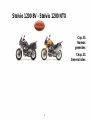 9
9
-
 10
10
-
 11
11
-
 12
12
-
 13
13
-
 14
14
-
 15
15
-
 16
16
-
 17
17
-
 18
18
-
 19
19
-
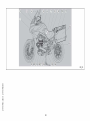 20
20
-
 21
21
-
 22
22
-
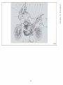 23
23
-
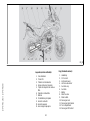 24
24
-
 25
25
-
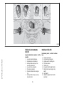 26
26
-
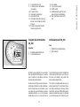 27
27
-
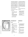 28
28
-
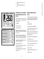 29
29
-
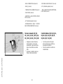 30
30
-
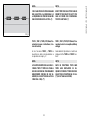 31
31
-
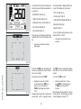 32
32
-
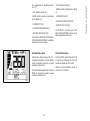 33
33
-
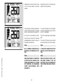 34
34
-
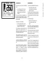 35
35
-
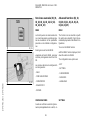 36
36
-
 37
37
-
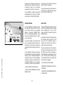 38
38
-
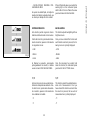 39
39
-
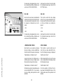 40
40
-
 41
41
-
 42
42
-
 43
43
-
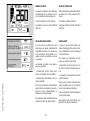 44
44
-
 45
45
-
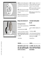 46
46
-
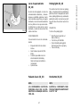 47
47
-
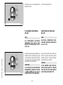 48
48
-
 49
49
-
 50
50
-
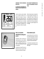 51
51
-
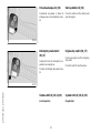 52
52
-
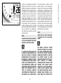 53
53
-
 54
54
-
 55
55
-
 56
56
-
 57
57
-
 58
58
-
 59
59
-
 60
60
-
 61
61
-
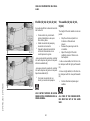 62
62
-
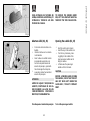 63
63
-
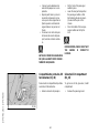 64
64
-
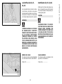 65
65
-
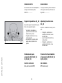 66
66
-
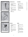 67
67
-
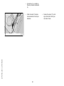 68
68
-
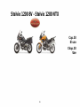 69
69
-
 70
70
-
 71
71
-
 72
72
-
 73
73
-
 74
74
-
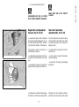 75
75
-
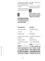 76
76
-
 77
77
-
 78
78
-
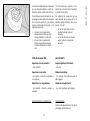 79
79
-
 80
80
-
 81
81
-
 82
82
-
 83
83
-
 84
84
-
 85
85
-
 86
86
-
 87
87
-
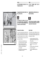 88
88
-
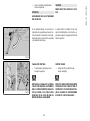 89
89
-
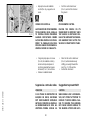 90
90
-
 91
91
-
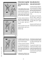 92
92
-
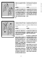 93
93
-
 94
94
-
 95
95
-
 96
96
-
 97
97
-
 98
98
-
 99
99
-
 100
100
-
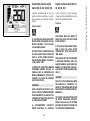 101
101
-
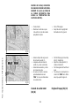 102
102
-
 103
103
-
 104
104
-
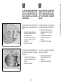 105
105
-
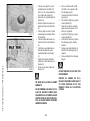 106
106
-
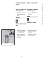 107
107
-
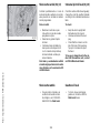 108
108
-
 109
109
-
 110
110
-
 111
111
-
 112
112
-
 113
113
-
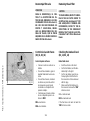 114
114
-
 115
115
-
 116
116
-
 117
117
-
 118
118
-
 119
119
-
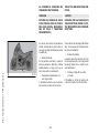 120
120
-
 121
121
-
 122
122
-
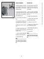 123
123
-
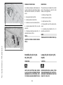 124
124
-
 125
125
-
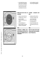 126
126
-
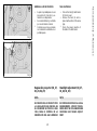 127
127
-
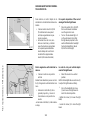 128
128
-
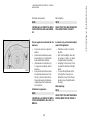 129
129
-
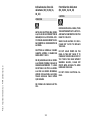 130
130
-
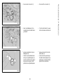 131
131
-
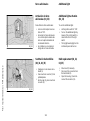 132
132
-
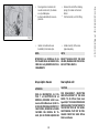 133
133
-
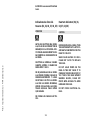 134
134
-
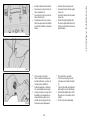 135
135
-
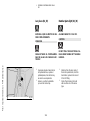 136
136
-
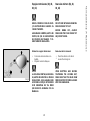 137
137
-
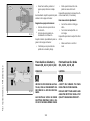 138
138
-
 139
139
-
 140
140
-
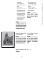 141
141
-
 142
142
-
 143
143
-
 144
144
-
 145
145
-
 146
146
-
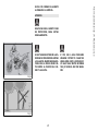 147
147
-
 148
148
-
 149
149
-
 150
150
-
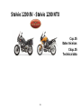 151
151
-
 152
152
-
 153
153
-
 154
154
-
 155
155
-
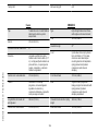 156
156
-
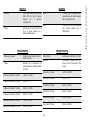 157
157
-
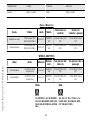 158
158
-
 159
159
-
 160
160
-
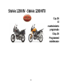 161
161
-
 162
162
-
 163
163
-
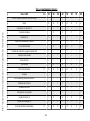 164
164
-
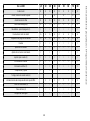 165
165
-
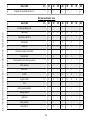 166
166
-
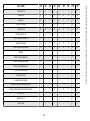 167
167
-
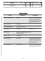 168
168
-
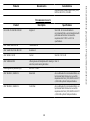 169
169
-
 170
170
-
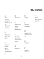 171
171
-
 172
172
-
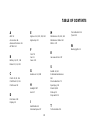 173
173
-
 174
174
-
 175
175


MOTO GUZZI Stelvio 1200 NTX Manual de usuario
- Categoría
- Carros
- Tipo
- Manual de usuario
- Este manual también es adecuado para
en otros idiomas
Artículos relacionados
-
MOTO GUZZI V7 II Special Manual de usuario
-
-
-
-
-
-
-
MOTO GUZZI V7 CLASSIC El manual del propietario
-
-