
JnstaJJatJoninstructions
38"EJectHcFreestandin9Range
TabJe of Contents:
Before you start ........................... 2
Product dimensions ........................ 4
Cabinet dimensions/requirements ........... 4-5
EHectricaH requirements .................... 6-8
Installation steps ........................ 9-17
Jf range does not operate ................... 18
Moving the range ...................... 18-19
For service ....................... Back Cover
Doing so wHk
* make installation easier.
* help you in the future if you have questions.
* help if you have an electrical inspection.
Call your Sears store or service center when you have
questions or need service. When you call, you will
need the range model and serial numbers.
9758666
lnstraccienesdeinstalaci a dela
estafael ctrica aat6nemade38"
indiee:
Antes de empezar .......................... 2
Dimensiones del producto ................... 4
Dimensiones/requisitos del gabinete ......... 4-5
Requisitos el6ctricos ...................... 6-8
Etapas de instalaci6n ..................... 9-17
Si la estufa no funciona ..................... 18
C6mo trasladar la estufa ................. 18-19
Para obtener servicio ............... Contratapa
Hacedo:
• facilitara la instalaci6n.
• Io ayudara en el futuro si tiene dguna pregunta.
• Io ayudara si tiene un inspecci6n el6ctrica.
Si tiene alguna pregunta o necesita servicio, Ilame a
su tienda o centro de servicio Sears. Cuando Ilame,
necesitara tener el nL_mero de modelo y el m3mero de
serie de la estufa.
PartNo 9758666
ParteNo. 9758666
Tip Over Hazard
A child or adult can tip the range and be killed.
Connect anti-tip bracket to rear range foot.
Reconnect the anti-tip bracket, if the range is moved.
Failure to follow these instructions can result in death
or serious burns to chiJdren and adults.
PeHgro de VueJco
Un niSo o un adutto puede volcar accidentaJmente Ba
estufa y resumtar muerto.
Conecte el soporte antivuelco a la pata trasera de ta
estufa.
Si traslada de lugar la estufa, vuemva a conectar el
soporte antivuelco.
No seguir estas instrucciones puede ocasionar la muerte
o quemaduras graves en niSos y adultos.

Before you start... Antes de empezar...
Your safety and the safety of others are
very important.
We have provided many important safety messages in
this manual and on your appliance. Always read and
obey all safety messages.
This is the safety alert symbol.
This symbol alerts you to potential hazards
that can kill or hurt you and others.
All safety messages wil! follow the safety alert symbol
and either the word "DANGER" or 'WARNING." These
words mean:
You can be killed or seriously injured if you don't
immediately_ follow instructions.
You can be killed or seriously injured if you don't
follow instructions,
All safety messages wil! tell you what the potential
hazard is, tell you how to reduce the chance of injury,
and tell you what can happen if the instructions are not
followed.
iMPORTANT: Observe aH governing codes
and ordinances.
Proper installation is your responsibility. A qualified
technician must install this range. Make sure you have
everything necessary for correct installation. It is the
instdler's responsibility to comply with installation
clearances specified on the model/serial rating plate.
The model/serial rating plate is located on the oven
frame behind the storage drawer panel.
Check location where range will be installed. The
range should be located for convenient use in kitchem
Grounded electrical outlet is required. See "Electrical
requirements," Page 6.
Su seguridad y la seguridad de los dem&s es
muy importante.
Hemos incluido muchos mensajes importantes de
seguddad en este manual y en su electrodomestico. Lea
y obedezca siempre todos los mensajes de seguridad.
Este es el simbolo de advertencia de
seguridad.
Este simbolo le llama la atencion sobre
peligros potenciales que pueden ocasionar la
muerte o una lesi6n a usted y a los demas.
Todos los mensajes de seguridad iran a continuaci6n
del simbolo de advertencia de seguridad y de la palabra
' PEUGRO" o "ADVERTENCIA." Estas palabras
significan:
Si no sigue [as instrucciones de inmediato, usted
)uede morir o sufrir una lesi6n grave.
Si no sigue Jas instrucciones, usted puede morir o
sufrir una [esi6n grave.
Todos los mensajes de seguridad le dir&n el peligro
)otencia[, le diran como reducir las posibilidades de
sufrir una lesi6n y Io que puede suceder si no se siguen
las instrucciones.
IMPORTANTF: Observe todos los c6digos y reglamentos
locales.
La debida instabci6n es su responsabilidad. Esta estufa
debe ser instaiada por un tecnico calificado. Asegurese
de tener todo Io necesario para instahda correctamente.
Es responsabilidad del instdador cumplir con los
espacios especificados en la placa de modelo y serie. La
placa de modelo y serie esta ubicada en el marco del
homo detras del panel del caj6n de almacenamiento.
Revise el lugar donde se ha de instaiar la estufa. La
estufa debe ser instdada en un lugar de la cocina donde
resulte comodo usada.
Se requiere de un tomacorriente de conexion a tierra.
Ver los "Requisitos el6ctricos" en la pagina 6.
OI
o[
Mobile home installation
The installation of this range must conform with the
Manufactured Home Construction and Safety
Standard, Title 24 CFR, Part 3280 [formerly the Federal
Standard for Mobile Home Construction and Safety,
Title 24, HUD (Part 280)] or, when such standard is not
applicable, the Standard for Manufactured Home
Installations, ANSI A225.1/NFPA 501A% or with local
codes.
When this range is installed in a mobile home, it must
be secured to the floor during transit. Any method of
securing the range is adequate as long as it conforms
to the standards listed above.
Four-wire power supply cord or cable must be used in
a mobile home installation, The appliance wiring will
need to be revised. See "Four-wire electrical
connection," Pages 13 and 15.
Copies of the standards listed may be obtained from:
*National Fire Protection Association
One Batterymarch Park
Quincy, Massachusetts 02269
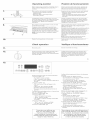
Tools needed
Assemble the required tools and parts before starting
installation. Read and follow the instructions provided
with any tools listed here,
• level
• 3/8" drive ratchet
• flat-blade screwdriver
• 3/8" and 5/16" nut driver
• channel lock pliers
• wood floors: 1/8"drill bit
• concrete/ceramic floors: 3/16" carbide-tipped masonry
drill bit (Hammer may be needed for anchors.)
• tape measure or ruler
• hand or electric drill
Parts supplied
Bracket must be securely mounted to sub-floor.
Thickness of flooring may require longer screws to
anchor bracket to sub-floor, Longer screws are
available from your local hardware store.
A, floor-mounted anti-tip bracket
B. 2 screws (#10 x 1-1/2")
C. 2 plastic anchors
hstalaei6n en una easa m6vil
La instalaci6n de esta estufa debe cumplir con el
Estandar de Construccion y Seguridad de Casas
Fabricadas ("Manufactured Home Construction and
Safety Standard), Tu'tuio 24 CFR, Parte 3280
[anteriormente el Estandar Federal de Construccion y
Seguridad de Casas Moviies, Tu'tuio 24, HUD (Parte
280)] o, cuando dicho estandar no sea aplicable, el
Estandar de [nstalaciones en Casas Fabricadas
("Standard for Manufactured Home Installations'),
ANSI A225.1/NFPA 501A% o con los codigos locales.
Cuando se instala esta estufa en una casa m6vil, debe
ser asegurada al piso durante el transporte. Cualquier
metodo de asegurar esta estufa es adecuado siempre
que cumpla con los estandares arriba indicados.
Para instalar esta estufa en una casa m6vil, debe
usarse un cord6n o cane de alimentacidn electrica de
cuatro hilos. Debera revisarse el cableado del
electrodomestico. Ver "Conexion electrica de cuatro
hiios" en ias paginas 13 y 15.
Se pueden obtener copias de Ios est_ndares indicados de:
*National Fire Protection Association
Qrle Batterymarch Park
Quincy, Massachusetts 02269
Herramientas necesarias
EnsamNe las piezas y herramientas necesarias antes
de comenzar la instalaci6n, Lea y siga las
instrucciones provistas con cudquiera de las
herramientas enumeradas aquL
nivei
llave de trinquete de 3/8"
destornillador de hoja plana
liave de tuerca de 3/8" y 5/16"
liave corrediza con ajustes
para pisos de madera: broca de barrena de 1/8"
para pisos de concreto/ceramica: broca de barrena
de mamposten'a con punta de carburo de 3/16"
(podr_asernecesarioun martiiioparaiasancias).
. cinta o regla para medir
. taladro manual o electrico
Partes que vienen con
la unidad
Lo soportes deben asegurarse bien al contrapiso.
SeguJn el grosor del piso de su casa, podr_a ser
necesario usar tornillos mas largos para fijar el
soporte ai contrapiso. Puede encontrar torniiios m_s
largos en la ferretena de su Iocalidad.
A. soporte antivuelco para fijar al piso
B. 2 tornillos (#10 x 1-1/2")
C. 2 anclas de plastico

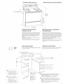
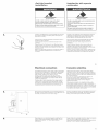
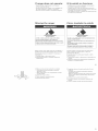
Product dimensions Dimensiones del producto
\
27-1/8" depth with handle
27-1/8" de profundidad con maniia
24-13/16"
__t 29-7/8" width
_'¢'_- 29-7/8" de ancho
36 _'
cooktop
height
36" de
altura
hasta la
superficie
de la
estufa
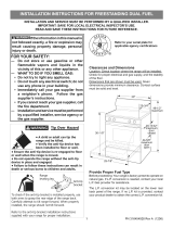
Cabinet dimensions!
requirements
To eHiminate the risk of burns or fire by reaching over
heated surface units, cabinet storage space Hocated
above the surface units shouHd be avoided, tf cabinet
storage is to be provided, the risk can be reduced by
installing a range hood that projects horizontally a
minimum of 5 inches beyond the bottom of the
cabinets.
AH openings in the wall or floor where range is to be
installed must be sealed.
Cabinet opening dimensions that are shown must be
used. Given dimensions are minimum clearances.
46-7/8"
overall height
46-7/8" de
altura total
Dimensiones! requisitos
del gabinete
Para eliminar el riesgo de quemaduras o incendio al
extenderse sobre las unidades con superficies calientes,
se debe evitar el uso de los armarios de dmacenamiento
ubicadosencimalassuperficiesdelasunidades. Sise
provee un armario de dmacenamiento, se puede reducir
el riesgo instdando una campana sobre la superficie de
la estufa que se proyecte horizontdmente 5 pulgadas
como minimo mas alia de los armarios.
Deben sellarse todas los aberturas en la pared o en el piso
donde se ha de instalar la estufa+
Deben usarse las dimensiones de la abertura del gabinete
que se muestran. Estas dimensiones son los espacios
mu'nimos+ 4
Anti-tip bracket
The floor+mounted anti-tip bracket must be installed+ To install
the anti-tip bracket supplied, see Page 9 and the anti-tip bracket
template/instruction sheet.
Soporte antivuMco
Debe instalarse el soporte antivuelco fiiado al sue!o+ Pare instalar
el soporte antivuelco que viene con la estufa, ver la P_gina 9 y la
hoia de instrucciones/plantilla del soporte antivuelco+
_._ 18" rain+vertical clearance
between overhead side cabinet
to countertop -- both sides
espacio vertical minimo de 18"
entre el gabinete superior y e!
mostrador, a ambos lados.
4" rain. horizontal spacing to
side wall or other combustible
material above coektop -- both
sides
4" de espacio minimo
horizontal sobre la superficie
de la estufa hasta la pared
lateral o cualquier otro material
combustible, a ambos lados.
30-1/8" opening width
I [_ 30-1/8" de ancho de la
I I abertura
13" max. upper cabinet depth
13" de pgOfUndidad m_xima en el _ ...... _ /
/
\
Outlet
8" to 22" from either
cabinet, 5-1/2" max+
from floor+ Position
outlet as shown.
Tomacorriente
mural -- de 8" a 22"
desde cualquier
gabinete,
5-1/2" max+ desde el
piso+ Coloque e!
tornacorriente como
se muestra+
For minimum clearance to the top of the coo!<top, see _+
Pare e! espacio minimo desde la parte superior de la superficie
de la estufa, vea la _+
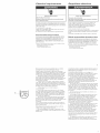
Do not pinch the power supply cord between the
range and the wall.
De net seal the range to the side cabinets.
No presione el cordon de alimentaci6n entre la
estufa y la pared+
No pegue la estufa a los gabinetes laterales+
24" min. when bottom of wood or metal cabinet is protected by
notlessthanI/4"flame retardantmillboardcoveredwithnet less
than No. 28 MSG sheet steel, 0.015" stainless steel, 0.024"
aluminum or 0+020"copper.
30" rain. clearance between the top of the cooking platform and
the bottom of an unprotected wood or metal cabinet.
24" rnin. cuando la parte inferior de! gabinete de madera o
metal esta protegida pot un cart6n retardante alas llamas no
menor de 1/4", cubierto al n-lenos por una hoia de acero No. 28
MSG, acero inoxidable de 0.015", aluminio de 0.024" o cobre de
0.020".
Un espacio minirno de 30" entre la parte superior de la
plataforma para estufar y la parte inferior de un gabinete no
protegido de madera o metal+

Electrical requirements Requisitos electricos
Electrical Shock Hazard
ElectdcaHy ground range.
Failure to follow this instruction can result in death,
fire or electrical shock.
If codes permit and a separate ground wire is used, it
is recommended that a qualified electrician determine
that the ground path and wire gauge are in accordance
with iocai codes.
Do not ground to a gas pipe.
Check with a qualified electrician if you are not sure
range is properly grounded.
Do not have a fuse in the neutral or ground circuit.
Recommended ground method
It is the personal responsibility and obligation of the
customer to contact a qualified electrician to assure
that the electrical installation is adequate and is in
conformance with the National Electrical Code,
ANSI/NFPA 70 -- latest edition _ and all local codes
and ordinances.
Copies of the standards listed above may be obtained from:
*National Fire Protection Association
One Batterymarch Park
Quincy, Massachusetts 02269
Peligro de Choque E!_ctrico
Conecte a tierra la estufa.
No seguir esta instrucci6n puede ocasionar [a muerte,
incendio o choque el_ctrico.
Si los c6digos Io permiten y se usa un alambre de
puesta a tierra separado, se recomienda qua un
electricista cdificado determine qua el trayecto de
puesta a tierra y el calibre del ahmbre esten de
acuerdo con los c6digos Iocales.
No la conecte a tierra a un tubo de gas.
Consulte con un electricista calificado si no esta seguro
de qua la estufa tenga la debida conexi6n de puesta a
tierra.
No ponga un fusible en el circuito neutro o de tierra_
Metodo reeomendado de puesta a tierra
Es responsabilidad personal y obligacion del cliente
contactar a un electricista calificado para asegurar que
la instalacion electrica sea adecuada y cumpla con el
Codigo Electrico Nacional, ANSI/NFPA 70 -- uJltima
edicion _ y todos los codigos y reglamentos locales.
Se pueden obtener copias de !os est@adares indicadoa arriba de:
_National Fire Protectior! Associatior!
One Batterymarch Park
Quincy, Massachusetts 02269
Power supply cord is not supplied, but is available
through your local electrical supply house.
Range must be connected to the proper electrical
voltage and frequency as specified on the model/serial
rating plate. (The model/serial rating plate is located
on the oven frame behind the storage drawer paneL)
Aluminum/copper connection must conform with
local codes and industry accepted wiring practices.
This range is provided with appropriate connectors for
attachment of aluminum wiring. Follow installation
instructions provided.
A three-wire or four-wire, single@hase, 120/240-
volt, 6O-Hz, AC-only, electrical supply (or three-wire or
four-wire 120/208-volt if specified on the model/serial
rating plate} is required on a separate circuit of at least
5g-amp, fused on both sides of the line.
A time-delay fuse or circuit breaker is
recommended.
Local codes may permit the use of a U.L.-listed,
250-volt, range power supply cord (pigtail) of at least
BO-amp. This cord matches a three-wire receptacle @
of NEMA Type 10-50R. Connectors on the appliance
end must be provided at the point the power supply
cord enters the appliance.
The range can be connected directlyto the fused
disconnect (or circuit breaker box) through flexible
armored conduit. Allow two to three feet of slack in the
line so that it can be moved if servicing is ever
necessary.
A U.L-listed conduit connector must be provided at
each end of the power supply cane (at the range and
at the junction box)_
Wire sizes and connections must conform with the
rating of the range (at least 5O-amp}_
. The wiring diagram is located on the back of the
range or on the inside of the storage drawer in a clear
plastic bag.
La unidad no incluye cordon de alimentaci6n, pero se
puede adquirir en el establecimiento de suministros
electricos de su Iocalidad.
La estufa se debe conectar con el voltaic y la
frecuencia adecuados seguJn se especifica en la placa
de modelo y serie (ubicada en el marco del homo
detras del panel del caj6n de almacenamiento).
La conexion de cobre/aluminio debe hacerse
conforme alas prScticas de cableado aceptadas pot la
industria y los c6digos locales. Esta estufa esta
provista de los conectores adecuados para fijarse al
cableado de aluminio. Siga las instrucciones de
instalacion provistas.
Se requiere de un suministro eiectrico de tres hiios
o de cuatro hiios, de una soia fase, de 120/240 voitios,
60 Hz, s6io de CA (o de tres hiios o de cuatro hiios, de
120/208 voitios, si esto se especifica en ia placa de
modelo y serie}, en un circuito separado de 50 amp
como mu'nimo, protegido con fusible en ambos lados
de la I_nea.
Se recomienda usar un fusible con retardo o un
interruptor de circuito.
Los codigos locales podru'an permitir el uso de un
cordon de alimentacion electrica (caNe flexible de
conexi6n) para estufas de 250 voitios, de 50 amp
como mu'nimo, aprobado pot U.L Este cordon
corresponde a un tomacorriente de tres hiios @ Tipo
NEMA 10-BOR. Deben usarse conectores en el extremo
de la unidad, en el punto donde el cord6n de
alimentacion electrica entra en la unidad.
La estufa puede conectarse directamente a la caja
de fusibles desconectada (o caja del disyuntor) a
traves de un conducto blindado flexible. Deje de dos a
tres pies de holgura en la I_nea para que se pueda
mover la unidad si llega a necesitar servicio.
Se debe poner un conector de conductos aprobado
pot U.L a cada extremo del cable de alimentaci6n
electrica (en la estufa yen la caja de empalmes}.
Las dimensiones del alambre y las conexiones deben
cumplir con la clasificaci6n de la estufa (de 50 amp
como mu'nimo}.
El diagrama de cableado se encuentra en la parte
trasera de la estufa o en el interior del caj6n de
almacenamiento, en una bolsa plastica transparente.

ff connecting to a four-wire system:
This range is manufactured with the ground connected
to the cabinet_ The ground must be revised so the
green grounding wire of the four-wire power suppiy
cord is connected to the cabinet, See "Four-wire
eiectricai connection," section, Pages 13-15,
When a four-wire receptacb ® of NEMA Type 14-50R
is used, a matching U_L-Hsted, four-wire, 250-voit, at
least 40 amp, range power supply cord (pigtail) must
be used. This cord contains four copper conductors
with either ring terminals or spade terminals with
upturned ends at the appliance end, terminating in a
NEMA Type 14-50P plug on the supply end. The fourth
(grounding) conductor must be identified by a green
or green/yellow cover and the neutral conductor by a
white cover. Cord should be Type SRD or SRDT with a
U.L=listed strain relief and be at least four feet long,
The minimum conductor sizes for the copper
four-wire power cord are:
40 amps circuit
2 No.-8 conductors
1 No.-lO white neutral
1 No=8 green grounding
Si se conecta la estufa a un sistema de
cuatro hilos:
Esta estufa se fabrica con la toma de tierra conectada
al gabinete. Se debe revisar la toma de tierra de
manera que el hiio verde de puesta a tierra del cordon
de alimentacion electrica de cuatro hiios este
conectado al gabinete. Ver la seccion de "Conexi6n
electrica de cuatro hiios" en la Paginas 13-15.
Cuando se usa un tomacorriente de cuatro hiios ®
Tipo NEMA 14-50R, debe usarse un cordon de
alimentaci6n electrica (cable flexible de conexi6n) para
estufa correspondiente, de cuatro hiios, 250 voitios, de
40 amp como mu'nimo, aprobado por U.L Este cordon
contiene cuatro conductores de cobre con terminales
anulares o terminales de horquilla con los extremos
hacia arriba, con una clavija de contacto Tipo NEMA
14-50P en el extremo del suministro electrico, El cuarto
conductor (de tierra) debe identificarse por medio de
una cubierta verde o verde/amarilla y el conductor
neutro por una cubierta blanca. El cordon debe ser
Tipo SRD o SRDT con una abrazadera de anclaje
aprobada por U.L, y medir al menos cuatro pies de
Iongitud.
Las dimensiones mu'nimas del conductor del cordon de
alimentacion de cobre de cuatro hiios son:
circuito de 40 amp
2 conductores No. 8
1 hiio neutro No_ 10
1 conexion a tierra verde No_ 8
lnstMlatien steps Etapas de instMaci6n
Excessive Weight Hazard
Use two or more people to move and install range.
Failure to do so can resutt in back or other injury.
PeHgro de Peso Excesivo
Use dos o m&s personas para mover e instalar la
estufa.
No seguir esta instrucci6n puede ocasionar una
Besi6n en BaespaMa u otto tipo de mesiones.
lm
Put on safety glasses and gloves. Remove oven racks
and parts package from inside oven. Remove shipping
materials, tape and protective film from range.
P6ngase anteojos de seguridad y guantes. Quite ias
rejillas del horno y el paquete de piezas del interior del
horno. Quite los materiales de embarque, la cinta y la
peHcula protectora de la estufa_
Do not remove the cardboard shipping base @ at
this time.
No quite todavu'a la base de carton para embarque @.
m
®
@
@
,{i ,,
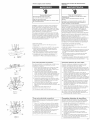
Remove storage drawer. Use a 3/8" drive ratchet (_ to
lower rear leveling legs _) one-half turn. Use channel
lock pliers @ to lower front leveling legs _ one-half
turn.
Saque ei caj6n de almacenamiento, Use una iiave de
trinquete de 3/8" _ para bajar media vuelta las patas
niveladoras traseras @. Use la llave corrediza con
ajustes @ para bajar media vuelta las patas
niveladoras delanteras (_).

Anti-t@ bracket
installation
lnstMacion del sopo e
antivuelco
Tip Over Hazard
A child or adult can tip the range and be killed.
Connect anti-tip bracket to rear range foot.
Reconnect the anti-tip bracket, if the range is moved.
Failure to follow these instructions can result in death
or serious burns to children and aduffs.
PeJigro de Vue[co
Un niSo o un adu[to puede vo[car accidenta[mente la
estufa y resumtar muerto,
Conecte e[ soporte antivueJco a [a pata trasera de [a
estufa.
Si traslada de lugar la estufa, vue!va a conectar el
soporte antivuelco.
No seguir estas instrucciones puede ocasionar la
muerte o quemaduras graves en niSos y aduffos.
-%
Contact a qualified floor covering installer for the best
procedure for drilling mounting holes through your
type floor covering.
Use the anti-tip bracket template/instruction sheet to
install the anti-tip bracket.
Anti-tip bracket must be anchored securely to the
sub-floor.
Depending on the thickness of your flooring, longer
screws may be necessary to anchor the bracket to the
sub-floor. Longer screws are available from your local
hardware store.
Before moving range across floor, check that range is
still on cardboard shipping base to protect floor
covering.
Contacte a un instalador de revestimientos de pisos
calificado para determinar el procedimiento mas
adecuado para taladrar los orificios de mnntaje a
traves del tipn de material del pisn de su casa.
Use la hoja de instrucciones/plantilla del soporte
antivuelco para instalar el soporte antivuelco.
El soporte antivuelco debe asegurarse bien al
contrapisn.
Segu3n el grosor del piso de su casa, podna ser
necesarin usar tornillos mas largos para fijar el
soporte ai contrapisn. Puede encontrar torniiios mas
largos en la ferretena de su Incalidad.
Antes de mover la estufa sobre el piso, asegurese de
que la estufa este todavu'a snbre la base de carton de
embarque para proteger el revestimiento del piso.
10
Electrical connection
Grounding instructions: This range must be grounded.
in the event of malfunction or breakdown, grounding
wiii reduce the risk of electric shock by providing a
path of least resistance for electric current.
if using a power supply cord, the plug must be
plugged into an appropriate outlet that is properly
installed and grounded in accordance with all local
codes and ordinances.
if using a direct wire connection, this range must be
connected to a grounded metal, permanent wiring
system; or an equipment-ground conductor must be
run with the circuit conductors and connected to the
equipment-ground terminal or lead on the range.
Conexi6n eiectrica
hstruccinnes de puesta a tierra: Esta estufa debe
conectarse a tierra. En cash de real funcionamientn o
falla, la conexion a tierra reducira el riesgo de chnque
electrico al proveer una via de menor resistencia para
la corriente electrica.
Si se usa un cordon de alimentacion electrica, la
clavija de cnnexion debe conectarse a un
tnmacorriente adecuadn debidamente instaladn y
puesto a tierra de acuerdo con ins c6digos y
reglamentos locales.
Si se usa una conexion con alambre directo, esta
estufa debe conectarse a un sistema de instalaci6n
permanente metalica de tierra, o debe correr junto con
los conductores de circuito, un conductor a tierra para
el material conectado al borne a tierra para el material
nal alambre de conexion de la estufa.
m
®
t j_
Remove the terminal block cover screws @ located on
the back of range. Pull terminal box cover @ down and
towards you to remove cover from range.
Quite los tornillns @ de la tapa del tablero de bnrnes
en la parte trasera de la estufa. Jale la tapa (_ hacia
abajo y hacia usted para sacarla de la estufa.
m
Depending on your electrical supply, make the four-
wire or three-wire connection following the "Power
supply cord method" or "Direct wire method"
instructions_
Segun el tipo de suministro electrico, haga la conexion
con tres hiios o cuatro hiios siguiendo ias
instrucciones del "Metndo del cordon de alimentaci6n
electrica" o del "Metodo de alambre directo'.
11

Power supply cord method: Mbtodo del cord6n de alimentaci6n
elbctrica:
Electrical Shock Hazard
Disconnect power before servicing.
Use a new 40 amp power supply cord.
Plug into a grounded outmet.
Failure to follow these instructions can result in death,
fire, or electrical shock.
WARNING -improper connection of the equipment-
grounding conductor can result in a risk of electric
shock. Check with a qualified electrician or service
personnel if you are in doubt as to whether the range
is properly grounded. Do not modify the power supply
cord plug, if it will not fit the outlet, have a proper
outlet installed by a qualified electrician.
This range is manufactured with the neutral terminal
connected to the cabinet. Use a three-wire, U.L=listed,
at bast 40 amp power supply cord (pigtail}; or if local
codes do not permit ground through the neutral, use a
four-wire power supply cord rated at 250 volts, at least
40 amp and investigated for use with ranges. (See
"Four-wire electrical connection/')
1. Disconnect power.
2. Remove the knockout A for the 40 amps power
supply cord.
3. Assemble a U.L=listed strain relief B in the opening.
4. insert the power supply cord through the strain
relief, allowing enough slack to easily attach the
wiring to the terminal block.
B. Use either ring-type terminals or spade terminals
with upturned ends to connect the power supply.
6. Complete electrical connection according to your
type electrical supply ("Three-wire electrical
connection" or "Four-wire electrical connection/')
Peligro de Choque Et_ctrico
Desconecte el suministro de energia antes de dade
mantenimiento.
Use un cable de suministro el_ctrico nuevo de
40 amp.
Enchufe en un tomacorriente de conexi6n a tierra.
No seguir estas instrucciones puede ocasionar la
muerte, incendio o choque el_ctrico.
ADVERTENCIA - La conexion indebida del conductor a
tierra para el material puede producir riesgo de choque
electrico, Consulte con un electricista calificado o tecnico
de servicio sitiene dudas de que su estufa tenga ia
debida conexi6n de puesta a tierra. No modifique la
clavija de contacto del cord6n de alimentacion el6ctrica.
Si no encaja en el tomacorriente, haga que un
electricista calificado instale un tomacorriente adecuado.
Esta estufa se fabrica con el borne neutro conectado al
gabinete. Use un cordon de alimentacion electrica (caNe
flexible de conexi6n} de tres hilos, de
40 amp como mu'nimo, aprobado pot U_L, o, si los
c6digos locales no permiten la conexi6n a tierra a traves
del conductor neutro, use un cord6n de alimentaci6n
electrica de cuatro hilos, clasificado con 250 voltios, de
40 amp como mu'nimo, que haya sido probado para uso
con estufas, (Vet "Conexi6n eiectrica con cuatro hiios"}.
1, Desconecte el suministro de energu'a.
2. Quite el agujero ciego A para el cord6n de
alimentaci6n de 40 amp.
3. Instale en la abertura una abrazadera de anclaje B
aprobada pot U,L
4. Inserte el cord6n de alimentaci6n electrica a traves de
la abrazadera de anclaje, dejando suficiente holgura
para fijar con facilidad el cableado al tablero de
bornes.
B. Use terminales anulares o terminales de horquilla
con los extremos hacia arriba para conectar el
suministro de energ_a,
6. Complete la conexi6n electrica de acuerdo con el tipo
de suministro electrico ("Conexion electrica de tres
hilos" o "Conexion electrica de cuatro hilos"}. 12
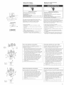
\
%---©
Figure 1
Figura 1
Figure 2
Figura 2
Fourowire electrical connection:
Use this method for new installations, mobile homes,
recreational vehicles, and whenever four-wire
installation is required.
7. Remove the ground-link screw @ from the range
frame_ Save the grounddink screw. Bend the
groun-link @ away from the range so that it does
not contact the range. See Figure 1.
8. Connect the green ground wire @ from power
supply cord to the range using the ground-link
screw. The ground wire must be attached first and
must not contact any other terminal See Figure 2.
9. Use a 1/4" nut driver and remove the hex washer
head screws from the terminal blocks.
10. Connect the neutral (center) wire (_ to the center
terminal connector @ using one of the hex washer
head screws. Securely tighten screw for proper
electrical connection. See Figure 2.
11. Connect the other two wires @ (lines 1 and 2} to
the outer aluminum terminal blocks. Securely
tighten screws for proper electrical connection. See
Figure 2.
12. Tighten the strain relief screws _.
13. Replace the terminal block cover.
14. Plug power supply cord into grounded outlet.
Cone×i6n electrica de cuatro hilos:
Use este metodo para instalaciones nuevas, casas
rodantes, veh_culos recreativos y siempre que se
requiera una instalacion de cuatro cables.
7. Quite el tornillo del enlace de puesta a tierra © del
marco de la estufa. Guarde el tornillo del enlace de
puesta a tierra. DoNe el enlace de puesta a tierra @
lejos de la estufa para que no haga contacto con la
misma. Vet Figura 1.
8. Conecte el hilo verde de puesta a tierra @ del
cord6n de alimentacion electrica a la estufa usando
eltornillodelenlace depuestaatierra. EIhilode
puesta a tierra debe fijarse primero y no debe
hacer contacto con ningun otto borne. Vet Figura 2.
9. Use una iiave de tuerca de 1/4" y saque los torniiios
de cabeza hexagonal de la arandela de los tableros
del borne.
10. Conecte el hiio neutro (hiio central} (_ al conector
central del tablero _) usando uno de los tornillos
de cabeza hexagonal de la arandela. Apriete con
seguridad el tornillo para una conexion electrica
adecuada. Ver Figura 2,
11. Conecte los otros dos hiios @ (l_neas 1 y 2) a los
tableros de bornes exteriores de aluminio. Apriete
con seguridad los tornillos para una conexi6n
electrica adecuada. Vet Figura 2.
12. Apriete los tornillos de la abrazadera de anclaje _.
13, Vuelva a colocar la tapa del tablero de bornes,
14. Enchufe el cordon de alimentacion electrica en el
tomacorriente de conexion a tierra,
@
Figure 1
Figura 1
Three-wire electrical connection:
Use this method only if local codes permit connecting
cabinet-ground conductor to neutral wire of power
supply cord.
7. Use a 1/4" nut driver and remove the hex washer
head screws from the aluminum terminal blocks.
8. Connect the neutral (center) wire ©to the center
terminal connector @ using one of the hex washer
head screws. Securely tighten screw for proper
electrical connection. See Figure 1.
9. Connect the other two wires _) to outer terminal
screws _ on the terminal block. See Figure 1.
10. Tighten the strain relief screws @_
11. Replace the terminal block cover.
12. Plug power supply cord into grounded outlet.
Cone×i6n eJecttica de tres hHos:
Use este metodo unicamente si los codigos locales
permiten conectar el conductor de tierra del gabinete
al hilo neutro del cordon de alimentacion electrica.
7. Use una llave de tuerca de 1/4" y saque los
tornillos de cabeza hexagonal de la arandela de los
tableros de aluminio del borne.
8. Conecte el hilo neutro (hilo central} @ al conector
central del tablero @ usando uno de los tornillos de
cabeza hexagonal de la arandela. Apriete con
seguridad el tornillo para una conexi6n electrica
adecuada. Vet Figura 1_
9. Conecte los otros dos hilos @ a Iostornillos
terminales exteriores (_ en el tablero de bornes.
Vet Figura 1_
10. Apriete los tornillos @ de la abrazadera de anclaje.
11.Vuelva a colocar la tapa del tablero de bornes.
12. Enchufe el cord6n de alimentacion electrica en el
tomacorriente de conexion a tierra.
13

Direct wire method:
AUuminum or Copper
M6todo de aiambre directo:
AUuminie o cobre
I1" I
Electrical Shock Hazard
Disconnect power before servicing.
Use 8 gauge copper wire or 6 gauge
aluminum wire.
Electrically ground range.
Failure to follow these instructions can result in death,
fire, or emectrical shock.
This range may be connected directly to the fuse
disconnect or circuit breaker box; or with a U.L.-listed,
range power supply cane of at least 40 amps.
Depending on your ebctrbal supply, make the
required three-wire or four-wire connection.
1, Disconnect power.
2. Remove the knockout @ as needed for conduit
connection.
3. Assemble a U.hdisted conduit connector ® in the
opening,
4. Strip the insulation back 1 inch from the end of each
wi re.
5. Allow enough slack in the wire to easily attach the
wiring to the terminal block.
6. Complete electrical connection according to your
type electrical supply ("Four-wire electrical
connection" or "Three-wire electrical connection.")
Peligro de Cheque Em&ctrico
Antes de conectar el cord6n, desconecte et
suministro de energ[a.
Utimicealambre de cobre de ancho 8 o alambre de
aluminio de ancho &
Conecte a tierra ta estufa.
No seguir estas instrucciones puede ocasionar la
muerte, incendio o cheque el_ctrico.
Esta estufa se puede conectar directamente al
desconectador con fusible o dispositivo interrupter de
circuitos, o con un cable de dimentaci6n el6ctrica para
estufas de 40 amp come m_nimo aprobado per U.L.
Segun el tipo de suministro el6ctrico, haga la conexi6n
con tres hilos o con cuatro hilos.
1. Desconecte el suministro de energ_a,
2. Quite el disco removibb @, segun sea necesario,
para la conexi6n del circuito,
3. Ensamble un conector de conducto ® que este en la
lista de U.L en la abertura.
4. Retire el aislamiento 1 pulgada desde el extreme de
cada hilo.
5. Deje que el cable quede Io suficientemente flojo
para poder sujetar con facilidad el bloque terminal
de cabbado.
6. Complete la conexi6n el6ctrica de acuerdo con el
tipo de suministro electrico ("Conexi6n el6ctrica de
cuatro hilos" o "Conexi6n el6ctrica de tres hilos").
Figure 1
Figura 1
Figure 3
Figura 3
Figure 2 \"(_
Figura 2
c
Four-wire electrical connection:
Use this method for new installations, mobile homes,
recreational vehicles, and whenever four-wire
installation is required,
7. Remove the ground-link screw © from the range
frame. Save the ground-link screw and cup washer.
Bend the ground-link @ away from the range so
that it does not contact the range. See Figure 1.
8. Connect the bare ground wire _to the range using
the ground-link screw and cup washer. The ground
wire must be attached first and must not contact
any other terminal. See Figure 2.
9. Loosen (do not remove) the hex washer head
screw @ and insert the neutral (white) wire
under the screw clamp at the bottom of the center
position terminal connector. Insert the other two
wires (lines 1 and 2) @ under the other two screw
clamps, Securely tighten the hex washer head
screws to 90 in/Ibs minimum torque to make
proper electrical connection. See Figure 3.
10. Tighten the locking ring ® of the conduit
connector _.
11, Replace the terminal block cover.
14
Conexi6n el6etrica de cuatro hilos:
Use este metodo para instalaciones nuevas, casas
rodantes, veh_culos recreativos y siempre que se
requiera una instalaci6n de cuatro cables.
7. Quite el tornillo del enlace de puesta a tierra © del
marco de la estuf& Guarde el tornillo de enlace a
tierra y la arandela acopada. DoNe el enlace de
puesta a tierra @ lejos de la estufa para que no
haga contacto con la misma. Ver Figura 1,
8. Conecte el cable desnudo de tierra @ a la estufa
usando el tornillo de enlace a tierra y la arandela
acopada. El cane de tierra debe sujetarse primero
y no debe estar en contacto con ninguJn otro
terminal. Vea la Figura 2.
9. Afloje (no quite) el tornillo de cabeza hexagonal
con arandela @ e inserte el hiio neutral (blanco)
debajo de la abrazadera del tornillo en la parte
inferior del conector del borne de posici6n central
Inserte los otros dos hiios (Hneas 1 y 2) (_ debajo
de las otras dos abrazaderas de tornillo. Apriete
con seguridad los torniiios de cabeza hexagonal
de arandela a un par de torsion m_nimo de
96 pulg./Ibs para hacer una conexion electrica
adecuada. Ver Figura 3.
10. Apriete el anillo de sujeci6n @ del conector de
conducto (_,
11. Vuelva a colocar la tapa del tablero de berries.
o ©
Figure 1
Figura 1
_}b _,
Figure 2
Figura 2
Three-wire electrical connection:
Use this method only if local codes permit connecting
ground conductor to neutral supply wire.
7. Loosen (do not remove) the hex washer head
screw @ and insert the neutral (white) wire @
under the screw damp at the bottom of the center
position terminal connector, insert the other two
wires (lines 1 and 2} @ under the other two screw
clamps, Securely tighten the hex washer head
screws to 90 in/Ibs minimum torque to make
proper electrical connection. See Figure 2.
8. Tighten the locking ring (_ of the conduit
connector.
9, Replace the terminal block cover.
Conexi6n elbetrica de tres hilos:
Use este metodo solo si los codigos locales permiten la
conexion del conductor de tierra al cane de suministro
neutral
7. Afloje (no quite) el tornillo de cabeza hexagonal con
arandela © e inserte el hiio neutral (blanco) @
debajo de la abrazadera del tornillo en la parte
inferior del conector del borne de posici6n central,
Inserte los otros dos hiios (Hneas 1 y 2) @ debajo de
las otras dos abrazaderas de tornillo. Apriete con
seguridad los torniiios de cabeza hexagonal de
arandela a un par de torsi6n m_nimo de
96 pulg./Ibs para hacer una conexion electrica
adecuada. Ver Figura 2.
8. Apriete el anillo de sujeci6n @ del conector de
conducto.
9. Vuelva a colocar la tapa del tablero de bornes.
15

Operating position Posicidn de fundenamiente
m
m
10.
Before moving range across floor, check that range is
still on cardboard shipping base to protect floor
covering,
Antes de mover la estufa sobre el piso, asegurese de
que la estufa esta todavu'a sobre la base de carton de
embarque para proteger el revesfimiento del piso,
Make sure the anti4ip bracket is installed:
, Look for the antFtip bracket A securely
attached to floor,
, Slide range back so rear range foot B is
under antFtip bracket,
Asegurese de que el soporte antivuelco este [nstalado:
, Busque el soporte antivuelco @ que esta bien
asegurado al piso,
Deslice la estufa hacia atras de manera que la pata
trasera de la estufa ® quede debajo del soporte
antivuelco,
If installing the range in a mobile home, you must
secure the range to the floor. Any method of securing
the range is adequate as long as it conforms to the
standards in the "Mobile home installation"
instructions,
Cuando se instala la estufa en una casa m6vil, debe
ser asegurada al piso. Cualquier metodo de asegurar
esta estufa es adecuado s[empre que cumpla con los
estandares indicados en las instrucciones para
'qnstalaci6n en una casa m6vil".
Place rack @ in oven. Place level @ on rack, first side
to side then front to back.
if range is not level, puii range forward until rear
leveling leg is removed from the anti-tip bracket, Use
3/8" drive ratchet and channel lock pliers to adjust
leveling legs up or down until range is level. Slide
range back so rear range foot is under antFtip bracket.
NOTE: Oven must be level for satisfactory baking
conditions.
Replace the storage drawer or lower panel.
Coloque la rejilla @ en el horno. Coloque el nivel @ en la
rejilla, primero de lado a lado, luego de la parte
delantera a la trasera.
Si la estufa no esta nivelada, jale la estufa hacia adelante
hasta que la pata niveladora trasera se separe del
soporte antivuelco, Use una llave de trinquete de 3/8" y
una llave corrediza para ajustar las patas niveladoras
hacia arriba o hacia abajo hasta que la estufa este
nivelada. Deslice la estufa hacia atrOs de manera que la
pata trasera de la estufa quede debajo del soporte
antivuelco.
NOTA: el horno debe estar nivelado para que las
condiciones sean adecuadas para hornear.
Vuelva a colocar el caj6n de almacenamiento o el
panel inferior.
Check operation Verifique el funcionamiento
1 1. Reconnect power. Conecte el suministro de energu'a.
ooo Check the operation of the cooktop elements: Push in
12. oo
and turn each surface unit control knob to "Hi"
position. Check the operation of the cooktop elements
and indicator lights.
Verifique el funcionamiento de los elementos de la
superficie de estufa: empuje y gire cada una de las
perillas de control de la unidad de superficie hasta la
posicion "Hi". Verifique el funcionamiento de los
elementos de la superficie de estufa y las luces
indicadoras.
16
13.
LU6_T
Check the operation of the oven and broil elements:
1. Press the "BAKE" pad.
• The "BAKE" indicator wiii light.
"350°F '' will appear in the display,
• The "START ?" indicator will begin to flash after 5
seconds.
2. Press the "START" pa&
• "PrE" and the time of day wiil appear in the
display.
• "HEAT" and "ON" indicators wiii lighL
• The bottom element should glow red.
• The upper element should become hot but not
glow red.
The oven is preheated when you hear a 1-second tone,
and "PrE" changes to "350°R"
3. Press the "STOP/CLEAR" pa&
4. Press the "BROIL" pad.
, "500°F " will appear in the display.
, "BROIL" indicator will light.
, The "START ?" indicator will begin to flash after
5 seconds.
5. Press the "START" pa&
, "HEAT" and "ON" indicators will light.
, The upper element should glow re&
& Press the "STOP/CLEAR" pa&
Verifique el funcionamiento del homo y los elementos
para asar:
1, Oprima el bot6n de "BAKE" (Hornear),
Se encendera la luz indicadora de "BAKE" (Hornear).
En la pantalla aparecera "350°F ".
La luz indicadora de "START ?" (Empezar?)
comenzara a destellar despues de 5 segundos.
2. Oprima el boton de "START" (Empezar),
• Apareceran en la pantalla "PrE" y la hora del dia,
• Se encenderan las luces indicadoras de "HEAT"
(Calor) y "ON" (Encendido),
• El elemento inferior debe ponerse rojo,
• El elemento superior debe calentarse, pero sin
ponerse rojo,
El homo esta precalentado cuando usted escucha un
tono de 1 segundo, y "PrE" cambia a "350°F ".
3, Oprima el boton de "STOP/CLEAR" (Detener/
Despejar),
4, Oprima el boton de "BROIL" (Asar),
• En la pantalla aparecera "500°F ''.
• Se encendera la luz indicadora de "BROIL" (Asar),
• La luz indicadora de "START ?" (Empezar?)
comenzara a destellar despues de 5 segundos,
5, Oprima el boton de "START" (Empezar),
• Se encenderan las luces indicadoras de "HEAT"
(Calor) y "ON" (Encendido).
• El elemento superior debe ponerse rojo.
6, Oprima el boton de "STOP/CLEAR" (Detener/
Despejar),
To get the most efficient use
from your new electric range,
read your Owner's Manual.
Keep Installation Instructions and
Owner's Manual close to the electric
range for easy reference.
Para obtener el uso mas eficiente de su
nueva estufa el6ctrica, lea su Manual de
Uso y Cuidado. Guarde las Instrucciones
de Instalaci6n y el Manual cerca
de la estufa el6ctrica para tenedos
a mano cuando los necesite.
17

If range does not operate:
, Check that the circuit breaker is not tripped
or the house fuse blowm
Check that the power supply cord is plugged into
the wall receptacle or power is connected.
See Use and Care Guide for troubbshoofing list.
Si la estu@ no funciena:
Verifique que no se haya disparado el interruptor
de circuito o quemado un fusible.
Verifique que el cord6n de alimentaci6n electrba
este enchufado en el tomacorriente mural o que este
conecttado el suministro d energia.
Vea el Manual de Uso y Cuidado para obtener la Iista
de soluci6n de problemas.
Moving the range:
Cemo trastadar la estufa:
Tip Over Hazard
A child or adult can tip the range and be killed.
Connect antiotip bracket to rear range foot.
Reconnect the anti=tip bracket, if the range is moved.
Failure to follow these instructions can result in death
or serious burns to children and adults.
PeHgro de Vue[co
Un niSo o un adu[to puede vo[car accidenta[mente Ba
estufa y resultar muerto.
Conecte el soporte antivuelco a [a pata trasera de ta
estufa.
Si traslada de lugar la estufa, vuelva a conectar el
soporte antivuelco.
No seguir estas instrucciones puede ocasionar la
muerte o quemaduras graves en niSos y adumtos.
When moving range, slide range onto cardboard or
hardboard to prevent damaging the floor covering.
If moving the range is necessary for cleaning or
maintenance:
1. Unplug range or disconnect power.
2. Slide range forward to complete cleaning or
maintenance.
Cuando traslade la estufa, deslice la estufa sobre
carton o lamina de madera para no da_lar el
recubrimiento del piao.
Si neceaita mover la estufa para limpiarla o darle
mantenimiento:
1. Desenchufe la estufa o desconecte el suministro de
energu'a.
2. Deslice la eatufa hacia adelante para completar la
limpieza o el mantenimiento.
18
3. Make sure the anti-tip bracket @ is installed:
• Check that the anti-tip bracket is securely
attached to floor.
Slide range back so rear range foot ® is under
anti-tip bracket.
4. Check that range is level
5. Hug in range or reconnect power.
6. Reinstall storage drawer.
3. Asegurese de que el soporte antivuelco @ este
instalado:
Verifique que el soporte antivuelco eate bien
aaegurado al piso.
Dealice la eatufa hacia atras de manera que la pata
trasera de la estufa @ quede debajo del aoporte
antivuelco.
4. Verifique que la estufa este nivelada.
5. Enchufe la estufa o reconecte el suministro de
energu'a.
6. Vuelva a instalar el caj6n de almacenamiento.
19

For in-home major brand repair service:
Call24 hoursa day, 7 days a week
1-800o4°MY-HOME'_(1=800=469=4663)
For the repair or replacement parts you
need:
Call7 a.m.--7 p.m.,7 days a week
1oSO0-366oPART(1=800=366=7278)
For the location of a Sears Parts and
Repair Center in your area:
Call24 hoursa day, 7 days a week
For information on purchasing a SearsMaintenance
Agreement or to inquire about an existing Agreement:
Call9 a.m.- 5 p.m., Monday- Saturday
1°800°827°6655
SEARS
TheServiceSideofSears,
Para servicios de reparaci6n en la casa
de las principales marcas:
Uame Uas24 horas deUdia, bs 7 dias de Uasemana
1-800-4-MYoHOME®(1=800=469=4663)
Para las reparaciones y piezas de
reemplazo que usted necesita:
Uame de 7 a.m. a 7 p.m., bs 7dias de Uasemana
1-800-366-PART (1=800=366=7278)
Para Ioealizar un Centro de Piezas de
Reempiazo y Reparaeiones Sears en
su area:
Uame Uas24 horas deUdia, bs 7 dias de Uasemana
1-800-488-1222
Para informaci6n sobre c6mo adquirir un Contrato de
Mantenimiento Sears o para preguntar sobre un
contrato ya existente:
Llame de 9 a.m. a 5 p.m., de lunes a sabado
1-800-827-6655
TheServiceSideofSears,
Part No. 9758666
Parte No,9758666
Sears. Roebuck and Co,. 3333 Beverly Rd,. Hoffman Estates, IL 60179
Printed in U.S,A.
Irnpreso en los EE.UU.
02/2004
-
 1
1
-
 2
2
-
 3
3
-
 4
4
-
 5
5
-
 6
6
-
 7
7
-
 8
8
-
 9
9
-
 10
10
-
 11
11


en otros idiomas
Artículos relacionados
-
Amana AEP222VAW Installation Instructions Manual
-
Estate AEP222VAW0 Guía de instalación
-
Kenmore 66595825003 Guía de instalación
-
Kenmore 79097502001 Guía de instalación
-
Kenmore 79075503206 Guía de instalación
-
Kenmore 79046633602 Guía de instalación
-
 Kenmore Elite 79075353311 Guía de instalación
-
Kenmore 79077553802 Guía de instalación

Otros documentos
-
Haier HCR2250ACS Guía de instalación
-
-
Maytag MER5750BAQ - Electric Range Guía de instalación
-
Jenn-Air MER5555QAQ Guía de instalación
-
-
Kenmore Pro 79079623700 Guía de instalación
-
Electrolux E36DF76GPS4 Guía de instalación
-
Kenmore Pro 79079523604 Guía de instalación
-
Electrolux E36EC70FSS1 Guía de instalación
-
 Kenmore Elite 79099513307 Guía de instalación
