Kenmore 79046633602 Guía de instalación
- Categoría
- Cocinas
- Tipo
- Guía de instalación

INSTALLATIONANDSERVICEMUSTBEPERFORMEDBYAQUALIFIEDINSTALLER.
IMPORTANT:SAVEFORLOCALELECTRICALINSPECTOR'SUSE.
READANDSAVETHESEINSTRUCTIONSFORFUTUREREFERENCE.
I
If the information in this manual is not followed exactly, a fire or explosion I _,,_-_'-_,
may result causing property damage, personal injury or death.
J
FOR YOUR SAFETY:
-- Do not store or usegasoline or other flammable vapors and liquids in the vicinity of this or any
other appliance.
-- WHATTO DO IFYOU SMELLGAS:
• Do not try to light any appliance.
• Do not touch any electrical switch; do not use any phone in your building.
• Immediately call your gas supplier from a neighbor's phone. Follow the gas supplier's instructions.
• If you cannot reach your gas supplier, call the fire department.
-- Installation and service must be performed by a qualified installer, service agency or the gas supplier.
For existing 29" (73.7 cm) cutout
width opening, you must call the
Sears Service Center for optional
thinner side panels. Also you must
prepare the countertop edge as
shown in the "Countertop
Preparation" section (see page 7).
Shave 1 Y2" Max.
Raised (3.8 cm Max.
Edge
to Clear
Space
for a 311/2"
(81 cm) Wide
Cooktop.
These surfaces
should be flat &
leveled (hatched-_\
area).
112" Min.\
S" Min.
l 12.7 cm Min ,
From Wal Bott
Sides
30" Min.
(76.2 cm Min.
30" Min. (76.2
18" Min.
(45.7 cm) Min.
11
(33 cm)
Locate Cabinet Doors
1" (2.5 cm) Min. from
Cutout Opening.
24" Min.
(61 cm Min.)
IMPORTANT:
Cabinet and
cou ntertop
width should
match the
cutout width.
E
E
Grounded Jonction Box or Wall Outlet
Should Be Located 8" to 17" (20.3 cm
to 43.2 cm) From Right Cabinet and 2"
to4" (5.1 cm to 10.2 cm) From Floor.
Do not install the unit in the cabinet before reading next two pages.
A HEIGHT B.WIDTH C: COOKTOP D. DEPTH TO
m _ WIDTH FRONT OF RANGE
35 5/8" (90.5cm)- 30" (76,2 cm) 31Y2" (80cm) 28 5/16" (71,9cm)
36 5/8" (93 cm)
E. CUTOUT WIDTH ***
(Countertop and Cabinet
30+_1116"
(76,2_+0,15 cm)
NOTE: Wiring diagram for these appliances are enclosed in this booklet.
Printed in United States
F. cUTOUT' G. HEIGHT
DEPTH , OF COUNTERIOP
21 314" (55,2 cm) Min. 36 5/8" (93 cm) Max.
22 118" (56,2 cm) Max 35 5/8" (90.5 cm) Min.
24" (61 cm) Min. with
backguard
P/N 318201670 (0604) Rev. D
English - pages 1-13
Espat_ol - paginas 14-27
Wiring Diagrams - pages 28

NOTES:
O!D Do not pinch the power supply cord between the range and the wall.
Do not seal the range to the side cabinets.
_t 24" (61 cm) minimum clearance between the cooktop and the bottom of the cabinet when
the bottom of wood or metal cabinet is protected by not less than 1/4" (0.64 cm) flame
retardant millboard covered with not less than No. 28 MSG sheet metal, 0.015" (0.4 mm)
stainless steel, 0.024" (0.6 mm) aluminum, or 0.020" (0.5 mm) copper.
30" (76.2 cm) minimum clearance when the cabinet is unprotected.
For cutouts below 22 7/8"(58.1 cm), appliance will slightly show out of the cabinet.
Allow at least 19 ¼" (48.9 cm) clearance for door depth when it is open.
22 7/8" (58.1 cm) min.
23 1/4" (59.05 cm) max.
(see Note 4) ---_
11/8"
(2.86 cm)
FRONT
OF _ F
CABINET Ref.
21¾"
(55.25 cm)" 1
Door Open
(see note 5)
/
A
Side Panel
I I I I
A. HEIGHT B.WIDTH C. COOKTOP D. DEPTH TO E. CUTOUT WIDTH *** F. CUTOUT G. HEIGHT
. . WIDTH FRONT QF RANGE (Countertop and Cabinet DEPTH OF COUNTERTOP
35 518" (90.5cm)- 30" (76,2 cm)
36 5/8" (93 cm)
31Y2" (80 cm} 28 5/16" (71,9 cm) 30±1/16"
(76,2±0,15 cm)
21 3/4" (55,2 cm} Min.
22 I/8" (56,2 cm} Max
24" (61 cm) Min. with
backguard
36 518" (93 cm) Max.
35 518" (90.5 cm} Min.

To avoid breakage: Do NOT handle or
manipulate the unit by the cooktop glass.
The counter-top around the cut-out should be flat and
leveled (see hatched area on illustration 1).
Before installing the unit, measure the heights of the two (2)
cabinet sides (H1-4), front and back (see illustration 1) from the
floor to the top of the counter.
Level the range using the
four (4)leveling legs so
that the height from the
floor to the underside of
the cooktop glass is
greater than the tallest
cabinet measurement by
at least 1/16" (see
illustration 2).
Shave 1 Y2"Max. 1
Raised (3.8cm Max.)
I
Edge
to Clear
Space for
31Y2" (81 cm)Wic
Cooktop.
Illustration 1
Slide the unit into the cabinet. Make sure the center of the unit is
aligned with the center of the cabinet cut-out.
Remove the protective channels on each side of the glass
cooktop (if provided).
The metal flange under each side of the cooktop MUST be
placed over the cabinet countertop for proper unit support.
The glass cooktop should NOT directly touch the countertop
(see illustration 2) or could cause glass breakage voiding the
warranty. Level the unit if needed.
After the installation, MAKE SUREthat the uni
is supported by the leveling legs NOT by the
cooktop.
"To successfully install
the range, the initial
levelheight from floor
to underside of
cooktop glass should
be at least 1/16" taller
than cabinet sides as
measured in step 1.
Illustration 2

Important Notes to the InstalJer • Make sure the wall coverings around the range
can withstand the heat generated by the range.
1. Read all instructions contained in these installation
instructions before installing range.
2. Remove all packing material from the oven
compartments before connecting the gas and electrical
supply to the range.
3. Observe all governing codes and ordinances.
4. Be sure to leavethese instructions with the consumer.
Important Note to the Consumer
Keep these instructions with your Use& Care Guide for future
reference.
IMPORTANT SAFETY
INSTRUCTIONS
Installation of this range must conform with local codes
or, in the absence of local codes, with the National Fuel
Gas Code ANSI Z223. l--latest edition.
This range has been design certified by CSA
international. As with any appliance using gas and
generating heat, there are certain safety precautions you
should follow. You will find them in the Use and Care
Guide, read it carefully.
Be sure your range is installed and grounded
properly by a qualified installer or service
technician.
• This range must be electrically grounded in
accordance with local codes or, in their absence,
with the National Electrical Code ANSI/NFPA No.
70--latest edition. See Grounding Instructions on
page 6.
The installation of appliances designed for
manufactured (mobile) home installation must conform
with Manufactured Home Construction and Safety
Standard, title 24CFR, part 3280 [Formerly the Federal
Standard for Mobile Home Construction and Safety,
title 24, HUD (part 280)] or when such standard is not
applicable, the Standard for Manufactured Home
Installation 1982 (Manufactured Home Sites,
Communities and Setups), ANSI Z225.1/NEPA 501A-
latest edition, or with local codes.
_ Toreduce
@
All ranges
can tip.
* Injury to
personscould
result.
Install anti-tip
device
packed with
range.
the risk of tipping of the
range, the range must be
secured by properly
installed anti-tip bracket
orovided with the range.
To check if the bracket is
installed properly, grasp
the top rear edgge of the
range and carefully tilt it
forward to make sure the
range isanchored.
• Before installing the range in an area covered
with linoleum or any other synthetic floor
covering, make sure the floor covering can
withstand heat at least 90°F above room
temperature without shrinking, warping or
discoloring. Do not install the range over carpeting
unless you place an insulating pad or sheet of 1/
4"(10,16 cm)thick plywood between the range and
carpeting.
• Do not obstruct the flow of combustion air at the
oven vent nor around the base or beneath the
lower front panel of the range. Avoid touching the
vent openings or nearby surfaces as they may become
hot while the oven is in operation. This range requires
fresh air for proper burner combustion.
Never leave children alone or
unattended in the area where an appliance is in use.
As children grow, teach them the proper, safe use of all
appliances. Never leave the oven door open when the
range is unattended.
Stepping, leaning or sitting on the
doors or drawers of this range can result in serious
injuries and can also cause damage to the range.
• Do not store items of interest to children in the
cabinets above the range. Children could be seriously
burned climbing on the range to reach items.
• To eliminate the need to reach over the surface
burners, cabinet storage space above the burners
should be avoided.
• Adjust surface burner flame size so it does not
extend beyond the edge of the cooking utensil.
Excessive flame is hazardous.
• Do not use the oven as a storage space. This
creates a potentially hazardous situation.
• Never use your range for warming or heating the
room. Prolonged use of the range without adequate
ventilation can be dangerous.
• Do not store or use gasoline or other flammable
vapors and liquids near this or any other
appliance. Explosions or fires could result.
• In the event of an electrical power outage, the surface
burners can be lit manually. To light a surface burner,
hold a lit match to the burner head and slowly turn the
Surface Control knob to LITE.Use caution when
lighting surface burners manually.
• Reset all controls to the "off" position after using
a programmable timing operation.
FOR MODELS WITH SELF-CLEAN FEATURE:
• Remove broiler pan, food and other utensils
before self-cleaning the oven. Wipe up excess
spillage. Follow the precleaning instructions in the Use
and Care Guide.

Power Supply Cord Kit
The user is responsible for connecting the power supply
cord to the connection block located behind the back
panel access cover.
This appliance may be connected by means of permanent
"hard wiring" (flexible armored or nonmetallic shielded
copper cable), or by means of a power supply cord. Only a
power supply cord kit rated at 125/250 volts minimum, 40
amperes minimum and marked for usewith ranges shall be
used. Seechart (below) for cord kit connection opening size
rating information. Cord must haveeither 3 or 4 conductors.
Appliance Rating Watts Minimum Conductor Size, AWG
120V/208V L1 and L2 Neutral Ground
Conductors Conductor Conductor
0-3120 16 16 14
3121-3900 16 16 12
3901-4160 14 16 12
4161-5200 14 16 10
5201-5570 12 16 10
5571-7430 12 14 10
7431-7800 12 12 10
7801-12500 10 12 10
12501-14500 8 12 10
Appliance Rating Watts Minimum Conductor Size, AWG
120V / 240V L1 and L2 Neutral Ground
Conductors Conductor Conductor
0-3600 16 16 14
3601-4500 16 16 12
4501-4800 14 16 12
4801-6000 14 16 10
6001-6425 12 16 10
6426-8749 12 12 10
8750-14500 10 12 10
14501-16500 10 10 10
16501-24000 8 10 8
For mobile homes, new installations, recreational
vehicles, or areas where local codes do not permit
grounding through neutral, a 4 conductor power supply
cord kit rated at 125/250 volts minimum, 40 amperes
and marked for use with ranges should be used (see
Figure 4).
Terminals on end of wires must be either closed loop or
open-end spade lugs with upturned ends. Cord must
have strain-relief clamp.
Range Connection Opening Size Chart
Refer to chart below for proper range connection opening size anc
power supply cord kit ampere rating information. See serial plate
on range for kilowatt rating data.
SeeSerial Hate on Range Minimum Diameter (inches)of Range
for KWRating Cord kit Connection Opening
120/240 Volts 120/208 Volts Ampere Cord Kit DirectConnection
Rating
0-16.5 Kw 0-12.5 Kw 40 Amp 1-3/8 in. 1-1/8 in.
16.6-22.5Kw 12.6-18.5Kw 50Amp 1-3/8in. 1-3/8in.
Figure 1
NOTE: Dual fuel Slide-in Range isshipped from factory
with 1 1/8" dia. hole asshown on figure 3. If a larger hole
is required, punch out the knockout.
Risk of fire or electrical shock exists if
the incorrect amperage cord is used, the
installation instructions are not followed, or the
strain relief bracket is discarded (see Figure 3).
Do not loosen the nuts which secure
the factory-installed range wiring to terminal block
while connecting range. Electrical failure or Jossof
electrical connection may occur.
Electrical Connection to the Range
This appliance is manufactured with the neutral terminal
connected to the frame.
Note: Refer to the wiring diagram in the center pages of
this manual.
Electrical Shock Hazard
• Electrical ground is required on this appliance.
• Do not connect to the electrical supply until
appliance is permanently grounded.
• Disconnect power to the circuit breaker or fuse
box before making the electrical connection.
• This appliance must be connected to a
grounded, metallic, permanent wiring system,
or a grounding connector should be connected
to the grounding terminal or wire lead on the
appliance.
• Do not use the gas supply line for grounding
the appliance.
Failure to do any of the above could result in a
fire, personal injury or electrical shock.
Three Conductor Wire Connection to Range
(The 3-conductor cord or cable must be replaced with a
4-conductor cord or cable where grounding through the
neutral conductor is prohibited in new installations,
mobile homes, recreational vehicles or in other areas
where local codes do not permit neutral grounding)
If local codes permit connection of the frame grounding
conductor to the neutral wire of the copper power supply
cord (see Figure 3):
I. Remove the 3 screws at the lower end of the rear
wire cover, then bend the lower end of the rear wire
cover (access cover) upward to expose range
terminal connection block (see Figure 2).
Figure 2
BEND REARWIRE COVER
HEREFOR ACCESS TO
TERMINAL BLOCK

2. Removethe3loosenuts(afteryouremovethe
rubberband)ontheterminalblockusinga3/8"nut
driverorsocket.
3. Connect the neutral white wire of the copper power
supply cord to the center silver-colored terminal of
the terminal block, and connect the other wires to
the outer terminals. Match wires and terminals by
color (red wires connected to the right terminal,
black wires connected to the left terminal).
4. Replace the 3 nuts on the terminal block. (See
Figure 3)
5. Lower the terminal cover and replace the 3 screws.
Silver colored Terminal
5. Connect the neutral of the copper power supply cord
to the center silver-colored terminal of the terminal
block, and connect the other wires to the outer
terminals. Match wires and terminals by color (red
wires connected to the right terminal, black wires
connected to the left terminal).
6. Replace the 3 nuts on the terminal block (see Figure
4).
7. Lower the terminal cover and replace the 3 screws.
Block
Terminal
Wi re
Terminal
Block
Black
wi re
A strain relief
supplied by the user 1-1/8" Dia. Direct
must be installed at Connection Hole. Punch
this location To 240 V out knockout for
receptacle 1-3/8" Dia. Cord Kit Hole
Figure 3
Four Conductor Wire Connection to Range
(mobile homes)
1. Remove the 3 screws at the lower end of the rear
wire cover, then raise the lower end of the rear wire
cover (access cover) upward to expose range
terminal connection block (see figure 2).
2. Remove the 3 loose nuts (after you remove the
rubber band) on the terminal block using a 3/8" nut
driver or socket.
3. Remove the grounding strap from the terminal block
and from the appliance frame.
4. Connect the ground wire (green) of the copper
power supply cord to the frame of the appliance
with the ground screw, using the hole in the frame
where the ground strap was removed (see Figure 4).
Black
Direct
Connection
Hole. Punch
out knockout
for 1-3/8" Dia.
Cord Kit Hole
A strainrelief
supplied by the user
must be installed at 240 V receptacle
this location
r_
NOTE: Be sure to remove the supplied F'I
grounding strap _"
Figure 4
Direct Electrical Connection to the Circuit
Breaker, Fuse Box or Junction Box
If the appliance is connected directly to the circuit
breaker, fuse box or junction box, use flexible, armored
or nonmetallic sheathed copper cable (with grounding
wire). Supply a U.L listed strain-relief at each end of the
cable. At the appliance end, the cable goes through the
Direct Connection Hole (see Figure 4) on the Cord
Mounting Plate. Wire sizes (copper wire only) and
connections must conform to the rating of the appliance.
Where local codes permit connecting the appliance-
grounding conductor to the neutral (white) wire
(see Figure 5):
(The 3-conductor cord or cable must be replaced with a
4-conductor cord or cable where grounding through the
neutral conductor is prohibited in new installations,
mobile homes, recreational vehicles or in other areas
where local codes do not permit neutral grounding)
1. Disconnect the power supply.
2. In the circuit breaker, fuse box or junction box
connect the appliance and residence cable wires as
shown in Figure 5.

White Wire
(Neutral)
Cable from
Residence
-- Black
Wires !
)n
Box
White Wire
(Neutral)
Green -- U.L.-listed
(or Bare Copper) Conduit
Wire Cable from Connector
Range (or CSA listed)
Figure 5
3-Wire (Grounded Neutral) Electrical System
(Example: Junction Box)
Where local codes DO NOT permit connecting the
appliance-grounding conductor to the neutral
(white) wire, or if connecting to 4-wire electrical
system (see Figure 6):
I. Disconnect the power supply.
2. Separate the green (or bare copper) and white
appliance cable wires.
3. In the circuit breaker, fuse box or junction box:
connect appliance and residence cable wires as
shown in figure 6.
Cable from
Green Residence Junction
(or Bare Copper) Box
Wire
Green
(or Bare Copper)
Wire
White Wire
/-- (Neutral)
-- Black
White Wire
(Neutral)
U.L.-listed
Cable from Conduit
Appliance Connector
(or CSA listed)
Figure 6 - 4-Wire Electrical System
(Example: Junction Box)
Cabinet Construction
_ :_ To eliminate the risk of cabinet
burns or fire do not have cabinet storage space
above the range. If there is cabinet storage space
above range, reduce risk by installing a range hood
that projects horizontally a minimum of 5" (12.7
cm) beyond the bottom of the cabinet.
Countertop Preparation
@_ The cooktop sides of the fit over the cutout
range
edge of your countertop.
• If you have a square finish (flat) countertop,
no countertop preparation is required. Cooktop
sides lay directly on edge of countertop.
• Formed front-edged countertops must have
molded edge shaved flat 3/4" (1.9 cm) from each
front corner of opening (Figure 7).
• Tile countertops may need trim cut back 3/
4"(1.9 cm) from each front corner and/or rounded
edge flattened (Figure 7).
_'_.. _/Width z
_.. 311/2"_ _
81 cm)
Formed or tile countertop
ed ¼" (1.9 cm) back at
/ I front corn2prSOfngOU nte rto p
Figure 7
if the existing cutout width is greater than
30-1116" (76,4 cm), reduce the 3A" (1.9 cm)
dimension.
Countertop must be level. Place a level on the
countertop, first side to side, then front to back. If
the countertop is not level, the range will not be
level. The oven must be level for satisfactory
baking results. Cooktop sides of range fit over
edges of countertop opening.
For existing cutout width of 29"
(73.7 cm) (Figure 8):
2 3/16"
2 3/16" (5.56 cm)
You must also clear
(5.56 cm) 2 3/16" (5.56 cm) of
11/4"
4W' Min. t(3"2crn) [
11.4 cm} ,_
3°"j "_
z(762cm) 31,/2" I
/ (80 cm)
/ Formed or tile countertop
_-_ trimmed 1W' (3.2 cm) back at
Figure 8

Gas Supply - InstaJlation
When shipped from the factory, this unit isdesigned to
operate on 4"(10,16 cm) water column (1.0 kPa)Natural
gas manifold pressure. A convertible pressure regulator is
connected to the range manifold and MUST be connected
in series with the gas supply line. To accessthe regulator,
remove the drawer.
For proper operation, the maximum inlet pressure to
the regulator should be no more than 14"(35,56 era)of
water column pressure (3.5 kPa).
The inlet pressure to the regulator must be at least 1" (.25
kPa)greater than the regulator manifold pressure setting.
The regulator is set for 4"(I 0,16 cm)water column (1.0
kPa) Natural gas manifold pressure; the inlet pressure must
be at least 5"(12.60 cm)water column (1.25 kPa) Natural
gas. For LP/Propanegas, the regulator must be set for
10"(25,4 cm)water column (2.5 kPa) manifold pressure; the
inlet pressure must be at least 11"(27,9 era)water column
(2.75 kPa).
The supply line should be equipped with an approved
shutoff valve (see Figure 11). This valve should be located
in the same room asthe range and should be in a location
that allows easeof opening and closing. Do not block
accessto the shutoff valve. The valve is for turning on or
shutting off gasto the appliance.Open the shutoff valve in
the gas supply line. Wait a few minutes for gas to move
through the gas line.
The gas supply between the shutoff valve and the regulator
may be connected by rigid piping or by A.G.A./C.G.A.-
approved flexible metallic union-connected piping where
local codes permit use.
The gas supply piping can be through the side wall of the
right cabinet. The right side cabinet isan ideal location for
the main shutoff valve.
Connection to Pressure Regulator
The regulator is already installed on the appliance.
Do not make the connection too tight. The
regulator isdie cast.Overtightening may crackthe regulator
resulting in a gasleakand possiblefire or explosion.
Manual GAS FLOW Pressu re
Shutoff Flare _'_ Flare Regulator
Valve Union Union
Nipple Flexible Nipple ] I ........
Off Connector Access
Cap
All connections must be wrench-tightened
Figure 10
Assemble the flexible connector from the gas supply pipe
to the pressure regulator in the following order:
I. manual shutoff valve (not supplied)
2. 1/2" nipple (not supplied)
3. 1/2" flare union adapter (not supplied)
4. flexible connector (not supplied)
5. 1/2" flare union adapter (not supplied)
6. 1/2" nipple (not supplied)
7. pressure regulator (supplied)
The gas supply line to the shutoff valve should be
I/2"(1,27 cm) or 3/4"(1.9 cm) solid pipe.
The user must know the location of the main shutoff
valve and have easy access to it.
When using flexible gas conduit on the range, allow
sufficient slack to pull the range outside the cutout for
cleaning or servicing.
NOTE: Do not allow the flexible conduit to get pinched
between the wall and the range. To visually check,
remove the range drawer.
Use pipe-joint compound made for usewith Natural and
LP/Propane gas to seal all gas connections. If flexible
connectors are used, be certain connectors are not kinked.
t5
PRESSUREREGULATORLOCATION
Figure g
Shutoff Valve =
Open position
Figure 11
The supply line must be equipped with an approved
manual shutoff valve. This valve should be located in the
same room as the range and should be in a location that
allows ease of opening and closing. Do not block access
to the shutoff valve. The valve isfor turning on or
shutting off gas to the appliance.

Onceregulatorisinplace,opentheshutoffvalveinthe
gassupplyline.Waitafewminutesforgastomove
throughthegasline.
Leaktestingof theapplianceshallbeconducted
according to the manufacturer's instructions.
Check for leaks. After connecting the rangeto the gassupply,
check the systemfor leakswith a manometer. If a manometer
is not available,turn on the gas supply and usea liquid leak
detector at alljoints and connections to checkfor leaks.
Do not use a flame to check for leaks
from gas connections. Checking for leaks with a flame
may result in a fire or explosion.
All openings in the wall or floor where the range is to be
installed must be sealed.
Tighten all connections if necessary to prevent gas
leakage in the cooktop or supply line.
Disconnect this range and its individual shutoff
valve from the gas supply piping system during any
pressure testing of the system at test pressures greater
than I/2 psig (3.5 kPa or 14"(35,56 era)water column).
isolate the range from the gas supply piping system
by closing its individual manual shutoff valve during any
pressure testing of the gas supply piping system at test
pressures equal to or less than 1/2 psig (3.5 kPa or
14"(35,56 cm) water column).
LP/Propane Gas Conversion
Thisappliance can be usedwith Natural gasor LP/Propane
gas. It isshippedfrom the factory for usewith naturalgas.
If you wish to convert your range for use with LP/Propane
gas, use the supplied fixed orifices located in a bag
containing the literature marked "FOR LP/PROPANEGAS
CONVERSION." Follow the instructions packaged with
the orifices.
Moving the Appliance for
Servicing and Cleaning
Turn off the range line fuse or circuit breakers at the main
power source, and turn off the manual gas shut-off valve.
Make sure the range is cold. Remove the service drawer
(warmer drawer on some models) and open the oven door.
Lift the range at the front and slide it out of the cut-out
opening without creating undue strain on the flexible gas
conduit. Make sure not to pinch the flexible gas conduit at
the back of the range when replacing the unit into the cut-
out opening. Replace the drawer, close the door and switch
on the electrical power and gas to the range.
The conversion must be performed by a qualified service
technician in accordance with the manufacturer's
instructions and all local codes and requirements. Failure
to follow these instructions could result in serious injury
or property damage. The qualified agency performing
this work assumes responsibility for the conversion.
Failure to make the appropriate
conversion can result in personal injury and property
damage.

Range Installation
Important Note: Door removal is not a requirement for
installation of the range, but isan added convenience.
Refer to the Use and Care Guide for oven door removal
instructions.
Standard Installation
The range cooktop overlaps the countertop at the
sides and the range rests on the floor. The cooktop
is 31 1/2" (81 cm) wide.
Install base cabinets 30" (76.2 cm) apart. Make
sure they are plumb and level before attaching
cooktop. Shave raised countertop edge to clear 31
I/2" (81 cm) wide range top rim.
Install cabinet doors 31 " (78.7 cm) rain. apart so as
not to interfere with range door opening.
Cutout countertop exactly as shown on page 1.
Make sure the four leveling legs (front and rear) are
setup higher than the height of the cabinet (shown
on page 3).
Install the anti-tip bracket at this
point before placing the range at its final
position, Follow the installation instructions on
page 13 or on the anti-tip bracket template
supplied with the range.
To provide an optimum installation, the top surface
of the countertop must be level and flat (lie on the
same plane) around the 3 sides that are adjacent to
range cooktop. Proper adjustments to make the top
flat should be made or gaps between the
countertop and the range cooktop may occur.
Position range in front of the cabinet opening.
Make sure that the glass which overhangs the
countertop clears the countertop. If necessary, raise
the unit by lowering the leveling legs.
Level the range (see section 8), The floor where
! the range is to be installed must be level. Follow the
instructions under "Leveling the Range".
Slide the range into the cutout opening.
If Accessories Needed
Installation For 29" Existing Cutout Wide
Opening
I. You must replace the actual side trims by new
and smaller side trims. These new side trims can
be ordered through a Service Center.
2. Follow instructions supplied with your new side
trims to replace the actual side trims with the new
ones.
3. Check if the countertop is prepared for 29" cutout
wide opening in "Countertop Preparation"
section (see page 7).
4. Install range as in the "Installation without side
panels" section.
Installation With Backguard
The cutout depth of (21 3/4" (55.2 cm)Min., 22 I/8"
(56.2cm) Max.) needs to be increased to 24" (61 cm)
when installing a backguard.
Installation With End Panel
A End Panel kit can be ordered through a Service
Center.
Installation With Side Panels
A Side Panels kit can be ordered through a Service
Center.
Install cabinet doors 31 " (78.7 cm) rain, apart so as
not to interfere with range door opening.
To reduce the risk of damaging your
appliance, do not handle or manipulate it by the
ceramic glass. Manipulate with care.
10

Leveling the Range -
Level the range after installation in the cutout opening.
I. Open the range drawer. The leveling screws control
the height of the rear leg.
2. Adjust the appliance legs asfollows until the underside
of the cooktop surface issitting levelon the countertop
(Figure 12).
Decorative Rear Trim Installation
(if required)
1. Disconnect the power from the range.
2. Make sure the range is leveled.
3. Pull range toward you.
4. Measure the distance between the floor and the
surface underneath the cooktop frame.
5. Mark that distance on the wall where the decorative
trim will be installed.
6. Draw a line.
7. Place the top of the decorative trim under that line.
8. Using the screws provided fix the decorative trim into
the wall.
9. Slide the range back into position as far as it will go
and reconnect the power source.
Font
Leveling
Leg
LOWER
RAISE
Figure 12
1. To adjust the front leveling legs, usea wrench and turn
counterclockwise to lower or clockwise to raise.
2. To adjust the rear leveling screws, usea ratchet or a
nutdriver and turn counterclockwise to lower or
clockwise to raise.
3. Check if the range is level by installing an oven rack in
the center of the oven and placing a level on the rack
(Figure 13)
4. Take 2 readings with the level placed diagonally in
one direction and then theother.Levelthe range, if
necessary, by adjusting the leveling legs.
5. If the range isnot level,contact a carpenter to correct
saggingor slopingfloor.
Trim
Figure 14
Check Operation
Refer to the Use and Care Guide packaged with the
range for operating instructions and for care and cleaning
of your range.
Do not touch the elements or burners. They may be hot
enough to cause burns.
Remove all packaging from the oven before testing.
1.Install Burner Bases and Burner Caps
This range is equipped with sealed burners as
shown (see Figure 15 on next page).
I. Unpack burner bases and burner caps.
2. Placeburner basesover each gas opening.
3. Make sure the burner is properly aligned and leveled.
Placeburner caps over appropriate burner bases.
Figure 13
11

Figure15
Burner Cap (
5. Operation of Oven Elements
The oven is equipped with an electronic oven control. Each
of the functions has been factory checked before shipping.
However, it issuggested that you verify the operation of
the electronic oven controls once more. Refer to the
Electronic Oven Control Guide for operation. Follow the
instructions for the Clock, Timer, Bake, Broil, Convection
(some models) and Clean functions.
Bake-After setting the oven to 350% (177°C) for baking,
the lower element in the oven should become red.
Broil-When the oven is set to BROIL,the upper element
in the oven should become red.
ElecTroae
NOTE: There are no burner adjustments necessary on this
range.
2.Turn on Electrical Power and Open Main Shutoff
Gas Valve
3.Check the Igniters
Operation of electric igniters should be checked after
range and supply line connectors have been carefully
checked for leaks and range has been connected to
electric power. To check for proper lighting:
1.Push in and turn a surface burner knob to the LITE
position. You will hear the igniter sparking.
2. The surface burner should light when gas is available
to the top burner. Each burner should light within four
(4) seconds in normal operation after air has been
purged from supply lines. Visually check that burner
has lit.
3.Once the burner lights, the control knob should be
rotated out of the LITEposition.
There are separate ignition devices for each burner. Try
each knob separately until all burner valves have been
checked.
4.Adjust the "LOW" Setting of Surface Burner
Valves (see Figure 16)
Figure16
1.Push in and turn each control to LITEuntil burner ignites.
2.Quickly turn knob to LOWESTPOSITION.
3.If burner goesout, readjustvalveasfollows:
Resetcontrol to OFF.Removethe surfaceburner control
knob, insert athin-bladed screwdriver into the hollow valve
stem and engage the slotted screw inside. Flamesizecan be
increasedor decreasedwith the turn of the screw.Adjust
flame until you can quickly turn knob from LITEto LOWEST
POSITIONwithout extinguishing the flame. Flameshould be
assmallaspossiblewithout going out.
Clean-When the oven is set for a self-cleaning cycle, the
upper element should become red during the preheat
portion of the cycle. After reaching the self-cleaning
temperature, the lower element will become red.
Convection (some models)-When the oven is set to
CONV. BAKE/ROASTat 350°F (177°C), the convection
element cycles on and off and the convection fan turns.
The convection fan will stop turning when the oven door
is opened during convection baking or roasting.
Warmer Drawer (some models)-Set the control knob
to HI and check to see the drawer is heating.
When All Hookups are Complete
Make sure all controls are left on the OFFposition.
Make sure the flow of combustion anf ventilation air to the
range isunobstructed.
Model and Serial Number Location
The serial plate is located on the oven front frame
behind the oven door (some models) or on the drawer
side frame (some models).
When ordering parts for or making inquiries about your
range, always be sure to include the model and serial
numbers and a lot number or letter from the serial plate
on your range.
Your serial plate also tells you the rating of the burners,
the type of fuel and the pressure the range was adjusted
for when it left the factory.
Before You Call for Service
Read the Before You Call Checklist and operating
instructions in your Use and Care Guide. It may save
you time and expense. The list includes common
occurrences that are not the result of defective
workmanship or materials in this appliance.
Refer to your Use & Care Guide for Sears service phone
numbers or call 1-800-4-MY-HOME ®.
12

Anti-Tip Brackets installation
Instructions
To reduce the risk of tipping of the range,
the range must be secured to the floor by properly installed
anti-tip bracket and screws packed with the range. Those
parts are located in the oven. Failure to install the anti-tip
bracket will allow the range to tip over if excessiveweight
is placed on an open door or if a child climbs upon it.
Serious injury might result from spilled hot liquids or from
the range itself.
Follow the instructions below to install the anti-tip
brackets.
If range is ever moved to a different location, the anti-tip
brackets must also be moved and installed with the
range.
Tools Required:
Adjustable Wrench
Ratchet
Drill & 1/8"(0,32 cm) bit
5/I 6" (0,79 cm) Nutdriver
Level
Door
Cabinet
The anti-tip bracket attaches to the floor at the back of
the range to hold range rear center leg. When fastening
bracket to the floor, be sure that screws do not
penetrate electrical wiring or plumbing. The screws
provided will work in either wood or concrete.
1. Draw a center line (CL) on the floor where the range
should be installed. Also draw a line on the floor at
the range back position if there isno wall.
2. Unfold paper template and place it flat on the floor
positioned exactly on the intersection of the center
and back lines you just drew before. (Use the diagram
below to locate brackets if template is not available
(Figure 17)).
3. Mark on the floor the location of the 4 mounting
holes shown on the template. For easier installation,
3/16"(0,48 cm) diameter pilot holes I/2"(1,27 cm)
deep can be drilled into the floor.
4. Remove template and place bracket on floor. Line
up holes in bracket with marks on floor and attach
with 4 screws provided. Bracket must be secured to
solid floor (Figure 18). If attaching to concrete floor,
first drill 3/16"(0,48 cm) dia. pilot holes using a
masonry drill bit.
5. Be sure the leveling legs and leveling device are at
the highest position they can be.
6. Slide range into place making sure rear center leg is
trapped by the anti-tip bracket (Figure 17). Lower
the range by adjusting the leveling legs and leveling
device until the underside of the cooktop is sitting
leveled on the countertop. Refer to "Leveling the
Range" section.
7. After installation, verify that the anti-tip bracket is
engaged by grasping the top rear edge of the range
and carefully attempt to tilt it forward to make sure
range isproperly anchored.
Figure 17
SLIDE
BACK
Screws
Figure 18
13

LA INSTALACION Y EL SERVIClO DEBEN SER EFECTUADOS POR UN INSTALADOR CALIFICADO.
IMPORTANTE: GUARDE ESTAS INSTRUCClONES PAPA USO DEL INSPECTOR LOCAL DE ELECTRIClDAD.
LEA Y GUARDE ESTAS INSTRUCClONES PARA REFERENClA FUTURA.
Si la informad6n contenida en este manual no es seguida exactamente,
puede ocurrir un incendio o explosi6n causando daEos materiales, lesi6n personal o la muerte.
PARA SU SEGURIDAD:
-- No almacene ni utilice gasolina u otros vapores y liquidos inflamables en la proximidad
de 6ste o de cualquier otro artefacto.
-- QUE DEBE HACER SI PERCIBE OLOR A GAS:
• No trate de encender ning_n artefacto.
• No toque ning_n interruptor el6ctrico; no use ning_n tel6fono en su edificio.
• Llame a su proveedor de gas desde el tel6fono de un vecino. Siga las instrucciones del proveedor de gas.
• Si no Iogra comunicarse con su proveedor de gas, Ilame al departamento de bomberos.
-- La instalaci6n y el servido de mantenimiento deben ser efectuados por un instalador calificado, la
agenda de servicio o el proveedor de gas.
NOTA: Para la abertura amplia de corte de
29" (73,7 cm), tiene que Ilamar al Centro de
Servicios Sears y solicitar paneles laterales
opcionales. Despejar el reborde ancho de la
cocina tal como se muestra en la seccion
"Preparacion de la Mesada"
(ver p_igina 16).
La superficie debe
estar plana y nive!ada
(area sore
112" Min.,
Acepille el borde 1_/2,, M_ix
subido a que (3,8 cm M_tx
dejeespacio
para un
borde
31V2"
(81 cm)
de anchura
de estufa
30" Min.
(76.2 cm Min.)
18" Min.
(45.7 cm) Min.
13"
(33 cm)
IMPORTANTE: El
ancho de la cubierta
y el armario debe
de set igual al
ancho del corte.
Localise las puertas del
armario 1"(2.5 cm) min del
hueco de la abertura.
24" Min.
(61 cm Min.)
Lacajadeempalmeso el enchufecon puestaa
tierra deberia situarsede 8" a 17" (20.3 cm a
43.2 cm) delarmario derechoy de 2" a 4" (5.1
Notas importantes para el Instalador cm a 10.2 cm)delsuelo.
1. Lea todas las instrucciones contenidas en este manual antes de instalar la estufa.
2. Saque todo el material usado en el embalaje del compartimiento del homo antes de
conectar el suministro electrico o de gas a la estufa.
3. Observe todos los codigos y reglamentos pertinentes.
4. Deje estas instrucciones con el comprador.
No instale la unidad en el gabinete si no ha leido esta 2 p_iginas.
I I I I I
AIALTURA tI, ANCHO C. ANCHODELD D, PROffUNDIDADA E,ANCHO F, PROFUNDIDADDE i G, ALTURADEL
LA FRENTEDELA DE RECORTADO**_ RECORTADO MOSTRADOR
EsTUFA (cubiertay armafi0) _ !
355/8" (90.5cm)- 30" (76,2 cm) 31V2" (80cm) 28 5/16" (71,9cm) 30_+1/16" 21 3/4" (55,2 cm) Min. 36 5/8" (93 cm) Max.
36 5/8" (93 cm) (76,2_+0,15 cm) 22 1/8" (56,2 cm) Max 35 5/8" (90.5 cm) min.
24" (61 cm) Min. con un
protector trasero.
NOTA: Se adjunta el diagrama de cables de esta cocina al final de este libreta, P/N318201670 (0604) Rev,
Imprimido en los EstadosUnidos English- pages 1-13
EspaF_ol- paginas 14-27
Diagramade la instalacionalambrica- p_iginas28

NOTAS:
O No pellizque el cord6n el_ctrico entre la estufa y la pared.
No selle la estufa a los armarios de lado.
Un espado minimo de 24" (61 cm) entre la superfide de la estufa y el fondo del
armario esto cuando el fondo del armario de madera o metal est_qprotegido pot no
menos de 1/4" (0.64 cm) de madera resistente al fuego cubierta por una I_qmina
mebilica de MSG, n0mero 28, 0.015" (0.4 ram) de acero inoxidable, 0.024" (0.6 ram)
aluminio, 6 0.020" (0.5 ram) de cobre.
Un espado minimo de 30" (76.2 cm) cuando el armado no este protegido.
Para los recortados menos que 22 7/8", el electrodom_stico apareceria ligeramente
en el exterior del armario.
Deje por los 19 1/4"(48.9 cm) de espacio libre para la profundidad de la puerta
cuando este abierta.
PARTE
DELANTERA
DEL
ARMARIO
22 7/8" (58.1 cm) min.
23 1/4" (59.05 cm) max.
÷(vea la nota 4) ÷
1 1/8"
-- _--(2.86cm)
F
Ref.
21¾"
55.25 cm
Puerta abierta
(vea la nota 5) A
Panel lateral
A:ALTURA B:ANcHo C.ANcHoDELA D. PROFUNDIDADA E.ANCHO F. PRoFUNDIDADDE G. ALTURADEL
PLANCHADE . LAFRENTE DE LA DE RECORTADO*** , RECORTADO ' MOSTRADOR
• ' COCINAR " ESTUFA (cubierta yarmario)
35 5/8" (90.5cm)- 30" (76,2 cm) 31Y2" (80cm) 28 5/16" (71,9cm) 30+_I/16" 21 3/4" (55,2 cm) Min. 36 5/8" (93era) Max.
36 5/8" (93 cm) (76,2_+0,15 cm) 22 1/8" (56,2 cm) Max 35 5/8" (90.5 cm) rain.
24" (61 cm) Min. con un
protector trasero.
15

Para evitar fractura de la unidad: NO manipule
la unidad sosteniendo la cubierta de vidrio.
La cubierta alrededor del espacio donde usted instalara su unidad
debe de estar plana y nivelada. (Vea el area sombreada en la
ilustracion n0mero 1)
Antes de instalar la unidad, mida la altura de los dos (2)lados de
los gabinetes (H1-4), frente y parte trasera (vea ilustracion 1) del
piso a Io alto de la cubierta.
Nivele la estufa usando
las 4 patas niveladoras de
manera que la altura del
piso a la superficie inte-
rior de la cubierta de
vidrio es mayor que la
altura del gabinete mas
alto de su mobiliario de
cocina pot Io menos pot
1/16" (vea ilustracion 2).
Lime el 1 1/2"Max. I
horde (3.8 cm Max.)
I
levantado
para dejar
espacio
para una
unidad con un dimension
31 Y2" (81 cm).
Ilustracion 1
Deslice la unidad hacia el gabinete. Aseg0rese que la unidad este
centrada con el centro de la abertura del gabinete.
Remueva la parte en plastico extruido en cada lado de la
cubierta de vidrio. (Algunos modelos)
Esimprescindible que el reborde de metal que se encuentra
debajo de la cubierta este sobre la cubierta del gabinete. La
cubierta de vidrio no debera tocar directamente la cubierta del
gabinete (vea ilustraciOn 2) de no set asi la fractura del vidrio
anulara la garantia. Nivele la unidad si es necesario.
Despues de la instalacion, ASEGURESE
unidad este sostenida por las patas
NO pot la cubierta.
: Para instalar
exitosamente su
estufa la medida
inicial del Iqisoa la
superficie interior
de la cubierta de
vidrio debe set
mayor que la altura
del gabmete por Io
menos 1/16" como
se midio en el paso
numero 1.
Ilustracion 2
16

IMPORTANTES
INSTRUCCIONES DE
SEGURIDAD
InstalaciOn de esta estufa debe cumplir con todos los
cOdigos locales, o en ausencia de cOdigos locales con el
COdigo National de Gas Combustible ANSI Z223.1--
01tima editiOn.
El dise_o de esta estufa ha sido certificado por la CSA
International. En este comoen cualquier otroartefacto
que use gas y genere calor, hay ciertas precauciones de
seguridad que usted debeseguir. Estasser_in
encontradas en el Manual del Usuario, lealo
cuidadosamente.
• Asegurese de que el material que recubre las
paredes alrededor de la estufa, pueda resistir el
calor generado por la estufa.
• No obstruya el flujo del aire de combusti6n en la
ventilaci6n del homo ni tampoco alrededor de la
base o debajo del panel inferior delantero de la
estufa. Evitetocar lasaberturaso _freascercanas de
la ventilaci0n, ya que pueden estar muy calientes
durante el funcionamiento del homo. La estufa
requiere aire fresco para la combustion apropiada de
los quemadores.
_Nunca deje ni_os solos o
desatendidos en un area donde un artefacto esta
siendo usado. A medida que los nihos crecen,
enseheles el uso apropiado y de seguridad para todos los
artefactos. Nunca deje la puerta del homoabierta
cuando la estufa ester desatendida.
• Asegurese de que la estufa sea instalada y
conectada a tierra en forma apropiada por un
instalador calificado o por un t_cnico.
I!__No se pare, apoye o siente en las
puertas o cajones de esta estufa pues puede resultar
en serias lesiones y puede tambien causar daEo a la
estufa.
• Esta estufa debe ser el_ctricamente puesta a tierra
de acuerdo con los cOdigos locales, o en su
ausencia, con el C6digo El_ctrico National ANSI/
NFPA No. 70, ultima edici6n. Vea las instrucciones
para la puesta a tierra en la p_fgina 4.
• La instalaciOn de aparatos diseFlados para instalaciOn
en casas prefabricadas (m6viles) debe conformar con el
Manufactured Home Construction and Safety Standard,
titulo 24CFR, parte 3280 [Anteriormente el Federal
Standard for Mobil Home Construction and Safety,
titulo 24, HUD (parte 280)] o cuando tal est_fndar no se
aplica, el Standard for Manufactured Home Installation
1982 (Manufactured Home sites, Communities and
Setups), ANSI Z225.1/NFPA 501A-ediciOn m_is reciente,
o con los cOdigos locales.
• Antes de instalar la estufa en un &tea cuyo piso
este recubierto con linOleo u otro tipo de piso
sintetico, asegurese de que _stos puedan resistir
una temperatura de por Io menos 90°F sobre la
temperatura ambiental sin provocar encogirniento,
deformaci6n odecoloraci6n. No instale la estufa
sobre una alfombra al menos que coloque una plancha
de material aislante de por Io menos 1/4 pulgada,
entre la estufa y la alfombra.
• No almacene articulos que puedan interesar a los
ni_os en los gabinetessobre la estufa. Los ni_os
pueden quemarse seriamente tratando de trepar a la
estufa para alcanzar estos articulos.
• Los gabinetes de almacenamiento sobre la estufa
deben set evitados, para eliminar la necesidad de
tenet que pasar sobre los quemadores superiores
de la estufa para Ilegar a ellos.
" Ajuste el tamaSo de la llama de los quemadores
superiores de tal manera que _sta no sobrepase el
borde de los utensilios de cocinar. La llama
excesiva es peligrosa.
• No use el homo como espacio de almacenaje. Esto
create1 una situaciOn potencialmente peligrosa.
• Nunca use la estufa para calentar el cuarto. El uso
prolongado de la estufa sin la adecuada ventilaciOn
puede resultar peligroso.
• No almacene ni utilice gasolina u otros vapores y
liquidos inflamables en la proximidad de _ste o de
cualquier otto artefacto electrico. Puede provocar
incendio o explosion.
r_
• Todas las
estufas
pueden
volcarse.
• Esto podria
resultar en
lesiones
personales.
. Instale el
dispositivo
antivuelcos
que se ha
empacado
junto con
esta estufa.
Para reducir el riesgo de
que se vuelque la estufa,
hay que asegurarla
adecuadamente colo
candole los soportes
antivuelco que se
proporcionan. Para
comprobar si estos estan
instalados y apretados en
su lugar como se debe,
ase el borde trasero
superior de la estufa y
cuidado samente incline la
hacia adelante para
asegurar que la estufa se
ancle.
• En caso de una interrupti6n del servicio electrico, es
pasible de encender los quemadores de superficie a
mano. Para encender un quemador de suoerficie,
acerque un f6sforo encendido del cabezal del
quemador, y gire delicadamente el bot6n de control de
superficie a LITE (encendido). Tener cuidado al
encender los quemadores a mano.
• Ajuste todos los controles a la position "OFF"
(apagada) despu_s de haber hecho una operation
con tiempo programado.
17
PARA MODELOS AUTOLIMPIANTES:
• Saque la asadera, alimentos o cualquier otro
utensilio antes de usar el ciclo de autolimpieza del
homo. Limpietodoexceso de derrame de alimentos.
Siga las instrucciones de prelimpiado en el Manual del
Usuario.

Juego de Cordon El ctrico
El consumidor tiene la responsabilidad de conectar el
cordon electrico al bloque de conexiOn ubicado detr_is de
la cubierta de acceso del panel trasero.
El electrodom_stico se puede conectar a traves de un
cableado permanente "cableado duro"; cable de cobre
blindado armado o cable no-metalico flexible (cuando el
c6digo local Io permit@ o pot medio de un kit de cable de
alimentacion. Vea la grafica (en la pagina siguiente) para
encontrar el tamaho minimo del cable a utilizarse (el listado
general de la UL, codigo local puede diferenciar).
@adode ratios delebctrodomestko
120V / 208V
0-3120
3121-3900
3901-4160
4161-5200
5201-5570
5571-7430
7431-7800
7801-12500
12501-14500
Tamat_o minimo del conductor AWG
Conductores
L1 y L2
16
16
14
14
12
12
12
10
8
Conductor Conductor
Neutral de Tierra
16 14
16 12
16 12
16 10
16 10
14 10
12 10
12 10
12 10
Gradodevatiosdelebctrodomestico
120V / 240V
0-3600
3601-4500
4501-4860
4801-6000
6001-6425
6426-8749
8750-14500
14501-16500
16501-24000
Tamat_ominimo
Conductores
L1 y L2
16
16
14
14
12
12
10
10
8
del conductor AWG
Conductor Conductor
Neutral de Tierra
16 14
16 12
16 12
16 10
16 10
12 10
12 10
10 10
I0 8
Tabla de tama_o de abertura de conexi6n de cocina
Referirse a la tabla de arriba para el tamat_o de abertura de
connexion de cocina adecuada, y la informacion sobre el regimen
de amperios del ensamblaje de cordon de suministro electrico..
Vea la placa de serie de la
cocina para informaciOn
sobre el regimen de
kilovatio.
120/240 Volts 120/208 Volts
Minimo
regimen de
amperios
de
ensambiaje
del cordon
0-16.5 Kw 0-12.5 Kw 40 Amp
16.6-22.5Kw 12.6-18.5 Kw 50 Amp
Figura 1
Diametro (pulgadas) de
abierta de conexion de
codna.
EnsembBje Connect.
del cordon Directa
1-3/8 pulg 1-1/8 pulg
1-3/8 pulg 1-3/8 pulg
Nota: La cocina corrediza fuel dual viene de fabrica con
un agujerod diametro 1 1/8" come muestra en la figura 3.
Si un agujero mas largo est,1 necesario retire la arandela
pre'cortada.
Puede ocurrir riesgo de incendio o
choque electrico si se usa un juego de cord6n de estufa
de tama_o incorrecto, si las instrucdones de instalaci6n
no son seguidas o si no se usa el anclaje del cable (vea
Figura 3).
No desate las tuercas que sujetan el
alambraje de cocina que ha sido instalado en la
factoria al bloque terminal, cuando se hace la
conexion de la cocina. Se puede ocurrir el mal
funcionamiento o una interrupcion del suministro
el&ctrico.
Conexi6n El ctrico de la Estufa
Este aparato se fabrica con el terminal neutro conectado
al marco.
Refiere al diagrama de alambraje en las paginas de
centro de este manual.
Para las casas sobre ruedas, las nuevas instalaciones, en los
vehiculos de recreaciOn o en las _ireas donde los cOdigos lo-
cales no permiten la conexiOn del conductor a tierra al neutro,
un ensamblaje de suministro electrico de 4 conductores para
estufas, clasificado a 125/250 voltios minimo, 40 amperios
minimo, debe de set utilizado (vet la figura 4).
Los homes a la extremidad de los alambres deben set a curvas
cerradas o con extremidades de lenguetas en forma de U
abiertas y curvadas. El cordon debe de tenet una abrazadera
releva de anclaje
Vet la tabla de arriba para conexiOn de alambres de 3 o 4
conductores.
Riesgo de Choque El_ctrico
* Una puesta a tierra esta requerido en este
aparato.
* No Io conecte a la corriente el&ctrica hasta que
el aparato haya sido puesto a tierra
permanentemente.
* Desconecte la corriente el&ctrica a la caja de
empalmes antes de hacer la conexi6n electrica.
* Este aparato debe estar conectado con un
sistema de alambres puesto en tierra, metalico
y permanente o un conector de puesta a tierra
debe conectarse al terminal de puesta a tierra
o el alambre conductor en el aparato.
* No utilice el suministro de gas para hater la
puesta a tierra.
La falta de hacer cualquier de las cosas arriba
podria resultar en un incendio, choque el&ctrico
o lesiones personales.
18

Conexi6n de tres alambres de conduction a
la estufa
(Un cord6n flexible o cable de 3 conductores debe de ser
reemplazado con un cord6n flexible o cable de 4 conducto-
res donde la conexi6n del conductor a tierra al neutro esta
prohibida en las nuevas instalaciones, las casas sobre
ruedas, los vehiculos de recreaci6n o otras areas donde los
c6digos locales no permiten la conexi6n a tierra al neutro.)
Si los cOdigos locales permiten la conexi6n del conductor
de tierra del marco con el alambre neutro del cord6n
electrico de cobre (vea Figura 3):
1. Quite los tres tornillos en la parte m4s baja del panel
trasero, luego levante la parte m_is baja del panel
trasero (la cubierta de acceso) exponiendo el bloque
de conexiones de los terminales de la estufa (vea
Figura 2).
2. Quite las tres tuercas desatadas (despues de remover
la cinta de goma) sobre el bloque terminal usando
un destornillador o una Ilave de casquillo de 3/
8"(0,95 cm).
3. Conecte el cable neutro del cordon electrico de
cobre al terminal de color de plata en el centro del
bloque, y conecte los otros cabels a los terminales
laterales. Empareje los cables y los terminales
segon el color (cables rojos conectados con el
terminal derecho, cables negros conectados con el
terminal izquierdo.
4. Repone las tres tuercas desatadas sobre el bloque
terminal.
5. Baje la cubierta del terminal y reinstale los tres (3)
tornillos.
LEVANTE LA PARTE MAS BAJA DEL PANEL
TRASERO AQUI PARA TENER ACCESO AL
BLOQUEDECONEXlONESDELOS
TERMINALES
Figura 2
ue terminal plata
rojo
Conexion de 4 alambres de conduction a la
estufa (casas m6viles)
1. Quite los tres tornillos en la parte m_is baja del panel
trasero, luego levante la parte m_is baja del panel
trasero (la cubierta de acceso) exponiendo el bloque
de conexiones de los terminales de la estufa.
2. Quite las tres tuercas dasatadas (despues de remover
la cinta de goma) sobre el bloque termianl usando
un destornillador o una Ilave de casquillo de 3/
8"(0,95 cm).
3. Quite la banda de puesta a tierra del bloque de los
terminalesy del marco del artefacto. Retenga el
tornillo de puesta a tierra.
4. Conecte el alambre de puesta a tierra (verde) del
cordon electrico de cobre al marco del artefacto con
el tornillo de puesta a tierra, usando el agujero en el
marco donde se quit6 el tornillo de puesta a tierra
(vea figura 4).
5. Conecte el alambre neutro (blanco) del cordon
electrico de cobre alterminal de color de plata en
el centro del bloque y conecte los otros alambres al
los terminales laterales.
6. Repone las tres tuercas desatadas sobre el bloque
terminal.
7. Baje la cubierta de acceso y vuelva a poner los 3
tornillos.
Bloque terminal plata
Rojo
Alambre
Negro
1-1/8" Dia. _/
Agujero de ta
conexion
directa.Retira
ta arandeia
pre-cortada
para 1-3/8" Dia.
Agujero
Una arazadera
de reteva provista
debe de estar
instalada a est_
ubicacion
Hacia el 240 V receptgcuto
Alambre
Negro
NOTA: Asegurese de quitar
tabanda de puesta a tierra provista.
Figura 4
Una arazadera
de releva provista debe de estar
instalada a esta ubicaci6n
Hacia el 240 V
recepbiculo
Figura 3
I/8" Dia,
Agujero de la
conexion directa.
Retira la arandela
pre-cortada para
1-3/8"' Dia. Agujero
19

Conexi6n eJ_ctricadirecta al cortacircuito, a
la caja de fusibles o la caja de empalmes
Si el aparato esta conectado directamente al cortacircuito,
a la caja de fusibles o a la caja de empalmes, use un
cable blindado flexible o no metalico recubierto de cobre
(con alambre a tierra). Provee una abrazadera releva de
anclaje homologo ULa cada extremidad del cable. A la
extremidad del elOctrodomOstico, el cable pase a travOs
del agujero de la conexiOn directa (ver figura 4) en el
cordon de la placa de montaje. El tamaho de los alambres
(alambre de cobre solamente) y las conexiones deben
estar conforme al regimOn del elOctrodom_stico.
Donde los c6digos locales permitan conectar el
conductor de puesta a tierra del el_ctrodom_stico al
neutral (blanco) (vea figura 5):
(Un cordon flexible o cable de 3 conductores debe de ser
reemplazado con un cord6n flexible o cable de 4 conduc-
tores donde la conexiOn del conductor a tierra al neutro
esta prohibida en lasnuevas instalaciones, las casassobre
ruedas, los vehiculos de recreaciOn o otras areasdonde los
cOdigos locales no permiten la conexiOn a tierra al neutro.)
1. Desconecte el suministro elOctrico.
2. En el cortacircuito, la caja de fusibles o la caja de
empalmes
a) Conecte el alambre verde (o cobre desnudo), el
alambre blanco del cable del el_ctrodom_stico y
el alambre neutral (blanco)juntos.
b) Conecte losdos alambres negrosjuntos.
c) Conecte los dos alambres rojosjuntos.
Cable de la fuente
de alimentaci6n
Alambre
Blanco Alambres
(Neutro)
negros
rojo
Donde los c6digos locales NO permitan conectar el
conductor de puesta a tierra del el_ctrodom_stico al
neutral (blanco), o si est_ conectado con un sistema a 4
alambres (vea figura 6):
1. Desconecte el suministro el_ctrico
2. Separe el alambre verde (o cobre desnudo) y el alambre
blanco del electrodomestico.
3. En el cortacircuito, la caja de fusibles o la caja de
empalmes.
a. Conecte el alambre blanco del cable del
elOctrodomOstico al alambre neutral (blanco).
b. Conecte los2 alambres negrosjuntos.
c. Conecte los2 alambres rojosjuntos.
d. Conecte el alambre verde (o de cobre desnudo) de
la puesta a tierra del alambre al alambre de puesta
a tierra del cortacircuito, de la caja de fusibles o de
la caja de empalmes.
Alambre
desnudo o
verde
\
Alambres
rojos
I
Cable de la fuente
de alimentaci6n
Caja de
empalmes
Alambre
Blanco
(Neutro)
Alambres
negros
Alambres
desnudos o
verdes
Cable de la
estufa
Alambre
Blanco
(Neutro)
de
uni6n Jistado-UL
(o listado-CSA)
Figura 6 - Sistema el_ctrico de 4 alambres
(ejemplo caja de empalme)
AJambres
desnudos
o verdes
Cable de la
estufa
Caja de
empalmes
Alambre
Blanco
(Neutro)
Conductor de
uni6n listado-UL
(listado-CSA)
Figura 5 - Sistema el_ctrico (ejemplo: caja de
empalmes) de 3 alambres (a tierra neutral)
2O

Construction del armario
V.__ Para eliminar el riesgo de quemaduras o de fuego tratando de alcanzar algo por encima de las zonas
calientes, evite de colocar articulos sobre la cocina. Si tree necesitar este espacio, el riesgo puede disminuir si instala un
sombrerete que proteja horizontalmente un minimo de 5" (12.7cm) sobre la base del armario.
Preparaci6n del mostrador
• Las extremidades de la cocina sobrepasan el borde de su mostrador.
• Si tiene un rnostrador con Jas extremidades cuadradas (planas), no se necesita ninguna preparaci6n del
mostrador.
El reborde de frente de mostradores moldeados deben tener bordes moldeados a 3/4" (1.9cm) a partir de
cada extremidad de la apertura (Figura 7).
Los mostradores enazulejos deberan necesitar un recorte de 3/4" (1.9 cm) a partit de cada extremidad y/o un
horde redondeado aplanado (Fiqura 7).
(1.9 cm)
311/2,,_//
(81 cm)
o enazulejo recortado
3/4" (1,9 cm) hada atr_s en las esquinas de
Figura 7
• Si el ancho de la abertura del mostrador es m_s grande que 30 1/16" (76,4 cm), ajuste a las dimensiones
como para el 3/4" (1.9).
• Para la Anchura existente del Recorte de el 29"(73.7 cm) (Figura 8):
2 3/16"
2 3/16" (5.56 cm)
_ (5.56 cm)
Quite el 2 3/16" de
material de frente a la
parte posteriora,
3C
(762 cm)
311/2"
(80cm)
J
[Figura 8
11/4 "
(3.2 cm)
Mostrador moldeado o enazulejo
recortado 314" (I,9 cm) hacia atr_s
en las esquinas de frente de la
abertura del mostrador.
• El mostrador deber set nivelado. Coloque un nivelador sobre el mostrador, primero de lado a lado y luego del
frente hacia atras. Si el mostrador no esta nivelado, la cocina no estara nivelada. El homo debe ser nivelado para
tener resultados satisfactorios al hornear. Lasextremidades de la plancha de la cocinar sobrepasan los hordes de la
abertura del mostrador.
21

Instaladon de la alimentad6n de gas
Esta unidad ha sido ajustada para operar con un m01tiple
de admisi6n para gas natural de 4"(10,16 cm) (1.0 kPa).
Un regulador de presi6n convertible esta conectado a la
wilvula distribuidora y DEBE ser conectado en serie con
la tuberia de suministro de gas.
Para la operad6n apropiada, la m_qxima presi6n de
entrada al regulador no debe exceder la presi6n de una
columna de agua de 14 pulgadas (3.5 kPa).
La presi6n de entrada al regulador debe ser por Io
menos 1 pulgada m_is grande que la wilvula distribuidora
(.25 kPa). El regulador ha sido ajustado para gas natural
a 4 pulgadas de presi6n para la wilvula distribuidora (1.0
kPa). La presi6n de entrada debe ser por Io menos de 5
pulgadas (1.25 kPa). Para propano liquido a 10 pulgadas
de presi6n para la valvula distribuidora (2.5 kPa) la
presi6n de entrada debe ser por Io menos de 11
pulgadas (2.75 kPa).
La tuberia deberia ser equipada con una valvula de
cierre aprobada(vea Figura 11). Esta valvula debe
ubicarse en la misma habitaciOn que la estufa en un
lugar que permita una una facilidad de abrir y cerrar.
No bloqueeel acceso a lavalvula de cierre. Lavalvula
es para abrir o cerrar el suministro de gas al aparato.
Abra la wqlvula de cierre en la linea de suministro de
gas. Espere unos minutos a que el gas se mueva por el
tubo.
El suministro de gas entre la wilvula de cierre y el
regulador se puede conectar con tuberia rigida o con
tuberia flexible uni6n met_ilica conectada y aprobada por
la AGA/CGA donde los c0digos locales permiten.
La tuberia del suministro de gas puede pasar por la
pared lateral delarmario derecho. Elarmario lateral
derecho es un lugar ideal para la wilvula de cierre
pincipal.
Conecte el Regulador de Presi6n
El regulador de presiOn esta ya instalada para la estufa.
Valvula de FLUJO DEL GAS Regulador
_ de presi6n
cierre Uni6n Uni6n
manual
A_li_Bioq_u_/:_ Boq!i,,a_
Apagado flexible Tapa de
(Off) entrada
Todas las conexiones deben ser apretadas con una Ilave
inglesa
Figura 10
Re0na el conector flexible del tubo del suministro de gas al
regulador de la presion en la orden siguiente:
1. V_ilvuladecierremanual (noincluido)
2. Boquilla de 1/2" (noincluido)
3. 1/2" Adaptador deunion (noincluido)
4. Conectorflexible (noincluido)
5. 1/2" Adaptador deuni6n (noincluido)
6. Boquilla de 1/2" (noincluido)
7. regulador de presion (incluido)
La tuberia de suministro de gas debe ser de 1/2 "(1.27 cm) o
3/4"(1,9 cm) D.I.
El consumidor debe saber la posici6n de la wilvula
principal de cierre y tenet acceso f_icil a ello.
Cuando se usa un conducto flexible en la estufa, permita
suficiente flojedad como para sacar la estufa fuera del
recortado para la limpieza y el servicio.
NOTA: No permita que el conductose pellizque entre la
pared y la estufa. Para verlo, saque el cajOn.
Use un compuesto para junturas de tuberia hecho para
uso con gas natural y de LP/Propano para sellar todas las
conexiones del gas. Sise usan los conectores flexibles
aseg0rese de que no esten enroscados.
No haga que la conexiOn este
demadiadoapretada. El reguladorest_i fundidoa
troquel. Apret_indolo demasiado podria romper el
regulador resultando en escape de gas y posiblemente
un incendio o explosi6n.
Figura 9
UBICACION DEL REGULADOR DE PRESION
Valvula de cierre -
Abierta
Figura 11
La linea del suministro se debe de set equipada de una
valvula de cierre manual aprobada. Esta valvula se debe
Iocalizar en el mismo cuarto que la estufa y debe estar
en una Iocalizaci6n que permita la facilidad de la
abertura y del cierre. No bloquee el acceso a la valvula,
La valvula es para encender o apagar el gas del aparato.
22

Unavezquereguladorestaensulugar,abralavalvula
enlalineadelsuministrodegas.Esperealgunos
minutosparaqueelgaspuedamoverseatray,sdela
lineadegas.
Paraverificarsihayfugasenel electrodom_stico
sedebedeseguirlasinstrucciones del fabricante.
Asegurese de que no haya escapes de gas.Despues
de conectar la estufa al suministro de gas, compruebe el
sistema con un menOmetro. Si no tiene un manOmetro,
abre el gas y use un detector de fugas liquido en todas
las junturas y conexiones para averiguar si hay escapes
de gas.
No use llama para controlar que no
hayan perdidas de gas. La comprobaci6n de perdidas de
gas con una llama puede resultar en un incendio o
explosi6n.
Se debe sellar todas las aberturas en la pared o el piso
donde la estufa se instala.
Apriete todas las conexiones si hace falta para
prevenir fugas de gas en la superficie de la estufa o en
la linea de suministro.
La mudanza del aparato para
reparaciones o limpieza
Apague la corriente electrica a la estufa a la fuente de
poder principal, y apague la wilvula de cierre manual de
gas. Aseg0rese de que la estufa este fresca. Quite el cajOn
de servicio (el cajOn calentador en algunos modelos) y abre
la puerta del homo. Levante la frente de la estufa y
deslicela fuera de la abertura sin crear tension desmedida
sobre el conducto flexible de gas. Aseg0rese de no
pellizque el conducto flexible de gas detr_% de la estufa al
reemplazar la unidad en la abertura. Reemplace el cajOn,
cierre la puerta y enciende el gas y la corriente electrica a
la estufa.
Desconecte esta estufa y su valvula individual de
cierre del sistema del siministro de gas durante
cualquier prueba de presiOn de ese sistema a presiones
mayores de 1/2 psig (3.5 kPa o 14"(35,56 cm) columna
de agua).
Aisla la estufa del sistema del suministro de gas
cerrando su wilvula manual de cierre individual durante
cualquier prueba de presiOn del suministro del gas a
presiones iguales a menos de 1/2 psig (3.5 kPa o
14"(35,56 cm) columna de agua).
Conversi6n para uso de Propano Liquido
Este aparato puede ser usado con gas natural o propano
liquido. Ha sido ajustado en la f_ibrica para operar con
gas natural solamente.
Si desea convertir su estufa para uso con propano
liquido, use los orificios provistos ubicados en el bolso
que contiene la literatura titulada "FOR LP/PROPANE
GAS CONVERSION." Siga las instrucciones que vienen
con los orificios.
La conversion debe ser efectuado por un tecnico de
servicio capacitado, de acuerdo con las instrucciones del
fabricante y con todos los cOdigos y requisitos de las
autoridades correspondentes. El no seguir las
instrucciones podria dar como resultado lesiones graves
o danos a la propiedad. EIorganismoautorizado para
Ilevar a cabo este trabajo asume la responsabilidad de la
conversi6n.
W_ La falta de una conversion apropiada
puede resultar en lesiones graves y daflos a la propiedad.
23

instalaci6n de la estufa AsegOrese de que el vidrio que esta colgado sobre la
Nota importante: No es necesario, pero si es
conveniente, quitar la puerta para instalar el horno.
Consulte lasinstrucciones para retirar la puerta en la Guia
de Uso y Cuidado.
cubierta deje despejada la cubierta. Si es necesario,
levante la unidad bajando las patas de nivelaci6n.
Nivele la cocina (vea Nivelaci6n de la estufa). El
piso donde se instala la cocina debe estar nivelado.
Siga las instrucciones "nivelaci6n de la estufa-
modelos equipado con las patas niveladoras".
Deslice la estufa en la abertura.
JnstaJaci6n sin paneJ(es) JateraJ(es).
La plancha de cocinar se sobrepone por encima del
mostrador con sus extremidades y la cocina reposa
sobre el suelo. La plancha de cocinar es 31 1/2" (81
cm) de ancho.
Instale la base de los armarios a 30" (76.2 cm) de
espacio entre elias. AsegOrese que estos esten
verticales y alineados antes de instalar la plancha de
cocinar. Lije el horde del mostrador para obtener las 31
I/2 (81 cm)" en la parte superior del mostrador.
Instale las puertas del armario a 31 " (78,7 cm) de
espacio entre elias para que no interfieran con la
abertura de la puerta de la cocina.
Corte el mostrador exactamente como en la pagina 1.
AsegOrese que el frente de las patas niveladoras y el
dispositivo de nivelaci6n posterior estOn ajustados
mas altos que la altura del gabinete (vea pagina 3).
Jnstale eJ soporte anti-indinad6n
de acuerdo a Jas instrucciones del patron anti-
inclinaciOn ( si no Io tiene vea la pagina 22).
Para una instalaci6n 6ptima, la superficie superior de
la cubierta debe estar nivelada y ser plana (sobre el
mismo piano) en los 3 lados adyacentes a la c. Se
deben hater los ajustes correspondientes para hater
que la parte superior quede plana, de Io contrario
podran quedar espacios entre la cubierta y la cocina.
V._q__ Para reducir el riesgo de dahar su
artefacto, no Io manipule cerca del vidrio ceramico.
ManipOlelo con cuidado.
Coloque la cocina enfrente de la abertura del
armario.
Jnstalaci6n para JaAnchura existente deJ Recorte de
eJ29"(73.7 cm) :
1. Usted debe substituir los paneles laterales reales por los
paneles laterales nuevos y mas pequehos. Paneles
laterales puede ser pedido con su representante.
2. Siga la fuente de las instrucciones con sus paneles
laterales nuevos para substituir los paneles laterales
reales por los nuevos.
3. Compruebe siel mostrador esta preparado para la
abertura amplia del recorte del 29".
4. Instale la estufa para Instaiaci6n sin paneJ(es)
JateraJ(es).
InstaJaci6n con un protector trasero
La profundidad del recortado de (21 3/4" (55.2 cm)Min.,
22 1/8" (56.2cm) Max.) necesita aumentarse a 24"(61 cm)
al instalar un protector trasero.
Instaiaci6n con el juego de termino de panel.
Un juego de termino de panel puede ser pedido con su
representante.
Instalaci6n con Paneles Laterales
Paneles Laterales puede ser pedido con su
representante.
Instale las puertas de los arrnarios a 31" (78.7 cm) de
espacio entre elias para que no interfieran con la
abertura de la puerta de la cocina.
24

Nivelaci6n de la estufa
Nivele la cocina despu_s de haberla instalado en la
abertura deJ mostrador.
1. Abra la gaveta.
2. Bajeel aparato, las4 patas de nivelaci6n alternadamente,
hasta que la parte baja de la superficie de cocciOnrepose
sobre el mostrador (Figura 12).
7. Coloque la parte superior del accesorio decorativo
debajo de esa linea.
8. Utilizando los tornillos provistos con este juego, fije el
accesorio decorativo a la pared.
9. Deslice el aparato hacia atras hasta que quede en la
posiciOn deseada y encienda la alimentaciOn (la parte
inferior de la parte superior de la cocina debe estar
ubicada sobre el accesorio decorativo).
Tomillos de
Figure 12
I. Para ajustar las pe delanteras, utilice
una Ilave y d_ vuelta a la izquierda para bajar o a la
derecha para levantar.
2.Para ajustar lostornillos niveladores traseros, utilice
una Ilave y d_ vuelta a la izquierda para bajar o a la
derecha para levantar.
3. Verifique si la cocina esta nivelada colocando una parrilla
en el centro del homo y poniendo un nivel sobre esta
(Figura13).
4. Mida dos veces con el nivel en posici6n diagonal en una
direcci6n y luego en otra. Nivele la cocina si es necesario
ajustando las patas de nivelaciOn.
5. Sial cocina no senivela,aseg0reseque el pisoeste nivelado.
Figure 13
)ecorativo trasero
Figura 14
Comprobacion dei
Funcionamiento
Consulte el Manual del Usuario incluido con la estufa
para instrucciones de operation y instrucciones para el
cuidado y limpieza de su estufa.
No toque Ioselementoso quemadores. Pueden estar
bastante calientes para causar quemaduras.
Quite todo el embalaje de la unidad antes de comprobarla.
1. Instale las tapas de los quemadores y de las tapas
de los quemadores.
Esta estufa esta equipada con quemadores sellados
como se muestra mas abajo (Figura 15).
Tapa del
/ j
Instalacion de Accesorio Decorativo
Trasero (si se requiere)
1. Desconecte la alimentaci6n del aparato.
2. Asegtirese de que el aparato est_ nivelado.
3. Tire la cocina hacia usted.
4. Tome la distancia entre el piso y la superficie debajo
del marco de la parte superior de la cocina.
5. Marque la distancia sobre la pared donde instalara el
accesorio decorativo.
6. Dibuje una linea.
25
Figure 15
Base del
quemador--
Electrode
Abertura
_de gas

1. Desembale las basas de los quemadores y las tapas
de los quemadores,
2. Coloque una basa de quemador sobre cada abertura
de gas,
3. Asegurese que el quemador est_ correctamente
alineado y nivelado, Coloque las tapas de los
quemadores sobre las correctas basas de
quemadores,
NOTA; No hace falta ning0n ajuste de
quemador en esta estufa.
2. Enciende la corriente electrica y abre la valvula
principal de cierre.
3. Comprobaci6n de los Encendedores
El funcionamiento de los encendedores electricos
debe set comprobado despues de que la estufa y los
conectores a la tuberia de suministro de gas hayan
sido comprobados pot escapes y la estufa haya sido
conectada electricamente. Para comprobar que el
encendido sea correcto:
1. Empuje y gire una perilla del quemador superior
hasta la posiciOn LITE (encender). Se podria oir el
encendedor haciendo chispas.
2. El quemador se deber_i encender en cuatro (4)
segundos para un funcionamiento normal, luego de
que el aire haya sido purgado de la tuberia de
suministro de gas. Controlevisualmente que el
quemador se hay encendido.
3. Luego que el quemador se haya encendido, la perilla
debe set girada fuera de la posiciOn LITE.
Cada quemador tiene su encendedor individual.
Controle las perillas separadamente hasta que todas
las wilvulas hayan sido controladas.
El homo est,1 equipado con un control electr6nico. Cada
funciOn ha sido probada en la f_ibrica antes del transporte.
Sin embargo, sugerimos que Ud. verifique el
funcionamiento de los controles del homo una vez m_is.
Veaseel Manual del Usuario para la operaciOn. Siga las
instrucciones par el Reloj Minutero, Cocer, Asar,
CovecciOn (algunos modelos) y las funciones de limpieza.
Cocer/Bake-Despues de poner el homo a 350°F (177°C)
para cocer, el element inferior debe ponerse rojo
Asar/BroiI-Cuando est,1 puesto para BROIL, el elemento
superior se debe poner rojo.
Limpieza/Clean-Cuando el homo est,1 puesto para un
ciclo de auto-limpieza, el element superior se pondr_i
rojo durante el periodo de precalentamiento del ciclo.
Despues de alcanzar la temperatura de auto-limpieza ,
el elemento inferior se pondr_i rojo.
Convecci6n/Convection (algunos modelos)-Cuando
el homo se pone a CONV. BAKE/ROAST a350°F (177°C),
el elemento de convecci6n alterne entre prendido y
apagoy elventilador se pone en marcha. EIventilador
de convecci6n se parar_i cuando se abre la puerta del
homo durante el cocido o el asado pot convecci6n.
Caj6n calentador (algunos modelos)-Ponga la perilla de
control a HI y verifique que se est,1 calentando el caj6n.
Despues de Terminar la Instaladon
Asegurese de que todos los controles esten en la posici6n
OFF (apagada).
Asegurese de que el fluir del aire de combusti6n y de
ventilaci6n a la estufa no este obstruido.
4. Ajuste de la Posici6n LOW (BAJA) Para la Valvula
del Quemador Superior (Figura 16)
1. Gire la perilla a la posici6n LITE (encender) hasta que el
quemador encienda.
2. Rapidamente gire la perilla a la POSICION MAS BAJA.
3. Si el quemador se apaga, reajuste la wilvula de la
siguienteforma: Mueva el controla la posiciOn OFF
(apagada). Saque la perill ade control del quemador
superior, inserte un destornillador piano pequeho en el
hueco del wistago del a wilvula hsta enganchar el
tornillointerior. EItamaflode la llama puedeser
aumentadoodisminuidogirandoeltornillo. Ajusteel
tamano de la llama hasta que pueda pasar r_ipidamente
de la posiciOn LITE hasta la posiciOn MAS BAJA sin que
seapague la llama. La llama debe set Io m_is pequefla
posible sin que se apague.
5. Funcionamiento de los Elementos del Horno
Ubicacion del N6mero de Modelo y de Serie
La placa con el n0mero de serie est,1 ubicada en el
marco delantero del homo detr_is de la puerta del homo
(algunos modelos) o detr_is del cajOn (algunos modelos).
Cuando haga pedidos de repuestos o solicite informaciOn
con respecto a su estufa, este siempre seguro de incluir
el n0mero de modelo y de serie y el n0mero o letra del
Iote de la placa de serie de su estufa.
La placa con el n0mero de serie tambien le da la potencia
nominal de los quemadores, el tipo de combustible y la
presiOn a la cual fue ajustada la estufa en la f_ibrica.
Antes de Llamar al Servicio
Lea la secci6n Evite Llamadas de Servicio en su Manual del
Usuario. Esto le podr_i ahorrar tiempo y gastos. Esta lista
incluye ocurrencias comunes que no son el resultado de
defectos de materiales o fabricaciOn de este artefacto.
Figure 16_%
Lea la garantia y la informaciOn sobre el servicio en su
Manual del Usuario para obtener el n0mero de telefono
gratuitoy la direcciOn del servicio. Por favor Ilame o
escriba si tiene preguntas acerca de su estufa o necesita
repuestos.
26

| instrucciones de instaiaci6n de la
fijaci6n anti-indinaci6n
Para reducir el riesgo de
inclinaci6n de la cocina, 6sta debe ser asegurada hacia el
piso con lasfijaciones de anti-inclinaci6n y los tornillos que
vienen con la cocina. Estos componentes seencuentran en
el homo. Si no instala lasfijaciones, corre el riesgo que su
cocina pueda inclinarse si pone demasiado peso en ella o
si un niho sube sobre 6sta. Esto podria ocasionar graves
heridas causadas por liquidos calientes o por la propia
cocina.
Siga estas instrucciones para instalar lasfijaciones de anti-
inclinaciOn.
Si la cocina es trasladada a otro lugar, las fijaciones de anti-
inclinaci6n deben tambi6n ser trasladados con la cocina.
Herramientas necesarias:
Llave de tuerca ajustable
Trinquete
Taladro el6ctrico con barrena de 1/8"(0,32 cm)
Aprietatuercas de 5/16" (0,79 cm)
Nivel
Abrazadera sujetada al suelo en la parte trasera de la
cocina para tener asida la pata ubicada en la parte poste-
rior de la cocina. AI fijarla al suelo, verificar que los tornillos
no atraviesen la instalaci6n el6ctrica o de fontaneria. Los
tornillos 3rovistos sirven para madera o concreto.
FIJACION
ANTI
INCLINACION
1. Dibujar una linea central en el piso donde seinstalara
la cocina. Si no hay pared posterior, dibujar otra linea
en el piso que corresponda a la parte posterior de la
cocina.
2. Desplegar el molde de papel y colocarlo alisado sobre
el piso con el v6rtice posterior derecho posicionado
exactamente en la intersecciOn de las lineas central y
posterior dibujadas anteriormente. (Sino sedispone de
un molde, usar el diagrama incluido a continuaciOn
para ubicar las m6nsulas (Figura 17)).
3. Marque en el suelo la ubicaciOn de los cuatro orificios
de montaje que aparecen en el modelo. Para facilitar
la instalaciOn se pueden hacer en el suelo orificios
pilotos de 3/16"(0,48 cm) de diametro de I/2"(1,27
cm) de profundidad.
4. Retire el modelo y ubique la abrazadera en el suelo.
Alinee los orificios en la abrazadera con las marcas en
el suelo y ajuste con los cuatro tornillos provistos. La
abrazadora debe quedar fijada al suelo (Figura 18)
sOlido. Si sefija al suelo concreto, primero haga
orificios pilotos de un diametro de 3/16"(0,48 cm),
utilizando una barrena para concreto.
5. AsegOrese que las 4 patas de nivelaciOn estan en la
mas alta posiciOn posible.
6. Deslice la cocina hacia su lugar asegOrand6se que la
pata de centro trasera esta completamente segura con
el soporte anti-inclinaciOn (Figura 17). Baje la cocina
ajustando las 4 patas de nivelaciOn hasta que la
plancha de cocinar esta apoyada en el mostrador.
Refiere a la "NivelaciOn de la cocina" a la pagina 6.
7. Despues de haber realizado la instalaci6n verifique
que la fijaci6n anti-inclinaciOn esta empotrada. Usted
tambi6n puede asir el horde trasero de la cima de la
estufa y cuidadosamente intentar voltearla para
asegurarse de que la estufa sea adecuadamente
anclada.
O
Figura 17
DESLIZAR HACIA
DETR,&,S
Tornillos de montaje
de suelo
Figura 18
27

OVEN CIRCUIT // CIRCUITO DE HORNO // CIRCUIT DU FOUR
ioiN W5
i (_ L,L22 R 7 ELECTRONIC OVEN CONTROL/CONTROL DE HORNO ELECTRONICO/
[ ] COMMANDE FOUR ELECTRONIQUE ES 565
TE.... LBLOCK [ _ _ .... P4_ I ....... CIRCU.... EAKER
m o > = _ P5 I
BLOQUE DE CONEXION / _ o Z >_ o .... i........ORDEC,RCUITO
BLOCDECONNECTION '_L_L'_°17L_2 ) ) _ TE"MICO
..... 4_ _ I __v,4DISJONC.........._ OUE
BK 7 9> .... 19 Bg V 14
3R-19 TEMPERATURE PROBE/SONDA DE
¢.B15 TEMPERATURA/SONDE THERMIOUE
0-19
_B12 0 14
_L-19 £W.A
;EE LEGEND/DER LEYENDA/ BR 19
- B9 VOIR LEG_NDE
BL 5 BL 14 c
.... 3B5
DOOR SWITCH/INTERRUPTOR DE
PUERTA/INTERRUPTEUR DE PORTE
CONVECTION MOTOR/MOTOR DE
CONVECCION / MOTEUR CONVECTION
_11 BR 5 BR 5
TRANSFOR_
GY 1 TRANSFORMATEUR HALOGEN/HALOGENO /
q HALOGENE)GENE_ W 5
LATCH MOTOR 5R 1 !
MOTOR CERROJO _@ _K 5HALOGEN/HALOGENO/___
MOTEUR VERROU : : HALOGEN
, ,w5 w5
Wl " _ "_ B2 W5
((
FAN HOLD THERMOSTAT
TERMOSTATO DE MANTENIMIENTO COOLING FAN/
DEL VENTILADOR/THERMOSTAT DE MAINTIEN VENTILADOR DE ENFRIAMIENTO/
DU VENTILATEUR VENTILATEUR REFROIDISSEMENT
R5
i LO W SPEED/BAJA NC BK 5
VELOCIDAD/
°__ _c..... ssEVITESS_ w5
BR 5
N0 O HIGH SPEED/
C
R 5 _ W 5 ALTA VELOCIDAD/
HAUTE VITESSE
OP TI ONAL / OP CI ONAL / RELAY / RELE / RELAI S
FACULTATI F
• WARMERDRAWER!CAJON DE CALENTADOR/TIROIR RECHAUD ,
WARMER ELEMENT/ELEMENTO DE CALENTADOR/ i
i TIMER/MINUTERO/ ELEMENT RECHAUD i
!MINUTERIE BR 5 W 5 !
PCB J6-4 BR 5 i
!TIMER/MINUTERO_ y 5 TIMER/MINUTERO/ !
iMINUTERIE LO LIMIT THM/ MINUTERIE i
IPCB d6 1 TERMOSTATO D£ LIMITO LO PCB d6 2 i
[ THM BASSE LIMITE ]
COOKTOP CIRCUIT / CIRCUITO DE PLANCHA DE COCINAR / CIRCUIT TABLE CUISSON
BR 3
B14/2_
/\
CONVECTION ELEMENT/
BR 7 ELEMENTO DE CONVECCION/
ELEMENT CONVECTION
06 _[ _LJ_ O_).B7 02
BAKE ELEMENT/ELEMENTO
DE HORNO / ELEMENT I
CUISSON _ _ _ Y 6 BIO
_ _ U L_> Y2
BROIL ELEMENT / ELEMENT0
DE ASADO/ELEMENTGRIL B4 BL 3
BL7 _ [_ I BL7 _/
RIGHT REAR IGNITER SWITCH._m_O INTERRUPTOR ENCENDIDO
TRASERO D£RECHO
INTERRUPTEUR ALLUMEUR
R 14 R 14 ARRIERE DROIT
RIGHT FRONT IGNITER SWITCH.
/_ INTERRUPTOR ENCENDIDO
FRENTE D£RECHO
N INTERRUPTEUR ALLUMEUR
W 5L2 R 14 R 14 AVANT DROIT
R 5 LEFT FRONT IGNITER SWITCH.
_/_ INTERRUPTOR ENCENDIDO
FRENTE IZOUI£RDO
INTERRUPTEUR ALLUMEUR
II ......... R14AVANTOAUCHE
I PARA T_SPOnTE
DE FUER_ LEFT REAR IGNITER SWITCH,
C_LE
DAEI_ENTAT_O_ INTERRUPTOR ENCENDIDO
TRASERO IZQUIERDO
INTERRUPTEUR ALLUMEUR
ARRIERE GAUCHE
R14
CAUTION: DISCONNECT POWER BEFORE SERVICING UNIT.
w23 b_:\
IGNITER MODULE BOARD "1
_UARDO DE MODULO DE ENCENDIDO TOP BURNER
3LOC CONNECTION ALLUMEUR OUEMADOR DE ENCENDIDO UP£RIOR
BOUGIE DALLUMAGE BRULEUR
0 C_ ....
(2/ (> ToPBU.... '
°UEMADOR DE ENCENDIDO SUPERIOR
BOUGIE DALLUMAGE BRULEUR
w23 __\
w 14 R 14
TOP BURNER
OUEMADOR DE ENCENDIDO SUPERIOR
BOUGIE DALLUMAGE BRULEUR
TOP BURNER
°UEMADOR DE ENCENDIDO _UPERIOR
BOUGIE DALLUMAGE BRULEUR
ATENCION:CORTAR EL CORIENTE ANTES DE REALtZAR EL MANTENIMIENTO DEL ELECTRODOMESTICO.
ATTENTION:COUPEZ L'ALIMENTATION AVANT D'EFFECTUER LA REPARATION.
COLOR CODE/CODIGOS D£ COLOR/CODE DE COULEUR
G,-GREEN/VERDE/VERT
W.-WHITE/BLANCO/BLANC
RI-RED/ROJO/ROUGE
O.-ORANGE/NARANJA/ORANGE
YI-YELLOW/AMARILLO/JAUNE
BR.-BROWN/MORENO/BRUN
BL. BLUE/AZUL/BLEU
BK. BZACK/NEGRO/NOIR
CODE GAUGE TEMP._ CSA UL
CODIGO MEDIDA
CODE CALIBRE
1 18 125 CL1251 3173
2 16 125 CL1251 3173
3 14 125 CL1251 3173
4 12 125 CL1251 3173
5 18 150 EXL-150 3321
6 16 150 EXL-150 3321
7 14 150 EXL-150 3321
8 12 150 EXL-150 3321
9 10 150 EXL-150 3321
10 18 200 SEW-1 3122
11 16 2o0 SEW 1 3122
12 12 250 3252
13 16 250 3252
14 20 150 EXL-150 3321
15 8 150 EXL 150 3321
16 8 60
17 10 60
18 10 200 SEW-1 3122
19 20 125 CL1251 3173
20 20 20O S£W-1 3122
21 22 125 CL-1251 3173
22 22 150 EXL 150 3321
23 18 2OO 3573
SWIA SWIA_
LATCH MOTOR
MOTOR DE CERROJO _ .
MOTEUR VE
HALOGEN / HALOGEN0 /
HALOGENE
CONNECTOR / CONECTOR/
CONNECTEUR
B
&&&
&&&
&&&
1o 11
13 14
318271913 REV:C
-
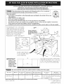 1
1
-
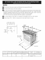 2
2
-
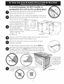 3
3
-
 4
4
-
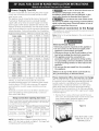 5
5
-
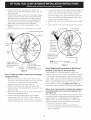 6
6
-
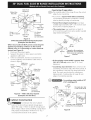 7
7
-
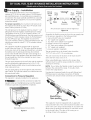 8
8
-
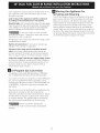 9
9
-
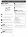 10
10
-
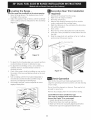 11
11
-
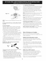 12
12
-
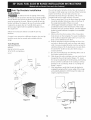 13
13
-
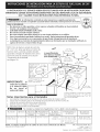 14
14
-
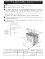 15
15
-
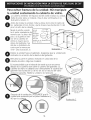 16
16
-
 17
17
-
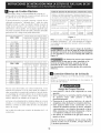 18
18
-
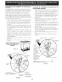 19
19
-
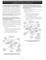 20
20
-
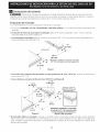 21
21
-
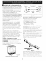 22
22
-
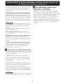 23
23
-
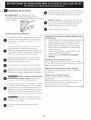 24
24
-
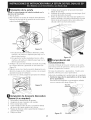 25
25
-
 26
26
-
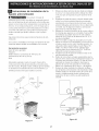 27
27
-
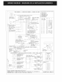 28
28


Kenmore 79046633602 Guía de instalación
- Categoría
- Cocinas
- Tipo
- Guía de instalación
en otros idiomas
Artículos relacionados
-
Kenmore 79075503206 Guía de instalación
-
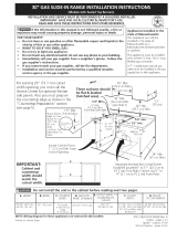 Kenmore Elite 79036603601 Guía de instalación
-
-
Kenmore Elite 79036714504 Guía de instalación
-
Kenmore 66595825003 Guía de instalación
-
Kenmore 66592162300 Guía de instalación
-

Otros documentos
-
Frigidaire FFES3025LW Guía de instalación
-
Electrolux EW30DS80RS Guía de instalación
-
-
Electrolux EW30DS80RSE Guía de instalación
-
Electrolux EW30GS6CGS7 Guía de instalación
-
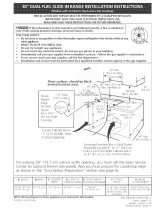 Kenmore Elite 79046622501 Guía de instalación
-
Kenmore Pro 79079523605 Guía de instalación
-
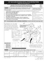 Kenmore Elite 79031043802 Guía de instalación
-
Electrolux EW30DS6CGW3 Guía de instalación
-
Frigidaire GLCS389FBC Guía de instalación

