La página se está cargando...

INSTALLATION AND SERVICEMUST BE PERFORMED BY A QUALIFIED INSTALLER.
iMPORTANT: SAVE FOR LOCAL ELECTRICALiNSPECTOR'S USE.
READ AND SAVE THESE INSTRUCTIONS FOR FUTUREREFERENCE.
_][_[_ Jf the information in this manual is not followed exactly, a fire or explosion
may result causing property damage, personal injury or death,
FOR YOUR SAFETY:
,@
-- Do not store or use gasoline or other flammable vapors and liquids [n the v[dn[ty of this or any
other appliance.
-- WHATTO DO IFYOU SMELLGAS:
• Do not try to light any appliance.
• Do not touch any electrical switch; do not use any phone in your building.
• Immediately call your gas supplier from a neighbor's phone. Follow the gas supplier's instructions.
• tf you cannot reach your gas supplier, call the fire department.
-- Installation and service must be performed by a qualified installer, service agency or the gas supplier.
_Njx_
30" Min.
(76.2 cm Min.
These surfaces
meveled (hatched area).
Shave
Raised
Edge
to Clear
Space
fora 31_z"
(81 cm) Wide
Cooktop.
1 Y2" Max.
(3.8 cm Max.
should be flat &
m?'_W_.\30" Min. (76.2
1/2'
3"
18" Min. (33 cm)5
rL
12.7 cm Min
n Wal! E (45.7 cm) Min.
Locate Cabinet Doors
1" (2.5 cm) Min. from
Cutout Opening.
Grounded Jonction Box or Wall Outlet
Should Be Located 8" to 17" (203 cm
to 433 cm) From Right Cabinet and 2"
to4" (5.1 cm to 103 cm) From Floor.
24" Min.
(61 cm Min.)
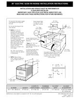
For existing 29" (73.7 cm) cutout width opening, you must call the Sears Service
Center for optional thinner side panels. Also you must prepare the countertop edge
as shown in the "Countertop Preparation" section (see page 6).
[ [ \!V!D!kt' FRONT OF RANGE (Counte<top and <abinet, o DEPTH . OF COUNIERTOP
355/8" 1905cm)- 30" (76,2 crrl) 31Y2"(80cm) 28 5116" /71,9cm) 30±1116"
36 518" (9_ crn) (76,2±0,15 cm)
NOTE: Wiring diagram for these appliances are enclosed in this booklet.
Printed in United States
21 3/4" (55,2 cm) Min. 365/8" (93 cm) Max
22 1/8" (56,2cm) Max 35 518" 1905cm) Min
24" 161 cm) Min with
backguard
P/N 318201670 (05101 Rev C
English - pages 1-12
Espai_ol - p_ginas 13-25
Wiring Diagrams - pages 28

NOTE:
1.Do not pinch the power supply cord or the flexible gas conduit between the range and the wall.
2. Do not seal the range to the side cabinets.
3.24" (61 cm) minimum clearance between the cooktop and the bottom of the cabinet when the
bottom of wood or metal cabinet is protected by not less than X" (0.64 cm) flame retardant
milIboard covered with not lessthan No. 28 MSG sheet metal, 0.015"(0.4 mm) stainless steel,
0.024"(0.6 mm) aluminum, or 0.020" (0.5 ram) copper.
30" (76.2 cm) minimum clearance when the cabinet is unprotected.
4. For cutouts below 22 7/8"(58.1 cm), appliance will slightly show out of the cabinet.
5. Allow at least 19 X" (48.9 cm) clearance for door depth when it is open.
FRONT OF
CABINET
22 7/8"(581 cm) rnim
23 1/4"(5905 cm) max
_-- (see Note 4) -_
I
1 118"
Ref.
Door Open
A
Side Panel
IMPORTANT: Cabinet and
countertop width should match
the cutout width.
E
E
*** IMPORTANT: To avoid cooktop glass
breakage for cutout width (E dimension)
of more than 30 1/16" (76.4 cm), make
sure the appliance is centered in the
counter opening while pushing into it.
Raise leveling legs at maximum position,
insert the appliance in the counter anod
then level. Make sure the unit ms
supported by the leveling legs not by the
cooktop glass itself.
B
D, DEPTH TO
FRONT OF RANGE
35 5/8" (905cm)- 30" (76,2 cm)
36 518" (93 cm)
3IY2" (80 cm) 28 5/16" (71,9 cm) 30+_II16" 21 3/4" (55,2 crn) Min
(76,2+_0,15 cm) 22 I18" (56,2 cm) Max
24" (61 cm) Min with
backgua/d
36 518" (93 cm) Max
35 518" (905 crn) Min

Important Notes to the Installer
1. Read all instructions contained in these installation
instructions before installing range.
2. Remove all packing material from the oven
compartments before connecting the gas and electrical
supply to tile range.
3. Observe all governing codes and ordinances.
4. Be sure to leavethese instructions with the consumer.
Important Note to the Consumer
Keep these instructions with your Use& Care Guide for future
reference.
IMPORTANT SAFETY
[NSTRU S
Installation of this range must conform with local codes
or, in the absence of local codes, with the National Fuel
Gas Code ANS! Z223. l--latest edition.
This range has been design certified by CSA
international. As with any appliance using gas and
generating heat, there are certain safety precautions you
should follow. You will find them in the Use and Care
Guide, read it carefully.
• Be sure your range is instai[ed and grounded
properly by a qualified installer or service
technician.
• This range must be electrically grounded in
accordance with toca[ codes or, in their absence,
with the National EJectrica[ Code ANSJ/NFPA No.
7O--Jatest edition. See Grounding Instructions on
page 6.
• The installation of appliances designed for
manufactured (mobile) home installation must conforra
with Manufactured Home Construction and Safety
Standard, title 24CFR, part 3280 [Formerly the Federal
Standard for Mobile Home Construction and Safety,
title 24, HUD (part 280)] or when such standard is not
applicable, the Standard for Manufactured Home
Installation 1982 (Manufactured Home Sites,
Communities and Setups), ANSI Z225.1/NFPA 501A-
latest edition or with local (.odes.
To reduce
All ranges
cantip.
Injuryto
persons could
result.
Installanti-tip
device
packed with
range.
the risk of tipping of tile
range, the range must be
secured by properly
installed anti-tip bracket
provided with the range.
To check if the bracket is
installed properly, grasp
the top rear edgge of the
range and carefully tilt it
forward to make sure the
range isanchored.
Make sure the wa
Power Suppmy Cord Kit
The user is responsible for connecting tile power supply
cord to tile connection block located behind tile back
panel access (:over.
This appliance may be connected by means of
permanent "hard wiring" (flexible armored or
nonmetallic shielded copper cable), or by means of a
power supply cord. Only a power supply cord kit rated at
125/250 volts minimum, 40 amperes minimum and
marked for use with ranges shall be used. See chart
(below) for cord kit connection opening size rating
information. Cord must have either 3 or 4 conductors.
For mobile homes, new installations, recreational
vehicles, or areas where local codes do not permit
grounding through neutral, a 4 conductor power supply
cord kit rated at 125/250 volts minimum, 40 amperes
and marked for use with ranges should be used (see
Figure 4).
Terminals on end of wires must be either closed loop or
open-end spade lugs with upturned ends. Cord must
have strain-relief (.lamp.
Range Connection Opening Size Chart
Refer to chart below for proper range conr_ectior_ operfing size ant
power supply cord kit ampere rating information. See serial plate
on range for kilowatt rating
See Serial Plate on Range
for KW Rating
data.
120/240 Volts 120/208 Volts
0-16.5 Kw 0-12.5 Kw 40 Amp
16.6-22,5 Kw 12.6-18,5 Kw 50 Amp
Minimum
Cord kit
Ampere
Rating
Diameter (inches)of Range
Conrlectiorl Opening
Direct
Cord Kit Connection
1-3/8 in. I-1/8 in.
1-://8 in. I-:_/8 in.
Figure 1
NOTE: Dual fuel Slide-in Range isshipped from factory
with ! 1/8" dia. hole asshown on figure 3. If a larger hole
is required, punch out the knockout.
Risk of fire or e[ectrka[ shock exists [f
the incorrect amperage cord [s used, the
installation instructions are not followed, or the
strain relief bracket is discarded (see Figure 3).
Do not [oosen the nuts which secure
the factory-installed range wiring to terminal block
while connecting range. Electrical failure or loss of
electrical connection may occur.
Electrical Connection to the Range
This appliance is manufactured with the neutral terminal
connected to the frame.
Note: Refer to the wiring diagram in the center pages of
this manual.
Electrical Shock Hazard
• Electrical ground is required on this appliance.
• Do not connect to the electrical supply until
appliance is permanently grounded.
• Disconnect power to the circuit breaker or fuse
box before making the electrical connection.
• This appliance must be connected to a
grounded, metallic, permanent wiring system,
or a grounding connector should be connected
to the grounding terminaJ or wire [ead on the
appliance.
• Do not use the gas supply line for grounding
the appliance.
Failure to do any of the above could result in a
fire, personal injury or electrical shock.
Three Conductor Wire Connection to Range
(The 3-conductor cord or (able must be replaced with a
4-conductor cord or (able where grounding through the
neutral conductor is prohibited in new installations,
mobile homes, recreational vehicles or in other areas
where local codes do not permit neutral grounding)
If local codes permit connection of the frame grounding
conductor to the neutral wire of the copper power supply
cord (see Figure 3):
1. Remove the 3 screws at the lower end of the rear
wire (:over, then bend the lower end of the rear wire
(over (access cover) upward to expose range
terminal connection block (see Figure 2).
BEND REARWIRE COVER HERE
FORACCESS TO TERMINAL BLOCK
Figure 2

2. Removethe3loosenuts(afteryouremovethe
rubberband)ontheterminalblockusinga3/8"nut
driverorsocket.
3. Connect tile neutral white wire of the copper power
supply cord to the center silver-colored terminal of
the terminal block, and connect the other wires to
tile outer terminals. Match wires and terminals by
color (red wires connected to the right terminal,
black wires connected to the left terminal).
4. Replace the 3 nuts on the terminal block. (See
Figure 3)
5. Lower tile terminal cover and replace the 3 screws.
Silver colored Terminal
5. Connect the neutral of the copper power supply cord
to the center silver-colored terminal of the terminal
block, and connect the other wires to the outer
terminals. Match wires and terminals by color (red
wires connected to the right terminal, black wires
connected to the left terminal).
6. Replace the 3 nuts on the terrainal block (see Figure
4).
7. Lower the terminal cover and replace the 3 screws.
Block
Terminal
Red
Wire
Terminal
Block
wire
A strain relief
supplied by the user 1-1/8" Dia. Direct
must be installed at Connection Hole. Punch
this location To 240 V out knockout for
receptacle 1-3/8" Dia. Cord Kit Hole
Figure 3
Four Conductor Wire Connection to Range
(mobile homes)
1. Remove the 3 screws at the lower end of the rear
wire (:over, then raise the lower end of the rear wire
(.over (access cover) upward to expose range
terminal connection block (see figure 2).
2. Remove the 3 loose nuts (after you remove the
rubber band) on the terminal block using a 3/8" nut
driver or socket.
3. Remove the grounding strap from the terminal block
and from the appliance frame.
4. Connect the ground wire (green) of the copper
power supply cord to the frame of tile appliance
with the ground screw, using the hole in the frame
where tile ground strap was removed (see Figure 4).
1-118"
Direct
Connection
Hole. Punch
out knockout
for 1-3/8" Dia.
Cord Kit Hole
A strainrdief
supplied by the user
must be installed at
this location
NOTE: Be sure to remove the supplied
grounding strap
Figure 4
Direct Electrical Connection to the Circuit
Breaker, Fuse Box or Junction Box
If the appliance is connected directly to the circuit
breaker, fuse box or junction box, use flexible, armored
or nonmetallic sheathed copper cable (with grounding
wire). Supply a U.L listed strain-relief at each end of the
cable. At the appliance end, tile cable goes through tile
Direct Connection Hole (see Figure 4) on the Cord
Mounting Plate. Wire sizes (copper wire only} and
connections must conform to tile rating of tile appliance.
Where local codes permit connecting the appliance-
grounding conductor to the neutral (white) wire
(see Figure 5):
(The 3-conductor cord or cable must be replaced with a
4<onductor cord or cable where grounding through tile
neutral conductor is prohibited in new installations,
mobile homes, recreational vehicles or in other areas
where local codes do not permit neutral grounding)
1. Disconnect tile power supply.
2. In the circuit breaker, fuse box or junction box
connect the appliance and residence cable wires as
shown in Figure 5.

White Wire
(Neutra0
Cable from
Residence
Bmack
Wires--
Box
White Wire
(Neutram)
Green U.L°=hsted
(or Bare Copper) cable from Conduit
Wire Connector
Range (or CSA misted)
Figure 5
3-Wire (Grounded Neutra0 ElectrkaJ System
(ExampJe: Junction Box)
Where tocaJ codes DO NOT permit connecting the
appliance-grounding conductor to the neutral
(white) wire, or if connecting to 4-wire electrical
system (see Figure 6):
1. Disconnect the power supply.
2. Separate the green (or bare copper) and white
appliance cable wires.
3. In the circuit breaker, fuse box or junction box:
connect appliance and residence cable wires as
shown in figure 6.
Cabmefrom
Green Residence Junction
(or Bare Copper) Box
[wi
(Got;Bare Copper)_e
Wire __:d ra')
Cable from Conduit
Appbance Connector
(or CSA misted)
Figure 6 - 4-Wire Electrical System
(Example: Junction Box)
Cabinet Construction
To eliminate the risk of cabinet burns or
fire do not have cabinet storage space above the range.
If there is cabinet storage space above range, reduce risk
by installing a range hood that projects horizontally a
minimum of 5" (12.7 cm) beyond the bottom of tile
cabinet.
Countertop Preparation
• The cooktop sides of tile range fit over the cutout edge
of your countertop.
• If you have a square finish (flat) countertop, no
countertop preparation is required. Cooktop sides lay
directly on edge of countertop.
Formed front-edged countertops must have molded
edge shaved flat 3/4" (1.9 cm) from each front corner
of opening (Figure 7).
Tile countertops may need trim cut back 3/4"(1.9
cm) from each front corner and/or rounded edge
flat :ened (Hgure
[vlin.
Cutout
WMth
(1.9 cm)
(1.9cm)
311/2,_
(81cm)
/ Formed or tile countertop
trimmed %" (1.9 cm) back at
front corners of countertop
opening.
Figure 7
tf the existing cutout width is greater than
30-1/15" (76,4 cm), reduce the 3A" (1.9 cm)
dimension.
For existing cutout width of 29" (73.7 cm) (Figure 8):
2 3/15"
cm)
You must also clear 2 3/
16" (5.56 cm) of materia_
from front of countertop.
(3.2 cm)
• Countertop must be level Place a level
on the countertop, first side to side, then
front to back. If the countertop is not level,
the range will not be level. The oven must
be level for satisfactory baking results, 11/,,
Cooktop sides of range fit over edges of (3.2cm)
countertop opening, I
30'o_ _
(75.2 cm) 311/_" _.::.,:::::::,
_. (80 cm)
_Formed or tile countertop trimmed
_'_"_ 11/4" (3.2 cm) back at front corners of
countertop opening.
Figure 8

Gas Suppmy- Installation
When shipped from the factory, this unit isdesigned to
operate on 4"(!0,16 cm) water column (! .0 kPa)Natural
gas manifold pressure. A convertible pressure regulator is
connected to the range manifold and MUST be connected
in serieswith the gas supply line. To accesstile regulator,
remove the drawer.
For proper operation, the maximum inlet pressure to
the regulator should be no more than 14"(35,56 cm)of
water column pressure (3.5 kPa).
The inlet pressure to the regulator must be at least I " (.25
kPa)greater than the regulator manifold pressure setting.
The regulator isset for 4" (10,16 cm)water column (1.0
kPa) Natural gas manifold pressure; the inlet pressure must
be at least 5"(12.60 era)water column (1.25 kPa) Natural
gas. For LP/Propanegas, the regulator must be set for
10"(25,4 era)water column (2.5 kPa)manifold pressure; tile
inlet pressure must be at least 11"(27,9 cm)water column
(2.75 kPa).
The supply line should be equipped with an approved
shutoff valve (see Figure 11). This valve should be located
in the same room asthe range and should be in a location
that allows easeof opening and closing. Do not block
accessto the shutoff valve. The valve isfor turning on or
shutting off gasto tile appliance.Open the shutoff valve in
the gas supply line. Wait a few minutes for gasto move
through the gas line.
The gas supply between the shutoff valve and tile regulator
may be connected by rigid piping or by A.G.A./C.G.A.-
approved flexible metallic,union-connected piping where
local codes permit use.
The gas supply piping can be through the side wall of the
right cabinet. The right side cabinet isan ideal location for
the main shutoff valve.
Connection to Pressure Regulator
The regulator is already installed on the appliance.
Do not make the connection too tight. The
regulator isdie cast.Overtightening may crackthe regulator
resulting in a gasleakand possiblefire or explosion.
ManuaH GAS FLOW Pressure
Shutoff Hare _ Hare
VaHve Union Union
,-r ..........'T
On_ NiPple t --
J
Flexible Nipple I .........
Access
Off Connector
Cap
All connections must be wrench4ightened
Figure 10
Assemble the flexible connector from the gas supply pipe
to the pressure regulator in the following order:
1. manual shutoff valve (not supplied)
2. 1/2" nipple (not supplied)
3. 1/2" flare union adapter (not supplied)
4. flexible connector (not supplied)
5. 1/2" flare union adapter (not supplied)
6. 1/2" nipple (not supplied)
7. pressure regulator (supplied)
The gas supply line to the shutoff valve should be
1/2"(1,27 cm) or 3/4"(I .9 cm) solid pipe.
The user must know the location of the main shutoff
valve and have easy access to it.
When using flexible gas conduit on the range, allow
sufficient slack to pull the range outside the cutout for
cleaning or servicing.
NOTF: Do not allow the flexible conduit to get pinched
between the wall and the range. To visually check,
remove the range drawer.
Use pipe-joint compound made for usewith Natural and
LP/Propane gas to seal all gas connections. If flexible
connectors are used, be certain connectors are not kinked.
t_
PRESSUREREGULATOR LOCATION
Figure 9
Shutoff Valve -
Open position
Figure 11
The supply line must be equipped with an approved
manual shutoff valve. This valve should be located in the
same room as the range and should be in a location that
allows ease of opening and closing. Do not block access
to the shutoff valve. The valve is for turning on or
shutting off gas to the appliance.

Onceregulatorisinplace,opentheshutoffvalveinthe
gassupplyline.Waitafewminutesforgasto move
throughthegasline.
Leaktestingof theapplianceshallbeconducted
accordingto themanufacturer'sinstructions.
CheckforJeaks.A_terconnectingtherangetothegassupply,
checkthesystemforleakswithamanometer.Ifamanometer
isnotavailable,turnonthegassupplyandusealiquidleak
detectoratalljointsandconnectionstocheckforleaks.
Donotuseaflameto checkforleaks
fromgasconnections.Checkingforleakswithaflame
mayresultinafireorexplosion.
Allopeningsinthewallorfloorwheretherangeistobe
installedmustbesealed.
Tightenallconnectionsif necessaryto preventgas
leakageinthe(ooktoporsupplyline.
Disconnectthisrangeandits individualshutoff
valvefromthegassupplypipingsystemduringany
pressuretestingofthesystemattestpressuresgreater
than1/2psig(3.5kPaor14"(35,56era)watercolumn).
tsoJatetherangefromthegassupplypipingsystem
byclosingitsindividualmanualshutoffvalveduringany
pressure testing of the gas supply piping system at test
pressures equal to or less than 1/2 psig (3.5 kPa or
14"(35,56 cm) water column).
LPiPropane Gas Conversion
Thisapplian(e (an be used with Natural gasor LP/Propane
gas. It isshippedfrom the factory for usewith natural gas.
If you wish to convert your range for use with LP/Propane
gas, use the supplied fixed orifices located in a bag
containing tile literature marked "FOR LP/PROPANEGAS
CONVERSION." Follow the instructions packaged with
the orifices.
The conversion must be performed by a qualified service
technician in accordance with the manufacturer's
instructions and all local codes and requirements. Failure
to follow these instructions could result in serious injury
or property damage. The qualified agency performing
this work assumes responsibility for the conversion.
Failure to make the appropriate
conversion can result in personal injury and property
damage.
Moving the Appliance for
Servicing and Cleaning
Turn off the range line fuse or circuit breakers at the main
power source, and turn off the manual gas shut-off valve.
Make sure tile range is cold. Remove tile service drawer
(warmer drawer on some models) and open the oven door.
Lift the range at the front and slide it out of tile cut-out
opening without creating undue strain on tile flexible gas
conduit. Make sure not to pinch the flexible gas conduit at
the back of the range when replacing the unit into tile cut-
out opening. Replace the drawer, close the door and switch
on the electrical power and gas to the range.

Range JnstaJJation
mportant Note: Door removal is not a requirement for
installation of tile range, but is
an added convenience.
Refer to the Use and Care
Guide for oven door
removal instructionso
Standard Installation
1. The range cooktop
overlaps tile countertop at
the sides and the range
rests on the floor. The cooktop is 31 I/2"(1,27
cm)(81 cm) wide.
2. Install base cabinets 30" (76.2 cm) apart. Make sure
they are plumb and level before attaching cooktop.
Shave raised countertop edge to clear 31 1/2 "(1,27
cm)wide range top rim.
3. Install cabinet doors 31 " (78.7 cm) min. apart so
they will not interfere with range door opening.
4. Cutout countertop exactly as shown on page 1.
5. A backguard kit can be ordered through Sears
Service Center.
6. When you unpack the range, the leveling devices
at rear are at the highest position they can be. Make
sure the front leveling legs are also at their highest
position.
7. _ Install the anti-tip bracket at this
point before placing the range at its finaJ
position. Follow tile installation instructions on page
12 or on the anti-tip bracket template supplied with
tile range.
8. To provide an optimum installation, the top surface
of the countertop must be level and flat (lie on the
same plane) around the 3 sides that are adjacent to
range cooktop. Proper adjustments to make the top
flat should be made or gaps between the countertop
and tile range cooktop may occur.
9. _ To reduce the risk of damaging your
appliance, do not handle or manipulate it by tile
ceramic glass. Manipulate with care.
10. Position range in front of the cabinet opening.
11. Make sure that the cooktop glass which overhangs
tile countertop clears tile countertop. If necessary,
raise tile unit by lowering the leveling legs.
12. Slide the range into the cutout opening.
13. Level the range (see section 8). The floor where the
range isto be installed must be level. Follow the
instructions under "Leveling tile Range - Models
Equipped with Leveling Device".
14. Adjust leveling legs so that the underside of the
cooktop is sitting on the countertop.
15. Carefully screw in the back leveling leg until the
cooktop glass overhang touches slightly the
countertop (refer to "Leveling tile range: Models
equipped with Leveling Device"). The cooktop
glass must not support the unit,
16.Then carefully screw in the front two leveling legs
(similar to 15) until the cooktop glass overhang
touches slightly the countertop.
Installation For 29" Existing Cutout Width Opening
1. You must replace the original side panels with new and
thinner side panels. These new side panels can be
ordered through a SearsService Center.
2. Follow instructions supplied with your new side panels to
replace tile original side panels with the new ones.
3. Check if the countertop isprepared for 29" cutout wide
opening in "Countertop Preparation" sectionat page 5.
4. Install range as in the "Standard installation" section
above.
Installation With Backguard
Tile cutout depth of (21 3/4" (55.2 cm)Min., 22 1/8"
(56.2cm) Max.) needs to be increased to 24"(10,16
cm)(61 cm) when installing a backguard.
installation With End PaneJ
A End Panel kit can be ordered through a Sears Service
Center.
[nstaJJation With Side Panels
A Side Panels kit can be ordered through a Sears Service
Center.
Install cabinet doors 31 " (78.7 cm) min. apart so as not
to interfere with range door opening.
Leveling the Range -
Level the range after installation in the cutout opening.
1. Open the range drawer. The leveling screws control
the height of the rear leg.
2. Adjust the appliance legs asfollows until tile underside
of the cooktop surface issitting level on the countertop
(Figure 12).
Font
L_,,_n_----_ Figure 12
Leg
LOWER
RAISE
1. To adjust the front leveling legs, use a wrench and turn
counterclockwise to lower or clockwise to raise.
2. To adjust tile rear leveling screws, use a ratchet or a
nutdriver and turn counterdockwise to lower or
clockwise to raise.

3. Checkiftherangeislevelbyinstallinganovenrackin
the(.enteroftheovenandplacingalevelontherack
(Figure13)
4. Take2readingswiththelevelplaceddiagonallyin
onedirectionandthentheother.Leveltherange,if
necessary,byadjustingthelevelinglegs.
5. Iftherangeisnotlevel,contactacarpentertocorrect
saggingorslopingfloor.
Check Operation
Refer to the Use and Care Guide packaged with the
range for operating instructions and for (.are and (.leaning
of your range.
Do not touch the elements or burners. They may be hot
enough to cause burns.
Remove all packaging from the oven before testing.
1.[nstaJ[ Burner Bases and Burner Caps
This range is equipped with sealed burners as
shown (see Figure 15).
1. Unpack burner bases and burner caps.
2. Placeburner bases over each gas opening.
3. Make sure the burner is properly aligned and leveled.
Placeburner caps over appropriate burner bases.
Burner Cap
J /
Figure 13
Decorative Rear Trim lnstaJJation
(if required)
1. Disconnect the power from the range.
2. Make sure tile range is leveled.
3. Pull range toward you.
4. Measure the distance between the floor and the
surface underneath the cooktop frame.
5. Mark that distance on the wall where the decorative
trim will be installed.
6. Draw a line.
7. Place the top of the decorative trim under that line.
8. Using the screws provided fix the decorative trim into
the wall.
9. Slide the range back into position asfar as it will go
and reconnect tile power source.
Trim
underneath the
Figure 14
Figure 15 Electrode
NOTE: There are no burner adjustments necessary on this
range.
2.Turn on Electrical Power and Open Main Shutoff
Gas VaIve
3.Check the Igniters
Operation of electric: igniters should be checked after
range and supply line connectors have been carefully
checked for leaks and range has been connected to
electric power. To check for proper lighting:
1.Push in and turn a surface burner knob to the LITE
position. You will hear the igniter sparking.
2. The surface burner should light when gas is available
to the top burner. Each burner should light within four
(4) seconds in normal operation after air has been
purged from supply lines. Visually check that burner
has lit.
3.Once the burner lights, the control knob should be
rotated out of the LITEposition.
There are separate ignition devices for each burner. Try
each knob separately until all burner valves have been
checked.
10

4.Adjustthe "LOW"Settingof SurfaceBurner
Valves(seeFigure16)
Figure!6%
1.PushinandturneachcontroltoLITEuntilburnerignites.
2.QuicklyturnknobtoLOWESTPOSITION.
3.Ifburnergoesout,readjustvalveasfollows:
ResetcontroltoOFF.Removethesurfaceburnercontrol
knob,insertathin-bladedscrewdriverintothehollowvalve
stemandengagetileslottedscrewinside.Flamesizecanbe
increasedordecreasedwiththeturnofthescrew.Adjust
flameuntilyoucanquicklyturnknobfromLITEtoLOWEST
POSITIONwithoutextinguishingtheflame.Flameshouldbe
assmallaspossiblewithoutgoingout
5. Operationof OvenElements
Theovenisequippedwithanelectronicovencontrol.Each
oftilefunctionshasbeenfactorycheckedbeforeshipping.
However,itissuggestedthatyouverifytheoperationof
theelectronicovencontrolsoncemore.Refertothe
ElectronicOvenControlGuideforoperation.Followthe
instructionsfortheClock,Timer,Bake,Broil,Convection
(somemodels)andCleanfunctions.
Bake-Aftersettingtheovento350%(177°C)forbaking,
thelowerelementintheovenshouldbecomered.
Broil-WhentheovenissettoBROIL,theupperelement
intheovenshouldbecomered.
Clean-Whentheovenissetforaself<leaningcycle,the
upperelementshouldbecomeredduringthepreheat
portionofthecycle.Afterreachingtheself<leaning
temperature,thelowerelementwill becomered.
Convection(somemodels)-Whentheovenissetto
CONV.BAKE/ROASTat350%(177°C),tile convection
elementcyclesonandoff andtheconvectionfanturns.
Theconvectionfanwillstopturningwhentileovendoor
isopenedduringconvectionbakingorroasting.
WarmerDrawer(somemodels)-Setthecontrolknob
to HIandcheckto seethedrawerisheating.
When All Hookups are Complete
Make sure all controls are left on the OFF position.
Make sure the flow of combustion anf ventilation air to tile
range isunobstructed.
Model and Serial Number Location
The serial plate is located on the oven front frame
behind the oven door (some models or on the drawer
side frame (some models).
When ordering parts for or making inquiries about your
range, always be sure to include the model and serial
numbers and a lot number or letter from tile serial plate
on your range.
Your serial plate also tells you the rating of the burners,
the type of fuel and the pressure tile range was adjusted
for when it left tile factory.
Before You Call for Service
Read tile Before You Call Checklist and operating
instructions in your Use and Care Guide. It may save
you time and expense. The list includes common
occurrences that are not the result of defective
workmanship or materials in this appliance.
Refer to your Use & Care Guide for Sears service phone
numbers or call 1-800-4-MY-HOME ®.
11

Anti-Tip Brackets JnstaJJation
instructions
To reduce tile risk of tipping of the range,
the range must be secured to the floor by properly installed
anti-tip bracket and screws packed with the range, Those
parts are located in the oven, Failure to install the anti-tip
bracket will allow the range to tip over if excessiveweight
is placed on an open door or if a child climbs upon it,
Serious injury might result frora spilled hot liquids or from
the range itself,
Follow the instructions below to install tile anti-tip
brackets.
If range is ever moved to a different location, the anti-tip
brackets must also be moved and installed with the
range.
Tools Required:
Adjustable Wrench
Ratchet
Drill & I/8"(0,32 cm) bit
5/I 6" (0,79 cm) Nutdriver
Level
Kitchen
Cabinet
Toe
Door
Cabinet
S
Figure 17
BACK
The anti-tip bracket attaches to the floor at the back of
the range to hold range rear center leg. When fastening
bracket to the floor, be sure that screws do not
penetrate electrical wiring or plumbing. The screws
provided will work in either wood or concrete.
1. Draw a center line (CL) on the floor where the range
should be installed. Also draw a line on the floor at
the range back position if there is no wall.
2. Unfold paper template and place it flat on the floor
positioned exactly on the intersection of the center
and back lines you just drew before. (Use the diagram
below to locate brackets if template is not available
(Figure 17)).
3. Mark on the floor the location of the 4 mounting
holes shown on the template. For easier installation,
3/16"(0,48 cm) diameter pilot holes 1/2"(!,27 cm)
deep can be drilled into the floor.
4. Remove template and place bracket on floor. Line
up holes in bracket with marks on floor and attach
with 4 screws provided. Bracket must be secured to
solid floor (Figure 18). If attaching to concrete floor,
first drill 3/16"(0,48 cm) dia. pilot holes using a
masonry drill bit.
5. Be sure the leveling legs and leveling device are at
the highest position they can be.
6. Slide range into place making sure rear center leg is
trapped by the anti-tip bracket (Figure 17). Lower
tile range by adjusting the leveling legs and leveling
device until the underside of the cooktop is sitting
leveled on the (ountertop. Refer to "Leveling tile
Range" section.
7. After installation, verify that the anti-tip bracket is
engaged by grasping the top rear edge of the range
and carefully attempt to tilt it forward to make sure
range isproperly anchored.
C
Screws
Figure 18
12

LA INSTALAaON Y EL SERVlaO DEBEN SER EFECTUADOS POR UN INSTALADOR CAUNCADO.
IMPORTANTE: GUARDE ESTAS INSTRUCaONES PARA USO DEL INSPECTOR LOCAL DE ELECTRlaDAD.
LEA Y GUARDE ESTAS INSTRUCaONES PARA REFERENaA FUTURA.
Si [a informad6n contenida en este manuaJ no es seguida exactamente,
puede ocurrk un incendio o exptosi6n causando da_os materiales, tesi6n personaJ o ta muerte.
PARA SU SEGURDAD:
-- No almacene ni utilice gasolina u otros vapores y t_q@dos inflamables en [a proximidad
de _ste o de cua[q@er otto artefacto.
-- QUE DEBE HACER SJPERCtBE OLOR A GAS:
• No trate de encender ningQn artefacto.
• No toque ningun interruptor e[_ctrico; no use ningQn te[_fono en su edificio.
, L[ame a su proveedor de gas desde e[ te[_fono de un vecino. Siga [as instrucciones de[ proveedor de gas.
• S[ no [ogra comunkarse con su proveedor de gas, [lame a[ departamento de bomberos.
-- La [nsta[ad6n y e[ serv[c[o de manten[m[ento deben set efectuados pot un [nsta[ador ca[[f[cado, [a
agenda de servk[o o e[ proveedor de gas.
***JMPORTANTE: Para el
torte a 1oancho (dimensi6n
E)de m&s de 30 1/15" (76,4
cm) para evitar que se
rompa e[ vidrio, asegQrese
que el artefacto est&
centrado en [a abertura de
[a mesada m[entras [o
presiona. Levante [as patas
de n[ve[ad6n hasta [a
poski6n m&xima; inserte el
artefacto en [a mesada y
[uego nivele. As_::jurese
de que la unidad est_
apoyada en [as patas
de nive[aci6n y no en
La superfk[e debe estar piana y
niveiada (area sombreada).
1 Y2" M_x.
(3.8 cm M_x,)
Acepille el
borde
subido a
que deje
espacio
para un
borde 31 1/2" (81
cm) de anchura de
estufa
Localise las puertas del
armario 1"(2,5 cm) rain del
hueco de la abertura,
NOTA: Para la abertura amplia de corle de 29" (73,7
cm), tiene que [larnar al Centro de Servkios Sears y
solkitar paneles laterales opcionales, Despejar el
reborde ancho de la cocina tal como se muestra en la
section "Preparacion de la Mesada "(vet pagina 16)
E
30" Min.
(76.2 cm Mln,)
30" Min,
18" Min.
(45.7 cm) Min,
I3"
(33 cm)
24" Min,
(61 cm Min,)
caja de empahnes o el enchufe con puesta a
tierra deberia situarse de 8" a 17" (20.3 cm a
43.2 cm) del armario derecho y de 2" a 4" (5.1
cm a 10.2 cm) del suelo,
IMPORTANTE: El ancho de la
cubierta y e[ armario debe de
set igua[ a[ ancho de[ torte.
B._,r,_cHoc.ANcH0H LAD.PROFUNDDADA
: RLANCHA DE LA FRENTEDE LA
" COCINAR ° ESTUFA
:_B5/8" (905 cm) -- :_0" (76,2 cm) 31/2" (80 cm) 28 B/16" (71,9 cm)
:_65/8" (g:_cm)
B
E, ANCHO G, ALTURA DEL
DE RECORTADO*** RECORTADO ' M©SIRADOR
(cubierta yarmario)
_0±1/I6" 2I :V4" 65,2 cm) Min. 36 B/8" (93 cm) Max
(76,2±0,15 cm) 22 I/8" (56,2 cm) Max 35 5/8" (905 cm) rain
24" 61 cm) Min con un
protector trasero_
NOTA: Se adjunta el diagrama de cables de esta codna a[ final de este [ibreta. P/N 318201670 (0510) Rev C
Imprimido en los Estados Unidos English - pages 1-12
Espai_o[ - p_ginas 13-25
Diagrama de la instalaci6n alambrica - p_ginas 28

1, No pellizque el cordon electrico o e! conducto flexible de gas entre la estufa y la pared,
No selle la estufa a los armarios de lado,
3_
cuando e! fondo deI armario de madera
o metal est,1protegido pot no menos de
1/4" (0,64 cm) de madera resistente aI
fuego cubierta pot una I_imina met_ilica
de MSG, n0mero 28, 0,015" (0.4 ram)
de acero inoxidable, 0.024" (0.6 ram) de
aluminio, 6 0.02" (0,5 ram) de cobre,
Un espacio mfnimo de 30" (76.2 cm)
cuando el armario no est,1protegido,
Un espacio mfnimo de 24" (61 cm) entre la superficie de la estufa y el fondo del armario
4, Para los recortados menos que 22 7/
8", el electrodomestico aparecerfa
ligeramente en el exterior del armario,
Puerta
abierta
(vea la
nota 5)
A
5, Deje pot los 19 ¼" (48.9 cm) de
espacio libre para Ia profundidad de la
puerta cuandoesta abierta,
lateral
PARTE
DELANTERA
22 718" (58.1 cm) rain.
23 114" (59.05 cm) max.
Notas importantes para el lnstalador
1. Lea todas Ias instrucciones contenidas en este
manual antes de instalar Ia estufa.
Saque todo el material usado en e! e,mbalaje
det compartimiento deI homo antes de
conectar el suministro eI_ctrico o de gas a la
estufa.
3. Observe todos los codigos y reglamentos
pertinentes.
4. Deje estas instrucciones con el comprador.
Nota lmportante para el Consumidor
Conserve estas instrucciones y el Manual del
Usuario para referencia futura.
A.AL-ruRA e,ANcflOC.ANcHODEL,iDIPROFUNDIDADA
PLANCHA DE LA ERENTE DELA
' COCINAR ESTUFA
:355/8" (90.5 cm) - 30" (76,2 cm) :31Y2"(80 cm) 28 5/16" (71,9 cm)
:36'_/8" (9_ cm)
E. ANCHO
DE RECORTADO***
(cubierta y armario)
30±1/16"
(7d,2±0,I5 cm)
F; PROFUNDIDAD DE G. ALTURA DEL
RECQRTADO I MOSTRADOR
21 3/4" (55,2 cm) Min. 36 5/8" (93 cm) Max
22 1/8" (56,2 cm) Max 35 5/8" (905 c:m)rain
24" (61 cm) Min con un
protector trasero
14

[NSTRUCCIONES DE
SEGUR[DAD
InstataciOn de esta estufa debe cumplir con todos los
c0digos locates, o en ausencia de c0digos locales con el
C0digo National de Gas Combustible ANS! Z223.1--
Oltima edici0n,
El diseflo de esta estufa ha sido certificado por la CSA
International, En estecomoencualquierotroartefacto
que use gas y genere calor, hay ciertas precauciones de
seguridad que usted debeseguir. Estasser_in
encontradas en el Manual del Usuario, lea!o
cuidadosamente.
AsegQrese de que [a estufa sea instalada y
conectada a tierra en forma apropiada pot un
instalador calificado o pot un t_cnico.
Esta estufa debe set emectrkamente puesta a tierra
de acuerdo con los cbdigos locales, o en su
ausenda, con el COdigo El(_ctrko National ANSI/
NFPA No. 70, Q[tima edkibn. Vea las instrucciones
para la puesta a tierra en la p_gina 4.
La instalaciOn de aparatos diseflados para instalaciOn
en casas prefabricadas (m0viles) debe conformar con el
Manufactured Home Construction and Safety Standard,
titulo 24CFR, parte 3280 [Anteriormente e! Federal
Standard for Mobil Home Construction and Safety,
titulo 24, HUD (parte 280)] o cuando tal est_indar no se
aplica, el Standard for Manufactured Home Installation
1982 (Manufactured Home sites, Communities and
Setups), ANSI Z225,1/NFPA 501A-edici0n ma's reciente,
o con los c0digos locales.
Antes de instalar [a estufa en un Mea cuyo piso
este recubierto con Iinbleo u otto tipo de piso
sint_tko, asegurese de que estos puedan resistir
una temperatura de pot 1o menos 90°F sobre [a
temperatura ambiental sin provocar encogimiento,
deformation odecoloradOn, Noinstale laestufa
sobre una alfombra al menos que coloque una plancha
de material aislante de por Io menos 1/4 pulgada,
entre la estufa y la alfombra.
• Todas las
estufas
pueden
volcarse.
Esto podria
resultar en
lesiones
personales.
®Instale el
dispositivo
antivuelcos
que se ha
empacado
junto con
esta estufa.
Para reducir el riesgo de
que se vuelque la estufa,
hay que asegurarla
adecuadamente co!o
candole los soportes
antivuelco que se
proporcionan. Para
comprobar si estos estan
instalados y apretados en
su lugar como se debe,
ase el horde trasero
superior de la estufa y
cuidado samente incline la
hacia adelante para
asegurar que la estufa se
ancle.
15
Asegurese de que el material que recubre [as
paredes alrededor de [a estufa, pueda resistir el
calor generado pot [a estufa.
No obstruya el flujo de{ aire de combustion en [a
vent[laciOn de[ homo n[ tampoco alrededor de [a
base o debajo de[ panel inferior delantero de [a
estufa. Evite tocar lasaberturaso areascercanas de
la ventilaciOn, ya que pueden estar muy calientes
duranteelfuncionamientodel homo. Laestufa
requiere aire fresco para la combustion apropiada de
los quemadores.
_Nunca deje ni_os solos o
desatendidos en un Mea donde un artefacto est&
siendousado, Amedida que los nifloscrecen,
ensefleles el uso apropiado y de seguridad para todos los
artefactos. Nuncadeje la puerta del homoabierta
cuando la estufa est,1 desatendida.
_7_lNo se pare, apoye o siente en [as
puertas o cajones de esta estufa pues puede resultar
en serias [esiones y puede tambien causar da_o a [a
estufa.
No almacene articulos que puedan interesar a los
niffos en los gabinetes sobre [a estufa. Los niflos
pueden quemarse seriamente tratando de trepar a la
estufa para alcanzar estos art[culos.
Los gabinetes de almacenamiento sobre [a estufa
deben set evitados, para eliminar la necesidad de
tenet que pasar sobre los quemadores superiores
de [a estufa para [[egar a e{los.
Ajuste el tamaffo de [a llama de los quemadores
superiores de ta[ manera que esta no sobrepase e[
bordede los utensilios decocinar. La llama
excesiva es peligrosa.
No use el homo como espacio de almacenaje. Esto
create1 una situaci0n potencialmente peligrosa.
Nunca use [a estufa para calentar el cuarto. El uso
prolongado de la estufa sin la adecuada ventilaci0n
puede resultar peligroso.
No almacene ni utilice gasolina u otros vapores y
[iquidos inflamab[es en [a proximidad de este o de
cualquier otro artefacto etectrico. Puede provocar
incendio o explosion.
En caso de una interruption del servicio electrico, es
pasible de encender los quemadores de superficie a
mano. Para encender un quemador de suoerficie,
acerque un fOsforo encendido del cabezal del
quemador, y gire delicadamente e! bot0n de control de
superficie a LITE (encendido). Tener cuidado al
encender los quemadores a mano.
Ajuste todos los controles a la posicibn "OFF"
(apagada) despues de haber hecho una operaciOn
con tiempo programado.
PARA MODELOS AUTOLIMPIANTES:
Saque [a asadera, alimentos o cualquier otto
utensilio antes de usar el cic{o de autoIimpieza de[
homo, Limpietodoexceso de derrame dealimentos.
Siga las instrucciones de prelimpiado en el Manual del
Usuario.

]uego de Cord6n Electrko
El consumidor tiene la responsabilidad de conectar el
cord6n electrico al bloque de conexi6n ubicado detra% de
la cubierta de acceso del panel trasero.
Este electrodomestico puede ser conectado por medio de
una "conexi6n directa" de cables permanentes (cable
blindado flexible o no met_ilico recubierto de cobre), o por
medio de un ensamblaje de cord6n de suministro electrico,
Solamente un ensamblaje de cordon de suministro electrico
con regimen de 125/250 voltios minimo, 40 amperios
minimo y marcado para use con cocinas debe set utilizado
.Vea la tabla (ma's abajo) para informaci6n sobre el tamafio
de abertura de la conexi6n del ensamblaje de cord6n, E!
cord6n debe de tener 3 o 4 conductores,
Para las casas sobre ruedas, las nuevas instalaciones, en los
vehiculos de recreaci6n o en las a'reas donde los c6digos lo-
cales no permiten la conexi6n del conductor a tierra al neutro,
un ensamblaje de suministro electrico de 4 conductores para
estufas, clasificado a 125/250 voltios minimo, 40 amperios
mfnimo, debe de ser utilizado Ever la figura 4),
Los bornes a la extremidad de los alambres deben ser a cur,vas
cerradas o con extremidades de lenguetas en forma de U
abiertas y curvadas. El cord6n debe de tener una abrazadera
releva de anclaje
Ver la tabla de arriba para conexi6n de alambres de 3 o 4
conductores.
TabJa de tama_o de abertura de conexi6n de cocina
Referirse a la tabla de arriba para el tamaflo de abertura de
cormexion de codna adecuada, y la informacion sobre el regimen
de amperios del ensambhje de cordon de suministro electrico..
Vea la plata de serie de la
cocina para informad0n
sobre el regimd_n de
kilovatio
120/240 Volts 120/208 Volts
Mlnimo
regimen de
amperios
de
ensambiaje
del cordon
iDiametro (pulgadas) de
abierta de conexion de
cocina,
iEnsemblaje
idel cordon
Connect,
Directa
0-16.5 Kw 0-I 2.5 Kw 40 Amp I-3/8 pulg 1-I/8 pulg
16.6-22,5 Kw 12,6-18.5 Kw 50 Amp I-3/8 pulg 1-3/8 pulg
Figura 1
Nota: La cocina corrediza fue! dua! viene de fabrica con
un agujero d diametro 1 1/8" come muestra en la figura 3.
Si un agujero mas largo esta" necesario retire la arandela
pre'cortada.
Puede ocurrir riesgo de incendio o
choque eJOctrico si se usa un juego de cord6n de estufa
de tamaFio incorrecto, si las instrucciones de instalaci6n
no son seguidas o si no se usa el anclaje del cable (vea
Figura 3).
_.__ No desate las tuercas que sujetan et
alambraje de cocina que ha sido instaJado en la
factoria aJ bloque terminal, cuando se hate la
conexion de la cocina. Se puede ocurrir el real
funcionamiento o una interruption det suministro
etectrico.
Conexi6n Electrico de la Estufa
Este aparato se fabrica con el terminal neutro conectado
al marco,
Befiere al diagrama de alambraje en las paginas de
centro de este manual.
Riesgo de Choque El@ctrico
o Una puesta a tierra est_ requerido en este
aparato.
, No Jo conecte a la corriente electrica hasta que
el aparato haya sido puesto a tierra
permanentemente,
, Desconecte Ja corriente electrica a la caja de
empaJmes antes de hacer la conexi6n eJ_ctrica.
, Este aparato debe estar conectado con un
sistema de alambres puesto en tierra, met_Jico
y permanente o un conector de puesta a tierra
debe conectarse al terminal de puesta a tierra
o el alambre conductor en eJ aparato,
No utilice el suministro de gas para hater Ja
puesta a tierra.
La falta de hater cualquier de las cosas arriba
podria resuJtar en un incendio, choque etectrico
o Jesiones personaJes.
Conexi6n de tres alambres de conducd6n a
la estufa
(Un cord6n flexible o cable de 3 conductores debe de ser
reemplazado con un cord6n flexible o cable de 4 conducto-
res donde la conexi6n del conductor a tierra al neutro esta
prohibida en las nuevas instalaciones, las casas sobre
ruedas, los vehk:ulos de recreaci6n o otras _reas donde los
c6digos locales no permiten la conexi6n a tierra al neutro.)
Si los c6digos locales permiten la conexi6n del conductor
de tierra del marco con el alambre neutro del cord6n
electrico de cobre (yea Figura 3):
1. Quite los tres tornillos en la parte m4s baja del panel
trasero, luego levante la parte m4s baja del panel
trasero (la cubierta de acceso) exponiendo el b!oque
de conexiones de los terminales de la estufa (vea
Figura 2).
2. Quite las tres tuercas desatadas (despues de remover
la cinta de goma) sobre el bloque terminal usando
un destornillador o una
Ilave de casquil!o de 3/'
8"(0,95 cm),
3. Conecte el cable neutro
del cord6n ebctrico de
cobre al terminal de color
de plata en el centro del
bloque, y conecte los
otros cabels a los
Figura 2
LEVANTE LA PARTE MAS BAJA DEL PANEL
TRASERO AQUI PARA TENER ACCESO AL BLOQUE
DE CONEXIONES DIE LOS TIERMENALES
16

terminales laterales. Empareje los cables y los
terminales seg0n e! color (cables rojos conectados
con el terminal derecho, cables negros conectados
con el terminal izquierdo.
4. Repone las tres tuercas desatadas sobre el b!oque
terminal.
5. Baje la cubierta del terminal y reinstale los tres (3)
tornillos.
Cone×ion de 4 alambres de conduccion a la
estufa (casas moviles}
ue terminal plata
Alambre
Negro
Una arazadera
de releva provista debe de estar
instalada a esta ubicaci6n Hacia el 240 V
receptaculo
Figura 3
J/8" Dia.
Agujero de la
conexi6n directa.
Retira la arandela
pre-cortada para
1-3/8" Dia. Agujero
1. Quite los tres torni!los en la parte m_is baja del panel
trasero, luego levante la parte ma's baja del panel
trasero (la cubierta de acceso) exponiendo el bloque
de conexiones de los terminales de la estufa.
2. Quite las tres tuercas dasatadas (despues de remover
la cinta de goma) sobre el b!oque termianl usando
un destornillador o una Ilave de casqui!lo de 3/
8"(0,95 cm).
3. Quite la banda de puesta a tierra de! bloque de los
terminalesy del marco delartefacto. Retengae!
torni!lo de puesta a tierra.
4. Conecte e! alambre de puesta a tierra (verde) de!
cordon electrico de cobre al marco del artefacto con
e! tornillo de puesta a tierra, usando el agujero en e!
marco donde se quit0 el tornillo de puesta a tierra
(vea figura 4).
5. Conecte e! alambre neutro (blanco) de! cordon
electrico de cobrealtermina! de color de plataen
e! centro del bloque y conecte los otros alambres a!
los terminates laterales.
6. Repone las tres tuercas desatadas sobre el bloque
terminal.
7. Baje la cubierta de acceso y vuelva a poner los 3
tornillos.
Bloque terminal plata
Rojo
Atambre
Negro l/
1-1/8" Dia.
Agujero de ta
conexi6n
directa.Retira
ta arandeta
pre-cortada
para !-3/8" Dia.
Agujero
Una arazadera
de releva provista
debe de estar
instalada a est_
ubicaciOn
NOTA: Asegurese de quitar
ta banda de puesta a tierra provista.
Figura 4
Hacia el 240 V receptaculo
Conexi6n elOctrica directa a[ cortadrcuito, a
[a caja de fusibles o [a caja de empalmes
Si el aparato esta conectado directamente al (ortacircuito,
a la (aia de fusibles o a la cap de empalmes, use un cable
blindado flexible o no metalico recubierto de cobre (con
alambre a tierra). Provee una abrazadera releva de anclaie
homologo UL a cada extremidad del cable. A la
extremidad del electrodomOstico, el cable pase a travOs del
agujero de la conexion directa (vet figura 4) en el cordon
de la plata de montaje. El tama¢io de los alambres
(alambre de cobre soIamente) y las (onexiones deben
estar conforme al regimOn del electrodomOstico.
Donde los c6digos [ocales permitan conectar el
conductor de puesta a tierra de[ e[Octrodom_stico a[
neutral (blanco) (yea figura 5}:
(Un cordon flexible o cable de 3 conductores debe de ser
reemplazado con un (ordOn flexible o cable de 4 conducto-
res donde la conexion del conductor a tierra al neutro esta
prohibida en las nuevas instalaciones, lascasassobre
ruedas, los veh[culos de recreation o otras areasdonde los
codigos locales no permiten la conexiOn a tierra al neutro.)
1. Desconecte el suministro ele(trico.
2. En el cortacircuito, la caia de fusibles o la caja de
empalmes
a) Conecte el alambre verde (o cobre desnudo), el
alambre blanco del cable del electrodomOstico y el
alambre neutral (blanco)iuntos.
b) Conecte losdos alambres negros iuntos.
c) Conecte los dos alambres rojosjuntos.
17

Alambre
Blanco
(Neutro)
A[ambres-_._
roJo
CaMedelafuente
dea[imentaci6n
-- Alambres
negros
Figura5- Sistema e[_ctrico
(ejemp[o: caja de empa[mes)
de 3 a[ambres (a tierra
neutra[)
Alambres
desnudos
o verdes
Cable de [a
estufa
Caja de
empalmes
Alambre
Blanco
(Neutro)
Conductor de
uni6n [istado-UL
(listado-CSA)
Donde los c6digos locales NO permitan conectar el conductor de puesta a tierra de[
electrodomestico a[ neutral (blanco), o siesta conectado con un sistema a 4 alambres (vea figura 6):
1. Desconecte el suministro electrico
2. Separe el alambre verde (o cobre desnudo) y el alambre blanco del electrodomestico.
3. En el cortadrcuito, la caja de fusibles o la caja de empalmes.
a. Conecte el alambre bhnco del cable del electrodomestico al alambre neutral (bhnco).
b. Conecte los 2 alambres negros juntos.
c. Conecte los 2 alambres rqos juntos.
d. Conecte el alambre verde (o de cobre desnudo) de la puesta a tierra del alambre al alambre de
puesta a tierra del cortacircuito, de la ca]a de fusibles o de la ca]a de empalmes.
F[gura 6 - S[stema
e[_ctHco de 4 a[ambres
(ejemp[o caja de
empa[me)
Alambre Cable de la fuente Caja de
desnudo o de alimentaci6n empalmes
verde Alambre
Alambres Blanco
rojos (Neutro)
1
Alambres
negros
A[ambres
desnudos o
verdes
Cable de la
estufa
Alambre
Blanco
(Neutro)
or de
uni6n [[stado-UL
(o listado-CSA)
18

Construcdon del armario
Para eliminar el riesgo de quemaduras o de fuego tratando de alcanzar algo por encima de las zonas
calientes, evite de (olocar articulos sobre la co(ina. Si (ree necesitar este espacio, el riesgo puede disminuir si instala un
sombrerete que proteja horizontalmente un mfnimo de 5" (12.7cm) sobre la base del armario.
Preparation de[ mostrador
Las extremidades de la cocina sobrepasan el horde de su mostrador.
Si tiene un mostrador con tas extremidades cuadradas (ptanas), no se necesita ninguna preparation del
mostrador.
E[ reborde de frente de mostradores moldeados deben tenet bordes moldeados a 3/4" (I .9cm) a partir de
cada extremidad de la apertura (Figura 7).
Los mostradores enazulejos deberSn necesitar un recorte de 3/4" (I .9 cm) a partit de cada extremidad y/o un
horde redondeado aplanado (Fiqura 7).
(81 cm)
o enazulejo recortado
3/4" (1.9 cm) hada arras en las esquinas de
Si el ancho de Ja abertura del mostrador es m_s grande que 30 1/16" (76,4 cm}, ajuste alas dimensiones
como para el 3/4" (I .9).
Para ta Anchura existente del Recorte de eJ29"(73.7 cm) (Figura 8):
2 3/!6"
2 3/16" (5.56 cm)
"_ (5.56cm)
_3i7 Quite el 2 3/16" de
material de frente a la
parte posteriora.
cm)
11/4"
41/2,oMin. (3.2 cm)
(3.2 cm)
Mostrador mo[deado o enazu[ejo
recortado 3/4" (1.9 cm) hada atr&s
en tas esquinas de frente de ta
abertura del mostrador.
E[ mostrador deber set hive[ado. Coloque un nivelador sobre el mostrador, primero de lado a lado y luego del
frente hacia atras. Si el mostrador no esta nivelado, la cocina no estar5 nivelada. El homo debe ser nivelado para
tener resultados satisfactorios al hornear. Lasextremidades de la plancha de la cocinar sobrepasan los hordes de la
abertura del mostrador.
19

lnstalacion de la alimentadon de gas
Esta unidad ha sido ajustada para operar con un m01tiple
de admisi0n para gas natural de 4"(10,16 cm) (1,0 kPa),
Un regulador de presiOn convertible esta conectado a la
wilvula distribuidora y DEBE ser conectado en serie con
la tuberia de suministro de gas.
Para [a operad6n apropiada, la ma_xima presiOn de
entrada al regulador no debe exceder la presiOn de una
columna de agua de 14 pulgadas (3,5 kPa),
La presiOn de entrada al regulador debe ser pot !o
menos 1 pulgada m4s grande que la v&lvula distribuidora
(,25 kPa), E! regulador ha sido ajustado para gas natural
a 4 pulgadas de presi6n para la v41vula distribuidora (1,0
kPa). La presi6n de entrada debe ser pot Io menos de 5
pulgadas (1,25 kPa), Para propano liquido a 10 pulgadas
de presiOn para la va'lvula distribuidora (2.5 kPa) la
presi6n de entrada debe ser pot Io menos de 11
pulgadas (2.75 kPa),
La tuberfa deberia ser equipada con una valvula de
cierre aprobada(vea Figura 11). Estawilvula debe
ubicarse en la misma habitaci0n que la estufa en un
lugar que permita una una facilidad de abrir y cerrar,
No bloqueeel acceso a lavalvula de cierre, Lavalvula
es para abrir o cerrar el suministro de gas al aparato.
Abra la va'lvula de cierre en la linea de suministro de
gas. Espere unos minutos a que el gas se mueva pot e!
tubo,
El suministro de gas entre la va'lvula de cierre y el
regulador se puede conectar con tuberia rfgida o con
tuberia flexible union met31ica conectada y aprobada por
la AGA/CGA donde los cOdigos locales permiten,
La tuberia del suministro de gas puede pasar por la
pared lateral del armario derecho, El armario lateral
derecho es un lugar ideal para la va'lvula de cierre
pincipal.
Conecte el Regulador de Presi6n
El regulador de presion esta ya instalada para la estufa.
No haga que la conexi0n este
demadiadoapretada, El reguladorest_i fundidoa
troque!, Apret3ndo!odemasiado podria romper el
regulador resultando en escape de gas y posiblemente
un incendio o explosi6n,
Vatvula de FLUJO DEL GAS Regulador
_'_ de presi6n
cierre Uni6n Uni6n
manual
( ) k,_ Boquilla Conector Boquill_
Apagado flexible Tapa de
(off) entrada
Todas las conexiones deben ser apretadas con una Ilave
inglesa
Figura 10
ReOnael conector flexible del tubo del suministro de gas al
regulador de la presi6n en Jaorden siguiente:
1. V_ilvuJadecierremanual (noincluido)
2. Boquilla de 1/2" (noincluido)
3. 1/2" Adaptador deunion (noincluido)
4. Conectorflexible (noincluido)
5. 1/2" Adaptador deuniOn (noincluido)
6. Boquilla de 1/2" (no incluido)
7. reguladorde presiOn (incluido)
La tuberia de suministro de gas debe ser de 1/2 "(I ,27 cm) o
3/4"(1,9 cm) D,L
El consumidor debe saber la posici0n de la wilvula
principal de cierre y tener acceso fa'cil a ello.
Cuando se usa un conducto flexible en la estufa, permita
suficiente flojedad como para sacar la estufa fuera del
recortado para la limpieza y el servicio,
NOTA: No permita quee!conductose pellizqueentre la
pared ylaestufa, Paraverlo, saqueelcajOn,
Use un compuesto para junturas de tuberfa hecho para
uso con gas natural y de LP/Propano para sellar todas las
conexionesdel gas, Sise usan Iosconectores flexibles
aseg0rese de que no estOn enroscados.
Figura 9
UBICACION DEL REGULADOR DE PRESION
V lvula de cierre o
Abierta
Figura 11
La Ilnea del suministro se debe de set equipada de una
valvula de cierre manual aprobada. Esta v_lvula se debe
Iocalizar en el mismo cuarto que la estufa y debe estar
en una Iocalizacion que permita la facilidad de la
abertura y del cierre. No bloquee el acceso a la valvula.
La valwJla es para encender o apagar el gas del aparato.
2O

Unavezquereguladorestaensulugar,abralavalvula
enlalineadelsuministrodegas.Esperealgunos
minutosparaqueelgaspuedamoverseatravOsdela
lineadegas.
Paraverificarsi hayfugasen el electrodomesti¢o
se debe de seguir las instrucdones del fabricante.
AsegQrese de que no haya escapes de gas.Despu#s
de conectar la estufa al suministro de gas, compruebe el
sistema con un menOmetro, Si no tiene un manOmetro,
abre el gas y use un detector de fugas liquido en todas
las junturas y conexiones para averiguar si hay escapes
de gas.
No use llama para controlar que no
hayan p#rdidas de gas. La comprobaciOn de perdidas de
gas con una llama puede resultar en un incendio o
explosi6n.
Se debe se!lar todas las aberturas en la pared o el piso
donde la estufa se instala.
Apriete todas las conexiones si hate falta para
prevenir fugas de gas en la superficie de la estufa o en
la linea de suministro.
Desconecte esta estufa y su v_lvula individual de
cierre del sistema del siministro de gas durante
cualquier prueba de presi6n de ese sistema a presiones
mayores de 1/2 psig (3.5 kPa o 14"(35,56 cm) columna
de agua).
Aisla Ja estufa del sistema del suministro de gas
cerrando su v_lvula manual de cierre individual durante
cualquier prueba de presiOn del suministro del gas a
presiones iguales a menos de 1/2 psig (3.5 kPa o
14"(35,56 cm) columna de agua).
para uso de Propano Uquido
Este aparato puede ser usado con gas natural o propano
liquido, Ha sido ajustado en la fiibrica para operar con
gas natural solamente,
Si desea convertir su estufa para uso con propano
liquido, use los orificios provistos ubicados en el bolso
que contiene la literatura titulada "FOR LP/PROPANE
GAS CONVERS!ON." Siga las instrucciones que vienen
con los orificios,
La conversion debe ser efectuado por un t#cnico de
servicio capacitado, de acuerdo con las instrucciones del
fabricante y con todos los cOdigos y requisitos de las
autoridades correspondentes, El no seguir las
instrucciones podrfa dar como resultado lesiones graves
odaP_osa la propiedad, EIorganismoautorizado para
Ilevar a cabo este trabajo asume la responsabilidad de la
conversion.
_-__ La falta de una conversion apropiada
puede resultar en lesiones graves y dar_os a la propiedad.
La mudanza det aparato para
reparadones o limpieza
Apague la corriente el#ctrica a la estufa a la fuente de
poder principal, y apague la wilvula de cierre manual de
gas, AsegOrese de que la estufa este fresca, Quite el cajOn
de servicio (el cajOn calentador en algunos mode!os) y abre
la puerta del horno, Levante la frente de la estufa y
deslicela fuera de la abertura sin crear tension desmedida
sobre el conducto flexible de gas, AsegOrese de no
pellizque e! conducto flexible de gas detr_is de la estufa al
reemplazar la unidad en la abertura, Reemplace e! cajOn,
cierre la puerta y enciende el gas y la corriente el#ctrica a
la estufa.
lnstaladon de la estufa
Nota importante: No es necesario, pero si es
conveniente, quitar la puerta para instalar el horno.
Consulte las instrucciones para retirar la puerta en la Guia
de Uso y Cuidado.
para retirar la puerta en la
Guia de Uso y Cuidado.
f-
lnstalad6n estandar
1. La superficie de la estufe pone al mostrador
por los lados y la estufa descansa sobre el piso. La
estufa es de 31 1/2" (81 cm) de anchura.
2. Instale los gabinetes de base con una sepa_aciOn de
30" (76.2 cm). Aseg0rese de que se aplomen y sean
nivelados antes de juntar la estufa. Acepille la parte
levantada del borde del mostrador dejando espacio
para la superficie de la estufa de 31 1/2" (81 cm).
3. Instale las puertas de los gabinetes con una separaci6n
minima de 31" (78.7 cm) para que no obstruyan con
la puerta de la estufa al abrirse.
4. Recorte e! mostrador exactamente seg0n el dibujo en
la pa'gina 1.
5. Un protector trasero puede pedirse mediante su
negociante.
6. Cuando desempaque la cocina, el dispositivo trasero
para nivelarla se encuentra al m3s alto nive! al cual
puede Ilegar. Aseg0rese que las patas delanteras esten
tambiOn alma's alto nivel.
7. _ Instate et soporte antPinclinaci6n
de acuerdo a [as instrucdones del patron anti-
inctinaciOn (si no Io tiene vea la pa'gina 25),
8. Para una instalacion Optima, la superficie superior de
la mesada debe estar nivelada y ser plana (sobre el
mismo piano) en los 3 lados adyacentes a la cocina.
Se deben hacer los ajustes correspondientes para
ha(er que la parte superior quede plana, de Io
contrario podrim quedar espacios entre la mesada y
la cocina.
21

9. _ Para reducir el riesgo de da¢iar su
artefacto, no Io manipule cerca del vidrio ceritmico.
ManipOlelo con cuidado.
10.Coloque la cocina enfrente de la abertura del
armario.
11.AsegOrese de que el vidrio que est& colgado sobre la
mesada deie despejada la mesada. Si es necesario,
levante la unidad baiando las patas de nivelaci6n.
12.Deslize la cocina en el corte del mostrador:
13.Nive[e [a codna (vea Nivelaci6n da la estufa). El piso
donde se instala la cocina debe estar nivelado. Siga las
instrucciones "Nivelaci6n de la estufa".
14.Ajuste alas piernas de nivelaci6n de manera que la
parte de abaio de la plancha de cocinar esta
apoyada contra el mostrador.
15.Atornille con cuidado en la pata de nivelaci6n
trasera hasta que el vidrio que esta (olgado toque
levemente la mesada. El vidrio debe soportar el peso
de la unidad.
16.Luego, atornille con cuidado en las dos patas de
nivelaci6n anteriores (igual a 15) hasta que el vidrio
que esta colgado toque levemente la mesada.
[nsta[ad6n para [a Anchura ex[stente de[ Recorte de
e[ 29"(73.7 cm) :
1. Usted debe substituir los paneles laterales reales por los
paneles laterales nuevos y mas peque¢ios. Paneles
laterales puede ser pedido con su representante.
2. 5iga la fuente de las instrucciones con sus paneles
laterales nuevos para substituir lospaneles laterales
realesper losnuevos.
3. Compruebe siel mostrador est_ preparadopara la
abertura amplia del recorte de129".
4. Instale la estufa para Instalacion sin panel(es)lateral(es).
[nsta[ad6n con un protector trasero
La profundidad del recortado de (21 3/4" (55.2 cm)Min.,
22 I/8" (56.2cm) Max.) necesita aumentarse a 24"(61 cm)
al instalar un protector trasero.
tnstalad6n con e[ juego de termino de pane[.
Un juego de termino de panel puede ser pedido con su
representante.
[nsta[ad6n con Pane[es Latera[es
PanelesLaterales puede ser pedido con su representante.
Instale las puertas de los armarios a 31 " (78.7 cm) de
espacio entre elias para que no interfieran con la
abertura de la puerta de la cocina.
Niveiad6n de [a estufa
N[ve[e [a codna despu(_s de haber[a insta[ado en [a
abertura de[ mostrador.
1. Abra la gaveta.
2. Bajeel aparato, las4 patas de nivelaci6n alternadamente,
hasta que la parte baja de la superficie de coccion repose
sobre el mostrador (Figura 12).
Tot nillos de
nivelad6n .....
Pata de
de frente
Figure 12
1.Para ajustar las patas niveladoras delanteras, utilice
una Ilave y d(_vuelta a la izquierda para bajar o a la
derecha para levantar.
2.Para ajustar lostornillos niveladores traseros, utilice
una Ilave y de vuelta a la izquierda para bajar o a la
derecha para levantar.
3. Verifique si la cocina esta nivelada colocando una parrilla
en el centro del homo y poniendo un nivel sobre esta
(Figura13).
4. Mida dos veces con el nivel en posici6n diagonal en una
direction y luego en otra. Nivele la cocina si es necesario
ajustando las patas de nivelad6n.
5.5i al cocina no senivela,asegOreseque el pisoeste nivelado.
Figure 13
22

Instalacion de Accesorio Decorativo
Trasero (si se requiere)
1. Desconecte la alirnentaci6n del aparato.
2. Asegtirese de que el aparato est6 nivelado.
3. Tire la cocina hacia usted.
4. Tome la distancia entre el piso y la superficie debajo
del marco de la parte superior de la cocina.
5. Marque la distancia sobre la pared donde instalara el
accesorio decorativo.
6. Dibuje una linea.
7. Coloque la parte superior del accesorio decorativo
debajo de esa linea.
8. Utilizando los tornillos provistos con este juego, fije el
accesorio decorativo a la pared.
9. Deslice el aparato hacia atras hasta que quede en la
posici6n deseada y encienda la alimentacion (la parte
inferior de la parte superior de la cocina debe estar
ubicada sobre el accesorio decorativo).
)ecorativo trasero
Comprobadon det
Fundonamiento
Consulte el Manual del Usuario inch[do con la estufa
para instrucciones de operaciOn y instrucciones para el
cuidado y limpieza de su estufa,
No toque Ioselementos o quemadores, Pueden estar
bastante calientes para causar quemaduras,
Quite todo e! embalaje de la unidad antes de comprobarla,
1. Instale [as tapas de los quemadores y de [as tapas
de los quemadores.
Esta estufa esta equipada con quemadores sellados
como se muestra mas abajo (Figura 15).
1. Desembale las basas de los quemadores y las tapas
de los quemadores,
2. Coloque una basa de quemador sobre cada abertura
de gas,
3. Asegurese que el quemador est,1 correctamente
alineado y nivelado, Co!oque las tapas de los
quemadores sobre las correctas basas de
quemadores. Tapa del
I
I
Figura 14
Figure 15 Electrodo_
NOTA: No hate falta ningOnajuste de
quemador en esta estufa,
2. Endende [a corriente el_ctrica y abre [a v_lvula
principam de cierre.
3. Comprobad6n de los Encendedores
E! funcionamiento de los encendedores electricos
debe ser comprobado despues de que la estufa y los
conectores a la tubefia de suministro de gas hayan
sido comprobados por escapes y la estufa haya sido
conectada electricamente, Paracomprobar queel
encendido sea correcto:
1. Empuje y gire una perilla del quemador superior hasta
la posici6n LITE(encender), Se podfia off el
encendedor haciendo chispas,
2. El quemador se deber_i encender en cuatro (4)
segundos para un funcionamiento normal, luego de
que el aire haya sido purgado de la tuberia de
suministro de gas, Controlevisualmente queel
quemador se hay encendido.
23

3. Luego que el quemador se haya encendido, la
perilla debe set girada fuera de la posiciOn LITE,
Cada quemador tiene su encendedor individual,
Controle las perillas separadamente hasta que todas
las va'lvulas hayan sido controladas.
4. Ajuste de la Posicibn LOW (BAJA) Para la
V_lvula del Quemador Superior (Figura 16)
1. Gire la perilla a la posiciOn LITE (encender) hasta que
el quemador encienda.
2. R_pidamente gire la perilla a la POSICION MAS BAJA,
3. Si el quemador se apaga, reajuste la valvula de la
siguiente forma: Mueva e! control a la posiciOn OFF
(apagada), Saque la perill ade control del quemador
superior, inserte un destornillador piano peque_o en el
hueco del vastago del a v31vula hsta enganchar el
tomillo interior. El tamaflo de la llama puede set
aumentado o disminuido girando e! tornillo, Ajuste el
tama_o de la llama hasta que pueda pasar
r_ipidamente de la posiciOn LITE hasta la posiciOn MAS
BAJAsin que seapague la llama, La llama debe ser
Io mas peque_a posible sin que se apague.
5. Fundonamiento de los Elementos del Homo
El horno est_ equipado con un control electrOnico, Cada
funciOn ha sido probada en la fabrica antes del transporte.
Sin embargo, sugerimos que Ud, verifique el
funcionamiento de los controles del homo una vez m_is,
Veaseel Manualde! Usuario para laoperaciOn, Siga las
instrucciones par e! Reloj Minutero, Cooer, Asar,
CovecciOn (algunos modelos) y las funciones de limpieza,
Cocer/Bake-Despuesdeponerel homoa 350°F(177°C)
para cooer, el element inferior debe ponerse rojo
Asar/BroiI-Cuando esta_ puesto para BROIL, el elemento
superior se debe poner rojo.
Limpieza/Clean-Cuando e! homo est,1 puesto para un
ciclo de auto-limpieza, el element superior se pondr_
rojo durante e! periodo de precalentamiento del ciclo,
Despues de alcanzar la temperatura de auto-limpieza ,
el elemento inferior se pondr_i rojo,
ConvectiOn/Convection (algunos modelos)-Cuando
e! homo se pone a CONV. BAKE/ROAST a3B0°F (177°C),
e! elemento de convecciOn alterne entre prendido y
apagoyelventiladorse poneen marcha, EIventilador
de convecciOn se parara cuando se abre la puerta del
homo durante el cocido o el asado por convection,
Cajbn calentador (algunos modelos)-Ponga la perilla de
control a HI y verifique que se est,1 calentando el cajOn.
Despu_s de Terminar la InstaladOn
Aseg0rese de que todos los controles esten en la posiciOn
OFF (apagada),
Aseg0rese de que e! fluir de! aire de combustion de
ventilaciOn a la estufa no este obstruido.
Ubicacion del NOmero de Modelo y de Serie
La plata con el n0mero de serie est,1 ubicada en el
marco delantero de! homo detra's de la puerta del homo
(algunos modelos) o detra_s del cajOn (algunos modelos),
Cuando haga pedidos de repuestos o solicite informaciOn
con respecto a su estufa, este siempre seguro de incluir
el n0mero de modelo y de serie y el n0mero o letra del
Iote de la plata de serie de su estufa,
La placa con e! n0mero de serie tambien le da la potencia
nominal de los quemadores, el tipo de combustible y la
presiOn a la cual fue ajustada la estufa en la fa'brica.
Antes de Llamar al Servicio
Lea la secciOn Evite Llamadas de Servicio en su Manual del
Usuario, Esto le podra ahorrar tiempo y gastos, Esta lista
incluye ocurrencias comunes que no son e! resultado de
defectos de materiales o fabricaciOn de este artefacto.
Lea la garantia y la informaciOn sobre e! servicio en su
Manual de! Usuario para obtener el n0mero de te!Ofono
gratuitoyla direcciOn delservicio, Porfavorllameo
escriba si tiene preguntas acerca de su estufa o necesita
repuestos.
24

Jnstrucdones de instaiad6n de la
fiiadon antiqndinad6n
Para reducir el riesgo de
in(linac.i6n de la c.ocina, esta debe ser asegurada hac.iael
piso c.on lasfijaciones de anti4nclinaci6n y los tornillos que
vienen con la cocina. Estos componentes seencuentran en
el horno. Si no instala lasfijaciones, corre el riesgo que su
cocina pueda inclinarse si pone demasiado peso en ella o
si un ni¢io sube sobre esta. Esto podria ocasionar graves
heridas c.ausadaspor liquidos calientes o por la propia
c.ocina.
Siga estas instrucciones para instalar lasfiiaciones de anti-
inclinad6n.
Si la cocina es trasladada a otro lugar, las fiiaciones de anti-
inclinaci6n deben tambien ser trasladados con la c.ocina.
Herramientas necesarias:
Llave de tuerca ajustable
Trinquete
Taladro el6ctric.o con barrena de 1/8"(0,32 c.m)
AprietatueKas de 5/16" (0,79 cm)
Nivel
Abrazadera suietada al suelo en la parte trasera de la
cocina para tener asida la pata ubicada en la parte poste-
rior de la cocina. AI fijarla al suelo, verificar que los tornillos
no atraviesen la instalaci6n electrica o de fontaneria. Los
tornillos %ovistos sirven para madera o concreto.
1. Dibuiar una Ilnea central en el piso donde seinstalara
la co(ina. Si no hay pared posterior, dibujar otra Ilnea
en el piso que c.orresponda a la parte posterior de la
c.ocina.
2. Desplegar el molde de papel y colocarlo alisado sobre
el piso con el vertice posterior derecho posicionado
exactamente en la interseccion de las Ilneas central y
posterior dibuiadas anteriormente. (Sino sedispone de
un molde, usar el diagrama incluido a c.ontinuaci6n
para ubicar las m6nsulas (Figura 17)).
3. Marque en el suelo la ubicacion de los cuatro orificios
de montaie que aparecen en el modelo. Para facilitar
la instalacion se pueden hacer en el suelo orificios
pilotos de 3/!6"(0,48 cm) de diametro de 1/2"(1,27
c.m)de profundidad.
4. Retire el modelo y ubique la abrazadera en el suelo.
Alinee los orificios en la abrazadera con las marc.asen
el suelo y aiuste con los cuatro tornillos provistos. La
abrazadora debe quedar fiiada al suelo (Figura 18)
s61ido. Si sefiia al suelo concreto, primero haga
orificios pilotos de un diametro de 3/16"(0,48 cm),
utilizando una barrena para concreto.
5. AsegOrese que las 4 patas de nivelaci6n est_n en la
mas alta posicion posible.
6. Besli(e la cocina hac.iasu lugar asegOrand6se que la
pata de centro trasera est_ (ompletamente segura con
el soporte anti4nclina(i6n (Figura 17). Baje la (ocina
ajustando las 4 patas de nivela(i6n hasta que la
plancha de c.ocinar est_ apoyada en el mostrador.
Refiere a la "Nivelaci6n de la cocina" a la pagina 6.
7. Despues de haber realizado la instalaci6n verifique
que la fiiaci6n anti4nclinaci6n est_ empotrada. Usted
tambien puede asir el horde trasero de la cima de la
estufa y cuidadosamente intentar voltearla para
asegurarse de que la estufa sea adecuadamente
anclada.
O
Figura 17
DESLIZAR HACIA
DETRAS
Torni!!os de montaje
de sue!o
Figura 18
25

Notas ."
26

Notas :
27

OVEN CIRCUIT // CIRCUITO DE HORNO // CIRCUIT DU FOUR
ioiN W5
i (_ L_L22 R 7 ELECTRONIC OVEN CONTROL/CONTROL DE HORNO ELECTRONICO/
[ ] COMMANDE FOUR ELECTRONIQUE ES 565
TE ..... L BLOCK [ _ _ .... P4[_ I THE .... CIRCU .... EAKER
BLOQUE DE CONEXION I _ o z >_ o; .... i........ORDEG,ROUITO
BLOCDECONNECTION __L_2L'_°17L_2 ) ) _ TE_MICO
..... I v' DIGJONG..........OUE
BK 7 _X .... 19 B6 V 14 (_
5R-19 TEMPERATURE PROBE/SONDA DE
fl. B15 TEMPERATURA/SONDE THERMIOUE
0-19
_B12 0 14
_L-19 SW.A
_EE LEGEND/DER LEYENDA/ BR 19
- B9 VOIR LEG_NDE
BL 5 BL 14 c
.... 3B5
DOOR SWITCH/INTERRUPTOR DE
PUERTA/INTERRUPTEUR DE PORTE
CONVECTION MOTOR/MOTOR DE
CONVECCION / MOTEUR CONVECTION
_11 BR 5 BR 5
TRANSFOR_
GY 1 TRANSFORMATEUR HALOGEN/HALOGENO /
F ] HALOGENE)GENE_ W 5
LATCH MOTOR 5R 1 !
MOTOR CERROJO _@ _K 5HALOGEN/HALOGENO/___
MOTEUR VERROU : : HALOGEN
, ,w5 w5
Wl " _ "_ B2 W5
((
FAN HOLD THERMOSTAT
TERMOSTATO DE MANTENIMIENTO COOLING FAN/
DEL VENTILADOR/THERMOSTAT DE MAINTIEN VENTILADOR DE ENFRIAMIENTO/
DU VENTILATEUR VENTILATEUR REFROIDISSEMENT
R5
i LO W SPEED/BAJA NC BK 5
VELOCIDAD/ _
_ .Be..... ssEVITESS_ w5
BR 5
NO0 HIGH SPEED/
C
R 5 _'_ W 5 ALTA VELOCIDAD/
HAUTE VlTESSE
OP TI ONAL / OR CI ONAL / RELAY / RELE / RELAI S
FACULTATI F
• WARMERDRAWER!CAJON DE CALENTADOR/TIROIR RECHAUD ,
WARMER ELEMENT/ELEMENTO DE CALENTADOR/ i
i TIMER/MINUTERO/ ELEMENT RECHAUD i
!MINUTERIE BR 5 W 5 !
PCB J6-4 BR 5 i
!TIMER/MINUTERO_ y 5 TIMER/MINUTERO/ !
iMINUTERIE LO LIMIT THM/ MINUTERIE i
IPCB d6 1 TERMOSTATO DE LIMITO LO PCB d6 2 i
[ THM BASSE LIMITE ]
COOKTOP CIRCUIT / CIRCUITO DE PLANCHA DE COCINAR / CIRCUIT TABLE CUISSON
BR 3
B14//_
/\
CONVECTION ELEMENT/
BR 7 ELEMENT0 DE CONVECCION/
ELEMENT CONVECTION
06 [_ _J_ _>B7 02
BAKE ELEMENT/ELEMENTO
DE HORNO / ELEMENT I
CUISSON _ _ _ Y 6 BIO
_ _ U L_> Y2
BROIL ELEMENT / ELEMENTO
DE ASADO/ELEMENTGRIL B4 BL 3
BL7 _ [_ I BL7 _/
RIGHT REAR IGNITER SWITCH._0 INTERRUPTOR ENCENDIDO
TRASERO DERECHO
INTERRUPTEUR ALLUMEUR
R 14 R 14 ARRIERE DROIT
RIGHT FRONT IGNITER SWITCH.
J_ INTERRUPTOR ENCENOIOO
FRENTE OERECHO
N INTERRUPTEUR ALLUMEUR
W 5L2 R 14 R 14 AVANT DROIT
R 5 LEFT FRONT IGNITER SWITCH.
_J_ INTERRUPTOR ENCENOIO0
FRENTE IZOUIERDO
INTERRUPTEUR ALLUMEUR
i] ......... RI AVANTOAUGHE
I PARA T_SPORTE
DE _UER_ LEFT REAR IGNITER SWITCH,
C_LE
DAEZ_ENTAT_O_ INTERRUPTOR ENCENOIO0
TRASERO IZOUIERO0
INTERRUPTEUR ALLUMEUR
ARRIERE GAUCHE
R14
CAUTION: DISCONNECT POWER BEFORE SERVICING UNIT.
w23 b_:\
IGNITER MODULE BOARD _1
JUARDO DE MODULO DE ENCENDIDO TOP BURNER
3LOC CONNECTION ALLUMEUR OUEMADOR DE ENCENDIDO UPERIOR
BOUGIE DALLUMAGE BRULEUR
0 C_ ....
(2/ (> ToPBU.... '
°UEMADOR DE ENCENDIDO SUPERIOR
BOUGIE DALLUMAGE BRULEUR
w23 __\
w 14 R 14
TOP BURNER
OUEMADOR DE ENCENDIDO SUPERIOR
BOUGIE DALLUMAGE BRULEUR
TOP BURNER
°UEMADOR DE ENCENDIDO _UPERIOR
BOUGIE DALLUMAGE BRULEUR
ATENCION:CORTAR EL CORIENTE ANTES DE REALtZAR EL MANTENIMIENTO DEL ELECTRODOMESTICO.
ATTENTION:COUPEZ L'ALIMENTATION AVANT D'EFFECTUER LA REPARATION.
COLOR CODE/CODIGOS DE COLOR/CODE DE COULEUR
G,-GREEN/VERDE/VERT
W.-WHITE/BLANCO/BLANC
RI-RED/ROJO/ROUGE
O.-ORANGE/NARANJA/ORANGE
YI-YELLOW/AMARILLO/JAUNE
BR.-BROWN/MORENO/BRUN
BL. BLUE/AZUL/BLEU
BK. BZACK/NEGRO/NOIR
CODE GAUGE TEMP._ CSA UL
CODIGO MEDIDA
CODE CALIBRE
1 18 125 CL1251 3173
2 16 125 CL1251 3173
S 14 125 CL1251 3173
4 12 125 CL1251 3173
5 18 150 EXL-150 3321
6 16 150 EXL-150 3321
7 14 150 EXL-150 3321
8 12 150 EXL-150 3321
9 10 150 EXL-150 3321
10 18 200 SEW-1 3122
11 16 2o0 SEW 1 3122
12 12 250 3252
13 16 250 3252
14 20 150 EXL-150 3321
15 8 150 EXL 150 3321
16 8 60
17 10 6O
18 10 200 SEW-1 3122
19 20 125 CL1251 3173
20 20 20O S£W-1 3122
21 22 125 CL-1251 3173
22 22 150 EXL 150 3321
23 18 2OO 3573
SW.A SWIA_
LATCH MOTOR
MOTOR DE CERROJO _.
MOTEUR VE
HALOGEN / HALOGEN0 /
HALOGENE
CONNECTOR / CONECTOR/
CONNECTEUR
B
&&&
&&&
&&&
1o 11
13 14
318271913 REV:C
/