
iNSTALLATiON AND SERVICE MUST BE PERFORMED BY A QUALiFiED iNSTALLER.
IMPORTANT: SAVE FOR LOCAL ELECTRICALINSPECTOR'S USE.
READ AND SAVE THESEiNSTRUCTiONS FOR FUTUREREFERENCE.
if the information in this manual is not followed exactly, a fire or
expJosion may resuJt causing property damage, personal injury or death.
FOR YOUR SAFETY:
-- Do not store or use gasoline or other flammable vapors and liquids in the
vicinity of this or any other appliance.
-- WHAT TO DO iF YOU SMELL GAS:
* Do not try to light any appliance.
. Do not touch any eJectrical switch; do not use any phone in your buiJding.
* Immediately calJ your gas supplier from a neighbor's phone. Follow the
gas supplier's instructions.
* If you cannot reach your gas supplier, calJ the fire department.
-- Installation and service must be performed by a qualified instalJer,
service agency or the gas supplier.
Appliances InstalJed in the
state of Massachusetts:
This Appliance can only be
installed in the state of
Massachusetts by a
Massachusetts licensed plumber
or gasfitter.
This appliance must be installed
with a three (3) foot / 36 in. long
flexible gas connector.
A"T" handle type manual gas
valve must be installed in the gas
supply line to this appliance.
For existing 29" (73.7 cm) cutout
width opening, you must call the
Service Center for optional thinner
side panels. Also you must prepare
the countertop edge as shown in the
"Countertop Preparation" section
(see page 5).
Shave Raised
Edge to Clear
Space for a
31s/16"min
(81 cm)
Wide
Cooktop.
Dimension C in
table.
11/2 Max.
(3.8 cm Max.
These surfaces should
be flat & leveled
(hatched area).
1/2" Min_,
5" M n.
(12.7 cm Min.J
From Wall Both Sioes
30" Min.
(76.2 cm Min
30" Min.
\13"
(seeNote 3) 18" Min. (33 cm)
(45.7 cm) Min.
IM PORTANT:
Cabinet and
countertop
width should
match the
cutout width.
Locate Cabinet Doors
1" (2.5 cm) Min. from
Cutout Opening.
E ii l
24" Min.
(61 cm Min.)
Grounded Jonction Boxor Wall Outlet
Should Be Located 8" to 17" (20.3 cm to
43.2 cm) From Right Cabinet and 2" to
4" (5.1 cm to 10.2 cm) From Floor.
Do not install the unit in the cabinet before reading next two pages.
A HE GHT Bi WIDTH Cl COoKTOP ID: DEPTH IF:CUTOUT WIDTH _** I=: cUTouT GI HEIGHT
I ........... I WIDTH I FRONT OF RANGE (C0untert0Pand I DEPTH OFCOUNTERTOP
Cabinet)
35 5/8" (90.5cm)- 30" (76,2 cm) Porcelain 28 5/16" (71,9 cm) 30_+1/16" 21 3/4" (55,2 cm) Min. 36 5/8" (93cm) Max.
36 5/8" (93 cm) 315/16"(79.5cm) (76,2_+0,15 cm) 22 1/8" (56,2 cm) Max 35 5/8" (90.5 cm) Min.
Glass 24" (61 cm) Min. with
31 1/2" (81 crn) backguard
NOTE: Wiring diagram for these appliances are enclosed in this booklet.
Printed in United States
P/N 318201677 (0806) Rev. A
English - pages 1-14
Espahol - p_iginas 15-28
Wiring Diagrams - pages 29-32

NOTES:
_!1 Do not pinch the power supply cord between the range and the wall.
Do not seal the range to the side cabinets.
_I 24" (61 cm) minimum clearance between the cooktop and the bottom of the cabinet when
the bottom of wood or metal cabinet is protected by not less than 1/4" (0.64 cm) flame
retardant millboard covered with not less than No. 28 MSG sheet metal, 0.01 5" (0.4 mm)
stainless steel, 0.024" (0.6 mm) aluminum, or 0.020" (0.5 mm) copper.
30" (76.2 cm) minimum clearance when the cabinet is unprotected.
For cutouts below 22 7/8"(58.1 cm), appliance will slightly show out of the cabinet.
q_! Allow at least 19 ¼" (48.9 cm) clearance for door depth when it is open.
22 7/8" (58.1 cm) min.
23 1/4" (59.05 cm) max.
(see Note 4)
'T..........
/
_/ _ 1 1/8
II
/ (2.86 cm)
FRONT /
CABINET
Door Open
(seenote 5)
\
i
/
/ /
i
-q.
A
Side Panel
A. HEIGHT B: wiDTH c] CoOKTOP D, DEPTH TO E. CUTOUT WIDTH F: CUToLIT G: HEIGHT
WDTH FRONT OF RANGE (Caunte_top and DEPTH OF COUNTERTOP
• . . Cabinet)
35 5/8" (90.5crn)- 30" (76,2 cm) 31 5/16" 28 5/16" (71,9 crn) 30el/16" 121 3/4" (55,2 cm) Min. 36 5/8" (93crn) Max.
36 5/8" (93 cm) (79.5 crn) (76,2e0,15 crn) 22 1/8" (56,2 cm) Max 35 5/8" (90.5crn) Min.
24" (61 cm) Min. with
backguard

To avoid breakage: Do NOT handle or
manipulate the unit by the cooktop glass.
The counter-top around the cut-out should be flat and
leveled (see hatched area on illustration 1).
Before installing the unit, measure the heights of the two (2)
cabinet sides (H1-4), front and back (see illustration 1)from the
floor to the top of the counter.
Level the range using the
four (4)leveling legs so
that the height from the
floor to the underside of
the cooktop glass is
greater than the tallest
cabinet measurement by
at least 1/16" (see
illustration 2).
Shave
Raised
Edge
to Clear
Space for a
1 1/2"Max. I
(3.8cm Max.)
I
311/2" (81 cm)
Cooktop.
Illustration 1
Slide the unit into the cabinet. Make sure the center of the unit is
aligned with the center of the cabinet cut-out.
Remove the protective channels on each side of the glass
cooktop (if provided).
The metal flange under each side of the cooktop MUST be
placed over the cabinet countertop for proper unit support.
The glass cooktop should NOT directly touch the countertop
(see illustration 2) or could cause glass breakage voiding the
warranty. Level the unit if needed.
After the installation, MAKE SUREthat the
is supported by the leveling legs NOT by the
cooktop.
successfully install
the range, the initial
levelheight from floor
to underside of
cooktop glass should
be at least 1/16" taller
than cabinet sides as
measured in step 1.
Illustration 2
3

Important Notes to the Installer
1. Read all instructions contained in these installation
instructions before installing range.
2. Remove all packing material from the oven
compartments before connecting the gas and electrical
supply to the range.
3. Observe all governing codes and ordinances.
4. Be sure to leavethese instructions with the consumer.
5. Note: For operation at 2000 ft. elevations above see
level, appliance rating shall be reduced by 4 percent
for each additional 1000 ft.
Important Note to the Consumer
Keep these instructions with your Use & Care Guide for
future reference.
I RTANT SAFETY
INSTRUCTIONS
Installation of this range must conform with local codes
or, in the absence of local codes, with the National Fuel
Gas Code ANSI Z223.1/NFPA .54-latest edition.
This range has been design certified by CSA
International. As with any appliance using gas and
generating heat, there are certain safety precautions you
should follow. You will find them in the Use and Care
Guide, read it carefully.
• Be sure your range is installed and grounded
properly by a qualified installer or service
technician.
This range must be electrically grounded in
accordance with local codes or, in their absence,
with the National Electrical Code ANSI/NFPA No.
70--latest edition. See Grounding Instructions.
Before installing the range in an area covered with
linoleum or any other synthetic floor covering,
make sure the floor covering can withstand heat at
least 90°F above room temperature without
All ranges
cantip.
Injury to
persons could
result.
Install anti-tip
device
packed with
range.
To reduce
the risk of tipping of the
range, the range must be
secured by properly
installed anti-tip bracket
provided with the range.
To check if the bracket is
installed properly, grasp
the top rear edge of the
range and carefully tilt it
forward to make sure the
range is anchored.
o
o
shrinking, warping or discoloring. Do not install the
range over carpeting unless you place an insulating pad
or sheet of 1/4"(10,16 cm) thick plywood between the
range and carpeting.
Make sure the wall coverings around the range
can withstand the heat generated by the range.
Do not obstruct the flow of combustion air at the
oven vent nor around the base or beneath the
lower front panel of the range. Avoid touching the
vent openings or nearby surfaces as they may become
hot while the oven is in operation. This range requires
fresh air for proper burner combustion.
Never leave children alone or
unattended in the area where an appliance is in use.
As children grow, teach them the proper, safe use of all
appliances. Never leave the oven door open when the
range is unattended.
Stepping, leaning or sitting on the
doors or drawers of this range can result in serious
injuries and can also cause damage to the range.
Do not store items of interest to children in the
cabinets above the range. Children could be seriously
burned climbing on the range to reach items.
To eliminate the need to reach over the surface
burners, cabinet storage space above the burners
should be avoided,
Adjust surface burner flame size so it does not
extend beyond the edge of the cooking utensil,
Excessiveflame is hazardous.
Do not use the oven as a storage space, This
creates a potentially hazardous situation.
Never use your range for warming or heating the
room, Prolonged use of the range without adequate
ventilation can be dangerous.
Do not store or use gasoline or other flammable
vapors and liquids near this or any other
appliance. Explosions or fires could result.
In the event of an electrical power outage, the surface
burners can be lit manually. To light a surface burner,
hold a lit match to the burner head and slowly turn the
Surface Control knob to LITE.Use caution when
lighting surface burners manually.
Reset all controls to the "off" position after using
a programmable timing operation.
FOR MODELS WITH SELF-CLEAN FEATURE:
Remove broiler pan, food and other utensils
before self-cleaning the oven. Wipe up excess
spillage. Follow the predeaning instructions in the Use
and Care Guide.
Unlike the standard gas range, THIS COOKTOP IS
NOT REMOVABLE, Do not attempt to remove the
cooktop.
4

©
©
Cabinet Construction
To eliminate the risk of cabinet
burns and fire, do not have cabinet storage space
above the range. If there is cabinet storage space
above range, reduce risk by installing a range
hood that projects horizontally a minimum of 5"
(12.7 cm) beyond the bottom of the cabinet.
Countertop Preparation
• The cooktop sides of the range fit over the
cutout edge of your countertop.
• If you have a square finish (flat) countertop,
no countertop preparation is required. Cooktop
sides lay directly on edge of countertop.
• Formed front-edged countertops must have
molded edge shaved flat 3/4" (1.9 cm) from
each front corner of opening (Figure 2).
• Tile countertops may need trim cut back 3/4"(1.9 cm)
from each front corner and/or rounded edge flattened
(Figure 2).
(1.9cm)
I
311/2"_
(81cm)
Formed or tile countertop
trimmed _A" (1.9 cm) back at
front corners of countertop
opening.
Figure 2
• If the existing cutout width is greater than
30-1116" (76,4 cm), reduce the s4" (1.9 cm) dimension.
Countertop must be level. Placea level on the
countertop, first side to side, then front to back. If the
countertop is not level, the range will not be level. The
oven must be level for satisfactory baking results. Cooktop
sidesof range fit over edges of countertop opening.
_ • For cutout width of
existing
29" (73.7 cm) (Figure 3):
2 3116"
Figure 3

Provide an adequate Gas Supply
When shipped from the factory, this unit is designed to
operate on 4"(10,16 cm) water column (1.0 kPa) Natural
gas manifold pressure. A convertible pressure regulator is
connected to the range manifold and MUST be
connected in series with the gas supply line. If LP/
Propane conversion kit has been used, follow instructions
provided with the kit for converting the pressure
regulator to LP/Propane use.
Care must be taken during installation of range not to
obstruct the flow of combustion and ventilation air.
For proper operation, the maximum inlet pressure to the
regulator should be no more than 14"(35,56 cm) of
water column pressure (3.5 kPa). The inlet pressure to
the regulator must be at least 1" (.25 kPa) greater than
the regulator manifold pressure setting. Examples: If
regulator is set for natural gas 4"(10,16 cm) manifold
pressure, inlet pressure must be at least 5"(12.60 cm); if
regulator has been converted for LP/Propane gas
10"(25,4 cm) manifold pressure, inlet pressure must be
at least 11 "(27,9 cm).
Leak testing of the appliance shall be conducted
according to the instructions in step 4.
The gas supply line should be 1/2"or 3A" I.D. (Interior
Diameter)
|Seal the openings
Seal any openings in the wall behind the range and in the
floor under the range after gas supply line isinstalled.
Connect the range to the gas supply
Important: Remove all packing material and literature
from range before connecting gas and electrical supply.
To prevent leaks, put pipe joint sealant on all external
pipe threads.
Your regulator is in location shown below.
Do
not allow regulator
to rotate on pipe
when tightening
fittings.
Figure 4
Connection to Pressure Regulator
The regulator is already installed on the appliance.
Do not make the connection too tight.
The regulator is die cast. Overtightening may crack the
regulator resulting in a gas leak and possible fire or
explosion.
Manual GAS FLOW Pressure
Shutoff Flare __ Flare Regulator
Valve Union Union ;
Nipple Flexible
Nipple
Access
Off Connector
Cap
All connections must be wrench-tightened
Figure 5
Assemble the flexible connector from the gas supply pipe
to the pressure regulator in the following order:
1. manual shutoff valve (not included)
2. 1/2" nipple (not included)
3. 1/2" flare union adapter (not included
4. flexible connector (not included)
5. 1/2" flare union adapter (not included
6. 1/2" nipple (not included)
7. pressure regulator (included)
Use pipe-joint compound made for use with Natural and
LP/Propane gas to seal all gas connections. If flexible
connectors are used, be certain connectors are not
kinked.
The supply line must be equipped with an approved
manual shutoff valve. This valve should be located in the
same room as the range and should be in a location that
allows ease of opening and closing. Do not block access
to the shutoff valve. The valve is for turning on or
shutting off gas to the appliance.
PRESSUREREGULATOR
LOCATION
Shutoff Valve =
Open position
Figure 6
It%

Onceregulatorisinplace,opentheshutoffvalveinthe
gassupplyline.Waitafewminutesforgastomove
throughthegasline.
Checkfor leaks.Afterconnectingtherangetothegas
supply,checkthesystemforleakswithamanometer.If
amanometerisnotavailable,turnonthegassupplyand
usealiquidleakdetector(orsoapandwater)atall
jointsandconnectionstocheckforleaks.
Electrical Requirements
120 volt, 60 Hertz, properly grounded dedicated circuit
protected by a 15 amp circuit breaker or time delay fuse.
Note: Not recommended to be installed with a Ground
Fault Interrupt (GFI).
Do not use an extension cord with this range.
Grounding Instructions
IMPORTANT Please read carefully.
Do not use a flame to check for leaks
from gas connections. Checking for leaks with a flame
may result in a fire or explosion.
Tighten all connections as necessary to prevent gas
leakage in the range or supply line.
For personal safety, this appliance must be properly
grounded.
The power cord of this appliance is equipped with a 3-
prong (grounding) plug which mates with a standard 3-
prong grounding wall receptacle (see Figure 7) to
minimize the possibility of electric shock hazard from the
appliance.
Disconnect this range and its individual manual
shutoff valve from the gas supply piping system during
any pressure testing of that system at test pressures
greater than 1/2 psig (3.5 kPa or 14" water column).
Isolate the range from the gas supply piping system
by closing its individual manual shutoff valve during any
pressure testing of the gas supply piping system at test
pressures equal to or less than 1/2 psig (3.5 kPa or 14"
water column).
The wall receptacle and circuit should be checked by a
qualified electrician to make sure the receptacle is
properly grounded.
Preferred Method
Grounding type
wall receptacle
not, under any
circumstances, cut,
remove, or bypass
the grounding
prong.
LP/Propane Gas Conversion
Thisappliance can be usedwith Natural gasor LP/Propane
gas. It isshippedfrom the factory for usewith natural gas.
If you wish to convert your range for use with LP/Propane
gas, use the supplied fixed orifices located in a bag
containing the literature marked "FOR LP/PROPANEGAS
CONVERSION." Follow the instructions packaged with
the orifices for surface, oven and broil burners
conversion.
The conversion must be performed by a qualified service
technician in accordance with the manufacturer's
instructions and all local codes and requirements. Failure
to follow these instructions could result in serious injury
or property damage. The qualified agency performing
this work assumes responsibility for the conversion.
Failure to make the appropriate
conversion can result in serious personal injury and
property damage.
Figure 7
Power supply cord with 3-
prong grounding plug.
Where a standard 2-prong wall receptacle is installed, it
is the personal responsibility and obligation of the
consumer to have it replaced by a properly grounded 3-
prong wall receptacle.
Do not, under any circumstances, cut or remove the
third (ground) prong from the power cord,
Disconnect electrical supply cord from
wall receptacle before servicing cooktop.
Moving the Appliance for
Servicing and Cleaning
Turn off the range line fuse or circuit breakers at the main
power source, and turn off the manual gas shut-off valve.
Make sure the range iscold. Remove the service drawer
(warmer drawer on some models) and open the oven door.
Lift the range at the front and slide it out of the cut-out
opening without creating undue strain on the flexible gas
conduit. Make sure not to pinch the flexible gas conduit at
the back of the range when replacing the unit into the cut-
out opening. Replacethe drawer, dose the door and
switch on the electrical power and gas to the range.
7

Range Installation
Important Note: Door removal is not a requirement for
installation of the range, but is an added convenience.
Refer to the Use and Care
Guide for oven door
removal instructions,
Standard Installation
The range cooktop overlaps the countertop at the
sides and the range rests on the floor. The cooktop is
31 1/2" (81 cm)wide.
Install base cabinets 30" (76.2 cm) apart. Make sure
they are plumb and level before attaching cooktop.
Shave raised countertop edge to clear 31 1/2" (81
cm) wide range top rim.
Install cabinet doors 31 " (78.7 cm) min. apart so it
will not interfere with range door opening.
Slide the range into the cutout opening and center it
before leveling it.
Level the range (see section 9). The floor where
the range is to be installed must be level. Follow the
instructions under "Leveling the Range- Models
Equipped with Leveling Device".
Adjust leveling legs so that the underside of the
cooktop is sitting on the countertop. Carefully screw
in (refer to Leveling the range: Models equipped
with Leveling Device") the back leveling leg until the
cooktop glass overhang touches slightly the
countertop. Then carefully screw in the front two
leveling legs until the cooktop glass overhang
touches slightly the countertop.
For models equipped with Leveling Leg only (no
leveling device):
Make sure the four leveling legs (front and rear) are
setup higher than the height of the cabinet (shown
on page 3).
Cutout countertop exactly as shown on page 1.
For models equipped with Leveling Device:
Make sure the front leveling legs and the rear
leveling device are setup higher than the height of
the cabinet (shown on page 3).
Install the anti=tip bracket at this
point before placing the range at its final
position. Follow the installation instructions on page
12 or on the anti-tip bracket template supplied with
the range.
To provide an optimum installation, the top surface
of the countertop must be level and flat (lie on the
same plane) around the 3 sides that are adjacent to
range cooktop. Proper adjustments to make the top
flat should be made or gaps between the countertop
and the range cooktop may occur.
To reduce the risk of damaging your
appliance, do not handle or manipulate it by the
ceramic glass. Manipulate with care.
Position range in front of the cabinet opening.
Make sure that the cooktop glass which overhangs
the countertop clears the countertop. If necessary,
raise the unit by lowering the leveling legs.
Install the anti=tip bracket at this
point before placing the range at its final
position. Follow the installation instructions on page
12 or on the anti-tip bracket template supplied with
the range.
To provide an optimum installation, the top surface
of the countertop must be level and flat (lie on the
same plane) around the 3 sides that are adjacent to
range cooktop. Proper adjustments to make the top
flat should be made or gaps between the countertop
and the range cooktop may occur.
To reduce the risk of damaging your
appliance, do not handle or manipulate it by the
ceramic glass. Manipulate with care.
Position range in front of the cabinet opening.
Make sure that the glass which overhangs the
countertop clears the countertop. If necessary, raise
the unit by lowering the leveling legs.
Level the range (see section 9). The floor where
the range is to be installed must be level. Follow the
instructions under "Leveling the Range-Models
Equipped with Leveling Legs".
Slide the range into the cutout opening.

If Accessories Needed :
Installation For 29" Existing Cutout Width Opening
1. You must replace the actual side trims by new and
smaller side trims. These new side panels can be
ordered through a Sears Service Center.
2. Follow instructions supplied with your new side trims
to replace the actual side trims with the new ones.
3. Check if the countertop is prepared for 29" cutout
wide opening at page 7.
4. Install range as in the "Installation Without Side
Panels" section above.
Installation With Backguard
A backguard kit can be ordered through a Sears Service
Center.The cutout depth (21 3/4" (55.2 cm) Min.,
22 1/8" (56.2 cm) Max.) needs to be increased to 24"
(61 cm) when installing a backguard
Installation With End Panel
An end panel kit can be ordered through a Sears
Service Center.
Installation With Side Panel
A side panels kit can be ordered through a Sears
Service Center.
Install cabinet doors 31 " (78.7 cm) min. apart so as not
to interfere with range door opening.
(9_ Models Equipped with Leveling Legs
Level the range and set cooktop height before
installation in the cut-out opening.
1. Install an oven rack in the center of the oven.
2. Place a level on the rack (see Figure 9). Take 2
readings with the level placed diagonally in one
direction and then the other. Level the range, if
necessary, by adjusting the 4 leg levelers with a
wrench (see Figure 18).
3. Taking care to not damage the countertop, slide
range into cutout opening and double check for
levelness.
Leveling the Range
(9._ Models Equipped with Leveling Device
Level the range after installation in the cutout
opening.
1. Open the range drawer. The leveling screws
control the height of the rear leg.
2. Adjust the appliance legs as follows until the
underside of the cooktop (or cooktop glass)
surface is sitting level on the countertop
(Figure 8).
a.To adjust the front legs, use a wrench on
the leg base and turn counterclockwise to
lower or clockwise to raise the range.
b.To adjust the rear legs, use a ratchet or a
nutdriver and turn the leveling screws
counterclockwise to lower or clockwise to
raise the range.
3. Check if the range is level by installing an
oven rack in the center of the oven and
placing a level on the rack (Figure 9).
4. Take 2 readings with the level placed
diagonally in one direction and then the other.
Level the range, if necessary, by adjusting the
leveling legs.
5. If the range cannot be level, contact a
carpenter to correct sagging or sloping floor.
Font
Leveling
Leg Figure 8
LOWER
RAISE
Figure 9
9

Decorative Rear Trim Installation
(if required)
1. Disconnect the power from the range.
2. Make sure the range is leveled.
3. Pull range toward you.
4. Measure the distance between the floor and the
surface underneath the cooktop frame.
5. Mark that distance on the wall where the decorative
trim will be installed.
6. Draw a line.
7. Place the top of the decorative trim under that line.
8. Using the screws provided fix the decorative trim into
the wall.
9. Slide the range back into position as far as it will go
and reconnect the power source.
Trim
Figure 10
Check Operation
Refer to the Use and Care Guide packaged with the
range for operating instructions and for care and
cleaning of your range.
Remove all packaging from the oven before testing.
11.1 Install Burner Bases and Burner Caps
This range is equipped with sealed burners
as shown (see Figure 11).
a. Unpack burner bases and burner caps.
b. Place burner bases over each gas opening.
c. Make sure the burner is properly aligned and leveled.
Place burner caps over appropriate burner bases.
NOTE: There are no
burner adjustments
necessary on this range. Electrode
Figure 11
11.2 Turn on Electrical Power and Open
Main Shutoff Gas Valve
11.3 Check the Igniters
Operation of electric igniters should be checked after
range and supply line connectors have been carefully
checked for leaks, and range has been connected to
electric power. To check for proper lighting:
a.Push in and turn a surface burner knob to the LITE
position. You will hear the igniter sparking.
b. The surface burner should light when gas is available
to the top burner. Eachburner should light within four
(4) seconds after air has been purged from supply
lines. Visually check that burner has lit.
c. Once the burner lights, the control knob should be
rotated out of the LITEposition.
There are separate ignition devices for each burner. Try
each knob separately until all burner valves have been
checked.
11.4 Adjust the "LOW" Setting of Surface
Burner Valves (see Figure 12)
a.Push in and turn each control to LITE until burner
ignites.
b. Quickly turn knob to LOWEST POSITION.
c. If burner goes out, readjust valve as follows:
Reset control to OFF. Remove the surface burner
control knob, insert a thin-bladed screw driver into
the hollow valve stem and engage the slotted screw
inside. Flame size can be increased or decreased with
the turn of the screw. Adjust flame until you can
quickly turn knob from LITEto LOWEST POSITION
without extinguishing
the flame. Flame
should be as small as
possible without
going out.
Figure 12
10

11.5 Operation of Oven Burners and Oven
Adjustments
11.5.1 Electric Ignition Burners
Operation of electric igniters should be checked after
range and supply line connectors have been carefully
checked for leaks, and range has been connected to
electric power.
The oven burner is equipped with an electric control
system aswell asan electric oven burner igniter. If your
model isequipped with a waist-high broil burner igniter, it
will also have an electric burner igniter. These control
systems require no adjustment. When the oven is set to
operate, current will flow to the igniter. It will "glow"
similar to a light bulb. When the igniter has reached a
temperature sufficient to ignite gas, the electrically
controlled oven valve will open and flame will appear at
the oven burner. There is a time lapse from 30 to 60
seconds after thermostat is turned ON before the flame
appears at the oven burner. When the oven reaches the
display setting, the glowing igniter will go off. The burner
flame will go "out" in 20 to 30 seconds after igniter goes
"OFF". To maintain any given oven temperature, this
cycle will continue as long asthe display is set to operate.
After removing ail packing materials and literature from
the oven:
a) Set the oven to BAKE at 300%. See Use & Care Guide
for operating instructions.
b) Within 60 seconds the oven burner should ignite.
Check for proper flame, and allow the burner to cycle
once. Resetcontrols to off.
c) If your model isequipped with a high-waist broiler, set
oven to broil. See Use & Care Guide for operating
instructions.
d) Within 60 seconds the broil burner should ignite. Check
for proper flame. Resetcontrols to off.
11.5.2 Air Shutter-Oven Burner
Lower Oven Bottom
_t--Air Shutter (removable)
Figure 13
The approximate oven burner flame length is 1 inch
(distinct inner cone of blue flame).
To determine if the oven burner flame is proper,
remove the oven bottom and burner baffle and set
the oven to bake at 300°F.
To remove the oven bottom, remove oven hold down
screws at rear of oven bottom. Pull up at rear,
disengage front of oven bottom from oven front
frame, and pull the oven bottom out of the oven.
Remove burner baffle so that burner flame can be
observed.
If the flame is yellow, increase air shutter opening size
(see "2" in Figure 14). If the entire flame is blue,
reduce the air shutter opening size.
To adjust frame loosen lock screw (see "3" in Figure
14), reposition air shutter, and tighten lock screw.
Replace oven bottom.
/ Burner Tube
(_) Lock Screw_
(_ Air Shutter,,,l_
Figure 14 Orifice Hood
11.5.3 Air Shutter-Broil Burner
The approximate flame length of the burner is 1 inch
(distinct inner cone of blue flame). To determine if the broil
burner flame is proper, set the oven to broil. If flame is
yellow, increase air shutter opening size (see "2" in Figure
14 ). If the entire flame is blue, reduce the air shutter
opening size. To adjust, loosen lock screw (see "3" in
Figure 14), reposition air shutter, and tighten lock screw.
When Aii Hookups are Complete
Make sure all controls are left in the OFFposition.
Make sure the flow of combustion and ventilation air to
the range is unobstructed.
Model and Serial Number Location
The serial plate is located on the oven front frame
behind the oven door (some models) or on the drawer
side frame (some models).
When ordering parts for or making inquiries about your
range, always be sure to include the model and serial
numbers and a lot number or letter from the serial plate
on your range.
Your serial plate also tells you the rating of the burners,
the type of fuel and the pressure the range was adjusted
for when it left the factory.
Before You Call for Service
Read the Before You Call Checklist and operating
instructions in your Use and Care Guide. It may save you
time and expense. The list includes common occurrences
that are not the result of defective workmanship or
materials in this appliance.
Refer to your Use & Care Guide for Sears service phone
numbers or call 1-800-4-MY-HOME ®.
11

Anti-Tip Brackets Installation
instructions
Models Equipped with Leveling Device
To reduce the risk of tipping of the range,
the range must be secured to the floor by properly installed
anti-tip bracket and screws packed with the range. These
parts are located in the oven. Failure to install the anti-tip
bracket will allow the range to tip over if excessiveweight
is placed on an open door or if a child climbs upon it.
Serious injury might result from spilled hot liquids or from
the range itself.
Follow the instructions below to install the anti-tip
brackets.
If range is ever moved to a different location, the anti-tip
brackets must also be moved and installed with the
range.
Tools Required:
Adjustable Wrench
Ratchet
Drill & 1/8"(0,32 cm) bit
5/16" (0,8 cm) Nutdriver
Level
The anti-tip bracket attaches to the floor at the back of the
range to prevent range from tipping. When fastening
bracket to the floor, be sure that screws do not penetrate
electrical wiring or plumbing. The screws provided will
work in either wood or concrete.
Door
Cabinet
1. Draw a center line (CL) on the floor where the range
should be installed. Also draw a line on the floor at
the range back position if there is no wall.
2. Unfold paper template and place it flat on the floor
with the right rear corner positioned exactly on the
intersection of the center and back lines you just drew
before. (Use the diagram below to locate brackets if
template is not available (Figure 15)).
3. Mark on the floor the location of the 4 mounting holes
shown on the template. For easier installation, 3/
16" (0,48 cm) diameter pilot holes 1/2" (1,27 cm) deep
can be drilled into the floor.
4. Remove template and place bracket on floor. Line up
holes in bracket with marks on floor and attach with 4
screws provided. Bracket must be secured to solid floor
(Figure 16). If attaching to concrete floor, first drill 3/
16"(0,48 cm)dia, pilot holes using masonry drill bit.
5. Be sure the 4 leveling legs are at the highest position
they can be.
6. Slide range into place making sure structure of the
range istrapped by the anti-tip bracket (Figure 15).
Lower the range by adjusting the 4 leveling legs until
the underside of the cooktop is sitting level on the
countertop. Referto "Leveling the Range" section.
7. After installation, verify that the anti-tip bracket is
engaged by grasping the top rear edge of the range and
carefully attempt to tilt it forward to make surerange is
properly anchored.
- Walt
Screws
Figure 16
Figure 15
BACK
12

Models Equipped with Leveiin Ig__gs
To reduce the risk of tipping of the range,
the range must be secured to the floor by properly
installed anti-tip brackets and screws packed with the
range. These parts are located in a plastic bag in the
oven. Failure to install the anti-tip brackets will allow the
range to tip over if excessive weight is placed on an
open door or if a child climbs upon it. Serious injury
might result from spilled hot liquids or from the range
itself.
Follow the instructions below to install the anti-tip
brackets.
If range is ever moved to a different location, the anti-tip
brackets must also be moved and installed with the
range. To check for proper installation, see step 5.
Tools Required:
5/16" (0,79 cm) Nutdriver or Flat Head Screwdriver
Adjustable Wrench
Electric Drill
3/16"(0,5 cm) Diameter Drill Bit
3/16"(0,5 cm) Diameter Masonry Drill Bit (if installing in
concrete
Brackets attach to the floor at the back of the range to
hold both rear leg levelers. When fastening to the floor,
be sure that screws do not penetrate electrical wiring or
plumbing. The screws provided will work in either wood
or concrete.
Anti-tip Bracket
BackEdgeof Range
or RearWall ,_Z_,,
_-'9 1/8" _, . 18'_ ''"r " j_"-
f-,,-_,,_> (23.2 cm) " ,(46.4 cm)
/ " . 28 1/8"
Anti-tip Bracket __(71.4 cm)
"-.J (Rearwidth of range
with body sides)
(CL = Center line)
1. Unfold paper template and place it flat on the floor
with the back and side edges positioned exactly
where the back and sides of range will be located
when installed. (Use the diagram below to locate
brackets if template is not available. (Figure 17))
2. Mark on the floor the location of the 4 mounting
holes shown on the template. For easier installation,
3/16" (0.5 cm) diameter pilot holes 1/2" (1.3 cm)
deep can be drilled into the floor.
3. Remove template and place brackets on floor with
turned up flange to the front. Line up holes in
brackets with marks on floor and attach with 4
screws provided. Brackets must be secured to solid
floor. If attaching to concrete floor, first drill 3/16"
(0.5 cm) dia. pilot holes using a masonry drill bit.
4. Level range if necessary, by adjusting 4 leg levelers
with wrench (Figure 18). A minimum clearance of 1/
8" (0.8 cm) is required between the bottom of the
range and the rear leg levelers to allow room for the
anti-tip brackets.
5. Slide range into place making sure rear legs are
trapped by ends of brackets. Range may need to be
shifted slightly to one side as it is being pushed back
to allow rear legs to slide under brackets. You may
also grasp the top rear edge of the range and
carefully attempt to tilt it forward to make sure
range is properly anchored.
LevelingLeg
\\\
Raise
Lower
Figure 18
Figure 17
Slide Back
13

NOTES

LA INSTALACION Y EL SERVICIO DEBEN SER EFECTUADOS POR UN INSTALADOR
CALIFICADO. IMPORTANTE: GUARDE ESTAS INSTRUCCIONES PAPA USO DEL INSPECTOR LOCAL
DE ELECTRICIDAD. LEA Y GUARDE ESTAS INSTRUCCIONES PARA REFERENCIA FUTURA.
!!_ Si la informad6n contenida en este manual no esseguida exactamente,
puede ocurrir un incendio o explosi6n causandodaEos materiales, lesi6n personal o la
muerte.
PARASUSEGURIDAD:
-- Noalmacene ni utilicegasolina u otrosvaporesy liquidos inflamables en laproximidad
de _steo de cualquier otto artefacto.
-- QUEDEBEHACERSIPERCIBEOLORA GAS:
• Notrate de encender ning0n artefacto.
• Notoque ningun interruptor el_ctrico,no useningun tel_fono en suedificio.
• Llameasuproveedor de gasdesdeel tel_fono de un vecino. Siga lasinstruccionesdel
proveedordegas.
• Sino Iogracomunicarseconsu proveedor de gas, Ilameal departamento de bomberos.
-- La instalaci6n y el servicio de mantenimiento deben set efectuados pot un instalador
calificado,la agenciade servicioo el proveedor de gas.
Aparatos Instalados en el
estado de Massachusetts;
Este Aparato s61opuede ser
instalado en el estado de
Massachusetts por un plomero
o ajustador de gas licenciado
de Massachusett.
Este aparato se debe instalar
con un largo conector flexible
de gas de tres (3) pies/36
pulgadas.
Una wilvula manual de gas de
tipo manija de forma de "T" se
debe instalar en la I[nea del
suministro de gas de este
aparato.
NOTA: Para laabertura amplia de corte de
29" (73,7 cm), tiene que iiamar ai Centro
de Servicios y solicitar paneles laterales
opcionaies. Despqar ei reborde ancho de
ia cocina tai como se muestra en la
seccion "Preparacion de ia Mesada "(vet
p_qgina15).
Acepille el borde
subido a que
deje espacio
para un borde
31Y2" (81 cm)de
anchura de estufa
30" Min.
1_(76.2 cm Min.) I
La superficie debe i _,'__--_J i j
estar plana y nivelada I _ I
(area sombreada).__ I --_
30" Min.
1 (76.2 cm Min.) "
(v_a la nota 3) (33 cm)
Min. 5" 18" M[n.
(12.7 cm) de la parea, (45.7 cm) Min.
amE
Localise las puertas del
armario 1"(2.5 cm) min
del hueco de la
IMPORTANTE: El
ancho de la cubierta
y el armario debe de
set igual al ancho
del torte.
24" Min.
(61 cm Min.)
/
La caja de empalmes o el enchufe con
puesta a tierra deberia situarse de 8" a 17"
(20.3 cm a 43.2 cm) del armario derechoy de
2" a4" (5.1 cma 10.2 cm) del suelo.
No instale la unidad en el gabinete si no ha leido esta p_igina.
I m
A ALTURA B: ANCHO C:ANCHO DE LA D: PRoFuNDiDAD A E. ANCHO F: PROFUNDIDAD DE G. ALTURA DEL
PLANCHA DE LA FRENTE DE LA DE RECORTADO*** RECORTADO MOSTRADOR
I COCINAR I ESTUFA (cubierta y armario) I
35 5/8" (90.5cm)- 30" (76,2 cm) 31 5/16" 28 5/16" (71,9cm) 30_+1/16" 21 3/4" (55,2 cm) Min. 36 5/8" (93cm) Max.
36 5/8" (93 cm) (79.5cm) (76,2_+0,15 cm) 22 1/8" (56,2 cm) Max 35 5/8" (90.5cm) min.
24" (61 cm) Min. con un
protector trasero.
NOTA: Se adjunta el diagrama de cables de esta codna al final de este libreta. P/N 318201677 (0806) Rev.A
Impreso en los Estados Unidos English -pages 1-14
Espa6ol - p_qginas 15-28
Diagrama de la instalaci6n al_imbrica - p_iginas 29-32

NOTAS:
No pellizque el cordon electrico entre la estufa y la pared.
No selle la estufa a los armarios de lado.
Un espacio minimo de 24" (61 cm) entre la superficie de la estufa y el fondo del
armario esto cuando el fondo del armario de madera o metal est,1 protegido por no
menos de 1/4" (0.64 cm) de madera resistente al fuego cubierta por una I_imina
met_ilica de MSG, n0mero 28, 0.015" (0.4 mm) de acero inoxidable, 0.024" (0.6 mm)
aluminio, 6 0.020" (0.5 ram) de cobre.
Un espacio minimo de 30" (76.2 cm) cuando el armario no este protegido.
Para los recortados menos que 22 7/8", el electrodomestico apareceria ligeramente
en el exterior del armario.
Deje por los 19 ¼" (48.9 cm) de espacio libre para la profundidad de la puerta
cuando este abierta.
PARTE
DELANTERA
DEL
ARMARIO
22 7/8" (58.1 cm) min.
23 1/4" (59.05 cm) max.
÷ (yea la nota 4) ÷ r
1 1/8"
°(2.86 cm)
Ref.
Puerta abierta
(vea la nota 5)
\
/ /
/
i
21¾"
Panel lateral
I
A. ALTURA B. ANCHO CI ANCHO DE LAD. PROFUNDIDAD A
PLANCHA DE LA FRENTEDE LA
I, COC!NAR ESTUFA
35 5/8" (90.5 cm)- 30" (76,2 cm) 31 5/16" 28 5/16" (71,9cm)
36 5/8" (93 cm) (79.5 cm)
E. ANCHO Fi PROFUNDIDAD DE G. ALTURA DEL
DE RECORTADO*** RECORTADO MOSTRADOR
(em:ima y armario) I
30_+1/16,, 21 3/4,, (55,2 cm) Min. 36 5/8" (93 cm) Max.
(76,2_+0,15cm) 22 1/8" (56,2 cm) Max 35 5/8" (90.5 cm) min
24" (61 cm) Min. con un
protector trasero.
16

Para evitar fractura de la unidad: NO manipule
la unidad sosteniendo la cubierta de vidrio.
La cubierta alrededor del espacio donde usted instalara su unidad
debe de estar plana y nivelada. (Vea el _irea sombreada en la
ilustracion n0mero 1)
Antes de instalar la unidad, mida la altura de los dos (2)lados de
los gabinetes (H1-4), frente y parte trasera (vea ilustracion 1) del
piso a Io alto de la cubierta.
Nivele la estufa usando
las 4 patas niveladoras de
manera que la altura del
piso a la superficie inte-
rior de la cubierta de
vidrio es mayor que la
altura del gabinete mas
alto de su mobiliario de
cocina por Io menos por
1/16" (vea ilustracion 2).
Lime el 1 1/2" Max. I
borde (3.8 cm Max.)
I
levantado
para dejar
espacio
aara una
Jnidad con un dimensibn
31 Y2" (81 cm).
Ilustraci0n 1
Deslice la unidad hacia el gabinete. Aseg0rese que la unidad este
centrada con el centro de la abertura del gabinete.
Remueva la parte en pl_istico extruido en cada lado de la
cubierta de vidrio. (Algunos modelos)
Es imprescindible que el reborde de metal que se encuentra
debajo de la cubierta este sobre la cubierta del gabinete. La
cubierta de vidrio no deber_i tocar directamente la cubierta del
gabinete (vea ilustracion 2) de no ser asi la fractura del vidrio
anular_i la garantfa. Nivele la unidad si es necesario.
Despues de la instalacion, ASEGURESE
unidad este sostenida por las patas n
NO por la cubierta.
ue
} Para instalar
exitosamente su
estufa, la medida
inicial .del piso a la
superticie interior
de la cubierta de
vidrio debe ser
mayor que la altura
del gablnete por Io
menos 1/16" como
se midi6 en el paso
nOmero 1.
Ilustraci0n 2
17

Notas importantes para el Instalador
1. Lea todas las instrucciones contenidas en este manual
antes de instalar la estufa.
2. Saque todo el material usado en el embalaje del
compartimiento del homo antes de conectar el
suministro electrico o de gas a la estufa.
3. Observe todos los codigos y reglamentos pertinentes.
4. Deje estas instrucciones con el comprador.
5. Nota: Para la utilizacion a m_is de 2 000 pies de
altura, la potencia del aparato deber_i set reducida de
4 pot ciento a cada 1 000 pies adicionales.
Nota Importante para el Consumidor
Conserve estas instrucciones y el Manual del Usuario para
referencia futura.
IMPORTANTES
INSTRUCCIONES DE
SEGURIDAD
Instalacion de esta estufa debe cumplir con todos los
codigos locales, o en ausencia de codigos locales con el
Codigo Nacional de Gas Combustible ANSI Z223.1/NFPA
.54--01tima edicion.
El diseho de esta estufa ha sido certificado pot la CSA
Internacional. En este como en cualquier otto artefacto
que use gas y genere calor, hay ciertas precauciones de
seguridad que usted debe seguir. Estas set,in encontradas
en el Manual del Usuario, lealo cuidadosamente.
• Asegurese de que la estufa sea instalada y
conectada a tierra en forma apropiada pot un
instalador calificado o pot un tecnico.
• Esta estufa debe set electricamente puesta a tierra
de acuerdo con los cOdigos locales, o en su
ausenda, con el COdigo Electrico National ANSI/
NFPA No, 70, ultima ediciOn. Vea las instrucciones
para la puesta a tierra en la p_igina 4.
• Antes de instalar la estufa en un _rea cuyo piso
este recubierto con Iin61eo u otto tipo de piso
sintetico, asegurese de que estos puedan resistir
una temperatura de por Io menos 90°F sobre la
temperatura ambiental sin provocar encogimiento,
deformaci6n o decoloraci6n. No instale la estufa
sobre una alfombra al menos que coloque una plancha
de material aislante de pot Io menos 1/4 pulgada,
entre la estufa y la alfombra.
• Todas las
estufas
pueden
volcarse.
• Esto podria
resultar en
lesiones
personales.
Instale el
dispositivo
antivuelcos
que se ha
empacado
junto con
esta estufa.
Para reducir el riesgo de
que se vuelque la estufa,
hay que asegurarla
adecuadamente colo
candole los soportes
antivuelco que se
proporcionan. Para
comprobar si estos estan
instalados y apretados en
su lugar como se debe,
ase el borde trasero
superior de la estufa y
cuidado samente incline la
hacia adelante para
asegurar que la estufa se
ancle.
• Asegurese de que el material que recubre las
paredes alrededor de la estufa, pueda resistir el
calor generado pot la estufa.
• No obstruya el flujo del aire de combusti6n en la
ventilaci6n del homo ni tampoco alrededor de la
base o debajo del panel inferior delantero de la
estufa. Evite tocar las aberturas o _ireas cercanas de la
ventilacion, ya que pueden estar muy calientes durante
el funcionamiento del homo. La estufa requiere aire
fresco para la combustion apropiada de los
quemadores.
Nunca deje nihos solos o
desatendidos en un _rea donde un artefacto est_
siendo usado. A medida que los nihos crecen,
enseheles el uso apropiado y de seguridad para todos los
artefactos. Nunca deje la puerta del homo abierta
cuando la estufa est,1 desatendida.
No se pare, apoye o siente en las
puertas o cajones de esta estufa pues puede resultar
en serias lesiones y puede tambien causar daho a la
estufa.
• No almacene articulos que puedan interesar a los
nihos en los gabinetes sobre la estufa. Los nihos
pueden quemarse seriamente tratando de trepar a la
estufa para alcanzar estos art[culos.
• Los gabinetes de almacenamiento sobre la estufa
deben set evitados, para eliminar la necesidad de
tenet que pasar sobre los quemadores superiores
de la estufa para Ilegar a ellos.
• Ajuste el tama_o de la llama de los quemadores
superiores de tal manera que esta no sobrepase el
borde de los utensilios de cocinar. La llama
excesiva es peligrosa.
• No use el homo como espacio de almacenaje. Esto
create1 una situacion potencialmente peligrosa.
• Nunca use la estufa para calentar el cuarto. El uso
prolongado de la estufa sin la adecuada ventilacion
puede resultar peligroso.
• No almacene ni utilice gasolina u otros vapores y
liquidos inflamables en la proximidad de este o de
cualquier otto artefacto electrico, Puede provocar
incendio o explosion.
En caso de una interruption del servicio electrico, es
posible de encender los quemadores de superficie a
mano. Para encender un quemador de superficie,
acerque un fosforo encendido del cabezal del
quemador, y gire delicadamente el boton de control de
superficie a LITE (encendido). Tenet cuidado al
encender los quemadores a mano.
• Ajuste todos los controles a la posici6n "OFF"
(apagada) despues de haber hecho una operaci6n
con tiempo programado.
PARA MODELOS AUTOLIMPIANTES:
• Saque la asadera, alimentos o cualquier otto
utensilio antes de usar el ciclo de autolimpieza del
homo. Limpie todo exceso de derrame de alimentos.
Siga las instrucciones de prelimpiado en el Manual del
Usuario.
• A diferencia de la gama est_ndar cocinas de gas,
ESTA PLANCHA DE COCINA NO ES MOVlBLE. No
intente quitar la plancha de cocina.
18

| Construccion del armario
Paraeliminar el riesgo de quemaduras o
de fuego tratando de alcanzar algo pot encima de las
zonas calientes, evite de colocar articulos sobre la cocina.
Si cree necesitar este espacio, el riesgo puede disminuir si
instala un sombrerete que proteja horizontalmente un
minimo de 5" (12.7cm) sobre la base del armario.
Preparacion del mostrador
• Las extremidades de la cocina sobrepasan el horde de
su mostrador.
• Si tiene un mostrador con las extremidades
cuadradas (planas), no se necesita ninguna
preparaci6n del mostrador.
El reborde de frente de mostradores moldeados
deben tenet hordes moldeados a 3/4" (1.9cm) a partir
de cada extremidad de la apertura (Figura 2).
• Los mostradores enazulejos deber_in necesitar un
recorte de 3/4" (1.9 cm) a partit de cada extremidad
y/o un horde redondeado aplanado (Figura 2).
(81 cm)
Mostrador moldeado o
enazulejo recortado 3/4" (1,9 cm)
hacia atr_s en las esquinas de
(1.9 cm) frente de la abertura del
I Figura 2
mostrador.
Si el ancho de la abertura del mostrador es m_s
grande que 30 1/16" (76,4 cm), ajuste alas
dimensiones como para el 3/4" (1.9).
• Para la Anchura existente del
29"(73,7 cm) (Figura 3):
2 3/16"
2 3/16" (5.56 cm)
5cm)
Recorte de el
Quite el 2 3/16" de
material de frente a la
parte posteriora.
1%"
30"
(76.2 cm) 311/2"z
(81 cm)
Mostrador moldeado o
!jo recortado 3/4" (1,9 cm)
hacia atr_s en las esquinas de
(3,2 cm) frente de la abertura del
mostrador.
I Figura 3
• El mostrador deber set nivelado. Coloque un
nivelador sobre el mostrador, primero de lado a lado y
luego del frente hacia atr_is. Si el mostrador no est_S
nivelado, la cocina no estate1nivelada. El homo debe
set nivelado para tenet resultados satisfactorios al
hornear. Las extremidades de la plancha de la cocinar
sobrepasan los hordes de la abertura del mostrador.
Proporcione un suministro de gas
adecuado
Cu_indo se envia de la f_ibrica, esta unidad ha sido
ajustada para operar con un mOltiple de admisi6n para
gas natural de 4" (10.16 cm)(1.0 kPa). Un regulador de
presi6n convertible esta conectado a la wilvula
distribuidora y DEBEset conectado con la tuberia del
suministro de gas. Si el juego de conversi6n del propano
LP/Propano se ha utilizado, sigue las instrucciones
proporcionadas el juego para convertir el regulador de
presi6n al uso de LP/Propano.
se debe de tenet cuidado durante la instalaci6n de la
estufa para no obstruir el flujo de aire de combusti6n y
ventilaci6n
Para la operaci6n apropriada, la m_ixima presi6n de
entrada al regulador no debe execeder la presi6n de una
columna de agua de 14"(35,56 cm) (3.5 kPa). La presi6n
de entrada al regulador debe set pot Io menos 1 " (.25
kPa) m_isgrande que la wilvula distribuidora.Ejemplos: Si
regulador se pone para el gas natural con una presi6n de
4"(10,16 cm), la presi6n de entrada al regulador debe
set pot Io menos 5"(12.60 cm); si el regulador se ha
convertido para gas LP/Propane 10"(25,4 cm)la presi6n
de entrada al regulador debe set pot Io menos 11 "(27,9
cm).
Un examen de detection de fugas del aparato debe ser
realizado segOn las instrucciones en el paso 4,
La linea de fuente de gas debe set de 1/2"o de 3A".
Seile las aperturas
sella todas lasaperturas en la pared detr_is de la estufa y
en el suelo debajo de la estufa despu_s que la linea del
suministro de gas seainstalada.
L Conecte la estufa al suministro de gas
Importante: Quite todo el material de embalaje y
literatura de la estufa antes de conectar el gas y la
fuente el_ctrica.
Para evitar fugas, aplique
sellador de tuberias en
todas las partes roscadas
machos (exterior) de la
tuberia. El regulador se
encuentra en el lugar que
se muestra en la
illustration. (Figura 4)
No
permita que el
regulador gire sobre la
tuberi,i al apretar las
uniones,
Figura 4
UBICACION DEL
REGULADOR DE PRESION
19

Conecte el Regulador de Presi6n
El regulador de presiOn esta ya instalada para la estufa.
No haga la conexi6n demasiado
apretada. El regulador es de die cast. El apretar
demasiado puede agrietar el regulador dando por
resultado una fuga de gas y un fuego o una explosion.
Valvula de FLUJO DEL GAS Regulador
_I_ de presi6n
cierre Uni6n Uni6n
manual _,
Abierto,:: t t
(On)_ Boquilla Conector II
Apagado flexible Tapa de
(Off) entrada
Todas las conexiones deben set apretadas con
una Ilave inglesa- Figura 5
Re0na el conector flexible del tubo del suministro de gas
al regulador de la presiOn en la orden siguiente:
1. V_ilvula de cierre manual (no incluido)
2. Boquilla de 1/2" (no incluido)
3. 1/2" Adaptador de union (no incluido)
4. Conector flexible (no incluido)
5. 1/2" Adaptador de union (no incluido)
6. Boquilla de 1/2" (no incluido)
7. regulador de presiOn (incluido)
Use sellador para uniones de tuberias hecho para el uso
de gas natural y LP/Propane para sellar todas las
conectiones de gas. Si se utilizan los conectadores
flexibles, asegures_ de que los conectadores no est_in
enroscados.
La linea del suministro se debe de set equipada de una
wilvula de cierre manual aprobada. Esta wilvula se debe
Iocalizar en el mismo cuarto que la estufa y debe estar
en una Iocalizaci6n que permita la facilidad de la
abertura y del cierre. No bloquee el acceso a la wilvula.
La wilvula es para encender o apagar el gas del aparato.
man6metro. Si un man6metro no est,1disponible, gire la
fuente de gas y utilice un detector liquido de fugas (o
jab6n y agua) en todos los empalmes y conexiones has
la comprobaci6n para fugas.
No utilice una llama para verificar
fugas en las conexiones de gas. Verificar para fugas con
una llama puede tenet como resultado un fuego o la
explosi6n.
Apriete todas las conexiones como necesario para
prevenir fugas de gas en la superficie de la estufa o en
la linea de suministro.
Desconecte la estufa y su valvula de cierre manual
del sistema de tuberia del suministro de gas durante
cualquier prueba de presiOn de ese sistema a presiones
mayores de 1/2 psig (3,5 kPa o 14" columna de agua).
Aisle la estufa del sistema de tuberia del suministro
de gas cerrando su wilvula de cierre manual durante
cualquier prueba de presiOn del sistema de tuberia del
suministro de gas prueba de presiOn iguala a o a menos
de 1/2 psig (3,5 kPa o 14" columna de agua).
Conversi6n para uso de Propano
Liquido
Este aparato puede set usado con gas natural o propano
liquido. Ha sido ajustado en la f_ibrica para operar con
gas natural solamente.
Si desea convertir su estufa para uso con propano
liquido, use los orificios provistos ubicados en el bolso
que contiene la literatura titulada "FOR LP/PROPANE
GAS CONVERSION." Siga las instrucciones que vienen
con los orificios.
V_lvula de cierre =
Figura 6 Abierta
Una vez que regulador est,1en su lugar, abra la wilvula
en la linea del suministro de gas. Espere algunos minutos
para que el gas pueda moverse a trav_s de la linea de
gas.
Compruebe para saber si hay fugas de gas. Despu_s
de conectar la estufa con la fuente de gas, compruebe
el electrodomestico para saber si hay fugas con un
La conversion debe set efectuado pot un t@cnicode
servicio capacitado, de acuerdo con las instrucciones del
fabricante y con todos los cOdigos y requisitos de las
autoridades correspondentes. El no seguir las
instrucciones podria dar como resultado lesiones graves o
dahos a la propiedad. Elorganismo autorizado para
Ilevar a cabo este trabajo asume la responsabilidad de la
conversion.
La falta de una conversion apropiada
puede resultar en lesiones graves y dahos a la
propiedad.
20

Requisitos e[ectricos
120 voltio, 60 Hertzio, circuito dedicado apropiadamente
puestos a tierra protegido por un circuito de amperio o
fusible de demora de tiempo de 15 amp. Nota: no es
recomendado instalarlo con un Interruptor (GFI) de
puesta a tierra.
No utilice una extension con esta estufa.
Instrucdones de puesta a tierra
IMPORTANTE Por favor lea con cuidado.
Para la seguridad personal, este aparato debe ser
puesto a tierra apropiadamente.
El cable del suministro electrico de esta estufa est,1
equipado con un enchufe de tres patillas (para puesta a
tierra) que coincida con un enchufe de pared est_indar
con puesta a tierra de tres patillas para minimizar la
posibilidad que se produzcan descargas el_ctricas.
El cliente deber_i encargar a un t_cnico para asegurarse
de que el enchufe se encuentra debidemente conectado
a tierra y polarizado.
Metodo preferido
Enchufe de pared
con toma de
tierra
corte, retire o
deribe, bajo ninguna
drcunstancia, la
pati[[a de la toma de
tierra de[ enchufe
La mudanza de[ aparato para
reparaciones o limpieza
Apague la corriente electrica a la estufa a la fuente de
poder principal, y apague la wilvula de cierre manual de
gas. Aseg0rese de que la estufa este fresca. Quite el cajon
de servicio (el cajon calentador en algunos modelos) y abre
la puerta del homo. Levante la frente de la estufa y
deslfcela fuera de la abertura sin crear tension desmedida
sobre el conducto flexible de gas. Aseg0rese de no
pellizque el conducto flexible de gas detr_is de la estufa al
reemplazar la unidad en la abertura. Reemplace el cajon,
cierre la puerta y enciende el gas y la corriente electrica a
la estufa.
que est,1colgado toque levemente la mesada.
Cable de suministro
el_ctrico con enchufe con
toma de tierra
Figura 7
En lugares en los que aya un enchufe de pared est_qndar
de dos patillas, el cliente tendr_i resposabilidad directa y
la obligacion de reemplazarlo por un enchufe de pared
de tres patillas debidemente cableado a tierra.
Bajo ninguna drcunstanda, torte, retire o deribe la
tercera pati[[a (de toma de tierra) de[ cable del
suministro de energ[a e[ectrica.
Desenchufa el cable del suministro de
energia el_ctrica del enchufe de pared antes de
mantener la plancha de cocina.
21

Instalacion de la estufa
Nota importante: No es necesario, pero sies
conveniente, quitar la puerta para instalar el horno.
Consulte las instrucciones para retirar la puerta en la Guia
de Uso y Cuidado.
InstalaciOn sin panel(es) lateral(es).
Deslice la unidad hacia el gabinete y c_ntrela antes
de nivelarla.
Nivele la cocina (vea Nivelaci0n de la estufa). El
piso donde se instala la cocina debe estar nivelado.
Siga las instrucciones "nivelaci6n de la estufa-
modelos equipado con un sistema de dispositivo de
nivelaci6n").
La plancha de cocinar sesobrepone pot encima del
mostrador con sus extremidades y la cocina reposa
sobre el suelo. La plancha de cocinar es 31 1/2" (81
cm) de ancho.
Instale la base de los armarios a 30" (76.2 cm) de
espacio entre elias. AsegOrese que estos esten
verticales y alineados antes de instalar la plancha de
cocinar. Lije el horde del mostrador para obtener las31
1/2 (81 cm)" en la parte superior del mostrador.
Instale las puertas del armario a 31 " (78,7 cm) de
espacio entre elias para que no interfieran con la
abertura de la puerta de la cocina.
Corte el mostrador exactamente como en la p_igina 1.
Ajuste alas patas de nivelaci6n de manera que la
parte de abajo de la plancha de cocinar est,1
apoyada contra el mostrador. Atornille con cuidado
en la pata de nivelaci6n trasera hasta que el vidrio
que est,1colgado toque levemente la cubierta. El
vidrio debe soportar el peso de la unidad. Luego,
atornille con cuidado en las dos patas de nivelaci6n
anteriores (igual a 15) hasta que el vidrio que est,1
colgado toque levemente la cubierta.
Para los modelos equipado con las patas
niveladoras:
Aseg0rese que el frente de las patas niveladoras y el
dispositivo de nivelaci6n posterior est_n ajustados
mas altos que la altura del gabinete (vea p_igina 3).
Para los modelos equipado con un sistema de
dispositivo de niveladOn:
AsegOrese que el frente de las patas niveladoras y el
dispositivo de nivelaciOn posterior est_n ajustados mas
altos que la altura del gabinete (vea p_igina 3).
Instale el soporte anti-indinad6n
de acuerdo alas instrucciones del patron anti-
inclinaci0n ( si no Io tiene vea la p_igina 23).
Para una instalaci6n Optima, la superficie superior de
la cubierta debe estar nivelada y set plana (sobre el
mismo piano) en los 3 lados adyacentes a la cocina.
Se deben hacer los ajustes correspondientes para
hater que la parte superior quede plana, de Io
contrario podr_in quedar espacios entre la cubierta y
la cocina.
Para reducir el riesgo de dahar su
artefacto, no Io manipule cerca del vidrio cer_imico.
ManipOlelo con cuidado.
Coloque la cocina enfrente de la abertura del armario.
AsegOrese de que el vidrio que est,1colgado sobre la
cubierta deje despejada la cubierta. Si es necesario,
levante la unidad bajando las patas de nivelaci6n.
Instale el soporte anti-indinad6n
de acuerdo alas instrucdones del patron anti-
inclinaci0n ( si no Io tiene vea la p_igina 23).
Para una instalaci6n Optima, la superficie superior de
la cubierta debe estar nivelada y set plana (sobre el
mismo piano) en los 3 lados adyacentes a la c. Se
deben hacer los ajustes correspondientes para hacer
que la parte superior quede plana, de Io contrario
podr_in quedar espacios entre la cubierta y la cocina.
F.__ Para reducir el riesgo de dahar su
artefacto, no Io manipule cerca del vidrio cer_imico.
ManipOlelo con cuidado.
Coloque la cocina enfrente de la abertura del
armario.
AsegOrese de que el vidrio que est,1colgado sobre la
cubierta deje despejada la cubierta. Si es necesario,
levante la unidad bajando las patas de nivelaci6n.
Nivele la cocina (vea Nivelaci6n de la estufa). El
piso donde se instala la cocina debe estar nivelado.
Siga las instrucciones "nivelaci6n de la estufa-
modelos equipado con las patas niveladoras".
Deslice la estufa en la abertura.
22

Instalad6nparalaAnchuraexistentedelRecortedeel
29"(73.7cm):
1. Usteddebesubstituirlospaneleslateralesrealespotlos
paneleslateralesnuevosym_ispequehos.Paneles
lateralespuedesetpedidoconsurepresentante.
2. Sigalafuentedelasinstruccionesconsuspaneles
lateralesnuevosparasubstituirlospaneleslaterales
realespotlosnuevos.
3. Compruebesielmostradorest,1preparadoparala
aberturaampliadelrecortedel29".
4. Instalelaestufa.
Instalad6nconelrepuesto.
Laprofundidaddelcortede(213/4"(55.2cm)Min.,221/
8" (56.2cm)Max.)necesitasetaumentadaa24"(61cm)
cuandoinstalaelrepuesto.
Instalad6nconeljuegodeterminodepanel.
Unjuegodeterminodepanelpuedesetpedidoconsu
representante.
Instalad6nconPanelesLateralesLlenos
PanelesLateralespuedesetpedidoconsurepresentante.
Instalelaspuertasdelosarmariosa31" (78.7cm)de
espacioentreeliasparaquenointerfieranconlaabertura
delapuertadelacocina.
Nivelacion de la estufa
(_) Para los modelos equipado con un
sistema de dipositivo de nivelad6n.
Nivele la codna despu_s de haberla instalado en
la abertura del mostrador.
1. Abra la gaveta.
2. Baje el aparato, las 4 patas de nivelaci0n
alternadamente, hasta que la parte baja de la
superficie de cocci6n repose sobre el mostrador
(Figura 8).
3. Verifique si la cocina est,1nivelada colocando
una parrilla en el centro del homo y poniendo
un nivel sobre esta (Figura 9).
4. Mida dos veces con el nivel en posiciOn
diagonal en una direcci6n y luego en otra.
Nivele la cocina si es necesario ajustando las
patas de nivelaci6n.
5. Sial cocina no se nivela, aseg0rese que el piso
este nivelado.
(_ Para los modelos equipado con ias
patas niveladoras.
Nivele la esufa y ajuste la altura de la estufa
antes de instalarla en la abertura.
1. Coloque una parilla del homo en el centro
del homo.
2. Ponga un nivel sobre la parrilla (Figura 9).
Tome dos lecturas con el nivel puesto
diagonalmente en una direcci6n y despu_s en
la otra. Nivele la estufa, si es necesario,
ajustando las4 patas niveladoras con una
Ilave de tuercas (Figura 18).
3. Aseg0rese de no dahar al mostrador, deslice
la estufa dentro de la abertura del
hueco y vuelva a verificar
a la nivelaciOn.
Tornillos de
niveladon
de frente
Figura 8
Figura 9
23

Instalacion de Accesorio
Decorativo Trasero (si se requiere)
1. Desconecte la alimentaci6n del aparato.
2. Aseg0rese de que el aparato est_ nivelado.
3. Tire la cocina hacia usted.
4. Tome la distancia entre el piso y la superficie debajo
del marco de la parte superior de la cocina.
5. Marque la distancia sobre la pared donde instalar_qel
accesorio decorativo.
6. Dibuje una linea.
7. Coloque la parte superior del accesorio decorativo
debajo de esa linea.
8. Utilizando los tornillos provistos con este juego, fije el
accesorio decorativo a la pared.
9. Deslice el aparato hacia atr_is hasta que quede en la
posici6n deseada y encienda la alimentaci6n (la parte
inferior de la parte superior de la cocina debe estar
ubicada sobre el accesorio decorativo).
trasero
Figura 10
Comprobacidn dei funaonamiento
Consulte el Manual del Usuario inclddo con la estufa
para instrucciones de operacion y instrucciones para el
cuidado y limpieza de su estufa.
No toque Ioselementosoquemadores. Pueden estar
bastante calientes para causar quemaduras.
Quite todo el embalaje de la unidad antes de
comprobarla.
11.1 Instala las Bases y ias tapas de los
Quernadores
Esta estufa esta equipada con quernadores
sellados corno rnostrado (vea ia Figura 11).
a. Desembale las basas y las tapas de los quemadores.
b. Coloque una basa de quemador sobre cada abertura
de gas.
c. Asegurese que el quemador est_qcorrectamente
alineado y nivelado. Coloque lastapas de los
quemadores sobre lascorrectas basas de quemadores.
NOTA: Nohacefalta ning0najustedequemadoren
esta estufa.
Tapadequemador_ - { -_ "_,
/;/ ,
Figura 11 electroao
11.2 Endende ia corriente electrka y abre ia
vaivula principal de derre.
1 1.3 Cornprobaci6n de los Encendedores
Elfuncionamiento de los encendedores el_ctricos
debe ser comprobado despu@sde que la estufa y los
conectores a la tuberia de suministro de gas hayan
sido comprobados para las fugas y la estufa haya sido
conectada el@ctricamente. Pan comprobar que el
encendido sea correcto:
a. Empuje y gire un bott6n control del quemador superior
hasta la posici6n LITE(encender). Se podria oir el
encendedor haciendo chispas.
b. El quemador se deber_i encender en cuatro (4)
segundos para un funcionamiento normal, despu@sde
que el aire haya sido purgado de la tuberia de
suministro de gas. Controle visualmente que el
quemador se haya encendido.
c. Despu@sde que el quemador se haya encendido, la
plancha de cocina debe ser girada fuera de la posici6n
LITE.Cada quemador tiene su encendedor individual.
Controle las perillas separadamente hasta que todas
laswilvulas hayan sido controladas.
11.4 Ajuste de ia Poskion LOW (BAJA) Para ia
Vaivula dei Quernador Superior (Figura 12)
a. Gire el bottOn de control a la posiciOn LITE(encender)
hasta que el quemador encienda.
b. R,ipidamente gire el bottOn de control a la POSICION
MAS BAJA.
c. Si el quemador seapaga, reajuste la wilvula de la siguiente
forma: Mueva el control a la posiciOnOFF(apagada).
Saque la perilla de control del quemador superior, inserteun
destornillador piano pequeflo en el huecodel wistago del a
wilvula hasta enganchar el tornillo interior. Eltamaflo de la
llamapuede seraumentado o disminuido girando eltornillo.
Ajuste el tamaflo de la llama hasta que
pueda pasarr@idamente de la
posiciOnLITEhasta la posiciOn
MAS BAJAsinque se @ague la
llama. La llama debe ser Io m_qs
pequefla posible sinque se Figura 12 _
@ague.
24

11.5 OperatiOn de Quemadores del Homo y
Ajustes de Homo
11.5.1 Quemadore de ignic6n electrica
La operaci6n de los encendores el_ctricos debe de ser
revisada desp0es de que la cocina y los conectores de la linea
de suministro hayasido cuidadosamente revisada para
descartar fugas y que la cocina haya sido conectada a la
coriente el@ctrica.
Elquemador del homo est_qequipado con un sistema de
control electrico asicomo un encendedor de quemador de
homo el@ctrico.Sisu modelo esta equipado con un
quemador de asado central superior, tambi@ncontar_i con un
encendedor de quemador el@ctrico.Estossistemasde control
no requieren ajustes. Cuando el homo esta configurado para
operar, la coriente fluir_i haciael encendedor y tendr_i un
resplandor de manera similar a una bombilla de luz. Cuando
el encendedor a alcanzado una temperatura suficiente para
encender el gas, la wilvula del homo controlada
el@ctricamenteseabrir_iy el fuego aparecer_ienel quemador
del homo. hay un lapsode tiempo de 30 a 60 segundos
depu@sde que el termostato seenciende y antes de que la
llama aparezca en el quemador del homo. Cuando el homo
alcanza la configuraci6n del dial, el encendedor
resplandeciente se apagar_i,la llama del quemador
desaparecer_ipor 20 a 30 segundos despu@sde que el
encendedor seapage. Paramantener qualquier temperatura
de homo dada, este ciclo continuar_i tanto como el dial (o
visualizador)est@configurado para operar.
Despu@sde retirar todos los materiales del empaque y la
literatura del homo:
a) Fijeel homo en HORNEAR(BAKE)a 300%. Vea la guia de
Usoy Cuidado para conocer lasinstrucciones de
funcionamiento.
b) En60 segundos el quemador del homo seencender_i.
Reviseque exista un fuego adecuado, y permita que el
quemador cumpla suciclo una vez. Gire los controladores
haciaoff (APAGADO).
c)Sisu modelo esta equipado con un asadorcentral superior,
fije el homo en ASAR.Vea la Guia de Uso y Cuidado para
conocer lasinstrucciones de funcionamento.
d) En60 segundos el quemador de asardebe de encenderse.
Revisesi existauna llama adecuada. Gire los controles
haciaoff (APAGADO).
11.5.20bturador del Aire - Quemador del homo
Deflector inferior
del homo
(extraible),,
Figura 13
_" _" I
Quemador a la
)bturador altura de la
aire cintura
_4t.-Obturador
de aire
Parte nfeior del
homo (extraible)
La Iongitud aproximada de la llama del quemador del
homo es 1 pulgada (interior claro, llama azul). Para
determinar si la llama del quemador de homo es la
adecuada, retire el fondo del homo y el deflector del
quemador i fije el homo en la opci6n hornear a 300°F.
Para retirar el fondo del homo, retire los tornillos de
ajuste del homo en la parte posteior del fondo del
homo. jale hacia arriba, desenganche el frente del fondo
del marco anterior del homo, y jale la base hacia a fuera
de @ste.retire el deflector del quemador de manera que
la llama del quemador pueda ser observada.
Si la llama es de color amarillo, aumente el tamaffo de la
abertura del obturador de aire (Vea el tamaffo "2" en el
gr_ifico de abjo). Si la llama es de azul claro, reduzca el
tamaffo de la abertura del obturador de aire. Para ajustar
un tornillo de cierre flojo (Vea el gr_ifico "3" de ariba),
vuelva a colocar el obturador de aire, y ajuste el tornillo
de cierre. Reemplace el fondo del homo.
/ Tubos del
quemador
del homo
Tornillos de
(_) seguridad
_ Obturador =._
de aire
Figura 14
(_Tapa del orifido
11.5.30bturador de aire - Quemador de asado
La Iongitud aproximada de la llama del quemador de
asado es 1 pulgada (interior claro, llama azul). Para
determinar si la llama del quemador de asado es la
adecuada, poner el homo en la opci0n asar.
Si la llama es de color amarillo, aumente el tamaSo de
la abertura del obturador de aire (Vea el tamano "2"
en el gr_ifico de abjo). Si la llama es de azul claro,
reduzca el tamaSo de la abertura del obturador de
aire, y ajuste el tornillo de cierre.
Despues de Terminar la Instalaci6n
Aseg0rese de que todos los controles esten en la posicion
OFF(apagada).
Aseg0rese de que el fluir del aire de combustion y de
ventilacion a la estufa no este obstruido.
UbicaciOn del Nurnero de Modelo y de Serie
La placa con el n0mero de serie est,1 ubicada en el
marco delantero del homo detr_is de la puerta del homo
(algunos modelos) o detr_is del cajon (algunos modelos).
Cuando haga pedidos de repuestos o solicite informacion
con respecto a su estufa, este siempre seguro de incluir
el n0mero de modelo y de serie y el n0mero o letra del
Iote de la placa de serie de su estufa.
La placa con el n0mero de serie tambien le da la potencia
nominal de los quemadores, el tipo de combustible y la
presion a la cual fue ajustada la estufa en la f_ibrica.
25

Antes de Llamar al Servicio
LealaseccionEviteLlamadasdeServicioensuManualdel
Usuario.Estolepodr_iahorrartiempoygastos.Estalista
incluyeocurrenciascomunesquenosonelresultadode
defectosdematerialesofabricaciondeesteartefacto.
Lea la garantfa y la informacion sobre el servicio en su
Manual del Usuario para obtener el n0mero de telefono
gratuitoy la direccion del servicio. Pot favor Ilameo
escriba si tiene preguntas acerca de su estufa o necesita
repuestos. Refere a el gufo Uso y Cuido para los
numeros de telephono del Servicio de Sears o Ilame al 1-
888-SU-HOGAR.
Instrucciones de instalacion de la
fijaci6n anti-inclinacion - Modelos con
una cubierta ceramico vidriado
Para Jos modelos equipado con un sistema
de dipositivo de nivelacion.
Para reducir el riesgo de inclinaciOn de la
cocina, @stadebe ser asegurada hacia el piso con las
fijaciones de anti-inclinaci6n y los tornillos que vienen con
la cocina. Estoscomponentes se encuentran en el homo.
Si no instala lasfijaciones, corre el riesgo que su cocina
pueda inclinarse si pone demasiado peso en ella o si un
niho sube sobre @sta.Esto podrfa ocasionar graves heridas
causadas por Ifquidos calientes o por la propia cocina.
Siga estas instrucciones para instalar las fijaciones de anti-
inclinaci6n.
Si la cocina estrasladada a otro lugar, las fijaciones de anti-
inclinaci6n deben tambi@nser trasladados con la cocina.
Herramientas necesarias:
Llave de tuerca ajustable,Trinquete, Taladro el@ctricocon
barrena de 1/8" (0,32 cm), Aprietatuercas de 5/16"(0,8 cm)
Nivel _o_
A,mo,,oIII
¢ l"bo I_'" de cocina
i?¢_-O_1__I_'_06_1_'_. Contorno de Puerta (
• _',,
iI_ " . (26.7 cm)
FIJACION
ANTI " "
INCLINACION
Abrazadera sujetada al suelo en la parte trasera de la
cocina para tener asida la parte posterior de la cocina. AI
fijarla al suelo, verificar que los tornillos no atraviesen la
instalaci6n el_ctrica o de fontanerfa. Lostornillos provistos
sirven para madera o concreto.
1. Dibujar una Ifnea central en el piso donde se instalar_i
la cocina. Si no hay pared posterior, dibujar otra Ifnea
en el piso que corresponda a la parte posterior de la
cocina.
2. Desplegar el molde de papel y colocarlo alisado sobre
el piso con el v_rtice posterior derecho posicionado
exactamente en la intersecci6n de las Ifneascentral y
posterior dibujadas anteriormente. (Si no sedispone de
un molde, usar el diagrama induido a continuaci6n
para ubicar las m_nsulas (Figura 15)).
3. Marque en el suelo la ubicaci6n de los cuatro orificios
de montaje que aparecen en el modelo. Para facilitar
la instalaci6n se pueden hacer en el suelo orificios
pilotos de 3/16 "(0,48 cm) de di_imetro de 1/2" (1,27
cm) de profundidad.
4. Retire el modelo y ubique la abrazadera en el suelo.
Alinee los orificios en la abrazadera con las marcas en
el suelo y ajuste con los cuatro tornillos provistos. La
abrazadora debe quedar fijada al suelo (Figura 16)
s61ido.Si se fija al suelo concreto, primero haga
orificios pilotos de un di_imetro de 3/16" (0,48 cm),
utilizando una barrena para concreto.
5. Aseg0rese que las 4 patas de nivelaci6n est_in en la
m_isalta posici6n posible.
6. Deslice la cocina hacia su lugar aseg0rand6se que la
pata de centro trasera est,1completamente segura con
el soporte anti-inclinaci0n (Figura 15). Baje la cocina
ajustando las4 patas de nivelaci0n hasta que la
plancha de cocinar est,1apoyada en el mostrador.
Refiere a la "Nivelaci6n de la cocina" a la p_igina 6.
7. Despu_s de haber realizado la instalaci6n verifique
que la fijaci6n anti-inclinaci6n est,1empotrada. Usted
tambi_n puede asir el horde trasero de la cima de la
estufa y cuidadosamente intentar voltearla para
asegurarse de que la estufa sea adecuadamente
anclada.
C
/Cocina
DESLIZAR HAClA
Figura 15 DETRA, S
Tornillos de montaje
de sueto
Figura 16
26

Para los modelos equipado con ias patas
niveladoras.
Para reducir el riesgo de inclinaci6n de
la cocina, @stadebe ser asegurada hacia el piso con las
fijaciones de anti-inclinaci6n y los tornillos que vienen
con la cocina. Estos componentes se encuentran en el
homo. Si no instala las fijaciones, corre el riesgo que su
cocina pueda inclinarse si pone demasiado peso en ella
o si un niho sube sobre @sta.Esto podrfa ocasionar
graves heridas causadas por Ifquidos calientes o por la
propia cocina.
Siga estas instrucciones para instalar las fijaciones de anti-
inclinaci6n.
Si la cocina estrasladada a otro lugar, las fijaciones de anti-
inclinaci6n deben tambi@nser trasladados con la cocina.
Para controlar la instalaci6n apropiada, vea el paso nOmero
5.
Herramientas Necesarias:
Llave de tuerca de 5/16"(0,79 cm) o destornillador para
tornillos de cabeza plana
Llave inglesa
Taladro el@ctrico
Broca de 3/16"(0,48 cm) de di_metro
Broca para taladro de mamposterfa de 3/16"(0,48 cm) de
dfa. (si se est,1instalando en concreto)
Los soportes se fijan al suelo en la parte trasera de la
estufa para sujetar ambos niveladores de las patas
traseras. Cuando los est@instalando al piso, asegOrese de
que los tornillos no penetren el alambrado el@ctrico o
plomerfa. Lostornillos provistos pueden utilizarse en
madera o concreto.
1. Desdoble la plantilla de papel y col6quela plana en
el piso con los hordes laterales y el trasero colocados
exactamente donde la parte trasera y los lados de la
estufa ser_n colocados cuando sea instalada. (Use el
diagrama siguiente para ubicar los soportes si no se
dispone de la plantilla (Figura 17)).
2. Marque en el piso la ubicaci6n de los 4 agujeros de
montaje como se muestra en la plantilla. Para
facilitar la instalaci6n, se pueden taladrar agujeros
piloto de 3/16" (0.5 cm) de dfa. y 1/2" (1.3 cm) de
profundidad en el piso.
3. Saque la plantilla y coloque los soportes en el piso
con la brida hacia arriba dirigida hacia el frente.
Alinee los agujeros en los soportes con las marcas en
el piso y sujete con los 4 tornillos provistos. Los
soportes deben estar asegurados al piso firme. Si se
va a instalar en piso de concreto, primero debe
taladrar agujeros gufa de 3/16" (0.5 cm) de di_metro
usando una broca para taladro de mamposterfa.
4. Nivele la estufa si es necesario ajustando las cuatro
patas niveladoras con una Ilave (Ver la Figura 18
abajo). Se requiere un espacio libre mfnimo de 1/8"
(0.8 cm) entre la parte inferior de la estufa y los
niveladores de las patas traseras para dejar espacio
para los soportes antivuelco.
5. Deslice la estufa a su lugar asegur_ndose de que las
patas traseras est@nsujetas por los extremos de los
soportes. La estufa puede necesitar ser movida
ligeramente a un lado cuando est_ siendo empujada
hacia atr_s para permitir que las patas se alineen con
los soportes. Usted tambi@n puede asir el horde
trasero de la cima de la estufa y cuidadosamente
intentar voltearla para asegurarse de que la estufa
sea adecuadamente anclada.
Soporte antivuelco
Borde de atras de la /
estufa o pared trasera
CL, :_k ....-,
.-9 1/8" _-. 181A'''_" "
(23.2 cm)
.. 28 1/8"
" (71 4 cm)
Soporte -.... _ •
antivuelco "_</(Anchura traserade la
estufa con los lados)
J_, Deslizar
hacia atras
Figura 17
/
/
/
/
Bajar
Figura 18
27

OVEN ClRCUIT//CIRCUITO DE HORNO//CIRCUIT FOUR
[]
W-6
W-14
C2
W-19
ELECTRONIC OVEN CONTROL/
CONTROL DE HORNO ELECTRONZCO/
CONTROLE ELECTRONIQUE FOUR
J
OVEN LAMP/LAMPARA DEL HORNO/LAMPE DE FOUR
_ 7
_ _" _ B R-14 ii 6
LAMP HALOGEN/LAMPABA HALOGENE/LUMIERE HALOGENE OR/O/OU ' 5
OVEN LAMP/LAMPARA DBL HORNO/LAMPE DE FOUR I
//'\, ..........i.........
w44 -,, 'i _ DR.4 / BR-19: 4
BK-14 BK-19
o13 2
R-19
c15 1
FAN MOTOR/MOTOR DE VENTILADOR/MOTEUR VENTILATEUR J3
CONVECTION ELEMENT/ELEMENTO DE CONVECCION/ELEMENT CONVECTION
0-5 D2_i; 0-5 C7 O- 1
BAKE VALVE/
VALVULA DE HORNBAR/
BAKE IGNITER/
VALVE DE CDISSON
R/W-19 C1_
R-6 R-2
C16 ........
C12 R-2
[]
[]
CONV
B1
OPTIONAL BROIL VALVE/ BROIL IGNITER/
OPCIONAL VALVULA DE ASAR/ ENCENBIDO DE ASAR/
PAOULTATIP1 _A!__ _!!_ _ _
WARMER ELEMENT
ELEMENTO DE CALENTABOR
} ELEMENT RECHAUD A2
R-6
[]
[]
[]
[]
[]
[]
V-19
LO LIMIT THERMOSTAT/ l i i
TBRMOSTATO DE LIMITO LO/ I i }
THERMOSTAT BASSE LIMITE I i i
!Y/BK-19 Y/BK-14/xV-1_ V_l\\ Y/BK-14 i i i
C17__-' _'<_ ..............I _ i
A1 A3 = i i
OPTIONAL/ .... MOTOR SWITCH LATCH/ i
OPCIONAL/ INTERRUPTOR MOTOR DE LOQUETA BE PUERTA/
PACULTATIF INTERRUPTEUR MOTEUR VERROU
i 0/W-19 Cl10/W-14_-...._> 0/W-14 _ ,
NO C
CONNECTOR/ I CONNECTOR/
CONECTOR/ I CONECTOR/
CONNECTEUR I BONNECTEUR
CONNECTOR/
CONECTOR/
CONNEBTEUR
B
i _ 2 _.......
_ © ©
t ..........................................,
CONNECTOR/
CONECTOR /
CONNECTEUR
A
......i 2 3 _i
)
_¢ *./ kJ \J
i
...................... I
L •
COOKTOP CIRCUIT// CIRCUtTO DE PLANCHA DE COCINAR // CIRCUIT TABLE CUISSON
W-23 _ \"
>
IIBMITERMODMLE_OARD/ ....... _:-'
CUARDO BE MODULO DE ENCENDEDO/ 0 U /
BLOC CONNECTION ALLNMEUR QUEMADOR DE ENOBNDIDO SUPERIOR/
8OUGIE B'ALLUMAGE BRULEUR
/
N L | TOP BURNER/
_ /_ QUBMADOR DE ENCENBIDO SUPERIOR/
\ i _\ .9 BOUGIE D'ALLUMAGE BRULEUR
iW-14 -,i
TOP BURNER/
QUEMADOR DE ENCENDIDO SUPERIOR/
BOUGZE D'ALLUMAGE BRULEUR
R-14
N RIGHT REAR IGNITER SWITCH/
- INTERRUPTOR ENCENDIBO
i i INTERRUPTEUR ALLUMEUR
W-EL2 M_-",_ TRASERO DERECHO/
_5 R_14 R_14 ARRIERE BROITI I I RIGHT FRONT IGNITER SWITCH/
_J [NTERRUPTOR ENCENDIDO
<_;"" _ FRENTE DEREOHO/
TRANSPORTE AVANT DROIT
FUBRZA/
CABLE R'14 R-14
B'ALIMENTATION LEFT FRONT IGNITER SWITCH/
, _ , [NTERRUPTOR BNCENDIDO
'_" "_) FRENTE IZQUIERDO/
I ] ' I [NTERRUPTEUR ALLUMEUR
AVANT GAUCHE
R'14 R-14 LEFT REAR IGNITER SWITCH/
TRANSFORMER/ /_ [NTERRUPTOR ENCENBIDO
TRANSFORMABOR/ _"" _ TRASERO IZQUIERDO/
D1 03 TRANSFORMATEUR i i INTERRUPTEUR ALLUMEUR
W-23 _
TOP BURNER/
6UEMADOR DE ENCENDIDO SUPERIOR/
BOUGIE DALLUMAGE BRULEUR
COLORS/COBIGOS DE COLORES/COBE COULEUR
BK.-BLACK/NEGRO/NOIR
G.-GRBEN/VBRDE/VERT
W,-WHITE/BLANCO/BLANC
R,-RED/ROJO/ROUGE
O.-ORANGE/NARANJA/ORANGE
Y.-YELLOW/AMARILLO/JAUNE
DR.-BROWN/CAPE/DRUM
BL.-BLUE/AZUL/BLEU
CODE GAUGE TEMP.% CSA UL
CODIGO MEDIDA
CODE CALIBRE
1 18 125 CL1251 3173
2 16 125 BL1251 3173
3 14 125 CL1251 3173
4 12 125 CL1251 3173
B 18 150 EXL-150 3321
6 16 150 EXL-150 3321
7 14 150 EXL-150 3321
8 12 150 EXL-150 3321
9 10 150 EXL-150 3321
10 18 200 SEW-1 3122
11 16 200 SEW-1 3122
12 12 250 3252
13 16 250 3252
14 20 150 EXL-150 3321
15 8 150 EXL*150 332t
16 B 60
17 10 60
18 10 200 SEW-I 3122
19 20 125 CL1251 3173
20 20 200 SEW-1 3122
21 22 125 3266
22 22 150 10109
23 18 200 3573
CAUTION: DISCONNECT CURRENT BEFORE REMOVING REAR COVER,
ATENCION:CORTAR LA CORIENTE ANTES DE REALIZAR EL MANTENIMIENTO DEL ELECTRODOMESTICO.
ATTENTION:COUPEZ L'ALIMENTAT!ON AVANT D'ENLEVER LE PANNEAU ARRIERE,
28
SONDE THERMIQUE
W14
BL/W-19 BL/W-14
C9
BK/W- 19 DOOR SWITCH/
INTERRUPTOR DE PUERTA/ i i
[NTERRUPTEUR PORTE i
_-. BK/W- 14 _
c5_ "-_..........................................
-
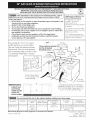 1
1
-
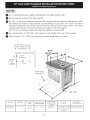 2
2
-
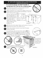 3
3
-
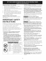 4
4
-
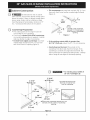 5
5
-
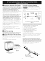 6
6
-
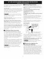 7
7
-
 8
8
-
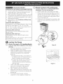 9
9
-
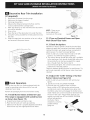 10
10
-
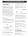 11
11
-
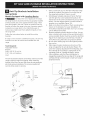 12
12
-
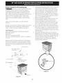 13
13
-
 14
14
-
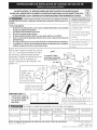 15
15
-
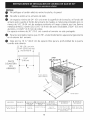 16
16
-
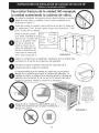 17
17
-
 18
18
-
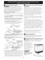 19
19
-
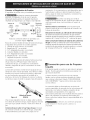 20
20
-
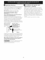 21
21
-
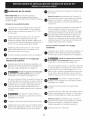 22
22
-
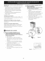 23
23
-
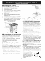 24
24
-
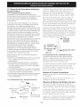 25
25
-
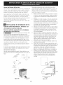 26
26
-
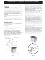 27
27
-
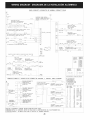 28
28


en otros idiomas
Artículos relacionados
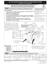
Otros documentos
-
Electrolux E36GF76JPS2 Installation Insrtuctions
-
Kenmore Elite 79032363415 Guía de instalación
-
-
-
Kenmore Pro 79079613801 Guía de instalación
-
Electrolux 318201778 Manual de usuario
-
-
Frigidaire CFGS3035LS3 Installation Instructions Manual
-
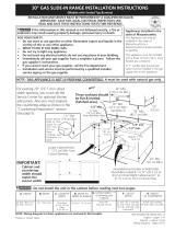 Kenmore Elite 79031043802 Guía de instalación
-
