Kenmore 79097502001 Guía de instalación

Tipo
Guía de instalación
iNSTALLATiON AND SERVICE MUST BE PERFORMED BY A QUALiFiED TECHNiCiAN.
iMPORTANT: SAVE FOR THE LOCAL ELECTRICAL iNSPECTOR'S USE.
READ AND SAVE THESE iNSTRUCTiONS FOR FUTURE REFERENCE.
1. Clearances and Dimensions
a. Provide adequate clearances between the range and adjacent combustible surfaces.
b. Location--Check location where the range will be installed. Check for proper electrical supply and the stability of floor.
c. Dimensions that are shown must be used. Given dimensions provide minimum clearance. Contact surface must
be solid and level.
FRONT TYPICAL CABINET iNSTALLATiON
ViEW
Minimumto 1"
wail on either - Pit
sideof range I
I
above 36" height. I
° s"#vff
1_13"÷
18" cabinets on Maximumdepth
"" either side for cabinets f/
_------- 301/8 "--------_ O"dearance below cooking top and at rear ofrange.
1' 30"--_ I
30"
Minimum t Minimumto
FRONT
VIEW
T
49" l
Maximum
36 ± 1/8"
46' X
\..
Door
open "\ 30,,.11"v_-_
29-7/8"--._i I 25-3/4"
* 30" minimum clearance between the top of the cooking surface
and the bottom of an unprotected wood or metal cabinet; or 24 "
minimum when bottom of wood or metal cabinet is protected by not
less than 1A"flame retardant millboard covered with not less than
no. 28 MSG sheet steel, 0.015" stainless steel, 0.024" aluminum or
0.020" copper. The minimum clearance is O"for the rear of the
range. Follow all dimension requirements provided above to
prevent property damage, potential fire hazard, and incorrect
countertop and cabinet cuts.
Avoid locating cabinet storage space above the surface units to
eliminate the possibility of cabinets catching on fire, or
personal burns from reaching for the cabinets over the heated
units. If cabinet storage is to be provided, risk can be reduced
by installing a range hood that projects horizontally a minimum
of 5" beyond the bottom of the cabinets.
Important Notes to the Installer
1. Read all instructions contained in these installation instructions
before installing the appliance.
2. Remove all packing material before connecting the electrical
supply to the appliance.
3. Observe all governing codes and ordinances.
4. Be sure to leave these instructions with the consumer.
important Note to the Consumer
Keep these instructions with your Use and Care Guide for future reference.
Printed in United States
BACK
ViEW
_f'-:i:- ...........__-_--__o_electrical outlet
',//_ _- ........location aremaximum.
/ ........................ ( Cubed area shows '
I / Terminal'_ I where the electricall I
I Block [ _/ outlet must be
I Location .__ installed for the
',/ ' "_ :'_-_'1range to be flush
I'_- 9' _ _ ,,to the wall. /;
o ,o,I t
"_" _ 3"_ -_:-__v_ Edge
318201720 (0807) Rev.A
=
=
Install Anti-Tip Bracket (See instructions on
page 4.)
Serial Plate Information
The serial plate is located as shown below. See
the serial plate for the following information:
A.Model, lot and serial number of range.
B.Kilowatt rating (power requirements).
C.Voltage ratings.
4. Electrical Connection Requirements
This appliance must be properly installed and
grounded by a qualified technician in accordance with
the National Electrical Code ANSI/NFPA No. 70--latest
edition--and local electrical code requirements.
This appliance may be connected by means of
permanent "Hard Wiring" or "Power Supply Cord Kit."
When hard wiring, do not leave excess wire in range
compartment. Excess wire in the range compartment
may not allow the access cover to be replaced
properly, and could create a potential electrical hazard
if wires become pinched. Connect only as instructed
under "WIRING INSTRUCTIONS" in sections 6 and 7.
When using flexible conduit or range cable, use flex
connector or range cable strain relief.
NOTE: Only use copper wire in connection to terminal
block.
4.1 Models Requiring Power Supply Cord
Kit
l
U.S. STYLE
Figure 1 - 3=Wire Cord Kit
Risk of fire or electrical shock may
occur if an incorrect size range cord kit is used, the
installation instructions are not followed or strain relief
bracket is discarded.
This appliance may be connected by means of a
power supply cord. Only a power supply cord kit rated
at 40 or 50 amperes, 125/250 volts, and marked for
use with ranges shall be used. Terminals on end of
wires must be either closed loop or open-end spade
lugs with upturned ends. Cord must have strain relief
clamp.
NOTE: In mobile home installation or areas where
local codes do not permit grounding through
neutral, a four (4) conductor power cord must be
used.
A 1-3/8" knock-out hole is provided at the bottom of
the range terminal box for connecting the power
supply cord kit to the range terminal block (see
Figures 2 and 3).
5. Permanent Hard Wiring (3 or 4 Wires)
Insert the residence 3-wire power supply cable
through the 1-1/8" hole at the bottom of the range
terminal box (see Figure 2). For mobile home
application or where connections with a 3-wire power
supply cable is not allowed, use a 4-wire power supply
cable (for connections, see Figure 3). Use a U.L.
approved strain relief clamp to secure the cable to the
terminal box.
6. Wiring Instructions = 3-Wire Supply Cable
ELECTRICAL GROUND IS REQUIRED
ON THIS APPLIANCE.
Risk of electric shock, frame grounded
to neutral of appliance through a link. Grounding
through the neutral conductor is prohibited for new
branch-circuit installations (1996 NEC); mobile homes;
and recrational vehicles, or in an area where local
codes prohibit grounding through the neutral
conductor. When installed where it is not permitted to
ground through the neutral, the 3-condutor cord or
cable assembly must be replaced by a 4-conductor
cord or cable assembly.
NOTE: If the ground link is removed for any reason, a
separate ground wire must be connected to the
separate ground screw attached to the range chassis,
and to an adequate ground source.
2
From Range
Terminal Box
range ...............
/
models ....
Silver .
colored._
termi_
Line 1-4_
Ground
link
Line 2 ......
Neutral
(white or
center)
Figure 2 = 3=Wire Supply Cable
From Range
range ..... Ter, inalBo,
models ......
Silver /
colored-(/
termi_
Line 1=_
Ground"
screw
No. 8 green
insulated
copper
ground wire
Pigtail or
Line 2
J eutral
(white or
_center)
from
junction box
Figure 3 =4-Wire Supply Cable
A. Remove the 2 screws and remove terminal box
cover.
B. Remove the 3 loose nuts on the terminal block
using 3/8" nut driver or socket. Install a strain relief.
C. Attach pigtail or cable from junction box to the 3
studs in terminal block, as local codes require. The
neutral wire (white) or center wire must be
connected to center terminal.
D. Reinstall terminal box cover,
Do not loosen nuts which secure the
factory installed range wiring to terminal block while
connecting range. Electrical failure or loss of electrical
connection may occur.
7. Wiring Instructions = 4-Wire Supply Cable
Risk of electric shock, frame grounded
to neutral of appliance through a link. Grounding
through the neutral conductor is prohibited for new
branch-circuit installations (1996 NEC); mobile homes;
and recrational vehicles, or in an area where local
codes prohibit grounding through the neutral
conductor. When installed where it is not permitted to
ground through the neutral, the 3-condutor cord or
cable assembly must be replaced by a 4-conductor
cord or cable assembly.
A,
B.
C,
D,
E,
F,
Remove the 2 screws and remove terminal box
cover.
Remove ground screw
from the ground link.
Save the ground screw
for future use.
Bend up the ground
link so that it does not
contact the range, link
Install a strain relief.
Connect ground wire Ground
(green) of pigtail or screw
junction box cable to
frame of appliance with ground screw, using hole
in frame where ground link was removed (see
Figure 3).
Connect neutral (white) wire of pigtail or junction
box cable to center silver colored terminal of
terminal box, and connect the other wires to outer
terminals using the 3 loose nuts on the terminal
block to terminal box using 3/8" nut driver or
socket.
Reinstall terminal box cover.
3
8. Leveling the Range
A. Install an oven rack in the center of the oven.
B. Place a level on the rack (see Figure 4). Take 2
readings with the level placed diagonally in one
direction and then the other. Level the range, if
necessary, by adjusting the 4 leg levelers with a
wrench (see Figure 5).
Figure 4
9.Anti-Tip Bracket Installation instructions
iMPORTANT SAFETY WARNING
To reduce the risk of tipping of the range, the range
must be secured to the floor by properly installed anti-
tip bracket and screws packed with the range. These
parts are located in a plastic bag in the oven. Failure
to install the anti-tip bracket will allow the range to tip
over if excessive weight is placed on an open door or
if a child climbs upon it. Serious injury may result from
spilled hot liquids or from the range itself. Refer to the
instructions located in the anti-tip bracket package for
proper bracket installation. If the range is moved to a
different location, the anti-tip bracket must also be
moved and installed with the range.
For the bracket installation intructions, refer to the
anti-tip bracket template shipped in the anti=tip
bracket package.
10. Checking Operation
Refer to the Use and Care Guide for operation.
_Do not touch cooktop glass or elements.
They may be hot enough to burn you.
Before You Call for Service
Read the Before You Call for Service Checklist and
operating instructions in your Use and Care Guide. It
may save you time and expense. The list includes
common occurrences that are not the result of
defective workmanship or materials in this appliance.
Refer to your Use and Care Guide for Sears service
phone numbers, or call 1=800=4=MY=HOME ®.
Figure 5
4
LA INSTALACION Y EL SERVICIO DEBEN SER PROPORCIONADOS POR UN TECNICO CALIFICADO.
IMPORTANTE: GUARDE ESTAS iNSTRUCCIONES PARA SU USO POR EL iNSPECTOR ELECTRICO LOCAL.
LEA Y GUARDE ESTAS INSTRUCCIONES PARA FUTURA REFERENClA.
=
Espacios y dimensiones:
a. Proporcione espacios adecuados entre la estufa y las superficies combustibles adyacentes.
b. Ubicaci6n--Examine el lugar en el cual va a set instalada la estufa. Determine la existencia de suministro electrico
adecuado y la estabilidad del piso.
c. Se deben usar las medidas indicadas. Las dimensiones indicadas proporcionan espacio minimo. La superficie de
contacto debe set s61iday estar a nivel.
VISTA
FRONTAL -
TYPICAL CABINET iNSTALLATiON
30" I
Mfnimoalapared1"_ Minimum 1' Minimoalos
a cada lado de la ___ ° " 18" gabinetes
cocina o la codna sobre cada
lado de la
a 36" de alto.
estufa.
m
'_301/8"_
1_-13"-_
Mb,xima distancia
entre los gabinetes_
y la parte superior ___1
de la cocina. [_J
_25"_
O"clearance below cooking top and atrear ofrange.
36 + 1/8"
Un minimo de 30" de espacio entre la parte superior de la
superficie para estufar y el fondo no protegido de un gabinete de
metal o madera; o un minimo de 24" cuando el fondo de metal o
madera del gabinete esta protegido por no menos de 1A"de
material retardante, con una hoja de acero de no menos MSG
No.28, 0.015" de acero inoxidable, 0.024" de aluminio o 0.020" de
cobre. 0" es el espacio minimo para la parte trasera de la estufa.
Siga todos los requerimientos de medidas antes proporcionados
para evitar da_os a la propiedad: peligro de incendidos potenciales
o superficies y cortes de gabinetes que sean incorrectos.
Para eliminar el riesgo de quemaduras o incendio cuando trate de
alcanzar objetos por sobre unidades de superficie calentadas, debe
evitarse que los gabines para almacenamiento esten Iocalizados
encima de la supefficie de la estufa. Si existen gabinetes de
almacenamiento, el riesgo puede set reducido instalando una
campana de estufa que se proyecte en forma horizontal a una
distancia minima de 5" mas alia del fondo de los gabinetes.
Notas importantes para el instalador
1. Lea todas las instrucciones contenidas en este manual antes de
instalar la estufa.
2. Saque todo el material usado en el embalaje de la estufa antes
de conectar el suministro electrico a la estufa.
3. Observe todos los c6digos y reglamentos pertinentes.
4. Deje estas instrucciones con el consumidor.
VISTA
POSTERIOR
I _ _'2_ -"_ -"-_ /_ '_
[<_."_°--_:-._._ _ _ [Todas las dimensiones"_._i>
I_ :::: '-- ..... i para la ubicaci6n del
[_ L_.: ..........+--+++++tomacorriente el+ctrico N
I_/ .... |'"'
| .........................._El_ d_l_obo
| [Ubicaci6n i muestra donde se debe
| Jdel bloque _ instalar el
' . i_: -
l! I t_m,oal,_<_tomaeomentee=eotr,_oI
_1._ r,, _ :,de lapared. {
Nota importante al consumidor
Conserve estas instrucciones y el Manual del usuario para referencia futura.
Impreso en los Estados Unidos 318201720 (0807) Rev.A
=
3.
Instale los soportes antivuelco. (Vet
instrucciones en la p_gina 4.)
Placa de Identificaci6n
Esta placa de identificaci6n esta Iocalizada sobre el
marco y se puede ver cuando la gaveta esta abierta.
Consulte la placa de identificaci6n para obtener la
siguiente informaci6n:
A. N0meros de modelo, partida y serie de la estufa.
B.Tasa de kilovatios (requerimientos de energia.)
C.Tasa de voltaje.
Placa con los numeros
de modelo y serie
4. Requisitos de conexi6n el6ctrica
Este aparato debe estar instalado en forma apropiada y
puesto a tierra pot un tecnico calificado, de acuerdo con el
National Electric Code (C6digo Nacional de Electricidad)
ANSl/NFPA No. 70 --01tima edici6n-- y con los
requerimientos de electricidad de los c6digos locales.
Este aparato puede ser conectado por medio de una
extensi6n a un tomacorriente local permanente o pot
medio de "Juego de Cord6n para el Suministro de
Energia"
Cuando se use la extensi6n, no deje exceso de alambre
en el compartimiento de la estufa. Si se deja exceso de
alambre en el compartimiento, esto no permitira que la
cubierta de acceso sea cerrada en forma apropiada, Io
cual puede crear un riesgo el6ctrico potencial si se
perforan los alambres. Conecte este aparato solamente de
acuerdo con las "INSTRUCCIONES PARA ALAMBRADO"
que aparecen en las secciones 6 y 7. Cuando se use
conduit flexible o cable para estufas, use un conector
flexible o cable de estufa resistente a tensiones.
NOTA: Use solamente alambre de cobre en la conexi6n al
bloque terminal.
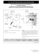
4.1 Modelos que requieren Juego de
Cord6n para el Suministro de Energia
!
Figura 1 - Juego de cord6n de 3 alambres
_J___PUEDE OCURRIR RIESGO DE
INCENDIO O DESCARGA ELECTRICA SI SE USA UN
CORDON DE ESTUFA DE CALIBRE INCORRECTO; SI
NO SE SIGUEN LAS INSTRUCCIONES DE
NSTALACION O SI SE DESHECHA LA ESCUADRA DE
RESISTENCIA ALAS TENSlONES.
Este aparato puede ser conectado pot medio de un cord6n
de suministro de energia. $61o debe usarse un juego de
cord6n de suministro de energia, tasado a 40 o 50
amperios, 125/250 voltios, y marcado para set usado en
estufas el6ctricas. Las terminales en los extremes de los
alambres deben ser ya sea, de lazo cerrado o de tal6n tipo
espada de final abierto con terminales torneadas.
NOTA: PARA LA INSTALACION EN CASAS MOBILES
O EN AREAS EN LAS CUALES LOS CODIGOS
LOCALES NO PERMITEN LA PUESTA A TIERRA A
TRAVES DE NEUTROS, DEBE USARSE UN CORDON
DE ENERGIA DE CUATRO (4) CONDUCTORES.
Se proporciona un agujero de disco removible de 1-3/8"
al fondo de la caja terminal de la estufa para conectar el
juego de cord6n de suministro de energia al bloque
terminal de la estufa (ver Figuras 2 y 3).
5. Alambrado Perrnanente (3 o 4 alarnbres)
Introduzca el cable de suministro de energia de 3
alambres de la residencia a traves del agujero de 1-1/8"
que est,. al fondo de la caja terminal de la estufa (ver
Figura 2). Para su uso en casas m6viles, o donde las
conexiones con un cable de suministro de 3 alambres
no sean permitidas, use un cable de suministro de
energia de 4 alambres (para conexiones ver la Figura
3). Use una abrazadera de prevenci6n de tensi6n
aprobada de acuerdo con U.L., para asegurar el cable a
la caja terminal.
6. Instrucciones de Alarnbrado - Cable de
suministro de 3 alarnbres
_J__EN ESTE APARATO SE EXIGE LA
PUESTA A TIERRA.
No podr_ conectar a tierra la
cocina a tray, s del cable neutral (blanco) si la
cocina se usa en una nueva instalaci6n de ramal de
circuito (1996 NEC), en una casa rodante, en un
vehiculo para recreaci6n o si los c6digos locales no
permiten hacer la cone×i6n a tierra a trav_s del
cable neutral (blanco). Cuando est_ prohibida la
conexi6n a tierra a tray,s del cable neutral (blanco),
debe usar un cable de alimentaci6n de 4 hilos. Si no
observa esta precauci6n, puede sufrir electrocuci6n
u otra lesi6n personal grave.
NOTA: Si por cualquier raz6n se quita la uni6n a tierra,
un alambre separado de puesta a tierra debe ser
conectado a un tornillo separado de puesta a tierra que
se debe unir al chasis de la estufa, y a una fuente de
tierra adecuada.
2
Desde la Caja Terminal
estufa ..... de la_stufa
AIgunos
Modelos
puesta a tierra
Tornillo de
puesta
tierra ....
Abrazadera de
prevenci6n de
tensi6n ............
Linea 2 ......
Neutro
(bianco o
central)
Para fusible, desconectar la caja o el
instrumento aprobado de alambrado para el
cordon de cobre de suministro de energia
Figura 2
Cable de suministro de 3=alambres
Desde la
estufa .....
AIgunos
Modelos
Terminal
plateada'
ii
ii
il
Linea
Tornillo de
a tierra
Alambre de puesta
a tierra,verde, #8,
de cobre
Abrazadera de
prevenci6n
tensi6n
Caja Terminal
de la estufa
L_nea 2 ......
Neutro
bianco o
central)
/
Para fusible, desconectar la caja o el
instrumento aprobado de alambrado para el
cordon de cobre de suministro de energia
Figura 3
Cable de suministro de 4-alambres
A. Quite los dos tornillos y quite la cubierta de la caja
terminal.
B. Quite las tres tuercas desatadas (despues de remover
la cinta de goma) sobre el bloque terminal usando un
destronillador o una Ilave de casquillo de 3/8". Instale
un abrazadera de prevenci6n de tensi6n.
C. Una el cable o el cable flexible de conexi6n a los 3
parales que est_tn sobre el bloque terminal, segt_n Io
exigen los c6digos locales. El alambre neutro
(blanco) o central debe set conectado al centro de
la terminal.
D. Vuelva a colocar la cubierta de la caja de la terminal.
_No afloje las tuercas que aseguran el
alambrado instalado en f&brica al bloque terminal mientras
se conecta la estufa. Puede ocurrir falla electrica o perdida
de conexi6n.
7.1nstrucciones de alambrado - Cable de
Suministro de 4 alambres (para casas
m6viles)
No podr_ conectar a tierra la
cocina a tray, s del cable neutral (blanco) si la
cocina se usa en una nueva instalaci6n de ramal de
circuito (1996 NEC), en una casa rodante, en un
vehiculo para recreaci6n o si los c6digos locales no
permiten hacer la conexi6n a tierra a trav_s del
cable neutral (blanco). Cuando est_ prohibida la
conexi6n a tierra a trav_s del cable neutral (blanco),
debe usar un cable de alimentaci6n de 4 hilos. Si no
observa esta precauci6n, puede sufrir electrocuci6n
u otra lesi6n personal grave.
A.
B.
C.
U.
E.
F.
Quite los dos tornillos y quite la cubierta de la caja
terminal.
Quite el tornillo de la uni6n a
tierra usando un
destornillador. Guarde el
tornillo para uso futuro.
Doble la uni6n a tierra hacia Unibn de
arriba para que no entre en puesta a tierra
contacto con la estufa.
Instale un abrazadera de
prevenci6n de tensi6n. Tornillo de
Conecte el alambre de puesta a tierra
puesta a tierra (verde) o el
cord6n de cobre de suministro de energfa al marco
del aparato, con el tornillo de puesta a tierra, usando
el agujero en el marco del cual se quit6 la faja de
puesta a tierra (ver Figura 3).
Conecte el alambre neutral (blanco) del cord6n de
cobre de suministro de energia a la terminal de color
plateada del centro de la caja terminal, y conecte los
otros alambres a las terminales de salida, usando las
3 tuercas de ajuste que estAn unidas a la caja
terminal, usando una Ilave de 3/8".
Vuelva a colocar la cubierta de la caja de la terminal.
3
8. Cbmo nivelar la estufa
A. Coloque una parilla del homo en el centro del horno.
B. Ponga un nivel sobre la parrilla (Figura 4). Tome dos
lecturas con el nivel puesto diagonalmente en una
direcci6n y despu6s en la otra. Nivele la estufa, si es
necesario, ajustando las 4 patas niveladoras con una
Ilave de tuercas (Figura 5).
Figura 4
9. Instrucciones para la Instalaci6n del
Soporte Antivuelco
ADVERTENCIA IMPORTANTE PARA SEGURIDAD
Para reducir el riesgo de que la estufa se vuelque, esta debe
estar asegurada al piso por medio de soportes antivuelco,
propiamente instaladas con los tornillos que se acompaSan
con la estufa. Las piezas se encuentran en un saco de
pla.stico en el homo. Si no se instalan estes soportes, la
estufa se volcara si se coloca peso excesivo sobre una
puerta abierta o si un niSo se subiera al aparato. Puede tener
como resultado lesiones serias como consecuencia de
derrame de liquidos calientes o por que la estufa misma
puede caerse. Estudie las instrucciones en esta pagina para
una instalaci6n apropiada. Si la estufa se mueve a un lugar
diferente, los soportes para evitar el balanceo tambien deben
quitarse y volverse a instalar con la estufa.
Instrucciones para la instalaci6n ver la plantilla
antivuelco encuentran en un saco de pl_stico en el
homo.
Antes de Ilamar al servicio
Lea la secci6n Lista de Antes de Ilamar en su Manual
del Usuario. Esto le podrA ahorrar tiempo y gastos.
Esta lista incluye ocurrencias comunes que no son el
resultado de defectos de materiales o fabricaci6n de
este artefacto.
Lea la garantfa y la informaci6n sobre el servicio en su
Manual del Usuario para obtener el n_mero de
telefono gratuito y la direcci6n del servicio o llama
l=888=SU=HOGAR SM.
Figura 5
4
  • Page 1 1
  • Page 2 2
  • Page 3 3
  • Page 4 4
  • Page 5 5
  • Page 6 6
  • Page 7 7
  • Page 8 8

Kenmore 79097502001 Guía de instalación

Tipo
Guía de instalación

En otros idiomas