MTD 247881720 El manual del propietario
- Categoría
- Lanzadores de nieve
- Tipo
- El manual del propietario
Este manual también es adecuado para

Operator's Manual
CRRFr MRN
24" SNOW THROWER
Model No. 247.881720
CAUTION" Before using this
product, read this manual and
follow all safety rules and operating
instructions.
,, SAFETY
o ASSEMBLY
OPERATION
MAINTENANCE
PARTS LIST
o ESPANOL
Sears Brands Management Corporation, Hoffman Estates, IL 60179, U.S.A.
Visit our website: www.craftsman.com FormNo.769-08175A
(July9,2012)

WarrantyStatement.................... Page2
SafeOperationPractices.............. Pages3-6
Assembly......................... Pages8-11
Operation........................ Pages12-15
Service&Maintenance.............. Pages16-23
Off-SeasonStorage................... Page24
Troubleshooting...................... Page25
PartsList......................... Pages26-43
RepairProtectionAgreement............ Page47
Espadol............................. Page48
CRAFTSMANTWOYEARFULLWARRANTY
FORTWOYEARSfromthedateofpurchase,thisproductiswarrantedagainstanydefectsinmaterialorworkmanship.Defectiveproductwill
receivefreerepairorfreereplacementifrepairisunavailable.
Forwarrantycoverage details to obtain repairor replacement,visit the website: www.craftsman.com
This warranty covers ONLYdefects in materialandworkmanship. Warrantycoverage does NOTinclude:
• Expendableitemsthatcanwearoutfromnormalusewithinthewarrantyperiod,includingbutnotlimitedtoaugers,augerpaddles,drift
cutters,skidshoes,shaveplate,shearpins,sparkplug,air cleaner,belts,andoil filter.
• Standardmaintenanceservicing,oilchanges,or tune-ups.
• Tirereplacementor repaircausedbypuncturesfromoutsideobjects,suchasnails,thorns,stumps,or glass.
• Tireor wheelreplacementor repairresultingfromnormalwear,accident,orimproperoperationor maintenance.
Repairsnecessarybecauseof operatorabuse,includingbutnotlimitedtodamagecausedbyover-speedingtheengine,or fromimpacting
objectsthat bendtheframe,augershaft,etc.
• Repairsnecessarybecauseof operatornegligence,includingbutnotlimitedto,electricalandmechanicaldamagecausedbyimproper
storage,failureto usethepropergradeandamountofengineoil,orfailureto maintaintheequipmentaccordingtotheinstructionscontained
intheoperator'smanual.
• Engine(fuelsystem)cleaningor repairscausedbyfueldeterminedto becontaminatedoroxidized(stale).Ingeneral,fuelshouldbeused
within30 daysof itspurchasedate.
Normaldeteriorationandwearoftheexteriorfinishes,or productlabelreplacement.
Thiswarrantyisvoidifthisproductiseverusedwhileprovidingcommercialservicesor if rentedtoanotherperson.
Thiswarrantygivesyouspecificlegalrights,andyoumayalsohaveotherrightswhichvaryfromstatetostate.
Sears Brands Management Corporation, Hoffman Estates, IL 60179
EngineOilType: 5W-30
EngineOilCapacity: 20ounces
FuelCapacity: 2Quarts
SparkPlug: F6RTC(951-10292)
SparkPlugGap: .020"to .030"
ModelNumber.................................................................
Serial Number.................................................................
Dateof Purchase .............................................................
Recordthemodelnumber,serialnumber
anddateof purchaseabove
©SearsBrands,LLC
2

Thissymbolpointsoutimportantsafetyinstructionswhich,if not
followed,couldendangerthepersonalsafetyand/orpropertyof
yourselfandothers.Readandfollowall instructionsin thismanual
beforeattemptingtooperatethismachine.Failuretocomplywith
theseinstructionsmayresultin personalinjury.Whenyouseethis
symbol,HEEDITSWARNING!
CALIFORNIA PROPOSITION 65
EngineExhaust,someof itsconstituents,andcertainvehicle
componentscontainoremitchemicalsknowntoStateofCalifornia
tocausecancerandbirthdefectsorotherreproductiveharm,
Thismachinewasbuilttobeoperatedaccordingtothesafeopera-
tionpracticesinthis manual.Aswithanytypeof powerequipment,
carelessnessorerroron thepartoftheoperatorcanresultin serious
injury.Thismachineiscapableofamputatingfingers,hands,toes
andfeetandthrowingdebris.Failuretoobservethefollowingsafety
instructionscouldresultin seriousinjuryor death.
Your Responsibility--Restrict theuseofthispowermachineto
personswhoread,understandandfollowthewarningsand instruc-
tionsin thismanualandon themachine,
SAVE THESE INSTRUCTIONS!
TRAiNiNG
• Read,understand,andfollowall instructionson themachineand
in themanual(s)beforeattemptingtoassembleandoperate.
Failuretodo socan resultinseriousinjurytotheoperatorand/
orbystanders.Keepthismanualin a safeplaceforfutureand
regularreferenceandfororderingreplacementparts.
• Befamiliarwithall controlsandtheirproperoperation.Knowhow
tostopthemachineanddisengagethemquickly.
• Neverallowchildrenunder14yearsofagetooperatethis
machine.Children14andovershouldreadandunderstandthe
instructionsandsafeoperationpracticesin thismanualandon
themachineandbe trainedandsupervisedbyanadult.
Neverallowadultstooperatethis machinewithoutproper
instruction.
• Thrownobjectscancauseseriouspersonalinjury.Planyour
snow-throwingpatterntoavoiddischargeof materialtoward
roads,bystandersandthelike.
Keepbystanders,petsandchildrenat least75feetfromthe
machinewhileitisin operation.Stopmachineifanyoneenters
thearea.
• Exercisecautiontoavoidslippingor falling,especiallywhen
operatingin reverse.
PREPARATION
Thoroughlyinspecttheareawheretheequipmentistobeused.
Removeall doormats,newspapers,sleds,boards,wiresandother
foreignobjects,whichcouldbe trippedoverorthrownbytheauger/
impeller.
• Alwayswearsafetyglassesor eyeshieldsduringoperationand
whileperformingan adjustmentor repairto protectyoureyes.
Thrownobjectswhichricochetcancauseseriousinjurytothe
eyes.
Donotoperatewithoutwearingadequatewinteroutergarments.
Donotwearjewelry,longscarvesorotherlooseclothing,which
couldbecomeentangledin movingparts.Wearfootwearwhich
willimprovefootingonslipperysurfaces.
Usea groundedthree-wireextensioncordand receptacleforall
machineswithelectricstartengines.
Disengageall controlleversbeforestartingtheengine.
Adjustcollectorhousingheighttocleargravelorcrushedrock
surfaces.
• Neverattempttomakeanyadjustmentswhileengineis running,
exceptwherespecificallyrecommendedintheoperator'smanual.
Letengineandmachineadjusttooutdoortemperaturebefore
startingtoclearsnow.
3

SafeHandlingof Gasoline
Toavoidpersonalinjuryor propertydamageuseextremecarein
handlinggasoline.Gasolineisextremelyflammableandthevaporsare
explosive.Seriouspersonalinjurycanoccurwhengasolineisspilled
onyourselfor yourclotheswhichcanignite. Washyourskinand
changeclothesimmediately.
• Useonlyan approvedgasolinecontainer.
• Extinguishallcigarettes,cigars,pipesandothersourcesof
ignition.
• Neverfuelmachineindoors.
• Neverremovegascapor addfuelwhiletheengineishotor
running.
• Allowenginetocoolat leasttwo minutesbeforerefueling.
• Neveroverfillfueltank.Filltankto nomorethan1/2inchbelow
bottomoffillernecktoprovidespaceforfuelexpansion.
• Replacegasolinecapandtightensecurely.
• Ifgasolineisspilled,wipeitoff theengineandequipment.Move
machinetoanotherarea.Wait5 minutesbeforestartingthe
engine.
• Neverstorethemachineorfuelcontainerinsidewherethereisan
openflame,sparkor pilotlight(e.g.furnace,waterheater,space
heater,clothesdryeretc.).
• Allowmachinetocoolatleast5 minutesbeforestoring.
• Neverfillcontainersinsidea vehicleor ona truckor trailerbed
witha plasticliner.Alwaysplacecontainersonthegroundaway
fromyourvehiclebeforefilling.
• If possible,removegas-poweredequipmentfromthetruckor
trailerandrefuelitontheground.Ifthis isnotpossible,thenrefuel
suchequipmenton a trailerwitha portablecontainer,ratherthan
froma gasolinedispensernozzle.
• Keepthenozzlein contactwiththerimofthefueltankor
containeropeningatalltimesuntilfuelingiscomplete.Donotuse
a nozzlelock-opendevice.
OPERATION
• Donotputhandsorfeetnear rotatingparts,in theauger/impeller
housingor chuteassembly.Contactwiththerotatingpartscan
amputatehandsandfeet.
• Theauger/impellercontrolleverisa safetydevice.Neverbypass
itsoperation.Doingsomakesthemachineunsafeandmaycause
personalinjury.
• Thecontrolleversmustoperateeasilyin bothdirectionsand
automaticallyreturntothedisengagedpositionwhenreleased.
• Neveroperatewitha missingor damagedchuteassembly.Keep
all safetydevicesin placeandworking.
• Neverrunanengineindoorsor ina poorlyventilatedarea.Engine
exhaustcontainscarbonmonoxide,anodorlessanddeadlygas.
• Donotoperatemachinewhileundertheinfluenceofalcoholor
drugs.
• Mufflerandenginebecomehotandcancausea burn.Donot
touch.Keepchildrenaway.
• Exerciseextremecautionwhenoperatingon orcrossinggravel
surfaces.Stayalertforhiddenhazardsor traffic.
Exercisecautionwhenchangingdirectionandwhileoperatingon
slopes.Donotoperateon steepslopes.
Planyoursnow-throwingpatternto avoiddischargetowards
windows,walls,carsetc.Thus,avoidingpossibleproperty
damageor personalinjurycausedbya ricochet.
Neverdirectdischargeatchildren,bystandersand petsor allow
anyoneinfrontofthemachine.
Donotoverloadmachinecapacitybyattemptingtoclearsnowat
toofastof a rate.
Neveroperatethis machinewithoutgoodvisibilityorlight.Always
be sureofyourfootingand keepa firmholdon thehandles.Walk,
neverrun.
Disengagepowertotheauger/impellerwhentransportingor not
in use.
Neveroperatemachineathightransportspeedson slippery
surfaces.Lookdownand behindand usecarewhenbackingup.
Ifthemachineshouldstarttovibrateabnormally,stoptheengine,
disconnectthesparkplugwireandgrounditagainsttheengine.
Inspectthoroughlyfordamage.Repairanydamagebefore
startingandoperating.
Disengageall controlleversandstopenginebeforeyouleave
theoperatingposition(behindthehandles).Waituntiltheauger/
impellercomestoa completestopbeforeuncloggingthechute
assembly,makinganyadjustments,or inspections.
Neverputyourhandinthedischargeor collectoropenings.Do
notunclogchuteassemblywhileengineisrunning.Shutoff
engineand remainbehindhandlesuntilall movingpartshave
stoppedbeforeunclogging.
Useonlyattachmentsandaccessoriesapprovedbythemanufac-
turer(e.g.wheelweights,tirechains,cabsetc.). Forinformation
concerningtheseitems,call1-800-469-4663.
Whenstartingengine,pullcordslowlyuntilresistanceisfelt,then
pull rapidly.Rapidretractionofstartercord(kickback)willpull
handandarmtowardenginefasterthanyoucanletgo.Broken
bones,fractures,bruisesor sprainscouldresult.
Ifsituationsoccurwhichare notcoveredinthis manual,usecare
andgoodjudgment.
Toorderpartsor scheduleserviceforthisproduct,call 1-800-
469-4663.
CLEARING A CLOGGED DISCHARGE CHUTE
Handcontactwiththe rotatingimpellerinsidethedischargechute
is themostcommoncauseofinjuryassociatedwithsnowthrowers.
Neveruseyourhandtocleanoutthedischargechute.
Toclearthechute:
1. SHUTTHEENGINEOFF!
2. Wait 10secondstobe suretheimpellerbladeshavestopped
rotating.
3. Alwaysusea clean-outtool,notyourhands.
4

MAINTENANCE & STORAGE
• Nevertamperwithsafetydevices.Checktheirproperoperation
regularly.Refertothemaintenanceandadjustmentsectionsof
thismanual.
• Beforecleaning,repairing,or inspectingmachinedisengageall
controlleversandstoptheengine.Waituntiltheauger/impeller
cometoa completestop.Disconnectthe sparkplugwireand
groundagainsttheenginetopreventunintendedstarting.
Checkboltsand screwsforpropertightnessatfrequentintervals
tokeepthemachineinsafeworkingcondition.Also,visually
inspectmachineforanydamage.
Donotchangetheenginegovernorsettingor over-speedthe
engine.Thegovernorcontrolsthe maximumsafeoperatingspeed
oftheengine.
Snowthrowershaveplatesand skidshoesaresubjecttowear
anddamage.Foryoursafetyprotection,frequentlycheckall
componentsand replacewithoriginalequipmentmanufacturer's
(OEM)partsonlyaslistedinthe Partspagesof thisoperator's
manual.Useofpartswhichdonotmeettheoriginalequipment
specificationsmayleadto improperperformanceandcompro-
misesafety!
Checkcontrolleversperiodicallytoverifytheyengageanddisen-
gageproperlyandadjust,ifnecessary.Refertotheadjustment
sectioninthisoperator'smanualforinstructions.
Maintainor replacesafetyandinstructionlabels,asnecessary.
Observeproperdisposallawsand regulationsforgas,oil,etc.to
protecttheenvironment.
Priorto storing,runmachinea few minutestoclearsnowfrom
machineand preventfreezeupofauger/impeller.
Neverstorethemachineorfuelcontainerinsidewherethereisan
openflame,sparkorpilotlightsuchasa waterheater,furnace,
clothesdryeretc.
Alwaysrefertotheoperator'smanualforproperinstructionson
off-seasonstorage.
Checkfuelline,tank,cap,andfittingsfrequentlyforcracksor
leaks.Replaceifnecessary.
Donotcrankenginewithsparkplugremoved.
AccordingtotheConsumerProductsSafetyCommission(CPSC)
andtheU.S.EnvironmentalProtectionAgency(EPA),thisproduct
hasan AverageUsefulLifeof seven(7)years,or 60 hoursof
operation.AttheendoftheAverageUsefulLifehavethemachine
inspectedannuallybyan authorizedservicedealertoensurethat
allmechanicalandsafetysystemsareworkingproperlyand not
wornexcessively.Failuretodo socanresultinaccidents,injuries
ordeath.
DO NOT MODIFY ENGINE
Toavoidseriousinjuryor death,do notmodifyengineinanyway.
Tamperingwiththegovernorsettingcanleadtoa runawayengineand
causeittooperateat unsafespeeds.Nevertamperwithfactorysetting
ofenginegovernor.
NOTICE REGARDING EMiSSiONS
EngineswhicharecertifiedtocomplywithCaliforniaandfederal
EPAemissionregulationsforSORE(SmallOff RoadEquipment)are
certifiedtooperateon regularunleadedgasoline,and mayinclude
thefollowingemissioncontrolsystems:EngineModification(EM),
OxidizingCatalyst(OC),SecondaryAirInjection(SAI)and ThreeWay
Catalyst(TWO)if soequipped.
SPARK ARRESTOR
Thismachineisequippedwithaninternalcombustionengineand
shouldnotbe usedonor nearanyunimprovedforest-covered,
brush-coveredorgrass-coveredlandunlesstheengine'sexhaust
systemisequippedwitha sparkarrestormeetingapplicablelocalor
statelaws(ifany)
Ifa sparkarrestorisused,itshouldbe maintainedin effectiveworking
orderbytheoperator.IntheStateofCaliforniatheaboveis required
bylaw(Section4442oftheCaliforniaPublicResourcesCode).Other
statesmayhavesimilarlaws.Federallawsapplyonfederallands.
A sparkarrestorforthemufflerisavailablethroughyournearestSears
PartsandRepairServiceCenter.

SAFETY SYMBOLS
Thispagedepictsanddescribessafetysymbolsthatmayappearonthisproduct. Read,understand,andfollowall instructionson themachine
beforeattemptingtoassembleandoperate.
. +
i
i
"JIp
READ THE OPERATOR'S MANUAL(S)
Read, understand, and follow all instructions in the manual(s) before attempting to assemble and
operate
WARNING-- ROTATING BLADES
Keep hands out of inlet and discharge openings while machine is running. There are rotating blades
inside
WARNING-- ROTATING BLADES
Keep hands out of inlet and discharge openings while machine is running. There are rotating blades
inside
WARNING-- ROTATING AUGER
Do not put hands or feet near rotating parts, in the auger/impeller housing or chute assembly.
Contact with the rotating parts can amputate hands and feet.
WARNING--THROWN OBJECTS
This machine may pick up and throw objects which can cause serious personal injury.
WARNING--GASOLINE ISFLAMMABLE
Allow the engine to cool at least two minutes before refueling.
WARNING-- CARBON MONOXIDE
Never run an engine indoors or in a poorly ventilated area. Engine exhaust contains carbon
monoxide, an odorless and deadly gas+
WARNING-- ELECTRICAL SHOCK
Do not use the engine's electric starter in the rain
6

Thispageleftintentionallyblank.
7

NOTE:Referencesto rightorleft sideofthesnowthrowerare
determinedfrombehindtheunitintheoperatingposition(standing
directlybehindthesnowthrower,facingthe handlepanel).
REMOVING FROM CARTON
1. Cutthecornersofthecartonandlaythesidesflaton theground.
Removeanddiscardallpackinginserts.
2. Movethesnowthroweroutofthecarton.
3. Makecertainthecartonhasbeencompletelyemptiedbefore
discardingit.
ASSEMBLY
1. Placetheshiftleverin theForward-6position.
2. Observethe lowerrearareaofthesnowthrowertobesureboth
cablesarealignedwith rollerguidesbeforepivotingthehandle
upward.See Figure1.
NOTE:Makecertaintheupperendsofeachcableare seatedproperly
in itsbracket.
.
Securethehandlebytighteningtheplasticwingknoblocatedon
boththeleftand rightsidesofthehandle.SeeFigure2. Remove
anddiscardanyrubberbands,ifpresent.Theyareforpackaging
purposesonly.
\
Figure1
f
Figure2
8

4. Pivotflangekeepersoutand positionthechuteassemblyoverthe
base.SeeFigure3.
5. Closetheflangekeepersto securethechuteassemblytothe
chutebase.SeeFigure4.Theflangekeeperswillclickintoplace
whenproperlysecure.
NOTE:Iftheflangekeeperswillnoteasilyclickintoplace,usethe
palmofyourhandtoapplyswift,firmpressuretothebackofeach.
.
7.
Removethecap,flatwasher,andhairpinclipfromtheendof
thechutedirectionalcontrol.
Inserttheendofthechutedirectionalcontrolintothelower
bracketandsecurewiththeflatwasherandhairpinclipjust
removed.See Figure5.If necessary,thelowerbracketcan
beadjusted.Referto ChuteBracketAdjustmentin the
Service& Maintenancesection.
Figure4
f F
Figure3
\
J
Figure5
9

SET-UP
Chute Clean-Out Tool
Achute clean-out tool isfastenedtothetopoftheaugerhousing
witha mountingclip.SeeFigure6.Thetoolisdesignedtocleara
chuteassemblyoficeandsnow.Thisitemisfastenedwitha cabletie
atthefactory.Cutthecabletiebeforeoperatingthesnowthrower.
Neveruseyourhandsto cleara cloggedchuteassembly.Shut
offengineand remainbehindhandlesuntilall movingpartshave
stoppedbeforeusingtheclean-outtooltoclearthechuteassembly.
Tire Pressure
Underanycircumstancedo notexceedmanufacturer'srecom-
mendedpsi. Equaltirepressureshouldbe maintainedatall times.
Excessivepressurewhenseatingbeadsmaycausetire/rim
assemblytoburstwithforcesufficienttocauseseriousinjury.Refer
tosidewallof tirefor recommendedpressure.
Thetiresareover-inflatedforshippingpurposes.Checkthetire
pressurebeforeoperatingthesnowthrower.Refertothetiresidewall
fortiremanufacturer'srecommendedpsianddeflate(or inflate)the
tiresasnecessary.
NOTE:Equaltirepressureistobe maintainedat alltimesforperfor-
mancepurposes.
ADJUSTMENTS
Skid Shoes
Thesnowthrowerskidshoesareadjustedupwardatthefactoryfor
shippingpurposes.Adjustthemdownward,ifdesired,priortooperat-
ingthesnowthrower.
It isnotrecommendedthatyouoperatethis snowthrowerongravel
asitcaneasilypickup andthrowloosegravel,causingpersonal
njuryordamageto thesnowthrowerand surroundng property.
• Forclosesnowremovalona smoothsurface,raiseskidshoes
higherontheaugerhousing.Referto Figure7.
• Usea middleor lowerpositionwhentheareatobe clearedis
uneven,suchasa graveldriveway.
Chute Clean=out Tool
Figure6
f
Smooth Surface
Surface
Figure7
NOTE:If youchoosetooperatethesnowthrowerona gravelsurface,
keeptheskidshoesin positionformaximumclearancebetweenthe
groundandtheshaveplate.
Toadjusttheskidshoes:
1. Loosenthefourhexnuts(twooneachside)andcarriagebolts.
Moveskidshoestodesiredposition. SeeFigure7.
10

2, Makecertaintheentirebottomsurfaceof skidshoeisagainstthe f
groundtoavoidunevenwearontheskidshoes, ....
3. Retightennutsandboltssecurely.
Chute
Thedistancesnowisthrowncanbeadjustedbychangingtheangleof
theupperchute.Todo so:
1. Stoptheenginebyremovingtheignitionkeyandloosenthe
plasticwingknobfoundontheleft sideofthechuteassembly.
2. Pivotthechuteupwardordownwardbeforeretighteningthewing
knob.See Figure8.
Auger Control
Priortooperatingyoursnowthrower,carefullyreadandfollowall
instructionsbelow.Performalladjustmentstoverifyyoursnow
throwerisoperatingsafelyand properly.
Figure8
Checktheadjustmentoftheaugercontrolasfollows:
1. Theaugercontrolislocatedontheleft handle.SeeFigure9 inset.
Whentheaugercontrolis releasedandin thedisengaged"up"
position,thecableshouldhavevery littleslack.ItshouldNOTbe
tight.
2. Ina well-ventibtedarea,startthesnowthrowerengine.Referto
StartingtheEngineintheOperationsection.
3. Whilestandingintheoperator'sposition(behindthe snow
thrower),engagetheauger.
4. Allowtheaugertoremainengagedforapproximatelyten(10)
secondsbeforereleasingtheaugercontrol.Repeatthisseveral
times.
5. Withtheaugercontrolin thedisengaged"up"position,walktothe
frontofthemachine.
6. Confirmthattheaugerhascompletelystoppedrotatingand
showsNOsignsofmotion.If theaugershowsANYsignsof
rotating,immediatelyreturntotheoperator'spositionandshutoff
theengine.WaitforALLmovingpartstostopbeforeadjustingthe
augercontrol.
7. Toreadjustthecontrolcable,loosentheupperhexboltonthe
augercablebracket.SeeFigure9.
8. Positionthebracketupwardtoprovidemoreslack(or downward
toincreasecabletension).
9. Retightentheupperhexbolt.
10. Repeatsteps2-6aboveto verifyproperadjustmenthasbeen
achieved.
\
ii
Figure9
11

f
Drive Control
Shift Lever
J
Auger Control
ChuteAssembly
\,
Auger
Housing
\
Augers
Gas Cap
\
OilFill
\\\\
\\
\
Skid Shoes
_jjjj Chute Directional Control
Mumer RecoilStarter
ndle
\
\
Key
Figure10
Nowthat youhavesetup yoursnowthrower,it'simportanttobecome KEY
acquaintedwith itscontrolsandfeatures,RefertoFigure10, Thekeyisa safetydevice.It mustbefully
insertedinorderfortheenginetostart, Remove
SHIFT LEVER thekeywhenthesnowthrowerisnotin use,
'
1 2345 6
NOTE:Donotturntheignitionkeyinan attempt
to starttheengine,Doingsomaycauseitto
break.
Theshiftleverislocatedonthedashpanel.Placetheshiftleverinto
anyofeightpositionstocontrolthedirectionoftravelandground
speed.
Forward
Yoursnowthrowerhassixforward(F)speeds.Positionone(1)is the
slowestandpositionsix(6) isthefastest.
Reverse
Yoursnowthrowerhastwo reverse(R)speeds.One(1)istheslower
andtwo(2) isthefaster.
CHOKE CONTROL
Thechokecontrolisfoundon therearofthe
engineand isactivatedbyturningthe rotary
chokeknobtotheCHOKEposition.Activating
thechokecontrolclosesthechokeplateon the
carburetorandaidsinstartingtheengine.
J
Meets ANSi Safety Standards
CraftsmanSnowThrowersconformtothesafetystandardoftheAmericanNationalStandardsInstitute(ANSI).
12

THROTTLE CONTROL
aiW'
Thethrottlecontrolis locatedon therearoftheengine.It regulatesthe
speedoftheengineandwillshutofftheenginewhenmovedintothe
STOPposition.
r 1
Depressingtheprimerforcesfueldirectlyinto __<<<
theengine'scarburet°rt° aid inc°'dweather [k, _"_'-_ 3X Jstarting.
RECOIL STARTER HANDLE
Thishandleisusedto manuallystarttheengine.
Theaugercontrolislocatedon thelefthandle.Squeezethecontrol
gripagainstthehandletoengagetheaugerandstartsnowthrowing
action.Releasetostop.
DRIVE CONTROL
J DRIVE
CONTROL
Thedrivecontrolis locatedon therighthandle.Squeezethecontrol
gripagainstthehandletoengagethewheeldrive.Releasetostop.
ELECTRIC STARTER BUTTON
Pressingtheelectricstarterbuttonengagestheengine'selectric
starterwhenpluggedintoa 120Vpowersource.
NOTE:Alwaysreleasethedrivecontrolbeforechangingspeeds.
Failureto dosowillresultinincreasedwearon yourmachine'sdrive
system.
ELECTRIC STARTER OUTLET
Requirestheuseof athree-prongoutdoorextensioncord(included)
anda 120Vpowersource/walloutlet.
CHUTE DIRECTIONAL CONTROL
:c.uT,=D,.EcTIo.A.co.T.o
OIL FILL
Engineoil levelcanbecheckedand oiladdedthroughtheoil fill.
GAS CAP
Unthreadthegascaptoaddgasolinetothefueltank.
AUGER
Whenengaged,theaugerbladesrotateand drawsnowintotheauger
housing.
CHUTE ASSEMBLY
Snowdrawnintotheaugerhousingisdischargedoutthechute
assembly.
AUGER CONTROL
ADJUSTABLE
DISCHARGE DISCHARGE CHUTETiLT
LEFT
The chute directionalcontrol is located on left side d the snow thrower.
Tochange the direction inwhich snow is thrown, rotate the chute
directionalcontrol.
SKID SHOES
Positiontheskidshoesbasedonsurfaceconditions.Adjustupward
forhard-packedsnow.Adjustdownwardwhenoperatingon gravelor
crushedrocksurfaces.
13

CLEAN-OUT TOOL
Neveruseyourhandstocleara cloggedchuteassembly.Shut
off engineandremainbehindhandlesuntilall movingpartshave
stoppedbeforeusingtheclean-outtooltoclearthechuteassembly.
Thechuteclean-outtoolisconvenientlyfastenedtotherearofthe
augerhousingwitha mountingclip. Shouldsnowandicebecome
lodgedin thechuteassemblyduringoperation,proceedasfollowsto
safelycleanthechuteassemblyandchuteopening:
1. ReleaseboththeAugerControlandtheDriveControl.
2. Stoptheenginebyremovingtheignitionkey.
3. Removetheclean-outtoolfromtheclipwhichsecuresittothe
rearoftheaugerhousing.
4. Usetheshovel-shapedendof theclean-outtooltodislodgeand
scoopanysnowand icewhichhasformedin andnearthechute
assembly.
5. Refastentheclean-outtooltothemountingclipontherearofthe
augerhousing,reinserttheignitionkeyandstartthesnow
thrower'sengine.
6. Whilestandingintheoperator'sposition(behindthesnow
thrower),engagetheaugercontrolfora fewsecondstoclearany
remainingsnowandicefromthechuteassembly.
BEFORE STARTING ENGINE
Read,understand,andfollowall instructionsandwarningson the
machineand inthismanualbeforeoperating.
Oil
Theunit wasshippedwith oil inthe engine.Checkoil levelbefore
eachoperationtoensureadequateoil intheengine.Forfurther
instructions,refertothe stepson page16.
NOTE:Besuretochecktheengineon a levelsurfacewiththeengine
stopped.
1. Removetheoil fillercap/dipstickandwipethedipstickclean.
2. insertthecap/dipstickintotheoilfillerneck,butdo NOTscrewit
in.
3. Removetheoil fillercap/dipstick,ifthelevelislow,slowlyadd
oil (5%30, witha minimumclassificationof SF/SG)untiloil level
registersbetweenhigh(H) andlow(L).
NOTE:Donotoverfill.Overfillingwithoil mayresultinenginesmoking,
hardstartingor sparkplugfouling.
4. Replaceandtightencap/dipstickfirmlybeforestartingengine.
Gasoline
Useautomotivegasoline(unleadedor lowleadedtominimizecombus-
tionchamberdeposits)witha minimumof87octane.Gasolinewith
upto 10%ethanolor 15%MTBE(MethylTertiaryButylEther)canbe
used.Neveruseanoil/gasolinemixtureor dirtygasoline.Avoidgetting
dirt,dust,or waterinthefueltank.DONOTuseE85gasoline.
• Refuelina well-ventilatedareawiththeenginestopped.Donot
smokeorallowflamesor sparksin theareawheretheengineis
refueledor wheregasolineisstored.
• Donotoverfillthefueltank.After refueling,makesurethetank
capisclosedproperlyandsecurely.
• Becarefulnotto spillfuelwhenrefueling.Spilledfuelorfuelvapor
mayignite,ifanyfuelisspilled,makesuretheareaisdrybefore
startingtheengine.
• Avoidrepeatedorprolongedcontactwithskinor breathingof
)or.
Useextremecarewhenhandlinggasoline.Gasolineisextremely
flammableandthevaporsare explosive.Neverfuelthemachine
indoorsorwhiletheengineishotor running.Extinguishcigarettes,
cigars,pipesandothersourcesof ignition.
1. Cleanaroundfuelfillbeforeremovingcaptofuel.
2. A fuellevelindicatorislocatedinthefueltank.SeeFigure10
inset.Becarefulnottooverfill.Filltank untilfuelreachesthefuel
levelindicatortoallowspaceforfuelexpansion.
STARTING THE ENGINE
Alwayskeephandsandfeetclearof movingparts.Donotusea
pressurizedstartingfluid.Vaporsare flammable.
NOTE:Allowtheenginetowarmupfora fewminutesafter starting.
Theenginewillnotdevelopfullpoweruntilitreachesoperating
temperatures.
1. Makecertainboththeaugercontrolanddrivecontrolarein the
disengaged(released)position.
2. insertkeyintoslot.Makesureitsnapsintoplace.Donotattempt
toturnthekey.
NOTE:Theenginecannotstartwithoutthekeyfullyinsertedintothe
ignitionswitch.
Electric Starter
Theoptionalelectricstarterisequippedwitha groundedthree-wire
powercordand plug,andisdesignedtooperateon 120voltAC
householdcurrent.Itmustbe usedwitha properlygroundedthree-
prongreceptacleatall timestoavoidthepossibilityofelectricshock.
Followall instructionscarefullypriortooperatingtheelectricstarter.
DONOTuseelectricstarterinthe rain.
Determinethatyourhome'swiringisa three-wiregroundedsystem.
Aska licensedelectricianifyouarenotcertain.
Ifyouhavea groundedthree-prongreceptacle,proceedasfollows.
Ifyoudonothavetheproperhousewiring,DONOTusetheelectric
starterunderanyconditions.
1. Plugtheextensioncordintotheoutletlocatedon theengine's
surface.Plugtheotherendof extensioncordintoa three-prong
120-volt,grounded,ACoutletina well-ventilatedarea.
14

2. Movethrottlecontrolto FAST(rabbit)_T position.
3. MovechoketotheCHOKEIJl position(coldenginestart).If
engineiswarm,placechokein RUNposition.
4. Pushprimerthree(3)times,makingsuretocoverventholein
primerbulbwhenpushing.If engineiswarm,pushprimeronly
once.Alwayscoverventholewhenpushing.Coolweathermay
requireprimingtobe repeated.
5. Pushstarterbuttontostartengine.Oncetheenginestarts,im-
mediatelyreleasestarterbutton.Electricstarterisequippedwith
thermaloverloadprotection;systemwilltemporarilyshut-downto
allowstartertocoolifelectricstarterbecomesoverloaded.
6. Astheenginewarms,slowlyrotatethechokecontroltoRUN
position.If theenginefalters,restartengineandrunwithchoke
athalf-chokepositionfora shortperiodoftime,andthenslowly
rotatethechokeintoRUNposition.
7. Afterengineisrunning,disconnectpowercordfromelectric
starter.Whendisconnecting,alwaysunplugtheendatthewall
outletbeforeunpluggingtheoppositeendfromtheengine.
Recoil Starter
Donotpullthestarterhandlewhiletheenginerunning.
1. Movethrottlecontrolto FAST(rabbit)_J_ position.
2. MovechoketotheCHOKEI,'_¢1position(coldenginestart).If
engineiswarm,placechokein RUNposition.
3. Pushprimerthree(3)times,makingsuretocoverventholewhen
pushing.Ifengineiswarm,pushprimeronlyonce.Alwayscover
ventholewhenpushing.Coolweathermayrequireprimingtobe
repeated.
4. Pullgentlyonthe starterhandleuntilitbeginstoresist,then
pullquicklyandforcefullytoovercomethecompression.Do
notreleasethehandleandallowitto snapback.Returnrope
SLOWLYtooriginalposition.If required,repeatthisstep.
5. Astheenginewarms,slowlyrotatethechokecontroltoRUN
position.If theenginefalters,restartengineandrunwithchoke
athalf-chokepositionfora shortperiodoftime,andthenslowly
rotatethechokeintoRUNposition.
Toavoidunsupervisedengineoperation,neverleavethemachine
unattendedwiththeenginerunning.Turntheengineoffafteruseand
removekey.
STOPPING THE ENGINE
Afteryouhavefinishedsnow-throwing,runenginefora few minutes
beforestoppingtohelpdryoffanymoistureontheengine.
1. MovethrottlecontroltoOFFposition.
2. Removethekey.Removingthekeywillreducethepossibilityof
unauthorizedstartingoftheenginewhileequipmentisnotin use.
Keepthekeyina safeplace.Theenginecannotstartwithoutthe
key.
3. Wipeanymoistureawayfromthecontrolson theengine.
TO ENGAGE DRIVE
1. Withthethrottlecontrolinthe Fast(rabbit)'_ position,move
shiftleverintooneof thesix forward(F)positionsortwo reverse
(R)positions.Selecta speedappropriateforthesnowconditions
anda paceyou'recomfortablewith.
NOTE:Whenselectinga DriveSpeed,usetheslowerspeedsuntil
youarecomfortableandfamiliarwiththeoperationofthesnow
thrower.
2. Squeezethedrivecontrolagainstthehandleandthesnow
throwerwillmove.Releaseitanddrivemotionwillstop.
NOTE:NEVERrepositiontheshiftlever(changespeedsordirection
oftravel)withoutfirstreleasingthedrivecontrolandbringingthesnow
throwertoa completestop.Doingsowill resultin prematurewearto
thesnowthrower'sdrivesystem.
TO ENGAGE AUGER
1. Toengagetheaugerand startthrowingsnow,squeezetheauger
controlagainsttheleft handle.Releasetostoptheauger.
REPLACING SHEAR PINS
Eachaugerbladeissecuredtothespiralshaftwitha shearpinand
bow-tieclip. Ifanaugerbladestrikesa foreignobjector icejam,the
pinwillshearoff topreventdamagetotheblade.Ifanaugerblade
doesnotturn,checktoseeifits pinhasshearedoff.SeeFigure11.
NEVERreplacetheaugershearpinswithanythingotherthanSears
SKU#88389/0EMPartNo.738-04124Areplacementshearpins.
Anydamagetotheaugergearboxor othercomponentsasa resultof
[fang to dosow NOTbe coveredbyyoursnowthrowerswarranty.
Alwaysturnoff thesnowthrower'sengineandremovethekeypriorto
replacingshearpins.
s ¸......
iJ
Figure11
15

MAINTENANCE SCHEDULE
Beforeperforminganytypeofmaintenance/service,disengageall
controlsandstoptheengine.Waituntilallmovingpartshavecometo
acompletestop.Disconnectsparkplugwireandgrounditagainstthe
enginetopreventunintendedstarting.Alwayswearsafetyglassesduring
operationorwhileperforminganyadjustmentsorrepairs.
EachUseandevery5
hours
1st5 hours
Annuallyor 25 hours
Annuallyor 50 hours
Annuallyor 100hours
BeforeStorage
1. Engineoil level
2. Looseor missinghardware
3. Unitand engine.
1. Engineoil
1. Sparkplug
2. Controllinkagesandpivots
3. Wheels
4. GearshaftandAugershaft
1. Engineoil
1. Sparkplug
1. Fuelsystem
Followthemaintenanceschedulegivenbelow.Thischartdescribes
serviceguidelinesonly.UsetheServiceLogcolumntokeeptrackof
completedmaintenancetasks.Tolocate the nearest SearsService
Centeror to scheduleservice,simplycontactSearsat
1-800-4-MY-HOME®.
1. Check
2. Tightenor replace
3. Clean
1. Change
1. Check
2. Lubewithlightoil
3. Lubewithmultipurposeautogrease
4. Lubewithlightoil
1. Change
1. Change
1. Runengineuntilit stopsfromlack
offuel
ENGINE MAINTENANCE
Checking Engine Oil
Beforelubricating,repairing,or inspecting,disengageall controls
Iandstopengine.Waituntilall movingpartshavecometo a complete
_stop.
NOTE: Checktheoil levelbeforeeachuseto besurecorrectoil level
ismaintained.
Whenaddingoiltotheengine,referto viscositychart below.Engine
oilcapacityis 600ml(approx.20 oz.).Donotover-fill.Usea 4-stroke,
oran equivalenthighdetergent,premiumqualitymotoroilcertified
tomeetorexceedU.S.automobilemanufacturer'srequirementsfor
serviceclassificationSG,SRMotoroilsclassifiedSG,SFwillshow
thisdesignationonthecontainer.
1. Removetheoil fillercap/dipstickandwipethedipstickclean.
2. Insertthecap/dipstickintotheoilfillerneck,butdo NOTscrewit
in.
3. Removetheoil fillercap/dipstick.Iflevelislow,slowlyadd oiluntil
oil levelregistersbetweenhigh(H)andlow(L).SeeFigure12.
4. Replaceandtightencap/dipstickfirmlybeforestartingengine.
Changing Engine Oil
NOTE:Changetheengineoilafterthefirst5 hoursof operationand
oncea seasonorevery50 hoursthereafter.
1. Drainfuelfromtankbyrunningengineuntilthefueltankisempty.
Besurefuelfillcapissecure.
f
1 •
_i!_!iiii_ii!i!jili iiiIiiiii_H
marks
Figure12
2. Placesuitableoil collectioncontainerunderoil drainplug.
3. Removeoil drainplug.SeeFigure13on nextpage.
4. Tipunittodrainoil intothecontainer.Usedoil mustbedisposed
ofata propercollectioncenter.
Usedoil isa hazardouswasteproduct.Disposeofusedoil properly.
IDonotdiscardwithhouseholdwaste.Checkwithyourlocalauthori-
lties or SearsServiceCenterforsafedisposal/recyclingfacilities.
16

.
6.
Reinstallthedrainplugandtightenit securely.
Refillwiththerecommendedoil andchecktheoil level.See
RecommendedOil Usagechart.Theengine'soil capacityis20
ounces.
(%-400 -200 0o 200 400
("c) -300 -200 -10° 0°
DONOTusenondetergentoilor 2-strokeengineoil.Itcouldshorten
theengine'sservicelife.
7. Reinstalltheoilfillercap/dipsticksecurely.
Oil Drain
Plug
Figure13
afterhandling usedoil.
Checking Spark Plug
DONOTcheckforsparkwithsparkplugremoved.DONOTcrank
enginewithsparkplugremoved.
Iftheenginehasbeenrunning,themufflerwillbevery hot.Becareful
nottotouchthemuffler.
NOTE: Checkthesparkplugoncea seasonorevery25hoursof
operation.Changethesparkplugoncea seasonor every100hours.
Toensureproperengineoperation,thesparkplugmustbe properly
gappedandfreeofdeposits.
1. Removethesparkplugbootandusea sparkplugwrenchto
removetheplug.See Figure14.
2. Visuallyinspectthesparkplug.Discardthesparkplugifthereis
apparentwear,orifthe insulatoriscrackedor chipped.Cleanthe
sparkplugwitha wirebrushifitisto be reused.
3. Measurethepluggapwitha feelergauge.Correctas necessary
bybendingsideelectrode.SeeFigure15.Thegapshouldbeset
to.02-.03inches(0.60-0.80ram).
4. Checkthatthe sparkplugwasherisingoodconditionandthread
thesparkplugin byhandtopreventcross-threading.
5. Afterthesparkplugisseated,tightenwitha sparkplugwrenchto
compressthewasher.
NOTE:Wheninstallinga newsparkplug,tighten1/2-turnafterthe
sparkplugseatstocompressthewasher.Whenreinstallinga used
sparkplug,tighten1/8-to 1/4-turnafterthesparkplugseatsto
compressthewasher.
17
Spark Plug
O
J
Figure14
Electrode
.02-.03 in.
{0.60-0.80 ram)
Figure15

become hotandcan inc.
LUBRICATION
Gear Shaft
Thegear(hex)shaftshouldbe lubricatedatleastoncea seasonor
afterevery25 hoursofoperation.
1. Topreventspillage,removeall fuelfromtank byrunningengine
untilitstops.
2. Carefullypivotthesnowthrowerupandforwardsothat itrestson
theaugerhousing.
3. Removethe lowerframecoverfromtheundersideofthesnow
throwerbyremovingtheself-tappingscrewswhichsecureit.
4. Applya lightcoatingofengineoil (or3-in-1oil) tothehexshaft.
SeeFigure16.
NOTE:Whenlubricatingthehexshaft,be carefulnottogetanyoilon
thealuminumdriveplateor rubberfrictionwheel.Doingsowillhinder
thesnowthrower'sdrivesystem.Wipeoff anyexcessor spilledoil.
Wheels
Atleastoncea season,removebothwheels.Cleanandcoattheaxles
witha multipurposeautomotivegreasebeforereinstallingwheels.
Chute Directional Control
Oncea season,lubricatetheeyeboltbushingand thespiralwith3-in-1
oil.
Auger Shaft
Atleastoncea season,removetheshearpinson augershaft.Spray
lubricantinsideshaft,andaroundthespacersandflangebearings
foundateitherendoftheshaft.SeeFigure17.
f
Figure16
SHAVE PLATE AND SKID SHOES
Theshaveplateand skidshoesonthebottomofthesnowthrowerare
subjecttowear.Theyshouldbecheckedperiodicallyandreplaced
whennecessary.
NOTE:Theskidshoeson thismachinehavetwowearedges.When
onesidewearsout,theycanbe rotated1800to usetheotheredge.
Toremoveskidshoes:
1. Removethetwocarriagebolts,washers,andhexflangenutsthat
secureeachskidshoetothesnowthrower.
2. Reassemblenewskidshoeswiththefourcarriagebolts(twoon
eachside),washers,andhexflangenuts.RefertoFigure18.
Toremoveshaveplate:
1. Removethecarriageboltsand hexnutswhichattachit tothe
snowthrowerhousing.
2. Reassemblenewshaveplate,makingsureheadsofcarriage
boltsaretotheinsideof housing.Tightensecurely.SeeFigure18.
Figure17
NOTE:Augers not shown for clarity.
Figure18
/
/
/
/
18

ADJUSTMENTS
Shift Cable
If thefull rangeofspeeds(forwardandreverse)cannotbe achieved,
refertothefiguretotherightandadjusttheshiftcableasfollows:
1. Placetheshiftleverin thefastest forwardspeedposition(F6).
2. Loosenthehex nuton theshiftcableindexbracket.SeeFigure
19.
3. Pivotthebracketdownwardtotakeupslackinthecable.
4. Retightenthehexnut.
Drive Control
Whenthedrivecontrolisreleasedandin thedisengaged"up"position,
thecableshouldhaveverylittle slack.It shouldNOTbetight.Also,
ifthereisexcessiveslackin thedrivecableor iftheunitexperiences
intermittentdrivewhileusing,thecablemayneedtobeadjusted.
Checktheadjustmentofthedrivecontrolasfollows:
1. Withthedrivecontrolreleased,pushthesnowthrowergently
forward.Theunitshouldrollfreely.
2. Engagethedrivecontrolandgentlyattempttopushthesnow
throwerforward.Thewheelsshouldnotturn.Theunitshouldnot
rollfreely.
3. Withthedrivecontrolreleased,movetheshiftleverbackand
forthbetweenthe R2positionandtheF6positionseveraltimes.
Thereshouldbeno resistancein theshiftlever.
4. If anyoftheabovetestsfailed,thedrivecableisin needof
adjustment.Proceedasfollows:
a. Shutoff theengineas instructedintheOperationsection.
b. Loosenthelowerhexboltonthedrivecablebracket.See
Figure20.
c. Positionthebracketupwardtoprovidemoreslack(or
downwardto increasecabletension).
d. Retightenthelowerhexbolt.
Figure19
f
Chute Bracket
If thespiralatthe bottomofthechutedirectionalcontrolisnotfully
engagingwiththechuteassembly,thechutebracketcanbeadjusted.
Todo so:
1. Loosenthetwonutswhichsecurethechutebracketandreposi-
tionitslightly.See Figure21.
2. Retightenthenuts.
f
Figure20
Figure21
19

Auger Control f "_
RefertotheAssemblysectionforinstructionsonadjustingtheauger
controlcable.
Skid Shoes
RefertotheAssemblysectionforinstructionsonadjustingtheskid
shoes.
BELT REPLACEMENT
Auger Belt
Toremoveandreplaceyoursnowthrower'saugerbelt,proceedas
follows:
1. Topreventspillage,removeall fuelfromtank byrunningengine
untilitstops.
2. Removethe plasticbeltcoveronthefrontoftheenginebyremov-
ingthetwoself-tappingscrews.SeeFigure22.
3. Rolltheaugerbeltoff theenginepulley.See Figure23.
4. Carefullypivotthesnowthrowerupandforwardsothat itrestson
theaugerhousing.
5. Removetheframecoverfromtheundersideofthesnowthrower
byremovingfourself-tappingscrewswhichsecureit.SeeFigure
24.
f
Figure22
J
f
Figure 23
//
2O
Figure24
J

6. Removethebeltasfollows.RefertoFigure25.
A. Loosenandremovetheshoulderscrewwhichactsasabelt
keeper.
B. Unhooktheaugerbrakebracketspringfromtheframe.
7. Removethebeltfromaroundtheaugerpulley,andslipthebelt
betweenthesupportbracketandtheaugerpulley.SeeFigure26.
8. Reassembleaugerbeltbyfollowinginstructionsinreverseorder.
9. PerformtheAugerControltestoutlinedintheAssemblysection
ofthismanual.
NOTE:DoNOTforgettoreinstalltheshoulderscrewandreconnect
thespringtotheframeafterinstallingareplacementaugerbelt.
Drive Belt
Toremoveand replaceyoursnowthrower'sdrivebelt,proceedas
follows:
1. Topreventspillage,removeallfuelfromtankby runningengine
untilitstops.
2. Removetheplasticbeltcoveronthefrontoftheenginebyremov-
ingthetwoself-tappingscrews.See Figure22on previouspage.
3. Removethebeltasfollows.RefertoFigure27.
A. Rolltheaugerbeltoff theenginepulley.
B. Useawrenchto pivottheidlerpulleytowardthe right.
C. Liftthedrivebeltoffenginepulley.
Figure25
Figure26
21
Figure27

4, Carefullypivotthesnowthrowerupandforwardsothatitrestson
theaugerhousing.
5. Removetheframecoverfromtheundersideofthesnowthrower
byremovingtheself-tappingscrewswhichsecureit.Referto
Figure24,
6. Backoutthestopbolttoincreasetheclearancebetweenthe
frictionwheeldiscandfrictionwheel,SeeFigure28,
7. Slipthedrivebeltoffthepulleyandbetweenfrictionwheeland
frictionwheeldisc,SeeFigure28,
8, Removeandreplacebeltinthereverseorder,Besuretoreinstall
thestopbolt.
FRiCTiON WHEEL REMOVAL
Ifthe snowthrowerfailstodrivewiththedrivecontrolengaged,
andperformingthedrivecontrolcableadjustmentfailstocorrect
theproblem,thefrictionwheelmayneedtobe replaced.Followthe
instructionsbelow.Examinethefrictionwheelrubberforsignsof wear
orcrackingand replacewheelif necessary.
1. Topreventspillage,removeall fuelfromtank byrunningengine
untilitstops.
2. Placetheshiftleverin thirdForward(F3)position.
3. Carefullypivotthesnowthrowerupandforwardsothat itrestson
theaugerhousing.
4. Removetheframecoverfromtheundersideofthesnowthrower
byremovingtheself-tappingscrewswhichsecureit.
5. Removethe right-handwheelbyremovingthescrewandbell
washerwhichsecureitto theaxle.See Figure29.
6. Carefullyremovethehexnutandwasherwhichsecuresthe hex
shafttothesnowthrowerframeand lightlytaptheshaft'send
todislodgetheballbearingfromtherightsideof theframe.See
Figure30.
i° i
Friction ;,
Wheel
Stop Bolt
Figure28
/ ii
J
Figure29
f
Figure30
J
22

NOTE:Becarefulnottodamagethethreadson theshaft,
7. Carefullypositionthehexshaftdownwardandtotheleft before
carefullyslidingthefrictionwheelassemblyoff theshaft.See
Figure31.
NOTE:Ifyou'rereplacingthefrictionwheelassemblyasa whole,
discardthewornpartand slidethenewpartontothehexshaft.
8. Followthestepsaboveinreverseorderto reassemble
components.
9. PerformthetestpreviouslydescribedintheDriveControl
section.
If you'redisassemblingthefrictionwheeland replacingonlytherubber
ring,proceedasfollows:
1. Removethefourscrewswhichsecurethefrictionwheel'sside
platestogether.SeeFigure32.
2. Removetherubberringfrombetweentheplates.
3. Reassemblethesideplateswitha newrubberring.
NOTE: Whenreassemblingthefrictionwheelassembly,makesure
thattherubberringiscenteredand seatedproperlybetweentheside
plates.Tighteneachscrewonlyone rotationbeforeturningthewheel
clockwiseandproceedingwiththenextscrew.Repeatthisprocess
severaltimestoensuretheplatesaresecuredwithequalforce
(between6 ft-lbsand 9 ft-lbs).
Figure31
4. Slidethefrictionwheelassemblybackontothehexshaftand
followthestepsabovein reverseordertoreassemble
components.
5. Performthetestpreviouslydescribedin theDriveControl
section.
t j
Figure32
23

Ifthe snowthrowerwillnotbe usedfor30 daysor longer,or ifit istheendofthesnowseasonwhenthelastpossibilityof snowisgone,the
equipmentneedstobestoredproperly.Followstorageinstructionsbelowtoensuretopperformancefromthesnowthrowerformanymoreyears.
PREPARING ENGINE
Enginesstoredover30daysneedtobedrainedoffueltoprevent
deteriorationandgumfromforminginfuelsystemor onessential
carburetorparts.If thegasolineinyourenginedeterioratesduring
storage,youmayneedto havethecarburetor,andotherfuelsystem
components,servicedor replaced.
1. Removeall fuelfromtank byrunningengineuntilitstops.Donot
attempttopourfuelfromtheengine.
2. Changetheengineoil.
3. Removesparkplugandpourapproximately1oz.(30 rnl)ofclean
engineoil intothecylinder.Pullthe recoilstarterseveraltimesto
distributetheoil,and reinstallthesparkplug.
4. Cleandebrisfromaroundengine,andunder,around,andbehind
muffler.Applya lightfilmofoilon anyareasthatare susceptible
torust.
• Storeina clean,dry andwellventilatedareaawayfromanyap-
pliancethatoperateswithaflameor pilotlight,suchasa furnace,
waterheater,or clothesdryer.Avoidanyareawitha spark
producingelectricmotor,or wherepowertoolsareoperated.
Neverstoresnowthrowerwithfuelintank indoorsor inpoorlyventi-
latedareas,wherefuelfumesmayreachan openflame,sparkor pilol
lightasona furnace,waterheater,clothesdryerorgasappliance.
• If possible,avoidstorageareaswithhighhumidity.
• Keeptheenginelevelin storage.Tiltingcancausefueloroil
leakage.
PREPARING SNOW THROWER
Whenstoringthesnowthrowerin anunventilatedormetalstor-
age shed,careshouldbetakentorustprooftheequipment.Using
a lightoilor silicone,coattheequipment,especiallyanychains,
springs,bearingsandcables.
• Removealldirt fromexteriorofengineandequipment.
• Followlubricationrecommendations.
• Storeequipmentin a clean,dryarea.
• Inflatethetirestothe maximumPSi.Referto tiresidewall.
24

Enginefailstostart
Enginerunningerratically/
inconsistentRPM(huntingor
surging)
Excessivevibration
Lossofpower
Unitfailstopropelitself
Unitfailstodischargesnow
1. ChokecontrolnotinCHOKEposition.
2. Sparkplugwiredisconnected.
3. Faultysparkplug.
4. Fueltankemptyor stalefuel.
5. Enginenotprimed.
6. Keynotinserted.
7. Extensioncordnotconnected(when
usingelectricstartbutton,on modelsso
equipped).
1. EnginerunningonCHOKE.
2. Stalefuel.
3. Waterordirt infuelsystem.
4. Over-governedengine.
1. Loosepartsor damagedauger.
1. Sparkplugwireloose.
2. Gascapventholeplugged.
1. Drivecableinneedofadjustment.
2. Drivebeltlooseor damaged.
3. Wornfrictionwheel.
1. Chuteassemblyclogged.
2. Foreignobjectlodgedin auger.
3. Augercablein needof adjustment.
4. Augerbeltlooseordamaged.
5. Shearpin(s)sheared.
1. Chuteassembledincorrectly.
1. Movechokecontrolto CHOKEposition.
2. Connectwireto sparkplug.
3. Clean,adjustgap,or replace.
4. Filltankwith clean,freshgasoline.
5. PrimeengineasinstructedintheOperationSection.
6. Insertkeyfully intotheswitch.
7. Connectoneendoftheextensioncordtotheelectric
starteroutletandtheotherendtoa three-prong
120-volt,grounded,ACoutlet.
1. Movechokecontrolto RUNposition.
2. Filltankwith clean,freshgasoline.
3. Drainfueltankby runningengineuntilitstops.Refill
withfreshfuel.
4. ContactyourSearsParts& RepairCenter.
1. Stopengineimmediatelyand disconnectsparkplug
wire.Tightenall boltsand nuts.Ifvibrationcontinues,
haveunitservicedbya SearsParts& RepairCenter.
1. Connectandtightensparkplugwire.
2. Removeiceand snowfromgascap. Becertainvent
holeisclear.
1. Adjustdrivecontrolcable.RefertoServiceand
Maintenancesection.
2. Replacedrivebelt.Referto Serviceand Mainte-
nancesection.
3. Havefrictionwheelreplacedata SearsParts&
RepairCenter.
1. Stopengineimmediatelyand disconnectsparkplug
wire.Cleanchuteassemblyandinsideofauger
housingwithclean-outtoolor a stick.
2. Stopengineimmediatelyand disconnectsparkplug
wire.Removeobjectfromaugerwith clean-outtool
ora stick.
3. Adjustaugercontrolcable.RefertoAssembly
section.
4. Replaceaugerbelt.RefertoServiceand Mainte-
nancesection.
5. Replacewith newshearpin(s).
Chutefailstoeasilyrotate180 1. Disassemblechutecontroland reassembleas
degrees directedintheAssemblysection.
NEED HORE HELP?
Yot,Fttfind. th_ answer a!ld mo_e on ma_age_y_ifeocom _ for free]
Find this and att your other product manua[s ontine.
Get answers from our team of home experts.
Get a personalized maintenance p[an for your home.
Find information and tools to he[p with home projects.
managemylife
b_e'_g_t_/_eyeu by Sea_s
25

Craftsman Snow Thrower IViodel 247.881720
I
i
/
,// ///'
/
26

Craftsman Snow Thrower IViodel 247.881720
D = 0 0
731-2635 SnowRemovalToolMount
2. 684-04057A-0637 ImpellerAssembly,12"Dia.
3. 710-0347 HexScrew,3/8-16,1.75,Gr5
4. 710-0451 Bolt,Carriage,5/16-18,.750Grl
5. 710-04484 Screw, 5/16-18,0.750
6. 710-0703 Screw,Carriage,1/4-20,.750,Gr5
7. 712-04063 Nut,FlangeLock,5/16-18,Nylon
8. 712-04064 Nut,FlangeLock,1/4-20,Nylon
9. 712-04065 Nut,FlangeLock,3/8-16,Nylon
10. 714-04040 CotterPin,Bow-tie
11. 725-0157 Cable,Tie,3/16x .05x7.4
12. 926-04012 Nut,Push-on,.25Dia
13. 731-04705D Chute,Adapter5" Dia
14. 732-04460 Spring,Extension,.38ODx 4.59
15. 736-0174 Washer,Wave,.625x .885x.015
16. 736-0242 Washer,Bell,.340x .872x .060
17. 946-04230A ClutchCable,Auger,47.23"
18. 931-2643 SnowRemovalTool
19. 738-0143 Screw,Shoulder,.498x .34,3/8-16
20. 938-0281 Screw,Shoulder,.625x .17,3/8-16
21. 738-04124A ShearPin,.25x 1.50
22. 941-0245 Bearing,HexFlangex.75ID
23. 941-0309 Bearing,Ball,.75IDx 1.85OD
24. 756-04224 FlatPulley,Idler, 2.75OD
25. 790-00075 Housing,Bearing,1.85ID
26. 790-00080B Bracket,AugerIdlerw/Brake
27. 918-04171B GearboxAssembly,Auger,24"
28. 684-04265-4044 HousingAssembly,Auger24"
684-04107-0637
30. 684-04108-0637
31. 731-04870
32. 736-0188
33. 741-0493A
34. 790-00087A-0637
35. 790-00120-4044
36. 731-06439
37. 918-0123A
38. 918-0124A
39. 921-0338
40. 741-0662
41. 710-0642
42. 711-04285
43. 914-0161
D = O
SpiralAssembly,LH
SpiralAssembly,RH
Spacer,1.25ODx.75IDx 1.00
Washer,Flat,.76x 1.49x.06
Bushing,Flange,.80IDx .91OD
Housing,1"HexBearing
ShavePlate,2.25x 23.66
SlideShoe
Housing,Gearbox,RH
Housing,Gearbox,LH
Seal,Oil,.750x 1.00x .125
Bearing,Flange,.75x 1.0x .59
Screw,Self-tapping,1/4-20,0.750
Axle,Auger,24"
Key,Hi-pro3/16x5/8
44. 715-04021 Pin,Dowel,.25ODx 1.2
45. 917-04126 Shaft,Worm.75OD
46. 917-04861 Gear,Worm20T
47. 718-04071 Collar,Thrust
48. 721-0325 Plug,1/4x .437
49. 721-0327 Seal,Oil,.75x 1x .131
50. 936-0351 Washer,Flat,.760IDx 1.50D
51. 736-3084 Washer,Flat,.51x 1.12
52. 741-0663 Bearing,Flange,.75x 1.0x .925
53. 741-0661A Bearing,Flange,.75x 1.00x .975
54. 929-0071A ExtensionCord,110V
55. 710-0276 Screw,Carriage,5/16-18x 1.00
56. 936-0159 Washer,Fiat,.349x .879x .063
27

Craftsman Snow Thrower Model 247.881720
[]
=\!Sj)
28

Craftsman Snow Thrower IViodel 247.881720
D = " 0
631-04133A HandleAssembly,ClutchLock,LH
2. 631-04134B HandleAssembly,ClutchLock,RH
3. 684-04105B HandleAss'y,Engage,LH
4. 684-04106C HandleAss'y,Engage,RH
5: J631-04131B JChute,Lower(Inc/_Ref.#27,Qty.3)
6. 712-04064 Nut,FlangeLock,1/4-20
7. 914-0145 ClickPin
8. 710-0606 Screw,1/4-20x 1.50
9. 790-00219-4044 Panel,Handle,(nocutout)
10. 710-1233 Screw,Machine,#10-24,1.375
11. 914-0104 Pin,Cotter,.072x 1.13
12. 712-04063 Nut,FlangeLock,5/16-18,Nylon
13. 749-04190A-0637 Handle,Upper,RH
14. 936-0185 Washer,Fiat,.375x .738x .063
15. 720-0274 Grip,1.0IDx5.0
16. 720-04039 Knob,Shift,Black
17. 735-0234 Grommet,.44IDx .94ODx .50
18. 926-0100 Cap,Push,3/8 Rod
19. 732-0193 Spring,.39x.60x .88
20. 920-0284 Knob,5/16-18,Black
21. 720-0201A CrankKnob,1.0Dia.x3.2, Black
D = W O
749-04138A-0637 Handle,Lower
23. 935-0199A Bumper,Rubber,.62ODx .22
24. 736-0262 Washer,Fiat,.385x.870x .092
25. 738-04118 Bolt,Shoulder,5/16-18x0.905
26. 738-04348 Screw,Shoulder,.43x 1.3,1/4-20
27. 731-04869A Chute,FlangeKeeper
28. 946-04397A Cable,SpeedSelector
29. 749-04191A-0637 Handle,Upper,LH
30. 747-04263 EyeBolt,ChuteCrank
31. 790-00313-0637 ShiftLever
32. 731-04912B Chute,Lower,5.0Dia.
33. 710-0276 Bolt,Carriage,5/16-18,1.0
34. 710-04071 Bolt,Carriage,5/16-18,1.0
35. 710-0451 Bolt,Carriage,5/16-18,.750
36. 731-04426A Chute,Upper,w/Label
37. 936-0159 Washer,.349x .879x .063
38. 941-0475 Bushing,Plastic,.380
39. 784-5647-0637 Bracket,ChuteCrank
40. 684-04104-0637 CrankAssembly,Chute
41. 710-0449 Screw,Carriage,5/16-18,2.25
42. 710-04484 Screw,5/16-18,2.25,Gr5
29

Craftsman Snow Thrower IViodel 247.881720
A
/
/
/
/
A
3O

Craftsman Snow Thrower IViodel 247.881720
I = 0 0
656-04055 DiscAssembly,FrictionWheel
2. 684-04153 FrictionWheelAssembly,5.50D
3. 684-04154B-0637 SupportBracket,FrictionWheel
4. 684-04156A ShiftAssembly,Rod
5. J710-0627 J HexScrew,5/16-24,.750,Gr5
6. 710-0788 Screw,1/4-20,1.000
7. 710-1652 Screw,1/4-20x .625
8. 712-04065 Nut,FlangeLock,3/8-16,Nylon
9. 712-0417A Nut,Flange,5/8-18
10. 914-0126 Key,HiPro,3/16x 3/4 Dia.
11. 916-0104 E-ring,.500Dia.
12. 716-0136 E-ring,Retaining,.875Dia.
13. 916-0231 E-ring,.750Dia.
14. 917-04209A HexShaft,.8125,7-Tooth
15. 917-04230A Gear,80-Tooth
16. .726-0221 Speed Nut,.500
17. 932-0264 ExtensionSpring
18. 736-0242 Washer,Bell,.340x .872x .060
19. 936-0287 Washer,Flat,.793x 1.24x .060
20. 736-04161 Washer,Flat,.75x 1.00x .060
21. 790-00289A-0637 Plate,Cover
22. 738-04439 ShoulderScrew
23. 738-04184A Screw,Shoulder,.37x .105,1/4-20
24. 738-0924A Screw,1/4-28,.375
25. 941-0245 Bearing,HexFlangex.75ID
26. 941-0563 Bearing,Ball,17x 40x 12
27. 946-04229B ClutchCable,Wheel,44.95"
28. 935-04054 Rubber,FrictionWheel,5.50D
29. 748-0190 Spacer,.508IDx .75ODx.68
30. 756-0625 Roller,Cable
31. 790-00096-0637 FrontGuideBracket,AugerCable
32. 790-00180A-4044 Frame
33. 790-00206A-0637 GuideBracket,AugerCable
34. 790-00207C GuideBracket,DriveCable
35. 790-00316-0637 Cover,Frame
36. 634-04167A-0911 LHWheelAssembly
634-04168A-0911 RHWheelAssembly
D = O e
731-04873 Spacer,1.25x .75x 3.0
38. 938-04168 Axle,.75x22"
39. 736-0329 Washer,Lock,1/4
40. 710-0809 HexScrew,1/4-20,1.25,Gr5
41. 710-0191 HexScrew,3/8-24,1.25,Gr8
42. 710-0672 HexScrew,5/16-24,1.25,Gr5
43. 710-0654A Screw,Seres,3/8-16,1.00
44. 710-1245B HexScrew,5/16-24,.875,Gr8
45. 710-0896 Screw,1/4-20x .625
46. 926-04012 Nut,Push-on,.25Dia.
47. 731-04792A Cover,Belt
48. 732-04308A Spring,Torsion,.850IDx.354
49. 736-0247 Washer,Flat,.406x 1.25x .157
50. 936-0119 Washer,Lock.3125
51. 736-0505 Washer,Flat,.34x 1.50x .150
52. 748-04053A Pulley,Adapter,.75Dia.
53. 748-04112B Spacer,Shoulder,.317x.50x .102
54. 750-04303 Spacer,.875IDx 1.185OD
55. 750-04477A Spacer,.340x.750x.360
56. 954-04050 Belt,AugerDrive
57. 954-04260 Belt,WheelDrive
58. 756-04109 Pulley,AugerDrive,8.1x .5
59. 756-04113 Pulley,Half,V x2.600OD
60. 756-04252 Pulley,Half,3/8-Vx 1.7160OD
61. 790-00208C IdlerBracket,WheelDrive
62. 684-04169 IdlerPulleyAssembly
63. 750-04571 Spacer,Shoulder,.26x .79x .538
64. 735-04099 Plug,3/8 ID
65. 735-04100 Plug,1/2ID
66. 712-04064 Nut,FlangeLock,1/4-20,Nylon
67. 710-0751 HexScrew,1/4-20,.620,Gr5
68. 732-04311A Spring,Torsion,.750IDx .968
69. 712-04063 Nut,FlangeLock,5/16-18,Nylon
70. 936-3015 Wash.,Flat,.469x .875x .105
71. 790-00217A-0637 PivotBracket,SpeedSelector
72. 790-00218A-0637 ShiftBracket,SpeedSelector
73. 952Z265-SUA ReplacementEngine
31

Craftsman Engine Model 265=SUA For Snow Model 247.881720
24
23
m
I
i
i19
!
i
120
i
i
i
i20
!
!
i
121
i
i
122
i
i
i
i23
!
i
i
124
i
951-11282
710-05001
751-14190
951-11289
712-04214
710-04915
951-10642B
m = I! O
MufflerAssembly
StudM8x36
MufflerStudKit
ExhaustPipeGasket
Nut,M8
BoltM6x12
MufflerShield
32

Craftsman Engine Model 265=SUA For Snow Model 247.881720
41 _42
°0
37
35
m
34
35
36
37
39
4O
41
42
43
951-10634
712-04213
951-11284
951-10757
951-10637
731-05632
951-10640
951-10635
710-04943
D = O O
Air CleanerHousing
Nut
ChokeKnob
ThrottleControlKnob
KeySwitch
Key
Choke PushRod
HeaterBox
BoltM6x28
33

Craftsman Engine Model 265=SUA For Snow Model 247.881720
132- 6asketKit-Complete
133- 6asketKit-External
134-CompleteEngine
63
62
34

Craftsman Engine IViodel 265=SUA For Snow IViodel 247.881720
m
5O
51
52
53
54
55
56
57
58
59
6O
61
62
63
64
65
66
67
68
69
951-11688
951-11632
951-11900
951-11901
710-04915
951-11113
951-11573
951-14053
736-04461
951-11902
714-04078
951-11575
951-11369
951-10307
951-11247A
951-11576
715-04092
715-04096
951-11371
951-12125
951-11246
D = O
PistonRingSet
PistonPinSnapRing
Piston
PistonPin
BoltM6x12
Air Shield
ConnectingRodAssembly
GovernorArmShaft
Washer5.2xl.9
GovernorSeal
CotterPin
CamshaftAssembly
RadialBallBearing,6205
WoodruffKey
CrankshaftKit
(Incl.62-64,74,79)
GovernorGear/ShaftAssembly
DowelPin7x14
DowelPin9x14
CrankcaseCoverGasket
CrankcaseCover
CrankcaseCoverKit
(Incl.62,68-74)
m
7O
71
73
74
75
76
77
78
79
131
132
133
134
710-04932
951-11283
951-11577
951-11368
951-11248A
951-11062B
951-11350
736-04440
710-04906
951-11370
951-10641
951-11061A
951-10661B
952Z265-SUA
D = O O
BoltM8x32
Oil FillPlugAssembly
O-Ring15.8x2.5
OilSeal,25x41.25x6
CrankcaseKit
(Incl.59,62,74,75,79)
ShortBlockAssembly
(Incl.4,21,27-29,32,44,
46,47,80-53,56-79)
Oil DrainPipeAssy.
Washer10x16x1.5
Oil DrainPlug
OilSeal25x41.25x6
Oil DrainAssembly
GasketKit- Complete
(Incl.4,21,27-29,32,44,
58,59,68,74,77,79)
GasketKit- External
(Incl.4,21,27-29,32,77)
CompleteEngine
35

Craftsman Engine Model 265=SUA For Snow Model 247.881720
48
15 44 _)
13
u_ _ _'45
10
\6
17
132-GasketKit-Complete
133-GasketKit-External
134-CompleteEngine
36

Craftsman Engine IViodel 265=SUA For Snow IViodel 247.881720
m
1
2
3a
3b
4
5
6
7
8
9
10
11
12
13
14
15
16
17
18
44
45
46
47
48
49
130
132
133
134
710-04968
951-11054A
731-07059
726-04101
951-11565
951-12000
951-11892
751-11124
751-11123
951-11893
710-04902
951-12002
951-12003
951-12004
951-11894
710-04933
951-11895
751-14195
951-10292
951-11898
951-10648
951-11899
715-04108
951-10647A
951-10647A
951-12626
951-11061A
951-10661B
952Z265-SUA
D = W O
BoltM6x16
ValveCover
BreatherHose
BreatherHoseClamp
ValveCoverGasket
ValveSpringRetainer(Intake)
RockerArmAssembly
Nut,PivotLocking
AdjustingNut,Valve
RockerArm
Bolt,Pivot
ExhaustLashCap
ValveSpringRetainer(Exhaust)
ValveSpring
ValveSeal(Intake)
BoltM8x55
PushRodGuide
CylinderHeadAssembly
(Incl.4-14,16,17,21,27,
29,44,48,49)
SparkPlug/F6Rtc
Gasket,CylinderHead
PushRodKit
Tappet
DowelPin 10x16
ValveKit
ValveKit
ValveCoverKit
GasketKit- Complete
(Incl.4,21,27-29,32,44,
58,59,68,74,77,79)
GasketKit- External
(Incl.4,21,27-29,32,77)
CompleteEngine
37

Craftsman Engine IViodel 265=SUA For Snow IViodel 247.881720
27
28
3O
135- CarburetorKit
31_
w
38

Craftsman Engine IViodel 265=SUA For Snow IViodel 247.881720
m
25
26
27
28
29
30
30
31
32
33
135
a
b
C
d
e
f
g
h
I
J
k
I
m
n
o
P
q
r
s
t
U
V
W
X
Y
710-04939
710-04910
951-11567
951-11896
951-11569A
951-10639A
951-11824
951-12705
951-11897
951-11112
951-14050
n/a
n/a
n/a
n/a
710-05469
736-04638
n/a
n/a
n/a
n/a
951-11699
951-11906
n/a
n/a
n/a
951-12875
n/a
n/a
n/a
951-11589
n/a
951-11348
710-04945
951-11349
710-04938
D = O O
StudM6x117
StudM6x105
CarburetorInsulatorGasket
CarburetorInsulator
CarburetorGasket
PrimerAssembly
PrimerBulb
CarburetorAssembly
CarburetorGasketPlate
ChokeControl
CarburetorKit
(Incl.h,n,o,p,q,r,s,t,v,x)
ChokeShaft
ChokePlate
ThrottleShaft
ThrottlePlate
ScrewM3x6
LockWasher
Gasket,ThrottlePlate
IdleJet Assembly(0.34)
IdleSpeedAdjustingScrew
PrimerPipe
PrimerHose
HoseClamp
CarburetorBody
FloatPin
EmulsionTube(P18-019)
NeedleValve
MainJet(#73)
NeedleValveSpring
Float
FuelBowlO-Ring
FuelBowl
FuelBowlMountingBoltGasket
FuelBowlMountingBolt
FuelBowlDrainBoltGasket
FuelBowlDrainBolt
39

Craftsman Engine Model 265-SUA For Snow Model 247.881720
82
85
86
92/° _3
87 94
93
_89 _89 92-_ _/93
m
8O
81
82
83
85
86
87
88
89
91
92
93
94
951-10646
951-11110
710-04940
710-04919
951-12416
951-10934
951-10911
712-04209
710-04915
951-10663A
736-04455
710-04974
951-14151
D = O O
IgnitionCoilAssembly
Air FlowShield
BoltM6xlO
BoltM6x25
Flywheel
CoolingFan
StarterCup
Nut,Special,M14x1.5
BoltM6x12
BlowerHousing
Gasket6
BoltM6xlO
RecoilStarter
4O

Craftsman Engine Model 265=SUA For Snow Model 247.881720
,115
116
96 103 _--117
9s 99
107
95
m
95
96
97
98
99
1CO
102
103
104
105
106
107
951-10758
710-05103
951-11108
951-11935
951-10664
951-10665
951-11106
712-04212
710-04908
951-11700
951-10650
710-04915
D = O
PrimerBracket
BoltM6x12
GovernorSystemShield
GovernorSpring
ThrottleLinkageSpring
ThrottleLinkage
GovernorArm
NutM6
GovernorArmBolt
FuelHoseClamp
FuelLineKit
BoltM6x12
m
108
109
110
111
112
113
114
115
116
117
118
951-11914
710-04905
710-04915
951-11913
951-11381
951-10656
951-11904
951-12482
951-12533
951-11933
951-10653B
D = O O
DipstickDecorationCover
Bolt
BoltM6x12
Oil FillTubeAssembly
O-Ring
Oil FillTube
O-Ring
DipstickAssembly
FuelCapAssembly
FuelLevelIndicator
FuelTankAssembly
41

Craftsman Engine Model 265=SUA For Snow Model 247.881720
121
119
120
123
122
126
_i _128
29
126
m
i
1119
1
1
1
i 120
!
i
1121
1
1
1
i 122
1
1
1
i 123
!
i
i 124
1
1
1
i 125
!
!
i
i 126
1
1
i 127
1
1
1
i 128
!
i
1
i 129
1
710-04914
951-11680
951-11114
712-05015
710-04935
710-04965
710-05182
715-04088
951-10645A
710-04915
951-11109
D = O !
BoltM6xlO
WireClip
SwitchHousingMountingBracket
Nut,M6
BoltM4x60
BoltM4x55
BoltM6x32
DowelPin8x8
ElectricStarter
BoltM6x12
BlowerHousingShield
42

Craftsman Snow Thrower IViodel 247.881720
777S32636
1001 InO-NVqlO
7VANV_ 8,HOIVH3dOQV3H"f!
"S33VdHAS13AVH9NO9NIlV_]dO
N3HMNOIIAV3VHIX33Sfl"SH3ONVIS18IV3OHVHOSIO
1338108]A]N 'S318AFNI$133r80 NMOUHLQIOAV01 "_
"3NIHOVW9NIOIAH3S80 9NIgOOlONA
3UOd38O]dd01S]AVHSlUVdONIAO_3IV 311NAS3]QNVH
ONIH38NIVW3UQNV'3NION3dOIS'SU3A33HOIA3339VgN3810"8
"]IAH339UVHOSIQ9013NAO11001/AO'NV3103SA"g
"133:1QNVSQNVH31VIAdWVNV3U39AV80 Hill]dill HIlM
IOVlNOO"U3OAVONV83113d_JI9NIIVIOUWOHdIVMVd33H"L
777X43688
/ USEE85 ORFUEL
/ CONTAININGMORE ',
THAN 10% ETHANOL
777S32236
777D16343
777D16340
777D18039
777122581
777D18034
43

MTD CONSUMER GROUP INC (MTD), the California Air Resources Board (CARB)
and the United States Environment Protection Agency (U. S. EPA)
Emission Control System Warranty Statement
(Owner's Defect Warranty Rights and Obligations)
EMISSIONCONTROLSYSTEMCOVERAGEISAPPLICABLETOCERTIFIEDENGINESPURCHASEDINCALIFORNIAIN2005ANDTHERE-
AFTER,WHICHAREUSEDINCALIFORNIA,ANDTOCERTIFIEDMODELYEAR2005ANDLATERENGINESWHICHAREPURCHASEDAND
USEDELSEWHEREINTHEUNITEDSTATES.
Californiaandelsewherein theUnitedStatesEmissionControlDefectsWarrantyCoverage
TheCaliforniaAir ResourcesBoard(CARB),U.S.EPAandMTDarepleasedtoexplaintheemissionscontrolsystemwarrantyonyourmodelyear
2006andlatersmalloff-roadengine.InCalifornia,newsmalloff-roadenginesmustbe designed,builtand equippedtomeettheStatesanti-smog
standards.ElsewhereintheUnitedStates,newnon-road,spark-ignitionenginescertifiedformodel2005and later,mustmeetsimilarstandardsset
forthbytheU.S.EPA.MTDmustwarrantytheemissioncontrolsystemonyourenginefortheperiodoftimelistedbelow,providedtherehasbeen
noabuse,neglector impropermaintenanceofyoursmalloff-roadengine.
Youremissioncontrolsystemmayincludepartssuchasthecarburetor,fuel-injectionsystem,theignitionsystem,andcatalyticconverter,fueltanks,
fuellines,fuelcaps,valves,canisters,filters,vaporhoses,clamps,connectors,andotherassociatedemission-relatedcomponents.
Wherea warrantableconditionexists,MTDwillrepairyoursmalloff-roadengineat nocosttoyourincludingdiagnosis,partsand labor.
MANUFACTURER'S WARRANTY COVERAGE:
Thisemissionscontrolsystemiswarrantedfortwoyears.If anyemission-relatedpartonyourengineisdefective,thepartwillberepairedor
replacedbyMTD.
OWNER'S WARRANTY RESPONSIBILITIES:
Asthesmalloff-roadengineowner,youare responsibleforthe performanceofthe requiredmaintenancelistedinyourOwner'sManual.MTD
recommendsthatyouretainall yourreceiptscoveringmaintenanceson yoursmalloff-roadengine,butMTDcannotdenywarrantysolelyforthe
lackofreceiptsor foryourfailureto ensuretheperformancetoallscheduledmaintenance.
Asthesmalloff-roadengineowner,youshouldhoweverbeawarethat MTDmaydenyyourwarrantycoverageifyoursmalloff-roadengineorpart
hasfaileddue toabuse,neglect,impropermaintenanceor unapprovedmodifications.
Youare responsibleforpresentingyoursmalloff-roadenginetoan AuthorizedMTDServiceDealerassoonasa problemexists.Thewarranted
repairsshouldbe completedina reasonableamountof time,nottoexceed30 days.
Ifyouhaveanyquestionsregardingyourwarrantyrightsand responsibilities,youshouldcontacta MTDServiceRepresentativeat 1-800-800-7310
andaddressisMTDCONSUMERGROUP,RO.Box361131,ClevelandOH,44136-0019.
DEFECTS WARRANTY REQUIREMENTS FOR 1995 AND LATER SMALL OFF-ROAD ENGINES:
Thissectionappliesto 1995andlatersmalloff-roadengines.Thewarrantyperiodbeginsonthedatetheengineor equipmentisdeliveredtoan
ultimatepurchaser.
(a) GeneralEmissionsWarrantyCoverage_
MTDmustwarranttotheultimatepurchaserandeachsubsequentpurchaserthattheengineis:
(1)Designed,built,andequippedsoasto conformwithallapplicableregulationsadoptedbytheAirResourcesBoardpursuantto itsauthorityin
Chapters1and2,Part5,Division26of theHealthandSafetyCode;and
(2) Freefromdefectsin materialsandworkmanshipthatcausethefailureofa warrantedparttobeidenticalin all materialrespectstothepartas
describedin theenginemanufacturer'sapplicationforcertificationfora periodoftwoyears.
.(b)Thewarrantyonemissions-relatedpartswillbe interpretedasfollows:
(1)Anywarrantedpartthatisnotscheduledforreplacementas requiredmaintenanceinthewritteninstructionsrequiredbySubsection(c)
mustbewarrantedforthewarrantyperioddefinedinSubsection(a)(2).Ifanysuchpartfailsduringtheperiodof warrantycoverage,it mustbe
repairedor replacedbyMTDaccordingto Subsection(4)below.Anysuchpartrepairedor replacedunderthewarrantymustbewarrantedfor
theremainingwarrantyperiod.
(2)Anywarrantedpartthat isscheduledonlyfor regularinspectioninthewritteninstructionsrequiredbySubsection(c)mustbewarrantedfor
thewarrantyperioddefinedin Subsection(a)(2).A statementinsuchwritteninstructionstotheeffectof"repairor replaceasnecessary"will
notreducetheperiodofwarrantycoverage.Anysuchpartrepairedor replacedunderwarrantymustbe warrantedfortheremainingwarranty
period.
(3) Anywarrantedpartthat whichisscheduledfor replacementas requiredmaintenancein thewritteninstructionsrequiredbySubsection(c)
mustbewarrantedfortheperiodoftimepriortothefirstscheduledreplacementpointforthat part.Ifthepartfailspriorto thefirstscheduled
replacement,thepartmustbe repairedor replacedbyMTDaccordingtoSubsection(4) below.Anysuchpart repairedor replacedunder
warrantymustbewarrantedfortheremainderoftheperiodpriortothefirstscheduledreplacementpointforthepart.
(4) Repairor replacementofanywarrantedpartunderthewarrantyprovisionsofthisarticlemustbe performedatnochargetotheownerata
warrantystation.
(5) Notwithstandingtheprovisionsof Subsection(4)above,warrantyservicesor repairsmustbe providedatall MTDdistributioncentersthat
arefranchisedto servicethesubjectengines.

(6)Theownermustnotbechargedfordiagnosticlaborthatleadstothedeterminationthatawarrantedpartisinfactdefective,providedthat
suchdiagnosticworkisperformedatawarrantystation.
(7)Theenginemanufacturerisliablefordamagestootherenginecomponentsproximatelycausedbyafailureunderwarrantyofanywarranted
part.
(8)Throughouttheengine'swarrantyperioddefinedinSubsection(a)(2),MTDwillmaintainasupplyofwarrantedpartssufficienttomeetthe
expecteddemandforsuchparts.
(9)Anyreplacementpartmaybeusedintheperformanceofanywarrantymaintenanceorrepairsandmustbeprovidedwithoutchargetothe
owner.SuchusewillnotreducethewarrantyobligationsofMTD.
(10)Add-onormodifiedpartsthatarenotexemptedbytheAirResourcesBoardmaynotbeused.Theuseofanynon-exemptedadd-onor
modifiedpartsshallbegroundsfordisallowingawarrantyclaimmadeinaccordancewiththisarticle.Theenginemanufacturershallnotbe
liableunderthisarticletowarrantfailuresofwarrantedpartscausedbytheuseofnon-exemptedadd-onormodifiedpart.
(c)MTDwillincludea copyofthefollowingemissionwarrantypartslistwitheachnewengine,usingthoseportionsofthelistapplicabletothe
e__&gine.
(1)FuelMeteringSystem
•Coldstartenrichmentsystem(softchoke)
,,Carburetorandinternalparts
•FuelPump
•FuelTank
(2)Air InductionSystem
•Aircleaner
•Intakemanifold
(3) IgnitionSystem
•Sparkplug(s)
•MagnetoIgnitionSystem
(4)ExhaustSystem
Catalyticconverter
•SAI(Reedvalve)
(5) MiscellaneousItemsUsedin AboveSystem
Vacuum,temperature,position,timesensitivevalvesand switches
Connectorsandassemblies
(6) Evaporativecontrol
•FuelHosecertifiedforARBevaporativeemissionof2006.
•FuelHoseClamps
Tetheredfuelcap
Carboncanister
•Vaporlines
GD0C-100174Rev.B

Look For Relevant Emissions Durability Period and
Air index information On Your Engine Emissions Label
Engines that are certified to meet the California Air Resources Board (CARB) Tier 2 Emission Standards must
display information regarding the Emissions Durability Period and the Air Index. Sears Brands Management
Corporation makes this information available to the consumer on our emission labels.
The Emissions Durability Period describes the number of hours of actual running time for which the engine is
certified to be emissions compliant, assuming proper maintenance in accordance with the Operating & Mainte-
nance Instructions. The following categories are used:
Moderate: Engine is certified to be emission compliant for 125 hours of actual engine running time.
Intermediate: Engine is certified to be emission compliant for 250 hours of actual engine running time.
Extended: Engine is certified to be emission compliant for 500 hours of actual engine running time.
For example, a typical walk-behind lawn mower is used 20 to 25 hours per year. Therefore, the Emissions
Durability Period of an engine with an intermediate rating would equate to 10 to 12 years.
The Air index is a calculated number describing the relative level of emissions for a specific engine family. The
lower the Air Index, the cleaner the engine. This information is displayed in graphical form on the emissions label.
After July 1,2000, Look For Emissions Compliance Period
On Engine Emissions Compliance Label
After July 1, 2000 certain Sears Brands Management Corporation engines will be certified to meet the United
States Environmental Protection Agency (USEPA) Phase 2 emission standards. For Phase 2 certified engines, the
Emissions Compliance Period referred to on the Emissions Compliance label indicates the number of operating
hours for which the engine has been shown to meet Federal emission requirements.
For engines less than 225 cc displacement, Category C = 125 hours, B = 250 hours and A = 500 hours.
For engines of 225 cc or more, Category C = 250 hours, B = 500 hours and A = 1000 hours.
This isa generic representation of the emission label typically found on a certified engine.
FAMILYYBSXS.3192VA 274812
GDOC-100182Rev.B
46

Congratulations on making a smart purchase. Your new Craftsman® product is designed and
manufactured for years of dependable operation. But like all products, it may require repair
from time to time. That's when having a Repair Protection Agreement can save you money and
aggravation.
Here's what the Repair Protection Agreement* includes:
[] Expert service by our 10,000 professional repair specialists
[] Unlimited service and no charge for parts and labor on all covered repairs
[] Product replacement up to $1500 if your covered product can't be fixed
[] Discount of 25% from regular price of service and related installed parts not covered by the
agreement; also, 25% off regular price of preventive maintenance check
[] Fast help by phone - we call it Rapid Resolution - phone support from a Sears representative.
Think of us as a "talking owner's manual."
Once you purchase the Repair Protection Agreement, a simple phone call is all that it takes for you
to schedule service. You can call anytime day or night, or schedule a service appointment online.
The Repair Protection Agreement is a risk-free purchase. If you cancel for any reason during the
product warranty period, we will provide a full refund. Or, a prorated refund anytime after the
product warranty period expires. Purchase your Repair Protection Agreement today!
Some limitations and exclusions apply. For prices and additional information in the U.S.A.
call 1=800=827=6655.
*Coverage in Canada varies on some items. For full details call Sears Canada at 1=800=361=
6665.
Sears Installation Service
For Sears professional installation of home appliances, garage door openers, water heaters, and
other major home items, in the U.S.A. or Canada call 1=800=4=MY=HOME®.
47

Declaraci6n de garantia ............................ Pagina 48
Pr,_cticas operaci6n seguras ..................... Pagina 49
Montaje ...................................................... Pagina 53
Operaci6n .................................................. Pagina 57
Servicio y Mantenimiento .......................... Pagina 61
Almacenamiento fuera de temporada ....... Pagina 69
Soluci6n de problemas .............................. Pagina 70
Acuerdo de protecci6n para reparaciones .... Pagina 75
Lista de piezas ........................................... Pagina 26
NOmero de servicio ................................... Cubierta
posterior
GARANTiA COMPLETA CRAFTSMAN POR DOS ANOS
PORDOSANOSapartirdela fechade lacompra,esteproductoest,.garantizadopordefectosen losmaterialesyla manodeobra.
Losproductosdefectuososser_.nreparadossincostoo reemplazadossincostosi la reparaci6nnoest,.disponiNe.
Paraobtener informaci6nsobreelalcancede lagarantiay solieitar lareparaci6no elreemplazo,visiteelsitio Web:www.craftsman.com
Esta garantiaeubre 0NICAMENTElos defectos en los materialesy enlamanode obra. Estagarantia NOcubre:
• Elementosno renovaNesquepuedendesgastarsepor elusonormal,duranteel plazodela garanfia,incluyendoentreotros,lasbarrenas,
laspaletasdelasbarrenas,loscortadoresde desplazamiento,laszapatasantideslizantes,la placade raspado,lospasadoresdecuchilla,
la bujia,elfiltrode air& lascorreasyel filtrodeaceite.
• Serviciosde mantenimientoest_ndar,cambiosde aceiteo afinaci6n.
• Cambiode neum_ticoso reparadonesporpinchadurasconobjetosextemoscomoclavos,espinas,toconeso vidrios.
• Reemplazoo reparaci6nde neum_ficoso ruedascomoresultadodel desgastenormal,unacddente,o funcionamiento
o mantenimientoincorrectos.
• Reparacionesrequeridascomoresultadodel usoinadecuadoporpartedeloperador,incluyendoentreotrosel daSoocasionadoporobjetos
queimpactanla maquinay quetuercenel bastidor,el ejede labarrena,etc.,odebidoa queel motorfueaceleradoenexceso.
• Reparadonesnecesariasdebidoa negligenciadeloperador,incluyendoentreotros,daSosmec_nicoyel_ctricoocasionadopor
unalmacenamientonoapropiado,fallaporel usodeaceitede gradoy/o cantidadnoapropiadoso fallapornodar mantenimiento
alequipodeacuerdoconlasinstruccionescontenidasenel manualdel operador.
• Limpiezao reparacionesdel motor(sistemade combustible)debidasa combustiblequesedeterminaestAcontaminadou oxidado(viejo).
Engeneral,el combustibledebeutilizarseen unperbdo no mayorde 30d[asa partirde suadquisici6n.
• Eldeterioroydesgastenormalde losacabadosexteriores,o reemplazode laetiquetadelproducto.
Lapresentegarantiaseanulasiseutilizaesteproductoalgunavezparaprestarservicioscomercialeso si seIoalquilaa otrapersona.
Estagarantialeotorgaderechoslegalesespecificos,peroustedpodriagozarde otrosderechosen raz6nde sulugarde residencia.
Sears Brands Management Corporation, Hoffman Estates, IL 60179
Tipode aceitedelmotor:
Capacidaddeaceitedel motor:
Capacidaddecombustible:
Bujias:
Separaci6nde lasbujias:
5W-30
20onzas
2 cuartos
F6RTC(951-10292)
.020"a.030"
©SearsBrands,LLC
48
NSrnerode modelo ..........................................................
N_merode serie ..............................................................
Feehade eompra.............................................................
RegistrearribaelnOmerodel modelo,elnOmerode seriey lafecha
decompra

Lapresenciadeestesfrnboloindicaquesetratadeinstrucciones
irnportantesdeseguridadquesedebenrespetarparaevitar
ponerenpeligrosuseguridadpersonaly/omaterialyladeotras
personas.Leaysigatodaslasinstruccionesdeestemanualantes
deponerenfuncionarnientoestarn_.quina.Sinorespetaestas
instruccionespodrfaprovocarlesionespersonales.Cuandoveaeste
sfrnbolo,ipresteatenci6nalaadvertencia!
PROPOSICION 65 DE CALIFORNIA
Elescapedel motordeesteproducto,algunosde suscornponentes
y algunoscornponentesdelvehfculocontieneno liberansustancias
qufrnicasqueelestadodeCaliforniaconsideraque puedenproducir
c_.ncer,defectosde nacirnientouotrosproblernasreproductivos.
Estarn_.quinarueconstruidaparaseroperadadeacuerdocon
lasreglasde seguridadcontenidasenestemanual.AIigualque
concualquiertipodeequipornotorizado,undescuidoo errorpor
partedeloperadorpuedeproducirlesionesgraves.Estarn_.quina
escapazde arnputarrnanosy piesy dearrojarobjetoscongran
fuerza.Deno respetarlasinstruccionesde seguridadsiguientesse
puedenproducirlesionesgraveso larnuerte.
Su responsabilidad--Restrinja elusode estarn_.quina
rnotorizadaalas personasque lean,cornprendany respetenlas
advertenciase instruccionesqueaparecenen estemanualyen la
rn_.quina.
iGUARDEESTASINSTRUCCIONES!
CAPACITACI6N
• Lea,entiendaycurnplatodaslasinstruccionesincluidasen
la rn_.quinayen losrnanualesantesdernontarlay utiNzarla.
Guardeestemanualenun lugarseguroparaconsultasfuturasy
peri6dicas,asf cornoparasolicitarrepuestos.
• Leael ManualdelOperadorysigatodaslasadvertenciase
instruccionesdeseguridad.Elfracasode hacerasf puedecausar
la heridaseriaal operadory/o personaspresentes.
• Farniliarfcesecontodosloscontrolesyconel usoadecuado
delosrnisrnos.Sepac6rnodetenerlarn_.quinaydesactivarlos
controlesr_.pidarnente.
• Noperrnitanuncaque losni_osrnenoresde 14a_osutilicen
estarn_.quina.Losni_osde 14a_osen adelantedebenleery
entenderlasinstruccionesde operaci6ny norrnasdeseguridad
contenidaseneste manual,yen la rn_.quinaydebenserentrena-
dosy supervisadosporun adulto.
• Nuncaperrnitaquelosadultosoperenestarn_.quinasinrecibir
antesla instrucci6napropiada.
• Losobjetosarrojadosporla rn_.quinapuedenproducirlesiones
graves.Planifiqueel patr6nenel quevaair arrojandonievepara
evitarque ladescargade materialserealicehacialoscarninos,
losobservadores,etc.
• Mantengaa losobservadores,ayudantes,rnascotasy ni_ospor
Iornenosa 75piesde la rn_.quinarnientrasla rnisrnaest,.en
funcionarniento.Detengala rn_.quinasialguienseacerca.
• Seaprecavidoparaevitarpatinarseo caerseespecialrnente
cuandooperala rn_.quinaen reversa.
PR E PARATIVO S
Inspeccionerninuciosarnenteel_.readondeutilizar_,el equipo.Saque
todoslosfelpudos,peri6dicos,trineos,tablas,cablesy otrosobjetos
extra_osconlosquepodrfatropezaro quepodrfanserarrojadospor
labarrena/irnpulsor.
• Paraprotegerselosojosutilicesiernpreanteojosoantiparras
de seguridadrnientrasoperala rn_.quinao rnientrasla ajusta
o repara.Losobjetosarrojadosquerebotanpuedenproducir
lesionesocularesgraves.
• Nooperelarn_.quinasinla vestirnentaadecuadaparaestaral
airelibreen invierno.Noutilicealhajas,bufandaslargasu otras
prendassueltasquepodrfanenredarseenlaspartesrn6viles.
UtiNceun calzadoespecialparasuperficiesresbaladizas.
• Useun prolongadory untornacorrientedetrescablescon
conexi6na tierraparatodaslasrn_.quinasconrnotoresde
encendidoel_ctrico.
• Ajustelaalturade lacajadeltornacorrienteparaNrnpiarla grava
o lassuperficiesconpiedrastrituradas.
• Desengranetodaslaspalancasde controlantesde arrancarel
motor.
• Nuncaintenterealizarajustesrnientrasel motorest,.enrnarcha
exceptoen loscasosespecfficarnenterecornendadosen el
manualdeloperador.
• Dejequeelmotoryla rn_.quinaseadaptena laternperatura
exteriorantesde cornenzara sacarla nieve.
49

Manejosegurode lagasolina
Paraevitarlesionespersonales0 daSosrnaterialestengarnucho
cuidadocuandotrabajecongasolina.Lagasolinaessurnarnente
inflarnableysusvaporespuedencausarexplosiones.Si sederrarna
gasolinaencirna0 sobrela ropasepuedelesionargravernenteyaque
sepuedeincendiar. L&vesela pielyc&rnbiesede ropade inrnediato.
• Utilices610losrecipientesparagasolinaautorizados.
• Apaguetodosloscigarrillos,cigarros,pipasyotrasfuentesde
cornbusfi6n.
• Nuncacarguecombustibleen larn&quinaen unespaciocerrado.
• Nuncasaquela tapadelcombustibleni agreguecombustible
rnientrasel motorest&caliente0 en rnarcha.
• Dejequeel motorseenfrieporI0rnenosdosrninutosantesde
volvera cargarcombustible.
• Nuncalleneenexcesoel dep6sitodecombustible.Lleneel
tanquea no rn&sde1/2pulgadapordebajode la basedelcuello
de Ilenadodejandoespacioparaladilataci6ndeIcombustible.
• Vuelvaa colocarla tapade lagasoiinay aj_stelabien.
• Lirnpieel combustiblequesehayaderrarnadosobreel motoryel
equipo.Trasladela rn&quinaa otrazona.Espere5 rninutosantes
deencenderel motor.
• Nuncaalrnacenela rn&quina0 el recipientedecombustibleen
unespaciocerradodondehayafuego,chispas0 luzpiloto(por
ejernplo,hornos,calentadoresdeagua,calefactores,secadores
de ropa,etc.).
• Dejequela rn_.quinaseenfrieporIornenos5 rninutosantesde
guardarla.
• NuncaIlenelosrecipientesenel interiordeunvehiculoo carni6n
ocajade rernolquecon recubrirnientospl_.sticos.Coloque
siernprelosrecipientesenel pisoy lejosdelvehiculoantesde
Ilenarlos.
• Sies posible,retireel equipoa gasolinadelcarni6no rernolque
yII_neloen el suelo.Siestonoes posible,Ileneel equipoen un
rernolqueconcontenedorport_.til,envezdedesdeunaboquilla
dispensadoradegasolina.
• Mantengala boquilladispensadoraen contactoconel hordedel
dep6sitode combustibleo conla aberturadel recipienteentodo
rnornento,hastaterrninarlacarga.Noutiliceundispositivode
apertura/cierrede boquilla.
FUNCIONANIIENTO
• Nopongalasrnanoso lospiescercadelaspiezasrotatorias,
en lacajade la barrena/ irnpulsoro en el rnontajedelcanalde
descarga.Hacercontactoconpiezasgiratoriaspuederesultaren
laarnputaci6ndernanoso pies.
• La palancadecontrolde la barrena/ irnpulsoresun dispositivo
de seguridad.Nuncaevitesufuncionarniento.Dehacerlola
operaci6nde la rn_.quinaesriesgosay puedeocasionarlesiones.
• Laspalancasdecontroldebenfuncionarbienen arnbasdirec-
cionesy regresarautorn_.ticarnentea la posici6nde desengrane
cuandoselassuelta.
• Nuncaoperela rn_.quinasifaltaunrnontajedelcanalo siel
rnisrnoest,.daSado.Mantengatodoslosdispositivosde seguri-
daden sulugary enfuncionarniento.
• Nuncaenciendaelmotorenespacioscerradoso en unazona
conpocaventilaci6n.Elescapedel motorcontienernon6xidode
carbono,ungasinodoroyletal.
• Noutilicela rn_.quinabajola influenciadelalcoholo lasdrogas.
• Elsilenciadoryel motorsecalientanypuedencausarquernadu-
ras.Nolostoque.Mantengaa losniSosalejados.
• Seasurnarnenteprecavidocuandooperelarn_.quinasobreuna
superficiecongravaocuandola cruce.Mant_ngasealertaporsi
sepresentanpeligrosocultoso tr_.nsito.
• Tengacuidadocuandocarnbiede direcci6no cuandoopere
la rn_.quinaenpendientes.Nousela rn_.quinaen pendientes
pronunciadas.
• Planifiqueel patr6nenel quevaair arrojandonieveparaevitar
que ladescargade materialseproduzcahacialasventanas,
lasparedes,losautorn6viles,etc.y evitarasi posiblesdaSos
rnaterialeso lesionesproducidasporlos rebotes.
• NuncadirijaladescargahacialosniSos,losobservadoreso las
rnascotasni dejequenadieseparedelantede la rn_.quina.
• Nosobrecarguelacapacidadde la rn_.quinatratandode sacarla
nievernuyr_.pidarnente.
• Nuncaopereestarn_.quinasinbuenavisibilidado ilurninaci6n.
Siernpredebeestarsegurode queest,.bienafirrnadoy su-
jetandofirrnernentelasrnanijas.Carnine,nuncacorra.
• Cortela corrientea la barrena/ irnpulsorcuandotransportela
rn_.quinao cuandolarnisrnanoest,.en uso.
• Nuncaoperela rn_.quinaaaltavelocidadde desplazarniento
sobresuperficiesresbaladizas.Mirehaciaabajoy haciaatr_.sy
tengacuidadocuandovayarnarchaatr_.s.
• Si la rn_.quinacornenzaraavibrarde rnaneraanorrnal,detengael
motor,desconecteel cablede labujiay p6ngalade rnaneraque
hagarnasacontrael motor.Inspeccionela rn_.quinarninuciosa-
rnenteparaversiest,.daSada.ReparetodoslosdaSosantesde
encenderyoperarla rn_.quina.
• Desengranetodaslaspalancasde controlydetengaelmotor
antesdedejarla posici6nde operaci6n(detr_.sdelasrnanijas).
Espereaque labarrena/ irnpulsorsedetengaporcornpleto
antesdedestaparelrnontajedelcanalo realizarajustese
inspecciones.
• Nuncapongalasrnanosenlasaberturasdedescargao de
recolecci6n.Utilicesiernprela herrarnientadelirnpiezaquese
adjuntaparadestaparla aberturadedescarga.Nodestapeel
rnontajedelcanalrnientrasel motorest,.en funcionarniento.
Antesde destaparlo,apagueel motory perrnanezcadetr_.sde las
rnanijashastaque todaslaspartesrn6vilessehayandetenido.
• Uses61ounionesyaccesoriosaprobadospotel fabricante(por
ejernplo,pesasparalasruedas,cadenasparalosneurn_.ticos,
cabinas,etc.). Paraobtenerrn_.sinforrnaci6nacercadeestos
ternas,Ilarneal 1-800-469-4663.
5O

• Paraencenderel motor,jale de lacuerdalentarnentehastaque
sientaresistencia,luegojale r_.pidarnente.Elreplieguer_.pidode
la cuerdade arranque(tensi6nde retroceso)lejalar_,la rnanoy
el brazohaciael motorrn_.sr_.pidodeIoqueustedpuedesoltar.
El resultadopuedenserhuesosrotos,fracturas,hernatornaso
esguinces.
• Si sepresentansituacionesquenoest_.nprevistasen este
manual,seacuidadosoyuseel sentidocornOn.
• Parapedirrepuestoso serviciohorarioparaesteproducto,Ilarne
a 1-800-469-4663.
MANTENIMIENTO Y ALMACENAMIENTO
• Nuncaalterelosdispositivosde seguridad.Controleperi6dica-
rnentequefuncionencorrectarnente.Rernitasea lassecciones
demantenirnientoyajustede estemanual.
• Antesde realizarla lirnpieza,repararo revisarla rn_.quina,
desengranetodaslaspalancasdecontroly detengael motor.
Esperea quela barrena/ irnpulsorsedetengaporcornpleto.
Desconecteel cabledela bujfayp6ngalohaciendornasacontra
el motorparaevitarqueseenciendaaccidentalrnente.
• Controlefrecuenternentequetodoslospernosytornillosest_n
bienajustadosparacornprobarquela rn_.quinaseencuentra
encondicionessegurasde funcionarniento.Adern_.s,hagauna
inspecci6nvisualde larn_.quinaparaverificarsiest,.da_ada.
• Nocarnbielaconfiguraci6ndel reguladordelmotorni acelere
dernasiadoelrnisrno.Elreguladordelmotorcontrolala velocidad
rn_.xirnaseguradefuncionarnientodelmotor.
• Lasplacasde raspadoy laszapatasantideslizantesquese
usanconla rn_.quinaquitanievesedesgastanyseda_an.
Paraprotegersuseguridad,verifiquefrecuenternentetodoslos
cornponentesy reernpl_.celoss61oconpartesde losfabricantes
deequiposoriginales(OEM).iEIusode piezasquenocurnplen
conlasespecificacionesdelequipooriginalpuederesultaren
rendirnientoinadecuadoadern_.sde poneren riesgola seguridad!
• Reviselaspalancasde controlperi6dicarnenteparaverificar
queengranenydesengranenadecuadarnentey ajOstelossies
necesario.Consultela secci6nde ajustesdeeste manualdel
operadorparaobtenerinstrucciones.
• Mantengao reernplacelasetiquetasde seguridade instrucciones
segQnseanecesario.
• Respetelasnorrnasreferentesa ladisposici6ncorrectay las
reglarnentacionessobregasolina,aceite,etc.paraprotegerel
medicarnbiente.
• Antesdealrnacenarlarn_.quinaenci_ndalaunosrninutospara
sacarla nievequehayaquedadoen larnisrnay paraevitarasi
quesecongelela barrena/irnpulsor.
• SegOnlaCornisi6nde Seguridadde Productosparael Consurni-
dorde losEstadosUnidos(CPSC)y laAgenciade Protecci6n
Arnbientalde losEstadosUnidos(EPA),esteproductotieneuna
vidaQtilmediadesiete(7)a_os,660 horasdefuncionarniento.
AI finalizarlavidaOtilmedia,adquieraunarn_.quinanuevao
hagainspeccionaranualrnente_staporun distribuidordeservicio
autorizadoparacerciorarsede quetodoslossisternasrnec_.nicos
y deseguridadfuncionancorrectarnentey notienenexcesivo
desgaste.Si no Iohace,puedenproducirseaccidentes,lesiones
o rnuerte
• Nuncaalrnacenela rn_.quinao el recipientedecombustibleen un
espaciocerradodondehayafuego,chispaso luzpilotocornopor
ejernplo,calentadoresde agua,hornos,secadoresde ropa,etc.
• Consultesiernpreel manualdeloperadorparaobtener
instruccionesadecuadasparaelalrnacenarnientofuerade
ternporadaVerifiquefrecuenternentelaIfneade combustible,el
tanque,el tap6n,y losaccesoriosbuscandorajaduraso perdidas.
Reernplacede sernecesario.
• Nod_ arranqueal motorsinoest,. labujiade encendido.
NO MODIFIQUE EL MOTOR
Paraevitarlesionesgraveso larnuerte,nornodifiqueel motorbajo
ningunacircunstancia.Si carnbiala configuraci6ndel reguladorel
motorpuededescontrolarsey operara velocidadesinseguras.Nunca
carnbielaconfiguraci6ndef_.bricadel reguladordel motor.
AVISO REFERIDO A EMISIONES
Losrnotoresqueest&ncertificadosycurnplenconlasregulaciones
de ernisionesfederalesEPAyde CaliforniaparaSORE(Equipos
peque_ostodoterreno)est_.ncertificadosparaoperarcongasolina
cornOnsinplornoy puedenincluirlossiguientessisternasde control
de ernisiones:Modificaci6ndemotor(EM)ycatalizadorde tresvias
(TWO)si est_.nequipadosde esarnanera.
GUARDACHISPAS
Estarn&quinaest,.equipadaconunmotorde cornbusti6ninternay
nodebeserutilizadaen o cercade unterrenoagrestecubiertopor
bosque,rnalezaso hierbaexceptosiel sisternade escapedelmotor
est,.equipadoconunarnortiguadorde chispasquecurnplaconlas
leyeslocaleso estatalescorrespondientes,encasodehaberlas.
Siseutilizaun arnortiguadordechispasel operadorIodebernantener
en condicionesde usoadecuadas.Enel Estadode Californialas
rnedidasanteriorrnenternencionadassonexigidasporley(Arficulo
4442del C6digode RecursosPOblicosde California).Esposible
queexistanleyessirnilaresenotrosestados.Lasleyesfederalesse
aplicanenterritoriosfederales.
Puedeconseguirelarnortiguadorde chispasparael silenciadora
travesde sudistribuidorautorizadode rnotoreso poni_ndoseen
contactoconeldepartarnentodeservicios.
51

SiMBOLOS DESEGURIDAD
Estap_ginadescribelossirnbolosy figurasde seguridadinternacionalesquepuedenaparecerenesteproducto.Leael manualdeloperador
)araobtenerla inforrnaci6nterrninadasobreseguridad,reunirse,operaci6ny rnantenimientoy reparaci6n.
i
i
LEAELMANUALDELOPERADOR(S)
Lea,entienda, y sigatodas lasinstrucciones en el manual (es)antes de intentar reunirse y funcionar.
LA ADVERTENCIA -- PLATOS ROTATORIOS
Guarde manos de entrada y aperturas de la descarga mientras la m_iquina corre. Alli ellos hacen para
girar platos dentro.
LA ADVERTENCIA- LAMINAS ROTATIVAS
Guarde manos de entrada y aperturas de descarga mientras la m_iquina corre. Alli hacen girar I_iminas
dentro.
LA ADVERTENCIA -- TALADRO ROTATIVO
No ponga manos o pies cerca del giro de partes, en el alojamiento de taladro/aspa o asamblea de
tolva. Contacto con las partes rotativas puede amputar manos y pies.
OBJETOS LANZADOS POR ADVERTENClA
Esta m_iquina puede recoger y lanzar objetos que pueden causar la herida personal seria.
GASOLINA DE ADVERTENClA ESINFLAMABLE
Permita que el motor se enfrie al menos dos minutos antes del reabastecimiento de combustible.
ADVERTENCIA -- MONOXIDO DE CARBONO
Nunca dirijas un motor dentro o en un _irea mal ventilada. Los gases de combusti6n de motor
contienen el mon6xido de carbono, un gas inodoro y mortal.
ADVERTENCIA -- ELECTROCHOQUE
No use eljuez de salida el6ctrico del motor en la Iluvia.
52

NOTA:lasreferenciasal ladoderechoo yciertosde la m_.quina
quitanievesedeterminandesdela parteposteriorde la unJdaden
posicJ6ndeoperacJ6n(permaneciendodirectamentedetr_.sde la
m_.quinaquitanJeve,mirandohaciael panelde la manija),
EXTRACCION DE LA UNIDAD DE LA CAJA
1. Cortelasesquinasdela cajade cart6ny exti6ndalaenel piso
Quiteydescartetodoslosinsertosde empaque.
2. Saquela m_.quinaquitanievede la caja.
3. Aseg0resede vaciarcompletamentela cajaantesde tirarla.
iVIONTAJE
,
2.
Coloquela palancadecambiosenla posici6ndeavance(F)6.
Observeel _.reainferiortraserade la m_.quinaquitanievepara
asegurarsede queamboscablesest6nalineadosconlasgufas
rotatorJasantesdegirarla manijahaciaarrJba,Vealafigura1,
NOTA:Aseg0resede quelosextremossuperioresdecadacable
estAncorrectamenteasentadosensu soporte.
,
Asegurela manijaajustandola perillaa mariposade plAstico
situadaen losladosizquierdoyderechodedichamanija.Veala
figura2. Retirey descartetodoslasbandasdeplAstico,si Las
hubiera.0nicamenteseutilizanparael empaque.
f
Figura1
J
/ /
/ /
/
/
Figura2
J
53

4. f i_
5. i
SitOeel montajedel canalsobrela base.Vealafigura3.
Cierrelosfijadoresde labridaparaasegurarelmontajedelcanal
a la basedelcanal.Veala figura4.Losfijadoresde labrida
emitenunchasquidocuandoest_.nbienasegurados.
NOTA:silosfijadoresde labridano seajustanen sulugarf_.clmente,
utilicelapalmadesurnanoparaaplcar unapresi6nr_.piday firmeen
la parteposteriorde cadauno.
.
a.
b.
Quitelaarandelaplanayel brochede horquiladel extremo
delcontroldireccionaldel canal.
Inserteelextremodelcontroldireccionaldelcanalenel soporte
inferioryasegOrelomediantelaarandelaplanayel broche
dehorquilaqueacabade retirar.Vealafigura5.Sies
necesario,puedeajustarseelsoporteinferior.Consute"Ajuste
delsoportedelcanal"enlasecci6nde Servicioy
Mantenimiento.
Figura4
F -,, f
J
Figura3
Figura5
\
54

CONFIGURACION
Herramienta de Lirnpieza del Canal
Hayuna herrarnientade lirnpiezadel canal iajustadaa laparte
superiorde lacajadela barrenaconun pasadordeensarnNado.Vea
la figura6. LaherrarnientaestAdiseSadaparalirnpiarel hieloy la
nievedelrnontajede uncanal.Esteproductosesujetarnedianteuna
unbn de cableen laf_.brica.Cortelaunbn decableantesde operar
la rnAquinaquitanieve.
Nuncausesusrnanosparaliberarun rnontajede canaltapado.Ap-
agueel motoryperrnanezcadetr_.sde lasrnanijashastaquetodas
laspartesrn6vilessehayandetenidoantesde utilizarla herrarnienta
de lirnpiezaparalirnpiarel rnontajedelcanal.
Presi6n de los neumaticos
Bajoningunacircunstancianoexcedandelfabricanterecornienda
psi.Laigualdadde lapresi6nde losneurn_.ticosdebenrnantenerse
entodornornento.Cuandolapresi6nexcesivapuedecausarasientos
bolasneurn_.tico/ Ilantadernontajeparareventarconlafuerza
suficienteparacausarunda_ograve.Serefierena losfiancosde los
neurn_.ticosde la presi6nrecornendada.
Losneurn_.ticossondernasiadoinfladosparaprop6sitosde envio.
Revisela presi6nde losneurn_.ticosantesdela nievelanzador.Se
refierena la paredlateraldelneurn_.ticoparael fabricantede neurn_.ti-
cos recornendadopsiydesinfiar(o infiar)losneurn_.ticos,segQnsea
necesario.
NOTA:Laigualdaddela presi6nde losneurn_.ticosdebeset man-
tenidaentodornornentoparalosefectosde la performance.
AJUSTES
Zapatas antideslizantes
Laszapatasantideslizantesdela rn_.quinaquitanieveseajustanpara
arribaen f_.bricaparaelenvio.Si Iodesea,puedeajustarlashacia
abajoantesdehacerfuncionarlarn_.quinaquitanieve.
Nose recorniendaqueopereestarn_.quinaquitanievesobregrava,
yaqueesposiblequela rn_.quinaquitanievetomela gravasueltay
labarrenala expulse,Iocualpodriacausarlesionespersonaleso
da_arla rn_.quinaquitanieve.
• Sideseaquitarnieveal rasdel suelo,elevern_.slaszapatas
antideslizantesenla cajade la barrena.
• Uselasposicionesmediao bajacuandola superficiequedesee
lirnpiarseadespareja,cornouncarninodegrava.
Herramienta de
Lira )ieza del Canal
Figura6
Superficie lisa
Superficie desigual
Figura7
NOTA:Sitieneque usarlarn_.quinaquitanievesobregrava,rnantenga
la zapataantideslizanteen la posici6nrn_.selevadaparaIograruna
separaci6nrn_.xirnaentreel pisoy laplacade raspado.
55

Paraajustarlaszapatasantideslizantes:
1. Aflojelascuatrostuercashexagonales(dosencadalado)y los
pernosdel carro.Muevalaszapatasantideslizantesa la posici6n
deseada.Vealafigura7.
2. Cornpruebequetodala superficieinferiorde laszapatas
antideslizantesest_contrael sueloparaevitarundesgaste
desparejode losrnisrnos.
3. Vuelvaa ajustarbienlastuercasy lospernos.
Canal
Esposibleajustarla distanciaa la cualsearrojalanievecarnbiandoel
_.ngulodelcanalsuperior.Parahacerlo:
1. Detengael motorquitandola Ilavedeencendidoy aflojelaperilla
a rnariposade pl_.sticoqueseencuentraenel ladoizquierdodel
rnontajedel canal.
2. Gireelcanalhaciaarribao haciaabajoantesdeapretarlaperilla
a rnariposa.Veala figura8.
Prueba de control de la barrena
operarsurn&quinaquitanieve,leaatentarnenteycurnplato-I
Antesde
daslasinstruccionesqueaparecena continuaci6n.RealicetodoslosI
ajustesparaverificarque larn_.quinaest,.operandoconseguridady I
correctarnente, j
Cornpruebeel ajustedel controlde labarrenadela siguienteforrna:
1. Elcontrolde la barrenaseencuentraen el mangoizquierdo.
Consultela Figura9 el recuadro.Cuandosesueltael controlde
la barrenay est,.en posici6ndesengranadaarriba,elcabledebe
tenerrnuypocojuego.NOdebeestartenso.
2. Enun _.reabienventilada,arranqueel motorde larn_.quina
quitanievesegQnseindicaanteriorrnenteen estarnisrnasecci6n.
3. Paradoenla posici6ndel operador(detr_.sde la rn_.quina
quitanieve),engranelabarrena.
4. Dejela barrenaengranadaduranteaproxirnadarnentediez(10)
segundosantesde soltarel controlde la barrena.Repitaesta
operaci6nvariasveces.
5. Conlabarrenaenposici6ndesengranadaarriba,carnineal frente
de larn_.quina.
6. Confirrnequelabarrenahadejadodegirarporcornpletoyno
rnuestraNINGONsignodernovirniento.Sila barrenarnuestra
CUALQUIERsignode rotaci6n,vuelvaa la posici6ndeloperador
yapagueel motorinrnediatarnente.Esperea queTODASlas
partesrn6vilessedetenganantesde volvera ajustarel controlde
la barrena.
7. Paravolvera ajustarel cablede control,aflojela tuercahexago-
nalsuperioren la rn_nsuladelcablede la barrena.
8. Ubiquelarn_nsulahaciaarribaparabrindarrn_.sjuego (ohacia
abajoparaaurnentarla tensi6ndelcable).Veala figura9.
9. Vuelvaa apretarla tuercahexagonalsuperior.
10. Repitala pruebadecontrolde la barrenaparaverificarqueseha
Iogradoelajusteadecuado.
Figura8
Figura 9
56

Control de Transmisi6n
Palanca de Cambios
J
.._ControldelaBarrena
Tap6n de
combustible
\
Montajedel canal
\\\
Herramienta de
limpieza del canal
\
\
Caja de la \
barrena
\
\,
Llenado de
aceite
\\
\
Barrenas
Zapatas
antideslizantes
Figura10
Ahoraqueyahaajustadosularn_.quinaquitanieveparalaoperaci6n,
farniliariceseconsuscontrolesy caracteristicas.Veala Figura10.
PALANCA DE CAMBIOS
21 12345 6
Lapalancade carnbiosest,.ubicadaenel paneldecarrera.SitQe
lapalancade carnbiosencualquierade lasochoposicionespara
controlarladirecci6ndeldesplazarnientoyla velocidadde piso.
Avance
Hayseisposicionesdeavance(F). Laposici6nuno(1)esla rn_.s
lenta,yla posici6nseis(6) esla rn_.sr_.pida.
Retroceso
Haydosvelocidadesde retroceso(R). Launo(1)es larn_.slenta,y la
dos(2) esla rn_.sr_.pida.
Control direccional del canal
f . . Manija del arrancador
Sdenc_aclor de retroceso
Cebador __
Llave
Control del
regulador
Control del
cebador
/
Llene del acelte Salida del a rancador
\
Bot6n del
arrancador
el_ctrico
J
J
LLAVE DE ENCENDIDO
La Ilavees undispositivodeseguridad.Debe
estarcornpletarnenteinsertadaparaque el
motorarranque.Retirela Ilavecuandono usela
rn_.quinaquitanieve.
NOTE:Nogire laIlaveparaintentararrancarel
motor.AIhacerlopodriarornperla.
CONTROL DE OBTURACION
Elcontrolde obturaci6nseencuentraen laparte
posteriordel motor,yseactivahaciendogirar
elcontroldeobturaci6na posici6nCHOKE.
AIactivarel controldeobturaci6nsecierrala
placadeobturaci6ndel carburadory seayudaa
encenderel motor.
Cumple con los estandares de seguridad de ANSi
LasrnAquinasquitanievedeCraftsmancurnplenconlosestAndaresdeseguridaddelinstitutoestadounidensedeest&ndaresnacionales(ANSI).
57

CONTROL DEL REGULADOR
Elcontroldel regulador estfi ubicado en la parte trasera del motor.
Negula lavelocidad del motor,yIoapaga cuando se Iocoloca en la
posicidn STOP (detencidn).
CEBADOR
AIpresionarel cebadorseenviacombustible
directamenteal carburadordelmotorpara
ayudaral encendidocuandoel climaesfrio.
MANIJA DEL ARRANCADOR DE
RETROCESO
Estamanijaseutilizaparaarrancarel motormanualmente.
BOTON DEL ARRANCADOR ELECTRICO
Sioprimeel bot6ndelarrancadorel_ctricoseengranael arrancador
el_ctricodel motorcuandose1oenchufaa unafuentedeenergiade
120V.
SALIDA DEL ARRANCADOR ELI_CTRICO
Esnecesariousarun cord6nprolongadorparaexterioresdetres
espigasyunafuentede energia/ tomacorrientede paredde 120V.
BARRENA
Cuandoest_.nen granadas,(abarreragirany retiran(anievealinterior
dela cajade la barrena.
MONTAJE DEL CANAL
Lanieveretiradaal interiorde la cajade labarrenasedescargaen el
montajedel canal.
ZAPATAS ANTIDESLIZANTES
Ubiquelaszapatasantidesiizantesen funci6ndelascondicionesde
(asuperficie.Ajustehaciaarribasilanieveest,.muycompactada.
AjQstelashaciaabajosi usala m_.quinaengravaso superficiescon
piedrastrituradas.
CONTROL DE LA BARRENA
/ CONTROL DE _---1 \
LA BARRENA
@
J
Elcontrolde (abarrenaest,.ubicadoen (amanijaizquierda.Apriete
la empu_aduradecontrolcontralamanijaparaengranarla barrenay
empiecea quitarnieve.Suelteparaquesedetenga.
CONTROL DE LA TRANSMISION
/s CONTROL DE LA
TRANSIVi|S|()N
Elcontroldetransmisi6nest,.ubicadoen la manijaderecha.Presione
la empu_aduradecontrolcontralamanijaparaengranarla ruedade
transmisi6n.Suelteparaquesedetenga.
NOTA:Sueltesiempreel controlde latransmisi6nantesde cambiar
de velocidad.Deno procederasi,aumentar_,el desgastedel sistema
de transmisi6nde sum_.quina.
LLENADO DE ACEITE
Esposiblecontrolarel niveldeaceitedelmotor,asicomotambi_n
agregaraceite,atravesdel((enadodeaceite.
TAPON DE COMBUSTIBLE
Desenrosqueeltap6nde combustibleparaagregargasolinaal tanque
de combustible.
CONTROL DIRECCIONAL DEL CANAL
JCONTROL DiRECCiONAL DEL CANAL
DESCARGA
IZQUIERDA
DESCABGA
INCLINACI6N DEL
CANALAJUSTABLE
__ %%=
#
Paracambiarladirecci6nhacia(acualsearroja(anieve,gireel
controldireccionaldelcanal.
58

HERRAIVllENTA DE LINIPIEZA
Laherrarnientade lirnpiezadelcanalestaajustadaconvenienternente
a laparteposteriorde lacajadela barrenaconun pasadordeensarn-
Nuncausesusrnanosparaliberarunrnontajede canaltapado.AntesI
de destaparlo,apagueel motoryperrnanezcadetr_sde lasrnanijas
hastaquetodas as partesrn6vessehayandetendo. I
blado.Siseacurnulannieveyhieloenel canalde descargadurante
laoperaci6n,procedacornoseindicaa continuaci6nparalirnpiarde
rnanerasegurael rnontajedelcanaly laaberturadelcanal:
1. Suelteel controlde labarrenayel controlde latransrnisi6n.
2. Paradetenerel motorsaquela Ilavedeencendido.
3. Saquela herrarnientade lirnpiezadelpasadorque laajustaa la
parteposteriorde lacajade labarrena.
4. Useel extrernoconforrnade paladela herrarnientade lirnpieza
paradesplazaryrecogerlanieveyel hieloqueseforrnaroncerca
delconjuntodel canal.
5. Vuelvaa ajustarlaherrarnientade lirnpiezaal pasadordeen-
sarnbladoubicadoen la parteposteriorde lacajade labarrena,
insertede nuevola Ilavedeencendidoyenciendael motorde la
rn_.quinaquitanieve.
6. Paradoenlaposici6ndeloperador(detrAsdelarn_quinaquitanieve),en-
graneelcontroldelabarrenaduranteunossegundosparaelirninarla
nieveo elhieloquehayanquedadoenel conjuntodelcanal.
ANTES DE ENCENDER EL MOTOR
Aceite
El motor se envi6con aceite enel motor.Controleel nivelde
Lea,cornprenday sigatodaslasinstruccionesyadvertenciasque
aparecenen la rn_quinayen estemanualantesdeoperarla.
aceiteantesde cadaoperaci6nparaasegurarsede quehayaaceite
suficienteenel motor.Paraobtenerrn_sinstrucciones,rernitasea los
pasosqueaparecenenla p_gina52.
hacerqueel motorgenerehurno,quecuestearrancarloo fallasenla
bujia.
4. Vuelvaa colocarel tap6n/la varilladeaceiteyajusteconfirrneza
antesde arrancarel motor.
Gasolina
Utilicegasolinaparaautorn6viles(sinplornooconbajocontenidode
plornopararninirnizarlosdep6sitosen lac_rnaradecornbusti6n)con
un octanajerninirnode 87.Sepuedeusargasolinaconhastaun 10%
de etanolo un 15%de MTBE(eterrnefilicoterciario-bufilico).Nunca
useunarnezclade aceiteygasolinanigasolinasucia.Evitequese
introduzcasuciedad,polvoo aguaenel tanquedecombustible.NO
utilicegasolinaE85.
• Carguecombustibleen un_reabienventiladayconel motor
apagado.Nofumeni perrnitallamaso chispasen el lugardonde
secargacombustibleo seencuentraeldep6sitodecombustible
del motor.
• NoIleneenexcesoel tanquedecombustible.Despu_sdecargar
combustible,asegOresedequeel tap6ndeltanqueest_bien
cerradoyasegurado.
• Tengacuidadode no derrarnarcombustibleal realizarla recarga.
Elcombustiblederrarnadoo susvaporessepuedenincendiar.
Si sederrarnacombustible,asegOresede queel _reaest_seca
antesde arrancarel motor.
• Eviteel contactorepetidoo prolongadoconlapielo inhalarlos
vapores.
1. Antesde sacarlata ar combustible,lirn_iealrededor.
Tengaextrernocuidadocuandornanipulegasolina.Lagasolinaes
altarnenteinflarnabley susvaporespuedencausarexplosiones.
Nuncaagreguecombustiblea la rn_.quinaeninterioreso rnientras
lel motorest,.calienteo en funcionarniento.Apagueloscigarrillos,
[cigarros,pipasyotrasfuentesde cornbusti6n.
2. Eneltanquedecornbustiblehayunindicadordenivel.Lleneeltanque
hastaIlegaral nivelde combustibledel indicador.Veala Figura
10.TengacuidadoparanoIlenarel dep6sitoenexceso.
ENCENDIDO DEL MOTOR
NOTA:AsegQresede cornprobarel motorsobreuna superficie
niveladayconelmotorapagado.
1. Retireel tap6ndeIlenado/la varillade rnedici6nde nivelde
aceitey lirnpielavarilla.
2. Inserteel tap6n/la varillade rnedici6nen el cuellode Ilenadode
aceite,perono laatornille.
3. Extraigaeltap6nde Ilenado/ lavarilladenivelde aceite.Si
el niveles bajo,agregueaceite(5W-30,conunaclasificaci6n
minimadeSF/SG)lentarnentehastaqueel registromarqueentre
nivelalto(H) ybajo(L).
NOTA:NoIoIleneenexceso.ElIlenadoexcesivode aceitepuede
Siernprernantengalasrnanosy lospiesalejadosdelaspartes
rn6viles.Noutilicefluidoscornprirnidosparaarrancar.Losvapores
soninfiarnables.
NOTA:Dejequeel motorsecalienteduranteunosrninutostrasel
arranque.Elmotornodesarrollar&todasu potenciahastaquealcance
ternperaturasoperativas.
1. AsegQresedequeelcontroldelabarrenayelcontroldelatransrnis-
i6n est_nen posici6ndesengranada(sinpresionar).
2. Insertela Ilaveenla ranura.AsegQresedequeentrea presi6nen
sulugar.Nointentegirarla Ilave.
NOTA:Elmotorno puedearrancarsi laIlavenoest,.cornpletarnente
insertadaenel interruptordeencendido.
59

Arrancador el_ctrico
Elarrancadorel_ctricoopcionalest&equipadoconuncablede ali-
rnentaci6nyunenchufede tresterrninalesconectadosa tierrayest,.
dise_adoparaoperarconcorrientedorn_sticade 120voltios.Debe
set utilizadoconun recept_.culodetresterrninalescorrectarnente
conectadoa tierraentodomornentoparaevitarlaposibiNdadde
descargasel_ctricas.Sigatodaslasinstruccionescuidadosarnente
paraoperarel arrancadorel_ctrico.NOutiliceel arrancadorel_ctrico
bajola Nuvia.
Determinesiel cableadodesuhogares unsisternadetrescables
conectadoa tierra.Consulteconunelectricistarnatriculadosinoest,.
seguro.
Sicuentaconun recept_.culode tresterrninales,sigalossiguientes
pasos.Si elcableadode suhogarno eseladecuado,NOuseel
arrancadorel_ctricoen ningunacircunstancia.
1. Conecteelprolongadoralasalidasituadaenlasuperficiedelmotor.
Conecteelotroextrernodelprolongadoren unrecept_.culodeCA
conconexi6na tierrade tresterrninalesde 120voltios,en un_.rea
bienventilada.
2. Muevalapalancade controldel reguladora laposici6nFAST
(r_.pido,representadapotunaliebre).
3. Muevalapalancadel cebadorhastalaposici6nCHOKEIJl
(encendidoconel motorenfifo). Siel motoryaest,.caliente,
ubiqueelcebadorenla posici6nOFE
4. Presioneel cebadortres(3) veces,asegur_.ndosedecubrirel
orificiodeventilaci6ncuandoIohaga.Si elmotorest,.caliente,
presioneelcebadorunasolavez.Cubrasiernpreel orificiode
ventilaci6ncuandooprirnael bot6ndelcebador.Si hacefifo
puederesultarnecesariorepetirelcebado.
5. Presioneel bot6ndelarrancadorparaarrancarel motor.Una
vezencendidoel motor,suelteinrnediatarnenteel bot6ndel
arrancador.Elarrancadorel_ctricotieneunaprotecci6ncontra
sobrecargat_rrnica;el sisternaseapagar_,transitoriarnentepara
perrnitirque seenfrfeel arrancadorencasoquesesobrecargue
elarrancadorel_ctrico.
6. Mientrassecalientaelmotor,girelentarnenteelcontroldelobturador
ala posici6nOFF(apagado).Si el motorsedetiene,vuelvaa
encenderlo,h_.galofuncionarconel cebadoren suposici6n
mediaduranteunlapsobreveyluegogire lentarnenteelcebador
hastala posici6nOFF(apagado).
7. Unavezqueel motorest_en funcionarniento,desconectedel ar-
rancadorel_ctricoel cabledealirnentaci6n.Paradesconectarlo,
desenchufesiernpreel extrernoqueest,.enchufadoal tornacor-
rientede paredantesdedesenchufarel extrernoopuestoque
est,.conectadoal motor.
Arrancador de retroceso
lNo tirede larnanijadelarrancadorrnientrasel motorest,.en rnarcha,l
1. Muevalapalancadecontroldelreguladoralaposici6nFAST(r_.pido,
representadaporunaNebre'qJ_I ).
2. Muevala palancadelcebadorhastala posici6nCHOKEIJl
(encendidoconel motoren fifo).Si el motoryaest,.caliente,
ubiqueel cebadoren la posici6nOFR
3. Presioneelcebadortres(3) veces,asegur_.ndosedecubrirel
orificiode ventilaci6ncuandoIohaga.Siel motorest,.caliente,
presioneel cebadorunasolavez.Cubrasiernpreel orificiode
ventilaci6ncuandooprirnael bot6ndelcebador.Sihacefifo
puederesultarnecesariorepetirel cebado.
4. Jalesuavernentelarnanijadelarrancadorhastaquecorniencea
ofrecerresistencia,luegoj_.lelar_.pidarnenteyconfuerzapara
superarla cornpresi6n.Nosueltelarnanijani perrnitaque se
desenganche.VuelvalacuerdaLENTAMENTEa suposici6n
original.Deset necesario,repitaestepaso.
5. Mientrassecalientaelmotor,girelentarnenteelcontroldelobturador
a la posici6nOFF(apagado).Siel motorsedetiene,vuelvaa
encenderlo,h_.galofuncionarconelcebadorensuposici6n
mediaduranteun lapsobrevey luegogirelentarnenteel cebador
hastalaposici6nOFF(apagado).
saquela Nave.
DETENCI6N DEL MOTOR
Dejeencendidoel motordurantealgunosrninutosantesdedetenerlo
paraperrnitirquesesequelahurnedadenel rnisrno.
1. Muevaelcontroldel reguladora la posici6nOFR
2. Retirela Ilave.AIretirarlaNavesereducela posibilidaddeque el
motorseapuestoenrnarchasinautorizaci6nrnientraselequipo
noest,.en uso.GuardelaNaveen unlugarseguro.Elmotorno
puedearrancarsinla Nave.
3. Elirninela hurnedaddeloscontrolesdel motor.
PROCEDIMIENTO PARA ENGRANAR LA
TRANSMISI6N
1. Conel controldel estranguladoren posici6nr&pida_J_ (dibujo
de unconejo),rnuevala palancadecarnbiosaunade lasseis
posicionesdeavance(F)o delasdosposicionesde reversa(R).
Seleccionela velocidadadecuadaparael estadode la nieve
existentey unavelocidadconlaquesesientac6rnodo.
2. Aprieteelcontroldela transrnisi6ncontrala rnanijaderecha,yla
rn_.quinaquitanievesernover_..Su_lteloysedetendr_,el
rnovirnientodela transrnisi6n.
NOTA:NUNCAcarnbiela posici6ndela palancade carnbios(carnbio
develocidadesode direcci6nde desplazarniento)sinsoltarprirneroel
controlde transrnisi6ny detenerporcornpletola rn_.quinaquitanieve.
Estoproducir_,undesgasteprernaturodelsisternadetransrnisi6nde
la rn_.quinaquitanieve.
PROCEDIMIENTO PARA ENGRANAR LAS
BARRENAS
1. Aprieteelcontrolde la barrenacontralarnanijaylasbarrenas
rotar_.n.Su_ltelaylasbarrenassedetendr_.n.
6O

LISTA DE MANTENIMIENTO
Antesde realizarcualquiertipodel rnantenirniento/servicio,suelte
todoslosrnandosy pareel motor.Esperehastaquetodaslaspartes
de rnovirnientohayanvenidoa unaparadacornpleta.Desconecteel
alarnbrede bujiay b_.selocontrael motorparaprevenirelcornienzo
involuntario.SiernpreIlevepuestoscristalesinastillablesdurantela
operaci6no realizandocualquierajusteo reparaciones.
CadaUsoy5 horas
los 5
Anualrnente o 25 horas
1. Niveldel aceitede motor
2. Hardwaresueltooausente
3. Unidadymotor
1. Elaceitedemotor
1. Bujfa
2. Encadenarnientosde control
ypivotes
3. Ruedas
4. Ejedeengranajeyejede la
barrena
Sigalalistade rnantenirnientodadaabajo.Estacartadescribepautas
de servicios61o.Usela colurnnade Troncode Servicioparaguardar
lapistadetareasdernantenirnientocornpletadas.Localizarel rn_.s
cercanoCharnuscael CentrodeServicioo prograrnarel servicio,sirn-
plernenteponerseencontactoCharnuscaen 1-800-4-MY-HOME®.
= •
1. Cornprobar
2. Aprieteo sustituir
3. Lirnpio
1. Carnbio
1. Cornprobar
2. Lubricaci6nconpetr61eoligero
3. Lubricaci6nconautornotores
rnultiusos
4. Lubricaci6nconpetr61eoligero
Anualrnenteo50 horas 1. Elaceitede motor 1. Carnbio
Anualrnenteo100horas 1. Bujia 1. Carnbio
Antesde Alrnacenaje 1. Sisternadecombustible 1. Elmotordirigidohastaqueestose
parea faltadelcombustible
MANTENIMIENTO DE MOTOR
IAntes lubricaci6n,reparaci6no inspecci6n,
de realizartareasde
desengranetodosloscontrolesydetengael motor.Esperea quese
detengantodaslaspiezasrn6viles.
Control del aceite del motor
NOTA:Verifiqueel niveldeaceiteantesdecadausoparacerciorarse
que sernantieneel niveldeaceiteindicado.
Cuandoleagregueaceiteal motor,consultela siguientetablade
viscosidad.Lacapacidadde aceitedel motores600rnl(aprox.20
onzas).NoIleneexcesivarnente.Useunaceiteparamotorde cuatro
tiernpos,o unaceitedetergentede calidadPremiumconcertificado
quecubraoexcedalasexigenciasde losfabricantesde autorn6viles
arnericanosrespectodela clasificaci6nde servicioSGy SE Los
aceitesparamotorconlaclasificaci6nSG,SFtienenest,.designaci6n
en el envase.
1. Retireeltap6nde Ilenadodeaceiteylirnpiela varillade rnedici6n
de aceite.
2. Insertela varillade rnedici6nenel cuellodeIlenadode aceite,
perono Ioatornille.
61
Figura11
3. Retireel tap6nde Ilenadodeaceite.Siel nivelest,.bajo,agregue
aceitelentarnentehastaregistrosde niveldelaceiteentrealto(H)
y bajo(L).Veala Figura11.
4. Ajustefirrnernentela varillade rnedici6nantesdearrancarel
motor.

Cambio de aceite del motor
NOTA:Cambieel aceitedespu_sde las5 primerashorasde
operaci6nydespu_sdecada50 horasdeoperaci6no unavezpor
temporada.
1. Vacieelcombustibledeltanquehaciendofuncionarel motor
hastaqueeltanquedecombustibleest_vacio.Cerci6resede
quela tapadel combustibleest,.asegurada.
2. Coloqueun recipienteadecuadopararecolectarel aceitebajoel
tap6nde drenajede aceite.
3. Retireel tap6ndedrenajede aceite.Veala Figura12.
4. Inclinelaunidadparadrenarel aceiteenel recipiente.Elaceite
usadosedebedescartarenun centrode recolecci6nadecuado.
Elaceite usadoes unresiduo peligroso.Elimineel aceiteusado
adecuadamente.NoIoarrojejuntocon losresiduosdomicilMos. Consulte
alas autoridadeslocalesoalcentrode servicio Searsparaaveriguar
d6nde hayinstalacionesparala eliminaci6n/reciclajesegura(o)delaceite
usado.
.
6.
Vuelvaacolocareltap6ndedrenajedeaceiteyajOstelobien.
Relleneel motorconel petr61eorecomendado.Verlacartade
UsodelAceiteRecomendada.Lacapacidaddelaceitedel motor
es20onzas.
(%-40 ° -20o 0o 200 400
(°C) -30° -20° -10° 0°
NOutiliceaceitessindetergenteo paramotorde dostiempos.Podria
acortarlavidaOtildelmotor.
7. Vuelvaa colocary ajustarel tap6nde Ilenado/lavarillade nivel
deaceite.
Tap6n de Drenaje
de Aceite
Figura12
ia de encendido
Fundade labujia
Figura13
L_.vesebienlasmanosconaguayjab6ninmediatamentedespu_s
de tocaraceiteusado.
Control de la bu'ia
NOpruebelachispasinoest,.la bujiadeencendido.NOd_
arranqueal motorsi noest,.la bujiade encendido.
Si el motorhaestadofuncionando,el silenciadorestate,muy
caliente.Tengacuidadode notocarel silenciador.
NOTA:Controlela bujiaanualmenteocada25horasdeoperaci6n.
Cambielabujiaanualmenteo cada100horas.
Paraasegurarsedequeel motorfuncionebien.la bujiadebetenet
unaseparaci6ncorrectaynotenet sedimentos.
1. Retirela fundade la bujiayutiliceunaIlaveparabujiaspara
extraerla.Veala Figura13.
2. Inspeccionevisualmentelabujfa.Descartela bujfasipresenta
muchodesgaste,o sielaislanteest,.agrietadoo astillado.Limpie
la bujiaconuncepillode alambresilava avolvera utilizar.
62

iilIi,,,
3. Midalaseparaci6ndebujiaconuncalibrador.Corrijade ser
necesariotorciendoelelectrodolateral.Veala Figura14.La
separaci6ndebeestablecerseentre0,02y0,03pulgadas
(0,60-0,80ram).
4. Verifiqueque laarandeladela bujiaest_enbuenascondiciones
yenr6squelamanualmenteparanoestropearla rosca.
5. Unavezquela bujfaest_colocada,apri_telacon unaIlavepara
comprimirlaarandela.
NOTA:Cuandoinstaieunabujianueva,unavezcolocadala bujia
apriete1/2vueltaparacomprimirlaarandela.Cuandovuelvaa co[ocar
unabujfausada,unavezcolocadalabujiaapriete1/8- 1/4de vuelta
paracomprimirla arandela.
Electrodo
da_arel motor.
LUBRICACION
Eje de engranaje
Eleje deengranaje(hexagonal)sedebelubricaral menosunavezpor
temporadao trascada25horasde operaci6n.
1. Paraprevenirel derramamiento,eliminetodoelcombustibledel
tanquehaciendofuncionarel motorhastaque sedetenga.
2. Gireconcuidadola m_.quinaquitanievehaciaarribayhacia
delantede maneraquequedeapoyadasobrela cajade la
barrena.
3. Retirela cubiertadelmarcoinferiorquitandolostornillosquela
aseguran.
4. Apliqueal ejehexagonalunacapaligerade unagrasamultiusos
aptaparacondicionesclim_.ticasm_ltiples.Vealafigura15.
NOTA:Evitelosderramesde aceitesobrela ruedade fricci6nde
cauchoysobrela placadetransmisi6nde aluminio.Haciendotan
dificultar_,el sistemade paseodel lanzadordenieve.Borrecualquier
excesoo petr61eoderramado.
Ruedas
Retireambasruedasal menosunavezcadatemporada.Limpiey
recubralosejesconunagrasaparaautomotoresmultiusosantesde
volvera instalarlasruedas.
Control direccional del canal
Lubriqueel manguitodel pernode ojoyla espiralconaceite3-en-1
unavezportemporada.
Eje de la barrena
AImenosunavezportemporada,quitelospasadoresdecuchilladel
ejede labarrena.Rodelubricanteal interiordeleje,alrededorde
losseparadores.Asimismo,lubriqueloscojinetesbridadosquese
encuentranenambosextremosdel eje.Vealafigura16.
63
Figura14
Figura15
/ /
Figura16

PLACA DE RASPADO Y ZAPATAS
ANTIDESLIZANTES
La placade raspadoy laszapatasantideslizantesubicadasenlabase
de larn_.quinaquitanieveest_.nsujetasa desgaste.Peri6dicarnente
deberiacontrolarlospernosy reernplazarloscuandoseanecesario.
NOTA:Laszapatasdeestarn_.quinatienendoshordesdedesgaste.
Cuandoun ladosedesgasta,selaspuederotar1800parausarel otto
horde.
Pararetirarlaszapatasantideslizantes:
1. Quiteloscuatropernosdel carro,arandelas,y lastuercasde
bridahexagonalesquelosasegurana la rn_.quinaquitanieve.
2. Montelasnuevaszapatasantideslizantesconcuatrospernos
decarro(dosencadalado),arandelas,ylastuercasde brida
hexagonales.Consultela figura17.
Pararetirarla placade raspado:
1. Quitelospernosde carroy lastuercashexagonalesque la
sujetana lacajadela rn_.quinaquitanieve.
2. Montela placade raspadonueva,asegur_.ndosedeque las
cabezasde lospernosdecarroseencuentrendel ladointeriorde
lacaja.Ajustebien.
AJUSTES
Cable de cambios
Si nosepuedeIogrartodala garnadeveiocidades(avancey retro-
ceso),consultela figuradela izquierday ajusteel cabledecarnbios
de lasiguienteforrna:
1. Coloquela palancadecarnbiosenla terceraposici6nrn_.sr_.pida
deavance.
2. Aflojelatuercahexagonaldelsoportede posicionarnientodel
cabledecarnbios.Vealafigura18.
3. Gireelsoportehaciaabajoparareducirel juegodelcable.
4. Vuelvaa apretarla tuercahexagonal.
Control de la transmisi6n
Cuandosesueltael controlde latransrnisi6nyest&en posici6n
desenganchadaarriba,el cabledebetenorrnuypocojuego.NOdebe
estartenso.Tarnbi_n,si hayexcesivofiojoen elcablede paseoo si
la unidadexperirnentael paseointerrnitenteusando,elcablepuede
tenorquesetajustado.
Cornpruebeel ajustedel controlde latransrnisi6ndela siguiente
forrna:
1. Cuandosuelteel controlde latransrnisi6n,ernpujesuavernente
la rn_.quinaquitanievehaciadelante.La unidaddeberiaavanzar
librernente.
2. Engancheel controlde latransrnisi6ne intenteernpujarsuave-
montela rn_.quinaquitanievehaciadelante.Lasruedasno deben
girar.Launidadno debeavanzarlibrernente.
3. Conel controlde latransrnisi6nsuelto,rnuevala palancade
carnbioshaciaatr_.syhaciadelanteentrelaposici6nR2y la
posici6nF6variasveces.Nodeberiahaberresistenciaen la
palancadecarnbios.
4. Sifallacualquierade laspruebasanteriores,esnecesarioajustar
elcabledela transrnisi6n.Procedade lasiguienternanera:
a. Apagueel motorcornoseindicaen lasecci6ndeOperaci6n.
64
f
f
/
\\
,i'
/
NOTA:las barrenas noso muestrao para mayor claridad.
Figura17
Figura18
\\
ii
i!
ii
Figura19
J
/s ......
J
J

b, Aflojelatuercahexagonalinferiordelsoportedelcabledela
transmisi6n,Yealafigura19,
c, Ubiquelam6nsulahaciaarribaparabrindarm_.sjuego(o
haciaabajoparaaumentarlatensi6ndelcable),
d, Vuelvaaapretarlatuercahexagonalsuperior,
Soporte del canal
Silaespiralsituadaenlaparteinferiordelcontroldireccionaldelcanal
noseenganchacompletamenteconelmontajedelcanal,esposible
ajustarelsoportedelcanal,Parahacerlo:
1, Aflojelasdostuercasquesujetanelsoportedelcanalycambie
suposici6nNgeramente,Vealafigura20,
2, Vuelvaaajustarlastuercas,
Control de la barrena
Consultela seciondemontajeparaajustardichocontrol.
Zapatas antideslizantes
Consultela seciondemontajeparaajustarLaszapatasantidesli-
zantes,
REEIVIPLAZO DE LA CORREA
La Correa de la barrena
Pararetirary reemplazarla correadela barrenade sum_.quina
quitanieve,procedacomoseindicaaconfinuaci6n:
1, Paraprevenirel derramamiento,eliminetodoel combustibledel
tanquehaciendofuncionarel motorhastaque sedetenga.
2, Saquela cubiertapl_.sticade lacorreaubicadaen el frentedel
motor.ParaeNosaquelosdostorniNosautorroscantes,Veala
figura21,
3, Saquela correade la barrenade la poleadelmotor,Veala figura
22,
4, Gireconcuidadola m_.quinaquitanievehada arribay hacia
delantede maneraquequedeapoyadasobrela cajade la
barrena,
5, Saquela cubiertadelmarcodesdedebajode la m_.quina
quitanieveretirandoloscuatrotornillosautorroscantesquela
aseguran,Vealafigura23,
F
Figura20
/
/
J
Figura21
i
t
t
/ .................
/ /
//
Figura22
.J
/
Figura23
65

6. A. Aflojeyretireel tornHIoconrebordequeactQacomoguarda
dela correa.Vealafigura24.
B. Desengancheel resortede larn_nsuladesoportedel
marco.
7. Retirela correadealrededordela poleade la barrenaydesNce
la misrnaentrelarn_nsuladesoportey lapoleade labarrena.
Vealafigura25.
8. ParareaNzarel reensarnbladode lacorreade la barrenasigalas
instruccionesenordeninverso.
9. Realicela pruebade Controlde Taladroperfiladaen la secci6n
deAsarnbleadeestemanual.
NOTA:NOolvidevolvera instalarel torniNoconrebordeyvolvera
conectarel resorteal marcotrasinstalarunacorreade la barrenade
repuesto.
La correa de la transmisi6n
Pararetirary reernplazarla correadela barrenadesurn_.quina
quitanieve,procedacomoseindicaa confinuaci6n:
1. Paraprevenirel derrarnarniento,eNrninetodoelcombustibledel
tanquehaciendofuncionarel motorhastaquesedetenga.
2. Saquela cubiertapl_.sticade lacorreaubicadaen el frentedel
motor.ParaeNosaquelosdostorniNosautorroscantes.Veala
figura21.
3. A. Saquela correade la barrenade lapoleadelmotor.
B. TomelapoleaIocay gfrelahacialaderecha.Veala figura
26.
C. Levantela correade la barrenaparasacarlade la poleadel
motor.
Figura24
J
Figura25
66
Figura26
J

4. Gireconcuidadolarn_.quinaquitanievehaciaarribay hacia
delantede rnaneraquequedeapoyadasobrela cajade la
barrena.
5. Saquela cubiertadel marcodesdedebajode la rn_.quinaquita
nieveretirandolostornillosautorroscantesquela
aseguran.Veala figura23.
6. Detr_.slaparadaseescapaparaaurnentarlaautorizaci6nentreel
discode ruedade fricci6nyruedade fricci6n.Vealafigura27.
7. Deslicelacorreadela transrnisi6nfueradela poleay deentrela
ruedade fricci6nyeldiscode la ruedadefricci6n.Veala figura
27.
8. Retirey reernplacela correaenel ordeninverso.AsegOresede
volvera instalarel pernode parada.
EXTRACCION DE LA RUEDA DE FRI¢¢I6N
Si larn_.quinaquitanievenoseaccionacuandoelcontrolde la trans-
rnisi6nest,.engranado,ysial realizarelajustedel cabledecontrolde
la transrnisi6nqueapareceel problernano secorrige,talvezsedeba
reernplazarla ruedadefricci6n.Sigalasinstruccionesqueaparecen
a continuaci6n.Examinela gornadesu ruedadefricci6nen buscade
signosde desgasteo grietasy reernplaceruedasies necesario.
1. Paraprevenirel derrarnarniento,eNrninetodoel combustibledel
tanquehaciendofuncionarel motorhastaque sedetenga.
2. Coloquelapalancadecarnbiosenlaterceraposici6ndeavance
(F3).
3. Gireconcuidadola rn_.quinaquitanievehaciaarribay hacia
delantede rnaneraquequedeapoyadasobrela cajade la
barrena.
4. Saquelacubiertadelmarcodesdedebajodelarn_.quinaquitanieve
retirandolostornillosautorroscantesquelaaseguran.
5. Retirela ruedaderechaquitandoeltornilloy laarandelade
carnpanaquela aseguranaleje.Veala figura28.
6. Retireconcuidadola tuercahexagonaly laarandelaquesujetan
el ejehexagonalal marcode larn_.quinaquitanieve,ygolpee
suavernenteelextrernodel ejeparadesplazarel cojinetede
bolasdelladoderechodel marco.Vealafigura29.
Perno de
parada
Figura27
ii
/
Figura28
Figura29
J
.J
67

NOTA:Tengacuidadodeno daSarlasroscasdeleje. I -,
7. Concuidado,ubiqueel ejehexagonalhaciaabajoy haciala
izquierdaantesde deslizarconprecauci6nel rnontajede la rueda
defricci6nfueradel eje.Vealafigura30.
NOTA:Cuandosedeseareernplazarel conjuntode la ruedade
fricci6ncornpleto,descartela piezadesgastadaydeslicela nueva
piezaenel ejehexagonal.
8. Parareensarnblarloscornponentessigalospasosanterioresen
ordeninverso.
9. Realicela PruebadeControlde Paseoperfiladaantesen la
secci6nde Servicioy Mantenirniento.
Siest,.desrnontandola ruedade fricci6nparareernplazarQnicarnente
elanillodegorna,procedacornoseindicaa continuaci6n:
1. Saqueloscuatrotornillosdernantienenunidaslasplacas
lateralesde la ruedadefricci6n.Vealafigura31.
2. Retireel anillode gornadeentrelasplacas.
3. Reensarnblelasplacaslateralesconunnuevoanillode gorna.
NOTA:AIreensarnblarel conjuntode la ruedade fricci6n,asegQrese
dequeel anillodegornaestacorrectarnentecentradoyasentado
entrelasplacaslaterales.AprietecadatornilloQnicarnenteungiro
antesde girarla ruedaenel sentidodelasagujasdelrelojyproceder
conel siguientetornillo.Repitaesteprocesovariasvecespara
asegurarsede quelasplacasseaprietanconla rnisrnafuerza(entre6
y9 pies-libras).
4. Vuelvaa deslizarelconjuntode laruedade fricci6nsobreeleje
hexagonaly sigalospasosanterioresen ordeninversopara
reensarnblarloscornponentes.
5. Realicela Pruebade Controlde Paseoperfiladaantesen la
secci6nde Servicioy Mantenirniento.
BARRENAS
Lasbarrenasest_.najustadasal ejeespiralconcuatropasadores
decuchillay pasadoresdechaveta.Si la barrenagolpeaunobjeto
extraSoo unabarrade hMo, larn_.quinaquitanieveest,.diseSadade
rnaneraquelospasadoressepuedencortar.Silasbarrenasnogiran,
verifiquesi lospasadoressecortaron.Veala figura32.
NUNCAcarnbielospasadoresde cuchilladelasbarrenaspor
otracosaquelospasadoresdecuchillade repuestodel fabricante
delequipooriginal,SearsSKU#88389/NOde pieza738-04124A.
CualquierdaSoquesufraelengranajedela barrenao cualquierotto
cornponentepordejardehacerloIoanterior,NOestarAcubiertopor
lagarantiade surn_.quinaquitanieve.
Siernpredebeapagarel motorde la rn_.quinaquitanievey retirarla
Ilaveantesdecarnbiarlospasadoresdecuchilla.
..............i ..............
f
Figura30
_J
Figura31
J
J
68

Sinosevaa utilizael equipodurante30dfasorn_.s,o sieselfinaldelaternporadadenieveyyanoexisteposibilidaddequenieve,esnecesario
alrnacenarelequipode rnaneraadecuada.Sigalasinstruccionesdealrnacenarnientoqueseindicanacontinuaci6nparagarantizarelrendirniento
rn_.xirnodelarn_.quinaquitanieveduranternuchosa_os.
PREPARACI6N DEL MOTOR
Losrnotoresquesealrnacenandurantern&sde30 dfasnecesitan
serdrenadosdecombustibleparaevitarquesedeteriorenyseforrne
gornaenel sisternade combustibleoen laspiezasprincipalesdel
carburador.Si lagasoNnade sumotorsedeterioraduranteel alrnace-
narniento,esposiblequedeba repararo reernplazarelcarburadory
otroscornponentesdel sisternade combustible.
1. Elirninetodoel combustibledel tanquehaciendofuncionarel
motorhastaquesedetenga.Nointentede combustibleparael
motor.
2. Carnbieel aceitedel motor.
3. Extraigala bujfade encendidoy viertaen elcilindroaproxirna-
darnente1onza(30 rnl)de aceiteparamotorNrnpio.Tirevarias
vecesdel arrancadorde retrocesoparadistribuirelaceitey
reinstalela bujfa.
4. Lirnpielos residuosdealrededordel motor,ydebajo,alrededor,
ydetr_.sdel silenciador.ApNqueunacapadelgadade aceiteen
todaslas_.reasquepuedenNegara oxidarse.
• Alrnaceneenun sectorlirnpio,secoy bienventilado,lejosde
cualquierartefactoquefuncioneconunaNarnao luzpilotocorno
unhomo,calentadordeaguao secadorde ropa.Evitecualquier
sectorconun motorel_ctricoqueproduzcachispaso dondese
utilicenherrarnientasel_ctricas.
Nuncaalrnacenelarn_.quinaquitanieveconcombustibleenel
tanqueenun espaciocerradooen _.reasconpocaventilaci6n,
dondelosgasesdelcombustiblepuedanalcanzarel fuego,chispas
o unaluzpilotocornola quetienenalgunoshornos,calentadoresde
agua,secadoresde ropao algQnotto dispositivoagas.
PREPARACI6N DE LA NIAQUINA QUITANIEVE
1. Cuandoalrnacenelarn&quinaquitanieveen ungalp6nde
dep6sitornet_.licoo conpocaventilaci6n,tengaespecialcuidado
de realizarleuntratarnientoanti-oxidanteal equipo.Useaceite
ligeroo silic6npararecubrirel equipo,especialrnentelas
cadenas,losresortes,loscojinetesy loscables.
2. Elirninetodoel polvodelexteriordelmotory delequipo.
3. Sigalasrecornendacionesde lubricaci6nen la secci6nde
rnantenirnientodeestemanual.
4. AIrnaceneel equipoen un_.readespejaday seca.
5. Inflarlosneurn_.ticosa la presi6nde psirn_.xirna.Consulteel
costadodelneurn_.tico.
• Siesposible,evitesectoresdealrnacenarnientoconrnucha
hurnedad.
• Mantengael motorniveladoen el alrnac_n.Lainclinaci6ndel
motorpuedecausarperdidasde combustibleo aceite.
69

Elmotornoarranca
1. La palancadeobturaci6nnoest,.enla
posici6nON(encendido)
2. Seha desconectadoelcablede la bujia
3. La bujianofuncionacorrectamente
4. Eltanquedecombustibleest,.vado o el
combustibleesviejo
5. El motornoest,.cebado
6. La Ilavenoseencuentraenel encendido
delmotor
7. Cabledeextensi6nnoconectado(cuando
seusael bot6nde arranqueel@trico,en
losmodelosequipados).
1. Pongael interruptoren la posici6nCHOKE(obtura-
ci6n).
2. Conecteel cablea la bujfa.
3. Limpie,ajustela distanciadisruptivao cambie.
4. Lleneel tanquecongasolinalimpiay fresca.
5. Cebeel motortalycomoseindicaen lasecci6nde
operaci6n.
6. Insertela Ilavetotalmentedentrodelinterruptor.
7. Conecteunextremodel cablede extensi6na la
salidadearranqueel@tricoyelotroextremoa un
triplede 120-voltios,detierra,tomade CA.
Elmotorfuncionademanera
err_.tica
1. La unidadest,.funcionandoen laposici6n
CHOKE(obturaci6n)
2. EIcombustibleesviejo
3. Aguao suciedadenel sistemadel combus-
tible
4. M_.sgobernadosmotor
1. Cambiela palancade obturaci6na la posici6nOFF
(apagado).
2. Lbne el tanquecongasolinalimpiay fresca.
3. Drenarel tanquedecombustibleenel motoren
marchahastaque sedetenga.Vuelvaa Ilenarlocon
combustiblelimpio.
4. Contacteconsucentrode partesy reparaciones
Sears.
zNECESITA MAS AYUDA?
_!ncor_V:r_r5 b I_e i_uu v:_y m_ en managemylife.com _ isin cargo!
En linea podr3 encontrar este manual y los manuales de todos los otros productos que posea,
Sus preguntas ser_n respondidas pot nuestro equipo de especialistas,
Obtenga un plan de rnantenimiento personalizado para su hogar,
Encuentre informaciOn y herramientas que Io ayudar_n con los proyectos de su hogar,
managemyHfe
70

Dernasiadavibraci6n
1. Haypiezasqueest_.nfiojaso la barrena
est,.dafiada
1. Elcabledela bujfaest,.flojo
2. Elorificiodeventilaci6ndel tap6nde
Ilenadodelcombustibleest,.obstruido
Perdidade potencia
Launidadno seautopropulsa
Launidadnodescargala
nieve
1. Elcabledelcontroldetransrnisi6nnecesita
unajuste
2. Lacorreade transrnisi6nest,.flojao
da_ada
3. Ruedadefricci6nIlevadapuesta.
1. Elrnontajedelcanalest,.tapado
2. Hayunobjetoextra_oenla barrena
3. Elcabledelcontrolde la barrenanecesita
unajuste
4. Lacorreade labarrenaest,.flojao da_ada
5. El/lospasador/esdecuchillaest_.n
cortados
1. Detengael motorde inrnediatoydesconecteel
cablede la bujia.Ajustetodoslospernosylas
tuercas.Sila vibraci6ncontinQa.Ilevela unidada
reparara uncentrode partesy reparaci6nSears.
1. Conecteyajusteel cablede la bujfa.
2. Retireel hieloy la nievedel tap6nde Ilenadodel
combustible.Cornpruebequeel orificiode venti-
laci6nnoest_obstruido.
1. Ajusteel cabledelcontrolde transrnisi6n.Consulte
la secci6nde Servicioy Mantenirniento.
2. Reernplacela correade latransrnisi6n.Consultela
secci6nde Servicioy Mantenirniento.
3. Hareernplazadola ruedade fricci6nde piezasen un
CentrodeServicioSears.
1. Detengael motorde inrnediatoydesconecteel
cablede la bujia.Lirnpieel rnontajedelcanalyel
interiorde la cajade labarrenaconlaherrarnienta
de lirnpiezao unavarilla.
2. Detengael motorde inrnediatoydesconecteel
cablede la bujia.Retireelobjetode la barrenacon
la herrarnientade lirnpiezao unavarilla.
3. Ajusteel cabledelcontrolde la barrena.Consultela
secci6nde rnontaje.
4. Reernplacela correade la barrena Consultela
secci6nde Servicioy Mantenirniento.
5. Reernplaceconnuevo(s)pasador(es)de cuchilla.
Chutenogirar180grados 1. Chuternontadosincorrectarnente. 1. Unassernbletolvadecontroly volvera cornose
indicaen laAsarnbleasecci6n.
71

MTD CONSUMER GROUP, iNC. (MTD), el Bordo de Recursos de Aire de California (CARB)
y la Agencia de Protecci6n Medioambiental de Estados Unidos (U. S. EPA)
Declaraci6n de Garantia del Sistema de Control de Emisiones
(Derechos y obligaciones del propietario seg_n la garantia contra defectos)
LACOBERTURADESISTEMADECONTROLDEEMISIONESAPLICABLEA MOTORESCERTIFICADOSCOMPRADOSENCALIFORNIA
EN2005Y A PARTIRDEENTONCES,QUESONUSADOSENCALIFORNIA,Y HASTAANO2005DEMODELOCERTIFICADOY MOTORES
POSTERIORESQUESONCOMPRADOSY USADOSENOTRAPARTEENLOSESTADOSUNIDOS.
Californiayen otraparteen la Coberturade Garantiade DefectosdeControlde Emisi6nde losEstadosUnidos
El Bordode Recursosde Airede California(CARB),la U.S.EPAy MTDsecomplacenenexplicarla garantiadel sistemade controldeemisiones
de sumotorparaequipotodoterreno,modelo,aSo2005yversionesposteriores.EnCalifornia,losnuevosmotorespequeSosparaequipotodo
terrenosedebendise5ar,fabricaryequiparparacumplirconest_.ndaresde antinieblat6xicade estados.Enotraparteen losEstadosUnidos,
el nuevonocamino,motoresdeignici6ndechispacertificadosparaelmodelo2005ym_.starde,debeencontrareljuegode est_.ndaressimilar
adelanteporlosEstadosUnidos.EPA.MTDdebegarantizarel sistemadecontrolde emisionesdesumotorpor elperiodode tiempoindicadom&s
abajo,siempreycuandono hayaexistidousoincorrecto,negligencianimantenimientoinadecuadode sumotorpequeBoparaequipotodoterreno.
El sistemadecontrolde emisionespuedeincluirpiezascomo,porejemplo,el carburador,sistemadeinyecci6ndecombustible,el sistemade
encendido,el catalizador,losdep6sitosdecombustible,abastecedecombustiblelineas,gorrasde combustible,v&lvulas,latas,filtros,mangueras
devapor,abrazaderas,conectoresy otroscomponentesrelacionadosconlasemisiones.
Dondeexistaunacondici6ncubiertaporla garantia,MTDreparar&sumotorpequeBoparaequipotodoterrenosincostoalgunoincluyendoel
diagn6stico,laspiezasy la manode obra.
COBERTURA DE LA GARANTJA DEL FABRICANTE:
Estesistemade controldeemisionessegarantizaporel t@rminodedosa5os.Si algunapiezade sumotorrelacionadaconlasemisioneses
defectuosa,MTDreparar&o sustituir&dichapieza.
RESPONSABJLIDADES DEL PROPIETARIO SEGUN LA GARANTJA:
Comopropietariodeun motorpequeSode equipotodoterreno,ustedes responsablede realizarel mantenimientonecesarioquefiguraenel
manualdel propietario.MTDle recomiendaqueconservetodoslosrecibosquecubrenlosserviciosdemantenimientodel motorpeque5opara
equipotodoterreno,noobstanteIocualMTDnopodr&denegarel cumplimientodela garantiaQnicamenteporlafaltade reciboso porsuimposibi-
lidadde asegurarqueserealizar_.ntodoslosserviciosdemantenimientoprogramado.
Comopropietariodelmotorpeque5oparaequipotodoterreno,sinembargo,ustedtambi@ndebesaberque MTDpuededenegarlacoberturadela
garantiasi sumotorpeque5oparaequipotodoterrenoo unapiezadel mismofallandebidoa usoincorrecto,negligencia,mantenimientoindebido
oa modificacionesnoaprobadas.
Ustedesresponsablede presentarlacortadoradecespedal centrode distribuci6no de mantenimientode MTDCONSUMERGROUP,INC.tan
prontocomoaparecierael problem&Lasreparacionescubiertaspor lagarantfasedebenIlevaracaboenun lapsorazonableque noexcedade
30dias.Si desearealizaralgunaconsultaconrespectoa la coberturade lagarantia,debeponerseencontactoconsudistribuidorlocalde MTD.
Paracomunicarseconla LineadeAsistenciaal Clientede Distribuidoresde MTD,Ilameal nQmero(877)282-8684.
REQUERJMJENTOS DE GARANTJA SOBRE DEFECTOS PARA MOTORES PEQUENOS DE EQUJPO TODO TERRENO
DE 1995YVERSJONES POSTERJORES:
Estasecci6nseaplicaa motorespeque5osdeequipotodoterrenode 1995yversionesposteriores.Elperiododegarantiacomienzaa partirde la
fechaen queel motoro elequiposeentreganal compradorfinal.
(a)Coberturade la garantiacontraemisionesgenerales
MTDgarantizaal compradorfinaly acadacompradorsubsiguientequeel motor:
(1)hasidodiseSado,construidoy equipadode maneraquecumplacontodaslasregulacionesvigentesadoptadasporel Departamentodelos
RecursosdeAire envirtuda suautoridadconferidaen loscapitulos1y2, Parte5, Divisi6n26del C6digode Saludy Seguridad;y
(2)est,. librede defectosen losmaterialesyen la manode obraquecausenlafalladeunapiezabajogarantiaque seaid@nticaentodoslos
aspectosmaterialesa lapiezacomoaparecedescriptaen laaplicaci6ndelfabricantedel motorparacertificaci6npor unperiododedosa5os.
Lb/LagarantiasobrepiezasrelacJonadasconemisJonesseinterpretar_,de la sJguientemanera:
(1)Cualquierpiezacubiertaporgarantiaquenoest@programadaparasureemplazosegQnel mantenimientorequeridoenlasinstrucciones
escritasdela Subsecci6n(c)debeestargarantizadapor unperiodode garantiadefinidoen la Subsecci6n(a)(2). Sila piezafalladurante
el periododecoberturadela garantia,lamismaser_.reparadao reemplazadaporMTD de acuerdoconlaSubsecci6n(4)a continuaci6n.
Cualquierpiezareparadao reemplazadasegQnlagarantiasegarantizarB,porel restodelperiodode garantia.
(2) Cualquierpiezacubiertaporgarantiaqueest@programadasoloparainspecci6nregularen lasinstruccionesescritasde la Subsecci6n
(c)debeestargarantizadaporun periododegarantiadefinidoenla Subsecci6n(a) (2). Unadeclaraci6nen dichasinstruccionesporescrito
alefectode "reparaci6no reemplazosegQnseanecesario"no reducir_,elperiodode coberturade la garantia.Cualquierpiezareparadao
reemplazadasegQnla garantiasegarantizar_,porel restodel periodode garantia.

(3) Cualquierpiezagarantizadaqueest_prograrnadaparareernplazosegQnelrnantenirnientorequeridodeconforrnidadconlasinstruc-
clonesescritasdelaSubsecci6n(c)segarantizaporelperiododetiernpoanterioralaprirnerafechadereernplazoprograrnadaparaesa
pieza.Silapiezafallaantesdelprimerreernplazoprogramatic,larnisrnaser_.reparadaoreernplazadaporMTDdeacuerdoconlaSubsecci6n
(4)acontinuaci6n.Cualquierpiezareparadaoreernplazadabajogaranfiasegarantizar_,porelrestodelperiodoanterioralprimerreernplazo
programaticpuntualparaesapieza.
(4)Lareparaci6noelreernplazodecualquierpiezagarantizadadeconforrnidadconlasdisposicionesdelagaranfiaqueaquiseestipulase
deberealizarenuncentrodegaranfiasincostoalgunoparaelpropietario.
(5)SinperjuiciodelasdisposicionesdelaSubsecci6n(4)anterior,losserviciosoreparacionescubiertosporlagaranfiadebensersurnin-
istradosportodosloscentrosdedistribuci6ndeMTDquetenganlafranquiciapararealizarreparacionesyrnantenirnientoalosrnotoresen
cuesti6n.
(6)ElpropietarionodebeafrontarningQncargoparatrabajosdediagn6sticoqueIlevenalaconclusi6ndequeunapiezabajogaranfiapresenta
efectivarnentedefectos,siernpreycuandodichodiagn6sticoseaIlevadoacaboenuncentrocubiertoporlagarantia.
(7)ElfabricantedelmotoresresponsablepordaSoscausadosaotroscornponentesdernotoresderivadosdelafallabajogaranfiadecualquier
piezagarantizada.
(8)DurantetodoelperiododegaranfiadelmotordefinidoenlaSubsecci6n(a)(2),MTDrnantendr_,unsurninistrodepiezascubiertaspor
garantiasuficienteparasatisfacerladernandaesperadaparatalespiezas.
(9)Cualquierpiezadereernplazosepodr_,usarparaelcurnplirnientodelrnantenirnientooreparacionesbajogaranfia,ysesurninistrar_,sin
cargoalpropietario.Dichousonoreducir_,lasobligacionesdegarantiadeMTD.
(10)Nosepodr_.nusarpiezasadicionalesnirnodificadasquenoest_nexentasdeacuerdoconelDepartarnentodelosRecursosdelAire(Air
ResourcesBoard).Elusodepiezasadicionalesornodificadasnoexentasser_.causasuficienteparaanularunreclarnobajogaranfiarealizado
deacuerdoconestearticulo.Elfabricantedelmotornotendr_,responsabilidad,enconforrnidadconestearticulo,degarantizarfallasdepiezas
garantizadasquefuerencausadasporelusodeunapiezanoexentaadicionalornodificada.
.(c)MTDincluir_,unacopiade lasiguientelistade piezasbajogarantiacontraernisionesconcadanuevomotor,utilizandolaspartesde la lista
a_plicablesal motor.
(1)Sisternadernedici6ndecombustible
•Sisternade rnejoraparainicioenfrio (cebadosuave)
•Carburadorycornponentesinternos
•Bornbade combustible
•Dep6sitodecombustible
(2) Sisternadeinducci6ndeaire
•Filtrode aire
•Colectordeentrada
(3) Sisternadeencendido
•Bujia(s)
•Sisternadeencendidopor magneto
(4)Sisternadeescape
•Catalizador
•SAI(v_Jvulade CaSa)
(5) Cornponentesvariosutilizadosen el sisternaanterior
•V_Jvulase interruptoresde vado, ternperatura,posici6nsensiblesal tiernpo
•Conectoresy rnontajes
(6)Controlde Evaporative
•Manguerade CombustiblecertificadaparaARBevaporativeernisi6nde 2006.
•Abrazaderasde Manguerade Combustible
•Gorrade combustibleatada
•Latade carb6n
•Lineasdevapor
GD0C-100174Rev.B

Busque el periodo de duraci6n de emisiones importantes yla informaci6n de clasificaci6n de aire en
la etiqueta de emisiones de su motor
Los motores cuyo cumpiimiento con los estAndares de emisi6n Tier 2 de laComisi6n de Recursos Ambientales de California (CARB)
est6 certificado deben exhibir la informaci6n relacionada con el periodo de duraci6n de ias emisiones y la clasificaci6n de aire. Sears
Brands Management Corporation ponen esta informaci6n a disposici6n del consumidor en nuestras etiquetas de emisiones.
Ei Periodo de Duraci6n de las Emisiones describe el nQmero de horas de tiempo real de funcionamiento para el cuai se certifica que
el motor cumpie con ias reglas de emisi6n, descontando el mantenimiento adecuado del mismo segQn las instrucciones de oper-
aci6n y mantenimiento. Se utilizan las siguientes categonas:
Moderado:Se certifica que el motor cumpie con las reglas de emisi6n durante 125horas de tiempo real de funcionamiento del motor.
Inmediato:Se certifica que el motor cumpie con las reglas de emisi6n durante 250 horas de tiempo real de funcionamiento del motor.
Extendido:Se certifica que el motor cumpie con las reglas de emisi6n durante 500 horas de tiempo real de funcionamiento del motor.
Por ejemplo, una cortadora de c6sped tJpica que se empuja desde arras se usa entre 20 y 25 horas por aSo. Por Io tanto, el Periodo
de Duraci6n de Emisiones de un motor con una clasificaci6n intermedia sena equivaiente aentre 10 y 12 aSos.
Laciasificaci6n de aire es un nQmero calculado para describir el nivel relativo de emisiones para un grupo de motores en particular.
Cuanto menor sea la clasificaci6n de aire, mayor es la limpieza del motor. La informaci6n se presenta de forma grAfica en la etiqueta
de emisiones.
Despu_s del 1 de julio de 2000, busque el periodo de cumplimiento de las reglas de
emisiones en la etiqueta de cumplimiento de las reglas de emisiones del motor
Despu6s del 1 de julio de 2000 se certificarA que determinados motores Sears Brands Management Corporation cumplen
con los estAndares de emisiones de la fase 2 de la Agencia de Protecci6n Ambientai de los Estados Unidos (USEPA). Para
los motores certificados para la etapa 2, el periodo de cumplimiento con ias reglas de emisiones al cual se hace referencia
en la etiqueta de cumplimiento con las reglas de emisiones indica el nQmero de horas de funcionamiento para el cual se ha
demostrado que el motor cumple con los requerimientos federales de emisi6n.
Para los motores con desplazamiento inferior a 225 cc, Categoria C = 125 horas, B = 250 horas y A = 500 horas.
Para los motores con desplazamiento de 225 cc o mAs, Categoria C = 250 horas, B = 500 horas y A = 1000 horas.
El desplazamiento de los motores de la serie modelo 150112 es 249 cc.
La presente es una representaci6n gen_rica de laetiqueta de emisi6n que se encuentra generaimente en un
motor certificado.
FAMILYYBSXS.3192VA 274812
GDOC-100182Rev.A
74

Felicitaciones por haber realizado una adquisici6n inteligente. El producto Craftsman® que ha
adquirido esta diseSado y fabricado para brindar muchos aSos de funcionamiento confiable. Pero
como todos los productos a veces puede requerir de reparaciones. Es en ese momento cuando el
disponer de un Acuerdo de protecci6n para reparaciones le puede ahorrar dinero y problemas.
A continuaci6nse detallanlos puntosincluidos en el Acuerdo:
[] Servicio experto prestadopor nuestros10,000especialistasen reparacionesprofesionales
[] Servicio ilirnitado sin cargo paralas piezasy la mano de obra entodas las reparacionescubiertas
[] Reernplazo del producto hasta 1500d61aressi no es posible repararel producto cubierto
[] Descuento de 25% del precionormal delservicio y de las piezas relacionadascon el mismo que no estencubiertas
por elacuerdo; ademas,25% del precionormal de laverificaci6nde mantenimientopreventivo
[] Ayuda r_pida pot tel_fono - Io IlamamosResoluci6n RApida- el apoyotelef6nico de unChamusca al representante.
Pienseennosotroscomo elmanual "de un dueSohablador."
Una vezadquiridoel Acuerdo,puede programarel servicio con tan s61orealizar una Ilamadatelef6nica. PuedeIlamaren
cualquier momentodeldia o de la nocheo programarunservicioen linea.
ElAcuerdode Protecci6nde Reparaci6nes unacompra sin riesgo. Si ustedanulapor alguna raz6n duranteel periodode
garantiade producto,proporcionaremosunreembolso Ileno.O, un reembolsoprorrateadoencualquier momentodespues
del periodode garantiade producto expira,iAdquiera hoysu acuerdode protecci6npara reparaciones!
Se aplican determinadas limitaciones y exclusiones. Paraobtener informaciTnadicional y precios en los Estados
Unidos Ilame al 1-800-827-6655.
El *Coverage en Canad_ivaria en algunos articulos. Para detalles Ilenos la Ilamada Chamusca Canad_ien 1-800-
361-8885.
Servicio de instalaci6nde Sears
Sidesea solicitarla instalaci6nprofesionalde Searsde aparatosdomesticos,dispositivos paraabrir portones,calentado-
resde aguay otrosarticulos domesticosimportantes,en los EstadosUnidoso Canadaflameal 1-800-4-MY-HOME®.
75

Your Home
For troubleshooting, product manuals and expert advice:
managernylife
www.managemylife.com
For repair - in your home - of all major brand appliances,
lawn and garden equipment, or heating and cooling systems,
no matter who made it, no matter who sold it!
For the replacement parts, accessories and
owner's manuals that you need to do-it-yourself.
For Sears professional installation of home appliances
and items like garage door openers and water heaters.
1-800-4-MY-HOME ® (1-800-469-4663)
Call anytime, day or night (U.S.A. and Canada)
www.sears.com www.sears.ca
Our Home
For repair of carry-in items like vacuums, lawn equipment,
and electronics, call anytime for the location of your nearest
Sears Parts & Repair Service Center
1-800-488-1222 (U.S.A.) 1-800-469-4663 (Canada)
www.sears.com www.sears.ca
To purchase a protection agreement on a product serviced by Sears:
1-800-827-6655 (U.S.A.) 1-800-361-6665 (Canada)
Para pedir servicio de reparaci6n
a domicilio, y para ordenar piezas:
1-888-SU-HOGAR ®
(1-888-784-6427)
www.sears.com
Au Canada pour service en frangais:
1-800-LE-FOYER Mc
(1-800-533-6937)
www.sears.ca
® Registered Trademark / TMTrademark of KCD IP, LLC in the United States, or Sears Brands, LLC in other countries
® Marca Registrada ! TMMarca de Fabrica de KCD IP, LLC en Estados Unidos, o Sears Brands, LLC in otros paises
MCMarque de commerce ! MDMarque deposee de Sears Brands, LLC
-
 1
1
-
 2
2
-
 3
3
-
 4
4
-
 5
5
-
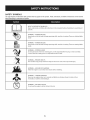 6
6
-
 7
7
-
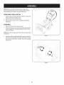 8
8
-
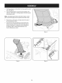 9
9
-
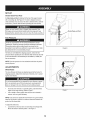 10
10
-
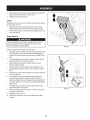 11
11
-
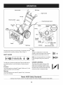 12
12
-
 13
13
-
 14
14
-
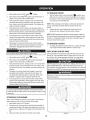 15
15
-
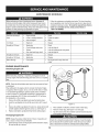 16
16
-
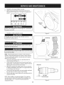 17
17
-
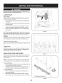 18
18
-
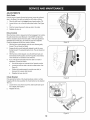 19
19
-
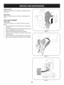 20
20
-
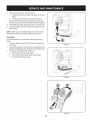 21
21
-
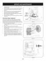 22
22
-
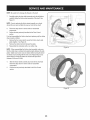 23
23
-
 24
24
-
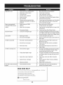 25
25
-
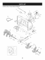 26
26
-
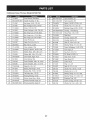 27
27
-
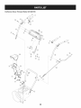 28
28
-
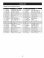 29
29
-
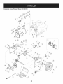 30
30
-
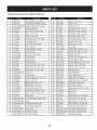 31
31
-
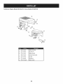 32
32
-
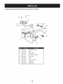 33
33
-
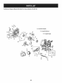 34
34
-
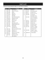 35
35
-
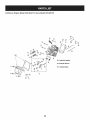 36
36
-
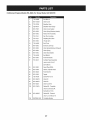 37
37
-
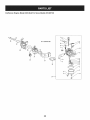 38
38
-
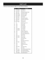 39
39
-
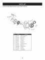 40
40
-
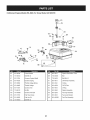 41
41
-
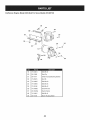 42
42
-
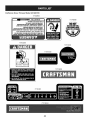 43
43
-
 44
44
-
 45
45
-
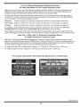 46
46
-
 47
47
-
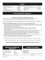 48
48
-
 49
49
-
 50
50
-
 51
51
-
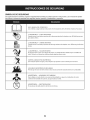 52
52
-
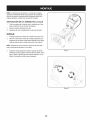 53
53
-
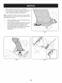 54
54
-
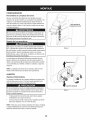 55
55
-
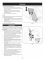 56
56
-
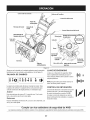 57
57
-
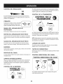 58
58
-
 59
59
-
 60
60
-
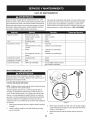 61
61
-
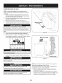 62
62
-
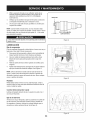 63
63
-
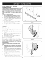 64
64
-
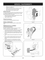 65
65
-
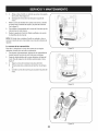 66
66
-
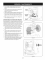 67
67
-
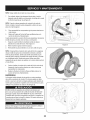 68
68
-
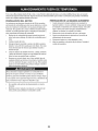 69
69
-
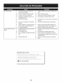 70
70
-
 71
71
-
 72
72
-
 73
73
-
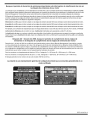 74
74
-
 75
75
-
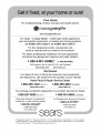 76
76


MTD 247881720 El manual del propietario
- Categoría
- Lanzadores de nieve
- Tipo
- El manual del propietario
- Este manual también es adecuado para
en otros idiomas
- English: MTD 247881720 Owner's manual
Artículos relacionados
-
MTD 247985360 El manual del propietario
-
MTD 31AS63EE799 El manual del propietario
-
-
-
-
-
-
-
-
Otros documentos
-
Craftsman 247.88173 El manual del propietario
-
-
-
-
Craftsman 247.886912 Manual de usuario
-
Craftsman 247887791 El manual del propietario
-