Craftsman 13953918D El manual del propietario
- Categoría
- Abridor de puerta de garage
- Tipo
- El manual del propietario

Owner'sManual/ManualDel Propietario
CRRFTSMRN °
GARAGEDOOROPENER
ABRIDORDEPUERTADECOCHERA
ForResidentialUse0nly/S61oparausoresidencial
Model/Modelo139.53918D
I"11
z
I"11
'13
;Z=,
Z_
Readandfollowall safetyrulesandoperating
instructionsbeforefirstuseofthis product.
Fastenthe manualnearthegaragedoorafter
installation.
Periodic checksofthe opener arerequiredto
ensuresafeoperation.
Leery seguirtodaslas reglasdeseguridady
lasinstruccionesdeoperaci6n antesde usar
esteproductoporprimeravez.
Guardarestemanualcercade la puerta de la
cochera.
Sedebenrealizarrevisionesperi6dicas
del abridorde puertaspara asegurarsu
operaci6n segura.
cQus
Sears, Roebuckand Co., HoffmanEstates,IL 60179 U.S.A
www.sears.com/craftsman

TABLE OF CONTENTS
Introduction 2-7
Safetysymbol reviewand signal word review................ 2
Preparingyour garagedoor ............................. 3
Tools needed......................................... 3
Planning .......................................... 4-5
Carton inventory ...................................... 6
Hardware inventory.................................... 7
Assembly 8-11
Assemblethe rail and install thetrolley ..................... 8
Fastenthe rail to the motor unit .......................... 9
Install the idler pulley .................................. 9
Install the belt ....................................... 10
Tighten the belt...................................... 10
Install the sprocket cover .............................. 11
Installation 11-26
Installation safety instructions .......................... 11
Determinethe headerbracket location .................... 12
Install the header bracket .............................. 13
Attachthe rail to the headerbracket ...................... 14
Position theopener................................... 15
Hangthe opener ..................................... 16
Install the door control ................................ 17
Install the battery .................................... 18
Install the lights ..................................... 18
Attachthe emergency releaseropeand handle.............. 19
Electrical requirements................................ 19
Install The Protector System® ....................... 20-22
Fastenthe door bracket............................. 23-24
Connectthedoor arm to the trolley ................... 25-26
Adjustment 27-29
Program thetravel limits............................... 27
Setthe force ........................................ 28
Testthe safety reversalsystem.......................... 29
TestThe ProtectorSystem® ............................ 29
Operation 30-36
Operationsafety instructions ........................... 30
Using your garagedoor opener ......................... 30
Using the wall-mounted door control ..................... 31
Careof your opener .................................. 32
Toopen the door manually ............................. 32
Batterybackup ...................................... 33
Having a problem (Troubleshooting) ..................... 34
Diagnostic chart ..................................... 35
Smart Control Panel®messages......................... 36
Programming 37-38
Toadd or reprograma hand-held remote control ............ 37
Toeraseall codesfrom motor unit memory................ 37
3-Button remotes .................................... 37
Toadd, reprogram or changea
KeylessEntry PIN .................................... 38
Repair Parts 39-40
Rail assemblyparts................................... 39
Installation parts ..................................... 39
Motor unit assembly parts ............................. 40
Accessories 41
Warranty 41
Repair Parts & Service Back Cover
INTRODUCTION
SafetySymbolReviewand Signal WordReview
This garage door opener has beendesignedand tested to offer safe serviceprovided it is installed, operated,maintained and tested in
strict accordancewith the instructions and warnings contained in this manual.
Mechanical
Electrical
Whenyou seethese SafetySymbols and Signal Words on the
following pages,they will alertyou to the possibility of serious
injury or deathif you do not comply with the warnings that
accompanythem. Thehazardmay come from something
mechanicalor from electric shock. Readthe warnings carefully.
Whenyou seethis SignalWord on the following pages, it will
alertyou to the possibility of damageto your garagedoor and/or
the garagedoor opener if you do not comply with the cautionary
statements that accompany it. Readthem carefully.

Preparingyourgaragedoor
Beforeyou begin:
• Disablelocks.
• Removeany ropes connectedto garage door.
• Completethe followingtest to makesure your garagedoor
is balancedand is not sticking or binding:
1. Lift the door about halfway asshown. Releasethe door. If
balanced,it should stay in place,supported entirely by its
springs.
2. Raiseand lower the door to seeif there is any binding or
sticking.
If your door binds, sticks, or is out of balance,call a trained
door systems technician.
To prevent possible SERIOUSINJURYor DEATH:
• ALWAYScall atrained door systemstechnician if garagedoor
binds, sticks, or is out of balance.An unbalancedgaragedoor
may NOTreversewhen required.
• NEVERtry to loosen, move or adjust garagedoor, door
springs, cables,pulleys, brackets or their hardware,ALL of
which are under EXTREMEtension.
• DisableALL locks and removeALL ropes connectedto garage
door BEFOREinstalling and operating garagedoor opener to
avoid entanglement.
To prevent damageto garage door and opener:
• ALWAYSdisable locks BEFOREinstalling and operating the
opener.
• ONLYoperategaragedoor opener at 120V, 60 Hzto avoid
malfunction and damage.
SectionalDoor
One-Piece Door
Tools needed
During assembly, installation and adjustment of the opener,
instructions will call for handtools as illustrated below.
Stepladder
Level (optional)
Tape Measure
Drill 3/16", 5/16"
and 5/32"
8_ _/°2c'_e5t/s8"a,7d/1W"r,e_/Clh"
and 1/4"
Pencil HackSaw
Wire Cutters
Pliers
Claw Hammer
Screwdriver
Adjustable End Wrench

P_nnmg
Identify the type and height of your garagedoor. Surveyyour
garagearea to see if any of the conditions below apply to your
installation. Additional materials may be required.You may find it
helpful to referback to this pageand the accompanying
illustrations asyou proceedwith the installation of your opener.
Dependingon your requirements, thereare several installation
steps which may call for materialsor hardware not included in
the carton.
• Installation Step 1 - Lookat the wall or ceiling abovethe
garagedoor. Theheader bracketmust be securelyfastenedto
structural supports.
• Installation Step 5 - Doyou havea finished ceiling inyour
garage? If so, a support bracketand additionalfastening
hardware may be required.
• Installation Step 11 - Dependingupon garageconstruction,
extension brackets or wood blocks may be neededto install
sensors.
• Installation Step 11 - Alternate floor mounting of the safety
reversingsensor will require hardwarenot provided.
Doyou havean access door in addition to the garagedoor? If
not, Model 139.53702 EmergencyKeyReleaseis required.See
Accessoriespage.
Lookat the garage door where it meetsthe floor. Any gap
betweenthe floor and the bottom of the door must not exceed
1/4" (6 mm). Otherwise,the safety reversal system may not
work properly. SeeAdjustment Step 3. Floor or door should be
repaired.
SECTIONALDOORINSTALLATION
• Doyou havea steel, aluminum, fiberglass or glasspaneldoor?
If so, horizontal and vertical reinforcement is required
(Installation Step 12).
• Theopener should be installed abovethe center of the door. If
there is a torsion spring or center bearing plate in the way of
the header bracket, it may be installed within 4 feet (1.22 m)
to the left or right of the door center. See Installation Steps 1
and 12.
• If your door is morethan 7 feet (2.13 m) high, see rail
extension kits listed on Accessories page.
SECTIONALDOORINSTALLATION
Horizontal andvertical reinforcement
is neededfor lightweight garage doors
(fiberglass, steel, aluminum, door with
glass panels, etc.). See page 23 for details.
Header Wall
Reversing Sensor
of Garage
.Door
Gap between floor
and bottom of door
must not exceed 1/4" (6 mm).
Rail
Extension Spring
OR
Torsion Spring
Wall- mounted
Door Control
Safety
Reversing
Sensor
Access Door
©
FINISHEDCEILING
Support bracket &
fastening hardware
is required.
See page16.
tor unit
Header
Bracket Rail Tab
CLOSEDPOSITION
Trolley
Header Curved
Wall Door
Garage Door Arm
Door Bracket
Belt
Emergency Release
Rope & Handle

Planning(Continued)
ONE-PIECEDOORINSTALLATIONS
• Generally,a one-piecedoor does not requirereinforcement. If
your door is lightweight, refer to the information relatingto
sectional doors in InstallationStep 12.
• Dependingonyour door's construction, you may need
additional mounting hardwarefor the door bracket (Step 12).
Without a properly working safety reversalsystem, persons
(particularly small children) could be SERIOUSLYINJUREDor
KILLEDby a closing garagedoor.
• Thegap betweenthe bottom of the garagedoor and the floor
MUSTNOTexceed1/4" (6 mm). Otherwise,the safety
reversalsystem may NOTwork properly.
• Thefloor or the garage door MUSTbe repairedto eliminate
the gap.
ONE-PIECEDOORWITHOUTTRACK
SafetyReversing
Sensor
Header Wall
Rail
Access
Door
o
Safety Reversing
Sensor
Gap between floor
and bottom of door must
not exceed 1/4" (6 mm).
FINISHEDCEILING
Support bracket
& fastening
hardware is required.
See page 16.
Wall-Mounted
Door Control
Motor Unit
CLOSEDPOSITION
Rail Tab Belt Trolley
eader
_all Door
Cul
Door
Arm
Emergency
Release
Rope & Handle
ONE-PIECEDOORWITH TRACK
Gapbetween floor
and bottom of door
Safety must not exceed
Reversing Sensor 1/4" (6 mm).
Access
Door
Safety
Reversing Sensor
Header
Wall
CLOSEDPOSITION
Rail Tab Belt Trolley
Door
Straight
Door
Arm
Rail
Emergency
Release
Rope &
Handle

CartonInventory
Your garagedoor opener is packagedin one carton which
contains the motor unit and all parts illustrated below.
Accessorieswill depend on the model purchased.If anything is
missing, carefully check the packing material. Hardwarefor
assembly and installation is shown on the next page.Savethe
carton and packing material until installation and adjustment is
complete.
Smart Control Panel®
SECURITY+®
3 Function Remote Control (2)
Sprocket Cover
Trolley
Battery
Motor Unit with 2 Light Lenses
Rail
Center/Back
Sections
Rail
Front (header)
Section
Idler Pulley
Header Bracket
Belt
Door Bracket
Safety Reversing
Sensor Bracket (2)
The Protector System <'_
(2) Safety Reversing Sensors
(1 Sending Eyeand 1 Receiving Eye)
with 2-Conductor White & White/Black
Bell Wire attached
/
Curved Door
Arm Section
2-Conductor Bell Wire
White & White/Red
Safety Labels
and
Literature
SECURITY÷®
Keyless Entry
Io
i 1°
_PI,,
Io
Io
%
Hanging Brackets
Straight Door
Arm Section

HardwareInventory
Separateall hardwareand group as shown below for the assembly and installation procedures.
ASSEMBLYHARDWARE
i
i
e O @
Lock Nut Lock Washer 3/8" Nut 8/8"
]/4"-20 Master Link
_] Bolt 1/4"-20xl-3/4" !!!)!_}}!_ 0
Idler Bolt
Threaded Shaft with
Spring Trolley Nut
INSTALLATIONHARDWARE
Carriage Bolt Wing Nut
1/4"-20xl/2" (2) 1/4"-20 (2)
_]IIIIIIIIIILI _
Lag Screw
5/16"-9xl-5/8" (4)
_ng Screw
1/4"-14x5/8" (2)
Drywall Anchors (2)
0
Ring
Fastener (3)
Hex Bolt
5/16"-18x7/8" (4)
_lllllllllllllllllb
Screw
6ABxl"(2)
ol 8 o, 8
Clevis Pin Clevis Pin
5/16"xl -1/2" 5/16"xl"
@
Nut 5/16"-18 (6)
@
Lock Washer 5/16" (5)
Handle
Insulated Staples
(Not shown)
111111111111111111111
Screw 6-32x1" (2)
Clevis Pin
5/16"x1-1/4"
o_
Rope

ASSEMBLY STEP 1
Assemblethe Rail and Install the Trolley
To avoidinstallationdifficulties,do notrunthe garagedoor
openeruntil instructedto do so.
Thefront rail has a cut out "window" at the door end. Thefront
and back rail both haverail tabs. Theserail tabs MUSTbe on top
of the rail whenassembled.
1. Removethe straight door arm andhanging bracket
packagedinside the front rail and set asidefor Installation
Steps 5 and 13.
NOTE:Toprevent INJURY whileunpacking the rail carefully
remove thestraight door arm stored within the rail section.
2. Align the rail sections on a flat surface asshown and slide the
taperedends into the larger ones. Tabs along the side will lock
into place.
3. Placethe motor unit on packingmaterialto protect the cover,
and rest the back end of the rail on top. Forconvenience,put a
support under thefront end of the rail.
To prevent INJURYfrom pinching, keephandsand fingers
away from the joints while assembling the rail.
4. As a temporary stop, insert a screwdriver into the hole
10"(25 cm) from the front end of the rail, as shown.
5. Checkto besure there are 4 plastic wear pads insidethe inner
trolley. If they becameloose during shipping, checkall packing
material. Snapthem backinto position asshown.
6. Slide the trolley assembly along the rail from the back end to
the screwdriver.
7. Slide the rail onto the "U" bracket, until it reachesall the stops
on thetop and sidesof the "U" bracket.
Back Rail Section
(TO MOTOR UNIT)
Outer Trolley
InnerTrolley
Wear Pads
SLIDETO STOPS
ONTOP AND SIDES OF
"U" BRACKET
FrontRail Section
(TO DOOR)
Rail Tab
Idler Pulley
Trolley
Window
Cut-Out

ASSEMBLY STEP 2
Fastenthe Rai/ to the MotorUnit
1. Inserta 1/4"-20xl-3/4 bolt into the cover protection bolt hole
on the back end of the rail as shown. Tighten securelywith a
1/4"-20 lock nut. DONOTovertighten.
2. Removethe two bolts from the top of the motor unit.
3. Usethe carton to support the front end of the rail.
4. Placethe "U" bracket,flat side down onto the motor unit and
align the bracketholes with the bolt holes. Fastenthe "U"
bracketwith the previously removed bolts; DONOTuse any
power tools. Theuse of powertools may permanently damage
the garagedoor opener.
To avoid SERIOUSdamageto garage door opener, useONLY
those bolts/fasteners mounted in the top of the opener.
Bolts
Cover
Protection
Bolt Hole
"U" Bracket
Bolt \
HARDWARESHOWNACTUALSIZE
d 0
Bolt 1/4"-20xl-3/4"
Lock Nut
1/4"-20
Lock Nut _
ASSEMBLY STEP 3
Insta// theId/er Pu//ey
1. Laythe belt besidethe rail, as shown. Graspthe end with the
hookedtrolley connector and pass approximately 12"(30 cm)
of beltthrough the window. Keepthe ribbed side toward the
rail, and allow it to hang until Assembly Step 4.
2. Removethe tapefrom the idler pulley. The inside center should
be pre-greased.If dry, regreaseto ensure proper operation.
3. Placethe idler pulley into the window as shown.
4. Insertthe idler bolt from the top through the rail and pulley.
Tighten with a 3/8" lock washer and nut underneaththe rail
until the lock washer is compressed.
5. Rotatethe pulley to be sure it spins freely.
6. Locatethe rail tab. The rail tab is betweenthe idler bolt andthe
trolley in the front rail section. Usea flat headscrewdriver and
lift the rail tab until the tab is vertical (90°).
Screwdriver
. _ _Grease Inside
I
Lock _
Washer _ Idler Pulley
3/8" _l_Nut 3/8"
Trolley
Connector
HARDWARESHOWNACTUALSIZE
Idler Bolt Nut 3/8"
Lock Washer 3/8"
CORRECT
Q
INCORRECT
Pulley

ASSEMBLY STEP 4
Install theBelt
1. Pull the belt around the idler pulley and toward the trolley.
Theribbed side must contact thepufley.
2. Hookthe trolley connector into the retaining slot on the trolley
as shown (Figure 1).
3. With the trolley against the screwdriver, dispensethe
remainderof the belt along the rail length toward the motor
unit and around the sprocket(Figure 2). The sprocketteeth
must engagethe belt.
4. Checkto makesure the belt is not twisted. Connectthe trolley
threaded shaftwith the master link (Figure3).
• Pushpins of master link barthrough holes in end of belt
and trolley threadedshaft.
• Pushmaster link capover pins and past pinnotches.
• Slide clip-on spring over cap and onto pin notches until both
pins are securelylocked in place.
5. Removethe spring trolley nut from the threadedshaft.
6. Insertthe trolley threadedshaft through the holein thetrolley.
[©
HARDWARESHOWNACTUALSIZE
Master Link
FTigureI 1
rolley Connector]
Threaded Shaft with
Spring Trolley Nut
Figure2
Sprocket
Figure3
Master Link Clip-On Spring
Master Link Cap
ASSEMBLY STEP 5
TightentheBelt
1. Byhand,threadthe spring trolley nut on the threadedshaft
until it is finger tight againstthetrolley. Do not useanytools.
Removethe screwdriver.
2. Inserta flathead screwdriver tip into oneof the nut ring slots
and braceit firmly againstthe trolley.
3. Tighten the spring trolley nut with anadjustable wrench or a
7/16" openendwrench about a quarterturn until the spring
releasesand snapsthe nut ring againstthe trolley. This setsthe
spring to optimum belttension.
I- BEFORE-I
1 "
(2.5 cm)
1-1/4"
(3.18 cm)
" Spring Trolley Nut
10

ASSEMBLY STEP 6
Install the SprocketCover
1. Position the sprocket cover over the sprocket as shown and
fastento the mounting platewith 8x3/8" hex screwsprovided.
Youhave nowfinishedassemb//ngyourgaragedooropener.
P/ease read thelot/owingwarningsbeforeproceedingtothe
insta//afionsection.
To avoid possible SERIOUSINJURYto fingers from moving
garagedoor opener:
• ALWAYSkeephand clear of sprocket while operating
opener.
• Securelyattach sprocket cover BEFOREoperating.
8x3/8" Hex Screws
Sprocket
Mounting
Plate
INSTALLATION
IMPORTANTINSTALLATIONINSTRUCTIONS
Toreducethe riskofSEVEREINJURYorDEATH:
1. READAND FOLLOWALL INSTALLATIONWARNINGS
AND INSTRUCTIONS.
2. Install garagedoor opener ONLYon properly balanced
and lubricated garage door. An improperly balanceddoor
may NOTreversewhen required and could result in
SEVEREINJURYor DEATH.
3. ALL repairsto cables,spring assemblies and other
hardware MUSTbe made by a trained door systems
technician BEFOREinstalling opener.
4. DisableALL locks and removeALL ropesconnectedto
garage door BEFOREinstalling opener to avoid
entanglement.
5. Install garagedoor opener7 feet (2.1 m) or more above
floor.
6. Mount the emergencyreleasewithin reach, but at least
6 feet (1.8 m) abovethefloor and avoiding contact with
vehiclesto avoid accidental release.
7. NEVERconnect garagedoor opener to power source
until instructed to do so.
8. NEVERwear watches, rings or looseclothing while
installing or servicing opener.They could be caught in
garagedoor or opener mechanisms.
9. Installwall-mounted garage door control:
• within sight of the garagedoor.
• out of reachof children at minimum height of
5 feet (1.5 m).
• away from ALL moving parts of the door.
10. Placeentrapmentwarning label on wall next to garage
door control.
11. Placemanual release/safetyreversetest label in plain view
on inside of garage door.
12. Uponcompletion of installation, test safety reversal
system. Door MUST reverseon contact with a
1-1/2" (3.8 cm) high object (or a 2x4 laid flat) on the
floor.
13. To avoid SERIOUSPERSONALINJURYor DEATHfrom
electrocution, disconnect ALL electric and battery power
BEFOREperforming ANY serviceor maintenance.
11

INSTALLATION STEP 1
Determinethe HeaderBracketLocation
To prevent possible SERIOUSINJURYor DEATH:
• HeaderbracketMUST be RIGIDLYfastenedto structural
support on headerwall or ceiling, otherwise garagedoor
might NOTreversewhen required. DONOTinstall header
bracket over drywall.
• Concreteanchors MUST be usedif mounting headerbracket
or 2x4 into masonry.
• NEVERtry to loosen,moveor adjust garagedoor, springs,
cables, pulleys,brackets, or their hardware,ALL of which are
under EXTREMEtension.
• ALWAYScall a trained door systemstechnician if garage
door binds, sticks, or is out of balance.An unbalanced
garagedoor might NOTreversewhen required.
Installation procedures vary according to garagedoor types.
Follow the instructions which applyto your door.
1. Closethe door andmarkthe insidevertical centerline of the
garagedoor.
2. Extendthe lineonto the headerwall abovethe door.
Youcanfastenthe headerbracketwithin 4 feet (1.22 m) of
the left or rightof thedoorcenter onlyif a torsionspringor
center bearingplate is in theway; or youcanattach itto the
ceiling (see page 13) whenclearanceis minimal. (It may be
mountedon thewall upsidedownif necessary,to gain
approximately1/2" (1 cm).)
If you needto install the headerbracket on a 2x4 (on wall or
ceiling), use lag screws (not provided) to securelyfasten the
2x4 to structural supports as shown hereand on page13.
3. Openyour door to the highest point of travel asshown. Draw
an intersecting horizontal line on the headerwall abovethe
high point:
• 2" (5 cm) abovethe high point for sectionaldoor and
one-piecedoor with track.
• 8" (20 cm) abovethe high point for one-piecedoor without
track.
This heightwill provide travel clearancefor the top edgeof the
door.
NOTE:If the total number of inches exceedsthe heightavailable
in your garage,use themaximum height possible, or refer to
page 13for ceiling installation.
Unfinished
Ceiling
HeaderWall
Vertical Centerline
of GarageDoor
Header Wall
Track
Highest Point
of Travel
Door
Sectional door with curvedtrack
all
_Highest
Hardware
One-piecedoorwithouttrack:
jambhardware
OPTIONAL
CEILING
MOUNT
!FOR
HEADER
BRACKET
2x4 Structural
Supports
Y
e"
HeaderWall Track
t
One-piece door with horizontal track
Header Wall
:- 8" (20 cm)
" -;" ", Highest
I_#..-;" ,',Point
41-:-_'_/I."_-" ',',of Travel
Door ',
One-piece door without track:
pivot hardware
12

INSTALLATION STEP 2
Install theHeaderBracket
You can attachthe headerbracketeither to the wall abovethe
garagedoor, or to the ceiling. Follow the instructions which will
work bestfor your particular requirements. Donot install the
header bracketoverdrywall. If installingintomasonry,use
concreteanchors(not provided).
WALLHEADERBRACKETINSTALLATION
1. Centerthe bracket on the vertical centerline with the bottom
edge of the bracket on the horizontal line asshown (with the
arrow pointing toward the ceiling).
2. Mark thevertical set of bracket holes. Drill 3/16" pilot holesand
fastenthe bracketsecurely to a structural support with the
hardware provided.
HARDWARESHOWNACTUALSIZE
LagScrew
5/16"-9xl -5/8"
- Header Wall -
2x4
Structural
SuppoR
J
1
Horizontal
Line
i
HighestPoint of
GarageDoorTravel
Wall Mount
Optional
Mounting Holes
Vertical
Centerline
of Garage Door
_ Lag Screws
5/16"-9xl -5/8"
DoorSpring
- Garage Door -
Vertical
Centerline
of GarageDoor
CEILINGHEADERBRACKETINSTALLATION
1. Extendthe vertical centerline onto the ceiling as shown.
2. Centerthe bracket on the vertical mark, no more than
6" (15 cm) from the wall. Make sure the arrow is pointing away
from the wall. The bracketcan be mounted flush against the
ceiling when clearanceis minimal.
3. Mark the side holes. Drill 3/16" pilot holes and fasten bracket
securelyto a structural support with the hardwareprovided.
Ceiling Mounting Holes
Bracket
6" (15 cm) M
- FinishedCeiling-
VerticalCenterline
ofGarageDoor
Door
Spring
" Lag Screws
5/16"-9xl -5/8"
HeaderWall -
13

INSTALLATION STEP 3
AttachtheRail to the HeaderBracket
1. Position the openeronthe garagefloor below the header
bracket. Usepacking material asa protective base.
NOTE:If the door spring is in the way,you will need help. Have
someone hold the opener securely on a temporary support to
allow the rail to clear the spring.
2. Position the rail bracket againstthe headerbracket.
3. Align the bracket holesand join with aclevis pin as shown.
4. Inserta ring fastenerto secure.
Header Wall
Header Bracket
Idler Pulley
"o
Mounting
Hole
__ Garage
Door
Temporary
Support
HARDWARESHOWNACTUALSIZE
0
Clevis Pin 5/16"x1-1/2" Ring Fastener
14

INSTALLATION STEP 4
Positionthe Opener
Follow instructions which applyto your door type as illustrated.
SECTIONALDOORORONE-PIECEDOORWITH TRACK
A 2x4 laid flat is convenient for setting an idealdoor-to-rail
distance.
1. Raisethe opener onto a stepladder.You will needhelpat this
point if the ladder is not tall enough.
2. Openthe door all the way and placea 2x4 laid flat on the top
section beneaththe rail.
3. If the top section or panel hits the trolley whenyou raise
the door, pull down on the trolley releasearm to disconnect
inner and outer sections. Slide the outer trolley toward the
motor unit. Thetrolley can remain disconnecteduntil
Installation Step 12 is completed.
To prevent damageto garage door, rest garagedoor opener rail
on 2x4 placedon top section of door.
Rail
Door 2x4 is used to
Trolley
lease
ENGAGED RELEASED _
ONE-PIECEDOORWITHOUTTRACK
A 2x4 on its side is convenientfor setting an ideal
door-to-rail distance.
1. Raisethe opener onto a stepladder.You will needhelpat this
point if the ladder is not tall enough.
2. Openthe door all the way and placea 2x4 on its side on the
top section of the door beneaththe rail.
3. Thetop of the door should be levelwith thetop of the motor
unit. Donot position the openermore than 4" (10 cm) above
this point.
Header
Bracket
I
from ceiling.
2x4 is used to
determine the correct
mounting height
from ceiling.
15

INSTALLATION STEP 5
Hangthe Opener
Threerepresentativeinstallations are shown. Yours maybe
different. Hangingbrackets should be angled (Figure 1) to provide
rigid support. On finished ceilings (Figures 2 and 3), attach a
sturdy metal bracketto structural supports before installing the
opener.This bracketand fastening hardwareare not provided.
1. Measurethe distancefrom eachside of the motor unit to the
structural support.
2. Cut both piecesof the hanging bracketto required lengths.
3. Drill 3/16" pilot holes in the structural supports.
4. Attach one end of eachbracketto a support with
5/16"-9xl-5/8" lag screws.
5. Fastenthe opener to the hanging brackets with
5/16"-18x7/8" hex bolts, lock washers and nuts.
6. Checkto make sure the rail is centered over the door (or in line
with the headerbracket if the bracket is not centeredabove
the door).
7. Removethe 2x4. Operatethe door manually. If the door hits
the rail, raisethe header bracket.
NOTE:DONOTconnectpower to openerat this time.
HARDWARESHOWN ACTUALSIZE
llllllllllll
LagScrew5/16"-9xl-5/8"
HexBolt
5/16"-18x7/8" Nut5/16"-18 LockWasher5/16"
To avoid possible SERIOUSINJURYfrom afalling garagedoor
opener,fasten it SECURELYto structural supports of the
garage.Concreteanchors MUST be usedif installing ANY
brackets into masonry.
FigureI
)orts
Measure ',
Distance
Bolt 5/16"-18x7/8"
Lock Washer 5/16"
Nut 5/16"-18
Lag Screw
5/16"-9xl -5/8"
Figure2
Hidden _- _ _ _
Bracket Support __- _
(Not Provided) _ _ _ _1 _ _ _
_ . _,,,,,._&_-- _ _- _ LagScrew
-222_ ....
_\k __(Not Provided)
.- _ - __ ._7_--- - L/_r.-,_ Bolt5/16"-18x7/8"
- --- _.\o,_o__.-- LH Lock Washer 5/16"
- _,_.X _/_ Nut 5/16"-18
Figure3
LagScrew
5/16"-9xl -5/8"
Bolt 5/16"-18x7/8"
LockWasher5/16"
Nut 5/16"-18
FINISHED CEILING
(Not Provided)
Bolt 5/16"-18x7/8"
Lock Washer 5/16"
Nut 5/16"-18
16

INSTALLATION STEP 6
Install the Door Control
Locate door control within sight of door, at a minimum height of
5 feet (1.5 m) where small children cannot reach, awayfrom
moving parts of door and door hardware. If installing into drywall,
drill 5/32" holes and usethe anchors provided. Forpro-wired
installations (as in new home construction), it may bemounted to
a single gang box (Figure2).
1. Strip 7/16" (11 mm) of insulation from oneendof bell wire and
connect to the two screwterminals on backof door control by
color: white wire to 2 and white/red wire to the 1.
2. Removecover by gentlyprying at slot in top of the cover
with a small flat headscrewdriver (Figure 1). Fastenwith
6ABxl" self-tapping screws (drywall installation) or 6-32x1"
machine screws (into gang box) as follows:
• Install bottom screw, allowing 1/8" (3 mm) to protrude above
wall surface.
• Position bottom of door control on screw headand slide
down to secure.Adjust screw for snug fit.
• Drill and install top screw with care to avoid cracking plastic
housing. DONOTovertighten.
• Insert top tabs and snap on cover.
3. (Forstandardinstallationonly) Runbell wire up wall and
across ceiling to motor unit. Use insulated staplesto secure
wire in several places. Donot piercewire with a staple,
creating a short or open circuit.
4. Strip 7/16" (11 mm) of insulation from endof bell wire.
Connectbell wire to the quick-connect terminals as follows:
white to white and white/red to red(Figure3).
5. Position the antennawire as shown.
6. Usetacks or staplesto permanently attachentrapment warning
label to wall near door control, and manual release/safety
reversetest label in a prominent location on inside of garage
door.
NOTE:DONOTconnectpower and operateopener at this time.
Thetrolley will travel to the furl openposition but will not return
to the close position until thesensor beamis connectedand
properly aligned.
To prevent possible SERIOUSINJURYor DEATHfrom
electrocution:
• DisconnectALL electric and battery power BEFORE
performing ANYserviceor maintenance.
• ConnectONLYto 24 VOLTlow voltage wires.
To prevent possible SERIOUSINJURYor DEATHfrom a closing
garagedoor:
• Install door control within sight of garagedoor, out of reach
of children at a minimum height of 5 feet (1.5 m), andaway
from ALL moving parts of door.
• NEVERpermit children to operateor play with door control
push buttons or remotecontrols.
• Activate door ONLYwhen it can be seenclearly, is properly
adjusted, and there are no obstructions to door travel.
• ALWAYSkeepgaragedoor in sight until completely closed.
NEVERpermit anyoneto cross path of closing garagedoor.
HARDWARESHOWNACTUALSIZE
_ lllllllllMIMlllllb Insulated Staples
Screw 6ABxl" (Not shown)
(std installation)
(Gang box installation) Drywall Anchors
FigureI Figure2
REMOVE& REPLACECOVER PRE-WIREDINSTALLATION
To Replace
Insert Top
Tab___ _ _'"
Push Bar Cover I Wire
Figure3 ,___
Door Control To release or insert wire,
Connections )ush in tab with screwdriver tip
Strip wire 7/16" (11 mm)
417/1611(11 mm)]D.
Red White Grey
_ ,, _1+ -- +1 )Mounting
_ell II I I Hole
Wire It I_1'
_=_Terminal
II T-, TI I screws
It:__ Bottom
" " Mounting
(BACKVIEW) Hole
A
F Push Bar
_Wi re
Smart Control PaneP
17
0

INSTALLATION STEP 7
Install the Battery
1. Make sure motor unit is unplugged.
2. Using a Phillips headscrewdriver, removethe battery cover on
the motor unit.
3. Partially insert batteryinto motor unit with terminals facing
out.
4. Connectthe red (+) and black (-) wires from motor unit to
corresponding terminals on battery.
5. Verify the batterywires are seated in the channel.
6. Replacebattery cover.
ALWAYSwear protective gloves and eyeprotection when
changing the battery or working around the battery
compartment.
Battery
INSTALLATION STEP 8
Install theLights
1. Pressthe releasetabs on both sides of lens. Gentlyrotate lens
back and downward until the lens hinge is in thefully open
position. Do not removethe lens.
2. Install up to a 100 watt maximum light bulb in eachsocket.
Light bulb size should be A19, standard neck only. Thelights
will turn ONand remain lit for approximately 4-1/2 minutes
when power is connected.Thenthe lights will turn OFF.
3. Reversethe procedureto close the lens.
4. If the bulbs burn out prematurelydue to vibration, replacewith
a garage door opener bulb. UseA19, standard neck garage
door opener for replacement.
NOTE:Useonly standard light bulbs. Theuseof short neck or
speciality light bulbs may overheatthe endpanelorlight socket.
To prevent possible OVERHEATINGof the endpanelor light
socket:
• DONOTuse short neck or specialty light bulbs.
• DONOTuse halogen bulbs. UseONLYincandescent.
To prevent damageto the opener:
• DONOTuse bulbs larger than IOOW.
• ONLYuseA19 size bulbs.
1O0Watt
Standard Light Bulb
ReleaseTab /
Hinge
100 Watt (Max)_
Standard Light Bulb _...._
18

INSTALLATION STEP 9
Attachthe EmergencyRelease Ropeand Handle
1. Insert one end of the emergencyreleaseropethrough the
handle. Makesure that "NOTICE"is right side up.Tie a knot at
least 1 inch (2.5 cm) from the end of the emergency release
rope.
2. Insertthe other end of the emergency releaserope through the
hole in the trolley releasearm. Mount the emergency release
within reach, but at least 6 feet (1.83 m) abovethe floor,
avoiding contact with vehiclesto prevent accidental releaseand
secure with a knot.
NOTE:If it is necessaryto cut theemergencyreleaserope, seal
the cut end with a match or lighter to prevent unraveling. Ensure
the emergencyreleaserope and handle areabove thetop ofaft
vehiclestoavoid entanglement.
INSTALLATION STEP 10
Electrical Requirements
To avoidinstallationdifficulties,do notrunthe openerat this
time.
To reducethe risk of electric shock, your garagedoor opener has
a grounding type plug with a third grounding pin. This plug will
only fit into a grounding type outlet. If the plug doesn't fit into the
outlet you have, contacta qualified electricianto install the proper
outlet.
If permanent wiringis requiredbyyourlocal code,refer to the
followingprocedure.
To make a permanent connection through the 7/8" hole in the top
of the motor unit:
1. Removethe motor unit cover screwsandset the cover aside.
2. Removethe attached3-prong cord.
3. Connectthe black (line) wire to the screw on the brass
terminal; the white (neutral) wire to the screw on the silver
terminal; and the ground wire to the green ground screw.
The openermustbe grounded.
4. Reinstallthe cover.
To avoidinstallationdifficulties,do notrunthe openerat this
time.
To prevent possible SERIOUSINJURYor DEATHfrom a falling
garagedoor:
• If possible, useemergency releasehandleto disengage
trolley ONLYwhen garagedoor is CLOSED.Weak or broken
springs or unbalanceddoor could result in an open door
falling rapidly and/or unexpectedly.
• NEVERuseemergency releasehandle unless garagedoorway
is clear of persons and obstructions.
• NEVERusehandle to pull door open or closed. If ropeknot
becomes untied, you could fall.
Trolley
I
__e Arlm__
Emergency _ _verhandnot
ReleaseHandle
To prevent possible SERIOUSINJURYor DEATHfrom
electrocution or fire:
• DisconnectALL electric and battery power BEFORE
performing ANY serviceor maintenance.
• Garagedoor installation and wiring MUSTbe in compliance
with ALL local electrical and building codes.
• NEVERusean extension cord, 2-wire adapter,or change
plug in ANYway to make it fit outlet. Besure the opener
is grounded.
PERMANENTWIRING
CONNECTION
Ground Tab
Green
Ground Screw
Ground Wire Wire
White Wire Black Wire
19

INSTALLATION STEP 11
Install TheProtectorSystem®
Thesafety reversingsensormustbeconnectedand aligned
correctlybeforethe garagedooropenerwill movein the down
direction.
IMPORTANTINFORMATIONABOUT
THESAFETYREVERSINGSENSOR
When properly connectedand aligned, the sensor will detect an
obstacle in the pathof its electronic beam.Thesending eye (with
an amber indicator light) transmits an invisible light beamto the
receiving eye (with a green indicator light). If an obstruction
breaks the light beamwhile the door is closing, the door will stop
and reverseto full open position, andthe opener lights will flash
10 times.
Theunits must be installed inside the garageso that the sending
and receivingeyes face eachother across the door, no morethan
6" (15 cm) abovethefloor. Either can be installed on the left or
right of the door as long as the sun nevershines directly into the
receiving eye lens.
Themounting brackets are designedto clip onto thetrack of
sectional garagedoors without additional hardware.
Besure power is NOTconnectedto the garagedoor opener
BEFOREinstalling the safety reversingsensor.
To prevent SERIOUSINJURYor DEATHfrom a closing garage
door:
• Correctly connect and align the safety reversingsensor. This
required safety device MUSTNOTbe disabled.
• Install the safety reversing sensor so beamis NOHIGHER
than 6" (15 cm) abovegaragefloor.
If it is necessaryto mount the units on the wall, the brackets
must be securelyfastenedto a solid surface such asthe wall
framing. Extensionbrackets (seeaccessories) areavailableif
needed.If installing in masonry construction, add a pieceof wood
at eachlocation to avoid drilling extra holes in masonry if
repositioning is necessary.
Theinvisible light beam path must be unobstructed. No part of
the garagedoor (or door tracks, springs, hinges, rollers or other
hardware) may interrupt the beamwhile the door is closing.
Reversing Sensor Invisible Light B_,,, _,_.._ Safety R,versing Sensor
6" (15 cm) max. Protection Area 6" (15 cm) max.
above floor above floor
Facingthe doorfrom insidethegarage
2O

INSTALLINGTHE BRACKETS
Besure power to the opener is disconnected. Install and align
the brackets so the sensors will faceeachother across the garage
door, with the beam no higher than 6" (15 cm) abovethe floor.
They may be installed in one of three ways, as follows.
Garage doortrack installation(preferred):
1. Slip the curved arms over the rounded edge of each door track,
with the curved arms facing the door. Snap into placeagainst
the side of the track. Itshould lie flush, with the lip hugging the
back edge of the track, asshown in Figure1.
If your door track will not support the bracket securely,wall
installation is recommended.
Wall installation(Figures2 and 3):
1. Placethe bracketagainst the wall with curved arms facing the
door. Besure there is enough clearancefor the sensor beamto
be unobstructed.
2. If additional depth is needed,an extensionbracket
(seeAccessories) or wood blockscan be used.
3. Usebracketmounting holes asa template to locate and drill
(2) 3/16" diameter pilot holeson the wall at eachside of the
door, no higher than 6" (15 cm) abovethefloor.
4. Attach brackets to wall with lag screws (not provided).
5. If using extensionbrackets or wood blocks, adjust right and
left assembliesto the same distanceout from the mounting
surface. Make sure all door hardwareobstructions are cleared.
Floorinstallation(Figure4):
1. Usewood blocks or extensionbrackets (seeAccessories)to
elevatesensor bracketsso the lenseswill be no higher than
6" (15 cm) abovethe floor.
2. Carefullymeasure and place right and left assembliesat the
same distanceout from the wall. Besure all door hardware
obstructions are cleared.
3. Fastento the floor with concrete anchors as shown.
HARDWARESHOWN ACTUALSIZE
CarriageBolt Wing Nut
1/4"-20xl/2" 1/4"-20
InsulatedStaples
(NotShown)
DOORTRACKMOUNT(RIGHT SIDE)
1
,oureoorI[
t\ Track
1I: Lip
_i __ Indicator
Safety "--"-:
_--_ . Reversing
_--_.,._'_" Sensor
"_ Bracket
Figure2
WALL MOUNT(RIGHT SIDE)
FastenWood Block to Wall with
Screws (Not provided)
Indicator
Light Safety
Reversing
Sensor
Bracket
Lag Screws
_ (Not provided)
Lens ......
WALL MOUNT(RIGHT SIDE)
Figure3 ..........
Extension Bracket
(See Accessories)
I .,,., (Provided with
l .._f_l Extensio_ Bracket)
(Provided with ._?" __ k,..Y_i,_ _'_ Reversing
Extension Bracket)_"_ _. Sensor
_ I " _racKe[
Lens Indicator
Light
Figure4
J
FLOORMOUNT(RIGHT SIDE)
-- ttach with
Concrete Anchors
i (Not provided)
Indicator
Light
Reversing
Sensor
Bracket
21

MOUNTINGANDWIRINGTHESAFETYREVERSINGSENSORS
1. Slide a 1/4"-20xl/2" carriage bolt headinto the slot on each
sensor. Usewing nuts to fastensensors to brackets,with
lenses pointing toward eachother across the door. Besure the
lens is not obstructed by a bracket extension (Figure5).
2. Fingertighten the wing nuts.
3. Runthe wires from both sensorsto the opener. Useinsulated
staplesto secure wire to wall and ceiling.
4. Strip 7/16" (11 mm) of insulation from eachset of wires.
Separatewhite and white/black wires sufficiently to connect to
the opener quick-connect terminals. Twist like colored wires
together. Insert wires into quick-connect holes: white to white
and white/black to grey (Figure6).
ALIGNINGTHESAFETYREVERSINGSENSORS
1. Plug in the opener. Theindicator lights in both the sending and
receiving eyeswill glow steadilyif wiring connections and
alignment are correct.
Thesending eyeamber indicator light will glow regardlessof
alignment or obstruction. If the green indicator light in the
receiving eyeis off, dim, or flickering (and the invisible light beam
path is not obstructed), alignment is required.
2. Loosenthe sending eyewing nut and readjust, aiming directly
at the receiving eye. Lock in place.
3. Loosenthe receiving eyewing nut and adjust sensoruntil it
receivesthe sender's beam.Whenthe green indicator light
glows steadily, tighten the wing nut.
Figure5
Wing Nut
Carriage Bolt _
1/4"-20xl/2"
TROUBLESHOOTINGTHESAFETYREVERSINGSENSORS
1. If the sending eyeindicator light does not glow steadily after
installation, checkfor:
• Electric powerto the opener.
• A short in the white or white/black wires. Thesecanoccur at
staples, or at opener connections.
• Incorrect wiring betweensensors andopener.
• A broken wire.
2. If the sending eyeindicator light glows steadily but the
receiving eyeindicator light doesn't:
• Checkalignment.
• Checkfor an openwire to the receiving eye.
3. If the receiving eyeindicator light is dim, realigneither sensor.
NOTE:Whenthe invisible beampath is obstructed or misaligned
whilethe door is closing, the door will reverse.If the door is
alreadyopen,it will not close. Theopenerlights will blink 10
times. Seepage20.
Figure6
BellWire
Finished Ceiling
Connect Wire to
Quick-Connect Terminals
.... ,_ BellWire
\
1. Strip wire
7/16"(11mm)
7,16 (11 mm) I
2. Twist like colored wires
together
Safeb
Reversing Sensor
Invisible Light Beam
Protection Area
Safety Reversing Sensor
3. To release or insert
wire, push in tab with
screwdriver tip
Red White Grey
Quick-Connect Terminals
22

INSTALLATION STEP 12
Fastenthe DoorBracket
Follow instructions which applyto your door typeas illustrated
below or on the following page.
A horizontal reinforcementbrace shouldbe longenoughto be
securedtotwo orthree vertical supports.A vertical
reinforcementbraceshouldcoverthe heightof thetop panel.
Figure1 shows one pieceof angle iron as the horizontal brace.
Forthe vertical brace, 2 pieces of angle iron are usedto createa
U-shaped support. The best solution isto checkwith your
garage door manufacturer for an opener installation door
reinforcement kit.
NOTE:Many door reinforcement kits provide for direct
attachment of the clevispin and door arm. In this caseyou will
not needthe door bracket, proceed to Step 13.
SECTIONALDOORS
1. Centerthe door bracketon the previously markedvertical
centerline usedfor the headerbracket installation. Note
correct UPplacement, asstamped inside the bracket.
2. Position the top edgeof the bracket2"-4"(5-10 cm) below
the top edgeof the door, ORdirectly below anystructural
support across the top of the door.
3. Mark, drill holes and install as follows, depending on your
door's construction:
Metal orlight weight doorsusinga vertical angleiron brace
betweenthe doorpane/support and thedoorbracket:
• Drill 3/16" fastening holes.Securethe door bracket using the
two 1/4"-14x5/8" self-threading screws. (Figure2A)
• Alternately, usetwo 5/16" bolts, lock washers and nuts (not
provided). (Figure 2B) Metal, insulated or light weight factory
reinforced doors:
• Drill 3/16" fastening holes.Securethe door bracket using the
self-threading screws (Figure3).
WoodDoors:
• Usetop and bottom or sideto side door bracket holes. Drill
5/16" holes through the door andsecurebracketwith
5/16"x2"carriage bolts, lock washersand nuts (not provided).
(Figure4)
NOTE:The1/4"-14x5/8"self-threadingscrews are not intended
for useon wood doors.
Fiberglass,aluminum or lightweight steel garage doors WILL
REQUIREreinforcement BEFOREinstallation of door bracket.
Contactyour door manufacturer for reinforcement kit.
Vertical
Centerline of
Garage Door
Figure1
HORIZONTALAND VERTICAL
- REINFORCEMENTIS NEEDEDFOR
LIGHTWEIGHTGARAGEDOORS
(FIBERGLASS,ALUMINUM, STEEL,
DOORSWITH GLASS PANEL,ETC.).
(NOT PROVIDED)
Vertical
Reinforcement
O IG|U I _ Veernti_rallineof
ageDoor
Door Bracket
Self-Threading Screw
1/4"-14x5/8"
(Not Provided) Vertical
'x_ Reinforcement
r..d&"_1,_I1'_1_1 Vertical
"_'\I_ "¢/Ceanr_eg_iDe°°°fr
.,_ UP
DoorBracket_ _t_
LockWasher 5/1B"_..
Nut 5/16"-18
Figure2B
Figure2A
HARDWARESHOWN
ACTUALSIZE
Self-Threading
Screw 1/4"-14x5/8"
Vertical Centerline
of Garage Door
_Self-Threading
"_1_, Screw 1/4"-14x5/8"
Figure3
(Not Provided)
Bolt 5/16"x2"
Inside Edgeof Door or
Reinforcement Board
Centerline of _,
GarageDoor
Figure4
23

ONE-PIECEDOORS
Pleasereadand comply with the warnings and reinforcement
instructions on the previous page.They applyto one-piecedoors
also.
• Centerthe door bracketon thetop of the door, in line with the
header bracketas shown. Mark either the left and right, or the
top and bottom holes.
• Metal Doors: Drill 3/16" pilot holesand fasten the bracketwith
the 1/4"-14x5/8" self-threading screws provided.
• WoodDoors:Drill 5/16" holesand use5/16"x2"carriage bolts,
lock washersand nuts (not provided) or 5/16"x1-1/2" lag
screws (not provided) depending on your installation needs.
NOTE:Thedoor bracketmay be instafledon the top edgeof the
door if required for your installation. (Referto the dottedline
optional placement drawing.)
HARDWARESHOWN
ACTUALSIZE
Self-Threading Screw
1/4"-14x5/8"
Header Wall
Door
Bracket
2x4 Support
Optional
Placement
of Door
Bracket
Vertical
Centerline of
Garage Door
-- Finished Ceiling --
HORIZONTALANDVERTICAL
REINFORCEMENTIS NEEDED
FOR LIGHTWEIGHTGARAGE
DOORS(FIBERGLASS,ALUMINUM,
STEEL, DOORSWITH GLASS
PANEL, ETC.). (NOT PROVIDED)
Fora door with no exposed framing,
or for the optional installation, use
lagscrews 5/16"x1-1/2" (Not Provided)
to fasten door bracket.
Door
Bracket
__ elf-Threading
Screw
1/4"-14x5/8"
Top of Door
(Inside Garage)
Optional
Placement
METAL DOOR
Lock
@_ Washer
5/16"
Topof Door
Garage)
Top Edge
of Door
Optional
Placement
, Carriage Bolt
_ _-- 5/16"x2"
(Not Provided)
WOOD DOOR
24

INSTALLATION STEP 13
ConnectDoorArmto Trolley
Follow instructions which applyto your door typeas illustrated
below and on the following page.
SECTIONALDOORSONLY
Make sure garagedoor isfully closed. Pull the emergencyrelease
handle to disconnect the outer trolley from the inner trolley. Slide
the outer trolley back (awayfrom the pulley) about 8"(20 cm) as
shown in Figures 1, 2 and 3.
Figure 1:
• Fastenstraight door arm section to outer trolley with the
5/16"x1"clevis pin. Securethe connection with a ring fastener.
• Fastencurved section to the door bracketin the sameway,
using the 5/16"x1-1/4" clevis pin.
IMPORTANT'.Thegroove on thestraight door arm MUSTface
away from the curved door arm (Figure4).
Figure2:
• Bring arm sections together. Findtwo pairs of holes that line up
and join sections. Select holes asfar apartas possible to
increase door arm rigidity.
Figure3, Hole alignmentalternative:
• If holes in curved arm are aboveholes in straight arm,
disconnect straight arm. Cut about 6" (15 cm) from the solid
end. Reconnectto trolley with cut end down asshown.
• Bring arm sections together.
• Findtwo pairs of holesthat line up and join with bolts, lock
washers and nuts.
Pull the emergencyreleasehandle toward the opener at a 45°
angle so that the trolley releasearm is horizontal. Proceedto
Adjustment Step 1, page27. Trolley will re-engageautomatically
when opener is operated.
HARDWARESHOWNACTUALSIZE
o Qo
Nut 5/16"-18 Lock Washer 5/16" Ring Fastener
on
Clevis Pin Clevis Pin
5/16"x1" (Trolley) 5/16"x1-1/4" (Door Bracket)
Hex Bolt
5/16"-18x7/8"
Figure
Figure2
Figure3
Figure4
(
Pulley
/i._8"(20°m)
Ring
Fastener
/
O Door
Bracket
Cuwed DoorArm
Clevis Pin 5/16"x1-1/4"
Pulley
i-- 8"(20 cm) min. i
Lock t
Washers/(
5/16" /oo]
_ult_._1 , /o/
Door Bracket
J
_ Bolts
5/16"-18x7/8"
Pulley
i " (20 cm) min. ,
Nuts / /o7'
5/16"-1_._/_
v Cutthis end
Door Arm
(Groove
facing out)
CORRECT INCORRECT
25

ALLONE-PIECEDOORS
1. Assemblethe DoorArm:
IMPORTANT:Thegroove on thestraight door arm MUSTface
away from the curved door arm (Figure5).
• Fastenthe straight andcurved door arm sectionstogether to
the longest possible length (with a 2 or 3 hole overlap).
• Make sure the garagedoor isfully closed. Connectthe
straight door arm section to the door bracketwith the
5/16"x1-1/4" clevis pin.
• Securewith a ring fastener.
• Pull the emergencyreleasehandle,disconnecting the outer
trolley from the inner trolley by pulling straight down on the
emergencyreleasehandle and sliding the outer trolley back
toward the motor unit.
• Connectthe curved door arm sectionto the trolley using the
5/16"x1-1/4" clevis pin and ring fastener.
NOTE:Adjusting the limits on the following page:
• Thetrofley will automatically connect. If not, review the
trolley lockout feature on page 32.
• Whensetting the uplimit on the following page,the door
should not havea "backward" slant whenfully openas
illustrated below. A slight backwardslant will cause
unnecessarybucking and/orjerking operationas the door is
being opened or closed from the fully open position.
Door
Bracket
Clevis Pin
5/16"xl -1/4"
CORRECT INCORRECT
__ Ring
Fastener
Straight
Arm
Bolts
5/16"-18x7/8"
Lock
Washers
5/16"
Nuts
5/16"-18
}u_ed
DoorArm
Figure6
Inner Trolley
I _ Emergency ReleaseHandle
Closed
I Door
Inner Trolley
Outer Trolley
Open Door
Backward Slant
(Incorrect)
26

ADJUSTMENT STEP 1
Program the Travel Limits
Travellimits regulatethepoints at which thedoor will stop
whenmovingup or down.
Figure1
Black Button
)le Button
Without a properly installed safety reversalsystem, persons
(particularly small children) could be SERIOUSLYINJUREDor
KILLEDby a closing garagedoor.
• Incorrectadjustment of garagedoor travel limits will interfere
with proper operation of safety reversal system.
• NEVERuseforce adjustments to compensate for a binding or
sticking garage door.
• After ANY adjustments are made,the safety reversal system
MUST betested. Door MUST reverseon contact with
1-1/2" (3.8 cm) high object (or 2x4 laid flat) on floor.
Adjust the position of the door by using the black and purple
buttons. Blackmoves the door UP(open) and purplemoves the
door DOWN(close).
Settingthe UP position:
1. Pressand hold the black button until the LEDstarts flashing
slowly, then release.
2. Pushand hold the black button until the door reachesthe
desired UP(open) position (Figure2).
NOTE:Make sure the door opens high enough for your vehicle.
3. Pushthe door control or programmed remote control.
This sets the UP(open) limit and begins closing the door
(Figure3).
4. Immediatelywhen the door begins to close, press and release
eitherthe black or purple button. This will stop the door.
Settingthe DOWNposition:
5. Pushand hold the purple button until the door reachesthe
desired DOWN(closed) position (Figure4).
6. Oncethe door is closed, if there appearsto betoo much
pressure on the door, you maytoggle the door back and forth
using the black and purple buttons to reachthe desired closed
position.
7. Pushthe door control or programmed remote control
(Figure3). This sets the DOWN(close) limit and the door
should open.
Proceedto Setthe Force.
To prevent damageto vehicles, be surefully open door
provides adequateclearance.
Figure2 LED
Push and hold
until the door
is at desired UP
position
t
Figure3
Figure4
LED
Push either
button to stop
door at desired
DOWNposition
27

ADJUSTMENT STEP 2
Set theForce
Theforce settingmeasuresthe amountofforce requiredto
openand close the door.
1. Pushthe purple button twice to enter intothe ForceAdjustment
Mode(Figure 2). TheLEDwill flash quickly.
2. Pushthedoor control or programmed remotecontrol. Thedoor
will close (DOWN)(Figure3).
3. Pushthedoor control or programmed remotecontrol again.The
door will open (UP).
4. Pushthedoor control or programmed remotecontrol a third
time to closethe door (DOWN).
TheLEDwill stop flashing whenthe force has beenprogrammed.
Thedoor must travel through a completecycle, up and down, in
order for the force to beset properly. If the garagedoor opener
cannotopen and closethe door fully, inspectthe door to ensure
that it is balancedproperlyand is not sticking or binding.
If thedoor is not stopping exactlywhereyou would likeit, repeat
Program the TravelLimits.
Without a properly installed safety reversalsystem, persons
(particularly small children) could be SERIOUSLYINJUREDor
KILLEDby a closing garagedoor.
• Too much force on garage door will interfere with proper
operation of safety reversalsystem.
• NEVERuseforce adjustments to compensatefor a binding or
sticking garage door.
• After ANY adjustments are made,the safety reversal system
MUST betested. Door MUST reverseon contact with
1-1/2" (3.8 cm) high object (or 2x4 laid flat) on floor.
Figure1
LED
)le Button
Figure2
Push Purple button
twice to enter
unit intoForce
Adjustment Mode
Button
)le Button
Figure3
28

ADJUSTMENT STEP 3
Testthe SafetyReversalSystem
TEST
1. With the door fully open, placea 1-1/2" (3.8 cm) board (or a
2x4 laid flat) on the floor, centered under the garagedoor.
2. Operatethe door in the down direction. Thedoor must reverse
on striking the obstruction.
ADJUST
• If the door stops on the obstruction, it is not traveling far
enough in the down direction. CompleteAdjustment Steps1
and 2.
NOTE:On a sectional door, make sure limit adjustments do not
force the door arm beyond a straight up and down position.
SeeFigure 3, page25.
• Repeatthe test.
• Whenthe door reverseson the 1-1/2" (3.8 cm) board(or 2x4
laid flat), removethe obstruction and run the openerthrough 3
or 4 completetravel cycles to test adjustment.
• If the unit continues to fail the Safety ReverseTest, call for a
trained door systems technician.
IMPORTANTSAFETYCHECK:
Testthe Safety ReverseSystem after:
• Eachadjustment of door arm length, limits, or force controls.
• Any repair to or adjustment of the garagedoor (including
springs and hardware).
• Any repair to or buckling of the garagefloor.
• Any repair to or adjustment of the opener.
Without a properly installed safety reversalsystem, persons
(particularly small children) could be SERIOUSLYINJUREDor
KILLEDby a closing garagedoor.
• Safety reversalsystem MUST betested every month.
• After ANY adjustments are made,the safety reversalsystem
MUSTbe tested. Door MUSTreverse on contact with
1-1/2" (3.8 cm) high object (or 2x4 laid flat) on the floor.
(or a 2x4 laid flat
ADJUSTMENT STEP 4
TestTheProtectorSysterr
1. Pressthe remote control push button to openthe door.
2. Placethe opener carton inthe pathof the door.
3. Pressthe remote control push button to close the door. The
door will not move more than an inch (2.5 cm), and the opener
lights will flash.
Thegarage door openerwill not close from a remoteif the
indicator light in either sensor is off (alerting you to the fact that
the sensor is misaligned or obstructed).
If the openerclosesthe doorwhen thesafety reversingsensor
is obstructed(and the sensorsare nomore than 6" (15 cm)
abovethefloor), call for a trained doorsystemstechnician.
Without a properly installed safety reversing sensor, persons
(particularly small children) could be SERIOUSLYINJUREDor
KILLEDby a closing garagedoor.
Safety Reversing Sensor Safety Reversing Sensor
29

OPERATION
IMPORTANTSAFETYINSTRUCTIONS
iiiiiiiiiiiiiiiiiiiiiiiiiiiiiiiiiiiiiiiiiiiiiiiiiiiiiiiiiiiiiiiiiiiiiiiiiiiiiiiiiiiiiiiiiiiiiiiiiiiiiiiiiiiiiiiiiiiiiiiiiiiiiiiiiiiiiiiiiiiiiiiiiiiiiiiiiiiiiiiiiiiiiiiiiiiiiiiiiiiiiiiiiiiiiiiiiiiiiiiiiiiiiiiiiiiiiiiiiiiiiiiiiiiiiiiiiiiiiiiiiiiiiiiiiiiiiiiiiiiiiiiiiiiiiiiiiiiiiiiiiiiiiiiiiiiiiiiiiiiiiiiiiiiiiiiiiiiiiiiiiiiiiiiiiiiiiiiiiiiiiiiiiiiiiiiiiiiiiiiiiiiiiiiiiiiiiiiiiiiiiiiiiiiiiiiiiiiiiiiiiiiiiiiiiiiiiiiiiiiiiiiiiiiiiiiiiiiiiiiiiiiiiiiiiiiiiiiiiiiiiiiiiiiiiiiiiiiiiiiiiiiiiiiiiiiiiiiiiiiiiiiiiiiiiiiiiiiiiiiiiiiiiiiiiiiiiiiiiiiiiiiiiiiiiiiiiiiiiiiiiiiiiiiiiiiiiiiiiiiiiiiiiiiiiiiiiiiiiiiiiiiiiiiiiiiiiiiiiiiiiiiiiiiiiiiiiiiiiiiiiiiiiiiiiiiiiiiiiiiiiiiiiiiiiiiiiiiiiiiiiiiiiiiiiiiiiiiiiiiiiiiiiiiiiiiiiiiiiiiiiiiiiiiiiiiiiiiiiiiiiiiiiiiiiiiiiiiiiiiiiiiiiiiiiiiiiiiiiiiiiiiiiiiiiiiiiiiiiiiiiiiiiiiiiiiiiiiiiiiiiiiiiiiiiiiiiiiiiiiiiiiiiiiiiiiiiiiiiiiiiiiiiiiiiiiiiiiiiiiiiiiiiiiiiiiiiiiiiiiiiiiiiiiiiiiiiiiiiiiiiiiiiiiiiiiiiiiiiiiiiiiiiiiiiiiiiiiiiiiiiiiiiiiiiiiiiiiiiiiiiiiiiiiiiiiiiiiiiiiiiiiiiiiiiiiiiiiiiiiiiiiiiiiiiiiiiiiiiiiiiiiiiiiiiiiiiiiiiiiiiiiiiiiiiiiiiiiiiiiiiiiiiiiiiiiiiiiiiiiiiiiiiiiiiiiiiiii
ToreducetheriskofSEVEREINJURYorDEATH:
1. READAND FOLLOWALL WARNINGSAND INSTRUCTIONS.
2. ALWAYSkeepremote controls out of reachof children.
NEVERpermit children to operateor playwith garagedoor
control push buttons or remote controls.
3. ONLYactivate garagedoor when it can beseen clearly, it is
properly adjusted,and there are no obstructions to door
travel.
4. ALWAYSkeepgaragedoor in sight until completely closed.
NOONESHOULDCROSSTHE PATHOFTHEMOVING
DOOR.
5. NOONESHOULDGO UNDERA STOPPED,PARTIALLY
OPENDOOR.
6. If possible, useemergency releasehandle to disengage
trolley ONLYwhen garagedoor is CLOSED.Weak or broken
springs or unbalanceddoor could result in an open door
falling rapidlyand/or unexpectedly,causing SEVERE
INJURYor DEATH.
7. NEVERuse emergencyreleasehandle unless garage
doorway is clear of persons and obstructions.
8. NEVERuse handleto pull garagedoor open or closed. If
rope knot becomesuntied, you could fall.
9. If one control (force or travel limits) is adjusted, the other
control may also needadjustment.
10.After ANYadjustments are made, the safety reversal
system MUSTbe tested.
11.Safety reversal system MUSTbe tested every month.
Garagedoor MUST reverseon contact with 1-1/2"
(3.8 cm) high object (or a 2x4 laid flat) on the floor.
Failureto adjust the garagedoor opener properly may
cause SEVEREINJURYor DEATH.
12.ALWAYSKEEPGARAGEDOORPROPERLYBALANCED
(seepage3). An improperly balanceddoor mayNOT
reversewhen requiredand could result in SEVEREINJURY
or DEATH.
13.ALL repairsto cables,spring assemblies and other
hardware,ALL of which are under EXTREMEtension,
MUSTbe made by atrained door systems technician.
14.To avoid SERIOUSPERSONALINJURYor DEATHfrom
electrocution, disconnect ALL electric and battery power
BEFOREperforming ANYservice or maintenance.
is SAVETHESEINSTRUCTIONS.
Using Your Garage Door Opener
Your Security÷®opener and hand-held remote control havebeen
factory-set to a matching code which changeswith eachuse,
randomly accessing over 100 billion new codes.Your openerwill
operatewith up to ten Security÷® remotecontrols, one
Security÷® KeylessEntry System, and one accessorywall
control. If you purchasea new remote,or if you wish to
deactivateany remote, follow the instructions in the Programming
section.
Activateyour openerwithany ofthe following:
• TheHand-HeldRemoteControl: Holdthe large push button
down until the door starts to move.
• TheWall-Mounted Door Controh Hold the push button or bar
down until the door starts to move.
• TheKeylessEntry (seeAccessories): If provided with your
garagedoor opener, it must be programmed beforeuse. See
Programming.
Whenthe openeris activated(with thesafety reversingsensor
correctlyinstalledandaligned)
1. If open, the door will close. If closed, it will open.
2. If closing, the door will reverse.
3. If opening, the door will stop.
4. If the door hasbeen stopped in apartially open position, it will
close.
5. If obstructed while closing, the door will reverse.If the
obstruction interrupts the sensor beam, the opener lights will
blink for five seconds.
3O
6. If obstructed while opening, the door will stop.
7. If fully open, the door will not close when the beamis broken.
The sensor has no effect in the opening cycle.
If the sensor is not installed, or is misaligned,the door won't
close from a hand-heldremote. However,you canclose the door
with the door control, the Outdoor KeySwitch, or KeylessEntry, if
you activate them until down travel is complete. If you release
them too soon, the door will reverse.
Theopenerlightswill turn on under the following conditions:
when the opener is initially plugged in; when power is restored
after interruption; when the opener is activated.
They will turn off automatically after 4-1/2 minutes or provide
constant light when the Light feature on the door control is
activated. Bulb size is A19. Bulbpower is 100 watts maximum.
Security÷_ light feature:Lights will also turn on when someone
walks through the opengaragedoor. With aSmartControl
Panel®, this feature may be turned off asfollows: With the opener
lightsoff, press and hold the lightbutton for 10 seconds, until the
lightgoes on, then off again.To restore this feature, start with the
opener lightson, then press and hold the lightbutton for 10
seconds until the lightgoes off, then on again.

Usingthe Wall-MountedDoorControl
THESMARTCONTROLPANEL®
Press the push button
to open or close the
door. Pressagain to
reversethe door during
the closing cycle or to
stop the door while it's
opening.
This door control
contains a motion
detector that will
automatically turn on
the light when it detects
Motion Detecting
Light On/Off
Prog <Learn> _
Hour
Minute --
Language _i
Degrees (F/C) J
L Push Bar
_"- LightButton
\ Lock Button
a person entering the garage.This feature can be easily turned off
for extendedwork light use.
pr_t__sHtheUgg_:uet_Unr[oturn the opener light on or off. it will not
control the opener lights when the door is in motion. If you turn it
on and then activatethe opener,the light will remainon for 4-1/2
minutes. Press againto turn it off sooner.The 4-1/2 minute
interval canbe changedto 1-1/2, 2-1/2, or 3-1/2 minutes as
follows: Press and hold the Lock button until the light blinks
(about 10 seconds). A single blink indicatesthat the timer is reset
to 1-1/2 minutes. Repeatthe procedure and the light will blink
twice, resetting the timer to 2-1/2 minutes. Repeatagainfor a
3-1/2 minute interval, etc., up to amaximum of four blinks and
4-1/2 minutes. When using the opener lights asworking lights, we
recommend that you first disablethe motion sensor.
LO_CK LD_[_gnF_ttor_revent operation of the door from
hand-held remote controls. However,the door will open and close
from the door control, the outdoor key switch and the keyless
Entry accessories.
To activate,press and hold the Lock button for 2 seconds.
Toturn off, press and hold the Lock button again for 2 seconds.
The Lock feature will alsoturn off wheneverthe "learn" button on
the motor unit panel is activated.
MotionDetectingLightFeature:The opener light will turn on
automatically when a person walks in front of the wall-mounted
door control. This feature works by detecting motion and body
heatand may not work in temperatures around IO0°F(37.7° C).
Theopener light will come onfor 5 minutes, then shut off
automatically if no additional motion or heat differential is
calculated.
To disable this feature, press the Automatic Light On/
Off button on the left side of the door control.
We recommendthat you disablethe motion sensor
when using the opener lights asworking lights. Otherwise,they
will turn off automatically if you are working beyondthe sensor's
range.
PROG<Learn>Feature
Thedoor control is equipped with aPROG<LEARN>button to
assist in learning remote controls to the unit. Pressthe PROG
<LEARN>button onceto initiate LEARNmodeand the display will
show 'Learn RemoteControl - Press Learn Button Again to
Confirm.' Pressthe PROG<LEARN>button asecondtime and
the display will show 'Learn Mode- Press RemoteControl Button
to Learn Remote.' Pressthe button of the remote control to be
learned and the worklight will blink to confirm the remote control
has been learned.
H--I_'_--M Hour andMinute Feature
Press or hod ether of these side buttons to
increment the hour or minute displayed on the LCDdisplay.
<LAHG>LanguageFeature
Press this side button to toggle betweenthe three languages-
English, Spanish, and French.
DegreesF/CFeature
Pressthis side button to toggle the temperature units
betweenFahrenheitand Celsius.
Additionalfeature whenusedwith the3-Button
hand-heldremote
Tocontrol the opener lights:
1. With the door closed, press and hold a small remote button
that you want to control the light.
2. Pressand hold the Light button on the door
control.
3. While holding the Light button, press and
hold the Lock button on the door control.
4. After the opener lights flash, releaseall buttons.
31

Careof YourOpener
MAINTENANCESCHEDULE
Oncea Month
• Manually operate door. If it is unbalancedor binding, call a
trained door systems technician.
• Checkto be sure door opens andcloses fully. Adjust limits
and/or force if necessary(see pages27 and 28).
• Repeatthe safety reversetest. Makeany necessary
adjustments (SeeAdjustment Step 3).
Oncea Year
• Oil door rollers, bearingsand hinges.Theopener does not
require additional lubrication. Donot greasethe door tracks.
ToOpenthe DoorManually
To prevent possible SERIOUSINJURYor DEATHfrom a falling
garagedoor:
• If possible, useemergency releasehandleto disengage
trolley ONLYwhen garagedoor is CLOSED.Weak or broken
springs or unbalanceddoor could result in an open door
falling rapidly and/or unexpectedly.
• NEVERuseemergency releasehandle unless garagedoorway
is clear of persons and obstructions.
• NEVERusehandle to pull door open or closed. If ropeknot
becomes untied, you could fall.
THEREMOTECONTROLBATTERY
To prevent possible SERIOUSINJURYor DEATH:
• NEVERallow small children near batteries.
• If battery is swallowed, immediately notify doctor.
To reduce risk of fire, explosion or chemical burn:
• ReplaceONLYwith 3V2032 coin batteries.
• DONOTrecharge, disassemble,heatabove212° F(100° C)
or incinerate.
The lithium batteryshould produce
power for up to 5 years.
To replacebattery, usethe visor clip or
screwdriver bladeto pry open the case
as shown. Insert battery positive
side up (+).
Disposeof old battery properly.
Replacethe batterywith only
3V2032 coin cell batteries.
Open this end ,,,,,,_,_
first to avoid/_(....._ j-'_
cracking _ (_L.__/
hous_
NOTICE: To comply with FCCand or Industry Canada rules (IC), adjustment or modifications of this
receiver and/or transmitter are prohibited, except for changing the code setting or replacing the
battery. THERE ARE NO OTHER USER SERVICEABLE PARTS,
Tested to Comply with FCC Standards FOR HOME OR OFFICE USE, Operation is subject to the
following two conditions: (1) this device may not cause harmful interference, and (2) this device
must accept any interference received, including interference that may cause undesired operation.
DISCONNECTTHETROLLEY
Thedoor should be fully closed if
possible. Pull down on the
emergency releasehandle (so that
the trolley releasearm snaps into
a vertical position) and lift the
door manually. Thelockout
feature preventsthe trolley from
reconnecting automatically, and
the door can be raisedand
lowered manually as often as
necessary.
TORE-CONNECTTHETROLLEY
Pull the emergencyrelease
handle toward the opener at an
angle so that the trolley release
arm is horizontal. Thetrolley will
reconnect on the nextUPor
DOWNoperation, either manually
or by using the door control or
remote.
Trolley
Trolley ...J
Release Arm
(In Manual
Disconnect
Position)
Lockoutposition
(Manual disconnect)
Trolley
Release
Emergency \ ._Arm
Release Handle _ _ ._
(Down and Back) ."_._,_'
TOreconnect
32

Battery Backup
OPERATINGINSTRUCTIONS
1. Testthe installedbatterywith themotorunit.
Totest the battery, disconnect the motor unit powercord from
the electrical outlet.
• A solid orange LEDindicatesthe battery is operating on battery
power.
• A flashing orange LEDwith beepindicatesthe unit is operating
on battery power and that the battery chargeis low.
• To test the battery is functioning properly, open andclosethe
garagedoor.
• Re-connectthe motor unit power cord back into the electrical
outlet.
• Verify that the green LEDis flashing on the BBU(indicates that
the battery is now charging).
• Testcompleted.
2. Chargethe battery.
• Batterywill take 24 to 48 hours to fully charge.
A fully chargedbattery supplies 12 Vdc to the motor unit for one
to two days of normal operation during an electrical power
outage. If the battery voltage drops too low, the batterieswill
disconnect andthe motor unit will no longer operateunder
battery power.
After the electrical power has beenrestored, the batterywill
rechargewithin 48 hours. Undernormal usagebatterieswill last
3 to 5 years.
To obtainmaximumbattery life and prevent damage,
disconnectthe batterywhenthe motorunitis unpluggedfor an
extendedperiodoftime.
NOTE:Door operation may be limited until batteryis fully
charged. Themotor unit's lights will not turn on during battery
mode.
o o
Battery
Door
To reducethe risk of FIREor INJURYto persons:
• DisconnectALL electric and battery power BEFORE
performing ANYservice or maintenance.
• UseONLYCraftsmanpart #41B822 for replacementbattery.
• DONOTdispose of battery in fire. Batterymay explode.
Checkwith local codes for disposal instructions.
Battery
Status LED
@
NOTE:LEDis most visible with worklight off.
GREENLED:
Aft systems are normal
• A solid LEDlight indicatesthe battery is fully charged.
• A flashing LEDindicatesthe battery is being charged.
NOTE:Batterydoesnot haveto be fully chargedto operatethe
motor unit.
ORANGELED:
Themotor unit haslost power and is operating off of thebattery.
• A solid LEDwith beep,sounding approximately every 2
seconds, indicates the motor unit is activating the door and is
operating off of the battery.
• A flashing LEDwith beep,sounding every 30 seconds,
indicates battery is low.
• Oncethe power is restoredthe battery will recharge.This is
indicated by a flashing green LED.
REDLED:
• If a red LEDremains on when the power is restored, and is
accompaniedby a beepsounding every 30 seconds, pleasecall
for service.
• To obtain maximum battery life and prevent damage,also
disconnect the battery if you unplug the motor unit while on
vacation or anyother extended period of time.
33

Having a Problem (Troubleshooting)
NOTE: Always unplug battery prior to troubleshooting.
1. My doorwill notclose andthe light bulbsblink on my motor
unit:Thesafety reversing sensor must beconnectedand
aligned correctly before the garagedoor openerwill move in
the down direction.
• Verify the safety reversing sensors are properly installed,
aligned and free of anyobstructions. Refer to Installation
Step 11:Instafl TheProtector System®.
• Checkdiagnostic LEDfor flashes on the motor unit then refer
to the Diagnostic Chart on the following page.
2. My remoteswill notactivatethe door:
• Verify your Smart Control Panel® doesnot display "Lock
Mode." If it does, deactivatethe Lock Modefollowing the
instructions for Using the Smart ControlPaneP.
• Reprogram remotesfollowing the programming instructions.
Refer to Programming.
• If remote will still not activateyour door, checkdiagnostic
LEDfor flashes on motor unit then referto Diagnostic Chart
on the following page.
3. My doorreversesfor noapparentreason:Repeatsafety
reversetest after adjustments to force or travel limits. Theneed
for occasionaladjustment for theforce and limit settings is
normal. Weatherconditions in particularcan affectdoor travel.
• Manually check door for balanceor anybinding problems.
• Refer to Adjustment Step2, Set the Force.
4. My doorreversesfor noapparentreasonafterfully closing
and touchingthe floor: Repeatsafety reversetest after
adjustments to force or travel limits.The needfor occasional
adjustment for the force and limitsettings is normal.Weather
conditions in particular canaffect door travel.
• Refer to Adjustment Step 1,Program the TravelLimits.
5. My lightswill notturn offwhendoor isopen:
• Thegarage door opener is equippedwith a security light
feature.This feature activatesthe lighton whenthe safety
reversing sensor beam hasbeenobstructed. Refer to
Operationsection; Using the Smart Control PaneP, Light
Feature.
6. BatterystatusLEDis notlit properly:
• Checkbattery connections.
7. My garagedooropenerbeeps:
• A solid LEDwith beep,sounding approximately every
2 seconds, indicatesthe motor unit is activating the door
and is operatingoff of the battery.
• A flashing LEDwith beep,sounding every 30 seconds,
indicates battery is low.
• If a red LEDremains on when the power is restored,and is
accompaniedby a beepsounding every 30 seconds,
replacethe battery.
BellWire
J
Safety Reversing Sensor
"Learn"
Button LED
or Diagnostic )
Sending EyeSafety
Reversing Sensor
(Amber Indicator Light)
8. My motorunithumsbriefly:
Receiving EyeSafety
Reversing Sensor
(Green Indicator Light)
• First verify that the trolley is againstthe stop bolt.
• Releasethe door from the openerby pulling the Emergency
ReleaseRope.
• Manually bring the door to a closed position.
• Loosenthe belt by adjusting the outernut4 to 5 turns. This
relieves thetension.
• Run the motor unit from the remote control or door control.
Thetrolley should travel towards the door and stop. If the
trolley re-engageswith the door, pull the emergencyrelease
rope to disengage.
Trolley --
• Re-Tightenthe outer nut until the trolley spring is
approximately 1-1/4" (3.18 cm) in length.
• If the trolley does not move away from the bolt, repeat
the steps above.
34

DiagnosticChart
I L
Yourgaragedooropeneris programmedwithserf-diagnostic
capabilities. The "Learn" button/diagnosticLED wi// f/ash a
numberof timesthenpause signifyingit hasfounda potential
issue. ConsultDiagnosticChartbelow.
Safetyreversingsensors
wire open(brokenor
disconnected).
OR
Safetyreversingsensorswire
shortedor black/whitewire
reversed.
Doorcontrolorwire shorted.
Safetyreversingsensors
slightlymisaligned
(dim orflashingLED).
Motor RPM isnotrecognized.
• Symptom:Oneor bothofthe Indicatorfights onthesafetyreversingsensorsdonot
glowsteady.
• Inspect sensor wires for a short (staple in wire), correct wiring polarity (black/white wires
reversed),broken or disconnected wires, replace/attachas needed.
• Disconnect all wires from back of motor unit.
• Removesensorsfrom brackets and shortensensorwires to 1-2 ft (30-60 cm) from back
eachof sensor.
• Reattachsending eyeto motor unit using shortened wires. If sending eyeindicator light
glows steadily, attach the receiving eye.
• Align sensors, if the indicator lights glow replacethe wires for the sensors. If the sensor
indicator lights do not light, replacethe safety reversing sensors.
•.0 Symptom:LEDis notlit on doorcontrol.
• Inspect door control/wires for a short (staple in wire), replaceas needed.
• Disconnectwires at door control, touch wires together. If motor unit activates, replace
door control.
• If motor unit doesnot activate,disconnect door control wires from motor unit. Momentarily
short across redand white terminals with jumper wire. If motor unit activates, replacedoor
control wires.
•.• Symptom:Sendingindicatorfight glowssteadily, receivingindicatorfight is dim or
flashing.
• Realign receivingeyesensor, clean lensand securebrackets.
• Verify door track is firmly securedto wall and does not move.
•.• Symptom:Doortravels 2-3 inches andstops.
• Reprogram limits andforces. SeeAdjustment section.
• If the motor unit continues to travel 2-3 inches,check the travel module connection or
replacethe travel module.
Symptom:Nomovement,motorruns2-3 seconds.
• Reconnectthe emergency release.
• Motor may needto be replaced.
35

SmartControlPanel®Messages
Thefollowing messagesare contained within the Smart Control
Panel®and may appearduring the operations of the unit:
SAFETYSENSORSCHECK
ALIGNMENT,BLOCKAGE
ORIVIISWIRINGSEE
OWNER'SMANUAL
SAFETYSENSORS
MALFUNCTIONCHECK
IVIISWIRINGSEE
OWNER'SMANUAL
LEARNREMOTE
CONTROLPRESS
LEARNBUTTON
TOCONFIRM
LEARNMODEPRESS
REMOTECONTROL
BUTTONTOPROGRAM
REMOTE
LOCKMODEREMOTE
CONTROLLOCKEDOUT
PRESSLOCKBUTTONTO
ENABLEREMOTE
ENGLISH,FRAN_AIS
ANDESPANOL
MOTIONSENSINGON
MOTIONSENSINGOFF
•4) Meaning: Thismessagewi//appear if theSafetyReversingSensorsare out ofalignment, if they
are blockedorif thewiringis disconnected.Tocleat messagefrom doorcontroldothefollowing:
• Checkto seethat areais clearbetweenthe safety reversing sensors.
• Checkto seethat the safety reversing sensors are not misaligned.
• Realign receivingeyesensor, clean lens and secure brackets.
• Verify door track is firmly securedto wall and does not move.
• Checkto seethat the safety reversing sensors' wires are connectedto the motor unit.
• If messagehas not clearedafter the abovechecks,refer to message#2.
•"0 Meaning: Thismessagewill appearif thesafety reversingsensors are miswired.
Tocleat the message,do thefollowing:
• Inspect the safety reversing sensor wires for a short (staple in wire), correct wiring polarity
(black/white wires reversed),replace/attachas needed.
• Disconnect all wires from back of motor unit.
• Removesafety reversing sensors from brackets and shorten sensorwires to 1-2 ft. (30-60 cm)
from backof eachsensor.
• Reattachsending eyeto motor unit using shortened wires. If sending eyeindicator light glows
steadily, attachthe receiving eye.
• Align sensors, if the indicator lights glow replacethe wires for the sensors. If the sensor indicator
lights do not light, replacethe safety reversingsensors.
•"0 Meaning: Thismessagewi//appear whenthe 'LEARN'buttonhas beenpressedonthe door
control Pressingthe 'LEARN'buttonagain wi// a/low theuser toprogramanadditionalremote
controltothe opener.
•"0 Meaning: Thismessagewill appear whenthe 'LEARN'buttonhasbeen presseda second time on
the doorcontroloranytime on the opener. Theopenerisready toprogramanotherremote
controlbysimplypressingtheremote controlbutton.Oncethe openerhas 'LEARNED'the remote
control,the work/ightwi// b/ink one time.
•"0 Meaning: Thismessagewi//appear whenthe 'LOCK' buttonhasbeenpressedand heldfor more
thanone second. Thisfeature wi// disablethe openerfromreceivingremote controlsignals. To
exit 'LOCK'mode,press and holdthe buttonfor more thanone second.
•"0 Meaning: Thismessagewill appear whenthe 'LANGUAGE'buttonhasbeen pressed.Pressing
thebuttonwi// toggle tothe nextlanguage.
•"• Meaning: Thismessagewill appear whentheMotionSensingbuttonis pressed. Themotion
detectorwi// toggleon or off witheachpressof thebutton.
36

PROGRAMMING
NOTICE:If this Security,i_ garage door openeris operated witha non-rolling code transmitter, the technical measurein the receiver of
the garage door opener, which provides security against code-theft devices, will be circumvented. Theowner of the copyright in the
garage door opener doesnot authorize thepurchaser or suppfier of the non-rolling code transmitter to circumvent that technical
measure.
Your garage door opener has alreadybeenprogrammed at the factory to operatewith your hand-heldremotecontrol. The door will
open and close when you pressthe largepush button.
Beloware instructions for programming your openerto operatewith additional Security÷®315 MHz remotecontrols.
USINGTHE"LEARN"BUTTON
ToAdd or Reprogram a Hand-he/d Remote Contro/
USINGTHEDOORCONTROL
1. Pressandreleasethe "learn" button on
themotor unit.Thelearn LEDwill glow
steadilyfor 30 seconds.
2. Within 30 seconds,pressand holdthe
button onthe hand-heldremote*that you
wishto operateyour garagedoor.
3. Releasethe buttonwhenthe motor unit
lights blink. It haslearnedthe code. If
light bulbsare notinstalled,two clicks
will be heard.
1. Pressthe Learnbutton onthe door control.
2. Pressthe Learnbuttonagainto confirm
LearnMode.
3. Pressthe button onthe hand-heldremote*that
youwish to operateyour garagedoor.
4. Whenthe motor unit lights blink, it haslearned
thecode. If light bulbsare notinstalled,two
clicks will be heard.
\1 /
ToErase A// Codes From Motor Unit Memory
codes are now erased.Reprogram each
remote or keylessentry you wish to use.
To deactivateany unwanted remote,first eraseall codes:
Pressand hold the purple "learn" button on __-_1 I
motor unit until the learn LEDgoes out
(approximately 6 seconds). All previous
*3-Button Remotes (315 MHz)
If provided with your garage
door opener,the large button
is factory programmed to
operateit. Additional buttons
on any Security÷® 3-Button
remote or compact remote can
be programmed to operate
other Security÷® garagedoor openers.
37

ToAdd, Reprogram or Change a Key/ess Entry PIN
NOTE:Your new KeylessEntry must be programmed to operateyour garagedoor opener.
USINGTHE"LEARN"BUTTON USINGTHEDOORCONTROL
1. Pressand releasethe "learn"button on
motor unit. ThelearnLEDwill glow
steadilyfor 30 seconds.
2.Within 30 seconds,entera four digit
personalidentificationnumber(PIN)of
your choiceonthe keypad.Thenpress
and holdthe ENTERbutton.
3. Releasethe buttonwhenthe motor unit
lights blink. It haslearnedthe code.If
light bulbsare not installed,two clicks
will beheard.
\1/
Tochangean existing,knownPIN
If the existingPINis known,it may bechangedbyone person
without usinga ladder.
1. Pressthe four buttonsfor the presentPIN,then pressandhold
the# button.
Theopenerlight will blinktwice. Releasethe# button.
2. Pressthe new4-digit PINyou havechosen,then pressENTER.
The motor unit lights will blink oncewhenthe PINhasbeenlearned.
Test bypressingthe newPIN,then pressENTER.Thedoor should
move.
Toset a temporaryPIN
You mayauthorizeaccessbyvisitors or servicepeoplewith a
temporary4-digit PIN.Aftera programmednumberof hoursor
numberofaccesses,this temporaryPINexpiresand will no longer
openthedoor. It can beusedto closethe door evenafter it has
expired.To seta temporaryPIN:
1. Pressthe four buttonsfor your personalentry PIN (notthe last
temporaryPIN),then pressand holdthe¢ button.
Theopenerlight will blinkthreetimes. Releasethe button.
i .....i.
NOTE:Thismethodrequirestwo peopleif theKeylessEntryis
alreadymountedoutsidethegarage.
1. Pressthe Learnbutton onthe door control.
2. Pressthe Learnbuttonagainto confirm
LearnMode.
3. Entera four digit personalidentification
number(PIN)of your choiceonthe keypad.
Thenpress ENTER.
4. Whenthe motor unit lights blink, it has
learnedthecode. If light bulbsare not
installed,two clickswill beheard.
\1/
2. Pressthetemporary4-digit PINyou havechosen,then press
ENTER.
Theopenerlight will blinkfour times.
3. Tosetthe numberof hoursthistemporaryPINwill work, press
thenumberof hours(up to 255),then press¢.
OR
3. Tosetthe numberof timesthis temporaryPINwill work, press
thenumberoftimes (up to 255),then press#.
Theopenerlight will blink oncewhenthe temporaryPINhasbeen
learned.
Test bypressingthe four buttonsfor thetemporaryPIN,thenpress
ENTER.Thedoor shouldmove.If thetemporary PINwas setto a
certainnumberof openings,rememberthat the test hasusedup one
opening.Toclearthe temporarypassword,repeatsteps1-3, setting
the numberof hoursor timesto 0 in step3.
OneButtonClose:Openercanbe closedbypressing onlytheENTERbutton if theone button closefeaturehasbeenactivated.Thisfeature
hasbeenactivatedat thefactory. Toactivateor deactivatethis featurepressand hold buttons 1and 9 for 10seconds.Thekeypadwillblink
twice whentheone button closeisactive. Thekeypadwill blink fourtimes whenonebutton close is deactivated.
38

REPAIR PARTS
Rail Assembly Parts S
5 _ J NO. NO. DESCRIPTION
Installation Parts
1
2
3
4A1008
41C5141-2
41C5665
Master link kit
Completetrolley assembly
Complete rail
4
5
6
7
41B4103-1
144C54
41A5250
12D598-1
183A163
KEY PART
NO. NO.
Spring trolley nut
Idler pulley
Full belt assembly
"U" bracket
NOTSHOWN
Wear pads
3
\
13
1
2
41A6317
41A6140-1
3 10A20
4 29B137
5 41D543-1
6 41D541
7 41A2828
8 41B4494-1
9 41A5047-3
10 41A5047-1
11 178B35
12 178B34
13 12B776
14 41A5034
15 041A5266-3
16 41B822
1
101D165
041A7920-2
114A4283
DESCRIPTION
Smart Control PaneP
3-Button remote control case
(no circuit board)
3V2032 Lithium battery
Visor clip
Keylessentry keypadcover
Keylessentry battery cover
Emergencyreleaseropeand handleassembly
2-Conductor bell wire: white andwhite/red
Header bracketwith clevis pin and fastener
Door bracket with clevis pin and fastener
Curveddoor arm section
Straight door arm section
Hanging bracket
Safetyreversing sensor kit (receiving and
sending eyes) with wire attached
Safetyreversing sensor bracket
Battery
NOTSHOWN
Push bar for door control
Installation hardware bag
(includes hardware listed on page 7)
Owner's manual
39

MotorUnitAssemblyParts
10
10
9
KEY
NO.
1
2
3
4
5
6
7
PART
NO. DESCRIPTION
41A537 Sprocketcoverandpulley
41B4245 Linecord
41B4375-3 Terminalblockwith screws
41A6281 Wireharnesskit
41D843 Motorwithtravelmodule
41DB102-2 Receiverlogicassembly
41A6268 Endpanelwithbatterydoor
andscrew
KEY PART
NO. NO.
8 41C190
9 41D503-2
10 108D77
11 175B88
41B822
DESCRIPTION
Transformerandharness
Oover
Lightlens
Lightsocket
NOTSHOWN
Batterykit
40

ACCESSORIES
139.53702
139.53728
EmergencyKeyRelease:
Requiredfor a garagewith NOaccess
door. Enableshomeowner to open garage
door manually from outside by
disengagingtrolley.
8 Foot(2.4 m) Rail Extension:
To allow a 8 foot (2.4 m) door to open
fully.
139.53589
139.30498
SupportBrackets:
Forfinished ceilings or where additional
support is required, basedon garage
construction. Includes bracketsand
fastening hardware.
RemoteControl:
Works with all Craftsmanopeners
1993-Present. Includesvisor clip.
139.53729
10 Foot(3 m) Rail Extension:
To allow a 10 foot (3 m) door to open
fully.
139.30499
KeychainRemoteControl:
Works with all Craftsmanopeners
1993-Present.With key ring.
041A5281-1
139.53709
ExtensionBrackets:
(Available onlythroughSearsParts&
Service)
(Optional) For safety reversing sensor
installation onto the wall or floor.
DoorClearanceBrackets:
(For SectionalDoorsOnly)
Replacestop brackets and rollers on door
to reduceheight of door travel. Foruse
when installing opener in garagewith low
headroom clearance.
139.3050
41A6344
139.53749
Wireless Keypad:
Foruseoutside of the hometo enableaccess
to the garageusinga 4-digit PIN.Works with
ALL Craftsmanopeners 1993-Present.
Wireless DoorControl:
(Available only throughSears Parts&
Service)
Onebutton door control for additional
control panel.
Plug-In LightControl:
Enableshomeowner to turn on a lamp,
television or other appliancefrom car,
bedside, or anywherein the home with a
remote.
WARRANTY
CRAFTSMAN GARAGE DOOR OPENER LIMITED WARRANTY
90-DAY IN-HOME FULLWARRANTYONPRODUCT
For 90 daysfrom the date of purchase, this product will be repaired, free of charge, if defective in material or workmanship.
ADDITIONALLIMITED WARRANTYONPARTS
Fromthe 91st day up to 3 year from the date of purchase, replacement parts for any defective parts on this product will befurnished, free of charge. You pay for labor.
IO-YEAR LIMITEDWARRANTY ONMOTOR
From the 91st day and through 10 years, ifthe motor on this product is defective, a replacement motor will befurnished free of charge. You pay for labor.
WARRANTYRESTRICTION
This Craftsman GarageDoor Opener Limited Warranty does not cover light bulbs or repair parts necessary because of operator abuse or negligence, including the failure to install, adjust
andoperate this garage door openeraccording to instructions contained in the owner's manual. This limited warranly also does nol coverany problems caused by interlerence.
LIMITATION ONLIABILITY
Seller will not be liablefor loss or damage to property or any incidental or consequential loss or expense from property damage duedirectly or indirectly to the use of this product. Some
states do not allow the exclusion or limitation of incidental or consequential damages, so the above limitation or exclusion may not apply to you.
DISCLAIMER OFIMPLIED WARRANTIES
Except for the motor, all impliedwarranties for this product, including but not limited to any implied warranties of merchantability and fitness for a particular purpose, are limited in
duration to the 91st day through 3-year limited warranty period set forth above. All implied warranties with respect to the motor arelimited in duration to the 91st daythrough 1O-year
limited warranty period set forth above. Noimplied warranties will exist or apply after such periods. Some States do not allow limitations on how long an implied warranty lasts, so the
above limitations may not apply to you.
FROM THE918T DAY, WARRANTYSERVICEIS AVAILABLEBYSIMPLY CONTACTINGTHENEARESTSEARSSTOREORSEARS SERVICECENTERIN
THEUNITED STATES.
WARRANTYSERVICEIS AVAILABLEBYCALLING 1-80O-4-MY-HOME_L
This warranty applies only while this product is in use in the United States.
This warranty gives you specific legal rights, andyou may also have other rights which vary from state to state.
Sears, Roebuckand Co., Dept. 817WA, Hollman Estates, IL 60179
41

CONTENIDO
Introducci6n 2-7
Revisi6n de los simbolos y t_rminos de seguridad.................. 2
Preparaci6n de lapuerta desu cochera .......................... 3
Herramientas necesarias...................................... 3
Planificaci6n ............................................. 4-5
Inventario de la cajade cart6n ................................. 6
Inventario de piezas ......................................... 7
Montaje 8-11
Monte el riel y instale eltrole .................................. 8
Fijeel riel a la unidad del motor ................................ 9
Instale la poleaIoca ......................................... 9
Instale la banda............................................ 10
Ajuste de la correa ......................................... 10
Instalaci6n de lacubierta de la ruedadentada .................... 11
Instalaci6n 11-26
Instrucci6nes importantes para lainstalaci6n..................... 11
Determine d6ndevaa instalar la m_nsuladel cabezal .............. 12
Instale la m_nsuladel cabezal................................. 13
Coloqueel riel en la m_nsula del cabezal........................ 14
Coloqueel abridor en posici6n ................................ 15
Cuelgueel abridor .......................................... 16
Instale la control de la puerta................................. 17
Instale la bateria ........................................... 18
Instale las luces ........................................... 18
Instale la manijay la cuerda de emergencia...................... 19
Requisitos para la instalaci6n el_ctrica.......................... 19
Instale La Protector System_ .............................. 20-22
Fije lam_nsula de la puerta ............................... 23-24
Conecteel brazode la puerta al trole ........................ 25-26
Ajustes 27-29
Programaci6n de los limites del recorrido ....................... 27
Ajuste lafuerza ............................................ 28
Pruebeel sistema de seguridad de reversa ...................... 29
Pruebe la Protector System_ ................................. 29
Operaci6n 30-36
Instrucci6nes importantes deseguridad......................... 30
C6mo usar su abridor de puertade cochera...................... 30
C6mo usar la control de lapuerta de pared ...................... 31
Mantenimiento de su abridor de puertade cochera ................ 32
C6moabrir la puerta manualmente ............................ 32
Reservade bateria ......................................... 33
Tienealg_n problema (Diagn6stico defallas) ..................... 34
Tablade diagn6stico........................................ 35
Mensajes de la Smart Control PaneP........................... 36
C6moProgramarel Abridor 37-38
C6moagregar o reprogramar un control remoto manual............ 37
Para borrartodos los c6digos de la memoria de la unidad la motor... 37
Controles remotos de 3 botones .............................. 37
C6moagregar, reprogramar o cambiar un c6digo de entrada
sin Ilave.................................................. 38
Accesorios 39
Garantia 39
N#merosde Servicio Contratapa
INTRODUCCION
Revisi6nde/os simbo/osy t_rminosdeseguridad
Esteabridor de puertade cochera ha sido diseSadoy probado para un funcionamiento seguro, siempre y cuando se instale,se pruebe, seopere y se
le d_ mantenimiento como se indica en este manual, cumpliendo al piede la letra con todas las advertencias e instrucciones generalesaqui
contenidas.
Mecanica
El_ctrica
Estasadvertenciasy/o simbolos de seguridad queaparecen en este
manual le alertar_.ndeque existe el riesgo de una lesi6n seria e de
muerte si no se siguen las instrucciones correspondientes. El peligro
puede ser el6ctrico (electrocuci6n) o mec_.nico.Lea lasinstrucciones con
mucho cuidado.
Cuandovea esta palabray/o simbolo de seguridaden este manual, le
alertar_,de queexiste el riesgo de da_ar la puertade la cocheray/o el
abridor si no sesiguen las instrucciones correspondientes. Lea las
instrucciones con mucho cuidado.

Preparaci6nde la puerta de su cochera
Antes de comenzar:
• Quite los seguros.
• Retire cualquier cuerda o cable queest_ conectado a la puerta.
• Haga la siguienteprueba con su puerta paraverificar queest_
balanceaday que no seatore ni se pandee:
1. Levante la puerta hasta la mitad de su recorrido como semuestra.
Sueltela puerta. Si est,.balanceada,deber_,mantenerse en esa
posici6n con s61oelsoporte de los resortes.
2. Subay baje lapuerta; observesi seatora con algo o si se pandea.
Si su puertase atora o se pan@a, o no est,. balanceadaIlamea un
t@nico especializadoen sistemas de puertas.
Para evitar una LESIONGRAVEo INCLUSOLA MUERTE:
• SIEMPREIlamea unt@nico profesional para quele d_ servicio a su
puerta de cocherasi _sta seatora, se pandeao est,.desbalanceada.
Una puertade cochera que no est_ bien balanceadapuedeque NO
retroceda como se requiere.
• NUNCAintente aflojar, mover ni ajustar la puerta de su co@era, los
resortes de lapuerta, los cables, las poleas, las m_nsulas ni la
tornilleria, puesTODOSestos elementos est_.nbajo tensi6n
EXTREMA.
• Quite TODOSlos segurosy retire TODASlas cuerdas conectadasa
la puertade cocheraANTESde instalar y operar el abridor de la
puerta de cochera paraevitar que seenreden.
Para evitarque sedaSenel puerta y el abridor:
• SIEMPREquite los seguros ANTESde instalar y/o de operar el
abridor.
• SOLAMENTEopereel abridor de puertade cochera con corriente de
120V, 60Hz con objeto de evitar su malfuncionamiento y que el
abridor se daSe.
Puertaseccional
Puertadeunasolapieza
Herramientasnecesarias
Duranteel montaje, instalaci6n y ajuste delabridor, las instrucciones le
indicar_.nc6mo usar las berramientas queaparecenen la siguiente
ilustraci6n.
Escalera
Cinta de medir
Taladro Brocas de 3/16, 5/16
y 5/32 de pulgada
NO 7/16, 9/16 y 1/4 de p'ulgada
L_piz
Oortadora de alambre
Sierra de mano
Martillo
Destornillador
...... O_
Llave inglesa

Planificaci6n
Identifique laaltura y el tipo de su puerta de cochera. Reviseel _.reade
su cocheray observesi alguna de lassiguientes instalaciones
corresponden a la suya. A veces serequieren materiales adicionales, asi
quetal vez seaconvenientetener esta hoja y las ilustraciones
correspondientes a mano cuando inicie la instalaci6n de su abridor.
Dependiendode sus necesidadesindividuales, es posible queen algunos
casos vayaa necesitar materialeso herramientasque no se incluyen con
este producto.
• Instalaci6nPaso 1- Observe lapared o el cielo rasojusto por encima
de la puertade lacochera. La m_nsula del cabezaldebe estar
firmemente sujeta a los soportes de la estructura.
• Instalaci6nPaso 5- Si el plaf6n o cielo rasode su cocheratiene
acabado,es posible que necesite una m_nsula desoporte y/o m_.s
pernos y tornilleria para lainstalaci6n.
• Instalaci6nPaso 11 - Dependiendodel tipo de construcci6n de su
cochera, esposible que necesitem_nsulas deextensi6n o bloques de
madera para instalar lossensores.
• Instalaci6nPaso 11 - El montajeen el piso del sensor queactiva el
sistema de retroceso de seguridad podria requerir piezasque no se
incluyen.
• &Hayotra puerta que d_ accesoa la cochera? Si no esasi, ser_.
necesario contar con el sistema de Ilavede emergenciaModelo
139.53702. Vea la p_.ginadeAccesorios.
Observe el punto donde la puerta hace contacto con el piso. El
espacioentre la basede la puerta y el piso no debeexceder 6 mm
(1/4 de pulgada). Si no esasi, se corre el riesgo de que el sistema de
retroceso de emergencia nofuncione correctamente.Vea Ajustes,
Paso 3. Ser_.necesarioreparar yasea el piso o la puerta.
INSTALACIONCONUNAPUERTASECCIONAL
• Si tiene una puertade acero,aluminio, fibra de vidrio o con paneles de
vidrio, necesitar_,refuerzosverticales y horizontales en lapuerta
(Instalaci6n, Paso 12).
• El abridor se debe instalar por encima del centro de la puerta, pero si
existe alg_n resorte de tensi6n o placa de apoyo en elpaso de la
m_nsula del cabezal,se puede instalar hastaa 1.22 m (4 pies) a la
derecha oa la izquierdadel centro de la puerta.Vea Instalaci6n, Pasos
del 1 al 12.
• Si su puertaes de m_.sde 2.13 m (7 pies) de altura, vea Extensiones
de riel en lasecci6n de Accesorios.
INSTALACIONCONUNAPUERTASECCIONAL
Los refuerzosverticales y horizontales son
necesarios para las puertas de cochera de
materiales m_s livianos (fibra de vidrio, acero,
aluminio o puertas con paneles de vidrio).
Vea la pAgina23, donde encontrarA mAs detalles.
Pareddelantera
Resorte de extensi6n
0
Resorte de torsi6n
CIELORASOCONACABADO
Se requiere mdnsula de
soporte y tornillos o
sujetadores. Vea lap_gina 16.
Unidad del motor
Linea
central-ql I
vertical de
la puerta de I
g
Unidad de
control de
la puerta,
instalada en
la pared
Puerta de
acceso
0
Sensor de seguridad de reversa
Sensor de seguridad de reversa_
El espacio entre la basede
la puertay el piso nodebe
exceder 6 mm (1/4 de pulg.).
EN POSICIONCERRADA
Pesta_a
Mensula delriel
Trole
Banda
Mensula
de la
puerta
Brazo
curvode
la pueda
Cuerday manija
delsistemade
liberaci6n
de emergencia

Planificaci6n (continUa)
INSTALACIONCONPUERTASDE UNASOLAPIEZA
• Generalmenteunapuerta de una sola piezano requiere refuerzos
adicionales. Si ustedtiene una puerta de material liviano y quiere
reforzarla, consulte la informaci6n respecto a puertas seccionales,
contenida en Instalaci6n,Paso 12.
• Dependiendodel dise_o de su puerta, tal vez necesite piezasde
montaje adicionales para la m6nsula de lapuerta (Paso 12).
Sin un sistema de retrocesode seguridad que funcione debidamente,
al cerrar la puertade la cocherase corre el riesgo de que las personas
(yen particular los ni_os peque_os) sufran LESIONESGRAVESo
INCLUSOLA MUERTE.
• El espacio entre la basede la puerta de lacocheray el piso
NO DEBEexceder6 mm (1/4 de pulgada). De no ser asi, el sistema
de retroceso de seguridad NOvaafuncionar debidamente.
• El piso o la puerta de lacochera se DEBEreparar para eliminar este
espacio.
PUERTADEUNA SOLAPIEZASIN CARRIL
\
Sensordeseguridad
de reversa
Pareddelantera
CIELORASOCONACABADO
Se requiere m6nsula desoporte
ytornillos o sujetadores.
Vea la pAgina 16.
Riel
Puerta de
acceso
ol
Sensor de seguridad
El espacio entre la base de reversa
la puertayel piso no debe de
exceder 6 mm (1/4 de pulg.).
eseour,dadI
Elespacio entre la basede de reversa I
................................Sensor de seguridad La,pue;ay.eLpls_°In°deb,ede
de reversa u^vuu_ u mm it/'4 uu ,uuty. b |
]
Unidad del motor
Unidadde control de la puerta,
instalada en lapared
,i/11
/////
,,'///.,
/////
/////
/////
,,'///.,
/////
/////
/////
,,'///.,
/////
/////
/////
,,'///.,
/////
/////
/////
,,'///.,
/////
/////
/////
,,'///.,
/////
iiHfl
lantera
ENPOSICIONCERRADA
Pesta_adel riel Banda Trole
I
'- " ?_Ja
_ Puerta de
_N.._I lacochera
EN POSICIONCERRADA
Pesta_a del riel Banda Trole
Brazo recto
la puerta de la puerta
Puerta de
la cochera
Riel
manija
delsistema de
liberaciOn
de emergencia

Inventariode la caja de cart6n
Su abridor viene empacado en unacaja de cart6n que contiene el motor
y las piezasque se muestranen la siguiente ilustraci6n. Tome notade
que los accesorios depender_.ndel modelo que hayacomprado. Si falta
alguna pieza,revise con cuidado el material deempaque.Toda la
tornilleria y las piezas necesariaspara el montaje einstalaci6n de su
puerta se ilustran en la siguiente p_.gina.Conservela cajay los materiales
de empaquehastaque la instalaci6ny el ajustese hayanterminado.
SmartControlPanel®
SECURITY÷®
Controles remotode 3 botches(2)
Cubierta de la ruedadentada
Trole
Bateria
Seccionescentral
y posteriordelriel
Unidaddel motorcon dos lente
@
PoleaLoca
Secci0ndelantera
delriel (cabezal)
Mensuladelcabezal
Banda
Mensulade la puerta
Secci6ncurva del
brazode la puerta
Mensulaspara lossensoresdel
sistemade retrocesodeseguridad(2)
The ProtectorSystem®
Sensoresde seguridadde reversa
(un ojoemisoryun ojo receptor)
eoneetadosa uncable decampana
de dos conductoresBlancoyblanco/negro(2)
O--
Cablede campanade 2 conductores
Blancoyblanco/rojo
Etiquetasde
seguridady
literatura
SECURITY÷®
Entradasin llave
%
I,
%
%
I°
9°
Mensulasparacolgar
Secci6nrecta
delbrazode
la puerta

Inventario de piezas
Antes de lainstalaci6n, organicetodas las piezas engrupos como se muestra en la siguiente ilustraci6n.
TORNILLERIAY PIEZASPARAELMONTAJE
Tuerca de Arandela de Tuerca de
1/4 de pulg.-20 3/8 de pulg. 3/8 de pulg.
Perno de
1/4-20xl-3/4 de pulg. Perno Ioco
Ejeroscado del carro con
resorte/tuerca de carro
i
i
Eslab6n
maestro
TORNILLERIAY PIEZASPARALAINSTALACION
Pernode coche Tuerca de mariposa
de 1/4-20xl/2 depulg. (2) 1/4 de pulg.-20 (2)
O
Anillo sujetador (3) Tuercade
5/16 de pulg.-18 (6)
'Zor'nio'd 'ca,lz,'>
de 5/16 de pulg.-9xl-5/8 de pulg. (4)
Pernohexagonal
de 5/16-18x7/8 de pulg. (4) Arandela de 5/16 de pulg. (5)
lllMIMlllllllllll
Tornillo 6ABxl pulg. (2)
Pasador de chaveta
de 5/16x1-1/2 de pulg.
_orroscante
de 1/4-14x5/8 de pulg. (2)
Taquetepara muro falso (2)
Pasador de chaveta
de 5/16xl de pulg
Manija
Grapas con aislamiento
(No mostrado)
gornillo de 6-32xl pulg. (2)
oH
Cuerda
Pasador de chaveta
de 5/16x1-1/4 de pulg.

MONTAJE, PASO 1
Monte e/fie/e insta/e e/tro/e
No enciendani useel abridor hastaque Ilegue al pasode la
instalaci6n correspondiente,de otra manera correel riesgode
complicarel proceso de instalaci6n.
El riel delanterotiene uiTa"veiTtaiTa"ei7el extremo depuerta. El frentey el
posterior del reil tienen pestafias. Estaspestafias del riel DEBENestar
encima del carril cuando est_n ensamblado.
1. Quite el brazo recto de lapuerta, lasm_nsulas paracolgar y el
pasador de chavetaque viene empacadodentro del riel delantero y
p6ngalos a un lado para usarlos en elPaso 5 y 13 de la Instalaci6n.
NOTA:Parano sufrir una LESIONal desempacarel riel, mueva con
cuidado el brazo recto de la puerta queest_ almacenadodentro de la
seccibn de rieL
2. Alinee las seccionesdel riel sobre unasuperficie plana exactamente
como se indica y luego deslice los extremos m_.speque_os dentro de
los m_.sgrandes. Las pesta_asque se encuentrana Io largo de los
lados del riel sevan aajustar en su lugar.
3. Coloqueel motor sobre el material de empaquepara proteger la
cubierta del mismo y apoye elextremo posterior del riel encima. Para
que le resulte m_.sc6modo, ponga alg_n tipo de apoyo bajo el
extremo delantero del riel.
Para evitarQUESE PELLIZQUE,conserve los manos y dedos lejos de
las juntas cuandomonte el reil.
4. Ponga en el riel un destornillador como tope temporal del trole a
25 cm (10 pulg.) del centro del orificio de la polea Ioca, como se
indica en lailustraci6n.
5. Revisey cerci6rese de que haya4 cojinetes de desgastedentro del
trole interno, estos cojinetes son de pl_.stico.Si los cojinetes sehan
soltado durante eltransporte, revisetodo el material de empaque.
Ponga los cojinetes de desgasteen su lugar como se indica.
6. Deslice eltrole a Io largo del riel desde el extremo posterior hacia el
destornillador.
7. Deslice del riel en la m_nsulaen 'U', hastalos topes que sobresalen
en la parte superior y a los lados de la m_nsula.
Rieles posteriores
(AL MOTOR)
M6nsula en 'U'
Trole externo
\
Trole interno
Cojinetes de
desgaste
INSERTAR ELRIEL
HASTALOSTOPES
SUPERIORY
LATERALESDE
LA MENSULA
Riel delantero
(A LA PUERTA)
PestaRa
del riel
Orificio de
Trole
\
Ventana

MONTAJE, PASO 2
Fije el riel a la unidadde/motor
1. Introduzcaun tornillo de 1/4-20 x 2-1/2 de pulg., con arandelay
separador, en el agujero del perno de protecci6n de latapa ubicado en
la partetrasera del riel (tal como semuestra). Coloqueel separador y
la arandela inferior y ajustefirmemente con unatuerca de seguridad
de 1/4 de pulg.-20. NOajuste en forma excesiva.
2. Quite dos pernosde la partesuperior del motor.
3. Uso el cart6n para soporte el frente del riel.
4. Ponga la m6nsula en 'U' sobre el motor con el lado piano haciaabajo
y alinee los orificios de la m_nsula con los orificios de los pernos.
Ajustar laabrazaderaen "U" con los pernosquitados anteriormente;
SIN usar herramientasel_ctricas. El uso de herramientas el_ctricas
podria daSarpermanentementeel abre-puerta de garaje.
Use SOLOel pernoy la tuerca que vienen montados en laparte
superior del abridor para evitar que el abridor de la puerta de cochera
seda_e SERIAMENTE.
Orificiopara
el pernoen
la cubierta
de proteccbn
Perno
Uensulae._'U'_lll
Perno
ESTASPIEZASSEMUESTRANENSU TAMANOREAL
Perno de 1/4 depulg.-20xl-3/4 de pulg. Tuerca de
1/4 de pulg.-20
Tuerca
MONTAJE, PASO 3
Instale la polea Ioca
1. Ponga la bandaa un lado del riel como semuestra en lailustraci6n.
Tomeel extremo del cable y pase por la ventana aproximadamente30
cm (12 pulg.) D_jeloque cuelgue hastaque Ilequeal Paso4 de
Montaje.
2. Retire la cinta de la poleaIoca. El interior del centro debe estar
engrasado. Sise ha secado,vuelva a engrasarlo paraasegurar que la
operaci6n sea adecuada.
3. Coloque la polea Iocadentro de la ventana como se muestra en la
ilustraci6n.
4. Inserteel perno Ioco desde laparte superior y a trav6s del riel y la
polea.Apriete con unaarandelay una tuerca de 3/8 de pulg. por
debajo del riel hastaque laarandela quedecomprimida.
5. Hagagirar la polea paracerciorarse de que davuelta libremente.
6. Ubicar lapestaSadel riel. La pestaSadel riel se encuentra entre el
perno de la poleaIoca y el trolley, en la parte delanteradel riel. Utilizar
un destornillador de punta planapara levantar la pestaSahastaque
quede en posici6n vertical (a 90°).
I
Arandela de
3/8 de pulg.
ESTASPIEZASSEMUESTRANEN SUTAMANO REAL
PernoIoco
Tuerca de 3/8 de pulg.
Destornillador
CORRECTO
Q
INCORRECTO
Engrase el interior
-.. _. _de la polea
Polea Ioca
_ Tuerca de
3/8 de pulg.
Conector
deltrole
Arandelade 3/8de pulg.

MONTAJE, PASO 4
/nsta/e /a banda
1. Jale la bandaalrededor de lapolea Ioca haciael trole.
El lado acanalado debeestar en contacto con la pole&
2. Engancheel conectador del trole en la ranura de retenci6n que se
encuentraen eltrole como se indica en lailustraci6n (Figura1).
3. Ponga eltrole contra las pinzasy alimenteel resto de la bandaa
todo Io largo del riel hacia launidad del motor y alrededor de la
ruedadentada (Figura2). Los dientes de la rueda dentadadeben
retener la polea.
4. Compruebeque la correa no estetorcida. Conecteel eje roscado del
carro al enlace maestro (Figura 3).
• Empuje lasclavijas del enlace maestro por los orificios en el
extremo de lacorrea y eleje roscado del carro.
• Empuje latapadel enlacemaestro sobre los pernos y las muescas
de los pernos.
• Desliceel resorte de sujeci6n sobre latapay sobre las muescas de
los pernos hastaque los dos pernos est_nbien colocados y
seguros ensu lugar.
5. Quite latuerca con resorte del carro del eje roscado.
6. Introduzca el ejeroscado del carro por el orificio del carro.
ESTASPIEZASSEIVIUESTRANEN SUTAIVIA_IOREAL
Eslab6nmaestro
Eje roscado del carro con
resorte/tuerca de carro
f
Figura 1
Conector del trole
conranura
Figura2
Figura3
Rueda dentada
Resorte de clip del
enlace maestro
Tapa del enlace
maestro
del trole
MONTAJE, PASO 5
Ajustede la correa
1. Con la mano, enrosque la tuerca del carro con resorte en eleje
roscado hastaque este ajustadafirmemente contra elcarro. No utilice
ninguna herramienta. Quite el destornillador.
2. Introduzcala punta de un destornillador piano en una de las ranuras
del aro de la tuerca yfijelo firmemente contra el carro.
3. Ajuste latuerca del carro con resorte con una Ilave regulable o con
una Ilavede bocaancha de 7/16 de pulg, aproximadamente un cuarto
de giro, hastaque se suelte el resorte yelaro de latuerca quede
presionado contra el carro. Enesta posici6n, seobtiene la tensi6n
6ptima de la correa.
Anillo de la tuerca.
I-ANTES--I
2.5 cm
(1 pulg.)
_DESPUES_I
3.18 cm "
(1-1/4 de pulg.)
Resorte/tuerca
del trole
10

MONTAJE, PASO 6
Insta/aci6nde/a cubiertade la ruedadentada
1. Ooloque lacubierta de la ruedadentadasobre la ruedadentadadel
abre-puertas del garajey sujetecon los tornillos hexagonales.
Yatermin#dearmarsuabridordepuertadecochera.Leales
siguientesadvertenciasantesdecontinuara lasecci#nde
instalaci#n.
Para evitar posibles LESIONESGRAVESen los dedos causadaspor las
partes m6viles delabre-puertas de garaje:
• SIEMPREtenga las manos lejos de la rueda dentadamientras el
abre-puertas este enfuncionamiento.
• Ponga bien la cubierta de la rueda dentadaANTESde hacerfuncionar
el abre-puertas.
Tornillo hexagonals
8x3/8 de pulg. I
i
i
Rueda dentada
Placade
montaje
INSTALACION
INSTRUCCIONESIMPORTANTESPARALAINSTALACION
Parareducirel riesgodeunaLESIONGRAVEo LAMUERTE:
1. LEA YSIGAAL PIEDE LA LETRATODASLAS INSTRUCCIONES
PARALA INSTALACION.
2. Instaleel abridor de puerta de cocheraSOLOsi lapuerta de la
cochera est,. debidamentebalanceaday lubricada. Si lapuerta no
est,. debidamentebalanceadaes posible que NO retrocedacuando
se requiera, Ioque podria ocasionar una LESIONGRAVEo INCLUSO
LA MUERTE.
3. TODASlas reparacionesde los cables, resortes y otras piezas las
DEBEIlevara cabo un t_cnico especializadoensistemas de puertas,
ANTESde instalar elabridor.
4. Quite TODOSlos segurosy retire TODASlas cuerdas conectadasa
la puerta de la cochera ANTESde instalar elabridor parade evitar
que se enreden.
5. Instaleel abridor de lapuerta de cocheraa una distancia de
2.1 m (7 pies)del piso.
6. Monte la manija de liberaci6n de emergenciadentro alcance, pero
una altura minima de 1.8 m (6 pies)sobre ely evitar contacto con
los vehiculos para evitar liberaci6n accidente.
7. NUNCAconecte elabridor de la puerta de cocheraa unafuente de
energia el_ctrica hastaque asi se indique.
8. NUNCAIleve puestos relojes, anillos ni ropa muy floja mientras
est_ instalando o dando servicio al abridor, pues podrian atorarse
en la puertade lacocherao en los mecanismos delabridor.
9. Instale la consola de control de garajede pared:
• de manera que quedea la vista desde la puerta de lacochera.
• fuera del alcancede los ni_os y a una altura minima de
1.5 m (5 pies).
• lejos deTODASlas partes m6viles de la puerta.
10. Coloquela calcomaniaque advierte sobre el riesgo deatraparse
cercadel control de lapuerta de la cochera, en la pared.
11. Coloquela calcomaniaque contienela prueba de retroceso de
seguridad y liberaci6n de emergenciaa plenavista en la parte
interior de lapuerta de la cochera.
12. AI concluir la instalaci6n, pruebeel sistema de retroceso de
seguridad. La puerta DEBEretrocederal entrar en contacto con un
objeto de 3.8 cm (1-1/2 de pulg.) o bien con un pedazode madera
de 5x10 cm (2x4 pulg.) puesto piano sobre el piso.
13. Paraevitar LESIONESPERSONALESGRAVESo MORTALES
debidasa electrocuci6n, desconecte TODAlacorriente el_ctrica
y de la bateriaANTESde realizar cualquier servicio o
mantenimiento.
11

INSTALACI6N, PASO 1
Determined#ndevaa instalarla m nsulade/cabezal
Paraevitar una posible LESIONGRAVEo INCLUSOLA MUERTE:
• La m_nsula del cabezalDEBEquedar RiGIDAMENTEsujetaal
soporte estructura[ en la pareddeianterao en ei cieio raso, de no
ser as[ es posible que la puerta de la cochera NO retroceda cuando
se requiera. NOinstaie la m6nsula dei cabezalen muros falsos.
• Se DEBENusar sujetadores paraconcrete si el montaje de la
m_nsula delcabezalo del pedazode maderade 5x10 cm
(2x4 pulg.) sehace en mampostefia.
• NUNCAtrate de aflojar, mover ni ajustar la puerta de la cochera, los
resortes, los cables, las poleas,las m_nsuias ni la torniileria, pues
TODASestas piezasest_.nbajo unatensi6n EXTREMA.
• SIEMPREIlamea unt_cnico especializadoen sistemas de puertas
si la puerta de cocherase pandea,se atora o si est,, desbalanceada.
Una puertade cochera que no est_ balanceadapuede NO retroceder
cuando se requiera.
El proceso deinstalaci6n varia dependiendode los diferentes tipos de
puerta decochera. Siga lasinstrucciones que correspondan a supuerta.
1. Cierre la puerta y marque la lineacentral vertical dei interior de la
puerta.
2. ContinUemarcando esta linea hacia arriba hasta Ilegara la pared
delantera,per encima de lapuerta.
Espesible [nstalarla m_nsula del cabezal hastauna distancia
m_ix[made 1.22 m (4 pies) a cada lade del centre de la puerta,
pete tinicamente si tin reserte de tersi6n e [in plata central de
apoye se encuentra en el recerfido. Tambi_n cuande el espacio es
reducide,se puede instalar la m_nsula en el cielo rasoe plaf6n de
la cochera(yea la p_gina 13). (Asimismo, se puede instalar
invertida sobrela pared si es necesafio, esto le dar_
apreximadamente 1 cm (1/2 pulg.) de espacio.)
Si necesitainstaiar la m_nsuladei cabezalen un pedazode maderade
5x10 cm (2x4 pulg.) (ya seaen la paredo en el techo), usetornillos
de cabezacuadrada o pijas (no se incluyen) para sujetar ei pedazo de
madera a los soportes estructurales, come se indica aqu[yen la
p_.gina13.
3. Abra la puerta hastael punto m_,salto de su recorrido come se
muestra. Marque una i[nea horizontal que intersecteen la pared
delanteray a dei punto m_,salto dei recorrido:
• 5 cm (2 pulg.) per encima del punto m6,salto en el case de puertas
seccionalesy puertas de unasola pieza con riel.
• 20 cm (8 pulg.) per encima del punto m6,salto en el case de
puertas de una sola piezasin riei.
Aesta altura, el extreme superior de la puertatendr_ suficiente
espacio parasu recorrido.
NOT,d: Si el mimero total de centfmetros excedela altura disponible
en su cochera, use la altura m_xima posible o consulte la p_gina 13
para la Instalaci6n en el cielo raso o plaf6n.
Cielo raso
sin acabado
Pared
delantera
vertical de la
puerta de garaje
Pareddecabecera
--5 em (2pulg.)
Puntomas
altode recorrido
Puertaseccional conguia curva
Fc e cabecera
m (8 pulg.)
_7
Puerta Punto
Accesorios
demontaie
de la puerta
Puertade una piezasin riel guia:
accesorios de montaje
INSTALACION
OPCIONALDE
LAMI_NSULADEL
CABEZALENEL
CiEL0 RAS0
5x10 cm (2x4 pulg.)
Soportes de
la estructura
H
Y
Paredde cabecera
era_(2pulg.)
Puntomas
altoderecorrido
T
Puertade una piezacon rio[ guia horizontal
Puerta
Paredde cabecera
20 cm (8 pulg.)
Puertade una piezasin riel guia:
accesorios de articulaci6n
12

INSTALACION, PASO 2
Insta/e /a m_nsu/ade/cabeza/
La m_nsuladel cabezalsepuede fijar a la pared justo por encima de la
puerta de la cochera o en el cielo raso. Siga las instrucciones que sean
m_.sadecuadas parasu cochera. No instale la m_nsula delcabezal en
unmuro falso. Si va a fijar la m_nsula del cabezal a ladrillo o
mamposteria, asegzirese deutilizar sujetadoresde cemento
(nose incluyen).
INSTALACIONDE LAMENSULADELCABEZALEN LAPARED
DELANTERA
1. Coloque la m_nsula sobre la linea central vertical con el borde inferior
sobre la linea horizontal, como se muestra en la ilustraci6n (con la
flecha de la m_nsulaapuntando hacia el techo).
2. Marque los orificios de lam_nsula quevan en lineavertical. Taladre
los orificios con una broca de 3/16 de pulgaday sujete la m_nsulaal
soporte de la estructura con la tornilleria que se incluye.
ESTASPIEZASSEMUESTRAN ENSU
TAMA_IOREAL
de 5/16 de pulg. 9xl-5/8 de pulg.
Montaje en la pared
Orificios opcionales
para la instalaciOn
Punto mds alto del
recorrido de la puerta
de lagaraje
Linea central
vertical de la
puerta de garaje
. Tornillos de cabeza
cuadrada de
5/16 de pulg.-9xl-5/8 de pulg.
la puerta
- Puerta dela cochera -
Linea central
de la
puerta de garaje
INSTALACIONDE LAMENSULADELCABEZALEN ELCIELORASO
1. Extienda lalinea central vertical sobre elcielo raso como semuestra
en la ilustraci6n.
2. Coloque la m6nsula enel centro de la lineaa no m_.sde 15 cm
(6 pulg.) de la pared.Cerci6resede que la flecha de la m_nsula apunte
hacia el lado opuesto de la pared. La m_nsula puedeser instalada
pegadaal cielo rasocuando el espacio es muy reducido.
3. Marque d6nde vaataladrar losorificios laterales.Taladre los orificios
con unabroca de 3/16 de pulgaday fije la m_nsulafirmemente al
soporte de la estructura con la tornilleria que se incluye.
Orificios para la instalaciOn
en elcielo raso
.." - Cielo raso conacabado -
t _t ///_/_ Lineacentral
t _// / _ vertical de la puerta de garaje
Mdnsula del
cabezal _/_
/
M_ximo de 15 cm (6
Resorte
la puerta cuadrada de
5/16-9xl-5/8 de pulg.
-Pared delantera-
13

INSTALACION, PASO 3
Coloqueel fie/en la m_nsulade/cabezal
1. Coloqueel abfidor sobre el piso de la cocheradebajo de la m_nsula
del cabezal.Use elmaterial de empaquecomo basepara protegerlo.
NOTA:Si el resorte de la puerta est# obstruyendo, va a necesitar
ayuda. Otrapersona tendr# que sostener el abridor firmemente sobre
un soporte temporal para permitir que el rid pueda librar el resorte.
2. Coloque la m_nsula del riel contra la m6nsula del cabezal.
3. Procedaa alinear los agujeros de las m_nsulas y _nalas con una
chaveta de5/16 por 1-1/2 de pulg., tal se muestra.
4. Introduzcaun anillo de seguro paraterminar la uni6n.
Anillo
,_tador
del
cabezal _
\
Orificiode
montaje
-- Puerta de la cochera
ESTASPIEZASSE IVlUESTRANEN SUTAIVIA_IOREAL
Pasador de chaveta de
5/16 por 1-1/2 de pulg.
0
Anillo sujetador
14

INSTALACION, PASO 4
Coloque el abridor en posici6n
Siga las instruccionescorrespondientes al tipo de puerta de su cochera,
como semuestra en lailustraci6n.
PUERTASECCIONAL0 PUERTADE UNASOLAPIEZACONCARRIL
Un pedazode madera de 5x10 cm (2x4 pulg.) le ser_.de ayudaal
determinar la distancia idealentre la puerta y el riel.
1. Ponga elabridor sobre la escalera;si la escalerano es Io
suficientemente alta,va a necesitarayuda.
2. Abra completamente la puertay coloque el pedazode madera de
5x10 cm (2x4 pulg.) en la secci6n superior, de manera que quede
debajo del riel.
3. Si el panelsuperior golpea el trole al levantarla puerta,tire hacia
abajoel brazo de liberaci6n deltrole paradesconectar las secciones
interna y externa del mismo. Deslice eltrole externo hacia elmotor. El
trole puedepermanecerdesconectado hastael final del Paso 12 de la
secci6n de Instalaci6n.
Para evitarque la puertade cochera sufra daSos,apoye el riel del
abridor de la misma sobre un pedazode madera de 5x10 cm
(2x4 pulg.) colocado en la secci6n superior de la puerta.
Riel
(2x4 pulg.)se utilizapara
Braze de --
eraci6
CONECTADO del trole SUELTO
PUERTADEUNASOLAPIEZASIN CARRIL
Coloque un pedazode maderade 5x10 cm (2x4 pulg.) sobre su lado de
ayudaal determinar la distancia idealentre la puerta y el riel.
1. Ponga elabridor sobre la escalera;si la escalerano es Io
suficientemente alta,va a necesitarayuda.
2. Abra completamente la puertay coloque un pedazode madera de
5x10 cm (2x4 pulg.) sobre su lado en lasecci6n superior, de manera
quequede debajo del riel.
3. La parte superior de la puerta debeestar alineada con la parte
superior de la unidad del motor. No instale elabridor a m_.sde 10 cm
(4 pulg.) por encima de este punto.
I
Mensula
j de cabezal
Partesuperior
i
Elpedazo de maderade 5x10cm
(2x4pulg.)se utilizapara
determinarla distanciacorrecta
de instalacbndesde eltecho.
15

INSTALACION, PASO 5
Cuelgueel abridor
Aqui se muestran tres ejemplos distintos para lainstalacibn; sin
embargo, es posible quesu cochera no concuerdecon ninguno de ellos.
Las m_nsulasde soporte deben estar en _.ngulo(Figura 1), para que
proporcionen un soporte rigido. En caso detener un cielo rasoacabado
(Figura 2 y Figura3), instale una m_nsula de metal resistente en alg_n
soporte de la estrucura antesde instalar el abridor. No se incluye esta
m_nsula ni latornilleria.
1. Mida la distancia desde cadalado de la unidad del motor hasta el
soporte de la estructura.
2. Corte las dos partes de lasm_nsulas colgantes a la medidaadecuada.
3. Taladre losorificios de 3/16 de pulgadaen los soportes de la
estructura.
4. Fije un extremo de cada m_nsula alsoporte con tornillos de cabeza
cuadradade 5/16 -9xl-5/8 de pulg.
5. Fijeel abridor alas m_nsulas colgantes con pernos hexagonales de
5/16 -18x7/8 de pulg.,y sus tuercas y arandelas correspondientes.
6. Verifique que el abridor est_ centradosobre la puerta (o alineado con
la m_nsula del cabezal,si la m_nsula no est,. centradasobre la
puerta).
7. Quite el pedazode madera de 5x10 cm (2x4 pulg.). Hagafuncionar la
puerta manualmente. Si la puerta golpea elriel, subala m_nsula del
cabezal.
NOTA:NO conecteel abridor ala fuente de energfa el#ctrica en este
momento.
ESTASPIEZASSE MUESTRANENSU
TAMA_IOREAL
'To'rn,,,'odJcaleza'culdra'd '''>
de 5/16-9xl-5/8 de pulg.
_ IPelrnlol I I I I I I_
hexagonal
de 5/16-18x7/8 Tuerca de
de pulg. 5/16 de pulg.-18
Arandela de
5/16 depulg.
Para evitar la posibilidad de unaLESIONGRAVEsi se cae el abridor de
la puertade cochera, suj_telo FIRMEMENTEa los soportes
estructurales de lacochera. SeDEBENusarsujetadores para concreto
si alguna de las m_nsulasseva a instalar en mamposteria.
Figura1
)ortes de
estructura
Mida la ',
Pernos de ,
5/16-18x7/8 depulg. ,,
Arandelas de
5/16 de pulg.
Tuercas de
5/16-18 de pulg
\ Tornillos de cabeza cuadrada de
5/16 de pulg.-9xl-5/8 de pulg.
Figura2
Pernos de _c:
5/16-18x7/8 depulg.
Arandelas de
5/16 de pulg.
Tuercas de
5/16-18 de pulg.
(No se incluyen)
Pernos de
5/16-18x7/8 depulg.
Arandelas de 5/16 de pulg.
Tuercas de5/16-18 depulg.
Figura3
Tornillos de cabeza cuadrada
de 5/16 de _ _ _ _ _ _ _ _ _ ;_'---
pulg.-9xl-5/8 de pulg.
Pernos de
5/16-18x7/8 de pulg.
Arandelas de
5/16 de pulg.
Tuercas de
5/16-18 de pulg.
(No se incluyen)
Pernos de
5/16-18x7/8 depulg.
Arandelas de 5/16 de pulg.
Tuercas de5/16-18 depulg.
16

INSTALACION, PASO 6
Instalela controldelapuerta
Ubique el control de lapuerta de manera quequede a la vista desde la
puerta y a una altura minima de 1.5 m (5 pies) donde los niSos
pequeSosno Io puedanalcanzary lejos de las partes m6viles de la
puerta y de latornilleria. Si sevaa instalar en un muro falso, taladredos
orificios de 5/32 de pulg. y use los sujetadores que se incluyen. Parauna
instalaci6n precableada,(por ejemplo, en unacasa en construcci6n) los
modelos de consola se puedeninstalar en una caja mOItipleest_.ndar
(Figura 2).
1. Pele 11 mm (7/16 de pulg.) del extremo del cable decampana y
con@telo a las terminales detornillo correspondientes al color del
cable en la parte posterior de launidad de control de la puerta; blanco
a 2y blanco y rojo a 1.
2. Con un destornillador abra latapa por el costado (Figura 1).Sujete
con untornillo autorroscante de 6ABxl pulg. (instalaci6n en muro
falso) o con un tornillo para metales de 6-32xl pulg. (dentro de la
caja mOItiple)como se indica acontinuaci6n:
• Instaleel tornillo de la parte inferior de manera que sobresalga por
Io menos 3 mm (1/8 de pulg.) de la pared.
• Coloque la parte inferior de launidad de control de la puertasobre
la cabezadel tornillo y deslicelo para sujetarlo,vuelva a apretar el
tornillo para un ajustefirme.
• Taladre y coloque el tornillo de la parte superior con precauci6n de
no romper la cubierta pl_.sticade la unidad. NOapriete en exceso.
• Inserte las lengOetassuperiores y cierre la cubierta.
3. (Onicamente para las instalaciones est_ndar) Corra elcable de
campanaal motor a Io largo de la pared y el techo; use grapascon
aislamiento en varios puntos a Io largo del cable para sujetarlo. Tenga
cuidado de no perforar el cable al engraparlo, creando asi un corto
circuito o un circuito abierto.
4. Pele 11 mm (7/16 pulg.) del aislamiento en un extremo del cable de
campana. Conecteel cable alas terminales deconexi6n r_.pidade
acuerdo asu color, como sigue: el blancoal blanco y elblanco/rojo
al rojo (Figura 3).
5. Coloqueel cable de laantenacomo seindica.
6. Usetachuelas o grapaspara sujetar permanentemente
la calcomania de advertenciasobre el riesgo de quedar atrapado; esta
calcomania debeestar en la pared y cerca del control de la puerta. La
calcomania deadvertencia de la prueba de retroceso de seguridad y
liberaci6n manual debe colocarse en un punto prominente del interior
de la puertade lacochera.
NOTA:NO conectee/abridor a/a energfae/#ctrica ni /o haga funcionar
en este momento. El tro/e har# e/recorrido hasta//egar a/a posiciSn
comp/etamente abierta,pero no regresar#a/a posiciSn cerrada hasta
que e/rayo de/sensor est# conectadoy a/ineadodebidamente.
Para evitar la posibilidad de unaLESIONGRAVEo INCLUSO
LA MUERTEpor electrocuci6n:
• DesconecteTODA lacorriente el@trica y de labateriaANTESde
realizar cualquier servicio o mantenimiento.
• Conecteel control SOLOacables de bajo voltaje de 24 VOLTIOS.
Para evitar la posibilidad de unaLESIONGRAVEo INCLUSO
LA MUERTEcuando la puerta de la cochera seest,. cerrando:
• Instaleel control de la puertade manera que quedea la vista desde
la puertade la cochera,fuera del alcancede los niSos a una altura
minima de 1.5 m (5 pies), y alejadode las partes m6viles de la
puerta.
• NUNCApermita que los niSos haganfuncionar o jueguen con los
botones de control de la puerta ni con lostransmisores de control
remoto.
• Hagafuncionar la puerta SOLOsi la puedever claramente, si la
puerta est,. debidamenteajustada, y si no no hay ninguna
obstrucci6n en su recorrido.
• SIEMPREtenga a la vista la puerta de la cochera hastaque est_
completamente cerrada. NUNCApermita que alguien seatraviese en
el recorrido de lapuerta de la cochera cuando se est,. cerrando.
ESTASPIEZAS SEMUESTRAN ENSU TAMANOREAL
_ ilililililililil_
Tornillo6ABxl pulg.
(instalaci6nestandar)
(instalacidnprecableada)
Grapas con aislamiento
(No mostrado)
Taquetesparamurofalso
Figura1
QUITARYVOLVER A PONERLATAPA
Paravolvera ponerla,
primeroinsertelas
lengQetassuperiores
Tapa de barra
pulsadora
Figura2
INSTALACIONPRECABLEADA
Cable de campanade
24 voltiosdedos conductores
Figura3
Cable de
campana
Parasoltar o insertirel cable,empuje la lengeeta
haciadentrocon la puntade un destornillador
Peleel cable 11mm(7/16 pulg.)
,_11 mm (7, 6pug_
Roio Gr, [ BarraPu,sadora
*1 I superior _ Consolade control
I _ de montaje L_7_t'_!llde detecci6n
_Tornillos _ demovienmiento
_i terminales
Orificio
inferior
VISTA POSTERIOR de montaje
O
17

INSTALACION, PASO 7
Insta/e /a bateria
1. Aseg_resede que la unidad de motor est_ desenchufada.
2. Quite latapa de la bateriade la unidad de motor usandoun
destornillador de cabezaPhillips.
3. Introduzcaparcialmente la bateriaen la unidad de motor con los
terminales apuntando haciaafuera.
4. Conectelos cables rojos (+) y negros (-) de la unidad de motor con
los terminales correspondientes de la bateria.
5. Verificar que los cablesde bateriaest_.nasentado en el canal.
6. Vuelvaacolocar la tapa de la bateria.
SIEMPREuso los guantes protectores y protecci6n ocular cuando
cambiar la bateriaotrabajando cercael compartimiento de la bateria.
de la baterfa
INSTALACION, PASO 8
Instale /as luces
1. Oprima las lengiJetasde liberaci6n a ambos lados de lalente. Rote la
lentesuavemente haciaatr_.sy hacia abajohasta que la bisagra quede
en la posici6n totalmente abierta. No quite la lente.
2. Instalebombillos de hasta100 vatios como m_.ximoen cada
portal_mpara. Los bombillos debenserdeA19 cuello estandars61o.
En cuanto se conecte laelectricidad, las lucesse ENOENDERANy
permanecer_.nencendidas por aproximadamente cuatro minutos y
medio; luego las luces seAPAGAN.
3. Invierta el procedimiento para cerrar lalente.
4. Si los bombillos se funden prematuramente debido a lavibraci6n, use
los bombillos parael abridor de puerta de cochera. Parareemplazo
uso los bombillos para abridorde puertade cochera deA19, estandar.
NOTA:S51outilice bombiflos est#ndar. El uso de bombillos decuello
corto o especialespuede sobrecalentar el panel o la portal#mpara.
Para evitar un posible SOBRECALENTAMIENTOdel portabombillas:
• NOutilice bombillas de cuello corto ni detipo especial.
• NOutilice bombillas hal6genas.Utilice SOLObombillas
incandescentes.
Para evitardaSoal abridor:
• NOutilice bombillas m_.sgrande que100W.
• SOLOutilice bombillas detama_o A19.
Leng0eta
de liberaci0n
Bombillo estandar
de 100vatios ----_t )
(maximo)
/
/
/
Bombillo estandarb
de 100 vatios
(maximo) --
Bisagra
delalente
18

INSTALACION, PASO 9
Instale la manija y la cuerdade emergencia
1. Inserteun extremo de lacuerda de desenganchede emergenciaa
trav_sde la manija. Verifique que la palabra "NOTICE"(aviso)este;
mirando hacia arriba. Asegurela con un nudo por Io menosa
2.5 cm (1 pulg.) del extremo de la cuerda de desenganchede
emergencia.
2. Inserteel otro extremo de la cuerda de desenganchede emergenciaa
trav_s del orificio delbrazode desenganchedel carro. Instaleel abridor
de emergenciadonde pueda ser alcanzado,almenosa 1.83 m (6 pies)
sobre el nivel piso, donde no est_en riesgo de entrar en contacto con
vehiculos. Fijelo con un nudo.
NOTA:Si esnecesariocortar la cuerdade desenganchede emergencia,
quemeel extremo cortado con un f6sforo ocon un encendedorpara evitar
que elcord6n sedesate.AsegEiresede quela cuerdade desenganchede
emergenciay la manija estenencima de laparte superior delos vehfculos
para queno se enreden.
INSTALACION, PASO 10
Requisitosparala instalaci6nel ctrica
Para evitar dificultades conla instalaci6n, no enciendani use el
abridoren este momento.
Para reducir el riesgo de choque el_ctrico, su abridor para puerta de
cocheraviene con una clavija de conexi6n atierra detres patas. Esta
clavija s61ose puedeconectar a unatoma de corriente puestaa tierra y
con tres entradas. Si la clavija no entra en la toma de corriente que usted
tiene, dirijase a un electricista profesional para que le instale latoma de
corriente correcta.
CORRECT_
INCORRECT0
Para evitar la posibilidad de unaLESIONGRAVEo INCLUSO
LA MUERTEsi lapuerta de la cochera se cae:
• De ser posible, use la manija de emergencia parasoltar el trole
SOLOcuando la puerta de lacochera est_ CERRADA.Si los resortes
est,. d_biles o rotos, o bien si la puerta est,. desbalanceada,la
puerta abierta podria caerse r_.piday/o inesperadamente.
• NUNCAuse la manijade emergencia a menos que la entrada ala
cocheraest_ libre de obstrucciones y no haya ninguna persona
presente.
• NUNCAuse la manija paratirar de la puerta para abrirla o
cerrarla. Si el nudo de la cuerdase suelta, ustedpodria caerse.
Trole
I
Manijade -_ _ Nudo
emergencia
Para evitar la posibilidad de unaLESIONGRAVEo INCLUSOLA
MUERTEpor electrocuci6n o incendio:
• Cerci6resede queel abridor no est_conectado a la energia
el6ctrica, y desconectela alimentaci6n el_ctrica al circuito ANTESde
quitar la cubierta paraestablecer laconexi6n del cableado
permanente.
• Tanto la instalacidn como el cableadode la puerta de cochera
DEBENcumplir con TODOSlos c6digos localesde construcci6n y
el_ctricos.
• NUNCAuse una extensi6n ni un adaptador de dos hilos, tampoco
modifique la clavija para poder enchufarla.Aseg0rese de que el
abridor est6 puesto a tierra.
CONEXIONCON
CABLEAD0PERMANENTE
Si la reglamentaci6n local exige que su abridortenga cableado
permanente, siga lossiguientespasos.
Paraconectar el abridor a la corriente el_ctrica deforma permanentea
trav6s del orificio de 7/8 pulg. Iocalizado en laparte superior del motor:
1. Quite lostornillos de la cubierta de launidad del motor y dejela
cubierta a un lado.
2. Quite elcable de tres entradas.
3. Conecteel cable negro (linea) altornillo de laterminal de cobre, el
cable blanco (neutral) al tornillo de laterminal color plata,y el cable
verde (tierra) al tornillo verde de la puestaa tierra. El abridordebe
estar puesto a tierra.
4. Vuelvaa poner la cubierta en su lugar y atornillela.
Para evitar dificultades conla instalaci6n, no enciendani use el
abridoren este momento.
LengOeta
de latierra
Tornillo verde
de puesta atierra_
Cable a tierra
negro
Cable blanco Cable
negro
19

INSTALACION, PASO 11
Insta/e /a ProtectorSystem®
Elsensorde seguridadde reversadebe estar instaladoy alineado
correctamente, antesde que el abridor de la puerta de cocheramueva
la puerta hacia abajo.
INFORMACIONIMPORTANTECONRESPECT0AL SENSOR
DESEGURIDADDEREVERSA
Si seinstala y sealineacorrectamente, el sensor de seguridad de reversa
cualquier obst_.culoquese cruce en el recorrido del rayo electr6nico. El
ojo emisor (el quetiene la luz indicadora de color _.mbar)envia un rayo
electr6nico invisible al ojo receptor (el quetiene la luz indicadora de
color verde). Si alg_n objeto obstruyera este rayo invisible mientras la
puerta seest,. cerrando, la puerta sedetendr_,autom_.ticamente,
retroceder_,hastaabrirse por completo, y la luz del abridor parpadear_.
diezveces.
Estos sensoresse deben instalar en el interior de la cochera de manera
que el ojo emisor y elojo receptor est_nuno frente al otro a ambos
lados de la puerta y a una distancia m_.ximade 15 cm (6 pulg.) del piso.
Ambos sensoresse puedeninstalar en cualquiera de losdos lados de la
puerta, ya seael derecho o el izquierdo, siempre y cuando nunca le d_el
sol directamente a la lentedel ojo receptor.
Cerci6resede que la energiael_ctrica NOest_ conectadaal abridor de
la puertade la cochera ANTESde instalar el sensor del sistema de
retroceso de seguridad.
Para evitar una LESIONGRAVEo INCLUSOLA MUERTEcuandola
puerta de la cochera seest,. cerrando:
• Conectey alineecorrectamente el sensor de seguridad de reversa.
Estedispositivo de seguridad esnecesarioy no se DEBEdesactivar.
• Instaleel sensor de seguridad de reversade manera queel rayo NO
ESTI_a m_.sde 15 cm (6 pulg.) del piso.
Las m_nsulas para la instalaci6n han sido diseSadasparaque sesujeten
directamente al carril de la puerta, sin la necesidad detornilleria ni piezas
adicionales.
Si esnecesario instalar las unidades sobre la pared,aseg_resede que
todas las m_nsulas est_nsujetas a una superficie s61ida,por ejemplo,
uno de los soportes de la pared. Las m_nsulasde extensi6n est_.n
disponibles, si senecesitan (vea la secci6nde accesorios). Siva a
instalar los sensores sobre ladrillo o mamposteria, use un pedazode
madera para evitar hacer orificios innecesarios sobre la mamposteria en
caso que necesitecambiarlos de lugar.
El trayecto del rayo elecr6nico invisible debe estar libre de cualquier
obstrucci6n. Ninguna de laspartes de la puerta (los carriles, resortes,
bisagras, rodillos, u otras piezasotornilleria) debe interrumpir el rayo
cuando la puerta seest_ cerrando.
Vistadela puertadesdeel interiordela cochera
20

INSTALACIONDE LASMI_NSULAS
Aseg_resede queel abridornoest_ conectadoa la corriente
el_ctrica. Instaley alineelas m_nsulas de manera que los sensores
est_n uno frente al otro en los lados opuestos de la puerta, a una
distancia m_.ximade 15 cm (6 pulg.) del piso. Instalelas m_nsulas de
una de lastres manerassiguientes:
Instalaci6n en el carril de la puerta dela cochera(recomendada):
1. Deslice los brazos curvos sobre la orilla redondeadade cada uno de
los carriles de la puerta, con los brazoscurvos apuntando hacia la
puerta. Col6quelos en su posici6n contra el costado del carril. Debe
quedar ras, con el reborde pegadoa la orilla posterior del carril, como
se ilustra en la Figura1.
Si el carril de su puerta no soporta la m_nsula firmemente, se
recomienda que la instale sobre la pared.
Instalaci6n en la pared (Figuras 2 y 3):
1. Coloque la m_nsula contra la paredcon los brazos curvos apuntando
hacia la puerta. Cerci6resede quehaya suficiente espacio para queel
rayo del sensor no est_obstruido.
2. Si es necesariotener m_.sprofundidad, puede usar m_nsulas de
extensi6n (yeaAccesorios) o bloques de madera.
3. Use los orificios de montaje de la m_nsula para marcar y taladrar los
(2) orificios de 3/16 de pulgadade di_metro acada lado de lapuerta a
unadistancia m_.ximade 15 cm (6 pulg.) del piso.
4. Fije la m_nsulaa la paredcon tornillos de cabezacuadrada
no seincluyen).
5. Si est,. usando m_nsulasde extensi6n o bloques de madera por la
falta deespacio, aseg_rese deque las dos unidadesqueden a la
misma distancia de la superficie de montaje. Asimismo, aseg_rese de
que no haya ninguna obstrucci6n.
Instalaci6n en el piso (Figura 4):
1. Use bloques de maderao m_nsulas de extensi6n(yeaAccesorios)
para elevar lasm_nsulas de los sensores de manera quelas lentes
quedena una distancia m_ima de 15 cm (6 pulg.) del piso.
2. Cuidadosamentemida e instale las unidadesderecha y izquierdaa la
misma distancia con respecto ala pared.Aseg_rese de que no haya
ninguna obstrucci6n.
3. Fijeal piso las m_nsulas para lossensores con los sujetadores para
cemento, como semuestra en la ilustraci6n.
ESTASPIEZASSEMUESTRANEN SUTAMA_IOREAL
Perno de coche de Tuerca de mariposa
1/4 de pulg.-2Oxl/2 de pulg. 1/4 de pulg.-20
Grapas con aislamiento
(1/o mostrado)
Figura1 INSTALACIONEN ELCARRIL DE LAPUERTA(LADO DERECHO)
Carril de
'?eUCe
7---- -
Figura2 INSTALACIONEN LA PARED (LADODERECHO)
Fijeel bloque de madera a la pared con
J tornillos de cabezacuadrada (No se incluyen)
Luz
indicadora Mdnsula
sensor
_Tornillos decabeza
___..t 1...... cuadrada(Noseincluyen)
_ Lente .... _
Figura3 INSTALACIONEN LA PARED(LADO DERECHO)
Mdnsula deextensi@
(VeaAccesorios)
-_ (pmSaiii!_!i !n _iens,On)
(Seincleyeen .. M_nsula
_paqueZ:l_ "_,'_..i_l _zuzd.........
de extensi6n) Lente indicadora
Figura4
INSTALACIONENEL PISO (LADO DERECHO)
i F Use sujetadores
, o pernos para
, concreto
(No se incluyen)
Luz
indicadora
delsensor
21

MONTAJEY CABLEADODE LOSSENSORESDESSISTEMADE
SEGURIDADDEREVERSA
1.Deslice lacabezade un perno de coche de 1/4-20xl/2 de pulgada
dentro de la ranura de los sensores. Usetuercas de mariposa para
sujetar los sensores alas m_nsulas,con las lentes de cadasensor
frente afrente aambos lados de lapuerta. Cerci6resede que la
extensi6n de la m_nsula no obstruya las lentes (Figura 5).
2.Apriete las tuercas de mariposaa mano.
3.Lleve los cables de los dos sensoresal abridor. Utilice grapascon
aislamiento para sujetar el cable ala paredy al cielo raso.
4.Pele 11 mm (7/16 pulg.) del aislamiento en cada juego de cables.
Separelos alambres blancoy blanco/negro los suficiente para que
pueda conectarlos alas terminales de conexi6n r_.pidadel abridor, de
la forma siguiente. Tuerzajuntos los cables del mismo color. Inserte
los cables en los orificios de conexi6n r_.pida:el blancoal blancoy el
blanco/negro al gris (Figura6).
COMO ALINEAR LOS SENSORES DE SEGURIDAD DE REVERSA
1. Conecteel abridor; las lucesdel sensor emisor y del sensor receptor
sedeben de encendery permanecer encendidassi todas las
conexionesdel cableadoy laalineaci6n sehan hecho correctamente.
La luz_.mbardel sensor queemite el rayose encender#aunque est_
obstruido ofuera dealineaci6n, pero si la luz verde del sensor receptor
del rayoest,. apagada,parpadeao seve baja, (y no hay ninguna
obstrucci6n en el recorrido del rayode luz invisible), ser_.necesario
alinearlos.
2.Afloje latuerca de mariposa del sensor emisor y reajusteel sensor.
Apunte directamente al otro sensory apriete la tuerca de mariposa.
3.Afloje latuerca de mariposa del sensor receptor del rayo, y reajuste
hastaque reciba el rayo del sensor emisor. Unavezque la luzverde
brille continuamente, apriete latuerca de mariposa.
Figura5
Tuerca demariposa
Pernode coche de ---_ -_
1/4 de pulg.-2Oxl/2 de pulg.
DIAGNOSTICODEFALLASCONRESPECTOA LOSSENSORDE
SEGURIDADDE REVERSA
1. Si laluz verde del sensorque emite el rayo no permanece encendida
despu6s de la instalaci6n, verifique Io siguiente:
• El suministro de corriente el_ctricaal abridor.
• Que hayaun corto circuito en alguno de los cables, ya sea el blanco,
o el blanco/negro. Esto ocurre frecuentemente donde hayalguna
grapa.
• AIg_n error en la conexi6n de los cables de los sensores al abridor.
• AIg_n cable roto.
2. Si laluz indicadora del sensor que emiteel rayo enciendey
pennanece encendida,pero laluz del otro sensor no enciende:
• Verifique que est6ncorrectamente alineados.
• Verifique que no hayaun alambre roto en elcable del
sensor receptor.
3. Si laluz indicadora del sensor receptor estad6bil o baja, verifique la
alineaci6n de los sensores.
NOTA:Si la trayectoria del rayo invisible seve obstruida o est# fuera de
alineaciSn,al tratar de cerrar lapuerta #sta seabrir# autom#ticamente. Si
la puerta est#abierta, simplemente no sepodr# cerrar, y las luces de
abridor parpadear#ndiez veces. Veala p#gina 20.
Figura6
Cablede campana
'Sensor
de seguridad
de reversa
Conecteel cable alas
terminales de conexiOn r_pida
-- Cielo raso conacabado -- .......... " ....
p
Cable de campana
\
1. Peleelcable
11mm(7/16pulg.)
I 7_16pulg (11 ram) I
2. Tuerza juntos los cables
delmismo color
Area de protecciOn del
rayo electrOnico invisible
Sensor
de seguridad
de reversa
22
3. Para soltar o insertir el
cable, empuje laleng_Jeta
hacia dentro con la punta
de undestornillador
Rojo Blanco Gris
Terminales de conexi6n r_pida

INSTALACION PASO 12
Fije la m_nsulade/a puerta
Siga las instrucciones que correspondan al tipo de puerta que usted
tenga, segQnlas ilustraciones siguientes o de la pr6xima p_.gina.
Si usaun refuerzohorizontal, debe ser Io suficientementelargo
para poderfijarlo a doso tres soportesverticales. Si usa un
refuerzovertical, debecubrirla altura del panel superiorde la
puerta.
En la Figura 1se muestra untramo de hierro en _.ngulocomo refuerzo
horizontal. Comorefuerzovertical, se usan dos hierros en _.ngulopara
formar un perfil en U. La mejor alternativa seria consultar con el
fabricante de la puerta para comprar directamente un juego de
refuerzoestructural para instalaci6n del mecanismo de apertura.
NOTA:Hayjuegos prefabricados derefuerzo quepermiten laconexiSn
directa de lachavetay del brazode lapuerta. Enestecaso, no
necesitar#instalar la m#nsulade la puerta; continfie con el Paso 13.
PUERTASSECCIONALES
1. Centre lam_nsula de la puerta en lalinea vertical de centro
marcada anteriormente para la instalaci6n de la m_nsula de
cabecera.Aseg_rese de queel lado marcado con la inscripci6n "UP"
en el interior de lam_nsula quedehacia arriba.
2. El borde superior de la m_nsuladebequedar a una distancia de 5 a
10 cm (2 a 4 pulgadas) por debajo del bordesuperior de la puerta,
o directamente bajo un soporte transversal en la parte superior de
la puerta.
3. Haga losagujeros y proceda con las siguientes instrucciones de
instalaci6n, seg_n el tipo de puerta:
Puertas met_licas o/ivianas conrefuerzovertical deflierro en
_ngu/o entre/a nervadurade soporte de/panel de/a puertay/a
m_nsu/ade/a puerta:
• Haga losagujeros de 3/16 de pulg. para fijar la m_nsula.
Fije lam6nsula de la puerta con dos tornillos autorroscantes de
1/4-14x5/8 de pulg. (Figura 2A).
• Comoalternativa puede usardos pernos de 5/16 de pulg. con
arandelas de presi6ny tuercas (no incluidos) (Figura 2B).
• Haga losagujeros de 3/16 de pulg. para fijar la m6nsula.Fije la
m_nsula de la puerta con tornillos autorroscantes (Figura3).
Puertas de madera:
• Puede usar los agujeros lateraleso superior e inferior de la
m6nsula. Haga losagujeros correspondientes de 5/16 de pulg. en la
puerta y fije la m_nsulacon tornillos de 5/16x2 de pulg.,arandelas
de presi6n y tuercas (no incluidos) (Figura4).
NOTA:Los tomillos autorroscantes de 1/4-14x5/8 de pulg. no son
aptos para puertasde madera.
--J TAMA_IOREAL
Tornillo autorroscante de
1/4 de pulg.-14x5/8 de pulg.
En puertas degaraje de fibra de vidrio, aluminio o acero liviano ES
NECESARIOcolocar los refuerzos ANTESde instalar la m_nsula de la
puerta. Consulte con el fabricante de la puerta sobre juegos
prefabricados de refuerzo.
Figura1
Refuerzo
vertical
_----'1olOI Lineavertical
I_11olOI delcentro
FIIr4oI de lapuerta
ii°.J
dMed_s_'Lae_
Tornilloautorroscante
de 1/4 de pulg.-14x5/8 de pulg.
Figura2A
(
ACEROFINO, ALUMINIO, PUERTAS
CON PANELESDEVIDRIO, ETC.), ES
NECESARIOINSTALARUN
REFUERZOHORIZONTALY UNO
VERTICAL(NO INCLUIDOS).
Refuerzo vertical
(No/incluid_ Linea vertical
1_5,.1_1.1_,1 del centro
%, ;tlililde ipaerta
Pernode IOlL,M. L up
5/16-18x2Iot KI".At'N/ARR'BA>
de pulg, p_.J.,./_.h_
Udnsula '-4 _'_-_ _[0jl"
de la puerta_ t_.
Arandela de_
i
presi6n de Tuerca'de J_\
5/16 de pulg. 5/16 de pulg.-18
Figura2B
Linea
vertical
centro
de lapuerta
UP
(ARRIBA)
Borde interno
, _ de la puerta o
e+rno,ae , rdi_,,, panel derefuezo
/] b ae pu_g.xz_
de pulg. \ _'-.___
Linea vertica_ _
del centro _..,,,,_._
de lapuerta _ "_"_.
Figura3
autorroscante de
1/4 de pulg.-14x5/8
de pulg.
J
Figura4
23

PUERTASDEUNASOLAPIEZA:
Leay respetetodas las advertenciase instrucciones respecto alos
refuerzoscontenidas en la p_.ginaanterior, ya queson v_.lidastambi_n
para puertas de unasola pieza.
• Centre la m_nsula en la partesuperior de lapuerta, alineadacon la
m_nsula del cabezal,tal se muestra en la ilustraci6n. Marque ya sea
los orificios derecho e izquierdoo superior e inferior.
• Puertas met_licas: Hagaagujeros guia de 3/16 de pulg. y fije la
m_nsula con los tornillos autorroscantes de 1/4-14x5/8 de pulg.
(incluidos).
• Puertas de madera: Haga losagujeros de 5/16 de pulgaday fije la
m_nsula con tornillos de 5/16x2 de pulg., tuercas y arandelasde
presi6n (no incluidos), o con tirafondos de 5/16x1-1/2 de pulg. (no
incluidos), seg_n las condiciones particulares de instalaci6n.
NOTA:La m#nsu/apara /apuerta puede ser flTsta/adasobre el borde
superior de/a puerta si esnecesariopara su insta/aciSnenparticular.
(Vea/a i/ustraciSn de co/ocaciSnopciona/,sefia/adacon/a/flTea
punteada.)
ESTASPIEZAS SE
MUESTRAN EN SU
TA[VlA_IOREAL
Tornillo autorroscante de
1/4 de pulg.-14x5/8 depulg.
Pared de cabecera
de lapuerta
Soportede38mm
opcional del
a mdnsula
de la puerta
Linea vertical
delcentro
de la puerta
--Techo terminado--
PARAPUERTASLIVIANASDE
GARAJE(DE FIBRA DEVIDRIO,
ACEROFINO,ALUMINIO, PUERTAS
CONPANELESDE VIDRIO, ETC.),
ESNECESARIOINSTALARUN
REFUERZOHORIZONTALY UNO
VERTICAL.(NO INCLUIDOS
M6nsula
de la
En puertas sin marco expuesto o en la instalacion
opcional, utilice tirafondos de 5/16x1-1/2 de pulg.
(No incluidos) para fijar la m6nsula dela puerta.
_1, Tornillos autorroscantes
t_--de 1/4 de pulg.-14x5/8
_de pulg.
+
, Parte superior
de la puerta
(lado interno)
Borde
superior
dela puerta
UbicaciOn
opcional
PUERTAIVIETALICA
Tuerca de
5/16 depulg.-]8+
M6nsula
de la
_ randelade
presiOn de
5/16 de pulg.
Parte superior
de lapuerta
(lado interno)
Borde superior
de la puerta
Ubicaci6n
opcional
_--Perno de 5/16 depulg.x2
de pulg. (No incluidos)
PUERTADEIVIADERA
24

INSTALACION, PASO 13
Conecte el brazo de la puerta al trole
8ioa las instruccionesque correspondan altipo de puerta de cocheraque
usted tenoa, como se muestra a continuaci6n yen lap_.oinasiouiente.
Figura1
SOLOPARAPUERTASSECCIONALES
Cerci6resede que la puerta de lacochera est_ completamente cerrada.
Tire de la manijade emergencia para desconectarel trole exterior del
trole interior. Deslice eltrole exterior hacia atr_.s(en direcci6n opuesta
a la polea) por Io menos 20 cm (8 pulg.) como se indica en las
Figuras 1,2 y 3.
Figura 1:
• Fijela secci6n rectadel brazode la puertaal trole exterior usandoun
pasadorde chavetade5/16xl pulg.Asegurela conexi6n con elanillo
sujetador.
• Fije lasecci6n curva del brazoa la m_nsula de la puerta de la misma
manera,con un pasador de chaveta de5/16 por 1-1/4 de pulg.
Figura2
IMPORTANTE:El ranura en el brazo recto de la puerta DEBEvolt#esedel
brazo curvado de la puerta (Figura4).
Figura2:
• Junte las dos seccionesdel brazo, Iocalizandodos pares de orificios
quese puedanalinear. Seleccionedos orificios que est_ntan
separadoscomo sea posible paraaumentar la rigidezdel brazo de la
puerta.
Figura3, Opcionespara alinear los orificios:
• En caso deque los orificios del brazo curvo no sepuedanalinear con
los orificios del brazo recto, desconecteel brazo recto y corte
aproximadamente 15 cm (6 pulg.) del extremo que no tiene orificios.
Vuelvaaconectarlo altrole, con el extremo cortado hacia abajo, como
se muestra.
• Junte las dos seccionesde los brazos.
• Localicedos pares de orificios deambas seccionesque se puedan
alinear y _naloscon tornillos, arandelas y tuercas. Figura3
Tire de la manijade emergencia hacia elabridor en un_.ngulode
45 grados, de manera que el brazode liberaci6n del trole est6 en
posici6n horizontal. Procedaa la secci6n de Ajustes, Paso 1, en la
p_.gina27. Eltrole volver_,aestar listo autom_.ticamente,cuando se
opere el abridor.
ESTASPIEZASSEMUESTRANENSU TAMANOREAL
Arandela de Anillo sujetador
5/16 de pulg.
°l
Pasadordechavetade
5/16 de pulg.xl-1/4 de pulg.
(para la m6nsula de la puerta)
Perno
hexagonal de
5/16 depulg.
-18x7/8 de pulg.
Tuerca de
5/16 depulg.-18
_ Pasador de chaveta de
5/16 depulg.xl pulg.
(para el trole)
Figura4
\ Trole
exterior
Pasador de chaveta
de 5/16xl de pulg.
Brazo curvo
_-Pasador de chaveta
de 5/16x1-1/4 de pulg.
Brazo
recto
Manija de
emergencia
Polea
, Lo mellOS20 em ,
i(----(8 P"Jg)---->i
Arandelaej
de 5/16 /(
de pulg. /0
Tuercas de / /o/
5/16 depulg.-18 / /o°/
Mdneuladelapuerta
__lr__°lS8dx_/8
de pulg.
Polea
, LOmenos 20 cm ,
(8pulg.)._._.)i
_ . de 5/16 Z /
Tuercas de de pulg./2/
u d:
CORRECTO INCORRECTO
25

TODAS LAS PUERTAS DE UNA SOLA PIEZA
1. Arme el brazo de/a puerta:
IMPORTANTE:Elranura el7el brazorecto dela puerta DEBEvolt#ese
del brazo curvado dela puerta (Figura5).
• Sujete las dos secciones de los brazos de la puerta(recto y curvo)
a la mayor distancia posible, de manera que dos otres de los
orificios sesobrepongan uno al otro.
• Cierre la puerta y fije la secci6n recta del brazoa la m_nsula de la
puerta con el pasador de chavetade 5/16x1-1/4 de pulgada.
• Aseg_relos con un anillo sujetador.
• Tire hacia abajode la manija de separaci6n de emergencia,
desconectando el trole externo deltrole intemo y deslice eltrole
externo hacia la unidad del motor.
• Conectela secci6n curvadadel brazo de lapuertaa la puerta
usando la clavija horquilla de 5/16x1-1/4 de pulg.y sujetador
anular.
NOTA:Ajuste los ffmitesen la p_gina siguiente:
• E/tro/e seconecta autom_ticamente. Si no, consu/tar/a
caracter[stica de traba de/tro/e en /ap_gina 32.
• A/estab/ecer e//[mite haciaarriba como se flTdicaen/a p_gina
siguiente, /apuerta no debetener una inc/inacibn "haciaarras"
cuando est# tota/menteabierta, como sei/ustra abajo. Una/igera
inc/inaci6n haciaatr_s ocasionar_ que/apuerta sepandee
innecesariamentey/o que /aoperacibn no sea uniforme a/abrir o
cerrar /apuerta desde /aposicibn tota/menteabierta.
Figura5 CORRECTO INCORRECTO
recto
I J
Mdnsula dela puerta
_6 deAnill° sujetador
Tuerca de
Arandela de 5/16 de pulg.-18_._
ou,0.//+j/
Pasador de Brazorecto _ '",4,__------______._ 'ktt_.Q_ \ I iI
VI
x1-1/4depul_ 5/16depulg._ -"_''_f /
-18x7/8depulg. Brazocurvo
Figura6
Trole interno
I ,,,.L-- Manija de emergencia
Puerta
I cerrada
Trole interno
Puerta abierta
Angulodelapuerta
(incorrecto)
26

AJUSTES, PASO 1
Programaci6n de/os/imites de/recorrido
Los/imites de/recorrido regu/an/ospuntosen los que/a puertase
detendr_al abrirsey cerrarse.
Figura1
negro
Bot6n morado
Si el sistema de retroceso de seguridad no seha instalado
debidamente,las personas (y los niSos pequeSosen particular)
podrian sufrir LESIONESGRAVESo INCLUSOLA MUERTEcuando se
cierra la puerta de lacochera.
• El ajuste incorrecto de los limites del recorrido de la puertade la
cochera interferir_,con la operaci6n adecuadadel sistema de
retroceso de seguridad.
• NUNCAuse los ajustes de lafuerza para compensar si la puerta del
garaje se atascao se atora.
• Despu_sde Ilevara cabocualquier ajuste, se DEBEprobar el
sistema de retroceso de seguridad. La puerta DEBEretrocederal
entrar en contacto con un objeto de3.8 cm (1-1/2 de pulg.) de
altura (o bien un pedazode madera de 5x10 cm (2x4 pulg.)
acostado) enel piso.
Ajuste la posici6n de la puerta utilizando el bot6n negro y el p_rpura. El
bot6n negro mueve la puerta haciaARRIBA (abierta) y el p_rpura mueve
la puerta haciaABAJO (cerrada).
Ajustede la posici6nARRIBA:
1. Oprima y mantenga oprimido elbot6n negro hastaque la DEL
comience a parpadearlentamente, luego su61telo.
2. Oprima y mantenga oprimido elbot6n negro hastaque la puerta
alcancela posici6n ARRIBA (abierta) deseada(Figura 2).
NOTA: Verifiquequela puerta seabra Io suficiente para que pase
su vehfculo.
3. Oprima el estaci6n de un solo bot6n. Estofija el limite ARRIBA
(abierta) y comienza acerrar la puerta (Figura3).
4. Inmediatamentedespu6sde que la puertacomience a moverse hacia
abajo, oprima y suelteel bot6n negro o el p_rpura. Esto detendr_,la
puerta.
Ajustede la posici6nABAJ0:
5. Oprima y mantenga oprimido elbot6n p_rpura hastaque la puerta
alcancela posici6n ABAJO(cerrada) deseada(Figura 4).
6. Si la puerta tiene presi6n exceso,puede mover la puerta hacia
adelentey haciaatras utilizando el boton negro y purpura para
alcanzar la posici6n deseada.
7. Oprima el estaci6n de un solo bot6n (Figura 3). Estofija el limite
ABAJO(cerrada) y debe mover la puerta hacia la posici6n abierta.
Procedaal CSmoajustar la fuerza.
Para evitarque los vehiculos sufran daSos,cerci6rese de quecuando
la puertaest_ completamente abierta haya espaciosuficiente.
Figura2 DEL
_ primay mantenga
oprimidohasta que
lapuerta esteen la
posici6nhacia
ARRIBA deseada
t
I
Figura3
Figura4
DEL
!
Optimacualquierabot6n
paradetenerla puertaen
la posici6nde ABAJO que
usteddesea.
27

AJUSTES, PASO 2
Ajustela fuerza
Elajuste dela fuerzamide la cantidadde fuerzanecesaria para abrir
ycerrar la puerta.
1. Oprima el bot6n p_rpura dos vecespara que la consola ingrese al
Modo deAjuste de Fuerza(Figura 2). La DELparpadear_,r_.pidamente.
2. Oprima la control de lapuerta o control remoto programado. La
puerta se mover_,hastala posici6n ABAJO (cerrada) (Figura 3).
3. Oprima la control de lapuerta o control remoto programado
nuevamentey la puertase mover_,asta la posici6n ARRIBA (abierta).
4. Oprima la control de lapuerta o control remoto programado un solo
bot6n por tercera vez paraenviar la puertaa la posici6n ABAJO
(cerrada).
La DELdejar_,de parpadearcuando lafuerza sehaya programado.
La puerta debe recorrer un ciclo completo, arriba y abajo, para quela
fuerza se ajuste adecuadamente.Si laconsola no puedeabrir ni cerrar su
puerta completamente, inspeccione su puerta paraasegurarse de que
est6 bien equilibrada y no est_ atascadani atorada.
Si la puerta no se detiene exactamentedonde usted quiere, repita
ProgramaciSn de los limites del recorrido.
Si el sistema de retroceso de seguridad no se hainstalado
debidamente,las personas (y los niSos pequeSosen particular)
podrian sufrir LESIONESGRAVESo INCLUSOLA MUERTEcuando se
cierra la puerta de lacochera.
• El ajuste incorrecto de los limites del recorrido de lapuerta de la
cochera interferir_,con la operaci6n adecuadadel sistema de
retroceso de seguridad.
• NUNCAuse los ajustes de lafuerza para compensar si la puertadel
garaje se atascao se atora.
• Despu_sde Ilevara cabocualquier ajuste, se DEBEprobar el
sistema de retroceso de seguridad. La puerta DEBEretrocederal
entrar encontacto con un objeto de 3.8 cm (1-1/2 de pulg.) de
altura (o bien un pedazode madera de 5x10 cm (2x4 pulg.)
acostado) en el piso.
Figura1
negro
Bot6n morado
Figura2
Oprima el bot6nmorado
dos veces paraquela
unidadentre en el modo
A]uste de lafuerza
negro
Figura3
28

AJUSTES, PASO 3
Pruebee/sistemadeseguridaddereversa
PRUEBA
1. Abra completamente la puerta, coloque un pedazode madera de
3.8 cm (o un tabl6n de madera de 2x4 pulg.) acostadosobre el piso al
centro de la puertadel garaje.
2. Opere lapuerta en la direcci6n haciaabajo. La puerta deber_ entrar en
reversaautom_.ticamenteal hacercontacto con la obstrucci6n.
AJUSTE
• Si la puerta sedetiene altoparse con la obstrucci6n, esto significa que
el recorrido HACIAABAJO (cerrar) no essuficiente. Termine los pasos
de progresi6n 1 y 2 del ajuste que programan los limites y las fuerzas.
NOTA:Si supuerta es seccional,asegElresede quelosajustes al
Ifmite no hagan queel brazode lapuerta semueva m_s all_de
unaposici6n recta hacia arribay haciaabajo. VeaFigura3, de la
p#gina 25.
• Repita la prueba.
• Si la puerta retrocede autom_.ticamenteal hacer contacto con el
pedazode maderade 3.8 cm (1-1/2 de pulg.) (o untabl6n de madera
de 2x4 pulg.), quite la obstrucci6n y abra y cierre la puerta
completamente por Io menos cuatro o cinco veces paraverificar que
el ajuste seaadecuado.
• Si la unidad a_n no pasala prueba del sistema de reversa, Ilamea un
t_cnico especializadoen sistemas de apertura de puertas.
VERIFICACIONIMPORTANTEDESEGURIDAD:
Pruebe del sistemade seguridad de reversadespu_s de que:
• Se haganajustes al largo del brazo de lapuerta, los limites del
recorrido, o los controles de la fuerza.
• Se hagan reparacioneso ajustes a la puerta del garaje (incluyendo los
resortes y la perneria).
• Se hagan reparacionesal piso del garaje porque est,. desnivelado,etc.
• Se hagan reparacioneso ajustes al abre-puertas.
Si el sistema de reversade seguridad no se ha instalado debidamente,
las personas (y los ni_os peque_os en particular) podrian sufrir
LESIONESGRAVESo INCLUSOLA MUERTEcuando secierre la puerta
del garaje.
• Elsistema de reversade seguridad se DEBEprobar cadames.
• Despu6sde Ilevara cabo cualquier ajuste,se DEBEprobar el sistema
de reversade seguridad. La puerta DEBEretrocederal entrar en
contacto con un objeto de 3.8 cm (1-1/2 de pulg.) dealtura
(o untabl6n de maderade 2x4 pulg.) acostadoen el piso.
maderade 3.8cm (1-1/2de pulg.),
(oun tabbn de maderade3.8 cm (2x4pulg.)
acostadosobre el piso)
AJUSTES, PASO 4
Pruebala ProtectorSystem+
1. Abra la puertacon el control remoto.
2. Coloqueen el piso la cajaen la que vino embalado elabre-puertas,
adonde interfiera con el recorrido de la puerta.
3. Comandeel cierre de la puertacon el control remoto. La puerta no se
mover_,m_.sde 2.5 cm (1 pulgada) y la luz delabre-puertas
comenzar_,a destellar.
El abre-puertas no ejecutar_,el cierre con comando remoto si la luz
indicadora decualquiera de los sensores de seguridad estuvieraapagada
(adviertiendo al usuario que los sensoresest_.ndesalineadoso hayuna
obstrucci6n).
Si el abre-puertas comandael cierre de la puertacon unaobstrucci6n
presente (y los sensoresde seguridadno est_n instaladosa ms de
15 cm (6 pulgadas) de altura sobreel piso), Ilame a unt_cnico
especializadopara reparar este problem.
Si el sistema de auto-reversa de seguridad no seha instalado
debidamente,las personas (y los niSos pequeSosen particular)
podrian sufrir accidentes GRAVESo FATALEScuando se cierre la
puerta del garaje.
Sensorde seguridadde reversa Sensordeseguridadde reversa
29

OPERACION
INSTRUCCIONESIMPORTANTESDESEGURIDAD
Para reducirel riesgode LESIONESGRAVESo LA IViUERTE:
1. LEAY SIGATODASLASADVERTENCIASY LAS INSTRUCCIONES 10. Despu6sde Ilevara cabo cualquierajuste, se DEBEprobar el
DEOPERACION.
2. SIEMPREconserve los controles remotos fuera delalcancede los
ni_os. NUNCApermita que los ni_os operen o jueguen con los
botones del control de la puerta de la cochera ni con los controles
remotos.
3. SOLOactive la puerta de lacochera siemprey cuando la puedaver
con claridad, est_ debidamenteajustada y no hayaninguna
obstrucci6n en el recorrido de lapuerta al cerrarse.
4. TengaSIEMPREla puertadelgarajea la vista hastaqueest_
completamentecerrada.NADIEDEBEATRAVESARELRECORRIDO
DELA PUERTACUANDOESTAENMOVIMIENTO.
5. NADIEDEBEPASARPORDEBAJODELA PUERTASI ESTA
DETENIDAY PARCIALMENTEABIERTA.
6. De ser posible, use la liberaci6n de emergenciapara soltar el trole
SOLOcuando la puerta de la cochera est_ CERRADA.Un resorte
d6bil o roto, o unapuerta desbalanceadapuede caerse r_.piday
repentinamente,yes un RIESGOGRAVEDEACCIDENTES,que
puedenser INCLUSOMORTALES.
7. NUNCAuse la manija del desenganchede emergenciaa menos que
la entrada al garaje est_libre de obstrucciones y no haya ninguna
persona en elcamino.
8. NUNCAuse la manija paratirar de la puerta paraabrirla o cerrarla. Si
el nudo de la cuerdasesuelta,usted podria caerse.
9. Cuandoseajusta uno de los controles (limites de fuerzao de
recorrido), esposible que seanecesarioajustar tambi_n el otro
control.
sistema de retroceso de seguridad.
11. El sistema de reversa deseguridad se DEBEprobar cada mes. La
puerta DEBEinvertir su direcci6n al entrar encontacto con un
objeto de3.8 cm (1-1/2 de pulg.) dealtura (o un tabl6n de madera
de 2x4 pulg.) apoyadosobre elpiso. El ajustey la regulaci6n
incorrectas de la abre-puertas de garaje puede causar GRAVES
LESIONESe INCLUSOLA MUERTE.
12. SIEMPREMANTENGALA PUERTADE LA COCHERA
DEBIDAMENTEBALANCEADA(vea la p_.gina3). Si la puerta no
est,. debidamentebalanceadapodria NO retrocedercuando se
requiera, Io que podria ocasionar unaLESIONGRAVEo INCLUSO
LA MUERTE.
13. TODASlas reparaciones necesariasen los cables,resortes y otras
piezas lasDEBEIlevara cabo unt_cnico especializadoen sistemas
de puertas, pues TODASestas piezasest_.nbajo unatensi6n
EXTREMA.
14. Para evitar LESIONESPERSONALESGRAVESo MORTALES
debidas a electrocuci6n, desconecteTODAla corriente el_ctricay
de la bateria ANTESde realizar cualquier servicio o mantenimiento.
CONSERVEESTAS
INSTRUCCIONES.
C6mousarsuabridordepuertade cochera
Suabridor Security+®y el control remoto manual hansido programados
en laf_.bricacon un c6digo coincidente que cambia cadavez que seusa,
accesandoal azarm_.sde 100,000 millones de c6digos nuevos. Su
abridor funcionar_,hastacon 10 controles remotos Security.l-®y un
sistema de entradasin IlaveSecurity.I-®.Si compra un control remoto
nuevo, o si deseadesactivar alg_n control remoto, siga las instrucciones
queaparecen en la secci6n sobre CSmoprogramar elabridor.
Active suaflridor de alguna de/as siguientesmaneras:
• El Control remoto manual: Mantengaoprimido el bot6n grande hasta
quela puerta se empiece a mover.
• Conla controlde la puerta depared: Mantenga oprimido el bot6n
hastaque la puerta se empiecea mover.
• La Entradasin Ilave (veaAccesorios): Si su abridor de puerta de
cocheraviene con esteaccesorio, deber_,estar programado antes de
usarlo. VeaCSmoprogramar el abridor.
Una vezactivado el aflridor (conel sensor de seguridad de retroceso
correctamenteinsta/ado y a/ineado)
1. Si la puerta est,.abierta se va acerrar. Si la puerta est,. cerrada seva
a abrir.
2. Si la puerta se est,. cerrando vaa retroceder.
3. Si la puerta seest,. abriendo se vaa detener.
4. Si la puerta seha detenido en un punto parcialmenteabierta, seva a
cerrar.
5. Sial cerrarse la puerta se top6 con alguna obstrucci6n, va a
retroceder. Si la obstrucci6n interrumpe el rayodel sensor,
las luces del abridor van a parpadeardurante cinco segundos.
6. Si al abrirse la puertasetop6 con alguna obstrucci6n, se va a detener.
7. Si lapuerta est,. completamenteabierta, no vaa cerrar si el rayo est,.
interrumpido. El sensor no tiene ning_n efecto en elciclo de apertura.
Si el sensor no seha instalado o est,. desalineado,la puerta no se
cerrar_,con el control remoto manual.Sin embargo, la puerta se puede
cerrar con el Control de la puerta, el Interruptor de Ilaveexterno, o la
Entradasin Ilave, siempre y cuando los active hasta que el recorrido
hacia abajohaya terminado. Si los sueltademasiado pronto, la puerta va
a retroceder&
Las luces gel abridorse encender_.nen los siguientes casos: Siempre
queconecte elabridor inicialmente; cuando se restaurael suministro de
energiadespu6s de una interrupci6n; cuando el abridor seactiva.
Las luces seapaganautom_.ticamentedespu6s de4 minutos y 1/2 o
sequedan encendidascuando se activa Luz en la consola de control.
Los bombillos deben ser A19. El poder de la bombillos es 100 m_imo
de vatios.
La funci#nde la luz de/Security._: Laslucesse encender_.ntambi_n si
alguien camina por la puerta de lacochera cuando est,. abierta. Si tiene
la Smart Control Panel®,esta funci6n puededesactivarse como sigue:
Con las luces del abridor apagadas,oprima y mantengaoprimido el
bot6n de la luz durante 10 segundos hastaque la luz se encienda y se
apaguede nuevo. Paravolver a activar estafunci6n, empiece el
procedimiento con las lucesencendidas, luego oprima y mantenga
oprimido el bot6n de laluz durante 10 segundos hastaque la luz se
apaguey luegose encienda de nuevo.
3O

Cdmousar/a contre/de /a puerta depared
LASMART CONTROLPANEL®
Oprima el bot6n iluminado
para abrir o cerrar la puerta.
Oprima de nuevo para quela
puerta retroceda en el ciclo de
cierre o para detenerla puerta
cuando seest,. abriendo.
Esta control de la puertal
contiene un detector de
movimiento que encender_.
autom_.ticamentela luz cuando
detecte la entrada de una
persona en el garaje.
Luz de Detecci6n
de movimiento
(encendidooapagad._ _
Prog <Programaci6n>_;_
Hora "q_ I '
Minuto
Idioma
Grados (F/C)/
_/Barra
_ Pulsadora
Bot6n
Bot6n de Luz
del Seguro
Esta caracteristicapuede apagarsef_.cilmentecuando se usen
extensivamente las lucesde trabajo.
L_tGHT LUZ
Oprima el bot6n de Luz paraencender o apagar la luz del
abridor. Estebot6n no controla las luces delabridor cuando la
puerta est,.en movimiento. Si usted enciendela luzy luego
activa elabridor, la luz permanecer_,encendida durante cuatro minutos y
medic. Oprimael bot6n nuevamente paraque la luz se apagueantes. El
intervalo de 4 minutos y 1/2 puedecambiarse a 1 minuto y 1/2, 2
minutos y 1/2 o 3 minutos y 1/2, como sigue: Oprima y mantenga
oprimido el bot6n del seguro (Lock) hastaque la luz empiecea parpadear
(alrededor de 10 segundos). Si parpadea unavez,esto indica que el
medidor de tiempo se hafijado a un minuto y medic. Repita el
procedimiento y la luz parpadear_,dos veces, Io que significa queel
intervalo se hafijado en 2 minutos y 1/2. Repita unavezm_.ssi deseaun
intervalo de 3 minutos y 1/2, etc., hastaun m_ximo de4 minutos y 1/2,
en cuyo caso la luz parpadear_,cuatro veces. AI usar las luces del
abre-puertas como lucesde trabajo, recomendamos que primero
inhabilite el detector de movimiento.
_ eguro
Estafunci6n est,. dise5adapara evitar la operaci6n de la
• puerta con los controles remotos manuales.No obstante, la
puerta se puedeabrir y cerrar con los siguientes accesorios: el Control de
la puerta, el Interruptor de Ilaveexterno, y la Entrada sin Ilave.
Paraactivar estafunci6n, oprima y mantengaoprimido el bot6n del
seguro (Lock) por dos segundos.
Para desactivarla funci6n, oprima y mantengaoprimido el bot6n del
seguro por dos segundos. Lafunci6n del seguro tambi_n seapaga
siempre que el bot6n "aprender" del panel del motor est6activado.
CaracteHstica de la Luz dedetecci#nde movimiento:La luzdel abridor
se encender_,autom_.ticamentecuando unapersona camine por delante
del control de la puerta de pared. Estacaracteristica funciona al detectar
el movimiento y el calor del cuerpo y tal vez nofuncione atemperaturas
de unos 37.7° C (100 °F). La luz del abridor se encender_,durante 5
minutos, y despu_sde apagar_,autom_.ticamentesi no se calcula una
diferencia de movimiento o calor adicionales.
Para desactivaresta caracteristica, oprima el bot6n de
encendido/apagadoautom_.ticode la luz del lado izquierdo
del control de la puerta.
Recomendamos que desactiveel sensor de movimiento
cuando use lasluces delabridor como lucesde trabajo. De Iocontrario
seapagar_.nautom_.ticamentesi est,. trabajando m_.sall_.de la gama del
sensor.
Caracteristica de Programaci6n
La control de la .puertaest,.equipada con un bot6n de PROG
<PROGRAMACION>paraasistir en la programaci6n de los controles
remotos de launidad. Oprima el bot6n de PROG<PROGRAMAClON>una
vezpara iniciar la modalidad de PROGRAMACIONy la pantalla mostrar_.
Learn RemoteControl- PressLearn Button Againto Confirm (Control de
programaci6n remoto - Oprima nuevamenteel bot6n de Programaci6n
para confirmar). Oprima el bot6n de PROG<PROGRAMACION>por
segundavezy lapantallamostrar_.'Learn Mode - Press RemoteControl
Button to Learn Remote'(Modalidad de Programaci6n - Oprima el bot6n
de control remoto para programar elcontrol remoto) Oprima el bot6n del
control remoto quese vaya aprogramar y la luz detrabajo destellar_,para
confirmar que se haprogramado el control remoto.
H--_"_--M Caracteristica de Horasy minutos
Oprima o mantengaoprimido uno de estos botones
laterales paraaumentar las horas o minutos
mostrados en la pantalla LCD.
<LANG>Caracteristica de Idioma
Oprima este bot6n lateral paramoverse por los tres idiomas - Ingles,
espa_oly franc6s.
Caracteristica de Grados(F/C)
Oprima estebot6n lateral para pasarde grados Fahrenheita
centigradosy viceversa.
FunciOnadicionalcuandoseusaconel controlremotomanualdetres
botones
Paracontroiar /asluces delabridor:
1. Con la puerta cerrada,oprima y mantengaoprimido un bot6n peque_o
del control remoto que deseeusar para elcontrol de laluz.
2. Oprima y mantenga oprimido elbot6n de Luzdel control de lapuerta.
3. Mientras mantieneoprimido el bot6n de Luz,
oprima y mantengaoprimido el bot6n del
seguro (Lock) del control de la puerta.
4. Despu_sde que las luces del abridor se
enciendan brevemente,suelte todos los
botones.
31

Mantenimiento de su abridor de puerta de cochera
CALENDARIODE MANTENliVIIENTO
Una vezal mes
• Hagafuncionar la puerta manualmente Si est_ desbalanceadao se
pan@a, Ilamea un t@nico especializadoen sistemas de puertas
• Reviseparacerciorarse de que la puerta seabra y secierre
completamente. Ajuste los limites de ser necesario(Vealas p_.ginas
27 y 28).
• Repita laprueba de laretroceso de seguridad. Haga los ajustes
necesarios(veaAjustes, Paso 3).
Una vezal a#o
• Pongaaceite en losrodillos, loscojinetes y las bisagrasde lapuerta El
abridor no necesitalubricaci6n adicional. No lubrique los carriles de la
puerta.
C6moabrir la puertamanualmente
Para evitar la posibilidad de unaLESIONGRAVEo INOLUSO
LA MUERTEsi lapuerta de la cochera se cae:
• De ser posible, use la manila de liberaci6n de emergencia para
soltar el trole SOLOcuando la puertade la cocheraest_ CERRADA.
Si los resortes est_.nd_biles o rotos, o bien si la puertaest,.
desbalanceada,la puerta abierta podria caerse r_.piday/o
inesperadamente.
• NUNCAuse la manilade liberaci6n de emergencia a menos quela
entrada a la cocheraest_ libre de obstrucciones y no haya ninguna
persona presente.
• NUNCAuse la manila paratirar de la puerta para abrirla o cerrarla.
Si el nudo de la cuerdase suelta, usted podria caerse.
LABATERIADELCONTROLREMOTO
Para evitar la posibilidad de LESIONESGRAVESo INCLUSO
LA MUERTE:
• NUNCApermita que los n 5os pequeSosest_ncerca de las baterias.
• Si alguien setraga unabateria, Ilameal m_dico de inmediato.
Para reducir el riesgo de incendio, explosi6n o combusti6n quimica:
• ReemplaceUNICAMENTEcon baterias planas3V2032.
• NO recargue,desarme, caliente por encima de 212° F (100° C)o
incinere.
La bateriade litio puededurar hasta
5 aSos.
Paracambiar la bateria, useel broche
del visera o un destornillador paraabrir
la tapa, tal como se indica en la
ilustraci6n. Coloquela bateria con el
lado positivo hacia arriba (+).
Elimine las baterias usadasenforma
adecuada.
Abra este extremo
primero para
evitar que J ('-
la caja se _..._._/-"---_-,._/j'
agrle_
Reemplacelas pilas solamente por pilasde bot6n 3V2032.
AVISO: Para cumplir con las reglas de la FCC y/o de Canada (IC). ajustes o modificaciones de este receptor I
y/e emiser estan prehibides, excepte per el cambie de la graduaci6n del c6dige e el reemplaze de la pila. NO I
HAY OTRAS PIEZAS REPARABLES DEL USUARIO I
Se ha prebade para cutup r con las nermas de la FCC para USO DEL HOGAR O DE LA OFICINA. La
operaci6n est,1 sujeta a las des cendicienes siguientes:(1) este dispesitive no puede causar interferencia I
perjudicial, y (2)este dispesitivo debe aceptar cualquier interferencia recibida, incluyendo la interferencia que
puede causar una operac 6n no deseab e.
COMODESCONECTARELTROLE:
La puerta debeestar completamente
cerrada si es posible. Tire de la manilade
liberaci6n de emergencia (de maneraque
el brazode liberaci6ndel trole quede en
una posici6n vertical) y levantela puerta
manualmente. Lafunci6n de seguro evita
que eltrole se vuelvaa conectar
autom_.ticamente,y la puerta pueda
subirse y bajarse manualmentecon la
frecuencia quesea necesaria.
COMORECONECTARELTROLE:
Tire de la manilade liberaci6n de
emergencia hacia elabridor en un
_.nguloque el brazode liberaci6n del
trole quede horizontal. Eltrole se
reconecta en lasiguiente operaci6n
HACIAARRIBAo HACIAABAJO,ya
sea manualo mediante el uso del
control de lapuerta o del control
remoto.
Trole
de desconexi6n
manual)
PosiciOnconel seguro
(desconexiOn manual)
Trole
". _ liberacidn
"'% del trole
Manila de _ _ __
,iberaci6nde'_,_'
emergencia _. ,._-"
(por debajoy_
par detras)
Parareconectar
32

Reservade bateria
INSTRUCCIONESDE OPERACION
1. Pruebe /a bateria con/a unidad de motor.
Para probar la BBU,desconecte elcord6n de la unidad de motor de la
salida ebctrica.
• Un indicador DELnaranjas61idoindica que la bateria est,. operando
con energia de baterias.
• Un indicador DELnaranjaque parpadeacon bip indica que la unidad
est,. operando con energia de bateriay que la carga de la bateria est,.
baja.
• Para probar que la bateriaest,.funcionando adecuadamente,abra y
cierre la puerta de garaje.
• Vuelvaa conectar el cord6n de energia de la unidad de motor a la
salida el_ctrica.
• Verifique que el indicador DELverde est,. parpadeandoen la bateria
(indica que ahorase est,. cargandola bateria).
• Pruebacompletada.
2. Cargue/a bateria.
• Permita que las bateriasse carguen completamente de 24 a48 horas
antesde usarel sistema de la bateria.
Una bateriacompletamente cargadasuministra 12Vdc a la unidad de
motor durante uno o dos dias de operaci6n normal durante unafalla de
energia ebctrica. Si el voltaje de la bateriacaea un niveldemasiado bajo,
las bateriassedesconectar_.ny la unidad de motor ya no operar_,bajo el
poder de la bateria.
Despu6sde quese ha restaurado la energiael_ctrica, las baterias se
recargar_.nen las siguientes 48 horas. Enuso normal, las baterias
durar_.nde 3 a 5 aSos.
Para obtener la vida m_xima de la bateria y evitar dafio, tambi_n
desconecteel respaldo de bateria si desconectael motormientras
est_ devacacioneso durantecualquier otroperiodo extensode
tiempo.
NOTA:La operaci6n de puertas puede ser limitada hasta que las baterfas
est#n completamente cargadas.Las luces de la unidad de motor no se
encender#n durante el modo baterfa.
Puerta
de bateria
Para reducir el riesgo de INCENDIOo LESIONESa las personas:
• DesconecteTODA lacorriente el_ctrica y de labateriaANTESde
realizar cualquier servicio o mantenimiento.
• Use SOLAMENTElapiezaCraftsman N° 41B822 como bateria
de repuesto.
• NOarroje la bateria al fuego. La bateriapuede estallar. Compruebe
las instrucciones dedesechado en los c6digos locales.
@
Estado de bateria(DEL)
NOTA:El indicador DELes mas visiblecon el luz apagado.
INDICADORDELVERDE:
Todoslos sistemas est#nnormales.
• La luz s61idade un indicador DELindica que las baterias est_.n
totalmente cargadas.
• Un indicador DELque parpadeaindica que las bateriasse est_.n
cargando.
NOTA:Las baterfas no debenestartotalmente cargadaspara operarla
unidad demotor.
INDICADORDELNARANJA:
La unidad de motor haperdido energfay est_ operando fuera de la
baterfa.
• Un indicador DELs61idocon hip, que suenaaproximadamente cada2
segundos, indica que la unidad de motor est,. activando la puerta y
est,. operandofuera de la bateria.
• Un indicador DELque parpadeacon bip, que suena cada30
segundos, indica que las bateriasest_.nbajas.
• Unavez que se restaurala energia, se recargar_,la bateria. Esto se
indica con un indicador DELverde queparpadea.
INDICADORDELROJO:
• Si un indicador DELrojo permaneceencendido cuando se restaurala
energia,y viene acompaSadocon un bip que suena cada30
segundos, favor de Ilamarpara servicio.
• Para obtener la m_.ximaduraci6n de la bateria e impedir da5os,
desconectetambi_n la bateriasi desenchufa la unidad de motor
mientras est_ de vacaciones o durante cualquier otro periodo largo.
33

Tienealg#n prob/ema (Diagn6sticode fa//as)
NOTA:Desenchufesiempre la baterfaantes de resolverproblemas.
1. La puertano cierray las luces de la unidaddel motorparpadean:
El sensor de seguridad de reversadebe estar instalado y alineado
correctamente paraque el sistema de apertura de la puerta de la
cochera semueva en sentido descendente.
• Aseg_rese de quelos sensores de seguridad de reversa est6n
instalados y alineados correctamente, y que est6nlibres de
obstrucciones. Consulte la secci6n Instalaci6n, Paso 11: Instalela
Sistema de Protecci617_.
• Compruebe los DELde diagn6stico de la unidad del motor para ver
si parpadean.Luego consulte la Tablade Diagn6stico en la siguiente
p_.gina.
2. Elcontrolremoto noactiva la puerta:
• Compruebe Smart Control Panel® paraver si parpadea.Encaso
afirmativo, desactiveel modo de bloqueosiguiendo las
instrucciones de Uso /aSmart Control PaneP.
• Vuelva a programar elcontrol remoto seg_n las instrucciones.
Consulte la secci6n sobre su Programaci6n.
• Si elcontrol remoto sigue sin activar la puerta, compruebe el DEL
de diagn6stico de la unidad del motor paraver si parpadea;luego
consulte/a Tab/ade Diagn6stico en la siguiente p_.gina.
3. La puerta invierte el movimientosin ninguna raz6naparente: ajuste
la fuerza o los limites del recorrido y repita la prueba de retroceso de
seguridad. Es normal tener que ajustar la fuerzay los limites del
recorrido peri6dicamente. Las condiciones atmosf6ricas pueden
afectaral recorrido de la puerta.
• Compruebe manualmentesi la puerta tiene problemas de
equilibrado o si quedaatascada.
• Consulte el apartado Ajustes, Paso2: Ajuste/a Fuerza.
4. La puertase cierra completamente,toca el sueloy se vuelve a
abrir, sin ning_n motivo aparente: ajuste lafuerza o los limitesdel
recorrido y repita la pruebade retroceso de seguridad. Es normal
tener que ajustar lafuerza y los limites del recorrido peri6dicamente.
Las condiciones atmosf6ricas puedenafectar al recorrido de la puerta.
• Consulte el apartado Ajustes, Paso 1:ProgramaciSnde los Iflnites
del recorrido.
iv
i
Sensorde seguridad
de reversa
Cable de campana
)
Sensor de seguridad de reversasensor Sensor de seguridad de reversasensor
emisor (Luz indicadora _mbar) recepto (Luz indicadora verde)
8. La unidaddel motoremite un breve zumbido:
• En primer lugar, compruebe si el trole est,. atascadoen el perno de
tope.
• Libere la puertadel abridor tirando de lacuerda de emergencia.
• Cierre la puerta manualmente.
• Afloje la cadena haciendogirar la tuerca exterior4 6 5 vueltas. Se
aliviar_,la tensi6n.
• Hagafuncionar la unidad del motor con el control remoto o con el
conmutador de pared. Eltrole debedesplazarse haciala puerta,y
detenerse. Si se engranacon la puerta,tire de lacuerda de
liberaci6n de emergencia para desengranarlo.
Trole --
5. Las luces no se apagancuandola puerta se abre:
• El sistema de apertura de la puertade la cocheracuenta con una
funci6n de seguridad de luz. Estafunci6n activa laluz cuando el haz
del sensor est,. obstruido; Uso la Smart Control Panel®,Luz.
6. IndicadorDELdeestadodebateriano illuminado:
• Compruebelosconexi6nesdela bateria.
1_ 3.18
(1-1/4 de pulg.)
• Vuelva aapretar la tuerca exterior hastaque el resorte del trole est6
aproximadamente a3.18 cm (1-1/4 de pulg.) de Iongitud.
• Repita estos pasos si el trole no se libera del perno detope.
7. La abre-puertadel garaje hace unbip:
• Un indicador DELs61idocon bip, que suenaaproximadamente cada
2 segundos, indicaque launidad de motor est,. activando lapuerta
y est,. operandofuera de la bateria.
• Un indicadorDELque parpadeacon bip, quesuena cada
30 segundos, indica que las bateriasest_.nbajas.
• Si un indicador DELrojo permanece encendido cuandose
restaura la energia, y viene acompaSadocon un bip que
suena cada30 segundos, reemplazela bateria.
34

Cable de campana
\
Sensor de seguridad
de reversa
El sistema de aperturade/a puertacuentacon unafunci6n de
autodiagn6stico.El bot6n "Aprender'/LED de diagn6sticoparpadear_
varias veces antesde detenerse, indicandoque ha encontradoun
posib/eprob/ema. Consu/te/a tab/a de diagn6sticoa continuaci6n.
Tabla de Diagn6stico
Elcircuitodelossensoresde
seguridaddereversaest_abierto
(cablerotoodesconectado).
0 BIEN
Hayuncortocircuitoenelcable
delossensoresdeseguridadde
reversa,o loscablesblancoy
negroest_ninvertidos.
Lacontroldelapuertao elcable
tienenuncortocircuito.
Lossensoresdeseguridad
dereversaest_nligeramente
realalineados(DELd_bilo
parpadeante).
ElRPMdemotornoes
reconocer.
•"0 Sintoma: Una oambas luces indicadorasde lossensores de seguridad de reversa no
permanecen encendidas.
• Inspeccionelos cables de los sensores paradeterminar si presentan un cortocircuito (grapa
en el cable), corrija la polaridad de los cables (cables blancoy negro invertidos), cables rotos
o desconectados, sustituir/conectar seg_n proceda.
• Desconectetodos los cables en eldorso de la unidad del motor.
• Quite los sensores de sus soportes y acorte sus cables a30-60 cm (1-2 pies) desdela parte
posterior de cadasensor.
• Vuelvaa conectar la c_lula transmisora con la unidad del motor, utilizando los cables cortos.
Si la luz indicadora de la c_lulatransmisora permaneceencendida, conecte lac61ulareceptora.
• Alinee los sensores. Si las luces indicadoras se encienden,sustituya los cables de los
sensores. Si las luces de los sensores no seencienden, sustituya los sensores de seguridad.
•"0 Sfntoma:El DELdel consolade controlnose enciende.
• Inspeccionela unidad del control de lapuerta/cable para ver si tienen un cortocircuito (grapa
clavadaen el cable)y sustituya Ioque proceda.
• Desconectelos cables de launidad de control de la puertay hagapuente con los cables. Si la
unidad del motor se activa, sustituya la unidad de control.
• Si el motor no seactiva, desconecte del motor los cables de consolade control. Con un
cable, hagapuenteentre los terminales rojoy blanco. Si el motor se activa, cambie los cables
de consola de control.
•"0 Sintoma: La luz indicadorade la c61ulatransmisorapermanece encendida; la luz
de la c#lula receptoraes d_bil oparpadea.
• Vuelvaa alinear la c_lula del sensor del receptor, limpie la lentey asegureel soporte.
• Aseg_rese de que el riel de la puerta est6fijado firmemente a la pared y que no se mueva.
..e
Sintoma: La puerta recorrido 2 a 3 pulg. yparar.
• Reprogramar los limites de recorrido Vea el secci6n de Ajuste
• Si el motor continua a recorrido de 2 a 3 pulg, verifique que el conexion del m6dulo de
recorrido o reemplaceel m6dulo de recorrido.
Sintoma: No movemimineto, el motor corrie 2 a 3 segundos.
• Volver a conectar el desenganchede emergencia
• Reemplaceel motor.
35

Mensajesde/a Smart ControlPaneP
Los mensajessiguientes est_.ncontenidos dentro de laSmart Control PaneP
y puedenaparecerdurante las operacionesde la unidad:
SENSORESDESEGURIDAD
COMPRUEBEELALINEAMIENTO
OBSTRUCCION0 CABLEADO
VEAELMANUALDEL
PROPIETARIO
FUNCIONAMIENTO
DEFECTUOSODELOS
• Significado:Estemensaje aparecer# si lossensores de seguridad de reversa est#ndesa/ineados,
b/oqueadososi loscables est#ndesconectados.Haga/o siguientepara borrarel mensaje de
/a conso/ade control:
• Compruebe paraver que el Areaest_ despejadaentre los sensors de seguridad de reversa.
• Compruebe paraver que los sensors de seguridad de reversa no est_ndesalineados.
• Vuelva aalinear el sensor de la c_lulafotoel_ctrica de recepci6n, limpie la lentey fije los soportes.
• Verifique que el carril de la puerta est_firmemente sujeto a la pared y no se mueva.
• Compruebe paraver que los cables de los sensoresde inversi6n deseguridad est_nconectados a la unidad
de motor.
• Si no seha borrado el mensajedespu_s de lascomprobaciones anteriores, consulte el mensaje2.
SENSORESDESEGURIDAD
COMPRUEBECONEXIONES
DELCABLEADOVEAEL
MANUALDELPROPIETARIO
APRENDAELCONTROL
REMOTO,OPRIMABOTON
"APRENDER"OTRAVEZPARA
CONFIRMA
LISTOPARAAPRENDER
CODIGODELCONTROL
REMOTOOPRIMABOTONDEL
CONTROLREMOTOPARA
APRENDERCODIGO
LISTOPARADESACTIVAR
CONTROLREMOTO(LOCK)
CONTROLREMOTO
DESACTIVADOOPRIMABOTON
(LOCK)PARAREACTIVAR
CONTROLREMOTO
INGLI_S,FRANCI_SY ESPA_IOL
SENSORDEMOVIMIENTO
ENCENDIDO,SENSORDE
MOVIMIENTOAPAGADO
Significado:Estemensaje aparecer# si lossensores de seguridad de reversa est#nmal conectados.Haga
/o siguientepara borrarel mensaje:
• Inspeccione los cables de los sensores de inversi6n de seguridad paraver si hay un cortocircuito (grapa en
el cable), polaridad correcta de las conexiones(cables negro/blanco invertidos), reemplace/conectesegQn
sea necesario.
• Desconectetodos los cables de la parte trasera de la unidad del motor.
• Desconecte los sensores de inversi6n de seguridad de los soportes y acorte los cables de los sensores
1-2 pies (30-60 cm) de la parte trasera de cadasensor.
• Vuelva aconectar la c_lulafotoel_ctrica de emisi6n a la unidad de motor usando cablesacortados. Si el
indicador de la c_lulafotoel_ctrica de emisi6n brilla de forma constante, conecte lac_lula fotoel_ctrica de
recepci6n.
• Alinee los sensores,si las luces indicadoras brillan, reemplace los cables de lossensores. Si no se
encienden lasluces indicadoras de los sensores, reemplace los sensores de inversi6n de seguridad.
•• Significado:Estemensaje aparecer# cuandose haya oprimidoel bot#nde PROGRAMACIONde/a conso/a
de control. A/ oprimir nuevamenteel bot#n de PROGRAMACION,se permitir# que el usuario programe un
controlremoteadiciona/ de/ abridor.
• Significado:Estemensajeaparecer_cuandose hayaoprimidoelbot6ndepmgramaci6npotsegundavez
enla consoladecontrolo encualquiermomentoenel abridor.El abridorest_listoparapmgramarotto
controlremoteoprimiendosimplementeel bot6ndecontrolremote.UnavezquesehayaPROGRAMADO
el controlremoto,laluzdetrabajodestellar_unavezm_s.
.• Significado:Estemensaje aparecer# cuandose haya oprimidoel bot#nde b/oqueosin so/tar/o durante
m#s deun segundo.Estacaracteristicadesactivar#el abridorde/as sefa/es de controlremoto de
recepci#n.Para sa/ir de/a moda/idadde BLOQUEO,optima el bot#nsinso#aflo durantem#s de un
segundo.
• Significado:Estemensaje aparecer# cuandose haya oprimidoel bot#nde Idioma. AI oprimir el bot#nse
pasar# a/ idiomasiguiente.
•• Significado:Estemensajeaparecer_cuandose hayaoprimidoel bot6ndeDetecci6ndemovimiento.El
detectordemovimientoseencender_y seapagar_cadavezqueseoptimael bot6n.
36

COMO PROGRAMAR EL ABRIDOR
AVISO:Si utiliza este abre puertas de garajeSecufity,I._ con un transmisor no dotado de un sistema de cSdigosde salto (cSdigo aleatorio), se verst7
circunvenidas las medidas t#cnicas incorporadas enel receptor del abridor para proteger contra los aparatos de captura de cSdigos. Elpropietario de
los derechospropiedad intelectual del abridor no autoriza ni al comprador ni al proveedor de un transmisor no dotado de un sistema de cSdigosde
salto (cSdigoaleatorio) a circunvenir dichas medidas t#cnicas.
Su abridor de puertade cochera ya viene programado de f_.bricaparaoperar con su control remoto manual. La puertase abrir_,y se cerrar_,cuando
oprima el bot6n grande.
A continuaci6n se proveen las instrucciones para programar suabridor paraque operecon controles remotos Security.I-<_315 MHzadicionales.
C6moagregaro reprogramaruncontro/remotomanua/
COMOUSAREL BOTONLEARN(APRENDER) USO DELCONTROLDE LAPUERTA
1. Oprima y suelte el bot6n "Aprender" de la
unidad del motor. La DELde este bot6n
estar_,encendida por 30 segundos.
2. En los 30 segundos, oprima y mantenga
oprimido el bot6n del control remoto
manual* que deseeusar parasu puertade
cochera.
3. Suelte el bot6n cuando las luces de la unidad
del motor empiecena parpadear.Yaaprendi6
el c6digo. Si no se han puesto bombillos, se
escuchar_.ndos chasquidos.
I /
1. Pulse el bot6n "Aprender" del control de la
puerta.
2. Oprima nuevamenteel bot6n "Aprender" para
confirmar la modalidad de "Aprender".
3. Oprima el bot6n del control remoto* port_.til
quedesee usar para lapuerta de su garaje.
4. Cuando destellen lasluces de la unidad de
motor, tiene el c6digo programado. Si no se
han instalado las bombillas, se oir_.ndos clics.
\1 /
Para borrartodos/os c6digosde/a memoria de la
unidadde/motor
Paradesactivarcualquiercontrol remotoqueno
deseeusar,antesquenadaborretodos los c6digos:
Oprimay mantengaoprimido el bot6n"Aprender"
de launidaddelmotor, hastaque laDELde
Aprenderseapague(aproximadamente6
segundos).Yaestar_.nborradostodos los c6digos
anteriores.Vuelvaaprogramarcadauno delos
controlesremotoso la entradasinIlaveque deseeusar.
*Contro/es remotos de 3 botones (315 MHz)
Si esprovistocon suabridorde puertadela cochera,el bot6ngrandeha
sido programadoenla f_.bricaparaoperaci6ndesuabridor. Losbotones
adicionalesdecualquiercontrol
remotodefunciones m_ltiples _ _
Security+<_*o deun minicontrol
remoto puedenprogramarsepara
operarotrosabridoresde puertade
cocheraSecurity,_L
37

C6moagregar,reprogramarocambiaruncddigode entradasin/lave
NOTA:Su nuevaEntrada sin Ilavedebeprogramarse para queopere el abridor de la puerta desu cochera.
COMOUSAREL BOTONLEARN(APRENDER) USO DELCONTROLDE LAPUERTA
1. Oprima y suelte el bot6n "Aprender" de la
unidad del motor. La DELde este bot6n
estar_,encendida por 30 segundos.
2. En los 30 segundos, introduzca un nQmero
de identificaci6n personal (PIN) que haya
elegido, usando el teclado. Luego oprima y
mantengaoprimido el bot6n ENTER.
3. Suelte el bot6n cuando las luces de la
unidad del motor empiecen a parpadear.Ya
aprendi6 el c6digo. Si no ha instalado
bombillos, seescuchar_.ndos chasquidos.
Para cambiarun PINexistente
Si el PINexistente ya esconocido, unapersona Io puede cambiar sin
usar una escalera.
1. Oprima los cuatro botonesque correspondan al PIN actual, luego
oprima y mantengaoprimido el bot6n #.
La luz delabridor parpadear_,dos veces. Suelte el bot6n #.
2. Oprima el nuevo PINde cuatro digitos y luego oprima ENTER.
Las luces de la unidad del motor parpadear_.nunavez cuando el PIN se
hayaaprendido.
Pruebe oprimiendo el nuevo PIN, luego oprima ENTER.La puerta debe
moverse.
Para porterun PIN temporal
Usted puedeautorizar el acceso a sus visitas o a personal de servicio
con un PINtemporal de cuatro digitos. Despu6sde un determinado
n_mero de horas programadas, o n_mero de accesos,este PINtemporal
expira y no vuelve aabrir la puerta. Se puede usar para cerrar la puerta
a_n despu6sde quehayaexpirado. Haga Iosiguiente para poner un PIN
temporal:
1. Oprima los cuatro botonescorrespondientes a su PIN de entrada
personal (no el _ltimo PIN temporal); luegooprima y mantenga
oprimido el bot6n _-'.
La luz delabridor va a parpadeartres veces. Suelteel bot6n.
)
NOTA:Estem_todo requiere dos personas si la Entradasin Ilaveya
est_ montada fuera de la cochera.
1. Pulse elbot6n "Aprender" del control de la
puerta.
2. Oprima nuevamenteel bot6n "Aprender" para
confirmar la modalidad de "Aprender".
3. Introduzcaun n_mero de identificaci6n
personal(PIN) que hayaelegido, usandoel
teclado. Luegooprima y mantengaoprimido el
bot6n ENTER.
4. Cuando destellen las lucesde la unidad de
motor, tiene el c6digo programado. Si no se
haninstalado lasbombillas, se oir_.ndos
clics.
\1 /
2. Oprima los cuatro digitos del PINtemporal que haya elegido, luego
oprima ENTER.
La luz delabridor va a parpadear_,cuatro veces.
3. Parafijar el n_mero de horasque el PIN temporal debefuncionar,
oprima el n_mero de horas (hasta255), luego oprima -','-'.
0
3. Parafijar el n_mero de vecesque el PINtemporal debefuncionar,
oprima el n_mero de veces (hasta 255), luego oprima #.
La luzdel abridor parpadear_,una vez cuando el PIN temporal hayasido
aprendido.
Pruebe oprimiendo los cuatro botonescorrespondientes al PIN temporal,
luego oprima ENTER.La puerta debemoverse. Si el PINtemporal seha
fijado para abrir la puerta un determinado n_mero deveces, recuerde
que la prueba constituye una vez. Paraborrar lacontrase5atemporal,
repita los pasos del 1 al 3; fijando el n_mero de horas o de vecesen O,
en el paso 3.
Cierre con unbot6n: Elabridor sepuede cerrar presionando sS/oel botSn ENTERsi est# acfivada /afunciSn de cierre con un botSn. EstafunciSn
vieneacfivada de f#brica. Para acfivar/a o desactivar/a,presione y mantengapresionados /os botones 1y 9 durante 10 segundos. El tec/ado
parpadear#dos vecescuando seactive/a funciSnde cierre con un botSn,y parpadear#cuatro vecescuando se /adesactive.
38

ACCESORIOS
139.53702
f
139.53728
Liberadorde la Ilave de emergencia:
Se requiereen las cocherasque NOtienen puerta
de acceso. Permiteal due_o de la casaabrir la
puertade la cochera manualmente desdeel exterior,
desconectando el trole.
ExtensiOndel riel de 2.4 m (8 pies):
Permiteque una puertade 2.4 m (8 pies) se abra
completamente.
139.53589
139.30498
M_nsulas de soporte:
Paracielos rasos sin acabados o en los casosen
que se necesite soporte adicional, basadoen la
construcci6n de lacochera. Incluyelas m_nsulas
y los sujetadores.
Control remoto:
Compatiblecon todos los modelos Craftsman
desde 1993 hastael presente. Con broche para
visera.
139.53729
ExtensiOndel riel de 3 m (10 pies):
Permiteque una puertade 3 m (10 pies) seabra
completamente.
139.30499 Control remotode Ilavero:
Compatiblecon todos los modelos Craftsman
desde 1993 hastael presente. Con Ilavero.
041A5281-1
139.53709
GARANTJA
M_nsulasdeextension:
(S#loest#ndisponiblesa tray,s deRefaccionesy
ServicioSears)
(Opcionales)Paralainstalaci6ndelsensorde
seguridadenlaparedo enelpiso.
M_nsulas para la altura de la puerta:
(S#lopara puertas seccionales)
Sustituyenalas m_nsulas superiores y los rodillos
de lapuerta para reducir la altura del recorrido de la
puerta. Parausarse cuando seinstala elabridor en
unacocheracon pocatolerancia (altura).
139.3050
41A6344
139.53749
Teclado inal_mbrico:
Utilizado del ladode afuera parafacilitar el ingreso
al garaje con un c6digo de 4 digitos. Compatible
con TODOSlosmodelos Craftsman desde 1993
hasta el presente.
Controldela puertasincable:
(S#Ioest#ndisponiblesa tray,sdeRefacciones
y ServicioSears)
Controlde lapuertadeun bot6nparaunpanelde
controladicional.
Controlde IGZenchufable:
Permite al dueSode la casa encender una
I_.mpara,latelevisi6n, u otro aparato dom_stico
con el control remoto desde elcoche, lacam& o
dondequieraque seencuentre en lacasa.
GARANTIALIMITADADEABRIDORDEPUERTADECOCHERACRAFTSMAN
GARANTiACOMPLETAENCASA DE90 DJASPORPRODUCTO
Para 90 dias a partir de la techade compra, este producto se reparar, sin cargo, si se determina que est4 defectuoso en su material o manufactura.
GARANTiALIMITADA ADIOIONALPORLASPIEZAS
Desdeel dia 91 hasta 3 ahos despu6s de lafecha decompra, las piezas del reemplazo paraalguna parte defectuosa en este producto se proporcionar4n, libre de la carga. Usted paga por el
trabajo.
GARANTJALIMITADA ADICIONALPOR10 ANOS DELMOTOR
Desdeel dia 91 hasta 10 a_os, si el motor en este producto es defectuoso, un motor del reemplazo se proporcionar4 libre la carga. Usted paga por el trabajo.
RESTRICCIONDE LAGARANTiA
Este garantia limitada del abridor de puerta de cochera deCraftsnlan nocubre las bombillas ni la reparaci6n despiden necesario acausa del abuso de operario ni negligencia, inclusive el
fracaso para instalar, ajustar y operar este abridor de puerta de cochera segtin instrucciones contenidas enel manual. Esle garantia limitada tambidn no cubre ningtin problema causado
por interferencia.
LJMITE DERESPONSABILIDADLEGAL
Elvendedor no sera responsible de la pdrdida ni elda_o a la propiedad ni ninguna p6rdida ni el gasto casuals ni consecuentes del daho de la propiedad debido directamenta ni
indirectamenta al uso de este producto. Algunos estados no permiten la exclusion ni la limitaci6n de da5os casuals, asi qe el encima de lalimitaci6n ni laexclusi6n no puede aplicar a usted.
DENEGACIONDEGARANTJASIMPLICITAS
Menos el motor, todas garantias implicitas para este producto, inclusive pero no limitado a ninguna garantia implicita de merchantability y salud para un prop6sito particular, se limitan en
la duraci6n al dia91 por de 3 ahos limit6 la garantiia el conjunto del periodo adelante arrriba. Todas garantias implicitas con respecto al motor se limitan en laduraci6n al dia 91 aunque de
10 ahos de lagarantia adelante arriba. Despu6s de dichos periodos no existir_ ni se aplicar4 ninguna garantia implicita. Algunos estados no permiten las limitaciones en cuean laragauna
garantia implicita duran, asi que el encima de limitaciones no puede aplicar a usted.
DESTEEL DIA 91, ELSERVICIO DELA GARANTJAESTADISPONIBLESIMPLEMENT ENTRANDOENCONTACTOCON LATIENDA 0 CENTRODESERVICIODE SEARSMAS
CERCANOEN LOSESTADOSUNIDOS.
SERVICIO DELA GARANTiAESTADISPONIBLELLAMANDO1-800-4-MY-HOME ®
Estagaranti_ aplica solo mientras este producto est4 en el uso en los EstadosUnidos.
Estagarantia le da derechos legales especificos, y useted puede tener tambi6n otoros derechos que varian del estado para indicar.
Sears, Roebuckand Co., Dept. 817WA, Holfman Estates, IL 60179
39

Your Home
For troubleshooting, product manuals and expert advice:
www.managemylife.com
For repair- in your home - of all major brand appliances,
lawn and garden equipment, or heating and cooling systems,
no matter who made it, no matter who sold it!
For the replacement parts, accessories and
owner's manuals that you need to do-it-yourself.
For Sears professional installation of home appliances
and items like garage door openers and water heaters.
1-800-4-MY-HOME ® (1-800-469-4663)
Call anytime, day or night (U.S.A. and Canada)
www.sears.com www.sears.ca
Our Home
For repair of carry-in items like vacuums, lawn equipment,
and electronics, call anytime for the location of your nearest
Sears Parts & Repair Service Center
1-800-488-1222 (U.S.A.) 1-800-469-4663 (Canada)
www.sears.com www.sears.ca
To purchase a protection agreement on a product serviced by Sears:
1-800-827-6655 (U.S.A.) 1-800-361-6665 (Canada)
Para pedir servicio de reparacidn
a domicilio, y para ordenar piezas:
1-888-SU-HOGAR ®
(1-888-784-6427)
Au Canada pour service en fran(_ais:
1-800-LE-FOYER Mc
(1-800-533-6937)
www.sears.ca
TM
® Registered Trademark / Trademark of KCD IP, LLC in the United States, or Sears Brands, LLC in other countries
® Marca Registrada / TMMarca de F_.brica de KCD IP, LLC en Estados Unidos, o Sears Brands, LLC in otros parses
MCMarque de commerce / MDMarque deposee de Sears Brands, LLC
114A4283F © 2013 KCP IP, LLC
-
 1
1
-
 2
2
-
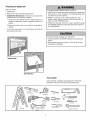 3
3
-
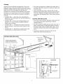 4
4
-
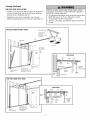 5
5
-
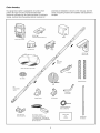 6
6
-
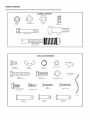 7
7
-
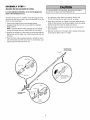 8
8
-
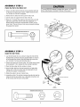 9
9
-
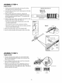 10
10
-
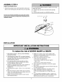 11
11
-
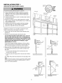 12
12
-
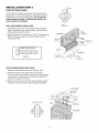 13
13
-
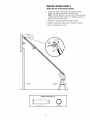 14
14
-
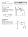 15
15
-
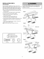 16
16
-
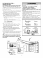 17
17
-
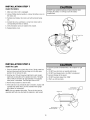 18
18
-
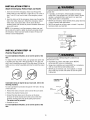 19
19
-
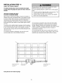 20
20
-
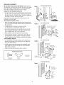 21
21
-
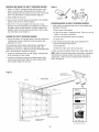 22
22
-
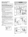 23
23
-
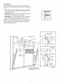 24
24
-
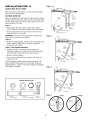 25
25
-
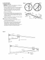 26
26
-
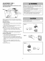 27
27
-
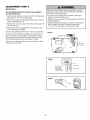 28
28
-
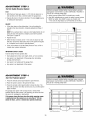 29
29
-
 30
30
-
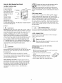 31
31
-
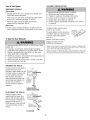 32
32
-
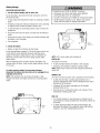 33
33
-
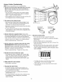 34
34
-
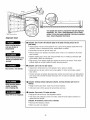 35
35
-
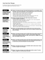 36
36
-
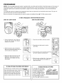 37
37
-
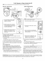 38
38
-
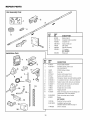 39
39
-
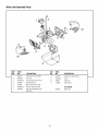 40
40
-
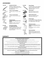 41
41
-
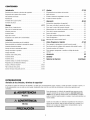 42
42
-
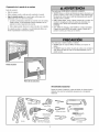 43
43
-
 44
44
-
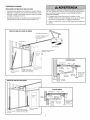 45
45
-
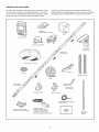 46
46
-
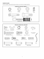 47
47
-
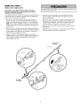 48
48
-
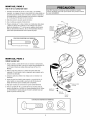 49
49
-
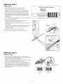 50
50
-
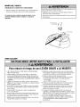 51
51
-
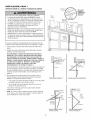 52
52
-
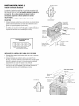 53
53
-
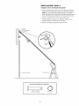 54
54
-
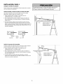 55
55
-
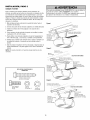 56
56
-
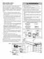 57
57
-
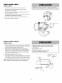 58
58
-
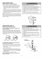 59
59
-
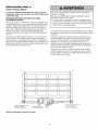 60
60
-
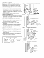 61
61
-
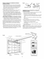 62
62
-
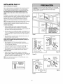 63
63
-
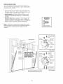 64
64
-
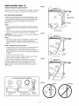 65
65
-
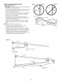 66
66
-
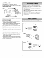 67
67
-
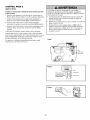 68
68
-
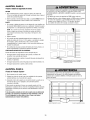 69
69
-
 70
70
-
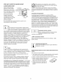 71
71
-
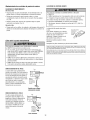 72
72
-
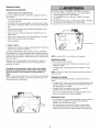 73
73
-
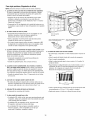 74
74
-
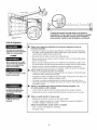 75
75
-
 76
76
-
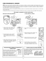 77
77
-
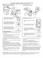 78
78
-
 79
79
-
 80
80


Craftsman 13953918D El manual del propietario
- Categoría
- Abridor de puerta de garage
- Tipo
- El manual del propietario
En otros idiomas
- English: Craftsman 13953918D Owner's manual
Documentos relacionados
-
Craftsman 139.53906D El manual del propietario
-
Craftsman 139.3043 Manual de usuario
-
-
-
-
-
-
-
-

